
Forming Machine for Metal Pipes: A metal forming machine for metal pipes is used to shape, bend, or size metal tubes and pipes into desired forms and specifications. There are several types of machines, each suited for specific applications and forming methods.
Tube Bending Machines
- Function: Bend metal pipes to various angles and radii.
- Types:
- Mandrel Bending Machines: Use an internal mandrel to prevent pipe deformation.
- Rotary Draw Bending: Offers precision for tight radii (common in automotive and aerospace).
- Roll Bending: Ideal for large-radius bends and spirals.
- Materials: Steel, stainless steel, aluminum, copper.
Pipe Swaging Machines
- Function: Reduce or expand the end diameter of pipes.
- Process: Uses dies and hammers to compress the pipe mechanically.
- Used in: Hydraulic systems, exhaust systems.
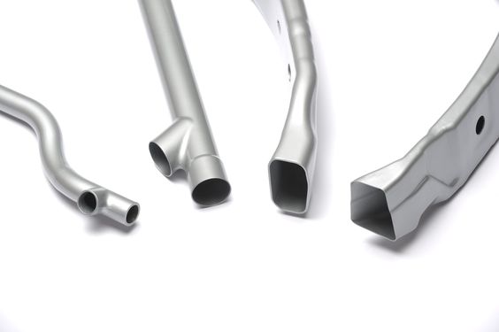
Pipe End Forming Machines
- Function: Create end shapes like flaring, beading, notching, and expanding.
- Techniques:
- Ram forming
- Rotary forming
- Segment forming
Hydroforming Machines
- Function: Use high-pressure hydraulic fluid to form complex shapes inside a die.
- Benefits: Produces lightweight, strong parts with uniform wall thickness.
- Used in: Automotive frames, exhaust systems.
Pipe Rolling Machines
- Function: Roll flat metal into cylindrical or conical pipe shapes.
- Also called: Plate rolls or section rolls.
- Used for: Large diameter pipe fabrication from sheet metal.
CNC Tube Forming Machines
- Function: Automated control for precision pipe forming.
- Features: Computer-controlled motion and tool positioning.
- Benefits: High repeatability, minimal waste, complex geometries.
Induction Bending Machines
- Function: Use localized heating with electromagnetic induction for precision bends.
- Applications: Oil & gas pipelines, large infrastructure.
Key Parameters to Consider:
- Pipe diameter and wall thickness
- Type of material (mild steel, stainless, alloy, etc.)
- Required bend radius or shape
- Production volume (manual, semi-auto, CNC)
- End forming needs (expansion, reduction, etc.)
Forming machines for metal pipes are industrial machines designed to shape metal into cylindrical or tubular forms. These machines are widely used in industries such as construction, oil & gas, automotive, and HVAC. Below is a breakdown of the major types of forming machines used for metal pipe production and their functions:
Tube Mill (ERW – Electric Resistance Welding)
- Function: Produces straight-seam welded pipes from steel coils.
- Process:
- Uncoiling: Metal strip is uncoiled.
- Forming: The strip is formed into a round shape using forming rolls.
- Welding: Edges are heated by electric resistance and fused together.
- Sizing: Pipe diameter is calibrated.
- Cutting: Pipe is cut to the desired length.
- Material: Carbon steel, stainless steel.
- Applications: Water/gas pipes, structural tubing, scaffolding.
Spiral Pipe Forming Machine (Helical Pipe Mill)
- Function: Produces large-diameter pipes by spirally winding a metal strip.
- Process:
- Coil strip is helically formed and welded (usually by submerged arc welding).
- Material: Typically carbon steel.
- Applications: Large pipelines, marine structures, wind towers.
Hydroforming Machines
- Function: Forms pipes by using high-pressure hydraulic fluid to shape a blank inside a die.
- Process:
- A tube blank is inserted into a mold and expanded using fluid pressure.
- Material: High ductility metals (aluminum, stainless steel, etc.).
- Applications: Automotive exhausts, aerospace tubing.
Mandrel Pipe Benders (Cold Forming)
- Function: Bends preformed pipes without wrinkling or collapsing.
- Process:
- A mandrel is inserted into the pipe to maintain shape during bending.
- Applications: Furniture, automotive frames, plumbing.
Roll Forming Machines
- Function: Gradually bends metal strips into tubes or other shapes using sequential rollers.
- Features:
- Continuous process.
- High production speed.
- Applications: HVAC ducts, conveyor tubes, structural components.
UOE Pipe Forming Machines
- Function: Used for large-diameter, thick-walled pipes (especially in oil & gas).
- Process:
- U-forming: Plate is formed into a U-shape.
- O-forming: Further bent into a circular shape.
- Expansion: Diameter is calibrated.
- Seam welding (usually SAW).
- Applications: Subsea pipelines, high-pressure transmission.
Stretch Forming Machines
- Function: Forms curves or bends in pipes by stretching over a die.
- Applications: Aerospace frames, architectural metalwork.
Summary Table
| Machine Type | Primary Use | Material Type | Typical Pipe Size |
|---|---|---|---|
| Tube Mill (ERW) | Small to medium straight pipes | Steel, SS | < 24 inch |
| Spiral Pipe Machine | Large diameter pipelines | Steel | > 24 inch |
| Hydroforming | Complex shapes | Ductile metals | Small to medium |
| Roll Forming | High-volume tubing | Mild steel, Al, SS | Varies |
| Mandrel Benders | Bending existing pipes | All pipe types | Varies |
| UOE Machine | High-strength pipelines | Carbon steel | Large diameter, thick wall |
| Stretch Forming | Curved forms | Light metals | Thin-walled sections |
Forming machines for metal pipes are essential equipment used to shape metal into tubular forms through various mechanical or hydraulic processes, depending on the material type, pipe dimensions, and application. One of the most common systems is the tube mill, particularly Electric Resistance Welding (ERW) mills, which produce straight-seam welded pipes from steel coils. In this process, a steel strip is uncoiled, gradually formed into a round shape through a series of rollers, then heated along the seam and welded by electric resistance. The pipe is then sized, cooled, and cut to length. These are typically used for water, gas, and structural applications using carbon steel or stainless steel.
For producing large-diameter pipes, especially in oil and gas or infrastructure projects, spiral pipe forming machines are used. These machines form pipes helically by spiraling a steel strip and welding the edges, often using submerged arc welding. This allows for larger diameters and longer pipe lengths with efficient material usage.
Hydroforming machines are used to shape metal pipes by applying high-pressure hydraulic fluid inside a tube placed within a die. This method is ideal for forming complex or asymmetrical shapes and is common in automotive and aerospace applications, particularly for materials like aluminum or stainless steel with good ductility.
Mandrel pipe bending machines are used when already-formed pipes need to be bent without deforming or collapsing. A mandrel or flexible support is inserted into the pipe to maintain its cross-sectional shape during the bending process. These machines are widely used in industries such as automotive exhaust systems, furniture, and HVAC.
Roll forming machines work by passing a continuous metal strip through sequential rollers that gradually shape it into a pipe or tube. This process is efficient for high-volume production and can handle a variety of materials including mild steel and aluminum. It’s commonly used for making structural tubes, rails, and ducts.
UOE forming machines are typically used for thick-walled, large-diameter pipes, especially in offshore oil and gas transmission. The process involves U-forming a flat steel plate, O-forming it into a circular shape, expanding it to ensure dimensional accuracy, and welding the seam using submerged arc welding. These pipes are known for their strength and ability to handle high-pressure conditions.
Stretch forming machines are used to create curved pipe sections by stretching the material over a form or die. This is typically used in aerospace structures or architectural designs where precise curves are needed without wrinkles or surface damage.
Each of these machines is designed for a specific production goal, whether it’s straight pipes for water transport, large spirals for infrastructure, or intricately shaped tubes for automotive systems. The choice of machine depends on the pipe’s size, shape, strength requirements, and intended use.
In a modern pipe manufacturing facility, these forming machines are often integrated into automated production lines to improve efficiency, consistency, and output rates. For example, in a tube mill setup, automation controls the coil feed rate, forming pressure, welding current, and cut-off timing, all of which are synchronized to maintain high-speed production with minimal human intervention. Sensors and feedback systems monitor weld integrity and dimensional accuracy in real time, ensuring quality control throughout the process.
In addition to forming, many lines incorporate secondary processes such as annealing, pickling, coating, threading, and non-destructive testing (NDT). Annealing softens the metal after forming or welding to relieve internal stresses and improve ductility. Pickling removes scale and oxide layers for better surface finish and corrosion resistance, especially important in stainless steel pipes. Coating or galvanizing may be applied to protect the pipe from corrosion in harsh environments, while threading is often used to prepare the pipe ends for joining in plumbing or gas lines. NDT methods such as ultrasonic testing (UT) and eddy current inspection are applied inline to detect flaws or inconsistencies in welds or wall thickness without interrupting production.
Material handling systems such as automatic loaders, conveyors, and stacking arms help transport the pipes safely and efficiently from one stage to another, minimizing damage and downtime. For heavy-duty applications such as those in oil, gas, or structural sectors, robotic arms and gantry cranes are often used to lift and position large-diameter or thick-walled pipes.
Over the years, forming machine designs have evolved to accommodate a wider range of materials including duplex stainless steels, titanium alloys, and high-strength low-alloy (HSLA) steels. These materials demand more precise control over temperature, force, and feed rates due to their sensitivity to cracking or distortion. As a result, forming machines have become more robust and sophisticated, equipped with adaptive controls and hardened tooling capable of handling the increased demands of advanced metal alloys.
Overall, the development of forming machines for metal pipes has allowed manufacturers to achieve high levels of productivity, precision, and versatility. They support everything from commodity-grade steel piping to highly engineered aerospace and automotive tubing. The ability to customize forming parameters for specific materials and applications makes them indispensable in a wide range of industrial sectors.
Curling Machine For Metal Pipes
A curling machine for metal pipes is a specialized forming machine used to shape or finish the ends of metal pipes, typically by rolling or forming a curl, bead, or flange at the pipe ends. This process is often used to prepare pipes for joining, sealing, reinforcement, or aesthetic purposes. Curling is common in the manufacturing of ducts, mufflers, container rims, and automotive or HVAC components.
Function and Purpose
The main function of a curling machine is to deform the end of a cylindrical pipe or tube into a rounded edge or spiral curl. This helps in:
- Creating safe, rounded edges to avoid sharp ends.
- Improving structural integrity and preventing cracking at the ends.
- Forming lips or flanges for joining or sealing with other parts.
- Enhancing appearance for consumer-facing products.
- Facilitating assembly, especially where interlocking or slip-fit connections are required.
Types of Curling Machines
- Manual or Semi-Automatic Curling Machines
- Operated with manual adjustments or foot pedal controls.
- Suitable for small batches or prototype work.
- Used in workshops or smaller production setups.
- Automatic Curling Machines
- PLC-controlled for consistent and high-volume production.
- Can handle varying diameters and lengths with quick setup changes.
- Integrated into production lines (e.g., for automotive exhausts, containers).
- Rotary Curling Machines
- Feature rotating dies or rollers that gradually form the curl while the pipe is held in position.
- Produce uniform curls with minimal distortion.
- Hydraulic or Pneumatic Curling Machines
- Use fluid or air pressure to form the curl.
- Often used for thicker or stronger materials requiring more force.
Working Principle
- The pipe is clamped or held in place by a fixture.
- A set of curling rollers or forming dies approach the pipe end.
- As the rollers move (rotationally or linearly), they gradually bend the pipe edge inward or outward, forming a curl, bead, or lip.
- The formed end is released and inspected for roundness, consistency, and integrity.
In high-end machines, this process can include automatic feed, curl depth adjustment, and inline quality checks.
Materials and Applications
- Materials: Mild steel, stainless steel, aluminum, copper, brass.
- Typical Pipe Sizes: From small-diameter tubes (e.g., ½ inch) to larger ducts or exhaust pipes.
- Applications:
- Automotive mufflers and exhaust components.
- HVAC ducts and fittings.
- Metal drums and canisters.
- Decorative or structural tubing.
- Industrial chimneys or hoods.
Key Features to Consider
- Adjustable tooling for different pipe diameters and wall thicknesses.
- Cycle time and automation level for production efficiency.
- Curl size and profile (U-shape, C-shape, flared, beaded, etc.).
- Material handling support, especially for large or heavy pipes.
- Tool change system for switching between pipe sizes quickly.
Curling machines are often integrated into a broader production line that may include pipe cutting, end-forming, flaring, swaging, or welding stations. Their ability to precisely and reliably shape pipe ends makes them essential for applications where end quality is critical to product function or appearance.
Curling machines for metal pipes operate as precision tools that finish the ends of pipes by rolling or shaping them into a curved profile, such as a bead or lip. This process is often used to strengthen the pipe end, eliminate sharp edges, or prepare the pipe for connection with other parts. Unlike general forming machines that shape the entire length of a pipe, curling machines focus specifically on modifying the pipe’s end geometry. The machines work by securing the pipe in place, then using rotating rollers or forming heads that apply progressive pressure to the edge of the pipe, bending it inwards or outwards depending on the desired curl profile. This action is tightly controlled to ensure uniformity, especially when producing high volumes of identical components.
In industries such as HVAC, automotive, and industrial ducting, curling is a common final step before assembly. For instance, curled ends on HVAC ducts help facilitate quick slip connections between segments. In automotive muffler production, the curled pipe end may be inserted into another part and then sealed, providing both strength and a clean finish. Similarly, in the manufacture of metal drums or containers, the curling operation forms the rim that will later be joined with a lid or base.
Materials processed in curling machines include carbon steel, stainless steel, aluminum, and copper, with varying wall thicknesses. The effectiveness of the curling operation depends on several factors such as material hardness, pipe diameter, and wall thickness, all of which affect the amount of pressure and tool design needed to create a clean curl without cracking or deforming the pipe body. More advanced machines may use servo-driven rollers and programmable logic controllers (PLCs) to allow operators to quickly change settings and automate the process for different pipe specifications.
Curling machines are sometimes paired with flanging or beading modules, allowing multiple end-forming operations in a single setup. For example, a pipe can be curled and then have a bead formed just below the curl for mechanical fastening or gasket retention. In a high-speed production environment, such machines may be part of a fully automated line that includes feeding, curling, inspection, and unloading.
Because end curling is often a critical feature from a mechanical and aesthetic standpoint, the machines must deliver consistent results over long production runs. Tooling must be durable and precise, often requiring hardened steel components and exact alignment to avoid uneven curls. In certain cases, especially with larger or thicker pipes, hydraulic or pneumatic pressure may be needed to achieve the curl, as mechanical rollers alone may not provide sufficient force. Some heavy-duty curling machines also integrate safety features such as automatic stop systems, guarding, and monitoring sensors to ensure operator safety and prevent equipment damage.
Ultimately, the curling machine plays a vital role in the production of finished metal pipe components that are ready for assembly, packaging, or installation. Its ability to form clean, strong, and consistent pipe ends is critical to the performance and reliability of many products in infrastructure, transportation, and industrial systems.
In large-scale manufacturing settings, curling machines are often configured to handle a wide range of pipe sizes and materials with minimal manual intervention. Changeover systems allow operators to quickly adjust tooling and settings when switching between different pipe diameters or curl specifications, reducing downtime and improving throughput. Some advanced curling systems include servo-controlled axes that allow for precise, repeatable motion, which is especially important when producing parts that must meet strict dimensional tolerances or aesthetic requirements.
The geometry of the curl itself can vary depending on the application. A simple inward curl may be used to eliminate a sharp edge for safety or ease of handling, while more complex profiles like an S-curl, rolled lip, or flared edge may be designed to mate with another component, hold a gasket, or provide additional stiffness to the pipe end. Engineers often choose the curl profile based on the expected loading conditions, sealing requirements, or the method of joining—whether it’s clamped, crimped, welded, or press-fitted. In the case of press-fit joints, a curled or beaded edge can serve as a mechanical stop or retainer.
The materials used in curled pipes are often selected for their formability. Metals like aluminum and mild steel are relatively easy to curl, while stainless steel and high-strength alloys require more force and specialized tooling due to their hardness and springback. In such cases, machines may be equipped with heat-assisted forming options to soften the material locally at the curl zone and reduce the risk of cracking. Lubrication is also used in many setups to reduce friction and extend the life of the rollers or dies.
Quality control is another critical component in pipe curling operations. Curl height, diameter, symmetry, and surface finish must all be within acceptable limits. Automated systems may use vision sensors or laser measurement tools to inspect the curl as it’s formed, providing immediate feedback and ensuring defective parts are identified and removed before moving downstream. This level of integration is essential in applications where a failed curl could lead to leakage, structural weakness, or assembly failure.
Curling machines can also be found in smaller job shops or specialized fabrication environments where custom piping solutions are produced in lower volumes. In such cases, machines might be manually operated or semi-automatic, offering greater flexibility for custom curl designs or one-off projects. These machines are often more compact and easier to set up, making them suitable for repair shops, prototyping, or small-batch production where speed and adaptability are more important than full automation.
In summary, curling machines for metal pipes are critical tools in both high-volume industrial manufacturing and smaller fabrication operations. Their ability to create precisely shaped and durable pipe ends makes them essential in a wide variety of industries, from ducting and drainage to automotive and food processing. Whether integrated into an automated production line or used as a standalone tool, the curling machine adds functional and structural value to metal pipes, ensuring that they are not only fit for assembly but also perform reliably in their final application.
Rolling Machine For Metal Pipes
A rolling machine for metal pipes is a type of metal forming equipment designed to bend, shape, or form metal sheets or plates into cylindrical or conical pipe shapes. These machines are widely used in industries such as pipeline construction, shipbuilding, pressure vessel manufacturing, HVAC, and structural fabrication. Rolling is typically a cold-forming process, where metal is shaped without heating, although in some cases for thicker or tougher materials, preheating may be used.
The fundamental principle behind pipe rolling is the gradual bending of a flat metal sheet by passing it through a series of rolls, which apply continuous pressure until the sheet takes the desired curvature and eventually forms into a full cylinder or spiral. The most common type of rolling machine for pipes is the plate rolling machine, also known as a plate bending machine.
Rolling machines are categorized based on the number and arrangement of rolls:
The most common configuration is the 3-roll plate rolling machine, which uses one top roll and two bottom rolls. The metal plate is positioned between the rolls, and the rolls are adjusted to apply pressure and bend the plate. By rotating the rolls and adjusting their positions, the plate is progressively bent into a cylindrical shape. The operator can control the roll position manually or through an automated system (CNC or NC) for more precision.
A more advanced design is the 4-roll plate rolling machine, which includes an additional bottom roll that improves grip, control, and forming accuracy. With four rolls, the material is held more securely, allowing for faster setup and the ability to pre-bend both ends of the plate without removal or repositioning. This makes 4-roll machines well-suited for high-precision rolling and automated production lines.
Pyramid-type rolling machines feature a triangular roll arrangement and are common in medium-duty applications, while horizontal and vertical rolling machines are used based on the space constraints and pipe size. For example, vertical rolling machines are often used for very large-diameter pipes, where the plate stands upright during the forming process.
Pipe rolling machines can also produce conical shapes by adjusting the rolls’ inclination or using tapered rolls. This is often used in applications like hoppers, nozzles, or architectural structures.
The material processed in these machines includes carbon steel, stainless steel, aluminum, and alloys, with thicknesses ranging from a few millimeters to several centimeters. The rolling capacity—defined by maximum plate width, thickness, and bending diameter—varies greatly depending on machine size, roll diameter, and motor power. For heavy-duty operations like pressure vessel or wind tower manufacturing, machines with hydraulic drive systems are used to provide the necessary forming force.
In operation, the metal sheet is fed into the rolling machine, pre-bent at one end, then gradually rolled into a circular shape. Once fully rolled, the seam is typically welded to form a closed pipe. This process may also be followed by post-rolling steps such as seam grinding, calibration, ultrasonic testing, and stress relieving, depending on the application.
Modern rolling machines are equipped with digital control systems for roll positioning, bending force adjustment, and process monitoring. These features enhance forming accuracy, reduce scrap, and enable repeatable quality across production runs. In some systems, laser alignment and 3D simulation tools are integrated to preview roll paths and outcomes before actual bending.
Rolling machines are essential in any operation where large-diameter pipes are needed, especially when the required size is not economically viable through extrusion or ERW tube mills. Their versatility in handling different metals, sizes, and shapes makes them a core component of many fabrication shops and manufacturing plants.
In continuous pipe fabrication workflows, rolling machines are often integrated with upstream and downstream equipment to streamline the process from raw material to finished pipe. At the start of the process, metal plates are unstacked, aligned, and fed into the rolling machine either manually or through an automated handling system. The sheet is then positioned between the rolls with precise alignment to ensure even forming. In modern systems, CNC controls guide the rolling sequence, adjusting the pressure and rotation speed to accommodate variables such as plate thickness, material yield strength, and target diameter.
During the rolling operation, the operator may perform a pre-bending step where one or both ends of the sheet are slightly curved before the main rolling cycle begins. This reduces the flat portions at the pipe ends and improves roundness once the full cylinder is formed. As the rolls rotate and apply downward or lateral pressure, the sheet gradually takes on a circular profile. For extremely thick or wide plates, multiple passes may be necessary, with each pass increasing the curvature incrementally. Once the two edges of the plate meet or come close, clamps or tack welds may be used to hold the seam in place for welding.
Welding is typically performed immediately after rolling, with processes such as submerged arc welding (SAW), gas tungsten arc welding (GTAW), or flux-cored arc welding (FCAW) depending on the material and application. In many facilities, welding equipment is mounted on rails alongside the rolling machine so that the rolled pipe does not have to be repositioned, allowing for fast and seamless transition between forming and joining. After welding, the pipe may undergo further rolling or mechanical calibration to achieve exact roundness and ensure the seam is flush with the pipe wall.
The capability of a rolling machine is influenced by roll diameter, motor power, and the distance between the lower rolls. Larger roll diameters are better suited for thicker plates as they provide greater leverage and bending force. Rollers are typically made from hardened steel alloys to resist wear and maintain surface quality over long production cycles. Roll surface finish is also important—too rough, and it can mark or damage the plate; too smooth, and it may fail to grip during rolling.
Some rolling machines come with crowning adjustments or support arms to compensate for deflection, especially when working with wide or thick plates. Deflection causes the center of the roll to bend slightly under pressure, which can result in an inconsistent bend across the length of the pipe. Crowning—either physical or hydraulic—helps maintain consistent curvature from end to end. Side supports and top pinch rolls may be added for long pipes that would otherwise sag under their own weight during forming.
In large diameter pipe manufacturing for oil and gas pipelines, wind towers, or marine structures, the rolling machine must maintain very tight tolerances on roundness and seam gap, as even minor deviations can affect welding quality or structural performance. These projects often use high-strength low-alloy steels or duplex stainless steel, which require higher forming forces and tighter control over springback. In such cases, machine builders provide custom rolling solutions with additional torque, programmable bending sequences, and high-precision hydraulic or servo drive systems.
While traditional rolling machines have relied heavily on operator skill, the shift toward automation and digital integration has significantly improved consistency and output. CNC-controlled rolling machines can store recipes for different pipe configurations, automatically adjust for material properties, and monitor forming parameters in real time. Sensors and software can track the radius being formed, flag errors, and make corrections on the fly. This has opened the door for mass customization, where small batches of different pipe sizes or shapes can be produced with minimal retooling or setup time.
Whether used in shipyards, energy plants, construction, or aerospace facilities, rolling machines serve as a versatile and indispensable tool in metal pipe fabrication. Their ability to create large, strong, precisely curved structures from flat sheet material makes them ideal for industries that demand both structural integrity and dimensional precision. As forming requirements continue to evolve with new materials and tighter standards, rolling machines remain at the heart of modern heavy fabrication.
Beyond traditional plate rolling machines, innovations have emerged to address increasingly complex pipe geometries and specialized applications. For example, incremental rolling machines use a series of small, closely spaced rollers to gradually bend the plate with minimal distortion and residual stress. This technique is particularly beneficial for advanced high-strength steels or alloys that are sensitive to cracking or deformation during forming. Incremental rolling can also produce tighter bend radii and more uniform thickness distribution compared to conventional rolling.
Another advancement is the integration of laser or ultrasonic measurement systems directly into rolling machines, enabling continuous monitoring of curvature, thickness, and flatness during the bending process. These inline quality control systems provide real-time data that can be fed back to the control system to adjust roll position and pressure dynamically. This closed-loop control minimizes defects and scrap, especially when working with expensive or difficult-to-form materials.
For very large-diameter pipes used in offshore pipelines, wind energy towers, or industrial chimneys, vertical rolling machines are often preferred. These machines orient the plate vertically, reducing the footprint of the equipment and better supporting the heavy plate during bending. Vertical rolling also leverages gravity to assist the forming process, lowering the required roll forces and improving operator safety by minimizing manual handling.
In addition, combined rolling and welding systems have been developed, where the pipe is formed and welded in a single automated cell. These integrated systems use synchronized robotics to move the pipe seamlessly between forming rolls and welding stations. This reduces cycle times, improves weld consistency, and lowers labor costs by reducing manual transport and setup.
Material handling innovations complement rolling machine capabilities. Automated loading and unloading systems, including robotic arms, conveyors, and roller tables, facilitate smooth transitions between manufacturing stages. For thick or heavy plates, overhead cranes and hydraulic lifts ensure precise positioning without damaging the material. These handling solutions are critical for maintaining product quality and maximizing throughput in demanding production environments.
Environmental and safety considerations have also influenced rolling machine design. Modern machines incorporate sound-dampening enclosures, dust extraction, and ergonomic controls to protect operators and comply with workplace regulations. Safety interlocks and emergency stops are standard features, particularly in fully automated lines where human interaction is limited but critical.
As digitalization progresses, the integration of Industry 4.0 technologies such as IoT sensors, cloud data analytics, and machine learning algorithms is becoming more common in rolling machine operations. These technologies enable predictive maintenance, remote monitoring, and advanced process optimization, helping manufacturers reduce downtime and improve overall equipment effectiveness (OEE).
Finally, rolling machines remain adaptable to emerging materials and new manufacturing paradigms. The growth of composite materials, hybrid metal laminates, and tailored blanks presents new challenges and opportunities in pipe forming. Manufacturers and machine builders continue to innovate tooling, process controls, and machine architectures to keep pace with these trends.
In summary, rolling machines for metal pipes have evolved far beyond simple mechanical benders into sophisticated, integrated production systems. They combine mechanical precision, automation, quality control, and material handling to meet the ever-increasing demands of modern industries. Whether producing standard steel pipes or advanced alloy tubing, rolling machines are foundational to shaping metal into reliable, high-performance cylindrical structures.
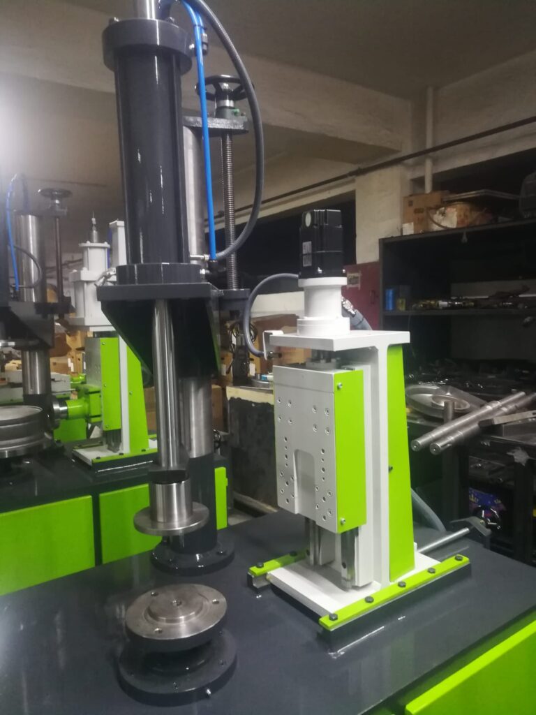
Compressing Machine For Metal Pipes
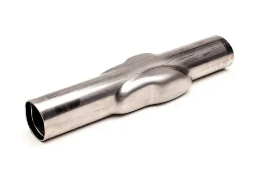
A compressing machine for metal pipes refers to equipment designed to apply compressive force to pipes or tubes for various forming, joining, or finishing operations. Unlike rolling or curling machines, which primarily bend or shape metal, compressing machines use direct pressure to reduce, reshape, or deform pipe sections, often to create features like swages, necks, crimps, or to join pipes through mechanical interlocking.
Commonly, compressing machines are used for:
- Swaging: Reducing the diameter of a pipe end by compressing it inward, creating a smaller-diameter section that can fit into another pipe or component for joining.
- Crimping: Applying radial compression to form a secure, leak-tight connection in plumbing or HVAC tubing.
- Necking: Tapering the pipe end to a smaller diameter.
- End forming: Flattening, expanding, or otherwise shaping pipe ends to prepare for welding, assembly, or sealing.
- Compression fitting preparation: Creating mechanical joints in pipes without welding, often in gas or water lines.
These machines may operate using hydraulic, mechanical, or pneumatic power sources, depending on the required force and precision. Hydraulic compressing machines are common in industrial settings due to their ability to generate high, controllable pressure suited for thick-walled pipes or tougher materials.
The compressing process typically involves placing the pipe in a die or between jaws that exert inward pressure in a controlled manner. The dies are shaped to achieve the desired pipe end profile without causing cracks, wrinkles, or distortion. The compression force is applied gradually or in stages to avoid excessive stress concentration.
In industrial pipe manufacturing, compressing machines can be standalone units or integrated into automated lines, where pipes move through successive forming stations. In some cases, compression is combined with heating to soften the metal, making deformation easier and reducing the risk of defects.
Material types processed in compressing machines vary from soft metals like copper and aluminum, commonly used in plumbing and HVAC, to harder steels used in oil and gas pipelines or structural tubing. The machine design is tailored accordingly, with tooling and force capacity sized for the specific pipe dimensions and material properties.
Compression forming offers a cost-effective and efficient way to prepare pipes for joining without welding or with minimal heat input. It is especially valuable in applications requiring quick assembly, maintenance, or repair, such as in refrigeration, hydraulic systems, or vehicle manufacturing.
Modern compressing machines may feature programmable controls for force, stroke length, and speed, enabling high repeatability and quality control. Some also include sensors to detect material deformation and ensure process consistency, preventing over-compression or under-forming.
Overall, compressing machines play a crucial role in the metal pipe industry by enabling precise, reliable end-forming and joining techniques that complement other pipe fabrication methods like rolling, welding, and curling.
Compressing machines apply controlled radial or axial pressure to metal pipes to achieve specific shapes or features essential for assembly and performance. The process typically involves positioning the pipe within a set of dies or molds that match the desired final geometry. As the compressive force is applied—usually by hydraulic cylinders or mechanical presses—the pipe material plastically deforms, altering its cross-sectional profile without causing cracks or surface damage. This deformation can create tapered ends for fitting into larger pipes, reduce diameters for insertion into couplings, or form ribs and grooves that improve joint strength.
In many cases, compression forming replaces welding or threading by enabling strong mechanical joints through interference fits or locking features. For example, in plumbing or refrigeration systems, crimped connections formed by compression machines provide leak-proof seals without the need for soldering or adhesives. Similarly, in automotive exhaust or hydraulic tubing, swaging the pipe ends allows for rapid assembly with minimal tooling.
The versatility of compression machines extends to handling various pipe sizes and wall thicknesses. For thinner-walled or softer materials, lower pressures and simpler tooling may suffice, whereas thick-walled steel pipes require robust frames, high-tonnage presses, and precisely machined dies to achieve uniform deformation. Compression tooling is often modular, allowing quick changes between different pipe diameters and compression profiles to accommodate diverse production needs.
Some advanced compression machines integrate sensors and closed-loop controls to monitor the applied force and displacement in real time. This feedback ensures each pipe end is formed within tight tolerances, reducing scrap rates and improving downstream assembly reliability. Operators can program specific force profiles and stroke sequences to optimize the compression for each material and pipe specification.
Safety features are critical due to the high forces involved. Modern machines include guarded enclosures, emergency stops, and interlock systems to protect operators during the forming cycle. Automated loading and unloading systems are also common in high-volume operations, reducing manual handling and improving overall efficiency.
In addition to end-forming, compression machines are sometimes used to repair or recondition pipes by reducing dented or deformed sections back to their original shape. This capability is valuable in maintenance operations where replacing entire pipe segments would be costly or impractical.
Industries relying heavily on compressing machines include plumbing, HVAC, automotive, aerospace, oil and gas, and manufacturing of industrial equipment. Their ability to create reliable, high-quality joints and end forms without heat or extensive machining makes them indispensable in modern pipe fabrication and assembly processes.
As technology advances, compression machines continue to evolve with enhanced automation, integration with robotic systems, and intelligent process controls. This evolution helps manufacturers meet increasing demands for precision, speed, and adaptability while minimizing costs and environmental impact.
In specialized applications, compressing machines may also be combined with other forming processes such as flaring, expanding, or beading to produce multi-functional pipe ends in a single operation. For instance, a pipe end might first be compressed to reduce its diameter for insertion, then flared or expanded slightly to create a tight, secure joint when assembled with a coupling or gasket. This multi-step forming capability reduces handling and improves overall manufacturing efficiency.
Compression forming can also be applied to non-cylindrical tubes or pipes with custom profiles. With the right tooling, these machines can produce square, rectangular, or oval cross-section ends that are compressed or reshaped for specific joining or sealing needs. This flexibility is particularly important in industries like aerospace and automotive, where lightweight, aerodynamic, or space-efficient pipe geometries are common.
When working with advanced materials like titanium alloys or composite metal laminates, compressing machines must account for differences in ductility and springback behavior. Specialized tooling coatings, temperature controls, and incremental compression steps help prevent surface cracking and maintain structural integrity in these challenging materials.
Another emerging trend is the use of servo-driven compression presses that offer highly programmable force application with fine control over speed and displacement. This allows for more delicate forming processes and the ability to quickly switch between different pipe sizes and compression profiles without mechanical adjustments. Combined with data logging and remote diagnostics, these systems support Industry 4.0 goals for smart manufacturing.
Maintenance and tooling changeover are key considerations for compression machines in high-volume production. Quick-change die systems and modular tooling racks reduce downtime and enable rapid adaptation to production schedules. Regular maintenance of hydraulic systems, press frames, and tooling surfaces is critical to ensure consistent quality and machine longevity.
In repair and field service contexts, portable or bench-top compression machines enable on-site pipe forming and joining, which is valuable for plumbing repairs, HVAC installations, or mobile equipment maintenance. These smaller units may use manual or pneumatic power and are designed for ease of transport and operation in confined spaces.
Overall, compressing machines are indispensable tools that complement rolling, curling, and welding equipment in the metal pipe manufacturing ecosystem. Their ability to shape, join, and finish pipe ends precisely and efficiently contributes to the production of durable, high-quality piping systems essential to countless industrial, commercial, and residential applications. As material science and manufacturing technologies advance, compressing machines will continue to adapt and innovate, supporting ever more demanding performance and quality standards.
Stretching Machine For Metal Pipes
A stretching machine for metal pipes is a specialized piece of equipment used to apply tensile force along the length of a metal pipe or tube to elongate, straighten, or improve its mechanical properties. Unlike rolling or compressing machines, stretching machines focus on lengthwise deformation rather than shaping the cross-section. This process is widely employed in industries like automotive, aerospace, construction, and pipeline manufacturing to enhance dimensional accuracy, surface finish, and structural integrity.
The core principle of pipe stretching involves gripping both ends of a pipe and pulling them apart under controlled tension. The pipe undergoes plastic deformation, lengthening while reducing residual stresses and often improving the alignment of the pipe’s grain structure. This can also help correct slight bends, warps, or ovality resulting from previous fabrication steps like rolling or welding.
Stretching machines typically consist of robust clamping mechanisms on each end of the pipe, hydraulic or servo-driven actuators to generate the tensile force, and a frame or bed to resist the load. The pipe is securely fixed to prevent slipping or damage during stretching. Controls allow operators to program the amount of elongation, stretching speed, and force applied, ensuring consistent results tailored to material type, pipe dimensions, and desired mechanical properties.
In addition to straightening and elongation, stretching is used to induce strain hardening in the pipe material, increasing its yield strength and improving fatigue resistance without additional heat treatment. This is particularly useful in applications where pipes must withstand cyclic loading or harsh environmental conditions.
The process can be applied to a wide range of metals including carbon steel, stainless steel, aluminum, and various alloys. Thinner-walled pipes may require careful force control to avoid necking or failure, while thicker pipes need higher tensile forces and more robust equipment.
Stretching machines may also include auxiliary features such as inline measurement systems that monitor elongation, diameter changes, and surface condition in real time. These sensors provide feedback for process adjustments and ensure quality control. Some advanced systems integrate with computerized controls to automate multi-step stretching sequences, including pre-tensioning, hold periods, and controlled relaxation phases to achieve optimal pipe characteristics.
Beyond manufacturing, pipe stretching is sometimes used in repair or refurbishment to restore dimensional accuracy to pipes that have been bent or deformed in service. Portable stretching units allow field technicians to perform on-site straightening without the need for complete pipe replacement.
In summary, stretching machines for metal pipes are essential tools for enhancing the physical and mechanical qualities of pipes by controlled lengthwise deformation. Their ability to straighten, elongate, and strengthen pipes contributes significantly to producing reliable, high-performance piping systems across a variety of industrial sectors.
Stretching machines operate by gripping the pipe ends firmly, often using hydraulic chucks or clamps that prevent slippage and damage during the pulling process. The pipe is then subjected to a gradually increasing tensile load until the desired elongation or straightening is achieved. The machine frame or bed must be sturdy enough to withstand the high forces generated, especially when working with thicker or high-strength materials.
The stretching process can be finely controlled to avoid over-stressing the pipe, which could cause necking, cracking, or permanent deformation beyond specifications. Operators or automated systems set parameters such as elongation percentage, applied force limits, and stretching speed based on the pipe material properties and final application requirements. In some cases, multiple stretching cycles are applied with intermittent relaxation phases to gradually shape the pipe while minimizing internal stresses.
This process is particularly effective at correcting slight bends, kinks, or ovality that may occur during earlier manufacturing stages like rolling, welding, or handling. Stretching improves the pipe’s straightness and roundness, essential for ensuring proper fit-up during assembly and reliable performance in service. For example, in pipeline construction, a straight, uniform pipe reduces installation challenges and enhances flow characteristics.
In addition to mechanical straightening, stretching imparts strain hardening to the pipe material. The plastic deformation realigns the metal’s grain structure and dislocations, increasing yield strength and resistance to fatigue and crack propagation. This mechanical strengthening can reduce or eliminate the need for additional heat treatments, saving time and cost in production.
Stretching machines may be equipped with digital feedback systems such as load cells, displacement sensors, and laser measurement devices. These tools monitor force, elongation, and dimensional changes in real time, enabling precise process control and consistent quality. Data from these sensors can be logged for traceability or used in closed-loop systems that automatically adjust stretching parameters for optimal results.
In some automated manufacturing lines, stretching machines are integrated with upstream and downstream equipment like pipe straighteners, cutters, or welders to create seamless workflows. This integration enhances throughput and reduces manual handling, improving overall efficiency.
Portable or bench-top stretching units are also available for maintenance and repair applications. These smaller machines allow technicians to straighten or elongate pipes on-site, avoiding costly replacements and downtime. Such units are common in plumbing, HVAC, and vehicle repair industries where quick corrective action is needed.
Material considerations are important in stretching operations. Metals with lower ductility or higher strength require careful control of stretching parameters to avoid failure. For some advanced alloys, preheating or specialized tooling may be necessary to prevent cracking. Conversely, more ductile metals like aluminum or copper can tolerate higher elongation with simpler setups.
Overall, stretching machines provide an effective, controlled method to improve pipe geometry and mechanical properties, making them essential tools in metal pipe fabrication and maintenance. Their ability to precisely lengthen and straighten pipes enhances product quality, reduces waste, and supports the demands of modern manufacturing and construction industries.
Stretching machines also play a crucial role in customizing pipe lengths and adapting standard pipes to specific project requirements. By carefully controlling the elongation process, manufacturers can fine-tune pipe dimensions without cutting and welding, which helps maintain material integrity and reduces production steps. This capability is especially valuable in sectors where precise pipe lengths and tight tolerances are critical, such as aerospace, automotive, and high-pressure piping systems.
Another important application of pipe stretching is in the production of tapered or variable-diameter pipes. By selectively applying tensile forces and sometimes combining stretching with localized heating or tooling constraints, operators can create gradual changes in pipe diameter along its length. This technique is useful for nozzles, reducers, or specialized structural components requiring non-uniform cross-sections.
In high-volume industrial environments, stretching machines often feature automated loading and unloading systems integrated with conveyors or robotic arms. This reduces cycle times and operator fatigue while enhancing repeatability and process consistency. Automation also facilitates the handling of heavy or awkwardly sized pipes that would be difficult or unsafe to manipulate manually.
Some modern stretching systems incorporate adaptive control algorithms and machine learning to optimize the stretching process. By analyzing data from previous cycles and material characteristics, these systems can predict the ideal force application and elongation sequence for new batches of pipes, improving yield and reducing defects.
Environmental and safety considerations have led to improved designs with enclosed work areas, noise reduction features, and ergonomic controls. These enhancements protect operators from high forces, moving parts, and potential material failures during the stretching process.
In summary, stretching machines for metal pipes extend beyond simple elongation or straightening. They enable customization of pipe geometry, improve mechanical properties through strain hardening, and integrate seamlessly with modern automated production lines. As materials and manufacturing requirements evolve, stretching technology continues to adapt, ensuring it remains a vital component of efficient, high-quality metal pipe fabrication.
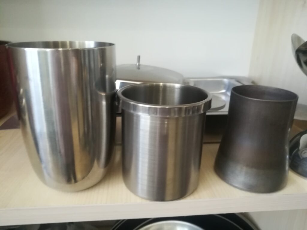
Reducing Diameter Machine For Metal Pipes
A reducing diameter machine for metal pipes is specialized equipment designed to decrease the outer diameter of a pipe or tube to a smaller size while maintaining the integrity and strength of the material. This process is essential in various industries where pipes of different diameters must be joined, connected, or fitted into assemblies requiring precise dimensional transitions, such as in plumbing, automotive exhaust systems, aerospace tubing, and industrial piping.
The machine operates by applying radial compressive forces to the pipe, either gradually or in stages, to deform the metal inward and reduce the diameter without causing wrinkles, cracks, or excessive thinning. The key challenge in diameter reduction is to maintain a uniform wall thickness and roundness while controlling material flow to avoid defects.
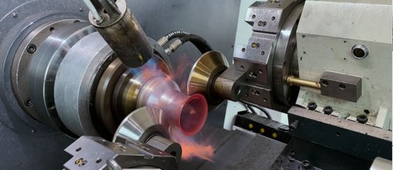
Typically, reducing diameter machines employ a series of conical dies, mandrels, or rollers arranged in a sequence. The pipe is fed through these dies, each progressively smaller than the last, which compress and reshape the pipe’s circumference and wall thickness. The process can be done cold or with localized heating, depending on the material type and thickness. Cold reducing is common for ductile metals like aluminum and mild steel, while hot reducing is used for thicker, less ductile materials.
Hydraulic or mechanical presses often power these machines, generating sufficient force to plastically deform the pipe while ensuring control over speed and pressure. Some machines use rotary reducing heads that spin the pipe against the dies for a smooth, continuous reduction process.
Precision is critical in diameter reduction, especially for applications requiring tight tolerances or where pipes must mate perfectly with fittings, flanges, or other components. Modern reducing diameter machines are frequently equipped with CNC controls to program the reduction profile, adjust feed rates, and monitor forces in real time. Sensors track diameter changes, wall thickness, and roundness to ensure consistent quality and prevent material failure.
Reducing diameter machines also support other end-forming operations such as necking, flaring, or beading by changing the tooling or adjusting process parameters. This versatility makes them valuable in manufacturing complex pipe assemblies or custom components.
In addition to manufacturing, diameter reducing machines are used in repair and refurbishment to resize pipes or tubes for retrofitting or modifications. Portable or smaller-scale versions enable on-site adjustments, minimizing downtime and material waste.
Material considerations influence the design and operation of reducing diameter machines. Higher strength or alloyed steels may require multiple passes, preheating, or specialized tooling coatings to prevent cracking and tool wear. Softer metals allow faster processing but still demand careful control to maintain surface finish and dimensional accuracy.
Overall, reducing diameter machines are essential tools for shaping metal pipes to precise diameters, enabling reliable connections and customized assemblies across diverse industrial applications. Their combination of mechanical power, precise control, and versatile tooling supports efficient production of high-quality, dimensionally accurate piping components.
Reducing diameter machines carefully control the deformation process to ensure that the pipe maintains its structural integrity throughout the diameter reduction. The gradual application of compressive forces prevents sudden material failure such as cracking or buckling. Typically, the pipe is first centered and aligned before entering the machine to avoid uneven compression or distortion. The dies or rollers are often adjustable or interchangeable to accommodate different pipe sizes and target diameters, enhancing the machine’s flexibility for various production needs.
In many designs, the pipe passes through multiple stages where each stage reduces the diameter incrementally. This staged reduction helps distribute the strain evenly along the pipe, minimizing residual stresses that could weaken the material or lead to warping during subsequent use. Between stages, some machines allow for measurement and quality checks to verify dimensional accuracy and detect any defects early in the process.
Advanced reducing diameter machines are integrated with sensors and digital control systems that provide real-time feedback on parameters such as force applied, pipe diameter, wall thickness, and roundness. This data enables operators or automated systems to adjust process variables instantly, optimizing product quality and reducing scrap rates. Some setups also include vision systems or laser scanners to inspect surface finish and detect anomalies immediately after forming.
The machines often feature robust frames and heavy-duty components to withstand the significant mechanical forces involved, especially when working with thick-walled pipes or high-strength alloys. Tooling is made from hardened materials to resist wear and maintain precise dimensions over long production runs. Regular maintenance and tooling calibration are necessary to preserve accuracy and avoid downtime.
For materials that are sensitive to cold working, localized heating methods such as induction coils or preheating ovens may be used in combination with diameter reduction. Heating increases ductility, reduces required force, and helps prevent cracking. After forming, pipes often undergo cooling and sometimes stress-relief treatments to stabilize the microstructure and improve mechanical properties.
Reducing diameter machines also play a role in producing stepped or tapered pipe sections, where one end of the pipe has a smaller diameter that transitions smoothly into a larger section. This is particularly important for components like reducers, nozzles, or adapters used in piping systems to connect different-sized pipes securely.
In repair or custom fabrication settings, portable reducing machines allow technicians to modify pipe diameters on-site, facilitating quick adjustments or retrofits without the need for new parts or extensive disassembly. These units tend to be smaller, manually operated, or pneumatic-powered, focusing on convenience and flexibility.
Overall, reducing diameter machines are vital in metal pipe fabrication, enabling precise control over pipe dimensions and ensuring compatibility with fittings and assemblies. Their capability to reshape pipes efficiently while preserving material properties supports a wide range of industrial applications, from construction and infrastructure to automotive and aerospace manufacturing. As technology advances, these machines continue to incorporate automation, smart controls, and improved tooling materials, driving productivity and quality in pipe production processes.
In addition to the fundamental diameter reduction process, many reducing diameter machines offer features for customization and integration into broader manufacturing workflows. For example, some machines incorporate multi-axis control, enabling operators to adjust not only the diameter but also the pipe’s contour along its length, creating complex shapes or profiles in a single pass. This capability is valuable for producing specialized components like tapered tubes or pipes with variable cross-sections tailored to unique engineering requirements.
Integration with upstream and downstream equipment—such as pipe straighteners, cutters, marking systems, and automated conveyors—helps create continuous production lines that enhance throughput and minimize manual intervention. This seamless integration is crucial in high-volume industries, where efficiency and repeatability directly impact cost and product consistency.
The ongoing development of smart manufacturing technologies has led to the inclusion of machine learning algorithms and predictive maintenance features in reducing diameter machines. By continuously analyzing process data, these systems can predict tool wear, detect early signs of mechanical issues, and optimize forming parameters dynamically to reduce waste and downtime.
Environmental and energy considerations also drive innovations in reducing diameter machines. Energy-efficient hydraulic systems, regenerative braking during die movements, and optimized cycle times help reduce operational costs and environmental impact. Additionally, cleaner and quieter machine designs improve workplace safety and comfort.
Training and operator support tools, such as augmented reality (AR) interfaces or virtual simulations, are increasingly used to assist with machine setup, troubleshooting, and process optimization. These technologies lower the learning curve for new operators and enable rapid adjustments to changing production demands.
Material science advancements also influence reducing diameter processes. The introduction of new alloys and composite pipes with unique mechanical behaviors requires tailored forming strategies, including specialized tooling and controlled strain rates. Research into these materials continues to expand the capabilities of reducing diameter machines, enabling manufacturers to work with ever more advanced pipe products.
Overall, reducing diameter machines remain an essential component in the metal pipe industry, evolving alongside technological progress to meet modern manufacturing challenges. Their ability to precisely reshape pipes while maintaining structural integrity ensures that piping systems across countless applications perform reliably, efficiently, and safely.
Expanding Machine For Metal Pipes
An expanding machine for metal pipes is specialized equipment designed to increase the outer diameter of a pipe or tube, either uniformly along a section or locally at the pipe end. This process is commonly used to create flares, bell ends, or other expanded sections necessary for joining pipes, improving flow characteristics, or preparing pipes for welding or coupling. Expanding machines are vital in plumbing, HVAC, automotive, aerospace, and industrial piping applications where precise and consistent pipe expansion is required.
The expansion process involves plastically deforming the pipe wall outward by applying internal pressure or mechanical force, causing the metal to stretch and increase in diameter. There are several methods used by expanding machines, including:
- Mechanical expansion: Using tapered mandrels or cones that are pushed or pulled through the pipe’s interior, forcing the pipe diameter to increase as the mandrel passes.
- Hydraulic or pneumatic expansion: Applying controlled internal pressure with fluid or air to uniformly expand the pipe outward.
- Roller expansion: Using external rollers that press against the pipe while it rotates, gradually increasing the diameter by controlled deformation.
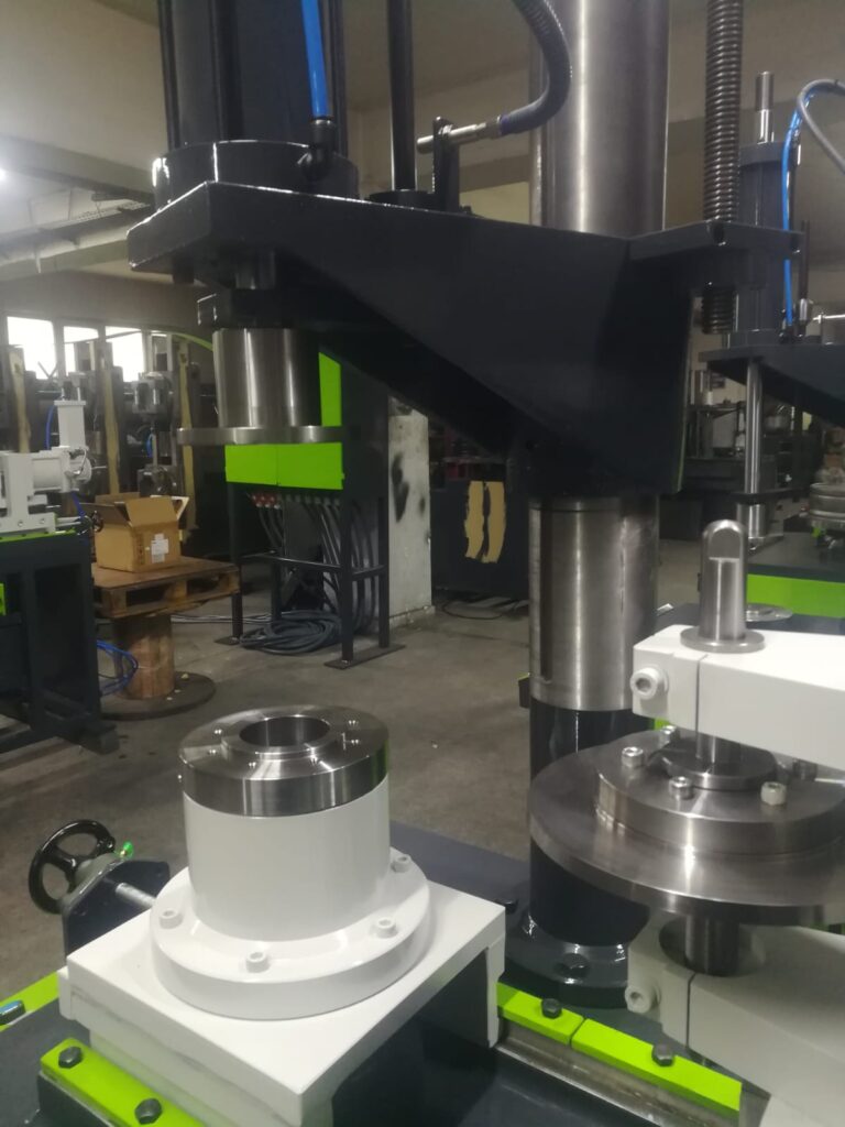
Expanding machines vary from simple hand-operated devices for small-diameter pipes to complex automated systems capable of expanding large-diameter, thick-walled pipes with high precision. In industrial settings, hydraulic or servo-driven expanding machines provide controlled force and displacement, allowing operators to set exact expansion parameters to achieve the desired diameter and wall thickness without causing damage.
The key to successful pipe expansion is controlling the amount of deformation to avoid thinning the pipe walls excessively, which could weaken the pipe or cause failure in service. Many machines use sensors to monitor pipe diameter, wall thickness, and applied forces in real time, enabling precise control and ensuring quality.
Some expanding machines are equipped with interchangeable tooling to accommodate different pipe sizes and expansion profiles. This flexibility is essential for manufacturers handling a wide variety of pipe types and dimensions. Additionally, some machines combine expansion with other end-forming operations such as flaring or beading to prepare pipe ends for specific joining techniques.
Expanding is also useful for correcting minor dimensional variations or out-of-round conditions in pipes, improving fit-up during assembly. In repair or maintenance operations, portable expanding machines allow field technicians to adjust pipe diameters on-site, facilitating quick fixes without pipe replacement.
Materials processed with expanding machines include carbon steel, stainless steel, aluminum, copper, and various alloys. Depending on the material properties, the expansion process may be performed cold or with localized heating to improve ductility and reduce the risk of cracking.
Overall, expanding machines for metal pipes are essential tools that enable precise diameter enlargement and end-forming operations. Their ability to reshape pipes efficiently and accurately supports reliable pipe connections and high-quality assemblies across many industrial and commercial applications.
Expanding machines operate by securely holding the pipe while the expansion tool—such as a mandrel, cone, or rollers—is inserted and advanced inside the pipe. The tool’s geometry causes the pipe wall to stretch outward, increasing the diameter in a controlled manner. The expansion force must be carefully regulated to prevent excessive thinning or deformation that could compromise the pipe’s strength or surface finish.
Many expanding machines feature adjustable speed and force controls, allowing operators to tailor the expansion process to the specific pipe material, thickness, and desired final diameter. Hydraulic systems often provide smooth, consistent pressure, while servo-driven machines enable precise positioning and force feedback for highly repeatable results.
For pipes with thicker walls or higher-strength materials, expansion may be performed in multiple passes with incremental diameter increases to minimize the risk of cracking or work hardening. In some cases, the pipe or tooling may be heated locally to enhance material ductility, facilitating safer and more effective expansion.
Advanced expanding machines incorporate sensors to continuously monitor parameters such as expansion force, pipe diameter, and wall thickness during the process. This real-time feedback helps maintain process control, ensuring that every pipe meets stringent quality standards. Some systems also store process data for traceability and quality assurance purposes.
In manufacturing environments, expanding machines are often integrated into automated production lines, coordinating with upstream cutting, straightening, or welding operations and downstream inspection or packaging stations. This integration improves throughput, reduces manual handling, and ensures consistent product quality.
Portable expanding tools and machines are also widely used in the field for maintenance, repair, and retrofit work. These smaller, often manually or pneumatically operated devices allow technicians to expand pipe ends on-site quickly and efficiently, avoiding the need for expensive replacements or extensive downtime.
The expanding process can also be combined with other forming techniques, such as flaring or beading, to create complex pipe end shapes suited for specific joining methods like press-fitting, crimping, or welding. This versatility makes expanding machines invaluable in producing customized pipe assemblies tailored to particular applications.
Material considerations are important in expansion processes. Softer metals such as copper or aluminum typically expand easily with minimal force, while high-strength steels or alloys require more robust equipment and careful control to avoid material failure. Tooling materials and coatings must withstand the forces involved and minimize friction to prevent surface damage to the pipes.
Overall, expanding machines provide an effective, controlled method to increase pipe diameters, enabling strong, leak-resistant joints and facilitating the fabrication of complex piping systems. Their adaptability, precision, and integration capabilities make them indispensable in modern metal pipe manufacturing and maintenance operations.
Expanding machines also contribute significantly to improving the efficiency and reliability of piping systems by enabling the creation of flared or bell-shaped pipe ends that simplify assembly and reduce the need for additional fittings. This can lower installation time and costs while enhancing the mechanical strength of joints, particularly in systems exposed to vibration, pressure fluctuations, or thermal expansion.
In industries like automotive exhaust manufacturing or HVAC ductwork, where pipes frequently require tight, secure connections, expanding machines help produce consistent end geometries that ensure proper sealing and reduce leakage risks. This consistency is especially important when working with thin-walled pipes where even slight dimensional variations can lead to assembly problems.
Some modern expanding machines incorporate CNC controls that allow operators to program precise expansion profiles, including complex shapes or gradual diameter transitions. This capability supports the production of custom components and reduces the need for manual adjustments or secondary machining operations.
The expanding process also positively affects the pipe’s internal surface by potentially improving smoothness and reducing imperfections, which can enhance fluid flow and reduce turbulence. This benefit is crucial in applications such as hydraulic systems, chemical processing, and gas pipelines where flow efficiency impacts system performance and energy consumption.
In terms of maintenance, portable expanding machines enable rapid, on-site adjustments to pipe systems during repairs or upgrades. This flexibility minimizes downtime and the need for pipe replacements, offering a cost-effective solution in many field service scenarios.
To accommodate a broad range of pipe sizes and materials, expanding machines often come with modular tooling sets that can be quickly swapped or adjusted, enabling manufacturers to switch between different product lines with minimal setup time. This adaptability supports lean manufacturing practices and responsive production schedules.
As materials technology advances, expanding machines are evolving to handle new alloys and composite pipes with unique mechanical characteristics. Tooling design, force control algorithms, and process parameters are continually refined to manage these materials safely and efficiently.
Environmental and safety considerations also play a role in machine design, with enclosed operation areas, noise reduction measures, and ergonomic controls becoming standard to protect operators and comply with workplace regulations.
Overall, expanding machines for metal pipes are essential for shaping pipe ends with precision and reliability. Their versatility, process control, and integration into modern manufacturing systems make them key enablers of high-quality pipe assemblies across numerous industrial sectors, supporting both production efficiency and product performance.
Swaging Machine For Metal Pipes
A swaging machine for metal pipes is a specialized tool used to reduce or reshape the diameter of a pipe or tube by applying radial compressive forces through dies or rollers. Swaging involves deforming the pipe cold, without removing material, to achieve a smaller diameter, taper, or other desired cross-sectional shape. This process enhances the pipe’s mechanical properties, improves fitment for connections, or creates specific end forms like tapered joints or stepped sections.
Swaging machines operate by pressing a series of dies or rollers uniformly around the pipe circumference. The pipe is typically rotated or the dies move radially inward to gradually compress the pipe wall. The process can be continuous or done in incremental steps, depending on pipe size, wall thickness, and required deformation. Unlike rolling or stretching, swaging primarily focuses on localized or section-specific diameter reduction without lengthening the pipe.
The main advantages of swaging include precise control over the diameter reduction, preservation of pipe length, and improved surface finish due to cold working. Swaging also induces strain hardening in the metal, increasing strength and fatigue resistance, which is beneficial for components subjected to cyclic loads or high stresses.
Swaging machines range from small bench-top models for light-duty applications to large industrial machines capable of handling thick-walled pipes or tubes of substantial diameter. Many industrial swaging machines use hydraulic or mechanical power to achieve the necessary forces with precision and repeatability.
Some machines feature multiple dies arranged symmetrically to ensure uniform deformation and minimize ovality or warping. Tooling is often interchangeable and adjustable to accommodate various pipe diameters and shapes. Advanced machines may incorporate CNC controls for automated adjustments, force monitoring, and process data recording.
Swaging is commonly used in industries like aerospace, automotive, oil and gas, and construction where precise pipe dimensions and strong, reliable joints are critical. Typical applications include creating tapered ends for welding or fitting, reducing pipe diameters for coupling, or forming stepped sections for assembly.
In addition to manufacturing, swaging machines are used in repair and maintenance to adjust pipe sizes on-site, enabling quick fixes or modifications without needing replacement parts. Portable swaging tools allow field technicians to perform these operations efficiently.
Material selection and properties influence swaging parameters. Metals with good ductility like aluminum, copper, and mild steel respond well to cold swaging, while harder alloys may require preheating or multi-step deformation to prevent cracking. Proper lubrication is essential to reduce friction and tooling wear during the process.
Overall, swaging machines are versatile and efficient tools for reshaping metal pipes through cold deformation. Their ability to produce precise diameter reductions, tapered ends, and custom profiles makes them indispensable in metal pipe fabrication and maintenance across a wide range of industrial sectors.
Swaging machines function by clamping the pipe securely and applying compressive forces radially through dies that move inward, either simultaneously or sequentially. This controlled deformation reshapes the pipe’s outer diameter while maintaining the integrity of the pipe wall. The dies are often arranged symmetrically around the pipe to ensure uniform pressure distribution and prevent distortion, such as ovality or localized thinning.
The process is highly controllable, allowing operators to achieve specific diameter reductions or profiles with tight tolerances. By adjusting the force applied and the number of passes, swaging machines can produce gradual tapers, stepped reductions, or uniform diameter changes over short or extended pipe sections. Some advanced machines incorporate automated controls and feedback systems that monitor applied forces and pipe dimensions in real time, enhancing consistency and repeatability.
Swaging imparts beneficial mechanical effects on the pipe material by cold working the metal, which increases hardness, yield strength, and fatigue resistance. This makes swaged sections particularly suitable for applications that experience cyclic loading, pressure fluctuations, or mechanical vibrations. The cold deformation also improves the surface finish by compressing surface irregularities, reducing the need for secondary finishing processes.
Tooling in swaging machines is typically made from hardened steel or carbide materials to withstand the high forces and abrasive conditions. Proper lubrication between the dies and pipe surface is crucial to minimize friction, prevent surface damage, and extend tooling life. In some cases, specialized coatings on tooling reduce wear and enhance performance when working with abrasive or hard materials.
Swaging machines vary widely in size and capacity. Smaller, portable units are common in fieldwork for on-site repairs or modifications, offering flexibility and ease of transport. Larger industrial machines can handle heavy-duty swaging tasks on thick-walled pipes or tubes with substantial diameters, often integrated into automated production lines for high-volume manufacturing.
The process is compatible with a wide range of metals, including steel, stainless steel, aluminum, copper, and various alloys. However, the material’s ductility and hardness influence the swaging parameters, such as the maximum achievable reduction per pass and the need for preheating or multiple passes to avoid cracking or excessive residual stresses.
In addition to diameter reduction, swaging machines can perform other forming operations like tapering pipe ends for welding or fitting, creating stepped sections for assembly, or preparing pipe ends for joining methods such as flaring, beading, or inserting couplings. This versatility makes swaging an essential technique in pipe fabrication, assembly, and repair.
Swaging machines also contribute to reducing material waste compared to cutting and re-welding, as they reshape existing pipes without removing material. This efficiency aligns with modern manufacturing goals of sustainability and cost reduction.
Overall, swaging machines provide precise, efficient, and reliable means of reshaping metal pipes through cold working. Their adaptability to various pipe sizes, materials, and forming requirements makes them indispensable across many industries, supporting high-quality pipe production and maintenance.
Swaging machines also offer significant advantages in terms of speed and efficiency compared to alternative pipe forming methods. Because the process is cold and does not require cutting or welding, it can be completed quickly, often in a single operation or a few passes. This rapid processing capability is especially valuable in production environments where throughput and turnaround times are critical.
The ability to perform localized reductions or tapers without affecting the entire pipe length makes swaging particularly useful for creating custom fittings and joints that fit precisely within complex piping systems. For example, swaged pipe ends can be designed to fit snugly into couplings, connectors, or flanges, improving the mechanical stability and leak resistance of assemblies.
In maintenance and repair scenarios, swaging machines enable operators to adjust pipe diameters or restore deformed sections without replacing entire pipe segments. This capability reduces downtime and material costs, especially in remote or difficult-to-access locations like offshore platforms, chemical plants, or pipeline networks.
With ongoing advancements in automation and control technologies, modern swaging machines increasingly incorporate programmable logic controllers (PLCs), CNC interfaces, and sensor arrays. These innovations allow for automated adjustments based on pipe material, size, and desired final dimensions, reducing operator dependency and minimizing human error. Data logging and quality tracking features further enhance process reliability and traceability.
Swaging is also environmentally favorable since it does not generate chips, sparks, or hazardous waste typical of machining or welding processes. The cold working nature conserves energy compared to hot forming techniques, contributing to greener manufacturing practices.
Furthermore, swaging can improve the metallurgical properties of the pipe at the deformed zone. The induced strain hardening enhances strength and fatigue resistance, making swaged areas suitable for demanding applications such as high-pressure lines or structural components. Proper post-processing, like stress-relief annealing when needed, can optimize these properties further.
Overall, swaging machines combine precision, speed, material efficiency, and mechanical benefits, making them an indispensable technology for shaping metal pipes in manufacturing, assembly, and field service. Their flexibility and evolving technological integration continue to expand their applications and effectiveness across diverse industrial sectors.
Flattening Machine For Metal Pipes
A flattening machine for metal pipes is specialized equipment designed to compress and deform metal pipes or tubes into flat or oval shapes. This process is essential in various manufacturing applications where metal pipes need to be reshaped to specific profiles for use in structural components, automotive parts, furniture, or other fabricated metal products. Flattening machines enable consistent, controlled deformation of round pipes into flat or shaped sections while maintaining material integrity.
Flattening typically involves passing the pipe through a pair of opposing rollers or presses that apply compressive force perpendicular to the pipe’s axis. The pipe is squeezed progressively to reduce its height and increase its width, transforming the circular cross-section into an elliptical or flat form. The amount of flattening can be adjusted to meet specific dimensional requirements.
Flattening machines come in different configurations, including hydraulic presses, mechanical roller sets, or combinations of both. Some machines use multiple stages or sets of rollers to achieve gradual flattening, which helps minimize material damage and ensures uniform deformation along the pipe length.
The machine’s tooling is designed to handle various pipe sizes, wall thicknesses, and materials such as steel, stainless steel, aluminum, copper, and alloys. Tooling surfaces are often hardened and precisely machined to produce smooth, consistent results and reduce wear.
In addition to flattening, some machines are capable of producing shaped profiles like rectangular, oval, or customized cross-sections by using specialized dies or roller configurations. This versatility makes them valuable in applications requiring unique pipe shapes beyond simple flattening.
Control over process parameters such as force, speed, and roller gap is critical to prevent cracking, wrinkling, or excessive thinning of the pipe walls. Modern flattening machines often include sensors and feedback systems to monitor these variables in real time, enabling precise adjustments and high-quality output.
Flattened pipes find applications in manufacturing automotive chassis components, bicycle frames, structural supports, furniture, and decorative metalwork. Flattening can also prepare pipes for further fabrication steps like bending, welding, or assembly where non-circular profiles are advantageous.
Portable or smaller flattening units are used in repair and maintenance to modify pipes on-site, while larger industrial machines serve high-volume production needs with automated feeding and exit systems.
Overall, flattening machines for metal pipes provide an efficient and precise method to convert round tubes into flat or shaped profiles, supporting diverse manufacturing and fabrication processes across multiple industries.
Flattening machines operate by securely guiding the pipe into the deformation zone, where it is subjected to a compressive force that gradually changes its cross-section. The degree of flattening depends on the original diameter and wall thickness of the pipe, as well as the final desired shape. The process must be carefully controlled to ensure that the deformation remains within the material’s elastic and plastic limits, preventing defects such as buckling, tearing, or excessive thinning. For thin-walled pipes, the risk of wrinkling is higher, so the machine’s speed and pressure must be adjusted accordingly.
Some flattening machines are equipped with programmable controls, allowing operators to set target dimensions and apply gradual force increments. This automation increases repeatability and ensures that each piece meets tight tolerances, especially important in mass production where consistency is critical. In many systems, after flattening, the machine can automatically eject the pipe or feed it directly into another forming or cutting station, increasing production efficiency.
When shaping pipes into non-standard profiles, such as ovals or rounded rectangles, the flattening process may involve custom-designed rollers or die inserts that guide the deformation into the desired geometry. This allows manufacturers to produce specialized profiles for aesthetic, aerodynamic, or functional purposes, such as improved load distribution or easier fitting into flat surfaces.
Material choice plays a critical role in flattening operations. Ductile metals like aluminum or annealed steel are well suited to the process, as they can undergo significant plastic deformation without cracking. Harder or brittle materials may require pre-heating or be limited to more conservative deformation levels. Lubrication is often used between the pipe and tooling to reduce friction, lower forming forces, and improve the finish quality on the flattened surface.
One of the key benefits of flattening is that it can significantly alter the form of the pipe without cutting or welding, thus preserving material integrity and eliminating joints that could become weak points. This continuous deformation helps maintain the strength and continuity of the metal, which is particularly advantageous in structural applications where uniformity and reliability are paramount.
In fabrication shops, flattening machines are often used as part of a larger workflow that includes cutting, bending, punching, or welding. Flattened ends, for example, may be easier to join or bolt to other components. In some designs, flattened sections serve as mounting surfaces, connection flanges, or even as points for decorative detail.
Industries that rely heavily on custom-shaped tubing—such as automotive manufacturing, construction scaffolding, sports equipment, and furniture production—benefit greatly from the precision and speed that flattening machines offer. The process not only expands design possibilities but also contributes to material efficiency, as shaped pipes can be optimized for their specific structural or functional role.
In summary, flattening machines are a powerful tool for transforming standard round pipes into tailored, application-specific profiles. Their ability to deliver precise, repeatable, and high-quality deformations makes them indispensable across modern metalworking environments.
As the demand for complex and lightweight structural components grows, flattening machines continue to evolve with advancements in precision engineering and automation. CNC-controlled flattening systems now offer programmable shape profiles, allowing operators to store multiple presets for different pipe sizes and target geometries. This feature greatly reduces setup time when switching between product runs and minimizes human error, ensuring high accuracy even across large production batches.
In high-volume environments, flattening machines are often integrated into fully automated production lines. Pipes are fed continuously from coil or cut-length sections, passed through flattening rollers, and then directed to downstream processes such as piercing, welding, or end-forming. Sensors and actuators ensure seamless synchronization between stations, eliminating the need for manual handling and significantly boosting throughput.
The flattened sections of pipes can be used not only to simplify joining methods but also to create mechanical interlocks or seating surfaces. For example, a flattened area on a pipe might fit into a corresponding channel or clamp, improving mechanical stability and reducing the need for fasteners. This is particularly useful in automotive and aerospace applications, where minimizing weight and part count is crucial.
When dealing with higher-strength materials like stainless steel or structural alloys, flattening machines may incorporate reinforced frames and high-torque drive systems to maintain stability and precision under load. For these tougher materials, multi-pass flattening or progressive deformation through a series of rollers may be necessary to achieve the final profile without inducing cracks or surface failures. Intermediate annealing may also be employed between passes to restore ductility.
Surface quality is another important consideration. A well-designed flattening machine should avoid introducing scratches, scoring, or other defects that can compromise performance or appearance. To address this, many systems use polished or coated rollers, non-marking support guides, and controlled lubrication to protect the pipe’s exterior during processing. Where cosmetic quality is paramount—such as in exposed architectural or furniture components—extra care is taken to maintain a flawless finish.
The flattened pipes themselves may go on to become parts of shelving supports, rack systems, protective railings, or frames. In many of these uses, the modified geometry improves the strength-to-weight ratio and provides better support for attachments, fasteners, or additional structural elements.
As flattening technology continues to advance, there is growing interest in combining flattening with in-line inspection and quality control systems. These systems can automatically measure cross-sectional dimensions, detect warping or asymmetry, and reject out-of-tolerance parts before they move further down the production line. This reduces waste and rework, improving overall manufacturing efficiency and product reliability.
The adaptability of flattening machines to a wide range of materials, shapes, and applications ensures their ongoing relevance in both traditional fabrication and modern, precision-driven industries. Whether used for basic functional reshaping or complex profile creation, these machines remain vital in transforming raw pipe stock into customized, high-performance components.
Bending Machine For Metal Pipes
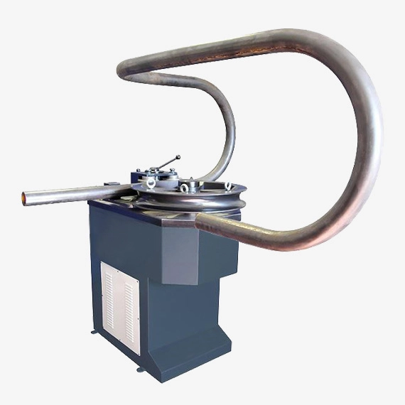
A bending machine for metal pipes is a key tool used to permanently deform pipes into curved or angled shapes without compromising the material’s structural integrity. These machines are essential in industries such as construction, automotive, shipbuilding, aerospace, HVAC, and furniture manufacturing, where precise pipe bends are critical for both function and form. Bending machines use mechanical, hydraulic, or electric force to create smooth curves, tight radii, or complex 3D shapes while maintaining the continuity and strength of the metal.
The bending process can be executed through various methods depending on the pipe’s material, thickness, and required bend geometry. Common types include rotary draw bending, compression bending, roll bending, and mandrel bending. Rotary draw bending is highly precise and often used when a tight radius and minimal deformation are needed, such as in roll cages or exhaust systems. Compression bending is simpler and more cost-effective, suitable for larger radii where precision is less critical. Roll bending, using a three-roller system, is ideal for producing large, sweeping curves over longer sections. Mandrel bending, which involves inserting a flexible rod or ball assembly into the pipe, prevents collapse or wrinkling during tight-radius bends, especially in thin-walled tubes.
Bending machines are equipped with dies and tooling matched to the pipe’s diameter and bend specifications. Tooling must be correctly designed to avoid flattening, ovalization, or kinks at the bend. The radius of the bend, often defined as the centerline radius, is a key parameter, and machines are designed to repeat bends consistently across multiple parts.
Modern pipe bending machines often include CNC controls that allow for programmable multi-plane bends with high accuracy and repeatability. These machines can store complex bend sequences and execute them automatically, reducing setup time and operator intervention. Sensors and feedback systems help detect and correct errors in real-time, improving quality control.
The ability to form pipes into complex configurations without cutting or welding enables stronger and more efficient structures. A single bent pipe section can replace multiple welded joints, reducing potential weak points and leak paths. This is particularly valuable in fluid and gas transport systems where integrity and pressure retention are critical.
Material characteristics influence how the pipe responds to bending. Ductile materials like aluminum and copper bend easily with low risk of cracking, while harder metals like stainless steel may require higher forces and tighter control to avoid failure. Some applications may involve heat-assisted bending to reduce internal stresses or allow tighter bends in less ductile materials.
Bending machines are not only used for new part fabrication but also for repairs and retrofitting. On-site portable benders allow technicians to fabricate replacement parts or adjust piping systems directly at the job site, saving time and reducing downtime.
As industries move toward more integrated and automated manufacturing systems, pipe bending machines are increasingly linked with CAD/CAM software. This enables the direct transfer of bend data from digital designs to the machine, streamlining workflow and ensuring the finished part precisely matches design specifications.
Overall, bending machines are indispensable for shaping metal pipes into functional, durable, and aesthetically refined components. Their flexibility, precision, and adaptability to a wide range of materials and geometries make them fundamental in both high-volume industrial production and custom fabrication work.
Bending machines continue to evolve with enhanced technologies that improve speed, accuracy, and versatility. In advanced systems, electric servo motors have replaced or supplemented hydraulic drives, offering cleaner operation, finer control, and energy efficiency. These machines can perform rapid sequential bends with minimal repositioning time, making them ideal for high-volume production environments where consistency and speed are paramount. The inclusion of multiple axes of control in CNC pipe benders allows not just for single-plane curves but for intricate three-dimensional bends that can navigate tight spaces and complex geometries, especially valuable in automotive exhaust routing or aerospace hydraulic lines.
Precision in pipe bending is critical, as even slight deviations can cause misalignment or mechanical issues in assembly. To address this, machines may include springback compensation features. Springback refers to the elastic recovery of the metal after bending, which can slightly reduce the final bend angle. CNC controls can automatically adjust bend commands to account for this based on material type and diameter, ensuring the finished shape conforms precisely to the design. This is especially useful when working with high-strength steels or alloys where springback is more pronounced.
Safety and ergonomics have also improved in modern pipe bending machines. Protective guarding, automated clamping, and user-friendly touch-screen interfaces reduce operator fatigue and risk while speeding up the learning curve for new users. Some systems include simulation software that visually previews the bending process before execution, allowing adjustments to be made virtually to avoid material waste or collisions with tooling.
From a manufacturing efficiency standpoint, the integration of pipe benders into digital production lines allows real-time tracking of part progress, quality metrics, and maintenance alerts. This data-driven approach supports predictive maintenance strategies, where machines self-monitor for wear or misalignment and notify operators before a failure occurs, thereby reducing downtime.
When bending pipes made from specialized materials such as titanium, Inconel, or duplex stainless steel, control becomes even more critical. These materials are often used in high-performance or corrosive environments, and defects in the bend can lead to premature failure. In such cases, bending machines must be carefully calibrated, and tooling must be designed with precision contours and surface treatments to prevent galling or cracking.
Bending pipes for aesthetic or architectural applications requires an additional focus on surface finish and symmetry. Even minor tooling marks or inconsistencies in the bend radius can become visible and undesirable in finished installations. To mitigate this, some machines feature polished dies or use non-marring materials for clamping surfaces, and some manufacturers employ post-bend polishing or finishing steps to enhance appearance.
Whether producing roll cages, railing systems, fuel lines, heat exchangers, or structural frameworks, bending machines enable the creation of strong, streamlined components with fewer joints and welds, reducing labor, leak paths, and overall system weight. The machine’s ability to reshape pipes to exact dimensions without cutting or weakening the material ensures the structural continuity and performance of the final product.
As manufacturing becomes more flexible and design-driven, pipe bending technology remains vital in enabling rapid prototyping, short-run production, and custom fabrication. Its ability to combine strength, accuracy, and efficiency ensures its continued importance in both traditional industries and future-oriented engineering applications.
Bending machines also accommodate a wide range of pipe diameters and wall thicknesses, from delicate thin-walled tubing used in medical devices or instrumentation, to heavy-duty structural pipes employed in construction and industrial frameworks. This flexibility is achieved through interchangeable tooling and adjustable machine settings, allowing manufacturers to tailor the bending process precisely for each job. Many machines include quick-change die systems to minimize downtime when switching between different pipe sizes or bend profiles, further improving productivity.
In addition to standard bends such as elbows and U-bends, some bending machines offer the capability to create complex shapes like spirals, coils, or compound bends. These advanced bending operations are essential for applications such as heat exchangers, automotive exhaust systems, and architectural installations where pipes must follow curved paths in multiple planes. The ability to produce these shapes accurately and consistently reduces the need for multiple components or complicated assembly procedures.
Another important factor in pipe bending is the management of material stresses and distortions that arise during deformation. Bending naturally introduces tensile and compressive stresses across the pipe’s cross-section, which can lead to wall thinning on the outer radius or wrinkling on the inner radius. To mitigate these issues, some bending machines employ internal support mechanisms such as mandrels, wiper dies, or pressure dies that stabilize the pipe internally during bending. These tools help maintain the pipe’s roundness, prevent collapse, and ensure smooth curvature.
The increasing use of lightweight and corrosion-resistant alloys like aluminum, titanium, and stainless steel has driven innovations in bending technology to handle these materials’ unique characteristics. For instance, the higher strength and springback tendencies of these alloys require precise control of bending parameters and sometimes auxiliary heating to facilitate deformation without cracking.
Bending machines are also designed with environmental and energy efficiency considerations. Electric-driven machines produce less noise and emissions compared to traditional hydraulic systems, and their energy consumption can be optimized through regenerative braking and power management systems. This aligns with modern manufacturing goals to reduce carbon footprints and operational costs.
Training and skill development remain integral parts of effective pipe bending operations. While CNC automation simplifies complex bends, understanding material behavior, tooling selection, and machine operation is crucial to avoid costly errors and achieve optimal results. Many manufacturers offer integrated training programs and simulation software to enhance operator expertise and confidence.
In maintenance and repair contexts, portable bending machines enable technicians to make precise adjustments or fabricate replacement parts on-site, reducing downtime and transportation costs. These compact units balance portability with the necessary power and control to handle a variety of pipe sizes and materials in challenging environments.
Looking ahead, the future of pipe bending technology is likely to be shaped by further integration with digital manufacturing ecosystems, including real-time data analytics, AI-driven process optimization, and enhanced robotics. These advancements promise even greater precision, efficiency, and customization capabilities, enabling manufacturers to meet increasingly complex design requirements while minimizing waste and cost.
In summary, pipe bending machines are sophisticated tools that combine mechanical ingenuity with advanced control systems to shape metal pipes into essential components across diverse industries. Their ability to deliver consistent, high-quality bends while preserving material properties makes them indispensable in modern fabrication and manufacturing processes.
Punching Machine For Metal Pipes
A punching machine for metal pipes is a specialized tool designed to create holes, slots, or other cutouts in metal pipes quickly and accurately. This process is essential in fabrication and manufacturing where pipes need to be prepared for fittings, attachments, mounting points, or ventilation. Punching machines provide a fast, efficient alternative to drilling or cutting by applying high force to shear the metal cleanly, producing precise openings without deforming the surrounding pipe material.
Punching machines for metal pipes typically use a punch and die system. The pipe is positioned between the punch, a hardened steel tool shaped to the desired hole or slot geometry, and the die, which supports the pipe and provides a cavity for the punched-out slug to exit. When force is applied—often hydraulically or mechanically—the punch presses through the pipe wall, creating a clean, burr-free hole.
There are several types of punching machines suited for pipes, including stationary presses, rotary turret punches, and CNC-controlled systems. Stationary presses are often used for simple or low-volume operations, where a single punch shape is needed. Rotary turret machines can switch quickly between multiple punch shapes and sizes, improving efficiency in jobs requiring varied hole patterns.
CNC punching machines represent the most advanced category. These systems use computer control to automatically position the pipe, select the correct punch and die, and execute complex hole patterns or arrays with high speed and accuracy. CNC punching reduces setup time, improves repeatability, and enables the production of intricate designs that would be difficult or slow to achieve manually.
Punching machines for pipes must accommodate different pipe diameters and wall thicknesses. Adjustable clamps and supports hold the pipe securely during punching to prevent movement or distortion. Tooling is selected based on material hardness, thickness, and desired hole size to ensure clean shearing without cracking or excessive deformation.
One of the key advantages of punching over drilling is speed. Punching can produce holes in seconds with minimal operator effort, making it ideal for mass production or high-throughput fabrication lines. Additionally, because punching shears the material rather than removing chips, it generates less waste and requires less cleanup.
In applications requiring high precision or specialized hole shapes—such as rectangular slots, keyholes, or elongated holes—custom punches and dies can be fabricated. Some machines also support secondary operations like notching or embossing, expanding their versatility.
Punching machines are widely used in industries such as automotive, shipbuilding, construction, HVAC, and pipeline manufacturing. They facilitate the installation of brackets, flanges, connectors, sensors, or fluid passage ports directly on the pipe, reducing assembly time and improving structural integrity by eliminating the need for welding additional plates.
For very thick-walled pipes or hard materials, hydraulic punching presses provide the necessary force to penetrate the metal cleanly. In contrast, lighter-duty pneumatic or mechanical punchers may be sufficient for thinner or softer materials.
Safety features are integral to punching machines due to the high forces involved. Protective guards, emergency stops, and automated clamps help prevent accidents and ensure safe operation.
Overall, punching machines for metal pipes offer a combination of speed, precision, and efficiency that makes them essential in modern pipe fabrication. Their ability to create clean, consistent holes with minimal material damage supports a wide range of industrial manufacturing and assembly processes.
Punching machines for metal pipes often incorporate features that enhance flexibility and automation to meet diverse production needs. Automated feeding systems can position pipes accurately for successive punching operations, enabling continuous processing without manual intervention. This capability is especially valuable in high-volume manufacturing where consistent hole placement and rapid cycle times are critical.
Integration with CNC controls allows for complex hole patterns and precise spacing along the pipe length, including multiple holes of varying sizes or shapes on a single pipe. Programmable tooling changes enable the machine to switch between different punches and dies automatically, minimizing downtime and increasing productivity. Some machines also incorporate rotary indexing, which rotates the pipe incrementally between punches to create holes around the circumference without repositioning the entire pipe.
The quality of punched holes depends heavily on tooling maintenance and material properties. Hardened steel punches and dies maintain sharp cutting edges longer, reducing burr formation and extending tool life. Proper alignment and clamping prevent pipe deformation or slipping during punching, ensuring clean, accurate holes. Lubrication or cooling may be applied to reduce friction and heat buildup during high-speed or heavy-duty punching operations.
Materials such as stainless steel, aluminum, copper, and various alloys can be punched effectively, but harder or thicker pipes may require slower punching speeds or increased force. In some cases, pre-drilling pilot holes or using specialized punch designs can facilitate cleaner cuts and reduce tool wear.
Punching machines also support secondary operations, including notching or partial cuts, which are useful for preparing pipe ends for fittings or assemblies. These combined functions can reduce the need for multiple machines and handling steps, streamlining production workflows.
Safety considerations are paramount in punching operations due to the rapid application of high force. Machines are typically equipped with protective enclosures, light curtains, or interlocks that halt operation if guards are opened. Operator training and adherence to safety protocols further minimize risks during setup and maintenance.
In repair or custom fabrication settings, portable or bench-top punching machines provide flexibility for on-site hole-making, enabling quick modifications or additions without transporting large pipes to a shop. While these units generally handle smaller diameters and lighter materials, they offer valuable convenience and time savings.
The ongoing evolution of punching technology includes the adoption of smart sensors and monitoring systems. These can detect tool wear, misalignment, or anomalies in the punching cycle, alerting operators before defects occur. Such predictive maintenance reduces downtime and ensures consistent product quality.
In summary, punching machines for metal pipes combine robust mechanical design with sophisticated controls to deliver precise, efficient hole-making capabilities. Their role in preparing pipes for assembly, mounting, and functional integration makes them indispensable across a wide range of industrial sectors, supporting both mass production and custom manufacturing needs.
Advancements in punching machine technology have also focused on improving the environmental footprint and operational efficiency of these systems. Energy-efficient hydraulic and electric drives reduce power consumption and operational costs while maintaining the high force needed for punching through tough materials. Additionally, improved chip and slug management systems collect and remove waste material efficiently, keeping the workspace clean and minimizing downtime for maintenance.
Customization plays a significant role in the design of punching machines for metal pipes. Manufacturers often tailor machines to specific industry requirements, such as punching corrosion-resistant stainless steel pipes for chemical plants or heat-resistant alloys for aerospace applications. This customization extends to tooling, machine size, clamping mechanisms, and control software, ensuring that each system fits perfectly within a customer’s production environment and meets the required tolerances and throughput.
Integration with other pipe processing machines—such as cutting, bending, welding, or coating equipment—is increasingly common. This integration creates automated production lines that streamline workflows and reduce manual handling, leading to higher overall productivity. For instance, a pipe can be cut to length, bent into shape, punched with mounting holes, and prepared for welding in a continuous, automated sequence.
The rise of Industry 4.0 and smart manufacturing has encouraged the inclusion of data collection and connectivity features in punching machines. Real-time monitoring of punch force, cycle counts, and tool wear can be fed into centralized management systems. This connectivity allows operators to optimize production parameters, schedule predictive maintenance, and ensure consistent quality control across multiple machines and facilities.
User-friendly interfaces and software have also advanced, enabling operators to easily program complex punching patterns or modify parameters without extensive technical training. Touchscreen controls with graphical simulations help visualize punching sequences before execution, reducing trial and error and material waste.
In terms of material handling, sophisticated pipe feeders, rotators, and supports reduce pipe deformation and ensure precise positioning. Automated loading and unloading systems minimize manual labor and improve safety by limiting operator contact with heavy or awkward pipe sections.
Emerging technologies such as laser-assisted punching or hybrid punching-laser systems are being explored to further enhance precision and reduce mechanical wear. These methods combine the speed and clean cutting of lasers with traditional punching force to achieve high-quality holes in challenging materials or complex geometries.
As industries continue to demand faster production times, higher precision, and greater versatility, punching machines for metal pipes will remain a critical technology. Their ability to deliver clean, accurate holes rapidly and reliably supports diverse applications, from industrial piping networks to architectural features and specialized machinery components.
Overall, the ongoing innovation in punching machine design, control, and integration ensures that these tools will keep pace with evolving manufacturing challenges, helping fabricators achieve improved efficiency, quality, and flexibility in pipe processing operations.
Slotting Machine For Metal Pipes
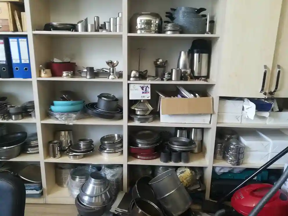
A slotting machine for metal pipes is a specialized machine designed to cut precise slots, grooves, or keyways into the surface or along the length of metal pipes. These slots are often required for mechanical assemblies, fittings, locking mechanisms, or to accommodate other components that need to interlock or pass through the pipe. Slotting enhances the functional versatility of pipes by allowing secure connections, improved alignment, or integration with other parts in structural, automotive, HVAC, and machinery applications.
Unlike simple drilling or punching, slotting requires controlled linear cutting to produce elongated openings with consistent width and depth. Slotting machines use a reciprocating tool—a slotting cutter or blade—that moves up and down vertically while the pipe is securely clamped and rotated or positioned as needed. The cutter removes material by successive passes, creating smooth and accurate slots with clean edges.
Slotting machines for pipes come in various configurations, from manual to fully automated CNC-controlled systems. Manual slotting machines are typically used for smaller-scale or repair work, where operators position the pipe and control the slotting process. CNC slotting machines allow programmable slot shapes, lengths, and locations, enabling complex patterns and multiple slots to be cut efficiently with high repeatability.
To accommodate different pipe diameters and wall thicknesses, slotting machines include adjustable clamps, supports, and tooling setups. The pipe must be held rigidly to prevent vibration or movement during slotting, which could lead to inaccurate cuts or tool damage. Some machines also provide coolant or lubrication delivery systems to reduce heat and wear during cutting.
The choice of slotting cutter material and design depends on the pipe’s metal type and thickness. High-speed steel (HSS) cutters are common for softer metals, while carbide-tipped or coated tools are preferred for harder alloys or stainless steel. Proper tool selection and maintenance ensure clean cuts, reduce burr formation, and extend tool life.
Slotting machines can produce various slot profiles, including rectangular keyways, T-slots, or angled grooves. These shapes are essential for mechanical joints that require locking features or for pipes designed to accept sliding or rotating components. In some cases, slotting is combined with other machining operations such as milling or drilling for comprehensive pipe modification.
In manufacturing environments, slotting machines are often integrated with feeding and positioning systems that automate pipe handling. This integration boosts throughput by minimizing manual setup and enabling continuous processing, especially when multiple slots or complex patterns are needed along long pipe sections.
Safety measures on slotting machines include protective guards around the reciprocating cutter, emergency stop functions, and secure clamping mechanisms to prevent accidental pipe movement. Operators are trained to maintain safe distances and handle tooling changes carefully.
Applications for slotted metal pipes are diverse. In construction and architectural designs, slots allow pipes to interlock with brackets or panels. In automotive and machinery, slotted pipes may serve as part of adjustable assemblies, ventilation ducts, or conduits for wiring and fluids. The precision and cleanliness of slots are critical to ensuring proper fit and function in these assemblies.
Emerging technologies in slotting machines focus on increasing automation, precision, and versatility. CNC control with multi-axis capabilities can produce angled or curved slots, expanding design possibilities. Integration with measurement systems allows real-time quality checks to maintain tight tolerances.
Overall, slotting machines for metal pipes are vital tools that expand the functionality and adaptability of pipes across many industrial sectors. Their ability to produce accurate, repeatable slots efficiently supports complex fabrication needs and enhances the performance of pipe-based assemblies.
Slotting machines continue to evolve with advancements in automation and control technology, enabling even greater precision and efficiency in pipe processing. Modern CNC slotting machines can store multiple slotting programs, allowing quick switching between different slot patterns without manual reprogramming. This capability is particularly beneficial in production environments where various pipe designs are fabricated in batches, reducing setup time and increasing overall throughput.
Automation of material handling is often integrated with slotting machines to improve workflow. Robotic arms or conveyor systems can feed pipes into the machine, position them accurately, and remove finished pieces, minimizing operator involvement and reducing the risk of errors or injuries. Such automation is essential in large-scale manufacturing facilities aiming to optimize production speed and maintain consistent quality.
Tooling innovations also contribute to improved slotting performance. The use of advanced coatings on cutters, such as titanium nitride or diamond-like carbon, increases tool durability and cutting efficiency, especially when working with hard or abrasive metals. Tool changers and automatic lubrication systems help maintain optimal cutting conditions, reducing downtime and extending tool life.
The geometry of slots can be highly customized to meet specific assembly or mechanical requirements. Some slotting machines can produce tapered or stepped slots, keyways with specific angles, or slots combined with countersinks or chamfers in a single operation. These complex features enhance the versatility of metal pipes in applications requiring precise mechanical interlocks or fluid flow control.
Quality assurance is a critical aspect of slotting operations. Advanced machines may include in-process inspection systems, such as laser scanners or cameras, that measure slot dimensions in real-time and detect defects like burrs or misalignments. This feedback allows for immediate corrections, ensuring that parts meet stringent tolerances and reducing scrap rates.
Safety remains a top priority, with machines incorporating enclosed cutting zones, interlocked doors, and emergency stop controls. Operators receive thorough training to handle the equipment safely and perform routine maintenance without risking injury.
Slotting machines are used across diverse industries including automotive, aerospace, construction, HVAC, and manufacturing of industrial machinery. Their ability to add precise functional features to metal pipes supports the creation of complex assemblies, enhances structural integrity, and facilitates easier installation and maintenance.
As manufacturing trends move toward greater digital integration, slotting machines are becoming part of connected production lines where data on machine performance, tool wear, and part quality is continuously collected and analyzed. This data-driven approach enables predictive maintenance, optimizes cutting parameters, and supports just-in-time production strategies.
In summary, slotting machines for metal pipes are indispensable for producing intricate, high-quality slots and grooves that enable sophisticated mechanical connections and design features. Their ongoing development in automation, tooling, and quality control ensures they remain a cornerstone technology in modern pipe fabrication and assembly processes.
Further developments in slotting machine technology for metal pipes emphasize flexibility and adaptability to meet the growing demands of modern manufacturing. Machines with multi-axis capabilities can now create slots at various angles and positions around the pipe circumference, allowing for complex geometries that were previously difficult or impossible to achieve. This enables fabricators to produce custom parts with integrated features, reducing the need for additional components or secondary operations.
Hybrid slotting machines that combine slotting with other machining processes, such as milling or drilling, are becoming more common. These multi-function machines save space and investment by consolidating multiple fabrication steps into a single setup, improving efficiency and accuracy by minimizing repositioning errors.
Material diversity is another area driving innovation. As pipes are increasingly made from advanced alloys, composites, or coated materials, slotting machines must adapt to these properties. Specialized cutters, adjustable cutting speeds, and cooling techniques help maintain slot quality and tool life even with challenging materials. For example, cutting slots in titanium or stainless steel pipes requires careful control to avoid heat buildup that could alter material properties.
Software enhancements play a critical role in maximizing machine capabilities. Modern slotting machines are equipped with intuitive CAD/CAM interfaces that allow engineers to design slot patterns digitally and simulate the cutting process before production. This virtual prototyping helps identify potential issues early, optimizing tool paths and reducing material waste.
Additionally, integration with enterprise resource planning (ERP) systems enables seamless coordination between design, production scheduling, and inventory management. This level of integration supports lean manufacturing principles by ensuring just-in-time production and minimizing excess inventory.
In terms of sustainability, newer slotting machines focus on reducing energy consumption and waste. Efficient motors, regenerative braking systems, and optimized cutting strategies contribute to lower environmental impact. Waste material from slots, such as metal chips and slugs, is often collected and recycled, supporting circular manufacturing processes.
Operator ergonomics and usability continue to improve, with machines featuring adjustable work heights, enhanced lighting, and noise reduction measures. Touchscreen controls with guided workflows and troubleshooting assist operators in maintaining productivity and quality with less fatigue.
Mobile or compact slotting machines are available for on-site or small workshop use, providing flexibility for repairs, custom jobs, or prototype development without needing large, fixed installations. These portable units balance capability with ease of transport, opening up new possibilities for field fabrication or maintenance work.
Looking forward, integration of artificial intelligence and machine learning is poised to further enhance slotting machine performance. AI-driven algorithms could optimize cutting parameters dynamically based on real-time sensor feedback, adapting to variations in material or tooling conditions to maintain consistent quality and extend tool life.
In conclusion, slotting machines for metal pipes continue to advance in precision, versatility, and integration, playing a vital role in fabricating complex pipe components across a broad range of industries. Their evolution aligns with the needs of modern manufacturing—delivering efficiency, customization, and high quality while supporting sustainable and digitally connected production environments.
Squeezing Machine For Metal Pipes
A squeezing machine for metal pipes is a specialized device designed to compress or deform metal pipes by applying controlled pressure. This process—often called swaging, crimping, or squeezing—modifies the pipe’s diameter, shape, or wall thickness to meet specific functional or assembly requirements. Squeezing machines are commonly used in manufacturing, repair, and construction industries to create fittings, joints, or connections without cutting or welding.
The squeezing process involves placing the pipe between two or more dies or jaws that exert uniform pressure, causing the pipe material to plastically deform. This deformation can reduce the pipe’s outer diameter, create tapered ends, or form shapes that facilitate joining with other components, such as flanges, couplings, or hoses. Because the metal is reshaped rather than removed, the pipe maintains structural integrity with minimal material loss.
There are various types of squeezing machines for metal pipes, including hydraulic presses, mechanical swaging machines, and rotary squeeze tools. Hydraulic squeezing machines use fluid pressure to generate high force, allowing them to handle thick-walled pipes or tougher alloys. Mechanical or manual swaging machines are often used for smaller diameter pipes or lighter-duty applications where portability or simplicity is important.
Many squeezing machines feature adjustable dies or jaws to accommodate different pipe diameters and shapes. Interchangeable tooling enables the machine to perform multiple squeezing operations, such as tapering, reducing, or forming specific profiles. Some advanced machines integrate CNC control for precise pressure application and repeatability in high-volume production.
The squeezing process can be applied to a wide range of metals, including steel, stainless steel, aluminum, copper, and various alloys. Material properties such as ductility and thickness influence the amount of force required and the design of squeezing dies. Proper tooling and machine settings are critical to avoid cracks, wrinkles, or unwanted distortions during deformation.
Applications of squeezing machines include creating pipe ends prepared for welding or flaring, manufacturing hose fittings, reducing pipe diameters to fit into connectors, or producing custom-shaped pipes for structural or decorative purposes. In plumbing and HVAC systems, squeezing or swaging machines enable quick and reliable joining without extensive welding, reducing installation time and improving joint consistency.
Safety features on squeezing machines typically include guards, emergency stop buttons, and pressure relief mechanisms to prevent overloading. Operators receive training to ensure correct die setup, material handling, and force application, minimizing the risk of accidents and equipment damage.
Recent developments in squeezing machine technology emphasize automation, with robotic arms or automated feeders handling pipe positioning and die changes. This automation improves throughput and consistency, especially in manufacturing environments with diverse product lines.
In summary, squeezing machines for metal pipes are essential tools that reshape pipes by applying compressive force, enabling efficient fabrication of joints, fittings, and custom profiles. Their versatility, precision, and ability to preserve material strength make them valuable across many industrial sectors.
Squeezing machines continue to evolve with advances in automation, precision control, and versatility. Modern machines often incorporate hydraulic systems with electronically controlled pressure settings, allowing operators to fine-tune the amount of force applied based on pipe material, thickness, and desired deformation. This precision reduces the risk of damaging pipes and ensures consistent, repeatable results, which is especially important in high-volume production.
Automation features such as robotic loading and unloading, automatic die changes, and integrated measurement systems help streamline operations and reduce manual labor. Sensors can monitor pressure and deformation in real time, providing feedback to the control system to adjust force dynamically or alert operators to potential issues like tool wear or material anomalies. These smart systems improve productivity, minimize downtime, and maintain high-quality output.
Squeezing machines are adaptable to various pipe sizes and shapes through modular tooling systems. Interchangeable dies can create different profiles, from simple diameter reductions to complex flares, crimps, or stepped shapes. Some machines can perform multi-stage squeezing operations in a single cycle, allowing intricate shapes to be formed quickly without multiple setups.
Material compatibility is broad, including carbon steel, stainless steel, copper, aluminum, and specialized alloys used in industries like automotive, aerospace, and construction. For harder or thicker materials, squeezing machines use higher forces and may incorporate cooling or lubrication to prevent overheating and preserve material properties during deformation.
Safety remains a primary focus with features like guarded work areas, emergency stops, and pressure relief valves to protect operators and equipment. Training ensures that operators understand correct die selection, setup, and machine operation to avoid accidents and maintain equipment longevity.
In field applications, portable or bench-top squeezing machines provide flexibility for maintenance, repairs, or custom fabrication on-site. These units balance power and size to accommodate various pipe diameters and materials while being easy to transport and operate in different environments.
Squeezing machines are integral to many manufacturing and construction processes, enabling efficient pipe fitting, custom shaping, and joint preparation without the need for welding or complex machining. Their ability to reshape pipes quickly and accurately improves assembly times and product reliability.
Looking forward, continued integration with digital manufacturing systems and Industry 4.0 technologies promises even greater efficiency and intelligence. Machine data can be collected and analyzed to optimize processes, schedule maintenance proactively, and reduce waste. Advances in materials science and tooling design may also extend the capabilities of squeezing machines to handle newer alloys and composites.
Overall, squeezing machines for metal pipes remain essential tools in modern fabrication, offering a blend of precision, strength retention, and operational efficiency that supports a wide range of industrial applications.
Emerging trends in squeezing machine technology also include the development of eco-friendly systems that focus on energy efficiency and waste reduction. Modern hydraulic drives are designed to consume less power while delivering high force, and regenerative circuits can recover energy during die retraction phases, reducing overall electricity usage. Additionally, improvements in die materials and coatings extend tooling life, decreasing the frequency of replacements and minimizing manufacturing waste.
The adaptability of squeezing machines is further enhanced by modular design approaches. Manufacturers offer machines with configurable frames and tooling sets that can be quickly adjusted or expanded to handle different pipe diameters, shapes, or production volumes. This flexibility allows fabricators to respond rapidly to changing customer requirements without investing in entirely new equipment.
Integration with other pipe processing technologies—such as cutting, bending, or welding—enables the creation of fully automated production lines where pipes are sequentially shaped, squeezed, and joined with minimal human intervention. These integrated systems improve product consistency and throughput, reduce handling errors, and optimize factory floor space.
Operator interfaces have also become more intuitive, with touchscreen controls and guided workflows simplifying machine setup and reducing training time. Augmented reality (AR) and virtual reality (VR) tools are being explored for remote assistance and troubleshooting, enabling experts to support operators in real time and minimize downtime.
In sectors like automotive and aerospace, where tight tolerances and material performance are critical, squeezing machines are being combined with in-line quality inspection tools. Non-destructive testing methods such as ultrasonic thickness measurements or 3D scanning can verify that the deformation process meets design specifications without compromising pipe integrity.
Portable squeezing machines are increasingly popular for maintenance and repair applications, especially in industries like oil and gas, where pipes often require on-site modification or fitting in remote locations. These machines prioritize compactness, ease of use, and reliability under challenging conditions.
Looking ahead, advances in artificial intelligence and machine learning have the potential to transform squeezing machine operations further. Predictive models can analyze sensor data to anticipate tool wear, material fatigue, or process deviations, enabling proactive adjustments and maintenance scheduling. This intelligence will help manufacturers achieve higher uptime, lower costs, and consistently high-quality output.
In conclusion, squeezing machines for metal pipes are continually advancing through improved automation, energy efficiency, versatility, and smart technology integration. These developments ensure they remain indispensable for efficient and precise pipe forming across diverse industrial applications, meeting the evolving demands of modern manufacturing and construction.
Pinching Machine For Metal Pipes
A pinching machine for metal pipes is a specialized tool used to deform or constrict a section of a metal pipe by applying localized pressure, effectively “pinching” the pipe to alter its shape or create a seal without cutting or removing material. This process is commonly employed in applications such as pipe fitting, joining, repair, or creating customized shapes like flattened or partially closed sections for specific functional purposes.
The pinching operation involves compressing a targeted area of the pipe using a pair of opposing dies or jaws that apply force precisely where deformation is needed. The machine may use hydraulic, mechanical, or pneumatic systems to generate the necessary pressure, depending on the pipe material and thickness. By squeezing the pipe walls inward, the machine can create tight seals, reduce diameters locally, or form profiles suitable for coupling with other components.
Pinching machines are widely used in industries such as plumbing, HVAC, automotive, and industrial piping systems. For example, in plumbing, pinching can temporarily or permanently close pipe ends during maintenance, testing, or repair. In manufacturing, pinched sections may serve as attachment points or prepare pipes for specialized fittings.
There are different types of pinching machines ranging from manual hand-operated tools to large automated hydraulic presses. Manual pinchers are often portable and used for on-site jobs, while automated systems provide consistent, high-force applications in production environments. Some machines come equipped with adjustable jaws or dies to accommodate various pipe sizes and shapes.
Material compatibility includes steel, stainless steel, copper, aluminum, and alloys, with considerations for pipe wall thickness and ductility to prevent cracking or damaging the pipe during pinching. Proper tooling and pressure control are crucial to ensure deformation without compromising the pipe’s structural integrity.
Advanced pinching machines may include features such as programmable force control, real-time pressure monitoring, and integrated safety systems. Automation can be combined with feeding and positioning mechanisms for efficient handling in high-volume production.
In summary, pinching machines for metal pipes provide a precise, efficient method to locally deform pipes for sealing, joining, or shaping purposes. Their versatility and range of configurations make them valuable across multiple industries requiring reliable pipe modification without material removal.
Pinching machines have seen ongoing improvements to enhance their precision, speed, and ease of use. Modern systems often feature hydraulic or pneumatic actuators with finely adjustable pressure settings, enabling operators to tailor the pinching force to specific pipe materials and dimensions. This careful control helps prevent over-compression that could cause cracking or weaken the pipe, ensuring a strong, reliable deformation.
Automation plays a growing role in pinching machine design, especially in industrial production lines. Automated pinching systems can be integrated with robotic arms, conveyors, and pipe feeding devices to handle pipes of varying sizes with minimal human intervention. These setups boost throughput and repeatability, which is crucial when large batches of pipes require consistent pinched sections for assembly or testing.
The tooling used in pinching machines has advanced to offer modular designs that can be swapped out quickly to accommodate different pipe diameters or shapes. Some machines employ multi-stage pinching dies that progressively compress the pipe, reducing the risk of sudden deformation damage. Tooling materials have also improved, with hardened steel and specialized coatings extending service life even under high forces and abrasive conditions.
Safety remains paramount, with machines typically featuring guarded pressing areas, emergency stop mechanisms, and sensors that detect misalignment or overpressure situations. Operators receive training not only on safe operation but also on proper pipe handling to avoid damage and ensure accurate pinching.
Pinching machines find applications across diverse fields—from temporary pipe closure during maintenance and leak testing to permanent shape modification for specialized fittings. For example, in HVAC systems, pinching is used to form crimps that help secure insulation or attach components without welding. In automotive manufacturing, pinched pipes may serve as attachment points for sensors or brackets.
Material versatility is wide, with machines designed to handle soft metals like copper and aluminum as well as harder steels and alloys. Adjusting pinching parameters according to material ductility and thickness is critical for optimal results. Some advanced machines incorporate sensors that monitor deformation progress and provide real-time feedback to prevent defects.
Portable pinching tools are also popular for fieldwork, offering compact, battery-powered operation that enables technicians to perform quick pipe modifications or closures on-site. These units prioritize ease of use, durability, and safety features suitable for varied environments.
Integration of digital controls and monitoring systems allows pinching machines to be connected within smart manufacturing setups, where data on force application, cycle counts, and tool wear contribute to predictive maintenance and process optimization. This connectivity enhances machine uptime and helps maintain consistent product quality.
Overall, pinching machines remain vital in metal pipe fabrication and maintenance, providing a non-destructive, efficient method to modify pipe geometry and facilitate assembly. Their continual technological evolution ensures they meet the increasing demands for precision, productivity, and adaptability in modern industrial operations.
Looking ahead, the future of pinching machines for metal pipes is closely tied to advancements in smart manufacturing and Industry 4.0 technologies. Machines are expected to incorporate more sophisticated sensors and AI-driven control systems that can adapt pinching force dynamically based on real-time feedback from pipe material behavior, environmental conditions, and tool condition. This adaptability will minimize defects, extend tooling life, and improve overall production efficiency.
The trend toward greater automation will also likely lead to fully integrated pipe processing cells, where pinching is seamlessly combined with cutting, bending, welding, and inspection in a single automated workflow. This will reduce manual handling, lower cycle times, and improve traceability, as data from each stage of fabrication is collected and analyzed to ensure quality and compliance with industry standards.
Sustainability considerations are driving design improvements as well. Newer pinching machines aim to reduce energy consumption through more efficient actuators and power management systems. Additionally, innovations in tooling materials and coatings help reduce wear and extend maintenance intervals, thereby lowering waste and operational costs.
Customization and flexibility remain key market demands. Modular machine designs allow manufacturers to quickly reconfigure pinching equipment for different pipe sizes, wall thicknesses, or project specifications. This agility supports just-in-time production and rapid prototyping, especially in industries like aerospace and automotive where frequent design changes are common.
Portable and handheld pinching tools continue to improve, offering better ergonomics, lighter weight, and longer battery life. These tools empower field technicians and maintenance crews to perform high-quality pipe modifications in remote or constrained locations without needing heavy or stationary equipment.
The integration of augmented reality (AR) and virtual reality (VR) for training and remote support is emerging as a valuable feature. Operators can receive step-by-step guidance through complex pinching procedures or troubleshoot issues with expert assistance in real time, reducing errors and downtime.
In summary, pinching machines for metal pipes are evolving toward smarter, more automated, and energy-efficient solutions that emphasize precision, flexibility, and operator support. These developments will enable industries to meet increasingly stringent quality and production demands while optimizing cost and sustainability, ensuring pinching remains a critical process in metal pipe fabrication and maintenance well into the future.
Mandrel Bending Machine For Metal Pipes
A Mandrel Bending Machine for Metal Pipes is a specialized machine designed to bend metal pipes or tubes with high precision while preventing deformation such as wrinkling, collapsing, or flattening of the pipe’s cross-section. This is achieved by inserting a flexible or segmented mandrel—a support tool—inside the pipe during the bending process, which reinforces the pipe internally and maintains its shape throughout the bend.
Mandrel bending is especially important for applications requiring tight radius bends or pipes with thin walls, where ordinary bending methods might cause structural damage or compromised aesthetics. The process is widely used in industries such as automotive exhaust systems, aerospace tubing, hydraulic lines, furniture manufacturing, and any field where precision tube bending is crucial.
The machine typically consists of a bending arm or rotary draw mechanism that pulls the pipe around a bending die while the mandrel inside supports the pipe internally. The mandrel can be a solid rod, a series of linked balls, or a flexible shaft, depending on the pipe diameter, wall thickness, and bend radius. The bending die matches the desired bend radius and shape, and the pipe is clamped securely to prevent slipping.
Mandrel bending machines may be manual, semi-automatic, or fully CNC-controlled. CNC mandrel benders allow programming of complex bend sequences, multiple bends, and precise control over bend angles and lengths. This capability is essential in mass production and custom fabrication where consistency and repeatability are critical.
Key advantages of mandrel bending machines include the ability to produce smooth bends without wrinkles or flattening, maintaining consistent wall thickness and internal diameter, and allowing bends with tight radii. This makes them ideal for pipes used in fluid or gas transport, structural frameworks, and decorative applications where appearance matters.
The tooling—mandrels, dies, clamps, and wiper dies—must be carefully selected and often customized based on pipe specifications. The wiper die, positioned on the inside radius of the bend, helps prevent wrinkles and supports the pipe as it is bent.
Modern mandrel bending machines often feature advanced controls with sensors to monitor bending forces, pipe position, and mandrel pressure, enabling real-time adjustments to optimize quality and prevent defects. Automation and quick-change tooling systems improve productivity, especially in manufacturing environments handling multiple pipe sizes and bend configurations.
In summary, mandrel bending machines are essential for producing high-quality, precise bends in metal pipes and tubes, especially when working with thin-walled or tight-radius bends. Their design ensures structural integrity and aesthetic quality, making them indispensable in many manufacturing sectors.
Mandrel bending machines continue to advance with improvements in automation, precision control, and flexibility. CNC technology allows operators to program complex bend sequences with exact angles, radii, and lengths, reducing setup times and increasing throughput. This is particularly valuable for industries like automotive and aerospace, where parts often require multiple bends with tight tolerances.
The mandrels themselves have evolved, with segmented or articulated designs that can better navigate tight bends while providing continuous internal support. Some mandrels are equipped with lubrication systems to reduce friction between the mandrel and pipe, minimizing wear and improving bend quality. This helps extend tool life and reduces maintenance needs.
Quick-change tooling systems allow for rapid swapping of dies and mandrels to accommodate different pipe sizes and materials, increasing the machine’s versatility and making it suitable for short production runs or prototyping. Some machines also incorporate multi-axis bending capabilities, enabling compound bends and complex shapes in a single operation.
Material considerations play a significant role in mandrel bending. The machine’s force and tooling must be matched to the pipe’s diameter, wall thickness, and alloy to avoid cracking or distortion. Advanced machines use sensors to monitor bending stress and detect anomalies in real time, adjusting parameters dynamically to ensure consistent quality.
Safety features such as guarded bending areas, emergency stops, and overload protection are standard to protect operators and equipment. Training programs emphasize proper setup, mandrel insertion, and machine operation to maximize performance and reduce the risk of accidents.
Integration with factory automation and data collection systems supports Industry 4.0 initiatives by enabling predictive maintenance, process optimization, and traceability. Machine data on bending cycles, force, and tool wear can be analyzed to improve productivity and product quality over time.
Portable or smaller-scale mandrel bending machines are available for field service or smaller workshops, offering flexibility for on-site pipe bending or custom jobs. These units balance capability with portability and ease of use.
In summary, mandrel bending machines are continually refined to deliver precise, high-quality bends in metal pipes, supporting a wide range of applications where shape integrity and surface finish are critical. Their combination of mechanical design, advanced tooling, and smart control systems makes them a cornerstone of modern pipe fabrication and manufacturing.
Looking forward, mandrel bending machines are poised to benefit from ongoing technological advancements that enhance their efficiency, precision, and adaptability. One emerging area is the incorporation of artificial intelligence and machine learning algorithms to optimize bending parameters in real time. By analyzing sensor data—such as bending force, pipe deformation, and mandrel stress—these intelligent systems can predict and prevent defects, fine-tune operations, and reduce scrap rates.
Automation will continue to expand, with more integrated robotic systems handling pipe loading, unloading, and positioning. This minimizes manual labor and increases cycle speed, especially in high-volume production environments. Advanced vision systems and laser measurement tools may be used to verify bend geometry immediately after forming, enabling on-the-fly quality control and reducing post-processing inspection times.
Material science innovations will also influence mandrel bending technology. As new alloys and composites are developed for lighter weight and higher strength, bending machines will adapt with more robust tooling, precise control mechanisms, and enhanced mandrel designs capable of handling these materials without damage. The ability to bend complex, multi-material pipes or tubes will open new possibilities in automotive, aerospace, and energy sectors.
Sustainability is another focus, with manufacturers seeking to reduce energy consumption through more efficient hydraulic and electric drive systems. Tooling durability improvements reduce waste and the environmental impact of tooling replacement. Additionally, the ability to bend pipes accurately on the first pass reduces material waste and rework.
User experience will improve with more intuitive human-machine interfaces, augmented reality (AR) assistance for setup and maintenance, and remote diagnostics. These tools help operators quickly identify issues and perform adjustments or repairs, minimizing downtime.
Customizable modular machine designs will allow manufacturers to tailor mandrel bending systems to specific production needs, supporting small-batch, custom, or prototype work alongside mass production. This flexibility is crucial for industries with rapidly changing design requirements or specialized products.
Overall, mandrel bending machines will become smarter, faster, and more versatile, enabling manufacturers to produce complex, high-quality pipe bends efficiently while adapting to evolving materials and market demands. Their role in metal pipe fabrication will remain essential as they incorporate cutting-edge technology to meet the challenges of modern manufacturing.
Tapering Machine For Metal Pipes
A Tapering Machine for Metal Pipes is a specialized machine used to gradually reduce the diameter of one end of a metal pipe, creating a tapered section. This tapering process is essential for applications where pipes need to fit into or connect with other pipes or components of different sizes, allowing for smooth transitions in piping systems, improved flow dynamics, or aesthetic finishes.
The machine works by applying controlled deformation along the pipe’s length, compressing and shaping the metal to achieve the desired taper angle and length. This can be accomplished through various mechanical methods such as rotary swaging, rolling, or hydraulic pressing. The tapering process maintains the pipe’s structural integrity while producing a uniform, precise conical shape.
Tapering machines are widely used in industries like plumbing, automotive, aerospace, oil and gas, and manufacturing, where accurate pipe fitting and flow optimization are critical. For example, tapered ends facilitate welding, mechanical coupling, or insertion into flanges and fittings.
The machine typically includes adjustable dies or rollers that clamp around the pipe and gradually reduce its diameter as the pipe is fed or rotated. Some tapering machines employ a combination of axial feeding and rotational movement to ensure an even, smooth taper. The taper angle and length can usually be set according to specific project requirements.
Modern tapering machines may be manual, semi-automatic, or fully CNC-controlled, allowing for high precision and repeatability, especially in mass production. CNC tapering machines enable operators to program multiple tapers of varying angles and lengths, improving versatility and efficiency.
Material considerations are important, as different metals (steel, stainless steel, aluminum, copper, alloys) respond differently to tapering forces. Proper tooling and speed adjustments prevent defects like cracking, wrinkling, or uneven tapering.
Advanced tapering machines incorporate sensors and control systems to monitor forces and pipe deformation in real time, adjusting parameters to maintain quality and reduce waste. Quick-change tooling systems allow for rapid switching between different pipe sizes or taper specifications.
Safety features such as guards, emergency stops, and overload protection are standard to protect operators and equipment. Training on correct setup and operation ensures optimal results and machine longevity.
In summary, tapering machines provide a precise and efficient method to create tapered ends on metal pipes, essential for fitting, joining, and functional performance in various industrial applications. Their combination of mechanical design, automation, and control systems supports consistent, high-quality tapering tailored to diverse manufacturing needs.
Tapering machines have continued to evolve with enhancements in automation, precision, and adaptability to meet modern manufacturing demands. CNC-controlled tapering machines allow operators to program complex taper profiles with exact dimensions, angles, and lengths, ensuring consistent results across large production runs. This capability is crucial in industries like automotive and aerospace, where precise pipe fittings are essential for performance and safety.
The mechanical design of tapering machines has advanced to include multi-roll systems that apply uniform pressure around the pipe, minimizing distortion and ensuring a smooth, even taper. These systems can handle a wide range of pipe diameters and wall thicknesses, with quick-change tooling to facilitate rapid adjustments between different production batches.
Material handling and feeding systems have improved to support continuous operation and reduce manual intervention. Automated feeding mechanisms and sensors help maintain correct alignment and feed rates, which contribute to the accuracy and quality of the tapered sections. Some machines also integrate inline measurement devices, such as laser scanners or contact gauges, to verify taper dimensions in real time, enabling immediate corrections if deviations occur.
Energy efficiency and sustainability have become priorities in tapering machine design. Hydraulic and electric drives are optimized for lower power consumption without sacrificing force or precision. Tooling materials and coatings have also improved to extend service life and reduce maintenance downtime, lowering overall operational costs and environmental impact.
Safety remains a focus, with guarded work areas, emergency stop systems, and overload protections standard on modern machines. Operators receive comprehensive training to ensure safe handling and proper machine setup, which helps maintain productivity and minimize accidents.
In addition to fixed machines, portable tapering devices have gained popularity for on-site fabrication and repair work. These units balance power and precision with mobility, allowing technicians to create tapered pipe ends directly in the field, which is valuable in construction, maintenance, and pipeline industries.
Looking ahead, integration with digital manufacturing systems and Industry 4.0 technologies promises to further enhance tapering machine capabilities. Connectivity enables data collection and analysis to optimize machine performance, schedule maintenance proactively, and ensure consistent quality. Augmented reality (AR) tools may assist operators with setup, troubleshooting, and training, improving efficiency and reducing downtime.
Overall, tapering machines are becoming smarter, more flexible, and more efficient, supporting a wide range of industrial applications where precise pipe end shaping is critical. Their role in facilitating strong, reliable pipe connections and smooth flow transitions ensures they remain essential tools in metal pipe fabrication and assembly.
Future developments in tapering machine technology will likely focus on even greater precision and customization capabilities. Advanced sensor integration, including real-time monitoring of pipe deformation and surface finish, will enable machines to adapt dynamically during the tapering process. This adaptive control will reduce material waste and ensure every pipe meets strict quality standards without the need for extensive manual inspection.
Automation and robotics will play a larger role, with tapering machines becoming part of fully automated pipe fabrication cells. These cells will coordinate tapering with cutting, bending, welding, and inspection steps to streamline production workflows and minimize handling time. Such integration will be especially beneficial in industries with high-volume or complex pipe assemblies, such as automotive exhaust systems, aerospace tubing, and oil and gas pipelines.
The range of materials that tapering machines can handle will expand as well. Emerging lightweight alloys, composites, and hybrid materials used in advanced manufacturing will require specialized tooling and process adjustments, which future machines will be designed to accommodate without sacrificing speed or accuracy.
Sustainability considerations will drive further innovations in energy efficiency and tooling longevity. Machines may incorporate regenerative energy systems, improved lubrication methods, and wear-resistant materials to reduce environmental impact and operational costs. Additionally, digital twins—virtual models of the machines and processes—will help optimize tapering operations before actual production, saving time and resources.
User experience will improve with more intuitive interfaces, customizable software, and remote monitoring capabilities. Operators will benefit from augmented reality (AR) support that overlays instructions or diagnostics directly onto the machine or workspace, helping to reduce errors and accelerate training.
In summary, tapering machines will become more intelligent, versatile, and integrated within broader manufacturing ecosystems. These advances will enable manufacturers to produce high-quality tapered pipe ends with greater efficiency, precision, and adaptability to evolving industrial requirements, securing their ongoing importance in metal pipe fabrication and assembly.
Grooving Machine For Metal Pipes
A Grooving Machine for Metal Pipes is a specialized machine designed to cut precise grooves or channels around the circumference or along the length of metal pipes. These grooves serve important functions in piping systems, such as creating secure joints for coupling, facilitating sealing with gaskets, or enabling mechanical locking with fittings. Grooving is commonly used in fire protection systems, HVAC, plumbing, and industrial piping applications.
The grooving machine operates by using cutting tools or rollers to remove material from the pipe surface in a controlled manner, forming a groove with specific dimensions and profiles. There are several types of grooving machines, including manual, hydraulic, and electric-powered units, with the choice depending on pipe size, material, groove type, and production volume.
Manual grooving machines are typically portable and suited for on-site work or small batches. They clamp onto the pipe and use a hand crank or powered mechanism to rotate the pipe while a cutting blade or roller forms the groove. Hydraulic and electric grooving machines offer faster operation and higher precision, suitable for workshop or industrial environments.
Common groove types include roll grooves, cut grooves, and internal grooves. Roll grooves are formed by rolling a hardened wheel around the pipe, deforming the metal without removing material, which maintains pipe strength. Cut grooves are made by removing metal with a blade, producing a sharp groove ideal for certain coupling systems. Internal grooves are less common and are cut inside the pipe end for specialized fittings.
The machine’s tooling must match the pipe diameter, wall thickness, and groove specifications, which vary by industry standards and coupling system requirements. Some grooving machines feature adjustable settings to accommodate different groove widths and depths, enhancing versatility.
Safety features are integral, including guards around cutting tools, emergency stops, and secure pipe clamping systems to prevent slippage during operation. Operator training is essential to ensure proper machine use and groove quality.
Modern grooving machines often integrate digital controls and measurement systems that monitor groove dimensions in real time, ensuring consistency and reducing rework. Quick-change tooling and modular design allow rapid switching between different pipe sizes and groove types, increasing productivity.
In summary, grooving machines for metal pipes are essential for producing accurate, reliable grooves that enable strong, leak-proof connections in piping systems. Their precision, adaptability, and range of operation make them vital tools in construction, manufacturing, and maintenance of metal pipe networks.
Grooving machines have become increasingly sophisticated, with automation playing a key role in improving speed, accuracy, and ease of use. CNC-controlled grooving machines enable operators to program specific groove dimensions and profiles, ensuring repeatability and reducing human error. This is especially important in large-scale production or when working with critical piping systems where joint integrity is paramount.
The evolution of tooling technology has led to the development of durable, wear-resistant cutting wheels and rollers that maintain sharpness and precision over extended use. Some machines incorporate adjustable pressure controls to optimize groove formation for different pipe materials, preventing damage such as cracking or excessive deformation.
Material compatibility is broad, with grooving machines capable of handling carbon steel, stainless steel, copper, aluminum, and various alloys. Adjusting machine parameters to suit each material’s properties is crucial for producing clean grooves without compromising pipe strength or surface finish.
Portability remains a key feature in many grooving machines, especially for maintenance and fieldwork. Compact, lightweight models with battery-powered operation allow technicians to quickly groove pipes on-site, reducing downtime and eliminating the need to transport pipes to a workshop.
Safety continues to be a priority, with many machines featuring automatic shutoff if the pipe shifts or if excessive force is detected. Guards and ergonomic designs help protect operators during prolonged use, while comprehensive training ensures proper machine setup and operation.
Integration with digital monitoring and data logging systems supports quality assurance and traceability, providing records of groove dimensions, machine settings, and maintenance activities. This data helps manufacturers meet industry standards and regulatory requirements.
Looking forward, grooving machines are expected to incorporate even more intelligent features, such as adaptive controls that automatically adjust cutting speed and pressure based on real-time feedback from sensors. This will further reduce defects and extend tool life.
Additionally, the trend toward fully automated pipe processing lines will see grooving machines working in tandem with cutting, bending, and welding equipment, streamlining production and enhancing throughput. Remote diagnostics and predictive maintenance technologies will minimize downtime and optimize machine performance.
Overall, grooving machines remain indispensable in metal pipe fabrication and assembly, continually evolving to meet the demands for precision, efficiency, and safety in modern industrial environments.
Future advancements in grooving machine technology will increasingly focus on smart automation and enhanced connectivity. Integration with Industry 4.0 platforms will allow grooving machines to communicate seamlessly with other equipment on the production floor, enabling synchronized workflows and real-time process optimization. This interconnectedness will improve production efficiency, reduce errors, and enable rapid adjustments when switching between different pipe sizes or groove specifications.
Machine learning algorithms may be applied to analyze historical grooving data, helping predict optimal machine settings for new pipe materials or groove profiles. This predictive capability will shorten setup times and improve first-pass quality, reducing material waste and rework costs.
Ergonomics and user interfaces will continue to improve, with touchscreen controls, customizable presets, and augmented reality (AR) overlays assisting operators during setup and maintenance. These features will make grooving machines more accessible to operators with varying skill levels, enhancing productivity and reducing training time.
Environmental considerations will drive the development of more energy-efficient drive systems and cutting tools designed to minimize material waste and noise pollution. Innovations in tool materials and coatings will extend service life and reduce downtime for maintenance or replacement.
For field operations, portable grooving machines will become lighter, more durable, and equipped with longer-lasting power sources, such as advanced battery technologies. Enhanced ruggedness will allow these machines to perform reliably in harsh or remote environments, supporting maintenance and emergency repairs without sacrificing quality.
In specialized applications, grooving machines may incorporate multi-function capabilities, combining grooving with pipe cutting or beveling in a single operation. This integration will simplify workflows and reduce equipment footprint in workshops or on job sites.
Overall, the future of grooving machines is geared toward smarter, more efficient, and highly adaptable systems that support the evolving needs of metal pipe fabrication and installation. These innovations will help industries maintain high-quality, reliable pipe connections while optimizing cost, safety, and environmental impact.
Crimping Machine For Metal Pipes
A Crimping Machine for Metal Pipes is a device used to join or seal metal pipes by deforming the pipe’s end or connecting fittings, creating a secure, leak-proof connection without welding or soldering. Crimping involves pressing a fitting or coupling tightly onto the pipe using mechanical force, which compresses and locks the components together. This method is popular for its speed, reliability, and ease of use in plumbing, HVAC systems, gas lines, and various industrial piping applications.
The machine typically works by applying radial pressure around the pipe or fitting using a set of jaws, dies, or rollers that close evenly and firmly. Depending on the pipe material and size, the force can be generated manually, hydraulically, or electrically. Crimping machines range from portable handheld units designed for fieldwork to larger, bench-mounted or automated systems for factory use.
Crimping technology accommodates various pipe materials such as copper, stainless steel, aluminum, and certain alloys. The fittings used with crimping machines are specially designed with grooves or ribs that interlock with the pipe once crimped, ensuring a tight mechanical seal. The crimped joint maintains the pipe’s strength and integrity while providing a quick alternative to traditional joining methods.
Modern crimping machines often feature adjustable dies and pressure settings to match different pipe diameters and wall thicknesses. This versatility allows a single machine to handle a range of pipe sizes, reducing the need for multiple tools.
Safety features are crucial, including secure clamping mechanisms to hold pipes firmly during crimping, emergency stops, and ergonomic designs to reduce operator fatigue. Training on correct machine use is essential to prevent under- or over-crimping, which can compromise joint quality.
Advanced crimping machines incorporate digital controls that monitor and regulate crimping force, ensuring consistent application and quality assurance. Some machines also provide visual or audible indicators to confirm a successful crimp, helping reduce errors and rework.
In summary, crimping machines offer a fast, efficient, and reliable method for joining metal pipes and fittings, widely used across industries requiring secure, leak-resistant pipe connections. Their range of sizes, automation levels, and compatibility with different materials make them indispensable tools in modern pipe assembly and maintenance.
Crimping machines have evolved significantly to meet the demands of modern pipe assembly, focusing on improving speed, precision, and ease of use. CNC and hydraulic systems enable highly controlled crimping forces, which are critical for ensuring uniform compression around the pipe circumference, preventing leaks, and avoiding damage to the pipe or fittings. This level of control is especially important when working with sensitive or thin-walled materials.
The design of crimping tools and dies has also improved, with modular and quick-change systems allowing operators to switch between different pipe sizes and fitting types rapidly. This flexibility reduces downtime and increases productivity, particularly in environments where multiple pipe standards and dimensions are handled.
Portability remains a key advantage for many crimping machines. Lightweight, battery-powered units enable technicians to perform high-quality crimps on-site, such as in plumbing repairs or HVAC installations, where mobility and ease of handling are essential. These portable machines often incorporate ergonomic features to reduce user fatigue during repetitive tasks.
Material considerations are paramount, as different metals require specific crimping pressures and tooling designs to achieve reliable joints. Manufacturers provide detailed guidelines to ensure the correct pairing of crimping machines, dies, and fittings for each application, helping to maintain safety and performance standards.
Safety features in crimping machines include pipe clamps that firmly secure the pipe during operation, preventing slippage, and sensors that detect improper positioning or incomplete crimps. Emergency stop functions and protective guards further safeguard operators during use.
Digital integration has enhanced quality control by enabling real-time monitoring of crimping parameters such as force applied, cycle time, and tool wear. This data can be logged for traceability and maintenance planning, supporting compliance with industry regulations and customer requirements.
Looking ahead, crimping machines are expected to incorporate more advanced automation, including robotic arms for pipe positioning and crimping in fully automated production lines. Machine learning algorithms may optimize crimping parameters dynamically based on pipe material and condition, reducing waste and improving joint consistency.
Environmental and energy efficiency improvements will also influence future designs, with machines using electric drives and energy-saving modes to minimize power consumption. Additionally, sustainable materials for tooling and machine components will reduce environmental impact and operational costs.
Overall, crimping machines remain vital tools in metal pipe fabrication and installation, continually adapting with technology to deliver fast, precise, and durable pipe connections across a wide range of industries.
Future innovations in crimping machine technology will likely focus on enhancing connectivity and intelligence, making them integral parts of smart manufacturing systems. Integration with the Industrial Internet of Things (IIoT) will allow crimping machines to share real-time data with other equipment and management platforms, enabling better workflow coordination, predictive maintenance, and quality assurance.
Machine learning and artificial intelligence could be used to analyze crimping results and automatically adjust pressure, speed, or tooling to optimize each joint for the specific pipe material and fitting type. This adaptive capability will help reduce human error, lower scrap rates, and ensure consistently high-quality crimps even as materials and product designs evolve.
Advanced sensor technologies will provide detailed feedback on crimp shape, depth, and uniformity, potentially using non-destructive testing methods like ultrasonic or laser scanning integrated directly into the crimping process. This will allow immediate detection of defects and help avoid costly rework or failures in the field.
Ergonomics and user experience will continue to improve, with more intuitive interfaces, touchscreen controls, and augmented reality (AR) support to guide operators through setup, troubleshooting, and maintenance. Remote operation and diagnostics will enable expert support to assist technicians in real time, reducing downtime and improving first-time fix rates.
Sustainability will be a key consideration, driving the development of more energy-efficient motors and drives, as well as tooling made from longer-lasting, eco-friendly materials. Efforts to reduce noise and vibration during crimping will also enhance workplace safety and comfort.
In addition to stationary and portable models, hybrid machines combining crimping with other pipe processing functions—such as cutting, bending, or flaring—may emerge, offering integrated solutions that save space and improve workflow efficiency in fabrication shops and onsite operations.
As industries demand faster, more reliable, and adaptable pipe joining solutions, crimping machines will continue to evolve into smarter, more connected, and highly versatile tools. These advancements will help manufacturers and contractors meet increasingly stringent quality standards while optimizing cost, safety, and environmental impact across metal pipe fabrication and installation.
Twisting Machine For Metal Pipes
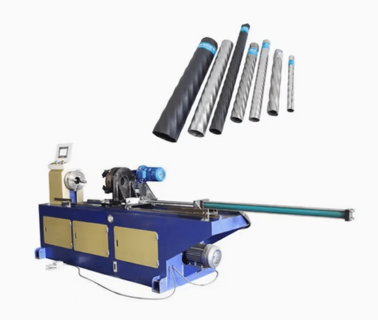
A Twisting Machine for Metal Pipes is a specialized device used to apply a controlled rotational force to metal pipes, causing them to twist along their longitudinal axis. This twisting process can be used for various purposes such as enhancing mechanical properties, creating decorative effects, or preparing pipe ends for certain types of connections.
The machine typically clamps the pipe securely at one or both ends and applies torque either manually or using hydraulic, electric, or pneumatic drives. The amount of twist applied is carefully controlled to achieve the desired effect without damaging the pipe or causing unwanted deformation.
Twisting metal pipes can improve structural characteristics by inducing torsional stress that sometimes enhances flexibility or toughness, depending on the pipe material and application. In some cases, twisted pipes are used architecturally or decoratively for railings, furniture, or artistic metalwork, where the twist adds an aesthetic element.
In industrial applications, twisting may be used to prepare pipe ends for coupling or joining processes that rely on mechanical interlocking. The twisted surface can provide a better grip or increased surface area for welding or adhesive bonding.
Modern twisting machines often include adjustable torque controls, speed settings, and clamping mechanisms to accommodate different pipe sizes, materials, and wall thicknesses. Automation features allow for precise repeatability in production environments, ensuring consistent twist angles across batches.
Safety features such as secure pipe clamping, emergency stop controls, and protective guards help prevent accidents during operation. Operators must be trained to set the appropriate parameters to avoid over-twisting, which can lead to pipe damage or failure.
In summary, twisting machines for metal pipes offer a controlled, efficient means of applying torsional deformation for structural, functional, or decorative purposes. Their versatility and precision make them useful tools in metal fabrication, construction, and artistic metalworking industries.
Twisting machines have advanced to incorporate precise digital controls and automated torque application, allowing operators to program specific twist angles and speeds for consistent results. This automation is particularly beneficial in manufacturing environments where uniformity is critical, such as producing twisted pipes for structural or architectural uses.
The machines are designed to handle a wide range of pipe diameters and materials, including steel, aluminum, copper, and various alloys. Adjustable clamping systems ensure the pipe remains securely in place during twisting, minimizing the risk of slippage or uneven deformation. Some machines also allow for simultaneous twisting of multiple pipes, increasing throughput in production settings.
Material properties play a significant role in determining the twisting process parameters. Ductile metals can tolerate higher degrees of twist without cracking, whereas more brittle materials require careful control to prevent fractures. Advanced sensors and feedback systems in modern twisting machines monitor torque and rotation in real time, enabling immediate adjustments to protect pipe integrity.
Twisting can also be combined with other pipe-forming processes, such as bending or rolling, to create complex shapes or customized pipe assemblies. This integration streamlines production and expands design possibilities for engineers and fabricators.
Safety remains a key concern, with machines equipped with emergency stop buttons, protective covers, and secure locking mechanisms. Operator training focuses on understanding material limits, machine operation, and emergency procedures to ensure safe and efficient use.
Emerging technologies may introduce robotics and AI-driven controls to further enhance twisting accuracy and efficiency. These innovations could enable adaptive twisting where the machine modifies torque dynamically based on material response, reducing waste and improving product quality.
Overall, twisting machines continue to evolve as versatile tools that provide controlled torsional deformation for functional, structural, and decorative applications in metal pipe fabrication, supporting a wide range of industrial and artistic needs.
As twisting machine technology progresses, integration with smart manufacturing systems becomes more common, allowing machines to be part of fully automated production lines. In such setups, pipes can be automatically loaded, twisted to precise specifications, and then passed on to subsequent operations like welding, coating, or inspection without manual intervention. This not only increases production speed but also ensures traceability and consistency throughout the manufacturing process.
With the adoption of IoT-enabled sensors, modern twisting machines can log critical data such as torque curves, rotation angles, and material response during each operation. This information can be stored for quality control, maintenance planning, and compliance with industry standards. It also allows operators to detect subtle variations that might indicate material fatigue or tooling wear before problems occur.
Tooling and die systems within twisting machines have also improved significantly. Hardened steel components, precision-ground clamping surfaces, and modular tooling platforms help achieve uniform twists without damaging the pipe surface. For applications where aesthetics are important, such as in architectural or furniture elements, surface finish quality is crucial, and machines are designed to minimize marks, scratches, or distortions during processing.
Environmental and energy efficiency is gaining attention, particularly in high-volume operations. Energy-saving motors, regenerative braking systems, and efficient hydraulic units help reduce power consumption and operating costs. At the same time, quieter machines and improved vibration damping make for a safer and more comfortable work environment.
Customization of twist profiles is another area of innovation. Some advanced machines allow for variable twisting—where the twist rate changes along the length of the pipe—creating unique patterns or functional characteristics such as increased flexibility at one end. This capability opens up new possibilities in both design and application, especially in industries like automotive, aerospace, or artistic metalworking.
Maintenance of twisting machines has also become more efficient thanks to built-in diagnostics, easy-access components, and predictive maintenance features. Operators can be alerted before parts wear out, reducing downtime and ensuring smoother operation.
Overall, twisting machines are increasingly versatile, intelligent, and efficient. They support both high-precision industrial manufacturing and custom artisanal work, adapting to a wide range of pipe materials and specifications. As demand for customized and high-performance metal components continues to grow, these machines will remain critical tools in the metal forming and fabrication industries.
Chamfering Machine For Metal Pipes
A Chamfering Machine for Metal Pipes is a specialized tool used to create a beveled edge or “chamfer” at the ends of metal pipes. Chamfering improves the pipe’s fit and finish, facilitates safer handling, prepares the edge for welding or threading, and ensures a clean joint with fittings. This process is critical in industries such as plumbing, gas and oil, shipbuilding, structural fabrication, and mechanical assembly where pipe end preparation must meet precise specifications.
Chamfering can be performed on both the inner and outer edges of a pipe, and machines are typically designed to handle various diameters, wall thicknesses, and materials such as carbon steel, stainless steel, aluminum, and copper alloys. The machine holds the pipe securely while a rotating cutting head or tool removes material at a fixed angle—commonly 30°, 37.5°, or 45°, though this can often be customized.
Modern chamfering machines range from manual and semi-automatic bench-top units to fully automated CNC-controlled systems that offer high repeatability and precision. Advanced models can simultaneously perform chamfering, facing, and even deburring in one pass, streamlining the process and reducing cycle times in production environments.
Portability is also a key feature for fieldwork. Lightweight, handheld chamfering tools allow technicians to quickly bevel pipe ends on-site before welding or connecting them. These portable units typically use pneumatic or electric power and are designed to be easy to align and operate even in tight spaces.
Safety and ergonomics are central to modern designs. Machines often include adjustable clamping mechanisms, chip guards, and hands-free operation modes. Additionally, they are engineered to minimize vibration and noise, reducing operator fatigue during extended use.
In automated and high-volume applications, chamfering machines may be integrated into full pipe processing lines, operating in coordination with cutting, bending, or threading equipment. Digital controls and sensors enable consistent chamfering depth and angle, while also logging process data for quality assurance.
Chamfering not only enhances the mechanical and structural quality of the pipe joints but also ensures compliance with industry standards that require clean, uniform edge preparation. As fabrication standards tighten and production efficiency becomes more critical, chamfering machines continue to evolve into smarter, faster, and more adaptable systems tailored to the demands of modern metal pipe processing.
Chamfering machines are increasingly being designed with modularity and flexibility in mind, allowing them to handle a wide range of pipe sizes and materials with minimal changeover time. This adaptability is particularly valuable in fabrication shops and manufacturing plants that deal with short production runs or a variety of custom specifications. Quick-change tooling systems and automated pipe positioning features further enhance throughput by reducing manual adjustments between operations.
Advanced chamfering systems may be equipped with programmable logic controllers (PLCs) or CNC interfaces that allow operators to set precise chamfer dimensions, angles, feed rates, and tool speeds. These settings can be saved as part of job recipes, enabling rapid setup for recurring work and ensuring consistency across production batches. Such precision is vital in industries like aerospace and petrochemicals, where weld preparation must meet stringent standards to ensure joint integrity and safety.
The integration of sensors and feedback systems enables real-time monitoring of cutting forces, tool wear, and surface finish, allowing for on-the-fly adjustments or automated stoppages when parameters deviate from acceptable ranges. This reduces scrap rates and minimizes the risk of defective parts entering downstream processes. In some cases, vision systems or laser scanning technology are used post-chamfering to inspect the quality and dimensions of the finished edges, further reinforcing quality control.
Chamfering machines are also evolving in response to environmental and energy concerns. Many modern models feature energy-efficient motors, optimized power consumption settings, and built-in coolant or lubrication systems that reduce heat buildup and prolong tool life while minimizing environmental impact. Additionally, quieter operation and lower vibration levels contribute to a safer, more comfortable working environment for operators.
In high-throughput manufacturing environments, chamfering machines may be fully automated and integrated with robotic arms or conveyor systems, enabling lights-out or unattended operation. These systems can handle loading, chamfering, inspection, and unloading in a continuous sequence, significantly boosting productivity and freeing skilled labor for more complex tasks.
For field service and maintenance tasks, the development of compact, battery-powered chamfering tools has made it easier to achieve high-quality edge preparation in remote or confined locations. These portable tools offer the same level of precision as shop-floor machines, making them invaluable for on-site work where speed and reliability are critical.
As the demand for higher production standards and tighter tolerances grows, chamfering machines are becoming more intelligent, efficient, and user-friendly. They now play a crucial role not only in preparing pipes for welding or joining but also in contributing to the overall quality, safety, and performance of piping systems across a wide range of industries.
Looking forward, the next wave of innovation in chamfering machines will likely revolve around further digitalization and integration with broader manufacturing ecosystems. Smart chamfering machines connected to plant-wide networks can share operational data in real time, enabling predictive maintenance scheduling, automated quality logging, and integration with enterprise resource planning (ERP) systems. This level of connectivity ensures that every chamfered pipe can be traced through its manufacturing history, supporting compliance, certification, and customer documentation requirements.
Artificial intelligence and machine learning will also begin to play a larger role. These technologies can be used to analyze large datasets generated by chamfering operations to identify patterns that lead to tool wear, surface defects, or dimensional deviations. Over time, machines will be able to adjust their parameters automatically to improve outcomes, reduce tooling costs, and avoid rework.
From a mechanical standpoint, chamfering machines will continue to improve in terms of tooling longevity and edge accuracy. Coated carbide and ceramic tools will allow faster feed rates and cleaner cuts, particularly on difficult-to-machine alloys like stainless steels or titanium pipes. Toolholders with vibration-damping technology will ensure smooth surface finishes even at high speeds, which is crucial for applications that involve high-pressure or hygienic piping systems.
Ergonomics and operator interface design will also see enhancements. Graphical touchscreens, real-time 3D previews, guided setup routines, and automated safety interlocks will simplify operation and reduce human error. Many machines are already equipped with diagnostic displays and guided maintenance alerts, and this trend will expand to include augmented reality (AR) overlays for training and servicing.
The importance of sustainability in manufacturing will influence chamfering machine design, pushing for reduced coolant use, recyclability of wear components, and low-energy operating modes. Compact designs that conserve floor space and modular setups that can be reconfigured as production needs change will become more desirable.
Ultimately, chamfering machines will continue to evolve from being simple material removal devices into smart, networked, and autonomous systems that contribute to the broader goals of modern manufacturing—efficiency, quality, flexibility, traceability, and sustainability. Whether used in a high-speed automated plant or as part of a mobile pipe preparation unit in the field, these machines will remain indispensable to producing metal pipes that meet the highest performance and safety standards.
Notching Machine For Metal Pipes
A Notching Machine for Metal Pipes is designed to cut precise indentations, grooves, or cutouts into the surface of a pipe, usually at the ends or along the length, to enable strong, clean joints—especially in preparation for welding, fastening, or intersecting with other pipes. These machines are crucial in industries like automotive, construction, furniture, and metal fabrication, where pipe assemblies need to be joined at various angles or integrated into complex frameworks.
The most common application is tube-to-tube joining, such as in handrails, roll cages, and structural frames, where a notched end allows one pipe to fit snugly against the curved surface of another before welding. To achieve this, the notching machine removes a curved section from the pipe end, matching the profile of the intersecting pipe.
There are several types of notching machines, including manual, hydraulic, and CNC-controlled models. Manual notchers are often used for light-duty work and small-scale operations, while hydraulic and CNC systems are favored in high-volume, precision-demanding environments. Rotary hole saw notchers, abrasive belt notchers, and end mill (milling cutter) notchers are the most common mechanisms, each suitable for different pipe materials, wall thicknesses, and notch geometries.
Precision is a key feature of advanced notching machines. CNC notchers can be programmed to cut specific angles and radii with extremely tight tolerances, allowing complex multi-axis joints to be produced rapidly and repeatably. These systems often include automated clamping, pipe rotation, and feed control, reducing operator involvement and increasing throughput.
Safety and ease of use are prioritized through features like adjustable clamps, enclosed cutting zones, and intuitive control panels. Many modern machines also come with quick-change tooling systems, which reduce downtime when switching between pipe sizes or notch types.
The flexibility of notching machines extends to their ability to process round, square, and rectangular pipes or tubes, as well as materials ranging from mild steel and aluminum to stainless steel and titanium. Multi-axis models can cut notches at compound angles or produce intersecting holes and slots, accommodating highly customized fabrication tasks.
Portable notching tools are also available for field use or tight workshop spaces. These units, powered electrically or pneumatically, allow on-site customization of pipe joints without sacrificing accuracy, making them valuable for construction, maintenance, and retrofit projects.
As pipe design becomes more complex and aesthetic and structural requirements grow more demanding, notching machines continue to evolve—delivering cleaner cuts, tighter joints, and more efficient workflows that enhance both the quality and integrity of metal pipe assemblies.
Notching machines have become increasingly sophisticated, incorporating computer numerical control (CNC) technology that allows for highly precise and repeatable cuts. These machines can execute complex notch shapes and angles that would be difficult or impossible to achieve manually, improving joint fit-up and overall structural integrity. CNC-controlled notching also reduces material waste and shortens cycle times, making production more efficient.
Many modern notching machines feature automatic pipe feeding and positioning systems, which can adjust the pipe’s orientation in multiple axes to create compound-angle notches. This capability is essential for fabricating intricate pipe assemblies, such as those found in automotive roll cages, aerospace frames, and architectural structures. The use of sensors and feedback loops ensures consistent quality and reduces the likelihood of errors during operation.
The tooling used in notching machines has evolved to include high-performance materials like carbide and coated inserts, which offer longer tool life and better cutting performance, especially on harder alloys and stainless steels. Quick-change tooling systems further enhance productivity by allowing operators to switch between different notch profiles rapidly without extensive setup.
Safety measures have improved with enclosed cutting areas, emergency stop systems, and ergonomic designs that minimize operator fatigue and risk of injury. User-friendly interfaces with touchscreen controls and pre-programmed notch patterns make the machines accessible even to less experienced operators while maintaining precision.
Integration with other pipe processing equipment, such as cutting, bending, and welding stations, is becoming more common, enabling fully automated production lines. This integration streamlines workflow, reduces manual handling, and ensures consistent part quality from raw material to finished assembly.
Portable notching solutions have also advanced, offering lightweight, battery-powered or pneumatic tools that bring high precision to fieldwork and maintenance operations. These portable machines are designed for quick setup and easy handling in confined spaces, expanding their usability beyond the factory floor.
Environmental considerations are influencing notching machine design as well. Newer models often feature energy-efficient drives, minimal coolant usage, and dust or chip collection systems to reduce environmental impact and improve workplace conditions.
Looking ahead, further developments may include the use of artificial intelligence to optimize notch parameters based on material behavior, predictive maintenance to reduce downtime, and enhanced connectivity for seamless integration into smart factories. Overall, notching machines continue to be indispensable tools in metal pipe fabrication, offering versatility, precision, and efficiency that support a wide range of industrial and creative applications.
Future advancements in notching machines will likely focus on increasing automation, precision, and adaptability to meet the evolving demands of metal pipe fabrication. Enhanced robotics integration could enable fully automated pipe handling, loading, and unloading, allowing continuous operation with minimal human intervention. This would be particularly valuable in high-volume production environments where maximizing throughput and minimizing downtime are critical.
Artificial intelligence and machine learning algorithms may be incorporated to analyze cutting data in real time, optimizing parameters such as feed rate, cutting speed, and tool path based on material properties and wear conditions. This adaptive capability would improve tool life, reduce scrap, and ensure consistently high-quality notches, even when dealing with diverse pipe materials or variable wall thicknesses.
Improvements in sensor technology could allow machines to detect imperfections or inconsistencies in the pipe surface before and during the notching process. Such systems could automatically adjust or halt operations to prevent defects, enhancing overall quality control and reducing waste.
The development of modular tooling systems will provide greater flexibility, enabling a single machine to perform a wider variety of notch types and sizes without extensive retooling. This modularity can significantly reduce setup times and support smaller batch sizes or custom fabrication projects with ease.
Sustainability will continue to shape design priorities, leading to energy-efficient motors, smart power management, and environmentally friendly coolant or lubrication systems. Additionally, advanced chip evacuation and filtration technologies will improve workplace cleanliness and reduce environmental impact.
On the software side, notching machines will increasingly integrate with broader manufacturing execution systems (MES) and enterprise resource planning (ERP) platforms. This connectivity will facilitate better scheduling, resource allocation, and traceability throughout the production lifecycle, supporting just-in-time manufacturing and lean processes.
For field applications, portable notching tools will gain enhancements in battery technology, lightweight materials, and ergonomic design, making them even more practical for on-site pipe fabrication, maintenance, and repairs.
Overall, notching machines will become smarter, more efficient, and highly versatile, playing a pivotal role in the fabrication of complex pipe assemblies across industries such as automotive, aerospace, construction, and energy. Their continued evolution will help manufacturers meet increasingly stringent quality standards while optimizing cost, speed, and environmental impact.
Spinning Machine For Metal Pipes
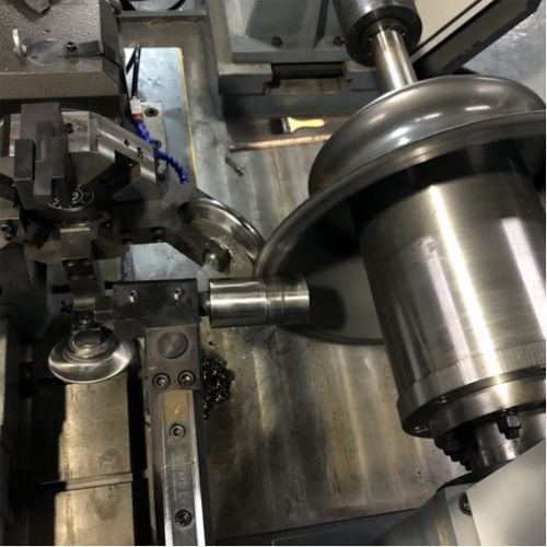
A Spinning Machine for Metal Pipes is a specialized piece of equipment used to shape, form, and refine metal pipes through a process called metal spinning or spin forming. In this process, a pipe or tubular metal workpiece is rotated at high speed on a lathe-like machine while a tool applies pressure to deform and shape the pipe into a desired contour, taper, or profile. This technique is widely used to create symmetrical shapes with smooth curves, such as cones, domes, flares, or curved sections in metal pipes.
Spinning machines for metal pipes operate by clamping the pipe securely onto a rotating spindle. As the pipe spins, a skilled operator or automated tooling system uses rollers, mandrels, or shaping tools to press against the pipe surface, gradually forcing the metal into the desired shape. The process relies on the ductility and plasticity of the metal, which allows it to be stretched and compressed without cracking.
These machines come in various configurations, including manual, semi-automatic, and fully CNC-controlled versions. Manual spinning machines require more operator skill and are suitable for small-scale or custom fabrication, while CNC machines enable high precision, repeatability, and efficiency for larger production runs.
The spinning process can alter the pipe’s diameter, thickness, and shape. It is commonly used to manufacture components like pipe reducers, nozzles, elbows, flanges, and other complex shapes that would be difficult or expensive to produce by traditional machining or welding methods.
Material versatility is a hallmark of spinning machines. They can work with a wide range of metals, including steel, stainless steel, aluminum, copper, brass, and various alloys. The choice of tooling, speed, and feed rates are adjusted based on the pipe material and thickness to ensure optimal forming without damage.
Modern spinning machines often feature computerized controls that allow operators to program specific tool paths, forces, and rotational speeds. This level of control helps produce consistent, high-quality parts with minimal material waste. Additionally, automation reduces operator fatigue and the risk of errors.
Spinning machines also incorporate safety features such as guards, emergency stop controls, and sensors that monitor torque and tool pressure to prevent overloading or damaging the pipe.
Overall, spinning machines for metal pipes offer a cost-effective, efficient, and flexible method for producing a wide range of precision-shaped metal pipe components, supporting industries from automotive and aerospace to construction and decorative metalworking.
Spinning machines continue to evolve with advancements in automation and precision control, making them increasingly capable of handling complex pipe shapes and tighter tolerances. CNC technology allows for programmable control over every aspect of the spinning process—such as spindle speed, tool pressure, and feed rate—enabling the production of intricate profiles with consistent repeatability. This automation not only improves quality but also speeds up production and reduces the need for highly skilled manual labor.
The tooling used in spinning machines has also improved significantly. Hardened steel rollers, carbide-tipped tools, and custom-shaped mandrels help achieve smoother surface finishes and more precise shapes, even on harder or thicker pipe materials. Quick-change tooling systems allow for faster transitions between different pipe sizes and shapes, increasing flexibility in manufacturing setups.
Many spinning machines now incorporate real-time monitoring systems that track parameters like torque, vibration, and temperature during the forming process. These sensors help detect potential issues such as material fatigue or tool wear early on, allowing operators to make adjustments before defects occur. This predictive capability reduces downtime and scrap rates while extending the lifespan of tooling and machinery.
Energy efficiency is another important consideration in modern spinning machines. Variable frequency drives, regenerative braking systems, and optimized motor designs reduce power consumption and operating costs. Some machines are also designed with compact footprints and modular components, making them easier to integrate into existing production lines or flexible manufacturing cells.
In addition to shaping pipe ends or reducing diameters, spinning machines are used to create decorative or functional features such as flares, beads, or curved sections that enhance both the structural and aesthetic properties of the pipe. This versatility makes spinning an essential process in industries ranging from automotive exhaust and aerospace ducting to architectural elements and artistic metalwork.
Portable or smaller-scale spinning machines have also become popular for on-site fabrication or repair work, where pipes need to be reshaped without transporting them back to a factory. These compact units provide many of the benefits of full-sized machines while allowing greater mobility and flexibility in the field.
As manufacturing trends continue toward customization and smaller batch sizes, spinning machines will likely become even more adaptable, combining smart controls, modular tooling, and integrated quality assurance to meet diverse production needs. This ongoing innovation ensures that metal pipe spinning remains a vital process for efficiently producing high-quality, precision-formed components.
Looking ahead, the integration of artificial intelligence (AI) and machine learning into spinning machines promises to revolutionize how metal pipe spinning is performed. AI-driven systems could analyze vast amounts of process data to optimize spinning parameters dynamically, adjusting tool pressure, speed, and feed rates in real time to accommodate variations in material properties or thickness. This would not only improve part quality and consistency but also extend tool life and reduce material waste.
Moreover, advancements in sensor technology will enable more comprehensive monitoring of the spinning process. High-resolution cameras, laser scanners, and force sensors can provide detailed feedback on surface finish, dimensional accuracy, and potential defects as the pipe is formed. This data can be fed back into control systems to enable adaptive corrections during spinning, effectively creating a closed-loop manufacturing process.
Robotic automation will further enhance spinning machine capabilities by enabling automated loading, unloading, and even tool changes without human intervention. Combined with advanced vision systems, robots could handle irregularly shaped pipes or complex assemblies, increasing throughput while maintaining precision. Such automation also supports lights-out manufacturing, where production can continue unattended for extended periods.
The development of new materials and alloys used in metal pipes will drive innovations in spinning machine design as well. Machines will need to accommodate increasingly tougher or more exotic metals, requiring more powerful drives, enhanced cooling systems, and advanced tooling materials that resist wear and deformation under high loads.
Sustainability considerations will influence future machine designs too. Reduced energy consumption, improved recycling of scrap material generated during spinning, and environmentally friendly lubricants will become standard features. Additionally, compact and modular machine designs will allow manufacturers to optimize floor space and adapt quickly to changing production requirements, supporting more sustainable and efficient manufacturing practices.
In specialized applications, hybrid machines that combine spinning with other forming processes—such as hydroforming, stretch forming, or incremental sheet forming—may emerge. These hybrid approaches can expand the range of achievable shapes and properties, enabling even more complex and high-performance metal pipe components.
In summary, spinning machines for metal pipes will continue to advance through smarter automation, enhanced precision, and greater versatility. They will play an increasingly important role in producing complex, high-quality pipe components across industries, meeting the demands of modern manufacturing for speed, flexibility, and sustainability.
Flanging Machine For Metal Pipes
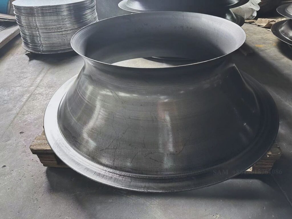
A Flanging Machine for Metal Pipes is a specialized device used to form flanges on the ends of metal pipes, allowing them to be easily connected to other pipes, fittings, valves, or equipment. Flanges are essential components in piping systems because they provide a secure, leak-resistant joint that can be assembled and disassembled without welding, facilitating maintenance and system modifications.
Flanging machines operate by shaping the pipe end into a flange—a flat or raised rim—using mechanical force. This is typically achieved through processes like spinning, rolling, or pressing, where the pipe end is expanded and formed into a specific flange profile. Common flange types produced include weld neck, slip-on, lap joint, socket weld, and threaded flanges, each suited to different applications and pressure ratings.
There are various types of flanging machines, ranging from manual and hydraulic units for small-scale or workshop use to fully automated CNC machines used in industrial production. Manual flanging machines often require the operator to position and apply force using levers or hydraulic presses, while automated machines use programmed sequences to ensure consistent flange dimensions and quality.
Modern flanging machines incorporate adjustable tooling and dies that can be changed quickly to accommodate different pipe diameters, wall thicknesses, and flange designs. CNC-controlled flanging machines allow precise control of parameters such as flange thickness, diameter, and angle, ensuring tight tolerances and repeatability—critical for high-pressure or safety-sensitive piping systems.
Safety features on flanging machines include guarded working areas, pressure relief valves, and emergency stop buttons to protect operators during high-force operations. Ergonomic designs and intuitive controls help reduce operator fatigue and improve workflow efficiency.
Flanging machines are used extensively in industries like oil and gas, chemical processing, water treatment, HVAC, and power generation, where robust and reliable pipe connections are essential. The ability to produce flanges on-site or in-house reduces reliance on pre-fabricated components and enables faster turnaround times for piping projects.
Additionally, portable flanging machines have been developed for field service applications, allowing technicians to flange pipe ends directly at installation or repair sites. These portable units often run on hydraulic or pneumatic power and are designed for ease of transport and use in confined spaces.
Overall, flanging machines provide an efficient, versatile, and precise method for preparing pipe ends with flanges, supporting the construction and maintenance of durable and leak-proof piping networks across a wide range of industries.
Flanging machines have continued to evolve with advancements in technology and manufacturing demands. One key development is the integration of CNC controls, which allows for programmable precision in flange production. This ensures that flanges meet exact specifications for dimensions, angles, and surface finishes, which is crucial in industries where tight tolerances and pressure ratings are mandatory. Automated processes also reduce operator error, improve consistency, and increase throughput.
The tooling systems in modern flanging machines are highly versatile, often featuring quick-change dies and adjustable components that enable rapid switching between different pipe sizes and flange types. This adaptability is particularly beneficial in fabrication shops and production lines handling diverse piping systems, reducing setup times and improving overall efficiency.
Many flanging machines now incorporate sensors and real-time monitoring systems that track forming pressures and deformation patterns. These feedback mechanisms help operators detect potential issues such as material fatigue, cracks, or improper forming before they result in defective flanges. This predictive capability minimizes scrap rates and enhances product quality.
Energy efficiency and safety are also priorities in the latest flanging machine designs. Machines are equipped with energy-saving drives, hydraulic systems optimized for reduced consumption, and safety enclosures to protect operators from high-pressure forces. Ergonomic features such as adjustable controls, user-friendly interfaces, and reduced noise levels contribute to a safer and more comfortable working environment.
Portable and compact flanging machines have become increasingly popular, especially for fieldwork in construction, maintenance, and repair of piping systems. These portable units offer the ability to produce flanges directly on-site, eliminating the need for transporting pipes to a fabrication shop. Lightweight designs, battery or hydraulic power sources, and intuitive controls make them practical for use in tight or remote locations.
Integration with other pipe processing equipment, such as cutting, beveling, and welding machines, is becoming more common, facilitating streamlined workflows in pipe fabrication. This connectivity supports automated manufacturing environments where multiple operations are coordinated to optimize production speed and quality.
Materials processed by flanging machines continue to expand, including not only traditional steels but also stainless steel, aluminum, copper alloys, and specialty metals used in corrosive or high-temperature environments. Advances in tooling materials and machine power allow flanging of thicker-walled pipes and harder alloys without compromising flange integrity.
Looking to the future, flanging machines are expected to incorporate more intelligent automation, including AI-driven process optimization, enhanced diagnostics, and integration into smart factory systems. This will enable predictive maintenance, real-time quality assurance, and seamless data exchange with other manufacturing systems, supporting lean production and higher overall equipment effectiveness.
In summary, flanging machines are indispensable in metal pipe fabrication, providing the necessary means to produce reliable, high-quality flanges efficiently. Their ongoing technological improvements ensure they meet the increasing demands for precision, flexibility, safety, and sustainability in modern piping industries.
Future developments in flanging machines will likely focus on greater automation and integration within digital manufacturing ecosystems. Smart flanging machines equipped with sensors and IoT connectivity will enable continuous monitoring and remote diagnostics, allowing operators and maintenance teams to track machine health, predict failures, and schedule maintenance proactively. This reduces downtime and keeps production running smoothly.
Advanced AI algorithms could analyze process data in real time, adjusting flanging parameters automatically to compensate for variations in pipe material properties, thickness, or temperature. This adaptive control would optimize forming forces and speeds, ensuring uniform flange quality while minimizing tool wear and energy consumption.
Robotics and automated material handling will play an increasing role, especially in high-volume production environments. Robots can manage pipe loading, positioning, and unloading with high precision, while collaborative robots (cobots) assist human operators by handling repetitive or heavy tasks, enhancing safety and productivity.
New materials and alloys used in piping systems—such as lightweight composites and high-strength steels—will drive innovation in flanging machine design. Machines will need to apply precise and controlled forces tailored to these materials to avoid cracking or distortion, requiring more sophisticated control systems and tooling.
Sustainability concerns will influence future machine development, encouraging energy-efficient drives, reduced hydraulic fluid use, and improved recycling of metal scrap generated during flange formation. Compact and modular machine designs will enable easier integration into existing production lines with minimal footprint.
On the software side, flanging machines will increasingly connect with manufacturing execution systems (MES) and enterprise resource planning (ERP) platforms to provide end-to-end traceability, quality control, and production scheduling. Digital twins—virtual replicas of the machines—may be used to simulate and optimize flanging processes before actual production, reducing trial-and-error and speeding up setup.
Portable flanging solutions will continue to improve, becoming lighter, more powerful, and easier to operate. This will benefit field service teams performing maintenance, repairs, or custom fabrications on-site, where flexibility and reliability are essential.
In conclusion, flanging machines will remain a cornerstone of metal pipe fabrication, evolving with smart automation, enhanced precision, and sustainable design to meet the increasingly complex and demanding requirements of modern industries. Their role in producing durable, leak-proof, and easy-to-assemble pipe connections will be vital in sectors ranging from oil and gas to construction, power generation, and beyond.
End Forming Machine For Metal Pipes
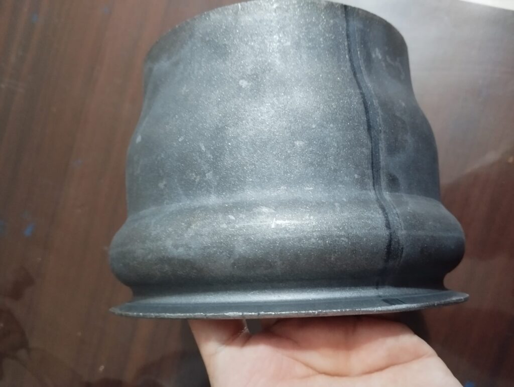
An End Forming Machine for Metal Pipes is a specialized device designed to alter the shape or profile of a pipe’s end to prepare it for joining, sealing, or specific functional requirements. End forming involves processes like expanding, reducing, flaring, beading, or profiling the pipe end, enabling it to connect securely with other pipes, fittings, or components without additional welding or machining.
These machines use mechanical, hydraulic, or pneumatic force to reshape the pipe ends precisely and consistently. Depending on the desired form, the machine may expand the pipe’s diameter to create a flange or bell shape, reduce it to fit inside another pipe, flare it outward for easier joint sealing, or create beads and grooves that improve mechanical locking and sealing capabilities.
End forming machines are widely used in industries such as automotive exhaust manufacturing, HVAC ducting, plumbing, aerospace, and industrial piping systems. They provide a cost-effective, high-speed solution for preparing pipe ends to meet stringent assembly and performance standards.
Many end forming machines are equipped with adjustable tooling and programmable controls to accommodate various pipe diameters, wall thicknesses, and materials, including steel, stainless steel, aluminum, copper, and alloys. CNC-controlled models offer high precision and repeatability, reducing setup times and minimizing material waste.
Safety features like guarded work areas, emergency stops, and overload protection ensure operator safety during high-force forming operations. Compact designs and modular tooling systems improve flexibility and allow easy integration into automated production lines.
Overall, end forming machines streamline pipe fabrication by producing consistent, high-quality pipe ends ready for assembly, enhancing joint integrity, and reducing the need for secondary machining or welding processes.
End forming machines have seen significant advancements driven by the demands for higher productivity, precision, and flexibility in pipe fabrication. Modern machines often incorporate CNC or servo-driven controls, which allow for precise manipulation of forming forces and sequences tailored to the specific pipe dimensions and materials. This level of control ensures consistent, defect-free pipe ends that meet stringent industry standards and reduce the need for rework.
Tooling systems have become more versatile, with modular designs that can be quickly swapped or adjusted to handle a wide range of pipe sizes and end forms. This adaptability is critical in production environments where multiple pipe types and specifications must be processed efficiently. Additionally, tooling made from advanced materials, such as carbide or coated alloys, extends tool life and maintains forming accuracy even under high-pressure operations.
Integration with automated material handling and inspection systems enhances the overall efficiency of end forming operations. Pipes can be loaded, formed, and unloaded with minimal human intervention, reducing cycle times and improving workplace safety. Inline inspection systems using laser scanners or vision technology verify dimensional accuracy and surface quality immediately after forming, allowing for rapid detection and correction of defects.
The capacity to form complex end geometries has expanded, enabling the production of specialized pipe ends such as tapered sections, double flares, or grooved profiles for sealing and connection purposes. This capability supports applications in critical sectors like automotive exhaust systems, aerospace fuel lines, and industrial fluid transport, where precise fit and reliable sealing are essential.
Energy efficiency and sustainability are increasingly important in machine design. Modern end forming machines utilize energy-saving drives, hydraulic systems with low fluid consumption, and regenerative braking technologies. These improvements reduce operational costs and environmental impact while maintaining high performance.
Portable and compact end forming machines have also been developed for field operations, allowing maintenance teams to perform repairs or modifications on-site without removing pipes from service. These units balance power and portability, featuring simplified controls and quick setup to handle a variety of pipe types in constrained environments.
Looking forward, end forming machines are expected to integrate more closely with digital manufacturing platforms, enabling real-time process optimization, predictive maintenance, and comprehensive traceability. Advances in AI and machine learning will further refine forming processes by analyzing operational data to suggest optimal settings and detect anomalies early.
In summary, end forming machines play a crucial role in preparing metal pipe ends for reliable, high-quality connections across numerous industries. Their ongoing evolution in automation, tooling versatility, and digital integration ensures they remain essential tools in modern pipe fabrication and assembly.
Future trends in end forming machines emphasize increased automation and smart manufacturing capabilities. With the rise of Industry 4.0, these machines are becoming more interconnected, enabling seamless communication with other equipment on the shop floor. This connectivity allows for synchronized workflows, real-time production monitoring, and better overall equipment effectiveness (OEE).
Artificial intelligence and machine learning will enable end forming machines to self-optimize by learning from previous forming cycles. By analyzing data on material behavior, tooling wear, and process parameters, the machine can adjust forming pressure, speed, and sequence on the fly to consistently produce superior quality pipe ends while minimizing scrap and tool degradation.
Advanced sensor integration will provide comprehensive feedback during the forming process. Sensors monitoring strain, force, temperature, and vibration can detect subtle anomalies that may indicate potential defects or tool wear. Early detection allows for proactive adjustments or maintenance, reducing downtime and maintaining high product quality.
Robotics and automated handling systems will increasingly be paired with end forming machines, automating loading, unloading, and transfer between production stages. This reduces labor costs, minimizes human error, and enhances safety by limiting operator exposure to heavy or hazardous materials.
New materials, including lightweight alloys and composites, will challenge traditional forming processes. End forming machines will need enhanced precision and adaptable tooling systems to handle these materials without causing cracks or deformation. This may lead to hybrid forming technologies combining mechanical, hydraulic, and even incremental forming methods to achieve complex shapes.
Sustainability considerations will shape future machine designs by focusing on reducing energy consumption, minimizing hydraulic fluid use, and enabling easier recycling of scrap metal generated during the forming process. Compact, modular designs will allow manufacturers to optimize factory layouts and quickly adapt to changing production needs.
In niche applications, portable or field-deployable end forming machines will grow in demand, especially in industries such as oil and gas, shipbuilding, and infrastructure maintenance. These machines will offer robust performance in challenging environments, enabling onsite pipe repairs or modifications without costly downtime.
Digital twin technology—virtual replicas of the physical end forming machines and processes—will become standard tools for simulation, troubleshooting, and operator training. By testing forming parameters virtually, manufacturers can reduce trial-and-error, optimize production setups, and improve workforce competency.
Overall, the future of end forming machines is tightly linked with advances in automation, digitalization, and materials science. These innovations will ensure that pipe ends can be formed with unparalleled precision, speed, and reliability to meet the evolving demands of modern manufacturing and infrastructure development.
Flaring Machine For Metal Pipes
A Flaring Machine for Metal Pipes is a specialized tool used to create a flared end on a metal pipe. Flaring involves expanding the pipe’s open end outward into a conical shape, which allows for a secure connection with fittings, hoses, or other piping components, often using compression or flare nuts to create leak-proof seals. This process is common in plumbing, HVAC systems, automotive brake lines, fuel lines, and refrigeration systems.
Flaring machines typically operate by clamping the pipe firmly in place and then using a conical mandrel or flaring tool to press or spin against the pipe end, causing it to expand outward uniformly. This precise forming ensures the flare has the correct angle and smooth surface for optimal sealing.
There are various types of flaring machines available, ranging from manual hand-operated models suitable for small workshops and field repairs to hydraulic or pneumatic-powered machines designed for industrial-scale production. More advanced machines often include adjustable tooling to accommodate different pipe diameters and wall thicknesses.
Manual flaring machines are compact and portable, making them ideal for onsite applications or maintenance tasks where mobility and ease of use are important. These machines require the operator to manually rotate or press the flaring tool, providing tactile feedback to ensure the flare is formed correctly.
Hydraulic and pneumatic flaring machines automate the process, offering higher precision, repeatability, and the ability to handle thicker or harder pipe materials. They reduce operator fatigue and improve throughput in production settings.
Modern flaring machines may also feature interchangeable dies and adjustable stops, allowing customization of flare angles and diameters to meet specific industry standards or customer requirements. CNC-controlled flaring machines can automate the entire process, ensuring consistent quality across large batches.
Safety features such as pipe clamps, guards, and pressure relief valves are integrated to protect operators during high-force operations. Ergonomic designs and user-friendly controls further enhance safety and ease of use.
In summary, flaring machines for metal pipes are essential tools for producing reliable, leak-proof flared connections in a variety of industrial and maintenance applications. Their range of sizes and capabilities allows for flexible use across different industries and pipe specifications.
Flaring machines continue to evolve with technological advancements, addressing the need for greater precision, efficiency, and versatility. The introduction of CNC and servo-driven controls in flaring machines allows for programmable, repeatable flares that meet stringent specifications. This automation minimizes operator error and ensures consistency, which is particularly important in industries such as automotive and aerospace, where tight tolerances are critical.
The tooling systems in modern flaring machines are designed for quick changeover, enabling rapid adaptation to different pipe diameters and flare angles. This flexibility supports manufacturers dealing with a variety of pipe sizes and materials, improving production efficiency by reducing downtime during tool changes. Materials used for tooling have also improved, with hardened alloys and coatings increasing tool longevity and maintaining surface finish quality even under high-pressure forming conditions.
Advanced sensor integration provides real-time feedback on forming forces and dimensional accuracy, helping operators monitor the process and detect potential issues before defects occur. This capability enhances quality control and reduces waste. Additionally, some machines incorporate inline inspection systems that automatically measure flare geometry immediately after forming, ensuring parts meet quality standards without interrupting production flow.
Safety remains a top priority, with modern flaring machines featuring enclosed work areas, pressure relief mechanisms, and emergency stop functions. Ergonomic considerations, such as adjustable clamps and user-friendly interfaces, reduce operator fatigue and improve overall workflow.
Portable flaring machines are increasingly sophisticated, combining lightweight designs with hydraulic or battery-powered systems to deliver high performance in field operations. These machines are essential for maintenance and repair tasks where pipes cannot be moved easily, offering convenience without sacrificing flare quality.
Integration with other pipe fabrication processes, such as cutting, beveling, and welding, is becoming more common, allowing for streamlined production lines that improve throughput and reduce handling. Software connectivity enables flaring machines to communicate with broader manufacturing systems, facilitating scheduling, traceability, and process optimization.
Looking forward, flaring machines are expected to incorporate AI-driven controls that adapt forming parameters in real time based on material feedback and environmental conditions. This smart automation will further improve quality, reduce tool wear, and enhance energy efficiency.
Overall, flaring machines play a vital role in preparing metal pipes for secure, leak-proof connections. Their ongoing development in precision, automation, and flexibility ensures they continue to meet the demanding requirements of modern manufacturing and maintenance across various industries.
Future trends in flaring machine technology will likely focus heavily on increased automation, connectivity, and adaptability to evolving manufacturing needs. As Industry 4.0 practices become more widespread, flaring machines will be integrated into smart factories where real-time data exchange enables seamless communication between machines, quality control systems, and production management software. This connectivity allows for better traceability of each flared pipe end, ensuring compliance with industry standards and simplifying quality audits.
Artificial intelligence and machine learning will play an increasingly important role by analyzing process data to optimize flare formation parameters automatically. These systems could detect subtle variations in pipe material properties, wall thickness, or temperature, adjusting pressure, speed, or tool position dynamically to maintain consistent quality and reduce scrap rates. This self-optimizing behavior will enhance machine uptime and extend tooling life.
Robotic automation will also complement flaring machines, handling tasks such as pipe loading, positioning, and unloading. This reduces manual labor, improves workplace safety, and increases throughput, especially in high-volume production environments. Collaborative robots (cobots) may assist operators in smaller workshops or maintenance settings, combining human flexibility with robotic precision.
Advances in tooling technology will enable flaring of new materials, including high-strength alloys and lightweight composites, which present challenges due to their differing deformation characteristics. Improved tool coatings and design will ensure clean, precise flares without cracking or distortion, broadening the applications of flaring machines.
Sustainability considerations will drive the development of more energy-efficient machines with optimized hydraulic systems, reduced power consumption, and recyclable components. Compact and modular designs will support flexible factory layouts and easier upgrades as production demands evolve.
Portable flaring units will continue to improve in power-to-weight ratio and ease of use, supporting field service and repair operations in industries like oil and gas, construction, and transportation. Enhanced battery technology and ruggedized designs will allow these machines to operate reliably in harsh environments.
Digital twin technology, creating virtual models of flaring machines and their processes, will become a powerful tool for simulating production scenarios, training operators, and predicting maintenance needs. This will help manufacturers reduce setup times, avoid costly errors, and maximize equipment lifespan.
In summary, the future of flaring machines lies in smart, connected, and adaptable solutions that combine precision engineering with intelligent automation. These advancements will enable manufacturers to produce high-quality, leak-proof flares more efficiently while meeting the increasingly complex requirements of modern industrial applications.
Necking Machine For Metal Pipes
A Necking Machine for Metal Pipes is a specialized forming machine designed to reduce the diameter of the pipe end, creating a tapered or constricted section often referred to as a “neck.” This necked end is commonly used to prepare the pipe for joining, welding, or fitting into another component with a smaller diameter, enabling secure and precise connections in piping systems.
Necking machines apply controlled mechanical, hydraulic, or pneumatic force to deform the pipe end uniformly without causing cracks or wrinkles. The process involves compressing or drawing the pipe end gradually, maintaining material integrity while achieving the desired reduction in diameter and length of the necked section.
These machines are essential in industries such as automotive exhaust fabrication, HVAC ducting, aerospace, plumbing, and industrial piping, where necked pipe ends facilitate assembly and improve joint strength and sealing performance.
Necking machines come in various types, including manual, hydraulic, and CNC-controlled models. Manual machines are typically used in smaller workshops or for field repairs, offering portability and ease of operation for simple necking tasks. Hydraulic and CNC machines provide higher precision, repeatability, and the ability to process a wide range of pipe sizes and wall thicknesses, making them ideal for high-volume production environments.
Adjustable tooling and die sets allow necking machines to accommodate different pipe diameters, neck lengths, and taper angles, providing versatility for diverse manufacturing requirements. Tooling materials are often hardened or coated to withstand the stresses of forming while maintaining dimensional accuracy over extended use.
Modern necking machines may incorporate safety features such as clamping mechanisms, emergency stops, and protective guards to ensure operator safety during high-force operations. Ergonomic designs enhance usability and reduce operator fatigue, improving productivity and quality.
Integration with automated loading and unloading systems, as well as inline inspection technologies, further enhances the efficiency of necking operations by minimizing manual handling and ensuring dimensional consistency.
In summary, necking machines are crucial in metal pipe fabrication, enabling precise diameter reduction at pipe ends for improved fitment and assembly. Their range of capabilities—from manual to highly automated systems—supports varied industrial needs, ensuring reliable and high-quality necked pipe ends.
Necking machines have advanced significantly with the integration of modern technologies aimed at improving precision, efficiency, and versatility. CNC-controlled necking machines allow operators to program specific necking parameters such as reduction diameter, taper angle, and neck length. This automation results in consistent, repeatable outcomes that meet strict manufacturing tolerances, especially important in industries like aerospace and automotive where joint integrity is critical.
Tooling systems in contemporary necking machines are designed for quick changeovers, enabling manufacturers to switch between different pipe sizes and necking profiles rapidly. This flexibility reduces downtime and supports just-in-time production methods. Tool materials have also evolved to include wear-resistant coatings and alloys that prolong tool life and maintain high-quality forming surfaces.
Advanced necking machines often feature sensor systems that monitor forming force, pipe position, and material behavior in real time. These sensors provide feedback to the control system, enabling dynamic adjustments during the forming process to prevent defects such as cracking or excessive thinning. This adaptive control improves yield and reduces scrap.
Safety enhancements such as automatic clamps, guarding, and emergency stop mechanisms protect operators from injury during high-pressure forming. Ergonomic machine designs improve user comfort and reduce fatigue, contributing to higher productivity and quality.
Automation is increasingly common, with robotic arms or conveyors handling pipe loading and unloading. This reduces manual labor and the risk of damage to the pipes, particularly when handling heavy or large-diameter pipes. Inline inspection technologies, including laser measurement and vision systems, verify neck dimensions immediately after forming to ensure conformity with specifications.
Portable necking machines are also available for field repairs and maintenance tasks where removing pipes from service is impractical. These machines balance compact size with sufficient forming power to handle a range of pipe materials and thicknesses.
Future developments in necking machine technology are expected to focus on further integration with digital manufacturing systems. Connectivity with manufacturing execution systems (MES) and enterprise resource planning (ERP) software will enable real-time tracking of production metrics, quality data, and maintenance schedules. Artificial intelligence may play a role in optimizing forming parameters based on historical data, material variability, and environmental conditions.
In addition, advancements in materials science will drive the need for necking machines capable of handling new alloys and composites, requiring more precise control of forming forces to avoid damage while achieving desired neck shapes.
Overall, necking machines remain an essential tool in metal pipe fabrication, providing precise and reliable diameter reduction at pipe ends. Their ongoing evolution toward greater automation, adaptability, and digital integration ensures they continue to meet the rigorous demands of modern manufacturing industries.
Looking ahead, necking machines are poised to become even more integral to advanced manufacturing processes, particularly as industries demand higher customization and faster turnaround times. The rise of smart manufacturing means necking machines will increasingly incorporate predictive maintenance features. By continuously monitoring machine health through sensors and IoT connectivity, these systems can anticipate tool wear or component failures before they occur, minimizing unplanned downtime and optimizing maintenance schedules.
Another important trend is the development of hybrid forming technologies within necking machines. Combining mechanical compression with localized heating, ultrasonic vibration, or incremental forming techniques will enable processing of difficult-to-form materials like titanium alloys or fiber-reinforced composites. These hybrid methods reduce forming stresses and improve the quality of necked ends, which is especially important in aerospace, medical devices, and high-performance automotive sectors.
Energy efficiency will also become a greater focus, with manufacturers seeking machines that consume less power while delivering high force and precision. Advanced hydraulic systems with energy recovery features, brushless servo motors, and intelligent drive controls will help reduce operating costs and environmental impact.
Modularity and scalability are key design principles for future necking machines. Manufacturers want equipment that can quickly adapt to new pipe sizes, materials, or forming requirements without the need for costly redesign or lengthy retooling. Modular tooling systems, adjustable machine frames, and configurable software interfaces will support this flexibility.
The user experience will continue to improve with enhanced human-machine interfaces (HMIs) featuring touchscreens, augmented reality (AR) assistance, and voice commands. These tools will simplify setup, reduce errors, and support operator training by providing real-time guidance and diagnostics.
In more automated production lines, necking machines will be part of a fully integrated system including cutting, end forming, inspection, and packaging. Such seamless integration reduces cycle times and labor costs while increasing throughput and quality consistency.
Finally, as global supply chains evolve, there will be greater emphasis on traceability and compliance. Necking machines equipped with data logging and barcode or RFID tagging will help manufacturers track each pipe’s production history, material batch, and forming parameters, ensuring accountability and simplifying recalls if necessary.
In essence, the future of necking machines lies in intelligent, adaptable, and sustainable solutions that enable manufacturers to meet increasingly complex and varied pipe forming challenges efficiently and reliably.
Beading Machine For Metal Pipes
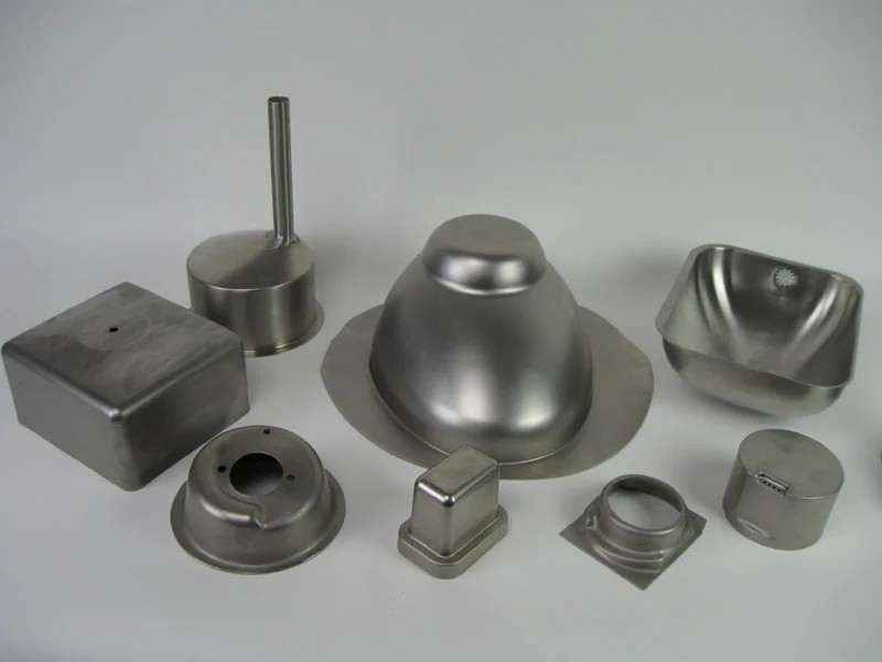
A Beading Machine for Metal Pipes is a specialized forming machine used to create beads—raised circular ridges or rings—on the outer surface of metal pipes. Beading enhances the structural strength and rigidity of the pipe ends, provides improved grip for fittings or seals, and can help prevent deformation or slipping when pipes are joined or clamped.
Beading is commonly applied in plumbing, automotive exhaust systems, HVAC ducting, and various industrial piping applications where secure connections and resistance to mechanical stress are essential. The raised beads also assist in creating tight seals when used with rubber gaskets or O-rings, improving leak resistance.
Beading machines operate by applying controlled pressure through rollers, dies, or punches to form uniform beads along the circumference of the pipe. The process can be done on pipe ends or along the length of the pipe, depending on the application. Beading can vary in size, number, and pattern, tailored to specific requirements.
These machines come in different forms, including manual, hydraulic, and CNC-controlled models. Manual beading machines are suitable for small workshops or maintenance jobs, providing basic bead forming capability with hand-operated controls. Hydraulic and CNC machines offer higher precision, repeatability, and the ability to handle thicker materials and larger production volumes.
Adjustable tooling and dies allow the machine to accommodate various pipe diameters and bead sizes. Hardened tooling materials ensure durability and maintain forming quality over repeated cycles.
Modern beading machines often integrate with automated handling systems and inline inspection tools that verify bead dimensions and uniformity immediately after forming, ensuring quality control without interrupting production flow.
Safety features such as pipe clamps, guards, and emergency stops are standard to protect operators during high-force forming operations. Ergonomic designs reduce operator fatigue and enhance productivity.
In summary, beading machines are essential in metal pipe fabrication for adding strength, improving sealing, and enhancing connection reliability. Their versatility and range of capabilities make them valuable tools across many industries requiring precise and durable pipe end treatments.
Beading machines have evolved to meet the growing demands of precision and efficiency in metal pipe fabrication. CNC-controlled beading machines enable operators to program exact bead sizes, spacing, and patterns, ensuring consistent quality across large production runs. This level of control is particularly valuable in automotive and HVAC industries, where tight tolerances directly impact system performance and longevity.
Tooling advancements allow for rapid changeover between different pipe diameters and bead configurations, supporting flexible manufacturing environments and reducing downtime. High-strength, wear-resistant materials for dies and rollers extend tool life and maintain the integrity of the beads, even when working with harder metals or thicker pipe walls.
Real-time monitoring systems are increasingly integrated into beading machines, using sensors to measure forming force, bead dimensions, and material behavior during the process. This data enables immediate adjustments to prevent defects such as cracking, uneven beads, or excessive deformation, thus improving yield and reducing waste.
Safety remains a priority, with modern machines featuring comprehensive guarding, automated clamping systems to secure pipes firmly during forming, and emergency stop functions to protect operators. Ergonomic designs and user-friendly interfaces minimize operator fatigue and simplify setup, enhancing productivity.
Automation plays a growing role in beading operations, with robotic arms or conveyors handling pipe loading and unloading to reduce manual labor and the risk of damage. Inline inspection systems using laser or vision technology verify bead geometry and surface quality immediately after forming, allowing defective parts to be identified and removed before downstream processing.
Portable beading machines are available for fieldwork, combining lightweight design with sufficient forming power for onsite repairs or custom pipe fitting. These machines are particularly useful in maintenance scenarios where pipes cannot be transported easily.
Looking forward, beading machines will continue to integrate with Industry 4.0 technologies, allowing for seamless communication with factory control systems for production scheduling, quality tracking, and maintenance management. AI-driven process optimization will enable machines to adjust forming parameters dynamically based on material variations or environmental factors, further enhancing product quality and equipment longevity.
Energy-efficient designs will also be emphasized, incorporating hydraulic systems with energy recovery, servo motors, and smart controls to minimize power consumption without compromising performance.
Overall, beading machines are vital for creating durable, high-quality pipe ends that improve connection integrity and mechanical strength. Their ongoing development in automation, precision, and connectivity ensures they remain indispensable tools in modern metal pipe manufacturing.
Future advancements in beading machine technology are expected to focus heavily on increasing customization capabilities and integration with other pipe fabrication processes. As manufacturers face growing demands for bespoke piping solutions, beading machines will incorporate more adaptable tooling systems capable of producing complex bead profiles, multiple bead patterns in a single cycle, and variable bead sizes on different sections of the same pipe.
The combination of beading with other end-forming operations, such as flaring, necking, or swaging, will be streamlined through modular machine designs or integrated multi-function systems. This will reduce handling and setup time, improving efficiency and reducing overall production costs.
Robotics and artificial intelligence will further enhance beading operations. Collaborative robots (cobots) may assist human operators in loading and unloading pipes, performing quality inspections, or even making minor adjustments during forming. AI-powered analytics will provide insights into machine performance, predicting tool wear and scheduling maintenance proactively, thereby reducing unexpected downtime.
Material innovations, including the use of advanced high-strength alloys and composite pipes, will challenge beading machines to adapt their forming techniques. Hybrid forming processes combining mechanical pressure with localized heating or vibration may emerge to handle these tougher materials without compromising bead quality.
Sustainability will play a larger role in beading machine development. Manufacturers will seek machines with reduced energy consumption, lower hydraulic fluid use, and environmentally friendly manufacturing processes. Machines designed for easy disassembly and recycling of components will support circular economy goals.
User interfaces will become increasingly intuitive, utilizing augmented reality (AR) or virtual reality (VR) for operator training, setup guidance, and troubleshooting. Such immersive technologies will shorten learning curves, reduce errors, and enhance safety.
In production environments, the integration of beading machines into smart factory ecosystems will allow real-time monitoring of every pipe’s forming history, material batch, and inspection data. This traceability will ensure compliance with strict industry standards and facilitate quality assurance across global supply chains.
In conclusion, beading machines will continue to evolve as highly flexible, intelligent, and energy-efficient tools that deliver precise, reliable bead formations. Their role in reinforcing pipe ends and improving connection integrity will remain critical across diverse industries, from automotive and HVAC to oil and gas, aerospace, and beyond.
Groove Rolling Machine For Metal Pipes
A Groove Rolling Machine for Metal Pipes is a specialized machine designed to form grooves or channels on the outer surface or ends of metal pipes. These grooves are critical for various pipe joining methods, including coupling connections, sealing, and enhancing mechanical grip. Groove rolling improves the pipe’s ability to form secure, leak-proof joints, often used in plumbing, fire protection systems, oil and gas pipelines, and HVAC installations.
The groove rolling process involves passing the pipe through a set of rollers or dies that exert controlled pressure to plastically deform the pipe’s surface, creating a precise and uniform groove. The grooves can vary in shape, size, and depth, depending on the pipe specifications and the type of joint or fitting required.
Groove rolling machines come in manual, hydraulic, and CNC-controlled models. Manual groove rolling machines are typically used for on-site or small-scale operations, offering portability and straightforward operation for basic groove profiles. Hydraulic and CNC machines provide higher accuracy, repeatability, and the ability to handle a wide range of pipe diameters, wall thicknesses, and groove designs, making them suitable for high-volume manufacturing.
Adjustable tooling and dies allow groove rolling machines to accommodate various pipe sizes and groove configurations. The tooling is typically made of hardened steel or other wear-resistant materials to withstand the repetitive high-pressure forming process and maintain groove precision over long production runs.
Safety features such as clamping mechanisms, protective guards, and emergency stop functions are standard on modern machines to ensure operator protection during the high-force rolling process. Ergonomic controls and user-friendly interfaces improve operator comfort and efficiency.
Advanced groove rolling machines may include sensor systems to monitor forming force, groove dimensions, and pipe position in real time. This feedback allows for immediate adjustments to maintain quality and prevent defects such as over-rolling or surface cracking.
Integration with automated material handling systems and inline inspection equipment further enhances productivity and quality assurance. Automated loading and unloading reduce manual labor and the risk of pipe damage, while inline inspection tools verify groove dimensions and surface finish, ensuring conformance to industry standards.
Portable groove rolling machines are available for field applications where pipes cannot be transported to a workshop. These machines combine compact size with sufficient forming power, enabling maintenance and repair work on-site.
Looking forward, groove rolling machines are evolving with increasing automation, digital control, and connectivity. CNC and servo-driven systems allow for programmable groove profiles and rapid changeover between pipe sizes. Integration with Industry 4.0 platforms enables real-time process monitoring, predictive maintenance, and production data analytics.
In summary, groove rolling machines are essential in metal pipe fabrication for creating precise, consistent grooves that facilitate secure pipe connections. Their adaptability, accuracy, and growing automation make them indispensable across many industrial sectors requiring reliable, leak-resistant piping systems.
Groove rolling machines have become increasingly sophisticated with the integration of digital controls and automation technologies. Modern CNC groove rolling machines allow manufacturers to program complex groove profiles with high precision, ensuring that each groove meets stringent specifications necessary for reliable pipe joining. This level of control is especially important in industries such as oil and gas, where safety and durability are critical.
Tooling systems in these machines have been designed for rapid changeover, enabling quick adjustments to accommodate different pipe diameters, wall thicknesses, and groove types. This flexibility supports just-in-time manufacturing and reduces downtime, which is vital in high-volume production environments.
Real-time monitoring and feedback systems play a crucial role in maintaining groove quality. Sensors measure parameters like forming force, groove depth, and pipe alignment, providing data that helps operators and automated systems make immediate adjustments. This adaptive capability minimizes defects such as uneven grooves, surface damage, or material thinning, thereby reducing scrap and rework.
Safety remains a top priority in groove rolling operations. Machines are equipped with features like automated clamping to secure pipes firmly, comprehensive guarding, and emergency stop functions to protect operators during the high-force forming process. Ergonomic designs and intuitive interfaces contribute to a safer and more efficient work environment.
Automation is also extending to material handling. Robotic arms, conveyors, and automated feeders are increasingly used to load and unload pipes, improving throughput while reducing manual labor and the risk of damage to the pipes. Inline inspection systems, including laser scanning and vision technologies, verify groove dimensions and surface integrity immediately after forming, ensuring quality without interrupting production.
Portable groove rolling machines have been developed to serve field maintenance and repair needs. These units are designed to be compact and robust, allowing operators to perform groove rolling on-site where moving pipes to a workshop is impractical. Battery-powered or hydraulically driven models enhance mobility and ease of use in remote or constrained locations.
Looking to the future, groove rolling machines will continue to advance with enhanced connectivity to factory networks. Integration with manufacturing execution systems (MES) and enterprise resource planning (ERP) software will provide comprehensive data on production rates, machine health, and quality metrics. This connectivity supports predictive maintenance strategies that reduce downtime and extend equipment life.
Material innovations, including the use of advanced alloys and composite pipes, will push groove rolling machines to adopt new forming techniques, such as hybrid mechanical-thermal processes, to handle materials with varying ductility and strength without compromising groove quality.
Energy efficiency will also be a focus, with manufacturers seeking machines that optimize power use through advanced hydraulic systems, regenerative drives, and smart control algorithms. These improvements contribute to lower operating costs and environmental impact.
In essence, groove rolling machines are evolving into highly adaptable, intelligent systems capable of producing precise, durable grooves essential for safe and effective pipe connections. Their role in metal pipe fabrication will remain critical as industries demand ever higher standards of quality, efficiency, and traceability.
Future developments in groove rolling machines will likely emphasize greater integration with automated production lines and smart factory ecosystems. As industries move toward fully digitalized manufacturing, groove rolling machines will be equipped with enhanced sensors and AI-driven controls that enable self-optimization of forming parameters based on real-time data. This means machines can adjust force, speed, and tooling positions dynamically to compensate for variations in pipe material properties or environmental conditions, ensuring consistent groove quality across batches.
Modular machine designs will become more prevalent, allowing manufacturers to customize groove rolling setups for specific applications or rapidly switch between different groove profiles without extensive downtime. This adaptability supports diverse production requirements—from small batches of specialized pipes to large-scale runs—making groove rolling machines more versatile and cost-effective.
Robotics will play an increasing role not only in pipe handling but also in tool maintenance and changeover. Automated tool changers and robotic inspection systems will streamline production and minimize manual intervention, reducing labor costs and improving safety.
The ability to handle new materials will expand as groove rolling machines incorporate hybrid forming techniques, such as combining mechanical rolling with localized induction heating or ultrasonic vibration. These technologies reduce forming stresses and improve groove precision on difficult-to-form alloys or layered composite pipes, broadening the range of pipes that can be efficiently processed.
Sustainability initiatives will drive the development of energy-efficient machines with low hydraulic fluid consumption, regenerative energy systems, and recyclable components. Manufacturers will also focus on reducing noise and vibration levels to create better working environments.
Advanced user interfaces utilizing augmented reality (AR) and virtual reality (VR) will assist operators in machine setup, maintenance, and troubleshooting by providing interactive, real-time guidance. This technology will accelerate training and reduce human errors.
Data analytics and cloud connectivity will enable seamless tracking of groove rolling operations, integrating production data with supply chain and quality management systems. This end-to-end traceability is essential for industries with strict regulatory requirements, such as aerospace, petrochemical, and nuclear sectors.
In summary, groove rolling machines are evolving into smart, flexible, and sustainable tools integral to modern pipe manufacturing. Their continuous advancement ensures that manufacturers can meet the increasing demands for precision, efficiency, and reliability in creating grooves essential for secure pipe connections across a broad spectrum of industries.
Flattening Edges Machine For Metal Pipes
A Flattening Edges Machine for Metal Pipes is a specialized forming machine designed to flatten or level the edges or ends of metal pipes. This process is essential in preparing pipes for subsequent fabrication steps such as welding, joining, or fitting, where smooth, even edges ensure better contact, improved sealing, and reduced risk of damage or leakage.
Flattening the edges removes irregularities, burrs, or slight deformities that may occur during cutting or handling, providing a clean, uniform surface. This is particularly important in industries like plumbing, automotive exhaust systems, HVAC, and structural applications, where precision and quality of pipe ends directly impact the integrity and performance of the final assembly.
Flattening machines work by applying controlled mechanical pressure using rollers, presses, or flattening plates that compress the pipe ends without damaging the pipe’s overall shape or structure. The process can be done on various pipe materials such as steel, stainless steel, aluminum, copper, or other alloys, depending on the machine’s capabilities.
Different designs exist, from manual and semi-automatic to fully automated flattening edge machines. Manual machines are generally suitable for small workshops or repair tasks, allowing operators to position the pipe and apply force by hand or simple mechanical leverage. Semi-automatic and fully automatic machines use hydraulic or servo-driven systems to provide consistent pressure and precise control, enabling higher production rates and uniform results.
Adjustable settings allow the machine to accommodate different pipe diameters, wall thicknesses, and desired flattening lengths. Hardened tooling components ensure durability and maintain flatness accuracy over prolonged use.
Safety features are integrated to protect operators during the pressing or rolling process, including pipe clamps to secure the pipe, protective guards, and emergency stop mechanisms.
Modern flattening edge machines may be integrated with other pipe processing equipment, such as cutting, beveling, or end-forming machines, creating streamlined production lines that minimize handling and increase throughput.
Quality control is often supported by inline measurement systems that check edge flatness, dimensions, and surface finish immediately after flattening, ensuring compliance with specifications and reducing the risk of defects in downstream processes.
Portable versions of flattening machines enable on-site maintenance or fabrication work where pipes cannot be easily transported.
Looking forward, these machines will increasingly incorporate digital controls, real-time monitoring, and automation to improve precision, repeatability, and efficiency. Integration with Industry 4.0 systems will allow data tracking for traceability and predictive maintenance, supporting continuous production improvements.
In summary, flattening edges machines are vital tools in metal pipe fabrication, ensuring pipe ends are properly prepared for high-quality connections and assemblies. Their versatility and evolving technology make them indispensable in a variety of manufacturing and repair applications.
Flattening edges machines have seen considerable advancements in automation and precision control to meet the demands of modern pipe fabrication. CNC-controlled flattening systems allow operators to program specific flattening lengths and pressures for different pipe sizes and materials, ensuring consistent edge quality across production batches. This level of precision is crucial in applications where flatness tolerances directly affect joint integrity, such as in pressure vessels and automotive exhaust systems.
The machines utilize hydraulic or servo-driven actuators to apply uniform force, reducing the risk of over-flattening or creating unwanted distortions. Adjustable tooling and dies enable quick changeovers, accommodating a wide range of pipe diameters and wall thicknesses with minimal downtime. Hardened flattening plates and rollers ensure longevity and maintain surface quality, even when processing abrasive or hard metals.
Safety enhancements include automatic clamping systems that securely hold pipes during flattening, preventing slippage and ensuring operator protection. Protective guards and emergency stop features are standard, complying with industrial safety regulations.
Integration with upstream and downstream equipment—such as pipe cutting, beveling, or welding stations—allows flattening machines to form part of continuous, automated production lines. This seamless workflow minimizes manual handling, reducing the chance of damage and increasing throughput.
Real-time monitoring technologies, including force sensors and laser measurement systems, provide feedback during flattening to detect inconsistencies or defects immediately. This data enables operators to adjust parameters on the fly, maintaining high-quality standards and reducing scrap rates.
Portable flattening machines are also available for fieldwork, offering compact designs with sufficient flattening power for on-site repairs or custom fitting jobs. These models often feature battery-powered hydraulics or manual mechanical systems for use in remote locations.
Looking ahead, flattening edge machines will increasingly leverage smart manufacturing technologies. Machine learning algorithms will analyze process data to optimize flattening parameters for varying pipe materials and conditions, further improving consistency and efficiency. Connectivity with factory-wide digital systems will allow remote diagnostics, predictive maintenance, and production analytics.
Energy efficiency will be enhanced through the use of servo motors and regenerative hydraulic systems, reducing power consumption and environmental impact. User interfaces will become more intuitive, utilizing touchscreen controls and augmented reality assistance for setup and troubleshooting.
Overall, flattening edges machines remain essential for producing pipes with precise, uniform ends that enable strong, reliable joints. Their continuous evolution in automation, safety, and integration ensures they meet the growing challenges of modern metal pipe manufacturing and assembly.
Future innovations in flattening edges machines will likely focus on increasing flexibility to handle a broader range of pipe sizes, shapes, and materials—including complex alloys and composite pipes. Adaptive tooling systems that automatically adjust flattening pressure and contact surfaces based on real-time measurements will reduce setup time and enhance quality control. This adaptability will be particularly valuable in industries requiring frequent changeovers or custom pipe specifications, such as aerospace or specialized industrial piping.
The integration of advanced sensors, such as ultrasonic or optical scanners, will enable machines to detect minute surface imperfections or internal stresses before and after flattening. This capability will help prevent defects that could compromise pipe integrity during welding or other joining processes. Coupled with AI-powered analytics, the machines could suggest optimal flattening strategies tailored to the material and pipe geometry, minimizing manual intervention.
Collaborative robots (cobots) are expected to become more common in flattening operations, assisting with pipe handling, positioning, and quality inspections. This will reduce operator fatigue and enhance safety, particularly when dealing with heavy or awkwardly shaped pipes.
Environmental sustainability will drive the development of greener flattening machines. Innovations may include reduced hydraulic fluid use, adoption of biodegradable lubricants, and energy-efficient drive systems that lower the overall carbon footprint of pipe fabrication.
Remote monitoring and control through cloud connectivity will allow operators and maintenance teams to access machine status and performance data from anywhere, enabling faster troubleshooting and minimizing downtime. Predictive maintenance, powered by machine learning models, will forecast potential failures or wear on key components, ensuring timely interventions before breakdowns occur.
Augmented reality (AR) and virtual reality (VR) tools will transform operator training and machine setup, providing immersive, hands-on experiences without the risks associated with live equipment. These technologies will also support remote expert assistance, allowing specialists to guide onsite operators through complex adjustments or repairs in real time.
In summary, flattening edges machines are evolving into highly intelligent, adaptable, and eco-friendly tools that underpin high-quality metal pipe fabrication. Their continuous innovation ensures they remain pivotal in producing precise pipe ends that facilitate strong, reliable connections essential to modern industrial applications.
Hem Forming Machine For Metal Pipes
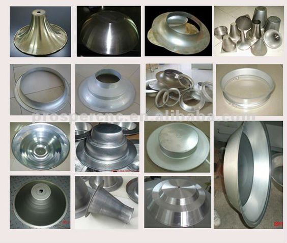
A Hem Forming Machine for Metal Pipes is a specialized type of forming equipment used to create hems or folded-over edges on the ends of metal pipes. This hemming process involves bending or rolling the pipe end back onto itself—either partially or fully—to create a smooth, rounded edge. The purpose of hemming is both functional and aesthetic: it strengthens the pipe end, eliminates sharp edges, and improves safety and sealing characteristics in applications where the pipe connects to other components or must be handled frequently.
Hem forming is common in automotive exhaust systems, ventilation ducts, industrial piping, and architectural applications where pipe ends are visible or interact with seals, gaskets, or other assemblies. The process can also serve as preparation for further joining techniques, such as crimping or welding.
These machines typically operate by clamping the pipe in place and then using rollers, dies, or segmented tooling to fold the edge of the pipe inward to a predetermined radius. Depending on the desired hem style, machines can produce either open hems (a simple, partially folded lip) or closed hems (a complete fold creating a double wall at the edge). The forming operation is performed with high precision to maintain dimensional accuracy and surface finish.
Modern hem forming machines are often CNC-controlled, allowing for programmable control of pipe diameter, hem depth, and folding force. This ensures consistent results across different pipe sizes and materials, including mild steel, stainless steel, aluminum, and copper alloys. Tooling is typically interchangeable or adjustable, allowing for quick reconfiguration between production runs.
Hydraulic or servo-electric drives are used to apply smooth, controlled pressure during hemming, minimizing deformation of the pipe body while achieving the desired edge shape. These systems are designed to maintain repeatability and prevent defects like cracking or uneven folds, especially in thin-walled pipes.
Advanced machines may include real-time feedback systems that monitor forming pressure, pipe positioning, and hem geometry during the process. This allows for on-the-fly corrections and quality assurance. Integration with laser or camera-based inspection systems ensures each hem meets specifications without requiring manual measurement or visual inspection.
Safety features such as automatic clamping, protective enclosures, and programmable emergency stops are built into modern hem forming machines to safeguard operators during high-force operations.
As with other pipe-forming machines, hem forming units are increasingly integrated into automated production lines, often operating in tandem with cutting, flaring, or end-forming equipment. Robotic handling systems can further streamline operations by automatically loading and unloading pipes, enabling high throughput and reduced labor requirements.
Looking ahead, developments in machine learning and material data integration will allow hem forming machines to adjust parameters dynamically based on the properties of each incoming pipe. This ensures optimal fold quality regardless of material inconsistencies or batch variations.
In summary, a hem forming machine for metal pipes is an essential tool in industries that demand clean, reinforced, and safe pipe ends. Through precise folding and modern automation, these machines contribute significantly to product durability, safety, and overall manufacturing efficiency.
Hem forming machines for metal pipes are expected to continue evolving as manufacturers demand greater precision, speed, and adaptability. One major advancement is the incorporation of intelligent automation systems that enable the machine to recognize pipe dimensions and material characteristics automatically, adjusting the hemming parameters in real time. This eliminates the need for manual setup and reduces downtime between production runs, which is particularly valuable in mixed-batch manufacturing environments.
Servo-driven hemming units are increasingly preferred over traditional hydraulic systems due to their precise motion control, energy efficiency, and lower maintenance requirements. These servo systems allow for smoother transitions during the folding operation, which is critical when working with thin-walled or delicate materials that are prone to deformation or cracking. By precisely controlling the speed and force of the fold, these machines can create tight, uniform hems that maintain the pipe’s structural integrity and appearance.
To further enhance quality, some hem forming machines are now equipped with integrated vision systems that use cameras and laser scanners to verify the shape, symmetry, and surface finish of the hem immediately after forming. These systems can detect even minor defects such as incomplete folds, wrinkling, or excessive edge stress. The machine can then automatically compensate for these issues in subsequent cycles, ensuring consistent output and reducing scrap.
In high-volume production environments, robotic arms are often deployed to feed and extract pipes from the hemming station, allowing the machine to operate continuously without manual intervention. These robots can also reorient pipes between hemming and other processing stages such as crimping, notching, or end forming, supporting a fully integrated and automated production cell.
Tooling flexibility is another area of improvement. Modern machines use modular tooling systems with quick-change capabilities, allowing operators to switch between hem profiles or pipe diameters within minutes. This boosts productivity, especially in industries like automotive or HVAC, where multiple pipe variants may be produced in the same facility.
Advanced data logging features are also becoming standard, enabling complete traceability of each pipe’s forming parameters. This is vital for industries that require stringent documentation for quality control and compliance. Data can be stored locally or uploaded to cloud-based platforms for analysis, allowing manufacturers to identify trends, optimize machine performance, and plan predictive maintenance.
Environmental considerations are also shaping the design of new hem forming machines. More energy-efficient motors, reduced fluid consumption, and quieter operation are being prioritized to meet sustainability goals and improve working conditions on the factory floor.
Future hem forming machines may incorporate AI algorithms capable of learning optimal forming strategies for new materials or geometries through trial cycles, minimizing the time needed for new product development. Augmented reality could also assist operators in performing setup, maintenance, or diagnostics, reducing training requirements and minimizing human error.
Ultimately, hem forming machines are becoming smarter, faster, and more versatile—capable of producing precisely folded pipe ends that improve safety, appearance, and performance across a wide range of applications. As these technologies mature, they will continue to play a critical role in efficient and high-quality metal pipe production.
Emerging trends in hem forming technology also focus on expanding the range of pipe materials and thicknesses that machines can handle. With the increasing use of advanced alloys, composites, and coated pipes in sectors like aerospace, automotive, and energy, hem forming machines must accommodate different mechanical properties, such as varying ductility and surface hardness. This requires more adaptive force control and specialized tooling materials to prevent damage or surface defects during hemming.
The push towards miniaturization and precision in industries such as medical devices and microfluidics means hem forming machines are also being engineered to work with very small-diameter pipes and tubes. This demands extremely fine control over forming forces and tooling geometry to achieve clean, consistent hems without compromising the pipe’s internal diameter or causing cracks.
In terms of integration, hem forming machines are increasingly combined with other pipe end-processing equipment into multifunctional cells. For example, a single automated station might perform cutting, hemming, flaring, and inspection sequentially, reducing handling and streamlining production flow. Such systems utilize advanced robotics and centralized control software that coordinates all processes, enabling just-in-time manufacturing and fast product changeover.
Maintenance and uptime improvements are supported by predictive analytics and sensor networks embedded in the machines. Real-time monitoring of critical components like hydraulic pumps, servo motors, and tooling wear allows for early detection of issues before breakdowns occur. This proactive maintenance reduces downtime and repair costs, essential for high-throughput industrial operations.
Additionally, as manufacturing moves towards more sustainable practices, designers of hem forming machines are exploring ways to minimize waste and energy use. This includes optimizing forming processes to reduce material stress and the need for secondary finishing, using recyclable tooling materials, and implementing energy recovery systems within the machine’s drive units.
Operator safety and ergonomics remain a priority. New machine designs feature enhanced guarding, touchless operation modes, and simplified interfaces that reduce physical strain and exposure to hazards. Remote operation capabilities are also being developed, allowing operators to control machines from safe distances or centralized control rooms.
The integration of digital twins—virtual models that replicate the physical machine and process—is another forward-looking development. Digital twins allow engineers to simulate hemming operations, predict outcomes, and optimize parameters without interrupting production. This accelerates process development and reduces trial-and-error on the shop floor.
In conclusion, the future of hem forming machines for metal pipes is shaped by advancements in automation, material science, connectivity, and sustainability. These innovations will enable manufacturers to produce high-quality, reliable hems across a diverse array of pipe types and applications, meeting the evolving demands of modern industry with greater efficiency and precision.
Fluting Machine For Metal Pipes
A Fluting Machine for Metal Pipes is a specialized machine designed to create flutes—longitudinal grooves or channels—on the surface of metal pipes. Fluting involves forming evenly spaced, parallel indentations along the pipe’s length or circumference, which can enhance the pipe’s mechanical properties, aesthetics, or functional performance.
Fluting machines serve several important purposes:
- Structural Strengthening: Flutes increase the pipe’s rigidity and resistance to bending or crushing forces without significantly increasing weight. This is particularly valuable in lightweight structural applications or where enhanced load-bearing capacity is needed.
- Improved Grip or Surface Area: The fluted surface provides better grip for coatings, adhesives, or insulation materials, improving bonding or coverage.
- Aesthetic Enhancement: Fluted pipes are often used decoratively in architectural, furniture, or automotive applications due to their distinctive textured appearance.
- Fluid Dynamics: In some heat exchanger or fluid transport systems, fluted surfaces can improve turbulence and heat transfer characteristics.
The fluting process typically involves rolling or pressing the pipe between specially shaped rollers or dies that imprint the desired flute pattern. The machine must maintain precise control of the rolling force, speed, and alignment to produce uniform flutes without damaging the pipe wall or altering its overall dimensions excessively.
Fluting machines come in various configurations depending on pipe size, flute pattern complexity, and production volume. Some use multiple rollers arranged to simultaneously form several flutes, while others employ a single roller that moves incrementally along the pipe’s surface.
Advanced fluting machines may be CNC-controlled to adjust flute depth, pitch (spacing), and width according to specific design requirements. This flexibility allows for customization in both functional and decorative pipe applications.
Material handling systems such as powered feeders and pipe supports ensure smooth pipe movement through the fluting station, minimizing surface scratches and misalignment.
Depending on the pipe material and thickness, fluting machines may incorporate cooling systems or lubrication to prevent overheating and reduce tool wear during the forming process.
Quality control is often integrated via sensors or optical scanners that measure flute depth and uniformity in real-time, enabling immediate corrections to maintain tight tolerances.
Safety features include guards around moving parts, emergency stops, and secure pipe clamping mechanisms to protect operators during operation.
Fluting machines can be standalone units or part of automated production lines combining cutting, forming, and finishing processes, increasing efficiency and consistency.
In summary, fluting machines for metal pipes provide an effective method for adding structural and aesthetic features through precision groove formation. Their adaptability and precision make them valuable in industries ranging from construction and automotive to HVAC and decorative metalwork.
Fluting machines for metal pipes are increasingly being designed with advanced automation to meet the demands of high-volume production and complex flute patterns. Modern systems use computer numerical control (CNC) to precisely program flute dimensions and spacing, allowing manufacturers to easily switch between different pipe specifications and flute designs without manual adjustments. This flexibility is especially important in industries like automotive and aerospace, where custom surface textures can enhance performance or meet aesthetic requirements.
The drive mechanisms in these machines have evolved from purely mechanical setups to servo-electric or hydraulic systems that offer smoother, more controllable rolling actions. These systems reduce the risk of pipe deformation or surface damage during fluting, ensuring consistent groove quality even on thin-walled or high-strength alloy pipes. Servo control also enables variable flute depths and patterns along the length of a single pipe, allowing for functional gradation tailored to specific engineering needs.
Integrated sensors and real-time monitoring systems are now common, allowing the machine to continuously measure flute depth, width, and uniformity as the pipe passes through the rollers. If deviations occur, the machine can automatically adjust forming parameters on the fly, reducing scrap rates and improving overall product quality. These feedback systems often use laser profilometers or optical scanners, providing non-contact, high-precision measurements that do not interfere with production speed.
For handling pipes safely and efficiently, modern fluting machines are equipped with automated loading and unloading systems, often coordinated with robotic arms or conveyor setups. These systems minimize manual handling, reducing operator fatigue and risk of injury while increasing throughput. Coupled with centralized control software, the entire fluting process can be integrated seamlessly into a smart factory environment.
To address environmental and operational concerns, newer fluting machines emphasize energy efficiency through the use of servo motors and regenerative braking systems. These technologies lower power consumption and reduce heat generation during operation, extending tool life and lowering maintenance needs. Additionally, lubrication systems are optimized to minimize waste and avoid contamination of finished pipe surfaces.
Material versatility is another focus area. Advances in tooling materials and surface coatings allow fluting machines to process increasingly hard or coated pipes without excessive wear or damage. Specialized rollers and dies made from carbide or ceramic composites maintain sharp flute profiles even under heavy production loads.
In specialty applications, fluting machines may be designed to create non-traditional flute shapes—such as helical grooves or varying cross-sectional profiles—to meet specific aerodynamic, structural, or fluid dynamic requirements. These complex fluting patterns are made possible by multi-axis CNC control and custom tooling designs.
Safety features continue to improve, with modern machines including light curtains, interlocked guards, and emergency stop systems that comply with the latest industry regulations. Operator interfaces are becoming more user-friendly, featuring touchscreen displays, intuitive menus, and diagnostic tools that simplify machine setup and troubleshooting.
Future developments in fluting technology are likely to incorporate artificial intelligence to optimize flute patterns for maximum performance based on pipe material, size, and intended use. Digital twin simulations could enable manufacturers to virtually test and perfect flute designs before committing to physical production, reducing development costs and lead times.
Overall, fluting machines for metal pipes have become highly sophisticated tools that blend precision engineering, automation, and smart technology. They play a crucial role in enhancing pipe functionality and aesthetics across a diverse range of industries, continually adapting to evolving manufacturing needs and standards.
Looking ahead, the integration of Industry 4.0 concepts into fluting machines is set to revolutionize how these systems operate within smart manufacturing ecosystems. Fluting machines will increasingly communicate with other production equipment, sharing data on pipe dimensions, material characteristics, and process parameters in real time. This interconnectedness enables adaptive process control across the entire production line, where upstream and downstream machines can adjust their operations based on fluting quality feedback, ensuring seamless workflow and minimal rework.
Advanced analytics and machine learning algorithms will analyze historical and real-time data from fluting operations to predict tool wear, schedule maintenance proactively, and optimize process parameters for new materials or pipe geometries. This predictive capability will extend tool life, reduce unscheduled downtime, and improve overall equipment effectiveness (OEE).
Customization and small-batch production will become more economically viable as fluting machines adopt modular tooling and rapid-change mechanisms. This will allow manufacturers to respond quickly to market demands for bespoke pipe designs, including unique flute patterns that combine functional and decorative elements. Additive manufacturing techniques may even be used to produce complex tooling components with optimized shapes and materials that enhance forming precision and durability.
Environmental sustainability will remain a key driver, prompting the development of fluting machines that minimize energy consumption and material waste. For example, energy-efficient servo drives combined with regenerative energy recovery systems will reduce operational costs and carbon footprints. Additionally, eco-friendly lubricants and dry-forming techniques may be further explored to eliminate fluid disposal issues and improve workplace safety.
Augmented reality (AR) and virtual reality (VR) technologies are anticipated to play a larger role in operator training, machine setup, and maintenance support. By overlaying digital information on physical equipment, AR can guide technicians through complex tasks, reducing errors and downtime. Remote assistance through VR platforms will enable experts to diagnose and resolve issues from anywhere in the world, accelerating problem-solving and minimizing production interruptions.
In niche sectors such as biomedical, aerospace, and microelectronics, fluting machines will be engineered to handle ultra-fine pipes and tubes with extremely tight tolerances. Precision control systems and vibration-damping technologies will be employed to maintain flute consistency at micro scales, where traditional mechanical approaches are insufficient.
Collaborative robots (cobots) will increasingly be integrated with fluting systems to assist in material handling, inspection, and packaging. These robots work safely alongside human operators, enhancing productivity while maintaining flexibility for varied production tasks.
Ultimately, the future of fluting machines for metal pipes lies in their ability to blend mechanical ingenuity with digital intelligence. By harnessing cutting-edge automation, real-time analytics, and human-machine collaboration, these machines will deliver higher quality, greater customization, and more sustainable manufacturing solutions, empowering industries to meet the complex challenges of tomorrow’s markets with confidence and efficiency.
Curling Edges Machine For Metal Pipes
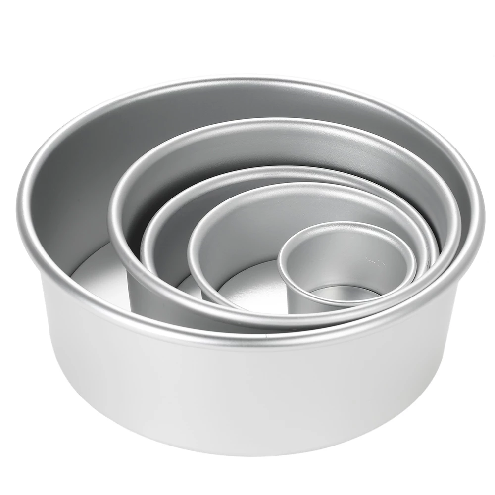
A Curling Edges Machine for Metal Pipes is specialized equipment used to curl or roll the edges of metal pipes to form a smooth, rounded lip along the pipe’s end. This curling process involves bending the pipe edge outward or inward into a curved shape, which serves multiple functional and aesthetic purposes.
Curling edges on metal pipes enhances the structural integrity of the pipe end by strengthening it and reducing the risk of deformation during handling or assembly. It also eliminates sharp edges that can cause injury or damage to adjacent components. Additionally, curled edges facilitate easier joining or sealing when pipes are connected with flanges, gaskets, or other fittings.
The curling process is typically achieved by feeding the pipe edge between rotating rollers or dies shaped to gradually bend the metal into a consistent curve. The machine controls factors such as curling radius, edge thickness, and curl length to produce precise, repeatable results tailored to the pipe’s material, diameter, and wall thickness.
Curling edge machines vary widely depending on pipe size, material, and production volume. Smaller, manually operated machines are used for low-volume or custom work, while large automated systems handle high-throughput industrial production with integrated feeding, curling, and unloading stations.
Modern curling machines may feature CNC controls that allow operators to program specific curling parameters, ensuring consistent edge profiles across different pipe batches and reducing setup times. Servo-driven rollers provide smooth, adjustable force to avoid cracking or wrinkling, especially on thin-walled or high-strength pipes.
Some curling machines can produce different curl types—such as single curls, double curls (rolled twice for extra strength), or flared curls—depending on the application requirements. Interchangeable tooling and adjustable roller spacing allow flexibility in producing these variations.
To maintain quality, many machines incorporate sensors that monitor curling force, roller alignment, and pipe positioning in real time. This helps prevent defects and ensures uniformity of the curled edge.
Safety features like automatic pipe clamping, protective guarding around moving parts, and emergency stop mechanisms are standard to protect operators during high-force curling operations.
Curling edge machines are often integrated into automated pipe finishing lines, working in sequence with cutting, flaring, hemming, or coating processes to optimize production efficiency and consistency.
In summary, curling edges machines for metal pipes provide a crucial finishing step that improves pipe durability, safety, and compatibility with other components. Through precise, controlled forming, these machines help manufacturers meet stringent quality standards and diverse application needs across industries such as automotive, construction, HVAC, and plumbing.
Curling edge machines continue to evolve with advancements in automation, precision control, and adaptability. Modern machines incorporate servo motors and CNC programming, allowing operators to customize curling parameters easily for different pipe sizes, materials, and wall thicknesses. This level of control helps avoid common issues like cracking, wrinkling, or uneven curls, especially when working with delicate or high-strength alloys.
In automated production environments, curling machines are often integrated with robotic loading and unloading systems. These systems reduce manual handling, improve throughput, and enhance workplace safety. Automated feeders ensure pipes are consistently positioned for precise curling, while sensors monitor the curling process in real time to detect any irregularities and trigger corrective actions immediately.
Advanced curling machines may also feature modular tooling systems with quick-change rollers or dies. This flexibility allows manufacturers to switch between different curl profiles or pipe diameters with minimal downtime, which is particularly beneficial in facilities producing a variety of pipe types or small batch runs.
The integration of real-time quality inspection technologies, such as laser measurement or machine vision systems, enables continuous monitoring of the curl dimensions and surface finish. Defective products can be identified instantly, ensuring that only pipes meeting strict quality criteria proceed further down the production line. This not only reduces waste but also enhances customer satisfaction by maintaining consistent product standards.
Energy efficiency is a growing consideration in curling machine design. The adoption of servo-driven systems over traditional hydraulic units reduces power consumption and maintenance requirements. Additionally, some machines incorporate energy recovery systems that capture and reuse braking energy from the rollers, further improving overall efficiency.
Environmental and operator safety concerns have led to improved machine enclosures, noise reduction measures, and the use of non-toxic lubricants or dry processing techniques. Ergonomic designs and user-friendly interfaces also minimize operator fatigue and training time, allowing for safer and more productive operation.
Looking toward the future, curling edge machines may incorporate artificial intelligence to optimize curling parameters dynamically based on pipe material properties, ambient conditions, or tool wear. Digital twin simulations could allow manufacturers to virtually test curl profiles before physical production, shortening development cycles and reducing trial scrap.
Integration with Industry 4.0 platforms will enable these machines to communicate seamlessly with upstream and downstream equipment, facilitating fully automated, smart pipe manufacturing lines. Data analytics from the curling process will contribute to predictive maintenance schedules, quality improvements, and overall process optimization.
In specialized industries, such as aerospace or medical device manufacturing, curling machines are being refined to handle ultra-thin or complex alloy pipes requiring extremely precise, defect-free curls. Innovations in tooling materials and forming methods ensure delicate pipes maintain structural integrity while achieving the desired curl shape.
Overall, curling edge machines for metal pipes are becoming more intelligent, efficient, and versatile. They remain essential in delivering finished pipe products that are safe to handle, easy to assemble, and structurally sound, supporting a wide range of industrial applications with growing demands for quality, customization, and sustainability.
Further advancements in curling edge machines focus on increasing their adaptability to diverse pipe materials, including stainless steel, aluminum alloys, copper, and even some non-metallic composites. Each material poses unique challenges such as varying ductility, hardness, and surface finish sensitivity, requiring curling machines to fine-tune force application and rolling speeds carefully. Innovations in roller surface coatings—like diamond-like carbon (DLC) or ceramic layers—help reduce friction and wear, enabling smoother curling on difficult materials while extending tool life.
Another important trend is the miniaturization of curling technology to handle smaller diameter tubes used in precision industries like electronics, medical devices, and instrumentation. Micro-curling machines incorporate ultra-precise servo drives, vibration isolation, and high-resolution sensors to achieve curls with microscopic accuracy without damaging delicate thin walls.
Hybrid curling processes are emerging where machines combine curling with additional edge treatments such as flaring, hemming, or bead forming in a single automated station. This reduces the number of handling steps, shortens cycle times, and ensures perfect alignment between the different edge profiles, enhancing both mechanical performance and aesthetic appeal.
Digital connectivity enhancements allow curling machines to become part of a fully connected manufacturing ecosystem. Through IoT-enabled sensors, machine performance data is uploaded to cloud platforms for comprehensive analysis. Manufacturers can track machine utilization, predict component failures, and benchmark production quality across multiple sites worldwide, leading to smarter maintenance strategies and continuous process improvement.
Safety continues to be a high priority, with curling machines now featuring advanced guarding systems combined with light curtains, area scanners, and fail-safe interlocks that stop machine operation immediately if a safety breach is detected. Operator interfaces have evolved to touchscreens with guided workflows, multi-language support, and real-time diagnostics, simplifying machine setup and troubleshooting.
Sustainability considerations influence machine design as well. Engineers are exploring lubrication-free curling methods and environmentally friendly coolants, reducing waste and chemical exposure. Energy-efficient motors and optimized mechanical transmissions help minimize carbon footprints during operation.
In terms of customization, machine manufacturers are increasingly offering modular curling systems that can be tailored with optional features such as variable-speed feeders, in-line inspection stations, or robotic handling arms. This modularity enables manufacturers to build production lines that precisely match their throughput, quality, and flexibility needs.
As manufacturing moves toward higher levels of automation and personalization, curling edge machines will play a vital role in producing pipe ends that meet exacting standards for strength, safety, and functionality. By embracing digital technologies, enhanced materials science, and ergonomic design, these machines continue to support industries in delivering superior metal pipe products efficiently and reliably.
Twisting With Tension Machine For Metal Pipes
A Twisting with Tension Machine for Metal Pipes is specialized equipment designed to apply controlled twisting (torsion) to metal pipes while simultaneously applying tension (axial force) along the pipe’s length. This combined mechanical action is used to modify the pipe’s structural and mechanical properties, achieve specific deformation patterns, or prepare pipes for specialized applications.
The primary purpose of this machine is to twist the pipe around its longitudinal axis to induce torsional stress while holding it under tension to prevent buckling, kinking, or unwanted bending. By carefully balancing twisting and tension forces, the machine can achieve uniform deformation and precise control over the pipe’s final shape and internal stress distribution.
This process is essential in applications such as:
- Producing helical grooves or patterns on pipe surfaces.
- Strengthening pipes through strain hardening by plastic deformation.
- Preparing pipes for subsequent forming operations like bending or flaring.
- Testing pipe material behavior under combined torsion and tension stresses.
- Creating decorative or functional twists for architectural or industrial use.
The machine typically consists of two main gripping stations that clamp the pipe ends. One end is connected to a motorized twisting unit that rotates the pipe at a controlled speed and angle, while the other end is held by a tensioning system that applies axial load. The tensioning can be achieved through hydraulic cylinders, servo-controlled actuators, or weighted systems, depending on precision and capacity requirements.
Advanced twisting with tension machines often feature programmable controls allowing operators to set parameters such as twist angle per unit length, tension force, twisting speed, and number of twist cycles. This programmability ensures repeatability and adaptability across different pipe materials, diameters, and thicknesses.
To prevent damage during twisting, the machine employs carefully designed clamps or mandrels that distribute gripping forces evenly, avoiding surface marring or crushing. Some setups use internal mandrels inserted into the pipe to maintain internal diameter and wall stability while twisting.
Real-time monitoring systems measure torque, tension force, angular displacement, and pipe deformation to provide feedback and maintain process control. Sensors may include load cells, rotary encoders, and laser displacement devices. Data collected helps optimize process parameters and ensure the twisted pipes meet required specifications.
Safety features are integral to these machines, including emergency stops, overload protection, and guarding around moving parts to protect operators from rotating components and high tension forces.
Twisting with tension machines are used across industries such as aerospace, automotive, construction, and pipeline manufacturing where pipes must meet stringent mechanical or aesthetic standards.
Integration into automated production lines is common, with robotic loading/unloading and quality inspection systems improving throughput and consistency.
Overall, twisting with tension machines provide a precise and controlled method to impart complex mechanical deformation in metal pipes, enhancing their performance and enabling advanced manufacturing techniques.
Twisting with tension machines continue to evolve with improvements in precision, automation, and versatility. Modern systems utilize servo-driven motors and advanced control software to finely tune the twisting speed, torque, and tension forces applied to pipes. This level of control is critical when working with high-strength alloys or thin-walled pipes, where improper handling can cause cracks, warping, or irreversible damage. The ability to program complex twisting patterns—including variable twist rates along the pipe length—allows manufacturers to produce customized pipe products tailored to specific mechanical or functional requirements.
To enhance the machine’s flexibility, many models now feature adjustable gripping heads and interchangeable mandrels, accommodating a wide range of pipe diameters and wall thicknesses without extensive setup changes. Some designs even support simultaneous twisting of multiple pipes in batch processing, significantly increasing throughput for high-volume operations.
Real-time feedback through integrated sensors measuring torque, tension, angular displacement, and pipe deflection enables closed-loop control, ensuring process consistency and immediate correction of deviations. This data is often linked to factory-wide monitoring systems as part of Industry 4.0 initiatives, enabling predictive maintenance and quality analytics that reduce downtime and waste.
Safety remains a top priority, with machines incorporating protective barriers, automatic shutdown on overload, and user-friendly interfaces that simplify operation while minimizing the risk of accidents. Remote monitoring and diagnostics capabilities allow technicians to troubleshoot issues without direct physical intervention, enhancing both safety and productivity.
In certain specialized applications, twisting with tension machines are combined with heating elements or induction coils to soften the metal during deformation. Controlled heating reduces internal stresses and lowers the force needed to achieve the desired twist, preserving material integrity and expanding the range of workable materials.
Integration with robotic handling systems streamlines loading and unloading, reducing manual labor and increasing cycle speeds. Combined with automated inspection stations using laser scanning or ultrasonic testing, these systems ensure that twisted pipes meet rigorous quality standards before leaving the production line.
Future developments are likely to focus on further refining process intelligence by incorporating machine learning algorithms that optimize twisting parameters based on historical data and pipe characteristics. Digital twin technologies could simulate twisting operations virtually, allowing engineers to predict outcomes and tweak processes without physical trials, saving time and resources.
In summary, twisting with tension machines for metal pipes are becoming highly sophisticated tools that deliver precise mechanical deformation while maintaining material integrity and safety. Their continued evolution supports a broad range of industrial applications where pipe strength, flexibility, and specialized surface features are critical.
Looking ahead, the integration of advanced materials science with twisting and tensioning technology promises to expand the capabilities of these machines even further. New high-performance alloys and composite materials require precise control over deformation processes to maintain their unique properties. Twisting with tension machines will increasingly incorporate adaptive controls that adjust forces dynamically based on real-time material behavior, detected through embedded sensors or external measurement devices.
Additive manufacturing techniques may also complement traditional twisting processes, allowing for the creation of hybrid pipes with complex internal geometries or variable wall thicknesses. Twisting with tension machines could be adapted to handle these advanced components, applying controlled deformation without compromising the integrity of printed features.
Moreover, energy efficiency and sustainability will drive innovations in machine design. Regenerative braking systems, which capture energy during the deceleration phase of twisting operations, will become more prevalent, feeding power back into the grid or machinery systems. Lightweight, high-strength materials in machine construction will reduce energy consumption while improving responsiveness and precision.
The adoption of augmented reality (AR) and virtual reality (VR) tools will enhance operator training and machine maintenance, providing immersive guidance through complex setup and troubleshooting tasks. Remote operation and monitoring capabilities will enable expert oversight from anywhere, facilitating faster response times and minimizing production interruptions.
In specialized sectors such as biomedical engineering, twisting with tension machines will be fine-tuned to manipulate ultra-thin tubes used in medical devices, catheters, and stents. Extremely precise control over twist angle and tension will ensure these delicate components meet exacting standards for flexibility and durability.
Finally, as manufacturing becomes more interconnected and data-driven, twisting with tension machines will act as intelligent nodes within smart factories. They will communicate seamlessly with upstream material preparation units and downstream quality inspection systems, contributing to a fully integrated production ecosystem that maximizes efficiency, quality, and customization.
In essence, the future of twisting with tension machines for metal pipes lies in their ability to combine mechanical precision with digital intelligence, adaptable materials handling, and sustainable operation. These advancements will enable manufacturers to meet increasingly complex requirements across industries while maintaining high standards of safety, reliability, and environmental responsibility.
Rolling Over Die Machine For Metal Pipes
A Rolling Over Die Machine for Metal Pipes is a specialized forming machine used to create precise shapes, contours, or features on the surface or ends of metal pipes by rolling the pipe against a die. This process involves pressing or shaping the pipe’s metal by passing it between one or more rollers that have a die with a specific profile or pattern, which “rolls over” the pipe surface to impart the desired deformation.
The machine is designed to apply controlled pressure and movement to the pipe as it rolls over the die, enabling smooth, consistent shaping without cracking or excessive thinning of the pipe walls. This method is especially useful for producing features like grooves, ribs, beads, flanges, or even complex ornamental patterns along the length or ends of pipes.
Key components of the rolling over die machine include the rolling rollers, the shaped die (which can be fixed or interchangeable for different profiles), a robust frame to withstand forming forces, and a drive system that controls rotation speed and pressure. Some machines have adjustable roller spacing and pressure settings to accommodate pipes of varying diameters and thicknesses.
The rolling over die process is typically cold forming, preserving the metal’s mechanical properties by avoiding heat. However, some applications may combine it with controlled heating to improve ductility when working with harder or thicker materials.
Rolling over die machines are used in industries such as automotive, HVAC, construction, and decorative metalwork, where precise surface features or end-forming on pipes improve mechanical performance, facilitate assembly, or enhance aesthetics.
Automation features such as CNC controls and servo motors allow operators to program exact rolling patterns, speeds, and forces, ensuring high repeatability and production efficiency. Integration with feeding and unloading systems can create continuous production lines for high-volume manufacturing.
The machines also incorporate safety features like guards, emergency stops, and overload protection to protect operators from moving parts and high forming forces.
In summary, rolling over die machines offer an efficient, precise method to add functional or decorative shapes to metal pipes by rolling them against shaped dies under controlled conditions, supporting a wide range of manufacturing needs.
Rolling over die machines continue to advance with the integration of digital controls and enhanced mechanical precision. Modern systems often feature CNC-driven rollers and dies, enabling highly customizable profiles and complex patterns to be produced with consistent accuracy. This flexibility allows manufacturers to quickly switch between different pipe designs or adapt to changing production requirements without extensive manual adjustments.
The dies themselves have seen innovations in materials and coatings, such as carbide or ceramic surfaces, which increase durability and reduce wear during continuous rolling operations. This longevity improves machine uptime and lowers maintenance costs. Additionally, some machines incorporate quick-change die systems, minimizing downtime when switching between different rolling profiles.
To handle a broader range of pipe sizes and materials, rolling over die machines may include adjustable roller pressures and speeds. This adaptability is essential for working with thin-walled pipes or delicate alloys where excessive force could cause deformation or cracking. Conversely, for heavy-duty pipes, machines provide robust structural components and high-torque drives to ensure consistent forming.
Real-time monitoring systems with sensors track parameters like rolling force, torque, pipe position, and surface quality during the operation. This feedback enables closed-loop control, automatically adjusting settings to maintain optimal forming conditions. Such automation reduces scrap rates and ensures that all pipes meet strict quality standards.
Safety remains a key consideration, with machines equipped with protective guards around moving rollers and dies, emergency stop mechanisms, and interlocks that halt operations if unsafe conditions are detected. Ergonomic controls and user-friendly interfaces help operators manage machine functions efficiently while minimizing fatigue and error.
In many manufacturing setups, rolling over die machines are integrated into automated production lines with robotic loading and unloading systems. This integration streamlines workflow, increases throughput, and ensures precise alignment of pipes during forming, further enhancing product quality.
Environmental concerns have also influenced design improvements, with some machines using dry or minimal lubrication techniques to reduce chemical use and waste. Energy-efficient motors and optimized mechanical transmissions contribute to lower power consumption and reduced carbon footprint.
Looking forward, rolling over die machines are expected to incorporate more advanced technologies such as artificial intelligence to predict tool wear, optimize rolling parameters dynamically, and detect defects in real time. These smart capabilities will further increase productivity, reduce downtime, and improve overall product quality.
In specialized industries, such as aerospace or medical device manufacturing, rolling over die machines are adapted to create ultra-precise surface features on small-diameter or thin-walled pipes, where tolerances are extremely tight and surface finish is critical.
Overall, rolling over die machines remain vital tools in metal pipe manufacturing, enabling efficient, repeatable, and high-quality forming processes that support diverse applications across multiple sectors.
Further developments in rolling over die machines focus on expanding their versatility to handle not only cylindrical pipes but also tubes with complex cross-sections, such as oval, rectangular, or custom profiles. This capability requires advanced roller and die designs that can conform to or reshape non-circular geometries while maintaining dimensional accuracy and surface integrity.
Adaptive forming technologies are being introduced, where sensors and actuators dynamically adjust roller pressures and die positioning in real-time based on feedback from the pipe’s deformation response. This adaptive control ensures uniform shaping even when the raw material exhibits slight inconsistencies, improving yield and reducing the need for rework.
Integration with inline inspection systems is becoming more common, using laser scanners, machine vision, or ultrasonic testing to assess the surface finish, dimensional accuracy, and detect defects immediately after rolling. This allows rapid identification and correction of issues before subsequent manufacturing stages, ensuring higher product quality and reducing waste.
In terms of user experience, manufacturers emphasize intuitive touch-screen interfaces with graphical programming and simulation capabilities. Operators can visualize rolling patterns, adjust parameters, and predict outcomes before running the machine, facilitating faster setups and minimizing trial-and-error.
Another area of innovation involves multi-functional rolling stations capable of performing additional forming operations without removing the pipe. For instance, a rolling over die machine may simultaneously groove, bead, or flare pipe ends while shaping the surface, combining processes to save time and floor space.
Energy efficiency continues to be a priority, with machine designs incorporating regenerative braking to capture and reuse energy generated during deceleration phases. Lightweight yet rigid frame materials and optimized mechanical linkages reduce power requirements while maintaining precision.
Remote monitoring and predictive maintenance tools allow manufacturers to track machine health and performance from anywhere, scheduling service proactively to avoid unexpected breakdowns and costly downtime.
Customization options have expanded, with modular tooling systems that let users quickly swap dies or rollers to create a variety of pipe features without purchasing new machines. This modularity supports shorter product runs and rapid response to market demands.
In highly regulated industries, rolling over die machines are being equipped with traceability features that log process parameters and inspection results for each pipe produced. This data supports quality assurance, compliance reporting, and customer transparency.
Looking ahead, integration of machine learning algorithms could further enhance process optimization by analyzing historical data to recommend ideal rolling conditions for new pipe materials or profiles, reducing setup times and improving consistency.
Overall, rolling over die machines continue to evolve as sophisticated, adaptable, and intelligent tools central to the manufacture of precision metal pipes, helping producers meet increasingly complex performance and aesthetic requirements efficiently.
Clamping Machine For Metal Pipes
A Clamping Machine for Metal Pipes is a device designed to securely hold, grip, or fix metal pipes in place during various manufacturing, processing, or assembly operations. The primary function of a clamping machine is to provide a stable, firm grip on the pipe, preventing movement or rotation so that subsequent operations—such as cutting, welding, bending, machining, or inspection—can be performed accurately and safely.
Clamping machines come in many designs, ranging from simple manual fixtures to fully automated systems integrated into production lines. They are essential in ensuring precision and repeatability in processes involving metal pipes.
Typically, a clamping machine consists of jaws, chucks, or pads that close around the pipe’s outer surface. These gripping components can be operated hydraulically, pneumatically, mechanically (e.g., screw or cam-actuated), or electrically, depending on the required clamping force and automation level. The clamps must hold the pipe securely without causing surface damage, so materials like rubber or polymer pads, or specially machined gripping surfaces, are often used to protect delicate finishes.
Clamping machines may be fixed or adjustable, accommodating different pipe diameters and wall thicknesses. Some models feature quick-adjust mechanisms or interchangeable jaws to speed up changeovers when working with pipes of varying sizes.
In machining or welding applications, clamping machines often include rotational capabilities, allowing the pipe to be rotated smoothly around its axis while clamped. This rotation is essential for processes such as pipe threading, beveling, or orbital welding.
Safety features are incorporated to prevent accidental release of the pipe and protect operators, including locking mechanisms, pressure sensors, and emergency stops.
More advanced clamping systems are integrated with CNC controls, enabling precise timing and force adjustments, synchronization with other machine tools, and remote operation. In automated production environments, robotic arms or automated loaders feed pipes into clamping machines, enhancing throughput and reducing manual labor.
Applications for clamping machines include pipe fabrication shops, pipeline construction, automotive exhaust manufacturing, HVAC duct production, and any industry where metal pipes require precise handling during processing.
In summary, clamping machines are critical for securely holding metal pipes during various manufacturing stages, ensuring accuracy, safety, and efficiency in pipe processing operations.
Modern clamping machines for metal pipes have evolved significantly to meet the demands of high-precision manufacturing and fast-paced production environments. Many now feature servo-driven actuators that provide controlled and consistent clamping force, minimizing the risk of pipe deformation while ensuring a firm grip. This precise control is especially important when working with thin-walled or delicate pipes that are prone to damage under excessive pressure.
Adjustability and quick-change capabilities allow operators to switch between different pipe sizes rapidly, reducing downtime and increasing overall productivity. Some machines incorporate sensor feedback systems that monitor clamping force in real-time, automatically adjusting pressure to maintain optimal grip throughout the process. This feedback loop helps prevent slippage or damage and enhances process reliability.
Integration with other machinery is common, where clamping machines serve as part of a coordinated system that includes cutting, welding, bending, or inspection stations. Automated workflows use robotics to load and unload pipes into the clamps, synchronizing movements to maintain steady production flow.
Ergonomics and safety are key considerations in machine design. Features such as enclosed clamping zones, interlocks that prevent operation if guards are open, and emergency release mechanisms protect operators from injury. User-friendly control panels with touchscreen interfaces provide intuitive machine operation and diagnostics, often supported by remote monitoring capabilities that allow maintenance personnel to troubleshoot issues without being physically present.
In industries like aerospace, automotive, and oil and gas, where quality standards are stringent, clamping machines may include traceability functions that record clamping parameters for each pipe processed. This data supports quality assurance and compliance with regulatory requirements.
Advanced models can also accommodate pipes with complex shapes or coatings, using customizable gripping pads that conform to the pipe surface and prevent damage. Some systems incorporate cooling or lubrication features to support processes that generate heat or friction during clamping.
Looking forward, clamping machines are expected to further integrate smart technologies such as artificial intelligence to predict and adjust clamping strategies based on pipe material, size, and process demands. This will lead to even greater efficiency, reduced waste, and improved quality control.
In summary, clamping machines for metal pipes have become sophisticated, adaptive tools essential for precise, safe, and efficient pipe handling across a wide range of industrial applications.
Future advancements in clamping machines for metal pipes are likely to focus heavily on automation, intelligence, and versatility. As manufacturing moves toward fully automated “lights-out” production, clamping machines will increasingly be integrated into robotic systems capable of autonomously handling pipes of varying sizes, materials, and shapes. These robotic cells will use vision systems and sensors to precisely position pipes before clamping, reducing human intervention and enhancing throughput.
Machine learning algorithms will analyze historical clamping data and real-time sensor feedback to optimize clamping force, duration, and timing dynamically. This adaptive control will minimize material stress and deformation while maximizing grip stability, particularly important for new or advanced pipe materials that exhibit varying mechanical properties.
Modular machine designs will allow manufacturers to quickly reconfigure clamping setups for different production runs, improving flexibility and reducing capital costs. For instance, interchangeable gripping modules could accommodate everything from small-diameter tubing to large industrial pipes with minimal downtime.
Energy efficiency will remain a priority, with future machines featuring regenerative energy systems that capture and reuse power during clamp release and other movements. Advanced materials like carbon fiber composites might be used in machine components to reduce weight and inertia, improving responsiveness and lowering energy consumption.
In addition to gripping, future clamping machines could incorporate multifunctional capabilities such as inline inspection, marking, or surface treatment, streamlining workflows by combining several steps into one automated station.
Augmented reality (AR) and virtual reality (VR) tools will assist operators and maintenance technicians by overlaying machine status, clamping parameters, and troubleshooting guides directly onto their field of view. This hands-free access to information will speed up setup and repairs, reducing machine downtime.
As sustainability becomes a stronger focus, machines will be designed for easier maintenance and longer service life, with parts designed for recycling or remanufacturing. Software updates delivered over the cloud will continually enhance performance and security without the need for physical upgrades.
Overall, clamping machines for metal pipes are evolving into intelligent, flexible, and efficient systems that seamlessly integrate with broader smart factory ecosystems. Their role will be critical in enabling manufacturers to meet the growing demands for precision, quality, and customization in pipe production while optimizing costs and environmental impact.
Folding Machine For Metal Pipes
A Folding Machine for Metal Pipes is a specialized piece of equipment designed to bend or fold metal pipes into specific angles or shapes by applying controlled force. Unlike simple bending, folding typically involves creating sharp bends or creases, often used in fabrication processes requiring angular pipe shapes, frames, or structural components.
The machine works by clamping the pipe securely and then applying force via a folding arm, press, or roller mechanism to deform the pipe metal along a predetermined line or section. This force causes the pipe to bend sharply, creating folds with precise angles. The process demands careful control to prevent cracking, wrinkling, or flattening of the pipe walls, especially when working with thinner or more brittle materials.
Folding machines vary in size and complexity, from manual or semi-automatic units for small-diameter pipes and light fabrication, to fully automated CNC-controlled systems capable of folding heavy-duty pipes with high repeatability and accuracy. Many machines include adjustable dies or folding jaws to accommodate different pipe diameters and wall thicknesses.
Advanced folding machines often integrate features such as multiple folding axes, allowing complex multi-angle folds in a single setup, and programmable folding sequences for batch production. Sensors monitor parameters like folding force and pipe deformation to optimize the process and ensure consistent quality.
Applications for folding machines span industries including automotive manufacturing, furniture production, construction scaffolding, HVAC ductwork, and custom metal fabrication, where precise angular pipe components are essential.
Safety features such as guards, emergency stops, and pressure sensors are standard to protect operators from injury during the folding process.
In summary, folding machines for metal pipes provide an efficient, precise way to create sharp bends and angular shapes in pipe materials, supporting diverse industrial and fabrication needs with varying levels of automation and flexibility.
Modern folding machines for metal pipes have evolved to offer greater precision, speed, and versatility. CNC-controlled folding machines enable operators to program exact angles, fold lengths, and sequences, allowing for complex pipe geometries to be produced with minimal manual intervention. This automation not only improves accuracy but also significantly reduces production time and labor costs.
The machines are equipped with robust clamping systems that hold the pipe securely during folding to prevent slipping or distortion. Advanced machines use hydraulic or servo-driven folding arms that deliver consistent force, ensuring clean, sharp bends without compromising the pipe’s structural integrity.
Many folding machines support adjustable tooling setups to handle a wide range of pipe sizes and materials, from thin-walled stainless steel tubing to thicker structural steel pipes. Quick-change tooling systems facilitate rapid transitions between different pipe dimensions or folding styles, enhancing flexibility in production.
To minimize defects such as wrinkles or flattening, some machines incorporate back supports, mandrels, or internal pipe supports that reinforce the pipe internally during folding. These features help maintain roundness and wall thickness, especially when folding pipes with small radii or tight angles.
Real-time monitoring systems measure folding force, angle, and pipe position, providing feedback to the control system for dynamic adjustments. This closed-loop control helps maintain consistent quality and reduces scrap rates.
In applications requiring multiple bends or complex folded shapes, multi-axis folding machines allow sequential or simultaneous folds along different planes. These machines can create intricate pipe assemblies for automotive frames, architectural structures, or industrial equipment.
Safety is a priority, with machines featuring protective guards, emergency stops, and safety interlocks to prevent accidental operation or injury. Ergonomic designs and user-friendly interfaces make setup and operation more efficient and reduce operator fatigue.
Integration with upstream and downstream processes, such as cutting, welding, or assembly stations, is common in automated production lines. Robots or conveyors may load and unload pipes into the folding machine, enabling continuous operation and higher throughput.
Environmental considerations have led to the use of energy-efficient drives and regenerative systems that recover energy during arm retraction phases. Lubrication systems are optimized to reduce waste and minimize environmental impact.
Looking forward, developments in sensor technology, machine learning, and artificial intelligence are expected to further enhance folding machines by enabling predictive maintenance, adaptive folding strategies based on material behavior, and real-time defect detection.
Overall, folding machines for metal pipes are essential tools in modern manufacturing, delivering precise, repeatable, and efficient angular forming capabilities across a broad spectrum of industries and applications.
Future advancements in folding machines for metal pipes are poised to emphasize increased automation, adaptability, and smart functionality. With Industry 4.0 principles becoming widespread, folding machines will increasingly be integrated into fully automated production ecosystems where they communicate seamlessly with upstream and downstream equipment.
Artificial intelligence (AI) and machine learning algorithms will play a greater role in optimizing folding parameters by analyzing material properties, pipe dimensions, and historical production data. This will enable machines to self-adjust folding force, speed, and sequence dynamically to achieve optimal bends while minimizing defects and material stress.
Robotic automation will become more prevalent in loading, positioning, and unloading pipes, further reducing manual handling and increasing throughput. Collaborative robots (cobots) may work alongside human operators for tasks requiring flexibility or complex setups, enhancing safety and efficiency.
Modular designs will allow manufacturers to quickly reconfigure folding machines for different pipe sizes, materials, and fold types, supporting just-in-time production and rapid product changes. This modularity will include easily swappable tooling and adjustable folding arms.
Sensors with enhanced resolution and new technologies like digital twins—virtual replicas of the physical machine and process—will enable real-time simulation and predictive maintenance. Operators and engineers can foresee potential issues, optimize machine settings, and schedule servicing before failures occur, reducing downtime and costs.
Sustainability will remain a focus, with folding machines designed to minimize energy consumption and material waste. Advanced lubrication methods, recyclable tooling materials, and eco-friendly hydraulic fluids will contribute to greener manufacturing practices.
The integration of augmented reality (AR) will assist operators by overlaying folding instructions, setup guides, and troubleshooting tips directly onto their field of view, improving training and reducing errors.
In specialized sectors like aerospace, medical devices, or high-end automotive, folding machines will cater to ultra-precise bends with extremely tight tolerances and surface finish requirements, aided by enhanced feedback systems and precision tooling.
Overall, the future of folding machines for metal pipes points toward highly intelligent, flexible, and interconnected systems that deliver superior quality, efficiency, and adaptability, meeting the evolving demands of advanced manufacturing environments.
Shaping Machine For Metal Pipes
A Shaping Machine for Metal Pipes is a specialized tool designed to alter the cross-sectional profile or overall contour of metal pipes, transforming them from their original round or standard shape into custom shapes such as oval, square, rectangular, or complex geometric profiles. This shaping process is essential in applications where pipes must fit specific design requirements, improve structural performance, or meet aesthetic standards.
The machine typically operates by applying controlled mechanical forces through rollers, dies, or presses that gradually deform the pipe as it passes through or is held within the shaping apparatus. The deformation must be precise to maintain consistent dimensions and avoid defects like wrinkles, cracks, or excessive thinning of the pipe walls.
Shaping machines can be manual, semi-automatic, or fully automated, depending on the production volume and complexity of the required shapes. Modern shaping machines often incorporate CNC controls, enabling operators to program exact shaping parameters such as force, speed, and progression, resulting in high repeatability and uniformity across batches.
Different types of shaping mechanisms are used, including:
- Roll forming: Pipes pass through a series of rollers that progressively reshape the cross-section without cutting or adding material.
- Press forming: Hydraulic or mechanical presses deform the pipe using custom-shaped dies.
- Mandrel-assisted shaping: Internal mandrels support the pipe from inside during shaping to prevent collapse and maintain wall integrity.
Shaping machines accommodate a variety of pipe materials, including steel, stainless steel, aluminum, copper, and alloys, with adjustable settings to cater to different thicknesses and mechanical properties.
Applications of shaped metal pipes are widespread across construction, automotive, aerospace, furniture manufacturing, and industrial equipment, where non-cylindrical pipe profiles offer advantages such as improved load distribution, easier assembly, or aesthetic appeal.
Safety features like guarding, emergency stops, and overload protection are standard to ensure operator safety and machine longevity.
In summary, shaping machines for metal pipes provide the capability to produce tailored pipe profiles with high precision and efficiency, supporting diverse industrial and design needs.
Modern shaping machines for metal pipes have become highly sophisticated, incorporating advanced technologies to enhance precision, efficiency, and versatility. CNC controls allow operators to input detailed shaping programs, enabling the production of complex profiles with minimal manual adjustments. This automation reduces errors and improves consistency, which is critical for industries requiring tight tolerances.
Many shaping machines utilize multi-stage forming processes where pipes pass through a sequence of rollers or dies, each progressively altering the shape. This gradual deformation helps maintain pipe integrity and surface quality, preventing defects such as cracking or excessive thinning. Adjustable roller spacing and pressure enable machines to accommodate a wide range of pipe sizes and materials, from thin-walled tubing to thick structural pipes.
To support pipes during shaping and prevent collapse, internal mandrels or supports are often used, especially when working with softer or thinner materials. These internal supports maintain the pipe’s shape and wall thickness, allowing for more aggressive shaping without compromising structural integrity.
Advanced shaping machines are designed for integration into automated production lines, where they work in tandem with cutting, welding, or inspection systems. Robotic loading and unloading reduce manual handling, increase throughput, and improve workplace safety. Real-time sensors monitor shaping force, pipe deformation, and surface quality, feeding data back to the control system for dynamic adjustments that optimize performance and reduce waste.
Energy efficiency is another focus, with machines employing servo drives and regenerative braking systems that recover energy during operation. Lubrication and cooling systems are optimized to extend tool life and minimize environmental impact.
Future developments are expected to include greater use of digital twins and simulation software, allowing manufacturers to virtually test shaping processes before production. This reduces setup time and material waste while ensuring optimal machine configuration.
Overall, shaping machines for metal pipes are evolving into intelligent, flexible, and highly automated tools that meet the growing demands for custom pipe profiles across industries such as automotive, aerospace, construction, and furniture manufacturing. They enable efficient production of complex shapes with excellent repeatability, quality, and minimal material waste.
As shaping machines for metal pipes continue to advance, the integration of adaptive technologies is becoming more common. These systems use data collected during shaping—such as force feedback, pipe temperature, and deformation rates—to adjust parameters on the fly. This ensures high-quality output even when working with inconsistent material batches or recycled metals, which can vary slightly in mechanical properties.
Another emerging trend is the use of hybrid shaping systems that combine multiple forming techniques—like roll shaping with slight pressing or localized heating—to handle challenging materials or to form multi-profile sections in a single pass. These systems reduce the need for secondary processing steps, improving efficiency and reducing the footprint of manufacturing lines.
High-precision sensors and laser measurement systems are being embedded directly into shaping machines, providing continuous feedback on dimensional accuracy. If the machine detects any deviation from target shapes, it can self-correct in real time or flag the product for inspection. This capability dramatically improves quality control and reduces the number of defective parts reaching the next stage of production.
Tooling flexibility is also being prioritized. Quick-change die systems and modular forming heads allow operators to switch between different pipe shapes quickly, minimizing downtime between product runs. This adaptability is especially valuable for job shops or manufacturers serving multiple clients with varied specifications.
In terms of operator interaction, human-machine interfaces (HMIs) have become more intuitive, often touchscreen-based, with graphical displays showing shaping profiles, process status, and error alerts. Operators can make adjustments more easily, and training time for new personnel is significantly reduced.
From a safety standpoint, shaping machines are now designed with enhanced perimeter guarding, automatic shutdown systems in case of anomaly detection, and smart diagnostics that notify maintenance teams before a mechanical issue escalates. These safety and predictive maintenance features improve machine uptime and protect operators.
Looking ahead, as demand increases for lightweight but high-strength components—especially in automotive and aerospace sectors—shaping machines will be further optimized for advanced materials like titanium, Inconel, and ultra-high-strength steels. This will require precision temperature control, customized die materials, and specialized forming sequences.
In total, shaping machines are no longer just mechanical devices for forming metal pipes—they are becoming smart, responsive manufacturing systems that are central to efficient, scalable, and high-quality pipe production.
Slitting Machine For Metal Pipes
A Slitting Machine for Metal Pipes is designed to make precise longitudinal cuts along the length of a pipe, either partially or fully, depending on the application. This machine is essential for processes that require dividing a pipe into smaller segments, creating open profiles, facilitating reshaping, or preparing pipes for further fabrication steps such as forming, expanding, or welding.
The slitting process typically uses high-speed rotary blades, circular saws, abrasive wheels, or laser cutters to slice through the pipe wall with accuracy and minimal deformation. The pipe is securely clamped or guided through the machine to maintain alignment, and the cutting head moves either in a stationary line or tracks along the pipe’s surface to make uniform slits.
Slitting machines are commonly used in manufacturing sectors where slotted or partially opened pipes are needed, such as in ventilation systems, automotive components, structural frameworks, cable management systems, and custom metal fabrications. The machine allows for variable slit widths, depths, and patterns depending on the tooling and control system, offering high flexibility in design.
Advanced slitting machines include CNC or PLC control systems that allow precise programming of slit positions, lengths, and repeatability. Automated feeding mechanisms and pipe rotation controls help ensure consistent results across multiple units. In high-production settings, robotic arms or conveyors are often integrated for automated loading and unloading.
To ensure a clean and burr-free cut, especially in stainless steel and thin-walled pipes, slitting machines may include lubrication systems or cooling jets to reduce heat buildup and blade wear. Some systems feature automatic deburring or brushing attachments downstream of the cut to prepare the slit pipes for immediate use or further processing.
Safety features are integrated into the design, such as blade guards, interlocks, emergency stops, and safety light curtains, protecting the operator from high-speed cutting tools. Noise and vibration dampening components are also common to improve operator comfort and machine durability.
Modern slitting machines are also designed with maintenance efficiency in mind—tool changes, blade sharpening, and cleaning procedures are streamlined to reduce downtime. As demand for custom and modular pipe systems grows, slitting machines continue to evolve to handle a broader range of pipe sizes, materials, and cutting configurations with greater automation, precision, and production speed.
Slitting machines for metal pipes are increasingly being designed for adaptability and integration within automated production lines. These machines can process a wide range of pipe diameters and wall thicknesses, from thin-walled stainless steel tubing to thick structural carbon steel, without sacrificing cut quality or dimensional control. The cutting head and feed system are precisely synchronized to maintain alignment along the pipe’s axis, ensuring consistent slit geometry throughout the length of the pipe. In many modern systems, laser or optical sensors are used to monitor pipe position and surface irregularities in real time, feeding data back into the machine’s control system to make automatic corrections during operation. This results in high accuracy and repeatability, even when processing pipes that may have slight bends or surface defects.
To improve productivity, many slitting machines feature multiple cutting heads that can operate simultaneously, allowing the machine to produce several parallel slits in a single pass. This is particularly useful in applications where slotted pipes are needed, such as perforated tubes used in filtration, drainage, or heat exchangers. The spacing between cutting tools can often be adjusted automatically, which reduces setup time and supports rapid product changeovers.
Blade technology continues to improve, with coatings and materials such as carbide-tipped and ceramic blades offering longer life and improved performance in high-speed or high-temperature applications. In laser slitting machines, beam intensity and focus are finely controlled to make clean cuts without mechanical contact, ideal for extremely thin or delicate tubing. These machines can be programmed to create not only straight slits but also curved or variable-depth cuts, greatly expanding design possibilities.
The user interface on modern slitting machines is typically a touchscreen panel that provides real-time feedback on cutting performance, blade wear, and throughput. Operators can monitor diagnostics, review historical performance data, and receive alerts for required maintenance. Some systems include remote monitoring capabilities that allow technicians to access and troubleshoot machines from offsite locations, minimizing downtime.
Slitting machines are also being developed with sustainability in mind. Efficient drive motors, regenerative braking systems, and optimized cutting strategies help reduce energy consumption. Swarf and debris collection systems are improved to separate recyclable material efficiently, while integrated dust and fume extraction systems ensure a safer and cleaner working environment.
As customization and precision become more important in industries like automotive, HVAC, and architecture, slitting machines for metal pipes are evolving into versatile, intelligent tools that offer fine control over cut patterns, minimal material waste, and compatibility with smart manufacturing systems. These innovations make them indispensable for manufacturers looking to maintain high quality and efficiency in pipe processing operations.
In addition to precision and automation, modern slitting machines for metal pipes are increasingly engineered with modularity in mind. This allows manufacturers to scale their production capabilities or reconfigure the machine for different pipe types or new product lines without requiring an entirely new system. Modular tooling setups enable quick adaptation for various slit configurations, pipe diameters, or materials, supporting just-in-time manufacturing and reducing storage needs for pre-slit pipe inventories.
Noise reduction has also become a focus in slitting machine design, especially in facilities with multiple machines running simultaneously. Enclosures made of acoustic-dampening materials and vibration-isolating mounts help reduce sound levels, creating a more comfortable and safer work environment. These design enhancements are especially important in facilities that process harder metals like stainless steel or high-strength alloys, where cutting noise can be particularly intense.
In high-volume operations, pipe slitting is often paired with downstream handling systems such as automatic sorting conveyors, stacking units, or robotic arms that move the slit pipes to the next processing station. This eliminates manual handling, reduces cycle times, and minimizes human error. Some systems are even capable of integrating with ERP or MES software, automatically syncing production data with inventory systems and order management platforms.
Slitting machines that use laser or plasma technology are also advancing in terms of precision and energy efficiency. These non-contact cutting methods offer the advantage of virtually zero mechanical wear, making them ideal for ultra-clean applications or when frequent tool changes would be disruptive. Lasers can also be used to make extremely narrow slits or micro-perforations in small-diameter pipes for specialized industries like medical device manufacturing or aerospace.
Maintenance practices are increasingly supported by predictive analytics. By using sensors to monitor cutting force, vibration, temperature, and motor loads, the machine can alert operators before a blade becomes dull, a bearing wears out, or a component drifts out of alignment. This reduces unplanned downtime and extends the life of expensive tooling components.
Training for slitting machine operators has also improved with the help of digital twins and simulation software. Operators can be trained virtually on the exact model they will use, including how to adjust parameters, respond to faults, and interpret machine diagnostics. This leads to faster onboarding and fewer operational errors.
Overall, the slitting machine for metal pipes is no longer a standalone cutter—it has evolved into a critical component of integrated, high-efficiency manufacturing systems. With advancements in smart automation, cutting technologies, environmental safety, and adaptive tooling, these machines are positioned to meet the increasingly complex needs of global manufacturing with precision, speed, and reliability.
Deburring Machine For Metal Pipes
A Deburring Machine for Metal Pipes is designed to remove sharp edges, burrs, and surface imperfections that are created during cutting, drilling, slitting, or other fabrication processes. These machines are critical for ensuring safety, dimensional accuracy, and the functional integrity of metal pipes, especially when the pipes are used in high-performance or safety-critical applications such as automotive, aerospace, HVAC, and fluid transport systems.
The deburring process can be mechanical, thermal, or abrasive. Mechanical deburring typically involves rotating brushes, grinding wheels, or belt sanders that contact the pipe’s surface and edges to smooth out irregularities. These tools are precisely positioned and can be adjusted to target internal or external edges, as well as both ends of the pipe. Internal deburring—removing burrs inside the pipe bore—is especially important for fluid-carrying pipes to prevent flow disruption or contamination.
More advanced machines use programmable tooling heads or flexible abrasives that conform to varying pipe geometries, making them suitable for round, square, or custom-shaped pipes. These systems often feature automated pipe feeding and alignment, allowing for consistent deburring without manual repositioning. Some machines also integrate chamfering heads, enabling simultaneous edge rounding or beveling while deburring, which is useful for pipes that will be joined by welding or threading.
Abrasive flow deburring is used in high-precision applications where conventional tools can’t reach. In this method, a semi-viscous abrasive media is forced through the pipe under pressure, smoothing internal surfaces and removing burrs with uniform pressure and control. This process is especially effective for small-diameter or intricate pipes, such as those used in hydraulic or medical systems.
Machines designed for high-volume production are often equipped with dual-ended stations that deburr both ends of a pipe simultaneously. Sensors and vision systems may be included to verify deburring quality and detect incomplete processes, sending alerts or diverting nonconforming parts for rework. This real-time quality assurance minimizes defects and ensures uniformity across large batches.
Noise and dust control are also important. Many deburring machines are enclosed and feature integrated vacuum or filtration systems to capture metal particles and reduce airborne contaminants, protecting both the machinery and the operator. The collected debris can often be recycled, supporting sustainable manufacturing practices.
Ease of maintenance and operator interface are key design priorities. Quick-change tooling systems, touchscreen control panels, and diagnostic dashboards help operators make fast adjustments and monitor system health without extensive technical training.
As automation becomes more prevalent, deburring machines are increasingly integrated into larger pipe processing lines—automatically receiving cut or formed pipes from upstream machines and passing them downstream for finishing or inspection. These integrated systems reduce handling time and ensure seamless transitions between production steps.
In total, modern deburring machines for metal pipes combine precision, automation, and versatility to deliver smooth, safe, and production-ready components with minimal manual intervention. They play a vital role in ensuring that final pipe products meet stringent standards for fit, finish, and functionality.
Deburring machines for metal pipes have evolved into highly efficient, automated systems capable of handling a broad range of pipe sizes, wall thicknesses, and materials with minimal operator involvement. These machines are essential for removing residual burrs left by processes such as sawing, laser cutting, shearing, punching, or internal machining, which can otherwise compromise assembly quality, cause injuries during handling, or lead to functional failures in fluid or gas transport systems. Modern deburring machines operate with high repeatability, offering a uniform finish across hundreds or thousands of parts without degradation in performance.
Most systems are built with dual-side processing capability, where both pipe ends are simultaneously deburred by a set of rotating tools, brushes, or grinding wheels that contour to the pipe’s edge. These tools are often mounted on spring-loaded or servo-controlled arms that compensate for variations in pipe dimensions and wall thickness. This flexibility is critical for reducing the need for manual sorting or adjustment between different pipe batches. When interior burrs are a concern—especially in applications like hydraulics or heat exchangers—internal-facing brushes or rotating tools are deployed to reach inside the bore, ensuring smooth flow paths and preventing burrs from breaking off and contaminating fluid systems.
High-end deburring machines incorporate CNC controls and programmable settings that allow operators to adjust spindle speed, tool pressure, and cycle time depending on material type and desired finish. This versatility supports a wide range of metals including carbon steel, stainless steel, aluminum, copper, and titanium. In systems equipped with laser or camera-based inspection modules, the machine can verify the quality of deburring in real time, rejecting defective parts before they proceed to the next production stage. These machines often sync with manufacturing execution systems, sending process data and performance logs to central monitoring platforms for traceability and quality assurance.
In multi-stage processing lines, deburring machines are positioned strategically between cutting, forming, and assembly equipment. Automated conveyors, feeders, and robotic loaders are commonly used to reduce labor, increase throughput, and prevent bottlenecks. These setups not only improve production speed but also protect operators from exposure to rotating tools or airborne metal dust. Enclosures, HEPA filtration, and dust suppression systems are standard features in many installations, especially when processing high volumes of pipes with abrasive materials.
Tool wear is a natural concern in continuous-use environments, so many machines now feature tool-life monitoring sensors that measure cutting force or vibration, alerting operators when brushes or burr-removal wheels need replacement. Quick-change tooling designs help reduce downtime during maintenance, and built-in diagnostics guide operators through maintenance tasks via the touchscreen interface.
Deburring is no longer treated as a secondary process or manual cleanup task—it is fully integrated into the core of precision pipe manufacturing. Whether used in the production of automotive exhaust systems, architectural railings, pressure tubing, or medical instruments, deburring machines ensure the final product is safe to handle, ready for welding or coating, and meets the high tolerance standards required in today’s competitive manufacturing landscape.
Further advancements in deburring machines for metal pipes focus heavily on increasing automation and process intelligence. Machine learning algorithms are being incorporated to analyze cutting patterns, tool wear, and pipe surface conditions, enabling the system to self-optimize in real time. This reduces the need for frequent human intervention and helps maintain consistent quality even as material batches or pipe geometries vary. These smart systems can also predict maintenance needs before a failure occurs, scheduling downtime at optimal times to minimize production disruption.
Robotics integration is becoming more common, especially in high-throughput or complex production environments. Robotic arms can load and unload pipes with precision, orient them correctly for deburring, and transfer finished parts to subsequent processing stations. This automation not only speeds up production but also reduces ergonomic risks and human error, improving workplace safety and product consistency.
Another emerging trend is the use of advanced abrasive materials and coatings on deburring tools. For example, diamond-coated or ceramic brushes offer longer tool life and more effective burr removal on hard-to-machine alloys like titanium and Inconel, commonly used in aerospace and medical applications. These high-performance tools maintain sharpness and surface finish quality over extended runs, reducing consumable costs and downtime.
Environmental considerations are increasingly influencing deburring machine design. Energy-efficient motors, regenerative braking, and optimized cutting paths reduce overall power consumption. Dust collection systems are upgraded to capture even the finest metal particles, improving air quality in manufacturing plants and enabling compliance with stricter environmental regulations. Collected debris is often recycled back into the production cycle, supporting circular manufacturing models.
Customization remains key, as deburring machines must accommodate a wide variety of pipe sizes, shapes, and materials. Modular tool heads and flexible tooling configurations enable rapid retooling and adaptation to new product lines. Some machines now include interchangeable modules that can switch between internal and external deburring without manual disassembly, further speeding up changeovers.
Finally, user interfaces have become highly intuitive, with touchscreens, graphical displays, and guided workflows that simplify operation and troubleshooting. Training programs now leverage virtual reality or augmented reality to provide immersive, hands-on experience without interrupting live production. These tools help reduce operator errors and improve overall manufacturing efficiency.
Overall, deburring machines for metal pipes continue to evolve from simple finishing tools into sophisticated, integrated components of modern pipe fabrication lines—offering precision, efficiency, and adaptability that meet the stringent demands of today’s industries.
Grinding Machine For Metal Pipes
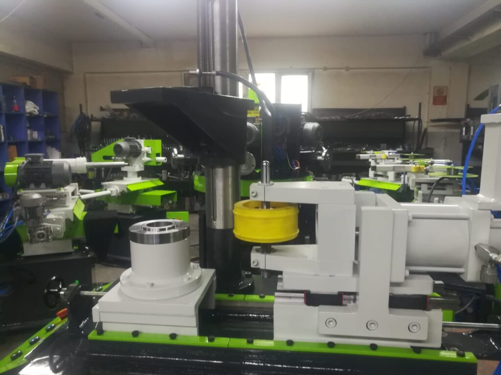
A Grinding Machine for Metal Pipes is a specialized machine designed to perform surface finishing, shaping, or dimensional accuracy improvement on metal pipes. Grinding is a critical step in pipe manufacturing and fabrication processes where smoothness, tight tolerances, or removal of surface defects such as scale, rust, or weld beads is required. These machines use abrasive wheels or belts to precisely remove material from the pipe surface or ends.
Grinding machines for metal pipes come in various types depending on the specific application:
- Surface Grinding Machines: Used to smooth and polish the external surface of pipes. These machines may have rotating grinding wheels or belts that run parallel or perpendicular to the pipe’s axis, ensuring a consistent finish over the entire length.
- Centerless Grinding Machines: Ideal for pipes where precise diameter control is required without the need for mounting the pipe between centers. The pipe rests on a support and is rotated by a regulating wheel while the grinding wheel removes material. This allows high-speed, high-precision grinding suitable for large batch production.
- Internal Grinding Machines: Designed to grind the inside diameter (ID) of pipes, improving bore surface finish or correcting dimensional inaccuracies. These machines use small-diameter grinding wheels or rods that are inserted into the pipe and rotated to uniformly grind the interior surface.
- End Grinding Machines: Focused on finishing the pipe ends to prepare them for welding, threading, or joining. End grinding can remove weld spatter, burrs, or uneven cuts, ensuring flat, smooth, and perpendicular pipe faces.
Grinding machines often include automated feeding and rotation systems to handle pipes of different lengths and diameters. They may also incorporate CNC controls for precise adjustment of grinding depth, speed, and feed rate, which enables consistent results and adaptability to varying material hardness or surface conditions.
Abrasive wheels or belts are selected based on the pipe material—common abrasives include aluminum oxide, silicon carbide, diamond-coated, or ceramic composites. Coolant systems are integrated to reduce heat generation during grinding, preventing damage to the pipe surface and extending the life of abrasive tools.
Safety features such as guarding, emergency stop buttons, and dust extraction units are standard to protect operators and maintain a clean working environment. Dust collectors capture fine metal particles, which can be hazardous if inhaled and can also interfere with machine operation.
Grinding machines for metal pipes are widely used in industries such as oil and gas, automotive, aerospace, and construction, where pipe quality and surface integrity are critical. These machines improve pipe longevity, ensure better fit and sealing in assemblies, and prepare pipes for coating or further finishing processes.
Grinding machines for metal pipes have advanced significantly with the integration of automated systems and precision controls, enabling high throughput and consistent quality in demanding industrial environments. These machines are designed to accommodate a wide range of pipe diameters and lengths, often featuring adjustable fixtures or clamps that secure pipes firmly while allowing smooth rotation or linear movement during grinding. Automation of loading and unloading mechanisms helps reduce manual handling, minimizing operator fatigue and the risk of damage to delicate pipe surfaces.
Modern grinding machines employ CNC technology to precisely control grinding parameters such as wheel speed, feed rate, and depth of cut. This precision allows for tight tolerances, essential in applications where pipe dimensions must meet exacting standards for assembly or fluid dynamics. CNC programming also enables quick changeovers between different pipe sizes or materials, enhancing production flexibility and reducing downtime.
A variety of grinding techniques are employed depending on the pipe’s intended use and material characteristics. Surface grinding focuses on removing surface imperfections and achieving a smooth, uniform finish. Internal grinding addresses the bore quality, critical for pipes used in high-pressure or high-purity applications where surface irregularities could lead to stress concentrations or contamination. End grinding ensures that pipe faces are perfectly flat and perpendicular, which is crucial for welding, threading, or coupling operations.
The abrasive media used in grinding can vary from traditional aluminum oxide wheels to high-performance diamond or cubic boron nitride (CBN) tools. These advanced abrasives offer longer tool life and better heat resistance, allowing grinding of harder materials like stainless steel, titanium, or nickel alloys without rapid wear. Cooling and lubrication systems are integral, typically involving mist or flood coolant delivery to prevent overheating, reduce friction, and wash away grinding debris.
Dust and particle management is a vital aspect of grinding machine design. Enclosed grinding chambers combined with high-efficiency extraction systems capture airborne particles and metal fines, maintaining operator safety and preventing contamination of the work environment. Proper ventilation and filtration also prolong the life of machine components by reducing abrasive wear and contamination.
In industrial settings, grinding machines are often integrated into production lines alongside cutting, forming, and finishing equipment. This seamless integration facilitates continuous pipe processing, from raw material to finished product, with minimal handling. Data collection and machine monitoring technologies track performance metrics, tool wear, and process consistency in real time, enabling predictive maintenance and quality control.
Operator interfaces have become more intuitive, featuring touchscreens with graphical displays that provide real-time feedback, diagnostic information, and easy parameter adjustments. Training tools, including simulations and augmented reality, help operators understand machine functions and troubleshoot problems quickly, reducing downtime and increasing overall efficiency.
Grinding machines for metal pipes continue to evolve, driven by the demand for higher precision, faster cycle times, and enhanced automation. They play a crucial role in ensuring the dimensional accuracy, surface finish, and structural integrity necessary for pipes used in critical sectors such as energy, transportation, and manufacturing. Their ability to deliver consistent, high-quality results while reducing manual labor and operational risks makes them indispensable in modern pipe fabrication.
Further innovations in grinding machines for metal pipes are focusing on incorporating smart manufacturing principles, aligning with Industry 4.0 standards. These machines are increasingly equipped with sensors and IoT connectivity that enable real-time monitoring of operational parameters such as vibration, temperature, and force applied during grinding. This data is analyzed through advanced algorithms to detect early signs of tool wear, misalignment, or process anomalies, allowing for predictive maintenance and reducing unplanned downtime.
Adaptive grinding systems use feedback loops to automatically adjust grinding pressure and speed based on the material hardness or surface condition of each individual pipe. This capability ensures uniform surface quality across batches, even when raw material properties vary, improving yield and reducing scrap rates. Additionally, machine learning models trained on historical production data can recommend optimal grinding parameters for new materials or pipe geometries, accelerating setup times and enhancing process stability.
Robotic automation integration is becoming more prevalent, with robotic arms or gantries handling pipe loading, positioning, and unloading tasks. This minimizes human involvement in potentially hazardous grinding environments and supports continuous operation in 24/7 production facilities. Some systems employ vision-guided robotics to inspect pipe surfaces before and after grinding, automatically rejecting parts that do not meet quality standards and providing traceability throughout the manufacturing process.
The development of multi-functional grinding machines capable of performing combined operations—such as grinding, polishing, chamfering, or even marking—within a single setup is also on the rise. These machines reduce handling and changeover times, enhancing throughput and reducing total manufacturing costs. Modular tooling and flexible machine configurations allow manufacturers to customize their grinding systems to specific production needs without investing in separate equipment.
Material advancements also influence grinding technology. New abrasive composites with enhanced durability and heat dissipation capabilities allow grinding of advanced alloys and composite-metal pipes without compromising surface integrity. Environmental concerns drive innovations in coolant systems, moving toward biodegradable and minimal-waste fluids that maintain grinding performance while reducing environmental impact.
Operator safety remains paramount. Modern grinding machines feature fully enclosed working areas with interlocked doors, emergency stop systems, and integrated dust extraction that complies with occupational health standards. Noise reduction measures, such as soundproof enclosures and vibration damping, contribute to a safer and more comfortable work environment.
In summary, grinding machines for metal pipes are transforming into intelligent, flexible, and highly automated systems. By leveraging advanced sensor technologies, robotics, and data analytics, these machines improve quality control, operational efficiency, and sustainability. They are essential components of modern pipe manufacturing lines, enabling producers to meet stringent industry standards while adapting quickly to changing production demands.
Drawing Machine For Metal Pipes
A Drawing Machine for Metal Pipes is a specialized piece of equipment used in the metalworking industry to reduce the diameter and wall thickness of pipes or tubes by pulling them through a shaped die. This cold working process, known as tube drawing or pipe drawing, enhances the mechanical properties of the metal, improves surface finish, and achieves precise dimensional tolerances. Drawing machines are essential for producing high-quality pipes used in applications such as automotive, aerospace, oil and gas, and construction.
The drawing process involves gripping the pipe or tube at one end and pulling it through a die with a smaller diameter than the original pipe. As the pipe passes through the die, its diameter is reduced, and its length increases. The metal undergoes plastic deformation, which refines the grain structure, increases strength and hardness, and improves surface smoothness. Drawing also eliminates internal defects and produces a more uniform wall thickness compared to other forming methods.
Drawing machines vary in design based on the size and material of the pipes being processed, but most share key components:
- Pulling Mechanism: This typically consists of a hydraulic or mechanical system that applies a controlled, steady pulling force on the pipe. Some machines use chain drives, capstans, or servo motors to maintain constant speed and tension.
- Die Assembly: The die is made from extremely hard materials such as tungsten carbide or diamond-coated alloys to withstand high stresses and abrasion. Dies come in various profiles depending on the desired pipe shape and dimensions.
- Lubrication System: Proper lubrication is critical to reduce friction between the pipe and die, minimize wear on the tooling, and prevent pipe surface damage. Lubricants can be oil-based, synthetic, or solid-film types, often applied automatically during the drawing process.
- Guides and Supports: These ensure the pipe is aligned correctly as it approaches and exits the die, preventing bending or deformation that could lead to dimensional inaccuracies or surface defects.
- Control Systems: Modern drawing machines feature CNC or PLC-based controls that monitor and adjust pulling speed, force, and die temperature to optimize the drawing process and protect equipment from overload.
Tube drawing machines can be categorized by the drawing method used:
- Direct Drawing: The pipe is pulled directly through the die, causing immediate diameter reduction.
- Indirect Drawing: The die remains stationary, and the pipe is pushed or pulled through a hollow die while the drawing mandrel moves with the pipe. This method reduces friction and is used for tighter tolerances and better surface finish.
- Floating Mandrel Drawing: A mandrel inside the pipe floats freely during drawing to control the internal diameter and wall thickness precisely.
Drawing machines are capable of processing a wide range of materials, including carbon steel, stainless steel, copper, aluminum, and specialty alloys. The process can be repeated multiple times through progressively smaller dies to achieve the final desired dimensions and properties.
Advanced drawing machines incorporate automation for loading and unloading pipes, integrated quality inspection systems such as laser measurement or ultrasonic testing, and real-time data acquisition for process optimization. These features improve throughput, consistency, and traceability, meeting the demands of modern manufacturing environments.
In summary, drawing machines for metal pipes are indispensable for producing precision pipes with superior mechanical properties and surface quality. They enable manufacturers to meet stringent industry specifications while optimizing production efficiency and reducing material waste.
Drawing machines for metal pipes have evolved to meet the demands for higher precision, better surface finishes, and increased production speeds. They are designed to handle a broad spectrum of pipe sizes and materials, adapting to the diverse requirements across industries such as automotive, aerospace, oil and gas, and plumbing.
One significant advancement is the integration of computerized controls that allow precise regulation of drawing speed, force, and die temperature. These controls help maintain consistent pipe dimensions and mechanical properties by adjusting parameters in real time based on sensor feedback. Monitoring systems can detect variations in material behavior or tooling wear and automatically compensate to avoid defects or scrap.
Lubrication plays a critical role in the drawing process, as it reduces friction between the pipe and the die, prevents surface damage, and extends die life. Modern drawing machines often feature automated lubrication systems that apply the right amount of lubricant at precise locations, optimizing consumption and minimizing environmental impact. Innovations in lubricant formulation, including biodegradable and low-residue types, further support sustainable manufacturing practices.
The tooling materials for dies and mandrels have also advanced. High-performance ceramics, tungsten carbide composites, and diamond-coated surfaces provide exceptional hardness and wear resistance, enabling longer runs with fewer tool changes. These materials support the drawing of hard alloys and specialty metals without compromising surface finish or dimensional accuracy.
To improve efficiency, many drawing machines incorporate automated handling systems such as robotic arms or conveyor feeds. These systems streamline the loading of raw pipes and unloading of finished products, reducing manual labor and cycle times. Additionally, inline inspection technologies—like laser micrometers, ultrasonic wall thickness gauges, and surface scanners—are used to continuously assess pipe quality during production. Real-time data from these sensors enable immediate corrective actions and ensure that only pipes meeting stringent specifications proceed to further processing or shipment.
Energy efficiency and environmental considerations are increasingly influencing drawing machine design. Modern machines employ energy-saving motors, regenerative braking systems, and optimized mechanical transmission to reduce power consumption. Waste management systems capture and recycle lubricants and metal particulates, while enclosed work areas with dust extraction maintain operator safety and workplace cleanliness.
In complex manufacturing setups, drawing machines are integrated into fully automated production lines that combine pipe drawing with forming, heat treatment, cutting, and finishing operations. This seamless integration enhances throughput and product consistency while lowering labor costs.
Overall, drawing machines for metal pipes have become highly sophisticated tools that blend mechanical precision, advanced materials, and digital intelligence. They play a crucial role in producing pipes that meet exacting dimensional, mechanical, and surface quality standards required by modern industries, all while improving operational efficiency and sustainability.
Further developments in drawing machines for metal pipes focus on increasing flexibility and customization to meet the evolving demands of diverse applications. Modular machine designs allow manufacturers to quickly reconfigure equipment for different pipe sizes, shapes, and materials without extensive downtime. Interchangeable dies, adjustable pulling mechanisms, and adaptable mandrel assemblies enable quick changeovers and support short production runs alongside high-volume manufacturing.
Innovations in process monitoring and control include the use of artificial intelligence (AI) and machine learning algorithms. These systems analyze vast amounts of operational data to optimize drawing parameters dynamically, predict potential failures, and recommend maintenance schedules. Such smart capabilities enhance product quality, reduce waste, and extend machine uptime.
Advanced sensor technologies are increasingly embedded within the machine to monitor parameters such as drawing force, temperature, vibration, and pipe surface condition. These sensors provide continuous feedback that helps maintain process stability, detect irregularities early, and ensure compliance with tight tolerances.
The integration of augmented reality (AR) and virtual reality (VR) tools is also emerging in the training and maintenance of drawing machines. Operators can use AR glasses or VR simulators to visualize machine components, simulate drawing processes, and receive real-time guidance during setup or troubleshooting. This improves operator skills, reduces errors, and speeds up maintenance procedures.
Environmental sustainability is a growing priority, driving the adoption of eco-friendly lubricants and the development of closed-loop cooling and filtration systems that minimize water and chemical usage. Efforts to reduce noise and vibration not only improve workplace safety but also comply with stricter environmental regulations.
In addition to standard cylindrical pipes, drawing machines are being adapted to manufacture complex profiles and thin-walled tubes used in high-tech industries. Custom dies and mandrels are engineered to produce specialized geometries while maintaining the mechanical integrity of the material.
In summary, the future of drawing machines for metal pipes lies in increased automation, intelligence, adaptability, and environmental responsibility. These advancements ensure manufacturers can consistently produce high-quality, precision pipes while optimizing operational efficiency and meeting sustainability goals.
Piercing Machine For Metal Pipes
A Piercing Machine for Metal Pipes is specialized equipment used to create precise holes or openings in metal pipes and tubes. This process is essential in various industries such as automotive, construction, plumbing, and manufacturing, where pipes often require holes for fittings, connections, drainage, or ventilation.
Piercing machines operate by applying a controlled force through a punch or piercing tool that penetrates the pipe wall without causing excessive deformation or cracking. The machines can pierce pipes of various diameters, thicknesses, and materials, including steel, stainless steel, copper, and aluminum.
Typically, piercing machines consist of several key components:
- Punch and Die Assembly: The punch, a hardened tool shaped to the desired hole profile, is forced through the pipe wall into the die, which supports the pipe and shapes the hole edges. Dies are made from durable materials like tool steel or carbide to withstand repeated impacts.
- Clamping System: To ensure accuracy and prevent movement during piercing, the pipe is securely clamped. This system may be adjustable to accommodate different pipe sizes and lengths.
- Actuation Mechanism: Piercing machines use hydraulic, mechanical, or pneumatic drives to deliver the force required for piercing. Hydraulic systems offer smooth, controlled pressure suitable for thicker or harder materials, while mechanical or pneumatic systems are often faster and suited for thinner pipes.
- Feeding and Positioning System: Automated feeding systems can position pipes accurately before piercing, allowing for high-speed, repetitive operations. CNC-controlled machines can precisely locate holes according to programmed patterns.
Piercing processes vary based on the application:
- Single Hole Piercing: Creating individual holes at specific locations.
- Multiple or Patterned Piercing: Producing several holes in a defined pattern, often in one operation using multi-punch tooling.
- Slitting or Slotting: Making elongated openings or slots, sometimes integrated with piercing operations.
To maintain pipe integrity, piercing machines are designed to minimize distortion and maintain the structural strength around the hole. This is particularly important for pipes used in pressure systems or load-bearing applications.
Lubrication is often applied during piercing to reduce tool wear and improve the quality of the hole edges. Some machines incorporate automatic lubrication systems to optimize this process.
Advanced piercing machines feature integrated inspection systems such as cameras or sensors that verify hole dimensions and detect defects immediately, enabling real-time quality control.
Automation enhances productivity by combining piercing with other operations like cutting, threading, or forming, creating efficient production lines.
In summary, piercing machines for metal pipes are vital tools for producing accurate, clean holes required in many pipe applications. Their precision, reliability, and adaptability make them indispensable in modern pipe fabrication and assembly.
Piercing machines for metal pipes continue to advance with a strong emphasis on automation, precision, and versatility. Modern systems integrate CNC controls, enabling highly accurate positioning of the piercing tool and programmable hole patterns. This allows manufacturers to produce complex and customized designs with minimal manual intervention, reducing errors and increasing throughput.
To accommodate a wide variety of pipe diameters and wall thicknesses, contemporary piercing machines often feature adjustable clamps and modular tooling systems. These innovations allow for rapid changeovers and flexibility in handling different pipe materials such as stainless steel, copper, aluminum, and specialty alloys without compromising the quality of the pierced holes.
In terms of actuation, hydraulic piercing remains popular for its consistent force and control, especially with thicker or harder metals. However, advances in servo-electric drives offer precise, energy-efficient alternatives that reduce maintenance needs and improve responsiveness. Pneumatic systems are favored for high-speed piercing of thinner pipes where rapid cycling is required.
Maintaining pipe integrity during piercing is critical, particularly for pipes used in high-pressure or structural applications. To minimize deformation, machines often incorporate secondary support dies or backing plates that stabilize the pipe around the piercing area. Some systems employ multi-stage piercing, gradually enlarging holes in steps rather than a single punch, which reduces stress concentrations and enhances finished hole quality.
The use of advanced materials in punches and dies, such as tungsten carbide and ceramic composites, has greatly increased tool life and reliability. Coupled with automated lubrication systems, these materials help maintain clean, burr-free holes and reduce downtime caused by tooling wear.
Automation extends beyond the piercing action itself. Many piercing machines are integrated into fully automated production lines, with robotic arms or conveyors handling pipe loading, positioning, and unloading. Inline inspection technologies, including vision systems and laser measurement, verify hole placement and size immediately after piercing, ensuring consistent quality and enabling rapid corrective action if defects are detected.
Environmental and safety considerations have led to the development of enclosed piercing cells equipped with dust extraction and noise reduction features. These not only protect operators but also improve overall plant cleanliness and compliance with occupational health standards.
Piercing machines are increasingly combined with other pipe processing operations, such as cutting, threading, or end forming, into multi-functional machines or production cells. This integration reduces handling times and improves efficiency, allowing manufacturers to respond quickly to diverse customer requirements.
Overall, piercing machines for metal pipes have evolved into sophisticated, high-precision, and highly automated tools that play a critical role in modern pipe fabrication. Their ability to deliver consistent quality, adapt to various materials and sizes, and integrate with smart manufacturing systems ensures they remain indispensable in industrial production environments.
Emerging trends in piercing machines for metal pipes focus heavily on enhancing digital integration and smart manufacturing capabilities. Industry 4.0 concepts are increasingly applied, where piercing machines are connected to centralized control systems that collect and analyze operational data in real time. This data-driven approach enables predictive maintenance, minimizing unexpected downtime by alerting operators to potential tool wear or machine faults before failures occur.
Machine learning algorithms analyze past production runs to optimize piercing parameters, such as punch force and speed, adapting automatically to variations in pipe material or thickness. This dynamic adjustment helps maintain consistent hole quality, reduce scrap rates, and extend tooling life.
The rise of additive manufacturing and rapid prototyping is influencing tooling design, with custom punches and dies being produced using 3D printing technologies. This allows for rapid iteration and the creation of complex hole geometries that were previously difficult or expensive to achieve, broadening the applications of piercing machines.
Safety enhancements continue to evolve, with advanced sensors and light curtains providing real-time monitoring of operator presence and machine access points. Machines are programmed to halt automatically if unsafe conditions are detected, reducing workplace accidents and complying with increasingly stringent safety regulations.
Energy efficiency remains a priority, with manufacturers adopting servo-driven actuation and regenerative braking systems that reduce power consumption during the high-force piercing cycles. Some machines incorporate smart energy management systems that optimize power usage based on load requirements throughout the production cycle.
Customization options now often include modular tooling stations, enabling simultaneous or sequential piercing of multiple holes with quick tool changes. This flexibility allows manufacturers to produce varied pipe designs on a single machine without lengthy setup times.
Integration with upstream and downstream processes through digital communication protocols (like OPC-UA or MTConnect) ensures seamless flow of pipes through cutting, bending, threading, and inspection operations. This interconnectedness supports just-in-time manufacturing and rapid response to changing production schedules.
In summary, piercing machines for metal pipes are rapidly transforming into intelligent, adaptable, and highly efficient systems. These machines not only meet the precise dimensional requirements of modern pipe applications but also support sustainable manufacturing, enhanced safety, and seamless integration within the broader digital factory ecosystem.
Ribbing Machine For Metal Pipes
A Ribbing Machine for Metal Pipes is specialized equipment designed to create raised ribs, ridges, or corrugations along the surface of metal pipes. These ribs serve various functional and structural purposes such as increasing pipe strength and stiffness, improving grip and handling, enhancing flexibility, or providing channels for airflow or liquid drainage. Ribbed pipes are commonly used in applications like drainage systems, flexible conduits, automotive exhausts, and structural tubing.
Ribbing machines work by plastically deforming the pipe surface through mechanical rolling, pressing, or embossing techniques. The process involves passing the pipe through sets of rollers or dies specifically designed with rib patterns. As the pipe rotates and moves forward, the rib-forming tools impress the raised shapes onto the metal surface without compromising the pipe’s overall integrity.
Key features of ribbing machines include:
- Forming Rollers or Dies: These are the core tools that create the ribs. Made from hardened steel or carbide, rollers are patterned with the desired rib profile, which can vary in shape, height, and spacing according to application requirements.
- Drive and Feeding System: The pipe is continuously fed through the ribbing station by synchronized rollers or conveyors that maintain steady rotation and forward movement, ensuring uniform rib formation.
- Adjustable Pressure Control: The force applied by the rollers can be finely tuned to accommodate different pipe materials, thicknesses, and rib depths. This adjustability helps prevent pipe distortion or cracking.
- Support and Guide Mechanisms: These ensure the pipe remains properly aligned and stable during the ribbing process, resulting in consistent rib geometry along the entire length.
Ribbing machines are often integrated into pipe manufacturing or finishing lines where ribs are added after initial forming and sizing. Depending on production needs, ribbing can be continuous along the pipe length or applied in discrete sections.
Different rib profiles can be produced, including longitudinal ribs running parallel to the pipe axis, circumferential ribs encircling the pipe, or complex patterns combining both. This versatility allows manufacturers to tailor ribbing for specific mechanical properties or aesthetic effects.
Automation and CNC controls enhance precision and repeatability in modern ribbing machines. Operators can program rib dimensions, spacing, and pattern sequences, enabling quick changes between different product designs with minimal downtime.
The ribbing process also improves surface grip, making ribbed pipes easier to handle and install, especially in applications involving manual labor or where pipes must be secured tightly. In flexible conduits, ribs add strength while allowing bending without collapsing.
Overall, ribbing machines for metal pipes provide an effective method to enhance pipe performance, meet specialized functional requirements, and expand the versatility of metal tubing across various industrial sectors.
Ribbing machines for metal pipes have continued to evolve with advancements that enhance efficiency, versatility, and precision. One significant development is the adoption of servo-driven systems that provide accurate control over roller speed, pressure, and pipe feed rates. This precise control ensures consistent rib profiles, even when processing pipes of varying diameters, wall thicknesses, or materials, including steel, stainless steel, aluminum, and copper alloys.
Modern ribbing machines often feature quick-change tooling systems, allowing manufacturers to switch between different rib patterns rapidly to accommodate diverse product lines or custom orders. This flexibility is critical in industries where product specifications change frequently or when multiple rib profiles are needed on a single pipe.
Automation plays a major role in ribbing machine operations, with integrated sensors and feedback loops monitoring parameters such as rib height, spacing, and pipe alignment in real time. Deviations from programmed standards can trigger automatic adjustments or halt the process, minimizing defects and reducing waste. Additionally, digital interfaces and CNC programming enable the storage and recall of complex ribbing patterns, simplifying setup and improving reproducibility across production runs.
In some applications, ribbing is combined with other surface treatments, such as coating or galvanizing, to enhance corrosion resistance and durability. Ribbing machines can be integrated into multi-stage production lines where rib formation is followed by these finishing processes without requiring manual handling, streamlining operations and reducing labor costs.
Environmental and safety considerations have driven innovations in ribbing machine design as well. Enclosures and guards protect operators from moving parts and reduce noise emissions. Efficient lubrication and cooling systems extend tooling life while minimizing waste and contamination.
Ribbed pipes produced by these machines find use in a variety of sectors, from construction and infrastructure—where increased rigidity improves load-bearing capacity—to automotive and aerospace industries, where tailored rib designs optimize weight and performance. In flexible piping applications, ribbing enhances flexibility without sacrificing structural integrity.
Looking forward, integration of Industry 4.0 technologies such as IoT connectivity and machine learning is expected to further optimize ribbing operations. Machines will increasingly self-monitor their condition, predict maintenance needs, and adapt to material variations autonomously. This will result in higher productivity, lower operational costs, and even greater product quality.
In conclusion, ribbing machines for metal pipes have become highly adaptable, precise, and intelligent systems. They enable manufacturers to produce ribs that enhance the mechanical and functional properties of pipes across a wide range of applications, supporting both traditional manufacturing and innovative new uses.
Further advancements in ribbing machines for metal pipes are focusing on expanding the scope of rib geometries and applications. New tooling technologies enable the creation of complex rib shapes, such as multi-level ribs, wave patterns, or interlocking ribs, which can improve specific performance characteristics like vibration damping, thermal expansion control, or enhanced fluid dynamics in pipes carrying gases or liquids.
Materials science developments also influence ribbing machine design. As manufacturers work with advanced alloys, composites, and coated metals, ribbing equipment must accommodate differing mechanical properties—such as hardness, ductility, and surface finishes—without compromising tool life or rib quality. Specialized coatings on rollers and dies reduce friction and wear, extending service intervals and maintaining consistent rib profiles even with challenging materials.
The ability to produce variable rib spacing or selective ribbing along pipe lengths is becoming increasingly important. This allows manufacturers to tailor stiffness or flexibility where needed, such as reinforcing stress points or enabling controlled bending sections, without changing the entire pipe design. Programmable ribbing machines make such variations possible within a single production run, adding a level of customization previously difficult to achieve.
In the realm of quality assurance, high-resolution surface scanning and 3D metrology integrated into ribbing machines provide detailed feedback on rib dimensions and surface integrity. Coupled with automated defect detection, these technologies help identify micro-cracks, surface irregularities, or deviations from design specifications early in the process, reducing costly rework and improving overall product reliability.
Sustainability considerations continue to shape ribbing machine innovation. Energy-efficient motors, regenerative braking during roller deceleration, and smart power management systems help reduce the environmental footprint of production. Additionally, recyclable lubricants and coolant systems with closed-loop filtration support eco-friendly manufacturing practices.
Collaborations between ribbing machine manufacturers and end-users drive the development of application-specific solutions. For example, in the construction industry, ribbed pipes with enhanced load-bearing ribs improve foundation drainage systems, while in automotive exhaust systems, ribs optimize acoustic properties and thermal dissipation.
Training and operator support are also enhanced by augmented reality (AR) and virtual reality (VR) tools, allowing maintenance personnel to visualize internal machine components, simulate ribbing processes, and receive real-time guidance during setup or troubleshooting, thereby minimizing downtime and improving operational efficiency.
In summary, ribbing machines for metal pipes are advancing toward more sophisticated, flexible, and sustainable technologies. These innovations support the production of high-performance ribbed pipes that meet increasingly complex engineering requirements while optimizing manufacturing efficiency and environmental responsibility.
Hydroforming Machine For Metal Pipes
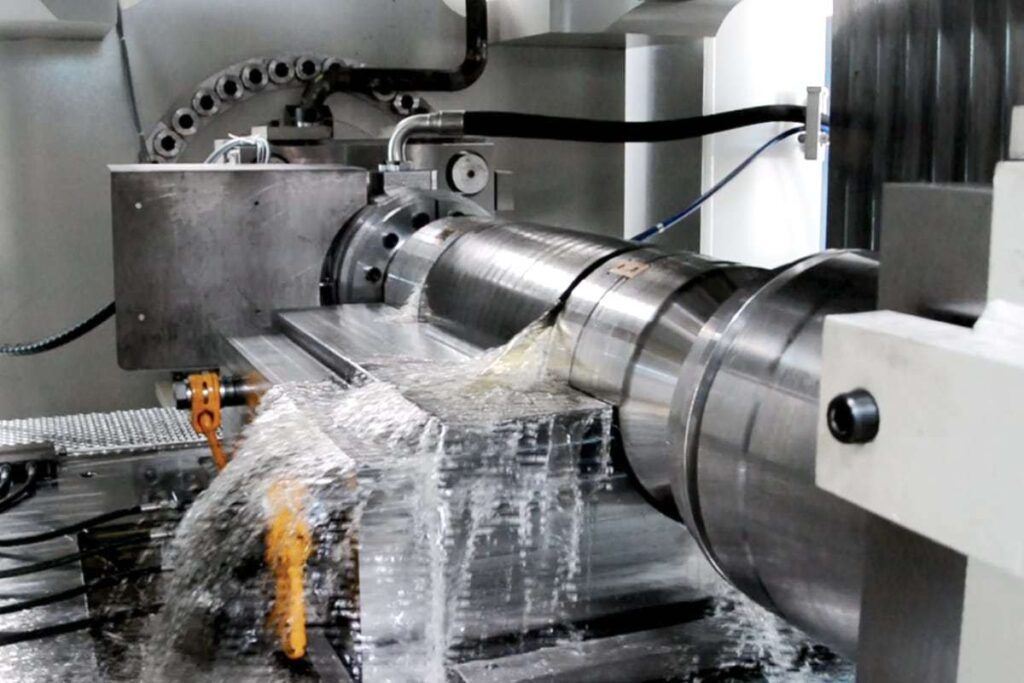
A Hydroforming Machine for Metal Pipes is a highly specialized piece of equipment that uses high-pressure fluid to form metal pipes into complex shapes within a die cavity. This technique enables the production of lightweight, seamless, and structurally strong components with intricate geometries that would be difficult or impossible to achieve through conventional forming methods. Hydroforming is widely used in automotive, aerospace, HVAC, and bicycle frame manufacturing, where high precision and material efficiency are critical.
The process begins with a straight tube (typically made of aluminum, steel, stainless steel, or other ductile metals) placed inside a die. The ends of the tube are sealed, and a hydraulic system injects fluid—usually water or oil—into the tube at extremely high pressures, often exceeding 1000 bar (14,500 psi). As pressure builds, the metal expands outward until it conforms precisely to the contours of the die. This method eliminates the need for welding or joining, reducing potential weak points and ensuring a uniform wall thickness.
Hydroforming machines are typically composed of several integrated systems, including a hydraulic intensifier or pump, clamping units to hold the tube and die in place, end-sealing mechanisms, and CNC controls to coordinate pressure application, axial feeding, and timing. Axial feeding is often combined with internal pressure to stretch and form the pipe without causing thinning or cracking, especially in complex shapes like T-sections, Y-branches, and curved or asymmetrical parts.
Recent innovations in hydroforming machines focus on improving cycle time, precision, and repeatability. Servo-hydraulic systems offer dynamic control over pressure and movement, enabling more accurate forming with lower energy consumption. These systems can rapidly adjust forming parameters in real time, responding to minor variations in material thickness or composition to avoid defects such as wrinkling or bursting.
Tooling advancements also play a critical role, with modular die systems allowing for quick changeovers and high customization. Simulation software integrated into machine control platforms helps predict metal flow and potential failures, allowing for virtual testing and process optimization before any physical forming takes place.
Automation and data integration are increasingly important in hydroforming systems. Machines are often linked to MES (Manufacturing Execution Systems) or ERP (Enterprise Resource Planning) platforms, allowing operators to monitor production remotely, track performance metrics, and schedule predictive maintenance. This enhances uptime, traceability, and quality assurance, especially in high-volume environments.
The benefits of hydroforming include material savings, reduced part count (as hydroformed components often replace assemblies of welded parts), improved strength-to-weight ratios, and superior surface finishes. It also supports green manufacturing by minimizing waste and enabling the use of recyclable materials.
In conclusion, hydroforming machines for metal pipes represent a high-precision, high-efficiency solution for producing structurally optimized components with complex geometries. Their ability to combine strength, light weight, and aesthetic quality makes them indispensable in advanced manufacturing sectors, and ongoing innovations continue to expand their capabilities and applications.
Hydroforming machines for metal pipes have become increasingly refined to handle a broader range of pipe diameters, wall thicknesses, and material types while maintaining high production efficiency and forming precision. These machines are now commonly equipped with adaptive control systems that automatically adjust forming pressure, axial feed speed, and die movement in response to material behavior during the forming cycle. This dynamic response is essential in preventing defects such as tearing, buckling, or excessive thinning, especially when working with ultra-high-strength steels or non-ferrous alloys.
The integration of finite element analysis (FEA) and process simulation software into the hydroforming workflow allows manufacturers to model complex forming scenarios before production begins. This virtual prototyping capability helps reduce tool development time, optimize part geometry, and ensure uniform material flow under pressure, all while minimizing trial-and-error runs. This is particularly valuable when developing components with varying cross-sections, compound curves, or features like embossments and reinforcing ribs.
Advanced hydroforming machines often feature multi-station setups, enabling simultaneous operations such as tube pre-bending, pressure forming, end trimming, and hole punching within a single machine cycle. This inline approach drastically reduces handling time and increases throughput while improving part-to-part consistency. Servo-electric or hybrid actuation systems have begun replacing traditional hydraulic-only setups in some configurations to enhance energy efficiency and reduce environmental impact.
Another significant evolution is in the tooling materials and surface treatments used within hydroforming machines. Hardened steel dies with specialized coatings—such as titanium nitride or diamond-like carbon—reduce wear and friction, prolonging tool life and maintaining dimensional accuracy across long production runs. These coatings also reduce the need for lubricants, simplifying part cleaning and reducing contamination in subsequent processes like welding or painting.
Industries that demand lightweight and high-strength components—such as automotive manufacturers aiming to meet strict emissions regulations—have pushed the development of more sophisticated hydroforming systems. Components like engine cradles, roof rails, subframes, and exhaust manifolds are now routinely hydroformed with high repeatability and minimal post-processing. In the aerospace industry, hydroformed tubular components are used where weight reduction and strength are critical without sacrificing geometric complexity.
As sustainability becomes more central to manufacturing strategy, hydroforming’s ability to reduce raw material consumption and waste is gaining recognition. By allowing parts to be formed from smaller blanks or thinner-walled tubes without sacrificing strength, hydroforming contributes to more efficient use of materials. Additionally, by combining multiple part features into a single hydroformed piece, overall assembly time, welding requirements, and inventory complexity are significantly reduced.
Future developments in hydroforming technology are expected to emphasize greater machine intelligence, including AI-assisted process tuning, machine learning for predictive maintenance, and integration with digital twins for real-time simulation and optimization. These capabilities will allow machines to not only perform complex forming operations but also learn from every cycle to continuously improve performance and reduce costs.
In essence, hydroforming machines for metal pipes represent a convergence of precision mechanics, fluid dynamics, material science, and intelligent control. Their unique ability to shape intricate, strong, and lightweight components with minimal waste and high repeatability ensures their continued relevance in advanced manufacturing environments focused on performance, quality, and sustainability.
Modern hydroforming machines are also designed with high modularity and flexibility to support quick reconfiguration for different product types. This is particularly valuable in industries where design cycles are short and production runs vary in volume. Tooling platforms now accommodate multiple part geometries with minimal downtime, aided by automatic tool change systems and programmable setups stored in the machine’s control unit. This level of responsiveness allows small and mid-sized manufacturers to compete with high-volume producers by adapting quickly to custom orders or new design requirements.
Digital connectivity is another area of significant advancement. Hydroforming machines now often include Industrial Internet of Things (IIoT) capabilities, where sensors embedded throughout the system feed real-time data to centralized dashboards. Operators and engineers can monitor critical variables like fluid pressure curves, tube elongation rates, die alignment, and seal integrity. This transparency improves troubleshooting and predictive maintenance while also generating comprehensive production reports that support traceability and quality assurance protocols, especially in regulated industries.
Hydroforming is also increasingly used in hybrid forming setups, where it’s combined with laser cutting, welding, or incremental forming in a unified line. For example, some machines feature integrated laser units that pre-cut holes or slots into tubes before hydroforming, enabling the creation of ventilation ducts, exhaust systems, or structural components with specific performance functions. These hybrid systems help reduce the number of separate manufacturing steps, optimize floor space, and lower total production cost.
Safety and ergonomics are also addressed through machine enclosure designs that protect operators from high-pressure systems and moving parts. Redundant safety interlocks, pressure relief systems, and real-time fault diagnostics ensure that machines meet strict international safety standards. Touchscreen interfaces with intuitive graphics make operation accessible even for less experienced users, and multilingual support ensures usability in global manufacturing settings.
Applications of hydroformed metal pipes are growing beyond traditional automotive and aerospace sectors. In architecture, hydroformed tubes are used for structural elements in buildings and bridges due to their strength and aesthetic appeal. In sports equipment, manufacturers are using hydroforming to create lightweight, aerodynamic frames for bicycles, motorcycles, and watercraft. Even in energy and medical equipment industries, custom-shaped hydroformed pipes are being used in heat exchangers, pressure vessels, and precision instrumentation housings.
Moreover, as the demand for electric vehicles (EVs) expands, hydroforming machines are being adapted to produce battery enclosures, lightweight chassis members, and crash-resistant frames that help meet weight and safety requirements unique to EV platforms. The ability to create complex shapes that absorb impact energy efficiently while maintaining low weight is a distinct advantage that hydroforming brings to EV design.
In the long term, as materials continue to evolve with the introduction of ultra-light alloys, composites, and even advanced hybrid materials, hydroforming machines will adapt further. This might include controlled temperature hydroforming (warm or hot hydroforming) to accommodate less ductile materials, or real-time adaptive feedback systems that change forming strategy mid-cycle based on sensor data. These enhancements will continue to push the boundaries of what is possible in pipe forming and precision manufacturing.
Ultimately, the hydroforming machine is not just a forming tool—it is a high-value integration of digital intelligence, mechanical precision, and materials engineering that enables manufacturers to achieve performance, sustainability, and innovation targets in highly competitive industries.
Swaging Down Machine For Metal Pipes
A Swaging Down Machine for Metal Pipes is a specialized metal forming machine designed to reduce the diameter of a pipe or tube by applying radial compressive forces through a series of dies or hammers. Unlike cutting or machining, swaging down reshapes the metal plastically without removing material, allowing for a seamless and strong transition in diameter. This method is commonly used to create tapered ends, prepare pipes for joining or fittings, or form stepped profiles in one continuous piece.
The basic operation involves placing a pipe inside a set of swaging dies that close and open rapidly in a synchronized motion. These dies can be powered mechanically, hydraulically, or pneumatically, and are typically mounted on a spindle or rotating head. As the dies oscillate around the pipe’s circumference, they progressively hammer the material inward, reducing its outer diameter while maintaining—or even improving—material integrity through work hardening.
Swaging down can be performed in both hot and cold conditions depending on the material and desired outcome. Cold swaging is ideal for softer metals like aluminum, copper, and mild steel, and provides a clean surface finish with tight tolerances. Hot swaging, where the pipe is preheated before forming, is preferred for tougher alloys or when a greater degree of deformation is needed.
Swaging down machines are highly valued in industries where strong, lightweight, and precisely shaped pipe ends are necessary. Common applications include automotive steering columns, drive shafts, aircraft tubing, hydraulic lines, exhaust systems, and furniture or scaffold components. In these uses, swaging allows for parts to be joined without welding, threading, or adding couplings, thereby reducing weight, improving aesthetics, and simplifying assembly.
Modern swaging down machines often incorporate CNC or PLC controls to program stroke frequency, force, and length of engagement. These features enable consistent output across high-volume production runs and allow operators to store multiple profiles or part programs for different pipe types. Many machines also include automatic feeding systems and pipe alignment guides to improve productivity and ensure concentricity during operation.
Noise reduction and vibration damping are key areas of development in newer machines, especially those used in factory environments with strict health and safety standards. Sound enclosures, servo-driven systems, and vibration-absorbing materials help mitigate the intense impacts associated with radial hammering. Additionally, maintenance is simplified with modular die assemblies and quick-change tooling systems that reduce downtime during setup or part changeover.
Some advanced swaging machines also combine swaging down with other processes like end forming, flaring, or notching. This multi-functionality makes them ideal for lean manufacturing setups where floor space and cycle time are at a premium. Sensors and vision systems can be added to ensure dimensional accuracy, detect defects, and monitor wear on forming tools.
From a metallurgical standpoint, swaging improves grain flow and mechanical strength in the formed zone. Unlike machining, which can introduce stress concentrations or sharp edges, swaging creates smooth, contoured transitions that enhance fatigue resistance and durability. This is especially valuable in components subjected to cyclic loading or pressure variations.
In summary, a swaging down machine for metal pipes is an efficient, versatile, and cost-effective solution for reducing pipe diameters and forming strong, seamless transitions. Its ability to reshape tubes without material loss, coupled with high repeatability and adaptability to a range of metals and pipe sizes, makes it a core technology in precision pipe fabrication across multiple industries.
Swaging down machines continue to evolve with advancements in control systems, automation, and integration into larger manufacturing cells. In high-volume production environments, these machines are often paired with robotic handling systems that feed pipes into the machine, rotate them if needed, and transfer the formed parts downstream for additional operations such as inspection, coating, or assembly. This integration reduces labor input, increases throughput, and enhances overall consistency across thousands of parts.
The machine’s performance depends significantly on the design and condition of the dies. Hardened tool steels and wear-resistant coatings like nitriding or PVD films are common choices to ensure long tool life and dimensional stability. Die profiles can be custom-made to form complex taper geometries, stepped reductions, or specific wall thickness transitions, and the swaging action can be controlled to achieve either smooth surface finishes or deliberate texturing where additional grip or bonding is needed.
In terms of materials, the swaging process is compatible with a wide range of metals including stainless steel, titanium, brass, nickel alloys, and even certain high-strength composite-clad tubes. This versatility makes swaging down applicable not only in conventional mechanical and structural components but also in advanced systems like aerospace hydraulic lines, nuclear instrumentation tubing, and medical devices such as catheters or surgical instrument housings, where absolute precision and integrity are required.
One of the distinct advantages of swaging is its ability to strengthen the material through strain hardening. As the dies compress the pipe, the metal’s grain structure is elongated and reoriented, resulting in enhanced tensile strength and fatigue resistance in the deformed area. This makes swaged ends ideal for high-pressure or high-vibration applications, where welded or threaded joints might fail over time.
Swaging down is also an environmentally friendly process in comparison to subtractive machining. There is minimal waste generated, no chips or coolant contamination, and the energy consumption per part is often lower, particularly in servo-driven or energy-efficient hydraulic systems. Moreover, since the operation is fast—often taking less than a second per cycle in high-speed systems—it contributes to lower per-unit production costs and higher operational efficiency.
Modern software integration allows swaging down machines to be part of digital manufacturing ecosystems. Process data such as force curves, stroke counts, die temperature, and part ID tracking can be logged and analyzed in real-time, supporting predictive maintenance and continuous improvement initiatives. If a dimensional deviation is detected, the system can alert the operator or automatically adjust forming parameters to bring the next part back within tolerance.
In custom fabrication shops, swaging machines serve both prototyping and production needs. For instance, when developing a new pipe assembly, engineers can quickly test multiple reduction profiles, check assembly fit, and validate sealing performance before committing to full-scale production. This agility supports innovation, particularly in sectors like green energy, where new piping systems are continuously being designed for hydrogen, biofuels, or advanced heat exchange technologies.
The footprint of swaging down machines varies by application—from compact benchtop models for small-diameter precision tubes to large, floor-mounted industrial units handling thick-walled pipes up to several inches in diameter. Transport and installation of larger machines require consideration of foundation vibration control and structural alignment, ensuring the consistent axial feed and uniform deformation around the circumference of the pipe.
Overall, the swaging down machine remains a cornerstone of modern pipe forming, balancing speed, strength, accuracy, and economy. Its ability to enhance structural integrity while enabling complex shaping in a single, rapid process continues to make it indispensable in the production of high-performance tubular components. As demands for efficiency, material conservation, and precision increase, swaging technology is expected to play an even more integral role in both legacy and emerging industries.
As swaging down machines advance, integration with simulation software has become increasingly common. Engineers can model the entire forming process using finite element analysis (FEA) to predict material flow, wall thinning, internal stress distribution, and final geometry before actual production begins. This preemptive modeling significantly reduces trial-and-error during die design and ensures that even tight-tolerance or safety-critical parts meet specification on the first production runs.
Another trend is the development of hybrid machines that combine swaging with secondary operations like trimming, internal mandrel forming, or even inline annealing. These combinations are particularly beneficial in industries that need to process high-strength materials or produce parts that transition between varying diameters and wall thicknesses in a single tube. Inline annealing between successive swaging passes, for instance, helps relieve stress and restore ductility, especially in harder alloys that are prone to cracking under cold work.
Acoustic emission sensors and force monitoring systems are also being embedded into machines for real-time quality assurance. These systems listen to the sound and measure the resistance of the swaging process, detecting anomalies such as die misalignment, workpiece slippage, or premature material failure. Any deviation from expected behavior triggers alerts, stopping the machine to prevent scrap and tooling damage.
For industries that require certification or regulatory traceability, such as aerospace or medical, swaging down machines now feature data logging systems that capture individual part forming histories. Each tube’s process data—including forming pressure, stroke count, operator ID, and part serial number—can be automatically recorded and linked to barcode or RFID systems for full traceability. This not only helps in meeting compliance but also builds trust with customers who demand verifiable quality control.
In terms of global application, the utility of swaging down technology spans markets. In North America and Europe, it’s widely used for fluid systems in automotive, HVAC, and aerospace manufacturing. In Asia, particularly in China, India, and Southeast Asia, swaging is applied in furniture production, scaffolding, bicycles, and construction fittings where high-volume output and material efficiency are critical. The growing emphasis on localized manufacturing in various regions has also increased demand for compact, cost-effective swaging solutions suitable for small- to medium-sized enterprises.
Training and operator skill remain important factors in machine efficiency. While modern machines are designed for user-friendliness, a trained operator can significantly impact machine uptime, quality, and maintenance scheduling. Many manufacturers now offer digital twins, AR-based setup guides, and interactive training programs to help upskill labor, particularly in countries where the skilled trades gap poses a risk to production scalability.
Even sustainability plays a role. Since swaging requires no welding, threading, or consumables, and produces no waste chips, it’s aligned with the principles of lean and green manufacturing. Some companies have even begun using swaging as a means to extend the lifecycle of reused or refurbished pipes, resizing and reshaping ends that were previously considered worn or out-of-spec.
In short, the swaging down machine has proven itself as a mature yet continually evolving technology. It is capable of delivering high structural performance, tight tolerances, and high-speed productivity with relatively low operational cost. As manufacturing moves toward greater customization, lower carbon output, and smarter automation, swaging down technology is well-positioned to meet future requirements in pipe and tube processing across nearly every industrial domain.
Punching Machine For Metal Pipes
A punching machine for metal pipes is designed to create precise holes, slots, or shaped openings in tubular materials by applying a high-force impact using a punch and die set. Unlike flat sheet punching, pipe punching presents unique challenges due to the pipe’s curved surface and hollow structure, which requires specialized tooling and support systems to ensure accuracy and prevent deformation. The machine operates by pressing a hardened punch through the pipe wall and into a matching die cavity, shearing out the material cleanly and rapidly.
These machines can be manually operated, semi-automatic, or fully CNC-controlled, depending on production scale and complexity. In basic setups, a hydraulic or mechanical actuator drives the punch downward into the pipe held in position on a V-block or clamping fixture. More advanced systems use servo-driven actuators and programmable logic controllers (PLCs) to automate the process, allowing for variable hole patterns, multiple punch heads, and synchronization with feeding equipment.
One of the key aspects of pipe punching is the ability to maintain concentricity and avoid pipe collapse. To address this, machines often include internal mandrels or support bars that sit inside the pipe during punching, providing resistance against inward pressure. This ensures that the pipe maintains its roundness and that the punched holes have clean edges without excessive burrs or distortion.
Punching machines are used in a wide range of industries including automotive, construction, HVAC, furniture, playground equipment, and scaffold manufacturing. Common applications include punching holes for bolted joints, rivets, cross-members, brackets, ventilation, or decorative features. In exhaust systems, for example, precision punching enables gas flow control or sensor integration, while in handrails and guardrails, symmetrical hole placement is critical for structural connections.
CNC pipe punching machines take this further by allowing hole spacing, orientation, and quantity to be programmed into the control system. These machines often feature rotating clamps or pipe positioning tables that enable multi-axis control, allowing holes to be punched at various angles along the pipe’s circumference or length. This is especially useful for complex assemblies, such as T-joints or intersecting frame structures, where multiple openings need to align perfectly.
Tooling versatility is another strong advantage. Punches and dies can be swapped to create round, square, oblong, or custom-shaped holes, and are made from hardened tool steel or carbide to withstand high wear. Quick-change tooling systems reduce downtime between part runs, supporting high-mix, low-volume production environments.
Safety is a major consideration in pipe punching operations. Guards, light curtains, and two-hand controls are typically incorporated into the machine design to protect operators from the high forces involved. Machines with automated feeding systems often include sensor-based pipe detection and misfeed alarms to prevent tooling damage and ensure consistent part quality.
Some machines combine punching with additional forming processes such as notching, flaring, or end forming, enabling multiple operations to occur in a single pass. This not only saves time but also reduces the need for multiple handling steps and minimizes the risk of part misalignment.
Punching machines are also moving toward greater energy efficiency, with servo-electric models replacing hydraulic systems in some applications. These newer designs offer better control over punch speed and force, quieter operation, and lower energy consumption, while still maintaining high cycle rates and forming capacity.
In summary, a punching machine for metal pipes is a powerful, precise, and adaptable piece of equipment essential for producing high-quality tubular components with repeatable and accurate perforations. Its ability to combine strength with precision, while adapting to various pipe sizes, hole shapes, and production volumes, makes it indispensable in modern metalworking and fabrication operations.
Punching machines for metal pipes continue to evolve with a strong emphasis on automation, precision, and adaptability. In high-volume manufacturing environments, these machines are typically integrated into fully automated production lines where pipes are fed automatically, positioned accurately, punched at multiple locations in sequence, and then moved to the next stage of processing without human intervention. These systems use servo motors for axis control, allowing precise coordination between the pipe’s rotation, longitudinal movement, and punching action. This level of control enables intricate patterns of holes to be created along curved or angled surfaces, often needed in applications like automotive frames, bicycle tubing, and modular furniture systems.
One of the most notable advancements is the use of robotic arms or automated loaders in conjunction with vision systems. These systems can detect pipe orientation, verify dimensions, and correct alignment on the fly, ensuring that every pipe enters the punching station in the correct position. This not only reduces errors but also eliminates downtime caused by misfeeds or incorrect setups. Additionally, robotic arms can handle different pipe diameters or wall thicknesses without manual changeover, increasing throughput and flexibility.
Material considerations play a vital role in machine setup. Thicker-walled pipes or high-strength alloys require more robust tooling and slower punching speeds to avoid tool wear and pipe deformation. Conversely, thin-walled pipes risk crushing or cracking if not adequately supported. To mitigate this, internal mandrels are often customized for the specific material and pipe geometry, sometimes using spring-loaded or expandable designs that adjust to internal diameters dynamically during the punching cycle.
Tooling design has also advanced significantly. Modern tooling systems allow for modular punches and dies with quick-change capabilities. These reduce tool changeover time and support diverse production requirements, from small pilot holes to large oblong slots or specialized perforations used in architectural piping or heat exchanger tubes. Many systems feature automatic lubrication and cooling for the punches and dies, extending tool life and maintaining hole quality over long production runs.
Data tracking and feedback systems are now integral to punching machines. As each pipe is punched, the system records stroke force, punch depth, and positional accuracy. This information is logged against a digital job record and can be reviewed in real time or archived for quality control audits. In industries like aerospace or medical device manufacturing, such traceability is essential for certifying parts and ensuring that production remains within tightly controlled tolerances.
Sound and vibration dampening have also become important features, especially in factories operating 24/7. Advanced punching machines use damped actuation systems and enclosed cabinets to reduce the noise impact of repetitive high-force operations. Some facilities even use punching machines enclosed in soundproof cells with transparent panels, allowing visual monitoring while minimizing noise exposure for nearby workers.
As demand grows for sustainable manufacturing, punching machines are being designed with energy-efficient systems, including regenerative braking in servo motors and low-power standby modes. Some models also use electrically actuated punches instead of hydraulics, reducing energy consumption and eliminating the need for oil cooling systems. These electric punch systems offer highly consistent force application, improved energy efficiency, and a cleaner working environment with less risk of fluid leakage or contamination.
Punching machines also play a crucial role in custom fabrication. In job shops or prototyping environments, programmable machines allow engineers to quickly test different hole configurations or pipe styles without the need for dedicated dies. With the rise of Industry 4.0, many machines now feature remote diagnostics, cloud-based production monitoring, and integration with digital design systems, enabling operators to upload CAD files directly to the machine, simulate the punching sequence, and execute it with minimal manual intervention.
Ultimately, the punching machine for metal pipes is no longer just a standalone piece of equipment but a critical node in a digitally connected, highly precise, and increasingly automated manufacturing process. Its role in ensuring that tubular components meet both functional and aesthetic requirements—whether for structural strength, assembly compatibility, or design appeal—continues to grow, making it a foundational tool in modern pipe fabrication.
In addition to the technological advancements, the versatility of punching machines for metal pipes also lies in their ability to accommodate a wide range of pipe geometries. While circular pipes are the most common, modern punching machines can be adapted to process square, rectangular, oval, and even custom-shaped tubing. This adaptability makes them especially valuable in industries such as architecture and furniture manufacturing, where non-standard profiles are often used to achieve specific visual or structural effects.
Custom fixtures and multi-clamp systems help stabilize these non-cylindrical shapes during the punching cycle, ensuring consistent hole alignment and dimensional accuracy. For square or rectangular pipes, corner bracing and multiple contact points prevent twisting or deflection under punching force. When dealing with irregular profiles or thin-walled tubes, special consideration is given to the location of punch strikes to avoid collapsing unsupported sections.
The demand for multi-functionality has also driven the development of combination punching systems, where punching heads are paired with other forming tools such as notching dies, embossers, or marking units. These all-in-one systems can simultaneously punch holes, create alignment slots, and emboss part numbers or batch codes in one pass, eliminating secondary operations and reducing production time.
Mobile and portable punching units have gained popularity for fieldwork and on-site fabrication tasks. These units are typically hydraulic or pneumatically powered, compact in size, and mounted on wheeled frames or even carried manually. They are commonly used in industries such as pipeline installation, structural steel construction, and shipbuilding, where in-situ pipe modification is necessary. Though not as fast or fully featured as stationary models, these portable units offer unmatched convenience and flexibility.
Another area of advancement is in tooling wear monitoring. Embedded sensors and adaptive algorithms can now predict tooling fatigue based on punch cycle counts, material hardness, and operational temperature. This predictive maintenance capability allows operators to schedule tool replacements before failure occurs, reducing machine downtime and avoiding quality defects caused by dull or misaligned punches.
In terms of integration, many punching machines are part of larger automated pipe processing cells, where upstream and downstream operations are synchronized through a central control system. For instance, a pipe may be automatically fed from a cutting station, punched in sequence, bent in a CNC pipe bender, and then transferred to welding or assembly—all with minimal human input. This level of integration is essential in lean manufacturing systems where takt time and throughput are tightly controlled.
For applications requiring angled holes or compound entry points—common in HVAC ducts or tubular trusses—machines are available with tilting punch heads or rotary pipe holders. These allow punches to enter the pipe wall at a precise angle rather than perpendicularly, making it easier to insert fasteners or accommodate intersecting structural members.
Environmental and operator safety has also driven design improvements. Many machines now include mist collectors or vacuum systems to extract particulates and punching debris. Some models are built with soundproof enclosures and soft-touch user interfaces to reduce operator fatigue. Safety interlocks, automatic guards, and lockout/tagout provisions are now standard on most commercial-grade machines to comply with increasingly strict workplace safety regulations.
As the global pipe fabrication market becomes more diversified—serving everything from lightweight aluminum sports gear to heavy steel infrastructure—punching machines must handle a wide range of materials. As such, machines are engineered to accommodate different mechanical properties: softer materials like copper and aluminum are punched with low-force, high-speed cycles, while harder materials like stainless steel or titanium require more robust frames, greater tonnage capacity, and slower feed rates to preserve edge integrity and tool life.
Overall, the punching machine remains a cornerstone of pipe manufacturing, valued for its speed, precision, and adaptability. With continued innovation in automation, materials engineering, and process control, punching systems are set to become even more efficient and integral to advanced pipe fabrication strategies in the years ahead.
The evolution of punching machines for metal pipes reflects a broader trend in manufacturing toward seamless digital integration and user-centric design. Today’s machines are equipped with advanced software interfaces that allow for intuitive programming and real-time monitoring. Operators can input hole patterns directly through touchscreens or import files from CAD/CAM systems, enabling fast setup and reducing the margin for human error. These systems can simulate the punching sequence in a virtual environment, highlighting potential issues such as collision risks or misalignments before any physical processing begins. This not only protects the machine and tooling but also ensures first-pass yield for high-value or limited-quantity workpieces.
Software-controlled servo punching mechanisms further enhance repeatability by offering precise control over ram velocity and stroke depth. This allows the machine to punch different materials and wall thicknesses with fine-tuned force, minimizing deformation and ensuring clean hole edges. In applications like fluid systems, HVAC, or medical tubing where flow dynamics or sealing surfaces are critical, such consistency in hole quality is essential. Punches with burr-free finishes and tightly controlled tolerances reduce the need for secondary deburring or finishing, thereby shortening the production cycle.
As modularity becomes a key aspect of manufacturing systems, many punching machines are designed to be upgraded with additional tooling heads, automated feeders, or laser alignment modules. This modular approach allows a manufacturer to scale capacity or adapt to changing product requirements without replacing the entire machine. In some configurations, one machine frame may serve as a platform for various operations—punching, marking, cutting, or even bending—using interchangeable tool stations controlled through the same central interface. This level of versatility is especially beneficial in job shops or OEMs that handle diverse product lines.
In high-precision environments, feedback loops driven by sensors embedded in the tooling or press head enable automatic compensation for wear, thermal expansion, or slight pipe irregularities. The system can adjust punching force or stroke depth in milliseconds, maintaining hole geometry even as operating conditions shift. In aerospace or precision automotive systems, this capability ensures every punched hole remains within micrometer-level tolerances, supporting the use of automated downstream assembly or robotic welding.
Collaborative robots—or cobots—are increasingly being used to assist in loading and unloading pipes for punching operations. These robots work safely alongside human operators, enhancing productivity without the need for fencing or isolation zones. Cobots are particularly effective in repetitive, low-skill tasks such as positioning pipes, rotating them between punches, or transferring them to conveyors, freeing skilled operators to manage programming, inspection, or maintenance tasks.
In facilities with smart manufacturing infrastructure, punching machines feed operational data into centralized production control systems. This data includes machine uptime, punch cycle counts, force curves, temperature trends, and maintenance alerts. Managers can use this data for predictive analytics, scheduling, and process optimization. For example, if punch wear begins to affect hole quality, the system can automatically initiate a tooling changeover or alert maintenance staff. Integration with ERP systems ensures that part tracking, material usage, and job costing are updated in real time, contributing to a transparent and efficient production environment.
As environmental and regulatory pressures grow, many punching machines are also being designed with sustainability in mind. All-electric drive systems eliminate the need for hydraulic oil, reducing fire risk and waste disposal challenges. Regenerative braking systems recover energy during punch retraction, improving energy efficiency. Manufacturers are also moving toward biodegradable lubricants and dry-punching techniques for certain materials, further reducing environmental impact.
Finally, user training and support have improved substantially through the use of augmented reality (AR) and digital twin technologies. Operators can view real-time 3D models of the machine’s internals, watch guided maintenance steps, or simulate punch setups using AR glasses or tablets. This empowers even less-experienced staff to handle machine operation and troubleshooting with greater confidence, improving uptime and reducing reliance on specialized technicians.
Altogether, the modern punching machine for metal pipes is a tightly integrated, highly precise, and increasingly intelligent system—designed not just to perforate materials but to do so in a way that supports the broader goals of quality, efficiency, flexibility, and sustainability in pipe manufacturing.
Metal pipe end forming machines are specialized equipment used to modify the ends of metal tubes or pipes for various purposes such as connection, sealing, strength enhancement, or to prepare for subsequent operations like welding or threading. These machines are common in industries like automotive, HVAC, aerospace, plumbing, and metal fabrication.
Common Types of Pipe End Forming Operations:
- Expanding – Increases the diameter of the pipe end.
- Reducing (Necking/Swaging) – Decreases the pipe diameter for fitting or joining.
- Beading – Forms a bead (ring) at the pipe end to retain hoses or gaskets.
- Flaring – Forms a cone-shaped flare, commonly used in hydraulic or fuel lines.
- Facing/Trimming – Cuts the pipe end square for uniformity.
- Notching – Creates notches or grooves for fitting or welding purposes.
- Chamfering – Cuts a beveled edge at the end of the pipe for easy insertion or welding.
Types of End Forming Machines:
- Ram Type End Forming Machine
- Uses hydraulic or pneumatic force to push dies into or onto the pipe.
- Suitable for simple, high-force forming (e.g., expanding/reducing).
- Rotary End Forming Machine
- Uses rotating dies or tools to shape the pipe end.
- Ideal for complex or symmetrical shapes like flaring and beading.
- Ram + Rotary Combined Machines
- Combines both technologies for multi-step operations in a single cycle.
- Often used in automotive exhaust or HVAC ducting.
- CNC End Forming Machines
- Controlled by computer for high precision and repeatability.
- Can perform multiple operations automatically with tool changers.
Key Features to Consider:
- Tube diameter and wall thickness capacity
- Number of forming steps (single or multi-station)
- Cycle time
- Automation and CNC capability
- Tooling flexibility
- Integration with upstream/downstream processes
Applications:
- Automotive exhaust and fuel lines
- HVAC ducting
- Hydraulic and pneumatic tubing
- Furniture and structural tubing
- Refrigeration coils and heat exchangers
Metal pipe end forming machines are essential tools used in metalworking and fabrication industries to shape the ends of pipes or tubes according to specific functional or assembly requirements. These machines perform various operations such as expanding, reducing, flaring, beading, notching, chamfering, and trimming. Expanding increases the outer diameter of the pipe end, often to allow it to fit over another pipe. Reducing, also known as necking or swaging, does the opposite—shrinking the diameter so it can fit into another pipe or component. Flaring creates a conical shape at the end of a tube, typically used in fluid or gas systems for leak-proof fittings. Beading involves forming a raised ring or bulge near the pipe end to hold hoses or seals in place. Notching and chamfering prepare the pipe ends for welding, bending, or easier insertion, and trimming ensures a clean, square cut.
There are several types of pipe end forming machines, each suited to different tasks. Ram type machines use hydraulic or pneumatic force to drive a tool into the pipe, making them ideal for expanding or reducing operations that require strong linear force. Rotary type machines use spinning tools to shape the pipe end and are better for creating symmetrical profiles like flares or beads. Some advanced machines combine both ram and rotary functions to perform multiple forming steps in one cycle, increasing productivity and precision. CNC-controlled machines bring automation and high repeatability, especially useful in applications that require complex or multi-step forming processes. These machines can switch tools and adjust operations on the fly based on programmed instructions, minimizing downtime and human error.
In terms of capabilities, these machines vary widely in terms of the pipe diameters and wall thicknesses they can handle, the speed of their operation (cycle time), and the complexity of their forming capabilities. High-end models may include automated feeding systems and can be integrated into full production lines, while simpler machines might be manually operated for lower-volume work. Typical applications include manufacturing automotive exhaust systems, HVAC ducts, hydraulic and pneumatic lines, heat exchanger tubes, and structural tubing used in construction or furniture. Choosing the right end forming machine depends on factors like the desired end shape, material type, production volume, and required precision.
When selecting or operating a metal pipe end forming machine, tooling is a critical aspect. The dies and mandrels must be matched precisely to the pipe’s material, diameter, wall thickness, and the specific shape required. For instance, stainless steel or titanium tubing may need more robust tooling and higher forming forces than aluminum or mild steel. Tool changeover speed also becomes important in high-mix, low-volume production environments where multiple tube geometries are processed.
Another key factor is the material’s behavior during deformation. Some metals harden or crack if formed too aggressively, which means multi-stage forming steps or preheating might be required to prevent failure. Modern machines often include programmable control over stroke length, pressure, and forming speed to accommodate these variables and ensure consistent quality. In CNC systems, these parameters are stored in recipes for each part type, allowing fast setup and reliable repeatability.
Quality control can also be integrated directly into end forming systems. Sensors and vision systems can verify dimensions, alignment, and surface condition in real time, rejecting defective parts before they move downstream. Some machines also include automated calibration and wear compensation features to maintain accuracy over long runs without manual intervention.
In production environments like automotive or HVAC manufacturing, pipe end forming machines are usually part of a larger cell that includes cutting, bending, and welding. Seamless integration with these processes ensures efficiency and minimizes handling. For instance, after a pipe is cut and bent, it might automatically feed into the end forming station, get its ends reduced and flared, and then move to a welding station—all with minimal operator input. Robotic loading and unloading are increasingly common, especially in high-volume production.
Maintenance and machine durability are also vital. Since forming exerts significant stress on mechanical components, machines are typically built with hardened tool steels and reinforced frames. Scheduled maintenance, including lubrication, seal replacement, and tool inspection, helps prevent downtime and extends machine life. Many CNC models now include predictive maintenance features that monitor machine health and alert operators to potential issues before they cause failure.
In summary, metal pipe end forming machines are highly versatile and technologically advanced systems that play a crucial role in producing tubes and pipes ready for assembly or further processing. Their precision, flexibility, and integration potential make them indispensable in modern manufacturing, especially when repeatability, speed, and part quality are non-negotiable.
Bead Inserting Machine For Metal Pipes
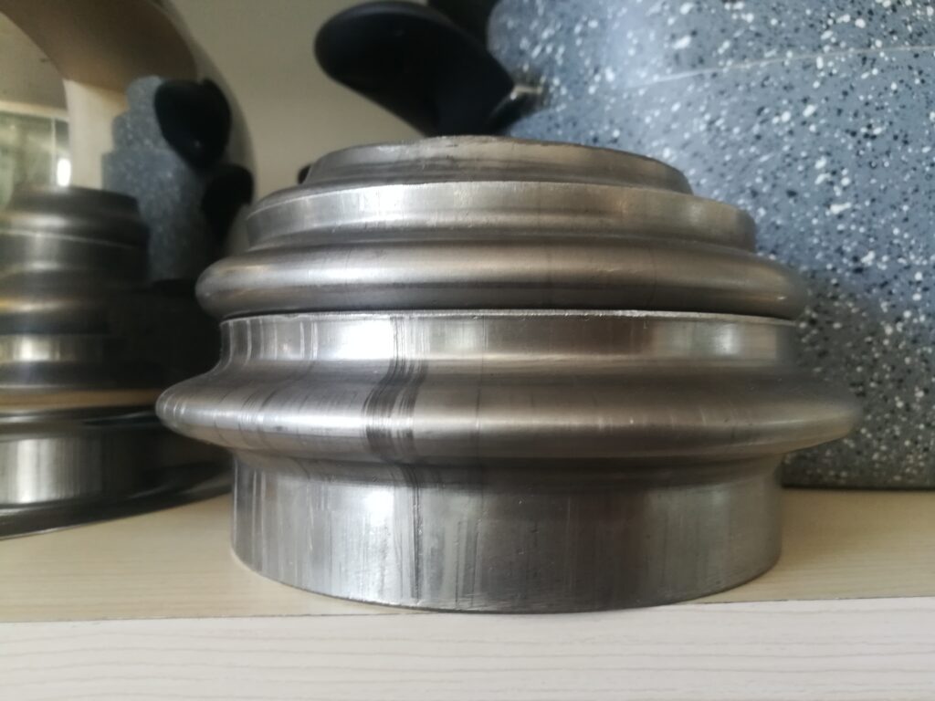
A bead inserting machine for metal pipes is a specialized type of end forming equipment designed to create raised rings or beads around the circumference of a pipe. These beads serve multiple purposes: they provide a mechanical stop for hose fittings, improve grip in clamped joints, increase sealing efficiency in rubber or silicone couplings, and can also reinforce structural rigidity in thin-walled tubes.
The bead can be formed either internally (raised from inside) or externally (indented from outside), depending on application requirements.
Bead inserting machines typically operate using hydraulic, pneumatic, or servo-electric actuators, and come in different formats depending on the production setup:
- Manual Beading Machines: Operated by hand or foot pedal, suitable for low-volume or prototype work.
- Ram-Type Beading Machines: Use a die pushed radially inward or outward in one quick motion. These are simple, fast, and well-suited for consistent, repeatable single-bead applications.
- Rotary Beading Machines: Use a rotating die or roller system to form the bead gradually around the circumference of the pipe. This method provides a smoother finish and is ideal for more complex or multi-bead configurations.
- CNC Beading Machines: Offer programmable control over bead position, depth, and profile. Capable of handling multiple operations in a single setup, often with automatic feeding and unloading.
Key Features:
- Tube size range (commonly 6 mm to 150 mm OD)
- Wall thickness capacity
- Adjustable bead depth and width
- Single or multiple bead formation
- Cycle time (typically under 5 seconds for simple beads)
- Quick-change tooling systems
- Material compatibility (steel, stainless steel, aluminum, copper, etc.)
Applications:
- Automotive exhaust and coolant lines
- HVAC ducting
- Refrigeration piping
- Hydraulic/pneumatic hose interfaces
- Aircraft and aerospace tubing
In high-volume settings, bead inserting machines are often integrated into automated cells, sometimes combined with cutting, bending, and end-forming stations. For parts requiring precise sealing or clamping, bead consistency is crucial, which is why modern machines often include sensors or inspection systems to verify bead geometry and alignment in real-time.
Bead inserting machines for metal pipes are built to ensure precise and consistent bead formation, which is critical in applications where hoses or rubber connectors rely on a physical stop or seal point. The basic principle involves clamping the pipe securely and then either pressing or rolling a shaped die against the outer or inner surface to deform the pipe wall into the desired bead profile. In many cases, especially in automotive or HVAC, the bead must meet strict dimensional tolerances to ensure that hose clamps sit properly and that no leaks occur under pressure or vibration.
Most bead inserting machines have a rigid frame and a high-force actuator to guarantee uniform bead formation even on harder materials like stainless steel. The tooling consists of a matched set of dies or rollers—one forming the bead, the other providing support to maintain the shape and avoid collapsing the pipe. For thin-walled tubes, internal mandrels or support rods may be used during the process to prevent buckling or ovality. For thick-walled or structural pipes, higher force and heat treatment may be necessary depending on the material and the bead geometry.
In modern production, programmable control is increasingly standard. CNC bead machines can store multiple part programs, allowing for rapid changeovers between different tube sizes or bead specifications. These systems also allow for complex sequences such as forming multiple beads at different axial positions on the same pipe, which might be needed for double-clamped joints or vibration isolation mounts. Servo-electric systems offer fine control over forming speed and position, improving repeatability and reducing tool wear.
The cycle time for a bead inserting operation is usually very short—often under five seconds—making these machines suitable for high-speed production lines. In many facilities, they are positioned between cutting and welding or bending operations, with automatic feeding systems bringing in cut tubes and transferring finished components downstream. Robots or servo-positioning arms may be used to orient the tubes, especially when the bead must be placed at an angle or in relation to other features such as holes or flanges.
From a maintenance perspective, these machines are relatively simple but require careful attention to tooling wear, die alignment, and hydraulic or pneumatic seals. If the dies become worn or misaligned, bead quality will suffer, leading to leaks or hose retention failures. Tool change systems are designed for quick swaps to minimize downtime. In some CNC machines, wear compensation is built into the control system, adjusting forming pressure or position automatically as tools degrade.
In sectors like aerospace, where even minor deviations in bead geometry can compromise joint integrity, inline inspection systems with laser measurement or camera-based profiling are often integrated. These systems provide immediate feedback, allowing the operator or the machine to adjust parameters on the fly. Some advanced machines even reject faulty parts automatically or alert maintenance teams if repeated issues occur.
Bead inserting machines continue to evolve with production demands. The push toward lighter materials, tighter tolerances, and higher automation levels means that manufacturers increasingly rely on machines that can adapt quickly and maintain high precision across varying production batches. Whether used for radiator tubes, turbocharger connections, or structural conduit, bead forming remains a critical operation that bridges the gap between raw tube and final assembly.
As production environments move toward more flexible and just-in-time manufacturing, bead inserting machines are being adapted for greater modularity and integration. In older systems, setup changes—such as switching tube diameters or bead profiles—could require significant downtime. But modern designs now include quick-change tooling stations, adjustable clamping systems, and servo-driven dies that allow for on-the-fly changes with minimal operator intervention. This is particularly important in industries where a single production line may handle several variants of a part, such as different lengths or diameters of coolant tubes for various vehicle models.
Safety and ergonomics are also key in machine design. Enclosures, light curtains, and dual-hand controls are standard in many semi-automatic machines to protect operators. For fully automatic machines, safety is managed through enclosure interlocks, emergency stops, and diagnostic systems that halt operation if a jam or alignment issue is detected. With more operators interacting with HMIs (human-machine interfaces), the usability of the control system is crucial. Interfaces typically allow the selection of part programs, display real-time machine status, and provide guided troubleshooting when faults occur.
In terms of materials, bead inserting machines must accommodate a wide range of metals—aluminum, stainless steel, carbon steel, brass, and more—each with different deformation characteristics. For example, aluminum forms easily but can wrinkle or tear if unsupported, while stainless steel requires more force and can spring back, which must be compensated in the forming depth. This is why many machines now include automatic compensation based on material type and thickness, either through pre-programmed settings or sensors that monitor forming load and adjust accordingly.
Some of the most demanding applications involve forming beads close to a bend or weld, where the material may already be stressed or where space is limited. Machines built for such jobs often use segmented dies or adjustable forming heads to reach tight spots without damaging adjacent features. In the case of aerospace or medical tubing, bead placement tolerances may be within tenths of a millimeter, which requires not only precision tooling but also highly stable machine frames and temperature-controlled environments.
From a cost standpoint, bead inserting machines vary widely. Manual benchtop models can be relatively inexpensive and suitable for low-volume or prototyping work, while fully automatic CNC beading systems integrated into robotic lines can be a significant investment. However, the productivity, quality consistency, and reduction in scrap they offer typically justify the cost in medium- to high-volume production. In many cases, ROI is realized quickly by eliminating manual labor, rework, and the need for secondary inspection steps.
As manufacturers push for digital integration, bead inserting machines are increasingly part of Industry 4.0 ecosystems. Data from each cycle—forming pressure, bead depth, cycle time, fault logs—is recorded and can be fed into a central MES (Manufacturing Execution System). This enables better traceability, predictive maintenance, and continuous improvement initiatives. Operators and engineers can monitor trends, anticipate tool changes, and trace any non-conforming parts back to specific machine cycles.
In summary, bead inserting machines have evolved from simple mechanical units into highly advanced, adaptive systems capable of meeting the demands of modern manufacturing. Their role is deceptively simple—form a raised ring on a tube—but the precision, speed, and repeatability they deliver are essential to product reliability in industries where failure is not an option.
Collar Forming Machine For Metal Pipes
A collar forming machine for metal pipes is a specialized forming system designed to create collars, flanges, or outward projections on the body of a metal tube or pipe. Unlike bead forming, which is typically applied near the end of the pipe, collar forming usually takes place somewhere along the tube’s length, creating a raised ring or flange that serves functional or structural purposes.
This process is used in a variety of applications including HVAC ductwork, automotive exhaust systems, irrigation systems, aircraft tubing, and plumbing systems, where collars may be needed to create branch connections, provide mounting or clamping surfaces, or act as stops for insertion into larger assemblies.
The process involves clamping the pipe, piercing or expanding the base material outward, and forming a collar or flange around the circumference. Depending on the design, the collar may be open (like a stub for a tee fitting), or closed (a raised ring around the pipe). The material is often displaced rather than added, which requires careful control to avoid thinning, wrinkling, or tearing, especially with thinner walls or harder alloys.
Collar forming machines come in a variety of configurations, typically categorized into:
– Ram-forming systems, which use hydraulic or pneumatic force to drive a die into or around the pipe
– Rotary forming systems, which gradually roll a collar outward with controlled radial movement
– Servo-driven systems, offering programmable control for collar height, thickness, and position, especially useful in CNC setups with multiple collars or complex geometries
Most machines feature adjustable tooling for different tube sizes and collar specifications. In high-end machines, the forming parameters can be stored in recipes, allowing quick transitions between different part numbers. For applications like HVAC branches or automotive tee junctions, collaring may be followed by hole cutting, expanding, or welding steps, often done in the same station or in a synchronized line.
Materials processed typically include mild steel, stainless steel, aluminum, copper, and sometimes titanium—each requiring unique considerations for force, speed, and die design. For thin-walled tubing, internal support mandrels or backup dies are often used to prevent collapse. With harder materials, preheating or multi-stage forming may be necessary to avoid cracking.
Cycle times for collar forming operations are generally efficient—often under 10 seconds for standard operations—and modern machines include auto-lubrication, diagnostics, and monitoring systems to improve uptime and consistency. In CNC-equipped systems, machine data such as forming pressure, collar height, and material feedback can be recorded for quality assurance or integrated into MES/ERP systems for traceability.
Collar forming is often combined with hole punching, trimming, and deburring in a single operation, reducing the need for downstream processes and ensuring accurate alignment between the collar and the hole it surrounds. For instance, in HVAC manufacturing, collars are formed and punched to accept smaller ducts or hoses, which are then spot-welded or crimped in place. In exhaust systems, the collar may serve as a stop or attachment feature for brackets or heat shields.
In summary, collar forming machines are vital tools in metal tube processing, allowing the formation of precise, durable collar features without adding material or requiring secondary welding in many cases. Their precision, repeatability, and integration potential make them a cornerstone in efficient, high-volume tube assembly lines.
Collar forming machines operate on a principle of controlled material displacement, which means the metal is pushed outward from the pipe wall without removing material or adding external parts. This requires precise control of forming force, speed, and tool alignment to prevent distortion of the surrounding pipe section. The collar is typically formed using a die set that first pierces or marks the location, then expands the area outward in a smooth, radiused shape. In cases where a branch connection is required, a punching or cutting tool may follow the collar formation to open a hole inside the raised collar. This creates a socket for branch pipe welding, brazing, or insertion.
Tooling design is critical, especially for production involving multiple collar sizes or tube materials. Interchangeable dies allow quick changes between parts, and high-volume systems often use hydraulic or servo-electric actuation to apply consistent pressure and repeatable motion. For more complex collar geometries or larger sizes, progressive forming is sometimes used, where the collar is formed in multiple steps to avoid overstressing the tube. This is particularly important when forming collars near bends, weld seams, or in high-strength materials like stainless steel or Inconel.
Positioning the collar accurately on the pipe is also essential, especially in automated setups. Machines use mechanical stops, servo-positioning arms, or CNC axis control to ensure each collar is placed within tight tolerances along the tube’s axis. In more advanced machines, sensors verify tube diameter, wall thickness, and exact position before and after forming, making adjustments in real-time to compensate for material variation or thermal expansion. For example, if the material is slightly out of round, the machine can adjust clamping pressure or forming depth dynamically to maintain collar symmetry and strength.
In high-speed production environments, collar forming machines are often part of an integrated line, positioned after a tube cutting or bending station. Tubes can be loaded by hand for low-volume jobs or by robotic handlers for automated lines. After collaring, the tubes may be routed to welding, leak testing, or finishing stations. This full-line integration reduces labor, increases throughput, and ensures uniformity across large production batches. Some systems include built-in part marking, barcode labeling, or vision inspection for traceability and quality control.
Material selection heavily influences collar forming performance. Aluminum offers excellent formability but may require reinforcement or thickening for structural collars. Mild steel and stainless steel are common due to their strength and weldability, but they demand higher forming forces and careful tool wear management. Tool coatings and lubricants are often used to reduce friction, prolong die life, and ensure smooth collar surfaces. In sanitary or high-purity applications, post-forming processes like polishing, deburring, or passivation may be applied to remove burrs or prevent corrosion.
Maintenance and machine reliability are essential in collar forming operations. Regular inspections of the forming dies, clamps, and actuation systems help avoid premature failure or dimensional drift. CNC-controlled systems usually include diagnostics to alert operators to issues like incomplete strokes, alignment errors, or excessive wear. Preventive maintenance schedules, combined with sensor-based monitoring, help extend uptime and reduce costly stoppages in continuous production lines.
The trend in modern collar forming machines leans toward digital integration and adaptive processing. Industry 4.0-ready systems can collect and transmit data on every cycle, including forming force, cycle time, tool temperature, and collar geometry. This data supports statistical process control and allows predictive maintenance based on real usage instead of fixed schedules. Operators can access real-time dashboards showing machine status, part counts, and alerts, while engineers can analyze trends across multiple lines or plants to optimize efficiency.
Whether used in manufacturing ventilation ducts, automotive exhaust systems, or hydraulic manifolds, collar forming machines are built to provide fast, accurate, and repeatable solutions for creating branch or flange features on tubes. Their value lies in their ability to eliminate welding, reduce parts count, and improve joint integrity with minimal material waste. In production environments where precision, speed, and repeatability matter, these machines remain a critical asset.
Advancements in collar forming technology have also introduced the use of servo-electric drives over traditional hydraulic systems, providing several benefits including quieter operation, cleaner environments (no hydraulic fluid leaks), more precise control over motion profiles, and reduced energy consumption. Servo-electric collar forming machines enable programmable speed ramps and multi-stage forming with higher repeatability. This is especially advantageous for delicate materials or complex collar shapes where gradual force application helps avoid cracking or deformation.
Another evolving area is the integration of robotic automation with collar forming. Robots can handle tube loading, orientation, positioning, and unloading, making the entire process nearly hands-free. This automation is critical in industries with strict cleanliness or traceability requirements, like aerospace and medical tubing. Robots also enable multi-axis positioning, allowing collars to be formed at precise angles or locations on bent tubes that would be difficult or impossible with fixed tooling.
Tooling innovations continue to improve machine versatility. Modular die systems allow a single machine to handle a wide range of collar sizes and profiles with minimal tooling changes. Advanced coatings and materials for dies extend their lifespan, reduce friction, and improve surface finish on the formed collars. Some tooling sets include integrated sensors that monitor forming pressure and temperature at the tool interface, feeding data back to the machine controller for adaptive process adjustment.
From a quality standpoint, inline inspection systems have become common in collar forming lines. Laser scanners or 3D vision systems measure collar height, diameter, concentricity, and surface finish immediately after forming. This data can be used for real-time process control—adjusting forming parameters on subsequent parts or flagging components that fail to meet specifications. In regulated industries, this level of quality control supports compliance with standards and reduces costly scrap or rework.
Material development also impacts collar forming processes. Newer alloys designed for lightweighting in automotive and aerospace sectors may require adjustments to forming speeds, forces, or even the introduction of heating stages to prevent cracking. Hybrid tubes—such as metal tubes with polymer linings—pose unique challenges where the collar must be formed without damaging the internal lining. Specialized tooling and carefully controlled forming parameters are necessary here to maintain integrity.
Looking forward, collar forming machines are expected to become even smarter and more connected. Advances in machine learning and AI could enable predictive adjustments based on material batch variations, tool wear patterns, and historical production data. This would allow machines to “learn” optimal forming conditions dynamically, minimizing downtime and maximizing part quality without operator intervention.
Overall, collar forming machines are key enablers of efficient, high-quality tube fabrication in many industries. Their ongoing evolution in precision, automation, material adaptability, and integration within smart factories ensures they will continue to meet growing demands for complex, lightweight, and reliable tubular assemblies. If you want, I can also cover specific manufacturers, machine models, or detailed technical parameters used in collar forming machines.
Expanding With Mandrel Machine For Metal Pipes
An expanding with mandrel machine for metal pipes is a specialized forming system designed to increase the outer diameter of a pipe or tube end by plastically deforming the metal outward, often while simultaneously supporting the inner surface of the tube with a mandrel. This process ensures that the expansion is smooth, uniform, and free of wrinkles or distortions, which is especially important when working with thin-walled or high-strength materials.
The key element in this machine is the mandrel, which is inserted inside the pipe to provide internal support during the expansion operation. By supporting the tube from within, the mandrel prevents the tube from collapsing or wrinkling while the outer diameter is increased by the forming tool or die.
These machines are widely used in industries where pipes or tubes must be joined by mechanical fittings, press-fit joints, or prepared for welding or assembly, such as automotive exhaust systems, HVAC, hydraulic and pneumatic tubing, and heat exchangers.
The expansion process typically involves placing the pipe end over an expanding die or roller system, while the mandrel inside exerts opposing pressure. The forming tool then pushes radially outward, expanding the tube’s outer diameter to the desired size. The mandrel’s shape corresponds precisely to the internal contour of the pipe, ensuring no internal deformation or damage occurs.
Mandrel expanding machines come in several varieties:
- Hydraulic or pneumatic ram-driven systems that push the expanding die outwards while holding the mandrel firmly in place.
- Rotary expanding machines, which use a rotating mandrel or rollers to expand the tube gradually around the circumference.
- CNC-controlled systems capable of precise control over expansion diameter, length, and tapering, often with programmable sequences for multi-step expansions.
The mandrel design is critical—it must fit snugly inside the pipe, often with adjustable diameters or multiple segments for quick size changes. The mandrel is typically made from hardened tool steel or carbide-coated materials to resist wear. Some machines use expandable mandrels that can be adjusted to fit a range of pipe diameters, reducing the need for multiple mandrels.
Material considerations are important. Thin-walled pipes or tubes made from aluminum, stainless steel, or other alloys require careful control of expansion speed and force to avoid cracking or thinning. The machine may allow multi-stage expansions, where the diameter is increased incrementally rather than in one step.
Cycle times for mandrel expansion vary depending on the material, size, and complexity but are generally fast enough to support high-volume production. Automation features like automatic feeding, loading, and unloading are common in industrial settings, increasing throughput and repeatability.
Mandrel expanding machines are sometimes combined with other forming operations such as end trimming, flaring, or beading, creating multi-function stations that reduce handling and improve production efficiency. Sensors may monitor expansion force, diameter, and tube straightness, providing real-time quality control and process feedback.
Maintenance includes regular inspection of mandrels and expanding dies for wear or damage, as well as hydraulic or pneumatic system upkeep. Proper lubrication is critical to minimize friction and extend tooling life.
In summary, expanding with mandrel machines are precision tools that enable controlled enlargement of pipe ends with internal support, ensuring high-quality expansion without deformation or damage. They are vital in producing components that require tight-fitting joints or connections, with applications across automotive, aerospace, HVAC, and fluid handling industries.
Expanding with mandrel machines rely heavily on the synchronization between the internal mandrel and the external expanding die or rollers. The mandrel’s purpose is to maintain the tube’s internal geometry and prevent buckling or wrinkling as the outer diameter increases. Without this internal support, the tube wall could collapse inward or form undesirable folds, especially with thin-walled or ductile metals. The mandrel itself can be solid, segmented, or expandable to accommodate different tube sizes and wall thicknesses, and in some designs, it is hydraulically or mechanically actuated to provide variable internal pressure during the expansion process.
The expansion force must be carefully controlled to avoid overstressing the material. Most machines incorporate load sensors or force feedback systems that monitor the pressure exerted during forming, allowing for real-time adjustments. This prevents cracks or thinning that could weaken the tube or cause leaks in fluid-carrying systems. Additionally, controlling the expansion speed helps ensure the metal flows evenly and that strain is distributed uniformly across the expanded section.
Many expanding with mandrel machines also offer the ability to create tapered or stepped expansions. This means the diameter can gradually increase along the pipe length or form multiple diameter changes in a single cycle. This capability is especially useful when preparing tubes for complex assemblies where a perfect press fit or interference fit is required. For example, an automotive exhaust system might require a slightly larger diameter at one end for slip fitting and a smaller, tighter expansion at another location for sealing or attachment.
In automated production lines, these machines are often integrated with feeding systems that position tubes accurately for expansion. Automated loading and unloading reduce manual handling, improving safety and throughput. Some setups include vision systems or laser measurement tools that verify the expanded diameter and check for defects immediately after forming. This inline inspection ensures quality control and allows defective parts to be rejected before moving downstream in the assembly process.
Material selection plays a crucial role in the expansion process. Metals like stainless steel, aluminum, and brass all behave differently under expansion forces. Aluminum, while ductile, can be prone to thinning and cracking if the expansion is too rapid or forceful. Stainless steel requires higher forming forces but offers excellent springback resistance, meaning the machine must account for elastic recovery to achieve the desired final diameter. To address these challenges, some machines include heating elements to warm the tube before expansion, making the metal more malleable and reducing the risk of cracks.
The tooling surfaces—the mandrel and expanding dies—are typically made from hardened steels or coated with materials like tungsten carbide to resist wear and reduce friction. Proper lubrication during expansion is essential to protect tooling and ensure smooth metal flow. Machines may feature automatic lubrication systems that deliver precise amounts of lubricant directly to the contact areas.
Maintenance of mandrel expanding machines involves routine checks of hydraulic or pneumatic systems, inspection of mandrel and die surfaces for wear or damage, and calibration of sensors and control systems. Given the high forces involved in expansion, even small misalignments or worn tooling can result in poor part quality or machine damage. Preventive maintenance schedules, combined with machine diagnostics and sensor feedback, help maximize uptime and part consistency.
With the increasing adoption of Industry 4.0 technologies, expanding with mandrel machines are becoming more connected and intelligent. Real-time monitoring data can be used not only for quality control but also for predictive maintenance, where machine learning algorithms analyze forming force patterns, cycle times, and sensor inputs to predict when tooling or components will need service. This minimizes unexpected downtime and optimizes production planning.
In some advanced systems, the mandrel itself is sensor-equipped to monitor internal tube conditions during forming, such as strain or temperature, providing unprecedented insight into the forming process. This data can inform adjustments in real time, enabling higher precision and reducing scrap rates.
Overall, expanding with mandrel machines provide a controlled and repeatable method to increase pipe diameters with internal support, ensuring that tubes maintain their structural integrity and dimensional accuracy. This process is essential in many industries where reliable tube connections and fittings are critical, and ongoing technological advances continue to improve machine capability, flexibility, and integration into automated manufacturing environments.
Expanding with mandrel machines also play a critical role in reducing secondary operations. By precisely controlling the expansion process, these machines often eliminate the need for additional machining, grinding, or finishing to meet dimensional tolerances or surface quality requirements. This streamlining reduces production time and lowers overall manufacturing costs.
The ability to create tight, interference-fit connections through mandrel expansion enhances joint strength and leak resistance without welding or adhesives, which is especially valuable in fluid and gas transport systems. For example, in hydraulic lines or fuel systems, expanded tube ends can be joined with fittings or connectors that rely on the expanded diameter to form a robust mechanical seal, improving reliability and simplifying assembly.
Customization is another strength of modern mandrel expanding machines. Operators can program multiple expansion steps within a single cycle, adjusting parameters like expansion length, diameter increments, and mandrel pressure to accommodate complex tube geometries. This flexibility supports a wide range of applications—from simple single-step expansions to multi-stage forming for specialized components.
In terms of materials, the growing use of high-strength alloys and composite tubes requires machines capable of adapting forming strategies. For example, some composite-metal hybrid tubes require careful mandrel support and slower expansion rates to avoid delamination or damage to the composite layers. Machines equipped with advanced control systems can adjust forming force and speed dynamically based on feedback from sensors embedded in the mandrel or tooling.
Energy efficiency is another focus in recent machine designs. Servo-electric drives and improved hydraulic systems reduce power consumption and noise levels, making mandrel expanding machines more environmentally friendly and cost-effective to operate. Some manufacturers incorporate regenerative braking or energy recovery systems to capture and reuse energy during forming cycles.
The size range of expanding with mandrel machines varies widely, from small bench-top units for precision tubing used in medical or aerospace applications, to large industrial machines capable of handling heavy-wall pipes several inches in diameter for oil and gas or structural uses. In all cases, the core principles remain consistent: supporting the tube internally while expanding the external diameter to precise specifications.
Training and operator interface design have evolved as well. Modern machines often feature touchscreen HMIs with guided setups, diagnostics, and recipe management. This reduces setup times, minimizes operator errors, and allows less-experienced workers to operate complex machines safely and effectively.
Looking ahead, the combination of mandrel expanding with other advanced tube forming processes—such as hydroforming, roll forming, and robotic welding—will further streamline production of complex tubular assemblies. Integration with real-time data analytics and AI will continue to push the boundaries of precision, efficiency, and adaptability in tube expansion technology.
If you want, I can provide more details on specific types of mandrels, machine manufacturers, or applications tailored to particular industries.
Groove Forming Machine For Metal Pipes
A groove forming machine for metal pipes is a specialized piece of equipment designed to create precise grooves or recesses on the external or internal surface of metal tubes and pipes. These grooves are critical for a variety of functional purposes such as enabling secure mechanical joints, facilitating sealing with O-rings or gaskets, providing locking features, or preparing pipes for coupling systems.
Grooves on pipes are commonly used in industries like plumbing, HVAC, automotive, oil and gas, fire protection systems, and industrial fluid transport. For example, in grooved piping systems used for quick assembly and disassembly, the groove allows a coupling to clamp around the pipe, providing a strong, leak-resistant joint without welding or threading.
Groove forming machines operate by deforming the pipe surface to cut or press a circumferential groove to precise dimensions and locations. The process may involve rolling, pressing, or cutting techniques depending on the groove profile, pipe material, and required tolerances.
These machines vary in complexity, from portable hand-held grooving tools for on-site pipe installation to fully automated CNC-controlled machines integrated into production lines. Portable grooving machines are common for fieldwork, allowing workers to create grooves directly on installed pipes without needing to move them. In contrast, industrial groove forming machines are designed for high-volume production and provide repeatable accuracy with minimal operator intervention.
The groove forming process typically involves clamping the pipe securely, then using a rotating or reciprocating tool to create the groove. The tooling is precisely engineered to match the groove specifications, including width, depth, and profile shape. Some machines use rollers or wheels that press into the pipe surface while rotating around it, forming the groove by plastic deformation without removing material. Others may employ cutting tools or milling heads for grooves requiring sharp edges or specific geometries.
Material considerations are important because groove forming must avoid cracking or excessive thinning of the pipe wall. Machines often include adjustable pressure and speed controls to accommodate different metals such as mild steel, stainless steel, copper, and aluminum. For thin-walled pipes, supporting fixtures or internal mandrels may be used to prevent deformation during the grooving process.
Advanced groove forming machines often feature CNC control, allowing precise positioning of the groove along the pipe length, programmable groove dimensions, and multiple grooves in a single cycle. This capability is especially useful in manufacturing complex piping assemblies where several grooves are required for couplings, seals, or connections.
Quality control is typically integrated, with sensors or laser measurement systems verifying groove depth and width immediately after forming. This reduces scrap and rework by ensuring each groove meets specifications before the pipe advances to assembly.
Maintenance involves regular inspection and replacement of tooling, calibration of pressure and position sensors, and lubrication of moving parts. Since groove forming involves repetitive high-contact forces, tool wear is a critical factor in maintaining consistent groove quality.
In summary, groove forming machines for metal pipes provide efficient and precise solutions for creating functional grooves that enable secure, leak-proof pipe connections. Their versatility, from portable field tools to automated production line equipment, makes them indispensable across many industries that rely on grooved piping systems.
Groove forming machines rely on precise control of tool pressure and positioning to create consistent grooves without damaging the pipe. The groove profile must meet strict dimensional tolerances to ensure proper fit with couplings or seals, so the machine often includes fine adjustments for groove depth, width, and shape. In some designs, the tooling rolls or presses the groove into the pipe gradually, minimizing stress and avoiding cracks, especially on harder metals or thin walls.
The clamping system plays a crucial role in stabilizing the pipe during forming. It must hold the pipe securely without causing deformation or flattening, often using segmented clamps or adjustable jaws that conform to different pipe diameters. Internal supports, such as mandrels or backing rings, may be employed for thin-walled or soft pipes to maintain roundness and prevent collapse during groove formation.
Portable groove forming machines are widely used in field applications like plumbing or fire protection installations. These handheld or semi-portable devices allow workers to create grooves on pipes already installed in buildings or industrial plants. They typically operate using hydraulic or electric power and are designed for quick setup, easy adjustment, and consistent groove quality. Despite their compact size, many portable units offer interchangeable tooling for different pipe sizes and groove types.
In contrast, industrial groove forming machines are designed for high-volume, repeatable production. These machines integrate into automated lines where pipes are fed, grooved, and passed to subsequent processes like cutting, bending, or assembly. CNC controls enable precise positioning of multiple grooves along the pipe length and allow for complex groove patterns required by specialized coupling systems. Automation reduces operator involvement, increases throughput, and improves consistency.
Tooling materials and design are critical for durability and groove quality. Grooving tools are usually made from hardened tool steel or carbide-tipped components to withstand the repeated high-pressure contact with metal pipes. Some machines feature quick-change tooling systems to minimize downtime during maintenance or when switching between pipe sizes.
Groove forming also requires proper lubrication to reduce friction between the tooling and pipe surface, preventing tool wear and avoiding surface defects on the pipe. Automatic lubrication systems are common in industrial machines, delivering precise amounts of lubricant at the contact points during each cycle.
The range of pipe materials processed includes carbon steel, stainless steel, copper, aluminum, and various alloys. Each material demands adjustments in forming speed, force, and tool design to accommodate differences in hardness, ductility, and wall thickness. For instance, stainless steel requires higher forming forces and slower tool movement to avoid work hardening and cracking.
Some advanced groove forming machines incorporate real-time monitoring systems, such as laser scanners or tactile sensors, to inspect the groove immediately after formation. These systems check parameters like groove depth, width, roundness, and surface finish, enabling instant rejection of non-conforming parts and reducing scrap rates. Data collected can be used for process optimization and traceability.
Maintenance and calibration are essential for ensuring long-term precision and machine reliability. Regular inspection of tooling for wear or damage, verification of sensor accuracy, and lubrication system upkeep help maintain groove quality and minimize production interruptions.
Groove forming machines continue to evolve with technological advancements. Integration with Industry 4.0 systems allows remote monitoring, predictive maintenance, and data-driven process improvements. Some machines now feature adaptive control that adjusts forming parameters based on real-time feedback from the pipe and tooling condition, optimizing cycle times and product quality.
In summary, groove forming machines for metal pipes combine mechanical precision, material science, and automation to produce high-quality grooves essential for modern piping systems. Whether used on-site with portable tools or in automated factories, these machines provide the accuracy, speed, and reliability needed for secure and leak-resistant pipe connections across many industries.
Modern groove forming machines increasingly incorporate flexible tooling systems that can quickly switch between different groove profiles and pipe sizes, enabling manufacturers to respond rapidly to changing production needs without lengthy downtime. This flexibility is especially valuable in industries like HVAC, fire protection, and oil and gas, where multiple pipe standards and coupling types coexist.
Some groove forming machines also feature multi-station setups, where pipes can be grooved, trimmed, flared, or beaded in a single integrated cycle. This reduces handling, shortens production time, and improves overall workflow efficiency. These multi-function machines often employ robotic arms or automated conveyors to transfer pipes seamlessly between stations.
Material handling innovations, such as automated pipe feeders and ejectors, further enhance productivity. Pipes can be loaded and positioned precisely for each groove, ensuring consistent quality and minimizing human error. Coupled with CNC controls, these features make high-volume grooving operations more efficient and less labor-intensive.
Environmental considerations are also shaping groove forming technology. Machines are designed with energy-efficient motors, hydraulic systems that minimize fluid leaks, and noise reduction features to comply with workplace safety and sustainability goals. Additionally, using dry lubrication or biodegradable lubricants is becoming more common to reduce environmental impact.
In specialty applications, groove forming machines adapt to non-circular pipes or tubes with complex cross-sections. Customized tooling and specialized clamping systems enable grooves on oval, rectangular, or profiled tubes, expanding the range of products that can benefit from grooved joints.
Quality assurance continues to be a key focus. Integration of smart sensors and AI-driven inspection systems enables predictive analytics, alerting operators to potential tool wear or process deviations before defects occur. This proactive approach enhances uptime and lowers waste, crucial in highly regulated industries such as aerospace or pharmaceutical piping.
Training and user interfaces have also improved, with intuitive touchscreen controls, guided setup procedures, and remote diagnostics enabling operators of various skill levels to run groove forming machines effectively. Some systems even support remote access, allowing experts to assist or troubleshoot from off-site locations, reducing downtime and support costs.
Overall, groove forming machines remain essential tools for producing precise, reliable grooves on metal pipes that meet stringent industry requirements. Their continued evolution toward automation, flexibility, environmental responsibility, and smart manufacturing integration ensures they will keep pace with growing demand for efficient and high-quality pipe joining solutions. If you want, I can provide information on specific machine models, manufacturers, or case studies demonstrating groove forming applications.
Edge Trimming Machine For Metal Pipes
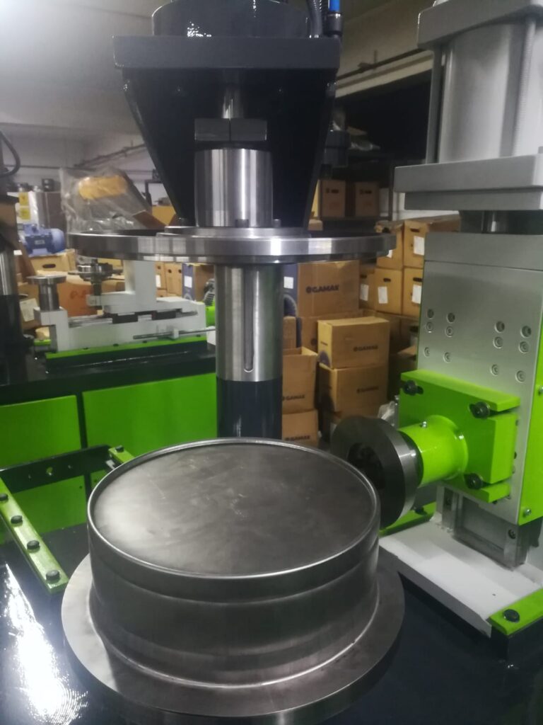
An edge trimming machine for metal pipes is a specialized device designed to remove excess material, burrs, or uneven edges from the ends of metal pipes or tubes. This process is essential to prepare pipe ends for further fabrication steps like welding, joining, coating, or assembly, ensuring clean, smooth, and dimensionally accurate edges.
Edge trimming is particularly important in industries such as automotive, aerospace, plumbing, HVAC, oil and gas, and general manufacturing, where precise pipe ends are critical for maintaining structural integrity, leak prevention, and aesthetic quality.
The primary function of an edge trimming machine is to cut away irregularities caused by upstream processes such as cutting, sawing, or stamping. These irregularities can include rough edges, burrs, or slight length variations that, if left untreated, could cause problems during fitting or assembly.
Edge trimming machines for metal pipes come in several configurations depending on pipe size, wall thickness, and production volume. Common types include:
- Rotary trimming machines, where rotating cutting tools or blades move around the pipe circumference to uniformly trim the edge.
- Stationary blade systems, where the pipe rotates against a fixed cutting blade to remove excess material.
- Automated CNC trimming machines, offering programmable cutting paths and depths for complex trimming requirements or irregular pipe geometries.
The machines typically clamp the pipe securely to prevent movement or vibration during trimming, which is critical for achieving consistent edge quality. Clamping systems vary but often use adjustable jaws or mandrels that conform to the pipe’s diameter.
Cutting tools are usually made of hardened tool steel, carbide, or other wear-resistant materials to maintain sharpness and precision over long production runs. Tool designs may include circular saw blades, milling cutters, or specialized knives, depending on the trimming method and material.
Edge trimming parameters such as feed rate, cutting speed, and depth of cut are adjustable to accommodate different pipe materials—ranging from soft aluminum and copper to hard stainless steel or high-strength alloys. Proper adjustment ensures smooth cuts, prevents tool wear, and minimizes heat buildup that could affect material properties.
Many edge trimming machines integrate automated loading and unloading systems to increase throughput in high-volume production environments. These may include conveyors, robotic arms, or feeders that position pipes accurately for trimming and transfer finished parts downstream.
Quality control systems are often incorporated to inspect the trimmed edge immediately after processing. Laser scanners, cameras, or tactile sensors measure edge straightness, length consistency, and surface finish, rejecting parts that don’t meet specifications and reducing scrap.
Maintenance includes regular inspection and replacement of cutting tools, calibration of clamping mechanisms, lubrication of moving parts, and monitoring of cutting parameters to maintain optimal performance.
Some edge trimming machines are designed as multifunctional units, combining trimming with other operations like chamfering, beveling, or deburring in a single station, streamlining workflow and reducing handling.
Overall, edge trimming machines play a vital role in ensuring pipe ends are clean, accurate, and ready for the next stage in manufacturing or assembly. Their adaptability to various pipe sizes, materials, and production demands makes them essential in modern metal pipe fabrication.
Edge trimming machines rely on precise synchronization between the cutting tools and the pipe rotation to achieve uniform material removal around the circumference. The pipe is usually rotated at a controlled speed while the cutting blade advances steadily to trim the edge evenly. Some machines feature multiple blades working simultaneously to speed up the process or to create specific edge profiles such as chamfers or bevels.
Clamping systems are designed to hold the pipe firmly without causing deformation or damage to the pipe wall. For thin-walled or delicate pipes, soft or adjustable jaws are often used to prevent crushing. In many designs, an internal mandrel supports the pipe from the inside, maintaining roundness and providing stability during trimming.
Material type and wall thickness significantly influence cutting parameters. Softer metals like aluminum and copper allow faster feed rates and higher cutting speeds, while harder materials such as stainless steel or alloy steels require slower, more controlled cutting to avoid tool wear and heat buildup that could affect the pipe’s mechanical properties. Cooling or lubrication systems are sometimes incorporated to reduce heat and extend tool life.
Edge trimming machines may be standalone units for batch processing or integrated into automated production lines. In integrated systems, robots or conveyors automatically load and position pipes, reducing manual handling and increasing throughput. Automated systems often include sensors and cameras to verify the pipe size and orientation before trimming, ensuring consistency.
For quality assurance, some machines feature real-time monitoring of cutting forces or vibrations, which helps detect tool wear or irregularities in the pipe surface. These feedback systems can trigger alerts or automatic adjustments to maintain trimming accuracy. Post-trimming inspection may involve laser measurement or optical scanning to confirm edge dimensions and surface finish.
Maintenance is a critical aspect of edge trimming machines. Cutting tools require periodic sharpening or replacement, and clamping components need regular calibration to ensure proper grip. Lubrication of moving parts reduces wear and prevents downtime. Preventive maintenance schedules based on usage data help optimize machine uptime.
Edge trimming is often combined with deburring processes, where additional tools remove microscopic burrs left after trimming to improve safety and functionality. Some machines incorporate integrated deburring heads or brushes immediately after trimming for a seamless workflow.
In specialized applications, edge trimming machines can handle non-standard pipe shapes, including oval or rectangular tubes, by using customized tooling and adaptive clamping mechanisms. This versatility supports a wide range of manufacturing requirements beyond standard round pipes.
Recent advancements include the incorporation of CNC control, allowing operators to program precise trimming depths, speeds, and profiles for different pipe batches. This flexibility enables quick changeovers and supports small batch or custom orders efficiently.
Energy-efficient designs with servo motors and optimized hydraulic systems reduce power consumption and noise emissions, contributing to more sustainable manufacturing environments.
Edge trimming machines are crucial in ensuring the quality and reliability of pipe ends, which directly affect downstream processes like welding, joining, or sealing. Their precise operation, adaptability to different materials and sizes, and integration with automated production systems make them indispensable in modern pipe fabrication facilities.
Edge trimming machines also contribute significantly to workplace safety by removing sharp edges and burrs that can cause injuries during handling and assembly. Properly trimmed and finished pipe ends reduce the risk of cuts or damage to seals and gaskets, improving overall product safety and reliability.
In addition to traditional metal pipes, these machines are increasingly being adapted to work with composite and clad pipes, which combine different materials for enhanced performance. The trimming process for such pipes requires careful control to avoid delamination or damage to the bonding layers, often involving specialized tooling and gentler cutting parameters.
Customization options allow manufacturers to tailor trimming processes to specific industry standards or customer requirements. For instance, some pipes need specific bevel angles or edge preparations to optimize welding quality or to meet certifications in aerospace, automotive, or energy sectors.
With the rise of smart manufacturing, edge trimming machines are being integrated into digital ecosystems. Data collected from sensors on cutting forces, machine cycles, and tool wear can be analyzed to optimize maintenance schedules, reduce downtime, and improve process consistency. Remote monitoring and diagnostics also enable faster troubleshooting and support.
For manufacturers handling a wide variety of pipe diameters, modular machine designs allow quick swapping or adjustment of tooling and clamping components. This modularity minimizes changeover time and maximizes flexibility in mixed production environments.
In summary, edge trimming machines are vital in producing clean, precise pipe ends that ensure proper fit, function, and safety in downstream applications. Their evolving features—ranging from automation and smart controls to material versatility—continue to enhance productivity and quality in metal pipe fabrication across diverse industries.
Rib Rolling Machine For Metal Pipes
A rib rolling machine for metal pipes is a specialized machine designed to create raised ribs or corrugations along the length or circumference of metal pipes and tubes. These ribs serve multiple purposes such as increasing structural strength, improving grip, enhancing fluid dynamics, or providing aesthetic finishes. Ribbed pipes are widely used in industries including automotive, construction, HVAC, oil and gas, and manufacturing.
Rib rolling involves deforming the pipe’s surface plastically by rolling it between shaped rollers or dies that imprint the rib pattern onto the metal. This cold-forming process strengthens the pipe by work hardening the metal and increasing its moment of inertia without significantly adding weight or thickness.
The rib rolling machine typically consists of a set of rollers arranged so that the pipe passes through them while rotating. One or more rollers have specially designed rib profiles that press into the pipe’s outer surface as it advances, creating continuous ribs or corrugations. The shape, height, pitch, and number of ribs can be customized depending on application requirements.
These machines vary widely, from small bench-top units for thin tubing or precision work, to large industrial-scale machines capable of processing heavy-duty pipes with thick walls. Modern rib rolling machines often feature CNC control to adjust roller pressure, rotation speed, and rib spacing dynamically, enabling complex patterns and consistent quality.
Material versatility is key; rib rolling machines handle a range of metals such as carbon steel, stainless steel, aluminum, copper, and various alloys. Adjustments to rolling force and speed are made based on the pipe’s material properties to avoid cracking or distortion.
Ribbed pipes offer several functional advantages. Structurally, ribs increase stiffness and resistance to bending or crushing forces, allowing for lighter-weight designs without compromising strength. In fluid transport, ribs can create turbulence inside or outside the pipe, improving heat transfer or flow characteristics in heat exchangers and cooling systems.
In applications requiring grip or anti-slip surfaces, such as scaffolding tubes or handrails, ribs provide enhanced friction. Aesthetic applications use ribbing for decorative effects or brand identification on visible pipework or furniture.
Rib rolling machines are often integrated into production lines with automated feeding, cutting, and inspection systems. Sensors and cameras can monitor rib dimensions and spacing in real time, ensuring compliance with specifications and minimizing defects.
Maintenance involves regular inspection of roller surfaces for wear or damage, lubrication of bearings and moving parts, and calibration of pressure controls to maintain consistent rib depth and profile.
With increasing demand for lightweight, strong, and functional pipe products, rib rolling machines continue to evolve. New developments include servo-driven systems for precise control, modular roller assemblies for quick pattern changes, and smart diagnostics for predictive maintenance.
If you want, I can share details about specific rib rolling machine types, industries that use ribbed pipes, or the design considerations behind different rib patterns.
Rib rolling machines operate by feeding the metal pipe between one or more rollers that apply controlled pressure to the pipe’s surface, plastically deforming it to form ribs or corrugations. The rollers are precisely machined with rib patterns that determine the shape, height, and spacing of the ribs. As the pipe rotates and moves forward, the ribs are formed continuously along the desired length or around the circumference.
The process must be carefully controlled to prevent damage such as cracking, excessive thinning, or distortion of the pipe. This involves adjusting rolling speed, pressure, and roller alignment based on the pipe material, wall thickness, and rib design. Some machines allow for incremental ribbing, gradually increasing rib depth over multiple passes to reduce stress on the pipe.
Clamping and guiding mechanisms keep the pipe stable and correctly positioned during rib rolling, ensuring uniform rib formation. These systems can include adjustable supports and guides that accommodate different pipe diameters and lengths, enabling quick changeovers between production batches.
Materials commonly processed include carbon steel, stainless steel, aluminum, and copper, with each requiring different process parameters. For harder metals or thicker walls, higher rolling forces and slower speeds are typically necessary to achieve the desired rib depth without compromising pipe integrity.
Rib rolling machines can produce a variety of rib patterns, from simple longitudinal ribs running along the pipe length to complex helical or circumferential ribs. The choice depends on functional requirements such as increasing stiffness, improving grip, or enhancing fluid flow dynamics. Multiple rib shapes and sizes can be combined on a single pipe to meet specific performance criteria.
In addition to structural benefits, ribbed pipes often offer improved thermal characteristics. For example, external ribs increase the surface area of heat exchanger tubes, enhancing heat transfer efficiency. In HVAC applications, internally ribbed pipes promote turbulent flow, improving heating or cooling performance.
Automated rib rolling lines integrate with pipe feeding, cutting, and inspection systems to ensure high productivity and consistent quality. Real-time monitoring using laser or optical sensors checks rib dimensions and spacing, allowing immediate correction of deviations. Data from these systems supports quality control and traceability, critical in industries with strict standards such as automotive or aerospace.
Maintenance focuses on the rollers, which must be kept free of wear, corrosion, or damage to maintain rib accuracy. Regular lubrication of bearings and mechanical parts ensures smooth operation, while calibration of pressure systems maintains consistent forming forces.
Technological advances have introduced servo-driven rollers that provide precise control over ribbing pressure and speed, enabling complex patterns and faster changeovers. Modular roller systems allow manufacturers to swap out rib profiles quickly, increasing flexibility and reducing downtime.
Smart monitoring systems predict tool wear and maintenance needs based on usage patterns and sensor data, helping to prevent unexpected breakdowns and optimize production schedules.
Rib rolling machines contribute significantly to producing lightweight, strong, and functional metal pipes across various sectors. Their ability to enhance mechanical properties, improve fluid dynamics, and add aesthetic value makes them essential in modern pipe manufacturing.
In many rib rolling applications, the process is fine-tuned to balance rib height and spacing with the pipe’s intended use. For instance, in structural applications, higher and more closely spaced ribs can significantly increase rigidity and resistance to bending or crushing without adding much weight. Conversely, in fluid handling or heat exchange, ribs might be shallower but spaced to maximize turbulence or surface area for efficient heat transfer.
Some rib rolling machines are designed to produce variable rib patterns along the pipe length, allowing different sections to have different rib geometries tailored to specific functional zones. This capability is particularly valuable in custom or specialized pipe manufacturing, where multiple performance requirements must be met within a single part.
Portable rib rolling machines also exist for on-site applications where pipes need modification after installation or for repair work. These portable units are smaller, manually operated, or semi-automatic, allowing workers to add ribs or corrugations to pipes without moving heavy components or dismantling systems.
In addition to traditional metal pipes, rib rolling technology is sometimes applied to composite or clad pipes, which combine layers of different materials for enhanced strength, corrosion resistance, or thermal properties. Rolling ribs on such pipes requires careful control to avoid delamination or damage to the outer layers, often involving lower pressures or specialized tooling.
The versatility of rib rolling machines also extends to non-cylindrical pipes and tubes. With custom roller designs and adaptable clamping systems, some machines can create ribs on oval, rectangular, or other shaped tubing, broadening the range of products that benefit from rib enhancements.
Environmental and efficiency considerations are driving innovations in rib rolling machinery, such as energy-efficient drives, quieter operation, and reduced lubrication requirements. These improvements contribute to more sustainable and cost-effective manufacturing processes.
Industry trends toward smart manufacturing have brought advanced monitoring and control systems into rib rolling operations. Sensors track parameters like roller pressure, pipe feed rate, and temperature, feeding data into control software that adjusts settings in real time for optimal rib quality and consistency. Predictive maintenance algorithms analyze this data to schedule tool replacement or servicing before failures occur, minimizing downtime.
Rib rolling machines often integrate with broader production ecosystems, communicating with upstream and downstream equipment for seamless workflow automation. This connectivity supports just-in-time manufacturing, reducing inventory and improving responsiveness to market demands.
In summary, rib rolling machines are essential tools for enhancing the mechanical and functional properties of metal pipes through the precise formation of ribs or corrugations. Their adaptability, technological sophistication, and integration with modern manufacturing practices ensure they remain a cornerstone in the production of high-performance piping solutions across diverse industries.
Pinching With Dies Machine For Metal Pipes
A pinching with dies machine for metal pipes is a specialized forming machine designed to reduce the diameter or alter the shape of a metal pipe at specific locations by compressing or “pinching” it using matched dies. This process creates a localized deformation, such as a narrowed section, a flattened area, or a tailored profile, often used for fitting, joining, or assembly purposes.
Pinching machines use precision-engineered dies that clamp around the pipe and apply controlled force to deform the pipe’s wall without cracking or weakening it. The dies are typically made from hardened tool steel or other wear-resistant materials to withstand repeated high-pressure contact with metal pipes.
The pinching process can serve various functions:
- Joining: Creating reduced sections or profiles that fit into connectors or couplings.
- Sealing: Forming tight, compressed areas that improve sealing surfaces for gaskets or O-rings.
- Structural: Altering pipe geometry to increase strength or facilitate attachment points.
- Preparation: Pinching pipe ends before welding or brazing to improve joint quality.
Pinching machines range from manual or hydraulic bench-top models for small-diameter pipes to fully automated CNC-controlled systems capable of handling large pipes with high precision and repeatability. Automated machines often incorporate programmable settings for die position, force, and deformation length, supporting complex or repetitive manufacturing tasks.
The process must balance sufficient force to achieve the desired deformation without causing cracks, wrinkles, or excessive thinning of the pipe wall. Material properties such as ductility and thickness influence machine settings, including die design, applied pressure, and compression speed.
Clamping mechanisms securely hold the pipe during pinching, preventing movement or distortion outside the target area. In some designs, internal supports like mandrels are used to maintain pipe roundness and prevent collapse.
Pinching machines often include adjustable stops and guides to ensure precise location and length of the pinched section. This is critical in applications requiring tight tolerances for fitting or assembly.
Integration with automated production lines enables continuous processing, where pipes are fed, pinched at programmed intervals, and moved to subsequent operations such as cutting, welding, or inspection. Sensors may monitor force application and deformation quality in real time, triggering alerts or adjustments if specifications are not met.
Maintenance involves regular inspection of dies for wear or damage, lubrication of moving parts, and calibration of force controls to maintain consistent deformation quality.
Pinching with dies machines are essential in industries such as automotive, HVAC, plumbing, and manufacturing, where precise localized pipe deformation supports reliable, leak-free connections and efficient assembly processes.
Pinching with dies machines operate by bringing two or more hardened dies together around a section of the pipe, applying compressive force that plastically deforms the metal into the desired shape. The dies are typically shaped to create specific profiles—such as a narrowed diameter, flattened areas, or complex geometries—that match the functional requirements of the pipe assembly.
The machine’s force application is carefully controlled to avoid defects like cracking, wrinkling, or excessive thinning, which could compromise pipe integrity. This is especially important for pipes made from harder or less ductile materials, where improper force or die design can lead to failure. To address this, modern pinching machines often allow fine adjustment of pressure, speed, and die alignment.
Many pinching machines use hydraulic or mechanical presses to deliver consistent and repeatable force. Hydraulic systems provide smooth, adjustable pressure and can accommodate a wide range of pipe sizes and materials. Mechanical presses may offer faster cycle times but require precise calibration.
Pipe positioning during pinching is crucial for accuracy and quality. Adjustable clamps, guides, and stops ensure the pipe is held firmly in the correct location so the deformation occurs exactly where needed. In some cases, internal mandrels or support pins are inserted inside the pipe to maintain its shape and prevent collapse or deformation outside the pinched area.
For high-volume production, automated pinching machines are integrated with conveyors or robotic feeders that load pipes, perform the pinching operation, and transfer parts downstream with minimal operator intervention. This automation improves throughput, consistency, and worker safety.
Real-time monitoring systems are increasingly common, using sensors to track force, displacement, and position during the pinching cycle. These systems detect anomalies such as insufficient deformation or over-compression and can pause production or alert operators to potential issues, reducing scrap and rework.
Different die designs enable the creation of various profiles suited for specific applications. For example, some dies produce smooth, tapered reductions ideal for insertion into fittings, while others create ridged or grooved pinched sections to enhance mechanical locking or seal retention.
Pinching is often combined with other pipe end-forming processes like flaring, beading, or swaging to prepare pipes for complex assemblies. Multi-functional machines can perform several of these operations in sequence, increasing efficiency and reducing handling.
Materials commonly processed include carbon steel, stainless steel, copper, aluminum, and various alloys. Each material requires tailored settings for pinching force and speed based on its mechanical properties and thickness.
Maintenance routines focus on inspecting dies for wear, chips, or deformation that could affect forming accuracy. Regular lubrication of moving components and hydraulic systems keeps the machine running smoothly and extends its service life.
Pinching with dies machines are widely used in industries requiring precise, localized pipe deformation for reliable joints, efficient assembly, and leak-proof connections. Their versatility, precision, and adaptability to various pipe sizes and materials make them essential tools in modern pipe fabrication and manufacturing workflows.
Advanced pinching with dies machines often incorporate CNC or programmable logic controllers (PLCs) to automate the entire deformation cycle with high precision. Operators can input exact parameters such as pinch length, force, speed, and die positioning, allowing for rapid changeovers between different pipe sizes or production requirements. This level of control enhances repeatability and reduces operator error.
In some setups, multiple pinching stations are arranged sequentially to perform several deformations on a single pipe without manual repositioning. This multi-stage approach is especially useful for complex components that require different pinched sections for fitting, sealing, or structural reinforcement.
The dies themselves can be customized to match the exact shape needed, often designed using CAD software and manufactured with CNC machining to tight tolerances. Special coatings or surface treatments may be applied to dies to reduce wear and friction, prolonging tool life and ensuring consistent results over long production runs.
Pinching machines may also include integrated quality control systems that inspect the pinched sections for dimensional accuracy, surface finish, and structural integrity. Techniques such as laser scanning, vision systems, or tactile probes verify that each part meets specifications before moving further down the production line.
In applications where the pinched pipe section needs additional processing—like welding, brazing, or sealing—pinching machines are sometimes paired with those downstream operations to streamline workflow and minimize handling.
Environmental and ergonomic considerations have led to designs that minimize noise, vibration, and operator fatigue. For example, enclosed pinching stations reduce noise levels, while intuitive human-machine interfaces (HMIs) improve usability and reduce training time.
Pinching with dies machines also accommodate a wide range of pipe diameters and wall thicknesses, often through adjustable or interchangeable dies and clamps. This flexibility makes them suitable for diverse industries, including automotive exhaust systems, plumbing, refrigeration, hydraulic lines, and structural frameworks.
In summary, pinching with dies machines offer precise, controlled, and repeatable pipe deformation essential for creating functional features such as reduced sections, sealing surfaces, and mechanical joints. Their adaptability, integration with automation, and quality assurance capabilities make them indispensable in modern metal pipe fabrication processes.
Curling With Rollers Machine For Metal Pipes
A curling with rollers machine for metal pipes is a specialized machine used to form curled or rolled edges on the ends of metal pipes and tubes. Curling involves bending the pipe edge inward or outward to create a smooth, rounded lip or flange. This curled edge can improve safety by eliminating sharp edges, enhance aesthetics, increase structural integrity, or prepare pipe ends for joining, sealing, or attachment.
The machine operates by feeding the pipe between one or more rollers shaped specifically to gradually bend the pipe’s edge into a curl. The rolling action applies consistent pressure, deforming the pipe’s edge plastically without cracking or wrinkling. Rollers may be adjustable or interchangeable to accommodate different pipe diameters, wall thicknesses, and curling profiles.
Curling with rollers is a cold-forming process that preserves the pipe’s strength and surface finish. It is commonly used in manufacturing automotive exhausts, HVAC ducting, furniture frames, and piping systems where smooth, finished edges are required.
The machine usually consists of a set of rollers arranged to guide and rotate the pipe while progressively curling the edge. The pipe is either rotated by the rollers themselves or driven by a motorized feed system. Pressure and speed are adjustable to ensure the curl forms evenly and accurately along the pipe circumference.
Roller designs vary depending on the curl type desired—whether a tight inward curl, a broad outward flange, or a decorative edge. Some machines can produce complex curled profiles by using multiple rollers in sequence, each progressively shaping the pipe edge.
Clamping and guiding mechanisms hold the pipe securely during curling to prevent slipping or deformation outside the curled area. In some designs, internal mandrels support the pipe from the inside to maintain shape and prevent collapse during the curling process.
Curling machines are available in manual, semi-automatic, and fully automated versions. Automated machines often integrate with production lines, including pipe feeding, cutting, and inspection stations, to enhance throughput and consistency.
Materials commonly processed include carbon steel, stainless steel, aluminum, and copper. Process parameters such as roller pressure and feed speed are adjusted based on material properties and wall thickness to avoid damage.
Maintenance involves regular inspection and replacement of rollers, lubrication of moving parts, and calibration of pressure and feed controls. High-quality rollers are typically made from hardened steel or coated to resist wear and maintain precision.
In addition to functional benefits, curled pipe edges improve safety by removing sharp edges that can cause injuries during handling or installation. They also provide improved sealing surfaces for gaskets or O-rings and enhance the pipe’s visual appearance.
Advancements in curling with rollers machines include CNC controls for precise adjustment of curling parameters, modular roller systems for quick changes between pipe sizes and curl profiles, and sensor-based monitoring to detect defects in real-time.
Overall, curling with rollers machines are essential in metal pipe fabrication, delivering clean, safe, and functional curled edges that support downstream processes and final product quality across multiple industries.
Curling with rollers machines function by gradually bending the pipe edge through the coordinated action of rollers that apply consistent pressure while the pipe rotates or advances. The process requires careful control to avoid common defects like cracking, wrinkling, or uneven curling. Adjustments to roller pressure, speed, and alignment are made based on pipe material, diameter, and wall thickness to achieve a uniform and smooth curl.
The curling rollers themselves are precisely machined to create the desired curl radius and profile. Depending on the application, the curl can be tight, forming a rolled lip that strengthens the pipe end, or more open, creating a flange for attachment or sealing. Some machines use multiple rollers arranged in stages, progressively shaping the curl in incremental steps to minimize stress on the metal and maintain dimensional accuracy.
During operation, the pipe is securely clamped and guided to prevent axial or radial movement outside the curling zone. Internal mandrels or supports are often used for thin-walled pipes or softer materials to maintain roundness and prevent deformation during curling. The feed system, whether motor-driven or roller-driven, controls pipe rotation speed, which is synchronized with roller pressure for consistent results.
Curling machines can be manual, where an operator controls the feed and curling process, or fully automated with programmable settings and feedback systems. Automated systems improve repeatability, reduce operator fatigue, and enable integration with other pipe fabrication processes like cutting, welding, or inspection.
Materials such as carbon steel, stainless steel, aluminum, and copper respond differently to curling due to their mechanical properties. For harder or thicker materials, higher rolling forces and slower feed rates are necessary, while softer metals can be curled more quickly with less pressure. Adjusting these parameters is key to preventing defects and ensuring a high-quality curl.
Applications for curled pipe ends are varied. In automotive exhaust systems, curled edges help in fitting and sealing between pipe sections. HVAC ducts often feature curled flanges to ease assembly and improve airflow efficiency. In furniture manufacturing, curled pipe edges provide a smooth, safe finish and aesthetic appeal. Plumbing and fluid systems benefit from curled edges that enhance gasket sealing and reduce leakage risk.
Maintenance of curling with rollers machines focuses on preserving roller condition and machine alignment. Rollers must be regularly inspected for wear, pitting, or damage, as imperfections can transfer to the pipe edge and degrade product quality. Lubrication of bearings and moving components ensures smooth operation and extends machine life. Periodic calibration of pressure and feed controls maintains process consistency.
Recent innovations in curling technology include CNC-controlled rollers that allow rapid adjustment of curling parameters and programmable curling profiles tailored to specific pipe designs. Sensor-based monitoring systems can detect deviations in curl shape or surface finish in real time, enabling immediate corrective actions and reducing scrap rates.
Environmental and ergonomic improvements have led to quieter machine designs, reduced lubrication requirements, and user-friendly interfaces, enhancing workplace safety and comfort.
Overall, curling with rollers machines are vital in producing high-quality curled pipe ends that meet functional, safety, and aesthetic requirements across many industries. Their precision, versatility, and adaptability make them a cornerstone of modern metal pipe fabrication.
Modern curling with rollers machines often incorporate modular designs, allowing quick changes of rollers and setups to accommodate different pipe diameters, wall thicknesses, and curl profiles without extensive downtime. This flexibility supports just-in-time manufacturing and smaller batch sizes, helping manufacturers respond swiftly to varying customer demands.
Integration with automated production lines is common, where curling machines are linked with upstream pipe feeding, cutting, and cleaning equipment, as well as downstream processes like welding, assembly, or inspection. This seamless integration enhances throughput and reduces handling, minimizing the risk of damage to the curled pipe ends.
Some machines feature adjustable curling lengths, enabling operators to set precise curl extents according to part specifications. This capability is especially useful when producing pipes with multiple sections or when only a portion of the pipe end requires curling.
In addition to standard round pipes, curling with rollers machines can often handle shaped or oval tubes by using specially designed rollers and supports. This expands their application across diverse industries such as automotive chassis manufacturing, architectural tubing, and specialty furniture.
Advanced control systems enable monitoring and logging of process parameters, facilitating traceability and quality assurance in regulated industries. Data analytics can be used to optimize curling parameters, reduce tool wear, and improve overall efficiency.
Safety features such as emergency stops, safety guards, and interlocks are integrated to protect operators from moving parts and high forces during curling operations. Ergonomic designs reduce operator strain, with some machines equipped for remote or automated operation to further enhance workplace safety.
Research into new materials for rollers and tooling coatings aims to extend tool life and reduce maintenance costs. Innovations such as ceramic coatings, surface hardening, and self-lubricating materials are being applied to improve performance under high loads and abrasive conditions.
As environmental concerns grow, manufacturers are also developing more energy-efficient curling machines with optimized motors and drives, reducing power consumption without compromising performance.
Overall, curling with rollers machines continue to evolve, combining mechanical precision, automation, and smart technologies to meet the increasing demands for quality, flexibility, and efficiency in metal pipe manufacturing. Their role in producing smooth, functional, and safe pipe edges remains critical across a wide range of applications.
Hot Forming Machine For Metal Pipes
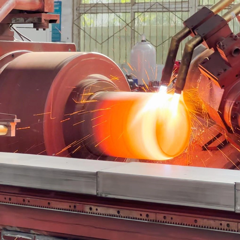
A hot forming machine for metal pipes is specialized equipment designed to shape, bend, or otherwise deform metal pipes at elevated temperatures. Heating the pipe above its recrystallization temperature makes the metal more ductile and easier to form without cracking or excessive internal stresses, enabling complex shapes and tighter bends that would be difficult or impossible at room temperature.
Hot forming machines typically combine controlled heating systems—such as induction coils, furnaces, or gas torches—with mechanical forming tools like rollers, dies, or bending arms. The heating raises the pipe’s temperature uniformly or locally, depending on the desired shape and process, while the forming mechanism shapes the softened metal.
Heating methods vary: induction heating is common for its precise, fast, and energy-efficient localized heating, while furnace heating is used for batch processes or large pipes needing uniform temperature. Gas or oil-fired torches provide flexibility for on-site or smaller-scale operations.
The forming section of a hot forming machine can include various tools, such as bending dies, mandrels, rollers, or presses, which shape the heated pipe into curves, angles, or complex profiles. Internal mandrels are often used to support the pipe from inside during forming, preventing collapse or wrinkling, especially for thin-walled pipes.
Hot forming is essential for applications requiring sharp bends with small radii, large deformation without cracking, or reshaping thick-walled or high-strength alloys that are less ductile at room temperature. Industries benefiting from hot-formed pipes include automotive, aerospace, oil and gas, shipbuilding, and construction.
Control systems monitor and regulate temperature, forming speed, and force to ensure consistent quality. Uniform heating avoids thermal gradients that could cause warping or uneven mechanical properties. Cooling methods post-forming—such as air quenching or controlled slow cooling—help achieve desired metallurgical characteristics like strength or hardness.
Hot forming machines come in various configurations, from simple bench-top models for small pipes to large-scale automated lines capable of processing heavy industrial pipes with precise temperature and forming control.
Maintenance involves regular inspection of heating elements, cooling systems, and forming tools, as well as calibration of temperature sensors and control units. Proper lubrication and cleaning reduce wear and prevent contamination.
The advantages of hot forming include improved formability, reduced spring-back, better surface finish, and the ability to produce complex shapes with minimal defects. It also enables the use of advanced alloys and materials that are otherwise difficult to process.
In summary, hot forming machines for metal pipes provide critical capabilities for shaping and bending pipes under controlled high-temperature conditions, enabling high-quality, precise, and complex pipe geometries for demanding industrial applications.
Hot forming machines for metal pipes operate by first heating the pipe to a temperature where the metal’s ductility significantly increases, often above its recrystallization point. This heating reduces the force required for deformation and allows for more complex shapes or tighter bends without the risk of cracking or weakening the material. Precise temperature control is crucial because overheating can cause grain growth or oxidation, while insufficient heating may lead to incomplete forming or material damage.
Once the pipe reaches the desired temperature, it is transferred to the forming station, where mechanical tools such as rollers, bending dies, or presses shape the pipe according to specifications. The forming process may be continuous or involve staged operations, depending on the complexity and size of the pipe. For example, induction heating systems can rapidly heat a localized section of pipe just before bending, allowing for continuous production lines with minimal heat loss.
Internal supports like mandrels or plug dies are commonly used during hot forming to maintain the pipe’s internal shape and prevent collapse or wrinkling, especially in thin-walled pipes or pipes with high aspect ratios. These supports are often cooled separately or designed to withstand the high temperatures involved in the process.
The forming tools themselves must be made from materials that can tolerate high temperatures and mechanical stresses, such as heat-resistant steels or alloys. Tool design incorporates considerations for thermal expansion, wear resistance, and ease of maintenance to ensure consistent forming quality and reduce downtime.
After forming, the pipe may undergo controlled cooling to achieve desired mechanical properties. Rapid cooling or quenching can increase hardness and strength but may also introduce residual stresses. Alternatively, slow cooling can help relieve stresses and improve ductility. Some machines integrate cooling stations immediately after forming to manage this phase.
Hot forming machines are equipped with advanced control systems that monitor parameters like temperature, forming speed, applied force, and pipe position in real time. Feedback loops adjust these parameters dynamically to maintain product quality and compensate for variations in material properties or environmental conditions.
Safety features are critical due to the high temperatures and forces involved. These include thermal shields, emergency stops, interlocks, and operator training programs to prevent accidents and equipment damage.
The use of hot forming expands the range of materials and pipe geometries manufacturers can produce. High-strength steels, stainless steels, and exotic alloys that are brittle or hard to form at room temperature become manageable with hot forming, enabling lighter, stronger, and more durable piping systems.
Industries such as automotive exhaust, oil and gas pipelines, aerospace structural tubing, and heavy machinery components rely heavily on hot formed pipes for their demanding performance requirements. The ability to produce precise bends and complex shapes reduces the need for welding or assembly, improving strength and reliability.
Maintenance of hot forming machines focuses on the heating elements, such as induction coils or furnace linings, which experience significant wear and degradation over time. Regular calibration of temperature sensors and control electronics is essential to maintain accuracy. Forming tools require inspection for thermal fatigue, wear, and distortion, with replacements scheduled to avoid production disruptions.
Emerging technologies in hot forming include hybrid processes that combine hot forming with incremental forming or laser-assisted heating for even greater precision and energy efficiency. Integration with Industry 4.0 systems allows for predictive maintenance and process optimization based on real-time data analytics.
Overall, hot forming machines play a vital role in metal pipe fabrication by enabling complex, high-quality shapes through controlled high-temperature deformation. Their continued development supports the growing demands of modern industrial applications for strength, precision, and efficiency.
Hot forming machines have evolved to incorporate sophisticated automation and robotics to improve efficiency and reduce human exposure to high temperatures and heavy machinery. Robotic arms or automated transfer systems often handle the heated pipes, moving them between heating zones, forming stations, and cooling areas with precise timing to optimize production flow and minimize heat loss.
Many modern hot forming setups include integrated sensors and machine vision systems that continuously monitor the pipe’s temperature, dimensional accuracy, and surface condition throughout the process. This data enables immediate adjustments to maintain quality and helps detect defects early, reducing scrap and rework costs.
Energy efficiency is a growing focus in hot forming technology. Induction heating systems are favored because they can target heat precisely to the area being formed, reducing wasted energy compared to furnace heating. Additionally, heat recovery systems can capture and reuse waste heat from the process to preheat incoming pipes or power auxiliary equipment, lowering overall energy consumption.
Hot forming machines are often customizable to handle various pipe sizes, thicknesses, and materials by swapping out heating coils, adjusting forming tools, or reprogramming control software. This versatility supports manufacturers who produce multiple product lines or need to quickly switch between jobs.
The increasing use of advanced alloys and composite materials in industries like aerospace and automotive demands continuous innovation in hot forming techniques. These materials often require very precise temperature control and forming conditions to avoid damaging their microstructure while achieving the desired shape.
Operator training remains a critical component in the effective use of hot forming machines. Even with automation, skilled technicians are needed to program equipment, interpret data, perform maintenance, and troubleshoot issues. User-friendly interfaces and simulation software aid in reducing the learning curve and improving overall productivity.
Environmental regulations also influence the design and operation of hot forming machines. Emissions from heating processes are managed through exhaust systems, filters, and adherence to safety standards to minimize the impact on workers and surroundings.
Future trends point toward greater integration of AI and machine learning to optimize process parameters automatically based on historical data and live feedback. This could lead to adaptive forming cycles that adjust in real time to material variations, improving yield and reducing energy use.
In conclusion, hot forming machines for metal pipes represent a blend of high-temperature metallurgy, precision mechanics, and modern automation technologies. Their role in enabling complex pipe geometries and processing advanced materials makes them indispensable in many high-performance manufacturing sectors. Ongoing innovations continue to enhance their capability, efficiency, and safety, ensuring they meet evolving industrial demands.
Cold Working Machine For Metal Pipes
A cold working machine for metal pipes is equipment designed to shape, form, or deform metal pipes at or near room temperature, without the need for heating. Cold working processes improve the mechanical properties of the metal—such as strength and hardness—through strain hardening, while maintaining tight dimensional tolerances and good surface finishes. These machines are widely used for forming, bending, expanding, reducing, or finishing pipe ends and sections.
Cold working machines use mechanical force applied through rollers, dies, presses, or mandrels to plastically deform the pipe. Because the metal is not heated, the forming forces are higher than in hot forming, so these machines are built robustly with powerful drive systems and precise controls.
Typical cold working operations for metal pipes include bending, swaging (reducing diameter), expanding, flaring, beading, and end-forming such as curling or necking. Each operation uses specialized tooling and machine designs to achieve the desired shape without causing cracks, wrinkles, or surface defects.
Cold working machines are often hydraulic, mechanical, or servo-electric powered, providing controlled, repeatable force and movement. Hydraulic systems offer smooth, adjustable pressure and are common in pressing or expanding applications. Mechanical and servo-electric drives provide high speed and precise motion control, favored in bending or rolling operations.
The machines typically feature clamping and guiding systems to hold the pipe securely and align it precisely during forming. Internal supports such as mandrels or plug dies are used to maintain pipe shape and prevent collapse during bending or reduction processes.
Cold working preserves the pipe’s metallurgical structure and surface finish better than hot forming, which is critical for applications where corrosion resistance, appearance, or tight tolerances are required. It also avoids the oxidation and scale formation associated with heating, reducing cleaning and finishing steps.
Because cold working increases strength through strain hardening, pipes processed this way can achieve higher mechanical performance without additional heat treatments. However, some operations may require intermediate annealing to relieve internal stresses if extensive deformation is involved.
Cold working machines are used across industries such as automotive, aerospace, plumbing, HVAC, oil and gas, and construction. Applications range from shaping exhaust pipes and hydraulic tubing to producing structural components and fluid conduits.
Maintenance of cold working machines focuses on tooling condition, hydraulic system health, and precise alignment. Tooling is typically made from hardened steel or carbide materials to withstand repeated stress and wear. Regular inspection and calibration ensure consistent forming quality.
Recent advances include CNC and servo-electric controls, allowing complex bending profiles and high repeatability. Integrated sensors and feedback systems monitor force, displacement, and alignment to detect issues and optimize the process in real time.
Overall, cold working machines for metal pipes provide versatile, precise, and efficient means of shaping pipe products without the need for heating, preserving material properties and surface quality while enabling a wide range of shapes and sizes.
Cold working machines operate by applying mechanical force to the pipe to deform it plastically at room temperature, relying on the metal’s natural ductility. The process requires careful control of pressure, speed, and tooling alignment to avoid defects such as cracking, wrinkling, or uneven deformation. Depending on the specific operation—whether bending, expanding, reducing, or forming—the machine adjusts these parameters to match the pipe’s material properties, thickness, and diameter.
Bending operations use rollers or bending arms to curve the pipe gradually, maintaining its cross-sectional shape and preventing flattening or ovality. Expanding and reducing machines alter the pipe’s diameter by pressing outward or inward, often using conical mandrels or dies that slide along the pipe to achieve uniform deformation. End-forming operations like beading, flaring, or curling employ specially shaped dies that clamp and press the pipe end into the desired profile.
Cold working machines often include internal supports, such as mandrels or plug dies, to maintain pipe shape and prevent collapse during deformation, especially for thin-walled or high-strength pipes. These supports also help improve surface finish and dimensional accuracy by reducing internal stresses.
The machines are designed for high repeatability and precision, which is essential in industries requiring tight tolerances and consistent quality. Automated or CNC-controlled systems allow operators to program complex forming sequences and control parameters precisely, minimizing human error and increasing throughput.
Material choice influences the cold working process significantly. Ductile metals like aluminum and copper are easier to form cold, while high-strength steels or alloys may require higher forming forces or multiple passes with intermediate stress relief. In some cases, cold working is combined with heat treatments before or after the process to balance strength and ductility.
Because cold working induces strain hardening, the mechanical properties of the pipe improve, often resulting in increased yield strength and hardness. This can be advantageous for applications requiring enhanced durability without additional processing steps. However, excessive cold working can lead to brittleness or cracking, so process parameters must be carefully optimized.
Maintenance focuses on tooling wear, hydraulic system performance, and machine alignment. Hardened tooling materials resist deformation and wear, but periodic replacement is necessary to maintain forming quality. Hydraulic fluids and seals require regular inspection and change to ensure consistent pressure and avoid leaks.
Modern cold working machines increasingly incorporate sensors and feedback controls to monitor force, displacement, and position in real time. This data helps detect forming anomalies, reduce scrap, and optimize process parameters dynamically. Some systems also log production data for traceability and quality control purposes.
Cold working machines are adaptable to a wide range of pipe sizes and wall thicknesses. Adjustable tooling and modular machine designs allow manufacturers to switch between different pipe specifications quickly, supporting flexible production schedules and small batch runs.
The environmental impact of cold working is generally lower than hot forming since it requires no external heating, reducing energy consumption and emissions. Additionally, because surface oxidation is minimal, there is less need for post-processing cleaning or finishing, further improving sustainability.
Applications for cold worked pipes include automotive exhaust systems, hydraulic and pneumatic lines, structural tubing, plumbing, HVAC ducting, and precision components in aerospace and medical devices. The ability to achieve precise shapes and dimensions without heat makes cold working ideal for parts where surface finish and mechanical integrity are critical.
In summary, cold working machines provide a versatile, energy-efficient, and precise method for shaping metal pipes at room temperature. Their combination of mechanical robustness, process control, and tooling flexibility makes them essential in modern pipe fabrication across numerous industries.
A metal forming machine for metal pipes is designed to shape or alter the geometry of pipes to meet specific industrial requirements. These machines handle processes such as bending, expanding, reducing, flaring, beading, notching, and rolling. The most common types include tube bending machines, which are widely used to form pipes into precise angles and curves. These can operate with or without a mandrel depending on the precision and wall support needed. Mandrel bending machines are ideal when the internal shape of the pipe must be maintained during tight radius bends, while roll bending is suited for forming large-radius curves.
Swaging machines are used when the pipe ends need to be reduced or expanded mechanically. These operate by compressing the material using a series of dies and are commonly used in hydraulic systems or exhaust applications. Pipe end forming machines go a step further by allowing complex modifications at the pipe ends—such as flaring, beading, or slotting—depending on the assembly or connection requirements. These machines may operate through ram or rotary motion, depending on the forming style.
Hydroforming machines offer another method of forming, using high-pressure fluid to conform a pipe or tube to a die cavity. This process is highly valued in applications that require strength-to-weight optimization, such as automotive and aerospace components. CNC tube forming machines automate the process and provide high accuracy, repeatability, and control. They are suitable for complex geometries, small or large batch runs, and environments where consistency and speed are essential.
In the fabrication of pipes from flat sheets, plate rolling or pipe rolling machines are used. These machines take flat sheet metal and roll it into cylindrical or conical shapes, which are then welded and finished. When very precise and large-diameter bends are required, such as in oil and gas pipelines, induction bending machines are used. These apply localized electromagnetic heating and mechanical force to create accurate bends while preserving material integrity.
Choosing the right machine depends on several factors including the diameter and thickness of the pipe, the type of metal (such as mild steel, stainless steel, aluminum, or copper), the required shape and end form, and the desired production speed and volume. For high-volume or precision-demanding industries, CNC and hydraulic variants are preferred. Simpler mechanical versions may suffice for small workshops or low-volume needs. The selection must also consider tool change flexibility, control systems, and integration with other production stages like cutting or welding.
In advanced manufacturing environments, metal pipe forming machines are often integrated into automated production lines. This integration can include feeding systems, cutting stations, and quality control units. For example, after forming, the pipe might be automatically cut to length, subjected to non-destructive testing (like ultrasonic or eddy current inspection), and then transferred to a welding or assembly line. Such setups are common in industries like automotive exhaust systems, HVAC ductwork, and fluid transport piping.
Tooling is a critical aspect of these machines. Interchangeable dies, mandrels, and formers must be selected and maintained to match the pipe’s dimensions and material properties. Tool wear can lead to inconsistencies in pipe shape, especially in operations like swaging or flaring, where precise contact and pressure are essential. In CNC machines, tool paths and forming sequences are programmed, allowing fast transitions between different pipe designs with minimal downtime.
Material behavior is another key consideration. Some metals, like stainless steel or titanium, require higher forming forces and more careful handling to avoid cracking or surface damage. Aluminum, being softer, is easier to form but may suffer from wrinkling if not properly supported. Work hardening, springback, and elongation must all be accounted for during design and machine setup. Simulation software is sometimes used to predict these behaviors and optimize forming parameters before production begins.
Safety is vital in metal forming environments due to the presence of high forces, moving parts, and sometimes high temperatures (in induction bending or hot forming). Modern machines come with enclosed working zones, safety interlocks, emergency stop systems, and programmable load limits. Operators are trained to handle setup and maintenance while avoiding manual intervention during operation.
Maintenance of pipe forming machines typically involves checking hydraulic systems, lubricating mechanical parts, inspecting electrical components, and recalibrating control systems. Preventive maintenance schedules help reduce downtime and extend equipment lifespan. In high-precision or high-output environments, even small deviations in tooling alignment or hydraulic pressure can lead to costly defects, so regular checks are essential.
In summary, metal forming machines for pipes range from simple manual benders to sophisticated CNC-controlled systems with automation and precision tooling. Their use spans from small-scale workshops to large-scale industrial plants, and the choice of equipment must align with the product design, production volume, material properties, and quality standards. Proper selection, setup, and maintenance of these machines are key to achieving reliable, repeatable, and high-quality pipe forming results.
Folding With Press Brake Machine For Metal Pipes
Folding metal pipes with a press brake machine is not a typical practice, as press brakes are primarily designed for bending flat sheet metal, not round or tubular sections. However, in certain specialized or modified setups, press brakes can be used to form or flatten sections of pipes—but this requires a careful understanding of the process and limitations.
Here’s how press brakes may be used in relation to metal pipes:
Pipe Flattening:
One common application is flattening the ends of round pipes or tubes, typically for joining, clamping, or welding purposes. This is done by placing the pipe section in the V-die of the press brake and pressing it down with the punch to squash part of the circular cross-section into a flat.
- Common in: Agricultural equipment, exhaust components, structural pipe joints
- Precautions: Flattening too much or too abruptly can crack the pipe, especially if the wall thickness is low or the material is brittle.
2. Pipe Slotting or Notching:
By carefully controlling the stroke and using custom dies, a press brake can help form notches or slots at the end of a pipe, useful for slip joints or interlocking assembly. In these cases, only a portion of the pipe is formed while the rest retains its round shape.
3. V-Forming or Creasing Pipes:
In some niche fabrication scenarios, press brakes are used to partially bend pipes into a V or U shape. This is more likely done with oval or square tubes rather than round pipes. Special bottom dies (such as channel dies or U-dies) may be used.
4. Bending Open Pipe Halves (Shells):
If a pipe has been cut longitudinally into half-shells, those halves can be bent with a press brake just like sheet metal, to form large ducts or semi-circular channels.
Important Considerations:
- Die and Tooling Design: Standard V-dies are not ideal for round shapes. Custom V-blocks or cradle-type dies may be needed.
- Wall Thickness: Thin-wall pipes deform easily; thicker pipes resist flattening but may crack if improperly formed.
- Material Type: Ductile materials like mild steel or aluminum tolerate forming better than stainless steel or titanium.
- Springback: Round sections tend to spring back more than flat sheets, especially if bent off-center.
Summary:
While press brakes are not generally intended for forming round pipes, they can be adapted for flattening, partial shaping, or working on cut pipe sections with proper tooling and care. For full pipe bending or curving, specialized tube or pipe bending machines are always preferred. If your application involves modifying the ends or shapes of pipes for joining, a press brake might be useful with the right die setup. If you’re attempting full-radius bends or controlled shaping of cylindrical pipes, a rotary draw bender, roll bender, or hydraulic forming press is more appropriate.
Using a press brake machine for working with metal pipes is unconventional but possible in specific scenarios. The primary challenge lies in the fact that a press brake is fundamentally designed to apply linear force to flat sheet material, while a pipe is a curved, hollow structure that reacts differently under pressure. When a pipe is placed on a press brake, the curved geometry causes instability unless supported properly. For tasks like end flattening, fabricators often use a custom V-block or a soft bed to cradle the pipe and apply force only where needed. This is particularly useful in fabricating mounting points or mating surfaces, where the round pipe needs to transition into a flat area for welding or bolting.
To prevent deformation or cracking, especially with thin-walled pipes, pressure must be applied gradually, and often in multiple passes. Excessive force in a single stroke can collapse or split the pipe wall. For tougher materials like stainless steel, preheating may sometimes be used to reduce the likelihood of cracking. Operators also commonly reinforce the interior of the pipe using a mandrel or insert during the pressing operation to maintain internal shape and minimize collapse.
In other cases, a press brake might be used to gently dimple or curve a pipe by pressing it against a die designed to partially deform the profile. For example, creating a small indentation along the pipe can act as a locator or alignment feature in certain assemblies. This is seen in scaffolding systems or structural pipe frameworks where a pipe must nest into a slot or groove. However, such work requires custom tooling and extremely cautious pressure control, usually supported by a CNC press brake for accuracy and repeatability.
In applications where a pipe is split lengthwise into two halves—like a semi-cylinder—the press brake becomes more viable for forming. These half-shells behave more like curved plates and can be manipulated into larger radius curves or stiffened with beads and creases, similar to sheet metal work. HVAC ducting and large conduit shells are examples where this approach may be employed. Additionally, square and rectangular tubing is more suited to press brake forming because the flat faces can align with the punch and die more predictably, allowing for standard bends like those used in metal furniture or frame fabrication.
It’s essential to understand that when modifying pipe geometry on a press brake, any distortion introduced affects flow dynamics if the pipe carries fluids or gases. Flattening or deforming a section of a pipe may restrict flow, increase turbulence, or create weak spots, which must be accounted for in the design. The mechanical strength and fatigue life of the pipe also change after forming, especially around press-formed areas, so structural analysis or testing may be required in critical applications.
Overall, while a press brake is not the go-to tool for pipe forming, creative setups, careful tooling, and skilled operators can use it effectively for certain tasks involving pipes, particularly when the goal is to prepare the pipe for joining or integration into a larger assembly. For more efficient and accurate results on full pipe bending or shaping, dedicated pipe bending equipment remains the preferred solution.
In custom fabrication shops or maintenance environments, press brake operations on pipes often arise from necessity rather than design. When specialized pipe bending or end-forming machines are unavailable, a press brake can serve as a temporary or improvised solution. In these cases, jigs and fixtures play a crucial role. Technicians may design cradles, clamps, or guides to stabilize the pipe during pressing, ensuring consistent positioning and avoiding slippage that could lead to uneven deformation or safety hazards. For example, a V-block cradle can distribute the load across the curved pipe wall, while end stops or clamps maintain alignment.
For operations involving short pipe sections, like when forming stubs or adapters, the press brake’s precision can be leveraged to control depth and alignment accurately. Pressing the pipe against a die with a shaped profile allows for repeatable forming of features like flared ends or localized dents that aid in fit-up. With CNC press brakes, programmable stroke depth and dwell time can be fine-tuned to avoid over-compression and reduce springback. Some modern systems even include pressure sensors and feedback loops to adjust force dynamically during the stroke, which helps when dealing with variable pipe wall thicknesses or materials with inconsistent hardness.
Additionally, press brake forming on pipes may be applied to create flat zones along the curvature, particularly in parts that require contact surfaces or anchoring points. For instance, in custom railing systems or pipe brackets, a flat pressed area allows for easier drilling, bolting, or welding. These localized deformations must be precisely placed, often requiring measurement jigs or laser guides to align each pipe section before pressing.
There are also more advanced techniques such as segmented pressing, where the operator forms a complex shape by making a series of shallow presses along the length of the pipe. This can simulate a curved or tapered shape, similar in concept to roll bending, but done incrementally. Though time-consuming and not as smooth, it can be useful for prototyping or low-volume work where dedicated equipment is unjustified.
Despite these possibilities, using a press brake on pipes introduces certain risks. Pipes, especially those with a small diameter or thin wall, can deform unpredictably if the force is not evenly distributed. Wrinkling, ovalizing, and collapsing are common failure modes if internal support is not provided. Additionally, the forming process can induce residual stresses, especially if the deformation is severe or off-center. These stresses may later lead to warping, cracking, or premature fatigue if the pipe is subjected to pressure, vibration, or temperature fluctuations.
In industries where such forming operations are common—such as custom exhaust fabrication, structural handrail work, or frame modification for vehicles—operators often combine press brake forming with other processes. These include notching (to remove material before bending), mandrel insertion (to maintain shape), and post-forming treatments like annealing (to relieve stresses). The key is understanding the limits of what a press brake can do with round pipe and compensating for those limitations with preparation, support tooling, and experience.
Ultimately, while a press brake is not intended for pipe forming in the traditional sense, it remains a versatile tool when used creatively and cautiously. Its utility increases with customized dies, robust fixturing, and an awareness of how pipe materials behave under localized compressive forces. In production settings where consistent, high-quality pipe bending is needed, however, the press brake should be seen as a supplement—not a substitute—for dedicated pipe forming machinery.
Die Bending Machine For Metal Pipes
A die bending machine for metal pipes is a specialized forming system that uses matched tooling (dies) to bend pipes or tubes into precise angles and radii. Unlike flat sheet die bending on a press brake, pipe die bending involves rotating the pipe around a fixed radius die while applying controlled pressure to create smooth, accurate bends without collapsing or deforming the pipe’s cross-section.
The most common form of die bending for pipes is rotary draw bending, where the pipe is clamped to a rotating bend die and pulled around it with assistance from a pressure die, wiper die, and (optionally) a mandrel inside the pipe. This method is widely used for tight-radius bends and high-quality finishes, especially when dimensional accuracy and repeatability are critical.
Die bending machines for pipes come in manual, semi-automatic, and CNC-controlled variants. Manual benders are suitable for simple, small-scale work like handrails or basic plumbing bends. Hydraulic or electric CNC die bending machines, on the other hand, are used in industries like automotive exhaust systems, aerospace, furniture tubing, and structural frames, where complex geometries and precision are required.
These machines rely heavily on die sets, which must match the pipe’s outer diameter and wall thickness. A poor die match can lead to common defects like flattening, wrinkling on the inside of the bend, or rippling along the outer surface. To prevent internal collapse or ovality, especially with thin-walled pipes, a mandrel is often inserted into the pipe during bending to maintain internal support.
Die material and precision also matter. Hardened steel or bronze dies are typically used for long service life and smooth surface contact, especially with soft or polished metals like aluminum or stainless steel. Some die bending machines can switch out dies quickly to allow different bend radii or pipe sizes with minimal downtime, which is crucial for job shops handling a variety of parts.
In advanced CNC machines, the bending sequence, angle, and speed are programmable. This allows for multi-radius and multi-plane bends in a single setup, useful in complex assemblies like automotive frames or HVAC conduits. Sensors and feedback systems ensure accurate positioning, and software can simulate bends to prevent collisions or over-bending.
In summary, a die bending machine for metal pipes uses a precise combination of rotational force and shaped tooling to achieve clean, repeatable bends. It’s essential in applications that demand consistent dimensions, minimal deformation, and high aesthetic or structural integrity. Proper die selection, material compatibility, and machine control are key to getting the best results from this bending method.
Die bending machines for metal pipes operate by securely clamping the pipe and rotating it around a fixed-radius die to create bends with precise angles and consistent radii. This process minimizes deformation such as flattening or wrinkling, which can easily occur if the pipe is bent improperly. The key to success lies in the interplay between the bend die, pressure die, wiper die, and sometimes a mandrel inserted inside the pipe to support the wall during bending. The pressure die holds the pipe firmly against the bend die while the wiper die prevents the inside of the bend from wrinkling by supporting the pipe as it curves.
The mandrel, typically a segmented or ball-type steel insert, is used especially for pipes with thin walls or those made from materials prone to cracking or wrinkling, such as stainless steel or aluminum alloys. Without the mandrel, the pipe might collapse or become oval instead of maintaining its round profile. The presence and design of the mandrel significantly influence the minimum achievable bend radius without damaging the pipe.
Die bending machines vary in complexity from simple mechanical setups to fully CNC-controlled systems. Manual machines rely on operator skill to achieve the desired bend angle and quality, while CNC machines use precise control of bending parameters, including rotation speed, bend angle, and clamp pressure. This automation ensures repeatability and can handle complex bends that include multiple planes or compound angles.
Proper die selection is critical and involves matching the die diameter to the pipe outer diameter and wall thickness. Using the wrong die size can lead to poor bend quality or damage to the pipe surface. The dies themselves are often made of hardened tool steel or bronze to withstand repeated use and provide smooth contact surfaces that reduce scoring or marring of the pipe.
In production environments, quick die change systems enhance flexibility, allowing operators to switch between different pipe sizes or bend radii rapidly, minimizing downtime. The ability to program multiple bends in sequence without repositioning the pipe further increases efficiency and accuracy, particularly in batch manufacturing.
Material considerations are equally important. Different metals have different ductility, springback characteristics, and hardness, which affect how the pipe responds to bending forces. For instance, aluminum pipes tend to bend more easily but may wrinkle without internal support, while stainless steel pipes require higher forces and careful control to avoid cracking. Simulation software is often used before actual bending to predict and compensate for springback, deformation, and stress concentrations.
Die bending machines also find application in industries where aesthetics and structural integrity are both critical, such as automotive exhaust systems, bicycle frames, architectural handrails, and aerospace tubing. The ability to produce smooth, consistent bends without surface defects is essential for performance and visual appeal.
In summary, die bending machines for metal pipes provide a highly controlled method to form pipes into accurate and repeatable shapes. Their effectiveness depends on the proper combination of tooling, machine capability, material properties, and operator expertise. When used correctly, they enable the production of complex pipe assemblies with minimal waste and high structural integrity.
Die bending machines have evolved significantly, with modern systems integrating advanced features like real-time force monitoring and adaptive control. These improvements help prevent pipe damage during bending by adjusting the pressure and speed dynamically based on feedback from sensors. This is particularly important when working with expensive materials or pipes destined for critical applications, where even minor defects can compromise performance or safety.
Another advancement is the integration of software-driven simulation tools that allow engineers to model the bending process virtually before actual production. These tools predict springback—the tendency of metal to partially return to its original shape after bending—allowing the machine to compensate by bending slightly beyond the target angle. Simulations also identify potential issues like wrinkles or cracks, enabling designers to adjust parameters or select different tooling ahead of time, saving both time and material costs.
Some die bending machines feature multi-axis capabilities, enabling bends in multiple planes without removing the pipe from the machine. This flexibility is essential for creating complex geometries found in automotive chassis, aerospace components, and custom furniture. The ability to program sequences that combine rotations, bends, and indexing improves precision and reduces the risk of operator error.
Maintenance and tooling care are vital for the longevity and performance of die bending machines. Dies must be regularly inspected for wear, as even slight imperfections can imprint on the pipe surface or cause inconsistent bends. Hydraulic and mechanical components require routine servicing to maintain pressure accuracy and avoid machine downtime. Training operators on best practices for setup, tool changes, and monitoring ensures consistent quality.
In industries like oil and gas, where pipe integrity is paramount, die bending is often paired with rigorous inspection methods. Non-destructive testing techniques, such as ultrasonic thickness measurement and X-ray inspection, verify that the bends meet strict quality standards without hidden cracks or thinning. This integration of forming and inspection highlights how die bending fits into a larger quality assurance workflow.
Environmental factors also influence die bending operations. Temperature, humidity, and even machine location can affect material behavior and machine performance. Controlled environments or adjustments in machine parameters may be necessary to maintain consistent results, especially in precision manufacturing.
Overall, die bending machines combine mechanical precision, sophisticated tooling, and modern control technologies to transform straight metal pipes into complex, high-quality components. Their ability to deliver repeatable, accurate bends while preserving material properties makes them indispensable across a broad spectrum of manufacturing industries. The continuous development in this field aims to improve efficiency, reduce waste, and expand the range of materials and shapes that can be formed reliably.
Edge Rolling Machine For Metal Pipes
An edge rolling machine for metal pipes is a specialized piece of equipment used to roll or form the edges (ends) of metal pipes or tubes. This process modifies the pipe ends to create features such as flanges, beads, hems, or collars, which are important for joining, sealing, or strengthening the pipe connections.
Edge rolling machines work by applying controlled pressure with rollers or forming dies that gradually bend or shape the pipe edge while it rotates or moves through the machine. Unlike bending or full pipe forming, edge rolling focuses specifically on the pipe’s circumference at one or both ends to create a rolled or curled profile.
This rolling of the pipe edges is common in applications like exhaust systems, HVAC ducts, automotive components, and plumbing fittings, where pipes need to be joined securely or have their edges reinforced to prevent damage or deformation during installation.
The machine typically consists of a rotating chuck or spindle that holds the pipe and a set of adjustable rollers or dies that press and roll the edge into the desired shape. The rollers may be motor-driven and adjustable to accommodate different pipe diameters and wall thicknesses.
Edge rolling machines can be manual, semi-automatic, or fully automated with CNC controls, allowing precise control over the rolling speed, pressure, and final edge shape. Automated systems are especially useful in high-volume manufacturing where consistent edge profiles and fast cycle times are critical.
Materials commonly processed include steel, stainless steel, aluminum, and copper pipes, with the machine settings adjusted to suit each metal’s ductility and thickness. Proper tooling and setup ensure smooth edges without cracking, wrinkling, or unwanted thinning of the pipe wall.
In summary, edge rolling machines provide an efficient and reliable way to prepare pipe ends for assembly, enhancing mechanical strength, sealing capability, and ease of connection in metal pipe systems.
Edge rolling machines for metal pipes operate by clamping the pipe securely and then rotating it while rollers progressively shape the pipe’s edge into the desired profile. This process applies gradual pressure to avoid cracking or deforming the pipe, which is critical when working with thinner-walled or more brittle materials. The rotation ensures a uniform roll around the entire circumference, producing consistent and smooth edges.
These machines can handle a range of pipe diameters and wall thicknesses by adjusting the roller positions and the pressure applied. Some machines incorporate multiple rollers that work together to control the shape and size of the rolled edge, whether it’s a simple curled lip, a flange for welding, or a bead to increase rigidity. The flexibility in tooling allows manufacturers to produce a variety of edge profiles without changing machines, simply by swapping out rollers or dies.
In automated edge rolling systems, the speed of rotation and the pressure of the rollers can be precisely controlled through CNC programming. This ensures repeatability and allows complex profiles to be created with minimal operator intervention. Such automation is especially valuable in mass production settings like automotive exhaust manufacturing or HVAC ductwork, where consistent quality and throughput are paramount.
Material considerations are important because the rolling process introduces localized plastic deformation that can affect the mechanical properties at the pipe end. Metals with good ductility, such as mild steel and aluminum, respond well to edge rolling, while harder or more brittle materials require careful adjustment of rolling parameters to prevent cracks or splits. Sometimes preheating the pipe ends is employed to improve formability, especially in stainless steel or titanium pipes.
Proper edge rolling not only enhances the pipe’s mechanical strength at the joints but also improves sealing performance when the pipes are joined using gaskets or welding. A rolled edge provides a more reliable surface for welding beads or sealants, reducing the risk of leaks in fluid or gas transport systems. In addition, rolled edges can help reduce sharp edges that might cause injury during handling or assembly.
Maintenance of edge rolling machines typically involves checking roller alignment, lubrication of moving parts, and monitoring wear on the rollers or dies. Since the rollers directly contact the pipe, wear can lead to uneven rolling or surface damage. Regular inspection and timely replacement of tooling ensure consistent product quality and prevent costly downtime.
Overall, edge rolling machines are indispensable in metal pipe fabrication when precise and uniform edge finishing is required. They combine mechanical precision with adaptable tooling to meet diverse manufacturing needs, improving both the functional and aesthetic qualities of metal pipes across many industries.
Edge rolling machines often incorporate additional features to enhance their versatility and efficiency. For example, some models include automatic feeding systems that continuously supply pipe sections into the rolling station, significantly increasing production speed in industrial settings. These systems can be synchronized with downstream operations like welding, cutting, or assembly lines to create seamless manufacturing workflows.
In more advanced machines, sensors monitor key parameters such as roller pressure, pipe diameter, and rotational speed in real-time. These inputs enable automatic adjustments during the rolling process to compensate for material variations or tooling wear, ensuring consistent edge quality without frequent manual intervention. Data from these sensors can also be logged for quality control and traceability, which is essential in regulated industries such as aerospace or medical tubing.
Edge rolling is often combined with other forming or finishing processes within a single machine or production line. For instance, after rolling, pipes may pass through calibration stations that verify dimensions or surface finish before moving on to cutting or assembly. Integration with robotic arms or conveyors allows for fully automated handling, reducing labor costs and minimizing the risk of damage during transfer.
The ability to roll edges precisely also supports customization in product design. For example, manufacturers can create specialized pipe ends that facilitate quick connections using clamps or fittings, or that improve flow characteristics by shaping the edge to reduce turbulence. This flexibility is valuable in custom fabrication shops or industries with stringent performance requirements.
When selecting or designing an edge rolling machine, factors such as pipe size range, wall thickness, material type, desired edge profile, and production volume all influence machine configuration. Smaller manual or semi-automatic machines may suffice for low-volume or prototype work, while large-scale manufacturing demands robust, high-speed automated systems with extensive tooling options.
Training operators on the nuances of edge rolling is important, as improper setup or handling can cause defects like wrinkles, cracks, or uneven rolls. Understanding material behavior, tooling geometry, and machine settings helps optimize the process and extend tooling life.
In summary, edge rolling machines play a critical role in pipe fabrication by delivering consistent, high-quality edge finishes that enhance pipe functionality and durability. Advances in automation, sensor integration, and tooling design continue to expand their capabilities, making them essential tools in modern metalworking industries.
Stretch Forming Machine For Metal Pipes
A stretch forming machine for metal pipes is a specialized piece of equipment designed to shape metal pipes or tubes by applying a combination of tensile force (stretching) and bending simultaneously. This process allows the pipe to be formed into complex curves or shapes with smooth contours, minimal wrinkling, and reduced springback compared to conventional bending methods.
In stretch forming, the pipe is clamped firmly at both ends, and a controlled tensile force is applied to elongate the pipe slightly. While the pipe is under tension, it is then bent or wrapped around a forming die or a shaped mandrel. The stretching reduces the pipe’s tendency to wrinkle or collapse during bending and helps achieve larger radii and more precise shapes.
Stretch forming machines for metal pipes are commonly used in industries requiring high-quality curved tubing with excellent surface finish and tight dimensional tolerances, such as aerospace, automotive exhaust systems, architectural components, and shipbuilding.
The machines typically include hydraulic or servo-driven clamps to grip the pipe ends and a forming section with adjustable dies or rollers that define the desired curve or contour. Modern systems often incorporate CNC controls for precise adjustment of stretching force, bending angle, and die position, allowing complex shapes to be formed repeatably.
Materials processed on stretch forming machines include various metals such as steel, stainless steel, aluminum alloys, and titanium, with process parameters adjusted according to material ductility and thickness. The stretching action helps minimize springback, which is common in bending, thus reducing the need for secondary finishing operations.
Overall, stretch forming machines provide a highly controlled method to produce smooth, accurate bends and shapes in metal pipes, especially where traditional bending methods fall short due to shape complexity or material limitations.
Stretch forming machines for metal pipes operate by first securely gripping the pipe ends to apply a uniform tensile force along its length. This stretching not only elongates the pipe slightly but also preconditions the material, increasing its formability and reducing internal stresses that typically cause defects like wrinkling or buckling during bending. Once the pipe is under tension, it is guided or wrapped around a forming die or mandrel that defines the desired curvature or shape.
The combined effect of stretching and bending allows the pipe to conform smoothly to complex profiles, such as compound curves or large-radius bends, which are difficult to achieve with conventional bending techniques alone. This method is especially beneficial for pipes with thin walls or made from high-strength alloys, where minimizing deformation and surface damage is critical.
Stretch forming machines vary in size and complexity, from simple manual setups for small-diameter pipes to large, fully automated CNC systems capable of handling long sections and producing intricate shapes. The machines often include sensors to monitor tension and bending angle, enabling precise control and repeatability in production runs. Programmable control systems can adjust the stretching force dynamically to account for variations in material properties or pipe dimensions.
One key advantage of stretch forming is its ability to reduce springback—the elastic recovery of the material after bending. By stretching the pipe during the forming process, the plastic deformation is more uniform, which helps the pipe maintain the intended shape without extensive secondary corrections. This results in higher dimensional accuracy and better surface finish, reducing the need for costly rework.
Stretch forming is widely used in aerospace for structural components, in automotive for exhaust and chassis parts, and in architectural applications where aesthetically pleasing, smooth curves are essential. The process also supports the fabrication of large, curved pipes used in shipbuilding and industrial piping systems where tight tolerances and mechanical integrity are required.
The machines can be equipped with various tooling options to accommodate different pipe sizes, wall thicknesses, and materials. Dies and mandrels are typically made from hardened steel or other wear-resistant materials to withstand the forces involved and ensure long tool life. Quick-change tooling systems may be incorporated for flexibility in handling different job requirements.
Proper setup and operator expertise are crucial for successful stretch forming. Parameters such as clamp pressure, stretch force, bending speed, and die geometry must be carefully balanced to prevent defects like thinning, cracking, or ovality. Additionally, pre- and post-forming heat treatments may be applied to relieve residual stresses or enhance material properties, depending on the application.
In summary, stretch forming machines provide an advanced solution for shaping metal pipes with complex curves and high precision. By combining tensile stretching with controlled bending, they overcome many limitations of traditional pipe forming methods, enabling manufacturers to produce durable, high-quality components across various industries.
Stretch forming machines also offer significant advantages in terms of material utilization and cost efficiency. Because the process applies uniform tensile stress, it allows for tighter bend radii without excessive thinning or damage to the pipe walls. This reduces scrap rates and minimizes the need for additional material, which is particularly important when working with expensive alloys like titanium or stainless steel.
The precise control over stretching and bending forces also means that less tooling pressure is required compared to purely mechanical bending methods. This reduces wear and tear on machine components and tooling, extending their lifespan and lowering maintenance costs. Additionally, the smoother deformation reduces the likelihood of surface imperfections, which can compromise corrosion resistance or require costly finishing.
Another benefit is the flexibility of stretch forming machines to produce a wide variety of shapes and contours without extensive retooling. By simply adjusting the forming dies or mandrels and programming the stretch and bend parameters, manufacturers can quickly switch between different parts or prototypes. This adaptability is especially valuable in industries with rapidly changing design requirements or small batch sizes.
Stretch forming machines can be integrated into automated production lines, with robotic loading and unloading, inline inspection systems, and data-driven quality control. This automation enhances throughput and consistency while reducing manual labor and human error.
Despite these advantages, stretch forming does have limitations. It is generally less suitable for extremely tight bends or sharp corners, where metal may fracture or excessive thinning could occur. In such cases, complementary processes like incremental bending, roll bending, or mandrel bending may be combined with stretch forming for optimal results.
Training and expertise remain essential, as incorrect parameter settings can lead to defects such as wrinkling, necking, or unwanted springback. Detailed knowledge of material properties, machine capabilities, and process dynamics helps operators optimize forming cycles and troubleshoot issues effectively.
Environmental factors such as temperature and humidity can also impact the stretch forming process, particularly with metals that exhibit temperature-sensitive behavior. Controlled environments or preheating may be employed to maintain consistent quality.
In conclusion, stretch forming machines for metal pipes represent a sophisticated and highly effective technology for producing complex, smooth, and precise curved components. Their ability to combine tensile stretching with bending allows manufacturers to achieve superior quality, reduce waste, and maintain flexibility across diverse applications, making them a critical tool in modern metal fabrication.
Shaping With Rollers Machine For Metal Pipes
A shaping with rollers machine for metal pipes is a forming device that uses a series of rollers to gradually bend, curve, or shape metal pipes into desired profiles. This method is often called roll bending or section bending, and it’s widely used to create large-radius bends, arcs, spirals, or even complex curved shapes in pipes and tubes.
The machine typically consists of three or more rollers arranged in a triangular or linear configuration. The pipe is passed between these rollers, which apply pressure at specific points to plastically deform the pipe gradually. By adjusting the position and pressure of the rollers, operators can control the curvature and radius of the bend. The pipe can be passed through multiple times, with incremental adjustments, until the desired shape is achieved.
Roller shaping is especially useful for larger diameter pipes or when gentle, sweeping bends are required that can’t be efficiently produced by rotary die bending or stretch forming. This method works well on a wide range of materials including steel, stainless steel, aluminum, and copper.
The rollers themselves are usually made of hardened steel or similar durable materials to withstand continuous contact with the pipe surface without causing damage. In some machines, the rollers can be driven (powered) to feed the pipe through automatically, improving speed and consistency. Others are manual or semi-automatic, suited for lower volume or custom jobs.
Roller shaping machines can be simple mechanical setups or sophisticated CNC-controlled systems that precisely program roller positions and feed rates. CNC systems enable complex shapes like spirals or compound curves to be produced with high accuracy and repeatability.
Because the rolling process gradually bends the pipe, it minimizes the risk of wall thinning, wrinkling, or ovality that can occur in more aggressive bending methods. However, care must be taken to properly support the pipe ends and control roller pressure to avoid deformation or surface marks.
Roller shaping is commonly used in industries such as construction, shipbuilding, automotive, and furniture manufacturing where large curved pipe sections are needed for frames, railings, exhaust systems, and architectural elements.
In summary, shaping with rollers machines provide a flexible, efficient, and gentle method to form metal pipes into smooth curves and complex shapes, accommodating a wide range of pipe sizes and materials while preserving structural integrity and surface quality.
Shaping with rollers machines work by feeding the metal pipe between a set of rollers that apply controlled pressure to gradually deform the pipe into the desired curve. The position of the rollers, especially the middle or adjustable roller, determines the amount and radius of bending. By moving this roller closer to the other fixed rollers, the pipe is bent more sharply. The process can be repeated multiple times, with adjustments between passes, to achieve precise shapes without overstressing the pipe.
The gradual bending action of roller shaping helps prevent common defects such as flattening or wrinkling that occur in more abrupt bending methods. Since the pipe is slowly formed over a large radius, internal stresses are lower, which helps maintain the pipe’s original cross-sectional shape and strength. This is especially beneficial for pipes with thinner walls or those made from materials sensitive to cracking or deformation.
In addition to producing simple bends, roller shaping machines are capable of creating more complex shapes, including spirals, S-curves, or elliptical bends. This versatility is achieved through CNC controls or skilled manual adjustments, allowing for precise control over roller pressure, rotation speed, and pipe feed rate. With CNC programming, the machine can perform multi-axis bending, producing consistent and repeatable parts with complex geometries.
These machines accommodate a wide range of pipe diameters and wall thicknesses by adjusting roller sizes and spacing. Some setups include additional support rollers or guides to stabilize the pipe during shaping and prevent unwanted movement or vibration. This ensures smooth feeding and uniform bending throughout the process.
Roller shaping is widely used in sectors such as construction, where curved pipes serve as structural elements in buildings and bridges; shipbuilding, for forming curved hull sections; automotive, for exhaust systems and chassis components; and in furniture manufacturing, where aesthetically pleasing curved tubes are required.
Because shaping with rollers applies a bending force distributed over a wide area and across multiple passes, it is an energy-efficient and low-impact process that preserves material properties and reduces waste. Operators must, however, carefully monitor the process to avoid over-bending or creating surface marks from excessive roller pressure.
Maintenance of roller shaping machines includes regular inspection and lubrication of rollers and bearings, checking for wear or damage to roller surfaces, and ensuring accurate alignment of rollers to maintain consistent bending quality. Tooling and machine condition directly affect the finish and dimensional accuracy of the shaped pipes.
Overall, shaping with rollers machines offer an effective and adaptable solution for forming metal pipes into smooth, large-radius curves and complex shapes while maintaining structural integrity and surface quality. Their ability to handle a wide variety of materials and pipe sizes makes them essential tools in metal fabrication industries worldwide.
Advanced shaping with rollers machines often integrate features such as automated pipe feeding systems, which increase throughput and reduce manual handling. These systems feed pipes continuously or in batches, coordinating roller adjustments and feed rates to optimize cycle times. Automated loading and unloading options further streamline production, especially in high-volume manufacturing environments.
Sensor technology is increasingly incorporated to monitor parameters such as pipe diameter, wall thickness, roller pressure, and bending angle in real-time. This data enables dynamic adjustments during the shaping process, ensuring consistent quality even when material properties vary between batches. Additionally, recording these parameters supports traceability and quality control, which is crucial in industries with strict regulatory standards like aerospace or oil and gas.
The adaptability of roller shaping machines also extends to multi-material fabrication. For instance, some setups can handle composite pipes or pipes with internal linings without damaging sensitive layers, broadening their application scope. In cases where surface finish is critical, protective coatings or rollers with specialized surfaces are used to prevent scratching or marring.
Integration with CAD/CAM systems allows complex pipe shapes to be programmed directly into the machine, reducing setup time and human error. Operators can simulate bending sequences virtually before actual production, identifying potential issues such as springback or collision risks. This simulation capability not only improves first-pass accuracy but also enhances overall production efficiency.
Some roller shaping machines feature modular designs that enable easy swapping or addition of rollers to accommodate different pipe sizes or shapes. This modularity supports small batch production and custom jobs without the need for entirely new equipment, making the process cost-effective for diverse manufacturing needs.
Environmental considerations are also part of modern roller shaping operations. Machines are often designed for energy efficiency and equipped with noise reduction features, improving workplace safety and reducing operational costs. Dust and debris generated during pipe handling or surface finishing can be managed with integrated extraction systems to maintain clean and safe production areas.
Operator training remains essential despite automation. Skilled operators understand how to interpret machine feedback, adjust parameters on the fly, and identify subtle signs of tooling wear or material anomalies. This expertise helps maximize machine lifespan, maintain product quality, and reduce downtime.
In conclusion, shaping with rollers machines combine mechanical precision, automation, and smart controls to offer flexible, efficient, and high-quality pipe forming solutions. Their ability to produce large-radius bends and complex shapes reliably makes them indispensable across a wide range of industries, continually evolving with technological advances to meet modern manufacturing challenges.
Bead Inserting Machine For Metal Pipes
A bead inserting machine for metal pipes is a specialized machine used to create beads—or raised ridges—along the length or ends of metal pipes. These beads serve multiple purposes, such as reinforcing the pipe structure, improving grip during handling, enhancing sealing when pipes are joined, or providing aesthetic detailing.
The bead inserting process involves mechanically pressing or rolling a bead profile into the pipe’s surface without significantly compromising the pipe’s wall thickness or integrity. The machine typically uses specially designed rollers or dies that indent the pipe metal to form the bead. This operation can be performed on straight pipe sections or on pipes that have been pre-shaped or bent.
Bead inserting machines can be manual, semi-automatic, or fully automated, depending on production volume and precision requirements. In automated systems, pipes are fed through the machine on conveyors or rollers, while the bead forming rollers apply consistent pressure and profile along the pipe’s surface.
The machines are adjustable to accommodate various pipe diameters and wall thicknesses, and different bead shapes and sizes can be produced by changing the tooling. This versatility allows manufacturers to customize bead profiles to suit specific applications, such as ensuring better mechanical interlocking in coupling systems or strengthening thin-walled pipes.
Materials commonly processed include steel, stainless steel, aluminum, and copper pipes. The bead inserting process is carefully controlled to prevent cracking or deformation, particularly in harder or thinner materials. Sometimes, preheating or lubrication is used to enhance formability.
Bead inserting machines are widely used in industries such as plumbing, HVAC, automotive exhaust, and construction, where beaded pipes improve joint strength, leak resistance, and ease of assembly.
In summary, bead inserting machines provide an efficient and precise way to add functional or decorative bead profiles to metal pipes, enhancing their mechanical performance and usability in various industrial applications.
Bead inserting machines operate by feeding the metal pipe through a set of rollers or dies that gradually impress the bead profile onto the pipe surface. The pipe is typically rotated or moved longitudinally to ensure the bead is formed evenly and continuously along the desired section. The pressure applied by the forming rollers is carefully controlled to avoid excessive thinning or cracking of the pipe wall while achieving a clear, consistent bead shape.
The tooling in bead inserting machines is usually interchangeable, allowing different bead patterns, heights, and widths to be produced on the same machine. This flexibility supports customization for different applications, such as deeper beads for reinforcement or shallower beads for aesthetic purposes. Tooling materials are chosen for durability and wear resistance, often made from hardened steel or alloy materials.
Automated bead inserting machines may include features such as programmable length control, enabling the bead to be inserted at precise intervals or lengths on the pipe. Some machines can create multiple beads simultaneously or form complex bead patterns as required. Integration with other pipe processing equipment, like cutting, bending, or welding machines, is common in production lines to streamline manufacturing workflows.
In addition to structural benefits, beads created by these machines improve pipe joint sealing by providing better surface engagement for gaskets or welding seams. This enhances the pipe’s performance in fluid or gas transport systems, reducing the risk of leaks. Beads also increase pipe stiffness locally, which can be important in applications where pipes are subject to bending or impact loads.
Operators must consider material characteristics during bead insertion, as metals with lower ductility require slower forming speeds and more precise pressure control to prevent defects. Some processes may include lubrication to reduce friction between the pipe and tooling, improving surface finish and tool life.
Regular maintenance of bead inserting machines is essential to maintain consistent bead quality. This includes inspecting and replacing worn tooling, checking roller alignment, and ensuring smooth operation of feeding mechanisms. Proper calibration helps avoid defects such as uneven bead depth, surface scratches, or deformation around the bead.
In industries such as automotive exhaust manufacturing, plumbing, and HVAC, bead inserting machines contribute significantly to product reliability and performance by enhancing pipe joint strength and durability. Their ability to produce precise, repeatable bead profiles at high speeds makes them valuable in both high-volume production and specialized fabrication settings.
Overall, bead inserting machines combine mechanical precision and adaptable tooling to provide an efficient solution for reinforcing and finishing metal pipes, meeting diverse industrial requirements with consistent quality.
Modern bead inserting machines often incorporate advanced control systems to further enhance precision and efficiency. CNC or PLC controls allow operators to program bead placement patterns, lengths, and intervals, enabling the production of pipes with complex bead designs tailored to specific functional or aesthetic needs. This level of automation reduces setup time, minimizes human error, and increases repeatability across large production runs.
Some machines are equipped with sensors that monitor the force applied during bead forming and the pipe’s dimensional changes in real time. These feedback systems help detect any anomalies early, such as variations in pipe wall thickness or material inconsistencies, allowing immediate adjustments to prevent defects. Data collected can also be logged for quality assurance and traceability, which is especially important in regulated industries like automotive or aerospace.
The integration of bead inserting machines into automated manufacturing lines facilitates continuous production workflows. Pipes can be fed directly from forming or cutting machines into the bead inserter, then onward to inspection, welding, or packaging stations without manual handling. This automation not only speeds up production but also reduces the risk of damage or contamination.
Material considerations remain critical; harder metals or those with lower ductility may require slower forming speeds or additional preparation, such as annealing, to avoid cracking. For softer metals, lubrication helps reduce friction and wear on tooling, extending tool life and maintaining surface quality. Some bead inserting machines are designed with modular tooling systems to quickly switch between different bead profiles or pipe sizes, offering flexibility for diverse product lines.
Safety features are integral to modern machines, including guards around moving parts, emergency stop controls, and sensors that detect misfeeds or jams. These protections help ensure operator safety and minimize downtime.
Training for operators focuses on understanding material behavior, machine setup, and troubleshooting common issues like uneven beads, surface defects, or tool wear. Skilled operators can optimize machine parameters to balance speed, quality, and tooling longevity.
In summary, bead inserting machines have evolved into sophisticated, automated systems that deliver high-quality, precise bead profiles on metal pipes. Their ability to improve mechanical performance, enhance sealing, and add functional design elements makes them essential in many manufacturing sectors. Continuous technological advancements in control, monitoring, and integration ensure these machines remain efficient, adaptable, and reliable components of modern metal pipe fabrication.
Collar Forming Machine For Metal Pipes
A collar forming machine for metal pipes is a specialized machine designed to create collars—raised or flared sections—at the ends or along the length of metal pipes. These collars serve various functional purposes such as improving joint strength, facilitating connections through welding or threading, providing sealing surfaces, or enhancing pipe alignment during assembly.
Collar forming involves plastically deforming a section of the pipe wall to create a protruding flange or lip. This process can be done through methods like spinning, rolling, pressing, or a combination of these, depending on the design of the collar and the pipe material.
The collar forming machine typically uses tooling such as dies, rollers, or mandrels to shape the pipe end precisely. The pipe is clamped and rotated or held stationary while the tooling applies controlled pressure to form the collar. In some machines, hydraulic or mechanical systems drive the forming tools, allowing for consistent and repeatable collar shapes.
These machines can be manual, semi-automatic, or fully automated, with CNC controls available for high-precision applications. CNC-operated collar forming machines enable programming of collar dimensions, angles, and lengths, allowing for quick adjustments and production of complex or customized collars.
Collar forming is widely used in industries like plumbing, automotive exhaust systems, HVAC ducting, oil and gas pipelines, and manufacturing of structural tubing. Collars produced by these machines improve pipe joint integrity, facilitate easier assembly, and often enhance the mechanical strength of connections.
Materials processed include steel, stainless steel, aluminum, copper, and various alloys. The machine settings are adjusted according to material properties and pipe wall thickness to prevent cracking or excessive thinning during forming.
In summary, collar forming machines provide an efficient and precise method for creating collars on metal pipes, enhancing their functionality and adaptability in various industrial applications.
Collar forming machines work by securely clamping the pipe while applying force through rollers, dies, or mandrels to plastically deform the pipe end or section into the desired collar shape. The pipe may be rotated or held stationary depending on the machine design and forming method. The deformation process is carefully controlled to maintain pipe wall integrity, avoiding cracks or excessive thinning that could weaken the pipe.
The tooling used in collar forming machines is often interchangeable, allowing manufacturers to produce collars of varying diameters, lengths, and profiles using the same equipment. This flexibility enables quick adaptation to different pipe sizes and application requirements. Tooling is typically made from hardened steel or other wear-resistant materials to ensure durability and maintain precise shaping over extended production runs.
Automated collar forming machines often include CNC controls that allow operators to program specific collar dimensions and shapes. This automation improves repeatability and reduces setup times, particularly valuable in high-volume manufacturing or when producing complex or custom collar designs. Some machines can also form collars with integrated features like grooves or flanges for sealing or locking purposes.
The machines may be designed to handle pipes of different diameters and wall thicknesses, with adjustable clamping pressure and forming forces to accommodate various materials, including steel, aluminum, copper, and alloys. For materials that are more prone to cracking or deformation, the forming speed and force are carefully optimized to ensure quality.
Collar forming is commonly integrated into production lines where pipes undergo multiple processing steps, such as cutting, bending, and welding. By forming collars in-line, manufacturers reduce handling time and improve overall efficiency. Some systems incorporate sensors to monitor forming pressure and collar dimensions in real-time, ensuring consistent quality and enabling immediate correction of any deviations.
Proper maintenance of collar forming machines involves regular inspection and replacement of tooling to prevent wear-related defects, calibration of pressure and positioning systems, and lubrication of moving parts. Well-maintained equipment contributes to higher production uptime and better product quality.
In applications like plumbing, collars provide stronger joints that resist leaks and mechanical stresses. In automotive exhaust or HVAC systems, collars help connect pipes securely while allowing for thermal expansion. In oil and gas pipelines, collars can act as reinforcement points or facilitate connection with other components, enhancing system reliability.
Training operators to understand material behavior, machine operation, and quality control is essential for successful collar forming. Skilled operators can adjust parameters to handle variations in material or design specifications, troubleshoot issues, and optimize production speed without compromising collar quality.
In conclusion, collar forming machines offer a precise, adaptable, and efficient solution for producing collars on metal pipes. By improving pipe joint strength, assembly ease, and overall durability, these machines play a crucial role across many industrial sectors requiring high-quality pipe fabrication.
Advanced collar forming machines incorporate features such as programmable multi-step forming processes, allowing complex collar shapes with multiple contours or thickness variations to be produced in a single cycle. This capability is especially useful in applications where collars must accommodate seals, threads, or mating flanges with tight tolerances.
Some machines use servo-driven systems for precise control of forming speed, force, and position, enabling the processing of a wide range of pipe materials—including high-strength alloys and thin-walled tubes—without causing defects like cracking or excessive thinning. The ability to finely tune forming parameters helps optimize cycle times while maintaining consistent quality.
Integration with computer-aided design and manufacturing (CAD/CAM) software allows manufacturers to import collar designs directly into the machine control system. This streamlines setup, reduces errors, and facilitates rapid prototyping or small-batch production runs. Simulations can predict material behavior during forming, helping to prevent issues before physical production begins.
In production environments, collar forming machines are often linked with upstream and downstream equipment—such as pipe cutting, end-facing, or welding stations—to form fully automated fabrication lines. These lines can produce finished pipe assemblies with minimal manual intervention, improving throughput and reducing labor costs.
Modern machines also feature safety mechanisms, including protective guarding, emergency stop functions, and sensors that detect anomalies like improper pipe loading or tooling misalignment. These features protect operators and minimize downtime caused by equipment faults or accidents.
Maintenance protocols typically include regular inspection of tooling for wear or damage, calibration of hydraulic or servo systems, and lubrication of mechanical components. Preventive maintenance schedules help maintain tight tolerances and extend the lifespan of critical parts.
Industries benefiting from collar forming machines range from construction and infrastructure to automotive, aerospace, and energy sectors. The collars produced contribute to stronger, more reliable pipe connections that can withstand mechanical loads, pressure variations, and environmental stresses.
Operator training remains key to maximizing machine performance and product quality. Experienced operators understand the nuances of different materials, can interpret machine feedback, and quickly adjust parameters to address production challenges.
Overall, collar forming machines have evolved into sophisticated, flexible tools that enhance metal pipe fabrication by delivering precise, durable collars efficiently and consistently. Their role continues to grow as manufacturing demands for quality, customization, and automation increase.
Expanding With Mandrel Machine For Metal Pipes
An expanding with mandrel machine for metal pipes is a specialized machine used to enlarge or expand the diameter of metal pipes or tubes precisely and uniformly. This expansion process involves inserting a mandrel—a hardened, tapered tool—inside the pipe and then applying force to gradually stretch the pipe outward to a desired larger diameter. The mandrel supports the pipe internally during expansion to prevent collapse or wrinkling of the pipe wall.
The expanding with mandrel machine is commonly used to achieve tight tolerance expansions needed for pipe fittings, assemblies, or to meet specific design requirements. The process allows pipes to be joined by expanding one pipe end to fit over another, creating a strong mechanical joint often combined with welding, brazing, or sealing.
The machine typically consists of a frame to hold the pipe securely, a mandrel mechanism to insert and expand the pipe internally, and a hydraulic or mechanical system to apply controlled force. The mandrel is designed to match the pipe’s internal diameter before expansion and gradually increase in diameter to expand the pipe as it moves through the pipe length.
Expanding with mandrel machines can be manual, semi-automatic, or fully automated, with CNC controls in advanced versions for precise control of expansion length, diameter, and speed. The process minimizes thinning or deformation of the pipe walls by supporting them internally, making it suitable for high-quality pipe materials, including steel, stainless steel, aluminum, and copper.
This method is widely used in industries such as automotive, aerospace, oil and gas, HVAC, and plumbing, where reliable, precise pipe expansions are critical for assembly and function.
In summary, expanding with mandrel machines provide an effective and accurate way to enlarge pipe diameters while preserving structural integrity, essential for quality pipe fabrication and assembly operations.
Expanding with mandrel machines operate by first securely clamping the pipe in place to prevent movement during the expansion process. The mandrel, which is typically tapered or segmented to facilitate smooth insertion and expansion, is then inserted into the pipe’s interior. As hydraulic or mechanical pressure is applied, the mandrel gradually pushes outward against the pipe walls, expanding the diameter incrementally along the desired length.
The internal support provided by the mandrel is crucial to prevent common issues such as wrinkling, buckling, or ovality that can occur when pipes are expanded without internal reinforcement. This ensures that the expanded section maintains a uniform, round cross-section and consistent wall thickness, preserving the pipe’s mechanical properties and dimensional accuracy.
Many mandrel expanding machines allow for adjustable expansion diameters, enabling operators to set precise target sizes depending on the application requirements. This adjustability is essential when producing pipes that need to fit tightly with other components, such as flanges, couplings, or other pipe segments.
The speed of the expansion process can also be controlled to optimize quality. Slower expansion rates reduce the risk of material stress or cracking, especially with harder or less ductile metals. Some machines feature real-time monitoring systems that track expansion force, pipe diameter, and wall thickness to ensure the process stays within safe limits.
Advanced versions of these machines incorporate CNC controls, allowing for programmable expansion profiles. This means the pipe diameter can be varied along its length, creating tapered or stepped sections as needed for complex assemblies. Such precision is valuable in aerospace or automotive industries where custom pipe shapes are often required.
Material considerations are critical in mandrel expansion. Pipes with thinner walls or made from high-strength alloys require careful control of expansion parameters to avoid damaging the pipe. Sometimes preheating the pipe or applying lubrication helps improve ductility and surface finish during expansion.
Mandrel expanding machines are often integrated into production lines alongside other pipe processing equipment such as cutting, bending, and welding machines. This integration supports efficient workflows, reduces handling, and improves overall throughput in manufacturing environments.
Routine maintenance includes checking mandrel condition for wear or damage, calibrating hydraulic or mechanical systems, and ensuring smooth operation of clamps and feed mechanisms. Proper maintenance helps maintain product quality and extend machine lifespan.
Operators require training to understand the specific demands of different materials and pipe sizes, interpret machine feedback, and adjust parameters to avoid defects like wall thinning, cracking, or dimensional inaccuracies.
In industries like plumbing, HVAC, automotive exhaust, and oil and gas pipelines, mandrel expanding machines play a vital role in producing pipes with precise diameter modifications that facilitate strong, leak-resistant joints and reliable system performance.
Overall, expanding with mandrel machines offer a controlled, efficient, and high-precision solution for enlarging metal pipes while preserving their structural integrity, making them indispensable tools in modern pipe fabrication and assembly processes.
Modern expanding with mandrel machines increasingly incorporate automation and smart technologies to enhance precision, repeatability, and efficiency. Advanced control systems allow operators to pre-program expansion sequences tailored to specific pipe dimensions and material types. These programs can adjust expansion speed, pressure, and mandrel positioning dynamically, reducing setup time and minimizing human error.
Sensors embedded in the machine monitor critical parameters such as expansion force, pipe diameter, and wall thickness in real time. This continuous feedback enables immediate adjustments, ensuring consistent quality and preventing defects before they occur. Data logging features also support traceability and quality assurance, which are essential in regulated industries like aerospace, oil and gas, and automotive manufacturing.
Some machines feature modular mandrels with interchangeable segments or adjustable diameters, allowing quick changeovers between different pipe sizes and expansion profiles. This flexibility is particularly valuable in production environments with varied product lines or custom fabrication requirements.
Integration with upstream and downstream equipment, such as pipe cutting, beveling, or welding stations, allows the expanding process to be seamlessly embedded within automated fabrication lines. This reduces manual handling, accelerates production cycles, and improves overall workflow efficiency.
Energy efficiency and safety are also priorities in modern designs. Hydraulic systems are optimized for lower energy consumption, and machines include safety interlocks, guards, and emergency stops to protect operators. Ergonomic features reduce operator fatigue during setup and maintenance tasks.
Maintenance protocols emphasize preventive care, with sensors and diagnostic tools alerting operators to wear or misalignment in mandrels and clamps before they impact product quality. Regular inspection and timely replacement of components help sustain machine performance and minimize downtime.
Operator training programs focus on understanding material behavior during expansion, interpreting machine data, and optimizing process parameters for various pipe alloys and thicknesses. Skilled operators contribute significantly to achieving high-quality outcomes and maintaining operational efficiency.
In summary, expanding with mandrel machines have evolved into highly sophisticated, automated systems that deliver precise and reliable pipe expansion while safeguarding material integrity. Their continued advancement supports the growing demands of industries requiring accurate, repeatable, and efficient pipe fabrication processes.
Square Tube Pressing and Shrinking Machine
A square tube pressing and shrinking machine is a specialized metal forming machine designed to precisely reduce or alter the dimensions of square or rectangular metal tubes. This machine performs pressing and shrinking operations, which are essential for adjusting tube sizes, improving fitment in assemblies, or creating specialized shapes for structural, automotive, or industrial applications.
Pressing involves applying force to flatten, bend, or otherwise deform the tube, while shrinking specifically reduces the tube’s cross-sectional dimensions—usually by compressing one or more sides. These operations can be used to taper tube ends, form collars, or create custom profiles that facilitate joining, assembly, or aesthetic finishes.
The machine typically uses hydraulic or mechanical presses with custom-designed dies or molds shaped to the desired final tube profile. During the process, the tube is securely clamped and positioned between the dies, and controlled pressure is applied to achieve the necessary deformation without damaging the tube or compromising wall thickness excessively.
Square tube pressing and shrinking machines may be manually operated or automated, with CNC control available in advanced models to precisely regulate pressing force, stroke length, and cycle times. Automation allows consistent production of complex shapes and tight tolerances, which is vital in industries like automotive manufacturing, construction, and furniture production.
These machines accommodate various tube sizes and thicknesses, often featuring adjustable tooling or interchangeable dies to handle different profiles. Materials processed include steel, stainless steel, aluminum, and other metal alloys, with machine parameters tuned to material ductility and thickness to prevent cracking or unwanted deformation.
The shrinking process is often used to prepare tubes for joining by fitting one tube end snugly inside another, enhancing the strength and stability of welded or mechanically fastened joints. Pressing can also reinforce tube sections, add aesthetic details, or create features like indentations or grooves that improve assembly or function.
Safety features such as guards, emergency stops, and sensors are typically incorporated to protect operators during pressing operations, which involve high forces and potential pinch points. Routine maintenance includes inspecting dies for wear, calibrating pressure systems, and ensuring smooth mechanical movements.
In summary, square tube pressing and shrinking machines provide essential capabilities for modifying the shape and dimensions of square and rectangular metal tubes, enabling manufacturers to produce components with precise fits, improved strength, and customized profiles for a wide range of industrial applications.
Square tube pressing and shrinking machines operate by securely holding the tube in place between specially designed dies or molds that match the desired final shape. When activated, hydraulic or mechanical presses apply controlled force to compress or reshape the tube. The pressing action can create indentations, bends, or flattened sections, while shrinking reduces the tube’s cross-section by compressing one or more sides inward.
The precision of these machines is critical to ensure uniform deformation without compromising the tube’s structural integrity. Excessive pressure or incorrect die alignment can lead to wall thinning, cracking, or distortion. Therefore, the machines often feature adjustable pressure settings and positioning controls to tailor the process to specific tube sizes, wall thicknesses, and material types.
Automation and CNC controls enhance repeatability and efficiency, allowing complex pressing and shrinking patterns to be programmed and executed consistently across production runs. This is especially important in applications requiring tight tolerances, such as automotive chassis components, architectural frameworks, or high-performance furniture.
Interchangeable dies and tooling systems provide versatility, enabling quick changeovers between different tube profiles or shapes. This flexibility supports manufacturers producing a range of products without extensive downtime for tool changes.
Materials commonly processed include mild steel, stainless steel, aluminum, and other alloys. Each material’s ductility and thickness influence the machine’s pressure settings and cycle speed. For harder or thicker materials, slower pressing speeds and higher forces are applied, while softer metals require gentler handling to avoid surface damage.
The shrinking function is often used in tube assembly processes where one tube must fit tightly inside another for welding or mechanical joining. By precisely reducing the end of the tube, the machine ensures a snug fit that enhances joint strength and alignment.
Safety mechanisms such as guards, emergency stops, and sensors detecting misfeeds or overpressure conditions help protect operators and maintain consistent product quality. Regular maintenance of the hydraulic system, die surfaces, and mechanical components ensures reliable operation and reduces the risk of defects caused by tool wear or machine malfunction.
Operators are trained to understand material behavior under pressure, adjust machine settings accordingly, and recognize signs of defects like cracking or uneven deformation. Proper training and experience contribute significantly to producing high-quality pressed and shrunk square tubes.
In many industrial sectors—including automotive, construction, furniture manufacturing, and heavy machinery—these machines play a vital role in producing customized, strong, and precisely shaped square tube components. By enabling controlled deformation with high accuracy, square tube pressing and shrinking machines help manufacturers meet stringent design and performance requirements efficiently.
Modern square tube pressing and shrinking machines often incorporate advanced features to further improve productivity and precision. Many are equipped with programmable logic controllers (PLCs) or CNC systems that allow operators to input exact parameters such as pressing force, stroke length, dwell time, and shrinkage amount. This programmability ensures consistent output even in complex or repetitive tasks and allows for easy switching between different product specifications without extensive manual adjustments.
Some machines feature servo-driven presses that provide smooth, highly controllable force application, reducing the risk of sudden impacts that can damage the tube or tooling. This level of control is especially beneficial when working with delicate materials or thin-walled tubes that require gentle handling to maintain their structural integrity and surface finish.
Integration with sensors and real-time monitoring systems enhances process reliability by detecting variations in tube positioning, wall thickness, or pressing force. These sensors can trigger automatic adjustments or halt the machine if anomalies are detected, preventing defective parts from proceeding further down the production line. Data from these systems can also be logged for quality assurance and traceability, important in industries with strict regulatory requirements.
The tooling in these machines is designed for durability and ease of maintenance. High-quality tool steels or carbide inserts are often used to withstand the repeated high pressures and reduce wear. Modular die designs enable quick replacement or reconfiguration, minimizing downtime during production changes.
In some configurations, the machines include multi-stage pressing and shrinking capabilities, allowing tubes to be progressively formed into complex shapes or tapered profiles within a single setup. This eliminates the need for multiple machines or manual intervention, streamlining production and improving throughput.
Ergonomics and operator safety remain key considerations in machine design. Features like adjustable work heights, intuitive control panels, and comprehensive guarding help reduce operator fatigue and risk of injury. Emergency stop buttons and safety interlocks are standard, ensuring quick shutdown in hazardous situations.
Maintenance schedules typically involve routine inspection of hydraulic fluids, seals, and press cylinders, along with regular calibration of force sensors and alignment checks of tooling components. Keeping these elements in optimal condition is crucial for maintaining dimensional accuracy and machine reliability.
Industries that benefit from square tube pressing and shrinking machines include automotive manufacturing, where precise tube joints and custom shapes improve vehicle frame strength and crashworthiness; construction, for creating structural elements with exact fit and finish; furniture production, where aesthetic shaping and assembly ease are important; and heavy machinery fabrication, requiring durable, well-fitting components.
Operator training emphasizes not only machine operation but also understanding material characteristics, recognizing early signs of tool wear or part defects, and performing basic troubleshooting. Skilled operators are essential to optimize cycle times and maintain high-quality standards.
Overall, the evolution of square tube pressing and shrinking machines towards automation, precision control, and integration within production lines reflects the increasing demand for complex, high-quality metal tube components. These machines provide manufacturers with the flexibility, efficiency, and accuracy needed to meet modern industrial challenges effectively.
Diameter Shrinking Machine for Metal Pipes
A diameter shrinking machine for metal pipes is a specialized machine designed to reduce the outside diameter of metal pipes or tubes in a controlled and precise manner. This process is often used to prepare pipe ends for fitting or joining, to improve pipe surface finish, or to create stepped or tapered sections on pipes for specific applications.
The machine works by applying uniform compressive forces around the circumference of the pipe, gradually reducing its diameter without causing damage such as cracking, wrinkling, or excessive thinning of the pipe wall. The shrinking operation helps achieve a tight, interference fit with other pipe components, facilitating strong mechanical joints or welds.
Diameter shrinking machines typically use hydraulic, mechanical, or servo-driven systems to apply radial pressure evenly. The pipe is securely clamped and rotated, while shrinking tools—such as rolling dies, expanding rings, or pressing collars—apply compressive force to the pipe’s exterior. Some machines feature adjustable tooling that can accommodate different pipe diameters and wall thicknesses, providing versatility for various pipe sizes and materials.
Advanced models may incorporate CNC controls for precise regulation of shrinking speed, pressure, and length of pipe processed. This level of control allows consistent production of pipes with tight dimensional tolerances and complex shrinking profiles, such as tapered or stepped diameter reductions.
Materials processed by diameter shrinking machines include steel, stainless steel, aluminum, copper, and various alloys. The machine settings are carefully adjusted to the material’s ductility and thickness to prevent defects and maintain the pipe’s structural integrity.
Diameter shrinking is widely used in industries such as plumbing, automotive, aerospace, HVAC, and oil and gas pipelines, where reliable pipe connections and fittings are critical for system performance and safety.
In summary, diameter shrinking machines provide an effective, precise, and efficient method for reducing pipe diameters, improving fitment, and enabling secure, high-quality pipe assemblies in diverse industrial applications.
Diameter shrinking machines operate by firmly holding the pipe in place, often using clamps or chucks to prevent movement during the shrinking process. The pipe is then rotated slowly while shrinking tools apply uniform pressure around the pipe’s circumference. These tools can be rollers, segmented dies, or expanding collars that contract inward, gradually reducing the pipe’s outer diameter.
The key to successful diameter shrinking is applying pressure evenly and incrementally to avoid creating weak spots, cracks, or distortions in the pipe wall. The process is carefully controlled to ensure that the wall thickness remains sufficient for the pipe’s intended application, preserving its mechanical strength and durability.
Adjustable tooling allows operators to set the final diameter reduction according to specific requirements. This flexibility is important when pipes must fit precisely within other components or when creating tapered or stepped profiles for specialized uses. Some machines can program shrinking profiles along the pipe length, producing complex shapes in a single pass.
Modern diameter shrinking machines often incorporate CNC or PLC controls to automate the process. These systems enable precise control over shrinking parameters such as pressure, rotation speed, and feed rate, enhancing repeatability and reducing operator error. Real-time sensors may monitor force applied and pipe dimensions to maintain tight tolerances and ensure consistent quality.
The materials suitable for diameter shrinking include mild and stainless steels, aluminum alloys, copper, and other ductile metals. Each material requires specific settings to account for its unique ductility and thickness. Operators must be trained to adjust parameters appropriately to prevent surface damage or internal stresses that could compromise pipe integrity.
Integration of diameter shrinking machines into automated production lines is common, linking them with upstream cutting, beveling, or bending equipment and downstream welding or assembly stations. This integration streamlines workflows, improves production efficiency, and reduces manual handling.
Safety features such as guards, emergency stop mechanisms, and overload sensors are essential due to the high forces involved in the shrinking process. Regular maintenance ensures that hydraulic systems, mechanical components, and tooling remain in optimal condition, preventing defects caused by wear or misalignment.
Operator expertise plays a vital role in monitoring machine performance, interpreting sensor data, and making real-time adjustments to handle material variations or unexpected issues. Skilled operators help maintain high-quality output and reduce scrap rates.
Industries benefiting from diameter shrinking machines include automotive manufacturing for exhaust systems and chassis components, oil and gas for pipeline fittings, aerospace for lightweight tubular structures, HVAC for duct connections, and plumbing for pipe joints.
Overall, diameter shrinking machines provide a precise, reliable, and efficient method for reducing pipe diameters, enabling manufacturers to produce high-quality, well-fitting pipe components that meet stringent industrial standards.
Advancements in diameter shrinking machine technology have led to greater automation and precision control, significantly improving productivity and quality. Modern machines are often equipped with servo motors and hydraulic systems that allow smooth, adjustable application of shrinking forces, reducing the risk of sudden impacts or uneven deformation. This is especially important when working with thin-walled or high-strength pipes where material integrity is critical.
Many machines now feature programmable shrinking profiles, enabling operators to create variable diameter reductions along the pipe length, such as tapered ends or stepped sections. This capability is invaluable for applications requiring custom fits or specialized joint designs, reducing the need for multiple processing steps or secondary machining.
Real-time monitoring systems, including force sensors and laser measurement tools, provide continuous feedback on the shrinking process. These systems detect deviations from specified dimensions immediately, allowing automatic corrections or halting the operation to prevent defective parts. The collected data also supports quality control documentation and traceability, which are essential in regulated industries like aerospace and oil and gas.
The tooling used in diameter shrinking machines is designed for durability and rapid changeover. High-grade tool steels and carbide inserts resist wear and deformation under repeated pressure cycles, maintaining consistent performance. Quick-change tooling systems reduce downtime when switching between pipe sizes or profiles, enhancing manufacturing flexibility.
Energy efficiency is another focus, with machines optimized for lower hydraulic power consumption and reduced cycle times. Some models incorporate regenerative hydraulic systems that recycle energy during operation, lowering operational costs and environmental impact.
Operator safety is ensured through comprehensive guarding, emergency stops, and interlock systems that prevent access to moving parts during operation. Ergonomic designs and intuitive controls reduce operator fatigue and improve ease of use, contributing to consistent performance over long production runs.
Maintenance protocols emphasize preventive care, including regular inspection of hydraulic fluids, seals, and mechanical components, as well as calibration of sensors and control systems. Predictive maintenance technologies, such as vibration analysis or thermal imaging, help identify potential issues before failures occur, minimizing unplanned downtime.
Diameter shrinking machines are often integrated into fully automated pipe fabrication lines, working in concert with cutting, beveling, welding, and inspection stations. This integration streamlines production workflows, improves throughput, and ensures consistent quality across complex manufacturing processes.
Training for operators includes understanding material behavior during shrinking, interpreting machine diagnostics, and adjusting parameters for different pipe materials and thicknesses. Skilled operators play a crucial role in optimizing machine performance and maintaining product quality.
In conclusion, diameter shrinking machines have evolved into highly sophisticated, automated systems that offer precise, efficient, and reliable pipe diameter reduction. Their continued development supports the growing demand for complex, high-quality tubular components in diverse industries worldwide.
Groove Forming Machine For Metal Pipes
A groove forming machine for metal pipes is a specialized machine designed to create precise grooves or channels along the outer or inner surface of metal pipes. These grooves serve various functional and assembly purposes, such as improving pipe connections, enhancing sealing surfaces, enabling mechanical joints, or facilitating locking mechanisms in piping systems.
The groove forming process involves controlled deformation of the pipe material, typically by rolling, pressing, or milling, to cut or form the groove to specific dimensions and profiles. The machine ensures consistent groove depth, width, and shape, which are critical for proper fit and performance in applications such as grooved couplings, gasket seats, or pipe fittings.
Groove forming machines are equipped with tooling sets—rollers, dies, or cutters—designed according to the groove specifications required. These tools engage the pipe surface while it rotates or is fed linearly through the machine. The process can be performed on pipes of various diameters, wall thicknesses, and materials, including steel, stainless steel, aluminum, and copper alloys.
Modern groove forming machines often use hydraulic or servo-driven mechanisms to apply precise force and maintain control over groove dimensions. CNC controls may be integrated to program groove length, position, and profile, enabling high repeatability and complex groove patterns for customized pipe assemblies.
Safety features such as guards and emergency stops protect operators from moving parts and tooling. Regular maintenance involves inspecting tooling for wear, calibrating machine settings, and ensuring smooth operation of feeding and clamping mechanisms.
Industries that rely heavily on groove formed pipes include fire protection systems, plumbing, HVAC, industrial piping, and construction, where grooved pipe joints provide easy assembly, disassembly, and maintenance advantages over traditional welded or threaded connections.
In summary, groove forming machines for metal pipes deliver precise, reliable grooves essential for mechanical pipe joints and sealing applications, improving both the efficiency and quality of pipe fabrication processes.
Groove forming machines operate by securely holding the metal pipe in place, either through clamping or a rotating chuck system, depending on the machine design. As the pipe is rotated or fed through the machine, the groove-forming tooling—typically in the form of rollers or cutting dies—engages the pipe surface. These tools apply pressure or remove material to create the groove with exact dimensions and shape.
The forming process can be incremental, where the groove is deepened gradually through multiple passes to avoid excessive stress or deformation in the pipe material. Alternatively, some machines perform the groove in a single pass using specially designed tooling that balances force and precision. The choice depends on pipe material, wall thickness, and groove complexity.
Adjustable tooling and control systems allow the operator to set groove width, depth, and location along the pipe length with high accuracy. CNC or PLC controls enhance this precision, enabling programmed production runs that produce consistent groove patterns without manual adjustment between parts. This is critical for applications where exact groove specifications ensure proper coupling and sealing.
The groove profiles can vary widely depending on the application, from simple V-shaped or U-shaped grooves to more complex geometries designed for specific gasket or coupling types. Machines can be configured or customized with different tooling sets to accommodate these variations, making them versatile for multiple pipe sizes and standards.
Material considerations are important; harder alloys or thicker walls require higher forces and more robust tooling, while softer metals may need gentler handling to avoid surface damage. Operators adjust machine parameters like pressure, feed speed, and rotation rate to optimize groove quality and minimize defects such as cracking or uneven grooves.
Safety systems protect operators from pinch points and rotating parts, and regular maintenance of the tooling and mechanical components ensures consistent groove quality and extends machine life. Monitoring tooling wear is especially important since worn grooves can lead to improper fits and joint failures.
Groove forming machines are commonly integrated into pipe fabrication lines alongside cutting, beveling, and welding equipment, streamlining production and reducing manual handling. This integration boosts efficiency, particularly in high-volume manufacturing settings such as fire protection piping, HVAC systems, and industrial fluid transport.
Training for machine operators focuses on understanding groove requirements, selecting appropriate tooling, setting machine parameters, and recognizing signs of tooling wear or process issues. Skilled operators contribute significantly to maintaining groove precision and overall product quality.
By providing precise and repeatable grooves on metal pipes, groove forming machines improve assembly speed, joint reliability, and serviceability in piping systems. This technology supports industries that demand durable, easy-to-install piping solutions with high performance and safety standards.
Advances in groove forming machines have introduced greater automation and versatility, allowing manufacturers to meet increasingly complex and demanding piping standards. Many modern machines come equipped with programmable logic controllers (PLCs) or CNC systems that enable fully automated groove positioning, depth control, and repeatability. This automation minimizes operator intervention and reduces the risk of human error, resulting in higher throughput and consistent quality.
Some groove forming machines feature multi-axis control, allowing grooves to be formed not just along straight pipe sections but also on bends or tapered areas. This capability expands the range of pipe components that can be produced without the need for secondary machining operations.
In addition to standard groove profiles, machines can create specialized groove shapes tailored to proprietary coupling systems or enhanced sealing requirements. This customization is often supported by modular tooling designs, which allow quick changes between different groove types and pipe sizes, reducing setup times and increasing production flexibility.
Real-time monitoring systems are often integrated to track force application, groove dimensions, and tool wear during operation. Sensors can detect anomalies such as uneven grooves or excessive force, triggering automatic adjustments or halting the machine to prevent defective parts. Data collected during production also supports quality assurance and traceability, critical for industries like oil and gas, fire protection, and HVAC, where compliance with standards is mandatory.
Material compatibility remains a key factor in machine setup. Groove forming machines are engineered to handle a wide range of metals, including carbon steel, stainless steel, aluminum, and copper alloys. Operators adjust parameters based on material hardness and ductility to avoid surface damage, cracking, or distortion while maintaining groove accuracy.
Safety remains paramount in machine design. Enclosures, interlocks, and emergency stop features protect operators from moving parts and high forces involved in groove forming. Ergonomic controls and user-friendly interfaces help reduce operator fatigue, improving productivity and attention to detail during longer production runs.
Maintenance schedules focus on regular inspection and replacement of tooling components, lubrication of moving parts, and calibration of sensors and control systems. Proper maintenance helps maintain groove precision, prolong tooling life, and minimize unplanned downtime.
Groove forming machines play a vital role in enabling quick, reliable assembly of piping systems that require frequent disassembly for maintenance or reconfiguration. Grooved joints formed with precision ensure leak-free connections, structural integrity, and easier installation compared to welded or threaded joints.
Industries ranging from fire protection and HVAC to oil and gas pipelines and industrial manufacturing depend on groove forming machines to deliver pipes that meet exacting specifications and performance standards. The ongoing evolution of these machines continues to support growing demands for higher quality, greater efficiency, and more complex pipe fabrication solutions.
Edge Trimming Machine For Metal Pipes
An edge trimming machine for metal pipes is a specialized piece of equipment designed to remove burrs, irregularities, or excess material from the edges of metal pipes after cutting, forming, or welding processes. This trimming ensures that pipe edges are smooth, uniform, and meet precise dimensional and quality standards, which is critical for proper pipe fitting, sealing, and safety.
The machine typically works by rotating the pipe while a cutting or grinding tool trims the edge to the desired profile. The process can be performed on both the inner and outer edges of the pipe, depending on the application requirements. Edge trimming can include removing sharp edges, cleaning up weld beads, or preparing pipe ends for further processing such as joining or coating.
Edge trimming machines are equipped with adjustable tooling that can be configured for different pipe diameters, wall thicknesses, and material types. Cutting tools may include rotary blades, milling cutters, grinding wheels, or specialized burr removal heads. The machine applies controlled pressure and speed to achieve precise trimming without damaging the pipe surface or altering critical dimensions.
Many modern edge trimming machines feature CNC or programmable controls that allow operators to set trimming depth, speed, and tool paths. This automation enhances repeatability, reduces manual adjustments, and enables complex edge profiles when required. Sensors may also be used to monitor the process, ensuring consistent edge quality and detecting tool wear or misalignment.
Materials processed include a wide range of metals such as carbon steel, stainless steel, aluminum, copper, and alloyed metals. Machine settings are adjusted based on material hardness and thickness to optimize trimming efficiency while minimizing tool wear.
Edge trimming machines are widely used in industries like pipe manufacturing, automotive, aerospace, HVAC, plumbing, and construction, where precise pipe edges are necessary for safety, durability, and ease of assembly.
Safety features such as guards, emergency stops, and dust extraction systems are commonly incorporated to protect operators from flying debris, sharp edges, and airborne particles generated during the trimming process. Regular maintenance includes inspection and replacement of cutting tools, lubrication of moving parts, and calibration of control systems to maintain performance.
In summary, edge trimming machines for metal pipes play a crucial role in producing high-quality pipe components with smooth, uniform edges, improving the reliability and safety of piping systems across various industries.
Edge trimming machines function by securely clamping or rotating the metal pipe to ensure stability during the trimming operation. The trimming tool—such as a rotary blade, grinding wheel, or milling cutter—is precisely positioned to engage the pipe’s edge, removing excess material or smoothing out irregularities. The pipe may rotate against the stationary tool, or the tool may move around a fixed pipe, depending on the machine design.
The process must be carefully controlled to avoid over-trimming, which can reduce pipe wall thickness and compromise structural integrity. Machines offer adjustable feed rates, trimming depths, and rotation speeds to accommodate different pipe sizes, materials, and edge conditions. This adjustability ensures that each pipe meets dimensional specifications while maintaining a clean, burr-free finish.
Automation plays a key role in modern edge trimming machines, with CNC or PLC systems enabling programmable trimming cycles. Operators can set parameters for multiple pipe diameters and edge profiles, reducing setup time and increasing throughput. Some machines also include sensors to monitor tool wear, edge quality, and process consistency, alerting operators to any deviations that might affect product quality.
Edge trimming is often integrated into larger pipe processing lines, following cutting, beveling, or welding stations. This integration allows continuous production flows, minimizing handling and improving efficiency. The trimmed edges facilitate easier pipe assembly, better sealing surfaces, and safer handling by eliminating sharp or rough edges that could cause injury.
Material-specific settings are crucial for optimal results. Harder metals like stainless steel require slower feed rates and more durable tooling to maintain edge quality without excessive wear. Softer metals such as aluminum or copper allow faster trimming speeds but may need gentler handling to avoid surface damage.
Safety considerations include machine enclosures to contain chips and debris, dust extraction systems to maintain a clean work environment, and emergency stop controls to quickly halt operations if needed. Proper guarding prevents operator contact with cutting tools, while ergonomic controls reduce operator fatigue during repetitive tasks.
Maintenance involves regular inspection and replacement of cutting or grinding tools to maintain sharpness and precision. Lubrication of moving parts and calibration of sensors and control systems ensure reliable operation and consistent edge quality over time.
Operators must be trained not only in machine operation but also in recognizing signs of tool wear, material inconsistencies, or machine malfunctions. Skilled operators contribute to minimizing scrap rates and maintaining production efficiency.
Edge trimming machines are essential in applications where pipe edges must meet high standards for fit, finish, and safety. These include industries like automotive exhaust systems, aerospace tubing, plumbing, HVAC ductwork, and structural steel fabrication.
By producing clean, uniform pipe edges, edge trimming machines help improve downstream processes such as welding, coating, and assembly, contributing to overall product quality and longevity. Their role is critical in ensuring that pipes perform reliably in demanding operational environments.
Recent developments in edge trimming machines have focused on enhancing precision, automation, and versatility to meet the evolving demands of metal pipe manufacturing. Advanced machines now feature multi-axis tool heads capable of performing complex edge profiles, such as beveled, contoured, or stepped edges, directly during the trimming process. This reduces the need for secondary machining operations and shortens production cycles.
Integration of real-time monitoring systems using laser scanners or vision sensors enables the detection of edge irregularities, burrs, or dimensional deviations immediately during trimming. Such feedback loops allow the machine to adjust cutting parameters on the fly, ensuring consistent quality even when material properties or pipe dimensions vary slightly.
The incorporation of servo motors and programmable controls facilitates smooth and precise tool movement, minimizing vibration and tool chatter that can degrade edge quality. This results in cleaner cuts, extended tool life, and less post-processing work.
Some edge trimming machines are designed to handle pipes with variable wall thicknesses or composite structures, applying adaptive force control to accommodate differences without damaging the material. This is particularly useful in industries like aerospace or automotive, where advanced lightweight materials are common.
Energy efficiency improvements have been implemented through optimized motor controls and hydraulic systems, reducing operational costs and environmental impact. Additionally, noise reduction features improve workplace conditions, making these machines more operator-friendly.
Maintenance has become more predictive, with sensors monitoring tool wear, machine vibrations, and hydraulic pressures to alert maintenance teams before failures occur. This reduces unplanned downtime and helps maintain consistent production quality.
Safety remains a top priority, with modern machines incorporating comprehensive guarding, light curtains, and emergency stop functions that meet or exceed industry standards. User interfaces have become more intuitive, providing operators with clear feedback and simplified control over complex operations.
In large-scale manufacturing environments, edge trimming machines are often integrated into automated production lines with robotic loading and unloading systems, further increasing throughput and reducing manual labor. These systems can be connected to factory-wide quality control networks, ensuring traceability and compliance with stringent industry standards.
Overall, edge trimming machines continue to evolve as indispensable tools in metal pipe fabrication, offering greater precision, efficiency, and adaptability. Their advancements support the production of higher-quality piping components that meet the rigorous demands of modern industries, from construction and infrastructure to aerospace and automotive manufacturing.
Rib Rolling Machine For Metal Pipes
A rib rolling machine for metal pipes is a specialized machine used to create ribs or raised patterns along the surface of metal pipes. These ribs enhance the structural strength, rigidity, and sometimes the aesthetic appearance of the pipes. Ribbing can also improve grip, increase surface area for heat dissipation, or provide anchoring features for coatings or insulation.
The rib rolling process involves passing the metal pipe through a set of rollers that have profiled surfaces matching the desired rib pattern. As the pipe moves through the rollers, the raised patterns are plastically deformed into the pipe’s surface without compromising the pipe’s overall integrity. This cold forming process strengthens the pipe by work hardening the ribbed areas.
Rib rolling machines are designed to accommodate a wide range of pipe diameters, thicknesses, and materials, including steel, stainless steel, aluminum, and copper alloys. The rolling dies or rollers can be customized to produce various rib shapes, sizes, and spacing based on specific application needs.
Most rib rolling machines use hydraulic or mechanical systems to control the pressure applied by the rollers, ensuring consistent and precise rib formation. Advanced machines feature CNC controls to regulate feed speed, roller pressure, and pattern repeat length, allowing for high repeatability and customization.
Rib rolling improves the mechanical properties of metal pipes by increasing their resistance to bending and torsion. This makes ribbed pipes suitable for structural applications, scaffolding, automotive components, heat exchangers, and decorative architectural elements.
The machine’s setup typically includes systems for pipe feeding, alignment, and support to ensure accurate rib placement along the pipe’s length. Safety features like guards and emergency stops protect operators from moving parts and high pressures involved in the rolling process.
Maintenance involves regular inspection and replacement of rollers to prevent wear-related defects and ensure rib quality. Proper lubrication and calibration of hydraulic or mechanical components keep the machine operating smoothly.
Industries using rib rolling machines include construction, automotive, aerospace, HVAC, and industrial manufacturing, where enhanced pipe strength and functionality are required.
In summary, rib rolling machines provide an efficient and precise method to add structural ribs to metal pipes, enhancing their performance and expanding their application range across multiple industries.
Rib rolling machines operate by feeding metal pipes through a set of specially designed rollers that have raised patterns corresponding to the desired rib shape. As the pipe passes between these rollers, the metal surface is plastically deformed, creating continuous ribs along the pipe’s length. The process is carefully controlled to ensure uniform rib height, width, and spacing, which are critical for achieving consistent mechanical properties and aesthetic quality.
The machine’s rollers are usually made from hardened tool steel or carbide to withstand the high pressures and repeated contact with the metal pipe. These rollers can be easily swapped out or adjusted to produce different rib patterns, allowing manufacturers to customize ribs for specific applications or customer requirements. Some machines are capable of producing multiple rib patterns in a single pass, increasing productivity and flexibility.
Hydraulic or mechanical systems apply the necessary pressure for rib formation. Operators can adjust the rolling force and pipe feed speed to optimize rib quality based on pipe material and thickness. Maintaining the correct balance of pressure is essential to avoid defects such as surface cracking, excessive thinning, or deformation of the pipe’s cross-section.
Modern rib rolling machines often incorporate CNC or programmable logic controllers, enabling precise control over parameters like roller position, pressure, and pipe feed rate. This automation helps achieve high repeatability and reduces manual intervention, improving throughput and reducing scrap rates.
The rib rolling process adds mechanical strength by increasing the pipe’s moment of inertia, enhancing resistance to bending and torsional forces. This makes ribbed pipes especially valuable in structural applications where lightweight yet strong components are needed. Additionally, ribs can improve heat dissipation by increasing surface area, which is beneficial in heat exchanger tubes or HVAC systems.
Pipe alignment and support during rib rolling are critical to ensure accurate and consistent rib placement. Machines are often equipped with guides and clamps that hold the pipe steady, preventing slippage or misalignment that could cause irregular ribs or damage.
Safety measures include guarding around the rollers, emergency stop buttons, and sensors to detect abnormal operating conditions such as excessive force or misfeeds. These features protect operators from injury and prevent damage to the machine and workpieces.
Routine maintenance involves inspecting the rollers for wear or damage, lubricating moving parts, and calibrating pressure systems to maintain consistent rib quality. Worn or damaged rollers can produce uneven ribs or surface defects, so timely replacement is crucial.
Rib rolling machines are widely used in industries like construction, automotive, aerospace, and industrial manufacturing, where pipes with enhanced mechanical properties are required. The ribs improve load-bearing capacity and durability while often providing functional or decorative surface features.
By enabling efficient, high-quality rib formation on metal pipes, rib rolling machines contribute significantly to the production of advanced tubular components that meet the rigorous demands of modern engineering and manufacturing applications.
Pinching With Dies Machine For Metal Pipes
A pinching with dies machine for metal pipes is a specialized metal forming machine designed to deform and reduce the diameter or cross-sectional area of a metal pipe at a specific section by applying compressive force through shaped dies. This process, commonly referred to as pinching, is used to create narrowed or contoured sections on pipes for purposes such as fitting, joining, sealing, or strengthening.
The machine operates by placing the metal pipe between two or more dies with precisely machined profiles. When activated, the dies close together, applying uniform pressure around the pipe’s circumference to plastically deform and compress the pipe wall in a controlled manner. This localized deformation changes the pipe’s shape and size at the pinched section without compromising the pipe’s overall integrity.
Pinching with dies machines can produce various shapes, including ovalizing the pipe end, creating tapered or stepped reductions, or forming collars and necked sections for coupling or welding preparation. The dies are typically made from hardened tool steel or similar durable materials to withstand high forces and repeated use.
The machine can be mechanically, hydraulically, or pneumatically powered, depending on the size of the pipe and the complexity of the deformation. Hydraulic systems are common in larger machines due to their ability to provide controlled and consistent high force.
Adjustable die setups and pressure controls allow the machine to accommodate a range of pipe diameters, wall thicknesses, and materials such as carbon steel, stainless steel, aluminum, and copper alloys. Operators can fine-tune the machine to achieve precise deformation depth and shape, ensuring proper fit and function in subsequent assembly or manufacturing steps.
Safety features like guards, interlocks, and emergency stop functions are integral to protect operators from high forces and moving parts during the pinching process.
Regular maintenance includes inspecting dies for wear or damage, lubricating moving components, and calibrating force systems to maintain deformation accuracy and repeatability.
Pinching with dies machines are widely used in pipe manufacturing, automotive exhaust production, plumbing, HVAC systems, and other industries requiring specialized pipe end or middle-section shaping for assembly, sealing, or reinforcement.
Overall, this machine provides a reliable and efficient means of precisely reshaping metal pipes through localized compression, enabling diverse pipe configurations and improved performance in downstream applications.
Pinching with dies machines work by firmly securing the metal pipe in position, usually with clamps or supports, to prevent movement during deformation. Once the pipe is aligned, the dies close around the targeted section, applying even compressive force. The shape of the dies determines the final contour of the pinched area, which can range from simple circular reductions to complex profiles tailored for specific fittings or connections.
The force applied must be carefully controlled; too little pressure results in incomplete deformation, while excessive force can cause cracking, splitting, or unwanted distortion of the pipe. Hydraulic or servo-controlled systems are often used to provide precise and adjustable pressure, allowing operators to adapt the process to different pipe materials and thicknesses.
Pinching is especially useful for preparing pipe ends for mechanical joints, such as compression fittings or clamping couplings, where a reduced or contoured section ensures a tight and leak-proof connection. It can also be used to create reinforced areas that resist bending or vibration stresses in service.
The dies themselves are typically designed for easy replacement or adjustment, allowing quick changes when switching between pipe sizes or deformation profiles. This modularity increases the machine’s versatility and reduces downtime in production environments.
Automation in modern pinching machines often includes programmable control systems that manage the die closing speed, pressure, and hold time, improving consistency across multiple parts. Some machines feature sensors that monitor the deformation process in real-time, ensuring that the pinching operation meets specified tolerances and alerting operators to any anomalies.
Due to the high forces involved, these machines incorporate robust safety mechanisms, including physical guards around moving parts, emergency stop buttons, and safety interlocks that prevent operation if guards are not properly in place. Operator training is essential to ensure safe and efficient machine use.
Maintenance focuses on regularly inspecting and servicing the dies to prevent wear-related defects, lubricating mechanical components, and calibrating force and position sensors to maintain precision. Timely maintenance helps avoid production delays and quality issues.
Industries such as automotive exhaust manufacturing, plumbing, HVAC, and industrial piping rely on pinching with dies machines to produce pipes with specialized shapes that enable reliable connections, structural reinforcement, or improved functionality. This process enhances the overall quality and performance of pipe assemblies.
By enabling precise and repeatable localized deformation, pinching with dies machines support a wide range of applications where custom pipe geometries are required, contributing to efficient manufacturing and high-quality end products.
Advancements in pinching with dies machines have introduced greater integration with automated production lines, allowing for seamless operation in high-volume manufacturing environments. These machines can be synchronized with upstream cutting, bending, or welding equipment to provide continuous, efficient pipe processing without manual intervention. This integration minimizes handling time and reduces the risk of errors or damage during transfer between operations.
Modern machines often feature digital interfaces with touchscreen controls, enabling operators to select pre-programmed pinching profiles quickly and modify parameters such as force, speed, and hold time with precision. This flexibility supports small batch runs and rapid changes between product types without extensive setup.
The use of high-strength alloys and advanced surface treatments for dies extends their operational life, improving uptime and lowering tooling costs. Additionally, the development of modular die systems allows for easy adaptation to new pipe sizes or shapes, enhancing machine versatility.
Real-time monitoring and data logging capabilities enable quality assurance teams to track each pinching cycle, ensuring that all deformations meet strict tolerances required in regulated industries such as automotive and aerospace. This traceability supports compliance with industry standards and helps identify and address any production anomalies swiftly.
Energy-efficient hydraulic systems and servo drives have reduced power consumption while providing smoother and more accurate force application, benefiting both operational costs and environmental impact. Noise reduction features also improve working conditions around these high-force machines.
Ongoing research into alternative materials and process parameters aims to expand the range of metals and composite pipes that can be effectively pinched without cracking or weakening, opening new possibilities in lightweight and corrosion-resistant piping systems.
Safety innovations continue to evolve, with advanced sensor networks that can detect operator presence, tool wear, or unusual force patterns, triggering automatic shutdowns to prevent accidents or equipment damage.
Overall, pinching with dies machines have become indispensable in producing specialized pipe sections that require precise shaping for reliable assembly and performance. Their continual improvement in automation, control, and safety reflects the growing complexity and quality demands of modern pipe fabrication industries.
Bending Over Form Machine For Metal Pipes
A bending over form machine for metal pipes is a specialized machine used to bend metal pipes around a fixed or adjustable form or die, allowing the pipe to take on precise, controlled curves or angles without collapsing, wrinkling, or deforming the cross-section. This type of bending is commonly used in applications requiring smooth, accurate bends with consistent radii, such as in automotive exhaust systems, furniture manufacturing, handrails, and structural frameworks.
The machine typically consists of a set of rollers or bending arms and a form block (or former) around which the pipe is bent. The pipe is fed into the machine and pressed or pulled against the form, causing it to conform to the desired curvature. The form acts as a guide to maintain the pipe’s shape and prevent distortion during bending.
Bending over form machines can be manual, semi-automatic, or fully automated. Manual machines rely on operator skill to control the bending pressure and pipe movement, while automated versions use hydraulic or servo-driven systems to precisely control bend angle, radius, and feed speed.
The key advantage of bending over form is its ability to produce consistent bends without flattening the pipe’s cross-section. This is particularly important for pipes with thin walls or those made from materials prone to cracking or wrinkling under stress.
Machines are designed to handle a range of pipe diameters and wall thicknesses, with adjustable forms and rollers to accommodate different sizes and materials such as carbon steel, stainless steel, aluminum, and copper alloys. The bending radius can often be varied by changing the form or adjusting its position.
To prevent damage during bending, machines often incorporate support rollers or mandrels inside the pipe to maintain its internal shape, especially for tight-radius bends. These internal supports reduce the risk of wrinkling, ovality, or collapse.
Safety features on bending over form machines include guards around moving parts, emergency stops, and pressure sensors to avoid excessive force application that could damage the pipe or machine. Ergonomic controls and user-friendly interfaces help reduce operator fatigue and improve accuracy.
Maintenance involves regular inspection and lubrication of rollers, adjustment mechanisms, and hydraulic components, as well as checking the condition of forms and mandrels for wear or damage.
In summary, bending over form machines are essential tools in metal pipe fabrication, providing precise, high-quality bends that preserve pipe integrity for a wide range of industrial, architectural, and consumer applications.
Bending over form machines operate by firmly clamping the metal pipe and guiding it around a shaped form or die that determines the bend radius and angle. As the pipe is fed or pushed around the form, pressure is applied gradually to bend the pipe without causing deformation such as flattening or wrinkling. The form supports the outside of the bend while internal supports, like mandrels or plug tools, can be inserted into the pipe to maintain the internal diameter and prevent collapse, especially for thin-walled pipes or tight bends.
The machine’s design often includes adjustable rollers or bending arms to accommodate different pipe sizes and to enable various bending radii. Operators can set parameters for bend length, angle, and feed speed to ensure precision and repeatability. Automated versions use CNC controls or programmable logic controllers (PLCs) to replicate complex bending sequences with minimal manual intervention, increasing throughput and consistency.
Material characteristics heavily influence the bending process; more ductile metals like aluminum and copper allow tighter bends with less risk of cracking, whereas harder metals may require slower bending speeds and more careful force application. The machine’s pressure and feed rates are adjusted accordingly to optimize bend quality and minimize defects.
Safety is a critical aspect, with machines equipped with guards to prevent accidental contact with moving parts and emergency stop systems to halt operation immediately if necessary. Operator training emphasizes proper setup, alignment, and monitoring of the bending process to avoid mishaps and maintain product quality.
Routine maintenance is essential for smooth operation. This includes lubricating moving components, inspecting forms and rollers for wear or damage, and calibrating pressure and control systems. Worn tooling can cause inconsistent bends or surface damage, so timely replacement is necessary to maintain standards.
Bending over form machines are widely used across industries such as automotive manufacturing, aerospace, construction, and furniture production, where precise pipe bending is required for components like exhaust systems, hydraulic lines, handrails, and structural supports. Their ability to produce smooth, uniform bends while preserving pipe integrity makes them indispensable in modern metal fabrication.
By combining mechanical precision with adaptable tooling and automation, bending over form machines enable manufacturers to achieve complex pipe geometries that meet strict design and performance criteria, supporting innovation and efficiency in metal pipe applications.
Recent advancements in bending over form machines have focused on improving automation, precision, and adaptability to meet increasingly complex manufacturing requirements. Modern machines often feature multi-axis CNC controls, allowing operators to program intricate bending sequences with varying radii, angles, and orientations in a single setup. This capability reduces manual adjustments, shortens cycle times, and enhances production flexibility.
Integration with sensors and real-time monitoring systems enables automatic detection of deviations such as spring-back—the tendency of the metal to partially straighten after bending—and compensates for it by adjusting bending angles dynamically. This ensures that the final pipe shape closely matches design specifications without the need for secondary corrections.
Enhanced tooling materials and coatings have improved the durability of forms and rollers, reducing wear and maintaining consistent bending quality over long production runs. Quick-change tooling systems also facilitate rapid setup changes between different pipe sizes and bend profiles, minimizing downtime and increasing operational efficiency.
Energy efficiency improvements, including servo-electric drives and optimized hydraulic systems, have reduced power consumption and operational noise, creating a more sustainable and comfortable working environment. These systems also offer finer control over bending forces, reducing material stress and improving the surface finish of bent pipes.
Safety remains a priority, with machines now equipped with comprehensive guarding, light curtains, and operator presence sensors that halt operation instantly if unsafe conditions are detected. User interfaces are designed to be intuitive, with touchscreens and graphical displays providing clear feedback and easy parameter adjustments.
Bending over form machines are increasingly integrated into automated production lines with robotic loading and unloading, further streamlining manufacturing processes and reducing labor costs. This integration supports high-volume production while maintaining high precision and repeatability.
Applications continue to expand as new materials and pipe designs emerge, including lightweight alloys and composite pipes that require specialized bending techniques to avoid damage. Ongoing research into adaptive bending technologies aims to extend the capabilities of bending over form machines to handle these advanced materials reliably.
Overall, bending over form machines have evolved into highly sophisticated tools that combine mechanical robustness, precision control, and automation to meet the diverse and demanding needs of modern metal pipe fabrication industries. Their continued development supports innovation, efficiency, and quality in producing complex pipe components across a wide range of applications.
Curling With Rollers Machine For Metal Pipes
A curling with rollers machine for metal pipes is a specialized forming machine designed to create curled or rolled edges on the ends of metal pipes. This curling process involves gradually bending the pipe’s edge into a smooth, rounded curl using a series of rollers that apply controlled pressure as the pipe is fed through the machine. The curled edge enhances the pipe’s structural integrity, improves safety by removing sharp edges, and can serve functional purposes such as creating a flange for joining or sealing.
The machine typically consists of multiple rollers arranged to progressively bend the pipe edge inward or outward, depending on the desired curl shape. The rollers are precisely aligned and adjustable to accommodate different pipe diameters, wall thicknesses, and materials such as steel, aluminum, or copper.
Curling with rollers is a cold forming process, meaning it reshapes the metal without heating, which preserves the material’s strength and surface finish. The gradual rolling action prevents cracking or wrinkling, producing a smooth and uniform curl.
Operators can adjust parameters such as roller spacing, pressure, and feed speed to control the curl’s tightness, width, and shape. Advanced machines may include CNC controls for repeatability and the ability to program complex curling profiles, especially useful in high-volume or precision manufacturing.
The curling process improves pipe end durability by distributing stresses over a curved edge rather than a sharp corner, which can reduce the risk of cracking or damage during handling, installation, or service. Curled edges can also provide better engagement when fitting pipes together with gaskets, clamps, or welding.
Safety features on curling machines include guards to protect operators from moving rollers, emergency stop buttons, and sensors to detect jams or misfeeds. Regular maintenance ensures rollers remain smooth and properly aligned to avoid surface damage or inconsistent curls.
Curling with rollers machines are widely used in industries such as plumbing, HVAC, automotive, and construction, where curled pipe ends enhance assembly, safety, and performance. This machine enables efficient, consistent edge curling that meets both functional and aesthetic requirements for metal pipe products.
Curling with rollers machines function by feeding the metal pipe through a sequence of rollers that gradually apply pressure to the pipe’s edge, bending it into the desired curled shape. The rollers are designed to support and guide the pipe during this process, ensuring the curl forms evenly around the circumference. The gradual bending action is crucial to avoid stress concentrations that could cause cracking or deformation of the pipe wall.
The rollers can be adjusted to accommodate different pipe diameters and wall thicknesses, allowing the same machine to handle a variety of pipe sizes. By changing the roller configuration or pressure settings, operators can control the curl’s diameter, tightness, and length, tailoring the process to specific application requirements.
Most curling machines incorporate features to maintain the pipe’s alignment as it moves through the rollers, preventing wobbling or uneven curling. This is particularly important for long pipe sections or materials prone to distortion. Support guides or clamps may be used to stabilize the pipe and ensure consistent contact with the rollers.
In automated or CNC-controlled machines, parameters such as roller speed, pressure, and feed rate are precisely controlled to produce repeatable results. This automation minimizes operator intervention and increases production efficiency, especially when manufacturing large volumes of curled pipe ends with consistent quality.
Curling with rollers not only improves the structural integrity of the pipe ends but also enhances safety by eliminating sharp edges that can cause injury during handling and installation. Additionally, the curled edges can serve as anchoring points for seals, gaskets, or other joining mechanisms, improving the reliability of pipe connections.
Maintenance is a key aspect to ensure smooth operation and high-quality output. Rollers must be kept clean, smooth, and free of wear or damage, as imperfections can transfer onto the pipe surface, causing defects. Regular lubrication of moving parts and inspection of alignment and pressure systems help maintain consistent curling performance.
The curling process is widely applied across industries such as plumbing, automotive exhaust systems, HVAC ducting, and furniture manufacturing, where curled pipe ends contribute to product functionality, durability, and aesthetics. By providing a precise, controlled method for edge curling, these machines play a vital role in the fabrication of metal pipes tailored to specific engineering needs.
Overall, curling with rollers machines enable manufacturers to efficiently produce metal pipes with enhanced end features, meeting both technical and safety standards while supporting diverse industrial applications.
Recent developments in curling with rollers machines have focused on enhancing precision, flexibility, and automation to meet the evolving demands of modern manufacturing. CNC-controlled systems now allow operators to program multiple curling profiles, enabling rapid changeovers between different pipe sizes and curl specifications without extensive manual adjustment. This reduces setup time and improves overall production efficiency.
Advanced sensor technology is often integrated to monitor key parameters such as roller pressure, pipe alignment, and curl uniformity in real-time. These sensors can detect deviations from preset tolerances and automatically adjust machine settings or halt the process to prevent defects, ensuring consistent quality throughout production runs.
The use of durable, wear-resistant materials and surface coatings for rollers extends tooling life, minimizing downtime and reducing maintenance costs. Additionally, modular roller designs facilitate quick replacement or reconfiguration, allowing manufacturers to adapt quickly to new product requirements.
Energy-efficient drive systems, such as servo-electric motors, have been introduced to provide smoother operation with lower power consumption and reduced noise levels. These systems also offer finer control over roller speed and force, which helps in handling delicate materials or complex curl shapes without causing damage.
Safety remains a priority, with modern machines equipped with comprehensive guarding, light curtains, and emergency stop systems to protect operators. Ergonomic designs and user-friendly interfaces further improve operator comfort and reduce the likelihood of errors during setup and operation.
Curling with rollers machines are increasingly integrated into automated production lines, where robotic loading and unloading systems handle pipe positioning and transfer. This automation streamlines the manufacturing process, lowers labor costs, and improves throughput while maintaining high precision.
The curling process itself continues to be refined to handle a wider range of materials, including advanced alloys and composite pipes, which present unique challenges due to their varied mechanical properties. Research into adaptive curling techniques aims to expand the machine’s capabilities while preserving material integrity.
Industries such as automotive, aerospace, HVAC, and construction benefit from these technological advancements, gaining the ability to produce metal pipes with precise curled ends that enhance both performance and safety. The evolution of curling with rollers machines supports manufacturers in meeting stringent quality standards and complex design specifications with greater efficiency and reliability.
In summary, curling with rollers machines have become highly sophisticated tools that combine mechanical precision, automation, and intelligent control systems to deliver consistent, high-quality curled pipe ends across diverse industrial applications. Their ongoing development continues to drive innovation and productivity in metal pipe fabrication.
Knife Edging Machine For Metal Pipes
A knife edging machine for metal pipes is a specialized metal forming machine used to create precise, clean edges or bevels on the ends of metal pipes. This process is essential for preparing pipe ends for welding, joining, or finishing operations where a smooth, angled edge improves fit-up, sealing, and structural integrity.
The machine uses a sharp, adjustable knife or blade tool that trims, bevels, or shapes the pipe edge by removing material in a controlled manner. This creates a uniform edge profile, such as a straight cut, chamfer, or beveled edge, depending on the requirements. The precision of the knife edging ensures consistent weld penetration and stronger joints.
Typically, the pipe is securely clamped and rotated while the knife blade is fed against the edge, either by a manual or automated mechanism. The cutting tool may be fixed, or it can move along the pipe end to create complex bevel angles or contoured edges.
Knife edging machines are designed to handle a variety of pipe materials, including carbon steel, stainless steel, aluminum, and alloys, and can process different pipe diameters and wall thicknesses. Adjustable settings allow operators to customize the cut depth, angle, and edge finish.
Safety features include protective guards around the cutting area, emergency stop controls, and secure clamping systems to prevent pipe movement during operation. Proper maintenance of the blade is critical for clean cuts and includes regular sharpening and replacement to avoid rough or uneven edges.
These machines are widely used in industries such as oil and gas, petrochemical, construction, and shipbuilding, where high-quality pipe end preparation is critical for reliable welding and assembly.
Overall, knife edging machines provide an efficient, precise method for finishing metal pipe ends, enhancing weld quality and ensuring the durability and safety of pipe assemblies.
Knife edging machines operate by securely holding the metal pipe in place, often with adjustable clamps or chucks that accommodate various pipe sizes. The pipe is either rotated or the cutting blade is moved around the circumference to ensure a uniform edge finish. The knife or blade is precisely positioned to remove the desired amount of material, creating clean, angled edges that improve the fit and bonding during welding or assembly.
The cutting tools used are typically made from hardened steel or carbide to maintain sharpness and resist wear, as a dull blade can cause rough edges, burrs, or uneven bevels, which compromise weld quality and may require additional finishing. Many machines include systems for quick blade changes or adjustments, minimizing downtime and allowing operators to switch between different edge profiles efficiently.
Advanced knife edging machines may feature automated controls or CNC programming, enabling operators to set specific bevel angles, cut depths, and edge profiles with high repeatability. These controls reduce human error and increase productivity, especially in high-volume or complex fabrication environments.
Material characteristics such as hardness, thickness, and ductility influence the cutting parameters. Softer metals may require slower feed rates to prevent deformation, while harder alloys demand more robust blades and precise control of cutting forces. Operators adjust speed and pressure accordingly to achieve optimal edge quality without damaging the pipe.
Safety is paramount in knife edging operations. Machines incorporate guards to protect users from sharp blades and moving parts, as well as emergency stop buttons and interlocks that disable the cutting mechanism if guards are removed or clamps are improperly secured. Operator training ensures safe handling and proper setup.
Regular maintenance is critical for consistent performance. This includes sharpening or replacing blades, lubricating moving components, inspecting clamps and alignment mechanisms, and calibrating control systems. A well-maintained knife edging machine reduces scrap rates and improves overall fabrication efficiency.
Industries requiring high-quality pipe welding and assembly—such as oil and gas pipelines, power plants, shipbuilding, and heavy machinery—rely on knife edging machines to prepare pipe ends with precision. The clean, uniform edges produced enhance weld penetration, reduce post-weld defects, and contribute to the structural integrity of the final assembly.
By providing a controlled, efficient method for edge preparation, knife edging machines play a vital role in metal pipe fabrication, supporting strong, reliable joints and high-quality finished products across numerous industrial applications.
Recent advancements in knife edging machines focus on integrating automation, precision, and flexibility to meet the growing demands of modern pipe fabrication. CNC-controlled machines allow operators to program specific bevel angles, edge profiles, and cutting depths, ensuring consistent results even across complex production runs or varying pipe sizes. This reduces manual adjustments, minimizes human error, and speeds up the manufacturing process.
Many modern knife edging systems incorporate real-time monitoring through sensors that detect blade wear, cutting force, and surface finish quality. These systems can alert operators when maintenance or blade replacement is needed, preventing poor-quality edges and reducing downtime. Some machines also adjust cutting parameters automatically based on feedback, optimizing performance for different materials or thicknesses.
Blade technology has improved with the use of advanced materials like tungsten carbide and coated alloys that extend tool life and maintain sharpness under heavy use. Quick-change blade holders enable rapid swapping of cutting tools, which supports flexible production schedules and minimizes interruptions.
Safety remains a top priority. Newer machines feature enhanced guarding, light curtains, and interlocked enclosures that halt machine operation if an operator enters hazardous zones. Ergonomic design improvements reduce operator fatigue and improve control precision.
Integration with broader manufacturing systems allows knife edging machines to be part of automated pipe processing lines. Robotic loaders and unloaders can handle pipes before and after edging, enabling continuous operation and higher throughput with reduced manual labor.
The versatility of knife edging machines has expanded with the development of multi-functional units capable of combining edge cutting with other operations such as chamfering, facing, or even surface finishing. This consolidation reduces the need for multiple machines and handling steps, improving efficiency.
Industries such as oil and gas, aerospace, automotive, and construction benefit from these innovations, which help produce pipe components with superior weldability and structural integrity. The consistent quality and repeatability of knife edged pipe ends directly contribute to the safety and durability of welded assemblies in critical applications.
Overall, knife edging machines have evolved into highly precise, automated, and flexible tools essential for modern metal pipe fabrication, supporting both high production volumes and demanding quality standards. Their continuous development enhances manufacturing capabilities and ensures reliable pipe joining across a wide range of industrial sectors.
Edge Folding Machine For Metal Pipes
An edge folding machine for metal pipes is a specialized machine used to fold or bend the edges of metal pipes, creating precise folds along the pipe ends or other sections. This process enhances the pipe’s structural rigidity, prepares the edges for joining or sealing, and removes sharp edges that could cause damage or injury during handling or installation.
The machine typically operates by clamping the pipe securely and using a folding tool or set of rollers that apply controlled pressure to bend the pipe edge inward or outward at a specific angle. The folding action can be adjusted to achieve different fold widths, angles, and shapes depending on the application requirements.
Edge folding machines can handle a range of pipe materials such as steel, stainless steel, aluminum, and copper, as well as various diameters and wall thicknesses. The machines are designed with adjustable settings to accommodate different pipe sizes and folding specifications.
The folding process is usually a cold forming operation, meaning the metal is bent without heating, which preserves the pipe’s material properties and surface finish. The machines ensure uniform folds around the pipe circumference to maintain consistent quality and appearance.
These machines may be manual, semi-automatic, or fully automated. Automated versions often feature CNC controls that allow operators to program fold dimensions, angles, and sequences, ensuring repeatability and high production efficiency.
Safety features typically include guards around moving parts, emergency stop buttons, and secure clamping mechanisms to prevent pipe movement during folding. Regular maintenance ensures the folding tools and rollers remain in good condition for precise, clean folds.
Edge folding machines are widely used in industries like plumbing, automotive, HVAC, and structural manufacturing, where folded pipe edges improve strength, facilitate assembly, and enhance safety. They provide an efficient and reliable method to shape pipe edges for diverse industrial and commercial applications.
Edge folding machines work by securely holding the metal pipe in place, often using adjustable clamps or chucks that fit various pipe diameters. The folding tool or roller applies gradual pressure along the pipe edge, bending the metal to the desired angle and shape. The machine’s design ensures that the fold is even and continuous around the pipe’s circumference, preventing deformation such as wrinkling, cracking, or flattening.
Adjustability is a key feature, allowing operators to set parameters like fold angle, width, and length to suit specific production needs. The folding tool can be adjusted or replaced to create different fold profiles, whether a simple hem, a tight flange, or a more complex shape for joining or reinforcement purposes.
In manual or semi-automatic machines, operators often control the folding process by adjusting feed rates and pressure, while fully automated edge folding machines use CNC or programmable logic controllers to execute precise folds with minimal human intervention. Automation enhances repeatability and throughput, especially when producing large quantities of folded pipes or when complex folding sequences are required.
Material properties influence the folding process; ductile metals like aluminum and copper bend easily with minimal force, while harder materials require more precise control of pressure and feed speed to avoid cracking or surface damage. The machine settings are tailored accordingly to maintain pipe integrity and achieve high-quality folds.
Safety considerations include protecting operators from moving parts and pinch points with guards, emergency stop mechanisms, and secure pipe clamping to prevent slipping or unexpected movement during folding. Proper training in machine setup and operation further ensures safe and efficient use.
Routine maintenance involves inspecting and lubricating moving components, checking folding tools and rollers for wear or damage, and calibrating machine controls to maintain accuracy. Well-maintained machines reduce downtime and produce consistent, defect-free folds.
Industries such as HVAC duct manufacturing, automotive exhaust systems, plumbing, and structural fabrication rely on edge folding machines to produce pipes with reinforced or shaped edges that improve mechanical strength, facilitate connections, and provide safer handling.
By providing precise control over edge folding, these machines help manufacturers meet stringent quality and performance standards, supporting the production of durable, reliable metal pipe components across a wide range of applications.
Recent innovations in edge folding machines for metal pipes have emphasized increased automation, precision, and versatility to meet the evolving demands of various industries. CNC-controlled edge folding machines allow for highly accurate and repeatable folds, enabling manufacturers to produce complex fold profiles and handle diverse pipe sizes and materials with ease. These automated systems reduce operator intervention, minimize setup times, and enhance overall production efficiency.
Advanced sensor technology integrated into these machines monitors folding force, angle, and material behavior in real time, allowing for immediate adjustments to ensure consistent fold quality and prevent defects such as cracking or deformation. This feedback loop is especially important when working with advanced alloys or thinner materials that are more sensitive to folding stresses.
The use of durable, wear-resistant tooling materials such as hardened steel or carbide coatings extends tool life and maintains fold precision over extended production runs. Modular tooling designs facilitate quick changeovers between different folding tasks, supporting flexible manufacturing workflows.
Energy-efficient servo drives have replaced traditional hydraulic systems in many modern machines, offering smoother control, lower power consumption, and reduced noise levels. This shift not only improves the working environment but also enables more precise manipulation of folding forces, which is critical for maintaining material integrity.
Safety enhancements include comprehensive guarding, light curtains, and interlock systems that prevent accidental machine operation if safety barriers are breached. Ergonomic machine designs and intuitive user interfaces reduce operator fatigue and training time, contributing to safer and more efficient operations.
Integration with robotic loading and unloading systems is becoming more common, allowing edge folding machines to operate within fully automated production lines. This automation boosts throughput, reduces labor costs, and ensures consistent product quality.
Applications for edge folded pipes continue to expand across industries such as automotive, HVAC, construction, and aerospace. The ability to create strong, uniform folds enables improved mechanical performance, easier assembly, and enhanced aesthetics in finished products.
Overall, the continuous development of edge folding machines is driving greater productivity, precision, and flexibility in metal pipe fabrication, enabling manufacturers to meet stringent industry standards and adapt quickly to new product requirements.
Lock Forming Machine For Metal Pipes
A lock forming machine for metal pipes is a specialized machine designed to create interlocking seams or joints on metal pipes by folding and shaping the pipe edges into a locking profile. This lock forming process allows pipes to be securely joined without the need for welding, adhesives, or additional fasteners, facilitating quick assembly and providing strong, leak-resistant connections.
The machine operates by feeding the pipe through a series of rollers or dies that progressively fold and interlock the edges of the pipe wall. The tooling is precisely engineered to create complementary profiles—such as hooks, lips, or tabs—that snap or lock together when pipes are joined. This mechanical interlock ensures stability, alignment, and structural integrity in the assembled piping system.
Lock forming machines can accommodate a range of pipe materials, including steel, stainless steel, aluminum, and other metals, as well as varying pipe diameters and wall thicknesses. Adjustable settings enable customization of the lock profile dimensions and tightness to meet specific application requirements.
The process is typically a cold forming operation, preserving the material’s mechanical properties while producing consistent, accurate lock seams. Automated lock forming machines often feature CNC controls, allowing operators to program precise forming sequences, speeds, and pressures for repeatable high-quality output.
Safety features on lock forming machines include guards to protect operators from moving rollers and pinch points, emergency stop functions, and secure clamping systems to prevent pipe slippage during forming. Routine maintenance of the tooling ensures clean, sharp lock profiles without deformation or surface damage.
Industries such as HVAC ductwork, electrical conduit, automotive exhaust systems, and structural tubing use lock formed pipes for their ease of assembly, strength, and reliability. The lock forming process eliminates the need for welding or other joining methods, reducing labor costs and assembly time while ensuring robust pipe connections.
In summary, lock forming machines provide an efficient and precise method for creating interlocking pipe seams, supporting the production of durable, easily assembled metal piping systems across a wide range of industrial applications.
Lock forming machines work by feeding metal pipes through a series of carefully designed rollers that gradually bend and fold the edges to create interlocking profiles. These rollers are arranged in stages, with each set performing a specific portion of the lock forming process, ensuring the edges fold precisely and consistently around the pipe’s circumference. The gradual forming reduces stress on the material, preventing cracks or distortions.
The pipe is securely held in place during the process using adjustable clamps or guides to maintain alignment and prevent movement, which is critical for achieving tight, uniform lock seams. The machine’s design allows for adjustment to accommodate different pipe diameters, wall thicknesses, and material types, providing flexibility for various manufacturing needs.
Operators can control parameters such as roller pressure, speed, and feed rate to optimize the forming process based on the pipe material and desired lock profile. For example, thicker or harder metals may require slower speeds and increased pressure to form the lock securely without damaging the pipe.
Modern lock forming machines often include CNC or programmable logic controllers to automate these settings, ensuring consistent production quality and enabling quick changeovers between different pipe sizes or lock designs. This automation reduces operator error and increases throughput, making the machines suitable for both small batch production and large-scale manufacturing.
Safety mechanisms are integral to lock forming machines, with protective guards around moving parts, emergency stop buttons, and sensors to detect misalignment or jams. Proper training for operators on machine setup and emergency procedures further enhances workplace safety.
Maintenance involves regular inspection of rollers and forming dies for wear or damage, as well as lubrication of moving parts to ensure smooth operation. Worn tooling can result in poor lock profiles, which may compromise joint strength or lead to assembly difficulties.
Lock forming machines are widely used in applications requiring quick and secure pipe assembly, such as HVAC ducting, electrical conduits, drainage systems, and automotive exhaust components. The interlocking seam produced eliminates the need for welding, reducing fabrication time and costs while providing strong, leak-resistant joints.
By offering a precise, repeatable method for creating mechanical lock seams, these machines support efficient production of metal pipes with reliable connections, meeting the demands of diverse industrial sectors.
Recent advancements in lock forming machines have focused on increasing automation, precision, and adaptability to support modern manufacturing demands. CNC-controlled systems allow operators to program specific lock profiles and adjust forming parameters with high accuracy, ensuring consistent seam quality across different pipe sizes and materials. This reduces setup time and minimizes human error, enhancing overall productivity.
Some machines now feature real-time monitoring systems that track forming force, roller alignment, and seam integrity. These sensors provide immediate feedback, enabling automatic adjustments or alerts to prevent defects such as incomplete locks, material cracking, or misalignment. This technology helps maintain stringent quality standards, particularly when working with high-strength alloys or thin-walled pipes that are more sensitive to forming stresses.
Tooling improvements, such as the use of wear-resistant materials and modular designs, have extended the lifespan of rollers and dies, reducing downtime for maintenance and replacements. Quick-change tooling systems further increase machine flexibility, allowing rapid switching between different lock profiles and pipe dimensions to accommodate diverse production requirements.
Energy-efficient servo motors have replaced older hydraulic drives in many lock forming machines, offering smoother operation, precise control over roller speeds and pressures, and lower energy consumption. These benefits translate into better forming accuracy, reduced operational costs, and quieter working environments.
Safety enhancements continue to evolve, with comprehensive guarding, light curtains, and interlocks integrated into machine designs to protect operators from pinch points and moving parts. Ergonomic controls and user-friendly interfaces improve operator comfort and reduce fatigue, promoting safer and more efficient workflows.
Lock forming machines are increasingly incorporated into automated production lines where robotic systems handle pipe feeding, positioning, and unloading. This integration streamlines operations, reduces manual labor, and ensures high throughput while maintaining consistent quality.
Industries such as HVAC, automotive, construction, and electrical manufacturing benefit from these advancements by producing lock-formed pipes that combine ease of assembly with structural strength and leak resistance. The ability to form reliable mechanical seams without welding shortens production cycles and lowers fabrication costs.
Overall, the continued development of lock forming machines enhances metal pipe fabrication by delivering precise, efficient, and flexible solutions for creating strong, interlocking pipe joints tailored to a wide range of industrial applications.
Slot Punching Machine For Metal Pipes
A slot punching machine for metal pipes is a specialized machine designed to create precise slots or openings on the surface or ends of metal pipes. These slots are often necessary for purposes such as ventilation, drainage, assembly fittings, mounting, or to enable locking and joining mechanisms.
The machine works by using a powerful punching mechanism, typically driven by hydraulic, mechanical, or pneumatic systems, to press a sharp die through the pipe wall, cutting out the slot in a clean and controlled manner. The pipe is securely clamped and positioned so that the punch aligns accurately with the desired slot location.
Slot punching machines can handle a wide range of pipe materials, including steel, stainless steel, aluminum, and other alloys, as well as various diameters and wall thicknesses. Adjustable clamps and positioning systems allow the machine to accommodate different pipe sizes and ensure consistent slot placement.
These machines may offer manual, semi-automatic, or fully automated operation. Advanced versions include CNC controls or programmable systems that enable precise slot patterns, dimensions, and positions to be repeated reliably across multiple pipes, which is essential for large-scale production.
The punching process is designed to minimize deformation around the slot area, maintaining the structural integrity of the pipe while producing clean, burr-free openings. Some machines include deburring or edge-finishing attachments to smooth the punched edges immediately after cutting.
Safety features typically include guarding around the punch area, emergency stop buttons, and sensors to detect proper pipe positioning before punching. Proper training and maintenance ensure safe operation and consistent machine performance.
Slot punching machines are widely used in industries such as HVAC, automotive, construction, and manufacturing, where metal pipes require custom openings for functional or assembly reasons. They provide an efficient, accurate, and repeatable method for adding slots, enhancing the versatility and usability of metal piping systems.
Slot punching machines operate by securely holding the metal pipe in place using adjustable clamps or fixtures that prevent movement during the punching process. The pipe is positioned so the punch aligns precisely with the desired location for the slot. The punching mechanism then drives a sharp die through the pipe wall, cutting out the slot in a single, controlled stroke. This ensures clean, accurate openings with minimal distortion to the surrounding material.
The dies used for slot punching are typically made of hardened steel or carbide to maintain sharpness and withstand the forces involved in cutting through metal. They come in various shapes and sizes depending on the slot dimensions required, and can be easily changed or adjusted for different production needs. Advanced machines allow programming of multiple slot patterns and locations, enabling complex or repetitive punching tasks to be automated with high precision.
Punching parameters such as force, stroke length, and speed are adjustable based on the pipe’s material type, thickness, and diameter. Softer metals require less force and faster punching, while thicker or harder materials need slower, more powerful strokes to avoid tool damage or material deformation. These adjustments help maintain the integrity of the pipe and ensure consistent slot quality.
Some slot punching machines incorporate secondary processes such as automatic deburring or edge smoothing, either integrated into the machine or as an added station in a production line. This reduces the need for manual finishing, speeds up throughput, and improves the safety and appearance of the final product.
Safety features are critical, with guards surrounding the punch area to protect operators from moving parts and flying debris. Emergency stop controls and sensors verify that the pipe is properly secured before allowing the punch to operate. Regular maintenance includes inspecting and sharpening or replacing dies, lubricating moving parts, and checking clamp alignment to maintain accuracy and machine reliability.
Industries that frequently use slot punching machines include HVAC, where slots are needed for airflow and mounting; automotive, for exhaust or structural components; construction, for drainage and conduit systems; and general manufacturing where custom pipe modifications are required. By enabling rapid, accurate slot creation, these machines improve production efficiency, reduce manual labor, and increase the versatility of metal pipe components across many applications.
Recent developments in slot punching machines for metal pipes emphasize automation, precision, and versatility to meet the needs of modern manufacturing environments. CNC-controlled slot punching machines allow operators to program exact slot dimensions, positions, and patterns, ensuring repeatable accuracy across large production batches. This automation reduces manual intervention and minimizes errors, which is especially valuable for complex or high-volume applications.
Advanced machines integrate sensors that monitor punch force, alignment, and tool condition in real time. These systems can detect issues like misfeeds, improper clamping, or tool wear, triggering automatic adjustments or alerts to prevent defective slots and minimize downtime. Such monitoring is crucial when working with thin-walled or high-strength materials that are prone to deformation or cracking if improperly handled.
Tooling innovations include modular dies and quick-change systems, enabling rapid switching between slot sizes and shapes without lengthy machine stoppages. The use of wear-resistant materials like carbide coatings extends die life and maintains clean cuts over extended runs, enhancing productivity and reducing maintenance costs.
Energy-efficient electric servo drives are replacing traditional hydraulic systems in many slot punching machines. Servo drives offer precise control over punch speed and force, smoother operation, and lower power consumption. These improvements contribute to consistent slot quality and quieter, more environmentally friendly operation.
Safety remains a priority, with comprehensive guarding, light curtains, and interlocked enclosures protecting operators from punch mechanisms. Ergonomic machine interfaces and easy setup procedures reduce operator fatigue and training time, supporting safer and more efficient production.
Slot punching machines are increasingly integrated into automated pipe fabrication lines, where robotic loaders and unloaders handle pipe positioning and transport. This integration streamlines workflows, increases throughput, and reduces labor costs while maintaining consistent quality.
Applications benefiting from these advancements include HVAC systems requiring precise vent slots, automotive components with customized openings, plumbing and drainage pipes with drainage or mounting holes, and specialized industrial pipes needing functional modifications. The ability to produce accurate, clean slots efficiently enhances the versatility and functionality of metal pipes, meeting the evolving demands of diverse industries.
Overall, the continuous improvement of slot punching machines supports faster, more precise, and flexible metal pipe processing, enabling manufacturers to deliver high-quality components tailored to specific applications with greater efficiency and reliability.
Edge Forming Machine For Metal Pipes
An edge forming machine for metal pipes is a specialized piece of equipment designed to shape, roll, or fold the edges of metal pipes to create specific profiles or finishes. This process improves the mechanical properties of the pipe ends, prepares them for joining or assembly, enhances aesthetics, and removes sharp edges to ensure safety and better handling.
The machine typically operates by feeding metal pipes through a series of rollers, dies, or folding tools that gradually apply pressure and shape the pipe edges into the desired form. Edge forming can include processes such as flanging, curling, hemming, or beading, depending on the requirements of the application.
Edge forming machines can handle a wide range of pipe materials including steel, stainless steel, aluminum, and copper, and can accommodate different pipe diameters and wall thicknesses. Adjustable tooling and settings allow operators to customize the edge profile, controlling factors like fold angle, curl radius, and bead size.
The process is usually done cold, preserving the strength and surface finish of the pipe material. Modern edge forming machines often feature CNC or programmable controls for high precision and repeatability, enabling complex edge shapes and consistent quality across large production runs.
Safety features typically include guards around moving parts, emergency stop buttons, and secure clamping mechanisms to prevent pipe slippage during forming. Routine maintenance ensures the tooling remains sharp and correctly aligned, which is crucial for producing clean, accurate edges without damaging the pipe surface.
Edge forming machines are widely used in industries such as automotive exhaust systems, HVAC ductwork, plumbing, and structural fabrication, where well-formed pipe edges improve joint strength, assembly efficiency, and product durability.
In summary, edge forming machines provide an efficient and reliable way to shape metal pipe edges for enhanced functionality, safety, and aesthetic appeal in a variety of industrial applications.
Edge forming machines function by securely clamping the metal pipe to prevent any movement during the forming process. The pipe is fed through a sequence of rollers or dies designed to apply controlled pressure that shapes the edge gradually, avoiding any sudden deformation or damage. This gradual forming ensures the material maintains its structural integrity and achieves a smooth, uniform edge profile.
The tooling used in edge forming machines is highly customizable. Different roller shapes and die configurations allow for various edge finishes such as flanges, hems, beads, or curls. Operators can adjust the machine to control the angle and tightness of the fold, the radius of the curl, or the depth of the bead, tailoring the edge to specific requirements.
In manual or semi-automatic machines, operators monitor and adjust the feed rate and pressure to suit the pipe’s material and thickness. Automated machines use CNC or programmable logic controllers to execute precise edge forming sequences, ensuring consistency and repeatability, which is especially important in high-volume production environments.
Material type and thickness influence the forming parameters. Softer metals like aluminum require less force and can be formed at higher speeds, while harder metals such as stainless steel need slower, more controlled forming to avoid cracking or surface damage. Proper machine settings and tooling maintenance help optimize the process for each material.
Many edge forming machines include secondary features like deburring stations or edge finishing tools to smooth out rough edges immediately after forming. This integration reduces the need for manual post-processing and speeds up production.
Safety measures are essential due to the moving parts and high forces involved. Machines are equipped with protective guards, emergency stop functions, and sensors to detect incorrect pipe positioning or clamping issues. Training operators on safe setup and operation practices minimizes accidents and downtime.
Maintenance routines focus on inspecting and replacing worn rollers or dies, lubricating moving components, and calibrating the control systems. Keeping the machine in optimal condition ensures consistent edge quality and prolongs the equipment’s lifespan.
Industries such as automotive, HVAC, plumbing, and construction use edge formed pipes where precise edge shapes improve joint strength, ease assembly, and enhance the finished product’s appearance. The versatility and efficiency of edge forming machines make them indispensable in modern pipe fabrication, supporting diverse manufacturing needs with high quality and reliability.
Recent advancements in edge forming machines focus heavily on automation and integration with broader manufacturing systems. Modern machines often incorporate servo-driven rollers and robotic feeding mechanisms, which allow for highly precise control over edge forming parameters and seamless handling of pipes of varying lengths and diameters. This automation reduces human error, increases throughput, and supports continuous production cycles with minimal downtime.
CNC programming capabilities enable operators to pre-set complex forming sequences that can vary the edge profile along the length of a single pipe. For instance, a pipe may have a flanged edge at one end and a curled edge at the other, all formed in a single run. This flexibility is crucial for meeting increasingly complex design requirements in industries like automotive exhaust systems and aerospace tubing.
Integration of sensors and real-time monitoring allows the machine to detect deviations in forming pressure or pipe positioning and make automatic adjustments. This helps prevent defects such as wrinkles, cracks, or uneven folds that could compromise the structural integrity or aesthetics of the pipe edges.
Energy efficiency improvements, such as replacing hydraulic systems with electric servo drives, have lowered power consumption and noise levels while enhancing control precision. These drives also contribute to smoother machine operation and longer equipment lifespan due to reduced mechanical wear.
Safety systems continue to evolve, with advanced light curtains, proximity sensors, and automatic shutoff features providing enhanced protection for operators. Machine interfaces are designed with user-friendly touchscreens, offering intuitive control and diagnostics, which shorten training times and improve overall operational efficiency.
Edge forming machines are increasingly being paired with other pipe processing equipment—such as cutting, welding, or coating systems—in automated production lines. This integration streamlines workflows, reduces handling time, and ensures consistent quality from raw pipe stock to finished, edge-formed components.
Applications across sectors benefit from these improvements: automotive manufacturers achieve better-fitting exhaust components, HVAC companies produce ductwork with enhanced airflow and seal integrity, and construction firms fabricate structural pipes with improved joint reliability. The ability to create precise, consistent edge profiles directly impacts the performance, safety, and appearance of final products.
Overall, the ongoing development of edge forming machines strengthens metal pipe fabrication capabilities by delivering greater accuracy, efficiency, and adaptability—key factors for manufacturers competing in today’s demanding industrial landscape.
Punch Bending Machine For Metal Pipes
A punch bending machine for metal pipes is a specialized machine designed to bend metal pipes by applying force through a punching mechanism. This process involves using a punch and die system to create precise bends at specific locations along the pipe without causing deformation, wrinkling, or cracking.
The machine works by securely clamping the pipe in place, then using a hydraulic or mechanical punch to press the pipe into a die with a predetermined radius and angle, producing an accurate bend. The punch applies concentrated force, enabling sharp or gradual bends depending on the tooling and setup.
Punch bending machines can handle various pipe materials, including steel, stainless steel, aluminum, and copper, and accommodate different pipe diameters and wall thicknesses. Adjustable settings allow operators to control bend angles, radii, and positions to meet specific design requirements.
These machines often feature CNC or programmable controls for high precision and repeatability, enabling complex bending sequences or multiple bends on a single pipe with consistent quality. The automation reduces manual labor, increases production speed, and minimizes errors.
Safety features typically include guards around the punch and die area, emergency stop functions, and sensors to ensure proper pipe positioning before bending. Regular maintenance of punches and dies is essential to maintain sharp, accurate bends and prevent tool wear.
Punch bending machines are widely used in industries such as automotive, construction, plumbing, and HVAC, where precise pipe bends are necessary for system fit, structural integrity, and aesthetic purposes.
In summary, punch bending machines provide an efficient, accurate, and versatile solution for bending metal pipes, supporting diverse industrial applications requiring controlled, high-quality bends.
Punch bending machines operate by securely holding the metal pipe in place using clamps or fixtures that prevent any movement during the bending process. The pipe is positioned so that the punch aligns precisely with the desired bend location. When activated, the punch presses the pipe into the die, which shapes the bend according to the die’s radius and angle. This method ensures consistent, repeatable bends with minimal distortion to the pipe’s cross-section.
The dies and punches used are made from hardened steel or other durable materials to withstand the forces involved in bending and to maintain accuracy over repeated cycles. Different die sets can be swapped out or adjusted depending on the required bend radius and pipe diameter. The ability to customize tooling allows the machine to handle a wide variety of pipe sizes and materials.
Parameters such as punch pressure, bending speed, and clamp force are adjustable, allowing the operator or automated system to optimize the process for different metals and wall thicknesses. Softer materials may require less force and faster bends, while harder or thicker pipes need slower, more controlled movements to avoid cracking or wrinkling.
CNC or programmable control systems enable the machine to execute complex bending sequences with high precision. This is particularly useful when multiple bends at different angles and positions are needed on a single pipe, as the program can automatically reposition the pipe and control the punch actions accordingly.
Safety is a key consideration, with guarding around the punch and die area to protect operators from moving parts and potential pinch points. Emergency stops and sensors verify correct pipe placement and clamp engagement before the punch activates, reducing the risk of accidents.
Maintenance involves regular inspection and replacement of punch and die tooling to prevent wear-related defects, lubrication of moving parts, and calibration of the control system to maintain bending accuracy. Proper maintenance ensures long-term machine reliability and consistent quality of bends.
Punch bending machines are commonly used in applications where precise pipe bending is essential, such as automotive exhaust systems, plumbing and piping installations, structural frameworks, and HVAC ductwork. By providing controlled, repeatable bends, these machines improve assembly fit, structural performance, and overall product quality.
In conclusion, punch bending machines offer an effective and versatile method for bending metal pipes, combining mechanical precision, automation, and safety to meet the demands of modern metal fabrication industries.
Recent advancements in punch bending machines have focused on enhancing automation, precision, and versatility. Modern machines often feature servo-driven hydraulic or electric punch systems that provide smoother, more controlled force application. This results in cleaner bends with less material stress and deformation, even on high-strength alloys or thin-walled pipes.
Integration with CNC controls allows operators to program complex bending patterns, including varying bend angles, radii, and positions on a single pipe. This reduces manual setup times and minimizes errors, improving productivity and consistency, especially in large production runs.
Some punch bending machines now incorporate sensors and real-time monitoring systems that track parameters such as punch force, bend angle, and pipe positioning. These systems can detect anomalies like underbending, overbending, or pipe misalignment and automatically adjust the process or alert operators, reducing scrap rates and rework.
Tooling innovations include quick-change punch and die sets, enabling rapid switching between different pipe sizes or bend profiles without extensive downtime. Wear-resistant coatings on tooling materials extend service life, lowering maintenance costs and improving uptime.
Energy efficiency improvements are achieved through the use of electric servo drives, which replace traditional hydraulic systems in many new machines. These drives offer precise motion control, reduced power consumption, and quieter operation, benefiting both operators and facilities.
Safety features continue to evolve, with advanced guarding, light curtains, and automatic shutdowns enhancing operator protection. Ergonomic designs and intuitive touch-screen interfaces make setup and operation easier, reducing operator fatigue and training time.
Punch bending machines are often integrated into automated fabrication lines where robotic pipe loaders and unloaders facilitate continuous operation. This integration streamlines workflow, increases throughput, and supports just-in-time manufacturing practices.
Industries such as automotive, aerospace, construction, and HVAC benefit from these advancements by producing accurately bent pipes that meet tight tolerances and complex specifications. The ability to deliver precise bends quickly and reliably improves overall product quality and reduces manufacturing costs.
Overall, the evolution of punch bending machines enhances metal pipe fabrication by combining mechanical robustness, sophisticated controls, and user-friendly features. These improvements ensure that manufacturers can meet the growing demands for precision, efficiency, and flexibility in metal pipe bending applications.
Rib Forming Machine For Metal Pipes
A rib forming machine for metal pipes is a specialized machine designed to create raised ribs or ridges along the surface of metal pipes. These ribs enhance the pipe’s structural strength, rigidity, and resistance to deformation, while sometimes also improving aesthetics or serving functional purposes such as improving grip or facilitating connections.
The machine works by feeding the metal pipe through a series of rollers or dies specifically shaped to impress rib patterns onto the pipe’s outer surface. These ribs are formed by applying controlled pressure and shaping forces, which deform the pipe material locally without compromising the overall integrity of the pipe wall.
Rib forming machines can handle a variety of metals including steel, stainless steel, aluminum, and copper, and are adjustable to accommodate different pipe diameters and wall thicknesses. The rib pattern, height, spacing, and shape can be customized through interchangeable tooling or adjustable rollers, allowing for a wide range of rib designs based on application needs.
Typically, the rib forming process is done cold to maintain the mechanical properties of the pipe, and modern machines often include CNC or programmable control systems to ensure precision, repeatability, and efficiency. This automation allows manufacturers to produce consistent rib patterns across large production volumes.
Safety features on rib forming machines include guarding around moving rollers, emergency stop controls, and sensors to ensure proper pipe positioning before forming begins. Regular maintenance of rollers and dies is necessary to prevent wear-related defects and maintain rib quality.
Ribbed metal pipes are commonly used in construction, automotive, industrial piping, and infrastructure projects where enhanced strength and durability are required without significantly increasing weight. The ribs can also facilitate better bonding in concrete applications or improve pipe handling and installation.
In summary, rib forming machines provide an effective method to reinforce metal pipes by adding ribs, combining durability, efficiency, and customization to meet diverse industrial requirements.
Rib forming machines operate by feeding metal pipes through precisely engineered rollers that apply pressure to create raised rib patterns on the pipe surface. The rollers are carefully designed to shape the ribs without causing cracks, wrinkles, or thinning in the pipe material. The gradual forming process ensures the ribs are uniform in height and spacing, maintaining the pipe’s structural integrity while enhancing its mechanical properties.
The tooling setup is highly customizable, allowing manufacturers to select different rib profiles depending on the application. These profiles can range from simple, narrow ribs to wider, more pronounced ridges. The spacing between ribs can also be adjusted, providing flexibility for different strength and aesthetic requirements.
Material properties influence the rib forming process; softer metals generally allow faster forming speeds and more aggressive rib profiles, while harder materials require slower, more controlled forming to avoid defects. Machine parameters such as roller pressure, speed, and pipe feed rate are adjusted accordingly to optimize rib quality and production efficiency.
Automation plays a significant role in modern rib forming machines, with CNC systems enabling precise control over rib dimensions and patterns. This allows for consistent production of complex rib layouts and rapid changeovers between different pipe designs. Integrated sensors monitor the pipe’s position and roller performance in real time, ensuring accuracy and minimizing waste.
Maintenance involves regular inspection of rollers and dies for wear, lubrication of moving parts, and calibration of control systems to maintain forming precision. Proper upkeep extends tool life and preserves the quality of ribs over long production runs.
Ribbed pipes produced by these machines are widely used in applications requiring increased stiffness and load-bearing capacity without adding significant weight. In construction, ribbed pipes reinforce concrete or earth-retaining structures. In automotive and industrial sectors, ribs enhance resistance to bending and torsional stresses, improving component durability and lifespan.
By combining mechanical precision, adaptability, and automated control, rib forming machines enable efficient production of reinforced metal pipes tailored to meet rigorous industrial demands. This capability supports manufacturers in delivering stronger, more reliable pipe products with improved performance characteristics across various applications.
Recent innovations in rib forming machines have introduced enhanced automation and flexibility to meet the increasing demands for customized pipe designs. Servo-driven roller systems allow for precise control of rib height, spacing, and shape, enabling manufacturers to create complex rib patterns that can vary along the length of a single pipe. This capability is particularly useful in applications where varying stiffness or grip is required at different sections.
Modern rib forming machines often incorporate real-time monitoring systems that track roller pressure, pipe alignment, and forming consistency. These systems detect any deviations from set parameters and can adjust the process on the fly or alert operators to potential issues, reducing scrap rates and ensuring consistent rib quality.
The integration of quick-change tooling systems enables rapid switching between different rib profiles or pipe sizes, minimizing downtime during production changeovers. Tooling materials with advanced wear-resistant coatings extend operational life and maintain rib sharpness and definition over extended runs.
Energy efficiency improvements include replacing hydraulic systems with electric servo drives, reducing power consumption and noise while improving control accuracy. These drives facilitate smoother operation and reduce mechanical stress on machine components, enhancing reliability.
Safety features continue to advance, with enhanced guarding, presence-sensing devices, and ergonomic controls protecting operators during setup and operation. User-friendly touchscreens provide intuitive interfaces for programming rib patterns and monitoring machine status, reducing training time and operational errors.
Rib forming machines are increasingly integrated into automated pipe fabrication lines where robotic loading and unloading streamline production flow. This integration supports high-volume manufacturing environments by increasing throughput and minimizing manual handling.
Industries such as construction, automotive, oil and gas, and manufacturing benefit from these advancements by obtaining ribbed pipes with superior strength, durability, and tailored performance characteristics. The ability to efficiently produce precisely ribbed pipes supports innovation in pipe design and broadens the range of applications for metal pipes.
Overall, the evolution of rib forming machines enhances metal pipe fabrication by delivering higher precision, adaptability, and productivity. These improvements help manufacturers meet stringent quality standards and respond rapidly to market demands for customized, high-performance pipe products.
Hot Forming Machine For Metal Pipes
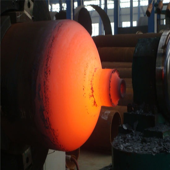
A hot forming machine for metal pipes is a specialized piece of equipment designed to shape and form metal pipes at elevated temperatures. Unlike cold forming processes, hot forming involves heating the metal pipe to a temperature where it becomes more pliable, allowing for easier deformation with less risk of cracking or excessive stress.
The heating process typically involves furnaces, induction heaters, or other controlled heat sources that uniformly raise the pipe temperature to the desired level, which varies depending on the metal type—for example, steel pipes are often heated to between 900°C and 1200°C. Once heated, the pipe is immediately transferred to the forming section of the machine, where rollers, dies, or presses shape the pipe into the desired profile, bend, or contour.
Hot forming machines are capable of producing complex shapes, large-diameter bends, or thick-walled pipes that would be difficult or impossible to form using cold methods. The elevated temperature reduces the material’s yield strength, increasing ductility and reducing forming forces, which minimizes tooling wear and extends machine life.
These machines are widely used in heavy industry sectors such as oil and gas pipelines, shipbuilding, automotive, aerospace, and structural engineering, where high-strength pipes with precise shapes and smooth finishes are required.
Hot forming machines often include temperature control systems, conveyors or transfer mechanisms to move the heated pipes safely, and cooling systems to gradually reduce pipe temperature after forming to prevent warping or cracking. Advanced models use automation and CNC controls to ensure precise control over heating, forming speed, and shape accuracy.
Safety is a critical aspect of hot forming machines due to the high temperatures involved. Protective shielding, heat-resistant operator enclosures, emergency shutoffs, and strict operational protocols are standard features to protect workers.
Maintenance involves regular inspection of heating elements, rollers, dies, and mechanical components, as well as calibration of temperature controls and monitoring equipment to ensure consistent forming quality and machine longevity.
In summary, hot forming machines enable efficient shaping of metal pipes with enhanced mechanical properties and complex geometries by leveraging elevated temperatures, making them essential in industries demanding high-performance pipe products.
Hot forming machines operate by first heating metal pipes to a temperature where the material’s ductility increases significantly, allowing it to be reshaped with less force and reduced risk of defects such as cracks or tears. The heating process is carefully controlled to ensure uniform temperature distribution, which is critical for achieving consistent forming results and avoiding thermal stresses that could weaken the pipe.
Once the pipe reaches the target temperature, it is transferred—often using mechanized conveyors or robotic arms—to the forming station. Here, the pipe is shaped using heavy-duty rollers, presses, or dies designed to handle the softer, heated metal. The forming tools apply controlled pressure, bending or reshaping the pipe to the desired geometry while maintaining the integrity of the pipe wall.
The advantage of hot forming is its ability to produce complex shapes and large-radius bends that are difficult or impossible to achieve with cold forming. Thick-walled pipes or high-strength alloys, which are typically resistant to deformation at room temperature, can be shaped efficiently in hot forming processes. The lower yield strength of heated metal reduces the load on machinery and tooling, resulting in less wear and longer tool life.
After forming, the pipes typically go through a controlled cooling phase to solidify the new shape and restore mechanical strength. Cooling methods vary and may include air cooling, water quenching, or controlled furnace cooling, depending on the material and application requirements. Proper cooling is essential to prevent warping, residual stresses, or cracking.
Automation and CNC controls enhance the hot forming process by precisely regulating heating temperature, forming speed, and tool positioning. This ensures high repeatability, reduces operator intervention, and improves overall efficiency. Some systems include real-time monitoring of temperature and forming parameters to adjust operations dynamically, minimizing defects.
Safety is paramount in hot forming due to the extreme temperatures and heavy machinery involved. Machines are equipped with heat shields, protective enclosures, and emergency stop systems. Operators are trained to follow strict safety protocols, including the use of personal protective equipment (PPE), to avoid burns or injuries.
Maintenance focuses on the upkeep of heating elements, ensuring they provide consistent and reliable heat output. Rollers and dies are inspected regularly for wear caused by hot metal contact and replaced or refurbished as needed. Calibration of temperature controls and sensors is performed routinely to maintain process accuracy.
Industries such as oil and gas, power generation, shipbuilding, and heavy machinery manufacturing rely on hot forming machines to produce pipes that meet stringent specifications for strength, durability, and precise shapes. The ability to form pipes at high temperatures allows manufacturers to expand design possibilities and improve the performance of final products.
Overall, hot forming machines combine controlled heating, robust mechanical forming, and precise automation to enable the efficient production of complex, high-quality metal pipes suitable for demanding industrial applications.
Recent developments in hot forming machines emphasize increased automation, energy efficiency, and precision control. Advanced induction heating systems have become popular for their rapid, localized heating capabilities, which reduce energy consumption and minimize thermal distortion by heating only the section of the pipe being formed rather than the entire pipe length.
CNC-controlled forming stations now allow for highly accurate shaping with programmable bend angles, radii, and lengths, supporting complex pipe geometries and repeatable production runs. The integration of real-time temperature sensors and feedback loops ensures that the pipe is formed at the optimal temperature, preventing overheating or underheating, which can lead to material defects.
Some modern hot forming machines incorporate modular designs, enabling manufacturers to quickly switch between different pipe sizes, materials, or forming processes. This flexibility supports just-in-time manufacturing and reduces setup times, which is critical in industries where product variety and customization are growing.
Energy recovery systems are being implemented to capture and reuse heat from exhaust gases or cooling systems, further improving the environmental footprint and reducing operational costs. These systems contribute to greener manufacturing practices and compliance with increasingly strict environmental regulations.
Safety enhancements include automated enclosure systems that shield operators from hot surfaces and emissions, as well as integrated sensors that detect unsafe conditions such as overheating or mechanical faults and automatically halt the process to prevent accidents.
Maintenance protocols have evolved to include predictive analytics using sensor data, allowing maintenance teams to anticipate wear or failures in heating elements, rollers, and mechanical parts before they cause downtime. This predictive maintenance approach increases machine uptime and reduces repair costs.
Applications benefiting from these improvements include the fabrication of thick-walled pipeline components for oil and gas transport, precision aerospace tubing requiring complex bends, and structural pipes used in heavy construction. The ability to efficiently produce high-strength, intricately shaped pipes ensures that manufacturers can meet rigorous quality standards while maintaining competitive production speeds.
In conclusion, ongoing advancements in hot forming machine technology are driving improvements in process control, energy efficiency, safety, and operational flexibility. These innovations empower manufacturers to produce superior metal pipe products tailored to increasingly demanding industrial needs.
Thread Rolling Machine For Metal Pipes
A thread rolling machine for metal pipes is a specialized machine designed to create external threads on metal pipes by using a cold-forming process called thread rolling. Unlike traditional cutting or machining methods, thread rolling forms threads by pressing hardened dies against the pipe surface, plastically deforming the material to create precise, strong threads without removing any metal.
The process begins by securely clamping the metal pipe in the machine, aligning it with the thread rolling dies. These dies are typically made from hardened steel and have the negative profile of the desired thread form. As the pipe rotates or the dies move, high pressure is applied, causing the pipe’s surface material to flow into the thread shape.
Thread rolling offers several advantages: it produces stronger threads due to work hardening of the material, improves surface finish, and ensures greater dimensional accuracy and consistency compared to cutting. Because it does not cut away material, the pipe wall integrity is maintained, which is especially important for pressure-bearing pipes.
Thread rolling machines can be configured to produce various thread types, such as tapered threads for pipe fittings (e.g., NPT) or straight threads for mechanical joints. Machines may have manual, semi-automatic, or fully automatic operation modes, depending on production volume and complexity.
The machine’s parameters—such as rolling speed, pressure, and feed—are adjustable to accommodate different pipe diameters, wall thicknesses, and materials including steel, stainless steel, aluminum, and copper. Proper lubrication is critical during thread rolling to reduce friction, prevent tool wear, and ensure smooth thread formation.
Modern thread rolling machines often feature CNC controls for precise positioning and repeatability, making them suitable for high-volume manufacturing environments. Safety features include guarding around moving parts and emergency stop mechanisms.
Threaded metal pipes produced with thread rolling machines are widely used in plumbing, oil and gas pipelines, automotive, and industrial equipment where reliable, leak-proof threaded connections are essential.
In summary, thread rolling machines provide an efficient, high-quality method for forming strong, accurate threads on metal pipes, combining mechanical precision with material benefits to support diverse industrial applications.
Thread rolling machines operate by firmly securing the metal pipe while rotating it against a pair or set of hardened dies that contain the thread pattern in reverse. As pressure is applied, the dies impress the thread form into the pipe surface through plastic deformation, displacing the material rather than cutting it away. This cold-forming technique strengthens the pipe threads through work hardening, resulting in improved fatigue resistance and durability compared to machined threads.
The rolling process is carefully controlled to ensure consistent thread depth, pitch, and profile. Parameters such as rolling force, rotational speed, and lubrication are adjusted according to the pipe material, diameter, and wall thickness. Proper lubrication reduces friction and heat buildup, extending die life and ensuring smooth, burr-free threads.
Thread rolling machines come in various configurations, from simple manual models suitable for small batches or repairs to fully automated CNC machines designed for high-volume production. CNC controls allow for programmable threading operations, including thread length, pitch variation, and synchronization with pipe feeding mechanisms. This automation improves repeatability, reduces operator error, and speeds up production cycles.
The dies used in thread rolling machines are typically made from tool steels or carbide materials, selected for their hardness and wear resistance. Regular maintenance and periodic die replacement are necessary to maintain thread quality and prevent defects such as incomplete threads or surface damage.
Safety features include guards around the rotating dies, emergency stop buttons, and sensors to verify proper pipe positioning before rolling begins. Operators are trained to follow strict procedures due to the high forces involved in the process.
Thread rolling is favored in applications requiring high-strength, leak-proof threaded connections, such as oil and gas pipelines, hydraulic systems, and plumbing installations. The cold forming method also produces smoother thread surfaces, reducing the risk of galling and improving sealing when combined with appropriate thread sealants or tape.
In addition to external threading, some thread rolling machines are capable of internal thread rolling, expanding their versatility. The process also tends to be faster than cutting methods, reducing manufacturing time and cost.
Overall, thread rolling machines provide an efficient, reliable, and high-quality solution for threading metal pipes, leveraging material deformation rather than removal to enhance thread strength and surface finish. This technology is essential in industries where pipe connections must withstand high pressure, mechanical stress, and corrosive environments.
Advancements in thread rolling machines for metal pipes have focused on improving precision, speed, and adaptability to meet evolving industrial requirements. Modern machines often feature multi-axis CNC controls that enable complex thread profiles and the ability to handle varying pipe sizes and materials with minimal setup time. This flexibility supports manufacturers producing diverse product lines without sacrificing efficiency.
Incorporating real-time monitoring systems, these machines can detect anomalies such as improper pipe alignment, inadequate lubrication, or die wear, allowing immediate corrective actions to prevent defects. Automated quality inspection using sensors or vision systems can verify thread dimensions and surface finish immediately after rolling, ensuring only compliant parts proceed to the next production stage.
Materials beyond traditional steels, including stainless steel alloys and non-ferrous metals like aluminum and brass, are increasingly processed on thread rolling machines. This requires machines with adjustable rolling forces and advanced lubrication systems tailored to different material properties to maintain thread integrity.
Energy efficiency has also become a priority, with newer machines utilizing servo-driven mechanisms that consume less power and provide more precise control compared to older hydraulic systems. These servo drives reduce mechanical stress on components, enhancing machine longevity and reliability.
The integration of thread rolling machines into automated production lines with robotic loading and unloading further boosts throughput and reduces manual labor, enabling high-volume manufacturing with consistent quality. Such integration is common in sectors like oil and gas, automotive, and plumbing, where threaded pipe components are produced in large quantities.
Maintenance strategies now leverage predictive analytics based on sensor data, enabling proactive servicing of dies, bearings, and drive systems. This approach minimizes unplanned downtime and maintains optimal machine performance over time.
In critical industries, the enhanced durability and superior finish of thread-rolled pipes contribute significantly to the reliability of fluid or gas transport systems, reducing leakage risks and maintenance costs. As demands for higher pressure ratings and more complex piping systems grow, thread rolling technology continues to evolve, offering manufacturers a powerful tool to meet these challenges efficiently.
In summary, ongoing innovations in thread rolling machines enhance their precision, adaptability, and integration capabilities, solidifying their role as a vital technology for producing high-quality threaded metal pipes across a broad range of industrial applications.
Wrinkling Machine For Metal Pipes
A wrinkling machine for metal pipes is a specialized piece of equipment used to intentionally create controlled wrinkles or corrugations on the surface of metal pipes. Unlike defects caused by uncontrolled deformation, these wrinkles are purposefully formed to enhance flexibility, increase surface area, or improve the pipe’s mechanical properties for specific applications.
The wrinkling process typically involves passing the metal pipe through a set of rollers or dies designed to exert localized compressive forces that deform the pipe surface in a controlled manner. These wrinkles or corrugations can vary in size, shape, and pattern depending on the machine setup and the intended use of the pipe.
Wrinkling machines are widely used in industries requiring flexible metal conduits, expansion joints, or pipes designed to absorb thermal expansion and contraction without damage. Corrugated or wrinkled pipes are common in automotive exhaust systems, HVAC ducts, flexible plumbing lines, and certain types of structural tubing.
The machine parameters such as roller pressure, spacing, and speed are adjusted according to the pipe diameter, wall thickness, and material properties to achieve the desired wrinkle pattern without compromising pipe integrity. Materials commonly processed include steel, stainless steel, aluminum, and copper.
Advanced wrinkling machines may incorporate CNC controls to produce precise, repeatable wrinkle patterns with varying amplitude and frequency along the pipe length. Automation enhances productivity and allows customization for different product specifications.
Lubrication is often applied during wrinkling to reduce friction between the pipe and tooling, minimizing surface damage and extending tool life. After wrinkling, pipes may undergo further processing such as heat treatment or surface finishing depending on the application.
Safety features include guarding around moving parts and emergency stops to protect operators from injury during the high-force deformation process.
In summary, wrinkling machines enable manufacturers to produce metal pipes with controlled surface corrugations that improve flexibility, accommodate movement, and meet specialized performance requirements in a variety of industrial applications.
Wrinkling machines for metal pipes function by carefully applying compressive forces along the pipe’s axis using sets of specially shaped rollers or dies that deform the pipe wall into a series of uniform waves or folds. These wrinkles are not structural flaws but are engineered features that enhance the pipe’s flexibility and resilience, allowing it to absorb mechanical stress, thermal expansion, or vibration without cracking or deforming permanently. The process is cold-forming, meaning the metal is not heated, which preserves its original mechanical properties while introducing the wrinkled geometry.
The geometry of the wrinkles—such as wave height, pitch, and depth—can be adjusted through precise control of the roller gap, feed rate, and applied force. This allows manufacturers to tailor the wrinkling pattern to specific applications. For example, tighter, shallower wrinkles may be used for lightweight HVAC ducts, while deeper, more widely spaced corrugations may be applied to exhaust or industrial piping requiring high flexibility and strength. Some machines include programmable logic controls or CNC systems that allow for automatic adjustment of wrinkling patterns during operation, enabling variable designs on a single pipe length or faster setup between production runs.
Materials suitable for wrinkling include soft metals like aluminum and copper as well as tougher alloys such as stainless steel, depending on the machine’s capacity. Proper lubrication during the wrinkling process reduces wear on the rollers and minimizes the risk of surface cracking or galling on the pipe. In automated setups, pipes are fed into the machine via conveyors or clamps, and the wrinkled product exits continuously, ready for further processing such as cutting, forming, or surface finishing.
Wrinkled pipes are widely used in applications where rigidity must be balanced with the need for motion or thermal tolerance. In automotive systems, for instance, wrinkled stainless steel pipes are used in exhaust systems to allow for engine and chassis movement. In industrial and HVAC systems, corrugated pipes help accommodate temperature-induced expansion without the need for additional fittings or joints.
The design of the machine emphasizes both forming precision and mechanical robustness, as the repeated compressive action on metal pipes requires durable rollers and high-strength frames. Safety measures include physical guards, sensors to detect incorrect pipe feed or slippage, and emergency stop functions to protect both the operator and the machine. Maintenance of a wrinkling machine involves regular inspection of rollers for wear or alignment issues, lubrication systems to prevent dry contact, and checks of hydraulic or mechanical drive components for consistent pressure delivery.
Overall, wrinkling machines provide a reliable, efficient method for producing specialized pipe geometries that offer enhanced mechanical flexibility and durability. These machines serve key roles in industries ranging from automotive to construction to HVAC, where the functional benefits of a wrinkled or corrugated pipe surface are essential to system performance and longevity.
Continued improvements in wrinkling machine design focus on automation, modular tooling, and integration with downstream processes. High-end machines now often include servo-driven roller systems that allow precise control over wrinkle depth and spacing in real time, adapting to variations in pipe material or wall thickness during continuous production. This is particularly useful for manufacturers working with a range of alloys or when producing pipes with non-uniform profiles.
Some machines are equipped with adaptive feedback systems using sensors and cameras to monitor the wrinkle formation process as it happens. These systems detect inconsistencies in shape or alignment and automatically adjust roller pressure or position, ensuring consistently high-quality output without manual intervention. This not only reduces scrap but also improves overall efficiency and product reliability.
Wrinkling can also be combined with other forming operations in a single pass. For example, a machine might first wrinkle a pipe section and then flare, bead, or crimp it further downstream, all within the same line. This integration reduces handling time and space requirements, making production lines more compact and streamlined.
Material handling systems play a crucial role in automated wrinkling setups. Robotic arms or servo-controlled feeders load straight pipes into the machine, and automated conveyors or stackers collect the finished wrinkled pipes. This reduces labor costs and increases throughput, especially in high-volume environments.
In terms of tooling, quick-change roller systems allow operators to swap out wrinkling dies for different wrinkle geometries within minutes, minimizing downtime during product changeovers. Tool life is also extended through advanced coatings like TiN or DLC on rollers, which reduce wear and surface friction during continuous cold forming.
In industries like aerospace, where wrinkled or corrugated tubing is used for ducts and conduits exposed to extreme temperatures and motion, precision is critical. Here, CNC-controlled wrinkling machines provide fine control over profile uniformity and ensure compliance with strict tolerances. In HVAC applications, wrinkle patterns may also serve an aesthetic purpose, and surface smoothness and uniformity are valued alongside mechanical performance.
Environmental considerations are also driving improvements. Modern machines consume less power, utilize closed-loop lubrication systems to minimize waste, and are built with noise and vibration dampening to meet stricter workplace safety standards.
In essence, the wrinkling machine has evolved from a purely mechanical tool into a highly adaptable, intelligent system capable of producing advanced pipe geometries at high speeds with minimal error. Its continued development is driven by the demand for flexible, durable, and precisely formed metal piping solutions across a broad spectrum of engineering and construction industries.
Curling Ends Machine For Metal Pipes
A curling ends machine for metal pipes is a forming device designed to create a smooth, rounded edge—or “curl”—at the open ends of metal pipes or tubes. This curled edge is often used for functional, structural, or safety purposes. The curling process involves shaping the raw, sharp edge of a pipe into a rounded loop or circular bead by applying pressure with specialized dies or rollers, typically without removing material.
The machine operates by securing the pipe in position while a rotating or translating forming tool gradually bends the edge inward or outward, depending on the desired curl geometry. The forming motion can be carried out using rollers, segmented dies, or a mandrel system, depending on pipe diameter, material type, and the size of the curl. The operation is controlled to maintain dimensional accuracy and prevent tearing or cracking, especially in thinner-walled pipes or when working with hard metals.
Curling adds rigidity to the pipe end, making it stronger and more resistant to deformation during handling or use. It also eliminates sharp edges, improving safety for both users and assembly workers. In applications where pipes interface with gaskets or need to form sealed joints, the curled edge provides a smooth, consistent surface that enhances the sealing effect and prevents leaks.
Common materials used with curling machines include mild steel, stainless steel, aluminum, copper, and brass. Curling can be performed as a cold-forming process, though some setups may involve light heating to aid in forming thicker or harder metals without causing surface damage.
The design of curling ends machines varies: manual models are used for low-volume or custom work, while high-volume production lines use CNC-controlled or servo-powered machines capable of curling both ends of the pipe in sequence or simultaneously. Advanced models allow curl diameter, tightness, and angle to be precisely programmed, and they often feature automatic pipe feeding, positioning, and ejection for continuous production.
Curling is commonly applied in automotive exhaust tubing, ventilation ducts, pipe fittings, furniture frames, and appliance housings. It is especially valued where the pipe end will be visible, touched, or connected mechanically or elastically to other components.
Modern curling ends machines incorporate safety guards, emergency stop systems, and sensors to detect incorrect part placement or metal inconsistencies. Proper lubrication and tool maintenance are also essential to prevent galling and maintain curl quality.
Overall, curling ends machines are essential in any metal pipe fabrication process that requires strengthened, smoothed, or interfacing pipe ends. They combine precision forming with repeatability, ensuring reliable, high-quality results across a wide range of industrial applications.
Curling ends machines for metal pipes are engineered to apply consistent, controlled force that gradually bends the pipe’s open edge into a rounded profile, either inward toward the pipe’s interior or outward away from it. This curling is achieved using rotary dies, pressure rollers, or a combination of forming heads that revolve around the pipe’s circumference while keeping the pipe body stationary or slowly rotating. The process ensures a uniform curl without flattening the pipe wall or introducing wrinkles. Because curling strengthens the end through work hardening and geometry, the result is both structurally and aesthetically enhanced.
Depending on the application, the curl may serve different functions. In ducting systems, an outward curl facilitates easier coupling with flexible hoses or other ducts. In automotive and HVAC systems, a curled end may act as a retention edge for clamps, gaskets, or seals, helping to maintain a leak-proof connection. In furniture and appliance manufacturing, the curl serves primarily as a safety feature, removing sharp edges and improving the finish of exposed metal ends. The radius and depth of the curl can be tightly controlled based on the required joint or safety specification.
The materials that respond best to curling are ductile metals such as mild steel, aluminum, brass, and stainless steel. However, tool and machine configuration must vary to suit the hardness and wall thickness of the material. For softer metals, fewer forming passes or a single die operation may suffice, while for harder alloys or thicker sections, multiple passes and precise alignment of forming tools are necessary to prevent tearing or warping at the curl zone.
Curling machines can be standalone or integrated into production cells with other forming, punching, or trimming operations. In a fully automated line, pipes are fed in, detected by sensors, positioned by servo actuators, curled at one or both ends, and ejected—all without manual handling. The use of programmable logic controllers (PLCs) or CNC systems enables flexible programming of curl size, feed rate, and forming sequence. This is particularly useful in high-mix, low-volume environments or where custom curl profiles are needed.
The tooling is typically made of hardened steel or carbide and may include interchangeable components to switch between different curl radii or pipe sizes. Regular inspection and maintenance of forming dies are critical to maintaining edge integrity and preventing defects such as splitting or over-thinning, especially with repeated cold forming. Lubricants may be applied to reduce friction between the pipe and the forming surface, extending tool life and improving surface finish.
Curling ends machines often incorporate safety enclosures, interlocked doors, and pressure-sensitive mats to prevent operator access during motion. Optical sensors can also detect pipe presence and length before forming begins, ensuring only properly aligned parts are processed.
As industries move toward leaner manufacturing and higher-quality standards, curling ends machines have adapted with better control systems, faster setup changes, and higher forming speeds. Their role remains vital wherever pipe ends need to be prepared for safe handling, tight joining, or mechanical reinforcement, combining precision and repeatability in a compact and efficient form.
Further innovations in curling ends machines focus on improving efficiency, versatility, and integration with smart manufacturing systems. Modern machines often feature quick-change tooling systems that allow operators to swap curl dies rapidly, minimizing downtime when switching between different pipe diameters or curl profiles. This flexibility supports manufacturers handling diverse product lines or custom orders without sacrificing productivity.
Advanced curling machines incorporate servo motors and programmable controllers to finely tune the curling speed, pressure, and angle in real time. This precise control helps accommodate pipes with variable wall thicknesses or material inconsistencies, ensuring consistent curl quality throughout long production runs. The use of sensors and closed-loop feedback systems allows the machine to automatically adjust forming parameters to maintain dimensional accuracy and surface finish.
Integration with industrial automation is increasingly common, where curling machines are linked to upstream and downstream equipment like pipe cutting, welding, or inspection stations. Automated material handling systems, including robotic loaders and unloaders, reduce manual intervention and speed up overall production flow. Data from the curling process can be logged and analyzed to track quality trends, predict maintenance needs, and optimize throughput.
Some curling machines offer multi-functional capabilities, combining curling with other end-forming operations such as flaring, beading, or hemming in a single setup. This multi-step forming reduces handling and equipment footprint, making manufacturing lines more compact and cost-effective.
Environmental and safety considerations drive design improvements, including quieter operation, energy-efficient drives, and enclosed lubrication systems that minimize waste and workplace exposure to oils and coolants. Ergonomic designs facilitate easier operator access for maintenance and quick visual inspection without compromising protection.
In specialized applications like aerospace or medical tubing, curling machines must meet stringent quality standards, requiring validation through detailed inspection protocols such as laser measurement or high-resolution imaging to verify curl uniformity and dimensional tolerances.
Overall, curling ends machines continue to evolve by integrating smarter controls, adaptable tooling, and enhanced automation, meeting the increasing demands of precision, flexibility, and efficiency in metal pipe manufacturing. These machines remain indispensable for preparing pipe ends that are structurally reinforced, safer to handle, and ready for subsequent assembly or finishing operations.
Bead Forming Machine For Metal Pipes
A bead forming machine for metal pipes is specialized equipment designed to create raised or recessed bead profiles—circular ridges or grooves—around the circumference of metal pipes. These beads serve various functional and structural purposes, such as increasing pipe rigidity, improving joint strength, facilitating sealing, or enhancing aesthetic appeal.
The bead forming process typically involves cold forming, where the pipe is clamped and rotated while a shaped roller or die applies pressure to the pipe surface, plastically deforming the metal to form the bead. This is done without removing any material, maintaining the pipe’s integrity while adding the desired contour. The bead’s size, shape, and position can be precisely controlled by adjusting the roller profile, pressure, and feed rate.
Beads increase the stiffness of a pipe section by creating a localized increase in cross-sectional moment of inertia, making the pipe less prone to bending or collapse under external pressure. This is particularly valuable in thin-walled pipes used in automotive, HVAC, or structural applications. Beads also act as locating features or stop points when pipes are assembled into fittings or clamped, improving alignment and sealing performance.
Materials commonly processed include steel, stainless steel, aluminum, copper, and brass. The machine design and tooling must accommodate differences in material ductility and thickness to avoid cracking or surface damage during bead formation.
Bead forming machines range from manual or semi-automatic units suitable for small batches or custom work to fully automated CNC-controlled machines integrated into high-speed production lines. Automation features include automatic pipe feeding, rotation, precise positioning of the bead along the pipe length, and synchronized roller pressure adjustment for consistent bead quality.
The tooling system often includes interchangeable rollers or dies to produce various bead profiles, including single beads, double beads, or complex shapes like grooves combined with ribs. Quick-change tooling options reduce downtime during product changeover.
Lubrication is applied during the bead forming process to minimize friction and wear on both the pipe surface and forming tools, ensuring smooth operation and high-quality surface finish. Maintenance involves regular inspection of rollers for wear, alignment checks, and lubrication system upkeep.
Safety features commonly integrated into bead forming machines include protective guarding, emergency stop buttons, and sensors to detect pipe presence or positioning errors. These measures protect operators from moving parts and ensure only correctly loaded pipes are processed.
Bead formed pipes find use in automotive exhaust systems, HVAC ducts, plumbing lines, and structural tubing, where enhanced strength, alignment, or sealing is necessary. The bead profiles improve the durability and functionality of pipe assemblies without requiring additional components or welding.
In summary, bead forming machines provide an efficient, precise method to enhance the mechanical properties and assembly capabilities of metal pipes through controlled cold forming of bead features, supporting a wide range of industrial applications.
Bead forming machines for metal pipes work by clamping the pipe securely and rotating it steadily while a roller or set of rollers applies controlled pressure to the pipe’s surface. The roller’s shape corresponds to the desired bead profile, which can range from simple rounded ridges to more complex multi-step grooves or ribs. As the pipe rotates, the roller presses inward or outward, plastically deforming the metal to create a continuous bead around the circumference. The process does not remove any material but reshapes the pipe wall to increase stiffness and add functional features.
The machines vary in complexity, from manually operated units where the operator feeds and positions the pipe, to fully automated CNC-controlled systems integrated into production lines with robotic feeding and unloading. Automation allows precise control over bead location along the pipe length, consistent bead geometry, and high throughput. Programmable systems can adjust roller pressure, rotation speed, and feed rate dynamically to accommodate variations in pipe diameter, wall thickness, or material hardness, ensuring uniform quality even when working with mixed batches.
Materials commonly processed by bead forming machines include mild steel, stainless steel, aluminum, copper, and other ductile alloys. Since the forming process involves plastic deformation, tool design and process parameters must be carefully selected to avoid surface cracking, splitting, or excessive thinning, especially for pipes with thin walls or hard materials. Lubrication systems are usually employed to reduce friction between the roller and pipe surface, improving finish quality and extending tool life.
Beads add mechanical benefits by increasing the pipe’s resistance to bending and buckling under external forces. This makes bead-formed pipes suitable for applications requiring enhanced structural performance without adding significant weight. Additionally, beads serve as stop features or alignment guides during assembly, improving the fit and sealing of pipe joints or fittings. This is particularly important in HVAC ductwork, plumbing systems, automotive exhausts, and structural tubing where precise assembly and leak prevention are critical.
The tooling on bead forming machines is typically modular, with quick-change rollers or dies to allow rapid switching between different bead sizes and profiles. This versatility supports manufacturers who produce a range of pipe sizes and bead configurations for various industries. Maintenance includes regular inspection of rollers for wear or damage, calibration of pressure settings, and lubrication system upkeep to maintain consistent performance and part quality.
Safety features are integral to bead forming machines, including guards around moving components, emergency stops, and sensors that ensure pipes are properly positioned before forming begins. These features protect operators from injury and prevent damage to the machine or workpieces.
Some advanced bead forming systems combine bead creation with other forming operations, such as flaring, hemming, or corrugating, allowing multiple end or mid-pipe features to be produced in one automated sequence. This integration reduces handling, cycle time, and the footprint of production equipment, boosting efficiency and lowering costs.
In industries demanding precise, durable, and functional metal piping, bead forming machines are essential tools that improve product strength, assembly accuracy, and overall system reliability. Their continued development focuses on enhancing automation, precision, tooling flexibility, and integration with broader manufacturing processes, meeting the evolving needs of modern metal fabrication.
Advancements in bead forming machines are increasingly driven by the demand for higher precision, faster cycle times, and greater flexibility in handling a variety of pipe materials and sizes. Modern machines often incorporate servo-driven motors and CNC controls that allow operators to program exact bead dimensions, locations, and forming pressures. This digital control enhances repeatability and reduces setup time, enabling quick shifts between production runs with minimal downtime.
Integration with real-time monitoring and quality control systems is becoming standard in advanced bead forming setups. Sensors can measure parameters such as bead height, width, and surface finish during or immediately after forming, feeding data back to the control system to make on-the-fly adjustments. This closed-loop feedback ensures consistent product quality and early detection of defects like cracks or uneven deformation, which helps reduce scrap rates and rework.
Bead forming machines are also increasingly integrated into smart factory environments, where they communicate with upstream and downstream equipment. For example, automated pipe cutting, cleaning, or inspection stations can be linked to the bead forming machine, creating a seamless flow of materials through the production line. This connectivity supports just-in-time manufacturing principles and enhances overall operational efficiency.
From a tooling perspective, innovations in materials and coatings for rollers and dies have extended their service life, even when processing abrasive or hard materials. Tooling designs are evolving to include modular components that can be easily swapped or adjusted, supporting a wide range of bead profiles and pipe diameters without the need for extensive downtime.
Environmental and safety considerations have also influenced the design of bead forming machines. Energy-efficient motors and drives reduce power consumption, while enclosed lubrication and coolant systems minimize environmental impact and workplace hazards. Enhanced guarding and automation reduce operator exposure to moving parts, contributing to safer manufacturing conditions.
In applications such as automotive exhaust systems, HVAC ducting, and structural components, the precise and consistent bead profiles created by these machines improve not only mechanical performance but also aesthetic quality, important for visible components. Bead forming also helps reduce the need for secondary reinforcement parts or welding, lowering material costs and assembly complexity.
Overall, bead forming machines for metal pipes have evolved into highly sophisticated, automated systems that deliver precise, durable, and functional enhancements to pipe products. Their adaptability, combined with smart controls and integration capabilities, ensures they remain a cornerstone of modern metal pipe fabrication across many industries.
Diameter Shrinking Machine for Metal Pipes
A diameter shrinking machine for metal pipes is a specialized forming device used to reduce the outer diameter of a pipe or tube over a defined length, creating a stepped-down section that enables tighter fits, improved assembly with other components, or preparation for welding, flaring, or sealing operations. This reduction is achieved through cold forming, where a set of dies or segmented jaws close radially around the pipe while applying axial or rotary pressure, compressing the metal inward without cutting or removing material.
The process typically begins with the pipe being loaded into the machine and aligned precisely with the forming tools. Once secured, hydraulic or servo-powered dies clamp around the pipe’s circumference, gradually reducing the diameter in a controlled manner. The length of the shrink zone can be adjusted by modifying how far the dies travel along the pipe or by repositioning the pipe in multiple stages. Depending on machine type, the reduction can be performed in one single operation or through multiple incremental forming passes to avoid overstraining the material.
This method is especially effective for thin- to medium-wall pipes made from ductile metals such as mild steel, stainless steel, aluminum, copper, and brass. Shrinking enhances the mechanical connection between parts in slip-joint assemblies, where one pipe must slide into another. It is also used to create tight-fitting ends for brazing or welding and to match pipes to components such as collars, connectors, or fittings without requiring additional sleeves or adhesives.
Machines may vary in complexity from manual hydraulic presses used for small-batch work to fully automated CNC-controlled units with programmable shrink profiles. CNC models can shrink multiple diameters in sequence, apply tapered transitions, or combine shrinking with other end-forming functions such as beading or flaring. High-end systems feature quick-change tooling, servo-driven actuators for repeatability, and touch-screen interfaces for recipe storage and control.
Tooling must be precisely machined to match the desired finished diameter and avoid deformation or wrinkling of the pipe surface. In some cases, an internal mandrel may be inserted into the pipe to prevent collapse or ovality during the shrinking process. Lubrication may also be used to minimize friction and wear on both the pipe and tools, especially in continuous or high-speed production settings.
Diameter shrinking improves structural integrity at the joint, minimizes the need for welding filler material, and offers a clean, professional finish that is often more durable and leak-resistant than adhesive or gasket-based connections. It is widely used in industries like automotive exhaust systems, HVAC piping, aerospace tubing, and general structural fabrication.
Safety systems on modern machines include two-hand control operations, interlocked safety guards, and automatic cycle interruption if misalignment or obstruction is detected. These safeguards help protect operators during high-force forming operations.
In summary, diameter shrinking machines play a crucial role in precision tube and pipe fabrication, offering a fast, material-efficient way to modify pipe ends for tighter assembly, better fluid sealing, and reduced part count in structural and mechanical systems.
Diameter shrinking machines operate by gradually compressing the pipe’s circumference using precisely engineered dies that apply uniform pressure around the pipe. The process is carefully controlled to ensure the metal flows inward without causing defects such as wrinkling, cracking, or flattening of the pipe wall. To maintain the pipe’s roundness and prevent collapse during compression, some machines employ internal support mandrels or expandable plugs inside the pipe, which provide counter-pressure from within.
The shrinking can be done in a single continuous stroke or through multiple incremental steps, especially when a significant diameter reduction is needed or when working with thicker or harder materials. This staged approach minimizes stress concentrations and maintains material integrity. The machine’s hydraulic or servo-driven actuators allow precise adjustment of force and speed, optimizing the process for different pipe sizes, wall thicknesses, and materials.
Operators load the pipe onto the machine either manually or via automated feeding systems. Positioning devices such as clamps, guides, or laser sensors ensure the pipe is correctly aligned before shrinking begins. Automated systems often include programmable logic controllers (PLCs) that control the sequence of shrinking operations, track tool wear, and log production data for quality assurance.
Diameter shrinking improves the pipe’s fitment with other components by creating a tight, interference-fit section. This is essential in applications where pipes must be joined without welding or adhesives, such as in slip-fit connections for exhaust systems, HVAC ducting, or hydraulic tubing. By reducing the pipe’s diameter precisely, the shrinking process eliminates gaps that could cause leaks or mechanical failure, enhancing overall assembly reliability.
Because the process is cold forming, the metal experiences strain hardening in the shrunken area, increasing local strength and stiffness. However, this also requires careful control to avoid over-hardening or embrittlement, which could lead to cracking under service conditions. Material selection and process parameters must be tailored accordingly.
Tooling for diameter shrinking is typically made from hardened steel or carbide to withstand repeated high-pressure cycles without deformation. Interchangeable die sets allow the same machine to handle different pipe sizes and shrink diameters, improving versatility and reducing downtime during product changes.
Lubrication plays an important role in reducing friction between the pipe surface and forming dies, extending tooling life and improving surface finish. Some machines incorporate closed-loop lubrication systems that deliver consistent amounts of lubricant during each forming cycle.
Safety mechanisms are integral to diameter shrinking machines due to the high forces involved. Guards, emergency stop systems, and sensors prevent operator access to moving parts during operation. Two-hand control systems may be employed to ensure the operator’s hands are clear before the machine cycles.
Diameter shrinking machines can be integrated into automated production lines, working in tandem with pipe cutting, cleaning, welding, or inspection stations. Such integration streamlines manufacturing, reduces manual handling, and enhances throughput while maintaining consistent quality.
Overall, diameter shrinking machines provide a precise, efficient, and material-saving method to modify pipe ends for improved fit, structural performance, and assembly readiness. Their role is vital in industries requiring tight tolerance connections and durable joints, combining mechanical efficiency with production flexibility.
Recent developments in diameter shrinking machines emphasize increased automation, precision, and adaptability to meet diverse industrial demands. CNC-controlled machines now offer fully programmable shrinking sequences, allowing manufacturers to create complex shrink profiles, such as tapered transitions or multiple diameter steps along a single pipe length. This capability supports applications where pipes must fit into varying connectors or housings without additional machining or adapters.
Advanced sensors and vision systems are being integrated to monitor the shrinking process in real time. These systems detect deviations in pipe diameter, wall thickness, or shape during forming and adjust machine parameters dynamically to maintain quality. This closed-loop feedback reduces scrap and rework, improves yield, and ensures compliance with strict dimensional tolerances required in sectors like aerospace, automotive, and medical tubing.
Energy efficiency is another focus area. Modern machines utilize servo-driven electric actuators instead of traditional hydraulic systems, which reduces energy consumption, improves control responsiveness, and simplifies maintenance. Regenerative braking and energy recovery features further optimize power usage during cyclic operations.
Tooling innovations include modular die systems with quick-change capabilities, enabling faster transitions between different pipe sizes or shrink diameters. Tool materials and coatings have evolved to extend service life even when processing abrasive or high-strength alloys. Some machines incorporate in-situ tool condition monitoring, alerting operators to wear or damage before it affects product quality.
Integration with smart factory systems allows diameter shrinking machines to communicate with upstream and downstream equipment, creating seamless automated workflows. For example, pipes can be automatically fed from cutting stations, shrunk to precise dimensions, and then transferred to welding or inspection units without manual intervention. Data collected throughout the process supports traceability, quality control, and predictive maintenance.
Safety features continue to advance, with machine enclosures, light curtains, and interlock systems minimizing operator exposure to high-force moving parts. Remote operation and monitoring options also reduce the need for direct interaction, further enhancing workplace safety.
In summary, diameter shrinking machines have evolved into highly versatile, precise, and efficient tools essential for modern metal pipe fabrication. Their ability to produce tight-fitting, structurally sound pipe ends with minimal material waste supports a wide range of industrial applications while aligning with trends toward automation, sustainability, and digital manufacturing.
Square Tube Pressing and Shrinking Machine
A Square Tube Pressing and Shrinking Machine is specialized equipment designed to perform two key metal forming operations on square or rectangular metal tubes: pressing (also called flattening or shaping) and shrinking (reducing the tube’s cross-sectional dimensions locally). These machines are widely used in industries such as automotive, construction, furniture manufacturing, and structural fabrication, where square tubes require precise end-form modifications for assembly, joining, or enhanced mechanical performance.
The pressing function typically involves compressing a section of the square tube to achieve a desired profile or shape. This can include flattening one side, creating grooves, or forming specific contours. Pressing alters the tube’s geometry to improve fitment with other components, create attachment points, or enhance aesthetic and functional characteristics.
The shrinking function reduces the cross-sectional dimensions of the square tube locally, often at one or both ends, to enable tight-fitting joints, slip-fit connections, or preparation for welding or fastening. Shrinking helps achieve interference fits, which are critical for strength and leak prevention in structural and mechanical assemblies.
The machine generally consists of a robust frame with hydraulic or servo-driven cylinders that apply high pressure to the tube via specially designed dies or jaws. The dies are shaped to match the required pressing or shrinking profile and can be interchanged for different tube sizes and configurations. The tube is positioned accurately between the dies, and controlled pressure is applied to deform the metal plastically without causing cracking or excessive distortion.
For shrinking, segmented dies or jaws close evenly around the tube’s perimeter, compressing it inward while maintaining its square or rectangular shape as much as possible. In pressing, the dies apply force in specific areas to flatten or shape the tube’s surface. Some machines combine both processes sequentially or simultaneously, depending on production requirements.
Automation levels vary from manual setups, where operators position and activate the press, to fully automated CNC-controlled machines integrated into production lines. Advanced machines feature programmable cycles, adjustable pressure and speed, and sensors for precise control of deformation and quality assurance.
Tooling design is critical to ensure even force distribution and prevent defects such as wrinkling, cracking, or wall thinning. Materials processed commonly include mild steel, stainless steel, aluminum, and other ductile metals suitable for cold forming.
Lubrication and cooling systems may be incorporated to reduce friction, improve surface finish, and prolong tooling life during repetitive operations.
Safety features are integral, including guarded enclosures, emergency stops, two-hand controls, and sensors that detect tube presence and correct positioning before operation begins, protecting operators from injury.
Square tube pressing and shrinking machines enable efficient, precise, and repeatable modifications to tube profiles, enhancing mechanical strength, facilitating assembly, and reducing the need for additional joining components. Their versatility and adaptability make them indispensable in modern metal fabrication environments where square and rectangular tubing is extensively used.
Square tube pressing and shrinking machines operate by applying controlled force through hydraulic or servo-driven cylinders onto the tube, which is securely positioned between dies or jaws shaped to the desired profile. During pressing, the machine compresses specific areas of the tube to alter its geometry, such as flattening a side or creating grooves, while during shrinking, segmented dies close uniformly around the tube to reduce its overall cross-section without compromising its shape integrity.
The process begins with accurate positioning of the tube, often aided by clamps, guides, or automated feeders to ensure consistency and precision. Once the tube is in place, the machine cycles apply force gradually, controlling speed and pressure to avoid defects like cracking, wrinkling, or unwanted deformation. For shrinking, some machines use internal support mandrels or inserts to maintain internal dimensions and prevent collapse, especially with thin-walled tubes.
These machines are designed to accommodate a range of tube sizes and wall thicknesses, with interchangeable tooling allowing quick transitions between different products. CNC controls and programmable settings enable operators to define pressing and shrinking parameters such as force, speed, stroke length, and sequence, allowing repeatable production runs with minimal setup time.
Lubrication systems are commonly used to reduce friction between the tube and tooling, ensuring smooth forming and extending tool life. Some machines incorporate cooling systems to manage heat generated during high-speed or high-pressure operations.
The combination of pressing and shrinking in a single machine or integrated production line reduces handling and cycle time, improving throughput and reducing production costs. These operations prepare tubes for downstream processes such as welding, joining, assembly, or finishing, ensuring tight fits and enhanced mechanical strength in the final product.
Safety is a priority in these machines, with features like interlocked guards, emergency stop buttons, and sensors that verify tube presence and positioning before operation. Two-hand control mechanisms often require operators to have both hands clear of moving parts, minimizing injury risks.
Applications for square tube pressing and shrinking machines span automotive chassis components, furniture frames, architectural structures, and mechanical assemblies. The precise control over tube shape and dimensions enhances product quality, structural integrity, and ease of assembly, contributing to overall manufacturing efficiency.
Continuous advancements in automation, tooling materials, and control systems drive improvements in these machines, enabling higher precision, faster cycle times, and greater flexibility to handle new tube materials and complex forming requirements. This evolution ensures that square tube pressing and shrinking machines remain vital in modern metal fabrication industries.
Modern square tube pressing and shrinking machines increasingly incorporate smart technologies to enhance productivity and quality. Integration with sensors and vision systems allows real-time monitoring of tube positioning, deformation progress, and dimensional accuracy. These feedback mechanisms enable the machine to automatically adjust force, speed, or die alignment mid-cycle to compensate for material inconsistencies or tooling wear, minimizing defects and scrap.
Automation also extends to material handling, with robotic arms or conveyor systems feeding tubes into the machine and removing finished parts, reducing manual labor and improving cycle times. Some machines offer multi-station configurations where pressing and shrinking operations are performed sequentially or in parallel on the same piece without operator intervention, streamlining the production process.
The use of advanced materials and coatings for tooling improves durability and reduces maintenance intervals, particularly when working with high-strength alloys or abrasive metals. Quick-change tooling systems reduce downtime during product changeovers, supporting just-in-time manufacturing and flexible production runs.
Energy efficiency is another focus area, with many machines employing servo-electric drives instead of traditional hydraulic systems. These drives offer more precise control, faster response times, and reduced energy consumption, contributing to lower operational costs and a smaller environmental footprint.
Safety remains paramount, with comprehensive guarding, light curtains, and emergency stop systems standard on modern machines. Remote operation and monitoring capabilities allow operators to supervise and control the machine from a safe distance, further enhancing workplace safety.
In sectors like automotive manufacturing, construction, and furniture production, square tube pressing and shrinking machines enable the creation of complex, high-strength assemblies with tight dimensional tolerances. Their ability to shape and size tubes accurately reduces the need for welding, fastening, or additional components, lowering costs and improving structural integrity.
Overall, these machines continue to evolve, combining mechanical precision, automation, and intelligent controls to meet the growing demands of modern metal fabrication industries. They play a critical role in producing durable, high-quality square tube components efficiently and reliably.
EMS Metalworking Machines
We design, manufacture and assembly metalworking machinery such as:
- Hydraulic transfer press
- Glass mosaic press
- Hydraulic deep drawing press
- Casting press
- Hydraulic cold forming press
- Hydroforming press
- Composite press
- Silicone rubber moulding press
- Brake pad press
- Melamine press
- SMC & BMC Press
- Labrotaroy press
- Edge cutting trimming machine
- Edge curling machine
- Trimming beading machine
- Trimming joggling machine
- Cookware production line
- Pipe bending machine
- Profile bending machine
- Bandsaw for metal
- Cylindrical welding machine
- Horizontal pres and cookware
- Kitchenware, hotelware
- Bakeware and cuttlery production machinery
as a complete line as well as an individual machine such as:
- Edge cutting trimming beading machines
- Polishing and grinding machines for pot and pans
- Hydraulic drawing presses
- Circle blanking machines
- Riveting machine
- Hole punching machines
- Press feeding machine
You can check our machinery at work at: EMS Metalworking Machinery – YouTube
Applications:
Flange-punching
Beading and ribbing
Flanging
Trimming
Curling
Lock-seaming
Ribbing