
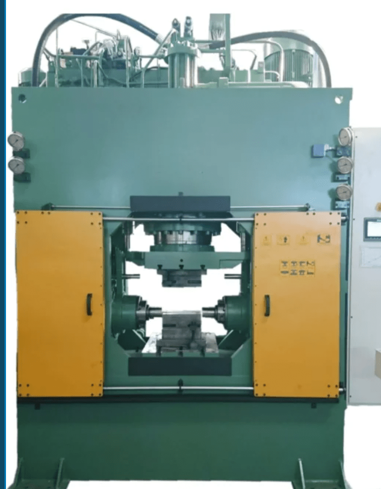
Hydroforming Bulge Press: Hydroforming is a specialized metal forming process that uses high-pressure hydraulic fluid to press room-temperature metal into a die. A hydroforming metal forming machine is engineered to perform this process efficiently, offering high dimensional accuracy and lightweight yet strong components. These machines are commonly used in the automotive, aerospace, bicycle, and appliance industries.
Key Features of Hydroforming Machines:
- High-pressure hydraulic system: Pressures can range from 10,000 to over 100,000 psi depending on the material and application.
- Die and cavity systems: Typically consist of a lower die with a cavity and an upper seal system that contains the fluid and applies force.
- Tube or sheet hydroforming capability: Machines may be designed for either tubular hydroforming (for exhausts, chassis parts) or sheet hydroforming (for panels, enclosures).
- Programmable logic controls (PLC): For accurate, repeatable, and automated cycle control.
- Robust frames and press structures: To withstand the immense pressures without deflection.
Types of Hydroforming Machines:
- Tube Hydroforming Machines:
- Load a metal tube into a die.
- Ends are sealed and pressurized fluid is introduced.
- The tube expands to conform to the die shape.
- Sheet Hydroforming Machines:
- A metal sheet is clamped over a die.
- Pressurized fluid forces the sheet into the die cavity from above or below.
- Ideal for complex, shallow-drawn parts.
Advantages:
- Uniform wall thickness and smooth surfaces.
- Reduction in welding and part count.
- Lightweight components with high strength.
- Enhanced formability of complex shapes.
Common Applications:
- Automotive: Frame rails, engine cradles, roof rails, suspension arms.
- Aerospace: Structural supports, fuselage panels, brackets.
- Furniture & appliances: Tubular frames, ergonomic components.
Hydroforming metal forming machines are highly specialized systems that shape metal using high-pressure hydraulic fluid rather than mechanical force. In operation, a piece of metal—either a tube or a sheet—is placed into a die, and then fluid pressure is applied to force the material to conform to the shape of the die. This process allows for the creation of lightweight, structurally rigid, and complex shapes that are difficult or impossible to achieve with conventional stamping or pressing techniques. The machines themselves are built to withstand extremely high pressures, often in excess of 100,000 psi, and are equipped with precision control systems to ensure accurate and repeatable forming cycles. In tube hydroforming, the metal tube is sealed at both ends and filled with hydraulic fluid, then pressurized internally until it expands and molds against the die cavity.
In sheet hydroforming, the sheet metal is clamped over a die and fluid pressure is applied from one side to push the sheet into the die. These machines are favored in industries such as automotive, aerospace, and high-performance bicycles, where reducing weight without compromising strength is crucial. Components like automotive chassis parts, suspension elements, and aerospace brackets are commonly made using hydroforming due to the method’s ability to produce smooth contours and consistent wall thickness. Additionally, hydroforming reduces the number of welds and joints in a part, enhancing its structural integrity and reducing post-processing requirements. The integration of programmable logic controllers, servo hydraulics, and automated loading systems in modern hydroforming machines allows for high production efficiency, real-time quality monitoring, and flexibility in handling different part geometries.
Modern hydroforming metal forming machines are often integrated into fully automated production lines to increase throughput and consistency. Robotic arms or gantry systems load raw tubes or sheets into the forming dies, while sensor systems verify correct positioning before the press cycle begins. During forming, the fluid pressure is carefully controlled to avoid rupturing the material while still achieving full die conformance. Advanced hydroforming setups also feature pressure pulsation techniques or variable pressure zones, which help form extremely complex or asymmetric geometries without thinning or tearing the material.
Machine frames are constructed from high-strength steel to withstand not only the intense pressures but also the stress of continuous industrial operation. Die materials are typically hardened tool steels with precision-machined surfaces to ensure repeatability and long service life. Some systems also include heated dies or thermal regulation to accommodate materials that form better under controlled temperatures.
Another advantage of hydroforming is its ability to reduce part count by combining multiple components into a single, seamless structure. For instance, a car’s roof rail that would traditionally be assembled from several stamped and welded parts can be hydroformed in one piece, enhancing strength and reducing weight and production time. In aerospace applications, hydroforming allows engineers to create structural elements with complex curvatures and minimal fasteners, which is critical for performance and safety.
Some machines offer hybrid capabilities, such as integrating pre-forming with hydroforming or combining hydroforming with secondary operations like piercing, trimming, or laser cutting within the same machine cycle. These features streamline manufacturing by minimizing material handling and reducing cycle times. Additionally, the machines are capable of forming a wide variety of metals, including aluminum, stainless steel, brass, copper, and high-strength alloys, making them suitable for both high-volume production and custom fabrication.
With increasing demand for energy-efficient vehicles and lighter aircraft, the relevance of hydroforming continues to grow. As a result, equipment manufacturers are developing ever more advanced control software, adaptive pressure modulation systems, and real-time monitoring technologies to enhance precision and reduce scrap rates. Hydroforming remains one of the most versatile and high-performance metal forming technologies available for industrial manufacturing.
Hydroforming Press Setup
A hydroforming press setup involves configuring and preparing the machine, tooling, and support systems to shape metal using internal hydraulic pressure. This setup must be precise and secure, as the process operates under extremely high pressures and requires accurate control to produce high-quality parts. The setup process varies slightly between tube and sheet hydroforming, but the fundamental principles are similar.
The process begins with selecting and installing the correct die set into the press. Dies are precision-machined to match the desired part geometry and are mounted securely onto the press base and ram. In tube hydroforming, sealing units are installed at both ends of the tube to contain the pressurized fluid. These seals must be tight and resilient enough to withstand pressures up to 100,000 psi. In sheet hydroforming, a blank holder or clamping ring is set up to secure the sheet metal over the die cavity before pressure is applied.
Next, the workpiece material—either a pre-cut metal sheet or a pre-bent tube—is loaded into the die. For tube hydroforming, accurate positioning is crucial, as the tube must align properly within the die to expand symmetrically. Some setups require pre-forming of the tube to fit better into more complex dies. For sheet hydroforming, the sheet is placed on top of the lower die and clamped tightly to prevent slippage or wrinkling during the press cycle.
The hydraulic system is then configured. Pressure settings are programmed based on the material type, thickness, and complexity of the part. Pressures are ramped up in stages or pulses during the forming cycle to allow gradual deformation and prevent rupture. The system may also incorporate back pressure or counter-pressure functions to control metal flow and maintain uniform wall thickness.
Control systems, typically PLC or CNC-based, manage all press functions, including die movement, pressure application, and cycle timing. These controls also interface with sensors and safety systems, ensuring the operation only proceeds under proper conditions. Many modern hydroforming presses have data logging and feedback systems that monitor strain, pressure distribution, and part conformity in real-time.
Before production begins, a trial cycle is usually performed to verify the setup. Engineers check for material behavior, forming completeness, surface finish, and any sign of failure like cracks or thinning. Adjustments to pressure curves, clamping force, or die alignment may be needed based on these results. Once validated, the press is ready for full production, often supported by automated loading, unloading, trimming, and inspection stations to streamline workflow and maintain consistency.
The hydroforming press setup is a critical step that determines the quality, efficiency, and reliability of the entire forming process. It demands precision, robust equipment, and thorough understanding of material behavior under high-pressure conditions.
Once the hydroforming press setup is validated and optimized, production can proceed continuously with minimal manual intervention. The system typically operates on a cycle-based process where each press stroke forms one part, and automated systems handle loading of raw material and unloading of finished components. The operator’s role is primarily supervisory, monitoring system indicators, checking for alarms, and occasionally inspecting parts to confirm ongoing quality. Any deviation in cycle time, pressure response, or material behavior is flagged by the control system, which can pause the operation to prevent damage or waste.
Maintaining die alignment is crucial during the production run. Even a slight misalignment can result in uneven material flow, localized thinning, or part distortion. High-precision guide systems and self-centering mechanisms in the press help maintain consistent alignment throughout repeated cycles. Cooling channels may also be integrated into the die to manage heat buildup, especially during extended runs, as temperature variations can affect forming behavior and material properties. In advanced systems, temperature sensors are embedded in the tooling and linked to the control system to dynamically adjust process parameters.
Tool wear is another factor considered in hydroforming press setups. Because forming is done under high pressure, even hardened die surfaces gradually degrade. Regular inspection and surface treatment or re-polishing ensure dimensional accuracy and surface finish are maintained. Some facilities rotate die sets or use modular tooling to enable quick changeovers, increasing machine uptime and reducing setup time between different part models.
Hydraulic oil condition is also monitored closely, as any contamination or breakdown of fluid properties can compromise the pressure system and damage seals or pumps. Filtration systems, cooling units, and routine maintenance of the hydraulic circuit are integral to long-term machine reliability. The press frame and all mechanical linkages must also be routinely checked for stress or fatigue, especially in high-tonnage systems handling structurally demanding components.
Over time, machine learning algorithms and historical process data can be used to fine-tune press setups. By analyzing variables such as forming pressure curves, metal springback behavior, and rejection rates, engineers can refine the setup for future production runs. In high-volume environments, digital twins or simulation software may be used before physical setup to test parameters virtually, minimizing trial-and-error during initial press configuration.
The hydroforming press setup is not just a mechanical procedure but a complex orchestration of tooling design, fluid dynamics, materials science, and automation. When done correctly, it enables the efficient production of strong, lightweight, and intricately shaped metal parts with excellent surface quality and minimal waste.
As production continues, the stability of the hydroforming press setup ensures consistent part quality across long runs. One of the key aspects that sustains this consistency is process repeatability. The combination of precise hydraulic control, rigid machine structure, and well-maintained tooling ensures that each part follows the same deformation path. In fully optimized systems, cycle times can be reduced to under a minute per part, depending on complexity, while maintaining dimensional tolerances within fractions of a millimeter.
Quality control becomes tightly integrated with the hydroforming process. Many machines are equipped with in-line inspection systems such as laser scanners, vision systems, or contact probes to detect shape conformity, surface defects, and dimensional integrity right after forming. Parts that fall outside preset tolerance limits are automatically ejected or flagged for manual inspection. These feedback loops reduce scrap rates and prevent defective components from entering downstream assembly processes.
In terms of safety, hydroforming presses are designed with multiple interlocks and redundant safety features. High-pressure operations carry inherent risks, so access to the press area is restricted during forming cycles. Safety light curtains, enclosure doors, and pressure relief valves are standard. Emergency shutdown procedures are built into the control system to quickly depressurize and halt machine movement in case of malfunction or unexpected material behavior.
Changeovers between part models or material types require careful planning. Tooling must be swapped, pressure profiles adjusted, and press timing recalibrated. In highly automated environments, these changeovers are optimized using preset recipes stored in the machine’s control system. Operators can select a job profile, and the press automatically adjusts stroke length, pressure stages, clamping forces, and other critical parameters. This minimizes downtime and allows for flexible production of multiple part types on the same machine.
Energy efficiency is another consideration in hydroforming press operations. Because these machines operate with high-pressure hydraulic systems, energy consumption is significant. To reduce this, modern presses incorporate variable displacement pumps, servo-hydraulic drives, and energy recovery systems that reduce power usage during idle periods or return energy during pressure release phases. Monitoring systems help track energy per part and optimize the process further.
Finally, the data collected throughout the setup and production phases plays a central role in continuous improvement. Detailed logs of forming pressures, material batch properties, and production output enable engineers to trace defects, optimize cycle times, and adapt the setup to new alloys or geometries. In high-volume manufacturing settings, this data-driven approach turns the hydroforming press into a precision production tool capable of delivering consistent, lightweight, and structurally strong components at industrial scale.
Hydroforming Press Tool
A hydroforming press tool is the die and associated components used within a hydroforming press to shape metal parts using high-pressure fluid. It is the core element that defines the final geometry of the formed component and must be engineered to withstand extreme pressures while ensuring dimensional precision and surface quality. The tool consists of multiple elements, each playing a critical role in the forming process.
The primary component of the hydroforming press tool is the die cavity, which is precision-machined to the shape of the final part. This cavity can be fixed into the lower platen or the upper portion of the press, depending on the machine configuration. For tube hydroforming, the die includes a channel where the tube is positioned before high-pressure fluid expands it outward into the cavity walls. For sheet hydroforming, the tool includes a punch or cavity under or over the sheet, depending on whether the fluid pressure is applied from below or above.
Alongside the die, sealing tools or axial punches are used in tube hydroforming to close the ends of the tube and apply axial forces to prevent wrinkling and control length changes. These sealing systems must resist not only the pressure of the internal fluid but also provide uniform axial movement if needed during the forming process. These punches may also serve as fluid delivery channels, allowing pressurized fluid to enter the tube during forming.
Blank holders and clamps are critical in sheet hydroforming tools. They ensure that the sheet metal stays in place and does not move or wrinkle during pressurization. These holders must provide enough force to secure the material without damaging it, and they are sometimes designed with variable clamping force to allow controlled flow of material into the cavity during forming.
Hydroforming press tools often include cooling or heating channels, especially when working with metals that are sensitive to temperature, such as aluminum or high-strength steels. Controlled die temperature ensures material flow is predictable and reduces the risk of defects such as tearing or springback. Cooling channels also help maintain dimensional consistency across long production runs by dissipating heat generated through material deformation and hydraulic compression.
The materials used in hydroforming press tools are typically hardened tool steels, sometimes with coatings like nitriding or hard chrome to resist wear and extend tool life. Tool surfaces are often polished or finely textured, depending on whether a high-gloss finish or a more matte surface is desired on the finished part.
Hydroforming press tools may also integrate secondary features, such as internal trimming blades, integrated sensors for force and displacement, or embedded pressure transducers. These allow real-time monitoring of tool performance and early detection of misalignment, cracking, or underforming. In automated lines, the tools are often modular, allowing for quick changeovers when switching part geometries, which is essential for maintaining production efficiency.
In essence, the hydroforming press tool is a complex, high-precision system tailored to the specific geometry and material properties of the part being formed. Its design and condition directly influence part quality, cycle time, and the overall efficiency of the hydroforming process.
Designing and manufacturing a hydroforming press tool requires a deep understanding of metal behavior under pressure, fluid dynamics, and the mechanical limits of both the workpiece and the press system. During the design phase, engineers use computer-aided design (CAD) and finite element analysis (FEA) to simulate how the metal will flow within the die cavity under various pressure and axial loading conditions. These simulations help identify potential issues like excessive thinning, wrinkling, or incomplete filling before any physical tooling is made. Once the design is finalized, the tool is manufactured using precision CNC machining, heat treatment, and surface finishing processes to achieve the necessary hardness and dimensional accuracy.
During production, the performance of the hydroforming press tool must be closely monitored. High pressures can cause microscopic wear even on hardened surfaces, so regular inspection is essential. Dimensional checks on formed parts are used to detect gradual tool wear or surface degradation. In some cases, tools are designed with replaceable inserts or wear plates in high-contact areas to reduce maintenance costs and extend the life of the main die body. Additionally, press tools are often mounted with quick-release systems or modular die plates to allow rapid changeovers, which is especially valuable in operations that produce multiple part types or variations.
Another important aspect of the hydroforming press tool is its compatibility with the machine’s hydraulic system. The tool must be able to contain and channel high-pressure fluid in a controlled manner. This requires precision-sealed interfaces, often using O-rings, gaskets, or metallic sealing rings designed to maintain integrity over many cycles. If the seal fails, fluid leaks not only interrupt production but can damage parts, the press, or the surrounding equipment. Therefore, the design of the sealing system is as critical as the die cavity itself.
In automated hydroforming cells, sensors may be embedded in the tool body to monitor real-time forming pressure, temperature, and strain. These sensors provide data back to the control system, which can adjust the press cycle dynamically to ensure consistent results. For example, if material springback is detected, the control software can modify the pressure profile slightly on the next cycle to compensate. These feedback systems turn the hydroforming tool into an intelligent, adaptive component of the overall production system.
Over time, even the best tools will require rework. Tooling maintenance includes re-polishing die surfaces, replacing worn seals, and checking alignment. In some cases, 3D scanning is used to compare the tool’s current geometry to its original design, allowing technicians to identify areas that need repair. For high-volume production environments, duplicate tool sets are often kept in rotation to ensure minimal downtime during maintenance.
Because of the high value and complexity of hydroforming press tools, they are typically stored in climate-controlled environments and handled with precision equipment. Damage to a single surface or seal can compromise forming accuracy, so every stage from storage to setup is managed carefully. The investment in high-quality tooling pays off in the form of lower scrap rates, more consistent part geometry, and greater overall process efficiency. In industries such as automotive and aerospace, where structural integrity and precision are non-negotiable, the role of the hydroforming press tool is absolutely central to successful production.
In addition to the mechanical and material considerations, the hydroforming press tool must also be designed with ergonomics and maintenance accessibility in mind. Since these tools can be heavy and complex, provisions for safe handling—such as lifting points, guide rails, and quick-mount systems—are integrated into the design. This reduces setup time and minimizes the risk of damage or injury during tool changes. Some advanced hydroforming setups also feature automated tool changing systems, allowing for rapid swaps with minimal human intervention, which is especially beneficial in flexible manufacturing environments with multiple product variants.
Environmental factors also influence tool design. Hydroforming presses generate considerable hydraulic fluid mist, heat, and sometimes noise, so tools and press cells are often enclosed or shielded to protect operators and maintain a clean production area. Tool designs may include integrated drainage or containment systems to manage any incidental leaks, ensuring workplace safety and compliance with environmental regulations.
Material choice for tooling is evolving as well. While traditional hardened tool steels remain the standard, newer materials like advanced composites or ceramic coatings are being explored to extend tool life, reduce weight, or improve thermal management. These innovations can lower operating costs by reducing wear and energy consumption during forming cycles.
Furthermore, the hydroforming press tool plays a crucial role in enabling innovations in product design. Because hydroforming allows for complex, seamless shapes with varying wall thicknesses, designers are no longer limited to conventional stamping constraints. This freedom means that engineers can design lighter, stronger, and more aerodynamically efficient components that improve overall product performance. The press tool acts as the physical realization of these designs, translating digital models into precise, repeatable parts.
Continuous advancements in digital manufacturing technologies, such as additive manufacturing for rapid prototyping of tooling components or embedded sensor arrays, are further pushing the boundaries of what hydroforming press tools can achieve. These tools are becoming smarter and more adaptable, reducing downtime, improving quality control, and supporting increasingly sophisticated part geometries.
Ultimately, the hydroforming press tool is a critical asset in modern manufacturing. Its design, construction, maintenance, and integration directly influence the efficiency, quality, and cost-effectiveness of hydroforming operations. Successful hydroforming production relies on a well-engineered tool that balances strength, precision, and adaptability to meet the demands of high-pressure metal forming processes.
Select Hydroforming Press Unit Hydroforming Press Unit
A Hydroforming Press Unit is the complete machinery system designed to perform hydroforming metal shaping processes, integrating hydraulic power, control systems, and tooling to produce complex metal components. Selecting the right hydroforming press unit depends on several key factors including part geometry, material type, production volume, and precision requirements.
Typically, a hydroforming press unit consists of:
- Press frame and platen: A rigid structure to withstand the very high pressures generated during forming, often made of heavy-duty steel with precise alignment features.
- Hydraulic system: High-pressure pumps, accumulators, valves, and piping that generate and control the hydraulic fluid pressure used to expand or shape the metal.
- Control system: Usually a PLC or CNC-based system that manages press operations, pressure profiles, cycle timing, safety interlocks, and integrates sensor feedback.
- Tooling interfaces: Mechanisms to hold, align, and quickly change dies and sealing components.
- Auxiliary equipment: This can include automated loading/unloading systems, robotic arms, trimming stations, and inspection devices to streamline production.
When selecting a hydroforming press unit, the following criteria are crucial:
- Press Tonnage and Pressure Capacity: The unit must be rated to deliver the necessary hydraulic pressure—often up to 100,000 psi or more—and the structural tonnage to contain these forces safely.
- Bed Size and Stroke: The size of the press bed and the maximum ram stroke should accommodate the largest part dimensions and forming depth expected.
- Control Precision: For complex parts, precise control of pressure ramping, hold times, and clamping force is essential to avoid defects.
- Automation Compatibility: If high-volume or flexible manufacturing is planned, the unit should support integration with robotic systems and automated tooling change.
- Material Compatibility: The unit must be able to handle the specific metal types (aluminum, stainless steel, brass, etc.) and thicknesses involved.
- Energy Efficiency: Modern units often incorporate servo-hydraulics or variable-displacement pumps to reduce power consumption.
- Safety and Compliance: The unit should include certified safety systems and meet local workplace regulations.
By carefully considering these factors and collaborating with experienced hydroforming press manufacturers, businesses can select a press unit that optimizes production efficiency, part quality, and cost-effectiveness for their specific application.
Once the basic specifications of the hydroforming press unit are defined, it’s important to evaluate the system’s overall reliability and maintainability. A press with robust construction and high-quality components will ensure consistent performance under demanding operating conditions. The hydraulic system should have redundancy features such as multiple pumps or backup accumulators to prevent downtime during maintenance or component failure. Additionally, the unit should allow easy access to key components like valves, filters, and seals for routine inspection and service, minimizing production interruptions.
Another vital consideration is the integration of advanced control and monitoring technologies. Modern hydroforming press units often include real-time data acquisition systems that track parameters such as pressure curves, cycle times, temperature, and tool wear indicators. These data streams can be analyzed to optimize the forming process, predict maintenance needs, and reduce scrap rates. Some units come equipped with touchscreen interfaces and remote monitoring capabilities, allowing operators and engineers to adjust settings and troubleshoot issues quickly.
The adaptability of the hydroforming press unit also plays a significant role in long-term productivity. Modular designs that support quick tooling changes and adjustments enable manufacturers to switch between different parts or product lines with minimal downtime. This flexibility is particularly important for companies producing smaller batch sizes or customized components, as it maximizes the return on investment for the equipment.
In addition, environmental and energy considerations are increasingly influencing the choice of hydroforming press units. Units with energy recovery systems, servo-driven hydraulics, and efficient cooling circuits not only reduce operating costs but also help manufacturers meet sustainability goals. Noise reduction features and enclosed press cells contribute to a safer and more comfortable working environment.
Lastly, vendor support and training services should be factored into the selection process. A reliable supplier will provide comprehensive installation, commissioning, and operator training, ensuring that the hydroforming press unit is used to its full potential from day one. Ongoing technical support and access to spare parts are crucial for maintaining continuous operation, especially in high-volume production settings.
In summary, selecting a hydroforming press unit involves balancing technical capabilities with operational flexibility, maintenance ease, energy efficiency, and supplier partnership. Thoughtful evaluation of these factors helps manufacturers deploy equipment that delivers consistent quality, efficient throughput, and long-term value.
Beyond the initial selection and installation, the operational lifecycle of a hydroforming press unit requires continuous optimization to maintain peak performance. As production progresses, process engineers collect and analyze data on forming pressures, cycle times, and part quality to fine-tune press parameters. This iterative adjustment ensures the machine adapts to slight variations in material batches or environmental conditions, preserving part consistency and minimizing defects.
Periodic preventive maintenance schedules are critical to the longevity of the hydroforming press unit. Components such as hydraulic seals, valves, pumps, and sensors have finite lifespans and must be replaced or recalibrated before failure occurs. Routine checks of hydraulic fluid cleanliness and viscosity, along with filter replacements, help prevent contamination that could degrade system responsiveness and accuracy. Structural inspections detect any frame fatigue or platen wear that might compromise press alignment.
Upgrading the hydroforming press unit’s control software and hardware is another avenue to enhance productivity. Manufacturers frequently release firmware updates that improve control algorithms, enable new sensor integrations, or provide better diagnostics. Retrofitting older machines with modern servo-hydraulic drives or more precise pressure transducers can extend equipment usability and reduce energy consumption.
Operator training remains an ongoing priority. Skilled operators not only run the press efficiently but can detect subtle anomalies early, preventing costly downtime. Training programs that incorporate simulation and troubleshooting exercises empower personnel to respond effectively to process deviations and equipment alerts.
In larger production facilities, integrating the hydroforming press unit into a connected manufacturing execution system (MES) allows seamless coordination with upstream and downstream processes like material feeding, trimming, inspection, and assembly. This connectivity supports real-time production tracking, quality control, and inventory management, enabling just-in-time manufacturing and reducing lead times.
Finally, sustainability considerations are becoming more prominent. Efforts to recycle hydraulic fluids, optimize energy use, and minimize scrap contribute to environmentally responsible production. Selecting a hydroforming press unit that supports these initiatives not only reduces operational costs but also aligns with corporate social responsibility goals and regulatory compliance.
Overall, a well-selected and properly managed hydroforming press unit becomes a cornerstone of efficient, high-quality metal forming operations, capable of adapting to evolving manufacturing demands while delivering consistent value throughout its service life.
High-Pressure Hydroforming Press
A High-Pressure Hydroforming Press is a specialized metal forming machine designed to shape metal components using extremely high hydraulic fluid pressures, often exceeding 10,000 psi and sometimes reaching up to 100,000 psi or more. This elevated pressure capability enables the forming of complex shapes, thin-walled structures, and lightweight parts with excellent dimensional accuracy and structural strength.
The core advantage of a high-pressure hydroforming press lies in its ability to apply uniform internal pressure to the metal workpiece—whether it’s a tube, sheet, or blank—causing it to expand precisely into the contours of a die cavity. This process minimizes mechanical contact stresses compared to traditional stamping, reducing the risk of cracks, wrinkles, and springback.
Structurally, these presses feature reinforced frames and platens engineered to withstand the intense forces generated during high-pressure operations. The hydraulic system incorporates high-capacity pumps, accumulators, and pressure intensifiers capable of generating and sustaining these pressures safely and reliably throughout the forming cycle. Precision valves and servo-hydraulic controls regulate the pressure ramping and holding stages, allowing for optimized forming sequences tailored to the material and part geometry.
High-pressure hydroforming presses are widely used in industries such as automotive, aerospace, and appliance manufacturing, where lightweight, complex parts with high strength-to-weight ratios are essential. Examples include structural automotive components, exhaust manifolds, and complex airframe sections.
Safety is paramount due to the extreme pressures involved. These presses are equipped with multiple redundant safety interlocks, pressure relief valves, and robust enclosures to protect operators and equipment. Maintenance routines emphasize regular inspection of hydraulic seals, tubing, and pressure vessels to prevent leaks or failures.
In summary, a high-pressure hydroforming press is a powerful, precision machine that expands the possibilities of metal forming by combining fluid power and advanced control to produce high-quality, lightweight components with intricate shapes and superior mechanical properties.
High-pressure hydroforming presses demand advanced hydraulic systems that can generate and maintain extremely high fluid pressures consistently throughout the forming cycle. These systems often use accumulators that store hydraulic energy and pressure intensifiers that step up the pressure from standard hydraulic pumps to the required levels. The control system must be capable of finely tuning pressure application rates and holding times to avoid defects like bursting or incomplete forming. Achieving this level of control requires sophisticated servo valves and real-time feedback from pressure sensors integrated into the tooling or press hydraulics.
The mechanical design of the press frame is equally critical. Since the forces generated inside the tool cavity can be enormous, the frame must have exceptional rigidity and strength to prevent deformation that could compromise part accuracy or damage the tooling. High-strength alloy steels and heavy ribbed structures are typical in these presses to resist bending and twisting. Platen surfaces are precisely machined and hardened to provide accurate and repeatable die alignment under load.
Tooling for high-pressure hydroforming must be engineered to withstand these pressures while maintaining tight dimensional tolerances. Sealing systems are a major design focus to contain the fluid pressure within the workpiece without leakage. Additionally, the tooling often incorporates cooling channels to dissipate heat generated during forming, which can affect material behavior and dimensional stability. Wear-resistant coatings and surface treatments extend tool life despite the severe conditions.
Due to the complexity and cost of high-pressure hydroforming presses, their operation typically involves highly trained personnel who understand both the mechanical and process aspects. Operators and engineers monitor process parameters closely, often through integrated data acquisition systems that provide real-time insights into pressure curves, cycle times, and material response. This data is used to optimize forming profiles, reducing scrap rates and improving consistency.
Integration with automated material handling and downstream operations is common in industrial settings. Robots may load blanks, position tubes, or remove finished parts, improving cycle times and operator safety by minimizing manual intervention near high-pressure equipment. Automated trimming, inspection, and assembly stations further streamline production.
Energy efficiency is an ongoing challenge with high-pressure systems. Advanced presses use servo-driven hydraulic pumps, energy recovery during pressure release phases, and optimized fluid circuits to minimize power consumption without compromising forming quality. This reduces operating costs and environmental impact.
Safety systems are comprehensive, including physical barriers, interlocks, emergency stops, and pressure relief devices. Regular inspections and preventative maintenance ensure hydraulic components, seals, and structural elements remain in safe operating condition. Given the high stakes of failure, many facilities implement rigorous protocols and certifications for equipment and operators.
In applications where extremely complex geometries or lightweight parts are required, high-pressure hydroforming presses provide a unique combination of precision, flexibility, and mechanical performance that other forming methods struggle to match. Their ability to produce single-piece, seamless components with reduced welds and joints contributes to stronger, lighter, and more durable products, meeting the increasing demands of modern manufacturing sectors.
Beyond the core forming process, high-pressure hydroforming presses often incorporate advanced process monitoring and quality assurance technologies. In-line sensors embedded within the tooling or press structure can measure strain, pressure distribution, and temperature in real time, providing detailed feedback on how the material behaves under the applied hydraulic forces. This data enables adaptive control systems to fine-tune pressure profiles dynamically during each cycle, compensating for variations in material thickness, temperature fluctuations, or tooling wear. Such closed-loop control improves part consistency, reduces scrap rates, and extends tool life.
Moreover, the increasing use of digital twins—virtual replicas of the hydroforming press and tooling—allows engineers to simulate and optimize forming processes before actual production. By integrating sensor data and material properties into these models, potential issues like excessive thinning or springback can be predicted and mitigated through design adjustments or process parameter tweaks. This approach shortens development times and improves first-pass yield.
From a materials perspective, high-pressure hydroforming presses enable the efficient forming of lightweight alloys like aluminum and advanced high-strength steels (AHSS), which are critical in industries focused on weight reduction and fuel efficiency, such as automotive and aerospace. The uniform pressure distribution reduces localized stresses, allowing for thinner sections and complex shapes that might otherwise crack or deform using conventional stamping.
The ability to produce large, integrated components with fewer welds and joints also improves structural integrity and corrosion resistance. This is especially valuable in safety-critical parts, such as automotive chassis components or aircraft fuselage sections, where performance and durability are paramount.
In terms of scale, high-pressure hydroforming presses range from compact laboratory units used for prototyping and small batch production to massive industrial presses capable of forming large automotive body panels or structural aerospace parts. This scalability makes hydroforming adaptable to various production volumes, from bespoke manufacturing to high-throughput assembly lines.
As sustainability gains importance, manufacturers increasingly focus on reducing waste generated during hydroforming. The process inherently produces less scrap compared to stamping, but ongoing improvements in tooling design, pressure control, and material usage further enhance resource efficiency. Some facilities are also exploring closed-loop hydraulic systems that recycle fluid and recover energy, lowering the environmental footprint of high-pressure hydroforming operations.
Finally, the integration of artificial intelligence (AI) and machine learning into hydroforming press controls promises to further revolutionize the field. By analyzing vast datasets from production runs, AI algorithms can detect subtle patterns indicating tool wear or process drift before defects occur. Predictive maintenance schedules and automated parameter optimization driven by AI help maintain peak press performance, reduce downtime, and enhance overall manufacturing agility.
In conclusion, the high-pressure hydroforming press is a sophisticated, high-value asset that combines mechanical strength, precise hydraulic control, advanced monitoring, and digital technologies to produce complex, lightweight, and high-quality metal components. Its evolving capabilities continue to open new possibilities in design innovation and manufacturing efficiency across multiple high-tech industries.
Hydroforming Sheet Press
A Hydroforming Sheet Press is a specialized machine designed to form sheet metal into complex shapes using hydraulic fluid pressure. Unlike traditional mechanical stamping, which relies on mechanical force from a die, a hydroforming sheet press applies a controlled fluid pressure that pushes the metal sheet into a die cavity, enabling the creation of intricate geometries, smooth contours, and varying thicknesses with minimal springback or distortion.
The hydroforming sheet press typically consists of a rigid frame and platen, a hydraulic system capable of generating high fluid pressures, and a tooling setup including a blank holder, die, and sealing components. During operation, the metal sheet is placed between the die and a flexible diaphragm or bladder filled with hydraulic fluid. When the fluid pressure increases, the diaphragm presses the sheet into the die, conforming it precisely to the desired shape.
This process offers several advantages over conventional forming methods, including reduced tooling costs since a single die can often be used with varying pressure profiles to create multiple shapes. It also produces parts with fewer defects such as wrinkles, cracks, or uneven thickness, improving strength and surface finish quality. Hydroforming sheet presses are widely used in automotive body panels, appliance housings, and aerospace components where lightweight, strong, and visually appealing parts are essential.
The control system in a hydroforming sheet press manages pressure ramp-up, hold times, and release sequences to optimize material flow and prevent failures. Some presses use multi-stage pressure cycles or combined mechanical-hydraulic forming to handle more challenging shapes or thicker materials.
Overall, the hydroforming sheet press is a versatile and efficient tool for shaping sheet metals into complex, high-quality parts with precision and repeatability.
Hydroforming sheet presses require precise synchronization between hydraulic pressure and mechanical clamping to ensure the metal sheet is securely held and evenly formed without slippage or wrinkling. The blank holder pressure is carefully controlled alongside the hydraulic fluid pressure to regulate material flow into the die cavity, which is critical for achieving uniform thickness distribution and preventing defects. In some systems, flexible diaphragms made from high-strength elastomers or metallic membranes transmit the hydraulic pressure to the sheet while maintaining a reliable seal to prevent fluid leakage.
The hydraulic system itself must be capable of generating smooth and controllable pressure curves, often reaching pressures in the range of several thousand psi, depending on the material and part complexity. Pressure sensors and flow meters provide real-time feedback to the control unit, which adjusts the pump output and valve positions accordingly. This precise control allows for complex forming sequences, such as multi-stage pressure increases or pressure holding phases, that optimize metal flow and part accuracy.
Tooling for hydroforming sheet presses is designed to withstand repeated exposure to high pressures and mechanical loads while maintaining tight tolerances. Dies are usually made from hardened tool steel with surface treatments to resist wear and corrosion. Because the hydroforming process can be less harsh on tooling compared to mechanical stamping, die life is often extended, reducing tooling replacement costs. Additionally, tooling may incorporate cooling channels to manage temperature during the forming cycle, as excessive heat can affect both material behavior and dimensional stability.
The flexibility of hydroforming sheet presses enables manufacturers to produce parts with complex geometries and varying wall thicknesses without the need for multiple stamping operations or welds. This capability reduces assembly time and improves structural integrity. It also supports the use of advanced materials such as aluminum alloys and high-strength steels, which can be challenging to form using traditional methods.
Automation integration is common in modern hydroforming sheet press systems, with robotic loading and unloading, inline inspection, and trimming stations improving throughput and consistency. Data from the press can be fed into manufacturing execution systems for real-time production monitoring and quality control, supporting lean manufacturing principles.
Maintenance of hydroforming sheet presses focuses on hydraulic system upkeep, including fluid quality management, seal replacement, and valve calibration, as well as mechanical inspections of the frame and tooling. Preventive maintenance schedules help avoid unplanned downtime and ensure consistent part quality.
In summary, hydroforming sheet presses combine hydraulic power, precise control, and durable tooling to efficiently produce high-quality, complex sheet metal parts with improved performance and reduced manufacturing costs compared to conventional forming methods. This technology continues to gain traction across automotive, aerospace, appliance, and other industries seeking advanced metal forming solutions.
Hydroforming Tube Press
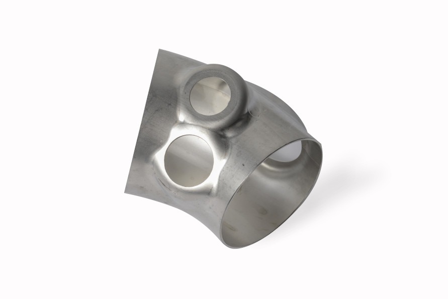
A Hydroforming Tube Press is a specialized machine used to shape hollow metal tubes or pipes into complex, lightweight, and strong components by applying high internal hydraulic pressure. Unlike traditional mechanical forming, this process uses a pressurized fluid—typically oil or water—to expand the tube inside a rigid die, enabling intricate shapes such as bends, bulges, and tapered sections without compromising structural integrity.
The hydroforming tube press consists of a sturdy frame with platens to hold the tooling, a hydraulic system capable of generating high-pressure fluid, and precision control systems that manage pressure application and cycle timing. The tube is placed inside a die cavity, sealed at both ends, and then filled with hydraulic fluid. As pressure increases, the tube walls expand outward to conform exactly to the die’s internal geometry.
This method allows manufacturers to produce lightweight, strong, and seamless tubular components with fewer welds and joints, which improves strength, reduces weight, and enhances corrosion resistance. Hydroforming tube presses are widely used in automotive chassis parts, bicycle frames, aerospace structures, and industrial piping where complex shapes and high strength-to-weight ratios are essential.
Control over pressure ramp-up, hold, and release stages is crucial to prevent material failure such as bursting or wrinkling. Many presses employ multi-stage pressure profiles and use feedback from sensors embedded in the tooling or hydraulic lines to adjust parameters in real time.
The tooling in a hydroforming tube press is designed to withstand high pressures and maintain tight tolerances for accurate part dimensions. Tool steel with specialized coatings and cooling channels is common to extend tool life and maintain process consistency.
Integration with automated loading, unloading, and trimming systems enhances production efficiency. Operators typically monitor forming parameters through advanced software interfaces that provide real-time data and diagnostics.
In summary, the hydroforming tube press is a powerful and precise machine that transforms simple tubular blanks into complex, high-performance components through controlled hydraulic expansion within a die, offering superior part quality and manufacturing flexibility.
Hydroforming tube presses rely heavily on the precise coordination of hydraulic pressure and mechanical clamping to ensure the tube remains securely positioned during forming. Sealing systems at the tube ends must be robust enough to contain extremely high internal pressures without leakage, often using specialized end plugs or mandrels that support the tube internally and help control wall thickness distribution during expansion. Mandrels can be fixed or flexible, depending on the complexity of the shape and the need to prevent collapse or wrinkling in bends or tight radii.
The hydraulic system must be capable of delivering smooth and accurately controlled pressure profiles, sometimes exceeding tens of thousands of psi. Pressure sensors and flow meters continuously monitor the system, feeding data back to sophisticated controllers that adjust pump speeds and valve positions in real time. This dynamic control helps optimize material flow and prevents defects like thinning, tearing, or excessive springback.
The press frame is designed to withstand substantial forces generated not only by the hydraulic pressure but also by the mechanical clamping required to hold tooling and tubes in place. Heavy-duty steel construction with reinforced platens and precise alignment features ensures repeatability and dimensional accuracy of formed parts over long production runs.
Tooling in hydroforming tube presses is complex and engineered to balance strength, precision, and longevity. Dies are often made from hardened tool steels with wear-resistant coatings to withstand repeated high-pressure contact with expanding tubes. Cooling channels may be integrated to manage thermal stresses that arise during forming cycles, which helps maintain tool integrity and dimensional stability.
Because hydroforming allows for the creation of complex shapes in a single forming step, it reduces the need for multiple welds, joints, or assembly processes, thereby improving structural integrity and lowering production costs. This makes it particularly attractive for applications in automotive frames, exhaust systems, bicycle components, and aerospace structural parts where strength-to-weight ratio and design flexibility are paramount.
Automation is commonly integrated with hydroforming tube presses to improve throughput and safety. Robotic systems handle tube loading, positioning, and unloading, minimizing manual interaction with high-pressure equipment. Inline inspection systems may check for dimensional accuracy and surface quality immediately after forming, ensuring only parts that meet specifications proceed to the next stage.
Maintenance focuses on hydraulic system health, including regular checks of fluid cleanliness, seal integrity, and valve function. Structural inspections verify that press frames and tooling maintain alignment and show no signs of fatigue or wear that could compromise part quality or operator safety. Preventive maintenance and predictive diagnostics, sometimes supported by real-time monitoring data, help minimize downtime and extend equipment life.
Energy efficiency is also a consideration; modern hydroforming tube presses may use servo-hydraulic drives and energy recovery systems to reduce power consumption without sacrificing performance. These advances help manufacturers meet environmental goals and reduce operating costs.
Overall, the hydroforming tube press is a versatile and high-precision tool that transforms simple tubular stock into complex, lightweight, and strong components with excellent surface finish and dimensional control, making it indispensable in advanced manufacturing sectors focused on innovation and efficiency.
Beyond standard operation, advanced hydroforming tube presses increasingly incorporate digital technologies to enhance process control and part quality. Real-time data acquisition systems collect information on pressure, force, temperature, and displacement throughout each forming cycle. This data is analyzed using machine learning algorithms and predictive models to detect subtle changes in material behavior or tooling conditions that might indicate wear, misalignment, or process drift.
Such intelligent systems can automatically adjust forming parameters on the fly, optimizing pressure profiles and cycle times to maintain consistent part dimensions and surface quality. This adaptive control reduces scrap rates and tooling damage while improving overall equipment effectiveness (OEE).
Digital twins—virtual replicas of the hydroforming press, tooling, and process—are used to simulate forming scenarios before actual production. By inputting real-time sensor data and material characteristics, engineers can predict potential defects like thinning, wrinkling, or excessive springback, allowing them to modify process parameters or tooling designs preemptively. This reduces trial-and-error cycles, shortens product development timelines, and lowers costs.
The trend toward Industry 4.0 connectivity means hydroforming tube presses are often integrated into broader manufacturing execution systems (MES) and enterprise resource planning (ERP) platforms. This integration facilitates seamless data flow across production, quality, and supply chain functions, enabling better planning, inventory control, and traceability of formed parts.
On the materials front, hydroforming tube presses enable the efficient forming of advanced alloys and composites that are difficult to shape with conventional methods. Lightweight metals such as aluminum, magnesium, and titanium alloys, as well as high-strength steels, benefit from hydroforming’s uniform pressure distribution, which minimizes localized stresses and material failure.
This capability supports industries striving for lighter, stronger components to meet fuel efficiency, performance, and environmental standards—most notably automotive and aerospace sectors. The reduction or elimination of welding and joining in hydroformed tubes also enhances structural integrity and corrosion resistance.
Environmental sustainability is an increasing priority in hydroforming operations. Modern presses employ energy-efficient hydraulic systems, fluid recycling, and waste minimization strategies. The reduction in scrap and secondary processing due to near-net-shape forming further reduces resource consumption and environmental impact.
Safety remains a paramount concern with high-pressure hydroforming tube presses. These machines incorporate comprehensive physical guarding, emergency stops, pressure relief valves, and advanced diagnostic systems to detect anomalies and prevent accidents. Operators receive specialized training to safely manage high-pressure processes and respond to alarms or irregularities.
In conclusion, the hydroforming tube press represents a cutting-edge manufacturing technology that combines mechanical robustness, hydraulic precision, digital intelligence, and advanced materials capability. It empowers manufacturers to produce complex, lightweight, and high-strength tubular components efficiently and consistently, meeting the evolving demands of modern industry.
Hydraulic Forming Press
A Hydraulic Forming Press is a versatile machine used to shape metal and other materials by applying controlled hydraulic pressure. Unlike mechanical presses that rely on direct mechanical force, hydraulic forming presses use fluid pressure—typically oil—to exert force evenly and smoothly over the workpiece. This method allows for precise control of pressure, speed, and stroke, enabling the forming of complex shapes with high accuracy and minimal risk of material damage.
Hydraulic forming presses consist of a hydraulic power unit (pump, valves, and reservoir), a press frame with a ram or platen, and tooling designed for the specific forming operation. The hydraulic system generates force by pressurizing fluid that moves the ram, which then applies pressure to the material either directly or through a die or mold. The pressure can be finely regulated throughout the forming cycle, allowing gradual application, holding at peak pressure, and controlled release to optimize material flow and part quality.
These presses are widely used in metal forming operations such as deep drawing, bending, punching, and embossing. They are especially valuable for forming thick or high-strength materials, where mechanical presses may struggle or cause damage. Hydraulic forming presses also enable larger strokes and longer dwell times, useful for complex or precise forming tasks.
The flexibility of hydraulic forming presses makes them suitable for a range of industries including automotive, aerospace, appliance manufacturing, and heavy equipment. They accommodate various materials like steel, aluminum, copper, plastics, and composites.
Modern hydraulic forming presses often feature computer numerical control (CNC) for automated and repeatable operations, along with sensors for monitoring pressure, position, and force. This enables sophisticated forming cycles and integration into automated production lines.
Overall, hydraulic forming presses combine power, precision, and flexibility, making them essential tools for advanced manufacturing processes that require high-quality, complex-shaped components.
Hydraulic forming presses offer several advantages over traditional mechanical presses, primarily due to the nature of hydraulic power which provides a smooth and consistent force application. This smoothness reduces shock loads on both the machine and the tooling, extending their service life and reducing maintenance costs. The ability to control pressure and ram speed independently allows operators to tailor the forming process to the specific material and part geometry, improving product quality and reducing defects such as cracking, wrinkling, or springback.
The press frame of a hydraulic forming machine is typically robust and built to handle high forces generated by the hydraulic system. These frames are often constructed from heavy-duty steel with reinforced sections to maintain rigidity and alignment under load. Proper alignment is critical to ensure even force distribution across the workpiece and to prevent uneven wear on tooling components.
Hydraulic systems in these presses use pumps—either fixed or variable displacement—to supply pressurized fluid to cylinders that move the ram. Control valves regulate the flow and pressure of the hydraulic fluid, enabling precise adjustment of forming parameters during the stroke. Modern presses incorporate proportional and servo valves, allowing for highly dynamic and responsive control compared to older on/off valve systems.
The tooling in hydraulic forming presses is designed to work harmoniously with the press’s capabilities. Dies and molds must withstand high forces and repeated impacts while maintaining tight tolerances for part dimensions. Cooling channels within tooling can help manage heat generated during forming cycles, especially in high-volume production, preserving tool integrity and preventing dimensional changes due to thermal expansion.
Hydraulic forming presses are capable of handling a wide range of materials, from soft metals like aluminum and copper to harder steels and exotic alloys. The pressure and speed settings can be optimized for each material to maximize formability while minimizing material stress.
In applications such as deep drawing, hydraulic forming presses allow for greater blank holder force flexibility, which helps control material flow and reduce defects like wrinkles. They are also widely used in bending and embossing where precise force application is essential for consistent results.
Safety features are an important aspect of hydraulic forming presses. Modern machines are equipped with pressure relief valves, emergency stop systems, and overload protection to prevent accidents and equipment damage. Guarding and interlocks ensure operator safety during operation, especially when presses are integrated into automated production cells.
Maintenance of hydraulic forming presses includes regular inspection of hydraulic fluid condition, filter changes, seal replacements, and monitoring of cylinder and valve performance. Keeping the hydraulic system clean and well-maintained is crucial for consistent press performance and longevity.
Integration with automation and digital controls allows hydraulic forming presses to be part of sophisticated manufacturing lines. CNC systems enable repeatable and programmable forming cycles, while sensors and feedback loops provide real-time process monitoring and quality control.
Energy efficiency is an ongoing focus, with newer presses using servo-hydraulic systems and energy recovery technologies to reduce power consumption without compromising performance. This contributes to lower operating costs and reduced environmental impact.
In summary, hydraulic forming presses provide a powerful, precise, and flexible solution for shaping a wide variety of materials into complex forms. Their smooth force application, advanced control capabilities, and compatibility with automation make them essential tools in modern manufacturing environments focused on quality, efficiency, and innovation.
Hydraulic forming presses also excel in applications requiring variable force throughout the forming cycle. Unlike mechanical presses with fixed strokes and forces, hydraulic presses can apply different pressure levels at different stages, such as a slow initial pressure to pre-form the material, followed by higher pressure for final shaping. This staged approach helps minimize material stress and reduces the risk of defects like cracking or tearing, particularly in difficult-to-form materials or complex geometries.
Another key advantage is the ability to hold pressure at the end of the stroke, allowing the material to “set” in the desired shape. This hold time can relieve internal stresses and improve dimensional stability, which is critical for precision parts that require tight tolerances. This feature also aids in forming thicker materials or parts with intricate features that need time for the metal to flow properly.
Hydraulic presses can be configured for multiple types of forming operations, including blanking, piercing, coining, and powder compaction, in addition to deep drawing and bending. This versatility makes them valuable assets in job shops and flexible manufacturing setups where production demands may change frequently.
The size range of hydraulic forming presses varies widely—from small tabletop units used for research and prototyping to massive industrial presses capable of delivering thousands of tons of force. This scalability allows manufacturers of all sizes to leverage hydraulic forming technology tailored to their specific production needs.
In terms of control technology, integration with programmable logic controllers (PLCs) and human-machine interfaces (HMIs) provides operators with intuitive control over press parameters, diagnostics, and safety systems. Advanced presses also support remote monitoring and troubleshooting, reducing downtime and maintenance costs.
Hydraulic forming presses have found important roles in emerging manufacturing trends such as lightweight vehicle structures, where high-strength but formable materials are necessary. The ability to precisely control forming parameters enables the use of advanced high-strength steels and aluminum alloys, supporting industry goals of fuel efficiency and emission reduction.
Environmental considerations are increasingly important, and hydraulic presses benefit from designs that minimize fluid leaks, use biodegradable hydraulic oils, and incorporate energy-saving features. Recycling and proper disposal of hydraulic fluids are standard practices to reduce environmental impact.
Finally, ongoing research and development in hydraulic press technology focus on improving system responsiveness, reducing cycle times, and increasing forming accuracy. Innovations such as electro-hydraulic servo systems, adaptive control algorithms, and integration with additive manufacturing for hybrid forming processes are shaping the future of hydraulic forming.
In conclusion, hydraulic forming presses are vital in modern manufacturing due to their force control precision, operational flexibility, and adaptability to a wide range of materials and applications. They continue to evolve alongside industry needs, enabling the production of high-quality, complex parts efficiently and sustainably.
Further advancements in hydraulic forming press technology are driving improvements in cycle times and overall productivity. Traditional hydraulic systems, while precise, often faced limitations in speed due to fluid compressibility and valve response times. To overcome these challenges, modern presses increasingly incorporate electro-hydraulic servo drives that combine the high force capacity of hydraulics with the fast, accurate positioning of electric servo motors. This hybrid approach significantly improves responsiveness and repeatability, enabling faster forming cycles without sacrificing control.
Another area of innovation involves the use of advanced materials and coatings for key hydraulic components such as pistons, cylinders, and valves. These enhancements reduce friction and wear, leading to longer service intervals and improved machine uptime. Additionally, sensor technologies embedded within the hydraulic system monitor component health in real time, facilitating predictive maintenance and minimizing unexpected failures.
The adoption of Industry 4.0 principles is transforming hydraulic forming presses into intelligent machines that communicate with other equipment and production management systems. Data collected during forming cycles are analyzed not only for quality assurance but also for process optimization, allowing manufacturers to fine-tune parameters and adapt quickly to material or design changes.
Energy recovery systems have also been introduced to capture and reuse energy during the press’s return stroke or deceleration phases. These systems reduce power consumption and lower operational costs, contributing to more sustainable manufacturing processes.
Hydraulic forming presses are also being adapted for specialized forming methods such as warm or hot forming, where materials are heated to improve ductility. Integrated heating systems and temperature controls allow presses to handle these processes safely and efficiently, expanding the range of materials and shapes that can be formed.
Safety technology continues to advance, with modern presses featuring comprehensive monitoring of pressure, position, and force to detect abnormalities early. Automated shutdown procedures, redundant safety circuits, and ergonomic machine designs help protect operators and ensure regulatory compliance.
Training and simulation tools, including virtual reality (VR) and augmented reality (AR), are being used to enhance operator skills and maintenance procedures. These technologies provide immersive environments where personnel can practice setup, troubleshooting, and emergency response without risk to equipment or themselves.
Looking ahead, the integration of additive manufacturing with hydraulic forming is opening new possibilities. For instance, custom tooling created by 3D printing can accelerate prototyping and allow for complex die geometries that were previously impractical. Combining additive processes with hydraulic forming offers a hybrid approach that leverages the strengths of both technologies.
In summary, the hydraulic forming press continues to evolve through technological innovation, digital integration, and process enhancements. These developments ensure it remains a cornerstone of advanced manufacturing, capable of meeting increasing demands for precision, efficiency, and sustainability in producing complex formed parts across diverse industries.
Expanding on the evolving role of hydraulic forming presses, customization and modularity have become key trends in their design. Manufacturers now offer presses with configurable frames, multiple ram sizes, and interchangeable tooling systems, enabling rapid adaptation to different production runs and product variants. This flexibility is especially valuable in industries with fast-changing demands or low-volume, high-mix production environments.
The rise of smart manufacturing has also pushed hydraulic presses to integrate more sensors not only for pressure and force but also for vibration, temperature, and acoustic emissions. These data streams provide a holistic view of the press’s condition and the forming process. Advanced analytics can detect subtle patterns indicating tool wear or material inconsistencies before defects occur, allowing for preemptive adjustments or maintenance.
Remote diagnostics and cloud connectivity further enhance the value of these machines by enabling experts to monitor performance and troubleshoot issues from anywhere in the world. This capability shortens downtime and supports continuous improvement initiatives without the need for frequent on-site visits.
Sustainability efforts extend beyond energy efficiency. Hydraulic fluid management has become more sophisticated, using biodegradable or synthetic fluids that reduce environmental impact while maintaining performance. Closed-loop fluid recycling systems minimize waste, and advances in seal technology prevent leaks that can harm both equipment and the workplace environment.
In terms of process innovation, combining hydraulic forming with other methods such as incremental forming or superplastic forming offers new possibilities for shaping materials with complex geometries or challenging properties. Multi-stage processes leveraging hydraulic presses enable manufacturers to push the boundaries of design freedom while maintaining structural integrity.
Material science developments, like high-entropy alloys and metal matrix composites, present fresh challenges and opportunities for hydraulic forming presses. Adapting press parameters and tooling to these advanced materials requires close collaboration between material scientists, process engineers, and machine designers.
The human-machine interface (HMI) is evolving to become more user-friendly and intuitive, incorporating touchscreen controls, gesture recognition, and voice commands. These interfaces reduce operator training time and enhance safety by simplifying complex operations and providing clear real-time feedback.
Training simulators using VR and AR are being combined with actual press control systems to create hybrid learning environments. Operators can practice forming sequences and emergency procedures virtually, improving readiness and reducing the risk of errors during real production.
Finally, global supply chain integration allows hydraulic forming presses to be designed and manufactured with components sourced worldwide, ensuring cost competitiveness and access to cutting-edge technologies. Standardization and interoperability between equipment from different vendors promote flexible and scalable production lines.
In conclusion, hydraulic forming presses are becoming smarter, more adaptable, and environmentally responsible. Their continued advancement supports manufacturers in meeting stringent quality, efficiency, and sustainability targets while enabling the creation of increasingly complex and high-performance formed parts across diverse sectors.
Hydroforming Hydraulic Machine
A Hydroforming Hydraulic Machine is a specialized type of hydraulic press designed to perform hydroforming—a metal forming process that uses a high-pressure hydraulic fluid to shape ductile metals into complex, lightweight, and precise components. This machine integrates hydraulic technology to apply fluid pressure inside a metal blank or tube, forcing it against a die or mold to create intricate shapes with smooth contours and high dimensional accuracy.
The core principle behind a hydroforming hydraulic machine is the use of a pressurized fluid—typically oil or water-based hydraulic fluid—that acts uniformly on the internal surfaces of a metal workpiece. Unlike traditional mechanical presses that apply force through rigid punches and dies, hydroforming employs fluid pressure that distributes evenly, allowing complex shapes, thin walls, and hollow parts to be formed with less tooling complexity and reduced risk of defects like wrinkling or tearing.
Hydroforming hydraulic machines come in different configurations depending on the part being formed. For sheet hydroforming, a flat metal sheet is sealed within a die and fluid pressure pushes it into the die cavity to form the desired shape. For tube hydroforming, a hollow tube is sealed at both ends, and internal fluid pressure expands it outward to fill a die, creating complex tubular geometries such as automotive chassis components, exhaust manifolds, or aerospace frames.
The machine’s hydraulic system consists of a high-pressure pump, pressure intensifiers, valves, and accumulators capable of generating and controlling pressures often exceeding several thousand bars (tens of thousands of psi). Precision control of pressure and timing is crucial to achieve optimal material flow and part quality.
The press frame is robustly built to withstand both the internal fluid pressure acting on the workpiece and the clamping forces that hold the material and tooling securely in place during forming. Advanced hydroforming machines incorporate computer numerical control (CNC) systems to program pressure profiles, clamping sequences, and cycle times with high repeatability.
Sealing technologies are a critical component of hydroforming hydraulic machines, especially for tube hydroforming, where end plugs or mandrels must prevent fluid leakage while supporting the tube internally. These seals must withstand extreme pressures and maintain tight tolerances to ensure dimensional accuracy.
Hydroforming hydraulic machines enable manufacturers to reduce part count by forming complex shapes in one operation, eliminating welds or joints that add weight and potential failure points. This contributes to lighter, stronger, and more cost-effective components, particularly valuable in automotive, aerospace, and industrial applications.
Automation is often integrated with hydroforming hydraulic machines to handle material loading, unloading, and quality inspection. Sensors monitor pressure, flow, and temperature, feeding data to control systems that adapt forming parameters in real time for consistent results.
Energy efficiency and environmental considerations are addressed by optimizing hydraulic circuits, using energy recovery systems, and employing environmentally friendly hydraulic fluids. Maintenance protocols focus on fluid cleanliness, seal integrity, and hydraulic component condition to ensure long-term reliability.
In summary, a hydroforming hydraulic machine is a high-pressure, precision-controlled hydraulic press engineered specifically for the hydroforming process. Its unique combination of hydraulic force application and advanced control systems allows the efficient production of complex, lightweight metal components with superior strength and finish quality.
Hydroforming hydraulic machines are widely valued for their ability to produce intricate, lightweight parts with high structural integrity and excellent surface finish, often outperforming traditional stamping or welding methods. The uniform pressure exerted by the hydraulic fluid ensures consistent material flow into the die, which reduces the occurrence of defects such as wrinkles, thinning, or springback that can compromise part quality.
The design of the hydraulic system in these machines is critical to their performance. High-pressure pumps and intensifiers generate the necessary fluid pressure, sometimes reaching up to 10,000 psi or more depending on the material and geometry. Pressure sensors and flow meters provide feedback to sophisticated control units, enabling precise regulation of pressure buildup and release. This controlled pressure profile is essential for tailoring the process to different materials like aluminum, stainless steel, or advanced high-strength alloys, each with unique flow and deformation characteristics.
The tooling used in hydroforming hydraulic machines is typically made from hardened steel or other wear-resistant materials. For tube hydroforming, dies are often designed to accommodate complex cross-sections and varying wall thicknesses, sometimes incorporating internal mandrels to support the tube during expansion. For sheet hydroforming, flexible diaphragms or bladder systems may be used to transmit hydraulic pressure evenly over the sheet surface.
A key advantage of hydroforming hydraulic machines is their flexibility. By adjusting pressure, clamping force, and cycle timing, operators can fine-tune the process to handle a wide variety of part sizes, shapes, and materials without needing extensive retooling. This adaptability makes hydroforming particularly suitable for low to medium production volumes where tooling costs and lead times need to be minimized.
In industrial settings, hydroforming hydraulic machines are often integrated into automated production lines with robotic material handling, inline inspection, and process monitoring. This integration enhances throughput, repeatability, and quality control, allowing manufacturers to meet tight tolerances and stringent industry standards efficiently.
Hydroforming hydraulic machines also contribute to sustainability goals by reducing material waste and energy consumption. The near-net-shape forming process minimizes the need for secondary machining, and the elimination of welding or joining reduces energy-intensive assembly steps. Additionally, advanced hydraulic systems are designed for energy recovery and efficient fluid use, further lowering the environmental footprint.
Operator safety is a paramount concern given the extremely high pressures involved. Modern hydroforming hydraulic machines are equipped with comprehensive safety systems, including pressure relief valves, emergency stops, and physical guarding. Automated control systems monitor for anomalies such as pressure spikes or leaks, enabling rapid shutdowns to prevent accidents.
Maintenance of hydroforming hydraulic machines focuses on keeping the hydraulic fluid clean and at optimal levels, regular inspection of seals and hoses, and ensuring the integrity of pressure vessels and tooling. Preventive maintenance schedules supported by condition monitoring help maximize uptime and extend machine life.
Looking forward, ongoing developments in sensor technology, machine learning, and digital twin simulations are enhancing the capabilities of hydroforming hydraulic machines. Real-time data analytics enable adaptive process control that can compensate for material batch variations or tooling wear, further improving quality and reducing scrap.
In summary, hydroforming hydraulic machines combine high-pressure hydraulic technology with advanced control and tooling systems to deliver a flexible, efficient, and precise metal forming solution. Their ability to produce complex, high-strength, and lightweight components positions them as essential equipment in modern manufacturing sectors such as automotive, aerospace, and industrial machinery.
Hydroforming hydraulic machines continue to evolve with advancements in materials, control systems, and integration capabilities. One notable development is the incorporation of multi-stage hydroforming processes, where the part undergoes successive forming steps within a single machine or line. This approach allows for the gradual shaping of complex geometries that would be difficult or impossible to achieve in a single operation, improving dimensional accuracy and reducing residual stresses.
Another innovation is the use of adaptive forming techniques enabled by real-time sensor feedback. Pressure sensors, strain gauges, and optical measurement systems feed data into control algorithms that adjust hydraulic pressure and clamping forces dynamically during the forming cycle. This closed-loop control helps accommodate variations in material properties, thickness, and temperature, resulting in consistent part quality even with challenging or new materials.
The integration of advanced materials like aluminum-lithium alloys, magnesium, and composites into hydroforming processes is expanding the application range of these machines. These lightweight materials are increasingly demanded in aerospace and automotive industries for fuel efficiency and performance improvements. Hydroforming hydraulic machines, with their precise and uniform pressure application, are well-suited to forming these materials without inducing defects or compromising structural integrity.
In terms of machine design, modular hydraulic units and standardized interfaces allow manufacturers to customize presses for specific applications more efficiently. Quick-change tooling systems and automated die loading reduce downtime between production runs, enhancing overall equipment effectiveness (OEE).
Hybrid forming technologies are also gaining traction, combining hydroforming with additive manufacturing or incremental sheet forming. For example, additively manufactured dies with complex internal cooling channels improve thermal management during forming, enabling higher cycle speeds and better part quality. Incremental forming combined with hydroforming can create parts with variable thickness and tailored properties.
On the digital front, digital twins of hydroforming hydraulic machines simulate forming processes virtually before actual production. These simulations help optimize tool design, process parameters, and cycle times, reducing costly trial-and-error in physical setups. When linked with real-time machine data, digital twins enable predictive maintenance and process optimization, further boosting efficiency.
Sustainability considerations are shaping the future of hydroforming hydraulic machines as well. Efforts to reduce hydraulic fluid consumption, incorporate biodegradable fluids, and recycle energy within the hydraulic system are becoming standard. Additionally, machine manufacturers focus on reducing noise and emissions, improving workplace conditions.
Training and workforce development are evolving alongside machine technology. Virtual and augmented reality tools assist operators and maintenance personnel by providing immersive, interactive experiences that improve understanding of complex systems and procedures without risking downtime or damage.
In essence, hydroforming hydraulic machines are advancing toward smarter, more flexible, and environmentally conscious manufacturing solutions. Their unique combination of high-pressure fluid forming, precise control, and adaptability ensures they will remain indispensable in producing next-generation lightweight, complex metal components for diverse industries worldwide.
Building further on these trends, collaboration between machine manufacturers, material scientists, and end users is becoming increasingly important to unlock the full potential of hydroforming hydraulic machines. Tailored solutions are developed that match specific material characteristics with optimized pressure profiles, tooling designs, and cycle parameters, resulting in improved part performance and manufacturing efficiency.
Another important development is the increased focus on miniaturization and micro-hydroforming. As industries like electronics, medical devices, and precision engineering require ever smaller and more intricate metal parts, hydraulic machines are being adapted to handle micro-scale components. These machines utilize ultra-precise pressure control and micro-tooling to achieve detailed features on tiny workpieces, expanding hydroforming’s reach into high-tech applications.
Moreover, hybrid energy systems are being explored to further enhance hydraulic press efficiency. For example, combining hydraulic drives with electric servo motors or pneumatic assist systems can optimize energy use during different phases of the forming cycle. This synergy not only reduces operational costs but also improves dynamic response and control accuracy.
In terms of data utilization, the integration of artificial intelligence and machine learning algorithms is beginning to revolutionize process control and predictive maintenance. These systems analyze vast amounts of sensor data to detect patterns, predict component wear, and suggest process improvements automatically. Over time, such “smart” machines adapt to changing conditions and continuously optimize forming parameters, minimizing scrap and downtime.
Remote monitoring and cloud-based management platforms allow operators and maintenance teams to access machine performance data from anywhere, facilitating rapid troubleshooting and decision-making. This connectivity supports just-in-time production strategies and aligns with broader Industry 4.0 initiatives for digital manufacturing ecosystems.
Customization of hydroforming hydraulic machines is also advancing with modular hydraulic units, standardized electrical and control interfaces, and adaptable frame sizes. These features allow manufacturers to scale machines up or down easily, integrate additional axes or tooling stations, and modify clamping or pressure systems to suit diverse production needs without extensive redesign.
Environmental sustainability continues to drive innovation in fluid management and machine lifecycle design. Efforts include designing machines for easy disassembly and recycling, using long-life components to reduce waste, and implementing closed-loop hydraulic circuits that minimize fluid losses and contamination.
On the human side, ergonomic machine design improves operator comfort and safety, while interactive training modules using AR provide real-time guidance during complex operations or maintenance tasks. Such tools enhance workforce skills and reduce the risk of errors or accidents.
Finally, as new applications emerge—such as forming bio-compatible implants, lightweight structures for electric vehicles, or advanced aerospace components—the adaptability and precision of hydroforming hydraulic machines position them at the forefront of manufacturing technology. Continuous research into materials, process innovations, and digital integration ensures these machines will meet future challenges and enable the production of increasingly complex, high-performance metal parts with speed, quality, and sustainability.
Hydroforming Pressing Machine
A Hydroforming Pressing Machine is an advanced metal forming system that uses high-pressure fluid to shape ductile metals into complex, lightweight, and structurally strong parts. Unlike conventional mechanical pressing, which applies force via rigid tools, a hydroforming pressing machine applies fluid pressure inside or around a metal blank—either a tube or sheet—causing it to conform precisely to a die or mold. This process allows manufacturers to produce intricate shapes with fewer joints, better material distribution, and improved surface finish.
The machine typically consists of a robust press frame capable of withstanding the intense forces generated by hydraulic pressure, a high-pressure hydraulic system including pumps and intensifiers to generate fluid pressure often ranging from several hundred to thousands of bars, and precision tooling to hold the workpiece and define the desired shape. Control systems with programmable logic controllers (PLCs) or CNCs regulate pressure application, clamping, and timing, ensuring consistent, repeatable results.
Hydroforming pressing machines are used extensively in automotive, aerospace, appliance, and industrial manufacturing to form structural components, frames, exhaust parts, and other complex geometries. Their ability to produce near-net-shape parts reduces the need for welding and secondary operations, resulting in lighter, stronger, and more cost-effective products.
Safety features, including pressure relief valves, emergency stops, and sensor monitoring, protect operators and equipment during high-pressure operation. Modern machines often include automation for material handling, process monitoring, and quality inspection to maximize throughput and minimize downtime.
In summary, a hydroforming pressing machine is a specialized hydraulic press designed to use fluid pressure for shaping metals into complex, high-performance components with precision, efficiency, and structural integrity.
Hydroforming pressing machines stand out for their ability to form complex shapes with excellent dimensional accuracy and uniform wall thickness. This is achieved through the controlled application of hydraulic pressure, which distributes evenly across the metal surface, minimizing common forming defects such as wrinkling, thinning, or cracking. The fluid pressure effectively acts as a flexible tool that adapts to the material’s behavior during forming, allowing more intricate designs and thinner materials to be used without sacrificing strength.
The hydraulic system of these machines is engineered to deliver precise and adjustable pressure profiles tailored to specific materials and geometries. Pressure intensifiers and pumps generate the necessary high pressures, while sensors and feedback loops enable real-time control, ensuring each forming cycle meets exact specifications. This capability is critical when working with advanced materials like aluminum alloys, stainless steel, or high-strength steels that respond differently under stress.
Tooling in hydroforming pressing machines is designed to accommodate the fluid pressure while securely clamping the workpiece. For tube hydroforming, dies are crafted to guide the expansion of hollow sections into complex shapes, often supported internally by mandrels or seals to prevent collapse or leakage. For sheet hydroforming, flexible membranes or bladders transmit hydraulic pressure to the metal sheet, pushing it into die cavities for precise shaping.
One significant advantage of hydroforming pressing machines is their versatility. By adjusting pressure, clamping force, and cycle times, manufacturers can adapt the process to produce a wide variety of parts without extensive tooling changes. This flexibility reduces lead times and tooling costs, making hydroforming suitable for both prototype development and medium-volume production.
Automation integration is common, with robotic systems loading and unloading parts, and inline sensors performing dimensional checks or detecting defects. This integration enhances productivity, reduces labor costs, and ensures consistent quality across batches. Additionally, many machines incorporate safety features like interlocks, pressure relief systems, and emergency stop mechanisms to protect operators from the hazards of high-pressure operation.
Energy efficiency is a growing focus in the design of hydroforming pressing machines. Innovations include energy recovery systems that capture and reuse hydraulic energy, optimized hydraulic circuits to reduce losses, and environmentally friendly hydraulic fluids that minimize ecological impact. These improvements not only lower operating costs but also support manufacturers’ sustainability goals.
Maintenance practices emphasize cleanliness of hydraulic fluids, regular inspection of seals and hoses, and calibration of sensors and control systems. Predictive maintenance techniques, enabled by condition monitoring and data analytics, help prevent unexpected downtime by identifying wear or faults before they lead to failures.
In recent years, digital technologies such as simulation software and digital twins have become invaluable tools in hydroforming pressing machine operations. These tools allow engineers to model material flow, predict forming outcomes, and optimize process parameters before physical trials, reducing development time and scrap rates.
Emerging trends include combining hydroforming with other forming methods, such as incremental or superplastic forming, to create parts with complex geometries and tailored properties. Furthermore, advances in sensor technology and AI-driven control systems enable adaptive process management that responds dynamically to variations in material behavior or tooling condition.
Overall, hydroforming pressing machines represent a powerful solution for manufacturers aiming to produce lightweight, high-strength components with complex shapes efficiently and reliably. Their combination of hydraulic precision, flexible tooling, and advanced controls continues to drive innovation across industries such as automotive, aerospace, and industrial equipment manufacturing.
Continuing, hydroforming pressing machines are increasingly important in industries pushing for lightweighting and improved performance, such as electric vehicles and aerospace. Their ability to form high-strength alloys into complex, hollow structures helps reduce weight without compromising safety or durability. This capability supports regulatory demands for fuel efficiency and emission reductions by enabling components that are both lighter and stronger.
The design of hydroforming pressing machines also emphasizes modularity and scalability. Manufacturers can configure machines with varying press forces, die sizes, and hydraulic capacities to suit different production volumes and part complexities. This modular approach allows companies to upgrade or customize equipment as needs evolve, enhancing return on investment and production flexibility.
In terms of control systems, the shift towards Industry 4.0 has led to integration of smart sensors, IoT connectivity, and cloud-based monitoring. Operators and maintenance teams can access real-time data remotely, analyze performance trends, and optimize machine utilization. Predictive analytics help forecast maintenance needs, reducing unplanned downtime and extending machine life.
Safety remains a core concern given the high pressures involved. Modern machines include multiple redundant safety systems, such as pressure relief valves, load sensors, and emergency stop functions. Physical barriers and ergonomic designs minimize operator exposure to moving parts and hydraulic fluid hazards.
Environmental considerations also influence machine design and operation. Advances in hydraulic fluid technology reduce toxicity and improve biodegradability. Energy-efficient components, such as variable frequency drives and energy recovery units, lower overall power consumption. Waste reduction is achieved through near-net-shape forming, minimizing scrap and the need for secondary machining.
Operator training is another focus area, with virtual reality and simulation tools helping personnel understand machine operation, safety protocols, and troubleshooting procedures without risking damage or injury. These training programs improve workforce readiness and contribute to consistent production quality.
Looking ahead, research into new materials and process innovations continues to expand the capabilities of hydroforming pressing machines. Developments in high-strength lightweight alloys, multi-material joining, and surface treatments open new application possibilities. Advanced control algorithms utilizing artificial intelligence may soon enable fully autonomous process optimization, adapting in real time to variations in materials and tooling wear.
In summary, hydroforming pressing machines are evolving into sophisticated, adaptable manufacturing platforms that combine hydraulic power, precise control, and digital intelligence. Their ability to produce complex, lightweight, and high-strength components efficiently positions them as critical assets in modern manufacturing environments focused on quality, sustainability, and innovation.
Further advancements in hydroforming pressing machines are focusing on enhancing precision and repeatability through improved sensor technologies and machine learning integration. High-resolution pressure sensors, strain gauges, and optical systems enable detailed monitoring of the forming process, capturing subtle variations in material deformation and pressure distribution. This data feeds into machine learning models that predict optimal pressure curves and adjust parameters dynamically to reduce defects and improve part consistency.
Materials science is also playing a critical role. The ability to hydroform advanced composites and multi-layered materials is expanding, allowing manufacturers to combine metals with polymers or ceramics in a single forming operation. This capability opens pathways to produce multifunctional parts that integrate structural strength, thermal management, or corrosion resistance, reducing the number of assembly steps and improving overall product performance.
In production environments, the use of robotic automation for loading, unloading, and in-process handling is becoming standard. Robots equipped with vision systems can identify part orientation, inspect formed components, and perform quality checks inline, enabling seamless integration into highly automated manufacturing cells. This reduces human error, increases throughput, and allows manufacturers to maintain tighter tolerances.
Sustainability efforts extend beyond energy and fluid efficiency. Manufacturers are exploring circular economy principles by designing tooling and machines for easier refurbishment, remanufacturing, or recycling. Additionally, closed hydraulic circuits and filtration systems minimize contamination and extend fluid life, reducing waste and operational costs.
Collaborative research between academia and industry continues to drive innovation in hydroforming technology. Experimental studies and computer simulations improve understanding of complex material behaviors under hydroforming conditions, guiding the development of new alloys and process parameters that push the limits of achievable shapes and strengths.
The digital transformation also enables comprehensive lifecycle management of hydroforming pressing machines. From design and commissioning through operation and maintenance, digital twins provide a virtual counterpart of the physical machine, allowing predictive maintenance, process optimization, and training within a simulated environment. This integration reduces downtime and accelerates troubleshooting.
In niche applications, miniaturized hydroforming presses are enabling the production of microscale components with features measured in microns. These advances support sectors such as medical devices and microelectronics, where precision and material performance are critical.
Ultimately, the future of hydroforming pressing machines lies in their ability to adapt and integrate emerging technologies—such as AI, additive manufacturing, and advanced materials science—to meet evolving manufacturing challenges. Their unique combination of hydraulic power, precision control, and process flexibility ensures they will remain vital tools in producing next-generation metal components that are lighter, stronger, and more complex than ever before.
Hydroforming System
A Hydroforming System is a comprehensive assembly of mechanical, hydraulic, and control components designed to perform hydroforming processes, where ductile metals are shaped using high-pressure fluid. This system enables the production of complex, lightweight, and high-strength components, particularly in automotive, aerospace, and industrial applications. Unlike conventional stamping or bending, hydroforming relies on fluid pressure—typically from hydraulic oil or water—to push the metal blank into a die, achieving superior formability and uniform wall thickness.
At its core, a hydroforming system includes a pressing unit, which delivers the mechanical force required to hold dies in place and apply fluid pressure to the metal. This press is supported by a hydraulic power unit (HPU), consisting of pumps, motors, valves, and pressure intensifiers capable of generating the high pressures necessary—often ranging from 500 to over 4,000 bar. These pressures can deform metals in a controlled manner, whether for tube hydroforming (internal pressurization of metal tubes) or sheet hydroforming (external pressure on a metal sheet).
The system also incorporates form-specific tooling, such as fixed and movable dies, punch assemblies, and sealing devices. Tooling is engineered to manage pressure forces, define the final geometry of the part, and ensure consistent results. Advanced dies may include cooling channels or integrated sensors for process monitoring.
Control systems are a vital part of modern hydroforming systems. PLCs or CNCs orchestrate pressure application, clamp sequencing, dwell times, and synchronization between hydraulic and mechanical movements. Feedback from pressure transducers, displacement sensors, and temperature monitors allows the system to adjust in real time, optimizing the forming process and preventing defects.
An essential feature of a hydroforming system is its flexibility. Operators can adjust pressure curves, stroke lengths, and forming speeds for different materials and part designs. This adaptability makes hydroforming systems suitable for a wide range of production requirements, from high-volume automotive parts to low-volume aerospace components.
Automation and auxiliary systems enhance efficiency and consistency. These include robotic arms for material handling, pre-lubrication stations, trimming and calibration units, and in-line inspection systems using vision or laser technologies. These elements are integrated into the hydroforming system to create a fully automated, closed-loop production environment.
Safety systems are critical due to the extremely high pressures involved. These include pressure relief valves, burst protection shields, and interlocked doors that prevent access during operation. Modern hydroforming systems are also equipped with emergency stop circuits and diagnostics for real-time fault detection.
In terms of environmental performance, hydroforming systems are evolving to become more energy-efficient and sustainable. Closed-loop hydraulic systems minimize fluid consumption and contamination. Regenerative drives and energy recovery modules reduce power usage during idle or return strokes. Some systems also use biodegradable hydraulic fluids to lessen environmental impact.
Overall, a hydroforming system is a high-precision, high-force metal forming solution designed to meet modern demands for part complexity, strength, weight reduction, and production efficiency. By combining powerful hydraulics with intelligent controls and adaptable tooling, it enables manufacturers to produce superior metal components with minimal waste and maximum performance.
The development of hydroforming systems has been closely tied to the evolving needs of industries seeking to manufacture components that are simultaneously lighter, stronger, and more geometrically complex. In such systems, every component—from the pressure pumps to the die assembly—is engineered to work in harmony under extreme conditions, often forming parts in a single cycle that would otherwise require multiple stages using conventional forming methods.
One of the most critical aspects of a hydroforming system is the synchronization between fluid pressure and mechanical clamping. If clamping is not properly timed with the pressure rise, the metal blank can slip, wrinkle, or rupture. To mitigate this, control algorithms are finely tuned, and high-speed valves are used to adjust pressure with millisecond accuracy. These systems allow for programmable pressure ramps, pulsation sequences, or dwell phases that help materials flow more naturally into complex shapes without overstressing any particular area.
In tube hydroforming systems, sealing the tube ends is a primary engineering challenge. End-feed cylinders apply axial force on both sides of the tube while pressure is applied inside. This axial compression allows the material to flow into the die cavity without thinning. Elastomeric or metallic seals are used to contain internal fluid pressure at the tube ends, and the quality of these seals directly affects both the efficiency and safety of the process.
In sheet hydroforming systems, a flexible diaphragm or bladder may be used to apply pressure uniformly over the surface of the metal sheet. This technique is especially useful for deep-drawn parts where conventional stamping might lead to tearing or uneven thickness. Since the diaphragm conforms to the sheet and supports it during deformation, the result is a smoother surface finish and fewer tool marks.
Hydroforming systems often feature quick-change tooling setups to accommodate multiple part geometries on the same machine. This includes modular dies, automated clamping mechanisms, and die lifters. These design features reduce setup times and make it feasible to use hydroforming not only for mass production but also for short runs or prototyping.
Modern systems are designed with a high level of self-diagnostics and intelligent communication. Sensors continuously report on pressure, displacement, temperature, and fluid levels, feeding data into central control systems. The system can alert operators to seal degradation, pressure leakage, or hydraulic imbalance before a failure occurs. This predictive maintenance approach reduces downtime and protects the machine from damage.
The integration of simulation software has revolutionized hydroforming system design and operation. Forming simulations can predict how different materials will behave under hydroforming pressure, allowing engineers to virtually test die designs and pressure curves before production begins. This reduces the need for physical trials and helps optimize tooling and process parameters early in development.
Another innovation in hydroforming systems is adaptive process control, where the machine monitors the part as it is being formed and makes real-time adjustments to pressure or axial feed to compensate for material variability. This kind of feedback-driven manufacturing is essential when working with high-performance alloys or ultra-thin sheets that may respond unpredictably to static settings.
Because of its precision and ability to work with a wide variety of metals—including aluminum, stainless steel, titanium, and Inconel—hydroforming is a preferred technology for structural and cosmetic components in cars, airplanes, bicycles, and kitchen equipment. These systems allow the formation of parts with high stiffness-to-weight ratios, integrated features like mounting flanges or ribs, and complex curves that would be nearly impossible to achieve with traditional presses.
Environmental considerations are also reshaping hydroforming systems. More machines are now equipped with low-noise hydraulic pumps, high-efficiency motors, and filtered hydraulic circuits to minimize fluid waste and contamination. Some systems are even fully electric, eliminating hydraulic oil entirely in favor of electro-mechanical actuation, further reducing environmental impact and simplifying maintenance.
As global competition pushes manufacturers to reduce costs while improving quality, the hydroforming system continues to evolve as a highly adaptable and technically advanced solution. Whether forming structural beams, aerospace supports, or appliance panels, these systems deliver unmatched versatility, precision, and performance in modern metal forming.
Another major advantage of a hydroforming system is its ability to consolidate multiple components into a single, integrated part. Traditional fabrication methods often require welding, bolting, or riveting together several stamped or bent pieces to achieve the desired geometry. Hydroforming eliminates many of these secondary operations by producing near-net-shape parts in one cycle, reducing assembly time, improving strength at the joints, and lowering overall production costs. This makes the system not just a forming solution but also a strategic enabler of lightweight design and structural optimization.
The forming uniformity achieved by hydroforming systems is especially beneficial in safety-critical applications. In the automotive sector, hydroformed components such as engine cradles, roof rails, and B-pillars exhibit enhanced crash energy management because the material is distributed more consistently along complex geometries. This reliability has led car manufacturers to increasingly adopt hydroforming for both traditional combustion vehicles and electric vehicle platforms, where lightweighting is critical to extend battery range.
System scalability is another key factor in its adoption. Hydroforming equipment ranges from compact benchtop units used in research labs or low-volume aerospace shops to massive industrial-scale machines with clamping forces exceeding 10,000 tons. These larger systems often feature long stroke lengths and high-capacity fluid delivery systems, capable of handling long tubes or deep draw sheet components. Depending on the application, the system may be designed for vertical or horizontal press orientations, with specific configurations for tube, sheet, or hybrid hydroforming operations.
From an operational standpoint, cycle time is one of the most closely monitored metrics in hydroforming production. Although hydroforming is sometimes slower than traditional stamping due to the need to control pressure profiles and axial feed movements, modern systems have narrowed this gap through innovations in rapid pressure build-up, simultaneous multi-stage forming, and high-speed actuation. For high-throughput production lines, some systems are designed with multiple forming stations working in parallel, enabling continuous production with minimal delay between cycles.
In terms of process flexibility, hydroforming systems can adapt to different forming techniques such as low-pressure hydroforming, high-pressure hydroforming, and active draw hydroforming. Each of these methods serves specific use cases. For instance, low-pressure hydroforming is used for gentle shaping of complex surfaces without severe material thinning, while high-pressure methods are used when extreme formability and tight tolerances are needed.
Tool and die design remains a critical component of hydroforming system success. Dies must be engineered not only for final part shape but also to manage pressure flow, material movement, and potential stress concentrations. High-strength tool steels, precise machining, and advanced surface treatments are used to withstand repeated cycles under intense pressure. In many cases, tools are designed with integrated cooling systems or embedded sensors that measure die temperature and wear in real-time.
In specialty applications, hybrid systems that combine hydroforming with other technologies—like laser trimming, magnetic pulse forming, or superplastic forming—are becoming more prevalent. These systems allow manufacturers to unlock new capabilities such as post-forming modifications, ultra-fine detailing, or high-strength low-weight construction that cannot be achieved through hydroforming alone.
Ultimately, the continued development of hydroforming systems reflects the broader trend toward intelligent, efficient, and high-performance manufacturing. As industries push the boundaries of design and sustainability, these systems provide a vital bridge between material capability and design ambition—offering unparalleled control, adaptability, and precision in metal forming.
As hydroforming systems continue to advance, their role within smart manufacturing environments becomes increasingly pronounced. These systems are now often embedded within digitally connected production lines, where they interact seamlessly with upstream and downstream processes. For example, raw material quality can be tracked from coil to finished part, with hydroforming parameters adjusted automatically based on the material batch characteristics. This data-driven approach ensures consistency, reduces scrap, and facilitates full traceability—a major benefit for industries under strict regulatory compliance such as aerospace and medical device manufacturing.
The concept of the “digital twin” is also being extended to hydroforming systems. Here, a real-time virtual model of the system—including the press, tooling, fluid circuits, and workpiece—is used to simulate and optimize the process even as it runs. The twin responds to sensor feedback from the physical machine, allowing operators to predict part outcomes, identify anomalies early, and test modifications without interrupting production. This level of process insight shortens product development cycles, enhances quality assurance, and minimizes trial-and-error tooling changes.
In terms of maintenance and lifecycle management, hydroforming systems are benefiting from embedded diagnostics and machine learning models that anticipate wear and service needs. Hydraulic systems, for instance, can now detect tiny fluctuations in fluid viscosity, pump efficiency, or seal integrity and issue early warnings. These proactive maintenance systems are invaluable for reducing unplanned downtime, which is especially costly on capital-intensive hydroforming lines.
Additionally, environmental sustainability is shaping hydroforming system design in profound ways. The energy consumption of large presses, especially during pressure build-up and decompression phases, has traditionally been significant. However, the introduction of servo-driven hydraulic pumps, energy recovery units, and smart standby modes has dramatically reduced the carbon footprint of modern hydroforming operations. Moreover, closed-loop fluid systems prevent waste and reduce the risk of environmental contamination—important for facilities working under ISO 14001 or other environmental management standards.
The versatility of hydroforming systems is also expanding in terms of materials. Originally dominated by aluminum and mild steel, hydroforming has now proven effective with high-strength steels, stainless alloys, magnesium, titanium, and even hybrid laminate materials. This broad material compatibility makes hydroforming suitable for cutting-edge applications such as EV battery frames, aircraft fuselage components, and medical-grade structural parts.
Furthermore, the integration of additive manufacturing (AM) into hydroforming workflows is beginning to emerge. 3D-printed tools or inserts made of advanced polymers or tool steels can be used for prototyping or for producing short-run dies with complex surface geometries. In some advanced cases, additive structures are directly bonded to hydroformed parts, combining the mass-production efficiency of hydroforming with the customization flexibility of AM.
Educational institutions and industry partnerships are playing a growing role in training operators, engineers, and technicians in the operation and optimization of hydroforming systems. Given the sophistication of these machines, proper training is essential—not only in mechanical operations but also in fluid dynamics, material science, process simulation, and digital controls. Some manufacturers even offer virtual reality training environments where personnel can practice tool changes, parameter setup, and fault recovery procedures without exposure to the risks of high-pressure equipment.
From a market standpoint, the adoption of hydroforming systems is expected to rise steadily as global industries pursue structural efficiency, material savings, and advanced design freedom. With the pressure to decarbonize manufacturing and reduce product weight without sacrificing strength, hydroforming stands out as a mature yet continuously evolving solution.
In essence, the hydroforming system of today is not just a high-pressure forming machine—it’s a sophisticated, interconnected, and adaptive manufacturing platform. It supports flexible production, real-time analytics, sustainability goals, and forward-looking design innovation, making it indispensable in the quest for smarter, greener, and more efficient industrial production.
As hydroforming systems move further into the realm of advanced manufacturing, their integration with cloud-based platforms and edge computing devices is becoming increasingly common. These systems no longer operate in isolation; instead, they are part of a broader industrial ecosystem where real-time production data is shared across the enterprise. Operators, engineers, and decision-makers can access live system metrics remotely—such as cycle time trends, pressure curves, seal wear predictions, and fault logs—via secure cloud dashboards. This connectivity supports centralized quality control, faster troubleshooting, and remote system optimization, which is particularly valuable in global manufacturing operations.
Another significant evolution is the increasing use of multi-station hydroforming lines. These systems combine forming, trimming, calibration, and in some cases even laser cutting or surface inspection into one continuous process. By minimizing part transfers and manual handling between stages, manufacturers reduce the risk of deformation or contamination and achieve higher throughput with tighter quality control. In industries such as automotive, where takt time and output consistency are critical, these fully integrated hydroforming cells have proven to be both economically and operationally superior.
Tool longevity and efficiency are also being enhanced by the use of specialized surface coatings and treatments on dies and sealing components. Hard chrome, titanium nitride, DLC (diamond-like carbon), and ceramic-based coatings increase wear resistance and reduce friction, which is especially important when forming abrasive materials or high-strength alloys. Some tools are even equipped with embedded sensors that monitor internal temperature, strain, and wear rate—allowing manufacturers to predict tool failure and schedule maintenance during planned downtimes, not in the middle of production runs.
In terms of precision, hydroforming systems are now capable of forming components with extremely tight dimensional tolerances and consistent wall thicknesses—features that are vital for fluid handling parts, pressure vessels, or aerodynamic structural elements. This consistency is not only the result of high-quality dies and exact fluid pressure control, but also due to closed-loop feedback systems that monitor how each individual part behaves during forming. If deviations are detected—such as increased springback or localized thinning—the system can adapt by adjusting internal pressures or feed strokes in the very next cycle.
Noise and vibration control is another area of refinement. Older hydroforming systems were often characterized by loud pump operations and strong mechanical vibrations during press cycling. New systems, however, utilize variable-speed drive motors, noise-dampened frames, and hydraulic accumulators that deliver smoother, quieter performance. This not only improves operator comfort and safety but also reduces long-term mechanical fatigue on the system itself.
The use of simulation and virtual prototyping has also become indispensable in hydroforming system setup. Engineers can digitally test hundreds of combinations of tool geometry, pressure sequencing, and axial feed values before any physical tooling is created. These simulations provide not only visual deformation predictions but also detailed stress maps, thinning patterns, and springback forecasts. As a result, companies are able to achieve first-shot success more often, dramatically cutting down on costly physical trials and rework.
Moreover, in sectors like aerospace and defense, where parts are often low-volume but high-complexity, hydroforming systems are valued for their ability to form intricate geometries from expensive or exotic materials with minimal waste. The high formability and material utilization efficiency of hydroforming means that costly alloys—such as titanium or Inconel—can be shaped with less trimming or scrap, making the process both economical and performance-driven in critical applications.
In the context of global supply chain challenges, hydroforming systems also support greater production independence. Their flexibility allows manufacturers to bring part production in-house or localize it closer to end users, reducing reliance on external suppliers and minimizing logistic disruptions. Modular system designs make it possible to reconfigure machines for new part families or materials without complete retooling, offering a robust response to shifting market demands.
Altogether, the modern hydroforming system represents a culmination of high-pressure forming science, smart automation, and digital intelligence. It enables manufacturers to innovate confidently, reduce waste, shorten lead times, and meet rigorous quality and design standards across industries. As lightweight design, sustainability, and performance optimization become the pillars of next-generation manufacturing, hydroforming will continue to expand its role as a key enabling technology.
Hydroforming Tooling Press
A hydroforming tooling press is the specialized equipment used to apply controlled hydraulic pressure during the hydroforming process, forming metal components into complex shapes using matched tooling sets. This press serves as the structural and mechanical backbone of the hydroforming operation, accommodating the dies, punch assemblies, fluid delivery systems, and actuation mechanisms needed to precisely shape the workpiece—whether it’s a tube or a sheet.
The core of the hydroforming tooling press is its tooling system, which includes a fixed die, a movable die (or punch), and sealing or clamping devices. For tube hydroforming, the tooling holds a metal tube between die halves, while axial actuators apply end-feed force and pressurized fluid expands the tube into the shape of the die cavity. In sheet hydroforming, the tooling press typically involves a die on the lower platen and a bladder or diaphragm system on the upper portion to distribute high-pressure fluid over the metal sheet.
These presses are designed with:
- High frame rigidity, to withstand pressures of up to 4000 bar or more without deflection.
- Precision alignment systems, to ensure repeatable die closure and uniform pressure distribution.
- Servo-hydraulic or electrohydraulic controls, for fine regulation of press force, speed, and pressure ramping.
- Quick-change tooling capabilities, especially in flexible manufacturing environments that produce different part types on the same line.
In some systems, modular tooling cartridges are used, allowing the press to be rapidly reconfigured between different part geometries. These tooling modules often include integrated fluid connections, sensors, and self-aligning mechanisms to reduce setup time and enhance repeatability.
To ensure tooling durability and accuracy, hydroforming tooling presses are equipped with:
- Die temperature management systems, such as embedded cooling channels or heating elements.
- Real-time feedback systems, using strain gauges and displacement sensors to monitor tool loads and detect anomalies.
- Tool protection systems, including pressure relief and over-travel detection to prevent damage in case of misalignment or material failure.
These presses support a wide range of applications—from structural automotive components and aerospace panels to medical device housings and bicycle frames—due to their ability to deliver high forming forces with exceptional geometric precision.
Ultimately, the hydroforming tooling press is not just a source of force, but a highly engineered machine that harmonizes tool mechanics, fluid dynamics, and digital control to achieve consistent, high-quality part production in demanding industrial environments.
The hydroforming tooling press operates as a unified system where every mechanical, hydraulic, and control component works in perfect synchronization to shape the workpiece accurately and repeatably. The tooling mounted inside the press defines the geometry of the part to be formed, while the press structure ensures the application of enormous and evenly distributed clamping and forming forces. The tooling itself is usually precision-machined from high-strength tool steels to resist wear from both the mechanical loads and the high-pressure fluid contact. These dies are often hardened, surface-coated, and polished to ensure long service life and minimal friction during forming.
A typical hydroforming tooling press includes massive platens that support and align the dies. These platens must remain absolutely parallel under full load to prevent uneven forming and tooling damage. The press ram or upper platen moves vertically (or horizontally in some tube systems) to close the dies and apply pressure during the forming cycle. The motion is powered by large hydraulic cylinders that can be finely controlled for speed and pressure over time. This gradual application of pressure is critical in hydroforming to allow the material to flow and conform to the die shape without tearing or wrinkling.
In tube hydroforming applications, the press tooling includes sealing units at each end of the tube. These are clamped tightly to prevent leakage of the forming fluid, usually water or oil-based hydraulic fluid, which is then pumped into the tube to expand it outward against the die cavity. At the same time, axial cylinders feed the tube ends inward to maintain material thickness and encourage uniform expansion. These multiple simultaneous movements—fluid pressure, axial feed, and die closure—require precise coordination from the control system, which monitors every variable in real time.
For sheet hydroforming, the upper tooling in the press is typically a flexible diaphragm or rubber bladder that transmits pressure from the fluid chamber to the sheet metal. As pressure builds, the sheet is pressed into the lower die cavity and shaped into its final form. This method avoids the need for a matched upper die and results in fewer tool marks and more consistent wall thickness. Sheet hydroforming is widely used in aerospace and appliance manufacturing due to its ability to form large panels with deep draws and complex contours.
The press control system is equipped with programmable logic controllers (PLCs) or advanced CNC units that allow precise customization of every aspect of the forming cycle. Operators can set the pressure build-up rate, dwell time, retraction speed, and emergency parameters. Advanced systems also include pressure feedback loops that can detect variations in material resistance and adjust forming pressures in real time to ensure consistent part quality. Sensors built into the tooling monitor forces, die alignment, and seal condition, feeding this data back into the control system for adaptive process optimization and maintenance alerts.
One of the significant benefits of modern hydroforming tooling presses is their ability to accommodate a wide variety of part geometries with fast changeover. Tooling bases are often modular, allowing dies to be swapped without removing the entire fixture. Quick-connect hydraulic and sensor lines make it possible to reconfigure the press for a new part within hours instead of days. This flexibility is crucial in industries where product lifecycles are short and demand fluctuates.
To support continuous operation and minimize downtime, many presses incorporate automatic tool lubrication, self-cleaning fluid systems, and high-capacity filters that extend the life of both tooling and hydraulic components. For safety, presses are enclosed with interlocked guarding, pressure relief systems, and light curtains or proximity sensors to prevent injury during tool change or operation.
As industries pursue lighter, stronger, and more efficient components, the role of the hydroforming tooling press continues to expand. It offers unmatched forming capability for hollow and complex shapes while reducing the number of parts, welds, and secondary operations required. Its adaptability, accuracy, and ability to shape difficult materials under high pressure make it an indispensable asset in modern manufacturing strategies focused on performance, precision, and productivity.
Advancements in hydroforming tooling press technology are increasingly focused on improving energy efficiency and operational sustainability. Traditional hydraulic systems consume significant amounts of energy due to constant pump operation at high pressure. To address this, many modern presses now incorporate variable displacement pumps and servo-hydraulic drives that adjust power consumption dynamically based on load requirements. This not only reduces electricity costs but also lowers heat generation, decreasing the need for extensive cooling systems and extending component life.
In addition to energy savings, innovations in fluid management are critical. Closed-loop fluid circuits with filtration and conditioning extend hydraulic fluid lifespan and maintain consistent viscosity and cleanliness. Some presses even use environmentally friendly biodegradable hydraulic fluids to reduce ecological impact in case of leaks or disposal.
Tooling presses equipped with digital monitoring systems collect extensive data on pressure profiles, force application, temperature, and cycle counts. This data can be analyzed with machine learning algorithms to identify trends and optimize maintenance schedules, predicting component wear before failure occurs. The reduction in unexpected downtime and the ability to plan maintenance around production schedules significantly enhance plant productivity and reduce operating costs.
The integration of automated loading and unloading systems into hydroforming tooling presses is also on the rise. Robotic arms, conveyors, and automated clamping devices can feed raw tubes or sheets into the press and remove finished parts without manual intervention. This automation not only increases throughput but also improves safety by minimizing operator exposure to high-pressure equipment.
Further improvements include the development of multi-functional tooling presses capable of performing combined operations. For example, some systems integrate hydroforming with incremental forming or stamping within a single press cycle. These hybrid approaches reduce the total number of process steps, improve part accuracy, and enable the production of more complex geometries that would be difficult to achieve with hydroforming alone.
Materials innovation also plays a role in tooling press design. New alloys and composite materials for tooling components offer higher strength-to-weight ratios, improved wear resistance, and reduced thermal expansion. This leads to more precise forming, longer tool life, and faster heating or cooling cycles, enhancing overall press performance.
Operator interfaces have evolved to incorporate touchscreens, intuitive graphical displays, and augmented reality (AR) support. AR systems can overlay real-time process data or guided maintenance instructions directly onto the press tooling via smart glasses or tablets, reducing training time and minimizing errors during setup or troubleshooting.
Safety systems in hydroforming tooling presses continue to advance, incorporating redundant sensors, emergency stop networks, and predictive analytics to prevent hazardous conditions before they arise. Machine enclosures and pressure containment structures are designed according to stringent industry standards to protect personnel from fluid leaks, burst pipes, or tool failures.
In summary, the hydroforming tooling press is evolving from a purely mechanical forming device into a sophisticated, digitally connected, and highly efficient production platform. These presses are increasingly designed for flexibility, sustainability, automation, and intelligent control—making them essential for manufacturers aiming to meet the demands of modern high-volume, high-precision, and environmentally responsible metal forming.
Looking ahead, the future of hydroforming tooling presses is tightly linked to advancements in smart manufacturing and Industry 4.0 concepts. Integration with Internet of Things (IoT) networks will enable presses to communicate continuously with enterprise resource planning (ERP) systems, supply chain management, and quality assurance platforms. This connectivity allows real-time tracking of production metrics, predictive maintenance alerts, and adaptive process adjustments based on upstream and downstream data, creating a fully synchronized manufacturing ecosystem.
Additive manufacturing (AM) is expected to play a larger role in tooling press development, with 3D-printed components—such as complex cooling channels, lightweight structural elements, or wear-resistant inserts—being incorporated directly into tooling designs. This can reduce lead times for tool production, lower costs, and enable bespoke tooling solutions tailored to unique part geometries or materials.
The increasing adoption of artificial intelligence (AI) and machine learning will enable hydroforming presses to optimize forming parameters autonomously. By analyzing vast amounts of sensor data, these systems can fine-tune pressure profiles, feed rates, and cycle times to maximize part quality and minimize tool wear without human intervention. This level of autonomy also supports rapid adaptation to material batch variations or design changes, further reducing downtime and scrap rates.
In terms of environmental impact, the ongoing development of low-energy hydraulic systems and renewable energy integration will reduce the carbon footprint of hydroforming operations. Presses powered by electrically driven pumps fed from solar or wind sources may become standard in factories aiming for carbon neutrality. Additionally, water recycling and fluid purification technologies will minimize resource consumption and waste generation.
Modular press designs that enable quick scaling of capacity or easy relocation within flexible manufacturing cells will support the shift toward decentralized and on-demand production models. Smaller, mobile hydroforming presses could bring high-precision forming capabilities closer to assembly lines or distributed manufacturing sites, cutting logistics costs and speeding up product delivery.
From a materials perspective, the capability to hydroform increasingly advanced alloys, composites, and multi-material laminates will open new frontiers in lightweight, high-strength part design. Tooling presses will need to evolve to handle these materials’ unique characteristics, such as higher forming pressures or specialized surface finishes, further driving innovation in press structure and tooling technologies.
Finally, workforce development will be critical as hydroforming tooling presses become more complex and digitally integrated. Training programs incorporating virtual reality (VR) and augmented reality (AR) will provide immersive, hands-on learning environments that prepare operators and engineers to manage advanced presses safely and efficiently. This will help bridge the skills gap and ensure manufacturers fully leverage the capabilities of next-generation hydroforming systems.
In essence, the hydroforming tooling press of the future will be a cornerstone of smart, sustainable, and flexible manufacturing—combining mechanical precision, digital intelligence, and environmental responsibility to meet the evolving challenges of modern industry.
Hydroforming Metal Press
A hydroforming metal press is a specialized press machine designed to shape metal parts through the hydroforming process, where a high-pressure fluid (usually water or oil) is used to press a metal blank—typically tubes or sheets—into a die to create complex and precise geometries. Unlike traditional mechanical presses that use direct mechanical force, hydroforming presses apply uniform hydraulic pressure inside or against the metal, allowing the material to flow and conform smoothly to the die cavity.
Hydroforming metal presses are characterized by their ability to generate very high fluid pressures, often in the range of 1,000 to 4,000 bar (14,500 to 58,000 psi) or higher, enabling the forming of intricate shapes with minimal springback and excellent surface finish. These presses combine a robust frame, precision tooling, and a hydraulic system capable of controlled pressure ramping and cycling to ensure consistent and repeatable forming results.
The typical components of a hydroforming metal press include a rigid frame, hydraulic cylinders or servo-hydraulic actuators, fluid delivery and control systems, tooling interfaces (for dies, seals, and bladders), and sophisticated electronic controls for managing pressure, timing, and sequence. The press must maintain tight tolerances and alignment under extreme pressure to avoid defects and ensure part quality.
Hydroforming metal presses are widely used across industries such as automotive, aerospace, appliance manufacturing, and structural components production, where lightweight, strong, and complex-shaped parts are required. Their ability to reduce welds, joints, and secondary operations translates to better structural integrity, reduced weight, and improved manufacturing efficiency.
Modern hydroforming metal presses increasingly integrate automation, digital monitoring, and advanced control systems to optimize forming cycles, extend tooling life, and improve throughput. Their flexibility also allows quick changeovers between different part geometries and materials, supporting diverse production needs in high-mix environments.
Overall, the hydroforming metal press is a versatile and powerful machine that enables advanced metal forming beyond the capabilities of traditional mechanical presses, supporting innovation and efficiency in contemporary manufacturing.
Hydroforming metal presses operate by using high-pressure hydraulic fluid to form metal blanks into precise shapes within a die cavity. This fluid pressure can be applied internally, as in tube hydroforming, where a sealed tube is pressurized from the inside, or externally, as in sheet hydroforming, where a flexible diaphragm transmits pressure onto the metal sheet to press it into the die. The uniform distribution of pressure allows for the creation of complex contours, deep draws, and thin-walled parts without the localized stresses and defects typical of conventional stamping or mechanical pressing.
The frame of a hydroforming metal press is engineered to withstand enormous forces without deformation. It typically consists of massive steel or cast iron structures with precisely machined surfaces to maintain alignment and ensure consistent die closure. The hydraulic system includes high-pressure pumps, accumulators, and valves that regulate fluid flow and pressure with high precision. In many modern presses, servo-hydraulic technology is employed to allow fine control over speed, position, and force, improving cycle times and forming accuracy.
The tooling used inside a hydroforming press plays a critical role in determining part quality. For tube hydroforming, tooling usually consists of matched die halves that clamp the tube and provide the final external shape, along with seals to contain the high-pressure fluid. Axial feed cylinders push the tube ends inward during forming to control material flow and prevent thinning or wrinkling. In sheet hydroforming, the upper die is replaced by a flexible bladder or diaphragm that presses the sheet metal into the lower die cavity under hydraulic pressure. Tooling materials are selected for high wear resistance and fatigue strength to endure repeated high-pressure cycles.
Control systems are essential in hydroforming metal presses to synchronize the multiple axes of motion, pressure ramping, and dwell times required for successful forming. Programmable logic controllers (PLCs) or computer numerical control (CNC) units coordinate hydraulic actuators, pressure sensors, and feedback devices to execute predefined forming profiles. These controls allow operators to optimize the process parameters for different materials, thicknesses, and part geometries, enhancing repeatability and minimizing scrap.
Hydroforming presses are adaptable to various metal types including aluminum, stainless steel, brass, and advanced high-strength alloys, making them valuable for lightweighting efforts in automotive and aerospace sectors. Their ability to form complex shapes with fewer parts reduces the need for welding or fastening, improving part strength and reducing overall assembly time.
Automation is increasingly integrated with hydroforming metal presses to boost production rates and operator safety. Robots and conveyor systems can load raw material, remove finished parts, and even assist with tool changes. Advanced monitoring systems track machine health, fluid quality, and tooling condition, enabling predictive maintenance that prevents unexpected downtime.
Environmental considerations have also influenced hydroforming press design. Efficient hydraulic circuits minimize energy consumption, while filtration and recycling systems reduce fluid waste. Presses built with noise reduction features and safety interlocks help create a safer and more comfortable working environment.
In summary, the hydroforming metal press is a sophisticated machine combining mechanical strength, hydraulic power, precise tooling, and digital control to produce high-quality metal parts with complex shapes and tight tolerances. Its capabilities enable manufacturers to achieve innovative designs, improve material utilization, and streamline production processes across diverse industrial applications.
The continued evolution of hydroforming metal presses focuses on enhancing precision, flexibility, and integration with modern manufacturing environments. Advanced sensor technologies embedded in the press and tooling provide real-time data on pressure, force distribution, temperature, and part deformation. This detailed feedback enables adaptive control systems to adjust parameters on the fly, compensating for material variability or tool wear to maintain consistent quality throughout production runs.
Furthermore, the modularity of hydroforming metal presses is expanding, allowing manufacturers to quickly reconfigure machines for different product lines. Interchangeable tooling setups, standardized hydraulic and electrical connections, and automated tool alignment systems reduce changeover times significantly, increasing overall equipment effectiveness (OEE). This flexibility is crucial in industries with short product life cycles or frequent design updates.
Additive manufacturing is also beginning to influence press and tooling design. Custom tooling inserts produced via 3D printing can incorporate complex cooling channels or tailored surface textures to improve material flow and reduce forming defects. This technology accelerates prototype development and enables rapid iteration without the costs and delays of traditional tooling fabrication.
On the software side, integration of digital twins—virtual models of the hydroforming press and process—allows engineers to simulate forming cycles before physical production. This reduces trial-and-error during setup, shortens time-to-market, and optimizes forming parameters for new part designs. Coupled with machine learning algorithms, the press can progressively learn from production data, improving efficiency and reducing scrap over time.
Energy efficiency remains a priority. Press manufacturers are increasingly adopting servo-driven hydraulic pumps, energy recovery systems, and variable-speed drives to lower power consumption. The use of environmentally friendly hydraulic fluids and closed-loop filtration systems also contributes to sustainable operation.
Safety systems have grown more sophisticated, with multiple redundant sensors, automatic shutdown features, and advanced guarding to protect operators from high-pressure hazards. Augmented reality (AR) training tools help operators and maintenance personnel visualize press components and processes, enabling safer and faster troubleshooting.
Hydroforming metal presses are also being designed to handle emerging materials like composite-metal hybrids and ultra-high-strength alloys. These materials require higher pressures or special surface treatments, driving innovation in press frame strength, sealing technology, and tooling coatings.
As manufacturing trends shift towards greater automation and connectivity, hydroforming metal presses will become integral nodes in smart factories. They will communicate seamlessly with upstream and downstream equipment, participate in predictive maintenance networks, and adjust operations dynamically based on production schedules and supply chain inputs.
In essence, the hydroforming metal press is transitioning from a powerful standalone machine into a digitally enhanced, flexible, and environmentally responsible manufacturing platform. This transformation supports the growing demand for complex, lightweight, and high-performance metal components in automotive, aerospace, consumer goods, and other advanced industries.
Looking further into the future, the convergence of hydroforming metal press technology with emerging digital and materials innovations will unlock even greater potential. For instance, the integration of artificial intelligence (AI) algorithms can enable fully autonomous operation, where the press independently monitors process conditions, predicts tool wear, adjusts forming parameters in real-time, and schedules maintenance without human intervention. This level of smart automation will reduce production variability and significantly improve throughput.
The use of advanced sensors such as fiber optic strain gauges, high-speed cameras, and ultrasonic thickness measurement devices embedded directly into the tooling and formed parts will provide unprecedented insight into the forming process. These sensors enable immediate detection of anomalies like wrinkles, cracks, or thinning, allowing the system to halt or modify the cycle before defective parts are produced, cutting waste and quality costs.
Innovations in hydraulic fluids—such as nano-engineered lubricants—could reduce friction between the metal and tooling surfaces, allowing for smoother material flow and lower required pressures. Combined with enhanced surface coatings on tooling, this would extend tool life and open possibilities for forming ultra-thin or highly complex geometries that are currently challenging.
Hybrid hydroforming presses, combining hydraulic pressure with electromagnetic or mechanical forces, might emerge to tailor the forming environment to specific materials or part shapes. For example, electromagnetic forming can provide ultra-fast, high-energy shaping bursts that complement the steady pressure of hydroforming, enabling new manufacturing pathways for high-strength or multi-material components.
The design of hydroforming presses will likely evolve toward greater compactness and modularity, supporting distributed and on-demand manufacturing models. Smaller, portable units could be deployed closer to assembly lines or in satellite factories, reducing transportation costs and enabling rapid customization of parts for niche markets.
Workforce transformation will accompany these technological advances. Operators and engineers will shift from manual machine control toward oversight of complex cyber-physical systems, relying on digital twins, augmented reality interfaces, and AI decision support. Continuous learning and cross-disciplinary skills will become essential as the hydroforming press becomes a nexus of mechanics, electronics, data science, and materials engineering.
Sustainability will remain a central theme. Beyond energy and fluid efficiency, presses may incorporate recyclable and biodegradable materials in their construction and tooling. Circular manufacturing approaches will be supported by hydroforming’s inherent material efficiency, as it often requires fewer parts and produces less scrap compared to conventional forming methods.
Overall, the hydroforming metal press is poised to be a key enabler of the next generation of manufacturing—facilitating the production of lighter, stronger, and more complex metal components with unmatched precision, efficiency, and environmental responsibility. This will empower industries ranging from automotive and aerospace to consumer electronics and medical devices to innovate and compete in an increasingly demanding global market.
As hydroforming metal presses continue to advance, their role within integrated manufacturing ecosystems will deepen. Future presses will seamlessly connect with upstream processes like material preparation and downstream operations such as machining, assembly, and quality inspection. This end-to-end integration will enable fully synchronized production lines where data flows bidirectionally, allowing rapid adjustments and minimizing bottlenecks.
The adoption of edge computing within hydroforming presses will facilitate real-time processing of vast sensor data directly on-site, reducing latency and dependency on centralized cloud systems. This capability ensures immediate response to process variations or faults, enhancing stability and product consistency. Combined with blockchain technologies, secure and transparent traceability of parts’ manufacturing history will become standard, supporting quality certifications and regulatory compliance.
Customization and personalization trends will push hydroforming presses toward higher flexibility. Adaptive tooling systems—capable of self-adjusting shape and dimensions through embedded actuators or smart materials—could allow a single press to produce multiple variants of parts without manual tool changes. This agility will be crucial for low-volume, high-mix production common in sectors like electric vehicles and aerospace.
In material development, the synergy between hydroforming and emerging alloys, such as high-entropy alloys or shape-memory metals, will enable novel functionalities. These advanced materials may require tailored forming cycles and pressure profiles, driving innovation in press control algorithms and sensor arrays.
Sustainability efforts will expand beyond operational efficiency to include lifecycle considerations. Press designs will facilitate easier disassembly and recycling of tooling components. Hydroforming processes themselves support lightweighting strategies by enabling complex hollow structures that reduce material use without sacrificing strength—key to lowering carbon footprints in transportation and infrastructure.
Human-machine collaboration will become more intuitive through advances in natural language processing and gesture recognition. Operators may interact with presses via voice commands or augmented reality interfaces, receiving contextual guidance and remote expert assistance. This enhances safety, reduces errors, and accelerates training for increasingly complex systems.
Finally, the global spread of hydroforming technology will democratize access to high-precision metal forming. Compact, cost-effective presses tailored for emerging markets will support local manufacturing, fostering innovation and economic development worldwide.
In essence, hydroforming metal presses are evolving into intelligent, connected, and adaptable platforms that not only shape metal but also shape the future of manufacturing—enabling smarter, greener, and more customized production for a rapidly changing world.
Hydraulic Hydroforming Press
A hydraulic hydroforming press is a specialized machine that uses hydraulic pressure to shape metal parts by forming them against a die through fluid pressure. It is a core piece of equipment in hydroforming technology, where a hydraulic system generates and controls high-pressure fluid—typically oil or water—to press metal tubes, sheets, or blanks into desired complex shapes with high precision and minimal mechanical stress.
Unlike conventional mechanical presses that rely on direct mechanical force applied by rams or punches, a hydraulic hydroforming press applies force indirectly via a pressurized fluid. This fluid pressure is transmitted evenly over the surface of the metal workpiece, allowing it to deform plastically and conform smoothly to the contours of the die cavity. This results in parts with smooth surfaces, complex geometries, and improved structural integrity.
The hydraulic hydroforming press consists of several key components:
- Rigid Frame: Engineered to withstand high hydraulic forces without deformation, ensuring alignment and repeatability.
- Hydraulic System: Includes pumps, valves, accumulators, and cylinders that generate and regulate fluid pressure, typically capable of reaching thousands of bars (or tens of thousands of psi).
- Tooling: Custom dies, seals, bladders, and clamps designed to contain the metal and hydraulic fluid during forming.
- Control System: Programmable logic controllers (PLCs) or CNC units that precisely manage pressure ramps, hold times, and synchronization of hydraulic actuators.
- Safety and Monitoring: Sensors and safety devices to monitor pressure, position, and system status, ensuring safe operation under high pressures.
Hydraulic hydroforming presses are widely used in industries such as automotive, aerospace, appliance manufacturing, and construction, where lightweight, strong, and complex metal parts are needed. They enable manufacturing of hollow structures, intricate shapes, and thin-walled components that would be difficult or impossible to produce using traditional stamping or forging methods.
Advantages of hydraulic hydroforming presses include:
- Uniform pressure application reducing localized stress and improving material flow.
- Ability to form complex, three-dimensional geometries with high accuracy.
- Improved surface finish and reduced need for secondary operations.
- Capability to form high-strength and difficult-to-form alloys.
- Reduced tooling wear due to fluid cushioning effect.
Modern hydraulic hydroforming presses incorporate advanced features such as servo-hydraulic controls for enhanced precision, real-time sensor feedback for quality assurance, and integration with automation systems to improve throughput and efficiency.
Overall, the hydraulic hydroforming press is a powerful and versatile machine that plays a critical role in advanced metal forming processes, enabling innovative product designs and efficient production workflows.
A hydraulic hydroforming press operates by pressurizing hydraulic fluid to levels often exceeding several thousand bar, which acts on the metal workpiece inside a sealed die environment. This high-pressure fluid applies force uniformly over the metal surface, allowing it to flow into the desired shape without concentrated mechanical stress points that can cause tearing or wrinkling. The process is especially effective for forming hollow tubular parts, complex sheet metal components, and other geometries that require precise control of material deformation.
The press frame must be extremely robust to handle the forces generated during forming, maintaining dimensional stability to ensure parts are produced within tight tolerances. Hydraulic cylinders, often mounted vertically or horizontally, generate the necessary fluid pressure and coordinate movement with the press tooling. Accumulators may be used to store and quickly release fluid pressure, enabling rapid forming cycles and improving efficiency.
Control systems are essential to managing the pressure application profile, which usually involves ramping pressure gradually to prevent shock loading, holding pressure to allow material to fully conform to the die, and then safely releasing pressure to avoid damaging the formed part or tooling. Modern hydraulic hydroforming presses use advanced programmable controllers and sensors to monitor pressure, displacement, and force, enabling precise adjustments and repeatability across large production volumes.
The tooling in hydraulic hydroforming presses is carefully designed to accommodate the high pressures and fluid environment. For tube hydroforming, dies clamp the tube securely, while internal sealing mechanisms prevent fluid leakage. Axial feed mechanisms may push the tube ends inward to control material flow and reduce thinning in critical areas. In sheet hydroforming, flexible diaphragms or bladders transmit hydraulic pressure evenly across the metal sheet, pressing it into a matched die cavity.
Hydraulic hydroforming presses allow manufacturers to produce parts with improved strength-to-weight ratios, as the uniform deformation process results in better grain flow and reduced residual stresses compared to traditional forming methods. This is particularly valuable in automotive and aerospace applications, where lightweight structural components contribute to fuel efficiency and performance.
Maintenance and safety are vital aspects of hydraulic hydroforming press operation. The high-pressure hydraulic system requires regular inspection and fluid quality monitoring to prevent leaks and ensure consistent pressure delivery. Safety interlocks, pressure relief valves, and emergency shutdown features protect operators from potential hazards associated with high-pressure operation.
Ongoing innovations in hydraulic hydroforming press technology focus on enhancing automation, integrating real-time quality monitoring, and improving energy efficiency. Servo-hydraulic drives allow for more precise control of pressure and movement, reducing cycle times and increasing process stability. Additionally, advances in sensor technology enable early detection of forming defects, minimizing scrap and rework.
The versatility of hydraulic hydroforming presses makes them suitable for a wide range of materials including aluminum, stainless steel, brass, and advanced high-strength steels. They are capable of forming components such as automotive chassis parts, fuel tanks, structural frames, and appliance housings with complex shapes that optimize both function and aesthetics.
In summary, hydraulic hydroforming presses represent a critical technology for modern metal forming, leveraging fluid power to create complex, lightweight, and high-quality metal components efficiently and reliably. Their continued development supports innovation across multiple industries, meeting evolving demands for performance, sustainability, and manufacturing flexibility.
Hydraulic hydroforming presses also play a crucial role in reducing manufacturing costs and material waste. Because the forming pressure is distributed evenly by the hydraulic fluid, the metal undergoes less localized deformation, which lowers the chances of cracking or tearing. This means fewer rejected parts and less scrap, contributing to cost savings and more sustainable production. Additionally, hydroforming typically reduces the number of separate parts and welding operations required, streamlining assembly processes and further cutting expenses.
The design flexibility enabled by hydraulic hydroforming presses allows engineers to consolidate multiple components into a single formed part. This reduces the complexity of assemblies and enhances the overall structural integrity by eliminating joints and fasteners, which can be weak points under stress or fatigue. For industries like automotive manufacturing, where weight reduction is critical for fuel efficiency and emissions reduction, this capability is highly valuable.
Hydraulic hydroforming presses are also compatible with advanced material technologies such as ultra-high-strength steels and aluminum alloys. These materials provide superior strength-to-weight ratios but are often more difficult to shape using conventional methods due to their limited ductility. Hydroforming’s uniform pressure application enables the forming of these challenging materials without compromising part quality or performance.
To maximize productivity, hydraulic hydroforming presses are increasingly integrated into automated production lines. Robotic loading and unloading systems, automated quality inspection, and predictive maintenance systems help maintain high throughput and reduce downtime. This integration is essential for industries with large-scale manufacturing demands, where consistency, speed, and reliability are paramount.
The operation of hydraulic hydroforming presses also requires skilled personnel trained in both mechanical and hydraulic systems, as well as in interpreting sensor data and controlling advanced automation software. Continuous training and knowledge updates are necessary to keep pace with evolving technologies and ensure optimal machine performance.
Looking ahead, the evolution of hydraulic hydroforming presses will likely continue along the lines of increased precision, smarter controls, and more sustainable operation. Research into alternative hydraulic fluids, energy recovery systems, and lighter yet stronger press frame materials aims to reduce the environmental footprint of these machines. Furthermore, enhanced simulation tools and digital twins will enable more accurate prediction and optimization of forming processes before physical production begins.
In conclusion, hydraulic hydroforming presses are indispensable in modern manufacturing, providing a unique combination of force, precision, and flexibility to form complex metal parts efficiently. Their ability to improve product quality, reduce costs, and enable innovative designs ensures their continued relevance and advancement in a competitive global market.
Beyond traditional applications, hydraulic hydroforming presses are increasingly being adapted for niche and emerging industries. In medical device manufacturing, for example, the precision and repeatability of hydraulic hydroforming allow the creation of complex, biocompatible metal components such as stents, surgical instruments, and implant housings. These parts often require intricate geometries and strict tolerances, which hydroforming presses can achieve while maintaining material integrity.
In the aerospace sector, where weight savings and structural performance are paramount, hydraulic hydroforming presses enable the production of lightweight, high-strength structural components with complex shapes that optimize aerodynamic efficiency and fuel consumption. The ability to form titanium and other difficult-to-work alloys with hydraulic pressure is particularly advantageous here.
The energy industry also benefits from hydraulic hydroforming technology, especially in fabricating components like heat exchanger tubes, pressure vessels, and fuel cell parts. The process’s precision and control help meet stringent safety and durability standards, ensuring reliable performance under harsh operating conditions.
Another growing application is in the production of electric vehicle components, where hydroforming supports the manufacture of battery enclosures, chassis frames, and cooling systems with integrated features that improve assembly and thermal management. The need for lightweight yet robust parts aligns well with hydroforming’s capabilities.
Research into combining hydroforming with other advanced manufacturing methods—such as additive manufacturing for tooling, or laser-assisted forming—promises to further expand the versatility and efficiency of hydraulic hydroforming presses. These hybrid approaches may reduce cycle times, improve surface finishes, or enable the use of novel materials.
The continued development of sensor technologies integrated within hydraulic hydroforming presses also facilitates real-time process optimization and adaptive control. For example, machine learning algorithms can analyze sensor data to predict tool wear or forming defects, allowing proactive maintenance and process adjustments that reduce downtime and scrap rates.
Environmental considerations remain a driver for innovation. Efforts to recycle hydraulic fluids, minimize energy consumption through regenerative systems, and design presses with reusable or biodegradable materials reflect the industry’s commitment to sustainability.
In summary, hydraulic hydroforming presses are evolving into multifaceted, intelligent manufacturing platforms that support a broadening range of industries and materials. Their combination of precision, flexibility, and efficiency positions them as key enablers of advanced metal forming solutions needed to meet the challenges of modern manufacturing and product innovation.
Hydroforming Press Machine
A hydroforming press machine is a specialized metal forming device that uses high-pressure hydraulic fluid to shape metal workpieces such as tubes, sheets, or blanks into complex, precise geometries. Unlike traditional mechanical presses that apply force through direct mechanical contact, hydroforming presses utilize fluid pressure to distribute force evenly across the metal surface, enabling smooth, controlled deformation and minimizing defects such as wrinkling or tearing.
The core components of a hydroforming press machine include a robust frame designed to withstand high forces, a hydraulic system capable of generating and regulating extremely high pressures (often thousands of bars), precision tooling tailored to the specific part geometry, and an advanced control system to manage the pressure cycle, timing, and synchronization with auxiliary equipment.
Hydroforming press machines are widely employed in industries like automotive, aerospace, appliance manufacturing, and construction, where lightweight, structurally efficient, and complex-shaped metal parts are required. They enable the production of hollow, seamless components such as vehicle chassis parts, fuel tanks, appliance housings, and intricate structural frames that are difficult or impossible to form with conventional stamping or forging techniques.
The machine operates by enclosing the metal workpiece within a die and applying hydraulic pressure internally (in the case of tube hydroforming) or externally via a flexible diaphragm or bladder (in sheet hydroforming). The hydraulic fluid’s uniform pressure causes the metal to flow and conform precisely to the die cavity. This process improves material utilization, reduces scrap, and often consolidates multiple parts into a single formed component, thereby simplifying assembly.
Modern hydroforming press machines incorporate programmable logic controllers (PLCs) or CNC systems to precisely regulate pressure ramp-up, hold times, and release sequences, ensuring repeatable and reliable production. Integrated sensors monitor pressure, displacement, and force, providing real-time data for process optimization and quality assurance.
Advantages of hydroforming press machines include the ability to form complex shapes with excellent surface finish, improved mechanical properties due to uniform deformation, reduced tooling wear from fluid cushioning, and flexibility to work with a range of metals including aluminum, stainless steel, brass, and high-strength alloys.
Continuous advancements in hydroforming press machine design focus on increasing automation, enhancing precision through servo-hydraulic systems, improving energy efficiency, and integrating digital technologies such as real-time monitoring, machine learning, and digital twins to enable smarter manufacturing processes.
In essence, hydroforming press machines are essential tools in modern manufacturing, enabling innovative metal forming solutions that meet evolving demands for quality, efficiency, and sustainability across diverse industries.
Hydroforming press machines operate by applying controlled hydraulic pressure to deform metal workpieces into desired shapes within a matched die set. The process begins with positioning the raw material—whether a tube, sheet, or blank—inside the forming chamber, where it is securely clamped to prevent slippage or leakage during pressurization. In tube hydroforming, the tube is sealed at both ends, and internal hydraulic pressure is gradually increased to push the metal outward against the die walls. In sheet hydroforming, the metal sheet is often placed over a die cavity and covered with a flexible diaphragm or bladder filled with hydraulic fluid, which presses the sheet into the cavity when pressurized.
This fluid-based force application allows for highly uniform pressure distribution, reducing the likelihood of defects such as wrinkling, thinning, or cracking that are common in traditional mechanical forming processes. The ability to precisely control pressure profiles—ramping up slowly, holding steady, and releasing carefully—helps optimize material flow and thickness distribution throughout the part.
The design of the hydroforming press machine’s frame and hydraulic system is critical. The frame must withstand intense forces generated by hydraulic pressures that can reach up to several thousand bar (hundreds of megapascals). High-strength steels and reinforced structures are commonly used to ensure rigidity and longevity. The hydraulic system includes pumps, valves, accumulators, and cylinders engineered to generate, maintain, and release fluid pressure reliably and efficiently. Some modern presses utilize servo-hydraulic or electro-hydraulic systems, offering more precise pressure control and faster cycle times.
Tooling for hydroforming presses is custom-designed for each part and material. Dies must be machined with high accuracy to ensure the final part’s dimensional fidelity. Seals and clamps are engineered to contain the high-pressure fluid without leakage. In tube hydroforming, axial feeding mechanisms often push the tube ends inward during forming to control material distribution and avoid excessive thinning.
Automation integration is increasingly common in hydroforming press machines, enhancing throughput and repeatability. Robotic loading and unloading systems reduce cycle times and minimize manual labor. Advanced sensor arrays provide real-time data on pressure, displacement, and part geometry, enabling adaptive control systems to adjust forming parameters dynamically for consistent quality.
Hydroforming press machines offer several advantages over traditional stamping or forging. The fluid pressure’s even application reduces tool wear and maintenance requirements. Parts produced often exhibit improved mechanical properties due to better material flow and strain distribution. Complex shapes with thinner walls and integrated features can be formed, reducing part count and assembly complexity in final products.
Industries ranging from automotive to aerospace rely on hydroforming presses for manufacturing lightweight, high-strength components that contribute to fuel efficiency, performance, and durability. As materials evolve—with increased use of high-strength steels, aluminum alloys, and novel composites—hydroforming presses adapt by refining pressure control and tooling designs to accommodate these advanced materials.
Maintenance of hydroforming press machines involves regular inspection of hydraulic components, fluid quality checks, and calibration of sensors and controls to maintain performance. Safety systems including pressure relief valves, emergency stops, and guarding protect operators from the high-pressure environment.
Emerging trends in hydroforming press machines include the incorporation of digital twins and simulation models that allow engineers to predict forming outcomes and optimize tooling and process parameters before physical production. Energy recovery systems capture and reuse hydraulic energy during press cycles, improving sustainability.
Overall, hydroforming press machines are pivotal in advancing metal forming technology, enabling manufacturers to produce innovative, high-quality metal components efficiently and reliably. Their continued development aligns with industry demands for smarter manufacturing, greater flexibility, and environmental responsibility.
Hydroforming press machines continue to evolve with the integration of cutting-edge technologies that enhance process control, efficiency, and part quality. One significant advancement is the use of servo-hydraulic drives, which replace traditional hydraulic pumps with servo motors controlling hydraulic valves. This allows for highly precise modulation of pressure and flow, resulting in smoother pressure ramps, faster cycle times, and reduced energy consumption. The ability to tailor the pressure profile precisely to the material and geometry being formed also minimizes defects and improves material utilization.
In addition to mechanical improvements, software and data analytics play an increasing role. Modern hydroforming presses are equipped with comprehensive sensor networks measuring pressure, force, displacement, temperature, and vibration in real time. These data streams feed into intelligent control systems that use machine learning algorithms to detect anomalies, predict tool wear, and optimize process parameters dynamically. This proactive approach reduces downtime, scrap rates, and maintenance costs while maintaining consistent part quality.
Another important development is the integration of hydroforming press machines into fully automated production lines. Robotic arms and conveyors handle material loading and unloading, part inspection, and transfer between stations with minimal human intervention. This automation boosts throughput and ensures repeatability, which is critical for high-volume manufacturing sectors such as automotive and appliance production.
Hydroforming press machines also benefit from advancements in tooling materials and design. The use of hardened tool steels, composite materials, and additive manufacturing techniques enables more durable, lightweight, and complex tooling solutions. Additive manufacturing allows for rapid prototyping of dies and even the creation of internal cooling channels or optimized geometries that improve tool life and thermal management during forming.
Sustainability is an increasingly important focus in hydroforming press design and operation. Manufacturers are exploring environmentally friendly hydraulic fluids that offer biodegradability and reduced toxicity. Energy recovery systems capture kinetic energy during the press’s return stroke and convert it back to usable power, lowering electricity consumption. Additionally, the precision of hydroforming reduces material waste and eliminates many secondary finishing processes, contributing to a smaller environmental footprint.
Material innovation is closely linked with hydroforming press machine capabilities. The rise of lightweight metals like aluminum alloys and advanced high-strength steels (AHSS) has pushed hydroforming technology to adapt, ensuring these materials can be formed without cracking or excessive thinning. Hydroforming presses are tuned to the unique flow characteristics of these materials, allowing manufacturers to achieve strong, lightweight components critical for fuel efficiency and structural performance.
Training and workforce development are vital to maximizing the benefits of hydroforming press machines. Operators and engineers must be proficient not only in traditional mechanical skills but also in hydraulic systems, control software, and data interpretation. Many companies invest in simulation training and digital twins to prepare personnel for complex troubleshooting and process optimization.
Looking forward, hydroforming press machines are expected to become even more intelligent and connected, integrating with Industry 4.0 frameworks. Real-time data exchange with enterprise resource planning (ERP) systems, supply chain management, and quality control platforms will enable seamless production monitoring and continuous improvement. Virtual commissioning and augmented reality tools may further assist operators in setup, maintenance, and training.
In conclusion, hydroforming press machines remain a cornerstone of advanced metal forming technologies, continuously adapting to meet the demands of modern manufacturing. Their combination of hydraulic power, precise control, and flexible tooling makes them indispensable for producing high-quality, complex metal parts efficiently and sustainably across diverse industries.
As hydroforming press machines advance, customization becomes increasingly important. Manufacturers now tailor machines to specific applications, balancing factors like press size, tonnage capacity, hydraulic pressure range, and tooling compatibility. For instance, automotive OEMs may require large-capacity presses capable of handling long structural components, while medical device manufacturers prioritize small, high-precision presses for intricate parts. This customization ensures optimal performance, cost-effectiveness, and integration into existing production workflows.
Another trend is the exploration of hybrid forming processes combining hydroforming with other metalworking techniques to unlock new design possibilities and efficiency gains. Examples include laser-assisted hydroforming, where localized heating softens the metal prior to forming, enabling more complex shapes and reducing forming pressures. Similarly, integrating hydroforming with incremental sheet forming or superplastic forming allows the production of ultra-thin, highly complex parts that would be difficult with hydroforming alone.
The global push for lightweighting in transportation—driven by regulatory emissions targets and consumer demand—further propels hydroforming press adoption. By enabling the efficient forming of aluminum, magnesium, and composite-metal hybrid structures, hydroforming helps manufacturers meet these stringent weight and strength requirements. This contributes not only to improved vehicle performance but also to overall sustainability goals.
Material characterization and simulation technologies continue to evolve alongside hydroforming presses. Accurate, high-fidelity material models that capture complex behaviors such as anisotropy, strain-rate sensitivity, and damage initiation allow engineers to predict forming outcomes more reliably. This reduces the need for costly trial-and-error in tooling development and shortens time-to-market for new components.
Hydroforming press manufacturers are also focusing on modular machine architectures to increase flexibility and reduce capital investment risks. Modular presses can be reconfigured or upgraded as production needs change, accommodating different part sizes or materials without requiring entirely new equipment. This adaptability is especially valuable for smaller manufacturers or those producing diverse product lines.
In terms of maintenance and lifecycle management, predictive maintenance strategies supported by sensor data and AI analytics help minimize unplanned downtime. By monitoring parameters such as hydraulic fluid condition, seal integrity, and structural stress, manufacturers can schedule maintenance proactively, extend machine life, and improve overall equipment effectiveness (OEE).
Safety enhancements continue to be a priority in hydroforming press design. Improved guarding, interlocks, and emergency shutdown protocols protect operators from high-pressure hazards. Moreover, user-friendly interfaces and augmented reality-based training tools improve operator awareness and reduce human error during setup and operation.
As digital transformation accelerates, cloud connectivity enables remote monitoring and diagnostics, allowing equipment suppliers and manufacturers to collaborate more effectively on troubleshooting and optimization. This also facilitates continuous process improvement through data-driven insights gathered across multiple machines and facilities.
In summary, hydroforming press machines are evolving into smart, adaptable, and integrated manufacturing solutions that support a wide range of materials, industries, and part complexities. Their ongoing development ensures they remain at the forefront of efficient, precise, and sustainable metal forming technologies in the years to come.
Hydroforming Hydraulic Press
A hydroforming hydraulic press is a type of metal forming machine that uses high-pressure hydraulic fluid to shape metal components by forcing them into a die cavity. This press combines the principles of hydraulic power and hydroforming technology to deliver precise, uniform pressure over the metal workpiece, enabling the formation of complex shapes with high accuracy and excellent surface finish.
The hydraulic system in such presses typically consists of a high-pressure pump, control valves, hydraulic cylinders, and fluid reservoirs. The pump generates hydraulic pressure which is then carefully regulated and applied to the workpiece either internally (as in tube hydroforming) or externally (as in sheet hydroforming) via a flexible membrane or bladder. This pressure causes the metal to flow and conform to the die shape without the need for mechanical pressing tools applying force directly to the metal.
Hydroforming hydraulic presses are particularly valued for their ability to form hollow, seamless parts like automotive chassis components, fuel tanks, structural frames, and appliance housings with superior mechanical properties. The hydraulic fluid’s even pressure distribution reduces common defects such as wrinkling, thinning, or cracking, improving yield and quality.
These presses can achieve very high pressures, often exceeding 1000 bar (approximately 14,500 psi), depending on the application and material. Their frames are built to withstand these immense forces, often constructed from heavy-duty steel with reinforced structures to maintain dimensional stability and safety during operation.
Control systems for hydroforming hydraulic presses use programmable logic controllers (PLCs) or CNC interfaces to precisely regulate pressure cycles, including ramp-up, dwell, and release phases. This level of control allows customization for different metals and part geometries, optimizing material flow and minimizing defects.
The tooling for these presses includes precision-machined dies, seals, clamps, and flexible membranes or bladders designed to contain the hydraulic fluid and shape the workpiece effectively. Tooling materials are chosen for durability and resistance to high pressures and wear.
Applications of hydroforming hydraulic presses span industries such as automotive, aerospace, household appliances, medical devices, and energy. Their ability to form lightweight, strong, and complex parts makes them critical in producing components that improve fuel efficiency, reduce material waste, and simplify assembly processes.
Advancements in hydroforming hydraulic press technology include the integration of servo-hydraulic systems for enhanced precision, real-time monitoring via sensors for process optimization, and automation features such as robotic loading/unloading. Sustainability improvements focus on energy-efficient hydraulic systems, environmentally friendly fluids, and recycling of materials.
Maintenance of hydroforming hydraulic presses involves regular inspection of hydraulic components, fluid quality checks, seal replacement, and calibration of sensors and controls to ensure consistent operation and safety.
In essence, hydroforming hydraulic presses combine the power of hydraulic pressure with the versatility of hydroforming to enable the manufacture of complex, high-quality metal parts with efficiency and precision unmatched by traditional mechanical presses.
Hydroforming hydraulic presses operate by converting hydraulic energy into mechanical force to deform metal workpieces precisely within a die cavity. The hydraulic fluid, usually oil, is pumped at high pressure into a chamber where it exerts uniform pressure on a flexible membrane or directly inside hollow tubes, depending on the process type. This pressure forces the metal to flow and conform exactly to the die shape, enabling the formation of intricate geometries that would be challenging or impossible to achieve with conventional mechanical presses.
The hydraulic system is designed for fine control over pressure, flow rate, and timing, which is crucial to prevent defects like cracking, wrinkling, or uneven thinning of the metal. The control unit, often a sophisticated programmable logic controller (PLC), manages pressure ramp-up to avoid sudden shocks to the material, maintains steady pressure during forming, and controls pressure release to prevent part deformation or springback. This level of precision ensures repeatability and consistent part quality across production batches.
Structural integrity is essential for hydroforming hydraulic presses, as they must withstand continuous exposure to extreme pressures. The press frames are engineered from high-strength steel with reinforced beams and supports. Finite element analysis (FEA) is commonly used during design to simulate stress distribution and ensure the machine maintains rigidity under load, which is critical for maintaining dimensional accuracy in formed parts.
Hydraulic components such as pumps, valves, accumulators, and cylinders are selected for durability, responsiveness, and efficiency. Some presses incorporate servo-hydraulic technology, where electric servo motors drive hydraulic pumps or valves, allowing for dynamic adjustment of pressure and flow. This results in energy savings, reduced heat generation, and enhanced process flexibility.
The tooling used in hydroforming hydraulic presses is tailored to the specific application. Dies are precision-machined to exact dimensions and surface finishes to achieve desired part characteristics. Seals and clamping mechanisms secure the workpiece and contain the hydraulic fluid to maintain pressure without leakage. Flexible membranes or bladders, often made from high-strength elastomers or composites, transmit hydraulic pressure to the workpiece while accommodating complex shapes and preventing damage to the metal surface.
Hydroforming hydraulic presses are extensively used in automotive manufacturing for producing lightweight structural components like chassis rails, cross members, and suspension parts. These parts benefit from hydroforming’s ability to create strong, seamless structures with optimized geometry that improves crashworthiness and reduces vehicle weight. Aerospace applications utilize these presses for forming complex ducting, brackets, and structural frames where strength-to-weight ratios are critical.
The appliance industry uses hydroforming hydraulic presses to manufacture aesthetically pleasing, durable housings and components for washing machines, refrigerators, and ovens. Medical device manufacturing benefits from the technology’s precision and ability to form complex, small parts with excellent surface quality.
Automation integration is common in modern hydroforming hydraulic presses to enhance productivity and consistency. Robots often handle loading and unloading, and inline inspection systems use optical or laser scanning to verify part dimensions immediately after forming. Data from sensors monitoring pressure, position, and force is collected and analyzed to detect deviations and adjust processes in real-time, supporting quality control and minimizing scrap.
Sustainability initiatives in hydroforming hydraulic presses focus on reducing energy consumption through more efficient hydraulic circuits, regenerative systems that capture and reuse energy during press movements, and environmentally friendly hydraulic fluids that minimize environmental impact. Waste reduction is achieved by minimizing scrap through precise process control and enabling designs that reduce material usage by forming complex parts in fewer steps.
Operator safety is paramount given the high pressures involved. Presses are equipped with multiple safety interlocks, emergency stop systems, and physical guards to prevent access to moving parts or high-pressure zones during operation. Training programs emphasize safe operating procedures, hydraulic system awareness, and emergency response.
Maintenance of hydroforming hydraulic presses involves regular monitoring of hydraulic fluid cleanliness, pressure system integrity, seal conditions, and wear on tooling components. Predictive maintenance strategies using sensor data help schedule interventions before failures occur, reducing downtime and extending machine life.
Emerging technologies such as digital twins—virtual replicas of the press and forming process—enable engineers to simulate and optimize forming sequences, predict maintenance needs, and train operators without interrupting production. Integration with factory-wide digital platforms supports real-time production monitoring, traceability, and continuous improvement initiatives.
In summary, hydroforming hydraulic presses represent a sophisticated synergy of hydraulic power, precision control, and advanced tooling that enables manufacturers to produce complex, high-performance metal components efficiently, reliably, and sustainably. They continue to evolve through technological innovation, driving improvements across automotive, aerospace, appliance, and many other industries.
Building on the core strengths of hydroforming hydraulic presses, manufacturers are pushing the boundaries of what these machines can achieve through innovations in materials science, process engineering, and digitalization. One key area of advancement is the adaptation of hydroforming processes to new and emerging materials. Traditional hydroforming often involved steels and aluminum alloys, but today’s presses are increasingly used to form advanced high-strength steels (AHSS), titanium, magnesium, and metal matrix composites. These materials offer superior strength-to-weight ratios but can be more challenging to form due to their mechanical properties. Hydroforming presses equipped with precise pressure control and tailored forming cycles can accommodate these materials, unlocking their potential for lightweight, high-performance parts.
Process innovation is also focused on combining hydroforming with complementary manufacturing techniques to enhance part functionality and production efficiency. For example, multi-stage forming sequences may integrate hydroforming with stamping, bending, or joining operations in a single machine setup or production cell. Hybrid processes like laser-assisted hydroforming locally heat the material to reduce forming forces and extend formability, enabling even more complex geometries or the use of harder alloys. Such integrated approaches reduce cycle times and tooling requirements while improving overall part quality.
Digital technologies are central to the ongoing transformation of hydroforming hydraulic presses. Advanced sensor networks embedded in the press and tooling gather comprehensive data on pressures, temperatures, strain, and displacement during forming. This data feeds into machine learning models and AI-driven analytics that predict potential issues such as material failure, tooling wear, or hydraulic system anomalies before they occur. Predictive maintenance based on these insights reduces unexpected downtime and extends equipment lifespan.
Digital twins simulate the hydroforming process virtually, allowing engineers to optimize process parameters, tooling design, and material selection without the expense and delay of physical trials. This accelerates development cycles and enhances first-time-right production, which is critical in industries with short product lifecycles or highly customized parts.
Connectivity and integration with smart factory ecosystems enable hydroforming hydraulic presses to communicate seamlessly with enterprise resource planning (ERP) systems, supply chain platforms, and quality management tools. This interconnectivity supports just-in-time production, traceability, and compliance with increasingly stringent quality and regulatory standards. Operators can access real-time dashboards to monitor machine status, production metrics, and quality indicators, enabling rapid response to deviations.
Environmental and sustainability considerations remain a strong driver of innovation. Efforts to reduce the carbon footprint of hydroforming hydraulic presses include optimizing hydraulic circuit efficiency, implementing energy recovery systems that capture and reuse press kinetic energy, and transitioning to bio-based or low-toxicity hydraulic fluids. Moreover, hydroforming’s inherent material efficiency—forming complex shapes in a single step with minimal scrap—aligns well with circular economy principles by reducing waste and promoting material conservation.
Future trends indicate further miniaturization and modularization of hydroforming press units to serve specialized applications, including micro-hydroforming for electronics and medical devices. Enhanced automation with collaborative robots (cobots) will facilitate flexible production lines capable of handling small batch sizes economically.
In workforce development, training programs increasingly incorporate virtual and augmented reality tools to simulate press operation, maintenance, and troubleshooting, enhancing skill acquisition while reducing risks associated with live training on high-pressure equipment.
In summary, hydroforming hydraulic presses are evolving into highly sophisticated, digitally enabled manufacturing platforms that combine hydraulic power with smart control and integration to produce complex metal parts efficiently and sustainably. Their ability to adapt to new materials, integrate with other processes, and leverage data-driven optimization ensures they will remain indispensable tools in advanced manufacturing well into the future.
Continuing forward, one of the most significant developments in hydroforming hydraulic press technology is the enhancement of energy efficiency through advanced hydraulic system designs. Traditional hydraulic presses can consume large amounts of energy, much of which is lost as heat due to the throttling of fluid and continuous running of pumps. To combat this, manufacturers are increasingly incorporating variable displacement pumps, load-sensing systems, and servo-hydraulic drives. These technologies adjust the hydraulic power output dynamically based on actual process requirements rather than running at full power continuously, leading to substantial energy savings and reduced operational costs.
Another important advancement is the refinement of sealing technologies within the hydraulic system and tooling interfaces. High-pressure hydroforming demands seals that can withstand extreme pressures and repeated cycling without leakage or degradation. Innovations in polymer science and seal design have resulted in longer-lasting seals that reduce downtime for maintenance and improve overall system reliability.
The use of high-strength elastomers and composite materials in forming membranes or bladders has also progressed. These membranes must be flexible enough to transmit hydraulic pressure uniformly while resisting wear and chemical degradation from hydraulic fluids. New materials extend membrane life and allow for higher pressure thresholds, expanding the range of parts and materials that can be hydroformed.
Integration of smart sensors into the press structure and tooling is increasingly common. These sensors measure parameters such as pressure distribution, temperature, vibration, and strain in real-time. The data collected not only enables more precise process control but also feeds into predictive analytics systems to detect early signs of component fatigue, hydraulic leaks, or tooling wear, facilitating proactive maintenance and avoiding costly breakdowns.
In parallel, user interface and control software for hydroforming hydraulic presses have seen a leap forward. Modern systems feature touchscreen displays with intuitive graphical interfaces, guided setup procedures, and recipe-based process management. Operators can store and recall optimized process parameters for different parts, ensuring consistent quality and reducing setup times between production runs. Remote access capabilities allow engineers and service personnel to monitor machine performance, perform diagnostics, and update software remotely, reducing downtime and service costs.
Automation continues to be a major focus, with robotic arms and automated conveyors increasingly integrated for material handling. This reduces manual labor, enhances repeatability, and allows for 24/7 operation in high-volume production environments. Vision systems and laser scanners perform real-time quality inspection inline, catching defects early and enabling immediate corrective actions.
On the material front, hydroforming hydraulic presses facilitate innovative multi-material assemblies by allowing localized deformation without compromising adjacent areas. This capability is valuable in manufacturing parts that combine metals with polymers or composites, achieving multifunctional properties like corrosion resistance, vibration damping, or electrical insulation.
As additive manufacturing gains traction, hybrid approaches are emerging where 3D-printed preforms or inserts are combined with hydroforming to create complex, lightweight structures. Hydroforming presses provide the necessary force and precision to shape these advanced materials while maintaining tight tolerances.
From an industry perspective, hydroforming hydraulic presses play a crucial role in meeting increasing regulatory requirements for safety, emissions, and fuel economy, especially in automotive and aerospace sectors. By enabling the production of structurally optimized, lightweight components, they contribute directly to the development of cleaner, more efficient vehicles and aircraft.
Finally, the global supply chain for hydroforming press components and fluids is becoming more resilient and diversified. Manufacturers are adopting just-in-time inventory strategies supplemented with local sourcing to reduce lead times and minimize disruptions.
Overall, the hydroforming hydraulic press continues to evolve as a cornerstone of modern metal forming technology, blending mechanical strength, hydraulic power, digital intelligence, and environmental consciousness to meet the demands of today’s manufacturing landscape and beyond.
Hydroforming Equipment
Hydroforming equipment refers to the specialized machinery, tools, and accessories used in the hydroforming metal forming process, which shapes metal parts by applying high-pressure hydraulic fluid to form materials into desired geometries within a die. This equipment enables the production of complex, lightweight, and high-strength components, widely used across automotive, aerospace, appliance, and industrial manufacturing sectors.
Key components of hydroforming equipment include:
- Hydroforming Press
The central machine that generates and controls the high-pressure hydraulic fluid. It typically consists of a hydraulic power unit, control system, and frame structure. Presses come in various sizes and configurations depending on the application—ranging from small benchtop units for prototyping to large industrial presses capable of forming automotive structural parts. - Hydraulic Power Unit (HPU)
Supplies the press with high-pressure fluid, usually oil, via pumps, reservoirs, filters, and valves. The HPU controls fluid pressure, flow rate, and direction, allowing precise manipulation of the forming pressure applied to the workpiece. - Forming Dies and Tooling
Custom-engineered molds that define the final shape of the hydroformed part. Dies are typically made from hardened steel or other durable materials to withstand high pressures. Tooling may include split dies, single-piece dies, or modular systems depending on the complexity of the part and forming process. - Flexible Membranes or Bladders
Elastomeric or composite membranes placed between the hydraulic fluid and the metal workpiece in sheet hydroforming. These membranes transmit pressure evenly while preventing direct contact between fluid and metal, protecting the part surface. - Clamping Systems
Devices that hold the metal blank securely in place within the die cavity during forming. Effective clamping prevents material slippage and ensures consistent part dimensions. - Control Systems
Programmable controllers (PLCs or CNC-based systems) that regulate hydraulic pressure cycles, monitor sensor feedback, and coordinate press operations. Advanced systems allow for recipe management, data logging, and integration with factory automation. - Material Feeding and Handling Equipment
Includes robotic arms, conveyors, and loading/unloading stations designed to automate the supply and removal of metal blanks or tubes, enhancing production efficiency and safety. - Inspection and Quality Control Devices
Optical scanners, laser measurement systems, and sensors embedded in the tooling or press monitor part geometry and surface quality in real-time, ensuring adherence to specifications. - Safety Systems
Interlocks, emergency stops, guarding, and pressure relief valves designed to protect operators and equipment from hazards associated with high-pressure operations.
Hydroforming equipment can be broadly categorized based on the type of hydroforming process:
- Sheet Hydroforming Equipment: Designed for shaping flat metal sheets into complex forms, using membranes and dies to apply uniform pressure.
- Tube Hydroforming Equipment: Tailored for forming hollow tubes or pipes by internally pressurizing them within dies to create intricate shapes like automotive chassis components or structural frames.
Advanced hydroforming equipment often integrates with digital technologies such as sensors for real-time monitoring, servo-hydraulic systems for improved energy efficiency, and automation for high-volume production.
Overall, hydroforming equipment represents a sophisticated fusion of hydraulic power, precision tooling, and control systems, enabling manufacturers to produce high-quality, lightweight, and complex metal parts efficiently and reliably.
Hydroforming equipment plays a critical role in advancing manufacturing capabilities by enabling the creation of complex metal parts with high precision, strength, and lightweight properties. The equipment’s effectiveness relies heavily on the seamless integration of hydraulic power, mechanical design, and sophisticated control systems. At the heart of the hydroforming process is the hydraulic press, which must deliver consistent, controllable high-pressure fluid to form metal components without damaging material integrity. To achieve this, the hydraulic power unit incorporates robust pumps, accumulators, and valves that precisely modulate fluid flow and pressure. Modern presses utilize servo-hydraulic or electro-hydraulic systems to optimize energy consumption and provide highly responsive pressure control, reducing cycle times and improving repeatability.
The tooling associated with hydroforming is engineered to withstand extreme forces while maintaining dimensional accuracy and surface finish quality. Dies are precision-machined, often using hardened tool steels or coatings to extend lifespan against abrasive wear and high contact stresses. For sheet hydroforming, flexible membranes or bladders act as pressure transmitters, allowing uniform force application over complex geometries without causing surface defects. Material selection for these membranes is crucial, often involving high-strength elastomers or composite layers that balance flexibility with durability. Clamping systems secure the metal blank firmly, preventing movement during pressurization that could lead to wrinkling or thinning.
In tube hydroforming, tooling consists of rigid dies and internal mandrels or supports to control tube expansion and wall thickness distribution. Sophisticated internal pressure control and axial feeding mechanisms synchronize to shape tubes into desired profiles while minimizing defects. Some systems employ multi-stage forming where pressure, axial feed, and bending are controlled dynamically to achieve complex 3D shapes with tight tolerances.
Automation increasingly complements hydroforming equipment, with robotic arms and automated conveyors handling material loading and unloading to improve throughput and operator safety. Integrated vision systems and laser scanning enable real-time inspection of formed parts, immediately detecting dimensional deviations or surface imperfections. This inline quality control reduces scrap rates and supports continuous process improvement.
Control systems have evolved from basic hydraulic logic to advanced programmable platforms with graphical user interfaces. Operators can program detailed forming sequences, adjust pressure profiles, and monitor sensor feedback to optimize part quality. Data logging and connectivity features facilitate integration with broader factory management systems, supporting traceability, maintenance scheduling, and process analytics.
Safety remains paramount given the high pressures involved. Modern hydroforming presses incorporate multiple layers of protection including mechanical guards, safety interlocks, emergency stop buttons, and pressure relief valves to prevent over-pressurization. Operator training and clear procedures are essential to mitigate risks associated with hydraulic fluid leaks or sudden equipment failures.
Hydroforming equipment also benefits from ongoing innovations in materials, such as the use of additive manufacturing to produce complex, customized tooling inserts or components that reduce lead times and tooling costs. Hybrid manufacturing methods, combining hydroforming with laser-assisted heating or stamping, expand the range of achievable shapes and materials.
Sustainability considerations drive improvements in hydraulic system efficiency, such as regenerative circuits that capture and reuse energy during press operations, and the use of environmentally friendly hydraulic fluids. By minimizing material waste through near-net-shape forming and reducing the number of manufacturing steps, hydroforming equipment contributes to more resource-efficient production.
As manufacturing demands grow more complex, hydroforming equipment continues to adapt by incorporating smart technologies like digital twins and AI-powered process optimization. These tools enable virtual commissioning, predictive maintenance, and faster troubleshooting, ensuring equipment reliability and maximizing uptime.
In conclusion, hydroforming equipment represents a sophisticated convergence of mechanical engineering, fluid power technology, materials science, and digital innovation. Its ongoing evolution expands the possibilities for efficient, precise, and sustainable metal forming across diverse industries.
Building further, the future of hydroforming equipment is closely tied to the rise of Industry 4.0 and smart manufacturing paradigms. Intelligent hydroforming presses are being equipped with comprehensive sensor arrays that monitor variables such as pressure, temperature, vibration, and strain at multiple points throughout the machine and tooling. This rich data stream feeds into machine learning algorithms that continuously analyze process stability and part quality, enabling adaptive control systems to make real-time adjustments. Such closed-loop feedback improves forming accuracy, reduces scrap, and extends tool life by preventing conditions that cause premature wear or failure.
Digital twins—virtual replicas of the hydroforming press and process—are increasingly used for design, testing, and optimization. Engineers can simulate different process parameters, material behaviors, and tooling configurations in a virtual environment before applying them on the shop floor. This reduces costly trial-and-error cycles, accelerates product development, and supports customization for low-volume or specialty parts.
The modularization of hydroforming equipment is another key trend. Modular presses and tooling systems can be rapidly reconfigured or scaled to match changing production needs, supporting flexible manufacturing lines capable of producing a wide variety of parts with minimal downtime. Such adaptability is critical in industries like automotive, where rapid model changes and variant production are common.
Integration with robotic systems is becoming standard, enabling automated loading/unloading, part transfer between forming stages, and inline inspection. Collaborative robots (cobots) further enhance flexibility by working safely alongside human operators, assisting with tasks that require dexterity or precision while reducing ergonomic risks.
Advances in materials science influence hydroforming equipment design as well. The push towards lightweighting involves forming increasingly advanced alloys and composites that challenge traditional equipment capabilities. Hydroforming presses are being engineered to deliver higher pressures and faster response times while maintaining control to form these materials without defects.
Environmentally, efforts continue to improve the sustainability profile of hydroforming operations. Innovations in hydraulic fluid formulations aim to reduce toxicity and improve biodegradability. Energy recovery systems that harness the kinetic energy of moving press components or hydraulic fluid help lower overall power consumption. Additionally, the reduction of scrap and process waste inherent in hydroforming aligns well with circular economy goals.
Training and workforce development evolve alongside equipment sophistication. Virtual and augmented reality platforms provide immersive training experiences, allowing operators and maintenance personnel to simulate machine operation, troubleshooting, and repair procedures safely and effectively. This accelerates skill acquisition and reduces downtime caused by human error.
From a market perspective, hydroforming equipment manufacturers are expanding their global footprint, offering localized support and customization to meet regional industry requirements. Partnerships between equipment suppliers, material producers, and end-users foster collaborative innovation, ensuring hydroforming technology evolves in concert with emerging manufacturing challenges.
In essence, hydroforming equipment stands at the crossroads of mechanical robustness and digital intelligence. Its continual advancement enables manufacturers to meet ever-tightening demands for complexity, quality, efficiency, and sustainability. As these machines grow smarter, more flexible, and environmentally friendly, they will play an increasingly pivotal role in shaping the future of advanced metal forming and production.
Continuing onward, the evolution of hydroforming equipment is also closely linked to advances in simulation and material characterization. High-fidelity finite element analysis (FEA) software now allows engineers to accurately predict how different metals will behave under hydroforming conditions, including their flow, thinning, wrinkling, and springback tendencies. This enables optimization of tooling designs and process parameters well before physical trials, saving time and reducing costly material waste.
Material characterization techniques such as digital image correlation (DIC) and in-situ mechanical testing under pressurized conditions provide valuable data to refine material models. These insights help hydroforming equipment manufacturers fine-tune press force application and cycle timing to accommodate new alloys and tailor forming strategies for complex shapes.
On the tooling side, surface treatments and coatings have improved dramatically to enhance die life and reduce friction between the workpiece and tooling. Advanced coatings such as diamond-like carbon (DLC), nitrides, and ceramics extend tool durability, enabling longer production runs and better surface finishes on formed parts. Moreover, the integration of conformal cooling channels within tooling—manufactured using additive processes—allows precise temperature control, mitigating thermal distortion and improving cycle times.
Hydroforming equipment is also increasingly used in hybrid manufacturing setups. For example, combining hydroforming with incremental sheet forming or stamping can produce parts with features difficult to achieve by any single process alone. This hybrid approach extends the range of feasible geometries and materials while maintaining cost-effectiveness.
In terms of hydraulic system components, there is ongoing development of environmentally friendly, bio-based hydraulic fluids that provide adequate lubrication and wear protection while reducing ecological impact. Improvements in filtration and contamination control systems ensure fluid cleanliness, critical for preventing premature wear and maintaining consistent press performance.
The push toward digital connectivity has led to hydroforming presses being equipped with standardized communication protocols (like OPC UA or MTConnect), enabling seamless integration into smart factory ecosystems. This connectivity supports real-time monitoring, remote diagnostics, and predictive maintenance, minimizing downtime and maximizing throughput.
Further, the incorporation of energy-efficient components, such as variable frequency drives (VFDs) for pumps and motors, regenerative braking systems, and low-friction seals, contribute to reducing the overall carbon footprint of hydroforming operations. Manufacturers are also exploring alternative actuation methods like electromechanical or servo-electric drives for certain hydroforming tasks to complement or replace traditional hydraulics, aiming for quieter, cleaner, and more precise operation.
As regulatory environments tighten, especially concerning workplace safety and environmental compliance, hydroforming equipment is designed with enhanced ergonomic features, noise reduction technologies, and emissions controls. Operator interfaces are designed to be more user-friendly, reducing fatigue and the risk of errors.
Looking ahead, research is ongoing into integrating artificial intelligence (AI) not only for process control but also for autonomous fault detection and correction. AI algorithms can analyze vast amounts of operational data to identify subtle patterns indicating wear or malfunction, triggering preventive actions without human intervention.
Finally, the role of hydroforming equipment in emerging industries, such as electric vehicle manufacturing, renewable energy components, and medical devices, is expanding. The capability to produce lightweight, structurally optimized parts with high repeatability makes hydroforming an indispensable technology in the shift toward advanced, sustainable products.
Overall, hydroforming equipment is not static but a dynamic field, constantly incorporating innovations from materials science, fluid power, digital technologies, and manufacturing engineering to meet the challenges of modern industry efficiently and sustainably.
Hydroforming Machine
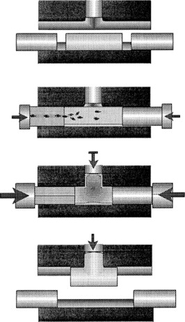
A Hydroforming Machine is a specialized metal forming device that uses high-pressure hydraulic fluid to shape ductile metals into complex, lightweight, and strong components. It works by applying controlled fluid pressure inside a sealed chamber or against a flexible membrane to force the metal blank or tube into a shaped die cavity. This process enables manufacturers to produce parts with intricate geometries and excellent structural integrity, often reducing the need for welding or assembly.
Hydroforming machines are widely used in industries like automotive, aerospace, appliances, and construction, where high-strength, precision-formed parts are essential.
Key features of hydroforming machines include:
- High-Pressure Hydraulic System: Generates and controls fluid pressure, which can reach thousands of bars, to form the metal.
- Forming Chamber and Dies: The workpiece is placed inside or on the die cavity where shaping occurs.
- Flexible Membrane or Internal Pressure: For sheet hydroforming, a flexible membrane transmits pressure; for tube hydroforming, fluid is applied internally to expand the tube.
- Control Systems: Precise control of pressure, timing, and clamping ensures consistent and defect-free parts.
- Safety Mechanisms: Includes interlocks, pressure relief valves, and emergency stops due to the high operating pressures.
Hydroforming machines can be categorized by their application:
- Sheet Hydroforming Machines: Shape flat sheets into complex forms using hydraulic pressure and membranes.
- Tube Hydroforming Machines: Form hollow tubes by internal pressurization combined with axial feeding.
Modern hydroforming machines integrate automation, advanced controls, and real-time monitoring to optimize quality and efficiency, making them vital tools in advanced metal manufacturing.
Hydroforming machines operate by carefully balancing hydraulic pressure and mechanical forces to deform metal blanks or tubes into precise shapes. The process begins by placing a metal blank—either a flat sheet or a hollow tube—into the machine’s forming area. For sheet hydroforming, a flexible membrane is positioned over the blank, and as hydraulic fluid pressure increases, the membrane presses the metal into the die cavity, replicating its complex contours. In tube hydroforming, internal hydraulic pressure expands the tube outward against the die, while axial feeding mechanisms push the tube lengthwise to prevent thinning or wrinkling.
The hydraulic power unit in the machine provides the high-pressure fluid, which is carefully regulated via pumps, valves, and accumulators. These components work together to deliver precise pressure profiles, often controlled by programmable logic controllers (PLCs) or computer numerical control (CNC) systems that enable repeatable and adjustable forming cycles.
Material handling features, including clamps, grippers, and robotic loaders, enhance throughput by automating the loading and unloading of blanks and finished parts. These systems improve safety and reduce operator intervention, especially when handling heavy or complex components.
Hydroforming machines are designed for durability and precision, with robust frames that resist deformation under high pressures and tooling that is engineered for long service life. Advances in materials and manufacturing techniques, such as additive manufacturing, enable the production of optimized dies and inserts that improve forming quality and reduce lead times.
Modern hydroforming machines often include sensors and monitoring devices that track pressure, displacement, force, and temperature throughout the forming cycle. This data supports quality control and process optimization, allowing operators to detect defects early and make real-time adjustments. Integration with factory automation systems facilitates data logging, maintenance scheduling, and process analytics, aligning hydroforming with Industry 4.0 standards.
Energy efficiency is also a focus in hydroforming machine design. Features such as servo-hydraulic systems, regenerative circuits that capture and reuse hydraulic energy, and variable frequency drives help reduce power consumption and environmental impact. Hydraulic fluids used are increasingly formulated to be environmentally friendly and biodegradable, aligning with sustainability goals.
Safety is paramount in hydroforming machine operation due to the high pressures involved. Machines are equipped with multiple safety layers, including mechanical guards, pressure relief valves, emergency stop functions, and interlocks. Operator training and adherence to safety protocols are critical to preventing accidents.
As hydroforming technology advances, machines continue to evolve toward greater automation, flexibility, and intelligence. The integration of AI-driven process control, digital twins for simulation, and advanced materials testing enables manufacturers to produce more complex, lightweight parts with higher quality and less waste. These capabilities make hydroforming machines indispensable in sectors demanding precision, efficiency, and innovation.
Continuing, the adaptability of hydroforming machines is a significant advantage in modern manufacturing. They can be customized to accommodate a wide range of materials, from conventional steels and aluminum alloys to advanced high-strength steels, titanium, and even some composites. This versatility allows industries like automotive and aerospace to leverage hydroforming for producing lightweight components that meet stringent strength and safety requirements.
Hydroforming machines can also be scaled to different production volumes. Smaller, compact units are suitable for prototyping or low-volume specialty parts, while large, high-tonnage presses serve mass production needs. This scalability is enhanced by modular designs, enabling manufacturers to upgrade or reconfigure machines quickly in response to evolving production demands or new product introductions.
The integration of hydroforming machines with other manufacturing processes forms streamlined production lines. For example, hydroformed parts may be seamlessly transferred to robotic welding stations, painting booths, or assembly cells, reducing manual handling and cycle times. Such integration supports lean manufacturing principles, optimizing space, reducing inventory, and improving overall efficiency.
Emerging trends include the use of multi-stage hydroforming machines, which perform sequential forming steps within a single machine or cell. This approach allows for the creation of increasingly complex parts with tighter tolerances and reduced secondary operations.
Maintenance of hydroforming machines has also evolved with predictive analytics and remote monitoring. Sensors continuously assess component wear, hydraulic fluid condition, and machine performance, alerting maintenance teams before failures occur. This proactive approach minimizes downtime, extends equipment life, and lowers operational costs.
In addition to mechanical and hydraulic components, the software controlling hydroforming machines is becoming more sophisticated. User-friendly interfaces, real-time diagnostics, and process simulation tools help operators optimize settings and quickly adapt to new part designs. Cloud connectivity enables centralized data management and facilitates expert support from remote locations.
Hydroforming machines contribute to sustainable manufacturing by reducing material waste through near-net-shape forming, minimizing the need for secondary machining or assembly. This efficiency, combined with energy-saving hydraulic technologies and environmentally conscious fluids, lowers the overall ecological footprint of production.
Looking ahead, the convergence of hydroforming technology with advanced materials research, digital manufacturing, and automation will continue to expand the possibilities for creating high-performance, cost-effective components. These innovations will empower industries to meet the growing demands for lightweight, strong, and complex metal parts essential to modern products and infrastructure.
Expanding further, one of the critical factors driving the evolution of hydroforming machines is the increasing demand for complex geometries that traditional forming methods struggle to achieve. Hydroforming excels at producing parts with smooth contours, integrated stiffening ribs, and varying cross-sections without requiring multiple joining steps. This capability not only improves the structural integrity of components but also reduces the total number of parts and assembly time, which is a significant cost and quality advantage.
To handle these complexities, hydroforming machines often incorporate multi-axis control and precision servo-hydraulic systems. These allow for finely tuned pressure application, synchronized with mechanical movements such as clamp force and axial feeding in tube hydroforming. Such coordinated control is essential to prevent defects like wrinkling, tearing, or uneven thickness distribution, especially when working with advanced lightweight materials.
The tooling used in hydroforming machines is equally critical. Innovations in tool design, such as flexible or segmented dies, enable adjustable forming cavities to accommodate part variations or multiple product families without the need for full tool replacement. Additionally, additive manufacturing is increasingly used to produce complex tool inserts with internal cooling channels or tailored surface textures that enhance forming efficiency and part quality.
Hydroforming machines are also adapting to serve emerging sectors. For example, in the production of electric vehicles, hydroforming is employed to fabricate battery enclosures, motor housings, and lightweight chassis components that require high precision and strength. Similarly, in aerospace, the ability to form large, lightweight panels with integrated features reduces weight and improves fuel efficiency.
Research into hybrid hydroforming techniques is progressing, combining traditional hydroforming with other processes like stamping, forging, or incremental forming to tackle parts with extreme complexity or special material requirements. These hybrid approaches broaden the design space available to engineers and open new opportunities for innovation.
Environmental considerations continue to shape hydroforming machine development. Energy recovery systems capture excess hydraulic energy during pressurization cycles and reuse it, significantly improving the machine’s energy efficiency. Moreover, closed-loop hydraulic fluid management systems maintain fluid quality and reduce disposal needs.
Finally, workforce skill development remains an essential aspect of hydroforming machine adoption. As machines become more automated and digitally connected, operators and engineers require training not only on mechanical and hydraulic systems but also on software, data analytics, and digital twins. Augmented reality (AR) and virtual reality (VR) training modules are becoming popular tools to accelerate learning and reduce errors.
In summary, hydroforming machines are evolving into highly sophisticated, flexible, and efficient systems that integrate mechanical robustness with advanced digital capabilities. Their continued advancement ensures they remain a cornerstone technology in manufacturing industries aiming for innovation, quality, and sustainability.
Bulge Forming Hydraulic System
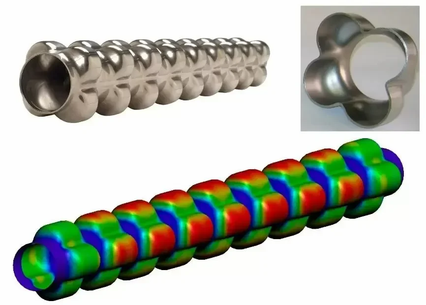
A Bulge Forming Hydraulic System is a specialized hydraulic setup designed to perform bulge forming—a metal forming process where internal hydraulic pressure is used to expand a hollow tube or sheet metal into a die cavity, creating complex shapes with uniform thickness and high strength. The hydraulic system plays a critical role in controlling the pressure, flow, and timing to precisely shape the workpiece without defects.
Key components of a bulge forming hydraulic system include:
- Hydraulic Power Unit (HPU): Provides pressurized hydraulic fluid using pumps (usually gear or piston pumps), a reservoir, filters, and cooling systems.
- Pressure Control Valves: Regulate and maintain the precise hydraulic pressure needed to expand the metal gradually and uniformly.
- Directional Valves: Control the flow path of the hydraulic fluid, allowing for the pressurization and depressurization phases of the forming cycle.
- Accumulators: Store hydraulic energy and help maintain steady pressure during rapid forming stages, smoothing out pressure fluctuations.
- Sensors and Feedback Devices: Measure pressure, flow rate, and piston position to ensure accurate control and safety.
- Control Unit: Often PLC or CNC-based, this unit coordinates pressure application, timing, and safety interlocks to execute the bulge forming cycle precisely.
During bulge forming, the system pumps hydraulic fluid into the inside of a tube or under a sheet metal blank, increasing internal pressure to push the metal outward against the die walls. The hydraulic system must provide a smooth and controllable pressure ramp to avoid sudden bursts or wrinkles. It also needs to maintain constant pressure during the hold phase to ensure the part fully forms to the die shape.
The hydraulic system’s responsiveness, reliability, and precision directly affect part quality, cycle time, and tool life. Modern bulge forming hydraulic systems incorporate advanced servo-hydraulic technology for dynamic pressure and flow control, improving energy efficiency and process repeatability.
In applications such as automotive structural components, aerospace tubing, or complex pipe fittings, the bulge forming hydraulic system enables the production of lightweight, strong, and seamless parts that meet demanding specifications.
The bulge forming hydraulic system’s effectiveness relies heavily on its ability to deliver consistent and precisely controlled pressure throughout the forming cycle. Pressure buildup must be carefully managed to gradually deform the metal without causing failure such as cracking, excessive thinning, or wrinkling. This is achieved through sophisticated control algorithms that modulate pump speed, valve positions, and accumulator functions in real time.
Hydraulic fluid quality and temperature control are crucial factors, as fluid viscosity affects responsiveness and pressure stability. Cooling systems are often integrated into the hydraulic power unit to maintain optimal fluid temperature, preventing overheating that could degrade performance or damage components.
In addition to pressure control, the system often includes axial feed mechanisms synchronized with the hydraulic pressure to feed the tube lengthwise during bulge forming. This axial feeding prevents thinning at the bulge and helps maintain uniform wall thickness, enhancing the mechanical properties of the final part.
Safety mechanisms are critical due to the high pressures involved. Pressure relief valves, emergency shutdown systems, and robust structural design ensure that any overpressure conditions or malfunctions do not lead to equipment failure or operator injury.
The integration of sensors such as pressure transducers, flow meters, and displacement sensors allows for continuous monitoring of the hydraulic system and forming process. Data from these sensors feed into control units, enabling adaptive adjustments and early detection of anomalies, which helps maintain product quality and reduce scrap rates.
Modern bulge forming hydraulic systems increasingly use servo-hydraulic technology, combining the power density of hydraulics with the precision and efficiency of electronic controls. Servo valves and variable displacement pumps enable highly dynamic control of pressure and flow, resulting in smoother pressure curves, faster cycle times, and energy savings compared to traditional fixed-displacement systems.
Furthermore, predictive maintenance tools, powered by real-time monitoring and AI analytics, help anticipate hydraulic component wear or fluid contamination, scheduling maintenance before failures occur. This approach reduces downtime and extends the service life of the equipment.
The design of bulge forming hydraulic systems also takes into account environmental considerations. The use of biodegradable hydraulic fluids, energy recovery circuits, and noise reduction measures align these systems with modern sustainability and workplace safety standards.
Overall, the bulge forming hydraulic system is a sophisticated assembly of mechanical, hydraulic, and electronic components working in harmony to produce complex metal shapes with high precision, reliability, and efficiency. Its continued development enables manufacturers to push the boundaries of lightweight, high-strength metal components used across automotive, aerospace, and industrial sectors.
Building on these fundamentals, the versatility of bulge forming hydraulic systems extends to a wide variety of materials, including advanced high-strength steels, aluminum alloys, titanium, and even some stainless steels. The hydraulic system must be adaptable to accommodate the different flow stresses and deformation characteristics of these materials, which often require fine-tuned pressure profiles and feed rates.
In the design of the hydraulic circuit, the choice between open-loop and closed-loop control systems impacts performance and efficiency. Closed-loop systems, which use continuous feedback from sensors to adjust pressure and flow in real time, offer superior precision and repeatability. This is particularly important when forming complex geometries where even minor deviations in pressure can result in defects.
The physical layout of the hydraulic components also affects machine responsiveness. Minimizing the length and volume of hydraulic lines reduces pressure losses and improves reaction time, enabling the system to react quickly to changing load conditions during forming.
Hydraulic accumulators play a vital role in buffering pressure spikes and storing energy. They absorb sudden pressure changes caused by rapid metal deformation, helping to maintain a steady force on the workpiece and protect the system from shock loads. Gas-charged accumulators are commonly used due to their responsiveness and energy storage capacity.
Control software for bulge forming hydraulic systems is becoming increasingly sophisticated. It often includes customizable pressure ramp profiles, multi-step forming sequences, and integration with simulation software that predicts material behavior and optimal process parameters. This digital integration enables engineers to fine-tune the system before production, reducing trial-and-error and material waste.
Maintenance and troubleshooting benefit from advanced diagnostics built into the hydraulic system. Operators receive alerts about fluid contamination, pump wear, valve malfunctions, or sensor issues. These diagnostics can be accessed remotely, supporting faster response times and reducing the need for specialized onsite personnel.
The mechanical structure supporting the hydraulic system is engineered to withstand the cyclic high pressures and forces involved. This includes reinforced frames, precision-machined cylinders, and heavy-duty seals that prevent fluid leakage and contamination. The reliability of these components directly impacts machine uptime and overall production efficiency.
In terms of energy consumption, modern bulge forming hydraulic systems incorporate energy recovery and regeneration technologies. These systems capture hydraulic energy during pressure release phases and reuse it, lowering power requirements and reducing operating costs.
As manufacturing moves toward Industry 4.0, bulge forming hydraulic systems are increasingly networked within smart factories. Data collected from forming operations is analyzed for process optimization, quality control, and predictive maintenance, driving continuous improvement.
The future of bulge forming hydraulic systems is focused on greater automation, improved energy efficiency, and enhanced process intelligence. These advances will continue to enable the production of lighter, stronger, and more complex metal components that meet the evolving demands of high-performance industries.
Further advancements in bulge forming hydraulic systems involve the integration of multi-axis control and hybrid forming techniques. By combining hydraulic pressure with mechanical actuators—such as servo-driven rams or electric presses—manufacturers can achieve even greater control over the deformation process. This hybrid approach expands the range of achievable shapes and allows for the forming of ultra-high-strength materials that are otherwise challenging to process.
Incorporating real-time process monitoring with machine learning algorithms is another emerging trend. These intelligent systems analyze sensor data continuously, detecting subtle patterns that indicate potential defects or deviations from optimal forming conditions. This predictive capability enables adaptive control adjustments on the fly, minimizing scrap rates and improving first-pass yield.
Customization of hydraulic systems to specific production requirements is becoming more prevalent. Modular hydraulic units allow manufacturers to scale system capacity and features according to part complexity, production volume, and material type. This flexibility reduces upfront investment and enables easier upgrades as product lines evolve.
The use of advanced hydraulic fluids with enhanced lubricity and thermal stability improves system efficiency and component longevity. Some formulations also reduce environmental impact and improve workplace safety by minimizing toxicity and flammability.
In terms of tooling, advances in quick-change systems and adaptive dies complement the hydraulic system by reducing setup times and enabling rapid product changeovers. This synergy supports lean manufacturing principles and makes bulge forming attractive for both high-volume and low-volume production runs.
Hydraulic system designers are increasingly focusing on noise reduction, employing sound-dampening materials and optimizing pump and valve operations to create quieter work environments, which is important for operator comfort and regulatory compliance.
Finally, the rise of additive manufacturing technologies is influencing bulge forming hydraulic systems indirectly. Printed components—such as complex manifolds or lightweight hydraulic blocks—offer design freedom that can improve fluid flow paths and reduce system weight.
Altogether, these innovations position bulge forming hydraulic systems at the forefront of metal forming technology, enabling manufacturers to produce complex, lightweight, and high-strength parts efficiently while meeting stringent quality and sustainability standards.
Bulge Expansion Hydraulic Press
A Bulge Expansion Hydraulic Press is a specialized hydraulic press designed to perform bulge expansion forming, a metal shaping process that uses internal hydraulic pressure to expand a tubular or hollow metal workpiece outward into a die cavity. This press allows manufacturers to create complex, seamless parts with controlled wall thickness and enhanced mechanical properties.
The press typically consists of a robust frame to withstand high forming forces, a hydraulic power unit to generate and control pressure, and tooling designed to support and shape the workpiece during expansion. Hydraulic cylinders apply internal pressure through fluid injection, causing the metal to bulge outward. Simultaneously, axial feeding mechanisms may be employed to feed the tube lengthwise, preventing excessive thinning at the bulge and ensuring uniform material distribution.
Key features of a bulge expansion hydraulic press include precise pressure control, high tonnage capacity, and synchronized mechanical movements to maintain part quality and process repeatability. Advanced models incorporate servo-hydraulic systems for enhanced responsiveness and energy efficiency.
These presses are widely used in automotive, aerospace, and industrial manufacturing to produce lightweight, strong components such as structural tubes, pressure vessels, and complex pipe fittings, offering advantages over traditional welding or stamping methods by reducing joints and improving strength-to-weight ratios.
The bulge expansion hydraulic press operates by gradually increasing internal hydraulic pressure within the tube or hollow blank, forcing the material outward against a die or mold. This controlled expansion allows for the creation of complex shapes with smooth contours and precise dimensions. The hydraulic system’s ability to maintain steady pressure during the forming cycle is critical to preventing defects such as wrinkling, cracking, or uneven thickness.
Axial feeding is often integrated into the press operation, where the workpiece is simultaneously pushed lengthwise to compensate for material thinning at the bulge area. This combined radial expansion and axial feed ensure uniform wall thickness and improved mechanical properties, resulting in stronger and lighter components.
The press frame is engineered to endure high pressures and forces generated during forming, often featuring reinforced structures and heavy-duty components to ensure durability and safety. High-quality seals and cylinders in the hydraulic system prevent leaks and maintain consistent pressure, while pressure relief valves and safety interlocks protect operators and equipment.
Modern bulge expansion hydraulic presses utilize advanced servo-hydraulic controls, offering precise regulation of pressure, flow, and timing. This technology enables programmable pressure profiles tailored to different materials and part geometries, improving flexibility and reducing setup times. Energy-efficient components, such as variable displacement pumps and energy recovery units, help reduce power consumption and operational costs.
Tooling for bulge expansion presses is designed to support the part while allowing free expansion where needed. Dies are often made from hardened materials to withstand repeated high-pressure cycles and maintain dimensional accuracy. Quick-change tooling systems facilitate faster product changeovers, enhancing production efficiency.
Integration with digital control systems allows for real-time monitoring of pressure, displacement, and force, enabling adaptive adjustments during forming to ensure consistent quality. Data logging supports traceability and continuous process improvement, while predictive maintenance systems help minimize downtime by detecting potential hydraulic system issues before failures occur.
Bulge expansion hydraulic presses are essential in producing components with superior strength-to-weight ratios, such as automotive frame parts, aerospace structural members, and industrial piping. By reducing the need for welding or assembly, these presses contribute to higher product reliability and lower manufacturing costs.
Ongoing developments focus on improving automation, enhancing hydraulic system responsiveness, and expanding material compatibility to include ultra-high-strength alloys and lightweight metals. These advances will continue to position bulge expansion hydraulic presses as vital equipment for modern precision metal forming applications.
Continuing, the future of bulge expansion hydraulic presses is closely tied to advancements in automation and smart manufacturing. Integration of robotics and automated handling systems reduces manual intervention, increases throughput, and improves worker safety by minimizing exposure to high-pressure environments. Automated loading and unloading, combined with in-line inspection systems, enable continuous production with real-time quality assurance.
The adoption of Industry 4.0 technologies transforms bulge expansion presses into connected smart machines. Embedded sensors provide comprehensive data on pressure, flow rates, temperatures, and mechanical stresses. This data is analyzed using artificial intelligence and machine learning algorithms to optimize forming parameters, detect anomalies early, and predict maintenance needs. Such predictive maintenance strategies significantly reduce unplanned downtime and extend the service life of critical components like pumps, valves, and seals.
Material science developments also influence bulge expansion press design and operation. As manufacturers increasingly use advanced high-strength steels, aluminum-lithium alloys, and titanium to meet weight reduction and performance goals, hydraulic systems must adapt to the specific forming behaviors of these materials. This requires more sophisticated pressure control, customized tooling, and precise synchronization between axial feeding and internal pressure application.
Energy efficiency remains a priority, with innovations such as regenerative hydraulic circuits capturing and reusing energy during pressure release cycles. This not only reduces operational costs but also aligns manufacturing processes with sustainability targets by lowering carbon footprints.
Safety features continue to evolve, incorporating advanced monitoring of hydraulic pressures, system integrity, and operator presence to prevent accidents. Ergonomic design improvements in press access, control interfaces, and noise reduction enhance the working environment for operators.
Additionally, modular press designs enable flexible configuration and scalability, allowing manufacturers to tailor machines to specific production volumes and part complexities. This flexibility supports both high-mix, low-volume manufacturing and mass production environments.
Finally, collaboration between hydraulic press manufacturers, tooling suppliers, and end-users fosters continuous innovation, ensuring that bulge expansion hydraulic presses remain at the forefront of metal forming technology. By combining mechanical robustness, hydraulic precision, digital intelligence, and operator-friendly design, these presses enable the efficient production of complex, lightweight, and high-strength components essential to modern industries such as automotive, aerospace, and energy.
Building further, the customization of bulge expansion hydraulic presses is increasingly driven by the diverse needs of emerging industries such as electric vehicles, aerospace composites, and renewable energy sectors. For example, electric vehicle manufacturers demand lightweight structural components with complex geometries, pushing presses to handle a wider range of exotic alloys and hybrid materials. This requires adaptive hydraulic control systems capable of fine-tuning pressure curves and feed rates in real time.
Additive manufacturing (3D printing) is also beginning to complement bulge forming processes. Custom tooling components, hydraulic manifolds, and intricate die inserts produced via additive methods enable faster prototyping and tooling modifications, reducing lead times and costs. This synergy accelerates product development cycles and enables more rapid iteration of part designs.
The integration of virtual and augmented reality tools enhances operator training and maintenance procedures. Technicians can visualize hydraulic system layouts, simulate fault conditions, and receive guided repair instructions, improving service quality and reducing downtime.
On the software side, advanced simulation tools model material flow, stress distribution, and potential defects during bulge expansion. These simulations inform hydraulic system settings and tooling design, minimizing trial-and-error in production and lowering scrap rates.
Emerging trends also focus on miniaturization and compact hydraulic systems for smaller-scale bulge forming applications in precision engineering, medical devices, and electronics housings. These compact presses combine micro-hydraulics with precision control to achieve delicate, high-accuracy forming tasks.
Environmentally, the use of eco-friendly hydraulic fluids and improved sealing technologies helps reduce the risk of leaks and contamination, supporting green manufacturing initiatives. Noise and vibration reduction techniques, including optimized pump operation and chassis damping, contribute to healthier work environments.
Overall, bulge expansion hydraulic presses continue to evolve through multidisciplinary innovation, combining mechanical engineering, hydraulics, digitalization, and material science. This evolution enables manufacturers to meet increasingly stringent demands for part complexity, structural performance, production efficiency, and sustainability, ensuring these presses remain indispensable tools in advanced metal forming.
Bulge Metal Forming Machine
A Bulge Metal Forming Machine is specialized equipment designed to shape metal tubes or hollow sections by expanding them outward using internal pressure. This process, known as bulge forming, allows manufacturers to produce complex, seamless parts with controlled wall thickness and high strength without the need for welding or joining.
The machine typically consists of a strong frame, a hydraulic system that generates and regulates high internal pressure, axial feeding mechanisms to control material flow, and custom tooling or dies that define the final shape. During operation, a metal tube or blank is sealed and placed inside the machine; hydraulic fluid or gas is then injected internally, causing the tube to expand or bulge into the shape of the die cavity.
Bulge metal forming machines are widely used in industries such as automotive, aerospace, and construction to produce lightweight structural components, pressure vessels, and specialized fittings. The process improves part strength by maintaining continuous grain flow and uniform wall thickness, enhancing mechanical properties compared to traditional forming methods.
Modern machines incorporate advanced hydraulic controls, servo systems, and digital interfaces to optimize forming pressure, feed rates, and cycle times, resulting in high precision, repeatability, and reduced material waste. Safety features and monitoring systems ensure reliable operation under the high-pressure conditions required for effective bulge forming.
Bulge metal forming machines operate by applying internal pressure to expand a metal tube or hollow blank into a desired shape. The hydraulic system generates controlled pressure, which forces the material outward against a die or mold. This process allows complex geometries to be formed with smooth, continuous surfaces and uniform wall thickness, eliminating the need for welding or multiple assembly steps.
Axial feeding mechanisms are often integrated to push the tube longitudinally during expansion. This feeding compensates for the thinning of material at the bulged region, maintaining consistent thickness and preventing failure due to over-stretching. The synchronization of hydraulic pressure and axial feed is critical for optimal forming results.
The machine’s frame and structure are built to withstand the high forces generated during bulging, often incorporating heavy-duty steel construction and reinforced components. Precision-machined tooling and dies made from hardened materials ensure durability and accuracy, supporting high-volume production without frequent maintenance.
Advanced bulge forming machines include servo-hydraulic systems that offer precise control over pressure ramp-up, hold times, and release sequences. These systems enhance process flexibility, allowing the machine to adapt to various materials and part geometries. Programmable logic controllers (PLCs) and human-machine interfaces (HMIs) enable operators to set and monitor process parameters easily.
Safety features such as pressure relief valves, emergency stops, and protective guards are standard to protect operators and equipment. Sensors continuously monitor pressure, displacement, and force, providing feedback for real-time adjustments and quality assurance.
Energy efficiency is also a focus, with some machines incorporating energy recovery systems that capture hydraulic energy during depressurization and reuse it, reducing overall power consumption. Noise reduction measures, including sound-dampening enclosures and optimized pump operation, improve the working environment.
Bulge metal forming machines are versatile, capable of handling a wide range of materials including aluminum alloys, stainless steels, titanium, and high-strength steels. This versatility makes them valuable for producing lightweight yet strong components critical to automotive frames, aerospace structures, pressure vessels, and industrial piping.
Ongoing developments in bulge forming technology emphasize greater automation, integration with digital manufacturing ecosystems, and the use of smart sensors and data analytics to optimize process control and predictive maintenance. These advancements contribute to improved product quality, reduced cycle times, and lower operational costs, ensuring that bulge metal forming machines remain essential tools in modern manufacturing.
Continuing, the integration of robotics and automated material handling systems with bulge metal forming machines is transforming production lines by increasing throughput and reducing manual labor. Automated loading and unloading minimize cycle times and improve consistency by precisely positioning blanks for forming, while robotic arms handle finished parts, enhancing safety and efficiency.
The ability to quickly switch tooling and program new forming profiles enables manufacturers to adapt to changing product designs or small batch production runs, supporting the trend toward mass customization. Modular machine architectures allow for scalable solutions that can be upgraded or reconfigured as production needs evolve.
Digital twins and virtual simulations play a growing role in bulge forming by enabling engineers to predict material behavior and optimize machine settings before actual production. These simulations reduce trial-and-error in tooling design and process parameters, lowering scrap rates and speeding up development cycles.
Materials used in bulge forming continue to advance, with an emphasis on lightweight alloys and composites that meet stringent performance and environmental standards. Bulge forming machines must therefore accommodate these materials’ unique deformation characteristics, requiring precise control over pressure, feed rate, and temperature.
Enhanced monitoring systems utilizing high-resolution sensors and cameras provide detailed insights into forming quality, detecting defects like wrinkling, cracking, or thinning early in the process. Coupled with machine learning algorithms, these systems enable adaptive control strategies that adjust parameters in real time for optimal results.
Maintenance strategies are evolving with predictive and condition-based maintenance becoming standard. Sensors track hydraulic fluid quality, system pressures, and component wear, allowing service teams to intervene before failures occur, thus minimizing downtime and repair costs.
Environmental considerations drive the adoption of biodegradable hydraulic fluids, improved sealing technologies to prevent leaks, and energy-efficient components. These features not only reduce environmental impact but also contribute to cost savings and regulatory compliance.
Overall, bulge metal forming machines are at the forefront of precision manufacturing, combining mechanical robustness with smart technologies to meet the increasing demands for complex, high-performance metal components in a wide range of industries. The continuous innovation in machine design, control systems, and process monitoring ensures that these machines remain vital assets for efficient, high-quality metal forming operations.
Further expanding, the future of bulge metal forming machines is also influenced by the rise of hybrid forming processes that combine bulging with other metal shaping techniques such as hydroforming, incremental forming, or stretch forming. These hybrid approaches offer enhanced flexibility, enabling the production of even more complex geometries while optimizing material usage and mechanical properties.
The development of multi-chamber hydraulic systems allows for localized pressure control within different sections of the workpiece, providing finer detail and reducing the risk of defects. This capability is particularly useful when forming parts with variable wall thicknesses or intricate shapes.
Integration with real-time data analytics and cloud-based platforms enables remote monitoring and diagnostics, allowing manufacturers to oversee multiple machines across various sites and respond quickly to process deviations. This connectivity supports lean manufacturing principles and global production coordination.
The use of advanced coatings and surface treatments on tooling extends tool life and reduces friction during forming, improving part surface quality and decreasing maintenance frequency. Additionally, innovations in additive manufacturing for tooling components allow rapid customization and repair of dies, significantly shortening lead times.
Sustainability goals push manufacturers to explore closed-loop hydraulic systems that recycle fluids and minimize waste. Incorporating renewable energy sources to power hydraulic systems also contributes to reducing the carbon footprint of bulge forming operations.
On the workforce side, training programs increasingly incorporate virtual reality (VR) and augmented reality (AR) tools to simulate machine operation, safety procedures, and maintenance tasks. This immersive learning improves skill retention and reduces the risks associated with hands-on training in high-pressure environments.
As industries demand ever-lighter and stronger parts, bulge metal forming machines will continue evolving to accommodate new alloys, composite-metal hybrids, and tailored blanks with graded properties. These advancements will require ongoing refinement of hydraulic controls, sensor technologies, and process modeling.
In conclusion, bulge metal forming machines stand as a cornerstone technology for modern metal shaping, combining precision hydraulics, robust mechanical design, and digital intelligence. Their continuous evolution ensures they remain indispensable for manufacturing complex, high-quality, and lightweight components essential to sectors ranging from automotive and aerospace to energy and construction.
Bulge Press System
A Bulge Press System is an integrated setup designed to perform bulge forming—a metal shaping process where internal pressure is applied to a hollow workpiece (typically a tube or cylindrical blank) to expand it against a die, creating complex shapes with uniform wall thickness. This system combines mechanical, hydraulic, and control components to precisely manage the expansion process, ensuring high-quality, defect-free parts.
At the core of the bulge press system is a robust press frame engineered to withstand the significant forces generated during forming. Within this frame, hydraulic cylinders apply controlled internal pressure to the workpiece, which is usually sealed and connected to the hydraulic supply through specialized fixtures. Axial feeding mechanisms often complement this by pushing the workpiece longitudinally to balance material flow and avoid thinning in critical areas.
The hydraulic system includes pumps, valves, accumulators, and pressure sensors, all coordinated by advanced control units that regulate pressure ramp-up, hold, and release phases with high precision. Modern bulge press systems incorporate servo-hydraulic technology, offering enhanced responsiveness and programmability to adapt to various materials and geometries.
Tooling plays a vital role, consisting of precision-machined dies that define the external shape, clamping devices to secure the workpiece, and sealing elements to maintain hydraulic pressure. Tool changeover systems can be integrated to improve production flexibility and reduce downtime.
Safety is paramount, so bulge press systems feature pressure relief valves, emergency stop mechanisms, interlocks, and operator guards. Real-time monitoring via sensors and digital interfaces enables operators to track forming parameters, detect anomalies, and ensure consistent quality.
Energy efficiency is addressed through features like variable displacement pumps and regenerative hydraulic circuits, which reduce power consumption by recovering energy during pressure release.
Bulge press systems are widely used in industries requiring lightweight, strong, and complex-shaped components, such as automotive frame parts, aerospace structures, and pressure vessels. Their ability to produce seamless, high-integrity parts with minimal secondary processing makes them valuable for modern manufacturing.
Ongoing advancements focus on enhancing automation, integrating smart sensors and data analytics for predictive maintenance, and developing modular designs that allow scalability and customization to meet evolving production demands.
A bulge press system functions by carefully coordinating hydraulic pressure and axial feeding to expand a tubular or hollow metal blank into a die cavity. The hydraulic unit builds pressure gradually to prevent sudden material failure, while axial feed mechanisms push the blank longitudinally to compensate for thinning as the metal expands outward. This synchronization is crucial to maintain wall thickness and avoid defects such as cracking or wrinkling.
The press frame is engineered for rigidity and strength, often constructed from heavy-duty steel and reinforced at stress points to handle the forces generated during forming. Precision guides and clamping systems hold the workpiece securely, preventing movement that could cause inaccuracies or damage.
Modern bulge press systems employ servo-hydraulic technology for fine control over pressure profiles, feed rates, and stroke positions. These systems allow operators to program complex forming cycles tailored to different materials and geometries, enabling quick adjustments for varying production runs or part designs.
Digital control panels with intuitive human-machine interfaces provide real-time feedback on system parameters, including pressure, displacement, and cycle time. Integrated sensors monitor these variables continuously, allowing the system to make automatic adjustments or halt operations if unsafe conditions arise.
Energy efficiency is a significant design consideration. Variable speed pumps reduce power usage by matching hydraulic flow to demand, and energy recovery systems capture fluid energy during decompression phases for reuse. Such features contribute to lower operational costs and a reduced environmental footprint.
The tooling setup includes hardened dies designed to withstand repeated high-pressure contact while producing accurate, repeatable shapes. Quick-change tooling systems may be incorporated to facilitate rapid transitions between different part geometries, supporting flexible manufacturing environments.
Safety mechanisms such as pressure relief valves prevent system overpressure, while physical barriers and interlocks protect operators during machine cycles. The entire system often integrates into larger production lines with automated material handling, inspection, and quality control systems to streamline manufacturing.
Bulge press systems are versatile, capable of processing various materials ranging from aluminum and stainless steel to advanced high-strength alloys. This flexibility makes them indispensable in sectors like automotive manufacturing, aerospace, and energy, where complex, lightweight, and structurally sound components are required.
Continuous innovation in bulge press systems focuses on enhancing automation, integrating predictive maintenance through sensor data analysis, and improving user interfaces for ease of operation. These advancements ensure that bulge press systems remain efficient, reliable, and adaptable to the ever-evolving demands of modern metal forming industries.
Further development in bulge press systems emphasizes the integration of intelligent automation and advanced diagnostics. These systems increasingly utilize machine learning algorithms to analyze vast datasets collected from sensors during operation. Over time, the system can identify subtle changes in process performance and predict potential issues such as seal wear, hydraulic fluid degradation, or misalignment of tooling, allowing maintenance to be scheduled proactively rather than reactively.
Robotics is another area of integration, particularly for loading and unloading tubular blanks or finished components. Robotic arms can work in tight synchronization with the press cycle, improving safety by reducing human intervention and increasing throughput by maintaining a continuous production rhythm. Some bulge press systems also support dual-station or tandem configurations, where one part is being formed while another is being set up, effectively minimizing idle time between cycles.
The use of modular construction in bulge press systems enables manufacturers to configure the system according to their specific application—whether for small-diameter tubes in HVAC systems or large-scale structural elements in heavy vehicles or infrastructure. This modularity extends to hydraulic units, control systems, and die setups, making it easier to upgrade or reconfigure the system without complete replacement.
Environmental sustainability is addressed not only through energy-efficient hydraulics but also through cleaner production methods. Eco-friendly hydraulic fluids, leak-proof circuit designs, and closed-loop fluid recovery systems reduce environmental risks and disposal costs. Some systems are even designed for low-noise operation, using damped pumps and acoustic enclosures, making them more suitable for factory environments focused on worker health and noise control.
Material-specific adaptations are also becoming more common. For example, high-strength steel and titanium alloys used in aerospace or defense require precise control over strain rates and pressure application to prevent springback or microcracking. Bulge press systems tuned for these materials often include temperature management features such as heated dies or preform warming stations.
As digital manufacturing becomes standard, bulge press systems are increasingly connected to MES (Manufacturing Execution Systems) and ERP (Enterprise Resource Planning) platforms. This allows for real-time production tracking, part traceability, and integration with digital twins—virtual models that simulate the physical press to test setups and predict outcomes before actual forming begins.
In essence, the bulge press system continues to evolve from a purely mechanical process into a smart, interconnected forming solution. Its ability to create lightweight, seamless, and structurally optimized components while adapting to new materials and production paradigms makes it a cornerstone of advanced manufacturing across a range of demanding industries.
Additionally, the role of real-time process feedback in bulge press systems is growing in importance. High-resolution pressure sensors, linear encoders, and displacement transducers provide second-by-second data during the forming cycle, allowing precise adjustments to pressure levels and axial feed to ensure optimal material flow. This real-time adaptability minimizes scrap rates and enhances part repeatability, especially in forming operations that demand tight tolerances.
Modern systems also support adaptive control loops that automatically adjust based on the feedback received during each cycle. For example, if the wall thickness starts to deviate from target values due to minor material variation, the system can correct the pressure curve mid-process to bring the output back into spec without halting production. This level of responsiveness not only boosts part quality but also significantly reduces reliance on manual oversight and post-process inspection.
Another advancing area is the development of hybrid bulge press systems that integrate both internal hydraulic pressure and external mechanical forming, such as restraining dies or clamping rams that act in sequence or parallel. This combination allows for more complex geometries to be achieved while maintaining material integrity, especially in multi-diameter tube sections or parts with offset bulges.
Tooling development also remains a central focus. Wear-resistant coatings, advanced alloys, and even additive-manufactured die inserts with internal cooling channels are being used to extend tool life and maintain dimensional precision. For high-volume production, automated die calibration and cleaning mechanisms are sometimes integrated to ensure consistent tool performance over long shifts or unmanned operations.
In terms of usability, user interfaces are becoming more operator-friendly. Touchscreen HMIs now often feature guided setup wizards, visual status indicators, and automatic error diagnosis. This reduces training requirements and minimizes operator mistakes, especially in facilities where machines may be shared between teams or operate around the clock.
In Industry 4.0 environments, data from the bulge press system feeds into centralized dashboards that consolidate productivity metrics, downtime causes, energy consumption, and maintenance logs. Managers can analyze trends across multiple machines or facilities, allowing smarter decision-making on capacity planning, tooling investment, or predictive maintenance schedules.
Global manufacturers are also emphasizing compliance with international forming and safety standards, such as CE Marking in Europe or ANSI in the U.S. As such, modern bulge press systems come pre-certified or easily adaptable to meet the requirements of different regulatory environments, including those related to safety interlocks, pressure vessel integrity, and fluid containment.
Ultimately, the bulge press system is no longer just a forming machine—it’s an integrated, data-rich, intelligent manufacturing unit capable of producing highly accurate, complex parts at high volumes with minimal waste and downtime. Its continuing evolution ensures its relevance in the future of advanced, sustainable, and flexible metal forming industries.
Bulge Forming Tooling Press
A Bulge Forming Tooling Press is a specialized hydraulic press system designed to expand hollow metal workpieces—typically tubes—using internal pressure while employing precisely engineered tooling to define the final shape of the part. The tooling is central to the success of the bulge forming process, as it determines not only the geometric accuracy of the final product but also the uniformity of material distribution and wall thickness.
The press provides the controlled internal hydraulic pressure that pushes the metal outward into the die cavity, where the tooling—comprising male and female dies, support blocks, and seal assemblies—shapes the component. The tooling must be meticulously designed to match the intended final form, taking into account the mechanical behavior of the material under pressure, the required bulge depth, and critical features like radii, step changes, or asymmetrical profiles.
The die material is typically hardened tool steel or advanced alloy to withstand repeated high-pressure forming cycles without deformation or excessive wear. Tool coatings such as titanium nitride or DLC (diamond-like carbon) may be applied to reduce friction and improve surface finish. For complex parts or high-volume runs, cooling channels may be integrated into the tooling to manage heat buildup and ensure dimensional consistency.
Sealing elements are crucial to maintaining pressure inside the tube during the forming cycle. These seals are integrated into the tooling at each end of the tube and are designed to handle high pressures without leakage or extrusion. In some systems, the seals also allow axial feeding—pushing the tube ends inward during forming—which helps control wall thinning and improve material flow.
Tooling setups can include replaceable inserts for fast configuration changes between part variants, especially in manufacturing environments that require frequent product changes. Some presses use automated tool change systems to speed up retooling, minimizing downtime and improving overall equipment effectiveness.
Precise alignment between tooling components is essential. Misalignment can result in uneven expansion, wall thickness variations, or cracking. As such, most bulge forming tooling presses are equipped with guide rails, centering mechanisms, and feedback sensors to ensure accurate placement and alignment during each cycle.
The interplay between the press’s pressure control system and the geometry of the tooling determines the quality of the formed part. Sophisticated systems use pressure-time and pressure-displacement curves tailored to each part geometry and material type. The tooling is designed to match these curves, ensuring smooth deformation, wrinkle resistance, and minimal springback.
In advanced systems, digital simulations of the tooling and forming process—using finite element analysis (FEA)—are employed during design to predict material flow, identify potential problem zones, and optimize tool geometry before physical prototypes are made. This reduces development time, cost, and trial-and-error during commissioning.
Bulge forming tooling presses are used in industries such as automotive (for exhausts, chassis parts, and crumple zones), aerospace (for structural frames and fluid lines), and HVAC (for duct transitions and manifolds). Their ability to deliver strong, seamless, and geometrically accurate parts from single tubes or blanks makes them indispensable for lightweight and high-performance applications.
In a bulge forming tooling press, the tooling is engineered not only for dimensional precision but also for longevity and operational efficiency. The press must deliver consistent, repeatable hydraulic force, and the tooling must endure hundreds of thousands of cycles without failure or degradation. Therefore, high-strength tool steels such as H13 or D2 are commonly used, often heat-treated to improve wear resistance and structural stability. Tooling maintenance is also a critical aspect—press systems may include automated lubrication and tool monitoring sensors to track wear or misalignment before it results in part defects or tool failure.
The design of the tooling directly influences forming outcomes such as wall thickness distribution, corner fill, and structural integrity. For deeper or asymmetrical bulges, the tooling might include staged cavities or multi-section dies that allow sequential forming or intermediate holds to guide material flow progressively and avoid overstressing the metal. Additionally, computer-controlled die movement or deformation-resistant support tooling may be employed for highly engineered parts.
Tooling also incorporates features that support fast and safe loading and unloading of the tube or blank. This includes retractable clamping jaws, integrated alignment pins, and quick-closing mechanisms that hold the workpiece steady during the high-pressure phase of the cycle. To support automation, many presses are equipped with robotic arms or part feeders that interact directly with the tooling to insert or extract components.
Sealing elements in the tooling are typically made from high-performance elastomers or composites designed to withstand both the applied internal pressure and the chemical exposure from hydraulic fluids. The design ensures a tight seal without excessive compression that could damage the workpiece or reduce seal life. In cases where axial feeding is required, dynamic seals that allow controlled material feed through the seal during pressurization are used.
Tooling setup and calibration processes are simplified in modern bulge forming systems through digital presets and mechanical stops. Once a die set is installed, the system automatically verifies tooling position, aligns it using servo-driven actuators or guides, and runs diagnostic cycles to ensure readiness. This digital integration reduces human error and significantly shortens changeover time between parts or batches.
For parts that require extreme accuracy or are made from exotic materials like titanium, tooling may also feature integrated heating systems to assist in warm forming. Heated tooling maintains the metal at a temperature that increases ductility without risking oxidation or metallurgical degradation, allowing for cleaner forms and fewer defects.
In manufacturing cells using bulge forming tooling presses, traceability is often built into the tooling interface. Each toolset may carry RFID chips or barcodes that communicate with the machine control unit to load the correct process parameters, monitor tool usage, and record performance statistics for each production lot. This ensures full traceability and quality assurance compliance, especially in regulated sectors like aerospace or medical device production.
Ultimately, the bulge forming tooling press is a convergence of high-precision mechanics, advanced materials science, and intelligent control systems. Its tooling is not just a passive component but a dynamic element of the forming process, interacting in real-time with pressure, feed, and feedback systems to ensure each formed part meets stringent standards for strength, geometry, and surface quality. As demands for lightweight, high-performance structures grow across industries, the role of well-designed and adaptive tooling in bulge forming becomes even more central to modern manufacturing strategies.
Further refinement in bulge forming tooling press systems is increasingly focused on automation and digital connectivity. Smart tooling concepts are being adopted, where embedded sensors within the dies monitor parameters such as pressure distribution, strain, and temperature during the forming process. This data is fed back to the machine controller, allowing for adaptive corrections mid-cycle or from part to part. For example, if a localized thinning or over-expansion is detected, the system can automatically adjust the pressure ramp or axial feed rate on subsequent parts to maintain quality.
The precision alignment of tooling has also been improved through innovations like magnetic or vacuum-assisted die positioning. These systems eliminate micro-shifts in die placement that might otherwise cause forming inconsistencies, particularly important in high-tolerance applications such as structural automotive members or aerospace ductwork. The use of such technologies reduces reliance on mechanical fasteners or manual adjustments, streamlining changeovers and reducing wear from repeated handling.
Die cooling and thermal control are now more commonly integrated into tooling design, especially for processes involving high-strength steels or forming at elevated temperatures. Internal cooling channels, sometimes 3D-printed directly into die bodies, help dissipate heat uniformly, preventing distortion of the tool and preserving dimensional consistency in the finished parts. These systems are particularly important in long production runs where cumulative heat buildup can lead to tolerance drift.
Toolpath simulation and virtual forming trials have become integral to the tooling development process. Using finite element modeling, engineers simulate the bulge forming sequence—including material flow, thinning zones, wrinkling risks, and tool contact pressure—before the first physical tool is cut. This predictive modeling reduces the time and cost of development and increases the likelihood that the first physical trial run will produce acceptable results.
On the manufacturing floor, digital integration means that the press system recognizes which toolset is installed and automatically applies the correct process parameters. Operator errors in pressure setting or axial feed adjustment are eliminated, and full part history—including tooling ID, cycle time, pressure profile, and real-time feedback—is recorded for each production batch. This level of documentation supports traceability and compliance with industry-specific quality standards such as ISO/TS 16949 or AS9100.
For advanced manufacturing environments, bulge forming tooling presses are now integrated into closed-loop production cells that include in-line inspection and feedback. After forming, components pass through automated inspection stations—often using laser or 3D scanning systems—that compare part geometry against digital models. Any deviation beyond tolerance thresholds is flagged, and if a trend emerges, the system can signal the press to recalibrate itself or alert technicians before defects accumulate.
Tool maintenance schedules are also becoming predictive rather than reactive. Based on the number of cycles, pressure levels, and feedback from in-die sensors, the system can forecast when a tool insert or seal is nearing the end of its usable life. This enables planned maintenance during shift changes or downtimes rather than unexpected halts in production, greatly enhancing uptime and reducing costs.
As the demand for complex, high-performance, and lightweight components continues to grow—particularly in electric vehicles, aerospace, and energy infrastructure—the sophistication of bulge forming tooling press systems keeps evolving. They are no longer just mechanical devices but comprehensive forming ecosystems, where precision tooling, intelligent controls, digital feedback, and automated maintenance converge to create consistent, reliable, and efficient metal forming capabilities at industrial scale.
Bulge Expansion Machine
A Bulge Expansion Machine is a specialized forming system designed to reshape tubular or hollow metal workpieces by applying high internal pressure or axial force to expand specific areas outward into a predefined die cavity. It’s widely used in industries such as automotive, aerospace, HVAC, and fluid systems to produce components like Y-branches, reducers, or localized bulges that cannot be made with standard drawing or stamping techniques.
At the core of the machine is a hydraulic or servo-hydraulic system that injects a controlled amount of fluid—typically oil or water—into the tube at high pressure. The internal pressure causes the material to plastically deform outward against a closed die, shaping the bulge precisely according to the cavity profile. This process may be assisted by axial force applied from either end of the tube to control material flow and minimize thinning in the expanded zone.
The machine includes robust clamping units to hold the tube firmly in place during forming, ensuring alignment and preventing movement under extreme pressure. These clamps may also integrate dynamic sealing elements that prevent fluid leaks while accommodating axial feed if required. In some advanced machines, servo-controlled feed cylinders coordinate perfectly with internal pressure to optimize the balance between wall thickness, bulge height, and part symmetry.
The bulge expansion machine typically includes interchangeable tooling sets to accommodate different part geometries. These toolsets are often made from hardened steel or composite materials with high wear resistance, and may feature internal cooling to regulate temperature during long production runs.
Modern machines are controlled by programmable logic controllers (PLCs) or CNC systems, allowing precise control over pressure curves, feed rates, and hold times. Operators can select preprogrammed forming cycles from a touchscreen HMI, and advanced systems can adapt in real time based on sensor input, ensuring consistent part quality even with variations in material batch or ambient temperature.
To improve cycle time and reliability, many bulge expansion machines are integrated into automated lines with robotic loading and unloading, in-line inspection, and part sorting. They often include data logging capabilities for traceability, storing pressure profiles and force curves for each cycle.
Overall, bulge expansion machines provide a high-precision, efficient, and repeatable method for forming complex tubular shapes, particularly when strength, appearance, and dimensional accuracy are critical. Their ability to form without seams or welds also enhances the structural integrity of the final component.
These machines are often built with a rigid, heavy-duty frame to withstand the immense internal forces generated during the bulging process. The forming pressure can reach hundreds or even thousands of bars, depending on the material and the size of the expansion. Structural rigidity is critical not only to maintain repeatability and safety but also to ensure that the tooling remains perfectly aligned under stress, as any deviation can lead to uneven wall thickness, surface wrinkling, or cracks.
In high-end bulge expansion systems, the pressure application is highly programmable. Instead of simply ramping to a set pressure, the machine can follow a pressure-time curve that changes dynamically during the forming cycle. This approach allows for more gradual material deformation, reducing stress concentrations and ensuring more uniform metal flow into complex die cavities. This is particularly important when forming metals with low ductility, like high-strength steel or certain aluminum and titanium alloys.
The machines also often include safety features such as pressure relief valves, burst protection shields, and real-time monitoring of seal integrity. If a seal starts to fail or internal pressure behaves unexpectedly, the system can automatically halt the cycle to prevent damage to the part, tooling, or machine structure.
Tooling changes are facilitated by quick-release die holders, positioning pins, and sometimes robotic tool changers. These features are essential in production environments where different part variants need to be produced on the same equipment. A typical changeover can be performed in minutes, with the control system automatically identifying the installed toolset and loading the appropriate process parameters, including pressure limits, feed distances, and cycle durations.
Sensor integration is increasingly common. Load cells measure axial force; LVDTs or encoders track displacement; temperature sensors monitor both fluid and tooling; and in some cases, cameras or laser scanners verify tube alignment and position before and after forming. This level of instrumentation enables real-time process control and quality assurance, ensuring that each part meets tight dimensional tolerances and structural requirements.
In automotive production, bulge expansion machines are used to form parts like exhaust manifolds, cross-members, engine cradle components, and energy-absorbing crash tubes. The process allows for strong, lightweight components that would otherwise require multiple pieces to be joined by welding. In HVAC and plumbing industries, the machines produce bulged connectors and reducers used in piping systems, where smooth flow and leak resistance are crucial.
As environmental regulations push for more efficient and lightweight structures, the demand for seamless, structurally optimized tubular parts continues to grow. Bulge expansion machines meet this need by offering an economical, scalable, and high-precision manufacturing method that minimizes material waste and eliminates the need for additional welding, fitting, or joining processes.
With continued advances in materials engineering, control algorithms, and automation, these machines are evolving toward fully autonomous forming cells capable of handling batch-to-batch variations, learning from previous cycles, and adjusting in real time for optimal forming results. As such, the bulge expansion machine stands out as a core technology for modern tubular part manufacturing, combining precision forming with operational flexibility and digital intelligence.
Further developments in bulge expansion machines emphasize integration with smart factory environments, allowing them to operate as part of an interconnected production ecosystem. These machines can exchange data with MES (Manufacturing Execution Systems), ERP platforms, and cloud-based monitoring solutions. This connectivity allows operators and engineers to track production metrics in real-time—such as cycle times, defect rates, tool wear, and energy consumption—leading to more informed decision-making and improved overall equipment effectiveness (OEE).
In advanced applications, machine learning algorithms can be applied to the data collected from sensors and controllers within the bulge expansion system. These algorithms can detect subtle patterns that precede part defects or equipment malfunctions, enabling predictive maintenance and quality forecasting. For instance, a slight increase in pressure during a specific phase of the cycle might indicate an issue with material uniformity or developing wear in the die cavity. With enough data, the system can flag these conditions automatically and suggest corrections before a defect occurs.
Mechanical innovations continue as well. New machine designs are incorporating modular construction that allows expansion of the system’s capacity by adding additional pressure modules, larger die plates, or longer stroke feed units. This modularity makes it easier for manufacturers to scale up production or shift to larger part geometries without needing a complete new system.
Some machines are now equipped with hybrid forming capability, combining internal pressure with external mechanical punches, rollers, or segmented dies. This allows the production of more intricate geometries, such as parts with bulges and flanges, or transitions between round, square, and elliptical sections. The synchronization of these movements is handled by sophisticated servo-hydraulic or electric actuation systems, ensuring that every step in the forming process aligns perfectly with the material behavior at each moment.
Environmental and energy considerations are also shaping machine design. Newer bulge expansion systems are designed to minimize hydraulic oil volume, utilize energy-efficient pumps, and capture and reuse heat generated during the process. Additionally, water-based forming fluids are increasingly used as an alternative to oil in certain applications, improving environmental compliance and reducing post-processing requirements such as cleaning or degreasing.
In terms of material versatility, modern bulge expansion machines are designed to handle a broader range of metals—including stainless steels, Inconel, magnesium alloys, and dual-phase steels—thanks to improved control systems and tooling materials. This flexibility is essential for manufacturers supplying to aerospace, medical, or energy sectors where different materials are required for strength, corrosion resistance, or biocompatibility.
Training and operation have also become more accessible through the use of augmented reality (AR) and digital twins. Operators can use AR headsets or touchscreen interfaces to receive step-by-step guidance on setup, maintenance, and troubleshooting. Meanwhile, a digital twin—a real-time simulation of the physical machine—can be used for operator training, process optimization, and virtual commissioning of new part programs before they are run on the actual equipment.
Altogether, the bulge expansion machine is no longer just a hydraulic forming press but a high-tech system combining advanced mechanics, digital intelligence, and flexible automation. Its evolution reflects the broader shift in manufacturing toward smarter, more adaptive, and more sustainable production technologies capable of meeting the demands of complex geometries, new materials, and ever-stricter quality requirements.
Looking ahead, one of the most transformative aspects of bulge expansion machines is their integration into multi-stage forming systems, where a single workpiece can undergo several deformation operations in a continuous cycle without manual intervention. For example, a tube might first be pre-bent, then bulge-expanded, then calibrated—all within a single automated sequence. This approach eliminates intermediate handling, reduces cycle times, and ensures tighter control over part dimensions and mechanical properties.
In some configurations, heating elements are being introduced into the forming zone, allowing for warm or hot bulge forming. By locally elevating the temperature of the metal tube, especially in areas of high strain, the material’s ductility is increased, enabling the formation of more complex or deeper bulges without cracking. This is especially useful for high-strength steels and alloys that are difficult to cold form. Controlled local heating—via induction coils, infrared elements, or embedded resistive heaters—combined with advanced temperature monitoring ensures precise thermal control for each cycle.
Advanced sealing technology is another area of innovation. As forming pressures increase—particularly in high-expansion or thin-wall applications—traditional elastomeric seals can degrade quickly or allow micro-leakage. New sealing systems use composite materials, self-compensating geometries, and pressure-assisted backup rings to extend life, reduce downtime, and ensure reliable sealing even under severe conditions. Some designs incorporate sensors within the seals themselves to detect early signs of wear or misalignment.
The development of customized lubrication systems tailored to bulge expansion processes is also improving surface finish and die life. Internal lubrication of the tube, combined with tool surface coatings such as TiN, CrN, or DLC (diamond-like carbon), reduces friction and material sticking. This not only improves part aesthetics but also reduces galling and scoring on internal surfaces—critical for components that handle fluids or gases.
In terms of part design freedom, engineers are now using topology optimization and simulation-driven design to create tube geometries that were previously thought to be unformable. Bulge expansion technology supports these innovative geometries because it can precisely control how material flows into and around complex shapes without introducing weld seams or stress risers. As such, it is becoming essential in the push toward part integration—combining multiple components into a single formed piece to reduce weight, cost, and assembly complexity.
Moreover, quality control advancements now allow for full 3D scanning of every part immediately after forming. These scanners generate a digital point cloud that can be compared to CAD models in real time. Any deviation outside of tolerance triggers automatic rejection, logging, and potential process correction. Some systems even feed this data back into the forming algorithm to adjust the pressure curve or feed rate on the next cycle, creating a fully closed-loop manufacturing system.
Finally, sustainability is gaining importance in the development of bulge expansion machines. Beyond energy-efficient hydraulic systems and environmentally friendly fluids, manufacturers are optimizing machines for reduced footprint, lower noise levels, and simplified maintenance. Modular construction, fewer hydraulic lines, and plug-and-play electronic components mean that these machines are easier to install, easier to maintain, and more adaptable to the needs of future manufacturing lines.
In conclusion, the bulge expansion machine is rapidly evolving into a key pillar of advanced metal forming. With its combination of structural precision, digital control, process flexibility, and integration potential, it enables manufacturers to produce high-performance tubular components with exceptional quality, repeatability, and efficiency—meeting the demands of modern industry while paving the way for the next generation of lightweight, structurally optimized product designs.
Continued advancement in bulge expansion machine technology is also being driven by finite element analysis (FEA) integration during the design and setup phases. Engineers can simulate the entire bulge forming process—accounting for material properties, pressure application, wall thinning, friction, and tooling interaction—before committing to physical tooling or production trials. This reduces development time, avoids costly tooling redesigns, and optimizes forming parameters for each specific part geometry and material combination. In many facilities, FEA results are directly linked to machine programming, enabling highly efficient transition from virtual prototyping to real-world production.
Customization for niche industries is expanding as well. In aerospace, for example, bulge expansion is used for lightweight structural connectors, bleed air ducts, and other high-performance components made from titanium or nickel-based superalloys. These materials require extremely precise forming conditions and strict dimensional tolerances. Machines adapted for aerospace often feature advanced thermal control, vacuum-compatible tooling, and specialized pressure monitoring systems to accommodate these demanding requirements.
For the medical device industry, machines are being tailored to form small-diameter, ultra-thin-walled tubes made of stainless steel or cobalt-chromium alloys, often used in catheters, stents, and minimally invasive surgical instruments. These applications demand not only precision but also ultra-clean forming environments, gentle material handling, and micro-scale tooling, often supported by cleanroom-compatible designs and automated part handling.
In the renewable energy sector, particularly hydrogen and fuel cell systems, bulge expansion machines are employed to manufacture high-pressure tubing and fittings with zero leak paths and superior fatigue resistance. These systems often operate at extreme pressures and require seamless construction, making hydro and bulge forming highly suitable. Equipment is therefore being adapted to meet pressure certification standards for critical applications, including ASME and PED compliance.
Operator ergonomics and interface design have also become key differentiators. Older systems relied heavily on manual setup and analog gauges, but modern machines feature large, intuitive HMI screens, real-time animation of the forming cycle, diagnostic feedback, and even voice-controlled commands in some prototype systems. This improves ease of use, reduces training time, and helps less experienced operators manage complex setups with higher confidence and fewer errors.
A growing trend is also the combination of bulge forming with additive manufacturing. In some cases, metal tubes formed by expansion are later joined with 3D-printed fittings, flanges, or brackets, reducing part count and enabling hybrid assemblies that combine the speed of forming with the design freedom of additive processes. This hybrid approach is finding traction in prototyping and low-volume production, particularly in motorsport, defense, and research applications.
To support rapid product development, modular tool libraries are being developed where standard die sets, punches, and seals can be quickly assembled into custom configurations. This allows manufacturers to prototype new shapes or adapt to new customer specifications with minimal lead time. It also supports contract manufacturers who may need to serve a wide variety of clients and part geometries without investing in dedicated tooling for each.
Lastly, global standardization and certification are improving confidence in bulge-formed parts. Industry standards are emerging for pressure forming tolerances, wall thinning limits, minimum burst strength, and material integrity post-forming. These standards facilitate widespread adoption by OEMs and Tier 1 suppliers who require strict traceability, documented quality control, and regulatory compliance across multiple regions and industries.
All these developments point to a clear trajectory: bulge expansion machines are becoming smarter, more versatile, and increasingly essential in high-value manufacturing sectors. Their ability to produce lightweight, seamless, structurally optimized parts at high precision and repeatability positions them as one of the most future-proof forming technologies in modern fabrication.
Bulge Metal Press
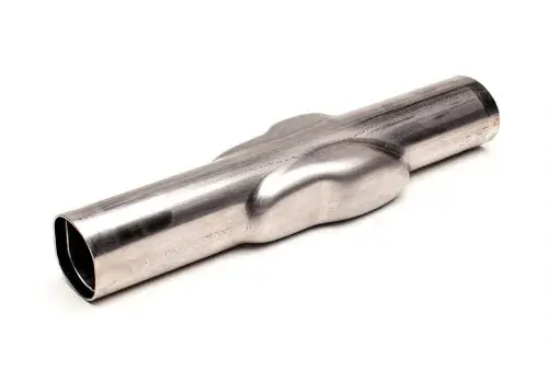
A Bulge Metal Press is a specialized forming machine designed to deform metal tubes or hollow components by applying internal pressure, causing the material to expand outward into a die cavity. This method, known as bulge forming, is primarily used to create complex, seamless shapes in tubular workpieces that would be difficult or inefficient to produce with traditional mechanical or welded fabrication methods.
The bulge metal press typically consists of a hydraulic press system integrated with a high-pressure fluid injection unit, robust clamping mechanisms, and precision form tooling. During operation, a tube is placed inside a die, and its ends are sealed. High-pressure fluid—often water or oil—is pumped into the interior of the tube. As the pressure increases, the tube expands outward and conforms to the shape of the die cavity. The die may have symmetrical or asymmetrical contours, allowing for a wide range of geometries such as T-junctions, bellows, reducers, or elliptical expansions.
These presses are engineered to handle pressure ranges from 200 to over 2,000 bar, depending on the material and complexity of the desired shape. The forming process is carefully controlled through a programmable logic controller (PLC) or human-machine interface (HMI), which regulates the timing, pressure profile, and synchronization with axial feeding (if required). In some applications, axial force is applied simultaneously at the tube ends to support material flow and reduce wall thinning.
Bulge metal presses are used extensively in automotive, aerospace, HVAC, fluid handling, and exhaust system manufacturing, where strength-to-weight ratio, leak-free construction, and part integration are critical. Materials commonly processed include aluminum, stainless steel, titanium, and high-strength steel alloys.
Modern bulge metal presses are often equipped with advanced sensor arrays, servo-hydraulic control, and quick-change tooling systems. These features enhance repeatability, speed up production changeovers, and ensure consistent forming quality. In high-volume production environments, bulge presses are frequently incorporated into automated production cells, complete with robotic loading, unloading, and post-forming inspection systems.
In summary, the bulge metal press is a high-precision, high-pressure forming machine designed for efficient, seamless shaping of tubular metal parts. It combines fluid mechanics and mechanical force to create robust, complex geometries that meet demanding structural and aesthetic requirements across a wide range of industries.
Bulge metal forming machines continue to evolve, integrating higher degrees of automation, digital control, and mechanical refinement. These machines are no longer limited to traditional tube expansions but are being adapted to accommodate varying diameters, wall thicknesses, and asymmetric geometries within a single forming cycle. The development of servo-controlled feeding systems allows precise axial movement during bulging, enabling the material to stretch in a controlled manner and maintain wall thickness uniformity even under complex deformation patterns. The synergy between internal pressure and external axial force is key to producing high-integrity components with minimal defects.
Modern bulge forming machines often operate in tandem with CNC-driven tube handling equipment, including loading arms, alignment fixtures, and rotary stations for repositioning the tube during multi-axis forming. This reduces the need for human intervention and increases repeatability. By using programmable recipes for different parts, manufacturers can switch from one product to another with minimal downtime, which is essential in industries with high part variety and short production runs. Integrated vision systems and laser measurement units are sometimes mounted on these machines to verify dimensional conformity in real time.
Another major advancement lies in the use of adaptive pressure profiles. Rather than applying a single high-pressure spike, the forming process uses a dynamic pressure curve tailored to the flow characteristics of the material. Sensors embedded within the die and the fluid system continuously feed data to a central control unit that adjusts pressure in milliseconds, preventing material rupture, reducing friction against the die, and optimizing the overall strain distribution across the part. This is particularly important when forming high-strength alloys or ultrathin tubing.
Tooling systems used in these machines are increasingly modular and precision-engineered using hardened tool steels or coated materials that resist wear and galling. This not only extends tool life but also improves part surface finish and reduces the need for secondary polishing or machining. Some machines now feature self-aligning or quick-lock die systems that drastically reduce setup times and improve repeatability.
The energy efficiency of bulge metal presses has improved through innovations in hydraulic unit design, such as the use of variable-speed pump drives and regenerative circuits that recycle unused hydraulic energy. These features help reduce operating costs and environmental impact, aligning with broader goals of sustainable manufacturing. Advanced fluid management systems also ensure minimal fluid usage and reduce the frequency of fluid replacement, which contributes to cleaner operations and lower maintenance requirements.
On the software side, the machines are typically controlled by PLC systems that offer user-friendly graphical interfaces. Operators can simulate the entire forming cycle before actual production, making it easier to optimize parameters for different part geometries or materials. Historical data logging and process traceability are built into the system, which is crucial for industries such as automotive and aerospace that demand full accountability of part history and forming conditions.
The versatility of these machines has led to their adoption in non-traditional sectors, including medical device manufacturing, sports equipment production, and even high-end furniture fabrication. Their ability to form complex, seamless shapes from a single tube makes them attractive for creating organic, flowing designs that are both functional and visually appealing.
Overall, the modern bulge metal press represents a synthesis of high-pressure hydraulics, precision mechanics, digital intelligence, and flexible automation. It stands as a critical enabler for producing next-generation metal components that are lighter, stronger, more aerodynamic, and manufactured with greater efficiency and environmental responsibility.
In addition to their technical capabilities, bulge metal forming machines are now being designed with a strong emphasis on process flexibility, allowing users to configure the same press for both hydroforming and traditional mechanical forming tasks. This dual-mode functionality enables manufacturers to meet diverse part requirements without investing in multiple dedicated machines. Some systems offer interchangeable press heads, adjustable sealing units, and modular frame designs that can be quickly adapted to handle tubes of varying lengths, diameters, and materials—all within the same production environment.
Safety and reliability have also become central concerns, especially as operating pressures rise above 2,000 bar in some applications. To address this, modern presses incorporate high-pressure containment systems with reinforced frames, layered safety shields, pressure relief valves, and interlocked safety enclosures. Operators are protected by real-time diagnostics that monitor seal integrity, fluid levels, temperature, and pressure spikes. In some cases, automated emergency stop sequences are triggered by deviation thresholds in load or displacement sensors, ensuring both the operator’s safety and the preservation of the workpiece and machine.
In high-output facilities, bulge forming machines are increasingly linked to Manufacturing Execution Systems (MES) that oversee production performance across entire lines. These systems track each formed component, link it to a specific machine cycle, log forming parameters, and compare them against preset standards for pass/fail verification. As a result, manufacturers gain enhanced traceability, reduced scrap rates, and actionable data for continuous process improvement. Predictive maintenance algorithms based on sensor data can also alert technicians of developing issues—such as hydraulic pressure decay or abnormal thermal patterns—before a breakdown occurs, reducing unplanned downtime.
The growing use of eco-friendly forming fluids is another emerging trend. Where water-glycol or mineral oils were once the norm, many systems now use biodegradable, low-toxicity fluids that are easier to manage and dispose of. These fluids are not only safer for workers and the environment but also help reduce wear on internal seals and plumbing systems. Fluid filtration and recirculation units further extend fluid life and maintain consistent pressure performance, which is critical for quality forming outcomes.
In research and prototyping environments, compact desktop versions of bulge forming machines are gaining popularity. These scaled-down systems, often powered by servo-hydraulic or even electric actuation, are used in universities, design labs, and R&D centers to quickly test forming limits, study new materials, or experiment with unusual geometries before scaling up to full production. The results from these mini-formers often feed directly into digital twins or AI-based simulation models used in concurrent product development.
The strategic role of bulge forming in lightweight design cannot be overstated. With global industries under pressure to reduce emissions, increase fuel efficiency, and cut material use, the ability to form lightweight yet strong hollow components without welding or joining becomes highly valuable. For example, in electric vehicles, bulge-formed aluminum structures are used for battery enclosures, structural cross-members, and crash management systems. Their seamless construction ensures better mechanical integrity and corrosion resistance compared to welded assemblies.
Looking into the near future, the integration of AI-enhanced process control is expected to further elevate the capabilities of bulge forming machines. AI algorithms can monitor forming outcomes in real time, learn optimal pressure/axial feed profiles for specific materials, and even predict material springback or deformation anomalies before they happen. These systems not only improve accuracy but also drastically reduce the trial-and-error phase in process development, making bulge forming more accessible and scalable for a wider range of manufacturers.
In conclusion, bulge metal forming machines have evolved from niche hydraulic presses into advanced, digital-capable systems central to modern tube-based component manufacturing. Their ability to produce seamless, high-precision parts from a wide variety of materials with minimal waste and tooling makes them indispensable in sectors prioritizing structural performance, efficiency, and design flexibility. As industries continue to demand faster, smarter, and more sustainable forming solutions, the bulge press remains at the forefront of innovation in metal shaping technologies.
As the industrial landscape continues to shift toward greater customization and shorter product life cycles, bulge forming machines are being optimized for rapid retooling and flexible production planning. Tooling systems now feature integrated alignment guides, smart clamping systems, and RFID tagging to automatically identify toolsets and load the appropriate forming parameters. This significantly reduces human error during changeovers and enables production facilities to handle low to mid-volume batch manufacturing economically.
In parallel, real-time digital twins are emerging as a transformative feature. These digital replicas of the forming process allow engineers to simulate and visualize stress-strain behavior, pressure distribution, and potential defect zones while the machine operates. This feedback loop allows immediate corrective action—adjusting pressure rates, axial feed speeds, or lubrication parameters—to ensure first-part success. For complex part geometries or new materials, this virtual validation helps reduce scrap, tooling wear, and downtime.
Bulge forming systems are also being adopted in industries with extreme operating environments, such as space, subsea, and defense sectors. In such applications, components often require unique geometries, precise wall thickness control, and performance under fluctuating loads or pressures. Bulge forming can meet these demands while eliminating weld seams, which are common failure points in critical conditions. Machines serving these sectors must meet rigorous standards such as AS9100, MIL-SPEC, and various international pressure vessel codes.
A notable development is the application of multi-chamber forming, where different sections of a single tube are expanded sequentially using multiple pressure stages. This method allows forming of complex parts such as heat exchanger manifolds, multi-port tubing, or transition components in HVAC systems. The process is orchestrated through CNC and servo-hydraulics, allowing full synchronization and repeatable expansion profiles for each chamber within a single cycle.
Environmental sustainability is being enhanced not only through cleaner fluids but also via material-efficient forming strategies. Bulge forming minimizes material wastage compared to subtractive methods, and often enables the use of near-net-shape blanks. Some systems can even re-use tube scrap as feedstock for smaller parts, supported by in-line cutting and secondary forming units, forming part of a closed-loop manufacturing strategy that appeals to circular economy goals.
Human-machine interaction has advanced to the point where operators can control machines via touchscreen tablets or remote consoles, allowing safer operation from outside the immediate press zone. These interfaces include real-time 3D representations of the part being formed, alerts for tool wear, and predictive cycle analytics. Cloud connectivity also enables remote diagnostics, software updates, and performance benchmarking across multiple factory sites or even international facilities.
In high-volume automotive manufacturing, especially for electric and hybrid vehicles, bulge forming is being used to produce high-pressure coolant lines, air suspension components, and structural members with integrated brackets. These parts benefit from reduced weld points, lighter construction, and optimized flow paths. Combined with robotic welding, inspection, and bending cells, bulge presses are forming the backbone of advanced tube-based part production lines.
Meanwhile, the use of non-metallic bulge forming is being explored, particularly for forming fiber-reinforced thermoplastics or composite liners in hydrogen fuel storage tanks. Though metal forming dominates the field, these experimental machines operate on similar principles—using internal pressure and heat to shape advanced polymers into complex profiles—hinting at a broader application scope for bulge forming technology.
In essence, bulge metal forming machines are no longer defined merely by their hydraulic capabilities. They are now smart, interconnected, adaptable manufacturing assets capable of meeting the highest standards in precision, traceability, and material efficiency. As more industries demand innovative solutions for lightweight, strong, and geometrically complex components, bulge forming will remain one of the most strategically important technologies for shaping the future of metal and advanced material fabrication.
Bulge Pressing Machine
A Bulge Pressing Machine is a precision forming system designed to shape hollow metal components—primarily tubes—by applying internal pressure that causes the material to expand outward into a mold or die. This process, commonly known as bulge forming, is widely used to manufacture parts with complex contours, variable diameters, and seamless transitions that are difficult to achieve through conventional fabrication techniques such as welding, stamping, or machining.
The machine typically consists of a high-capacity hydraulic press frame, a pressure intensifier or fluid pump unit, tube end sealing mechanisms, and custom die tooling. During operation, a hollow workpiece is inserted into the die, and both ends are sealed using clamping heads. High-pressure fluid—usually water or oil—is injected into the interior, causing the tube to expand and fill the contours of the die. The amount of expansion and the final geometry depend on factors like material ductility, wall thickness, tube length, and applied pressure, which can exceed 2,000 bar in advanced systems.
Modern bulge pressing machines integrate PLC or CNC control systems for accurate regulation of pressure cycles, axial feeding (if required), and synchronization of multiple forming stages. Some systems feature servo-hydraulic actuation for even finer control and energy efficiency. Tool changeover systems are often quick-locking and modular, allowing the press to be used for a wide variety of parts without significant downtime. For higher productivity, these machines may include automated loading/unloading systems, robot-assisted handling, and in-line dimensional inspection units.
The primary advantages of bulge pressing machines include:
- Seamless construction: Eliminates the need for welds, reducing stress points and improving structural integrity.
- Complex geometries: Enables the creation of branches, expansions, or tapering sections in a single piece.
- Material efficiency: Reduces scrap and allows near-net-shape forming, minimizing secondary operations.
- Repeatability: Ensures consistent part quality through automated pressure and forming control.
These machines are commonly used in industries such as automotive, aerospace, HVAC, furniture, plumbing, defense, and appliance manufacturing, where strong, lightweight, and leak-proof hollow components are essential. Materials processed include stainless steel, aluminum, copper, brass, titanium, and various high-strength alloys.
With ongoing advancements in digital controls, forming simulation, and energy-saving hydraulics, the bulge pressing machine remains a cornerstone of advanced metal tube forming, offering both precision and adaptability for future manufacturing challenges.
Bulge pressing machines continue to advance in both precision and versatility, adapting to the increasing demands of industries that require high-strength, intricately shaped, and seamless tubular components. These machines have evolved beyond basic hydraulic configurations to include digitally integrated systems that allow operators to control and monitor every stage of the forming cycle with high accuracy. The forming process is finely tuned to apply pressure in a controlled gradient, preventing material rupture while achieving uniform wall thickness, even in sections where the tube geometry dramatically changes. This ability to finely modulate pressure during the forming phase enables the production of sophisticated parts that meet tight tolerances and mechanical performance requirements.
The machines are often engineered with robust frames capable of withstanding extremely high forming forces without flexing or misalignment. Precision-ground platens, rigid tie rods, and advanced sealing mechanisms ensure that the process remains consistent over thousands of cycles. The internal pressure system, driven by intensifiers or servo-controlled pumps, delivers fast and responsive pressure builds, which are necessary to maintain productivity in industrial-scale operations. Many systems also support synchronized axial feeding, where the ends of the tube are pushed inward during the forming process to counteract thinning and elongation, resulting in more uniform material distribution.
In terms of tooling, the bulge pressing process relies heavily on precisely machined dies that match the desired part profile. These dies are typically made from hardened tool steels or coated alloys that resist wear and galling during repeated high-pressure cycles. Depending on the part geometry, the dies may be split, sectional, or include internal mandrels to shape features that cannot be formed by pressure alone. The tool changing process is increasingly automated, with clamping, positioning, and verification systems reducing manual labor and minimizing downtime between production runs.
Machine controls have advanced to include touch-based HMI panels, real-time pressure and position feedback, and process diagnostics that not only record the forming cycle but actively adjust it based on material behavior. These adaptive control systems reduce scrap rates and improve consistency, even when working with batches of material that vary slightly in hardness or thickness. Operators can load pre-programmed forming profiles, simulate the expected deformation paths, and verify tool clearances before committing to a production cycle. In high-mix, low-volume environments, this functionality is essential for efficient workflow.
Bulge pressing machines are also seeing increased use in forming non-round profiles, such as rectangular, elliptical, or asymmetrical cross-sections. This is made possible through tailored die designs and precise control of the internal pressure and axial movement, which together allow for accurate material flow into every corner of the cavity. The machines can form not only expanded ends or central bulges but also integrated bends, curves, or reinforcing ribs directly into the tube wall. This eliminates welding and secondary machining, resulting in a stronger, lighter, and more cost-effective part.
Environmental considerations are influencing the design of the fluid systems used in bulge pressing. Water-based emulsions, biodegradable oils, and closed-loop filtration systems are being adopted to reduce waste, improve worker safety, and meet increasingly strict environmental regulations. Energy-efficient motors and pumps further reduce the operational footprint, making the machines more viable in modern lean and green manufacturing facilities.
From a design standpoint, the components produced using bulge pressing machines exhibit excellent surface quality, precise internal volume control, and strong resistance to fatigue and pressure loads. These characteristics make them ideal for applications such as fluid transport lines, exhaust systems, structural chassis components, heat exchangers, and pressure vessels. As automotive and aerospace manufacturers pursue lighter designs without compromising strength, bulge pressing technology provides a critical manufacturing solution that supports these goals.
In research and prototyping environments, scaled-down versions of bulge pressing machines allow engineers to test new materials, experiment with novel geometries, and optimize forming parameters before committing to full-scale production. These smaller systems replicate the core functions of industrial machines and are often used in conjunction with simulation software and digital modeling to accelerate product development. The insights gained from these experimental setups are then transferred directly to larger production units, improving efficiency and reducing the time to market.
Overall, the bulge pressing machine has become a high-precision, high-performance tool that bridges the gap between design freedom and manufacturing feasibility. Its ability to form seamless, complex tubular shapes with high mechanical integrity continues to support innovation across industries where strength, weight, and precision are critical. With ongoing improvements in digital control, energy efficiency, and tooling adaptability, bulge pressing technology is set to remain a core process in advanced metal forming well into the future.
In addition to its core industrial role, the bulge pressing machine is becoming a platform for integrated quality control and predictive maintenance systems. Modern machines often come equipped with embedded sensors that continuously monitor hydraulic pressure, tool wear, fluid temperature, and structural stress in the frame. This real-time data is analyzed using onboard diagnostic software or sent to cloud-based analytics platforms, where trends can be observed across multiple machines and production cycles. These insights allow operators and maintenance teams to anticipate component failures, schedule service intervals intelligently, and minimize unplanned downtime, thereby increasing overall equipment effectiveness (OEE).
Automation is another key area of advancement. In high-throughput environments, bulge pressing machines are increasingly deployed as part of a fully automated cell that includes robotic loading arms, laser tube cutting systems, automated deburring, and dimensional inspection units. Integration with manufacturing execution systems (MES) and enterprise resource planning (ERP) software means that each tube’s production data—including the pressure profile, forming time, and inspection results—is logged and traceable. This level of control and documentation is essential in safety-critical applications, such as those found in aerospace, nuclear energy, or medical device manufacturing.
As manufacturing shifts toward lighter and stronger materials, bulge pressing is also being tailored to handle ultra-high-strength steels (UHSS), aluminum alloys, Inconel, titanium, and even hybrid materials like metal matrix composites. Forming these materials often requires higher pressures and precise deformation control to prevent cracking or springback. This demand has pushed manufacturers to develop presses with even finer regulation of fluid flow, improved heat management systems, and enhanced die coatings that reduce friction and wear during forming.
One important trend is the integration of thermoforming capabilities within bulge pressing machines. In these configurations, the tube is preheated or formed within a heated die to improve ductility, especially when working with advanced alloys or thick-walled tubes. Temperature sensors within the die or toolholder ensure optimal thermal conditions are maintained throughout the cycle. This hybrid process extends the forming limits of traditional cold bulge pressing and allows manufacturers to create shapes that were previously difficult or impossible to produce with cold methods alone.
The bulge pressing technique is also being adapted for additive and hybrid manufacturing strategies. For example, metal tubes formed via bulge pressing may then be post-processed with laser welding, internal surface treatments, or even 3D-printed features to create custom joints or integrated functional elements. This combination of traditional and advanced techniques results in parts with both the structural integrity of formed metals and the complexity of additively manufactured geometries.
Another innovation lies in the use of modular press designs, which enable users to scale up or reconfigure their machine depending on production needs. These presses feature interchangeable forming modules, adjustable stroke lengths, and adaptive clamping systems that can accommodate tubes of various sizes and shapes without requiring a completely new machine. This modularity supports agile manufacturing and rapid product iteration, which are essential in sectors like motorsports, medical devices, and consumer product development.
In terms of operator training and usability, virtual reality (VR) and augmented reality (AR) systems are being employed to provide immersive training simulations and real-time operational overlays. These technologies help reduce the learning curve for new users, improve safety, and allow complex forming cycles to be visualized and adjusted before the machine begins actual production. They also support remote troubleshooting, where experts can guide on-site operators through setup, diagnostics, or adjustments using AR headsets or tablets.
In summary, the bulge pressing machine has grown from a basic forming press into an advanced, smart, and adaptive manufacturing system. It continues to evolve in step with broader trends in industrial automation, digitalization, and sustainable manufacturing. Its ability to create strong, complex, and seamless metal parts makes it indispensable across a wide range of applications, and its future potential will only expand as new materials, processes, and production philosophies emerge.
Beyond conventional manufacturing domains, bulge pressing technology is making inroads into sectors demanding ultra-clean, precision-formed tubular components such as pharmaceutical, semiconductor, and food-grade processing equipment. In these industries, the ability to form tubes without seams, welds, or inconsistent surface finishes is not only advantageous—it is often a regulatory requirement. Bulge pressing machines, with their capability to form intricate geometries from a single tube segment, help eliminate potential contamination points and reduce the need for internal polishing or post-fabrication cleaning.
The use of mirror-finish internal mandrels or die coatings during the forming process ensures high-grade interior surface quality, which is critical when tubes are used for transporting reactive gases, sterile fluids, or abrasive slurries. Furthermore, non-destructive testing (NDT) equipment such as eddy current or ultrasonic probes can be integrated into the forming cell to immediately check each part for microcracks, thinning, or inclusions, ensuring product integrity without slowing down production.
In advanced automotive applications, such as electric vehicles (EVs) and hydrogen fuel systems, bulge pressing enables the creation of lightweight, structurally efficient tubing systems for battery cooling, brake lines, crash energy absorption members, and pressurized hydrogen tanks. These applications often require custom cross-sections, variable wall thicknesses, or integrated mounting features—elements that bulge forming excels at producing in a single, repeatable operation. The inherent strength and smooth flow paths of bulge-formed parts contribute to lower fluid resistance, better thermal management, and increased crash safety.
In architectural and artistic fabrication, bulge pressing is increasingly used to create visually striking, organically curved hollow forms from stainless steel, bronze, or aluminum tubing. Designers take advantage of the process’s ability to produce smooth, compound curves and transitions without distortion or welds. These elements are then used in sculptures, furniture frames, façade supports, or lighting installations that require both beauty and strength.
As global standards and certifications for formed components become more stringent, bulge pressing machines are being built with compliance in mind. Machines often support documentation and validation according to ISO 9001, IATF 16949, AS9100, and other quality systems. Forming cycles are recorded in tamper-proof logs that track each part’s exact parameters, including temperature, pressure, cycle time, tool ID, and operator credentials. This traceability is critical in sectors like aerospace, defense, and medical manufacturing, where failure is not an option.
Environmental sustainability is also reshaping the development of bulge forming systems. Traditional hydroforming and bulge forming use significant volumes of fluid under high pressure, which has historically raised concerns about leaks, waste, and energy usage. Today’s machines feature closed-loop hydraulic and filtration systems, energy recovery modules, and electro-hydraulic hybrid drives that minimize consumption without compromising performance. Additionally, water-based forming fluids with biodegradable additives are replacing conventional mineral oils, aligning with global environmental directives and corporate sustainability goals.
From a research perspective, universities and industrial R&D labs are employing advanced bulge forming setups to explore material behavior under extreme forming conditions. Using high-speed cameras, digital image correlation (DIC), and forming limit diagrams (FLDs), they study how various alloys respond to internal pressure and strain paths. These insights feed directly into the development of formable high-strength alloys, optimization of forming dies, and the reduction of trial-and-error in industrial settings.
Looking ahead, we are likely to see more intelligent automation in bulge pressing, with real-time AI-driven systems adjusting parameters mid-process based on sensor feedback, material feedback loops, and historical data. This “smart forming” approach ensures higher consistency and allows for adaptive batch manufacturing, where different part geometries can be formed in quick succession with minimal setup time—ideal for just-in-time and small-batch production models.
In conclusion, bulge pressing continues to evolve far beyond its original scope. Its unique ability to form seamless, strong, and intricately shaped tubular components makes it a powerful solution across a growing range of technical and creative industries. As control systems, materials science, and manufacturing philosophies advance, bulge forming will remain a key enabler of next-generation engineering, design, and sustainability.
Bulge Forming Hydraulic Machine
A Bulge Forming Hydraulic Machine is a specialized hydraulic press designed to perform bulge forming, a metal forming process where a tube or hollow cylindrical workpiece is expanded outward by internal hydraulic pressure while being supported by a die or tooling. This machine precisely controls hydraulic pressure and axial forces to shape metal tubes into complex, seamless geometries with variable wall thicknesses, commonly used in automotive, aerospace, and industrial applications.
Key Features of a Bulge Forming Hydraulic Machine:
- Hydraulic Pressure System: Utilizes a high-pressure hydraulic pump or intensifier to generate controlled internal pressure inside the tube. This pressure causes the tube to expand against a die, forming the desired shape.
- Axial Feeding Mechanism: Applies controlled axial compression or feeding forces at the tube ends during bulging. This compensates for tube elongation and prevents wall thinning or cracking.
- Rigid Frame and Tooling Support: Built with a heavy-duty, stiff frame to withstand the forces during bulging, ensuring minimal deflection and high precision. Tooling consists of dies and mandrels shaped to the desired final geometry.
- Control System: Advanced CNC or PLC controls manage pressure build-up, axial feed rate, cycle timing, and safety interlocks. Modern systems may include touchscreens and real-time monitoring.
- Pressure and Displacement Sensors: Embedded sensors monitor hydraulic pressure and tube deformation to ensure process accuracy and quality.
- Safety Systems: Hydraulic overload protection, emergency stops, and guarding to protect operators during high-pressure forming.
Typical Applications:
- Forming automotive structural components such as control arms, chassis parts, and suspension elements.
- Manufacturing aerospace tubing with complex cross-sections and reinforcing ribs.
- Producing pressure vessels, pipes with variable diameters, and fluid delivery components.
- Creating artistic or architectural hollow metal shapes with smooth, seamless surfaces.
Advantages:
- Ability to produce complex shapes without welding or joining.
- Improved strength and structural integrity due to seamless forming.
- High dimensional accuracy and repeatability.
- Efficient material usage with controlled wall thickness distribution.
Summary:
Bulge forming hydraulic machines combine high-pressure hydraulic technology with precise mechanical control to enable seamless, complex tube shaping. Their robustness, precision, and adaptability make them essential in industries requiring strong, lightweight, and intricately formed tubular metal parts.
Bulge forming hydraulic machines operate by introducing high-pressure hydraulic fluid into a sealed metal tube, causing the tube’s walls to expand outward against a matched die or mold. The key to success in this process is the precise coordination between internal pressure and axial feeding forces applied at the ends of the tube. Axial feeding controls tube elongation and prevents excessive thinning or rupture, ensuring uniform wall thickness and structural integrity in the formed part. The hydraulic system typically includes a high-pressure pump or intensifier capable of generating pressures ranging from several hundred to several thousand bars, depending on the material and complexity of the component.
The machine’s frame must be extremely rigid to resist the intense forces generated during bulging. Constructed from heavy-duty steel, the frame minimizes deformation and vibration, which are critical to achieving high dimensional accuracy and repeatable forming cycles. Tooling is custom-designed for each application and often consists of a split die that can open and close around the tube, internal mandrels to support the tube from the inside if needed, and sealing systems to contain the hydraulic fluid. Tooling materials must be wear-resistant and capable of withstanding repeated cycles under high pressure and mechanical stress.
Control systems in modern bulge forming hydraulic machines have evolved significantly, incorporating programmable logic controllers (PLC) or CNC technology that automate the forming cycle, including pressure ramp-up, dwell time, axial feed rate, and pressure release. Real-time sensors continuously monitor key parameters like internal fluid pressure, axial displacement, and temperature. Data collected can be used to adjust process variables on the fly, improving yield and reducing scrap rates. Advanced models also feature human-machine interfaces (HMI) that allow operators to set parameters, track cycle progress, and diagnose faults easily.
Safety is paramount given the high pressures involved. Machines are equipped with multiple safety interlocks, pressure relief valves, and emergency stop functions. Enclosures or guarding protect operators from accidental exposure to hydraulic fluid or flying debris. Maintenance of hydraulic components such as pumps, valves, seals, and fluid cleanliness is crucial to prevent leaks, contamination, and premature failure.
Bulge forming hydraulic machines are versatile and can process a wide range of metals including steel, stainless steel, aluminum, titanium, and specialized alloys. The ability to form seamless parts with variable wall thicknesses and complex shapes makes the process highly attractive for industries seeking weight reduction without sacrificing strength, such as automotive and aerospace manufacturing. In recent years, integration with Industry 4.0 technologies has enabled predictive maintenance, remote monitoring, and process optimization, further enhancing productivity and part quality.
Environmental considerations are also influencing machine design. Hydraulic fluid recycling systems, energy-efficient drives, and closed-loop filtration reduce waste and minimize environmental impact. Some manufacturers are exploring electro-hydraulic hybrid systems that combine electric servo drives with hydraulics to improve energy efficiency and control precision.
Overall, bulge forming hydraulic machines embody a sophisticated blend of mechanical engineering, fluid power technology, and automation to deliver precise, strong, and complex tubular components. Their continued development reflects the growing demand for advanced manufacturing techniques that produce high-performance parts with minimal material waste and high reliability.
Advancements in bulge forming hydraulic machines are increasingly focused on enhancing automation and process intelligence. Integration with sensors such as strain gauges, pressure transducers, and laser displacement meters allows for in-process measurement of deformation, wall thickness, and material behavior. These sensors feed data into machine learning algorithms and adaptive control systems, enabling real-time adjustments to pressure and feed rates. This closed-loop control improves part consistency and reduces trial-and-error setups, which historically have been time-consuming and costly.
The design of tooling is also evolving with the use of advanced materials and manufacturing methods. Tool inserts made from carbide, ceramics, or coated with diamond-like carbon (DLC) offer improved wear resistance and reduced friction. Additive manufacturing (3D printing) enables rapid prototyping of complex tooling geometries that optimize material flow and reduce stress concentrations during forming. This flexibility accelerates design cycles and enables more intricate component shapes.
Hybrid bulge forming techniques are emerging, combining hydraulic expansion with supplemental mechanical or thermal forming processes. For example, preheating the tube or applying localized heating during forming increases ductility, allowing the machine to shape ultra-high-strength alloys or titanium alloys that are otherwise challenging to form at room temperature. Simultaneously, mechanical axial compression or bending tools can be integrated to produce multi-axis deformations, expanding the range of achievable geometries beyond simple radial expansion.
In terms of scalability, bulge forming hydraulic machines are available in various sizes, from small bench-top units used for prototyping and research to large industrial presses capable of handling thick-walled tubes several meters in length. Modular machine architectures enable manufacturers to customize stroke length, pressure capacity, and tooling interfaces according to specific production requirements. This modularity also facilitates easier maintenance and upgrade paths as technology advances.
Energy efficiency is becoming a priority in modern bulge forming systems. Innovations include regenerative hydraulic circuits that capture and reuse energy during the pressure release phase, variable displacement pumps that adjust flow based on demand, and the use of servo-hydraulic drives which combine the precision of electric servo motors with the power density of hydraulics. These improvements reduce operating costs and environmental footprint.
Safety and ergonomics remain integral to machine design. User-friendly interfaces, remote monitoring capabilities, and collaborative robotics assist operators in tool setup, loading, and unloading. Remote diagnostics and firmware updates help minimize downtime and ensure machines operate within safe parameters.
Applications of bulge forming hydraulic machines continue to expand into emerging industries. In medical device manufacturing, they enable the creation of seamless stents, catheters, and implantable tubes with tight tolerances and biocompatible surfaces. In renewable energy, these machines form components like heat exchanger tubes and structural supports for wind turbines. Even in consumer electronics, miniature bulge forming presses are used to shape delicate components from thin metal tubing.
Overall, the bulge forming hydraulic machine represents a mature yet continuously evolving technology that meets the demands of modern manufacturing for precision, efficiency, and flexibility. Its ability to produce high-quality, seamless tubular parts with complex geometries positions it as a vital tool across diverse industrial sectors, with ongoing innovations driving further enhancements in performance and sustainability.
Another significant development in bulge forming hydraulic machines is the incorporation of digital twins—virtual replicas of the physical machine and forming process that simulate behavior in real time. By combining sensor data, material properties, and process parameters within a digital twin, manufacturers can predict potential defects, optimize cycle times, and fine-tune forming conditions before running actual production. This reduces scrap rates and accelerates ramp-up for new parts.
Material science advances also influence bulge forming capabilities. New high-strength, lightweight alloys with improved formability enable thinner wall sections and more complex shapes without compromising strength. The hydraulic machines must adapt by offering higher pressures and more precise control to handle these advanced materials safely. Additionally, the development of smart coatings and surface treatments for tubes enhances lubrication and reduces friction during forming, extending tooling life.
Additive manufacturing not only supports tooling production but also facilitates custom fixture design and quick-change systems. These enable faster setup times and increased flexibility, critical for manufacturers shifting toward smaller batch sizes and greater product variety.
Collaborative robotics (cobots) are beginning to integrate with bulge forming cells, assisting operators with loading, unloading, and tool changes. This enhances safety, reduces fatigue, and boosts productivity without the need for full automation. In high-volume settings, fully automated robotic cells combine bulge forming machines with in-line inspection and part handling for seamless production flow.
Data analytics derived from machine operations, combined with predictive maintenance algorithms, help reduce unplanned downtime. Sensors monitor hydraulic oil quality, pump performance, and machine vibrations, alerting maintenance teams to issues before failures occur. This proactive approach extends machine life and optimizes production schedules.
Environmentally, bulge forming hydraulic machines are evolving toward greener operation through fluid recycling systems, biodegradable hydraulic oils, and energy recovery technologies. Some manufacturers explore replacing traditional hydraulic systems with electro-hydraulic or fully electric servo presses to further cut energy use and emissions.
In summary, bulge forming hydraulic machines continue to integrate cutting-edge technologies across mechanical design, control systems, materials science, and automation. This convergence fosters greater precision, efficiency, sustainability, and adaptability—qualities essential for modern manufacturing challenges. As industries demand ever more complex tubular components with stringent quality requirements, these machines remain at the forefront of seamless metal forming innovation.
Bulge Press Tool
A Bulge Press Tool is a specialized tooling component used in bulge forming processes to shape hollow metal tubes or cylinders by expanding them radially through internal hydraulic pressure. The tool is critical in defining the final geometry, surface finish, and dimensional accuracy of the bulged part.
Components and Features of a Bulge Press Tool:
- Die or Mold: The main part of the tooling that provides the external shape against which the tube is expanded. Dies are precisely machined to the desired final contour and are often split or hinged to allow easy loading and unloading of the tube.
- Mandrel or Internal Support: In some applications, an internal mandrel supports the tube from inside, preventing collapse and controlling internal diameters during forming. Mandrels are especially important when tight tolerances or complex internal features are required.
- Sealing Systems: Seals ensure the hydraulic fluid stays contained within the tube during pressure application, preventing leaks and maintaining consistent pressure. These may include O-rings, lip seals, or custom sealing mechanisms.
- Clamping Mechanism: To hold the tube securely in place during forming, the tool includes clamps or fixtures that prevent movement or slippage as pressure and axial forces are applied.
- Material and Surface Treatment: Tooling materials are typically hardened steels, sometimes coated or treated (e.g., nitriding, DLC coating) to resist wear, corrosion, and galling due to repeated high-pressure contact with the workpiece and hydraulic fluid.
- Cooling Channels (optional): Some bulge press tools incorporate internal cooling passages to manage heat generated during forming, maintaining tool integrity and prolonging service life.
Function:
During the bulge forming cycle, the tube is positioned inside the bulge press tool. Hydraulic fluid pressure inside the tube causes it to expand outward, pressing against the die to take on its shape. Simultaneously, axial forces may be applied to the tube ends to control elongation and wall thickness distribution. The tool ensures precise shaping while supporting the workpiece to avoid defects like wrinkling, cracking, or thinning.
Applications:
- Manufacturing automotive structural components with complex curved profiles.
- Forming aerospace tubing with varying cross-sections.
- Producing pressure vessels, pipes, and fittings with seamless joints.
- Creating decorative or architectural tubular shapes.
Summary:
The bulge press tool is an essential element in the bulge forming process, carefully engineered to withstand high pressure and mechanical loads while delivering precise, repeatable shaping of hollow metal parts. Its design, materials, and integration with the bulge forming machine directly impact product quality and process efficiency.
Bulge press tools are custom-designed for each specific application, taking into account the material properties of the tube, the desired final shape, and the forming parameters such as pressure and axial feed. The tool design process often involves computer-aided design (CAD) and finite element analysis (FEA) to predict metal flow, stress distribution, and potential failure points. This ensures the tooling can handle the required forces without deforming or failing prematurely.
The interface between the tool and the bulging tube is critical; surface finish and lubrication reduce friction and wear, preventing damage to both the tool and the workpiece. Toolmakers may apply specialized coatings or surface treatments to extend tool life and maintain consistent part quality over many production cycles. Additionally, the tool must be designed to facilitate quick loading and unloading to minimize machine downtime, which is especially important in high-volume manufacturing.
Because bulge forming often involves high internal pressures and precise dimensional control, tool alignment and clamping systems are engineered to maintain tight tolerances during the entire forming cycle. Misalignment can lead to defects such as uneven wall thickness, wrinkles, or even rupture. Therefore, robust guiding systems, such as pins, bushings, or hydraulic clamps, are integrated into the tooling to keep the tube perfectly positioned.
Maintenance of bulge press tools includes regular inspection for wear, cracks, or damage caused by repeated high-pressure cycles. Worn tools can cause poor part quality and increase scrap rates, so preventive maintenance schedules are critical. Some advanced tooling designs incorporate modular inserts that can be replaced individually, reducing overall tooling replacement costs.
In complex bulge forming setups, the tooling may include multiple components working together—such as secondary dies for shaping ends, internal mandrels for support, or specialized seals to handle high pressures with minimal leakage. These integrated tool assemblies require careful coordination with the hydraulic press controls to synchronize pressure application and axial movement.
Overall, the effectiveness and durability of bulge press tools directly influence the efficiency, quality, and cost-effectiveness of the bulge forming process. Continuous improvements in tooling materials, coatings, design software, and manufacturing techniques contribute to enhanced performance and expanded capabilities in forming more complex and high-strength tubular components.
Modern bulge press tools increasingly incorporate smart technologies to enhance monitoring and control during the forming process. Embedded sensors within the tooling can measure parameters such as pressure distribution, temperature, and strain in real time. This data is transmitted to the press’s control system, enabling adaptive adjustments that improve forming accuracy and reduce defects.
Additive manufacturing (3D printing) has started to revolutionize bulge press tool production by enabling complex internal geometries that improve fluid flow and cooling channels, which were previously impossible or costly to machine. This allows for better thermal management, reducing tool wear and extending tool life. Rapid prototyping also shortens development cycles, letting manufacturers quickly test and refine tooling designs before committing to full-scale production.
Another trend is modular tooling systems that allow quick swapping of different die inserts or sealing components, reducing downtime during product changeovers. This flexibility supports just-in-time manufacturing and smaller batch sizes, which are becoming more common in industries like automotive and aerospace where customization is increasingly important.
Tool materials continue to evolve, with high-performance alloys and advanced coatings improving resistance to abrasive wear, galling, and corrosion caused by hydraulic fluids. Some manufacturers also experiment with surface texturing techniques to optimize friction characteristics between the tool and workpiece, further enhancing formability and finish quality.
Maintenance strategies for bulge press tools now often include predictive analytics based on usage data collected during operation. This approach helps schedule tool refurbishments or replacements proactively, preventing unexpected failures that could halt production lines.
Overall, the combination of advanced materials, smart sensors, additive manufacturing, and modular designs is driving significant improvements in bulge press tooling. These advances not only improve the quality and complexity of formed parts but also increase the productivity and sustainability of the bulge forming process, making it a vital technology for modern metal forming applications.
In addition to these technological enhancements, collaboration between tool designers, material scientists, and machine manufacturers is becoming increasingly important to optimize bulge press tool performance. This interdisciplinary approach ensures that tooling is perfectly matched to both the hydraulic press capabilities and the specific material behavior of the tubes being formed, resulting in higher precision and fewer defects.
The integration of advanced simulation tools allows engineers to virtually test different tool geometries, materials, and process parameters before physical production. This reduces costly trial runs and shortens development time, making it easier to bring new products to market faster.
Ergonomics and operator safety are also factored into tool design. Features such as quick-release mechanisms, lightweight modular components, and automated tool handling systems help minimize manual labor and reduce the risk of injury during setup and maintenance.
In specialized applications, bulge press tools may be designed to enable multi-stage forming, where different sections of a tube are sequentially expanded or shaped to create complex profiles and functional features like flanges, beads, or ribs. This capability expands the range of parts that can be produced using bulge forming, making it a versatile choice for industries requiring customized tubular components.
Environmental considerations are influencing tool design as well. For instance, toolmakers are selecting materials and coatings that minimize the need for hazardous lubricants and enable easier recycling or refurbishment of tooling components.
Looking forward, continued advancements in digital manufacturing, such as augmented reality (AR) for tool setup assistance and artificial intelligence (AI) for process optimization, promise to further improve the efficiency and flexibility of bulge press tooling. These innovations will help manufacturers meet the increasing demand for lightweight, high-strength tubular parts across automotive, aerospace, medical, and energy sectors while controlling costs and environmental impact.
Metal Bulge Press
A Metal Bulge Press is a specialized forming machine used to expand hollow metal tubes or shells into a desired shape by applying internal pressure—usually hydraulic—causing the metal to bulge outward against a die or mold. This method is particularly effective for creating seamless, complex, or asymmetrical geometries in hollow components while maintaining structural integrity and surface quality.
The operation begins by placing a metal tube or shell into a die cavity. The ends are sealed, and hydraulic fluid is introduced inside the component. As internal pressure builds up, the metal expands uniformly, taking the exact shape of the die. Simultaneously, axial forces can be applied from one or both ends to control the wall thickness and prevent thinning or wrinkling.
Metal bulge presses are built to withstand extremely high internal pressures, often exceeding 1000 bar (14,500 psi) depending on the material and component geometry. The press frame must be rigid, the hydraulic system precisely controlled, and the tooling robust and tightly sealed. The machine’s stroke length, tonnage capacity, and control accuracy all directly influence its forming capabilities.
These presses are widely used in industries like automotive (to manufacture exhaust components, subframes, and suspension parts), aerospace (for lightweight ducting and structural elements), plumbing (for T-joints and fittings), and even decorative applications (such as metal lamp housings or artistic tubes).
Advancements in metal bulge press design include CNC-controlled hydraulic systems for better pressure ramping and timing, servo-hydraulic actuators for more efficient and energy-conscious operations, and real-time process monitoring systems that ensure each bulge operation stays within strict quality parameters. These presses can be integrated into fully automated production lines, equipped with robotic loading/unloading, part tracking systems, and in-line inspection for high-volume manufacturing.
Ultimately, a metal bulge press provides a powerful, reliable, and highly accurate solution for shaping hollow metal parts without seams, welding, or complex machining, ensuring strength and uniformity throughout the component.
Metal bulge presses are valued not only for their ability to produce seamless parts but also for their material efficiency. Unlike traditional stamping or machining, bulge forming minimizes scrap, as the material is plastically deformed into shape rather than removed. This is particularly advantageous when working with expensive metals like stainless steel, titanium, or nickel alloys, where waste reduction translates directly into cost savings.
The forming process relies heavily on precise control of pressure, temperature (if warm or hot bulge forming is used), and material flow. Variations in any of these parameters can cause defects such as tearing, thinning, or wrinkling. Therefore, modern metal bulge presses are often equipped with sophisticated control units that allow operators to program complex pressure and force curves, synchronize axial feeding with internal pressurization, and apply adaptive control logic based on real-time feedback from sensors.
Tooling for metal bulge presses must match the durability and precision of the machine itself. Dies are typically made from hardened tool steels, sometimes coated to resist corrosion and wear from repeated contact with hydraulic fluid and metal surfaces. Sealing elements are equally critical—they must contain extremely high pressures without failure and allow for repeated cycling under harsh conditions. The sealing system design also influences cycle time and ease of maintenance, both of which are crucial in production environments.
The flexibility of metal bulge forming makes it suitable for a wide range of part geometries. While simple cylindrical bulges are common, advanced die designs can create ovals, squares, ribs, asymmetrical contours, and even multiple bulges in a single forming operation. This eliminates secondary operations like welding, machining, or assembly, which not only cuts production time but also improves part consistency and performance.
In manufacturing systems where rapid changeover is required, some metal bulge presses are designed with modular tool mounts and quick-connect hydraulic fittings, allowing for tool swaps in a matter of minutes. This supports lean production models and enables manufacturers to respond quickly to changing product requirements or customer demands.
Sustainability is another focus area. Recent designs aim to reduce the environmental impact of bulge forming by incorporating energy-efficient hydraulic systems, closed-loop fluid management, and quieter, less heat-intensive components. Replacing conventional hydraulics with servo-driven units further improves control precision and reduces energy consumption during idle or low-load periods.
Overall, the metal bulge press remains a critical tool in industries that require strong, lightweight, and geometrically complex hollow components. Its combination of forming power, dimensional accuracy, and compatibility with automation makes it a go-to solution for modern tube and shell forming operations.
As industry demands continue to evolve toward lightweight design and complex geometries, the metal bulge press is increasingly integrated into high-performance production environments. Manufacturers are now incorporating inline quality inspection systems using laser scanners or vision cameras directly after the forming stage. These systems verify that each part conforms to geometric and dimensional tolerances without the need for manual inspection, enabling zero-defect manufacturing and real-time process validation.
Advanced software is also being used to simulate bulge forming operations before any physical tooling is made. Finite element analysis (FEA) models predict metal flow, wall thickness distribution, and stress points during forming. This allows engineers to refine the die design and forming sequence digitally, reducing development time and tooling costs while avoiding trial-and-error runs. Once the optimal design is confirmed, digital tool paths and pressure profiles can be uploaded directly to the press’s CNC controller, creating a smooth transition from design to production.
For operations involving exotic or high-strength metals, such as titanium or Inconel, metal bulge presses are sometimes paired with heating systems. Warm or hot bulge forming reduces the required pressure by softening the material, improving formability and reducing the risk of cracking. These presses are often fitted with insulated dies, heated platens, or even induction coils, depending on the forming temperature required.
In terms of automation, robotic integration allows for seamless material handling—loading raw tubes, positioning them in the die, and transferring formed parts to downstream operations like trimming, welding, or assembly. Coordinated robotic arms and press timing improve cycle efficiency and reduce the need for human intervention, making the entire process safer and more consistent.
Presses can also be part of a larger networked production environment, where machine data such as cycle times, pressure logs, temperature records, and part counts are continuously fed to central monitoring systems. These digital twins of the physical press can be used for predictive maintenance, production planning, and process optimization.
In sectors like automotive, the ability of a metal bulge press to produce strong, lightweight, hollow components with minimal joins or welds supports crashworthiness and fuel efficiency goals. In aerospace, the same advantages support weight reduction without compromising structural integrity. In industrial applications, the simplicity and repeatability of the process make it ideal for forming pressure vessels, plumbing connectors, and architectural metalwork.
The versatility, scalability, and precision of metal bulge presses make them an essential technology in the future of advanced metal forming. As material science, digital control, and forming techniques continue to improve, these machines will remain central to manufacturing strategies that prioritize strength, efficiency, and innovative design.
Looking ahead, developments in digital manufacturing are poised to take metal bulge press technology even further. With the increasing adoption of Industry 4.0 principles, presses are becoming smarter and more autonomous. Real-time analytics, combined with artificial intelligence and machine learning, are enabling predictive process control. These systems learn from historical data to adjust forming pressures, timing, and feed rates dynamically, compensating for variations in material batches or environmental conditions—minimizing defects and maximizing throughput without operator input.
In addition to AI-enhanced control, augmented reality (AR) and virtual reality (VR) tools are being introduced for operator training and maintenance. Through AR glasses or tablet overlays, technicians can receive real-time visual instructions for tool setup, alignment, diagnostics, or part changeover, dramatically reducing training time and preventing costly setup errors.
Hybrid forming systems that combine bulge pressing with other processes—like stretch forming, spinning, or even additive manufacturing—are also in development. These setups expand the capability of bulge presses to form parts that would otherwise require multiple machines and steps. Such hybrid approaches enable the formation of highly customized components with integrated features, such as reinforced ribs or fluid channels, directly in a single operation.
As more manufacturers pursue sustainable practices, bulge press systems are being designed to operate with biodegradable hydraulic fluids, incorporate regenerative energy systems to recycle braking energy from moving parts, and optimize fluid use through recirculation and filtration technologies. These advancements reduce both operational costs and environmental impact, aligning with stricter global regulations and customer expectations for green manufacturing.
There is also a growing emphasis on flexibility and scalability. Newer press models are built with modular frames and adjustable stroke lengths, tonnage ranges, and tooling zones, allowing a single press to handle a wide variety of part sizes and shapes. This is particularly valuable for smaller manufacturers or job shops that need to switch between product types quickly while maintaining tight tolerances and production standards.
The future of metal bulge pressing is firmly linked to high-mix, low-volume production environments as well. With increasing demand for custom products—especially in sectors like motorsports, aerospace, and luxury goods—presses must offer fast tooling changes, easy reprogramming, and adaptability to exotic materials. This trend is encouraging further miniaturization and specialization in press designs, including compact benchtop bulge presses for R&D and prototyping purposes.
In essence, the metal bulge press continues to evolve from a high-force forming machine into a digitally integrated, adaptive, and sustainable manufacturing platform. It is not just a piece of equipment but a vital link in the broader ecosystem of modern metal forming—where efficiency, intelligence, and innovation define competitive advantage.
Bulge Forming Hydraulic Press
A Bulge Forming Hydraulic Press is a precision metal forming machine designed to shape hollow or tubular components by applying high internal hydraulic pressure. This process causes the metal to expand outward, or “bulge,” into a die cavity, taking on the desired external geometry without the need for seams, welding, or multiple forming stages. It is widely used to manufacture parts that require a seamless and complex shape with high structural integrity.
The key components of a bulge forming hydraulic press include a heavy-duty frame, a hydraulic system capable of generating very high pressure (often exceeding 1000 bar), a die set that defines the final shape of the part, and a programmable control system. During operation, the metal tube is sealed at both ends and placed into the die. The hydraulic fluid is then injected into the interior of the tube while axial compression or end feeding may also be applied to assist material flow and control wall thickness. The metal plastically deforms outward against the die, forming the required geometry.
This press type is favored for producing parts like automotive exhaust manifolds, structural subframes, aerospace ducting, plumbing T-joints, and even decorative tubular components. Its advantages include minimal material waste, high repeatability, and the ability to create smooth, curved forms that would be difficult or impossible using traditional stamping or machining techniques.
Modern bulge forming hydraulic presses feature closed-loop control systems that allow for precise management of pressure and feed rate, ensuring optimal forming conditions and reducing the risk of tearing or thinning. They may also include automated loading systems, quick-change tooling, and data integration features to support Industry 4.0 applications. With growing demand for lightweight and high-performance components, these presses continue to be a cornerstone of advanced manufacturing in transportation, energy, and industrial sectors.
Bulge forming hydraulic presses operate by converting hydraulic energy into mechanical deformation, which is particularly well-suited for shaping ductile metals such as stainless steel, aluminum, copper, and titanium alloys. The hydraulic system typically includes a high-pressure pump, control valves, accumulators, and precision cylinders that work in tandem to deliver fluid at controlled pressures into the interior of the metal workpiece. Depending on the application, the process may be cold, warm, or hot formed. Cold forming is common for softer metals or simpler geometries, while warm and hot forming are used for more challenging materials or to reduce the required pressure.
The setup and tooling of a bulge forming press are crucial. Dies are engineered with tight tolerances to define complex external profiles, and sealing systems are designed to withstand repeated high-pressure cycles without leakage. These seals may be mechanical, elastomeric, or a combination, and must be precisely aligned to prevent premature wear or part failure. The tube is held in place with a clamping system that resists movement as pressure builds, ensuring that the part forms accurately and safely.
Control systems play a major role in modern bulge forming presses. Programmable logic controllers (PLCs) or CNC systems allow the operator to input pressure profiles, stroke timings, and feeding sequences. These controls help tailor the forming parameters to each specific part, making it easier to switch between different components and materials. Sensor feedback, such as pressure, temperature, and displacement data, ensures that the forming process remains consistent and enables closed-loop corrections in real time.
Cycle times vary based on part complexity and forming requirements, but presses are often designed for high-throughput environments. To further enhance productivity, automation systems such as robotic part loaders, unloading conveyors, and integrated inspection cameras can be added. This not only improves efficiency but also supports quality assurance by detecting defects early in the process.
One key benefit of bulge forming is that it allows for smooth internal and external surfaces without welding or joining, which is essential in applications requiring cleanliness, flow dynamics, or structural reliability. This makes it ideal for components like fluid conduits, intake manifolds, and heat exchanger housings. Additionally, by forming in a single operation, manufacturers reduce secondary processing, minimize handling, and lower production costs.
Bulge forming hydraulic presses are also designed with operator safety in mind. They typically feature safety curtains, interlocked guards, pressure relief systems, and emergency stop functions. Maintenance is streamlined through modular hydraulic components and easy-access service panels, while diagnostic software can alert technicians to potential issues before they cause downtime.
As industries push toward stronger yet lighter components, particularly in electric vehicles, aerospace, and renewable energy systems, bulge forming presses offer a balance of performance, precision, and adaptability. Their ability to form complex hollow parts with high repeatability ensures they remain a vital tool in modern metalworking operations.
With the growing complexity of part geometries and the need for improved mechanical properties, bulge forming hydraulic presses are increasingly optimized with multistage forming capabilities. This means a single press cycle can include multiple pressure and feeding stages, allowing the operator to create parts with varying diameters, asymmetrical features, or stepped contours—all in one setup. This not only increases the range of parts that can be produced but also enhances part strength by controlling material strain distribution more precisely.
In high-performance applications—such as aerospace, defense, and advanced automotive systems—presses are often customized with force-feedback sensors and high-resolution displacement monitoring. These enable real-time mapping of the part’s expansion profile during the press stroke. If the tube begins to thin unevenly or expand irregularly, the press can self-correct, adjusting axial feed or pressure instantly. This dynamic forming capability ensures optimal wall thickness and material flow, which is essential for critical components that must withstand high pressures or fatigue loads.
Energy efficiency is another area of advancement. Many modern presses now use servo-hydraulic systems in place of traditional fixed-displacement pumps. These variable-speed drives only consume energy during active motion, drastically reducing idle-time power consumption. In addition, regenerative hydraulic circuits capture excess fluid energy during decompression phases and feed it back into the system, improving overall system efficiency by 20% or more.
The digitalization of forming data is also revolutionizing quality control. Each formed part can be tagged with its forming parameters—such as peak pressure, stroke rate, and material batch—making it traceable through the entire supply chain. This is especially valuable in industries with strict compliance requirements (e.g., aerospace AS9100 or automotive IATF 16949), where documentation of every forming cycle is essential.
Furthermore, the growing use of composite and hybrid metal tubes (e.g., aluminum-steel laminates or metal-plastic-metal sandwiches) has led to the development of presses with adaptive forming logic. These presses can adjust parameters mid-cycle based on the different deformation behaviors of each layer, allowing lightweight multi-material parts to be formed without delamination or cracking.
Tooling flexibility has also evolved. Quick-change die systems now use hydraulic or magnetic clamping that reduces tool change time from hours to minutes. This is particularly beneficial in just-in-time manufacturing settings, where press utilization rates and short run responsiveness are key.
In terms of infrastructure, presses can be installed as standalone units or integrated into automated production lines with coordinated PLCs and MES (Manufacturing Execution Systems). In the latter case, the bulge forming press is one node in a continuous flow—receiving cut-to-length tubing from an upstream process and passing formed parts downstream for trimming, joining, or final assembly. This layout improves takt time and minimizes manual intervention.
Overall, the bulge forming hydraulic press continues to evolve not only as a mechanical forming device but as a smart, energy-efficient, digitally connected system. Its ability to combine high-pressure precision, versatility in geometry, and material-saving benefits makes it an indispensable asset in the next generation of manufacturing environments.
Bulge Expansion Press
A Bulge Expansion Press is a specialized metal forming machine designed to enlarge or expand hollow metal components—typically tubes or shells—by applying internal pressure or mechanical force. The goal is to create bulged geometries, expanded ends, or complex hollow profiles that would be difficult to produce using traditional methods like rolling, welding, or stamping. This process is particularly valuable when seamless structures with uniform wall thickness and high strength are required.
In a typical bulge expansion press setup, the workpiece (usually a metal tube or preform) is sealed at both ends and placed inside a precision-engineered die cavity. Expansion is then achieved using one of two main methods:
- Hydraulic Bulging: High-pressure hydraulic fluid is injected into the interior of the tube, forcing the metal outward to conform to the shape of the surrounding die. This method is ideal for creating smooth, rounded, or ballooned forms with minimal thinning.
- Mechanical Expansion: A mechanical punch, mandrel, or segmented expander is inserted into the tube, physically pushing the walls outward. This approach is often used for localized expansions, such as flaring, beading, or socket formations, especially in thicker or shorter workpieces.
Key features of a bulge expansion press include:
- A robust press frame capable of withstanding high forces.
- Precision dies and mandrels tailored to the final part geometry.
- A high-pressure hydraulic system or servo-driven mechanical actuators.
- Axial feed units to assist material flow during expansion (in some configurations).
- Advanced control systems (PLC or CNC) for monitoring and adjusting pressure, displacement, and forming time.
Applications span multiple industries:
- Automotive: bulged exhaust components, fuel rails, air intake tubes.
- HVAC and plumbing: expanded pipe fittings, tee joints, reducers.
- Aerospace: lightweight ducting and fluid conduits.
- Industrial manufacturing: pressure vessel nozzles, heat exchanger components.
Advantages of using a bulge expansion press include:
- No need for welding or assembling multiple parts.
- High repeatability and dimensional precision.
- Efficient material usage with minimal waste.
- Smooth internal and external surfaces.
Modern systems may also include automated loading/unloading, quick-change tooling, and data logging for traceability and quality control. As lightweight and seamless designs become more important in energy and transportation sectors, bulge expansion presses are increasingly vital in high-precision forming operations.
A bulge expansion press operates on the principle of forcing a metal tube or hollow workpiece to expand outward beyond its original diameter, using carefully controlled internal pressure or mechanical displacement. The machine applies this pressure uniformly, ensuring that the metal flows plastically rather than fracturing or wrinkling. The expansion may target the full length of the tube or only a selected portion, allowing manufacturers to create components with variable cross-sections, integrated flanges, or bulbous midsections, all in a single forming cycle.
The control over material flow is critical. The metal must be evenly distributed along the walls to prevent thinning, especially in areas that experience maximum expansion. To achieve this, bulge expansion presses are often equipped with axial feeding systems, which apply compressive force from both ends of the tube during expansion. This axial load helps the material flow into the bulged region, reducing strain concentration and enabling tighter dimensional tolerances. The interplay between internal pressure and axial feed must be finely tuned for each part geometry and material type.
Dies used in bulge expansion presses are typically custom-made from hardened tool steels and finished with precise surface treatments to reduce friction and extend service life. They define the external geometry of the final part and are engineered to resist deformation under the high loads applied during the expansion process. In some cases, segmented or collapsible mandrels are used to shape the interior or assist in forming undercuts, sharp transitions, or internal features. Once the forming cycle is complete, the mandrel retracts to allow easy removal of the part.
In addition to hydraulic expansion, some machines utilize mechanical expansion systems, such as radial expander tools or segmented jaws that move outward within the tube. These systems are preferred for operations requiring higher force in localized zones, such as forming bulged ends, sockets, or reinforced shoulders. In many production environments, both hydraulic and mechanical systems are integrated into a single machine to allow flexible forming strategies depending on the complexity of the part.
The press itself is built to handle large forming forces and high-frequency operation. Frames are stress-relieved and rigidly constructed to prevent flexing, ensuring consistent part quality across repeated cycles. Hydraulic circuits are designed for rapid pressurization and controlled decompression to avoid sudden shocks that could damage the workpiece or tooling. Modern bulge expansion presses often include multi-zone pressure control, allowing different segments of the tube to be expanded at varying rates—useful when producing asymmetrical shapes or complex multi-diameter parts.
Digital controls play an essential role in achieving precision and repeatability. Operators program pressure ramps, holding durations, and feed rates through an HMI or CNC interface. Data from pressure transducers, displacement sensors, and load cells are recorded during each cycle for monitoring and quality assurance. If a parameter deviates from acceptable limits, the system can halt operation or adjust in real time, reducing the risk of scrap or defective parts.
The advantages of bulge expansion forming over welding or subtractive machining are significant. The process eliminates joints and seams, creating stronger and often lighter parts. This is especially important in safety-critical applications like automotive crash components or high-pressure fluid systems. Furthermore, the single-step forming process reduces labor and equipment costs while improving production speed.
The versatility of the bulge expansion press extends to a broad range of materials, including stainless steel, Inconel, aluminum alloys, copper, brass, and even titanium. Each material responds differently to expansion forces, and machines are often calibrated accordingly. Lubrication plays a role in reducing surface defects, while heating—either localized or full-length—may be used for particularly resistant materials, further enhancing formability.
In modern manufacturing, bulge expansion presses are often part of integrated production cells that include tube cutting, end forming, trimming, and inspection. Robotic arms or automated handling devices load blanks into the press and remove finished parts, improving cycle time and minimizing operator involvement. This integration supports lean manufacturing principles and allows companies to respond quickly to changing part designs or batch sizes without compromising quality or efficiency.
Advanced bulge expansion presses are increasingly designed to support real-time diagnostics and predictive maintenance, using embedded sensors that continuously monitor the condition of hydraulic systems, seals, tooling alignment, and structural loads. These sensors feed data into control systems that can detect early signs of wear, pressure leakage, or misalignment, prompting scheduled maintenance before a breakdown occurs. This shift from reactive to predictive servicing reduces unplanned downtime, extends equipment lifespan, and enhances overall equipment effectiveness (OEE).
In high-volume production environments, tooling modularity is a critical feature. Quick-change die systems, magnetic or hydraulic clamping, and standardized tool interfaces enable fast retooling for different part geometries. This flexibility is essential in industries such as automotive and aerospace, where multiple variants of a single part family must be produced on the same press with minimal downtime. Some advanced systems include self-centering tooling and automatic tool recognition, where the control system adjusts parameters based on the identified tooling set without operator input.
Part accuracy and surface quality are increasingly refined through controlled expansion curves, where the press follows a predefined pressure-time profile rather than applying force in a single step. These curves allow gradual forming in sensitive areas, reduce the risk of overexpansion, and help maintain concentricity in complex shapes. For tubes with varying wall thicknesses, segmented expansion cycles can target specific zones, compensating for material inconsistencies and ensuring dimensional uniformity.
Another important development is the integration of inline quality assurance systems. Cameras, laser scanners, or 3D measurement systems installed near the exit of the press inspect each part for dimensional conformity, surface defects, and ovality. These systems can compare scanned parts against CAD models in real-time, instantly flagging any deviation. In some systems, out-of-tolerance parts can be automatically sorted or reworked, eliminating the need for separate inspection stations and reducing post-process errors.
For industries aiming to meet sustainability goals, material savings through bulge expansion are a significant benefit. Because the process relies on forming rather than machining or welding, it avoids material removal and joint scrap. Additionally, the use of seamless bulged parts can reduce the need for brackets, fasteners, and reinforcement, further reducing weight and assembly complexity. This is especially advantageous in electric vehicles and lightweight aircraft, where every gram of weight savings translates into improved performance or range.
Bulge expansion is also enabling the next generation of fluid systems, especially in hydrogen and high-pressure gas applications. These systems demand leak-free, high-strength conduits with integrated connectors and branching features—capabilities that traditional fabrication methods struggle to deliver without welding or multi-part assemblies. With bulge expansion, manufacturers can produce these components as one-piece forms with high structural integrity and fewer potential failure points.
Finally, the versatility of bulge expansion presses is increasingly supported by software simulation tools that allow forming trials to be conducted virtually. Engineers can model material behavior, pressure application, and part deformation in simulation environments before committing to physical tooling. This reduces trial-and-error development, shortens lead times, and optimizes forming parameters for maximum efficiency and part quality. These tools also aid in reverse engineering and redesign of existing parts, especially when transitioning legacy parts from welded assemblies to seamless bulged equivalents.
Altogether, the bulge expansion press is evolving into a highly intelligent and adaptable platform—one that not only forms complex hollow metal parts with precision, but also contributes directly to cost reduction, energy savings, and streamlined production workflows. As global manufacturing moves toward digitalization and lean operations, these presses are playing a crucial role in reshaping how hollow components are designed and produced across multiple sectors.
In the latest implementations of bulge expansion presses, the convergence of forming technology with automation and digital integration has led to fully automated forming cells capable of operating with minimal human oversight. These cells often include robotic arms for loading raw tubes, conveyor systems or turntables for transporting formed parts, and automatic deburring, cleaning, or trimming stations. The ability to execute a complete part workflow—from blank handling to finished, inspected components—within a single enclosed unit significantly reduces labor costs, ensures consistency, and enhances production speed.
Hybrid systems are also gaining ground, combining bulge forming with additional operations such as piercing, necking, or thread forming within the same press stroke or machine footprint. This multifunctional capability reduces the need for secondary machinery and simplifies production layouts. For instance, a hydro-mechanical bulge press may first expand a tube into a die cavity and then use mechanical punches to form holes or threads immediately afterward. This not only saves time but also ensures better feature alignment since the part remains fixed throughout the process.
Material adaptability continues to expand as well. While traditional bulge expansion processes were primarily optimized for mild steel or stainless steel tubes, modern systems are now capable of forming harder alloys like Inconel, titanium, and duplex stainless steels. These materials are often used in aerospace, nuclear, and chemical applications where corrosion resistance and strength are critical. To accommodate these materials, presses are equipped with enhanced pressure systems, high-temperature capabilities, and advanced lubrication techniques such as micro-spray or plasma-assisted forming.
Thermal assistance is particularly important in forming materials with limited ductility. In such cases, induction heating or resistive heating systems are integrated into the press setup, either to preheat the entire tube or to selectively heat regions that require additional ductility. Heated bulge forming can reduce required pressure, increase formability, and improve surface finish while avoiding excessive thinning or cracking.
The safety infrastructure of modern bulge expansion presses has also advanced considerably. Enclosures with interlock systems, light curtains, pressure relief valves, and redundant controls ensure operator protection at all stages. Emergency stop features and diagnostics are often connected to centralized plant safety networks, enabling real-time alerts and remote troubleshooting. These safety enhancements not only meet but often exceed international machinery directives and workplace safety standards.
From a design standpoint, the use of digital twins has become increasingly common in the development and operation of bulge forming systems. Digital twins are virtual models of the physical press and forming process that update in real-time based on sensor data and operational inputs. This allows engineers to predict how a change in tooling, pressure, or material properties will affect the final part—without risking a single real-world part. It also enables predictive analytics that anticipate issues such as tool wear, misalignment, or fluid leakage before they impact production.
In the context of Industry 4.0, these machines are becoming key nodes in a connected production ecosystem. They support remote monitoring, integration with MES/ERP systems, and centralized data logging for process traceability. Such connectivity allows production managers to track press utilization, part output, quality metrics, and maintenance needs across facilities—even across global operations—in real time.
Looking forward, innovations in servo-hydraulic and electro-mechanical drives may offer even finer control over pressure application and axial feed, with higher energy efficiency and quieter operation. This shift is especially relevant as manufacturers face growing pressure to reduce the carbon footprint of production lines. Eco-friendly hydraulic fluids, energy recovery systems, and variable-speed pump technology are also being adopted to minimize energy consumption during idle and low-load phases.
Ultimately, the bulge expansion press has evolved from a niche forming tool into a flexible, intelligent manufacturing solution capable of meeting the complex demands of modern metal forming—whether for mass automotive production or precision aerospace and medical applications. Its ability to produce strong, seamless, lightweight components with minimal waste ensures it remains a cornerstone technology in the future of advanced metalworking.
Bulge Shaping Press
A Bulge Shaping Press is a specialized metal forming machine designed to expand and shape hollow metal tubes or cylindrical workpieces by applying controlled internal pressure, often combined with axial forces. This process plastically deforms the tube, allowing the formation of complex shapes such as bulges, flares, or variable diameters along the length of the part without cutting or welding.
The press typically consists of a rigid frame, hydraulic or servo-hydraulic systems to generate and regulate internal pressure, and tooling that defines the final external shape. The internal pressure is applied via a sealed fluid—usually hydraulic oil or water—inside the tube, causing the material to expand outward against a die or mandrel, which ensures dimensional accuracy and surface finish.
Bulge shaping presses are widely used in industries such as automotive, aerospace, and HVAC, where lightweight, seamless, and structurally sound hollow components are critical. Typical applications include forming pipes with bulbous sections, tube flares for connections, shock absorber cylinders, and structural frames with integrated reinforcements.
Key features of a bulge shaping press include:
- High-pressure hydraulic system: To generate the internal pressure needed for material expansion.
- Axial feed mechanism: To push the tube ends inward or outward, aiding material flow into the bulge and controlling wall thickness.
- Precision tooling: Custom dies and mandrels that shape the external geometry and sometimes internal features.
- Digital control system: For programming pressure profiles, feed rates, and cycle times to optimize forming conditions.
- Safety systems: Including enclosures, pressure relief, and emergency stops to protect operators.
The bulge shaping process enables the production of strong, lightweight parts with seamless construction, reducing assembly steps and improving mechanical properties compared to welded assemblies. This makes it especially valuable for parts subject to high pressure or mechanical stress.
Bulge shaping presses operate by carefully balancing internal pressure and axial forces to control the expansion of the tube material. As hydraulic pressure increases inside the tube, the metal begins to yield and flow outward against the shaping tooling. Simultaneously, axial feed either pushes the tube ends inward to help material flow into the bulge or pulls them to control length and wall thickness distribution. This coordinated movement helps avoid thinning or rupturing the tube while achieving the desired shape.
Modern bulge shaping presses are equipped with advanced control systems that allow the pressure and feed to be programmed in complex profiles. These profiles can gradually increase pressure to prevent sudden bursts and enable multi-stage forming for intricate geometries. Pressure sensors and feedback loops monitor the forming process in real time, adjusting parameters dynamically to maintain quality and reduce scrap rates.
The tooling used in bulge shaping presses is highly specialized. Dies are often made from hardened tool steel or carbide and are precision-machined to the exact shape required. Mandrels, which support the inside of the tube during forming, may be solid or segmented to facilitate removal after forming. Some tooling incorporates cooling channels or coatings to extend life and improve surface finish on the formed parts.
Material selection plays a crucial role in the bulge shaping process. Tubes made from aluminum alloys, stainless steels, mild steels, and some high-strength alloys are commonly formed. The process can be sensitive to material properties such as ductility, yield strength, and strain-hardening behavior, so tubes are often pre-treated or annealed to optimize formability. For harder alloys, heated bulge shaping—where the tube or tooling is heated prior to or during forming—can be used to increase ductility and reduce the risk of cracking.
One of the significant advantages of bulge shaping presses is their ability to produce seamless, complex-shaped hollow components in a single operation. This reduces the need for welding, joining, or assembly of multiple parts, which in turn improves structural integrity, reduces weight, and often lowers production costs. The process is particularly favored in automotive exhaust systems, aerospace structural elements, hydraulic cylinders, and HVAC tubing where performance and durability are critical.
Automation and integration with other manufacturing steps are increasingly common in bulge shaping operations. Robots may load and unload tubes, automated inspection systems check part dimensions, and quality data is collected for traceability. This level of integration helps manufacturers meet stringent quality standards and production volumes while minimizing manual labor and variability.
Overall, the bulge shaping press is a powerful tool for manufacturers looking to create high-quality, lightweight, and complex hollow metal parts efficiently. Its ability to combine precision forming with minimal material waste aligns well with modern demands for sustainability and cost-effectiveness in metal fabrication.
In recent years, advancements in bulge shaping presses have increasingly focused on improving energy efficiency and reducing the environmental footprint of the forming process. Newer presses often incorporate variable-speed hydraulic pumps that adjust flow and pressure based on demand, minimizing energy consumption during idle or low-load periods. Some systems use energy recovery technology, capturing and reusing hydraulic energy during pressure release phases, which contributes to overall sustainability goals.
The integration of sensors and Industry 4.0 technologies has also transformed how bulge shaping presses operate and are maintained. Condition monitoring systems track key parameters such as hydraulic fluid temperature and cleanliness, pressure fluctuations, and mechanical vibrations. By analyzing this data, predictive maintenance can be scheduled before equipment failures occur, reducing downtime and repair costs. Furthermore, digital twin simulations enable engineers to virtually test forming processes and tool designs, optimizing cycle times and material usage without physical trials.
Customization is another area where bulge shaping presses excel. Tooling and process parameters can be tailored to produce a wide variety of shapes, from simple cylindrical expansions to complex profiles with multiple bulges, tapered sections, or integrated features like flanges and collars. This flexibility supports rapid product development cycles and allows manufacturers to respond quickly to market demands.
Safety remains a top priority in bulge shaping press design. Modern machines are equipped with multiple redundant safety systems, including physical barriers, interlocked doors, emergency stop buttons, and pressure relief valves. Operator training and clear procedural controls complement these hardware features to ensure safe working environments.
Looking ahead, research into hybrid bulge shaping technologies—combining hydraulic, mechanical, and electromagnetic forming methods—promises to further expand the capabilities of these presses. Such innovations aim to enhance forming speed, precision, and material range while maintaining or improving energy efficiency.
In summary, the bulge shaping press continues to evolve as a versatile and indispensable machine in metal forming. Its ability to produce high-strength, lightweight, and complex hollow parts efficiently makes it a critical technology for automotive, aerospace, energy, and industrial sectors pursuing advanced manufacturing solutions.
Further innovations in bulge shaping press technology focus on enhancing precision and expanding material compatibility. The incorporation of servo-hydraulic systems allows for ultra-precise control over pressure and feed rates, enabling the forming of parts with tighter tolerances and complex geometries that were previously difficult or impossible to achieve. This precision reduces post-processing needs such as machining or trimming, streamlining the overall production workflow.
Advances in real-time monitoring and adaptive control use machine learning algorithms to predict material behavior based on sensor feedback, allowing the press to adjust parameters on the fly. This adaptability improves yield, reduces defects, and optimizes cycle times by tailoring the process to the specific batch of material or environmental conditions.
The evolution of bulge shaping presses also involves the ability to work with composite and multi-material tubes, such as metal-lined composites or clad metals. These require careful control of forming forces to avoid delamination or damage to the layered structure, and presses are being designed with specialized tooling and forming strategies to handle these challenges.
In terms of size and scale, presses have been developed ranging from small benchtop models for prototyping and small-batch production to large-scale industrial presses capable of shaping heavy-gauge, long-length tubes used in structural and aerospace applications.
Environmental considerations drive the adoption of eco-friendly hydraulic fluids and closed-loop cooling systems that minimize waste and emissions. Additionally, noise reduction techniques and vibration damping are integrated into press designs to improve workplace comfort and comply with occupational health standards.
The bulge shaping press remains integral to emerging industries such as electric vehicles, where lightweight structural components with complex shapes are critical for performance and range. As materials and design requirements continue to evolve, the flexibility and sophistication of bulge shaping technology ensure its continued relevance and expansion.
In conclusion, the ongoing developments in bulge shaping press technology reflect a broader trend toward smarter, more efficient, and environmentally responsible metal forming processes that meet the demands of modern manufacturing industries.
Hydraulic Bulge Press
A Hydraulic Bulge Press is a specialized machine used in metal forming that employs hydraulic pressure to expand and shape hollow metal tubes or cylindrical workpieces. Unlike mechanical presses that rely on mechanical linkages, a hydraulic bulge press uses a hydraulic system to generate controlled, high-pressure fluid forces inside the tube, causing it to bulge outward against a die or mandrel, forming the desired shape.
These presses are particularly effective for creating seamless, complex shapes such as bulges, flares, and tapered sections on tubes without cutting or welding. The hydraulic system allows for precise pressure control, which helps in managing material flow and avoiding defects like thinning, cracking, or bursting.
Key components of a hydraulic bulge press include:
- Hydraulic pump and system: Generates and regulates high-pressure fluid used to expand the tube internally.
- Press frame: A rigid structure that supports the tooling and withstands the forces generated during forming.
- Tooling: Dies and mandrels that shape the external and internal profiles of the workpiece.
- Control system: Often computerized, it manages pressure levels, cycle timing, and safety interlocks for consistent, repeatable forming.
- Clamping and feeding mechanisms: Hold the tube securely and feed it axially as needed during the bulging process.
Hydraulic bulge presses are used extensively in industries such as automotive, aerospace, and HVAC, where the production of strong, lightweight, and complex hollow components is essential. They allow manufacturers to reduce assembly steps and improve mechanical properties by forming parts in a single seamless operation.
Advantages of hydraulic bulge presses include:
- Fine control over forming pressure for improved quality.
- Capability to form complex shapes with tight tolerances.
- Reduced risk of material failure due to gradual pressure application.
- Flexibility to work with a wide range of materials and tube sizes.
Overall, hydraulic bulge presses are vital tools for advanced metal forming applications, enabling efficient production of high-performance tubular components.
Hydraulic bulge presses operate by injecting pressurized fluid—typically hydraulic oil or water—into a sealed hollow tube, causing the tube walls to expand outward against the contours of a shaping die or mandrel. The hydraulic pressure is precisely controlled to gradually deform the material, ensuring uniform expansion and preventing defects such as cracking or excessive thinning. Axial feed mechanisms often accompany this process, pushing the tube ends to help material flow into the expanding section, maintaining consistent wall thickness and desired geometry.
The hydraulic system in these presses is designed to generate very high pressures, often reaching thousands of bars, to form strong metals like stainless steel, aluminum alloys, or high-strength steels. The fluid pressure acts evenly around the tube’s inner surface, allowing for smooth and continuous shaping even in complex geometries like multi-bulges, flares, or tapered sections.
Modern hydraulic bulge presses incorporate advanced control systems that enable programmable pressure curves, allowing the pressure to increase or decrease according to a precise profile during the forming cycle. This prevents sudden pressure spikes that might damage the tube and enables multi-stage forming where the tube is gradually shaped in successive steps. Real-time monitoring through sensors measures pressure, displacement, and force, providing feedback for process optimization and quality assurance.
Tooling in hydraulic bulge presses is critical for part accuracy and surface finish. Dies are commonly made from hardened tool steels with polished surfaces to minimize friction and wear. Mandrels, which provide internal support during forming, may be solid or segmented and are designed to fit the internal shape required for the part. Some presses also use cooling or lubrication systems integrated into the tooling to enhance tool life and part quality.
Hydraulic bulge pressing is widely applied in industries requiring seamless, lightweight, and structurally sound tubular components. Automotive manufacturers use this technology to produce exhaust pipes, shock absorber cylinders, and frame components with enhanced strength-to-weight ratios. Aerospace applications benefit from the ability to form high-precision, high-strength hollow parts with reduced joining and welding requirements. Additionally, HVAC and plumbing industries rely on hydraulic bulge presses for producing flared tubes and fittings that require tight dimensional tolerances and leak-free construction.
The process reduces material waste and eliminates the need for welding or joining, resulting in improved mechanical properties and reliability. Furthermore, the versatility of hydraulic bulge presses allows them to work with various tube diameters, wall thicknesses, and materials, making them adaptable to many production needs.
Energy efficiency is a growing focus in hydraulic bulge press design. Newer systems often feature variable-speed pumps, energy recovery during pressure release, and improved hydraulic circuit designs to minimize energy consumption. Automation is increasingly incorporated to handle loading, unloading, inspection, and data collection, improving throughput and reducing operator intervention.
Safety systems are integral, including pressure relief valves, interlocks, and guarding to protect operators from high-pressure hazards. Training and strict operational procedures further ensure safe and reliable press operation.
In summary, the hydraulic bulge press is a highly effective metal forming solution that combines precision hydraulic pressure control, sophisticated tooling, and modern automation to produce complex, high-quality tubular parts efficiently. Its continued development reflects the evolving demands for lightweight, strong, and cost-effective metal components in advanced manufacturing sectors.
Hydraulic bulge presses have also seen significant improvements in their integration with digital manufacturing environments. Through connectivity with factory automation systems, these presses can participate in smart production lines where data on each formed part—such as pressure profiles, cycle times, and sensor readings—is collected and analyzed. This data-driven approach enables tighter quality control, traceability, and continuous process improvement.
Advanced simulation tools complement the physical forming process by allowing engineers to model tube material behavior under hydraulic pressure and axial feed. Finite element analysis (FEA) helps predict potential issues such as thinning, wrinkling, or cracking before tooling is built, reducing development time and cost. Virtual prototyping also aids in optimizing tooling shapes and press parameters, resulting in more efficient production runs and less trial-and-error.
Customization options in hydraulic bulge presses cater to diverse industry needs. Modular press designs enable the addition or removal of components like axial feeders, pressure intensifiers, or specialized clamping systems. This flexibility supports a range of part sizes and shapes, from small-diameter medical tubing to large aerospace structural elements.
Material compatibility continues to expand, with research focusing on forming ultra-high-strength steels, titanium alloys, and even composite-metal hybrid tubes. Some presses incorporate heating elements or induction coils to perform warm or hot bulge forming, improving ductility and enabling more extreme shape changes without compromising material integrity.
Maintenance and serviceability are also key considerations. Presses are designed for easy access to critical components such as hydraulic pumps, valves, and tooling to minimize downtime. Condition-based monitoring helps predict wear and schedule preventative maintenance, extending machine life and reducing unexpected failures.
As environmental concerns grow, hydraulic bulge presses are adopting greener technologies. This includes biodegradable hydraulic fluids, closed hydraulic circuits to prevent leaks, and energy-efficient motors and pumps. Noise reduction measures and ergonomic designs improve working conditions for operators.
In application, hydraulic bulge presses are essential for producing seamless, durable parts with complex internal and external geometries. Their ability to replace multi-piece assemblies with single, formed components results in lighter, stronger products with fewer potential failure points. This advantage is particularly critical in industries like automotive and aerospace, where weight reduction directly contributes to fuel efficiency and performance.
Looking forward, the integration of artificial intelligence and machine learning holds promise for further optimizing bulge press operations. AI algorithms could analyze sensor data in real-time to adapt forming parameters automatically, predict tool wear, and identify defects early in the process. This intelligent automation could boost productivity, reduce scrap, and enhance product quality.
Overall, the hydraulic bulge press remains a cornerstone of modern metal forming technology, continuously evolving to meet the complex demands of advanced manufacturing with precision, efficiency, and reliability.
Bulge Metal Forming Press
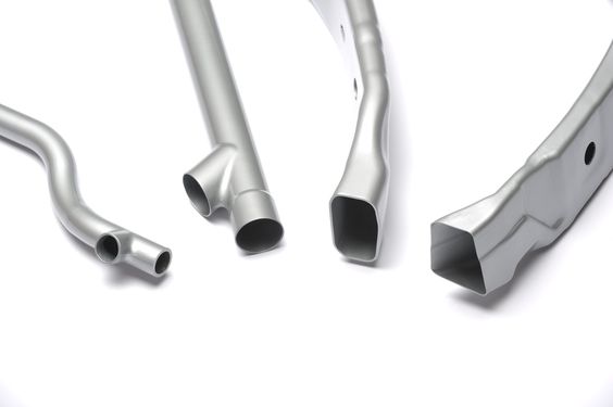
A Bulge Metal Forming Press is a specialized machine designed to shape hollow metal tubes or cylinders by expanding them outward through internal pressure, creating bulges, flares, or complex contours. This process is widely used in industries where seamless, strong, and lightweight tubular components are required, such as automotive, aerospace, and industrial manufacturing.
The core principle of a bulge metal forming press involves placing a metal tube within a die or mold and applying controlled internal pressure—typically hydraulic or pneumatic—to expand the tube wall against the die surfaces. Simultaneously, axial feeding or mechanical displacement may be used to help material flow into the bulged area, maintaining uniform wall thickness and achieving the desired shape.
Bulge metal forming presses can vary in design, including hydraulic presses, mechanical presses with specialized tooling, or servo-hydraulic systems that offer precise control of pressure and displacement. Hydraulic bulge presses are particularly common due to their ability to generate high, evenly distributed pressure, which is essential for forming high-strength materials and complex shapes without causing material failure.
Key features of bulge metal forming presses include:
- High-pressure hydraulic or pneumatic systems that provide controlled and adjustable internal pressure.
- Robust press frames to withstand the forces generated during expansion.
- Specialized tooling such as dies, mandrels, and clamps designed for specific part geometries.
- Axial feed mechanisms that push the tube ends to facilitate material flow.
- Advanced control systems for programming pressure curves, cycle timing, and safety features.
The process benefits manufacturers by eliminating welds and joints, reducing material waste, and improving mechanical properties of the formed parts due to uniform strain distribution. This leads to higher strength, better fatigue resistance, and improved aesthetics.
Applications of bulge metal forming presses include production of automotive shock absorber bodies, exhaust components, aerospace structural elements, hydraulic cylinders, and custom industrial tubing. The presses are valued for their flexibility to handle a wide range of materials, tube diameters, and wall thicknesses.
In summary, bulge metal forming presses are essential machines in modern metal forming, enabling efficient, high-quality production of complex hollow parts that meet stringent performance and design requirements.
Bulge metal forming presses work by applying controlled internal pressure to a hollow tube while supporting it externally with a die or mandrel, causing the tube wall to expand outward and conform to the desired shape. The process relies on precise balance between the internal pressure and the axial feeding or compressive forces that help the metal flow and stretch evenly. If pressure is too high or applied too quickly, it can cause the tube to crack or burst. Conversely, insufficient pressure results in incomplete forming or wrinkling. Therefore, controlling the pressure ramp-up and feed rates is critical.
The presses often feature hydraulic systems capable of generating very high pressures, sometimes exceeding several thousand bar, depending on the material and thickness of the tube. Hydraulic fluid, usually oil or water, is injected into one end of the tube, which is sealed at both ends, forcing the tube to expand into the shaping cavity. Some machines use multi-chamber pressure systems to form complex bulges or multi-stage expansions in a single cycle.
Tooling is a vital aspect of bulge metal forming presses. Dies are carefully designed and machined to exact specifications, typically made from hardened steel with polished surfaces to reduce friction and wear. Internal mandrels provide support to maintain tube integrity and prevent excessive thinning. In certain applications, segmented or adjustable mandrels are used to accommodate varying internal geometries. Clamping systems hold the tube ends firmly to prevent slippage and ensure consistent pressure sealing.
Advanced control systems with programmable logic controllers (PLCs) and human-machine interfaces (HMIs) allow operators to define pressure profiles, timing sequences, and safety limits. Sensors monitor parameters such as pressure, displacement, and force throughout the process, providing real-time feedback and enabling automated adjustments. This level of control helps reduce scrap rates and increases repeatability in high-volume production.
Bulge metal forming presses can accommodate a variety of metals including carbon steel, stainless steel, aluminum alloys, and even some titanium grades. This versatility enables their use across sectors that require high strength-to-weight ratios or corrosion resistance. Additionally, some presses integrate heating systems to perform warm or hot bulge forming, improving formability of tougher materials without compromising mechanical properties.
The technology enables the production of complex shapes that would be difficult or costly to achieve with traditional machining or welding. By forming parts in a single piece without joints, manufacturers benefit from improved strength, reduced weight, and enhanced aesthetics. This is particularly valuable in automotive frames, aerospace structural components, hydraulic cylinders, and precision tubing used in medical or industrial applications.
Energy efficiency improvements have been incorporated into newer bulge presses, such as variable frequency drives on hydraulic pumps, energy recovery systems, and improved fluid circuits to minimize losses. Automation of material handling, loading, and unloading further boosts productivity while reducing manual labor and associated risks.
Maintenance considerations include regular inspection and servicing of hydraulic components, tooling wear monitoring, and system calibration to maintain consistent forming quality. Many presses are designed with easy access points and modular components to facilitate quick repairs and minimize downtime.
Overall, bulge metal forming presses are essential in modern manufacturing, providing a reliable, precise, and efficient means of producing complex tubular parts that meet evolving performance, weight, and cost requirements across multiple industries.
Bulge metal forming presses continue to evolve with advancements in materials science, control technology, and manufacturing integration. The adoption of Industry 4.0 principles has introduced smart sensors and IoT connectivity, enabling presses to communicate with other equipment on the factory floor and centralized monitoring systems. This connectivity allows for predictive maintenance by analyzing machine data trends, minimizing unplanned downtime, and optimizing press utilization.
The integration of artificial intelligence and machine learning algorithms is beginning to influence bulge forming operations. These technologies can analyze vast amounts of sensor data to identify subtle patterns indicating tool wear, material inconsistencies, or process deviations. By adjusting parameters proactively, AI-driven control systems can maintain product quality while reducing scrap and rework.
Customization is also more accessible, with modular press designs that can be configured for specific applications, varying tube sizes, and material types. Quick-change tooling systems reduce setup times between production runs, making bulge presses more adaptable for small-batch or prototype manufacturing alongside mass production.
Materials compatibility is expanding as research advances in forming high-performance alloys and composite tubes. The ability to bulge form lightweight, high-strength materials like titanium alloys or metal matrix composites opens new possibilities in aerospace, medical devices, and high-tech automotive components.
Environmental considerations have led to the use of more eco-friendly hydraulic fluids and closed-loop systems that minimize leaks and fluid waste. Energy consumption is addressed through regenerative hydraulic systems and improved pump efficiency, aligning with sustainability goals.
Operator safety remains paramount, with modern presses featuring multiple redundant safety systems including pressure relief valves, emergency stop circuits, and physical barriers. Enhanced training programs and digital simulation tools also improve operator preparedness and process understanding.
In application, bulge metal forming presses excel at producing parts that require both internal and external precision shaping, such as automotive shock absorber bodies, aerospace structural components, hydraulic cylinders, and specialized medical tubing. The elimination of welds and joints not only enhances strength and fatigue resistance but also reduces potential leak points, improving reliability in demanding environments.
Looking ahead, ongoing innovation in bulge press technology promises even greater precision, efficiency, and flexibility. Combined with digital manufacturing trends, these machines will play a critical role in producing next-generation tubular components that meet stringent performance, cost, and sustainability criteria across diverse industries.
Bulge Pressing Equipment
Bulge Pressing Equipment refers to the specialized machinery and associated components used to perform bulge forming—a metal forming process where hollow tubes or cylindrical blanks are expanded by internal pressure to create bulges, flares, or complex shapes. This equipment is critical in manufacturing industries requiring seamless, strong, and lightweight tubular parts with precise geometries.
Typically, bulge pressing equipment includes:
- Hydraulic or Pneumatic Press Units: These provide the internal pressure necessary to expand the metal tube. Hydraulic systems are most common due to their ability to generate high and controllable pressures with smooth ramping, essential for preventing material failure.
- Tooling and Dies: Hardened steel molds and dies shape the external profile of the tube. These are precision-engineered to match the desired final geometry, often with polished surfaces to reduce friction and wear during forming.
- Mandrels or Internal Supports: Used inside the tube to control internal geometry and prevent excessive thinning or wrinkling. Some systems use adjustable or segmented mandrels for complex shapes.
- Axial Feed Mechanisms: These push the tube ends axially during forming, helping distribute material evenly and accommodating changes in tube length or diameter.
- Clamping and Sealing Systems: Secure the tube ends and maintain pressure tightness during the forming cycle.
- Control Systems: PLCs and HMIs allow operators to program pressure profiles, feed rates, cycle timing, and monitor process parameters in real time for consistent quality and safety.
Additional components may include sensors for pressure, displacement, and force, as well as safety interlocks, emergency stops, and data logging modules.
Bulge pressing equipment is designed to handle a wide range of materials such as steel, stainless steel, aluminum, titanium, and specialty alloys. Its versatility extends to different tube sizes, wall thicknesses, and shape complexities, making it indispensable in automotive, aerospace, hydraulic, and medical manufacturing.
Modern bulge pressing equipment often integrates features for automation, quick tooling change, energy efficiency, and condition-based maintenance, contributing to higher productivity, reduced downtime, and improved product quality. The equipment’s robust construction ensures durability under high-pressure operations while maintaining precision and repeatability in the bulge forming process.
In summary, bulge pressing equipment encompasses the machinery, tooling, and control technologies that enable reliable, precise, and efficient forming of hollow metal parts through internal pressure expansion, meeting the demanding requirements of advanced manufacturing industries.
Bulge pressing equipment operates by combining high internal pressure with mechanical support to expand metal tubes into desired shapes. The hydraulic or pneumatic systems generate pressure that is carefully controlled and gradually increased to avoid material failure. The dies and tooling surrounding the tube shape the external contours while mandrels inside provide support, maintaining dimensional accuracy and preventing defects such as wrinkling or thinning.
A critical aspect of bulge pressing equipment is the synchronization between pressure application and axial feeding. Axial feed mechanisms push or pull the tube ends to control material flow, ensuring uniform expansion and wall thickness distribution. This coordination minimizes the risk of cracks or uneven deformation.
The equipment’s control systems feature advanced programmable logic controllers (PLCs) and user-friendly human-machine interfaces (HMIs), enabling operators to set precise pressure curves, timing sequences, and safety parameters. Real-time monitoring through sensors provides feedback on pressure, displacement, and force, allowing immediate adjustments and ensuring consistent quality throughout the production run.
Tooling for bulge pressing is often modular and customizable, allowing rapid changes between different part designs and sizes. Dies are made from hardened steel or other wear-resistant materials and are regularly inspected for wear to maintain forming accuracy. Some tooling systems incorporate cooling or lubrication channels to extend tool life and improve forming conditions.
Bulge pressing equipment can be integrated into automated production lines, where robotic arms or conveyors handle loading and unloading of tubes, further increasing throughput and reducing manual labor. Automation also enhances safety by minimizing operator exposure to high-pressure operations.
Energy efficiency improvements in bulge pressing machines include variable frequency drives for hydraulic pumps, energy recovery systems that recycle hydraulic energy during pressure release, and optimized hydraulic circuits that reduce fluid losses. These advances contribute to lower operating costs and environmental impact.
Maintenance of bulge pressing equipment involves regular inspection of hydraulic components, seals, and tooling wear. Predictive maintenance enabled by sensor data and IoT connectivity allows early detection of potential issues, preventing unexpected downtime.
Industries that utilize bulge pressing equipment benefit from producing seamless, strong, and lightweight components with complex geometries not achievable through conventional forming or machining methods. Applications range from automotive shock absorber bodies and exhaust parts to aerospace structural tubes and medical devices, demonstrating the versatility and critical role of bulge pressing in modern manufacturing.
Bulge pressing equipment continues to advance with the integration of cutting-edge technologies that improve precision, flexibility, and efficiency. Modern systems increasingly incorporate digital twins—virtual models that simulate the bulge forming process in real time—enabling engineers to optimize tool design, process parameters, and material usage before actual production. This reduces trial-and-error cycles, shortens development times, and lowers costs.
The incorporation of adaptive control algorithms allows bulge presses to respond dynamically to variations in material properties or tooling conditions during operation. By continuously adjusting pressure profiles and feed rates based on sensor feedback, these systems maintain optimal forming conditions and product quality, even with batch-to-batch variability.
In terms of materials, bulge pressing equipment is being adapted to handle next-generation lightweight alloys and composite tubes. These materials present new challenges due to their distinct mechanical properties, requiring precise control over pressure and deformation to avoid cracking or delamination. Specialized tooling coatings and surface treatments help reduce friction and tool wear when working with abrasive or hard-to-form materials.
Safety enhancements include multi-level interlocks, advanced pressure relief mechanisms, and ergonomic designs that facilitate safer operator interactions. Virtual and augmented reality training tools allow operators to gain hands-on experience with bulge press operation and troubleshooting in a simulated environment, improving preparedness and reducing on-the-job errors.
Sustainability considerations drive the development of environmentally friendly hydraulic fluids and closed-loop fluid recycling systems, minimizing waste and environmental impact. Additionally, energy-efficient hydraulic components and regenerative systems reduce overall power consumption.
The growing demand for complex tubular components with tight tolerances and superior mechanical performance ensures that bulge pressing equipment remains essential in industries such as automotive, aerospace, defense, oil and gas, and medical device manufacturing. The ability to produce seamless, high-strength parts with minimal post-processing contributes to lightweighting initiatives and performance improvements across sectors.
Looking forward, the combination of advanced materials, smart controls, and digital integration will continue to push the boundaries of what bulge pressing equipment can achieve, enabling the production of ever more sophisticated, reliable, and efficient tubular components that meet evolving industry demands.
Bulge Forming Machine
A Bulge Forming Machine is a specialized metal forming machine designed to expand hollow tubes or cylindrical blanks by applying internal pressure, creating bulges, tapers, or complex shapes with high precision and structural integrity. This process, known as bulge forming or hydro-bulging, is widely used in industries requiring seamless, lightweight, and strong tubular components such as automotive, aerospace, hydraulics, and medical devices.
The core of a bulge forming machine consists of a hydraulic or pneumatic system that generates controlled internal pressure within the tube. This pressure causes the tube walls to expand outward against a surrounding die or mold, shaping the metal into the desired contour. Simultaneously, axial feeding mechanisms may push or pull the tube ends to control material flow, ensuring uniform wall thickness and preventing defects such as wrinkling or thinning.
Key components of a bulge forming machine include:
- Hydraulic/Pneumatic Pressure System: Provides the high internal pressure necessary for expansion, with fine control over pressure ramping and holding.
- Forming Die or Tooling: Precisely shaped molds that define the external geometry of the bulged section. These dies are made of hardened materials to withstand repeated forming cycles.
- Mandrels or Internal Supports: Inserted inside the tube to maintain dimensional accuracy, prevent excessive deformation, and control the final shape.
- Axial Feed System: Controls the axial movement of the tube, optimizing material distribution during forming.
- Clamping and Sealing Mechanisms: Secure the tube ends and maintain pressure containment during forming.
- Control Unit: Equipped with programmable logic controllers (PLCs) and human-machine interfaces (HMIs) to manage the forming process, monitor parameters, and ensure operator safety.
Modern bulge forming machines may incorporate automation features such as robotic loading/unloading, quick-change tooling systems, and real-time process monitoring with sensors to enhance productivity, consistency, and safety. Advances in software enable simulation and optimization of the forming process before production, reducing setup time and material waste.
The bulge forming process allows the production of complex shapes without welding or joints, resulting in improved strength, fatigue resistance, and aesthetic quality. It is especially beneficial for manufacturing parts like shock absorber cylinders, aerospace structural components, hydraulic cylinders, and medical tubing.
In summary, a bulge forming machine is a sophisticated, versatile tool essential for creating high-quality, seamless tubular parts through controlled internal pressure expansion, supporting modern manufacturing demands for strength, precision, and efficiency.
Bulge forming machines operate by carefully controlling the internal pressure applied to a hollow metal tube, causing it to expand outward against a precisely shaped die that defines the desired final geometry. The process relies on balancing internal pressure with axial feeding of the tube ends to distribute material evenly and prevent defects like thinning, cracking, or wrinkling. Hydraulic systems are commonly used for their ability to generate high, controllable pressures and smooth pressure ramps, essential for forming complex shapes without damaging the material.
Inside the tube, mandrels or internal supports play a crucial role in maintaining dimensional accuracy and preventing excessive deformation, especially in regions requiring tight tolerances or complex contours. These supports can be fixed or adjustable depending on the complexity of the part being formed.
The tooling surrounding the tube, typically made of hardened steel or other durable materials, must withstand repeated cycles of high pressure and mechanical stress while maintaining tight tolerances to ensure consistent product quality. Tooling designs often incorporate channels for lubrication or cooling to reduce wear and improve the forming process.
Control systems in modern bulge forming machines utilize programmable logic controllers (PLCs) combined with human-machine interfaces (HMIs) that allow operators to set and monitor pressure profiles, feed rates, and cycle times. Real-time sensor feedback from pressure transducers, displacement sensors, and force gauges enables closed-loop control, allowing dynamic adjustments during the forming cycle to maintain optimal conditions.
Automation integration is common, with robotic arms or conveyors handling the loading and unloading of tubes to improve cycle times and reduce manual labor. This automation also enhances operator safety by minimizing direct interaction with high-pressure equipment.
Energy efficiency improvements include variable frequency drives for hydraulic pumps and regenerative systems that capture and reuse hydraulic energy during pressure release phases, reducing power consumption and operational costs.
Bulge forming machines are compatible with a wide range of materials, including steel, stainless steel, aluminum, titanium, and advanced alloys, making them versatile for many industries. They enable the production of seamless, lightweight parts with superior mechanical properties, reducing the need for secondary welding or machining processes.
Maintenance of these machines involves regular inspection and replacement of hydraulic seals, monitoring of tooling wear, and calibration of sensors to ensure long-term accuracy and reliability. Condition monitoring and predictive maintenance strategies, supported by IoT connectivity, help minimize unexpected downtime.
The bulge forming process facilitated by these machines is essential for producing components where strength, precision, and reliability are critical, such as automotive suspension parts, aerospace structural tubes, hydraulic cylinders, and medical instrument components. As technology advances, bulge forming machines continue to evolve with improved control algorithms, smarter automation, and better material handling capabilities, supporting the manufacturing of increasingly complex and high-performance tubular parts.
Further advancements in bulge forming machines include the integration of digital technologies such as machine learning and artificial intelligence to enhance process control and predictive maintenance. By analyzing historical data and real-time sensor inputs, these systems can optimize forming parameters for different materials and part geometries, reducing trial runs and scrap rates.
The use of simulation software and digital twins allows engineers to virtually model the bulge forming process, predicting potential issues like material thinning, wrinkling, or springback before physical production. This capability streamlines product development, enabling rapid prototyping and fine-tuning of tooling designs to achieve precise tolerances and surface finishes.
Material innovations also push the capabilities of bulge forming machines. Lightweight alloys and composite materials with complex behaviors require adaptive control systems that can respond instantly to changing deformation characteristics. Specialized coatings on tooling surfaces reduce friction and wear, improving the lifespan of dies and mandrels and ensuring consistent quality across production batches.
Safety features continue to improve with advanced interlocks, pressure relief valves, and automated shutdown protocols that protect operators and equipment in case of abnormal conditions. Ergonomic designs and intuitive user interfaces help operators manage complex forming cycles more effectively while minimizing fatigue and error.
Environmental considerations are addressed by using biodegradable or less hazardous hydraulic fluids, implementing closed-loop fluid recycling systems, and optimizing energy consumption through efficient hydraulic pump designs and energy recovery during the decompression phase. These efforts align bulge forming technologies with broader sustainability goals in manufacturing.
In manufacturing environments, bulge forming machines are increasingly integrated into flexible production lines capable of handling multiple part types and sizes with quick tooling changes. This flexibility supports just-in-time manufacturing and customization demands from industries such as automotive, aerospace, and medical devices.
The continued evolution of bulge forming machines is driven by the need for stronger, lighter, and more complex tubular components. These machines play a critical role in enabling innovative designs that improve product performance, reduce weight, and lower manufacturing costs, all while maintaining high standards of quality and reliability. As such, bulge forming remains a vital and dynamic technology within modern metal forming and manufacturing sectors.
Bulge Press Machine
A Bulge Press Machine is a specialized hydraulic or mechanical press designed to expand hollow metal tubes or cylindrical blanks by applying controlled internal pressure, causing the material to bulge outward into a specific shape defined by external dies or tooling. This forming method enables manufacturers to produce seamless, lightweight, and structurally strong components with complex geometries, commonly used in automotive, aerospace, hydraulics, and other precision engineering industries.
The fundamental operation of a bulge press machine involves sealing the ends of a metal tube and introducing high internal pressure, typically through hydraulic fluid or gas, which forces the tube walls to expand against a surrounding die. At the same time, axial feeding mechanisms can apply force to the tube ends to control the distribution of material, ensuring even wall thickness and preventing defects such as wrinkles, cracks, or thinning.
Key components of a bulge press machine include a high-pressure hydraulic system, precision dies or molds, axial feed mechanisms, clamping units to securely hold the workpiece, and advanced control systems to regulate pressure, feed rate, and cycle timing. The dies are usually crafted from hardened steel and may incorporate cooling channels to manage temperature during repeated cycles.
Modern bulge press machines often feature programmable logic controllers (PLCs) and human-machine interfaces (HMIs) that allow operators to customize forming parameters, monitor real-time sensor data, and automate production processes. Integration with robotic handling systems improves throughput and safety by automating loading and unloading tasks.
The bulge pressing process enables the production of complex, high-strength tubular parts without the need for welding or joining, resulting in improved structural integrity and aesthetic quality. Applications include automotive shock absorber cylinders, aerospace structural tubes, hydraulic cylinders, and various medical device components.
Maintenance of bulge press machines involves routine checks on hydraulic components, seals, tooling wear, and sensor calibration to ensure consistent performance and minimize downtime. Advances in sensor technology and IoT connectivity facilitate predictive maintenance, allowing early detection of potential issues.
Overall, bulge press machines are essential tools in modern manufacturing, providing efficient, precise, and flexible forming solutions for complex tubular components that meet stringent quality and performance standards.
Bulge press machines operate by precisely controlling the internal pressure applied within a hollow metal tube, causing it to expand against an external die that defines the desired shape. This process requires a careful balance of hydraulic pressure and axial feed to ensure the metal flows uniformly, avoiding defects such as thinning, cracking, or wrinkling. The hydraulic system in these machines is designed to deliver smooth and adjustable pressure ramps, allowing the material to deform progressively and maintain its structural integrity.
The tooling used in bulge press machines is typically made from hardened steel or similarly durable materials to withstand the high stresses of repeated forming cycles. These dies are precision-engineered to match the complex geometries required, and often incorporate cooling or lubrication channels to prolong tool life and improve forming consistency. Internal supports, like mandrels, may be used inside the tube to maintain dimensional accuracy and prevent excessive deformation in critical areas.
Control systems play a vital role in modern bulge press machines, featuring programmable logic controllers (PLCs) and human-machine interfaces (HMIs) that enable operators to set detailed forming parameters such as pressure profiles, axial feed speeds, and cycle durations. Real-time sensor feedback from pressure transducers, displacement sensors, and force gauges facilitates closed-loop control, allowing automatic adjustments during the forming process to optimize quality and repeatability.
Automation enhances the efficiency of bulge press machines through robotic loading and unloading, quick-change tooling setups, and integrated quality inspection systems. These features reduce manual labor, shorten cycle times, and improve operator safety by minimizing direct contact with high-pressure components.
Energy efficiency improvements in bulge press machines include the use of variable frequency drives on hydraulic pumps and regenerative hydraulic systems that recover energy during pressure release phases. Such innovations help lower operational costs and support sustainability goals in manufacturing.
Bulge press machines are versatile in handling a wide range of materials, from traditional steels and aluminum alloys to advanced lightweight materials and composites. This versatility allows manufacturers to produce parts with superior mechanical properties, reduced weight, and complex shapes that would be difficult or impossible with other forming methods.
Routine maintenance is essential to keep bulge press machines operating reliably. This includes inspecting and replacing hydraulic seals, monitoring tool wear, calibrating sensors, and maintaining hydraulic fluid quality. Predictive maintenance strategies, supported by IoT-enabled monitoring, allow early detection of potential issues and minimize unplanned downtime.
The bulge pressing process facilitated by these machines is critical in producing components where strength, precision, and surface finish are paramount. Industries such as automotive, aerospace, oil and gas, and medical device manufacturing rely heavily on bulge press technology to deliver high-performance tubular parts with minimal post-processing.
Continuous advancements in bulge press machine technology—driven by improved materials, smarter controls, and digital integration—are expanding the capabilities of the process. These machines enable manufacturers to meet increasingly demanding design requirements while optimizing production efficiency and cost-effectiveness, ensuring bulge pressing remains a cornerstone of modern metal forming.
As bulge press technology advances, the integration of digital twins and advanced simulation tools has become increasingly important. Engineers can create detailed virtual models of the bulge forming process to predict material behavior, potential defects, and final part geometries before physical production begins. This reduces trial-and-error in tooling design and parameter setting, saving time and material costs.
Machine learning algorithms are also being incorporated to analyze process data from multiple production runs. These algorithms identify subtle trends and correlations that may not be obvious to operators, enabling continuous optimization of pressure profiles, feed rates, and cycle timing. Such adaptive control enhances product consistency and reduces scrap.
Materials science developments are pushing the boundaries of what bulge press machines can form. High-strength alloys, aluminum-lithium composites, and even some fiber-reinforced metals require more sophisticated control of deformation to avoid cracking or uneven thickness. Specialized coatings on dies and mandrels reduce friction and wear, improving tool life and part surface finish.
Safety remains a critical concern due to the high pressures involved in bulge pressing. Modern machines include multiple redundant safety systems such as pressure relief valves, emergency stops, and advanced interlocks that prevent operation if tooling or clamping conditions are not met. Operator training and ergonomic machine design also contribute to a safer workplace.
Environmental impact is another focus area. Manufacturers increasingly use biodegradable hydraulic fluids and implement closed-loop filtration and recycling systems to minimize waste and pollution. Energy-efficient hydraulic components and smart energy management further reduce the carbon footprint of bulge forming operations.
In production environments, bulge press machines are often integrated into flexible manufacturing cells. Quick-change tooling systems and programmable controls allow rapid switching between different part designs, supporting small batch runs and customized orders without significant downtime. This flexibility is essential in industries where product variety and responsiveness are competitive advantages.
Bulge forming presses continue to play a pivotal role in producing lightweight, structurally efficient tubular components that contribute to fuel savings, performance improvements, and safety enhancements in vehicles and aircraft. Their ability to create seamless parts with excellent mechanical properties and complex shapes keeps them at the forefront of metal forming technologies.
Looking forward, ongoing innovations in sensor technology, artificial intelligence, and materials will further expand the capabilities and applications of bulge press machines. This continuous evolution ensures that bulge forming remains a vital, cost-effective, and high-quality manufacturing process for decades to come.
Further innovation in bulge press machines is focusing on enhanced automation and integration with Industry 4.0 concepts. Real-time data collection via embedded sensors across hydraulic circuits, tooling, and workpieces enables comprehensive process monitoring. This connectivity allows for predictive analytics, where machine learning models forecast maintenance needs, detect anomalies early, and optimize forming cycles dynamically to maximize throughput and minimize defects.
Advances in servo-hydraulic systems provide finer control over pressure and feed rates compared to traditional hydraulic setups, enabling more precise deformation profiles. This precision is critical when working with advanced alloys or thin-walled components where material behavior is highly sensitive. The result is improved part quality, reduced material waste, and longer tool life.
Hybrid bulge forming machines combining mechanical and hydraulic actuation offer increased flexibility and energy efficiency. Mechanical components can handle gross movements or positioning, while hydraulics provide the fine-tuned pressure control needed for bulging. This hybrid approach reduces energy consumption and improves response times during forming cycles.
Material innovation also extends into the use of smart or functional materials that change properties during forming, such as shape-memory alloys. Bulge press machines adapted for these materials open new possibilities in medical devices, aerospace, and robotics by producing components with embedded functionalities.
Tooling innovation includes modular die systems that allow rapid configuration changes for different part geometries, minimizing downtime. Additive manufacturing (3D printing) is increasingly used to create complex die inserts with internal cooling channels or surface textures that improve forming performance and part quality.
Environmental sustainability continues to shape bulge press design. Machines with energy recovery systems harvest hydraulic energy during decompression and store it for reuse, significantly lowering power consumption. Use of water-based or biodegradable hydraulic fluids reduces environmental impact and improves workplace safety.
In manufacturing workflows, bulge press machines are integrated into fully automated cells with robotic loading/unloading, inline inspection via machine vision, and immediate feedback loops to control systems. This integration supports high-mix, low-volume production and just-in-time manufacturing, responding flexibly to customer demands.
The role of bulge press machines in producing lightweight, high-strength tubular parts is critical for industries aiming to reduce emissions and improve fuel efficiency. By enabling complex shapes without joints or welds, bulge forming ensures superior mechanical properties and reliability.
Ongoing research into process modeling, real-time adaptive control, and new materials promises to expand the capabilities and applications of bulge press machines even further. As such, these machines remain central to innovation in metal forming, combining traditional hydraulic power with cutting-edge digital technologies to meet modern manufacturing challenges.
EMS Metalworking Machines
We design, manufacture and assembly metalworking machinery such as:
- Hydraulic transfer press
- Glass mosaic press
- Hydraulic deep drawing press
- Casting press
- Hydraulic cold forming press
- Hydroforming press
- Composite press
- Silicone rubber moulding press
- Brake pad press
- Melamine press
- SMC & BMC Press
- Labrotaroy press
- Edge cutting trimming machine
- Edge curling machine
- Trimming beading machine
- Trimming joggling machine
- Cookware production line
- Pipe bending machine
- Profile bending machine
- Bandsaw for metal
- Cylindrical welding machine
- Horizontal pres and cookware
- Kitchenware, hotelware
- Bakeware and cuttlery production machinery
as a complete line as well as an individual machine such as:
- Edge cutting trimming beading machines
- Polishing and grinding machines for pot and pans
- Hydraulic drawing presses
- Circle blanking machines
- Riveting machine
- Hole punching machines
- Press feeding machine
You can check our machinery at work at: EMS Metalworking Machinery – YouTube
Applications:
Flange-punching
Beading and ribbing
Flanging
Trimming
Curling
Lock-seaming
Ribbing