
Hemming and Seaming Machine for Sheet Metal: Machinery For Industrial Metal Forming includes a wide range of equipment designed to shape, deform, and fabricate metal components through mechanical force, temperature, or pressure. These machines are foundational in manufacturing industries like automotive, aerospace, construction, shipbuilding, and energy systems. Here’s an overview of the main types:
Hydraulic Press Machines
These use hydraulic cylinders to generate compressive force, ideal for deep drawing, punching, and pressing applications.
- Applications: automotive body panels, appliance parts, cookware.
2. Mechanical Presses
Driven by flywheels and mechanical linkages, they are suitable for high-speed stamping and punching.
- Applications: production of brackets, gears, and enclosures.
3. Forging Presses and Hammers
Used to form metal under high pressure by deforming it into a die cavity.
- Open die: for large, rough shapes.
- Closed die: for precision parts like crankshafts or connecting rods.
4. Rolling Mills
Consist of rolls that compress and elongate metal sheets or billets.
- Hot rolling: for slabs and structural shapes.
- Cold rolling: for thin sheets, high precision, and finish.
5. Extrusion Presses
Force metal through a die to create long products with uniform cross-sections.
- Direct and indirect extrusion options.
- Common in aluminum and copper production.
6. Metal Spinning Machines
Rotate a metal disc at high speed and press it onto a mandrel to form round, symmetrical parts.
- Applications: lighting reflectors, cookware, aerospace parts.
7. Stretch Forming Machines
Stretch a metal sheet while bending it over a form to produce curved components.
- Applications: aircraft skin panels, structural parts.
8. Hydroforming Presses
Use high-pressure hydraulic fluid to press ductile metal into a die.
- Tube hydroforming and sheet hydroforming types.
- Ideal for hollow and complex geometries.
9. Bending Machines
Apply force to bend sheets, tubes, or profiles into desired angles or shapes.
- Includes press brakes, profile benders, and tube benders.
10. Punching and Blanking Machines
Use dies and punches to remove or shape material.
- CNC turret punch presses enable high-precision repetitive operations.
11. Swaging Machines
Reduce the diameter or shape metal rods/tubes by hammering around the workpiece.
- Cold forming process.
- Used for aerospace and automotive parts.
12. Wire and Bar Drawing Machines
Pull metal through dies to reduce diameter and increase length.
- Typically used for electrical wire, cables, and fasteners.
13. Die Casting Machines (for molten metal forming)
Inject molten metal into a mold under high pressure.
- Common for aluminum, magnesium, and zinc parts.
14. Induction Heating & Forming Systems
Heat the metal locally using electromagnetic induction, then deform it.
- Suitable for forming high-strength steels and alloys.
15. CNC Metal Forming Machines
Automated systems for high-precision metal shaping using numerical control.
- Examples: CNC press brakes, spinning lathes, panel benders.
Industrial metal forming machinery encompasses a wide array of equipment designed to deform and shape metal into useful products through mechanical, hydraulic, or thermal force. Among the foundational machines are hydraulic presses, which apply uniform force via fluid pressure, making them suitable for deep drawing, pressing, and forming large sheet metal components. Mechanical presses operate using flywheel energy and mechanical linkages, allowing for fast and repetitive stamping, punching, and cutting operations commonly found in automotive and appliance part production.
Forging equipment, including both mechanical and hydraulic forging presses as well as hammers, is used to compress heated metal into die cavities, creating dense and strong parts such as crankshafts, gears, and fasteners. Rolling mills, either hot or cold, progressively reduce the thickness or change the shape of metal sheets or billets using pairs of rotating rolls. Hot rolling is typically used for large structural steel components, while cold rolling improves surface finish and dimensional precision for products like sheet metal and coils.
Extrusion presses push or pull heated metal through a die to produce long products with constant cross-sections, such as tubes, bars, and profiles, especially in aluminum and copper industries. Metal spinning machines rotate a metal blank at high speed and form it against a mandrel using a roller or stylus, producing symmetrical items like lampshades, cookware, and aerospace cones.
Stretch forming machines are used to stretch metal sheets while wrapping them over a form, creating smooth, contoured surfaces commonly required in aircraft skins and curved architectural panels. Hydroforming equipment employs high-pressure fluids to form ductile metals against a die, enabling the creation of complex, hollow, and seamless parts such as automotive frames and exhaust systems. In tube hydroforming, internal pressure is used to expand tubes into shapes that would be difficult to achieve using conventional methods.
Bending machinery, including press brakes and tube benders, applies force to metal sheets, bars, or tubes to achieve specific angles and forms, crucial in fabrication shops and industrial production. Punching and blanking machines rapidly remove or shape parts of sheet metal using a die and punch combination, with CNC turret punches offering automation and accuracy for high-volume production runs.
Swaging machines form or reduce the diameter of rods and tubes by hammering them with rotating dies, often used in aerospace, medical, and automotive applications. Drawing machines reduce wire or bar diameters by pulling them through progressively smaller dies, producing uniform and precise metal rods and wires used in construction, electronics, and fasteners.
Die casting machines, although not solid-state forming equipment, are crucial in shaping molten metal by injecting it into metal molds at high pressure, widely used for producing complex and detailed components from aluminum, zinc, and magnesium. Induction heating systems enable localized heating of metal parts, which can then be forged, bent, or formed with greater control and reduced tool wear.
CNC-controlled forming equipment combines automation and digital precision to handle complex forming tasks with minimal manual intervention. CNC press brakes, CNC spinning lathes, and robotic panel benders are increasingly used in high-precision manufacturing settings. Overall, metal forming machinery spans both traditional and advanced technologies, enabling the efficient and scalable production of parts ranging from small precision components to large structural elements.
Modern industrial metal forming also heavily relies on integrated systems that combine forming, cutting, and handling functions within a single production cell. These systems improve throughput, reduce manual labor, and ensure repeatable quality. For example, automated bending cells may include a robotic arm that feeds sheet metal into a CNC press brake, follows with repositioning for multi-axis bends, and ends with stacking or transfer to the next station.
Incremental sheet forming (ISF) technologies are gaining traction, particularly in prototyping or low-volume production. In this method, a small stylus or tool gradually deforms a sheet by tracing programmed paths without requiring a dedicated die. This process enables fast design iterations and is ideal for custom parts or tooling.
Servo-electric presses are another development in the field. Unlike traditional hydraulic or mechanical presses, servo presses use electric motors for precise force and position control. This provides better energy efficiency, programmability, and consistency in forming operations. These are commonly used in applications requiring extreme dimensional precision or multiple forming stages with varied parameters.
Roll forming machines offer continuous bending of long metal strips into desired cross-sections. This method is widely used in the production of roof panels, structural supports, and automotive trim. Each pass through a roll stand gradually shapes the profile with high speed and consistency.
Orbital forming and radial riveting machines are used for fastening and joining purposes where conventional welding or bolts are impractical. These machines apply localized pressure in a controlled orbital or radial path to deform a metal fastener, effectively locking two or more components together without damaging the surrounding area.
Explosive forming and electromagnetic forming are specialized high-energy-rate processes used for shaping large or thick metal sheets where traditional mechanical force would be insufficient. These methods rely on the rapid release of energy—either from chemical explosives or magnetic pulses—to push the metal into a die. Such techniques are often reserved for aerospace and military components with highly demanding tolerances and material characteristics.
Hot metal gas forming (HMGF) is a newer hybrid technology that combines hot forming and internal pressurization. Tubes are heated and simultaneously inflated inside a die, allowing complex shapes with reduced springback and thinning. This is especially effective for high-strength steels used in automotive structural components where weight reduction is critical.
Additionally, rotary draw bending and mandrel bending machines allow for tight-radius tube bends without collapsing the wall, making them essential for producing exhaust pipes, roll cages, and furniture frames. Rotary swaging, particularly for hollow or stepped components, provides consistent outer diameter reduction while preserving or refining the inner wall surface.
Edge-forming and flange-forming machines are dedicated to producing raised or rolled edges, critical in container production, HVAC ducting, and enclosures. These processes add rigidity and prevent sharp edge exposure.
With increasing demands on material efficiency and product complexity, simulation software and digital twins are being paired with metal forming machinery to optimize tool design, predict springback, and minimize trial runs. These virtual models simulate the behavior of metal under real forming conditions and guide tool adjustments before physical manufacturing begins.
Overall, the field of industrial metal forming machinery continues to evolve toward higher precision, automation, and energy efficiency, supporting mass production as well as agile manufacturing for customized solutions across a wide range of industries.
Advanced metal forming machinery is also increasingly integrating sensor technology and closed-loop control systems. These sensors monitor variables like force, displacement, temperature, and material flow in real-time, allowing the system to make immediate adjustments during the forming process. This ensures consistent product quality and helps detect tool wear, misfeeds, or process deviations early, minimizing waste and downtime. In press lines, for instance, load sensors and position encoders are used to monitor die alignment and part accuracy throughout the stroke cycle.
Another important trend is the use of modular forming lines, where different types of forming machines—such as feeders, straighteners, press units, and shearing machines—are arranged in a flexible configuration. This allows manufacturers to reconfigure the setup quickly for different part geometries or material types. Such modularity is key for contract manufacturers or industries with frequently changing product lines, like electronics or small appliance components.
Servo-hydraulic hybrid systems combine the high force capacity of hydraulics with the precision of servo controls. These systems reduce energy consumption by eliminating constant motor running and offer better speed and force control, particularly in deep drawing and complex multi-step operations. Additionally, hybrid machines reduce noise levels and require less maintenance due to fewer mechanical components under continuous load.
In tube and pipe forming, laser-assisted forming technologies are being used to locally soften high-strength or hardened materials before bending or shaping. This process extends formability limits and prevents cracking in materials that would otherwise fail under cold forming. Such technologies are useful in aerospace and automotive industries where exotic alloys and ultra-high-strength steels are common.
Rotary forging, also known as radial forging, is another high-precision technique where the workpiece rotates and is simultaneously compressed radially by several dies. It allows the forming of long parts with excellent grain structure, making it ideal for aerospace shafts, spindles, and axles. The process enhances material strength through directional grain flow and is used in applications where fatigue resistance and mechanical integrity are critical.
Incremental forming technologies like dieless forming and robotic hammer peening are emerging solutions for large-scale prototypes or one-off components, especially in architectural metalwork or custom equipment housings. Robotic arms equipped with forming tools can deform sheet metal in freeform geometries without traditional tooling, offering unprecedented design flexibility.
Surface-enhancing techniques, such as shot peening and burnishing, are sometimes incorporated into forming lines. These processes improve fatigue strength and surface finish after deformation, especially in aerospace and high-performance mechanical parts. Some forming machines integrate these finishing steps into the forming cycle to reduce overall processing time and part handling.
Cold forging machines, especially in the fastener industry, allow for the high-speed production of bolts, screws, and rivets with minimal material waste. Multi-station cold forging presses can progressively shape blanks into final components without heating, making them energy efficient and cost-effective for high-volume output.
Another key development in metal forming is additive-subtractive hybrid systems, where additive manufacturing is used to build up complex features, followed by forming and trimming processes to refine shapes and ensure mechanical strength. These machines bridge the gap between flexibility and strength, enabling new design possibilities in tooling, aerospace fittings, and medical implants.
As sustainability becomes a growing concern, many metal forming systems are now being designed with energy regeneration systems, improved lubrication systems, and die materials that reduce friction and extend tool life. Eco-efficient forming lines reduce operational costs while meeting environmental standards.
Overall, the machinery used in industrial metal forming is not only evolving in capability and sophistication but is also becoming more interconnected, adaptive, and sustainable. Whether forming sheets, tubes, rods, or complex profiles, these technologies support the ongoing transformation of manufacturing toward smarter, leaner, and more resilient operations.
Rope Hemming Machine for Sheet Metal
A Rope Hemming Machine for Sheet Metal is a specialized piece of forming equipment used to create a rolled, tubular edge—often called a “rope hem” or “curl”—along the perimeter of a metal sheet. This process involves folding and then curling the sheet’s edge around itself or around a wire core, resulting in a rounded, reinforced edge that enhances strength, safety, and aesthetics.
Rope hemming is commonly used in applications where sharp sheet edges must be eliminated or reinforced for structural or handling purposes. These machines are prevalent in the production of automotive parts (like doors, hoods, and trunk lids), household appliances, lighting fixtures, and enclosures.
Key features and functions of a rope hemming machine include:
– Edge Curling Mechanism: The machine uses rotary tools or forming rollers that gradually curl the sheet metal edge into a tubular shape without cracking or distorting the material. Some systems use multi-pass forming to achieve a tight, uniform curl.
– Wire Insertion Capability: In certain designs, the machine allows a steel or aluminum wire to be inserted inside the curl during the hemming operation, significantly increasing edge rigidity and impact resistance.
– Adjustable Rollers or Dies: These enable the machine to handle different thicknesses, materials (like aluminum, mild steel, or stainless steel), and hem diameters. Changeable tooling allows for quick adaptation between production runs.
– Servo or Pneumatic Drive Systems: Depending on the precision and speed required, the drive mechanism may be powered by servo motors (for automated lines) or pneumatic cylinders (in simpler setups).
– Manual, Semi-Automatic, or Fully Automatic Operation:
- Manual machines are suitable for low-volume or prototype work.
- Semi-automatic machines are used in medium-volume operations with operator loading.
- Fully automatic systems are integrated into robotic or conveyor-based sheet metal lines for high-throughput production.
– Safety and Clamping Systems: To ensure consistency and prevent slipping during forming, the sheet is clamped firmly during the hemming process. Safety interlocks are included to protect the operator from pinch points.
– Typical Materials Handled: Cold-rolled steel, galvanized steel, aluminum, and pre-coated or laminated sheets, all ranging in thickness from 0.5 to 2.5 mm, depending on machine capacity.
Rope hemming not only removes sharp edges and improves handling safety but also increases the stiffness of panels, making them less prone to vibration or flexing. In industries like automotive, curled hems are favored for their durability and clean, aerodynamic appearance.
This machine plays a crucial role in forming assemblies that require both form and function, especially where panel joining or weather sealing is involved.
A rope hemming machine for sheet metal operates through a precise and controlled forming process where the outer edge of a flat or pre-formed sheet is gradually rolled into a tight circular shape, either around itself or around an inserted metal wire. This edge transformation not only removes sharpness but also creates a structurally enhanced border that resists deformation, cracking, or detachment during use. The process is particularly useful in applications where a strong yet smooth edge is essential for safety, functionality, or visual finish. These machines are commonly found in production environments where components such as vehicle body panels, appliance housings, air conditioning casings, lighting reflectors, and even some furniture parts require robust and aesthetically refined edges.
In automated production lines, rope hemming machines are often paired with robotic arms or conveyor systems that feed the sheet metal into the forming area, clamp it in place, and initiate the hemming operation in multiple passes to ensure smooth curling without overstressing the material. In simpler or manual setups, the operator places the part manually and initiates the forming cycle using foot pedals or button controls. Depending on the design and production needs, rope hemming can be accomplished in a single continuous motion or broken into staged forming where the edge is first flanged, then folded, and finally curled into a complete tubular hem. The design of the rollers and dies is crucial here—they must be machined to exact profiles that guide the material flow gradually to prevent wrinkling, cracking, or irregular forming.
The material’s ductility plays a major role in hemming success. Softer and more ductile metals like aluminum or low-carbon steel are ideal candidates. In contrast, high-strength steel or coated sheets may require special lubrication or heated tooling to avoid fractures along the hemline. The insertion of a wire core inside the curled hem, which is a feature in more advanced rope hemming operations, further enhances the edge’s strength and is often used in applications where the part will be subject to impact, load-bearing, or torsional forces.
In the automotive industry, rope hemming is often used to reinforce door edges and trunk panels, providing a strong, smooth edge that can also accommodate seals or fasteners. In the appliance sector, manufacturers use rope hems to eliminate sharp edges on access panels or frames, improving user safety and product quality. The resulting curl provides excellent dimensional stability and a clean appearance, even after long-term use or repeated mechanical stress.
Some rope hemming machines are equipped with programmable logic controllers (PLCs) or touch-screen HMIs (Human-Machine Interfaces) that allow operators to store and recall hemming parameters, monitor cycle times, and adjust roller positions in real time. This digital control makes it easier to switch between different part designs, thicknesses, and materials, increasing machine versatility and production efficiency. More advanced systems may also include sensors to detect sheet position, edge alignment, and hem integrity, ensuring high-quality results with minimal manual inspection.
Over time, developments in servo-driven hemming technology have replaced traditional hydraulic or pneumatic systems in many cases. Servo systems offer higher control over speed and force, lower energy consumption, and quieter operation. This is especially beneficial in precision-heavy industries or cleanroom manufacturing environments. As sustainability and automation grow in importance, rope hemming machines continue to evolve in design, integrating features that allow for better energy efficiency, noise reduction, and seamless integration into smart manufacturing cells.
Whether used in small batch production or high-speed automotive lines, rope hemming machines provide a critical edge-forming solution that blends mechanical strength, user safety, and industrial-grade appearance, making them indispensable tools in modern sheet metal fabrication.
The versatility of rope hemming machines allows them to accommodate a wide range of part geometries, from simple flat panels to curved or contoured components. For non-flat or three-dimensional shapes, especially those with compound curves or variable radii, the hemming process must be finely tuned to maintain consistent pressure and alignment throughout the edge. In these cases, the forming tools—typically custom-machined rollers or modular dies—must be designed to follow the exact contour of the part without introducing stress concentrations or distortions. CNC-controlled hemming systems are particularly valuable for these complex shapes, as they can precisely coordinate the movement of rollers in multiple axes to maintain uniform curl depth and diameter around bends, corners, and edges.
In some industrial environments, especially in the production of HVAC ducting, cabinet enclosures, or steel doors, rope hemming machines are combined with in-line punching, notching, or flanging units. This integration reduces the number of handling steps, increases cycle efficiency, and ensures better dimensional consistency from start to finish. For example, a sheet might first be automatically notched and flanged before being indexed into the hemming station, where the rope hem is formed in a continuous process. This approach significantly reduces labor costs and material waste, especially when processing high volumes of parts with repeatable geometry.
To accommodate different sheet thicknesses or alloy compositions, modern hemming machines often include quick-change tooling systems or adjustable roller heads. Operators can easily switch between roller sets or modify forming parameters through digital inputs without disassembling the machine. This flexibility allows manufacturers to respond quickly to changing production requirements or material availability without compromising output quality. Some systems even include automatic tool recognition, which adjusts pressure and speed settings based on the installed tooling, reducing the risk of operator error.
Noise and vibration control are also important aspects of modern rope hemming machines, particularly in high-speed environments or when forming thicker gauge material. Machines are typically mounted on vibration-isolated bases, and the forming heads are built with noise-dampening enclosures or padding to reduce operational sound levels. This makes the equipment more suitable for clean and ergonomic workspaces, particularly in industries with strict workplace safety and noise regulations.
Maintenance considerations are also built into newer designs. Hemming rollers are made from hardened tool steel or carbide-coated materials for extended wear life, and machines are equipped with centralized lubrication systems that automatically service critical moving components. Many systems also offer diagnostic features that alert operators to issues like roller misalignment, bearing wear, or inconsistent torque during forming. These predictive maintenance tools help avoid unscheduled downtime and keep production lines running efficiently.
The use of simulation software during tool design and process planning is another significant advancement. Before a part ever enters the hemming station, engineers can simulate the forming process using finite element analysis (FEA) to predict how the material will behave during curling, including risks of thinning, cracking, or surface defects. These insights allow for optimization of roller profiles, forming speeds, and even material selection before physical trials begin, reducing development time and tooling costs.
In the context of Industry 4.0, rope hemming machines are now often equipped with IoT connectivity, allowing them to communicate with other machines in a production cell, share performance data with centralized dashboards, and receive updates or new recipes remotely. This connectivity ensures greater control over production quality, enables remote diagnostics, and supports traceability for each part produced—essential for regulated industries like automotive and aerospace.
Ultimately, the rope hemming machine is a critical component in modern sheet metal fabrication, enabling manufacturers to produce parts with smooth, reinforced, and safe edges that are not only functional but also meet high standards for appearance and durability. Whether working with steel, aluminum, or coated materials, these machines support high-quality edge finishing with the precision and repeatability required in competitive industrial environments.
As production demands increase and product designs grow more complex, rope hemming machines are evolving to meet higher expectations for speed, flexibility, and consistency. One of the most notable developments is the rise of robotic hemming cells, where industrial robots equipped with hemming heads or flexible roller arms perform the hemming operation directly on parts placed in jigs or fixtures. These robotic systems are highly adaptable, capable of hemming multiple panel types without retooling, making them ideal for industries with short product cycles or mixed-model production.
Robotic hemming offers several advantages over traditional fixed-die systems. It can follow complex, three-dimensional geometries with fine control of forming pressure, angle, and speed, which is especially valuable for automotive closures like hoods, tailgates, and fenders. By using a single robot for multiple operations—such as part positioning, adhesive application, and hemming—manufacturers can reduce equipment footprint and maximize floor space efficiency. These systems often integrate advanced vision or laser guidance tools to detect part orientation and ensure precise roller tracking even when minor variations occur in incoming parts.
For industries requiring extremely high-volume output, carousel-type hemming machines are used. These machines feature multiple stations arranged in a circular layout, with each station performing a specific stage of the hemming process as the part rotates through. This configuration allows continuous loading and unloading, minimizing idle time and maximizing productivity. Such systems are commonly used in the mass production of electrical enclosures, automotive structural panels, and appliance chassis where forming speed is critical to maintaining throughput.
Energy efficiency has also become a key design consideration. Modern rope hemming machines are engineered with low-friction components, energy recovery systems, and power management software that reduces energy use during idle or non-productive states. In some cases, servo-electric drives are favored over hydraulic or pneumatic systems not only for their precision but also because they consume power only when movement is required, unlike traditional systems that run continuously.
In terms of safety and compliance, today’s machines come equipped with comprehensive protection systems including light curtains, emergency stops, interlocked guards, and status indicators. These features ensure that the operator is protected during all stages of the process and that the machine meets international safety standards such as CE or ISO certifications. For machines operating in collaborative settings, force-limited actuators and safety-rated monitored stopping allow for safe human-machine interaction without rigid isolation barriers.
Customization is another growing trend. Manufacturers now offer modular hemming machines that can be tailored to specific applications with interchangeable forming heads, configurable part clamps, and optional automation modules such as loading gantries, barcode scanners, or inspection cameras. These custom configurations allow users to build a machine specifically optimized for their product mix, material types, and production volumes, rather than compromising with a one-size-fits-all solution.
Training and usability have also improved with modern rope hemming machines. Touchscreen interfaces, multilingual controls, real-time diagnostics, and step-by-step setup wizards make it easier for operators to run the machine efficiently with minimal technical background. Some systems even include augmented reality overlays or digital manuals accessible via tablets, allowing operators to view internal components, understand forming paths, and perform troubleshooting or maintenance with visual guidance.
As part of overall digital transformation in manufacturing, data collected from rope hemming machines—such as forming force trends, roller wear rates, and cycle times—is now analyzed using machine learning algorithms to detect performance drift and optimize operations over time. This continuous feedback loop supports predictive maintenance, process optimization, and even design feedback for upstream engineering teams.
Whether used in automotive, HVAC, white goods, or custom fabrication, rope hemming machines are no longer just edge forming devices—they have become intelligent, networked production systems capable of adapting to diverse part designs, responding to production variables, and delivering high-quality, repeatable results in demanding industrial environments.
Open Hemming Machine for Sheet Metal
An Open Hemming Machine for Sheet Metal is a specialized forming system used to bend and fold the edge of a metal panel—typically without fully curling it—into a hemmed or flanged shape. Unlike rope hemming, which rolls the edge into a tubular profile, open hemming creates a flat or partially bent return edge, usually at 90° or folded flat against the parent sheet. This technique is widely used in the automotive industry for exterior body panels like doors, hoods, trunk lids, and fenders, and also in appliance enclosures, HVAC panels, lighting fixtures, and metal furniture.
The open hemming process usually involves two or more forming stages. First, the edge of the panel is flanged or pre-bent, typically to about 30–45 degrees. Then a hemming tool—either a roller, blade, or die—presses the edge further down until it reaches the final angle, which may be a tight fold or a nearly flat overlay. This creates a double-thickness edge that increases stiffness, improves alignment with mating components, and provides a clean, finished appearance. In automotive panels, this hem often encloses another reinforcement panel or frame to create a strong bonded assembly.
Open hemming machines are typically built with a C-frame or open-access architecture, allowing easy access to the hemming area from multiple sides. This is especially important for large or awkwardly shaped panels. The open-frame design makes it easier to load parts manually or with automation, and it allows clearance for long or wide panels that wouldn’t fit inside a closed or boxed forming system.
There are several types of open hemming systems depending on the production volume and level of automation:
- Manual open hemming presses, operated with a foot pedal or lever, are used for small batch production, prototyping, or simple parts. These are suited for lighter gauge materials and less complex geometries.
- Semi-automatic open hemming machines include motorized forming heads and clamping systems to improve consistency and reduce operator fatigue. These are ideal for medium-scale production and can be adjusted for different hem angles or lengths.
- Fully automatic open hemming machines are equipped with CNC or servo-driven heads, automatic part positioning, clamping, and programmable hemming paths. These are used in high-volume production environments like car body manufacturing lines.
Tooling in open hemming machines is carefully designed to avoid marring or cracking the sheet metal, especially when working with painted, coated, or pre-finished panels. The use of urethane-coated rollers, precision-ground forming dies, and adaptive force controls helps maintain high quality across a range of materials, including aluminum alloys, high-strength steels, and stainless steel.
In integrated production environments, open hemming machines can be part of a robotic cell, where a robot picks up the part, positions it against the hemming tool, and performs the hemming cycle before placing the finished part in a stack or moving it to the next station. These robotic hemming systems are increasingly replacing fixed-die systems due to their flexibility and ability to handle multiple part types with minimal changeover.
Quality control is a key part of the hemming process, especially in industries where visual finish and dimensional accuracy are critical. Modern open hemming machines may include vision systems or laser sensors that measure hem depth, angle, and flatness in real time. This feedback can be used to adjust forming pressure or roller path during operation, reducing the risk of defects and improving yield rates.
The open hemming process also allows space for applying adhesives, sealants, or noise-dampening materials between the sheet layers before final folding. This is commonly done in automotive assembly to bond outer panels to inner frames, providing structural integrity, corrosion protection, and vibration resistance.
In short, open hemming machines are essential for creating clean, strong, and professional edge finishes on a wide variety of sheet metal components. Their flexibility, accessibility, and compatibility with manual or automated setups make them a cornerstone in both traditional and advanced sheet metal fabrication operations.
Open hemming machines operate on the principle of gradually folding a flanged edge over itself or over an inner component, usually in a controlled two-step process that ensures precise alignment, material integrity, and aesthetic finish. The first step involves pre-flanging the edge to a shallow angle, typically around 30 to 45 degrees, while the second step completes the fold, pressing the edge flush against the parent sheet or another part surface. This type of hemming does not involve curling the edge into a tubular shape, as in rope hemming, but rather forms a clean, flat edge that is often used for joining two panels, reinforcing a structural edge, or creating a smooth profile suitable for sealing, welding, or painting.
Open hemming machines are designed to handle a wide range of materials and part sizes, from small brackets and electrical panel doors to full-sized automotive outer skins. They are built to allow maximum accessibility, which is essential for loading irregular or large sheet metal parts. The open design means there are no enclosures blocking the sides or ends of the machine bed, giving operators or automated systems the freedom to position parts quickly and precisely. This is especially useful when hemming long edges or working with deep panels, where closed-frame systems would be impractical or limit the forming area.
These machines use various forming methods depending on production needs. Some use blade-style tools that sequentially press down along the edge of the sheet to complete the hem, while others use rotary rollers that travel along the flange, applying gradual pressure to avoid wrinkling or stretching. Rotary hemming heads are ideal for delicate or coated surfaces, as they provide smoother forming with less risk of damaging finishes. In high-volume environments, servo-controlled or CNC-driven hemming heads are favored for their repeatability, precision, and ability to execute complex hemming paths across curved or angled edges. These systems allow programmable control of forming speed, force, and position, ensuring optimal results for different materials and panel geometries.
In many industrial applications, particularly automotive manufacturing, open hemming machines are integrated with positioning jigs and part-holding fixtures that secure both the outer panel and any inner reinforcement component during the hemming process. This alignment is critical for maintaining tight dimensional tolerances, panel stiffness, and surface quality, especially in visible exterior parts like vehicle doors, tailgates, and hoods. Often, adhesives or bonding agents are applied between the layers before hemming to create a stronger assembly, prevent corrosion, and reduce vibrations or rattling over time. The hemming process compresses these sealants evenly across the contact area, helping form a continuous and sealed joint.
Modern open hemming systems are built with production efficiency and operator usability in mind. Control panels with touchscreens and programmable logic controllers allow users to store multiple forming programs, quickly switch between part types, and monitor the hemming process in real time. Safety features such as light curtains, emergency stop buttons, and two-hand control systems are standard on most machines to protect the operator during manual loading and setup. Some models include automated clamping systems that detect part presence and engage only when the sheet is correctly positioned, reducing setup time and improving process reliability.
Tooling flexibility is another strength of open hemming machines. Quick-change dies and adjustable roller assemblies allow users to adapt to different panel sizes, material thicknesses, or hem depths without extensive downtime. The use of hardened steel or coated forming tools ensures long tool life even when processing abrasive or high-strength materials. Urethane-coated rollers are commonly used to form aluminum or painted steel parts to avoid surface scratching. Advanced systems may also feature adaptive hemming controls that automatically adjust forming force or speed based on material feedback, allowing consistent results even when variations occur in blank quality or coating thickness.
In addition to automotive and appliance manufacturing, open hemming machines are widely used in the HVAC industry for duct panels and ventilation casings, in lighting fixture production where crisp, finished edges are necessary for both function and appearance, and in the fabrication of metal cabinets, shelves, and doors. Wherever sheet metal needs to be folded neatly and securely without the complexity of curling or enclosing a wire, open hemming offers a practical, reliable solution. As part of a complete sheet metal production line, open hemming machines play a vital role in transforming flat blanks into durable, ready-to-assemble components that meet both structural and aesthetic standards.
Open hemming machines continue to evolve in line with the growing demands of modern manufacturing, especially with the push toward automation, precision, and sustainability. In high-volume production environments, open hemming is often integrated into fully automated production cells where robotic arms or gantry systems load sheets onto fixtures, position them accurately, and execute the hemming cycle with minimal human intervention. These systems can handle a variety of panel sizes and shapes, switching quickly between programs to accommodate different models or part variants without requiring manual tooling changes.
Advanced open hemming machines also incorporate real-time monitoring and feedback systems that track hemming force, roller position, and material behavior during each cycle. This data is used not only for quality assurance—ensuring each hem meets strict dimensional and aesthetic standards—but also for predictive maintenance. By analyzing trends in force or alignment deviations, the system can alert operators to tool wear or misalignment before defects occur, reducing downtime and scrap rates.
The design of hemming tools and fixtures has become increasingly sophisticated, utilizing computer-aided design and finite element analysis to optimize the forming process and minimize stress concentrations that could lead to cracking or surface damage. Specialized coatings and surface treatments on forming tools improve durability and reduce friction, allowing for smoother operation and longer intervals between maintenance. Additionally, some machines offer temperature control features, such as heated dies or cooled rollers, to adapt to materials with varying ductility or coating sensitivity, further expanding the range of applications.
Sustainability considerations are also shaping the development of open hemming machinery. Energy-efficient servo drives replace older hydraulic systems to lower power consumption and reduce maintenance complexity. Machines are designed to use environmentally friendly lubricants and minimize waste through precision forming that reduces material deformation and rejects. Integration with factory-wide energy management systems allows operators to optimize machine usage patterns, powering down non-essential components during idle periods.
Furthermore, digital integration within Industry 4.0 frameworks enables open hemming machines to communicate seamlessly with upstream and downstream equipment, providing real-time status updates, production metrics, and quality data. This connectivity facilitates just-in-time manufacturing, adaptive scheduling, and rapid response to changing production requirements. Digital twins of hemming machines and processes allow engineers to simulate and optimize forming parameters virtually, speeding up new product introductions and reducing physical prototyping costs.
Training and ease of use are enhanced through user-friendly interfaces, on-screen diagnostics, and augmented reality support tools that guide operators through setup, troubleshooting, and maintenance tasks. Remote support and software updates delivered over the internet help keep machines running efficiently without requiring frequent onsite visits.
Overall, open hemming machines remain a cornerstone in sheet metal fabrication, bridging the gap between traditional manual forming techniques and highly automated, intelligent manufacturing systems. Their ability to produce strong, accurate, and visually appealing hems on a broad spectrum of materials and panel types ensures their continued relevance in automotive, appliance, HVAC, lighting, and many other industries where sheet metal parts are essential.
Tear Drop Hemming Machine
A Tear Drop Hemming Machine is a specialized sheet metal forming machine designed to create a distinctive tear-drop-shaped hem along the edge of metal panels. This unique hemming style combines both functional and aesthetic benefits, providing a strong, smooth, and visually appealing edge finish. The tear-drop hem is often used in applications requiring enhanced rigidity, smooth contours, and improved joining surfaces, such as automotive body panels, decorative metal parts, lighting fixtures, and appliance housings.
The machine operates by progressively folding and shaping the sheet metal edge into the characteristic tear-drop profile, which features a rounded outer curve tapering smoothly toward the base, resembling the shape of a water droplet. This profile improves panel stiffness and distributes stress more evenly compared to conventional flat or rolled hems, reducing the risk of cracking or deformation during use. It also creates an attractive edge that enhances the overall visual quality of the finished part.
Tear drop hemming machines typically employ a series of precisely machined rollers or dies that gradually form the metal edge through multiple passes, ensuring smooth material flow without wrinkles or cracks. The forming tools are often customized to match specific part geometries and material thicknesses, allowing the machine to handle a variety of metals, including aluminum, steel, and stainless steel, across different gauges.
Depending on production requirements, these machines can be manual, semi-automatic, or fully automated. Automated tear drop hemming systems may include CNC controls to adjust roller positions and forming pressure dynamically, ensuring consistent quality across complex or curved panel edges. In high-volume manufacturing, robotic integration allows for rapid loading, hemming, and unloading of parts with minimal operator intervention.
The tear drop hem is particularly advantageous in applications where edge strength and smooth contours are essential for assembly, sealing, or aerodynamic performance. By providing a robust yet aesthetically pleasing edge, the tear drop hemming machine helps manufacturers meet both functional demands and design expectations efficiently and reliably.
Tear drop hemming machines work by carefully controlling the metal flow along the edge of the sheet to create the gradual, rounded taper characteristic of the tear drop shape. This is achieved through a sequence of forming rollers or dies that incrementally fold and shape the flange with minimal material stress. The process typically involves multiple passes, each refining the edge profile and ensuring uniform thickness without causing cracks or distortion. The gradual nature of the tear drop profile helps distribute stresses smoothly, making it ideal for panels subjected to dynamic loads or where fatigue resistance is important.
These machines are designed to accommodate a range of part sizes and shapes, from small decorative components to large automotive body panels. The forming tools are often custom-engineered based on the specific part geometry and material characteristics, allowing precise control over hem dimensions such as width, curvature, and taper length. In some setups, adjustable roller positions and pressure settings enable the machine to handle varying thicknesses or alloys without extensive retooling.
Automation is a significant feature in modern tear drop hemming machines. CNC-controlled systems allow operators to program complex hemming paths and fine-tune forming parameters for different panel profiles. This flexibility supports quick changeovers between product variants and helps maintain consistent quality across production runs. Integration with robotic material handling further streamlines operations, reducing cycle times and labor requirements while improving repeatability.
In industries like automotive manufacturing, the tear drop hem offers both structural and aesthetic advantages. The smoothly tapered edge enhances panel stiffness, which contributes to overall vehicle body rigidity and noise, vibration, and harshness (NVH) reduction. Additionally, the clean, flowing hem profile improves paint adherence and reduces the likelihood of corrosion by minimizing exposed edges or crevices where moisture could accumulate. This makes the tear drop hem a popular choice for visible exterior panels such as doors, hoods, and fenders.
Besides automotive applications, tear drop hemming is used in appliance manufacturing, lighting fixture production, and metal furniture fabrication, where edge strength and appearance are critical. The tear drop profile can also facilitate better sealing or bonding when panels are assembled with adhesives, gaskets, or welds, improving the durability and performance of the final product.
Maintenance and tooling longevity are key considerations for tear drop hemming machines. Forming rollers and dies are typically made from hardened steel or coated with wear-resistant materials to withstand the stresses of repeated metal forming. Some machines include automated lubrication systems and tool condition monitoring to maximize uptime and reduce unplanned maintenance.
With growing emphasis on Industry 4.0 and smart manufacturing, tear drop hemming machines are increasingly equipped with sensors and data collection systems. These allow real-time monitoring of hemming force, roller positions, and part quality metrics, enabling predictive maintenance and process optimization. Connected with factory-wide networks, these machines contribute to overall production efficiency and traceability.
In summary, tear drop hemming machines combine precise mechanical design, customizable tooling, and automation to deliver strong, smooth, and visually appealing hems on sheet metal parts. Their ability to enhance structural integrity and aesthetic finish makes them invaluable in industries where edge quality and durability are paramount.
As demand for higher precision and efficiency grows, tear drop hemming machines continue to advance through integration with cutting-edge technologies and manufacturing philosophies. Modern tear drop hemming systems often incorporate servo-electric drives, which offer precise control over roller speed, position, and pressure. This fine-tuned control reduces material stress during hemming, lowers energy consumption compared to hydraulic systems, and results in quieter, cleaner operation—important factors in high-volume or cleanroom environments.
To further enhance process flexibility, some machines feature modular tooling platforms that allow rapid swapping or adjustment of forming rollers and dies. This adaptability enables manufacturers to switch quickly between different panel designs or material thicknesses with minimal downtime, supporting lean manufacturing principles and just-in-time production. The tooling itself may include advanced surface coatings, such as diamond-like carbon (DLC) or ceramic layers, that extend wear life and maintain a smooth finish on sensitive materials like coated aluminum or stainless steel.
Robotic integration is another key trend. By equipping industrial robots with tear drop hemming heads or specialized roller attachments, manufacturers can hem complex, three-dimensional panel shapes that are difficult or impossible to process with fixed tooling. These robotic hemming cells offer unparalleled versatility, allowing rapid changeover between diverse product lines and the ability to handle variable part geometries with minimal fixture changes. Vision systems and laser scanners are often combined with robotics to ensure precise alignment and adaptive hemming paths that compensate for part-to-part variations or distortions.
The tear drop hem profile also lends itself well to secondary operations integrated into the hemming process. For example, in automotive assembly, adhesive dispensing or sealant application can be synchronized with the hemming cycle, creating a strong, sealed joint without additional handling. This in-line bonding capability improves cycle times, reduces assembly complexity, and enhances the overall durability and corrosion resistance of the final product.
Quality assurance plays a critical role in tear drop hemming applications, particularly for high-end automotive and aerospace components. Inline inspection systems, such as laser profilometers or 3D scanning devices, measure hem dimensions, curvature, and surface finish in real time. Data from these inspections feed into machine control systems that can adjust forming parameters dynamically, ensuring each part meets stringent specifications without requiring offline rework or manual inspection.
Training and user interface improvements have made modern tear drop hemming machines more accessible to operators and technicians. Touchscreen panels with intuitive controls, step-by-step setup wizards, and remote monitoring capabilities reduce learning curves and facilitate rapid troubleshooting. Some manufacturers offer augmented reality (AR) support tools that overlay maintenance instructions or forming paths directly onto the machine or tooling via smart glasses or tablets, improving efficiency and minimizing errors.
From an environmental standpoint, advancements in tear drop hemming technology contribute to sustainability goals by reducing energy consumption, minimizing scrap through precise forming, and enabling the use of lightweight or advanced materials. Energy-efficient drives, regenerative braking in servo systems, and optimized cycle programming lower operational costs and reduce factory carbon footprints. Additionally, precise hemming reduces the need for costly secondary finishing processes, further conserving resources.
Looking ahead, tear drop hemming machines are poised to become even more integrated into fully digitalized manufacturing ecosystems. With continued advancements in machine learning and artificial intelligence, hemming systems may soon predict optimal forming parameters based on material batches, environmental conditions, and historical production data, automatically adjusting to maintain peak quality. Combined with increased automation and flexible robotics, this will enable manufacturers to respond rapidly to market demands while maintaining exceptional product consistency.
In essence, the tear drop hemming machine represents a fusion of traditional metal forming craftsmanship with modern automation, precision engineering, and smart technology. It delivers a reliable solution for producing durable, high-quality hems that meet the evolving challenges of today’s manufacturing landscape across automotive, appliance, aerospace, and specialty metal fabrication industries.
Corner Edge Rolling Machine for Sheet Metal
A Corner Edge Rolling Machine for Sheet Metal is a specialized forming machine designed to roll, round, or smooth the edges and corners of sheet metal parts. Its primary function is to improve the safety, aesthetics, and structural integrity of metal components by eliminating sharp corners and edges, which can cause injury, damage, or stress concentrations.
This machine is widely used in industries like automotive manufacturing, appliance production, HVAC fabrication, metal furniture, and lighting, where finished parts require rounded or rolled edges for improved handling, assembly, or appearance. It is especially important when dealing with high-volume production of sheet metal parts that need consistent and repeatable edge profiles.
The corner edge rolling process involves feeding the sheet metal part into the machine, where specially designed rollers or forming tools engage the edges and corners. The rollers apply controlled pressure and motion to gradually bend or curl the edges and corners into a smooth, rounded shape without cracking or deforming the material. This rolling action can be applied to external edges as well as internal corners, depending on the tooling configuration.
Corner edge rolling machines are typically equipped with adjustable roller positions, enabling operators to accommodate different sheet thicknesses, materials, and corner radii. The machine’s design often features an open frame or C-frame construction, providing easy access for loading and unloading parts, especially larger or irregularly shaped components.
Depending on production needs, these machines range from manual or semi-automatic models—where an operator guides the part through the rollers—to fully automated systems integrated with conveyor lines or robotic handling. Automated machines often include programmable controls to adjust roller speed, pressure, and path, allowing for high precision and repeatability across varying part geometries.
The rolling tools themselves are typically made from hardened steel or coated materials to resist wear and maintain smooth surface contact with delicate or coated sheets. Some advanced systems utilize servo-driven rollers for finer control over forming forces and speeds, reducing the risk of surface defects, material thinning, or cracking, especially when working with high-strength steels or aluminum alloys.
In many applications, corner edge rolling improves not only safety by eliminating sharp edges but also contributes to the overall strength and durability of the part. Rounded corners reduce stress concentrations, which can improve fatigue life and resistance to impact or vibration. Additionally, rolled edges facilitate assembly by allowing easier mating of parts and improved sealing when gaskets or adhesives are used.
Integration with quality inspection systems, such as laser scanners or vision cameras, allows for real-time measurement of corner radii and edge profiles, ensuring parts meet strict dimensional and surface finish standards. Data from these inspections can be fed back into machine controls to dynamically adjust forming parameters and maintain consistent quality.
In summary, corner edge rolling machines provide an essential finishing operation in sheet metal fabrication, delivering safer, stronger, and more visually appealing parts. Their versatility, precision, and compatibility with manual or automated production make them indispensable in modern manufacturing environments.
Corner edge rolling machines operate by gradually applying pressure along the edges and corners of sheet metal parts using a set of precisely shaped rollers. These rollers rotate in coordination with the movement of the part, gently bending the metal to create a smooth, rounded profile. The process is designed to avoid sharp bends or sudden deformations that could weaken the metal or damage surface coatings. By controlling the rolling speed, pressure, and roller positioning, the machine ensures consistent corner radii and edge contours, even on parts with complex shapes or varying thicknesses.
The versatility of corner edge rolling machines allows them to handle a wide range of materials including mild steel, stainless steel, aluminum, and coated or painted metals. Adjustable tooling and roller settings enable operators to adapt the machine quickly for different part sizes, thicknesses, and edge requirements. This flexibility is especially valuable in job shops or manufacturing lines producing multiple product variants, where rapid changeover and consistent quality are critical.
In manual or semi-automatic versions, operators feed parts into the rolling area and may guide them through the rollers to ensure proper alignment and edge contact. Safety features such as guards, emergency stops, and light curtains are standard to protect operators during handling. For higher-volume production, fully automated corner edge rolling machines integrate with conveyor systems and robotic arms to load, position, roll, and unload parts with minimal human intervention. These automated cells often include programmable logic controllers (PLCs) that manage roller speed, pressure, and sequencing, allowing for precise control over the rolling process and enabling data collection for quality assurance.
The roller tools themselves are crafted from hardened steel, often with specialized coatings like chrome or carbide, to withstand the wear and abrasion from repeated metal contact. Some advanced machines use servo-electric drives to finely tune roller torque and speed, reducing noise and energy consumption while enhancing forming accuracy. This precise control is particularly important when working with high-strength or heat-treated metals that are more prone to cracking or surface damage.
Besides improving safety by eliminating sharp edges, corner edge rolling also enhances part durability by reducing stress concentrations at corners, which are common initiation points for cracks or fatigue failures. Rolled corners distribute mechanical stresses more evenly, improving the lifespan and reliability of components exposed to vibration, impact, or cyclic loading. Additionally, rounded edges are easier to handle and assemble, reducing damage to adjoining parts and simplifying processes such as sealing, bonding, or welding.
Quality control measures often include inline inspection systems using laser profilometry or vision cameras to verify corner radius uniformity and edge smoothness. These inspection systems can trigger automatic adjustments to roller pressure or speed if deviations are detected, maintaining strict tolerances and reducing scrap rates. The data collected can also be used for process optimization, predictive maintenance, and traceability, aligning with Industry 4.0 practices.
The open design of many corner edge rolling machines provides easy access for maintenance and tooling changes, minimizing downtime. Modular tooling systems allow quick replacement or adjustment of rollers to accommodate new part designs or materials, enhancing production flexibility. Some machines are also designed to handle curved or contoured edges, with roller assemblies capable of tilting or moving in multiple axes to maintain consistent pressure on non-linear profiles.
Applications for corner edge rolling extend beyond automotive and appliance manufacturing to include HVAC ductwork, electrical enclosures, metal furniture, lighting fixtures, and decorative metalwork. Wherever safe, smooth, and structurally sound edges are needed, these machines deliver an efficient, repeatable, and high-quality solution.
In summary, corner edge rolling machines are critical finishing tools in sheet metal fabrication, offering enhanced safety, structural benefits, and improved aesthetics. Their adaptability to various materials and part geometries, combined with options for manual or fully automated operation, makes them indispensable in modern manufacturing processes focused on quality, efficiency, and operator safety.
As manufacturing trends push toward greater automation and precision, corner edge rolling machines are increasingly integrated into fully automated production lines. These lines often feature robotic loading and unloading systems, conveyor transport, and in-line quality inspection, all coordinated through advanced control software. This integration not only boosts throughput but also minimizes human exposure to potentially hazardous operations, enhancing workplace safety.
Robotic systems equipped with specialized grippers or vacuum end-effectors can manipulate parts with complex geometries, orienting them precisely for consistent edge rolling. In some cases, multi-axis robots collaborate with corner edge rolling machines to handle not just straight edges but also curved or irregular contours, maintaining uniform pressure and radius throughout. This flexibility supports a wider variety of product designs without the need for extensive retooling.
Energy efficiency is another focus area in modern corner edge rolling equipment. Servo-electric drives, regenerative braking systems, and optimized motion profiles reduce power consumption and machine wear. These technologies contribute to lower operating costs and align with sustainability initiatives prevalent across industries.
Safety features have evolved to include comprehensive guarding systems, light curtains, and safety interlocks that prevent accidental machine operation during loading or maintenance. Some machines utilize advanced sensors to detect the presence and correct positioning of parts, ensuring that rolling only commences under safe conditions. Ergonomic considerations such as adjustable-height workstations and easy-access control panels improve operator comfort and reduce fatigue.
Maintenance strategies have also benefited from technology advancements. Predictive maintenance tools, powered by sensors monitoring vibrations, motor currents, and roller conditions, allow early detection of potential issues before they result in downtime. Modular machine designs facilitate quick replacement of worn components, minimizing disruption in production schedules.
In industries where visual appearance is critical, corner edge rolling machines can be equipped with soft or coated rollers that protect painted or delicate surfaces from scratches and marring. This capability is vital for high-end automotive trim, consumer appliances, and architectural metalwork, where surface quality directly impacts perceived product value.
Moreover, corner edge rolling can be combined with secondary processes such as deburring, edge sealing, or coating application to create multi-functional finishing stations. This consolidation reduces handling and transport times, improving overall production efficiency.
With the growing adoption of Industry 4.0 practices, corner edge rolling machines are increasingly networked for real-time data exchange, remote monitoring, and integration with factory-wide manufacturing execution systems (MES). This connectivity supports traceability, quality assurance, and continuous improvement efforts by providing detailed process data and enabling rapid response to production anomalies.
In conclusion, corner edge rolling machines are evolving from simple mechanical devices into sophisticated, automated, and intelligent systems. They play a vital role in producing safer, stronger, and more aesthetically refined sheet metal components across a broad spectrum of industries. By embracing advances in automation, control, and data analytics, these machines help manufacturers meet the challenges of modern production demands while enhancing quality, efficiency, and operator safety.
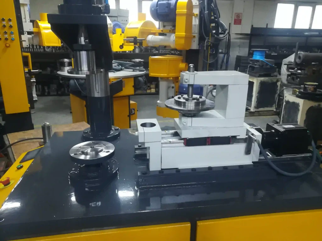
Rotary Forming Machine for Sheet Metal
A Rotary Forming Machine for Sheet Metal is an industrial machine designed to shape, bend, or contour sheet metal parts using rotary motion tools, typically rollers or forming heads that rotate as they engage the material. This forming method allows for smooth, continuous shaping of metal edges, flanges, or profiles with high precision and repeatability, making rotary forming machines widely used in automotive, aerospace, appliance, HVAC, and general metal fabrication industries.
The core principle behind rotary forming is the use of one or more rotating rollers that move along the edge or surface of a sheet metal blank, gradually bending or shaping it into the desired form. Unlike press or stamping operations that apply force through a single stroke, rotary forming applies consistent pressure along the part as the rollers travel, enabling gentle metal flow and minimizing risks of cracking, wrinkling, or distortion. This continuous rolling action is ideal for creating hems, flanges, curls, or complex contours with smooth transitions and uniform thickness.
Rotary forming machines come in various configurations depending on application requirements. Some machines feature a single roller that travels along straight or curved edges to form simple flanges or hems. Others have multiple rollers arranged in coordinated paths to perform multi-stage forming operations in one pass. CNC-controlled rotary forming machines allow precise adjustment of roller speed, pressure, and path, enabling complex geometries, variable flange widths, or tapered profiles to be formed consistently.
The machines are typically equipped with adjustable fixtures or clamps to securely hold the sheet metal part during forming, ensuring accurate positioning and repeatability. Tooling is usually made from hardened steel or coated materials to resist wear, with some rollers featuring urethane or polymer coverings to protect coated or painted surfaces. This versatility allows rotary forming machines to process a broad range of materials, including mild steel, stainless steel, aluminum, and advanced high-strength alloys.
One of the key advantages of rotary forming is its ability to handle long, continuous edges or complex contours with minimal cycle time. Because the roller moves steadily along the flange or edge, large panels such as automotive body skins, appliance housings, or HVAC ducts can be formed with uniform quality without the need for multiple press strokes or repositioning. This continuous process also reduces tooling costs compared to progressive dies or multiple stamping operations.
Rotary forming machines can be manually operated for prototype or small batch production, where an operator guides the rollers along the part. However, most industrial applications utilize semi-automatic or fully automated systems with motorized or servo-driven rollers and programmable controls. Automation enhances consistency, throughput, and operator safety by reducing manual handling and enabling integration with upstream and downstream manufacturing processes.
In advanced production lines, rotary forming machines are often integrated with robotic loading/unloading, vision systems for quality inspection, and sensors for process monitoring. Real-time feedback on roller force, speed, and position enables adaptive control, ensuring that forming parameters are optimized for each part and material batch. This reduces scrap rates, improves yield, and supports traceability in regulated industries such as automotive or aerospace.
Applications of rotary forming machines extend beyond hemming and flanging. They are also used for roll forming of specific edge profiles, crimping, embossing, or adding stiffening ribs and beads to sheet metal parts. The rotary motion provides a gentle forming action that preserves material integrity and surface finish, crucial for high-quality exterior panels or visible components.
Maintenance considerations include regular inspection and replacement of forming rollers, lubrication of moving parts, and calibration of control systems to maintain precision. Modern rotary forming machines often include diagnostics and predictive maintenance features that alert operators to wear or misalignment, minimizing downtime and ensuring continuous operation.
In summary, rotary forming machines for sheet metal provide a flexible, efficient, and precise method for shaping metal edges and profiles. Their continuous rolling action, adaptability to various materials and shapes, and compatibility with automation make them essential equipment in modern sheet metal fabrication across many industries.
Rotary forming machines continue to evolve in response to increasing demands for precision, speed, and flexibility in metal fabrication. Their ability to perform edge-forming operations with minimal material stress and superior surface quality makes them particularly valuable in the production of complex parts where aesthetics, structural integrity, and dimensional accuracy must coexist. This is especially evident in sectors like automotive manufacturing, where exterior body panels must be formed to exact contours without visible deformation, and in appliance production, where rolled edges are both a safety and design requirement.
At the core of a rotary forming machine’s capability is the control over forming dynamics. With servo-driven roller heads, the machine can apply precise amounts of pressure that gradually deform the sheet metal without introducing localized thinning, warping, or cracking. This is critical when working with sensitive materials such as high-strength steel or aluminum alloys, which are more prone to fracture under abrupt forming forces. Because the rotary forming process spreads deformation gradually along the edge of the part, it maintains more uniform material properties and surface finishes compared to abrupt pressing techniques.
Many machines today are equipped with CNC control systems that allow programming of complex forming paths along irregular geometries. For example, a single machine might be set to form straight flanges on one section of a panel and switch seamlessly to rolling a curved edge or even a variable-depth hem on another portion of the same part. This level of flexibility drastically reduces the need for retooling or multiple workstations and is a major advantage in environments where design changes or part variety are frequent. With the growing push toward modular vehicle platforms or customizable product lines, this agility in forming is a critical factor for competitive production.
Rotary forming is also highly compatible with other finishing operations. In many advanced systems, forming heads can be swapped or reoriented to perform additional tasks such as edge curling, ribbing, or beading. In one pass, a sheet metal part might receive a precision flange, a strengthening bead, and a smooth curled edge, reducing handling and improving throughput. Some systems incorporate automated tool changers that can load different roller heads based on the operation programmed in the control unit, allowing for multi-functionality without manual intervention.
Another notable feature in modern rotary forming machines is the ability to process pre-painted or coated materials without damaging their surface finish. By using non-marking rollers with urethane coatings or polished surfaces, the machine can maintain the protective layer on the sheet while forming it to tight tolerances. This capability is particularly important in the appliance industry, where panels must not only fit perfectly but also exhibit flawless finishes straight out of the forming process, ready for final assembly.
The use of sensors and adaptive controls in rotary forming has expanded significantly with the rise of smart manufacturing. Integrated force sensors measure the resistance encountered by the roller during forming, and this data is analyzed in real time to adjust motor torque, roller angle, or feed rate. These adjustments ensure consistent results even when dealing with minor material inconsistencies or batch variations. In some cases, machine learning algorithms are used to analyze historical forming data and refine the process automatically, reducing operator dependence and increasing repeatability.
In terms of ergonomics and usability, rotary forming machines are designed for easy access and minimal operator strain. Touchscreen interfaces provide intuitive navigation through programs and machine settings, while automated clamping systems position and secure parts without the need for manual adjustment. In semi-automatic configurations, foot pedals or dual-hand controls can be used to initiate forming cycles safely. Advanced models include full enclosure systems with light curtains or interlocks to meet stringent safety requirements, especially in high-speed environments.
From a maintenance perspective, rotary forming machines are designed with durability in mind. The rollers, typically the most stressed components, are often modular and easy to replace or recondition. Machines feature centralized lubrication systems and diagnostic software that alert users to bearing wear, misalignment, or abnormal motor loads before major failures occur. This proactive maintenance support is vital in minimizing unplanned downtime and ensuring uninterrupted production.
Industries that rely on the precision and finish of rotary forming include not only automotive and appliances but also aerospace, architectural panels, and even the medical sector for specialized enclosures or equipment housing. As product designs become more refined and customer expectations for quality and aesthetics continue to rise, the role of rotary forming machines in delivering superior edge profiles, functional bends, and decorative contours becomes increasingly central to advanced sheet metal fabrication. The combination of digital control, mechanical finesse, and multi-functional capability positions these machines as a cornerstone in any modern manufacturing facility focused on high-quality, scalable production.
As rotary forming machines become more deeply embedded into modern manufacturing systems, their role continues to shift from being a standalone forming tool to becoming a central, fully integrated station within smart production cells. These cells are often designed around flexibility and real-time responsiveness, where the rotary forming machine acts in conjunction with vision systems, robotics, and part tracking technologies to create a streamlined, error-proof process. Each part entering the forming station can be automatically scanned for orientation, material type, and even subtle dimensional variances before forming begins. The machine then adapts its forming profile accordingly, optimizing the operation for the exact conditions of that specific part.
This high level of responsiveness not only improves part quality and consistency but also drastically reduces waste. In industries like aerospace or high-end consumer products, where raw materials can be expensive and margins for error are minimal, this reduction in scrap and rework contributes directly to profitability. Moreover, for parts with very tight tolerances—where minor variations in edge profile can affect sealing, fit, or structural performance—the rotary forming machine’s ability to deliver repeatable, finely tuned forming paths is invaluable.
The influence of rotary forming technology also extends into product design itself. Engineers and industrial designers are increasingly taking into account the forming capabilities of these machines when developing new components. For example, the use of complex compound curves, flowing edge transitions, or integrated features like grooves and beads can be confidently specified in CAD models because designers know that rotary forming equipment can execute these profiles without compromising material strength or visual appeal. This synergy between design and manufacturing enables more innovative, lightweight, and integrated components to be developed across a wide range of applications.
In the context of sustainability and environmental compliance, rotary forming machines offer additional advantages. Their ability to form parts with minimal heat input or energy consumption aligns well with goals for greener production. Compared to methods like press forming or hot stamping, rotary forming uses less force, creates less noise, and produces fewer emissions. Furthermore, by eliminating the need for secondary deburring or grinding processes (which often generate waste and dust), rotary forming contributes to cleaner, more efficient operations overall.
From a logistics and factory layout perspective, rotary forming machines are relatively compact and adaptable. They can be installed as part of an island workstation for manual or semi-automatic operations, or integrated into linear or circular production lines with other forming, welding, and assembly equipment. Their modularity makes them well suited for scalable production, where additional forming stations can be added to accommodate increased volume or to introduce new product variants without reconfiguring the entire production floor.
Even in job shop environments where part types change frequently, rotary forming machines excel due to their short setup times and low tooling requirements. With the right programming and roller configurations, the same machine can switch from forming a straight edge on a flat panel to contouring a tapered curve on a domed part within minutes. This adaptability helps small-to-medium manufacturers compete with larger operations by offering quick turnaround and custom forming capabilities.
In applications involving pre-coated or laminated sheet materials, rotary forming is often the preferred method because of its gentle and progressive forming action. Paint, plastic films, or decorative laminates are preserved throughout the process, reducing the need for costly touch-up or refinishing steps. This is particularly important in architectural panel fabrication, signage, and consumer appliance manufacturing where first-surface appearance is critical.
In terms of future developments, rotary forming machines are expected to become increasingly intelligent, with deeper integration into digital manufacturing ecosystems. Cloud-based analytics, real-time process optimization, and even remote troubleshooting or toolpath adjustments through secure internet connections are all on the horizon. Operators and engineers will be able to simulate forming processes digitally, preview results, and adjust parameters without needing to run physical parts. This virtual prototyping capability will shorten product development cycles and reduce prototype costs, reinforcing the machine’s value beyond just forming parts—it becomes a core part of the design-to-production pipeline.
Ultimately, rotary forming machines offer a powerful combination of precision, flexibility, and efficiency. Their capacity to produce high-quality, complex edge profiles with minimal stress and maximum repeatability makes them essential to modern metalworking operations. Whether forming structural edges, enhancing appearance, or supporting downstream joining processes, rotary forming delivers unmatched capability for manufacturers focused on performance, speed, and quality.
Hydraulic Edge Roller for Sheet Metal
A Hydraulic Edge Roller for Sheet Metal is a robust forming machine designed to roll, bend, or contour the edges of sheet metal components using hydraulic power to drive its forming rollers. Unlike electric or manual systems, hydraulic edge rollers use pressurized fluid to deliver consistent, high-force output—making them ideal for processing thicker gauge metals or harder alloys that require substantial forming pressure.
The basic operation involves a sheet metal part being clamped or guided into position while a powered forming head—equipped with one or more rollers—applies controlled pressure to the edge or corner of the material. As the hydraulic system activates, the rollers rotate and simultaneously press into the metal, shaping it progressively along a predefined path. The machine may form a simple hem, a curled edge, a beaded profile, or a more complex contour depending on the roller geometry and motion path.
Hydraulic edge rollers are commonly used in applications requiring high-strength edge shaping, including industrial enclosures, structural panels, vehicle chassis components, and HVAC casings. The hydraulic system provides high torque and forming force, making these machines particularly effective when dealing with stainless steel, structural aluminum, and other high-resistance materials. The forming action is steady and powerful, yet precise, which allows the machine to shape edges without tearing, thinning, or wrinkling the base material.
These machines are typically built with heavy-duty frames to resist deformation under load, ensuring consistent accuracy over long-term production. Most hydraulic edge rollers feature adjustable roller spacing and stroke controls, enabling operators to customize the forming depth, radius, and shape based on the sheet thickness and material type. Multi-axis configurations may also allow for forming along curved paths, tapered edges, or circular contours.
While hydraulic edge rollers can be manually operated for low-volume jobs, industrial models often include programmable logic controllers (PLCs) and digital touchscreen interfaces. These allow for storage and recall of forming recipes, automatic adjustment of roller pressure and speed, and integration with part-tracking or quality monitoring systems. Some setups also include servo-controlled positioning tables that move the sheet into position between rolling stages, allowing for more complex or multi-edge forming in a single cycle.
The forming tools themselves are made from wear-resistant, hardened steel or alloy materials and may include coatings to reduce friction or protect painted or coated surfaces. In some models, interchangeable roller sets allow for quick changeover between different edge profiles or part types, improving efficiency and reducing downtime in mixed-batch manufacturing.
A key advantage of hydraulic edge rollers is their ability to produce smooth, strong, and consistent edges even in heavy materials. The hydraulic system’s fine control of pressure helps avoid overstressing the metal, making it ideal for forming parts that require both precision and durability. Applications include truck body panels, shipbuilding sheet components, architectural steel frames, heavy-duty equipment housings, and air handling ducts.
Maintenance typically involves monitoring the hydraulic fluid levels, checking seals and hoses for wear or leakage, and ensuring the forming rollers are free from damage or buildup. Modern machines may include sensor systems that detect roller wear, pressure anomalies, or part misalignment, allowing for preventive maintenance and reducing the risk of unscheduled downtime.
In summary, the hydraulic edge roller is a powerful and reliable solution for shaping the edges of thick or high-strength sheet metal parts. Its strength, adaptability, and forming precision make it an essential tool in heavy-duty fabrication environments where conventional forming methods might fall short.
Hydraulic edge rollers continue to be a preferred choice in environments where consistent forming of heavy or high-strength sheet metal is required, especially when working with parts that must maintain structural integrity under stress or when forming needs to be repeated at scale with exact uniformity. These machines excel in producing smooth, repeatable edge profiles without the high vibration or sudden deformation that can come from stamping or pressing processes. Because hydraulic systems allow for continuous pressure throughout the forming path, edge shaping is accomplished gradually and with tight control, minimizing material fatigue and avoiding localized thinning.
The versatility of hydraulic edge rollers is enhanced by their ability to handle various edge shapes. Whether forming tight-radius hems, wide flanges, shallow beads, or full curls, the forming head can be adapted with the appropriate rollers, and the hydraulic system can be finely tuned to deliver the exact pressure needed for each operation. This level of control makes the machines suitable for parts that will be visible in the finished product, where edge quality directly affects both the part’s function and its visual appeal. In HVAC systems, for instance, curled or hemmed edges reduce sharpness for safer handling and better sealing performance, while in vehicle body construction, rolled edges allow for better mating of outer and inner panels without compromising panel fit or surface finish.
Another benefit of the hydraulic drive system is its robustness in handling material inconsistencies. When forming metals that vary slightly in hardness, surface coating, or thickness, hydraulic edge rollers can accommodate these changes better than mechanical or pneumatic systems. With built-in pressure regulation and flow control, the system responds in real time to resistance changes in the material, maintaining a consistent forming profile even when the input sheets are not completely uniform. This feature is crucial in industries where recycled or batch-variant metals are common, such as construction or transportation equipment manufacturing.
In more advanced systems, hydraulic edge rollers are integrated with digital control systems that manage the full forming cycle. These systems monitor stroke length, roller speed, and forming pressure at each point along the edge, adjusting automatically if variations are detected. Data collected during forming can be stored for process traceability or exported to centralized manufacturing execution systems (MES) to support quality documentation and certification, which is often required in aerospace, defense, and medical device manufacturing. Some machines also include teach-and-learn features where operators can manually guide a new part through a forming cycle once, and the machine will store that path for automatic replay on future parts.
The physical design of hydraulic edge rollers supports both straight and curved edge forming. Some machines feature rotating worktables or adjustable positioning arms that allow the rollers to follow complex contours without repositioning the part manually. Multi-axis movement systems enable the forming head to follow a programmed 2D or 3D path across the sheet’s edge, ideal for shaped panels, conical components, or architectural metalwork. This capability is further extended with sensors that track roller angle and orientation, enabling real-time correction of misalignment and consistent forming pressure across curved or tapered parts.
In terms of operation, hydraulic edge rollers are generally easy to manage once programmed. For manual operations, a foot pedal or two-hand safety control is often used to initiate the cycle, while in automated configurations, cycle start is tied to sensors detecting proper part placement. Tooling changeovers are straightforward, with modular roller assemblies that can be quickly removed and replaced. Tool storage trays, calibration jigs, and even auto-adjust rollers are increasingly common on modern equipment, helping reduce downtime and maintain high productivity during changeovers or maintenance.
Hydraulic edge rollers also offer strong compatibility with a variety of production setups. In small-scale operations, they can function as a standalone workstation. In high-volume environments, they’re often one of several forming machines integrated into a continuous production line that includes blanking, punching, edge rolling, welding, and finishing. Their compact form factor, when compared to large stamping presses, allows them to be placed near the point of use, reducing material handling time and simplifying logistics within the shop floor layout.
For parts where appearance matters, such as architectural fascia, elevator panels, or consumer appliance components, the surface integrity maintained during hydraulic rolling is a major advantage. Since the rolling action is smooth and free from sudden impacts, protective films or coatings are rarely damaged, and additional surface finishing steps like deburring or edge polishing can often be eliminated entirely. This not only reduces labor and consumable costs but also speeds up time-to-assembly.
Looking ahead, developments in hydraulic systems—such as electro-hydraulic hybrids, smart flow controls, and low-noise pumps—are making hydraulic edge rollers even more efficient and responsive. Energy-saving features like load-sensing pumps and automatic standby modes reduce power usage during idle periods, aligning these machines with broader factory sustainability initiatives. As with other digitally enabled manufacturing tools, connectivity through IoT platforms will continue to increase, allowing real-time performance monitoring, remote diagnostics, and integration into fully automated smart factories.
In all, hydraulic edge rollers provide a critical capability in sheet metal forming operations that demand a balance between power and precision. Their ability to roll edges on thick or hard materials with minimal operator input, combined with adaptability to a wide range of edge profiles and part shapes, makes them a staple in modern fabrication lines where quality, safety, and production speed must be achieved simultaneously.
Hydraulic edge rollers also contribute significantly to worker safety and ergonomics in metal fabrication environments. Traditional edge finishing methods—such as manual grinding or hand forming—expose operators to sharp edges, flying debris, repetitive stress, and vibration-related injuries. By replacing these manual operations with a hydraulic edge roller, manufacturers eliminate much of the physical strain and risk. Operators no longer need to manually handle heavy sheets during edge work; instead, the machine holds, positions, and forms the sheet automatically or with minimal intervention. The hydraulic motion is smooth and quiet, further enhancing operator comfort compared to older pneumatic or mechanical alternatives.
In fabrication shops focused on quality assurance and lean production, hydraulic edge rollers also help reduce rework and scrap rates. The consistent rolling pressure and automated path-following capabilities produce uniform edge profiles from the first part to the thousandth, reducing variation that could affect downstream processes such as assembly, welding, or painting. If a part needs to be sealed with gaskets, joined with other panels, or mounted flush to a structure, the uniformity of the edge contour ensures a better fit and finish. This predictability is essential in industries where tolerances are tight and final products must pass stringent inspections before delivery.
Additionally, the versatility of hydraulic edge rollers makes them an attractive investment for fabrication companies serving multiple markets. A single machine can be adapted to work on HVAC duct corners one day and heavy truck panels the next, simply by changing rollers and adjusting stroke or pressure settings. In service centers or contract fabrication plants where product diversity is high, this flexibility reduces the need for specialized forming equipment and lowers the overall capital investment required to serve different clients and industries.
In high-end applications, such as architectural cladding or clean-room enclosures, hydraulic edge rolling provides not only a mechanical advantage but a cosmetic one. Rolled or hemmed edges created by these machines have a clean, finished appearance that can be left exposed in the final product, reducing the need for edge trim, protective caps, or additional finishing. This capability is often a key reason why architects, product designers, or engineers prefer rolled edges over sharp or stamped contours—especially in visible, customer-facing installations.
Hydraulic edge rollers are also well-suited for pairing with sheet tracking and barcode scanning systems in smart factories. When integrated into an automated line, a sheet or panel can be scanned for ID upon entering the station, and the machine will automatically load the correct forming parameters for that specific part number. This reduces errors, shortens setup times, and supports full traceability, which is critical for regulated industries like aerospace, energy, or medical manufacturing. The use of automation also helps compensate for skilled labor shortages, enabling less-experienced operators to produce high-quality parts by relying on preprogrammed processes.
Another application area where hydraulic edge rollers are making inroads is in green technologies and renewable energy equipment fabrication. Parts for wind turbine housings, solar panel frames, battery enclosures, and electric vehicle chassis all require consistent, structurally sound edges that can withstand environmental exposure and mechanical stress. The ability of hydraulic edge rollers to handle stainless steel, zinc-coated sheets, and thick aluminum panels makes them well suited for these applications, especially when product life cycles and reliability are paramount.
In terms of cost-effectiveness, hydraulic edge rollers strike a strong balance between up-front investment and long-term operating efficiency. Although they may carry a higher initial price tag compared to manual or pneumatic forming devices, their precision, speed, and reduced material waste quickly deliver ROI through increased throughput and lower scrap rates. Because the forming action is smooth and distributed, there is also less wear and tear on the rollers and tooling, which extends maintenance intervals and further reduces total cost of ownership.
Training and onboarding for hydraulic edge roller operators have also become simpler thanks to intuitive interfaces and digital controls. New operators can be trained quickly using stored programs, simulation modes, and guided setup procedures. Many systems feature user-friendly HMIs (Human-Machine Interfaces) that walk the operator through each forming cycle, allow real-time parameter adjustments, and provide visual feedback on machine status or maintenance needs. This usability helps ensure safe and efficient operation even in facilities with frequent staff rotation or varying skill levels.
In conclusion, the hydraulic edge roller is a cornerstone of precision edge forming in the sheet metal industry. It combines strength, flexibility, and control to produce high-quality, consistent edges across a wide range of materials and part geometries. Whether used for heavy-duty structural panels or delicate aesthetic parts, its smooth forming action, robust construction, and compatibility with automation make it an indispensable asset for modern manufacturing operations committed to quality, safety, and efficiency.
CNC Edge Rolling Machine for Sheet Metal
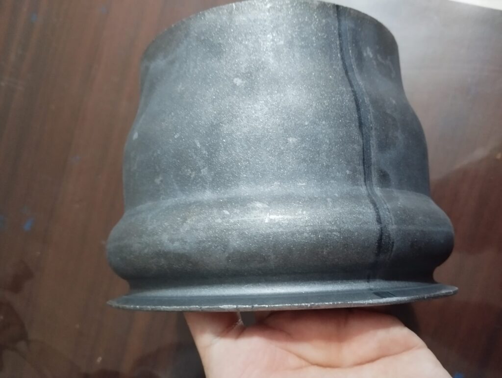
A CNC Edge Rolling Machine for Sheet Metal is a high-precision forming system designed to roll, hem, flange, or contour the edges of sheet metal components using computer-controlled rotary motion. Unlike traditional mechanical or hydraulic edge rollers, CNC edge rolling machines are equipped with programmable controls that automate and fine-tune every aspect of the forming process, including roller position, pressure, path, and speed. This level of control results in exceptional accuracy, repeatability, and flexibility—qualities that are increasingly vital in industries such as automotive, aerospace, electronics, and precision sheet metal fabrication.
These machines use servo-driven or hybrid electro-hydraulic systems to power the forming heads, which are typically equipped with hardened rollers that apply continuous pressure along the edge of the sheet. The CNC controller executes a predefined path, gradually deforming the metal into the desired profile. The forming can include straight hems, curved flanges, beading, edge curling, and even variable-depth or stepped profiles. Because the process is digitally controlled, each movement of the roller is coordinated and repeatable across large production runs or mixed part batches.
One of the standout advantages of CNC edge rolling machines is their ability to handle complex geometries. With multi-axis capability, the rollers can follow not just straight lines but also curves, compound corners, and contoured edges. The path is defined in a CAD/CAM environment and translated directly into motion instructions for the machine. This allows manufacturers to move seamlessly from design to production, shortening development cycles and enabling rapid prototyping or custom part fabrication without the need for specialized dies or manual setup.
CNC edge rolling machines are highly versatile when it comes to materials. They can process a wide range of metals, including aluminum, stainless steel, copper, mild steel, and coated or laminated sheets, with minimal risk of surface damage or deformation. This is achieved through precise force control and the use of custom or soft-coated rollers for delicate surfaces. Adjustments to pressure and forming angle can be made on the fly via the control system, allowing one machine to handle multiple gauges and material types without physical reconfiguration.
Automation is at the core of CNC edge rolling machines. Once a part program is loaded, the machine can position, form, and even inspect the part with minimal operator intervention. In more advanced setups, robotic arms load and unload sheets, integrated sensors verify part orientation and alignment, and inline metrology tools check edge dimensions and curvature. This full automation reduces labor, eliminates manual variability, and enables 24/7 production with high throughput.
CNC edge rollers are also known for their high repeatability. Every parameter—roller speed, pressure, position, and stroke—is executed exactly as programmed. This consistency is crucial in industries where even small variations in flange depth or curvature could affect assembly tolerances, sealing integrity, or surface finish. For example, in automotive door panels or appliance front frames, a precisely rolled hem ensures proper fit, function, and visual quality.
From a software standpoint, these machines are usually equipped with advanced HMIs (Human Machine Interfaces) that allow for part program selection, toolpath simulation, real-time process monitoring, and error diagnostics. The control systems often support industry-standard G-code and can be linked with CAD/CAM systems or production databases, enabling integration into smart factory environments. Operators can view forming simulations, adjust process parameters based on feedback, and even receive predictive maintenance alerts via the control interface.
Maintenance of CNC edge rolling machines is also simplified by their modular design and diagnostic features. The machine can log usage data, detect tool wear or alignment issues, and notify technicians before breakdowns occur. Most systems are designed for easy roller changes and have auto-calibration routines that reduce downtime during tooling setup. Lubrication systems, if needed, are often automated and monitored by the CNC to ensure consistent operation.
Environmentally, CNC edge rolling machines support sustainable manufacturing by minimizing material waste, reducing energy consumption compared to hydraulic presses, and eliminating secondary finishing steps like grinding or deburring. The precise forming action produces clean, finished edges in one pass, allowing parts to move directly to assembly, painting, or packaging without additional handling.
In summary, CNC edge rolling machines for sheet metal offer unmatched precision, flexibility, and automation for forming clean, consistent edges on complex parts. Their digital programmability, material adaptability, and integration potential make them a key asset in modern fabrication facilities seeking high-quality results, reduced labor, and streamlined production. Whether in high-volume industrial lines or precision job shops, these machines represent the future of edge forming technology.
CNC edge rolling machines continue to gain prominence as manufacturing evolves toward greater customization, tighter tolerances, and higher production efficiency. The precise control offered by CNC systems enables manufacturers to perform edge forming with a level of finesse that is nearly impossible with manual or conventional hydraulic systems. Every roller path, pressure profile, and motion sequence is driven by exact coordinates derived from CAD models, allowing even the most intricate edge contours to be rolled with minimal deviation. This is especially valuable for industries producing complex assemblies such as electric vehicle components, aircraft skin panels, or precision enclosures for medical devices.
The integration of CNC edge rolling machines into digital manufacturing ecosystems is another major advancement. These machines can communicate directly with factory-wide MES and ERP systems to retrieve part specifications, update production schedules, and report quality metrics in real time. As a result, they don’t just perform forming tasks—they become active nodes in a connected production chain, adapting on the fly to batch changes, custom orders, or feedback from quality control systems. This level of digital integration supports mass customization, where individualized parts can be rolled with the same efficiency as high-volume standardized ones.
In robotic cells, CNC edge rollers often operate as fully autonomous units. Robots equipped with vision systems pick parts from input stations, feed them into the machine, and reposition them for multi-edge forming. Once forming is complete, the robot removes the part and transfers it to welding, assembly, or inspection stations. Because the CNC system precisely controls forming speed and roller position, it can maintain perfect coordination with robotic movements, ensuring consistent timing and no bottlenecks. This kind of full-line synchronization is essential in industries like white goods or aerospace where throughput, precision, and traceability are equally critical.
The forming quality of CNC edge rollers also has implications for downstream operations. When edges are rolled to tight tolerances and clean finishes, welding or fastening becomes easier and more reliable. Components align more accurately, seal more effectively, and require fewer adjustments during final assembly. This leads to shorter cycle times and fewer quality issues on the production floor. In packaging and enclosure fabrication, for example, a perfectly formed rolled edge ensures that doors close flush, panels align seamlessly, and gaskets or seals perform correctly.
Advanced CNC systems also allow for dynamic forming adjustments during the cycle itself. Sensors embedded in the machine may monitor part resistance, roller position, or material springback, and the control system can immediately adjust pressure or path accordingly. This real-time feedback loop ensures that even if sheet material varies slightly in hardness or coating thickness, the final edge will meet the desired specifications. This adaptive forming capability is particularly important when working with recycled or variable-lot materials common in sustainable manufacturing environments.
The machine’s modularity further enhances its appeal. With multiple roller heads mounted on linear or rotary axes, a single CNC edge rolling machine can be configured for several forming types without retooling. Some systems include automatic roller change units, allowing the machine to switch between forming heads mid-cycle based on the geometry of the next part in the queue. This makes it ideal for mixed-model manufacturing where multiple part types must be produced back-to-back with minimal setup time.
Noise and vibration reduction is another important benefit. CNC edge rolling operates more quietly and smoothly than press forming or stamping, making it suitable for clean production areas or facilities with strict noise compliance regulations. It also creates less wear on tooling and machine components, contributing to longer service life and more predictable maintenance cycles. Operators benefit from quieter working conditions, and the machine can be placed in more sensitive production areas without requiring heavy isolation or enclosures.
In terms of training and usability, CNC edge rolling machines are typically equipped with graphical user interfaces and step-by-step programming aids that reduce the skill threshold for operation. Operators can learn to run the machine quickly, using visual simulations to preview forming paths and make adjustments without running test parts. For facilities facing skilled labor shortages, this ease of use is a major advantage, allowing less-experienced staff to produce high-quality results with the assistance of pre-set programs and guided workflows.
As more companies shift toward modular and customizable product platforms, CNC edge rolling machines are becoming a key enabler of agile manufacturing. They offer the ability to rapidly switch between parts, roll intricate or branded edge designs, and scale production up or down without sacrificing quality. Combined with their ability to minimize material waste and eliminate post-processing, they contribute not just to operational efficiency but also to environmental goals and cost savings over the long term.
Overall, CNC edge rolling machines represent a mature, highly capable solution for precision edge forming. Their digital control, automation readiness, and material flexibility make them indispensable in advanced manufacturing environments where consistency, adaptability, and speed must be achieved simultaneously. As manufacturing continues to evolve toward smarter, cleaner, and more responsive production systems, these machines will remain at the forefront of edge forming technology.
As the demand for lightweight, high-strength, and aesthetically refined metal components continues to rise, CNC edge rolling machines are being pushed to deliver not only speed and precision but also design versatility. In industries such as electric vehicles, aerospace, and architecture, there is growing interest in complex geometries and unconventional edge shapes—rolled transitions, segmented flanges, variable-thickness curves, or dual-material panels. CNC edge rollers are uniquely equipped to handle such requirements because their tool paths can be freely programmed and adapted to nearly any profile, including asymmetrical and multi-stage forms. This enables the fabrication of parts that combine structural functionality with design-driven aesthetics, all while maintaining tight tolerances and surface integrity.
Material science also intersects with CNC edge rolling in important ways. As advanced sheet materials such as aluminum-lithium alloys, high-strength low-alloy steels, and coated laminates become more common, traditional edge forming methods often fail due to cracking, springback, or surface damage. CNC edge rolling overcomes these issues with programmable pressure control, gradual material deformation, and the ability to dynamically adjust forming paths based on real-time feedback. This ensures that even difficult-to-form materials can be shaped into usable, production-ready components without compromising performance or finish.
Customization and personalization trends are also fueling the adoption of CNC edge rolling. In sectors like luxury appliances, architecture, or high-end consumer products, clients increasingly demand unique edge contours or branded finishes. CNC machines allow the manufacturer to implement such requests efficiently—whether it’s a decorative rolled detail, a custom curvature for ergonomic interfaces, or an integrated channel for lighting or hardware. Since the forming is digital and tool-less apart from the rollers, producing variations or special editions does not require expensive dies or extended lead times.
CNC edge rolling also plays a crucial role in hybrid manufacturing systems that combine additive, subtractive, and forming processes. For instance, a metal component may be laser-cut or waterjet-cut to net shape, then passed to a CNC edge rolling station for precision forming, and finally to welding or laser joining. This seamless integration reduces the number of fixtures and repositions required, eliminates redundant tolerance buildup, and maintains a digital thread from design to delivery. In such setups, the CNC edge roller functions not just as a forming device but as a critical node in a tightly choreographed digital workflow.
From a sustainability standpoint, CNC edge rolling minimizes waste and material overuse by forming close to final shape without generating offcuts, chips, or abrasive dust. The absence of consumables like grinding wheels or sanding belts, combined with lower energy consumption compared to press-based systems, gives these machines a lower environmental footprint. Furthermore, because the forming process preserves protective coatings or films, fewer parts are rejected due to cosmetic flaws, and post-finishing steps are reduced or eliminated. In production environments aiming for ISO 14001 certification or other sustainability benchmarks, CNC edge rollers contribute positively to overall metrics.
The next frontier for CNC edge rolling involves deeper integration with artificial intelligence and cloud-based control platforms. Predictive analytics can optimize tool wear schedules based on thousands of forming cycles. AI-driven algorithms may recommend roller paths that balance cycle time and material stress. Cloud platforms allow service teams to monitor edge rolling stations remotely, push software updates, and coordinate maintenance without physical intervention. These capabilities transform the CNC edge roller from a fixed tool into a dynamic, intelligent asset within the broader context of smart manufacturing.
Even in traditional job shop environments, these machines are proving transformative. A CNC edge rolling machine enables a small fabrication shop to quote jobs it couldn’t handle before—tight-radius curls on aluminum covers, precision hems on display enclosures, or custom-flanged panels for architectural builds—without adding significant labor, tooling, or setup costs. The machine essentially levels the playing field by allowing smaller operations to offer high-end results that rival those of much larger factories.
All of this underscores one fundamental reality: CNC edge rolling machines are no longer optional upgrades or niche tools. They are becoming central fixtures in competitive sheet metal production because they combine digital precision with mechanical reliability, support a wide range of applications, and align with global trends toward smart, sustainable, and customized manufacturing. Whether a plant produces thousands of identical panels or one-off architectural features, the ability to control every millimeter of edge geometry via CNC makes these machines invaluable across the spectrum of industrial fabrication.
Edge Conditioning Machine for Sheet Metal
An Edge Conditioning Machine for Sheet Metal is a specialized piece of equipment designed to improve, refine, and prepare the edges of sheet metal parts for downstream applications such as welding, assembly, coating, or aesthetic finishing. Unlike machines that primarily shape or bend edges (like edge rollers or hemming presses), edge conditioning machines focus on removing burrs, smoothing sharp corners, rounding profiles, and applying uniform finishes to raw or cut sheet metal edges. They are widely used in industries such as aerospace, automotive, appliance manufacturing, HVAC, electrical enclosures, and metal furniture, where edge quality directly impacts safety, performance, and product appearance.
These machines are essential in operations where laser cutting, shearing, stamping, or punching leaves behind burrs or rough edges that could cause safety hazards, interfere with assembly, or compromise coating adhesion. By conditioning the edge, the machine enhances both the mechanical and cosmetic properties of the sheet part, ensuring that each piece is ready for subsequent processing or final use.
Edge conditioning machines typically use rotating abrasive belts, wheels, or brushes to grind, polish, or radius the edge of a part as it is guided through the system. In many models, sheets are fed automatically between upper and lower heads equipped with conditioning tools that simultaneously work both edges. Some machines include side heads for vertical edge conditioning, enabling full perimeter processing in a single pass. The material is typically clamped or guided using rollers to maintain alignment and consistent pressure throughout the operation.
Advanced systems offer CNC or servo-controlled adjustments that allow the machine to automatically set belt pressure, tool height, and feed speed depending on part thickness, material type, or edge profile. These programmable features are particularly useful when processing a mix of parts with different specs, reducing changeover time and minimizing human error.
Edge conditioning can be tuned to achieve a variety of results. For structural parts or panels that will be welded, a slightly chamfered or deburred edge ensures proper joint penetration and reduces spatter. For painted or powder-coated products, rounding the edge promotes better coating wrap and corrosion resistance. For consumer-facing products like appliances or electronics, a smooth, polished edge improves both safety and tactile appeal.
Materials commonly processed include stainless steel, aluminum, cold-rolled and galvanized steel, copper, and even non-metallic substrates such as plastics or composites in some hybrid machines. Tooling may include abrasive belts, non-woven wheels, ceramic-grit flap brushes, or specialized tools for oxide removal. Many machines allow quick changeover of media to suit different materials or finish requirements, and some include automatic tool-wear compensation to maintain consistent results over long runs.
Dust extraction and debris control are key components in edge conditioning machines. Abrasive processes generate fine particulate matter, so most machines are equipped with integrated vacuum systems, mist collectors, or dust hoods that remove debris at the source. This not only protects operators and machinery but also ensures that the finished part remains clean and contamination-free.
Edge conditioning is also increasingly automated and digitally integrated. Systems may include part scanning or barcode readers that identify the incoming part and load the appropriate program. The machine can then adjust its settings instantly, apply the necessary finish, and record process parameters for quality control. In high-volume or just-in-time manufacturing environments, this ability to condition parts on demand while maintaining full traceability adds considerable value.
In fabrication lines where edge quality is critical, such as in battery enclosures, medical equipment, or food-grade stainless steel products, edge conditioning machines are often placed immediately after cutting stations. This inline setup ensures that every part is processed consistently before entering forming, welding, or coating. For high-mix, low-volume production, standalone edge conditioning stations offer flexibility, allowing operators to quickly process short runs or prototypes with minimal setup.
Overall, edge conditioning machines play a vital role in bridging the gap between raw sheet cutting and final product finishing. By delivering uniform, safe, and application-ready edges, they improve product quality, reduce rework, increase operator safety, and enhance the overall efficiency of sheet metal production processes. Whether in a high-speed automated line or a flexible job-shop setup, edge conditioning ensures that sheet metal components meet the exacting standards of today’s manufacturing industries.
Edge conditioning machines continue to evolve in response to the growing demands for precision, surface quality, and production efficiency in modern sheet metal fabrication. Their role is especially important in the context of high-value applications where edge quality directly influences both functionality and safety. For example, in the aerospace and defense sectors, improperly finished edges can lead to premature fatigue failures, micro-cracking, or poor bonding surfaces in structural assemblies. By consistently removing stress risers, sharp corners, and micro-burrs, edge conditioning machines contribute significantly to long-term durability and reliability of the final product.
In many production scenarios, edge conditioning serves not only a functional purpose but also a regulatory one. Standards such as OSHA, ISO, and EN safety norms often require exposed metal edges in consumer-facing or handling-intensive products to be rounded to reduce laceration risks. Edge conditioning machines meet these requirements with programmable control over edge radius, finish type, and edge symmetry, ensuring compliance without compromising production speed. The result is a safer, more compliant product that is also easier to assemble, coat, and ship.
Some of the more advanced edge conditioning machines use high-speed vision systems and laser sensors to assess the condition of incoming part edges before processing begins. These sensors measure edge height, burr length, edge sharpness, and surface finish in real time, providing closed-loop feedback to the machine’s controller. This adaptive control system automatically adjusts tool pressure, speed, and positioning to compensate for variations in material condition, sheet thickness, or cut method. Whether the edge was produced by plasma, laser, or mechanical shearing, the system adapts to deliver a uniform result with minimal operator input.
Another key advancement is the use of multi-head, multi-directional conditioning systems. These machines can perform simultaneous top, bottom, and side edge finishing, allowing parts to pass through a single station and emerge completely conditioned on all sides. This is particularly useful for rectangular panels, formed enclosures, or cabinet doors where all four sides need to be smooth, burr-free, and consistent in finish. Some configurations even include corner-forming heads or oscillating tools that allow for precise edge rounding at part corners, which are often the most difficult areas to process manually or with traditional equipment.
Energy efficiency and environmental impact are also being addressed with new edge conditioning technologies. Modern machines are designed with efficient motors, variable-frequency drives, and automatic shutoff systems that reduce idle consumption. Tooling life is maximized through wear monitoring and intelligent tool rotation schedules, while abrasive waste is minimized with reclaim systems that collect and recycle media. Dust extraction systems with HEPA filtration ensure that even the smallest airborne particles are captured, making the machines suitable for clean-room or low-contamination production zones.
The flexibility of edge conditioning machines is also a major advantage for manufacturers working with varied product portfolios. One day, the machine might be finishing thin-gauge aluminum HVAC panels with soft brushed edges; the next day, it could be deburring thick stainless steel blanks for industrial enclosures. Because many machines offer fast tool changeovers, pre-loaded finishing recipes, and intuitive touchscreen controls, this versatility can be realized without extended downtime or specialized labor. Operators can switch between jobs quickly while maintaining a high level of consistency and quality control across all part types.
Edge conditioning machines are often used in tandem with other post-cutting processes such as deburring, oxide removal, and surface texturing. In fact, some integrated systems combine all these steps into a single machine footprint, reducing floor space requirements and simplifying the production flow. These all-in-one solutions are particularly appealing to manufacturers who want to shorten lead times, reduce WIP (work-in-progress), and eliminate the need for multiple handling or inspection steps between stations.
Digital documentation and traceability are also becoming standard features. As edge conditioning becomes a quality-critical step, manufacturers are increasingly required to document how, when, and with what settings each part was processed. Edge conditioning machines with built-in data logging systems automatically record key process variables—such as belt wear, roller speed, edge profile measurements, and cycle time—and store them against each batch or part number. This data can be reviewed by quality control teams, uploaded to factory databases, or sent to customers as part of compliance reports.
As production trends continue toward lights-out manufacturing and full automation, edge conditioning machines are being designed for unattended operation. This includes features like automatic tool wear detection, robotic part handling, and self-calibrating sensors that enable the machine to run continuously with minimal human supervision. With properly integrated software and automation, a single edge conditioning unit can process thousands of parts per day with consistent results, feeding directly into robotic welding cells, powder coating booths, or final assembly stations.
In summary, edge conditioning machines for sheet metal are no longer auxiliary tools—they have become essential contributors to modern fabrication workflows. Their precision, adaptability, and ability to ensure consistent edge quality across varying materials and part geometries make them indispensable in meeting today’s performance, safety, and aesthetic standards. As manufacturing continues to prioritize automation, customization, and lean production, edge conditioning will remain a vital process, ensuring that every part not only fits and functions but also reflects the highest standards of quality and finish.
As edge conditioning machines become more deeply embedded in digital manufacturing environments, their role continues to expand beyond simple finishing into active quality control and production optimization. With increasing pressure on manufacturers to deliver defect-free parts at faster rates, these machines are now expected to not only perform consistent edge treatment but also detect irregularities and adapt in real time. For instance, a modern edge conditioning machine can identify excessive burrs caused by tool wear upstream in the cutting process and alert maintenance or even pause production, acting as a sentinel within the production line.
This intelligence is also playing a growing role in predictive maintenance. Using embedded sensors and data analytics, edge conditioning machines track their own operational metrics—run time, temperature, vibration, media wear, and load cycles—and forecast when maintenance or media replacement will be required. This capability helps avoid unexpected downtime and reduces the risk of producing out-of-spec parts due to unnoticed tool degradation. In high-throughput environments where even a short stoppage can create a backlog, this kind of predictive functionality is essential to maintaining consistent output and delivery timelines.
For operations seeking to adopt lean manufacturing principles, edge conditioning machines support continuous improvement initiatives by offering high levels of process control, repeatability, and efficiency. The consistency they bring to edge profiles reduces downstream defects and rework, supports faster assembly, and ensures that parts align properly during joining. The reduction of secondary deburring or touch-up operations not only saves time but also reduces the potential for human error or cosmetic damage caused by manual intervention.
Another emerging application of edge conditioning technology lies in surface preparation for advanced joining techniques. For example, when parts are to be joined by structural adhesives, laser welding, or friction stir welding, edge cleanliness and contour uniformity are critical to joint integrity. Edge conditioning machines can be configured to deliver precise surface roughness or oxide removal along the edges to ensure reliable adhesion or fusion, significantly improving joint strength and product longevity.
In industries such as medical equipment, electronics, and food processing, where hygiene and product cleanliness are paramount, edge conditioning contributes to compliance with strict regulatory standards. Clean, smooth edges reduce the risk of bacterial contamination, eliminate particle shedding from unfinished edges, and improve the wash-down capability of stainless-steel components. The ability of edge conditioning machines to process parts without compromising these standards is a major reason why they are often found in the production of pharmaceutical enclosures, surgical instruments, and cleanroom hardware.
Another area where edge conditioning is gaining traction is in the production of EV battery enclosures and renewable energy components. In these applications, edge integrity is closely linked to safety, especially in high-voltage environments where burrs or rough edges can compromise insulation or create hotspots. Precision-rounded or beveled edges produced by conditioning machines improve insulation reliability, reduce handling injuries, and meet tight tolerances required for modular battery packs and structural casings. Additionally, the process supports sustainability objectives by enabling clean forming without the need for toxic chemical edge treatments or high-energy thermal processes.
The modularity of modern edge conditioning machines also supports scalable production. Entry-level models can be deployed in low-volume or prototype environments, while higher-capacity systems with multiple conditioning heads, automatic tool changers, and robotic part handling can meet the needs of high-volume, multi-shift production. This scalability ensures that manufacturers can invest at the level appropriate to their current needs while preserving the option to expand or upgrade as demand grows.
Training and usability have also improved dramatically. Touchscreen interfaces with multilingual support, visual programming aids, and real-time feedback allow operators with minimal technical background to run the machines effectively. Training time is shortened, error rates are reduced, and less reliance is placed on tribal knowledge or manual skill, which is crucial in labor-constrained environments. Cloud-based training modules and digital twins further assist in workforce development, allowing operators to simulate edge conditioning processes before touching the machine.
In terms of return on investment, edge conditioning machines offer measurable cost savings across multiple dimensions: reduced rework, fewer safety incidents, lower coating failure rates, less manual labor, and faster part flow. When amortized across long production runs or mission-critical applications, these savings far outweigh the initial capital cost. And as edge conditioning becomes a specification in itself—often called out explicitly in RFQs and technical drawings—having this capability in-house becomes a competitive differentiator for manufacturers bidding on precision parts contracts.
Ultimately, the edge conditioning machine represents a fusion of finishing, quality assurance, and process intelligence. It transforms raw-cut parts into safe, functional, and cosmetically acceptable components, ready for whatever comes next in the production chain—whether that’s welding, coating, assembling, or packaging. In doing so, it not only adds value but also removes risk, making it one of the most strategically important machines in any modern metal fabrication operation.
Slip Roll Machine (Slip Roller) for Sheet Metal
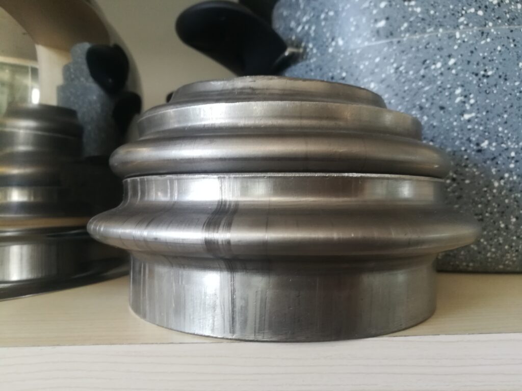
A Slip Roll Machine (commonly known as a Slip Roller) for sheet metal is a fundamental forming tool used to roll flat sheets into curved forms, cylinders, cones, or arcs. It operates using a set of three rollers—typically arranged in a triangular configuration—through which the sheet metal is fed and progressively bent. Slip rollers are essential in any fabrication environment where rounded or rolled metal components are needed, including ductwork, tanks, enclosures, vehicle parts, and architectural metal elements.
The machine works by pinching the sheet between two rollers—usually the bottom rollers—and bending it as it is drawn around the third, adjustable roller, typically located on top or behind. The degree of curvature is controlled by adjusting the position of this forming roller, which determines how tightly the material wraps during the pass. As the sheet is fed forward and back through the rollers, it is gradually shaped into the desired curvature.
Slip rollers are available in manual, motorized, and hydraulic configurations. Manual slip rollers are compact and operated by a hand crank, making them suitable for light-gauge metals like aluminum or thin steel and for low-volume tasks in shops, schools, or prototyping environments. Motorized slip rollers offer powered feeding and are designed for heavier gauges or higher volumes, enabling smoother operation, consistent feed rates, and reduced operator fatigue. Hydraulic slip rollers, the most powerful version, can handle thick-gauge steel or stainless steel and are used in industrial settings for heavy-duty applications.
Most slip roll machines allow for cone rolling—creating tapered cylindrical forms—by independently adjusting the position of the side rollers. Some advanced models feature digital readouts, programmable roller positions, and automatic return features to improve forming precision and reduce operator involvement. Higher-end machines may also be integrated with CNC systems for automated rolling of complex contours and radius transitions.
Tooling in a slip roll machine is critical for clean results. The rollers are typically made of hardened steel to resist wear and deformation. They may have polished or grooved surfaces depending on whether they are used for smooth sheet rolling or wire/rod forming. For delicate or pre-finished materials, protective coatings or sleeves can be added to prevent surface scratching or galling.
Slip rollers are used across many industries. In HVAC, they form round ducts, elbows, and sleeves. In food and pharmaceutical equipment, they help shape cylindrical tanks and drums. In architectural metalwork, they are used to roll parts for decorative railings, signage, or artistic structures. Automotive and aerospace applications include exhaust pipes, tubular supports, and curved body panels. The machine’s ability to create smooth, continuous curves with minimal effort makes it indispensable for any operation that works with curved or cylindrical forms.
The forming process with a slip roller is relatively straightforward but requires skill to achieve high consistency. The operator must feed the sheet evenly, apply the right roller pressure, and often roll multiple times to achieve tight radii. Adjustments must be made carefully to prevent flat spots, uneven curves, or sheet slippage. With experience, operators can quickly judge the pressure needed for different materials and radii, achieving precise results with minimal trial and error.
Slip roll machines also play an important role in prototyping and small-batch production. They allow fabricators to quickly form round or curved parts without the need for expensive press tooling or dies. For example, a metal tube, decorative column, or bracket with a gentle arc can be formed in minutes using just one operator and a slip roll. This agility is key in design shops, custom fabrication houses, and R&D departments.
Safety features vary by machine size and power but generally include finger guards, emergency stop switches, and limiters to prevent over-rolling. Larger or powered models may feature foot pedals, dual-hand controls, and overload sensors to enhance operator protection.
In summary, the slip roll machine is a simple yet powerful forming tool that transforms flat sheet metal into curved components with speed and precision. Whether manual or motorized, it remains one of the most versatile and cost-effective machines in any sheet metal workshop, capable of producing a wide range of parts for countless industries with consistent and repeatable results.
Slip roll machines continue to be a go-to solution in fabrication because of their balance between mechanical simplicity and forming versatility. The three-roll configuration, usually with two fixed lower rolls and one adjustable upper roll, allows gradual and controlled deformation of the metal sheet as it passes through. For tighter radii, the top roll is moved downward, increasing the pressure and curvature of the bend. The operator can also adjust the end rollers laterally to allow conical shapes to form, which is especially useful in producing tapered hoods, transition ducts, or flared components.
One of the key strengths of slip rollers is their ability to deliver smooth curves without introducing stress marks, kinks, or deformations commonly seen with press braking or manual bending techniques. This is crucial in aesthetic applications where the surface quality of the final part must remain pristine. Because the forming occurs through rolling rather than impacting, slip rollers distribute force more evenly across the sheet surface, preserving coatings, finishes, and base material integrity. In stainless steel kitchen equipment, high-end signage, or polished architectural trim, this surface preservation is especially valuable.
Operators often use slip rollers in combination with other forming and cutting machines. After a sheet is laser-cut or sheared to size, it can be sent directly to the slip roller for forming. This seamless flow supports lean manufacturing principles and minimizes handling time. In automated production environments, slip roll machines may be outfitted with digital positioners, part sensors, and programmable roll adjustments to facilitate one-touch forming cycles. Sheet metal can be automatically fed into the rollers, formed to exact specifications, and then conveyed downstream to welding, fastening, or assembly stations.
The ability of slip rollers to work with a broad range of materials also contributes to their widespread use. Aluminum, mild steel, stainless steel, copper, brass, and even plastic or composite sheets can all be rolled with the right settings and tooling. Some machines feature hardened rollers or specialty coatings that allow them to handle abrasive or high-tensile materials without excessive wear. When rolling metals like galvanized steel or aluminum with a decorative finish, urethane sleeves or protective films are sometimes used to prevent scratching.
In terms of size and capacity, slip rollers range from compact bench-top units designed for light-gauge sheets and small shop use, to large industrial machines capable of rolling several-millimeter-thick steel plates over several meters in width. The larger models often include hydraulic assist for the roll adjustments and motorized drives to power the feed and reverse actions, which makes them suitable for continuous, heavy-duty operations. Some high-capacity machines also incorporate crowning adjustments, allowing operators to compensate for roll deflection and maintain consistent curvature across the full width of wide sheets.
Another area where slip roll machines excel is in the production of small-radius or multi-radius curves. By feeding the sheet multiple times through the rollers with incremental adjustments, a complex curve or nested arc can be built up gradually. Skilled operators use this technique to produce decorative scrolls, semi-circular frames, and cylindrical shells with precise radii. This repeatability and control make slip rollers indispensable in metal art, custom vehicle parts, and bespoke architectural projects.
Maintenance of slip roll machines is relatively straightforward, making them a durable, low-cost investment over time. Lubrication of the gears and bushings, occasional inspection for roller alignment and wear, and routine cleaning to remove metal dust are usually all that’s required to keep the machine performing well. Because there are few moving parts and no high-impact operations, machine longevity is excellent, and many well-maintained slip rollers remain in service for decades.
Training for slip roll operation is also accessible. Basic manual rollers require only an understanding of feed direction, pressure adjustment, and rollback for re-feeding. Even powered or hydraulic models have intuitive controls that can be mastered quickly by new operators. In workshops where a wide variety of radii or materials are handled, simple measuring jigs and rolling charts can be used to speed up setups and improve accuracy.
From a production planning standpoint, slip roll machines allow a high level of flexibility. They are ideal for just-in-time production of parts that are needed in variable sizes and quantities. Whether a job calls for a single prototype shell, a short run of duct collars, or hundreds of steel cylinders, the slip roller can meet the need without requiring dies, mold changes, or extensive programming. This ability to form on demand with minimal prep is especially valuable in custom metal fabrication, repair shops, and dynamic production environments where responsiveness is critical.
In modern metalworking operations, the slip roller remains one of the most useful machines thanks to its mechanical simplicity, adaptability to different tasks, and suitability for forming a wide range of sheet materials into curves, rolls, and shells. It supports high-quality results whether used in manual operations or integrated into automated production lines, and continues to provide an essential bridge between flat-sheet preparation and final product fabrication.
In addition to its core functions, the slip roll machine often acts as a creative tool for fabricators, enabling the realization of custom forms and design elements that would otherwise require complex and costly tooling. This freedom makes it especially valuable in industries where uniqueness and customization drive demand. In custom vehicle fabrication, for instance, builders use slip rollers to craft fender flares, air intakes, and exhaust shields that follow the contours of a bespoke chassis. In sculpture and architectural metalwork, artists and designers roll smooth arcs and elegant spirals that become integral to the aesthetic expression of their projects. These creative uses reinforce the slip roller’s role not only as a production tool but as a means of artistic and design flexibility.
Even in industrial production, where parts must conform to strict tolerances and repeatability is paramount, slip rollers contribute to accuracy through careful calibration and machine rigidity. Precision-ground rollers, tight-clearance bearings, and digital controls on high-end models allow even tight-radius cylinders to be produced with consistent diameter and surface finish. When integrated with CNC controls, slip roll machines can follow exact rolling sequences, enabling compound curves or non-uniform arcs to be programmed directly from CAD designs. This digital interface minimizes human variability and extends the machine’s utility into advanced production scenarios where design-to-part accuracy must be tightly controlled.
The ability to form rolled parts without introducing marks or deformation is also important for applications that undergo additional surface treatments. Powder coating, anodizing, and plating processes benefit from the smooth transitions and undisturbed grain structure that slip rollers provide. Any excessive marking, galling, or pinching during forming can lead to uneven coating thickness or adhesion issues—problems that are minimized when rolling is performed with properly adjusted tension and clean, defect-free rollers.
Because of the growing demand for lightweight and corrosion-resistant structures, slip roll machines are increasingly used with aluminum alloys and stainless steel. These materials require careful handling due to their tendency to spring back and their sensitivity to surface marring. Slip rollers accommodate this through incremental rolling, precise pressure control, and multi-pass techniques. Skilled operators know how to anticipate springback and compensate for it during the rolling process, ensuring that the final part retains its intended shape once released from the machine.
Slip rolling is also favored in industries that prioritize low-distortion forming methods. Unlike press brakes, which concentrate force along a sharp bend line and can induce warping or residual stress, slip rollers distribute deformation evenly across the curve. This is especially important in components that must remain flat along adjoining surfaces or must assemble into round configurations with little post-processing. Rolled edges and curves are not only structurally stronger due to their distributed stress, but they also produce a cleaner, more refined appearance with less effort.
Furthermore, slip rollers can assist in pre-forming operations for more complex forming stages. In some cases, a sheet is rolled into a loose curve using a slip roller, then transferred to a die press or stamping tool to complete the shape. Pre-rolling reduces the strain on the secondary forming tool and minimizes the risk of cracking, buckling, or tool damage. In metal spinning, for instance, starting with a slightly rolled blank improves spinning consistency and reduces machine time.
Slip roll machines also allow for adjustments mid-process. Operators can roll a sheet partially, remove it, inspect the curvature, and re-feed it for minor correction or tightening of the radius. This iterative forming approach is difficult or impossible with rigid press-based methods, offering greater control when forming is highly dependent on fit or alignment with adjacent parts. In cases such as panel closures, pressure vessels, or frame collars, this flexibility ensures that the final product fits seamlessly into the assembly without rework.
Durability is another hallmark of well-built slip rollers. The machine frames are typically made from heavy-duty cast iron or welded steel to withstand the high forces involved in forming thicker materials. Precision-machined components, sealed bearings, and robust drive systems contribute to a long operational life even under daily use. Many slip rollers operate for decades with only routine maintenance and occasional roller regrinding. This longevity and low maintenance make them one of the most cost-effective forming investments for metal fabricators of all sizes.
In educational environments, slip rollers are commonly used in technical schools and trade programs to teach students the fundamentals of metal forming. Their visible mechanics and hands-on operation make them ideal for demonstrating key concepts such as bend radius, material springback, work hardening, and the effects of forming pressure. They provide immediate feedback and visual results, helping students gain confidence and understanding in forming techniques before progressing to more advanced equipment.
In conclusion, the slip roll machine remains one of the most versatile, reliable, and essential tools in the sheet metal fabrication world. Its ability to create smooth, consistent curves with minimal setup, wide material compatibility, and adaptability across industries makes it a foundational asset in both manual workshops and automated production lines. Whether forming simple cylinders or complex custom curves, it provides unmatched value through durability, precision, and creative potential.
Flanging Roller Machine for Sheet Metal
A Flanging Roller Machine for Sheet Metal is a specialized forming tool used to create flanges—raised or bent lips—along the edges of sheet metal components. These flanges serve structural, assembly, or sealing functions, allowing parts to be joined, stiffened, or fastened to other components. The machine forms the flange by rolling the sheet edge against a rotating die or forming wheel, producing a clean, uniform bend without cracking, wrinkling, or distortion. Flanging roller machines are used across industries such as automotive, HVAC, cookware, appliance manufacturing, ductwork, and metal enclosures, where precise edge forming is essential.
Unlike press flanging, which deforms the edge in a single stroke, flanging rollers gradually shape the flange in multiple controlled passes. This incremental forming process allows the operator or machine to adapt to complex contours, curved edges, and varying radii without damaging the material. Flanging rollers can be configured to work with straight, round, or irregular edge profiles, making them highly versatile for a wide range of part geometries.
The basic setup of a flanging roller includes a set of forming heads—typically one driven and one idle—mounted on adjustable arms. These heads guide and press the edge of the sheet as it rotates or is fed into the machine. Depending on the type of flange required, the forming wheels may be shaped for 90-degree flanges, tapered lips, curl flanges, or return bends. Adjustments can be made to set flange height, forming speed, and pressure, allowing the machine to accommodate different materials and thicknesses.
More advanced flanging roller machines are CNC-controlled, allowing automated and programmable flanging of complex parts. These machines can memorize multiple part profiles, control forming angle in real time, and even compensate for springback. Servo-driven rollers apply precise force along curved or angled paths, and in some setups, robotic arms feed and manipulate the sheet to allow multi-sided flanging without repositioning. This level of control is especially useful in applications such as automotive body panels or aircraft skin components, where tight tolerances and consistent flange geometry are critical.
Flanging roller machines are capable of processing various metals, including aluminum, mild steel, stainless steel, copper, and coated or painted materials. For softer or prefinished materials, polyurethane-covered rollers or non-marring forming wheels can be used to prevent surface damage. The forming pressure can be tuned to avoid stretching or cracking, especially in tighter curves or on high-strength alloys. Because the material is worked gradually, residual stress and distortion are minimized compared to press-based methods.
One of the major advantages of flanging roller machines is their suitability for both external and internal radii. They can follow concave and convex curves around a part’s perimeter, making them ideal for circular tank heads, pressure vessel ends, and rolled enclosures. In the production of cookware, for example, the flanging roller is often used to create a turned edge that stiffens the rim and allows lids or accessories to seat properly. In ductwork and ventilation, rolled flanges improve sealing surfaces and make it easier to crimp, rivet, or bolt duct sections together.
Flanging also serves as a mechanical preparation step for joining processes. By forming a flange, a part can be spot-welded, riveted, clinched, or hemmed to a mating component with greater structural integrity. The flange adds stiffness and contact area, improving strength without increasing material thickness. In HVAC cabinets or appliance bodies, flanged edges align panels, improve assembly speed, and contribute to the overall rigidity of the finished product.
Tooling changes on flanging roller machines are typically fast and straightforward. The forming rollers are mounted on keyed shafts or quick-release spindles, allowing operators to switch between flange shapes or material types with minimal downtime. Some machines include multi-tool heads or dual-station designs for performing two flanging operations in sequence—such as rough bending and final sizing—without manual intervention. For high-volume production, this reduces cycle time and increases consistency.
Flanging roller machines also play a key role in prototyping and small-batch production. Their flexibility makes them ideal for one-off parts or product development runs where flange dimensions or designs may change frequently. Because they do not require custom dies or heavy presses, they enable fast iteration and testing of new designs. Operators can make quick changes to flange height, angle, or location simply by adjusting the roller settings or using a different profile wheel.
In automated production environments, flanging roller machines can be integrated into complete forming cells. Sheet blanks are loaded by robotic arms, positioned precisely, and flanged on one or more edges before moving to welding, painting, or assembly stations. Sensors and camera systems verify flange quality, position, and shape, and defective parts can be rejected automatically. Data from each cycle can be logged and used for process monitoring, traceability, and quality assurance.
In summary, flanging roller machines for sheet metal offer a precise, repeatable, and flexible solution for forming flanges on a wide variety of part shapes and materials. Their ability to follow complex contours, form delicate or hard metals, and integrate with both manual and automated systems makes them a critical tool in modern metal fabrication. Whether used for structural reinforcement, joint preparation, or edge finishing, these machines help ensure that parts are formed with accuracy, consistency, and efficiency.
Flanging roller machines continue to advance in response to industry demands for greater precision, versatility, and automation. Modern machines often incorporate servo or hydraulic drives that provide smooth, programmable force application throughout the flange forming cycle. This controlled force helps avoid common issues such as cracking, wrinkling, or uneven flange height, especially when working with high-strength alloys or complex geometries. The ability to program forming parameters also enables repeatable production of intricate flanges with varying profiles along a single part edge, supporting customized and lightweight designs.
The integration of CNC control systems has transformed flanging roller operations by allowing operators to store multiple flange programs, reducing setup times between different parts or batches. CNC flanging rollers can precisely synchronize roller position, pressure, and sheet feed rates to produce consistent flange angles and heights even on irregularly shaped parts. When combined with automated loading and unloading systems, these machines support high-throughput manufacturing while maintaining tight tolerances essential in automotive, aerospace, and appliance production.
Flanging roller machines also excel at handling a wide range of materials, from thin-gauge aluminum sheets used in electronics enclosures to thicker steel plates for HVAC ducting. They accommodate various surface finishes, including pre-painted or coated metals, by using non-marring roller coverings or adjustable pressure settings that protect delicate surfaces from damage. This capability reduces the need for costly post-flanging touch-ups or refinishing, which can be labor-intensive and time-consuming.
The machines are often designed with modular tooling systems, enabling quick changes between flange profiles to accommodate diverse production requirements. This modularity benefits job shops and flexible manufacturing environments where a wide variety of parts with different flange specifications must be produced. Operators can switch from producing a simple 90-degree flange on one batch to a tapered or curled flange on another with minimal downtime, maximizing productivity and machine utilization.
Beyond traditional flanging tasks, some flanging roller machines are equipped to perform complementary edge treatments, such as hemming, beading, or seaming, in the same setup. This multi-function capability streamlines fabrication workflows by reducing the number of machines required and minimizing part handling. For example, a part can be flanged and then hemmed immediately afterward, creating a finished edge ready for assembly or coating without manual intervention.
Safety and ergonomics are integral to modern flanging roller machine designs. Features like enclosed guarding, emergency stop buttons, and two-hand control systems protect operators during machine operation. Additionally, adjustable work supports, ergonomic control panels, and automated feed systems reduce operator fatigue and improve handling of large or heavy sheet metal parts, contributing to safer and more efficient production environments.
Maintenance of flanging roller machines is facilitated by their robust construction and easily accessible components. Routine tasks such as roller inspection, lubrication, and tool replacement are straightforward, ensuring minimal downtime and long service life. Manufacturers often provide diagnostic software and remote support capabilities to assist with troubleshooting and optimize machine performance over time.
In the context of sustainability and lean manufacturing, flanging roller machines contribute by minimizing material waste and energy consumption. Their precise forming reduces scrap rates by preventing flange defects and material damage. The gradual rolling action also requires less energy than high-impact stamping presses, aligning with industry efforts to reduce carbon footprints and operating costs.
Flanging roller machines continue to find new applications as sheet metal fabrication evolves. They are critical in producing lightweight structural components in electric vehicles, complex enclosures in medical devices, and aesthetically demanding parts in consumer electronics. Their adaptability, precision, and integration potential ensure they remain a cornerstone technology for efficient, high-quality flange forming across diverse manufacturing sectors.
Ultimately, the flanging roller machine’s combination of mechanical reliability, process control, and operational flexibility makes it indispensable in modern sheet metal fabrication. By enabling accurate, consistent flange production on a wide variety of materials and geometries, these machines support manufacturers’ goals of delivering durable, high-performance, and visually appealing products in increasingly competitive markets.
Flanging roller machines are also instrumental in supporting advanced manufacturing trends such as Industry 4.0 and smart factory integration. With embedded sensors and IoT connectivity, these machines can provide real-time data on forming forces, roller positions, and cycle times. This data enables predictive maintenance, minimizing unexpected downtime by alerting operators when roller wear or component fatigue reaches critical levels. Moreover, process data can be analyzed to optimize forming parameters for improved quality and reduced material stress, feeding into continuous improvement initiatives.
The digital connectivity of flanging roller machines facilitates seamless integration into fully automated production lines. Parts can be tracked throughout the manufacturing process using barcode scanners or RFID tags, ensuring that the correct flange program is applied to each component based on its design specifications. Robotic material handling systems can load and position parts with high precision, reducing operator intervention and improving throughput. This level of automation is especially valuable in high-volume industries like automotive and appliance manufacturing, where consistent quality and rapid cycle times are paramount.
In addition to standard sheet metal, flanging roller machines are increasingly used with advanced materials such as high-strength steels, aluminum alloys, and composite-metal laminates. These materials often present forming challenges due to their strength, elasticity, or surface sensitivity. The gradual, controlled forming action of flanging rollers helps prevent cracking or delamination, ensuring flange integrity and part performance. For example, in aerospace applications, where weight reduction is critical, the ability to flange thin, high-strength aluminum sheets without damaging the material enables lighter and safer component designs.
Custom tooling development for flanging rollers has expanded to accommodate unique flange shapes and specialized forming requirements. Manufacturers often collaborate with tooling specialists to design rollers with tailored profiles that produce flanges with precise geometries, including stepped edges, tapered lips, or integrated sealing channels. These custom tools allow flanging roller machines to meet niche application demands, such as fluid-tight tank rims, complex enclosure joints, or decorative trims, extending the machine’s usefulness beyond standard flange production.
From a training and operational perspective, modern flanging roller machines feature user-friendly interfaces, including touchscreen controls and graphical programming environments. These systems simplify setup by guiding operators through parameter selection, tool changes, and process validation steps. Built-in diagnostics and error detection further enhance usability by preventing common mistakes and providing corrective recommendations. This accessibility reduces training time, improves first-pass yield, and lowers reliance on highly specialized labor, which is especially beneficial for small to medium-sized manufacturers.
Environmental considerations are increasingly influencing flanging roller machine design. Energy-efficient motors, variable speed drives, and low-friction components reduce power consumption during operation. Furthermore, quieter machine designs and effective vibration dampening contribute to healthier workplace conditions. Many manufacturers now offer machines compliant with global environmental standards and regulations, helping fabricators meet sustainability goals while maintaining productivity.
Flanging roller machines also contribute to cost savings beyond the obvious reduction in labor and tooling expenses. By enabling in-house flange production, companies avoid outsourcing costs and lead times associated with subcontracted forming operations. The ability to rapidly adjust flange dimensions and profiles supports agile manufacturing, allowing quick response to design changes or customer requests without costly retooling. This flexibility is especially valuable in industries characterized by fast product cycles and frequent customization.
In repair and refurbishment settings, flanging roller machines enable restoration of damaged or worn flanges without replacing entire parts. Technicians can re-flange edges to restore sealing surfaces, structural strength, or alignment, extending the service life of components and reducing material waste. This capability supports sustainability initiatives and lowers operational costs in sectors such as heavy equipment maintenance, shipbuilding, and industrial machinery repair.
Looking forward, ongoing innovations in materials science, digital control, and automation will continue to enhance flanging roller machines’ capabilities. Integration with artificial intelligence may enable adaptive forming processes that learn optimal parameters for new materials or part designs, further reducing setup times and improving quality. Collaborative robots could assist with part handling and tool changes, increasing safety and operational efficiency. As manufacturers strive for higher precision, lower costs, and greater sustainability, flanging roller machines will evolve to meet these complex demands, remaining a vital component of advanced sheet metal fabrication.
In essence, the flanging roller machine embodies a blend of mechanical ingenuity, precision control, and operational adaptability that makes it indispensable in modern manufacturing. Its capacity to produce consistent, high-quality flanges across diverse materials and geometries ensures that manufacturers can meet rigorous performance and aesthetic standards while optimizing efficiency and flexibility. Whether in standalone operations or integrated smart factories, flanging roller machines continue to play a critical role in shaping the future of sheet metal forming.
Bead Rolling Machine for Sheet Metal
A Bead Rolling Machine for Sheet Metal is a specialized forming tool used to create beads—raised or recessed ridges—on sheet metal surfaces. These beads serve multiple purposes: they add structural stiffness and rigidity to otherwise flat sheets, improve aesthetic appeal with decorative patterns, and sometimes act as guides or locating features in assembly. Bead rolling is widely used in industries such as automotive restoration, aircraft manufacturing, HVAC ductwork, decorative metalwork, and cookware production.
The bead rolling process involves pressing a shaped roller—or a pair of rollers, one male and one female—against the sheet metal while it is passed through the machine. The rollers emboss or deform the metal surface to create a consistent bead or ridge, which can be straight, curved, or follow complex contours depending on the setup. Beads can vary in size, shape, and profile from narrow, sharp creases to wide, shallow ribs, depending on the tooling used and the desired effect.
Bead rolling machines range from simple manual units operated by hand cranks to sophisticated motorized and CNC-controlled systems. Manual bead rollers are often used in smaller shops or for custom work where flexibility and low cost are priorities. They allow operators to feed sheet metal through by hand, controlling the speed and bead placement intuitively. Motorized bead rollers improve consistency and productivity by providing powered feeding and pressure adjustment, making them suitable for medium to high volume production environments.
Advanced bead rolling machines feature CNC controls, enabling precise control over bead location, depth, and pattern repetition. CNC bead rollers can follow programmed paths to create complex bead layouts or replicate intricate designs with high accuracy. This is particularly valuable in aerospace and automotive industries, where bead patterns may contribute both to part strength and to aerodynamic or aesthetic requirements.
Bead rolling provides several important functional benefits in sheet metal fabrication. Structurally, beads increase the moment of inertia of sheet metal panels, significantly improving their stiffness and resistance to bending or buckling without increasing material thickness. This allows designers to use thinner, lighter sheets while maintaining strength and rigidity—a critical advantage in aerospace, automotive, and other weight-sensitive applications.
In addition to strength, beads improve dimensional stability. Flat sheets tend to warp or vibrate under stress or temperature changes, but bead patterns help to lock the sheet’s shape, reducing distortion during handling or operation. In HVAC ductwork, for example, beads enhance the rigidity of large panels, ensuring they maintain shape and seal integrity over time.
Bead rolling can also serve aesthetic or decorative purposes. Raised bead patterns add texture and visual interest to metal panels used in architectural applications, appliances, or custom automotive parts. Skilled operators or CNC programs can produce smooth, elegant curves or sharp geometric lines, transforming a simple sheet into a visually striking component.
Materials typically processed in bead rolling machines include aluminum, mild steel, stainless steel, copper, and brass. Each material’s thickness and ductility influence bead formation parameters such as roller pressure, feed speed, and bead profile. Machines are often equipped with interchangeable roller sets, allowing operators to select the appropriate bead shape and size for the job. Some rollers have polished surfaces to prevent scratching or marring, especially important for finished or painted materials.
Safety features on bead rolling machines vary but generally include guards around rotating parts, emergency stops, and foot pedals or two-hand controls to keep operator hands clear during forming. Because bead rolling involves localized deformation and significant pressure, proper guarding and operational protocols are essential to prevent accidents.
Bead rolling machines are used in combination with other forming equipment. For example, after bending, hemming, or rolling, beads may be added to strengthen flanges, stiffen panels, or provide locating features. Bead patterns can also be applied before painting or coating, as the process typically does not damage surface finishes when done with appropriate rollers and pressures.
In prototyping and small-batch production, manual bead rolling machines provide great flexibility. Operators can experiment with bead placement and profiles without the need for complex tooling or programming. This allows quick iteration and customization, which is valuable in restoration work, custom fabrication, or limited production runs.
In high-volume manufacturing, automated bead rolling integrated with CNC and robotic feeding systems ensures repeatability, speed, and consistent quality. Parts can be processed continuously, with bead positions logged and verified as part of quality control protocols. This integration supports lean manufacturing goals by reducing cycle times and minimizing manual handling.
Maintenance of bead rolling machines involves regular lubrication of moving parts, inspection and replacement of worn rollers, and periodic calibration of pressure and alignment settings. Well-maintained machines deliver consistent bead quality and long operational life, making them a sound investment for fabricators of all scales.
Overall, bead rolling machines for sheet metal combine mechanical simplicity with forming versatility, enabling the creation of functional and decorative bead patterns that enhance strength, stability, and appearance. Whether used manually for artistic work or as part of automated production lines, they remain essential tools in modern metal fabrication.
Bead rolling machines are prized for their ability to enhance sheet metal parts without adding extra material, which makes them especially valuable in industries where weight savings and material efficiency are critical. By embossing beads, fabricators can improve stiffness and reduce vibrations in large panels or thin sheets, helping prevent warping or deformation during handling and service. This is particularly important in aerospace and automotive sectors, where component weight and performance directly impact fuel efficiency and safety.
The versatility of bead rolling machines allows operators to create a wide variety of bead shapes and patterns. From simple straight lines that increase rigidity to complex curved or decorative motifs, bead rolling can be adapted to functional requirements and aesthetic desires alike. Some machines are equipped with multiple roller profiles that can be quickly swapped, allowing production of both deep, narrow beads and broad, shallow ribs on the same machine. This flexibility supports diverse applications ranging from structural reinforcements to ornamental metalwork.
In addition to standard bead profiles, specialty rollers can produce double beads, offset beads, or overlapping patterns for enhanced stiffness or unique visual effects. These complex bead patterns are often used in custom fabrication, restoration projects, and design-driven industries where parts must not only perform but also convey craftsmanship and style.
Automation and CNC integration have greatly expanded the capabilities of bead rolling machines. CNC bead rollers can precisely position beads along multiple axes, following complex part contours or CAD-generated paths. This reduces operator variability, ensures repeatable quality, and enables the production of parts with consistent bead layouts across large production runs. Automated feeders and robotic part handling further increase throughput and reduce manual labor, improving safety and efficiency in demanding manufacturing environments.
Material handling is an important consideration when operating bead rolling machines. Since bead formation applies localized pressure and deformation, sheets must be securely supported and accurately fed to maintain bead alignment and uniformity. Some machines include adjustable back supports, hold-down rollers, or vacuum tables to stabilize thin or flexible materials during rolling. Proper material control also prevents unwanted buckling or wrinkling adjacent to the bead area.
The forming parameters—such as roller pressure, feed speed, and bead depth—must be carefully controlled to avoid common defects like cracking, tearing, or excessive thinning of the sheet. Operators rely on experience, machine settings, and sometimes real-time feedback systems to optimize these parameters based on material type, thickness, and desired bead characteristics. Advanced machines may include sensors to monitor forming forces and adjust pressure automatically for consistent results.
Maintenance of bead rolling machines is generally straightforward but critical for preserving bead quality. Regular cleaning to remove metal shavings, lubrication of bearings and gears, and inspection of roller surfaces help prevent surface imperfections and mechanical wear. Worn or damaged rollers can cause uneven beads, surface scratches, or even damage to the sheet metal, so timely replacement is essential.
In addition to their functional benefits, beads produced by these machines often enhance the visual appeal of finished metal products. In architectural metalwork, appliances, and custom automotive parts, bead patterns add texture, shadow lines, and a sense of craftsmanship that distinguishes the final product. Skilled fabricators can use bead rolling creatively to highlight design elements or to complement other forming techniques such as embossing, stamping, or engraving.
Bead rolling machines are also valuable educational tools in metalworking training programs. Because the process is intuitive and the results are immediately visible, students quickly learn key principles of metal deformation, strain distribution, and forming forces. The machines provide hands-on experience with practical skills that translate directly to industrial applications.
Safety remains a priority in bead rolling operations. Machines are equipped with guards to protect operators from pinch points and rotating parts, emergency stop buttons for immediate shutdown, and ergonomic controls to minimize fatigue. Proper training ensures that operators understand how to safely feed material and adjust forming parameters, reducing the risk of accidents and enhancing workplace safety.
Bead rolling complements other sheet metal fabrication processes, often serving as a finishing or strengthening step following cutting, bending, or rolling. It can be integrated into multi-stage forming cells where beads are added before welding, coating, or assembly. This integration streamlines production flow, reduces handling, and supports consistent quality across complex assemblies.
In industries focused on repair and restoration, bead rolling machines enable the recreation of original bead patterns on replacement panels or parts. This capability is especially important for classic car restoration, vintage aircraft maintenance, and heritage building renovations where authenticity and visual accuracy are paramount. The ability to match original bead profiles helps preserve historical integrity and maintain part compatibility.
Emerging trends in bead rolling include the use of advanced materials such as aluminum-lithium alloys and composite-metal laminates, which require precise forming techniques to avoid cracking or delamination. The gradual and controlled deformation provided by bead rolling is well-suited to these sensitive materials, enabling manufacturers to produce lightweight, high-performance parts with enhanced structural properties.
Overall, bead rolling machines represent a blend of mechanical simplicity and forming sophistication. They allow fabricators to add critical strength, dimensional stability, and aesthetic appeal to sheet metal parts efficiently and reliably. Whether used in small workshops or integrated into automated production lines, bead rollers remain essential tools in modern metal fabrication, supporting a wide array of industries and applications.
Bead rolling machines also play a crucial role in facilitating customization and rapid prototyping in sheet metal fabrication. Because bead patterns can be easily adjusted or changed simply by swapping rollers or modifying CNC programs, manufacturers can quickly respond to design changes or create unique parts without the need for costly tooling or lengthy setup times. This agility is particularly valuable in industries such as automotive aftermarket parts, architectural metals, and artistic metal fabrication, where bespoke designs or limited runs are common.
The use of bead rolling contributes to sustainability efforts as well. By increasing panel stiffness without adding extra material, bead rolling enables the use of thinner sheets, reducing overall material consumption and weight. This leads to lower energy use both in manufacturing and in the life cycle of the final product, especially in transportation sectors where lighter parts improve fuel efficiency. Furthermore, by enhancing part durability and resistance to deformation, bead rolling can extend product lifespan, reducing the need for replacements and associated waste.
Integration with digital manufacturing tools further enhances the capabilities of bead rolling machines. CAD/CAM software enables designers to model bead patterns precisely and simulate their impact on part strength and formability before production. These digital models can be directly translated into CNC bead rolling programs, minimizing trial-and-error and accelerating development cycles. Additionally, digital monitoring of the bead rolling process helps ensure consistent quality, providing real-time feedback that operators can use to adjust parameters and avoid defects.
In terms of tooling innovations, manufacturers continue to develop specialized roller profiles tailored to specific materials and applications. For example, rollers designed for ultra-thin or high-strength metals may incorporate optimized geometries and surface treatments to reduce friction and prevent cracking. Some advanced rollers feature interchangeable inserts, allowing rapid adaptation to different bead shapes without full roller replacement. These innovations help extend the operational life of tooling and reduce downtime in production.
Bead rolling machines also complement other surface enhancement techniques, such as embossing and corrugation. Combining bead rolling with these processes can produce complex surface textures that improve both aesthetics and functionality, like increased grip, airflow management, or acoustic damping. Such multi-process approaches expand the design possibilities for sheet metal parts and allow manufacturers to tailor properties precisely to end-use requirements.
From a workforce perspective, bead rolling machines are accessible tools for both skilled fabricators and entry-level operators. Training programs emphasize the fundamental principles of metal flow, strain hardening, and process control through hands-on bead rolling exercises. Because bead rolling provides immediate visual and tactile feedback, it serves as an effective teaching platform, helping operators develop intuition and expertise that translates to broader metal forming skills.
In conclusion, bead rolling machines are versatile, efficient, and essential components in modern sheet metal fabrication. Their ability to enhance structural performance, enable design flexibility, support sustainability, and integrate with digital manufacturing systems ensures their continued relevance across diverse industries. Whether creating functional stiffening beads or intricate decorative patterns, bead rolling machines empower fabricators to meet evolving production demands with precision and reliability.
Motorized Edge Rolling Machine
A Motorized Edge Rolling Machine is an industrial device designed to form, smooth, or round the edges of sheet metal parts through a continuous rolling action powered by an electric motor. Unlike manual edge rollers, motorized models automate the feed and rolling process, increasing productivity, consistency, and precision in shaping sheet metal edges for improved strength, safety, and aesthetics.
These machines typically consist of a set of powered rollers—usually two or three—that the sheet metal passes through. The rollers apply controlled pressure to the edge of the sheet, gradually bending or rounding it to a desired profile. The motorized drive system feeds the sheet automatically, maintaining a steady speed and uniform pressure, which ensures consistent edge quality over long production runs. The operator’s role is often limited to loading material, setting parameters, and monitoring the process.
Motorized edge rolling machines are widely used in industries such as automotive manufacturing, HVAC duct production, appliance fabrication, metal furniture, and architectural metalwork. In these sectors, properly finished edges improve part safety by removing sharp burrs, enhance structural integrity by adding rolled hems or flanges, and contribute to the overall appearance of the finished product.
Many motorized edge rollers offer adjustable roller spacing, pressure settings, and speed controls, allowing them to work with various material thicknesses and types, from thin aluminum sheets to thicker mild steel or stainless steel panels. Some advanced models incorporate digital controls or CNC interfaces for programmable edge profiles, enabling quick changeovers and precise repeatability.
The rolling process also helps to strengthen the sheet edges by work hardening and forming curved profiles that resist deformation and cracking. For example, rolled hems are commonly used to stiffen panel edges, create safe handling surfaces, or prepare edges for welding or assembly. The motorized feed ensures these features are produced uniformly and efficiently, reducing manual labor and minimizing operator fatigue.
Safety features on motorized edge rolling machines often include emergency stop buttons, protective guarding around rollers, overload protection, and ergonomic controls such as foot pedals or two-hand control systems. These precautions help prevent accidents by keeping operators clear of pinch points and allowing rapid shutdown if needed.
Maintenance typically involves routine lubrication of moving parts, inspection of rollers for wear or damage, and occasional adjustment or replacement of belts and bearings. Because motorized edge rollers operate continuously under load, proper upkeep is essential to maintain edge quality and machine longevity.
Some motorized edge rolling machines are designed as part of integrated production lines, working in sequence with cutting, bending, and welding stations. Automated loading and unloading systems may be added for high-volume operations, increasing throughput and reducing handling time. Digital monitoring and data logging enable quality assurance and traceability, important in regulated industries such as automotive and aerospace manufacturing.
Overall, motorized edge rolling machines combine the simplicity of rolling action with the efficiency and consistency of powered automation. They provide fabricators with a reliable, high-speed method to finish sheet metal edges that enhances product quality, safety, and functionality across a wide range of applications.
Motorized edge rolling machines have become increasingly vital as manufacturers seek to improve production efficiency and product quality. By automating the edge forming process, these machines reduce variability caused by manual handling and ensure each part meets exact specifications. This uniformity is critical when parts must fit together precisely in assemblies or when surface finishes need to be preserved for cosmetic reasons.
The adaptability of motorized edge rolling machines allows them to handle a variety of sheet metal types, including aluminum, galvanized steel, stainless steel, and coated materials. Adjustable roller pressures and feed speeds enable fine-tuning of the rolling action to accommodate different thicknesses and material properties. This flexibility supports manufacturers dealing with mixed production runs or custom orders without requiring extensive machine reconfiguration.
In addition to standard edge rolling, some machines offer multifunctional capabilities, such as combining edge rounding with flanging or hemming operations. These integrated processes streamline fabrication by reducing the number of machines and handling steps required, which lowers production costs and cycle times. For example, a single pass through a motorized edge roller could simultaneously create a rolled hem while rounding the edge, readying the part for subsequent welding or assembly.
The design of motorized edge rolling machines emphasizes operator comfort and safety. Features such as adjustable work supports, intuitive control panels, and ergonomic feeding mechanisms help minimize fatigue during long production runs. Safety interlocks, guards around moving parts, and emergency stop functions are standard to prevent accidents and ensure compliance with workplace regulations.
Maintenance and serviceability are key considerations in these machines. Manufacturers design them with easy access to rollers, drives, and control components to facilitate quick inspections, cleaning, and parts replacement. Preventive maintenance schedules often include lubrication, roller surface checks, and calibration of feed and pressure settings to maintain optimal performance and extend machine lifespan.
In modern manufacturing environments, motorized edge rolling machines are increasingly integrated with digital control systems and factory automation networks. This connectivity allows real-time monitoring of machine status, production metrics, and quality data. Operators and engineers can use this information to detect deviations early, optimize process parameters, and implement predictive maintenance strategies, reducing downtime and improving overall equipment effectiveness (OEE).
Customization options are available for motorized edge rolling machines to suit specific production needs. Machines can be equipped with variable roller diameters and profiles to produce different edge shapes, from simple roundings to complex stepped hems. Some models also feature adjustable roller angles and offsets, enabling the formation of angled or flared edges for specialized applications.
In high-volume or automated production lines, motorized edge rollers may be paired with robotic part loaders and unloaders, further reducing manual intervention. Vision systems and sensors can verify edge quality immediately after rolling, enabling automated rejection of defective parts. Such integrated systems enhance throughput and maintain stringent quality standards required in industries like automotive, aerospace, and appliance manufacturing.
The energy efficiency of motorized edge rolling machines has improved through advances in motor technology and control electronics. Variable frequency drives (VFDs) allow precise speed control with reduced energy consumption, while efficient motors minimize heat generation and mechanical losses. These improvements contribute to lower operating costs and align with sustainability goals in manufacturing facilities.
From a cost perspective, investing in a motorized edge rolling machine can yield significant returns through faster cycle times, reduced labor costs, and higher-quality output that minimizes rework and scrap. The machine’s versatility also helps manufacturers adapt to changing production demands without extensive tooling expenses, supporting lean manufacturing principles.
Overall, motorized edge rolling machines represent a powerful combination of mechanical robustness, automation, and precision control. They enhance sheet metal fabrication by delivering consistent, high-quality edge finishes at scale, while offering flexibility and integration options that meet the evolving needs of modern manufacturing industries.
Beyond standard applications, motorized edge rolling machines are increasingly employed in specialized processes where edge integrity and finish are critical. For example, in the fabrication of medical device enclosures, electronics housings, or food-grade equipment, the rolled edges created by these machines eliminate sharp burrs and potential contamination sites, enhancing safety and hygiene compliance. Similarly, in aerospace component manufacturing, precise edge rolling helps maintain aerodynamic profiles and structural integrity, contributing to overall performance and safety.
The technology behind motorized edge rolling machines continues to evolve, incorporating innovations such as servo-driven rollers, adaptive pressure controls, and real-time feedback systems. Servo drives provide highly responsive control over roller speed and torque, enabling delicate handling of thin or highly formable materials without risk of damage. Adaptive pressure systems adjust forming force dynamically based on material thickness variations or detected deformation, ensuring consistent edge quality even with material tolerances or surface irregularities.
Real-time feedback through sensors measuring force, displacement, or surface finish allows machines to automatically compensate for process deviations. This closed-loop control minimizes scrap rates and reduces the need for manual inspection, especially important in automated production environments. Machine learning algorithms are beginning to be explored to analyze process data, predict maintenance needs, and optimize forming parameters over time, pushing motorized edge rolling technology towards smart manufacturing.
Customization and modularity remain key features for many users. Manufacturers often offer modular roller assemblies and interchangeable tooling kits, enabling rapid changes between different edge profiles or material types. This flexibility supports quick product changeovers, small batch sizes, and prototyping efforts without significant downtime or cost. Some machines can be configured with multiple rolling stations, allowing sequential edge treatments in a single pass to maximize efficiency.
Ergonomics and user experience are also priorities in machine design. Intuitive user interfaces with touchscreen controls, visual process guidance, and programmable recipes simplify operation and reduce operator error. Remote monitoring and control via networked systems allow supervisors and maintenance personnel to oversee multiple machines, troubleshoot issues, and coordinate production schedules more effectively.
The integration of motorized edge rolling machines with upstream and downstream equipment is increasingly seamless. For example, sheet metal parts may be cut by laser or plasma systems, then automatically transferred to edge rolling stations before final assembly or coating. This interconnected workflow reduces manual handling, shortens production lead times, and enhances product traceability.
Environmental and energy efficiency considerations influence machine design and operation as well. Newer machines incorporate energy-saving components, regenerative braking systems, and low-friction bearings to minimize power consumption. Reduced noise and vibration improve workplace conditions, aligning with health and safety standards. Additionally, optimized forming processes minimize material waste and reduce the carbon footprint of metal fabrication operations.
Training and support from machine manufacturers play a significant role in maximizing the benefits of motorized edge rolling technology. Comprehensive training programs, including hands-on sessions, simulation software, and troubleshooting guides, help operators and maintenance teams achieve consistent quality and rapid issue resolution. Remote technical support and software updates ensure machines stay current with the latest capabilities and industry standards.
In summary, motorized edge rolling machines combine robust mechanical design with advanced automation and control to deliver precise, consistent, and efficient edge finishing for sheet metal parts. Their adaptability, integration potential, and evolving smart features make them indispensable tools in diverse manufacturing sectors, helping companies meet quality, safety, and productivity goals in increasingly competitive markets.
Sheet metal hemming tool
A sheet metal hemming tool is a forming device or machine used to bend the edge of a sheet metal part back onto itself to create a hem—a doubled-over edge that improves strength, eliminates sharpness, and prepares parts for joining or finishing. Hemming is common in automotive panels, appliances, cabinetry, and architectural components where durable, safe, and aesthetically clean edges are required. The hemming tool may be a simple hand tool, a mechanical press die, or a fully automated CNC hemming system depending on the scale and precision of the application.
At its core, the hemming process is typically carried out in two stages: a pre-hem, which bends the edge to approximately 30–45 degrees, and a final hem, where the edge is pressed flat against the parent sheet. This staged forming reduces stress on the material, preventing cracks or distortions, especially in metals like aluminum or high-strength steel.
Manual sheet metal hemming tools are used for small-scale work, such as in HVAC ducting, prototyping, or custom fabrication. These tools resemble tongs or pliers with specially shaped jaws that allow the user to bend the edge progressively. For straight hems or flanges, a bench brake or bar folder can be used to create the initial bend, followed by mallets, stakes, or hand seamers to flatten the hem. Though slower and more reliant on operator skill, manual hemming tools are affordable, portable, and ideal for thin-gauge metals.
Mechanical and pneumatic hemming machines are suited to medium-volume production. These machines use powered actuators to press the sheet edge into a hem, often guided by dies or forming blades. They allow for faster, more consistent results compared to manual methods and are often found in sheet metal shops and small manufacturing plants.
Hydraulic or servo-controlled hemming presses offer higher force and precision and are widely used in industries like automotive manufacturing. In these applications, hemming tools are integrated into progressive dies or robotic cells where complex panel assemblies—like vehicle doors, hoods, or trunk lids—are hemmed automatically around inner reinforcements. These systems use carefully machined hemming tools that follow the part profile to avoid wrinkling, cracking, or surface damage, especially when dealing with curved geometries.
A special variant known as the roller hemming tool uses a rolling head to form the hem progressively along the edge of the part. This method is ideal for complex 3D contours and large panels, as it reduces the localized forces that can cause distortion. Roller hemming is common in the automotive industry for assembling outer body panels to structural frames, especially when tight tolerances and surface quality are critical.
Sheet metal hemming tools are also compatible with various materials such as galvanized steel, stainless steel, aluminum, and coated metals. To avoid surface marring during hemming, protective coatings on the tooling or the use of urethane pads is common, especially in cases where post-painting is not feasible. In high-finish applications like appliance panels or metal enclosures, maintaining pristine surface conditions during hemming is essential.
Tooling design is a critical aspect of effective hemming. The shape, hardness, and finish of the hemming edge influence the flow of material and the quality of the finished hem. In CNC or automated systems, the hemming path is typically preprogrammed based on part geometry and material characteristics, allowing for high repeatability and minimal variation between parts.
In summary, a sheet metal hemming tool enables the clean, reliable formation of folded edges in metal components, enhancing safety, appearance, and structural performance. Whether handheld or fully automated, these tools are essential in industries that demand durable, precision-formed edges for functional or aesthetic purposes.
Sheet metal hemming tools play a vital role in modern fabrication environments where edge integrity, safety, and appearance are priorities. The hemming process not only strengthens the edge but also conceals sharpness, making components safer to handle and more durable in service. In applications like automotive doors and hoods, the hem secures the outer skin to the inner frame, acting as both a structural and cosmetic element. In appliances, enclosures, signage, and furniture, hems provide a clean, rounded finish that also improves the rigidity of the sheet.
Precision is essential in hemming, especially when forming parts with complex curves or high-gloss finishes. Hemming tools must maintain consistent pressure and alignment to avoid wrinkling, stretching, or splitting the edge material. Even minor imperfections in the hemming path can become visible on the surface, particularly in parts that will not be painted or coated later. As a result, high-end hemming tools and machines are built with tightly controlled tolerances and use smooth, hardened tool surfaces to ensure consistent, mark-free forming.
CNC-controlled hemming systems have become the standard in large-scale operations due to their accuracy and repeatability. These systems use servo drives or hydraulic actuators to guide the hemming blade or roller along a programmed path, adjusting pressure and angle dynamically based on the part geometry. This allows for hemming of intricate shapes, tight corners, and compound curves while maintaining uniform edge folding. CNC systems can store multiple part programs, enabling rapid changeovers between product lines and reducing downtime in mixed production settings.
Robotic hemming cells take this automation a step further by integrating industrial robots with end effectors fitted with hemming rollers. These robots can hem around a part’s perimeter with flexible motion, adapting to complex contours and variable edge conditions. Roller hemming using robots is particularly useful in vehicle assembly lines where large panels like trunk lids and fenders need to be hemmed with minimal distortion. The robot’s force and speed are adjusted on the fly to match the material resistance and geometry, ensuring smooth, defect-free hems.
In low- to mid-volume fabrication, semi-automated hemming machines strike a balance between manual flexibility and production efficiency. These machines often feature foot pedals or simple programmable logic controllers to guide the hemming blade along the edge. Operators load the sheet, initiate the cycle, and the machine performs the pre-hem and final hem in sequence. This reduces operator fatigue and ensures more consistent results than manual methods, especially for repetitive parts or small batches.
Material selection significantly influences the hemming process. Softer materials like aluminum are generally easier to hem but are more prone to surface damage or cracking if overworked. Harder materials such as stainless steel or high-strength galvanized steel require more precise pressure control and robust tool materials to prevent cracking or tool wear. Hemming tools may incorporate hardened steel or carbide inserts, and in some cases, use composite or nylon surfaces to protect delicate finishes during forming.
In industries like HVAC, sheet metal cabinets, and ducting, where functional strength is more critical than visual appearance, hemming tools are often simpler and more rugged. These may be bench-mounted tools or press-mounted dies that can fold long hems along duct walls or panel edges. These tools are optimized for speed and durability, often handling large, heavy-gauge sheets with minimal setup.
Design considerations for hemming include the hem width, angle of pre-bend, inner radius, and allowable springback, all of which are influenced by the material’s thickness and mechanical properties. Proper hemming tool design takes these factors into account to ensure a tight, flat hem without inducing unwanted stress or deformation. Finite element analysis and simulation software are commonly used during tool design and process development to predict material behavior and fine-tune tool geometry before actual production.
Hemming tools also support secondary operations such as spot welding, adhesive bonding, or clinching. Once the hem is formed, the folded edge can be mechanically joined to an underlying part, creating a rigid and tamper-resistant joint. In some cases, hemming is used as a prelude to sealing or gasketing, especially where weather-tight edges are required.
Portability is another advantage of simpler hemming tools, especially for field work or repair tasks. Hand-held hemming pliers or pneumatic edge folders are compact and lightweight, allowing technicians to form hems on-site without the need for large presses or stationary equipment. These tools are frequently used in roofing, guttering, signage, and sheet metal installation tasks where versatility and speed are more important than mass production.
Overall, sheet metal hemming tools form a foundational part of the metal forming toolkit. They allow fabricators to enhance safety, improve aesthetics, and create durable, professional-grade edges across a wide range of applications. From manual tools in small shops to robotic systems in automotive plants, hemming technology continues to evolve, offering ever more precise, efficient, and material-friendly ways to shape and secure the edges of metal parts.
As demand grows for higher precision and cleaner finishes in metal fabrication, sheet metal hemming tools continue to evolve to meet tighter quality standards and greater design complexity. In particular, manufacturers are increasingly adopting automated hemming processes to streamline workflows and reduce human error, especially in applications where dimensional accuracy and visual perfection are non-negotiable—such as automotive outer body panels or consumer electronics casings.
In high-throughput environments, hemming is often integrated into fully automated production lines, working in sync with punching, bending, and welding stations. Robotic arms equipped with hemming rollers or dies can handle large, heavy parts with ease, following complex paths around irregular shapes. These systems ensure perfect consistency from the first part to the last, with built-in quality assurance features such as force feedback and part position sensors. Any deviation from the ideal hemming force or path is instantly flagged or corrected in real time, reducing waste and avoiding costly rework.
For industries producing smaller or more customized runs, servo-driven hemming tools provide agility and repeatability. These machines store multiple hemming programs and allow quick adjustments without manual intervention. Operators can switch between parts of varying size, thickness, or shape in minutes, making the machines ideal for job shops or modular assembly cells. The digital interface also allows part data to be linked to production analytics, helping engineers refine cycle times, identify process bottlenecks, or detect maintenance needs early.
At the opposite end of the spectrum, portable hemming tools remain indispensable in applications like roofing, signage, ductwork installation, and metal framing. These tools are designed for speed, ruggedness, and simplicity, enabling technicians to perform hems on the job site with minimal setup. Battery-operated or pneumatic models provide enough force for hemming aluminum or thin-gauge steel, and interchangeable dies support different hem styles such as closed, open, or teardrop hems.
Surface-sensitive materials such as brushed stainless steel, painted aluminum, or pre-coated panels require hemming tools that avoid scratching or gouging. In these cases, rollers with non-marking urethane surfaces or specially polished dies are used. Some systems even include heated dies to reduce forming force and improve hem tightness on coated or laminated materials.
As industries push toward lightweighting and material efficiency, hemming tools also help enable the use of thinner or higher-strength materials. While these materials are more challenging to form, advanced hemming technology—with controlled feed rates, variable pressure application, and multi-stage forming—makes it possible to create precise, clean hems without cracking, stretching, or springback. This capability is especially critical in electric vehicle chassis, aircraft skin panels, and high-performance consumer goods where every gram counts and joint reliability is paramount.
The hemming process is also highly compatible with modern joining techniques. Adhesive bonding within a hem is common, creating sealed, corrosion-resistant edges that perform better than mechanical fasteners alone. Some parts use hemming in combination with spot welding or laser welding to achieve both strength and appearance goals. The hem not only aligns and holds the pieces together, but also distributes stress and prevents weld distortion along the seam.
Tooling design continues to advance, with modular kits that allow one machine to hem a range of profiles and thicknesses using swap-in tools. This is especially helpful for OEMs and tier suppliers who need to produce multiple variants of the same part platform. The ability to adjust tool paths, roller diameters, and pre-hem angles quickly boosts machine utilization and flexibility.
In digital manufacturing environments, hemming tools are increasingly supported by simulation and CAD integration. Engineers can model the hem as part of the part design process, simulate material flow and stress concentration, and digitally test the hemming sequence before the first prototype is ever made. This saves time, reduces material waste, and ensures that hemming tools are optimized for both performance and manufacturability from the start.
In essence, the sheet metal hemming tool is no longer just a simple forming device—it’s a crucial link in a chain of digital, automated, and precision-focused production. Whether used for structural bonding, aesthetic finishing, or ergonomic safety, hemming delivers consistent, reliable edge treatment that enhances both the performance and appearance of metal parts. With continual innovation in forming technology, materials compatibility, and digital integration, hemming tools are set to remain indispensable in both traditional and cutting-edge metalworking industries.
Types of hem in sheet metal
There are several types of hems in sheet metal, each designed for specific functional, structural, or aesthetic purposes. These hems are typically formed by bending the edge of a metal sheet back on itself, either partially or fully, and are commonly used to eliminate sharp edges, increase stiffness, create smooth finishes, or enable joining with other components.
Here are the main types of hems in sheet metal:
Closed Hem
- Description: The metal edge is folded completely back onto itself with no gap between the layers.
- Uses: Ideal for clean edges, strength, and safety. Common in automotive body panels, cabinetry, and consumer appliances.
- Advantages: Strong and durable, hides sharp edges, improves rigidity.
Open Hem
- Description: Similar to a closed hem but with a small, consistent gap between the folded layers, often around the radius of the bend.
- Uses: Used when material thickness or design tolerances don’t allow a fully closed hem. Often seen in ductwork and enclosures.
- Advantages: Easier to form, requires less force, avoids cracking thicker or hard metals.
Teardrop Hem
- Description: A variation of the open hem where the folded edge forms a rounded “teardrop” shape.
- Uses: Decorative and functional; helps guide seals or gaskets in automotive doors and hoods.
- Advantages: Aesthetically smooth, allows space for rubber or plastic inserts, resists deformation.
Rolled Hem (Wire Hem)
- Description: The edge is rolled around a wire or rod, then pressed tight to create a rounded, reinforced edge.
- Uses: Found in cookware, drums, buckets, and decorative items where high edge strength is needed.
- Advantages: Extremely strong and smooth, excellent for hand-contact surfaces or parts requiring edge retention.
Single Hem (Simple Bend)
- Description: The edge is bent just once, typically at 90° or a custom angle, but not flattened onto itself.
- Uses: Often a preparatory step for more complex forming or where minimal edge treatment is required.
- Advantages: Quick to make, preserves material thickness, allows future joining.
Double Hem
- Description: Similar to a closed hem but with the metal folded twice—first 180°, then again back under the sheet.
- Uses: Used when extra strength and clean edge hiding are required, such as in structural flanges or heavy-duty panels.
- Advantages: Extra rigidity, prevents moisture or dirt from getting between layers.
Wire Hem with Sealant
- Description: A wire hem filled or coated with a sealant or adhesive.
- Uses: Weather-sealed panels in automotive and outdoor equipment.
- Advantages: Combines mechanical strength with water/dust resistance.
Summary Table:
| Hem Type | Layer Gap | Shape | Main Use |
|---|---|---|---|
| Closed Hem | None | Flat | Strength, aesthetics, safety |
| Open Hem | Small gap | Slightly raised | Easier forming, thick materials |
| Teardrop Hem | Hollow rounded | Rounded end | Decorative, for seals/gaskets |
| Rolled/Wire Hem | Wire inside | Rounded with wire | High strength, cookware, containers |
| Single Hem | One fold | 90° or angled bend | Light treatment, pre-forming |
| Double Hem | Two folds | Layered flat | Heavy-duty applications |
| Wire Hem + Sealant | Wire + fill | Sealed rounded | Weatherproof panels, automotive |
Each type of hem is chosen based on material thickness, part function, required strength, appearance, and manufacturability. The hemming process is typically performed using press brakes, hemming dies, roller hemming tools, or automated hemming machines depending on part complexity and production volume.
Different hem types are selected not only for strength and appearance but also for how they affect manufacturing processes, assembly compatibility, and long-term durability. For example, a closed hem provides excellent edge protection and a clean appearance, making it a preferred option in products that are visible to the end-user, such as appliances or automotive exteriors. Its flat profile makes it easy to stack or fit into tight assemblies. However, it requires more forming force and precision tooling, which may not be ideal for thicker or harder materials.
Open hems, while slightly less refined in appearance, offer more flexibility in terms of material and tooling. Because the edge isn’t completely flattened, there’s less risk of cracking or stress marks during forming, especially on thicker gauges or brittle materials like high-strength steel or coated aluminum. Open hems are frequently used in ducting systems, HVAC panels, or structural components where speed and function outweigh visual requirements.
Teardrop hems, also known as loop hems, serve a dual function—adding a distinctive rounded edge and providing a channel or guide for additional components such as rubber seals or trim elements. These are commonly found in vehicle doors, hoods, and other closure panels where a soft gasket must compress into the hem. The rounded profile allows for better sealing and reduced friction, which improves noise insulation and weather resistance in automotive assemblies.
Rolled hems, especially those incorporating a wire, are used in applications where high edge strength is necessary, or where the part may be subject to impact, deformation, or high wear. The wire reinforces the edge while also creating a smooth contour that is safe to handle and difficult to deform. This technique is common in cookware rims, metal buckets, and container lids where users frequently grip or impact the edge during use.
Single hems, while not always considered a true hem in the strictest sense, offer a simple way to fold an edge for basic stiffening or safety. They are often used in prototyping or as preparatory steps for more complex forming operations. The bend can later be flattened into a closed hem or used as a flange for joining, welding, or riveting. Single hems are quick to form and require minimal tooling, making them efficient for large sheets or general-purpose fabrication.
Double hems offer the most robust construction of all hem types. By folding the metal twice, they create a triple-layered edge that is resistant to unintentional opening, moisture intrusion, and mechanical fatigue. This makes them suitable for structural parts, load-bearing panels, and applications where the hem also serves as a mounting flange or critical joining feature. However, they consume more material and add bulk to the edge, which may not be suitable for tight assembly constraints.
When selecting the hem type, factors such as the forming equipment, material properties, required finish, and part function must all be considered. For example, softer materials like aluminum may accept a closed hem without cracking, while harder materials like stainless steel may require an open hem or staged forming to avoid stress fractures. Coated or painted metals may benefit from rounded or teardrop hems to reduce edge damage during forming.
Hem dimensions such as the hem width, inside radius, and material thickness influence the overall strength and appearance of the finished part. Tight hem radii may produce a cleaner look but increase the risk of cracking, especially if the grain direction of the metal is unfavorable. Industry standards often recommend a minimum bend radius of 1–1.5 times the material thickness for most closed or double hems to ensure safe and durable forming.
Advanced forming processes like roll hemming, robotic hemming, or servo-driven hemming presses allow for precise and repeatable hem creation even on large or irregular parts. In these cases, different hem types may be used on the same part, depending on the design requirements of each section. For instance, a closed hem might be used along the bottom edge of a car door for structural integrity, while a teardrop hem may be used along the sides to accommodate sealing.
Each hem type plays a specific role in sheet metal design and fabrication, balancing formability, strength, safety, appearance, and cost. Mastery of these hem types and their applications allows engineers and fabricators to design more effective and efficient metal products across a wide range of industries.
Understanding the behavior of different hem types during forming is critical to achieving consistent results, especially when working with coated or painted materials. Forming a closed hem, for instance, can cause paint cracking or coating delamination if not executed with the correct radii and pressure. To mitigate this, manufacturers often use protective film layers, low-friction dies, or pre-hemming techniques that gradually form the hem in stages rather than a single, high-force operation. This staged approach is particularly important in the automotive and appliance industries where surface quality is a key metric.
Design engineers must also account for material springback when selecting hem dimensions. After forming, sheet metal tends to partially return to its original shape due to internal stress relief. This can affect the final angle or flatness of the hem, especially in high-strength materials. Compensation through overbending or designing slightly tighter radii helps control this behavior, ensuring that the final hem lies flush and performs as intended.
In multi-material assemblies, such as bonding aluminum panels to steel reinforcements, hem design must accommodate differences in thermal expansion and mechanical properties. A well-executed open or teardrop hem can provide enough flexibility to absorb stress and prevent cracking or loosening over time. Additionally, when adhesives are used within a hem for structural bonding, the hem geometry must allow proper adhesive flow and cure, ensuring a secure and uniform joint.
Edge quality before hemming also plays a critical role. Burrs, irregular cuts, or rough surfaces can disrupt the hem line, create folds or bulges, or even initiate cracks during folding. That’s why clean laser or punch cutting, followed by edge deburring, is standard practice prior to hemming, especially in automated production. Precision in upstream processes supports a smooth and reliable hemming operation downstream.
In robotic and CNC hemming systems, different hem types are programmed into the forming path using CAD/CAM software. These systems simulate the entire forming process, checking for collision risks, force distribution, and material behavior in real time. Such digital validation helps prevent tool damage, part deformation, or unexpected failure during actual production. Simulation also enables engineers to experiment with different hem profiles virtually, choosing the optimal shape and sequence for a given application.
The choice of hem also affects the final assembly method. Closed and double hems provide secure edges for mechanical fasteners, rivets, or spot welds, while open hems may be better suited to adhesive bonding or snap-fit joints where some flexibility is beneficial. In aesthetic applications like decorative panels or trim pieces, the smoothness of the hem and uniformity of the edge profile take precedence, often requiring tighter forming tolerances and more refined tooling.
In large-format sheet metal components—such as appliance doors, elevator panels, or machine enclosures—hemming is used not just to finish edges but to maintain flatness and reduce oil canning. By reinforcing the perimeter with a hem, these wide panels become stiffer, more resistant to vibration, and easier to handle or mount. Here, a combination of hem types may be used strategically: a rolled hem on the bottom for strength, an open hem on the side for fast assembly, and a teardrop hem on the top for sealing or gasket compatibility.
Hem type selection also intersects with corrosion control. Rolled or closed hems can trap moisture or debris if not properly sealed, leading to hidden corrosion over time. Engineers often address this by specifying drainage holes, sealant application, or corrosion-resistant coatings within the hem fold. In marine and outdoor applications, hem design directly influences long-term durability, making the integration of such protective measures essential.
As metal forming technologies advance, new hem profiles and forming methods are being developed to meet lightweighting, cost, and design demands. Hybrid hems—featuring layered materials, bonded edges, or co-formed inserts—are emerging in electric vehicles and aerospace parts. These innovative solutions use traditional hem concepts in novel configurations to support evolving product architectures and multifunctional part requirements.
Ultimately, hem design in sheet metal is both a science and an art. It requires an understanding of material behavior, forming physics, aesthetic expectations, and downstream integration. Whether creating a simple safety edge on a control panel or forming a complex curved hem on a car body, the choice and execution of the hem directly impact product performance, assembly efficiency, and perceived quality. With the right hem type and tooling strategy, fabricators can enhance product durability, manufacturing precision, and customer satisfaction.
Sheet metal joints without welding
Sheet metal can be joined in many ways without welding, using mechanical or adhesive techniques that offer strength, flexibility, ease of assembly, and compatibility with a variety of materials and finishes. These non-welded sheet metal joints are widely used in industries like HVAC, automotive, electronics, aerospace, furniture, and appliance manufacturing, especially when heat-based processes (like welding) are not ideal due to distortion, coating damage, or dissimilar materials.
Here are the most common types of sheet metal joints without welding:
Riveted Joints
- Description: Metal fasteners called rivets are inserted into pre-drilled holes and deformed to hold sheets together.
- Types: Solid rivets, blind (pop) rivets, semi-tubular rivets.
- Advantages: Strong, permanent, easy to automate.
- Used in: Aircraft panels, structural components, HVAC ducts.
Bolted or Screwed Joints
- Description: Bolts, nuts, or screws pass through aligned holes in sheets and are tightened to hold parts.
- Advantages: Detachable, allows reassembly or maintenance.
- Used in: Machinery housings, enclosures, metal frames.
Snap-Fit or Interlocking Joints
- Description: Sheet metal is formed with tabs, hooks, or flanges that fit into slots or lock with other forms.
- Types: Lance and slot, tab-and-slot, hook locks.
- Advantages: Fast, no tools or extra parts needed.
- Used in: Electrical cabinets, panels, office equipment.
Seam Joints (Folded Edges)
- Description: Edges of the sheets are bent, interlocked, and then pressed or rolled flat.
- Types: Pittsburgh seam, standing seam, double seam.
- Advantages: Strong, flush, continuous; used for airtight or watertight seals.
- Used in: Ductwork, roofing, containers, enclosures.
Clinching (Press Joining)
- Description: Sheets are pressed together using a punch and die to deform and lock them without fasteners.
- Advantages: No holes, fast and clean, suitable for coated materials.
- Used in: Automotive panels, appliances, electronics cases.
Adhesive Bonding
- Description: High-strength industrial adhesives or sealants are used between sheet surfaces.
- Types: Epoxies, acrylics, polyurethane, structural tape.
- Advantages: No heat, works on dissimilar materials, smooth appearance.
- Used in: Aerospace, electronics, clean design panels.
Crimping
- Description: Sheets are joined by deforming the edge together using crimping pliers or machines.
- Advantages: Fast, manual or automated, often used with seams.
- Used in: Metal pipes, ventilation ducts, lightweight frames.
Hemmed or Folded Joints
- Description: One sheet edge is folded over another or back onto itself, sometimes combined with adhesive or clinching.
- Advantages: Strong, aesthetic, no additional parts.
- Used in: Automotive panels, appliances, furniture.
Punch-Lock or Mechanical Locking Systems
- Description: Specialized machinery punches and locks sheets by creating interlocking deformations.
- Advantages: Secure, no consumables, suited to automated lines.
- Used in: Industrial ducting, control panels, structural trays.
Summary Table:
| Joint Type | Permanent? | Strength | Disassembly | Typical Uses |
|---|---|---|---|---|
| Riveting | Yes | High | No | Aerospace, HVAC, panels |
| Bolting/Screwing | No | High | Yes | Machinery, large enclosures |
| Snap-Fit/Interlock | Yes | Medium | Sometimes | Cabinets, electronics, furniture |
| Seam/Folded Joint | Yes | Medium–High | No | Ducts, containers, sheet panels |
| Clinching | Yes | Medium–High | No | Appliances, auto panels |
| Adhesive Bonding | Yes | Medium–High | No | Aerospace, decor panels |
| Crimping | Yes | Low–Medium | No | Pipe ends, ducts, sleeves |
| Hemmed Joints | Yes | Medium | No | Automotive, appliances |
| Mechanical Locks | Yes | High | No | Duct systems, metal trays |
Non-welded joints allow designers and fabricators to avoid heat-related distortion, preserve coatings, and speed up production with clean, fast joining methods. The choice of joint depends on material type, load requirements, environmental conditions, assembly speed, and aesthetics.
Sheet metal joints without welding are particularly valuable in applications where heat distortion, metallurgical changes, or damage to surface finishes must be avoided. These methods also allow joining of dissimilar metals or coated sheets that would be compromised by welding. For instance, galvanized or powder-coated panels are often joined mechanically to preserve their corrosion-resistant or decorative surfaces.
Riveting is a classic joining method that continues to be widely used due to its simplicity and reliability. Blind rivets, also known as pop rivets, are especially useful because they can be installed from one side of the workpiece, making them ideal for enclosed assemblies or hard-to-reach areas. Riveted joints distribute load evenly and maintain joint integrity under vibration, which is why they are preferred in structural and transportation applications. They are permanent, but tools exist for removing rivets without damaging the surrounding material.
Bolted and screwed joints, though less permanent than rivets, offer the advantage of disassembly. This is useful in assemblies that require maintenance, upgrading, or repositioning. Sheet metal screws come in a variety of head types and thread forms, including self-tapping versions that eliminate the need for pre-drilled holes. Locking mechanisms such as lock nuts, spring washers, or thread adhesives are often used to prevent loosening under vibration or thermal expansion.
Snap-fit and interlocking joints are designed into the geometry of the parts themselves. Tabs, slots, and hooks are punched or cut into sheet metal and then bent or pressed into place during assembly. These joints allow for rapid, tool-free construction of enclosures, chassis, or brackets. They are often used in consumer electronics, shelving, or lightweight metal furniture where quick assembly and clean finishes are essential. Although not as strong as rivets or bolts, snap-fit joints can be surprisingly robust if properly engineered.
Seam joints, particularly folded ones like the Pittsburgh seam or standing seam, provide both mechanical interlock and a finished edge. These are common in ductwork, roofing panels, and cylindrical containers. They can be formed using hand tools, seamers, or automated forming machines. Once the seam is locked and flattened, it provides a continuous, often air- or watertight joint, depending on the material and sealing method used.
Clinching is a highly efficient cold-forming process that uses a punch and die to plastically deform the sheets together at specific points. This creates a mechanical interlock without the need for holes, fasteners, or heat. Clinching is clean, fast, and easily automated, making it a popular choice in automotive and white goods manufacturing. It works best on ductile materials and can be used with coated or pre-painted sheets without damaging the finish.
Adhesive bonding is another non-welded method gaining popularity due to advances in high-performance adhesives. Structural adhesives provide excellent shear and peel strength, distribute loads evenly across the joint, and isolate dissimilar metals to prevent galvanic corrosion. Bonding also reduces vibration and noise, as the adhesive layer acts as a cushion. Cure times, surface preparation, and environmental resistance must be considered when choosing adhesives for sheet metal joining.
Crimping is a manual or semi-automated method often used for thin-gauge metal tubes, ducts, or light enclosures. It involves rolling or pressing the edges together to create a mechanically secure connection. While not as strong as other methods, crimping is quick and effective for parts that don’t carry high structural loads.
Hemmed joints fold one sheet edge over another, often compressing them together or integrating them with clinching or adhesives. This technique strengthens the edge, conceals sharpness, and adds rigidity. In some cases, it’s used solely for aesthetic or ergonomic purposes, as in the edges of control panels or appliance doors.
Punch-lock and similar proprietary mechanical joining systems use precisely engineered tools to deform overlapping sheets in a way that locks them together. These systems are designed for high-volume, high-speed production, offering secure, consistent joints without consumables. They are ideal for forming enclosures, panels, or trays from thin-gauge steel or aluminum.
In many applications, multiple non-welded joining methods are combined. For example, a sheet metal panel might be hemmed for strength, bonded for vibration isolation, and clinched or riveted for mechanical locking. This layered approach ensures performance across various stress types, such as tensile load, shear, impact, or thermal cycling.
Non-welded joints also offer logistical and environmental benefits. They eliminate the need for welding equipment, shielding gases, and high electrical power. This makes them safer, more energy-efficient, and easier to implement in mobile or remote assembly lines. Additionally, disassembly-friendly joints like bolts or snap fits support sustainability by enabling product recycling, repair, or modular upgrades.
Overall, non-welded sheet metal joining methods provide a broad toolkit for engineers and fabricators to create durable, functional, and often more efficient assemblies. The best method depends on the required strength, production volume, aesthetics, assembly speed, and environmental exposure of the final product.
As production trends shift toward modularity, lightweighting, and mixed-material use, non-welded sheet metal joints are becoming increasingly important in both design and manufacturing strategies. The growing demand for components that are easy to assemble, disassemble, recycle, or repair favors techniques like bolting, clinching, and adhesive bonding over traditional welding. This trend aligns with circular economy principles and is particularly valuable in sectors such as electronics, electric vehicles, and green construction.
Mechanical joints like snap-fits and interlocks are particularly well-suited for automated assembly. These joints require no fasteners, produce no fumes, and eliminate the need for secondary finishing. They are especially useful in precision parts where heat from welding might cause warping or dimensional changes. When designed properly, snap-fits can withstand repeated use, enabling tool-free disassembly for maintenance or access.
Clinching continues to gain ground in high-throughput environments due to its speed and repeatability. It’s also increasingly applied to hybrid structures where different metals must be joined—such as aluminum to high-strength steel—without galvanic corrosion or weld-induced stress. Because clinching doesn’t generate sparks or thermal zones, it’s safer and more energy-efficient in factory environments. Some advanced clinching machines now include force feedback systems and real-time monitoring to ensure consistent joint quality.
Adhesive bonding is advancing rapidly due to improvements in material chemistry and surface preparation technology. Modern adhesives are often stronger than the base material and can outperform rivets or welds in specific loading conditions. Hybrid adhesive joints may also combine bonding with spot mechanical attachments (like rivets or bolts) to secure the joint during adhesive curing. This is useful in automotive assembly lines where production speed is critical.
One important consideration when using adhesives is environmental resistance—bonded joints must withstand temperature cycles, moisture, UV exposure, and chemical contact without degradation. Many structural adhesives are formulated to exceed these requirements, with curing times ranging from seconds (for UV or heat-cured systems) to hours (for high-load epoxies). Additionally, tape-based systems (like VHB tapes) are popular for smooth, clean bonding in display panels, doors, and signage due to their strong, instant adhesion and visual neatness.
For applications involving flexible or thin-gauge sheet metal, crimping and hem joints provide simple, reliable options that don’t add much bulk or weight. In some cases, these are reinforced with clinches or adhesive strips for added durability. For example, round ducting in HVAC systems is often joined by a seam, crimped, and then sealed with tape or mastic to ensure airtightness. In these cases, a combination of low-cost, simple tools and repeatable geometry ensures long-lasting results.
In high-precision electronics or aerospace assemblies, designers may opt for miniature mechanical joints that do not rely on heat or adhesives at all. Micro-rivets, laser-cut tabs, or modular slide-in joints provide strong, scalable options for compact assemblies where space and weight are at a premium. These joints often contribute to EMI shielding, thermal management, or mechanical stability without the complexity of soldering or welding.
Each non-welded joint type also influences downstream processes like finishing, painting, and inspection. For instance, since mechanical joints do not introduce heat zones or slag, there’s no need for post-weld grinding or heat distortion correction. This saves time and material and ensures better surface finish and flatness. Joints that allow easy access—like snap fits or bolted panels—also improve maintainability and speed up inspections or repairs, which is vital in modular or field-serviceable systems.
Newer technologies like magnetic clinching, friction riveting, and ultrasonic joining are also expanding the landscape of non-welded sheet metal assembly. These methods use novel energy sources or mechanical action to create solid-state joints without traditional fasteners or adhesives. Though still niche in many industries, they demonstrate how innovation continues to open new possibilities for joining metal components reliably, cleanly, and with minimal waste.
In summary, sheet metal joining without welding has grown into a robust field with a wide range of techniques suited to different materials, geometries, production volumes, and performance requirements. As product designs become more multifunctional, sustainable, and modular, these non-welded joining methods will play an even more central role in the future of manufacturing.
Grooved seam joint machine
A grooved seam joint machine is a specialized sheet metal forming device used to mechanically join two or more metal sheets by interlocking their edges with a grooved seam. This process forms a strong, continuous connection without the need for welding, adhesives, or external fasteners, making it ideal for round or rectangular ducts, cylindrical containers, tanks, and tubular sheet metal products.
The grooved seam (also known as a lock seam, groove seam, or barrel seam) involves folding the edges of the sheet metal into shaped profiles that are then rolled or pressed together to form a tight interlocking joint. This joint is often circular in application, and commonly used in HVAC systems, food containers, drums, and light metal tanks.
Key Features of a Grooved Seam Joint Machine:
- Edge Profiling: The machine shapes both sheet edges into complementary hook-like profiles.
- Grooving/Locking Rollers: The edges are inserted into rotating rollers that roll the joint closed by compressing and locking the seams together.
- Manual, Electric, or Pneumatic Drive: Machines can be hand-operated or powered depending on the thickness of the metal and production volume.
- Compatibility: Works on materials like galvanized steel, aluminum, stainless steel, copper, and tinplate.
- Application Versatility: Ideal for round ducts, cylindrical bodies, canisters, and ventilation components.
Advantages:
- Strong mechanical joint without heat or consumables.
- Leak-resistant when properly formed, and can be sealed further for airtight or watertight performance.
- Preserves coatings (zinc, paint, powder) since there is no thermal effect.
- Consistent, repeatable seam quality in production settings.
- Can accommodate round and straight seams, especially in ductwork and circular tanks.
Types of Grooved Seam Machines:
- Bench-mounted seamers: Used in small workshops for forming cylindrical items like stove pipes or cans.
- Floor-standing powered seamers: Designed for large-diameter duct or tank production, often with adjustable forming heads.
- Rotary seam closers: For high-speed automated production, especially where circular containers are mass-produced.
- Portable seamers: Handheld or lightweight units for on-site work in ducting or roofing.
These machines are essential for operations where welding is not feasible or desirable, offering a clean, durable, and efficient alternative for joining sheet metal. They are particularly important in industries like HVAC, food processing, exhaust systems, and any product where metal tubes, ducts, or shells need reliable, uniform joining around their circumference.
Grooved seam joint machines operate by first preparing the edges of the sheet metal, typically by creating a flange or hook profile that can interlock with a complementary edge. This preparation is critical because it ensures the sheets fit together precisely before the seam is locked. After positioning the sheets, the machine’s rollers or forming heads gradually close the seam by rolling the hooked edges tightly together, producing a strong mechanical interlock.
The rolling process not only locks the seam but also compresses the metal layers, which helps achieve a tight fit and enhances the seam’s structural integrity and resistance to leakage. Proper adjustment of roller pressure and alignment is essential to avoid damaging the material or creating gaps. For coated or thin-gauge materials, specialized rollers with smooth or urethane-covered surfaces are sometimes used to prevent surface marking.
Grooved seam joint machines vary in complexity from simple manual devices to sophisticated CNC-controlled systems. In manual or semi-automatic models, operators feed the sheet edges into the machine and control the seam closure speed and pressure. Automated versions can handle continuous sheets or pre-formed cylindrical shells, performing the seam locking with minimal human intervention. These automated machines often incorporate sensors and feedback systems to monitor seam quality in real time, detecting misalignments or insufficient compression and making corrections on the fly.
In many HVAC and duct manufacturing facilities, grooved seam machines are integrated into production lines alongside cutting, shaping, and punching stations. This integration ensures efficient workflow and reduces handling time, which is especially important when producing large volumes of ducting or pipework. Seam machines can be equipped with adjustable guides and supports to handle varying diameters and thicknesses, enabling quick changeover between different product sizes.
Besides cylindrical ducts and tanks, grooved seam joints are also used in the manufacture of metal barrels, food containers, and exhaust pipes where a continuous, strong seam is required around a curved surface. The seam formed by these machines offers excellent mechanical strength and can often be further sealed with gaskets, tapes, or welding beads if additional leak resistance is needed.
Maintenance of grooved seam joint machines typically involves regular inspection of rollers for wear and alignment, lubrication of moving parts, and calibration of pressure settings. Wear or damage to the rollers can cause uneven seams, metal cracking, or surface damage, which compromises joint quality. Manufacturers often provide tooling kits for different seam profiles, allowing the machine to be adapted for various sheet thicknesses and materials.
Some grooved seam machines are designed to handle a wide range of metals, including aluminum alloys, galvanized steel, stainless steel, and even copper or brass sheets. Each material has specific forming characteristics, so machine parameters must be adjusted accordingly. For example, aluminum’s softness requires gentler roller pressure, while stainless steel may need more force and wear-resistant tooling.
Portable grooved seam machines have become increasingly popular for on-site duct installation or repair work. These lightweight, hand-operated seamers allow technicians to form tight seams directly in the field, avoiding the need to transport large duct sections back to the workshop. Despite their compact size, portable machines maintain consistent seam quality and are designed to be ergonomic for ease of use in various working positions.
In recent years, innovations in grooved seam machinery include servo-motor drives for precise speed and pressure control, programmable seam profiles for complex or custom joint designs, and integration with robotic arms for automated seam formation on large or irregular parts. These technological advancements enable manufacturers to achieve higher throughput, improved seam consistency, and reduced operator fatigue.
Overall, grooved seam joint machines provide an efficient, reliable, and cost-effective solution for joining sheet metal in applications where welding is impractical or undesirable. Their ability to produce strong, leak-resistant seams while preserving material coatings and minimizing distortion makes them indispensable in ductwork, container manufacturing, and many other sheet metal fabrication sectors.
Grooved seam joint machines also play a key role in sustainable manufacturing practices. Because the seam is formed mechanically without heat, there’s less energy consumption compared to welding processes, which require high temperatures and shielding gases. The absence of heat also reduces thermal distortion and residual stresses in the metal, minimizing scrap rates and rework caused by warping or cracking.
In addition, grooved seam joints can often be disassembled or modified if needed, depending on the design. This adds flexibility in maintenance or upgrades, particularly for large duct systems or industrial tanks. When combined with sealing materials such as silicone gaskets or butyl tapes, these seams provide excellent long-term resistance to air and water infiltration, which is crucial in HVAC and fluid containment applications.
The ability of grooved seam machines to handle a variety of sheet thicknesses and materials makes them versatile across different industries. For example, in the food and beverage industry, stainless steel ducts or tanks with grooved seams ensure hygienic, cleanable joints that meet strict sanitation standards. In construction, galvanized steel ducts formed with grooved seams resist corrosion while maintaining structural integrity and ease of installation.
Operator training is important for maximizing the effectiveness of grooved seam joint machines. Proper feeding technique, seam alignment, and machine adjustment help prevent common issues such as seam gaps, uneven rolling, or metal deformation. Many manufacturers provide detailed setup guides and training programs to ensure operators can produce consistent, high-quality seams at optimal speed.
When selecting a grooved seam machine, factors like maximum sheet thickness, seam profile types supported, machine portability, power source, and automation level are critical considerations. Budget constraints and production volume also influence the choice between manual, semi-automatic, and fully automatic models. Integration with other forming equipment, such as edge rollers, notchers, or seam closers, can further streamline the fabrication process.
Environmental regulations increasingly demand airtight and energy-efficient building systems, driving demand for well-formed grooved seam joints in HVAC installations. Tight seams minimize energy losses by preventing leaks and reduce noise by dampening vibrations at joint interfaces. This has led to innovations in seam design, including profiles optimized for improved sealing performance when paired with specialized gaskets or sealants.
In aerospace and automotive manufacturing, grooved seam joints may be used in non-structural panels or ducting systems where weight savings and corrosion resistance are priorities. Here, the precision and repeatability of grooved seam machines contribute to consistent part quality, essential for certification and performance standards.
Looking ahead, emerging trends include hybrid seam formation techniques that combine mechanical grooving with laser-assisted edge preparation or adhesive bonding for enhanced joint strength and sealing. Additive manufacturing and digital twin simulations are also being explored to optimize seam design and machine settings before production, reducing trial-and-error cycles and material waste.
In summary, grooved seam joint machines are a cornerstone technology for producing reliable, efficient, and clean sheet metal joints without welding. Their adaptability, precision, and ability to preserve material properties make them a go-to solution in many fabrication environments, supporting both traditional manufacturing needs and modern, sustainable production goals.
Electric lock seaming machine
An electric lock seaming machine is a powered sheet metal forming machine designed to create lock seams—mechanical joints formed by folding and interlocking the edges of sheet metal—using electric motors to drive the seam closing and rolling process. These machines automate and speed up the creation of strong, continuous seam joints commonly used in HVAC ductwork, roofing, tanks, and cylindrical containers.
Electric lock seaming machines typically feature:
- Electric drive system: Provides consistent and adjustable power for rolling and folding operations, allowing precise control over seam closure force and speed.
- Seam forming rollers or heads: These tools progressively fold, press, and lock the metal edges together as the sheet or cylindrical part is fed through the machine.
- Adjustable settings: Operators can set parameters to accommodate various material thicknesses, seam profiles, and diameters.
- Automation options: Some models include programmable controls or semi-automated feeding to enhance production efficiency.
- Portability or fixed installation: Available as portable units for on-site duct assembly or as larger stationary machines for workshop fabrication.
Electric lock seaming machines provide faster cycle times and more consistent seam quality than manual or pneumatic machines, improving productivity and reducing operator fatigue. They are essential in industries where reliable, airtight, and strong sheet metal joints are required without welding, preserving coatings and preventing heat distortion.
Common applications include manufacturing round or rectangular HVAC ducts, metal roofing panels, food-grade containers, ventilation components, and industrial tanks. The electric drive enables operation on a wide range of materials, including galvanized steel, aluminum, stainless steel, and coated metals, making these machines versatile across fabrication environments.
Electric lock seaming machines streamline the seam formation process by automating the folding and locking of sheet metal edges, which significantly reduces manual labor and improves repeatability. The electric motor provides consistent torque and speed control, allowing operators to achieve uniform seam tightness and quality across long production runs. This consistency is critical for applications where airtight or watertight seals are required, such as HVAC systems or liquid containment tanks.
These machines often include adjustable roller heads or interchangeable tooling to accommodate different seam profiles and material thicknesses. This flexibility enables manufacturers to switch quickly between product types or sizes, improving operational efficiency. For instance, an electric lock seaming machine can handle thin aluminum sheets for lightweight ducting as well as thicker galvanized steel panels for structural roofing.
Portability is another key feature for many electric lock seamers. Portable models are designed to be lightweight and ergonomic, with battery-powered or corded electric drives that enable technicians to perform seam locking directly on-site during duct installation or repair. This eliminates the need to transport large assemblies back to a workshop and accelerates fieldwork, reducing downtime.
In fixed production environments, larger electric lock seaming machines may be integrated into automated fabrication lines alongside cutting, punching, and bending equipment. Integration with programmable logic controllers (PLCs) and computer numerical control (CNC) systems allows for precise coordination of seam formation with upstream and downstream processes, minimizing handling time and maximizing throughput.
The electric drive system also allows for sophisticated control features such as adjustable rolling speed, seam pressure, and reversing capability. These controls help prevent seam damage, reduce material stress, and accommodate sensitive coatings or finishes. Some advanced machines incorporate sensors and feedback loops to monitor seam quality in real time, automatically adjusting parameters to maintain optimal joint integrity.
Because electric lock seaming machines avoid the heat and fumes associated with welding, they maintain the integrity of surface coatings and prevent warping or distortion of thin-gauge materials. This is especially important in applications requiring corrosion resistance or aesthetic finishes. The seam itself provides mechanical strength and a smooth edge, enhancing both structural performance and safety.
Operator training and maintenance are important factors to ensure consistent seam quality and machine longevity. Regular inspection and replacement of rollers and tooling prevent wear-related defects such as uneven seams or metal marking. Additionally, proper setup and alignment reduce the risk of seam gaps or incomplete locking, which can compromise airtightness and structural integrity.
In industries like HVAC, construction, automotive, and food processing, electric lock seaming machines have become indispensable tools that balance productivity, quality, and flexibility. Their ability to deliver fast, reliable, and precise seam joints makes them ideal for both high-volume manufacturing and customized, on-site fabrication tasks.
Emerging trends in electric lock seaming include integration with digital controls, remote monitoring, and IoT-enabled maintenance alerts to further enhance efficiency and reduce downtime. As manufacturing moves toward more automated and connected processes, these machines will continue evolving to meet the demands of modern sheet metal fabrication.
Electric lock seaming machines also contribute significantly to improving workplace safety and ergonomics. By automating the seam forming process, they reduce the physical strain on operators that would otherwise come from manual rolling or hammering. This helps lower the risk of repetitive strain injuries and fatigue, enabling workers to maintain higher productivity over longer shifts.
The precision and repeatability offered by electric drive systems also minimize material waste. Consistently well-formed seams reduce the occurrence of rejects caused by improper locking, cracks, or deformation. This efficiency translates to lower raw material costs and less scrap disposal, supporting more sustainable manufacturing practices.
In addition, electric lock seamers often feature modular designs that allow manufacturers to customize or upgrade machines as production needs evolve. For example, tooling kits for different seam styles or sheet thicknesses can be swapped out quickly, while software or control upgrades can add new functionality or improve user interfaces. This modularity protects investment by extending machine life and adapting to changing product lines.
Maintenance-wise, these machines typically require periodic lubrication, cleaning of rollers and guides, and inspection for wear. Because electric lock seamers generally have fewer pneumatic or hydraulic components than alternative machines, they tend to have lower maintenance complexity and costs. Some advanced models incorporate diagnostic systems that alert operators to impending maintenance needs before failures occur, improving uptime.
In environments where space is limited, compact electric lock seamers can be an excellent solution. Their relatively small footprint compared to traditional seamers allows installation in confined workshops or mobile fabrication units. Coupled with ergonomic features like adjustable handles, lightweight frames, and easy-to-use controls, these machines are well suited for a variety of working conditions.
The application scope for electric lock seaming machines continues to expand as industries adopt lighter, more corrosion-resistant materials and demand faster production cycles. With the rise of electric vehicles, renewable energy components, and precision electronics, the need for consistent, high-quality sheet metal joints that don’t compromise material integrity is growing rapidly.
Finally, integration with upstream and downstream processes is becoming more sophisticated. Electric lock seamers may now be connected to CAD/CAM systems to receive precise seam specifications or be linked to quality control stations with machine vision to inspect seam profiles automatically. This integration facilitates Industry 4.0 practices, where data-driven decision-making and real-time monitoring optimize production efficiency and product quality.
In summary, electric lock seaming machines combine mechanical precision, automation, and operator-friendly features to provide an efficient, reliable solution for sheet metal seam joining. Their ability to produce consistent, strong, and clean lock seams without welding or adhesives makes them indispensable in modern metal fabrication industries focused on quality, productivity, and sustainability.
Locked seam joint machine
A locked seam joint machine is a specialized sheet metal forming machine designed to create locked seam joints—mechanical interlocking joints formed by folding and locking the edges of sheet metal together to produce a strong, continuous, and often airtight or watertight seam. These machines are widely used in industries such as HVAC, roofing, tank manufacturing, ductwork, and container fabrication where welding is impractical or undesirable.
Locked seam joints typically involve multiple folds of sheet metal edges that are pressed and rolled together to form a secure mechanical lock. This joint provides high strength and durability while preserving surface coatings, preventing heat distortion, and enabling fast assembly.
Features of Locked Seam Joint Machines:
- Edge Preparation and Folding: The machine forms the sheet edges into the required fold profiles before locking.
- Seam Closing Rollers or Dies: Progressive rollers or dies fold and compress the sheet edges to lock them firmly.
- Adjustable Settings: The seam width, fold tightness, and forming pressure can be adjusted to suit various materials and thicknesses.
- Drive Systems: Can be manual, electric, pneumatic, or hydraulic depending on the required production speed and material thickness.
- Portability: Available in portable versions for onsite duct or tank assembly, and stationary models for factory production.
- Automation Options: Advanced machines may integrate with CNC systems for automated feeding, seam closing, and quality control.
Applications:
- Round and rectangular HVAC duct seams
- Metal roofing panels and siding
- Storage tanks and containers
- Cylindrical cans and drums
- Exhaust and ventilation pipes
Locked seam joint machines provide a reliable alternative to welding, delivering consistent, strong seams that maintain material integrity and coatings. They improve productivity and seam quality, especially in high-volume or precision fabrication environments.
Locked seam joint machines work by progressively folding and interlocking the edges of sheet metal to form a seam that locks itself mechanically without the need for additional fasteners or heat. The process begins with precise edge preparation, where the sheet metal edges are bent into complementary profiles designed to fit snugly together. Once aligned, the machine uses a series of rollers or dies to progressively close and compress the joint, ensuring the folds engage tightly and form a durable lock.
The forming rollers are typically arranged so that the seam is gradually folded in multiple steps rather than forcing the lock in a single pass. This multi-stage folding reduces stress on the metal, prevents cracking or deformation, and results in a smoother, more uniform seam. Adjustments to roller pressure and speed allow the machine to handle different sheet thicknesses and materials, from thin aluminum and galvanized steel to heavier gauge stainless steel.
These machines may be manually operated for small-scale or on-site applications, or fully automated in production lines where high throughput and repeatability are required. Automated systems often include features such as motorized feeding, adjustable seam dimensions, and real-time monitoring of seam quality. Sensors and feedback systems can detect misalignment, insufficient locking, or material defects, prompting corrections or stopping production to avoid defective parts.
Portability is an important aspect for locked seam joint machines used in field assembly of HVAC ductwork or large storage tanks. Portable units are lightweight and ergonomically designed, allowing technicians to form lock seams directly on installed components without needing to transport them to a workshop. These machines often run on battery power or standard electrical outlets, providing flexibility in various work environments.
In factory settings, locked seam joint machines are often integrated with complementary forming equipment such as edge rollers, notching machines, or hemmers. This integration creates streamlined production lines that minimize handling time, reduce errors, and increase output. Seam machines with programmable controls can quickly switch between different seam profiles and material thicknesses, supporting diverse product lines without lengthy setup times.
The locked seam itself provides strong mechanical bonding that resists separation, vibration, and environmental factors like moisture or temperature changes. When properly formed, the seam is airtight and watertight, making it suitable for ducting, roofing, and fluid containment. Additional sealing materials such as gaskets or sealants can be applied to further enhance joint performance where necessary.
Maintenance of locked seam joint machines involves routine inspection of forming rollers, cleaning to prevent buildup of metal particles or lubricants, and timely replacement of worn tooling. Proper machine calibration ensures consistent seam dimensions and quality over time. Training operators in correct feeding technique, alignment, and adjustment settings also contributes significantly to producing defect-free seams.
Materials processed by locked seam machines range widely and include galvanized steel, aluminum, stainless steel, copper, and coated metals. Each material’s forming characteristics influence machine settings, with softer metals requiring gentler pressure and harder metals needing more robust tooling. The versatility of locked seam joint machines makes them indispensable across industries that demand strong, high-quality mechanical joints without welding.
Recent advances in locked seam technology include servo-driven machines that provide precise control over seam formation parameters and enable integration with digital quality control systems. These innovations enhance seam consistency, reduce operator fatigue, and allow remote monitoring of production lines. The growing emphasis on sustainable and efficient manufacturing further highlights the benefits of mechanical locked seams over heat-based joining methods.
In summary, locked seam joint machines offer a practical, efficient, and reliable means to create strong sheet metal joints without welding. Their ability to form consistent, high-integrity seams while preserving material properties and coatings makes them essential in modern sheet metal fabrication for HVAC, roofing, tank fabrication, and many other applications.
Locked seam joint machines continue to evolve in response to the increasing demands of modern manufacturing, where speed, precision, and flexibility are paramount. One of the key developments is the integration of advanced control systems that enable real-time adjustment of seam parameters based on material feedback. For example, sensors can detect variations in sheet thickness or surface conditions and automatically tweak roller pressure or seam tightness to maintain uniform quality. This reduces waste, lowers defect rates, and enhances overall process stability.
Another important trend is the expansion of automated loading and unloading systems paired with locked seam machines. Automated conveyors, robotic arms, or indexing tables can feed sheets or cylindrical components into the seaming station, position them precisely, and transfer finished parts downstream. This automation minimizes manual handling, speeds up cycle times, and supports high-volume production environments such as HVAC duct manufacturing or tank fabrication.
Modularity is also a growing feature in locked seam machinery. Manufacturers design machines with interchangeable tooling and adjustable components to accommodate a wide range of seam profiles and sheet thicknesses. This adaptability allows fabricators to switch between different products quickly, reducing downtime and increasing equipment utilization. Some systems also offer multi-axis adjustment to handle complex seam geometries or non-standard joint configurations.
Ergonomics and operator safety are prioritized through thoughtful machine design. Features like guarded pinch points, emergency stop buttons, and intuitive user interfaces help protect workers and simplify operation. The reduction of manual force required for seam formation, thanks to electric or servo drives, also lowers physical strain and the risk of repetitive injuries.
The material scope for locked seam machines continues to widen with innovations in tooling materials and surface treatments. Tool steels with advanced coatings extend roller life when working with abrasive or hard-to-form metals, while urethane-covered rollers can handle delicate surfaces without causing scratches. This capability is crucial when working with coated or pre-painted sheets, preserving aesthetic and corrosion-resistant finishes.
In addition to HVAC and roofing, locked seam joint machines are gaining traction in industries like automotive, aerospace, and appliance manufacturing. In these sectors, lightweight construction and precise joint integrity are vital. Locked seams provide consistent mechanical strength while avoiding heat-related distortions or metallurgical changes associated with welding.
Maintenance and serviceability have improved through modular machine components and smart diagnostics. Quick-change tooling and easily accessible parts reduce downtime during routine maintenance or tooling swaps. Embedded diagnostics can alert operators to wear patterns, lubrication needs, or alignment issues before they lead to production stoppages.
As Industry 4.0 principles permeate manufacturing, locked seam joint machines are increasingly equipped with connectivity features. Integration with factory management software enables data collection on machine performance, seam quality, and production throughput. This information supports predictive maintenance, quality assurance, and continuous improvement initiatives.
Environmentally, the mechanical nature of locked seam joining aligns well with sustainability goals. Eliminating welding reduces energy consumption, toxic fumes, and consumables like shielding gases or filler materials. Mechanical seams also facilitate easier disassembly and recycling of sheet metal products, supporting circular economy initiatives.
Looking ahead, research into hybrid joining technologies may enhance locked seam performance further. Combining mechanical locking with localized adhesive bonding or ultrasonic sealing could provide improved joint strength, vibration damping, or sealing properties. Additionally, additive manufacturing techniques might enable custom tooling designs optimized for specific seam profiles or materials, pushing the limits of joint complexity and performance.
In conclusion, locked seam joint machines represent a mature yet continuously advancing technology that addresses the evolving needs of sheet metal fabrication. Their blend of mechanical precision, adaptability, automation readiness, and sustainability ensures they remain integral to industries requiring high-quality, efficient, and non-heat-based sheet metal joining solutions.
Lock seam closing machine
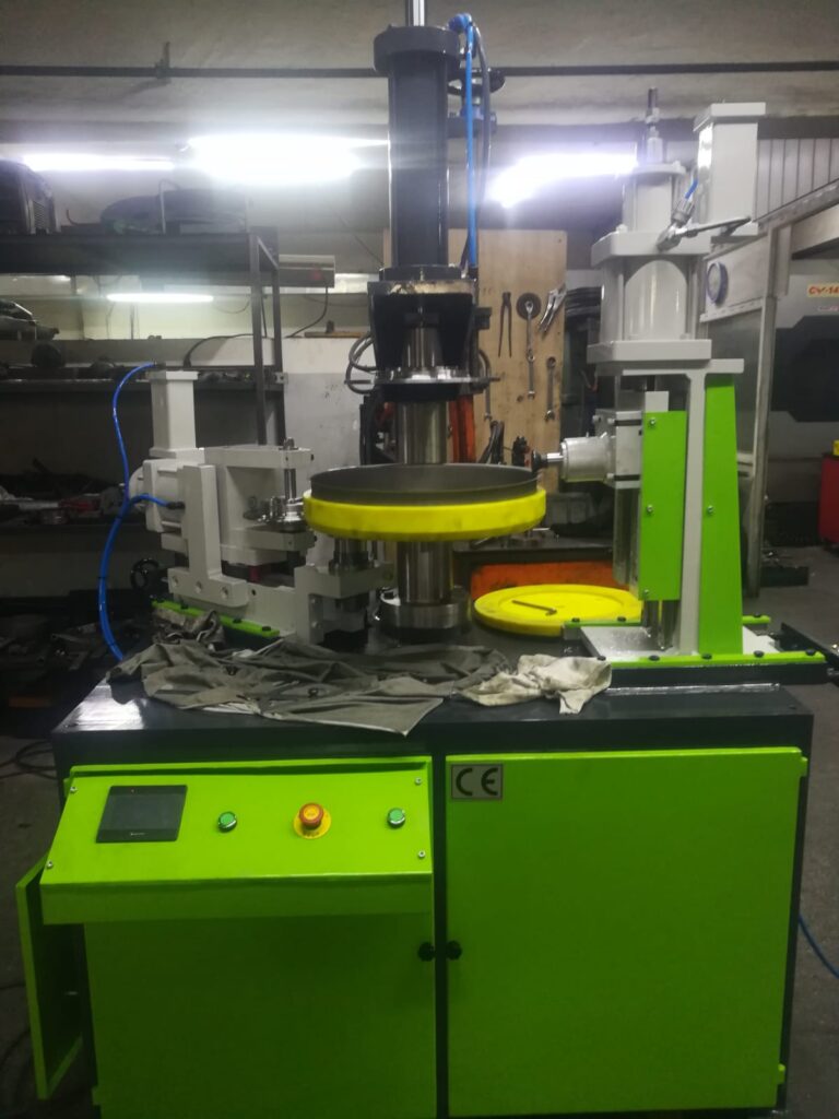
A lock seam closing machine is a specialized piece of sheet metal fabrication equipment designed to close and secure lock seams—mechanically interlocked folds along sheet metal edges—by folding, pressing, and rolling the edges together to form strong, continuous joints without welding or adhesives. These machines are essential in industries where durable, airtight, and watertight seams are needed, such as HVAC duct manufacturing, roofing, tank fabrication, and metal container production.
The lock seam closing machine operates by taking pre-formed sheet metal edges—often shaped into complementary profiles like hooks or flanges—and progressively rolling or pressing them together in multiple stages. This process locks the edges securely while minimizing material stress and preventing damage. The machine’s rollers or dies are carefully engineered to apply controlled pressure, ensuring the seam is tight and uniform along its entire length.
Lock seam closing machines come in various sizes and configurations, ranging from portable handheld units for on-site seam closing to large, floor-mounted systems integrated into automated production lines. They can be manually operated, electrically powered, or driven by pneumatic or hydraulic systems depending on production volume, material thickness, and seam complexity.
Key features often include adjustable roller pressure and seam width, interchangeable tooling for different seam profiles, and variable speed controls to accommodate different materials such as aluminum, galvanized steel, stainless steel, and coated sheets. Some advanced machines incorporate sensors or feedback systems to monitor seam integrity and ensure consistent quality.
By automating the lock seam closing process, these machines enhance production efficiency, reduce operator fatigue, and produce more reliable, repeatable seams compared to manual methods. They preserve surface coatings by avoiding heat input, reduce distortion and warping, and facilitate faster assembly in both shop and field environments.
Lock seam closing machines are integral in producing components like round or rectangular HVAC ducts, cylindrical storage tanks, metal roofing panels, food-grade containers, and exhaust pipes. Their ability to deliver high-quality mechanical joints without welding makes them a vital tool in modern sheet metal fabrication workflows.
Lock seam closing machines function by first ensuring that the sheet metal edges are properly prepared and aligned. Typically, the edges are pre-formed into profiles such as hooks or flanges designed to interlock when pressed together. The machine then gradually closes the seam through a series of rollers or dies that fold and compress the metal edges in multiple steps, avoiding excessive stress or deformation that could weaken the joint or damage the material.
The closing process is carefully controlled to maintain consistent pressure and seam tightness, which is essential for producing joints that are both structurally strong and leak-resistant. Machines often allow adjustment of roller pressure and seam width to accommodate different sheet thicknesses and materials, from thin aluminum used in lightweight ducts to thicker galvanized steel for industrial tanks.
Many lock seam closing machines are designed with operator ergonomics in mind, especially portable models used in fieldwork. Lightweight frames, adjustable handles, and electric or pneumatic drives reduce manual effort and operator fatigue. This is particularly valuable when working on large duct systems or onsite repairs where manual seam closing would be time-consuming and physically demanding.
In automated production environments, lock seam closing machines may be integrated into continuous manufacturing lines. Sheets or cylindrical components are fed automatically into the seaming station where servo-driven rollers close the seam with precise timing and force. These systems often include quality monitoring features, such as sensors that detect seam gaps, improper alignment, or insufficient compression, ensuring only properly formed seams proceed down the line.
The versatility of lock seam closing machines allows them to handle a wide variety of seam types and profiles, including round lock seams commonly found in HVAC ducts, rectangular seams for sheet metal boxes, and specialized profiles used in roofing or container fabrication. Interchangeable tooling or adjustable roller setups enable quick changeovers between different product specifications, improving production flexibility.
Maintaining lock seam closing machines involves regular inspection of rollers and dies for wear, ensuring proper lubrication of moving parts, and periodic calibration of pressure settings to maintain seam quality. Worn or damaged tooling can cause uneven seams, surface markings, or insufficient locking, which compromises joint performance.
The mechanical seam produced by these machines offers numerous benefits over welded joints. Since no heat is applied, the material’s metallurgical properties and coatings remain intact, preventing corrosion and preserving surface finishes. The seam also avoids distortion or warping that can occur with welding, which is crucial in applications requiring precise dimensions and flatness.
Lock seam joints are widely used in HVAC ductwork, where airtight, strong seams improve energy efficiency and system reliability. They are also common in roofing systems, providing weather-resistant joints that contribute to building durability. In tank and container manufacturing, locked seams ensure structural integrity and containment without the risks associated with heat-affected zones.
Portable lock seam closing machines enable technicians to perform seam closure directly on installed components, reducing transportation and assembly time. These machines often operate on standard electrical power or batteries and are designed to be user-friendly in confined or awkward spaces.
Emerging technologies are enhancing lock seam closing machines with digital controls, programmable settings, and real-time quality feedback. Integration with factory automation and Industry 4.0 platforms allows manufacturers to track seam quality, machine performance, and maintenance needs remotely, improving uptime and reducing defects.
In summary, lock seam closing machines are vital tools for efficiently producing strong, consistent, and high-quality mechanical seams in sheet metal fabrication. Their ability to join metals without welding makes them indispensable in many industries, supporting faster production, improved joint performance, and preservation of material properties.
Lock seam closing machines also contribute significantly to reducing production costs and improving workflow efficiency. By automating the seam closing process, these machines minimize manual labor requirements and speed up cycle times, enabling manufacturers to meet high-volume demands without sacrificing quality. The repeatability and precision offered by the machines ensure that each seam meets strict tolerances, reducing the need for rework or scrap.
In addition, the preservation of surface coatings during the seam closing process lowers the need for secondary finishing operations, such as repainting or corrosion treatment. This not only saves time and materials but also maintains the aesthetic and protective qualities of the final product, which is particularly important in industries like HVAC, food processing, and architectural metalwork.
Many lock seam closing machines are designed with modular tooling systems that allow for rapid changes between different seam profiles and material thicknesses. This flexibility is crucial for manufacturers that produce a range of products or handle varying specifications. The ability to quickly switch tooling reduces downtime and enhances responsiveness to customer orders or design changes.
Operator training and machine setup play important roles in maximizing the benefits of lock seam closing machines. Proper alignment of the sheet edges, correct adjustment of roller pressures, and careful handling of materials help ensure consistent seam integrity. Manufacturers often provide detailed manuals, training sessions, and customer support to help users optimize machine performance.
Maintenance practices such as routine inspection of rollers for wear, cleaning of forming surfaces, and timely replacement of consumable parts are essential for sustaining seam quality over long production runs. Some modern machines include diagnostic features that alert operators to maintenance needs or potential issues, allowing for proactive servicing and minimizing unexpected downtime.
Environmental considerations further highlight the advantages of lock seam closing machines. Because the process does not involve heat or consumables like welding gases or filler materials, it generates less pollution and energy consumption. This aligns well with growing industry focus on sustainable manufacturing and reducing the carbon footprint of production processes.
Technological advancements continue to enhance lock seam closing machines. Integration with digital control systems enables precise monitoring and control of seam parameters, leading to improved quality assurance. Connectivity features allow for remote diagnostics and integration into smart factory ecosystems, supporting data-driven decision making and continuous improvement.
In specialized applications, lock seam closing machines can be combined with other joining methods, such as adhesive bonding or clinching, to create hybrid joints that offer enhanced performance characteristics like improved vibration damping or sealing. These combined approaches broaden the range of possible applications and material combinations.
Overall, lock seam closing machines represent a mature and versatile technology that supports efficient, high-quality sheet metal fabrication. Their ability to create robust, reliable seams without heat or consumables makes them a cornerstone of modern metalworking across a wide range of industries, from construction and HVAC to automotive and consumer goods manufacturing.
Types of Sheet Metal seams
There are several types of sheet metal seams, each designed for specific applications based on joint strength, appearance, airtightness, and ease of fabrication. These seams are commonly used in HVAC systems, ductwork, roofing, tanks, containers, and metal furniture. Below are the main types:
Lap Seam
One sheet overlaps the other, and the two are joined either by adhesive, mechanical fasteners, or spot welding.
- Use: Simple joining, low-stress applications
- Advantages: Easy to fabricate, minimal tooling
- Disadvantages: Not airtight or watertight unless sealed
Grooved Seam (Pittsburgh Seam)
Edges of the sheet are folded and interlocked with a groove, often used in ductwork.
- Use: HVAC ducts, rectangular channels
- Advantages: Strong, semi-airtight
- Disadvantages: Requires forming tools or machines
Locked Seam
A mechanical joint formed by double folding the edges of two sheets to interlock them.
- Use: Cylindrical ducts, tanks, and containers
- Advantages: Very strong and tight
- Disadvantages: Requires multiple folds and precise tooling
Standing Seam
Sheets are joined vertically with interlocking edges that are folded together and often sealed.
- Use: Roofing and cladding systems
- Advantages: Durable, weather-resistant, aesthetic
- Disadvantages: Labor-intensive, needs special tools
Double Seam
Involves folding each edge twice—used for cans and containers to provide strength and tightness.
- Use: Food containers, sealed cylinders
- Advantages: Airtight, very strong
- Disadvantages: Complex process, high tooling precision
S-Clip Seam
An “S”-shaped clip joins two flanged edges together, commonly used in rectangular ducting.
- Use: HVAC duct systems
- Advantages: Quick assembly, removable
- Disadvantages: May need sealing for air/water tightness
Drive Cleat Seam
A cleat (U-shaped channel) is driven over flanged sheet metal ends to form the seam.
- Use: Rectangular HVAC ducts
- Advantages: Fast, tool-friendly
- Disadvantages: May loosen if not secured
Hemmed Seam (Plain Hem / Tear Drop Hem / Rope Hem)
The edge of the sheet is folded back on itself. Variations like tear drop or rope hem are shaped for specific stiffness or edge safety.
- Use: Automotive panels, cookware, enclosures
- Advantages: Smooth edge, safe handling
- Disadvantages: Limited to edge finishing, not joining
Butt Seam with Backing Strip
Edges are butted together and reinforced from behind with a strip.
- Use: Aircraft skin panels, large tanks
- Advantages: Flush appearance
- Disadvantages: Not as strong without welding or bonding
Flanged Seam (Flanged Edge with Spot Weld or Clinch)
Sheets are flanged outward and joined by welding or clinching.
- Use: Enclosures, panels, appliances
- Advantages: Hidden joint, good strength
- Disadvantages: Requires joining process like clinching or spot welding
Each seam type is selected based on the functional requirement—such as structural integrity, leak resistance, ease of manufacturing, and appearance. In many cases, seams are also reinforced with adhesives, rivets, or sealants for added performance.
Sheet metal seams are a foundational aspect of metal fabrication, with each type offering specific advantages depending on the application, material, and manufacturing process. One of the most widely used seams in HVAC ductwork is the Pittsburgh seam, a type of grooved seam where one edge is formed into a pocket or groove and the other is shaped into a flange that fits into it. After the edges are interlocked, a seam closing machine compresses them together, producing a secure joint with good structural strength and moderate airtightness. Its ease of assembly and compatibility with automation make it popular in mass production environments.
The snap-lock seam is another variant commonly used in ductwork. It is similar to the Pittsburgh seam but allows the seam to lock into place without requiring a separate seaming tool for closure, reducing assembly time. This seam is ideal for field installation and lightweight ducting systems, where speed and simplicity are prioritized.
The standing seam, especially in roofing and architectural cladding, is prized for its clean lines and exceptional weather resistance. Panels are installed with raised interlocking edges that are mechanically folded together. These seams are highly durable, expand and contract with temperature changes, and offer excellent protection from water infiltration, making them well suited for exterior applications exposed to harsh climates.
Double seams are frequently seen in cylindrical and container applications, such as food cans, chemical drums, and pressure vessels. These involve a more complex folding process in which both sheet edges are folded over each other and compressed, sometimes in conjunction with sealants or gaskets to achieve hermetic sealing. Their strength and leak-proof characteristics are critical in applications where contents must be safely stored or transported.
Hemmed seams, though not used primarily for joining two sheets, are essential for creating smooth, safe, and reinforced edges. A plain hem is a simple fold, while variations like tear drop or rope hems involve shaping the folded edge into a rounded profile to improve rigidity or for aesthetic purposes. These are common in automotive panels, cookware, and appliance enclosures where edge finish and safety are important.
Drive cleat and S-clip seams are also popular in HVAC work, particularly in the construction of rectangular ducts. They allow quick assembly and disassembly, which is useful in systems that may require future modification or repair. While they may not be fully airtight by themselves, they can be sealed with mastic or gaskets if required for pressure-sensitive environments.
Butt seams with backing strips are typically used when a flush surface is required, especially in applications like aircraft skin panels or custom tanks. Although the seam may require welding or bonding to achieve strength, the visual and structural benefits make it useful in high-end or performance-focused designs.
Clinched seams, which use a mechanical fastening method to press and interlock the sheets together without extra fasteners, are becoming more prevalent in environmentally sensitive applications because they avoid welding, adhesives, or rivets. This technique offers clean, strong joints and is often used in appliances, automotive bodies, and enclosures.
Another notable seam is the knocked-up seam, which is used in square and rectangular containers. It involves folding one sheet over the other and hammering or pressing the joint flat. Though simple, it provides decent strength and is suited to applications where aesthetics are secondary.
As manufacturing technology evolves, combinations of seam types or hybrid joining techniques are becoming more common. For instance, a lock seam might be reinforced with adhesives or spot welds for enhanced performance in vibration-sensitive or high-pressure environments. CNC-controlled seam forming machines and programmable rolling heads allow for precise fabrication of custom seam profiles, supporting innovation in both product design and production efficiency.
In modern sheet metal design, selecting the right seam type is as important as the material choice itself. It affects the product’s durability, performance under stress, appearance, and overall manufacturing cost. Seam integrity, especially in pressurized systems or exposed installations, must be validated through quality control procedures such as leak testing, tensile tests, or visual inspections. As industries continue to push for lighter, stronger, and more efficient products, seam technology will remain a critical area of focus in metal fabrication.
Advanced manufacturing environments often require sheet metal seams that not only provide mechanical strength but also meet strict aesthetic, environmental, or safety standards. For example, in the food and pharmaceutical industries, seams must be clean, free of crevices, and resistant to corrosion. In such cases, double-locked seams or continuous folded seams with hygienic finishes are preferred because they prevent bacterial buildup and can be easily cleaned. Materials like stainless steel are typically used, and the seam forming process must ensure smooth transitions with no sharp edges.
In the aerospace and automotive industries, seam types are selected with consideration for vibration resistance, weight reduction, and fatigue life. Seam integrity is critical because failure could lead to structural compromise. Here, hemmed seams and flanged clinch seams are frequently used, sometimes reinforced with adhesives or spot welding for additional security. These seams are tested under cyclic loading and thermal cycling to ensure they maintain their integrity over long operational lifespans.
In roofing and architectural cladding, long-panel standing seams are often used not just for durability, but also for visual design. Panels are roll-formed with male and female edges that interlock and are then mechanically folded or snapped into place. These seams can span long lengths without intermediate support and accommodate thermal expansion, which makes them ideal for large-scale exterior applications. Sealant strips can be integrated into the seam profile for enhanced waterproofing, and hidden fastener systems maintain a clean, uninterrupted surface appearance.
As modular construction and prefabricated systems gain popularity, seam types that allow for disassembly and reassembly without degradation are increasingly valuable. S-clip, drive cleat, and snap-lock seams are particularly useful in modular HVAC ducting or temporary enclosures where joints may need to be opened and resealed multiple times. These types of seams are designed to hold under light pressure but can be disengaged without damaging the sheet metal.
Robotic seam forming is another growing area. Robots equipped with programmable tools can create consistent and complex seam profiles without manual input. This allows for mass production of panels or ducts with high dimensional accuracy and low variability. Vision systems and in-line measurement tools ensure that seam dimensions stay within tolerance, while adaptive control systems adjust forming parameters based on real-time feedback.
With the emergence of new materials such as aluminum composites, pre-painted steels, and lightweight alloys, traditional seam forming processes must be adapted. These materials can be more sensitive to pressure, prone to surface damage, or less ductile, requiring precision in tooling geometry and roller pressure. As a result, tooling for seam forming now often includes polyurethane-coated rollers, precision-ground dies, and servo-driven control to manage delicate forming operations.
In electric vehicle battery enclosures, for instance, sheet metal seams must meet high standards for electromagnetic shielding, thermal performance, and structural rigidity. Flanged and hemmed seams are often used here, sometimes sealed with conductive adhesives or gaskets. The joints must resist ingress of moisture and particles while also withstanding crash forces, making seam selection a crucial design factor.
Educational and prototyping environments benefit from simpler seam types such as plain hems and grooved seams, which can be formed with basic tools. These allow students, designers, or engineers to quickly develop and test sheet metal models without investing in specialized machinery. As designs are finalized for production, seam types may be upgraded to more robust options.
Finally, future developments in sheet metal seams are likely to include digital simulation and AI-driven design optimization. Engineers are beginning to use finite element analysis (FEA) and digital twins to predict seam performance before physical fabrication. By simulating forming stresses, material flow, and joint strength, designers can refine seam geometry to meet performance targets while reducing material usage and tooling costs.
Overall, the diversity and adaptability of sheet metal seams make them essential to modern manufacturing. Whether for structural strength, leak resistance, aesthetics, modularity, or manufacturability, choosing the right seam—and forming it correctly—can determine the success of a product across its entire lifecycle.
Double seam joint in Sheet metal
A double seam joint in sheet metal is a strong, durable, and often airtight or watertight mechanical joint formed by folding and compressing two pieces of sheet metal together with multiple layers of interlocking bends. This seam is especially common in the fabrication of cylindrical containers like cans, drums, pressure vessels, and sealed tanks.
Structure of a Double Seam:
A double seam typically consists of five layers of material:
- Two from the body hook (the edge of the can body or container)
- Two from the end hook (the edge of the lid or base)
- One from the cover or closure flange that wraps around them
These layers are tightly rolled and pressed together by a specialized double seaming machine, creating a mechanically locked and compressed joint. The seam is formed in two operations:
- First Operation: Forms the initial hook and locks the metal edges into position.
- Second Operation: Compresses and flattens the joint, ensuring tightness and structural strength.
Key Features:
- High strength due to multiple folds and compression
- Airtight and watertight when formed properly
- Preserves surface coatings, making it corrosion-resistant
- Often used with sealant or compound inside the seam for enhanced sealing
- Can be inspected and measured with special gauges to verify quality
Common Applications:
- Food and beverage cans
- Aerosol spray containers
- Paint and chemical drums
- Metal battery housings
- Sealed electronic enclosures
- Cookware or industrial filters
Advantages:
- No welding or adhesives required
- Reliable, consistent, and repeatable joint
- Fast to produce in high-volume manufacturing
- Excellent for applications requiring long-term sealing or pressurization
Considerations:
- Requires precision tooling and machine setup
- Misalignment or improper pressure can lead to weak or leaky seams
- Seam inspection is critical (seam thickness, height, and overlap must be within tolerances)
- Not typically used for flat sheet joining—best suited to round or cylindrical parts
In summary, the double seam joint is one of the most secure and reliable methods of joining sheet metal, especially for containers that need to be sealed tightly. Its mechanical strength and sealing capability have made it a cornerstone technology in the packaging, chemical, and manufacturing industries.
The double seam joint plays a critical role in the manufacturing of containers where the integrity of the seal is directly related to the safety, shelf life, and performance of the product. In applications such as food cans, beverage containers, and pressurized aerosol cans, the double seam must be precisely formed to prevent leaks, contamination, or structural failure during handling, storage, or transportation. The reliability of this joint is so important that the packaging industry employs strict quality control measures, including visual inspection, seam micrometry, and destructive testing such as teardown analysis to evaluate the seam’s tightness, overlap, and compound coverage.
Double seaming is a cold-forming process, meaning no heat is applied, which preserves the metal’s physical properties and any protective coatings. This is especially beneficial in applications where corrosion resistance is crucial. For instance, in food packaging, both the can body and the lid are often coated with tin or lacquer to prevent the contents from reacting with the metal. The double seam maintains these coatings without damage, making it superior to welding in such environments.
The machines used to form double seams are typically high-speed, rotary-type systems that can seam hundreds of containers per minute. These machines are designed to perform the first and second operations in quick succession using specially profiled rollers. The rollers exert just enough force to deform the metal layers into the correct shape without causing cracking or excessive thinning. Any deviation in roller profile, pressure, or timing can lead to defective seams that may burst under internal pressure or fail to keep contents sterile.
In some cases, a sealing compound is applied into the curl of the lid or flange before the seam is formed. This compound fills microscopic voids between the metal layers during the seaming process, enhancing leak resistance and helping the seam absorb small deformations from impact or thermal expansion. The compound remains trapped inside the seam after compression and is not visible from the outside.
Double seams are also used in battery and capacitor housings where a secure and gas-tight seal is required. In such cases, the joint must withstand pressure variations, vibrations, and chemical exposure. Engineers may modify seam dimensions or materials to suit the demands of each application, and seam performance is verified under extreme conditions like thermal cycling or mechanical shock.
For industries that rely on hermetically sealed metal packaging, the dimensional control of a double seam is extremely precise. Measurements such as seam height, seam thickness, overlap length, and hook lengths must fall within tight tolerances. Specialized gauges and micrometers are used to measure the seams, and quality control records are maintained to track seam integrity across production batches.
Advancements in double seam technology include servo-driven seamers that provide better control over roller movement, allow rapid adjustments, and reduce mechanical wear. Digital seam monitoring systems equipped with sensors and AI algorithms are now capable of detecting subtle issues like missing compound, uneven folds, or metal buckling. These systems provide real-time feedback to operators or trigger automatic stoppages when deviations are detected.
Although double seam joints are most associated with round containers, they can also be applied to non-cylindrical shapes using custom tooling and forming stations. However, the complexity increases with shape irregularity, and forming speed may be reduced.
One of the advantages of double seams over welded or riveted joints is their ability to accommodate dissimilar materials. For example, aluminum lids can be seamed onto steel can bodies using proper tooling. This hybrid construction reduces weight and material cost while maintaining structural performance.
In terms of environmental sustainability, double seamed containers are highly recyclable. Since no adhesives or foreign materials are introduced during joining, the metal remains pure and can be easily re-melted and reused. This is increasingly important in sectors where regulatory or consumer pressure demands fully recyclable and non-toxic packaging.
Overall, the double seam joint is a hallmark of reliable sheet metal joining in sealed containers. Its unmatched combination of strength, leak resistance, manufacturability, and compatibility with coated or treated metals ensures its continued relevance in both high-speed production and specialized industrial applications.
The versatility of the double seam joint extends well beyond traditional packaging. In industrial and technical fields—such as filter housing manufacturing, electrical enclosures, and even certain types of aerospace components—the double seam is valued for its ability to withstand internal pressure, mechanical loads, and environmental exposure without sacrificing cleanliness or appearance. In many of these cases, double seams are used not just for sealing but also as a structural element, contributing to the rigidity and mechanical integrity of the component.
In filter housings, for example, where liquid or gas flows under pressure, the joint must maintain a consistent seal over long periods without deforming or loosening. The double seam, once set, resists internal stresses and can endure pressure cycling and vibration without leaking. This reliability is achieved through the compact, layered design of the seam, which distributes stress evenly and minimizes the risk of fatigue or crack initiation.
As manufacturing processes continue to evolve, digital simulation of double seam formation has become increasingly common. Engineers now use finite element analysis (FEA) to model the flow and deformation of metal during the first and second operations of seam formation. These simulations help optimize roller profiles, adjust seam dimensions, and predict failure modes, reducing the need for physical prototypes and accelerating development. With this approach, designers can preemptively address issues such as metal thinning, wrinkling, or tooling misalignment.
From a safety standpoint, double seams are critical in products that may be exposed to internal pressure or vacuum. In aerosol cans, for example, the internal pressure can exceed 6 to 10 bars. The double seam must not only hold under static pressure but also survive drops, impacts, and prolonged storage without leaking. Industry standards dictate precise seam strength and leak-proof criteria, and failure to meet these standards can result in hazardous outcomes. That’s why aerosol containers undergo rigorous burst testing and seam integrity inspections.
In modern production lines, quality assurance for double seams is often performed using non-destructive methods such as X-ray inspection or laser-based dimensional analysis. These systems can measure seam height, thickness, and hook lengths in real time and flag any deviations without interrupting the production flow. Such systems help maintain extremely low defect rates, even at line speeds exceeding 300 containers per minute.
The double seam has also found applications in high-performance consumer products like thermoses, vacuum-insulated drink containers, and metal fuel cells. In these cases, the seam contributes not only to pressure retention but also to thermal insulation by maintaining a vacuum seal between inner and outer shells. Seam precision in these products must be extremely high to prevent thermal bridging or leakage, and the aesthetic finish is equally important, often requiring flawless, smooth seams with no surface damage or irregularity.
In terms of materials, double seams can be formed in a wide variety of metals, including aluminum, tinplate, stainless steel, and coated steels. The key requirement is that the metal must be ductile enough to endure folding and compression without cracking. For more demanding applications, such as corrosive environments or food-grade packaging, the selected material must also be compatible with sealants or resistant to chemical attack. Special double seaming compounds are used to enhance the seal, and these compounds must be approved for contact with the intended contents (e.g., food-safe or solvent-resistant).
For manufacturers, the ability to produce strong, reliable, and fast-formed joints without heat or adhesives makes the double seam process an ideal solution. The process can be highly automated, is relatively low in energy consumption compared to welding, and produces minimal waste. With sustainability goals becoming increasingly important, the recyclability and non-toxic nature of double-seamed products give them an advantage over alternative joining methods.
In conclusion, the double seam joint remains a pillar of precision sheet metal joining, capable of satisfying stringent technical, structural, and regulatory requirements. Its blend of performance, efficiency, and adaptability has ensured its survival for over a century in mass production—and with continued advancements in machine control, material science, and quality monitoring, it continues to be improved and refined to meet the complex demands of today’s industrial landscape.
Lap Bottom Seaming Machine
A Lap Bottom Seaming Machine is a specialized sheet metal forming machine designed to create lap-type bottom seams—particularly in cylindrical or conical containers such as buckets, paint cans, food tins, and pails. It forms a mechanical joint at the bottom of the container, typically where the sidewall and bottom piece (disk or base) are overlapped and then seamed together to provide strength, liquid-tightness, and durability.
What is a Lap Bottom Seam?
A lap seam involves overlapping one piece of metal over another and then rolling or pressing them together. In the context of bottom seaming, the container body sits over the bottom disk, and both pieces are interlocked via folding and compression without the use of welding. This method creates a strong joint while preserving coatings and minimizing heat distortion.
How a Lap Bottom Seaming Machine Works:
- Loading: The cylindrical body (already welded or locked along the side seam) and the bottom disk are fed into the machine.
- Positioning: The bottom disk is placed precisely inside the body flange.
- First Operation: The machine folds the edge of the body over the bottom disk to create an initial hook or interlock.
- Second Operation: Rollers compress and tighten the folded seam to lock the parts together, often forming a double-layered joint for strength.
- Optional Sealing Compound: A sealant may be applied in the seam area for leak-proofing, especially for liquid containers.
Key Features:
- High-Precision Rollers: For forming consistent lap seams
- Adjustable Tooling: Accommodates different container sizes and materials
- Single or Double Operation: Depending on required seam tightness
- Manual, Semi-Automatic, or Fully Automatic: Depending on production scale
- Sealant Applicators: Optional systems to dispense compound before seaming
- Speed Control: Adjustable RPM for different thicknesses or materials
Applications:
- Paint buckets
- Food tins (e.g. oil cans, milk powder tins)
- Industrial drums
- Metal pails for chemicals
- Household containers
Advantages:
- No heat distortion since it’s a cold-forming process
- Strong, reliable seams suitable for liquids and semi-solids
- Preserves coatings (e.g., tin-plated, lacquered surfaces)
- Fast and repeatable—suitable for high-volume production
- Can be made leak-proof with compound application
Considerations:
- Requires precise alignment of parts for proper seam formation
- Rollers and tooling need periodic maintenance and cleaning
- Not ideal for extremely thick materials unless machine is specially designed
- Operator training is essential for consistent performance in semi-automatic machines
In summary, a Lap Bottom Seaming Machine is a cornerstone of round can and pail manufacturing. It offers a fast, reliable, and cost-effective method to join container bottoms without welding, making it indispensable in industries requiring durable and sealed metal packaging.
Lap Bottom Seaming Machines are integral to modern packaging lines, especially where metal containers are expected to carry liquids, semi-liquids, or sensitive contents that require tight sealing and structural stability. These machines are commonly placed downstream of body forming and welding stations. After a cylindrical body has been formed and its side seam joined—usually by resistance welding or lock seaming—the next critical step is to attach the bottom disk using the lap seaming process. The machine uses specially profiled seaming rollers that apply controlled pressure and rotational motion to fold the flanged edge of the can body over the edge of the bottom disk. This action creates a tight, compressed seam with a characteristic layered profile, often consisting of three or more overlapping folds.
The precision with which the rollers are machined and aligned is essential to the consistency and quality of the seam. If the bottom disk is not perfectly centered or if the flange is misaligned, the resulting seam can be incomplete or weak, leading to leaks, deformation, or outright failure during filling, storage, or transport. Therefore, high-precision fixtures are used to hold the body and bottom disk in exact position during the seaming operation. Most modern machines also feature quick-change tooling, allowing operators to switch between container sizes or profiles with minimal downtime.
Sealant application is a critical option in lap bottom seaming machines, especially for cans intended to hold volatile or perishable liquids. The sealant is typically applied in a thin bead around the flange of the bottom disk just before the seam is closed. As the seam is compressed, the compound is squeezed into the microscopic gaps between the metal layers, forming a barrier against air, moisture, or product leakage. The compound must be compatible with the contents of the can—for example, food-grade sealants for edible goods or chemical-resistant compounds for industrial applications.
High-volume production lines use fully automatic lap bottom seaming machines with integrated feeders and discharge conveyors. These systems can handle hundreds of containers per minute and often include sensors and vision systems to check for correct part positioning, seam integrity, and compound application. Any defective units are automatically rejected before they enter the filling or labeling stations. The automation not only ensures consistent quality but also reduces labor costs and operator fatigue.
In medium-scale or custom container manufacturing, semi-automatic lap bottom seaming machines offer greater flexibility. These machines require manual loading and unloading but still feature motorized rollers, adjustable pressure, and programmable settings for seam height, flange width, and rotation speed. They are ideal for short production runs, prototype containers, or specialized products that don’t justify a full automation investment.
The seam strength created by lap bottom seaming machines is typically validated through burst testing, drop testing, and vacuum or pressure checks, depending on the container’s intended use. For example, paint cans may be subjected to drop tests from standard heights to ensure that the seam doesn’t rupture under impact. Food cans are often pressure-tested to confirm that the seam maintains a vacuum seal. Manufacturers may also cut cross-sections of completed seams for microscopic analysis to verify layer thickness, compression uniformity, and proper compound spread.
Maintenance of lap bottom seaming machines is critical to long-term performance. Rollers must be kept clean and smooth, free of burrs or wear that could damage the can edges or compromise the seam. Lubrication systems ensure that moving parts operate smoothly under high loads, and regular calibration checks are required to maintain roller alignment. Some machines now feature automatic lubrication and diagnostic alerts to reduce downtime and prevent unplanned failures.
As consumer demand increases for sustainable and recyclable packaging, lap-seamed metal containers remain a favored solution. Unlike welded or plastic-lined alternatives, they are fully recyclable, and the seam contains no adhesives or materials that contaminate the metal during recycling. Furthermore, because lap seams are formed through a cold process, they consume far less energy than welding, contributing to lower emissions and more eco-friendly manufacturing.
Technological advances continue to enhance lap bottom seaming machines. Servo-driven roller systems now offer more precise control of roller pressure and motion, allowing the seam to adapt in real time to slight variations in material thickness or flange geometry. Touchscreen controls with digital recipes let operators quickly switch between product types, while built-in data logging systems record seam performance, production counts, and error events for traceability and quality assurance.
In industries like automotive fluids, lubricants, adhesives, and food packaging, the lap bottom seam remains one of the most trusted and proven joint designs. It provides the balance of durability, speed, and sealing performance needed for modern packaging, and the machines that form these seams continue to evolve with industry requirements. Whether for mass production or specialized applications, the lap bottom seaming machine is a cornerstone of reliable metal container fabrication.
Lap Bottom Seaming Machines are also being tailored to meet the needs of non-standard container designs, such as conical pails, oval-shaped tins, and specialty metal cans with decorative or functional bottom contours. In these cases, standard round tooling is insufficient, so manufacturers employ custom roller profiles, adjustable fixtures, and multi-axis control systems to ensure consistent seam formation even on irregular geometries. This is particularly relevant in the paint and coatings industry, where conical pails are commonly used and must maintain leak-proof bottom seams despite varying wall angles.
In addition to mechanical precision, the material handling systems integrated into lap bottom seaming machines play a major role in production efficiency. For high-speed lines, automated feeding systems precisely index each can body and bottom disk into position, while conveyorized outfeed systems move finished containers to the next stage—typically filling or lid seaming. In more advanced setups, robotic arms or pick-and-place systems are incorporated to handle larger or heavier containers, or to manage parts with sensitive surface coatings that require gentle handling to prevent scratching or denting.
Many lap bottom seaming machines are designed to operate with tinplate, galvanized steel, stainless steel, and aluminum, accommodating the broad spectrum of metal packaging used across industries. The machine’s rollers and structural components must therefore be robust enough to handle both thin-walled containers and heavier-gauge industrial cans. For containers subject to internal pressure, such as chemical drums or liquid storage tins, the seam strength must meet stringent structural standards, including burst and torque resistance, which the machine must be able to reproduce consistently over thousands of cycles.
For decorative tins—used in packaging confectionery, tea, tobacco, or promotional items—cosmetic quality is as important as functionality. Lap bottom seaming machines used in these applications are equipped with non-marking rollers, anti-scratch surfaces, and high-precision drive mechanisms to ensure that printed or embossed finishes on the container are not marred during the seaming process. These machines may also include laser positioning systems to align the artwork on the sidewall with the seam for a flawless final appearance.
Some modern machines are equipped with smart control systems that enable seam recipe storage, allowing operators to switch between different container types with minimal setup time. These recipes store parameters such as roller pressure, rotational speed, dwell time, and flange positioning, and may even include step-by-step visual guides for machine setup, reducing operator training time and minimizing the potential for errors.
In facilities that emphasize traceability, machines can be integrated with barcode or RFID systems, enabling each can to be tracked from body forming to final packaging. Production data from the seaming machine—such as cycle counts, seam dimensions, and rejection rates—can be logged automatically into a centralized database for quality audits and regulatory compliance.
As the push for sustainable packaging continues, lap bottom seams offer a competitive advantage by enabling the use of 100% recyclable monomaterials with no weld flash, glue residue, or composite bonding. Because the seam is purely mechanical and cold-formed, the resulting containers can be melted down cleanly, supporting closed-loop recycling systems and aligning with circular economy goals.
In retrofitting older seaming lines, many manufacturers offer modular lap bottom seaming units that can be added to existing production lines to enhance capability without full replacement. These units can interface with existing upstream body-making machines and downstream conveyors, providing cost-effective upgrades with modern control features and improved performance.
In sum, the lap bottom seaming machine is not just a piece of forming equipment—it is a critical link in the container manufacturing chain that influences product integrity, process efficiency, regulatory compliance, and even customer satisfaction. As automation, data integration, and customization become increasingly important in industrial production, lap bottom seaming machines are evolving to deliver not only faster output but also greater precision, adaptability, and intelligence. This ensures that they remain indispensable tools across a wide spectrum of metal packaging applications, from heavy-duty industrial drums to high-end consumer tins.
Grooved Flat Lock Seaming Machine
A Grooved Flat Lock Seaming Machine is a specialized piece of sheet metal fabrication equipment designed to form flat lock seams with a grooved interlock. These seams are widely used in ductwork, roofing, architectural panels, tanks, and cylindrical enclosures, offering a strong, flat, and low-profile joint between two sheet metal parts. The machine creates a mechanically interlocked seam that is durable, tight-fitting, and, in many cases, capable of being sealed for weatherproof or airtight performance.
What is a Grooved Flat Lock Seam?
A flat lock seam is formed when two sheet metal edges are folded, interlocked, and then pressed flat to create a continuous joint. In the grooved variation, one piece of metal is folded into a grooved profile (often similar to a “C” shape), while the mating piece is folded into a flange that fits tightly into the groove. When pressed flat by the machine, the two pieces are locked together and compressed into a smooth, strong seam.
Functionality of the Grooved Flat Lock Seaming Machine:
- Edge Forming: The machine first shapes the edges of each sheet—one into a groove and the other into a mating flange.
- Feeding: The interlocked edges are fed into the seaming rollers, either manually or automatically.
- Groove Compression: Precision rollers apply pressure to flatten the seam and lock it securely.
- Consistent Alignment: Guides and clamps ensure that the seam forms evenly and along a straight path.
- Optional Sealant Application: For weatherproofing or airtightness, a bead of sealant can be applied before seam closing.
Key Features:
- Grooved roller profiles for precise seam formation
- Adjustable roller pressure to accommodate various metal thicknesses
- Manual, semi-automatic, or CNC-controlled operation depending on the model
- Compatible with steel, galvanized sheet, aluminum, copper, or zinc
- Tooling sets for different seam styles and geometries
- Compact or inline designs for integration into fabrication lines
Applications:
- HVAC duct construction (especially rectangular or oval ductwork)
- Standing seam metal roofing systems (for transverse seam joints)
- Metal wall cladding
- Architectural sheet metal fabrication
- Tanks and enclosures requiring smooth seams
- Rainwater goods (gutters, downspouts)
Advantages:
- Strong, low-profile joint that sits flush with the surface
- Improved appearance over raised seams or fastener-based joints
- Can be sealed easily with solder, mastic, or sealant
- Reliable for both indoor and outdoor applications
- Reduces welding or riveting requirements
- Ideal for pre-painted or coated sheet metal as the groove preserves surface finish
Considerations:
- Proper alignment is critical for seam strength and aesthetics
- The machine requires accurate edge preparation for consistent results
- Rollers must be maintained clean and burr-free to avoid marring metal surfaces
- Some models are limited in the range of seam styles they can create
- Heavier gauges may require industrial or hydraulic models
In summary, the Grooved Flat Lock Seaming Machine enables fabricators to produce flat, clean, and strong mechanical seams ideal for visible architectural metalwork, ducting, and precision sheet assemblies. Its mechanical locking method avoids heat input, preserves coatings, and results in highly durable joints suitable for a wide range of metal forming industries.
Grooved Flat Lock Seaming Machines are essential tools in sheet metal fabrication lines, especially where precise, consistent seam quality is critical. Their ability to create a strong, flat joint makes them particularly valuable in applications where surface aesthetics and dimensional accuracy matter. Unlike raised seams or lap joints, the flat lock seam minimizes protrusions, reducing interference and allowing panels to fit tightly against each other or adjoining structures.
The operation of these machines often begins with careful edge preparation—sheet metal edges may be trimmed or pre-formed to ensure they fit perfectly into the groove and flange profiles. This preparation is vital because any deviation can cause incomplete locking or surface irregularities that compromise seam strength and appearance. Many machines incorporate edge guides and clamps to maintain sheet alignment during seaming, reducing the risk of distortion or misfeeds.
Grooved Flat Lock Seaming Machines can operate in manual, semi-automatic, or fully automated modes. In manual machines, an operator typically feeds the sheet metal edges between the rollers and guides the material along the seam path. Semi-automatic machines may feature powered feeding and roller adjustments, improving consistency and reducing operator fatigue. Fully automated CNC models allow programmable seam lengths, roller pressures, and seam profiles, facilitating rapid changeovers between different product types or metal thicknesses.
Materials commonly processed on these machines include galvanized steel for HVAC applications, aluminum and copper for architectural panels, and stainless steel for industrial enclosures. Because the seam is formed mechanically without heat, coatings such as paint or anodized finishes remain intact, preserving corrosion resistance and aesthetic qualities. This advantage makes flat lock seams particularly popular in the construction industry, where long-lasting, visually appealing joints are essential.
The seam produced by a grooved flat lock seaming machine is both mechanically strong and capable of being sealed against air and water infiltration. In roofing and cladding, sealants or butyl tapes may be applied within the groove before seaming, creating a waterproof barrier that withstands weather exposure. In HVAC ductwork, seams formed by these machines help maintain system efficiency by reducing air leakage, which is critical for energy savings and indoor air quality.
Maintenance of the seaming machine’s rollers and tooling is crucial to maintain seam quality over time. Rollers must be inspected regularly for wear, surface damage, or contamination that could scratch or deform the sheet metal. Precision ground rollers ensure uniform pressure distribution along the seam, preventing defects such as wrinkling, buckling, or incomplete locking. Many manufacturers provide specialized tooling kits for different seam types or metal thicknesses, allowing fabricators to optimize machine performance for each application.
In recent years, advances in control systems have allowed integration of sensors that monitor seam formation parameters in real time. These systems can detect variations in roller pressure, seam height, or metal feed rate, alerting operators to potential issues before defective seams are produced. This reduces waste and increases overall equipment effectiveness (OEE), particularly in high-volume production environments.
Grooved flat lock seams also lend themselves well to modular construction techniques. Because the seams are flat and strong, prefabricated panels can be quickly joined on site, speeding up building assembly while maintaining tight joints that improve insulation and weatherproofing. This has led to growing adoption in modern architectural projects focused on energy efficiency and rapid construction.
While the flat lock seam is extremely versatile, it is generally limited to relatively thin sheet metals, typically ranging from 0.3mm to 1.5mm thickness depending on the machine capacity. For heavier gauges, more robust hydraulic or servo-driven models are used, but at higher cost and complexity. In applications where very thick materials or irregular profiles are required, alternative seam types such as standing seams or welded joints may be more appropriate.
Overall, the grooved flat lock seaming machine is a key enabler of efficient, high-quality sheet metal joining in a variety of industries. Its combination of mechanical strength, aesthetic appeal, and compatibility with coated metals ensures it remains a popular choice for fabricators aiming to produce durable, precision seams without the complexity or heat input of welding. With continuing developments in automation, tooling, and quality monitoring, these machines will remain integral to modern sheet metal manufacturing for years to come.
Grooved Flat Lock Seaming Machines have also found important applications in the fabrication of specialty metal products such as rainwater systems, including gutters, downspouts, and collector boxes. In these products, the flat lock seam provides a neat, unobtrusive joint that resists leakage and corrosion while maintaining a smooth external appearance. The ability to form continuous, straight seams quickly and consistently makes these machines highly valuable in the production of long-length profiles.
In addition to flat panels, some grooved flat lock seaming machines are adapted to handle curved or formed components, such as cylindrical ducts or curved architectural panels. These machines feature adjustable rollers and guiding systems that accommodate varying radii without compromising seam integrity. This adaptability expands the range of applications and allows fabricators to produce complex shapes with precision seams in a single operation.
The flat lock seam’s low profile also contributes to improved airflow in HVAC duct systems. Unlike raised or overlapped seams that can create turbulence or catch debris, flat lock seams maintain smooth internal surfaces that optimize air movement and reduce pressure loss. This results in more efficient ventilation systems and energy savings in heating and cooling applications.
When used in roofing and exterior cladding, the flat lock seam offers excellent resistance to wind uplift and thermal cycling. The groove and flange interlock creates a joint that can flex slightly with temperature-induced expansion and contraction without opening or cracking. This flexibility is essential for long-term durability in environments exposed to extreme weather conditions.
The grooved flat lock seaming process is also compatible with pre-painted and coated sheet metals. Since the seam is formed mechanically without heat, there is minimal risk of damaging paint layers or protective coatings. This preservation of surface finish helps extend the life of metal roofing, siding, and other architectural components by preventing premature corrosion.
Automation trends in grooved flat lock seaming have led to the development of integrated systems combining feeding, seam forming, and quality inspection. Some machines now incorporate laser measurement tools that scan the seam profile as it is formed, detecting deviations in real time. This data can be used to automatically adjust roller pressure or feed rate, ensuring consistent seam quality throughout production runs.
Operators benefit from intuitive control interfaces with programmable parameters for different seam profiles and materials. This flexibility allows rapid switching between product types, reducing changeover time and increasing plant productivity. Remote diagnostics and predictive maintenance features further enhance machine uptime by alerting maintenance personnel before breakdowns occur.
Environmental and safety considerations also play a role in the choice of grooved flat lock seams. Since the process does not require welding or adhesives, it avoids fumes, heat hazards, and the introduction of potentially harmful chemicals. This makes it safer for operators and aligns well with increasingly strict workplace environmental regulations.
Looking ahead, advances in material science may expand the use of grooved flat lock seams into new alloys and composite sheets. Improved roller materials and surface treatments could further reduce wear and extend tooling life. Meanwhile, integration with Industry 4.0 concepts promises even smarter machines capable of self-optimization and seamless integration into digital manufacturing ecosystems.
In summary, the grooved flat lock seaming machine remains a versatile, reliable, and efficient solution for producing flat, strong seams across a wide range of sheet metal applications. Its benefits in terms of mechanical performance, aesthetics, and environmental impact ensure its continued importance in sheet metal fabrication for construction, HVAC, industrial equipment, and specialty products.
Flat Lock Seaming Machine
A Flat Lock Seaming Machine is a specialized sheet metal fabrication machine designed to create flat lock seams, which are mechanical joints formed by interlocking and flattening sheet metal edges together. This seam type is widely used in industries such as HVAC, roofing, architectural metalwork, duct fabrication, and tank construction due to its strength, low profile, and clean appearance.
Flat lock seams join two metal sheets edge-to-edge by folding and interlocking their edges, then compressing the joint flat to create a continuous seam that is both structurally sound and aesthetically smooth. Unlike raised seams or lap joints, the flat lock seam lies flush with the sheet surface, minimizing protrusions and allowing panels to fit tightly together.
How It Works
The machine forms the seam in several stages:
- Edge preparation: The sheet edges are pre-formed with specific bends or hooks to facilitate interlocking.
- Feeding: The two edges are aligned and fed into the seaming rollers.
- Interlocking: The machine folds the edges to lock them together.
- Compression: Precision rollers flatten the seam, creating a tight, mechanically locked joint.
Flat Lock Seaming Machines can operate manually, semi-automatically, or fully automatically, depending on production needs and machine sophistication.
Features
- Adjustable roller pressure for different metal gauges and materials.
- Compatibility with various metals, including steel, aluminum, copper, and galvanized sheets.
- Tooling sets tailored to different seam profiles.
- Optional integration with sealant application systems.
- CNC control for programmable seam length and seam quality.
- Edge guides and clamps for precise alignment.
Applications
- HVAC rectangular and oval ductwork.
- Standing seam roofing panels.
- Architectural metal wall cladding.
- Rainwater systems (gutters and downspouts).
- Metal enclosures and tanks.
- Decorative and functional sheet metal assemblies.
Advantages
- Creates strong, flush seams with excellent mechanical integrity.
- Preserves surface coatings by avoiding heat input.
- Seam can be sealed for weatherproofing or airtightness.
- Suitable for high-volume or custom production.
- Reduces or eliminates need for welding or mechanical fasteners.
Considerations
- Requires precise edge preparation and alignment.
- Maintenance of rollers is critical for consistent quality.
- Best suited for thin to medium gauge metals.
- Machine setup time can vary depending on seam complexity.
In summary, the Flat Lock Seaming Machine is an essential tool in modern sheet metal fabrication, enabling efficient production of strong, low-profile seams that combine durability with aesthetic appeal. Its versatility and adaptability make it a staple across multiple industries requiring reliable metal joining without heat or adhesives.
Flat Lock Seaming Machines are widely valued for their ability to produce uniform, high-quality seams that combine both strength and aesthetic appeal. The flat seam profile allows for smooth surfaces, which is particularly important in applications where airflow, weather resistance, or visual appearance is critical. In HVAC systems, for instance, flat lock seams minimize air leakage and reduce turbulence inside ducts, contributing to energy efficiency and improved indoor air quality. Similarly, in roofing and siding, these seams provide weather-tight joints that can withstand wind, rain, and thermal expansion over long service lives.
The operation of flat lock seaming machines often involves precise synchronization between feeding mechanisms, rollers, and guiding systems. This ensures that metal sheets feed evenly and the seam forms consistently without wrinkles or gaps. Manual machines rely on operator skill to maintain this precision, whereas semi-automatic and automatic machines incorporate servo drives, sensors, and programmable logic controllers (PLCs) to automate and monitor the process. These advancements allow for higher throughput, reduced scrap, and greater repeatability, which are essential in mass production environments.
Material compatibility is another strength of flat lock seaming machines. They can handle a range of metals including galvanized steel, aluminum, copper, and stainless steel. Since the seaming process is cold forming, coatings such as paint, anodizing, or galvanization remain intact, preserving corrosion resistance and appearance. This is particularly advantageous in architectural and outdoor applications where durability and aesthetics are equally important.
Maintenance and tooling care play a crucial role in maintaining seam quality. Rollers must be free of debris, dents, or wear that could mar the metal or cause seam defects. Tooling sets are often specific to particular seam profiles or material thicknesses, so fabricators typically keep multiple sets on hand to switch quickly between different jobs. Calibration of roller pressure and alignment ensures that seams meet specified tolerances for height, thickness, and mechanical engagement.
In addition to standard flat lock seams, some machines offer flexibility to form variations like grooved seams or custom profiles, expanding their application range. These options enable fabricators to tailor seam characteristics for specific performance criteria such as enhanced waterproofing, increased mechanical strength, or easier assembly.
Flat lock seams can also be combined with sealants or gaskets to improve weather resistance and airtightness. Sealants are often applied before seam formation, filling micro-gaps and preventing moisture ingress. This combination is common in exterior cladding and roofing where protection against water and air infiltration is critical to building performance.
Technological advances continue to improve flat lock seaming machines. Modern systems integrate real-time monitoring and quality control sensors that detect seam defects early in the production cycle. Data from these sensors can trigger alarms or halt production to prevent defective products from advancing. Some machines also feature touchscreen interfaces and recipe management, enabling quick setup and minimizing operator error.
The use of flat lock seams extends beyond traditional construction and HVAC sectors into specialty markets such as decorative metalwork, transportation (e.g., bus or train paneling), and industrial equipment housings. In these markets, the combination of seam strength, precision, and clean aesthetics makes flat lock seaming an attractive joining solution.
Overall, the flat lock seaming machine remains a fundamental tool for sheet metal fabricators seeking efficient, reliable, and visually appealing joints. Its continued evolution through automation, enhanced tooling, and digital integration ensures it meets the demands of modern manufacturing environments while maintaining versatility across a broad spectrum of metalworking applications.
Flat lock seaming machines also contribute significantly to sustainable manufacturing practices. Because the process involves cold forming rather than welding or adhesive bonding, it consumes less energy and produces minimal waste or emissions. Additionally, the seams formed are fully mechanical, allowing the joined sheet metal assemblies to be recycled more easily at the end of their lifecycle without the complications introduced by bonded or welded joints.
In production environments, flat lock seaming machines are often integrated into larger fabrication lines alongside cutting, bending, and punching equipment. This integration facilitates seamless workflow and reduces handling, which minimizes damage to coated or delicate sheet surfaces. Automation capabilities such as robotic feeding and unloading further enhance productivity and reduce labor costs.
Training and safety are important considerations when operating flat lock seaming machines. Because the machines use rollers exerting substantial force to form seams, operators must be aware of pinch points and ensure guards and emergency stops are functional. Modern machines typically include safety interlocks and compliance with international machinery safety standards to protect personnel.
Customization is a growing trend in flat lock seam fabrication, driven by diverse industry needs. Manufacturers often collaborate with machine builders to develop custom tooling, roller profiles, and machine configurations tailored to specific product geometries, material types, and production volumes. This bespoke approach ensures optimal seam quality, durability, and aesthetics for unique applications.
In repair and maintenance contexts, flat lock seams are sometimes preferred for patching or joining sheet metal components because they can be formed on-site without the need for specialized welding equipment or heat sources. This flexibility supports quicker turnaround times and reduces the risk of heat-related distortion or damage in sensitive assemblies.
The future of flat lock seaming machines is closely tied to advances in digital manufacturing. Integration with Industry 4.0 technologies enables machines to communicate with plant-wide control systems, track production metrics in real time, and facilitate predictive maintenance schedules. Enhanced sensor technology will improve seam inspection and quality assurance, potentially allowing for fully automated, closed-loop control of the seaming process.
Overall, the flat lock seaming machine continues to be an indispensable asset in sheet metal fabrication, combining mechanical reliability, operational efficiency, and adaptability. Its ability to create durable, low-profile seams without compromising surface finishes or structural integrity ensures its ongoing relevance across construction, industrial, and specialty metalworking sectors.
Single seam joint in sheet metal
A single seam joint in sheet metal refers to a type of mechanical joint where two sheets are joined together by folding or interlocking one edge over the other just once, creating a single fold or seam. This method is simpler compared to double seams or multiple folds and is often used in applications where moderate strength and a quick, economical joining method are sufficient.
In a typical single seam joint, one sheet has its edge bent or flanged, and this flange is either hooked over, folded onto, or pressed against the adjacent sheet’s edge. The seam may then be compressed or rolled to hold the two sheets together securely. Because it involves only one fold or interlock, the joint tends to be less strong and less airtight compared to double seam joints, but it offers faster assembly and requires simpler tooling.
Single seam joints are commonly used in sheet metal applications such as ductwork, light enclosures, metal roofing, and other fabrication tasks where the joint does not have to withstand high mechanical loads or pressures. They can be combined with adhesives, sealants, or spot welding for added strength or leak resistance depending on the requirements.
Advantages of single seam joints include their simplicity, reduced material deformation, and lower manufacturing cost. However, they may be less durable under stress or environmental exposure than more complex seam types, so proper design and application are essential to ensure performance.
In summary, the single seam joint is a straightforward, efficient way to mechanically join sheet metal edges for moderate-duty applications, balancing ease of fabrication with acceptable joint strength and appearance.
Single seam joints are frequently employed in applications where quick assembly and moderate joint strength are sufficient. For instance, in HVAC duct fabrication, single seam joints are often used to connect sections of sheet metal ductwork where airtightness is not critical or where additional sealing methods like mastic or tape will be applied externally. In these cases, the seam serves mainly to hold parts in position before sealing, making it a cost-effective solution.
The manufacturing process for single seam joints typically involves bending or flanging the edge of one sheet metal piece so that it can be overlapped and pressed against the adjoining sheet. This may be done using simple manual tools, press brakes, or automated folding machines depending on production scale. After folding, the seam can be secured by mechanical fastening methods such as spot welding, riveting, or clinching to improve joint integrity if needed.
Material selection plays a key role in single seam joint performance. Thinner gauge metals are easier to fold and require less force, but they may be prone to deformation or buckling under load. Thicker materials offer greater strength but can be harder to bend and may require specialized tooling or higher forming forces. Metals commonly used include galvanized steel, aluminum, and stainless steel, with coatings preserved through cold forming processes.
While single seam joints are simpler than double or multiple seams, they do have limitations. Because the joint relies on a single fold, it is more susceptible to opening under tensile stress or repeated cyclic loading. Additionally, the joint typically offers less protection against moisture ingress, which can lead to corrosion or leaks if used in outdoor or wet environments without additional sealing measures.
To enhance durability, single seam joints are sometimes combined with sealants or adhesives applied along the seam before or after folding. This approach improves water resistance and can also increase joint strength by bonding the overlapping surfaces. In some cases, specialized sealing tapes or gaskets are integrated to provide improved weatherproofing for exterior applications such as roofing or siding panels.
Quality control in single seam joint fabrication often involves visual inspection, dimensional checks, and, where applicable, leak testing. Because the joint geometry is simpler, inspection can be relatively straightforward, but care must be taken to ensure consistent folding angles, proper overlap, and absence of cracks or wrinkles that could compromise performance.
In repair and maintenance contexts, single seam joints offer advantages due to their ease of formation and ability to be modified or reinforced in situ without complex equipment. This makes them suitable for patching or joining sheet metal components on site, where welding may not be practical or safe.
Overall, single seam joints provide a balance of simplicity, speed, and moderate performance suitable for many industrial, commercial, and residential sheet metal applications. Their effectiveness depends heavily on correct design, material choice, and appropriate use of supplemental fastening or sealing methods when higher durability or airtightness is required.
Single seam joints also find application in lightweight enclosures and housings, where ease of assembly and cost reduction are prioritized over maximum structural strength. In consumer electronics, appliances, and certain automotive components, single seam joints allow for rapid production and disassembly if necessary, supporting both manufacturing efficiency and serviceability.
In fabrication shops, forming single seam joints can be highly flexible. Manual folding tools, bench brakes, or portable seamers enable on-site adjustments and customization without requiring full-scale production equipment. This versatility is particularly valuable in construction or maintenance work where bespoke sheet metal parts must be tailored and joined in confined or irregular spaces.
Despite their relative simplicity, single seam joints require thoughtful design considerations to ensure longevity. Proper flange dimensions and overlap lengths are crucial to prevent seam separation or metal fatigue, especially if the assembly will experience vibration or thermal cycling. Designers often use computer simulations and physical testing to optimize joint parameters for specific applications.
Environmental factors also influence the choice of single seam joints. In corrosive or outdoor environments, protective coatings and sealants are essential to prevent moisture ingress at the seam. Additionally, galvanic compatibility between joined metals must be assessed to avoid accelerated corrosion when dissimilar metals are in contact within the seam.
Manufacturers sometimes reinforce single seam joints by adding mechanical fasteners like spot welds, rivets, or screws after folding. This hybrid approach increases load capacity and resistance to peel forces, extending the seam’s applicability to moderately demanding conditions. However, the addition of fasteners can impact the seam’s aesthetic and may introduce points susceptible to corrosion or fatigue if not properly treated.
In comparison with double seam joints, single seams offer faster cycle times and require less complex tooling, which can translate to cost savings in both small-batch and high-volume production. However, for applications demanding airtightness, fluid containment, or high mechanical strength, double or multiple seam configurations are typically preferred.
Emerging fabrication techniques are exploring ways to enhance the performance of single seam joints. For example, advanced adhesive technologies and polymer-based sealants are being developed to improve joint sealing without compromising flexibility or adding significant processing steps. Laser welding and ultrasonic joining methods are also under investigation as potential complements or alternatives to mechanical single seams in certain applications.
From a sustainability perspective, single seam joints contribute positively by enabling easier disassembly and recycling of sheet metal components. Since they avoid complex bonding agents or heat-affected zones, the metal parts remain largely uncontaminated and easier to reclaim at end-of-life.
In conclusion, single seam joints serve as a practical, economical, and adaptable joining method in sheet metal fabrication. Their balance of simplicity and function makes them suitable for a wide array of uses, particularly when combined with proper design, material selection, and supplementary fastening or sealing techniques to meet specific performance requirements.
Seaming Machine for Seam in sheet metal
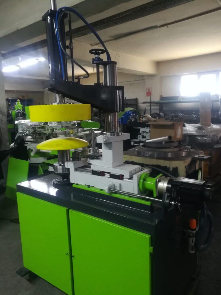
A Seaming Machine for Sheet Metal Seams is a specialized mechanical device designed to join two or more sheet metal parts by forming continuous seams along their edges. These machines create strong, precise, and often airtight or watertight joints without the need for welding, adhesives, or fasteners. Seaming machines are essential in industries such as packaging, HVAC, roofing, automotive, and appliance manufacturing where reliable sheet metal joints are critical.
Seaming machines work by folding, interlocking, and compressing the edges of sheet metal components together through a series of rollers, dies, or folding tools. The exact seam type formed depends on the machine design and application, including common seam styles such as lap seams, lock seams, flat lock seams, grooved seams, single or double seams, and hem seams.
These machines range from small manual or semi-automatic units for prototype or low-volume production, to fully automated high-speed systems integrated into production lines. Features often include adjustable roller pressure, programmable seam length, edge guiding systems, and optional sealant dispensers to enhance seam integrity.
Applications of seaming machines cover a broad spectrum: joining can bodies to their bottoms or lids in metal packaging, forming ductwork and ventilation components with airtight seams, assembling metal roofing panels with weatherproof joints, or producing automotive fuel tanks and industrial containers requiring durable mechanical seals.
Advantages of using seaming machines include consistent seam quality, increased production speed, preservation of metal coatings due to cold forming, and elimination of heat-affected zones common in welding. Maintenance of tooling and rollers is essential to ensure seamless operation and to avoid damage to sheet metal surfaces.
In summary, seaming machines for sheet metal seams are versatile, efficient, and precise equipment critical for fabricating a wide range of metal assemblies, providing mechanical strength, leak resistance, and aesthetic finish in joined metal products.
Seaming machines for sheet metal seams have evolved to accommodate various materials, thicknesses, and seam designs, offering flexibility for diverse industrial needs. Their ability to form seams mechanically without applying heat preserves protective coatings like paint, galvanization, or anodizing, which is crucial for corrosion resistance and product longevity. This cold-forming process also minimizes distortion or warping of thin sheets, maintaining dimensional accuracy and surface quality.
Modern seaming machines often incorporate advanced control systems, enabling precise adjustment of parameters such as roller pressure, seam pitch, and feeding speed. Programmable logic controllers (PLCs) and human-machine interfaces (HMIs) allow operators to store seam “recipes” for quick changeovers between product types, enhancing efficiency in production environments with varied output requirements.
Integration with automated feeding and handling equipment allows seaming machines to operate continuously with minimal operator intervention, boosting throughput and consistency. Some machines are equipped with sensors and vision systems that monitor seam formation in real time, detecting defects like misalignment, incomplete folding, or surface damage. This feedback can trigger automatic corrections or line stoppages, reducing waste and ensuring quality.
Seaming machines are used extensively in packaging industries, especially for cans and containers where the body, bottom, and lid must be joined reliably to prevent leaks and contamination. In HVAC fabrication, they form seams that maintain airtightness in ductwork, improving system performance and energy efficiency. Roofing and architectural metal panels benefit from seaming machines by producing weatherproof joints that resist wind and water ingress while maintaining a clean aesthetic.
Tooling maintenance and changeover are critical to the performance of seaming machines. Rollers and dies must be free of wear and debris to avoid damaging sheet metal surfaces or compromising seam integrity. Manufacturers provide interchangeable tooling sets for different seam profiles and material thicknesses, enabling customization and flexibility. Regular calibration ensures that roller alignment and pressure settings meet required specifications.
Environmental and safety considerations are integral to machine design. Because seaming avoids heat and hazardous chemicals, it offers a safer working environment with fewer emissions. Machines include safety features like guards, emergency stops, and interlocks to protect operators from moving parts and pinch points.
As manufacturing moves towards Industry 4.0, seaming machines are increasingly networked within smart factories. Data on machine performance, seam quality, and maintenance needs can be tracked and analyzed to optimize production and reduce downtime. Remote diagnostics and predictive maintenance capabilities help maintain continuous operation and extend machine life.
Overall, seaming machines for sheet metal are indispensable tools that enable efficient, high-quality joining of metal parts across many industries. Their combination of mechanical precision, automation readiness, and adaptability to different seam types ensures they remain central to modern sheet metal fabrication processes.
Seaming machines also play a vital role in reducing production costs and improving sustainability in sheet metal fabrication. By enabling precise, repeatable seams without the need for consumables like welding rods, adhesives, or fasteners, these machines reduce material waste and lower overall operational expenses. The cold-forming nature of seaming preserves material properties and coatings, extending product lifespan and reducing the need for costly rework or repairs.
In high-volume manufacturing settings, seaming machines contribute to consistent product quality, which is crucial for meeting regulatory standards and customer expectations. Automated controls minimize human error and ensure that each seam meets exact specifications, enhancing reliability especially in critical applications like pressure vessels, food and beverage cans, or pharmaceutical containers where joint integrity is paramount.
Seaming technology has also advanced to support complex geometries and customized seam profiles. Some machines offer multi-axis capabilities to handle curved, tapered, or irregular sheet metal parts, broadening the range of possible product designs. This flexibility enables manufacturers to innovate with new shapes and features while maintaining efficient seam formation.
Customization extends to machine configurations as well; modular designs allow integration of seaming units with upstream and downstream equipment such as cutting lasers, stamping presses, or inspection stations. This creates seamless production lines that reduce handling time and improve overall workflow efficiency.
Operator training and ergonomic design are important aspects of modern seaming machines. User-friendly interfaces, clear visual indicators, and adjustable controls help reduce operator fatigue and errors, contributing to safer and more productive workplaces. Some machines also include remote monitoring and support features that allow experts to assist operators or perform troubleshooting without needing to be physically present.
Looking to the future, innovations in materials, sensor technology, and artificial intelligence are poised to further enhance seaming machine capabilities. Adaptive control systems may automatically optimize seam parameters in real time based on material variations or environmental conditions, improving quality and reducing setup times. Integration with augmented reality (AR) could provide operators with interactive guidance and diagnostics, further streamlining maintenance and training.
In summary, seaming machines for sheet metal seams are a cornerstone of efficient, high-quality metal fabrication. Their continued evolution supports the growing demands of diverse industries for faster, smarter, and more sustainable manufacturing solutions. Through precision, automation, and integration, these machines enable fabricators to produce strong, reliable seams that meet exacting functional and aesthetic requirements while optimizing cost and resource use.
Sheet Metal Hem Roller
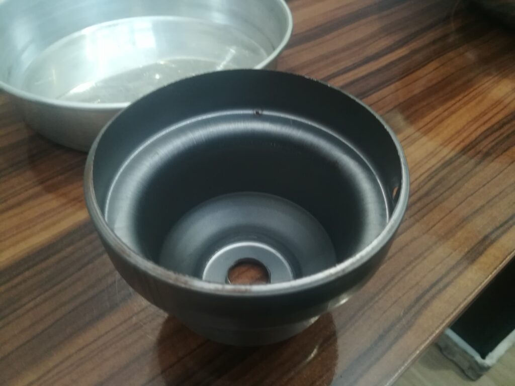
A Sheet Metal Hem Roller is a specialized machine or tool used to create hems on sheet metal edges by rolling or folding the metal over itself. Hemming is a common sheet metal fabrication process where the edge of a metal sheet is bent back onto the sheet, doubling the material thickness at the edge. This strengthens the edge, removes sharpness, improves safety, and enhances the appearance of the finished part.
Hem rollers work by gradually bending or curling the sheet metal edge through a series of rollers or a rotating drum, producing a smooth, consistent hem along the length of the material. Depending on the machine design and application, hem rollers may be manual, motorized, or fully automated.
Common uses for sheet metal hem rollers include manufacturing automotive panels, appliances, HVAC components, metal furniture, and enclosures. Hemming is critical where edges need reinforcement or where parts will be joined via seams, spot welding, or adhesives.
Key features of hem rollers often include adjustable roller pressure and spacing to accommodate different metal thicknesses and hem types. Some machines offer variable rolling speeds and interchangeable roller profiles for forming various hem styles like closed hems, open hems, or tapered hems.
Hem rollers preserve the metal’s surface finish by cold forming without cutting or excessive deformation, making them suitable for coated or painted metals. They contribute to safer handling by eliminating sharp edges and can improve assembly strength when hems are used as mechanical joints.
In summary, sheet metal hem rollers are essential tools in sheet metal fabrication for producing strong, smooth, and safe edges through controlled rolling or folding, supporting a wide range of industrial and commercial metalworking applications.
Sheet metal hem rollers are versatile machines that play a crucial role in producing consistent, high-quality hems across various types of sheet metal materials, including steel, aluminum, copper, and stainless steel. The hemming process performed by these rollers not only strengthens edges but also prepares parts for subsequent assembly processes such as welding, riveting, or adhesive bonding. By rolling the metal edge back onto the sheet, hem rollers help create seams that improve structural rigidity while maintaining smooth, safe edges, which is particularly important in automotive and appliance manufacturing where both safety and appearance matter.
Depending on the complexity and production volume, hem rollers range from small manual devices suitable for prototype or repair work to large, automated machines integrated into full production lines. Manual hem rollers typically involve hand-cranked or motor-assisted rotating rollers that allow operators to guide the sheet metal edge through the hemming process with controlled pressure. In contrast, automated hem rolling machines use powered rollers with adjustable speed and pressure settings to ensure uniform hem dimensions across long runs, reducing operator fatigue and increasing throughput.
Adjustability is a key feature of sheet metal hem rollers, allowing operators to modify roller gap, pressure, and rolling speed to accommodate different material gauges and hem profiles. This flexibility is vital to prevent cracking, wrinkling, or distortion during the rolling process, especially when working with high-strength or coated metals. Interchangeable roller sets or profiles may also be available to form various hem types such as closed hems, tapered hems, or rolled hems, catering to diverse design requirements.
The hemming process conducted by these rollers is typically a cold-forming operation, preserving the integrity of surface coatings such as paint, galvanization, or anodizing. This ensures that the finished product retains corrosion resistance and aesthetic quality, which is essential for exterior automotive parts, architectural panels, and consumer appliances. Additionally, hemming eliminates sharp edges, improving safety for both assembly workers and end-users.
In production environments, sheet metal hem rollers can be integrated with upstream and downstream equipment such as press brakes, laser cutters, or welding stations to create streamlined fabrication workflows. Automation and CNC controls allow for precise control over hem dimensions and repeatability, enabling quick changeovers between different part designs and reducing scrap rates. Some advanced systems incorporate sensors to monitor roller pressure and detect defects in real time, enhancing quality control.
Maintenance of hem rollers involves regular inspection and cleaning of rollers to prevent surface damage or buildup that could mar sheet metal finishes. Proper lubrication and alignment of moving parts are essential to maintain smooth operation and extend machine life. Operators are trained to recognize signs of wear or damage that may affect hem quality, ensuring timely tooling replacement.
Beyond industrial applications, sheet metal hem rollers are also valuable in repair and custom fabrication contexts. Their ability to form durable, clean hems on-site allows technicians to restore damaged panels or create bespoke metal parts without extensive tooling or welding, offering cost-effective and flexible solutions.
As manufacturing technologies advance, sheet metal hem rollers continue to evolve, incorporating features like programmable controls, enhanced ergonomics, and improved integration with digital manufacturing systems. These developments support higher production speeds, better quality consistency, and greater adaptability to complex part geometries.
Overall, sheet metal hem rollers are indispensable in modern metal fabrication, providing a reliable, efficient means to strengthen, finish, and prepare sheet metal edges for assembly or final use. Their role spans from heavy industrial manufacturing to delicate decorative work, underscoring their versatility and importance in a wide array of metalworking industries.
Sheet metal hem rollers also contribute significantly to product durability and performance by reinforcing edges that are often subject to wear, impact, or stress during use. Hemmed edges resist deformation better than raw cut edges, reducing the risk of cracking or bending, which is crucial in automotive body panels, appliance housings, and HVAC components that undergo repeated handling or vibration.
In terms of design flexibility, hemming allows engineers to optimize part geometry by incorporating stronger edges without adding extra material thickness or weight. This can lead to lighter assemblies with improved structural integrity, supporting industry trends toward weight reduction for fuel efficiency in vehicles or ease of installation in construction.
The hemming process facilitated by these rollers is compatible with a wide range of metal thicknesses, though the limits depend on machine capacity and tooling. Thin gauge metals are easier to form but require careful control to avoid wrinkles or tearing, while thicker metals demand more robust machines with higher rolling forces and precise adjustment mechanisms.
Safety is an important consideration in hem roller operation. Since these machines involve rotating components and substantial force, they are equipped with safety features such as emergency stops, protective guards, and sensors to prevent accidental injury. Ergonomic designs minimize operator strain, and training ensures proper handling to maintain a safe working environment.
Emerging technologies are enhancing sheet metal hem rollers through automation and smart controls. CNC programming enables precise control over rolling speed, pressure, and roller positioning, ensuring consistent hems even on complex or variable profiles. Integration with factory automation systems allows seamless coordination with upstream cutting or bending equipment, reducing manual handling and improving overall workflow efficiency.
Quality control in hem rolling has benefited from the introduction of real-time monitoring tools. Sensors can measure hem dimensions, detect surface defects, and verify roller alignment during operation, enabling immediate corrections and reducing scrap. Data collected can be analyzed to optimize process parameters for different materials or designs.
In repair and custom fabrication, portable hem rollers provide flexibility by allowing technicians to form hems directly on-site, reducing downtime and transport costs. These portable units range from simple hand tools to motorized rollers capable of handling larger or more complex parts, expanding their utility beyond standard production environments.
Sustainability considerations also favor the use of hem rollers. Because hemming is a cold forming process, it consumes less energy than welding or heat-based joining methods and generates minimal waste. By enabling strong mechanical joints without adhesives or fasteners, it facilitates easier recycling at end-of-life, supporting circular economy goals.
In conclusion, sheet metal hem rollers are vital tools that enhance the strength, safety, and aesthetics of metal components through efficient edge forming. Their adaptability across materials, part geometries, and production volumes makes them indispensable in diverse manufacturing sectors. Continuous technological advancements ensure that hem rollers remain at the forefront of sheet metal fabrication, meeting the evolving demands of modern industry.
Hemming Process in Sheet Metal
The hemming process in sheet metal fabrication involves folding the edge of a sheet metal piece back onto itself to create a smooth, rounded, and reinforced edge. This process serves several purposes: it strengthens the edge, removes sharpness for safety, improves aesthetics, and prepares the sheet for joining with other components. Hemming is widely used in automotive panels, appliance manufacturing, HVAC ducts, furniture, and architectural metalwork.
Hemming typically occurs in two stages: first, the edge of the sheet metal is bent to approximately 90 degrees (pre-hem or first operation), and then it is folded further, usually flat against the sheet (final hem or second operation). This two-step bending reduces cracking or wrinkling and results in a clean, uniform fold. Depending on the design, hems can be closed (tight fold), open (with a slight gap), tapered, or rolled.
The hemming process can be performed manually with hand tools or mechanically using dedicated hemming machines such as press brakes, hem rollers, or rotary hemming machines. In industrial settings, hemming is often automated, with CNC-controlled presses or rollers producing consistent, high-quality hems rapidly and with minimal operator intervention.
Proper hemming requires precise control over material handling, bend angles, and tooling to prevent defects like cracking, wrinkling, or springback. Material properties such as thickness, ductility, and coating type influence the hemming parameters. High-strength or coated metals may need specialized tooling and slower bending speeds to maintain surface finish and avoid damage.
Hemming improves the mechanical properties of sheet metal parts by increasing stiffness and resistance to deformation at edges. It also facilitates assembly by creating edges suitable for spot welding, adhesive bonding, or mechanical fastening. In many applications, hems enhance the overall appearance and safety of the final product by providing smooth, rounded edges.
In summary, the hemming process is a vital sheet metal forming technique that enhances edge strength, safety, and aesthetics, enabling durable and functional joints in a wide variety of metal products.
The hemming process also plays an important role in improving the durability and service life of sheet metal components. By folding the edge back onto itself, the hem distributes stresses more evenly along the edge, reducing the likelihood of cracks or tears developing during handling, installation, or use. This is especially important in industries such as automotive manufacturing, where panels undergo repeated vibrations and impacts, or in HVAC systems, where duct edges need to maintain shape under airflow pressure.
The quality of a hem depends heavily on precise control over material flow during bending. If the metal is bent too quickly or with excessive force, it can develop wrinkles or cracks, particularly in high-strength or coated materials. To avoid these defects, manufacturers often use a two-step hemming process: the initial bend (pre-hem) sets the edge at an intermediate angle, relieving stress, followed by the final fold that completes the hem smoothly. This staged approach minimizes material fatigue and preserves surface finish.
Tooling design is critical for effective hemming. Specialized dies and rollers are shaped to gradually guide the metal edge through the folding process without causing distortion or damage. These tools must be matched to the specific material type, thickness, and desired hem profile. For coated metals, tooling surfaces are often polished or coated themselves to prevent scratching or marring the finish.
In automated production environments, hemming machines are often integrated with other forming equipment such as stamping presses and welding stations. This integration streamlines fabrication by reducing handling time and improving dimensional consistency. Advanced CNC controls allow for programming multiple hemming sequences and adjusting parameters in real time to accommodate variations in material or part geometry.
Hemming also facilitates downstream assembly operations. The folded edge can act as a flange for spot welding, riveting, or adhesive bonding, providing a reliable and uniform surface for joint formation. This capability is especially valuable in industries that require strong, precise joints without the heat or distortion associated with welding.
In some cases, hemming is combined with sealing materials such as gaskets or sealants to create moisture-resistant joints, important in applications like automotive door panels, appliances, or HVAC ducts exposed to weather or humidity. The hem helps contain the sealing material and maintains compression for effective sealing.
Safety considerations during hemming include protecting operators from pinch points and ensuring ergonomic handling of metal sheets. Machines are equipped with guards, emergency stops, and sensors to minimize risks. Operator training emphasizes proper setup and monitoring to prevent damage to parts and tooling.
With ongoing advances in materials and manufacturing technologies, the hemming process continues to evolve. New alloys with higher strength or special coatings may require optimized hemming techniques or tooling materials. Automation and sensor integration improve process reliability and reduce waste. Additionally, the trend toward lightweight design drives innovations in hemming thin or multi-layered sheets without compromising joint quality.
Overall, the hemming process remains a cornerstone of sheet metal fabrication, providing a versatile and effective method for enhancing edge strength, safety, and aesthetics. Its adaptability and efficiency make it indispensable across automotive, aerospace, appliance, construction, and many other industries.
The hemming process also offers significant benefits in terms of material utilization and cost efficiency. By folding the edge of the sheet metal back onto itself, hemming effectively reinforces the perimeter without requiring additional material, which helps reduce overall weight and material costs. This is particularly valuable in industries like automotive and aerospace, where every gram saved contributes to fuel efficiency and performance.
Hemming is compatible with a wide range of sheet metal thicknesses and alloys, though the process parameters must be carefully optimized to each specific material to avoid defects. Thinner sheets tend to hem more easily but are prone to wrinkling or tearing if not handled carefully. Thicker or high-strength materials require greater forming force and often specialized tooling to ensure a smooth, crack-free hem.
In addition to flat sheets, hemming can be applied to curved or complex geometries, allowing designers greater freedom to create intricate parts with finished edges. Rotary hemming machines and flexible tooling systems can accommodate these shapes, enabling seamless integration of hems into 3D components such as automotive fenders or appliance housings.
Environmental considerations also favor the hemming process. Since it is a cold forming operation, it uses less energy compared to heat-based joining techniques like welding. Additionally, hemming does not involve adhesives or consumables, minimizing waste and simplifying recycling at the end of product life.
Process monitoring and quality assurance have improved with technological advances. Inline sensors and vision systems can inspect hems for dimensional accuracy, surface defects, or incomplete folding, allowing immediate correction and reducing scrap rates. Data collected can be analyzed to refine process parameters and support continuous improvement initiatives.
For custom or low-volume production, manual hemming tools and portable hemming machines offer flexibility and cost savings. These tools enable fabricators to form hems on-site or in small batches without investing in large, automated equipment. Portable hem rollers and hand-operated hemmers are common in repair shops and small manufacturing facilities.
The hemming process also enhances safety in handling and assembly. Hemmed edges eliminate sharp metal burrs, reducing the risk of injury to workers during manufacturing and to end-users during product use. This contributes to workplace safety compliance and improves product quality perception.
As materials science evolves, new alloys and coated metals present both challenges and opportunities for hemming. Innovations in tooling materials, surface treatments, and process control continue to extend hemming’s applicability to these advanced materials, maintaining its relevance in cutting-edge manufacturing.
In conclusion, hemming is a fundamental sheet metal process that strengthens edges, improves safety, and enables efficient assembly. Its adaptability, cost-effectiveness, and environmental benefits ensure its ongoing importance across a broad spectrum of industries, from automotive to consumer appliances and beyond. Continuous technological advancements promise to further enhance the efficiency, quality, and scope of hemming in modern manufacturing.
Customizable Hemming System for Industrial Metalwork
A Customizable Hemming System for Industrial Metalwork is a specialized, flexible setup designed to meet the diverse hemming requirements of various metal fabrication applications. Unlike standard hemming machines with fixed configurations, a customizable system allows manufacturers to tailor machine components, tooling, controls, and automation features to handle different metal types, thicknesses, part geometries, and production volumes efficiently.
Such systems typically include modular components—adjustable rollers, interchangeable dies, and configurable feeding mechanisms—that can be quickly adapted or swapped out to produce a wide range of hem profiles, including closed hems, open hems, tapered hems, and rolled hems. This flexibility supports fabricators working with multiple product lines or custom parts without needing separate machines for each application.
Integration with CNC or PLC control units enables precise adjustment of hemming parameters like roller pressure, speed, and bend angles, allowing operators to program and save setups for repeatability and quick changeovers. Advanced systems may also incorporate sensors for real-time monitoring of seam quality and automated defect detection, ensuring consistent results and minimizing scrap.
Customization extends beyond mechanical elements to software and automation. Hemming systems can be configured with robotic material handling, automated loading/unloading, and inline quality inspection to streamline production and reduce labor costs. Touchscreen interfaces with user-friendly controls facilitate operator training and reduce setup times.
Material compatibility is a key aspect; customizable systems are designed to handle a variety of metals such as steel, aluminum, copper, and stainless steel, across a range of thicknesses and coatings. Tooling and machine adjustments accommodate differences in ductility and strength, ensuring clean hems without cracking or surface damage.
These systems are widely used in industries including automotive, aerospace, HVAC, appliance manufacturing, and architectural metalwork, where varying part designs and high-quality hems are critical. They support both small batch custom fabrication and large-scale production runs by balancing flexibility with throughput.
Maintenance and serviceability are integral to customizable hemming systems. Modular design allows easy replacement or upgrading of components, minimizing downtime. Remote diagnostics and support may be offered in advanced systems to quickly address issues and maintain continuous operation.
In summary, a customizable hemming system for industrial metalwork provides versatile, precise, and efficient hemming solutions adaptable to a wide range of fabrication needs. Its modular design, advanced controls, and automation integration enable manufacturers to meet evolving production demands while ensuring high-quality, consistent hems across diverse metal parts.
A customizable hemming system for industrial metalwork enhances operational flexibility by allowing manufacturers to seamlessly transition between different product requirements without major reconfiguration. This is especially valuable in environments where multiple metal parts with varying geometries and material properties are produced on the same line. The ability to adjust tooling and settings on the fly not only reduces downtime but also boosts overall equipment effectiveness (OEE) by minimizing changeover time and scrap rates.
The heart of such a system lies in its modular tooling platform. Tooling stations can be adapted to suit specific hem profiles, whether they involve a simple single hem or more complex multi-stage hems. Quick-release tooling interfaces and automated alignment systems ensure that tool changes can be completed rapidly and with minimal skill, enabling faster product transitions and supporting high-mix manufacturing.
CNC and PLC integration allows precise, programmable control over hemming parameters, giving operators the ability to store recipes for different parts. This ensures consistent quality from the first part to the last, regardless of operator variability. Hemming speed, pressure, dwell time, and roller angles can all be controlled through a central interface, and real-time data logging supports traceability and process optimization.
Sensor-based feedback systems and machine vision technology can be included to monitor part positioning, hem quality, and tool wear in real time. These systems can detect wrinkles, misalignment, or incomplete hems and either alert the operator or automatically correct the process, significantly reducing rework. Over time, collected performance data can be analyzed to improve process reliability, identify trends, and inform predictive maintenance schedules.
In terms of materials, a customizable system is capable of handling a range of sheet metal thicknesses and grades, from thin aluminum panels to thick high-strength steels. Adjustable roller pressure and variable speed control ensure that the metal is formed without causing surface damage, cracking, or internal stress. Systems are often designed to accommodate coated, pre-painted, or anodized materials, preserving the integrity of aesthetic or corrosion-resistant finishes during hemming.
Advanced systems may include robotic automation, where articulated arms position parts for hemming or transfer them between operations. This reduces manual handling, improves cycle time, and enhances precision—especially important in automotive, aerospace, or appliance sectors where tolerance control is critical. Robotic systems can also be taught to handle parts with irregular contours or 3D profiles, further expanding the range of components that can be hemmed.
In-line hemming stations can be synchronized with punching, bending, and welding operations in a continuous production flow. This integration eliminates unnecessary handling and work-in-progress storage, reducing lead times and manufacturing costs. Smart factory features like IoT connectivity and remote diagnostics also contribute to higher uptime and allow real-time monitoring across multiple production sites.
Maintenance efficiency is built into the system design. Modular roller units, self-lubricating components, and standardized interfaces reduce maintenance time and simplify spare parts inventory. Training for operators and technicians is often simplified through intuitive user interfaces, simulation software, and digital manuals, shortening the learning curve and improving operational safety.
In today’s competitive manufacturing landscape, the demand for flexibility, speed, and quality has never been higher. A customizable hemming system meets these demands by offering a platform that can be tailored to specific production needs while remaining scalable for future growth. Whether used for prototyping or full-scale mass production, such systems provide the adaptability and precision needed to stay competitive in fast-evolving markets.
Customizable hemming systems are increasingly becoming central to smart manufacturing strategies, where agility and data-driven decision-making are paramount. These systems can be equipped with Industrial Internet of Things (IIoT) capabilities, enabling remote monitoring, cloud connectivity, and integration into enterprise-level production management systems. This allows factory managers to monitor hemming performance in real time, adjust settings remotely, and respond proactively to any anomalies or maintenance needs—improving overall equipment reliability and reducing downtime.
In industries such as automotive, where panel accuracy, aesthetic quality, and dimensional integrity are critical, customizable hemming systems provide the necessary control and repeatability. These systems can adapt to new vehicle models or changes in body-in-white design without the need for entirely new equipment. This flexibility shortens time to market and reduces capital expenditure on new tooling for each model.
In aerospace and rail manufacturing, where lightweight materials like aluminum and titanium alloys are often used, a customizable system can be fine-tuned to handle delicate, high-value parts. Advanced roller materials, servo-controlled actuators, and multi-stage forming sequences help prevent cracking or warping while maintaining tight tolerances on complex shapes.
Another advantage of customizable systems is their scalability. A company can begin with a semi-automated setup for smaller production runs and gradually upgrade it with robotic handling, automated quality control, or multi-station inline processing as demand increases. This modular expansion capability allows manufacturers to grow their capabilities without needing to replace entire systems, preserving initial investments and supporting lean manufacturing principles.
The design of these systems also supports operator safety and ergonomic efficiency. Features like automatic part clamping, intuitive touchscreen interfaces, and programmable safety zones reduce operator fatigue and lower the risk of accidents. Built-in diagnostics assist operators in troubleshooting, providing guidance on resolving errors or alerts, and enabling less experienced personnel to manage operations with confidence.
In terms of cost savings, customizable hemming systems reduce waste by consistently producing accurate hems, minimizing rejected parts due to edge defects or incorrect folds. They also reduce tooling wear through optimized load distribution and intelligent pressure control, extending the lifespan of components like rollers and forming dies.
Customization also means the system can be adapted to specific spatial constraints or factory layouts. Whether configured as a standalone station, a turntable-type system, or an inline transfer solution, the equipment can be designed to integrate seamlessly with the flow of a specific production environment. This allows manufacturers to optimize floor space and streamline material handling.
As sustainability becomes a more pressing concern, hemming systems align well with green manufacturing goals. The cold-forming process consumes less energy compared to thermal joining methods, generates little to no fumes or emissions, and supports clean, safe working environments. The ability to process coated and recyclable metals without degrading their properties also simplifies the recovery and reuse of offcuts or end-of-life components.
In essence, a customizable hemming system is not just a piece of equipment—it’s a strategic investment that delivers adaptability, efficiency, and long-term value. It empowers manufacturers to respond quickly to changing designs, materials, and market demands while maintaining high standards of precision, safety, and cost-effectiveness. As fabrication technology continues to advance, these systems will remain a cornerstone of innovative, responsive industrial metalworking operations.
Compact Hemming Machine for On-Site Fabrication
A Compact Hemming Machine for On-Site Fabrication is a portable, space-efficient device designed to perform hemming operations directly at job sites, workshops, or in confined production spaces where full-size machinery is impractical. These machines enable fabricators, contractors, and maintenance teams to hem sheet metal parts without the need for transporting materials back to a central facility, saving time, cost, and effort—especially in construction, HVAC installation, vehicle repair, and metal roofing projects.
Compact hemming machines typically feature lightweight frames, integrated handles or wheels, and simplified controls, making them easy to transport, set up, and operate. Despite their small size, they are capable of producing high-quality hems on a variety of metals such as galvanized steel, aluminum, copper, and stainless steel. These machines often support basic hem types like single hems, open hems, and flattened hems along straight or slightly curved edges.
Most models use either hand-crank mechanisms or low-power electric motors, allowing operation in places without industrial power supplies. Variable speed control, adjustable roller pressure, and replaceable forming tools give users enough flexibility to work with different sheet thicknesses and project requirements. For rugged job sites, the machines are often built with durable frames and wear-resistant components to withstand frequent transport and use.
Compact hemming machines are particularly valuable in tasks such as creating safe, smooth edges on exposed ductwork, hemming roofing panels to improve structural integrity, or forming joints for cladding and siding. They help reduce reliance on large fixed infrastructure and allow for real-time fabrication adjustments, which is ideal when measurements or conditions vary from the original design.
In summary, a compact hemming machine for on-site fabrication offers portability, convenience, and versatility, allowing precise edge forming in locations where traditional hemming equipment cannot be used. It is a vital tool for mobile metalworkers and industries that demand flexibility without compromising on seam quality.
Compact hemming machines for on-site fabrication are increasingly popular among contractors and small-scale manufacturers due to their ability to bring precision metalworking directly to the point of installation or repair. Their portable nature means that custom panels, trim pieces, or enclosure edges can be hemmed in real time, reducing delays caused by shipping parts to off-site workshops or waiting for custom orders. This immediacy is especially advantageous in time-sensitive projects such as HVAC retrofits, roofing installations, and emergency metal repairs where quick edge finishing is essential for both function and safety.
These machines often include interchangeable rollers or die sets that allow the operator to create different hem types without extensive retooling. Some models even offer built-in gauges and backstops for consistent edge alignment, improving uniformity across multiple parts. Since they are designed for field use, many compact hemming machines have robust, maintenance-friendly designs with minimal electronics and simple mechanical systems that can withstand dirt, dust, and transportation shocks.
In metal roofing and cladding applications, compact hemmers are used to create closed or safety hems on flashings, drip edges, and fascia panels. These formed edges not only provide a clean, professional appearance but also increase resistance to wind uplift and water penetration. On HVAC job sites, sheet metal workers use portable hemmers to fold duct edges for safer handling and easier connection, eliminating the need for pre-fabricated flanges or separate edge treatments.
Electric models are typically powered by standard 110V or 220V outlets, making them compatible with general construction site power supplies. Battery-powered versions are becoming more common as cordless tool technology improves, enabling even greater mobility and reducing setup time. For very tight workspaces or elevated locations, hand-operated versions remain a reliable option, offering good control and precision without requiring any power source.
Compact hemming machines are also ideal for educational settings and entry-level workshops where budget constraints or space limitations prevent investment in large equipment. Their intuitive operation makes them suitable for training purposes while still producing professional-grade hems. Furthermore, for artisans, metal artists, or small fabricators working on custom furniture, lighting, or architectural features, these machines enable creative freedom by allowing quick experimentation with edges and folds without heavy infrastructure.
In terms of safety, compact hemming machines are generally low-risk thanks to their slow forming speeds and contained mechanisms. Most are equipped with ergonomic handles or padded grips to reduce strain during extended use, and some include guards to shield fingers from rollers. Their small footprint also makes them easy to clamp to a bench or secure within a mobile workstation.
Overall, the compact hemming machine has become a versatile and practical solution in modern metalworking, offering the flexibility to form precise, reinforced, and clean edges anywhere they’re needed. Whether used in the field or as part of a lean production setup, these machines bridge the gap between quality and convenience, empowering users to maintain fabrication standards without being tied to a large manufacturing facility.
Beyond their practical benefits in edge forming, compact hemming machines also contribute to workflow efficiency and cost savings in industries where agility and mobility are essential. For example, in modular construction or custom architectural metalwork, project specifications can change on-site due to measurement corrections or structural alterations. Having a hemming machine available at the location allows technicians to adapt immediately—forming new hems or adjusting existing ones without shipping delays, additional transport costs, or the need to maintain excess inventory.
Compact hemmers are also increasingly being used in prefabricated metal building assembly, where panel customization and edge treatment often need to be carried out during installation. These machines allow crews to fabricate accurate hems that meet structural requirements and local building codes without needing to rely on distant suppliers. By producing consistent, burr-free folds on-site, installers can also maintain high standards for weatherproofing and safety without sacrificing productivity.
For maintenance and repair operations (MRO), especially in industries like marine, aviation, and industrial enclosures, a compact hemming machine enables field technicians to restore or reinforce damaged sheet metal components without dismantling entire systems or transporting bulky panels back to a central facility. This responsiveness can reduce downtime significantly and prevent minor issues from escalating into more costly repairs.
Customization is another major advantage of compact hemming machines. Since many models are designed with swappable components and user-adjustable settings, they can be quickly reconfigured for different materials, edge lengths, or hem styles. This adaptability is valuable for low-volume, high-mix production environments such as bespoke metalwork, artistic fabrication, and prototype development. In these settings, users need tools that respond to changing creative or engineering requirements without investing in full-size industrial lines.
Noise levels from compact hemming equipment tend to be relatively low compared to heavy industrial presses or roll formers, which makes them suitable for indoor use in residential construction zones, urban workshop environments, or sensitive locations such as museums and high-end architectural installations. Combined with their small footprint, this opens up possibilities for their use in unconventional or restricted areas.
Some advanced compact models now include digital controls and memory storage, allowing operators to save parameters for frequently used hem profiles and ensure repeatability across different jobs. As Industry 4.0 trends continue to shape even small-scale equipment, future versions of compact hemmers may include wireless diagnostics, usage tracking, and integration with mobile apps or cloud-based job management systems.
In terms of materials, these machines are capable of handling a wide range—from soft metals like aluminum and copper to harder ones like stainless steel—within their capacity limits. Because they apply controlled pressure without heat, they are ideal for pre-painted or coated sheets where preservation of the finish is essential. The resulting hems are clean, with minimal distortion or marring, ensuring that even decorative or exposed parts meet both functional and aesthetic expectations.
In conclusion, the compact hemming machine is a powerful enabler for on-site metal fabrication, offering a blend of portability, precision, and flexibility. Whether used in construction, repair, design, or education, it provides craftsmen and technicians with the tools to work efficiently and effectively without being tied to large-scale infrastructure. As industries continue to prioritize mobility, customization, and lean production, the role of compact hemming machines will only grow more essential.
Advanced Sheet Metal Flanging and Hemming Tool
An Advanced Sheet Metal Flanging and Hemming Tool is a high-precision, multi-functional piece of equipment designed to perform both flanging (bending up or down a narrow edge of a sheet) and hemming (folding the edge back onto itself) operations in a single or integrated process. This type of tool is widely used in industries where structural integrity, dimensional accuracy, and surface quality are critical—especially automotive body manufacturing, aerospace components, HVAC systems, appliance panels, and architectural facades.
The advanced nature of the tool lies in its ability to adapt to different materials, geometries, and production requirements while maintaining high levels of repeatability and finish quality. It combines robust mechanical engineering with modern control systems such as servo-electric or hydraulic actuation, programmable logic controllers (PLCs), and human-machine interfaces (HMIs), enabling precise control over bending angles, force application, timing, and positioning.
In flanging, the tool creates an upward or downward bend along the edge of a sheet metal panel. This is often a preparatory step before hemming, as the flange provides a defined edge to fold over during the hemming operation. In complex assemblies, flanges serve as stiffeners or alignment features and are critical for spot welding or adhesive joining in subsequent manufacturing stages.
Hemming is then performed in one or more stages—typically a pre-hem at an intermediate angle followed by a final flattening or roll-in. Advanced systems can accommodate variations in material thickness, hardness, and coatings by adjusting force and speed dynamically to prevent defects such as cracking, wrinkling, or surface marking.
Some advanced tools integrate rotary actuators or CNC-guided rollers that follow complex part contours, enabling seamless hemming and flanging on curved or asymmetrical surfaces. This is especially important in automotive applications like doors, hoods, and fenders where the outer and inner panels must be joined precisely along complex edges without warping or visible distortion.
Automation is a hallmark of these tools. Fully integrated systems often include robotic part handling, automatic tool change systems, in-line inspection, and feedback loops to adjust forming parameters in real time. These features enable high-speed production without sacrificing quality, making them suitable for both mass production and just-in-time manufacturing environments.
Tooling versatility is also key. Advanced flanging and hemming tools may use modular or multi-position dies that can switch configurations on demand, supporting rapid changeovers and minimizing downtime between different part runs. Some systems offer smart tooling that monitors wear and alignment to trigger maintenance alerts before defects occur.
With increasing emphasis on digital manufacturing, these tools are often networked into MES (Manufacturing Execution Systems) or ERP platforms, allowing manufacturers to track performance, schedule jobs, analyze downtime, and ensure traceability from raw material to finished product.
In summary, an advanced sheet metal flanging and hemming tool delivers unmatched precision, flexibility, and automation for edge-forming operations. Its ability to process complex parts with tight tolerances and premium surface finishes makes it indispensable in high-end metalworking environments where strength, appearance, and speed must coexist.
Advanced sheet metal flanging and hemming tools are also essential in supporting modern product design demands, where the integration of tight tolerances, complex contours, and clean visual lines is increasingly common. These tools allow manufacturers to achieve smooth, continuous bends and folds along varying radii without distortion, which is especially important in applications like electric vehicle panels, aircraft skins, or precision enclosures where aesthetic quality and aerodynamic function are both critical.
The ability of these tools to handle both operations—flanging and hemming—within one system reduces the need for intermediate handling or transferring parts between machines. This not only improves production speed but also ensures higher dimensional accuracy by eliminating the cumulative errors that can result from repositioning. In robotic applications, articulated arms equipped with adaptive end-effectors may work in tandem with the hemming tool, dynamically adjusting grip and pressure to maintain control over parts during the forming cycle.
Material adaptability is another core strength of these advanced tools. They are engineered to work with a variety of metals, including high-strength steels, aluminum alloys, and advanced lightweight materials used in automotive and aerospace sectors. Servo-driven or hydraulic actuation systems can be programmed to adjust the forming force and motion profile in real time, based on feedback from sensors monitoring torque, resistance, or material deflection. This ensures precise results even with differences in material hardness, springback tendencies, or thickness variability.
Another distinguishing feature is the integration of intelligent process monitoring systems. Cameras, laser measurement tools, and pressure sensors may be embedded into the tool setup to monitor every stage of flanging and hemming. This data can be analyzed instantly to detect irregularities such as incorrect bend angles, unbalanced pressure distribution, or tool wear. These systems not only catch defects early but also support continuous improvement by providing real-time insights that engineers can use to optimize tooling paths and production parameters.
Advanced flanging and hemming systems are often equipped with automated tool calibration routines that ensure consistent performance over long production runs. The system can detect deviations in position or pressure and automatically compensate for them, reducing the need for manual adjustments and extending tool life. This level of precision and self-correction is especially valuable in industries with strict compliance requirements, such as aerospace or medical equipment manufacturing, where repeatability and part conformity are non-negotiable.
Ergonomics and operator efficiency are also factored into the design. User-friendly interfaces with touchscreens and graphical programming environments make it easy for technicians to set up jobs, monitor progress, and switch between production modes. In smaller-scale or custom production, this allows faster learning curves and reduces reliance on highly specialized labor. Software often includes simulation capabilities that let users preview the forming operation and make adjustments before production begins, minimizing trial-and-error and material waste.
From a business standpoint, investing in an advanced flanging and hemming system delivers long-term value by reducing cycle times, improving product quality, and lowering operational costs. These systems eliminate bottlenecks in forming operations and reduce the number of machines required on the shop floor. Their ability to be tailored for high-mix, low-volume production also makes them ideal for manufacturers moving toward more flexible, demand-driven models.
In terms of sustainability, the cold-forming nature of these processes means lower energy consumption and less environmental impact compared to welding or adhesive bonding. The absence of fumes, emissions, and consumables contributes to a cleaner, safer working environment. Additionally, hemming preserves coatings and surface finishes, eliminating the need for costly post-processing or rework.
In essence, an advanced sheet metal flanging and hemming tool represents the convergence of mechanical precision, digital control, and manufacturing intelligence. It empowers fabricators to produce high-quality, structurally sound, and visually flawless components with remarkable efficiency and consistency. As product designs continue to evolve and materials become more complex, these tools provide the adaptability and control needed to keep modern metal fabrication at the cutting edge of performance and productivity.
As advanced sheet metal flanging and hemming tools continue to evolve, they are also becoming integral parts of fully automated production cells. In these setups, the hemming and flanging station is just one step in a continuous flow process that may include blanking, forming, punching, joining, inspection, and packaging—all synchronized under a centralized control system. This level of integration not only boosts output but also ensures that every part adheres to strict quality standards with minimal human intervention.
To further enhance process control, many of these tools now come equipped with adaptive forming algorithms that respond in real time to variations in material behavior. For instance, if a particular panel exhibits more springback due to subtle material hardness differences, the system can detect this through feedback sensors and dynamically adjust the hemming or flanging force and angle. This ensures that even with inconsistent inputs, the output remains within tolerance—an especially critical factor in industries like automotive, where panels must fit precisely to ensure flush assembly and noise reduction.
For multi-stage applications, some hemming tools are designed with multi-axis positioning systems, allowing them to form complex profiles on all four sides of a part or follow curved, variable paths on irregularly shaped components. These machines often use a combination of linear guides, rotary actuators, and precision servo motors to control roller or punch movement with micron-level accuracy. This capability is essential for parts such as automotive door skins, fuel tank covers, or appliance faceplates that require continuous, distortion-free edge treatment across complex geometries.
Digital twin technology is also being incorporated into high-end hemming and flanging systems. A virtual representation of the tool, part, and forming sequence allows engineers to simulate the operation in advance, test for issues, and optimize process parameters without risking material waste or tool damage. These digital models are constantly updated during production through real-time sensor feedback, allowing predictive maintenance and process optimization based on actual usage and performance data.
Another important trend is collaborative hemming cells, where advanced flanging and hemming tools work alongside human operators or collaborative robots (cobots). These setups are designed with safety sensors, light curtains, and intelligent motion controls to ensure safe interaction. This approach combines the precision and power of automation with the adaptability and decision-making of skilled technicians, making it ideal for high-variability, low-volume production runs.
Material handling systems paired with these tools are also becoming more intelligent. Automated feeders, vacuum lifters, or magnetic grippers can load and orient parts with extreme precision, ensuring that flanging and hemming operations begin with perfectly aligned material. Misfeeds and positioning errors are minimized, further reducing scrap and downtime.
Tool wear tracking is another area where innovation is enhancing system performance. Embedded RFID chips or sensor-enabled tool components can track usage cycles, temperature exposure, and force application, alerting operators when maintenance or replacement is due. This proactive approach prevents unplanned stoppages and extends the productive life of high-cost tooling components.
In the context of global supply chains and localized production, advanced hemming and flanging tools also support decentralized manufacturing models, allowing companies to deploy compact, intelligent forming systems closer to point-of-use. This not only reduces logistics and warehousing costs but also enables faster response to market changes, product customization, and region-specific design requirements.
In conclusion, the advanced sheet metal flanging and hemming tool is no longer just a station in a metalworking line—it is a dynamic, intelligent system that plays a critical role in high-quality, efficient, and scalable production. By combining adaptive mechanics, digital intelligence, automation, and seamless integration with broader manufacturing systems, these tools ensure that modern fabrication can meet the exacting standards of today’s industries—both in terms of physical performance and operational efficiency.
Multi-Purpose Sheet Metal Hemming Workstation
A Multi-Purpose Sheet Metal Hemming Workstation is a versatile, all-in-one fabrication setup designed to perform a wide range of hemming operations on sheet metal components. Unlike single-function hemming tools, this workstation is equipped to handle various hem types, edge preparation tasks, and even secondary processes such as flanging, beading, or edge rolling—all within a single, compact unit. It is ideal for environments where flexibility, precision, and efficiency are required, such as prototyping labs, custom metal shops, HVAC fabrication, small-batch manufacturing, and repair facilities.
At the core of a multi-purpose workstation is its modular design. The system typically features interchangeable heads or tooling stations that allow the operator to switch between different operations without needing a completely separate machine. For example, a single workstation might include attachments for closed hems, open hems, teardrop hems, and rope hems, along with tooling for creating flanges or curled edges. This adaptability makes it highly cost-effective and space-efficient, especially for shops that handle a wide variety of part shapes and specifications.
Most modern versions are outfitted with servo-driven actuators, programmable depth controls, and multi-axis movement systems that ensure consistent forming across flat or contoured surfaces. Advanced models may feature a touchscreen HMI (Human-Machine Interface) that allows the user to select a job profile, adjust pressure settings, or recall saved parameters for specific materials or part designs. This simplifies setup and increases repeatability, particularly when switching between materials like aluminum, stainless steel, or galvanized steel.
To support quality and efficiency, the workstation often integrates real-time feedback systems. Sensors monitor forming pressure, roller alignment, and hem angle, instantly alerting the operator to any deviations that could result in defective parts. Some systems even include a laser or camera-based inspection system to verify edge accuracy and surface finish post-operation, reducing the need for separate quality control steps.
Safety and ergonomics are built into the design, with guarded tooling areas, two-hand safety activation for manual operations, emergency stop buttons, and adjustable working heights. These features reduce fatigue and the risk of accidents while supporting continuous use over long shifts. In manual or semi-automatic variants, ergonomic handles and foot-pedal controls are often provided for hands-free operation.
Portability can also be a feature. Some multi-purpose hemming workstations are built on lockable casters, allowing them to be moved between work areas or brought to the part instead of the part being brought to a fixed machine. This mobility is valuable in tight workspaces or for large or unwieldy panels that are difficult to transport.
In addition to standard sheet metal fabrication, these workstations are commonly used in custom vehicle bodywork, architectural detailing, ductwork fabrication, and the creation of high-finish consumer metal products. In each of these cases, the workstation allows for fast adjustment, high-quality edge treatment, and reduced reliance on secondary finishing processes.
In summary, a multi-purpose sheet metal hemming workstation brings together the flexibility of multiple edge-forming operations with the precision and control of modern automation and tooling. It streamlines production, improves part consistency, and gives fabricators the ability to handle a wide range of tasks from a single, adaptable station—making it a valuable asset in today’s dynamic and detail-driven metalworking environments.
A multi-purpose sheet metal hemming workstation is especially beneficial in applications where design variation is frequent and short production runs are the norm. Instead of dedicating separate machines or setups for each hemming style, this integrated workstation allows operators to adapt quickly, reducing downtime and increasing responsiveness to customer needs. Whether it’s producing a flat hem on an HVAC duct, forming a rolled hem on an appliance panel, or creating a flanged and hemmed edge for an automotive prototype, the operator can transition between operations efficiently with minimal retooling.
In terms of materials, the workstation typically supports a wide range of gauges and metal types, from light aluminum sheets used in signage or lightweight casings to heavy-gauge stainless steel found in industrial enclosures or architectural panels. Adjustments for thickness and hardness can be made digitally or manually, depending on the sophistication of the system. In some advanced models, the machine automatically senses material thickness and adjusts roller pressure and travel distance to produce a consistent hem without operator input.
Modular workstations often feature multi-head configurations that can perform sequential operations, such as flanging a sheet edge followed by hemming it—all within one cycle. This reduces handling and increases throughput. For more complex parts that require hems on multiple sides, turntables or positioning tables can be included to rotate or move the part into place between operations, maintaining alignment and speeding up production.
Tooling versatility is a core strength. Quick-change dies and roller assemblies allow the user to swap between profiles and shapes as needed. For shops dealing with custom or variable edge geometries, contour-following capabilities can be added through articulated heads or servo-controlled rollers. This makes the workstation suitable not just for flat sheets but also for parts with shallow curves, radiused edges, or non-standard contours.
The workstation can also serve as a valuable platform for training and prototyping. In educational settings, it allows students or apprentices to learn a wide range of forming techniques on a single machine. In design studios or R&D departments, engineers can test different hem or flange designs in small batches before moving to full-scale production, helping to verify fit, strength, and appearance quickly and cost-effectively.
For digital integration, many workstations now support job tracking and performance logging through USB ports, Wi-Fi, or Ethernet connections. Operators can download job files, upload performance reports, or receive maintenance reminders directly from the HMI. In some setups, the workstation communicates with a central production database or MES system, ensuring that production data, tolerances, and output quantities are continuously monitored.
Because space efficiency is increasingly important in modern workshops, the compact footprint of multi-purpose workstations makes them attractive even in crowded or mobile setups. Some are even mounted on mobile frames with folding work surfaces or retractable tooling arms to optimize storage when not in use. This compact, mobile design is particularly useful in service environments, field repair units, or satellite production cells.
The workstation’s ability to create clean, uniform edges reduces the need for additional finishing processes like deburring or sanding, especially on visible or consumer-facing parts. This is critical in applications like high-end appliance manufacturing or decorative architectural panels, where surface finish directly impacts perceived quality.
Overall, the multi-purpose sheet metal hemming workstation combines adaptability, compact design, and advanced forming capabilities into a single, efficient solution. Its ability to consolidate multiple operations into one streamlined process makes it a powerful tool for fabricators who demand both versatility and consistency—whether they are producing a one-off prototype, running a small production batch, or performing on-site modifications.
The growing demand for customized and small-batch manufacturing has further elevated the importance of multi-purpose sheet metal hemming workstations. These systems empower manufacturers to respond quickly to evolving customer requirements without investing in multiple dedicated machines. By supporting rapid changeovers and offering digital recall of settings, they enable efficient production of diverse parts while maintaining high-quality hems and consistent edge profiles.
Integration with complementary metalworking equipment also enhances the value of such workstations. For example, pairing them with automated feeding systems, laser cutters, or bending machines creates a streamlined workflow where sheet metal moves seamlessly from cutting and forming to hemming and finishing. This reduces manual handling, shortens cycle times, and improves overall shop-floor productivity.
Advanced workstation models may include smart diagnostics and predictive maintenance capabilities, using sensors and software analytics to monitor tool wear, alignment, and hydraulic or servo system performance. Alerts can be generated proactively, minimizing unplanned downtime and extending the life of expensive tooling components. This ensures reliable operation even under demanding production schedules.
Ergonomics continue to be a key design consideration. Adjustable working heights, intuitive control panels, and easy-access tooling help reduce operator fatigue and improve precision. Safety features such as light curtains, emergency stop buttons, and guarded moving parts are standard, ensuring compliance with workplace safety regulations and protecting operators during repetitive tasks.
Customization options extend to the workstation footprint and configuration. Depending on facility constraints, manufacturers can select standalone units, bench-mounted stations, or integrated lines with material handling and robotic assistance. This flexibility allows businesses to optimize their workspace and tailor the system to their specific production volume and part complexity.
In addition to metal fabrication shops, these multi-purpose hemming workstations are widely adopted in sectors such as aerospace, automotive prototyping, HVAC, custom architectural metalwork, and even artistic metal fabrication. Their ability to deliver precise, repeatable hems on a broad range of materials and shapes makes them valuable across industries that require both form and function.
Ultimately, the multi-purpose sheet metal hemming workstation addresses the critical need for agility and quality in modern manufacturing. It combines the strengths of advanced automation, flexible tooling, and operator-friendly design to deliver a versatile solution capable of handling complex edge-forming challenges efficiently. As manufacturing trends continue to emphasize customization, rapid turnaround, and lean operations, such workstations will remain indispensable tools for fabricators seeking to stay competitive and responsive in a fast-changing market.
Precision Edge Folding Machine for Sheet Metal
A Precision Edge Folding Machine for Sheet Metal is a specialized industrial device designed to accurately bend and fold the edges of sheet metal parts with high repeatability and fine tolerance control. This machine is essential in industries where precise edge geometry directly affects assembly fit, structural integrity, and overall product quality—such as automotive panels, aerospace components, electrical enclosures, HVAC ducts, and consumer appliance housings.
The key feature of a precision edge folding machine is its ability to create consistent, sharp bends along sheet metal edges while minimizing distortion, cracking, or surface damage. This is achieved through rigid machine construction, high-precision tooling, and advanced control systems that regulate bending angle, force, and material positioning. The folding tools often consist of precision-ground dies and anvils that support the metal while bending, ensuring clean, burr-free folds.
Modern precision edge folders incorporate CNC or servo-electric control for programmable and repeatable folding operations. Operators can input exact bend angles, fold lengths, and material thickness parameters, enabling the machine to produce complex or multiple folds with minimal manual intervention. This level of automation reduces human error and increases throughput for high-volume production environments.
Many machines feature adjustable backgauges and hold-down clamps to secure the sheet during folding, preventing movement or slippage that could compromise fold accuracy. For longer or irregularly shaped parts, some models offer segmented or movable tooling that can follow curved edges, ensuring consistent fold profiles on complex geometries.
The machines are designed to accommodate a range of materials, including mild steel, stainless steel, aluminum, and coated metals, with thicknesses varying from thin foils up to several millimeters. Adjustable folding speeds and force settings allow delicate materials to be folded without cracking or surface blemishes, while thicker, tougher metals can be formed with sufficient power to maintain tight tolerances.
In addition to basic edge folding, some precision machines offer multifunction capabilities such as hemming, beading, or flange forming, expanding their versatility in sheet metal fabrication. Integration with automated material handling systems, such as rollers, conveyors, or robotic arms, can further enhance productivity and reduce operator workload.
Safety features are integral to these machines, including guarded tooling areas, emergency stop systems, and operator presence sensors. Ergonomic designs help reduce operator fatigue during repetitive tasks, with intuitive control panels and touchscreen interfaces simplifying programming and monitoring.
In summary, a precision edge folding machine delivers the accuracy, consistency, and efficiency required to produce high-quality folded edges on sheet metal parts. Its combination of robust mechanical design, precise tooling, and advanced control systems makes it a vital asset for manufacturers aiming to meet stringent quality standards and tight production schedules in a wide range of industrial applications.
Precision edge folding machines play a critical role in maintaining dimensional accuracy and part integrity throughout the manufacturing process. By producing uniform folds with tight tolerances, these machines ensure that components fit together seamlessly during assembly, reducing the need for secondary adjustments or rework. This is particularly important in sectors like automotive and aerospace, where even minor deviations in edge geometry can lead to issues with panel gaps, sealing, or structural performance.
The use of CNC or servo-driven controls allows operators to store multiple fold programs, making it easy to switch between different part designs and maintain consistent quality across production batches. This programmability also supports complex folding sequences that might involve multiple bends at varying angles, enabling the fabrication of intricate parts without manual intervention. The ability to quickly recall settings shortens setup times and increases overall machine utilization.
Material handling and clamping systems integrated into precision edge folders contribute to enhanced accuracy by securing the sheet firmly during the folding operation. This minimizes slippage or distortion, which can be common issues when handling thinner or flexible materials. Some machines include vacuum or magnetic hold-down features to accommodate delicate sheets or coated metals, preserving surface finishes while maintaining fold precision.
In addition to straight-edge folding, advanced machines often provide solutions for folding along curved or contoured edges. Using segmented tooling or articulated bending arms, the machine can adapt to various profiles, producing consistent folds on both convex and concave surfaces. This flexibility is invaluable for fabricating components like curved ductwork, contoured panels, or specialized enclosures where uniform edge treatment is critical.
The versatility of precision edge folding machines extends to their ability to work with a broad spectrum of metal types and thicknesses. Operators can adjust folding speed, force, and bend radius to prevent issues such as cracking or surface marking, which can compromise both structural integrity and aesthetic appearance. This adaptability makes them suitable for applications ranging from delicate aluminum housings to robust stainless steel frames.
Automation features further enhance the machine’s productivity and repeatability. Integration with robotic loaders or conveyor systems can facilitate continuous operation in high-volume environments, reducing manual handling and operator fatigue. Real-time monitoring systems can track parameters like fold angle accuracy and machine performance, enabling predictive maintenance and minimizing downtime.
Operator safety and ergonomic design are also key considerations. Precision edge folding machines typically include guarded tooling areas, emergency stops, and intuitive control interfaces that simplify operation and reduce training time. Adjustable work heights and user-friendly programming screens contribute to a comfortable working environment, enhancing efficiency and reducing the risk of errors.
By delivering precise, reliable edge folding, these machines help manufacturers improve assembly quality, reduce scrap rates, and meet stringent industry standards. Whether producing automotive body panels, aerospace components, or custom enclosures, precision edge folding machines provide the control and consistency necessary to support advanced fabrication processes and tight production schedules.
Beyond their core function, precision edge folding machines increasingly incorporate smart technologies to enhance performance and integration within modern manufacturing ecosystems. Many machines are now equipped with sensors and data acquisition systems that monitor critical parameters such as fold angle, applied force, and tool wear in real time. This data can be fed into manufacturing execution systems (MES) or quality management software to ensure traceability and support continuous process improvement.
The adoption of Industry 4.0 principles means that precision edge folders can communicate with upstream and downstream equipment, enabling synchronized workflows and automated part tracking. For example, when integrated with CNC laser cutters or bending machines, the folding process can be triggered automatically based on part readiness, optimizing production flow and reducing idle time.
Another emerging feature is the use of digital twins—virtual replicas of the machine and parts being folded—which allow operators and engineers to simulate folding sequences, identify potential issues, and optimize parameters before actual production. This reduces trial runs, minimizes material waste, and speeds up product development cycles.
Customization is a hallmark of advanced folding machines. Manufacturers can tailor tooling designs, machine configurations, and software interfaces to meet specific application requirements. This flexibility is particularly valuable for sectors like aerospace or medical device manufacturing, where unique part geometries and stringent compliance standards demand specialized solutions.
Environmental considerations are also influencing machine design. Precision edge folding machines are engineered for energy efficiency, using servo motors and optimized hydraulics to minimize power consumption. Noise reduction features and ergonomic layouts contribute to healthier work environments, aligning with workplace safety regulations and operator wellbeing initiatives.
Training and support services often accompany these machines, providing operators with comprehensive instruction on setup, programming, and maintenance. User-friendly graphical interfaces, remote diagnostics, and virtual assistance tools help reduce downtime and ensure consistent product quality.
In conclusion, precision edge folding machines are evolving into intelligent, connected systems that combine mechanical precision with digital sophistication. They enable manufacturers to achieve high-quality folds with speed and accuracy while integrating seamlessly into automated production lines. As industry demands grow more complex and quality standards tighten, these machines will continue to be essential assets for fabricators striving for excellence, efficiency, and innovation.
Servo-Controlled Hemming Station
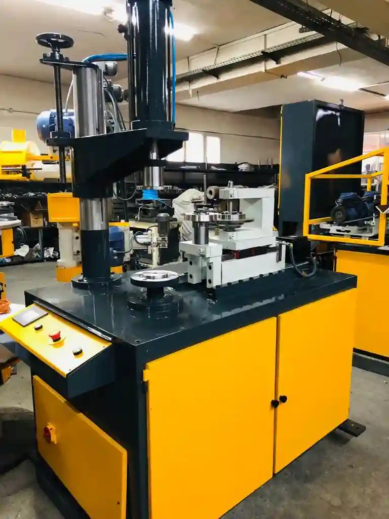
A Servo-Controlled Hemming Station is an advanced metal fabrication unit designed to perform precise hemming operations on sheet metal parts using servo motor technology. Unlike traditional mechanical or hydraulic hemming machines, servo-controlled stations offer superior accuracy, repeatability, and flexibility by electronically controlling the motion and force applied during the hemming process.
At its core, the servo motor drives the hemming roller or press with programmable speed, position, and torque, allowing operators to tailor the hemming cycle to the specific material type, thickness, and part geometry. This precision control reduces the risk of defects such as cracking, wrinkling, or surface damage, which are common when processing delicate or high-strength metals. It also enables the handling of complex hem profiles and varying edge contours with consistent quality.
The station typically features an integrated CNC or PLC control system with an intuitive Human-Machine Interface (HMI). Operators can input custom hemming programs, save multiple job profiles, and monitor process parameters in real time. The system can automatically adjust parameters such as roller pressure, hemming speed, and fold angle based on feedback from sensors that monitor force, position, or material behavior, ensuring optimal forming conditions throughout the operation.
Servo-controlled hemming stations are highly versatile and used across a wide range of industries, including automotive manufacturing, aerospace, appliance production, and HVAC fabrication. They can handle various materials—such as aluminum, stainless steel, galvanized steel—and sheet thicknesses, accommodating both high-volume production and smaller batch runs with equal ease.
Safety and ergonomics are integral to these stations. Features like guarded hemming zones, emergency stop buttons, and two-hand control systems protect operators during use. Additionally, compact designs with adjustable working heights and modular components facilitate integration into existing production lines or robotic automation cells.
In terms of productivity, servo control allows for faster cycle times with precise, smooth motion, reducing mechanical wear and maintenance compared to traditional hemming presses. The ability to fine-tune hemming parameters also minimizes scrap rates and post-processing work, contributing to cost savings and improved product quality.
Integration capabilities extend to automated material handling, inline inspection systems, and networked manufacturing environments, enabling seamless communication with other equipment and production management software. This connectivity supports Industry 4.0 initiatives, offering enhanced traceability, process optimization, and predictive maintenance.
In summary, a servo-controlled hemming station combines the precision of servo technology with sophisticated control systems to deliver flexible, efficient, and high-quality hemming solutions. Its adaptability, accuracy, and integration potential make it a vital tool in modern sheet metal fabrication environments focused on achieving consistent, defect-free edge forming.
Servo-controlled hemming stations significantly enhance the flexibility and precision of sheet metal hemming processes by offering dynamic control over motion profiles and force application. This adaptability is especially important when working with advanced materials such as high-strength steels or aluminum alloys, which have varying springback characteristics and require carefully controlled bending sequences to avoid cracking or distortion. The ability to program and fine-tune parameters like roller speed, fold angle, and pressure ensures that even complex hem geometries or variable thicknesses can be handled reliably.
These stations often incorporate real-time feedback systems using force sensors, encoders, or laser measurement devices to continuously monitor the hemming operation. This feedback loop allows the servo drive to adjust torque and position instantly, compensating for inconsistencies in material behavior or tooling conditions. Such closed-loop control improves repeatability and reduces scrap, which is crucial in high-volume automotive or aerospace production where consistent quality is mandatory.
The compact footprint and modular construction of many servo-controlled hemming stations facilitate their integration into automated production lines or robotic cells. By combining with robotic part loading and unloading systems, these stations enable continuous, unattended operation, boosting throughput while maintaining high-quality standards. Furthermore, connectivity options such as Ethernet, OPC UA, or Profinet allow the hemming station to communicate with plant-wide manufacturing execution systems (MES), providing data for traceability, process optimization, and predictive maintenance.
Operator interfaces on servo-controlled hemming stations are typically designed for ease of use, featuring touchscreen HMIs with graphical programming tools. This reduces setup times and lowers the skill barrier for operators, allowing rapid job changes and efficient production of multiple part variants. Preloaded hemming recipes can be quickly selected or modified, and real-time process data can be displayed for quality assurance and troubleshooting.
Energy efficiency is another advantage of servo technology over traditional hydraulic systems. Servo motors consume power only when in motion and can precisely control acceleration and deceleration, resulting in lower overall energy consumption and reduced mechanical wear. This contributes to a more sustainable and cost-effective manufacturing process.
Safety features such as light curtains, interlocked guards, and emergency stop systems are standard, ensuring compliance with workplace safety regulations. Ergonomic considerations, including adjustable work heights and accessible control panels, help reduce operator fatigue and improve productivity during extended shifts.
In addition to traditional hemming, some advanced servo-controlled stations offer multifunctional capabilities, such as combining hemming with flanging or beading operations within a single cycle. This versatility streamlines workflow and reduces the need for multiple machines, saving space and investment costs.
Overall, servo-controlled hemming stations represent a modern evolution in sheet metal edge forming technology. By leveraging precise electronic control, real-time feedback, and integration capabilities, they enable manufacturers to produce high-quality, consistent hems efficiently while adapting quickly to changing production demands. As industries push for greater automation, tighter tolerances, and smarter manufacturing, these stations will continue to play a key role in advancing sheet metal fabrication processes.
Servo-controlled hemming stations are increasingly designed with advanced diagnostic and predictive maintenance features that enhance uptime and reliability. By continuously monitoring parameters such as motor current, vibration, temperature, and cycle counts, the system can predict potential failures before they occur and notify maintenance teams proactively. This shift from reactive to predictive maintenance helps avoid costly downtime and extends the service life of critical components like servo motors, bearings, and tooling.
The precision offered by servo control also allows for the implementation of adaptive hemming strategies, where the machine adjusts its folding process based on real-time feedback about material springback or edge condition. For example, if the sensor data detects uneven resistance during folding, the controller can modulate roller speed or pressure to compensate, ensuring a uniform hem even on parts with variable thickness or slight imperfections. This adaptability is particularly valuable when working with coated or painted sheets, where surface quality must be preserved.
Integration with vision systems is another growing trend. Cameras can inspect the hem immediately after forming, verifying fold dimensions, edge alignment, and surface condition. If deviations are detected, the system can automatically reject defective parts or trigger corrective actions such as reprocessing or alerting operators. This inline quality control reduces scrap rates and increases confidence in the production output.
Servo-controlled hemming stations also facilitate customization and rapid prototyping. Their programmable nature enables quick adjustments to accommodate new part designs or experimental hemming profiles without physical tooling changes. This accelerates product development cycles and supports just-in-time manufacturing strategies where flexibility is critical.
Connectivity to cloud-based platforms allows manufacturers to collect and analyze hemming process data across multiple machines or sites. This data-driven approach supports benchmarking, continuous improvement, and remote troubleshooting by experts, further enhancing operational efficiency.
The ergonomics of these stations continue to improve with intuitive touchscreens, augmented reality (AR) guidance for setup and maintenance, and collaborative robot (cobot) interfaces that assist operators in handling heavy or awkward parts safely.
In summary, servo-controlled hemming stations embody the convergence of mechanical precision, intelligent automation, and digital integration. They provide manufacturers with a powerful tool to meet demanding quality standards, optimize production workflows, and adapt swiftly to evolving market needs, solidifying their role as essential equipment in advanced sheet metal fabrication.
Roller-Type Hemming Machine for Seam Perfection
A Roller-Type Hemming Machine for Seam Perfection is a specialized piece of sheet metal fabrication equipment designed to create smooth, precise hems along the edges of metal panels using a series of rolling tools. This type of hemming machine emphasizes achieving flawless seam quality with consistent edge profiles, minimal distortion, and excellent surface finish, making it indispensable in industries like automotive manufacturing, aerospace, appliance production, and HVAC systems.
The core working principle involves the gradual folding and compressing of a metal sheet’s edge by one or more rollers that move along the seam. Unlike press-based hemming machines that fold the edge in a single stroke, roller-type machines use continuous rolling action, which reduces stress concentration on the material and prevents cracking or wrinkling. This rolling process allows the machine to handle complex contours and variable edge geometries with high precision.
Roller hemming machines typically consist of a powered rolling head mounted on a movable arm or gantry that follows the part’s edge, guided either manually or through CNC controls. The rollers apply carefully controlled pressure and bending force to the metal edge, shaping it into the desired hem profile in a smooth, progressive manner. This results in uniform seam thickness, tight fold angles, and a clean, aesthetically pleasing finish.
Precision is enhanced by adjustable roller pressure, speed, and position, allowing operators to fine-tune the hemming process based on material type, thickness, and desired hem style. Many modern machines incorporate servo motors and programmable controls that enable consistent replication of hemming parameters across production batches, reducing variability and scrap.
The roller hemming process is particularly suited for materials sensitive to cracking, such as aluminum alloys and high-strength steels, because the gradual rolling action distributes forming forces more evenly. Additionally, the gentle nature of rolling helps preserve surface coatings and finishes, reducing the need for costly post-processing or refinishing.
Safety features such as protective guards, emergency stop controls, and ergonomic designs are integrated to protect operators and facilitate ease of use during repetitive hemming tasks. Some machines also include automation options like robotic part handling or CNC-guided roller paths to enhance throughput and reduce labor costs.
In summary, a roller-type hemming machine offers a reliable, efficient, and high-quality method for producing perfect seams on sheet metal parts. Its ability to deliver smooth, uniform hems with minimal material stress makes it a preferred choice in industries where seam integrity, appearance, and performance are critical.
Roller-type hemming machines excel at handling a wide variety of part shapes and sizes due to their flexible design and adaptable tooling. The rolling head can often be adjusted or swapped with different roller profiles to accommodate various hem styles such as single hems, double hems, or rolled hems. This adaptability allows manufacturers to use the same machine for multiple applications, reducing the need for additional equipment and lowering overall production costs.
The continuous rolling action also enables the machine to follow complex contours, including tight curves and irregular shapes, without causing distortion or surface damage. This is particularly advantageous in automotive and aerospace industries, where parts often feature intricate edge geometries that require precise hemming to ensure proper assembly and sealing.
Material versatility is another strength of roller-type hemming machines. They are capable of processing diverse metals ranging from soft aluminum and galvanized steel to harder high-strength steel alloys, with thicknesses varying widely depending on the application. The ability to fine-tune roller pressure and speed helps prevent common hemming defects like cracking, wrinkling, or uneven folds, even when working with challenging materials.
Integration with CNC controls or robotic systems enhances the precision and efficiency of roller hemming machines. Automated systems can guide the roller along programmed paths with micron-level accuracy, ensuring consistent seam quality throughout production runs. Robotics also reduce operator fatigue and improve safety by handling repetitive or heavy parts, increasing overall throughput and reliability.
Real-time monitoring and feedback systems are increasingly incorporated to maintain seam quality and detect potential issues early. Sensors measuring force, roller position, or part alignment provide data that can be used to adjust parameters on the fly or trigger alerts for preventive maintenance. This proactive approach reduces downtime and minimizes scrap rates, contributing to cost-effective manufacturing.
Ergonomic considerations include adjustable machine heights, intuitive user interfaces, and safety guards to protect operators during operation. Easy access to tooling and simple changeover procedures enable rapid setup and reduced downtime when switching between different hemming jobs.
Roller-type hemming machines also offer environmental benefits compared to more forceful forming methods. The gradual rolling action typically consumes less energy and generates less noise, creating a safer and more sustainable workplace.
Overall, the roller-type hemming machine stands out as a versatile, precise, and operator-friendly solution for producing high-quality seams on sheet metal parts. Its ability to combine gentle forming action with advanced automation and control technologies makes it an essential tool in modern metal fabrication industries focused on achieving seam perfection with efficiency and reliability.
Advancements in roller-type hemming machines continue to push the boundaries of what these systems can achieve. Modern machines increasingly incorporate intelligent software that allows for automatic adjustment of rolling parameters based on real-time material feedback. This “smart hemming” capability can adapt to subtle variations in metal thickness, hardness, or surface conditions, ensuring optimal seam quality without manual intervention.
The development of modular roller assemblies enables manufacturers to quickly change or customize roller profiles to meet specific part requirements. This flexibility supports rapid production changes and helps shops accommodate diverse customer needs without extensive downtime. In addition, some machines feature multi-roller configurations that perform sequential hemming steps—such as initial flange formation followed by final edge rolling—in a single pass, greatly improving throughput.
Integration with Industry 4.0 technologies also enhances roller hemming machines’ effectiveness. Connectivity options allow seamless data exchange with factory management systems, enabling comprehensive tracking of machine performance, maintenance schedules, and production output. This transparency aids in identifying bottlenecks, optimizing workflows, and ensuring consistent product quality across batches and facilities.
Moreover, the combination of roller hemming with other forming techniques, such as flanging, beading, or embossing, within integrated systems provides even greater manufacturing versatility. Such multifunctional stations reduce the number of handling steps and equipment required, leading to lower production costs and improved lead times.
In sectors like automotive and aerospace, where stringent standards govern part fit and finish, roller-type hemming machines are often part of automated production cells that include robotic loading/unloading, inline inspection, and real-time quality assurance. These integrated systems deliver repeatable, high-precision hems essential for aerodynamic performance, structural integrity, and aesthetic excellence.
Sustainability considerations also play a role in machine design. Energy-efficient servo drives, reduced lubricant use, and quieter operation contribute to greener manufacturing environments. The ability to minimize scrap through precise, consistent hemming further supports waste reduction initiatives.
In summary, roller-type hemming machines continue to evolve with smarter controls, modular tooling, and enhanced connectivity, solidifying their position as vital assets for manufacturers pursuing seam perfection. Their combination of gentle, precise forming action with automation and data-driven management ensures they remain indispensable in producing high-quality sheet metal products efficiently and reliably.
Sheet Metal Hemming Solutions
Sheet Metal Hemming Solutions encompass a broad range of technologies, machines, and processes designed to fold, bend, and secure the edges of sheet metal parts for improved strength, appearance, and assembly compatibility. Hemming is essential in industries such as automotive, aerospace, HVAC, appliance manufacturing, and architectural metalwork, where clean, durable edge finishes are critical.
At the heart of sheet metal hemming solutions are various types of hemming machines, including mechanical presses, hydraulic presses, roller-type hemmers, and servo-controlled hemming stations. Each type offers distinct advantages depending on production volume, material type, part complexity, and precision requirements. Mechanical and hydraulic presses are well-suited for high-volume, repetitive hemming tasks, delivering strong, consistent folds. Roller-type hemmers provide gentle, continuous forming ideal for delicate or complex parts, while servo-controlled stations combine precision and flexibility for advanced applications.
Complementing these machines are specialized hemming tools and dies engineered to match specific hem profiles—such as single hems, double hems, teardrop hems, and rope hems—and to accommodate a variety of sheet thicknesses and materials including aluminum, steel, stainless steel, and coated metals. Tooling design plays a critical role in achieving defect-free hems by controlling metal flow and minimizing distortion or cracking.
Automation and integration form a significant part of modern hemming solutions. Robotic loading and unloading, CNC-guided hemming operations, and inline inspection systems enable high throughput and consistent quality, while reducing manual labor and errors. These automated cells often feature adaptive controls that adjust hemming parameters in real time based on sensor feedback, ensuring optimal forming conditions even with variable material properties.
Process optimization is supported by software tools that allow for simulation, programming, and data collection. Digital twins and virtual setup systems enable engineers to refine hemming sequences before production, reducing setup times and material waste. Data analytics provide insights into machine performance and product quality, facilitating continuous improvement and predictive maintenance.
Safety and ergonomics are integral to hemming solutions, with modern equipment incorporating guarded work zones, emergency stops, and operator-friendly interfaces. Adjustable fixtures and modular designs help accommodate different part sizes and shapes, enhancing workflow flexibility.
For smaller shops or prototype work, portable or bench-top hemming units provide practical options, delivering professional-quality hems without the footprint or cost of large industrial machines. These solutions balance ease of use with sufficient precision for low-volume or custom jobs.
In summary, sheet metal hemming solutions encompass a comprehensive ecosystem of machinery, tooling, automation, and software designed to meet diverse manufacturing needs. By combining precision forming, adaptability, and integration capabilities, these solutions help manufacturers achieve strong, attractive, and consistent hems that enhance product functionality and appearance across a wide array of industries.
Sheet metal hemming solutions are continuously evolving to address the growing demands for higher quality, faster production, and greater flexibility. Advances in servo technology and automation have transformed traditional hemming processes, enabling manufacturers to produce complex hem profiles with minimal manual intervention. This evolution supports both mass production environments and highly customized, small-batch manufacturing where quick changeovers and precise control are essential.
One of the key trends in hemming solutions is the integration of real-time process monitoring and adaptive control. Sensors embedded in hemming machines collect data on parameters such as fold angle, roller pressure, and material thickness, allowing systems to adjust in real time to maintain consistent seam quality. This reduces scrap and rework, saving time and materials while ensuring products meet stringent specifications.
The combination of hemming with other sheet metal forming operations, like flanging, beading, and embossing, within integrated workstations streamlines production and minimizes part handling. Such multifunctional systems reduce cycle times and improve overall workflow efficiency, which is particularly valuable in industries like automotive and aerospace where complex parts require multiple edge treatments.
Digital tools play an increasingly important role in hemming solutions, with software for simulation, programming, and quality management becoming standard. Virtual setups enable engineers to test hemming sequences and predict material behavior before production, minimizing trial-and-error and accelerating product development. Connectivity to factory networks facilitates data-driven decision-making, helping manufacturers optimize machine utilization and maintain consistent quality across different production lines or sites.
Safety and ergonomics remain priorities in the design of hemming equipment. Modern machines feature guarded tooling areas, emergency stops, and user-friendly interfaces to protect operators and reduce fatigue. Adjustable components and modular tooling increase versatility, enabling quick adaptation to a wide variety of part sizes and designs without compromising comfort or safety.
For smaller operations or prototype work, compact and portable hemming units provide accessible options without sacrificing quality. These solutions offer ease of setup and operation, making them ideal for low-volume runs, repairs, or fieldwork, complementing larger automated systems used in high-volume production.
Sustainability considerations are also influencing hemming technology. Energy-efficient servo drives, reduced lubricant requirements, and quieter operation contribute to greener manufacturing processes. The ability to produce high-quality hems consistently on the first pass reduces material waste and rework, supporting environmental goals alongside economic benefits.
Overall, modern sheet metal hemming solutions represent a synergy of mechanical precision, intelligent automation, and digital connectivity. They empower manufacturers to meet increasingly complex design requirements and production schedules while maintaining high quality and operational efficiency. As technology advances, these solutions will continue to play a crucial role in driving innovation and competitiveness in sheet metal fabrication across diverse industries.
Expanding on sheet metal hemming solutions, customization and flexibility remain at the forefront of innovation. Manufacturers increasingly demand systems that can quickly adapt to new part designs, materials, and production volumes without extensive downtime. To meet this need, many hemming machines now feature modular tooling and quick-change mechanisms, enabling rapid switching between different hemming profiles or part sizes. This agility supports just-in-time manufacturing and reduces inventory costs associated with dedicated tooling.
Advanced hemming solutions also integrate seamlessly with broader manufacturing ecosystems. Connectivity through protocols like OPC UA, Ethernet/IP, or Profinet allows hemming stations to communicate with upstream and downstream equipment, such as laser cutters, press brakes, or robotic assembly cells. This connectivity fosters synchronized production flows, minimizing bottlenecks and improving overall throughput.
Artificial intelligence (AI) and machine learning are beginning to influence hemming processes by analyzing operational data to optimize machine settings and predict maintenance needs. For example, AI algorithms can identify subtle patterns indicating tool wear or material inconsistencies before defects occur, enabling proactive adjustments and reducing downtime. Such smart systems enhance productivity while preserving part quality.
In terms of operator experience, augmented reality (AR) and virtual reality (VR) technologies are emerging as valuable tools for training, setup, and maintenance. AR overlays can guide technicians through complex tooling changes or troubleshooting steps directly on the machine, speeding up interventions and reducing errors. VR simulations provide safe, immersive environments for operator training, improving skill acquisition without disrupting production.
Sustainability is also driving material and process innovation within hemming solutions. Manufacturers are exploring how to efficiently hem advanced lightweight materials like composites or multi-layered metal stacks, which require delicate forming techniques to avoid damage. Hemming machines equipped with sensitive force control and adaptive feedback systems are essential to handle these new materials while maintaining seam integrity.
Finally, as customization and design complexity increase, hemming solutions are evolving to support highly intricate edge treatments. This includes multi-stage hemming sequences combining folding, rolling, and flanging, often executed within a single integrated workstation. Such capabilities enable the production of aesthetically refined and structurally robust parts that meet stringent functional and visual requirements.
In summary, the future of sheet metal hemming solutions lies in intelligent, connected, and flexible systems that deliver consistent quality across a wide range of materials and designs. By embracing modularity, digital integration, and advanced analytics, these solutions help manufacturers stay competitive in rapidly changing markets while achieving operational excellence and sustainability goals.
Hemming Machine for Light and Heavy Sheet Metal
A Hemming Machine for Light and Heavy Sheet Metal is a versatile industrial machine designed to fold and secure edges of sheet metal parts across a broad range of material thicknesses and strengths. This type of machine is engineered to accommodate both delicate, thin-gauge metals commonly used in consumer products and robust, thick-gauge metals required in heavy-duty industrial or automotive applications.
For light sheet metals—such as aluminum, thin steel, or galvanized coatings—the hemming machine provides gentle but precise folding actions that minimize the risk of cracking, wrinkling, or surface damage. These machines often feature adjustable pressure controls, fine-tuned roller speeds, and specialized tooling that support delicate materials while maintaining clean, tight hems essential for aesthetic and functional performance.
In contrast, when working with heavy sheet metals—thicker steel plates or high-strength alloys—the machine must deliver sufficient force and rigidity to form consistent, strong hems without tool deformation or metal fatigue. Hydraulic or servo-driven power systems are commonly employed to generate the required folding pressure and torque. Robust machine frames and heavy-duty tooling ensure durability and repeatability under demanding production conditions.
Many modern hemming machines designed for this dual capability incorporate adaptive controls and modular tooling systems. These features allow quick adjustment of folding parameters, such as pressure, speed, and die profiles, enabling operators to switch seamlessly between light and heavy gauge jobs. CNC or servo controls provide programmable settings for different materials and part designs, improving setup efficiency and process consistency.
Safety features like guarded hemming zones, emergency stops, and ergonomic controls are standard to protect operators during handling of heavy parts and repetitive tasks. Additionally, integration with automated material handling—such as robotic loading, conveyors, or lift tables—facilitates the safe and efficient movement of both light and heavy sheet metal parts throughout the hemming process.
Applications for hemming machines capable of processing both light and heavy sheet metals span numerous industries, including automotive manufacturing (body panels and chassis components), appliance production (thin outer shells and structural reinforcements), HVAC systems (ductwork and fittings), and construction (metal cladding and architectural panels).
By offering broad material compatibility, precise control, and robust construction, hemming machines for light and heavy sheet metal provide manufacturers with flexible, reliable solutions to meet diverse fabrication needs. Their ability to maintain seam quality across varying gauges helps optimize production efficiency, reduce scrap, and ensure strong, visually appealing finished products.
Hemming machines designed to handle both light and heavy sheet metal typically balance precision and power by combining advanced control systems with rugged mechanical components. Servo-electric drives are increasingly favored for their ability to deliver precise, programmable motion control while providing sufficient force for heavier gauge materials. This results in smoother hemming cycles, reduced mechanical wear, and improved energy efficiency compared to traditional hydraulic systems.
Adjustability is key to accommodating different material thicknesses and types. Operators can fine-tune parameters such as hemming pressure, roller speed, and fold angle through intuitive control interfaces, allowing the same machine to switch rapidly between delicate aluminum sheets and thicker steel panels without compromising quality. This flexibility supports mixed-production environments where varied part specifications are common.
The tooling design is often modular, with interchangeable dies and rollers optimized for specific thickness ranges or hem profiles. Quick-change tooling systems minimize downtime during product changeovers, enhancing overall manufacturing agility. For heavier materials, tooling is constructed from hardened steel or specialized alloys to withstand higher forces and resist wear over prolonged use.
Safety and ergonomics are critical considerations given the range of material sizes and weights processed. Hemming machines are frequently equipped with adjustable work supports, lift assists, and protective guarding to ease operator handling and minimize injury risk. Automated feeding and unloading systems further reduce manual intervention, particularly beneficial when working with bulky or heavy parts.
In high-volume production, these machines are integrated into fully automated lines where robotic systems handle loading, hemming, and unloading in continuous cycles. Real-time monitoring using sensors and vision systems ensures consistent seam quality, detecting defects early and allowing immediate correction. Data collected can feed into quality management software for traceability and process optimization.
The broad capability to process both light and heavy sheet metal in a single hemming machine reduces the need for multiple dedicated machines, lowering capital investment and floor space requirements. This versatility makes such machines especially attractive to manufacturers aiming to streamline operations and quickly respond to shifting production demands.
Industries benefiting from these flexible hemming solutions include automotive, aerospace, appliance manufacturing, HVAC, and heavy equipment fabrication. Whether folding thin exterior panels or reinforcing thick structural components, these machines provide reliable, repeatable hems that enhance part strength, appearance, and assembly fit.
Ultimately, hemming machines tailored for a wide material range enable manufacturers to maintain high product quality while optimizing efficiency and reducing operational complexity. Their combination of precision control, robust construction, and adaptable tooling equips fabricators to meet evolving market needs with confidence and agility.
In addition to versatility and robustness, hemming machines capable of processing both light and heavy sheet metal often incorporate advanced diagnostic and maintenance features to maximize uptime and longevity. Embedded sensors monitor critical components such as motor load, hydraulic pressure (if applicable), and tool wear, providing early warnings of potential issues. This predictive maintenance capability helps avoid unexpected breakdowns, reduces repair costs, and extends machine service life.
Modern machines also offer enhanced software integration, allowing seamless connectivity with enterprise resource planning (ERP) systems and manufacturing execution systems (MES). This connectivity enables real-time tracking of production metrics, quality data, and maintenance schedules, supporting lean manufacturing principles and continuous improvement initiatives. Operators and maintenance teams benefit from user-friendly dashboards that provide actionable insights and facilitate faster decision-making.
Ergonomic design remains a priority to support operator comfort and efficiency across a range of part sizes and weights. Features such as adjustable workstations, intuitive touchscreens, and simplified tooling change mechanisms reduce physical strain and setup times. Some systems even include augmented reality (AR) assistance for training and troubleshooting, helping operators perform tasks more accurately and safely.
Energy efficiency is another focus area, with many modern hemming machines utilizing servo motors and regenerative drives to minimize power consumption during operation and idle periods. This not only lowers operational costs but also aligns with increasing environmental regulations and corporate sustainability goals.
Customization options abound, with manufacturers able to specify machine size, force capacity, automation level, and tooling configurations to precisely match production requirements. Some machines come equipped with multi-function capabilities, combining hemming with flanging or beading operations in a single cycle to reduce handling and improve throughput.
Overall, hemming machines designed for both light and heavy sheet metal represent a fusion of mechanical strength, technological sophistication, and operational flexibility. By delivering consistent, high-quality hems across diverse materials and part geometries, they empower manufacturers to optimize productivity, enhance product quality, and maintain competitiveness in demanding industrial markets.
CNC Hemming Unit for Metal Sheets
A CNC Hemming Unit for Metal Sheets is an advanced automated system designed to perform precise hemming operations on sheet metal parts with programmable control over the bending and folding process. Utilizing Computer Numerical Control (CNC) technology, this unit offers high accuracy, repeatability, and flexibility, making it ideal for complex or high-volume production environments.
The CNC hemming unit typically consists of a rigid frame housing a hemming tool—such as rollers, press dies, or folding arms—whose movement is controlled by CNC axes. Operators program specific hemming parameters including fold angle, roller pressure, feed speed, and hemming sequence, allowing the machine to execute consistent hems tailored to different materials, thicknesses, and part geometries.
One of the key advantages of CNC control is the ability to store multiple hemming programs, facilitating quick job changes and minimizing setup time. This is especially valuable in manufacturing settings with frequent part variations or custom orders. The precise motion control reduces material stress and deformation, resulting in smooth, defect-free hems even on delicate or high-strength metals.
Many CNC hemming units integrate sensors and feedback loops to monitor force, position, and part alignment in real time, enabling adaptive control that compensates for material inconsistencies or tooling wear. This closed-loop system enhances quality assurance and reduces scrap rates.
These units can be standalone machines or incorporated into fully automated production lines with robotic loading/unloading, inline inspection, and data communication capabilities. Integration with factory control systems supports Industry 4.0 practices, providing traceability, predictive maintenance, and process optimization.
CNC hemming units accommodate a wide range of hemming styles—single hems, double hems, rolled hems—and are suitable for materials such as aluminum, stainless steel, galvanized steel, and coated metals. Their precision and programmability make them essential for industries demanding tight tolerances and high-quality finishes, including automotive, aerospace, appliance manufacturing, and HVAC.
Safety features are built in, including guarded working zones, emergency stops, and operator interfaces designed for ease of use. Ergonomic considerations, such as adjustable work surfaces and intuitive programming interfaces, further enhance operator efficiency and comfort.
In summary, CNC hemming units provide manufacturers with a powerful, flexible tool to produce consistent, high-quality hems on sheet metal parts. Their combination of precise control, automation readiness, and adaptability makes them a cornerstone of modern sheet metal fabrication processes.
CNC hemming units significantly improve production efficiency by enabling rapid and accurate hemming cycles that minimize operator intervention. The programmable nature of these machines allows for complex hemming sequences involving multiple bends, varied fold angles, and adjustable roller pressures to be executed consistently across large production runs. This consistency reduces variations between parts, ensuring higher assembly quality and reducing the need for downstream rework or adjustments.
The integration of CNC technology also facilitates easy adaptation to new part designs. Changes in hemming parameters can be made quickly through software updates rather than physical tooling changes, which decreases setup times and improves responsiveness to customer demands. This flexibility is especially beneficial for industries such as automotive and aerospace, where frequent design updates and tight tolerances are common.
Many CNC hemming units are equipped with real-time monitoring systems that track operational parameters like force applied, roller position, and cycle timing. This data can be used for quality control, enabling immediate detection of defects or deviations from programmed values. Additionally, historical data logging supports traceability and continuous process improvement by identifying trends that may indicate tooling wear or machine calibration drift.
Automation capabilities are often extended with robotic integration for loading and unloading parts, further increasing throughput and reducing manual labor. CNC hemming units can be synchronized with upstream cutting, bending, or stamping operations to form part of a fully automated fabrication line. Communication protocols such as Ethernet/IP or OPC UA allow seamless data exchange between machines and factory management systems, supporting Industry 4.0 initiatives.
Operator interfaces on CNC hemming units are designed to be user-friendly, often featuring touchscreen displays with graphical programming environments that simplify setup and parameter adjustments. Some systems offer offline programming and simulation, enabling operators to prepare hemming sequences without occupying the machine, thus maximizing production uptime.
Safety is a core consideration, with CNC hemming units incorporating guarded enclosures, emergency stop functions, and sensors to detect operator presence or potential hazards. Ergonomic design features, such as adjustable work heights and accessible controls, contribute to operator comfort and efficiency.
The versatility of CNC hemming units extends to their ability to handle a wide range of materials and thicknesses. By adjusting hemming parameters electronically, the same machine can process thin aluminum panels as well as thicker steel parts, making it a cost-effective solution for manufacturers with diverse product portfolios.
In conclusion, CNC hemming units combine precision, flexibility, and automation to deliver superior hemming performance. Their capability to produce consistent, high-quality hems efficiently and adapt quickly to changing production needs makes them essential equipment in advanced sheet metal fabrication environments.
CNC hemming units also often feature modular designs that allow easy integration of additional functionalities, such as flanging, beading, or embossing, within the same machine footprint. This multi-function capability helps streamline production by reducing the need for multiple separate machines, thereby saving floor space and minimizing part handling.
The use of servo-driven axes in CNC hemming units contributes to smoother motion control and reduced mechanical wear compared to traditional hydraulic systems. Servo motors provide precise positioning and controlled force application, which is particularly important when working with advanced materials like high-strength steel or coated aluminum that require gentle yet accurate forming to avoid surface damage or cracking.
Environmental considerations are increasingly influencing the design of CNC hemming units. Energy-efficient servo drives, reduced hydraulic fluid use, and quieter operation align with manufacturers’ sustainability goals and workplace safety standards. Some systems also incorporate advanced cooling and filtration solutions to maintain consistent operating conditions and extend machine longevity.
Training and support are integral parts of deploying CNC hemming technology. Manufacturers typically provide comprehensive operator training, including virtual simulations and hands-on sessions, to ensure efficient machine operation and maintenance. Remote diagnostics and software updates further enhance support, enabling quick troubleshooting and continuous improvement without prolonged downtime.
As industries move toward greater automation and smart manufacturing, CNC hemming units are evolving with features like artificial intelligence (AI) and machine learning algorithms. These technologies analyze process data to optimize hemming parameters dynamically, predict maintenance needs, and improve overall productivity and quality.
In highly regulated sectors such as aerospace and medical device manufacturing, CNC hemming units assist in meeting strict quality and traceability requirements by documenting every hemming cycle with detailed process data. This documentation supports certification and audit processes while enabling root-cause analysis if issues arise.
Ultimately, CNC hemming units represent a critical investment for manufacturers seeking to balance flexibility, quality, and efficiency in sheet metal fabrication. Their ability to adapt quickly to varied production demands while delivering precise, repeatable hems ensures they remain central to modern manufacturing strategies across diverse industries.
Compact Sheet Metal Edge Hemmer
A Compact Sheet Metal Edge Hemmer is a space-efficient, specialized machine designed to fold and secure the edges of sheet metal parts, providing clean, durable hems without requiring a large industrial footprint. This type of hemmer is ideal for workshops, small to medium-sized production facilities, or manufacturing environments where floor space is limited but precise edge finishing is still essential.
Despite its compact size, this hemmer delivers reliable and consistent hemming performance on a variety of sheet metal materials such as aluminum, steel, stainless steel, and galvanized sheets, typically ranging from light to medium thicknesses. It uses precision rollers or folding dies to gradually bend the metal edge into the desired hem profile, ensuring minimal distortion, cracking, or surface damage.
Compact edge hemmers often feature user-friendly controls, including manual, semi-automatic, or CNC-assisted operation modes, allowing flexibility for both low-volume and moderate-volume production. Their ergonomic design ensures ease of loading, hemming, and unloading, which helps reduce operator fatigue and improve throughput.
The machine’s tooling is typically designed for quick adjustment or changeover to accommodate different hem styles—such as single hems, double hems, or rope hems—and various part sizes. This versatility makes the compact edge hemmer suitable for a wide range of applications, including HVAC ductwork, appliance panels, automotive components, and custom sheet metal fabrication.
Safety features like protective guards and emergency stops are integrated despite the machine’s small footprint, maintaining operator protection during hemming operations. Additionally, some compact hemmers can be equipped with optional automation accessories, such as part feeders or conveyors, to further enhance efficiency.
Energy-efficient motors and low-maintenance mechanical components contribute to the machine’s overall cost-effectiveness, making it a practical choice for facilities seeking quality hemming capabilities without the complexity or expense of larger hemming presses.
In summary, a compact sheet metal edge hemmer offers an excellent balance of precision, flexibility, and space-saving design. It enables manufacturers to produce high-quality hems with reduced floor space requirements, making it a valuable tool for shops focused on delivering durable, professional sheet metal edges efficiently within limited workspace environments.
Compact sheet metal edge hemmers often incorporate modular tooling systems that allow rapid changeovers between different hemming profiles or part sizes, enhancing their flexibility for diverse production needs. Their smaller size does not compromise precision; many models use advanced servo or stepper motor controls to ensure consistent roller pressure and fold angles, resulting in high-quality hems with minimal material distortion or surface damage. These machines can handle a wide variety of metals, including aluminum, stainless steel, and coated steels, typically ranging from thin gauges used in appliances to thicker materials in automotive panels. Operator-friendly interfaces, often featuring touchscreens with programmable settings, streamline setup and allow even less experienced workers to achieve repeatable results. Some compact hemmers also integrate with automated feeders or conveyors to improve throughput in semi-automated production lines. Safety features such as enclosed working areas, emergency stops, and ergonomic access points are standard to protect operators during operation. Because of their efficient use of floor space, energy-efficient components, and relatively low maintenance requirements, compact sheet metal edge hemmers are ideal for small to medium-sized fabrication shops, prototype development, or specialized production runs where space, precision, and cost-effectiveness are critical factors.
Building on their compactness and precision, many modern sheet metal edge hemmers include smart features such as real-time process monitoring and adaptive control systems. Sensors track parameters like roller pressure, fold angle, and material thickness during operation, allowing the machine to automatically adjust settings on the fly to maintain consistent seam quality. This helps reduce scrap and rework, especially when handling variable or coated materials that are prone to surface defects or cracking.
Connectivity options enable these machines to communicate with factory management systems, facilitating production tracking, quality documentation, and predictive maintenance scheduling. This integration supports lean manufacturing and Industry 4.0 initiatives by providing actionable data and minimizing downtime.
The modular design of compact hemmers also allows easy upgrades or customization, such as adding additional rollers for complex hemming profiles or integrating auxiliary functions like flanging or beading within the same machine footprint. Some units offer quick-change tooling systems that drastically reduce setup time, making them highly adaptable to short production runs or prototype work.
Ergonomics continue to be emphasized in newer models, with adjustable work heights, intuitive control panels, and easy access to tooling and maintenance points, improving operator comfort and productivity. Safety remains paramount, with features including interlocked guards, emergency stop buttons, and light curtains to prevent accidents during operation.
Due to their versatility, precision, and space-saving design, compact sheet metal edge hemmers are widely used across various industries—from HVAC duct manufacturing and automotive component production to appliance fabrication and custom metalworking shops. They provide an efficient, cost-effective solution for achieving high-quality hems without the footprint or complexity of larger industrial machines, enabling manufacturers to meet tight tolerances and aesthetic requirements while optimizing floor space and operational costs.
EMS Metalworking Machines
We design, manufacture and assembly metalworking machinery such as:
- Hydraulic transfer press
- Glass mosaic press
- Hydraulic deep drawing press
- Casting press
- Hydraulic cold forming press
- Hydroforming press
- Composite press
- Silicone rubber moulding press
- Brake pad press
- Melamine press
- SMC & BMC Press
- Labrotaroy press
- Edge cutting trimming machine
- Edge curling machine
- Trimming beading machine
- Trimming joggling machine
- Cookware production line
- Pipe bending machine
- Profile bending machine
- Bandsaw for metal
- Cylindrical welding machine
- Horizontal pres and cookware
- Kitchenware, hotelware
- Bakeware and cuttlery production machinery
as a complete line as well as an individual machine such as:
- Edge cutting trimming beading machines
- Polishing and grinding machines for pot and pans
- Hydraulic drawing presses
- Circle blanking machines
- Riveting machine
- Hole punching machines
- Press feeding machine
You can check our machinery at work at: EMS Metalworking Machinery – YouTube
Applications:
Flange-punching
Beading and ribbing
Flanging
Trimming
Curling
Lock-seaming
Ribbing