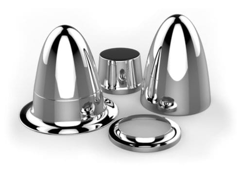
Hydraulic Press Manufacturer: A Hydraulic Press for Rubber Products is a specialized type of forming machinery used to mold, compress, or shape rubber materials into desired forms and components through the application of hydraulic force. These presses are vital in the production of various rubber goods such as seals, gaskets, bushings, O-rings, mats, footwear soles, and automotive parts.
Hydraulic rubber presses operate by closing a mold cavity under high pressure and often elevated temperatures. The rubber compound, either preheated or cold, is placed inside the mold, and the press exerts controlled force to compress it until it takes the desired shape and cures (vulcanizes). This process ensures dimensional accuracy, surface finish, and mechanical integrity of the product.
Key types and configurations include:
- Compression Molding Presses: These are the most common and operate by applying direct vertical force to close a mold and cure the rubber. Suitable for thicker and more robust parts.
- Transfer Molding Presses: These presses preheat the rubber in a chamber and then transfer it into a closed mold. They offer better control over flash and cavity fill, ideal for complex geometries.
- Injection Molding Hydraulic Presses: These systems inject rubber into a closed mold cavity under high pressure and are typically semi- or fully automated, allowing for high production rates and consistent part quality.
Important technical features often include:
- Programmable temperature and pressure controls for precise curing cycles.
- Platens with integrated heating systems (electrical, steam, or oil).
- Multiple daylight configurations to allow for multi-mold operations.
- Automated mold opening, ejector systems, and deflashing options for enhanced productivity.
- High clamping forces (ranging from 50 tons to over 1000 tons depending on product size).
Industries relying on hydraulic presses for rubber include:
- Automotive (engine mounts, bushings, gaskets),
- Footwear (soles, insoles),
- Industrial (seals, vibration dampers),
- Medical (sterile rubber components),
- Aerospace (specialized sealing elements).
Modern versions integrate digital control systems for cycle timing, pressure regulation, and real-time diagnostics, improving consistency and efficiency in rubber molding processes.
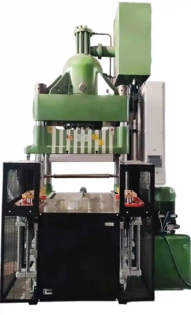
Hydraulic presses for rubber products are essential machines used extensively in industrial rubber molding applications. They function by using hydraulic cylinders to apply high pressure to a rubber compound placed inside a mold, allowing it to flow, fill the cavity, and cure into the final shape. These presses are built with robust steel frames and heavy-duty platens that can withstand sustained thermal and mechanical stress during molding cycles. The heating of the platens is typically achieved through electric heaters or thermal oil systems, providing the necessary temperature control for vulcanization of the rubber material.
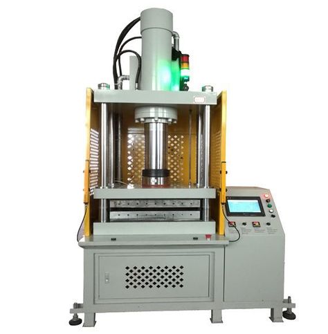
Depending on the design and complexity of the product, these presses can be operated manually or be fully automated with programmable logic controllers, touchscreen HMIs, and servo-driven components for greater accuracy and repeatability. Compression molding hydraulic presses are widely used for making thick rubber parts, vibration isolators, automotive rubber mounts, and large gaskets, where the rubber preform is directly placed in the open mold and then compressed. Transfer molding hydraulic presses are suitable for medium to high volume production of intricate parts such as rubber-to-metal bonded components, using a pot and plunger system to transfer the rubber into a closed mold, minimizing flash and improving surface finish. In high-output industries, injection molding rubber presses combine precision with speed by injecting rubber compound directly into closed molds under pressure, enabling continuous production with reduced labor and high uniformity.
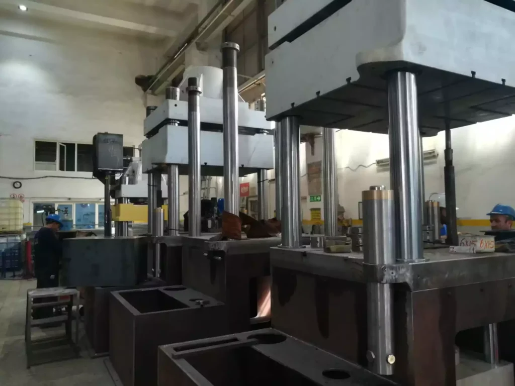
The tonnage of hydraulic presses for rubber applications varies greatly depending on the product size, typically ranging from 50 tons for small items up to 2000 tons for large-scale or multi-cavity molds. Presses can have single, double, or even four-column designs, and the mold opening mechanisms can include sliding or tilting platens for easy demolding and maintenance. Some systems include vacuum chambers to remove air and prevent bubbles during molding, which is critical in achieving high-quality results. Safety features such as two-hand control, emergency stop systems, and light curtains are standard in modern machines to protect operators.
These presses are used in sectors like automotive, aerospace, footwear, household goods, and medical devices, where rubber components must meet strict durability and dimensional standards. The precise control of pressure, temperature, and time cycles in these machines ensures that rubber products are properly crosslinked, dimensionally stable, and resistant to mechanical stress, heat, and chemical exposure. As sustainability and energy efficiency become more important, newer models also incorporate energy-saving hydraulic units, servo-hydraulic drives, and low-maintenance sealing systems to improve environmental performance and lower operational costs.
In addition to standard designs, custom-built hydraulic presses are often developed to suit specific rubber product requirements, especially when dealing with oversized parts, multi-layer assemblies, or specialized materials such as silicone, fluorocarbon, or EPDM. These materials have unique curing behaviors that require tailored pressure and heat profiles, which modern press systems can accommodate through programmable recipes stored in the control unit. Operators can select different mold programs depending on the type of product, material batch, or cycle requirements, ensuring consistency even in batch production.
Cooling systems integrated into the platen or external heat exchangers help reduce the cycle time by accelerating the cooling phase after curing, thus increasing throughput. For parts requiring tight dimensional tolerances or embedded metal inserts, the presses are often equipped with alignment pins, guided platens, or die lifters to ensure mold precision and facilitate part removal. Advanced rubber molding presses may include closed-loop control systems that monitor pressure and temperature in real time, automatically adjusting the process to maintain ideal conditions. This reduces waste and improves yield, which is critical in sectors where materials are expensive or production volumes are high.
For continuous production lines, some presses are linked with robotic systems for part handling, mold loading, and unloading. This not only improves safety but also significantly increases productivity by minimizing downtime between cycles. In tire manufacturing, large-scale presses are used for tread and sidewall vulcanization, while smaller precision presses are essential in the production of O-rings, medical seals, and high-performance gaskets.
Maintenance of these presses involves periodic inspection of hydraulic cylinders, seals, and platen alignment to avoid pressure loss or uneven mold closure. Hydraulic oil quality, filtration systems, and temperature control units must be monitored regularly to maintain performance and prevent premature wear. As digital integration expands, some machines now offer remote diagnostics, data logging, and integration with manufacturing execution systems (MES), allowing for complete traceability of each product made.
Whether used in small batch workshops or in automated high-volume facilities, hydraulic presses for rubber products remain a cornerstone of industrial manufacturing, offering unmatched versatility, precision, and adaptability across a wide range of applications.
Hydraulic press automation involves integrating control systems, sensors, and mechanical handling equipment to optimize, streamline, and often fully automate the operation of hydraulic presses across various industrial applications. This transformation significantly improves productivity, consistency, safety, and operational efficiency, especially in repetitive or high-volume manufacturing environments.
Modern hydraulic presses are frequently equipped with programmable logic controllers (PLCs), human-machine interfaces (HMIs), and servo-driven systems that allow precise control of pressure, ram movement, position, speed, and dwell time. Operators can program multiple cycles and parameters into the system, enabling the press to perform complex sequences without manual intervention. With touchscreens and digital displays, machine setup becomes more intuitive, reducing the need for skilled labor and minimizing human error.
Automation extends to material handling with the use of robotic arms, conveyors, feeders, and pick-and-place systems that load raw materials into the press, remove finished parts, and even reposition dies or molds. These systems are often synchronized with the press cycle through sensors and encoders, ensuring perfect timing and coordination. In mold-based operations like rubber molding, metal forming, or composite pressing, automatic die lubrication, mold cleaning, and ejector systems further increase cycle speed and reduce downtime.
For quality control, automated hydraulic presses can be integrated with sensors to monitor force, displacement, and temperature in real-time. Vision systems and part scanners can inspect components for defects or dimensional deviations immediately after pressing, allowing for closed-loop feedback and immediate corrective actions. In some setups, barcode or RFID systems are used to identify tools, dies, or part batches, ensuring the correct parameters are automatically selected for each job, which is essential for mixed-model production environments.
Safety is another key advantage. Automation eliminates the need for operators to be close to moving components, and safety systems such as light curtains, interlocked doors, two-hand controls, and emergency stops are integrated into automated presses to comply with international safety standards. Emergency diagnostics and predictive maintenance functions help identify issues before failures occur, reducing unplanned downtimes and extending equipment life.
Hydraulic press automation also enables integration into Industry 4.0 frameworks, where machines communicate with central control systems for data collection, process monitoring, and energy management. This facilitates detailed production analytics, remote monitoring, and real-time decision-making, making operations more agile and cost-effective.
Industries such as automotive, appliance manufacturing, aerospace, electronics, and medical device production benefit heavily from press automation, especially where precision, repeatability, and high throughput are essential. Whether applied to metal stamping, rubber molding, deep drawing, or powder compaction, automated hydraulic presses provide a scalable and intelligent solution for modern production demands.
As automation continues to evolve, hydraulic presses are increasingly being integrated into fully interconnected production cells where all components—from raw material input to finished part output—are managed by a unified control system. These cells often include automated feeding systems such as coil feeders, sheet loaders, or bulk material hoppers that prepare and position the material precisely before each cycle. After forming or molding, robotic arms or gantry systems swiftly remove the part and either transfer it to the next workstation, such as trimming, cooling, inspection, or packaging, or deposit it onto conveyors for further processing. In high-speed operations, sensors continuously monitor press stroke positions, oil pressure, mold temperature, and cycle time, providing critical data for process optimization and immediate fault detection.
Smart sensors can detect irregularities such as incomplete mold fill, pressure fluctuations, or component misalignment and trigger automatic corrections or shutdowns. This level of intelligence reduces scrap rates, ensures uniform product quality, and significantly shortens time-to-market. Hydraulic presses equipped with servo-hydraulic drives offer greater energy efficiency and dynamic control, adapting in real time to different load conditions, reducing noise levels, and improving cycle response. These systems consume less energy during idle periods and eliminate the need for continuous pump operation, making them more sustainable for large-scale operations.
Additionally, machine learning algorithms are beginning to play a role in predictive maintenance by analyzing data trends from sensors and historical performance logs to forecast component wear and schedule servicing before a breakdown occurs. Remote access capabilities allow engineers to monitor press performance, adjust parameters, or troubleshoot faults from anywhere in the world, which is especially valuable in global manufacturing setups. For applications that require traceability, such as medical devices, aerospace parts, or safety-critical automotive components, automated presses can store cycle parameters and part history in centralized databases, linking each product to specific processing conditions. This digital backbone enables compliance with regulatory standards and supports audits and quality control documentation.
Training and operator interaction are also being enhanced with simulation software and digital twins, allowing new users to practice on virtual models of hydraulic presses before engaging with actual machines, reducing learning curves and risk. As the cost of automation technology decreases and the demand for precision and speed increases, even small and medium-sized manufacturers are beginning to adopt automated hydraulic press systems to remain competitive. These automated systems not only enhance production output and repeatability but also improve workplace safety, reduce reliance on manual labor, and open the door to more complex manufacturing capabilities that were previously limited by human intervention or traditional mechanical setups.
In highly specialized manufacturing lines, automation in hydraulic presses enables seamless integration with peripheral systems such as temperature-controlled mold heating units, vacuum chambers, and real-time quality inspection stations, forming a cohesive and highly efficient production loop. These integrated systems operate with minimal human oversight and are designed for continuous or multi-shift production, maintaining consistent output even under demanding conditions. Advanced motion control technologies enable precise synchronization between press movements and auxiliary operations, such as indexing tables or rotary actuators, ensuring smooth transitions between cycles and reducing mechanical stress on components. In multi-layer or composite material forming, automated systems can layer different materials or inserts between press cycles, achieving complex assemblies with consistent alignment and bonding. The coordination between heating cycles, pressure profiles, and material placement is controlled down to milliseconds, yielding products that meet tight mechanical and thermal performance specifications.
Furthermore, when paired with cloud-based platforms, these automated presses can be monitored across different facilities, allowing centralized control teams to oversee machine status, production rates, and maintenance needs. This connectivity enables real-time alerts, production dashboards, and historical data analysis that supports lean manufacturing strategies and continuous improvement initiatives. With advancements in artificial intelligence, some systems are now capable of self-tuning—automatically adjusting cycle parameters based on sensor feedback to optimize energy use, minimize wear, and improve cycle consistency. This is particularly useful in applications such as precision metal stamping or rubber compression molding, where even slight deviations in pressure or temperature can affect product quality.
Die changing systems, once a time-consuming and labor-intensive process, are now commonly automated with die storage units, quick clamping devices, and automatic die alignment systems, drastically reducing setup times and enabling flexible manufacturing. This flexibility is key in just-in-time production models where rapid product changeover is necessary to meet fluctuating demands without incurring excessive downtime. Safety protocols have also advanced in parallel with automation. In addition to physical safeguards, systems now incorporate intelligent safety monitoring that analyzes operational patterns to detect unsafe conditions, issuing warnings or halting operations before incidents occur. This proactive approach enhances operator safety while maintaining high productivity.
As automation in hydraulic presses continues to evolve, its scope expands beyond traditional manufacturing into new fields such as micro-forming, biomedical device production, and energy sector components where precision, cleanliness, and traceability are critical. The convergence of automation, digital control, and smart data analytics is transforming the role of hydraulic presses from standalone machines into integrated, intelligent nodes within the broader digital factory ecosystem, paving the way for faster innovation cycles, higher-quality outputs, and more resilient industrial operations.
Bending With Hydraulic Press
Bending with a hydraulic press is a powerful and versatile method used to deform metal sheets, bars, or profiles into desired angles or curves by applying controlled force through a die and punch setup. Unlike mechanical or pneumatic systems, hydraulic presses offer adjustable pressure and slower, more precise ram movement, making them ideal for bending operations that require high accuracy and the ability to handle thick or high-strength materials. The process begins with the workpiece positioned on a lower die, typically a V-block or channel-shaped support, while a punch, usually mounted on the press ram, descends to force the metal into the die cavity. This action induces plastic deformation, permanently changing the shape of the material. Common bending applications include forming channels, angles, U-shapes, brackets, and complex curved geometries in a single stroke or through multiple forming steps.
Hydraulic press bending is particularly suitable for custom or low-volume production where flexibility and the ability to adapt to different materials and geometries are crucial. The press force can be precisely adjusted to match the material thickness, type, and desired bend radius, minimizing the risk of cracking, warping, or springback. For wider or longer parts, the press bed and ram can be equipped with extended platens or support arms to ensure even pressure distribution across the entire bend line. Hydraulic presses used for bending can be C-frame or H-frame configurations depending on the size, tonnage, and workspace requirements, with capacities ranging from a few tons for small components to several hundred tons for structural parts.
Various tooling configurations are used for different bending methods such as air bending, bottoming, and coining. Air bending, where the punch does not fully bottom out in the die, offers flexibility in bend angle by varying stroke depth, while bottoming and coining provide higher precision and strength at the cost of greater tooling wear and energy consumption. Dies and punches can be interchanged easily to accommodate different profiles, and segmented tooling allows for box or channel bending without interference.
Automation and digital controls further enhance hydraulic press bending, with programmable stroke depths, dwell times, and return speeds ensuring consistent results across production runs. In advanced systems, angle sensors and backgauge systems provide feedback and adjustment to correct for material variability or springback, crucial in tight-tolerance bending operations. Safety systems such as light curtains and two-hand operation controls are standard features, protecting the operator while allowing efficient workflow. Bending with a hydraulic press is widely used in industries such as metal fabrication, automotive chassis production, construction, furniture manufacturing, and shipbuilding, where forming large or complex metal parts is necessary. It combines force, flexibility, and control, making it a fundamental operation in both manual workshops and automated production lines.
The versatility of hydraulic press bending lies in its ability to accommodate a wide range of materials, from mild steel and aluminum to stainless steel, copper, and even high-strength alloys. By adjusting the hydraulic pressure and ram speed, operators can bend thick or hard materials without causing cracks or material failure, a limitation often encountered in mechanical presses with fixed stroke rates. This makes hydraulic presses especially useful in applications involving heavy-gauge plates, custom architectural elements, or structural beams where precise deformation is essential. The bending radius can be finely tuned through tooling selection and stroke control, allowing for tight angles or large sweeping curves depending on the application. For operations requiring repetitive and precise bending, digital depth controllers, linear encoders, and angle measurement devices are often integrated into the system to ensure high repeatability and real-time correction.
In more advanced setups, programmable backgauges are used to position the workpiece accurately before each bend, enabling complex multi-bend sequences on a single part without manual repositioning. These backgauges can move along multiple axes to accommodate both linear and angled bends, and are often synchronized with the press cycle to optimize speed and reduce setup time. Some hydraulic press bending systems also feature memory storage for different part programs, allowing quick transitions between product types in mixed-production environments. This flexibility is particularly advantageous in small batch manufacturing, prototyping, or job-shop operations where time and tooling change efficiency are critical.
For large workpieces or heavy plate bending, multi-cylinder hydraulic systems distribute the bending force evenly across the ram to prevent deflection and ensure uniform bending results. Specialized press brakes, a form of hydraulic press optimized for bending, are commonly used for sheet metal operations and often include CNC control systems that allow full automation of bend sequences, stroke length, pressure application, and tool positioning. In structural applications such as I-beam or channel section bending, custom V-dies or bottom support blocks are used to maintain profile integrity while inducing the desired deformation. Additionally, radius bending or roll-forming attachments can be added to hydraulic presses to perform gradual, arc-shaped bends required in guard rails, tanks, or architectural elements.
Hydraulic presses can also be configured for horizontal bending, especially for long bars, rods, or tubes where vertical clearance may be limited or alignment is more manageable in a horizontal plane. These machines use side-acting hydraulic rams to push the material into fixed or adjustable bending tools, often supported by guides to ensure straight, consistent curves. In tube bending, hydraulic press setups may include mandrels or dies specifically designed to prevent wrinkling or ovalization of the tube, which is critical in applications like exhaust systems, handrails, or fluid conduits.
Bending operations using hydraulic presses are also well-suited for integration into broader forming lines, where the bent part proceeds to welding, punching, trimming, or coating processes. Through the use of automation and feedback loops, the entire cycle becomes more efficient and traceable, supporting modern manufacturing standards. The inherent control and adaptability of hydraulic presses, combined with advances in tooling and digital integration, ensure that hydraulic press bending remains a key method in metalworking, offering durability, accuracy, and flexibility for a wide spectrum of industrial needs.
In production environments where consistency and speed are paramount, hydraulic press bending is often integrated into automated cells that combine part feeding, bending, unloading, and even inspection into a continuous workflow. These cells might include robotic arms that load blanks into the press, position them with millimeter precision, and remove the finished parts directly to stacking systems or further processing units. The press cycle can be initiated automatically once the part is correctly positioned, and with safety interlocks and laser-based safety curtains in place, the entire operation runs efficiently with minimal human interaction. For applications involving multiple bends or sequential forming, rotary positioning tables and multi-station dies can be used to perform complex shapes in a single setup, significantly reducing cycle times and manual handling. In architectural and artistic metalwork, hydraulic press bending is preferred for its smooth force application, which minimizes marking or scarring on decorative surfaces, while allowing for clean, aesthetic curves and transitions.
The adaptability of hydraulic presses extends to precision operations such as bending electrical enclosures, chassis components, control panels, and customized brackets, where dimensional accuracy and repeatable quality are critical. In these cases, CNC-controlled systems provide live diagnostics and digital feedback on ram position, bend angle, and material springback, automatically adjusting parameters between cycles to account for tool wear or material variability. This precision is vital in industries such as aerospace and electronics, where tolerances are tight and any deviation can compromise functionality or assembly. Additionally, bending with hydraulic presses is often used for post-fabrication adjustments or correction of parts that require realignment, where the gradual and controllable pressure of hydraulics is less likely to cause material damage compared to sudden mechanical impact.
Energy efficiency has also improved in recent years with the adoption of variable-speed hydraulic pumps and servo-hydraulic systems. These allow the press to consume energy only during the active portion of the cycle, reducing idle losses and lowering operating costs. Environmentally, these systems also produce less heat and noise, creating a better workspace for operators. Presses can be equipped with touch-screen controls that store thousands of job settings, providing easy access to past production data and facilitating fast changeovers and reduced setup times, which are essential in high-mix, low-volume manufacturing environments. Remote support features and diagnostic software allow service technicians to troubleshoot issues or upgrade software without requiring on-site visits, enhancing uptime and reducing maintenance delays.
Overall, bending with a hydraulic press is a foundational technique that continues to evolve in line with industrial demands. Whether forming heavy-gauge structural steel, creating intricate sheet metal assemblies, or producing high-precision components, hydraulic presses offer unmatched control, strength, and adaptability. Their ability to integrate with digital systems, automation, and a wide variety of tooling makes them indispensable in both traditional fabrication shops and modern smart factories aiming for lean, flexible, and high-performance manufacturing.
Metal Forming Press
A metal forming press is a machine tool used to shape or deform metal workpieces through the application of controlled mechanical force. These presses are fundamental in manufacturing processes where metal is plastically deformed without removing material, such as in stamping, forging, bending, drawing, extrusion, and embossing. The main function of a metal forming press is to convert raw metal sheets, bars, or billets into desired shapes, sizes, or surface textures by exerting compressive forces with dies and tooling designed for specific forming operations.
Metal forming presses vary widely in design, capacity, and operation depending on the type of forming process and material involved. The most common types include mechanical presses, hydraulic presses, pneumatic presses, and servo presses, each offering different force ranges, speeds, and control capabilities. Mechanical presses use a flywheel and crankshaft system to deliver rapid, consistent strokes and are ideal for high-speed stamping and blanking. Hydraulic presses provide slower, more controllable force application with adjustable pressure and stroke, making them suitable for deep drawing, forging, and heavy-duty bending tasks. Pneumatic presses utilize compressed air for lighter-duty forming and trimming operations, while servo presses combine electronic control with mechanical components for precise and programmable force and position control.
The core components of a metal forming press include the frame, ram (or slide), bed, drive system, and tooling. The frame supports the press structure, providing rigidity to withstand high forces. The ram moves vertically or horizontally to apply pressure, guided precisely to interact with the workpiece held in the bed or die area. Tooling—comprising dies, punches, and blanks—is custom-designed to achieve the desired shape and finish of the metal part. Modern metal forming presses are equipped with sophisticated controls, sensors, and safety systems, allowing for automated operation, real-time monitoring of force and stroke, and integration with robotic handling systems.
Metal forming presses are extensively used across industries such as automotive, aerospace, appliance manufacturing, electronics, and construction. They enable mass production of complex, lightweight, and high-strength metal components like body panels, brackets, housings, structural frames, and precision parts. Advances in press technology have led to improvements in energy efficiency, precision, and flexibility, supporting trends such as lightweighting with advanced high-strength steels and aluminum alloys, and just-in-time manufacturing with rapid tool change and programmable cycles.
In summary, metal forming presses are versatile and essential machines in modern manufacturing, capable of transforming raw metal materials into precise, durable components through a variety of controlled deformation processes tailored to meet diverse industrial needs.
Metal forming presses play a crucial role in shaping metals by applying controlled force through various mechanical actions, enabling manufacturers to produce parts with complex geometries, tight tolerances, and consistent quality. Depending on the specific application, presses may perform operations such as stamping, punching, bending, deep drawing, forging, or coining.
The choice of press type—mechanical, hydraulic, pneumatic, or servo—depends on factors including required force, stroke speed, precision, and material characteristics. Mechanical presses excel in high-speed, repetitive tasks like blanking and piercing, thanks to their flywheel-driven mechanisms that deliver rapid and consistent strokes. Hydraulic presses, with their adjustable force and slower, more controllable ram movement, are preferred for processes requiring variable pressure and longer dwell times, such as deep drawing, embossing, and forging heavy or thick materials. Pneumatic presses offer lighter force for less demanding forming tasks and are valued for their speed and cleanliness in industries like electronics or food packaging. Servo presses combine the mechanical press structure with electronically controlled servo motors, providing precise control over ram speed, position, and force throughout the stroke, which allows complex forming profiles, energy savings, and reduced noise.
The structural design of metal forming presses varies widely from small bench-top units for prototype or low-volume work to massive industrial machines capable of delivering thousands of tons of force for large-scale metal forming. Frame designs include C-frame presses, which offer easy access for operators and tooling, and four-column or straight-side presses that provide higher rigidity and stability for heavy-duty operations. The bed or bolster plate serves as the foundation for tooling and workpieces, often featuring T-slots or customized fixtures for quick die changes. The ram or slide carries the upper die and moves vertically or horizontally depending on press configuration, guided by precision ways or bearings to maintain alignment under heavy loads.
Advanced metal forming presses incorporate automation and digital control systems to enhance productivity and repeatability. Programmable logic controllers (PLCs) and human-machine interfaces (HMIs) allow operators to set and monitor parameters such as ram speed, stroke length, pressure, and cycle times. Sensors embedded in the press monitor force, position, and vibration, providing feedback for quality control and predictive maintenance. Integration with robotic systems enables automated material feeding, part removal, and die changes, reducing labor costs and improving cycle times. Safety features including light curtains, interlocks, emergency stops, and safety mats protect operators from moving parts and pinch points, ensuring compliance with industrial safety standards.
The versatility of metal forming presses makes them indispensable in industries ranging from automotive manufacturing, where they shape body panels and structural components, to aerospace for forming high-strength, lightweight alloys. In appliance production, presses create housings, frames, and panels, while in electronics, they form precision enclosures and connectors. Construction and heavy machinery sectors rely on presses for fabricating durable structural elements and machinery parts. Furthermore, advances in materials such as high-strength steels, aluminum alloys, and composites have driven innovations in press technology, requiring machines that can handle increased forces and complex forming sequences while maintaining precision and minimizing material stress.
Overall, metal forming presses are central to efficient and high-quality metal fabrication, providing manufacturers with the capability to produce a vast array of metal components with speed, accuracy, and reliability. Their continued evolution through improved control systems, automation, and materials handling ensures they remain foundational equipment in modern manufacturing ecosystems.
As metal forming presses continue to evolve, their integration with Industry 4.0 technologies is transforming traditional manufacturing into smart, connected operations. Data acquisition systems collect real-time information on press cycles, forces applied, temperature, vibration, and other key parameters, enabling detailed process analysis and optimization. This data can be fed into machine learning algorithms to predict maintenance needs, detect early signs of tool wear or material defects, and adjust process parameters dynamically to ensure consistent part quality. Such predictive maintenance reduces downtime and lowers operational costs by preventing unexpected failures.
Energy efficiency has become a major focus in press design, with innovations like servo-driven mechanical presses and variable displacement hydraulic pumps reducing energy consumption during idle periods and optimizing power use during forming cycles. These systems not only cut electricity costs but also reduce heat generation and noise levels, creating safer and more comfortable work environments. Modular press designs allow manufacturers to tailor machines precisely to their production needs, whether for high-speed stamping or heavy-duty forging, enabling scalability and flexibility.
The tooling used in metal forming presses has also seen significant advancements. Modern dies are designed using computer-aided engineering (CAE) to simulate metal flow, stress distribution, and springback, minimizing trial-and-error during development and ensuring higher first-pass success rates. Quick-change die systems facilitate rapid tool swaps, reducing setup times and allowing for just-in-time production of diverse parts. Additionally, tooling materials and coatings have improved, enhancing wear resistance and extending tool life even under high tonnage and abrasive conditions.
Automation in metal forming presses extends beyond the machine itself. Entire production lines are often integrated with automated material handling, quality inspection using vision systems and laser scanners, and robotic packaging. This level of automation not only boosts throughput but also improves traceability, enabling manufacturers to track each component through every stage of production. Such traceability is critical in sectors like aerospace and automotive, where regulatory compliance and quality assurance are paramount.
In summary, metal forming presses remain at the heart of modern manufacturing, continuously advancing through innovations in control technology, automation, energy efficiency, and tooling. These developments ensure they meet the ever-increasing demands for higher precision, greater flexibility, faster production cycles, and sustainability. As a result, metal forming presses will continue to be indispensable tools across a wide array of industries, supporting the production of complex, high-quality metal components essential for today’s technological and industrial advancements.
Hydraulic Press Control System
A hydraulic press control system is the integrated set of electronic, hydraulic, and mechanical components that manage and regulate the operation of a hydraulic press. Its primary function is to control the press’s ram movement, pressure, speed, position, and cycle timing to ensure precise, repeatable, and safe forming or molding operations. These control systems range from simple manual valves and switches on basic presses to complex programmable logic controllers (PLCs) with sophisticated human-machine interfaces (HMIs) and feedback sensors in advanced industrial machines.
At the core of a hydraulic press control system is the hydraulic power unit, which includes a pump, reservoir, valves, and actuators that deliver pressurized fluid to move the ram. Directional control valves govern the flow and direction of hydraulic oil to the cylinders, controlling the ram’s forward and return strokes. Pressure relief valves ensure the system operates within safe limits by preventing overpressure conditions. In basic systems, manual or pilot-operated valves are used to initiate and stop press cycles, while more advanced presses employ electro-hydraulic valves controlled by electrical signals from a PLC or other controllers.
Programmable logic controllers play a central role in modern press control systems by automating the sequence of operations, managing timing, monitoring sensor inputs, and adjusting parameters such as pressure setpoints, ram speed, and dwell time. The PLC communicates with sensors that measure ram position via linear encoders or potentiometers, force sensors to detect pressure, temperature sensors for mold or hydraulic fluid temperature, and safety devices to ensure operator protection. This closed-loop feedback enables the control system to precisely regulate the press’s motion, allowing for complex cycle profiles like slow approach, high-speed pressing, controlled dwell under pressure, and smooth retraction.
Human-machine interfaces provide operators with graphical displays to monitor press status, adjust parameters, select pre-programmed cycles, and receive alarms or maintenance notifications. Touchscreens with intuitive menus reduce setup times and facilitate quick changeovers between different jobs. Some systems store multiple recipes or tooling parameters, enabling consistent production and easy replication of parts.
Safety is a critical aspect of hydraulic press control systems. Controls integrate emergency stop functions, light curtains, interlocked doors, and two-hand operation requirements to prevent accidental injury. Additionally, the system may include diagnostics that monitor hydraulic pressure, oil temperature, and sensor functionality, automatically halting operation or alerting maintenance personnel in case of faults.
Advanced hydraulic press control systems can be networked for remote monitoring, data logging, and integration with manufacturing execution systems (MES) or Industry 4.0 platforms. This connectivity enables predictive maintenance, process optimization, and comprehensive traceability of production cycles.
In summary, the hydraulic press control system is essential for achieving precise, efficient, and safe operation, combining hydraulic mechanics with electronic automation and human interaction to meet diverse industrial forming and molding requirements.
Hydraulic press control systems have evolved significantly from basic manual controls to highly sophisticated automated solutions that enhance precision, repeatability, and safety. Modern systems rely heavily on sensors to provide real-time feedback on critical parameters such as ram position, velocity, pressure, and temperature. This data is continuously processed by the controller, typically a PLC or an industrial PC, which adjusts valve operations and pump output to maintain optimal performance throughout the pressing cycle. The ability to finely control the ram’s motion profile — including acceleration, deceleration, dwell time, and return speed — allows for complex forming processes that require delicate force application or precise timing, such as deep drawing or injection molding.
In addition to motion and pressure control, these systems often incorporate diagnostic and predictive maintenance features. By analyzing sensor data trends, the control system can detect early signs of component wear, hydraulic fluid contamination, or leaks, enabling scheduled maintenance that prevents unexpected downtime and costly repairs. Many presses now include condition monitoring modules that track usage statistics, cycle counts, and hydraulic system health, which can be accessed remotely by maintenance teams. This proactive approach improves equipment reliability and extends service life.
User interfaces on hydraulic press control systems have become more user-friendly, with graphical touchscreens providing operators with clear visualizations of machine status, cycle progress, and alarm conditions. Operators can select from predefined programs or customize parameters for specific jobs, with the system storing these recipes for quick retrieval. The software often supports multi-level access controls to restrict parameter changes to authorized personnel, ensuring process consistency and preventing accidental misconfiguration. Furthermore, interactive troubleshooting guides and real-time help screens assist operators in resolving minor issues without halting production.
Safety integration remains a paramount concern in hydraulic press control design. Beyond basic emergency stops, modern systems interface with light curtains, safety mats, door interlocks, and two-hand control mechanisms to prevent hazardous situations. The controller continuously monitors these inputs and can halt press operation immediately if any safety condition is violated. Redundant safety circuits and fail-safe valves are incorporated to ensure that, even in the event of a power failure or component malfunction, the press returns to a safe state, protecting operators and equipment.
Communication capabilities have expanded, with hydraulic press control systems supporting industrial networking protocols such as Ethernet/IP, ProfiNet, Modbus TCP, and OPC UA. This connectivity enables seamless integration into factory automation systems, allowing production data to be shared with enterprise resource planning (ERP) and manufacturing execution systems (MES). Such integration supports real-time monitoring, quality control, and traceability, which are essential for industries with strict regulatory requirements like automotive and aerospace. Remote diagnostics and software updates can also be performed over these networks, reducing service response times and enhancing overall uptime.
In summary, hydraulic press control systems have transitioned into intelligent, connected platforms that combine precise hydraulic actuation with advanced electronic automation and safety features. These systems not only improve the quality and efficiency of forming and molding operations but also contribute to safer workplaces and more sustainable production through energy-efficient control strategies and predictive maintenance. As technology advances, hydraulic press controls will continue to evolve, incorporating greater intelligence, connectivity, and adaptability to meet the complex demands of modern manufacturing.
Looking ahead, the future of hydraulic press control systems is closely tied to advancements in digitalization, artificial intelligence, and smart manufacturing. The integration of AI algorithms enables presses to self-optimize by analyzing vast amounts of process data to fine-tune cycle parameters, anticipate material behavior variations, and adapt in real time without operator intervention. Machine learning models can detect subtle anomalies that human operators might miss, improving defect detection and reducing scrap rates. This level of automation supports adaptive forming processes that maintain product quality even when raw material properties vary batch to batch.
Edge computing is becoming more prevalent in hydraulic press controls, allowing critical data processing and decision-making to occur locally at the machine rather than relying solely on cloud infrastructure. This reduces latency, enhances reliability, and ensures continued operation even with limited network connectivity. Edge devices can handle complex control loops, safety monitoring, and diagnostic tasks independently, while still sharing summarized data with centralized systems for overall plant optimization.
Augmented reality (AR) and virtual reality (VR) technologies are beginning to assist operators and maintenance personnel by overlaying digital information onto physical equipment. Through AR headsets or mobile devices, users can visualize real-time system parameters, receive guided troubleshooting instructions, and interact with 3D models of press components for repair or training purposes. This immersive approach shortens downtime, improves skill transfer, and reduces the likelihood of human error.
Sustainability considerations are driving the development of greener hydraulic press controls that optimize energy consumption throughout the press cycle. Advanced servo-hydraulic systems adjust pump speeds and flow rates dynamically to match process demands, minimizing wasted energy and heat generation. Regenerative hydraulic circuits capture and reuse energy during ram retraction phases, contributing to lower overall power consumption and reduced environmental impact.
Cybersecurity is also becoming an integral aspect of hydraulic press control systems as connectivity expands. Protecting machine controllers from unauthorized access and cyber threats is critical to maintaining production integrity and safety. Manufacturers are implementing secure communication protocols, user authentication, and regular software patching as part of their control system design and maintenance practices.
In conclusion, hydraulic press control systems are rapidly advancing beyond simple motion and pressure regulation into sophisticated, intelligent platforms that leverage AI, edge computing, AR/VR, and sustainable technologies. These innovations not only elevate manufacturing performance but also enhance operator experience, safety, and environmental responsibility. As smart factories and Industry 4.0 concepts continue to evolve, hydraulic press controls will play a pivotal role in enabling flexible, efficient, and resilient metal forming and molding operations for the future.
Hydraulic Press Components
A hydraulic press consists of several key components that work together to generate and control the force required for forming, molding, or shaping materials. The main components include:
- Frame: The structural backbone of the press, usually made of heavy-duty steel, designed to withstand the forces generated during pressing. Frames can be C-frame, H-frame (four-column), or other configurations depending on size and application.
- Hydraulic Cylinder: The actuator that converts hydraulic fluid pressure into mechanical force. It contains a piston that moves within a cylindrical chamber when pressurized oil is introduced, driving the ram.
- Ram (or Slide): The moving part connected to the piston of the hydraulic cylinder. The ram transmits force to the tooling or die, pressing the workpiece.
- Bed (Bolster Plate): The stationary lower platform on which the workpiece and tooling are mounted. It supports the workpiece during pressing and is designed to absorb and distribute forces evenly.
- Hydraulic Power Unit (HPU): Comprises the electric motor, hydraulic pump, reservoir (oil tank), filters, and valves. It generates, stores, and controls the flow of hydraulic fluid under pressure to the cylinder.
- Control System: Includes valves (directional, pressure, flow), sensors, and electronic controllers such as PLCs and HMIs. It regulates the press operation by controlling fluid flow, pressure, ram speed, and cycle timing.
- Valves: Hydraulic valves control the direction, pressure, and flow rate of the oil. Directional control valves manage the movement of the ram forward and backward, pressure relief valves protect the system from overpressure, and flow control valves regulate the speed of cylinder movement.
- Safety Devices: Components such as emergency stop buttons, light curtains, safety interlocks, and guards to protect operators and ensure safe machine operation.
- Tooling and Dies: Custom-designed metal parts mounted on the ram and bed that shape the workpiece during pressing. The tooling defines the final geometry of the product.
- Piping and Hoses: Connect various hydraulic components and transport pressurized oil from the power unit to the cylinder and back.
Each component plays a critical role in the function, precision, and safety of the hydraulic press, making the system capable of delivering controlled, high-force operations across diverse manufacturing applications.
Beyond the primary components, several auxiliary parts and systems support the efficient and reliable operation of a hydraulic press. The hydraulic fluid itself is a vital element, serving as the medium that transmits force within the system. This fluid must possess suitable viscosity, thermal stability, and lubricating properties to ensure smooth movement of the cylinder and prevent wear on seals and components. The reservoir holds this fluid and includes filters to remove contaminants that could damage sensitive hydraulic parts. Maintaining fluid cleanliness is crucial for prolonging the lifespan of the press and avoiding downtime caused by hydraulic failures.
The hydraulic pump within the power unit is responsible for converting mechanical energy from the motor into hydraulic energy by pressurizing the oil. Depending on the press design, the pump may be a fixed or variable displacement type, with variable pumps offering improved energy efficiency by adjusting flow according to demand. The electric motor powering the pump is typically sized to provide adequate flow and pressure while balancing energy consumption and heat generation. Cooling systems, such as oil coolers or heat exchangers, are often incorporated to dissipate heat generated during operation, preserving the integrity of the hydraulic fluid and preventing overheating of components.
Seals, gaskets, and bearings within the hydraulic cylinder and valve assemblies ensure leak-free operation and smooth motion of moving parts. Regular maintenance and timely replacement of these wear components are essential to prevent pressure loss and maintain the precision of the ram’s movement. The structural frame often includes reinforcement plates and gussets strategically placed to withstand the compressive loads and bending stresses experienced during pressing cycles, ensuring machine rigidity and repeatability of results.
Sensors embedded throughout the press monitor a variety of operational parameters. Position sensors track the exact location of the ram, pressure sensors measure hydraulic system pressure, temperature sensors monitor fluid or component temperatures, and flow sensors gauge oil movement. These inputs feed into the control system to create a closed-loop control environment, enabling precise and consistent pressing operations. The control system may also incorporate programmable timers and counters to manage cycle times, dwell periods under pressure, and the number of parts produced, facilitating automated production workflows.
Safety components are integrated at multiple levels. Physical guards and barriers prevent accidental contact with moving parts, while electronic safety interlocks ensure that the press cannot operate unless safety conditions are met, such as closed doors or disengaged emergency stops. Some presses employ redundant safety circuits and fail-safe valves that automatically release pressure or stop the ram in case of system malfunction or power loss, safeguarding both operators and equipment.
Additionally, tooling and die sets are engineered to be mounted securely yet allow for relatively quick changes to accommodate different parts or production runs. Precision alignment features such as guide pins and bushings ensure repeatable positioning between the ram and bed tooling, which is critical for maintaining dimensional accuracy and minimizing wear.
Piping and hoses connecting the hydraulic components are selected for pressure rating, flexibility, and resistance to temperature and chemical degradation. Proper routing and support prevent excessive vibration and wear, reducing the risk of leaks or failures. Overall, the combination of these core and auxiliary components forms a complex yet well-coordinated system that delivers the controlled force, motion, and safety required in hydraulic press operations across a wide range of industries.
In modern hydraulic presses, additional components and technologies are often incorporated to further enhance performance, reliability, and user convenience. For example, accumulators—pressure storage devices—can be integrated into the hydraulic circuit to smooth out pressure fluctuations, provide supplemental force during peak loads, and improve overall system responsiveness. These devices help reduce pump size and energy consumption by storing and releasing hydraulic energy as needed.
Advanced filtration systems go beyond simple particulate removal to include high-efficiency filters and contamination sensors that monitor fluid cleanliness in real time. Maintaining optimal fluid quality is critical, as even microscopic contaminants can cause valve sticking, seal damage, or accelerated wear of moving parts. Some presses also feature automatic lubrication systems for key mechanical components, reducing maintenance efforts and ensuring consistent machine performance.
In larger or more complex presses, multi-stage hydraulic circuits may be employed. These systems use several valves and cylinders working in sequence or in parallel to provide different force levels or motions during the pressing cycle. For example, an initial low-force approach phase may be followed by a high-force pressing phase, allowing for delicate positioning before heavy deformation. Such staged operation improves product quality and extends tooling life by minimizing shock loads.
Noise and vibration dampening components are increasingly common, especially in presses operating in environments sensitive to sound or mechanical disturbances. These include rubber mounts, shock absorbers, and precision-machined components designed to reduce mechanical backlash and chatter during operation. Reducing noise not only improves the workplace environment but also signals smoother, more precise machine function.
User interaction is further enhanced by the integration of smart diagnostics and predictive analytics. Sensors collect vast amounts of data during each press cycle, which can be analyzed to predict component wear, detect abnormal operating conditions, and schedule preventive maintenance before failures occur. This proactive approach to maintenance increases machine uptime and reduces costly emergency repairs.
Lastly, ergonomic design features such as adjustable operator consoles, strategically placed control panels, and optimized access points for tooling changeovers improve operator comfort and safety. Ease of maintenance is also prioritized, with components positioned for quick inspection and replacement, and modular sub-assemblies that simplify troubleshooting.
Together, these additional components and enhancements contribute to making modern hydraulic presses not only powerful and precise but also reliable, energy-efficient, and user-friendly machines that meet the complex demands of today’s manufacturing industries.
Hydraulic press manufacturer
Hydraulic press manufacturers are companies that design, engineer, and produce hydraulic presses used across various industries such as automotive, aerospace, construction, rubber and plastics, metal forming, and more. These manufacturers offer a wide range of press types and capacities, from small bench-top units for light-duty tasks to massive industrial presses capable of exerting thousands of tons of force.
Leading hydraulic press manufacturers typically provide customized solutions tailored to the specific needs of their clients, including specialized tooling, automation integration, control system programming, and after-sales support like maintenance and training. Many also develop advanced technologies such as servo-hydraulic drives, energy-efficient power units, and smart control systems with Industry 4.0 connectivity.
When selecting a hydraulic press manufacturer, companies often consider factors such as the manufacturer’s expertise in their specific industry, machine reliability, after-sales service, technological innovation, and the ability to provide custom engineering solutions. Many manufacturers also support global sales and service networks to ensure local support and rapid response times.
In summary, hydraulic press manufacturers play a critical role in supplying the essential machinery that powers a wide array of industrial forming and molding processes, continuously innovating to meet evolving production demands with efficiency, precision, and automation capabilities.
In addition to offering a broad range of standard hydraulic press models, many manufacturers focus heavily on customization to meet unique production requirements. This includes designing presses with specific tonnage capacities, stroke lengths, and frame configurations such as C-frame, H-frame, or four-column structures. Manufacturers also tailor hydraulic power units, control systems, and tooling interfaces to integrate seamlessly into existing production lines or to support fully automated manufacturing cells. Customization often extends to the development of multi-stage pressing cycles, servo-hydraulic drives for enhanced precision and energy efficiency, and advanced safety features complying with international standards.
Many hydraulic press manufacturers invest significantly in research and development to innovate new technologies that improve press performance, reliability, and environmental impact. These innovations include regenerative hydraulic systems that recycle energy during the ram’s return stroke, reducing power consumption and operational costs. The integration of Industry 4.0 technologies enables presses to communicate with enterprise resource planning (ERP) and manufacturing execution systems (MES), providing real-time data analytics, remote monitoring, and predictive maintenance capabilities. Such smart press solutions allow manufacturers to optimize throughput, minimize downtime, and maintain consistent product quality.
Global hydraulic press manufacturers often provide comprehensive after-sales support, including installation, operator training, spare parts supply, and maintenance services. This support is crucial for maintaining machine performance and prolonging service life, especially in demanding industrial environments. Many companies establish regional service centers and trained technician networks to offer rapid response times and minimize production disruptions. Additionally, technical support teams assist with troubleshooting, software updates, and upgrades to incorporate new features or improve efficiency.
Collaboration between hydraulic press manufacturers and end-users is common to ensure that machines meet specific production goals. This partnership may involve feasibility studies, process simulations, and prototype testing before finalizing press design. Such close cooperation helps optimize tooling, cycle times, and press parameters, ultimately delivering machines that maximize productivity and product quality. Some manufacturers also participate in joint development projects with universities and research institutions to explore emerging materials, forming techniques, and automation solutions.
As sustainability becomes increasingly important, many manufacturers focus on reducing the environmental footprint of their hydraulic presses. This includes using eco-friendly hydraulic fluids, designing machines with lower noise emissions, and developing systems that minimize energy waste. The trend toward modular press designs allows customers to upgrade or retrofit presses with new technologies, extending the machine’s useful life and reducing resource consumption.
In conclusion, hydraulic press manufacturers are vital partners in the manufacturing sector, offering not just machinery but complete solutions that combine engineering expertise, technological innovation, and customer-focused services. Their continuous advancements in machine design, automation, and sustainability ensure that hydraulic presses remain essential tools for producing high-quality components efficiently and reliably across a broad spectrum of industries worldwide.
Many hydraulic press manufacturers also place strong emphasis on global reach and localization, establishing manufacturing facilities, sales offices, and service centers in key markets around the world. This geographic presence allows them to better understand regional industry requirements, comply with local regulations, and provide timely support tailored to customer needs. Localization can include adapting machine designs to local power standards, safety codes, and workforce skill sets, ensuring that presses perform optimally in diverse environments.
Training and education are integral parts of many manufacturers’ offerings. They provide comprehensive programs for operators, technicians, and engineers to ensure safe and efficient press operation, proper maintenance practices, and effective troubleshooting. These training programs may be delivered onsite, at specialized training centers, or via digital platforms and virtual reality tools, enhancing knowledge retention and reducing human error.
In addition, some manufacturers develop complementary equipment and services that expand the functionality of hydraulic presses. These include automated loading and unloading systems, robotic part handling, integrated inspection stations, and material feeding devices. Such turnkey solutions enable manufacturers to build fully automated production lines, reducing cycle times and labor costs while increasing throughput and product consistency.
Sustainability efforts by manufacturers often extend to the entire lifecycle of the hydraulic press. This includes designing machines for easier disassembly and recycling, reducing hazardous materials in components, and providing options for refurbishing or upgrading older presses. By supporting circular economy principles, manufacturers help customers lower environmental impact while maximizing return on investment.
Industry specialization is another important aspect. Some manufacturers focus on sectors like automotive, aerospace, electronics, or rubber molding, developing presses and tooling specifically optimized for those applications. They leverage deep knowledge of industry standards, materials, and process requirements to deliver presses that meet the stringent demands of high-volume or precision manufacturing.
Finally, collaboration with technology partners—such as software developers, sensor manufacturers, and automation integrators—enables hydraulic press manufacturers to offer cutting-edge solutions incorporating artificial intelligence, machine learning, and advanced robotics. These partnerships accelerate innovation and help customers stay competitive in rapidly evolving markets.
Overall, hydraulic press manufacturers are evolving from traditional machine builders into comprehensive solution providers. Their broad capabilities encompass machine design, system integration, automation, service, training, and sustainability, all aimed at delivering reliable, efficient, and future-ready hydraulic pressing technologies that support diverse manufacturing needs worldwide.
Hydraulic press machine
A hydraulic press machine is a powerful industrial tool that uses hydraulic pressure to exert compressive force on a workpiece, enabling various forming, shaping, molding, and assembly operations. It operates based on Pascal’s principle, where a relatively small force applied to a fluid in a confined space is transmitted equally in all directions, allowing the machine to multiply the input force and generate very high pressures. This makes hydraulic presses highly effective for tasks requiring controlled, heavy-duty force, such as metal forming, punching, deep drawing, forging, and compression molding of plastics or rubber.
The typical hydraulic press machine consists of a frame that supports the mechanical structure, a hydraulic cylinder with a piston that moves the ram, a bed or bolster plate where the workpiece and tooling are placed, and a hydraulic power unit that generates and regulates pressurized fluid. The operator or control system directs the flow of hydraulic oil to the cylinder, causing the ram to move downward and apply force to the material held between the tooling components.
Hydraulic presses offer several advantages over mechanical or pneumatic presses, including the ability to apply variable pressure throughout the stroke, precise control of ram speed and position, and the capability to exert continuous force during the pressing cycle. This flexibility allows for forming complex shapes, handling thicker or stronger materials, and performing delicate operations that require gradual force application. The slower, smoother motion also reduces stress on tooling and workpieces, extending equipment life and improving product quality.
Modern hydraulic press machines are equipped with sophisticated control systems that automate cycle sequences, monitor process parameters, and ensure operator safety. They often feature programmable logic controllers (PLCs), touch-screen interfaces, sensors for ram position and pressure, and integrated safety devices. Automation can be extended to include robotic loading and unloading, quick die change systems, and connectivity to factory networks for data logging and remote diagnostics.
Hydraulic press machines are used extensively in diverse industries including automotive manufacturing, aerospace, construction, appliance production, electronics, and rubber and plastics processing. Their ability to generate immense force with precision and repeatability makes them indispensable for producing components ranging from metal body panels and engine parts to molded seals, gaskets, and composite materials.
In summary, hydraulic press machines are versatile, powerful, and precise tools essential for a wide variety of industrial forming and assembly processes. Their design, control sophistication, and adaptability continue to advance, meeting the evolving demands of modern manufacturing environments.
Hydraulic press machines are designed to handle a broad spectrum of applications by varying their size, capacity, and configuration. Smaller bench-top models are commonly used in laboratories or workshops for tasks like sample preparation, material testing, or prototype development. Larger industrial presses can deliver forces ranging from a few tons to thousands of tons, making them suitable for heavy-duty operations such as forging large metal components, compressing composite materials, or shaping structural steel parts. The frame design is a key factor influencing machine rigidity and usability, with common styles including C-frame presses that offer easy access and visibility, H-frame (four-column) presses that provide superior stability and support for high-tonnage applications, and platen-style presses optimized for uniform force distribution over large areas.
One of the defining characteristics of hydraulic press machines is their ability to precisely control ram movement and pressure throughout the pressing cycle. This is essential for processes that require careful force application to avoid defects such as cracking, warping, or excessive material thinning. Operators or automated systems can adjust parameters like approach speed, pressing force, dwell time under pressure, and return speed to optimize production quality and efficiency. This control flexibility also facilitates the processing of diverse materials, from ductile metals to brittle composites and soft polymers.
Safety is a critical consideration in hydraulic press operation, as the forces involved can pose significant hazards. Modern machines incorporate multiple layers of safety features including emergency stop buttons, light curtains that detect operator presence and halt motion, two-hand controls requiring simultaneous activation to start cycles, safety interlocks on doors and guards, and pressure relief valves to prevent overload. Control systems continuously monitor operational parameters and can automatically stop the press if abnormal conditions arise, protecting both personnel and equipment.
Hydraulic press machines are increasingly integrated into automated production lines, with robotic systems handling material loading, positioning, and unloading. This automation improves cycle times, reduces labor costs, and enhances consistency. Advanced control software allows for recipe management, where specific process parameters are stored and recalled for different products, supporting quick changeovers and high-mix manufacturing environments. Connectivity to manufacturing execution systems (MES) enables real-time production monitoring, quality control, and data-driven decision making.
Energy efficiency improvements have also become a focus in hydraulic press design. Variable-speed hydraulic pumps and servo-hydraulic systems reduce power consumption by matching hydraulic output to process demand rather than running at constant full capacity. Regenerative circuits capture energy during ram retraction phases and recycle it within the system, lowering operational costs and reducing heat generation. These advancements contribute to greener manufacturing practices and improved workplace comfort.
Overall, hydraulic press machines combine strength, precision, and adaptability, making them fundamental equipment in many industries. Their continued evolution, through enhanced control systems, automation, and energy efficiency, ensures they remain capable of meeting the challenges of modern manufacturing while delivering high-quality, reliable, and efficient production processes.
Hydraulic press machines also offer significant advantages in terms of maintenance and serviceability. Because hydraulic systems operate with fewer moving mechanical parts than purely mechanical presses, they tend to experience less wear and require less frequent major overhauls. Regular maintenance focuses on monitoring and replacing hydraulic fluid, inspecting seals and hoses, and ensuring the cleanliness of filters to prevent contamination-related damage. Many modern machines are equipped with diagnostic tools that alert operators to maintenance needs or potential issues before they lead to failures, helping to avoid unplanned downtime.
Customization is another important aspect of hydraulic press machines. Manufacturers often work closely with customers to develop presses tailored to specific processes or materials. This may involve engineering presses with unique tonnage capacities, specialized tooling interfaces, custom frame sizes, or integration with particular automation or safety systems. Such bespoke solutions help manufacturers optimize production efficiency and product quality, especially in industries with demanding requirements such as aerospace, automotive, and medical device manufacturing.
In addition, advances in simulation and computer-aided engineering (CAE) have enhanced the design and development of hydraulic press processes. Virtual simulations allow engineers to model material flow, stress distribution, and potential defects before physical production begins. This reduces tooling costs and shortens development cycles, enabling quicker time-to-market for new products.
With the ongoing integration of digital technologies, hydraulic press machines are increasingly becoming part of smart factories. Real-time data collection and analysis enable continuous process improvement and adaptive control strategies. Operators and engineers can remotely monitor machine performance, access detailed production histories, and optimize workflows using data-driven insights.
In conclusion, hydraulic press machines are versatile and indispensable tools in modern manufacturing. Their ability to deliver powerful, controlled force combined with flexibility, safety, and automation options makes them suitable for a wide range of applications. As technology advances, these machines continue to evolve, providing enhanced precision, efficiency, and connectivity that support the demands of today’s high-performance industrial environments.
BMC Press automation refers to the use of automated technologies and systems to optimize the manufacturing process of Bulk Molding Compound (BMC) presses. BMC is a thermoset composite material widely used in automotive, electrical, and industrial applications due to its excellent mechanical properties, heat resistance, and dimensional stability. Automating the pressing of BMC components improves production efficiency, consistency, quality, and safety by minimizing manual intervention and precisely controlling process parameters.
In BMC press automation, key process stages such as material feeding, molding, curing, cooling, and part removal are integrated with robotics, sensors, and programmable control systems. Automated feeders deliver pre-measured BMC charges to the press cavity, ensuring accurate and repeatable dosing. The hydraulic or mechanical press is controlled by programmable logic controllers (PLCs) that manage ram movement, pressure application, and dwell time according to optimized cycle parameters. Real-time sensors monitor temperature, pressure, and position, providing feedback to the control system for adaptive adjustments during the molding process.
Robotic arms or automated handling systems load the BMC material into the mold and remove finished parts after curing, reducing cycle time and minimizing defects caused by manual handling. Automated systems often include part inspection stations using vision or laser scanning technologies to verify dimensional accuracy and surface quality before packaging or further processing.
BMC press automation systems are typically equipped with human-machine interfaces (HMIs) that allow operators to easily program, monitor, and adjust process settings. Data logging and connectivity with factory networks enable traceability, production analysis, and predictive maintenance, enhancing overall equipment effectiveness (OEE).
The benefits of automating BMC presses include higher throughput, improved repeatability, reduced scrap rates, enhanced worker safety, and consistent product quality. This is especially critical in high-volume manufacturing environments such as automotive component production, where tight tolerances and strict quality standards are essential.
In summary, BMC press automation combines precision control, robotics, and smart sensing technologies to streamline the molding of Bulk Molding Compound parts, enabling manufacturers to meet demanding production goals efficiently and reliably.
Automating BMC press operations significantly reduces the variability inherent in manual processes, leading to more consistent part quality and fewer defects such as voids, incomplete curing, or dimensional inaccuracies. This consistency is crucial because BMC materials require precise control of temperature, pressure, and timing during molding to achieve optimal mechanical properties and surface finishes. Automation ensures that each cycle follows exact parameters, minimizing human error and improving repeatability.
Furthermore, the integration of advanced sensors allows real-time monitoring of key variables like mold temperature, ram force, and material flow. These sensors provide feedback to the control system, enabling dynamic adjustments that compensate for fluctuations in material batch properties or environmental conditions. This closed-loop control enhances process robustness and helps maintain compliance with stringent industry standards.
In addition to improving quality, automation increases production speed by minimizing idle times between cycles. Robotic systems swiftly handle loading and unloading of molds, reducing cycle times and enabling continuous operation with minimal operator intervention. This leads to higher throughput and better utilization of manufacturing resources. Automated tooling changeover systems further contribute to flexibility, allowing rapid switches between different product runs, which is especially valuable in industries with varied product portfolios or custom orders.
Safety is another key advantage of automation in BMC pressing. Automated handling reduces operator exposure to high temperatures, moving parts, and potentially hazardous materials, lowering the risk of workplace injuries. Safety interlocks, light curtains, and emergency stop functions integrated into the control system ensure the press operates only under safe conditions, protecting both personnel and equipment.
Data collection and connectivity features enable manufacturers to leverage Industry 4.0 benefits, including predictive maintenance and process optimization. By analyzing operational data, companies can identify wear patterns, anticipate maintenance needs, and avoid unplanned downtime. Additionally, detailed production records facilitate traceability and quality audits, which are essential in regulated industries like automotive and aerospace.
Overall, BMC press automation transforms the molding process into a highly efficient, reliable, and safe operation. It supports manufacturers in meeting increasing demands for quality, productivity, and flexibility while reducing costs and enhancing worker safety. As automation technologies continue to advance, their role in BMC pressing and composite manufacturing is expected to expand, driving further improvements in manufacturing performance and product excellence.
Building on these advantages, many BMC press automation systems now incorporate machine learning and artificial intelligence to further optimize production. By continuously analyzing data from sensors and previous cycles, these intelligent systems can predict the best process parameters for new material batches or part designs, reducing trial-and-error and speeding up setup times. They can also detect subtle deviations in the pressing process that may signal developing equipment issues or material inconsistencies, enabling proactive adjustments before defects occur.
Automation also facilitates integration with upstream and downstream processes, creating fully connected production lines. For example, automated material handling can link BMC compounding and dosing stations directly to the press, ensuring precise delivery of raw materials and reducing waste. After pressing, automated conveyors or robotic arms can transfer finished parts to inspection, trimming, or assembly stations without manual intervention. This end-to-end automation streamlines workflows, reduces human error, and enhances overall plant efficiency.
Customization remains important, as manufacturers often tailor automation solutions to the specific requirements of their BMC products, press types, and production volumes. Some systems feature modular designs that allow easy scaling or upgrading as production needs evolve. Others incorporate flexible robotic tooling or multi-axis manipulators to handle complex part geometries or multiple pressing operations within a single cycle.
Environmental considerations are increasingly influencing BMC press automation strategies. Automated systems can optimize energy use by adjusting hydraulic pressures, temperatures, and cycle times to the minimum necessary for quality production. They can also monitor and control emissions or waste generated during pressing, supporting sustainability goals.
Finally, workforce transformation is a critical aspect of BMC press automation. While reducing manual labor, automation creates demand for skilled operators, technicians, and engineers proficient in programming, maintaining, and optimizing automated systems. Manufacturers often invest in training and upskilling programs to equip their teams with these capabilities, fostering a more advanced and flexible workforce.
In summary, BMC press automation is a dynamic and evolving field that leverages advanced technologies to enhance quality, productivity, flexibility, and sustainability in composite manufacturing. Its continued development promises to enable manufacturers to meet increasingly complex market demands while maintaining competitive advantages.
SMC Press Automation
SMC press automation involves using automated systems and technologies to streamline and enhance the manufacturing process of Sheet Molding Compound (SMC) components. SMC is a fiber-reinforced composite material widely used in automotive, electrical, and industrial applications because of its high strength-to-weight ratio, corrosion resistance, and design flexibility. Automating the pressing of SMC parts helps improve production efficiency, consistency, quality, and safety by minimizing manual handling and precisely controlling the pressing parameters.
In SMC press automation, key process steps such as material loading, molding, curing, cooling, and part unloading are integrated with robotics, sensors, and programmable control systems. Automated feeders deliver accurately measured sheets or charges of SMC material into the press molds, ensuring consistent dosing. The hydraulic or mechanical press is controlled by PLCs that regulate ram motion, pressure, and cycle timing based on optimized recipes for each part. Sensors monitor temperature, pressure, and position in real time, feeding data back to the control system for adaptive adjustments to maintain process stability.
Robotic arms or automated handling systems are used to load SMC sheets into molds and remove cured parts, reducing cycle times and minimizing defects from manual handling. Automated inspection stations employing vision systems or laser scanners verify dimensional accuracy and surface quality before finished components proceed to further assembly or packaging.
Human-machine interfaces (HMIs) enable operators to monitor press status, modify process parameters, and select stored programs with ease. Data logging and connectivity with factory networks facilitate traceability, quality control, and predictive maintenance, enhancing overall equipment effectiveness (OEE).
By automating SMC pressing, manufacturers benefit from higher throughput, improved repeatability, reduced scrap rates, enhanced safety, and consistent product quality. This is particularly important in high-volume sectors like automotive manufacturing, where strict tolerances and rapid production cycles are critical.
In summary, SMC press automation leverages robotics, advanced controls, and smart sensing to optimize the molding of Sheet Molding Compound parts, helping manufacturers achieve efficient, reliable, and high-quality composite production.
Automating SMC press operations significantly reduces variability and human error, which are common challenges in manual processing. Precise control over pressing parameters such as temperature, pressure, and curing time is crucial for ensuring optimal fiber wetting, resin flow, and consolidation, which directly affect the mechanical properties and surface finish of the final parts. Automated systems maintain these parameters consistently across each cycle, resulting in uniform product quality and reduced scrap rates.
Real-time monitoring using advanced sensors allows the control system to detect deviations from the ideal process conditions and make immediate corrections. This closed-loop feedback enhances process robustness, compensating for material batch differences or environmental changes, which is vital in composite manufacturing where material behavior can vary.
In addition to quality improvements, automation increases production speed by minimizing delays between cycles. Robotic handling systems efficiently load SMC sheets into molds and unload finished parts, optimizing cycle times and reducing labor costs. Automated tooling changeover systems enable quick transitions between different product runs, supporting flexible manufacturing environments with varied part types and volumes.
Safety is enhanced by automation as well. Reducing manual intervention minimizes worker exposure to high temperatures, moving press components, and potentially hazardous materials. Safety interlocks, light curtains, and emergency stop functions integrated within the control system ensure the press operates only under safe conditions, protecting both personnel and equipment.
Connectivity and data logging enable manufacturers to implement Industry 4.0 practices, such as predictive maintenance and process optimization. Analysis of operational data helps identify wear patterns, anticipate maintenance needs, and prevent unexpected downtime. Detailed production records also support traceability and compliance with industry standards, which is especially important in sectors like automotive and aerospace.
Overall, SMC press automation transforms the molding process into a highly efficient, reliable, and safe operation. It helps manufacturers meet increasing demands for quality, productivity, and flexibility while reducing costs and improving workplace safety. As automation technologies continue to advance, their role in SMC pressing and composite manufacturing will expand, driving further improvements in manufacturing performance and product excellence.
Building further on these benefits, many SMC press automation systems are now incorporating intelligent features such as machine learning and artificial intelligence. These technologies analyze large volumes of process data to optimize pressing parameters for new materials or complex part geometries, reducing setup times and minimizing trial-and-error adjustments. AI-driven systems can also detect early signs of equipment wear or process anomalies, enabling proactive maintenance that reduces unplanned downtime and extends machine life.
Integration of automation extends beyond the press itself to create fully connected production lines. Automated material handling links SMC compounding, sheet cutting, and feeding systems directly with the press, ensuring precise, just-in-time delivery of raw materials. Post-press operations like trimming, inspection, and assembly can also be automated and synchronized with pressing cycles, streamlining the entire manufacturing workflow and maximizing throughput.
Customization remains a critical focus, as manufacturers tailor automation solutions to their specific product requirements, production volumes, and operational constraints. Modular robotic tooling and flexible control software allow adaptation to different part sizes, shapes, and pressing sequences, facilitating quick changeovers and high-mix production runs without sacrificing efficiency.
Environmental considerations are increasingly integrated into SMC press automation strategies. Automated systems optimize energy consumption by adjusting hydraulic pressure, temperature, and cycle times to only what is necessary for quality production. Monitoring systems track emissions and waste, supporting sustainability initiatives and regulatory compliance.
The rise of automation also transforms the workforce landscape, shifting the skill requirements toward more technical roles. Operators and maintenance personnel receive training to manage complex automated systems, interpret data analytics, and perform advanced troubleshooting. This evolution enhances workforce capabilities while improving overall production reliability.
In summary, SMC press automation represents a dynamic and rapidly advancing field that combines robotics, advanced control systems, AI, and smart manufacturing principles. It enables manufacturers to achieve higher quality, greater productivity, and improved sustainability while meeting the diverse and evolving demands of composite part production.
BMC Press Hydraulic System
A BMC (Bulk Molding Compound) press hydraulic system is a critical component that provides the controlled force and motion necessary for molding bulk composite materials into finished parts. This hydraulic system operates by converting electrical energy into hydraulic energy, which is then precisely regulated to move the press ram, applying the required pressure and speed during the molding cycle. The system must deliver consistent, reliable, and adjustable force to ensure proper compaction, curing, and shaping of the BMC material within the mold cavity.
At the heart of the BMC press hydraulic system is the hydraulic power unit (HPU), which consists of an electric motor driving a hydraulic pump, a reservoir to store hydraulic fluid, and various valves and filters. The pump pressurizes the hydraulic oil, which is directed through control valves to hydraulic cylinders that move the press ram up and down. Directional control valves manage the extension and retraction of the cylinder, while pressure relief valves protect the system from excessive pressure that could damage components or tooling.
Flow control valves regulate the speed of the ram by controlling the oil flow rate to the cylinder, enabling smooth acceleration and deceleration during pressing. Pressure sensors monitor the system’s force output in real time, providing feedback to the control system for precise pressure regulation. The hydraulic fluid itself must have suitable viscosity and thermal stability to maintain consistent performance under varying operating temperatures and pressures typical of BMC molding processes.
The hydraulic system is integrated with an electronic control unit, often a programmable logic controller (PLC), which automates the pressing cycle by coordinating valve operation, monitoring sensor inputs, and managing parameters such as ram speed, dwell time, and maximum pressure. This automation ensures repeatable and optimized molding conditions, improving product quality and minimizing cycle times.
Safety features within the hydraulic system include pressure relief valves, emergency stop controls, and interlocks that prevent unintended press operation. Additionally, filtration systems maintain fluid cleanliness to prevent wear and failure of sensitive hydraulic components, ensuring long-term reliability and reducing maintenance needs.
In summary, the BMC press hydraulic system is a complex assembly designed to deliver controlled, powerful, and precise motion to the press ram, enabling the effective molding of bulk molding compound materials. Its careful design and integration with control electronics are essential for achieving high-quality parts and efficient production.
The hydraulic system of a BMC press must be robust and finely tuned to handle the demanding nature of bulk molding compound processing. Since BMC materials require precise pressure profiles and temperature control for proper curing, the hydraulic system needs to maintain consistent force throughout the pressing cycle. This often involves sophisticated valve arrangements that allow multi-stage pressing—starting with a low-force approach phase to position the material gently, followed by a high-pressure phase to fully compact and cure the compound. Such staged control prevents material defects like voids or incomplete filling while protecting tooling from excessive stress.
Hydraulic fluid management is another critical aspect. The reservoir includes filtration units to continuously clean the oil, preventing contaminants from damaging valves, seals, and pumps. Cooling systems such as heat exchangers or oil coolers are often integrated to dissipate the heat generated during press operation, preserving fluid viscosity and component longevity. Regular monitoring of fluid quality and temperature ensures optimal system performance and prevents premature wear.
Sensors embedded in the hydraulic circuit provide real-time feedback on pressure, flow, and temperature, which the control system uses to adjust pump speed and valve positions dynamically. Variable displacement pumps or servo-hydraulic drives are increasingly employed to improve energy efficiency by matching hydraulic output precisely to process demands rather than running at full power constantly. This not only reduces energy consumption but also minimizes heat generation and noise.
The hydraulic cylinders themselves are engineered for high precision and durability, with carefully designed seals to prevent leaks and maintain consistent force output. Regular maintenance schedules focus on inspecting cylinder rods, seals, and valve components to avoid pressure losses and ensure smooth ram movement.
Safety remains a paramount concern in BMC press hydraulic systems. Pressure relief valves prevent dangerous over-pressurization, and emergency stop circuits immediately de-energize the system in case of fault detection. Interlocks linked to guarding and operator controls ensure the press cannot operate unless all safety conditions are met.
Overall, the hydraulic system in a BMC press is a highly integrated and carefully controlled network that balances power, precision, and reliability. Its design directly impacts the quality of molded parts, production efficiency, and machine uptime, making it a central focus in the engineering of BMC molding equipment.
Advancements in BMC press hydraulic systems increasingly incorporate digital and smart technologies to enhance control and diagnostics. Modern systems often utilize electronic proportional valves and servo-hydraulic actuators that offer finer control over ram position, speed, and pressure compared to traditional on/off valves. This improved control capability allows manufacturers to tailor the pressing profile with greater accuracy, optimizing material flow and cure characteristics for complex part geometries or varying batch materials.
Integration with programmable logic controllers (PLCs) and human-machine interfaces (HMIs) enables operators to easily set and monitor hydraulic parameters, receive real-time feedback, and access diagnostic information. These control systems can store multiple pressing programs, allowing quick changeovers between different parts or materials. Additionally, fault detection algorithms continuously monitor hydraulic pressures, flow rates, and temperatures, alerting maintenance teams to potential issues before they escalate into costly downtime.
Energy efficiency is a growing focus in hydraulic system design for BMC presses. Technologies such as variable frequency drives (VFDs) on hydraulic pumps and regenerative circuits capture and reuse energy generated during the ram’s return stroke. These innovations reduce power consumption, lower operational costs, and minimize heat generation, contributing to a greener manufacturing environment.
Hydraulic system modularity also enhances flexibility and maintenance. Many manufacturers design hydraulic power units and valve banks as modular assemblies that can be quickly swapped or upgraded. This approach simplifies repairs and enables easy adaptation to evolving production needs without extensive machine downtime.
In summary, the hydraulic system of a BMC press continues to evolve with the adoption of advanced control components, smart monitoring, and energy-saving technologies. These improvements not only elevate process precision and product quality but also enhance system reliability, operator convenience, and environmental sustainability, supporting the demands of modern composite manufacturing.
SMC Press Hydraulic System
An SMC (Sheet Molding Compound) press hydraulic system is a crucial part of the molding equipment used to compress and cure fiber-reinforced sheet composites into finished parts. This system provides the controlled hydraulic force and motion necessary to press the SMC material inside a heated mold, ensuring proper compaction, resin flow, and curing under precisely regulated pressure and temperature conditions. Because SMC materials require accurate pressure profiles and cycle control for optimal mechanical properties and surface finish, the hydraulic system must be both powerful and highly responsive.
At the core of the SMC press hydraulic system is the hydraulic power unit (HPU), consisting of an electric motor-driven hydraulic pump, a reservoir for hydraulic fluid, filtration units, and various control valves. The pump pressurizes hydraulic oil, which is directed via directional control valves to hydraulic cylinders that move the press ram vertically. The ram applies force to close the mold halves and maintain pressure during the curing cycle. Pressure relief valves safeguard the system from overpressure, while flow control valves regulate ram speed during pressing and mold opening to ensure smooth and precise motion.
The hydraulic fluid used must have stable viscosity and good thermal characteristics to maintain consistent performance under the high temperatures typical of SMC molding. Cooling systems such as oil coolers may be integrated into the circuit to dissipate heat generated during press operation and preserve fluid and component longevity.
Sensors installed throughout the hydraulic system monitor parameters including pressure, temperature, flow rate, and cylinder position. These sensors provide real-time feedback to the electronic control system—usually a PLC (Programmable Logic Controller)—which automates the pressing cycle by adjusting valve positions, pump operation, and ram movement according to predefined process recipes. This closed-loop control ensures repeatable and optimized pressing conditions for each part, enhancing quality and reducing scrap.
Energy efficiency considerations are increasingly incorporated into SMC press hydraulic designs. Variable displacement pumps or servo-hydraulic drives adjust hydraulic output based on demand, minimizing energy waste. Some systems also employ regenerative circuits that recover energy during ram retraction, lowering power consumption and heat generation.
Safety mechanisms such as emergency stops, pressure relief valves, and interlocks integrated with guarding ensure operator protection and prevent equipment damage. Regular maintenance of seals, hoses, filters, and hydraulic fluid is essential to maintain system reliability and performance.
Overall, the hydraulic system in an SMC press is a sophisticated assembly engineered to deliver precise, controllable force and motion. Its design and integration with electronic controls directly impact the quality of molded parts, productivity, and operational safety in composite manufacturing.
The performance of an SMC press hydraulic system heavily depends on the precision and reliability of its components. Hydraulic cylinders are designed with robust construction and high-quality seals to withstand the repetitive high-pressure cycles and elevated temperatures inherent in the SMC molding process. These cylinders must maintain consistent force output and smooth motion to avoid defects such as fiber misalignment or incomplete mold filling. Additionally, the system’s piping and hoses are selected for high-pressure ratings and resistance to temperature fluctuations and hydraulic fluid degradation, ensuring durability and leak-free operation.
The integration of advanced sensors throughout the hydraulic circuit allows continuous monitoring of critical parameters such as pressure, flow, temperature, and cylinder position. This data is fed into the control system, enabling real-time adjustments to maintain the optimal pressing profile. For example, if a sensor detects a drop in pressure or a temperature variation, the control system can compensate by modulating pump speed or valve openings, ensuring consistent molding conditions and minimizing cycle-to-cycle variation.
Modern SMC press hydraulic systems often use proportional and servo valves instead of traditional on/off valves. These valves provide finer control over fluid flow and pressure, allowing more precise regulation of ram speed and force. Such precision is especially important during the initial mold closing and final pressing phases, where gradual force application prevents damage to the composite material and tooling.
Energy efficiency is increasingly a focus in hydraulic system design. Variable displacement pumps reduce energy consumption by adjusting output flow to match the load demand, rather than operating at full capacity continuously. Some systems incorporate regenerative circuits that capture hydraulic energy during the ram’s return stroke and recycle it back into the system, reducing power draw and heat generation. These improvements not only lower operating costs but also enhance machine reliability by reducing thermal stress on hydraulic components.
The hydraulic power unit’s reservoir is equipped with filtration systems to maintain fluid cleanliness, which is vital to prevent premature wear of pumps, valves, and cylinders. Contaminants can cause valve sticking, seal damage, and reduced hydraulic efficiency. Regular fluid analysis and filter maintenance are essential parts of routine upkeep to prolong system life.
Safety features integrated into the hydraulic system include pressure relief valves that prevent overpressurization, emergency stop circuits that halt all hydraulic motion instantly, and interlocks that ensure the press cannot operate unless safety guards are in place. These measures protect operators and equipment from accidental injury or damage during operation.
In addition to these technical features, the hydraulic system’s design facilitates maintenance access and modularity. Components are often arranged to allow quick replacement or repair without extensive machine downtime. This modular approach enables upgrades or retrofits to incorporate newer technologies such as digital controls or improved energy-saving components, extending the useful life of the press.
Ultimately, the hydraulic system is central to the effectiveness of an SMC press. Its precise control, reliability, and integration with automation directly influence product quality, throughput, and operational safety. Continuous advancements in hydraulic technology and control strategies ensure that SMC presses remain capable of meeting the evolving demands of composite manufacturing with high efficiency and consistent results.
Building on these aspects, modern SMC press hydraulic systems increasingly leverage integration with advanced automation and digital technologies to further enhance performance and process control. The incorporation of programmable logic controllers (PLCs) and human-machine interfaces (HMIs) allows operators to precisely program pressing cycles, monitor system status in real time, and quickly adjust parameters such as pressure, ram speed, and dwell time to suit different part designs or material batches. This programmability not only improves product consistency but also reduces setup times and operator errors.
Data acquisition systems embedded within the hydraulic controls collect comprehensive information during each pressing cycle, including force profiles, temperatures, and timing. Analyzing this data enables manufacturers to optimize processes, identify trends, and implement predictive maintenance strategies that anticipate component wear before failures occur. Predictive maintenance minimizes unplanned downtime, extends machine life, and lowers overall operating costs.
Furthermore, connectivity to factory networks supports Industry 4.0 initiatives, allowing hydraulic press systems to communicate with enterprise resource planning (ERP) and manufacturing execution systems (MES). This integration facilitates real-time production monitoring, quality tracking, and workflow optimization, providing a holistic view of manufacturing operations and enabling agile decision-making.
Environmental considerations have also influenced hydraulic system design for SMC presses. Energy-efficient components like variable displacement pumps and servo valves reduce power consumption and heat generation. Additionally, some systems utilize biodegradable or environmentally friendly hydraulic fluids to lessen environmental impact without sacrificing performance or reliability.
Safety remains paramount, with modern hydraulic systems incorporating multiple redundant safeguards. Emergency stops, pressure relief devices, safety interlocks, and guarded enclosures work together to protect operators and equipment. Advanced diagnostics can detect abnormal conditions such as leaks, pressure drops, or component failures, triggering immediate shutdowns to prevent accidents.
Maintenance-friendly design principles guide the layout and accessibility of hydraulic components. Quick-disconnect fittings, modular valve manifolds, and standardized parts simplify repairs and component swaps, minimizing downtime. Training programs and digital manuals accessible via the HMI further empower maintenance personnel to perform effective upkeep.
In summary, the hydraulic system of an SMC press has evolved into a sophisticated, digitally integrated, and energy-efficient platform. Its precise control, robust safety features, and connectivity support high-quality, reliable, and sustainable composite part production, meeting the increasingly complex demands of modern manufacturing environments.
Thermoset Molding Press
A thermoset molding press is a specialized machine designed to shape and cure thermosetting polymer materials into finished products through the application of heat and pressure. Thermoset polymers, unlike thermoplastics, undergo a chemical curing process during molding that transforms them from a pliable state into a rigid, three-dimensional network. This irreversible cross-linking process imparts high thermal stability, mechanical strength, and chemical resistance to the molded parts, making thermoset molding presses essential in industries such as automotive, electrical, aerospace, and consumer goods.
The thermoset molding press typically consists of a robust frame supporting upper and lower platens, which hold the mold halves. The press applies precise hydraulic or mechanical force to close the mold tightly and maintain pressure throughout the curing cycle. Simultaneously, heating elements integrated into the platens or mold ensure that the material reaches and sustains the required curing temperature. Accurate control of temperature, pressure, and timing is critical because these parameters directly influence the quality, dimensional accuracy, and mechanical properties of the molded parts.
Thermoset molding presses come in various configurations, including compression molding presses, transfer molding presses, and injection molding presses, each suited to different thermoset processing methods. Compression molding presses are widely used for bulk molding compounds (BMC) and sheet molding compounds (SMC), where pre-measured material charges are placed in the mold cavity before the press closes. Transfer molding presses are employed when the thermoset material is preheated and then forced into the mold through runners and gates. Injection molding presses for thermosets combine features from both injection and compression molding, allowing precise material dosing and molding of complex geometries.
Modern thermoset presses integrate advanced control systems, including programmable logic controllers (PLCs) and human-machine interfaces (HMIs), to automate cycle sequences, monitor process variables, and ensure operator safety. Sensors measure temperature, pressure, and position in real time, enabling closed-loop control to maintain optimal curing conditions and reduce cycle times. Automation can extend to material handling, robotic loading and unloading, and inline inspection, enhancing productivity and consistency.
Safety features such as pressure relief valves, emergency stops, safety interlocks, and guarding are integral to thermoset press design, protecting operators from high forces, heat, and moving parts. Maintenance accessibility and modular design principles facilitate routine servicing and minimize downtime.
In summary, thermoset molding presses are precision machines engineered to transform thermosetting polymers into durable, high-performance components. Their combination of controlled heat, pressure, and timing, supported by modern automation and safety systems, makes them indispensable for producing complex parts with excellent mechanical and thermal properties across numerous industries.
Thermoset molding presses are engineered to maintain consistent performance under the demanding conditions required to cure materials like epoxy, phenolic, melamine, and unsaturated polyester compounds. These materials, once cured, cannot be re-melted or reshaped, so the press must apply highly accurate and repeatable pressure and temperature throughout every cycle to ensure proper cross-linking and dimensional integrity. Because of this, the platen surfaces are precision-machined and often heated by embedded electric cartridges, steam, or oil circulation systems, each selected based on the specific material and process speed requirements.
Cycle times in thermoset molding are generally longer than in thermoplastic molding because the curing process is chemical, not just thermal. The press must hold the mold closed under pressure for a fixed duration while the material undergoes polymerization. Any inconsistency in pressure or heat during this time can result in incomplete curing, internal stresses, or surface defects. The hydraulic system is therefore designed for stability and low tolerance for fluctuation, with flow controls that maintain ram movement smoothness and dwell pressure stability. Servo-hydraulic systems are also used in some presses to improve responsiveness and energy efficiency.
The growing demand for high-precision and high-strength thermoset parts in sectors like electric mobility and aerospace has pushed manufacturers to adopt automation in press operation. Preheating of inserts, robotic placement of charge material, and automated demolding are integrated into many production lines to reduce labor, ensure consistent cycle times, and eliminate contamination risks. Vision systems may be installed near the press to verify material positioning before closing, while post-molding inspection units check dimensions or surface finish for quality control purposes.
Thermoset molding presses are also customized to match part complexity and volume requirements. For simple, flat components like electrical insulation boards, a basic two-platen compression press may be sufficient. For more intricate parts with embedded inserts, such as automotive structural components or high-voltage switchgear housings, more sophisticated multi-platen or transfer-type presses may be used, often with closed-loop controls for temperature zoning, pressure ramping, and precision timing.
Durability and low maintenance are also hallmarks of a well-designed thermoset molding press. The machine must operate in high-temperature environments, withstand resin corrosion, and deliver repeatable performance over many thousands of cycles. Press frames are heavily reinforced, cylinders are sealed for high heat resistance, and platens are engineered to distribute pressure evenly even with off-center loads. Centralized lubrication, thermal compensation systems, and hardened valve assemblies help extend machine life and reduce servicing needs.
In conclusion, the thermoset molding press is more than just a machine that applies heat and force—it is a tightly controlled, highly specialized system that transforms reactive polymer compounds into precision components capable of withstanding extreme mechanical and thermal demands. Its role is vital in industries that depend on safety-critical, high-strength, and heat-resistant molded parts, and its performance is defined by control accuracy, system stability, and production consistency.
As thermoset molding technology evolves, the presses themselves are increasingly designed to accommodate the growing diversity of advanced composite materials. High-performance thermosets reinforced with glass, carbon, or aramid fibers require specialized mold clamping strategies to ensure uniform compression across the part surface, especially for large or complex geometries. In these applications, the thermoset press may include multi-zone heating control for the platens, enabling fine-tuned temperature gradients across different sections of the mold. This level of thermal control is crucial to managing resin flow and ensuring that curing is both complete and uniform throughout the part, avoiding localized defects or internal stresses.
Moreover, the structural integrity of the press is critical in achieving the high pressures often required for composite compaction—presses may range from 100 to over 2,000 tons depending on part size and fiber content. The frame must not only absorb and distribute these loads without deflection but also do so in a way that ensures even pressure across the mold cavity. Finite element analysis (FEA) is commonly used during press design to optimize stress distribution and prevent deformation that could affect product quality.
Digitalization plays an expanding role in modern thermoset presses. Industry 4.0 capabilities allow the press to be networked with other production equipment, quality systems, and maintenance dashboards. Process data—such as ram travel speed, pressure profiles, mold temperature curves, and curing times—can be collected and analyzed continuously. This supports real-time process optimization, traceability for critical components, and the development of digital twins for predictive modeling. It also enables remote diagnostics and software updates, reducing machine downtime and facilitating fast, informed decision-making.
In sectors like electric vehicle manufacturing and aerospace, thermoset molding presses are instrumental in producing lightweight yet strong parts such as battery casings, structural brackets, under-the-hood components, and interior panels. These parts must meet stringent standards for dimensional accuracy, flame resistance, and long-term thermal stability. The press’s ability to maintain strict control over pressure and temperature ensures that these specifications are met consistently, even across large production volumes.
Additionally, environmental considerations are influencing the design of thermoset molding presses. Energy-efficient hydraulic systems, such as servo-pump technology or hybrid drive units, reduce power consumption and heat waste. Automated standby modes, low-friction components, and smarter thermal insulation of platens contribute further to sustainability goals without compromising output. Presses are also being designed with ease of recyclability in mind, allowing for safe processing of thermoset materials that may include bio-based or low-emission resins.
In sum, today’s thermoset molding press is not just a forming machine—it is a high-precision, digitally integrated, energy-conscious manufacturing solution. Its performance is central to producing mission-critical parts with complex geometries and high structural demands, and its continuing evolution reflects the broader transformation of advanced manufacturing toward intelligence, adaptability, and environmental responsibility.
BMC Press Product Applications
BMC (Bulk Molding Compound) press product applications span a wide range of industries that require components with high strength, electrical insulation, thermal stability, and excellent surface finish. These applications take advantage of the unique properties of BMC—such as its resistance to heat, corrosion, and flame, as well as its dimensional stability and moldability into complex shapes—making it ideal for precision molding through compression or transfer molding presses.
In the automotive industry, BMC press-molded components are widely used for under-the-hood parts and structural elements that must withstand heat and vibration. Typical products include headlamp reflectors, valve covers, air ducts, ignition components, and electric motor housings. BMC’s low shrinkage and Class A surface finish capability also make it suitable for interior and exterior trim parts where appearance and fit are critical.
In the electrical and electronics sector, BMC is a preferred material for insulating and structural parts due to its dielectric properties and resistance to tracking and arcing. Common BMC press products include circuit breaker housings, switchgear components, terminal blocks, connector insulators, motor enclosures, and electrical panels. These parts require tight tolerances and high thermal stability, which the press-forming process can consistently achieve.
The appliance industry uses BMC molded in hydraulic presses to manufacture parts that must endure heat and mechanical stress, such as stove components, washer parts, motor mounts, fan housings, and pump covers. BMC’s ability to replicate fine detail and maintain dimensional accuracy under repeated thermal cycling makes it ideal for these demanding applications.
In the construction and infrastructure sector, BMC press-molded parts are used in lighting fixtures, water meter housings, electrical junction boxes, and wall plates. These components benefit from BMC’s weatherability, flame retardancy, and long-term stability, especially in outdoor or humid environments.
Medical and laboratory equipment also incorporate BMC molded components for casings, enclosures, and insulating parts due to their chemical resistance and non-conductive properties. These applications often require smooth finishes, tight tolerances, and resistance to sterilization processes.
Additionally, renewable energy and industrial applications are increasingly adopting BMC for molded housings, insulators, and structural supports in solar inverters, battery systems, and wind turbine components. The material’s strength-to-weight ratio and ability to encapsulate inserts during pressing are crucial advantages in these uses.
In summary, BMC press product applications are diverse and technically demanding. The press molding process allows for the production of complex, durable, and high-performance parts across industries where heat resistance, electrical insulation, strength, and precise geometry are essential.
BMC press-molded products also find extensive use in the lighting industry, where they are molded into components like reflectors, sockets, lamp holders, and enclosures. These parts benefit from BMC’s excellent surface reflectivity, resistance to heat deformation, and insulation properties, which are critical in both residential and industrial lighting systems. The dimensional stability of BMC under thermal cycling ensures that fittings and fixtures remain secure and aligned over time, even in environments with fluctuating temperatures.
In telecommunication infrastructure, BMC molded by hydraulic presses is used to produce protective enclosures, insulating panels, and terminal blocks for high-voltage and data transmission applications. The material’s flame-retardant characteristics and ability to withstand UV exposure make it suitable for both indoor and outdoor installations. Components can be designed with built-in mounting features or embedded metal inserts during molding, reducing secondary operations and assembly time.
In industrial machinery, BMC components are press-molded into control box housings, pump covers, and fan shrouds, where high mechanical performance and resistance to chemical exposure are required. These parts must often endure harsh operating conditions, including vibration, oil exposure, and high ambient temperatures. BMC’s resistance to creep and deformation ensures that molded parts retain their shape and functionality over long service periods.
The transportation sector beyond automotive—such as rail and heavy vehicles—also benefits from BMC press applications. Interior panels, cable ducts, and junction housings made from BMC offer both structural support and compliance with fire, smoke, and toxicity (FST) regulations. The ability to produce lightweight yet rigid components helps reduce vehicle weight, improving fuel efficiency and load capacity.
In consumer goods and furniture, BMC is used to create aesthetic yet durable parts such as handles, knobs, casings, and hardware components. The smooth moldability of BMC and its capacity to replicate detailed textures or high-gloss finishes makes it appealing for products that require both function and visual appeal. Colors and surface effects can be directly integrated during the molding process, eliminating the need for painting.
BMC molding through presses also enables production of multi-functional parts with embedded inserts, threaded features, and complex geometries that would be difficult or costly to achieve with metal or thermoplastics. This allows for component consolidation, reducing weight, cost, and assembly complexity across various product categories.
Overall, the versatility of BMC as a composite material and the precision offered by hydraulic press molding combine to create a platform capable of producing parts that meet stringent requirements across performance, durability, safety, and aesthetics. As industry demands continue to evolve—particularly in electric mobility, renewable energy, and high-efficiency electrical systems—BMC press applications are expected to grow, driven by the need for lightweight, high-performance, and thermally stable components.
As global industries push toward lighter, more energy-efficient, and durable components, BMC press molding is increasingly seen as a solution that meets multiple performance and manufacturing needs. Its compatibility with automated and high-volume press systems allows manufacturers to produce large quantities of parts with consistent quality and tight tolerances, making it especially suitable for just-in-time production models and complex assembly lines. The material’s ability to flow into intricate mold cavities during compression also supports the design of thin-walled, high-strength parts that reduce material consumption without compromising performance.
In the field of electromobility, BMC press-molded components are gaining prominence in electric vehicle (EV) platforms. Parts such as motor casings, electronic control housings, battery module covers, and terminal insulators are made with BMC because of its excellent dielectric strength, resistance to high operating temperatures, and ability to encapsulate electrical elements safely. The integration of inserts or busbars during molding allows for reduced part count and improved thermal management in compact spaces—both critical factors in modern EV architecture.
Furthermore, in the aerospace and defense sectors, where fire resistance, mechanical integrity, and weight reduction are critical, BMC parts are used in interior systems, electronics housings, and shielding components. The ability of BMC to meet regulatory flame, smoke, and toxicity (FST) standards while maintaining stable mechanical properties under severe thermal and vibration loads makes it a strong candidate for replacing traditional metallic parts. The press molding process allows aerospace manufacturers to produce complex geometries with built-in structural or fastening features, reducing the need for secondary machining or assembly.
The energy sector also benefits significantly from BMC press technology, particularly in power distribution and renewable energy systems. Molded parts like insulators, bushings, switchgear components, and inverter covers must endure high voltages, thermal cycling, and outdoor exposure for long periods. BMC’s resistance to tracking, aging, and chemical degradation makes it ideal for such environments, and its compatibility with automated press systems ensures scalable, reliable production.
Beyond these high-performance markets, sanitary and utility products such as water heater components, gas meter housings, and plumbing valve bodies are also press-molded from BMC. These products rely on the material’s low water absorption, dimensional stability, and corrosion resistance. Since BMC does not support biological growth or degrade with contact from common cleaning agents, it remains suitable for long-term service in both residential and industrial settings.
Finally, with increasing regulatory and environmental pressures, the sustainability profile of BMC molding is improving. Although thermosets are not remeltable, new formulations based on bio-resins and recycled fibers are under development. Moreover, the press molding process minimizes waste compared to subtractive manufacturing and supports material-efficient design through near-net-shape capabilities.
Altogether, BMC press applications continue to expand in alignment with technological advancement and the global shift toward more efficient, safer, and longer-lasting components. The process’s flexibility, speed, and ability to produce intricate, high-performance parts ensure that BMC molding will remain a core manufacturing method across industries demanding precision, strength, and durability.
SMC Press Product Applications
SMC (Sheet Molding Compound) press product applications cover a broad spectrum of industries where strong, lightweight, and durable composite parts are essential. SMC is a fiber-reinforced polyester composite material that can be molded into complex shapes with excellent surface finish, making it ideal for both structural and aesthetic components. Its combination of high mechanical strength, corrosion resistance, electrical insulation, and dimensional stability under heat and moisture makes it suitable for demanding applications.
In the automotive industry, SMC is extensively used for exterior and structural parts such as body panels, hoods, trunk lids, bumpers, fenders, and load floors. The material’s ability to be molded into large, contoured shapes with Class A surface finishes reduces the need for secondary finishing operations, enabling cost-effective production of lightweight components that help improve fuel efficiency and meet emissions regulations. Interior components like door panels and consoles also benefit from SMC’s durability and design flexibility.
In the electrical and electronics sector, SMC press-molded parts serve as insulating housings, switchgear components, circuit breaker cases, terminal blocks, and motor end shields. The material’s excellent dielectric properties, flame retardancy, and resistance to tracking and arc faults make it indispensable in ensuring electrical safety and reliability in high-voltage environments.
The construction industry utilizes SMC parts in applications such as architectural panels, wall cladding, roofing components, and access panels. These parts benefit from SMC’s weather resistance, fire retardancy, and UV stability, ensuring long-term performance in harsh outdoor environments.
In consumer goods and appliances, SMC is molded into durable housings, handles, and structural elements for products like washing machines, refrigerators, air conditioners, and power tools. Its ability to replicate fine surface details and maintain dimensional accuracy under repeated thermal cycling supports both functionality and aesthetics.
SMC is also increasingly used in renewable energy systems, including solar panel frames, inverter housings, and wind turbine components. Its lightweight and corrosion-resistant properties improve system efficiency and longevity, especially in outdoor or marine environments.
Other notable applications include transportation sectors beyond automotive, such as rail and commercial vehicles, where SMC parts contribute to weight reduction, corrosion resistance, and compliance with fire safety standards. In medical equipment, SMC is molded into casings and structural parts requiring chemical resistance and sterilizability.
Overall, SMC press molding enables manufacturers to produce complex, high-performance parts with consistent quality, making it a preferred choice across industries where strength, durability, and design flexibility are critical.
SMC’s versatility also extends to the production of parts with integrated features, such as embedded metal inserts or threaded bosses, which streamline assembly and reduce the number of components in final products. The compression molding process allows these inserts to be placed in the mold prior to pressing, enabling one-step manufacturing of ready-to-install parts that enhance product reliability and reduce labor costs.
In the automotive sector, the trend toward lightweighting has driven increased adoption of SMC for structural components like cross members, seat backs, and impact-resistant bumper reinforcements. These parts benefit not only from SMC’s favorable strength-to-weight ratio but also from its ability to absorb energy in crashes, contributing to improved vehicle safety. The material’s resistance to corrosion and environmental degradation further extends the service life of these components in demanding conditions.
Within electrical and electronic applications, SMC’s stable dielectric properties under varying temperature and humidity conditions make it a material of choice for high-voltage insulation parts in switchgear, transformers, and circuit breakers. The material’s flame retardance and resistance to electrical tracking enhance safety in critical infrastructure systems, helping to prevent electrical faults and fires.
In construction, the dimensional stability of SMC panels and housings ensures tight seals and reliable protection against moisture ingress, which is essential for outdoor electrical enclosures and architectural elements exposed to weather. Its resistance to UV radiation and chemical exposure means parts maintain appearance and performance without frequent maintenance or replacement.
Consumer appliance manufacturers leverage SMC’s ability to produce aesthetically appealing parts with textured or glossy finishes straight out of the mold, eliminating painting or coating steps. The material’s thermal stability ensures components like motor housings or pump covers withstand heat generated during operation without warping or degradation.
The renewable energy sector values SMC for components exposed to outdoor elements, such as solar panel frames or protective covers for inverters and batteries. These parts must endure prolonged UV exposure, temperature fluctuations, and moisture without losing mechanical integrity or electrical insulation properties. SMC’s ability to be molded into complex shapes also supports design flexibility in optimizing airflow, cooling, and mounting.
Additionally, SMC is used in rail and commercial vehicle manufacturing for interior panels, cable ducts, and junction boxes where fire safety standards are stringent. The material’s low smoke and toxicity levels during combustion make it suitable for enclosed environments where occupant safety is paramount.
In medical device applications, molded SMC parts provide chemical resistance to cleaning agents and sterilization processes, making them ideal for housings, instrument handles, and structural supports that require durability and hygienic surfaces.
As industries continue to demand materials that combine lightweight construction with high performance and design freedom, SMC press molding remains a key manufacturing process. Its capability to produce complex, high-quality parts efficiently and repeatedly ensures it will retain an important role across diverse application areas for years to come.
Looking ahead, ongoing advancements in SMC formulations and press molding technologies are expanding the range of possible applications. New SMC materials incorporating nano-fillers, bio-based resins, or enhanced fiber architectures improve mechanical strength, impact resistance, or environmental sustainability, opening doors for even more demanding uses. These developments also enable thinner, lighter parts without compromising performance, aligning with global trends toward resource efficiency and reduced emissions.
Press equipment innovations—such as multi-platen presses, faster cycle controls, and enhanced temperature zoning—allow for more precise process control and shorter molding cycles. This results in higher throughput and improved part consistency, which are crucial for industries with tight production schedules and strict quality standards, like automotive and aerospace.
Automation integration in SMC press lines is growing, with robotics handling material loading, part removal, and secondary operations such as trimming or inspection. This reduces labor costs, improves workplace safety, and further elevates production repeatability. Smart sensors and data analytics provide real-time monitoring and predictive maintenance, minimizing downtime and enabling rapid response to quality deviations.
In sectors like electric mobility, the growing use of SMC parts in battery housings, motor components, and electronic enclosures underscores the material’s role in enabling lighter, safer, and more efficient vehicles. Similarly, renewable energy applications continue to demand robust, weather-resistant composite parts that can be reliably produced at scale.
SMC press molding’s adaptability also supports customization and low-to-medium volume production runs, allowing manufacturers to meet niche or rapidly evolving market needs without sacrificing cost-effectiveness. This flexibility helps companies respond quickly to design changes or regulatory requirements.
In summary, the future of SMC press product applications is characterized by continuous material innovation, enhanced manufacturing technologies, and expanded industry adoption. Together, these trends ensure that SMC will remain a vital composite material, enabling high-performance, lightweight, and durable parts across a broad and evolving range of applications worldwide.
Thermoset Compression Molding Press
A thermoset compression molding press is a specialized machine designed to shape thermosetting polymer materials by applying heat and pressure within a closed mold. This molding process transforms raw thermoset compounds—such as phenolics, epoxies, melamines, or unsaturated polyesters—into rigid, durable parts through an irreversible chemical curing reaction. The press plays a critical role in controlling the molding parameters to ensure complete curing, dimensional accuracy, and optimal mechanical properties.
The core components of a thermoset compression molding press include a robust frame with upper and lower platens that clamp the mold halves, a hydraulic or mechanical system to apply controlled force, and an integrated heating system to bring the mold and material to the required curing temperature. The platens are often precision-machined and equipped with embedded heating elements—such as electric cartridges or oil channels—to provide uniform and rapid heat distribution. Temperature control is vital because thermoset curing is highly temperature-dependent and directly affects final part quality.
During operation, a pre-measured charge of thermoset material, often in the form of bulk molding compound (BMC) or sheet molding compound (SMC), is placed into the open mold cavity. The press then closes the mold, applying force to compact the material and initiate flow within the cavity. Simultaneously, the mold temperature is elevated to trigger the chemical cross-linking reaction that transforms the material from a viscous state to a solid network. The press maintains pressure and heat for a specified dwell time to complete curing before opening the mold and ejecting the finished part.
Thermoset compression molding presses vary in size and force capacity depending on the part size and complexity, ranging from small bench-top units for prototyping to large industrial presses capable of generating several thousand tons of clamping force. The hydraulic systems used are designed for smooth, precise control of ram movement and pressure application, ensuring consistent cycle-to-cycle quality and minimizing defects such as voids, delamination, or flash.
Modern presses incorporate programmable logic controllers (PLCs) and human-machine interfaces (HMIs) to automate cycle sequencing, control temperature and pressure profiles, and monitor system diagnostics. Automation enhances productivity, repeatability, and safety by reducing operator intervention and enabling rapid adjustment of molding parameters for different materials or part designs.
Safety features are integral, including emergency stops, pressure relief valves, interlocks, and guarded access to moving parts and hot surfaces. Maintenance accessibility and modular design help reduce downtime and facilitate repairs or upgrades.
In summary, thermoset compression molding presses are highly engineered machines that deliver controlled heat and pressure to mold reactive polymer composites into high-performance, dimensionally stable parts. Their precision and reliability are essential for producing complex, heat-resistant components used in automotive, electrical, aerospace, and other demanding applications.
Thermoset compression molding presses must maintain precise control over the entire molding cycle to ensure consistent part quality and material performance. Because the curing reaction is exothermic and irreversible, variations in temperature or pressure can lead to defects such as incomplete cure, internal stresses, warpage, or surface imperfections. To address this, presses are equipped with advanced temperature sensors embedded in the platens and sometimes within the mold itself, providing real-time feedback that allows the control system to adjust heating elements dynamically and maintain uniform temperatures throughout the cycle.
The hydraulic system is a key component, delivering smooth and stable ram movement and holding pressure steadily during the curing phase. Pressure fluctuations can cause material flash or uneven thickness, so the hydraulic circuit typically includes flow control valves and accumulators that buffer pressure changes. Some presses use servo-hydraulic drives for enhanced precision and energy efficiency, enabling finer control over ram speed and force profiles tailored to specific materials and part geometries.
Cycle times for thermoset compression molding are generally longer than those for thermoplastics because the chemical cross-linking must be fully completed to achieve the desired mechanical and thermal properties. To optimize throughput, presses often feature rapid mold opening and closing mechanisms and efficient heating and cooling systems. Cooling channels integrated into the platens or mold enable faster part solidification and cycle turnaround without compromising cure quality.
Thermoset presses also support multi-stage molding cycles, where pressure and temperature are ramped up and down in controlled sequences to improve material flow, reduce residual stresses, and prevent damage to fiber reinforcements in composites. This capability is especially important for complex or thick parts that require uniform curing throughout the mold volume.
Automation integration enhances operational efficiency by allowing recipe-based process control, where mold parameters are programmed and stored for quick changeover between different products. Robotic systems can be incorporated for automated loading and unloading of parts and material charges, reducing labor costs and improving workplace safety. Additionally, data logging and diagnostics enable predictive maintenance, minimizing unexpected downtime and extending press service life.
Maintenance-friendly design considerations include modular hydraulic and electrical components, easy access to wear parts, and standardized fittings to streamline servicing. The use of durable materials and corrosion-resistant coatings for platens and frames ensures longevity, even in high-temperature, chemically reactive environments.
In highly regulated industries such as aerospace and automotive, compliance with quality standards and traceability requirements is supported through integrated process monitoring and reporting. This capability helps manufacturers maintain consistent quality, validate processes, and meet certification demands.
Ultimately, thermoset compression molding presses combine mechanical strength, thermal management, precise hydraulic control, and digital automation to transform reactive polymer compounds into high-performance molded parts. Their role is critical in delivering components that meet strict performance, safety, and durability standards across a wide array of industrial applications.
Advancements in thermoset compression molding presses continue to focus on improving precision, efficiency, and adaptability to evolving materials and part complexities. Modern presses increasingly incorporate servo-electric drives alongside or in place of traditional hydraulic systems, offering even finer control over ram motion with reduced energy consumption and lower noise levels. These servo-driven presses enable customizable pressure profiles, allowing manufacturers to tailor the molding process to sensitive composite materials and minimize internal stresses.
Thermal management innovations include advanced heating technologies such as induction or infrared systems integrated into the press or mold tooling, providing faster and more uniform heat-up times compared to conventional cartridge or oil-heated platens. Improved temperature control reduces cycle times and enhances part quality by ensuring uniform cure and minimizing thermal gradients that can cause warping.
Integration with Industry 4.0 platforms is transforming thermoset compression molding presses into smart manufacturing nodes. Real-time process data—including force, temperature, cycle duration, and mold position—can be monitored remotely and analyzed using artificial intelligence algorithms to optimize process parameters dynamically. This connectivity supports predictive maintenance, quality assurance, and traceability, all critical for high-reliability sectors like aerospace, medical, and automotive.
Press designs are also evolving to accommodate multi-material molding and insert encapsulation techniques. Some presses are equipped with multi-stage clamping systems or robotic material feeders that enable overmolding or co-molding of thermoset materials with metals, thermoplastics, or electronics. This capability expands the functionality and integration of molded parts, reducing assembly steps and enhancing product performance.
Safety features are continuously enhanced, with comprehensive sensor networks that detect abnormal conditions such as mold misalignment, excessive temperatures, or hydraulic leaks. Automated shutdown protocols and operator alerts prevent accidents and protect equipment, while ergonomic design improvements reduce operator fatigue and facilitate easier access for maintenance.
In terms of sustainability, newer presses are designed to minimize energy usage through regenerative hydraulic circuits and standby modes, and to support the processing of emerging bio-based thermoset resins that reduce environmental impact. Waste reduction strategies include improved material handling to minimize scrap and optimized mold designs for near-net-shape molding.
Overall, the thermoset compression molding press remains an essential and evolving tool for manufacturing complex, high-performance composite parts. Its combination of robust mechanical design, precise thermal and hydraulic control, and increasing digital intelligence ensures it can meet the demands of modern industries seeking durability, precision, and efficiency in thermoset component production.
BMC Molding Press
A BMC (Bulk Molding Compound) molding press is a specialized machine designed for molding bulk molding compounds—thermoset composites consisting of a mixture of resin, filler, and chopped fibers—into high-strength, durable parts. These presses use heat and pressure to cure the BMC material within a closed mold, producing components with excellent mechanical properties, electrical insulation, and resistance to heat and chemicals. The BMC molding press is widely used across automotive, electrical, appliance, and industrial sectors due to its ability to produce complex shapes with consistent quality at relatively high production rates.
The typical BMC molding press consists of a rigid frame equipped with upper and lower platens that hold the mold halves. A hydraulic system applies controlled clamping force to compress the BMC material into the mold cavity. Embedded heating elements in the platens raise the mold temperature to initiate the thermosetting curing reaction. The press maintains pressure and temperature for a specific dwell time to ensure complete polymerization, after which the mold opens, and the finished part is ejected.
Precision control of temperature, pressure, and cycle timing is essential in BMC molding to achieve optimal part quality and dimensional accuracy. The hydraulic system must provide stable pressure with minimal fluctuation, while the heating system ensures uniform temperature distribution to avoid incomplete curing or internal stresses. Modern BMC presses incorporate programmable logic controllers (PLCs) and human-machine interfaces (HMIs) that automate cycle control, monitor process parameters, and provide diagnostic feedback for improved efficiency and repeatability.
BMC molding presses vary in size and tonnage depending on the complexity and size of the molded parts, ranging from small bench-top presses for prototyping to large industrial presses capable of several hundred to over a thousand tons of clamping force. The machines are designed for durability, with heavy-duty frames to withstand repetitive high-pressure cycles and integrated safety features such as emergency stops, pressure relief valves, and safety interlocks.
Automation can be integrated with BMC presses to streamline material loading, part removal, and quality inspection, enhancing throughput and reducing labor costs. Maintenance accessibility and modular component design facilitate routine servicing and minimize downtime.
In summary, a BMC molding press is a robust, precisely controlled machine that transforms bulk molding compounds into high-performance molded parts. Its combination of heat, pressure, and automation supports efficient production of durable, complex components essential in numerous industrial applications.
BMC molding presses are engineered to handle the unique characteristics of bulk molding compounds, which are highly viscous and require careful control during the molding process to ensure complete filling of the mold cavity and proper fiber distribution. The press must apply sufficient clamping force to prevent flash and maintain dimensional stability, while also enabling the BMC material to flow and conform to complex mold geometries. To achieve this balance, the hydraulic system is designed for smooth, consistent pressure application, often incorporating flow control valves and accumulators to dampen pressure fluctuations.
Temperature uniformity across the mold platens is critical because uneven heating can lead to incomplete curing or internal stresses that compromise part integrity. Presses typically feature embedded heating elements controlled by advanced thermal management systems that monitor and adjust platen temperatures in real time. Cooling channels may also be integrated to optimize cycle times by facilitating rapid cooling after curing, enabling faster part ejection and increased productivity.
Cycle times in BMC molding are influenced by material chemistry, part thickness, and mold complexity, often ranging from 30 seconds to several minutes. The press control system automates the entire cycle sequence, including mold closing, pressure ramp-up, dwell time, cooling, and mold opening, ensuring consistent processing conditions and minimizing operator intervention. Programmable controls allow quick adjustment of parameters to accommodate different BMC formulations or part designs, enhancing process flexibility.
Safety is paramount in BMC molding presses due to the high forces and elevated temperatures involved. Comprehensive safety features include emergency stop buttons, pressure relief valves, mechanical or electrical interlocks preventing mold opening during pressurization, and guarding around moving parts and hot surfaces. Ergonomic design considerations reduce operator fatigue and facilitate safe material handling and maintenance.
Maintenance-friendly design is achieved through modular hydraulic and electrical components, easy access to wear parts, and standardized fittings. This approach reduces downtime and simplifies troubleshooting and repairs. Press frames and platens are constructed from heavy-gauge steel and treated with corrosion-resistant coatings to withstand the harsh operating environment and extend service life.
BMC molding presses are often integrated into automated production lines, where robotic arms handle material placement and part removal, improving cycle times and reducing labor costs. Inline inspection systems can verify part dimensions and surface quality immediately after molding, ensuring only compliant parts proceed downstream.
The versatility of BMC molding presses makes them suitable for a wide range of industries and applications, from automotive under-the-hood components and electrical housings to appliance parts and industrial machinery components. Their ability to produce strong, heat-resistant, and electrically insulating parts with complex geometries and fine surface detail supports the manufacturing of critical, high-performance products.
Overall, the BMC molding press is a sophisticated machine that combines mechanical strength, precise thermal and hydraulic control, and automation to convert bulk molding compounds into durable, dimensionally accurate parts efficiently and reliably. Its role is essential in meeting the demands of modern manufacturing for composite components with excellent performance and consistent quality.
Continued innovation in BMC molding press technology focuses on improving efficiency, precision, and adaptability to new materials and evolving production demands. Advances in servo-hydraulic drive systems are increasingly incorporated to offer smoother, more energy-efficient operation with highly accurate control over ram speed, pressure, and position. This allows manufacturers to optimize the molding cycle for different BMC formulations and part geometries, reducing cycle times and improving part quality by minimizing internal stresses and material defects.
Thermal management in BMC presses is also evolving, with the integration of multi-zone heating controls and advanced sensors that provide real-time feedback on platen and mold temperatures. These systems enable precise temperature profiling throughout the molding cycle, ensuring uniform curing and reducing the risk of hot or cold spots that can cause warping or incomplete polymerization. Some presses utilize rapid heating technologies such as induction or infrared heating to further decrease cycle times and enhance throughput.
Automation integration continues to expand, with robotic systems managing not only material loading and part unloading but also secondary processes such as trimming, inspection, and packaging. This end-to-end automation reduces labor costs, increases consistency, and enhances workplace safety by minimizing operator exposure to hot surfaces and heavy components. Moreover, connected sensors and smart diagnostics enable predictive maintenance strategies, detecting wear or faults early to prevent unplanned downtime.
Material innovations complement press technology developments. New BMC formulations incorporating bio-based resins, improved fiber architectures, and nano-scale additives enhance mechanical strength, flame retardancy, and environmental sustainability. BMC presses must adapt to these materials by offering flexible process parameters and more precise control to fully realize their benefits without sacrificing productivity.
Sustainability considerations are also driving improvements in press design. Energy-efficient hydraulic circuits with regenerative capabilities reduce power consumption, while advanced insulation and thermal recovery systems lower heat loss. Waste reduction is supported by near-net-shape molding that minimizes excess material and scrap. Additionally, presses are being engineered to accommodate recycling or reclamation of off-spec or flash material, aligning with circular economy goals.
In highly regulated industries like automotive, aerospace, and electrical, BMC molding presses play a vital role in meeting stringent quality, safety, and traceability requirements. Integrated process monitoring and data logging facilitate compliance with standards and support continuous improvement initiatives. Traceability systems link each molded part to its specific molding cycle data, providing accountability and enabling root-cause analysis if issues arise.
Ultimately, the BMC molding press remains a cornerstone of composite manufacturing, evolving to meet the challenges of modern production with enhanced precision, efficiency, and connectivity. Its ability to transform versatile bulk molding compounds into complex, high-performance parts supports a wide array of critical applications where durability, heat resistance, and electrical insulation are paramount.
SMC Molding Press
An SMC (Sheet Molding Compound) molding press is a specialized compression molding machine designed to process sheet molding compounds—thermoset composite materials made of chopped fibers (usually glass) dispersed in a resin matrix combined with fillers and additives. The SMC molding press shapes and cures these materials under heat and pressure within a closed mold, producing strong, lightweight, corrosion-resistant parts with excellent surface finish and dimensional stability. SMC molding presses are widely used in automotive, electrical, construction, appliance, and industrial applications due to their ability to create complex geometries with tight tolerances at high production rates.
The basic structure of an SMC molding press consists of a robust frame with upper and lower platens that hold and clamp the mold halves. The platens are heated using embedded electrical heaters, oil channels, or steam to reach curing temperatures typically ranging between 140°C and 180°C (284°F to 356°F), depending on the resin system. A hydraulic system provides the force needed to close the mold and apply sufficient pressure—often several hundred to over a thousand tons—to compress the SMC sheets and force material flow into all mold features.
During molding, pre-cut SMC sheets are placed into the open mold cavity. The press closes rapidly, compressing the sheets and allowing the resin to flow and encapsulate any inserts or embedded components. Heat triggers the thermosetting resin to cure and cross-link, solidifying the material into a rigid, dimensionally stable part. The press holds the mold closed under pressure for a prescribed cure time before opening and ejecting the finished part.
Precise control of temperature, pressure, and cycle time is critical in SMC molding presses to achieve consistent part quality, mechanical performance, and surface aesthetics. The hydraulic system is designed to deliver smooth, stable clamping force without fluctuations that could cause flash or part distortion. Temperature controllers with multiple zones help maintain uniform platen heating, ensuring even curing and minimizing internal stresses.
Modern SMC molding presses often incorporate programmable logic controllers (PLCs) and human-machine interfaces (HMIs) to automate cycle sequences, monitor process parameters, and facilitate rapid changeover between different part programs. Automation can also extend to material handling, robotic loading and unloading, and inline quality inspection systems, increasing throughput and reducing labor costs.
Safety features are integral to SMC presses, including emergency stop buttons, pressure relief valves, mold safety interlocks, and guarded moving parts. The machine’s design typically prioritizes operator ergonomics and ease of maintenance, with modular components and accessible hydraulic and electrical systems.
In summary, an SMC molding press is a powerful and precise compression molding machine tailored to process sheet molding compounds into high-performance composite parts. Its combination of controlled heat, pressure, and automation enables the efficient production of complex, lightweight components with excellent mechanical and surface properties across a wide range of industries.
SMC molding presses are designed to accommodate the specific flow characteristics and curing requirements of sheet molding compounds. Because SMC materials have a defined sheet thickness and consist of randomly oriented chopped fibers, the press must apply enough pressure to fully consolidate the material and eliminate voids, while controlling flow to prevent fiber wash or misalignment that can weaken the final part. The hydraulic system provides steady clamping force throughout the cure cycle, ensuring the material fills intricate mold features and embeds any metal inserts or fasteners placed in the mold prior to pressing.
Temperature uniformity is crucial for consistent curing and part quality. To achieve this, SMC presses often feature multi-zone heating control systems that monitor and regulate temperatures across the platens and mold. This reduces the risk of localized overheating or cold spots, which can lead to incomplete cure, surface blemishes, or dimensional instability. Cooling systems integrated into the press or mold tooling speed up the transition between cycles by efficiently removing heat after curing, increasing production throughput.
Cycle times vary depending on part size, thickness, and resin formulation but generally range from 30 seconds to several minutes. The press control system automates each phase of the molding process—material loading, mold closing, pressure application, heating, curing, cooling, mold opening, and part ejection—ensuring repeatability and reducing operator error. Programmable controls also enable quick adjustments to process parameters for different materials or product designs, enhancing flexibility in manufacturing.
Many SMC molding presses are integrated into fully automated production lines with robotic arms handling sheet placement, mold loading, part removal, and transfer to downstream processes like trimming, inspection, or assembly. Automation reduces labor costs, improves safety by limiting operator exposure to hot surfaces and heavy molds, and increases consistency. Sensors and vision systems may be incorporated to verify material positioning and part quality in real time.
The robust construction of SMC presses, including reinforced frames and hardened platens, ensures durability under frequent, high-pressure cycles. Presses are engineered to minimize deflection and maintain platen parallelism to prevent flash and maintain tight dimensional tolerances. Maintenance-friendly design features like modular hydraulic units, easy access panels, and standardized components reduce downtime and simplify repairs.
SMC molding presses serve a diverse range of industries. In automotive manufacturing, they produce exterior body panels, structural components, and interior parts that benefit from SMC’s lightweight, corrosion-resistant, and impact-tough properties. Electrical and electronics applications include switchgear housings, circuit breaker components, and insulating parts that require excellent dielectric strength and flame retardance. In construction, SMC parts are molded into durable panels, covers, and architectural elements resistant to weathering and UV exposure.
The appliance sector relies on SMC for motor housings, pump components, and structural parts that withstand heat and mechanical stress. Renewable energy systems utilize SMC molded parts in solar panel frames, inverter housings, and wind turbine components where durability and resistance to environmental exposure are critical. Other applications include rail and commercial vehicles, medical equipment housings, and consumer goods requiring strong, dimensionally stable molded parts with fine surface finish.
Ongoing advances in SMC material formulations and press technology continue to expand capabilities. Enhanced fiber reinforcements, bio-based resins, and nano-additives improve strength, sustainability, and functionality. Press innovations like servo-hydraulic drives, multi-zone thermal control, and Industry 4.0 connectivity further optimize process control, energy efficiency, and integration into smart manufacturing environments.
In conclusion, the SMC molding press is a highly specialized compression molding machine that transforms sheet molding compounds into complex, high-performance composite parts. Its precise control over heat, pressure, and timing, combined with robust construction and automation readiness, make it indispensable for producing lightweight, durable components across numerous demanding industries.
Looking toward the future, SMC molding presses are evolving to meet growing demands for faster cycle times, improved energy efficiency, and greater process flexibility. Innovations such as servo-electric drive systems are being adopted to complement or replace traditional hydraulic drives, offering quieter operation, precise ram control, and reduced power consumption. These systems allow presses to execute complex pressure profiles, optimizing material flow and fiber orientation for enhanced part performance.
Thermal management continues to advance with the integration of rapid heating technologies—like induction and infrared heating—that reduce warm-up times and enhance temperature uniformity. Combined with advanced multi-zone control, these improvements enable shorter cycle times and higher throughput without compromising cure quality or part integrity.
The integration of Industry 4.0 principles transforms SMC molding presses into smart machines capable of real-time data collection and analysis. Sensors embedded in the press and molds provide continuous feedback on pressure, temperature, ram position, and cure status. This data enables adaptive process control, predictive maintenance, and seamless integration with factory-wide manufacturing execution systems (MES), increasing uptime and ensuring consistent quality.
Automation and robotics are further integrated for end-to-end production, including material feeding, part demolding, trimming, inspection, and packaging. This reduces human intervention, improves workplace safety, and enables scalable production with minimal variability. Machine learning algorithms analyze process data to identify optimal settings and anticipate maintenance needs, supporting continuous improvement.
Materials innovation drives the development of new SMC compounds with enhanced mechanical properties, lower environmental impact, and greater design versatility. Bio-based resins, recycled fibers, and nanocomposite additives are incorporated to meet sustainability goals and regulatory requirements. SMC presses must adapt to these materials through flexible process controls and tooling compatibility.
In sectors like automotive, renewable energy, aerospace, and electrical, the demand for lightweight, high-strength composite parts continues to grow. SMC molding presses will play a critical role in enabling this shift by producing complex components that meet stringent performance, safety, and aesthetic requirements while supporting cost-effective mass production.
Ergonomic and safety improvements remain a priority, with presses designed to reduce operator fatigue and exposure to heat or moving parts. Enhanced guarding, intuitive interfaces, and remote monitoring contribute to safer and more efficient work environments.
In summary, the future of SMC molding presses lies in combining advanced drive technologies, precise thermal and pressure control, automation, and digital connectivity to deliver faster, smarter, and more sustainable composite part manufacturing. This evolution ensures SMC molding remains a vital process for producing high-quality, durable, and lightweight components across a diverse range of industries.
Bulk Molding Compound Press
A Bulk Molding Compound (BMC) press is a specialized compression molding machine designed to process BMC materials—thermoset composites composed of a mixture of resin, fillers, chopped glass fibers, and additives—into high-strength, electrically insulating, and heat-resistant parts. The BMC press uses heat and pressure to cure the material inside a mold, transforming the compound into rigid, dimensionally stable components suitable for demanding applications in automotive, electrical, appliance, and industrial sectors.
The typical BMC press features a heavy-duty frame with upper and lower heated platens that clamp the mold halves securely during the molding cycle. Hydraulic or servo-hydraulic systems apply precise clamping force—ranging from a few hundred to several thousand tons depending on part size and complexity—to compress the BMC material, ensuring complete cavity filling and elimination of voids or defects. Embedded heating elements within the platens maintain uniform temperature, typically between 140°C and 180°C (284°F to 356°F), to initiate and complete the thermosetting curing reaction.
Operation begins with placing a pre-measured charge of BMC into the mold cavity. The press closes, compressing the material and allowing it to flow into intricate mold features while heat cures the resin matrix. The press holds the mold under pressure and temperature for a defined dwell time to ensure full polymerization and development of mechanical properties. After curing, the mold opens, and the finished part is ejected for cooling or secondary processing.
Precise control of pressure, temperature, and cycle time is critical to produce consistent, high-quality parts. Advanced BMC presses are equipped with programmable logic controllers (PLCs) and human-machine interfaces (HMIs) to automate the molding cycle, monitor process parameters, and allow rapid adjustment for different materials or part designs. Hydraulic systems incorporate flow and pressure control valves, accumulators, and sensors to deliver smooth, stable force and minimize fluctuations that could cause defects like flash or incomplete curing.
BMC presses range in size from small bench-top models used for prototyping to large industrial machines capable of clamping forces exceeding 2,000 tons. They are engineered for durability and reliability, featuring reinforced frames, corrosion-resistant platen coatings, and safety systems including emergency stops, pressure relief valves, and guarded moving parts to protect operators.
Automation integration is common, with robotic systems loading BMC charges, removing molded parts, and performing trimming or inspection. This reduces labor costs, increases throughput, and enhances workplace safety. Maintenance-friendly designs with modular hydraulic and electrical components facilitate quick servicing and reduce downtime.
BMC presses support a wide variety of applications, molding components like automotive ignition parts, electrical switchgear housings, appliance motor mounts, and industrial machinery parts. The combination of mechanical strength, electrical insulation, heat resistance, and moldability into complex shapes makes BMC molding presses essential in producing high-performance thermoset composite parts efficiently and reliably.
In summary, the Bulk Molding Compound press is a highly specialized compression molding machine that transforms BMC materials into durable, dimensionally accurate, and high-quality composite parts through controlled application of heat and pressure. Its precise control systems, robust construction, and automation capabilities enable consistent production of complex thermoset components across multiple industries.
Bulk Molding Compound (BMC) presses are engineered to handle the distinctive rheological properties of BMC materials, which are typically viscous and contain randomly oriented chopped fibers suspended in a resin matrix. The press must apply sufficient clamping force to fully compress the compound, forcing it to flow and fill every detail of the mold cavity while avoiding issues like fiber misalignment or void formation that could compromise the mechanical integrity of the final part. Hydraulic systems in these presses are designed to provide stable, smooth pressure throughout the entire curing cycle, preventing fluctuations that might lead to defects such as flash or incomplete filling.
Temperature control is a critical aspect of BMC molding presses. Since curing of thermoset resins is highly temperature-dependent, the platen heating system is designed to provide rapid and uniform heat distribution across the mold surface. Multi-zone temperature controllers monitor platen temperatures and adjust heating elements in real-time to maintain consistent thermal profiles. Cooling channels are often integrated within the platens or mold to expedite part solidification after curing, thereby improving cycle efficiency and reducing overall production time.
The molding cycle involves several tightly controlled stages, including mold closing, pressure ramp-up, curing dwell, cooling, and mold opening. The press control system automates these steps, ensuring repeatable process conditions and reducing operator intervention. Programmable logic controllers (PLCs) facilitate quick adjustments to accommodate varying BMC formulations or different part designs, increasing manufacturing flexibility.
Safety is a paramount consideration in BMC presses. High clamping forces and elevated temperatures require comprehensive safety systems, including emergency stop buttons, pressure relief mechanisms, interlocks that prevent mold opening under pressure, and guarded moving parts. Ergonomic design elements help reduce operator fatigue and exposure to heat, enhancing workplace safety.
Maintenance and serviceability are also key design factors. Modular hydraulic units, accessible electrical components, and standardized fittings simplify troubleshooting and repairs, minimizing downtime. Press frames and platens are typically made from heavy-duty steel and treated with corrosion-resistant coatings to withstand the demanding operating environment.
BMC presses are frequently integrated into automated production lines where robotic systems handle material loading, part removal, trimming, and inspection. This level of automation improves throughput, reduces labor costs, and enhances process consistency. Inline quality control systems may use sensors or vision technology to verify part dimensions and surface finish immediately after molding.
Industries served by BMC molding presses are diverse, ranging from automotive components such as ignition and electrical system parts to electrical switchgear housings, appliance motor mounts, and various industrial machine elements. The ability to produce complex, heat-resistant, and electrically insulating parts with excellent mechanical properties makes BMC molding presses indispensable in modern composite manufacturing.
In conclusion, Bulk Molding Compound presses combine robust mechanical construction, precise thermal and hydraulic control, and advanced automation to efficiently convert BMC materials into high-performance, dimensionally stable thermoset composite parts. Their role is critical in meeting the evolving needs of industries that demand durable, reliable, and complex molded components.
Continued advancements in Bulk Molding Compound (BMC) presses are driven by the need for higher productivity, improved energy efficiency, and greater process control to meet increasingly stringent industry requirements. Modern presses increasingly utilize servo-hydraulic systems or fully electric servo drives that offer more precise control over ram speed, pressure profiles, and clamp force. These technologies reduce energy consumption, minimize mechanical wear, and enable customized molding cycles tailored to specific BMC formulations or complex part geometries, thereby enhancing overall part quality and process repeatability.
Thermal management innovations in BMC presses focus on faster heating and cooling capabilities. Induction heating and advanced thermal sensors integrated into platens and molds allow for rapid, uniform temperature control, which shortens cycle times without compromising cure completeness or part integrity. Multi-zone temperature control ensures that large or complex molds maintain consistent thermal profiles, reducing internal stresses and warping.
Automation and Industry 4.0 connectivity are transforming BMC molding presses into intelligent production assets. Embedded sensors collect real-time data on temperature, pressure, mold position, and hydraulic parameters. This information feeds into machine learning algorithms and predictive analytics platforms that optimize molding parameters, detect anomalies early, and schedule maintenance proactively to avoid downtime. Remote monitoring and cloud-based data management facilitate centralized control of multiple presses across facilities, improving operational efficiency and quality assurance.
Integration of robotic material handling and automated quality inspection further streamlines production. Robots can precisely place BMC charges, remove finished parts, and transfer them to downstream processes such as trimming or assembly, reducing cycle times and labor costs. Vision systems and non-destructive testing technologies inspect parts inline for dimensional accuracy, surface defects, or internal flaws, enabling immediate rejection or rework and improving yield.
BMC material development continues to advance alongside press technology. New compounds incorporating bio-based resins, recycled fibers, and nano-additives enhance mechanical strength, thermal stability, flame retardance, and environmental sustainability. Presses must be adaptable to these evolving materials, offering flexible process controls and compatibility with varying cure kinetics and flow behaviors.
Environmental and sustainability considerations also drive press design improvements. Energy-efficient hydraulic circuits with regenerative capabilities lower power consumption, while enhanced insulation and heat recovery systems reduce thermal losses. Material handling innovations minimize waste by optimizing charge placement and enabling near-net-shape molding, reducing scrap and excess trimming.
In regulated sectors such as automotive, aerospace, and electrical, BMC presses support stringent quality standards and traceability requirements through comprehensive data logging and process validation. Linking molded parts to their specific molding cycles facilitates root cause analysis and compliance reporting, critical for safety and reliability.
Overall, the evolution of Bulk Molding Compound presses is characterized by enhanced precision, automation, energy efficiency, and adaptability to advanced materials. These developments ensure BMC molding remains a vital manufacturing technology for producing complex, high-performance thermoset composite parts that meet the demands of modern industry.
Sheet Molding Compound Press
A Sheet Molding Compound (SMC) press is a specialized compression molding machine designed for processing sheet molding compounds—pre-formed sheets of thermoset composite material composed of chopped fibers (usually glass) embedded in a polyester or vinyl ester resin matrix, combined with fillers and additives. The SMC press applies heat and pressure to mold these sheets into rigid, lightweight, corrosion-resistant parts with complex geometries and fine surface finishes. SMC molding presses are widely used in automotive, electrical, construction, appliance, and industrial sectors due to their ability to produce high-strength, dimensionally stable components efficiently and at high volumes.
The main structure of an SMC molding press includes a heavy-duty frame supporting upper and lower platens that house the mold halves. The platens are heated by embedded electrical heaters or oil channels, maintaining precise and uniform temperatures typically ranging from 140°C to 180°C (284°F to 356°F) to initiate resin curing. A hydraulic or servo-hydraulic system applies the clamping force—often several hundred to over a thousand tons—necessary to compress the SMC sheets and ensure complete filling of mold cavities, including intricate features and embedded inserts.
During operation, pre-cut SMC sheets are placed into the open mold cavity. When the press closes, it compresses the sheets, forcing the resin to flow and encapsulate fibers and any metal inserts or fasteners placed inside. The heat activates the thermosetting resin curing process, which cross-links the polymer chains to create a rigid, dimensionally stable composite part. The press holds the mold under controlled pressure and temperature for a specified curing time before opening and ejecting the finished component.
Precise control of temperature, pressure, and cycle time is essential to achieve consistent mechanical performance and surface quality. The hydraulic system delivers stable clamping force without fluctuations that could cause defects like flash or distortion. Multi-zone heating controls ensure even platen temperature, preventing uneven curing or warping. Modern SMC presses often include programmable logic controllers (PLCs) and human-machine interfaces (HMIs) to automate and monitor the molding cycle, allowing quick recipe changes and process optimization.
Automation integration is common, with robotic systems handling sheet loading, part removal, trimming, and quality inspection, reducing labor costs and improving throughput. Safety features such as emergency stops, mold safety interlocks, and guarding protect operators from high pressures and hot surfaces.
SMC presses are designed with durability in mind, featuring reinforced frames and hardened platens to withstand repetitive high-pressure cycles while maintaining platen parallelism for tight dimensional tolerances. Maintenance-friendly layouts provide easy access to hydraulic and electrical components to minimize downtime.
Applications for SMC molded parts include automotive exterior panels, structural reinforcements, electrical housings and switchgear components, construction panels, appliance motor mounts, and renewable energy device housings. The material’s excellent strength-to-weight ratio, corrosion resistance, and design flexibility make it ideal for parts requiring durability and aesthetic quality.
In summary, the Sheet Molding Compound press is a robust, precise compression molding machine that transforms SMC sheets into complex, high-performance composite parts. Its combination of controlled heat, pressure, and automation enables efficient production of durable, lightweight components across diverse industries.
SMC molding presses are specifically engineered to accommodate the unique flow and curing characteristics of sheet molding compounds. Because SMC materials are supplied as pre-formed sheets with uniform fiber distribution and controlled resin content, the press must apply sufficient clamping force to fully consolidate the sheets and ensure complete filling of mold cavities without fiber distortion or voids. The hydraulic system is designed to provide smooth, consistent pressure throughout the entire curing cycle, preventing defects such as flash, incomplete filling, or warping.
Temperature control plays a critical role in the molding process. SMC presses typically feature multi-zone heating elements embedded within the platens to maintain uniform temperature distribution, which is essential for consistent resin curing and dimensional stability. Advanced thermal management systems monitor platen temperatures in real time and adjust heating elements to prevent hot or cold spots that could cause uneven curing or internal stresses. Integrated cooling channels accelerate heat removal after curing, reducing cycle times and increasing production efficiency.
The molding cycle is fully automated and tightly controlled, encompassing stages such as mold closing, pressure ramp-up, heat curing, cooling, mold opening, and part ejection. Programmable logic controllers (PLCs) manage the sequence and timing of each stage to ensure repeatability and high throughput. Press parameters like clamp force, platen temperature, and dwell time can be quickly adjusted to accommodate different SMC formulations or part designs, enhancing manufacturing flexibility.
Automation integration is common in SMC molding operations. Robotic systems handle sheet loading into molds, finished part removal, and transfer to downstream processes such as trimming or quality inspection. This automation reduces labor costs, improves safety by limiting operator exposure to hot surfaces and heavy molds, and enhances process consistency. Inline sensors and vision systems may be employed to verify material placement and inspect molded parts for dimensional accuracy and surface defects immediately after molding.
The mechanical construction of SMC presses emphasizes durability and precision. Frames are built from heavy-gauge steel with reinforced cross-members to withstand high clamping forces without deformation. Platens are hardened and ground for flatness and parallelism, minimizing flash and ensuring tight dimensional tolerances. Modular hydraulic and electrical systems are designed for easy maintenance, with accessible components to reduce downtime.
SMC molded parts find applications across numerous industries. In automotive manufacturing, they are used for exterior body panels, structural reinforcements, and interior components that benefit from SMC’s high strength-to-weight ratio and corrosion resistance. Electrical and electronics industries utilize SMC for switchgear housings, circuit breaker components, and insulating parts that require excellent dielectric properties and flame retardancy. Construction and appliance sectors use SMC molded parts for durable, weather-resistant panels, motor housings, and structural elements.
Material innovations continue to expand the capabilities of SMC presses. New formulations incorporate bio-based resins, recycled fibers, and nano-additives to improve mechanical performance, sustainability, and flame resistance. Presses must adapt to these evolving materials through flexible process controls and enhanced thermal management.
In conclusion, Sheet Molding Compound presses are specialized, high-performance compression molding machines that transform pre-formed SMC sheets into complex, durable composite parts. Their precise control of heat, pressure, and cycle timing, combined with robust construction and automation readiness, make them essential equipment for efficient and reliable production of lightweight, high-strength components across a wide array of industries.
Looking ahead, the evolution of SMC molding presses is focused on increasing automation, energy efficiency, and intelligent process control to meet rising production demands and stricter quality standards. Servo-hydraulic and fully electric servo drive systems are being integrated into presses to provide more precise control of ram speed, pressure, and position, while reducing energy consumption and mechanical wear. This results in smoother molding cycles, enhanced part quality, and lower operational costs.
Thermal management continues to advance through the use of rapid heating technologies such as induction or infrared heaters combined with sophisticated multi-zone temperature controllers. These improvements enable faster platen warm-up and more uniform temperature distribution, which shorten cycle times and reduce the risk of curing defects like warping or incomplete polymerization.
Industry 4.0 connectivity transforms SMC presses into smart manufacturing hubs. Embedded sensors and IoT-enabled devices continuously monitor process parameters including clamp force, platen temperature, mold position, and cycle timing. Data analytics and machine learning algorithms optimize molding conditions in real time, detect anomalies, and predict maintenance needs before failures occur, improving uptime and product consistency.
Automation integration extends beyond molding to include robotic loading of SMC sheets, automated removal and transfer of molded parts, trimming, inspection, and packaging. This end-to-end automation minimizes human intervention, enhances workplace safety by limiting operator exposure to heat and moving machinery, and increases throughput. Inline inspection systems use vision or sensor technologies to verify part quality immediately after molding, facilitating rapid corrective actions and reducing scrap.
Material innovation complements press technology advancements. New SMC compounds featuring bio-based resins, recycled fibers, and nano-scale additives deliver enhanced mechanical strength, thermal stability, and sustainability. Presses are designed with flexible controls to accommodate these evolving materials and their unique processing requirements.
Sustainability is an increasing priority, driving energy-efficient hydraulic circuits with regenerative capabilities, improved insulation to reduce heat loss, and waste minimization strategies such as near-net-shape molding that lowers scrap rates. Some presses also support closed-loop material handling systems for recycling excess or defective parts.
SMC molding presses serve diverse industries including automotive, aerospace, electrical, construction, appliance, and renewable energy. The demand for lightweight, corrosion-resistant, and structurally sound composite parts continues to grow, and these presses remain central to meeting that demand with consistent quality and efficiency.
In summary, future SMC molding presses will combine advanced drive systems, precise thermal control, extensive automation, and smart connectivity to deliver faster, more efficient, and sustainable production of complex composite parts. This ongoing evolution ensures their vital role in manufacturing the next generation of high-performance, lightweight components.
BMC Press Machines
BMC press machines are specialized compression molding presses designed specifically for processing Bulk Molding Compounds (BMC), which are thermoset composite materials made from a mixture of resin, fillers, chopped glass fibers, and various additives. These presses apply heat and pressure to mold BMC materials into rigid, durable, and electrically insulating parts widely used across automotive, electrical, appliance, and industrial applications.
The structure of BMC press machines typically includes a robust steel frame supporting heated upper and lower platens where the mold halves are mounted. The platens are equipped with embedded heating elements or oil channels to maintain precise and uniform temperature control, usually between 140°C and 180°C (284°F to 356°F), to ensure complete curing of the thermoset resin matrix. Hydraulic or servo-hydraulic systems deliver high clamping forces—from hundreds to several thousand tons—needed to compress the BMC material thoroughly within the mold cavity.
Operation starts with loading a measured charge of BMC material into the open mold. The press closes the mold halves, applying force that compresses the compound, enabling the resin to flow and fill intricate mold details while initiating the curing process through heat. The mold remains clamped under heat and pressure for a predetermined dwell time to allow the polymerization reaction to complete, resulting in a solid, dimensionally stable part. Once curing is finished, the mold opens, and the part is ejected for cooling or further processing.
BMC press machines emphasize precise control of key process parameters such as clamp force, temperature, and cycle duration to produce consistent, defect-free parts. Advanced machines use programmable logic controllers (PLCs) and human-machine interfaces (HMIs) to automate molding cycles, monitor real-time process data, and allow quick adjustments for different materials or product designs. Smooth hydraulic operation with flow and pressure regulation prevents pressure spikes that could cause flash or incomplete fills.
BMC presses range from compact units for prototyping or small production runs to large industrial presses capable of handling complex molds and high-volume manufacturing. Safety features including emergency stops, pressure relief valves, and mold safety interlocks protect operators from injury and equipment damage. Ergonomic design and accessible maintenance points help minimize downtime and ease servicing.
Automation is often integrated into BMC press setups, with robotic systems performing material loading, part removal, trimming, and inspection tasks. This boosts throughput, reduces labor costs, and enhances workplace safety. Some systems incorporate inline quality control technologies such as vision inspection and dimensional measurement to ensure parts meet specifications before leaving the press area.
Typical applications for parts molded on BMC presses include automotive ignition components, electrical switchgear housings, appliance motor mounts, and various industrial machinery parts. The ability to produce complex shapes with excellent mechanical strength, heat resistance, and electrical insulation makes BMC press machines indispensable in many manufacturing environments.
In summary, BMC press machines are robust, precise compression molding systems that convert bulk molding compounds into high-quality, durable thermoset composite parts. Their combination of controlled heating, hydraulic force, automation, and safety features ensures efficient, repeatable production across diverse industrial sectors.
BMC press machines are designed to handle the unique flow and curing characteristics of bulk molding compounds, which are highly viscous and consist of chopped glass fibers uniformly dispersed in a thermoset resin matrix. The press must apply sufficient and steady clamping force to fully compress the material, ensuring it flows completely into all mold cavities and around any inserts or complex features, while preventing defects such as voids, fiber misalignment, or flash. Hydraulic systems in these presses are engineered to provide smooth, stable pressure throughout the entire curing cycle, with flow control valves and accumulators used to dampen pressure fluctuations and optimize force delivery.
Temperature uniformity across the mold platens is critical to achieving consistent curing and part quality. BMC presses incorporate multi-zone heating elements embedded within the platens, monitored by advanced temperature control systems that adjust heating in real time to maintain even thermal distribution. Cooling channels integrated into the platens or mold tooling help rapidly remove heat after curing, reducing cycle times and increasing production efficiency.
The molding cycle itself is carefully automated and controlled, involving stages such as mold closing, pressure ramp-up, dwell time under heat and pressure, cooling, mold opening, and part ejection. Programmable logic controllers (PLCs) orchestrate these sequences to ensure repeatability, high throughput, and minimal operator intervention. Cycle parameters can be quickly adjusted to accommodate different BMC formulations, part geometries, or production requirements, providing manufacturing flexibility.
Safety is a key consideration in BMC press machine design. High forces and elevated temperatures require multiple layers of protection, including emergency stop buttons, pressure relief valves, interlocks preventing mold opening during pressurization, and guarding of moving or hot components. Ergonomic features reduce operator fatigue and exposure to hazards, while intuitive controls facilitate safe and efficient operation.
Maintenance and serviceability are addressed through modular hydraulic and electrical components, standardized fittings, and accessible layouts that simplify troubleshooting and repairs. Press frames and platens are made from heavy-duty steel with corrosion-resistant coatings to endure repetitive cycles and harsh operating conditions, ensuring long service life.
Many BMC presses are integrated into automated production lines where robotic systems handle material loading, part removal, trimming, and inspection. This reduces labor costs, enhances workplace safety, and improves consistency. Inline quality control technologies such as vision systems or sensor arrays can detect defects or dimensional inaccuracies immediately after molding, allowing for quick corrective actions and minimizing waste.
Applications for BMC molded parts produced on these presses include automotive ignition components, electrical switchgear housings, appliance parts, and various industrial machinery elements. The material’s combination of mechanical strength, electrical insulation, heat resistance, and moldability into complex shapes makes BMC press machines vital tools in producing high-performance composite components.
In essence, BMC press machines combine robust mechanical design, precise thermal and hydraulic control, and automation capabilities to efficiently transform bulk molding compounds into reliable, high-quality thermoset parts. Their role is essential in meeting the demanding requirements of modern manufacturing across multiple industries.
Ongoing developments in BMC press machine technology focus on enhancing precision, productivity, and energy efficiency to meet evolving industry demands. Servo-hydraulic and fully electric servo drives are increasingly adopted to replace traditional hydraulic systems, offering smoother, more accurate control of ram speed, position, and pressure. These drives reduce energy consumption and mechanical wear while enabling tailored pressure profiles that optimize material flow and fiber orientation, ultimately improving part quality and reducing cycle times.
Thermal management advancements incorporate rapid heating technologies such as induction or infrared heating combined with sophisticated multi-zone temperature control systems. These allow for quicker platen warm-up, more uniform temperature distribution, and precise thermal profiling during curing, minimizing defects like warping or incomplete polymerization and supporting higher throughput.
Automation integration is expanding, with robotic material handling systems managing BMC charge placement, part extraction, trimming, and quality inspection. Inline sensors and vision systems verify part dimensions and surface quality immediately post-molding, enabling rapid rejection or rework and increasing yield. These automated processes reduce labor costs, improve safety by limiting operator exposure to hot, heavy components, and enhance overall process consistency.
Industry 4.0 connectivity transforms BMC presses into intelligent manufacturing assets. Real-time data collection from embedded sensors on pressure, temperature, mold position, and hydraulic parameters feeds advanced analytics platforms. Machine learning algorithms optimize process parameters dynamically, detect early signs of equipment wear or faults, and support predictive maintenance scheduling to prevent unplanned downtime.
Material innovations accompany machine improvements. New BMC formulations utilize bio-based resins, recycled fibers, and nano-additives to enhance mechanical strength, flame retardance, and environmental sustainability. BMC presses must offer adaptable processing conditions to accommodate these evolving materials without compromising productivity or part quality.
Energy efficiency and sustainability are priorities in modern press design. Regenerative hydraulic circuits recover and reuse energy during ram return strokes, while improved insulation and heat recovery systems reduce thermal losses. Near-net-shape molding techniques minimize scrap and material waste, aligning with circular economy principles.
BMC presses serve critical roles in regulated industries such as automotive, aerospace, and electrical manufacturing, where traceability and process validation are essential. Comprehensive data logging links molded parts to their specific process parameters, facilitating quality assurance, root cause analysis, and regulatory compliance.
In conclusion, the future of Bulk Molding Compound press machines lies in integrating advanced servo drives, precise thermal control, extensive automation, and smart data analytics to deliver faster, more efficient, and reliable production of high-performance thermoset composite parts. These developments ensure BMC presses remain indispensable in producing complex, durable components for a broad range of demanding industrial applications.
SMC Press Technology
Sheet Molding Compound (SMC) press technology is a specialized area of compression molding that focuses on transforming pre-formed sheets of composite material into complex, high-performance parts through controlled application of heat and pressure. SMC materials consist of chopped glass fibers dispersed within a thermoset resin matrix—typically polyester or vinyl ester—along with fillers and additives that provide mechanical strength, electrical insulation, and surface finish properties. The SMC press applies precise molding conditions to cure the resin and consolidate the fibers, producing rigid, dimensionally stable components with excellent surface quality.
The core of SMC press technology lies in the design and operation of the molding press itself, which typically features a heavy-duty steel frame housing upper and lower platens that hold the mold halves. The platens are equipped with embedded heating elements, oil heating channels, or steam heating systems to maintain consistent temperatures ranging between 140°C and 180°C (284°F to 356°F), essential for initiating and completing the thermoset curing reaction. Clamping force is applied hydraulically or via servo-hydraulic systems, with capacities ranging from several hundred to over a thousand tons, to compress the SMC sheets and ensure complete mold filling.
Process control is a fundamental aspect of SMC press technology. Advanced programmable logic controllers (PLCs) and human-machine interfaces (HMIs) automate the molding cycle, managing phases such as mold closing, pressure application, heating, curing, cooling, mold opening, and part ejection. These systems allow for fine-tuning of parameters including clamp force, platen temperature, dwell time, and ram speed, enabling the production of parts with consistent mechanical properties and dimensional accuracy.
Thermal management innovations enhance temperature uniformity and cycle efficiency. Multi-zone heating controls monitor and adjust platen temperatures to prevent hot or cold spots that could cause incomplete curing or warping. Cooling channels integrated into the press or molds accelerate heat removal after curing, reducing cycle time and increasing throughput.
Automation is integral to modern SMC press technology. Robotic systems handle material loading, part removal, trimming, and quality inspection, reducing labor requirements and improving safety by limiting operator exposure to hot surfaces and heavy molds. Inline inspection systems employing vision technology and sensors verify part dimensions and surface quality immediately after molding, allowing for rapid rejection or rework.
Material handling advances include precise sheet cutting and preforming systems that ensure consistent charge placement and thickness, optimizing material usage and reducing waste. Presses are also designed to accommodate inserts and overmolding, expanding the range of possible part configurations.
Mechanical design features focus on durability and precision. Press frames are engineered to resist deflection under high clamping forces, and platens are hardened and ground flat to maintain parallelism, ensuring tight dimensional tolerances and minimizing flash. Maintenance-friendly layouts with modular hydraulic and electrical components facilitate quick servicing and reduce downtime.
Applications of SMC press technology span automotive exterior and structural parts, electrical switchgear housings, construction panels, appliance components, and renewable energy device enclosures. The technology enables efficient production of lightweight, corrosion-resistant, and high-strength composite parts that meet demanding performance and aesthetic requirements.
Looking forward, SMC press technology continues to evolve with integration of servo-electric drives for more energy-efficient, precise ram control, rapid heating methods like induction and infrared, and Industry 4.0 connectivity for real-time process monitoring and predictive maintenance. Advances in SMC materials, including bio-based resins and nano-additives, drive the need for adaptable press controls to optimize curing and part quality.
In summary, Sheet Molding Compound press technology combines robust mechanical design, precise thermal and hydraulic control, advanced automation, and smart process management to efficiently produce complex, high-quality composite parts across a wide range of industries.
SMC press technology addresses the unique processing requirements of sheet molding compounds by ensuring optimal flow, consolidation, and curing of the composite sheets. Because SMC materials come as pre-impregnated sheets with randomly oriented chopped fibers and controlled resin content, the press must deliver a stable, consistent clamping force to fully compress the sheets, eliminating voids and ensuring complete filling of the mold cavity. Hydraulic or servo-hydraulic systems are engineered to provide smooth pressure application throughout the entire molding cycle, avoiding pressure spikes that could cause defects like flash or fiber wash.
Temperature uniformity across the mold platens is critical for consistent resin curing and dimensional stability. Modern SMC presses feature multi-zone heating elements with real-time temperature monitoring and control to maintain even thermal distribution. Cooling systems integrated into the press or molds expedite heat removal post-curing, shortening cycle times and enhancing productivity. Advanced thermal management helps reduce internal stresses and part warping, resulting in higher-quality molded components.
The molding cycle is fully automated and tightly controlled, including mold closing, pressure application, heating, curing, cooling, mold opening, and part ejection. Programmable logic controllers (PLCs) manage these phases with high precision, ensuring repeatable processing conditions and minimizing operator intervention. Parameter settings such as clamp force, platen temperature, and dwell time can be quickly adjusted to suit different SMC materials or part designs, offering flexibility in manufacturing.
Automation plays a significant role in modern SMC press operations. Robotic systems efficiently load SMC sheets into molds, remove finished parts, and transfer them to subsequent processing steps like trimming or inspection. This reduces labor costs and enhances safety by limiting operator exposure to hot and moving parts. Inline sensors and vision systems inspect parts immediately after molding, checking for dimensional accuracy and surface defects to maintain stringent quality standards.
The mechanical construction of SMC presses emphasizes durability and precision. Press frames are fabricated from heavy-gauge steel with reinforced cross-members to withstand high clamping forces without deformation. Platens are hardened and ground flat to maintain parallelism, minimizing flash and ensuring tight tolerances. Modular hydraulic and electrical components facilitate maintenance and quick repairs, reducing downtime and improving operational efficiency.
SMC molded parts serve a wide range of industries, including automotive, electrical, construction, appliances, and renewable energy. These parts benefit from SMC’s excellent strength-to-weight ratio, corrosion resistance, and ability to form complex shapes with fine surface finishes. The technology enables the efficient production of durable, lightweight components that meet demanding mechanical, electrical, and aesthetic requirements.
Advances in SMC press technology continue to integrate energy-efficient servo-electric drives, rapid heating methods like induction and infrared, and Industry 4.0 connectivity for real-time monitoring, predictive maintenance, and process optimization. Material developments such as bio-based resins and nano-enhanced composites drive the need for adaptable press controls to ensure optimal curing and part performance.
Overall, Sheet Molding Compound press technology represents a mature yet evolving field that combines robust mechanical engineering, precise thermal and hydraulic control, sophisticated automation, and smart manufacturing principles to deliver high-quality composite parts efficiently and reliably across diverse industrial sectors.
Looking forward, SMC press technology is advancing rapidly to meet the demands of modern manufacturing for higher efficiency, improved quality, and sustainability. One major trend is the increased adoption of servo-electric and servo-hydraulic drives, which offer greater precision in controlling ram speed, position, and pressure compared to traditional hydraulic systems. These drives consume less energy, operate more quietly, and allow for complex pressure profiles during molding, optimizing material flow and fiber orientation for superior mechanical properties.
Thermal management continues to evolve with the integration of rapid heating technologies such as induction and infrared systems, combined with advanced multi-zone temperature controls. These innovations reduce platen warm-up times, ensure uniform temperature distribution, and enable shorter cycle times without sacrificing part quality. Improved cooling mechanisms further accelerate part solidification, increasing overall production throughput.
Automation and Industry 4.0 connectivity play central roles in next-generation SMC presses. Embedded sensors collect real-time data on pressure, temperature, mold position, and curing status, feeding sophisticated analytics and machine learning algorithms that optimize the molding process dynamically. Predictive maintenance systems alert operators to potential equipment issues before failures occur, reducing downtime and maintenance costs. Remote monitoring and control enable centralized management of multiple presses across production sites.
Robotic automation extends beyond molding to include precise sheet handling, mold loading, part removal, trimming, and inspection. This reduces manual labor, enhances workplace safety by limiting operator exposure to hot and moving equipment, and improves consistency and repeatability. Inline quality assurance systems use vision and sensor technologies to verify part dimensions and surface quality immediately post-molding, facilitating rapid detection of defects and minimizing waste.
Material science innovations complement press technology advancements. New SMC formulations incorporating bio-based resins, recycled fibers, and nanomaterials improve strength, sustainability, and flame resistance. Presses must be flexible enough to accommodate these evolving materials’ distinct processing characteristics, including different flow behaviors and cure kinetics.
Energy efficiency and environmental sustainability remain key priorities. Regenerative hydraulic circuits recover energy during ram return strokes, while improved insulation and heat recovery systems reduce thermal losses. Near-net-shape molding techniques minimize scrap and trimming waste, supporting circular economy initiatives.
SMC press technology serves a broad spectrum of industries—from automotive and aerospace to electrical, construction, and renewable energy—where lightweight, corrosion-resistant, and high-strength composite parts are increasingly demanded. The continued evolution of SMC presses ensures they remain vital tools for producing complex, high-quality components efficiently and sustainably.
In summary, the future of Sheet Molding Compound press technology lies in integrating advanced drive systems, precise thermal controls, extensive automation, and smart digital connectivity. These developments enable faster, more flexible, and environmentally responsible manufacturing of sophisticated composite parts that meet the challenges of tomorrow’s industries.
Pipe Bending Machine Manufacturing Process
The manufacturing process of a pipe bending machine involves several key stages that transform raw materials into a precise, durable, and efficient machine capable of bending pipes to desired shapes and angles. The process combines mechanical design, material selection, fabrication, assembly, and quality testing to ensure the machine meets performance and safety standards. Here’s an overview of the typical steps involved:
- Design and Engineering
The process begins with detailed engineering design, where CAD (Computer-Aided Design) software is used to create precise blueprints of the pipe bending machine. Designers consider the machine’s bending capacity, pipe size range, bending radius, and type (manual, hydraulic, CNC) to specify components such as frames, bending dies, clamps, and hydraulic or electric drives. Structural analysis and simulations verify strength, stiffness, and durability under load. - Material Selection
High-strength steel and alloy materials are commonly selected for key structural components like the machine frame, bending arms, and dies to withstand heavy bending forces and ensure longevity. Components requiring wear resistance, such as bending dies and rollers, may use hardened steel or alloy steel. Other parts, including housings, covers, and control panels, might use sheet metal or castings. - Cutting and Shaping Raw Materials
Raw steel plates, bars, and tubes are cut into required shapes and sizes using laser cutting, plasma cutting, or sawing. Key frame components may be plasma-cut or laser-cut with high precision. Bending dies and rollers are machined from steel billets or forged blanks. - Machining
Critical parts undergo precision machining to achieve exact dimensions and surface finishes. CNC milling, turning, drilling, and grinding machines create features such as mounting holes, shaft bores, and die profiles. Machining ensures proper fit and function of moving parts like bending arms, clamps, and rollers. - Heat Treatment and Surface Hardening
To enhance strength and wear resistance, components such as bending dies, rollers, and shafts often undergo heat treatment processes like quenching and tempering or induction hardening. This improves hardness and fatigue resistance, crucial for parts subjected to repeated stress. - Welding and Fabrication
Cut and machined parts are assembled through welding and fabrication. The machine frame and structural components are welded using MIG, TIG, or arc welding methods, ensuring strong joints and alignment. Fixtures and jigs help maintain dimensional accuracy during assembly. - Surface Finishing
After welding and assembly, surfaces are ground, sanded, or shot-blasted to remove weld spatter and prepare for coating. Painting or powder coating is applied to protect against corrosion and provide an attractive finish. Some components may be chrome-plated or treated with anti-wear coatings. - Hydraulic or Electric System Assembly
For hydraulic pipe bending machines, hydraulic pumps, cylinders, valves, and hoses are installed and connected. Electric or CNC machines have motors, drives, control panels, sensors, and wiring integrated. System components are tested individually to verify functionality. - Final Assembly and Integration
All major assemblies—frame, bending units, clamps, hydraulic or electric drives, and control systems—are brought together. Alignment and calibration are performed to ensure smooth operation and accurate bending angles. Pneumatic or lubrication systems may be added. - Testing and Quality Control
The completed machine undergoes rigorous testing, including load tests, bending trials with different pipe sizes and materials, and cycle testing to verify durability. Dimensional accuracy and repeatability of bends are checked. Safety features such as emergency stops and guards are inspected. - Packaging and Shipping
Once approved, the machine is cleaned, packaged securely to prevent damage during transport, and shipped to customers or distributors.
Throughout the manufacturing process, continuous quality checks and adherence to engineering standards ensure that the pipe bending machine delivers reliable performance, safety, and precision in various industrial applications.
After packaging, pipe bending machines may undergo customer-specific customization or installation services, especially for CNC or automated models. This includes configuring software controls, programming bending sequences, and integrating the machine with existing production lines. Manufacturers often provide training and technical support to ensure proper operation and maintenance.
Advanced manufacturing facilities utilize automation in fabrication and assembly stages to enhance precision and reduce production time. Robotic welding systems, CNC machining centers, and automated material handling improve consistency and efficiency. Quality management systems aligned with ISO standards monitor every step to maintain product reliability.
Research and development continue to drive improvements in pipe bending machine design, focusing on increasing bending accuracy, expanding the range of pipe sizes and materials accommodated, and enhancing operator safety. Innovations include servo-electric drives replacing hydraulic systems for cleaner, quieter operation and the integration of sensors and vision systems for real-time bend monitoring and defect detection.
Environmental considerations also influence manufacturing practices. Efforts to minimize waste, recycle scrap metal, and reduce energy consumption in fabrication and assembly contribute to sustainable production. Use of eco-friendly coatings and lubricants further supports environmental responsibility.
End-users benefit from these manufacturing advancements through machines that offer greater productivity, precision, versatility, and longevity. Whether for construction, automotive, shipbuilding, or industrial piping applications, modern pipe bending machines provide essential capabilities to shape pipes efficiently and accurately.
In summary, the pipe bending machine manufacturing process encompasses a comprehensive sequence of design, material preparation, precision machining, fabrication, system integration, testing, and finishing. Continuous innovation and quality control ensure these machines meet the rigorous demands of diverse industries requiring reliable and precise pipe forming solutions.
Beyond the core manufacturing process, after-sales service and ongoing machine support are vital components of the overall pipe bending machine lifecycle. Manufacturers typically establish service networks that offer installation assistance, routine maintenance, spare parts supply, and technical troubleshooting. These services help maximize machine uptime, extend operational lifespan, and maintain bending accuracy over time.
Training programs for operators and maintenance personnel are often provided to ensure proper handling of the equipment, adherence to safety protocols, and understanding of routine inspection and lubrication tasks. Comprehensive user manuals and digital resources may accompany the machine to support efficient use and upkeep.
Manufacturers may also gather feedback from customers to inform iterative improvements and develop next-generation models with enhanced features like improved control interfaces, adaptive bending algorithms, or modular designs for easier upgrades.
Customization remains a key factor in many markets. Machines may be tailored to specific pipe diameters, materials, bending radii, or production volumes. Specialized tooling and dies can be designed for unique bending requirements, such as forming complex shapes or handling thin-walled or high-strength pipes without deformation.
Global supply chains for components such as hydraulic systems, electric drives, sensors, and control electronics contribute to the diversity of machine designs and price points. Quality assurance during component sourcing and assembly ensures consistent performance regardless of market or application.
In recent years, integration of Industry 4.0 principles has allowed pipe bending machines to become connected devices within smart factories. Data collected during operation can be used for predictive maintenance, production optimization, and remote diagnostics, enabling manufacturers and end-users to improve efficiency and reduce downtime.
As demand grows for precision pipe bending in sectors like oil and gas, aerospace, automotive, and construction, manufacturers continuously refine their processes and technologies. This ongoing evolution supports the delivery of reliable, efficient, and versatile pipe bending machines capable of meeting complex and diverse industrial challenges.
Horizontal Press Multi-Stage Pressing
Horizontal press multi-stage pressing is a manufacturing process where a horizontal press machine performs multiple sequential pressing operations on a workpiece within a single or coordinated set of strokes. This technique is commonly used in metal forming, powder metallurgy, composite molding, and other industrial applications requiring precise shaping, densification, or consolidation of materials through staged compression steps.
In multi-stage pressing, the workpiece is subjected to a series of controlled pressure applications, each designed to progressively shape or densify the material. The horizontal press setup typically includes a robust frame with horizontally oriented platens or rams that move linearly to apply force. Multiple tooling stations or progressive dies can be arranged so that the workpiece is transferred through successive pressing stages, or a single press may perform several sequential pressing strokes with repositioning between stages.
Each pressing stage can vary in parameters such as pressure magnitude, pressing speed, hold time, and tooling geometry to optimize material flow, reduce internal stresses, and achieve desired mechanical or dimensional properties. For example, an initial low-pressure stage might compact powder material lightly to eliminate large voids, followed by higher-pressure stages to achieve full density and shape accuracy.
Horizontal presses used for multi-stage pressing are designed to deliver high, precisely controlled forces and accommodate complex tooling configurations. They may utilize hydraulic, mechanical, or servo-hydraulic drive systems to provide accurate control over ram movement and force application. Advanced control systems coordinate the sequence of pressing stages, timing, and material handling, often integrating automation for loading, unloading, and transferring workpieces between stations.
Advantages of horizontal multi-stage pressing include improved process efficiency by consolidating multiple pressing steps within one machine or line, enhanced control over material properties through staged compaction, and the ability to produce complex parts with tight tolerances. This process is especially beneficial for powder metallurgy parts, ceramic components, composite laminates, and certain metal forming operations where gradual pressure application reduces defects like cracking or delamination.
In summary, horizontal press multi-stage pressing combines the mechanical advantages of horizontal press machines with a carefully controlled sequence of pressing operations to achieve precise, high-quality shaping and densification of various materials. It is a versatile and efficient method widely employed in advanced manufacturing sectors requiring complex, durable parts.
Horizontal press multi-stage pressing enhances manufacturing precision by applying controlled, incremental pressure steps that optimize material behavior throughout the forming process. By dividing compression into multiple stages, the technique reduces the risk of defects such as cracking, uneven density, or warping that can occur with a single, high-force press stroke. This staged approach allows the material—whether metal powder, composite laminate, or ceramic—to gradually consolidate and flow into the desired shape while relieving internal stresses between steps.
The horizontal orientation of the press facilitates efficient material handling and tooling arrangements, especially when integrated with automated transfer systems. Workpieces can be moved linearly through successive stations within the same press or across multiple presses aligned horizontally, enabling continuous or semi-continuous production flows. This reduces cycle times and labor requirements compared to manual repositioning or using separate machines for each pressing stage.
Advanced horizontal presses used for multi-stage operations often incorporate servo-hydraulic or fully electric servo drives, providing precise control over ram speed, position, and applied force during each pressing cycle. This control enables tailoring of pressure profiles—such as gradual ramping, holding, or pulsing—to suit specific material properties and part geometries, resulting in improved density uniformity and mechanical performance.
The tooling systems in multi-stage presses are typically modular and designed for quick changeovers, accommodating a variety of part designs and production volumes. Dies and punches can be configured to perform different shaping functions at each stage, such as pre-forming, final forming, trimming, or embossing. The modularity supports flexibility in manufacturing lines, allowing rapid adaptation to new products or process optimizations.
Process monitoring and quality control are integral to horizontal multi-stage pressing. Sensors measure parameters such as force, displacement, temperature, and vibration in real time, feeding data to control systems that adjust operations dynamically or flag anomalies. This enhances repeatability and reduces scrap rates, ensuring consistent part quality.
Industries benefiting from horizontal press multi-stage pressing include automotive, aerospace, electronics, powder metallurgy, ceramics, and composites manufacturing. Components such as engine parts, structural brackets, electrical insulators, ceramic tiles, and laminated composite panels are commonly produced using this method. The process supports high production rates while maintaining tight tolerances and material integrity.
Overall, horizontal press multi-stage pressing is a sophisticated manufacturing technique that combines precise mechanical control, staged material consolidation, and efficient production workflows. Its versatility and effectiveness make it a preferred choice for producing complex, high-quality parts from diverse materials in demanding industrial environments.
Continued advancements in horizontal press multi-stage pressing focus on increasing automation, improving energy efficiency, and integrating smart manufacturing technologies. Automation systems, including robotic loaders and unloaders, automated conveyors, and synchronized press sequencing, enable fully continuous operation with minimal human intervention. This enhances throughput, reduces labor costs, and improves safety by limiting operator exposure to moving machinery.
Energy efficiency improvements come from adopting servo-electric drives that consume power only during motion, regenerative braking systems that recover energy during ram deceleration, and optimized hydraulic circuits that reduce losses. These technologies lower operational costs and support sustainable manufacturing goals.
Integration with Industry 4.0 frameworks allows horizontal presses to collect and analyze vast amounts of process data in real time. Machine learning algorithms can predict maintenance needs, optimize pressing parameters on the fly, and detect subtle deviations that may affect part quality. Remote monitoring and control provide flexibility in managing multiple presses across different locations, ensuring consistent production standards.
Tooling innovation continues to evolve, with the development of advanced materials and coatings that extend die life and improve part surface finish. Quick-change tooling systems reduce downtime between production runs, allowing manufacturers to respond rapidly to changing market demands.
Material advancements also influence multi-stage pressing processes. New powders, composites, and laminates with tailored particle sizes, fiber orientations, and resin chemistries require precise control over pressing profiles to maximize performance. The versatility of horizontal multi-stage presses enables adaptation to these materials, supporting the production of lightweight, high-strength components critical for automotive, aerospace, and electronics industries.
Moreover, simulation and virtual prototyping tools play a growing role in process development. Finite element analysis (FEA) and computational fluid dynamics (CFD) models help predict material flow, stress distribution, and temperature changes during pressing, allowing engineers to optimize press settings and tooling designs before physical trials. This reduces development time and material waste.
In summary, horizontal press multi-stage pressing is continually advancing through automation, energy-saving technologies, smart data analytics, tooling improvements, and material innovations. These developments enhance the capability of this manufacturing method to produce complex, high-quality parts efficiently and sustainably, meeting the evolving demands of modern industry.
Horizontal Press Industrial Use
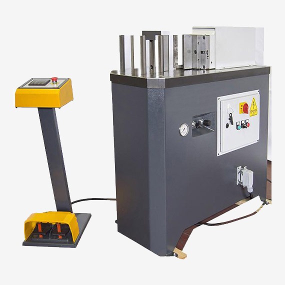
Horizontal presses are widely used in industrial manufacturing due to their efficient layout, adaptability to automation, and suitability for handling long, heavy, or irregularly shaped workpieces. Unlike vertical presses, horizontal presses apply force laterally, which provides ergonomic and spatial advantages in many production settings. They are commonly found in industries such as automotive, construction, railway, shipbuilding, electrical equipment, metal furniture, and heavy machinery fabrication.
In metal forming, horizontal presses are used for tasks such as straightening, bending, coining, punching, deep drawing, extruding, and flattening. Long metal parts like beams, pipes, rails, and rods are often better handled in a horizontal configuration, where they can be supported continuously along their length. The horizontal design minimizes gravitational sagging of workpieces, ensures precise alignment, and allows easier integration with conveyors, feeders, and robotic manipulators.
In structural steel fabrication, horizontal presses straighten H-beams, I-beams, angles, and channels that may become warped during welding or rolling processes. These machines can apply powerful corrective forces with high positional accuracy, ensuring that final assemblies meet tight tolerances and structural integrity standards.
In pipe and tube processing, horizontal presses are used for bending, expanding, shrinking, and forming operations. Their configuration supports long pipe lengths and allows quick setup for various pipe diameters and wall thicknesses. Tooling systems on these presses can be changed rapidly to switch between different forming operations, improving productivity in high-mix production environments.
In the railway and shipbuilding industries, large and heavy metal components often require horizontal presses for edge bending, frame correction, and shape forming. Due to the large scale of these parts, horizontal presses with extended bed lengths and multi-point pressing capability are used to deliver even force distribution across the workpiece.
Horizontal presses are also used in the production of electrical enclosures, control cabinets, and metal furniture. Operations like embossing, punching, notching, and panel bending are performed on sheet metal using precision tooling mounted in horizontal configurations. This allows seamless automation and efficient material flow in large-scale production lines.
In heavy industry, horizontal presses are integrated into forging and extrusion operations, forming high-strength components such as gear blanks, axle parts, and structural connectors. These presses may operate hydraulically or mechanically, depending on force requirements and cycle speeds. High-tonnage horizontal presses are designed with reinforced frames and precision guides to handle continuous duty cycles without deformation or misalignment.
The use of horizontal presses is also expanding in composite and plastic forming, especially for long parts requiring controlled pressure profiles or sequential processing. Multi-stage or progressive operations can be arranged in a linear format, with the press moving the ram through programmed steps while the workpiece remains fixed or is advanced mechanically.
In conclusion, horizontal presses are essential in industrial manufacturing where long, large, or complex parts need to be formed, corrected, or assembled with precision and force. Their flexibility, powerful capabilities, and compatibility with automation make them a backbone of modern production in sectors demanding accuracy, repeatability, and efficiency.
Horizontal presses are often selected for integration into automated production lines because their layout naturally accommodates inline transfer of materials and finished parts. This makes them ideal for applications involving high-volume, repeatable operations where speed and consistency are critical. Automated feeders, loaders, and robotic arms can be easily synchronized with horizontal press cycles, allowing continuous or semi-continuous manufacturing without human intervention. The result is reduced cycle times, lower labor costs, and enhanced workplace safety, particularly in applications involving heavy or hazardous materials.
In precision fabrication, horizontal presses are used in die sets where lateral pressing action is preferred to maintain flatness or reduce distortion. These machines excel in operations like edge trimming, flanging, grooving, and complex profile forming. The consistent pressure distribution in horizontal orientation helps achieve high surface finish and tight dimensional tolerances, especially in applications requiring multi-point contact or distributed forming pressure.
In powder metallurgy and ceramics, horizontal multi-stage presses are used to compact powdered materials into near-net-shape parts with uniform density. The lateral pressing motion supports stable compaction of slender or asymmetrical parts, minimizing breakage or cracking during pressing. This is particularly important in producing brake pads, cutting tools, or small mechanical components where microstructural integrity directly impacts performance.
The aerospace industry benefits from horizontal presses for precision forming of aircraft structural components, where exact angles, smooth surfaces, and consistent stress distribution are required. These presses are used in forming titanium, aluminum, and composite sheet materials into airframe elements, fuselage skins, and internal support structures.
Horizontal presses also serve a vital role in repair and maintenance operations. Many workshops use them for tasks like straightening bent axles, pressing in bearings, removing bushings, or aligning metal parts before welding or assembly. Their accessibility and open-sided design make them user-friendly for a wide range of manual and semi-automated tasks in maintenance facilities.
In addition to hydraulic horizontal presses, electric and hybrid versions are becoming more common. These provide enhanced energy efficiency, faster response times, and better control of speed and pressure curves. Electric servo systems, for instance, allow programmable stroke profiles, enabling operators to apply varying pressure at different stages of a single operation—ideal for delicate or high-precision work.
Tooling design for horizontal presses is evolving to support faster setup, longer life, and more complex part geometries. Interchangeable dies, modular frames, and self-aligning tool holders reduce downtime during tool changes and improve flexibility. Combined with real-time monitoring systems, modern horizontal presses can detect tool wear, misalignment, or material inconsistencies during operation and make adjustments or issue alerts to prevent defects.
Overall, horizontal presses are indispensable in sectors that demand durability, precision, and efficient material handling. Their adaptability to both traditional and high-tech production environments ensures they remain a cornerstone of industrial forming and assembly, capable of meeting increasingly complex production requirements with high reliability and minimal waste.
Modern advancements in horizontal press technology are pushing the boundaries of precision forming and enabling new capabilities in high-performance manufacturing environments. One key area of innovation is the integration of intelligent control systems that allow operators to program detailed force-displacement curves, track real-time press parameters, and adjust operations dynamically. These systems use PLCs, HMIs, and sensor arrays to monitor every aspect of the press cycle—from ram position to oil temperature—ensuring consistent quality and minimizing downtime.
These presses are also being designed with modularity in mind. Many industrial users now require press systems that can be easily adapted to different product lines. Modular horizontal presses can be reconfigured with various attachments such as punching heads, shearing tools, forming dies, and cutting systems. This flexibility allows manufacturers to shift between products or parts without replacing the core machine, reducing investment costs and setup time.
Environmental and energy considerations are further influencing horizontal press development. New hydraulic designs with energy-saving pumps, low-friction seals, and optimized flow control reduce power consumption. Meanwhile, fully electric versions eliminate the need for hydraulic fluids, making them cleaner and quieter. These electric presses are particularly valued in cleanroom environments or operations with strict environmental controls.
Horizontal presses also play a critical role in the processing of non-metallic materials, such as composites, plastics, and rubber. In SMC and BMC molding, for instance, horizontal presses apply even clamping pressure over large surface areas while maintaining excellent control over curing temperature and cycle timing. This is essential for producing parts like automotive panels, structural enclosures, or electrical insulation components where consistency and structural integrity are critical.
In industrial forging and warm forming, horizontal presses are increasingly preferred for shaping long shafts, rods, and tubes because of their ability to apply high forces in a linear fashion without compromising alignment. Forging applications benefit from built-in lubrication systems, programmable force curves, and durable slide guides that withstand the repeated stresses of high-load production.
In addition to their physical advantages, horizontal presses are becoming smarter through connectivity. Machine data can be integrated into MES (Manufacturing Execution Systems) and ERP (Enterprise Resource Planning) software, providing traceability of each press cycle, part ID, tool wear status, and energy usage. This supports lean manufacturing initiatives and ensures compliance with ISO and industry-specific standards.
The combination of force, precision, automation readiness, and adaptability ensures that horizontal presses will continue to be essential assets in advanced manufacturing. Whether used in high-speed production lines, specialized forming applications, or maintenance workshops, they provide a robust platform for consistent, accurate, and efficient material processing across countless industrial sectors.
Horizontal Press Metal Forming
Horizontal press metal forming is a manufacturing process in which a press applies lateral force to deform metal workpieces into desired shapes. Unlike vertical presses that apply force downward, horizontal presses operate with a horizontal ram stroke, making them especially effective for forming long, narrow, or awkwardly shaped parts. This orientation offers advantages in alignment, automation compatibility, and operator access, and is widely used in processes such as straightening, bending, extruding, coining, swaging, and forging.
In metal forming, horizontal presses are particularly suitable for working with profiles like tubes, rods, channels, beams, and flat bars. The lateral direction of force application allows these elongated components to be laid flat and supported along their length during pressing, reducing deflection and improving dimensional accuracy. The press bed may include V-blocks, rollers, or custom fixtures to secure the workpiece and guide it through the forming operation.
One common application is bar and tube straightening, where previously bent or distorted materials are corrected using precisely controlled press strokes. The operator or automated system adjusts pressure and stroke length to gradually straighten the workpiece without over-stressing or damaging the material. This is widely used in steel service centers, shipyards, and rail manufacturing.
Another use is in bending operations, where the press applies pressure through a die set that forces the metal to conform to a desired angle or radius. In horizontal bending, the setup is ideal for parts with long or heavy geometries that would be cumbersome to load vertically. Specialized bending tools can be configured for single-angle bends, multi-bend profiles, or adjustable-radius operations.
Horizontal presses are also employed in cold extrusion processes, where metal blanks are forced through dies to form complex profiles with high surface finish and dimensional accuracy. Because the material flow is directional and confined, the horizontal setup helps maintain better alignment and reduce die wear, especially in operations involving high-strength alloys or large parts.
In coining or embossing, horizontal presses provide the precise control and rigidity needed to imprint surface patterns or fine features on metal parts. The lateral pressure is uniform across the contact area, resulting in consistent and detailed impressions—useful in signage, architectural components, or decorative hardware.
Heavy-duty forging presses with horizontal orientation are used to preform or finish long metal parts like shafts, axles, and spindles. These machines may operate with very high tonnage to achieve the necessary deformation, and are designed to handle both hot and cold forging cycles. Cooling and lubrication systems are integrated to manage heat and reduce tool wear.
Automation systems can easily be integrated with horizontal presses, including robotic arms, part feeders, and conveyors. This compatibility with in-line processing makes horizontal presses especially useful in high-volume environments such as automotive, appliance, and construction hardware production. Parts can be moved seamlessly through multiple forming stages without vertical lifting or complex transfer mechanisms.
Because metal forming often involves high loads and repeated cycles, horizontal presses are built with robust frames, precision guides, and high-quality hydraulic or servo-electric systems. These features ensure long-term accuracy, reliability, and consistent performance. Modern models often include programmable control systems that allow operators to set stroke limits, force profiles, and multi-step sequences, offering greater flexibility and minimizing setup times.
In summary, horizontal press metal forming is a versatile and efficient method for shaping and adjusting metal components. Its structural orientation and force delivery are especially well-suited for handling long parts, facilitating precise operations, and integrating into automated production lines. This makes it a core process in industries requiring strength, dimensional control, and high repeatability in metal part fabrication.
Horizontal press metal forming continues to be favored in industrial settings due to its ability to handle challenging geometries and deliver precise, repeatable deformation with minimal setup complexity. The horizontal configuration naturally supports long workpieces during processing, allowing for better alignment and reducing the risk of buckling or material sag. This makes it especially efficient for operations on parts such as rails, beams, tubes, and rods, where stability and straightness are critical.
The adaptability of horizontal presses allows them to accommodate a variety of metal forming tasks beyond simple bending or straightening. For example, flaring operations can be performed to expand pipe ends; swaging can reduce diameters to create stepped or tapered profiles; and slotting or hole punching can be carried out on metal bars with integrated tooling systems. These functions are often combined in flexible production lines where the press is retooled or programmed for specific tasks without lengthy changeovers.
Modern horizontal presses also enable incremental forming techniques, where a series of lighter, precisely controlled presses gradually shape the metal. This is beneficial for forming high-strength alloys or hardened materials that would otherwise crack under a single heavy load. The ability to control force, displacement, and speed with servo-hydraulic or electric actuators improves formability and extends tool life. Advanced control systems can store and recall part programs, optimizing production for both small batch and high-volume applications.
The horizontal format supports ergonomic workflow and safety as well. Operators can load and unload materials at waist level, and automatic guarding systems can be implemented along the length of the press without obstructing access. Vision systems and sensors monitor each stage of the operation, ensuring the correct positioning of parts and tools while detecting any anomalies such as misalignment, excessive load, or material inconsistencies. These systems help prevent damage to both machine and workpiece while improving overall production quality.
Horizontal press forming is also advantageous for materials that require careful handling during shaping. For example, thin-walled tubes used in automotive exhaust systems, HVAC components, or aerospace structures can be deformed with precise pressure control to avoid buckling or wrinkling. Similarly, parts made from softer metals like aluminum or copper can be formed cleanly without surface damage using custom die sets and refined press stroke control.
In sectors like shipbuilding or bridge construction, horizontal presses are used to correct distortions in structural components during and after welding. Large flat plates, beams, and profiles may warp due to thermal stress, and horizontal presses apply targeted force to restore geometric accuracy. These operations are often mobile, with portable horizontal presses deployed on-site to perform adjustments in large-scale assemblies.
As industrial demands evolve, horizontal press metal forming technology continues to advance with digital integration, allowing real-time data logging, diagnostics, and feedback loops that maintain consistency and improve traceability. These capabilities are essential in certified manufacturing environments, such as automotive and aerospace, where each part must meet exact specifications and full records of the forming process are required.
In total, horizontal press metal forming combines mechanical precision, structural efficiency, and process flexibility, making it indispensable in the production of long, shaped, or corrected metal components. It offers a stable platform for both simple and complex operations while supporting automation and modern production principles, enabling manufacturers to deliver high-quality parts consistently and economically across a wide range of industries.
Further expanding on horizontal press metal forming, the equipment’s configuration also lends itself well to integration into modular production cells. In these setups, multiple forming tasks—such as bending, punching, straightening, and trimming—can be arranged in a single, linear workflow, minimizing part handling and streamlining the process from raw material to finished product. This layout improves manufacturing efficiency and reduces the risk of part damage, especially in high-throughput environments where consistency and speed are paramount.
Tooling flexibility is another key advantage. Horizontal presses often use interchangeable die sets that can be swapped quickly with minimal downtime, allowing for efficient adaptation to different part geometries or production batches. This is especially useful in industries such as automotive, where a single production line may be required to form various chassis components, brackets, or tubular parts in quick succession. Precision-ground guides and self-centering fixtures maintain alignment during tool changes, ensuring the machine can return to full operation almost immediately.
With the increased adoption of high-strength steels and lightweight alloys, horizontal presses are engineered to deliver controlled, progressive deformation, which is essential for preserving the integrity of advanced materials. Materials like dual-phase steels or aluminum-magnesium alloys require specific forming speeds and force profiles to avoid tearing or springback, challenges that are efficiently addressed through programmable force curves and real-time feedback control.
In addition to standard pressing operations, horizontal presses are also employed in end-forming processes, where the ends of tubes or rods are reshaped into flanges, beads, notches, or grooves. These features are often critical for assembly or sealing purposes in systems like automotive exhausts, HVAC ducting, or hydraulic piping. The controlled linear movement of the press ram makes it ideal for achieving uniform deformation across the length of the part, and multi-station setups can perform several forming actions in one press cycle.
Noise reduction, energy efficiency, and environmental impact are also considerations in modern horizontal press design. Many machines now feature noise-dampened enclosures, high-efficiency hydraulic pumps, and closed-loop systems that minimize fluid loss and contamination. Electric horizontal presses go a step further, offering near-silent operation, reduced power consumption, and precise, clean force application without the need for hydraulic oil—making them increasingly desirable in eco-conscious manufacturing environments.
Maintenance access and operational uptime are priorities as well. Horizontal presses are designed with accessible service zones, modular hydraulic units, and integrated diagnostics. Predictive maintenance systems can monitor key parameters like oil pressure, stroke consistency, and ram speed, notifying operators when wear or imbalance is detected before a breakdown occurs. These systems not only prolong machine life but also support lean manufacturing by minimizing unscheduled downtime.
Finally, the application versatility of horizontal press metal forming spans a wide industrial spectrum. In agricultural machinery, it forms and adjusts components like axles, brackets, and chassis members. In appliance manufacturing, it helps produce structural frames, handles, and enclosures. In infrastructure projects, it straightens and shapes massive structural members used in bridges, stadiums, or industrial buildings. Whether for high-precision, lightweight assemblies or heavy-duty structural components, the horizontal press remains an essential, adaptable tool in the modern metal forming landscape.
Horizontal Press Manufacturing Steps
The manufacturing of a horizontal press involves a series of precise and coordinated steps that transform raw materials into a robust, high-performance machine capable of delivering controlled lateral pressing forces. Each phase focuses on structural integrity, precision, and functional reliability to meet industrial demands. The key manufacturing steps include design, material preparation, machining, fabrication, assembly, testing, and finishing.
The process begins with detailed engineering design, where CAD and CAE software are used to model the press frame, ram, hydraulic or electric drive systems, tooling interfaces, and control components. Structural analysis verifies that the design will withstand the anticipated forces without deformation or fatigue, while ensuring ergonomic and maintenance accessibility.
Following design approval, raw materials such as heavy steel plates, billets, and bars are procured. These materials are selected for high strength, toughness, and fatigue resistance to endure repeated press cycles. Steel for structural frames is typically of a grade that combines weldability with mechanical strength, while critical components like ram shafts and guides may use alloy or heat-treated steels.
Cutting and shaping of raw materials are performed using CNC laser cutting, plasma cutting, or band saws to form frame parts, base plates, and mounting brackets. Machining operations follow, involving milling, turning, drilling, and grinding to achieve precise dimensions and tolerances on critical surfaces such as ram faces, guide rails, and bearing housings. CNC machining centers provide high repeatability and accuracy in producing complex components.
Heat treatment processes like quenching, tempering, or induction hardening are applied to key parts such as ram shafts, die holders, and hydraulic cylinder rods to improve hardness, wear resistance, and fatigue life. This step is crucial for components subjected to high stress and cyclic loads.
Fabrication involves welding and assembly of the main press frame and subassemblies. Skilled welders use MIG or TIG welding techniques to join steel components, ensuring strong, clean welds with minimal distortion. Fixtures and jigs are employed during welding to maintain precise alignment and dimensional accuracy.
The hydraulic system or electric drive components are assembled and installed next. Hydraulic cylinders, pumps, valves, hoses, and reservoirs are mounted and connected in hydraulic presses, while electric presses integrate servo motors, ball screws, controllers, and wiring. The hydraulic or electric control panel is built and wired to facilitate precise press operation and safety interlocks.
Final assembly combines the frame, ram, drive units, tooling interfaces, sensors, and control electronics. Alignment checks ensure the ram moves smoothly and parallel to the press bed, with minimal clearance to prevent lateral play. Lubrication systems are installed to maintain moving parts and extend machine life.
Quality control and testing include static load tests, dynamic operation cycles, stroke accuracy measurements, and safety feature validation. The press undergoes repeated pressing cycles under controlled conditions to verify performance consistency, force output, and control response. Adjustments and calibrations are made as necessary.
Surface finishing involves grinding, sanding, and painting or powder coating the frame and exposed parts to protect against corrosion and improve aesthetics. Labels, safety decals, and user interfaces are installed to complete the machine.
Packaging is tailored to protect the press during shipping, often involving custom crates or frames, and includes user manuals, spare parts kits, and setup tools.
Overall, the manufacturing of a horizontal press is a complex process combining heavy fabrication, precision machining, advanced control system integration, and rigorous testing to produce a reliable industrial machine capable of meeting demanding metal forming and assembly tasks.
After packaging, the horizontal press often undergoes factory acceptance testing (FAT) or customer site installation and commissioning. During FAT, the machine is run through its full range of motions and operations to verify all systems function correctly under simulated production conditions. This helps identify and resolve any issues before shipment, ensuring smooth startup at the customer’s facility.
Installation involves placing the press on a prepared foundation, aligning it precisely using leveling equipment, and connecting utilities such as electrical power, hydraulic lines, and control interfaces. Technicians perform final calibrations, adjust safety guards and interlocks, and integrate the press with existing production lines or automation systems as needed.
Operator training is typically provided to familiarize users with machine controls, safety procedures, maintenance schedules, and troubleshooting techniques. Comprehensive documentation including user manuals, electrical and hydraulic schematics, and maintenance logs accompany the equipment to support long-term operation.
Throughout the press’s operational life, preventive maintenance is critical to preserve performance and safety. Regular inspections focus on hydraulic fluid levels and quality, wear of seals and bearings, condition of tooling, and calibration of sensors and control systems. Scheduled lubrication and replacement of consumables minimize downtime and costly repairs.
Manufacturers often offer service contracts or remote monitoring solutions that track machine health and predict maintenance needs using IoT sensors and data analytics. This proactive approach helps avoid unexpected failures and optimizes machine availability.
Continuous improvement based on feedback from production data and user experience drives iterative design updates. Advances in materials, electronics, and software are incorporated into newer press models, enhancing efficiency, precision, and operator ergonomics.
In summary, the full manufacturing cycle of a horizontal press extends beyond physical production into rigorous testing, installation, operator support, and ongoing maintenance, all aimed at ensuring reliable, safe, and efficient operation throughout its service life in industrial environments.
As industries evolve, horizontal press manufacturers increasingly focus on sustainability and environmental impact throughout the entire lifecycle of their machines. This includes selecting recyclable materials, minimizing waste during fabrication, and designing presses for energy efficiency. For example, many modern presses incorporate servo-electric drives that consume power only when actively pressing, reducing electricity usage compared to traditional hydraulic systems.
Manufacturers also optimize hydraulic systems to reduce fluid consumption and leakage, while employing biodegradable or less toxic hydraulic oils where possible. Advances in powder coating and painting techniques reduce volatile organic compounds (VOCs), contributing to a safer workplace and lower environmental footprint.
End-of-life considerations are becoming important too, with some manufacturers designing presses for easier disassembly and recycling of components. Modular designs facilitate upgrading or refurbishing presses rather than full replacement, extending the usable life of expensive equipment and reducing industrial waste.
On the innovation front, integration with Industry 4.0 technologies enables horizontal presses to communicate with other equipment and factory management systems. Real-time data collection supports predictive maintenance, quality control, and process optimization, helping manufacturers increase productivity while reducing downtime and scrap rates.
Customization remains a significant part of horizontal press manufacturing. Many users require presses tailored to specific production volumes, material types, part sizes, and automation levels. Manufacturers collaborate closely with clients during the design phase to develop bespoke solutions that meet exact operational requirements, including special tooling, control software, safety features, and footprint constraints.
In response to global competition and rapid market changes, manufacturing lead times have shortened thanks to advanced CAD/CAM tools, simulation software, and flexible fabrication techniques like robotic welding and additive manufacturing for complex parts. These capabilities allow quicker prototyping, testing, and ramp-up to full production, keeping manufacturers agile.
Finally, comprehensive after-sales support networks, including technical assistance, spare parts availability, remote diagnostics, and training programs, ensure that horizontal presses continue to operate at peak performance long after delivery. This holistic approach—from design and fabrication through installation, operation, and end-of-life—positions horizontal press manufacturing as a dynamic and essential industry sector adapting to modern demands for precision, efficiency, and sustainability.
Press Tooling Materials
Press tooling materials are critical to the performance, durability, and precision of press operations. The choice of tooling material depends on factors such as the type of press operation (stamping, forging, bending, extrusion), the material being formed, production volume, and the required surface finish. Tooling materials must withstand high stresses, resist wear and deformation, and maintain dimensional accuracy over many cycles.
Common press tooling materials include:
- Tool Steels
Tool steels are the most widely used materials for press tooling due to their excellent hardness, toughness, and wear resistance. Different grades are selected based on the application:
- D2 Steel: A high-carbon, high-chromium cold-work tool steel known for its excellent wear resistance and toughness. Often used for blanking, forming, and bending dies.
- A2 Steel: Air-hardening tool steel offering good toughness and wear resistance, suitable for punches and dies where shock resistance is important.
- O1 Steel: Oil-hardening tool steel with good machinability, used for lower volume tooling or prototype dies.
- S7 Steel: Shock-resistant tool steel ideal for impact applications like forging dies and punches.
- Carbide (Tungsten Carbide)
Tungsten carbide tooling inserts or tips are extremely hard and wear-resistant, making them suitable for high-volume production and abrasive materials. Carbide tooling is often used for cutting edges in stamping dies and forming tools but is more brittle than tool steel and requires careful handling. - High-Speed Steel (HSS)
HSS is used for tooling requiring high toughness and heat resistance, such as in high-speed stamping or extrusion dies. It maintains hardness at elevated temperatures and is used for punches and trimming tools subjected to thermal cycling. - Cast Iron and Alloy Steel
For larger tooling bases or die holders, cast iron or alloy steels are used due to their good machinability and vibration damping properties. These materials provide structural support but are not used for cutting or forming surfaces. - Powder Metallurgy Tool Steels
Powder metallurgy (PM) steels offer uniform microstructure, high toughness, and wear resistance. They are used in advanced tooling applications requiring long tool life and complex geometries. - Surface Treatments and Coatings
To extend tooling life, surface treatments such as nitriding, carburizing, or induction hardening are applied to improve surface hardness and fatigue resistance. Coatings like TiN (titanium nitride), TiCN, or DLC (diamond-like carbon) reduce friction and wear, particularly on forming dies and punches. - Polymer and Composite Materials
In specialized presses, softer tooling materials such as polyurethane or composite dies may be used for delicate forming operations or prototyping, where minimal damage to the workpiece surface is required.
Selecting the right tooling material is essential to balance cost, durability, and performance. Proper maintenance, lubrication, and regular inspection further enhance tooling lifespan and ensure consistent quality in press operations across various industries.
In addition to material selection, the design and manufacturing of press tooling also significantly influence tool life and performance. Tool geometry must be optimized to distribute stresses evenly, minimize wear points, and facilitate efficient material flow during forming or cutting. Sharp edges, radii, and draft angles are carefully engineered to reduce excessive loading and avoid premature failure.
Heat treatment processes are commonly applied to tooling components to enhance hardness and toughness. For example, quenching and tempering improve wear resistance while maintaining enough toughness to withstand impact loads. Surface hardening techniques like nitriding create a hard case on the tool surface without compromising the softer, tougher core, helping resist abrasive wear and fatigue cracking.
Proper lubrication during press operations reduces friction and heat buildup between the tooling and workpiece, which slows wear and prevents galling or scoring of the tool surface. Lubricants must be compatible with both the tooling material and the workpiece to avoid chemical reactions or contamination.
Regular inspection and preventive maintenance are crucial to detect early signs of wear, chipping, or deformation. Non-destructive testing methods, such as dye penetrant inspection or ultrasonic testing, can identify cracks or internal flaws before catastrophic failure. Worn tooling may be refurbished through grinding, polishing, or recoating to restore dimensional accuracy and surface finish, extending tool life and reducing replacement costs.
The evolution of tooling materials continues with the development of advanced alloys, composite materials, and coatings that push the limits of hardness, toughness, and thermal stability. Research into nanostructured coatings and additive manufacturing techniques for tooling components offers potential for customized wear-resistant surfaces and complex geometries not achievable through traditional methods.
Ultimately, the successful application of press tooling materials depends on matching their mechanical and chemical properties to the specific demands of the press operation, material to be formed, and production volume. A holistic approach encompassing material choice, heat treatment, surface engineering, lubrication, and maintenance ensures tooling delivers optimal performance, reduces downtime, and maintains the quality standards required in modern industrial manufacturing.
Emerging trends in press tooling materials are also shaping the future of metal forming and manufacturing. One such trend is the increasing use of powder metallurgy (PM) and additive manufacturing (AM) techniques to produce tooling components with enhanced microstructures and complex internal features. PM tooling steels provide uniform hardness and toughness, reducing the likelihood of failure under high cyclic loads. Meanwhile, AM allows for internal cooling channels, conformal cooling, and weight reduction without compromising strength, improving tool life and cycle times.
Coatings are becoming more sophisticated, with multi-layered or gradient coatings tailored for specific wear mechanisms such as abrasive wear, adhesive wear, or thermal fatigue. Advanced coatings incorporating ceramics, carbides, or diamond-like carbon layers provide superior hardness and low friction, extending tooling life especially in high-speed or high-temperature applications.
Composite tooling materials, combining metal matrices with ceramic or polymer reinforcements, are being explored for niche applications where weight reduction and vibration damping are advantageous. These composites can reduce wear and improve operator comfort by lowering machine noise and shock during pressing.
Sustainability considerations are also influencing tooling material selection. Efforts to reduce the environmental impact of tool production include using recyclable or more environmentally friendly materials, optimizing manufacturing processes to minimize waste, and designing tools for longer life and easier refurbishment.
Integration of sensor technology directly into tooling is an exciting development. Smart tooling embedded with strain gauges, temperature sensors, or acoustic emission monitors can provide real-time data on tool condition and performance. This enables predictive maintenance, reduces unexpected downtime, and enhances quality control by detecting wear or failure before defects occur in the finished parts.
In conclusion, the choice and development of press tooling materials are dynamic fields driven by advances in material science, manufacturing technology, and industrial needs. Continued innovation promises tooling solutions that are tougher, more wear-resistant, adaptable, and intelligent—supporting increasingly complex and demanding press operations across a broad range of industries.
Horizontal Press Deep Drawing
Horizontal press deep drawing is a metal forming process in which a sheet metal blank is transformed into a hollow or concave-shaped part by being drawn into a die cavity through a horizontal pressing action. Unlike vertical deep drawing presses where the ram moves vertically downward, a horizontal press applies force laterally, which can offer unique advantages for certain part geometries, workpiece sizes, and production layouts.
In deep drawing with a horizontal press, the sheet metal is typically positioned horizontally on a die set that includes a blank holder, a punch, and a die cavity. The horizontal ram drives the punch laterally into the sheet metal, drawing it into the die cavity and shaping it into the desired form. The blank holder applies pressure to control material flow and prevent wrinkling or tearing during the drawing process.
Horizontal deep drawing presses are particularly advantageous for forming long, narrow, or tubular components such as automotive panels, structural brackets, electrical enclosures, or containers that benefit from a horizontal workflow. The orientation allows easy handling and support of large or awkwardly shaped blanks and can simplify integration with automated feeding and stacking systems.
The key parameters in horizontal press deep drawing include ram stroke length, force applied, blank holder pressure, punch and die geometry, and drawing speed. Precise control over these factors is essential to avoid common defects like wrinkling, thinning, or cracking. Many horizontal presses used for deep drawing are equipped with servo-hydraulic or fully electric drives, enabling programmable force and speed profiles to optimize forming conditions for various materials and part complexities.
Tooling design in horizontal deep drawing presses must accommodate lateral movement and provide robust support to the blank and drawn part. Dies are engineered to minimize friction and material stress while ensuring consistent dimensional accuracy and surface finish. Lubrication systems are integral to the process, reducing friction between the blank and tooling surfaces to facilitate smooth material flow.
The horizontal press configuration offers ergonomic benefits as well, allowing operators easier access for loading and unloading, and making the process compatible with inline automation, robotic handling, and quality inspection stations.
Horizontal press deep drawing is widely used in automotive manufacturing for parts like side panels, door frames, and chassis components; in electrical equipment for enclosures and housings; and in consumer goods for items like kitchenware or containers. Its combination of flexibility, precision, and production efficiency makes it a valuable forming method for medium to high-volume manufacturing requiring complex shapes and consistent quality.
In summary, horizontal press deep drawing leverages lateral force application to shape sheet metal into hollow parts, offering advantages in handling, automation, and forming of long or irregular components. It requires careful process control and specialized tooling but delivers high-quality results across diverse industrial applications.
Horizontal press deep drawing continues to evolve with advancements in press technology, control systems, and tooling materials. Modern presses often utilize servo-driven hydraulic systems or fully electric drives to provide precise control over punch speed, stroke, and force application. This allows gradual and programmable drawing sequences that reduce material stress, minimize defects, and extend tool life. The ability to tailor the ram motion profile enables processing of advanced high-strength steels and lightweight aluminum alloys increasingly used in automotive and aerospace applications.
Automation integration is another significant development. Horizontal presses are frequently incorporated into automated production lines where blanks are fed by conveyors or robotic arms, drawn parts are immediately transferred for trimming or inspection, and finished components are stacked or moved to the next operation. This inline process flow reduces handling time, lowers labor costs, and improves overall throughput while maintaining consistent quality.
Tooling improvements include the use of wear-resistant coatings, modular die components for quick changeover, and enhanced blank holder designs that adapt pressure dynamically based on sensor feedback. Lubrication systems have also advanced with the use of environmentally friendly and more effective lubricants applied via automated spray or drip systems, optimizing friction reduction and material flow.
Quality control in horizontal press deep drawing benefits from real-time monitoring of process parameters such as force, displacement, and temperature. Integrated sensors and cameras can detect defects like wrinkles, tears, or surface blemishes immediately, allowing corrective action before scrap is produced. Data collected during forming cycles supports continuous process optimization and predictive maintenance, reducing downtime and improving part consistency.
The horizontal configuration also facilitates the forming of unusually shaped or asymmetrical parts that might be difficult to process in vertical presses due to gravitational effects or complex tooling arrangements. By supporting the blank and workpiece along their length, horizontal presses help maintain dimensional stability and reduce springback.
Industries beyond automotive and electrical manufacturing, such as appliance production, aerospace, and even medical device fabrication, leverage horizontal deep drawing for parts requiring precise wall thickness control, smooth surface finishes, and complex geometry. The process is adaptable to various sheet metals, including stainless steel, copper, brass, and titanium alloys.
Environmental and energy efficiency considerations are influencing horizontal press design, with newer models featuring energy recovery systems, low-friction drive components, and improved hydraulic circuit designs. These enhancements reduce power consumption and contribute to greener manufacturing practices.
In essence, horizontal press deep drawing is a versatile, efficient, and precise metal forming method suited for producing hollow, complex-shaped parts from sheet metal. Its advantages in handling, automation compatibility, and process control make it increasingly important in modern industrial manufacturing environments where quality, speed, and cost-effectiveness are critical.
Advancements in simulation and modeling software have further enhanced horizontal press deep drawing processes. Engineers now use finite element analysis (FEA) to predict material behavior, stress distribution, and potential failure points before physical tooling is manufactured. This digital prototyping reduces trial-and-error cycles, lowers tooling costs, and shortens development time for new parts. Simulations help optimize punch and die geometry, blank holder force, and lubrication strategies to improve forming outcomes and minimize defects.
The flexibility of horizontal press deep drawing also allows for hybrid forming techniques. For example, combined processes like deep drawing with subsequent ironing, trimming, or embossing can be performed in a single press cycle or station. These multi-step operations reduce handling and increase accuracy by maintaining part positioning throughout the sequence.
Material handling innovations complement these presses, such as servo-controlled feeding systems that precisely position blanks for each stroke, and automated stacking mechanisms that handle finished parts delicately to avoid damage. Integration with factory automation and smart manufacturing systems enables seamless communication between presses and peripheral equipment, enhancing overall production line efficiency.
Training and workforce development play a crucial role as well. Modern horizontal deep drawing presses with advanced controls require skilled operators and technicians who understand both the mechanical aspects and the software-driven process controls. Manufacturers often provide comprehensive training programs and simulation tools to prepare personnel for safe and effective machine operation.
The ongoing trend toward lightweighting in automotive and aerospace industries, driven by fuel efficiency and emissions regulations, continues to challenge horizontal deep drawing processes. Thinner sheets, multi-material stacks, and high-strength alloys demand ever-greater precision, adaptability, and control. Horizontal presses equipped with advanced sensors and adaptive control algorithms meet these challenges by dynamically adjusting forming parameters in real-time to accommodate material variability and complex geometries.
In addition, environmental considerations encourage the adoption of sustainable lubricants, energy-efficient drives, and waste minimization practices within horizontal deep drawing operations. These measures not only reduce ecological impact but also improve workplace safety and reduce operating costs.
In conclusion, horizontal press deep drawing remains a cornerstone metal forming technology that evolves with advances in materials, automation, and process control. Its unique combination of lateral force application, ergonomic design, and integration capability ensures it will continue to meet the demands of complex, high-quality, and cost-effective manufacturing well into the future.
Metal Bending Press
A metal bending press is a specialized machine used to bend sheet metal or metal plates into desired shapes by applying controlled force. It’s a fundamental tool in metal fabrication, enabling the creation of angled parts, curves, flanges, and complex bends with precision and repeatability. Metal bending presses come in various configurations, including hydraulic, mechanical, pneumatic, and electric, each suited to different applications based on force requirements, speed, and control.
The core function of a metal bending press is to deform metal by pressing it between a punch and a die, which shapes the metal according to the tooling design. The punch moves downward (or horizontally, depending on the press type) applying force to the metal blank placed on the die, causing it to bend at a specific angle or radius. The tooling setup, including punch shape, die opening, and clearance, directly influences the bend quality, accuracy, and the amount of springback.
Hydraulic bending presses use hydraulic cylinders to generate bending force, offering smooth and adjustable pressure, making them suitable for bending thicker or harder metals. Mechanical presses rely on flywheels and crank mechanisms to deliver rapid, high-energy strokes and are often used in high-volume production where speed is critical. Pneumatic presses use compressed air to generate force, suitable for lighter-duty applications with faster cycle times, while electric presses employ servo motors for precise motion control and energy efficiency.
Metal bending presses can perform various bending operations such as air bending, bottoming, and coining. Air bending involves pressing the metal into the die with some springback allowance, allowing flexibility in bend angles without changing tooling. Bottoming presses press the metal fully into the die cavity for precise angles, and coining involves applying very high pressure to plastically deform the metal surface, producing highly accurate bends with minimal springback.
The choice of tooling materials, machine capacity (tonnage), and bed size depends on the thickness and type of metal being bent, as well as the complexity of bends required. Tooling is typically made from hardened tool steels or carbide inserts for durability, especially when working with abrasive or high-strength materials.
Modern metal bending presses often incorporate CNC controls to automate bending sequences, adjust ram position and force dynamically, and store programs for repeatable production runs. These controls enhance precision, reduce setup time, and allow operators to handle complex bend patterns efficiently.
Applications of metal bending presses span across automotive manufacturing, appliance production, aerospace, construction, HVAC systems, and general sheet metal fabrication. They are essential in creating parts like brackets, panels, enclosures, chassis components, and decorative elements.
In summary, metal bending presses are versatile, powerful machines designed to form metal parts with precise bends through controlled force application. Their various types and tooling options allow adaptation to a wide range of materials and production needs, making them indispensable in modern metalworking industries.
Metal bending presses continue to advance with improvements in machine design, control systems, and tooling technology. One major trend is the integration of CNC (Computer Numerical Control) systems, which allow for fully automated bending cycles with programmable ram movements, bend sequences, and force adjustments. This automation reduces operator error, increases production speed, and enables the handling of complex bend geometries that would be difficult or impossible to achieve manually.
Safety features have also improved, with modern presses equipped with light curtains, safety interlocks, and emergency stop systems to protect operators during high-force operations. Ergonomic designs facilitate easier loading and unloading of metal blanks, reducing worker fatigue and improving overall workflow efficiency.
Hybrid presses combining hydraulic and electric systems offer benefits such as high force output with improved energy efficiency and quieter operation. Servo-electric presses provide precise control over ram speed and position, enabling delicate bends on thin or complex materials without damage, while hydraulic systems remain preferred for heavy-duty bending of thick or high-strength metals.
Advances in tooling materials and coatings enhance the durability and performance of punch and die sets. Carbide inserts, nitrided surfaces, and diamond-like carbon coatings reduce wear and friction, leading to longer tool life and better surface finishes on bent parts. Quick-change tooling systems allow faster setup and reduce downtime, which is vital in flexible manufacturing environments producing multiple part types.
Material handling improvements, such as automated feeders, robotic arms, and conveyors, integrate seamlessly with metal bending presses, supporting high-volume production lines and reducing manual handling. Inline measurement and quality control systems, including laser scanners and force sensors, monitor bend accuracy in real time and trigger adjustments or alerts if tolerances drift.
Metal bending presses are also increasingly used in conjunction with other forming processes like punching, laser cutting, and welding within integrated manufacturing cells. This holistic approach streamlines production, minimizes handling, and supports just-in-time manufacturing practices.
Environmental concerns drive developments in energy-efficient presses that reduce power consumption and hydraulic fluid use. Electric presses, in particular, offer cleaner operation with no risk of hydraulic leaks, aligning with stricter workplace safety and environmental regulations.
Overall, metal bending presses remain central to modern sheet metal fabrication, offering adaptable, precise, and efficient solutions for forming metal parts across diverse industries. Their continuous evolution ensures they meet the demands for higher quality, faster production, and greater flexibility in manufacturing operations.
Looking ahead, the future of metal bending presses is closely tied to the rise of Industry 4.0 and smart manufacturing technologies. Integration of advanced sensors, IoT connectivity, and machine learning algorithms enables presses to collect and analyze real-time data on machine performance, tooling wear, and part quality. This data-driven approach allows predictive maintenance, reducing unexpected downtime and extending the lifespan of both the press and its tooling.
Adaptive control systems use feedback from sensors to automatically adjust bending parameters during production, compensating for material inconsistencies or tool wear. Such self-optimizing capabilities improve repeatability and reduce scrap rates, which is especially important when working with expensive or difficult-to-form materials like advanced high-strength steels or exotic alloys.
Digital twins—virtual replicas of physical presses and tooling—allow manufacturers to simulate and optimize bending operations before actual production, helping identify potential issues and fine-tune processes without wasting material or machine time. This accelerates product development and shortens time-to-market for new parts.
Customization and modularity in press design enable manufacturers to tailor machines to specific applications or production volumes. Modular tool holders, quick-change systems, and configurable control software allow rapid switching between different jobs, supporting flexible manufacturing and smaller batch sizes demanded by modern supply chains.
Collaborative robots (cobots) working alongside operators to load blanks, change tooling, or handle finished parts improve safety and efficiency in metal bending operations. These robots can adapt to various tasks without extensive programming, making automation more accessible to smaller shops.
Sustainability also remains a key focus. Press manufacturers are exploring renewable energy integration, recyclable materials for tooling, and eco-friendly lubricants to reduce the environmental impact of metal forming processes. Efforts to minimize waste and energy consumption align with corporate social responsibility goals and regulatory requirements.
In sectors like automotive, aerospace, electronics, and construction, metal bending presses will continue to play a vital role in producing lightweight, complex-shaped components with tight tolerances. Advances in press technology combined with digital transformation promise higher productivity, improved quality, and greater operational flexibility, helping manufacturers stay competitive in a rapidly changing industrial landscape.
In summary, metal bending presses are evolving from purely mechanical machines into intelligent, connected systems that optimize performance through data and automation. This transformation enhances their ability to meet diverse and demanding fabrication needs efficiently and sustainably now and in the future.
Horizontal Press Applications
Horizontal presses are versatile machines widely used across various industries due to their ability to apply controlled lateral force for shaping, forming, and assembling metal and other materials. Their horizontal orientation offers distinct advantages for handling long, heavy, or awkwardly shaped workpieces, making them ideal for applications requiring stability, precision, and integration with automated production lines.
In metal forming, horizontal presses are commonly used for bending, straightening, deep drawing, coining, and extrusion of components such as beams, rods, tubes, and flat bars. This includes automotive parts like chassis members, door panels, and exhaust components, where the horizontal setup supports the part along its length to prevent distortion and ensure dimensional accuracy.
In manufacturing of heavy machinery and structural components, horizontal presses straighten warped beams or plates, perform forging preforms, and shape large metal profiles used in construction, shipbuilding, and rail industries. Their capacity to handle large-scale workpieces makes them indispensable for correcting thermal or mechanical distortions and forming complex geometries.
Electronics and electrical equipment manufacturing benefit from horizontal presses in producing enclosures, housings, and panels that require precise bends and deep drawing. The presses can be integrated with automated feeding and stacking systems for high-volume, consistent production.
Plastic and composite molding applications, such as thermoset compression molding and bulk or sheet molding compound (BMC and SMC) processes, utilize horizontal presses to form intricate parts for automotive, appliance, and consumer goods sectors. The lateral press action facilitates even pressure distribution essential for high-quality molding.
Other uses include pipe and tube bending, where horizontal presses shape cylindrical components into specific angles or curves required in HVAC, plumbing, and automotive exhaust systems. Multi-stage horizontal presses perform sequential operations like bending, trimming, and embossing in a single setup to improve efficiency.
In summary, horizontal presses serve diverse roles in metal forming, composite molding, structural correction, and assembly operations. Their structural advantages, combined with adaptability to automation and complex tooling, make them vital in industries demanding precise, repeatable, and high-volume production.
Horizontal presses also find extensive use in the aerospace industry, where precision forming of lightweight, high-strength alloys is critical for structural components and assemblies. Their ability to apply consistent, controlled force along extended parts helps maintain strict tolerances required for aerodynamic efficiency and safety. The horizontal orientation simplifies handling of large or irregularly shaped panels and frames, reducing the risk of distortion during forming.
In the appliance and consumer goods sectors, horizontal presses are employed to manufacture metal housings, frames, and decorative elements. The presses can efficiently form sheet metal into complex shapes with smooth surfaces, meeting both functional and aesthetic requirements. Automated press lines improve production rates and ensure uniform quality for high-volume products.
The railway industry uses horizontal presses to shape rail components, brackets, and undercarriage parts. Their capacity to handle long, heavy sections and deliver consistent forming forces makes them suitable for maintenance and manufacturing applications, including straightening worn or deformed rails.
Maintenance and repair shops leverage horizontal presses for metal straightening and reshaping tasks on damaged components. Their configuration allows quick setup and application of targeted force to restore part geometry without extensive disassembly or replacement, saving time and cost.
In shipbuilding, horizontal presses assist in forming large structural members and correcting distortions caused by welding or assembly stresses. Portable horizontal presses enable on-site adjustments to massive components that cannot be moved easily, supporting efficient construction workflows.
The agricultural equipment sector utilizes horizontal presses for fabricating robust parts like frames, brackets, and linkage components. The presses accommodate heavy-duty materials and provide precise bends and shapes necessary for reliable machinery performance under harsh conditions.
Additionally, horizontal presses are integrated into automated production lines that combine multiple forming, cutting, and assembly operations. Their compatibility with robotic loading, unloading, and in-line inspection systems streamlines manufacturing processes, reduces labor requirements, and enhances overall plant productivity.
Overall, horizontal press applications span a broad range of industries and functions, from heavy structural forming to delicate, high-precision manufacturing. Their versatility, strength, and adaptability to modern automation make them indispensable tools in contemporary industrial production environments.
Beyond traditional industries, horizontal presses are increasingly utilized in emerging sectors such as renewable energy and electric vehicles. In renewable energy manufacturing, they help form structural components for wind turbines, solar panel frames, and battery enclosures, where precise shaping and durability are essential. The presses accommodate large parts and complex profiles needed for efficient energy generation systems.
Electric vehicle production benefits from horizontal presses in fabricating lightweight chassis components, battery trays, and motor housings using advanced materials like aluminum alloys and composites. The precise control over forming forces and programmable motion profiles help manage the challenges posed by these materials, ensuring consistent quality and tight tolerances critical for vehicle safety and performance.
Medical device manufacturing also employs horizontal presses for forming metal components used in equipment frames, surgical instruments, and implantable devices. The presses’ ability to produce intricate shapes with smooth finishes supports the stringent standards of hygiene and reliability required in healthcare applications.
In the defense sector, horizontal presses contribute to fabricating armor plates, weapon components, and structural parts for vehicles and aircraft. The capability to handle thick, high-strength metals and perform multi-stage forming operations aligns with the demanding specifications and quality requirements of military hardware.
Customization and flexibility continue to drive horizontal press usage, with manufacturers offering modular tooling systems and adaptive control technologies that enable quick changeovers between different part designs. This agility supports just-in-time production and small batch sizes without sacrificing efficiency or quality.
Furthermore, the incorporation of advanced monitoring and diagnostic tools into horizontal presses enables predictive maintenance and reduces downtime. Sensors track parameters like force, speed, vibration, and temperature, alerting operators to potential issues before failures occur. This data integration also aids in quality assurance by ensuring each part is formed within specified limits.
In conclusion, horizontal presses are evolving to meet the diverse and complex needs of modern manufacturing across traditional and emerging industries. Their combination of strength, precision, adaptability, and integration with smart technologies ensures they remain vital assets in producing high-quality components efficiently and sustainably.
Horizontal Press Automation
Horizontal press automation involves integrating automated systems and controls into horizontal presses to enhance efficiency, precision, safety, and repeatability in metal forming and related manufacturing processes. Automation transforms traditional manual or semi-manual press operations into streamlined, highly controlled workflows that reduce human intervention, minimize errors, and increase throughput.
Key components of horizontal press automation include programmable logic controllers (PLCs), human-machine interfaces (HMIs), servo drives, sensors, and robotic systems. PLCs act as the central control units, coordinating press movements, force application, timing, and safety interlocks based on pre-programmed sequences. HMIs provide operators with intuitive interfaces to monitor machine status, adjust parameters, and manage production programs easily.
Robotic arms and automated feeders handle loading and unloading of blanks or parts, improving cycle times and reducing operator fatigue or injury risks. These robots can precisely position materials on the die, ensuring consistent alignment and enabling high repeatability even in complex or delicate forming operations. Automated part transfer systems or conveyors seamlessly move components between press stations or subsequent manufacturing steps.
Servo-driven hydraulic or electric presses offer fine control over ram speed, position, and force, allowing customizable forming profiles that adapt to different materials and part geometries. This precision reduces defects such as wrinkling, tearing, or excessive springback, particularly important when working with advanced high-strength steels or lightweight alloys.
Sensors embedded in tooling or machine structures monitor key process variables like force, stroke, temperature, and vibration in real time. Data from these sensors feed into control systems to enable adaptive process adjustments, predictive maintenance alerts, and quality control measures. Vision systems or laser scanners may also be integrated for automated inspection and defect detection.
Safety is enhanced through automation by incorporating light curtains, emergency stops, and interlocks that halt operation if unsafe conditions are detected. Automated guarding systems protect operators without impeding material flow or maintenance access.
Software platforms managing horizontal press automation often include data logging, analytics, and connectivity features that support Industry 4.0 initiatives. This connectivity enables remote monitoring, performance optimization, and integration with enterprise resource planning (ERP) or manufacturing execution systems (MES), facilitating better production planning and resource allocation.
Overall, horizontal press automation improves production speed, consistency, and safety while reducing labor costs and downtime. It enables manufacturers to meet tighter tolerances and higher quality standards required in modern industrial environments, making automated horizontal presses indispensable in automotive, aerospace, appliance, electronics, and many other sectors.
Automation of horizontal presses also enables flexible manufacturing systems where multiple part types can be produced on the same equipment with minimal changeover time. Quick tooling changes combined with programmable press sequences allow rapid adaptation to shifting production demands, supporting just-in-time inventory and reducing storage costs.
The integration of collaborative robots, or cobots, alongside horizontal presses is an emerging trend that combines automation benefits with human dexterity. Cobots can assist operators by handling repetitive loading and unloading tasks while working safely within shared spaces. This hybrid approach enhances productivity without requiring full robotic cell installations.
Energy efficiency is another advantage of automated horizontal presses. Servo-electric drives consume power only when performing work, reducing energy usage compared to continuously running hydraulic systems. Automated control also optimizes press cycles to avoid unnecessary movements and idle times, further lowering operational costs.
Real-time process monitoring through automation provides valuable insights into machine health and product quality. By collecting and analyzing data on force curves, cycle times, and part dimensions, manufacturers can implement predictive maintenance strategies that prevent unexpected breakdowns. This reduces downtime and extends the lifespan of expensive press components and tooling.
Automated horizontal presses also improve workplace safety by minimizing direct operator contact with high-force machinery. Interlocks, presence sensors, and safety-rated monitored stops ensure the press operates only when all safety conditions are met. These features comply with stringent industrial safety standards, protecting personnel and avoiding costly accidents.
In complex forming operations, automation facilitates multi-stage processes where the press performs sequential bending, drawing, trimming, or embossing steps within a single cycle or linked press line. Coordinated automation ensures precise timing and positioning throughout these stages, maintaining dimensional accuracy and reducing cumulative errors.
Overall, horizontal press automation revolutionizes metal forming by combining mechanical strength with intelligent control, flexibility, and safety. As manufacturing demands grow more sophisticated, automated horizontal presses provide the agility and precision required to produce high-quality parts efficiently and consistently across diverse industrial applications.
Looking further ahead, the integration of artificial intelligence (AI) and machine learning (ML) into horizontal press automation is poised to bring even greater advancements. AI-driven systems can analyze vast amounts of process data to optimize forming parameters dynamically, adapting to variations in material properties, tooling wear, and environmental conditions without manual intervention. This results in improved product quality, reduced scrap rates, and more efficient use of resources.
Machine learning algorithms can predict maintenance needs by identifying subtle patterns in sensor data that indicate impending equipment failures. Such predictive maintenance minimizes unexpected downtime and extends the operational life of both the press and its tooling, leading to significant cost savings over time.
Advanced digital twin technology allows manufacturers to create virtual replicas of the horizontal press and its tooling, simulating the entire forming process before actual production. This enables engineers to experiment with different settings, tooling designs, and materials in a risk-free environment, accelerating development cycles and improving first-pass yields.
Connectivity enabled by Industrial Internet of Things (IIoT) platforms facilitates seamless communication between multiple presses, robots, and quality inspection systems within a smart factory. This interconnectedness supports coordinated production planning, real-time performance monitoring, and rapid response to issues, boosting overall equipment effectiveness (OEE).
User interfaces are becoming more intuitive, employing augmented reality (AR) and virtual reality (VR) for operator training, maintenance assistance, and remote troubleshooting. These technologies help reduce human error, shorten learning curves, and enhance collaboration between on-site personnel and off-site experts.
As global manufacturing trends shift toward mass customization and smaller batch sizes, horizontal press automation offers the flexibility and precision needed to efficiently handle frequent product changes without sacrificing throughput. Modular automation components and configurable control software make it easier to scale production up or down as market demands fluctuate.
Sustainability remains a core consideration, with automated systems designed to optimize energy consumption, reduce waste, and support environmentally friendly manufacturing practices. Integration of renewable energy sources, smart energy management, and recyclable tooling materials all contribute to greener production environments.
In summary, the future of horizontal press automation lies in intelligent, connected, and adaptive systems that enhance productivity, quality, and sustainability. These innovations empower manufacturers to meet increasingly complex and dynamic production requirements while maintaining cost-effectiveness and operational resilience in a rapidly evolving industrial landscape.
Hydraulic System In Press
A hydraulic system in a press is a crucial mechanism that uses pressurized fluid to generate, control, and transmit power to perform heavy-duty pressing, forming, or shaping operations. This system converts hydraulic energy into mechanical force, enabling the press to exert significant pressure with precise control over speed, force, and position, making it ideal for applications requiring smooth and consistent power delivery.
The primary components of a hydraulic system in a press include a hydraulic pump, reservoir (oil tank), control valves, hydraulic cylinders (actuators), filters, pressure relief valves, and piping. The hydraulic pump draws fluid from the reservoir and pressurizes it, sending it through control valves that regulate flow direction, pressure, and volume to the hydraulic cylinders. These cylinders then convert the hydraulic pressure into linear mechanical motion that drives the press ram or platen.
Hydraulic presses benefit from the incompressibility of hydraulic fluid, allowing for precise control of force and movement. Operators can adjust pressure settings to match the requirements of different materials and forming operations. The system can deliver extremely high forces, suitable for heavy stamping, forging, molding, and bending tasks.
Control valves, such as directional control valves, pressure relief valves, and flow control valves, manage the hydraulic fluid’s path and ensure safe operation by preventing excessive pressure buildup. Pressure relief valves protect system components by releasing fluid if pressure exceeds preset limits. Flow control valves regulate the speed of cylinder movement, enabling smooth acceleration and deceleration during pressing cycles.
Hydraulic cylinders are designed to withstand high pressure and convert hydraulic energy into mechanical work. They consist of a piston inside a cylinder barrel; pressurized fluid moves the piston, which in turn moves the ram or tooling. Double-acting cylinders are common in presses, allowing force to be applied in both directions for complex forming operations.
The hydraulic fluid, typically a specially formulated oil, lubricates components, transmits power, and dissipates heat generated during operation. Maintaining fluid cleanliness and proper viscosity is critical to system longevity and performance, often ensured by filters and routine maintenance.
Hydraulic systems in presses offer several advantages including high force density, smooth and controllable motion, overload protection, and the ability to hold force without continuous power consumption. They can be integrated with electronic control systems to enable programmable pressure and position profiles, enhancing precision and repeatability.
In summary, the hydraulic system is the powerhouse behind hydraulic presses, enabling controlled, powerful, and precise metal forming and shaping operations through the management of pressurized fluid and mechanical actuation.
The efficiency and reliability of a hydraulic system in a press depend heavily on proper design, component selection, and maintenance practices. The hydraulic pump is often a variable displacement type, allowing the system to adjust flow rate and pressure based on load demands, improving energy efficiency and reducing heat generation. Additionally, modern hydraulic systems incorporate servo or proportional valves that provide precise control over fluid flow and pressure, enabling complex motion profiles and adaptive force control during pressing cycles.
Heat management is a key aspect of hydraulic system performance, as the compression and movement of fluid generate heat that can degrade oil quality and damage components if not properly dissipated. To address this, hydraulic presses are equipped with cooling systems such as heat exchangers or oil coolers that maintain fluid temperature within optimal ranges, ensuring consistent operation and extending the lifespan of both fluid and hardware.
The hydraulic reservoir plays multiple roles beyond simply storing fluid; it allows for air separation, contaminant settling, and thermal expansion of the hydraulic oil. Proper reservoir sizing and placement ensure sufficient fluid volume to accommodate system demands and thermal variations.
Filtration is critical to protect sensitive components from contaminants that can cause wear, corrosion, or valve malfunctions. High-quality filters are placed at strategic points in the circuit, including return lines and suction ports, with regular replacement schedules to maintain system cleanliness.
Safety features integrated into hydraulic press systems include pressure relief valves set to prevent over-pressurization, emergency stop mechanisms that quickly depressurize the system, and load-holding valves that maintain the ram position if power is lost, preventing sudden movements that could endanger operators or damage tooling.
Advanced hydraulic presses may use closed-loop feedback systems with sensors measuring position, pressure, and velocity to achieve high precision. These sensors communicate with controllers that adjust valve openings in real time, enabling features like force profiling, soft start and stop, and automatic compensation for material variations or tooling wear.
Hydraulic system diagnostics and monitoring tools are increasingly common, using data analytics to predict component wear or fluid degradation before failure occurs. This proactive maintenance approach reduces unplanned downtime and helps maintain consistent production quality.
In designing hydraulic systems for presses, engineers carefully balance factors such as required force, stroke length, cycle time, and system responsiveness. Larger presses may use multiple hydraulic circuits to independently control different axes or functions, increasing versatility for complex forming operations.
Overall, the hydraulic system is central to the performance of hydraulic presses, combining powerful force generation with fine control and safety features. Its successful operation depends on robust design, precise control components, effective thermal and contamination management, and ongoing maintenance to meet the demanding requirements of modern industrial manufacturing.
Modern hydraulic systems in presses are also embracing eco-friendly innovations to reduce environmental impact and improve sustainability. For instance, biodegradable hydraulic fluids made from vegetable oils or synthetic esters are increasingly used to replace traditional petroleum-based oils. These fluids offer excellent lubrication and thermal stability while minimizing harm in case of leaks or spills, aligning with stricter environmental regulations and workplace safety standards.
Energy recovery technologies are being integrated into hydraulic press systems as well. Regenerative circuits capture and reuse energy during the return stroke of the ram, feeding it back into the hydraulic system or electrical grid. This reduces overall power consumption and operational costs, especially in high-cycle or large-tonnage presses.
Compact and modular hydraulic power units (HPUs) facilitate easier installation, maintenance, and scalability. These units combine pumps, motors, reservoirs, and control valves into integrated packages optimized for specific press models and production needs. Modular designs allow manufacturers to customize system capacity and features while simplifying troubleshooting and upgrades.
The trend toward Industry 4.0 also influences hydraulic press systems through the integration of smart sensors and IoT connectivity. Real-time monitoring of parameters such as fluid cleanliness, pressure fluctuations, temperature, and pump performance enables predictive maintenance and remote diagnostics. This connectivity supports data-driven decision-making, reduces downtime, and enhances the overall efficiency of manufacturing operations.
Furthermore, advancements in materials and sealing technologies have improved the durability and leak resistance of hydraulic components, reducing fluid loss and contamination risks. High-performance seals and hoses extend maintenance intervals and improve system reliability under demanding industrial conditions.
In safety-critical applications, redundant hydraulic circuits and fail-safe valve designs ensure that presses can be safely stopped or held in position in the event of component failure or power loss. These features protect operators, tooling, and workpieces, complying with rigorous safety standards and certifications.
In summary, hydraulic systems in presses continue to evolve by incorporating environmentally responsible fluids, energy-efficient designs, modular construction, smart monitoring, and enhanced safety features. These innovations help manufacturers achieve higher productivity, lower costs, and improved sustainability while maintaining the precision and power needed for complex metal forming and manufacturing tasks.
A horizontal press assembly line is a production setup where horizontal presses are integrated with automated material handling, tooling stations, and quality control systems to create a streamlined, efficient manufacturing workflow. This type of assembly line is designed to handle sequential forming, shaping, or assembling operations on parts or components, leveraging the horizontal press’s unique capabilities for lateral force application and ergonomic part handling.
In a typical horizontal press assembly line, raw materials or blanks are fed into the system via conveyors, robotic loaders, or automated feeders that position the workpieces precisely onto the press tooling. The horizontal press then performs its designated forming operation—such as bending, deep drawing, trimming, or coining—applying controlled lateral force with high repeatability and accuracy.
After pressing, parts are automatically transferred through conveyors, robotic arms, or shuttle systems to subsequent stations where additional forming steps, welding, fastening, or inspection may occur. Multi-stage horizontal press lines allow complex part geometries to be formed in successive operations without manual handling between steps, reducing cycle time and minimizing the risk of damage or misalignment.
Automation plays a central role in coordinating press motions, part transfers, and tooling changes. Programmable logic controllers (PLCs) and human-machine interfaces (HMIs) manage timing, safety interlocks, and process parameters, ensuring smooth operation and rapid response to production changes. Sensors and vision systems monitor part quality and positioning in real time, enabling immediate detection of defects and feedback adjustments.
Horizontal press assembly lines are particularly advantageous for producing long, narrow, or asymmetrical components that benefit from the horizontal orientation, which supports the workpiece along its length and improves dimensional stability. Examples include automotive body panels, structural brackets, appliance frames, and electrical enclosures.
The design of the assembly line emphasizes modularity and flexibility, allowing manufacturers to reconfigure stations or integrate additional processes as product designs evolve. Quick-change tooling systems reduce downtime during product changeovers, supporting just-in-time manufacturing and smaller batch sizes.
Safety features such as guarded enclosures, light curtains, and emergency stops are integrated throughout the assembly line to protect operators while maintaining efficient material flow. Ergonomic considerations facilitate easier maintenance and setup, reducing operator fatigue and improving overall productivity.
Energy efficiency is enhanced by synchronizing press and conveyor operations, utilizing servo-driven presses that consume power only when actively working, and incorporating regenerative braking in material handling systems.
Overall, a horizontal press assembly line combines the mechanical strength and precision of horizontal presses with advanced automation and process integration. This synergy enables high-volume, consistent production of complex parts with reduced labor, improved quality, and optimized throughput across diverse manufacturing industries.
Horizontal press assembly lines also benefit from integrated data collection and analytics systems that track every stage of production. By capturing information such as cycle times, press forces, part dimensions, and defect rates, manufacturers gain valuable insights to optimize performance, identify bottlenecks, and implement continuous improvement strategies. This data-driven approach supports predictive maintenance, reducing unplanned downtime and extending equipment life.
Flexibility in horizontal press assembly lines is further enhanced by the use of robotic automation for tasks such as part handling, inspection, and secondary operations like welding or fastening. Collaborative robots can work safely alongside human operators, sharing the workspace to perform repetitive or ergonomically challenging tasks, increasing overall efficiency without requiring large-scale infrastructure changes.
In multi-station lines, synchronization between presses and auxiliary equipment is critical. Advanced control systems coordinate the timing of press strokes, part transfers, and inspection routines to maintain smooth workflow and prevent delays. This ensures that each station operates at optimal speed, maximizing throughput while maintaining quality standards.
The horizontal configuration is especially suited to forming long or unwieldy parts, reducing deformation risks that might occur in vertical presses due to gravity. It also allows easier integration with conveyor systems and downstream processing equipment, facilitating seamless movement of parts through complex manufacturing processes.
Quick tooling change systems minimize downtime during product changeovers, enabling rapid shifts between different part geometries or production volumes. This capability is essential for manufacturers responding to market demands for customized or small-batch products while maintaining high efficiency.
Energy management strategies in these assembly lines focus on reducing consumption through intelligent control of press cycles, conveyors, and auxiliary systems. Use of servo-electric presses reduces energy waste by applying force only as needed, and regenerative drives capture kinetic energy during deceleration phases for reuse.
Safety remains a top priority in horizontal press assembly lines, with multiple layers of protection including light curtains, presence sensors, guarded enclosures, and emergency stop systems. These measures ensure compliance with industrial safety standards and protect workers from injury during high-force operations.
Maintenance activities are streamlined through modular line designs that allow easy access to presses and peripheral equipment. Remote diagnostics and monitoring tools enable technicians to quickly identify and address issues, minimizing downtime and maintaining consistent production quality.
Horizontal press assembly lines find applications across a wide range of industries, including automotive manufacturing for body panels and structural components, appliance production for metal housings and frames, electronics for enclosures and chassis, and aerospace for lightweight structural parts. Their combination of precision, automation, and flexibility makes them integral to modern high-volume, high-mix manufacturing environments.
In essence, horizontal press assembly lines represent a sophisticated integration of mechanical forming power with advanced automation, control, and data systems. They deliver efficient, safe, and flexible manufacturing solutions capable of meeting the evolving demands of today’s industrial landscape.
Further enhancing horizontal press assembly lines, manufacturers are increasingly adopting digital twin technology to create virtual models of the entire production line. These digital twins simulate machine behavior, material flow, and process interactions in real time, allowing engineers to optimize line layout, identify potential bottlenecks, and test process changes before implementing them physically. This reduces costly downtime and accelerates the introduction of new products.
Integration with enterprise-level systems such as Manufacturing Execution Systems (MES) and Enterprise Resource Planning (ERP) platforms allows seamless coordination between the assembly line and broader business processes. Real-time production data feeds into inventory management, scheduling, and quality control systems, enabling agile responses to market demand and resource allocation.
The rise of additive manufacturing also complements horizontal press assembly lines. For instance, 3D-printed tooling inserts or fixtures can be rapidly produced and incorporated into the line, speeding up tooling changes and enabling more complex part geometries without extensive retooling costs.
Sustainability initiatives drive the implementation of energy-efficient components and waste reduction practices in these lines. Automated scrap removal and recycling systems minimize material loss, while energy consumption is monitored and optimized through smart power management. Use of eco-friendly lubricants and hydraulic fluids aligns with environmental regulations and corporate responsibility goals.
Operator training and support increasingly leverage virtual and augmented reality tools, offering immersive simulations of assembly line operations and maintenance tasks. These technologies improve workforce readiness, reduce errors, and facilitate remote assistance, enhancing overall operational resilience.
Customization and modular expansion remain key features, with manufacturers able to scale horizontal press assembly lines by adding or reconfiguring stations to accommodate new products or increased capacity. This flexibility supports evolving production requirements without significant capital investment.
Finally, the ongoing development of artificial intelligence and machine learning applications promises further advances in process optimization, quality assurance, and autonomous decision-making within horizontal press assembly lines. As these technologies mature, they will enable even higher levels of efficiency, adaptability, and product quality, solidifying the role of horizontal press assembly lines as foundational elements of smart, future-ready manufacturing.
Metal Forming Press
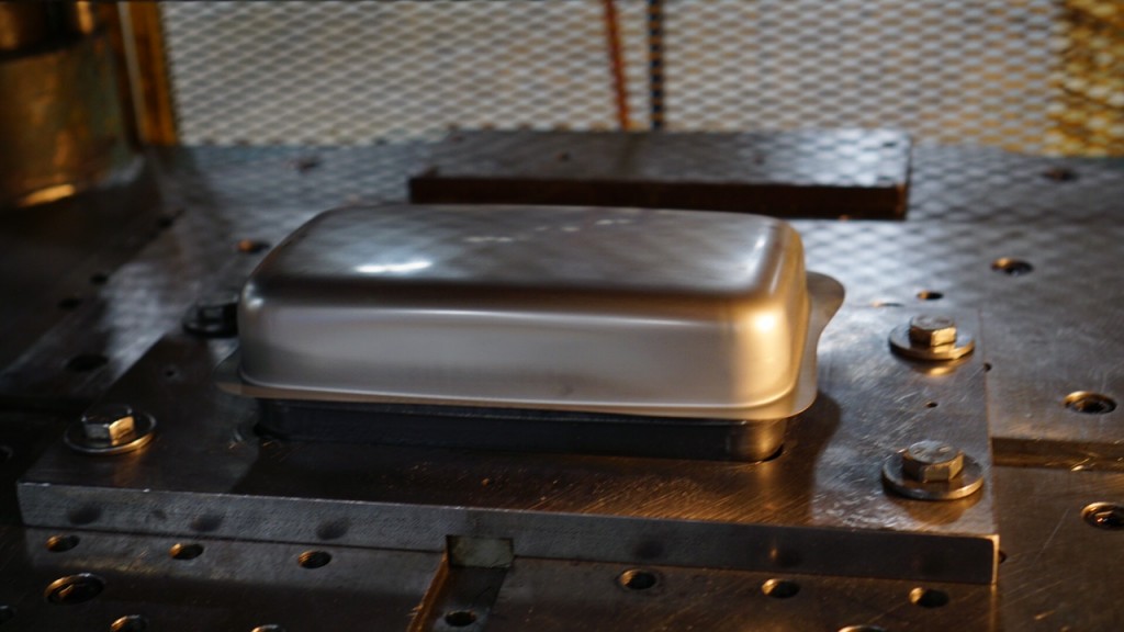
A metal forming press is a powerful machine designed to shape, deform, or cut metal materials into desired configurations by applying controlled force through a ram or slide. These presses are fundamental to manufacturing processes across industries like automotive, aerospace, construction, and consumer goods, enabling the mass production of components with consistent quality, precision, and efficiency.
Metal forming presses operate based on the principle of plastic deformation, where metal is forced to flow into a new shape without being removed or melted. Depending on the process and material, the deformation may occur at room temperature (cold forming) or elevated temperatures (hot forming). The most common types of operations performed include bending, drawing, punching, stamping, coining, forging, and extrusion.
Presses come in various designs tailored to specific applications. Mechanical presses use a flywheel and crankshaft mechanism to deliver high-speed, consistent strokes, ideal for operations like blanking and stamping. Hydraulic presses use pressurized fluid to produce high, adjustable force over longer strokes, making them suitable for deep drawing and forming thick materials. Servo presses employ electric motors for precise control of speed, position, and force, allowing for highly customizable forming cycles with energy efficiency and process flexibility.
A typical metal forming press system includes a frame, a bed or bolster plate, a ram or slide, tooling (such as dies and punches), and a drive mechanism. Tooling is crucial to the process and is often custom-designed to produce a specific part shape. The press forces the workpiece into or around the die cavity, transforming flat or preformed metal into finished shapes with tight tolerances.
Advanced metal forming presses incorporate programmable logic controllers (PLCs), human-machine interfaces (HMIs), and sensors for automation, real-time monitoring, and quality assurance. These features enable high productivity, repeatability, and integration into automated assembly lines. Safety systems, including light curtains, interlocks, and emergency stops, are standard to protect operators during high-force operations.
Materials processed in metal forming presses include a wide range of ferrous and non-ferrous metals such as steel, aluminum, brass, copper, and titanium. The choice of press type and process parameters depends on the material properties, part geometry, production volume, and desired surface finish.
In modern manufacturing, metal forming presses are essential for producing everything from automotive body panels and aircraft structural parts to appliance housings, metal containers, brackets, and electronic enclosures. Their adaptability, force capabilities, and integration with advanced automation make them a cornerstone technology in high-efficiency, high-precision production environments.
Metal forming presses continue to evolve with advancements in materials science, control systems, and manufacturing demands. As product designs become more complex and lightweight materials like high-strength steel and aluminum alloys are more widely used, presses must deliver greater accuracy, flexibility, and reliability. Modern presses often feature closed-loop feedback systems that monitor force, position, and velocity in real time, allowing automatic adjustments during the forming process to maintain quality and consistency.
Tooling innovations also play a major role in expanding press capabilities. Interchangeable die sets, precision-ground punch surfaces, and wear-resistant coatings extend tool life and improve part finish, especially when working with abrasive or hard metals. Quick-change tooling systems reduce downtime between production runs, increasing line efficiency and supporting high-mix, low-volume production strategies.
Energy efficiency is another key focus in modern metal forming press design. Servo-driven presses and energy recovery systems reduce power consumption by applying force only when needed and reusing kinetic energy from non-working strokes. These features help manufacturers reduce operating costs and meet environmental regulations without sacrificing performance.
Integration with upstream and downstream equipment enhances workflow and minimizes material handling. Automated feeding systems, such as coil feeders, straighteners, and transfer mechanisms, ensure continuous material input with precise alignment. Robotic arms or conveyors move parts between forming stations, reducing cycle time and human intervention while improving repeatability.
Metal forming presses are increasingly connected through Industrial Internet of Things (IIoT) platforms, enabling remote monitoring, predictive maintenance, and data analysis. By tracking metrics like press stroke count, lubrication levels, and temperature trends, manufacturers can prevent equipment failures, optimize usage, and improve process planning. This connectivity supports smart factory initiatives and aligns with the goals of Industry 4.0.
Applications of metal forming presses extend to nearly every sector of manufacturing. In the automotive industry, they produce chassis components, doors, hoods, and brackets with consistent thickness and complex curves. Aerospace applications include precision-formed structural parts with minimal weight and high strength. In appliance manufacturing, presses form frames, panels, and internal components with high throughput and accuracy. Even in small-scale metal shops, presses are used for prototyping and custom fabrication.
Customization options allow presses to be tailored for specific applications, whether through frame size, stroke length, tonnage capacity, or control features. Whether standalone or part of an automated line, metal forming presses deliver the mechanical force, control precision, and operational flexibility required to meet the demands of today’s fast-paced, high-accuracy manufacturing environment.
The versatility of metal forming presses also allows them to support a variety of forming methods beyond traditional stamping and drawing. For instance, hydroforming presses use high-pressure fluid to form metal around a die, enabling the creation of lightweight, structurally complex shapes with minimal seams—an essential technique in automotive and aerospace applications. Similarly, hot forming presses operate at elevated temperatures, allowing high-strength metals to be shaped more easily without cracking, which is critical for producing safety components or structural frames.
Multi-action presses, such as double- or triple-action hydraulic presses, provide additional control by independently moving multiple slides or blanks holders during a single cycle. This capability is crucial for deep drawing operations where material flow must be carefully managed to avoid thinning or tearing, especially in the production of deep cups, tanks, or cylindrical enclosures.
For high-speed applications, progressive die presses and transfer presses enable continuous part production by automatically moving metal strips through successive forming stages. These systems reduce handling and combine several operations—such as punching, bending, and coining—into one continuous workflow, achieving high output rates and consistent dimensional accuracy.
Another important development is the use of simulation and finite element analysis (FEA) in press design and tooling development. Engineers can now predict how a metal blank will behave under press forces, identify potential forming defects such as wrinkling or springback, and refine tool designs before production begins. This virtual prototyping reduces trial-and-error in the workshop, accelerates development time, and ensures higher first-pass yields.
Noise and vibration control is also gaining attention, especially in facilities focused on worker health and regulatory compliance. Presses now feature dampening systems and sound-insulating enclosures to reduce acoustic emissions during operation, creating safer and more comfortable working environments.
Moreover, presses are increasingly being adapted to handle advanced materials, such as ultra-high-strength steels, magnesium alloys, and titanium. These materials are essential in reducing the weight of vehicles and aircraft while maintaining structural integrity, and presses must apply precisely controlled force over longer durations to form them without introducing defects.
The ongoing innovation in metal forming presses ensures they remain a foundational technology in global manufacturing. From producing small electronic housings to large structural panels, these machines continue to offer unmatched versatility, speed, and precision. Their ability to integrate with automated systems, respond to new material challenges, and adapt to increasingly digital production environments secures their role as a vital tool in both current and next-generation fabrication processes.
Horizontal Press with Hydraulic Cylinder
A horizontal press with a hydraulic cylinder is a specialized forming machine that applies lateral (horizontal) force using hydraulic power to perform operations such as bending, straightening, punching, pressing, or assembling components. Unlike vertical presses, the working stroke of the ram is aligned horizontally, which offers significant advantages in handling long or heavy parts, particularly in structural or tubular applications.
At the heart of this machine is a hydraulic cylinder, which converts hydraulic pressure into linear mechanical motion. When pressurized fluid is introduced into the cylinder, it drives the piston forward, pushing the ram or tooling against the workpiece placed on a supporting bed or die block. This configuration allows precise control over force, stroke, and speed, which is especially useful when dealing with deformation-sensitive materials or tight tolerances.
Horizontal presses with hydraulic cylinders are commonly used in sectors such as metal fabrication, automotive frame straightening, shipbuilding, railway component manufacturing, and heavy machinery repair. Their design makes them ideal for working on beams, rods, shafts, pipes, and profiles, where gravity can be an issue in vertical presses, and long parts require support along their entire length.
These machines often feature adjustable supports or V-blocks to hold the workpiece firmly in place during pressing. Some versions are equipped with movable hydraulic heads or multiple cylinders to distribute force evenly or perform synchronized pressing across multiple points. The stroke and tonnage of the hydraulic cylinder can be adjusted through control panels with pressure regulators, stroke limiters, or servo valves for high-precision applications.
The hydraulic system typically includes a power unit with a pump, oil reservoir, pressure relief valve, directional control valve, filters, and cooling elements. These components ensure the safe, efficient, and consistent operation of the press under various load conditions. Safety features such as interlock switches, light curtains, and emergency stop buttons are often integrated to comply with industrial safety standards.
Automation can be added through programmable logic controllers (PLCs), enabling sequence control, pressure profiling, and integration with part feeding or unloading systems. Horizontal presses may also include sensors to detect part presence, monitor force, or log cycle data for quality assurance and traceability.
In summary, a horizontal press with a hydraulic cylinder offers robust, controlled force in a direction ideal for long or heavy workpieces. Its versatility, adjustability, and ability to apply high pressure evenly make it an indispensable tool in modern fabrication and repair environments.
Horizontal presses with hydraulic cylinders are especially advantageous for straightening deformed or bent components such as shafts, pipes, and beams. The operator can position the part along the machine bed and apply lateral pressure incrementally to correct bends with high precision. Because the force is applied horizontally, gravitational effects on long or heavy workpieces are minimized, resulting in more accurate alignment and easier handling compared to vertical setups. This configuration also improves safety and ergonomics for operators who can work at floor level without lifting parts vertically.
Many horizontal hydraulic presses are built with heavy-duty steel frames designed to withstand large side loads without deflection. The press bed often features T-slots or clamping systems to secure custom fixtures, dies, or V-blocks for different types of operations. In more advanced designs, the pressing head can be mounted on a movable carriage that travels along the length of the machine, allowing flexible positioning of the cylinder based on the part’s size and shape. This mobility is especially useful in applications where multiple pressing points are required across a long workpiece.
Hydraulic cylinders used in these presses are typically double-acting, meaning they can apply controlled force in both directions—forward for pressing and backward for retraction—ensuring smooth operation and consistent return. The stroke length and tonnage rating of the cylinder determine the press’s working capacity, which can range from a few tons in light-duty machines to hundreds of tons in large industrial units.
Horizontal presses with hydraulic cylinders are also widely used in tube and pipe bending applications. With the right dies and mandrels, these machines can create complex angles and radii, forming metal tubing without wrinkling or collapse. This makes them highly valuable in manufacturing exhaust systems, handrails, construction scaffolding, and hydraulic piping assemblies.
Customization is another strong advantage. Manufacturers can configure presses with multiple cylinders for synchronized pressing, add stroke-positioning sensors for automated control, or integrate CNC systems for repeatable cycles. For assembly or interference fit operations, horizontal hydraulic presses can be used to press-fit bearings, bushings, and pins with consistent force and minimal part damage.
In industrial maintenance and repair workshops, horizontal hydraulic presses play a key role in rebuilding damaged machinery by enabling the disassembly and reassembly of press-fitted components. They are often mounted on mobile bases or installed as part of flexible workstation layouts, providing versatility and responsiveness for on-demand tasks.
Overall, horizontal presses with hydraulic cylinders combine strong, controllable force with a user-friendly horizontal orientation. They deliver exceptional versatility for forming, straightening, bending, assembling, and correcting metal components—particularly long or awkward parts—and are essential machines across many sectors that demand precision, durability, and adaptability in metalworking operations.
The adaptability of horizontal presses with hydraulic cylinders extends into automation, where integration with programmable logic controllers (PLCs) and digital interfaces allows for precise, repeatable operation. Automated control over ram stroke, pressure ramping, dwell time, and return speed ensures consistent part quality across large production runs. In high-throughput environments, the press can be equipped with sensors and programmable stops to trigger pressing actions at predefined positions, making it possible to perform multi-point pressing without manually repositioning the workpiece.
For applications like tube expansion, swaging, or straightening heat exchanger bundles, horizontal presses deliver uniform force distribution and accurate alignment, which is crucial to prevent internal stress and material fatigue. Some systems include force-feedback loops where load cells measure applied pressure in real time, enabling intelligent correction and validation of forming parameters. This feature supports high-precision manufacturing, where even slight dimensional variations can lead to part rejection or system failures in critical assemblies.
In the context of custom manufacturing and prototyping, the horizontal orientation allows fast setup and flexible tooling changes. Fabricators can quickly reposition the press head, adjust fixtures, or change dies to accommodate different shapes and sizes, reducing lead time between design iterations. This makes the machine not just a production workhorse but also a valuable tool in agile, low-volume operations where versatility is essential.
In shipbuilding and heavy structural industries, large-scale horizontal hydraulic presses are sometimes installed in long bays, capable of pressing or correcting structural I-beams, girders, and massive welded assemblies. These presses are often built with extended beds—sometimes tens of meters long—and feature movable gantry-mounted pressing heads for localized adjustments. The ability to deliver enormous force with millimeter-level control across such distances makes them indispensable for final fitting, leveling, and precision finishing tasks.
Maintenance and safety considerations are central to reliable operation. Modern systems include overload protection, redundant safety valves, temperature and oil-level sensors, and automated shutdown protocols in case of abnormal operating conditions. Easy-access maintenance ports and centralized lubrication simplify upkeep, while digital control systems offer diagnostics and alerts to keep operators informed of system status.
With the rise of Industry 4.0, horizontal hydraulic presses are now being designed to interact with broader digital ecosystems. They can communicate with MES (Manufacturing Execution Systems), store usage data for traceability, and receive software updates remotely. These capabilities allow real-time performance tracking and optimize scheduling across multiple machines in smart factories.
In essence, the horizontal press with a hydraulic cylinder is a machine that combines brute force with fine control. Whether used for industrial forming, component straightening, part assembly, or custom fabrication, its horizontal layout, power, and precision make it one of the most versatile and valuable tools in any metalworking or repair facility.
Horizontal Press Tooling
Horizontal press tooling refers to the specialized dies, fixtures, supports, and accessories used in a horizontal press to perform operations like bending, straightening, punching, swaging, forming, pressing, and assembly. Because the press applies force laterally rather than vertically, the tooling must be specifically designed to accommodate horizontal load direction, support long or asymmetrical workpieces, and ensure stability, alignment, and precision during the forming process.
At the core of horizontal press tooling are die blocks and forming tools—typically fabricated from hardened steel or alloy materials to withstand repeated impact and deformation. For bending operations, V-blocks, U-dies, and radius formers are used in conjunction with matching punches or pressing heads. These components are mounted on the stationary bed and aligned precisely with the moving ram or hydraulic cylinder. V-blocks are commonly used for straightening shafts or pipes, providing a stable fulcrum to correct bends by controlled pressure from the ram.
Tooling configurations can be highly customized depending on the application. In tube bending, for example, mandrels or internal supports may be used to prevent collapse, while external dies guide the tube along a specified curve. For press-fitting, dedicated anvils and pressure plates are employed to uniformly apply force to a bearing, bushing, or pin without damaging the surrounding structure. For punching or shearing, hardened die plates with precise clearances are mounted to cut cleanly through the material using a corresponding punch attached to the press ram.
Fixtures and workholding devices are critical in horizontal presses to keep the workpiece from shifting under side loads. These can include adjustable clamps, jaws, and sliding supports with positioning scales or stops to ensure repeatable alignment for high-volume tasks. For long parts such as beams or rods, roller supports or extended guide rails may be added along the bed to maintain straightness and balance.
Tooling for horizontal presses often incorporates modularity, allowing rapid changeover between different setups without complete disassembly. Quick-lock mechanisms, magnetic plates, and T-slot mounts help operators reconfigure the press quickly for new jobs, which is especially beneficial in small-batch or custom manufacturing environments.
In automated horizontal press systems, tooling may also include integrated sensors or feedback elements. These detect part position, verify tooling engagement, or confirm completed press cycles, feeding information back to the control system for process monitoring and quality assurance.
Proper maintenance of tooling is essential to ensure accuracy and longevity. Lubrication, periodic inspection for wear or cracks, and careful alignment checks are standard practices. Worn tooling not only affects product quality but can also damage the press itself or cause unsafe operating conditions.
Ultimately, horizontal press tooling is what transforms raw hydraulic or mechanical force into precise, controlled actions. Its correct design, alignment, and maintenance are critical for safe, efficient, and high-quality forming operations—especially when dealing with complex shapes, long components, or tight tolerances. Whether for heavy industry or precision applications, the right tooling setup directly determines the press’s versatility and production value.
Advanced horizontal press tooling often includes custom-engineered dies tailored to specific parts, ensuring that each press cycle produces consistent results even on irregular or non-standard shapes. In forming applications involving asymmetrical or hollow sections, tooling may incorporate contoured supports or adaptive inserts to distribute force evenly and prevent localized deformation. This is particularly important when pressing high-strength materials or parts with critical surface finishes that must remain free of marks or distortions. In straightening operations, especially on shafts or rods, tooling must be designed to apply precise corrective pressure without inducing secondary bends, which means the choice of V-block angle, spacing, and surface treatment becomes a key factor in process accuracy.
For pressing components into assemblies, such as bearings into housings or pins into joints, precision alignment fixtures guide the part into exact position before the ram actuates. This tooling may include dowel pins, self-centering plates, or adjustable locators to accommodate tolerances and avoid part misalignment, which could result in damage or improper fit. Some tooling also includes force-distributing plates or soft inserts (such as bronze or polymer pads) to press sensitive components without scoring or scratching functional surfaces.
Quick-change tooling systems are becoming more common on horizontal presses, especially in operations where multiple part types or sizes are produced on the same machine. Tool holders and press beds are designed with standard interfaces such as T-slots, dovetail rails, or pin locators, allowing rapid exchange of dies, fixtures, or supports with minimal downtime. This flexibility supports high-mix, low-volume production environments where responsiveness and reconfigurability are essential.
In larger or automated horizontal press setups, tooling may be equipped with integrated hydraulics, pneumatics, or servo-driven actuators to perform additional functions such as clamping, rotating, or advancing parts within a cycle. These multifunctional dies enhance the complexity and capability of the press without requiring secondary machines or manual intervention. For example, in a tube-forming press, the tooling might include internal expanding mandrels controlled by hydraulic cylinders that open or close in sync with the main press stroke.
Material choice is critical in tooling construction. Hardened tool steels, sometimes coated with nitrides or carbides, are used for punches and dies to resist wear from repeated impact and high pressures. Tooling that interacts with softer materials may be made from alloy steels or aluminum alloys to avoid damage to the part, particularly in aerospace or medical applications where tolerance and surface finish are vital.
Tooling inspection and preventive maintenance routines are implemented to track wear, check alignment, and ensure reliable press cycles. Wear indicators, alignment pins, and visual reference lines are often built into the tooling to help operators verify setup accuracy before each use. In automated lines, sensors may detect incorrect die installation or tool misalignment, halting the press and prompting corrective action to prevent scrap or damage.
Horizontal press tooling is a foundational aspect of the press’s performance. It enables a wide range of operations—simple or complex—with accuracy, repeatability, and safety. Whether it’s forming, assembling, bending, or correcting, the effectiveness of the tooling system determines the efficiency of the overall process and the quality of the final product.
In high-volume or precision-critical applications, horizontal press tooling is often designed with digital integration in mind. Tooling may carry embedded RFID tags or QR codes to identify each die set within the press control system. This allows the press to automatically load corresponding settings such as stroke limits, pressure profiles, and safety interlocks, ensuring that each setup is not only fast but also exact, minimizing human error. When combined with press automation systems, this smart tooling approach shortens setup time and guarantees consistency across production runs.
Additionally, precision tooling for horizontal presses often undergoes finite element analysis (FEA) during the design phase. FEA helps engineers simulate how tooling will perform under real-world stresses, including force distribution, thermal expansion, and fatigue over time. This enables optimization of die geometry, support structures, and material selection to increase longevity and reduce failure risks, particularly in high-tonnage applications where even minor deflections in tooling can compromise the final product’s integrity.
Some advanced tooling solutions feature modular inserts that can be swapped out independently from the main die body. These inserts are particularly useful in forming operations where only a small area of the tooling experiences intense wear. By replacing only the worn section rather than the entire tool, maintenance costs are reduced, and tool life is extended. This modularity also supports the production of families of parts with slight dimensional variations, as different inserts can be installed on the same base tool to match specific configurations.
In bending and forming applications where springback is a concern—such as in the pressing of high-strength steels or aluminum extrusions—tooling can be fine-tuned with controlled overbend profiles. These are precisely machined die geometries or adjustable segments designed to offset the material’s natural tendency to return partially to its original shape. In some systems, active feedback from sensors embedded in the tooling provides real-time data that can adjust the overbend compensation dynamically during the stroke.
Cooling or heating elements can also be integrated into the tooling, especially in applications involving thermoplastic or thermoset materials, or in processes where tight temperature control affects material flow and part accuracy. Tooling with internal fluid channels, heating cartridges, or thermal insulation layers enables better process stability and is particularly valuable in composite part manufacturing or hot metal forming operations.
For operators and technicians, horizontal press tooling systems are increasingly being supported with visual aids and augmented reality (AR) tools that overlay setup instructions or maintenance tips onto the actual machine. This improves safety, speeds up training, and reduces setup errors, particularly in facilities with a wide variety of tooling setups and a rotating workforce.
In conclusion, horizontal press tooling is no longer just a static set of dies—it is an intelligent, adaptable, and integrated part of the press system that directly influences product quality, operational speed, and long-term productivity. Its evolution mirrors broader industrial trends toward digitization, automation, precision, and sustainability, and it remains one of the most critical factors in maximizing the performance and versatility of horizontal press machines in modern manufacturing.
Horizontal Press Design
Horizontal press design centers on delivering controlled lateral force through a robust, precise, and adaptable structure that accommodates long or complex workpieces. Unlike vertical presses, where gravity assists part loading and stroke return, horizontal presses must be structurally engineered to support side-loading mechanics, minimize deflection, and maintain alignment across the entire stroke length. This makes the frame, bed, hydraulic or mechanical actuation system, and tooling support the core elements of the design.
The frame is typically a heavy-duty welded or cast steel structure built to resist the bending and torsional forces generated by horizontal pressing. It houses the guideways, press bed, and hydraulic or mechanical cylinder mounts, ensuring rigidity and alignment even under high loads. Box-type or monoblock frames are often used in high-tonnage machines to eliminate flexing, while modular frames may be employed in smaller presses to allow customization and easier transport or installation.
The pressing mechanism is most often a hydraulic cylinder mounted in line with the working axis. It may be fixed or movable, depending on the application. In presses used for long parts, the cylinder or pressing head can travel along the bed via a carriage system with linear guides, allowing force to be applied precisely at multiple points along a large workpiece. Stroke length, speed, and force are programmable in advanced designs, offering flexibility for a wide range of operations.
The press bed or anvil area provides a flat, solid surface against which the workpiece is supported during pressing. This section is engineered to be perfectly aligned with the pressing ram and can include features like T-slots for securing tooling or V-blocks for holding cylindrical parts. For long or flexible parts, the bed may be extended or include roller supports or adjustable fixtures to prevent sagging or movement during pressing.
Control systems are increasingly integrated into the design, ranging from simple manual valve controls on basic units to advanced PLC and HMI systems on programmable machines. These allow operators to control force, stroke, dwell time, return speed, and even multi-point pressing sequences with precision. Position sensors, pressure transducers, and limit switches are built into the design for accuracy, safety, and feedback.
Automation compatibility is often factored into the design from the beginning. This includes provisions for robotic arms, part feeding systems, and conveyors, enabling the press to operate as part of a fully automated production cell. In such systems, the press design must account for rapid cycle times, repeatable positioning, and safe interaction with other equipment.
Cooling systems, hydraulic oil management, safety guards, emergency stops, and light curtains are also integrated into the design. In large-scale or high-duty presses, hydraulic power units may be housed separately and connected via high-pressure hoses, with reservoirs, filters, and cooling fans mounted for continuous-duty operation.
The modularity of modern horizontal press design allows machines to be customized for specific industrial needs—straightening shafts, forming profiles, expanding tubes, bending structural elements, or assembling large components. From compact benchtop models to massive floor-mounted systems, the design of a horizontal press must balance power, precision, ergonomics, and automation readiness to meet the growing demands of flexible and efficient manufacturing.
Horizontal press design also places significant emphasis on maintaining precise alignment between the ram and the press bed to ensure even force distribution and prevent uneven wear or part deformation. This is achieved through precision-ground guideways, linear bearings, or roller slides incorporated into the frame and carriage systems. These components enable smooth, low-friction movement of the pressing head while maintaining tight tolerances, which is critical for applications demanding high accuracy or repeatability.
The hydraulic system is integral to the design, with pumps, valves, accumulators, and reservoirs sized to meet the press’s tonnage and cycle time requirements. Modern designs often feature servo-hydraulic or electro-hydraulic systems, offering programmable pressure control, variable stroke speeds, and energy-efficient operation. These systems can deliver a wide range of pressing profiles, from slow, high-force pressing to rapid positioning strokes, accommodating diverse process needs.
Ergonomics and operator safety are key considerations. Controls are typically positioned to provide clear visibility of the work area, with intuitive interfaces and emergency stop functions within easy reach. Safety interlocks prevent press operation unless guards or doors are securely closed, and light curtains or presence sensors halt motion if an operator enters a hazardous zone. The horizontal layout itself often enhances safety by positioning operators alongside, rather than beneath, moving components.
Thermal management is another important aspect, especially in high-duty or continuous-use presses. Heat generated by hydraulic components and friction is managed through cooling circuits, heat exchangers, or fan systems incorporated into the machine design. Maintaining optimal operating temperatures extends the life of hydraulic fluids, seals, and electronic components, ensuring reliability and consistent performance.
Structural stiffness is carefully engineered to minimize frame deflection under load, which is especially critical for presses with long stroke lengths or those applying force at varying points along a workpiece. Finite element analysis (FEA) is frequently used during design to optimize frame geometry, material thickness, and reinforcements, ensuring the machine meets performance criteria without excessive weight or cost.
Modularity and scalability in design allow manufacturers to offer presses with customizable stroke lengths, tonnage capacities, and tooling interfaces. This flexibility supports a broad range of industries and applications, from light assembly tasks to heavy-duty metal forming and repair work.
Finally, integration capabilities are built into the design to facilitate Industry 4.0 connectivity. Ethernet ports, industrial communication protocols (such as Profinet or EtherCAT), and sensor networks enable the press to be monitored, controlled, and diagnosed remotely. This connectivity supports predictive maintenance, reduces downtime, and allows seamless incorporation into smart factory environments.
Overall, horizontal press design harmonizes mechanical robustness, precise motion control, operator safety, and digital integration to deliver machines that are versatile, reliable, and adaptable to the evolving demands of modern manufacturing processes.
The design of horizontal presses increasingly incorporates user-friendly features that simplify setup, maintenance, and operation. For example, adjustable supports and fixtures are often included to accommodate different workpiece sizes without extensive tooling changes. Some presses feature hydraulic or mechanical clamping systems integrated into the bed, allowing quick securing and release of parts, which reduces cycle time and enhances repeatability.
Maintenance accessibility is a critical aspect, with service panels, lubrication points, and component mounts designed for easy reach. Modular hydraulic units can be swapped out or serviced independently, minimizing downtime. Additionally, condition monitoring sensors embedded in key components track parameters like temperature, vibration, and pressure, alerting operators to potential issues before failures occur.
Energy efficiency is a growing priority in press design. Many modern horizontal presses use servo-driven hydraulic pumps or electric servo motors that consume power only when actively moving the ram, significantly reducing energy use compared to traditional constant-speed pumps. Regenerative braking and energy recovery systems capture and reuse kinetic energy during the ram’s return stroke, further optimizing power consumption.
Customizable control software often accompanies these presses, allowing operators to create and store multiple pressing programs. These programs can control variables such as force ramp rates, dwell times, and multi-stage pressing sequences, enabling complex forming operations and ensuring consistency across production batches. Remote diagnostics and software updates are increasingly available, allowing manufacturers to maintain and improve press performance without on-site intervention.
From a structural standpoint, frame materials and manufacturing processes continue to evolve. High-strength steel alloys and precision welding techniques enhance rigidity while reducing overall machine weight. Some manufacturers incorporate finite element optimization to balance strength with cost-effectiveness, creating designs that meet demanding performance requirements without excessive material use.
The horizontal press design also takes into account integration with peripheral equipment such as robotic loaders, conveyors, and inspection stations. Standardized mounting points and open architecture control systems facilitate smooth interfacing with automation solutions, enabling seamless production lines that increase throughput and reduce manual handling.
In summary, horizontal press design today reflects a holistic approach that balances mechanical strength, precise control, safety, energy efficiency, ease of use, and digital connectivity. This ensures that presses not only deliver the force and accuracy required for modern manufacturing but also align with evolving industrial trends toward sustainability, automation, and smart factory integration.
Horizontal Press Manufacturer
Horizontal press manufacturers are specialized companies that design, engineer, and produce horizontal press machines tailored to various industrial applications such as metal forming, straightening, bending, assembly, and repair. These manufacturers combine mechanical engineering expertise, hydraulic system design, and automation technology to deliver robust, precise, and efficient presses that meet the demanding requirements of sectors like automotive, aerospace, heavy machinery, construction, and energy.
Leading horizontal press manufacturers typically offer a broad range of standard models, from compact benchtop units to large, heavy-duty floor-mounted machines with tonnage capacities reaching several hundred tons. They often provide customization services to tailor stroke lengths, force capacities, tooling interfaces, and control systems according to client-specific applications and production volumes.
These manufacturers emphasize quality and durability by selecting high-strength materials for press frames and components, utilizing precision machining, and incorporating advanced hydraulic and control systems. Many integrate servo-hydraulic or electro-hydraulic drives for improved energy efficiency and process flexibility. Their presses commonly feature modular designs for easy maintenance and scalability.
Customer support is a key focus for reputable horizontal press manufacturers. They provide comprehensive services including installation, commissioning, operator training, tooling design assistance, and ongoing technical support. Many offer aftermarket parts, refurbishment programs, and retrofit upgrades to extend machine life and improve performance over time.
Innovation is central to their product development strategies, with investments in R&D driving advances such as smart press controls, Industry 4.0 integration, remote diagnostics, and automation compatibility. Some manufacturers partner with system integrators and automation specialists to deliver turnkey production lines incorporating horizontal presses.
Global manufacturers may serve diverse markets with regional sales and service centers to ensure rapid response times and local expertise. Certifications such as ISO 9001 quality management, CE marking for safety compliance, and other industry-specific standards are commonly maintained to meet international customer expectations.
Overall, horizontal press manufacturers play a vital role in advancing manufacturing capabilities by delivering machines that combine power, precision, versatility, and modern control technologies—helping customers increase productivity, reduce costs, and maintain high-quality standards across a wide array of industrial processes.
Many horizontal press manufacturers also focus heavily on customization and flexibility, recognizing that different industries and applications require unique solutions. They often collaborate closely with customers during the design phase to understand specific requirements such as workpiece size, material type, production volume, and integration needs. This customer-centric approach allows manufacturers to tailor machine specifications—including tonnage, stroke length, tooling interfaces, and control systems—ensuring optimal performance and efficiency for the intended application.
In addition to manufacturing new presses, many suppliers offer modernization and retrofit services for existing horizontal press equipment. This can include upgrading hydraulic systems to more energy-efficient servo-driven units, adding advanced control software, incorporating safety features compliant with current standards, or improving tooling systems for faster changeovers. Such services help extend machine life, improve reliability, and adapt older equipment to evolving production demands without the cost of full replacement.
Horizontal press manufacturers also invest in training and technical support programs to maximize customer satisfaction and operational uptime. This often involves on-site installation and commissioning, operator and maintenance staff training, preventive maintenance plans, and readily available spare parts inventories. Some manufacturers provide remote monitoring and troubleshooting services, leveraging IoT connectivity to detect issues early and minimize downtime.
Environmental considerations are increasingly incorporated into manufacturing and product design. Many manufacturers focus on reducing hydraulic fluid consumption, incorporating energy-saving technologies, and using recyclable materials where possible. Compliance with environmental regulations and workplace safety standards is emphasized, reflecting growing industry trends toward sustainable and responsible manufacturing practices.
The competitive landscape of horizontal press manufacturing includes both established global players and regional specialists. Larger manufacturers often have extensive R&D resources, broad product portfolios, and worldwide service networks. Meanwhile, smaller or regional companies may excel in highly specialized presses, rapid customization, and personalized customer service. This diversity ensures a wide range of options for customers seeking horizontal press solutions tailored to their specific needs.
Finally, as Industry 4.0 continues to reshape manufacturing, leading horizontal press manufacturers are integrating advanced features such as real-time data analytics, predictive maintenance, and machine learning algorithms into their products. These smart presses offer customers enhanced visibility into production performance, greater process control, and the ability to optimize operations proactively.
In summary, horizontal press manufacturers deliver not only the core machinery but also comprehensive solutions encompassing design customization, modernization, support services, and digital innovation—empowering manufacturers across industries to improve quality, efficiency, and competitiveness in their metal forming and assembly operations.
Horizontal press manufacturers are also increasingly embracing collaborative partnerships with automation specialists, software developers, and tooling experts to provide fully integrated systems rather than standalone machines. By combining horizontal presses with robotic loaders, conveyors, vision inspection systems, and advanced control platforms, they create turnkey solutions that streamline production lines, reduce manual labor, and boost throughput. This systems approach allows manufacturers to meet stringent quality standards and adapt quickly to changing product demands.
Research and development investments by leading manufacturers focus on expanding press capabilities such as increasing tonnage ranges, extending stroke lengths, and enhancing precision. Innovations in frame design and materials enable presses to handle heavier workloads with reduced machine footprint and weight. Advances in hydraulic components—like proportional valves and servo pumps—improve responsiveness, energy efficiency, and noise reduction.
Customization extends to user interfaces, with many manufacturers offering intuitive touchscreen HMIs, remote monitoring dashboards, and programmable sequences to simplify operation and maintenance. Integration with factory-wide data systems facilitates centralized control, production tracking, and analytics, which are critical in modern smart manufacturing environments.
Manufacturers also pay close attention to compliance with international safety and quality standards. Horizontal presses are designed and tested according to directives such as CE marking in Europe, ANSI or OSHA standards in the United States, and ISO certifications globally. These standards ensure that machines meet rigorous safety, reliability, and environmental requirements, protecting workers and reducing liability.
Market demands drive manufacturers to develop presses capable of processing a broad spectrum of materials, from mild steels to advanced high-strength alloys and composites. This requires not only mechanical strength but also advanced control over pressing parameters to avoid defects and ensure consistent results. Many manufacturers support this through engineering consulting services, helping customers optimize press processes and tooling design.
Global supply chain management is another focus area, as manufacturers balance cost, lead time, and quality by sourcing components from trusted suppliers while maintaining stringent quality control. Localized manufacturing and service centers help improve responsiveness and reduce shipping times, especially for large or customized equipment.
In essence, horizontal press manufacturers act as strategic partners, delivering advanced machinery backed by engineering expertise, customization, automation integration, and lifecycle support. Their role is critical in enabling manufacturers worldwide to meet evolving production challenges, improve operational efficiency, and maintain competitive advantages in an increasingly demanding industrial landscape.
Horizontal Hydraulic Press
A horizontal hydraulic press is a machine that uses hydraulic power to generate controlled, high-force linear motion in a horizontal direction. Unlike vertical presses that apply force downward, a horizontal hydraulic press applies force laterally, making it ideal for working on long, heavy, or awkwardly shaped parts such as shafts, pipes, beams, and profiles. The hydraulic system enables smooth, precise control of pressing speed, force, and stroke length, which is essential for forming, bending, straightening, assembling, or pressing-fit applications.
The core of a horizontal hydraulic press is a hydraulic cylinder that converts fluid pressure into mechanical force. The cylinder’s piston moves the ram horizontally toward the workpiece placed on a rigid press bed or fixture. This lateral configuration minimizes gravitational effects on the workpiece, improves operator ergonomics, and allows easier handling of long components without complex overhead lifting.
Hydraulic power units supplying the press typically consist of a pump, oil reservoir, valves, filters, and cooling systems, all designed to provide steady, controllable pressure. Modern presses often feature servo-hydraulic systems that optimize energy consumption by adjusting pump output based on demand, improving efficiency compared to traditional fixed-displacement pumps.
Horizontal hydraulic presses are widely used across industries including automotive manufacturing, aerospace, heavy machinery repair, metal fabrication, and construction. Their applications include straightening bent shafts or tubes, pressing bearings or bushings into housings, bending metal profiles, assembling components with interference fits, and forming metal sheets or sections.
Precision control is a key advantage. Operators can program the press to deliver exact force profiles, control ram position with high accuracy, and automate multi-stage pressing sequences. Sensors for pressure, position, and force provide real-time feedback, enabling consistent results and process monitoring.
Safety features are integrated into horizontal hydraulic presses, such as emergency stops, safety interlocks, light curtains, and protective guarding to prevent accidental operator contact during operation. Ergonomic design places controls and work areas within comfortable reach, enhancing usability and reducing operator fatigue.
Tooling for these presses is designed specifically for horizontal operation, often including V-blocks, adjustable supports, clamps, and specialized dies to securely hold and shape parts during pressing. Quick-change tooling options allow rapid setup changes to accommodate various part sizes and processes.
Overall, the horizontal hydraulic press combines the power and precision of hydraulic actuation with a lateral working orientation, making it an indispensable tool for manufacturing, assembly, and repair operations involving long or complex parts that benefit from controlled horizontal pressing force.
Horizontal hydraulic presses offer exceptional versatility due to their ability to precisely control force, speed, and ram position throughout the pressing cycle. This enables them to handle delicate operations, such as pressing in sensitive bearings or assembling intricate components, as well as heavy-duty tasks like straightening large structural elements or bending thick metal profiles. The hydraulic system’s inherent capacity for force modulation allows operators to apply gradual pressure, reducing the risk of part damage or tooling wear.
Many horizontal hydraulic presses feature programmable logic controllers (PLCs) or advanced human-machine interfaces (HMIs) that enable automation and repeatability. Operators can set multiple parameters including press force limits, stroke lengths, dwell times, and multi-stage sequences, which can be saved and recalled to streamline production and maintain consistent quality. In high-volume manufacturing, this level of control minimizes scrap rates and improves throughput.
The press bed design supports stable positioning of long or heavy workpieces, often incorporating T-slots, adjustable clamps, and roller supports to secure parts firmly during operation. Some presses include movable hydraulic heads or multiple cylinders to apply force at various points along a workpiece, which is particularly useful when working with components prone to deflection or requiring progressive forming.
Energy efficiency is an important feature in modern horizontal hydraulic presses. Servo-driven hydraulic pumps adjust flow and pressure dynamically based on load requirements, reducing unnecessary power consumption and heat generation. This not only lowers operating costs but also extends the lifespan of hydraulic fluids and components by minimizing thermal stress.
Safety is prioritized through integrated features such as emergency stop buttons, safety interlocks, guarded work zones, and presence-sensing devices like light curtains. These systems ensure the press operates only when conditions are safe, protecting operators from accidental injury. Ergonomic controls and clear visibility of the workspace further enhance safe operation.
Maintenance and serviceability are facilitated by modular hydraulic units, easily accessible components, and diagnostic sensors that monitor system health parameters including pressure, temperature, and fluid levels. Alerts and predictive maintenance features help prevent unexpected downtime, ensuring reliable operation in demanding industrial environments.
Horizontal hydraulic presses are employed in diverse industries ranging from automotive and aerospace manufacturing to metal fabrication, shipbuilding, and heavy equipment repair. Their capability to handle varied materials—from mild steel to high-strength alloys and composites—makes them indispensable in processes requiring controlled, high-force lateral pressing.
In summary, horizontal hydraulic presses blend the precision and power of hydraulic actuation with a horizontal orientation optimized for handling long, heavy, or complex parts. Their programmable controls, safety features, energy efficiency, and adaptable tooling options make them essential machines in modern manufacturing and maintenance operations that demand both versatility and reliability.
The adaptability of horizontal hydraulic presses also extends to their integration within automated production lines. By incorporating sensors, actuators, and communication interfaces, these presses can seamlessly interact with robotic arms, conveyor systems, and quality inspection stations. This integration enables fully automated workflows where parts are loaded, processed, and unloaded with minimal human intervention, boosting productivity while reducing labor costs and the risk of human error.
In more complex manufacturing environments, horizontal hydraulic presses can be equipped with multi-axis motion capabilities or synchronized multi-cylinder setups. This allows simultaneous pressing at multiple points or complex forming actions that require precise coordination of force and position. Such configurations are particularly valuable in industries producing large structural components or assemblies requiring uniform deformation or fit.
Material versatility is another strength. Horizontal hydraulic presses can handle a broad range of materials including metals, plastics, composites, and rubber. Their ability to finely control pressing speed and force enables processing of delicate materials without damage, as well as shaping tougher alloys with high precision. This makes them suitable for applications ranging from aerospace composite forming to heavy steel beam straightening.
Customization of tooling and press parameters is central to optimizing performance for specific tasks. Manufacturers often design bespoke dies, clamps, and supports that ensure proper force distribution and secure holding of irregularly shaped or fragile parts. Quick-change tooling systems enhance flexibility, allowing rapid transitions between different jobs or products with minimal downtime.
In terms of maintenance, horizontal hydraulic presses benefit from advanced diagnostic tools that continuously monitor key components like pumps, valves, cylinders, and electronic controls. Predictive maintenance strategies use this data to schedule servicing before failures occur, minimizing unplanned outages and extending machine lifespan.
Environmental considerations are increasingly incorporated into the design and operation of horizontal hydraulic presses. Energy-efficient servo pumps reduce electricity consumption, while advanced filtration and cooling systems maintain hydraulic fluid cleanliness and temperature, enhancing sustainability and reducing waste.
Overall, horizontal hydraulic presses provide a blend of power, precision, flexibility, and automation readiness that makes them indispensable in modern industrial manufacturing and repair. Their horizontal force application is uniquely suited to handling long or cumbersome parts, and their advanced control capabilities support a wide range of complex forming, assembly, and maintenance tasks with reliability and efficiency.
Horizontal Press Machine
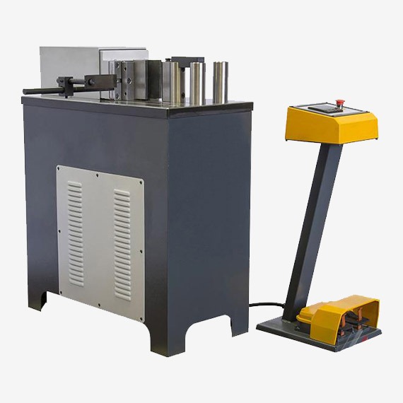
A horizontal press machine is an industrial device designed to apply force in a horizontal direction, typically using hydraulic or mechanical power, to perform operations such as bending, straightening, forming, pressing, or assembling components. Unlike vertical presses, where the ram moves up and down, the ram or pressing head in a horizontal press moves laterally, making it particularly well suited for handling long, heavy, or irregularly shaped parts that are difficult to manage in vertical configurations.
The core components of a horizontal press machine include a rigid frame or bed that supports the workpiece, a hydraulic or mechanical cylinder that drives the ram horizontally, tooling attachments such as dies or clamps tailored to the specific operation, and a control system that manages press force, speed, and stroke length. The robust frame ensures minimal deflection during pressing, maintaining alignment and precision, while the hydraulic system provides smooth, controllable force application.
Horizontal press machines find applications across numerous industries, including metal fabrication, automotive manufacturing, aerospace, shipbuilding, construction, and maintenance workshops. They are commonly used for tasks like straightening bent shafts, pressing bearings or bushings into assemblies, bending metal profiles, forming sheet metal, or assembling parts with interference fits.
Modern horizontal press machines often incorporate programmable controls such as PLCs and HMIs, enabling operators to set and save pressing parameters for repeatable and automated operation. Safety features, including emergency stops, guarding, light curtains, and interlocks, protect operators during use. Ergonomic design elements position controls and work areas for easy access and visibility.
The versatility of a horizontal press machine is enhanced by its tooling system, which can include adjustable supports, clamps, V-blocks, and quick-change die setups to accommodate various part sizes and shapes. Some machines feature movable rams or multiple hydraulic cylinders to apply force at different locations along the workpiece, especially beneficial for long or flexible components.
Energy-efficient hydraulic systems, such as servo-driven pumps, optimize power consumption and reduce heat generation. Maintenance-friendly designs with accessible components and diagnostic sensors contribute to machine reliability and uptime.
Overall, horizontal press machines combine mechanical strength, precise hydraulic control, and adaptable tooling to deliver efficient, safe, and high-quality pressing solutions tailored to a wide array of manufacturing and assembly needs.
Horizontal press machines are also valued for their ability to integrate seamlessly into automated production lines. They can be equipped with sensors and communication interfaces that allow them to work in concert with robotic loaders, conveyors, and inspection systems, enabling continuous, hands-free operation that enhances throughput and consistency. This automation capability is especially important in high-volume manufacturing environments where cycle time and repeatability directly impact productivity and product quality.
The design flexibility of horizontal presses allows them to be customized for specific applications, whether that means adjusting the stroke length, increasing tonnage capacity, or incorporating specialized tooling. Some machines feature movable or adjustable rams that can traverse the press bed, applying force at multiple points along a long workpiece to prevent distortion or uneven forming. This adaptability makes them suitable for diverse industries, including automotive component assembly, aerospace structural forming, heavy machinery repair, and construction material fabrication.
Control systems on modern horizontal presses provide operators with precise management over pressing parameters such as force, speed, dwell time, and ram position. Programmable logic controllers (PLCs) and touch-screen human-machine interfaces (HMIs) allow for easy setup, process monitoring, and repeatable operation. These controls can also store multiple pressing programs, enabling quick changeovers between different jobs and supporting flexible manufacturing.
Safety remains a critical aspect of horizontal press machines. Features such as emergency stop buttons, safety interlocks, guarded work zones, and presence-sensing devices help protect operators from injury. Ergonomic design elements, including well-placed controls and clear visibility of the workspace, further enhance safe operation and reduce operator fatigue.
Maintenance considerations are integrated into machine design to ensure longevity and reduce downtime. Accessible hydraulic units, modular components, and built-in diagnostic tools allow for efficient servicing and troubleshooting. Condition monitoring sensors track critical variables like oil pressure, temperature, and flow, facilitating predictive maintenance strategies that help avoid unexpected failures.
Energy efficiency is another focus area, with many horizontal presses employing servo-hydraulic systems that adjust pump output to match real-time demand, reducing electricity consumption and heat generation. Some machines incorporate regenerative technologies to capture and reuse energy during the ram’s return stroke, further enhancing sustainability.
In conclusion, horizontal press machines are robust, versatile tools engineered to deliver controlled lateral force with high precision and safety. Their ability to handle long, heavy, or complex parts, combined with advanced control and automation capabilities, makes them indispensable in modern manufacturing and assembly processes across a wide range of industries.
Horizontal press machines also benefit from advances in materials and manufacturing technology that enhance their durability and performance. The frames are commonly constructed from high-strength steel or welded assemblies designed using finite element analysis (FEA) to optimize stiffness and minimize deflection under heavy loads. This ensures consistent alignment between the ram and bed, which is critical for maintaining dimensional accuracy during pressing operations.
Tooling systems used with horizontal presses have evolved to include quick-change mechanisms and modular components, allowing operators to switch between different dies, clamps, and supports rapidly. This flexibility is essential in facilities producing a variety of parts or working with small to medium batch sizes, reducing setup time and improving overall equipment effectiveness (OEE).
In industries requiring tight tolerances or complex forming sequences, horizontal presses can be equipped with multiple synchronized cylinders or multi-stage pressing capabilities. These features enable precise control of force distribution across a workpiece, which is especially beneficial for long or delicate components prone to distortion or springback.
The integration of digital controls with Industry 4.0 principles has transformed horizontal press operation. Real-time data acquisition from sensors monitoring pressure, position, and force allows for advanced process control, quality assurance, and predictive maintenance. Operators and maintenance teams can access performance metrics remotely, enabling quicker responses to issues and continuous process improvement.
Environmental and safety regulations have also influenced horizontal press design. Machines now often include advanced guarding, light curtains, and interlocks to comply with OSHA, CE, and other international safety standards. Additionally, manufacturers incorporate energy-efficient hydraulic systems, low-noise components, and optimized fluid management to reduce the environmental footprint of these machines.
In summary, horizontal press machines continue to advance through improved structural design, flexible tooling, sophisticated control systems, and automation integration. These developments enhance their ability to deliver precise, reliable, and efficient pressing solutions tailored to the diverse needs of modern manufacturing and assembly operations.
Hydraulic Press Machines
Hydraulic press machines are powerful industrial devices that use hydraulic cylinders to generate compressive force for shaping, forming, assembling, or pressing materials. Operating on Pascal’s principle, these machines convert fluid pressure into mechanical force, allowing precise control over pressing speed, force magnitude, and stroke length. This makes hydraulic presses highly versatile and suitable for a wide range of applications, from metal forming and forging to molding, punching, and assembly.
A typical hydraulic press machine consists of a rigid frame that supports the press components, a hydraulic cylinder with a piston that delivers force to the ram, a hydraulic power unit containing pumps, valves, and fluid reservoirs, and a control system to regulate pressure, speed, and positioning. The hydraulic system ensures smooth, consistent force application, which is critical for processes requiring precision and repeatability.
Hydraulic press machines vary widely in size and capacity, ranging from small bench-top units used in laboratories or small workshops to massive industrial presses capable of delivering thousands of tons of force. Their flexibility allows them to be used in industries such as automotive manufacturing, aerospace, construction, metalworking, rubber and plastics molding, electronics, and more.
The key advantage of hydraulic press machines lies in their ability to provide a consistent and adjustable force throughout the stroke, unlike mechanical presses which often deliver peak force only at specific points. This capability allows hydraulic presses to handle a variety of materials—including metals, composites, plastics, and rubber—while minimizing the risk of damage and ensuring high-quality finished products.
Control systems on modern hydraulic presses often include programmable logic controllers (PLCs) and human-machine interfaces (HMIs) that enable operators to set and automate pressing parameters such as force limits, stroke length, dwell time, and multi-stage cycles. Safety features such as emergency stops, guards, interlocks, and sensors protect operators during operation.
Maintenance and serviceability are designed into hydraulic press machines with accessible hydraulic components, diagnostic tools, and condition monitoring sensors that track oil pressure, temperature, and flow. Predictive maintenance strategies enabled by these features help reduce downtime and extend machine life.
Overall, hydraulic press machines combine power, precision, and versatility, making them indispensable in manufacturing processes requiring controlled compressive force and accurate material deformation or assembly.
Hydraulic press machines also offer significant advantages in terms of energy efficiency and operational flexibility. Unlike mechanical presses that often run at constant speeds regardless of load, hydraulic systems can vary pump output and pressure to match the specific requirements of each pressing operation. This results in lower energy consumption, reduced heat generation, and less wear on components, contributing to longer machine life and lower operating costs.
The design of hydraulic presses allows for smooth and controllable ram movement, which is essential for delicate or complex forming tasks. Operators can adjust pressing speed, force ramp-up, and dwell times to optimize the process for different materials and part geometries. This control helps prevent defects such as cracking, distortion, or excessive residual stresses, which are critical concerns in precision manufacturing.
Hydraulic presses are highly customizable, with configurations including single-acting or double-acting cylinders, multiple rams, and various frame designs such as C-frame, H-frame, or portal styles. This adaptability enables them to serve a broad spectrum of industrial needs—from simple compression molding to multi-stage metal forming or heavy forging applications.
Safety is a paramount consideration in hydraulic press machines. Modern units are equipped with comprehensive safety systems including emergency stop functions, guarded work areas, light curtains, and interlocks that prevent machine operation unless all safety conditions are met. Ergonomic control layouts and clear visibility of the pressing area further enhance operator safety and comfort.
Maintenance practices for hydraulic presses benefit from modular component design and built-in diagnostic systems. Sensors monitor critical parameters such as hydraulic fluid condition, temperature, and pressure, providing real-time alerts to potential issues. This predictive maintenance capability helps avoid unplanned downtime and costly repairs, improving overall equipment effectiveness.
In manufacturing environments that demand high throughput and consistency, hydraulic press machines can be integrated with automation systems including robotic part loading, unloading, and inspection. Communication protocols like Ethernet/IP or ProfiNet allow seamless connectivity with factory-wide control systems, facilitating smart manufacturing and Industry 4.0 initiatives.
Ultimately, hydraulic press machines are indispensable tools that combine raw power with precise control, making them suitable for a vast array of applications. Their ability to handle diverse materials and complex forming processes, along with robust safety and maintenance features, ensures they remain central to modern industrial production and assembly lines.
Hydraulic press machines also excel in applications requiring multi-stage or sequential pressing operations. Many presses are equipped with programmable controllers that allow operators to define complex pressing cycles involving variable force application, multiple dwell periods, and controlled ram movement. This capability is especially useful in forming intricate parts, laminating materials, or assembling components that require precise timing and force sequences to achieve optimal results.
The versatility of hydraulic press machines is further enhanced by their ability to accommodate a wide range of tooling and fixtures. Dies can be custom designed to meet specific application needs, whether for deep drawing, blanking, embossing, or assembly. Quick-change tooling systems reduce downtime between production runs, increasing operational efficiency in environments where multiple part types are processed.
Hydraulic presses are also widely used in maintenance and repair settings due to their ability to apply controlled force without shock loads, making them ideal for pressing bearings, bushings, shafts, or other components into place without damage. Their precise control helps prevent over-pressing and ensures repeatable results, which is critical for quality repairs and refurbishment.
In industries where material properties vary widely, hydraulic press machines provide the flexibility to adjust pressing parameters on the fly. For example, when working with composites, plastics, or sensitive alloys, the operator can fine-tune pressure and speed to accommodate material behavior, reducing waste and improving part quality.
The construction of hydraulic press machines incorporates robust safety standards and ergonomic designs to protect operators and minimize fatigue. Controls are positioned for ease of use, often including remote operation capabilities that allow the press to be run from a safe distance. Machine enclosures, interlocks, and sensors work together to prevent accidents and ensure compliance with regulatory requirements.
Environmental concerns have influenced recent hydraulic press designs as well. Energy-efficient pumps, optimized hydraulic circuits, and advanced fluid management systems reduce power consumption and minimize hydraulic oil waste. Some presses utilize biodegradable or low-toxicity fluids to lessen environmental impact, aligning with corporate sustainability goals.
In summary, hydraulic press machines offer unmatched power, precision, and adaptability across a wide spectrum of industrial applications. Their ability to handle complex processes, integrate with automation, and maintain stringent safety and environmental standards makes them fundamental assets in modern manufacturing, assembly, and maintenance operations worldwide.
BMC Press Automation
BMC (Bulk Molding Compound) press automation refers to the integration of automated systems and controls into BMC molding presses to enhance productivity, precision, and repeatability in manufacturing composite parts. Bulk Molding Compound is a pre-mixed composite material made from resin, fillers, and glass fibers, which is compression molded using specialized presses. Automating these presses helps streamline the molding process, reduce cycle times, minimize human error, and improve overall quality and consistency of the molded parts.
Automation in BMC presses typically includes programmable logic controllers (PLCs) and human-machine interfaces (HMIs) that allow precise control over pressing parameters such as temperature, pressure, curing time, and ram movement. These controls enable operators to set up and save molding programs tailored to specific part geometries and material formulations, ensuring consistent repeatability across production batches.
Robotic or mechanized loading and unloading systems are often integrated to handle the transfer of BMC charge (material) into the press and removal of molded parts. This reduces manual handling, improves worker safety, and maintains a clean molding environment. Automated part handling can include conveyors, pick-and-place robots, or gantry systems, which synchronize with the press cycle for efficient throughput.
Sensors and feedback systems monitor critical process variables in real-time, such as mold temperature, ram position, and pressure. This data is used to adjust the process dynamically, detect faults or deviations, and ensure optimal curing conditions. Advanced automation can include closed-loop control systems that fine-tune parameters during molding to accommodate variations in material batches or environmental conditions.
Safety automation is a key component, with interlocks, guarded enclosures, emergency stop functions, and presence sensors integrated into the system to protect operators during press operation. Automated presses often feature light curtains or safety mats to prevent access to hazardous zones when the press is active.
Data acquisition and connectivity enable integration of BMC presses into broader manufacturing execution systems (MES) or Industry 4.0 networks. This allows real-time monitoring of production metrics, predictive maintenance alerts, and quality control analytics, helping manufacturers optimize operations and reduce downtime.
Overall, BMC press automation transforms the molding process by combining precise control, efficient material handling, enhanced safety, and data-driven monitoring, resulting in higher-quality composite parts produced with greater efficiency and consistency.
BMC press automation also improves cycle time management by precisely controlling the sequence and timing of each molding phase—from material loading and heating to pressing and cooling. This precise timing reduces idle periods and ensures consistent curing, which enhances part quality and throughput. Automated systems can rapidly adjust cycle parameters based on real-time feedback, compensating for variations in material behavior or ambient conditions to maintain optimal production.
Integration with robotic handling systems minimizes manual intervention, reducing the risk of contamination or damage to the composite material. Automated loading ensures the exact placement and quantity of BMC material within the mold, which is critical for uniform part properties and reducing scrap. Similarly, automated unloading quickly removes finished parts, speeding up the production cycle and allowing for immediate transfer to secondary processes like trimming or inspection.
Advanced automation platforms often incorporate predictive maintenance features that monitor key press components such as hydraulic systems, heating elements, and sensors. By analyzing trends and detecting anomalies early, these systems help schedule maintenance proactively, reducing unexpected downtime and extending the service life of the press.
User-friendly interfaces with touchscreen controls and guided setup procedures simplify operation and reduce training requirements. Operators can easily select stored programs or modify process parameters as needed, enabling quick changeovers between different part designs or material batches. This flexibility supports just-in-time manufacturing and small-batch production runs common in composite part fabrication.
Data connectivity allows BMC presses to communicate with factory-wide control systems, facilitating centralized monitoring and coordination of multiple presses or other production equipment. Real-time data on production rates, energy consumption, and process stability empower managers to optimize resource allocation and improve overall plant efficiency.
Safety remains paramount in automated BMC presses, with integrated safeguards preventing press operation if doors or guards are open, and emergency stops accessible throughout the work area. Automated systems reduce the need for operators to interact directly with moving or hot press components, lowering the risk of injury.
In summary, BMC press automation integrates precise process control, efficient material handling, predictive maintenance, and safety systems to deliver reliable, high-quality composite molding with improved productivity. These automated solutions are essential for manufacturers aiming to meet the demanding quality standards and production efficiencies required in industries such as automotive, electrical, and consumer goods.
Further advancements in BMC press automation include the incorporation of advanced process analytics and machine learning algorithms that enhance process optimization. By continuously collecting data on variables such as temperature profiles, pressure curves, and cycle durations, automated systems can identify subtle trends or deviations that might affect part quality. Machine learning models can predict optimal process parameters, adapt to variations in raw material batches, and flag potential defects before they occur, leading to reduced scrap rates and improved consistency.
Automation also facilitates scalability in production. With standardized control systems and modular automation components, manufacturers can quickly ramp production up or down based on demand without sacrificing quality. This flexibility is especially valuable in industries where product designs evolve rapidly or production volumes fluctuate.
The integration of vision systems and non-destructive testing (NDT) tools with automated BMC presses further enhances quality assurance. Cameras and sensors can inspect molded parts immediately after forming, detecting surface defects, dimensional inaccuracies, or internal flaws. Automated feedback loops can then adjust press parameters in real time or alert operators to take corrective actions, ensuring that only parts meeting stringent quality criteria proceed to the next stage.
Energy management systems are also increasingly embedded within automated BMC presses. These monitor and optimize power consumption of heating elements, hydraulic pumps, and auxiliary equipment, helping manufacturers reduce energy costs and environmental impact. Some systems incorporate energy recovery technologies that capture and reuse heat or hydraulic energy during the molding cycle.
Remote access and diagnostics capabilities enable service technicians to monitor press performance, troubleshoot issues, and deploy software updates without the need for on-site visits. This reduces downtime and accelerates problem resolution, supporting continuous, uninterrupted production.
User-centric design in automation software provides intuitive navigation, customizable dashboards, and multilingual support, improving usability across diverse operator teams. Training modules and guided troubleshooting aids built into the system help shorten learning curves and empower operators to manage the press confidently.
In essence, the evolution of BMC press automation leverages cutting-edge technologies—data analytics, machine learning, vision inspection, energy optimization, and remote connectivity—to create smarter, more efficient, and more reliable molding processes. These innovations enable manufacturers to meet ever-tightening quality standards, reduce operational costs, and maintain competitiveness in the fast-paced composites industry.
SMC Press Automation
SMC (Sheet Molding Compound) press automation involves the integration of automated systems into SMC molding presses to enhance precision, efficiency, and repeatability in producing composite parts. Sheet Molding Compound is a ready-to-mold fiberglass-reinforced polyester sheet widely used in automotive, electrical, and construction industries. Automating SMC presses helps streamline material handling, optimize pressing cycles, and improve part quality by controlling critical process parameters consistently.
Automation systems in SMC presses typically include programmable logic controllers (PLCs) and human-machine interfaces (HMIs) that allow operators to program and monitor pressing parameters such as temperature, pressure, ram speed, and curing time. These controls enable repeatable molding cycles, minimizing variations caused by manual operation and reducing scrap rates.
Robotic or automated loading and unloading systems play a crucial role by accurately placing SMC sheets into molds and removing finished parts. This minimizes human contact with the material, preventing contamination and ensuring precise material positioning for uniform thickness and optimal fiber orientation. Automated part handling also speeds up cycle times and enhances operator safety.
Sensors embedded within the press continuously monitor key variables like mold temperature, hydraulic pressure, and ram position. Real-time feedback from these sensors allows the control system to adjust process parameters dynamically, compensating for material batch differences or environmental changes. This closed-loop control improves curing consistency and final part properties.
Advanced automation platforms integrate data acquisition and connectivity features that enable real-time process monitoring and quality tracking. Data can be fed into manufacturing execution systems (MES) or Industry 4.0 networks, providing valuable insights for production optimization, predictive maintenance, and traceability.
Safety features incorporated in automated SMC presses include guarded enclosures, light curtains, emergency stops, and interlocks that prevent operation when safety conditions are not met. Automation reduces operator exposure to hazards by limiting manual interaction with hot molds and moving components.
Overall, SMC press automation combines precise control, efficient material handling, and comprehensive safety systems to deliver consistent, high-quality composite parts with increased productivity and reduced operational costs.
SMC press automation further enhances productivity by enabling precise timing and synchronization of the entire molding cycle, from material loading and mold closing to heating, curing, and part ejection. Automated systems reduce cycle variability by ensuring each phase is executed consistently, which is critical for maintaining tight tolerances and high-quality surface finishes in molded parts.
Material handling automation often includes robotic arms, gantry systems, or conveyors that feed pre-cut SMC sheets into the molds with exact positioning. This precision helps achieve uniform fiber distribution and thickness, directly impacting the mechanical properties and aesthetics of the finished component. Automated unloading systems remove cured parts efficiently, reducing downtime between cycles and facilitating immediate transfer to secondary operations such as trimming or inspection.
Real-time monitoring with embedded sensors allows the automation system to detect anomalies like temperature fluctuations, pressure drops, or incomplete curing. When deviations occur, the system can trigger alarms, adjust process parameters automatically, or halt the cycle to prevent defective parts from progressing. This proactive control minimizes scrap and improves overall process reliability.
Integration with broader factory control systems enables centralized monitoring of multiple presses and related equipment. Production managers can track key performance indicators such as cycle times, energy consumption, and maintenance needs, supporting data-driven decisions to optimize plant efficiency. Historical data logs also facilitate traceability and compliance with industry standards.
Predictive maintenance capabilities embedded in automated SMC presses analyze sensor data to forecast component wear or hydraulic system issues before failures occur. Scheduled maintenance reduces unexpected downtime and extends the lifespan of critical press parts, contributing to lower operational costs.
Safety automation protects operators through features like safety interlocks that prevent press operation unless all guards are in place, light curtains that stop machine motion upon detecting intrusion, and emergency stop buttons accessible throughout the work area. By minimizing direct human interaction with the molding cycle, automation reduces risks associated with high temperatures, moving machinery, and heavy molds.
User-friendly interfaces with touchscreen displays guide operators through setup, program selection, and troubleshooting, reducing training time and errors. The ability to store multiple molding recipes enables quick changeovers between different parts or materials, supporting flexible manufacturing demands.
In essence, SMC press automation integrates precise process control, efficient and safe material handling, predictive maintenance, and data connectivity to enhance the quality, speed, and reliability of composite molding operations. These capabilities enable manufacturers to meet the stringent demands of automotive, electrical, and industrial markets with consistent, high-performance composite parts.
Building on these capabilities, advanced SMC press automation systems often incorporate artificial intelligence (AI) and machine learning algorithms to further optimize the molding process. By continuously analyzing vast amounts of process data—such as temperature curves, pressure profiles, and cycle durations—these intelligent systems can identify subtle patterns and correlations that may not be evident through traditional monitoring. This insight enables adaptive control strategies that automatically fine-tune pressing parameters in real time, compensating for material inconsistencies or environmental changes to consistently produce parts within tight specifications.
Automation also supports scalability and flexibility in production. Modular automation components and standardized control platforms allow manufacturers to easily expand capacity by adding additional presses or reconfiguring existing lines. This adaptability is crucial for responding quickly to shifting market demands or new product introductions without significant downtime or retooling.
Integration of high-resolution vision systems and non-destructive evaluation (NDE) tools into automated SMC presses enhances quality assurance by providing immediate inspection of molded parts. These systems can detect surface defects, dimensional inaccuracies, or internal flaws, ensuring that only compliant parts proceed to assembly or shipment. Automated feedback loops can trigger process adjustments or alerts, enabling continuous improvement and reducing waste.
Energy efficiency is increasingly emphasized, with automated presses employing servo-driven hydraulic pumps and optimized heating cycles to minimize electricity consumption and thermal losses. Some systems recover waste heat for reuse, contributing to sustainable manufacturing practices that meet environmental regulations and corporate responsibility goals.
Remote monitoring and diagnostics enable service teams to access press performance data from anywhere, facilitating faster troubleshooting and software updates. This connectivity reduces maintenance costs and machine downtime, improving overall equipment effectiveness (OEE).
User-centric design in automation software emphasizes intuitive interfaces, customizable dashboards, and multilingual support, helping operators of varying skill levels manage complex molding processes confidently. Built-in training modules and guided troubleshooting aids further enhance operational reliability.
In summary, SMC press automation leverages cutting-edge technologies—AI-driven process optimization, scalable modular systems, integrated quality inspection, energy-saving innovations, and remote connectivity—to deliver smarter, more efficient, and highly reliable composite molding solutions. These advancements empower manufacturers to meet evolving industry standards and customer expectations while maximizing productivity and minimizing costs.
BMC Press Hydraulic System
The hydraulic system in a BMC (Bulk Molding Compound) press is a critical component responsible for generating and controlling the pressing force required to mold composite materials. This system converts hydraulic energy into mechanical force, driving the press ram to compress the BMC material within the mold cavity under precise pressure and timing conditions. A well-designed hydraulic system ensures consistent force application, smooth operation, and precise control throughout the molding cycle, which is essential for producing high-quality composite parts.
At its core, the BMC press hydraulic system consists of several key elements: a hydraulic pump that generates fluid flow, a reservoir to store hydraulic oil, directional control valves to manage the movement of the hydraulic fluid, pressure relief valves for safety, hydraulic cylinders that convert fluid pressure into linear motion, and various sensors and actuators for monitoring and control. The system typically operates with mineral-based or synthetic hydraulic fluids that provide lubrication, heat dissipation, and corrosion protection.
The hydraulic pump, often driven by an electric motor, supplies pressurized oil to the system. Depending on the press design, this pump can be a fixed or variable displacement type. Variable displacement pumps, especially those with servo control, offer improved energy efficiency by adjusting flow rates based on demand, reducing power consumption and heat generation.
Directional control valves regulate the flow of hydraulic fluid to and from the press cylinder, controlling the movement of the ram during pressing and retraction phases. These valves are often proportional or servo-controlled, allowing fine adjustments to ram speed and force for different molding stages. Pressure relief valves protect the system from excessive pressures by diverting fluid back to the reservoir if pressure limits are exceeded.
Hydraulic cylinders in BMC presses are robust, precision-engineered components designed to withstand high pressures and provide smooth, controllable ram motion. They typically feature seals and bearings optimized to reduce leakage and friction, ensuring consistent performance over prolonged cycles.
Sensors integrated within the hydraulic system continuously monitor parameters such as oil pressure, temperature, flow rate, and cylinder position. This real-time data feeds into the press control system, enabling closed-loop control of pressing force, speed, and stroke length. Advanced control strategies maintain optimal molding conditions despite variations in material properties or environmental factors.
Cooling and filtration systems maintain hydraulic fluid quality and temperature, which is crucial for system longevity and consistent operation. Filters remove contaminants that could damage components, while coolers prevent overheating during continuous or high-duty cycle operation.
Safety components such as pressure relief valves, emergency shut-off valves, and accumulators are incorporated to ensure safe operation under fault conditions. Accumulators can also help smooth pressure fluctuations and provide additional force during peak load demands.
In summary, the hydraulic system in a BMC press is a sophisticated assembly that delivers precise, reliable, and adjustable force necessary for effective compression molding. Its design balances power, efficiency, control accuracy, and safety to support the production of high-quality composite parts consistently and efficiently.
The hydraulic system of a BMC press is engineered to deliver smooth and consistent motion, which is critical for the proper compression and curing of bulk molding compound materials. The ability to precisely control the ram’s speed and force during different phases of the molding cycle—such as initial closing, full compression, dwell time for curing, and controlled retraction—helps prevent defects like material voids, fiber misalignment, or incomplete filling.
Energy efficiency is a key consideration in modern BMC press hydraulic systems. Many presses incorporate servo-hydraulic pumps that adjust their output dynamically based on real-time demand rather than running at full capacity continuously. This reduces electrical consumption, minimizes heat buildup in the hydraulic fluid, and lowers overall operational costs. Additionally, variable displacement pumps contribute to quieter operation and extended component lifespan by avoiding unnecessary stress.
The hydraulic fluid used is carefully selected to maintain stable viscosity across a range of temperatures, ensuring consistent force transmission and component lubrication. Proper fluid maintenance—including regular filtration and temperature control—is vital to prevent contamination and degradation, which can impair system responsiveness and increase wear.
Advanced BMC presses employ sensor arrays to provide feedback on key hydraulic parameters, integrating this information with the machine’s programmable logic controller (PLC). This closed-loop system continuously adjusts valve positions and pump speeds to maintain target pressures and ram positions with high accuracy. Such precise control supports repeatability and reduces variability between molded parts, which is especially important in high-volume production environments.
Safety is embedded throughout the hydraulic design. Pressure relief valves prevent damage from sudden spikes, while emergency stop systems can instantly depressurize and halt ram movement if unsafe conditions are detected. Redundant sensors and fail-safe controls ensure the hydraulic system responds appropriately under fault conditions, protecting both operators and equipment.
Maintenance-friendly features like modular valve assemblies, easily accessible filters, and quick-connect fittings simplify routine servicing. Condition monitoring systems can alert operators to potential issues such as oil contamination, leaks, or component wear, enabling proactive maintenance that minimizes downtime.
In addition to force generation, the hydraulic system often works in coordination with heating elements and mold temperature controls to ensure the BMC material cures properly within the specified cycle time. This integrated approach guarantees that mechanical pressure and thermal energy are delivered in harmony for optimal part quality.
Overall, the hydraulic system in a BMC press is a carefully balanced combination of power, precision, and reliability. It plays a fundamental role in enabling consistent, high-quality molding of complex composite parts, while also supporting energy efficiency, operator safety, and ease of maintenance within demanding industrial production environments.
The hydraulic system’s responsiveness and stability are also vital for accommodating variations in part geometry and material behavior during the molding process. As different BMC formulations or complex shapes require tailored pressure profiles, the hydraulic controls adjust ram speed and force dynamically, ensuring uniform compression and avoiding stress concentrations or uneven curing. This adaptability improves overall part integrity and reduces defects such as warping or delamination.
Integration with modern control technologies enhances the hydraulic system’s capabilities. For example, servo-hydraulic drives coupled with high-resolution position sensors allow for precise ram positioning and force modulation throughout the pressing cycle. This precision is essential in multi-stage molding processes where distinct force and timing profiles must be executed sequentially.
Hydraulic accumulators may be incorporated to store energy and smooth out pressure fluctuations during rapid load changes. This not only protects the system components from shock loads but also contributes to more stable ram motion and improved process repeatability.
Environmental considerations influence the design and operation of hydraulic systems in BMC presses. Advances in fluid formulations, such as biodegradable or low-toxicity hydraulic oils, reduce environmental impact and improve workplace safety. Efficient cooling systems help maintain optimal fluid temperatures, reducing degradation and extending service intervals.
In large-scale or high-tonnage BMC presses, redundancy and backup systems are often included to ensure uninterrupted operation. Dual pumps, backup power supplies, and redundant control channels increase reliability and minimize production downtime in critical manufacturing settings.
Furthermore, the hydraulic system is often designed with modularity in mind, allowing for easier upgrades or replacements of components as technology advances or production requirements change. This modularity helps manufacturers adapt to evolving industry standards and incorporate new features like improved sensors or energy-saving devices without extensive downtime.
Overall, the hydraulic system in a BMC press serves as the heart of the machine, providing the controlled, adjustable force needed for effective compression molding. Its sophisticated design balances power, precision, efficiency, safety, and sustainability to meet the rigorous demands of modern composite manufacturing processes.
SMC Press Hydraulic System
The hydraulic system in an SMC (Sheet Molding Compound) press is a vital subsystem responsible for generating and controlling the force necessary to compress and cure the SMC material within the mold. This system converts hydraulic energy into precise mechanical motion, driving the press ram to apply uniform pressure throughout the molding cycle. A well-engineered hydraulic system ensures consistent pressing force, smooth ram movement, and accurate control of pressing speed and dwell time, which are crucial for producing high-quality composite parts with optimal surface finish and structural integrity.
At the foundation, the hydraulic system comprises a hydraulic power unit—including an electric motor-driven pump, an oil reservoir, and cooling and filtration components—that supplies pressurized hydraulic fluid. Directional control valves regulate the flow of this fluid to hydraulic cylinders, which actuate the ram horizontally or vertically, depending on the press design. Pressure relief valves safeguard the system from overloads, while proportional or servo valves enable fine control of fluid flow, allowing precise adjustment of ram speed and force during different stages of the molding process.
Modern SMC press hydraulic systems frequently utilize variable displacement pumps with servo control technology. This setup adjusts fluid flow in real time based on load requirements, enhancing energy efficiency by reducing power consumption and minimizing heat generation during idle or low-demand periods. The result is quieter operation, longer hydraulic component life, and reduced operational costs.
Hydraulic cylinders are designed to withstand the high pressures and repetitive cycles typical in SMC molding. They incorporate high-quality seals and low-friction bearings to maintain performance and prevent leaks over extended periods. Sensors integrated into the hydraulic system monitor parameters such as pressure, flow rate, oil temperature, and cylinder position, feeding this data back to the press control unit for closed-loop regulation.
Closed-loop control enables the system to maintain target pressure and ram position with high accuracy, compensating dynamically for variations in material properties, mold conditions, or ambient temperature. This level of control ensures consistent curing, dimensional accuracy, and mechanical properties in the molded parts, reducing scrap and rework.
Cooling and filtration systems play a critical role in maintaining hydraulic fluid quality and temperature. Effective filtration removes contaminants that could damage valves or cylinders, while cooling systems prevent overheating during prolonged or high-duty cycles. Maintaining optimal fluid condition extends the life of hydraulic components and preserves system responsiveness.
Safety is integral to the hydraulic system’s design. Pressure relief valves, emergency shutoff mechanisms, and redundant sensor arrays protect both operators and equipment from hazardous conditions. Interlocks prevent press operation if safety guards are not engaged, and emergency stop functions can rapidly depressurize and halt hydraulic motion in case of emergency.
Maintenance accessibility is also a key consideration. Modular valve assemblies, easily reachable filters, and diagnostic ports facilitate routine inspection and servicing. Some advanced systems incorporate condition monitoring sensors that provide early warnings of fluid contamination, leaks, or component wear, enabling predictive maintenance strategies that minimize downtime.
In summary, the hydraulic system in an SMC press is a sophisticated, precision-engineered assembly that delivers controlled, reliable force essential for high-quality composite molding. Its combination of power, precision control, energy efficiency, safety features, and maintainability supports the demanding requirements of modern SMC manufacturing environments.
The hydraulic system in an SMC press also plays a crucial role in ensuring the smooth and consistent movement of the press ram throughout the molding cycle. By controlling the speed and force during mold closing, pressing, dwell, and opening phases, the system helps prevent defects such as incomplete filling, fiber misalignment, or surface imperfections. Precise control over ram velocity and pressure ramp-up minimizes stress on the material and tooling, extending the life of molds and enhancing part quality.
Energy efficiency is a significant focus in modern SMC press hydraulic systems. The use of servo-controlled variable displacement pumps allows the system to adjust flow and pressure dynamically based on real-time demands, reducing power consumption and heat generation. This not only lowers operating costs but also minimizes the thermal impact on hydraulic fluid, which helps maintain consistent viscosity and prolongs fluid and component life.
Hydraulic fluids are carefully selected to provide stable performance across a range of temperatures and pressures. Maintaining fluid cleanliness through effective filtration is essential, as contaminants can impair valve function and cause premature wear. Cooling systems integrated into the hydraulic circuit prevent overheating during continuous or high-duty cycle operations, ensuring reliable performance.
Sensors embedded within the hydraulic system continuously monitor critical parameters such as pressure, flow rate, oil temperature, and cylinder position. This data feeds into the press’s control unit, enabling closed-loop feedback control for highly accurate pressure and position management. Such precision is vital for replicating molding cycles consistently, ensuring that each part meets stringent quality standards.
Safety is embedded throughout the hydraulic design, with features like pressure relief valves to prevent overpressure situations, emergency stop systems for immediate shutdown, and interlocks that disable press operation if safety guards are not properly engaged. These safeguards protect operators from injury and prevent damage to the press or tooling.
Maintenance considerations are addressed by designing the hydraulic system with modular components, accessible filters, and diagnostic ports to simplify routine servicing. Some presses incorporate condition monitoring technologies that alert operators to fluid contamination, leaks, or component wear before failures occur, enabling predictive maintenance and reducing downtime.
The hydraulic system often works in concert with heating and cooling subsystems that regulate mold temperature, ensuring optimal curing of the SMC material. Coordinated control of mechanical pressure and thermal energy is critical for producing parts with the desired physical and aesthetic properties.
Overall, the hydraulic system in an SMC press is a highly engineered solution that balances power, precision, efficiency, safety, and serviceability. Its reliable operation is fundamental to achieving consistent, high-quality molding results in demanding composite manufacturing applications.
Further enhancing the hydraulic system’s capabilities, many modern SMC presses incorporate advanced automation and digital control technologies. Integration with programmable logic controllers (PLCs) and human-machine interfaces (HMIs) allows operators to precisely set and adjust hydraulic parameters such as pressure limits, ram speed profiles, and dwell times for different molding programs. This flexibility supports quick changeovers between part designs and materials, increasing manufacturing agility.
Real-time data acquisition from hydraulic sensors feeds into monitoring software that tracks system performance, alerts operators to abnormal conditions, and logs production metrics for quality control and traceability. Some systems use predictive analytics to forecast maintenance needs based on trends in pressure fluctuations, fluid quality, or component wear, helping prevent unexpected downtime.
Energy-saving features are becoming increasingly common, including the use of servo-driven pumps that vary output based on actual demand rather than running at constant speed. This reduces electricity usage and heat generation, improving overall system efficiency and extending hydraulic fluid life.
Safety systems integrated within the hydraulic controls include multiple layers of protection such as redundant pressure sensors, emergency stop circuits, and safety interlocks that disable hydraulic power when access doors or guards are open. These features ensure compliance with industry safety standards and protect operators from potential hazards.
Maintenance-friendly design aspects like modular valve banks, quick-connect fittings, and accessible filtration units simplify servicing tasks. Condition monitoring tools can provide early warnings of leaks, contamination, or pressure drops, allowing maintenance teams to address issues proactively and avoid costly repairs.
In high-tonnage or specialized SMC presses, hydraulic systems may include accumulators to smooth pressure delivery during rapid force changes or multi-stage pressing sequences. These components help maintain stable ram movement and improve process consistency for complex parts.
Overall, the hydraulic system in an SMC press is a sophisticated, precisely controlled powertrain that directly impacts part quality, production efficiency, and operational safety. Its integration with modern control and monitoring technologies ensures that manufacturers can meet demanding performance requirements while optimizing energy use and minimizing downtime.
BMC Press Product Applications
Bulk Molding Compound (BMC) presses are widely used to manufacture composite parts across various industries due to their ability to produce strong, lightweight, and corrosion-resistant components with complex shapes and excellent surface finishes. BMC molding combines thermosetting resins, fillers, and reinforcing fibers, typically glass, which are compression molded under heat and pressure to create durable parts.
In the automotive industry, BMC press applications include manufacturing electrical housings, under-the-hood components, and body panels. BMC parts offer high mechanical strength and thermal resistance, making them ideal for engine covers, distributor caps, and fuse boxes. Their lightweight nature contributes to vehicle weight reduction, improving fuel efficiency and performance.
Electrical and electronics sectors utilize BMC presses to produce insulators, switchgear components, circuit breakers, and connectors. The excellent electrical insulating properties and flame retardancy of BMC materials ensure safety and reliability in high-voltage and high-temperature environments.
Consumer goods benefit from BMC press applications by producing durable and aesthetically pleasing items such as appliance housings, decorative panels, and molded furniture parts. The versatility of BMC materials allows manufacturers to combine functionality with attractive finishes, meeting both performance and design requirements.
In construction and building materials, BMC presses are used to create corrosion-resistant fittings, pipe connectors, and architectural components. These parts withstand harsh environmental conditions and exposure to chemicals, making them suitable for plumbing, electrical conduit systems, and exterior cladding.
Industrial applications of BMC molding include manufacturing machine parts, valve bodies, pump housings, and wear-resistant components. The material’s resistance to chemicals, heat, and impact extends the service life of these components in demanding operational environments.
Additionally, the healthcare sector uses BMC presses to produce sterilizable medical device components and housings that require biocompatibility and durability. The ability to mold complex shapes with high precision supports the manufacture of ergonomic and functional medical equipment parts.
Overall, BMC press product applications span numerous industries where the combination of mechanical strength, thermal stability, electrical insulation, and design flexibility offered by BMC materials is essential. These presses enable efficient, repeatable production of high-performance composite parts tailored to specific functional and aesthetic requirements.
BMC press technology supports the production of parts with intricate geometries and tight dimensional tolerances, enabling manufacturers to meet complex design specifications across diverse applications. The ability to mold thick, ribbed, or reinforced structures without compromising mechanical properties makes BMC ideal for components that must withstand mechanical stress and thermal cycling.
In the automotive sector, the shift toward lighter vehicles to improve fuel efficiency has driven increased use of BMC parts to replace heavier metal components. Electrical housings molded with BMC provide excellent dielectric strength and resistance to heat and vibration, ensuring reliable operation of electronic systems under harsh conditions. Additionally, BMC’s flame-retardant properties contribute to vehicle safety standards.
Electrical industry applications benefit from the inherent insulation and thermal stability of BMC materials. Components such as circuit breakers and connectors are molded to precise specifications, maintaining performance and safety in critical electrical infrastructure. The press’s ability to deliver consistent pressure and temperature ensures uniform curing and reliable part quality.
Consumer goods manufacturers leverage BMC presses to produce durable, weather-resistant parts that combine functional performance with appealing surface finishes. This versatility allows for cost-effective production of items ranging from appliance housings to decorative fixtures, where both aesthetics and mechanical strength are important.
In construction, BMC parts offer long-term resistance to corrosion, moisture, and UV exposure, making them well-suited for plumbing fittings and exterior architectural elements. The press process can incorporate color pigments or textures, enabling the creation of parts that blend seamlessly into building designs.
Industrial equipment benefits from the chemical resistance and dimensional stability of BMC molded components. Valve bodies, pump housings, and wear-resistant parts maintain integrity under exposure to aggressive fluids and mechanical wear, reducing maintenance frequency and downtime.
Healthcare applications require materials that are sterilizable and biocompatible, and BMC molding presses provide the precision and repeatability needed for medical device enclosures and components. The ability to mold complex shapes with integrated features supports ergonomic designs and functional integration.
Across all sectors, BMC press product applications capitalize on the material’s combination of high strength-to-weight ratio, thermal and chemical resistance, and electrical insulating properties. The automated and programmable nature of modern BMC presses ensures high-volume production with consistent quality, meeting stringent industry standards and customer expectations.
Beyond traditional sectors, BMC press applications are expanding into emerging industries such as renewable energy and aerospace, where lightweight and durable composite parts are increasingly vital. In renewable energy, BMC molded components are used in electrical insulators, housings for solar panel junction boxes, and parts for wind turbine systems, benefiting from BMC’s resistance to harsh environmental conditions and electrical insulation capabilities.
In aerospace, although the demand for ultra-lightweight materials often leans toward advanced composites like carbon fiber prepregs, BMC parts find roles in non-structural components where fire resistance, dimensional stability, and cost-effectiveness are priorities. Items such as interior panels, electrical connectors, and brackets are molded using BMC presses to meet regulatory requirements for safety and performance.
The versatility of BMC presses also supports customization and integration of multiple functions into a single molded part. Complex shapes with embedded inserts, threaded bosses, or varying thicknesses can be produced in one cycle, reducing assembly steps and improving part integrity. This capability is particularly valuable in automotive and electrical applications, where reducing part counts and assembly complexity leads to cost savings and enhanced reliability.
Sustainability considerations are influencing BMC product development and press operations. Manufacturers are exploring bio-based resins and recyclable fillers compatible with BMC formulations, aiming to reduce environmental impact while maintaining material performance. Automated BMC presses contribute to sustainability by minimizing waste through precise material dosing and reducing energy consumption with efficient hydraulic and heating systems.
Quality control in BMC press applications leverages automated inspection technologies such as vision systems and in-process sensors to detect defects early and ensure compliance with tight tolerances. Data collected during molding cycles helps optimize process parameters and supports continuous improvement initiatives.
In summary, the product applications of BMC presses span a wide range of industries and functions, driven by the material’s unique combination of mechanical strength, thermal and electrical performance, and design flexibility. Advances in press technology and automation enable manufacturers to produce complex, high-quality composite parts efficiently, meeting the evolving demands of modern markets while addressing sustainability and quality challenges.
SMC Press Product Applications
Sheet Molding Compound (SMC) presses are widely utilized across numerous industries to manufacture high-performance composite parts that combine strength, durability, and lightweight characteristics. SMC is a ready-to-mold fiberglass-reinforced polyester material that is compression molded into complex shapes with excellent surface finishes and mechanical properties. The versatility of SMC molding and the precision of automated presses make them suitable for producing parts that meet demanding functional and aesthetic requirements.
In the automotive industry, SMC presses are extensively used to produce exterior body panels, bumper fascias, fenders, and structural components. The lightweight nature of SMC parts helps reduce vehicle weight, contributing to fuel efficiency and emission reductions. Additionally, the corrosion resistance and impact strength of SMC make these parts durable under harsh operating conditions. SMC is also preferred for under-the-hood components and electrical housings due to its thermal stability and electrical insulation properties.
Electrical and electronics applications benefit from SMC’s excellent dielectric strength and flame retardancy. Pressed SMC parts include switchgear housings, circuit breaker components, insulators, and connectors, where safety, reliability, and long service life are critical. The ability of SMC presses to produce intricate shapes with tight tolerances ensures precise fit and function in electrical assemblies.
In consumer goods manufacturing, SMC presses enable the production of durable housings for appliances, decorative panels, and ergonomic handles. The material’s flexibility in color and texture allows manufacturers to create visually appealing products without sacrificing mechanical performance. The molding process supports the integration of complex features such as ribs and bosses, reducing the need for secondary machining.
Construction and building industries use SMC molded parts for plumbing fittings, pipe connectors, electrical conduit components, and architectural panels. These parts provide excellent resistance to moisture, chemicals, and UV exposure, ensuring long-term durability in demanding environments. The versatility of SMC molding allows for customization to meet specific building codes and design preferences.
Industrial applications include pump housings, valve bodies, machine guards, and wear-resistant components. The chemical resistance and mechanical toughness of SMC make it suitable for equipment exposed to aggressive fluids and mechanical stresses. The molding process facilitates rapid production of parts with complex geometries, helping reduce assembly time and costs.
The medical and healthcare sectors utilize SMC presses to produce sterilizable device housings, casings, and ergonomic components that require precision and biocompatibility. The ability to mold complex shapes with integrated features supports functional design and patient comfort.
Overall, SMC press product applications are diverse and growing, driven by the material’s unique combination of mechanical strength, chemical resistance, electrical insulation, and design flexibility. Automated SMC presses enable high-volume, consistent production of complex composite parts that meet stringent industry standards and performance criteria across automotive, electrical, consumer, construction, industrial, and healthcare markets.
SMC press applications extend beyond traditional sectors as manufacturers explore new markets that benefit from the material’s combination of lightweight strength and design versatility. In the automotive industry, the use of SMC has expanded into structural components such as reinforcements and underbody shields, where its impact resistance and corrosion protection improve vehicle durability while contributing to overall weight reduction. The ability to mold large, complex parts with consistent quality makes SMC an attractive alternative to metal and heavier composites.
Electrical industry applications leverage SMC’s excellent dielectric properties and flame retardancy, making it ideal for high-voltage insulators, switchgear housings, and transformer components. The precision and repeatability of automated SMC presses ensure tight dimensional tolerances required for reliable electrical performance and safety compliance.
Consumer goods manufacturers benefit from the aesthetic flexibility of SMC, which allows for color matching, textured surfaces, and glossy finishes directly from the molding process. This capability reduces the need for additional finishing steps and supports cost-effective production of durable appliance housings, sports equipment parts, and outdoor furniture components that withstand environmental exposure.
In construction and infrastructure, SMC molded parts are used for plumbing fittings, electrical enclosures, and architectural panels that require resistance to moisture, UV rays, and chemicals. The corrosion resistance and dimensional stability of SMC contribute to long service life and reduced maintenance in harsh conditions.
Industrial equipment applications include manufacturing pump housings, valve bodies, machine guards, and protective covers that are exposed to chemical agents and mechanical wear. SMC’s toughness and chemical resistance help extend component life and reduce downtime.
Healthcare and medical device sectors utilize SMC presses to produce sterilizable housings and ergonomic components with complex geometries. The material’s stability and ability to maintain precision after molding support the stringent requirements for medical equipment.
Emerging sectors such as renewable energy are beginning to adopt SMC molded parts for electrical insulation in solar inverters, wind turbine components, and energy storage systems, where durability and electrical performance are critical. The scalability of SMC press production supports the growing demand in these fast-evolving markets.
The capability of SMC presses to integrate inserts, threaded features, and varying thicknesses in a single molding cycle reduces assembly steps and enhances product functionality. This integration supports lean manufacturing practices by minimizing part count and simplifying supply chains.
Manufacturers also focus on sustainability by incorporating bio-based resins and recyclable fillers in SMC formulations, while energy-efficient hydraulic and heating systems in presses help reduce environmental impact. Automated process control and real-time quality monitoring ensure minimal waste and consistent output.
In summary, SMC press product applications are broad and continuously evolving, driven by the material’s strength, electrical and chemical resistance, design freedom, and process efficiency. Automated SMC molding presses enable high-volume, precise production of composite parts that meet the complex demands of diverse industries, from automotive and electrical to consumer goods, construction, healthcare, and emerging energy sectors.
Advancements in SMC press technology continue to expand the scope and sophistication of product applications. Presses equipped with multi-zone heating and cooling controls enable more precise curing cycles, accommodating thicker or more complex parts with improved dimensional stability and surface quality. This allows manufacturers to produce larger panels, structural reinforcements, and parts with integrated functional features such as ribs, bosses, or embedded metal inserts, all in a single molding step.
Integration with Industry 4.0 and smart factory concepts further enhances SMC press applications by providing real-time monitoring and data analytics. Sensors embedded in the press and molds capture process parameters like temperature, pressure, and cure time, feeding data into centralized systems for analysis. This supports predictive maintenance, reduces scrap rates, and optimizes cycle times, thereby improving overall equipment effectiveness and reducing production costs.
Robotic automation for material handling—such as loading pre-cut SMC sheets, removing molded parts, and transferring components to secondary operations—streamlines workflows and increases throughput. Automated quality inspection systems using machine vision detect surface defects or dimensional deviations immediately after molding, enabling rapid corrective actions and ensuring consistent product quality.
Customization is another growing trend enabled by flexible SMC press operations. Manufacturers can rapidly switch between product variants or adjust molding parameters to accommodate new material formulations, colors, or design changes. This agility supports just-in-time production and reduces inventory requirements, aligning with modern lean manufacturing strategies.
Sustainability initiatives influence product development and press design as well. Efforts to develop recyclable or bio-based SMC materials align with circular economy principles, while presses with energy-efficient hydraulic drives and optimized thermal management reduce environmental footprints. These factors are increasingly important for meeting regulatory requirements and consumer expectations.
In niche markets such as aerospace and defense, SMC press products are valued for their fire resistance, dimensional stability, and weight savings. Although these sectors often require advanced composites, SMC components offer cost-effective solutions for non-structural parts that still demand high performance under stringent conditions.
Overall, the evolving capabilities of SMC presses—combining advanced process control, automation, and materials innovation—enable manufacturers to produce a wider array of high-quality composite parts. These advancements meet the diverse and increasingly complex requirements of industries seeking strong, lightweight, corrosion-resistant, and electrically insulating components, all while enhancing efficiency, flexibility, and sustainability in production.
Thermoset Compression Molding Press
A thermoset compression molding press is a specialized machine designed to mold thermosetting polymer materials under heat and pressure. Unlike thermoplastics, thermoset materials undergo a chemical curing process during molding, transforming from a malleable state into a rigid, cross-linked structure that cannot be remelted. Compression molding presses are widely used to produce complex, high-strength parts from thermoset resins such as phenolics, epoxy, polyester, and bulk molding compounds (BMC), as well as sheet molding compounds (SMC).
The press operates by placing a pre-measured amount of thermoset material—often in the form of pellets, sheets, or preforms—into an open mold cavity. The mold is then closed by the press platen, applying significant pressure and heat. This combination of pressure and elevated temperature causes the thermoset resin to flow, fill the mold, and chemically cure into a solid, durable shape. The curing phase is critical because it forms the permanent molecular network that gives thermoset parts their mechanical strength, heat resistance, and chemical stability.
Thermoset compression molding presses come in various configurations, including hydraulic, mechanical, or hybrid types, each offering different advantages in force control, speed, and precision. Hydraulic presses are popular for their ability to deliver high force with precise control over pressure and ram movement, essential for managing the complex flow and curing behavior of thermoset materials. Mechanical presses are valued for high-speed operations but may have less precise pressure control.
The mold design in compression molding presses is crucial. Molds must withstand high pressures and temperatures while facilitating even heat distribution to ensure uniform curing. They are often made of hardened steel with cooling channels to control cycle times and maintain dimensional stability. The molds can include features such as inserts, slides, and venting systems to enable complex part geometries and prevent defects like air entrapment.
Thermoset compression molding presses are widely used in industries that demand parts with high mechanical performance, thermal stability, and chemical resistance. Common applications include automotive components like brake pads, electrical insulators, and housings; household goods; aerospace parts; and industrial equipment components. The ability to mold thick, reinforced parts with excellent surface finish and structural integrity makes these presses indispensable in manufacturing durable composite products.
Thermoset compression molding presses enable precise control over the molding cycle, including the application of pressure, temperature, and timing, which is essential for achieving consistent part quality. The press typically includes heated platens that maintain the mold at the required curing temperature, while hydraulic or mechanical systems apply the necessary force to compress the material and promote resin flow. This control ensures the material fully fills the mold cavity, eliminates voids or air pockets, and facilitates thorough cross-linking of the polymer chains.
The pressing force must be carefully managed throughout the cycle. Initial high pressure helps the thermoset compound flow and conform to the mold’s shape, while sustained pressure during the curing phase maintains dimensional stability and prevents part deformation or shrinkage. Once curing is complete, the pressure is released, and the mold opens to eject the finished part.
Cycle time optimization is critical to maximize productivity without compromising quality. Factors such as mold temperature, material formulation, and part geometry influence curing duration. Modern thermoset compression presses often incorporate programmable logic controllers (PLCs) and sensors to monitor process variables in real time, enabling adaptive control and consistent repeatability.
Thermoset materials used in compression molding include phenolic resins known for heat resistance and flame retardancy; epoxy resins valued for mechanical strength and adhesion; polyester resins offering good chemical resistance and cost-effectiveness; and BMC or SMC composites reinforced with glass fibers for enhanced structural performance. These materials provide a balance of toughness, thermal stability, and electrical insulation, tailored for demanding applications.
The versatility of thermoset compression molding presses extends to producing parts with complex geometries, varying thicknesses, and integrated features such as ribs, bosses, or inserts. This capability reduces the need for secondary machining or assembly, lowering production costs and improving part performance.
Safety features are integral to the press design, including interlocks to prevent mold opening during pressing, emergency stop functions, and pressure relief valves to guard against system overload. Maintenance-friendly designs with accessible hydraulic components and mold cooling systems help minimize downtime and extend equipment life.
Overall, thermoset compression molding presses are essential tools in manufacturing robust, heat-resistant, and chemically stable composite parts across automotive, electrical, aerospace, and industrial sectors. Their precise control over heat and pressure during curing ensures high-quality, durable products suited for challenging environments and performance requirements.
Thermoset compression molding presses are also designed to accommodate a wide range of part sizes, from small intricate components to large structural panels, making them adaptable to various industry needs. The presses often feature adjustable stroke lengths and customizable platen sizes to optimize the molding process for specific applications. This flexibility allows manufacturers to produce everything from compact electrical insulators to sizable automotive body panels efficiently on the same equipment platform.
Automation integration is increasingly common in modern thermoset compression molding operations. Automated material handling systems load precise amounts of thermoset compounds into molds, reducing waste and improving cycle consistency. Robotic part removal and transfer systems further streamline production, enhancing throughput and reducing operator exposure to hot equipment.
Energy efficiency improvements in hydraulic systems, such as servo-driven pumps and variable displacement technology, contribute to lower operating costs and environmental impact. Advanced temperature control systems use multi-zone heating and cooling to maintain uniform mold temperatures, which improves part quality and reduces cycle times.
Process monitoring and quality assurance are enhanced through sensors that track pressure, temperature, and curing time in real-time. Data collected supports process optimization and predictive maintenance, minimizing downtime and ensuring product consistency. Integration with manufacturing execution systems (MES) enables traceability and compliance with industry standards.
Material developments continue to expand the capabilities of thermoset compression molding presses. New resin formulations with faster cure rates, improved mechanical properties, or enhanced environmental resistance enable manufacturers to meet evolving performance requirements. Additives and reinforcements, such as mineral fillers or specialty fibers, are tailored to specific applications to enhance strength, dimensional stability, or flame retardance.
Thermoset compression molding presses remain indispensable in sectors requiring durable, high-performance parts that withstand thermal, chemical, and mechanical stresses. Their ability to precisely control curing reactions and apply uniform pressure ensures the production of components with consistent quality, making them essential in automotive, aerospace, electrical, industrial, and consumer product manufacturing.
In addition to their core functions, thermoset compression molding presses are often designed with versatility in mind, supporting multi-cavity molds or complex tooling configurations that enable the simultaneous production of multiple parts per cycle. This capability significantly boosts production rates, especially for smaller components, while maintaining high dimensional accuracy and surface finish quality.
The presses are also engineered to accommodate inserts made of metal or other materials, which can be placed within the mold prior to compression. This insert molding capability allows for the creation of composite parts with embedded fasteners, bushings, or electrical contacts, reducing assembly steps and enhancing part functionality and durability.
Heat management within the mold and press system is critical. Uniform heating ensures consistent polymer flow and curing, while precise cooling after the cure phase enables controlled part release and minimizes internal stresses. Cooling channels integrated into the mold tooling are often paired with temperature control units to rapidly and evenly remove heat, thus optimizing cycle times and improving throughput.
Operator safety and ergonomics are paramount, with modern presses incorporating guarded access points, light curtains, and automated interlocks to prevent accidental exposure to moving or heated parts. User-friendly interfaces with touchscreen controls facilitate easy programming and monitoring of molding cycles, enabling operators to quickly adjust parameters and respond to process variations.
Furthermore, thermoset compression molding presses are continually evolving with advances in digitalization and Industry 4.0 technologies. Connectivity features allow remote monitoring, diagnostics, and process optimization, supporting smarter manufacturing environments that enhance productivity and reduce downtime.
Overall, the thermoset compression molding press stands as a critical asset in manufacturing environments that demand robust, heat-resistant, and chemically stable composite parts. Its ability to precisely control temperature, pressure, and curing time ensures consistent quality across diverse applications, making it indispensable in producing high-performance components for automotive, aerospace, electrical, industrial, and consumer markets.
BMC Molding Press
A Bulk Molding Compound (BMC) molding press is a specialized machine designed to shape thermoset composite materials composed of a mixture of resins, fillers, and reinforcing fibers, typically glass fibers, into high-strength, complex parts through compression molding. The BMC process involves placing a pre-measured quantity of the compound into a heated mold cavity, then applying heat and pressure via the press platens to flow, shape, and cure the material into a solid part with excellent mechanical properties and surface finish.
BMC molding presses are engineered to deliver precise control over pressing force, temperature, and cycle timing, essential for achieving uniform curing and minimizing defects such as voids, warping, or incomplete filling. Hydraulic systems are commonly used in BMC presses to provide consistent, adjustable force with smooth ram motion throughout the molding cycle, accommodating varying part geometries and material flow characteristics.
The molds used in BMC presses are robust and designed for high temperature and pressure conditions, often featuring cooling channels to regulate mold temperature and reduce cycle times. The ability to maintain uniform heat distribution is crucial for consistent cross-linking of the thermoset resin matrix, which imparts strength, thermal resistance, and dimensional stability to the molded parts.
BMC molding presses are widely applied in industries requiring durable, lightweight, and corrosion-resistant components, such as automotive, electrical, and consumer goods. Common products include electrical housings, automotive engine components, appliance parts, and industrial fittings. The process supports the molding of complex shapes with integrated ribs, bosses, and inserts, reducing assembly steps and enhancing functional performance.
Modern BMC presses often integrate automation features for material loading, mold handling, and part ejection, increasing production efficiency and repeatability. Advanced control systems monitor and adjust process parameters in real-time to maintain product quality and optimize throughput.
Safety features such as interlocks, emergency stops, and pressure relief valves are standard to protect operators and equipment. Maintenance-friendly designs facilitate quick access to hydraulic components, filters, and molds, minimizing downtime.
Overall, BMC molding presses combine power, precision, and reliability to enable high-volume manufacturing of thermoset composite parts with excellent strength-to-weight ratios, thermal stability, and electrical insulating properties, meeting stringent industrial requirements.
BMC molding presses are designed to handle a wide range of part sizes, from small intricate electrical components to larger structural automotive parts, providing flexibility for diverse manufacturing needs. The presses typically feature adjustable platen sizes and stroke lengths, allowing customization for specific part geometries and production volumes. This adaptability makes BMC molding presses suitable for both low-volume prototyping and high-volume mass production.
The pressing force is carefully controlled throughout the molding cycle to ensure optimal material flow and complete cavity filling. Initial high pressure helps the bulk molding compound spread evenly within the mold, while sustained pressure during the curing phase maintains dimensional stability and reduces internal stresses that could cause warping or cracking. The combination of temperature and pressure facilitates a chemical curing reaction that cross-links the thermoset resin, resulting in strong, heat-resistant finished parts.
Automation plays a significant role in enhancing the efficiency and consistency of BMC molding processes. Automated material feeders precisely measure and deliver the compound into molds, minimizing waste and ensuring consistent part weight. Robotic systems often handle mold loading and unloading, reducing cycle times and improving workplace safety by limiting operator exposure to hot surfaces and moving machinery.
Advanced hydraulic systems, frequently equipped with servo-controlled pumps and proportional valves, provide smooth, energy-efficient force application with precise ram speed and position control. This precision is critical for accommodating different part designs and material formulations, ensuring repeatable quality across production runs.
Temperature control is managed via heated platens with embedded heating elements and cooling channels, enabling rapid ramp-up and controlled cooling to optimize cycle times without compromising part integrity. Uniform heat distribution within the mold ensures consistent curing and surface finish quality.
Quality monitoring is enhanced through sensors that track key parameters such as mold temperature, hydraulic pressure, and ram position. Data integration with control software supports closed-loop process control, enabling real-time adjustments and predictive maintenance to reduce downtime and defects.
Safety systems in BMC presses include interlocks that prevent mold opening under pressure, emergency stop buttons, and pressure relief mechanisms to guard against overloads. Ergonomic designs with guarded access and user-friendly control interfaces improve operator comfort and reduce the risk of accidents.
Material advances complement press technology improvements, with ongoing development of BMC formulations that offer faster cure times, enhanced mechanical properties, and greater environmental sustainability. Incorporating bio-based resins and recyclable fillers aligns with industry trends toward greener manufacturing.
Overall, BMC molding presses combine robust mechanical design, precise hydraulic control, and advanced automation to deliver high-quality thermoset composite parts efficiently and reliably. Their versatility and capability to produce complex, durable components make them integral to modern manufacturing across automotive, electrical, consumer goods, and industrial sectors.
BMC molding presses continue to evolve with the integration of Industry 4.0 technologies, enhancing production intelligence and process optimization. Real-time data acquisition from sensors embedded in the press and molds allows manufacturers to monitor critical parameters such as temperature profiles, pressure curves, and cycle times. This data is analyzed using advanced algorithms and machine learning techniques to identify process trends, detect anomalies, and predict maintenance needs before failures occur. Such predictive maintenance capabilities reduce unplanned downtime and extend the lifespan of press components.
Connectivity features enable remote monitoring and control, allowing engineers and operators to oversee multiple presses across different facilities from centralized locations. This facilitates rapid troubleshooting and process adjustments, improving responsiveness and operational efficiency.
Energy efficiency is another focus area, with presses incorporating servo-driven hydraulic pumps that adjust power consumption dynamically according to process demands. These systems reduce electricity usage, lower heat generation, and minimize hydraulic fluid degradation, contributing to sustainable manufacturing practices.
The design of BMC presses increasingly supports quick mold changeovers to enhance flexibility and reduce downtime in facilities producing multiple part types or undergoing frequent product updates. Modular tooling systems, quick-release clamps, and automated alignment mechanisms streamline mold installation and removal.
Advanced automation extends to material handling, with robotic systems managing compound feeding, mold loading, part removal, and stacking. This minimizes manual intervention, increases throughput, and ensures consistent cycle times. Integrated vision and inspection systems perform real-time quality checks, detecting surface defects, dimensional inaccuracies, or incomplete curing, enabling immediate corrective actions.
Environmental considerations influence press operation and materials selection, with manufacturers adopting low-emission resins and recyclable fillers. Efficient hydraulic systems and thermal management reduce energy consumption and waste, aligning with regulatory requirements and corporate sustainability goals.
In summary, modern BMC molding presses embody a combination of robust mechanical engineering, precise hydraulic control, digital intelligence, and automation. These advances enable manufacturers to produce high-quality, durable thermoset composite parts with greater efficiency, flexibility, and environmental responsibility, meeting the evolving demands of automotive, electrical, consumer, and industrial markets.
SMC Molding Press
A Sheet Molding Compound (SMC) molding press is a specialized compression molding machine designed to process SMC materials—prepreg sheets composed of thermosetting resin, chopped glass fibers, fillers, and additives—into high-performance composite parts. SMC molding presses apply heat and pressure to the material inside a matched metal mold, causing the resin to flow, conform to the mold cavity, and chemically cure, producing parts with excellent strength-to-weight ratios, dimensional stability, and surface finish.
SMC presses typically use hydraulic systems to deliver precise, adjustable force and controlled ram movement, essential for managing the complex flow behavior of the sheet compound and ensuring uniform cavity filling. The molds are engineered to withstand high temperatures and pressures, often featuring cooling channels to regulate temperature during the curing cycle and reduce overall cycle time.
The molding process begins by placing a pre-cut SMC sheet or stack of sheets into the open mold. Once the mold closes under the press’s force, heat softens the resin, enabling the material to flow and fill the cavity, while pressure consolidates the fibers and removes air voids. As the thermoset resin cures and cross-links, the part solidifies into a rigid, durable component that retains the mold’s precise shape and surface details.
SMC molding presses are widely used in industries demanding lightweight, corrosion-resistant, and electrically insulating components with complex geometries. Automotive applications include body panels, hoods, bumpers, and structural reinforcements that benefit from SMC’s high strength and impact resistance. Electrical and electronics sectors use SMC parts for switchgear housings, insulators, and electrical enclosures, leveraging the material’s excellent dielectric and flame-retardant properties.
In consumer goods, SMC molded parts appear as durable appliance housings, decorative panels, and ergonomic components. Construction applications include plumbing fittings, pipe connectors, and architectural elements where moisture and chemical resistance are critical. Industrial uses cover pump housings, valve bodies, and protective guards exposed to harsh chemicals or mechanical stress.
Modern SMC presses integrate automation for material loading, mold handling, and part ejection, improving throughput and repeatability. Advanced control systems monitor temperature, pressure, and ram position in real time, enabling optimized curing cycles and consistent product quality. Safety features such as interlocks, emergency stops, and guarded access points protect operators during press operation.
Overall, SMC molding presses combine precise hydraulic force control, thermal management, and automation to produce high-quality thermoset composite parts efficiently and reliably. Their ability to mold large, complex shapes with integrated features makes them vital in manufacturing lightweight, durable components across automotive, electrical, consumer, construction, and industrial markets.
SMC molding presses offer flexibility in handling a variety of part sizes and thicknesses, from small intricate components to large automotive panels, making them suitable for diverse manufacturing requirements. The presses often have adjustable platen sizes and stroke lengths to accommodate different mold dimensions and part designs. This adaptability allows manufacturers to efficiently switch between product types and production volumes.
The hydraulic systems in SMC presses provide precise control over pressing force and ram speed, ensuring optimal material flow and consolidation during molding. Initial high pressure forces the softened resin-fiber mixture to fill the mold completely and eliminate air pockets, while sustained pressure during curing maintains dimensional stability and prevents warping. Temperature control through heated platens and integrated cooling channels ensures consistent curing by maintaining uniform mold temperatures, which is crucial for achieving high-quality surface finishes and mechanical properties.
Automation plays a significant role in modern SMC molding operations. Automated material handling systems accurately position pre-cut SMC sheets into molds, reducing cycle times and minimizing material waste. Robotics assist with mold loading and unloading, improving throughput and operator safety by limiting exposure to hot surfaces and moving components.
Advanced monitoring and control systems use sensors to track parameters like temperature, pressure, and ram position throughout the molding cycle. Data collected enables real-time adjustments, predictive maintenance, and quality assurance, reducing defects and downtime. Integration with manufacturing execution systems (MES) facilitates traceability and production reporting, ensuring compliance with industry standards.
Safety features in SMC presses include interlocks that prevent mold opening during pressing, emergency stop functions, and guarded access points to protect operators. Ergonomic designs and user-friendly interfaces allow operators to easily program and monitor press cycles, promoting efficient and safe operation.
Material advancements complement press technology, with ongoing development of SMC formulations offering faster cure times, improved impact resistance, and enhanced environmental performance. These improvements enable manufacturers to meet evolving regulatory requirements and customer demands for lightweight, durable, and sustainable composite parts.
Overall, SMC molding presses combine robust mechanical design, precise hydraulic control, advanced automation, and sophisticated process monitoring to deliver high-quality thermoset composite components. Their versatility and efficiency make them essential equipment in producing complex, lightweight parts for automotive, electrical, consumer goods, construction, and industrial applications.
SMC molding presses are continually advancing with the integration of Industry 4.0 technologies that enhance process intelligence and operational efficiency. Real-time data collection from embedded sensors within the press and molds provides insights into critical parameters such as temperature distribution, pressure profiles, and cycle duration. This data is leveraged through advanced analytics and machine learning algorithms to optimize molding cycles, predict maintenance needs, and reduce scrap rates, ultimately improving overall equipment effectiveness.
Remote monitoring capabilities enable engineers and operators to oversee multiple presses across various production sites from centralized control centers. This connectivity facilitates rapid troubleshooting, process adjustments, and coordination of maintenance activities, minimizing downtime and improving productivity.
Energy efficiency improvements in hydraulic drive systems, such as the adoption of servo-controlled pumps and variable displacement technology, allow presses to dynamically adjust power consumption based on process demands. This reduces energy usage, lowers operating costs, and minimizes environmental impact. Enhanced thermal management systems employing multi-zone heating and cooling provide precise temperature control, improving part quality and reducing cycle times.
Quick-change mold systems and modular tooling designs have become standard features in modern SMC presses, enabling rapid changeovers and greater manufacturing flexibility. This capability supports just-in-time production models and allows manufacturers to respond swiftly to changing market demands or product designs.
Automation extends beyond material handling to include robotic inspection and quality assurance. Vision systems integrated with molding presses detect surface defects, dimensional inconsistencies, and incomplete curing in real time, enabling immediate corrective actions. Such integration ensures consistent product quality and reduces reliance on manual inspection.
Environmental sustainability remains a key focus, with the development of bio-based resins and recyclable reinforcements for SMC materials aligning with circular economy goals. Press designs that emphasize energy-efficient hydraulics and thermal systems contribute to reducing the carbon footprint of composite manufacturing.
In niche sectors like aerospace and renewable energy, SMC molded parts are valued for their lightweight strength, electrical insulation, and resistance to environmental degradation. These industries benefit from the press’s ability to produce complex shapes with stringent performance requirements.
In summary, SMC molding presses today embody a convergence of robust mechanical engineering, precise hydraulic control, digital intelligence, and automation. These advancements empower manufacturers to produce high-quality, durable thermoset composite parts efficiently and sustainably, meeting the evolving needs of diverse industries worldwide.
Bulk Molding Compound Press
A Bulk Molding Compound (BMC) press is a compression molding machine specifically designed to process BMC materials—a thermoset composite composed of a mixture of resin, chopped glass fibers, fillers, and additives—into strong, lightweight, and durable parts. The BMC process involves placing a measured quantity of the compound into a heated mold cavity, where the press applies heat and pressure to flow, shape, and chemically cure the material, forming components with excellent mechanical strength, thermal resistance, and electrical insulation properties.
BMC presses commonly utilize hydraulic systems to provide precise control over pressing force, ram speed, and platen movement. This control is essential for managing the material flow and curing behavior of BMC, ensuring the compound fills the mold cavity uniformly and cures consistently to produce defect-free parts. The molds are designed to withstand high temperatures and pressures, often incorporating cooling channels to regulate temperature and optimize cycle times.
The molding cycle typically begins with loading pre-weighed BMC into the mold, followed by closing the mold under pressure. Heat softens the resin, enabling the compound to flow and fill the cavity, while pressure consolidates the fibers and expels air pockets. As curing progresses, the thermoset resin cross-links to form a rigid, dimensionally stable part with integrated reinforcements.
BMC presses are widely used in industries requiring corrosion-resistant, lightweight, and electrically insulating parts, such as automotive, electrical, consumer goods, and industrial equipment manufacturing. Common products include electrical housings, automotive engine components, appliance parts, and industrial fittings. The process supports complex shapes with integrated features like ribs and bosses, reducing the need for secondary operations.
Modern BMC presses often incorporate automation for material feeding, mold handling, and part ejection, enhancing production efficiency and consistency. Advanced control systems monitor process parameters in real time, enabling adjustments to optimize quality and throughput.
Safety features, including interlocks, emergency stops, and pressure relief valves, protect operators and equipment during operation. Maintenance-friendly designs allow quick access to hydraulic components and molds, minimizing downtime.
Overall, Bulk Molding Compound presses combine precise hydraulic control, thermal management, and automation to produce high-quality thermoset composite parts efficiently. Their versatility and reliability make them vital in manufacturing durable, lightweight components for a variety of demanding industrial applications.
Bulk Molding Compound presses are engineered to accommodate a broad range of part sizes and complexities, offering adjustable platen sizes and stroke lengths to optimize the molding process for different applications. This flexibility allows manufacturers to produce everything from small intricate electrical components to larger structural automotive parts using the same press platform. The precise control of pressing force throughout the molding cycle ensures that the BMC material flows uniformly within the mold cavity, completely filling complex geometries and minimizing the risk of defects such as voids or incomplete curing.
The molding cycle is carefully managed, starting with the placement of a pre-measured quantity of BMC material into the mold. Once the mold is closed under pressure, heat softens the resin, allowing it to flow and envelop the reinforcing fibers. Sustained pressure during curing maintains dimensional stability and prevents warpage or shrinkage. The chemical cross-linking that occurs during curing transforms the material into a strong, heat-resistant, and electrically insulating part with excellent mechanical properties.
Automation integration is common in modern BMC press operations, with automated feeders delivering precise amounts of material to the mold, reducing waste and improving repeatability. Robotic systems often handle mold loading and unloading, enhancing throughput and operator safety by limiting manual interaction with hot equipment. Sensors continuously monitor critical parameters such as temperature, pressure, and ram position, enabling real-time adjustments that maintain consistent product quality and optimize cycle times.
Energy efficiency improvements include servo-driven hydraulic pumps and variable displacement systems that adjust power consumption according to demand, reducing operational costs and environmental impact. Advanced thermal management, using multi-zone heating and cooling within the mold and platen systems, ensures uniform temperature control for consistent curing and shortened cycle times.
Safety features are incorporated throughout BMC press designs, including interlocks to prevent mold opening during pressing, emergency stop mechanisms, and pressure relief valves to protect against hydraulic overloads. Ergonomically designed control panels and guarded access points enhance operator comfort and reduce accident risks.
Ongoing developments in BMC materials complement press technology, with new formulations offering faster cure rates, enhanced mechanical performance, and improved sustainability through bio-based resins and recyclable fillers. These innovations align with growing industry demands for environmentally responsible manufacturing without sacrificing part quality.
In summary, Bulk Molding Compound presses provide a robust, precise, and adaptable platform for manufacturing high-quality thermoset composite parts. Their combination of controlled hydraulic force, thermal regulation, automation, and safety features supports efficient production of complex, durable components across automotive, electrical, consumer goods, and industrial sectors.
Advancements in Bulk Molding Compound presses continue to drive improvements in manufacturing efficiency, product quality, and sustainability. The integration of Industry 4.0 technologies enables real-time data collection and process analytics, allowing manufacturers to monitor pressing parameters such as temperature, pressure, and cycle time with high precision. This data-driven approach facilitates predictive maintenance, reduces scrap rates, and optimizes energy consumption.
Remote monitoring and control systems allow engineers to oversee multiple presses across different production sites, enhancing operational flexibility and enabling rapid response to process deviations. This connectivity supports continuous improvement initiatives and reduces downtime.
Energy-efficient hydraulic components, including servo-controlled pumps and variable displacement actuators, help minimize electricity use and reduce heat generation, leading to lower cooling requirements and extended equipment lifespan. Multi-zone heating and cooling within molds enable precise thermal management, resulting in faster curing cycles and improved part consistency.
Quick-change mold systems and modular tooling designs streamline mold swaps, increasing press versatility and supporting shorter production runs or rapid product changes. Automated material handling and robotic part removal systems reduce manual labor, improve cycle times, and enhance workplace safety.
Environmental considerations drive the adoption of bio-based and recyclable BMC formulations, aligning with sustainability goals and regulatory requirements. Press manufacturers also focus on reducing hydraulic fluid usage and implementing eco-friendly fluids to minimize environmental impact.
In specialized industries like aerospace, renewable energy, and medical devices, BMC molded parts offer lightweight, corrosion-resistant, and electrically insulating solutions that meet stringent performance standards. The ability to produce complex geometries with integrated features such as inserts or threaded components reduces assembly steps and enhances part functionality.
Overall, Bulk Molding Compound presses represent a mature, yet continually evolving technology that combines mechanical robustness, precise hydraulic control, digital intelligence, and automation. These attributes enable manufacturers to efficiently produce high-performance thermoset composite parts that satisfy the rigorous demands of diverse industrial applications while advancing toward more sustainable and flexible production paradigms.
Sheet Molding Compound Press
A Sheet Molding Compound (SMC) press is a specialized compression molding machine designed to process sheet molding compounds—prepreg sheets composed of thermosetting resin, chopped glass fibers, fillers, and additives—into strong, lightweight, and durable composite parts. The SMC press works by applying controlled heat and pressure to the SMC material placed inside a matched metal mold, causing the resin to flow, fill the mold cavity, and cure into a solid, dimensionally stable part with excellent mechanical and electrical properties.
SMC presses commonly utilize hydraulic systems to deliver precise and adjustable pressing force, ensuring uniform consolidation of the fiber-resin matrix and complete filling of complex mold geometries. The molds are engineered to withstand high temperatures and pressures and often include cooling channels for rapid thermal management, optimizing curing times and part quality.
The molding process begins with placing pre-cut SMC sheets or stacks of sheets into the open mold. Once the mold closes under pressure, heat softens the resin matrix, enabling it to flow and bond the reinforcing fibers tightly while pressure removes air voids. The thermoset resin then chemically cures, cross-linking to form a rigid, corrosion-resistant, and electrically insulating composite component that retains the mold’s precise shape and surface finish.
SMC presses are widely used in automotive manufacturing for body panels, structural reinforcements, and exterior components, taking advantage of SMC’s high strength-to-weight ratio and impact resistance. In electrical industries, SMC molded parts serve as insulators, switchgear housings, and electrical enclosures due to their excellent dielectric properties and flame retardancy. Consumer goods, construction, and industrial sectors also utilize SMC molded components for appliance housings, plumbing fittings, and protective machine covers, benefiting from the material’s durability and design versatility.
Modern SMC presses incorporate automation for material handling, mold loading, and part ejection, improving throughput, repeatability, and safety. Advanced control systems monitor temperature, pressure, and ram position in real-time, enabling optimized curing cycles and consistent quality. Safety features such as interlocks, emergency stops, and guarded access protect operators during operation.
In summary, SMC molding presses combine precise hydraulic force control, thermal management, and automation to efficiently produce high-quality thermoset composite parts. Their capability to mold large, complex shapes with integrated features makes them essential in manufacturing lightweight, durable components across automotive, electrical, consumer, construction, and industrial markets.
SMC presses offer significant flexibility in handling parts of varying sizes and thicknesses, from small intricate components to large automotive panels. Adjustable platen sizes and stroke lengths allow manufacturers to tailor the press to specific mold dimensions and production requirements. This versatility supports efficient switching between different product types and batch sizes, making SMC presses suitable for both prototype development and high-volume manufacturing.
The hydraulic systems provide smooth, precise control of pressing force and ram speed, which is essential for proper resin flow and fiber consolidation within the mold cavity. Applying initial high pressure ensures the softened resin spreads evenly and fills complex geometries while removing air pockets. Maintaining pressure throughout curing prevents warpage and shrinkage, preserving dimensional accuracy and part integrity. Temperature control through heated platens and embedded cooling channels ensures consistent curing, enhances surface finish quality, and shortens cycle times.
Automation plays a crucial role in modern SMC molding operations. Automated material feeders accurately position pre-cut SMC sheets into molds, reducing material waste and cycle times. Robotics assist with mold loading, unloading, and part handling, increasing throughput and improving operator safety by minimizing exposure to heated equipment and moving parts.
Advanced monitoring and control systems utilize sensors to continuously track temperature, pressure, and ram position during molding. This data supports real-time process adjustments, predictive maintenance, and quality assurance, minimizing defects and downtime. Integration with manufacturing execution systems facilitates production tracking and ensures compliance with industry standards.
Safety features incorporated in SMC presses include mold locking interlocks to prevent opening under pressure, emergency stop functions, and guarded access points to protect operators. Ergonomic control interfaces enable easy programming and monitoring of press cycles, improving efficiency and reducing the risk of operator error.
Material innovations complement press technology, with ongoing development of SMC formulations offering faster curing, enhanced mechanical performance, and improved environmental profiles. These advances allow manufacturers to meet evolving regulatory requirements and consumer demands for lightweight, durable, and sustainable composite parts.
Overall, SMC molding presses combine robust mechanical design, precise hydraulic control, automation, and advanced process monitoring to produce high-quality thermoset composite components efficiently. Their adaptability and reliability make them indispensable in manufacturing complex, lightweight parts across automotive, electrical, consumer goods, construction, and industrial sectors.
SMC molding presses continue to evolve with the incorporation of Industry 4.0 technologies that enhance manufacturing intelligence and operational efficiency. Embedded sensors within the press and molds collect real-time data on critical parameters such as temperature distribution, pressure profiles, and cycle durations. This information is analyzed using advanced algorithms and machine learning to optimize molding cycles, predict maintenance requirements, and reduce scrap rates, improving overall productivity.
Remote monitoring and control capabilities enable engineers to supervise multiple presses across different production facilities from centralized locations. This connectivity facilitates rapid troubleshooting, process adjustments, and coordinated maintenance efforts, minimizing downtime and ensuring consistent product quality.
Energy efficiency improvements include the use of servo-driven hydraulic pumps and variable displacement technology, which dynamically adjust power consumption based on process needs. These advancements reduce electricity usage, lower operational costs, and decrease environmental impact. Multi-zone heating and cooling systems provide precise temperature regulation, accelerating curing times and enhancing part consistency.
Quick-change mold systems and modular tooling designs allow for rapid mold swaps, increasing press flexibility and supporting shorter production runs or frequent product updates. Automation extends beyond material handling to robotic inspection and quality control, with vision systems detecting surface defects, dimensional inconsistencies, and incomplete curing in real time. This enables immediate corrective actions and ensures high product quality.
Sustainability remains a key focus, with growing adoption of bio-based resins and recyclable reinforcements for SMC materials aligning with circular economy principles. Press designs emphasize energy-efficient hydraulics and thermal systems to further reduce environmental footprints.
In specialized sectors such as aerospace, renewable energy, and medical devices, SMC molded parts offer lightweight strength, electrical insulation, and resistance to environmental degradation, meeting stringent performance criteria. The ability to produce complex geometries with integrated functional features reduces assembly steps and enhances part reliability.
In summary, modern SMC molding presses represent a convergence of robust engineering, precise hydraulic control, digital intelligence, and automation. These advances empower manufacturers to produce durable, lightweight thermoset composite parts efficiently and sustainably, addressing the evolving demands of diverse industries worldwide.
BMC Press Machines
Bulk Molding Compound (BMC) press machines are specialized compression molding systems designed to manufacture high-strength, lightweight composite parts from BMC materials. These materials consist of a mixture of thermosetting resin, chopped glass fibers, fillers, and additives, providing excellent mechanical properties, electrical insulation, and heat resistance once cured. BMC presses apply heat and pressure to shape and cure the compound within precision molds, producing complex parts with high dimensional stability and surface quality.
BMC press machines typically feature robust hydraulic systems that deliver precise and adjustable force control, ensuring uniform material flow and consistent cavity filling during the molding cycle. The pressing force and ram speed are carefully controlled to optimize the curing process, preventing defects such as voids, warping, or incomplete resin cross-linking. The molds used are engineered to withstand high pressures and temperatures, often incorporating cooling channels to regulate temperature and reduce cycle times.
These machines accommodate a wide range of part sizes and complexities, from small electrical components to larger structural automotive parts. Adjustable platen sizes and stroke lengths provide versatility to meet diverse production needs, supporting both low-volume prototyping and high-volume mass production.
Automation integration is common in modern BMC press machines, with automated feeders delivering precise amounts of material, robotic systems handling mold loading and part removal, and sensors monitoring process parameters in real time. This automation enhances throughput, repeatability, and operator safety by minimizing manual handling of hot molds and materials.
Energy efficiency is improved through servo-driven hydraulic pumps and variable displacement systems, reducing power consumption and operating costs. Advanced thermal management ensures consistent mold temperatures for uniform curing and high-quality finishes.
Safety features include interlocks, emergency stop functions, pressure relief valves, and guarded access points to protect operators and equipment. Maintenance-friendly designs allow easy access to hydraulic components and molds, minimizing downtime.
Overall, Bulk Molding Compound press machines combine precise hydraulic control, thermal regulation, automation, and safety features to efficiently produce durable, lightweight thermoset composite parts. Their adaptability and reliability make them essential in manufacturing components for automotive, electrical, consumer goods, and industrial applications.
BMC press machines are designed for both strength and precision, capable of maintaining tight tolerances and producing consistent results across large production runs. The robust frame construction resists deflection under high pressure, which is critical for the uniform distribution of material within the mold cavity. The hydraulic system, often servo-assisted, provides smooth and responsive movement of the ram, allowing for fine-tuned control over pressing force and speed throughout the molding cycle. This precision ensures that each part receives the same quality of consolidation and curing, reducing scrap and improving part reliability.
The typical cycle begins with placing a carefully weighed charge of BMC into the heated lower mold half. The mold closes under high pressure, initiating the flow of the material as it heats and begins to cure. The heat and pressure trigger the cross-linking of the thermosetting resin, transforming the soft compound into a rigid, finished component. Timing is crucial, as under-curing or over-curing can affect performance. Sophisticated control systems in modern BMC presses allow users to program and store optimal settings for each product, improving repeatability and reducing operator error.
To further enhance efficiency, many BMC press machines are equipped with quick mold change systems, allowing manufacturers to switch between products with minimal downtime. This is especially useful in operations that handle diverse product lines or require frequent tooling changes. The press platens are drilled for heating and cooling lines, supporting uniform temperature control that is essential for dimensional accuracy and part integrity. Uniform heating reduces internal stresses, warpage, and surface blemishes, resulting in aesthetically clean and mechanically strong components.
These presses are also compatible with insert molding, where metal inserts or other materials are placed into the mold prior to pressing. This enables the creation of hybrid components in a single operation, reducing assembly time and improving strength and functionality. Common applications for BMC molding include automotive parts such as headlamp housings, under-the-hood components, engine covers, as well as electrical components like circuit breakers, connectors, and switchgear housings.
With increasing demand for sustainable manufacturing, some BMC press systems are now integrated with environmentally friendly technologies, including low-emission hydraulic fluids, closed-loop cooling systems, and resins that contain bio-based or recyclable fillers. These improvements not only lower environmental impact but also align with regulatory trends and customer expectations for greener production.
In industrial environments, BMC press machines are often connected to central data systems, allowing plant managers to monitor performance metrics such as cycle time, energy consumption, and production output in real time. This connectivity supports predictive maintenance strategies, where potential issues are identified and resolved before they lead to costly downtime. Overall, BMC press machines represent a sophisticated, efficient, and highly adaptable solution for producing complex thermoset composite parts that meet demanding structural and electrical performance standards.
BMC press machines are increasingly optimized for high-volume, high-efficiency manufacturing environments where consistent output and minimal waste are essential. Their compatibility with fast-curing BMC materials allows for shorter molding cycles, and when combined with integrated ejection systems—such as pneumatic knockouts or hydraulic core pulls—the molded parts can be removed quickly and cleanly, preparing the press for the next cycle with minimal delay. These features help manufacturers meet tight production schedules without compromising quality.
To enhance flexibility, many BMC presses are designed to support both single- and multi-cavity molds. Multi-cavity tooling is especially beneficial when producing smaller components in bulk, significantly increasing output per cycle. For complex parts, mold venting systems may also be integrated to allow trapped air to escape as the material flows, reducing the occurrence of porosity or surface blemishes.
The surface finish of parts produced with BMC presses is often of very high quality, eliminating the need for secondary finishing operations. This is especially advantageous in industries such as consumer appliances or automotive interiors, where aesthetic standards are high. In electrical applications, the molded components must also meet stringent dielectric and flame-retardant requirements, and the combination of high glass-fiber reinforcement and thermoset resin in BMC ensures these properties are achieved reliably.
In terms of user interface, BMC press machines now frequently feature touchscreen HMIs (human-machine interfaces) with recipe storage, error logging, and multi-language support, simplifying setup and reducing training time for operators. The systems can alert users of maintenance needs, warn of temperature or pressure anomalies, and guide operators through troubleshooting sequences—greatly improving usability and minimizing operator dependency.
Beyond the core press, the production line may include integrated conveyor systems, trimming stations, or post-curing ovens depending on the part geometry and application. All of these elements can be linked into a fully automated cell where material loading, molding, part handling, and post-processing occur with minimal human intervention. Such integration not only enhances consistency and speed but also reduces labor costs and improves overall safety.
The structural design of BMC presses—usually with a four-column or frame-guided configuration—ensures parallel platen movement and high rigidity. This structural stability is critical when molding high-precision parts that demand uniform pressure across the entire mold surface. High-pressure BMC applications, such as parts exposed to mechanical loads or thermal cycling, benefit from this structural integrity by reducing the risk of internal voids or stress points that could compromise long-term durability.
In summary, BMC press machines are an advanced, reliable solution for producing precision thermoset parts from bulk molding compounds. They are built to accommodate complex shapes, tight tolerances, and demanding production schedules. With continued advances in automation, energy efficiency, and smart control, these presses remain essential tools in industries that rely on high-performance composite components—including automotive, electrical, appliance, and industrial manufacturing.
SMC Press Technology
SMC press technology is a refined and high-performance approach to compression molding designed for producing composite parts from Sheet Molding Compound. This thermoset material—made of polyester resin, chopped glass fibers, fillers, and other additives—is delivered in pre-impregnated sheet form and formed under heat and pressure using matched metal molds. SMC press technology focuses on the controlled transformation of this raw material into lightweight, strong, and dimensionally accurate components, with processes and machinery optimized for speed, precision, and durability.
Modern SMC presses utilize highly responsive hydraulic systems that ensure smooth, consistent force application during the pressing cycle. These systems are equipped with proportional and servo-valves, allowing operators to fine-tune the pressure, position, and velocity of the ram to suit different part geometries and curing requirements. Accurate control of the ram movement is essential to achieving even flow of the resin and fiber blend throughout the mold cavity, avoiding voids, incomplete fills, or fiber separation.
Temperature control is another core component of SMC press technology. The molds are typically heated using oil, electric cartridges, or steam, with embedded channels designed for efficient heat distribution. Multi-zone temperature management ensures uniform curing, which directly affects the mechanical performance and surface quality of the finished part. Advanced systems also include cooling cycles to reduce part ejection temperature and minimize warpage, further improving cycle times and dimensional stability.
To support high production efficiency, many presses integrate automation such as robotic sheet loading systems, preforming units, and automatic part ejection arms. These systems reduce manual labor and increase consistency, especially in high-volume environments like automotive production. Modern press control units feature user-friendly HMIs with programmable logic controllers (PLCs) that allow operators to store and recall process parameters, optimize cycle times, and monitor production in real time.
Safety systems are integrated into every level of the press, including light curtains, mold area guards, and interlock systems to prevent accidental access during press operation. Additionally, diagnostics and error reporting functions reduce downtime and simplify troubleshooting.
The ability to produce large, complex parts with tight tolerances and excellent surface finish makes SMC press technology ideal for applications in automotive, construction, electronics, and appliances. Typical parts include body panels, structural supports, battery enclosures, water-resistant electrical housings, and consumer product casings.
Overall, SMC press technology is defined by its balance of force, thermal control, and automation. As material formulations and production expectations evolve, the presses continue to advance with smarter controls, higher energy efficiency, and greater integration with digital manufacturing systems. This technology remains at the core of producing durable, lightweight, and high-performance thermoset composite parts across numerous industrial sectors.
SMC press technology continues to evolve with the integration of intelligent systems and advanced manufacturing concepts. Presses now come equipped with real-time monitoring tools that track pressure curves, temperature distribution, ram speed, and mold position throughout every cycle. This data can be analyzed instantly or logged for traceability and quality assurance. Operators can quickly identify deviations from optimal parameters, reducing scrap rates and ensuring consistent part quality even during long production runs.
Digital connectivity is becoming a standard feature, with SMC presses often linked to factory networks, MES (Manufacturing Execution Systems), and cloud-based platforms. This allows for centralized monitoring of multiple presses, remote diagnostics, and predictive maintenance based on historical performance patterns. These smart features reduce downtime and optimize machine usage across the production floor.
Energy efficiency is another key area where SMC press technology has seen significant improvements. Servo-hydraulic systems replace conventional constant-speed pumps, using energy only when motion or pressure is required. This drastically lowers electricity consumption, reduces heat generation, and extends the lifespan of hydraulic oil and seals. Additionally, improved insulation of heating systems and the use of thermal covers around molds contribute to better thermal efficiency and safer working environments.
In terms of tooling, molds used in SMC presses are built with high-strength steels or aluminum alloys, featuring hardened surfaces and precision-machined cavities that reproduce intricate part details with high accuracy. They are engineered with features such as self-cleaning vents, vacuum channels, and automatic alignment systems to improve process stability. Mold changeover systems—often supported by hydraulic clamps, rolling trolleys, and positioning pins—are designed to reduce downtime, especially in operations producing multiple product variants.
The material itself, SMC, continues to be optimized alongside the press technology. New grades of SMC offer faster curing cycles, lower shrinkage, and enhanced flow characteristics, which reduce press dwell time and improve cavity filling. Some formulations incorporate flame retardants, UV stabilizers, and color pigments directly into the resin, eliminating the need for post-molding finishing processes.
As SMC press technology becomes more refined, its use is expanding beyond traditional automotive and electrical industries. Aerospace companies adopt it for lightweight panels and enclosures. Renewable energy sectors utilize SMC components for weather-resistant housings and mounts. In the medical field, it’s used to produce equipment casings and sterilizable parts that require high mechanical strength and thermal stability.
The combination of precise hydraulic control, automated handling, digital integration, and thermal management makes SMC press systems one of the most advanced and reliable platforms for thermoset composite molding. Manufacturers benefit from reduced cycle times, lower production costs, greater design freedom, and improved environmental performance—all critical factors in staying competitive in today’s composite manufacturing landscape.
The future trajectory of SMC press technology is shaped by a push toward even greater precision, repeatability, and sustainability. Adaptive process control is becoming increasingly important—presses are now capable of dynamically adjusting ram speed, dwell pressure, and mold temperature during a single molding cycle based on real-time feedback from embedded sensors. This responsiveness allows the system to compensate automatically for material variability, ambient conditions, or slight inconsistencies in sheet thickness, thereby ensuring consistently high-quality parts with minimal human intervention.
Artificial intelligence and machine learning are also entering the space, enabling predictive quality control where the press learns from historical data to anticipate defects before they occur. These AI-driven insights can suggest or implement process tweaks automatically, improving overall yield and reducing reliance on post-production inspection. Combined with automated vision systems, AI helps identify surface flaws, incomplete fills, or flash formation within seconds, feeding the information back into the control loop to fine-tune the next cycle.
Customization of parts is also being streamlined. Modular press designs and reconfigurable mold systems allow rapid transitions between different product geometries and specifications. Manufacturers are able to produce small-batch, high-complexity components alongside standard parts without lengthy changeover procedures. This agility supports industries that require flexibility, such as electric vehicles, where diverse lightweight components with integrated design features are constantly evolving.
In terms of ergonomics and operator interaction, user interfaces have improved dramatically. Touchscreen HMIs are now paired with intuitive software that includes graphical mold layouts, digital work instructions, maintenance scheduling, and even augmented reality overlays for service and training. These features reduce training time, lower error rates, and empower operators to manage more complex systems confidently and efficiently.
Environmental performance continues to be a top priority. In addition to energy-saving servo hydraulics and thermal control systems, some press manufacturers are developing closed-loop hydraulic circuits and dry-cycle functionality that further reduce fluid usage and emissions. SMC materials themselves are evolving toward sustainability, with developments in bio-resins and glass-fiber alternatives that maintain mechanical strength while improving recyclability and lowering environmental impact.
Hybrid press systems are emerging that combine compression molding with in-mold decoration (IMD), structural inserts, or even local reinforcement technologies like pre-placed fabrics or 3D-printed core structures. These integrated processes allow manufacturers to produce finished parts that require little or no secondary processing, consolidating multiple functions into one efficient forming step.
Altogether, SMC press technology is no longer just about pressing resin and fiber into a mold—it has become a fully integrated, data-driven, and energy-efficient manufacturing system. Its role in the production of lightweight, complex, and high-performance components is only expanding as industries like electric mobility, smart infrastructure, and green energy demand more from composite technologies. These presses stand as a cornerstone of future-ready, industrial-scale thermoset composite manufacturing.
EMS Metalworking Machines
We design, manufacture and assembly metalworking machinery such as:
- Hydraulic transfer press
- Glass mosaic press
- Hydraulic deep drawing press
- Casting press
- Hydraulic cold forming press
- Hydroforming press
- Composite press
- Silicone rubber moulding press
- Brake pad press
- Melamine press
- SMC & BMC Press
- Labrotaroy press
- Edge cutting trimming machine
- Edge curling machine
- Trimming beading machine
- Trimming joggling machine
- Cookware production line
- Pipe bending machine
- Profile bending machine
- Bandsaw for metal
- Cylindrical welding machine
- Horizontal pres and cookware
- Kitchenware, hotelware
- Bakeware and cuttlery production machinery
as a complete line as well as an individual machine such as:
- Edge cutting trimming beading machines
- Polishing and grinding machines for pot and pans
- Hydraulic drawing presses
- Circle blanking machines
- Riveting machine
- Hole punching machines
- Press feeding machine
You can check our machinery at work at: EMS Metalworking Machinery – YouTube
Applications:
Flange-punching
Beading and ribbing
Flanging
Trimming
Curling
Lock-seaming
Ribbing