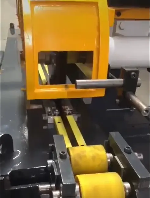
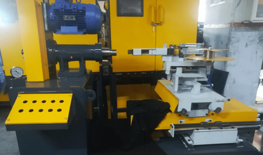
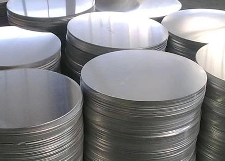
A stainless steel flat bar polishing machine is a specialized tool designed to create a smooth, reflective finish on flat metal surfaces. These machines are crucial in industries valuing aesthetics and durability.
They typically employ abrasive belts and brushes to gradually remove material and imperfections from the flat bar’s surface. The process involves stages like grinding, sanding, and polishing to achieve the desired finish.
Key components include abrasive belts, brushes, a workholding system, a drive system, and a cooling system.
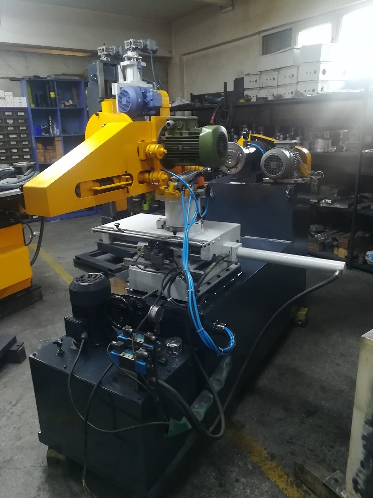
Machine types vary based on bar size, desired finish, and production volume: benchtop, floor-standing, and automated.
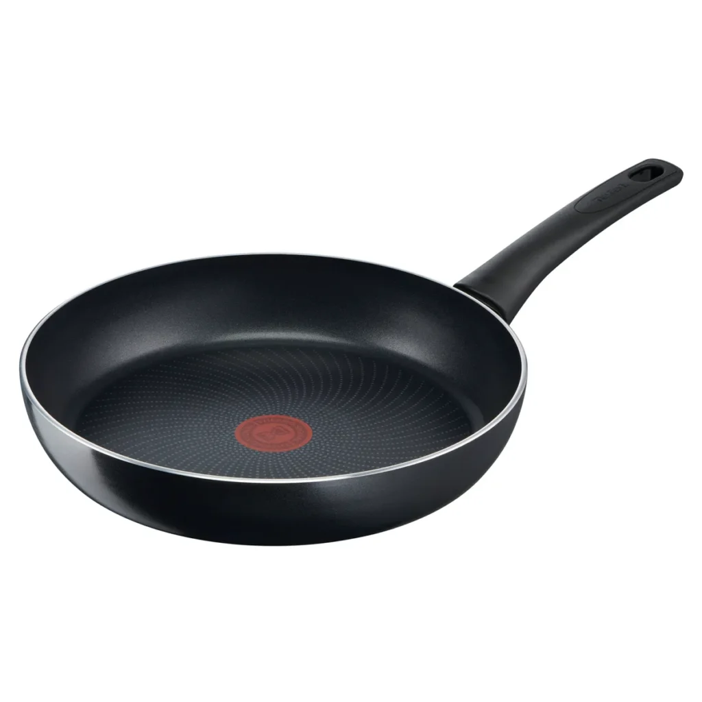
Stainless steel flat bars are used in various industries such as automotive, construction, furniture, and kitchen/bathroom applications.
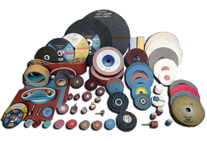
Buffing Polishing Grinding Machines
Buffing wheels and pads are essential tools used in surface finishing processes to achieve smooth, polished surfaces on various materials. Here’s an overview of buffing wheels and pads:
Buffing Wheels:
Material: Buffing wheels are typically made from various materials such as cotton, sisal, felt, or synthetic fibers. Each material offers different properties suitable for specific applications.
Density: The density of the buffing wheel affects its aggressiveness and cutting ability. Softer wheels provide a gentler touch, while denser wheels offer more cutting power.
Size and Shape: Buffing wheels come in various sizes and shapes to suit different applications and types of machinery. They can be cylindrical, conical, or disk-shaped.
Mounting: Buffing wheels are mounted on spindles or arbors of buffing machines, grinders, or handheld rotary tools. The mounting method ensures secure attachment and smooth rotation during use.
Polishing Pads:
Material: Polishing pads are commonly made from foam, microfiber, or wool. Each material has unique properties suitable for specific polishing tasks.
Density: Like buffing wheels, the density of polishing pads affects their performance. Softer pads are typically used for final polishing stages to achieve a high-gloss finish, while firmer pads are used for more aggressive polishing.
Attachment: Polishing pads may feature hook-and-loop (Velcro) backing for easy attachment to backing plates or sanding/polishing machines. Some pads may also have adhesive backing for permanent attachment.
Size and Shape: Polishing pads come in various sizes and shapes, including circular, rectangular, and triangular, to accommodate different surface contours and applications.
Both buffing wheels and polishing pads are available in a range of abrasiveness levels, from coarse to fine, to address various surface imperfections and achieve desired finishing results. They are commonly used in industries such as automotive, aerospace, metalworking, woodworking, and jewelry making for applications such as paint correction, metal polishing, and surface restoration. Proper selection of buffing wheels and polishing pads based on material type, surface condition, and desired finish is crucial for achieving optimal results.
Polishing Pads
Polishing Pads
Polishing pads are essential tools used in surface finishing processes to achieve smooth and glossy surfaces on various materials. Here’s a detailed overview of polishing pads:
Material Composition:
Foam Pads: These pads are made from foam materials of varying densities. They are versatile and suitable for a wide range of polishing applications. Foam pads are available in different colors, with each color representing a specific level of abrasiveness.
Microfiber Pads: Microfiber pads are constructed from densely packed microfiber strands. They are highly effective in removing fine imperfections and producing a high-gloss finish on surfaces.
Wool Pads: Wool pads are made from natural or synthetic wool fibers. They are commonly used for heavy cutting and compounding tasks due to their aggressive cutting action.
Density and Firmness:
Polishing pads come in different densities and firmness levels. Softer pads are typically used for final polishing stages to achieve a mirror-like finish, while firmer pads are used for more aggressive polishing or compounding tasks.
Attachment Mechanism:
Polishing pads may feature various attachment mechanisms for easy mounting onto backing plates or polishing machines. Common attachment methods include hook-and-loop (Velcro) backing for quick and secure attachment and adhesive backing for permanent mounting.
Size and Shape:
Polishing pads are available in various sizes and shapes to suit different surface contours and applications. Common shapes include circular, rectangular, and triangular pads. The size and shape of the pad should be chosen based on the specific surface being polished and the type of polishing machine being used.
Application:
Polishing pads are used with polishing compounds or polishes to remove imperfections, scratches, and swirl marks from surfaces. They are commonly used in automotive detailing, furniture refinishing, woodworking, metal polishing, and other surface finishing applications.
Maintenance and Cleaning:
Proper maintenance and cleaning of polishing pads are essential to ensure optimal performance and longevity. Pads should be regularly cleaned with a pad cleaning brush or pad conditioning brush to remove excess polish buildup and debris.
Durability and Longevity:
The durability and longevity of polishing pads depend on factors such as material quality, construction, and proper care and maintenance. High-quality pads made from durable materials can withstand repeated use and provide consistent performance over time.
Overall, polishing pads play a crucial role in achieving high-quality surface finishes and are indispensable tools for professionals and hobbyists alike involved in surface finishing and detailing applications.
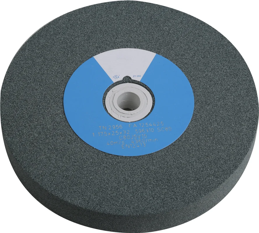
Grinding Wheels
Grinding Wheels
Grinding wheels are essential tools used in various industries for cutting, grinding, and shaping materials. Here’s an overview of grinding wheels:
Composition:
Grinding wheels are typically made from abrasive particles bonded together with a binder material. The abrasive particles can vary in composition and include materials such as aluminum oxide, silicon carbide, diamond, cubic boron nitride (CBN), and ceramic grains.
The binder material holds the abrasive particles together and provides structural integrity to the grinding wheel. Common binder materials include vitrified bonds, resin bonds, rubber bonds, and metal bonds.
Types of Grinding Wheels:
Straight Wheels: These are the most common type of grinding wheel and have a flat, parallel surface. They are used for surface grinding, cylindrical grinding, and tool sharpening applications.
Cylinder Wheels: Cylinder wheels have a cylindrical shape and are used for grinding cylindrical surfaces such as shafts, sleeves, and rolls.
Tapered Wheels: Tapered wheels have a tapered shape and are used for grinding threads, gear teeth, and other tapered surfaces.
Dish Wheels: Dish wheels have a concave shape and are used for grinding curved surfaces and profiles.
Diamond and CBN Wheels: Diamond and cubic boron nitride (CBN) wheels are used for grinding hard and abrasive materials such as carbides, ceramics, and glass. They offer superior hardness and wear resistance compared to conventional abrasive wheels.
Grit Size:
Grinding wheels are available in various grit sizes, ranging from coarse to fine. Coarser grits remove material more aggressively, while finer grits produce smoother surface finishes.
The grit size of the grinding wheel should be selected based on the material being ground and the desired surface finish.
Bond Type:
The bond type of a grinding wheel refers to the material used to bond the abrasive particles together. Common bond types include vitrified, resin, rubber, and metal bonds.
The choice of bond type depends on factors such as the hardness of the material being ground, the grinding process requirements, and the operating conditions.
Applications:
Grinding wheels are used in a wide range of applications, including metalworking, woodworking, automotive, aerospace, construction, and manufacturing. They are used for tasks such as stock removal, surface grinding, sharpening, deburring, and shaping of various materials including metals, ceramics, plastics, and composites.
Safety Considerations:
Proper safety precautions should be followed when using grinding wheels, including wearing appropriate personal protective equipment (PPE) such as safety glasses, gloves, and face shields. Grinding machines should be properly guarded, and operators should receive training on safe grinding practices to prevent accidents and injuries.
Overall, grinding wheels are versatile tools that play a critical role in machining and manufacturing processes, enabling efficient material removal and surface finishing operations across a wide range of industries.
Application Areas
Buffing, polishing, and grinding machines find application in a wide range of industries and processes where surface finishing is essential. Here are some of the key application areas:
Automotive Industry:
Buffing, polishing, and grinding machines are extensively used in the automotive industry for finishing various components such as body panels, chrome trim, wheels, and exhaust systems. They help achieve high-gloss finishes, remove imperfections, and enhance the aesthetic appeal of automotive parts.
Metalworking:
In metalworking industries, these machines are employed for surface preparation, deburring, and finishing of metal components. They are used in applications such as removing weld seams, polishing stainless steel and aluminum surfaces, and grinding metal parts to precise dimensions.
Woodworking:
Woodworking industries utilize buffing, polishing, and grinding machines for finishing wooden surfaces, furniture, and cabinetry. These machines are used to sand, smooth, and polish wood surfaces to achieve desired textures, stains, and finishes.
Aerospace Industry:
In the aerospace industry, buffing, polishing, and grinding machines are utilized for finishing critical components such as aircraft engine parts, turbine blades, and structural elements. They help achieve precise surface finishes, dimensional accuracy, and aerodynamic profiles.
Electronics Manufacturing:
Buffing, polishing, and grinding machines find application in electronics manufacturing for finishing components such as printed circuit boards (PCBs), semiconductor wafers, and electronic enclosures. They are used to achieve smooth, flat surfaces and remove burrs and surface defects.
Medical Device Manufacturing:
In the medical device industry, these machines are employed for finishing surgical instruments, orthopedic implants, and medical equipment components. They help achieve sterile surfaces, smooth edges, and precise dimensions required for medical applications.
Jewelry Making:
Buffing, polishing, and grinding machines are widely used in jewelry making for finishing precious metals and gemstones. They are used to polish gold, silver, platinum, and gemstones to achieve high-gloss finishes, intricate designs, and precise facets.
Construction and Architecture:
In construction and architectural industries, these machines are utilized for finishing concrete, stone, and other building materials. They are used for tasks such as concrete polishing, stone honing, and surface preparation for decorative coatings and sealants.
Plastics and Composites:
Buffing, polishing, and grinding machines are used in the manufacturing of plastic components, composites, and molded parts. They help achieve smooth, glossy finishes and precise dimensions on plastic molds, injection-molded parts, and composite panels.
Metal Fabrication and Welding:
Metal fabrication and welding industries utilize these machines for removing weld spatter, smoothing weld seams, and finishing metal surfaces. They are used in applications such as fabricating structural steel, stainless steel tanks, and aluminum structures.
These are just a few examples of the diverse application areas where buffing, polishing, and grinding machines play a crucial role in achieving high-quality surface finishes, dimensional accuracy, and aesthetic appeal across various industries and sectors.
Surface finishing operations are essential processes applied to sheet metal parts to enhance their appearance, functionality, and durability. These operations involve the removal of imperfections, smoothing of surfaces, and application of protective coatings. The importance of surface finishing cannot be overstated, as it directly impacts the performance, longevity, and aesthetic appeal of the final product.
Key Objectives of Surface Finishing:
Improve aesthetic appearance.
Enhance corrosion resistance.
Reduce friction and wear.
Remove surface defects.
Prepare surfaces for further processing.
Overview of Surface Finishing Techniques
Surface finishing techniques encompass a wide range of processes, each tailored to achieve specific results. The primary techniques include deburring, polishing, and buffing, each serving a unique purpose in the finishing workflow.
Deburring: The process of removing burrs—tiny protrusions or unwanted materials—from the edges of sheet metal parts.
Polishing: Involves smoothing and shining the surface to achieve a reflective finish.
Buffing: A finishing process that further enhances the shine and smoothness of the surface.
Applications in Industry
Surface finishing operations are vital across various industries, including automotive, aerospace, electronics, and consumer goods. The demand for high-quality finishes in these sectors drives innovation and the development of advanced finishing techniques.
Automotive: Enhancing the appearance and durability of car components.
Aerospace: Ensuring precision and performance in aircraft parts.
Electronics: Improving the aesthetic and functional quality of devices.
Consumer Goods: Increasing the appeal and longevity of products.
Section 2: Deburring in Sheet Metal Parts
Section 2: Deburring in Sheet Metal Parts
Definition and Types of Burrs
Deburring is the process of removing small, unwanted protrusions or burrs that form on the edges of sheet metal parts during manufacturing processes like cutting, drilling, and stamping. Burrs can negatively affect the performance, safety, and appearance of metal parts, making deburring a critical step in the production cycle.
Types of Burrs:
Poisson Burr: Caused by material deformation, often appears as a thin edge.
Roll-Over Burr: Occurs when material is pushed over the edge of a part.
Tear Burr: Created by tearing of material, resulting in irregular edges.
Cut-Off Burr: Occurs at the end of the cutting process, often requiring specific removal techniques.
Methods of Burr Removal
The selection of a deburring method depends on factors such as the type of burr, material properties, and desired surface finish. Below are common deburring methods:
Manual Deburring
Tools Used: Files, scrapers, abrasive pads, and brushes.
Advantages:
Cost-effective for small-scale production.
Provides control over the finishing process.
Disadvantages:
Labor-intensive and time-consuming.
Inconsistent results due to human error.
Mechanical Deburring
Methods:
Tumbling: Parts are placed in a tumbler with abrasive media that polishes the edges.
Vibratory Finishing: Uses vibrations to agitate parts and media for deburring.
Grinding: Utilizes rotating abrasive wheels to remove burrs.
Advantages:
Suitable for large-scale production.
Consistent and repeatable results.
Disadvantages:
May require additional equipment and space.
Potential for media contamination.
Thermal Deburring
Process: Involves exposing parts to a controlled explosion of gas to burn away burrs.
Advantages:
Effective for hard-to-reach areas.
Fast and efficient for complex parts.
Disadvantages:
High initial setup cost.
Limited to specific materials.
Electrochemical Deburring
Process: Involves the use of electrolytic solutions to dissolve burrs.
Material Compatibility: Different materials require specific deburring techniques.
Cost Considerations: Balancing cost and efficiency in high-volume production.
Quality Control: Ensuring consistent results across batches.
Case Studies
Case Study 1: Automotive Component Deburring
Objective: Improve the precision and safety of automotive parts.
Method Used: Mechanical deburring with vibratory finishing.
Outcome: Enhanced safety and performance of components, reduced production time.
Case Study 2: Aerospace Part Deburring
Objective: Achieve high precision and reliability in aircraft parts.
Method Used: Electrochemical deburring for intricate components.
Outcome: Improved accuracy and reliability, meeting industry standards.
Section 3: Polishing of Sheet Metal Parts
Section 3: Polishing of Sheet Metal Parts
Definition and Purpose
Polishing is a surface finishing process aimed at smoothing and shining metal parts to achieve a reflective finish. It enhances the appearance and functionality of metal parts by removing scratches, pits, and other imperfections.
Purpose of Polishing:
Improve aesthetic appeal.
Increase corrosion resistance.
Enhance surface smoothness and reflectivity.
Prepare surfaces for further coating or finishing processes.
Polishing Techniques
Various polishing techniques are employed based on the desired finish and application requirements.
Mechanical Polishing
Process: Involves the use of abrasive materials to remove surface irregularities.
Techniques:
Belt Polishing: Uses abrasive belts for continuous polishing.
Disk Polishing: Utilizes rotating disks with abrasive pads.
Buffing Wheels: Employs rotating cloth wheels with polishing compounds.
Advantages:
Cost-effective and versatile.
Suitable for various metals and shapes.
Disadvantages:
Limited precision for complex geometries.
Requires skilled operators for optimal results.
Electropolishing
Process: Involves the use of an electrolytic bath to dissolve the surface layer of metal, resulting in a smooth and shiny finish.
Advantages:
Superior surface finish and reflectivity.
Removes microscopic imperfections.
Enhances corrosion resistance.
Disadvantages:
High setup and operational costs.
Limited to specific metals and applications.
Tools and Equipment Used
Abrasive Belts and Disks: Used for mechanical polishing.
Buffing Wheels and Compounds: For fine finishing.
Electropolishing Equipment: Includes electrolytic baths and power supplies.
Comparison of Different Polishing Methods
Method
Advantages
Disadvantages
Mechanical
Cost-effective, versatile
Limited precision for complex parts
Electropolishing
Superior finish, corrosion resistance
High cost, limited material compatibility
Applications in Various Industries
Automotive: Enhancing the appearance of exterior and interior components.
Medical Devices: Ensuring the smoothness and biocompatibility of implants and tools.
Aerospace: Improving the aerodynamics and aesthetics of aircraft parts.
Consumer Electronics: Enhancing the visual appeal of devices and components.
Challenges and Solutions
Surface Uniformity: Achieving consistent finishes across complex geometries.
Material Constraints: Adapting techniques for various metals and alloys.
Environmental Concerns: Managing waste and emissions from polishing processes.
Section 4: Buffing Process for Sheet Metal Parts
Section 4: Buffing Process for Sheet Metal Parts
Definition and Difference from Polishing
Buffing is a surface finishing process that involves the use of soft cloth wheels and polishing compounds to achieve a high-gloss finish on metal surfaces. While similar to polishing, buffing focuses on enhancing the final appearance rather than removing significant surface imperfections.
Difference from Polishing:
Polishing: Involves removing surface material to smooth and refine.
Buffing: Focuses on creating a high-gloss, reflective finish.
Buffing Techniques
Different buffing techniques are employed based on the desired finish and complexity of the parts.
Manual Buffing
Process: Involves the use of hand-held buffing wheels and compounds.
Advantages:
Flexibility for small-scale production.
Control over the finishing process.
Disadvantages:
Labor-intensive and time-consuming.
Inconsistent results due to human error.
Automatic Buffing
Process: Utilizes automated machines and robotic arms for buffing.
Advantages:
Suitable for large-scale production.
Consistent and repeatable results.
Disadvantages:
High initial setup cost.
Limited flexibility for intricate parts.
Buffing Compounds and Materials
Buffing compounds are essential for achieving desired finishes and vary based on the material and application.
Types of Buffing Compounds:
Tripoli: Used for initial cutting and smoothing.
Rouge: Provides a high-gloss finish.
White Diamond: Removes light scratches and enhances shine.
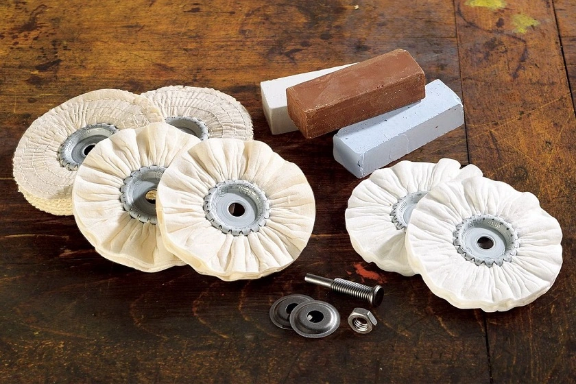
Materials Used:
Cloth Wheels: Made from cotton, flannel, or sisal.
Buffing Pads: Available in various grades for different finishes.
Tools and Equipment Used
Buffing Machines: Includes bench grinders and automated buffing stations.
Buffing Wheels and Pads: Available in different sizes and materials.
Polishing Compounds: Formulated for specific applications and finishes.
Applications in Various Industries
Jewelry: Enhancing the luster and appeal of metal pieces.
Automotive: Achieving high-gloss finishes on body panels and trim.
Furniture: Polishing metal components for aesthetic appeal.
Consumer Goods: Improving the appearance of household items and appliances.
Advantages and Limitations
Advantages:
Enhances aesthetic appeal and surface smoothness.
Suitable for various metals and applications.
Limitations:
Limited material removal capability.
Requires careful handling to avoid surface damage.
Section 5: Comparison of Deburring, Polishing, and Buffing
Differences in Techniques and Applications
Process
Purpose
Applications
Deburring
Remove burrs and imperfections
Manufacturing, machining
Polishing
Smooth and shine surfaces
Automotive, aerospace, electronics
Buffing
Enhance gloss and appearance
Jewelry, consumer goods, automotive
Suitability for Different Types of Sheet Metal
Deburring: Essential for parts with sharp edges and complex geometries.
Polishing: Suitable for achieving reflective finishes on flat and contoured surfaces.
Buffing: Ideal for enhancing the appearance of decorative and high-visibility parts.
Cost and Time Considerations
Deburring: Cost-effective for high-volume production, but may require specialized equipment.
Polishing: Balances cost with desired finish quality, may involve multiple steps.
Buffing: Cost-effective for achieving high-gloss finishes, but may require additional polishing.
Environmental and Safety Considerations
Deburring: Potential for media and chemical contamination, requires proper disposal.
Polishing: Generates dust and waste, necessitating effective ventilation and filtration.
Buffing: Involves the use of chemicals, requires protective equipment and safety measures.
Section 6: Advancements in Surface Finishing Technologies
Automation and Robotics
The integration of automation and robotics in surface finishing operations has revolutionized the industry, offering improved efficiency, precision, and consistency.
Benefits of Automation:
Reduced labor costs and human error.
Enhanced precision and repeatability.
Increased production speed and efficiency.
Applications:
Robotic deburring for intricate parts.
Automated polishing systems for large components.
Intelligent buffing machines with adaptive control.
Innovative Materials and Techniques
Advancements in materials and techniques continue to drive improvements in surface finishing processes.
Innovative Materials:
Advanced Abrasives: Developments in abrasive materials enhance cutting and polishing efficiency.
Eco-Friendly Compounds: Formulations that reduce environmental impact and improve safety.
New Techniques:
Laser Deburring: Uses laser beams to remove burrs with precision.
Nano-Polishing: Employs nanotechnology for superior surface finishes.
Impact of Industry 4.0
Industry 4.0 is reshaping surface finishing operations through the integration of smart technologies and data-driven approaches.
Key Aspects of Industry 4.0:
IoT Connectivity: Enables real-time monitoring and control of finishing processes.
Data Analytics: Provides insights into process optimization and quality control.
AI and Machine Learning: Enhances decision-making and process automation.
Case Studies on Modern Applications
Case Study 1: Automotive Industry
Objective: Improve production efficiency and finish quality.
Solution: Implementation of robotic polishing systems with IoT connectivity.
Outcome: Increased production speed, reduced defects, and enhanced finish quality.
Case Study 2: Aerospace Industry
Objective: Achieve high precision and consistency in aircraft parts.
Solution: Integration of AI-driven deburring and polishing systems.
Outcome: Improved accuracy, reduced waste, and compliance with industry standards.
Section 7: Best Practices and Quality Control
Quality Standards and Certifications
Adhering to quality standards and certifications ensures the reliability and performance of surface-finished parts.
Key Standards:
ISO 9001: Quality management systems for consistent product quality.
ISO 14001: Environmental management standards for sustainable practices.
NADCAP: Aerospace industry standards for process quality and control.
Inspection Techniques
Effective inspection techniques are crucial for maintaining the quality and consistency of finished parts.
Visual Inspection: Identifying surface defects and irregularities.
Dimensional Inspection: Measuring critical dimensions and tolerances.
Surface Roughness Testing: Assessing surface smoothness and texture.
Non-Destructive Testing: Evaluating structural integrity without damaging parts.
Process Optimization
Optimizing surface finishing processes enhances efficiency and reduces costs.
Key Strategies:
Lean Manufacturing: Minimizing waste and improving workflow.
Continuous Improvement: Implementing feedback loops for process refinement.
Process Automation: Utilizing technology for increased efficiency and precision.
Safety Measures and Precautions
Ensuring safety in surface finishing operations is paramount to protect workers and the environment.
Safety Precautions:
Personal Protective Equipment (PPE): Gloves, masks, goggles, and protective clothing.
Ventilation and Filtration: Effective air quality management to reduce dust and fumes.
Training and Education: Ongoing training programs for workers to ensure safe practices.
Section 8: Conclusion
Summary of Key Points
Surface finishing operations, including deburring, polishing, and buffing, are essential for enhancing the appearance, functionality, and durability of sheet metal parts.
Deburring removes burrs and imperfections, while polishing smooths and shines surfaces, and buffing enhances gloss and appearance.
Advancements in technology, automation, and materials continue to drive improvements in surface finishing processes.
Future Trends in Surface Finishing
The future of surface finishing operations will be shaped by continued advancements in automation, materials, and sustainability.
Emerging Trends:
Green Technologies: Development of eco-friendly compounds and processes.
Advanced Robotics: Increased use of robotics for precision and efficiency.
Smart Manufacturing: Integration of IoT and AI for data-driven process optimization.
Final Thoughts
Surface finishing operations are a vital component of modern manufacturing, contributing to the quality and performance of sheet metal parts across various industries. By staying abreast of technological advancements and best practices, manufacturers can achieve superior finishes and meet the evolving demands of the market.
Types of Polishing
Types of Polishing
Polishing is primarily categorized into mechanical and chemical methods, each serving different purposes and achieving unique results.
1. Mechanical Polishing
Mechanical polishing involves using abrasive tools and materials to physically remove surface material and achieve a smooth, reflective finish.
a. Belt Polishing
Process: Uses abrasive belts that continuously rotate around rollers to polish the surface of the metal.
Applications: Ideal for flat surfaces and edges.
Advantages: Cost-effective, easy to set up, and suitable for removing larger imperfections.
Commonly Used Materials:
Aluminum Oxide: A widely used abrasive for general-purpose polishing.
Silicon Carbide: Suitable for hard metals and provides a fine finish.
b. Disk Polishing
Process: Utilizes rotating disks with abrasive pads to polish surfaces.
Applications: Suitable for curved and irregular surfaces.
Advantages: Provides uniform pressure and can reach tight spots.
Commonly Used Materials:
Diamond Abrasives: Known for cutting efficiency and durability, especially on hard metals.
Ceramic Abrasives: Used for rapid stock removal and fine finishes.
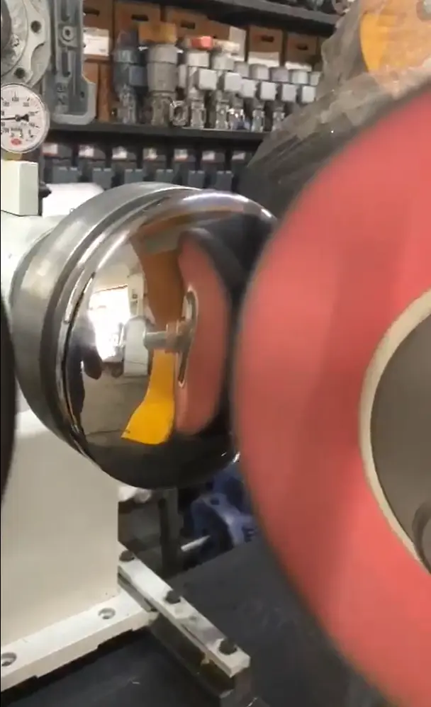
c. Buffing Wheels
Process: Employs cloth wheels coated with polishing compounds to achieve a high-gloss finish.
Applications: Suitable for finishing and enhancing shine on metal surfaces.
Advantages: Produces a mirror-like finish, ideal for aesthetic applications.
Commonly Used Materials:
Cotton and Flannel Wheels: Provide softness and flexibility, allowing for smooth finishes.
Sisal Wheels: Used for cutting and initial buffing stages due to their firmness.
d. Vibratory Polishing
Process: Involves placing parts in a vibrating container filled with abrasive media and compounds.
Applications: Ideal for small and complex parts that require even polishing.
Advantages: Provides consistent finishes, handles large volumes, and reduces manual labor.
Commonly Used Materials:
Ceramic Media: Effective for heavy cutting and smoothing.
Plastic Media: Used for delicate parts and achieving fine finishes.
2. Chemical and Electrochemical Polishing
Chemical and electrochemical polishing methods involve the use of chemical reactions to remove surface material and achieve a smooth finish.
a. Electropolishing
Process: Uses an electrolytic bath to dissolve the surface layer of metal, smoothing and leveling the surface.
Applications: Commonly used in industries requiring high precision and cleanliness, such as medical and food processing.
Electrolytic Solutions: Acidic solutions containing phosphoric and sulfuric acids.
Anodes and Cathodes: Typically made from stainless steel or titanium for durability.
b. Chemical Polishing
Process: Involves submerging the metal in a chemical solution that selectively removes surface material.
Applications: Suitable for intricate shapes and areas difficult to reach with mechanical methods.
Advantages: Provides uniform finishes and is effective for complex geometries.
Commonly Used Materials:
Acidic Solutions: Mixtures of nitric, hydrochloric, and sulfuric acids tailored to specific metals.
Additives: Agents that control the polishing rate and improve surface quality.
3. Abrasive Polishing
Abrasive polishing uses fine abrasive particles to refine the surface, removing minor scratches and achieving a high level of smoothness.
a. Sandblasting
Process: Propels fine abrasive particles against the surface of the metal to remove contaminants and smoothen the surface.
Applications: Suitable for preparing surfaces for painting or coating.
Advantages: Fast and effective for large surfaces and tough residues.
Commonly Used Materials:
Silica Sand: Traditional abrasive for general-purpose sandblasting.
Glass Beads: Provides a smoother finish and is less aggressive than sand.
Garnet: Known for its hardness and sharpness, ideal for heavy-duty applications.
b. Lapping
Process: Involves using a lapping plate and abrasive slurry to achieve a fine, flat surface finish.
Applications: Used in precision applications requiring tight tolerances, such as in optics and semiconductor industries.
Advantages: Produces extremely flat surfaces and fine finishes.
Commonly Used Materials:
Diamond Slurry: Provides precision and is used for hard materials.
Aluminum Oxide Slurry: Suitable for softer materials and less abrasive applications.
c. Micro-Abrasive Blasting
Process: Uses a controlled stream of micro-abrasive particles to remove fine surface layers.
Applications: Ideal for delicate and detailed parts requiring precision.
Advantages: Highly controlled process, reduces risk of surface damage.
Commonly Used Materials:
Aluminum Oxide Powder: Common for general applications and provides a good balance of cutting and polishing.
Sodium Bicarbonate: Gentle abrasive for sensitive materials.
Materials Used in Polishing
Materials Used in Polishing
The choice of materials used in polishing depends on the type of metal, desired finish, and specific polishing method. Below are commonly used materials and compounds in metal polishing:
1. Abrasive Materials
Aluminum Oxide: A versatile and widely used abrasive for various metals, including steel and aluminum. It provides a good balance between cutting and finishing capabilities.
Silicon Carbide: Known for its hardness and sharpness, it is used for polishing hard metals and achieving a smooth surface.
Diamond Abrasives: Offers superior cutting efficiency and is ideal for polishing hard and brittle metals, such as tungsten and ceramics.
Ceramic Abrasives: Used for heavy-duty applications, offering high material removal rates and durability.
2. Polishing Compounds
Polishing compounds are essential in achieving the desired finish and are formulated for specific metals and applications.
a. Tripoli Compound
Description: A coarse compound used for initial cutting and smoothing of surfaces.
Applications: Commonly used on softer metals like aluminum and brass to remove scratches and surface imperfections.
b. Rouge Compound
Description: A fine polishing compound used for achieving a high-gloss finish.
Applications: Ideal for polishing precious metals such as gold and silver, as well as achieving a mirror-like finish on stainless steel.
c. White Diamond Compound
Description: A versatile compound used for polishing and refining surfaces.
Applications: Suitable for use on plastics and metals, providing a bright finish and removing light scratches.
d. Green Chromium Oxide Compound
Description: A compound containing chromium oxide, used for achieving a fine finish.
Applications: Ideal for polishing stainless steel and other hard metals, providing a high level of smoothness and shine.
3. Polishing Pads and Wheels
Polishing pads and wheels come in various materials and are selected based on the desired finish and application requirements.
Cotton Buffing Wheels: Soft and flexible, suitable for applying polishing compounds and achieving a smooth finish.
Flannel Buffing Wheels: Provide a finer finish and are often used in the final buffing stage.
Sisal Buffing Wheels: Firm and durable, used for cutting and initial buffing stages.
Foam Polishing Pads: Used in conjunction with polishing compounds for fine finishing and detailing.
4. Chemical Solutions
Chemical solutions play a critical role in chemical and electrochemical polishing processes, providing the necessary reactions to achieve desired surface finishes.
Electrolytic Solutions: Composed of acids like phosphoric and sulfuric acids, used in electropolishing to dissolve surface material and enhance smoothness.
Chemical Polishing Solutions: Tailored mixtures of acids and additives designed for specific metals and applications, providing controlled material removal and surface refinement.
Conclusion
Polishing is a vital surface finishing process that enhances the appearance and functionality of metal parts. By understanding the various polishing methods and materials, manufacturers can achieve the desired finishes for different applications and industries. Whether through mechanical, chemical, or abrasive techniques, the choice of polishing materials and compounds plays a crucial role in achieving high-quality surface finishes.
Best Polishing Methods for Metal
Best Polishing Methods for Metal
Polishing metal surfaces is a critical step in many manufacturing processes, enhancing both the aesthetic appeal and functional properties of metal parts. The best polishing methods depend on various factors, including the type of metal, the desired finish, and specific application requirements. Below, we’ll explore some of the most effective polishing methods and their respective advantages, disadvantages, and suitable applications.
1. Mechanical Polishing
Mechanical polishing is one of the most commonly used methods due to its versatility and effectiveness in achieving smooth, shiny surfaces. This method involves using abrasive materials to physically remove surface imperfections.
a. Belt Polishing
Process: Belt polishing uses continuous abrasive belts to grind and polish metal surfaces. It is suitable for flat and slightly curved surfaces.
Advantages:
Cost-effective and suitable for high-volume production.
Can handle a wide range of metals, including steel, aluminum, and brass.
Efficient at removing larger surface imperfections.
Disadvantages:
Limited precision for intricate parts and complex geometries.
May require additional finishing steps to achieve a mirror-like finish.
Applications:
Automotive parts such as body panels and bumpers.
Large metal sheets and plates.
Metal furniture components.
b. Disk Polishing
Process: Disk polishing involves rotating abrasive disks to smooth and shine metal surfaces. It is often used for smaller or more intricate parts.
Advantages:
Provides uniform pressure and consistent results.
Suitable for complex shapes and small parts.
Versatile for a range of metals and finishes.
Disadvantages:
Requires skilled operators to avoid over-polishing.
Limited to flat and moderately curved surfaces.
Applications:
Jewelry and small metal components.
Precision instruments and tools.
Metal parts with intricate designs.
c. Vibratory Polishing
Process: Vibratory polishing involves placing metal parts in a vibrating container filled with abrasive media and compounds. The vibrations cause the media to polish the surfaces of the parts.
Advantages:
Ideal for large batches of small parts.
Provides even polishing across surfaces.
Reduces manual labor and operator fatigue.
Disadvantages:
Slower than other mechanical methods.
Limited to smaller parts and components.
Applications:
Small automotive components.
Hardware and fasteners.
Jewelry and decorative items.
d. Buffing Wheels
Process: Buffing involves using cloth wheels and polishing compounds to achieve a high-gloss finish on metal surfaces. It is often used as a final finishing step.
Advantages:
Achieves a mirror-like, high-gloss finish.
Suitable for a wide range of metals, including stainless steel and aluminum.
Enhances the aesthetic appeal of metal surfaces.
Disadvantages:
Limited material removal capability.
Requires careful handling to avoid surface damage.
Applications:
Automotive trim and decorative parts.
Consumer electronics and appliances.
Jewelry and luxury goods.
2. Chemical and Electrochemical Polishing
Chemical and electrochemical polishing methods use chemical reactions to smooth and refine metal surfaces, offering high precision and uniform finishes.
a. Electropolishing
Process: Electropolishing involves submerging metal parts in an electrolytic bath, where controlled electrical currents dissolve the surface layer of the metal, smoothing and leveling it.
Advantages:
Produces superior surface finishes with excellent reflectivity.
Removes microscopic burrs and imperfections.
Enhances corrosion resistance and passivation of metals.
Disadvantages:
High initial setup and operational costs.
Limited to conductive materials like stainless steel, titanium, and aluminum.
Applications:
Medical devices and implants.
Food processing equipment.
Aerospace components.
b. Chemical Polishing
Process: Chemical polishing involves immersing metal parts in a chemical solution that selectively removes surface material, refining and smoothing the surface.
Advantages:
Uniform finishes on complex geometries.
Suitable for delicate parts and thin-walled components.
Reduces surface stress and improves fatigue resistance.
Disadvantages:
Requires precise control of chemical concentrations and temperature.
Potential environmental and safety concerns with chemical handling.
Applications:
Intricate metal parts and components.
Electronics and semiconductor industries.
Decorative metal products.
3. Abrasive Polishing
Abrasive polishing methods involve using fine abrasive particles to achieve a smooth and refined surface finish, often used for precision applications.
a. Lapping
Process: Lapping uses a lapping plate and abrasive slurry to achieve flat, smooth surfaces with tight tolerances. It is often used for precision applications.
Advantages:
Achieves extremely flat and smooth surfaces.
Suitable for high-precision parts and components.
Provides tight tolerances and uniform finishes.
Disadvantages:
Requires specialized equipment and expertise.
Limited to flat surfaces and precision applications.
Applications:
Optics and lenses.
Semiconductor wafers.
Precision mechanical components.
b. Micro-Abrasive Blasting
Process: Micro-abrasive blasting uses a controlled stream of micro-abrasive particles to remove fine surface layers and achieve precision finishes.
Advantages:
Highly controlled process for precision applications.
Suitable for delicate and detailed parts.
Minimizes surface damage and distortion.
Disadvantages:
Limited to small areas and precision applications.
Requires specialized equipment and expertise.
Applications:
Aerospace and aviation components.
Medical devices and instruments.
Precision electronics and circuit boards.
Comparison of Polishing Methods
Here’s a table comparing the various polishing methods to highlight their advantages, disadvantages, and applications:
Method
Advantages
Disadvantages
Applications
Belt Polishing
Cost-effective, handles large surfaces
Limited precision, may require additional finishing
Automotive parts, large metal sheets
Disk Polishing
Uniform pressure, suitable for intricate parts
Skilled operation required, limited to flat surfaces
Jewelry, precision instruments, complex shapes
Vibratory Polishing
Even polishing, suitable for large batches
Slower process, limited to small parts
Small automotive components, hardware, jewelry
Buffing Wheels
Achieves high-gloss finish, enhances aesthetics
Limited material removal, requires careful handling
Automotive trim, consumer electronics, jewelry
Electropolishing
Superior finishes, removes microscopic burrs, enhances corrosion resistance
High setup costs, limited to conductive materials
Medical devices, food processing, aerospace components
Chemical Polishing
Uniform finishes on complex geometries, reduces surface stress
Precise control required, environmental concerns
Intricate parts, electronics, decorative products
Lapping
Extremely flat surfaces, tight tolerances
Requires specialized equipment, limited to flat surfaces
Limited to small areas, requires specialized equipment
Aerospace components, medical devices, precision electronics
Factors to Consider When Choosing a Polishing Method
Selecting the best polishing method for a specific application involves considering several key factors:
Material Type: Different metals have varying properties, such as hardness and corrosion resistance, that affect their suitability for specific polishing methods. For example, stainless steel benefits from electropolishing due to its corrosion resistance, while softer metals like aluminum can be effectively polished using mechanical methods.
Desired Finish: The intended appearance and surface quality of the finished product influence the choice of polishing method. For instance, a high-gloss finish may require buffing, while a matte finish could be achieved with abrasive blasting.
Component Geometry: The shape and complexity of the metal parts play a crucial role in determining the most suitable polishing method. Intricate geometries may require chemical or electrochemical polishing for uniform finishes, while flat surfaces can be efficiently polished using mechanical methods.
Production Volume: The scale of production impacts the choice of polishing method, with high-volume production benefiting from automated mechanical processes and small-batch or custom work requiring more manual techniques.
Cost and Efficiency: The overall cost and efficiency of the polishing process, including equipment, labor, and materials, must be evaluated to determine the most cost-effective solution without compromising quality.
Environmental and Safety Considerations: The environmental impact and safety of the polishing process, including waste management and operator safety, should be considered when selecting a method. Chemical processes may require special handling and disposal procedures, while mechanical methods can generate dust and noise.
Conclusion
Polishing is a vital process in the metalworking industry, significantly impacting the appearance and functionality of metal parts. By understanding the strengths and limitations of each polishing method, manufacturers can select the most appropriate technique to achieve the desired finish and meet specific application requirements. Whether through mechanical, chemical, or abrasive methods, the choice of polishing technique plays a critical role in producing high-quality, durable metal products.
What is Industrial Buffing?
What is Industrial Buffing?
Industrial buffing is a crucial process in the metal finishing industry, aimed at enhancing the appearance and functional properties of metal surfaces. It involves using buffing wheels and compounds to produce smooth, reflective finishes on various metal products. This section will explore the methods, materials, applications, and advancements in industrial buffing, providing a comprehensive understanding of this essential metalworking technique.
Industrial buffing is a surface finishing process used to achieve a high-gloss, mirror-like finish on metal surfaces. It involves using buffing wheels made from cloth, felt, or other materials, along with buffing compounds, to polish and smoothen the surface of metal parts. Buffing is often the final step in the finishing process, following grinding or polishing, to achieve the desired surface quality.
Objectives of Industrial Buffing
Enhance Aesthetic Appeal: Buffing improves the visual appearance of metal parts by creating a reflective, glossy surface.
Improve Surface Smoothness: The process removes fine scratches and imperfections, resulting in a smooth, even surface.
Increase Corrosion Resistance: A polished surface can help reduce the risk of corrosion by minimizing surface irregularities where moisture could accumulate.
Prepare for Further Coating: Buffing can prepare metal surfaces for additional coatings, such as paint or plating, by ensuring a smooth base.
Buffing Methods
Industrial buffing can be performed using various methods, each tailored to specific applications and desired finishes. Below are the primary methods used in industrial buffing:
1. Manual Buffing
Manual buffing involves skilled operators using hand-held buffing tools to polish metal surfaces. This method is often used for small-scale production or intricate parts requiring precise attention to detail.
Advantages:
Provides greater control over the buffing process.
Suitable for complex shapes and detailed work.
Allows for adjustments during the process to achieve the desired finish.
Disadvantages:
Labor-intensive and time-consuming.
Inconsistent results due to human error.
Limited to small production volumes.
Applications:
Jewelry and decorative items.
Small automotive components.
Custom metalwork.
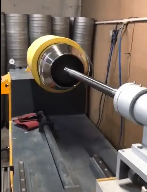
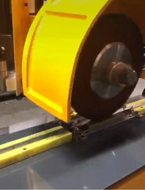
2. Automated Buffing
Automated buffing employs machines and robotic systems to buff metal surfaces, offering consistent and efficient results for large-scale production.
Advantages:
High-speed production and consistent quality.
Reduces labor costs and human error.
Capable of handling large and complex parts.
Disadvantages:
High initial setup and equipment costs.
Limited flexibility for intricate parts or custom finishes.
Applications:
Automotive parts and assemblies.
Household appliances and electronics.
Aerospace components.
3. Robotic Buffing
Robotic buffing utilizes robotic arms equipped with buffing tools to perform precise and efficient buffing operations, especially for complex geometries and large parts.
Advantages:
High precision and repeatability.
Reduced human labor and increased safety.
Capable of handling intricate and large-scale parts.
Disadvantages:
High capital investment for robotic systems.
Requires programming and maintenance expertise.
Applications:
Aerospace and automotive industries.
Large metal structures and equipment.
High-volume production of standardized parts.
Buffing Compounds and Materials
Buffing Compounds and Materials
The choice of buffing compounds and materials significantly influences the quality and efficiency of the buffing process. Various compounds are used based on the type of metal and desired finish.
Buffing Compounds
Buffing compounds are abrasive materials mixed with binders that help achieve the desired finish on metal surfaces. They come in different formulations, each suited for specific applications.
a. Tripoli Compound
Description: A coarse compound used for initial cutting and smoothing of metal surfaces.
Applications: Ideal for removing scratches and surface imperfections on softer metals like aluminum and brass.
b. Rouge Compound
Description: A fine compound used to achieve a high-gloss, mirror-like finish.
Applications: Suitable for polishing precious metals such as gold and silver, as well as stainless steel.
c. White Diamond Compound
Description: A versatile compound used for polishing and refining metal surfaces.
Applications: Effective on plastics and metals, providing a bright finish and removing light scratches.
d. Green Chromium Oxide Compound
Description: A compound containing chromium oxide, used for achieving a fine finish.
Applications: Ideal for polishing stainless steel and other hard metals, offering a high level of smoothness and shine.
Buffing Wheels and Materials
Buffing wheels are essential tools in the buffing process, available in various materials and configurations to suit different applications.
a. Cloth Buffing Wheels
Description: Made from cotton or flannel, cloth wheels are soft and flexible, allowing for smooth finishes.
Applications: Commonly used for applying buffing compounds and achieving a polished finish.
b. Sisal Buffing Wheels
Description: Made from natural fibers, sisal wheels are firm and durable, making them suitable for initial cutting and buffing stages.
Applications: Used for aggressive cutting and removing surface imperfections before finer buffing.
c. Felt Buffing Wheels
Description: Dense and rigid, felt wheels are used for precision buffing and achieving high-gloss finishes.
Applications: Ideal for detailed work and achieving mirror-like finishes on metals.
Applications of Industrial Buffing
Applications of Industrial Buffing
Industrial buffing is used across various industries to enhance the appearance and functionality of metal parts. Here are some key applications:
1. Automotive Industry
Applications:
Buffing car body panels to achieve a smooth, glossy finish.
Polishing chrome trim and accessories for enhanced aesthetic appeal.
Smoothing engine components and parts for improved performance.
Benefits:
Improves the overall appearance and marketability of vehicles.
Enhances corrosion resistance and durability of parts.
Prepares surfaces for additional coatings or treatments.
2. Aerospace Industry
Applications:
Buffing aircraft components for improved aerodynamics and aesthetics.
Polishing turbine blades and engine parts for enhanced performance.
Smoothing fuselage and wing surfaces for reduced drag.
Benefits:
Increases the efficiency and reliability of aerospace components.
Enhances safety and performance of aircraft.
Meets stringent industry standards for quality and precision.
3. Jewelry and Decorative Products
Applications:
Buffing gold, silver, and platinum jewelry to achieve a high-gloss finish.
Polishing decorative metal items such as sculptures and ornaments.
Enhancing the appearance of metal art pieces and custom creations.
Benefits:
Improves the aesthetic appeal and value of jewelry and decorative items.
Provides a luxurious and professional finish to products.
Enhances the durability and wear resistance of metal pieces.
4. Electronics and Appliances
Applications:
Buffing metal casings and components for electronics and appliances.
Polishing stainless steel surfaces for enhanced appearance and cleanliness.
Smoothing metal parts for improved functionality and aesthetics.
Benefits:
Enhances the visual appeal and marketability of products.
Improves the performance and longevity of electronic devices.
Provides a polished and professional finish to consumer goods.
Advancements in Industrial Buffing
Advancements in Industrial Buffing
The field of industrial buffing has seen significant advancements in recent years, driven by technological innovations and industry demands for improved efficiency and quality. Here are some notable advancements:
1. Automation and Robotics
The integration of automation and robotics in industrial buffing processes has revolutionized the industry, offering improved precision, efficiency, and consistency.
Benefits:
Reduces labor costs and human error.
Increases production speed and throughput.
Provides consistent and repeatable results.
Applications:
Automated buffing systems for automotive and aerospace components.
Robotic buffing for large and complex parts in various industries.
Intelligent systems with adaptive control for customized finishes.
2. Innovative Materials and Compounds
Advancements in buffing materials and compounds have led to improved performance and environmental sustainability.
Innovative Materials:
Eco-Friendly Compounds: Formulations that reduce environmental impact and improve safety.
Advanced Abrasives: Developments in abrasive materials enhance cutting and polishing efficiency.
Applications:
High-performance compounds for demanding industrial applications.
Environmentally friendly solutions for sustainable manufacturing practices.
Custom formulations for specific metals and finishes.
3. Industry 4.0 and Smart Technologies
Industry 4.0 is reshaping industrial buffing through the integration of smart technologies and data-driven approaches.
Key Aspects:
IoT Connectivity: Enables real-time monitoring and control of buffing processes.
Data Analytics: Provides insights into process optimization and quality control.
AI and Machine Learning: Enhances decision-making and process automation.
Applications:
Smart buffing systems for adaptive process control and optimization.
Predictive maintenance and quality assurance through data-driven insights.
Integration of IoT and AI for intelligent manufacturing solutions.
Challenges and Solutions in Industrial Buffing
Challenges and Solutions in Industrial Buffing
Despite its advantages, industrial buffing also presents certain challenges that need to be addressed for optimal performance and quality. Here are some common challenges and their solutions:
1. Surface Uniformity
Challenge: Achieving consistent finishes across complex geometries and large surfaces can be difficult, leading to variations in surface quality.
Solution: Implementing automated and robotic systems ensures uniform pressure and consistent results, reducing variations in surface quality.
2. Material Compatibility
Challenge: Different metals have varying properties, such as hardness and corrosion resistance, that affect their compatibility with specific buffing methods and materials.
Solution: Selecting appropriate buffing compounds and materials for each metal type ensures optimal performance and finish quality.
3. Cost and Efficiency
Challenge: Balancing cost and efficiency in high-volume production while maintaining quality can be challenging, especially with manual buffing processes.
Solution: Investing in automated and robotic systems reduces labor costs and increases efficiency, allowing for cost-effective production without compromising quality.
4. Environmental and Safety Concerns
Challenge: Managing waste and emissions from buffing processes, as well as ensuring operator safety, can be challenging, especially with chemical compounds and dust generation.
Solution: Implementing effective ventilation and filtration systems, as well as using eco-friendly compounds, minimizes environmental impact and enhances safety.
Best Practices for Industrial Buffing
To achieve optimal results in industrial buffing, it is essential to follow best practices that ensure quality, efficiency, and safety. Here are some key best practices:
1. Quality Control and Inspection
Implementing robust quality control and inspection processes ensures the consistency and reliability of buffing results.
Visual Inspection: Identifying surface defects and irregularities to ensure uniform finishes.
Surface Roughness Testing: Assessing surface smoothness and texture to meet quality standards.
Dimensional Inspection: Measuring critical dimensions and tolerances to ensure precision.
Lean Manufacturing: Minimizing waste and improving workflow for efficient production.
Continuous Improvement: Implementing feedback loops for process refinement and optimization.
Process Automation: Utilizing technology for increased efficiency and precision.
3. Safety Measures and Precautions
Ensuring safety in industrial buffing operations is paramount to protect workers and the environment.
Personal Protective Equipment (PPE): Providing gloves, masks, goggles, and protective clothing to ensure operator safety.
Ventilation and Filtration: Implementing effective air quality management systems to reduce dust and fumes.
Training and Education: Offering ongoing training programs for workers to ensure safe practices and awareness.
4. Maintenance and Upkeep
Regular maintenance and upkeep of buffing equipment and systems ensure optimal performance and longevity.
Routine Inspections: Conducting regular inspections and maintenance to identify and address equipment issues.
Cleaning and Lubrication: Keeping buffing tools and equipment clean and lubricated for smooth operation.
Calibration and Adjustments: Ensuring equipment is calibrated and adjusted for precise and consistent results.
Conclusion
Industrial buffing is a vital process in the metalworking industry, offering numerous benefits in terms of appearance, functionality, and durability. By understanding the methods, materials, applications, and advancements in buffing, manufacturers can achieve high-quality finishes and meet the evolving demands of the market. Whether through manual, automated, or robotic methods, the choice of buffing technique plays a critical role in producing superior metal products. By adhering to best practices and addressing challenges, the industry can continue to innovate and improve the efficiency and quality of industrial buffing operations.
Types of Deburring Machines
Types of Deburring Machines
A deburring machine is an essential tool in metal fabrication, designed to remove burrs and other imperfections from metal parts. Burrs are unwanted projections of material that often occur during machining, cutting, or stamping processes. These imperfections can negatively affect the performance, safety, and appearance of metal parts, making deburring an important step in the manufacturing process.
Below, we’ll explore the various types of deburring machines, their working principles, applications, advantages, and considerations for selecting the right machine for your needs.
Deburring machines come in various types, each suited for specific applications and materials. Here are some of the most common types of deburring machines used in the industry:
1. Vibratory Deburring Machines
Description
Vibratory deburring machines use a vibrating bowl filled with abrasive media and parts to remove burrs. The vibrations cause the media to rub against the parts, effectively deburring and polishing them.
Working Principle
Parts and abrasive media are placed inside a vibrating chamber.
The vibrations cause the media to move in a circular motion, rubbing against the parts.
The abrasive action of the media removes burrs and smooths the surface of the parts.
Applications
Suitable for small to medium-sized parts.
Ideal for batch processing of components.
Used in industries such as automotive, aerospace, and electronics.
Advantages
Effective for complex shapes and geometries.
Can process multiple parts simultaneously.
Provides a consistent and uniform finish.
Disadvantages
Limited to smaller parts and components.
May require longer processing times for heavy burrs.
2. Centrifugal Disc Deburring Machines
Description
Centrifugal disc deburring machines use a rotating disc to generate high-speed motion, creating a sliding movement of abrasive media against the parts.
Working Principle
Parts and abrasive media are placed in a stationary container with a rotating disc at the bottom.
The rotation creates a centrifugal force that causes the media to slide against the parts.
The abrasive action removes burrs and smooths the surfaces.
Applications
Suitable for small to medium-sized parts with intricate shapes.
Used in industries such as jewelry, electronics, and precision engineering.
Advantages
Provides fast and efficient deburring.
Produces smooth and polished finishes.
Suitable for delicate and intricate parts.
Disadvantages
Limited to smaller parts and components.
May not be suitable for large or heavy parts.
3. Tumbling Deburring Machines
Description
Tumbling deburring machines use a rotating barrel filled with abrasive media and parts. The rotation causes the media to tumble against the parts, removing burrs and smoothing surfaces.
Working Principle
Parts and abrasive media are placed in a rotating barrel or drum.
The rotation causes the media and parts to tumble against each other.
The abrasive action of the media removes burrs and polishes the surfaces.
Applications
Suitable for small to medium-sized parts.
Commonly used in industries such as automotive, aerospace, and consumer goods.
Advantages
Cost-effective and simple to operate.
Capable of processing large batches of parts.
Provides consistent and uniform finishes.
Disadvantages
Limited to smaller parts and components.
May require longer processing times for heavy burrs.
4. Magnetic Deburring Machines
Description
Magnetic deburring machines use magnetic fields to agitate small steel pins or media, which in turn deburr and polish the surfaces of metal parts.
Working Principle
Parts are placed in a chamber with small steel pins or media.
Magnetic fields agitate the pins, causing them to move and interact with the parts.
The mechanical action of the pins removes burrs and polishes surfaces.
Applications
Suitable for small, delicate, and intricate parts.
Commonly used in industries such as electronics, medical devices, and jewelry.
Advantages
Gentle and precise deburring.
Suitable for intricate and delicate parts.
Can access hard-to-reach areas.
Disadvantages
Limited to small parts and components.
May require additional equipment for larger parts.
5. Brush Deburring Machines
Description
Brush deburring machines use rotating brushes made from abrasive materials to remove burrs and smooth surfaces.
Working Principle
Parts are fed through the machine where rotating brushes make contact with the surfaces.
The abrasive action of the brushes removes burrs and smooths the surfaces.
Applications
Suitable for flat surfaces and edges.
Used in industries such as automotive, aerospace, and metal fabrication.
Advantages
Effective for flat surfaces and edges.
Provides consistent and uniform finishes.
Can be integrated into production lines.
Disadvantages
Limited to flat surfaces and edges.
May not be suitable for complex shapes or intricate parts.
6. Thermal Deburring Machines
Description
Thermal deburring machines use controlled explosions of gas to burn away burrs from metal parts.
Working Principle
Parts are placed in a chamber filled with a mixture of gases.
The gases are ignited, creating a controlled explosion that burns away burrs.
Applications
Suitable for complex and intricate parts.
Commonly used in industries such as automotive, aerospace, and precision engineering.
Advantages
Effective for hard-to-reach areas and complex shapes.
Provides a clean and burr-free finish.
Fast and efficient process.
Disadvantages
High initial setup and operational costs.
Limited to specific materials and applications.
7. Electrochemical Deburring Machines
Description
Electrochemical deburring machines use electrolytic solutions to dissolve burrs from metal parts.
Working Principle
Parts are submerged in an electrolytic bath with an electric current applied.
The current causes the burrs to dissolve, leaving a smooth surface.
Applications
Suitable for precision and intricate parts.
Used in industries such as aerospace, medical devices, and electronics.
Advantages
Precise and controlled deburring.
Minimal tool wear and surface damage.
Suitable for intricate and delicate parts.
Disadvantages
Requires careful handling of chemicals.
High operational costs.
Selecting the Right Deburring Machine
Choosing the right deburring machine involves considering several factors, including the type of metal, the size and complexity of the parts, and the desired finish. Here are some key considerations for selecting the right deburring machine:
1. Type of Metal
Different metals have varying properties that affect their deburring requirements. Consider the hardness, ductility, and conductivity of the metal when selecting a deburring machine.
2. Size and Complexity of Parts
The size and complexity of the parts influence the choice of deburring machine. Consider the geometry, size, and intricacy of the parts to determine the most suitable machine.
3. Desired Finish
The desired finish and surface quality of the parts play a crucial role in selecting the right deburring machine. Consider the level of smoothness, precision, and appearance required for the finished parts.
4. Production Volume
The scale of production impacts the choice of deburring machine. Consider the production volume and batch size to determine whether manual or automated machines are more suitable.
5. Cost and Efficiency
Evaluate the overall cost and efficiency of the deburring process, including equipment, labor, and materials, to determine the most cost-effective solution without compromising quality.
6. Environmental and Safety Considerations
Consider the environmental impact and safety of the deburring process, including waste management and operator safety, when selecting a machine. Some machines may require special handling and disposal procedures for chemicals or emissions.
Advantages of Deburring Machines
Advantages of Deburring Machines
Deburring machines offer several advantages over manual deburring methods, making them essential tools in modern manufacturing processes. Here are some key advantages of using deburring machines:
1. Improved Efficiency and Productivity
Deburring machines automate the deburring process, significantly reducing the time and labor required compared to manual methods. This results in increased efficiency and productivity in manufacturing operations.
2. Consistent and Uniform Finishes
Deburring machines provide consistent and uniform finishes across batches, ensuring high-quality results with minimal variations in surface quality. This is particularly important for precision parts and components.
3. Reduced Labor Costs
Automated deburring machines reduce the need for manual labor, leading to lower labor costs and improved resource allocation in manufacturing operations.
4. Enhanced Safety
Deburring machines reduce the risk of operator injuries associated with manual deburring processes, such as cuts and abrasions. Additionally, automated machines minimize the exposure to hazardous materials and chemicals.
5. Versatility and Flexibility
Deburring machines offer versatility and flexibility in handling a wide range of parts and materials, making them suitable for various industries and applications.
6. Precision and Accuracy
Deburring machines provide precise and accurate deburring, ensuring high-quality finishes with minimal surface damage or tool wear.
Challenges and Solutions in Deburring
Challenges and Solutions in Deburring
Despite their advantages, deburring machines also present certain challenges that need to be addressed for optimal performance and quality. Here are some common challenges and their solutions:
1. Material Compatibility
Challenge: Different materials require specific deburring techniques, which can impact the selection of deburring machines and abrasive media.
Solution: Select appropriate deburring machines and materials for each metal type to ensure optimal performance and finish quality.
2. Surface Uniformity
Challenge: Achieving consistent finishes across complex geometries and large surfaces can be difficult, leading to variations in surface quality.
Solution: Implement automated and robotic systems to ensure uniform pressure and consistent results, reducing variations in surface quality.
3. Cost and Efficiency
Challenge: Balancing cost and efficiency in high-volume production while maintaining quality can be challenging, especially with manual deburring processes.
Solution: Invest in automated and robotic systems to reduce labor costs and increase efficiency, allowing for cost-effective production without compromising quality.
4. Environmental and Safety Concerns
Challenge: Managing waste and emissions from deburring processes, as well as ensuring operator safety, can be challenging, especially with chemical compounds and dust generation.
Solution: Implement effective ventilation and filtration systems, as well as use eco-friendly compounds, to minimize environmental impact and enhance safety.
Best Practices for Using Deburring Machines
Best Practices for Using Deburring Machines
To achieve optimal results in deburring, it is essential to follow best practices that ensure quality, efficiency, and safety. Here are some key best practices for using deburring machines:
1. Quality Control and Inspection
Implement robust quality control and inspection processes to ensure the consistency and reliability of deburring results.
Visual Inspection: Identify surface defects and irregularities to ensure uniform finishes.
Surface Roughness Testing: Assess surface smoothness and texture to meet quality standards.
Dimensional Inspection: Measure critical dimensions and tolerances to ensure precision.
2. Process Optimization
Optimize deburring processes to enhance efficiency and reduce costs, ensuring high-quality results.
Lean Manufacturing: Minimize waste and improve workflow for efficient production.
Continuous Improvement: Implement feedback loops for process refinement and optimization.
Process Automation: Utilize technology for increased efficiency and precision.
3. Safety Measures and Precautions
Ensure safety in deburring operations to protect workers and the environment.
Personal Protective Equipment (PPE): Provide gloves, masks, goggles, and protective clothing to ensure operator safety.
Ventilation and Filtration: Implement effective air quality management systems to reduce dust and fumes.
Training and Education: Offer ongoing training programs for workers to ensure safe practices and awareness.
4. Maintenance and Upkeep
Regular maintenance and upkeep of deburring equipment and systems ensure optimal performance and longevity.
Routine Inspections: Conduct regular inspections and maintenance to identify and address equipment issues.
Cleaning and Lubrication: Keep deburring tools and equipment clean and lubricated for smooth operation.
Calibration and Adjustments: Ensure equipment is calibrated and adjusted for precise and consistent results.
Conclusion
Deburring machines play a crucial role in the metalworking industry, providing efficient and effective solutions for removing burrs and imperfections from metal parts. By understanding the types, applications, and considerations for selecting deburring machines, manufacturers can achieve high-quality finishes and meet the evolving demands of the market. Whether through vibratory, centrifugal, tumbling, or advanced methods like thermal and electrochemical deburring, the choice of deburring machine plays a critical role in producing superior metal products. By adhering to best practices and addressing challenges, the industry can continue to innovate and improve the efficiency and quality of deburring operations.
If you have any further questions or need more detailed information on specific aspects of deburring machines, feel free to ask!
Best Deburring Techniques
Best Deburring Techniques
Deburring is a crucial step in metalworking and manufacturing that involves removing burrs—unwanted protrusions or rough edges—resulting from machining, cutting, drilling, or stamping processes. The presence of burrs can negatively affect the performance, safety, and aesthetics of metal parts. Therefore, selecting the best deburring techniques is essential for achieving smooth, functional, and visually appealing products.
Below, we’ll explore the most effective deburring techniques, their applications, advantages, disadvantages, and considerations for choosing the right method for specific needs.
1. Manual Deburring
Manual deburring involves using hand tools to remove burrs from metal parts. It is one of the oldest and most straightforward methods, offering flexibility and precision for small-scale or intricate tasks.
Tools Used
Files: Metal files are used to manually scrape and smooth burrs off the edges of metal parts. Available in various shapes and sizes to match specific needs.
Scrapers: Sharp, flat tools used for removing burrs from flat surfaces and edges.
Abrasive Pads: Scouring pads that can be used to smooth out small imperfections and surface burrs.
Rotary Tools: Dremel-like tools with small abrasive attachments for precise deburring of intricate areas.
Applications
Suitable for small batches and custom jobs.
Ideal for intricate and delicate parts where precision is critical.
Commonly used in the aerospace, automotive, and jewelry industries.
Advantages
Low initial investment and setup costs.
Provides precise control over the deburring process.
Flexibility to handle various part sizes and shapes.
Disadvantages
Labor-intensive and time-consuming for large volumes.
Inconsistent results due to human error.
Limited efficiency for high-volume production.
Best Practices
Ensure operators are well-trained and skilled in using manual tools.
Use appropriate safety gear, such as gloves and goggles, to protect against metal filings.
Regularly maintain and sharpen tools to ensure efficiency and precision.
2. Mechanical Deburring
Mechanical deburring involves using machines to automate the deburring process. This method is suitable for high-volume production and can handle various part sizes and shapes.
Types of Mechanical Deburring
a. Vibratory Deburring
Process: Uses a vibrating container filled with abrasive media to deburr parts. The vibration causes the media to rub against the parts, removing burrs.
Applications: Suitable for small to medium-sized parts with complex geometries.
Advantages: Handles multiple parts simultaneously, consistent finishes, effective for complex shapes.
Disadvantages: Limited to smaller parts, longer processing times for heavy burrs.
b. Tumbling Deburring
Process: Uses a rotating barrel filled with abrasive media and parts. The rotation causes the media to tumble against the parts, removing burrs.
Applications: Ideal for small parts and batch processing.
Advantages: Cost-effective, simple operation, capable of processing large batches.
Disadvantages: Limited to smaller parts, may require longer processing times for heavy burrs.
c. Brush Deburring
Process: Involves using rotating brushes made from abrasive materials to remove burrs from flat surfaces and edges.
Applications: Suitable for flat surfaces and edges, used in industries such as automotive and aerospace.
Advantages: Consistent finishes, can be integrated into production lines, effective for flat surfaces.
Disadvantages: Limited to flat surfaces, not suitable for intricate shapes.
Best Practices
Choose the right abrasive media for the specific material and part geometry.
Regularly monitor and maintain machinery to ensure optimal performance.
Adjust processing times and media compositions based on part specifications and desired finishes.
3. Thermal Deburring
Thermal deburring is an advanced method that uses controlled explosions of gas to remove burrs from metal parts. It is particularly effective for complex and intricate parts.
Process
Parts are placed in a chamber filled with a mixture of combustible gases, such as hydrogen and oxygen.
The gases are ignited, creating a controlled explosion that burns away burrs.
Applications
Suitable for intricate and complex parts with hard-to-reach areas.
Commonly used in the automotive and aerospace industries.
Advantages
Effective for hard-to-reach areas and complex shapes.
Provides a clean and burr-free finish.
Fast and efficient process for large volumes.
Disadvantages
High initial setup and operational costs.
Limited to specific materials that can withstand high temperatures.
Requires careful handling and safety measures.
Best Practices
Ensure the chamber and parts are properly sealed to prevent gas leaks.
Conduct thorough safety checks and adhere to safety protocols to prevent accidents.
Regularly maintain equipment to ensure consistent and safe operation.
4. Electrochemical Deburring
Electrochemical deburring uses electrolytic solutions to dissolve burrs from metal parts. This method is precise and effective for parts with complex geometries.
Process
Parts are submerged in an electrolytic bath with an electric current applied.
The current causes the burrs to dissolve, leaving a smooth surface.
Applications
Suitable for precision parts and intricate geometries.
Used in industries such as aerospace, medical devices, and electronics.
Advantages
Precise and controlled deburring.
Minimal tool wear and surface damage.
Suitable for intricate and delicate parts.
Disadvantages
Requires careful handling of chemicals and electrolytes.
High operational costs and initial setup.
Limited to conductive materials.
Best Practices
Use appropriate personal protective equipment (PPE) to handle chemicals safely.
Regularly test and maintain electrolyte solutions to ensure effective deburring.
Optimize current levels and exposure times based on part specifications.
5. High-Pressure Water Jet Deburring
High-pressure water jet deburring uses water jets to remove burrs and clean metal surfaces. This technique is suitable for parts that are sensitive to heat and require precision deburring.
Process
High-pressure water jets are directed at the metal parts, removing burrs through the force of the water.
The process may involve rotating nozzles to reach all areas of the part.
Applications
Suitable for heat-sensitive materials and precision components.
Commonly used in the aerospace, automotive, and medical device industries.
Advantages
No thermal distortion or material stress.
Environmentally friendly, as it uses water instead of chemicals.
Effective for precision and intricate parts.
Disadvantages
High initial setup costs for equipment.
Limited to parts that can withstand high water pressure.
May require additional drying processes after deburring.
Best Practices
Ensure proper pressure levels and nozzle configurations for effective deburring.
Implement drying procedures to prevent corrosion or water damage.
Regularly inspect and maintain equipment to ensure consistent performance.
6. Cryogenic Deburring
Cryogenic deburring uses extremely low temperatures to embrittle burrs, making them easier to remove. This method is effective for flexible or rubber-like materials that are difficult to deburr using traditional methods.
Process
Parts are exposed to cryogenic temperatures using liquid nitrogen or similar substances.
The low temperature makes the burrs brittle, allowing them to be easily removed by tumbling or blasting.
Applications
Suitable for plastic, rubber, and flexible materials.
Commonly used in the automotive, electronics, and medical device industries.
Advantages
Effective for materials that are difficult to deburr using traditional methods.
Minimal impact on the part’s structural integrity.
Environmentally friendly, as it uses no chemicals.
Disadvantages
Limited to materials that can withstand low temperatures.
High setup and operational costs for cryogenic equipment.
May require additional processes to remove residual cold materials.
Best Practices
Ensure proper handling and safety measures when using cryogenic materials.
Optimize exposure times and temperatures based on material specifications.
Regularly maintain equipment to ensure efficient and safe operation.
Comparison of Deburring Techniques
Here’s a comparison table summarizing the advantages, disadvantages, and applications of each deburring technique:
Technique
Advantages
Disadvantages
Applications
Manual Deburring
Low cost, precise control, flexible for various shapes
Cost-effective, simple operation, large batch processing
Limited to smaller parts, longer processing times
Small parts, batch processing
Brush Deburring
Consistent finishes, integrated into production lines
Limited to flat surfaces, not suitable for intricate shapes
Flat surfaces, edges, automotive and aerospace
Thermal Deburring
Effective for complex shapes, fast and efficient
High costs, limited to specific materials, safety concerns
Intricate parts, automotive, aerospace
Electrochemical Deburring
Precise deburring, minimal tool wear, suitable for intricate parts
Requires chemical handling, high costs, limited to conductive materials
Precision parts, aerospace, medical devices
High-Pressure Water Jet
No thermal distortion, environmentally friendly
High costs, limited to parts that can withstand water pressure
Heat-sensitive materials, precision components
Cryogenic Deburring
Effective for flexible materials, minimal impact on structural integrity
Limited to low-temperature materials, high costs
Plastic, rubber, flexible materials
Factors to Consider When Choosing a Deburring Technique
Selecting the right deburring technique depends on several factors, including the type of material, part geometry, production volume, and desired finish. Here are some key considerations:
Material Type: Different materials have varying properties that affect their deburring requirements. Consider the hardness, ductility, and thermal sensitivity of the material when choosing a deburring method.
Part Geometry: The shape and complexity of the parts influence the choice of deburring technique. Intricate geometries may require advanced methods like electrochemical or thermal deburring for effective results.
Production Volume: The scale of production impacts the choice of deburring technique, with high-volume production benefiting from automated methods and small-batch or custom work requiring manual techniques.
Cost and Efficiency: Evaluate the overall cost and efficiency of the deburring process, including equipment, labor, and materials, to determine the most cost-effective solution without compromising quality.
Environmental and Safety Considerations: Consider the environmental impact and safety of the deburring process, including waste management and operator safety. Some methods may require special handling and disposal procedures for chemicals or emissions.
Desired Finish: The intended surface quality of the finished product influences the choice of deburring technique. For instance, precision parts with tight tolerances may benefit from electrochemical deburring, while simpler parts may be effectively deburred using mechanical methods.
Conclusion
Deburring is a vital process in manufacturing, significantly impacting the quality and functionality of metal parts. By understanding the strengths and limitations of each deburring technique, manufacturers can select the most appropriate method to achieve the desired finish and meet specific application requirements. Whether through manual, mechanical, thermal, or advanced methods, the choice of deburring technique plays a critical role in producing high-quality, durable metal products. By adhering to best practices and addressing challenges, the industry can continue to innovate and improve the efficiency and quality of deburring operations.
Edge Trim and Form Machine is a specialized machine used to deburr, smooth, trim, and shape edges of various materials, particularly metals, plastics, and wood. They employ a combination of cutting, grinding, and forming processes to achieve the desired edge finish and profile.
Types of Edge Cutting Trimming and Forming Machines
Edge cutting trimming and forming machines come in various configurations to suit specific applications and materials. Common types include:
Benchtop Machines: These compact and portable machines are ideal for small-scale edge finishing tasks, such as deburring and trimming small components.
Floor-standing Machines: These larger and more powerful machines are designed for heavy-duty edge finishing applications, such as trimming and shaping large sheets of metal or plastic.
Components of Edge Cutting Trimming and Forming Machines
Edge cutting trimming and forming machines typically consist of the following components:
Cutting Tool: The cutting tool is the primary element that removes material from the edge. It may be a rotating blade, a grinding wheel, or a milling cutter, depending on the material and desired finish.
Guide Rails: The guide rails provide precise positioning and movement of the workpiece during edge finishing.
Forming Tool: The forming tool, if used, shapes the edge of the workpiece to the desired profile. It may be a roller, a press, or a forming die, depending on the application.
Workpiece Support: The workpiece support securely holds the workpiece in place during edge finishing.
Control System: The control system regulates the movement of the cutting and forming tools, ensuring precision and repeatability.
Working Principle of Edge Cutting Trimming and Forming Machines
Edge cutting trimming and forming machines operate on the principle of controlled material removal and shaping. The cutting tool precisely removes unwanted material from the edge, while the forming tool shapes the edge into the desired profile. The guide rails ensure accurate positioning and movement of the workpiece, while the control system regulates the entire process.
Applications of Edge Cutting Trimming and Forming Machines
Edge cutting trimming and forming machines are widely used in various industries for a range of applications:
Metal Fabrication: Deburring, trimming, and shaping metal components for various applications, such as automotive parts, machinery components, and architectural elements.
Plastics Manufacturing: Deburring, trimming, and shaping plastic sheets and components for various applications, such as packaging, electronics, and automotive parts.
Woodworking: Deburring, trimming, and shaping wooden components for various applications, such as furniture, cabinetry, and decorative woodwork.
Medical Device Manufacturing: Deburring, trimming, and shaping medical devices and implants to achieve a smooth, sterile surface that meets medical standards.
Jewelry Making: Trimming and shaping gemstones, precious metals, and jewelry components to achieve precise dimensions and a polished finish.
Benefits of Edge Cutting Trimming and Forming Machines
Edge cutting trimming and forming machines offer several advantages, including:
Accuracy and Precision: They provide precise edge finishing with minimal material removal, ensuring consistent results.
Fast and Efficient: They can quickly deburr, trim, and shape edges of various materials, reducing production time.
Versatility: They can handle a wide range of materials, from soft plastics to hard metals, and can achieve various edge profiles.
Rugged Construction: They are typically made from durable materials and are designed to withstand heavy-duty use.
Automated Processes: Some machines can be automated, further reducing labor costs and improving efficiency.
Safety Considerations when Using Edge Cutting Trimming and Forming Machines
When using edge cutting trimming and forming machines, safety precautions are essential to prevent injuries and maintain a safe working environment:
Personal Protective Equipment: Wear safety glasses, gloves, and a respirator to protect from flying debris and metal splinters.
Safe Material Handling: Handle materials carefully to avoid cuts and abrasions.
Secure Workpiece Fixture: Ensure the workpiece is securely held in place to prevent it from moving during operation.
Adequate Ventilation: Provide adequate ventilation in the working area to remove dust and fumes.
Proper Machine Operation: Follow the manufacturer’s instructions and guidelines for safe operation.
These cutting and trimming of edges are carried out by our ECM-100, ECM-200, and ECM-300 machines, specially designed to cut the edges of round parts in serial production. In our machinery, cutting of edges and bending them inside are carried out in one cycle which shortens the cycle time of one part and makes economy in the production of the machine
Our order rounder machines are made as a welded sheet construction and complete painted, with an electrical board, controlled by a PLC
Edge Cutting Trimming and Forming Machine is a specialized machine used for cutting, trimming, and forming the edges of various materials such as metal, plastic, and wood. It is commonly used in the manufacturing industry for mass production of products such as panels, boards, and sheets.
The machine is equipped with sharp blades that can accurately cut and trim the edges of the material. It is also designed with different forming tools that can shape the edges of the material into various forms and profiles.
The operation of the Edge Cutting Trimming and Forming Machine is simple and efficient. The operator loads the material onto the machine and selects the appropriate cutting, trimming, or forming tool. The machine automatically performs the required operation according to the selected tool, and the finished product is discharged from the machine.
This machine is widely used in the manufacturing industry, including industries such as automotive, aerospace, construction, and furniture. It is particularly useful for cutting, trimming, and forming the edges of materials used in these industries.
Edge curling operation with the Edge Cutting Trimming and Forming Machine for sheet metals
Edge curling, also known as edge rolling or edge forming, is a metalworking process that creates a rolled or curled edge on sheet metal components. It is commonly used for various purposes, including:
Reinforcing edges: Curling strengthens the edges of sheet metal components, making them more resistant to damage and wear.
Creating a smooth finish: Curling eliminates sharp edges and creates a smooth, rounded edge that is safer to handle and aesthetically pleasing.
Preparing for welding: Curling can prepare the edges of sheet metal components for welding by aligning them and providing a consistent surface for the weld bead.
Edge curling can be performed using various tools and techniques, but one of the most efficient and versatile methods is using an edge cutting trimming and forming machine. These machines are equipped with specialized tooling that can precisely curl edges of various sizes and materials.
Edge Curling Operation with an Edge Cutting Trimming and Forming Machine
The edge curling operation with an edge cutting trimming and forming machine typically involves the following steps:
Material Preparation: Ensure the sheet metal is clean, free from burrs, and of uniform thickness.
Workpiece Positioning: Securely position the sheet metal on the machine’s workpiece support, ensuring it is aligned with the curling tool.
Tool Adjustment: Adjust the curling tool’s position and pressure settings according to the thickness and material of the sheet metal.
Edge Curling: Activate the machine to curl the edge of the sheet metal. The machine’s guide rails will ensure precise movement, and the curling tool will apply the appropriate pressure to achieve the desired curl radius.
Inspection: Inspect the curled edge for uniformity, consistency, and adherence to the desired specifications.
Benefits of Using an Edge Cutting Trimming and Forming Machine for Edge Curling
Edge cutting trimming and forming machines offer several advantages for edge curling operations:
Accuracy and Precision: They provide precise edge curling with consistent results, ensuring the desired curl radius and edge profile.
Versatility: They can handle a wide range of sheet metal thicknesses and materials, from thin aluminum to thick steel.
Efficiency: They can quickly curl edges of various sizes, reducing production time and increasing productivity.
Reduced Human Error: They automate the edge curling process, minimizing the risk of human error and ensuring consistent quality.
Safety: They provide safety features, such as guards and interlocks, to protect operators from potential hazards.
Edge curling is a special metalworking operation, to make the edges of a round or a flat sheet metal into hollow rings and this operation is carried out when there is a need of fixing one part on the other with air or watertight closure for safe handling. The rims of the round metal part are first cut (or also called trimmed) and then can be bent outside or inside by a special metal tool called “sheet metal curling tool”. In this way, the part has a better finishing and the rims have no longer the risk of cutting by usage.
https://www.youtube.com/embed/jXwlSb_1rbo?feature=oembedEdge curling machine in curling the rims of a round sheet metal part
The curling usually takes a few seconds more time in comparison to edge cutting operation. The operator needs to remove the edge cutting tool and put on the edge curling tool to go on with the curling.
Edge curling operation can be applied on metals such as:
Stainless steel
Black steel
Aluminum
Copper
Tin
Zinc
The edge curling (or edge closing) is also widely applied in bakeware production facilities. The stainless steel cake, aluminum or alusteel cake molds (or more generally bake molds) are also manufactured by a drawing hydraulic press and the rims of these molds are trimmed first by an edge trimming machine and then curled inside or outside depending on the application.
Cake molds with curled edges
The curling of sheet metals can be applied to the parts as below
Cake molds
Teapots and coffee pots
Milk canisters
Water heater bodies
Kettles
Bakery products
What is curling in sheet metal?
Curling in sheet metal is a metalforming process that creates a rolled or curled edge on sheet metal components. It is a versatile and widely used technique that serves various purposes, including:
Reinforcing edges: Curling strengthens the edges of sheet metal components, making them more resistant to damage and wear. This is particularly important for components subjected to frequent handling or potential impacts.
Eliminating sharp edges: Curling eliminates sharp edges that can pose safety hazards or cause discomfort during handling. The rounded edge created by curling provides a smoother, safer finish.
Enhancing aesthetics: Curling can enhance the aesthetic appearance of sheet metal components by creating a clean, uniform edge. This is often desirable for components that are visible or have decorative elements.
Preparing for welding: Curling can prepare the edges of sheet metal components for welding by aligning them and providing a consistent surface for the weld bead. This can improve the quality and strength of the welded joint.
Guiding fluid flow: In applications where sheet metal components are used to guide fluid flow, curling can help create a smooth, consistent internal profile that minimizes turbulence and enhances fluid flow characteristics.
Methods of Curling Sheet Metal
There are several methods for curling sheet metal, each with its own advantages and limitations. Some of the most common methods include:
Manual Curling: Manual curling involves using hand tools, such as curling pliers or a hammer and dolly, to bend the edge of the sheet metal. While this method is simple and inexpensive, it can be time-consuming and may not provide the precision and consistency required for critical applications.
Roll Forming: Roll forming utilizes a series of rollers to gradually bend the edge of the sheet metal into the desired curl radius. This method offers high precision and consistency, but it requires specialized equipment and may not be suitable for small-scale or complex shapes.
Press Forming: Press forming utilizes a press brake or other stamping equipment to press the edge of the sheet metal into a die that forms the desired curl shape. This method is suitable for high-volume production and can produce complex curl profiles.
Edge Cutting Trimming and Forming Machines: Edge cutting trimming and forming machines are versatile machines that can perform a variety of edge finishing operations, including curling. These machines offer a combination of precision, efficiency, and versatility, making them a popular choice for various sheet metal applications.
Factors Affecting Curling Process
The curling process is influenced by several factors, including:
Sheet Metal Thickness: Thinner sheet metal is generally easier to curl than thicker sheet metal, as it requires less force and is more pliable.
Sheet Metal Material: The material of the sheet metal also affects the curling process. Softer materials, such as aluminum, are generally easier to curl than harder materials, such as steel.
Curl Radius: The desired curl radius affects the curling process. Smaller curl radii require more precise tooling and control, while larger curl radii are more forgiving.
Lubrication: Lubrication can be applied to the sheet metal to reduce friction and prevent galling during the curling process.
Tooling: The type and quality of the curling tool significantly impact the curling process. Proper tool selection and maintenance are essential for achieving consistent results.
Machine Settings: Machine settings, such as speed, pressure, and feed rate, must be adjusted appropriately for the specific sheet metal thickness, material, and curl radius.
Curling is a valuable technique in sheet metal fabrication, offering a range of benefits and applications. By understanding the curling process, factors affecting it, and the appropriate methods and equipment, manufacturers can effectively curl sheet metal components to achieve the desired strength, aesthetics, functionality, and consistency.
Curling is one of the sheet metal forming applications to make the flat or round rims (edges) of a part hollow and circular roll. After the curling, the outer geometry of the edge changes completely. The thickness of the edge becomes the diameter of the hollow roll.
The curling operations can be made on the center of the roll or off the center of the roll. These two applications need separate machine tool designs
The diagram of a curling toll of an edge curling machine
The curling tool moves vertically on the sheet metal edge of the part while the part rotates about its own axis. The curling tool has a special hemisphere geometry and needs to be manufactured with a harder material than the part itself to withstand the wear and friction. The curling tool moves up and the contact of the part edge must be on the edge of the curling tool inside, maximum closest to the hemisphere finishing corner. the diameter of this hemisphere determines the outer diameter of the curling roll of the sheet metal part.
The speed of the upward movement of the curling tool (or curling die) is critical. This speed is calculated according to the yield strength of the material of the part. The bigger the yield strength, the slower the curling die needs to move upward in order no to damage the part edge
In our edge cutting trimming beading or curling machines, the movement and the speed of the curling die is controlled by a servo motor (which is also controlled by a PLC) to make the process go smoother.
The Edge Cutting Trimming and Forming Machine is a specialized machine used in the production of metal parts, particularly for sheet metal fabrication. It is designed to cut, trim, and form the edges of metal parts, resulting in a clean and smooth finish. The machine uses a series of cutting and forming tools to shape the edges of the metal parts into the desired configuration.
The Edge Cutting Trimming and Forming Machine is commonly used in industries such as automotive manufacturing, aerospace, construction, and metal fabrication. It is particularly useful in applications where the edges of the metal parts need to be precise and uniform, such as in the production of sheet metal components for automotive body parts or aircraft wings.
The machine consists of several components, including a cutting blade, a forming tool, a workpiece holder, and a control system. The cutting blade is used to cut the metal sheet to the required size, while the forming tool is used to shape the edges of the metal part into the desired configuration. The workpiece holder is used to securely hold the metal sheet in place while the machine operates, and the control system manages the operation of the machine and ensures that the metal parts are cut and formed correctly.
Overall, the Edge Cutting Trimming and Forming Machine is a versatile and essential tool in the metal fabrication industry, allowing for the production of high-quality metal parts with precise and uniform edges.
How does the Edge Cutting Trimming and Forming Machine work?
The Edge Cutting Trimming and Forming Machine is a versatile machine that performs multiple operations on sheet metal components, including edge cutting, trimming, and forming. It is a valuable tool in various industries, including metal fabrication, electronics manufacturing, and automotive production.
Working Principle
The Edge Cutting Trimming and Forming Machine operates primarily on the principles of controlled material removal and shaping. The machine utilizes a combination of cutting and forming tools that precisely remove unwanted material and shape the edges of sheet metal components to the desired profile.
Edge Cutting: The cutting tool, typically a rotating blade, removes excess material from the edges of the sheet metal component. The blade’s movement is controlled by guide rails to ensure precise and consistent cutting.
Trimming: Trimming involves removing any imperfections or irregularities from the cut edge. This ensures a clean, finished edge that is free of burrs or unevenness.
Forming: The forming tool, which may be a roller, press, or forming die, shapes the edge of the sheet metal component into the desired profile. This could involve creating a rolled or curled edge, a flanged edge, or a beaded edge.
Control System
The Edge Cutting Trimming and Forming Machine is equipped with a control system that regulates the movement of the cutting and forming tools and ensures precision and repeatability. The control system may consist of servo motors, encoders, and a programmable logic controller (PLC).
Versatility
The Edge Cutting Trimming and Forming Machine can handle a wide range of sheet metal thicknesses and materials, from thin aluminum to thick steel. It can also be used with various tooling configurations to achieve different edge profiles and shapes.
Applications
Edge Cutting Trimming and Forming Machines are used in various applications, including:
**Deburring and trimming metal components for various applications, such as automotive parts, machinery components, and architectural elements.
**Shaping edges of plastic sheets and components for various applications, such as packaging, electronics, and automotive parts.
**Creating rolled or curled edges on sheet metal components for reinforcement, aesthetics, or fluid flow optimization.
**Flanging edges of sheet metal components to provide a stronger joint or accommodate welding.
**Creating beaded edges on sheet metal components for decorative purposes or to enhance rigidity.
Benefits
Edge Cutting Trimming and Forming Machines offer several benefits, including:
Accuracy and precision: They provide precise edge finishing with consistent results, ensuring the desired edge profile and dimensional accuracy.
Versatility: They can handle a wide range of materials and thicknesses, making them suitable for various applications.
Efficiency: They can quickly process workpieces, reducing production time and increasing productivity.
Reduced human error: They automate the edge finishing process, minimizing the risk of human error and ensuring consistent quality.
Safety: They provide safety features, such as guards and interlocks, to protect operators from potential hazards.
Edge Cutting Trimming and Forming Machines are essential tools in sheet metal fabrication, enabling manufacturers to produce high-quality components with precise edge finishes, enhanced strength, and improved aesthetics.
The Edge Cutting Trimming and Forming Machine is designed to trim and form the edges of sheet metal parts. It works by using a set of cutting and forming tools that are mounted on a horizontal axis. The sheet metal part is placed on a support table, and then it is pushed against the cutting and forming tools. The cutting tools are used to trim the excess metal from the edges of the sheet, while the forming tools are used to create the desired shape or contour of the edge.
The machine is controlled by a computer program that controls the movement of the cutting and forming tools. The program is designed to take into account the dimensions and shape of the sheet metal part, as well as the desired shape and contour of the edge. Once the program is set, the machine can perform the cutting, forming, and trimming operations automatically, with a high degree of precision and accuracy.
Industries working with our machinery
Industries working with our machinery
Trimming and beading machines are versatile tools that are used in a wide range of industries. Here are some of the most common industries that use trimming and beading machines:
Automotive Industry
The automotive industry is one of the largest users of trimming and beading machines. These machines are used to trim and bead car body panels, fenders, doors, and other sheet metal components. Trimming ensures precise dimensions and eliminates rough edges, while beading strengthens the sheet metal and provides reference points for alignment during assembly and welding.
Aerospace Industry
The aerospace industry also relies heavily on trimming and beading machines. These machines are used to fabricate lightweight and high-strength components for aircraft and spacecraft. The precise and consistent trimming and beading operations ensure the structural integrity of these critical components.
Appliance Manufacturing
Appliance manufacturing is another major user of trimming and beading machines. These machines are used to trim and bead the sheet metal components of refrigerators, washing machines, and other household appliances. Trimming and beading help to strengthen the appliances, improve their appearance, and facilitate assembly.
HVAC Industry
The HVAC industry uses trimming and beading machines to fabricate ductwork, fans, and other sheet metal components. Trimming ensures that the components fit together properly, while beading strengthens the components and provides rigidity.
Construction Industry
The construction industry uses trimming and beading machines to fabricate roofing panels, siding, and other sheet metal components for buildings. Trimming and beading help to ensure that the components are weatherproof and durable.
Metal Fabrication Industries
Trimming and beading machines are widely used in various metal fabrication industries, including electrical equipment manufacturing, medical device manufacturing, and industrial machinery manufacturing. These machines are used to trim and bead a wide range of sheet metal components for various applications.
In addition to these specific industries, trimming and beading machines are also used in a variety of other applications, including:
Sign Manufacturing
Furniture Manufacturing
Toy Manufacturing
Food and Beverage Processing Equipment Manufacturing
Medical Device Manufacturing
The versatility and effectiveness of trimming and beading machines make them essential tools for a wide range of industries. These machines play a crucial role in producing high-quality, durable, and precisely dimensioned sheet metal components for a variety of applications.
Cookware Kitchenware
Defense
Water Tank Manufacturing
Solar Power Generator Manufacturing
Electrical Motor Fan Cover Manufacturing
Fire Extinguisher Manufacturing
Exhaust Pipe Manufacturing
LPG & LNG Tank Manufacturing
Trimming beading machines are specialized pieces of equipment used in various manufacturing industries to cut, shape, and form beads along the edges of metal sheets and other materials. These machines serve the critical function of enhancing the structural integrity and aesthetic appeal of products by creating precise and consistent beading.
Trimming beading machines are essential in processes where the appearance and durability of the edges are paramount. They are commonly employed in industries such as automotive, aerospace, HVAC, and consumer goods manufacturing, where precision and efficiency are crucial.
Importance in Industrial Applications
The primary importance of trimming beading machines lies in their ability to streamline manufacturing processes by automating edge-forming tasks that would otherwise be labor-intensive and prone to human error. By improving consistency and reducing waste, these machines contribute significantly to the overall productivity and cost-effectiveness of production lines.
Furthermore, trimming beading machines enhance the quality of finished products, ensuring they meet stringent industry standards and customer expectations. Their ability to produce uniform edges and beads also plays a vital role in the assembly and functionality of components, particularly in high-stakes industries like aerospace and automotive manufacturing.
Overview of the Content
This comprehensive guide aims to provide an in-depth exploration of trimming beading machines, covering their components, working principles, types, applications, technical specifications, maintenance, and emerging trends. By understanding these aspects, industry professionals can make informed decisions about implementing and optimizing trimming beading machines within their operations.
Components of Trimming Beading Machines
Base and Frame
Components of Trimming Beading Machines
The base and frame of a trimming beading machine form its structural backbone, providing stability and support for all other components. Typically constructed from robust materials such as steel or cast iron, the frame ensures the machine can withstand the stresses of operation and maintain precision over time.
Materials Used
Steel: Known for its durability and resistance to deformation, steel is commonly used in high-performance trimming beading machines. It offers excellent rigidity and longevity.
Cast Iron: Preferred for its vibration-damping properties, cast iron frames help minimize noise and improve accuracy during operation.
Structural Design
The structural design of trimming beading machines varies based on the specific model and intended application. Key considerations include the machine’s footprint, ease of access for maintenance, and adaptability to different manufacturing environments.
Cutting and Beading Tools
Cutting and Beading Tools
The cutting and beading tools are critical to the machine’s functionality, responsible for shaping and forming the edges of materials. These tools come in various shapes and sizes, tailored to the specific beading patterns and material thicknesses required.
Types and Materials
High-Speed Steel (HSS): Known for its hardness and heat resistance, HSS is commonly used for cutting tools that need to maintain sharpness under demanding conditions.
Carbide: Offering superior wear resistance and durability, carbide tools are ideal for high-volume production runs and materials that are difficult to machine.
Maintenance and Replacement
Regular maintenance of cutting and beading tools is essential to ensure consistent performance. This includes sharpening or replacing worn tools and adjusting alignment to prevent defects in the finished products.
Drive Mechanism
The drive mechanism powers the machine’s operations, converting electrical energy into mechanical motion. It is a crucial component that directly influences the machine’s efficiency and performance.
Motor Types
AC Motors: Widely used in trimming beading machines for their reliability and simplicity. AC motors offer consistent performance and are suitable for applications where speed control is not critical.
Servo Motors: Preferred for applications requiring precise control and variable speeds. Servo motors enable dynamic adjustments to the machine’s operations, enhancing versatility and efficiency.
Energy Efficiency Considerations
Modern trimming beading machines are designed with energy efficiency in mind, incorporating features like variable frequency drives (VFDs) to optimize power consumption and reduce operational costs.
Control Systems
Control systems govern the operation of trimming beading machines, allowing operators to configure settings, monitor performance, and ensure safety. These systems range from basic manual controls to sophisticated automated interfaces.
Manual vs. Automated Systems
Manual Systems: Suitable for smaller operations or applications requiring frequent adjustments. Manual controls offer simplicity and direct operator oversight.
Automated Systems: Essential for large-scale production environments, automated systems provide consistent performance, reduce human error, and enable integration with other machinery.
Integration with Industry 4.0 Technologies
Trimming beading machines are increasingly adopting Industry 4.0 technologies, such as IoT sensors and data analytics, to enhance operational efficiency and enable predictive maintenance.
Working Principles
Detailed Description of the Trimming Process
Detailed Description of the Trimming Process
The trimming process involves cutting away excess material from the edges of a workpiece to achieve a desired shape or size. Trimming beading machines utilize specialized tools to perform this task with high precision and consistency.
Material Feeding: The workpiece is fed into the machine, either manually or automatically, and positioned for trimming.
Tool Engagement: Cutting tools engage the workpiece, removing excess material while following the predefined path and pattern.
Material Removal: The machine’s cutting tools execute the trimming operation, guided by precise control systems to ensure uniformity.
Quality Inspection: The trimmed edges are inspected for accuracy and quality, with adjustments made as necessary.
Beading Techniques and Variations
Beading is the process of forming beads along the edges of a workpiece, enhancing both its structural integrity and aesthetic appeal. Different techniques and variations are employed based on the material and intended application.
Single Bead Formation: The simplest form of beading, involving a single continuous bead along the edge.
Double Bead Formation: Utilized when additional strength or a decorative effect is desired, double beads consist of two parallel beads along the edge.
Custom Bead Patterns: Some machines allow for custom bead patterns, tailored to specific design requirements or functional needs.
Workflow and Operational Steps
The workflow of a trimming beading machine is designed to maximize efficiency and ensure consistent output. Key operational steps include:
Setup and Calibration: Operators configure the machine settings, such as tool alignment and material thickness, to match the requirements of the production run.
Material Loading: Workpieces are loaded onto the machine, either manually or through automated systems, and positioned for processing.
Trimming and Beading: The machine executes the trimming and beading operations, following the specified parameters and patterns.
Quality Control: Finished pieces undergo quality control checks to verify dimensional accuracy and bead integrity.
Adjustment and Maintenance: Regular adjustments and maintenance are performed to ensure optimal performance and address any issues that arise during operation.
Common Challenges and Solutions
Trimming beading machines can encounter various challenges during operation, which can impact performance and product quality. Common issues and their solutions include:
Tool Wear and Dullness: Regular tool maintenance, including sharpening and replacement, is essential to maintain cutting precision and prevent defects.
Material Deformation: Proper machine calibration and tool alignment help prevent material deformation during trimming and beading processes.
Machine Downtime: Implementing predictive maintenance and monitoring systems can reduce downtime and improve overall equipment efficiency.
Quality Variability: Consistent quality control checks and process adjustments help ensure uniformity and adherence to specifications.
Types of Trimming Beading Machines
Types of Trimming Beading Machines
Trimming beading machines are available in various types, each suited to specific applications and production needs. Understanding the differences between these machines is crucial for selecting the right equipment for a given operation.
Manual Trimming Beading Machines
Features and Use Cases
Manual trimming beading machines are operated entirely by human intervention, making them suitable for small-scale production or applications requiring frequent adjustments. These machines offer simplicity and ease of use, often utilized in workshops or small manufacturing facilities.
Advantages and Disadvantages
Advantages:
Cost-effective for low-volume production
Flexibility to handle various materials and bead patterns
Simple operation and maintenance
Disadvantages:
Limited throughput and productivity
Higher labor costs due to manual operation
Inconsistent quality due to human error
Semi-Automatic Trimming Beading Machines
Features and Use Cases
Semi-automatic trimming beading machines combine manual input with automated processes, offering a balance between flexibility and efficiency. These machines are ideal for medium-scale production environments where speed and precision are important.
Advantages and Disadvantages
Advantages:
Improved productivity compared to manual machines
Enhanced consistency and accuracy
Reduced operator fatigue and error
Disadvantages:
Higher initial investment compared to manual machines
Requires skilled operators for setup and adjustment
Limited scalability for large-scale production
Fully Automatic Trimming Beading Machines
Features and Use Cases
Fully automatic trimming beading machines offer the highest level of automation and efficiency, designed for large-scale production environments. These machines are equipped with advanced control systems and automation features, enabling continuous and consistent operation.
Advantages and Disadvantages
Advantages:
Maximum productivity and throughput
Consistent quality and precision
Integration with other automated systems and Industry 4.0 technologies
Disadvantages:
High initial cost and complexity
Requires skilled technicians for maintenance and troubleshooting
Limited flexibility for custom or small-batch production
Applications in Various Industries
Applications in Various Industries
Trimming beading machines play a vital role in a wide range of industries, each benefiting from the precision and efficiency these machines offer. Here, we explore some of the key industries and their specific applications.
Automotive Industry
Specific Use Cases
In the automotive industry, trimming beading machines are used for forming edges on components such as fenders, doors, hoods, and other body panels. These machines ensure that parts meet the strict dimensional tolerances required for assembly and safety.
Benefits in Automotive Manufacturing
Improved part quality and consistency, reducing rework and waste
Enhanced structural integrity of components, contributing to vehicle safety
Increased production speed and efficiency, supporting high-volume manufacturing
Aerospace Industry
Specific Use Cases
Aerospace manufacturing demands precision and reliability, making trimming beading machines essential for producing parts such as fuselage panels, wing components, and engine casings. These machines contribute to the stringent quality standards of the aerospace industry.
Benefits in Aerospace Manufacturing
High precision and repeatability, ensuring compliance with aerospace standards
Reduction in material waste and production costs
Support for complex geometries and advanced materials
HVAC Industry
Specific Use Cases
In the HVAC industry, trimming beading machines are used to form edges and beads on ductwork, vents, and other components. These machines help produce parts that are essential for efficient heating, ventilation, and air conditioning systems.
Benefits in HVAC Manufacturing
Consistent part quality and fit, reducing installation time and costs
Enhanced durability and performance of HVAC components
Support for custom designs and specifications
Consumer Goods Industry
Specific Use Cases
The consumer goods industry utilizes trimming beading machines for a variety of products, including appliances, electronics, and packaging. These machines help create aesthetically pleasing and functional components.
Benefits in Consumer Goods Manufacturing
Improved product appearance and appeal
Increased manufacturing efficiency and speed
Support for diverse materials and product designs
Technical Specifications and Standards
Understanding the technical specifications and standards of trimming beading machines is crucial for selecting the right equipment and ensuring compliance with industry requirements.
International Standards and Compliance
Trimming beading machines must adhere to international standards to ensure safety, quality, and interoperability. Key standards include:
ISO 9001: Quality management systems standard that ensures consistent product quality and customer satisfaction.
ISO 12100: Safety of machinery – General principles for design, providing guidelines for reducing risks associated with machine operation.
CE Marking: Conformity with European health, safety, and environmental protection standards.
Key Technical Specifications
Trimming beading machines have various technical specifications that influence their performance and suitability for specific applications. Key specifications include:
Maximum Material Thickness: The thickest material the machine can handle, typically measured in millimeters or inches.
Beading Speed: The rate at which the machine can form beads, often measured in meters per minute.
Cutting Force: The amount of force exerted by the machine’s cutting tools, affecting its ability to handle different materials.
Power Requirements: The electrical power needed for operation, influencing energy consumption and infrastructure needs.
Customization Options
Manufacturers often offer customization options to tailor trimming beading machines to specific requirements. Common customization options include:
Tooling Variations: Custom tools and dies to accommodate unique bead patterns and material specifications.
Automation Features: Integration of advanced control systems and automation technologies for enhanced performance.
Material Handling Systems: Customized feeding and handling systems to improve workflow and reduce manual intervention.
Maintenance and Troubleshooting
Proper maintenance and troubleshooting are essential to ensuring the longevity and performance of trimming beading machines. Here, we outline key maintenance practices and common issues that operators may encounter.
Tool Inspection and Replacement: Regularly inspect cutting and beading tools for wear and damage. Sharpen or replace tools as needed to maintain cutting precision.
Lubrication: Ensure all moving parts are properly lubricated to reduce friction and wear.
Alignment Checks: Verify tool alignment and calibration to prevent defects and ensure uniformity.
Electrical System Inspection: Check electrical connections and components for signs of wear or damage, addressing issues promptly to prevent malfunctions.
Common Issues and Solutions
Trimming beading machines may encounter various issues during operation. Understanding these problems and their solutions is crucial for maintaining productivity and quality.
Tool Wear and Dullness: Dull or worn tools can lead to poor cutting performance and defects. Regularly sharpen or replace tools to maintain quality.
Material Jams: Misalignment or improper feeding can cause material jams, leading to downtime and damage. Ensure proper setup and alignment to prevent jams.
Machine Vibration: Excessive vibration can impact precision and tool life. Check for loose components and ensure the machine is properly anchored to reduce vibration.
Inconsistent Quality: Variability in bead quality and dimensions can arise from improper calibration or tool wear. Regularly inspect and adjust settings to maintain consistency.
Safety Considerations
Safety is paramount when operating trimming beading machines. Key safety considerations include:
Personal Protective Equipment (PPE): Operators should wear appropriate PPE, such as gloves, safety glasses, and hearing protection, to minimize injury risk.
Machine Guarding: Ensure all machine guards and safety features are in place and functional to prevent accidental contact with moving parts.
Emergency Stops: Verify that emergency stop mechanisms are operational and accessible in case of emergencies.
Training and Education: Provide thorough training to operators and maintenance personnel on safe machine operation and emergency procedures.
Latest Innovations and Trends
The field of trimming beading machines is continually evolving, with new technologies and trends shaping the future of manufacturing. Here, we explore some of the latest innovations and emerging trends in the industry.
Technological Advances
Advancements in technology are driving significant improvements in trimming beading machines, enhancing their capabilities and performance.
Smart Sensors and IoT Integration: Trimming beading machines are increasingly incorporating smart sensors and IoT connectivity to monitor performance, predict maintenance needs, and optimize operations.
Advanced Control Systems: New control systems offer greater precision and flexibility, enabling operators to achieve complex bead patterns and adapt to changing production requirements.
Automation and Robotics: The integration of automation and robotics is transforming trimming beading machines, reducing manual labor, and increasing throughput.
Future Trends in Trimming Beading Machines
Several trends are shaping the future of trimming beading machines, influencing how they are designed and utilized.
Sustainability and Energy Efficiency: Manufacturers are focusing on sustainability, developing machines with lower energy consumption and reduced environmental impact.
Customization and Flexibility: As demand for custom products grows, trimming beading machines are becoming more adaptable, with features that support rapid reconfiguration and customization.
Digitalization and Industry 4.0: The digital transformation of manufacturing is driving the adoption of Industry 4.0 technologies, enabling data-driven decision-making and enhanced machine performance.
Case Studies and Examples
Real-world examples and case studies demonstrate the impact of trimming beading machines in various industries, highlighting their benefits and applications.
Automotive Manufacturing: A leading automotive manufacturer implemented advanced trimming beading machines to improve production efficiency and reduce defects, achieving significant cost savings and quality improvements.
Aerospace Industry: An aerospace supplier adopted IoT-enabled trimming beading machines to enhance traceability and optimize maintenance, resulting in reduced downtime and improved compliance with industry standards.
HVAC Production: A major HVAC manufacturer integrated automated trimming beading machines to increase production capacity and reduce manual labor, leading to faster lead times and higher product quality.
Choosing the Right Trimming Beading Machine
Choosing the Right Trimming Beading Machine
Selecting the right trimming beading machine is crucial for achieving optimal performance and meeting specific production needs. Here, we outline key factors to consider and offer guidance on the selection process.
Factors to Consider
When choosing a trimming beading machine, several factors should be considered to ensure the equipment meets operational requirements.
Production Volume: Assess the production volume and throughput requirements to determine the appropriate machine type and capacity.
Material Specifications: Consider the types of materials and thicknesses the machine will handle, ensuring compatibility with the equipment’s capabilities.
Beading Patterns: Evaluate the complexity and variety of bead patterns needed, selecting machines that offer the necessary tooling and flexibility.
Automation Needs: Determine the level of automation required, balancing productivity gains with cost considerations and operator expertise.
Cost vs. Benefit Analysis
Conducting a cost vs. benefit analysis helps evaluate the financial implications of investing in a trimming beading machine.
Initial Investment: Assess the upfront cost of the machine, including installation and setup expenses.
Operational Costs: Consider ongoing operational costs, such as energy consumption, maintenance, and labor.
Return on Investment (ROI): Calculate the expected ROI by evaluating the machine’s impact on productivity, quality, and cost savings.
Vendor Selection and Partnerships
Choosing the right vendor and establishing strong partnerships are essential for acquiring quality equipment and support.
Reputation and Experience: Evaluate potential vendors based on their reputation, experience, and track record in the industry.
Technical Support and Service: Ensure the vendor offers comprehensive technical support, training, and maintenance services to maximize machine performance and uptime.
Customization and Flexibility: Consider vendors that offer customization options and flexible solutions tailored to specific production needs.
Conclusion
Recap of Key Points
Trimming beading machines are essential tools in modern manufacturing, offering precision, efficiency, and versatility across a range of industries. Understanding their components, working principles, and applications is crucial for making informed decisions and optimizing production processes.
Final Thoughts on Trimming Beading Machines
As technology continues to advance, trimming beading machines are poised to play an increasingly important role in the manufacturing landscape. By embracing innovation and adopting best practices, manufacturers can leverage these machines to enhance quality, productivity, and competitiveness in their respective industries.
Components of Trimming Beading Machines
To provide a detailed exploration of the components of a trimming beading machine, we’ll delve deeper into each part, discussing their functions, materials, and importance. Here’s an expanded version of the Components of Trimming Beading Machines section:
Trimming beading machines consist of several integral components, each playing a crucial role in ensuring precise operation and high-quality output. Understanding these components can aid in the proper selection, operation, and maintenance of the machines.
Base and Frame
Functionality and Importance
The base and frame of a trimming beading machine serve as the foundation, providing structural support and stability. A well-designed frame is essential to withstand operational stresses and vibrations, ensuring accurate and consistent performance.
Materials Used
Steel: Often used for its high tensile strength and durability. Steel frames provide rigidity, helping to maintain precision even under heavy loads.
Cast Iron: Valued for its excellent vibration-damping properties. Cast iron is commonly used in applications where reducing machine noise and vibration is critical to maintaining accuracy.
Aluminum Alloys: Used in some lightweight machines, aluminum alloys offer corrosion resistance and ease of handling, though they may lack the rigidity of steel or cast iron.
Structural Design
Box-Type Frames: Provide superior rigidity and support. Box-type frames are designed to minimize deformation and ensure precise alignment of components.
Open-Type Frames: Offer ease of access for maintenance and adjustments. Open frames are suitable for applications where quick changes and flexibility are required.
Welded vs. Bolted Structures: Welded structures provide a solid and seamless frame, while bolted structures offer flexibility in assembly and disassembly for maintenance.
Cutting and Beading Tools
Role in Operation
Cutting and beading tools are at the heart of the trimming beading machine’s functionality. They are responsible for removing excess material and forming beads along the edges of workpieces.
Types of Tools
Rotary Cutters: Used for continuous cutting operations, rotary cutters offer high speed and precision, ideal for long production runs.
Punch and Die Sets: Employed for stamping and forming operations, punch and die sets provide versatility in creating complex bead patterns and shapes.
Roller Dies: Utilized in forming continuous beads along the length of a workpiece. Roller dies offer consistent pressure and control, ensuring uniform bead formation.
Materials for Cutting Tools
High-Speed Steel (HSS): Known for its hardness and ability to maintain a sharp edge at high temperatures. HSS is suitable for a wide range of cutting applications.
Carbide: Offers superior wear resistance and durability, making it ideal for high-volume production and difficult-to-machine materials.
Ceramic and Diamond Coatings: Used for specialized applications requiring extreme hardness and wear resistance. These coatings can extend the life of cutting tools and improve performance.
Maintenance and Replacement
Regular maintenance of cutting and beading tools is essential to ensure optimal performance. This includes:
Tool Inspection: Conduct routine inspections to identify signs of wear or damage. Replace tools that have become dull or chipped.
Sharpening: Maintain sharp edges on cutting tools to ensure precise cuts and prevent material deformation.
Alignment and Calibration: Regularly check tool alignment and calibration to prevent defects and ensure uniformity in bead formation.
Drive Mechanism
Functionality and Importance
The drive mechanism powers the operation of trimming beading machines, converting electrical energy into mechanical motion. It directly influences the machine’s efficiency and performance.
Motor Types
AC Motors: Commonly used for their reliability and low maintenance requirements. AC motors provide consistent performance and are suitable for applications where speed control is not critical.
DC Motors: Offer precise speed control and are used in applications requiring variable speeds. DC motors can be paired with controllers to fine-tune performance.
Servo Motors: Provide high precision and dynamic control, enabling rapid adjustments to speed and position. Servo motors are ideal for applications requiring complex bead patterns and high-speed operations.
Stepper Motors: Offer precise positioning and repeatability. Stepper motors are used in applications where incremental movements and accuracy are essential.
Energy Efficiency Considerations
Variable Frequency Drives (VFDs): Used to optimize energy consumption by adjusting the motor’s speed and torque to match the operational needs. VFDs can significantly reduce energy costs and extend the life of the drive system.
Regenerative Drives: Capture and reuse energy generated during deceleration, further improving energy efficiency and reducing operational costs.
Control Systems
Role in Operation
Control systems govern the operation of trimming beading machines, allowing operators to configure settings, monitor performance, and ensure safety. These systems range from basic manual controls to sophisticated automated interfaces.
Types of Control Systems
Manual Controls: Suitable for smaller operations or applications requiring frequent adjustments. Manual controls offer simplicity and direct operator oversight.
Programmable Logic Controllers (PLCs): Provide automation and flexibility, enabling operators to program complex operations and adjust settings on the fly. PLCs are widely used in industrial applications for their reliability and ease of use.
Computer Numerical Control (CNC): Offers high precision and control, allowing for complex and repeatable operations. CNC systems are ideal for high-volume production and applications requiring intricate bead patterns.
Human-Machine Interfaces (HMIs): Facilitate interaction between operators and machines, providing real-time data and control over machine settings. HMIs enhance usability and improve operational efficiency.
Integration with Industry 4.0 Technologies
Trimming beading machines are increasingly adopting Industry 4.0 technologies to enhance operational efficiency and enable predictive maintenance. Key advancements include:
IoT Connectivity: Sensors and IoT devices provide real-time monitoring and data collection, enabling operators to track performance, detect anomalies, and predict maintenance needs.
Data Analytics and Machine Learning: Advanced analytics and machine learning algorithms optimize machine performance by analyzing operational data and identifying trends or inefficiencies.
Remote Monitoring and Control: Operators can access and control machines remotely, improving flexibility and enabling rapid response to issues.
Conclusion
The components of trimming beading machines play vital roles in ensuring precision, efficiency, and durability. By understanding these components, manufacturers can optimize their machines for specific applications, improve operational efficiency, and reduce downtime. Proper selection, maintenance, and integration of these components are essential for maximizing the performance and lifespan of trimming beading machines.
Raw Material Preparation
Material: Aluminum, stainless steel, or copper sheets/discs.
Process: Sheets are cut into circular blanks using sheet cutting machines or hydraulic shears.
Deep Drawing
Machine: Deep Drawing Press
Process: A hydraulic press forms the metal blank into a pot shape in one or more steps.
Tooling: Punch and die set specific to pot dimensions.
Output: Rough-formed pot.
Trimming
Machine: Trimming Machine
Purpose: Remove excess material from the rim to ensure uniform height and clean edges.
Necking / Beading (Optional)
Machine: Beading Machine or Necking Machine
Process: Forms a rolled rim or neck to add strength and improve aesthetics.
Ironing (Optional)
Machine: Ironing Press
Purpose: Thin the walls uniformly, used in high-speed aluminum pot production.
Handle Hole Punching
Machine: Hydraulic or Pneumatic Hole Punching Machine
Purpose: Create mounting holes for handles (side or top).
Bottom Impact Bonding (for multi-layered pots)
Machine: Impact Bonding Press
Purpose: Bond layers (e.g., aluminum + stainless steel + copper) for better heat distribution.
Annealing (if needed)
Machine: Annealing Furnace
Purpose: Relieve stresses in the metal and soften it for further processing.
Surface Treatment
Options:
Polishing (Mechanical or Electrochemical)
Sandblasting
Brushing
Machines: Polishing Machines, Buffing Wheels, or Vibratory Finishing Equipment
Machine: Shrink Wrapping, Cartoning, or Labeling Machines
Purpose: Final packaging for retail or wholesale distribution.
Optional Automation Add-ons
Robotic arms for material handling
CNC-based forming stations
Inline sensors for defect detection
Conveyor systems for process flow
In a metal pot manufacturing line, production begins with the preparation of raw material, typically in the form of circular blanks cut from aluminum, stainless steel, or copper sheets. These blanks are produced using hydraulic shears or sheet cutting machines, ensuring consistent dimensions and thickness. Once cut, the blanks are transferred to a deep drawing press, where the primary shaping occurs. This process transforms the flat disc into a cylindrical or rounded pot shape using a punch-and-die mechanism under high hydraulic pressure. Depending on the design and material, this might require one or multiple drawing stages.
Following deep drawing, the pot undergoes trimming. The trimming machine removes any excess material at the rim, ensuring a uniform height and clean edge finish. For added strength and ergonomic quality, many pots proceed to a beading or necking machine, where the rim is rolled or flared. If the production line is geared towards high-speed or high-volume output, ironing presses may be introduced to achieve consistent wall thickness, particularly for aluminum pots.
Subsequently, holes are punched into the body using pneumatic or hydraulic punching machines, preparing the pot for handle installation. For cookware requiring multilayered bottoms—such as stainless steel pots with aluminum or copper cores—impact bonding is employed. Here, multiple layers of metal are bonded under high pressure and temperature to create a thermally efficient base. Depending on the mechanical stress introduced during shaping, some pots go through annealing furnaces, where controlled heating softens the material and removes internal stresses.
Surface finishing follows, employing a range of polishing, brushing, or blasting machines. This not only enhances appearance but also prepares the surface for any subsequent coating. For non-stick or decorative finishes, spray booths apply PTFE or ceramic layers, which are then cured in high-temperature ovens. After coating, handles made of plastic, metal, or wood are affixed using riveting machines or spot welding units.
The almost-complete pots are then subjected to rigorous quality control. This includes dimensional checks, visual inspections, adhesion tests for coatings, and water tightness evaluations. Once approved, the pots are passed through automated or manual packaging stations, where they are labeled, shrink-wrapped, or boxed, ready for distribution. Throughout the line, conveyor systems and robotic arms may be used to automate transitions and improve production efficiency. The entire process, when well-integrated, ensures high throughput, consistency in quality, and minimal waste, making modern pot manufacturing lines highly productive and adaptable to various cookware types.
Advanced manufacturing lines often incorporate smart control systems and sensor-based monitoring to maintain consistency and minimize defects. Temperature sensors in annealing furnaces, pressure monitors in deep drawing presses, and thickness gauges during ironing help ensure every pot meets strict specifications. In modern setups, programmable logic controllers (PLCs) synchronize different machine stations, optimizing cycle times and coordinating robot arms for loading and unloading tasks. This results in a smoother workflow and reduced human intervention, which is especially important for large-scale production.
Customization options are integrated early in the line. Different pot sizes and shapes can be manufactured by simply changing the tooling sets in the deep drawing and trimming stations. Quick-change dies and servo-controlled machines make it possible to switch from one product line to another with minimal downtime, which is a key advantage in today’s flexible manufacturing environments.
For premium products, additional features like encapsulated bases, heat-diffusing disks, or laser-etched branding may be added near the final stages. Laser engraving systems are often used to apply logos or measurement marks on the inner wall or base. Some pots, particularly in high-end or export markets, are subjected to more refined finishing stages such as mirror polishing or satin brushing to enhance aesthetic appeal.
In non-stick pot manufacturing, the application of multiple coating layers—primer, mid-coat, and top-coat—is done in succession, often with automated spray systems that ensure uniform thickness. Each layer is cured in high-temperature ovens between applications. These ovens are typically tunnel-type with conveyor belts to allow continuous processing. Quality of the coating is verified using scratch resistance and adhesion tests to ensure durability during cooking and cleaning.
The handle assembly step varies depending on material and design. Plastic or bakelite handles are usually riveted using pneumatic presses, while stainless steel handles might be spot welded for a seamless look. Some designs include detachable handles, which require special fastening mechanisms and tighter dimensional control.
Final inspection is supported by vision systems or manual inspectors who verify shape, finish, handle fit, coating integrity, and overall workmanship. Some lines include leak-testing stations, where pots are filled with water or pressurized air to detect micro-perforations or weak welds.
After passing inspection, pots enter the packing zone, where automated systems may insert instruction booklets, lid accessories, or separators before final wrapping. Packaging can range from simple shrink-wrap to fully branded printed cartons, depending on the market segment. Palletizing robots or semi-automated stackers then prepare the goods for shipment.
Overall, the metal pot manufacturing line is a synergy of heavy-duty forming machinery, precision finishing systems, and increasingly intelligent automation. Whether producing basic aluminum pots or high-end multi-layer stainless steel cookware, the process is designed to balance quality, speed, and cost-efficiency while adapting to evolving consumer and industry demands.
In high-capacity factories, material flow is carefully engineered to minimize manual handling and idle time. Blank feeding systems automatically load discs into the deep drawing press, often using magnetic or vacuum-based loaders. After forming, conveyor belts or robotic arms transfer the semi-finished pots through each station, reducing labor costs and improving safety. These systems are programmed to adapt to different production sequences, making the line suitable for batch or continuous production.
For manufacturers targeting export or compliance with food safety regulations, additional treatments may be included. Stainless steel pots, for example, often undergo passivation to remove surface contaminants and improve corrosion resistance. This involves immersing the pots in a controlled acid bath, followed by thorough rinsing and drying, ensuring hygienic and long-lasting cookware.
Energy efficiency is also a growing priority. Modern furnaces, dryers, and presses are equipped with energy recovery systems, such as heat exchangers or insulation layers that reduce thermal loss. In addition, some lines integrate induction-based heating instead of traditional gas or electric systems to shorten cycle times and reduce emissions. Factories with environmental certifications often include filtration systems that manage dust from polishing stations and fumes from coating ovens.
When producing copper or copper-clad cookware, additional challenges arise due to the softness and oxidation tendency of copper. These lines may include special cleaning or coating stages to preserve surface shine. In such cases, clear lacquer may be applied to prevent tarnishing, or a stainless steel lining may be bonded inside the pot for safe food contact.
The design of the tooling—particularly dies and punches—is critical for the line’s flexibility and longevity. Tool steel is commonly used, and precise CNC machining ensures tight tolerances. Tool maintenance is scheduled regularly, with spare parts kept in stock to prevent downtime. Advanced facilities use simulation software to test drawing and forming processes virtually before full-scale production begins, reducing material waste and trial cycles.
Traceability is another important aspect in modern production. Each batch or even each pot may be marked with a serial or lot number—either engraved, stamped, or printed—linking it to production data such as raw material origin, press cycle parameters, coating batch, and operator ID. This allows for effective recall management, process optimization, and warranty service.
Finally, feedback loops between quality control and process control systems enable real-time adjustments. For instance, if a polishing defect is detected by a vision sensor, the line may automatically alert technicians or slow down until the issue is corrected. Similarly, if a drawing die shows signs of wear based on force sensors or cycle time anomalies, predictive maintenance systems can schedule replacement before failures occur.
Altogether, the metal pot manufacturing line is a tightly coordinated system that combines metallurgy, mechanical engineering, surface chemistry, and automation. It is scalable for small artisanal workshops or large industrial plants and can be tailored for various markets—from basic cooking vessels to designer cookware lines with strict performance and aesthetic standards.
Pot Factory Automation Solutions
Pot Factory Automation Solutions are designed to streamline production, enhance consistency, reduce labor dependency, and improve overall efficiency in metal cookware manufacturing. These automation systems integrate robotics, sensors, and intelligent controls across various stages of the pot production line. The degree of automation can be scaled based on production volume, product variety, and budget. Here’s a detailed view of key automation solutions in a modern pot factory:
Automation begins with blank handling systems, where robotic arms or gantry loaders automatically load metal sheets or discs into cutting or deep drawing machines. Vision systems and alignment sensors ensure precise positioning, reducing material waste and misfeeds. For high-speed operations, servo-driven feeders work in sync with press cycles to keep up with rapid production rates.
In deep drawing and forming, automation focuses on press synchronization, die lubrication, and part ejection. Smart hydraulic presses with programmable logic controllers (PLCs) allow for recipe-based operations, enabling quick changeovers between different pot models. Ejector arms and automated die changers reduce downtime and operator fatigue.
After forming, automated trimming and beading stations use robotic transfers or indexed conveyors to handle semi-finished pots. Servo-controlled rotary trimming machines automatically adjust to different diameters and heights, offering greater flexibility for mixed-model production lines.
Robotic handle hole punching systems integrate multi-axis positioning and sensor verification to punch precise holes regardless of pot shape or size. For factories producing pots with various handle types, vision-guided robots can adapt their position dynamically without the need for manual adjustment.
Impact bonding and base-cladding processes can also be automated. Advanced presses feature automated disc feeding, alignment correction, and bonding force control, ensuring consistent thermal diffusion properties in layered cookware bases. Automated annealing systems equipped with conveyors and temperature control ensure uniform heat treatment while minimizing energy usage.
In surface finishing, robotic polishing arms or multi-head polishing stations replicate manual polishing movements with far greater consistency. These systems are often coupled with dust extraction units and feedback loops to maintain finish quality. Robotic buffing arms can follow complex curves using force sensors and adaptive path control.
Coating automation includes spray robots in enclosed booths, ensuring even coverage of non-stick or decorative coatings. Coating thickness is monitored by inline sensors, while automated ovens cure coatings with precise thermal profiles. Conveyor-based curing tunnels optimize throughput and reduce manual handling.
Handle assembly benefits from robotic riveting or welding cells, capable of handling varying handle types and materials. These systems can identify handle orientation, position it with high accuracy, and complete the attachment process within seconds.
For inspection and quality control, machine vision systems detect dimensional errors, surface defects, or coating inconsistencies in real-time. These systems are often mounted above conveyors and work with reject diverters to separate defective products without stopping the line. Leak-testing machines automate water or air pressure checks, recording results for each unit.
End-of-line automation includes robotic packaging systems that insert instruction manuals, place lids, and pack pots into cartons. Shrink-wrapping and palletizing robots streamline final logistics steps. Labeling systems can automatically apply QR codes, barcodes, or branding stickers, tying each pot to digital traceability systems.
A fully automated pot factory is typically managed by a centralized SCADA or MES (Manufacturing Execution System), which collects data from every machine, tracks performance, predicts maintenance needs, and allows real-time control adjustments. Remote access features allow plant managers to monitor operations, perform diagnostics, or implement changes without being on-site.
Overall, automation in pot manufacturing not only boosts productivity but also ensures repeatable quality, reduces safety risks, shortens lead times, and enables agile responses to market changes. Whether it’s a semi-automated line or a fully lights-out factory, automation solutions are increasingly essential for competitiveness in the global cookware market.
In a fully automated pot factory, the production environment is orchestrated like a synchronized system where each element communicates with the next to maintain flow, consistency, and high output. From the moment raw materials enter the facility, automation ensures minimal manual intervention. Coils or stacks of metal sheets are automatically unrolled, leveled, and fed into blanking presses where discs are cut with precision. These discs are picked up by robotic arms or feeding systems and delivered directly into the deep drawing presses without the need for human handling. Servo-controlled presses automatically adjust their stroke and force based on the type and thickness of the metal, enabling the production of different pot shapes and sizes with minimal tooling changeover time.
Once the initial shape is formed, robotic pick-and-place systems or linear transfer units carry the semi-finished pots through trimming, beading, and ironing stations. These stations operate in tight coordination, with real-time data exchange ensuring each step is tailored to the exact dimensions of the product. For instance, if the deep drawing press outputs a slightly taller pot due to a minor tooling shift, the trimming station adjusts automatically to maintain consistent finished dimensions. Robots equipped with force sensors handle tasks like beading with sensitivity that mirrors a human craftsman, ensuring quality without deforming the pot.
In high-end pot lines, particularly those making layered-bottom cookware, bonding stations incorporate advanced automation that includes layer alignment, induction preheating, and synchronized impact pressing. Once bonded, the pots are automatically conveyed into annealing tunnels where temperature profiles are precisely controlled to relieve internal stresses. Automated cooling zones ensure safe handling temperatures for subsequent stages.
As pots proceed to surface preparation, automated systems polish or brush them using pre-programmed paths. Multi-axis robotic arms equipped with polishing wheels or abrasive pads adjust in real-time to pot curvature and diameter, delivering uniform surface finishes. Dust and residue are continuously extracted by integrated filtration systems to keep the environment clean and maintain operator safety, even in partially automated plants. If the cookware requires non-stick or decorative coatings, robotic spray arms coat the surfaces with exceptional consistency. These arms are equipped with flow meters, atomization sensors, and motion tracking to maintain optimal spray patterns and prevent overspray or undercoating.
Post-coating curing ovens, usually designed as conveyor tunnels, apply exact temperature and timing parameters depending on the type of coating used. Smart temperature zoning, airflow regulation, and exhaust management systems ensure energy efficiency while maintaining coating integrity. Once cooled, the pots are routed to handle assembly stations. Here, machine vision systems recognize the orientation and handle type, directing robotic riveters or welders to install side handles and knobs with micron-level alignment. Torque sensors verify rivet or weld strength, ensuring that every handle meets quality standards before proceeding.
The next critical step—quality control—is handled by integrated vision systems that scan the pot for cosmetic defects, surface irregularities, or dimensional deviations. High-resolution cameras and 3D scanning sensors operate at line speed, automatically rejecting flawed units. Additional automated leak-testing systems use air pressure or water immersion techniques, logging results against each pot’s serial number in the MES system.
Finally, finished pots are routed to end-of-line packaging. Automated lines insert manuals, attach lids, and load pots into customized packaging boxes. Robotic arms then stack cartons onto pallets with optimal space utilization. For direct-to-retail shipments, label applicators mark boxes with destination data, QR codes, or barcodes for easy traceability and inventory management. All these actions are monitored in real time via centralized dashboards that allow factory managers to track line performance, energy consumption, output quality, and production rates. If an issue arises, such as a misaligned spray nozzle or a jammed feeder, the system can pause the affected section, notify maintenance, and reroute production to minimize downtime.
In the most advanced setups, AI-powered analytics help forecast tool wear, optimize cycle times, and even recommend design adjustments to improve manufacturability. These smart systems learn from production data, improving accuracy and efficiency over time. In such factories, the workforce shifts from operating machinery to supervising systems, performing maintenance, and managing production flow, making the facility more resilient, scalable, and globally competitive.
In the context of lean manufacturing and Industry 4.0, automation in pot factories extends beyond physical machinery to include digital integration, data management, and predictive control. Each machine, sensor, and robot is part of a connected ecosystem where operational data is collected continuously—temperature, pressure, vibration, torque, cycle times, defect rates, energy consumption—all of which are fed into a central platform. This infrastructure enables real-time diagnostics, historical data analysis, and automated reporting that supports informed decision-making by plant managers and engineers.
Digital twins of the production line can be created, allowing operators to simulate changes in parameters or product types before applying them to the physical system. This reduces the risk of downtime or quality issues during actual production. A change in the design of a pot, such as altering the depth or wall thickness, can be virtually tested across all relevant stations—from deep drawing to polishing to coating—ensuring compatibility and optimal output before a single blank is processed.
Supply chain integration also benefits from factory automation. ERP systems communicate directly with the production floor, automatically adjusting production schedules based on order changes, material availability, or shipment deadlines. If a specific batch of stainless steel blanks arrives with slightly different hardness, the press parameters can be adapted accordingly to prevent tool damage or product rejection. RFID or barcode tagging at the raw material stage allows complete traceability through the production chain, enabling root-cause analysis if any product fails quality assurance at a later point.
Preventive and predictive maintenance are also fully digitized. Vibration sensors on motors, thermal sensors on bearings, and load sensors on hydraulic cylinders detect signs of mechanical stress or wear. When thresholds are breached, alerts are sent to maintenance teams, and replacement parts are automatically requested from inventory. This approach not only reduces unplanned downtime but also extends the life of expensive components like forming dies, polishers, and coating sprayers.
Human-machine interfaces (HMI) at each station are designed for ease of use, often with touchscreens displaying process parameters, alerts, and suggested actions in real time. Operators can adjust settings within authorized ranges, view instructional videos, or check system logs without leaving their station. Multilingual support and visual interfaces also help reduce training time for new staff, making the plant more adaptable to workforce changes.
Safety systems are fully integrated into the automation framework. Light curtains, laser scanners, and emergency stop zones are monitored digitally. When a worker enters a restricted area or a fault is detected, the system safely halts the relevant machines and triggers a cascade of warnings. Restart procedures are controlled and logged, ensuring that machines only resume operation under verified safe conditions.
Waste reduction is another major benefit. Automated systems optimize material use during blanking, monitor overspray in coating booths, and capture excess polishing dust for recycling. Scrap rates are continuously monitored and analyzed to detect trends and correct root causes—whether due to tool wear, incorrect parameters, or inconsistent raw materials. This not only improves sustainability but also increases profitability by reducing rework and material costs.
As customer expectations rise and product lines diversify, flexible automation becomes essential. Pot factories increasingly adopt modular automation cells that can be reconfigured or expanded as needed. For example, a plant might introduce a new line of induction-compatible cookware that requires ferritic stainless-steel bases bonded to aluminum bodies. Instead of building a separate line, a modular bonding station can be added, programmed, and integrated into the existing flow with minimal disruption.
Ultimately, full-factory automation in pot manufacturing offers a platform for scaling up production, ensuring consistent high quality, and remaining agile in a highly competitive market. It transforms the factory from a collection of isolated machines into a coordinated, intelligent system capable of adapting to both internal demands and external shifts in market trends or supply chain conditions.
Metal Pot Surface Polishing Equipment
Grinder
Metal pot surface polishing equipment is crucial in cookware manufacturing to enhance the aesthetic appeal, improve hygiene, and prepare surfaces for coating or branding. These machines are designed to handle different metals—such as stainless steel, aluminum, or copper—and adapt to varied pot shapes and sizes. They range from manual polishing units to fully automated robotic polishing cells, depending on production scale and finish requirements.
Rotary polishing machines are among the most commonly used. These feature multiple polishing heads that rotate at adjustable speeds while the pot is held and spun on a horizontal or vertical axis. They can perform mirror finishing, satin brushing, or matte texturing by using different polishing wheels—abrasive belts, non-woven pads, or buffing mops. High-end models include CNC control to vary the contact pressure and path, ensuring consistent results on curved surfaces and complex geometries.
For high-volume operations, robotic polishing systems are widely adopted. These use multi-axis robotic arms equipped with force-feedback sensors and rotary polishing tools to polish the interior and exterior of pots with precise control. The robot follows pre-programmed polishing paths, adapting to different diameters and profiles automatically. Vision systems can detect part orientation and surface condition, allowing dynamic adjustment of pressure and path to maintain a uniform finish.
Flat surface polishers or belt-grinding machines are used for pots with straight sides or flat bottoms. These machines use oscillating abrasive belts and adjustable pressure systems to maintain even polishing across the surface. Some are designed with auto-feed conveyors, allowing continuous processing of stacked cookware.
Double-sided polishing machines are ideal for simultaneous treatment of the inside and outside of the pot. These machines hold the pot between two rotating polishing heads, often with adjustable spacing and tilt angles. This dual action improves efficiency and ensures uniformity in one pass.
Vibration polishers or centrifugal barrel finishers are sometimes used for small or specialty cookware components, such as handles or knobs. These machines use abrasive media and motion to deburr, smooth, and lightly polish metal surfaces in bulk.
Dust and heat generated during polishing are managed through integrated extraction systems and cooling jets. High-end polishing equipment also includes automatic compound application systems that dispense polishing wax or liquid at set intervals, enhancing efficiency and finish quality.
In summary, metal pot surface polishing equipment is highly versatile and configurable. Whether for high-gloss mirror finishes or subtle brushed textures, the right combination of polishing machinery, abrasive tools, and automation ensures that each pot meets both functional and visual standards.
In an industrial setting where metal pots are manufactured in large volumes, the polishing stage is both critical and highly technical. The selection of polishing equipment depends on factors like pot geometry, base metal, desired surface finish, and downstream processes such as coating or engraving. For stainless steel pots requiring a mirror-like finish, rotary buffing units are fitted with fine cotton wheels or sisal wheels treated with abrasive compound. These machines operate with variable speed drives, allowing operators or controllers to fine-tune RPM and pressure based on material thickness and heat sensitivity. For matte or satin finishes, non-woven abrasive wheels or fine-grit flap wheels are preferred, giving a consistent grain pattern without causing surface overheating or discoloration.
Robotic polishing cells take this process further by integrating CNC controls and force-feedback technology. These systems enable the polishing head to maintain constant pressure on the pot surface, even if the pot has slight dimensional variations. The robot arm moves with precision across the contour of the pot, whether it’s a shallow frying pan or a deep stockpot, adjusting its angle, speed, and pressure automatically. This ensures uniform polishing from the top rim down to the rounded base, including complex areas around riveted handles or embossed logos. In many high-end installations, the polishing robot is coupled with a vision system that scans each pot prior to polishing, optimizing the path based on exact surface measurements. This minimizes rework and produces consistent surface reflectivity across every unit.
Some polishing lines feature rotating turret systems where pots are clamped onto turntables that rotate continuously as the polishing heads apply force. These systems are ideal for polishing the exterior of symmetrical cookware at high speed. Each turret can be customized with different types of abrasive wheels to create multi-step polishing processes within a single machine cycle—starting with coarse abrasives for surface leveling and progressing to fine abrasives for luster finishing. Automated compound feeders dispense polishing wax onto the wheels at pre-set intervals, maintaining their efficiency and preventing overheating.
Interior polishing, which is equally important for hygienic and aesthetic reasons, is handled by inner-surface polishing machines. These units use flexible polishing tools that conform to the curvature of the interior surface. Often installed as part of a conveyorized polishing station, pots are inverted and clamped while spinning brushes or flaps polish the internal surface. High-end machines monitor vibration and torque to adjust pressure and rotational speed dynamically, preventing damage to the thin inner walls of aluminum or stainless steel cookware.
Edge finishing is another specialized process often integrated into polishing lines. Rim polishers, usually composed of spinning brush heads or fine-grit belts, smooth out the sharp edges left by trimming or beading operations. These polishers may also slightly round the rim for safety and comfort in handling. For cookware with rolled edges, polishing heads are mounted on pivoting arms to access the tight radii and ensure a clean, smooth profile.
Dust and debris generated during polishing are managed through centralized extraction systems connected to each polishing station. These systems use high-efficiency filters and negative pressure to draw fine metal particles away from the work area, keeping both the machinery and the shop environment clean. Many robotic cells also include enclosures with fume extraction hoods, reducing airborne contamination and ensuring compliance with occupational health regulations.
For facilities that require high surface uniformity for downstream coating or laser marking, quality control checkpoints are installed after polishing. Automated inspection systems use light sensors, cameras, and reflectometers to measure surface smoothness, gloss level, and defect patterns. Any product falling outside acceptable ranges is diverted for rework or rejected automatically. This inline inspection improves yield and ensures that only fully qualified cookware advances to the next stage of production.
Maintenance of polishing equipment is also partially automated in advanced systems. Machine diagnostics track wheel wear, motor load, and spindle temperature, alerting operators when servicing or part replacement is needed. Polishing wheels can be automatically dressed or replaced using robotic changers in some high-throughput factories. These features reduce downtime and keep surface quality consistent over long production runs.
All polishing data—from cycle time and wheel consumption to surface gloss level and defect counts—can be logged in real-time and integrated with the factory’s digital production system. This allows managers to analyze trends, forecast consumable usage, and make adjustments to tooling or machine parameters to optimize performance over time. The result is a fully traceable and consistent polishing process that supports the high standards required in today’s competitive metal cookware markets.
In facilities aiming for zero-defect output and premium surface quality, metal pot polishing systems are further enhanced with intelligent synchronization between pre-polishing, fine polishing, and final buffing stations. Each station is configured to recognize the specific model of cookware passing through, either through barcode identification or shape recognition via 3D scanners. This enables dynamic adjustment of polishing parameters such as spindle angles, wheel type, abrasive grade, and contact time. Some systems are designed to store hundreds of polishing recipes, allowing instant switching between products without manual recalibration—ideal for flexible manufacturing environments with frequent batch changes.
The robotic polishing arms are often equipped with interchangeable tool heads mounted via automatic quick-change couplings. These heads can carry different abrasives or compounds depending on the stage of polishing. For example, a single robot may first use a coarse flap disc to eliminate micro-scratches from forming, then automatically switch to a soft cotton buffing wheel for the final luster finish. In ultra-high-end cookware production, these arms polish in several coordinated passes, mimicking the varied hand motions of traditional craftsmen but with perfect repeatability. The polishing path can be adjusted in real time by feedback from contact sensors that feel subtle variations in pressure across the pot surface.
Energy management is another key aspect of modern polishing equipment. Smart drives monitor motor loads and optimize spindle RPM and pressure to minimize power usage during idle or light-duty cycles. Advanced polishing systems can adjust torque in response to pot wall thickness to prevent overheating or warping thin aluminum or copper cookware. Additionally, some setups utilize regenerative braking systems in polishing spindles to recover energy during deceleration phases, contributing to overall plant efficiency.
For high-mirror finishes, cleanroom-compatible polishing cells are sometimes installed in isolated chambers with constant air filtration. These cells feature temperature-controlled environments to prevent thermal expansion of parts or tools that could cause micro-scratches or uneven polishing patterns. Buffing compounds in these applications are dispensed with medical-grade precision to avoid contamination. This level of surface finishing is typically reserved for cookware designed for luxury markets or display models where flawless surface reflection is essential.
The layout of a fully automated polishing section is designed for minimal material handling. Pots move through polishing stages on robotic conveyors or gantry systems equipped with part orientation correction mechanisms. These systems rotate, tilt, or re-position pots between stages to ensure correct alignment for each polishing operation. At the end of the polishing line, automatic blow-off or washing systems remove residual compound or dust before the pot proceeds to coating, branding, or packing.
For small to mid-sized operations, semi-automated polishing stations are often used. These include motorized polishing wheels on articulated arms, where operators manually guide the pot but benefit from assistive features like programmable speed control, digital load monitoring, and safety enclosures. Some setups offer hybrid solutions—robotic polishing for the exterior, and operator-assisted tools for interiors or decorative areas. This balances automation benefits with lower investment costs, making it accessible for niche cookware producers.
Over time, the integration of AI in polishing processes is gaining momentum. AI algorithms analyze surface finish data from previous production runs and continuously fine-tune variables such as wheel speed, compound application rate, and robot movement profiles to achieve optimal gloss and uniformity. Predictive analytics identify subtle wear patterns in polishing wheels or mechanical misalignments before they cause visible defects. These systems not only enhance output quality but also reduce waste, downtime, and the need for skilled manual polishers—whose availability is declining in many regions.
Ultimately, metal pot surface polishing equipment today represents a sophisticated combination of mechanical engineering, sensor integration, software intelligence, and ergonomic design. Whether in a high-volume, lights-out facility or a boutique cookware workshop, the goal remains the same: to deliver visually appealing, smooth, and defect-free pots that meet consumer expectations and brand standards. The right polishing technology becomes a critical competitive advantage, particularly in cookware segments where finish quality is directly linked to perceived product value.
Pot Rim Forming Machine
Polishing
A Pot Rim Forming Machine is a specialized piece of equipment used in cookware manufacturing to shape, smooth, and reinforce the rims or edges of metal pots and pans. The rim or flange of a pot is critical both for structural integrity and safety, as it provides strength, prevents sharp edges, and often serves as the attachment point for lids or handles.
These machines are designed to perform several key functions such as rolling, curling, flanging, or beading the rim to achieve the desired profile. The process typically follows initial deep drawing and trimming, ensuring the raw edge is reshaped into a smooth, consistent, and often rounded or rolled form.
Pot rim forming machines come in various designs:
Roller-type rim formers use a set of rollers—fixed and adjustable—that progressively curl or flange the edge by passing the pot through a rolling gap. The rollers can be configured to produce different rim profiles, including rolled edges, bead rims for aesthetic appeal, or double-flanged edges for added strength.
Spinning rim formers use a rotary chuck that holds and spins the pot while a forming tool presses against the rim, gradually shaping it by controlled force. This method is often employed for pots with complex profiles or thicker materials that require gradual, precise deformation.
Hydraulic or servo-driven rim formers offer programmable control over forming speed, pressure, and tool movement, enabling the production of a wide variety of rim shapes with high repeatability and minimal manual adjustment.
The machine typically includes adjustable guides and clamps to hold the pot securely and align it properly during forming. Sensors monitor rim thickness and profile to ensure quality, and automatic adjustment systems can compensate for slight variations in pot dimensions or material properties.
Some advanced rim forming machines integrate multiple forming steps into one unit, combining rolling, beading, and flanging operations in a continuous sequence to improve efficiency. Others are part of modular production lines where rim forming is synchronized with downstream processes like handle riveting or coating preparation.
In addition to forming rims, these machines often remove any burrs or sharp edges generated during trimming, ensuring the rim is safe to handle and ready for further processing.
Modern pot rim forming machines can be equipped with user-friendly interfaces, allowing operators to select or program rim profiles digitally. This flexibility is essential for manufacturers producing a range of cookware styles or customizing rim designs for branding and functional purposes.
Overall, the pot rim forming machine is essential for ensuring cookware durability, safety, and aesthetic quality, serving as a key step in automated and semi-automated pot manufacturing lines.
Pot rim forming machines play a vital role in enhancing both the functionality and appearance of cookware. The rim not only reinforces the structural integrity of the pot but also contributes significantly to user safety by eliminating sharp edges that could cause injury during handling. Additionally, the rim often serves as a sealing surface for lids, impacting heat retention and cooking performance, so precision in forming is critical.
In production lines, rim forming machines are typically positioned immediately after trimming and before surface finishing stages such as polishing or coating. After the pot blank is deep drawn and trimmed to the approximate shape, the rim forming machine engages to smooth and shape the edge to exact specifications. This sequence ensures that any sharp burrs created during trimming are removed or folded inward, preventing damage to workers and downstream equipment.
The forming process involves gradual plastic deformation, where the metal at the rim is bent, curled, or flanged by the forming tools. For thinner gauge materials like aluminum or stainless steel, care is taken to control the speed and pressure to avoid cracking or thinning that could weaken the rim. This is particularly important for cookware intended for induction cooking, where the rim must maintain dimensional stability under thermal cycling.
Many modern rim forming machines use servo motors and CNC controls to precisely regulate tool movement and forming force. This allows manufacturers to easily switch between different rim profiles—such as single or double rolled edges, bead rims for decorative purposes, or reinforced flanged rims designed for heavy-duty use—without mechanical retooling. Operators can load digital recipes for each product variant, speeding up changeovers and reducing human error.
Quality assurance during rim forming is increasingly automated. Integrated laser micrometers and optical scanners continuously measure rim thickness, diameter, and shape during operation. Any deviation beyond preset tolerances triggers alarms or automatically pauses the machine for adjustment. These inline inspection methods ensure consistent product quality and minimize scrap rates.
Advanced machines also feature real-time force sensors that monitor the forming pressure applied to the rim. If the force exceeds safe thresholds—indicating potential tool wear or material anomalies—the system alerts maintenance personnel or adjusts parameters dynamically to prevent damage. This predictive maintenance capability helps extend the life of expensive forming dies and reduces unexpected downtime.
In high-capacity manufacturing plants, rim forming machines are often linked with automated material handling systems. Robots or conveyors load pots into the forming station, orient them precisely, and transfer them onward to polishing or assembly stations. This integration enables continuous “lights-out” operation with minimal human intervention, increasing throughput and reducing labor costs.
Some manufacturers incorporate multi-stage rim forming units that combine edge rolling, beading, and deburring in a single machine. This compact setup optimizes floor space and reduces handling time. For example, after the rim is rolled, the machine may perform a bead pressing operation that strengthens the edge by creating a narrow raised ridge. This bead not only adds rigidity but also serves as an aesthetic design element, enhancing brand recognition.
The flexibility of modern rim forming machines makes them suitable for a wide range of cookware materials and styles. Whether producing lightweight camping pots from aluminum alloys or heavy-duty stainless steel stockpots, manufacturers can adjust machine settings to accommodate material thicknesses, alloy compositions, and rim shapes with high precision.
Safety features are integral to rim forming machines due to the high forces involved. Machines are equipped with protective guards, emergency stops, and light curtains that immediately halt operation if an operator enters the danger zone. Ergonomic designs minimize operator fatigue during loading and unloading, and user interfaces provide clear status indicators and troubleshooting guidance.
In summary, pot rim forming machines are indispensable in metal cookware manufacturing, ensuring the final product meets mechanical, safety, and aesthetic standards. Their integration into automated production lines contributes significantly to consistent quality, operational efficiency, and the ability to swiftly adapt to new product designs or market demands.
Beyond the core rim forming functions, many pot rim forming machines incorporate additional capabilities to further streamline production and enhance product quality. For example, some models include integrated edge trimming or flash removal tools that clean up excess material left after stamping or deep drawing. This integration reduces the need for separate deburring operations and minimizes handling time, helping to maintain a smooth, clean rim ready for subsequent processing.
In lines producing pots with handles, rim forming machines are often synchronized with handle attachment stations. The precise shape and consistency of the rim are critical to ensure secure and accurate riveting or welding of handles. Automated rim forming guarantees uniform edge geometry, improving joint strength and reducing the risk of assembly defects or post-sale failures.
Customization options for rim forming machines have also expanded to include variable rim height and thickness adjustments within the same production run. This feature allows manufacturers to produce multiple pot models with different rim specifications without changing tooling, increasing versatility. Some machines employ hydraulic or servo-actuated tooling that can raise or lower forming dies on the fly, controlled by programmable logic controllers (PLCs).
Material handling systems feeding pots into rim forming machines often include robotic vision systems that inspect each pot’s orientation, rim condition, and dimensional compliance before forming. If a pot fails inspection, it can be automatically rejected or sent to rework stations, preventing defective products from advancing down the line. This closed-loop quality control is vital for maintaining high standards in modern cookware manufacturing.
The control software of advanced rim forming machines integrates with factory-wide Manufacturing Execution Systems (MES), providing real-time data on machine performance, output rates, and quality metrics. Plant managers can monitor trends, predict maintenance needs, and optimize production schedules based on accurate and up-to-date information. This connectivity supports lean manufacturing principles and continuous improvement efforts.
In terms of physical footprint, rim forming machines vary from compact benchtop units suitable for prototyping and small-batch production, to large, fully automated inline systems designed for mass production. Modular designs allow manufacturers to add or remove forming stations as needed, tailoring the system to evolving product lines and market demands.
Environmental considerations are also addressed in modern rim forming equipment. Efficient power usage, reduced noise levels, and integrated dust or chip extraction systems contribute to safer and more sustainable operations. Some machines incorporate recyclable tooling materials and biodegradable lubricants to minimize ecological impact.
Training and user support are critical aspects of deploying rim forming machines. Manufacturers provide intuitive human-machine interfaces (HMIs) with touchscreens, graphical programming, and step-by-step setup guides. Remote diagnostics and software updates enable quick troubleshooting and minimize downtime. Operators receive comprehensive training to handle routine maintenance, changeovers, and quality checks confidently.
Looking forward, advancements in sensor technology and artificial intelligence are expected to further revolutionize pot rim forming. Adaptive control algorithms could adjust forming parameters in real time based on material behavior, wear patterns, and environmental conditions. Predictive maintenance systems will become more sophisticated, using machine learning to foresee failures before they occur. Such innovations will enhance precision, efficiency, and reliability even further.
Ultimately, the pot rim forming machine is a cornerstone of modern cookware manufacturing, balancing mechanical robustness, precision engineering, and digital intelligence. It ensures that each pot leaving the production line not only meets stringent technical standards but also delivers the safety, usability, and aesthetic qualities demanded by consumers worldwide.
Pot Spout Forming Machine
A Pot Spout Forming Machine is a specialized industrial machine designed to create and shape spouts on metal pots, kettles, or similar cookware. The spout is an important functional feature that allows controlled pouring of liquids, such as water, soups, or sauces, and is often integrated seamlessly into the pot’s body during manufacturing.
This machine automates the complex forming process required to produce consistent, precise spouts that meet quality and ergonomic standards. Typically, the pot or kettle body is positioned securely in the machine, and specialized tooling bends, stretches, and shapes a portion of the metal rim or side wall into the spout profile.
Depending on the design and material, pot spout forming machines can employ various technologies:
Mechanical Press Forming: Using stamping or progressive dies, the machine presses the pot wall or rim into the desired spout shape in a single or multiple stages. Dies are custom-designed for each spout style and size.
Hydraulic or Servo-driven Forming: These machines apply controlled force and motion to gradually shape the spout with high precision, reducing the risk of metal cracking or distortion. Servo control allows variable speed and pressure profiles.
Roll Forming and Curling: For pots with rolled spouts, specialized rollers bend and curl the metal edge outward, producing a smooth, rounded lip that improves pouring flow and prevents drips.
Spinning and Stretch Forming: In some cases, rotary tools spin the pot body while shaping the spout by pressing or stretching the metal, especially for complex or ergonomic spout designs.
Pot spout forming machines often include clamps or fixtures to hold the pot firmly without damaging the surface or geometry during forming. Alignment systems ensure that spouts are positioned consistently relative to handles and lids for ergonomic use and aesthetic harmony.
Some machines are integrated into automated production lines, where pots are fed sequentially by conveyors or robots. After spout forming, pots proceed directly to trimming, deburring, or surface finishing stations, maintaining efficient workflow and minimizing manual handling.
Quality control is an essential feature. Vision systems and laser scanners inspect spout dimensions, angles, and edge smoothness inline. If any irregularities or defects are detected—such as incomplete forming, cracks, or sharp edges—the system can reject the pot or flag it for rework.
Adjustability is crucial to accommodate different pot models and spout designs. Modern pot spout forming machines offer quick-change tooling, programmable parameters, and CNC controls, allowing rapid product changeovers and high flexibility.
In addition to functionality, the spout’s aesthetic appearance is important. The machine’s forming process ensures smooth, consistent curves and edges, contributing to the overall cookware design quality and brand identity.
Safety features like protective enclosures, emergency stops, and interlocks prevent operator injury during operation. Ergonomic design considerations facilitate easy loading and unloading of pots.
Overall, pot spout forming machines are integral to producing high-quality cookware that balances usability, durability, and visual appeal. Their precision and automation capabilities support efficient, scalable manufacturing while maintaining consistent product standards.
Pot spout forming machines are essential in ensuring the functionality and ergonomic quality of cookware, especially in products like kettles, saucepans, and specialty pots where controlled pouring is a key feature. The spout must be designed to provide a smooth flow of liquid without drips or spills, which requires precise shaping and finishing.
During the forming process, the machine handles the pot carefully to avoid deforming the main body or compromising its structural integrity. The metal used for pots—often stainless steel, aluminum, or copper alloys—has varying ductility and thickness, so the forming parameters such as pressure, speed, and tooling configuration are carefully controlled to match the specific material characteristics.
Many pot spout forming machines operate as part of a larger, integrated production line, enabling continuous and automated manufacturing. After the spout is formed, the pot typically moves immediately to trimming or deburring stages where any excess metal or sharp edges are removed. This sequence is crucial to guarantee user safety and product quality.
Automation systems, including robotic arms or conveyors, often load and unload pots into the spout forming station. These systems can include vision-guided alignment to ensure the spout is formed precisely in the correct position relative to other features like handles or lids. This precision is especially important for pots with ergonomic or aesthetic designs, where misalignment could affect usability or customer perception.
Tooling versatility is a key advantage of modern pot spout forming machines. Quick-change dies and programmable servo controls allow manufacturers to switch between different spout designs efficiently, supporting product diversification and customization without significant downtime or retooling costs.
Inline quality inspection is often integrated, using cameras and laser sensors to detect defects such as incomplete forming, cracks, or rough edges. This real-time monitoring helps maintain high production yields and reduces waste by catching issues early.
The forming process may also include secondary operations such as embossing brand logos or applying decorative patterns on or near the spout area. Some machines are equipped with multi-functional tooling capable of combining forming with light stamping or texturing in one cycle.
Energy efficiency and sustainability are increasingly important considerations. Pot spout forming machines are designed to optimize power usage, often through servo-driven systems that use energy only when actively forming. Lubricants and coolants used during forming are managed carefully to reduce environmental impact, with closed-loop systems recycling fluids and minimizing waste.
Operator safety and ease of use are priorities in machine design. Protective guarding, emergency stop systems, and intuitive control panels help prevent accidents. Ergonomic features such as adjustable loading heights and assistive handling tools reduce operator fatigue and improve productivity.
With advancements in Industry 4.0, pot spout forming machines are becoming smarter and more connected. Data from sensors and controls are collected for analysis, enabling predictive maintenance, production optimization, and seamless integration into smart factory environments. These capabilities help manufacturers increase uptime, improve product consistency, and respond flexibly to changing market demands.
In summary, pot spout forming machines combine mechanical precision, automation, and intelligent control to produce high-quality spouts that meet functional and aesthetic requirements. They are integral to modern cookware production, ensuring each pot delivers reliable pouring performance while maintaining the brand’s design standards and manufacturing efficiency.
Beyond the core forming process, pot spout forming machines also contribute significantly to the overall manufacturing efficiency and product differentiation. In competitive cookware markets, the ability to quickly introduce new spout designs or customize existing ones for different product lines offers manufacturers a distinct advantage. Machines with modular tooling and programmable control enable rapid transitions between styles, such as narrow pour spouts for precision pouring or wide lips for faster filling and cleaning.
Some advanced systems incorporate multi-axis forming heads that can manipulate the spout geometry in three dimensions, allowing more complex shapes that improve ergonomics or aesthetics. For example, angled or flared spouts can be formed to enhance liquid flow and reduce drips, features that are increasingly valued by consumers.
Integration with upstream and downstream processes enhances line efficiency. For example, after spout forming, the pots may proceed directly to automated handle attachment, lid fitting, or coating stations. Synchronizing these processes reduces manual handling and cycle times, increasing throughput while maintaining consistent product quality.
Maintenance and durability of pot spout forming machines are also critical. High-strength tool steels and wear-resistant coatings extend tooling life, reducing downtime and costs. Machines often include automated lubrication and cooling systems to protect both tools and material during forming, ensuring consistent results and preventing premature wear or damage.
Operators benefit from user-friendly software interfaces with graphical programming, diagnostic tools, and recipe management. These features simplify setup and troubleshooting, reduce human error, and allow less experienced personnel to manage complex forming tasks effectively.
Emerging technologies such as machine learning and AI are beginning to influence pot spout forming operations. By analyzing forming parameters and production data, these systems can optimize process settings in real time, compensating for material variations or wear and improving yield. Predictive maintenance alerts based on sensor data help avoid unexpected breakdowns.
The environmental footprint of pot spout forming processes is also a focus for manufacturers. Efforts to reduce energy consumption, recycle materials, and use environmentally friendly lubricants align with sustainability goals and regulatory requirements. This is especially relevant as cookware producers increasingly market eco-conscious products.
In conclusion, pot spout forming machines represent a sophisticated blend of mechanical engineering, automation, and digital innovation. They enable cookware manufacturers to produce durable, functional, and attractive pots with precision and efficiency, meeting evolving consumer expectations and industry standards. Their continued development supports the competitiveness and sustainability of modern cookware production.
Metal Pot Lid Production Line
Machinery and Machine for Metal Pot and Pan Manufacturing
A Metal Pot Lid Production Line is a specialized automated or semi-automated manufacturing system designed to produce metal lids for pots, pans, and cookware efficiently and with consistent quality. These lids, made from materials such as stainless steel, aluminum, or sometimes copper, require precise shaping, trimming, finishing, and sometimes assembly of components like handles or vents.
The production line typically involves several key stages:
Blanking and Cutting: Metal sheets or coils are fed into blanking presses or stamping machines that cut out circular or shaped lid blanks to the required diameter and shape.
Deep Drawing/Forming: The lid blank is formed into a shallow dome or flat profile using deep drawing presses or hydraulic forming machines. This shaping gives the lid its characteristic curvature, improving strength and fit on the pot.
Trimming and Edge Forming: After forming, excess material is trimmed to exact dimensions. The edges are then rolled, flanged, or curled using specialized rim forming machines to create smooth, safe, and strong rims. This process may include beading or embossing for structural reinforcement or aesthetic detail.
Surface Finishing: The lids undergo surface treatments such as polishing, buffing, or brushing to achieve the desired finish — whether mirror-like shine, matte texture, or brushed patterns. Automated polishing machines, often using abrasive belts, brushes, or wheels, improve efficiency and consistency.
Handle and Accessory Attachment: Many metal lids have handles, knobs, or steam vents attached. These components are usually riveted, welded, or screwed in place by robotic or manual assembly stations integrated into the line.
Quality Inspection: Vision systems and sensors inspect dimensions, surface quality, handle attachment integrity, and overall appearance to ensure conformity with specifications. Defective lids are automatically rejected or diverted for rework.
Packaging: Finished lids are stacked, counted, and packaged using automated systems, ready for shipping or further assembly.
Modern metal pot lid production lines emphasize automation to increase throughput, reduce labor costs, and maintain tight tolerances. Programmable controls and modular machinery allow quick product changeovers and customization for different lid sizes, shapes, and designs.
Integration with factory-wide manufacturing execution systems (MES) enables real-time monitoring of production metrics, predictive maintenance, and inventory management, further optimizing efficiency and product quality.
Safety features like guarding, emergency stops, and ergonomic design protect operators throughout the production process.
Overall, a metal pot lid production line is a critical component of cookware manufacturing, delivering high-quality lids that complement pots in durability, fit, and appearance while supporting scalable and flexible production.
The metal pot lid production line is designed to optimize every step of lid manufacturing for consistency, speed, and quality. Starting from the raw metal coil or sheet, precision feeding and blanking systems ensure minimal material waste by cutting lids with high accuracy and repeatability. Advanced blanking presses use high-strength tooling capable of handling various metals and thicknesses, accommodating a wide range of lid sizes from small saucepans to large stockpots.
Once blanks are cut, the deep drawing or forming stations use hydraulic or mechanical presses to shape the lids. This forming process is carefully controlled to prevent metal thinning, cracking, or wrinkling, which can compromise the lid’s strength and aesthetics. Adjustable stroke lengths, blank holders, and pressure settings allow operators to fine-tune the process for different materials and designs.
Edge trimming and rim forming follow, where specialized machines trim the excess metal and create rolled or flanged edges that provide structural rigidity and a safe, smooth surface for handling. Beading or embossing may be added during this phase to enhance strength or contribute to brand-specific design elements. The rim forming machines typically incorporate servo-driven controls for precise and repeatable edge shaping.
Surface finishing is a critical step, as the appearance of the lid greatly affects the perceived quality of the final cookware product. Automated polishing machines use belts, brushes, or pads with varying abrasives to achieve finishes ranging from high-gloss mirror polish to uniform brushed textures. These finishing machines are often equipped with dust extraction and coolant systems to maintain a clean work environment and prolong tool life.
Attachment of handles or knobs is usually integrated into the production line. Robotic arms or semi-automated stations align and fasten components through riveting, welding, or screwing, depending on the design. Steam vents or other features may also be added at this stage. These processes are synchronized with upstream operations to maintain smooth workflow and minimize bottlenecks.
Inline quality control systems equipped with cameras, laser scanners, and force sensors continuously monitor lid dimensions, surface quality, and handle security. Real-time data acquisition allows immediate rejection of defective lids or adjustments to process parameters to correct deviations, thereby reducing scrap rates and enhancing overall yield.
The entire production line is managed through advanced programmable logic controllers (PLCs) and human-machine interfaces (HMIs), providing operators with intuitive control panels, recipe management for different lid models, and diagnostic tools. Integration with manufacturing execution systems (MES) enables monitoring of production efficiency, downtime, and maintenance schedules, contributing to lean manufacturing goals.
Material handling throughout the line is often automated, with conveyor belts, robotic loaders, and stackers ensuring smooth and efficient transfer of lids between stations. This automation reduces manual labor, minimizes the risk of damage, and increases throughput.
Environmental considerations have become increasingly important in modern production lines. Energy-efficient drives, servo motors, and process optimization reduce power consumption. Recycling systems for metal scrap and polishing compounds help minimize waste. Additionally, noise reduction measures and dust control enhance workplace safety and comfort.
Operator safety remains a priority, with guards, interlocks, emergency stops, and ergonomic designs incorporated into each machine. Training programs and clear operational protocols help ensure safe handling of materials and machinery.
Flexibility and scalability are key features of contemporary metal pot lid production lines. Modular machine designs allow manufacturers to expand capacity or add new processing steps, such as laser engraving or anti-fingerprint coatings, without major overhauls. Quick-change tooling and programmable settings facilitate rapid product changeovers to meet evolving market demands.
Ultimately, the metal pot lid production line delivers high-quality lids that meet stringent standards for fit, durability, and aesthetics, playing a vital role in the overall success of cookware manufacturing operations. By combining advanced mechanical design, automation, quality control, and digital integration, these lines help manufacturers achieve competitive efficiency and product excellence.
In addition to the core manufacturing processes, many metal pot lid production lines now incorporate advanced customization and branding options to meet market differentiation needs. Laser engraving or etching stations can be integrated inline to apply logos, product information, or decorative patterns directly onto the lid surface with high precision and permanence. These markings enhance brand recognition and add value without requiring separate labeling or printing steps.
Another growing trend is the application of functional coatings during or after production. Anti-fingerprint, anti-corrosion, or scratch-resistant coatings may be applied via automated spray booths or dip coating stations. Some lines include curing ovens or UV treatment units to ensure coatings bond properly, enhancing the durability and appearance of the lids.
For lids requiring glass inserts or transparent windows, specialized assembly modules handle the precise placement and sealing of glass components. Robotic arms, vision systems, and adhesive dispensers work together to achieve strong, leak-proof bonds while maintaining tight tolerances. These hybrid lids offer consumers improved visibility during cooking while preserving heat retention and safety.
Steam vent mechanisms or pressure release valves are often incorporated into lid designs for advanced cookware. Automated assembly lines integrate these components with exact positioning and secure fastening, sometimes combining mechanical installation with electronic testing to verify functionality.
Modern production lines also emphasize digital traceability. Each lid can be assigned a unique identifier, such as a barcode or RFID tag, allowing manufacturers to track production history, quality inspections, and batch information throughout the supply chain. This traceability supports warranty claims, quality audits, and regulatory compliance.
Continuous improvement and data analytics play a key role in optimizing line performance. Sensors and data acquisition systems monitor equipment health, material usage, cycle times, and defect rates. Advanced software tools analyze this data to identify bottlenecks, predict maintenance needs, and suggest process adjustments that reduce downtime and improve yield.
Maintenance strategies have evolved with condition-based and predictive approaches replacing traditional scheduled maintenance. Smart sensors detect vibrations, temperature changes, or wear patterns, alerting technicians before failures occur. This reduces unexpected stoppages and extends equipment lifespan.
Energy management is increasingly integrated, with lines equipped to monitor and minimize electricity and compressed air consumption. Waste heat recovery systems may be installed on processes like forming or coating curing to improve overall plant efficiency.
Training and workforce development are essential for operating sophisticated production lines. Virtual reality (VR) and augmented reality (AR) tools offer immersive training experiences, allowing operators to practice machine setups, troubleshooting, and safety procedures without interrupting production.
In terms of layout, flexible manufacturing cells allow quick reconfiguration of machines and workstations to accommodate new product designs or volume changes. Collaborative robots (cobots) work alongside human operators to assist with loading, inspection, or assembly tasks, combining automation with human flexibility.
Environmental sustainability is a priority, with manufacturers seeking to reduce scrap metal through optimized nesting and cutting algorithms, recycle polishing compounds, and use eco-friendly materials wherever possible. Certifications such as ISO 14001 for environmental management are increasingly pursued to demonstrate commitment to responsible manufacturing.
In summary, modern metal pot lid production lines blend precision engineering, automation, digitalization, and sustainability to deliver high-quality, customizable lids efficiently. These capabilities empower cookware manufacturers to meet diverse market demands, improve operational resilience, and maintain competitive advantage in a dynamic industry.
Baking Pot Manufacturing Machines
Baking Pot Manufacturing Machines are specialized equipment designed to produce baking pots, which are cookware items typically used for oven baking, roasting, and slow cooking. These pots can be made from various metals such as cast aluminum, stainless steel, carbon steel, or coated steel, and often feature thick walls for even heat distribution and durability.
The manufacturing process involves several key machines and stages that work together to shape, finish, and assemble baking pots:
Metal Sheet or Coil Preparation Machines: These include decoilers, straighteners, and feeders that prepare metal sheets or coils by flattening and feeding them precisely into subsequent machines.
Deep Drawing Presses: Since baking pots usually have deep, round, and sometimes complex shapes, hydraulic or mechanical deep drawing presses are employed. These presses draw flat metal blanks into cup or pot shapes through one or multiple drawing steps, controlling material flow to avoid thinning or cracking.
Ironing and Wall Thickness Control Machines: Some baking pots require uniform wall thickness for optimal heat transfer. Ironing presses or wall thickness control machines reduce the thickness of the pot walls while increasing height, ensuring consistent thickness and strength.
Trimming Machines: After forming, excess metal around the pot rim or base is trimmed to precise dimensions. This can involve mechanical trimming presses or laser trimming for high accuracy and minimal waste.
Flanging and Beading Machines: The rim or edge of the pot is formed to improve strength and safety by rolling, flanging, or beading. This process creates smooth, rounded edges that prevent injury and help in lid fitting.
Surface Treatment Equipment: To prepare pots for use or coating, machines for cleaning, degreasing, and surface roughening may be used. Some lines incorporate shot blasting or brushing machines to improve surface texture for better coating adhesion.
Coating and Baking Ovens: For non-stick or protective coatings, automated spraying systems apply coatings evenly, followed by curing ovens that bake the coating onto the pot surface. This is essential for durable, food-safe finishes.
Handle and Accessory Assembly Machines: Robotic or semi-automated stations attach handles, knobs, or lid assemblies. Depending on design, attachment methods may include riveting, welding, or screwing.
Quality Inspection Systems: Vision inspection, dimensional measurement, and coating thickness gauges ensure each pot meets design and safety standards. Defective products are automatically rejected or diverted for rework.
Packaging Machines: Automated stacking, counting, and packaging equipment prepare finished baking pots for shipment, often including protective materials to prevent damage during transport.
Modern baking pot manufacturing machines emphasize automation, precision, and flexibility to produce a variety of pot sizes, shapes, and finishes efficiently. Integration with digital controls and monitoring systems supports high throughput, consistent quality, and quick product changeovers.
These machines are critical for producing durable, high-performance baking pots that deliver even cooking results and meet consumer expectations for quality and safety.
Baking pot manufacturing machines form a tightly integrated production system that combines mechanical precision, automation, and quality control to produce reliable cookware. The process begins with raw metal in sheet or coil form, which passes through feeders and straightening equipment to ensure flatness and correct dimensions before forming. Deep drawing presses then shape the metal into the pot’s characteristic rounded, deep form. This step is critical, as the metal must flow evenly into the die cavity without wrinkles, cracks, or thinning that could compromise durability or performance. Multiple drawing stages are often employed to gradually achieve the desired depth and shape, especially for larger or more complex pots.
After forming, trimming machines precisely cut away excess metal to finalize the pot’s dimensions and prepare it for edge treatment. Flanging and beading machines roll or curl the rim to enhance strength, improve safety by eliminating sharp edges, and facilitate secure lid fitting. These machines use servo-controlled tooling to ensure consistent, repeatable results that meet strict tolerances.
Surface preparation is a vital part of the manufacturing process. Automated cleaning and degreasing equipment remove oils, contaminants, and scale from forming to ensure proper adhesion of coatings and improve corrosion resistance. Depending on the pot’s material and finish requirements, shot blasting or brushing machines refine the surface texture, creating a uniform profile ideal for coating application.
Coating lines are integrated to apply non-stick, ceramic, or enamel layers that enhance cooking performance and ease of cleaning. Automated spray systems deliver coatings evenly across the pot’s interior and exterior, often with multiple layers applied. Curing ovens bake the coatings at controlled temperatures to achieve strong chemical bonds and durable finishes. Environmental controls manage overspray and emissions to comply with regulations and maintain worker safety.
Handle and accessory attachment machines are synchronized with earlier stages to maintain smooth flow through the line. Robotics or specialized assembly stations affix handles via riveting, welding, or mechanical fastening. These machines often include vision systems to verify correct positioning and secure attachment, reducing defects and improving product reliability.
Throughout the line, inline inspection systems use cameras, laser scanners, and sensors to monitor dimensions, surface quality, and coating integrity. Data collected supports real-time adjustments and quality assurance, reducing waste and rework. Defective pots are automatically removed from the line or flagged for manual inspection.
Material handling is highly automated, with conveyors, robotic arms, and stacking equipment minimizing manual intervention. This reduces the risk of damage, increases throughput, and supports continuous operation. Control systems coordinate all machinery, providing operators with intuitive interfaces for monitoring, recipe management, and troubleshooting.
Energy efficiency is a priority, with modern machines employing servo motors and optimized process controls to reduce consumption. Waste management includes recycling metal scrap from trimming and forming stages and reclaiming coating materials. Safety features such as guarding, emergency stops, and ergonomic design protect workers and enhance productivity.
The modular design of baking pot manufacturing machines allows manufacturers to scale capacity and adapt to new product lines quickly. Quick-change tooling and programmable controls facilitate rapid transitions between pot sizes, shapes, and finishes, enabling responsiveness to market trends and customer demands.
In essence, baking pot manufacturing machines form a sophisticated ecosystem that combines forming, finishing, assembly, and inspection into a seamless production flow. This integrated approach delivers high-quality, durable baking pots with consistent performance, supporting efficient and flexible cookware manufacturing operations.
Advancements in baking pot manufacturing machines continue to focus on increasing automation, precision, and flexibility while reducing production costs and environmental impact. One significant development is the integration of smart sensors and Industry 4.0 technologies into the machinery. These sensors continuously monitor parameters such as press force, temperature, vibration, and cycle times, transmitting data to centralized control systems. This real-time feedback allows for predictive maintenance, minimizing unplanned downtime by identifying wear or faults before failures occur.
Artificial intelligence and machine learning algorithms analyze production data to optimize forming parameters automatically, compensating for variations in material properties or environmental conditions. This adaptive control enhances product consistency and reduces scrap rates, improving overall equipment effectiveness (OEE).
Robotic automation is increasingly employed beyond handle assembly, including loading and unloading of presses, transfer of parts between stations, and packaging. Collaborative robots (cobots) work safely alongside human operators to assist with tasks that require dexterity or decision-making, increasing operational flexibility without sacrificing safety.
In coating applications, more environmentally friendly processes are being adopted, such as powder coatings and water-based coatings that emit fewer volatile organic compounds (VOCs). Automated coating lines with closed-loop monitoring ensure precise application thickness and uniformity, reducing material waste and improving finish quality.
Energy-saving technologies such as regenerative drives, energy-efficient motors, and optimized heating systems contribute to lowering the carbon footprint of baking pot production. Heat recovery systems capture waste heat from ovens or presses and reuse it within the facility, improving overall energy utilization.
Digital twin simulations of the manufacturing line allow engineers to model and test process changes virtually before implementing them on the floor. This reduces trial-and-error, speeds up product development, and helps plan expansions or modifications with minimal disruption.
Customization is becoming more accessible with flexible tooling and modular machine components. Manufacturers can quickly switch between different pot designs, sizes, or finishes to meet diverse market demands or seasonal trends. This agility helps maintain competitiveness in a dynamic consumer environment.
Quality assurance systems now often include automated defect detection using advanced vision technology, including 3D scanning and surface texture analysis. These systems identify issues such as dents, coating flaws, or dimensional inaccuracies that may be invisible to the naked eye, ensuring only the highest-quality pots reach customers.
Sustainability extends beyond manufacturing processes, with companies seeking recyclable or reusable packaging solutions and implementing closed-loop systems to reclaim scrap metal and coating overspray. These practices not only reduce environmental impact but can also lower raw material costs.
Worker training has also evolved, utilizing augmented reality (AR) and virtual reality (VR) tools for immersive learning experiences. Operators can practice machine setups, safety procedures, and troubleshooting in a risk-free virtual environment, increasing skill levels and reducing errors on the production line.
In conclusion, baking pot manufacturing machines are at the forefront of combining traditional metal forming expertise with cutting-edge automation, digital technologies, and sustainable practices. These innovations enable cookware manufacturers to deliver superior baking pots efficiently while adapting to market needs and environmental responsibilities, ensuring long-term success in the industry.
Steamer Pot Production Equipment
How to manufacture Sheet Metal Dutch Oven
Steamer pot production equipment encompasses the specialized machinery and systems used to manufacture steamer pots—cookware designed to cook food with steam by stacking perforated tiers over a boiling water base. These pots are commonly made from metals like stainless steel, aluminum, or sometimes coated steel, and require precise forming, joining, and finishing processes to ensure functionality, durability, and safety.
The production equipment typically includes:
Sheet Metal Preparation Machines: These feed and straighten raw metal sheets or coils, preparing them for forming operations with consistent thickness and flatness.
Deep Drawing Presses: Since steamer pots often have deep, rounded shapes with smooth walls, hydraulic or mechanical deep drawing machines form the base and tiers from metal blanks, drawing the material into the desired cup-like shapes without cracking or wrinkling.
Perforation or Punching Machines: A key feature of steamer pots is their perforated tiers that allow steam to pass through. Specialized CNC-controlled punching presses or laser cutting machines create precise, uniform perforations in the metal sheets before or after forming, depending on design.
Trimming and Flanging Machines: After forming and perforation, trimming presses remove excess metal, and flanging machines roll or curl the edges of the pot and tiers to create smooth rims for safe handling and to enable stacking and lid fitting.
Assembly Equipment: Since steamer pots are often composed of multiple stackable sections and lids, semi-automated or automated assembly stations fit and secure components. Welding or riveting machines may attach handles or other fittings.
Surface Finishing Machines: Polishing, buffing, or brushing machines provide the pots with smooth, attractive finishes and remove forming marks or burrs. These machines often incorporate dust extraction and coolant systems.
Quality Inspection Systems: Vision systems and dimensional gauges verify perforation quality, forming accuracy, surface finish, and assembly integrity to ensure products meet specifications.
Packaging Machines: Automated conveyors and packagers prepare finished steamer pots for shipping, including stacking, wrapping, and boxing.
Modern steamer pot production lines emphasize precision, repeatability, and efficiency, often integrating digital controls, robotic handling, and inline inspection to reduce defects and increase throughput. The specialized perforation and forming equipment differentiate steamer pot production from general cookware manufacturing, ensuring the final product functions properly to steam food evenly and safely.
Steamer pot production equipment operates as a coordinated system designed to efficiently manufacture durable, functional steamers with high precision and consistent quality. The process begins with raw metal sheets or coils that are fed through straightening and leveling machines to ensure uniform thickness and flatness, essential for flawless forming and perforation.
The deep drawing presses shape the metal into the pot’s base and the stackable tiers. These presses are engineered to control metal flow carefully, preventing defects such as cracks, wrinkles, or uneven thickness, which could compromise the pot’s strength or steam performance. Depending on the design, multi-stage drawing or redrawing may be used to achieve the required depth and geometry.
A defining feature of steamer pots is their perforated tiers that allow steam to circulate freely. CNC-controlled punching presses or laser cutting machines perform precise and consistent perforations according to programmed patterns and hole sizes. This precision ensures efficient steaming by balancing steam flow and structural integrity. In some cases, perforations are made before forming to optimize metal flow and maintain hole shapes during drawing.
After forming and perforation, trimming machines remove excess material around rims and bases, producing smooth edges that contribute to safety and ease of stacking. Flanging machines then roll or curl the edges, creating sturdy rims that prevent deformation and allow the tiers to nest securely. Some designs may incorporate beading or embossing to enhance rim strength or add decorative elements.
Assembly equipment plays a vital role in integrating handles, lids, and other components. Welding robots, riveting stations, or mechanical fasteners attach handles and locking mechanisms with accuracy and repeatability. Automation in assembly reduces labor costs and ensures consistent fit and finish.
Surface finishing machines polish or brush the pot surfaces, removing marks from forming and cutting while enhancing appearance. These finishing steps improve corrosion resistance and provide an attractive, smooth surface that meets consumer expectations. Dust extraction and coolant systems maintain a clean working environment and extend tool life.
Inline quality inspection systems use high-resolution cameras, laser scanners, and dimensional sensors to monitor every aspect of the production process. These systems detect issues such as incomplete perforations, dimensional deviations, surface defects, or loose assemblies. Real-time feedback allows immediate correction or rejection of faulty items, minimizing waste and maintaining high product standards.
Material handling automation, including conveyors and robotic arms, seamlessly transfers components between stations, increasing throughput and reducing human handling that could cause damage. The entire line is controlled through advanced programmable logic controllers (PLCs) and human-machine interfaces (HMIs), allowing operators to monitor performance, adjust parameters, and manage production schedules efficiently.
Environmental considerations are addressed by recycling metal scrap generated from trimming and perforation, managing lubricant and coolant usage, and incorporating energy-efficient drives and motors. Noise reduction and dust control measures improve worker safety and comfort.
Flexibility in production is achieved through modular machine designs and programmable tooling, allowing manufacturers to switch between different steamer pot sizes, perforation patterns, or finishes with minimal downtime. This adaptability helps meet varied market demands and supports rapid product innovation.
Steamer pot production equipment thus integrates forming, perforating, finishing, assembly, and inspection into a streamlined workflow that delivers high-quality steamers reliably and cost-effectively. By combining mechanical expertise with modern automation and digital controls, manufacturers can produce cookware that offers excellent steaming performance, durability, and consumer appeal.
Further innovations in steamer pot production equipment focus heavily on enhancing automation and data integration to boost efficiency and quality control. Advanced robotics increasingly handle complex tasks such as loading blanks into presses, transferring delicate perforated tiers, and precisely assembling multi-component units. These robots are often equipped with force sensors and vision systems to adapt to slight variations in part geometry and ensure gentle, accurate handling that prevents damage.
Artificial intelligence (AI) and machine learning algorithms are gradually being incorporated into monitoring and control systems. By analyzing production data in real time, AI can predict tool wear, optimize machine settings, and identify subtle defects that might be missed by conventional inspection methods. This predictive capability leads to fewer breakdowns, lower scrap rates, and improved overall equipment effectiveness.
Additive manufacturing (3D printing) is also emerging as a complementary technology in prototyping and tooling for steamer pot production. Custom dies, punches, or specialized assembly jigs can be rapidly produced, enabling faster development cycles and more complex product designs without traditional tooling delays.
Sustainability is a growing priority. New machines are designed to minimize metal waste by optimizing blank nesting and cutting patterns. Lubricant and coolant management systems recycle fluids to reduce environmental impact and operating costs. Energy-efficient motors and regenerative braking on presses cut power consumption, while noise reduction measures contribute to healthier work environments.
Surface treatment technology advances include environmentally friendly coating applications that improve corrosion resistance and ease of cleaning without harmful emissions. Inline curing ovens with precise temperature control ensure consistent coating quality while conserving energy.
In terms of quality assurance, multi-sensor inspection stations combine optical, laser, and tactile measurement technologies to provide comprehensive assessments of pot geometry, perforation accuracy, surface finish, and assembly integrity. Data from these inspections feed into traceability systems that document production history for each pot, supporting warranty claims and compliance with industry standards.
Operator interfaces have become more user-friendly and informative, featuring touchscreen panels with intuitive graphics, real-time performance dashboards, and remote access capabilities. This connectivity allows supervisors and maintenance personnel to monitor multiple production lines from centralized locations and respond quickly to issues.
Ergonomic design improvements in machine layouts and controls reduce operator fatigue and improve safety. Collaborative robots assist with repetitive or strenuous tasks, enabling human workers to focus on supervision and quality management.
Modular and scalable production systems allow manufacturers to expand capacity or adapt quickly to new product variations. Quick-change tooling and flexible automation enable efficient small-batch runs alongside mass production, catering to diverse customer requirements.
Overall, steamer pot production equipment is evolving into a highly integrated, intelligent, and sustainable manufacturing ecosystem. These advancements empower cookware producers to deliver superior-quality steamers with consistent performance while optimizing operational costs, environmental impact, and market responsiveness.
Casserole Pot Manufacturing Line
A casserole pot manufacturing line is a specialized production system designed to fabricate casserole pots, which are durable cookware typically used for slow cooking, stewing, and braising. These pots often feature thick walls and lids to retain heat and moisture, made from metals like cast aluminum, stainless steel, or carbon steel, sometimes with non-stick or enamel coatings.
The manufacturing line integrates various machines and processes to transform raw metal materials into finished casserole pots ready for distribution. It typically begins with metal sheet or coil handling equipment that straightens and feeds the metal into forming machines. Deep drawing presses shape the pot bodies by drawing flat metal blanks into deep, round containers with smooth contours and consistent wall thickness, ensuring structural integrity and even heat distribution.
Following forming, trimming machines remove excess metal from the pot rims and bases to achieve precise dimensions. The rims are then processed in flanging or beading machines that roll or curl edges, enhancing strength, safety, and providing a secure fit for lids. For pots requiring lids, lid forming machines operate similarly, shaping metal blanks into tight-fitting covers with features like handles or vent holes.
Surface preparation is essential for appearance and performance. The manufacturing line includes cleaning, degreasing, and polishing equipment to remove contaminants and smooth surfaces. For non-stick or enamel coatings, coating application systems spray or dip pots and lids with protective layers, followed by curing ovens that bake the coatings to ensure durability and food safety.
Assembly stations attach components such as handles, knobs, or locking mechanisms. These may involve riveting, welding, or screwing machines, often automated or robotic to maintain consistency and efficiency.
Throughout production, quality control systems inspect dimensions, surface finish, coating integrity, and assembly accuracy. These systems use vision cameras, laser measurement, and other sensors to detect defects and ensure compliance with standards.
Finally, packaging machines stack, wrap, and box finished casserole pots for shipment. Automation in material handling and line synchronization ensures smooth workflow and high throughput.
Modern casserole pot manufacturing lines emphasize flexibility, enabling quick changes for different pot sizes, shapes, or finishes. Integration of digital controls and monitoring systems supports efficient operation, reduces waste, and maintains consistent product quality, meeting consumer demands for reliable and attractive cookware.
The casserole pot manufacturing line is designed to maintain a seamless flow from raw material to finished product, maximizing efficiency and ensuring consistent quality. Initially, metal sheets or coils undergo straightening and leveling processes to prepare flat, uniform blanks. These blanks are then precisely cut to size by automated blanking presses that feed directly into the forming machines.
Deep drawing presses shape these blanks into the characteristic bowl-like form of casserole pots. The presses use carefully engineered dies to draw the metal smoothly without defects such as thinning or tearing. For pots with thicker walls or more complex geometries, multi-stage drawing or redrawing steps are employed to gradually achieve the desired shape and thickness. This careful control is critical to produce cookware that distributes heat evenly and withstands daily use.
Once formed, trimming machines cut excess material from the rim and base, ensuring dimensional accuracy and preparing the edges for subsequent treatments. Flanging or beading machines then process the rims, curling or rolling them to add strength and safety by eliminating sharp edges. These rim treatments also facilitate secure fitting of lids, an essential feature for casserole pots designed to trap moisture during cooking.
If the pot design includes a lid, lid forming machines operate in parallel to produce matching covers. These lids are shaped from metal blanks through drawing, pressing, or spinning techniques. Lid rims may be flanged or equipped with reinforcing beads to enhance rigidity. Features like handle mounting points or steam vents are incorporated during this stage through punching or welding operations.
Surface finishing is an integral part of the production line. Automated cleaning stations remove oils, dust, and forming residues that could interfere with coating adhesion or cause corrosion. Polishing and buffing machines smooth the pot’s interior and exterior surfaces, improving both aesthetics and functionality by creating even textures that facilitate cooking and cleaning.
For non-stick or enamel-coated casserole pots, coating application systems precisely spray, dip, or roll coating materials onto the prepared surfaces. These coatings enhance durability, prevent food from sticking, and provide attractive finishes. The coated pots then pass through curing ovens where controlled heating solidifies and bonds the coatings firmly to the metal substrate.
Attachment of handles, knobs, or locking mechanisms is performed at dedicated assembly stations. Automated riveting, welding, or screwing equipment securely fastens these components with repeatable precision. Robotics may assist in handling parts and aligning components to ensure ergonomic and safe designs.
Throughout the manufacturing line, inline inspection systems continuously monitor key quality attributes. High-resolution cameras, laser scanners, and other sensors detect defects such as surface blemishes, dimensional deviations, coating inconsistencies, or loose attachments. Real-time feedback allows operators to make immediate adjustments, reducing scrap and rework.
Material handling is streamlined with conveyors, robotic arms, and stacking equipment that minimize manual intervention and reduce damage risk. Control systems integrate machine operations, providing operators with intuitive interfaces to manage production schedules, monitor performance, and troubleshoot issues efficiently.
Energy efficiency and sustainability are prioritized by using servo-driven machines, regenerative energy systems, and recycling scrap metal generated during trimming and forming. Wastewater and emissions from coating processes are controlled with filtration and treatment systems to meet environmental regulations.
Flexibility in the casserole pot manufacturing line is supported by modular machine designs and programmable tooling. This adaptability allows rapid changes in pot size, shape, or finish to respond to shifting market trends or customer preferences without extensive downtime.
Overall, the casserole pot manufacturing line represents a sophisticated blend of metal forming, finishing, assembly, and inspection technologies. By combining automation with quality control and sustainable practices, manufacturers can produce high-quality casserole pots that deliver durability, performance, and aesthetic appeal to meet consumer expectations worldwide.
Continuous improvements in casserole pot manufacturing lines focus on integrating advanced technologies to further enhance productivity, precision, and sustainability. Automation plays a central role, with more sophisticated robotic systems managing complex tasks such as precise component placement, quality inspections, and packaging. These robots reduce human error and labor costs while increasing throughput and consistency.
Artificial intelligence and machine learning algorithms are increasingly used to analyze process data collected from sensors throughout the production line. These systems predict maintenance needs, optimize machine parameters in real time, and detect subtle defects before they impact product quality. This predictive capability reduces downtime and scrap rates, ensuring more efficient use of resources.
Digital twins of the manufacturing line allow engineers to simulate and optimize workflows virtually, testing new product designs, tooling changes, or process adjustments without disrupting actual production. This reduces development time and accelerates innovation.
In coating and finishing, environmentally friendly materials and processes are emphasized. Water-based coatings and powder coatings replace traditional solvent-based options, lowering emissions and waste. Automated coating lines with closed-loop controls ensure uniform application, reduce overspray, and minimize material usage.
Energy efficiency improvements include using servo motors and variable frequency drives to reduce power consumption and recover energy during braking. Heat recovery systems capture waste heat from curing ovens or presses to preheat incoming air or water, reducing overall energy demand.
Quality assurance benefits from multi-modal inspection systems that combine optical, laser, and tactile measurements for comprehensive evaluation of pot geometry, surface finish, and assembly accuracy. Integration with traceability systems enables tracking each pot’s production history, facilitating warranty management and regulatory compliance.
Flexible manufacturing cells with quick-change tooling enable small-batch and customized production runs, meeting diverse market demands without sacrificing efficiency. Modular line layouts allow capacity expansion or reconfiguration with minimal downtime.
Ergonomic design improvements and collaborative robots enhance operator safety and comfort, allowing humans and machines to work side by side effectively. Training tools using augmented or virtual reality help operators master complex machine setups and troubleshooting in a risk-free environment.
Sustainable practices extend beyond production, including recycling metal scraps, managing waste responsibly, and employing recyclable packaging solutions. These efforts contribute to corporate social responsibility goals and appeal to environmentally conscious consumers.
In summary, casserole pot manufacturing lines are evolving into highly automated, intelligent, and sustainable production systems. These advancements enable manufacturers to produce high-quality, durable cookware efficiently while adapting rapidly to changing market needs and environmental standards.
Frying Pan Production Machinery
How to Manufacture Sheet Metal Frying Pan
Frying pan production machinery consists of a series of specialized equipment designed to manufacture frying pans efficiently and with consistent quality. Frying pans, typically made from aluminum, stainless steel, or carbon steel, often feature flat or slightly curved bases, flared sides, and handles, sometimes coated with non-stick surfaces.
The production process begins with sheet metal handling equipment that feeds, straightens, and levels metal coils or sheets to prepare uniform blanks. These blanks are cut to size by automated blanking presses.
Deep drawing presses shape the pan bodies by drawing flat blanks into shallow, round containers with smooth walls. Some pans may require multiple drawing stages or ironing presses to achieve thinner walls and uniform thickness, improving heat distribution and durability.
After forming, trimming machines remove excess material from the rims and bases, achieving precise dimensions and preparing the edges for finishing.
Flanging or curling machines process the rims to roll or curl the edges, enhancing strength, safety, and facilitating handle attachment.
Handles are manufactured separately using molding or casting machinery and are attached to the pan bodies using riveting, welding, or screwing machines. Automated assembly lines often perform this step to maintain consistency.
For pans with non-stick or specialty coatings, surface preparation machines clean and polish the metal surfaces before applying coatings via spray, dip, or roll-coating systems. Coated pans then move through curing ovens that bake and set the coating to ensure durability and safety.
Additional finishing steps might include embossing or laser engraving for branding, texture, or anti-slip patterns.
Quality control stations using cameras, sensors, and dimensional gauges inspect frying pans for defects in shape, coating, and assembly throughout the line.
Finally, packaging machines organize, wrap, and box the finished pans for shipping.
Modern frying pan production machinery emphasizes automation, precision, and flexibility, allowing manufacturers to produce various pan sizes, materials, and finishes efficiently while meeting market demands for quality and durability.
Frying pan production machinery operates as an integrated sequence of processes designed to convert raw metal into high-quality cookware with efficiency and precision. The line starts with feeding metal sheets or coils into leveling and straightening machines to ensure consistent thickness and flatness, which is crucial for uniform forming and coating.
Once prepared, the metal blanks are cut to size by automated blanking presses, which provide clean, accurate pieces for forming. The forming stage typically employs deep drawing presses that shape the blanks into shallow pans with smooth, even walls. Some frying pans require additional ironing or wall thinning processes to enhance heat conduction and reduce weight while maintaining strength. These processes carefully control metal flow to avoid thinning or tearing.
After forming, trimming machines remove any excess metal from the pan’s rim and base, ensuring dimensional accuracy and preparing edges for finishing treatments. Flanging or curling machines then roll the rims to create smooth, safe edges and add structural reinforcement, which also facilitates handle attachment.
Handles are manufactured separately using injection molding for plastic or casting and machining for metal variants. Assembly machines attach handles securely to the pan bodies, commonly using riveting or welding methods. Automation in this step improves consistency and reduces labor costs.
Before coating, the pan surfaces go through cleaning and polishing stations to remove oils, dirt, and surface irregularities. This preparation is vital for ensuring that coatings—such as non-stick layers or protective finishes—adhere properly and last through extensive use.
Coating application machinery includes spray booths, dipping tanks, or roller coaters that evenly apply non-stick or specialty coatings. Curing ovens bake the coated pans under precise temperature control to set the coatings, providing durability and food safety. Some lines may include multiple coating and curing stages to achieve desired thickness and finish.
Additional features like embossed patterns, brand logos, or textured surfaces are applied using embossing presses or laser engraving machines, enhancing the pan’s appearance and usability.
Throughout production, inline inspection systems continuously monitor the frying pans’ shape, coating quality, handle attachment integrity, and surface finish using high-resolution cameras, laser scanners, and sensors. These inspections help identify defects early, allowing prompt correction and reducing waste.
Material handling automation, including conveyors and robotic arms, efficiently moves pans between processing stations, minimizing human contact and potential damage. Control systems synchronize operations, provide real-time monitoring, and facilitate adjustments to optimize throughput and quality.
Energy efficiency measures, such as servo drives on presses and ovens with heat recovery systems, help reduce operational costs and environmental impact. Waste management systems recycle scrap metal and capture coating overspray to maintain sustainable production.
The frying pan production machinery is designed to be flexible, supporting a variety of pan sizes, materials, and finishes. Quick-change tooling and programmable automation allow manufacturers to switch product lines rapidly to meet evolving market demands.
Ergonomics and safety are incorporated into machine design, with features like easy-access controls, noise reduction, and protective guards ensuring operator well-being.
Overall, frying pan production machinery integrates forming, trimming, finishing, coating, assembly, inspection, and packaging into a streamlined, automated process. This enables manufacturers to produce cookware that combines durability, performance, and aesthetic appeal while optimizing efficiency and sustainability.
Continuous advancements in frying pan production machinery focus on increasing automation, precision, and adaptability to meet growing consumer demands and sustainability goals. Robotics and automated guided vehicles (AGVs) are increasingly incorporated to handle delicate tasks such as transferring pans between stations, reducing manual labor and minimizing damage risks.
Machine learning and AI-driven analytics monitor equipment performance and product quality in real time, predicting maintenance needs and optimizing process parameters. This predictive maintenance minimizes downtime and extends tool life, while adaptive controls ensure coating thickness, shape tolerances, and assembly accuracy remain within tight specifications.
Innovative coating technologies, such as ceramic-based and diamond-enhanced non-stick surfaces, require precise application and curing methods. Specialized coating lines equipped with advanced spray nozzles and controlled environmental chambers improve coating uniformity and durability, meeting stricter food safety and performance standards.
Energy efficiency is enhanced through the use of servo motors, variable frequency drives, and regenerative braking on presses and conveyors. Heat recovery systems reclaim thermal energy from ovens and curing equipment, reducing overall energy consumption and lowering production costs.
Sustainable manufacturing practices extend to waste management, with metal scraps collected and recycled directly into the production cycle. Coating overspray is captured and reused where possible, and environmentally friendly coating materials replace traditional solvents, minimizing volatile organic compound (VOC) emissions.
Flexible manufacturing systems with modular layouts allow quick product changeovers, enabling manufacturers to respond rapidly to market trends and customer customization requests without significant downtime.
Advanced quality inspection combines multiple sensor technologies—optical, laser, ultrasonic, and tactile—to provide comprehensive, non-destructive testing of frying pans. Real-time data feeds into quality management systems for traceability, ensuring only products meeting stringent criteria proceed to packaging.
Ergonomic designs and collaborative robots improve workplace safety and operator comfort, while augmented reality (AR) tools assist with training, machine setup, and troubleshooting, accelerating staff proficiency.
Packaging machinery has evolved to include automated stacking, wrapping, and boxing systems that protect frying pans during transport and improve warehouse efficiency.
Altogether, these innovations transform frying pan production machinery into highly intelligent, efficient, and sustainable manufacturing ecosystems. This enables producers to deliver premium cookware that meets evolving consumer expectations for quality, performance, and environmental responsibility.
Saucepan Manufacturing Equipment
Saucepan manufacturing equipment consists of specialized machinery designed to efficiently produce saucepans, which are typically smaller, deeper cookware items used for boiling, simmering, and cooking sauces. The production process transforms raw metal sheets or coils into finished saucepans with precise dimensions, durable construction, and often coated surfaces for performance and aesthetics.
The manufacturing line begins with metal sheet feeding and leveling machines that straighten and flatten metal coils or sheets, ensuring uniform thickness and surface quality essential for forming and coating processes. Automated blanking presses cut metal blanks to exact sizes suited for saucepan dimensions.
Forming machinery, such as deep drawing presses, shape the metal blanks into cylindrical or rounded saucepan bodies. In some cases, multi-stage drawing or redrawing is applied to achieve deeper shapes with consistent wall thickness, important for even heat distribution and structural integrity. Ironing presses may thin and smooth the saucepan walls while maintaining strength.
After forming, trimming machines remove excess metal from rims and bases, providing precise and smooth edges. Flanging or curling machines process the rims to roll or fold edges, enhancing strength, safety, and lid compatibility.
If the saucepan design includes lids, separate lid forming machines shape matching covers with features such as handles or vent holes. These lids undergo similar forming, trimming, and finishing processes.
Surface preparation equipment cleans and polishes saucepan interiors and exteriors to remove oils, contaminants, and surface irregularities, improving coating adhesion and final appearance.
Coating application machinery applies non-stick, enamel, or other specialty coatings through spray, dip, or roll-coating systems, followed by curing ovens that bake and bond the coatings to the metal surface for durability and safety.
Handles and knobs are produced separately using molding or casting machines and are attached to saucepan bodies using riveting, welding, or screwing equipment, often automated for consistency and speed.
Throughout the line, quality control systems monitor dimensional accuracy, coating quality, assembly integrity, and surface finish using sensors, cameras, and measuring devices. These systems help reduce defects and ensure compliance with industry standards.
Material handling systems including conveyors, robotic arms, and stacking equipment facilitate smooth, efficient movement of saucepans through the production process, minimizing manual labor and risk of damage.
Packaging machinery organizes, wraps, and boxes finished saucepans for shipment, often tailored to product size and batch quantity.
Modern saucepan manufacturing equipment emphasizes automation, flexibility, and sustainability. Quick-change tooling and programmable controls enable efficient production of various saucepan sizes and designs, while energy-efficient drives, recycling systems, and environmentally friendly coatings reduce environmental impact and operational costs.
This integration of advanced forming, finishing, assembly, inspection, and packaging technologies enables manufacturers to produce high-quality saucepans that combine durability, performance, and aesthetic appeal to meet consumer demands.
Saucepan manufacturing equipment operates as a streamlined sequence of processes designed to transform raw metal into finished cookware with precision and efficiency. The process starts with feeding metal coils or sheets into leveling and straightening machines that prepare flat, uniform blanks. This step is crucial to ensure consistent thickness and surface quality for forming and coating.
Automated blanking presses then cut these metal sheets into exact sizes required for saucepan bodies. The blanks move to deep drawing presses where they are shaped into the characteristic cylindrical or rounded forms of saucepans. In cases where deeper or more uniform walls are needed, multi-stage drawing or ironing presses refine the shape and thickness, ensuring durability and optimal heat conduction.
Following forming, trimming machines remove excess metal from rims and bases, producing smooth, accurate edges. Flanging or curling machines process these edges further, rolling or folding rims to enhance strength, improve safety by eliminating sharp edges, and prepare the saucepan to securely fit lids.
If lids are part of the saucepan design, separate lid forming machines shape the covers through drawing or pressing operations. These lids may include additional features such as vent holes or handle attachments, created using punching, welding, or assembly stations.
Surface finishing equipment cleans and polishes the saucepan interiors and exteriors to remove contaminants and smooth the surfaces. This step ensures proper adhesion for coatings and improves the cookware’s aesthetic appeal and performance.
Coating lines apply protective or functional layers such as non-stick or enamel finishes using spray, dip, or roll-coating methods. The saucepans then pass through curing ovens, which bake the coatings under controlled conditions to provide a durable, food-safe surface resistant to wear and corrosion.
Handles and knobs are manufactured separately using injection molding for plastics or casting and machining for metals. These components are attached to saucepan bodies at dedicated assembly stations employing automated riveting, welding, or screwing machines to ensure strong, consistent connections.
Throughout the manufacturing line, inline inspection systems continuously monitor product dimensions, surface quality, coating integrity, and assembly precision. Advanced sensors, cameras, and measurement devices detect defects early, enabling corrective actions to minimize scrap and maintain high quality standards.
Material handling automation—including conveyors, robotic arms, and stacking equipment—streamlines the movement of saucepans between stations, reducing manual labor and the risk of damage. Control systems synchronize the operation of all machinery, providing operators with real-time monitoring and control interfaces to optimize production flow.
Energy-efficient technologies are integrated, such as servo-driven presses and conveyors, variable frequency drives, and heat recovery systems from curing ovens, which lower operational costs and environmental impact. Waste management practices recycle metal scraps and minimize emissions from coating processes.
Flexibility is built into the equipment through modular designs and quick-change tooling, enabling manufacturers to switch between saucepan sizes, shapes, and finishes with minimal downtime. This adaptability supports small batch production and customization according to market demands.
Ergonomics and operator safety are emphasized with easy-access controls, protective guarding, noise reduction features, and collaborative robots that assist workers with repetitive or physically demanding tasks.
Packaging machinery completes the line by automatically organizing, wrapping, and boxing finished saucepans for transport, ensuring protection and efficient logistics.
Altogether, saucepan manufacturing equipment integrates forming, finishing, coating, assembly, inspection, and packaging into a highly automated and efficient system. This enables manufacturers to produce durable, high-quality saucepans that meet consumer expectations for performance and design while maintaining sustainability and cost-effectiveness.
Advancements in saucepan manufacturing equipment continue to focus on increasing automation, precision, and environmental responsibility. Robotics and automated guided vehicles (AGVs) are increasingly integrated to handle material transport and delicate operations, minimizing human intervention and reducing the potential for damage or contamination.
Smart sensors and AI-powered analytics monitor machinery performance and product quality in real time, enabling predictive maintenance that reduces downtime and extends equipment life. These systems adjust process parameters dynamically to maintain tight tolerances in dimensions, coating thickness, and assembly quality.
Coating technology improvements include more durable and eco-friendly materials such as ceramic-based and PTFE-free non-stick coatings, requiring specialized application and curing processes. Advanced coating lines with controlled atmosphere chambers and precise spray systems ensure uniform coverage and adherence while reducing emissions.
Energy efficiency is enhanced through the use of servo motors, variable frequency drives, and heat recovery systems in ovens and curing stations, lowering energy consumption and operational costs. Waste management systems capture and recycle metal scraps and coating overspray, contributing to sustainable production.
Modular manufacturing setups with quick-change tooling allow rapid product changeovers, enabling flexible production of different saucepan sizes and designs without significant downtime. This agility helps manufacturers respond quickly to market trends and customer preferences.
Quality assurance employs multi-sensor inspection systems combining optical, laser, and tactile measurements to detect any defects in shape, coating, or assembly. Data from inspections feeds into traceability systems, supporting warranty management and compliance with food safety standards.
Ergonomics and safety improvements include collaborative robots working alongside operators, noise reduction technologies, and user-friendly control interfaces. Augmented reality tools assist in operator training, machine setup, and troubleshooting, accelerating skill development and minimizing errors.
Automated packaging lines improve throughput and ensure consistent protection of saucepans during transport, optimizing supply chain efficiency.
In summary, saucepan manufacturing equipment is evolving into a highly intelligent, flexible, and sustainable production ecosystem. These advances allow manufacturers to deliver cookware that meets the highest standards of quality, durability, and environmental responsibility while maintaining competitive efficiency.
Further developments in saucepan manufacturing focus on integrating Industry 4.0 technologies, where interconnected machines communicate seamlessly for optimized production workflows. Real-time data collection and analysis enable dynamic scheduling, resource allocation, and rapid response to any deviations in quality or equipment performance.
Additive manufacturing (3D printing) begins to play a role in producing complex handle designs and custom components, reducing lead times and allowing for greater design innovation. This complements traditional molding and casting processes, offering flexibility for limited runs or prototype development.
Sustainability remains a priority, with manufacturers adopting closed-loop water and air filtration systems in coating and cleaning stages to minimize environmental impact. Use of recycled metals in raw materials and eco-friendly packaging further supports green manufacturing initiatives.
Collaborative robotics and advanced automation reduce physical strain on workers and improve workplace safety. These systems also increase line uptime by automating routine maintenance checks and part replacements, guided by AI-driven predictive maintenance platforms.
Digital twins of the manufacturing line enable virtual testing of process changes, new product designs, or workflow optimizations without halting actual production. This simulation capability shortens development cycles and reduces costly trial-and-error.
Supply chain integration ensures just-in-time delivery of materials and components, reducing inventory costs and improving responsiveness to market demands. Advanced ERP systems connected to manufacturing equipment provide full visibility into production status and quality metrics.
Customization options for saucepans, such as personalized engraving or color variations, are facilitated by flexible machinery setups and automated finishing processes. This supports niche markets and customer engagement.
Overall, saucepan manufacturing equipment is transforming into smart, adaptable, and eco-conscious systems that balance high productivity with quality craftsmanship and sustainability, positioning manufacturers to meet evolving industry and consumer needs effectively.
Pressure Cooker Manufacturing Machines
Hydraulic Deep Drawing Presses for Deep Draw Applications
Pressure cooker manufacturing machines are specialized equipment designed to produce pressure cookers with high safety standards, durability, and precise engineering. These machines handle various stages—from shaping thick, high-strength metal bodies to assembling complex sealing and locking mechanisms—ensuring each cooker can withstand high pressure and temperature during use.
The process begins with sheet metal leveling and blanking machines that prepare raw metal coils or sheets, typically stainless steel or aluminum, by straightening and cutting them into blanks of exact sizes for cooker bodies and lids.
Forming machines, such as deep drawing and redrawing presses, shape the metal blanks into thick-walled, cylindrical or rounded pressure cooker pots. Due to the high-pressure requirements, these forming operations often involve multiple stages to achieve the necessary wall thickness and strength without material flaws.
After forming, trimming and edge-flanging machines remove excess metal and roll the rims to create strong, safe edges that support tight sealing and lid attachment.
Pressure cooker lids are formed separately using dedicated presses and stamping machines, which shape and prepare lids with features like safety valves, pressure indicators, locking grooves, and handle mounts.
Specialized machining centers drill and thread holes for pressure release valves, handles, and locking mechanisms. These components require precision to ensure safe and reliable operation.
Surface finishing equipment cleans and polishes cooker bodies and lids to remove oils and contaminants and prepare the surfaces for coatings or polishing, which improves corrosion resistance and aesthetics.
Handles, locking arms, and knobs are manufactured using injection molding (for plastics) or metal casting and machining. Assembly machines then attach these components to bodies and lids using riveting, welding, or screwing equipment, often with automation to ensure consistency.
Safety devices such as pressure release valves, gaskets, and locking systems are installed and tested on dedicated stations to comply with regulatory standards. Automated pressure testing machines simulate working conditions to verify cooker integrity.
Quality control systems, incorporating dimensional checks, surface inspections, and pressure testing, monitor every production stage to detect defects and guarantee product safety and reliability.
Material handling systems, including conveyors and robotic arms, transport parts between machines smoothly and reduce manual handling risks.
Packaging machinery prepares finished pressure cookers for shipment, often including protective inserts to prevent damage during transit.
Modern pressure cooker manufacturing machines prioritize automation, precision, and safety. They integrate advanced control systems, sensor technologies, and energy-efficient drives to maximize throughput while maintaining rigorous quality and safety standards.
Flexibility in tooling and programming allows manufacturers to produce various sizes and designs of pressure cookers, catering to different markets and customer preferences.
Overall, pressure cooker manufacturing equipment combines heavy-duty forming, precise machining, thorough testing, and careful assembly into a comprehensive production line that ensures each cooker performs safely and reliably under high pressure.
Pressure cooker manufacturing machines function as a cohesive production system that transforms raw metal materials into safe, durable, and high-performance cookware capable of withstanding extreme pressure and temperature conditions. The process initiates with metal coil or sheet feeding systems, where leveling and straightening equipment ensures the incoming stainless steel or aluminum stock is flat, uniform, and free of defects essential for subsequent forming steps.
Automated blanking presses precisely cut the metal sheets into blanks sized for pressure cooker bodies and lids. These blanks are fed into multi-stage deep drawing and redrawing presses that form the thick-walled, cylindrical shapes characteristic of pressure cooker pots. The forming sequence is carefully controlled to achieve consistent wall thickness and mechanical strength, crucial for withstanding internal pressure without failure.
Following forming, trimming machines remove excess metal from rims and bases, producing smooth, dimensionally accurate edges. Flanging or curling machines roll these edges to reinforce structural integrity, create safe surfaces for sealing gaskets, and prepare rims for secure lid fitting.
Pressure cooker lids are manufactured separately through specialized stamping and pressing machines that shape the metal into lids equipped with features such as locking grooves, valve mounts, and pressure indicator housings. Precision machining centers drill and thread holes necessary for mounting safety valves, pressure regulators, and handle attachments.
Surface preparation equipment cleans and polishes the interiors and exteriors of cooker bodies and lids, removing oils, contaminants, and surface irregularities. This ensures optimal adhesion for any coatings or finishes applied later and enhances corrosion resistance and appearance.
Handles, locking arms, knobs, and safety components are produced independently via injection molding for plastic parts or casting and machining for metal components. Assembly stations, often automated, attach these parts to the cookware bodies and lids using riveting, welding, or screwing techniques, ensuring strong, reliable connections capable of enduring frequent use and high stress.
Dedicated safety testing stations perform rigorous inspections, including automated pressure testing that simulates actual operating conditions to verify cooker integrity and leak-proof sealing. Pressure release valves and locking mechanisms undergo functional testing to meet regulatory safety standards.
Inline quality control systems incorporate sensors, cameras, and measurement devices to continuously monitor dimensional accuracy, surface quality, assembly precision, and functional performance throughout production. Any detected deviations trigger alerts or automated adjustments, reducing scrap and ensuring consistent product quality.
Material handling is streamlined with conveyors, robotic arms, and automated guided vehicles, facilitating smooth, damage-free transport of parts between processing stations while minimizing manual labor.
Energy-efficient drives, servo motors, and heat recovery systems integrated into presses, ovens, and other equipment reduce operational costs and environmental impact. Waste management systems recycle metal scraps and manage chemical waste from coatings and cleaning processes responsibly.
Modular machine designs and programmable controls offer flexibility for producing different pressure cooker sizes, designs, and safety features, allowing manufacturers to quickly adapt to market demands or customer specifications.
Ergonomic considerations and safety features such as guarded access points, noise reduction, and collaborative robots help protect operators and enhance workplace productivity.
Final packaging lines automate the stacking, wrapping, and boxing of finished pressure cookers, ensuring secure transit and efficient warehousing.
Together, these advanced manufacturing machines and integrated systems create a highly automated, precise, and reliable production line that produces pressure cookers meeting stringent safety regulations and consumer expectations for durability and performance.
Ongoing innovations in pressure cooker manufacturing emphasize integration of Industry 4.0 technologies, where connected machines communicate and coordinate through smart sensors and centralized control systems. Real-time monitoring of equipment conditions, product quality, and process parameters enables predictive maintenance, minimizing unplanned downtime and extending machine lifespan.
Advanced robotics increasingly handle material loading, unloading, and assembly tasks, improving production speed and consistency while reducing manual labor and occupational hazards. Collaborative robots (cobots) work alongside human operators to assist with complex or repetitive steps, enhancing efficiency without compromising safety.
Additive manufacturing technologies are gradually being adopted for producing complex or customized components such as ergonomic handles, locking mechanisms, or valve housings. This reduces tooling costs and accelerates prototyping and product customization cycles.
Sustainability remains a critical focus, with manufacturers implementing closed-loop water and air filtration systems in cleaning and coating areas to minimize environmental emissions. Use of recycled metals and environmentally friendly coatings helps reduce raw material consumption and pollution.
Energy efficiency improvements involve employing servo-driven presses and conveyors, variable frequency drives, and heat recovery systems in curing ovens and machining centers. These innovations lower power consumption and operational costs.
Flexible and modular production lines allow quick changeovers between different cooker models and sizes, enabling manufacturers to respond swiftly to market trends and customer demands without extensive downtime.
Quality assurance benefits from multi-sensor inspection systems that combine optical, laser, and tactile measurements for comprehensive defect detection. Data collected feeds into traceability and analytics platforms, supporting regulatory compliance and continuous process improvement.
Ergonomic design and automation improve workplace safety by reducing operator fatigue and exposure to hazards, while augmented reality (AR) tools facilitate operator training, machine setup, and troubleshooting.
Automated packaging solutions increase throughput and protect products during shipping, incorporating features like customized inserts and smart labeling for inventory management.
Overall, pressure cooker manufacturing machines are evolving into intelligent, adaptable, and eco-conscious systems that maximize productivity, safety, and product quality. These advances enable manufacturers to meet stringent safety standards and growing consumer expectations efficiently while minimizing environmental impact.
Cooking Pots Manufacturing Machinery
How to manufacture Sheet Metal Stock Pot
Cooking pots manufacturing machinery includes a range of specialized equipment designed to efficiently produce high-quality pots made from metals such as stainless steel, aluminum, or copper. These machines handle all stages from raw material preparation through forming, finishing, assembly, and packaging to create durable cookware suitable for everyday cooking needs.
The process begins with metal coil or sheet feeding and leveling machines that straighten and prepare flat metal blanks. Automated blanking presses cut these sheets into precise sizes for pot bodies and lids.
Deep drawing presses form the pot bodies by shaping the metal blanks into cylindrical or rounded shapes, often through multiple drawing and redrawing stages to ensure uniform wall thickness and structural strength.
Trimming and flanging machines then refine pot rims and edges by cutting away excess material and rolling edges for durability and safety, as well as to facilitate lid fitting.
Separate lid forming machines shape lids with features such as handles, vent holes, or decorative patterns. These lids undergo trimming and finishing similar to pot bodies.
Surface finishing equipment, including polishing and cleaning machines, remove impurities and prepare metal surfaces for coating or final treatments, enhancing corrosion resistance and appearance.
Coating machines apply protective or functional layers like non-stick, enamel, or anti-corrosion coatings using spray, dip, or roll-coating methods, followed by curing ovens to bond the coatings securely.
Handles and knobs are produced separately by injection molding (for plastics) or metal casting and machining. Assembly stations attach these components to pots and lids using automated riveting, welding, or screwing processes.
Inline quality control systems use sensors and cameras to inspect dimensions, surface finish, coating quality, and assembly accuracy throughout production to ensure consistent standards.
Material handling systems, including conveyors and robotic arms, facilitate smooth transfer of parts between stations, improving efficiency and reducing manual labor.
Packaging machines automatically pack finished cooking pots, often incorporating protective inserts and labeling for shipping.
Modern cooking pot manufacturing machinery emphasizes automation, precision, and flexibility. Modular designs and programmable controls allow rapid changes between pot sizes and styles, supporting diverse product lines.
Energy-efficient motors, drives, and recycling systems reduce operational costs and environmental impact, while ergonomic features and safety guards protect operators.
Altogether, these machines form integrated production lines capable of producing durable, attractive, and functional cooking pots that meet market demands for quality and variety.
Cooking pots manufacturing machinery operates as an interconnected production system that transforms raw metal materials into finished cookware through a series of precise, automated steps. The process starts with feeding metal coils or sheets into leveling and straightening equipment to ensure uniform thickness and flatness, critical for consistent forming quality.
Automated blanking presses cut the metal sheets into blanks of exact dimensions suited for pot bodies and lids. These blanks are transferred to deep drawing presses that shape the metal into cylindrical or rounded pot forms. Depending on the required wall thickness and strength, multiple drawing or redrawing stages may be employed to achieve uniformity and durability.
Following forming, trimming machines remove excess metal from rims and bases, producing smooth and accurate edges. Flanging or curling machines roll the rims to strengthen edges, enhance safety by eliminating sharpness, and prepare surfaces for secure lid fitting.
Separate lid forming machines shape lids through stamping and pressing operations, adding features like vent holes or decorative patterns. Lids are trimmed and finished to match the quality of pot bodies.
Surface preparation equipment cleans and polishes pot bodies and lids to remove oils, contaminants, and surface defects. This step is essential for adhesion of coatings and enhances corrosion resistance and visual appeal.
Coating lines apply functional or protective finishes such as non-stick, enamel, or anti-corrosion coatings. Methods include spray, dip, or roll-coating, followed by curing ovens that bake the coatings onto the metal surfaces, ensuring durability and food safety.
Handles, knobs, and accessory parts are manufactured separately using injection molding for plastics or casting and machining for metal components. Assembly stations attach these parts to pots and lids through automated riveting, welding, or screwing, ensuring secure, consistent, and ergonomic fittings.
Inline inspection systems employing sensors and cameras continuously monitor product dimensions, surface finish, coating integrity, and assembly precision. This real-time quality control enables early detection of defects, minimizing waste and maintaining high standards.
Material handling automation, including conveyors and robotic arms, facilitates efficient movement of components between processing stages, reducing manual labor and handling damage risks.
Energy-efficient drives and motors, servo controls, and waste recycling systems contribute to lower operational costs and environmental footprint. Safety features such as guarding, noise reduction, and ergonomic interfaces protect operators and improve workplace conditions.
Modular machine designs and programmable controls enable quick changeovers between different pot sizes, shapes, and finishes, providing flexibility to meet diverse market demands and customization requests.
Final packaging machinery organizes, wraps, and boxes finished pots for secure transport and storage, integrating seamlessly into the production flow.
Together, cooking pots manufacturing machinery forms an advanced, highly automated production ecosystem that balances efficiency, quality, flexibility, and sustainability. This allows manufacturers to deliver durable, attractive, and functional cookware products that satisfy consumer expectations and regulatory standards.
Continuing advancements in cooking pots manufacturing machinery focus heavily on digitalization and smart factory integration, enabling seamless communication between machines, centralized monitoring, and data-driven process optimization. Real-time data collection from sensors embedded throughout the production line allows manufacturers to track equipment performance, product quality, and material usage, facilitating predictive maintenance and reducing downtime.
Robotic automation increasingly handles complex tasks such as precise part placement, welding, and assembly of handles and lids, improving consistency while minimizing human error and labor costs. Collaborative robots assist operators in tasks requiring dexterity or flexibility, enhancing productivity and safety.
Additive manufacturing is being explored for creating prototype parts or complex components like ergonomic handles and decorative elements, allowing rapid design iteration and customized production runs without extensive tooling changes.
Sustainability remains a priority, with machinery designed to reduce energy consumption via servo motors, variable frequency drives, and heat recovery systems in curing ovens and polishing units. Waste management systems recycle metal scraps, coating overspray, and wastewater, contributing to greener manufacturing processes.
Flexible and modular machinery layouts enable quick reconfiguration for different pot sizes, shapes, and surface finishes, supporting shorter product lifecycles and more diverse product lines tailored to consumer preferences.
Advanced inspection technologies using AI-powered image recognition and multi-sensor arrays improve defect detection and quality control accuracy, ensuring every cooking pot meets stringent standards for safety, durability, and appearance.
Augmented reality (AR) and virtual reality (VR) tools assist with operator training, machine setup, and troubleshooting, reducing errors and accelerating skill development.
Smart packaging machines incorporate automation to adapt to different product sizes and shapes, adding protective materials and labeling for efficient logistics.
Overall, cooking pots manufacturing machinery is evolving into an intelligent, flexible, and environmentally conscious production environment. This transformation allows manufacturers to enhance productivity, maintain superior quality, and adapt rapidly to changing market demands while minimizing ecological impact.
Pot Production Process Automation
Pot production process automation involves integrating advanced machinery, control systems, and software to streamline and optimize every stage of manufacturing—from raw material handling to final packaging—reducing human intervention while increasing efficiency, consistency, and quality.
Automation starts with feeding and preparation systems where metal coils or sheets are automatically unrolled, leveled, and cut into precise blanks. These blanks move through robotic or servo-controlled transfer systems to forming presses that shape pot bodies via deep drawing or spinning processes with high repeatability and minimal error.
Subsequent trimming, flanging, and edge-forming stations are equipped with CNC-controlled tools ensuring exact dimensional accuracy. Automated quality inspection units using cameras and sensors monitor shape, thickness, surface defects, and dimensional tolerances at multiple checkpoints, triggering real-time adjustments or alerts.
Surface finishing, such as polishing and cleaning, uses robotic arms and conveyor-mounted polishing machines synchronized to maintain consistent quality and throughput. Coating lines employ automated spraying or dipping systems with controlled parameters for uniform application and curing ovens monitored by precise temperature controls.
Assembly cells utilize robotic arms for attaching handles, lids, knobs, and other accessories, performing welding, riveting, or screwing with programmed precision. These systems often incorporate force sensors and vision guidance for secure, accurate assembly.
Automated pressure and leak testing stations simulate operational conditions to ensure safety and durability of finished pots, rejecting units that don’t meet standards.
Material handling is managed by conveyors, automated guided vehicles (AGVs), and robotic pick-and-place systems that efficiently move parts between processes, reducing manual labor and minimizing damage risks.
Centralized Manufacturing Execution Systems (MES) coordinate all equipment, track production data, schedule maintenance, and provide traceability throughout the pot production cycle. Integration with Enterprise Resource Planning (ERP) systems aligns manufacturing with supply chain and inventory management.
Energy-efficient drives, regenerative braking, and optimized machine cycles reduce power consumption, supporting sustainability goals.
Human-machine interfaces (HMIs) and dashboards offer real-time monitoring and control, enabling operators to oversee multiple production lines, perform troubleshooting, and adjust parameters with minimal downtime.
Automation facilitates quick changeovers through programmable tooling and flexible machine setups, allowing manufacturers to switch between different pot sizes, materials, and finishes rapidly to meet market demands.
Overall, pot production process automation enhances productivity, consistency, safety, and quality while lowering costs and environmental impact, empowering manufacturers to compete effectively in dynamic markets.
Pot production process automation seamlessly integrates advanced machinery, robotics, sensors, and control systems to create a continuous, efficient manufacturing flow with minimal human intervention. Starting from automated feeding systems, metal coils or sheets are precisely unwound, leveled, and cut into blanks using servo-driven equipment that ensures accuracy and repeatability. These blanks are then conveyed automatically to forming stations where deep drawing presses, metal spinning machines, or hydroforming equipment shape the pot bodies with programmed precision, maintaining consistent wall thickness and structural integrity.
Post-forming, automated trimming and flanging machines refine the pot rims and edges, employing CNC controls to achieve exact dimensions essential for proper lid fitting and safe handling. Throughout the process, inline quality inspection units equipped with high-resolution cameras, laser scanners, and thickness gauges continuously monitor product geometry, surface finish, and defect presence, allowing real-time adjustments or rejection of out-of-spec parts.
Surface finishing operations such as polishing and cleaning are conducted using robotic arms and conveyor-mounted polishing machines that adapt their pressure and speed to maintain uniform quality across batches. Automated coating lines apply non-stick, enamel, or protective finishes with precise control over thickness and curing parameters, ensuring durability and compliance with safety standards.
Robotic assembly cells attach handles, lids, knobs, and other accessories using programmed welding, riveting, or screwing tools guided by vision systems and force sensors to guarantee secure, repeatable fittings. Functional testing stations automate pressure, leak, and durability testing to verify product safety and performance, automatically sorting and removing defective units.
Material handling automation employs conveyors, automated guided vehicles (AGVs), and robotic pick-and-place systems to efficiently transport components between process steps, reducing labor costs and minimizing handling damage. Centralized Manufacturing Execution Systems (MES) coordinate machine operations, schedule maintenance, track production data, and facilitate full traceability from raw material to finished product. Integration with Enterprise Resource Planning (ERP) systems aligns production schedules with supply chain and inventory management, optimizing resource use and reducing lead times.
Energy-saving technologies like servo motors, regenerative braking, and optimized machine cycles minimize power consumption, supporting sustainability objectives. Operator interfaces provide intuitive dashboards and controls that enable real-time monitoring, quick troubleshooting, and rapid product changeovers, allowing manufacturers to switch between pot designs, sizes, and finishes with minimal downtime.
Overall, automation in pot production streamlines manufacturing into a highly efficient, flexible, and quality-focused process that enhances throughput, reduces costs, improves workplace safety, and meets evolving market demands while ensuring consistent, high-quality cookware products.
Further advancements in pot production process automation focus on leveraging artificial intelligence and machine learning to optimize operations and quality control. AI-driven analytics analyze data collected from sensors and inspection systems to predict equipment maintenance needs, detect subtle quality deviations, and suggest process adjustments for improved yields.
Vision systems enhanced with deep learning algorithms identify surface defects, dimensional inconsistencies, and assembly errors with greater accuracy than traditional inspection methods, reducing false rejects and rework. These systems can also adapt to new product variants without extensive reprogramming, increasing flexibility.
Collaborative robots (cobots) are increasingly deployed to work alongside human operators for tasks requiring dexterity, adaptability, or visual judgment, such as handling delicate components or performing custom assembly steps. This synergy improves productivity while maintaining safety and operator comfort.
Digital twins—virtual replicas of the production line—allow manufacturers to simulate process changes, forecast outcomes, and optimize machine parameters in a risk-free environment before applying adjustments on the actual line, minimizing downtime and waste.
Cloud connectivity enables remote monitoring and control, facilitating expert support and data-driven decision-making across multiple facilities. This connectivity also supports supply chain integration, allowing dynamic adjustments based on material availability and customer demand.
Sustainable manufacturing is enhanced by automated waste segregation and recycling systems that recover scrap metal and manage chemical byproducts responsibly. Energy consumption is further reduced through smart scheduling algorithms that balance production loads and optimize equipment usage.
Modular and scalable automation solutions allow manufacturers to incrementally upgrade or expand their production capabilities as market needs evolve, protecting investments and ensuring long-term competitiveness.
Training programs using augmented and virtual reality provide immersive learning experiences for operators and maintenance personnel, shortening the learning curve and improving proficiency with complex automated systems.
Together, these cutting-edge automation technologies transform pot production into a smart, resilient, and environmentally responsible process capable of delivering consistent quality at scale, adapting swiftly to market trends, and minimizing operational risks.
Metal Spinning For Round Pots
Metal spinning for round pots is a specialized metal forming process used to create seamless, symmetrical, and durable pot bodies and lids. It involves rotating a metal blank—usually a flat circular disc or pre-formed shallow cup—at high speed on a lathe or spinning machine while a skilled operator or automated tooling applies force with rollers or tools to shape the metal against a mandrel or form.
The spinning process begins with securing the metal blank onto the spinning lathe. As the blank spins rapidly, a forming tool gradually presses and stretches the metal outward and downward over the mandrel, shaping it into a hollow, rounded pot profile. This method enables precise control over wall thickness and contours, producing pots with excellent structural integrity and smooth surfaces.
Metal spinning is well-suited for manufacturing round pots made from ductile metals such as aluminum, stainless steel, copper, or brass. It can accommodate various sizes and shapes, from small saucepans to large stockpots, with relatively low tooling costs compared to stamping or deep drawing.
This technique offers several advantages:
Seamless construction improves strength and eliminates welds or joints that could weaken the pot or cause leaks.
Flexibility in design changes, as new mandrels can be made quickly to create different shapes or sizes.
Efficient material use with minimal waste since the metal is stretched rather than cut away.
Smooth surface finishes requiring less post-processing.
Automation and CNC-controlled metal spinning machines enable high precision and repeatability, reducing cycle times and labor costs. Multi-axis CNC spinners can produce complex contours and decorative features with consistent quality.
In pot manufacturing, metal spinning is often combined with other processes such as trimming, polishing, and coating to produce finished cookware with aesthetic appeal and functional performance.
Overall, metal spinning is a versatile and cost-effective method for producing high-quality round pots with seamless, durable, and attractive shapes suitable for a wide range of cooking applications.
Metal spinning for round pots operates by firmly holding a flat metal blank or shallow preform on a rotating mandrel, which serves as the shape template. As the mandrel spins at high speeds, skilled operators or CNC-controlled tools gradually press the metal against the mandrel surface, causing the metal to flow and conform to the desired pot shape. The forming tools, often rollers or specialized shaping devices, apply controlled pressure while moving along the blank’s surface, stretching and thinning the material precisely where needed to maintain uniform wall thickness and prevent defects such as wrinkling or tearing.
This incremental forming process allows for complex curves and smooth transitions, creating pots with seamless, continuous surfaces that enhance both structural strength and visual appeal. The ability to adjust tool pressure, feed rate, and rotation speed dynamically enables operators or machines to produce pots with consistent dimensions and quality across large production runs.
Material selection is critical in metal spinning; metals must have sufficient ductility to undergo plastic deformation without cracking. Common choices include aluminum alloys for lightweight cookware, stainless steel for corrosion resistance and durability, and copper or brass for excellent heat conductivity and traditional aesthetics. The spinning process also preserves the metal’s grain structure in a way that can improve mechanical properties, such as tensile strength and hardness, in the finished pot.
After spinning, pots typically proceed to trimming operations where excess material is cut away to finalize rim dimensions and prepare for flanging or curling to strengthen edges. Surface finishing stages include polishing, cleaning, or texturing to achieve the desired appearance and surface quality. Finally, coating or plating processes may be applied to improve corrosion resistance, enhance non-stick performance, or add decorative finishes.
Modern metal spinning machines often incorporate CNC controls and automated tool changers to increase production speed, precision, and repeatability. Multi-axis spinners can create intricate designs, handle varying wall thicknesses, and integrate features like spouts or handles directly during the forming phase. Automated monitoring systems detect force variations and surface anomalies in real-time, allowing for immediate process adjustments and reducing scrap rates.
The metal spinning process for round pots is highly efficient in terms of material utilization, producing minimal waste compared to stamping or casting. Tooling costs are relatively low since mandrels can be machined quickly and affordably, enabling fast product development cycles and flexibility in manufacturing diverse pot shapes and sizes.
Overall, metal spinning remains a vital technique in cookware production, offering a balance of quality, flexibility, and cost-effectiveness that supports both small-scale artisan workshops and large automated manufacturing facilities producing round pots with seamless construction and excellent performance.
Advancements in metal spinning technology have introduced computer numerical control (CNC) systems that automate the spinning process, enabling highly precise and repeatable production of round pots with complex geometries. CNC metal spinning machines control spindle speed, tool pressure, and feed rate with fine accuracy, reducing human error and increasing throughput. This automation allows for consistent wall thickness, tighter dimensional tolerances, and the ability to produce intricate shapes, including tapered sides, flared rims, or integrated spouts.
In addition, modern metal spinning setups often incorporate robotic loading and unloading systems that minimize manual handling, improve workplace safety, and maintain continuous production flow. Sensors integrated into the machinery monitor variables such as torque, vibration, and temperature, providing data for predictive maintenance and process optimization.
Materials science advancements complement metal spinning by developing alloys with enhanced ductility and strength, permitting thinner walls without sacrificing durability or heat distribution. Surface treatments applied post-spinning—such as anodizing aluminum or passivating stainless steel—improve corrosion resistance and aesthetic appeal.
Hybrid manufacturing approaches combine metal spinning with other processes like hydroforming or incremental sheet forming to create pots with complex features that are difficult to achieve through spinning alone. For example, hydroforming can produce more pronounced curves or intricate details, which are then refined by spinning for surface finish and thickness control.
Sustainability is increasingly emphasized, with manufacturers optimizing metal spinning parameters to reduce energy consumption and material waste. Scrap metal generated during trimming and finishing is efficiently recycled back into production. Additionally, improvements in lubricant use and recycling during spinning contribute to environmentally responsible operations.
Training programs using virtual reality and simulation software help operators master the nuances of metal spinning, reducing setup times and improving quality control.
The versatility of metal spinning makes it well-suited not only for traditional cookware but also for specialty pots used in professional kitchens, outdoor cooking, or even decorative purposes. Its ability to produce seamless, high-quality round pots with rapid tooling changes supports small batch runs, custom designs, and mass production alike.
In summary, metal spinning continues to evolve as a cornerstone process in round pot manufacturing, combining tradition with cutting-edge technology to deliver durable, attractive, and functional cookware products efficiently and sustainably.
Pot Forming Press
Hydraulic Deep Drawing Presses for Deep Draw Applications
A pot forming press is a specialized machine designed to shape metal blanks into pot bodies through controlled mechanical force. Typically used in cookware manufacturing, the press transforms flat metal sheets or discs into three-dimensional pot shapes by applying high pressure via dies and punches, often in a deep drawing or stamping process.
The forming press consists of a robust frame housing the die set—comprising a punch, die cavity, and blank holder—and a driving mechanism, which may be mechanical, hydraulic, or servo-electric. The metal blank is positioned over the die cavity, and the punch presses down, forcing the metal into the cavity shape. This action stretches and shapes the metal into a hollow pot form with defined walls, rims, and contours.
Modern pot forming presses often use CNC controls to adjust stroke length, pressure, and speed, enabling precise control over metal flow and minimizing defects such as wrinkling, tearing, or uneven thickness. Presses can operate in single or multiple stages, where intermediate steps refine the shape progressively for complex geometries or thicker materials.
Servo-electric presses offer energy-efficient operation and highly repeatable performance, with the ability to program variable speed and force profiles tailored to specific pot designs and materials. Hydraulic presses provide high tonnage and force control, suitable for deep drawing thick metals or larger pots.
Pot forming presses are usually integrated into automated production lines, with robotic or mechanical feeders supplying blanks and transfer systems moving formed pots to trimming, flanging, or finishing stations. Inline sensors monitor force and displacement to detect anomalies early, ensuring consistent quality.
Tooling for pot forming presses is precision-machined, often from hardened steel, and may incorporate interchangeable inserts to allow quick changes between different pot sizes or styles. Proper tooling design is critical to controlling metal flow, wall thickness, and minimizing springback.
In summary, the pot forming press is a central machine in metal pot manufacturing, delivering efficient, high-precision shaping of metal blanks into durable, seamless pot bodies. Its combination of controlled force application, automation compatibility, and tooling flexibility makes it indispensable for modern cookware production.
The pot forming press works by clamping a flat metal blank securely between a blank holder and the die to prevent wrinkling during forming. As the punch descends with controlled force, it pushes the metal into the die cavity, gradually stretching and shaping it into the pot’s desired contour. The process requires precise synchronization of pressure, speed, and stroke depth to ensure uniform wall thickness and avoid common defects such as tearing or uneven material flow. To manage metal thinning and stresses, forming presses may perform the shaping in multiple stages, with intermediate annealing steps if necessary to restore metal ductility.
Modern pot forming presses use sensors to monitor force, position, and speed in real-time, allowing dynamic adjustment of parameters to optimize forming conditions for different metals like aluminum, stainless steel, or copper. This adaptability enhances product consistency and reduces scrap rates. Advanced presses equipped with servo-electric drives offer precise motion control and energy efficiency by consuming power only during active forming strokes, unlike traditional mechanical presses that run continuously.
Tooling for pot forming presses is engineered to tight tolerances and often includes replaceable components for easy maintenance and quick changeovers between different pot designs or sizes. Cooling channels may be integrated into dies to dissipate heat generated during forming, preserving tool life and maintaining dimensional accuracy. Additionally, surface coatings on tooling reduce friction and wear, contributing to smoother metal flow and better surface finishes on formed pots.
Automation integration is common, with robotic arms or conveyor systems loading blanks and unloading finished pots, increasing production speed and reducing manual labor. Inline quality control systems, such as laser scanners or machine vision, inspect pot dimensions and surface quality immediately after forming, enabling prompt rejection of defective parts and minimizing downstream rework.
The pot forming press can be combined with other processes, such as rim flanging, curling, or beading, either in dedicated stations or as multi-step operations within a single press, further streamlining production. Some presses are designed with progressive tooling to perform multiple forming steps in one stroke cycle, improving cycle times and throughput.
In summary, pot forming presses provide the essential shaping force and precision control required to convert flat metal blanks into high-quality pot bodies with consistent dimensions and mechanical properties. Their combination of robust mechanical design, advanced control systems, and integration capabilities makes them the backbone of efficient and scalable cookware manufacturing.
Recent developments in pot forming presses include increased use of servo-electric technology, which provides finer control over the forming process by precisely managing ram speed, position, and force throughout each stroke. This allows manufacturers to tailor the press cycle for different metals, thicknesses, and pot geometries, improving material utilization and reducing defects such as thinning or wrinkling. Servo presses also consume less energy compared to traditional mechanical or hydraulic presses, as they operate only during the forming stroke rather than continuously.
Another innovation is the integration of real-time monitoring and adaptive control systems. Sensors embedded in the press tooling and frame continuously measure parameters like force, vibration, temperature, and displacement. This data feeds into control algorithms that adjust press settings on-the-fly, ensuring optimal forming conditions and compensating for variations in material properties or blank dimensions. These smart presses help maintain consistent product quality and reduce scrap, enhancing overall manufacturing efficiency.
Tooling design has also advanced with modular, quick-change systems that allow rapid switching between different pot sizes or styles, minimizing downtime during product changeovers. Advanced coatings and surface treatments on dies reduce friction and wear, extending tool life and improving surface finishes on formed pots.
Multi-stage forming presses or progressive dies now enable complex pot shapes to be produced in fewer steps, combining deep drawing, trimming, and rim shaping within a single automated cycle. This reduces handling, lowers cycle times, and improves repeatability.
Automation plays a significant role in modern pot forming lines, with robotic loaders, unloaders, and material handling systems integrated tightly with the press. Vision systems and inline gauging verify blank quality before forming and inspect finished pots for dimensional accuracy and surface defects immediately afterward, enabling rapid feedback and quality assurance.
Environmental and sustainability considerations have driven presses to adopt energy-efficient drives, regenerative braking systems, and process optimizations that lower power consumption and reduce material waste. Scrap metal from trimming and forming operations is commonly recycled on-site to improve resource efficiency.
Overall, the pot forming press continues to evolve as a critical machine in cookware manufacturing, combining precision mechanics, intelligent controls, and automation to deliver high-quality, consistent, and cost-effective production of metal pots suited to a wide range of markets and applications.
Metal Pot Manufacturing Machine
Deep Drawing Mold For Sheet Metal
A metal pot manufacturing machine refers to the integrated equipment or a combination of machines used in the industrial production of metal pots. These machines handle various stages of the pot-making process, including blanking, forming, spinning, trimming, polishing, and finishing, often arranged in a production line to ensure efficient, high-volume output with consistent quality.
Typically, a metal pot manufacturing machine setup includes:
Blanking Machine: Cuts metal sheets or coils into circular blanks of precise size, which serve as the starting material for pot forming.
Pot Forming Press: Shapes the flat metal blanks into three-dimensional pot bodies using deep drawing or stamping techniques with dies and punches.
Metal Spinning Machine: For seamless pot shapes, this machine spins and forms the metal blanks over mandrels to produce round, symmetrical pots with controlled wall thickness.
Trimming and Flanging Machine: Removes excess metal around the pot rim and forms flanges or curls to strengthen edges and prepare the pot for handles or lids.
Surface Polishing Machine: Buffs and polishes the pot’s surface to improve aesthetics, remove surface imperfections, and prepare for coating or plating.
Handle and Accessory Fitting Machines: Automate the attachment of handles, lids, or spouts, ensuring consistent placement and secure fastening.
Coating or Plating Equipment: Applies protective or decorative coatings such as non-stick layers, anodizing, or paint to enhance durability and appearance.
Modern metal pot manufacturing machines are often CNC-controlled and integrated with robotic handling systems, enabling automation from raw material feeding to final product packing. These machines can be customized to accommodate various pot sizes, shapes, and materials like stainless steel, aluminum, copper, or brass.
The entire manufacturing system emphasizes precision, repeatability, and efficiency, minimizing material waste and labor costs while ensuring high product quality suitable for both consumer and commercial cookware markets.
Metal pot manufacturing machines operate in a coordinated workflow where raw metal sheets are first decoiled and fed into a blanking press that punches out circular discs based on the required pot dimensions. These blanks are then automatically transferred to the pot forming press, where deep drawing transforms them into hollow, cylindrical or rounded pot bodies. For designs requiring seamless, high-strength construction, the blanks may instead be processed on a metal spinning machine, where they are formed over a mandrel using rollers under high-speed rotation.
Once formed, the pot body is transferred to a trimming unit that precisely cuts the upper rim to ensure uniform height and removes any uneven or excess material. In the same or subsequent machine, flanging tools curl or fold the rim to add strength and safety. If the pot includes a pouring spout or contour features, additional shaping or pressing machines are used to achieve the specific profile, often with hydraulic or servo-driven presses and matched dies.
Next, the pot surface is subjected to polishing and surface preparation. Automated polishing machines use belts, brushes, or buffing wheels to clean, smooth, and shine the inner and outer surfaces. For higher-end cookware, mirror polishing or satin finishes are achieved using progressively finer abrasives and polishing compounds. At this stage, surface inspection systems can detect dents, scratches, or deformities, automatically rejecting flawed items or flagging them for manual review.
In parallel or subsequent operations, handles and accessories are attached using riveting, welding, or resistance bonding machines. These systems are designed to apply consistent pressure and temperature to ensure strong, long-lasting joints while avoiding damage to the pot body. Robotic arms may perform this step, precisely positioning and fastening components in synchronization with the production flow.
If the pot design requires interior or exterior coatings, such as non-stick layers or decorative finishes, the product passes through spray booths or immersion tanks where coatings are applied evenly. The coated pots then enter curing ovens where heat hardens the coating and bonds it to the metal. Quality control systems check coating thickness, adhesion, and coverage to meet specifications.
Throughout the line, advanced PLCs and HMI panels allow operators to monitor machine status, adjust parameters, and collect production data. Smart sensors detect tool wear, alignment issues, or material inconsistencies, enabling predictive maintenance and minimizing downtime. Automated packing systems at the end of the line collect, stack, and wrap finished pots, ready for storage or shipment.
These machines are highly modular and customizable, allowing manufacturers to produce a wide variety of pot shapes—such as deep stockpots, shallow saucepans, or multipurpose cooking pots—on the same line with minimal tooling changes. They are designed to handle high production volumes while maintaining dimensional precision, strength, and aesthetic quality, ensuring the finished cookware meets global performance and safety standards.
The integration of automation and digital control in metal pot manufacturing machines has significantly increased productivity, product consistency, and operational flexibility. Servo motors and computerized numerical control (CNC) systems enable extremely precise control over all mechanical movements, including drawing depths, trimming accuracy, and polishing pressure. This high level of precision is especially important when working with different metal types, each having unique forming characteristics and stress tolerances. For example, stainless steel may require higher forming pressure than aluminum but allows thinner walls with better strength retention, while copper, being soft and thermally conductive, demands extra care to prevent surface distortion during spinning and finishing.
Production lines can be tailored for either high-volume standard pot designs or flexible, small-batch custom cookware. In flexible setups, quick-change tooling systems allow operators to switch between different dies, mandrels, or polishing heads within minutes, reducing downtime between product runs. Vision-guided robots enhance this flexibility further, enabling real-time adjustments based on product detection and alignment without mechanical reconfiguration.
Material efficiency is a key design factor in these machines. Each process stage—from blanking to finishing—is optimized to reduce scrap, reuse cutoffs, and minimize surface defects that would lead to rework or rejection. Trimming machines use automated measuring systems to determine the minimum amount of material that needs to be removed, while polishing machines equipped with adaptive feedback reduce over-processing and extend polishing media life.
Noise reduction and worker safety are also considered in modern machine designs. Machines are equipped with sound enclosures, dust extraction systems, and safety interlocks to prevent access to moving parts during operation. Operator interfaces are touch-screen based and user-friendly, often supporting multiple languages and visual alerts, which simplifies training and reduces human error.
Maintenance features include automatic lubrication systems, wear sensors, and remote diagnostics modules that alert technicians of potential issues before they lead to failure. This approach not only reduces unscheduled downtime but also extends the lifespan of critical components like press dies, spinning tools, or polishing motors.
The versatility of metal pot manufacturing machines enables the production of various product types beyond standard cookware, including pressure cooker bodies, industrial food preparation vessels, and decorative or specialty kitchenware. With the growing demand for induction-compatible cookware, machines are also adapted to handle layered metal sheets—such as stainless steel-clad aluminum—to ensure even heat distribution while maintaining structural integrity.
In the broader context of smart manufacturing, these machines are increasingly linked to centralized data systems for real-time monitoring, traceability, and production analytics. Managers can track output rates, defect trends, material usage, and energy consumption remotely, making it easier to optimize processes and comply with quality standards like ISO 9001 or food-grade certifications.
Ultimately, the metal pot manufacturing machine is more than a single unit—it is a comprehensive, interconnected system designed to turn raw metal into functional, durable, and appealing cookware products through a series of automated, precision-driven stages, balancing efficiency, customization, and quality in industrial production.
Pot Trimming Machine
Integrated Trimming-Flanging-Beading Machine
A pot trimming machine is a specialized piece of equipment used in cookware manufacturing to accurately remove excess material from the rim of a formed metal pot. After a pot body is shaped through deep drawing or spinning, its upper edge often has irregularities, uneven height, or excess metal that needs to be removed to ensure a clean, uniform finish. The trimming machine performs this crucial operation, ensuring that every pot meets precise dimensional and quality standards.
The machine typically consists of a rotating chuck or fixture that securely holds the pot body in place while a cutting tool moves along the rim. Depending on the pot’s geometry, the trimming can be done using a lathe-style single-point cutter, a shear blade, or a circular saw blade. The pot rotates at controlled speed, and the cutter follows a programmed path to shave off excess material evenly around the circumference. The trimming can also incorporate contouring, chamfering, or grooving to achieve specific edge profiles.
Most modern pot trimming machines are CNC-controlled, allowing adjustments in trimming height, speed, and tool pressure for different pot sizes and materials. They can handle a wide variety of metals including stainless steel, aluminum, and copper, each of which behaves differently during cutting. The machines are designed to minimize burrs and deformation, producing smooth, straight rims ready for further processing like flanging, curling, or handle attachment.
To boost efficiency, trimming machines are often integrated into automated production lines. Pots are loaded and unloaded by robotic arms or conveyors, synchronized with upstream forming presses and downstream finishing stations. In some setups, the same machine may perform both trimming and beading or flanging operations in a single cycle to save space and reduce handling.
Safety features such as enclosed cutting areas, dust collection systems, and automatic shutdown mechanisms ensure operator protection and maintain a clean work environment. Sensors and quality inspection cameras may be included to monitor cut quality, detect anomalies like incomplete trimming, and reject defective parts automatically.
In summary, the pot trimming machine plays a key role in refining the dimensions and surface quality of cookware products. By delivering accurate, repeatable rim shaping with minimal material waste, it helps ensure that the final pots not only function well but also meet aesthetic and ergonomic standards expected in modern kitchens.
A pot trimming machine is engineered to deliver both precision and efficiency in the post-forming stage of cookware production. Once a pot is drawn or spun into shape, the upper edge often has slight warping, excess metal, or an uneven rim height, which must be corrected before further processing like flanging, curling, or welding handles. The trimming machine addresses this need by mounting the pot onto a rotating chuck or spindle, clamping it firmly in place to ensure concentricity, and then bringing a sharp cutting tool into contact with the rim to remove the excess material in a controlled, even manner.
The machine’s cutting system is typically servo-driven and programmable, allowing the operator to set the exact depth and speed of the cut based on pot diameter, wall thickness, and material type. Stainless steel pots, for example, may require slower cutting speeds and harder tooling, whereas aluminum pots allow faster cycles with lower cutting force. The cutting tool may be a carbide-tipped blade, high-speed steel tool, or even a specialized form tool shaped to simultaneously trim and profile the rim. During trimming, the pot rotates at a consistent speed, and the cutting tool progresses radially inward or outward, guided by a CNC program or mechanical cam system depending on the machine’s design.
Many modern trimming machines are equipped with automated part handling systems that allow pots to be loaded and unloaded without manual intervention. These systems use pneumatic or electric arms that grip the pot and position it precisely, reducing cycle times and operator fatigue. The trimming operation is often combined with in-line inspection, where sensors or vision systems verify the cut quality, rim height, and surface finish. If deviations are detected, the machine can alert operators or automatically divert the part for rework.
The machine’s structure is built for rigidity to prevent vibrations during cutting, which could otherwise cause chatter marks or uneven edges. The chuck mechanism is often adjustable to accommodate a range of pot sizes, and changeover between products is made efficient through quick-clamp tooling and touchscreen interfaces. Some machines even feature dual-station setups, allowing one pot to be trimmed while the next is being loaded or unloaded, effectively doubling output.
Trimming machines are also designed to manage metal chips and dust generated during cutting. Enclosed working areas with chip collection hoods and vacuum extraction systems help maintain cleanliness and prevent debris from contaminating subsequent processes like polishing or coating. Maintenance is straightforward, with easy access to the cutting tools, spindle, and chuck for cleaning or replacement.
Because rim quality directly affects not only the pot’s appearance but also its safety and compatibility with accessories like lids or sealing rings, the precision of trimming is critical. An uneven rim can cause improper lid fit, leakage during cooking, or discomfort during handling. Thus, the pot trimming machine ensures that every product exits the forming stage with a perfectly round, flat, and cleanly finished rim, ready for the next manufacturing steps.
In high-volume cookware production environments, trimming machines are an essential component that bridges the gap between metal forming and final finishing. Their role in ensuring consistency, dimensional accuracy, and aesthetic quality makes them indispensable for both automated and semi-automated pot manufacturing lines.
As cookware design becomes more advanced and consumer expectations for quality increase, pot trimming machines have evolved to meet stricter tolerances and support more complex product geometries. For example, pots with reinforced rims or multi-layered walls require trimming systems that can handle variable hardness across the cross-section without causing delamination or surface tearing. To achieve this, manufacturers integrate adaptive cutting systems with force feedback and real-time monitoring. These systems automatically adjust tool feed rates and angles based on resistance encountered during cutting, which ensures that each trim is smooth and burr-free regardless of material inconsistencies.
Some trimming machines are also equipped with programmable tooling turrets, allowing multiple operations—such as rough trimming, fine finishing, and chamfering—to occur in sequence within a single clamping cycle. This improves precision between cuts and reduces cumulative tolerance errors that could otherwise arise from repositioning the pot. The turret approach also makes it possible to process specialty products, such as pots with decorative flanges, inward-turned rims for pressure cookers, or double-wall insulation lips.
For manufacturers producing a wide variety of pot sizes or designs on the same line, quick-change tooling and automated recipe systems are essential. These features allow an operator to load a new set of parameters through an HMI screen while the machine automatically adjusts chuck diameter, tool position, and cut depth to match the new product. This minimizes downtime and eliminates manual recalibration, making batch changes both fast and accurate.
In facilities with Industry 4.0 integration, pot trimming machines are connected to centralized data networks. They send live performance data—including cycle counts, tool wear trends, error codes, and quality metrics—back to supervisory software. This allows plant managers to monitor line efficiency in real time, plan tool maintenance proactively, and make production adjustments to meet demand without sacrificing consistency. Predictive analytics can also be applied, using historical data from trimming operations to forecast upcoming maintenance needs or detect gradual quality drift before it affects output.
To improve sustainability and reduce operating costs, some trimming machines now incorporate regenerative braking systems and energy-efficient servo motors. These technologies recover energy during deceleration and reduce overall power consumption, particularly important in high-output plants running multiple shifts. Additionally, the machines are often designed with enclosed fluid systems for lubricating the cutting tool and reducing friction heat, helping extend tool life and maintain surface finish without requiring constant coolant replacement.
In cookware plants where cleanliness and hygiene are critical—such as those producing food-safe non-stick or stainless cookware—trimming machines are constructed using corrosion-resistant materials and feature smooth, easy-to-clean enclosures. Chip collection trays, magnetic filters, and oil-mist separators are included to prevent fine metal particles from contaminating downstream processes or compromising worker safety.
Ultimately, the pot trimming machine is not a standalone piece of equipment but a smart, adaptable component within a high-performance manufacturing system. Its ability to deliver precision edge finishing at high speed while supporting flexible production and digital control makes it a key asset in modern cookware production, contributing directly to both the functional integrity and commercial appeal of every finished pot.
Automated Pot Assembly Line
Hydraulic Deep Drawing Presses for Deep Draw Applications
An automated pot assembly line is a fully integrated system designed to streamline and accelerate the process of putting together the various components of a metal cooking pot, transforming formed and finished parts into a complete, ready-for-market product. This assembly line typically follows the forming, trimming, and finishing stages and includes automated operations such as handle attachment, lid fitting, quality inspection, packaging, and labeling.
The core of the automated pot assembly line is a series of interconnected workstations equipped with robotic arms, conveyors, and specialized tooling. Raw components—such as pot bodies, lids, handles, knobs, and accessories—are fed into the system either from upstream production processes or inventory buffers. Advanced feeders and conveyors ensure smooth, continuous flow, minimizing manual handling and the risk of damage or misalignment.
Robotic arms equipped with grippers, welding torches, riveting tools, or adhesive applicators perform precise assembly tasks. For example, handles are positioned and fastened onto the pot body using methods tailored to the product design—mechanical riveting for metal handles, ultrasonic welding for plastic parts, or automated screwing for detachable components. The line can accommodate different handle types and configurations by adjusting robot programming and end-effectors, supporting product variation without significant downtime.
Lid assembly stations automatically fit lids to pots, verifying proper fit and seal quality. Sensors detect misaligned or defective lids and divert those units for rework or rejection. In pressure cooker assembly lines, specialized sealing and locking mechanisms are integrated, with robotic systems ensuring safety-critical components meet strict assembly tolerances.
Inline quality control is a fundamental aspect of the assembly line. Vision systems and laser scanners check for correct handle placement, dimensional accuracy, surface defects, and proper mechanical fastening. Some lines employ force sensors to verify torque on screws or the strength of welded joints. Data from inspections is logged and analyzed to detect trends or recurrent defects, enabling continuous process improvement.
After assembly and quality checks, the pots move to cleaning stations where they may be wiped, air-blown, or washed to remove dust, oils, or residues from manufacturing. Automated packaging systems then take over, arranging pots into cartons, adding protective padding, and sealing boxes with labels and barcodes. Packaging machines can be programmed to handle different product sizes and packing configurations, ensuring safe transport and efficient storage.
The entire automated pot assembly line is governed by a centralized control system, often a programmable logic controller (PLC) network, which coordinates all equipment and synchronizes timing across stations. Operators monitor line status via human-machine interfaces (HMIs) displaying real-time data such as production rates, fault diagnostics, and maintenance alerts. Integration with enterprise resource planning (ERP) software allows for just-in-time inventory management and seamless order fulfillment.
Automation in pot assembly lines offers significant benefits, including reduced labor costs, consistent product quality, minimized human error, and increased throughput. Flexibility built into the system enables rapid changeovers to different pot models or accessory sets, which is crucial for manufacturers serving diverse markets with varying design preferences.
Safety considerations are integral to the assembly line design, with guarded robot cells, emergency stops, light curtains, and interlocks ensuring operators are protected during machine operation. Maintenance access points and modular equipment design facilitate quick servicing and minimize production interruptions.
In summary, an automated pot assembly line combines robotics, precision tooling, quality control, and material handling to transform individual pot components into finished cookware products efficiently and reliably. This approach supports large-scale production while maintaining the high standards expected by consumers and industry regulators.
Automated pot assembly lines are designed to optimize every stage of the assembly process through integration of advanced robotics, intelligent material handling, and real-time quality monitoring. The line begins with loading stations where pot bodies, lids, handles, knobs, and other accessories are automatically sorted and positioned for assembly. These components may come directly from upstream manufacturing or be supplied from storage systems that use automated guided vehicles (AGVs) or conveyor buffers to maintain a steady flow and prevent bottlenecks.
Robotic arms equipped with multi-functional end-effectors perform a variety of joining methods, including mechanical riveting, spot welding, adhesive bonding, and ultrasonic welding, depending on the materials and product specifications. For example, metal handles may be fastened by precision riveting guns that apply consistent force and ensure secure attachment without deforming the pot body. Plastic knobs or silicone seals are often attached using ultrasonic welders that create strong bonds without the need for additional hardware.
The assembly sequence is highly customizable and controlled through programmable logic controllers (PLCs) and industrial PCs, allowing quick adaptation to different pot models or accessory combinations. This flexibility is essential for manufacturers who produce multiple product lines or offer customized options. Tool changers, quick-change fixtures, and adaptive grippers enable the line to handle various shapes and sizes seamlessly.
Throughout the assembly process, inline vision inspection systems continuously scan parts to verify proper positioning, detect surface defects, and ensure fastener integrity. High-resolution cameras combined with AI-powered image recognition can identify scratches, dents, or misaligned components with greater accuracy than manual inspection. Laser measurement systems check dimensional tolerances to ensure that handles are mounted at the correct angles and heights, preventing ergonomic issues or functional defects.
When assembling pressure cookers or pots with complex locking mechanisms, force and torque sensors validate that latches engage properly and seals meet safety standards. Any units failing these criteria are automatically removed from the line for rework or rejection, improving overall product reliability and customer satisfaction.
After assembly, automated cleaning stations remove fingerprints, oils, or debris using ultrasonic baths, high-pressure air jets, or robotic wiping systems. This step is especially critical for pots that will receive coatings, non-stick layers, or surface treatments, as contaminants can negatively impact adhesion and finish quality.
The packaging section of the line is designed for speed and protection. Robotic palletizers and case packers organize products into shipping cartons with foam inserts or protective wraps to prevent damage during transit. Automated labeling machines print and apply product identification codes, QR tags, or compliance markings, which are tracked via barcode scanners to ensure traceability throughout the supply chain.
Data collected from sensors and inspection points feed into a manufacturing execution system (MES), which provides comprehensive analytics on line efficiency, quality rates, and maintenance needs. Predictive maintenance algorithms analyze equipment vibration, temperature, and performance trends to schedule service proactively, reducing downtime and extending machinery life.
Safety is paramount, with robotic work cells enclosed behind safety barriers, light curtains, and emergency stop systems that instantly halt operation if a hazard is detected. Ergonomic design of human-machine interfaces (HMIs) and clear visual indicators reduce operator error and streamline troubleshooting.
The overall result is a highly efficient, flexible, and quality-focused production environment that meets the demands of modern cookware manufacturers. Automated pot assembly lines enable high-volume output while maintaining consistent quality and offering the adaptability needed for evolving market trends and product innovations. This combination of automation, control, and data integration is a cornerstone of Industry 4.0 in cookware manufacturing.
In addition to the core functions, modern automated pot assembly lines often incorporate collaborative robots (cobots) that work safely alongside human operators for tasks requiring dexterity or quality judgment. Cobots can assist with component feeding, quality checks, or manual packaging, blending human flexibility with robotic precision. Their integration enhances overall line efficiency without the need for extensive safety barriers, allowing more compact production layouts.
Advanced assembly lines also leverage machine learning algorithms to optimize processes over time. By analyzing historical production data, these systems can adjust robot paths, tool speeds, and feeding sequences to reduce cycle times and minimize wear on tools. This continuous improvement helps manufacturers achieve higher throughput and lower operating costs.
Traceability and compliance are critical, especially for cookware intended for international markets. Assembly lines integrate serialization and RFID tagging to uniquely identify each pot, linking it to production parameters, inspection results, and batch information. This digital record enables rapid response to quality issues and supports warranty claims or recalls with precise tracking.
Energy efficiency is another growing focus. Automated lines employ variable frequency drives on motors, energy recovery systems, and smart lighting to reduce power consumption. Equipment is designed to enter low-power standby modes during idle periods, contributing to sustainable manufacturing practices.
Integration with upstream and downstream processes enhances supply chain coordination. Real-time communication between forming, trimming, assembly, and packaging stations ensures smooth material flow and enables just-in-time production. This reduces inventory costs and shortens lead times, giving manufacturers a competitive advantage.
Finally, user-friendly interfaces and remote monitoring capabilities allow plant managers and technicians to oversee multiple lines or facilities from centralized control rooms or mobile devices. Alerts for maintenance needs, quality deviations, or equipment faults can be received instantly, enabling rapid interventions that prevent costly downtime.
In sum, automated pot assembly lines represent the convergence of robotics, digital control, and data intelligence tailored specifically for cookware manufacturing. Their ability to deliver consistent quality, flexible production, and operational efficiency makes them indispensable for meeting modern market demands while supporting sustainable and scalable factory operations.
CNC Pot Manufacturing Machine
A CNC pot manufacturing machine is a computer-controlled system designed to automate the precise shaping, forming, and finishing of metal pots through numerical control programming. Unlike traditional manual or semi-automatic forming machines, CNC (Computer Numerical Control) machines utilize advanced software to control motion axes, tool paths, and process parameters with high accuracy and repeatability, enabling complex geometries and tight tolerances in pot manufacturing.
At its core, a CNC pot manufacturing machine combines a rigid machine frame with multiple axes of motion—typically including rotary, linear, and sometimes tilting movements—to manipulate a metal blank or preformed workpiece. The workpiece is mounted on a chuck, rotary table, or fixture, while cutting, spinning, or forming tools are precisely guided along programmed trajectories. This multi-axis control allows for sophisticated shaping operations such as contour spinning, flanging, trimming, and profiling in a single integrated setup.
Programming the CNC machine involves creating detailed toolpaths using CAD/CAM (Computer-Aided Design and Manufacturing) software, where the pot’s 3D model is translated into step-by-step instructions for tool movements, feed rates, spindle speeds, and coolant application. Operators can modify or optimize these programs to accommodate different pot sizes, materials, and design features, making CNC machines highly versatile for batch or custom production runs.
One common application of CNC in pot manufacturing is metal spinning, where a metal disk or tube is rotated at high speed and pressed against a shaped mandrel by CNC-controlled rollers or tools. The CNC system ensures consistent pressure, feed, and tool positioning, producing uniform pot walls and contours with minimal human intervention. This precision reduces material waste and improves surface finish compared to manual spinning.
CNC machines also excel in trimming and profiling operations, where automated tool changes allow for rough and finish cuts to be performed sequentially without repositioning the workpiece. This capability is critical for maintaining concentricity and dimensional accuracy of the pot rim, base, and other features, ensuring proper fit with lids, handles, and accessories.
Advanced CNC pot manufacturing machines integrate real-time monitoring and adaptive control systems that adjust parameters on-the-fly based on sensor feedback such as cutting forces, vibrations, or temperature. This dynamic adjustment enhances tool life, prevents defects, and maintains consistent quality throughout long production runs.
In terms of automation, CNC pot machines are often equipped with robotic loading/unloading systems, pallet changers, and tool magazines, enabling continuous operation with minimal downtime. Integration with plant-wide manufacturing execution systems (MES) allows for centralized job scheduling, quality tracking, and maintenance management.
Safety features include enclosed machining areas with interlocks, emergency stops, and advanced collision detection to protect operators and equipment. User interfaces feature graphical displays, touchscreen controls, and simulation modes that allow operators to verify programs before execution, reducing setup errors.
Overall, CNC pot manufacturing machines provide manufacturers with the capability to produce complex, high-quality metal pots with greater efficiency, flexibility, and precision than traditional methods. Their adaptability to various materials—such as stainless steel, aluminum, and copper—and complex designs makes them essential for modern cookware production facilities aiming for scalability and competitive quality standards.
CNC pot manufacturing machines continue to evolve with improvements in hardware, software, and integration capabilities that enhance productivity and product quality. Modern machines incorporate multi-axis configurations—such as 5-axis or even 6-axis setups—that allow complex three-dimensional shaping without the need for multiple repositioning steps. This reduces cycle times and minimizes errors caused by manual handling.
The precision of CNC control enables the production of pots with intricate features such as embossed patterns, ergonomic handles’ attachment points, and custom flanges for lids or sealing mechanisms. Toolpath optimization software further improves efficiency by calculating the most effective cutting or spinning strategies to reduce tool wear and machining time.
Material handling automation plays a key role in maximizing machine uptime. Automated loading systems use robotic arms or conveyor interfaces to supply raw blanks and remove finished pots seamlessly. This reduces operator fatigue and risk of injury while maintaining consistent feeding rates to match production targets.
Real-time data analytics integrated into CNC machines provide actionable insights to operators and managers. Parameters such as spindle load, vibration levels, and cutting forces are continuously monitored and logged, allowing early detection of tool wear or process deviations. Predictive maintenance algorithms use this data to schedule tool changes or machine servicing before failures occur, thus avoiding costly downtime.
CNC machines also support quick changeover capabilities that are vital for manufacturers producing multiple pot models. Tool libraries and modular fixtures enable rapid reconfiguration for different sizes, shapes, or materials, facilitating flexible batch production without compromising precision.
Integration with other manufacturing systems is a hallmark of CNC pot production lines. Data exchange with upstream processes like blank preparation and downstream finishing or assembly lines ensures synchronization across the entire manufacturing workflow. This holistic approach reduces lead times, inventory costs, and quality issues stemming from misaligned processes.
User experience improvements, such as intuitive graphical user interfaces and simulation environments, empower operators to program and troubleshoot machines with less specialized training. Virtual machining simulations allow validation of toolpaths and collision checks before physical runs, preventing material waste and equipment damage.
Sustainability considerations have driven developments in CNC pot manufacturing as well. Energy-efficient servo motors, regenerative braking systems, and coolant recycling reduce the environmental footprint and operational costs. Some machines incorporate dry machining techniques or minimal lubrication processes to decrease fluid consumption and waste.
In summary, CNC pot manufacturing machines are sophisticated, adaptable platforms that deliver unparalleled precision, efficiency, and flexibility in cookware production. Their advanced control systems, integration capabilities, and data-driven operation support manufacturers in meeting evolving market demands while optimizing costs and maintaining stringent quality standards.
Further advancements in CNC pot manufacturing machines include the incorporation of artificial intelligence (AI) and machine learning (ML) algorithms to enhance process optimization and predictive capabilities. These intelligent systems analyze vast amounts of operational data to automatically adjust machining parameters, such as feed rate, spindle speed, and toolpath trajectories, to maintain optimal cutting conditions and extend tool life without human intervention.
AI-driven quality control systems can detect subtle anomalies in surface finish or dimensional accuracy by processing sensor inputs and high-resolution imagery in real time. When deviations are identified, the CNC machine can pause the operation or trigger corrective measures, such as recalibrating tool alignment or initiating automatic tool changes, ensuring that defective parts are minimized.
The integration of Internet of Things (IoT) technologies enables CNC pot machines to communicate seamlessly with other manufacturing equipment and enterprise systems. This connectivity facilitates real-time monitoring, remote diagnostics, and cloud-based data storage, empowering plant managers to oversee multiple machines or production lines from centralized locations or mobile devices. Such remote capabilities are especially valuable for multi-site operations or during maintenance emergencies.
Additive manufacturing techniques are beginning to complement traditional subtractive CNC processes in pot manufacturing. Hybrid CNC machines equipped with additive heads can build complex features or repair worn tooling directly on the pot surface before final finishing, reducing material waste and expanding design possibilities.
Enhanced automation in CNC pot manufacturing also focuses on environmental and workplace safety improvements. Enclosed machining cells with integrated dust and fume extraction systems improve air quality, while noise reduction technologies create more operator-friendly environments. Furthermore, automated waste handling and recycling systems collect metal scraps and chips for efficient reuse, supporting circular manufacturing practices.
Training and skill development for CNC operators are facilitated by augmented reality (AR) and virtual reality (VR) platforms that simulate machine operation, programming, and troubleshooting. These immersive tools accelerate learning curves and reduce the risk of errors during actual production.
In the future, the convergence of CNC technology with advanced robotics, AI, and smart factory concepts will lead to even more autonomous, self-optimizing pot manufacturing systems. These next-generation machines will adapt dynamically to material variations, design changes, and production schedules with minimal human oversight, driving higher efficiency, lower costs, and superior product quality in cookware manufacturing.
Pot Embossing Machinery
Pot embossing machinery is specialized equipment used to create raised patterns, logos, textures, or decorative designs on the surface of metal pots, enhancing their aesthetic appeal and brand identity. This machinery operates by applying controlled pressure, heat, or mechanical force to imprint detailed designs onto the pot body or lid, often during or after the forming process.
The embossing process typically involves a pair of matched dies—an embossing die with the desired pattern and a corresponding counter-die—that press the pot surface between them. Depending on the material and design complexity, embossing can be performed using mechanical presses, hydraulic presses, or pneumatic systems. High-precision embossing machinery ensures uniform depth and crispness of the design while preserving the structural integrity of the pot.
Modern pot embossing machines often feature CNC controls for precise alignment and pressure adjustment, enabling consistent replication of intricate designs across large production volumes. The dies themselves are manufactured using advanced techniques such as CNC milling, electrical discharge machining (EDM), or laser engraving to achieve fine detail and durability.
Some embossing machines integrate heating elements to soften the metal surface slightly before imprinting, reducing the force required and minimizing the risk of cracking or deformation, especially with harder alloys. Temperature-controlled embossing also improves the sharpness of the embossed patterns and enhances surface finish quality.
Automation plays a key role in modern pot embossing lines. Robotic loading systems position pots accurately into the embossing station, while sensors and vision systems verify correct alignment before pressing. After embossing, automated conveyors transfer pots to subsequent finishing or inspection stations, maintaining smooth workflow and high throughput.
In addition to decorative purposes, embossing can serve functional roles, such as adding textured grips, reinforcing structural stiffness, or marking safety instructions and certification logos. This multifunctionality makes embossing machinery an essential part of comprehensive cookware manufacturing lines.
Some advanced embossing systems support variable designs via quick-change die setups or even use flexible embossing rollers with interchangeable patterns, allowing manufacturers to switch between product lines or customize designs with minimal downtime.
Maintenance of embossing machinery focuses on die care and press calibration. Regular inspection and polishing of dies prevent pattern degradation, while precise control of pressing forces ensures consistent quality and prolongs machine life.
Overall, pot embossing machinery combines mechanical precision, advanced control, and automation to deliver high-quality decorative and functional surface enhancements, enabling cookware manufacturers to differentiate their products in competitive markets through unique and appealing designs.
Pot embossing machinery continues to advance with the integration of digital technologies and enhanced automation to meet growing demands for customization, speed, and precision. One notable development is the use of servo-driven presses that replace traditional hydraulic or mechanical systems, offering greater control over force application, stroke speed, and positioning accuracy. This allows for delicate embossing on thin metal sheets without distortion, as well as the ability to program complex embossing sequences for multi-pattern designs in a single cycle.
The adoption of CNC-controlled embossing machines enables rapid switching between different embossing patterns through automated die changing systems or programmable embossing rollers. This flexibility supports shorter production runs and personalized designs, responding to market trends favoring bespoke cookware and limited editions. Additionally, some systems utilize laser-guided positioning to ensure exact alignment between the pot surface and embossing dies, further enhancing consistency and reducing scrap rates.
Embossing machinery is often integrated into continuous production lines where pots move through forming, embossing, polishing, and inspection stations with minimal human intervention. Advanced sensors monitor parameters such as embossing force, die temperature, and surface deformation in real time, allowing immediate adjustments to maintain quality standards. These feedback loops contribute to reducing defects like incomplete embossing, wrinkles, or cracking.
For materials with special coatings or finishes, embossing machines may incorporate controlled environments, such as inert gas chambers or temperature regulation, to prevent damage during the embossing process. This is critical for pots with non-stick coatings or decorative surfaces that require preservation of functional layers.
Maintenance and tooling innovations also play a significant role in the performance of embossing machinery. The use of wear-resistant coatings on embossing dies, such as titanium nitride (TiN) or diamond-like carbon (DLC), extends tool life and maintains pattern sharpness. Automated lubrication and cooling systems reduce downtime and ensure consistent operation under high production volumes.
Emerging technologies explore the combination of embossing with other surface treatments, such as laser engraving or chemical etching, within the same machinery setup. This multi-process capability enables manufacturers to create complex decorative effects or functional markings without multiple handling steps.
Environmental and ergonomic considerations influence machine design as well. Noise reduction features, vibration dampening, and enclosed safety guards protect operators, while energy-efficient servo motors and intelligent power management reduce operational costs and environmental impact.
In summary, pot embossing machinery represents a sophisticated blend of mechanical engineering, digital control, and materials science that empowers cookware manufacturers to produce visually distinctive and functionally enhanced products efficiently. Its evolving capabilities support the demands of modern production, from mass manufacturing to personalized, high-value cookware lines.
Advancements in pot embossing machinery also include the integration of smart manufacturing technologies that enable predictive maintenance and real-time process optimization. Sensors embedded within the press and dies continuously monitor critical parameters such as pressure consistency, die wear, and temperature fluctuations. This data is analyzed using machine learning algorithms to predict when components need servicing or replacement before failures occur, reducing unplanned downtime and maintaining high production quality.
The connectivity of embossing machines to factory-wide Industrial Internet of Things (IIoT) networks allows for centralized monitoring and control. Operators and managers can track machine performance, production rates, and quality metrics remotely via dashboards and mobile devices. Alerts and diagnostics enable rapid response to issues, improving overall equipment effectiveness (OEE) and minimizing waste.
Customization capabilities have expanded with the adoption of flexible tooling technologies. For example, modular embossing dies with interchangeable inserts can be quickly swapped out to change patterns without requiring a full die replacement. This reduces tooling costs and accelerates changeovers for short production runs or promotional products.
In some cutting-edge systems, digital embossing using laser or electron beam technologies is combined with traditional mechanical embossing. Digital embossing allows for rapid prototyping and the creation of complex, high-resolution textures without physical dies. These hybrid systems can seamlessly switch between digital and mechanical embossing depending on production requirements.
Automation extends beyond the embossing press itself to material handling and post-embossing processes. Robotic arms or conveyor systems ensure precise loading and unloading of pots, maintaining exact positioning needed for accurate embossing. Inline vision inspection systems verify embossing quality immediately after the process, rejecting defective parts and feeding data back to the control system for continuous improvement.
Environmental sustainability is increasingly a priority in embossing machinery design. Efficient energy usage is achieved through the use of servo-electric drives that consume less power compared to traditional hydraulic systems. Additionally, the use of eco-friendly lubricants and cooling fluids minimizes environmental impact and enhances workplace safety.
Training and operator support are enhanced through augmented reality (AR) tools that overlay instructions, troubleshooting guides, and safety information onto the machine interface or through wearable devices. This reduces errors, improves operator confidence, and accelerates onboarding for new personnel.
As consumer preferences continue to evolve, pot embossing machinery will play a pivotal role in delivering differentiated cookware products with unique textures, branding, and ergonomic enhancements. Its continuous technological evolution ensures manufacturers can meet the dual challenges of high-volume production efficiency and flexible customization, positioning them competitively in a dynamic global market.
Pot surface finishing equipment encompasses a range of machines and technologies designed to improve the appearance, texture, durability, and functionality of metal pots by treating their external and internal surfaces. This finishing process is crucial for cookware quality, affecting factors such as corrosion resistance, heat distribution, ease of cleaning, and aesthetic appeal.
The primary types of surface finishing equipment used in pot manufacturing include polishing machines, buffing machines, grinding machines, and surface treatment systems like electro-polishing or chemical etching units. These machines remove surface imperfections, scratches, and oxidation from pots, producing smooth, shiny, or textured finishes as required by the product specifications.
Polishing machines often use abrasive belts, wheels, or pads combined with polishing compounds to achieve the desired surface quality. They can be manual, semi-automatic, or fully automated and vary in size and capacity depending on production volumes. For metal pots, rotary polishing machines are common, where the pot is held securely while a rotating abrasive wheel or brush smooths its surface.
Buffing machines provide a finer finish by using softer wheels and polishing compounds to bring out a high-gloss shine. These machines often follow initial grinding or polishing steps to refine the pot’s appearance and enhance reflectivity.
Grinding machines are used when heavier surface material removal is necessary, such as eliminating weld seams, rough edges, or significant surface defects. They use abrasive discs or belts with higher grit to level and smoothen the pot surface before polishing.
Advanced surface finishing equipment includes electro-polishing systems that use electrochemical processes to dissolve microscopic surface layers, resulting in a highly smooth and corrosion-resistant finish. This method is particularly beneficial for stainless steel cookware, improving both hygiene and appearance without mechanical abrasion.
Chemical etching or passivation units treat the pot surface with acid or other chemicals to remove contaminants and enhance corrosion resistance. These processes can also create matte or textured finishes preferred in certain cookware designs.
Automation plays an important role in surface finishing lines. Robotic polishing and buffing arms can operate with consistent pressure and speed, reducing human fatigue and variability. Conveyor systems move pots through sequential finishing stations, integrating grinding, polishing, and inspection steps to ensure uniform quality.
Surface finishing equipment may also include cleaning and drying stations that prepare pots for coating or packaging by removing polishing residues, oils, or dust. Ultrasonic cleaning machines are sometimes used to ensure thorough contaminant removal.
In addition to improving appearance, surface finishing enhances the pot’s functional performance by smoothing microscopic surface irregularities that could trap food or promote corrosion. Proper finishing also aids in the adhesion of coatings such as non-stick layers or enamel, contributing to product longevity.
Overall, pot surface finishing equipment is essential in transforming raw or formed metal pots into finished cookware that meets aesthetic standards, durability requirements, and consumer expectations. The choice of finishing technologies and equipment depends on the pot material, desired surface characteristics, production volume, and cost considerations.
Continuing with pot surface finishing, modern equipment often integrates real-time monitoring systems that track parameters like abrasive wear, polishing pressure, and surface roughness. These feedback mechanisms help maintain consistent quality across large production runs, minimizing defects and rework. Adaptive control systems can adjust polishing speed and force dynamically to accommodate variations in pot thickness or material hardness, ensuring uniform results without damaging the product.
Robotic automation has become increasingly prevalent in polishing lines. Robots equipped with force sensors can apply precise, repeatable pressure while polishing complex pot shapes, including handles and rims, which are difficult to finish manually. This not only improves quality but also reduces labor costs and ergonomic risks associated with repetitive polishing tasks.
For high-volume manufacturing, multi-station polishing machines allow simultaneous finishing of multiple pots, significantly boosting throughput. These systems may feature rotating fixtures that index pots through sequential grinding, polishing, and buffing stages with minimal operator intervention. Integration with conveyors and automated loading/unloading systems further streamlines the workflow, reducing cycle times and improving overall equipment effectiveness.
Surface finishing processes also address environmental and safety concerns. Dust extraction and filtration units capture metal particulates generated during grinding and polishing, protecting worker health and complying with environmental regulations. Water-based polishing compounds and biodegradable lubricants replace traditional solvents to minimize chemical hazards and waste disposal issues.
Finishing equipment sometimes includes specialty attachments for texturing or patterning pot surfaces, such as brushing tools that create satin finishes or tumbling barrels that impart uniform surface textures. These aesthetic variations cater to consumer preferences and help differentiate product lines in competitive markets.
Advances in material science have led to the development of polishing abrasives and compounds tailored for specific metals, from stainless steel to aluminum and copper alloys. These specialized materials optimize cutting action and surface quality while extending the life of polishing tools.
Digital twin technology is emerging in pot finishing equipment, enabling virtual simulations of polishing processes before physical runs. This helps optimize parameters, predict wear patterns, and prevent costly trial-and-error, especially when launching new product designs or materials.
Overall, the synergy of automation, real-time control, and specialized tooling in pot surface finishing equipment empowers manufacturers to achieve superior surface quality, enhance product appeal, and maintain efficient, safe, and environmentally responsible production operations.
Further innovations in pot surface finishing focus on combining finishing techniques to achieve multifunctional surfaces. For example, hybrid finishing lines may integrate mechanical polishing with laser texturing or micro-engraving, adding both aesthetic patterns and functional features like improved grip or enhanced heat distribution. These combined processes allow manufacturers to create signature designs that stand out in the market while also improving cookware performance.
Another emerging trend is the use of dry polishing technologies that minimize or eliminate the need for liquids and compounds. Dry polishing reduces water consumption, simplifies waste management, and lowers operational costs. These methods often rely on advanced abrasives and high-speed brushes designed to achieve smooth finishes without causing excessive heat or surface damage.
Adaptive finishing machines increasingly use machine vision systems to inspect pot surfaces at multiple stages. High-resolution cameras detect imperfections such as scratches, dents, or uneven finishes, enabling automatic rejection or rework before the product proceeds further down the line. Integrating artificial intelligence algorithms helps these systems learn from defects over time, improving detection accuracy and reducing false positives.
In terms of energy efficiency, servo-driven motors and regenerative braking systems in polishing equipment help reduce electricity consumption, aligning with green manufacturing initiatives. Smart scheduling software optimizes machine usage by balancing workloads and minimizing idle times, further conserving energy.
Maintenance and tooling improvements also contribute to finishing efficiency. Quick-change abrasive modules and self-cleaning polishing pads reduce downtime and keep surface quality consistent. Predictive maintenance tools alert operators to impending wear or mechanical issues, ensuring timely intervention before defects occur.
Worker safety enhancements include improved ergonomic designs for manual finishing stations, noise reduction features in polishing machinery, and better dust extraction systems that comply with the latest occupational health standards.
Finally, sustainability efforts are reflected in the growing use of recycled abrasives, environmentally friendly polishing agents, and closed-loop water recycling systems within finishing lines. These measures reduce environmental footprints while maintaining high-quality output.
Together, these advancements in pot surface finishing technology enable cookware manufacturers to deliver products with superior appearance, functionality, and durability, all while improving operational efficiency and sustainability in their production processes.
Metal Polishing Machine For Pots
Vertical Lapping Machine
A metal polishing machine for pots is specialized equipment designed to smooth, brighten, and finish the surfaces of metal cookware such as pots, pans, and lids. These machines are essential in the manufacturing process to remove imperfections like scratches, burrs, or oxidation marks from formed metal pieces, resulting in a clean, shiny, and aesthetically pleasing surface that meets quality standards.
Metal polishing machines for pots come in various configurations depending on production scale, pot size, and desired finish. Common types include rotary polishing machines, belt polishing machines, buffing machines, and automated robotic polishing systems.
Rotary polishing machines typically use rotating abrasive wheels or brushes to polish the pot surfaces. The pot is either held stationary while the wheel moves or rotated against the wheel for uniform surface treatment. These machines can achieve different finishes ranging from matte to mirror-like shine by changing abrasive types and polishing compounds.
Belt polishing machines employ abrasive belts moving at high speed. Pots are brought into contact with the belt to remove surface defects efficiently. Belt polishing is suitable for flattening and leveling larger surface areas or removing weld seams and excess material from pot rims.
Buffing machines use softer wheels and finer compounds to produce a high-gloss finish after initial polishing. They are often the final step in the polishing process to enhance the pot’s visual appeal and surface smoothness.
Automated robotic polishing machines are increasingly popular in modern pot manufacturing. Equipped with force sensors and CNC control, these robots can polish complex pot shapes consistently and with minimal human intervention. Robotic arms can adapt pressure and speed in real time, ensuring delicate areas like handles, rims, and spouts receive proper finishing without damage.
Many polishing machines include integrated dust extraction and filtration systems to capture metal particles and maintain a clean working environment, improving operator safety and complying with regulations.
Some advanced machines also feature adjustable fixtures or chucks to securely hold pots of varying sizes and shapes during polishing, enabling quick changeovers and flexible production.
Metal polishing machines for pots are designed for durability and high throughput, often incorporating heavy-duty motors, precision bearings, and vibration-dampening features to maintain stable operation and consistent polishing quality over extended production runs.
In addition to standard polishing, some machines support multi-stage finishing processes, combining grinding, polishing, and buffing within a single integrated line to optimize production efficiency and surface quality.
Overall, metal polishing machines for pots are critical to producing cookware that is both visually attractive and functionally superior, contributing to enhanced corrosion resistance, better heat conduction, and improved consumer satisfaction.
Metal polishing machines for pots often incorporate programmable logic controllers (PLCs) or CNC systems to automate polishing cycles, adjust parameters such as speed, pressure, and polishing time, and enable repeatable high-quality finishes. This automation reduces operator fatigue and errors while increasing throughput and consistency. The machines can be integrated into larger production lines with conveyors, robotic loading/unloading systems, and quality inspection stations to create seamless workflows.
The choice of abrasive materials and polishing compounds is crucial in these machines to match the pot’s metal type—whether stainless steel, aluminum, copper, or alloys—and the desired surface finish. Machines may allow quick swapping of polishing pads, wheels, or belts made from materials like felt, cotton, sisal, or synthetic fibers, paired with different polishing pastes and liquids to optimize results for specific metals or finishes.
Dust and debris generated during polishing are typically managed by built-in extraction systems featuring vacuum hoods, filters, and sometimes water sprays or misting to suppress airborne particles. These systems protect worker health, maintain machine cleanliness, and help comply with environmental and workplace safety regulations.
Some polishing machines offer variable speed drives that enable operators to fine-tune the rotational speed of polishing wheels or belts for delicate finishing or aggressive material removal. Soft start and stop functions prevent sudden jolts that could damage pots or tooling.
Maintenance-friendly designs include easy access to wear parts, modular components for quick replacement, and self-lubricating bearings. Remote monitoring and diagnostics are becoming more common, allowing predictive maintenance that minimizes downtime.
For smaller production runs or artisan manufacturing, compact bench-top polishing machines with versatile fixtures accommodate different pot sizes and shapes. In contrast, large-scale industrial polishing machines prioritize continuous operation, multi-station arrangements, and integration with robotic arms for fully automated handling.
Ergonomic features in manual polishing setups—such as adjustable work tables, vibration dampening, and noise reduction—help reduce operator strain and improve productivity.
Overall, metal polishing machines for pots blend mechanical robustness, process flexibility, automation, and environmental controls to meet diverse manufacturing needs, delivering cookware with durable, attractive, and consistent surface finishes.
Further innovations in metal polishing machines for pots focus on enhancing precision and sustainability. Adaptive polishing technology uses sensors to monitor surface roughness in real time, allowing machines to adjust pressure, speed, or polishing duration automatically to achieve optimal finishes without over-processing. This not only improves quality but also extends tooling life and reduces material waste.
Integration with Industry 4.0 platforms enables data collection and analysis across polishing equipment fleets. Manufacturers gain insights into machine utilization, abrasive wear, and process trends, facilitating continuous improvement and predictive maintenance. This connectivity supports remote troubleshooting and software updates, reducing downtime and operational costs.
Energy-efficient components such as servo motors, regenerative braking systems, and optimized drive trains lower power consumption, aligning with environmental and cost-saving goals. Additionally, many machines now employ water-based or biodegradable polishing compounds instead of traditional solvents, minimizing hazardous waste and improving workplace safety.
Multi-functional polishing lines combine mechanical polishing with complementary surface treatments such as electro-polishing, chemical passivation, or laser texturing to provide enhanced corrosion resistance, improved hygiene, or unique surface aesthetics in one integrated workflow.
Ergonomic designs and user-friendly interfaces reduce operator fatigue and training requirements. Touchscreen controls with guided workflows, customizable programs, and safety interlocks make machines accessible to a broad range of skill levels.
Robotic polishing arms equipped with AI-powered vision systems can handle complex pot geometries, including curved surfaces, handles, and rims, ensuring uniform polishing quality that would be difficult to achieve manually. These robots can work continuously, supporting high-volume production with consistent results.
As consumer demand grows for customized cookware finishes, modular polishing machines with quick-change tooling and programmable patterns enable flexible production runs without extensive downtime or retooling costs.
Together, these advancements empower pot manufacturers to deliver superior products with appealing, durable finishes while optimizing production efficiency, reducing environmental impact, and maintaining competitive advantage in a dynamic market.
Pot Lid Manufacturing Machine
A pot lid manufacturing machine is specialized equipment designed to automate and streamline the production of metal lids used for cookware such as pots, pans, and pressure cookers. These machines perform a series of precise forming, shaping, trimming, and finishing operations to produce lids that fit securely, perform well under heat and pressure, and meet aesthetic quality standards.
The manufacturing process for pot lids typically starts with flat metal sheets or coils, usually stainless steel, aluminum, or other suitable alloys, which are fed into the machine. The machine then uses stamping and pressing techniques to form the basic dome or flat shape of the lid, often incorporating features like rims, handles, vent holes, or steam vents as required by the design.
Pot lid manufacturing machines generally include hydraulic or mechanical presses equipped with custom-designed dies and molds. These dies shape the lid profile in one or multiple stages, including deep drawing for domed lids or progressive stamping for flat lids with integrated features.
Trimming stations remove excess metal and refine the lid’s edge to ensure smoothness and uniformity, critical for a proper seal when fitted onto pots. Some machines include flanging or curling units that bend and finish the lid’s rim to enhance strength and compatibility with pot rims.
Additional stations may perform punching operations to create holes for handles, steam vents, or locking mechanisms. Automated insertion or welding equipment may attach handle components or knobs directly on the line, reducing manual labor and improving assembly speed.
To ensure high precision, these machines often incorporate sensors and quality control systems that monitor dimensional accuracy, detect defects such as cracks or warping, and reject substandard lids automatically.
Advanced pot lid manufacturing lines can be fully automated with robotic arms for material handling, reducing operator involvement and increasing production throughput. Integration with conveyor systems and buffer stations ensures smooth workflow and continuous operation.
Finishing processes such as polishing, brushing, or coating can be integrated inline or performed as separate post-processing steps to improve lid appearance, corrosion resistance, and usability.
Modern pot lid manufacturing machines are designed for flexibility, allowing quick die changes and adjustments to accommodate different lid sizes, shapes, and designs with minimal downtime.
Overall, pot lid manufacturing machines combine high-precision forming, trimming, and assembly capabilities with automation and quality control to produce durable, functional, and attractive cookware lids at scale.
Pot lid manufacturing machines often incorporate programmable logic controllers (PLCs) and CNC technology to enable precise control over each stage of the forming and trimming process. This allows manufacturers to quickly adjust parameters such as press force, stroke length, and timing to accommodate different lid designs and materials without extensive manual recalibration. Automated control systems improve consistency and reduce waste by minimizing off-spec production.
These machines frequently include multiple forming stations arranged in sequence to perform deep drawing, ironing, flanging, and trimming operations in a progressive or transfer press setup. Progressive presses enable continuous production where the metal sheet moves through a series of dies that incrementally shape the lid, improving speed and efficiency for high-volume manufacturing. Transfer presses use robotic or mechanical means to move partially formed lids between stations, allowing more complex forming steps and greater flexibility.
To ensure edge quality, pot lid machines use specialized trimming and flanging dies that produce smooth, uniform rims essential for airtight sealing and safe cooking performance. Some machines offer adjustable curling tools that shape the lid’s edge inward or outward depending on the sealing design, whether for standard pots, pressure cookers, or steamers.
Punching units integrated into the line can create precise holes or slots for steam vents, pressure release valves, or handle attachment points. These holes are often deburred and smoothed automatically to prevent sharp edges that could cause injury or damage seals.
For lid handle assembly, many modern machines include automated welding or riveting stations that attach handles made from metal or heat-resistant plastic. Robotic arms can pick and place handles, align them accurately, and perform spot welding or fastening, eliminating manual steps and ensuring repeatable quality.
Quality control systems with vision cameras and laser measurement sensors monitor critical dimensions such as lid diameter, dome height, and hole placement. Automated rejection mechanisms remove defective lids from the line, maintaining high standards without slowing production.
Material feeding systems, including coil unwinders and straighteners, provide continuous metal input to minimize downtime. These systems synchronize with the press cycles to ensure smooth, consistent feeding without jams or misfeeds.
Some pot lid manufacturing lines also integrate surface treatment processes, such as inline polishing, brushing, or coating applications, to improve corrosion resistance and surface aesthetics immediately after forming.
Ergonomics and safety features are integral to these machines, with guarded enclosures, emergency stop systems, and noise reduction measures protecting operators. User-friendly touchscreens provide real-time monitoring and diagnostics, simplifying operation and maintenance.
Overall, pot lid manufacturing machines combine advanced mechanical design, automation, and quality assurance technologies to deliver high-speed, flexible production of durable and precise cookware lids, meeting the demands of modern manufacturing and consumer expectations.
Emerging trends in pot lid manufacturing machines emphasize increased flexibility and customization capabilities to meet diverse market demands. Machines are now often designed with modular tooling systems that allow quick swapping of dies and fixtures, enabling manufacturers to switch between different lid sizes, shapes, or styles with minimal downtime. This adaptability is crucial for responding to shorter product life cycles and personalized cookware designs.
Incorporation of Industry 4.0 technologies is transforming pot lid production by enabling real-time data collection, process monitoring, and predictive maintenance. Sensors embedded throughout the machine track parameters such as press force, temperature, and cycle times, feeding information into centralized systems for analysis. This connectivity helps optimize machine performance, reduce unplanned downtime, and improve overall equipment effectiveness (OEE).
Robotics and automation continue to play a significant role in enhancing productivity and reducing labor costs. Advanced robotic systems handle material loading and unloading, lid transfer between stations, and complex assembly tasks such as handle attachment. These robots are equipped with vision systems and force sensors that ensure precision and prevent damage to delicate components.
Quality control is becoming more sophisticated, with inline non-contact measurement systems capable of detecting microscopic surface defects, dimensional inaccuracies, or surface finish inconsistencies. Automated feedback loops can adjust machine settings on the fly to correct deviations, maintaining stringent quality standards.
Environmental considerations are also influencing machine design. Manufacturers increasingly adopt energy-efficient drives, servo motors, and regenerative braking systems to reduce power consumption. Use of recyclable and environmentally friendly lubricants and coatings further minimizes the ecological footprint of the manufacturing process.
Ergonomic improvements continue to focus on operator safety and comfort, with intuitive interfaces, adjustable workstations, and advanced safety interlocks. Remote monitoring and control capabilities allow technicians to troubleshoot and optimize machine performance without being physically present, reducing exposure to hazardous environments.
In addition to traditional metals, some pot lid manufacturing machines are being adapted to process emerging materials like coated metals, composites, or hybrid laminates, enabling production of lids with enhanced properties such as improved heat retention, non-stick surfaces, or greater durability.
These advances collectively enable cookware manufacturers to produce pot lids that not only meet high standards of functionality and durability but also offer aesthetic appeal, safety, and environmental responsibility, helping them stay competitive in a dynamic global market.
Pot Bottom Attaching Machine
A pot bottom attaching machine is specialized equipment designed to securely join the base (bottom) of a pot to its cylindrical body during cookware manufacturing. This process is crucial because the strength, durability, and leak-proof quality of the pot largely depend on the precision and reliability of the bottom attachment.
These machines typically use one or a combination of joining methods such as welding (laser, TIG, or spot welding), mechanical fastening, or clinching, depending on the pot material, design, and production volume.
In welding-based pot bottom attaching machines, the pot body and the bottom plate are precisely aligned and held firmly using custom fixtures or clamps. A welding head then applies heat or electrical current to fuse the two parts together, creating a strong, continuous bond. Laser welding is especially favored for its speed, precision, minimal heat distortion, and clean finish, making it suitable for thin metals commonly used in cookware.
Mechanical attaching machines use methods like seaming or clinching, where the pot bottom is mechanically deformed or pressed onto the body edge using rollers or dies. This creates a tight, often leak-resistant joint without adding heat, which can be advantageous for certain metals or coatings sensitive to heat.
Pot bottom attaching machines are often integrated into automated production lines, with robotic arms or conveyors loading, positioning, and removing pots to and from the attachment station. This automation increases throughput and reduces manual labor.
The machines incorporate sensors and control systems to ensure correct alignment and pressure during joining, preventing defects such as gaps, weak welds, or misaligned components. Quality control systems may include visual inspections, ultrasonic testing, or leak detection to verify joint integrity immediately after attachment.
Many machines allow quick changeover of fixtures and tooling to accommodate different pot sizes, shapes, and materials, providing production flexibility.
Overall, pot bottom attaching machines ensure strong, precise, and consistent joining of pot bodies and bottoms, which is critical for manufacturing durable, high-quality cookware that meets safety and performance standards.
Pot bottom attaching machines often feature automated loading and unloading systems, such as conveyor belts or robotic arms, to streamline production and reduce manual handling. These automation elements help maintain high throughput and consistent quality by minimizing human error and physical strain on operators.
Alignment mechanisms are critical in these machines, ensuring the pot body and bottom are perfectly positioned before attachment. Precision sensors, such as laser or optical detectors, verify alignment in real time, allowing for adjustments or halting the process if discrepancies are detected. This prevents defects like leaks or weak joints that could compromise the cookware’s performance.
Welding machines for pot bottoms may employ various techniques depending on the material and design. Laser welding offers high speed and accuracy, producing narrow, clean welds with minimal heat-affected zones. TIG welding provides excellent control for thicker materials or complex geometries, while spot welding is suitable for high-volume production of simpler designs.
Mechanical joining methods like seaming or clinching avoid heat application and are often used for aluminum or coated cookware where heat could damage finishes or cause warping. These methods rely on precision rollers or presses that fold, crimp, or press the pot bottom securely onto the body rim.
Many pot bottom attaching machines include integrated inspection stations that use ultrasonic testing, pressure testing, or leak detection to verify joint integrity immediately after attachment. Automated rejection systems remove defective pots from the production line, ensuring only high-quality products proceed to subsequent stages.
The machines are typically controlled by PLC systems, allowing for programmable adjustments tailored to different pot sizes, materials, or joining methods. Quick-change tooling and modular fixtures facilitate fast setup for different production runs, improving flexibility and reducing downtime.
Energy efficiency and safety features are increasingly emphasized, with servo-driven components reducing power consumption and noise, and safety enclosures and interlocks protecting operators during the joining process.
In some advanced setups, pot bottom attaching is combined with downstream operations such as cleaning, surface finishing, or coating application, creating a seamless production flow that enhances efficiency and product quality.
Overall, pot bottom attaching machines are essential for producing cookware with robust, leak-proof bases that meet durability and safety standards while supporting efficient, scalable manufacturing.
Advanced pot bottom attaching machines increasingly incorporate real-time monitoring and adaptive control systems to optimize joining quality and reduce waste. Sensors track parameters like weld temperature, current, pressure, and alignment, feeding data to control units that can adjust the process dynamically. This ensures consistent weld strength and minimizes defects caused by material variation or machine wear.
Integration with factory automation platforms enables synchronized operation with upstream and downstream equipment, such as metal forming presses, trimming machines, and polishing stations. This holistic approach reduces bottlenecks and maximizes overall production efficiency.
Robotic arms equipped with vision systems are often used for precise handling and positioning of pot bodies and bottoms, especially for complex shapes or larger cookware. These robots can also perform multiple tasks, including flipping, rotating, and transferring parts between stations, reducing cycle times and labor costs.
For cookware made from coated or sensitive materials, machines may employ low-heat joining techniques or specialized mechanical fastening to preserve surface finishes and prevent warping. Some systems even incorporate cooling or post-weld heat treatment processes to maintain material integrity.
Safety remains a top priority, with modern machines featuring comprehensive guarding, emergency stops, and ergonomic designs to minimize operator fatigue and risk. Remote monitoring capabilities allow technicians to troubleshoot issues and perform maintenance without interrupting production.
Finally, many pot bottom attaching machines support quick tooling changes and flexible programming to accommodate varied product lines and custom orders, making them indispensable in agile manufacturing environments where responsiveness to market demands is key.
Together, these innovations in pot bottom attaching technology enable manufacturers to produce high-quality cookware efficiently, reliably, and with greater adaptability, meeting the evolving needs of both producers and consumers.
Pot Edge Rolling Machine
A pot edge rolling machine is specialized equipment used in cookware manufacturing to form, shape, and finish the rim or edge of pots, pans, and similar metal cookware components. The edge rolling process is essential to strengthen the pot’s rim, improve safety by eliminating sharp edges, and enhance the fit between pot and lid, ensuring a secure seal.
The machine operates by feeding the pot body or lid into a series of rolling rollers or forming tools that gradually bend and roll the metal edge inward or outward according to the desired design. This process can create smooth, rounded, or flanged edges that contribute to both the functionality and aesthetic appeal of the cookware.
Pot edge rolling machines often use adjustable tooling to accommodate different pot sizes, shapes, and rim profiles. The rollers are precisely synchronized to apply uniform pressure and maintain consistent edge thickness and shape around the entire circumference of the pot.
Many machines incorporate servo motors and CNC controls to allow programmable rolling speeds, pressure, and roller positions, enabling quick changeovers and high precision. This flexibility is especially valuable for manufacturers producing a range of cookware types or custom designs.
Edge rolling may be combined with other rim-forming operations such as beading, flanging, or curling, either inline or as separate processes, to enhance rim strength, provide grip areas, or improve sealing surfaces.
Safety features like guards and emergency stops protect operators from pinch points during the rolling process. Automated feeding and unloading systems reduce manual handling and improve production speed.
High-quality edge rolling is critical to prevent rim deformation, cracking, or stress concentrations that could lead to failure during cooking. Therefore, many machines integrate sensors and feedback systems to monitor pressure, roller alignment, and edge quality, ensuring consistent results.
In summary, pot edge rolling machines play a vital role in the final shaping and finishing of cookware rims, contributing to product durability, usability, and visual appeal while supporting efficient, repeatable manufacturing processes.
Pot edge rolling machines are typically designed to handle a wide range of materials, including stainless steel, aluminum, copper, and their alloys, which are commonly used in cookware manufacturing. The machine’s rollers and forming tools are often made from hardened steel or other wear-resistant materials to withstand the stresses of shaping metal edges over long production runs without degradation.
These machines can operate in continuous or intermittent modes depending on production requirements. Continuous rolling allows for faster processing of large batches, while intermittent rolling may be used for more precise control on complex rim profiles or smaller production runs.
The feeding system ensures the pot or lid is positioned correctly and fed smoothly into the rolling area. This may involve servo-driven conveyors, grippers, or rotary tables, which work together to maintain consistent speed and orientation. After rolling, parts are typically transferred via automated conveyors or robotic arms to subsequent stations like trimming, inspection, or packaging.
Edge rolling machines often come with adjustable parameters to control roller pressure, rolling speed, and the angle of the rolled edge. Operators can fine-tune these settings via a user-friendly interface, often a touchscreen panel with programmable recipes, allowing for quick changeover between different product types or sizes.
For quality assurance, some machines incorporate inline vision systems or laser measurement tools to check the rolled edge’s dimensions and surface finish. This helps detect defects such as uneven rolling, cracks, or burrs immediately, enabling timely corrections and reducing scrap rates.
Advanced machines may integrate with broader manufacturing execution systems (MES) for real-time monitoring, data logging, and predictive maintenance. This connectivity supports continuous improvement by identifying process trends and preventing unexpected downtime.
In terms of safety, modern pot edge rolling machines include protective guards around moving parts, emergency stop buttons accessible at multiple points, and safety interlocks that halt operation if a guard is opened. Ergonomic design features help reduce operator fatigue during setup and maintenance.
Overall, pot edge rolling machines are essential in delivering cookware products with strong, smooth, and consistent rims that enhance durability, safety, and aesthetics, while enabling manufacturers to meet high-volume production demands efficiently and with minimal waste.
To further enhance productivity, some pot edge rolling machines are equipped with multi-roller setups that can perform complex rolling profiles in a single pass. This reduces cycle times and ensures consistent edge geometry, which is especially important for cookware requiring specialized rim designs, such as those with integrated grip features or decorative flanges.
These machines may also offer capabilities to roll edges on different shapes, including round, oval, or even square pots, by adjusting the positioning and movement of rollers or using flexible tooling. This versatility allows manufacturers to expand their product lines without needing separate equipment for each shape.
In high-end manufacturing environments, pot edge rolling is sometimes combined with inline surface finishing processes like brushing or polishing. This integration streamlines production by smoothing and shining the rolled edges immediately after forming, enhancing the final product’s quality without extra handling.
Maintenance accessibility is another important design consideration. Easily removable rollers and modular components reduce downtime during routine servicing or tooling changes. Some machines also feature automatic lubrication systems that keep moving parts well-maintained, prolonging machine life and ensuring consistent operation.
Environmental factors such as noise reduction and energy efficiency are increasingly addressed in modern machine design. Noise-dampening enclosures and low-energy servo motors create a safer and more comfortable workplace while lowering operating costs.
The precision and repeatability provided by pot edge rolling machines are vital for meeting international cookware standards and customer expectations. Properly rolled edges improve cookware safety by eliminating sharpness, enhance sealing with lids, and contribute to the pot’s structural integrity, preventing warping or deformation during cooking.
In summary, pot edge rolling machines are indispensable in modern cookware manufacturing, offering a blend of precision, flexibility, and automation that supports efficient mass production while maintaining high product quality and safety standards.
Seam Welding Machine For Pots
A seam welding machine for pots is a specialized piece of equipment designed to join the cylindrical body of a pot to its bottom or to weld seams along the pot’s structure with a continuous, airtight weld. This welding process ensures the cookware is durable, leak-proof, and capable of withstanding the stresses of cooking and cleaning.
Seam welding machines use two rotating wheel electrodes—one on each side of the joint—that apply pressure and an electric current to create a continuous weld along the seam. The wheels roll over the joint as the pot moves through the machine, producing a strong, uniform bond without the need for filler materials or additional finishing.
These machines are widely used for stainless steel, aluminum, and other metal pots where a smooth, clean seam is required for both functional and aesthetic reasons. Seam welding is preferred over spot welding for cookware because it offers better sealing and structural strength.
Modern seam welding machines come with adjustable parameters such as wheel pressure, current, welding speed, and cooling to accommodate different pot sizes, materials, and thicknesses. CNC controls or PLC systems often manage these settings for repeatability and precision.
Automation integration allows for synchronized feeding, positioning, and welding of pots, often using conveyors or robotic arms to increase throughput and reduce manual handling. Sensors monitor parameters like wheel alignment, seam temperature, and electrical resistance to ensure weld quality and detect faults early.
Quality control can include inline inspection systems, such as ultrasonic or visual checks, to verify seam integrity. Defective products are automatically rejected to maintain high production standards.
Safety features such as guarding around moving parts, emergency stops, and interlocks are standard to protect operators during operation.
Seam welding machines are essential in producing leak-proof, strong, and visually appealing cookware that meets both performance and safety standards, while supporting efficient, high-volume manufacturing.
Seam welding machines for pots often include adjustable wheel electrode designs that can be tailored to different pot diameters and seam lengths, allowing manufacturers to handle a variety of pot sizes with minimal changeover time. The electrodes are typically made from copper alloys or other conductive, wear-resistant materials to ensure longevity and consistent weld quality.
The welding process involves precise control over the electrical current and wheel pressure to create a continuous molten weld pool that solidifies quickly, minimizing heat distortion and preserving the pot’s shape. Cooling systems, such as water-cooled electrodes, help manage heat buildup and extend electrode life, enabling longer production runs without interruptions.
Automated seam welding lines may incorporate pre-welding positioning stations where pots are accurately aligned and clamped to prevent movement during welding, ensuring seam consistency and reducing defects. Post-welding stations can include seam grinding or polishing to smooth weld beads, improving the cookware’s appearance and making it safer to handle.
Integration with plant-wide automation systems allows real-time data collection on welding parameters and machine performance, enabling predictive maintenance and process optimization. This connectivity supports quality traceability and helps manufacturers meet stringent industry standards.
Many machines are designed for easy maintenance, with quick-release electrodes and accessible components that reduce downtime. Operator interfaces are user-friendly, often featuring touchscreens and programmable welding recipes for different products, streamlining changeovers and reducing training requirements.
Seam welding technology also adapts to different metal types, including thin-gauge stainless steel or aluminum, which are common in cookware production. The machines are calibrated to handle variations in material thickness and surface conditions, maintaining weld integrity without compromising the pot’s structural or aesthetic qualities.
Overall, seam welding machines are critical in delivering cookware with durable, leak-proof joints, supporting efficient, high-quality manufacturing processes that satisfy both regulatory requirements and consumer expectations.
Advanced seam welding machines for pots increasingly incorporate real-time monitoring systems that track critical welding parameters such as current, voltage, wheel speed, and temperature. These data points help maintain consistent weld quality by allowing the machine’s control system to adjust parameters dynamically during production. If any irregularities are detected, the system can trigger alarms or halt the process to prevent defective products.
Many modern machines use servo-driven wheel actuators to achieve precise control over electrode pressure and positioning, which reduces wear on both the electrodes and the workpieces, while ensuring uniform welds along the entire seam length. This level of control is especially important for thin-walled cookware that can deform easily under excessive heat or pressure.
In fully automated production lines, seam welding machines are integrated with robotic handling systems that load and unload pots, position them precisely, and transfer them between different manufacturing stages. This automation minimizes manual intervention, enhances safety, and increases throughput.
Some seam welding systems also offer multifunctional capabilities, combining seam welding with spot welding or projection welding in the same unit. This versatility allows manufacturers to perform multiple joining operations without moving parts between separate machines, saving space and reducing cycle times.
Safety remains a top priority, so machines are equipped with comprehensive protective enclosures, interlocks that prevent operation if safety covers are open, and emergency stop mechanisms accessible from multiple points around the machine.
Energy efficiency improvements, such as optimized power supplies and regenerative braking in servo motors, contribute to reducing operating costs and environmental impact. Additionally, modular designs facilitate easy upgrades or reconfiguration to accommodate new pot designs or materials.
The result is a seam welding solution that balances speed, precision, reliability, and flexibility—key factors for cookware manufacturers aiming to produce high-quality pots that meet durability, safety, and aesthetic standards while maintaining cost-effective mass production.
Metal Pot Welding Equipment
Metal pot welding equipment encompasses various machines and tools designed to join metal components of cookware—such as pot bodies, bottoms, handles, and lids—with precision, strength, and durability. The choice of welding method and equipment depends on factors like material type (stainless steel, aluminum, copper), pot design, production volume, and quality requirements.
Common welding techniques used in pot manufacturing include seam welding, spot welding, TIG (Tungsten Inert Gas) welding, MIG (Metal Inert Gas) welding, and projection welding. Each method offers distinct advantages:
Seam welding creates continuous, leak-proof joints ideal for attaching pot bottoms or welding cylindrical seams.
Spot welding efficiently joins overlapping metal parts, often used for handle attachments or lid components.
TIG welding provides precise, clean welds suited for thicker materials or decorative finishes.
MIG welding allows faster welding speeds, beneficial for larger or thicker cookware parts.
Projection welding focuses current on specific projections, enabling strong localized joints with minimal distortion.
Metal pot welding equipment typically features automated or semi-automated operation to improve repeatability and throughput. Machines include adjustable fixtures and clamps to securely hold parts in precise alignment during welding, preventing distortion and ensuring consistent quality.
Advanced systems integrate programmable logic controllers (PLCs) and CNC controls for precise regulation of welding parameters—current, voltage, speed, and timing—tailored to different materials and pot designs. This flexibility enables rapid changeovers between product models.
Many welding machines incorporate cooling systems to manage heat build-up, preserving metal properties and preventing warping. Electrode materials and shapes are selected to optimize contact, wear resistance, and electrical conductivity.
Safety features such as protective guarding, ventilation systems to remove welding fumes, emergency stops, and operator training protocols are essential to maintain safe working conditions.
Integration with production line automation—robotic handling, conveyors, and quality inspection stations—enhances efficiency, reduces manual labor, and maintains consistent weld integrity. Inline inspection may include visual, ultrasonic, or leak testing to detect defects early.
Overall, metal pot welding equipment forms the backbone of cookware assembly, providing strong, reliable joints that ensure product durability, safety, and aesthetic appeal while supporting scalable, cost-effective manufacturing.
Metal pot welding equipment is often customized to suit specific manufacturing requirements, such as the type of pot being produced, the material thickness, and the desired production speed. For example, in high-volume operations, fully automated welding cells are common, where robotic arms load, position, and weld pot components with minimal human intervention. This automation increases consistency and throughput while reducing operator fatigue and errors.
Fixtures and tooling are critical components in welding equipment to ensure parts are held securely and accurately during the welding process. These fixtures are often modular and adjustable to accommodate different pot sizes and designs, allowing manufacturers to switch between product lines quickly without extensive downtime.
Welding parameters are precisely controlled and monitored throughout the process. Parameters such as welding current, voltage, electrode pressure, and welding speed are programmed based on the pot’s material and design to achieve optimal weld strength and appearance. Sensors and feedback systems can detect anomalies like excessive heat or poor contact, prompting automatic adjustments or halting production to prevent defects.
Cooling systems are integrated to dissipate heat generated during welding, protecting both the equipment and the pot materials from damage. Water-cooled electrodes and air-cooling mechanisms help maintain stable operating temperatures, which is particularly important when welding thin metals prone to warping.
In addition to welding the pot body and bottom, metal pot welding equipment can also handle attachments such as handles, spouts, and lids. Spot welding and projection welding are frequently used for these smaller components because they offer strong localized joints without excessive heat input.
Safety is paramount in welding operations. Modern equipment includes protective enclosures, ventilation systems to remove harmful fumes, emergency stop controls, and operator interfaces designed for ease of use and error prevention. Proper training and maintenance protocols further ensure safe and efficient operation.
Quality assurance is integrated into many welding lines through inline inspection techniques such as visual cameras, ultrasonic testing, or leak detection. This helps identify faulty welds early, minimizing waste and rework.
Overall, metal pot welding equipment combines precise mechanical design, advanced control systems, and automation technologies to produce cookware that meets rigorous standards for durability, safety, and appearance, while optimizing production efficiency and reducing costs.
Advancements in metal pot welding equipment also focus on improving energy efficiency and reducing environmental impact. Modern machines utilize power supplies with optimized energy consumption, regenerative braking in servo motors, and efficient cooling systems to lower electricity usage. This not only cuts operational costs but aligns with increasingly strict environmental regulations and sustainability goals.
Modular design is another trend, allowing manufacturers to expand or reconfigure welding lines easily as product demands change. For example, additional welding stations can be added to increase capacity, or the system can be adapted to handle new pot styles or materials without major capital investment.
Data connectivity plays a growing role in welding equipment, with Industry 4.0 integration enabling real-time monitoring and data analytics. Welding parameters, production rates, downtime, and quality metrics can be tracked continuously and accessed remotely. This facilitates predictive maintenance, reduces unplanned outages, and supports continuous process improvement.
User interfaces are becoming more intuitive, featuring touchscreen controls, recipe management, and troubleshooting assistance to reduce setup times and operator errors. Some systems even incorporate augmented reality (AR) support for training and maintenance, helping technicians quickly identify and resolve issues.
In specialty cookware manufacturing, welding equipment can be adapted for exotic materials like titanium or multi-layer clad metals, which require precise heat control and welding techniques to maintain material properties.
Ultimately, metal pot welding equipment represents a critical investment for cookware manufacturers, balancing speed, precision, flexibility, and safety to produce high-quality pots that satisfy both industrial standards and consumer expectations. The ongoing evolution of welding technologies ensures that manufacturers remain competitive while advancing product innovation and sustainability.
Hydraulic Press For Pot Manufacturing
Applications of Sheet Metal Machinery
A hydraulic press for pot manufacturing is a powerful machine that uses hydraulic pressure to shape, form, and mold metal sheets into pot bodies, lids, bottoms, or other cookware components. It provides controlled, uniform force, enabling precise deformation of metal without causing cracks or defects, which is essential for producing high-quality, durable cookware.
Hydraulic presses operate by applying pressure through a piston and cylinder system, where hydraulic fluid transmits force to a ram that presses the metal blank against a die or mold. This process can include deep drawing, stamping, embossing, flanging, or trimming operations, depending on the tooling used.
In pot manufacturing, hydraulic presses are ideal for deep drawing—a method where a flat metal blank is stretched into a hollow shape like a pot body. Hydraulic presses offer smoother and more controllable force application than mechanical presses, reducing metal tearing and improving surface finish.
Modern hydraulic presses used in cookware production often have programmable controls for adjusting pressing speed, pressure, stroke length, and hold time. This programmability allows optimization for different metal types (stainless steel, aluminum, copper), thicknesses, and pot designs, improving consistency and minimizing scrap.
Safety features such as two-hand controls, light curtains, emergency stop buttons, and protective guards are standard to protect operators during press operations.
Hydraulic presses vary in tonnage, typically ranging from a few tons for small lids or trims up to several hundred tons for large pot bodies or thicker materials. Presses may be single-acting or double-acting, depending on the complexity of the forming process.
In high-volume production, hydraulic presses can be integrated into automated lines with robotic loading/unloading, part positioning, and transfer systems to maximize throughput and reduce manual handling.
Overall, hydraulic presses are essential equipment in metal pot manufacturing, providing the force, precision, and flexibility needed to form complex shapes with high repeatability and quality, ensuring cookware meets design and performance standards.
Hydraulic presses used in pot manufacturing are valued for their ability to deliver consistent and adjustable force throughout the entire pressing cycle, unlike mechanical presses that have a fixed stroke and force profile. This consistent pressure application is crucial when working with thin metal sheets common in cookware, as it minimizes defects such as wrinkling, tearing, or uneven thickness.
The press tooling, including dies and punches, is custom-designed to match the specific pot shape and size. These tools are made from hardened steel or other durable materials to withstand repeated high-pressure cycles and maintain dimensional accuracy over time. Quick-change tooling systems can reduce downtime during production changes, improving overall efficiency.
Many hydraulic presses feature closed-loop control systems that monitor parameters such as ram position, force, and speed in real time. This feedback allows for precise control and repeatability, which is especially important when manufacturing complex pot designs with tight tolerances.
Hydraulic presses can also perform secondary operations such as trimming excess material from formed pots, embossing decorative patterns, or flanging edges to prepare pots for assembly. This multifunctional capability reduces the need for multiple machines and streamlines production.
Energy efficiency improvements in modern hydraulic presses include variable pump drives and energy recovery systems that reduce power consumption, lowering operational costs and environmental impact. Maintenance-friendly designs with easily accessible components and automated lubrication systems help minimize downtime.
Integration with automated material handling—such as robotic arms or conveyor systems—allows hydraulic presses to be part of a fully automated production line. This integration improves safety by limiting manual handling and enhances productivity by maintaining continuous operation.
Operator interfaces are designed for ease of use, often including touchscreen controls with programmable press cycles, recipe storage, and diagnostic tools to simplify setup and troubleshooting. Training modes and safety interlocks support safe operation and reduce errors.
In summary, hydraulic presses are a cornerstone of metal pot manufacturing, offering the precise force control, versatility, and reliability required to produce high-quality cookware efficiently and consistently. Their adaptability to different materials and pot designs makes them indispensable in modern cookware production facilities.
Hydraulic presses for pot manufacturing also support advanced process monitoring and quality control. Sensors integrated into the press can track force curves, ram displacement, and cycle times, allowing manufacturers to detect deviations from optimal forming conditions. This data enables early identification of tool wear or material inconsistencies, reducing scrap rates and improving overall product quality.
Some hydraulic presses come equipped with servo-hydraulic systems, combining the accuracy and energy efficiency of electric servo drives with the power of hydraulics. These systems offer highly controllable ram motion profiles, including variable speed and dwell times, which are beneficial for delicate forming processes and complex pot geometries.
In specialized applications, multi-stage hydraulic presses are used to perform sequential forming steps without removing the part, such as initial deep drawing followed by flanging or embossing. This approach reduces handling, improves dimensional accuracy, and speeds up production cycles.
The choice of hydraulic press size and capacity depends on the pot size, material thickness, and the complexity of the forming operation. Larger presses are required for bigger pots or thicker materials, while smaller presses are suitable for lids or small accessories.
Maintenance of hydraulic presses is critical for long-term reliability. Routine checks of hydraulic fluid quality, seals, and mechanical components help prevent leaks and breakdowns. Many presses are designed with condition monitoring systems that alert operators to potential issues before failures occur.
Environmental considerations also influence press design. Systems that minimize hydraulic fluid leaks and incorporate eco-friendly fluids contribute to safer, cleaner manufacturing environments.
Ultimately, hydraulic presses provide the strength, precision, and adaptability necessary to meet the evolving demands of metal pot manufacturing, supporting manufacturers in producing cookware that is durable, visually appealing, and consistent in quality. Their combination of force control, programmability, and integration capabilities make them indispensable assets in modern industrial kitchens’ cookware production.
Metal Spinning Lathe For Pots
Flat Sheet Edge Curling Machine
A metal spinning lathe for pots is a specialized machine used to form round, hollow cookware components—such as pot bodies, lids, or pans—by shaping flat metal discs or tubes on a rotating mandrel. This process, known as metal spinning or spin forming, is highly effective for creating symmetrical, seamless, and lightweight cookware with smooth contours.
The spinning lathe operates by clamping a metal blank onto a mandrel, which rotates at high speed. A skilled operator or automated tooling then applies controlled pressure using rollers, spoons, or other forming tools to gradually shape the metal against the mandrel’s profile. This plastic deformation thins and elongates the metal, producing the desired pot shape without cutting or welding.
Metal spinning lathes can be manual, CNC-controlled, or hybrid systems. Manual lathes rely on operator skill for tool manipulation and feed rate control, offering flexibility for custom or low-volume production. CNC spinning lathes automate tool movement and process parameters, ensuring high precision, repeatability, and faster cycle times—ideal for mass production of standardized pot designs.
These lathes accommodate various materials commonly used in cookware manufacturing, including stainless steel, aluminum, copper, and brass. The ability to work with thin sheets while maintaining strength and smooth surface finish is a key advantage.
In addition to forming pot bodies, metal spinning lathes are used for producing other cookware parts such as lids, bottoms, handles, or decorative elements. The process supports a wide range of sizes and shapes, from small saucepans to large stockpots.
Modern metal spinning lathes often include programmable settings for spindle speed, tool feed, and pressure to optimize forming for different metals and thicknesses. Integrated sensors monitor process parameters and detect issues like tool chatter or excessive force, enabling real-time adjustments and protecting both the tooling and workpiece.
Automation options include robotic loading/unloading and tool changers, further increasing throughput and reducing operator fatigue. Some systems also incorporate polishing or finishing stations inline to streamline production.
Safety features like protective guards, emergency stop controls, and ergonomic operator interfaces ensure safe operation. Noise and vibration dampening are also considerations due to the high rotational speeds and force involved.
Overall, metal spinning lathes are essential equipment in pot manufacturing, combining versatility, precision, and efficiency to produce high-quality, seamless cookware components that meet strict standards for durability, appearance, and performance.
Metal spinning lathes are particularly valued for their ability to create seamless cookware parts, which enhances strength and improves aesthetic appeal by eliminating weld lines or joints. The spun metal often exhibits favorable grain flow and work hardening effects, contributing to increased durability and resistance to deformation during use.
The versatility of metal spinning allows manufacturers to produce complex shapes with varying wall thicknesses, enabling lightweight yet sturdy pots. This is especially important for cookware where even heating and handling comfort are priorities. The gradual forming action reduces the risk of cracks or fractures compared to other forming methods.
In CNC metal spinning lathes, operators can store multiple forming programs, allowing quick changeovers between different pot models and sizes. This flexibility supports small batch runs and custom designs alongside high-volume production. Precision servo drives control tool positioning and spindle speed, ensuring consistent quality and reducing material waste.
Tooling for metal spinning includes various rollers, forming spoons, and mandrels, all tailored to the specific pot shape. Mandrels are typically made from hardened steel or aluminum and may be coated or polished to improve surface finish and reduce friction. Quick-change tooling systems help minimize downtime during production shifts.
Many modern spinning lathes incorporate closed-loop feedback systems that monitor force, spindle torque, and tool position. These sensors help maintain optimal forming conditions, prevent tool overload, and detect defects early. Data collected can be analyzed to optimize process parameters and improve yield over time.
Some manufacturers use robotic arms or automated loaders to feed blanks onto the mandrel and remove finished parts, integrating the lathe into fully automated production lines. This automation enhances throughput, reduces labor costs, and improves workplace safety by limiting operator exposure to moving parts.
Post-spinning processes such as trimming excess material, annealing to relieve stresses, or surface finishing are often integrated downstream to prepare pots for assembly or packaging. The quality of the spun surface also minimizes the need for extensive polishing, saving time and cost.
Due to the rotational forces involved, metal spinning lathes require robust construction with vibration damping and precision bearings to ensure smooth operation and long service life. Regular maintenance is important to keep the machine aligned and the hydraulic or servo systems calibrated.
Overall, metal spinning lathes combine traditional craftsmanship principles with modern automation and control technologies to deliver cookware components that excel in strength, appearance, and functional performance. Their adaptability and efficiency make them indispensable in contemporary pot manufacturing facilities.
In addition to their core forming capabilities, metal spinning lathes for pot manufacturing are increasingly incorporating smart technologies to enhance process control and productivity. For instance, integration with Industry 4.0 systems enables real-time data collection and remote monitoring of machine status, spindle speeds, cycle times, and tool wear. This connectivity supports predictive maintenance, reducing unexpected downtime and optimizing production scheduling.
Advanced software algorithms analyze forming parameters to identify the most efficient tool paths and speeds, minimizing material waste and extending tool life. Simulation tools allow manufacturers to virtually test new pot designs and forming sequences before physical production, reducing trial-and-error and accelerating time to market.
Ergonomics is another focus area, with operator cabins designed to reduce fatigue and improve visibility of the spinning process. Noise reduction measures and improved dust and debris extraction systems contribute to safer, cleaner working environments.
For specialty applications, some metal spinning lathes are equipped with multi-axis tool heads or additional forming stations, allowing more complex contours and details to be achieved in a single setup. This reduces handling and potential defects, enhancing overall product quality.
Training programs and virtual reality (VR) tools are sometimes used to help operators gain proficiency with spinning lathe controls and tooling changes, especially important when transitioning from manual to CNC or automated systems.
In summary, metal spinning lathes continue to evolve by combining time-tested metalworking techniques with cutting-edge automation, control, and data analytics technologies. This fusion empowers cookware manufacturers to produce seamless, durable, and attractive pots with greater efficiency, flexibility, and quality assurance, meeting the demands of both traditional and modern markets.
Deep Drawing Machine For Pots
Deep Drawing Mold For Sheet Metal
A deep drawing machine for pots is a specialized press system designed to transform flat metal blanks into deep, hollow shapes like cookware bodies through a controlled drawing process. This method involves placing a metal disc over a die cavity and applying downward force using a punch. As the punch descends, the metal is drawn into the die, forming a seamless, cylindrical or rounded pot body with uniform wall thickness.
The machine typically operates hydraulically or mechanically, with hydraulic models offering superior control over speed, pressure, and stroke length—crucial for avoiding defects like wrinkling, tearing, or thinning, especially when forming stainless steel, aluminum, or copper. The depth-to-diameter ratio achieved through deep drawing makes this process ideal for cooking pots, which require both height and structural strength.
Modern deep drawing machines feature programmable control systems that allow operators to adjust parameters for different pot sizes, materials, and shapes. These systems ensure repeatability, reduce operator error, and enable quick changeovers for flexible manufacturing. Some machines also support multi-draw operations, where parts are redrawn through progressive dies to achieve greater depth or more refined shapes.
Blank holders and pressure pads are integral to deep drawing machines, preventing metal from buckling during the punch stroke and ensuring a smooth, controlled flow of material. Lubrication systems are also essential, minimizing friction and tool wear, and contributing to the quality of the final surface finish.
Advanced models are equipped with sensors and force feedback systems that monitor the drawing process in real time, detecting anomalies and allowing on-the-fly adjustments. This leads to higher yield rates and fewer defective products. Some setups include automatic blank feeding, part ejection, and die cleaning to support continuous, high-speed production.
Deep drawing machines can be integrated into complete manufacturing lines, where post-drawing processes like trimming, ironing, flanging, and annealing are carried out sequentially. This integration streamlines workflow and improves efficiency.
Overall, the deep drawing machine is a core component in cookware manufacturing, delivering high-strength, aesthetically clean pot bodies with consistent dimensions. Its ability to produce seamless shapes with excellent material utilization makes it indispensable in both mass production and precision cookware fabrication.
Deep drawing machines used for pot manufacturing are built with heavy-duty frames to withstand the significant forces involved in forming deep, cylindrical parts from metal blanks. The tooling set—comprising the punch, die, and blank holder—is precisely machined to match the specific geometry of the pot being produced. These tools are typically made from hardened tool steel or carbide to endure repeated cycles without degradation. For different pot sizes or materials, interchangeable tooling can be installed, and modern machines often feature quick-change mechanisms to reduce downtime during production shifts.
Hydraulic deep drawing machines provide variable stroke control and adjustable forming speeds, which are essential when dealing with materials that respond differently under stress, such as stainless steel, which tends to harden quickly, or aluminum, which may wrinkle if not managed properly. These machines allow precise regulation of the punch velocity and blank holding force at different stages of the stroke, optimizing material flow and reducing the likelihood of defects like cracking or tearing.
In high-volume cookware production, automation is often integrated into deep drawing operations. Coil feeding lines can automatically cut circular blanks and deliver them to the drawing press. Robotic arms or conveyor systems may handle the transfer of blanks and drawn parts between machines. Sensors monitor critical variables such as punch load, draw depth, and cycle time, and this data is logged for traceability and quality control. Some systems also employ vision cameras to inspect the drawn parts for dimensional accuracy and surface defects before they move to the next station.
To achieve deeper draws or more complex shapes like tapered or contoured pot bodies, a multi-step drawing process may be required. This involves redrawing the part in secondary operations to gradually deepen and shape it further without overstressing the metal. Between stages, annealing ovens may be used to relieve internal stresses and soften the material, ensuring good formability in subsequent steps.
The efficiency of a deep drawing line is also influenced by how well the lubrication is managed. Lubricants reduce friction and help maintain a smooth metal flow, but they must be applied uniformly and cleaned off after forming. Some systems have automatic lubrication units that apply the correct amount at each cycle, while others include in-line cleaning stations to prepare the pot surface for polishing or welding.
Noise reduction, safety interlocks, and user-friendly operator panels are standard features in modern machines to ensure safe and efficient operation. Touchscreen controls allow for recipe storage, error diagnostics, and real-time process visualization, which not only makes the machine easier to use but also supports better production consistency.
In summary, deep drawing machines play a critical role in manufacturing metal pots by delivering fast, accurate, and repeatable shaping of flat metal into strong, seamless cookware. Their adaptability to various materials, pot dimensions, and production scales—combined with automation and digital controls—makes them a cornerstone of advanced cookware production technology.
As production demands grow and product design becomes more refined, deep drawing machines continue to evolve to meet tighter tolerances and faster cycle times without compromising product integrity. Some of the latest machines incorporate servo-hydraulic or fully electric systems instead of traditional hydraulics, which provide more precise movement, improved energy efficiency, and lower noise levels. These systems can execute highly controlled drawing curves, especially important when forming complex or asymmetrical cookware geometries.
To support the manufacture of premium cookware, deep drawing machines are often paired with ironing stations, which help to further refine the wall thickness of the pot body after the initial draw. This ironing process results in uniformly thin and smooth walls, reducing weight while maintaining strength—ideal for high-end aluminum or stainless-steel pots. Such integration is especially common in the production of multi-layer or clad pots, where uniformity is critical for even heat distribution.
In high-output facilities, deep drawing machines are configured as part of a fully automated production cell, where they are synchronized with trimming machines, edge rolling units, and surface polishing lines. This allows the freshly drawn pot to move seamlessly from one station to the next without manual handling. The machine’s control system coordinates with upstream and downstream equipment to avoid bottlenecks and ensure continuous, balanced operation.
Quality control systems are increasingly embedded into these lines. Using non-contact laser or 3D scanners, pot dimensions such as depth, diameter, and wall thickness are measured immediately after forming. Defective parts can be automatically rejected or flagged for secondary inspection. In some cases, forming data is linked directly to MES (Manufacturing Execution Systems) or ERP (Enterprise Resource Planning) software, giving production managers real-time visibility into machine performance, yield rates, and material consumption.
Tool maintenance is another area where technology assists operators. Tool wear is tracked via cycle counters or sensor feedback, and the machine can alert users when a die set needs inspection or replacement. Tool cooling systems, die coatings, and low-friction surfaces help extend tool life and maintain part consistency over thousands of cycles.
Sustainability is also a growing focus. Modern deep drawing machines are designed to minimize hydraulic oil consumption, recycle scrap material efficiently, and reduce power usage through smart energy-saving modes. Waste metal trimmed from the edges of drawn pots is collected and compacted for recycling, often fed back into the raw material loop to improve overall resource efficiency.
In conclusion, deep drawing machines for pot manufacturing have become highly advanced, blending traditional forming power with modern control, automation, and quality systems. Their ability to shape a simple flat disc into a flawless, durable, and precisely dimensioned pot body forms the foundation of modern cookware production. Whether for mass-market aluminum pots or high-end stainless steel cookware, the deep drawing process ensures high repeatability, excellent material utilization, and the structural integrity essential for everyday kitchen use.
Metal Sheet Forming Machine
A metal sheet forming machine is a versatile and essential piece of equipment used to transform flat sheet metal into specific shapes and profiles through mechanical deformation. In the context of cookware and pot manufacturing, these machines play a key role in producing components such as pot bodies, lids, handles, and bases by bending, pressing, cutting, rolling, or stamping metal sheets with high precision.
These machines come in various types depending on the forming method—such as press brakes for bending, stamping presses for blanking and punching, roll forming machines for continuous shaping, and hydraulic or mechanical presses for deep drawing and shaping. Each type is configured with dedicated dies and tools that determine the final geometry of the product. For example, in pot manufacturing, a forming press may stamp out the circular blank that becomes the base of the pot, while another machine may roll the edge or press the sheet into a concave shape.
High-performance metal sheet forming machines are CNC-controlled to ensure repeatable accuracy and efficient production. These systems allow operators to input precise dimensions, angles, and sequences through a digital interface, which improves consistency and reduces the need for manual adjustments. The CNC control also enables rapid switching between different product sizes or models, a major benefit in cookware lines with frequent design changes.
The machines often feature automatic feeding systems that uncoil, flatten, and cut sheet metal to size before feeding it into the forming area. This minimizes human handling, speeds up production, and reduces the risk of material defects. Sensors and feedback systems monitor the entire process, detecting issues such as misfeeds, overloading, or tool misalignment and halting the operation to prevent damage or scrap.
Tooling is central to the performance of a sheet forming machine. Precision-ground dies and punches are tailored to the thickness, type of metal, and shape being formed. Common materials processed include stainless steel, aluminum, and carbon steel, with thicknesses ranging from fractions of a millimeter to several millimeters depending on the application. High wear resistance and easy tool replacement are important to maintain productivity over time.
In advanced setups, multiple forming operations can be combined into a single cycle. For example, a progressive die setup in a stamping press can blank, punch holes, and form contours all in one pass. For cookware, this means not only shaping the pot body but also incorporating ventilation holes, embossed logos, or attachment points for handles—streamlining the workflow significantly.
Sheet forming machines are often integrated with downstream equipment such as welding systems, polishing stations, and assembly lines to create a fully automated production environment. In pot manufacturing, this can include a series of forming presses followed by trimming, edge rolling, and spot welding units, all connected through conveyors and robotic arms.
Ultimately, a metal sheet forming machine provides the structural foundation for nearly every component of a metal pot. Its precision, adaptability, and speed make it a cornerstone of industrial cookware production, enabling manufacturers to meet high volume demands while maintaining the quality, functionality, and design flexibility expected in modern kitchen products.
These machines are typically built with rigid steel frames to handle the high forces required during the forming process. Depending on the forming operation—be it blanking, punching, bending, or deep drawing—the tonnage capacity can vary widely, from small benchtop units to large-scale industrial presses capable of applying hundreds of tons of force. In cookware production, tonnage is carefully matched to the thickness and tensile strength of materials like stainless steel and aluminum to ensure clean forming without tearing or distortion.
The forming speed, stroke length, and die clearance are all adjustable on modern equipment, often controlled digitally. This adjustability allows the machine to accommodate a wide range of products with minimal changeover time. For example, forming machines used in pot manufacturing might switch between making deep stew pots, shallow frying pans, and lids simply by swapping dies and updating control parameters. This makes the production line more agile and reduces the need for multiple dedicated machines.
To further improve cycle efficiency and reduce human error, many sheet forming machines are equipped with automated lubrication systems that apply precise amounts of forming lubricant to the metal surface just before it enters the forming zone. This reduces tool wear, lowers friction, and helps in achieving clean, smooth surfaces without galling or scratches—especially important for kitchenware that demands both functional durability and a clean visual finish.
As safety is paramount in high-force forming operations, machines come equipped with safety light curtains, two-hand control systems, emergency stops, and protective enclosures. Operators are trained to perform tool changes, maintenance, and adjustments safely, and routine diagnostics are often built into the machine’s control system to alert the operator of wear, misalignment, or maintenance needs. In some systems, predictive maintenance algorithms use sensor feedback to schedule downtime before a component fails, avoiding costly production interruptions.
When producing complex cookware shapes or pots with specific ergonomic features, advanced forming techniques like hydroforming or servo-controlled stamping can be employed. These allow more nuanced and flexible shaping of sheet metal, offering better material flow, thinner walls, and smoother transitions without seams or welds. This is particularly beneficial when forming handles, spouts, or contoured bottoms that improve cooking performance or user comfort.
Recycling and material efficiency are also major considerations. The forming process is designed to use as much of the sheet metal as possible. Scrap material from punching or trimming is collected through conveyors or magnetic chutes and sent for re-melting or reuse. This helps reduce raw material costs and environmental impact, especially in operations where sustainability is a competitive priority.
In high-volume production, machine uptime and cycle time are critical. Therefore, manufacturers often run forming machines in multi-shift operations, and modular designs allow for quick maintenance and replacement of wear components. Some factories maintain a dedicated tooling department for sharpening and refurbishing dies, ensuring consistent product quality and extending tool life.
Overall, the metal sheet forming machine is an indispensable workhorse in cookware manufacturing. Its combination of mechanical strength, precision tooling, programmable control, and integration capability with upstream and downstream processes enables a streamlined, cost-effective, and high-quality production system. Whether producing a single model or a diversified range of pots and pans, these machines form the structural backbone of industrial kitchenware manufacturing.
In response to increasing market demand for customized cookware designs, modern metal sheet forming machines are often enhanced with digital tooling libraries and recipe management systems. These features allow operators to select pre-programmed tool settings for various products, minimizing setup time and ensuring repeatability. With digital records, production data for each pot model—such as die pressure, stroke count, feed rate, and part count—can be stored and recalled, enabling manufacturers to quickly resume production runs or analyze performance trends over time.
Forming accuracy is further improved by integrating servo-controlled feeding systems, which ensure the sheet metal is positioned precisely before each forming stroke. In multi-stage operations, this accuracy is vital to maintain alignment across progressive tooling stations. Errors in feed alignment can result in malformed parts or tool damage, so the inclusion of servo feeders, pilot release systems, and real-time monitoring ensures high consistency, especially when producing thousands of units per day.
For cookware with layered bottoms—such as pots with aluminum or copper sandwiched between stainless steel—forming machines are adapted to handle pre-bonded composite sheets. These sheets require controlled deformation to maintain the integrity of the layered structure during shaping. The forming machine’s tooling is calibrated to ensure that the bonding between layers is not compromised, and in some cases, heating elements are included in the press to assist with forming thermally bonded materials.
Post-forming operations are also increasingly integrated into the same machine or production cell. For instance, after forming the pot body, the machine may include an automated trimming station to remove excess metal or a beading system to prepare the edge for rolling or welding. This streamlining reduces handling, improves cycle time, and eliminates alignment errors that could occur when transferring parts between machines manually.
In smart manufacturing environments, metal forming machines are connected to factory-wide networks via industrial communication protocols such as OPC-UA or Ethernet/IP. This connectivity allows real-time data to be collected and shared across the production floor, enabling advanced scheduling, condition monitoring, and remote diagnostics. If an anomaly is detected—such as an unusual force curve during a forming stroke—the system can flag the part, pause production, or notify maintenance personnel before further issues arise.
Training and usability have also advanced. Modern machines feature user-friendly HMI (Human Machine Interface) panels with multilingual support, intuitive graphics, and touch-screen operation. Training operators on machine use, maintenance schedules, and safety procedures has become easier, and manufacturers increasingly provide simulation software that allows operators to rehearse production scenarios digitally before running actual parts.
All these developments reflect the growing complexity and competitiveness of metal cookware manufacturing. From the perspective of efficiency, precision, safety, and product diversity, the metal sheet forming machine has become far more than a mechanical press—it is now a programmable, intelligent hub that drives high-volume production while adapting to changing market and design demands. Its role in turning raw sheet material into perfectly formed pot components, consistently and cost-effectively, continues to make it central to any industrial cookware production line.
Copper Pot Production Machinery
Copper pot production machinery is specially designed to work with copper’s unique properties—its high thermal conductivity, excellent malleability, and aesthetic appeal. However, copper is softer and more reactive than stainless steel or aluminum, so machines used in this process must be finely tuned to handle forming, joining, and finishing without causing surface damage or structural distortion. The production line typically includes several core machines configured to form, shape, and polish copper into high-quality cookware.
The process often begins with a sheet cutting machine or circle cutting machine, which cuts precise circular blanks from copper sheets. These blanks are then transferred to a deep drawing press, where the flat disc is formed into a pot shape using a hydraulic or mechanical press equipped with hardened dies. Because copper flows easily under pressure, deep drawing can be completed in fewer stages than for harder metals, though careful control of pressure and lubrication is needed to prevent wrinkling or tearing.
After the initial draw, spinning lathes—often CNC-controlled—are used to refine the shape, create rounded bottoms, and form flared sides. These lathes rotate the drawn copper blank while a forming tool presses against it, shaping the pot with exceptional smoothness. Spinning is particularly well-suited for copper because of its ductility and ability to retain fine detail without cracking.
To reinforce the pot and improve heat distribution, some copper pots are manufactured with layered or clad bases, combining copper with stainless steel or aluminum. This is achieved using bottom attaching presses or impact bonding machines that fuse a multi-metal disc to the bottom of the pot body. The bonding is done under high pressure—and sometimes with induction heating—to ensure a permanent and thermally conductive joint.
Once the pot shape is finalized, a trimming and edge-beading machine refines the rim, giving it a clean, even finish. In traditional or high-end production, manual edge rolling may still be used, especially if the pot is designed with a hand-rolled rim or decorative detailing. For attaching handles, spot welding machines, rivet presses, or silver brazing stations are used depending on the construction style. Copper’s softness requires precision in these operations to avoid deformation and preserve strength.
Polishing is a critical stage in copper cookware manufacturing. Specialized metal polishing machines equipped with cloth buffs and polishing compounds are used to bring out copper’s rich luster. In high-volume factories, this process is automated with multi-head rotary polishers or robotic arms that follow the pot contour. After polishing, many pots are coated with a protective lacquer or tin lining to prevent oxidation and ensure food safety. Tin lining is typically applied using a hand-tinning station or automated electroplating unit, especially in traditional copper cookware production.
In more modern or large-scale facilities, the copper pot manufacturing process is fully integrated into automated production lines where robotic handling systems move pots from one station to the next, with CNC control ensuring repeatability, and vision systems conducting real-time inspection. These machines reduce human error, improve efficiency, and allow for consistent production quality at scale.
In summary, copper pot production machinery is engineered to respect the material’s softness and value, combining traditional metalworking techniques like spinning and hand-tinning with modern automation and precision forming technologies. The result is a blend of craftsmanship and industrial capability that supports the production of premium cookware used by chefs and home cooks around the world.
These machines must be both delicate and precise, as copper is highly reactive and visually sensitive to scratches, tool marks, or excessive heat during manufacturing. To maintain a high-end finish throughout the process, manufacturers often employ non-marring tooling materials and low-friction coatings on contact surfaces. Additionally, copper’s tendency to oxidize quickly requires the use of inert gas environments or protective coatings during certain forming and welding steps, especially if intermediate storage between process stages is expected.
Many manufacturers integrate inline surface cleaning systems such as acid bath units, ultrasonic washers, or mechanical brushing machines before polishing to ensure the copper surface is free from oil, scale, or particulate matter. Cleanliness at this stage is essential for producing a uniform polish and for the adhesion of any protective coatings or tin linings. These cleaning systems are especially important when bonding stainless steel discs to copper bases, as any contamination can lead to bonding failure or delamination during heating.
Automation is increasingly being adopted in copper pot production, even for artisan-style lines, to reduce human fatigue and guarantee uniformity. For instance, robotic arms can load and unload heavy or awkwardly shaped pots between forming, welding, and polishing stages, minimizing the risk of mishandling and improving workplace ergonomics. Additionally, sensors integrated into spinning and trimming equipment constantly monitor wall thickness and diameter, ensuring the tight tolerances required for nesting pot sets or precise lid fitting.
Quality control throughout the line is typically achieved using digital measurement tools such as laser micrometers and vision inspection systems. These devices check for concentricity, roundness, depth, and uniform surface appearance. Any deviation from the specifications can trigger automatic rejection or re-routing for rework. This systematized inspection is especially vital in premium cookware production, where cosmetic perfection is often just as important as structural integrity.
For manufacturers producing lined copper pots, especially those using traditional tin linings, temperature control and evenness of application are crucial. Manual tinning involves heating the copper pot evenly and applying molten tin with a cloth or brush, which bonds to the inner surface to form a food-safe layer. Machines that automate this process typically employ rotating fixtures and infrared heating systems to maintain constant surface temperatures while robotic applicators spread the tin. Excess tin is spun off or wiped clean to ensure a smooth finish. Electroplated linings—more common in industrial cookware—require a separate line with chemical baths, current controls, and post-plating rinsing and drying stations.
A complete copper pot production facility may include additional systems such as laser engravers for branding and logos, automated packaging lines that prevent scuffing during packing, and barcode tracking systems to manage inventory and traceability from raw material to finished product. The entire process—from copper sheet to boxed cookware—can be fully traceable and quality-assured using factory ERP systems that link each machine’s output data to the final batch records.
Despite the availability of full automation, many copper cookware brands still maintain a hybrid approach, combining industrial-grade machinery with handcrafted finishing to differentiate their products in the premium market. This means machines handle the repetitive or heavy processes—like drawing, spinning, trimming, and polishing—while human artisans apply fine surface detailing, rivet handles, or perform final inspections and packaging.
Ultimately, copper pot production machinery bridges the gap between tradition and innovation. It enables the scalability required for modern cookware demands while preserving the quality and craftsmanship that have long made copper pots a staple in professional kitchens. Whether producing decorative hammered pots, heavy-duty saucepans, or induction-compatible hybrid cookware, these machines form the backbone of a precision-driven manufacturing environment that transforms raw copper into culinary excellence.
As the demand for specialty and induction-compatible copper cookware rises, manufacturers have begun to incorporate advanced bonding and layering technologies into their machinery. This includes systems capable of forming tri-ply or multi-layer cookware where copper is sandwiched between inner and outer layers of stainless steel or aluminum. These layers are bonded using explosive bonding, roll bonding, or impact bonding presses, depending on the production volume and desired material properties. The equipment used in these processes must maintain extremely tight tolerances and uniform pressure across the entire surface to ensure complete fusion of the metals without voids or warping.
Following bonding, hydraulic or servo-hydraulic forming presses reshape these layered sheets into pot bodies. These presses are often CNC-controlled and outfitted with feedback systems that adjust force application in real time to accommodate any material variation, especially crucial in cookware applications where even thermal conductivity across the pot base is essential. Forming composite metals is more challenging than pure copper due to the differing hardness and stretch characteristics of each layer, so forming parameters must be finely calibrated to prevent layer separation or cracking during drawing or spinning.
For applications where aesthetic value is critical—such as hammered copper pots—specialized texturing or embossing rollers are employed to apply decorative finishes either before or after forming. These finishes can be purely decorative or functional, such as enhancing grip or increasing surface area for better heat distribution. In some cases, hammering is done manually or with pneumatic hammers operated by skilled workers, but high-volume operations use automated hammers that replicate traditional patterns with precision and speed.
Once forming and finishing are complete, heat treatment ovens may be used to anneal the copper, restoring ductility lost during forming. These ovens are carefully controlled to prevent discoloration or oxidation, often using a controlled atmosphere with inert gases like nitrogen or argon. Annealing is especially important in traditional copper production, where hand-formed or spun pots must retain flexibility for subsequent handle attachment or rim work.
Another key feature of modern copper pot manufacturing is the integration of induction-compatible ferromagnetic discs onto the pot base. Since copper is not naturally induction-compatible, a stainless steel plate is often added to the base using friction welding or diffusion bonding. Specialized machinery ensures that this plate is perfectly centered, level, and bonded flush to the pot’s bottom to prevent warping during heating. These machines often include in-line testing systems such as eddy current probes to verify the bond quality and ferromagnetic response of the base.
The final polishing and surface treatment stage involves several steps: mechanical polishing for mirror or satin finishes, chemical passivation to neutralize surface impurities, and often the application of a protective lacquer to preserve the shine during shipping and shelf life. For luxury brands or artisanal products, patina finishes or oxidation treatments may be applied intentionally to achieve a vintage or rustic appearance. These surface finishes are achieved using custom equipment like spray booths, rotary tumblers, or dipping stations that provide consistent and repeatable aesthetics.
Packaging lines designed for copper pots are usually equipped with non-abrasive handling equipment, such as fabric belts and foam-padded grippers, to protect the delicate polished surfaces. High-end cookware is often individually wrapped and boxed using robotic arms equipped with vision sensors, ensuring both speed and care. Smart labels and RFID tags may be applied at this stage for traceability and anti-counterfeiting, which is especially important in the luxury kitchenware market.
As copper continues to hold its place in the premium segment of cookware, machinery used in its production evolves to combine industrial efficiency with the preservation of hand-crafted appearance and quality. The ability to precisely control each stage—from bonding and forming to polishing and packaging—defines the competitiveness of modern copper cookware manufacturing. The best production lines not only produce consistently excellent results but also allow for flexibility in design, finishes, and materials, catering to a global market that values both function and form in the kitchen.
Aluminum Pot Manufacturing Equipment
How to manufacture Sheet Metal Pie Tin
Aluminum pot manufacturing equipment is designed to efficiently handle the forming, shaping, finishing, and assembly of cookware made from aluminum sheets or discs. Aluminum’s lightweight nature, excellent thermal conductivity, and affordability make it one of the most popular materials for mass-market and professional cookware. The equipment used in this industry is engineered for high-speed, high-volume production while ensuring dimensional accuracy, surface smoothness, and proper bonding in multilayer constructions when required.
The process typically begins with circle cutting machines or coil feeders with press lines, which feed aluminum sheets into a blanking die to cut circular discs. These discs are often lubricated and pre-cleaned before entering the next stage. The primary forming process for pots is carried out using a deep drawing press—either hydraulic or mechanical—where the aluminum blank is pulled into a die cavity to form a cylindrical or curved pot body. Because aluminum has excellent formability, it can be drawn deeper than harder metals without tearing, allowing manufacturers to produce taller pots in fewer operations.
After the initial drawing, redrawing presses or ironing machines may be used to refine the shape and wall thickness, especially for tall or thin-walled pots. For better aesthetic and thermal performance, many aluminum pots are manufactured using spinning machines—either manually controlled or CNC—where the pot is rotated and shaped further using forming tools. This step is crucial for making round-bottomed pots or ensuring a consistent wall profile.
To improve heat distribution and induction compatibility, some aluminum pots are manufactured with a bonded base, where a stainless steel or multi-layer disc is attached to the bottom using an impact bonding machine or friction welding system. These machines apply high force and temperature to permanently fuse the metals without adhesives or fasteners. The resulting composite base improves structural rigidity and broadens stove compatibility.
Following forming and base attachment, trimming machines are used to remove any excess material at the rim, and edge rolling machines or beading machines shape the lip of the pot to provide strength and ensure lid compatibility. Some models also use curling machines to fold over the rim if a rolled edge is desired for comfort or safety.
For handles, automatic hole punching units or robotic arm welding stations prepare and attach side handles and top knobs. Riveting machines, robotic MIG welders, or spot welders are commonly used, depending on the design. In high-end models, die-cast handles are also joined using stainless steel rivets or hidden welds.
Surface treatment for aluminum cookware varies by product type. Non-stick aluminum pots undergo sandblasting, etching, or hard anodizing using electrolytic processes to create a durable oxide layer before the application of PTFE or ceramic coatings via automated spray booths or rotational coating lines. Raw or polished aluminum pots are processed through automated polishing machines with multiple buffing heads for satin, mirror, or brushed finishes. For hard-anodized cookware, anodizing tanks, sealing baths, and drying ovens are part of the specialized equipment line.
To ensure product quality, CNC inspection stations, laser measuring systems, and balance testing machines check for dimensional consistency, wall thickness uniformity, and thermal base flatness. Vision systems may also be integrated into production lines for detecting dents, scratches, or coating flaws in real time.
At the end of the line, automatic packaging machines wrap, label, and box the cookware with protective films, cardboard inserts, and branding materials. These packaging systems are often synchronized with barcoding or tracking software to manage inventory and logistics efficiently.
Overall, aluminum pot manufacturing equipment is geared toward speed, reliability, and flexibility. Modern production lines can be fully automated, allowing for minimal manual intervention, fast changeovers between pot sizes and styles, and continuous monitoring. This allows cookware producers to meet high global demand with consistent quality, offering products that range from economy lines to professional-grade, multi-functional pots with induction-ready bases and advanced coatings.
Aluminum pot manufacturing machinery often incorporates integrated lubrication and cooling systems to maintain tool life and ensure smooth metal flow during forming and spinning. Proper lubrication prevents galling and reduces surface defects on the relatively soft aluminum. These systems dispense precise amounts of lubricants or coolants at critical contact points between the tooling and the aluminum blank, enhancing process stability and extending maintenance intervals.
Automation is also widely implemented in aluminum pot production to increase throughput and reduce labor costs. Robotic arms handle material loading, unloading, and transfer between machines such as presses, trimmers, and welders. This reduces human error, minimizes handling damage, and improves safety by limiting operator exposure to hot or sharp parts. Programmable logic controllers (PLCs) and human-machine interfaces (HMIs) allow operators to monitor, control, and optimize the entire production process in real time, often linked to factory-wide ERP and quality control systems.
In multi-layer cookware manufacturing, aluminum cores are clad with stainless steel or other metals to improve durability and stove compatibility. Equipment used for clad material production includes roll bonding mills and heat treatment furnaces that bond and stabilize the layers before forming. Precision cutting and forming machines handle the thicker, composite blanks, ensuring no delamination or distortion occurs during deep drawing or spinning.
For products requiring enhanced corrosion resistance or specialized finishes, aluminum pots may go through chemical conversion coating processes such as chromate or phosphate treatments. These coatings improve adhesion for subsequent painting or powder coating applied by automated spray or dip systems. In cases where decorative patterns or branding are required, laser engraving and pad printing machines add intricate details onto the pot surfaces with high speed and accuracy.
Welding equipment used in aluminum pot assembly must accommodate the metal’s high thermal conductivity and oxidation tendencies. TIG welding machines with inert gas shielding and pulsed current controls are standard for attaching handles and fittings without compromising the pot’s structural integrity or appearance. Some manufacturers employ friction stir welding for seam welding or base attachment, which produces strong, low-distortion joints without melting the metal.
After welding, pots often enter a stress-relief annealing oven to remove residual stresses from forming and welding, preventing warping or cracking during use. Temperature uniformity and atmosphere control in these ovens are critical to maintain surface quality and mechanical properties.
Quality assurance systems in aluminum pot manufacturing lines use laser scanners and 3D optical profilers to verify dimensional tolerances down to microns. Non-destructive testing such as eddy current testing detects subsurface defects or bonding issues in clad materials. Inline cameras and machine vision algorithms inspect surface finishes for scratches, dents, or coating defects before final packaging.
The final packaging stage frequently includes automated wrapping, boxing, and palletizing lines. Protective films and cushioning materials prevent abrasion during transport. Smart packaging solutions with RFID tags or QR codes enable traceability and inventory management throughout the supply chain.
Environmental considerations have also influenced aluminum pot manufacturing equipment design. Modern lines incorporate closed-loop lubrication systems to minimize waste, energy-efficient servo motors for presses and conveyors, and ventilation and filtration units to control emissions from coating or welding processes. Recycling stations for aluminum scrap generated during trimming or defective parts are integrated into factory layouts to reduce material loss.
Together, these advanced manufacturing systems enable aluminum cookware producers to achieve high volumes with consistent quality, offering products that meet diverse consumer demands—from lightweight camping pots to durable, multi-ply kitchen essentials with sophisticated surface treatments and enhanced thermal performance.
Aluminum pot manufacturing lines increasingly incorporate smart manufacturing technologies to optimize efficiency and quality control. Sensors embedded throughout the equipment collect data on parameters such as press force, temperature, spindle speed, and cycle times. This data is fed into centralized manufacturing execution systems (MES) or industrial Internet of Things (IIoT) platforms, where analytics and machine learning algorithms identify patterns and predict maintenance needs. Predictive maintenance helps reduce unplanned downtime by scheduling repairs before critical components fail, thus maintaining smooth production flow.
Flexible manufacturing systems (FMS) allow aluminum pot lines to quickly switch between different pot sizes, shapes, and designs with minimal setup time. CNC-controlled presses, trimming units, and polishing machines can be reprogrammed on the fly, enabling small batch production runs or custom orders without sacrificing productivity. This agility is vital in a competitive market where consumer preferences evolve rapidly and personalized cookware designs are increasingly popular.
Safety features are also integrated into modern manufacturing equipment. Light curtains, emergency stop systems, and interlocked guarding protect operators during high-speed forming, trimming, or welding operations. Automated material handling reduces manual lifting and exposure to hot or sharp parts, enhancing workplace ergonomics and compliance with occupational health regulations.
Energy efficiency improvements include the use of servo-driven presses and conveyors that adjust power consumption based on load, as well as heat recovery systems that capture and reuse energy from ovens or welding stations. Some plants employ renewable energy sources, such as solar panels or wind turbines, to further reduce their carbon footprint.
In terms of finishing, newer coating technologies are being adopted to improve durability and environmental compliance. For example, low-VOC (volatile organic compounds) powder coatings replace traditional solvent-based paints, while PFOA-free non-stick coatings meet stricter safety standards. Automated inspection systems verify coating thickness, adhesion, and appearance, ensuring each pot meets brand quality criteria.
Finally, collaboration with suppliers of raw aluminum and multilayer clad materials ensures consistent input quality, which is crucial for maintaining tolerances and preventing defects. Some manufacturers use blockchain-based supply chain tracking to verify material provenance and compliance with sustainability certifications.
Overall, aluminum pot manufacturing equipment today represents a blend of traditional metal forming expertise and cutting-edge automation, control, and sustainability technologies. This combination enables manufacturers to deliver high-quality, cost-effective cookware that meets diverse market demands while minimizing environmental impact and maximizing operational efficiency.
Stainless Steel Pot Making Machine
How to manufacture Sheet Metal Stock Pot
Stainless steel pot making machines are specialized equipment designed for the efficient production of cookware using stainless steel sheets or coils. Stainless steel, prized for its corrosion resistance, durability, and aesthetic appeal, requires precise and robust machinery to handle its higher hardness and lower formability compared to aluminum or copper.
The manufacturing process typically starts with sheet feeding and blanking machines, which cut stainless steel coils or sheets into circular blanks sized according to the pot design. Given stainless steel’s tougher nature, these machines feature reinforced blades and powerful hydraulic or mechanical presses to ensure clean, accurate cuts.
Next, deep drawing presses form the blanks into pot bodies by pulling the metal into shaped dies. Stainless steel’s spring-back tendency demands presses with higher tonnage and precise control over stroke and speed to avoid cracking or wrinkling. Both hydraulic and mechanical presses are common, with hydraulic offering greater flexibility for complex shapes.
After initial drawing, pots often go through redrawing and ironing processes to refine shape and achieve uniform wall thickness, especially for taller or thinner-walled models. Ironing machines squeeze the pot walls thinner while increasing height, requiring strong tooling with wear-resistant coatings to withstand the abrasive nature of stainless steel.
Spinning lathes—manual or CNC—are used for fine shaping, especially to produce round bottoms or flared rims. Stainless steel spinning tools are typically made from hardened steel or carbide to maintain sharpness and prevent galling.
To enhance heat conduction, many stainless steel pots include an encapsulated base with an aluminum or copper core. Machines such as impact bonding presses or clad base attachment systems securely join these multi-metal bases to the pot body without adhesives, ensuring excellent thermal performance.
The pot rims are then finished using trimming and beading machines that remove excess metal and shape the edges for strength, safety, and lid compatibility. Curling machines may be used to roll the rim inward for added rigidity and smoothness.
Handle attachment involves hole punching or laser perforation units to prepare mounting points, followed by welding stations (TIG or laser welding) or rivet fastening machines. Stainless steel welding requires inert gas shielding and precise control to avoid discoloration and maintain corrosion resistance.
Surface finishing is critical for stainless steel cookware. Pots undergo grinding and polishing machines to achieve finishes ranging from matte brushed to mirror shine. Automated polishing lines with multiple heads and abrasive belts or pads provide consistent surface quality. Some lines integrate electropolishing stations to enhance corrosion resistance and surface smoothness.
For high-end or decorative products, laser engraving and pad printing machines apply logos, measurement markings, or patterns directly onto the pot surfaces.
Quality control equipment includes dimensional inspection stations with laser scanners and optical systems to ensure tight tolerances, as well as surface defect detection cameras. Testing for weld integrity, base flatness, and handle strength is conducted using specialized fixtures and force measurement devices.
The final stage is packaging, where automated wrapping, boxing, and palletizing machines prepare the pots for shipping. Protective films or foam inserts prevent scratches during transport.
In summary, stainless steel pot making machines form a comprehensive set of high-precision, heavy-duty equipment tailored to the unique mechanical properties of stainless steel. These machines enable manufacturers to produce durable, corrosion-resistant cookware with excellent appearance and functional performance for both consumer and professional kitchens.
Stainless steel pot manufacturing lines emphasize durability and precision due to the metal’s hardness and lower ductility. Advanced blanking presses with servo controls optimize cutting speed and force to minimize burrs and distortion. Deep drawing presses utilize hydraulic systems with adjustable pressure curves to carefully control metal flow, preventing tears or wrinkling. Multiple-stage redrawing and ironing ensure consistent wall thickness, critical for heat distribution and structural strength. CNC spinning lathes enhance the roundness and surface finish, particularly for complex shapes or seamless designs.
Multi-layer base bonding is a key feature, where aluminum or copper cores are attached via mechanical impact or laser welding to improve heat conduction while maintaining stainless steel’s corrosion resistance. Precision rim finishing machines execute trimming, curling, and beading to reinforce edges, ensuring safety and compatibility with lids and handles.
Welding stations incorporate TIG or laser welders with gas shielding to join handles or accessories without compromising aesthetics or corrosion resistance. Automation in handle attachment and riveting improves cycle times and repeatability. Surface finishing lines often integrate multi-stage polishing with abrasive belts and pads, followed by optional electropolishing to enhance surface smoothness and cleanliness. Laser engraving and printing provide customization and branding, meeting diverse market demands.
Inspection systems use 3D scanning and vision cameras to detect dimensional variances, surface defects, and weld integrity. Inline testing rigs verify mechanical strength and flatness, assuring product reliability. The packaging process employs automated wrapping and cushioning to protect the finished pots during transport.
Modern stainless steel pot lines incorporate data acquisition and IoT connectivity for real-time monitoring and predictive maintenance, reducing downtime and improving quality consistency. Energy-efficient servo motors and closed-loop lubrication reduce operational costs and environmental impact. Safety interlocks, light curtains, and ergonomic material handling safeguard operators in fast-paced production environments.
Collaborations with raw material suppliers ensure the stainless steel sheets meet strict chemical and mechanical specifications, critical for consistent forming and finishing. Supply chain traceability and sustainable sourcing practices are increasingly integrated to meet regulatory and consumer expectations.
Overall, stainless steel pot making machines blend robust mechanical design with advanced automation and quality control technologies, enabling efficient production of high-quality cookware that withstands demanding cooking environments and maintains attractive finishes over time.
The trend toward customization and small-batch production in stainless steel cookware manufacturing has driven the adoption of flexible manufacturing systems. CNC-controlled presses, trimming, and polishing machines can be quickly reprogrammed to handle various pot sizes, shapes, and thicknesses, allowing manufacturers to respond swiftly to changing market demands or special orders. This flexibility is supported by modular tooling systems that reduce setup times and tooling costs.
To enhance efficiency, many stainless steel pot production lines now incorporate robotic material handling for loading blanks into presses, transferring parts between stations, and stacking finished products. These robots improve consistency, reduce labor costs, and minimize damage from manual handling. Collaborative robots (cobots) working alongside human operators further optimize processes by assisting in tasks such as quality inspection or packaging.
In terms of environmental impact, stainless steel manufacturing equipment increasingly features waste reduction measures. Scrap metal from trimming and defective parts is collected and recycled on-site, while process water and cooling fluids are treated and reused. Advanced filtration and ventilation systems capture airborne particles and fumes from welding and polishing, ensuring compliance with workplace safety and environmental regulations.
Emerging technologies like laser welding and additive manufacturing (3D printing) are beginning to find roles in prototyping and producing complex handle assemblies or decorative elements. Laser welding offers precision, low heat input, and minimal distortion, which are advantageous for maintaining the integrity of stainless steel pots. Additive manufacturing enables rapid iteration and customization without expensive tooling changes.
Digital twins—virtual replicas of the manufacturing line—are used by some manufacturers to simulate process parameters, predict potential bottlenecks, and optimize production flows before implementing physical changes. This reduces downtime and improves overall equipment effectiveness (OEE).
In quality assurance, machine learning algorithms analyze sensor data and high-resolution images to detect subtle surface defects or inconsistencies that human inspectors might miss. This leads to higher first-pass yield rates and reduced rework.
Safety advancements continue to evolve with real-time monitoring of operator presence and machine status, enabling predictive alerts and automatic shutdowns in hazardous situations. Ergonomic machine designs reduce operator fatigue and injury risk.
By combining traditional metal forming expertise with smart automation, sustainable practices, and flexible production capabilities, stainless steel pot manufacturing machines empower producers to meet the rigorous demands of modern cookware markets efficiently and reliably.
Automatic Metal Pot Production Line
An automatic metal pot production line integrates a series of advanced machines and automated systems to manufacture metal pots—from raw material feeding to final packaging—without requiring constant human intervention. This type of production line is designed to maximize productivity, ensure consistent quality, reduce labor costs, and improve safety.
The process typically begins with an automated coil feeding system that unrolls and straightens metal sheets (stainless steel, aluminum, copper, or clad materials). Precision feeding mechanisms position the metal blank for the next step with exact alignment.
Next, automatic blanking machines punch or shear metal sheets into circular blanks. These machines use hydraulic or servo-driven presses for fast, clean cuts and minimal waste. Blanks are transferred via conveyors or robotic arms to the forming section.
In the forming stage, deep drawing presses or metal spinning machines shape the flat blanks into pot bodies. Modern presses are equipped with CNC controls and servo motors to finely tune stroke speed, force, and dwell times, adapting to different pot sizes and materials. Some lines use multi-stage redrawing and ironing presses to achieve desired wall thickness and height.
After forming, trimming and rim forming machines remove excess material and create smooth, reinforced edges suitable for lids and handles. These machines operate automatically, often linked by conveyors with synchronized speeds to maintain continuous flow.
For pots requiring multi-layer bases, impact bonding machines or laser welding systems attach aluminum or copper cores to improve heat conduction. These machines ensure secure, defect-free bonding while preserving stainless steel surfaces.
Handle attachment stations integrate hole punching, welding (TIG or laser), or riveting. Robotics are increasingly employed here to handle delicate positioning and secure fastening with high repeatability.
Surface finishing is done by automated polishing lines that include grinding belts, abrasive brushes, and buffing wheels. Some lines also incorporate electropolishing or cleaning stations for superior surface quality. Inline vision systems inspect surface finish and detect defects in real time.
Quality control checkpoints with laser scanners and cameras verify dimensions, weld integrity, and surface condition throughout the line. Data collected feeds into manufacturing execution systems (MES) for process optimization and traceability.
The finished pots proceed to automated packaging machines, which wrap, label, and box products before stacking them on pallets. This reduces handling damage and speeds shipment preparation.
Throughout the line, programmable logic controllers (PLC) and industrial IoT sensors enable centralized monitoring and control. Operators can adjust parameters, track production rates, and perform predictive maintenance based on real-time analytics, minimizing downtime.
Safety features such as light curtains, emergency stops, and interlocked guards protect workers around high-speed presses and robotic arms. Ergonomic design reduces manual lifting and repetitive strain injuries.
Overall, automatic metal pot production lines combine high-speed forming, precise machining, surface finishing, and smart automation to produce cookware efficiently with consistent quality and minimal human labor. This approach is ideal for large-scale manufacturers aiming to meet growing demand while controlling costs and maintaining product standards.
Automatic metal pot production lines leverage a seamless flow of interconnected machinery to optimize throughput and consistency. After coil feeding and blanking, blanks are often conveyed via automated transfer systems like servo-driven conveyors or robotic arms that reduce manual handling and improve positioning accuracy. This smooth transfer minimizes cycle times and lowers the risk of damage or misalignment.
In forming stages, multi-station hydraulic or mechanical presses can perform progressive operations—drawing, redrawing, ironing, trimming—in a continuous sequence. These presses often incorporate sensors to monitor force and stroke parameters in real time, allowing adaptive control to accommodate material variations and reduce defects. For more complex shapes, CNC-controlled spinning or hydroforming may be integrated, providing versatility without slowing overall line speed.
Base bonding machines use precise impact or laser techniques to securely join heat-conductive cores without adhesives, maintaining the structural integrity and corrosion resistance of the pot body. Automation in handle attachment ensures consistent welding or riveting, with robots or automated fixtures positioning components rapidly and accurately.
Surface finishing is typically performed on continuous polishing lines featuring multiple abrasive stages, followed by buffing and cleaning. Automated polishing not only ensures uniform appearance but also optimizes abrasive usage, reducing consumables cost. Inline vision inspection systems detect scratches, dents, or uneven polish early, triggering rejection or rework to prevent downstream issues.
Throughout production, integrated quality control systems capture detailed data, including dimensional measurements, weld quality, and surface condition. This information feeds into a centralized MES platform that tracks each pot’s production history, supports traceability, and enables root cause analysis in case of defects.
Packaging automation incorporates robotic arms or conveyors to orient, wrap, label, and box finished pots efficiently. Automated palletizing systems then arrange packages for shipment, maximizing space utilization and reducing manual labor.
The entire line operates under sophisticated control architectures, combining PLCs, human-machine interfaces (HMIs), and IoT connectivity. This setup allows remote monitoring, predictive maintenance, and flexible scheduling, helping manufacturers quickly adjust to order variations or material changes.
Safety and ergonomics are key design considerations. Machines include interlocks, light curtains, and emergency stop systems to protect operators, while automated material handling minimizes physical strain. Ergonomic workstations and user-friendly interfaces improve operator comfort and reduce errors.
Sustainability features are increasingly integrated, such as scrap metal recycling systems, closed-loop coolant filtration, and energy-efficient motors. Waste reduction strategies and environmental controls ensure compliance with regulatory standards and support corporate responsibility goals.
By combining advanced automation, precise forming, real-time quality monitoring, and efficient material handling, automatic metal pot production lines enable manufacturers to deliver high volumes of consistently high-quality cookware while optimizing costs and reducing environmental impact.
To further enhance efficiency, many automatic metal pot production lines incorporate modular design principles. This modularity allows manufacturers to scale production capacity easily by adding or removing machine modules based on demand fluctuations. It also simplifies maintenance and upgrades, minimizing downtime and enabling faster integration of new technologies such as AI-driven quality inspection or advanced robotics.
Integration with enterprise resource planning (ERP) systems enables seamless coordination between production scheduling, inventory management, and supply chain logistics. Real-time data sharing ensures raw materials are replenished just-in-time, reducing storage costs and preventing production delays caused by stockouts.
Advanced robotics continue to expand their roles beyond simple handling to include precision welding, embossing, and even complex assembly tasks such as fitting multi-component handles or attaching lids with locking mechanisms. Collaborative robots (cobots) work alongside human operators to assist with tasks that require adaptability or manual dexterity, creating a hybrid work environment that leverages the strengths of both humans and machines.
In terms of customization, flexible automation systems allow quick changeovers between different pot models or finishes. Programmable tooling and adaptive control systems adjust parameters on the fly, enabling production of a diverse product range without extensive manual intervention. This flexibility supports trends toward personalized cookware and small-batch runs that cater to niche markets.
Energy efficiency is a growing priority, with many lines implementing regenerative drives, LED lighting, and heat recovery systems. Machine cycles are optimized to reduce peak power consumption, and smart sensors help monitor and manage energy usage across the facility.
Environmental sustainability is also addressed through responsible sourcing of metals and the use of environmentally friendly lubricants and cleaning agents. Closed-loop water systems minimize consumption, and waste handling procedures ensure that metal scraps and other byproducts are recycled or disposed of safely.
Operator training and digital assistance tools improve workforce capabilities, with augmented reality (AR) and virtual reality (VR) used for remote diagnostics, maintenance guidance, and skill development. These technologies reduce errors and enhance uptime by enabling faster troubleshooting and knowledge transfer.
Ultimately, the ongoing evolution of automatic metal pot production lines is driven by the need for higher quality, greater efficiency, increased customization, and sustainability. By adopting cutting-edge automation, data analytics, and ergonomic design, manufacturers can meet these demands while maintaining competitive advantages in a global market.
Metal Pots Manufacturing Machinery
Metal pots manufacturing machinery encompasses a wide range of specialized equipment designed to efficiently transform raw metal materials into finished cookware products with precise shapes, sizes, and surface finishes. These machines address each step of the manufacturing process, from material handling to forming, trimming, welding, finishing, and quality inspection.
Raw Material Preparation: The process begins with decoilers or coil feeders that unwind metal sheets or coils (commonly stainless steel, aluminum, copper, or clad metals). Straighteners and levelers ensure flatness and remove stress from the metal before feeding it into subsequent machines.
Blanking Machines: High-speed blanking presses cut metal sheets into round blanks, which serve as the base forms for pots. These presses may use hydraulic, mechanical, or servo-driven systems, depending on production volume and precision requirements.
Deep Drawing Presses: These presses shape the flat metal blanks into three-dimensional pot bodies through controlled deformation. Hydraulic deep drawing machines with CNC controls are preferred for precise and repeatable forming, preventing defects such as wrinkles or tears.
Redrawing and Ironing Presses: For pots requiring taller or thinner walls, redrawing presses re-form the pots to higher dimensions, while ironing presses thin and smooth the walls for uniform thickness and improved mechanical properties.
Metal Spinning Lathes: CNC-controlled spinning machines can also form pots by rotating the metal blank against a shaping tool, allowing for seamless and round shapes with smooth surfaces.
Trimming and Rim Forming Machines: Once shaped, pots undergo trimming to remove excess metal and rim forming to create reinforced edges. These machines ensure clean, uniform rims compatible with lids and handles.
Base Attachment Machines: For pots featuring layered bases, bonding machines attach conductive cores (aluminum or copper) to stainless steel pot bottoms, enhancing heat distribution. Methods include mechanical impact bonding or laser welding.
Handle and Accessory Welding: Specialized welding machines, such as TIG or laser welders, attach handles, spouts, or additional components with precision and minimal heat distortion. Automated robotic welding stations improve consistency and cycle times.
Surface Finishing Equipment: Polishing machines with abrasive belts, brushes, and buffing wheels provide the desired surface texture and shine. Electropolishing stations may be included for corrosion resistance and enhanced appearance.
Quality Inspection Systems: Automated vision and laser scanning equipment measure dimensions, detect surface defects, and verify weld integrity. Data integration allows traceability and process control.
Packaging Machinery: Finished pots are transported to packaging stations featuring automated wrapping, labeling, boxing, and palletizing, reducing manual labor and damage risks.
Overall, metal pots manufacturing machinery combines mechanical forming, precision machining, welding, finishing, and automation to produce cookware that meets stringent standards for performance, aesthetics, and durability. Manufacturers tailor equipment selections based on material type, pot design, production volume, and automation level desired.
Metal pots manufacturing machinery works in a highly coordinated manner to transform raw metal into finished cookware efficiently and consistently. The process begins with feeding metal coils or sheets into decoilers and leveling machines that prepare the material by removing curvature and stresses. This ensures smooth handling in later stages and prevents defects.
Next, blanking presses cut the material into precise circular blanks that serve as the foundation for forming. These presses can operate at high speeds with hydraulic or servo-driven systems, enabling quick and accurate blank production. After blanking, transfer systems such as conveyors or robotic arms move the blanks to forming stations, minimizing manual handling and enhancing line throughput.
Forming is carried out primarily through deep drawing presses that shape the blanks into three-dimensional pot bodies. These presses use controlled force and stroke patterns to avoid common issues like wrinkling or tearing of the metal. For pots requiring taller or thinner walls, multi-stage redrawing and ironing presses refine dimensions and wall thickness, producing consistent, high-quality shapes. Some manufacturers incorporate CNC-controlled metal spinning lathes as an alternative or complement to press forming, allowing for smooth, seamless pot surfaces.
Once formed, pots proceed to trimming machines that remove excess metal and refine edges. Rim forming machines create reinforced, uniform rims that improve durability and compatibility with lids or handles. In cases where enhanced heat conduction is needed, base bonding machines attach aluminum or copper cores to the pot bottoms using techniques like impact bonding or laser welding, maintaining the structural integrity and corrosion resistance of the pot body.
Handle attachment is a critical step where specialized welding machines—often robotic TIG or laser welders—secure handles or spouts with precision. Automation in this stage reduces inconsistencies and increases production speed. Surface finishing machines then polish the pots using multiple abrasive stages, brushes, and buffing wheels, sometimes including electropolishing for improved corrosion resistance and aesthetic appeal. Inline inspection systems monitor surface quality in real time to detect defects early.
Throughout the production line, quality control equipment such as laser scanners and vision systems verify dimensional accuracy, weld integrity, and surface finish. Data from these systems integrate into manufacturing execution systems, enabling traceability and facilitating rapid adjustments to maintain product standards.
Finished pots are conveyed to packaging stations featuring automated wrapping, labeling, boxing, and palletizing systems. These automated packaging solutions reduce labor costs, minimize product damage, and speed up shipment preparation.
The entire manufacturing setup is managed by programmable logic controllers (PLCs) and integrated control systems that coordinate machine operations, monitor production metrics, and enable remote supervision. IoT sensors provide real-time data on equipment health and process parameters, supporting predictive maintenance and reducing downtime.
Safety is paramount, with machines equipped with interlocks, light curtains, and emergency stops to protect operators. Ergonomic design principles reduce manual handling and operator fatigue, enhancing workplace safety and productivity.
Modern metal pots manufacturing machinery emphasizes flexibility, allowing quick changeovers between pot sizes and designs through programmable tooling and adaptive controls. This versatility supports diverse product lines and smaller batch production without sacrificing efficiency.
Energy efficiency and environmental sustainability are increasingly incorporated, including features like regenerative drives, water recycling systems, and scrap metal collection for recycling. These measures help manufacturers comply with regulations and reduce operating costs.
In sum, metal pots manufacturing machinery integrates advanced forming, welding, finishing, automation, and quality control technologies into streamlined production lines. This integration allows manufacturers to produce high-quality, durable cookware at scale while optimizing cost, safety, and sustainability.
To further optimize production, many metal pots manufacturing lines incorporate modular automation units, enabling manufacturers to scale capacity and customize configurations quickly. Modular design also facilitates maintenance and upgrades, allowing individual machines or sections to be serviced or replaced without halting the entire line.
Robotics play an increasing role beyond material handling and welding. Advanced robotic arms equipped with vision-guided systems perform complex assembly tasks, such as precise fitting of multi-part lids, spout attachment, or embossing decorative patterns. Collaborative robots, or cobots, work alongside human operators to assist with flexible tasks requiring dexterity or judgment, blending automation efficiency with human adaptability.
Data analytics and machine learning are applied to process monitoring systems to predict equipment wear, optimize cycle times, and improve product quality. By analyzing sensor data in real time, manufacturers can detect subtle deviations and adjust machine parameters dynamically, reducing scrap rates and increasing yield.
Flexible manufacturing systems enable rapid changeovers between different pot styles, sizes, or materials without extensive tooling changes. Programmable tooling combined with adaptive forming technologies supports production of diverse product lines, catering to market trends for personalized or premium cookware.
Energy management systems coordinate machine power usage to reduce peak loads and increase efficiency. Technologies such as regenerative braking in presses, LED lighting, and heat recovery systems contribute to lowering overall energy consumption. Water and coolant recycling systems minimize resource waste, aligning with environmental sustainability goals.
Operator training benefits from digital tools including augmented reality (AR) and virtual reality (VR), which provide immersive instruction for machine operation, troubleshooting, and maintenance. Remote support capabilities allow experts to guide onsite technicians through complex repairs, reducing downtime.
Safety systems integrate advanced sensors and interlocks with machine controls, ensuring that hazards are mitigated proactively. Ergonomically designed workstations and automated material handling reduce repetitive strain and enhance workforce well-being.
Environmental compliance is supported through effective waste management, including collection and recycling of metal scraps, responsible disposal of lubricants and chemicals, and emissions monitoring. Some facilities pursue certifications like ISO 14001 to formalize sustainability commitments.
Overall, modern metal pots manufacturing machinery and production lines combine mechanical precision, digital intelligence, and flexible automation. This synergy enables manufacturers to respond to evolving market demands efficiently while maintaining high standards for quality, safety, and environmental responsibility.
Machinery for Production of Cookware with Nonstick Coating
Machinery for the production of cookware with nonstick coating involves specialized equipment that handles both the base metal forming and the application and curing of nonstick surfaces. This equipment ensures that the cookware is shaped precisely, and that the nonstick coating is applied evenly, durable, and safe for cooking use.
The production line typically begins with standard metal forming machinery such as blanking presses, deep drawing machines, and trimming equipment to shape the pots, pans, or other cookware from materials like aluminum or stainless steel. The base cookware must have a smooth, defect-free surface before coating, so finishing machines such as polishing and cleaning stations are integrated early in the process.
Once the cookware bodies are shaped and cleaned, they enter the coating preparation phase. This includes automated cleaning and degreasing units that remove oils, residues, and impurities to ensure strong adhesion of the nonstick layer. Cleaning methods can involve chemical baths, ultrasonic cleaning, or plasma treatments.
After surface preparation, the cookware moves to coating application machines. These may be automated spray booths or dip-coating systems designed to apply one or multiple layers of nonstick coatings, such as PTFE (Teflon) or ceramic-based coatings. Robotic arms often handle the spraying to achieve uniform thickness and coverage, minimizing overspray and material waste.
Next, the coated cookware proceeds to curing ovens where the coating is thermally cured at precise temperatures and times, bonding the nonstick layer firmly to the metal substrate. Conveyors transport the items through curing chambers with controlled atmospheres to optimize coating properties and durability.
Additional machines may perform sanding or polishing between coating layers to improve surface smoothness and adhesion, especially in multi-layer coating systems. Some lines integrate in-line inspection systems using optical sensors or cameras to detect coating defects like bubbles, cracks, or uneven thickness, ensuring quality control before final packaging.
Depending on product design, machines for attaching handles, lids, or other accessories using welding or mechanical fastening may be included downstream, with care taken not to damage the nonstick surface during these operations.
Finally, automated packaging equipment prepares the finished cookware for shipment, including labeling and protective wrapping to prevent damage to the nonstick surface.
This integrated machinery setup allows manufacturers to produce high-quality nonstick cookware efficiently and consistently, combining precision metal forming with advanced surface coating technologies under controlled environmental conditions.
Machinery for producing cookware with nonstick coatings is designed to seamlessly integrate metal forming and advanced coating application processes into a continuous, efficient production line. The process begins with feeding metal sheets or coils into blanking presses that cut precise blanks for pans, pots, or lids. These blanks are then shaped through deep drawing or metal spinning machines, creating the cookware’s body with smooth contours essential for even coating adhesion.
Surface preparation is critical; therefore, the cookware passes through automated cleaning stations where chemical degreasing, ultrasonic baths, or plasma treatments remove oils, dust, and microscopic impurities. This ensures the metal surface is perfectly clean, enabling strong, uniform bonding of the nonstick layers.
Coating application machines employ robotic spray arms or dip-coating systems that apply one or more layers of nonstick materials such as PTFE or ceramic composites. These machines regulate spray pressure, nozzle movement, and coating thickness with high precision, ensuring consistent coverage across complex shapes while minimizing waste. Some advanced lines incorporate electrostatic spraying technology, which charges coating particles to improve adhesion and reduce overspray.
After coating application, the cookware moves through curing ovens where temperature and residence time are carefully controlled to chemically bond and harden the nonstick layers. Conveyor systems with heat-resistant belts or rollers transport the items through multiple curing zones, sometimes under controlled atmospheres to optimize coating properties.
Intermediate sanding or polishing machines may be integrated between coating layers to improve smoothness and adhesion. These use fine abrasives and automated brushes to gently refine the surface without damaging the underlying layers.
Inline quality inspection systems utilize high-resolution cameras, laser scanners, or ultraviolet imaging to detect surface defects such as bubbles, pinholes, or uneven coating thickness. When defects are detected, the system can trigger removal from the line or signal adjustments to coating parameters, minimizing scrap and ensuring product reliability.
Once coating is complete and quality verified, automated assembly stations attach handles, lids, or spouts using precise welding machines or mechanical fastening tools. These operations are designed to avoid contact or abrasion that could damage the nonstick surface.
Finally, the finished cookware is routed to automated packaging machines where protective films, labels, and boxing materials are applied. The packaging lines protect the delicate coating during storage and transport, enhancing product appeal and durability.
Control systems based on PLCs and industrial automation software coordinate all machinery, providing real-time monitoring of process variables, equipment status, and product quality. This integration enables manufacturers to maintain high throughput, reduce downtime, and respond quickly to production changes or quality issues.
Environmental and safety considerations are incorporated with solvent recovery systems for cleaning baths, ventilation for curing ovens, and dust extraction to maintain workplace safety and reduce emissions.
The combination of precise metal forming, advanced surface preparation, controlled coating application, rigorous curing, and thorough inspection enables production of cookware with durable, high-performance nonstick coatings suitable for modern cooking demands.
To enhance efficiency and consistency, many modern nonstick cookware production lines utilize modular automation that can be reconfigured to accommodate different product sizes, shapes, and coating types. This flexibility allows manufacturers to quickly switch between various cookware models without extensive downtime or tooling changes.
Robotic systems play a vital role in material handling and coating application, reducing human exposure to chemicals and ensuring precise, repeatable movements. Collaborative robots may assist operators in tasks requiring human judgment while maintaining high throughput and safety standards.
Advanced process control technologies collect data from sensors throughout the line—monitoring parameters such as spray thickness, curing temperature, and surface cleanliness—and feed it into analytics platforms. Machine learning algorithms analyze this data to optimize coating quality, reduce defects, and predict maintenance needs, enabling proactive interventions that minimize unplanned downtime.
To meet increasingly stringent environmental regulations, machinery often includes solvent recycling systems, closed-loop water treatment, and energy-efficient curing ovens with heat recovery. These features help reduce resource consumption, emissions, and waste generation.
Operator interfaces incorporate intuitive touchscreen controls, enabling easy adjustments, recipe management, and rapid troubleshooting. Remote monitoring and diagnostics allow supervisors and service technicians to access system status in real time, facilitating quick responses to issues regardless of location.
Safety systems integrate interlocks, emergency stops, and ventilation controls to protect personnel from chemical exposure, mechanical hazards, and thermal risks. Ergonomic design of workstations and automated material loading reduce physical strain and improve overall workplace health.
In summary, the machinery for producing nonstick coated cookware merges precise metal forming technologies with sophisticated surface treatment and coating equipment, enhanced by automation, data-driven process optimization, and environmental controls. This integrated approach allows manufacturers to deliver consistent, high-quality cookware products efficiently, safely, and sustainably.
Machinery for Polished Cookware Surfaces
Sanding
Machinery for producing polished cookware surfaces involves specialized equipment designed to achieve smooth, reflective, and aesthetically pleasing finishes on metal cookware such as pots, pans, and lids. Polishing not only enhances appearance but can also improve corrosion resistance and surface cleanliness, which is important for cookware performance and longevity.
The process usually starts after the cookware has been formed and trimmed. The cookware parts are fed into polishing machines that use abrasive belts, brushes, or wheels to remove surface imperfections, scratches, and roughness. These machines range from manual or semi-automatic bench polishers to fully automated polishing lines with robotic arms for high-volume production.
Automated polishing machines feature multiple polishing stations with varying abrasive grades, arranged in sequence to gradually refine the surface. Coarse polishing belts or pads remove major defects, while finer abrasives provide the final smooth, mirror-like finish. Some systems include buffing wheels with polishing compounds that enhance the shine and surface uniformity.
Polishing lines often incorporate vibration or rotary polishing machines, which rotate or vibrate the cookware parts against abrasive surfaces to ensure consistent contact and uniform finish. These machines can handle different shapes and sizes of cookware, including concave or convex surfaces.
For curved or complex shapes, robotic polishing systems equipped with force sensors and adaptive controls adjust pressure and speed dynamically to avoid over-polishing or deformation. Vision-guided robots use cameras and lasers to detect surface features and guide polishing tools precisely.
Before polishing, cleaning stations remove dust, oils, and residues to prevent contamination or scratching. After polishing, the cookware is cleaned again to remove polishing compounds and prepare it for subsequent coating or packaging.
Some polishing machines are equipped with coolant or lubrication systems to reduce heat buildup and extend abrasive tool life. Dust extraction and filtration systems are integrated to capture fine polishing particles, maintaining a clean and safe working environment.
Advanced polishing machinery includes automated quality inspection using optical sensors that measure surface roughness and detect defects in real time, allowing immediate correction or rejection.
Overall, polished cookware surface machinery combines mechanical abrasion, automation, and quality control to produce cookware with attractive, durable, and hygienic finishes, meeting both functional and aesthetic industry standards.
Polishing machinery for cookware often incorporates flexible fixtures and tooling to securely hold various cookware shapes—such as round pots, frying pans, or lids—ensuring consistent contact with polishing media. These fixtures enable quick changeovers between product types, boosting production efficiency.
High-capacity polishing lines may feature conveyor systems that automatically transfer cookware through multiple polishing stages. Each stage uses different abrasive materials and speeds tailored to progressively refine the surface finish, from initial grinding to fine buffing.
Robotic polishing cells utilize multi-axis arms capable of complex movements to reach hard-to-access areas, such as the inner surfaces of pots or curved edges. Force sensors integrated into the robotic end-effectors adjust polishing pressure in real time, protecting delicate cookware parts from damage while achieving uniform surface quality.
In addition to traditional abrasive belts and wheels, some polishing equipment employs advanced technologies like ultrasonic polishing or electrochemical polishing, which can further enhance surface smoothness and remove microscopic surface defects without mechanical abrasion.
Dust collection and ventilation systems are critical components of polishing machinery, capturing airborne particles generated during abrasion to maintain operator safety and comply with environmental regulations. These systems often include high-efficiency particulate air (HEPA) filters and cyclonic separators to ensure effective dust control.
Post-polishing cleaning stations use ultrasonic baths, high-pressure water jets, or chemical cleaning to eliminate residual polishing compounds and particles, preparing cookware for further processing or packaging.
Polishing machines are controlled via integrated PLC systems with user-friendly interfaces, allowing operators to set process parameters, monitor tool wear, and schedule maintenance. Data logging capabilities enable quality traceability and continuous process improvement.
By combining precision mechanical action, automation, adaptive control, and effective environmental management, polishing machinery ensures that cookware surfaces achieve the desired aesthetic and functional qualities efficiently and sustainably.
Machinery for Production of Cookware with Metal Spinning Process
Machinery for producing cookware using the metal spinning process involves specialized equipment that shapes flat metal discs or blanks into round, hollow cookware forms like pots, pans, lids, and bowls by rotating the metal at high speed and applying force with a roller or other tool.
The core machine is a metal spinning lathe, which holds a metal blank mounted on a rotating mandrel shaped like the desired cookware interior. As the mandrel spins at high RPM, a skilled operator or CNC-controlled roller tool presses against the spinning metal, gradually forming it over the mandrel’s profile. This cold forming process stretches and shapes the metal without cutting, producing seamless, smooth cookware shells with excellent structural integrity.
Modern metal spinning machines are often CNC-controlled to automate the toolpath, speed, and pressure, improving precision, repeatability, and production speed. CNC spinning machines can reproduce complex profiles and contours consistently, reducing scrap and manual labor.
The process begins with loading metal blanks—commonly aluminum, stainless steel, or copper discs—onto the mandrel. The spinning lathe’s rollers then gradually shape the metal by applying controlled pressure, moving along the mandrel’s surface. Depending on design complexity, multiple passes may be required to achieve the final form.
Supporting machinery includes:
Blanking presses to cut raw metal sheets into discs of precise size and thickness before spinning.
Mandrel manufacturing equipment to produce hardened, accurate mandrels tailored to specific cookware shapes.
Tooling sets such as rollers, cones, and pads designed for various forming stages and metal types.
Material handling systems for loading blanks and unloading finished spun parts, which can be manual or automated.
Surface finishing stations like polishing or grinding machines to smooth spun cookware surfaces after forming.
Quality inspection equipment using gauges and optical systems to verify dimensional accuracy and surface quality.
Metal spinning is advantageous for cookware manufacturing because it creates lightweight, seamless, and durable products with excellent strength-to-weight ratios. The process is versatile, capable of producing a wide range of sizes and shapes, and is suitable for both low and high-volume production.
Automation and CNC control have enhanced the metal spinning process by reducing operator dependency, increasing production speed, and enabling complex geometries with tight tolerances, all crucial for modern cookware manufacturing standards.
This machinery setup offers manufacturers a cost-effective, flexible, and efficient way to produce high-quality metal cookware with smooth, consistent shapes ideal for both commercial and consumer markets.
Metal spinning machinery often incorporates advanced servo motors and feedback systems to precisely control spindle speed, roller pressure, and tool path. This level of control minimizes material stress and thinning, ensuring uniform wall thickness and optimal mechanical properties in the finished cookware.
Automated loading and unloading systems improve throughput by reducing manual handling between spinning cycles. Robotic arms or conveyor-fed fixtures position blanks onto mandrels and remove finished parts, enabling continuous operation and integration with downstream finishing processes.
Tooling design is critical in metal spinning, with rollers and form tools custom-engineered from hardened materials to withstand high pressures and repeated use. Quick-change tooling systems allow rapid switches between different cookware designs, enhancing flexibility for varied product lines.
Material selection and preparation directly influence spinning quality. Pre-treated metal blanks, often annealed to increase ductility, reduce the risk of cracking or tearing during forming. Precision blanking machines ensure consistent disc dimensions, critical for maintaining process stability.
Post-spinning operations include trimming excess material from edges using hydraulic or mechanical trimming machines, followed by surface polishing and, if required, coating or anodizing to improve corrosion resistance and appearance.
Quality control is integrated throughout, with in-process sensors monitoring parameters like spindle torque and roller force to detect anomalies early. Finished parts undergo dimensional inspection with laser scanners or coordinate measuring machines to verify adherence to strict tolerances.
By combining precise mechanical forming, automation, and real-time monitoring, metal spinning machinery provides a highly efficient production method for cookware that balances strength, aesthetics, and cost-effectiveness. This technology remains a cornerstone for manufacturing seamless, high-quality metal cookware in modern industrial settings.
Modern metal spinning machines often feature multi-axis CNC capabilities, enabling complex contours and multi-step forming processes in a single setup. This reduces cycle times and eliminates the need for multiple machines, lowering overall production costs and improving consistency.
Integrated cooling and lubrication systems are essential to prevent overheating of both the tooling and the metal during high-speed spinning, which helps maintain material integrity and extends tool life. These systems precisely deliver coolants or lubricants to the contact points, reducing friction and heat buildup.
Advanced metal spinning lines may incorporate real-time vibration monitoring and adaptive control to detect and compensate for any irregularities during the spinning process. This predictive capability helps prevent defects such as wrinkling, cracking, or uneven thickness, ensuring high product quality.
In addition to traditional metals like aluminum, copper, and stainless steel, specialized spinning machinery can process exotic alloys and composite materials, expanding the range of cookware styles and performance characteristics available to manufacturers.
Integration with upstream and downstream processes—such as automatic blank feeding, trimming, polishing, coating, and packaging—allows for fully automated, end-to-end production lines. These integrated systems boost productivity, reduce labor costs, and improve traceability and quality control throughout the manufacturing chain.
User-friendly interfaces and programmable recipe management enable operators to quickly set up and switch between different cookware models, supporting flexible manufacturing and rapid response to market demands.
Environmental considerations are addressed by incorporating energy-efficient drives, waste metal recycling systems, and emissions controls, aligning metal spinning operations with modern sustainability goals.
Overall, metal spinning machinery combines precision engineering, automation, and smart process controls to produce high-quality, seamless cookware with excellent structural integrity and aesthetic appeal, meeting the rigorous demands of both commercial and consumer markets.
Machinery for Production of Forged Metal Cookware
Machinery for the production of forged metal cookware focuses on shaping cookware parts—such as pots, pans, lids, and handles—by applying compressive forces to heated metal billets or blanks. Forging enhances the strength, durability, and grain structure of the metal, resulting in cookware with superior mechanical properties compared to cast or stamped products.
The core forging machines used include:
Hydraulic Forging Presses: These presses use hydraulic cylinders to deliver controlled, high-force compressive loads that shape heated metal billets between custom-designed forging dies. The presses can be single-action or double-action, depending on the complexity and precision needed.
Mechanical Forging Hammers: Powered by mechanical linkages or pneumatic systems, these hammers deliver rapid, repeated blows to deform the metal billet. They are suitable for rough forging and initial shaping stages.
Drop Forging Machines: Drop hammers that repeatedly drop a weighted ram onto the metal workpiece to shape it in dies. Often used for high-volume production where fast cycle times are needed.
Upsetters: Specialized forging equipment that increases the diameter of metal sections by compressing lengthwise, useful for forming handles or rims.
Supporting equipment includes:
Heating Furnaces: Induction or gas-fired furnaces heat the metal billets to the forging temperature (typically between 900–1,200°C for steels, lower for aluminum and copper alloys), ensuring the metal is ductile and workable.
Die Manufacturing Machinery: Precision CNC milling and grinding machines create forging dies with complex cavity shapes tailored to cookware designs. Dies are made from hardened tool steels for durability.
Trimming Presses: After forging, excess flash material around the forged part is trimmed off using hydraulic or mechanical trimming presses to achieve the final shape and dimensions.
Heat Treatment Equipment: Post-forging heat treatment (annealing, quenching, tempering) optimizes the metal’s microstructure, enhancing strength and corrosion resistance.
Surface Finishing Machines: Forged cookware often requires grinding, polishing, or coating to improve aesthetics and functionality.
Material Handling Systems: Automated conveyors, robotic arms, and loading/unloading stations increase production speed and reduce manual labor.
The forging process produces cookware with improved strength, better heat conduction, and enhanced resistance to warping and impact compared to other forming methods. Forged cookware is often thicker and heavier, prized for its durability and cooking performance.
Modern forging machinery integrates CNC control, programmable forging cycles, and real-time force and position monitoring to ensure precision and repeatability. Automation reduces labor costs and improves safety by minimizing operator exposure to hot metals and heavy machinery.
Environmental controls, such as energy-efficient furnaces and scrap recycling systems, help minimize the ecological footprint of the forging process.
In summary, machinery for forged metal cookware production combines heavy-duty forging presses, precision die making, controlled heating, and finishing equipment to deliver high-performance, long-lasting cookware favored in both professional kitchens and consumer markets.
Forging machinery for cookware production often incorporates advanced hydraulic systems that allow precise control over force application, stroke length, and speed, enabling consistent shaping of metal billets with minimal defects. These systems improve material flow within the die, reducing internal stresses and enhancing the final product’s mechanical properties.
Modern forging presses are frequently equipped with CNC or programmable logic controllers (PLC) that automate the forging cycle, adjust parameters dynamically, and facilitate quick changeovers between different cookware designs. This flexibility supports both small batch runs and large-scale production with high repeatability.
Heating furnaces used in forging lines are designed for rapid, uniform heating to ensure billets reach the optimal temperature for forming while minimizing oxidation or scale formation. Induction heating systems are common due to their energy efficiency and precise temperature control. Some setups integrate inline temperature monitoring and feedback to maintain consistent heating profiles.
Forging dies are engineered with cooling channels and wear-resistant coatings to extend their lifespan and maintain dimensional accuracy over high production volumes. Quick die change systems reduce downtime, allowing manufacturers to switch between cookware models rapidly.
Post-forging, trimming presses remove flash material efficiently, often incorporating automated scrap collection and recycling systems to improve material utilization and reduce waste. Subsequent machining or grinding processes refine edges and surfaces to meet quality standards.
Integrated quality control systems use force sensors, optical inspection, and dimensional scanning to detect defects early and ensure every forged cookware piece meets tight tolerances. Data from these inspections feed into manufacturing execution systems (MES) for traceability and continuous process improvement.
Material handling automation—including robotic arms, conveyors, and palletizing systems—streamlines workflow, reduces manual labor, and enhances safety by limiting operator exposure to hot or heavy components.
Environmental considerations are addressed by optimizing furnace fuel consumption, implementing effective ventilation and dust extraction, and recycling metal scrap generated during trimming and machining.
Overall, forged cookware production machinery blends heavy-duty forging technology with automation, precise process control, and quality assurance to produce durable, high-performance cookware favored for professional culinary applications and premium consumer products.
Advanced forging lines for cookware production also incorporate simulation software during the design phase to optimize die geometry and forging parameters before actual production. This reduces trial-and-error costs, shortens development time, and helps predict material flow, stress distribution, and potential defects.
Some forging systems integrate multi-stage forging processes where a billet undergoes successive forming operations—such as pre-forging, final forging, and trimming—in a fully automated sequence. This approach enhances dimensional accuracy and material properties by controlling deformation more precisely throughout each stage.
Automation extends to billet handling with robotic loading and unloading that synchronize with forging cycles, minimizing idle time and improving throughput. These systems can include sensors and machine vision to verify billet dimensions and orientation before forging.
In addition to traditional metals like aluminum, stainless steel, and copper alloys, modern forging equipment can process specialty materials such as titanium or high-performance alloys used in cookware designed for superior heat retention or lightweight construction.
Integration with Industry 4.0 technologies enables real-time monitoring and data analytics across the forging line. Sensors track machine health, energy consumption, and product quality metrics, feeding data into centralized platforms for predictive maintenance and process optimization.
Safety systems are integral, with guards, emergency stops, and interlocks designed to protect operators from hazards associated with high-temperature materials and powerful mechanical presses.
Forged cookware machinery is often modular, allowing manufacturers to scale production capacity or add new capabilities like surface texturing or embossing without extensive retooling.
Finally, environmental sustainability is addressed through energy recovery systems, optimized furnace combustion, and closed-loop cooling, reducing the ecological footprint of forging operations.
These combined technological advances in forging machinery make it possible to produce cookware that meets demanding standards for strength, durability, and aesthetics while maintaining efficient, safe, and environmentally responsible manufacturing practices.
Machinery for Production of Clad Metal Cookware
Machinery for the production of clad metal cookware is specialized to bond multiple metal layers—typically a core metal like aluminum or copper for excellent heat conductivity, sandwiched between outer layers such as stainless steel for durability and corrosion resistance. This multi-layer construction enhances cookware performance by combining the strengths of different metals.
Key machinery and processes involved include:
Cladding Equipment:
Roll Cladding Mills: Large rolling mills compress and bond metal sheets or strips together under high pressure, often at elevated temperatures. Precise control of rolling speed, pressure, and temperature ensures a strong metallurgical bond without damaging the individual layers.
Explosive Cladding Systems: Although less common in cookware manufacturing, explosive bonding uses controlled detonations to join metal layers at high velocity, producing strong bonds with minimal intermetallic formation.
Diffusion Bonding Furnaces: Used for bonding layers by applying heat and pressure over time, diffusion bonding creates molecular-level bonds without melting metals, preserving layer integrity.
Sheet Preparation and Cutting:
After cladding, the bonded metal sheets are cut into blanks using high-precision laser cutters, blanking presses, or CNC punching machines tailored for clad materials, ensuring dimensional accuracy for subsequent forming.
Forming Machinery:
Deep Drawing Presses: Hydraulic or mechanical presses shape the clad metal blanks into cookware forms while maintaining the integrity of the layered structure. Tooling design must accommodate multiple layers and prevent delamination.
Hydroforming Machines: Utilize fluid pressure to form complex shapes with uniform thickness, ideal for clad cookware with intricate designs.
Spinning Lathes: Some clad cookware parts can be formed using metal spinning with careful control to avoid layer separation.
Edge Treatment and Joining:
Specialized edge rolling and trimming machines finish the rims and joints of cookware pieces, ensuring smooth, durable edges without compromising the clad layers.
Welding and brazing equipment designed for clad metals securely attach handles, lids, and other components without damaging the layered construction.
Surface Finishing:
Polishing, brushing, and passivation lines prepare the stainless steel exterior for corrosion resistance and aesthetics.
Coating lines may apply nonstick or other functional surface treatments compatible with the clad structure.
Quality Control Systems:
Non-destructive testing (NDT) equipment such as ultrasonic testing or eddy current inspection detects delamination or bonding defects within the clad layers.
Dimensional inspection with laser scanners ensures form accuracy.
Automation and Material Handling:
Robotic arms and conveyors automate material flow between cladding, cutting, forming, and finishing stages, optimizing throughput and reducing manual handling risks.
These combined technologies ensure clad metal cookware exhibits excellent thermal performance, mechanical strength, and corrosion resistance, meeting the high standards expected by professional chefs and consumers alike. The machinery is designed for precision, efficiency, and careful handling of multilayer materials to maintain the integrity of the clad construction throughout manufacturing.
The production of clad metal cookware requires tightly controlled process parameters throughout to maintain the bond quality and layer uniformity. Rolling mills must precisely regulate pressure and temperature to avoid defects such as wrinkles, voids, or layer separation. Advanced sensor systems monitor these variables in real-time, enabling immediate adjustments and ensuring consistent clad sheet quality.
Following cladding, the cutting and blanking operations use high-precision CNC machines equipped with tooling designed to handle multilayer sheets without causing delamination. These machines often have cooling and lubrication systems to prevent heat buildup and reduce mechanical stresses during cutting.
Forming machines like hydraulic deep drawing presses employ specially engineered dies with surface coatings and polishing to minimize friction and layer damage. The forming speed and stroke profiles are carefully programmed to accommodate the different ductility and deformation behavior of each metal layer, preserving the clad structure throughout shaping.
Hydroforming techniques offer advantages for complex or seamless cookware shapes by applying uniform fluid pressure, which reduces localized stresses and potential separation between layers. This method is increasingly popular for premium clad cookware designs requiring smooth contours and high dimensional accuracy.
Edge finishing processes are crucial because exposed edges are potential weak points for corrosion or layer separation. Edge rolling machines and trimming presses must ensure smooth, uniform edges with no cracks or gaps. In some cases, laser welding or brazing is employed to seal edges or attach handles and lids, using filler materials and parameters optimized for clad metals to maintain bond integrity.
Surface finishing lines are equipped to treat clad cookware exteriors delicately, often involving multi-stage polishing, brushing, and passivation to enhance corrosion resistance and aesthetic appeal without damaging the layered structure. Some manufacturers integrate coating lines applying nonstick or ceramic layers, which require precise surface preparation and environmental controls.
Throughout the production line, quality assurance systems employ ultrasonic or eddy current inspection to detect any internal flaws or delamination within the clad layers before assembly. High-resolution laser scanners measure geometry and thickness, ensuring every piece meets tight tolerances.
Automation plays a significant role, with robotic material handlers, conveyors, and loading systems synchronized to maintain smooth transitions between manufacturing steps, reducing handling damage risk and improving productivity. Centralized control systems collect process data for real-time monitoring and long-term analysis, enabling continuous improvement and traceability.
Environmental controls include energy-efficient rolling mill drives, advanced furnace technologies for any required heat treatments, and recycling systems for metal scrap generated during cutting and trimming, supporting sustainable manufacturing practices.
In summary, machinery for clad metal cookware production integrates precision rolling, cutting, forming, and finishing equipment with sophisticated monitoring, automation, and quality control systems. This ensures the final cookware products combine the best properties of multiple metals—superior heat conduction, durability, and corrosion resistance—delivered consistently at scale to meet consumer and professional demands.
Clad metal cookware production lines often incorporate modular designs, allowing manufacturers to adapt machinery configurations based on specific product types, metal combinations, and production volumes. This flexibility supports rapid switching between different clad constructions, such as stainless steel-aluminum-stainless steel, copper-stainless steel, or other specialized multilayer assemblies.
Roll cladding mills feature adjustable roll gaps, cooling systems, and variable speed drives to accommodate varying metal thicknesses and alloy properties. Some advanced mills use multi-roll configurations for enhanced bonding pressure distribution and improved sheet flatness. These mills are often paired with surface cleaning stations to remove oxides or contaminants before bonding, which is critical for achieving high-quality metallurgical bonds.
Cutting and blanking stations integrate automated loading and stacking systems that reduce manual handling and optimize material flow. Tooling materials and coatings are selected to withstand the increased wear from processing harder clad sheets and to maintain sharp cutting edges for precision blanking.
During forming, the use of computer-controlled servo presses and hydroforming machines enables precise control over force application and deformation rates. This is especially important when working with clad metals, as differing mechanical properties of layers require tailored forming strategies to prevent cracking or delamination.
Robotic welding systems used for attaching handles and assembling multi-component cookware are programmed with specialized parameters to handle clad metals. Techniques such as laser welding or TIG welding with filler materials compatible with both core and cladding metals ensure strong, durable joints without compromising layer integrity.
Surface finishing equipment often includes automated polishing and brushing machines capable of producing various finishes—from mirror-polished to matte textures—while maintaining consistent quality across batches. Passivation lines apply chemical treatments to enhance corrosion resistance, especially for stainless steel surfaces.
Inspection and testing stations employ cutting-edge non-destructive evaluation technologies, including phased-array ultrasonic testing, to detect subsurface defects or bonding irregularities invisible to the naked eye. Inline thickness measurement systems verify that clad layers meet specified dimensions, critical for performance consistency.
Data from sensors and inspection devices feed into manufacturing execution systems (MES) and quality management software, enabling traceability from raw material through final product. This data-driven approach supports compliance with industry standards and customer specifications.
Energy efficiency and environmental sustainability are priorities, with many production lines incorporating regenerative drives, waste heat recovery from rolling mills and furnaces, and water recycling in cooling and cleaning processes. Scrap metal is systematically collected and recycled to minimize waste and reduce raw material costs.
Together, these machinery and process innovations ensure clad metal cookware production is precise, efficient, flexible, and sustainable, meeting the high expectations of both manufacturers and end-users in a competitive market.
Machinery for Production of Anodized Aluminum Pans
Machinery for production of anodized aluminum pans combines precision metal forming equipment with specialized surface treatment systems to produce durable, corrosion-resistant cookware with enhanced aesthetics and performance.
The process typically starts with high-quality aluminum sheet or coil fed into cutting and blanking machines that prepare precise blanks for pan forming. These blanks then move to deep drawing or hydroforming presses that shape the aluminum into pan bodies, rims, and lids while maintaining dimensional accuracy and surface integrity.
After forming, the pans undergo trimming and edge finishing using automated trimming presses and edge rollers to ensure smooth, safe edges and consistent dimensions.
The key step unique to anodized aluminum pans is the anodizing line. This includes a series of stages:
Cleaning and Degreasing: Automated washing tanks remove oils, dirt, and surface contaminants to prepare the aluminum for anodizing.
Etching and Brightening: Chemical baths roughen and brighten the surface to ensure uniform anodic layer formation.
Anodizing Tanks: Large electrolytic tanks apply controlled electric current through the aluminum parts submerged in acidic electrolytes (typically sulfuric acid), forming a hard, porous aluminum oxide layer. The machinery includes power supplies with precise current and voltage controls to regulate layer thickness.
Sealing: After anodizing, pans are immersed in sealing tanks (hot water or steam) to close the porous oxide layer, enhancing corrosion resistance and surface hardness.
Drying and Inspection: Automated drying systems prepare pans for quality control, where surface thickness, hardness, and uniformity are inspected using specialized gauges and sensors.
Optional steps may include dyeing or coloring tanks for decorative anodized finishes, followed by protective coating applications like nonstick layers.
Throughout the anodizing process, robotic handling systems transfer pans between tanks and rinse stations, minimizing manual labor and contamination risks.
Supporting equipment includes water treatment and recycling systems for managing chemical effluents, ensuring compliance with environmental regulations.
Integration with automated production lines allows synchronization of forming, anodizing, finishing, and packaging steps, boosting throughput and consistency.
This machinery ensures aluminum pans gain a durable, wear-resistant surface with enhanced corrosion protection and aesthetic appeal, making anodized aluminum cookware popular for both commercial and consumer markets.
Anodized aluminum pan production machinery is designed for high efficiency and precise control over each stage to ensure consistent quality and performance. The forming presses used are often hydraulic or servo-driven to provide smooth, adjustable pressure that shapes aluminum blanks without cracking or deforming the metal. Tooling is carefully engineered and polished to minimize surface defects that could affect anodizing results.
After forming, automated trimming and edge finishing machines quickly and accurately remove excess material and create uniform rims, which are critical for pan durability and user safety. These machines often include sensors to detect dimensional deviations and trigger adjustments or rejects.
The anodizing line itself is a complex system of tanks and conveyors, with programmable logic controllers (PLCs) managing timing, electrical parameters, and chemical flow. Water spray rinse stations between tanks remove residual chemicals, preventing contamination and ensuring uniform oxide layer formation. The electrical power supplies used in anodizing must maintain stable current and voltage levels to control oxide thickness precisely, which directly affects wear resistance and appearance.
Sealing tanks use hot deionized water or steam at controlled temperatures and durations to effectively close the porous anodic layer, locking in the protective properties. Cooling and drying systems after sealing prepare pans for further processing or inspection.
Surface inspection stations use non-contact measurement tools, such as eddy current sensors or optical scanners, to verify layer thickness, surface uniformity, and detect defects like pits or uneven anodizing. Automated rejection systems remove defective parts, maintaining high quality standards.
Optional dyeing processes allow manufacturers to add vibrant colors by immersing anodized pans in dye baths before sealing. These tanks are carefully monitored for temperature, dye concentration, and immersion time to achieve consistent hues.
To enhance corrosion resistance and user experience, some production lines include automated application of nonstick coatings after anodizing. These coating systems use spray or roller technologies, followed by curing ovens that bake the coatings to durability.
Robotic arms and conveyors throughout the production line ensure smooth handling, reducing manual contact that could damage anodized surfaces. This automation also increases throughput and consistency while lowering labor costs.
Wastewater treatment plants integrated with the anodizing facility treat acidic effluents and heavy metals to meet environmental regulations. Closed-loop water recycling minimizes fresh water consumption and chemical waste.
Data acquisition and process monitoring software collect real-time information on all parameters, enabling predictive maintenance and process optimization. This digital integration helps manufacturers maintain consistent quality and reduce downtime.
Overall, machinery for anodized aluminum pan production combines advanced metal forming, chemical processing, and automated handling to produce cookware with superior durability, corrosion resistance, and attractive finishes suitable for commercial kitchens and household use.
To further optimize anodized aluminum pan production, manufacturers often integrate advanced automation technologies such as machine vision systems for detailed surface inspection. These vision systems can detect microscopic defects, discolorations, or surface inconsistencies that are invisible to the naked eye, ensuring only pans that meet strict quality criteria proceed to packaging.
The production line may also feature robotic loading and unloading stations that carefully transfer pans between forming, anodizing, and finishing stages. This minimizes handling damage and contamination, which is particularly important since anodized surfaces are porous and can be prone to staining before sealing.
In some setups, the anodizing line is modular, allowing manufacturers to scale production up or down or switch between different anodizing recipes based on product requirements. For example, thicker anodic layers can be produced for heavy-duty cookware, while thinner layers may be sufficient for lightweight pans. The flexibility of this machinery setup supports a wide range of pan sizes, shapes, and custom surface finishes.
Energy efficiency is another key consideration. Modern anodizing systems utilize power supplies with energy recovery features and process heat exchangers to reduce overall electricity and water usage. These sustainable technologies help manufacturers lower operational costs and meet environmental regulations more easily.
Furthermore, integration with enterprise resource planning (ERP) and manufacturing execution systems (MES) enables seamless tracking of production batches, raw material usage, and quality metrics. This traceability is essential for warranty management, product recalls, and continuous improvement initiatives.
Maintenance of anodizing equipment is facilitated by predictive diagnostics and remote monitoring, which alert operators to potential issues such as electrolyte contamination or power supply degradation before they cause defects or downtime. Scheduled maintenance routines based on actual equipment condition increase uptime and reduce unexpected breakdowns.
Finally, post-anodizing processes may include specialized packaging machinery that applies protective films or cartons designed to prevent scratches during transport and storage. Automated labeling systems print batch codes and product information, ensuring compliance with regulatory standards and facilitating supply chain management.
In summary, the machinery for anodized aluminum pan production encompasses highly automated forming, chemical treatment, inspection, and finishing systems that work in concert to deliver premium cookware products with consistent quality, operational efficiency, and environmental responsibility.
Machinery for Production of Carbon Steel Pans
Machinery for production of carbon steel pans focuses on robust metal forming, surface treatment, and finishing equipment tailored to handle the unique properties of carbon steel, ensuring durable, high-quality cookware suited for heavy-duty cooking applications.
The process begins with feeding carbon steel sheets or coils into cutting and blanking machines that produce precise circular blanks for pan bodies and lids. These machines typically use high-strength steel tooling to cut through the tougher material efficiently while minimizing burrs and edge defects.
Next, deep drawing or hydraulic pressing machines shape the blanks into pan bodies. Carbon steel’s higher tensile strength and lower ductility compared to aluminum require presses capable of delivering greater force with controlled deformation speeds to prevent cracking or wrinkling. Tooling is often specially coated or treated to reduce friction and wear during forming.
Following forming, trimming presses remove excess flange material and ensure uniform rim dimensions. Edge rolling or curling machines then create rolled rims to enhance strength and user safety. Some production lines use flanging machines to prepare the rims for handle attachment.
Surface preparation is a critical step since carbon steel pans are prone to rusting if not properly treated. Machinery for surface cleaning includes abrasive blasting units or shot peening systems that remove mill scale, rust, and surface imperfections while improving adhesion for subsequent coatings or seasoning.
Depending on the production style, pans may pass through pre-seasoning ovens that heat the steel at controlled temperatures to create a stable oxide layer, reducing initial rust formation. Automated seasoning lines spray or apply seasoning oils and bake the pans in curing ovens to develop a natural nonstick surface favored by many chefs.
For handle attachment, robotic or semi-automatic welding stations (such as spot welding, arc welding, or resistance welding machines) join handles securely to pan bodies. Precision fixtures and jigs ensure consistent placement and strong welds while minimizing distortion.
Finishing machines include polishing or buffing systems that smooth edges and surfaces for aesthetics and user comfort. Some manufacturers incorporate powder coating or enamel coating lines, where spray booths and curing ovens apply protective finishes that enhance corrosion resistance and color options.
Inspection stations equipped with dimensional gauges, surface roughness testers, and visual inspection cameras verify product quality throughout the process. Automated rejection systems remove defective units, maintaining stringent quality standards.
Packaging machinery wraps pans with protective materials to prevent scratches during shipping and applies labeling for branding and traceability.
Supporting equipment includes conveyor systems, robotic material handlers, and centralized control units integrating production data for process optimization.
In essence, machinery for carbon steel pan production combines heavy-duty forming presses, surface treatment systems, welding stations, and finishing lines designed to handle carbon steel’s characteristics, delivering cookware that balances durability, performance, and traditional cooking appeal.
Carbon steel pan production lines are typically built for durability and flexibility, accommodating various pan sizes and shapes while maintaining high throughput. The forming presses used are often hydraulic or mechanical, capable of delivering the high tonnage needed to shape thicker steel sheets without causing cracks or defects. Tooling materials are selected for wear resistance and low friction to extend service life and maintain consistent quality.
After forming, trimming machines precisely remove excess flange material to ensure uniform rim dimensions, which is crucial for pan stability and handle attachment. Edge rolling or curling machines then create rounded rims, enhancing strength and preventing sharp edges that could cause injury or damage during use.
Surface preparation equipment is essential due to carbon steel’s susceptibility to oxidation. Shot blasting or abrasive blasting machines clean the pan surfaces thoroughly, removing mill scale and any residual oils or contaminants. This process not only prepares the surface for seasoning or coatings but also improves adhesion.
Pre-seasoning ovens heat the pans to a controlled temperature, allowing a thin, protective oxide layer to form. This step is sometimes combined with automated seasoning systems that apply food-grade oils or waxes uniformly across pan surfaces. Baking ovens cure the seasoning layer, creating a semi-permanent, natural nonstick surface favored in professional kitchens.
For handle attachment, welding stations equipped with robotic arms or precision jigs ensure secure and consistent welding of steel, stainless steel, or cast iron handles. These systems often include spot welding or resistance welding methods, which produce strong joints with minimal heat distortion.
Polishing and buffing machines smooth surfaces and edges to provide a clean, professional finish. In some lines, powder coating or enamel coating stations spray protective layers that enhance corrosion resistance and aesthetic appeal. Curing ovens then bake these coatings for durability.
Inspection stations employ optical sensors, laser measurement tools, and manual checks to verify dimensions, surface quality, and weld integrity. Automated rejection systems divert defective pans to maintain quality standards.
Conveyor systems, robotic handlers, and automated packaging equipment streamline material flow, reduce labor, and protect finished products during shipping. Integrated control systems monitor production parameters, enabling real-time adjustments and data collection for quality control and process optimization.
Environmental controls and dust collection systems are included to maintain workplace safety and compliance with regulations during abrasive blasting and welding operations.
Overall, machinery designed for carbon steel pan manufacturing emphasizes strength, precision, and surface treatment to produce cookware that withstands rigorous use while offering traditional cooking performance and natural nonstick qualities through seasoning.
To enhance production efficiency and product consistency in carbon steel pan manufacturing, many modern facilities incorporate automation and digital controls throughout the line. Programmable logic controllers (PLCs) coordinate presses, welding stations, surface treatment units, and inspection devices to synchronize timing and reduce bottlenecks.
Advanced sensor arrays monitor critical parameters such as forming pressure, temperature in seasoning ovens, and welding current, providing real-time feedback to adjust processes dynamically. This reduces material waste and rework by catching deviations early.
Robotic arms handle repetitive tasks like loading/unloading blanks, positioning pans for welding, and transferring finished products between stations. This not only speeds up the line but also minimizes operator fatigue and safety risks.
Maintenance is streamlined through predictive analytics integrated into machinery, alerting technicians to wear patterns on tooling, hydraulic fluid conditions, or electrical component performance before failures occur. Scheduled maintenance can then be planned to minimize downtime.
Sustainability measures are increasingly common, such as water recycling in surface preparation systems, energy-efficient ovens with heat recovery, and dust extraction systems with particulate filtration to reduce environmental impact.
Customized modular production lines allow manufacturers to adapt quickly to different pan designs, sizes, or surface finishes without extensive retooling, improving market responsiveness.
Quality management software ties together inspection data, process parameters, and production output, enabling traceability of each pan back to raw material batches and machine settings. This facilitates continuous improvement and compliance with customer or regulatory standards.
In summary, carbon steel pan manufacturing machinery today blends heavy-duty forming equipment with precise surface treatment, automated handling, and integrated digital controls, delivering durable, high-quality cookware with efficient, adaptable production capabilities.
Machinery for production of nonstick cookware involves specialized equipment designed to form, treat, coat, and finish cookware surfaces that provide durable, easy-release cooking performance. The manufacturing process integrates traditional metal forming with advanced coating technologies to produce high-quality nonstick pans, pots, and other items.
The process typically begins with metal sheet feeding, cutting, and blanking machines that prepare precise metal blanks for forming. These machines handle aluminum, stainless steel, or other substrates suited for nonstick coating application.
Forming presses—such as hydraulic deep drawing or spinning lathes—shape the metal blanks into cookware bodies with consistent dimensions and smooth surfaces critical for coating adhesion. Tooling used here is precision-engineered to minimize surface defects and ensure uniform wall thickness.
Surface preparation is crucial for nonstick cookware. Specialized cleaning systems—often multi-stage washers, chemical etching tanks, or abrasive blasting units—thoroughly remove oils, oxides, and contaminants to optimize surface roughness for coating adhesion.
Coating application machinery includes automated spray booths or roll-coating lines that evenly apply primers and nonstick coatings, typically fluoropolymer-based (like PTFE) or ceramic formulations. These coating systems often feature robotic arms or conveyorized spray nozzles for consistent coverage and thickness control.
Curing ovens follow, where coated cookware passes through precisely controlled heat zones that polymerize and bond the nonstick layers to the substrate. These ovens use convection or infrared heating to ensure uniform curing without damaging the metal base.
In some lines, multiple coating layers are applied with intermediate curing steps to build up the desired nonstick performance and durability.
After coating, finishing machinery performs edge smoothing, handle attachment via welding or riveting, and quality inspections. Inspection stations employ optical sensors, thickness gauges, and adhesion testers to verify coating integrity and product specifications.
Packaging equipment prepares the cookware for shipment, often including protective films or cartons to prevent surface damage.
Supporting systems include conveyor belts, robotic handling, and integrated production control units that synchronize coating application, curing, and inspection for optimized throughput.
Environmental controls are essential due to volatile organic compounds (VOCs) and particulates generated during coating and curing. Thus, extraction and filtration systems maintain operator safety and regulatory compliance.
Overall, machinery for nonstick cookware production combines metal forming, advanced surface treatment, automated coating application, and precise curing technology, enabling manufacturers to produce cookware that delivers superior cooking performance, durability, and consumer appeal.
Nonstick cookware production lines are carefully designed to maintain a clean, controlled environment, as contamination during coating application can adversely affect product quality. Automated feeding systems ensure a steady supply of blanks to forming presses, reducing manual handling and minimizing surface damage. The forming processes use carefully calibrated force and speed to produce consistent shapes with smooth surfaces, which is critical for subsequent coating adhesion.
Surface preparation is typically multi-step, involving mechanical cleaning like abrasive blasting or brushing, followed by chemical treatments that etch the metal slightly to promote primer and coating adhesion. This preparation must be thorough yet gentle to avoid surface defects that can cause coating failures.
Coating application machinery often incorporates robotic spray arms or precision nozzles arranged on automated conveyors, providing uniform layer thickness and reducing overspray. Process parameters such as spray pressure, nozzle angle, and coating viscosity are tightly controlled. Some facilities employ electrostatic spray coating systems to increase transfer efficiency and reduce waste.
Curing ovens are calibrated to maintain exact temperature profiles, with zones for preheating, curing, and cooling. Uniform heat distribution is vital to ensure complete polymerization of the nonstick coatings without overheating, which can degrade the metal substrate or cause coating blistering.
Multiple coating layers may be applied sequentially, including primers for adhesion, base nonstick layers, and topcoats for scratch resistance and enhanced release properties. Between coating steps, inline quality checks such as thickness measurements and surface inspections identify defects early.
After coating and curing, finishing stations perform critical functions including edge rounding to eliminate sharpness, handle assembly through automated welding or riveting, and visual inspection. Optical and laser-based measurement tools verify coating uniformity, pan dimensions, and handle alignment, ensuring products meet stringent quality standards.
The packaging stage employs automated wrapping and boxing equipment designed to protect delicate coated surfaces from scratches during transport. Some lines integrate inline labeling and serialization for traceability.
Throughout the production line, centralized control systems monitor all machinery and process parameters, enabling rapid adjustments to maintain product quality and throughput. Data collection supports statistical process control and continuous improvement initiatives.
Environmental management includes ventilation, solvent recovery, and particulate filtration systems to minimize emissions and ensure worker safety. Many manufacturers invest in closed-loop water and air recycling systems to reduce environmental impact.
In summary, manufacturing machinery for nonstick cookware integrates precision metal forming, advanced surface preparation, automated coating application, and rigorous quality control within a highly automated and environmentally controlled production line. This ensures the final cookware products combine durability, excellent nonstick performance, and consumer appeal at high manufacturing efficiency.
Modern nonstick cookware production increasingly incorporates Industry 4.0 technologies to further enhance efficiency, quality, and traceability. Sensors embedded throughout the production line collect real-time data on variables such as forming pressures, coating thickness, oven temperatures, and line speeds. This data feeds into centralized manufacturing execution systems (MES), enabling predictive maintenance, process optimization, and rapid troubleshooting.
Robotic automation reduces human error and variability, especially in coating application and handle assembly. Advanced vision systems inspect pans at multiple stages for surface defects, coating inconsistencies, or dimensional deviations, automatically diverting nonconforming products before further processing.
Flexible manufacturing cells allow quick changeovers to different cookware sizes, shapes, or coating types with minimal downtime, supporting customized or limited-run production alongside mass manufacturing.
Energy-efficient curing ovens utilize infrared or microwave heating, reducing energy consumption and cycle times. Some lines integrate real-time coating cure monitoring using infrared spectroscopy or other sensor technologies to ensure optimal bonding without overheating.
Sustainability efforts include replacing solvent-based coatings with waterborne formulations and implementing closed-loop solvent recovery systems to minimize VOC emissions. Recycling scrap metal and overspray coating materials further reduce waste.
Ergonomic design and safety features in machinery protect operators from exposure to fumes, moving parts, and high temperatures, complying with strict workplace safety regulations.
Overall, these innovations make nonstick cookware production machinery more adaptive, precise, and environmentally friendly, enabling manufacturers to meet growing consumer demands for quality, performance, and sustainability in cookware products.
Machinery for Production of Copper Cookware
Machinery for production of copper cookware is specialized to handle the unique properties of copper—its high thermal conductivity, malleability, and softness—which require careful forming, joining, and finishing processes to produce durable, high-quality cookware.
The production line typically begins with copper sheet feeding and blanking machines that cut copper sheets into precise circular or shaped blanks sized for various cookware pieces. These machines are designed to handle copper’s softness without causing surface scratches or deformation.
Forming equipment includes hydraulic presses, deep drawing machines, and metal spinning lathes that shape the copper blanks into pots, pans, or lids. Due to copper’s ductility, forming tools are polished and lubricated to prevent galling and surface damage, ensuring smooth, uniform surfaces that are critical for cookware performance and aesthetics.
Annealing ovens are often integrated into the line to soften copper between forming steps, preventing cracking or work hardening during multiple forming stages. Controlled heating cycles restore copper’s ductility and allow more complex shapes to be achieved without defects.
Trimming machines accurately remove excess flange material after forming, preparing the edges for further processing like rim rolling or handle attachment. Copper-specific edge rolling machines create smooth, rounded rims that enhance strength and safety.
Joining processes for copper cookware frequently involve brazing or soldering rather than welding, due to copper’s thermal conductivity and oxidation tendencies. Automated brazing stations with precise temperature and filler metal control join components like handles or lids. In some advanced lines, laser brazing or TIG welding adapted for copper is used to achieve clean, strong joints.
Surface finishing machinery includes mechanical polishing machines—such as buffing wheels, vibratory finishers, or abrasive belts—that bring out copper’s natural bright, reflective appearance. Electrolytic polishing or chemical patination stations may also be included to create specific aesthetic effects or protective coatings.
Cleaning and degreasing units prepare the cookware for finishing or coating applications, ensuring no residues impair appearance or corrosion resistance.
Optional plating lines may apply tin or stainless steel linings inside copper cookware to provide a safe cooking surface, using electroplating or cladding machinery designed for precise layer thickness and adhesion.
Quality inspection systems, including dimensional measurement and surface defect detection, verify that each cookware piece meets stringent standards before packaging.
Automated material handling, conveyors, and packaging equipment streamline the workflow, reducing manual labor and protecting delicate copper surfaces from scratches during handling.
Environmental controls, such as fume extraction and filtration systems, manage emissions from brazing, polishing, and cleaning operations to ensure workplace safety and compliance.
Overall, copper cookware production machinery balances careful metal forming, controlled heat treatment, precision joining, and fine surface finishing to produce cookware that highlights copper’s excellent thermal properties and timeless aesthetic appeal.
Copper cookware production machinery is carefully engineered to accommodate the softness and high thermal conductivity of copper, ensuring each stage maintains the material’s integrity and aesthetic appeal. Sheet feeding and blanking systems deliver copper sheets with precise dimensional control, often incorporating protective films or coatings to prevent surface damage during handling. Forming equipment such as hydraulic presses and deep drawing machines apply controlled pressure to shape copper blanks into the desired cookware forms without inducing cracks or distortions, with lubricants and polished tooling minimizing friction and galling.
Annealing ovens play a crucial role between forming steps, as copper work hardens rapidly; these ovens heat components to carefully controlled temperatures to restore ductility and reduce internal stresses, allowing for subsequent forming or trimming without failure. Trimming machines remove excess flange material to prepare edges for finishing or assembly, while edge rolling machines create smooth, rounded rims essential for user safety and structural integrity.
Joining copper cookware parts typically involves brazing or soldering processes, favored over welding due to copper’s high thermal conductivity and oxidation susceptibility. Automated brazing stations regulate temperature and filler materials precisely to produce clean, strong joints with minimal oxidation or distortion. In advanced production lines, laser brazing or adapted TIG welding may be utilized for efficiency and joint quality. Handle attachment mechanisms integrate brazing, riveting, or mechanical fastening systems designed to secure handles without damaging the copper body.
Surface finishing equipment includes a variety of polishing machines such as buffing wheels, vibratory finishers, and abrasive belt systems to achieve the characteristic bright, reflective copper surface. Chemical treatments like patination or electrolytic polishing may be applied to create desired finishes or improve corrosion resistance. Cleaning and degreasing units ensure surfaces are free from oils, residues, and contaminants before finishing or plating steps.
Many copper cookware lines incorporate plating or lining processes to apply tin or stainless steel layers on the interior cooking surfaces, enhancing food safety and durability. Electroplating baths or cladding machinery apply these layers uniformly, with precise thickness control critical to performance and longevity.
Throughout the line, automated conveyors and robotic handlers reduce manual contact with delicate copper surfaces, minimizing scratches and defects. Quality control systems featuring optical inspection and dimensional measurement verify surface quality, joint integrity, and compliance with specifications before packaging. Packaging machines often include soft cushioning or protective films to preserve the cookware’s finish during shipping.
Environmental control systems manage fumes and particulates from brazing, polishing, and chemical treatments, ensuring safe working conditions and regulatory compliance. Water recycling and solvent recovery units help minimize environmental impact.
Together, these specialized machines and systems form a coordinated, efficient production line capable of producing high-quality copper cookware that combines excellent heat conduction with durability and aesthetic appeal.
Advanced copper cookware production lines increasingly integrate automation and smart technologies to boost precision, efficiency, and consistency. Robotic arms and CNC-controlled forming presses allow complex shapes to be manufactured with minimal human intervention, reducing variability and scrap rates. Sensors embedded in forming tools monitor pressure, temperature, and metal thickness in real time, enabling immediate adjustments to avoid defects such as thinning or cracking.
Modern annealing ovens use precise atmosphere control to prevent oxidation during heat treatment, maintaining copper’s bright finish and material properties. Automated brazing stations employ computer-controlled temperature profiles and filler feed rates to produce uniform, strong joints with minimal rework. Vision systems inspect brazed seams to detect any flaws or misalignments automatically.
Surface finishing operations benefit from programmable polishing machines that adjust speed, pressure, and abrasive type based on cookware shape and size, ensuring consistent shine and surface texture. Some lines utilize laser cleaning and polishing techniques to enhance surface quality without mechanical contact.
In plating and lining stages, inline thickness gauges and adhesion testers verify that coatings meet strict standards, while robotic sprayers and electroplating systems ensure uniform application with minimal waste. Automated drying and curing ovens maintain optimal environmental conditions for coating durability.
Integrated material handling systems, including conveyors, robotic pick-and-place units, and automated storage, reduce manual labor and the risk of surface damage during transfer between processes. Advanced packaging machines incorporate cushioning materials tailored to protect delicate copper finishes, with options for custom labeling and traceability codes.
Data collected throughout the production line feeds into manufacturing execution systems (MES), supporting predictive maintenance, quality analytics, and continuous improvement initiatives. This data-driven approach helps manufacturers optimize throughput, reduce downtime, and maintain high-quality output in competitive markets.
Environmental sustainability is also emphasized, with water and solvent recycling systems, energy-efficient equipment, and emission control technologies minimizing the ecological footprint of copper cookware manufacturing.
Altogether, the sophisticated machinery and automation systems in modern copper cookware production combine traditional metalworking craftsmanship with cutting-edge technology, enabling efficient, high-quality, and sustainable manufacturing of premium cookware products.
Machinery for Production of Aluminum Cookware
Machinery for production of aluminum cookware is designed to handle aluminum’s lightweight, high thermal conductivity, and formability, enabling efficient shaping, joining, and finishing processes that yield durable, heat-efficient cookware.
The process typically begins with aluminum coil feeding and blanking machines that cut aluminum sheets or coils into precise blanks. These machines feature advanced control to prevent surface scratches and maintain dimensional accuracy, crucial for subsequent forming steps.
Forming machinery includes hydraulic presses, deep drawing machines, and metal spinning lathes that shape aluminum blanks into pots, pans, lids, and other cookware parts. Aluminum’s ductility allows for relatively high-speed forming, but tooling is designed with polished surfaces and optimized lubrication to avoid galling and surface defects.
Annealing ovens are integrated in many production lines to soften aluminum between forming stages, reducing work hardening and preventing cracking. Precise temperature control during annealing ensures consistent material properties across batches.
Trimming machines cleanly remove excess flange material from formed parts, preparing edges for rim rolling or assembly. Edge rolling and curling machines create smooth, rounded rims to improve strength and safety.
Joining methods commonly include TIG welding, laser welding, or resistance welding, suitable for aluminum’s thermal properties. Automated welding stations maintain consistent weld quality while minimizing distortion and heat-affected zones. For parts that require handle attachment, riveting or mechanical fastening machines are also used.
Surface finishing equipment includes mechanical polishing machines—such as abrasive belts, buffing wheels, or vibratory finishers—that provide a smooth, shiny appearance. Some production lines incorporate anodizing tanks where aluminum cookware undergoes electrochemical surface treatment to enhance corrosion resistance and provide decorative finishes.
Cleaning and degreasing stations ensure all surfaces are free of oils and contaminants before finishing or coating. Nonstick coating application systems, including robotic spray booths or roller coaters, apply uniform layers of PTFE or ceramic coatings. Curing ovens then bake coatings to ensure adhesion and durability.
Automated quality inspection systems use vision sensors and laser scanners to detect dimensional deviations, surface defects, coating uniformity, and weld integrity. Defective pieces are automatically removed to maintain product standards.
Material handling systems such as conveyors, robotic arms, and automated storage reduce manual handling, protecting surfaces and increasing efficiency. Packaging machines finalize the process with protective padding and customized labeling for shipping.
Environmental controls manage emissions from welding, coating, and cleaning processes, employing fume extraction and solvent recovery systems. Many modern aluminum cookware lines focus on energy efficiency, water recycling, and waste reduction to meet sustainability goals.
Overall, aluminum cookware manufacturing machinery blends high-speed forming, precision welding, advanced surface treatment, and automated quality control to produce lightweight, durable, and visually appealing cookware suitable for modern kitchens.
Aluminum cookware production lines emphasize speed and precision to capitalize on aluminum’s excellent formability and thermal properties. Coil-fed blanking machines deliver consistent, smooth aluminum blanks, while servo-driven presses and deep drawing equipment shape the cookware efficiently with minimal material waste. These machines feature adjustable parameters to handle various thicknesses and cookware sizes, allowing flexible production runs.
Annealing ovens positioned between forming steps carefully regulate temperature and atmosphere to soften aluminum and relieve stresses, preventing cracking during deep draws or complex shapes. Automated trimming machines swiftly remove excess edges, with integrated scrap collection systems that recycle leftover aluminum.
Rim rolling and edge curling machines finish the cookware rims to enhance strength and safety, producing clean, uniform edges suitable for subsequent handle attachment. Handle assembly lines combine automated riveting, welding, or mechanical fastening stations designed to secure handles reliably without damaging the aluminum body.
Welding stations equipped with TIG or laser welding technology deliver precise, clean welds on aluminum parts, essential for cookware durability and appearance. These systems often include robotic arms programmed for complex weld paths, reducing labor and improving repeatability.
Surface finishing incorporates multi-stage polishing lines with abrasive belts, buffing wheels, and vibratory finishers to achieve smooth, attractive surfaces. Many lines integrate anodizing tanks where cookware pieces undergo electrochemical treatment, boosting corrosion resistance and offering a range of colors and finishes to meet market demands.
Nonstick coating lines apply PTFE, ceramic, or hybrid coatings using robotic sprayers or rollers, ensuring even coverage. Curing ovens bake these coatings at controlled temperatures to optimize adhesion and wear resistance, critical for cookware longevity.
Inline quality control systems utilize high-resolution cameras and laser scanners to inspect dimensions, surface finish, coating uniformity, and weld integrity. Defect detection algorithms enable real-time sorting, minimizing downstream rework or customer returns.
Automated material handling systems—including conveyors, robotic pick-and-place units, and automated guided vehicles (AGVs)—streamline workflow, reduce handling damage, and improve throughput. Packaging machines wrap cookware with protective materials and add customized labels or barcodes, facilitating traceability and retail readiness.
Environmental management is integral, with fume extraction systems capturing welding smoke and coating solvents, water treatment plants recycling rinse water from anodizing and cleaning processes, and energy-efficient equipment reducing operational costs and carbon footprint.
Together, these advanced machinery and process integrations create highly efficient aluminum cookware manufacturing lines that deliver consistent quality, scalability, and sustainability to meet global market needs.
Machinery for Production of Cast Iron Cookware
Machinery for production of cast iron cookware is specialized to handle the heavy, dense material and complex shapes typical of cast iron pots, pans, and skillets, focusing on molding, casting, finishing, and heat treatment processes that ensure durability and excellent cooking performance.
The production begins with molding machines, which prepare sand molds or other refractory molds for casting. These can be automatic or semi-automatic molding lines that compact and shape the molding sand around pattern tools to form precise cavities matching the cookware design. Core-making machines produce internal sand cores when hollow or intricate shapes are required.
Once molds and cores are prepared, the casting process takes place in foundry equipment where molten cast iron is poured into the molds. Furnaces—typically induction or cupola furnaces—melt iron scrap and alloys to produce molten metal at controlled temperatures. Automated pouring systems deliver molten iron efficiently and safely into molds, minimizing defects like cold shuts or misruns.
After cooling, shakeout machines and mold stripping equipment separate the solidified cast iron cookware from the sand molds. This is followed by shot blasting or sandblasting machines that clean residual sand and scale from the surface, preparing the castings for further processing.
Heat treatment ovens perform annealing or stress-relief cycles to improve mechanical properties, reduce internal stresses, and enhance toughness of the cast cookware.
Finishing machinery includes grinding and machining centers that trim excess metal from casting gates and risers, machine flat surfaces, and refine dimensions to ensure consistent fit and finish. CNC machining centers provide precision in critical areas like flat bottoms or handle attachments.
Surface treatment systems include shot blasting, grinding, and polishing machines that produce smooth or textured finishes depending on product specifications. Seasoning ovens bake protective coatings or pre-season layers onto the cookware surface, improving corrosion resistance and preparing it for consumer use.
Automated inspection systems using vision technology and coordinate measuring machines (CMM) check dimensional accuracy, surface defects, and structural integrity, ensuring consistent quality.
Material handling systems such as conveyors, robotic arms, and cranes facilitate the movement of heavy castings safely between stages, reducing manual labor and damage risk.
Packaging machinery is adapted to handle heavy cookware, using protective padding and sturdy materials to prevent damage during transport.
Environmental control equipment manages dust, fumes, and waste generated by molding, casting, and finishing processes, incorporating dust collectors, scrubbers, and recycling units to minimize environmental impact.
Together, this machinery suite enables efficient, precise, and safe manufacturing of durable cast iron cookware products known for their heat retention, longevity, and cooking performance.
Cast iron cookware production lines integrate advanced automation to enhance efficiency while managing the heavy and abrasive nature of the material. Modern molding machines utilize automated sand handling, mixing, and compaction systems to produce consistent molds with minimal human intervention. Core shooters create complex internal geometries with high precision, enabling sophisticated cookware designs such as multi-chambered pots or intricate handle features.
Furnaces equipped with automated controls maintain stable temperatures for melting cast iron, allowing for consistent metal quality and composition. Automated pouring systems use robotics or mechanized arms to deliver molten iron precisely into molds, reducing the risk of spillage and improving worker safety. Continuous monitoring of molten metal temperature and flow ensures optimal casting conditions to minimize defects.
After solidification, shakeout machines separate castings from molds efficiently, while dust suppression systems reduce airborne particulate matter. Shot blasting and vibratory finishing machines clean the rough cast surface, removing sand residues and preparing the cookware for machining.
CNC machining centers perform precise trimming, surface milling, and hole drilling to meet dimensional tolerances and prepare cookware for assembly or packaging. These centers can also machine flat cooking surfaces or intricate details on handles and rims, improving product uniformity and aesthetics.
Heat treatment ovens operate on programmable cycles to relieve stresses and condition the cookware for durability and resistance to cracking. Seasoning ovens apply pre-treatment layers that facilitate initial rust protection and improve seasoning adherence during consumer use.
Quality inspection uses laser scanning and vision systems to detect surface irregularities, measure dimensional accuracy, and verify structural integrity. Any defective units are automatically removed to maintain high product standards.
Material handling throughout the line is optimized with conveyors, robotic pickers, and heavy-duty cranes to transport cookware safely and reduce manual labor risks associated with heavy cast iron parts. These systems are designed to handle the high weight and prevent surface damage.
Packaging stations use custom foam inserts, heavy-duty cartons, and automated strapping to protect cookware during shipping, ensuring products reach customers intact.
Dust collection and fume extraction systems capture particulate and gaseous emissions from molding, casting, and finishing operations, maintaining regulatory compliance and worker safety. Sand reclamation units recycle spent molding material, improving sustainability and cost efficiency.
Overall, cast iron cookware machinery blends robust heavy-duty equipment with automation and precise control to produce high-quality, long-lasting cookware capable of meeting both traditional craftsmanship standards and modern manufacturing efficiency.
The integration of robotic automation in cast iron cookware manufacturing continues to advance, improving both productivity and safety. Robotic arms are increasingly deployed in mold handling, core placement, and pouring operations to reduce human exposure to high temperatures and heavy loads. These robots are equipped with vision systems and force feedback to handle molds delicately, ensuring precise alignment and reducing mold damage.
Advanced simulation software models casting flow and solidification to optimize mold design and pouring parameters, minimizing defects like porosity, shrinkage, and cracking. This predictive approach leads to fewer rejects and higher overall yield.
Additive manufacturing (3D printing) is beginning to complement traditional pattern-making by producing complex and precise patterns or cores rapidly, reducing lead times for new cookware designs. This technology enables rapid prototyping and small batch production runs without expensive tooling changes.
Energy-efficient induction furnaces and waste heat recovery systems reduce the environmental footprint and operational costs of melting processes. Some foundries adopt electric arc or plasma melting to further decrease emissions and improve metal cleanliness.
Post-casting surface treatments are evolving with plasma or chemical polishing techniques that provide smoother surfaces without extensive mechanical finishing. Additionally, innovative coating technologies, such as ceramic or enamel layers, are applied to enhance corrosion resistance, reduce seasoning maintenance, and expand cookware style options.
Smart factory systems monitor equipment health, production rates, and quality metrics in real time, allowing predictive maintenance and minimizing downtime. Data analytics and machine learning help identify process bottlenecks and optimize parameters for consistent output.
Worker safety is enhanced through enclosed casting cells, automated handling, and real-time monitoring of environmental conditions like temperature, dust, and gas levels. Ergonomic design in loading and unloading stations reduces strain during handling of heavy castings.
Sustainability initiatives focus on recycling scrap metal and spent molding materials, reducing water usage in cleaning and cooling, and minimizing airborne emissions through improved ventilation and filtration.
Collectively, these technological advancements in machinery and process control continue to transform cast iron cookware manufacturing into a more efficient, safer, and environmentally responsible industry while preserving the essential characteristics that make cast iron cookware prized for cooking performance and longevity.
Tool Maintenance Tips for Trimming Beading Machines
Tool Maintenance Tips for Trimming Beading Machines
Maintaining the tools of a trimming beading machine is essential for ensuring long-term efficiency, precision, and reliability. Regular maintenance not only prolongs the lifespan of the tools but also ensures consistent quality of the finished products. Here are some detailed tool maintenance tips:
1. Regular Inspection and Assessment
Visual Inspection
Daily Checks: Conduct visual inspections of cutting and beading tools at the start and end of each shift to identify any visible signs of wear, damage, or misalignment.
Surface Examination: Look for chips, cracks, or signs of wear on the cutting edges and surfaces, as these can affect the tool’s performance and the quality of the beading.
Performance Monitoring
Quality Checks: Routinely check the quality of the finished products for any signs of tool-related issues, such as burrs, uneven edges, or inconsistent beading.
Operational Sounds: Listen for unusual noises during operation, which may indicate tool misalignment or wear.
2. Proper Cleaning and Lubrication
Cleaning Procedures
Remove Debris: Regularly clean tools to remove metal shavings, dust, and other debris that can accumulate and affect performance.
Use Appropriate Solvents: Employ non-corrosive cleaning solvents to remove stubborn residues without damaging the tool’s surface.
Lubrication
Lubricant Selection: Use the correct type of lubricant for the specific tool material, such as oil-based lubricants for steel tools or dry lubricants for carbide tools.
Regular Application: Apply lubricants at regular intervals to reduce friction, prevent overheating, and protect against corrosion.
3. Sharpening and Reconditioning
Sharpening Techniques
Proper Tools: Use appropriate sharpening tools, such as diamond stones or grinding wheels, to maintain the cutting edge.
Sharpening Angles: Follow the manufacturer’s recommendations for sharpening angles to ensure optimal cutting performance.
Frequency: Establish a regular sharpening schedule based on tool usage and material hardness to maintain sharp edges.
Reconditioning Services
Professional Reconditioning: Consider professional reconditioning services for heavily worn or damaged tools to restore them to their original specifications.
Tool Replacement: Replace tools that have reached the end of their usable life to maintain performance and quality.
4. Alignment and Calibration
Tool Alignment
Proper Setup: Ensure that tools are correctly aligned before each operation to prevent uneven wear and ensure accurate cuts and beads.
Alignment Tools: Use precision alignment tools and gauges to verify proper tool positioning and alignment.
Calibration
Regular Calibration: Regularly calibrate the machine and its components to ensure that tools operate within specified tolerances.
Documentation: Keep detailed records of calibration activities and adjustments for quality control and maintenance purposes.
5. Storage and Handling
Tool Storage
Protective Cases: Store tools in protective cases or racks to prevent damage when not in use.
Controlled Environment: Maintain a clean, dry, and temperature-controlled environment to prevent corrosion and material degradation.
Handling Practices
Proper Handling: Use appropriate handling techniques to prevent dropping or mishandling tools, which can lead to damage.
Training: Train operators and maintenance personnel on proper handling and storage procedures to minimize accidental damage.
6. Documentation and Training
Maintenance Records
Detailed Logs: Keep detailed records of all maintenance activities, including inspections, cleaning, sharpening, and replacements. This information can help track tool performance and identify patterns or issues.
Tool Usage Records: Document tool usage, including hours of operation and materials processed, to anticipate maintenance needs and schedule downtime effectively.
Training and Education
Operator Training: Provide comprehensive training for operators and maintenance personnel on proper tool care and maintenance procedures.
Continuous Education: Stay updated on the latest tool maintenance techniques and technologies to improve maintenance practices and enhance tool longevity.
Conclusion
Effective tool maintenance is crucial for maximizing the performance and lifespan of trimming beading machines. By implementing these maintenance tips, manufacturers can ensure consistent product quality, reduce downtime, and extend the life of their tools. Regular inspections, proper cleaning and lubrication, alignment, and training are essential components of a comprehensive maintenance strategy.
Application Areas of Trimming Beading Machines
Trimming beading machines play a crucial role across various industries due to their ability to efficiently trim and bead the edges of metal and other materials. They are essential for achieving precision, consistency, and quality in manufacturing processes. Below, we delve into the primary application areas where these machines are indispensable:
1. Automotive Industry
Role and Importance
The automotive industry relies heavily on trimming beading machines to ensure the structural integrity and aesthetic quality of vehicle components. These machines are used to trim and form beads on various parts, contributing to the overall safety and appearance of vehicles.
Specific Applications
Body Panels: Trimming beading machines are used to trim and bead the edges of doors, hoods, fenders, and trunk lids. This ensures a smooth fit and finish, reducing the risk of sharp edges and improving the vehicle’s aesthetic appeal.
Exhaust Systems: Beading is essential for exhaust system components to ensure proper sealing and assembly. Trimming beading machines create precise beads that help maintain joint integrity under varying temperatures and pressures.
Interior Components: These machines are used to create beaded edges on interior panels and trim pieces, enhancing the aesthetic quality and durability of the interior components.
Benefits
Improved Safety: Proper beading enhances the strength and stability of components, contributing to vehicle safety.
Aesthetic Appeal: Beading provides a polished and professional appearance, enhancing the overall look of the vehicle.
Cost Efficiency: Automated trimming and beading reduce labor costs and increase production efficiency, enabling manufacturers to meet high-volume demands.
2. Aerospace Industry
Role and Importance
The aerospace industry demands the highest precision and quality standards, making trimming beading machines essential for manufacturing components that must withstand extreme conditions and stresses.
Specific Applications
Fuselage Panels: Trimming beading machines are used to trim and bead the edges of fuselage panels, ensuring a precise fit and alignment during assembly. Beading enhances the panels’ structural integrity and resistance to aerodynamic forces.
Wing Components: Beading is applied to wing components, such as flaps and ailerons, to improve their strength and performance. The precision of trimming beading machines ensures the components meet strict aerospace standards.
Engine Components: In engine manufacturing, trimming beading machines are used to create precise beads on engine casings and ducts, improving thermal and mechanical performance.
Benefits
Precision and Accuracy: Trimming beading machines provide the precision necessary to meet the stringent requirements of the aerospace industry.
Enhanced Performance: Beaded components offer improved strength and aerodynamic performance, contributing to the overall efficiency of aircraft.
Reliability: The consistent quality of beaded components ensures reliability and safety in critical aerospace applications.
3. HVAC Industry
Role and Importance
The HVAC (Heating, Ventilation, and Air Conditioning) industry utilizes trimming beading machines to manufacture components that require precise sealing and structural integrity.
Specific Applications
Ductwork: Trimming beading machines are used to bead the edges of ductwork components, ensuring a tight seal and preventing air leaks. Proper beading also enhances the structural stability of ducts.
Vents and Grilles: Beading is applied to vents and grilles to improve their strength and appearance. Trimming beading machines ensure a consistent fit and finish, contributing to the overall quality of HVAC systems.
Heat Exchangers: In heat exchanger manufacturing, trimming beading machines create beads that enhance the thermal performance and durability of components.
Benefits
Energy Efficiency: Beaded components improve sealing and reduce air leakage, enhancing the energy efficiency of HVAC systems.
Durability: The structural integrity provided by beading ensures the long-term durability of HVAC components.
Quality Assurance: Trimming beading machines deliver consistent quality, enabling manufacturers to meet industry standards and customer expectations.
4. Consumer Goods Industry
Role and Importance
In the consumer goods industry, trimming beading machines are employed to enhance the quality and appearance of a wide range of products, from household appliances to electronics.
Specific Applications
Appliances: Trimming beading machines are used to create beaded edges on appliances such as refrigerators, ovens, and washing machines. This improves the aesthetic appeal and durability of the products.
Electronics Enclosures: Beading is applied to electronic enclosures and casings to enhance their strength and provide a polished appearance. Trimming beading machines ensure a precise fit and finish, critical for protecting sensitive electronic components.
Packaging: In packaging manufacturing, trimming beading machines create beads that improve the strength and sealing of containers, ensuring the protection and integrity of packaged goods.
Benefits
Aesthetic Enhancement: Beading enhances the visual appeal of consumer products, contributing to customer satisfaction and brand image.
Structural Integrity: Beaded edges provide added strength and resistance to wear and tear, extending the lifespan of consumer goods.
Manufacturing Efficiency: Trimming beading machines increase production efficiency, allowing manufacturers to meet high demand while maintaining quality.
5. Metalworking Industry
Role and Importance
The metalworking industry utilizes trimming beading machines for a variety of applications where precision and consistency are paramount.
Specific Applications
Sheet Metal Fabrication: Trimming beading machines are used to trim and bead sheet metal components for a range of applications, from construction to transportation.
Custom Metal Components: Beading is applied to custom metal parts to enhance their strength and performance. Trimming beading machines enable the production of intricate and precise designs.
Architectural Metalwork: In architectural metalwork, trimming beading machines create beaded edges on decorative elements, ensuring a high-quality finish.
Benefits
Precision and Consistency: Trimming beading machines provide the accuracy required for complex metalworking applications.
Versatility: These machines can handle a wide range of materials and thicknesses, accommodating diverse metalworking needs.
Quality Assurance: The consistent quality of beaded metal components ensures they meet industry standards and project specifications.
6. Food and Beverage Industry
Role and Importance
In the food and beverage industry, trimming beading machines are used to manufacture components that require precise sealing and hygiene standards.
Specific Applications
Food Containers: Trimming beading machines are used to create beaded edges on food containers, ensuring a tight seal and preventing contamination.
Beverage Cans: Beading is applied to beverage cans to enhance their strength and resistance to pressure changes. Trimming beading machines ensure a uniform and reliable seal.
Processing Equipment: In food processing equipment manufacturing, trimming beading machines create beads that improve the structural integrity and hygiene of components.
Benefits
Food Safety: Beaded components provide secure sealing, preventing contamination and ensuring food safety.
Durability: The added strength provided by beading ensures the longevity and reliability of food and beverage packaging.
Efficiency: Trimming beading machines increase production efficiency, enabling manufacturers to meet high demand while maintaining quality and safety standards.
7. Medical Device Manufacturing
Role and Importance
The medical device manufacturing industry requires precision and reliability, making trimming beading machines essential for producing components that must meet strict standards.
Specific Applications
Surgical Instruments: Trimming beading machines are used to create beaded edges on surgical instruments, enhancing their strength and safety.
Medical Equipment Casings: Beading is applied to medical equipment casings to improve their structural integrity and provide a polished appearance.
Implantable Devices: In the manufacturing of implantable devices, trimming beading machines create beads that ensure precision and compatibility with human tissue.
Benefits
Precision and Accuracy: Trimming beading machines provide the precision necessary to meet the stringent requirements of medical device manufacturing.
Reliability: Beaded components ensure reliability and safety in critical medical applications.
Quality Assurance: The consistent quality of beaded medical components ensures they meet industry standards and regulatory requirements.
Conclusion
Trimming beading machines are versatile tools that play a vital role in various industries, from automotive to medical device manufacturing. Their ability to enhance the precision, consistency, and quality of components makes them indispensable for modern manufacturing processes. By understanding the specific applications and benefits of trimming beading machines, manufacturers can optimize their operations, improve product quality, and meet the demands of their respective industries.
Trimming Beading Tools
Trimming Beading Tools
Trimming beading tools are critical components of trimming beading machines, directly responsible for cutting and forming beads on workpieces. Their design, material, and maintenance play a crucial role in determining the quality and efficiency of the trimming and beading process. Here’s an in-depth look at trimming beading tools, including their types, materials, maintenance, and considerations for selection:
Types of Trimming Beading Tools
Trimming beading tools come in various shapes and forms, each designed for specific tasks and applications. The choice of tools depends on the material being processed, the desired bead pattern, and the machine’s capabilities.
1. Rotary Cutters
Functionality
Rotary cutters are used for continuous cutting operations and are ideal for long production runs.
They provide high-speed cutting and precision, making them suitable for trimming operations that require clean and straight edges.
Applications
Automotive body panels
Sheet metal fabrication
Packaging components
2. Punch and Die Sets
Functionality
Punch and die sets are used for stamping and forming operations, allowing for the creation of complex bead patterns and shapes.
They offer versatility and can be customized to meet specific design requirements.
Applications
Complex bead patterns in aerospace components
Decorative metalwork
Custom metal parts
3. Roller Dies
Functionality
Roller dies are utilized in forming continuous beads along the length of a workpiece.
They apply consistent pressure and control, ensuring uniform bead formation.
Applications
HVAC ductwork
Metal enclosures
Architectural metalwork
4. Serrated Cutters
Functionality
Serrated cutters feature a toothed edge that is designed for gripping and cutting through tougher materials.
They are often used in applications where a smooth finish is not critical but where material grip and precision are required.
Applications
Heavy-duty metal cutting
Thicker materials such as steel or titanium
5. Profile Tools
Functionality
Profile tools are used to create specific bead profiles and shapes, including U-beads, V-beads, and more complex designs.
These tools are customized to match the desired profile and are critical for applications requiring specific geometric shapes.
Applications
Automotive trim components
Custom metal profiles
Precision sheet metal work
Materials for Trimming Beading Tools
The choice of material for trimming beading tools affects their performance, durability, and suitability for different applications. Key materials include:
1. High-Speed Steel (HSS)
Characteristics
Known for its hardness and ability to maintain a sharp edge at high temperatures.
Offers good wear resistance and is suitable for a wide range of cutting applications.
Advantages
Cost-effective for general-purpose trimming and beading.
Easy to sharpen and recondition.
Limitations
May wear quickly in high-volume production or with abrasive materials.
2. Carbide
Characteristics
Carbide tools offer superior wear resistance and durability, making them ideal for high-volume production and difficult-to-machine materials.
Maintains sharpness and precision over extended periods.
Advantages
Long tool life and reduced downtime for tool changes.
Suitable for hard and abrasive materials.
Limitations
Higher initial cost compared to HSS tools.
More challenging to recondition and sharpen.
3. Ceramic and Diamond Coatings
Characteristics
Ceramic and diamond coatings provide extreme hardness and wear resistance.
Used for specialized applications requiring the highest levels of durability and precision.
Advantages
Exceptional tool life and performance in demanding applications.
Resistance to heat and wear, reducing tool degradation.
Limitations
Very high cost, typically reserved for critical applications.
Requires specialized equipment for sharpening and maintenance.
4. Tool Steel
Characteristics
Tool steel is a versatile material that offers a good balance of strength, toughness, and wear resistance.
Suitable for a variety of tool types and applications.
Advantages
Cost-effective and easy to machine and customize.
Provides a good balance between durability and flexibility.
Limitations
May not perform as well as carbide or ceramic in highly abrasive conditions.
Maintenance of Trimming Beading Tools
Proper maintenance of trimming beading tools is essential for ensuring consistent performance and longevity. Here are some key maintenance practices:
1. Regular Inspection and Assessment
Visual Inspections: Conduct regular visual inspections to identify signs of wear, damage, or misalignment.
Performance Monitoring: Monitor tool performance by checking the quality of the finished products for any signs of tool-related issues, such as burrs or uneven edges.
2. Cleaning and Lubrication
Cleaning Procedures: Regularly clean tools to remove metal shavings, dust, and debris that can accumulate and affect performance.
Lubrication: Apply appropriate lubricants to reduce friction, prevent overheating, and protect against corrosion. Ensure that the correct type of lubricant is used for the specific tool material.
3. Sharpening and Reconditioning
Sharpening Techniques: Use the appropriate sharpening tools, such as diamond stones or grinding wheels, to maintain the cutting edge. Follow manufacturer recommendations for sharpening angles.
Reconditioning Services: Consider professional reconditioning services for heavily worn or damaged tools to restore them to their original specifications.
4. Alignment and Calibration
Tool Alignment: Ensure that tools are correctly aligned before each operation to prevent uneven wear and ensure accurate cuts and beads.
Calibration: Regularly calibrate the machine and its components to ensure that tools operate within specified tolerances.
5. Storage and Handling
Proper Storage: Store tools in protective cases or racks to prevent damage when not in use. Maintain a clean, dry, and temperature-controlled environment.
Handling Practices: Use appropriate handling techniques to prevent dropping or mishandling tools. Train operators on proper handling and storage procedures.
Considerations for Selecting Trimming Beading Tools
Selecting the right trimming beading tools requires careful consideration of several factors to ensure optimal performance and quality:
1. Material Compatibility
Choose tools made from materials that are compatible with the workpiece material to ensure effective cutting and beading.
Consider the hardness, abrasiveness, and thickness of the material when selecting tool materials and coatings.
2. Tool Geometry
Select tools with the appropriate geometry for the desired bead profile and cutting requirements.
Consider factors such as tool angle, shape, and size when choosing tools for specific applications.
3. Production Volume
Consider the production volume and frequency of tool changes when selecting tools. High-volume production may require more durable materials such as carbide or ceramic.
4. Quality Requirements
Evaluate the quality requirements of the finished product, including precision, surface finish, and consistency.
Select tools that can meet the desired quality standards, taking into account the required tolerances and specifications.
5. Cost Considerations
Balance the cost of tools with their expected performance and longevity. Consider the total cost of ownership, including maintenance and replacement costs.
6. Machine Compatibility
Ensure that the selected tools are compatible with the specific trimming beading machine being used, including tool holders, spindles, and drive mechanisms.
Conclusion
Trimming beading tools are essential components of trimming beading machines, directly influencing the quality and efficiency of the manufacturing process. By understanding the different types of tools, their materials, and maintenance requirements, manufacturers can optimize their operations and ensure consistent, high-quality results. Proper tool selection, maintenance, and handling are key to maximizing performance and extending the lifespan of trimming beading tools.
Beading Machine Efficiency
Improving the efficiency of a beading machine is crucial for manufacturers seeking to enhance productivity, reduce costs, and maintain high-quality output. A beading machine’s efficiency is influenced by multiple factors, including machine design, tool selection, operational practices, and maintenance strategies. This guide will explore these factors in detail, providing insights into how efficiency can be optimized.
1. Machine Design and Configuration
The design and configuration of a beading machine have a significant impact on its efficiency. Considerations include the machine’s mechanical setup, automation capabilities, and adaptability to various production requirements.
Key Design Factors
Automation Level: Automated beading machines can significantly improve efficiency by reducing manual intervention, minimizing errors, and increasing throughput. Machines with advanced control systems, such as CNC (Computer Numerical Control) or PLC (Programmable Logic Controllers), offer precise control over operations.
Modular Design: Machines with modular components allow for quick changes and customization to accommodate different product specifications. This flexibility can lead to reduced downtime and faster setup times.
Ergonomic Design: An ergonomic design reduces operator fatigue and error rates. Features such as user-friendly interfaces and adjustable components enhance operator comfort and efficiency.
Technological Integration
Industry 4.0: Incorporating Industry 4.0 technologies, such as IoT (Internet of Things) sensors and data analytics, enables real-time monitoring of machine performance and predictive maintenance. This integration helps identify potential issues before they lead to downtime, ensuring continuous operation.
Adaptive Controls: Machines equipped with adaptive control systems can automatically adjust settings based on real-time data, optimizing performance for varying materials and production requirements.
2. Tool Selection and Maintenance
The selection and maintenance of tools are critical to maximizing the efficiency of a beading machine. High-quality tools, combined with regular maintenance, ensure precision and longevity.
Tool Selection
Material Compatibility: Choose tools that are compatible with the materials being processed. This minimizes wear and tear and ensures efficient operation. For example, carbide tools are ideal for high-volume production due to their durability and resistance to wear.
Tool Geometry: Select tools with the appropriate geometry for the desired bead profile and cutting requirements. Proper tool geometry can reduce material waste and improve cycle times.
Tool Maintenance
Routine Sharpening: Regularly sharpen tools to maintain their cutting efficiency. Dull tools increase cycle times and reduce product quality.
Alignment and Calibration: Ensure tools are properly aligned and calibrated to prevent defects and ensure consistent bead formation.
Inventory Management: Maintain an inventory of spare tools to prevent downtime in the event of tool failure or wear.
3. Operational Practices
Operational practices, including setup procedures, quality control, and process optimization, play a crucial role in enhancing beading machine efficiency.
Setup and Calibration
Efficient Setup Procedures: Streamline setup procedures to reduce downtime between production runs. This includes using quick-change tooling systems and pre-configured settings.
Calibration Checks: Regularly perform calibration checks to ensure the machine operates within specified tolerances. This prevents defects and reduces the need for rework.
Process Optimization
Cycle Time Reduction: Analyze and optimize cycle times by identifying bottlenecks and implementing process improvements. This can include adjustments to machine speed, tool changes, and material handling.
Lean Manufacturing Principles: Implement lean manufacturing principles to eliminate waste and improve process flow. Techniques such as 5S and value stream mapping can enhance efficiency.
Continuous Improvement: Foster a culture of continuous improvement by encouraging operators and engineers to identify inefficiencies and propose solutions.
4. Quality Control and Inspection
Implementing robust quality control and inspection processes ensures that beading machines produce consistent and high-quality output, reducing waste and rework.
In-Line Inspection
Automated Inspection Systems: Use automated inspection systems to monitor product quality in real-time. This allows for immediate identification and correction of defects.
Statistical Process Control (SPC): Implement SPC techniques to track and analyze production data. This helps identify trends and deviations, enabling proactive adjustments.
Feedback Loops
Operator Feedback: Encourage operators to provide feedback on machine performance and quality issues. This insight can be invaluable for identifying areas for improvement.
Customer Feedback: Collect and analyze customer feedback to identify quality issues and adjust processes accordingly.
5. Maintenance Strategies
A proactive maintenance strategy is essential for minimizing downtime and ensuring the long-term efficiency of beading machines.
Preventive Maintenance
Scheduled Maintenance: Implement a regular maintenance schedule to address wear and tear before it leads to machine failure. This includes lubrication, alignment checks, and part replacements.
Maintenance Logs: Maintain detailed logs of maintenance activities to track machine performance and identify recurring issues.
Predictive Maintenance
Condition Monitoring: Use condition monitoring tools, such as vibration analysis and thermal imaging, to detect signs of impending failure.
Data Analytics: Analyze maintenance and operational data to predict future maintenance needs, reducing unplanned downtime.
6. Training and Workforce Development
Investing in operator training and workforce development can enhance the efficiency of beading machines by ensuring proper machine operation and fostering a culture of continuous improvement.
Operator Training
Skill Development: Provide comprehensive training on machine operation, maintenance procedures, and quality control. This ensures operators are equipped to maximize machine performance.
Cross-Training: Implement cross-training programs to develop a versatile workforce capable of operating multiple machines and handling various tasks.
Continuous Learning
Workshops and Seminars: Encourage participation in workshops and seminars to stay updated on the latest industry trends and technologies.
Knowledge Sharing: Foster a culture of knowledge sharing among employees to disseminate best practices and innovations.
Conclusion
Enhancing the efficiency of a beading machine involves a multifaceted approach that encompasses machine design, tool selection, operational practices, quality control, maintenance strategies, and workforce development. By focusing on these areas, manufacturers can optimize machine performance, reduce costs, and maintain high-quality output. A commitment to continuous improvement and technological integration will ensure long-term efficiency and competitiveness in the industry.
Installation Requirements for Trimming Beading Machines
The installation of a trimming beading machine requires careful planning and consideration of various factors to ensure optimal performance and safety. Proper installation is crucial for maximizing efficiency, reducing downtime, and maintaining consistent product quality. Below, we explore the key installation requirements for trimming beading machines, covering site preparation, utility requirements, machine setup, safety considerations, and training.
1. Site Preparation
Preparing the installation site is a critical first step to ensure that the beading machine can be set up and operated efficiently. This involves selecting the appropriate location, ensuring structural support, and planning for space requirements.
Location Selection
Proximity to Production Lines: The machine should be located near the relevant production lines to minimize material handling time and improve workflow efficiency.
Access for Maintenance: Ensure that there is sufficient space around the machine for maintenance and repairs. Consider the accessibility of components that require frequent servicing.
Structural Support
Floor Load Capacity: Verify that the floor can support the weight of the machine and any additional equipment. Reinforce the floor if necessary to prevent vibrations and ensure stability.
Vibration Isolation: Implement vibration isolation measures, such as mounting the machine on anti-vibration pads, to reduce noise and prevent damage to nearby equipment.
Space Requirements
Working Area: Allocate sufficient space for operators to work safely and efficiently, including room for tool changes, adjustments, and inspections.
Material Handling: Plan for adequate space for the storage and handling of raw materials and finished products, including conveyors or material handling systems if necessary.
2. Utility Requirements
Ensuring that the necessary utilities are in place is essential for the proper operation of a trimming beading machine. This includes power supply, compressed air, and ventilation.
Power Supply
Voltage and Amperage: Confirm that the power supply meets the machine’s voltage and amperage requirements. Most industrial beading machines require a three-phase power supply with specific voltage levels (e.g., 220V, 380V, or 440V).
Electrical Connections: Ensure that electrical connections are made by a qualified electrician, adhering to local electrical codes and standards. Install circuit breakers and fuses as necessary to protect the machine and operators.
Compressed Air
Air Supply: Some beading machines require compressed air for certain operations, such as clamping or pneumatic controls. Verify the machine’s air pressure and flow requirements and ensure a reliable supply.
Air Quality: Install air filters and dryers to maintain air quality and prevent contaminants from affecting the machine’s performance.
Ventilation
Dust and Fume Extraction: Provide adequate ventilation to remove dust, fumes, and other airborne contaminants generated during the beading process. Consider installing dust extraction systems or local exhaust ventilation to maintain air quality.
Climate Control: Ensure that the installation area is climate-controlled to prevent temperature and humidity fluctuations that could affect machine performance and material quality.
3. Machine Setup and Alignment
Proper setup and alignment of the beading machine are critical to ensure precision and efficiency. This involves machine assembly, calibration, and testing.
Machine Assembly
Component Installation: Assemble the machine according to the manufacturer’s instructions, ensuring that all components are correctly installed and secured.
Tooling Installation: Install and configure the necessary cutting and beading tools, ensuring they are compatible with the materials and bead profiles required.
Alignment and Calibration
Tool Alignment: Align tools with the workpiece to ensure accurate trimming and beading. Use precision alignment tools and gauges to verify correct positioning.
Calibration: Calibrate the machine’s control systems to ensure that operations are performed within specified tolerances. This includes setting tool angles, cutting speeds, and beading pressures.
Testing and Verification
Trial Runs: Conduct trial runs with sample materials to verify that the machine is operating correctly and producing the desired results. Adjust settings as needed to achieve optimal performance.
Quality Inspection: Inspect finished samples for quality and consistency, checking for defects such as burrs, uneven edges, or incomplete beads.
4. Safety Considerations
Safety is a paramount concern during the installation and operation of a trimming beading machine. Implementing proper safety measures protects operators and equipment.
Machine Safety Features
Emergency Stops: Ensure that emergency stop buttons are accessible and functioning correctly. Test the emergency stop system to verify its effectiveness.
Safety Guards: Install safety guards and barriers to prevent accidental contact with moving parts. Ensure that guards are securely fastened and meet relevant safety standards.
Operator Safety
Personal Protective Equipment (PPE): Provide operators with appropriate PPE, such as gloves, safety glasses, and hearing protection, to minimize injury risks.
Safety Signage: Install safety signage to warn operators of potential hazards and remind them of safe operating procedures.
Compliance and Regulations
Regulatory Compliance: Ensure that the installation complies with all relevant safety and environmental regulations. This may include OSHA standards in the United States or similar regulations in other countries.
Risk Assessment: Conduct a risk assessment to identify potential hazards and implement mitigation measures.
5. Training and Workforce Development
Training operators and maintenance personnel is essential for ensuring safe and efficient machine operation.
Operator Training
Machine Operation: Provide comprehensive training on machine operation, including setup, tool changes, and adjustments. Ensure that operators understand the machine’s control systems and safety features.
Quality Control: Train operators on quality control procedures, including inspecting finished products for defects and making necessary adjustments.
Maintenance Training
Routine Maintenance: Train maintenance personnel on routine maintenance tasks, such as lubrication, tool sharpening, and alignment checks.
Troubleshooting: Provide training on troubleshooting common issues and performing repairs to minimize downtime.
Continuous Improvement
Feedback Mechanisms: Encourage operators and maintenance personnel to provide feedback on machine performance and suggest improvements.
Ongoing Training: Offer ongoing training opportunities to keep employees updated on the latest technologies and best practices.
Conclusion
Proper installation of a trimming beading machine involves careful consideration of site preparation, utility requirements, machine setup, safety considerations, and training. By addressing these factors, manufacturers can ensure that their machines operate efficiently, safely, and effectively, leading to improved productivity and product quality. A well-planned installation process lays the foundation for long-term success and competitiveness in the manufacturing industry.
Installation Time Estimate for a Trimming Beading Machine
Estimating the installation time for a trimming beading machine involves considering various factors, such as the complexity of the machine, site preparation, the availability of resources, and the experience of the installation team. While the specific time required can vary widely depending on these factors, I can provide a general breakdown of the installation steps and estimated time frames for each phase.
Here’s a detailed look at the various steps involved in the installation process and the estimated time required for each phase:
1. Pre-Installation Planning and Preparation
Estimated Time: 1-3 Days
Site Inspection and Preparation: Conduct a thorough inspection of the installation site to ensure it meets the necessary requirements, such as floor strength, ventilation, and space availability. Prepare the site by clearing any obstructions and ensuring utilities are accessible.
Utility Setup: Arrange for electrical connections, compressed air supply, and other necessary utilities. This might require coordination with electricians and other contractors to ensure compliance with safety standards.
Logistics and Equipment Handling: Plan the delivery and handling of the machine and its components. This includes scheduling transportation and ensuring equipment like cranes or forklifts is available for moving heavy parts.
2. Machine Assembly
Estimated Time: 2-5 Days
Unpacking and Inspection: Unpack the machine components and inspect them for any damage incurred during transportation. Verify that all components and accessories are present according to the packing list.
Base and Frame Setup: Assemble the base and frame of the machine. This involves positioning and securing the machine to the floor, ensuring it is level and stable. Vibration pads or anchors may need to be installed, depending on the machine’s design and site requirements.
Component Assembly: Assemble the various components of the machine, such as drive systems, control panels, cutting and beading tools, and other peripherals. This step can vary significantly depending on the complexity of the machine.
3. Electrical and Utility Connections
Estimated Time: 1-2 Days
Electrical Wiring: Connect the machine to the power supply, ensuring that wiring is done by a certified electrician. Test the connections to verify proper voltage and amperage levels.
Compressed Air and Pneumatics: Connect the compressed air supply if required by the machine. Verify that air pressure and flow meet the manufacturer’s specifications.
Ventilation Systems: Install any necessary ventilation systems or dust extraction equipment to ensure a safe working environment.
4. Calibration and Testing
Estimated Time: 1-3 Days
Tool Installation and Alignment: Install and align the cutting and beading tools. Use precision instruments to ensure correct alignment and positioning.
System Calibration: Calibrate the machine’s control systems, including CNC or PLC settings, to ensure operations are within specified tolerances. This may involve setting up parameters for speed, pressure, and bead patterns.
Trial Runs and Testing: Conduct trial runs using sample materials to verify machine operation. Inspect the finished products for quality and consistency, making necessary adjustments to settings.
5. Safety Checks and Final Adjustments
Estimated Time: 1 Day
Safety Inspections: Conduct a thorough safety inspection to ensure all guards, emergency stops, and safety features are operational. Address any potential hazards identified during this inspection.
Final Adjustments: Make final adjustments to optimize machine performance and address any remaining issues detected during testing.
6. Operator Training and Handover
Estimated Time: 1-3 Days
Operator Training: Provide comprehensive training to operators and maintenance personnel on machine operation, maintenance procedures, and safety protocols.
Handover: Conduct a formal handover process, providing documentation, manuals, and support contacts. Ensure that operators and technicians are comfortable with the machine’s operation and troubleshooting procedures.
Total Estimated Installation Time
Overall Time Estimate: 7-17 Days
This estimate assumes that all resources are available, and the installation team is experienced. The time required can vary based on the complexity of the machine, the readiness of the site, and the efficiency of the installation team.
Factors Influencing Installation Time
Machine Complexity: More complex machines with advanced automation and control systems may require additional time for assembly, calibration, and testing.
Site Readiness: Delays in site preparation, such as electrical work or structural modifications, can extend the installation timeline.
Team Experience: Experienced installation teams can complete the process more quickly and efficiently, reducing potential delays.
Logistical Challenges: Issues with transportation, equipment handling, or supply chain disruptions can affect the installation schedule.
Customizations: Custom or modified machines may require additional time for assembly and configuration to meet specific requirements.
Conclusion
The installation of a trimming beading machine involves several phases, each with its own set of tasks and time requirements. By planning effectively, coordinating resources, and ensuring that the installation team is well-prepared, manufacturers can optimize the installation process, minimizing downtime and ensuring that the machine is up and running efficiently. Proper installation not only ensures immediate productivity but also lays the foundation for long-term machine performance and reliability.
Tube form cutting or welding machines are specialized equipment used to process tubular materials. They combine forming, cutting, and welding processes into a single or integrated system to produce various tube products.
Types of Tube Form Cutting or Welding Machines
Tube Mills: These are complete production lines that form, weld, cut, and often straighten tubes. They can handle various tube shapes and sizes.
Tube Cutting Machines: These are dedicated machines for cutting tubes to specific lengths. They can be circular saw, plasma, laser, or waterjet based.
Tube Welding Machines: These machines join tube ends using different welding processes like TIG, MIG, or laser welding.
Tube Bending Machines: While primarily for forming, many tube benders also incorporate cutting capabilities.
Combination Machines: These versatile machines combine multiple processes, such as forming, welding, and cutting, in a single unit.
Key Processes Involved
Forming: Shaping the tube into desired cross-sections (round, square, rectangular, etc.).
Cutting: Separating the tube into required lengths.
Welding: Joining tube ends to form seamless or welded joints.
Factors to Consider
Tube material: Different materials require specific processing parameters.
Tube size and shape: The machine should accommodate the desired dimensions.
Production volume: High-volume production may require automated machines.
Cutting and welding precision: The machine should meet the required tolerances.
Applications
Tube form cutting or welding machines are used in various industries, including:
Automotive
Construction
Furniture
Appliances
Mechanical engineering
A circular welding machine can weld parts that have a round form. The purpose of the operation here is to have a proper welding seam on a round surface. As the area, that needs to be welded has a greater surface than the welding torch point, the welding machine makes small movements around the area to be welded. This determines the seam width.
A circular welding machine, also known as a girth welding machine or tank welding machine, is a specialized machine designed for welding cylindrical workpieces along their circumferential axis. It is commonly used in the manufacturing industry to produce continuous welds on pipes, tanks, pressure vessels, and other cylindrical components.
Principle of Operation:
Circular welding machines typically employ one of two main welding processes:
Submerged Arc Welding (SAW): SAW utilizes a consumable electrode and a layer of granular flux to create a protective shielding gas and provide additional heat input. The electrode feeds continuously into the weld pool, while the flux melts and forms a slag layer that prevents atmospheric contamination and promotes clean weld penetration.
Gas Metal Arc Welding (GMAW): GMAW uses a consumable wire electrode and shielding gas to protect the weld puddle from atmospheric contaminants. The wire electrode is fed continuously into the weld pool, and the shielding gas, typically argon or a mixture of argon and carbon dioxide, flows around the arc to prevent oxidation and ensure a clean weld.
Components of a Circular Welding Machine:
Traveling Carriage: The traveling carriage houses the welding head, filler metal feed mechanism, and control systems. It moves along the circumference of the workpiece, ensuring consistent weld positioning and alignment.
Welding Head: The welding head consists of the welding torch, electrode or wire feed mechanism, and shielding gas nozzle. It directs the welding energy and filler metal into the weld joint.
Control System: The control system regulates the welding parameters, such as welding current, voltage, travel speed, and filler metal feed rate. It ensures consistent weld quality and optimizes the welding process.
Workpiece Rotator: The workpiece rotator rotates the workpiece at a controlled speed, allowing the welding head to travel along the circumferential axis and produce a continuous weld.
Applications of Circular Welding Machines:
Circular welding machines are widely used in various industries, including:
Pipe Fabrication: Circular welding machines are essential for welding pipes of various diameters and thicknesses, used in oil and gas pipelines, water distribution systems, and industrial piping.
Pressure Vessel Manufacturing: Circular welding machines are crucial for producing pressure vessels, such as storage tanks, boilers, and reactors, which require high-quality welds to withstand pressure and maintain structural integrity.
Tank and Silo Production: Circular welding machines are employed in the fabrication of tanks and silos used for storing liquids, grains, and other materials.
Aerospace and Automotive Industries: Circular welding machines are used in the aerospace industry to weld fuel tanks, engine components, and structural assemblies. In the automotive industry, they are used to weld exhaust systems, chassis components, and vehicle frames.
Advantages of Circular Welding Machines:
High Production Rates: Circular welding machines can achieve high welding speeds, enabling efficient production of continuous welds on cylindrical workpieces.
Consistent Weld Quality: Circular welding machines produce consistent and high-quality welds with minimal defects, ensuring the integrity and reliability of welded components.
Automation and Versatility: Circular welding machines can be automated and integrated into production lines, reducing labor requirements and improving process consistency. They can weld a wide range of materials and workpiece diameters.
Safety and Ergonomics: Circular welding machines help minimize operator exposure to hazardous fumes and repetitive motions, enhancing safety and ergonomics.
Safety Considerations:
Proper Shielding Gas Flow: Ensure adequate shielding gas flow to protect the weld puddle from atmospheric contamination and prevent weld defects.
Fume Extraction: Employ appropriate fume extraction systems to remove welding fumes and gases from the work area.
Protective Equipment: Always wear personal protective equipment (PPE), including a welding helmet, gloves, safety glasses, and a welding jacket, to protect yourself from sparks, fumes, and arc rays.
Electrical Safety: Follow proper electrical safety practices to prevent electric shock hazards.
Workpiece Handling: Handle workpieces carefully to prevent injuries from sharp edges or hot surfaces.
Circular Welding Machine
Circular welding machines are specialized welding machines designed for welding circular or cylindrical workpieces around their circumference. They are commonly used in the manufacturing industry to produce continuous welds on pipes, tanks, pressure vessels, and other cylindrical structures.
Types of Circular Welding Machines
There are several different types of circular welding machines available, each with its own unique advantages and limitations. Some of the most common types include:
Submerged arc welding (SAW) machines: These machines utilize a consumable electrode and a layer of granular flux to weld along the circular axis. They are suitable for welding thick workpieces and offer high deposition rates.
Gas metal arc welding (GMAW) machines: These machines use a consumable wire electrode and shielding gas to weld along the circular axis. They are versatile and can weld a wide range of materials.
Friction stir welding (FSW) machines: These machines employ a rotating tool to generate frictional heat and plastic deformation in the weld joint, joining two or more metal pieces without melting the base material. They are particularly suitable for welding dissimilar metals.
Applications of Circular Welding Machines
Circular welding machines are used in a wide variety of applications in the manufacturing industry. Some of the most common applications include:
Welding of pipes and tubes
Welding of cylindrical tanks and vessels
Welding of pressure vessels
Welding of storage tanks
Welding of offshore structures
Benefits of Using Circular Welding Machines
Circular welding machines offer several benefits over other welding methods, including:
High production rates: Circular welding machines can achieve high welding speeds, allowing for efficient production of continuous welds.
Consistent weld quality: Circular welding machines produce consistent and high-quality welds with minimal defects.
Versatility: Circular welding machines can weld a wide range of materials and workpiece thicknesses.
Automation: Circular welding machines can be automated, reducing labor costs and improving process consistency.
Installation and Operation of Circular Welding Machines
The installation and operation of circular welding machines should be carried out by trained and experienced personnel. Here’s a general overview of the steps involved:
Installation
Site Preparation: Ensure adequate clearance and a level, stable installation surface.
Machine Positioning: Position the machine and align it with the workpiece.
Electrical and Control Connections: Connect power supply and control systems.
Safety Interlocks and Grounding: Verify proper grounding and safety interlocks.
Operation
Welding Parameter Setup: Set welding parameters based on workpiece material, thickness, and desired weld quality.
Welding Torch Positioning: Position the welding torch or carriage precisely along the weld path.
Welding Process Initiation: Initiate the welding process, monitoring and adjusting parameters as needed.
Weld Quality Inspection: Upon completion, inspect the weld for defects and verify its integrity.
Maintenance
Regular Inspection: Regularly inspect the machine for wear, damage, or malfunction.
Component Cleaning: Clean welding components, including the torch, carriage, and power supply.
Preventive Maintenance: Perform scheduled maintenance tasks as per the manufacturer’s recommendations.
Safety Precautions
Personal Protective Equipment (PPE): Always wear appropriate PPE, including a welding helmet, gloves, safety glasses, and a welding jacket.
Proper Ventilation: Ensure adequate ventilation to remove welding fumes and gases.
Electrical Safety: Follow electrical safety protocols to prevent electric shock hazards.
Machine Guarding: Use safety guards to protect operators from moving parts and potential pinch points.
Workpiece Handling: Handle workpieces carefully to prevent injuries from sharp edges or hot surfaces.
Circular welding machines are valuable tools for the manufacturing industry, enabling the production of high-quality, continuous welds on cylindrical workpieces. Their versatility, automation capabilities, and consistent weld quality make them essential in various manufacturing processes.
One or two welding positioners carry out the circular welding. The welding positioner is a device that keeps the part tight and rotates it with a required rotational speed. This rotational movement can in 3 Axis.
In circular welding, the round part is positioned under the welding torch. The MIG or TIG welding machine starts the welding. A MIG welder is a welding machine that uses a metal feed wire to weld the parts. In a MIG welding machine (Metal Inert Gas) the application can be made on different metals such as aluminum, stainless steel, and steel, and on every thickness from 26-gauge sheet metal to heavy-duty structural plates.
The MIG welding feed wire also acts not only as an electrode but also as a filler. So the thickness of the sheet metal doesn’t play a role here as the feed wire of the MIG welding torch can fill the space easily. Conversely, TIG welding (Tungsten Inert Gas) has a better finishing effect and higher quality.
Circular welding machine for cylindrical tank welding
A circular welding machine can be horizontal or vertical. A horizontal circular welding machine can also be called an automatic pipe welding machine. Here the round part is laid horizontally and is rotated by the pipe rotators. A pipe rotator is a tool that keeps the part fixed and rotates it around its own axis and meanwhile the welding torch contacts the part surface and starts to weld. The turning machine here can be located on the tips of the pipe or down on the welding bed.
The longitudinal welding machine is used to weld cylinders and pipes in a horizontal way. The pipe is placed on the positioners to rotate it. The positioner is energized by an electric motor. The operator can arrange the turning speed via the control screen. The cylinder turns around while the welding torch contacts the part and starts the welding process.
The Longitudinal Welding for Pipe Welding
A longitudinal welding machine is a specialized machine designed for welding cylindrical or rectangular workpieces along their longitudinal axis. It is commonly used in the manufacturing industry to produce long, continuous welds on various materials, including metals, plastics, and composites.
How does a longitudinal welding machine work?
The specific working principle of a longitudinal welding machine depends on the type of welding process being used. However, all longitudinal welding machines share the common goal of joining two or more workpieces together along their length. This is typically achieved by applying heat and pressure to the weld joint, causing the materials to fuse together.
What are the different types of longitudinal welding machines?
There are several different types of longitudinal welding machines available, each with its own unique advantages and limitations. Some of the most common types include:
Resistance seam welding (RSW) machines: These machines use electrical resistance to generate heat and fuse overlapping metal pieces together. They are commonly used for welding thin sheet metals, particularly in the automotive industry.
Laser seam welding (LSW) machines: These machines employ a highly focused laser beam to melt and fuse overlapping metal pieces. They are known for their precision and ability to produce clean, narrow welds.
Submerged arc welding (SAW) machines: These machines utilize a consumable electrode and a layer of granular flux to weld along the longitudinal axis. They are suitable for welding thick workpieces and offer high deposition rates.
Gas metal arc welding (GMAW) machines: These machines use a consumable wire electrode and shielding gas to weld along the longitudinal axis. They are versatile and can weld a wide range of materials.
Friction stir welding (FSW) machines: These machines employ a rotating tool to generate frictional heat and plastic deformation in the weld joint, joining two or more metal pieces without melting the base material. They are particularly suitable for welding dissimilar metals.
What are the applications of longitudinal welding machines?
Longitudinal welding machines are used in a wide variety of applications in the manufacturing industry. Some of the most common applications include:
Welding of pipes and tubes
Welding of cylindrical tanks and vessels
Welding of rectangular beams and frames
Welding of sheet metal assemblies
Welding of plastic and composite components
What are the benefits of using a longitudinal welding machine?
Longitudinal welding machines offer several benefits over other welding methods, including:
High production rates: Longitudinal welding machines can achieve high welding speeds, allowing for efficient production of long welds.
Consistent weld quality: Longitudinal welding machines produce consistent and high-quality welds with minimal defects.
Versatility: Longitudinal welding machines can weld a wide range of materials and workpiece thicknesses.
Automation: Longitudinal welding machines can be automated, reducing labor costs and improving process consistency.
Circular Welding System
Circular welding systems, also known as circumferential welding systems, are specialized machines designed to weld cylindrical components in a continuous rotation. They are commonly used in the manufacturing and construction industries to join pipes, tanks, pressure vessels, and other cylindrical structures.
Key Features of Circular Welding Systems:
Continuous Rotation: The workpiece is rotated continuously during the welding process, ensuring uniform heat distribution and consistent weld quality along the entire circumference.
Precise Torch Positioning: The welding torch is precisely positioned and controlled to maintain proper alignment with the weld seam, ensuring accurate weld penetration and fusion.
Automation Integration: Circular welding systems can be integrated with robotic arms or other automated systems, enabling high-volume production and reducing labor costs.
Versatility: These systems can handle a wide range of workpiece sizes, materials, and welding processes, making them adaptable to various applications.
Safety Features: Circular welding systems incorporate safety features, such as interlocks, guards, and emergency stop buttons, to protect operators from hazards.
Applications of Circular Welding Systems:
Circular welding systems are widely used in various industries, including:
Oil and Gas: Welding pipelines, pressure vessels, and storage tanks in the oil and gas industry.
Power Generation: Welding power plant components, such as boilers, turbines, and heat exchangers.
Chemical Industry: Welding flanges, pipes, and other components in chemical processing equipment.
Shipbuilding: Welding ship hulls, decks, and piping systems.
Construction Industry: Welding pipes, tanks, and other cylindrical structures in construction projects.
Water and Wastewater Treatment Industry: Welding pipes, tanks, and other components in water supply and wastewater treatment systems.
Food and Beverage Industry: Welding pipes, tanks, and other components in food and beverage processing equipment.
Pharmaceutical and Medical Device Manufacturing: Welding components for medical devices, such as implants, catheters, and other medical equipment.
Aerospace Industry: Welding components for aircraft structures, such as fuselages, pressure vessels, and landing gear.
Advantages of Circular Welding Systems:
Consistent Weld Quality: The continuous rotation and precise torch positioning ensure consistent weld quality along the entire circumference of the workpiece.
Increased Productivity: Automation and continuous operation significantly reduce welding time and enhance productivity, especially for large-volume production.
Reduced Labor Costs: Automated welding systems minimize the need for manual labor, reducing labor costs associated with traditional welding methods.
Enhanced Safety: Safety features and automated operation protect operators from hazards, such as sparks, fumes, and potential injuries.
Future Trends in Circular Welding Systems:
Advanced Automation: Integration of more sophisticated robotics, sensors, and control systems for greater automation and precision.
Real-Time Monitoring: Integration of monitoring systems to track welding parameters, weld quality, and potential defects in real-time.
Adaptive Welding Control: Development of adaptive welding control systems to adjust welding parameters based on workpiece material, geometry, and environmental factors.
Remote Operation: Implementation of remote operation capabilities to allow for control and monitoring of welding processes from a distance.
Data-Driven Optimization: Utilization of welding data and analytics to optimize welding parameters, improve weld quality, and predict potential issues.
Circular welding systems play a crucial role in various industries, ensuring efficient, precise, and reliable methods for joining cylindrical components. Their versatility, advanced automation capabilities, and safety features make them indispensable tools for manufacturing and construction applications. As technology advances, circular welding systems are expected to become even more sophisticated, enabling further automation, enhanced control, and improved weld quality across diverse industries.
Collar and Sleeve Welding Machine
A collar and sleeve welding machine, also known as a pipe coupling welding machine or a fitting welding machine, is a specialized welding machine designed for welding collars and sleeves onto pipes and tubes. Collars and sleeves are used to connect pipes and tubes of different diameters or to create branches or connections in piping systems.
Types of Collar and Sleeve Welding Machines
There are two main types of collar and sleeve welding machines:
Butt Welding Machines: These machines use electrical resistance or gas metal arc welding (GMAW) to join the collar or sleeve to the pipe or tube end-to-end.
Socket Welding Machines: These machines use GMAW or friction stir welding (FSW) to join the collar or sleeve to the pipe or tube by inserting the collar or sleeve into a pre-formed socket on the pipe or tube.
Applications of Collar and Sleeve Welding Machines
Collar and sleeve welding machines are used in a wide variety of applications, including:
Pipeline Construction: These machines are used to weld collars and sleeves onto pipes and tubes in oil and gas, water, and wastewater pipelines.
HVAC Systems: These machines are used to weld collars and sleeves onto pipes and tubes in heating, ventilation, and air conditioning (HVAC) systems.
Process Piping: These machines are used to weld collars and sleeves onto pipes and tubes in chemical, pharmaceutical, and food processing plants.
Structural Steelwork: These machines are used to weld collars and sleeves onto pipes and tubes in structural steelwork applications.
Benefits of Using Collar and Sleeve Welding Machines
Collar and sleeve welding machines offer several benefits over other welding methods, including:
High Production Rates: Collar and sleeve welding machines can achieve high welding speeds, allowing for efficient production of welds.
Consistent Weld Quality: Collar and sleeve welding machines produce consistent and high-quality welds with minimal defects.
Versatility: Collar and sleeve welding machines can weld a wide range of materials and workpiece thicknesses.
Automation: Collar and sleeve welding machines can be automated, reducing labor costs and improving process consistency.
Installation and Operation of Collar and Sleeve Welding Machines
The installation and operation of collar and sleeve welding machines should be carried out by trained and experienced personnel. Here’s a general overview of the steps involved:
Installation
Site Preparation: Ensure adequate clearance and a level, stable installation surface.
Machine Positioning: Position the machine and align it with the workpiece.
Electrical and Control Connections: Connect power supply and control systems.
Safety Interlocks and Grounding: Verify proper grounding and safety interlocks.
Operation
Workpiece Preparation: Prepare the pipe or tube and collar or sleeve for welding, including cleaning and surface preparation.
Welding Parameter Setup: Set welding parameters based on workpiece material, thickness, and desired weld quality.
Welding Torch Positioning: Position the welding torch precisely along the weld path.
Welding Process Initiation: Initiate the welding process, monitoring and adjusting parameters as needed.
Weld Quality Inspection: Upon completion, inspect the weld for defects and verify its integrity.
Maintenance
Regular Inspection: Regularly inspect the machine for wear, damage, or malfunction.
Component Cleaning: Clean welding components, including the torch, carriage, and power supply.
Preventive Maintenance: Perform scheduled maintenance tasks as per the manufacturer’s recommendations.
Safety Precautions
Personal Protective Equipment (PPE): Always wear appropriate PPE, including a welding helmet, gloves, safety glasses, and a welding jacket.
Proper Ventilation: Ensure adequate ventilation to remove welding fumes and gases.
Electrical Safety: Follow electrical safety protocols to prevent electric shock hazards.
Machine Guarding: Use safety guards to protect operators from moving parts and potential pinch points.
Workpiece Handling: Handle workpieces carefully to prevent injuries from sharp edges or hot surfaces.
Collar and sleeve welding machines are valuable tools for the piping and structural steel industries, enabling the production of high-quality, consistent welds on pipes, tubes, and fittings. Their versatility, automation capabilities, and consistent weld quality make them essential in various piping and structural applications.
Boom Welding Machine
A boom welding machine, also known as a column and boom welding machine, is a specialized piece of equipment designed to weld pipes and other cylindrical components in elevated positions. These machines typically consist of a stable column that houses the welding equipment and a boom that extends from the column to reach the workpiece. The boom can be maneuvered to position the welding torch precisely along the weld seam, ensuring consistent weld quality and accessibility in challenging work environments.
Key Features of Boom Welding Machines:
Stable Column: A sturdy column provides a solid base for the welding equipment, ensuring stability and preventing movement during welding operations.
Movable Boom: An extendable boom that can be maneuvered to reach various heights and positions, enabling welding in elevated or inaccessible areas.
Precision Positioning: The boom can be precisely positioned using various controls, allowing the welding torch to be accurately aligned with the weld seam.
Compatible Welding Processes: Compatible with various welding processes, such as gas metal arc welding (GMAW), gas tungsten arc welding (GTAW), and submerged arc welding (SAW), providing flexibility in material handling.
Welding Torch Positioning: Adjustable welding torch holders ensure the welding torch can be positioned to the desired location for optimal weld penetration and fusion.
Automation Integration: Can be integrated with robotic arms or other controlled systems for automated welding operations, enhancing productivity and reducing labor costs.
Safety Features: Interlocks, guards, and emergency stop buttons to prevent accidents and hazards, ensuring operator safety during welding operations.
Data Logging: Advanced boom welding machines may have data logging capabilities to record welding parameters and weld quality information for process control, quality assurance, and traceability purposes.
Adaptability: Boom welding machines can be adapted to handle a wide range of pipe diameters and configurations, making them versatile tools for various applications.
Durability: Boom welding machines are built to withstand the rigors of industrial environments, making them a reliable and long-lasting investment for welding operations.
Applications of Boom Welding Machines:
Boom welding machines are widely used in various industries to weld pipes and other cylindrical components:
Construction Industry: Welding pipes and other structural components in construction projects, such as scaffolding, towers, and pipelines.
Power Generation Industry: Welding pressure vessels, pipes, and other components for power plants in elevated or hard-to-reach areas.
Manufacturing Industry: Welding cylindrical components in various manufacturing processes, such as water tanks, vessels, and storage containers.
Shipbuilding: Welding pipes and tubes used in the construction and maintenance of ships in shipyards and other marine environments.
Oil and Gas Industry: Welding pipelines, storage tanks, and other infrastructure in offshore and onshore oil and gas operations.
Aerospace Industry: Welding components for aircraft fuselages, pressure vessels, and other structures in aircraft manufacturing.
Medical Device Manufacturing: Welding implantable devices, catheters, and other medical components that require precise and controlled welding operations.
Conclusion:
Boom welding machines are essential tools in various industries, providing efficient, precise, and reliable methods for joining cylindrical components in elevated or challenging work environments. Their adaptability, versatility, and ability to handle a wide range of applications make them indispensable tools for manufacturing, construction, and various industrial processes. As technology advances, boom welding machines are expected to become even more sophisticated, enhancing their efficiency, precision, and safety, further expanding their applications in diverse industries.
Pipe Welding Machine
An automatic pipe welding machine can easily weld pipes on a device called a pipe rotator. For fast and effective work, we designed and manufactured a brand new automatic tig pipe welding machine. For this reason, we use pipe position for welding. A pipe positioner or pipe rotator is a device used to rotate pipes around their own axis.
Pipe rotator for the automatic pipe welding machine
Pipe welding machines, also known as rotating welding machines or turning rolls, are specialized equipment used to join cylindrical and curved components, commonly pipes. These machines rotate the workpiece during the welding process, ensuring consistent access to all weld seams and enabling efficient, high-quality welds.
Types of Pipe Welding Machines:
1. Rotary Welding Machine:
This type of machine rotates the workpiece along its longitudinal axis, providing access to the entire weld seam. It is suitable for welding pipes of various diameters, from small-diameter tubing to large-diameter pipelines.
2. Orbital Welding Machine:
This machine moves the welding torch in an orbital motion around the weld joint, ensuring precise control over weld depth and penetration. It is particularly useful for joining pipes with complex geometries or where limited access is a concern.
3. Head-to-End Welding Machine:
This machine is designed specifically for welding pipes end-to-end, forming a continuous weld seam without any gaps or discontinuities. It is commonly used in oil and gas pipelines and similar applications.
4. Automatic Welding Machine:
This type of machine is integrated with robotic arms or other controlled systems to automate the welding process. This enables high-speed, consistent welding operations with minimal operator intervention, reducing labor costs and improving productivity.
Technical Specifications of Pipe Welding Machines:
Pipe welding machines are equipped with various technical specifications to ensure efficient and reliable welding operations. These include:
Load Capacity:
The maximum weight of the workpiece that the machine can handle. This is important to ensure the machine can support heavy pipes without compromising stability or precision.
Pipe Diameter Range:
The range of pipe diameters that the machine can weld. Pipe welding machines are typically designed to handle a variety of pipe sizes, from small-diameter tubing to large-diameter pipelines.
Rotation Speed:
The speed at which the machine rotates the workpiece or travels along the weld seam. This is crucial for ensuring consistent weld quality and controlling the deposition rate of the weld material.
Welding Process Compatibility:
The ability to weld using various welding processes, such as gas metal arc welding (GMAW), gas tungsten arc welding (GTAW), or submerged arc welding (SAW). This flexibility allows the machine to handle different pipe materials and applications.
Automation Capabilities:
The ability to integrate with automation systems for automated welding operations. This feature is essential for high-volume production and reduces labor costs.
Safety Features:
Interlocks, guards, and emergency stop buttons to prevent accidents and hazards. These safety features protect operators from exposure to sparks, flying debris, and electrical hazards.
Applications of Pipe Welding Machines:
Pipe welding machines are used extensively in various industries to weld a wide range of pipes and components:
Oil and Gas Industry:
Welding pipelines for oil and gas transportation is a critical application where pipe welding machines are essential for ensuring the integrity of pipelines under high pressure and harsh conditions.
Power Generation Industry:
Welding pressure vessels, pipes, and other components for power plants is another major application where pipe welding machines are used to create strong and durable welds that withstand the rigors of power generation environments.
Chemical Industry:
Welding reactor vessels, piping systems, and storage tanks in the chemical industry is crucial for ensuring the safety and integrity of chemical processing equipment.
Construction Industry:
Welding pipe structures, scaffolding, and other steel components in construction projects is essential for building strong and stable structures that can withstand various loads and conditions.
Manufacturing Industry:
Welding pipes for various applications, such as water supply, irrigation, and manufacturing equipment, is essential in various manufacturing processes.
Shipbuilding:
Pipe welding machines are crucial in shipbuilding for welding pipes and tubes used in the construction and maintenance of ships. These welds must withstand the harsh marine environment and the stresses of ship operation.
Food and Beverage Industry:
Pipe welding machines are used in the food and beverage industry to manufacture containers and equipment, such as cans, bottles, and tanks. These welds must meet food safety standards and prevent contamination.
Medical Device Industry:
Pipe welding machines are employed in the medical device industry for producing implantable devices, such as surgical stents, catheters, and prosthetic components. These welds must be precise, durable, and biocompatible to ensure the safety and effectiveness of medical devices.
Appliance Manufacturing:
Pipe welding machines are used in appliance manufacturing for welding cookware, water heaters, and other cylindrical components. These welds must withstand the heat and pressure of appliance operation.
General Manufacturing:
Pipe welding machines are used in various general manufacturing industries to weld cylindrical and curved components in a
Here’s a comprehensive overview of pipe welding machines:
Overview of Pipe Welding Machines
Pipe welding machines are specialized welding equipment designed to join cylindrical and curved components, commonly pipes. They are indispensable in various industries, including oil and gas, power generation, chemical, construction, and manufacturing, for creating strong and durable welds that ensure the integrity of critical structures and systems.
Types of Pipe Welding Machines
There are four main types of pipe welding machines:
1. Rotary Welding Machines:
These machines rotate the workpiece during welding, providing consistent access to all weld seams and ensuring uniform weld quality. They are suitable for welding a wide range of pipe diameters, from small-diameter pipes to large-diameter pipelines.
2. Orbital Welding Machines:
Orbital welding machines utilize an orbital motion to weld the joint, precisely controlling weld depth and penetration. This type of machine is particularly advantageous for joining pipes with complex geometries or where limited access is a concern.
3. Head-to-End Welding Machines:
Head-to-end welding machines are specifically designed for welding pipes end-to-end, forming a continuous weld seam without any gaps or discontinuities. They are commonly used in oil and gas pipelines and similar applications.
4. Automatic Welding Machines:
Automatic welding machines are integrated with robotic arms or other controlled systems to automate the welding process. This enables high-speed, consistent welding operations with minimal operator intervention, reducing labor costs and improving productivity.
Key Features of Pipe Welding Machines
Pipe welding machines are equipped with several essential features to ensure efficient and reliable welding operations:
Load Capacity:
The maximum weight of the workpiece that the machine can handle. This is important to ensure the machine can support heavy pipes without compromising stability or precision.
Pipe Diameter Range:
The range of pipe diameters that the machine can weld. Pipe welding machines are typically designed to handle a variety of pipe sizes, from small-diameter tubing to large-diameter pipelines.
Rotation Speed:
The speed at which the machine rotates the workpiece or travels along the weld seam. This is crucial for ensuring consistent weld quality and controlling the deposition rate of the weld material.
Welding Process Compatibility:
The ability to weld using various welding processes, such as gas metal arc welding (GMAW), gas tungsten arc welding (GTAW), or submerged arc welding (SAW). This flexibility allows the machine to handle different pipe materials and applications.
Automation Capabilities:
The ability to integrate with automation systems for automated welding operations. This feature is essential for high-volume production and reduces labor costs.
Safety Features:
Interlocks, guards, and emergency stop buttons to prevent accidents and hazards. These safety features protect operators from exposure to sparks, flying debris, and electrical hazards.
Applications of Pipe Welding Machines
Pipe welding machines are used extensively in various industries to weld a wide range of pipes and components:
1. Oil and Gas Industry:
Welding pipelines for oil and gas transportation is a critical application where pipe welding machines are essential for ensuring the integrity of pipelines under high pressure and harsh conditions.
2. Power Generation Industry:
Welding pressure vessels, pipes, and other components for power plants is another major application where pipe welding machines are used to create strong and durable welds that withstand the rigors of power generation environments.
3. Chemical Industry:
Welding reactor vessels, piping systems, and storage tanks in the chemical industry is crucial for ensuring the safety and integrity of chemical processing equipment.
4. Construction Industry:
Welding pipe structures, scaffolding, and other steel components in construction projects is essential for building strong and stable structures that can withstand various loads and conditions.
5. Manufacturing Industry:
Welding pipes for various applications, such as water supply, irrigation, and manufacturing equipment, is essential in various manufacturing processes.
Conclusion
Pipe welding machines are indispensable tools for joining cylindrical and curved components in various industries, providing efficient, high-quality welds that ensure the integrity of critical structures and systems. Their adaptability, automation capabilities, and wide range of applications make them valuable assets in various sectors, from infrastructure and manufacturing to oil and gas production. As technology advances, pipe welding machines are expected to become even more sophisticated, enhancing their efficiency, precision, and safety, further expanding their applications in various industries.
Pipe welding machines are specialized welding equipment designed to join cylindrical and curved components, commonly pipes. They utilize various welding processes, such as gas metal arc welding (GMAW), gas tungsten arc welding (GTAW), and submerged arc welding (SAW), to create strong and durable welds.
Types of Pipe Welding Machines:
Rotary Welding Machines: These machines rotate the workpiece during welding, ensuring consistent weld quality and access to all weld seams.
Orbital Welding Machines: These machines utilize an orbital motion to weld the joint, providing precise control over weld depth and penetration.
Head-to-End Welding Machines: These machines are designed for welding pipes end-to-end, forming a continuous seam.
Automatic Welding Machines: These machines are automated using robotic arms or other controlled systems, enabling high-speed and consistent welding operations.
Key Features of Pipe Welding Machines:
Load Capacity: The maximum weight of the workpiece that the machine can handle.
Pipe Diameter Range: The range of pipe diameters that the machine can weld.
Rotation Speed: The speed at which the machine rotates the workpiece or travels along the weld seam.
Welding Process Compatibility: The ability to weld using various welding processes, such as GMAW, GTAW, or SAW.
Automation Capabilities: The ability to integrate with automation systems for automated welding operations.
Safety Features: Interlocks, guards, and emergency stop buttons to prevent accidents and hazards.
Applications of Pipe Welding Machines:
Oil and Gas Industry: Welding pipelines for oil and gas transportation.
Power Generation Industry: Welding pressure vessels, pipes, and other components for power plants.
Chemical Industry: Welding reactor vessels, piping systems, and storage tanks.
Construction Industry: Welding pipe structures, scaffolding, and other steel components.
Manufacturing Industry: Welding pipes for various applications, such as water supply, irrigation, and manufacturing equipment.
Pipe welding machines are essential tools for joining cylindrical and curved components in various industries. They provide efficient, high-quality welds and contribute to the infrastructure, manufacturing, and energy sectors.
For robotic welding automation, we design and manufacture complete automatic welding equipment, including a welding column (column and boom welding machine), welding rotator machine, welding robot, and welding machine.
Automation of Circular Welding Machine
Automating a circular welding machine can significantly enhance its capabilities and productivity, enabling the production of high-quality welds with minimal human intervention. Here are some key aspects of automating a circular welding machine:
Robotic Integration: Integrating a robotic arm with the circular welding machine provides precise control over the welding torch’s movement, ensuring consistent weld paths and angles. The robot can handle complex geometries and variations in workpiece positioning, maintaining weld quality.
Sensor Integration: Incorporating sensors into the system allows for real-time monitoring of various parameters, such as workpiece position, weld bead width, and arc voltage. This data can be used to adjust welding parameters dynamically, ensuring consistent weld quality and minimizing defects.
Machine Vision Integration: Integrating machine vision systems enables the robot to identify and position itself accurately relative to the workpiece. This visual feedback ensures precise alignment and eliminates the need for manual adjustments.
Programming and Control Systems: Developing sophisticated programming and control systems is crucial for automating the welding process. These systems should be able to handle complex weld paths, manage welding parameters, and incorporate sensor data for adaptive control.
Safety Interlocks and Monitoring: Implementing robust safety interlocks and monitoring systems is essential to prevent accidents and ensure operator safety. This includes sensors for detecting obstructions, emergency stop mechanisms, and access control measures.
Human-Machine Interface (HMI): Designing a user-friendly HMI allows operators to monitor the welding process, adjust parameters, and intervene if necessary. The HMI should provide clear visualizations and intuitive controls for efficient operation.
Integration with Manufacturing Processes: Automating the circular welding machine should be integrated into the overall manufacturing process, ensuring seamless data exchange and synchronization with other machines and systems. This integration can optimize production flow and minimize downtime.
Maintenance and Troubleshooting: Establishing comprehensive maintenance procedures and troubleshooting protocols is crucial for maintaining the performance and reliability of the automated welding system. Regular inspections, preventive maintenance, and prompt error resolution are essential for continuous operation.
Training and Skill Development: Providing adequate training to operators and maintenance personnel is essential for ensuring the safe and effective operation of the automated welding system. Training should cover all aspects of the system, including operation, maintenance, and troubleshooting procedures.
Continuous Improvement and Optimization: Continuously evaluating and optimizing the automated welding system can further enhance its performance and efficiency. This includes identifying areas for improvement, implementing new technologies, and adapting to changing production requirements.
By implementing these automation strategies, manufacturers can significantly enhance the capabilities of their circular welding machines, achieving higher productivity, consistent weld quality, and improved safety in their manufacturing processes.
Development of a portable rotary MIG arc welding machine, the rotary MIG ARC welding is one of the several techniques developed for narrow gap welding. It has been found that the fusion characteristics of the HAZ is improved because of the nature of the ARC physics. The process can be effectively used for different materials, particularly those sensitive to heat input including high-strength low alloy, stainless steel, heat-resistant steels, aluminum, and titanium alloys.
Based on this result, it has been identified that this type of welding is more suitable for fillet and butt welding. The principle of the process is that the welding wire is fed into the electrode nozzle with eccentricity at the contact tip. In this project, we will be doing Design, Analysis & Manufacturing for automation for circular parts welding with uniform weld structure. We will be designing & manufacturing the turntable which will be rotating at a specifically required speed depending upon the requirement of fillet material to be added.
Further, the electrode nozzle is kept stationary, which will be in contact with the surface of the component to be welded. Hence in this project, a detailed design for converting the conventional MIG welding (ARC) machine into an automated circular component welding machine has been proposed. Along with this main modification the existing MIG welding machine – (a stationary downward ARG – HEAD that has provisions for horizontal and upward movements) is to be modified into a portable welding machine.
Horizontal circular welding machine
Robotic Welding Automation with a Circular Welding Machine
Robotic welding automation with a circular welding machine offers significant advantages in terms of productivity, consistency, and safety. By combining the precision and flexibility of robotics with the specialized capabilities of a circular welding machine, manufacturers can achieve high-quality welds on cylindrical workpieces with minimal human intervention.
Here are some of the key benefits of robotic welding automation with a circular welding machine:
Increased Productivity: Robotic welding automation can significantly improve welding speeds and reduce cycle times, leading to increased production output. Robots can operate continuously and consistently, eliminating the need for operator breaks and reducing downtime.
Enhanced Weld Quality: Robotic welding systems can precisely control welding parameters, ensuring consistent and high-quality welds with minimal defects. Robots can maintain precise positioning and torch angles, reducing the risk of weld inconsistencies.
Improved Safety: Robotic welding automation removes human operators from the hazardous environment of the welding arc, reducing the risk of burns, eye injuries, and exposure to fumes. Robots can work in confined spaces or around hazardous materials without putting workers at risk.
Reduced Labor Costs: Robotic welding automation can significantly reduce labor costs associated with manual welding processes. Robots can operate 24/7, eliminating the need for multiple shifts and reducing overtime expenses.
Data-Driven Optimization: Robotic welding systems can collect and analyze welding data, providing valuable insights into process performance and weld quality. This data can be used to optimize welding parameters, improve weld consistency, and identify potential issues early on.
Adaptability to Complex Geometries: Robotic welding systems can be programmed to handle complex weld paths and geometries, making them suitable for a wide range of applications. Robots can adapt to variations in workpiece size and position, ensuring consistent weld quality.
Integration with Automation Systems: Robotic welding systems can be integrated with various automation systems, including CNC machines and production lines, enabling seamless integration into manufacturing processes. This integration can further enhance productivity and efficiency.
Reduced Material Waste: Robotic welding systems can minimize material waste by precisely controlling weld bead size and deposition. This precision reduces the risk of weld defects and overconsumption of welding filler material.
Improved Ergonomics: Robotic welding automation eliminates the physical strain and repetitive motions associated with manual welding, reducing the risk of work-related musculoskeletal disorders. Operators can focus on monitoring and maintaining the robotic system, minimizing fatigue and discomfort.
Enhanced Scalability: Robotic welding systems can be easily scaled up or down to meet changing production demands. Additional robots can be added to increase capacity, while the system can be reconfigured for different product lines.
Overall, robotic welding automation with a circular welding machine offers a comprehensive solution for achieving high-quality, consistent welds on cylindrical workpieces while improving productivity, safety, and cost-effectiveness. The combination of robotic precision and specialized welding capabilities makes it an invaluable asset for various manufacturing industries.
Automatic Pipe Roller for Welding
An automatic pipe roller for welding, also known as a welding rotator or a pipe turning roll, is a specialized machine designed to rotate cylindrical workpieces, such as pipes and tubes, during the welding process. This rotation ensures that the weld seam is evenly heated and fused, resulting in a strong and consistent weld. Automatic pipe rollers are commonly used in various industries, including oil and gas, pipeline construction, shipbuilding, and structural steelwork.
Types of Automatic Pipe Rollers
Automatic pipe rollers can be categorized into two main types based on their rotation mechanism:
Driven Rollers: These rollers use a motor or drive system to mechanically rotate the workpiece. Driven rollers offer precise control over rotation speed and provide consistent rotation even for heavy workpieces.
Idler Rollers: These rollers rely on friction between the rollers and the workpiece to induce rotation. Idler rollers are often used in conjunction with driven rollers to support the workpiece and prevent slippage.
Features of Automatic Pipe Rollers
Automatic pipe rollers typically incorporate several key features to enhance their functionality and effectiveness:
Adjustable Workpiece Support: The rollers can be adjusted to accommodate various workpiece diameters and lengths, ensuring proper support and alignment.
Variable Rotation Speed Control: The rotation speed can be controlled to match the welding parameters, ensuring optimal weld quality and minimizing heat buildup.
Integrated Welding Seam Tracking: Some advanced rollers incorporate seam tracking systems that automatically adjust the rotation speed and angle based on the welding torch’s position, ensuring even weld coverage.
Remote Control and Monitoring: Many automatic pipe rollers can be operated and monitored remotely, allowing operators to control the welding process from a safe distance.
Safety Interlocks and Guards: Safety interlocks and guards are incorporated to prevent accidents and protect operators from rotating parts and potential pinch points.
Applications of Automatic Pipe Rollers
Automatic pipe rollers are widely used in various applications, including:
Welding of Pipes and Tubes: Automatic pipe rollers are essential for welding pipes and tubes in oil and gas pipelines, water and wastewater pipelines, and structural steelwork.
Welding of Cylindrical Tanks and Vessels: Automatic pipe rollers are used to weld cylindrical tanks and vessels in chemical, pharmaceutical, and food processing plants.
Welding of Pressure Vessels: Automatic pipe rollers are employed to weld pressure vessels in various industries, including oil and gas, power generation, and aerospace.
Welding of Offshore Structures: Automatic pipe rollers are used to weld offshore structures, such as platforms and pipelines, in the marine and oil and gas industries.
Benefits of Using Automatic Pipe Rollers
Automatic pipe rollers offer several benefits over manual welding methods, including:
Improved Weld Quality: Automatic pipe rollers ensure consistent and high-quality welds by providing precise rotation and control of welding parameters.
Increased Productivity: Automatic pipe rollers can significantly reduce welding time and increase production output by automating the rotation process.
Reduced Labor Costs: Automatic pipe rollers minimize the need for manual labor, reducing labor costs and improving efficiency.
Enhanced Safety: Automatic pipe rollers eliminate the need for operators to work in close proximity to the welding arc, reducing the risk of burns, eye injuries, and exposure to fumes.
Versatility: Automatic pipe rollers can handle a wide range of pipe diameters, lengths, and materials, making them suitable for various applications.
Overall, automatic pipe rollers play a crucial role in the welding industry, enabling the production of high-quality, consistent welds on cylindrical workpieces with increased productivity, safety, and cost-effectiveness.
Nowadays mass production is often required to automate the manufacturing processes that were conventionally done manually. At present, various welding technique is used for the welding processes such as CO2 welding, Electric arc welding, and TIG (tungsten inert gas welding), in that various fixture is used for various welding, but in many application, we use some technique which does not work efficiently & accurately.
Moving the electrode along the welding line is a skill full work and especially for circular component become much more difficult. To avoid such a problem we implement a welding rotator. The need of a special device that can rotate the job at a fixed rate to assist the welding process for circular components and ensure good profile and homogeneous welding. Many different energy sources can be used for welding, including a gas flame, an electric arc, a laser, an electron beam, friction, and ultrasound.
Industrial Welding Machine
Industrial welding machines are essential tools for joining metal parts in a wide variety of industries, including automotive, construction, shipbuilding, and aerospace. They are used to create strong, durable bonds that can withstand the stresses and forces encountered in these applications.
Types of Industrial Welding Machines
There are many different types of industrial welding machines, each with its own strengths and applications. Some of the most common types include:
Gas metal arc welding (GMAW) (MIG): This is a versatile process that is well-suited for welding a variety of metals, including steel, aluminum, and stainless steel. It uses a consumable wire electrode and shielding gas to create a stable arc and weld pool.
Shielded metal arc welding (SMAW) (Stick): This is a widely used process that is relatively simple to operate. It uses a consumable wire electrode that is coated with flux. The flux melts and creates a protective gas shield around the arc and weld pool.
Gas tungsten arc welding (GTAW) (TIG): This process is known for producing high-quality welds with a narrow weld bead. It uses a non-consumable tungsten electrode and shielding gas to create a clean, stable arc.
Submerged arc welding (SAW): This process is used for welding thick plates. It uses a consumable wire electrode and granular flux that is fed into the weld joint. The flux melts and surrounds the arc, creating a protective environment and shielding the weld pool from contamination.
Flux cored arc welding (FCAW) (Gasless MIG): This is a variation of GMAW that does not require a separate shielding gas. It uses a tubular electrode that contains flux, which provides both shielding and deoxidizing properties.
Applications of Industrial Welding Machines
Industrial welding machines are used in a wide variety of applications, including:
Joining steel beams in construction
Welding together pipes and tubes in the oil and gas industry
Repairing damaged metal parts in manufacturing
Creating strong, lightweight structures in the aerospace industry
Fabricating parts for automobiles and other vehicles
Benefits of Using Industrial Welding Machines
Industrial welding machines offer several benefits over traditional joining methods, such as riveting, bolting, and adhesive bonding:
Strength: Welded joints are typically stronger than riveted or bolted joints.
Durability: Welded joints are more resistant to corrosion and fatigue than other joining methods.
Versatility: Welding machines can be used to join a wide variety of metals and materials.
Cost-effectiveness: Welding is often a more cost-effective way to join metals than other methods.
Automation: Industrial welding machines can be automated, which can improve productivity and quality.
Safety Precautions for Industrial Welding Machines
Working with industrial welding machines can be dangerous if safety precautions are not taken. Some of the most important safety precautions include:
Wear personal protective equipment (PPE), such as gloves, safety glasses, and a welding helmet.
Work in a well-ventilated area to avoid inhaling fumes.
Keep flammable materials away from the welding area.
Never touch the electrode or any part of the welding circuit while it is energized.
Be aware of the arc flash hazard, which can cause severe burns.
While often an industrial process, welding can be done in many different environments, including open air, underwater, and in outer space. Regardless of location, welding remains dangerous, and precautions are taken to avoid burns, electric shock, eye damage, poisonous fumes, and overexposure to ultraviolet light.
In CO2 welding or sometimes electric arc welding, the need often arises for the welding of circular shape components, where the welding is carried out on the entire periphery or a partial arc length of the job. The electrode is thus moved along this circular path in the conventional method. But the movement of the electrode is much more difficult and it is much easier to index the job.
For welding, the current workpiece Cycle time is higher i.e 45- 60 sec. So we need to develop such a system for easy workpiece loading and & auto-welding gun positioning. Auto ON/OFF the switches of the welding machine to achieve smooth working. Objectives of Project
Develop a system using AutoCAD 2014 & CATIA V5R20
Check frame safety using analytical methods (Student Version ANSYS 15.0)
Implementation of concepts to increase the productivity of welding. Need For Project Robotic welding systems offer three main advantages:
Consistent weld quality, increased output, and decreased variable labor costs. Consistent weld quality The welding task associated with the magnet coils are extremely labor intensive. With most labor-intensive tasks, quality tends to decrease the longer the activity is continued. Unlike a manual welder, a robotic system is not subject to fatigue and is able to sustain high-quality welding for prolonged periods of time. Well-designed robotic systems have the capability to repeat any taught action with the same quality results. This attribute is important since there are several different magnet configurations and each configuration is used multiple times
Circular Welding Machine Characteristics
Circular welding machines, also known as circumferential welding machines, are specialized pieces of equipment designed to weld cylindrical components in a continuous rotation. They are commonly used in the manufacturing and construction industries to join pipes, tanks, pressure vessels, and other cylindrical structures.
Key Characteristics of Circular Welding Machines:
Continuous Rotation: The workpiece is rotated continuously during the welding process, ensuring uniform heat distribution and consistent weld quality along the entire circumference. This continuous rotation eliminates uneven heat distribution and prevents weld defects such as undercut and overlap.
Precise Torch Positioning: The welding torch is precisely positioned and controlled to maintain proper alignment with the weld seam, ensuring accurate weld penetration and fusion. This precise positioning ensures that the weld metal is properly deposited and fused along the entire weld joint, resulting in a strong and durable weld.
Automation Integration: Circular welding machines can be integrated with robotic arms or other automated systems, enabling high-volume production and reducing labor costs. Automation in circular welding machines allows for consistent and repeatable welding operations, reducing the risk of human error and ensuring consistent weld quality.
Versatility: These systems can handle a wide range of workpiece sizes, materials, and welding processes, making them adaptable to various applications. Circular welding machines can accommodate various workpiece diameters and lengths, and they can be used with different welding processes such as gas metal arc welding (GMAW), gas tungsten arc welding (GTAW), and submerged arc welding (SAW).
Safety Features: Circular welding systems incorporate safety features, such as interlocks, guards, and emergency stop buttons, to protect operators from hazards. These safety features prevent unauthorized access to the welding area, protect operators from flying sparks and debris, and allow for immediate shutdown of the machine in case of an emergency.
Welding Parameter Control: Circular welding machines provide precise control over welding parameters, such as welding current, voltage, travel speed, and filler metal type. This control allows for optimization of welding parameters based on the specific workpiece material, thickness, and welding requirements, ensuring consistent weld quality and preventing defects.
Non-Destructive Testing (NDT) Compatibility: Circular welding machines are compatible with non-destructive testing (NDT) methods, such as ultrasonic testing, radiographic testing, and magnetic particle inspection. NDT allows for inspection of the weld joint to identify any internal defects or discontinuities, ensuring the integrity and safety of the welded component.
Data Monitoring and Recording: Advanced circular welding machines can monitor and record welding parameters and weld quality data. This data can be used for process control, quality assurance, and traceability purposes. Data monitoring and recording allow for identification of potential issues, optimization of welding parameters, and documentation of weld quality for traceability purposes.
Ease of Operation and Maintenance: Circular welding machines are designed for user-friendly operation and maintenance. Clear controls, intuitive interfaces, and readily accessible components make them easy to operate and maintain. This ease of operation and maintenance minimizes training time and reduces downtime for maintenance tasks.
In summary, circular welding machines offer a combination of precision, efficiency, and safety that is essential for manufacturing and construction applications. Their ability to weld cylindrical components in a continuous rotation ensures consistent weld quality, and their automation capabilities enable high-volume production and reduced labor costs. As technology advances, these machines are expected to become even more sophisticated, incorporating advanced automation, monitoring, and control systems to further enhance their capabilities and contribute to the production of safe, durable, and efficient cylindrical structures.
Increased output Industrial experience suggests that the average robot can weld at least twice as fast as a skilled manual welder. The increased speed helps avoid potential delay due to the welding operation, and a quicker turnover of magnet coils can be realized. Decreased variable labor costs Due to the increased output, overall labor time is shortened and labor costs are reduced. The limited availability of skilled, certified welders may pose a challenge. Conversely, general machine operators are more readily available and more affordable than skilled, certified labor.
Study of different research papers
Line diagram of the project
Deciding dimensions and specifications
Assembling components
Results and discussion about errors
Components
Mounting table.
Rotating disc to place the job.
Job holding stand.
Rpm controlled gear motor.
Gear motor to control the auto feed of filler material.
Torch holding stand.
Gas Testing for the Circular Welding Machine
Gas testing is an essential procedure for ensuring the safe operation of a circular welding machine. It involves checking for the presence of hazardous gases, such as carbon monoxide, nitrogen dioxide, and argon, which can accumulate in the welding area and pose a risk to the health of operators.
Reasons for Gas Testing
Gas testing is crucial for several reasons:
Safety: Hazardous gases can cause serious health problems, including respiratory distress, dizziness, unconsciousness, and even death. Regular gas testing helps identify and address potential gas leaks or buildup, preventing these health hazards.
Compliance with Regulations: Many industries and workplaces have strict regulations regarding gas exposure limits and safety procedures for welding operations. Gas testing ensures compliance with these regulations and protects workers from potential legal repercussions.
Prevention of Welding Defects: Certain gases, such as argon, are used as shielding gases in welding processes to protect the weld from contamination. Gas testing ensures that the shielding gas is present at the appropriate level and quality, preventing weld defects and maintaining weld integrity.
Types of Gas Testing
There are two main types of gas testing for circular welding machines:
Continuous Gas Monitoring: This method involves using gas detectors that continuously monitor the air around the welding area for the presence of hazardous gases. These detectors can alarm if gas levels reach a predetermined threshold, alerting operators to take immediate action.
Periodic Gas Sampling: This method involves taking air samples from the welding area at regular intervals and analyzing them for the presence of hazardous gases. This method is less costly than continuous monitoring but may not be as effective in detecting short-term gas leaks or fluctuations.
Gas Testing Procedures
The specific gas testing procedures may vary depending on the type of gas testing equipment and the regulations in place. However, some general guidelines include:
Identification of Hazardous Gases: Identify the hazardous gases that are likely to be present in the welding area based on the type of welding process and the materials being welded.
Selection of Gas Testing Equipment: Choose the appropriate gas detectors or sampling equipment based on the identified hazardous gases and the desired sensitivity and accuracy of the measurements.
Preparation of the Welding Area: Ventilate the welding area adequately to ensure proper airflow and minimize the risk of gas buildup.
Calibration of Gas Testing Equipment: Calibrate the gas detectors or sampling equipment regularly to ensure the accuracy of the readings.
Conduction of Gas Testing: Perform gas testing according to the recommended procedures, including continuous monitoring or periodic sampling.
Interpretation of Gas Testing Results: Analyze the gas testing results to identify any hazardous gas levels that exceed acceptable limits.
Implementation of Corrective Actions: If hazardous gas levels are detected, take immediate corrective actions to address the source of the gas leak or buildup. This may involve ventilation improvements, equipment repairs, or changes in welding procedures.
Documentation of Gas Testing Results: Document the gas testing results, including dates, times, gas levels detected, and any corrective actions taken. This documentation can be used to demonstrate compliance with regulations and track the effectiveness of gas testing procedures over time.
Gas testing is an essential safety measure for the operation of circular welding machines. By regularly testing for hazardous gases, manufacturers and operators can protect workers from health risks, prevent welding defects, and ensure compliance with safety regulations.
Changing Drive Roll Sets
Changing drive roll sets for a circular welding machine is a necessary procedure to accommodate different workpiece diameters and ensure proper rotation during the welding process. The specific steps involved may vary depending on the machine model and manufacturer’s instructions. However, here’s a general overview of the process:
Preparation:
Power Down and Disconnect: Ensure the machine is completely powered down and disconnected from the electrical supply to prevent electrical hazards.
Clearance and Access: Clear the work area around the machine to provide ample space for removing and replacing the drive roll sets.
Gather Tools: Gather the necessary tools, such as wrenches, screwdrivers, and lifting equipment, as per the manufacturer’s instructions.
Removing Existing Drive Roll Sets:
Loosen Fasteners: Locate and loosen the fasteners securing the existing drive roll sets to the machine frame or support structure.
Disconnect Power Cables: Disconnect any power cables or electrical connections associated with the drive rolls.
Careful Handling: Carefully remove the existing drive roll sets, using appropriate lifting techniques and avoiding damage to the components.
Installing New Drive Roll Sets:
Align and Position: Align the new drive roll sets with the machine mounting points and position them properly.
Secure Fasteners: Secure the new drive roll sets to the machine frame or support structure using appropriate fasteners and tightening torque.
Connect Power Cables: Reconnect any power cables or electrical connections associated with the new drive rolls.
Verification and Testing:
Manual Rotation: Manually rotate the new drive rolls to ensure smooth movement and proper alignment.
Power Up and Test: Power up the machine and perform a test weld to verify the proper operation of the drive rolls and the quality of the weld.
Final Inspection: Conduct a final inspection of the drive roll installation, ensuring all fasteners are securely tightened and no loose parts or potential hazards are present.
Turn off the power source.
Release the pressure on the idle rolls by swinging the adjustable pressure arm down. Lift the cast idle roll assembly and allow it to sit in an upright position.
Unscrew the plastic knob retaining the lower grooved drive roll and side off the drive roller
Ensure the wire size marked on the side of the feed roller matches the wire size to be used.
Replace the drive rolls in reverse of the above procedure ensuring the wire size to be used is marked on the outward-facing side of the roller as it is refitted.
Note:- Be sure that the torch liner and contact tip are also sized to match the selected wire size.
Welding Wire Installation
Welding wire installation is a crucial step in preparing a welding machine for operation. The proper installation of welding wire ensures smooth wire feeding, consistent weld quality, and prevents damage to the welding equipment. Here’s a step-by-step guide to installing welding wire:
Preparation:
Power Down and Disconnect: Always ensure the welding machine is completely powered down and disconnected from the electrical supply to prevent electrical hazards.
Identify Wire Type: Determine the type of welding wire required for the specific welding process and material being welded.
Gather Tools: Gather the necessary tools, such as a wire cutter, wire spool, and wire feeder, as per the manufacturer’s instructions.
Installing Welding Wire:
Access Wire Feed Mechanism: Open the access panel or cover that provides access to the wire feed mechanism.
Remove Old Wire (if applicable): If there is an existing spool of wire, carefully remove it from the wire feed mechanism and discard it properly.
Load Wire Spool: Place the new spool of welding wire onto the wire feed spool holder or spindle. Ensure the wire spool is properly aligned and secured.
Unwind and Thread Wire: Unwind a few feet of wire from the spool and guide it through the wire feed channel or guide tubes.
Connect Wire to Contact Tip: Connect the end of the wire to the contact tip or nozzle of the welding torch. Ensure the wire is securely connected and properly aligned.
Adjust Wire Tension: Adjust the wire feed tension according to the manufacturer’s recommendations and the specific welding process. Proper wire tension ensures smooth feeding and consistent welding results.
Testing and Verification:
Manual Wire Feed: Manually feed the wire through the wire feeder to ensure smooth movement and proper tension.
Test Weld: Perform a test weld to verify the proper flow and operation of the welding wire. Check the weld quality and ensure the wire is feeding smoothly without any interruptions or tangles.
Final Inspection: Conduct a final inspection of the wire installation, ensuring the wire is properly threaded, secured, and tension is adjusted correctly.
Additional Tips:
Always consult the manufacturer’s instructions for specific wire installation procedures and recommended wire types and sizes.
Handle welding wire with care to avoid kinks or damage that could affect wire feeding and weld quality.
Store welding wire in a dry and dust-free environment to prevent contamination and ensure optimal performance.
Regularly inspect and clean the wire feed mechanism to maintain smooth wire feeding and prevent wire jams or malfunctions.
Always wear appropriate personal protective equipment (PPE), including gloves, safety glasses, and a welding helmet, when handling welding wire.
Torch Installation
Installing a welding torch involves connecting the torch to the welding machine and ensuring proper alignment and gas flow. Here’s a step-by-step guide to installing a welding torch:
Preparation:
Power Down and Disconnect: Ensure the welding machine is completely powered down and disconnected from the electrical supply to prevent electrical hazards.
Gather Tools: Gather the necessary tools, such as wrenches, screwdrivers, and any adapters or fittings specific to the torch and welding machine.
Identify Torch Connections: Locate the connection points on the welding machine and the torch that correspond to the gas lines (gas supply hose, shielding gas hose) and electrical cables (torch control cable).
Connecting the Gas Lines:
Gas Supply Hose: Connect the gas supply hose to the gas regulator and the corresponding gas connection point on the torch. Ensure the hose is properly tightened and there are no leaks.
Shielding Gas Hose: Connect the shielding gas hose to the shielding gas regulator and the corresponding gas connection point on the torch. Ensure the hose is properly tightened and there are no leaks.
Connecting the Electrical Cables:
Torch Control Cable: Connect the torch control cable to the corresponding electrical connection point on the torch and the welding machine. Ensure the cable is properly secured and the connectors are firmly attached.
Aligning the Torch:
Torch Angle: Adjust the torch angle to the recommended angle for the specific welding process and material being welded.
Torch Height: Adjust the torch height to the recommended distance from the workpiece to ensure proper weld penetration and coverage.
Torch Nozzle Position: Position the torch nozzle at the correct distance from the weld joint to ensure optimal heat distribution and weld quality.
Testing and Verification:
Gas Flow Check: Check the gas flow by opening the gas valves and observing the flow of gas through the torch. Ensure there are no leaks or obstructions.
Torch Trigger Test: Test the torch trigger to ensure it activates the welding process and controls the flow of shielding gas.
Test Weld: Perform a test weld to verify the proper operation of the torch, gas flow, and electrical connections. Check the weld quality and ensure the torch is functioning correctly.
Additional Tips:
Always consult the manufacturer’s instructions for specific torch installation procedures and recommended connections.
Handle the torch with care to avoid damage to the cables, gas lines, or torch head.
Store the torch in a protective case or cover when not in use to prevent damage and contamination.
Regularly inspect and maintain the torch, including cleaning the nozzle and checking for gas leaks or electrical faults.
Always wear appropriate personal protective equipment (PPE), including gloves, safety glasses, and a welding helmet, when handling and operating a welding torch.
MIG Welding Operation
MIG welding, also known as gas metal arc welding (GMAW), is a versatile welding process that can be used to join a wide variety of metals, including steel, aluminum, and stainless steel. It is a semi-automatic process that uses a consumable wire electrode and shielding gas to create a stable arc and weld pool.
MIG Welding Equipment
The basic equipment required for MIG welding includes:
Welding machine: The welding machine provides the electrical power and shielding gas for the welding process.
Welding torch: The welding torch holds the wire electrode and directs the shielding gas to the weld joint.
Wire feeder: The wire feeder feeds the wire electrode through the welding torch at a controlled rate.
Shielding gas cylinder and regulator: The shielding gas cylinder provides the shielding gas for the welding process. The shielding gas regulator controls the flow of shielding gas to the welding torch.
Personal protective equipment (PPE): Appropriate PPE is essential for protecting the welder from the hazards associated with welding, including arc flash, fumes, and heat.
MIG Welding Procedure
The basic steps involved in MIG welding are:
Prepare the weld joint: Clean the weld joint to remove any dirt, oil, or other contaminants.
Adjust the welding machine: Adjust the welding machine settings to match the type of metal being welded and the desired weld quality.
Install the welding torch: Connect the welding torch to the welding machine and the shielding gas cylinder.
Start the arc: Touch the wire electrode to the weld joint and pull it away to create an arc.
Weld the joint: Move the welding torch along the weld joint, feeding the wire electrode through the torch at a controlled rate.
End the weld: Allow the arc to extinguish and remove the welding torch from the weld joint.
MIG Welding Techniques
There are several different MIG welding techniques that can be used to achieve different weld qualities and appearances. Some of the most common MIG welding techniques include:
Straight polarity: This technique is the most common MIG welding technique. It uses the wire electrode as the negative (cathode) and the workpiece as the positive (anode).
Reverse polarity: This technique is less common than straight polarity. It uses the wire electrode as the positive (anode) and the workpiece as the negative (cathode).
Short-circuit transfer: This technique is used for welding thin materials. It uses a low welding current and short arc length to create a smooth, bead-free weld.
Globular transfer: This technique is used for welding thicker materials. It uses a higher welding current and longer arc length to create a larger, more globular weld bead.
Pulsed transfer: This technique combines the characteristics of short-circuit transfer and globular transfer. It uses a pulsing welding current to create a smooth, bead-free weld with good penetration.
MIG Welding Safety
MIG welding can be a dangerous process if safety precautions are not taken. Some of the most important safety precautions for MIG welding include:
Always wear appropriate personal protective equipment (PPE), including gloves, safety glasses, and a welding helmet.
Work in a well-ventilated area to avoid inhaling fumes.
Keep flammable materials away from the welding area.
Never touch the electrode or any part of the welding circuit while it is energized.
Be aware of the arc flash hazard, which can cause severe burns.
MIG Welding Tips
Here are some tips for improving MIG welding skills:
Practice regularly to develop your skills and techniques.
Watch experienced welders to learn from their techniques.
Read the manufacturer’s instructions for your welding machine and equipment.
Use the correct welding settings for the type of metal being welded and the desired weld quality.
Clean the weld joint thoroughly to ensure good weld quality.
Weld slowly and carefully to avoid defects.
By following these safety precautions and tips, you can safely and effectively weld a variety of metals using the MIG welding process.
Advantages of Welding
Welding is a versatile and essential manufacturing process that offers numerous advantages for joining metals and creating strong, durable structures. Here are some of the key benefits of welding:
Strength and Durability: Welded joints are typically stronger than other joining methods, such as riveting, bolting, or adhesive bonding. This makes welding particularly suitable for applications where high strength and durability are crucial, such as in construction, shipbuilding, and automotive manufacturing.
Versatility: Welding can be used to join a wide variety of metals, including steel, aluminum, stainless steel, and even different metals together. This versatility makes welding adaptable to a diverse range of applications and industries.
Precision and Control: Welding allows for precise control over the heat and material deposition during the joining process. This precision enables welders to create welds with specific characteristics and geometries, ensuring the integrity and performance of the welded structure.
Efficiency and Productivity: Welding can be a relatively fast and efficient method for joining metals, especially when compared to other joining methods that may require more preparation, drilling, or fastening. This efficiency translates into increased productivity and cost savings.
Automation Potential: Welding processes can be automated to a high degree, allowing for consistent, high-quality welds with minimal human intervention. This automation is particularly beneficial for repetitive tasks and high-volume production environments.
Repairability: Welded joints can be repaired or modified if necessary, making welding a versatile and adaptable joining method for maintenance and repair applications.
Wide Range of Applications: Welding is used in a vast array of industries and applications, including construction, shipbuilding, automotive manufacturing, aerospace, energy production, and infrastructure development.
Environmental Benefits: Welding can contribute to environmental sustainability by reducing the need for adhesives, solvents, and other materials associated with less efficient joining methods.
Aesthetics: Welding can produce aesthetically pleasing joints that are smooth, continuous, and can be blended to match the surrounding material, enhancing the overall appearance of the welded structure.
Cost-Effectiveness: In many cases, welding is a cost-effective joining method, particularly for high-strength applications where other methods may be more expensive or less reliable.
Overall, welding offers a combination of strength, versatility, precision, and efficiency that makes it an indispensable tool in manufacturing and construction. Its ability to create strong, durable joints that can withstand various stresses and conditions makes welding a crucial process in building and maintaining critical structures across various industries.
Applications of Welding Processes
Welding processes are used in a wide variety of applications, including:
Construction
Joining steel beams and columns in buildings and bridges
Assembling piping and ductwork for plumbing and HVAC systems
Fabricating metal stairs, railings, and other structural components
Repairing and renovating existing structures made of metal
Shipbuilding
Welding the hull and deck of ships and boats
Joining metal plates, pipes, and other components of marine vessels
Fabricating offshore structures, such as oil rigs and platforms
Repairing and maintaining ships and boats
Automotive Manufacturing
Assembling car bodies and frames
Joining metal parts in engines, transmissions, and other components
Fabricating exhaust systems, suspension parts, and other automotive components
Repairing and restoring damaged automotive parts
Aerospace
Joining metal parts in aircraft fuselages, wings, and landing gear
Fabricating spacecraft components, such as rockets and satellites
Repairing and maintaining aircraft and spacecraft
Energy Production
Welding pipes and tanks for oil and gas pipelines
Fabricating components for power plants and refineries
Repairing and maintaining energy infrastructure
Infrastructure Development
Welding steel beams and columns for bridges and other structures
Joining metal pipes for water and sewer systems
Fabricating railway tracks and other transportation infrastructure components
A metal brushing machine is an industrial tool used to improve the surface quality of various metals. It removes imperfections like rust, oxide layers, and scratches, preparing the metal for subsequent processes such as coating, painting, or polishing.
Types of Metal Brushing Machines
Belt Sander Polisher: Uses abrasive belts to remove material and smooth surfaces.
Wire Brush Machine: Employs rotating wire brushes to clean and deburr metal parts.
Vibratory Finishing Machine: Uses a vibrating chamber with abrasive media to polish and deburr parts.
Shot Blasting Machine: Employs a high-velocity stream of abrasive media to clean and prepare surfaces.
Tumbling Machine: Uses a rotating barrel filled with abrasive media to polish and deburr parts.
Factors to Consider
Metal type and condition: Different metals require different brushing techniques and abrasives.
Desired finish: The desired surface finish determines the type of machine and brush.
Part size and shape: The machine should be able to accommodate the workpiece.
Production volume: High-volume production may require automated machines.
Applications
Metal brushing machines are used in various industries, including:
Automotive
Aerospace
Construction
Manufacturing
Metal fabrication
Buffing Polishing Grinding Machines
Buffing wheels and pads are essential tools used in surface finishing processes to achieve smooth, polished surfaces on various materials. Here’s an overview of buffing wheels and pads:
Buffing Wheels:
Material: Buffing wheels are typically made from various materials such as cotton, sisal, felt, or synthetic fibers. Each material offers different properties suitable for specific applications.
Density: The density of the buffing wheel affects its aggressiveness and cutting ability. Softer wheels provide a gentler touch, while denser wheels offer more cutting power.
Size and Shape: Buffing wheels come in various sizes and shapes to suit different applications and types of machinery. They can be cylindrical, conical, or disk-shaped.
Mounting: Buffing wheels are mounted on spindles or arbors of buffing machines, grinders, or handheld rotary tools. The mounting method ensures secure attachment and smooth rotation during use.
Polishing Pads:
Material: Polishing pads are commonly made from foam, microfiber, or wool. Each material has unique properties suitable for specific polishing tasks.
Density: Like buffing wheels, the density of polishing pads affects their performance. Softer pads are typically used for final polishing stages to achieve a high-gloss finish, while firmer pads are used for more aggressive polishing.
Attachment: Polishing pads may feature hook-and-loop (Velcro) backing for easy attachment to backing plates or sanding/polishing machines. Some pads may also have adhesive backing for permanent attachment.
Size and Shape: Polishing pads come in various sizes and shapes, including circular, rectangular, and triangular, to accommodate different surface contours and applications.
Both buffing wheels and polishing pads are available in a range of abrasiveness levels, from coarse to fine, to address various surface imperfections and achieve desired finishing results. They are commonly used in industries such as automotive, aerospace, metalworking, woodworking, and jewelry making for applications such as paint correction, metal polishing, and surface restoration. Proper selection of buffing wheels and polishing pads based on material type, surface condition, and desired finish is crucial for achieving optimal results.
Polishing Pads
Polishing Pads
Polishing pads are essential tools used in surface finishing processes to achieve smooth and glossy surfaces on various materials. Here’s a detailed overview of polishing pads:
Material Composition:
Foam Pads: These pads are made from foam materials of varying densities. They are versatile and suitable for a wide range of polishing applications. Foam pads are available in different colors, with each color representing a specific level of abrasiveness.
Microfiber Pads: Microfiber pads are constructed from densely packed microfiber strands. They are highly effective in removing fine imperfections and producing a high-gloss finish on surfaces.
Wool Pads: Wool pads are made from natural or synthetic wool fibers. They are commonly used for heavy cutting and compounding tasks due to their aggressive cutting action.
Density and Firmness:
Polishing pads come in different densities and firmness levels. Softer pads are typically used for final polishing stages to achieve a mirror-like finish, while firmer pads are used for more aggressive polishing or compounding tasks.
Attachment Mechanism:
Polishing pads may feature various attachment mechanisms for easy mounting onto backing plates or polishing machines. Common attachment methods include hook-and-loop (Velcro) backing for quick and secure attachment and adhesive backing for permanent mounting.
Size and Shape:
Polishing pads are available in various sizes and shapes to suit different surface contours and applications. Common shapes include circular, rectangular, and triangular pads. The size and shape of the pad should be chosen based on the specific surface being polished and the type of polishing machine being used.
Application:
Polishing pads are used with polishing compounds or polishes to remove imperfections, scratches, and swirl marks from surfaces. They are commonly used in automotive detailing, furniture refinishing, woodworking, metal polishing, and other surface finishing applications.
Maintenance and Cleaning:
Proper maintenance and cleaning of polishing pads are essential to ensure optimal performance and longevity. Pads should be regularly cleaned with a pad cleaning brush or pad conditioning brush to remove excess polish buildup and debris.
Durability and Longevity:
The durability and longevity of polishing pads depend on factors such as material quality, construction, and proper care and maintenance. High-quality pads made from durable materials can withstand repeated use and provide consistent performance over time.
Overall, polishing pads play a crucial role in achieving high-quality surface finishes and are indispensable tools for professionals and hobbyists alike involved in surface finishing and detailing applications.
Grinding Wheels
Grinding Wheels
Grinding wheels are essential tools used in various industries for cutting, grinding, and shaping materials. Here’s an overview of grinding wheels:
Composition:
Grinding wheels are typically made from abrasive particles bonded together with a binder material. The abrasive particles can vary in composition and include materials such as aluminum oxide, silicon carbide, diamond, cubic boron nitride (CBN), and ceramic grains.
The binder material holds the abrasive particles together and provides structural integrity to the grinding wheel. Common binder materials include vitrified bonds, resin bonds, rubber bonds, and metal bonds.
Types of Grinding Wheels:
Straight Wheels: These are the most common type of grinding wheel and have a flat, parallel surface. They are used for surface grinding, cylindrical grinding, and tool sharpening applications.
Cylinder Wheels: Cylinder wheels have a cylindrical shape and are used for grinding cylindrical surfaces such as shafts, sleeves, and rolls.
Tapered Wheels: Tapered wheels have a tapered shape and are used for grinding threads, gear teeth, and other tapered surfaces.
Dish Wheels: Dish wheels have a concave shape and are used for grinding curved surfaces and profiles.
Diamond and CBN Wheels: Diamond and cubic boron nitride (CBN) wheels are used for grinding hard and abrasive materials such as carbides, ceramics, and glass. They offer superior hardness and wear resistance compared to conventional abrasive wheels.
Grit Size:
Grinding wheels are available in various grit sizes, ranging from coarse to fine. Coarser grits remove material more aggressively, while finer grits produce smoother surface finishes.
The grit size of the grinding wheel should be selected based on the material being ground and the desired surface finish.
Bond Type:
The bond type of a grinding wheel refers to the material used to bond the abrasive particles together. Common bond types include vitrified, resin, rubber, and metal bonds.
The choice of bond type depends on factors such as the hardness of the material being ground, the grinding process requirements, and the operating conditions.
Applications:
Grinding wheels are used in a wide range of applications, including metalworking, woodworking, automotive, aerospace, construction, and manufacturing. They are used for tasks such as stock removal, surface grinding, sharpening, deburring, and shaping of various materials including metals, ceramics, plastics, and composites.
Safety Considerations:
Proper safety precautions should be followed when using grinding wheels, including wearing appropriate personal protective equipment (PPE) such as safety glasses, gloves, and face shields. Grinding machines should be properly guarded, and operators should receive training on safe grinding practices to prevent accidents and injuries.
Overall, grinding wheels are versatile tools that play a critical role in machining and manufacturing processes, enabling efficient material removal and surface finishing operations across a wide range of industries.
Application Areas
Buffing, polishing, and grinding machines find application in a wide range of industries and processes where surface finishing is essential. Here are some of the key application areas:
Automotive Industry:
Buffing, polishing, and grinding machines are extensively used in the automotive industry for finishing various components such as body panels, chrome trim, wheels, and exhaust systems. They help achieve high-gloss finishes, remove imperfections, and enhance the aesthetic appeal of automotive parts.
Metalworking:
In metalworking industries, these machines are employed for surface preparation, deburring, and finishing of metal components. They are used in applications such as removing weld seams, polishing stainless steel and aluminum surfaces, and grinding metal parts to precise dimensions.
Woodworking:
Woodworking industries utilize buffing, polishing, and grinding machines for finishing wooden surfaces, furniture, and cabinetry. These machines are used to sand, smooth, and polish wood surfaces to achieve desired textures, stains, and finishes.
Aerospace Industry:
In the aerospace industry, buffing, polishing, and grinding machines are utilized for finishing critical components such as aircraft engine parts, turbine blades, and structural elements. They help achieve precise surface finishes, dimensional accuracy, and aerodynamic profiles.
Electronics Manufacturing:
Buffing, polishing, and grinding machines find application in electronics manufacturing for finishing components such as printed circuit boards (PCBs), semiconductor wafers, and electronic enclosures. They are used to achieve smooth, flat surfaces and remove burrs and surface defects.
Medical Device Manufacturing:
In the medical device industry, these machines are employed for finishing surgical instruments, orthopedic implants, and medical equipment components. They help achieve sterile surfaces, smooth edges, and precise dimensions required for medical applications.
Jewelry Making:
Buffing, polishing, and grinding machines are widely used in jewelry making for finishing precious metals and gemstones. They are used to polish gold, silver, platinum, and gemstones to achieve high-gloss finishes, intricate designs, and precise facets.
Construction and Architecture:
In construction and architectural industries, these machines are utilized for finishing concrete, stone, and other building materials. They are used for tasks such as concrete polishing, stone honing, and surface preparation for decorative coatings and sealants.
Plastics and Composites:
Buffing, polishing, and grinding machines are used in the manufacturing of plastic components, composites, and molded parts. They help achieve smooth, glossy finishes and precise dimensions on plastic molds, injection-molded parts, and composite panels.
Metal Fabrication and Welding:
Metal fabrication and welding industries utilize these machines for removing weld spatter, smoothing weld seams, and finishing metal surfaces. They are used in applications such as fabricating structural steel, stainless steel tanks, and aluminum structures.
These are just a few examples of the diverse application areas where buffing, polishing, and grinding machines play a crucial role in achieving high-quality surface finishes, dimensional accuracy, and aesthetic appeal across various industries and sectors.
Surface finishing operations are essential processes applied to sheet metal parts to enhance their appearance, functionality, and durability. These operations involve the removal of imperfections, smoothing of surfaces, and application of protective coatings. The importance of surface finishing cannot be overstated, as it directly impacts the performance, longevity, and aesthetic appeal of the final product.
Key Objectives of Surface Finishing:
Improve aesthetic appearance.
Enhance corrosion resistance.
Reduce friction and wear.
Remove surface defects.
Prepare surfaces for further processing.
Overview of Surface Finishing Techniques
Surface finishing techniques encompass a wide range of processes, each tailored to achieve specific results. The primary techniques include deburring, polishing, and buffing, each serving a unique purpose in the finishing workflow.
Deburring: The process of removing burrs—tiny protrusions or unwanted materials—from the edges of sheet metal parts.
Polishing: Involves smoothing and shining the surface to achieve a reflective finish.
Buffing: A finishing process that further enhances the shine and smoothness of the surface.
Applications in Industry
Surface finishing operations are vital across various industries, including automotive, aerospace, electronics, and consumer goods. The demand for high-quality finishes in these sectors drives innovation and the development of advanced finishing techniques.
Automotive: Enhancing the appearance and durability of car components.
Aerospace: Ensuring precision and performance in aircraft parts.
Electronics: Improving the aesthetic and functional quality of devices.
Consumer Goods: Increasing the appeal and longevity of products.
Section 2: Deburring in Sheet Metal Parts
Section 2: Deburring in Sheet Metal Parts
Definition and Types of Burrs
Deburring is the process of removing small, unwanted protrusions or burrs that form on the edges of sheet metal parts during manufacturing processes like cutting, drilling, and stamping. Burrs can negatively affect the performance, safety, and appearance of metal parts, making deburring a critical step in the production cycle.
Types of Burrs:
Poisson Burr: Caused by material deformation, often appears as a thin edge.
Roll-Over Burr: Occurs when material is pushed over the edge of a part.
Tear Burr: Created by tearing of material, resulting in irregular edges.
Cut-Off Burr: Occurs at the end of the cutting process, often requiring specific removal techniques.
Methods of Burr Removal
The selection of a deburring method depends on factors such as the type of burr, material properties, and desired surface finish. Below are common deburring methods:
Manual Deburring
Tools Used: Files, scrapers, abrasive pads, and brushes.
Advantages:
Cost-effective for small-scale production.
Provides control over the finishing process.
Disadvantages:
Labor-intensive and time-consuming.
Inconsistent results due to human error.
Mechanical Deburring
Methods:
Tumbling: Parts are placed in a tumbler with abrasive media that polishes the edges.
Vibratory Finishing: Uses vibrations to agitate parts and media for deburring.
Grinding: Utilizes rotating abrasive wheels to remove burrs.
Advantages:
Suitable for large-scale production.
Consistent and repeatable results.
Disadvantages:
May require additional equipment and space.
Potential for media contamination.
Thermal Deburring
Process: Involves exposing parts to a controlled explosion of gas to burn away burrs.
Advantages:
Effective for hard-to-reach areas.
Fast and efficient for complex parts.
Disadvantages:
High initial setup cost.
Limited to specific materials.
Electrochemical Deburring
Process: Involves the use of electrolytic solutions to dissolve burrs.
Material Compatibility: Different materials require specific deburring techniques.
Cost Considerations: Balancing cost and efficiency in high-volume production.
Quality Control: Ensuring consistent results across batches.
Case Studies
Case Study 1: Automotive Component Deburring
Objective: Improve the precision and safety of automotive parts.
Method Used: Mechanical deburring with vibratory finishing.
Outcome: Enhanced safety and performance of components, reduced production time.
Case Study 2: Aerospace Part Deburring
Objective: Achieve high precision and reliability in aircraft parts.
Method Used: Electrochemical deburring for intricate components.
Outcome: Improved accuracy and reliability, meeting industry standards.
Section 3: Polishing of Sheet Metal Parts
Section 3: Polishing of Sheet Metal Parts
Definition and Purpose
Polishing is a surface finishing process aimed at smoothing and shining metal parts to achieve a reflective finish. It enhances the appearance and functionality of metal parts by removing scratches, pits, and other imperfections.
Purpose of Polishing:
Improve aesthetic appeal.
Increase corrosion resistance.
Enhance surface smoothness and reflectivity.
Prepare surfaces for further coating or finishing processes.
Polishing Techniques
Various polishing techniques are employed based on the desired finish and application requirements.
Mechanical Polishing
Process: Involves the use of abrasive materials to remove surface irregularities.
Techniques:
Belt Polishing: Uses abrasive belts for continuous polishing.
Disk Polishing: Utilizes rotating disks with abrasive pads.
Buffing Wheels: Employs rotating cloth wheels with polishing compounds.
Advantages:
Cost-effective and versatile.
Suitable for various metals and shapes.
Disadvantages:
Limited precision for complex geometries.
Requires skilled operators for optimal results.
Electropolishing
Process: Involves the use of an electrolytic bath to dissolve the surface layer of metal, resulting in a smooth and shiny finish.
Advantages:
Superior surface finish and reflectivity.
Removes microscopic imperfections.
Enhances corrosion resistance.
Disadvantages:
High setup and operational costs.
Limited to specific metals and applications.
Tools and Equipment Used
Abrasive Belts and Disks: Used for mechanical polishing.
Buffing Wheels and Compounds: For fine finishing.
Electropolishing Equipment: Includes electrolytic baths and power supplies.
Comparison of Different Polishing Methods
Method
Advantages
Disadvantages
Mechanical
Cost-effective, versatile
Limited precision for complex parts
Electropolishing
Superior finish, corrosion resistance
High cost, limited material compatibility
Applications in Various Industries
Automotive: Enhancing the appearance of exterior and interior components.
Medical Devices: Ensuring the smoothness and biocompatibility of implants and tools.
Aerospace: Improving the aerodynamics and aesthetics of aircraft parts.
Consumer Electronics: Enhancing the visual appeal of devices and components.
Challenges and Solutions
Surface Uniformity: Achieving consistent finishes across complex geometries.
Material Constraints: Adapting techniques for various metals and alloys.
Environmental Concerns: Managing waste and emissions from polishing processes.
Section 4: Buffing Process for Sheet Metal Parts
Section 4: Buffing Process for Sheet Metal Parts
Definition and Difference from Polishing
Buffing is a surface finishing process that involves the use of soft cloth wheels and polishing compounds to achieve a high-gloss finish on metal surfaces. While similar to polishing, buffing focuses on enhancing the final appearance rather than removing significant surface imperfections.
Difference from Polishing:
Polishing: Involves removing surface material to smooth and refine.
Buffing: Focuses on creating a high-gloss, reflective finish.
Buffing Techniques
Different buffing techniques are employed based on the desired finish and complexity of the parts.
Manual Buffing
Process: Involves the use of hand-held buffing wheels and compounds.
Advantages:
Flexibility for small-scale production.
Control over the finishing process.
Disadvantages:
Labor-intensive and time-consuming.
Inconsistent results due to human error.
Automatic Buffing
Process: Utilizes automated machines and robotic arms for buffing.
Advantages:
Suitable for large-scale production.
Consistent and repeatable results.
Disadvantages:
High initial setup cost.
Limited flexibility for intricate parts.
Buffing Compounds and Materials
Buffing compounds are essential for achieving desired finishes and vary based on the material and application.
Types of Buffing Compounds:
Tripoli: Used for initial cutting and smoothing.
Rouge: Provides a high-gloss finish.
White Diamond: Removes light scratches and enhances shine.
Materials Used:
Cloth Wheels: Made from cotton, flannel, or sisal.
Buffing Pads: Available in various grades for different finishes.
Tools and Equipment Used
Buffing Machines: Includes bench grinders and automated buffing stations.
Buffing Wheels and Pads: Available in different sizes and materials.
Polishing Compounds: Formulated for specific applications and finishes.
Applications in Various Industries
Jewelry: Enhancing the luster and appeal of metal pieces.
Automotive: Achieving high-gloss finishes on body panels and trim.
Furniture: Polishing metal components for aesthetic appeal.
Consumer Goods: Improving the appearance of household items and appliances.
Advantages and Limitations
Advantages:
Enhances aesthetic appeal and surface smoothness.
Suitable for various metals and applications.
Limitations:
Limited material removal capability.
Requires careful handling to avoid surface damage.
Section 5: Comparison of Deburring, Polishing, and Buffing
Differences in Techniques and Applications
Process
Purpose
Applications
Deburring
Remove burrs and imperfections
Manufacturing, machining
Polishing
Smooth and shine surfaces
Automotive, aerospace, electronics
Buffing
Enhance gloss and appearance
Jewelry, consumer goods, automotive
Suitability for Different Types of Sheet Metal
Deburring: Essential for parts with sharp edges and complex geometries.
Polishing: Suitable for achieving reflective finishes on flat and contoured surfaces.
Buffing: Ideal for enhancing the appearance of decorative and high-visibility parts.
Cost and Time Considerations
Deburring: Cost-effective for high-volume production, but may require specialized equipment.
Polishing: Balances cost with desired finish quality, may involve multiple steps.
Buffing: Cost-effective for achieving high-gloss finishes, but may require additional polishing.
Environmental and Safety Considerations
Deburring: Potential for media and chemical contamination, requires proper disposal.
Polishing: Generates dust and waste, necessitating effective ventilation and filtration.
Buffing: Involves the use of chemicals, requires protective equipment and safety measures.
Section 6: Advancements in Surface Finishing Technologies
Automation and Robotics
The integration of automation and robotics in surface finishing operations has revolutionized the industry, offering improved efficiency, precision, and consistency.
Benefits of Automation:
Reduced labor costs and human error.
Enhanced precision and repeatability.
Increased production speed and efficiency.
Applications:
Robotic deburring for intricate parts.
Automated polishing systems for large components.
Intelligent buffing machines with adaptive control.
Innovative Materials and Techniques
Advancements in materials and techniques continue to drive improvements in surface finishing processes.
Innovative Materials:
Advanced Abrasives: Developments in abrasive materials enhance cutting and polishing efficiency.
Eco-Friendly Compounds: Formulations that reduce environmental impact and improve safety.
New Techniques:
Laser Deburring: Uses laser beams to remove burrs with precision.
Nano-Polishing: Employs nanotechnology for superior surface finishes.
Impact of Industry 4.0
Industry 4.0 is reshaping surface finishing operations through the integration of smart technologies and data-driven approaches.
Key Aspects of Industry 4.0:
IoT Connectivity: Enables real-time monitoring and control of finishing processes.
Data Analytics: Provides insights into process optimization and quality control.
AI and Machine Learning: Enhances decision-making and process automation.
Case Studies on Modern Applications
Case Study 1: Automotive Industry
Objective: Improve production efficiency and finish quality.
Solution: Implementation of robotic polishing systems with IoT connectivity.
Outcome: Increased production speed, reduced defects, and enhanced finish quality.
Case Study 2: Aerospace Industry
Objective: Achieve high precision and consistency in aircraft parts.
Solution: Integration of AI-driven deburring and polishing systems.
Outcome: Improved accuracy, reduced waste, and compliance with industry standards.
Section 7: Best Practices and Quality Control
Quality Standards and Certifications
Adhering to quality standards and certifications ensures the reliability and performance of surface-finished parts.
Key Standards:
ISO 9001: Quality management systems for consistent product quality.
ISO 14001: Environmental management standards for sustainable practices.
NADCAP: Aerospace industry standards for process quality and control.
Inspection Techniques
Effective inspection techniques are crucial for maintaining the quality and consistency of finished parts.
Visual Inspection: Identifying surface defects and irregularities.
Dimensional Inspection: Measuring critical dimensions and tolerances.
Surface Roughness Testing: Assessing surface smoothness and texture.
Non-Destructive Testing: Evaluating structural integrity without damaging parts.
Process Optimization
Optimizing surface finishing processes enhances efficiency and reduces costs.
Key Strategies:
Lean Manufacturing: Minimizing waste and improving workflow.
Continuous Improvement: Implementing feedback loops for process refinement.
Process Automation: Utilizing technology for increased efficiency and precision.
Safety Measures and Precautions
Ensuring safety in surface finishing operations is paramount to protect workers and the environment.
Safety Precautions:
Personal Protective Equipment (PPE): Gloves, masks, goggles, and protective clothing.
Ventilation and Filtration: Effective air quality management to reduce dust and fumes.
Training and Education: Ongoing training programs for workers to ensure safe practices.
Section 8: Conclusion
Summary of Key Points
Surface finishing operations, including deburring, polishing, and buffing, are essential for enhancing the appearance, functionality, and durability of sheet metal parts.
Deburring removes burrs and imperfections, while polishing smooths and shines surfaces, and buffing enhances gloss and appearance.
Advancements in technology, automation, and materials continue to drive improvements in surface finishing processes.
Future Trends in Surface Finishing
The future of surface finishing operations will be shaped by continued advancements in automation, materials, and sustainability.
Emerging Trends:
Green Technologies: Development of eco-friendly compounds and processes.
Advanced Robotics: Increased use of robotics for precision and efficiency.
Smart Manufacturing: Integration of IoT and AI for data-driven process optimization.
Final Thoughts
Surface finishing operations are a vital component of modern manufacturing, contributing to the quality and performance of sheet metal parts across various industries. By staying abreast of technological advancements and best practices, manufacturers can achieve superior finishes and meet the evolving demands of the market.
Types of Polishing
Types of Polishing
Polishing is primarily categorized into mechanical and chemical methods, each serving different purposes and achieving unique results.
1. Mechanical Polishing
Mechanical polishing involves using abrasive tools and materials to physically remove surface material and achieve a smooth, reflective finish.
a. Belt Polishing
Process: Uses abrasive belts that continuously rotate around rollers to polish the surface of the metal.
Applications: Ideal for flat surfaces and edges.
Advantages: Cost-effective, easy to set up, and suitable for removing larger imperfections.
Commonly Used Materials:
Aluminum Oxide: A widely used abrasive for general-purpose polishing.
Silicon Carbide: Suitable for hard metals and provides a fine finish.
b. Disk Polishing
Process: Utilizes rotating disks with abrasive pads to polish surfaces.
Applications: Suitable for curved and irregular surfaces.
Advantages: Provides uniform pressure and can reach tight spots.
Commonly Used Materials:
Diamond Abrasives: Known for cutting efficiency and durability, especially on hard metals.
Ceramic Abrasives: Used for rapid stock removal and fine finishes.
c. Buffing Wheels
Process: Employs cloth wheels coated with polishing compounds to achieve a high-gloss finish.
Applications: Suitable for finishing and enhancing shine on metal surfaces.
Advantages: Produces a mirror-like finish, ideal for aesthetic applications.
Commonly Used Materials:
Cotton and Flannel Wheels: Provide softness and flexibility, allowing for smooth finishes.
Sisal Wheels: Used for cutting and initial buffing stages due to their firmness.
d. Vibratory Polishing
Process: Involves placing parts in a vibrating container filled with abrasive media and compounds.
Applications: Ideal for small and complex parts that require even polishing.
Advantages: Provides consistent finishes, handles large volumes, and reduces manual labor.
Commonly Used Materials:
Ceramic Media: Effective for heavy cutting and smoothing.
Plastic Media: Used for delicate parts and achieving fine finishes.
2. Chemical and Electrochemical Polishing
Chemical and electrochemical polishing methods involve the use of chemical reactions to remove surface material and achieve a smooth finish.
a. Electropolishing
Process: Uses an electrolytic bath to dissolve the surface layer of metal, smoothing and leveling the surface.
Applications: Commonly used in industries requiring high precision and cleanliness, such as medical and food processing.
Electrolytic Solutions: Acidic solutions containing phosphoric and sulfuric acids.
Anodes and Cathodes: Typically made from stainless steel or titanium for durability.
b. Chemical Polishing
Process: Involves submerging the metal in a chemical solution that selectively removes surface material.
Applications: Suitable for intricate shapes and areas difficult to reach with mechanical methods.
Advantages: Provides uniform finishes and is effective for complex geometries.
Commonly Used Materials:
Acidic Solutions: Mixtures of nitric, hydrochloric, and sulfuric acids tailored to specific metals.
Additives: Agents that control the polishing rate and improve surface quality.
3. Abrasive Polishing
Abrasive polishing uses fine abrasive particles to refine the surface, removing minor scratches and achieving a high level of smoothness.
a. Sandblasting
Process: Propels fine abrasive particles against the surface of the metal to remove contaminants and smoothen the surface.
Applications: Suitable for preparing surfaces for painting or coating.
Advantages: Fast and effective for large surfaces and tough residues.
Commonly Used Materials:
Silica Sand: Traditional abrasive for general-purpose sandblasting.
Glass Beads: Provides a smoother finish and is less aggressive than sand.
Garnet: Known for its hardness and sharpness, ideal for heavy-duty applications.
b. Lapping
Process: Involves using a lapping plate and abrasive slurry to achieve a fine, flat surface finish.
Applications: Used in precision applications requiring tight tolerances, such as in optics and semiconductor industries.
Advantages: Produces extremely flat surfaces and fine finishes.
Commonly Used Materials:
Diamond Slurry: Provides precision and is used for hard materials.
Aluminum Oxide Slurry: Suitable for softer materials and less abrasive applications.
c. Micro-Abrasive Blasting
Process: Uses a controlled stream of micro-abrasive particles to remove fine surface layers.
Applications: Ideal for delicate and detailed parts requiring precision.
Advantages: Highly controlled process, reduces risk of surface damage.
Commonly Used Materials:
Aluminum Oxide Powder: Common for general applications and provides a good balance of cutting and polishing.
Sodium Bicarbonate: Gentle abrasive for sensitive materials.
Materials Used in Polishing
Materials Used in Polishing
The choice of materials used in polishing depends on the type of metal, desired finish, and specific polishing method. Below are commonly used materials and compounds in metal polishing:
1. Abrasive Materials
Aluminum Oxide: A versatile and widely used abrasive for various metals, including steel and aluminum. It provides a good balance between cutting and finishing capabilities.
Silicon Carbide: Known for its hardness and sharpness, it is used for polishing hard metals and achieving a smooth surface.
Diamond Abrasives: Offers superior cutting efficiency and is ideal for polishing hard and brittle metals, such as tungsten and ceramics.
Ceramic Abrasives: Used for heavy-duty applications, offering high material removal rates and durability.
2. Polishing Compounds
Polishing compounds are essential in achieving the desired finish and are formulated for specific metals and applications.
a. Tripoli Compound
Description: A coarse compound used for initial cutting and smoothing of surfaces.
Applications: Commonly used on softer metals like aluminum and brass to remove scratches and surface imperfections.
b. Rouge Compound
Description: A fine polishing compound used for achieving a high-gloss finish.
Applications: Ideal for polishing precious metals such as gold and silver, as well as achieving a mirror-like finish on stainless steel.
c. White Diamond Compound
Description: A versatile compound used for polishing and refining surfaces.
Applications: Suitable for use on plastics and metals, providing a bright finish and removing light scratches.
d. Green Chromium Oxide Compound
Description: A compound containing chromium oxide, used for achieving a fine finish.
Applications: Ideal for polishing stainless steel and other hard metals, providing a high level of smoothness and shine.
3. Polishing Pads and Wheels
Polishing pads and wheels come in various materials and are selected based on the desired finish and application requirements.
Cotton Buffing Wheels: Soft and flexible, suitable for applying polishing compounds and achieving a smooth finish.
Flannel Buffing Wheels: Provide a finer finish and are often used in the final buffing stage.
Sisal Buffing Wheels: Firm and durable, used for cutting and initial buffing stages.
Foam Polishing Pads: Used in conjunction with polishing compounds for fine finishing and detailing.
4. Chemical Solutions
Chemical solutions play a critical role in chemical and electrochemical polishing processes, providing the necessary reactions to achieve desired surface finishes.
Electrolytic Solutions: Composed of acids like phosphoric and sulfuric acids, used in electropolishing to dissolve surface material and enhance smoothness.
Chemical Polishing Solutions: Tailored mixtures of acids and additives designed for specific metals and applications, providing controlled material removal and surface refinement.
Conclusion
Polishing is a vital surface finishing process that enhances the appearance and functionality of metal parts. By understanding the various polishing methods and materials, manufacturers can achieve the desired finishes for different applications and industries. Whether through mechanical, chemical, or abrasive techniques, the choice of polishing materials and compounds plays a crucial role in achieving high-quality surface finishes.
Best Polishing Methods for Metal
Best Polishing Methods for Metal
Polishing metal surfaces is a critical step in many manufacturing processes, enhancing both the aesthetic appeal and functional properties of metal parts. The best polishing methods depend on various factors, including the type of metal, the desired finish, and specific application requirements. Below, we’ll explore some of the most effective polishing methods and their respective advantages, disadvantages, and suitable applications.
1. Mechanical Polishing
Mechanical polishing is one of the most commonly used methods due to its versatility and effectiveness in achieving smooth, shiny surfaces. This method involves using abrasive materials to physically remove surface imperfections.
a. Belt Polishing
Process: Belt polishing uses continuous abrasive belts to grind and polish metal surfaces. It is suitable for flat and slightly curved surfaces.
Advantages:
Cost-effective and suitable for high-volume production.
Can handle a wide range of metals, including steel, aluminum, and brass.
Efficient at removing larger surface imperfections.
Disadvantages:
Limited precision for intricate parts and complex geometries.
May require additional finishing steps to achieve a mirror-like finish.
Applications:
Automotive parts such as body panels and bumpers.
Large metal sheets and plates.
Metal furniture components.
b. Disk Polishing
Process: Disk polishing involves rotating abrasive disks to smooth and shine metal surfaces. It is often used for smaller or more intricate parts.
Advantages:
Provides uniform pressure and consistent results.
Suitable for complex shapes and small parts.
Versatile for a range of metals and finishes.
Disadvantages:
Requires skilled operators to avoid over-polishing.
Limited to flat and moderately curved surfaces.
Applications:
Jewelry and small metal components.
Precision instruments and tools.
Metal parts with intricate designs.
c. Vibratory Polishing
Process: Vibratory polishing involves placing metal parts in a vibrating container filled with abrasive media and compounds. The vibrations cause the media to polish the surfaces of the parts.
Advantages:
Ideal for large batches of small parts.
Provides even polishing across surfaces.
Reduces manual labor and operator fatigue.
Disadvantages:
Slower than other mechanical methods.
Limited to smaller parts and components.
Applications:
Small automotive components.
Hardware and fasteners.
Jewelry and decorative items.
d. Buffing Wheels
Process: Buffing involves using cloth wheels and polishing compounds to achieve a high-gloss finish on metal surfaces. It is often used as a final finishing step.
Advantages:
Achieves a mirror-like, high-gloss finish.
Suitable for a wide range of metals, including stainless steel and aluminum.
Enhances the aesthetic appeal of metal surfaces.
Disadvantages:
Limited material removal capability.
Requires careful handling to avoid surface damage.
Applications:
Automotive trim and decorative parts.
Consumer electronics and appliances.
Jewelry and luxury goods.
2. Chemical and Electrochemical Polishing
Chemical and electrochemical polishing methods use chemical reactions to smooth and refine metal surfaces, offering high precision and uniform finishes.
a. Electropolishing
Process: Electropolishing involves submerging metal parts in an electrolytic bath, where controlled electrical currents dissolve the surface layer of the metal, smoothing and leveling it.
Advantages:
Produces superior surface finishes with excellent reflectivity.
Removes microscopic burrs and imperfections.
Enhances corrosion resistance and passivation of metals.
Disadvantages:
High initial setup and operational costs.
Limited to conductive materials like stainless steel, titanium, and aluminum.
Applications:
Medical devices and implants.
Food processing equipment.
Aerospace components.
b. Chemical Polishing
Process: Chemical polishing involves immersing metal parts in a chemical solution that selectively removes surface material, refining and smoothing the surface.
Advantages:
Uniform finishes on complex geometries.
Suitable for delicate parts and thin-walled components.
Reduces surface stress and improves fatigue resistance.
Disadvantages:
Requires precise control of chemical concentrations and temperature.
Potential environmental and safety concerns with chemical handling.
Applications:
Intricate metal parts and components.
Electronics and semiconductor industries.
Decorative metal products.
3. Abrasive Polishing
Abrasive polishing methods involve using fine abrasive particles to achieve a smooth and refined surface finish, often used for precision applications.
a. Lapping
Process: Lapping uses a lapping plate and abrasive slurry to achieve flat, smooth surfaces with tight tolerances. It is often used for precision applications.
Advantages:
Achieves extremely flat and smooth surfaces.
Suitable for high-precision parts and components.
Provides tight tolerances and uniform finishes.
Disadvantages:
Requires specialized equipment and expertise.
Limited to flat surfaces and precision applications.
Applications:
Optics and lenses.
Semiconductor wafers.
Precision mechanical components.
b. Micro-Abrasive Blasting
Process: Micro-abrasive blasting uses a controlled stream of micro-abrasive particles to remove fine surface layers and achieve precision finishes.
Advantages:
Highly controlled process for precision applications.
Suitable for delicate and detailed parts.
Minimizes surface damage and distortion.
Disadvantages:
Limited to small areas and precision applications.
Requires specialized equipment and expertise.
Applications:
Aerospace and aviation components.
Medical devices and instruments.
Precision electronics and circuit boards.
Comparison of Polishing Methods
Here’s a table comparing the various polishing methods to highlight their advantages, disadvantages, and applications:
Method
Advantages
Disadvantages
Applications
Belt Polishing
Cost-effective, handles large surfaces
Limited precision, may require additional finishing
Automotive parts, large metal sheets
Disk Polishing
Uniform pressure, suitable for intricate parts
Skilled operation required, limited to flat surfaces
Jewelry, precision instruments, complex shapes
Vibratory Polishing
Even polishing, suitable for large batches
Slower process, limited to small parts
Small automotive components, hardware, jewelry
Buffing Wheels
Achieves high-gloss finish, enhances aesthetics
Limited material removal, requires careful handling
Automotive trim, consumer electronics, jewelry
Electropolishing
Superior finishes, removes microscopic burrs, enhances corrosion resistance
High setup costs, limited to conductive materials
Medical devices, food processing, aerospace components
Chemical Polishing
Uniform finishes on complex geometries, reduces surface stress
Precise control required, environmental concerns
Intricate parts, electronics, decorative products
Lapping
Extremely flat surfaces, tight tolerances
Requires specialized equipment, limited to flat surfaces
Limited to small areas, requires specialized equipment
Aerospace components, medical devices, precision electronics
Factors to Consider When Choosing a Polishing Method
Selecting the best polishing method for a specific application involves considering several key factors:
Material Type: Different metals have varying properties, such as hardness and corrosion resistance, that affect their suitability for specific polishing methods. For example, stainless steel benefits from electropolishing due to its corrosion resistance, while softer metals like aluminum can be effectively polished using mechanical methods.
Desired Finish: The intended appearance and surface quality of the finished product influence the choice of polishing method. For instance, a high-gloss finish may require buffing, while a matte finish could be achieved with abrasive blasting.
Component Geometry: The shape and complexity of the metal parts play a crucial role in determining the most suitable polishing method. Intricate geometries may require chemical or electrochemical polishing for uniform finishes, while flat surfaces can be efficiently polished using mechanical methods.
Production Volume: The scale of production impacts the choice of polishing method, with high-volume production benefiting from automated mechanical processes and small-batch or custom work requiring more manual techniques.
Cost and Efficiency: The overall cost and efficiency of the polishing process, including equipment, labor, and materials, must be evaluated to determine the most cost-effective solution without compromising quality.
Environmental and Safety Considerations: The environmental impact and safety of the polishing process, including waste management and operator safety, should be considered when selecting a method. Chemical processes may require special handling and disposal procedures, while mechanical methods can generate dust and noise.
Conclusion
Polishing is a vital process in the metalworking industry, significantly impacting the appearance and functionality of metal parts. By understanding the strengths and limitations of each polishing method, manufacturers can select the most appropriate technique to achieve the desired finish and meet specific application requirements. Whether through mechanical, chemical, or abrasive methods, the choice of polishing technique plays a critical role in producing high-quality, durable metal products.
What is Industrial Buffing?
What is Industrial Buffing?
Industrial buffing is a crucial process in the metal finishing industry, aimed at enhancing the appearance and functional properties of metal surfaces. It involves using buffing wheels and compounds to produce smooth, reflective finishes on various metal products. This section will explore the methods, materials, applications, and advancements in industrial buffing, providing a comprehensive understanding of this essential metalworking technique.
Industrial buffing is a surface finishing process used to achieve a high-gloss, mirror-like finish on metal surfaces. It involves using buffing wheels made from cloth, felt, or other materials, along with buffing compounds, to polish and smoothen the surface of metal parts. Buffing is often the final step in the finishing process, following grinding or polishing, to achieve the desired surface quality.
Objectives of Industrial Buffing
Enhance Aesthetic Appeal: Buffing improves the visual appearance of metal parts by creating a reflective, glossy surface.
Improve Surface Smoothness: The process removes fine scratches and imperfections, resulting in a smooth, even surface.
Increase Corrosion Resistance: A polished surface can help reduce the risk of corrosion by minimizing surface irregularities where moisture could accumulate.
Prepare for Further Coating: Buffing can prepare metal surfaces for additional coatings, such as paint or plating, by ensuring a smooth base.
Buffing Methods
Industrial buffing can be performed using various methods, each tailored to specific applications and desired finishes. Below are the primary methods used in industrial buffing:
1. Manual Buffing
Manual buffing involves skilled operators using hand-held buffing tools to polish metal surfaces. This method is often used for small-scale production or intricate parts requiring precise attention to detail.
Advantages:
Provides greater control over the buffing process.
Suitable for complex shapes and detailed work.
Allows for adjustments during the process to achieve the desired finish.
Disadvantages:
Labor-intensive and time-consuming.
Inconsistent results due to human error.
Limited to small production volumes.
Applications:
Jewelry and decorative items.
Small automotive components.
Custom metalwork.
2. Automated Buffing
Automated buffing employs machines and robotic systems to buff metal surfaces, offering consistent and efficient results for large-scale production.
Advantages:
High-speed production and consistent quality.
Reduces labor costs and human error.
Capable of handling large and complex parts.
Disadvantages:
High initial setup and equipment costs.
Limited flexibility for intricate parts or custom finishes.
Applications:
Automotive parts and assemblies.
Household appliances and electronics.
Aerospace components.
3. Robotic Buffing
Robotic buffing utilizes robotic arms equipped with buffing tools to perform precise and efficient buffing operations, especially for complex geometries and large parts.
Advantages:
High precision and repeatability.
Reduced human labor and increased safety.
Capable of handling intricate and large-scale parts.
Disadvantages:
High capital investment for robotic systems.
Requires programming and maintenance expertise.
Applications:
Aerospace and automotive industries.
Large metal structures and equipment.
High-volume production of standardized parts.
Buffing Compounds and Materials
Buffing Compounds and Materials
The choice of buffing compounds and materials significantly influences the quality and efficiency of the buffing process. Various compounds are used based on the type of metal and desired finish.
Buffing Compounds
Buffing compounds are abrasive materials mixed with binders that help achieve the desired finish on metal surfaces. They come in different formulations, each suited for specific applications.
a. Tripoli Compound
Description: A coarse compound used for initial cutting and smoothing of metal surfaces.
Applications: Ideal for removing scratches and surface imperfections on softer metals like aluminum and brass.
b. Rouge Compound
Description: A fine compound used to achieve a high-gloss, mirror-like finish.
Applications: Suitable for polishing precious metals such as gold and silver, as well as stainless steel.
c. White Diamond Compound
Description: A versatile compound used for polishing and refining metal surfaces.
Applications: Effective on plastics and metals, providing a bright finish and removing light scratches.
d. Green Chromium Oxide Compound
Description: A compound containing chromium oxide, used for achieving a fine finish.
Applications: Ideal for polishing stainless steel and other hard metals, offering a high level of smoothness and shine.
Buffing Wheels and Materials
Buffing wheels are essential tools in the buffing process, available in various materials and configurations to suit different applications.
a. Cloth Buffing Wheels
Description: Made from cotton or flannel, cloth wheels are soft and flexible, allowing for smooth finishes.
Applications: Commonly used for applying buffing compounds and achieving a polished finish.
b. Sisal Buffing Wheels
Description: Made from natural fibers, sisal wheels are firm and durable, making them suitable for initial cutting and buffing stages.
Applications: Used for aggressive cutting and removing surface imperfections before finer buffing.
c. Felt Buffing Wheels
Description: Dense and rigid, felt wheels are used for precision buffing and achieving high-gloss finishes.
Applications: Ideal for detailed work and achieving mirror-like finishes on metals.
Applications of Industrial Buffing
Applications of Industrial Buffing
Industrial buffing is used across various industries to enhance the appearance and functionality of metal parts. Here are some key applications:
1. Automotive Industry
Applications:
Buffing car body panels to achieve a smooth, glossy finish.
Polishing chrome trim and accessories for enhanced aesthetic appeal.
Smoothing engine components and parts for improved performance.
Benefits:
Improves the overall appearance and marketability of vehicles.
Enhances corrosion resistance and durability of parts.
Prepares surfaces for additional coatings or treatments.
2. Aerospace Industry
Applications:
Buffing aircraft components for improved aerodynamics and aesthetics.
Polishing turbine blades and engine parts for enhanced performance.
Smoothing fuselage and wing surfaces for reduced drag.
Benefits:
Increases the efficiency and reliability of aerospace components.
Enhances safety and performance of aircraft.
Meets stringent industry standards for quality and precision.
3. Jewelry and Decorative Products
Applications:
Buffing gold, silver, and platinum jewelry to achieve a high-gloss finish.
Polishing decorative metal items such as sculptures and ornaments.
Enhancing the appearance of metal art pieces and custom creations.
Benefits:
Improves the aesthetic appeal and value of jewelry and decorative items.
Provides a luxurious and professional finish to products.
Enhances the durability and wear resistance of metal pieces.
4. Electronics and Appliances
Applications:
Buffing metal casings and components for electronics and appliances.
Polishing stainless steel surfaces for enhanced appearance and cleanliness.
Smoothing metal parts for improved functionality and aesthetics.
Benefits:
Enhances the visual appeal and marketability of products.
Improves the performance and longevity of electronic devices.
Provides a polished and professional finish to consumer goods.
Advancements in Industrial Buffing
Advancements in Industrial Buffing
The field of industrial buffing has seen significant advancements in recent years, driven by technological innovations and industry demands for improved efficiency and quality. Here are some notable advancements:
1. Automation and Robotics
The integration of automation and robotics in industrial buffing processes has revolutionized the industry, offering improved precision, efficiency, and consistency.
Benefits:
Reduces labor costs and human error.
Increases production speed and throughput.
Provides consistent and repeatable results.
Applications:
Automated buffing systems for automotive and aerospace components.
Robotic buffing for large and complex parts in various industries.
Intelligent systems with adaptive control for customized finishes.
2. Innovative Materials and Compounds
Advancements in buffing materials and compounds have led to improved performance and environmental sustainability.
Innovative Materials:
Eco-Friendly Compounds: Formulations that reduce environmental impact and improve safety.
Advanced Abrasives: Developments in abrasive materials enhance cutting and polishing efficiency.
Applications:
High-performance compounds for demanding industrial applications.
Environmentally friendly solutions for sustainable manufacturing practices.
Custom formulations for specific metals and finishes.
3. Industry 4.0 and Smart Technologies
Industry 4.0 is reshaping industrial buffing through the integration of smart technologies and data-driven approaches.
Key Aspects:
IoT Connectivity: Enables real-time monitoring and control of buffing processes.
Data Analytics: Provides insights into process optimization and quality control.
AI and Machine Learning: Enhances decision-making and process automation.
Applications:
Smart buffing systems for adaptive process control and optimization.
Predictive maintenance and quality assurance through data-driven insights.
Integration of IoT and AI for intelligent manufacturing solutions.
Challenges and Solutions in Industrial Buffing
Challenges and Solutions in Industrial Buffing
Despite its advantages, industrial buffing also presents certain challenges that need to be addressed for optimal performance and quality. Here are some common challenges and their solutions:
1. Surface Uniformity
Challenge: Achieving consistent finishes across complex geometries and large surfaces can be difficult, leading to variations in surface quality.
Solution: Implementing automated and robotic systems ensures uniform pressure and consistent results, reducing variations in surface quality.
2. Material Compatibility
Challenge: Different metals have varying properties, such as hardness and corrosion resistance, that affect their compatibility with specific buffing methods and materials.
Solution: Selecting appropriate buffing compounds and materials for each metal type ensures optimal performance and finish quality.
3. Cost and Efficiency
Challenge: Balancing cost and efficiency in high-volume production while maintaining quality can be challenging, especially with manual buffing processes.
Solution: Investing in automated and robotic systems reduces labor costs and increases efficiency, allowing for cost-effective production without compromising quality.
4. Environmental and Safety Concerns
Challenge: Managing waste and emissions from buffing processes, as well as ensuring operator safety, can be challenging, especially with chemical compounds and dust generation.
Solution: Implementing effective ventilation and filtration systems, as well as using eco-friendly compounds, minimizes environmental impact and enhances safety.
Best Practices for Industrial Buffing
To achieve optimal results in industrial buffing, it is essential to follow best practices that ensure quality, efficiency, and safety. Here are some key best practices:
1. Quality Control and Inspection
Implementing robust quality control and inspection processes ensures the consistency and reliability of buffing results.
Visual Inspection: Identifying surface defects and irregularities to ensure uniform finishes.
Surface Roughness Testing: Assessing surface smoothness and texture to meet quality standards.
Dimensional Inspection: Measuring critical dimensions and tolerances to ensure precision.
Lean Manufacturing: Minimizing waste and improving workflow for efficient production.
Continuous Improvement: Implementing feedback loops for process refinement and optimization.
Process Automation: Utilizing technology for increased efficiency and precision.
3. Safety Measures and Precautions
Ensuring safety in industrial buffing operations is paramount to protect workers and the environment.
Personal Protective Equipment (PPE): Providing gloves, masks, goggles, and protective clothing to ensure operator safety.
Ventilation and Filtration: Implementing effective air quality management systems to reduce dust and fumes.
Training and Education: Offering ongoing training programs for workers to ensure safe practices and awareness.
4. Maintenance and Upkeep
Regular maintenance and upkeep of buffing equipment and systems ensure optimal performance and longevity.
Routine Inspections: Conducting regular inspections and maintenance to identify and address equipment issues.
Cleaning and Lubrication: Keeping buffing tools and equipment clean and lubricated for smooth operation.
Calibration and Adjustments: Ensuring equipment is calibrated and adjusted for precise and consistent results.
Conclusion
Industrial buffing is a vital process in the metalworking industry, offering numerous benefits in terms of appearance, functionality, and durability. By understanding the methods, materials, applications, and advancements in buffing, manufacturers can achieve high-quality finishes and meet the evolving demands of the market. Whether through manual, automated, or robotic methods, the choice of buffing technique plays a critical role in producing superior metal products. By adhering to best practices and addressing challenges, the industry can continue to innovate and improve the efficiency and quality of industrial buffing operations.
Types of Deburring Machines
Types of Deburring Machines
A deburring machine is an essential tool in metal fabrication, designed to remove burrs and other imperfections from metal parts. Burrs are unwanted projections of material that often occur during machining, cutting, or stamping processes. These imperfections can negatively affect the performance, safety, and appearance of metal parts, making deburring an important step in the manufacturing process.
Below, we’ll explore the various types of deburring machines, their working principles, applications, advantages, and considerations for selecting the right machine for your needs.
Deburring machines come in various types, each suited for specific applications and materials. Here are some of the most common types of deburring machines used in the industry:
1. Vibratory Deburring Machines
Description
Vibratory deburring machines use a vibrating bowl filled with abrasive media and parts to remove burrs. The vibrations cause the media to rub against the parts, effectively deburring and polishing them.
Working Principle
Parts and abrasive media are placed inside a vibrating chamber.
The vibrations cause the media to move in a circular motion, rubbing against the parts.
The abrasive action of the media removes burrs and smooths the surface of the parts.
Applications
Suitable for small to medium-sized parts.
Ideal for batch processing of components.
Used in industries such as automotive, aerospace, and electronics.
Advantages
Effective for complex shapes and geometries.
Can process multiple parts simultaneously.
Provides a consistent and uniform finish.
Disadvantages
Limited to smaller parts and components.
May require longer processing times for heavy burrs.
2. Centrifugal Disc Deburring Machines
Description
Centrifugal disc deburring machines use a rotating disc to generate high-speed motion, creating a sliding movement of abrasive media against the parts.
Working Principle
Parts and abrasive media are placed in a stationary container with a rotating disc at the bottom.
The rotation creates a centrifugal force that causes the media to slide against the parts.
The abrasive action removes burrs and smooths the surfaces.
Applications
Suitable for small to medium-sized parts with intricate shapes.
Used in industries such as jewelry, electronics, and precision engineering.
Advantages
Provides fast and efficient deburring.
Produces smooth and polished finishes.
Suitable for delicate and intricate parts.
Disadvantages
Limited to smaller parts and components.
May not be suitable for large or heavy parts.
3. Tumbling Deburring Machines
Description
Tumbling deburring machines use a rotating barrel filled with abrasive media and parts. The rotation causes the media to tumble against the parts, removing burrs and smoothing surfaces.
Working Principle
Parts and abrasive media are placed in a rotating barrel or drum.
The rotation causes the media and parts to tumble against each other.
The abrasive action of the media removes burrs and polishes the surfaces.
Applications
Suitable for small to medium-sized parts.
Commonly used in industries such as automotive, aerospace, and consumer goods.
Advantages
Cost-effective and simple to operate.
Capable of processing large batches of parts.
Provides consistent and uniform finishes.
Disadvantages
Limited to smaller parts and components.
May require longer processing times for heavy burrs.
4. Magnetic Deburring Machines
Description
Magnetic deburring machines use magnetic fields to agitate small steel pins or media, which in turn deburr and polish the surfaces of metal parts.
Working Principle
Parts are placed in a chamber with small steel pins or media.
Magnetic fields agitate the pins, causing them to move and interact with the parts.
The mechanical action of the pins removes burrs and polishes surfaces.
Applications
Suitable for small, delicate, and intricate parts.
Commonly used in industries such as electronics, medical devices, and jewelry.
Advantages
Gentle and precise deburring.
Suitable for intricate and delicate parts.
Can access hard-to-reach areas.
Disadvantages
Limited to small parts and components.
May require additional equipment for larger parts.
5. Brush Deburring Machines
Description
Brush deburring machines use rotating brushes made from abrasive materials to remove burrs and smooth surfaces.
Working Principle
Parts are fed through the machine where rotating brushes make contact with the surfaces.
The abrasive action of the brushes removes burrs and smooths the surfaces.
Applications
Suitable for flat surfaces and edges.
Used in industries such as automotive, aerospace, and metal fabrication.
Advantages
Effective for flat surfaces and edges.
Provides consistent and uniform finishes.
Can be integrated into production lines.
Disadvantages
Limited to flat surfaces and edges.
May not be suitable for complex shapes or intricate parts.
6. Thermal Deburring Machines
Description
Thermal deburring machines use controlled explosions of gas to burn away burrs from metal parts.
Working Principle
Parts are placed in a chamber filled with a mixture of gases.
The gases are ignited, creating a controlled explosion that burns away burrs.
Applications
Suitable for complex and intricate parts.
Commonly used in industries such as automotive, aerospace, and precision engineering.
Advantages
Effective for hard-to-reach areas and complex shapes.
Provides a clean and burr-free finish.
Fast and efficient process.
Disadvantages
High initial setup and operational costs.
Limited to specific materials and applications.
7. Electrochemical Deburring Machines
Description
Electrochemical deburring machines use electrolytic solutions to dissolve burrs from metal parts.
Working Principle
Parts are submerged in an electrolytic bath with an electric current applied.
The current causes the burrs to dissolve, leaving a smooth surface.
Applications
Suitable for precision and intricate parts.
Used in industries such as aerospace, medical devices, and electronics.
Advantages
Precise and controlled deburring.
Minimal tool wear and surface damage.
Suitable for intricate and delicate parts.
Disadvantages
Requires careful handling of chemicals.
High operational costs.
Selecting the Right Deburring Machine
Choosing the right deburring machine involves considering several factors, including the type of metal, the size and complexity of the parts, and the desired finish. Here are some key considerations for selecting the right deburring machine:
1. Type of Metal
Different metals have varying properties that affect their deburring requirements. Consider the hardness, ductility, and conductivity of the metal when selecting a deburring machine.
2. Size and Complexity of Parts
The size and complexity of the parts influence the choice of deburring machine. Consider the geometry, size, and intricacy of the parts to determine the most suitable machine.
3. Desired Finish
The desired finish and surface quality of the parts play a crucial role in selecting the right deburring machine. Consider the level of smoothness, precision, and appearance required for the finished parts.
4. Production Volume
The scale of production impacts the choice of deburring machine. Consider the production volume and batch size to determine whether manual or automated machines are more suitable.
5. Cost and Efficiency
Evaluate the overall cost and efficiency of the deburring process, including equipment, labor, and materials, to determine the most cost-effective solution without compromising quality.
6. Environmental and Safety Considerations
Consider the environmental impact and safety of the deburring process, including waste management and operator safety, when selecting a machine. Some machines may require special handling and disposal procedures for chemicals or emissions.
Advantages of Deburring Machines
Advantages of Deburring Machines
Deburring machines offer several advantages over manual deburring methods, making them essential tools in modern manufacturing processes. Here are some key advantages of using deburring machines:
1. Improved Efficiency and Productivity
Deburring machines automate the deburring process, significantly reducing the time and labor required compared to manual methods. This results in increased efficiency and productivity in manufacturing operations.
2. Consistent and Uniform Finishes
Deburring machines provide consistent and uniform finishes across batches, ensuring high-quality results with minimal variations in surface quality. This is particularly important for precision parts and components.
3. Reduced Labor Costs
Automated deburring machines reduce the need for manual labor, leading to lower labor costs and improved resource allocation in manufacturing operations.
4. Enhanced Safety
Deburring machines reduce the risk of operator injuries associated with manual deburring processes, such as cuts and abrasions. Additionally, automated machines minimize the exposure to hazardous materials and chemicals.
5. Versatility and Flexibility
Deburring machines offer versatility and flexibility in handling a wide range of parts and materials, making them suitable for various industries and applications.
6. Precision and Accuracy
Deburring machines provide precise and accurate deburring, ensuring high-quality finishes with minimal surface damage or tool wear.
Challenges and Solutions in Deburring
Challenges and Solutions in Deburring
Despite their advantages, deburring machines also present certain challenges that need to be addressed for optimal performance and quality. Here are some common challenges and their solutions:
1. Material Compatibility
Challenge: Different materials require specific deburring techniques, which can impact the selection of deburring machines and abrasive media.
Solution: Select appropriate deburring machines and materials for each metal type to ensure optimal performance and finish quality.
2. Surface Uniformity
Challenge: Achieving consistent finishes across complex geometries and large surfaces can be difficult, leading to variations in surface quality.
Solution: Implement automated and robotic systems to ensure uniform pressure and consistent results, reducing variations in surface quality.
3. Cost and Efficiency
Challenge: Balancing cost and efficiency in high-volume production while maintaining quality can be challenging, especially with manual deburring processes.
Solution: Invest in automated and robotic systems to reduce labor costs and increase efficiency, allowing for cost-effective production without compromising quality.
4. Environmental and Safety Concerns
Challenge: Managing waste and emissions from deburring processes, as well as ensuring operator safety, can be challenging, especially with chemical compounds and dust generation.
Solution: Implement effective ventilation and filtration systems, as well as use eco-friendly compounds, to minimize environmental impact and enhance safety.
Best Practices for Using Deburring Machines
Best Practices for Using Deburring Machines
To achieve optimal results in deburring, it is essential to follow best practices that ensure quality, efficiency, and safety. Here are some key best practices for using deburring machines:
1. Quality Control and Inspection
Implement robust quality control and inspection processes to ensure the consistency and reliability of deburring results.
Visual Inspection: Identify surface defects and irregularities to ensure uniform finishes.
Surface Roughness Testing: Assess surface smoothness and texture to meet quality standards.
Dimensional Inspection: Measure critical dimensions and tolerances to ensure precision.
2. Process Optimization
Optimize deburring processes to enhance efficiency and reduce costs, ensuring high-quality results.
Lean Manufacturing: Minimize waste and improve workflow for efficient production.
Continuous Improvement: Implement feedback loops for process refinement and optimization.
Process Automation: Utilize technology for increased efficiency and precision.
3. Safety Measures and Precautions
Ensure safety in deburring operations to protect workers and the environment.
Personal Protective Equipment (PPE): Provide gloves, masks, goggles, and protective clothing to ensure operator safety.
Ventilation and Filtration: Implement effective air quality management systems to reduce dust and fumes.
Training and Education: Offer ongoing training programs for workers to ensure safe practices and awareness.
4. Maintenance and Upkeep
Regular maintenance and upkeep of deburring equipment and systems ensure optimal performance and longevity.
Routine Inspections: Conduct regular inspections and maintenance to identify and address equipment issues.
Cleaning and Lubrication: Keep deburring tools and equipment clean and lubricated for smooth operation.
Calibration and Adjustments: Ensure equipment is calibrated and adjusted for precise and consistent results.
Conclusion
Deburring machines play a crucial role in the metalworking industry, providing efficient and effective solutions for removing burrs and imperfections from metal parts. By understanding the types, applications, and considerations for selecting deburring machines, manufacturers can achieve high-quality finishes and meet the evolving demands of the market. Whether through vibratory, centrifugal, tumbling, or advanced methods like thermal and electrochemical deburring, the choice of deburring machine plays a critical role in producing superior metal products. By adhering to best practices and addressing challenges, the industry can continue to innovate and improve the efficiency and quality of deburring operations.
If you have any further questions or need more detailed information on specific aspects of deburring machines, feel free to ask!
Best Deburring Techniques
Best Deburring Techniques
Deburring is a crucial step in metalworking and manufacturing that involves removing burrs—unwanted protrusions or rough edges—resulting from machining, cutting, drilling, or stamping processes. The presence of burrs can negatively affect the performance, safety, and aesthetics of metal parts. Therefore, selecting the best deburring techniques is essential for achieving smooth, functional, and visually appealing products.
Below, we’ll explore the most effective deburring techniques, their applications, advantages, disadvantages, and considerations for choosing the right method for specific needs.
1. Manual Deburring
Manual deburring involves using hand tools to remove burrs from metal parts. It is one of the oldest and most straightforward methods, offering flexibility and precision for small-scale or intricate tasks.
Tools Used
Files: Metal files are used to manually scrape and smooth burrs off the edges of metal parts. Available in various shapes and sizes to match specific needs.
Scrapers: Sharp, flat tools used for removing burrs from flat surfaces and edges.
Abrasive Pads: Scouring pads that can be used to smooth out small imperfections and surface burrs.
Rotary Tools: Dremel-like tools with small abrasive attachments for precise deburring of intricate areas.
Applications
Suitable for small batches and custom jobs.
Ideal for intricate and delicate parts where precision is critical.
Commonly used in the aerospace, automotive, and jewelry industries.
Advantages
Low initial investment and setup costs.
Provides precise control over the deburring process.
Flexibility to handle various part sizes and shapes.
Disadvantages
Labor-intensive and time-consuming for large volumes.
Inconsistent results due to human error.
Limited efficiency for high-volume production.
Best Practices
Ensure operators are well-trained and skilled in using manual tools.
Use appropriate safety gear, such as gloves and goggles, to protect against metal filings.
Regularly maintain and sharpen tools to ensure efficiency and precision.
2. Mechanical Deburring
Mechanical deburring involves using machines to automate the deburring process. This method is suitable for high-volume production and can handle various part sizes and shapes.
Types of Mechanical Deburring
a. Vibratory Deburring
Process: Uses a vibrating container filled with abrasive media to deburr parts. The vibration causes the media to rub against the parts, removing burrs.
Applications: Suitable for small to medium-sized parts with complex geometries.
Advantages: Handles multiple parts simultaneously, consistent finishes, effective for complex shapes.
Disadvantages: Limited to smaller parts, longer processing times for heavy burrs.
b. Tumbling Deburring
Process: Uses a rotating barrel filled with abrasive media and parts. The rotation causes the media to tumble against the parts, removing burrs.
Applications: Ideal for small parts and batch processing.
Advantages: Cost-effective, simple operation, capable of processing large batches.
Disadvantages: Limited to smaller parts, may require longer processing times for heavy burrs.
c. Brush Deburring
Process: Involves using rotating brushes made from abrasive materials to remove burrs from flat surfaces and edges.
Applications: Suitable for flat surfaces and edges, used in industries such as automotive and aerospace.
Advantages: Consistent finishes, can be integrated into production lines, effective for flat surfaces.
Disadvantages: Limited to flat surfaces, not suitable for intricate shapes.
Best Practices
Choose the right abrasive media for the specific material and part geometry.
Regularly monitor and maintain machinery to ensure optimal performance.
Adjust processing times and media compositions based on part specifications and desired finishes.
3. Thermal Deburring
Thermal deburring is an advanced method that uses controlled explosions of gas to remove burrs from metal parts. It is particularly effective for complex and intricate parts.
Process
Parts are placed in a chamber filled with a mixture of combustible gases, such as hydrogen and oxygen.
The gases are ignited, creating a controlled explosion that burns away burrs.
Applications
Suitable for intricate and complex parts with hard-to-reach areas.
Commonly used in the automotive and aerospace industries.
Advantages
Effective for hard-to-reach areas and complex shapes.
Provides a clean and burr-free finish.
Fast and efficient process for large volumes.
Disadvantages
High initial setup and operational costs.
Limited to specific materials that can withstand high temperatures.
Requires careful handling and safety measures.
Best Practices
Ensure the chamber and parts are properly sealed to prevent gas leaks.
Conduct thorough safety checks and adhere to safety protocols to prevent accidents.
Regularly maintain equipment to ensure consistent and safe operation.
4. Electrochemical Deburring
Electrochemical deburring uses electrolytic solutions to dissolve burrs from metal parts. This method is precise and effective for parts with complex geometries.
Process
Parts are submerged in an electrolytic bath with an electric current applied.
The current causes the burrs to dissolve, leaving a smooth surface.
Applications
Suitable for precision parts and intricate geometries.
Used in industries such as aerospace, medical devices, and electronics.
Advantages
Precise and controlled deburring.
Minimal tool wear and surface damage.
Suitable for intricate and delicate parts.
Disadvantages
Requires careful handling of chemicals and electrolytes.
High operational costs and initial setup.
Limited to conductive materials.
Best Practices
Use appropriate personal protective equipment (PPE) to handle chemicals safely.
Regularly test and maintain electrolyte solutions to ensure effective deburring.
Optimize current levels and exposure times based on part specifications.
5. High-Pressure Water Jet Deburring
High-pressure water jet deburring uses water jets to remove burrs and clean metal surfaces. This technique is suitable for parts that are sensitive to heat and require precision deburring.
Process
High-pressure water jets are directed at the metal parts, removing burrs through the force of the water.
The process may involve rotating nozzles to reach all areas of the part.
Applications
Suitable for heat-sensitive materials and precision components.
Commonly used in the aerospace, automotive, and medical device industries.
Advantages
No thermal distortion or material stress.
Environmentally friendly, as it uses water instead of chemicals.
Effective for precision and intricate parts.
Disadvantages
High initial setup costs for equipment.
Limited to parts that can withstand high water pressure.
May require additional drying processes after deburring.
Best Practices
Ensure proper pressure levels and nozzle configurations for effective deburring.
Implement drying procedures to prevent corrosion or water damage.
Regularly inspect and maintain equipment to ensure consistent performance.
6. Cryogenic Deburring
Cryogenic deburring uses extremely low temperatures to embrittle burrs, making them easier to remove. This method is effective for flexible or rubber-like materials that are difficult to deburr using traditional methods.
Process
Parts are exposed to cryogenic temperatures using liquid nitrogen or similar substances.
The low temperature makes the burrs brittle, allowing them to be easily removed by tumbling or blasting.
Applications
Suitable for plastic, rubber, and flexible materials.
Commonly used in the automotive, electronics, and medical device industries.
Advantages
Effective for materials that are difficult to deburr using traditional methods.
Minimal impact on the part’s structural integrity.
Environmentally friendly, as it uses no chemicals.
Disadvantages
Limited to materials that can withstand low temperatures.
High setup and operational costs for cryogenic equipment.
May require additional processes to remove residual cold materials.
Best Practices
Ensure proper handling and safety measures when using cryogenic materials.
Optimize exposure times and temperatures based on material specifications.
Regularly maintain equipment to ensure efficient and safe operation.
Comparison of Deburring Techniques
Here’s a comparison table summarizing the advantages, disadvantages, and applications of each deburring technique:
Technique
Advantages
Disadvantages
Applications
Manual Deburring
Low cost, precise control, flexible for various shapes
Cost-effective, simple operation, large batch processing
Limited to smaller parts, longer processing times
Small parts, batch processing
Brush Deburring
Consistent finishes, integrated into production lines
Limited to flat surfaces, not suitable for intricate shapes
Flat surfaces, edges, automotive and aerospace
Thermal Deburring
Effective for complex shapes, fast and efficient
High costs, limited to specific materials, safety concerns
Intricate parts, automotive, aerospace
Electrochemical Deburring
Precise deburring, minimal tool wear, suitable for intricate parts
Requires chemical handling, high costs, limited to conductive materials
Precision parts, aerospace, medical devices
High-Pressure Water Jet
No thermal distortion, environmentally friendly
High costs, limited to parts that can withstand water pressure
Heat-sensitive materials, precision components
Cryogenic Deburring
Effective for flexible materials, minimal impact on structural integrity
Limited to low-temperature materials, high costs
Plastic, rubber, flexible materials
Factors to Consider When Choosing a Deburring Technique
Selecting the right deburring technique depends on several factors, including the type of material, part geometry, production volume, and desired finish. Here are some key considerations:
Material Type: Different materials have varying properties that affect their deburring requirements. Consider the hardness, ductility, and thermal sensitivity of the material when choosing a deburring method.
Part Geometry: The shape and complexity of the parts influence the choice of deburring technique. Intricate geometries may require advanced methods like electrochemical or thermal deburring for effective results.
Production Volume: The scale of production impacts the choice of deburring technique, with high-volume production benefiting from automated methods and small-batch or custom work requiring manual techniques.
Cost and Efficiency: Evaluate the overall cost and efficiency of the deburring process, including equipment, labor, and materials, to determine the most cost-effective solution without compromising quality.
Environmental and Safety Considerations: Consider the environmental impact and safety of the deburring process, including waste management and operator safety. Some methods may require special handling and disposal procedures for chemicals or emissions.
Desired Finish: The intended surface quality of the finished product influences the choice of deburring technique. For instance, precision parts with tight tolerances may benefit from electrochemical deburring, while simpler parts may be effectively deburred using mechanical methods.
Conclusion
Deburring is a vital process in manufacturing, significantly impacting the quality and functionality of metal parts. By understanding the strengths and limitations of each deburring technique, manufacturers can select the most appropriate method to achieve the desired finish and meet specific application requirements. Whether through manual, mechanical, thermal, or advanced methods, the choice of deburring technique plays a critical role in producing high-quality, durable metal products. By adhering to best practices and addressing challenges, the industry can continue to innovate and improve the efficiency and quality of deburring operations.
Non-mandrel bending is a tube bending process that does not require an internal support (mandrel) to maintain the tube’s shape during the bending process. This method is often more cost-effective and faster than mandrel bending, but it might result in slightly lower precision.
How Non-Mandrel Bending Works
To compensate for the absence of a mandrel, non-mandrel bending machines employ a combination of:
Radial pressure: Applied to the outside of the tube to counteract the wall thinning caused by bending.
Die geometry: The shape of the bending die is crucial in preventing the tube from collapsing.
Advantages of Non-Mandrel Bending
Faster production speeds: Eliminating the need to insert and remove a mandrel saves time.
Lower costs: No mandrel purchase or maintenance is required.
Simpler setup: The bending process is less complex.
Disadvantages of Non-Mandrel Bending
Potential for ovality: The tube might experience slight ovality in the bent area.
Limited bend radii: Certain tight bends might be challenging to achieve without a mandrel.
Material limitations: Some materials might be more prone to wrinkling or cracking without mandrel support.
Applications of Non-Mandrel Bending
Non-mandrel bending is suitable for a wide range of applications, including:
Automotive components
Furniture
Handrails
Exercise equipment
HVAC systems
It’s important to note that while non-mandrel bending is a viable option for many applications, mandrel bending might be necessary for achieving the highest level of precision and quality, especially for complex bends or thick-walled tubing.
Pipe bending machine is a versatile tool used to shape pipes and tubes into various curves and angles. They are commonly used in various industries, including construction, plumbing, HVAC, and manufacturing, to create bends for piping systems, handrails, structural supports, and other applications.
Types of Pipe Bending Machines
There are various types of pipe bending machines, each with its own strengths and applications. Some of the most common types include:
Rotary Draw Bending Machines: These machines use a rotating mandrel to draw the pipe through a bend die, creating a smooth, continuous bend. They are well-suited for bending thin-walled pipes and tubes.
Ram Bending Machines: These machines use a hydraulic ram to push the pipe against a stationary bend die, forming a bend with greater curvature. They are suitable for bending thicker-walled pipes and tubes.
Mandrel Bending Machines: These machines use an internal mandrel to support the pipe’s interior wall during bending, preventing ovalization and maintaining the pipe’s circular shape. They are ideal for bending thick-walled pipes and tubes with tight bends.
Cold Bending Machines: These machines bend pipes at room temperature, using rollers or dies to form the desired curve. They are suitable for most types of pipes and tubes and offer a cost-effective bending solution.
Induction Bending Machines: These machines use induction heating to soften a localized area of the pipe, allowing it to be bent more easily. They are particularly useful for bending high-strength alloys, such as stainless steel, without compromising their material properties.
Applications of Pipe Bending Machines
Pipe bending machines are used in a wide range of applications, including:
Piping Systems: Bending pipes for plumbing, HVAC, and industrial piping systems.
Handrails: Creating curved handrails for stairs, balconies, and walkways.
Structural Supports: Bending pipes for structural supports in buildings, bridges, and other structures.
Furniture and Fixtures: Shaping pipes for furniture frames, decorative elements, and fixtures.
Automotive and Aerospace Components: Bending pipes for exhaust systems, roll cages, and other automotive or aerospace components.
Benefits of Using Pipe Bending Machines
Pipe bending machines offer several benefits over traditional bending methods, such as manual bending or using fittings:
Precision and Consistency: Produce precise and consistent bends with repeatable accuracy.
Minimize Material Waste: Reduce material waste by creating bends without the need for cutting and welding.
Strength and Durability: Create bends that maintain the strength and integrity of the pipe.
Versatility: Handle a wide range of pipe diameters, materials, and bend angles.
Improve Efficiency: Increase productivity and reduce labor costs compared to manual bending methods.
Enhanced Safety: Eliminate the risks associated with manual bending, such as muscle strain and repetitive motion injuries.
Safety Precautions for Working with Pipe Bending Machines
When working with pipe bending machines, it is crucial to follow safety precautions to prevent accidents and injuries:
Wear Proper Personal Protective Equipment (PPE): Wear safety glasses, gloves, and appropriate footwear.
Inspect the Machine Regularly: Inspect the machine for any damage or malfunction before each use.
Secure the Pipe Properly: Ensure the pipe is securely clamped or supported in the machine before bending.
Avoid Overbending: Do not overbend the pipe, as this can lead to cracking or failure.
Maintain Clear Working Area: Keep the working area around the machine clear of obstructions and potential hazards.
Follow Manufacturer’s Instructions: Always follow the manufacturer’s instructions for operating the specific pipe bending machine.
Pipe bending machines play a crucial role in various industries, enabling the creation of precise, durable bends for pipes and tubes. By choosing the appropriate machine type, following safety precautions, and adhering to manufacturer’s guidelines, operators can safely and effectively bend pipes to meet the requirements of their projects.
For more than 20 years, we have been manufacturing our own pipe bending machine for the metalworking industry. The pipe benders are automatic bending machines that can bend metal pipes in required angles with the bending tools. Industrial pipe bending machine can be classified as mandrel pipe bending machines and non-mandrel pipe bending machines.
Mandrel pipe bending machines use a mandrel during the bending. This mandrel is drawn into the pipe during the bending process. Non-mandrel pipe bending machines don’t have this mandrel tool. We manufacture non-mandrel pipe bending machines.
A pipe bending machine is a specialized tool used to shape and bend pipes and tubes into desired curves or angles. These machines are essential in various industries, including construction, manufacturing, and plumbing, where precise bending of pipes is crucial for creating functional and aesthetically pleasing structures.
Types of Pipe Bending Machines
There are several types of pipe bending machines available, each with its own strengths and applications. Some common types include:
Mandrel bending machines: These machines use a mandrel, a solid rod or bar that is inserted into the pipe, to prevent the pipe from collapsing or distorting during the bending process. Mandrel bending machines are ideal for bending pipes with tight bends or small diameters.
Rotational bending machines: These machines rotate the pipe around a stationary bend die, gradually forming the desired curvature. Rotational bending machines are suitable for bending pipes with large diameters and long bends.
Roller bending machines: These machines use multiple rollers to apply pressure and shape the pipe as it passes through the machine. Roller bending machines are versatile and can handle various pipe diameters and bend radii.
Hydraulic bending machines: These machines utilize hydraulic pressure to bend pipes, providing powerful and precise control over the bending process. Hydraulic bending machines are commonly used for bending thick-walled pipes and high-pressure applications.
Mandrel bending machines
Mandrel bending machines are specialized tools used to bend pipes and tubes into desired curves or angles without causing distortion or collapse. They are widely used in various industries, including construction, manufacturing, and plumbing, for creating functional and aesthetically pleasing structures.
Principle of Operation
Mandrel bending machines employ a mandrel, a solid rod or bar, that is inserted into the pipe or tube before bending. The mandrel provides internal support, preventing the pipe from collapsing or ovalizing during the bending process. This ensures that the bend is smooth, consistent, and free from internal defects.
Types of Mandrel Bending Machines
Mandrel bending machines can be classified into two main types based on their bending mechanism:
Rotary Mandrel Bending Machines: These machines rotate the pipe around a stationary mandrel, gradually forming the desired curvature. This method is suitable for bending pipes with large diameters or long bends.
Draw Mandrel Bending Machines: These machines pull the pipe through a fixed mandrel, shaping it into the desired curve. This method is particularly useful for bending pipes with small diameters or tight bends.
Advantages of Mandrel Bending Machines
Mandrel bending machines offer several advantages over other bending methods, such as roller bending or free-form bending:
Precision and Accuracy: Mandrel bending machines produce highly accurate and consistent bends, ensuring the integrity and functionality of the bent pipe.
Prevention of Collapse: The mandrel provides internal support, preventing the pipe from collapsing or ovalizing during the bending process, especially for thin-walled or large-diameter pipes.
Reduced Springback: Mandrel bending machines minimize springback, the tendency of the bent pipe to partially straighten after bending. This ensures that the final bend matches the desired shape and angle.
Suitable for Tight Bends: Mandrel bending machines are well-suited for producing tight bends or bends with small radii, which can be challenging with other bending methods.
Applications of Mandrel Bending Machines
Mandrel bending machines are widely used in various industries for a range of applications, including:
Construction: Bending pipes for plumbing, HVAC systems, and electrical conduits
Manufacturing: Fabricating pipes for machinery, automotive components, and industrial equipment
Oil and Gas: Bending pipes for pipelines, oil wells, and refinery equipment
Shipbuilding: Bending pipes for ship structures, piping systems, and marine equipment
Furniture Manufacturing: Bending pipes for chair frames, lamp stands, and other furniture components
Selection and Operation of Mandrel Bending Machines
Selecting the appropriate mandrel bending machine depends on several factors, including:
Pipe Diameter and Material: The machine should be capable of handling the pipe diameter and material being bent.
Bend Radius and Angle: The machine should be able to achieve the desired bend radius and angle.
Production Volume: The machine should have sufficient capacity to meet the production demands.
Accuracy Requirements: The machine should provide the desired level of accuracy and precision for the application.
Budget and Cost-Effectiveness: The machine should fit within the project budget and offer cost-effective operation.
When operating a mandrel bending machine, proper safety precautions should be followed to prevent accidents and injuries:
Wear Personal Protective Equipment (PPE): Always wear appropriate PPE, including gloves, safety glasses, and proper footwear, when operating a mandrel bending machine.
Securely Position the Machine: Ensure the machine is securely placed and leveled on a stable surface to prevent movement during operation.
Properly Lubricate the Mandrel: Apply appropriate lubricant to the mandrel to reduce friction and ensure smooth movement during bending.
Inspect the Pipe for Defects: Carefully inspect the pipe for any defects or damage before bending to prevent unexpected failures during the process.
Follow Manufacturer Instructions: Strictly follow the manufacturer’s instructions and safety guidelines for the specific mandrel bending machine in use.
Mandrel bending machines play a vital role in various industries, enabling the creation of precise bends and curves in pipes and tubes without compromising their integrity. By selecting the right machine, adhering to safety protocols, and following proper operating procedures, these machines contribute to efficient, safe, and productive manufacturing processes.
Applications of Pipe Bending Machines
Pipe bending machines are used in a wide range of applications, including:
Construction: Bending pipes for plumbing, HVAC systems, and electrical conduits
Manufacturing: Fabricating pipes for machinery, automotive components, and industrial equipment
Oil and Gas: Bending pipes for pipelines, oil wells, and refinery equipment
Shipbuilding: Bending pipes for ship structures, piping systems, and marine equipment
Furniture Manufacturing: Bending pipes for chair frames, lamp stands, and other furniture components
Benefits of Using Pipe Bending Machines
Pipe bending machines offer several advantages over manual bending methods, such as:
Accuracy and Precision: Pipe bending machines produce consistent and precise bends, ensuring proper fit and function in various applications.
Reduced Labor Costs: Pipe bending machines automate the bending process, minimizing the need for manual labor and reducing labor costs.
Enhanced Safety: Pipe bending machines eliminate the risk of injuries associated with manual bending, such as muscle strain and fatigue.
Versatility: Pipe bending machines can handle a wide range of pipe diameters, materials, and bend radii, making them suitable for diverse applications.
Increased Productivity: Pipe bending machines accelerate the bending process, enhancing production output and project timelines.
Choosing the Right Pipe Bending Machine
The choice of the appropriate pipe bending machine depends on several factors, including:
Pipe Diameter and Material: The machine should be capable of handling the pipe diameter and material being bent.
Bend Radius and Angle: The machine should be able to achieve the desired bend radius and angle.
Production Volume: The machine should have sufficient capacity to meet the production demands.
Accuracy Requirements: The machine should provide the desired level of accuracy and precision for the application.
Budget and Cost-Effectiveness: The machine should fit within the project budget and offer cost-effective operation.
Safety Considerations When Using Pipe Bending Machines
Working with pipe bending machines requires proper safety precautions to prevent accidents and injuries:
Wear Personal Protective Equipment (PPE): Always wear appropriate PPE, including gloves, safety glasses, and proper footwear, when operating a pipe bending machine.
Securely Position the Pipe: Ensure the pipe is securely placed and supported before bending to prevent movement during the process.
Avoid Overloading the Machine: Do not exceed the machine’s capacity or overload it with excessive force, which can lead to damage or malfunctions.
Maintain Proper Guarding: Keep safety guards and covers in place to protect hands and prevent accidental contact with moving parts.
Follow Manufacturer Instructions: Strictly follow the manufacturer’s instructions and safety guidelines for the specific pipe bending machine in use.
Pipe bending machines play a crucial role in various industries, enabling the creation of precise bends and curves in pipes and tubes. By selecting the appropriate machine, adhering to safety protocols, and following proper operating procedures, these machines contribute to efficient, safe, and productive manufacturing processes.
(Non-Mandrel) Rotational bending machines
(Non-Mandrel) Rotational bending machines
Rotational bending machines, also known as rotary bending machines, are specialized tools used to shape and bend pipes and tubes into desired curves or angles by rotating the pipe around a stationary bend die. These machines are particularly well-suited for bending pipes with large diameters or long bends.
Principle of Operation
Rotational bending machines employ a stationary bend die, a curved or shaped form that the pipe is rotated around. As the pipe rotates, it is gradually forced into the shape of the bend die, creating the desired curvature. The rotation and pressure applied by the bend die ensure that the pipe bends smoothly and evenly.
Types of Rotational Bending Machines
There are two main types of rotational bending machines based on their drive mechanism:
Hydraulic Rotational Bending Machines: These machines utilize hydraulic pressure to rotate the pipe and apply force against the bend die. Hydraulic rotational bending machines are commonly used for bending large-diameter pipes and heavy-duty applications.
Electric Rotational Bending Machines: These machines use an electric motor to rotate the pipe and apply force against the bend die. Electric rotational bending machines are suitable for bending a wide range of pipe diameters and are often preferred for their quieter operation.
Advantages of Rotational Bending Machines
Rotational bending machines offer several advantages over other bending methods, such as mandrel bending or roller bending:
Large Bend Capacity: Rotational bending machines can handle pipes with larger diameters and longer bending radii compared to mandrel bending machines.
Reduced Springback: Rotational bending machines tend to produce less springback, ensuring that the final bend is closer to the desired shape and angle.
Efficient Bending: Rotational bending machines can achieve consistent and precise bends in a relatively short amount of time.
Suitable for Thin-Walled Pipes: Rotational bending machines can be used for bending thin-walled pipes without causing collapse or distortion.
Applications of Rotational Bending Machines
Rotational bending machines are widely used in various industries for a range of applications, including:
Construction: Bending pipes for large-scale piping systems, structural supports, and infrastructure projects
Shipbuilding: Bending pipes for ship structures, piping systems, and marine equipment
Power Generation: Bending pipes for power plant piping systems, boilers, and heat exchangers
Oil and Gas: Bending pipes for pipelines, oil wells, and refinery equipment
Chemical Processing: Bending pipes for chemical processing plants, reactors, and piping systems
Selection and Operation of Rotational Bending Machines
Selecting the appropriate rotational bending machine depends on several factors, including:
Pipe Diameter and Material: The machine should be capable of handling the pipe diameter and material being bent.
Bend Radius and Angle: The machine should be able to achieve the desired bend radius and angle.
Production Volume: The machine should have sufficient capacity to meet the production demands.
Accuracy Requirements: The machine should provide the desired level of accuracy and precision for the application.
Budget and Cost-Effectiveness: The machine should fit within the project budget and offer cost-effective operation.
Pipe Diameter and Material
Pipe diameter and material are two crucial factors that determine the selection and performance of pipe bending machines. These parameters significantly influence the bending capacity, accuracy, and overall effectiveness of the bending process. Let’s delve into the significance of pipe diameter and material in pipe bending:
Pipe Diameter
Pipe diameter refers to the internal measurement of a pipe, typically expressed in inches or millimeters. It is a critical factor in determining the bending capacity of a pipe bending machine. The machine’s bending mechanism, whether mandrel bending, rotary bending, or roller bending, must be able to accommodate the pipe’s diameter to achieve the desired bend shape.
Larger pipe diameters generally require more powerful bending machines with larger bending capacities. Inadequate bending capacity can lead to incomplete or distorted bends, compromising the integrity and functionality of the bent pipe. Conversely, using an excessively powerful machine for smaller diameter pipes may result in over-bending or damage to the pipe material.
Pipe Material
The material of the pipe significantly impacts the bending process and the selection of an appropriate bending machine. Different pipe materials exhibit varying bending characteristics, such as ductility, strength, and springback. These properties influence the bend radius, bend angle, and overall accuracy achievable during bending.
For instance, softer and more ductile materials like aluminum or copper are easier to bend compared to harder and stronger materials like stainless steel or carbon steel. Harder materials may require higher bending forces and specialized machines to achieve the desired bends without causing cracking or distortion.
Additionally, different pipe materials have different springback tendencies, which refer to the material’s inclination to partially straighten after bending. Springback can affect the accuracy of the final bend angle, and machines with springback compensation mechanisms are often used for materials with high springback rates.
Matching Pipe Diameter and Material to Bending Machines
Selecting the appropriate pipe bending machine for a particular application necessitates careful consideration of both pipe diameter and material. By understanding the bending characteristics of the pipe material and the capacity of the bending machine, one can ensure that the bending process produces accurate, consistent, and high-quality bends.
Here are some general guidelines for matching pipe diameter and material to bending machines:
Pipe Diameter: Choose a bending machine with a bending capacity that exceeds the diameter of the pipe being bent. This ensures that the machine has sufficient power to achieve the desired bend without straining or damaging the pipe.
Pipe Material: Consult the manufacturer’s specifications of the bending machine to determine the compatible materials and their corresponding bending parameters. This information will help avoid over-bending or under-bending of the pipe material.
In summary, pipe diameter and material play essential roles in pipe bending, influencing the selection of bending machines and the effectiveness of the bending process. Understanding these factors is crucial for producing high-quality bends that meet the requirements of the application.
Safety
When operating a rotational bending machine, proper safety precautions should be followed to prevent accidents and injuries:
Wear Personal Protective Equipment (PPE): Always wear appropriate PPE, including gloves, safety glasses, and proper footwear, when operating a rotational bending machine.
Securely Position the Machine: Ensure the machine is securely placed and leveled on a stable surface to prevent movement during operation.
Properly Align the Bend Die: Ensure the bend die is properly aligned with the pipe to prevent uneven or distorted bends.
Monitor the Bending Process: Closely monitor the bending process to detect any potential issues or irregularities.
Follow Manufacturer Instructions: Strictly follow the manufacturer’s instructions and safety guidelines for the specific rotational bending machine in use.
Rotational bending machines offer a versatile and efficient method for bending pipes and tubes with large diameters or long bends. By selecting the right machine, adhering to safety protocols, and following proper operating procedures, these machines contribute to efficient, safe, and productive manufacturing processes in various industries.
Roller bending machines
Roller bending machines, also known as profile bending machines, are specialized tools used to shape and bend pipes and tubes into desired curves or angles by applying pressure from multiple rollers. These machines are widely used in various industries, including construction, manufacturing, and plumbing, for creating functional and aesthetically pleasing structures.
Principle of Operation
Roller bending machines employ a series of rollers, typically three or more, arranged in a staggered or pyramidal configuration. The pipe or tube is passed through the rollers, which gradually apply pressure and force the material to conform to the desired shape. The rollers rotate the pipe as it passes through, ensuring a smooth, consistent bend.
Types of Roller Bending Machines
Roller bending machines can be classified into two main types based on their roller configuration:
Hydraulic Roller Bending Machines: These machines utilize hydraulic pressure to apply force to the rollers, providing powerful and precise bending capabilities. Hydraulic roller bending machines are commonly used for bending large-diameter pipes or thick-walled tubes.
Electric Roller Bending Machines: These machines use an electric motor to drive the rollers, offering a more energy-efficient and cost-effective alternative to hydraulic machines. Electric roller bending machines are suitable for bending a wide range of pipe diameters and materials.
Advantages of Roller Bending Machines
Roller bending machines offer several advantages over other bending methods, such as mandrel bending or rotational bending:
Versatility: Roller bending machines can handle a wide range of pipe diameters, materials, and bend radii, making them suitable for various applications.
Reduced Springback: Roller bending machines generally produce less springback compared to other bending methods, ensuring the final bend closely matches the desired shape.
Efficient and Continuous Bending: Roller bending machines allow for continuous bending of pipes, enabling efficient and high-volume production.
Suitable for Small Bends: Roller bending machines can be used for bending pipes with relatively small bend radii, making them versatile for various projects.
Applications of Roller Bending Machines
Roller bending machines are widely used in various industries for a range of applications, including:
Construction: Bending pipes for railings, handrails, and structural supports
Manufacturing: Fabricating pipes for machinery frames, automotive components, and industrial equipment
HVAC Systems: Bending pipes for ductwork, air conditioning units, and ventilation systems
Shipbuilding: Bending pipes for ship structures, piping systems, and marine equipment
Furniture Manufacturing: Bending pipes for chair frames, lamp stands, and other furniture components
Selection and Operation of Roller Bending Machines
Selecting the appropriate roller bending machine depends on several factors, including:
Pipe Diameter and Material: The machine should be capable of handling the pipe diameter and material being bent.
Bend Radius and Angle: The machine should be able to achieve the desired bend radius and angle.
Production Volume: The machine should have sufficient capacity to meet the production demands.
Accuracy Requirements: The machine should provide the desired level of accuracy and precision for the application.
Budget and Cost-Effectiveness: The machine should fit within the project budget and offer cost-effective operation.
When operating a roller bending machine, proper safety precautions should be followed to prevent accidents and injuries:
Wear Personal Protective Equipment (PPE): Always wear appropriate PPE, including gloves, safety glasses, and proper footwear, when operating a roller bending machine.
Securely Position the Machine: Ensure the machine is securely placed and leveled on a stable surface to prevent movement during operation.
Properly Align the Rollers: Make sure the rollers are aligned and adjusted correctly to achieve the desired bend shape.
Monitor the Bending Process: Closely monitor the bending process to detect any potential issues or irregularities.
Follow Manufacturer Instructions: Strictly follow the manufacturer’s instructions and safety guidelines for the specific roller bending machine in use.
Roller bending machines provide a versatile and efficient method for bending pipes and tubes in various industries. By selecting the right machine, adhering to safety protocols, and following proper operating procedures, these machines contribute to efficient, safe, and productive manufacturing processes.
Hydraulic bending machines
Pipe Bending Machine
Hydraulic bending machines, also known as hydraulic press brakes, are specialized tools used to shape and bend metal sheets or plates into desired angles or curves. These machines are widely used in various industries, including metal fabrication, construction, and automotive manufacturing, for creating functional and structurally sound components.
Principle of Operation
Hydraulic bending machines employ a hydraulic cylinder, a piston-driven chamber filled with pressurized hydraulic fluid, to apply force to a bending beam or punch. The workpiece, typically a metal sheet or plate, is placed between the bending beam and the die, which is a shaped tool that determines the desired bend angle or shape. As the hydraulic cylinder extends, the bending beam forces the workpiece to conform to the shape of the die, creating the desired bend.
Types of Hydraulic Bending Machines
Hydraulic bending machines can be classified into two main types based on their frame design:
Open-Throat Bending Machines: These machines have an open frame structure, allowing for bending of workpieces of varying lengths. Open-throat bending machines are commonly used for bending long metal sheets or plates.
Box-Frame Bending Machines: These machines have a closed frame structure, providing greater rigidity and support for bending thicker or wider workpieces. Box-frame bending machines are often used for bending shorter metal sheets or plates that require higher bending forces.
Advantages of Hydraulic Bending Machines
Hydraulic bending machines offer several advantages over other bending methods, such as mechanical bending or manual bending:
Powerful and Precise Bending: Hydraulic bending machines provide powerful bending forces, allowing for bending of thick or high-strength materials with high precision.
Consistent Bend Angles: Hydraulic bending machines ensure consistent and accurate bend angles, reducing the risk of defects and ensuring the integrity of the bent workpiece.
Versatility: Hydraulic bending machines can handle a wide range of workpiece thicknesses, materials, and bend angles, making them suitable for various applications.
Automation Potential: Hydraulic bending machines can be automated or semi-automated, enabling efficient and high-volume production.
Safety Features: Hydraulic bending machines often incorporate safety features, such as light curtains or guards, to protect operators from potential hazards.
Applications of Hydraulic Bending Machines
Hydraulic bending machines are widely used in various industries for a range of applications, including:
Metal Fabrication: Bending sheets or plates for enclosures, structural components, and machine parts
Construction: Bending metal sheets or plates for roofing panels, ductwork, and structural framing
Automotive Manufacturing: Bending sheet metal for car bodies, panels, and structural components
Appliance Manufacturing: Bending metal sheets or plates for appliance enclosures, panels, and components
HVAC Systems: Bending sheet metal for ductwork, air conditioning units, and ventilation systems
Selection and Operation of Hydraulic Bending Machines
Selecting the appropriate hydraulic bending machine depends on several factors, including:
Workpiece Thickness and Material: The machine should be capable of handling the thickness and material of the workpiece being bent.
Bend Angle and Length: The machine should be able to achieve the desired bend angle and bend length for the application.
Production Volume: The machine should have sufficient capacity to meet the production demands.
Accuracy Requirements: The machine should provide the desired level of accuracy and precision for the application.
Budget and Cost-Effectiveness: The machine should fit within the project budget and offer cost-effective operation.
When operating a hydraulic bending machine, proper safety precautions should be followed to prevent accidents and injuries:
Wear Personal Protective Equipment (PPE): Always wear appropriate PPE, including gloves, safety glasses, and proper footwear, when operating a hydraulic bending machine.
Securely Position the Workpiece: Ensure the workpiece is securely placed and properly aligned with the bending beam and the die.
Clear the Bending Area: Keep the bending area clear of obstructions and maintain proper posture to avoid strain or injury.
Use Proper Handling Techniques: Use appropriate lifting techniques and avoid overloading the machine.
Follow Manufacturer Instructions: Strictly follow the manufacturer’s instructions and safety guidelines for the specific hydraulic bending machine in use.
Hydraulic bending machines play a crucial role in various industries, enabling the creation of precise bends and shapes in metal sheets or plates. By selecting the right machine, adhering to safety protocols, and following proper operating procedures, these machines contribute to efficient, safe, and productive manufacturing processes.
Technical characteristics of the pipe and tube benders
The technical characteristics of pipe and tube benders vary depending on the type of machine and the specific application. However, some general technical characteristics that are common to most pipe and tube benders include:
Bend capacity: This is the maximum diameter and wall thickness of pipe or tube that the machine can bend.
Bend radius: This is the minimum radius of a bend that the machine can create.
Bend angle: This is the maximum angle of a bend that the machine can create.
Bending speed: This is the rate at which the machine can bend pipe or tube.
Accuracy: This is the degree to which the machine can produce bends that are consistent and within the specified tolerances.
Power requirements: This is the amount of electrical or hydraulic power that the machine requires to operate.
Dimensions and weight: These are the physical dimensions and weight of the machine.
In addition to these general technical characteristics, some pipe and tube benders may also have additional features, such as:
Mandrel bending: This is a type of bending that uses a mandrel to support the inside of the pipe or tube as it is being bent. This can prevent the pipe or tube from ovalizing or collapsing during the bending process.
Rotary bending: This is a type of bending that rotates the pipe or tube around a stationary die. This can be used to create bends with large radii.
Computer numerical control (CNC): This is a type of control system that allows the machine to be programmed to create complex bends with high precision.
Hydraulic drive: This is a type of power system that uses hydraulic fluid to provide the bending force. This can be used to create bends with high power and precision.
Electric drive: This is a type of power system that uses an electric motor to provide the bending force. This can be used to create bends with high efficiency and cleanliness.
The specific technical characteristics of a pipe or tube bender will depend on the application for which it is being used. For example, a machine that is used to bend thin-walled pipes for plumbing applications will have different technical characteristics than a machine that is used to bend thick-walled pipes for industrial applications.
Here is a table that summarizes the key technical characteristics of some common types of pipe and tube benders:
Pipe forming is the main task of our TB series Pipe benders. During the pipe forming the machine tool presses the end of the pipe around the round mold to make a radius. Companies that purchase a pipe manufacturing machine, also need a sheet metal forming tube bender.
Pipe forming with a pipe bending machine is a process of shaping and curving pipes or tubes into desired angles or shapes. This technique is widely used in various industries, including construction, manufacturing, and plumbing, to create functional and aesthetically pleasing structures.
Pipe bending machines employ various methods to achieve the desired curvature, including:
Mandrel bending: This method utilizes a mandrel, a solid rod or bar, inserted into the pipe to prevent collapse or distortion during bending. Mandrel bending is particularly suitable for bending thin-walled pipes or achieving tight bends.
Rotational bending: In this method, the pipe is rotated around a stationary bend die, gradually forming the desired curvature. Rotational bending is well-suited for bending pipes with large diameters or long bends.
Roller bending: This method employs multiple rollers to apply pressure and shape the pipe as it passes through the machine. Roller bending is versatile and can handle various pipe diameters and bend radii.
Hydraulic bending: This method utilizes hydraulic pressure to apply force to the rollers or bending beam, providing powerful and precise bending capabilities. Hydraulic bending is commonly used for bending thick-walled pipes or high-strength materials.
Pipe forming with a pipe bending machine offers several advantages over manual bending methods:
Accuracy and Precision: Pipe bending machines produce consistent and accurate bends, ensuring the integrity and functionality of the bent pipe.
Reduced Labor Costs: Pipe bending machines automate the bending process, minimizing the need for manual labor and reducing labor costs.
Enhanced Safety: Pipe bending machines eliminate the risk of injuries associated with manual bending, such as muscle strain and fatigue.
Versatility: Pipe bending machines can handle a wide range of pipe diameters, materials, and bend radii, making them suitable for diverse applications.
Increased Productivity: Pipe bending machines accelerate the bending process, enhancing production output and project timelines.
To effectively form pipes using a pipe bending machine, consider the following steps:
Select the Appropriate Machine: Choose the machine that can handle the pipe diameter, material, and bend requirements of the project.
Prepare the Pipe: Clean and inspect the pipe for any defects or damage that could affect the bending process.
Properly Align the Pipe: Ensure the pipe is securely positioned and aligned with the bending mechanism to prevent misalignment or distortion.
Set the Bending Parameters: Adjust the machine settings according to the desired bend angle, radius, and speed.
Monitor the Bending Process: Observe the bending process closely to detect any irregularities or deviations from the desired shape.
Verify Bend Quality: Once the bending process is complete, inspect the bend for accuracy, consistency, and absence of defects.
Pipe forming with a pipe bending machine plays a crucial role in various industries, enabling the creation of precise bends and shapes in pipes and tubes. By selecting the right machine, adhering to safety protocols, and following proper operating procedures, these machines contribute to efficient, safe, and productive manufacturing processes.
Parts made with pipe bending machine
Sheet metals and Pipes made with our pipe bending machine
In our manufacturing facility, we design and manufacture every machine with our own manufacturing machines. Pipe manufacturers, tube manufacturing companies, and machine manufacturing companies are our biggest customers. In our 2500 m2 closed area, we have a 100% indoor production ability.
Pipe bending machines are used to create a wide variety of parts for various industries. Here are some examples of parts that can be made with a pipe bending machine:
Automotive industry:
Exhaust pipes
Frame components
Roll bars
Seat frames
Suspension parts
Construction industry:
Handrails
Guardrails
Piping systems
Structural supports
Tubing for electrical conduit
Manufacturing industry:
Appliance components
Chair frames
Furniture components
Hand tools
Medical equipment
Oil and gas industry:
Piping for oil and gas pipelines
Tubing for instrumentation and control systems
Valves and fittings
Wellbores
HVAC industry:
Ductwork
Pipe fittings
Tubing for refrigerant lines
Ventilation systems
Plumbing industry:
Drains
Pipes for water supply and waste disposal
Tubing for plumbing fixtures
Valves and fittings
In addition to these specific examples, pipe bending machines can be used to create a wide variety of other parts depending on the specific needs of the application.
Here are some additional factors that can affect the type of parts that can be made with a pipe bending machine:
The type of pipe bending machine: Different types of pipe bending machines have different capabilities. For example, mandrel bending machines are well-suited for bending thin-walled pipes, while rotary bending machines are better for bending pipes with large diameters.
The material of the pipe: Different materials have different bending characteristics. For example, stainless steel is more difficult to bend than aluminum.
The thickness of the pipe: Thicker pipes are more difficult to bend than thinner pipes.
The desired bend radius: The bend radius is the tightest bend that can be made in the pipe. Smaller bend radii require more force and specialized machines.
The desired bend angle: The bend angle is the angle at which the pipe is bent. Larger bend angles require more force and specialized machines.
With careful planning and the right equipment, pipe bending machines can be used to create a wide variety of parts for a wide range of applications.
Our production facility hall where we make our bending machinesOur production facility hall where we make our bending machinesOur production facility hall where we make our bending machinesOur production facility hall where we make our bending machinesOur production facility hall where we make our bending machines
All the equipment design and equipment manufacturing are carried out in our own production facility by our production machines. In our manufacturing site, we have been manufacturing machines and equipment since 1997.
Tube Bending Machine Manufacturing
Tube bending machines are specialized equipment used to shape and curve pipes and tubes into desired angles or shapes. These machines play a crucial role in various industries, including construction, manufacturing, and plumbing, for creating functional and aesthetically pleasing structures.
The manufacturing of tube bending machines involves a complex process that encompasses several stages:
Design and Engineering: The design phase entails creating detailed blueprints and specifications for the machine, considering factors such as bending capacity, bend radius, accuracy requirements, and power consumption.
Material Procurement: The procurement stage involves sourcing high-quality materials that meet the structural and performance requirements of the machine. This includes selecting the appropriate metals for the frame, bending mechanism, and hydraulic or electrical components.
Machining and Fabrication: The machining and fabrication stage involves transforming the procured materials into the various components of the machine. This involves precision cutting, drilling, milling, and shaping operations using advanced CNC machines.
Component Assembly: Once the individual components are manufactured, they are carefully assembled according to the design specifications. This involves aligning, joining, and securing the various parts to form the complete machine structure.
Hydraulic or Electrical System Installation: The hydraulic or electrical system, depending on the machine type, is installed and connected to the appropriate components. This includes pumps, motors, valves, and controls to provide the necessary power and precision for bending operations.
Quality Assurance and Testing: Rigorous quality assurance procedures are implemented to ensure the machine meets the specified standards for performance, accuracy, and safety. This involves testing the bending capacity, bend radius, and consistent operation under various conditions.
Documentation and Packaging: Comprehensive documentation is prepared, including user manuals, maintenance guides, and safety instructions, to ensure proper operation and maintenance of the machine. The machine is then packaged securely for shipment or storage.
Tube bending machine manufacturing is a specialized industry that requires expertise in mechanical engineering, hydraulics or electrical systems, and quality control procedures. Manufacturers continuously strive to innovate and improve their machines by incorporating new technologies, enhancing performance, and expanding bending capabilities.
Pipe bending is another way of manufacturing bending sheet metal technologies. Pipe bending is carried out by the movement of the pipe bending roller around its own axis while the fixture tool keeps the pipe fixed.
Due to the increase in globalization, it is very important to produce a good with high precision and high accuracy or reliability. pipe bending machine is mostly used in the fabrication industry generally using bending machine to produce U-shapes and V-shapes. The design of the pipe-bending machine use only two pulleys for the bending of pipe a different angle. due to the no of compost use overall cost of the machine is low. and machine portable type the weight of the machine is less than is very full portable.
Our project is to design and construct a bending machine. This machine is used to bend pipes into curves or another curvature shape. The size of the machine is very convenient for portable work. In various fabrication, works as well as in architectural work pipes are used in different ways. To bend these pipes into these artistic forms is not easy thing to be done manually. Using a particular machine specially developed for bending of pipe help.
Choosing component material is very important because it will affect the overall cost of the machine and product quality. With this consideration, we will design this machine with the maximum quality and low cost, During pipe bending operation stress concentration is occur in the bend area of pipe. the bend section may be damaged during service in the particular cases where significant validity and thickness version exist which are introduced during the menacing process and operation time.
Hence the acceptance of a pipe depends on the magnitude and shape of the pipe. in the pipe bending process, the thickness of the pipe changes. The acceptability of pipe bend is depending on magnitude and shape imperfection. Then we also study on failure analysis of pipe bend in these we assume pipe bend is a uniform thickness.
As a Pipe Bending Machine Manufacturer
The EMS Metalworking tube bending machines have a clamping die, pressure dies, mandrel, and bend head, which are all hydraulically operated. To enhance the usefulness of these EMS Metalworking machines, Electro pneumatics has developed the EMS Metalworking Series. These tube bending machines have a pre-settable linear and rotary indexing facility for multi-plane bends, in addition to the clamp, pressure dies, mandrel, and bend the arm.
These hydraulic, semi-automatic machines can handle tubes from 6 mm to 325 mm outside diameter, ft is possible to bend tubes of a variety of materials with round, square or rectangular sections and different profiles, which eliminates the need for locating fixtures on the machine. A carriage with a manual/hydraulic chucking arrangement that is capable of traversing the length of the machine is provided.
Electro pneumatics user-friendly programmable microprocessor-based numerical ‘Smart bend 4101 series controllers are specially designed for these machines. With these machines, all operations of the bending process are done automatically, while rotation and linear orientation of the component between two bends is done manually by the operator against pre-settable stops.
Metal pipe bending machine is used to bend metal pipes of different diameters
Features of Hydraulic Steel Pipe Bending Machines
Hydraulic steel pipe bending machines are powerful and versatile tools used to shape and bend steel pipes into desired angles or curves. These machines are widely used in various industries, including construction, manufacturing, and plumbing, for creating functional and aesthetically pleasing structures.
Here are some of the key features of hydraulic steel pipe bending machines:
1. High Bending Capacity: Hydraulic steel pipe bending machines utilize hydraulic pressure to apply force to the bending mechanism, providing powerful and precise bending capabilities. These machines can handle a wide range of pipe diameters and thicknesses, making them suitable for bending thick-walled steel pipes or high-strength materials.
2. Consistent and Accurate Bends: Hydraulic steel pipe bending machines produce consistent and accurate bends, ensuring the integrity and functionality of the bent pipe. The precise control of hydraulic pressure allows for precise adjustments to the bend angle and radius, resulting in bends that meet the specified tolerances.
3. Versatility: Hydraulic steel pipe bending machines can handle a wide range of pipe diameters, materials, and bend radii. They can be used for mandrel bending, rotary bending, and roller bending, providing flexibility and adaptability to various bending applications.
4. Automation Potential: Hydraulic steel pipe bending machines can be automated or semi-automated, enabling efficient and high-volume production. This automation reduces labor costs, minimizes human error, and increases production throughput.
5. Safety Features: Hydraulic steel pipe bending machines often incorporate safety features, such as light curtains or guards, to protect operators from potential hazards. These features help prevent injuries and accidents during the bending process.
In addition to these general features, specific hydraulic steel pipe bending machines may also have additional features, such as:
CNC control: Computer numerical control (CNC) allows for precise programming of the bending process, ensuring consistent and repeatable bends, even for complex shapes.
Multiple bending planes: Some machines can bend pipes in multiple planes, providing greater flexibility for creating intricate shapes and curved structures.
Data logging and monitoring: Advanced machines can record and monitor bending data, providing valuable insights for quality control and process optimization.
Overall, hydraulic steel pipe bending machines offer a powerful, versatile, and safe solution for shaping and bending steel pipes in various industries. Their ability to produce precise bends, handle a wide range of materials, and adapt to automated processes makes them essential tools for metal fabrication and construction applications.
An SS polishing machine, or stainless steel polishing machine, is specifically designed to achieve a desired finish on stainless steel surfaces. This type of machine is essential in various industries, including automotive, construction, and food processing, where the aesthetic appeal and hygienic properties of stainless steel are crucial.
Types of SS Polishing Machines
The specific machine used depends on the shape of the workpiece, desired finish, and production volume. Here are some common types:
Belt Sander Polisher: Used for flat surfaces and removing material quickly.
Disc Sander Polisher: Suitable for both flat and curved surfaces, offering versatility.
Vibratory Finishing Machine: Used for mass production and achieving a consistent finish on small parts.
Buffing Machine: Employs soft polishing wheels to achieve a high-gloss finish.
Electrolytic Polishing Machine: Uses an electrochemical process to remove material and create a smooth surface.
Polishing Process
The polishing process typically involves multiple stages, starting with coarser abrasives to remove scratches and imperfections and progressing to finer abrasives for achieving the desired finish. Coolants are often used to prevent overheating and improve the polishing process.
Factors to Consider
Stainless steel grade: Different grades of stainless steel may require different polishing techniques.
Desired finish: The desired level of polish will determine the type of machine and abrasives used.
Workpiece shape: The shape of the workpiece will influence the choice of machine.
Production volume: High-volume production may require automated machines.
Buffing Polishing Grinding Machines
Buffing wheels and pads are essential tools used in surface finishing processes to achieve smooth, polished surfaces on various materials. Here’s an overview of buffing wheels and pads:
Buffing Wheels:
Material: Buffing wheels are typically made from various materials such as cotton, sisal, felt, or synthetic fibers. Each material offers different properties suitable for specific applications.
Density: The density of the buffing wheel affects its aggressiveness and cutting ability. Softer wheels provide a gentler touch, while denser wheels offer more cutting power.
Size and Shape: Buffing wheels come in various sizes and shapes to suit different applications and types of machinery. They can be cylindrical, conical, or disk-shaped.
Mounting: Buffing wheels are mounted on spindles or arbors of buffing machines, grinders, or handheld rotary tools. The mounting method ensures secure attachment and smooth rotation during use.
Polishing Pads:
Material: Polishing pads are commonly made from foam, microfiber, or wool. Each material has unique properties suitable for specific polishing tasks.
Density: Like buffing wheels, the density of polishing pads affects their performance. Softer pads are typically used for final polishing stages to achieve a high-gloss finish, while firmer pads are used for more aggressive polishing.
Attachment: Polishing pads may feature hook-and-loop (Velcro) backing for easy attachment to backing plates or sanding/polishing machines. Some pads may also have adhesive backing for permanent attachment.
Size and Shape: Polishing pads come in various sizes and shapes, including circular, rectangular, and triangular, to accommodate different surface contours and applications.
Both buffing wheels and polishing pads are available in a range of abrasiveness levels, from coarse to fine, to address various surface imperfections and achieve desired finishing results. They are commonly used in industries such as automotive, aerospace, metalworking, woodworking, and jewelry making for applications such as paint correction, metal polishing, and surface restoration. Proper selection of buffing wheels and polishing pads based on material type, surface condition, and desired finish is crucial for achieving optimal results.
Polishing Pads
Polishing Pads
Polishing pads are essential tools used in surface finishing processes to achieve smooth and glossy surfaces on various materials. Here’s a detailed overview of polishing pads:
Material Composition:
Foam Pads: These pads are made from foam materials of varying densities. They are versatile and suitable for a wide range of polishing applications. Foam pads are available in different colors, with each color representing a specific level of abrasiveness.
Microfiber Pads: Microfiber pads are constructed from densely packed microfiber strands. They are highly effective in removing fine imperfections and producing a high-gloss finish on surfaces.
Wool Pads: Wool pads are made from natural or synthetic wool fibers. They are commonly used for heavy cutting and compounding tasks due to their aggressive cutting action.
Density and Firmness:
Polishing pads come in different densities and firmness levels. Softer pads are typically used for final polishing stages to achieve a mirror-like finish, while firmer pads are used for more aggressive polishing or compounding tasks.
Attachment Mechanism:
Polishing pads may feature various attachment mechanisms for easy mounting onto backing plates or polishing machines. Common attachment methods include hook-and-loop (Velcro) backing for quick and secure attachment and adhesive backing for permanent mounting.
Size and Shape:
Polishing pads are available in various sizes and shapes to suit different surface contours and applications. Common shapes include circular, rectangular, and triangular pads. The size and shape of the pad should be chosen based on the specific surface being polished and the type of polishing machine being used.
Application:
Polishing pads are used with polishing compounds or polishes to remove imperfections, scratches, and swirl marks from surfaces. They are commonly used in automotive detailing, furniture refinishing, woodworking, metal polishing, and other surface finishing applications.
Maintenance and Cleaning:
Proper maintenance and cleaning of polishing pads are essential to ensure optimal performance and longevity. Pads should be regularly cleaned with a pad cleaning brush or pad conditioning brush to remove excess polish buildup and debris.
Durability and Longevity:
The durability and longevity of polishing pads depend on factors such as material quality, construction, and proper care and maintenance. High-quality pads made from durable materials can withstand repeated use and provide consistent performance over time.
Overall, polishing pads play a crucial role in achieving high-quality surface finishes and are indispensable tools for professionals and hobbyists alike involved in surface finishing and detailing applications.
Grinding Wheels
Grinding Wheels
Grinding wheels are essential tools used in various industries for cutting, grinding, and shaping materials. Here’s an overview of grinding wheels:
Composition:
Grinding wheels are typically made from abrasive particles bonded together with a binder material. The abrasive particles can vary in composition and include materials such as aluminum oxide, silicon carbide, diamond, cubic boron nitride (CBN), and ceramic grains.
The binder material holds the abrasive particles together and provides structural integrity to the grinding wheel. Common binder materials include vitrified bonds, resin bonds, rubber bonds, and metal bonds.
Types of Grinding Wheels:
Straight Wheels: These are the most common type of grinding wheel and have a flat, parallel surface. They are used for surface grinding, cylindrical grinding, and tool sharpening applications.
Cylinder Wheels: Cylinder wheels have a cylindrical shape and are used for grinding cylindrical surfaces such as shafts, sleeves, and rolls.
Tapered Wheels: Tapered wheels have a tapered shape and are used for grinding threads, gear teeth, and other tapered surfaces.
Dish Wheels: Dish wheels have a concave shape and are used for grinding curved surfaces and profiles.
Diamond and CBN Wheels: Diamond and cubic boron nitride (CBN) wheels are used for grinding hard and abrasive materials such as carbides, ceramics, and glass. They offer superior hardness and wear resistance compared to conventional abrasive wheels.
Grit Size:
Grinding wheels are available in various grit sizes, ranging from coarse to fine. Coarser grits remove material more aggressively, while finer grits produce smoother surface finishes.
The grit size of the grinding wheel should be selected based on the material being ground and the desired surface finish.
Bond Type:
The bond type of a grinding wheel refers to the material used to bond the abrasive particles together. Common bond types include vitrified, resin, rubber, and metal bonds.
The choice of bond type depends on factors such as the hardness of the material being ground, the grinding process requirements, and the operating conditions.
Applications:
Grinding wheels are used in a wide range of applications, including metalworking, woodworking, automotive, aerospace, construction, and manufacturing. They are used for tasks such as stock removal, surface grinding, sharpening, deburring, and shaping of various materials including metals, ceramics, plastics, and composites.
Safety Considerations:
Proper safety precautions should be followed when using grinding wheels, including wearing appropriate personal protective equipment (PPE) such as safety glasses, gloves, and face shields. Grinding machines should be properly guarded, and operators should receive training on safe grinding practices to prevent accidents and injuries.
Overall, grinding wheels are versatile tools that play a critical role in machining and manufacturing processes, enabling efficient material removal and surface finishing operations across a wide range of industries.
Application Areas
Buffing, polishing, and grinding machines find application in a wide range of industries and processes where surface finishing is essential. Here are some of the key application areas:
Automotive Industry:
Buffing, polishing, and grinding machines are extensively used in the automotive industry for finishing various components such as body panels, chrome trim, wheels, and exhaust systems. They help achieve high-gloss finishes, remove imperfections, and enhance the aesthetic appeal of automotive parts.
Metalworking:
In metalworking industries, these machines are employed for surface preparation, deburring, and finishing of metal components. They are used in applications such as removing weld seams, polishing stainless steel and aluminum surfaces, and grinding metal parts to precise dimensions.
Woodworking:
Woodworking industries utilize buffing, polishing, and grinding machines for finishing wooden surfaces, furniture, and cabinetry. These machines are used to sand, smooth, and polish wood surfaces to achieve desired textures, stains, and finishes.
Aerospace Industry:
In the aerospace industry, buffing, polishing, and grinding machines are utilized for finishing critical components such as aircraft engine parts, turbine blades, and structural elements. They help achieve precise surface finishes, dimensional accuracy, and aerodynamic profiles.
Electronics Manufacturing:
Buffing, polishing, and grinding machines find application in electronics manufacturing for finishing components such as printed circuit boards (PCBs), semiconductor wafers, and electronic enclosures. They are used to achieve smooth, flat surfaces and remove burrs and surface defects.
Medical Device Manufacturing:
In the medical device industry, these machines are employed for finishing surgical instruments, orthopedic implants, and medical equipment components. They help achieve sterile surfaces, smooth edges, and precise dimensions required for medical applications.
Jewelry Making:
Buffing, polishing, and grinding machines are widely used in jewelry making for finishing precious metals and gemstones. They are used to polish gold, silver, platinum, and gemstones to achieve high-gloss finishes, intricate designs, and precise facets.
Construction and Architecture:
In construction and architectural industries, these machines are utilized for finishing concrete, stone, and other building materials. They are used for tasks such as concrete polishing, stone honing, and surface preparation for decorative coatings and sealants.
Plastics and Composites:
Buffing, polishing, and grinding machines are used in the manufacturing of plastic components, composites, and molded parts. They help achieve smooth, glossy finishes and precise dimensions on plastic molds, injection-molded parts, and composite panels.
Metal Fabrication and Welding:
Metal fabrication and welding industries utilize these machines for removing weld spatter, smoothing weld seams, and finishing metal surfaces. They are used in applications such as fabricating structural steel, stainless steel tanks, and aluminum structures.
These are just a few examples of the diverse application areas where buffing, polishing, and grinding machines play a crucial role in achieving high-quality surface finishes, dimensional accuracy, and aesthetic appeal across various industries and sectors.
Surface finishing operations are essential processes applied to sheet metal parts to enhance their appearance, functionality, and durability. These operations involve the removal of imperfections, smoothing of surfaces, and application of protective coatings. The importance of surface finishing cannot be overstated, as it directly impacts the performance, longevity, and aesthetic appeal of the final product.
Key Objectives of Surface Finishing:
Improve aesthetic appearance.
Enhance corrosion resistance.
Reduce friction and wear.
Remove surface defects.
Prepare surfaces for further processing.
Overview of Surface Finishing Techniques
Surface finishing techniques encompass a wide range of processes, each tailored to achieve specific results. The primary techniques include deburring, polishing, and buffing, each serving a unique purpose in the finishing workflow.
Deburring: The process of removing burrs—tiny protrusions or unwanted materials—from the edges of sheet metal parts.
Polishing: Involves smoothing and shining the surface to achieve a reflective finish.
Buffing: A finishing process that further enhances the shine and smoothness of the surface.
Applications in Industry
Surface finishing operations are vital across various industries, including automotive, aerospace, electronics, and consumer goods. The demand for high-quality finishes in these sectors drives innovation and the development of advanced finishing techniques.
Automotive: Enhancing the appearance and durability of car components.
Aerospace: Ensuring precision and performance in aircraft parts.
Electronics: Improving the aesthetic and functional quality of devices.
Consumer Goods: Increasing the appeal and longevity of products.
Section 2: Deburring in Sheet Metal Parts
Section 2: Deburring in Sheet Metal Parts
Definition and Types of Burrs
Deburring is the process of removing small, unwanted protrusions or burrs that form on the edges of sheet metal parts during manufacturing processes like cutting, drilling, and stamping. Burrs can negatively affect the performance, safety, and appearance of metal parts, making deburring a critical step in the production cycle.
Types of Burrs:
Poisson Burr: Caused by material deformation, often appears as a thin edge.
Roll-Over Burr: Occurs when material is pushed over the edge of a part.
Tear Burr: Created by tearing of material, resulting in irregular edges.
Cut-Off Burr: Occurs at the end of the cutting process, often requiring specific removal techniques.
Methods of Burr Removal
The selection of a deburring method depends on factors such as the type of burr, material properties, and desired surface finish. Below are common deburring methods:
Manual Deburring
Tools Used: Files, scrapers, abrasive pads, and brushes.
Advantages:
Cost-effective for small-scale production.
Provides control over the finishing process.
Disadvantages:
Labor-intensive and time-consuming.
Inconsistent results due to human error.
Mechanical Deburring
Methods:
Tumbling: Parts are placed in a tumbler with abrasive media that polishes the edges.
Vibratory Finishing: Uses vibrations to agitate parts and media for deburring.
Grinding: Utilizes rotating abrasive wheels to remove burrs.
Advantages:
Suitable for large-scale production.
Consistent and repeatable results.
Disadvantages:
May require additional equipment and space.
Potential for media contamination.
Thermal Deburring
Process: Involves exposing parts to a controlled explosion of gas to burn away burrs.
Advantages:
Effective for hard-to-reach areas.
Fast and efficient for complex parts.
Disadvantages:
High initial setup cost.
Limited to specific materials.
Electrochemical Deburring
Process: Involves the use of electrolytic solutions to dissolve burrs.
Material Compatibility: Different materials require specific deburring techniques.
Cost Considerations: Balancing cost and efficiency in high-volume production.
Quality Control: Ensuring consistent results across batches.
Case Studies
Case Study 1: Automotive Component Deburring
Objective: Improve the precision and safety of automotive parts.
Method Used: Mechanical deburring with vibratory finishing.
Outcome: Enhanced safety and performance of components, reduced production time.
Case Study 2: Aerospace Part Deburring
Objective: Achieve high precision and reliability in aircraft parts.
Method Used: Electrochemical deburring for intricate components.
Outcome: Improved accuracy and reliability, meeting industry standards.
Section 3: Polishing of Sheet Metal Parts
Section 3: Polishing of Sheet Metal Parts
Definition and Purpose
Polishing is a surface finishing process aimed at smoothing and shining metal parts to achieve a reflective finish. It enhances the appearance and functionality of metal parts by removing scratches, pits, and other imperfections.
Purpose of Polishing:
Improve aesthetic appeal.
Increase corrosion resistance.
Enhance surface smoothness and reflectivity.
Prepare surfaces for further coating or finishing processes.
Polishing Techniques
Various polishing techniques are employed based on the desired finish and application requirements.
Mechanical Polishing
Process: Involves the use of abrasive materials to remove surface irregularities.
Techniques:
Belt Polishing: Uses abrasive belts for continuous polishing.
Disk Polishing: Utilizes rotating disks with abrasive pads.
Buffing Wheels: Employs rotating cloth wheels with polishing compounds.
Advantages:
Cost-effective and versatile.
Suitable for various metals and shapes.
Disadvantages:
Limited precision for complex geometries.
Requires skilled operators for optimal results.
Electropolishing
Process: Involves the use of an electrolytic bath to dissolve the surface layer of metal, resulting in a smooth and shiny finish.
Advantages:
Superior surface finish and reflectivity.
Removes microscopic imperfections.
Enhances corrosion resistance.
Disadvantages:
High setup and operational costs.
Limited to specific metals and applications.
Tools and Equipment Used
Abrasive Belts and Disks: Used for mechanical polishing.
Buffing Wheels and Compounds: For fine finishing.
Electropolishing Equipment: Includes electrolytic baths and power supplies.
Comparison of Different Polishing Methods
Method
Advantages
Disadvantages
Mechanical
Cost-effective, versatile
Limited precision for complex parts
Electropolishing
Superior finish, corrosion resistance
High cost, limited material compatibility
Applications in Various Industries
Automotive: Enhancing the appearance of exterior and interior components.
Medical Devices: Ensuring the smoothness and biocompatibility of implants and tools.
Aerospace: Improving the aerodynamics and aesthetics of aircraft parts.
Consumer Electronics: Enhancing the visual appeal of devices and components.
Challenges and Solutions
Surface Uniformity: Achieving consistent finishes across complex geometries.
Material Constraints: Adapting techniques for various metals and alloys.
Environmental Concerns: Managing waste and emissions from polishing processes.
Section 4: Buffing Process for Sheet Metal Parts
Section 4: Buffing Process for Sheet Metal Parts
Definition and Difference from Polishing
Buffing is a surface finishing process that involves the use of soft cloth wheels and polishing compounds to achieve a high-gloss finish on metal surfaces. While similar to polishing, buffing focuses on enhancing the final appearance rather than removing significant surface imperfections.
Difference from Polishing:
Polishing: Involves removing surface material to smooth and refine.
Buffing: Focuses on creating a high-gloss, reflective finish.
Buffing Techniques
Different buffing techniques are employed based on the desired finish and complexity of the parts.
Manual Buffing
Process: Involves the use of hand-held buffing wheels and compounds.
Advantages:
Flexibility for small-scale production.
Control over the finishing process.
Disadvantages:
Labor-intensive and time-consuming.
Inconsistent results due to human error.
Automatic Buffing
Process: Utilizes automated machines and robotic arms for buffing.
Advantages:
Suitable for large-scale production.
Consistent and repeatable results.
Disadvantages:
High initial setup cost.
Limited flexibility for intricate parts.
Buffing Compounds and Materials
Buffing compounds are essential for achieving desired finishes and vary based on the material and application.
Types of Buffing Compounds:
Tripoli: Used for initial cutting and smoothing.
Rouge: Provides a high-gloss finish.
White Diamond: Removes light scratches and enhances shine.
Materials Used:
Cloth Wheels: Made from cotton, flannel, or sisal.
Buffing Pads: Available in various grades for different finishes.
Tools and Equipment Used
Buffing Machines: Includes bench grinders and automated buffing stations.
Buffing Wheels and Pads: Available in different sizes and materials.
Polishing Compounds: Formulated for specific applications and finishes.
Applications in Various Industries
Jewelry: Enhancing the luster and appeal of metal pieces.
Automotive: Achieving high-gloss finishes on body panels and trim.
Furniture: Polishing metal components for aesthetic appeal.
Consumer Goods: Improving the appearance of household items and appliances.
Advantages and Limitations
Advantages:
Enhances aesthetic appeal and surface smoothness.
Suitable for various metals and applications.
Limitations:
Limited material removal capability.
Requires careful handling to avoid surface damage.
Section 5: Comparison of Deburring, Polishing, and Buffing
Differences in Techniques and Applications
Process
Purpose
Applications
Deburring
Remove burrs and imperfections
Manufacturing, machining
Polishing
Smooth and shine surfaces
Automotive, aerospace, electronics
Buffing
Enhance gloss and appearance
Jewelry, consumer goods, automotive
Suitability for Different Types of Sheet Metal
Deburring: Essential for parts with sharp edges and complex geometries.
Polishing: Suitable for achieving reflective finishes on flat and contoured surfaces.
Buffing: Ideal for enhancing the appearance of decorative and high-visibility parts.
Cost and Time Considerations
Deburring: Cost-effective for high-volume production, but may require specialized equipment.
Polishing: Balances cost with desired finish quality, may involve multiple steps.
Buffing: Cost-effective for achieving high-gloss finishes, but may require additional polishing.
Environmental and Safety Considerations
Deburring: Potential for media and chemical contamination, requires proper disposal.
Polishing: Generates dust and waste, necessitating effective ventilation and filtration.
Buffing: Involves the use of chemicals, requires protective equipment and safety measures.
Section 6: Advancements in Surface Finishing Technologies
Automation and Robotics
The integration of automation and robotics in surface finishing operations has revolutionized the industry, offering improved efficiency, precision, and consistency.
Benefits of Automation:
Reduced labor costs and human error.
Enhanced precision and repeatability.
Increased production speed and efficiency.
Applications:
Robotic deburring for intricate parts.
Automated polishing systems for large components.
Intelligent buffing machines with adaptive control.
Innovative Materials and Techniques
Advancements in materials and techniques continue to drive improvements in surface finishing processes.
Innovative Materials:
Advanced Abrasives: Developments in abrasive materials enhance cutting and polishing efficiency.
Eco-Friendly Compounds: Formulations that reduce environmental impact and improve safety.
New Techniques:
Laser Deburring: Uses laser beams to remove burrs with precision.
Nano-Polishing: Employs nanotechnology for superior surface finishes.
Impact of Industry 4.0
Industry 4.0 is reshaping surface finishing operations through the integration of smart technologies and data-driven approaches.
Key Aspects of Industry 4.0:
IoT Connectivity: Enables real-time monitoring and control of finishing processes.
Data Analytics: Provides insights into process optimization and quality control.
AI and Machine Learning: Enhances decision-making and process automation.
Case Studies on Modern Applications
Case Study 1: Automotive Industry
Objective: Improve production efficiency and finish quality.
Solution: Implementation of robotic polishing systems with IoT connectivity.
Outcome: Increased production speed, reduced defects, and enhanced finish quality.
Case Study 2: Aerospace Industry
Objective: Achieve high precision and consistency in aircraft parts.
Solution: Integration of AI-driven deburring and polishing systems.
Outcome: Improved accuracy, reduced waste, and compliance with industry standards.
Section 7: Best Practices and Quality Control
Quality Standards and Certifications
Adhering to quality standards and certifications ensures the reliability and performance of surface-finished parts.
Key Standards:
ISO 9001: Quality management systems for consistent product quality.
ISO 14001: Environmental management standards for sustainable practices.
NADCAP: Aerospace industry standards for process quality and control.
Inspection Techniques
Effective inspection techniques are crucial for maintaining the quality and consistency of finished parts.
Visual Inspection: Identifying surface defects and irregularities.
Dimensional Inspection: Measuring critical dimensions and tolerances.
Surface Roughness Testing: Assessing surface smoothness and texture.
Non-Destructive Testing: Evaluating structural integrity without damaging parts.
Process Optimization
Optimizing surface finishing processes enhances efficiency and reduces costs.
Key Strategies:
Lean Manufacturing: Minimizing waste and improving workflow.
Continuous Improvement: Implementing feedback loops for process refinement.
Process Automation: Utilizing technology for increased efficiency and precision.
Safety Measures and Precautions
Ensuring safety in surface finishing operations is paramount to protect workers and the environment.
Safety Precautions:
Personal Protective Equipment (PPE): Gloves, masks, goggles, and protective clothing.
Ventilation and Filtration: Effective air quality management to reduce dust and fumes.
Training and Education: Ongoing training programs for workers to ensure safe practices.
Section 8: Conclusion
Summary of Key Points
Surface finishing operations, including deburring, polishing, and buffing, are essential for enhancing the appearance, functionality, and durability of sheet metal parts.
Deburring removes burrs and imperfections, while polishing smooths and shines surfaces, and buffing enhances gloss and appearance.
Advancements in technology, automation, and materials continue to drive improvements in surface finishing processes.
Future Trends in Surface Finishing
The future of surface finishing operations will be shaped by continued advancements in automation, materials, and sustainability.
Emerging Trends:
Green Technologies: Development of eco-friendly compounds and processes.
Advanced Robotics: Increased use of robotics for precision and efficiency.
Smart Manufacturing: Integration of IoT and AI for data-driven process optimization.
Final Thoughts
Surface finishing operations are a vital component of modern manufacturing, contributing to the quality and performance of sheet metal parts across various industries. By staying abreast of technological advancements and best practices, manufacturers can achieve superior finishes and meet the evolving demands of the market.
Types of Polishing
Types of Polishing
Polishing is primarily categorized into mechanical and chemical methods, each serving different purposes and achieving unique results.
1. Mechanical Polishing
Mechanical polishing involves using abrasive tools and materials to physically remove surface material and achieve a smooth, reflective finish.
a. Belt Polishing
Process: Uses abrasive belts that continuously rotate around rollers to polish the surface of the metal.
Applications: Ideal for flat surfaces and edges.
Advantages: Cost-effective, easy to set up, and suitable for removing larger imperfections.
Commonly Used Materials:
Aluminum Oxide: A widely used abrasive for general-purpose polishing.
Silicon Carbide: Suitable for hard metals and provides a fine finish.
b. Disk Polishing
Process: Utilizes rotating disks with abrasive pads to polish surfaces.
Applications: Suitable for curved and irregular surfaces.
Advantages: Provides uniform pressure and can reach tight spots.
Commonly Used Materials:
Diamond Abrasives: Known for cutting efficiency and durability, especially on hard metals.
Ceramic Abrasives: Used for rapid stock removal and fine finishes.
c. Buffing Wheels
Process: Employs cloth wheels coated with polishing compounds to achieve a high-gloss finish.
Applications: Suitable for finishing and enhancing shine on metal surfaces.
Advantages: Produces a mirror-like finish, ideal for aesthetic applications.
Commonly Used Materials:
Cotton and Flannel Wheels: Provide softness and flexibility, allowing for smooth finishes.
Sisal Wheels: Used for cutting and initial buffing stages due to their firmness.
d. Vibratory Polishing
Process: Involves placing parts in a vibrating container filled with abrasive media and compounds.
Applications: Ideal for small and complex parts that require even polishing.
Advantages: Provides consistent finishes, handles large volumes, and reduces manual labor.
Commonly Used Materials:
Ceramic Media: Effective for heavy cutting and smoothing.
Plastic Media: Used for delicate parts and achieving fine finishes.
2. Chemical and Electrochemical Polishing
Chemical and electrochemical polishing methods involve the use of chemical reactions to remove surface material and achieve a smooth finish.
a. Electropolishing
Process: Uses an electrolytic bath to dissolve the surface layer of metal, smoothing and leveling the surface.
Applications: Commonly used in industries requiring high precision and cleanliness, such as medical and food processing.
Electrolytic Solutions: Acidic solutions containing phosphoric and sulfuric acids.
Anodes and Cathodes: Typically made from stainless steel or titanium for durability.
b. Chemical Polishing
Process: Involves submerging the metal in a chemical solution that selectively removes surface material.
Applications: Suitable for intricate shapes and areas difficult to reach with mechanical methods.
Advantages: Provides uniform finishes and is effective for complex geometries.
Commonly Used Materials:
Acidic Solutions: Mixtures of nitric, hydrochloric, and sulfuric acids tailored to specific metals.
Additives: Agents that control the polishing rate and improve surface quality.
3. Abrasive Polishing
Abrasive polishing uses fine abrasive particles to refine the surface, removing minor scratches and achieving a high level of smoothness.
a. Sandblasting
Process: Propels fine abrasive particles against the surface of the metal to remove contaminants and smoothen the surface.
Applications: Suitable for preparing surfaces for painting or coating.
Advantages: Fast and effective for large surfaces and tough residues.
Commonly Used Materials:
Silica Sand: Traditional abrasive for general-purpose sandblasting.
Glass Beads: Provides a smoother finish and is less aggressive than sand.
Garnet: Known for its hardness and sharpness, ideal for heavy-duty applications.
b. Lapping
Process: Involves using a lapping plate and abrasive slurry to achieve a fine, flat surface finish.
Applications: Used in precision applications requiring tight tolerances, such as in optics and semiconductor industries.
Advantages: Produces extremely flat surfaces and fine finishes.
Commonly Used Materials:
Diamond Slurry: Provides precision and is used for hard materials.
Aluminum Oxide Slurry: Suitable for softer materials and less abrasive applications.
c. Micro-Abrasive Blasting
Process: Uses a controlled stream of micro-abrasive particles to remove fine surface layers.
Applications: Ideal for delicate and detailed parts requiring precision.
Advantages: Highly controlled process, reduces risk of surface damage.
Commonly Used Materials:
Aluminum Oxide Powder: Common for general applications and provides a good balance of cutting and polishing.
Sodium Bicarbonate: Gentle abrasive for sensitive materials.
Materials Used in Polishing
Materials Used in Polishing
The choice of materials used in polishing depends on the type of metal, desired finish, and specific polishing method. Below are commonly used materials and compounds in metal polishing:
1. Abrasive Materials
Aluminum Oxide: A versatile and widely used abrasive for various metals, including steel and aluminum. It provides a good balance between cutting and finishing capabilities.
Silicon Carbide: Known for its hardness and sharpness, it is used for polishing hard metals and achieving a smooth surface.
Diamond Abrasives: Offers superior cutting efficiency and is ideal for polishing hard and brittle metals, such as tungsten and ceramics.
Ceramic Abrasives: Used for heavy-duty applications, offering high material removal rates and durability.
2. Polishing Compounds
Polishing compounds are essential in achieving the desired finish and are formulated for specific metals and applications.
a. Tripoli Compound
Description: A coarse compound used for initial cutting and smoothing of surfaces.
Applications: Commonly used on softer metals like aluminum and brass to remove scratches and surface imperfections.
b. Rouge Compound
Description: A fine polishing compound used for achieving a high-gloss finish.
Applications: Ideal for polishing precious metals such as gold and silver, as well as achieving a mirror-like finish on stainless steel.
c. White Diamond Compound
Description: A versatile compound used for polishing and refining surfaces.
Applications: Suitable for use on plastics and metals, providing a bright finish and removing light scratches.
d. Green Chromium Oxide Compound
Description: A compound containing chromium oxide, used for achieving a fine finish.
Applications: Ideal for polishing stainless steel and other hard metals, providing a high level of smoothness and shine.
3. Polishing Pads and Wheels
Polishing pads and wheels come in various materials and are selected based on the desired finish and application requirements.
Cotton Buffing Wheels: Soft and flexible, suitable for applying polishing compounds and achieving a smooth finish.
Flannel Buffing Wheels: Provide a finer finish and are often used in the final buffing stage.
Sisal Buffing Wheels: Firm and durable, used for cutting and initial buffing stages.
Foam Polishing Pads: Used in conjunction with polishing compounds for fine finishing and detailing.
4. Chemical Solutions
Chemical solutions play a critical role in chemical and electrochemical polishing processes, providing the necessary reactions to achieve desired surface finishes.
Electrolytic Solutions: Composed of acids like phosphoric and sulfuric acids, used in electropolishing to dissolve surface material and enhance smoothness.
Chemical Polishing Solutions: Tailored mixtures of acids and additives designed for specific metals and applications, providing controlled material removal and surface refinement.
Conclusion
Polishing is a vital surface finishing process that enhances the appearance and functionality of metal parts. By understanding the various polishing methods and materials, manufacturers can achieve the desired finishes for different applications and industries. Whether through mechanical, chemical, or abrasive techniques, the choice of polishing materials and compounds plays a crucial role in achieving high-quality surface finishes.
Best Polishing Methods for Metal
Best Polishing Methods for Metal
Polishing metal surfaces is a critical step in many manufacturing processes, enhancing both the aesthetic appeal and functional properties of metal parts. The best polishing methods depend on various factors, including the type of metal, the desired finish, and specific application requirements. Below, we’ll explore some of the most effective polishing methods and their respective advantages, disadvantages, and suitable applications.
1. Mechanical Polishing
Mechanical polishing is one of the most commonly used methods due to its versatility and effectiveness in achieving smooth, shiny surfaces. This method involves using abrasive materials to physically remove surface imperfections.
a. Belt Polishing
Process: Belt polishing uses continuous abrasive belts to grind and polish metal surfaces. It is suitable for flat and slightly curved surfaces.
Advantages:
Cost-effective and suitable for high-volume production.
Can handle a wide range of metals, including steel, aluminum, and brass.
Efficient at removing larger surface imperfections.
Disadvantages:
Limited precision for intricate parts and complex geometries.
May require additional finishing steps to achieve a mirror-like finish.
Applications:
Automotive parts such as body panels and bumpers.
Large metal sheets and plates.
Metal furniture components.
b. Disk Polishing
Process: Disk polishing involves rotating abrasive disks to smooth and shine metal surfaces. It is often used for smaller or more intricate parts.
Advantages:
Provides uniform pressure and consistent results.
Suitable for complex shapes and small parts.
Versatile for a range of metals and finishes.
Disadvantages:
Requires skilled operators to avoid over-polishing.
Limited to flat and moderately curved surfaces.
Applications:
Jewelry and small metal components.
Precision instruments and tools.
Metal parts with intricate designs.
c. Vibratory Polishing
Process: Vibratory polishing involves placing metal parts in a vibrating container filled with abrasive media and compounds. The vibrations cause the media to polish the surfaces of the parts.
Advantages:
Ideal for large batches of small parts.
Provides even polishing across surfaces.
Reduces manual labor and operator fatigue.
Disadvantages:
Slower than other mechanical methods.
Limited to smaller parts and components.
Applications:
Small automotive components.
Hardware and fasteners.
Jewelry and decorative items.
d. Buffing Wheels
Process: Buffing involves using cloth wheels and polishing compounds to achieve a high-gloss finish on metal surfaces. It is often used as a final finishing step.
Advantages:
Achieves a mirror-like, high-gloss finish.
Suitable for a wide range of metals, including stainless steel and aluminum.
Enhances the aesthetic appeal of metal surfaces.
Disadvantages:
Limited material removal capability.
Requires careful handling to avoid surface damage.
Applications:
Automotive trim and decorative parts.
Consumer electronics and appliances.
Jewelry and luxury goods.
2. Chemical and Electrochemical Polishing
Chemical and electrochemical polishing methods use chemical reactions to smooth and refine metal surfaces, offering high precision and uniform finishes.
a. Electropolishing
Process: Electropolishing involves submerging metal parts in an electrolytic bath, where controlled electrical currents dissolve the surface layer of the metal, smoothing and leveling it.
Advantages:
Produces superior surface finishes with excellent reflectivity.
Removes microscopic burrs and imperfections.
Enhances corrosion resistance and passivation of metals.
Disadvantages:
High initial setup and operational costs.
Limited to conductive materials like stainless steel, titanium, and aluminum.
Applications:
Medical devices and implants.
Food processing equipment.
Aerospace components.
b. Chemical Polishing
Process: Chemical polishing involves immersing metal parts in a chemical solution that selectively removes surface material, refining and smoothing the surface.
Advantages:
Uniform finishes on complex geometries.
Suitable for delicate parts and thin-walled components.
Reduces surface stress and improves fatigue resistance.
Disadvantages:
Requires precise control of chemical concentrations and temperature.
Potential environmental and safety concerns with chemical handling.
Applications:
Intricate metal parts and components.
Electronics and semiconductor industries.
Decorative metal products.
3. Abrasive Polishing
Abrasive polishing methods involve using fine abrasive particles to achieve a smooth and refined surface finish, often used for precision applications.
a. Lapping
Process: Lapping uses a lapping plate and abrasive slurry to achieve flat, smooth surfaces with tight tolerances. It is often used for precision applications.
Advantages:
Achieves extremely flat and smooth surfaces.
Suitable for high-precision parts and components.
Provides tight tolerances and uniform finishes.
Disadvantages:
Requires specialized equipment and expertise.
Limited to flat surfaces and precision applications.
Applications:
Optics and lenses.
Semiconductor wafers.
Precision mechanical components.
b. Micro-Abrasive Blasting
Process: Micro-abrasive blasting uses a controlled stream of micro-abrasive particles to remove fine surface layers and achieve precision finishes.
Advantages:
Highly controlled process for precision applications.
Suitable for delicate and detailed parts.
Minimizes surface damage and distortion.
Disadvantages:
Limited to small areas and precision applications.
Requires specialized equipment and expertise.
Applications:
Aerospace and aviation components.
Medical devices and instruments.
Precision electronics and circuit boards.
Comparison of Polishing Methods
Here’s a table comparing the various polishing methods to highlight their advantages, disadvantages, and applications:
Method
Advantages
Disadvantages
Applications
Belt Polishing
Cost-effective, handles large surfaces
Limited precision, may require additional finishing
Automotive parts, large metal sheets
Disk Polishing
Uniform pressure, suitable for intricate parts
Skilled operation required, limited to flat surfaces
Jewelry, precision instruments, complex shapes
Vibratory Polishing
Even polishing, suitable for large batches
Slower process, limited to small parts
Small automotive components, hardware, jewelry
Buffing Wheels
Achieves high-gloss finish, enhances aesthetics
Limited material removal, requires careful handling
Automotive trim, consumer electronics, jewelry
Electropolishing
Superior finishes, removes microscopic burrs, enhances corrosion resistance
High setup costs, limited to conductive materials
Medical devices, food processing, aerospace components
Chemical Polishing
Uniform finishes on complex geometries, reduces surface stress
Precise control required, environmental concerns
Intricate parts, electronics, decorative products
Lapping
Extremely flat surfaces, tight tolerances
Requires specialized equipment, limited to flat surfaces
Limited to small areas, requires specialized equipment
Aerospace components, medical devices, precision electronics
Factors to Consider When Choosing a Polishing Method
Selecting the best polishing method for a specific application involves considering several key factors:
Material Type: Different metals have varying properties, such as hardness and corrosion resistance, that affect their suitability for specific polishing methods. For example, stainless steel benefits from electropolishing due to its corrosion resistance, while softer metals like aluminum can be effectively polished using mechanical methods.
Desired Finish: The intended appearance and surface quality of the finished product influence the choice of polishing method. For instance, a high-gloss finish may require buffing, while a matte finish could be achieved with abrasive blasting.
Component Geometry: The shape and complexity of the metal parts play a crucial role in determining the most suitable polishing method. Intricate geometries may require chemical or electrochemical polishing for uniform finishes, while flat surfaces can be efficiently polished using mechanical methods.
Production Volume: The scale of production impacts the choice of polishing method, with high-volume production benefiting from automated mechanical processes and small-batch or custom work requiring more manual techniques.
Cost and Efficiency: The overall cost and efficiency of the polishing process, including equipment, labor, and materials, must be evaluated to determine the most cost-effective solution without compromising quality.
Environmental and Safety Considerations: The environmental impact and safety of the polishing process, including waste management and operator safety, should be considered when selecting a method. Chemical processes may require special handling and disposal procedures, while mechanical methods can generate dust and noise.
Conclusion
Polishing is a vital process in the metalworking industry, significantly impacting the appearance and functionality of metal parts. By understanding the strengths and limitations of each polishing method, manufacturers can select the most appropriate technique to achieve the desired finish and meet specific application requirements. Whether through mechanical, chemical, or abrasive methods, the choice of polishing technique plays a critical role in producing high-quality, durable metal products.
What is Industrial Buffing?
What is Industrial Buffing?
Industrial buffing is a crucial process in the metal finishing industry, aimed at enhancing the appearance and functional properties of metal surfaces. It involves using buffing wheels and compounds to produce smooth, reflective finishes on various metal products. This section will explore the methods, materials, applications, and advancements in industrial buffing, providing a comprehensive understanding of this essential metalworking technique.
Industrial buffing is a surface finishing process used to achieve a high-gloss, mirror-like finish on metal surfaces. It involves using buffing wheels made from cloth, felt, or other materials, along with buffing compounds, to polish and smoothen the surface of metal parts. Buffing is often the final step in the finishing process, following grinding or polishing, to achieve the desired surface quality.
Objectives of Industrial Buffing
Enhance Aesthetic Appeal: Buffing improves the visual appearance of metal parts by creating a reflective, glossy surface.
Improve Surface Smoothness: The process removes fine scratches and imperfections, resulting in a smooth, even surface.
Increase Corrosion Resistance: A polished surface can help reduce the risk of corrosion by minimizing surface irregularities where moisture could accumulate.
Prepare for Further Coating: Buffing can prepare metal surfaces for additional coatings, such as paint or plating, by ensuring a smooth base.
Buffing Methods
Industrial buffing can be performed using various methods, each tailored to specific applications and desired finishes. Below are the primary methods used in industrial buffing:
1. Manual Buffing
Manual buffing involves skilled operators using hand-held buffing tools to polish metal surfaces. This method is often used for small-scale production or intricate parts requiring precise attention to detail.
Advantages:
Provides greater control over the buffing process.
Suitable for complex shapes and detailed work.
Allows for adjustments during the process to achieve the desired finish.
Disadvantages:
Labor-intensive and time-consuming.
Inconsistent results due to human error.
Limited to small production volumes.
Applications:
Jewelry and decorative items.
Small automotive components.
Custom metalwork.
2. Automated Buffing
Automated buffing employs machines and robotic systems to buff metal surfaces, offering consistent and efficient results for large-scale production.
Advantages:
High-speed production and consistent quality.
Reduces labor costs and human error.
Capable of handling large and complex parts.
Disadvantages:
High initial setup and equipment costs.
Limited flexibility for intricate parts or custom finishes.
Applications:
Automotive parts and assemblies.
Household appliances and electronics.
Aerospace components.
3. Robotic Buffing
Robotic buffing utilizes robotic arms equipped with buffing tools to perform precise and efficient buffing operations, especially for complex geometries and large parts.
Advantages:
High precision and repeatability.
Reduced human labor and increased safety.
Capable of handling intricate and large-scale parts.
Disadvantages:
High capital investment for robotic systems.
Requires programming and maintenance expertise.
Applications:
Aerospace and automotive industries.
Large metal structures and equipment.
High-volume production of standardized parts.
Buffing Compounds and Materials
Buffing Compounds and Materials
The choice of buffing compounds and materials significantly influences the quality and efficiency of the buffing process. Various compounds are used based on the type of metal and desired finish.
Buffing Compounds
Buffing compounds are abrasive materials mixed with binders that help achieve the desired finish on metal surfaces. They come in different formulations, each suited for specific applications.
a. Tripoli Compound
Description: A coarse compound used for initial cutting and smoothing of metal surfaces.
Applications: Ideal for removing scratches and surface imperfections on softer metals like aluminum and brass.
b. Rouge Compound
Description: A fine compound used to achieve a high-gloss, mirror-like finish.
Applications: Suitable for polishing precious metals such as gold and silver, as well as stainless steel.
c. White Diamond Compound
Description: A versatile compound used for polishing and refining metal surfaces.
Applications: Effective on plastics and metals, providing a bright finish and removing light scratches.
d. Green Chromium Oxide Compound
Description: A compound containing chromium oxide, used for achieving a fine finish.
Applications: Ideal for polishing stainless steel and other hard metals, offering a high level of smoothness and shine.
Buffing Wheels and Materials
Buffing wheels are essential tools in the buffing process, available in various materials and configurations to suit different applications.
a. Cloth Buffing Wheels
Description: Made from cotton or flannel, cloth wheels are soft and flexible, allowing for smooth finishes.
Applications: Commonly used for applying buffing compounds and achieving a polished finish.
b. Sisal Buffing Wheels
Description: Made from natural fibers, sisal wheels are firm and durable, making them suitable for initial cutting and buffing stages.
Applications: Used for aggressive cutting and removing surface imperfections before finer buffing.
c. Felt Buffing Wheels
Description: Dense and rigid, felt wheels are used for precision buffing and achieving high-gloss finishes.
Applications: Ideal for detailed work and achieving mirror-like finishes on metals.
Applications of Industrial Buffing
Applications of Industrial Buffing
Industrial buffing is used across various industries to enhance the appearance and functionality of metal parts. Here are some key applications:
1. Automotive Industry
Applications:
Buffing car body panels to achieve a smooth, glossy finish.
Polishing chrome trim and accessories for enhanced aesthetic appeal.
Smoothing engine components and parts for improved performance.
Benefits:
Improves the overall appearance and marketability of vehicles.
Enhances corrosion resistance and durability of parts.
Prepares surfaces for additional coatings or treatments.
2. Aerospace Industry
Applications:
Buffing aircraft components for improved aerodynamics and aesthetics.
Polishing turbine blades and engine parts for enhanced performance.
Smoothing fuselage and wing surfaces for reduced drag.
Benefits:
Increases the efficiency and reliability of aerospace components.
Enhances safety and performance of aircraft.
Meets stringent industry standards for quality and precision.
3. Jewelry and Decorative Products
Applications:
Buffing gold, silver, and platinum jewelry to achieve a high-gloss finish.
Polishing decorative metal items such as sculptures and ornaments.
Enhancing the appearance of metal art pieces and custom creations.
Benefits:
Improves the aesthetic appeal and value of jewelry and decorative items.
Provides a luxurious and professional finish to products.
Enhances the durability and wear resistance of metal pieces.
4. Electronics and Appliances
Applications:
Buffing metal casings and components for electronics and appliances.
Polishing stainless steel surfaces for enhanced appearance and cleanliness.
Smoothing metal parts for improved functionality and aesthetics.
Benefits:
Enhances the visual appeal and marketability of products.
Improves the performance and longevity of electronic devices.
Provides a polished and professional finish to consumer goods.
Advancements in Industrial Buffing
Advancements in Industrial Buffing
The field of industrial buffing has seen significant advancements in recent years, driven by technological innovations and industry demands for improved efficiency and quality. Here are some notable advancements:
1. Automation and Robotics
The integration of automation and robotics in industrial buffing processes has revolutionized the industry, offering improved precision, efficiency, and consistency.
Benefits:
Reduces labor costs and human error.
Increases production speed and throughput.
Provides consistent and repeatable results.
Applications:
Automated buffing systems for automotive and aerospace components.
Robotic buffing for large and complex parts in various industries.
Intelligent systems with adaptive control for customized finishes.
2. Innovative Materials and Compounds
Advancements in buffing materials and compounds have led to improved performance and environmental sustainability.
Innovative Materials:
Eco-Friendly Compounds: Formulations that reduce environmental impact and improve safety.
Advanced Abrasives: Developments in abrasive materials enhance cutting and polishing efficiency.
Applications:
High-performance compounds for demanding industrial applications.
Environmentally friendly solutions for sustainable manufacturing practices.
Custom formulations for specific metals and finishes.
3. Industry 4.0 and Smart Technologies
Industry 4.0 is reshaping industrial buffing through the integration of smart technologies and data-driven approaches.
Key Aspects:
IoT Connectivity: Enables real-time monitoring and control of buffing processes.
Data Analytics: Provides insights into process optimization and quality control.
AI and Machine Learning: Enhances decision-making and process automation.
Applications:
Smart buffing systems for adaptive process control and optimization.
Predictive maintenance and quality assurance through data-driven insights.
Integration of IoT and AI for intelligent manufacturing solutions.
Challenges and Solutions in Industrial Buffing
Challenges and Solutions in Industrial Buffing
Despite its advantages, industrial buffing also presents certain challenges that need to be addressed for optimal performance and quality. Here are some common challenges and their solutions:
1. Surface Uniformity
Challenge: Achieving consistent finishes across complex geometries and large surfaces can be difficult, leading to variations in surface quality.
Solution: Implementing automated and robotic systems ensures uniform pressure and consistent results, reducing variations in surface quality.
2. Material Compatibility
Challenge: Different metals have varying properties, such as hardness and corrosion resistance, that affect their compatibility with specific buffing methods and materials.
Solution: Selecting appropriate buffing compounds and materials for each metal type ensures optimal performance and finish quality.
3. Cost and Efficiency
Challenge: Balancing cost and efficiency in high-volume production while maintaining quality can be challenging, especially with manual buffing processes.
Solution: Investing in automated and robotic systems reduces labor costs and increases efficiency, allowing for cost-effective production without compromising quality.
4. Environmental and Safety Concerns
Challenge: Managing waste and emissions from buffing processes, as well as ensuring operator safety, can be challenging, especially with chemical compounds and dust generation.
Solution: Implementing effective ventilation and filtration systems, as well as using eco-friendly compounds, minimizes environmental impact and enhances safety.
Best Practices for Industrial Buffing
To achieve optimal results in industrial buffing, it is essential to follow best practices that ensure quality, efficiency, and safety. Here are some key best practices:
1. Quality Control and Inspection
Implementing robust quality control and inspection processes ensures the consistency and reliability of buffing results.
Visual Inspection: Identifying surface defects and irregularities to ensure uniform finishes.
Surface Roughness Testing: Assessing surface smoothness and texture to meet quality standards.
Dimensional Inspection: Measuring critical dimensions and tolerances to ensure precision.
Lean Manufacturing: Minimizing waste and improving workflow for efficient production.
Continuous Improvement: Implementing feedback loops for process refinement and optimization.
Process Automation: Utilizing technology for increased efficiency and precision.
3. Safety Measures and Precautions
Ensuring safety in industrial buffing operations is paramount to protect workers and the environment.
Personal Protective Equipment (PPE): Providing gloves, masks, goggles, and protective clothing to ensure operator safety.
Ventilation and Filtration: Implementing effective air quality management systems to reduce dust and fumes.
Training and Education: Offering ongoing training programs for workers to ensure safe practices and awareness.
4. Maintenance and Upkeep
Regular maintenance and upkeep of buffing equipment and systems ensure optimal performance and longevity.
Routine Inspections: Conducting regular inspections and maintenance to identify and address equipment issues.
Cleaning and Lubrication: Keeping buffing tools and equipment clean and lubricated for smooth operation.
Calibration and Adjustments: Ensuring equipment is calibrated and adjusted for precise and consistent results.
Conclusion
Industrial buffing is a vital process in the metalworking industry, offering numerous benefits in terms of appearance, functionality, and durability. By understanding the methods, materials, applications, and advancements in buffing, manufacturers can achieve high-quality finishes and meet the evolving demands of the market. Whether through manual, automated, or robotic methods, the choice of buffing technique plays a critical role in producing superior metal products. By adhering to best practices and addressing challenges, the industry can continue to innovate and improve the efficiency and quality of industrial buffing operations.
Types of Deburring Machines
Types of Deburring Machines
A deburring machine is an essential tool in metal fabrication, designed to remove burrs and other imperfections from metal parts. Burrs are unwanted projections of material that often occur during machining, cutting, or stamping processes. These imperfections can negatively affect the performance, safety, and appearance of metal parts, making deburring an important step in the manufacturing process.
Below, we’ll explore the various types of deburring machines, their working principles, applications, advantages, and considerations for selecting the right machine for your needs.
Deburring machines come in various types, each suited for specific applications and materials. Here are some of the most common types of deburring machines used in the industry:
1. Vibratory Deburring Machines
Description
Vibratory deburring machines use a vibrating bowl filled with abrasive media and parts to remove burrs. The vibrations cause the media to rub against the parts, effectively deburring and polishing them.
Working Principle
Parts and abrasive media are placed inside a vibrating chamber.
The vibrations cause the media to move in a circular motion, rubbing against the parts.
The abrasive action of the media removes burrs and smooths the surface of the parts.
Applications
Suitable for small to medium-sized parts.
Ideal for batch processing of components.
Used in industries such as automotive, aerospace, and electronics.
Advantages
Effective for complex shapes and geometries.
Can process multiple parts simultaneously.
Provides a consistent and uniform finish.
Disadvantages
Limited to smaller parts and components.
May require longer processing times for heavy burrs.
2. Centrifugal Disc Deburring Machines
Description
Centrifugal disc deburring machines use a rotating disc to generate high-speed motion, creating a sliding movement of abrasive media against the parts.
Working Principle
Parts and abrasive media are placed in a stationary container with a rotating disc at the bottom.
The rotation creates a centrifugal force that causes the media to slide against the parts.
The abrasive action removes burrs and smooths the surfaces.
Applications
Suitable for small to medium-sized parts with intricate shapes.
Used in industries such as jewelry, electronics, and precision engineering.
Advantages
Provides fast and efficient deburring.
Produces smooth and polished finishes.
Suitable for delicate and intricate parts.
Disadvantages
Limited to smaller parts and components.
May not be suitable for large or heavy parts.
3. Tumbling Deburring Machines
Description
Tumbling deburring machines use a rotating barrel filled with abrasive media and parts. The rotation causes the media to tumble against the parts, removing burrs and smoothing surfaces.
Working Principle
Parts and abrasive media are placed in a rotating barrel or drum.
The rotation causes the media and parts to tumble against each other.
The abrasive action of the media removes burrs and polishes the surfaces.
Applications
Suitable for small to medium-sized parts.
Commonly used in industries such as automotive, aerospace, and consumer goods.
Advantages
Cost-effective and simple to operate.
Capable of processing large batches of parts.
Provides consistent and uniform finishes.
Disadvantages
Limited to smaller parts and components.
May require longer processing times for heavy burrs.
4. Magnetic Deburring Machines
Description
Magnetic deburring machines use magnetic fields to agitate small steel pins or media, which in turn deburr and polish the surfaces of metal parts.
Working Principle
Parts are placed in a chamber with small steel pins or media.
Magnetic fields agitate the pins, causing them to move and interact with the parts.
The mechanical action of the pins removes burrs and polishes surfaces.
Applications
Suitable for small, delicate, and intricate parts.
Commonly used in industries such as electronics, medical devices, and jewelry.
Advantages
Gentle and precise deburring.
Suitable for intricate and delicate parts.
Can access hard-to-reach areas.
Disadvantages
Limited to small parts and components.
May require additional equipment for larger parts.
5. Brush Deburring Machines
Description
Brush deburring machines use rotating brushes made from abrasive materials to remove burrs and smooth surfaces.
Working Principle
Parts are fed through the machine where rotating brushes make contact with the surfaces.
The abrasive action of the brushes removes burrs and smooths the surfaces.
Applications
Suitable for flat surfaces and edges.
Used in industries such as automotive, aerospace, and metal fabrication.
Advantages
Effective for flat surfaces and edges.
Provides consistent and uniform finishes.
Can be integrated into production lines.
Disadvantages
Limited to flat surfaces and edges.
May not be suitable for complex shapes or intricate parts.
6. Thermal Deburring Machines
Description
Thermal deburring machines use controlled explosions of gas to burn away burrs from metal parts.
Working Principle
Parts are placed in a chamber filled with a mixture of gases.
The gases are ignited, creating a controlled explosion that burns away burrs.
Applications
Suitable for complex and intricate parts.
Commonly used in industries such as automotive, aerospace, and precision engineering.
Advantages
Effective for hard-to-reach areas and complex shapes.
Provides a clean and burr-free finish.
Fast and efficient process.
Disadvantages
High initial setup and operational costs.
Limited to specific materials and applications.
7. Electrochemical Deburring Machines
Description
Electrochemical deburring machines use electrolytic solutions to dissolve burrs from metal parts.
Working Principle
Parts are submerged in an electrolytic bath with an electric current applied.
The current causes the burrs to dissolve, leaving a smooth surface.
Applications
Suitable for precision and intricate parts.
Used in industries such as aerospace, medical devices, and electronics.
Advantages
Precise and controlled deburring.
Minimal tool wear and surface damage.
Suitable for intricate and delicate parts.
Disadvantages
Requires careful handling of chemicals.
High operational costs.
Selecting the Right Deburring Machine
Choosing the right deburring machine involves considering several factors, including the type of metal, the size and complexity of the parts, and the desired finish. Here are some key considerations for selecting the right deburring machine:
1. Type of Metal
Different metals have varying properties that affect their deburring requirements. Consider the hardness, ductility, and conductivity of the metal when selecting a deburring machine.
2. Size and Complexity of Parts
The size and complexity of the parts influence the choice of deburring machine. Consider the geometry, size, and intricacy of the parts to determine the most suitable machine.
3. Desired Finish
The desired finish and surface quality of the parts play a crucial role in selecting the right deburring machine. Consider the level of smoothness, precision, and appearance required for the finished parts.
4. Production Volume
The scale of production impacts the choice of deburring machine. Consider the production volume and batch size to determine whether manual or automated machines are more suitable.
5. Cost and Efficiency
Evaluate the overall cost and efficiency of the deburring process, including equipment, labor, and materials, to determine the most cost-effective solution without compromising quality.
6. Environmental and Safety Considerations
Consider the environmental impact and safety of the deburring process, including waste management and operator safety, when selecting a machine. Some machines may require special handling and disposal procedures for chemicals or emissions.
Advantages of Deburring Machines
Advantages of Deburring Machines
Deburring machines offer several advantages over manual deburring methods, making them essential tools in modern manufacturing processes. Here are some key advantages of using deburring machines:
1. Improved Efficiency and Productivity
Deburring machines automate the deburring process, significantly reducing the time and labor required compared to manual methods. This results in increased efficiency and productivity in manufacturing operations.
2. Consistent and Uniform Finishes
Deburring machines provide consistent and uniform finishes across batches, ensuring high-quality results with minimal variations in surface quality. This is particularly important for precision parts and components.
3. Reduced Labor Costs
Automated deburring machines reduce the need for manual labor, leading to lower labor costs and improved resource allocation in manufacturing operations.
4. Enhanced Safety
Deburring machines reduce the risk of operator injuries associated with manual deburring processes, such as cuts and abrasions. Additionally, automated machines minimize the exposure to hazardous materials and chemicals.
5. Versatility and Flexibility
Deburring machines offer versatility and flexibility in handling a wide range of parts and materials, making them suitable for various industries and applications.
6. Precision and Accuracy
Deburring machines provide precise and accurate deburring, ensuring high-quality finishes with minimal surface damage or tool wear.
Challenges and Solutions in Deburring
Challenges and Solutions in Deburring
Despite their advantages, deburring machines also present certain challenges that need to be addressed for optimal performance and quality. Here are some common challenges and their solutions:
1. Material Compatibility
Challenge: Different materials require specific deburring techniques, which can impact the selection of deburring machines and abrasive media.
Solution: Select appropriate deburring machines and materials for each metal type to ensure optimal performance and finish quality.
2. Surface Uniformity
Challenge: Achieving consistent finishes across complex geometries and large surfaces can be difficult, leading to variations in surface quality.
Solution: Implement automated and robotic systems to ensure uniform pressure and consistent results, reducing variations in surface quality.
3. Cost and Efficiency
Challenge: Balancing cost and efficiency in high-volume production while maintaining quality can be challenging, especially with manual deburring processes.
Solution: Invest in automated and robotic systems to reduce labor costs and increase efficiency, allowing for cost-effective production without compromising quality.
4. Environmental and Safety Concerns
Challenge: Managing waste and emissions from deburring processes, as well as ensuring operator safety, can be challenging, especially with chemical compounds and dust generation.
Solution: Implement effective ventilation and filtration systems, as well as use eco-friendly compounds, to minimize environmental impact and enhance safety.
Best Practices for Using Deburring Machines
Best Practices for Using Deburring Machines
To achieve optimal results in deburring, it is essential to follow best practices that ensure quality, efficiency, and safety. Here are some key best practices for using deburring machines:
1. Quality Control and Inspection
Implement robust quality control and inspection processes to ensure the consistency and reliability of deburring results.
Visual Inspection: Identify surface defects and irregularities to ensure uniform finishes.
Surface Roughness Testing: Assess surface smoothness and texture to meet quality standards.
Dimensional Inspection: Measure critical dimensions and tolerances to ensure precision.
2. Process Optimization
Optimize deburring processes to enhance efficiency and reduce costs, ensuring high-quality results.
Lean Manufacturing: Minimize waste and improve workflow for efficient production.
Continuous Improvement: Implement feedback loops for process refinement and optimization.
Process Automation: Utilize technology for increased efficiency and precision.
3. Safety Measures and Precautions
Ensure safety in deburring operations to protect workers and the environment.
Personal Protective Equipment (PPE): Provide gloves, masks, goggles, and protective clothing to ensure operator safety.
Ventilation and Filtration: Implement effective air quality management systems to reduce dust and fumes.
Training and Education: Offer ongoing training programs for workers to ensure safe practices and awareness.
4. Maintenance and Upkeep
Regular maintenance and upkeep of deburring equipment and systems ensure optimal performance and longevity.
Routine Inspections: Conduct regular inspections and maintenance to identify and address equipment issues.
Cleaning and Lubrication: Keep deburring tools and equipment clean and lubricated for smooth operation.
Calibration and Adjustments: Ensure equipment is calibrated and adjusted for precise and consistent results.
Conclusion
Deburring machines play a crucial role in the metalworking industry, providing efficient and effective solutions for removing burrs and imperfections from metal parts. By understanding the types, applications, and considerations for selecting deburring machines, manufacturers can achieve high-quality finishes and meet the evolving demands of the market. Whether through vibratory, centrifugal, tumbling, or advanced methods like thermal and electrochemical deburring, the choice of deburring machine plays a critical role in producing superior metal products. By adhering to best practices and addressing challenges, the industry can continue to innovate and improve the efficiency and quality of deburring operations.
If you have any further questions or need more detailed information on specific aspects of deburring machines, feel free to ask!
Best Deburring Techniques
Best Deburring Techniques
Deburring is a crucial step in metalworking and manufacturing that involves removing burrs—unwanted protrusions or rough edges—resulting from machining, cutting, drilling, or stamping processes. The presence of burrs can negatively affect the performance, safety, and aesthetics of metal parts. Therefore, selecting the best deburring techniques is essential for achieving smooth, functional, and visually appealing products.
Below, we’ll explore the most effective deburring techniques, their applications, advantages, disadvantages, and considerations for choosing the right method for specific needs.
1. Manual Deburring
Manual deburring involves using hand tools to remove burrs from metal parts. It is one of the oldest and most straightforward methods, offering flexibility and precision for small-scale or intricate tasks.
Tools Used
Files: Metal files are used to manually scrape and smooth burrs off the edges of metal parts. Available in various shapes and sizes to match specific needs.
Scrapers: Sharp, flat tools used for removing burrs from flat surfaces and edges.
Abrasive Pads: Scouring pads that can be used to smooth out small imperfections and surface burrs.
Rotary Tools: Dremel-like tools with small abrasive attachments for precise deburring of intricate areas.
Applications
Suitable for small batches and custom jobs.
Ideal for intricate and delicate parts where precision is critical.
Commonly used in the aerospace, automotive, and jewelry industries.
Advantages
Low initial investment and setup costs.
Provides precise control over the deburring process.
Flexibility to handle various part sizes and shapes.
Disadvantages
Labor-intensive and time-consuming for large volumes.
Inconsistent results due to human error.
Limited efficiency for high-volume production.
Best Practices
Ensure operators are well-trained and skilled in using manual tools.
Use appropriate safety gear, such as gloves and goggles, to protect against metal filings.
Regularly maintain and sharpen tools to ensure efficiency and precision.
2. Mechanical Deburring
Mechanical deburring involves using machines to automate the deburring process. This method is suitable for high-volume production and can handle various part sizes and shapes.
Types of Mechanical Deburring
a. Vibratory Deburring
Process: Uses a vibrating container filled with abrasive media to deburr parts. The vibration causes the media to rub against the parts, removing burrs.
Applications: Suitable for small to medium-sized parts with complex geometries.
Advantages: Handles multiple parts simultaneously, consistent finishes, effective for complex shapes.
Disadvantages: Limited to smaller parts, longer processing times for heavy burrs.
b. Tumbling Deburring
Process: Uses a rotating barrel filled with abrasive media and parts. The rotation causes the media to tumble against the parts, removing burrs.
Applications: Ideal for small parts and batch processing.
Advantages: Cost-effective, simple operation, capable of processing large batches.
Disadvantages: Limited to smaller parts, may require longer processing times for heavy burrs.
c. Brush Deburring
Process: Involves using rotating brushes made from abrasive materials to remove burrs from flat surfaces and edges.
Applications: Suitable for flat surfaces and edges, used in industries such as automotive and aerospace.
Advantages: Consistent finishes, can be integrated into production lines, effective for flat surfaces.
Disadvantages: Limited to flat surfaces, not suitable for intricate shapes.
Best Practices
Choose the right abrasive media for the specific material and part geometry.
Regularly monitor and maintain machinery to ensure optimal performance.
Adjust processing times and media compositions based on part specifications and desired finishes.
3. Thermal Deburring
Thermal deburring is an advanced method that uses controlled explosions of gas to remove burrs from metal parts. It is particularly effective for complex and intricate parts.
Process
Parts are placed in a chamber filled with a mixture of combustible gases, such as hydrogen and oxygen.
The gases are ignited, creating a controlled explosion that burns away burrs.
Applications
Suitable for intricate and complex parts with hard-to-reach areas.
Commonly used in the automotive and aerospace industries.
Advantages
Effective for hard-to-reach areas and complex shapes.
Provides a clean and burr-free finish.
Fast and efficient process for large volumes.
Disadvantages
High initial setup and operational costs.
Limited to specific materials that can withstand high temperatures.
Requires careful handling and safety measures.
Best Practices
Ensure the chamber and parts are properly sealed to prevent gas leaks.
Conduct thorough safety checks and adhere to safety protocols to prevent accidents.
Regularly maintain equipment to ensure consistent and safe operation.
4. Electrochemical Deburring
Electrochemical deburring uses electrolytic solutions to dissolve burrs from metal parts. This method is precise and effective for parts with complex geometries.
Process
Parts are submerged in an electrolytic bath with an electric current applied.
The current causes the burrs to dissolve, leaving a smooth surface.
Applications
Suitable for precision parts and intricate geometries.
Used in industries such as aerospace, medical devices, and electronics.
Advantages
Precise and controlled deburring.
Minimal tool wear and surface damage.
Suitable for intricate and delicate parts.
Disadvantages
Requires careful handling of chemicals and electrolytes.
High operational costs and initial setup.
Limited to conductive materials.
Best Practices
Use appropriate personal protective equipment (PPE) to handle chemicals safely.
Regularly test and maintain electrolyte solutions to ensure effective deburring.
Optimize current levels and exposure times based on part specifications.
5. High-Pressure Water Jet Deburring
High-pressure water jet deburring uses water jets to remove burrs and clean metal surfaces. This technique is suitable for parts that are sensitive to heat and require precision deburring.
Process
High-pressure water jets are directed at the metal parts, removing burrs through the force of the water.
The process may involve rotating nozzles to reach all areas of the part.
Applications
Suitable for heat-sensitive materials and precision components.
Commonly used in the aerospace, automotive, and medical device industries.
Advantages
No thermal distortion or material stress.
Environmentally friendly, as it uses water instead of chemicals.
Effective for precision and intricate parts.
Disadvantages
High initial setup costs for equipment.
Limited to parts that can withstand high water pressure.
May require additional drying processes after deburring.
Best Practices
Ensure proper pressure levels and nozzle configurations for effective deburring.
Implement drying procedures to prevent corrosion or water damage.
Regularly inspect and maintain equipment to ensure consistent performance.
6. Cryogenic Deburring
Cryogenic deburring uses extremely low temperatures to embrittle burrs, making them easier to remove. This method is effective for flexible or rubber-like materials that are difficult to deburr using traditional methods.
Process
Parts are exposed to cryogenic temperatures using liquid nitrogen or similar substances.
The low temperature makes the burrs brittle, allowing them to be easily removed by tumbling or blasting.
Applications
Suitable for plastic, rubber, and flexible materials.
Commonly used in the automotive, electronics, and medical device industries.
Advantages
Effective for materials that are difficult to deburr using traditional methods.
Minimal impact on the part’s structural integrity.
Environmentally friendly, as it uses no chemicals.
Disadvantages
Limited to materials that can withstand low temperatures.
High setup and operational costs for cryogenic equipment.
May require additional processes to remove residual cold materials.
Best Practices
Ensure proper handling and safety measures when using cryogenic materials.
Optimize exposure times and temperatures based on material specifications.
Regularly maintain equipment to ensure efficient and safe operation.
Comparison of Deburring Techniques
Here’s a comparison table summarizing the advantages, disadvantages, and applications of each deburring technique:
Technique
Advantages
Disadvantages
Applications
Manual Deburring
Low cost, precise control, flexible for various shapes
Cost-effective, simple operation, large batch processing
Limited to smaller parts, longer processing times
Small parts, batch processing
Brush Deburring
Consistent finishes, integrated into production lines
Limited to flat surfaces, not suitable for intricate shapes
Flat surfaces, edges, automotive and aerospace
Thermal Deburring
Effective for complex shapes, fast and efficient
High costs, limited to specific materials, safety concerns
Intricate parts, automotive, aerospace
Electrochemical Deburring
Precise deburring, minimal tool wear, suitable for intricate parts
Requires chemical handling, high costs, limited to conductive materials
Precision parts, aerospace, medical devices
High-Pressure Water Jet
No thermal distortion, environmentally friendly
High costs, limited to parts that can withstand water pressure
Heat-sensitive materials, precision components
Cryogenic Deburring
Effective for flexible materials, minimal impact on structural integrity
Limited to low-temperature materials, high costs
Plastic, rubber, flexible materials
Factors to Consider When Choosing a Deburring Technique
Selecting the right deburring technique depends on several factors, including the type of material, part geometry, production volume, and desired finish. Here are some key considerations:
Material Type: Different materials have varying properties that affect their deburring requirements. Consider the hardness, ductility, and thermal sensitivity of the material when choosing a deburring method.
Part Geometry: The shape and complexity of the parts influence the choice of deburring technique. Intricate geometries may require advanced methods like electrochemical or thermal deburring for effective results.
Production Volume: The scale of production impacts the choice of deburring technique, with high-volume production benefiting from automated methods and small-batch or custom work requiring manual techniques.
Cost and Efficiency: Evaluate the overall cost and efficiency of the deburring process, including equipment, labor, and materials, to determine the most cost-effective solution without compromising quality.
Environmental and Safety Considerations: Consider the environmental impact and safety of the deburring process, including waste management and operator safety. Some methods may require special handling and disposal procedures for chemicals or emissions.
Desired Finish: The intended surface quality of the finished product influences the choice of deburring technique. For instance, precision parts with tight tolerances may benefit from electrochemical deburring, while simpler parts may be effectively deburred using mechanical methods.
Conclusion
Deburring is a vital process in manufacturing, significantly impacting the quality and functionality of metal parts. By understanding the strengths and limitations of each deburring technique, manufacturers can select the most appropriate method to achieve the desired finish and meet specific application requirements. Whether through manual, mechanical, thermal, or advanced methods, the choice of deburring technique plays a critical role in producing high-quality, durable metal products. By adhering to best practices and addressing challenges, the industry can continue to innovate and improve the efficiency and quality of deburring operations.
A screw press machine is a mechanical device that utilizes a screw mechanism to generate force. It converts rotational motion into linear force by using a threaded screw. The screw engages with a nut, and as the screw rotates, the nut moves linearly, applying pressure to the object being pressed.
Types of Screw Presses
There are several types of screw presses, each with specific applications:
Bookbinding Press: Used in the bookbinding industry to apply pressure to books during the drying process, ensuring flat and even pages.
Hydraulic Press: While not exclusively a screw press, many hydraulic presses use a screw mechanism to initially generate pressure, which is then amplified by hydraulic fluid.
Industrial Screw Presses: Used in various industries for tasks like pressing, forming, and cutting materials.
Screw Press Dewatering Machines: Employed in wastewater treatment and other industries to remove water from sludge or other materials.
Key Components of a Screw Press
Screw: The threaded component that converts rotational motion into linear force.
Nut: Engages with the screw and moves linearly.
Frame: Provides structural support.
Handle or Motor: Drives the rotation of the screw.
Pressing Plate or Die: The component that applies pressure to the material.
Applications of Screw Presses
Screw presses have a wide range of applications, including:
Bookbinding
Metalworking
Plastics processing
Food processing
Waste management
Agriculture
A friction screw press, also known as a screw press or screw press machine, is a mechanical device used for various industrial processes, including forging, forming, and pressing operations. It operates on the principle of converting rotary motion into linear force through the use of a screw mechanism. Friction screw presses are widely used in metalworking, automotive, aerospace, and other manufacturing industries.
Here’s an overview of how a friction screw press works and its key characteristics:
How a Friction Screw Press Works:
Screw Mechanism: The core component of a friction screw press is a large screw or spindle that runs vertically through the press. This screw is often called the “flywheel screw” because it stores and transfers energy during the operation.
Motor or Power Source: A motor or power source is used to rotate the screw. The screw is threaded, and as it rotates, it moves either up or down, depending on the direction of rotation.
Flywheel: The screw is connected to a heavy flywheel or a clutch mechanism. The flywheel stores kinetic energy, and this energy is transferred to the screw when the press is activated.
Material Placement: The material to be processed, such as a metal workpiece or a forging blank, is placed on the press’s lower die or anvil.
Pressing Operation: To perform a pressing operation, the operator activates the press by engaging the motor or power source. The screw rotates rapidly, causing it to move downward, applying a compressive force to the material placed on the lower die.
Compression and Forming: The downward movement of the screw results in the material being compressed, shaped, or formed between the upper die (attached to the screw) and the lower die (the anvil). The force applied can be controlled and adjusted based on the application’s requirements.
Energy Release: During the pressing operation, energy is transferred from the flywheel to the screw, and this energy is released as mechanical force, creating the pressing action.
Repetition: The pressing operation can be repeated as needed, with adjustments made to the force, speed, and other parameters to achieve the desired results.
Key Characteristics of Friction Screw Presses:
Adjustability: Friction screw presses allow for precise control of pressing force and speed, making them suitable for a wide range of applications.
Energy Efficiency: These presses are known for their energy efficiency because the kinetic energy stored in the flywheel can be reused for subsequent press cycles.
Versatility: Friction screw presses are versatile machines used for tasks such as forging, extrusion, blanking, bending, and other forming operations.
High Force Capacity: They are capable of exerting high compressive forces, making them suitable for heavy-duty applications in the metalworking industry.
Reliability: Friction screw presses are robust and reliable machines, often used in continuous production processes.
Safety: Modern friction screw presses are equipped with safety features to protect operators and prevent accidents.
Ease of Maintenance: Routine maintenance is generally straightforward, making them cost-effective to operate.
In summary, friction screw presses are essential machines in metalworking and manufacturing industries, offering the ability to perform various forming and pressing operations with precision, efficiency, and versatility.
Friction Screw Press
A friction screw press is a type of mechanical press that utilizes friction to generate force for pressing or shaping materials. It consists of a frame, a flywheel, a screw mechanism, and a table. The flywheel, powered by an electric motor, rotates and transfers kinetic energy to the screw mechanism. The screw mechanism, in turn, converts rotational motion into linear motion, causing the press head to move downward and apply pressure to the material placed on the table.
Key Features of Friction Screw Presses:
Simple Construction: Friction screw presses have a relatively simple and robust construction, making them easy to maintain and operate.
High Force Capacity: These presses can generate high forces, making them suitable for pressing or shaping thick or dense materials.
Smooth Operation: Friction screw presses provide smooth and controlled force application, reducing the risk of defects and improving surface finish.
Versatility: They can handle a variety of materials and shapes, making them adaptable to different pressing applications.
Lower Cost: Compared to hydraulic presses, friction screw presses tend to be less expensive to purchase and maintain.
Applications of Friction Screw Presses:
Friction screw presses are widely used in various industries for a range of applications, including:
Metal Forming: These presses are commonly used for metal forming operations such as forging, stamping, and coining. They can shape and form various metal components, including parts for machinery, tools, and automotive applications.
Plastic and Rubber Processing: Friction screw presses are also used in plastic and rubber processing for operations such as compaction, molding, and trimming. They can compact powders, mold plastic parts, and trim rubber components with precision and control.
Packaging and Paperboard Manufacturing: These presses are employed in the packaging and paperboard industry for processes such as die cutting, embossing, and creasing. They can cut, shape, and form various packaging materials, including cardboard, paper, and plastic sheets.
Textile and Leather Processing: In the textile and leather industries, friction screw presses are used for operations such as embossing, punching, and stitching. They can create patterns, cut shapes, and join textile or leather pieces with accuracy and consistency.
Advantages of Friction Screw Presses:
Friction screw presses offer several advantages over other types of presses, such as hydraulic presses:
Lower Initial Cost: Friction screw presses are generally less expensive to purchase than hydraulic presses, making them an attractive option for budget-conscious applications.
Simple Maintenance: These presses have a simpler design and fewer components compared to hydraulic presses, resulting in lower maintenance costs and easier troubleshooting.
Energy Efficiency: Friction screw presses typically consume less energy than hydraulic presses, contributing to lower operating costs and a smaller environmental footprint.
Ease of Operation: They are relatively easy to operate and require less specialized training compared to hydraulic presses, making them suitable for a wider range of users.
Conclusion:
Friction screw presses are versatile and reliable machines that play a crucial role in various industries. Their simple construction, high force capacity, smooth operation, and versatility make them well-suited for a wide range of pressing and shaping applications. Their lower initial cost and ease of maintenance further enhance their appeal, making them a cost-effective and user-friendly solution for many manufacturing processes.
Metal Forming
Friction screw presses are widely used for metal forming operations due to their simple construction, high force capacity, smooth operation, and versatility. They can shape and form various metal components, including parts for machinery, tools, and automotive applications.
Key Principles of Metal Forming with Friction Screw Presses:
Friction Drive: The rotational motion of the flywheel is transferred to the screw mechanism through friction between the flywheel and a friction disc or clutch. This friction generates the force required to move the press head downward and press the workpiece.
Controlled Force Application: The screw mechanism converts rotational motion into linear motion, providing precise control over the force applied to the workpiece. This controlled force ensures consistent shaping and forming of the metal component.
Adjustable Stroke and Speed: The stroke length and pressing speed can be adjusted to suit the specific material and shaping requirements. This adjustability allows for optimal forming of a wide range of metal components.
Common Metal Forming Operations with Friction Screw Presses:
Forging: Friction screw presses are used to forge metal components by heating the workpiece to a high temperature and then pressing it into a die cavity to form the desired shape.
Stamping: Friction screw presses are used to stamp metal components by forcing the workpiece through a die to cut or shape it into the desired form.
Coining: Friction screw presses are used to coin metal components by pressing the workpiece between a punch and a die to create a raised or embossed design on the surface.
Embossing: Friction screw presses can be used to emboss metal components by pressing the workpiece against a textured die to create a raised pattern or design.
Swaging: Friction screw presses can be used to swage metal components by forcing the workpiece through a die to reduce its diameter or change its shape.
Advantages of Friction Screw Presses for Metal Forming:
Simple Construction and Operation: Friction screw presses have a relatively simple design and are easy to operate, making them suitable for a wide range of users.
High Force Capacity: These presses can generate high forces, making them suitable for forming thick or dense materials.
Precise Force Control: Friction screw presses provide accurate control over the applied force, ensuring consistent shaping and forming of components with intricate features.
Smooth Operation: They provide smooth and controlled force application, reducing the risk of defects and improving surface finish of the components.
Versatility: Friction screw presses can handle a variety of materials and shapes, making them adaptable to different metal forming applications.
Considerations for Metal Forming with Friction Screw Presses:
Material Properties: The material properties of the workpiece, such as strength, ductility, and strain hardening characteristics, influence the forming process and defect formation.
Die Design: The geometry and clearance between the punch and die play a significant role in material flow and defect formation.
Process Parameters: The pressing speed, lubrication, and temperature control affect the forming process and the quality of the formed component.
Conclusion:
Friction screw presses are valuable tools for metal forming operations, providing the force, precision, and versatility required to shape and form various metal components. Their simple construction, high force capacity, smooth operation, and adaptability to different materials make them essential equipment in various manufacturing industries. By carefully selecting appropriate dies, controlling process parameters, and considering material properties, manufacturers can minimize defects and produce high-quality metal components using friction screw presses.
Plastic and Rubber Processing
The production of plastic and rubber products involves various processes, from compounding and mixing to forming and finishing. Hydraulic presses play a crucial role in these processes, providing the force, precision, and control necessary to shape, consolidate, and form these materials into desired products.
Key Stages in Plastic and Rubber Processing:
Compounding and Mixing: Raw plastic or rubber materials are blended with additives, such as fillers, plasticizers, and pigments, to achieve the desired properties for the final product. Hydraulic presses can be used to mix these materials, ensuring uniform distribution of additives and a homogeneous mixture.
Forming: The mixed plastic or rubber material is then formed into the desired shape using various techniques, including compression molding, injection molding, and extrusion. Hydraulic presses provide the force required to compress, inject, or extrude the material into the mold or die cavity.
Vulcanization or Curing: For rubber products, vulcanization or curing is an essential step that involves crosslinking the polymer chains to achieve the desired strength, elasticity, and durability. Hydraulic presses are used to apply heat and pressure during the vulcanization or curing process, ensuring uniform crosslinking throughout the rubber product.
Finishing: Once formed, plastic and rubber products may undergo various finishing operations, such as trimming, cutting, and surface treatment. Hydraulic presses can be used for some finishing processes, such as trimming excess material or embossing patterns onto the surface.
Role of Hydraulic Presses in Plastic and Rubber Processing:
Hydraulic presses play a critical role in several stages of plastic and rubber processing, including:
Mixing: Hydraulic presses can be used to mix plastic or rubber compounds, ensuring uniform distribution of additives and a homogeneous mixture.
Compression Molding: Hydraulic presses apply pressure to molds filled with plastic or rubber material, forcing the material to conform to the shape of the mold cavity.
Injection Molding: Hydraulic presses are used to inject molten plastic into molds, filling the cavity and forming the desired product shape.
Extrusion: Hydraulic presses can be used to extrude plastic or rubber compounds through dies, producing continuous shapes such as tubes, sheets, or profiles.
Vulcanization or Curing: Hydraulic presses provide the heat and pressure required for vulcanization or curing of rubber products, ensuring uniform crosslinking throughout the material.
Trimming and Cutting: Hydraulic presses can be used to trim excess material from molded plastic or rubber components or cut them into specific shapes.
Embossing: Hydraulic presses can be used to emboss patterns or designs onto the surface of plastic or rubber products.
Advantages of Hydraulic Presses for Plastic and Rubber Processing:
Hydraulic presses offer several advantages for plastic and rubber processing applications:
Precise Force Control: Hydraulic presses provide accurate control over the applied force, ensuring consistent forming and shaping of plastic and rubber products.
High Force Capacity: Hydraulic presses can generate high forces, making them suitable for processing thick or dense plastic and rubber materials.
Uniform Pressure Distribution: Hydraulic presses ensure uniform pressure distribution across the mold surface, preventing uneven compaction or defects in the products.
Versatility: Hydraulic presses can handle a variety of plastic and rubber materials and shapes, making them adaptable to different processing applications.
Automation Capabilities: Hydraulic presses can be integrated with automation systems for high-volume production and consistent quality control.
Conclusion:
Hydraulic presses are essential tools in the plastic and rubber processing industry, providing the controlled force, precision, and versatility required to shape, consolidate, and form these materials into desired products. Their ability to accurately apply force, accommodate different materials, and integrate with automation systems makes them indispensable components in the production of high-quality plastic and rubber products.
Packaging and Paperboard Manufacturing
Friction screw presses play a versatile and crucial role in various stages of packaging and paperboard manufacturing, providing the force, precision, and control necessary to shape, form, and assemble various packaging components. Their simple construction, high force capacity, smooth operation, and adaptability to different materials make them essential equipment in this industry.
Core Applications of Friction Screw Presses in Packaging and Paperboard Manufacturing:
Die Cutting: Friction screw presses are widely used for die cutting a variety of packaging materials, including cardboard, paper, and plastic sheets. They can cut intricate shapes and patterns for boxes, bags, and other packaging elements with precision and accuracy.
Embossing: Friction screw presses are employed to emboss packaging materials, creating raised or textured patterns for decorative or branding purposes. They can emboss patterns on cardboard boxes, paper bags, or plastic packaging components, enhancing their aesthetic appeal and brand identity.
Creasing: Friction screw presses are used to crease packaging materials, creating score lines or folds to facilitate bending and shaping without tearing or cracking. They can crease cardboard boxes, paperboard folders, or plastic packaging components, ensuring clean and precise folds.
Blanking and Forming: Friction screw presses can be used for blanking and forming various packaging components, such as cardboard inserts, plastic dividers, or paperboard trays. They can cut and shape these components from raw materials, creating the basic shapes required for packaging assembly.
Assembly and Bonding: Friction screw presses can be used for assembly and bonding operations in packaging manufacturing. They can apply pressure to join components together, such as pressing cardboard inserts into boxes or bonding plastic dividers using adhesives.
Testing and Quality Control: Friction screw presses can be used for testing and quality control procedures in packaging manufacturing. They can apply controlled forces to evaluate the strength, durability, and performance of packaging components or assemblies.
Advantages of Friction Screw Presses for Packaging and Paperboard Manufacturing:
Simple Construction and Operation: Friction screw presses have a relatively straightforward design and are easy to operate, making them suitable for a wide range of users in the packaging industry.
High Force Capacity: These presses can generate high forces, making them suitable for processing thick or dense packaging materials, such as cardboard or heavy-duty plastic sheets.
Precise Force Control: Friction screw presses provide accurate control over the applied force, ensuring consistent cutting, embossing, creasing, and assembly of packaging components.
Smooth Operation: They provide smooth and controlled force application, reducing the risk of defects and improving the surface finish of packaging components.
Versatility: Friction screw presses can handle a variety of packaging materials and shapes, making them adaptable to different manufacturing processes and product designs.
Cost-Effectiveness: Compared to hydraulic presses, friction screw presses are generally less expensive to purchase and maintain, making them a cost-effective solution for packaging manufacturing.
Considerations for Using Friction Screw Presses in Packaging Manufacturing:
Material Properties: The properties of the packaging material, such as thickness, strength, and tear resistance, influence the cutting, embossing, and creasing processes.
Tool Design: The design of the cutting die, embossing tool, or creasing blade plays a significant role in the accuracy and quality of the final product.
Process Parameters: The pressing speed, pressure, and temperature control affect the cutting, embossing, creasing, and assembly processes.
Conclusion:
Friction screw presses are indispensable tools in packaging and paperboard manufacturing, providing the controlled force, precision, and versatility required to shape, form, and assemble various packaging components. Their simple construction, high force capacity, smooth operation, adaptability to different materials, and cost-effectiveness make them essential equipment in this industry. By carefully selecting appropriate tools, controlling process parameters, and considering material properties, manufacturers can produce high-quality, aesthetically pleasing, and durable packaging using friction screw presses.
Forging
Forging is a manufacturing process that involves shaping metal or other materials through the application of compressive forces. It is a critical process used to create a wide range of components and parts for various industries, including automotive, aerospace, construction, and manufacturing. Forging typically produces strong, durable, and high-quality parts with improved mechanical properties compared to cast or machined components. Here’s an overview of the forging process and its key aspects:
Types of Forging:
Open-Die Forging: In open-die forging, the metal workpiece is placed between flat or slightly contoured dies, and compressive forces are applied from above and below. This process allows for greater flexibility and can be used to shape large and complex parts.
Closed-Die Forging: Closed-die forging, also known as impression-die forging, involves placing the workpiece into a die cavity that contains the desired shape. The metal is then compressed within the die cavity, resulting in a precise and highly detailed part.
Roll Forging: Roll forging uses two or more cylindrical rollers to deform the workpiece. The rollers apply pressure as they rotate, gradually reducing the cross-sectional area of the material and shaping it into the desired form.
Swaging: Swaging is a cold forging process where a workpiece is reduced in diameter or length by being forced through dies or rollers.
Steps in the Forging Process:
Material Selection: The forging process begins with the selection of a suitable material, typically a metal alloy with desirable mechanical properties.
Heating: The chosen material is heated to a specific temperature to make it more malleable and easier to shape. The temperature varies depending on the material but is usually above its recrystallization temperature.
Forming: The heated material is placed between the forging dies or rollers, and compressive forces are applied. This deforms the material into the desired shape. The choice of open-die or closed-die forging depends on the complexity of the part and the required precision.
Cooling: After forming, the forged part is often cooled slowly to relieve internal stresses and prevent cracking or distortion. This is known as heat treatment.
Trimming and Finishing: The forged part may require further machining, trimming, or finishing operations to achieve the final dimensions and surface quality.
Advantages of Forging:
Strength and Durability: Forged parts are known for their high strength, toughness, and durability, making them suitable for critical applications.
Improved Grain Structure: Forging refines the grain structure of the material, enhancing its mechanical properties, such as fatigue resistance and impact strength.
Precision and Tight Tolerances: Closed-die forging allows for the production of parts with tight tolerances and intricate shapes.
Cost-Efficiency: Forging can be a cost-effective production method, especially for large quantities of parts with complex geometries.
Material Savings: Minimal material waste is generated during forging due to precise shaping and controlled deformation.
Customization: Forging can produce parts of various sizes and shapes, tailored to specific applications.
Reduced Porosity: Forging reduces the risk of porosity and inclusions in the material, resulting in higher-quality parts.
Forging plays a critical role in the manufacturing industry, producing components for everything from automobiles and aircraft to industrial machinery and hand tools. The process’s ability to create high-strength, reliable parts makes it a fundamental technique for a wide range of applications.
Screw Mechanism
Friction Screw Press
The screw mechanism of a friction screw press is a fundamental component responsible for generating the immense pressure required for various forging and forming operations. It plays a pivotal role in the press’s operation. Here’s an overview of the screw mechanism in a friction screw press:
Basic Components:
Screw: The screw is a long, threaded shaft that rotates during the operation of the press. It is usually made of high-strength steel and has a helical thread along its length.
Nut: The nut is a fixed component positioned below the screw. It has an internal threaded surface that matches the screw’s thread. The screw threads into the nut.
Ram (Slide): The ram or slide is attached to the screw and moves vertically along with it. The ram carries the forging tooling or dies that apply pressure to the workpiece.
Drive System: A motor and drive system are responsible for rotating the screw. The drive system may include belts, gears, or other mechanisms to transmit power from the motor to the screw.
Working Principle:
When the motor is activated, it rotates the screw in either a clockwise or counterclockwise direction, depending on the press’s design.
As the screw rotates, it moves vertically, either downward or upward, depending on the direction of rotation. This movement is controlled and precise, allowing for the application of controlled force to the workpiece.
The screw threads into the nut, and the friction between the screw and nut generates a significant amount of axial force along the length of the screw.
This axial force is transmitted to the ram, which carries the forging dies. As a result, the ram moves downward (or upward) with substantial force, applying pressure to the workpiece placed between the dies.
Pressure Generation:
The key to the friction screw press’s operation is the friction between the screw and the nut. This friction generates an axial force (also called axial thrust) along the length of the screw. The magnitude of this force depends on factors like the screw’s thread pitch, the nut’s design, and the torque applied by the motor.
The axial force is converted into compressive force when it acts on the ram and the attached forging dies. This force is what enables the press to deform and shape the workpiece.
Control and Precision:
The rotation of the screw and, consequently, the movement of the ram can be precisely controlled. This control allows for accurate application of force and precise control over the forging process.
Control systems may include feedback mechanisms, sensors, and automation to maintain consistent pressure and ensure the quality of the forged components.
Applications:
Friction screw presses are used in various metalworking applications, including hot forging, cold forging, coining, extrusion, and more. They are employed in industries such as automotive, aerospace, manufacturing, and metal fabrication for producing a wide range of components and parts.
The friction screw press’s screw mechanism is a critical element that enables the press to exert high pressures and carry out various metalworking processes with precision and control. Its ability to generate substantial axial forces through friction makes it a valuable tool in the manufacturing and forging industries.
Friction Screw Press Application Areas
Friction Screw Press
Friction screw presses find applications in various industrial sectors due to their versatility, capability to exert high compressive forces, and precise control over pressing operations. Here are some of the key application areas where friction screw presses are commonly used:
Forging: Friction screw presses are widely used in forging operations, where metal workpieces are heated and shaped using high pressure. They are employed in the production of automotive parts, aerospace components, hand tools, and various other forged products.
Extrusion: These presses are used in metal extrusion processes, where metal billets or powders are pushed through a die to create continuous profiles or shapes. Common applications include the manufacture of aluminum profiles for construction and automotive industries.
Stamping and Coining: Friction screw presses are used for stamping and coining operations, where sheets of metal are cut, stamped, or embossed to create precise shapes or designs. This is common in the production of coins, metal tags, and intricate metal components.
Cold Heading: In the fastener manufacturing industry, friction screw presses are used for cold heading, where cold-forming processes create fasteners like screws, bolts, and rivets from wire or rod stock.
Blanking and Shearing: These presses are employed for blanking and shearing processes, where metal sheets or plates are cut or sheared into specific shapes or sizes. Applications include the production of metal blanks for further processing.
Powder Compaction: In the pharmaceutical, ceramics, and powder metallurgy industries, friction screw presses are used for compacting powders into solid shapes or tablets.
Bending and Forming: Friction screw presses are utilized for bending and forming operations, which are common in the production of metal components for various industries, including HVAC, construction, and machinery manufacturing.
Coin Minting: In coin minting facilities, friction screw presses are used to produce coins with precise designs and dimensions.
Ball and Roller Manufacturing: The production of ball bearings and roller bearings involves precision forming and shaping operations that can be accomplished with friction screw presses.
Railway Component Manufacturing: Friction screw presses are used to manufacture railway components such as wheels, axles, and rail fasteners.
Ceramic and Refractory Products: In the ceramics industry, these presses are employed to shape and form ceramic products, including tiles, bricks, and refractory materials.
Rubber and Plastic Molding: Friction screw presses can be adapted for molding operations in the rubber and plastic industries, allowing for the creation of various molded products.
Composite Materials: Some industries use friction screw presses for composite material processing, including the shaping and consolidation of composite parts.
Specialized Applications: Beyond these common applications, friction screw presses are used in numerous specialized manufacturing processes, depending on the specific requirements of the industry and product.
Friction screw presses are valued for their reliability, precision, and ability to handle a wide range of materials and processes. They are an integral part of many manufacturing operations, contributing to the production of diverse products across various industries.
Cookware Production with Friction Screw Press
Cookware Production with Friction Screw Press
Cookware production with a friction screw press involves the use of this powerful and precise machine to shape and form metal sheets into various types of cookware, such as pots, pans, and utensils. Here’s an overview of the process:
Materials Preparation:
The cookware production process begins with the preparation of raw materials, which are typically metal sheets. Common materials used for cookware production include stainless steel, aluminum, cast iron, and copper. The thickness and grade of the metal sheets depend on the type of cookware being manufactured.
Blanking and Cutting:
The metal sheets are cut into blanks of the appropriate size and shape using cutting tools or presses. Blanking is the process of cutting out the initial shape of the cookware, often in the form of circular or rectangular pieces.
Forming and Shaping:
The friction screw press is used for the forming and shaping of the metal blanks. The press is equipped with specialized dies and molds that define the final shape of the cookware. The blanks are placed between the dies, and the press applies pressure to deform the metal and shape it into the desired cookware shape. For example, in the case of pots and pans, the press forms the metal into the curved, concave, or convex shapes required.
Handle Attachment:
If the cookware design includes handles, these are typically attached to the formed pieces. Handles may be welded, riveted, or otherwise securely fastened to the cookware.
Surface Finishing:
After forming and handle attachment, the cookware pieces undergo surface finishing processes. These processes may include polishing, grinding, and buffing to achieve a smooth and attractive surface finish. For certain types of cookware, such as non-stick pans, a coating or seasoning process may be applied to the cooking surface.
Quality Control:
Throughout the production process, quality control measures are implemented to ensure that the cookware meets the desired specifications. Inspections are performed to check for defects, proper dimensions, and surface finish quality.
Packaging and Distribution:
Once the cookware pieces pass quality control, they are packaged and prepared for distribution to retailers or customers. Packaging materials may include boxes, foam inserts, or other protective measures to prevent damage during transportation.
The use of a friction screw press in cookware production offers several advantages, including:
Precision and Consistency: The press allows for precise control over the forming and shaping of cookware, ensuring consistent dimensions and quality.
Efficiency: Friction screw presses are efficient in terms of both energy usage and production time, making them suitable for high-volume manufacturing.
Versatility: These presses can be adapted for various cookware designs and sizes, from small saucepans to large frying pans.
Strength and Durability: Cookware produced using this method tends to have the strength and durability required for cooking applications.
Cookware production with a friction screw press combines traditional metalworking techniques with modern machinery to create high-quality kitchen utensils that meet industry standards and customer expectations.
Cookware Forming and Shaping with Screw Friction Presses
Friction screw presses play a crucial role in cookware forming and shaping, providing the precise force, controlled pressure, and versatility required to transform raw materials into functional and aesthetically pleasing cookware components. Their simple construction, high force capacity, and smooth operation make them essential tools in the cookware manufacturing industry.
Key Stages of Cookware Forming and Shaping with Friction Screw Presses:
Blanking: Friction screw presses can be used to blank out the basic shapes of cookware components from sheets of metal, such as aluminum, stainless steel, or copper. The press applies force to cut the material along a predefined die, creating the desired shape.
Forming: Once blanked, the metal pieces undergo various forming operations to achieve the desired shape and depth of the cookware components. Friction screw presses provide the controlled force and precision required to form pots, pans, lids, and other cookware pieces.
Flanging: Flanging involves creating a rim or edge around the top of a cookware component, such as a pot or pan. Friction screw presses can apply the necessary force and control to form the flange smoothly and evenly.
Beading: Beading involves creating a decorative or reinforcing rim around the edge of a cookware component. Friction screw presses can precisely form the beading, enhancing the appearance and durability of the cookware.
Handle Attachment: Friction screw presses can be used to attach handles to cookware components. They can apply the appropriate force to press-fit or rivet handles securely onto the cookware body.
Polishing and Finishing: After forming, cookware components may undergo polishing and finishing operations to achieve the desired surface appearance. Friction screw presses can be used to apply polishing compounds or perform light embossing to enhance the finish.
Advantages of Friction Screw Presses for Cookware Forming and Shaping:
Precise Force Control: Friction screw presses provide accurate control over the applied force, ensuring consistent forming and shaping of cookware components.
Smooth Operation: They provide smooth and controlled force application, reducing the risk of defects and improving the surface finish of cookware components.
Versatility: Friction screw presses can handle a variety of metal materials and shapes, making them adaptable to different cookware manufacturing processes.
Safety Features: Friction screw presses can incorporate safety features to protect operators from potential hazards, such as overheating or sudden pressure release.
Cost-Effectiveness: Compared to hydraulic presses, friction screw presses tend to be less expensive to purchase and maintain, making them a cost-effective solution for cookware manufacturing.
Considerations for Using Friction Screw Presses in Cookware Manufacturing:
Material Properties: The properties of the cookware material, such as ductility, strength, and workability, influence the forming process and defect formation.
Tool Design: The design of the forming dies and tools plays a significant role in material flow and defect formation.
Process Parameters: The pressing speed, pressure, and temperature control affect the forming process and the quality of the formed cookware component.
Safety Precautions in Cookware Forming with Friction Screw Presses:
Proper Training: Operators should receive proper training on the safe operation of friction screw presses, including emergency procedures.
Personal Protective Equipment: Operators should wear appropriate personal protective equipment (PPE), such as safety glasses, gloves, and hearing protection.
Machine Guarding: Friction screw presses should be equipped with safety guards to prevent accidental contact with moving parts.
Regular Maintenance: Regular maintenance and inspections of the press are essential to ensure safe operation and prevent malfunctions.
Clearance Zones: Maintain clear workspaces around the press and avoid obstructions that could hinder safe operation.
Conclusion:
Friction screw presses are indispensable tools in cookware manufacturing, providing the controlled force, precision, and versatility required to shape and form various cookware components. Their simple construction, high force capacity, smooth operation, adaptability to different materials, and cost-effectiveness make them essential equipment in this industry. By carefully selecting appropriate tools, controlling process parameters, considering material properties, and adhering to safety guidelines, manufacturers can produce high-quality, durable, and aesthetically pleasing cookware using friction screw presses.
A circle cutting tool is specifically designed to create precise circular shapes in sheet metal. There are several options available depending on the material thickness, desired circle size, and production volume.
Types of Circle Cutting Tools
Hole Cutters: These tools are adjustable and can cut various circle sizes. They typically require a drill press for operation.
Disc Cutters: These consist of a set of punches and dies, allowing for cutting specific circle diameters. They are often used for smaller circles.
Plasma and Laser Cutters: While primarily used for larger cutting jobs, these can also create precise circles in sheet metal.
Water Jet Cutters: Similar to plasma and laser cutters, water jet cutters can produce high-quality circular cuts.
Factors to Consider
Material thickness: The tool’s ability to cut the desired metal thickness.
Circle size: The range of circle diameters the tool can produce.
Production volume: The tool’s speed and efficiency for high or low production.
Accuracy: The required precision of the cut circles.
A circle cutting machine is a tool used to cut circular shapes out of various materials, such as metal, plastic, paper, or fabric. Here are some parts and features commonly found in circle-cutting machines:
Cutting blade: The blade is the most important part of the circle cutting machine, and it can be made of different materials such as steel or tungsten carbide. The blade rotates as the machine is in use, cutting out the circular shape from the material.
Cutting guide: The cutting guide holds the material in place and guides the blade along the cutting path. The guide is adjustable to accommodate different circle sizes.
Cutting depth adjustment: The cutting depth adjustment allows the user to control the depth of the cut, which can be helpful when working with different materials.
Base plate: The base plate is the surface on which the material is placed during cutting. It is typically made of a durable material like metal or plastic.
Pivot arm: The pivot arm connects the cutting blade to the base plate and allows for precise control over the cutting angle and direction.
Motor: The motor powers the blade and allows it to rotate quickly and efficiently.
Safety features: Circle cutting machines may have safety features such as blade guards or automatic shut-off mechanisms to prevent injury or damage to the machine.
Circle cutting machines are used in a variety of industries, including metalworking, woodworking, and crafting. They are useful for creating circular shapes for products such as gears, wheels, and decorative items.
A circle cutting machine, also known as a circle cutter or disc cutter, is a specialized tool used to cut circular shapes from various materials, including paper, cardboard, plastic, fabric, and even thin metal sheets. These machines are commonly employed in industrial settings, craft workshops, and DIY projects.
Types of Circle Cutting Machines
Circle cutting machines come in various types, each with its own unique features and applications:
Handheld Circle Cutters: These compact and portable machines are commonly used for cutting circles from paper, cardboard, and other lightweight materials. They typically feature a rotating blade or a punch-and-die mechanism to cut circles.
Rotary Circle Cutters: These machines utilize a rotating blade mounted on a track or arm, allowing for precise cutting of circles in a variety of sizes. They are often used for cutting circles from fabric, leather, and other flexible materials.
Hydraulic Circle Cutters: These powerful machines employ hydraulic pressure to cut circles from thicker materials, such as plastic sheets, thin metal sheets, and rubber. They offer high precision and cutting force for heavy-duty applications.
CNC Circle Cutting Machines: These computer-numerically controlled (CNC) machines utilize computer programming to cut circles with exceptional precision and accuracy. They are commonly used in industrial settings for cutting circles from a wide range of materials.
Safety Precautions when using Circle Cutting Machines
When operating circle cutting machines, it is crucial to follow safety precautions to prevent injuries and ensure proper operation:
Wear Personal Protective Equipment (PPE): Always wear safety glasses, gloves, and a cutting mat to protect yourself from sharp blades, flying debris, and potential cuts.
Securely Clamp the Workpiece: Ensure the workpiece is firmly clamped to the machine’s work surface to prevent it from slipping or moving during cutting.
Use the Correct Blade or Punch: Choose the appropriate blade or punch size and type for the material and desired circle size. Using the wrong blade or punch can damage the material or cause injury.
Maintain Proper Blade or Punch Sharpness: Regularly sharpen or replace blades and punches to ensure they are sharp and maintain cutting efficiency. Dull blades can cause ragged edges and increase the risk of injury.
Handle with Care: Always handle the machine with care, avoiding sudden movements or forceful actions that could lead to accidents.
Never Touch the Moving Blade or Punch: Never touch the moving blade or punch while the machine is in operation.
Turn Off the Machine Before Making Adjustments: Always turn off the machine before making any adjustments or changing the blade or punch.
Store the Machine Properly: Store the machine in a safe, secure location when not in use, keeping it out of reach of children and unauthorized users.
By following these safety guidelines and operating the machine correctly, you can effectively utilize circle cutting machines to create precise circular shapes from various materials with minimal risk of injury.
Circle cutting machines are used in various industries, including:
Metalworking: Circle cutting machines are commonly used in metalworking industries to cut circular shapes out of metals, such as steel, aluminum, and copper. They are used to make parts for machinery, automotive components, and other metal products.
Woodworking: Circle cutting machines are also used in woodworking industries to cut circular shapes out of wood. They are used to make decorative wooden objects, such as clocks and signs, as well as to cut circular parts for furniture and other wooden products.
Textile and apparel: Circle cutting machines are used in the textile and apparel industries to cut circular shapes out of fabric, leather, and other materials. They are used to make clothing, hats, bags, and other textile products.
Craft and hobby: Circle cutting machines are popular among hobbyists and crafters, as they can be used to cut circular shapes out of a variety of materials. They are commonly used in scrapbooking, card making, and other paper crafts, as well as for creating decorative items like wreaths and ornaments.
Manufacturing: Circle cutting machines are used in various manufacturing industries to cut circular shapes out of different materials. They are commonly used to make parts for machines and equipment, as well as for creating decorative and functional products.
In factories, where hydraulic presses manufacture deep drawn parts, as blank, sheet metal circles need to be prepared beforehand. These circles can either be manufactured by a mechanical press in serial production or needs to be cut as a square first, then the corners need to be trimmed by a machine to turn these square sheets into circles. This machine is called a circle cutting machine
A circle cutting machine is a machine that is used to cut a circle into a sheet of steel. Circle cutters are mainly used in metalworking to cut round steel sheets into circles. They come in two types: manual and automatic.
The first type of circle cutting machine is the manual type. This type of machine has large handles on both sides which are turned by hand to rotate the blade and produce the circular cut out from the metal sheet. The second type of circle cutting machine is automatic, which is much more efficient than its manual counterpart because it does not require any human input or labor to operate it.
For this purpose, we design and manufacture circle cutting machines, to cut the corners of sheet metals, which are later sent to hydraulic drawing presses for further operation
Circle cutting machine
The capacity of our circle cutting machines is exceptionally high where an operator can get as high as 30 pcs per minute
The main body of the circle cutting machine is solid welded steel and knives to cut the sheet are made from high carbon high chromium steel
Circle cutting machine
Circle cutting machines can easily be used with stainless steel, aluminum, copper, and tin sheets for various industrial applications. The steel circles later are used to deep draw parts with a hydraulic press. For long-duration high-quality parts you can contact us as your supplier from our main page
For a better analysis of our circle blank cutting machine, you can check our video below
Our circle cutting machines are hand-operated. Hand-operated operations are safer as the operator needs to control the machine with his hands and he will need to keep his hands on the control board to operate the machine. Circle cutter machines are essential in production facilities where there is a deep drawing press. Deep drawing presses use round sheets to form vase forms by deep drawings.
With our round corner cutting machines or sheet metal circle cutting machines you can have a capacity as high as 1 piece in 4 seconds. With this capacity, you can feed 2 hydraulic presses with one 1 circle cutting machine easily
Circle cutting machines are versatile tools used in various industries and applications for precisely cutting circular shapes from a wide range of materials. They are commonly employed in industrial settings, craft workshops, and DIY projects.
Industrial Applications
Manufacturing: Circle cutting machines are used in various manufacturing processes, such as cutting circular gaskets, seals, and components from rubber, plastic, and thin metal sheets. They are also used to cut circular patterns in fabrics and textiles for clothing and industrial applications.
Packaging: Circle cutting machines are essential in the packaging industry for cutting circular packaging materials, such as cardboard discs, labels, and packaging inserts. They ensure precise dimensions and consistent quality for product packaging.
Graphic Design and Printing: Circle cutting machines are used in graphic design and printing studios to cut circular shapes from paper, cardboard, and other materials for creating promotional materials, signage, and decorative elements.
Craft and DIY Applications
Scrapbooking and Paper Crafts: Circle cutting machines are popular among scrapbookers and paper crafters for cutting circular embellishments, decorative shapes, and photo mats. They provide a precise and efficient way to create custom elements for scrapbooking projects.
Jewelry Making: Circle cutting machines are used in jewelry making to cut circular shapes from leather, felt, and other materials for creating jewelry components, such as pendants, earrings, and bracelets. They ensure consistent shapes and sizes for jewelry designs.
Home Décor and DIY Projects: Circle cutting machines are versatile tools for DIY projects, such as cutting circular patterns from fabrics for quilting, sewing, and home décor accents. They can also be used to cut circular shapes from materials like felt, foam, and cork for crafting projects.
Model Making and Architectural Design: Circle cutting machines are used in model making and architectural design to cut circular shapes from various materials, such as cardboard, balsa wood, and foam, for creating models and prototypes. They provide precision and accuracy for detailed work.
General Safety Guidelines
When operating circle cutting machines, safety is paramount. Always follow these general guidelines:
Wear Personal Protective Equipment (PPE): Always wear safety glasses, gloves, and a cutting mat to protect yourself from sharp blades, flying debris, and potential cuts.
Securely Clamp the Workpiece: Ensure the workpiece is firmly clamped to the machine’s work surface to prevent it from slipping or moving during cutting.
Use the Correct Blade or Punch: Choose the appropriate blade or punch size and type for the material and desired circle size. Using the wrong blade or punch can damage the material or cause injury.
Maintain Proper Blade or Punch Sharpness: Regularly sharpen or replace blades and punches to ensure they are sharp and maintain cutting efficiency. Dull blades can cause ragged edges and increase the risk of injury.
Handle with Care: Always handle the machine with care, avoiding sudden movements or forceful actions that could lead to accidents.
Never Touch the Moving Blade or Punch: Never touch the moving blade or punch while the machine is in operation.
Turn Off the Machine Before Making Adjustments: Always turn off the machine before making any adjustments or changing the blade or punch.
Store the Machine Properly: Store the machine in a safe, secure location when not in use, keeping it out of reach of children and unauthorized users.
By adhering to these safety guidelines and operating the machine responsibly, you can effectively utilize circle cutting machines for various applications while minimizing the risk of injury.
Sheet Metal Circle Cutter Machine
Circle cutting machine
How do you cut a circle in sheet metal?
Our sheet metal circle cutter machine can cut from as small as 2″ of circle blanks on sheet metal surfaces up to 12″ in diameter. The circle diameter to be cut can be arranged on the machine. The cutting tool is made from high-carbon cutting steel specially produced for metal cutting operations. The frame of the machine is complete welded steel and all the machinery goes through stress-relieving after the manufacturing is finished. Circle cutting machines are widely used in the cookware industry.
How do you cut big circles in metal?
with our sheet metal circle cutting machine, you can cut circle blanks from square metal sheets with sheet thickness starting from 0.1 mm up to 5 mm. The diameter also can be arranged from 5 cm up to 30 cm.
The circle cutting machine is a type of machine that can cut circles out of metal sheets. It is also called an automatic circle cutter or a steel circle cutter.
It is used to cut circles out of metal sheets. The machine has a circular blade that rotates around the circumference of the sheet. The operator sets the size and radius of the desired hole and then presses start to begin cutting.
The circle cutting machine is an automatic machine that cuts circles from flat steel sheets.
The circle cutting machine is a type of metalworking equipment that is used to cut circles in sheet metal. This equipment can be used for a variety of purposes, including manufacturing and construction. The round steel sheet, which is the most common material used in the process, can be cut into circles using this machine.
Adjustable Circle Cutter for Metal
An adjustable circle cutter typically consists of a central body that houses a pilot drill bit and an adjustable cutting blade.expand_more The pilot drill bit, usually made of high-speed steel (HSS) for durability, ensures the cutter stays centered while drilling into the metal. The cutting blade, also crafted from HSS for its ability to handle tough materials, is the workhorse of the tool.exclamation It can be adjusted outwards or inwards using a screw mechanism, allowing you to set the desired cutting diameter. Some models come with replaceable blades for extended use.
Operational Advantages
Versatility: The key benefit of an adjustable circle cutter is its ability to cut various hole sizes within its range. This eliminates the need to purchase and carry multiple hole saws for different sized holes.
Precision: When used correctly, adjustable circle cutters can produce clean, burr-free holes with minimal material distortion. The pilot drill bit helps maintain accuracy throughout the cutting process.
Cost-Effective: Compared to buying multiple hole saws, an adjustable circle cutter offers a more economical solution for creating holes in various sizes.
Drill Press Compatibility: Most adjustable circle cutters are designed for use with a drill press.expand_more The secure mounting of the drill press ensures stability and control while cutting, leading to cleaner cuts.exclamation
Factors to Consider When Choosing an Adjustable Circle Cutter
Cutting Capacity: Adjustable circle cutters come with different maximum cutting diameters. Choose one that accommodates your typical hole size requirements. Common ranges include 1 inch to 6 inches, 2 inches to 12 inches, and even larger options for heavy-duty applications.
Material Compatibility: While most adjustable circle cutters can handle sheet metal, brass, aluminum, and soft steel, some may not be suitable for very hard metals. Ensure the cutter you choose is rated for the type of metal you plan to work with.exclamation
Shank Size: The shank is the part of the cutter that fits into the drill press chuck. Make sure the shank size of the cutter matches the chuck capacity of your drill press. Common shank sizes include 3/8 inch and 1/2 inch.
Pilot Drill Bit Size: The pilot drill bit size should complement the cutting blade size.exclamation It ensures the cutter remains centered and prevents the metal from binding during the cutting process. Some adjustable circle cutters come with replaceable pilot drill bits.expand_more
Using an Adjustable Circle Cutter Safely and Effectively
Clamp Your Workpiece Securely: Always ensure your metal sheet is firmly clamped to a stable work surface to prevent movement during cutting.expand_more
Lubricate the Cutter: Use a cutting lubricant to reduce friction and extend the life of the blade.
Start with a Pilot Hole (Optional): For thicker metals, drilling a pilot hole slightly smaller than the desired cut diameter can help center the adjustable circle cutter and make the cutting process smoother.
Apply Moderate Pressure: Let the cutter do the work. Don’t force it through the metal, as this can cause the blade to bind or break.
Maintain a Steady Speed: Use a moderate and consistent drill press speed for optimal cutting performance. Refer to the manufacturer’s instructions for recommended speeds based on the material and hole diameter.
With proper selection, use, and care, an adjustable circle cutter can become a valuable tool in your metalworking arsenal, saving you time, money, and effort while delivering clean and precise holes in your projects.
Which machine is used to cut rings or circular sheet metal?
There are two main machines used for cutting rings or circular sheet metal, each with its own advantages:
Circular Shears: These machines are specifically designed for cutting out rings and discs from sheet metal. They typically have a stationary lower blade and a rotating upper blade that travels along a circular track. The metal sheet is fed between the blades, resulting in a clean, continuous cut. Circular shears can handle a wider range of metal thicknesses compared to some adjustable circle cutters.
Adjustable Circle Cutters: As discussed previously, these versatile tools can be used to create circular holes in sheet metal. However, with some adjustments, they can also be used to cut out rings. This method involves making two cuts with the adjustable circle cutter: one for the inner diameter of the ring and another for the outer diameter. While less specialized than circular shears, adjustable circle cutters offer more flexibility in terms of creating holes of various sizes within their range.
Circular Shears
Circular Shears
Circular shears, also known as rotary shears or ring shears, are specialized machines designed for efficiently and precisely cutting out rings and discs from sheet metal. They are ideal for high-volume production environments or applications requiring consistent, clean cuts in various ring sizes.
How They Work:
A circular shear typically has a sturdy base that houses the cutting mechanism. This mechanism consists of two key components:
Lower Blade: This is a stationary, sharp blade secured to the base of the machine. It’s usually made from high-quality tool steel for durability.
Upper Blade: This is a rotating blade mounted on an arm that travels along a circular track. The arm can be adjusted to set the desired cutting diameter for the ring. The upper blade is also crafted from tool steel for clean and efficient cutting.
Operation and Advantages:
Simple Operation: Circular shears are relatively straightforward to operate. Once the sheet metal is positioned and the desired cutting diameter is set, the operator engages the machine. The upper blade rotates and presses against the sheet metal, shearing it cleanly along the pre-determined circular path.
High Production Rate: Circular shears excel in production environments where repetitive cutting of rings is needed. They can handle a wider range of metal thicknesses compared to some adjustable circle cutters, making them suitable for heavier-duty applications.
Clean and Accurate Cuts: The shearing action produces clean, burr-free edges on the cut rings. Additionally, the precise adjustment mechanism ensures consistent ring diameters throughout the cutting process.
Versatility: While primarily used for rings, some circular shears offer the ability to make straight cuts as well. This adds to their overall functionality.
Choosing the Right Circular Shear:
When selecting a circular shear, consider the following factors:
Cutting Capacity: Circular shears come with different maximum cutting diameters and throat depths (the maximum width of sheet metal they can handle). Choose one that accommodates your typical ring size and sheet metal thickness requirements.
Material Compatibility: Ensure the shear is rated for the type of metal you plan to cut. Some models may be suitable for tougher materials like stainless steel.
Power Source: Circular shears can be manually operated, powered by electric motors, or hydraulically driven. Electric and hydraulic models offer greater cutting force and efficiency for thicker metals.
Additional Features: Some circular shears come with features like adjustable cutting speeds, digital displays for precise diameter settings, and foot pedals for hands-free operation.
Safety Considerations:
Always follow safety precautions when operating a circular shear, including wearing safety glasses, gloves, and proper clothing. Ensure the machine is properly secured and the sheet metal is firmly clamped in place before starting the cut.
In conclusion, circular shears are a powerful and efficient solution for cutting rings and discs from sheet metal. Their ability to handle high volumes, produce clean cuts, and accommodate various ring sizes makes them a valuable asset for metalworking professionals.
Adjustable Circle Cutter
Adjustable circle cutters, while not as specialized as circular shears, offer a versatile and cost-effective solution for creating holes in sheet metal. They can also be used, with a bit more work, to cut out rings.
How They Work:
An adjustable circle cutter is a more compact tool compared to a circular shear. It typically consists of:
Central Body: This houses the mechanism for adjusting the cutting diameter.
Pilot Drill Bit: Made from high-speed steel (HSS) for strength, it drills a pilot hole to center the cutter and prevent wandering.
Adjustable Cutting Blade: Also crafted from HSS, this blade can be moved inwards or outwards using a screw mechanism to set the desired cutting diameter.
Shank: This fits into the chuck of a drill press, providing stability and power for cutting.
Advantages:
Versatility: The key benefit is the ability to cut various hole sizes within its range, eliminating the need for multiple hole saws.
Cost-Effective: Compared to buying numerous hole saws, an adjustable circle cutter offers a more economical solution.
Drill Press Compatibility: Most models are designed for use with a drill press, which provides stability and control for cleaner cuts.
Can Cut Rings (with some effort): By making two cuts with the adjustable circle cutter (one for the inner and outer diameter), you can create rings from sheet metal.
Things to Consider When Choosing an Adjustable Circle Cutter:
Cutting Capacity: Choose a cutter that accommodates your typical hole size requirements. Common ranges include 1 inch to 6 inches, 2 inches to 12 inches, and even larger options.
Material Compatibility: Ensure the cutter is rated for the type of metal you plan to work with, such as sheet metal, brass, aluminum, or soft steel.
Shank Size: Match the shank size of the cutter to the chuck capacity of your drill press (common sizes are 3/8 inch and 1/2 inch).
Pilot Drill Bit Size: This should complement the cutting blade size for optimal centering and cutting performance. Some models come with replaceable pilot drill bits.
Using an Adjustable Circle Cutter Effectively:
Clamp Your Workpiece Securely: Ensure the metal sheet is firmly clamped to prevent movement during cutting.
Lubricate the Cutter: Use a cutting lubricant to reduce friction and extend blade life.
Pilot Hole (Optional): For thicker metals, consider drilling a pilot hole slightly smaller than the desired cut for better centering and smoother cutting.
Moderate Pressure: Let the cutter do the work. Don’t force it, as this can damage the blade.
Maintain a Steady Speed: Use a moderate and consistent drill press speed for optimal results. Refer to the manufacturer’s instructions for recommended speeds based on material and hole diameter.
While not a replacement for a dedicated circular shear for high-volume ring cutting, adjustable circle cutters offer a practical and adaptable solution for various hole-making needs in sheet metal, with the added bonus of creating rings when required.
A column and boom welding machine is a specialized piece of equipment used for welding large and complex structures. It consists of a vertical column and a horizontal boom that can be positioned and rotated to access different areas of the workpiece.
Column and Boom Welding Machine
Column: The stationary vertical support structure.
Boom: The horizontal arm that can be extended and rotated.
Welding Head: The unit that performs the welding process, attached to the boom.
Positioner: A rotating platform or table to position the workpiece.
How it Works
The welding head is mounted on the boom, allowing it to be precisely positioned over the weld joint. The workpiece is typically placed on a rotating positioner for optimal access. The welding process can be automated or manual, depending on the complexity of the weld.
Advantages of Column and Boom Welding
Versatility: Can be used for a wide range of welding applications, including circular, longitudinal, and complex welds.
Accessibility: Provides excellent access to hard-to-reach areas.
Productivity: Improves welding efficiency through automation and precise positioning.
Quality: Ensures consistent weld quality due to precise control over welding parameters.
Applications
Column and boom welding machines are commonly used in industries such as:
Shipbuilding
Offshore construction
Pressure vessel fabrication
Heavy equipment manufacturing
The boom welding machine is designed to work either independently or in conjunction with rotators and/or positioners to perform jobs like positioning an automatic welding head correctly over a workpiece to achieve accurate down-hand weld.
The Manipulator is fully motorized for raise, lower and boom traverse with an optional motorized traveling base. It allows the use of fully automated production techniques that increase quality, reduce production time and reduce operator fatigue.
Boom Welding Machine
A boom welding machine, also known as a column and boom welding machine, is a specialized piece of equipment designed to weld pipes and other cylindrical components in elevated positions. These machines typically consist of a stable column that houses the welding equipment and a boom that extends from the column to reach the workpiece. The boom can be maneuvered to position the welding torch precisely along the weld seam, ensuring consistent weld quality and accessibility in challenging work environments.
Key Features of Boom Welding Machines:
Stable Column: A sturdy column provides a solid base for the welding equipment, ensuring stability and preventing movement during welding operations.
Movable Boom: An extendable boom that can be maneuvered to reach various heights and positions, enabling welding in elevated or inaccessible areas.
Precision Positioning: The boom can be precisely positioned using various controls, allowing the welding torch to be accurately aligned with the weld seam.
Compatible Welding Processes: Compatible with various welding processes, such as gas metal arc welding (GMAW), gas tungsten arc welding (GTAW), and submerged arc welding (SAW), providing flexibility in material handling.
Welding Torch Positioning: Adjustable welding torch holders ensure the welding torch can be positioned to the desired location for optimal weld penetration and fusion.
Automation Integration: Can be integrated with robotic arms or other controlled systems for automated welding operations, enhancing productivity and reducing labor costs.
Safety Features: Interlocks, guards, and emergency stop buttons to prevent accidents and hazards, ensuring operator safety during welding operations.
Data Logging: Advanced boom welding machines may have data logging capabilities to record welding parameters and weld quality information for process control, quality assurance, and traceability purposes.
Adaptability: Boom welding machines can be adapted to handle a wide range of pipe diameters and configurations, making them versatile tools for various applications.
Durability: Boom welding machines are built to withstand the rigors of industrial environments, making them a reliable and long-lasting investment for welding operations.
Applications of Boom Welding Machines:
Boom welding machines are widely used in various industries to weld pipes and other cylindrical components:
Construction Industry: Welding pipes and other structural components in construction projects, such as scaffolding, towers, and pipelines.
Power Generation Industry: Welding pressure vessels, pipes, and other components for power plants in elevated or hard-to-reach areas.
Manufacturing Industry: Welding cylindrical components in various manufacturing processes, such as water tanks, vessels, and storage containers.
Shipbuilding: Welding pipes and tubes used in the construction and maintenance of ships in shipyards and other marine environments.
Oil and Gas Industry: Welding pipelines, storage tanks, and other infrastructure in offshore and onshore oil and gas operations.
Aerospace Industry: Welding components for aircraft fuselages, pressure vessels, and other structures in aircraft manufacturing.
Medical Device Manufacturing: Welding implantable devices, catheters, and other medical components that require precise and controlled welding operations.
Conclusion:
Boom welding machines are essential tools in various industries, providing efficient, precise, and reliable methods for joining cylindrical components in elevated or challenging work environments. Their adaptability, versatility, and ability to handle a wide range of applications make them indispensable tools for manufacturing, construction, and various industrial processes. As technology advances, boom welding machines are expected to become even more sophisticated, enhancing their efficiency, precision, and safety, further expanding their applications in diverse industries.
A safe vertical lift is achieved through an AC self-braking motor. A geared reducer provides constant speed and smooth movement. Moreover, the The manipulator is equipped with an automated safety latch.
This latch locks the room instantly when the chain tension on the boom lift is released. The boom is driven by spur gears. It has a rack on the underside to prevent the accumulation of foreign matter
A boom welding machine, often referred to as a column and boom welding manipulator, is a specialized piece of welding equipment used for precise and automated welding in various industries. It consists of a vertical column and a horizontal boom that can move in multiple directions to position the welding torch or welding head accurately. Here are key details about boom welding machines:
1. Vertical Column:
The vertical column is a sturdy and vertically oriented structure that provides support for the horizontal boom. It is often mounted to the floor or a fixed platform.
2. Horizontal Boom:
The horizontal boom is a moveable arm that extends horizontally from the top of the vertical column. It carries the welding torch or welding head and can move in various directions, including up and down, left and right, and forward and backward.
3. Positioning Controls:
Boom welding machines are equipped with advanced control systems that allow operators to precisely position the welding torch or head. These controls may include manual, semi-automatic, or fully automatic modes.
4. Range of Motion:
The range of motion of the horizontal boom can vary depending on the specific model and application. Some boom welders have a limited range, while others offer extended reach for large workpieces.
5. Welding Processes:
Boom welding machines are compatible with various welding processes, including MIG (Metal Inert Gas), TIG (Tungsten Inert Gas), SAW (Submerged Arc Welding), and more. They can handle a wide range of materials and welding applications.
6. Workpiece Positioning:
Boom welders are used to position the welding torch or head at the optimal angle and distance from the workpiece. This ensures precise and consistent welds, even on complex shapes and joints.
7. Automation:
Many boom welding machines are fully automated, allowing for programmable welding sequences. This automation improves welding efficiency and reduces operator fatigue.
8. Safety Features:
Safety is a critical consideration in welding. Boom welding machines often incorporate safety features such as emergency stop buttons, safety interlocks, and protective enclosures to safeguard operators and prevent accidents.
9. Versatility:
Boom welders are versatile machines suitable for a wide range of applications, including the fabrication of pressure vessels, pipes, structural steel, shipbuilding, and more.
10. Productivity and Quality: – These machines improve welding productivity by reducing setup time and ensuring consistent weld quality. They are especially valuable in high-production environments.
11. Welding Manipulator Attachments: – Depending on the specific application, various attachments can be added to the horizontal boom, including welding torches, wire feeders, welding heads, and other specialized tools.
12. Integration with Welding Power Sources: – Boom welding machines are typically integrated with welding power sources and control systems to provide a complete welding solution.
13. Maintenance: – Regular maintenance and calibration are essential to ensure the accuracy and reliability of boom welding machines.
Boom welding machines are essential for industries that require high-quality and efficient welding processes. They improve welding accuracy, reduce labor costs, and enhance overall productivity, making them valuable assets in modern manufacturing and fabrication facilities.
Key Features of Boom Welding Machines
Boom welding machines, or column and boom welding machines, are specialized pieces of equipment designed to weld pipes and other cylindrical components in elevated positions. These machines typically consist of a stable column that houses the welding equipment and a boom that extends from the column to reach the workpiece. The boom can be maneuvered to position the welding torch precisely along the weld seam, ensuring consistent weld quality and accessibility in challenging work environments.
Key features of boom welding machines:
Stability and Rigidity: Boom welding machines are designed with a sturdy column that provides a solid base for the welding equipment, preventing movement during welding operations. This stability is crucial for ensuring consistent weld quality and preventing defects.
Variable Boom Reach: The boom of a boom welding machine can be extended or retracted to reach various heights and positions, enabling welding in elevated or inaccessible areas. This flexibility allows for greater access to the workpiece and accommodates a wider range of welding applications.
Precision Torch Positioning: Boom welding machines incorporate precise control mechanisms to position the welding torch accurately along the weld seam. This precision is essential for achieving optimal weld penetration and fusion, ensuring strong and durable welds.
Compatibility with Various Welding Processes: Boom welding machines are designed to accommodate various welding processes, such as gas metal arc welding (GMAW), gas tungsten arc welding (GTAW), and submerged arc welding (SAW). This versatility allows them to handle a wide range of materials and welding requirements.
Automated Welding Capabilities: Boom welding machines can be integrated with robotic arms or other automated systems to perform welding operations without direct operator intervention. This automation enhances productivity and reduces labor costs, especially for repetitive or high-volume welding tasks.
Comprehensive Safety Features: Boom welding machines are equipped with various safety features to protect operators from potential hazards, such as interlocks to prevent unauthorized access, guards to shield from sparks and flying debris, and emergency stop buttons to halt operations in case of danger.
Data Logging and Monitoring: Advanced boom welding machines may incorporate data logging and monitoring capabilities to record welding parameters and weld quality information. This data can be used for process control, quality assurance, and traceability purposes, ensuring consistent weld quality and adherence to specifications.
Adaptability to Diverse Workpieces: Boom welding machines can be adapted to handle a wide range of pipe diameters and configurations, making them versatile tools for various applications. This adaptability allows them to accommodate different workpiece geometries and welding requirements.
Durability and Reliability: Boom welding machines are constructed from robust materials and components to withstand the rigors of industrial environments. This durability ensures a long service life and minimizes downtime due to machine failure.
Ease of Operation and Maintenance: Boom welding machines are designed for user-friendly operation and maintenance. Clear controls, intuitive interfaces, and readily accessible components make them easy to operate and maintain, reducing training time and minimizing downtime for maintenance tasks.
In summary, boom welding machines offer a combination of versatility, precision, and safety, making them indispensable tools in various industries, including construction, power generation, manufacturing, and shipbuilding. Their ability to handle elevated welding tasks and adapt to different workpiece geometries makes them valuable assets for a wide range of applications. As technology advances, boom welding machines are expected to become even more sophisticated, incorporating advanced automation, monitoring, and control systems to further enhance their capabilities and expand their applications across various sectors.
Application Areas
Boom welding machines, or column and boom welding manipulators, are versatile pieces of equipment used across various industries for precision welding and fabrication tasks. Their ability to position the welding torch or welding head accurately and consistently makes them valuable in a wide range of applications. Here are some common application areas for boom welding machines:
Pressure Vessel Fabrication:
Boom welding machines are used in the manufacturing of pressure vessels, such as boilers, storage tanks, and reactor vessels. They ensure precise and high-quality welds on curved and cylindrical surfaces.
Pipe and Pipeline Welding:
In the oil and gas industry, boom welding machines play a crucial role in welding pipelines and associated components. They help maintain weld quality and integrity over long pipe sections.
Structural Steel Fabrication:
Boom welders are used in the construction and fabrication of structural steel components for buildings, bridges, and infrastructure projects. They ensure accurate welds on large and complex steel structures.
Shipbuilding:
Shipbuilders use boom welding machines for welding various parts of ships, including hulls, bulkheads, and deck structures. These machines improve the efficiency and quality of ship welding.
Aerospace and Aircraft Manufacturing:
Boom welders are employed in the aerospace industry to weld components for aircraft, spacecraft, and missile systems. They ensure precision and repeatability in critical welds.
Automotive Manufacturing:
In automotive production, boom welding machines are used for welding vehicle frames, chassis components, and exhaust systems, ensuring structural integrity and safety.
Railroad and Rolling Stock:
The railroad industry utilizes boom welders for welding railcar components, locomotive frames, and rail infrastructure elements to maintain safety and reliability.
Heavy Equipment Manufacturing:
Manufacturers of heavy machinery and equipment, such as construction and mining equipment, use boom welding machines for welding large and robust components.
Energy and Power Generation:
Boom welding machines are used in the energy sector for welding components of power plants, including turbines, generators, and heat exchangers.
Nuclear Industry:
In the nuclear industry, boom welders are employed for welding components of nuclear reactors and associated systems that require precise and reliable welds.
Petrochemical and Chemical Processing:
Boom welding machines are used for fabricating components used in chemical plants, refineries, and industrial processing facilities where corrosion resistance is critical.
Metal Fabrication:
General metal fabrication shops use boom welding machines for a wide range of projects, including custom metalwork, structural components, and specialized equipment.
Research and Development:
Boom welders are used in research and development laboratories and facilities for prototyping and experimentation in various industries.
Custom and Specialized Applications:
Boom welding machines are adaptable and can be customized for specialized applications in diverse industries, meeting unique welding needs.
Boom welding machines contribute to improved welding efficiency, weld quality, and productivity across these industries. Their ability to handle various welding processes and materials, along with precise positioning capabilities, makes them valuable assets in modern manufacturing and fabrication environments.
Pressure Vessel Fabrication with Column Boom Welding Machine
Column and boom welding machines play a crucial role in the fabrication of pressure vessels, providing a stable and efficient method for joining the cylindrical and spherical components that form these critical structures. These machines offer several advantages for pressure vessel fabrication, including:
Accessibility and Precision: The column-mounted boom allows for precise positioning of the welding torch, ensuring consistent access to all weld seams, even in hard-to-reach areas. This precision is essential for achieving the high weld quality standards required for pressure vessels.
Stability and Rigidity: The sturdy column provides a stable foundation for the welding equipment, preventing movement and vibrations during welding operations. This stability is crucial for maintaining weld integrity and preventing defects.
Adaptability to Different Vessel Geometries: Column and boom welding machines can be adapted to handle a variety of pressure vessel shapes and sizes, from small-diameter tanks to large-scale storage vessels. This adaptability makes them versatile tools for a wide range of pressure vessel fabrication projects.
Integration with Automation: Column and boom welding machines can be integrated with robotic arms or other automated systems to perform welding operations without direct operator intervention. This automation enhances productivity, reduces labor costs, and ensures consistent weld quality, especially for repetitive or high-volume fabrication projects.
Safety Features for Hazardous Environments: Pressure vessel fabrication often involves working with high-pressure gases and flammable materials. Column and boom welding machines incorporate safety features, such as interlocks, guards, and emergency stop buttons, to protect operators from potential hazards and ensure a safe working environment.
Here’s a step-by-step overview of the pressure vessel fabrication process using a column and boom welding machine:
Preparation and Pre-Welding: The pressure vessel components, such as the cylindrical shell and end caps, are carefully prepared and inspected for any defects or irregularities. The welding surfaces are cleaned and preheated to ensure optimal weld quality.
Positioning and Alignment: The pressure vessel components are accurately positioned and aligned using jigs, fixtures, or other stabilizing tools. The column and boom welding machine is maneuvered to provide the welding torch with access to all weld seams.
Welding Operation: The welding process is initiated, with the welding torch precisely positioned along the weld seam. The welding parameters, such as current, voltage, and travel speed, are carefully controlled to achieve the desired weld characteristics.
Non-Destructive Testing (NDT): After welding, the weld joints undergo rigorous non-destructive testing (NDT) using methods such as ultrasonic testing, radiographic testing, or magnetic particle inspection. NDT ensures the integrity of the welds and identifies any potential defects that may require rectification.
Final Finishing and Testing: Upon successful NDT results, the pressure vessel undergoes final finishing and testing. This may include surface treatment, pressure testing, and certification to ensure it meets the required safety standards and performance specifications.
Column and boom welding machines have become indispensable tools in the fabrication of pressure vessels, providing a combination of precision, efficiency, and safety that is essential for manufacturing these critical components. As technology advances, these machines are expected to become even more sophisticated, incorporating advanced automation, monitoring, and control systems to further enhance their capabilities and contribute to the production of high-quality, reliable pressure vessels for various industrial applications.
Pipe and Pipeline Welding with Column Boom Welding Machine
Column and boom welding machines, also known as turning rolls or welding positioners, are specialized pieces of equipment designed to rotate and position pipes during the welding process. They provide a stable and controlled platform for welders to access all sides of the pipe, ensuring consistent weld quality and efficient welding operations. This makes them particularly well-suited for pipe and pipeline welding applications.
Key Advantages of Using Column and Boom Welding Machines for Pipe and Pipeline Welding:
Accessibility and Precision: The rotating platform allows for complete access to the entire pipe circumference, enabling welders to position the welding torch precisely along the weld seam. This ensures consistent weld quality and prevents defects.
Efficiency and Productivity: By rotating the pipe continuously, column and boom welding machines significantly reduce welding time compared to manual welding methods. This enhances productivity and reduces labor costs.
Minimizing Distortion and Defects: The controlled rotation of the pipe minimizes distortion and heat buildup, preventing weld defects and ensuring the integrity of the pipeline.
Adaptability to Various Pipe Diameters: Column and boom welding machines can be adapted to handle a wide range of pipe diameters, making them versatile tools for various pipeline projects.
Integration with Automation: These machines can be integrated with robotic arms or other automated systems, enabling high-volume, automated welding operations for large-scale pipeline projects.
Step-by-Step Process of Pipe and Pipeline Welding with Column and Boom Welding Machine:
Pipe Preparation: The pipes are inspected for any defects or irregularities, and the welding surfaces are cleaned and prepared for optimal weld quality.
Pipe Positioning and Alignment: The pipes are carefully positioned and aligned on the column and boom welding machine, ensuring they are properly secured and centered for rotation.
Welding Parameter Setup: The welding parameters, such as current, voltage, travel speed, and filler metal type, are determined based on the pipe material, thickness, and welding requirements.
Initiating Welding Operation: The welding process is initiated, with the welding torch precisely positioned along the weld seam. The continuous rotation of the pipe ensures consistent weld deposition and penetration.
Weld Inspection and Non-Destructive Testing (NDT): Upon completion of welding, the welds are thoroughly inspected for any visual defects. Additionally, NDT methods such as ultrasonic testing or radiographic testing are employed to identify any internal flaws or discontinuities in the welds.
Pipeline Assembly and Testing: The welded pipes are assembled into the pipeline, and the overall pipeline undergoes rigorous testing to ensure its integrity and leak-proofness. This may include pressure testing, leak detection, and final certification.
Column and boom welding machines have become essential tools in the construction and maintenance of pipelines, providing a reliable and efficient method for joining pipes and ensuring the integrity of these critical infrastructure components. As technology advances, these machines are expected to become even more sophisticated, incorporating advanced automation, control, and monitoring systems to further enhance their capabilities and contribute to the construction of safe, durable, and efficient pipelines.
A hydraulic metal brake, also known as a press brake, is a machine used to bend sheet metal into various angles and shapes. It employs hydraulic power to exert pressure on the metal, forcing it to conform to the desired angle between a V-shaped die and a flat punch.
Key Components of a Hydraulic Metal Brake
Frame: Provides the machine’s structural support.
Hydraulic Power Unit: Generates the hydraulic pressure to operate the ram.
Ram: The movable part of the machine that applies pressure to the metal.
Bed: The stationary base where the metal is placed.
V-Die: The lower tool that forms the desired angle in the metal.
Punch: The upper tool that applies pressure to the metal.
Back Gauge: A device that accurately positions the sheet metal for consistent bends.
Types of Hydraulic Metal Brakes
Mechanical Press Brakes: Rely on mechanical linkages for ram movement.
Hydraulic Press Brakes: Utilize hydraulic power for smoother and more controlled bending.
CNC Press Brakes: Computer-controlled for precise and automated bending operations.
Factors to Consider When Choosing a Hydraulic Metal Brake
Material thickness: The machine’s capacity to bend the desired material thickness.
Bend angle and length: The machine’s ability to achieve the required bend specifications.
Production volume: The machine’s speed and efficiency for high or low production demands.
Automation level: Manual, semi-automatic, or fully automatic based on production needs.
Budget: The initial investment and operating costs.
We manufacture a 20 ton Press Brake to bend sheet metal edges. 20 ton Press Brake is used in metalworking industries
A 20-ton press brake is a powerful and versatile machine used to bend sheet metal into various shapes and angles using hydraulic pressure. It is a common choice for small- to medium-sized metal fabrication shops due to its ability to handle a wide range of sheet metal thicknesses and produce precise bends.
Key Components of a 20-Ton Press Brake
Frame: The frame provides a sturdy base for the machine and supports the bending mechanism. It is typically made from heavy-duty steel or cast iron to withstand the immense forces involved in bending sheet metal.
Hydraulic System: The hydraulic system is the heart of the machine, generating and supplying pressurized hydraulic fluid to the bending mechanism. It consists of a hydraulic pump, hoses, valves, and a hydraulic cylinder. The hydraulic cylinder applies high-pressure hydraulic fluid to the ram, providing the force required to bend the sheet metal.
Ram: The ram is a movable component that applies downward force onto the sheet metal. It is connected to the hydraulic cylinder and guided by rails to ensure precise movement and alignment during the bending process.
Punch: The punch is a tooling component that forms the desired shape in the sheet metal. It is typically made from hardened steel or tool steel to withstand the abrasion and forces involved in bending. The punch’s profile corresponds to the desired bend shape.
Die: The die is another tooling component that supports the sheet metal during bending. It is designed to match the shape of the punch to create the desired bend angle and prevent distortion. The die provides a stable surface against which the punch forces the sheet metal to bend.
Work Table: The work table provides a stable and adjustable surface for positioning and securing the sheet metal during bending. It can be adjusted to accommodate different sheet metal sizes and bending angles, ensuring precise positioning.
Back Gauge: The back gauge, also known as the depth stop, controls the distance between the rear edge of the sheet metal and the bending line. It ensures consistent bending positions and prevents the sheet metal from slipping during the bending process, maintaining accuracy and consistency.
Controls: The control panel allows the operator to set and monitor the bending process. Modern press brakes often feature advanced computer controls for precise and automated operation. These controls enable operators to set bending angles, bending speeds, and other parameters, ensuring consistent and repeatable results.
Common Applications of 20-Ton Press Brakes
20-ton press brakes are widely used for a variety of applications in the metal fabrication industry:
Bending sheet metal components for various products: These components include enclosures, brackets, ducts, structural components, and various other sheet metal parts.
Manufacturing metal parts for appliances: 20-ton press brakes are used to create sheet metal components for appliances like refrigerators, washing machines, and dishwashers.
Producing automotive components: These components include car body panels, brackets, frames, and other sheet metal parts used in automotive manufacturing.
Creating custom-shaped sheet metal components: 20-ton press brakes can bend sheet metal into unique and custom shapes for specific applications.
Prototyping sheet metal designs: These machines are used to create prototypes of sheet metal components to evaluate form, fit, and functionality before full-scale production.
High-volume production of sheet metal components: 20-ton press brakes are designed for high-volume production, enabling efficient manufacturing of large quantities of sheet metal components for various industries.
Benefits of 20-Ton Press Brakes
20-ton press brakes offer several advantages over other bending methods, making them a popular choice in metal fabrication:
High Bending Capacity: 20-ton press brakes can handle thicker sheet metal than manual or pneumatic bending machines, making them suitable for heavy-duty applications and bending thicker materials.
Precision Bending: 20-ton press brakes provide precise control over the bending angle, ensuring consistent and accurate bends, even for complex shapes. The hydraulic system, punch, die, and back gauge contribute to precise bending results.
High Production Rates: 20-ton press brakes are designed for high-volume production, enabling efficient manufacturing of large quantities of sheet metal components. Their automation capabilities further enhance production efficiency.
Automation and Efficiency: Modern 20-ton press brakes can be automated, reducing labor costs and increasing production efficiency. Automated controls allow for repetitive and consistent bending operations, reducing human error and improving productivity.
Durability and Reliability: 20-ton press brakes are built to withstand demanding industrial environments and provide reliable performance over extended periods. Their robust construction and components ensure long-lasting operation.
Safety Precautions for Operating 20-Ton Press Brakes
When operating 20-ton press brakes, it is crucial to adhere to strict safety
20 Ton Press Brake
20 Ton Press Brake
A 20-ton horizontal press machine is a versatile and powerful piece of equipment used for a wide range of metal fabrication tasks. It utilizes hydraulic pressure to apply force to a ram, which in turn forces a punch down onto sheet metal, bending it over a die to create the desired shape or angle. Horizontal press brakes are commonly used for bending sheet metal, forming extrusions, and stamping or punching out shapes.
Key Components of a 20-Ton Horizontal Press Machine
Frame: The sturdy frame provides a solid base for the machine and supports the bending mechanism. It is typically constructed from heavy-duty steel or cast iron to withstand the immense forces involved in bending sheet metal.
Hydraulic System: The heart of the machine, the hydraulic system generates and supplies pressurized hydraulic fluid to the bending mechanism. It consists of a hydraulic pump, hoses, valves, and a hydraulic cylinder. The hydraulic cylinder applies high-pressure hydraulic fluid to the ram, providing the force required to bend the sheet metal.
Ram: The movable ram applies downward force onto the sheet metal. Connected to the hydraulic cylinder and guided by rails, it ensures precise movement and alignment during the bending process.
Punch: The punch is a tooling component that forms the desired shape in the sheet metal. Typically made from hardened steel or tool steel to withstand abrasion and bending forces, its profile corresponds to the desired bend shape.
Die: The die, another tooling component, supports the sheet metal during bending. Designed to match the punch’s shape, it creates the desired bend angle and prevents distortion. The die provides a stable surface against which the punch forces the sheet metal to bend.
Work Table: The adjustable work table provides a stable surface for positioning and securing the sheet metal during bending. It accommodates different sheet metal sizes and bending angles, ensuring precise positioning.
Back Gauge: The back gauge, also known as the depth stop, controls the distance between the rear edge of the sheet metal and the bending line. It ensures consistent bending positions and prevents the sheet metal from slipping during the bending process, maintaining accuracy and consistency.
Controls: The control panel allows the operator to set and monitor the bending process. Modern horizontal press brakes often feature advanced computer controls for precise and automated operation. These controls enable operators to set bending angles, bending speeds, and other parameters.
Common Applications of 20-Ton Horizontal Press Machines
20-ton horizontal press machines are widely used in various metal fabrication applications:
Bending Sheet Metal Components: These machines are commonly used to bend sheet metal components for enclosures, brackets, ducts, structural components, and various other sheet metal parts.
Forming Extrusions: Horizontal press brakes can form extrusions, which are shapes created by forcing metal through a die. This process is used to create various components, such as tubes, channels, and beams.
Stamping and Punching: Horizontal press brakes can be used for stamping and punching operations, where a punch is used to cut or form shapes in sheet metal. This process is used to create components like washers, gaskets, and electrical connectors.
Prototyping Sheet Metal Designs: These machines are employed to create prototypes of sheet metal components to evaluate form, fit, and functionality before full-scale production.
High-Volume Production: 20-ton horizontal press brakes are designed for high-volume production, enabling efficient manufacturing of large quantities of sheet metal components.
Benefits of 20-Ton Horizontal Press Machines
20-ton horizontal press brakes offer several advantages for metal fabrication:
Versatility: These machines can perform various operations, including bending, forming, stamping, and punching, making them versatile tools for metal fabrication.
Precision Bending: Horizontal press brakes provide precise control over bending angles, ensuring consistent and accurate bends, even for complex shapes.
High Production Rates: Designed for high-volume production, these machines enable efficient manufacturing of large quantities of sheet metal components.
Automation and Efficiency: Modern horizontal press brakes can be automated, reducing labor costs and increasing production efficiency. Automated controls allow for repetitive and consistent operations.
Durability and Reliability: Constructed to withstand demanding industrial environments, 20-ton horizontal press brakes offer reliable performance over extended periods.
Safety Precautions for Operating 20-Ton Horizontal Press Machines
When operating 20-ton horizontal press brakes, it is crucial to adhere to strict safety protocols:
Thorough Training: Operators must receive comprehensive training on the specific machine model, its operation, and safety procedures.
Personal Protective Equipment (PPE): Always wear appropriate PPE, including safety glasses, gloves, and hearing protection, to protect from flying debris, sharp edges, and noise.
Sheet metal bending is a fundamental process in manufacturing, playing a crucial role in the creation of various metal components and products. One of the most essential machines used in this process is the press brake machine. This powerful equipment is designed to bend and shape metal sheets with precision, efficiency, and consistency, making it indispensable in many industries, from automotive to aerospace.
The press brake machine’s ability to produce complex bends and shapes with high accuracy has revolutionized metal fabrication. By applying a controlled force through a punch and die, these machines can create intricate and precise metal parts that meet exact specifications. The evolution of press brake machines, from simple manual devices to sophisticated computer-controlled systems, reflects the technological advancements in the field of metalworking.
In this article, we will explore the history, types, components, working principles, and applications of press brake machines. We will also delve into the advantages of using these machines, maintenance and safety tips, and future trends in press brake technology. Whether you are an industry professional, a manufacturing enthusiast, or simply curious about this vital piece of machinery, this comprehensive guide will provide valuable insights into the world of sheet metal bending press brake machines.
History of Press Brake Machines
The origins of metal bending can be traced back to ancient civilizations, where blacksmiths used rudimentary tools to shape metal. As technology progressed, so did the methods of metal bending, leading to the development of more sophisticated machinery.
The first press brake machines emerged during the Industrial Revolution, driven by the need for more efficient and precise metalworking tools. Early press brake machines were manually operated, requiring significant physical effort and skill from the operator. Despite their limitations, these machines marked a significant advancement in the field of metal fabrication.
The 20th century witnessed substantial improvements in press brake technology. The introduction of hydraulic systems in the 1940s allowed for greater force and control, enabling the bending of thicker and tougher metals. This innovation revolutionized the industry, making hydraulic press brake machines the standard for many years.
In recent decades, the advent of computer numerical control (CNC) technology has transformed press brake machines once again. CNC press brake machines offer unparalleled precision and automation, allowing for complex bending operations to be performed with minimal human intervention. These machines are equipped with advanced software that can program and execute intricate bending sequences, ensuring consistency and accuracy.
Today, press brake machines continue to evolve, incorporating cutting-edge technologies such as robotics and artificial intelligence. These advancements are paving the way for even greater efficiency, flexibility, and precision in metal fabrication.
Types of Press Brake Machines
Horizontal Press Brake
Press brake machines come in various types, each with its own features, advantages, and applications. Understanding the different types of press brake machines is essential for selecting the right equipment for specific metal bending tasks.
Manual Press Brake Machines
Features and Uses Manual press brake machines are the simplest type of press brakes, operated entirely by human effort. They are typically used for small-scale or low-volume production tasks, where high precision is not critical.
Advantages
Cost-effective and affordable for small businesses
Easy to operate and maintain
Suitable for simple bending operations
Disadvantages
Limited bending capacity and precision
Labor-intensive and time-consuming
Not suitable for high-volume production
Hydraulic Press Brake Machines
Features and Uses Hydraulic press brake machines use hydraulic fluid to generate the necessary force for bending metal sheets. They are widely used in various industries due to their versatility and reliability.
Advantages
High bending capacity and precision
Capable of handling thicker and tougher metals
Smooth and consistent operation
Disadvantages
Higher initial cost compared to manual machines
Requires regular maintenance of hydraulic systems
Potential for hydraulic fluid leaks
Electric Press Brake Machines
Features and Uses Electric press brake machines use electric motors to drive the bending process. They are known for their energy efficiency and precision.
Advantages
Energy-efficient and environmentally friendly
High precision and repeatability
Lower operating costs compared to hydraulic machines
Disadvantages
Limited force compared to hydraulic machines
Higher initial cost than manual machines
Requires skilled operators
CNC Press Brake Machines
Features and Uses CNC (Computer Numerical Control) press brake machines represent the pinnacle of press brake technology. They are equipped with advanced computer systems that control the bending process with exceptional precision.
Advantages
Unmatched precision and accuracy
Automated and programmable operations
Suitable for complex and high-volume production
Disadvantages
High initial cost and investment
Requires skilled operators and programmers
Complex maintenance and troubleshooting
Each type of press brake machine has its unique advantages and disadvantages, making it crucial to select the appropriate type based on specific production requirements and budget constraints.
Components of a Press Brake Machine
Components of a Press Brake Machine
Press brake machines consist of several key components, each playing a vital role in the bending process. Understanding these components is essential for operating and maintaining the machine effectively.
Frame
The frame is the backbone of the press brake machine, providing structural support and stability. It is typically constructed from heavy-duty steel to withstand the forces exerted during the bending process.
Ram
The ram is a movable component that exerts force on the metal sheet, pressing it against the die to create the desired bend. The ram’s movement can be controlled manually, hydraulically, or electrically, depending on the type of press brake machine.
Die and Punch
The die and punch are the primary tools used in the bending process. The punch, attached to the ram, presses the metal sheet into the die, which is fixed to the machine’s bed. The shape and size of the die and punch determine the angle and radius of the bend.
Back Gauge
The back gauge is a positioning tool that helps in accurately aligning the metal sheet for bending. It ensures consistent bend angles and dimensions by providing a reference point for the sheet.
Control System
The control system manages the operation of the press brake machine. In manual machines, this may be a simple mechanical system, while hydraulic and electric machines use more advanced control systems. CNC press brake machines have sophisticated computer systems that program and control the entire bending process.
Safety Features
Press brake machines are equipped with various safety features to protect operators from accidents and injuries. These may include safety guards, emergency stop buttons, and light curtains that detect the presence of an operator’s hands near the bending area.
Working Principle
The basic working principle of a press brake machine involves applying a controlled force to bend metal sheets into specific shapes. Here are the key steps in the bending process:
Sheet Positioning: The metal sheet is positioned on the machine’s bed, aligned against the back gauge to ensure precise placement.
Tool Selection: The appropriate die and punch are selected based on the desired bend angle and radius. These tools are then installed on the machine.
Bending Operation: The ram descends, pressing the punch into the metal sheet and forcing it into the die. This action creates the bend, with the angle and shape determined by the tools used and the force applied.
Return Stroke: After the bend is completed, the ram ascends, releasing the pressure on the metal sheet. The sheet is then removed or repositioned for additional bends.
Precision and control are crucial in the bending process to ensure the accuracy and consistency of the bends. CNC press brake machines excel in this regard, as they use computer programming to control the ram’s movement and force, resulting in highly precise bends.
Applications of Press Brake Machines
Applications of Press Brake Machines
Press brake machines are used across various industries due to their versatility and precision. Here are some common applications:
Automotive Industry: Manufacturing car body panels, chassis components, and brackets.
Aerospace Industry: Producing aircraft parts, including wing components and fuselage sections.
Construction Industry: Fabricating structural components, such as beams, columns, and brackets.
Electronics Industry: Creating enclosures, chassis, and brackets for electronic devices.
Furniture Industry: Making metal frames and components for furniture.
HVAC Industry: Producing ductwork and ventilation components.
These machines are also used in creating custom metal parts and prototypes, showcasing their adaptability to various production needs.
Advantages of Using Press Brake Machines
Press brake machines offer several advantages that make them indispensable in metal fabrication:
Precision and Accuracy: These machines can produce highly precise bends, ensuring that components meet exact specifications.
Efficiency and Productivity: Press brake machines can perform complex bending operations quickly, increasing production efficiency.
Versatility: They can handle a wide range of materials and thicknesses, making them suitable for various applications.
Cost-effectiveness: By reducing material waste and increasing production speed, press brake machines can lower manufacturing costs.
Maintenance and Safety Tips
Proper maintenance and safety practices are essential for the efficient and safe operation of press brake machines. Here are some tips:
Routine Maintenance
Regularly inspect the machine for wear and tear.
Keep the machine clean and free from debris.
Lubricate moving parts as recommended by the manufacturer.
Check hydraulic fluid levels and replace as necessary.
Common Issues and Troubleshooting
Misalignment of the die and punch: Adjust the alignment to ensure precise bends.
Inconsistent bending angles: Check for wear on the tools and replace if needed.
Hydraulic system leaks: Inspect seals and hoses, and replace any damaged components.
Safety Guidelines for Operators
Always wear appropriate personal protective equipment (PPE).
Ensure that safety guards and emergency stop buttons are in place and functional.
Follow the manufacturer’s guidelines for safe operation.
Undergo proper training before operating the machine.
Future Trends in Press Brake Technology
The future of press brake technology is shaped by advancements in automation, materials, and environmental considerations:
Automation and Industry 4.0: The integration of robotics and IoT (Internet of Things) is enhancing the automation of press brake machines, leading to increased efficiency and reduced human intervention.
Advanced Materials and Designs: The development of new materials and innovative designs is expanding the capabilities of press brake machines, allowing for more complex and precise bends.
Environmental Considerations: Efforts to reduce energy consumption and minimize environmental impact are driving the adoption of electric press brake machines and other eco-friendly technologies.
Conclusion
Press brake machines are a cornerstone of modern metal fabrication, offering unmatched precision, efficiency, and versatility. From their historical evolution to the latest technological advancements, these machines continue to play a vital role in various industries.
Understanding the different types of press brake machines, their components, and working principles is essential for selecting the right equipment and maximizing its potential. By following proper maintenance and safety practices, operators can ensure the longevity and safe operation of these machines.
As we look to the future, advancements in automation, materials, and environmental sustainability will further enhance the capabilities of press brake machines, solidifying their place in the ever-evolving landscape of manufacturing.
Whether you are a seasoned professional or new to the field, this comprehensive guide provides valuable insights into the world of sheet metal bending press brake machines, highlighting their importance and potential in modern industry.
Components of a Press Brake Machine
Press brake machines consist of several key components, each playing a vital role in the bending process. Understanding these components is essential for operating and maintaining the machine effectively.
Frame
The frame is the backbone of the press brake machine, providing structural support and stability. Constructed from heavy-duty steel, the frame must be robust enough to withstand the significant forces exerted during the bending process. The frame’s design can vary depending on the machine type, but its primary function remains to ensure rigidity and durability.
Ram
The ram is a movable component that exerts force on the metal sheet, pressing it against the die to create the desired bend. The ram’s movement can be controlled manually, hydraulically, or electrically, depending on the type of press brake machine. In CNC press brakes, the ram’s motion is precisely controlled by computer programming, allowing for highly accurate and repeatable bends.
Die and Punch
The die and punch are the primary tools used in the bending process. The punch, attached to the ram, presses the metal sheet into the die, which is fixed to the machine’s bed. The shape and size of the die and punch determine the angle and radius of the bend. There are various types of dies and punches, each suited for different bending operations, such as V-dies, U-dies, and hemming dies.
Back Gauge
The back gauge is a positioning tool that helps in accurately aligning the metal sheet for bending. It ensures consistent bend angles and dimensions by providing a reference point for the sheet. Modern press brake machines often feature CNC-controlled back gauges, which can be programmed to automatically adjust positions for complex bending sequences, enhancing precision and efficiency.
Control System
The control system manages the operation of the press brake machine. In manual machines, this may be a simple mechanical system, while hydraulic and electric machines use more advanced control systems. CNC press brake machines have sophisticated computer systems that program and control the entire bending process. These systems can store multiple bending programs, allowing for quick setup and reduced downtime between jobs.
Safety Features
Press brake machines are equipped with various safety features to protect operators from accidents and injuries. These may include safety guards, emergency stop buttons, and light curtains that detect the presence of an operator’s hands near the bending area. Modern machines also incorporate safety sensors that halt the machine’s operation if a potential hazard is detected, ensuring a safer working environment.
The basic working principle of a press brake machine involves applying a controlled force to bend metal sheets into specific shapes. Here are the key steps in the bending process:
Sheet Positioning: The metal sheet is positioned on the machine’s bed, aligned against the back gauge to ensure precise placement. Proper alignment is crucial for achieving accurate and consistent bends.
Tool Selection: The appropriate die and punch are selected based on the desired bend angle and radius. These tools are then installed on the machine. The selection of the correct tools is essential for achieving the desired bend geometry and avoiding damage to the metal sheet.
Bending Operation: The ram descends, pressing the punch into the metal sheet and forcing it into the die. This action creates the bend, with the angle and shape determined by the tools used and the force applied. The bending process requires careful control of the ram’s speed and pressure to ensure precise and consistent results.
Return Stroke: After the bend is completed, the ram ascends, releasing the pressure on the metal sheet. The sheet is then removed or repositioned for additional bends. In CNC press brakes, the return stroke and repositioning of the sheet can be automated, increasing efficiency and reducing operator fatigue.
Precision and control are crucial in the bending process to ensure the accuracy and consistency of the bends. CNC press brake machines excel in this regard, as they use computer programming to control the ram’s movement and force, resulting in highly precise bends. The ability to program complex bending sequences also allows for the efficient production of intricate parts with minimal manual intervention.
Applications of Press Brake Machines
https://www.youtube.com/embed/o1dG-pIFkTk?feature=oembedApplications of Press Brake Machines
Press brake machines are used across various industries due to their versatility and precision. Here are some common applications:
Automotive Industry: Press brake machines are integral to manufacturing car body panels, chassis components, and brackets. These machines can produce complex shapes and bends required for modern vehicle designs, ensuring high precision and repeatability.
Aerospace Industry: The aerospace industry demands high precision and stringent quality standards. Press brake machines are used to produce aircraft parts, including wing components and fuselage sections, where accuracy and consistency are paramount.
Construction Industry: Press brake machines are utilized to fabricate structural components such as beams, columns, and brackets. These components must meet specific strength and dimensional requirements to ensure the safety and stability of buildings and other structures.
Electronics Industry: In the electronics industry, press brake machines are used to create enclosures, chassis, and brackets for electronic devices. These components often require intricate bends and precise dimensions to accommodate various electronic components and assemblies.
Furniture Industry: The furniture industry employs press brake machines to make metal frames and components for furniture. These machines enable the production of aesthetically pleasing and structurally sound furniture parts, such as legs, supports, and brackets.
HVAC Industry: The HVAC industry uses press brake machines to produce ductwork and ventilation components. These machines can create complex bends and shapes needed for efficient air distribution and ventilation systems.
These machines are also used in creating custom metal parts and prototypes, showcasing their adaptability to various production needs. The ability to quickly and accurately produce custom components makes press brake machines valuable tools for manufacturers and fabricators across different industries.
Advantages of Using Press Brake Machines
Press brake machines offer several advantages that make them indispensable in metal fabrication:
Precision and Accuracy: Press brake machines are designed to produce highly precise bends, ensuring that components meet exact specifications. CNC press brakes, in particular, offer unmatched precision and repeatability, allowing for the production of intricate and complex parts with tight tolerances.
Efficiency and Productivity: These machines can perform complex bending operations quickly, increasing production efficiency. The automation capabilities of CNC press brakes reduce the need for manual intervention, leading to faster setup times and higher throughput.
Versatility: Press brake machines can handle a wide range of materials and thicknesses, making them suitable for various applications. From thin aluminum sheets to thick steel plates, these machines can accommodate different bending requirements, providing flexibility in manufacturing processes.
Cost-effectiveness: By reducing material waste and increasing production speed, press brake machines can lower manufacturing costs. The precision and efficiency of these machines minimize errors and rework, resulting in significant cost savings over time.
Consistency: Press brake machines ensure consistent bend quality across multiple parts, which is essential for mass production. The ability to produce uniform parts enhances the overall quality and reliability of the final products.
Customizability: Modern press brake machines, especially CNC models, offer high levels of customizability. Operators can program specific bending sequences and parameters, allowing for the production of custom parts tailored to unique design requirements.
Reduced Labor Costs: Automation in CNC press brake machines reduces the need for skilled labor, lowering labor costs. These machines can operate with minimal supervision, enabling manufacturers to allocate human resources more efficiently.
Enhanced Safety: Press brake machines are equipped with advanced safety features that protect operators from accidents and injuries. Safety guards, emergency stop buttons, and sensors contribute to a safer working environment, reducing the risk of workplace incidents.
These advantages highlight the critical role of press brake machines in modern metal fabrication, underscoring their value in achieving high-quality, efficient, and cost-effective manufacturing processes.
Maintenance and Safety Tips
Proper maintenance and safety practices are essential for the efficient and safe operation of press brake machines. Here are some tips:
Routine Maintenance
Regular Inspection: Regularly inspect the machine for wear and tear. Check for any signs of damage or misalignment in the components, especially the die and punch.
Cleaning: Keep the machine clean and free from debris. Accumulated dust and metal shavings can affect the machine’s performance and lead to premature wear.
Lubrication: Lubricate moving parts as recommended by the manufacturer. Proper lubrication reduces friction and prevents wear, extending the machine’s lifespan.
Hydraulic Fluid: Check hydraulic fluid levels and replace as necessary. Ensure that the hydraulic system is free from leaks and that the fluid is clean and at the proper level.
Tool Maintenance: Inspect the die and punch for wear and replace them if needed. Sharp and well-maintained tools are crucial for achieving precise bends.
Common Issues and Troubleshooting
Misalignment: Misalignment of the die and punch can result in inaccurate bends. Adjust the alignment to ensure precise bending operations.
Inconsistent Bending Angles: Inconsistent bending angles may be due to worn tools or incorrect settings. Check the tools for wear and verify the machine’s settings.
Hydraulic System Leaks: Hydraulic system leaks can affect the machine’s performance. Inspect seals and hoses regularly and replace any damaged components.
Control System Errors: Errors in the control system, particularly in CNC machines, can disrupt operations. Ensure that the control system software is up-to-date and that any programming issues are addressed promptly.
Safety Guidelines for Operators
Personal Protective Equipment (PPE): Always wear appropriate PPE, including safety glasses, gloves, and protective clothing, to prevent injuries.
Safety Guards and Emergency Stops: Ensure that safety guards are in place and functional. Familiarize yourself with the location and operation of emergency stop buttons.
Manufacturer Guidelines: Follow the manufacturer’s guidelines for safe operation. These guidelines provide crucial information on operating the machine safely and efficiently.
Training: Undergo proper training before operating the machine. Training should cover machine operation, maintenance, and safety procedures.
Awareness: Stay alert and aware of your surroundings while operating the machine. Avoid distractions and ensure that the work area is free from hazards.
By adhering to these maintenance and safety tips, operators can ensure the longevity, efficiency, and safe operation of press brake machines, minimizing downtime and reducing the risk of accidents.
Future Trends in Press Brake Technology
The future of press brake technology is shaped by advancements in automation, materials, and environmental considerations. Here are some key trends to watch:
Automation and Industry 4.0
The integration of robotics and the Internet of Things (IoT) is enhancing the automation of press brake machines. Industry 4.0 technologies enable machines to communicate and coordinate with each other, leading to increased efficiency and reduced human intervention. Automated press brake machines can perform complex bending operations with minimal oversight, improving productivity and precision.
Advanced Materials and Designs
The development of new materials and innovative designs is expanding the capabilities of press brake machines. Advanced materials, such as high-strength alloys and composites, require precise and powerful bending techniques. Modern press brake machines are being designed to handle these materials, enabling the production of more durable and lightweight components.
Environmental Considerations
Efforts to reduce energy consumption and minimize environmental impact are driving the adoption of electric press brake machines and other eco-friendly technologies. Electric press brakes are more energy-efficient than their hydraulic counterparts, producing less noise and requiring less maintenance. Additionally, manufacturers are exploring sustainable materials and processes to further reduce the environmental footprint of metal fabrication.
Smart Manufacturing
Smart manufacturing technologies, including artificial intelligence (AI) and machine learning, are being integrated into press brake machines. These technologies enable predictive maintenance, real-time monitoring, and adaptive control, enhancing machine performance and reducing downtime. AI-powered systems can optimize bending operations by analyzing data and making adjustments in real-time.
User-Friendly Interfaces
Future press brake machines are likely to feature more user-friendly interfaces, making them easier to operate and program. Touchscreen controls, intuitive software, and augmented reality (AR) training tools will simplify the operation of these machines, reducing the learning curve for operators.
These trends highlight the ongoing evolution of press brake technology, promising greater efficiency, precision, and sustainability in metal fabrication.
Press brake machines are a cornerstone of modern metal fabrication, offering unmatched precision, efficiency, and versatility. From their historical evolution to the latest technological advancements, these machines continue to play a vital role in various industries.
Understanding the different types of press brake machines, their components, and working principles is essential for selecting the right equipment and maximizing its potential. By following proper maintenance and safety practices, operators can ensure the longevity and safe operation of these machines.
As we look to the future, advancements in automation, materials, and environmental sustainability will further enhance the capabilities of press brake machines, solidifying their place in the ever-evolving landscape of manufacturing.
Whether you are a seasoned professional or new to the field, this comprehensive guide provides valuable insights into the world of sheet metal bending press brake machines, highlighting their importance and potential in modern industry.
Press brake machines will undoubtedly continue to evolve, driven by technological innovations and industry demands. Staying informed about these advancements and adopting best practices will enable manufacturers to leverage the full potential of press brake machines, ensuring continued success in their metal fabrication endeavors.
Hydraulic Press
Hydraulic Press
A hydraulic press is a machine that uses a hydraulic cylinder to generate a compressive force. It operates based on Pascal’s Law, which states that when pressure is applied to a confined fluid, the pressure change occurs throughout the entire fluid. In a hydraulic press, this principle is used to multiply the input force applied by the user, producing a much larger output force that can be used for various industrial tasks.
Hydraulic presses are widely employed across different industries due to their ability to exert significant force with great precision and control. These machines are essential for tasks that involve compressing, shaping, or manipulating materials, especially metals. For example, they are often used to form car parts, assemble machinery, and create complex metal shapes that would otherwise require considerable manual labor.
The hydraulic press consists of a few essential components: a hydraulic cylinder, a piston, a hydraulic pump, and hydraulic fluid. The machine functions by pushing hydraulic fluid into the cylinder, which in turn pushes the piston down, applying pressure to the object being worked on. The amount of force the press can apply is determined by the size of the piston and the hydraulic system’s pressure level.
Hydraulic presses are versatile and come in various sizes, ranging from small tabletop units to massive industrial machines capable of generating thousands of tons of force. Their ability to produce immense pressure efficiently has made them invaluable in modern manufacturing and engineering processes. In addition to their use in industries like automotive, aerospace, and manufacturing, hydraulic presses are also found in smaller, more specialized applications such as plastic molding, metal forming, and even recycling industries for crushing waste materials.
The advantages of hydraulic presses are numerous. They are generally more compact than mechanical presses, requiring less space and offering smoother, more controlled operations. Additionally, they provide a higher degree of flexibility and can be used for a wider range of materials, including metals, plastics, and composites.
In summary, hydraulic presses are crucial machines in the modern industrial landscape. Their efficiency, precision, and ability to generate enormous force make them an indispensable tool across a wide array of sectors. As technology continues to advance, hydraulic presses are also evolving, becoming more energy-efficient and integrating with smart manufacturing systems to meet the growing demands of modern industry.
History and Evolution of Hydraulic Presses
2.1. Origins of Hydraulic Technology
The history of hydraulic technology can be traced back to ancient times, long before the invention of the modern hydraulic press. Early civilizations such as the Egyptians, Greeks, and Romans developed rudimentary hydraulic systems to manage water resources, including aqueducts, irrigation channels, and waterwheels. These innovations, while focused primarily on water flow, laid the groundwork for the more sophisticated hydraulic systems that would emerge in later centuries.
However, the application of hydraulics to generate mechanical force didn’t come until much later. It was during the Renaissance that scientists and inventors began to develop a deeper understanding of fluid mechanics. One of the key figures in the development of hydraulic principles was Blaise Pascal, a French mathematician and physicist, who formulated Pascal’s Law in the 17th century. Pascal’s Law states that pressure applied to a confined fluid is transmitted equally in all directions. This principle is foundational to the function of hydraulic presses, enabling them to multiply the force applied to the system.
2.2. The Invention of the Hydraulic Press
The development of the hydraulic press as we know it today is credited to Joseph Bramah, an English inventor, in the late 18th century. Bramah was primarily known for his work on the development of locks, but his interest in hydraulics led him to design the first hydraulic press in 1795. His invention, which was called the Bramah press, was a breakthrough in industrial machinery and provided a practical demonstration of Pascal’s Law.
Bramah’s hydraulic press was revolutionary because it allowed for the exertion of massive amounts of force using only a small input effort. By applying pressure to a small piston, the press could generate a significantly larger force on a larger piston, which was used to compress or shape materials. This principle of force multiplication made Bramah’s hydraulic press far more efficient than any mechanical press that had been developed up until that time.
The Bramah press found immediate use in industrial applications such as metal forming, stamping, and forging. It allowed manufacturers to shape metals and other materials with precision and ease, leading to the widespread adoption of hydraulic presses across a range of industries.
2.3. Evolution through Industrial Revolutions
The hydraulic press underwent significant evolution during the First Industrial Revolution (late 18th to early 19th century). As industries began to expand and new technologies emerged, there was a growing need for more efficient machinery capable of handling the increased demand for mass production. Hydraulic presses were instrumental in this process, as they enabled manufacturers to produce large quantities of goods with greater precision and control than was previously possible.
During the Second Industrial Revolution (late 19th to early 20th century), advances in materials science and engineering led to the development of more powerful and durable hydraulic presses. Steel became the material of choice for constructing hydraulic press frames, replacing the cast iron that had been used previously. Additionally, new hydraulic fluids were developed, improving the efficiency and reliability of the press’s hydraulic systems.
The introduction of electric motors and pumps during this period also revolutionized the hydraulic press. Previously, hydraulic systems had relied on manual pumps or steam engines to generate pressure. With the advent of electric power, hydraulic presses could operate more consistently and at higher pressures, allowing for greater force output and increased production capacity.
2.4. Major Milestones in Hydraulic Press Development
As the 20th century progressed, hydraulic presses continued to evolve and become more specialized. Several key developments marked the ongoing improvement of hydraulic press technology:
Hydraulic Press in Metal Forming (Mid-20th Century) The use of hydraulic presses in metalworking industries expanded significantly during the early to mid-20th century. Presses were now capable of handling extremely high pressures, which made them ideal for tasks like deep drawing, extrusion, and forging. These processes allowed manufacturers to create complex metal parts for industries like automotive, aerospace, and defense.
Advancement in Control Systems (1960s – 1980s) The integration of programmable logic controllers (PLCs) and computerized numerical control (CNC) systems into hydraulic presses in the 1960s and 1970s greatly enhanced their precision and automation capabilities. These developments allowed operators to control the press with high levels of accuracy, ensuring repeatability and reducing errors in production.
Servo-Hydraulic Systems (Late 20th Century) In the late 20th century, servo-hydraulic systems were introduced, which combined hydraulic power with electrical control systems. These systems offered significant advantages in terms of energy efficiency and precision. Servo-hydraulic presses allowed for precise control of speed, force, and position, making them ideal for applications requiring fine control, such as plastic molding or the production of delicate components.
Emergence of Industry 4.0 Integration (21st Century) The 21st century brought with it the rise of Industry 4.0, the concept of smart manufacturing where machines are connected to the internet and can communicate data in real-time. Hydraulic presses have not been exempt from this transformation. Modern presses now feature smart sensors, remote monitoring capabilities, and predictive maintenance algorithms that help optimize performance and reduce downtime.
2.5. The Hydraulic Press Today
Today, hydraulic presses are more advanced than ever, with innovations that allow them to operate with precision, power, and efficiency. Modern presses can exert thousands of tons of force while maintaining tight tolerances, making them indispensable in industries ranging from automotive manufacturing to aerospace and beyond. Additionally, the continued development of energy-efficient systems and sustainable hydraulic fluids reflects the ongoing commitment to making hydraulic presses more environmentally friendly.
The hydraulic press remains a key player in modern industrial processes, and its evolution continues as new technologies such as artificial intelligence, machine learning, and big data are integrated into hydraulic systems to further enhance their capabilities. With this trajectory, hydraulic presses are poised to remain an essential tool in industrial manufacturing for years to come.
Components of a Hydraulic Press
Hydraulic presses are composed of various components that work together to generate and control the immense force required for tasks like metal forming, crushing, and stamping. Understanding the function and role of each part is crucial for grasping how these machines operate. Below, we’ll take an in-depth look at the main components of a hydraulic press.
3.1. Hydraulic System Overview
The hydraulic system is the heart of a hydraulic press. It uses hydraulic fluid to transmit power and amplify force. In essence, this system takes the mechanical input (manual or powered) and converts it into hydraulic pressure, which is used to perform tasks such as compressing, bending, or cutting materials.
A typical hydraulic system includes the following:
Hydraulic fluid reservoir
Hydraulic pump
Cylinder
Piston
Control valves
Pressure gauges
Let’s now examine each component in detail.
3.2. Key Components
3.2.1. Cylinder
The hydraulic cylinder is one of the most critical components of a hydraulic press. It is a mechanical actuator that converts hydraulic energy (pressure from the fluid) into linear motion. The cylinder houses the piston, which moves up and down within it.
Construction: Typically, hydraulic cylinders are made from high-strength materials such as steel to withstand the immense pressures generated during operation.
Single-acting vs. double-acting cylinders: In a single-acting cylinder, hydraulic fluid is applied to only one side of the piston, moving it in one direction, with a spring or other mechanism returning it to its original position. In contrast, a double-acting cylinder has fluid applied to both sides of the piston, allowing it to move in both directions, giving greater control and flexibility.
The force generated by the hydraulic press is directly proportional to the surface area of the cylinder and the pressure applied to the fluid.
3.2.2. Piston
The piston is another key part of the press. It is positioned inside the cylinder and moves up and down as hydraulic pressure is applied. The downward movement of the piston is what creates the compressive force used to shape or press materials.
Force transmission: The piston transfers the hydraulic pressure into mechanical force. The larger the surface area of the piston, the greater the force it can apply. This is why hydraulic presses are capable of exerting much more force than what is applied by the operator or motor driving the system.
Precision and control: Modern presses are equipped with highly responsive pistons, ensuring that they operate smoothly and with precision, even under significant loads.
3.2.3. Hydraulic Fluid
Hydraulic fluid is the medium that transmits force within the hydraulic system. It plays an essential role in the overall functioning of the hydraulic press, acting not only as a power transmitter but also as a lubricant and coolant.
Types of hydraulic fluids: There are various types of hydraulic fluids used in presses, including:
Mineral-based fluids: Most commonly used in general applications due to their affordability and effectiveness.
Water-based fluids: Used in presses requiring fire resistance, as these fluids are less flammable.
Synthetic fluids: Offer superior performance and longer lifespan in extreme conditions, such as high temperatures or where high corrosion resistance is needed.
The properties of hydraulic fluids, such as viscosity, thermal stability, and compressibility, affect the performance of the hydraulic press. Fluids must be regularly maintained and replaced to ensure consistent press operation.
3.2.4. Press Frame
The frame of the hydraulic press is its structural backbone, holding all the components together and providing the necessary rigidity to support the press’s operations. The frame design varies depending on the type of press, but the most common designs include:
H-frame: Shaped like the letter “H”, this frame design provides strong support and is commonly used for heavy-duty applications.
C-frame: Shaped like a “C”, this design is more compact and is typically used for lighter pressing tasks where space is limited.
Four-column frame: This design uses four columns to support the press and is typically found in large presses used for manufacturing automotive or aerospace components.
The frame must be robust and durable to withstand the repeated high pressures that the press generates during operation.
3.2.5. Power Source (Hydraulic Pump)
The hydraulic pump is responsible for converting mechanical power into hydraulic energy by moving hydraulic fluid from the reservoir into the system. The pump creates a flow of fluid that allows the press to operate under pressure.
Types of pumps: There are several different types of hydraulic pumps used in presses:
Gear pumps: Simple and cost-effective, these pumps are suitable for applications with lower pressure requirements.
Vane pumps: Known for being quiet and efficient, these pumps are often used in presses that require moderate pressures.
Piston pumps: These pumps are the most powerful and are typically used in high-pressure hydraulic presses. They offer excellent precision and control.
The pump’s capacity directly affects how quickly the press can build pressure and how much force it can generate.
3.2.6. Valves and Controls
Hydraulic systems in presses use a variety of valves to control the flow and pressure of the fluid, ensuring that the press operates safely and efficiently. The key valves used in a hydraulic press include:
Directional control valves: These valves control the direction of the fluid flow, determining whether the piston will move up or down.
Pressure relief valves: To protect the system from over-pressurization, these valves release excess fluid back into the reservoir when pressure exceeds a safe level.
Flow control valves: These valves regulate the speed of the press by controlling the flow rate of hydraulic fluid into the cylinder.
In modern presses, these valves are often operated electronically, providing precise control over the system’s pressure and motion.
3.2.7. Hydraulic Fluid Reservoir
The reservoir is where the hydraulic fluid is stored when not in use. It is typically a large tank that holds the fluid and allows it to be cooled, filtered, and cleaned before re-entering the hydraulic system.
Cooling and filtering: Hydraulic fluid heats up during use, so the reservoir is equipped with cooling systems to dissipate heat. Additionally, filters remove impurities from the fluid, which could otherwise damage the system.
A well-maintained reservoir is crucial for preventing contamination and ensuring the longevity of the press.
3.2.8. Pressure Gauges and Sensors
Pressure gauges and sensors provide real-time data about the hydraulic system’s performance, allowing operators to monitor the pressure levels during press operation.
Manual vs. digital gauges: Older hydraulic presses often use manual gauges, which require visual inspection. However, modern presses are equipped with digital sensors that feed information directly to the control systems, making monitoring more efficient.
Safety and precision: These sensors are essential for maintaining safe operating conditions and ensuring that the press applies the correct force for each job.
3.3. The Interaction Between Components
All these components work together seamlessly to ensure the efficient operation of the hydraulic press. The pump sends hydraulic fluid from the reservoir into the cylinder, where pressure is applied to the piston. As the piston moves downward, it exerts force on the material placed beneath it. The valves and sensors regulate the flow and pressure of the fluid, while the frame provides structural support to withstand the forces generated by the press.
The effectiveness of a hydraulic press is dependent on the proper functioning and maintenance of each of these components. Any failure in one part of the system can lead to inefficiencies or even dangerous malfunctions. For example, leaks in the hydraulic fluid system can result in a loss of pressure, reducing the press’s ability to perform its tasks.
3.4. Modern Innovations in Hydraulic Components
Recent advancements in hydraulic technology have led to innovations in the components used in presses. Servo-hydraulic systems, for instance, have improved the efficiency and control of hydraulic presses, allowing for faster and more precise operations. Similarly, smart sensors are now being integrated into hydraulic systems, providing real-time feedback on performance and enabling predictive maintenance to avoid breakdowns.
The continuous evolution of these components ensures that hydraulic presses remain a critical tool in industrial processes, offering unmatched force and control for a wide range of applications.
Working Principle of a Hydraulic Press
The hydraulic press operates on the simple yet powerful principle of Pascal’s Law, which states that when pressure is applied to a confined fluid, the pressure is transmitted equally in all directions. This fundamental law of fluid mechanics enables hydraulic presses to amplify a small input force into a much larger output force. By manipulating hydraulic fluid in a sealed system, the hydraulic press can perform tasks such as compressing, bending, shaping, or cutting materials with remarkable efficiency.
In this section, we will explore the detailed working principle of hydraulic presses, focusing on how pressure is generated, how force is amplified, and how hydraulic systems manage energy efficiency and control.
4.1. Pascal’s Law and its Application in Hydraulic Presses
Pascal’s Law is the foundation of hydraulic technology. The law states that the pressure change in an incompressible and confined fluid is uniformly distributed throughout the fluid. The formula for Pascal’s Law is as follows:P=FAP = \frac{F}{A}P=AF
Where:
P is pressure,
F is force,
A is the area over which the force is applied.
In a hydraulic press, this law is applied to multiply force through the use of two pistons—one smaller and one larger—connected by hydraulic fluid within a sealed system. When force is applied to the smaller piston, the pressure created is transmitted through the fluid to the larger piston, which results in a much larger force being exerted.
4.2. How Pressure is Generated
The basic operation of a hydraulic press begins with the generation of hydraulic pressure. This pressure is created by the hydraulic pump, which forces hydraulic fluid from the reservoir into the system. Once the fluid enters the cylinder, it pushes against the piston, causing it to move.
The pump provides the necessary energy to create this pressure. There are several types of hydraulic pumps, including:
Gear pumps (common in smaller presses),
Vane pumps (known for their efficiency),
Piston pumps (used in high-pressure applications).
As the fluid is pushed into the cylinder, it creates a pressurized environment. This pressurized fluid exerts force on the piston, causing it to move in the direction of the applied pressure (usually downwards in most presses).
4.3. Force Amplification: From Small Piston to Large Piston
One of the most important aspects of a hydraulic press is its ability to amplify force. The hydraulic press uses two pistons of different sizes to achieve this amplification. Here’s how it works:
Small piston: This piston has a smaller surface area and is the point at which the input force is applied, either manually (in smaller presses) or via a motor (in larger presses).
Large piston: This piston has a much larger surface area and is responsible for generating the output force applied to the material being pressed.
Because Pascal’s Law states that pressure is constant throughout the system, the pressure generated at the small piston is transferred equally to the larger piston. However, since the larger piston has a greater surface area, the force it generates is proportionally larger.
Let’s break this down with an example:
If you apply 100 Newtons of force to a small piston with a surface area of 1 cm², the pressure created is 100 N/cm².
That same pressure is applied to the larger piston, which has a surface area of 10 cm². Therefore, the force on the larger piston will be 100 N/cm² × 10 cm² = 1000 Newtons.
This ability to amplify force makes hydraulic presses incredibly powerful. Even small input forces can generate thousands of Newtons of pressure, enabling the press to handle tasks like bending thick metal sheets or crushing large objects.
4.4. Hydraulic Fluid and Energy Transmission
The hydraulic fluid plays a crucial role in the transmission of force within the hydraulic press. As an incompressible medium, the fluid transmits pressure efficiently from the pump to the cylinder without significant losses.
Types of hydraulic fluids: Commonly used fluids include mineral oils, water-based fluids, and synthetic fluids. The choice of fluid depends on the operating conditions of the press, including temperature, pressure, and the need for fire resistance.
Hydraulic fluid also acts as a lubricant for the moving parts within the system, reducing wear and tear on components like pistons, seals, and valves. Additionally, the fluid helps dissipate heat generated by the system, ensuring that the press operates efficiently even under high loads.
4.5. Control of Pressure and Force
Controlling the pressure within the hydraulic system is essential for ensuring that the press operates safely and efficiently. The pressure and force applied by the press can be controlled using several methods:
Pressure relief valves: These valves release excess fluid back into the reservoir when the pressure exceeds safe operating limits. This prevents the system from becoming over-pressurized, which could cause damage or pose a safety hazard.
Directional control valves: These valves direct the flow of hydraulic fluid within the system, determining whether the piston moves up or down. They allow the operator to control the direction of force application.
Flow control valves: These valves regulate the flow rate of hydraulic fluid, which in turn controls the speed of the press. By adjusting the flow, operators can ensure that the press moves at the desired speed for each task.
In modern presses, these controls are often automated or managed via computer systems, allowing for precise and repeatable operations. Programmable Logic Controllers (PLCs) and Computer Numerical Control (CNC) systems enable operators to set specific pressure, force, and speed parameters, which the press then follows automatically.
4.6. Energy Efficiency and Conservation in Hydraulic Systems
One of the challenges associated with hydraulic presses is energy efficiency. Traditional hydraulic systems can be relatively inefficient because the pump runs continuously, even when the press is not in operation, consuming energy and generating heat. However, recent innovations have improved the energy efficiency of hydraulic presses:
Variable displacement pumps: These pumps adjust the amount of hydraulic fluid being moved depending on the demand of the system. When the press is idle or requires less pressure, the pump reduces its output, conserving energy.
Servo-hydraulic systems: These systems combine hydraulic power with electrical control. In servo-hydraulic presses, electric motors control the pump, adjusting its speed to match the force and speed requirements of the press. This results in lower energy consumption, reduced noise, and improved precision.
Hydraulic accumulators: These devices store energy in the form of pressurized fluid, which can be released when needed. Accumulators help reduce the load on the pump during peak operation, improving overall system efficiency.
These advancements have made modern hydraulic presses far more energy-efficient than their predecessors, making them more environmentally friendly and cost-effective.
4.7. Advantages of Hydraulic Press Operation
The working principle of hydraulic presses offers several key advantages:
Force multiplication: Hydraulic presses can amplify a relatively small input force into a much larger output force, making them ideal for heavy-duty applications like metal forming and compression.
Precision: Hydraulic presses allow for precise control over pressure and speed, enabling manufacturers to produce complex, high-quality parts.
Versatility: Hydraulic presses can be used for a wide range of materials and processes, from metal forming and plastic molding to recycling and waste management.
Efficiency: Modern presses with servo-hydraulic systems and variable displacement pumps are energy-efficient and can reduce operational costs.
4.8. Limitations of Hydraulic Press Operation
While hydraulic presses offer numerous advantages, they also have some limitations:
Energy consumption: Traditional hydraulic systems can consume significant amounts of energy, especially if the pump runs continuously.
Maintenance: Hydraulic systems require regular maintenance, including checking fluid levels, replacing worn seals, and cleaning filters. Contamination in the hydraulic fluid can reduce system performance and lead to component wear.
Noise: Hydraulic presses, particularly those with older pumps, can generate significant noise during operation, though modern systems are designed to be quieter.
Types of Hydraulic Presses
Hydraulic presses are available in various designs, each suited to specific industrial tasks. Depending on the force required, size, and operational method, different types of hydraulic presses are employed across industries, such as automotive manufacturing, aerospace, metalworking, plastic molding, and recycling. This section will explore the different types of hydraulic presses, comparing their designs and applications.
5.1. Manual Hydraulic Presses
Manual hydraulic presses are the simplest form of hydraulic presses, operated by hand. These presses are typically small, compact, and designed for tasks that require low to moderate pressure, such as small-scale metalworking, pressing bearings, or assembling components. They are often used in workshops, laboratories, and maintenance shops where precision work and control are needed, but high force is not necessary.
Key features:
Operated by a hand pump to generate hydraulic pressure.
Usually consist of a single-acting cylinder that moves in one direction when pressure is applied and returns to its original position using a spring.
Suitable for small, precise tasks like shaping or straightening metal parts, pressing in or removing bearings, and assembling components.
Advantages:
Inexpensive and easy to operate.
No need for external power sources, making them ideal for small workshops or remote locations.
High precision for small-scale jobs.
Limitations:
Limited force output compared to powered presses.
Slower operation due to manual pumping.
Suitable only for light-duty applications.
5.2. Powered Hydraulic Presses
Powered hydraulic presses are larger and more versatile than manual presses. These presses are driven by either electric or pneumatic systems and can generate much higher forces, making them suitable for industrial applications. There are several types of powered hydraulic presses, each designed for specific tasks.
5.2.1. Electric Hydraulic Presses
Electric hydraulic presses use an electric motor to drive the hydraulic pump, which generates pressure in the hydraulic system. These presses are common in manufacturing and metalworking industries, where consistent, high-force applications are required.
Key features:
Powered by an electric motor that drives the hydraulic pump.
Offers precise control over force and speed through adjustable settings.
Can be equipped with CNC or programmable control systems for automation.
Applications:
Metal forming, stamping, and bending.
Deep drawing processes in the automotive and aerospace industries.
Precision tasks in plastic molding or die cutting.
Advantages:
High force generation for heavy-duty applications.
Precise control over force and speed, ideal for complex, high-volume tasks.
Can be integrated into automated production lines for efficiency.
Limitations:
Higher energy consumption compared to manual or pneumatic presses.
Requires regular maintenance of the electrical and hydraulic systems.
Can be expensive to purchase and operate.
5.2.2. Pneumatic Hydraulic Presses
Pneumatic hydraulic presses use compressed air to generate hydraulic pressure. While not as powerful as electric hydraulic presses, they are more energy-efficient and often used in applications that do not require extremely high forces.
Key features:
Powered by compressed air rather than electricity.
Ideal for lighter tasks that still require hydraulic force but do not need the high power output of electric presses.
Used in environments where electrical power may not be readily available or where lower force and speed are acceptable.
Applications:
Assembly lines for light manufacturing tasks.
Punching, bending, and forming lighter materials.
Plastic molding and small-scale metalworking.
Advantages:
More energy-efficient than electric presses for lighter tasks.
Lower operating costs due to reduced energy consumption.
Suitable for environments where electrical systems pose a safety risk (e.g., explosive or flammable environments).
Limitations:
Limited force output compared to electric-powered presses.
Slower operational speeds.
Not suitable for heavy-duty applications.
5.3. Specialized Hydraulic Presses
In addition to manual and powered presses, there are also specialized hydraulic presses designed for specific industrial processes. These presses vary in their frame design, size, and operational capabilities.
5.3.1. H-Frame Presses
H-frame hydraulic presses are named for the shape of their frame, which resembles the letter “H.” They are among the most common hydraulic presses used in industries due to their versatility and ability to handle both light and heavy-duty applications.
Key features:
A strong, rigid frame shaped like an “H,” which provides excellent structural support and stability during operation.
Can be equipped with single or double-acting cylinders.
Available in both manual and powered configurations, making them suitable for a range of applications.
Applications:
Metal forming, stamping, and punching.
Straightening, bending, and assembling large parts.
Automotive repair (e.g., pressing out bearings or bushings).
Advantages:
Versatile and capable of handling both small and large tasks.
High force output, suitable for heavy-duty applications.
Widely used across many industries due to their robust construction.
Limitations:
The larger size of some models can take up significant floor space.
Requires careful alignment during operation to ensure even force distribution.
5.3.2. C-Frame Presses
C-frame hydraulic presses are more compact than H-frame presses and are shaped like the letter “C.” This design provides easy access to the work area from three sides, making C-frame presses ideal for tasks that require loading and unloading materials quickly.
Key features:
Open-front design allows for easy access to the pressing area.
Generally smaller and more compact than H-frame presses.
Ideal for tasks that require frequent adjustments or quick material changes.
Applications:
Light to medium-duty applications such as punching, bending, and forming smaller parts.
Assembling components in the electronics or automotive industries.
Precision pressing tasks where easy access to the workpiece is necessary.
Advantages:
Compact and space-efficient.
Easy access to the pressing area, reducing downtime between tasks.
Precise control over force and speed for smaller applications.
Limitations:
Limited to lighter tasks compared to H-frame presses.
The open design can cause slight deformation under extreme loads, reducing its effectiveness for heavy-duty tasks.
5.3.3. Four-Column Hydraulic Presses
Four-column hydraulic presses have four vertical columns that provide structural support for the press. This design is ideal for applications that require evenly distributed force across a large workpiece.
Key features:
Four vertical columns provide excellent stability and even force distribution.
Can handle large workpieces and high force applications.
Commonly used in heavy-duty industries such as automotive and aerospace manufacturing.
Applications:
Metal forming, die cutting, and large-scale forging.
Deep drawing processes that require precise, even pressure.
Pressing large or heavy workpieces where even force is critical.
Advantages:
Excellent stability and even force distribution, reducing the risk of material deformation.
Capable of handling large workpieces.
High force output, suitable for heavy-duty industrial tasks.
Limitations:
Large and heavy, requiring significant floor space.
Higher energy consumption due to the size and force capabilities of the press.
5.3.4. Bench Presses
Bench hydraulic presses are smaller presses designed to be mounted on a workbench or table. These presses are used for light-duty applications in workshops, laboratories, and small-scale manufacturing environments.
Key features:
Small, compact design that fits on a workbench or tabletop.
Usually operated manually or with a small hydraulic pump.
Ideal for light-duty tasks where precision is more important than force.
Applications:
Assembling small components, such as in electronics or jewelry making.
Light metalworking tasks, such as bending or pressing small parts.
Laboratory testing and material sample preparation.
Advantages:
Compact and easy to use in small workspaces.
Precise control over pressing force.
Inexpensive and suitable for small-scale tasks.
Limitations:
Limited force output, unsuitable for large or heavy-duty applications.
Small size limits the range of tasks that can be performed.
5.4. Comparative Analysis of Hydraulic Press Types
Each type of hydraulic press has its strengths and is suited to particular applications. The following table summarizes the key characteristics of the different press types:
Type
Force Output
Size
Applications
Advantages
Limitations
Manual Press
Low
Small
Light assembly, workshops
Low cost, portable
Limited force, slower operation
Electric Hydraulic Press
High
Medium-Large
Manufacturing, metal forming
High force, precision control, automation
Higher energy consumption, requires maintenance
Pneumatic Press
Moderate
Medium
Assembly lines, lighter manufacturing
Energy efficient, lower operating costs
Limited force output, slower than electric presses
H-Frame Press
High
Large
Metal forming, straightening, heavy-duty tasks
High force, versatile
Requires floor space, careful alignment needed
C-Frame Press
Moderate
Small-Medium
Precision tasks, light to medium duty
Compact, easy access to work area
Limited to lighter tasks, less stable under heavy loads
Four-Column Press
High
Large
Large-scale metal forming, deep drawing
Excellent force distribution, handles large workpieces
Requires significant space, high energy consumption
Bench Press
Low
Small
Small-scale assembly, testing
Compact, precise control, low cost
Limited force output, small work area
Applications of Hydraulic Presses
Hydraulic presses are versatile machines used across a broad range of industries, from automotive manufacturing and aerospace to plastic molding and recycling. Their ability to generate immense force while maintaining precision makes them essential in various industrial processes, including forming, cutting, shaping, and assembling materials. In this section, we’ll explore the key industries and applications where hydraulic presses play a vital role.
6.1. Automotive Industry
The automotive industry heavily relies on hydraulic presses for a variety of tasks, particularly in manufacturing car components, bodywork, and assemblies. The versatility of hydraulic presses allows for the precise and repeatable production of complex metal and plastic parts used in vehicles.
6.1.1. Pressing Car Parts
Hydraulic presses are used to manufacture critical car components such as:
Chassis parts: The frames that provide structural support for vehicles are often formed using hydraulic presses. The high force generated allows the press to mold thick sheets of metal into the desired shapes.
Body panels: Hydraulic presses are essential for creating body panels and hoods, where precise shaping is required to ensure proper fit and finish. The metal stamping process uses high-force hydraulic presses to cut, bend, and shape large sheets of metal into the necessary parts.
6.1.2. Brake and Clutch Plates
In the production of brake and clutch plates, hydraulic presses are used to compress and shape friction materials. These materials need to be highly durable and accurately produced to ensure vehicle safety. The controlled force of a hydraulic press ensures that each component meets the required specifications, contributing to the vehicle’s overall performance and reliability.
6.1.3. Assembly and Fabrication
Hydraulic presses also assist in the assembly of vehicle parts, such as joining or securing metal pieces together through compression. This process is particularly important in tasks like fastening bushings, bearings, and seals into their respective housings.
6.2. Manufacturing Industry
In general manufacturing, hydraulic presses are indispensable for processes like metal forming, stamping, forging, and plastic molding. The precision and power of hydraulic presses make them ideal for handling both lightweight and heavy-duty applications.
6.2.1. Metal Forming, Stamping, and Forging
One of the most significant uses of hydraulic presses is in metal forming, where the press shapes and molds metal into complex parts. Stamping and forging are specific methods within this category:
Stamping: Involves pressing sheet metal into a die to create precise shapes or patterns. Hydraulic presses are used to cut, bend, or punch holes in metal sheets, creating components used in everything from household appliances to industrial machinery.
Forging: Hydraulic presses apply immense force to a piece of metal, shaping it while it is hot. This process is used to create stronger, more durable parts, such as gears, engine components, and tools. Forging under hydraulic pressure ensures consistent material strength and structural integrity.
6.2.2. Plastic Molding
Hydraulic presses are essential in plastic injection molding and compression molding. In these processes, hydraulic presses:
Inject molten plastic into molds to create parts with precise dimensions, such as automotive interiors, medical devices, or packaging components.
In compression molding, plastic material is placed in a mold, and the hydraulic press applies force to shape the plastic. This process is often used to make large plastic components, such as housings or casings.
6.3. Aerospace Industry
The aerospace industry demands highly specialized components with precise dimensions and superior strength-to-weight ratios. Hydraulic presses are essential in forming parts for aircraft, spacecraft, and defense systems.
6.3.1. Shaping Aircraft Parts
In aerospace, hydraulic presses are used for metal forming, extrusion, and deep drawing to shape metal into complex, lightweight parts that meet stringent performance and safety requirements. Examples include:
Fuselage panels: Large hydraulic presses shape the lightweight aluminum or composite materials used in aircraft fuselages.
Wings and structural components: Precision is critical when forming aircraft wings and structural components to ensure they meet aerodynamics and load-bearing specifications.
The ability of hydraulic presses to handle materials like titanium and aluminum alloys, which are commonly used in aerospace due to their strength and low weight, makes them indispensable in aircraft manufacturing.
6.3.2. Assembly of Aerospace Systems
Hydraulic presses are also used in assembling and joining parts in aerospace systems. For example:
Hydraulic riveting presses secure fasteners in aircraft body panels and components.
Assembly presses are used to install precision bearings, bushings, and other critical components.
6.4. Construction and Engineering
In the construction and heavy engineering industries, hydraulic presses are used for various applications, including compressing construction materials, assembling heavy machinery, and shaping structural components.
6.4.1. Compression of Construction Materials
Hydraulic presses are often used to compress and shape materials such as concrete, brick, and tiles. For example:
Pre-cast concrete components: Hydraulic presses shape and compress concrete into pre-cast blocks or panels used in building construction.
Brick and tile production: In this process, the press compresses raw materials like clay or cement into bricks or tiles with consistent shapes and sizes.
6.4.2. Assembly of Heavy Machinery
Hydraulic presses play a crucial role in the assembly of heavy machinery and equipment used in construction. They are often used to press bearings, bushings, or other components into machinery parts like hydraulic cylinders, engines, and gear systems. The controlled application of force ensures that parts are assembled securely and without damaging sensitive components.
6.5. Agricultural Industry
Hydraulic presses also find applications in the agricultural industry, where they are used to process materials and create equipment parts.
6.5.1. Compressing Hay Bales
Hydraulic presses are used in agriculture to compress hay, straw, or other forage into compact bales for easy storage and transport. The press applies significant pressure to reduce the volume of the material while retaining its quality for feeding livestock.
6.5.2. Farm Equipment Assembly
Similar to the automotive and construction industries, hydraulic presses are used in the assembly of farm equipment, such as pressing bearings, bushings, and other components into tractors, plows, and harvesters. The precision of hydraulic presses ensures that the parts are securely and accurately installed, enhancing the reliability of agricultural machinery.
6.6. Recycling Industry
Hydraulic presses play a critical role in the recycling industry, particularly in the processing of scrap materials and waste management. They are used to crush, compact, or bale materials to prepare them for recycling or disposal.
6.6.1. Metal Recycling
In metal recycling, hydraulic presses are used to compress scrap metal into compact blocks or bales for easier transportation and processing. For example:
Car body recycling: Hydraulic presses crush old car bodies into manageable sizes for melting down and recycling.
Scrap metal baling: Loose metal scrap, such as aluminum cans, steel, and copper, is baled using a hydraulic press, reducing its volume and making it easier to transport and store before it is reprocessed.
6.6.2. Waste Management
Hydraulic presses are also used in waste management facilities to compact household and industrial waste into dense, manageable bales. This process reduces the space needed for waste storage and simplifies transportation to recycling or disposal facilities. The ability to compress materials like plastic, cardboard, and paper ensures more efficient waste handling and disposal.
6.7. Home Workshops and DIY
Hydraulic presses are not limited to large industrial applications. Smaller hydraulic presses are commonly used in home workshops and for do-it-yourself (DIY) projects. These compact presses offer hobbyists and small businesses a versatile tool for various applications.
6.7.1. Metalworking
In home workshops, hydraulic presses are frequently used for:
Bending and shaping metal: Small hydraulic presses are used to bend metal bars, rods, or sheets into desired shapes for custom projects, such as making furniture, gates, or decorative items.
Removing or installing bearings: Home mechanics and hobbyists use hydraulic presses to remove old bearings from machines or vehicle parts and press in new ones, ensuring proper fit and function.
6.7.2. Woodworking and Crafting
Hydraulic presses are sometimes used in woodworking and crafting, particularly in tasks that require compression or molding. For example:
Veneer pressing: Hydraulic presses are used to compress thin sheets of wood veneer onto furniture surfaces, creating a smooth, uniform bond.
Custom molds: In crafting, hydraulic presses can be used to create custom molds for making unique items like jewelry, art pieces, or decorative panels.
6.8. Hydraulic Press in Research and Testing
Hydraulic presses are widely used in research and testing environments for materials testing, particularly in laboratories where the mechanical properties of materials are evaluated.
6.8.1. Compression Testing
In materials science, hydraulic presses are used for compression testing to determine the strength and durability of materials. For example, concrete, metals, plastics, and composites are tested to see how much force they can withstand before deforming or breaking. The controlled pressure applied by the hydraulic press allows researchers to study how materials behave under stress.
6.8.2. Product Testing and Prototyping
Hydraulic presses are also used to test the durability and performance of finished products or prototypes. This includes tasks like:
Durability testing: Products like car parts, electronics, or industrial components are subjected to high pressures to determine their durability and resistance to wear.
Prototyping: In the development phase of new products, hydraulic presses can be used to shape or mold prototype parts to ensure that they meet design specifications before mass production begins.
6.9. Other Specialized Applications
Hydraulic presses can also be found in many other specialized applications, ranging from medical device manufacturing to the production of consumer goods.
6.9.1. Medical Device Manufacturing
In the medical field, hydraulic presses are used to manufacture precision components for devices like pacemakers, prosthetics, and surgical tools. The high precision offered by hydraulic presses ensures that each component meets strict medical standards for quality and safety.
6.9.2. Jewelry and Watchmaking
Hydraulic presses are also used in the jewelry and watchmaking industries to create intricate designs and shapes. For example:
Metal stamping: Hydraulic presses are used to stamp designs onto metal sheets for jewelry making.
Shaping watch components: Precision hydraulic presses form parts like watch cases, bezels, and straps, ensuring a perfect fit and high-quality finish.
Outline for Components of a Hydraulic Press
Types of Single-Acting Hydraulic Presses
A hydraulic press is a mechanical machine that uses hydraulic pressure to compress, bend, shape, or cut materials. The core principle behind a hydraulic press is Pascal’s Law, which states that pressure applied to a confined fluid is transmitted equally in all directions. This principle allows hydraulic presses to amplify force, enabling the machine to perform heavy-duty tasks with minimal input force.
At the heart of a hydraulic press is its hydraulic system, which consists of several key components: the hydraulic cylinder, piston, hydraulic fluid, pump, valves, and reservoir. These components work together to generate pressure, transmit force, and control the operation of the press. The hydraulic system allows for smooth, consistent application of force, making the press highly efficient and reliable.
Hydraulic presses are used in a wide range of industries, from automotive manufacturing and metalworking to plastic molding and recycling. Understanding the components of a hydraulic press is essential for maintaining its performance, optimizing its efficiency, and preventing breakdowns. Each part of the hydraulic system plays a critical role in its overall operation, and even minor issues with one component can impact the entire machine.
The hydraulic press system is highly adaptable, with different types of presses and configurations designed for specific applications. From small bench presses used in workshops to massive four-column presses in automotive plants, hydraulic systems can be tailored to the task at hand, whether it involves forming metal parts, shaping plastic components, or compressing scrap materials for recycling.
The efficiency of hydraulic presses has also improved significantly over the years, thanks to innovations in hydraulic fluid, pump design, and control systems. Modern hydraulic presses now integrate smart sensors, programmable controls, and servo-hydraulic systems, allowing operators to control pressure, force, and speed with extreme precision.
Maintaining a hydraulic press involves regular monitoring of components like the hydraulic cylinder, pump, and fluid system. Regular maintenance ensures that the press operates safely and effectively, minimizing downtime and extending the life of the equipment.
In summary, the hydraulic press system is a finely tuned machine composed of various interdependent components. A well-maintained hydraulic system ensures that the press operates efficiently, delivering the force and precision required for industrial applications.
Hydraulic Cylinder
The hydraulic cylinder is one of the most crucial components of a hydraulic press, responsible for converting hydraulic pressure into linear motion. It is the part of the system that directly generates the force required to press, compress, or shape the material. The cylinder houses the piston and is filled with hydraulic fluid, which, when pressurized, pushes the piston forward to perform the desired task.
2.1. Function and Significance of the Hydraulic Cylinder
The primary role of the hydraulic cylinder is to create the force needed to perform the press’s work. When hydraulic fluid is pumped into the cylinder, the resulting pressure pushes against the piston, causing it to move in a linear motion. This movement is transferred to the material being worked on, whether it involves compressing metal, forming plastic, or bending steel.
Hydraulic cylinders are designed to handle immense pressures, often in the range of several hundred to several thousand PSI (pounds per square inch), depending on the size and capacity of the press. The strength of the cylinder, along with its design and material construction, determines the overall force output of the press.
2.2. Types of Hydraulic Cylinders
There are several types of hydraulic cylinders, each designed for specific applications and press designs.
2.2.1. Single-Acting Cylinders
A single-acting cylinder uses hydraulic pressure to move the piston in one direction only. The return stroke is typically powered by a spring or gravity. These cylinders are simpler in design and are often used in presses where the return stroke does not require significant force.
Advantages:
Simple and cost-effective design
Requires less hydraulic fluid and a smaller pump
Commonly used in manual presses or lighter-duty applications
2.2.1. Single-Acting Cylinders (Continued)
Limitations (continued):
The return stroke relies on external forces (such as springs or gravity), which may result in slower or less controlled movements.
They are less suitable for applications requiring consistent force in both directions (pressing and releasing).
Single-acting cylinders are often found in smaller hydraulic presses, especially in tasks such as light pressing, assembling, or simple bending. They are typically used when the return stroke does not need to be fast or forceful, such as in certain assembly line tasks or in small workshops where simplicity and cost-effectiveness are prioritized.
2.2.2. Double-Acting Cylinders
In contrast to single-acting cylinders, double-acting cylinders are designed to exert force in both directions—both during the forward (pressing) and the return strokes. This is achieved by applying hydraulic pressure alternately to either side of the piston. Double-acting cylinders are more versatile and powerful, as they offer full control over the press’s movements.
Advantages:
Force can be applied in both directions, offering greater control over the entire operation.
They are faster and more efficient than single-acting cylinders, as the return stroke can be powered hydraulically rather than relying on gravity or springs.
Ideal for applications that require high precision and speed, such as metal forming, stamping, and forging.
Limitations:
More complex and expensive than single-acting cylinders.
Requires a larger hydraulic pump and more hydraulic fluid to operate effectively.
Double-acting cylinders are commonly used in heavy-duty hydraulic presses, especially those found in large-scale industrial applications like automotive manufacturing and metalworking. Their ability to exert force in both directions makes them ideal for tasks requiring precision and speed, such as deep drawing, metal extrusion, and heavy-duty forging.
2.2.3. Telescopic Cylinders
A telescopic hydraulic cylinder, also known as a multi-stage cylinder, consists of several smaller cylinders nested within each other. These cylinders extend in stages, allowing for a longer stroke in a more compact design. Telescopic cylinders are often used in applications where space is limited, but a long stroke length is required, such as in lifting or pressing operations.
Advantages:
Capable of delivering a very long stroke in a compact form.
Useful for applications where space is limited but the press needs to extend over a large distance.
Commonly used in heavy machinery, dump trucks, and other lifting devices.
Limitations:
More complex design and construction lead to higher costs.
Potential for more frequent maintenance due to the multiple stages of extension and retraction.
In hydraulic presses, telescopic cylinders are typically used when space is a concern, and a longer extension is needed to reach or compress materials. They are often found in construction equipment, large industrial presses, and certain custom-designed presses where long reach is essential.
2.3. Construction of Hydraulic Cylinders
The construction of a hydraulic cylinder is critical to its performance and longevity. The materials and manufacturing methods used must ensure that the cylinder can withstand high pressure, friction, and repeated use without failure.
2.3.1. Materials Used
Most hydraulic cylinders are made from high-strength steel or alloy materials. Steel is favored for its durability and ability to withstand the extreme pressures generated by hydraulic systems. Some components, such as the cylinder’s rod, are often plated with chrome or other anti-corrosive coatings to reduce friction and wear, and to protect the rod from corrosion.
Steel: The primary material used in heavy-duty cylinders due to its high strength and resistance to deformation under pressure.
Composite materials: In some specialized applications, lightweight composite materials may be used to reduce the weight of the cylinder while maintaining strength.
2.3.2. Seals and Rod Coatings
The seals used within hydraulic cylinders are critical to maintaining pressure and preventing fluid leaks. Common types of seals include O-rings, U-cups, and rod seals, all designed to prevent the escape of hydraulic fluid around the piston and rod.
Seals: Typically made from materials like rubber, polyurethane, or PTFE (Teflon), seals are chosen based on their resistance to heat, wear, and hydraulic fluid. High-performance presses may use self-lubricating seals, which reduce the friction between moving parts and extend the lifespan of the cylinder.
Rod coatings: To reduce wear and increase longevity, hydraulic cylinders often have chrome-plated rods. The chrome plating provides a hard, smooth surface that resists corrosion and minimizes friction between the rod and seals.
2.4. Cylinder Dynamics: Fluid Movement and Force Transmission
The movement of the hydraulic fluid within the cylinder is what enables the press to generate force. When the hydraulic pump pushes fluid into the cylinder, it creates pressure behind the piston, causing it to move forward. The size of the cylinder, the amount of hydraulic fluid pumped into it, and the surface area of the piston all affect how much force is generated.
Force transmission: Pascal’s Law is central to the operation of a hydraulic press. The pressure applied to the fluid in the cylinder is transmitted equally in all directions, pushing the piston forward with amplified force. The size of the piston and cylinder determines the force multiplication.
Cylinder size and pressure: Larger cylinders can exert more force because of the greater surface area over which the hydraulic pressure acts. However, the larger the cylinder, the more hydraulic fluid is required to move the piston, which means the press’s pump and reservoir must be appropriately sized.
2.5. Innovations in Cylinder Design for Longevity and Efficiency
Recent advancements in hydraulic cylinder design have focused on improving efficiency, durability, and energy savings. Some innovations include:
Servo-hydraulic systems: These systems allow for more precise control over the movement of the piston, improving the accuracy of the press’s operation and reducing energy consumption. Servo-hydraulic systems adjust the pressure and flow of hydraulic fluid based on the task, resulting in less wasted energy.
Lightweight materials: While most hydraulic cylinders are made from steel, some newer designs use composite materials to reduce the weight of the press without sacrificing strength. This is especially useful in mobile or lightweight presses where portability is a concern.
Improved seal technology: Advances in sealing materials, such as the use of self-lubricating seals, have extended the lifespan of hydraulic cylinders by reducing wear and preventing leaks.
2.6. Common Hydraulic Cylinder Issues
Despite their robust design, hydraulic cylinders can experience problems, often related to wear and tear or improper maintenance.
2.6.1. Leaks
Leaks are one of the most common issues in hydraulic cylinders, often caused by worn or damaged seals. A leaking cylinder will lose pressure, reducing the press’s effectiveness and potentially causing the machine to malfunction. Regular maintenance and timely replacement of seals can prevent leaks.
2.6.2. Pressure Loss
Pressure loss can occur if there is damage to the cylinder or its seals, or if there is air trapped in the hydraulic system. Low pressure reduces the force generated by the press and can lead to uneven or incomplete pressing.
2.6.3. Wear and Tear
Over time, the piston rod, seals, and cylinder walls can become worn due to friction and repeated use. Wear and tear are particularly common in presses that operate under high pressures or in harsh environments. Regular inspection and maintenance are necessary to extend the life of the hydraulic cylinder.
3. Pistons
The piston in a hydraulic press is a critical component responsible for transferring the hydraulic pressure generated in the cylinder to the material being pressed. It is the moving part that directly interacts with the hydraulic fluid and converts this pressure into mechanical force.
3.1. Role of the Piston in a Hydraulic Press
The piston’s primary role is to convert the pressure from the hydraulic fluid into the linear motion required for pressing, forming, or compressing materials. When the hydraulic fluid enters the cylinder, it pushes against the piston, causing it to move. This motion is what allows the press to apply force to the material being worked on, whether it’s bending metal, compressing plastic, or cutting sheet metal.
3.2. Force Transmission: Amplification of Input Force
The piston in a hydraulic press works in tandem with the hydraulic cylinder to amplify the input force. Through Pascal’s Law, the small force applied to the hydraulic fluid at the pump is multiplied when transmitted to the larger piston surface area inside the cylinder. The larger the piston, the greater the force that can be applied to the material.
For example:
In a hydraulic press with a small input piston and a large output piston, even a small amount of pressure at the input results in a much larger force being applied by the output piston. This is the key to the hydraulic press’s ability to generate high forces with minimal input effort.
3.3. Materials and Coatings: Ensuring Durability Under Pressure
The materials used in the construction of the piston are crucial to its durability, as it must withstand high pressures and repeated cycles of movement. Most pistons are made from high-strength steel, with certain coatings applied to reduce friction and prevent corrosion.
Steel pistons: Steel is the most commonly used material for pistons due to its strength and durability. Steel pistons can handle the high pressures typically found in hydraulic presses without deforming or wearing down quickly.
Coatings: To reduce friction and extend the life of the piston, it is often coated with materials such as chrome or nickel. These coatings provide a hard, smooth surface that resists wear and corrosion, allowing the piston to operate smoothly over time.
3.4. Interaction with Hydraulic Fluid: Sealing and Pressure Maintenance
The piston must maintain a perfect seal with the cylinder walls to ensure that hydraulic pressure is contained and transmitted effectively. To achieve this, piston seals are used. These seals prevent hydraulic fluid from leaking past the piston, which would reduce the press’s effectiveness and lead to pressure loss.
Seals: Piston seals are typically made from rubber, PTFE (Teflon), or polyurethane, depending on the press’s operating conditions. These materials are chosen for their ability to withstand high pressures, temperatures, and exposure to hydraulic fluids.
A well-maintained seal ensures that the piston can move freely within the cylinder while maintaining constant pressure on the material being pressed.
3.5. Types of Pistons for Different Press Designs
Different types of pistons are used in hydraulic presses, depending on the press’s design and intended application. Some of the common piston designs include:
Single-piece pistons: These are the most common type of piston used in hydraulic presses. They are made from a single piece of material, typically steel, and are designed for standard pressing tasks.
Telescopic pistons: Used in presses where a longer stroke is needed, telescopic pistons consist of multiple segments that extend outward during operation, allowing the press to apply force over a longer distance.
Custom pistons: In specialized presses, pistons may be custom-designed to meet the unique requirements of the application. These pistons may include additional features, such as integrated sensors or advanced coatings to handle extreme conditions.
3.6. Common Problems with Pistons and Solutions
Like hydraulic cylinders, pistons are subject to wear and tear, and issues can arise if they are not properly maintained. Common problems include:
3.6.1. Wear and Scoring
Over time, the piston can become worn or develop scoring (scratches or grooves) due to friction between the piston and the cylinder walls. This can reduce the piston’s effectiveness and lead to pressure loss. Regular inspection and replacement of worn pistons can prevent this issue.
3.6.2. Seal Failures
If the piston seals wear out or become damaged, hydraulic fluid can leak past the piston, reducing pressure and force. Replacing worn seals regularly and ensuring that the piston is properly lubricated can prevent seal failures.
3.6.3. Piston Deformation
In high-pressure applications, the piston can become deformed if it is not designed to handle the force generated by the press. Deformed pistons can lead to uneven pressure distribution and inefficient operation. Using pistons made from high-strength materials and ensuring that they are correctly sized for the application can prevent deformation.
Hydraulic Fluid
Hydraulic fluid is the lifeblood of any hydraulic press, responsible for transmitting the force generated by the pump to the cylinder and piston. It plays a critical role in ensuring the smooth operation of the press, lubricating moving parts, and dissipating heat generated during operation. The choice of hydraulic fluid has a significant impact on the performance, efficiency, and longevity of the hydraulic system.
4.1. Importance of Hydraulic Fluid in Force Transmission
The primary function of hydraulic fluid is to transmit force within the press. When the hydraulic pump pressurizes the fluid, the pressure is transmitted through the fluid to the cylinder and piston. Hydraulic fluid is incompressible, meaning that any pressure applied to it is transmitted equally throughout the system, ensuring efficient force transmission.
Force transmission: Pascal’s Law is the guiding principle behind the use of hydraulic fluid. The pressure applied to the fluid at the pump is transmitted to the piston, where it is converted into mechanical force. This allows the hydraulic press to exert significant force with relatively low input effort.
Fluid dynamics: The movement of hydraulic fluid within the system must be smooth and consistent to avoid pressure spikes or drops. Proper fluid management, including filtering and temperature control, is essential for maintaining consistent pressure throughout the hydraulic system.
4.2. Types of Hydraulic Fluids
The type of hydraulic fluid used in a press depends on the specific requirements of the application, including operating temperature, pressure, and environmental considerations. The most common types of hydraulic fluids are:
4.2.1. Mineral Oils
Mineral oils are the most commonly used hydraulic fluids in presses due to their affordability, availability, and overall effectiveness. Derived from petroleum, mineral oils offer good lubricating properties and are capable of withstanding the high pressures typically found in hydraulic systems.
Advantages:
Widely available and cost-effective.
Good lubrication and anti-wear properties.
Suitable for a wide range of hydraulic press applications.
Disadvantages:
Mineral oils can degrade at high temperatures.
They are not environmentally friendly and can pose disposal challenges.
4.2.2. Water-Based Fluids
Water-based hydraulic fluids are typically used in applications where fire resistance is a concern. These fluids are less flammable than mineral oils and are often used in presses that operate in environments with high heat or where the risk of fire is present.
Advantages:
Non-flammable, making them ideal for high-heat environments.
Provide good cooling properties due to their water content.
Disadvantages:
Water-based fluids offer less lubrication than mineral oils.
They are prone to corrosion and must be carefully managed to prevent damage to the hydraulic system.
4.2.3. Synthetic Fluids
Synthetic hydraulic fluids are engineered to provide superior performance in extreme conditions, such as high temperatures or environments requiring high resistance to oxidation and wear. These fluids are often used in high-performance hydraulic presses that operate under demanding conditions.
Advantages:
Excellent thermal stability and resistance to oxidation.
Long lifespan and reduced maintenance requirements.
Suitable for high-pressure and high-temperature applications.
Disadvantages:
More expensive than mineral oils and water-based fluids.
Disposal can be more complex due to their chemical composition.
4.2.4. Biodegradable Fluids
Biodegradable hydraulic fluids are gaining popularity due to their reduced environmental impact. These fluids are made from renewable sources, such as vegetable oils, and are designed to degrade naturally without harming the environment.
Advantages:
Environmentally friendly and biodegradable.
Suitable for presses used in environmentally sensitive applications, such as agriculture or marine industries.
Disadvantages:
Biodegradable fluids may not perform as well at extreme temperatures or pressures.
More expensive than traditional mineral oils.
4.3. Properties of Hydraulic Fluid
The properties of hydraulic fluid have a significant impact on the performance and efficiency of the hydraulic press. The most important properties include:
4.3.1. Viscosity
Viscosity refers to the fluid’s resistance to flow. Hydraulic fluids with the proper viscosity ensure smooth operation and efficient force transmission within the system.
Low viscosity: Fluids with low viscosity flow more easily, but may not provide enough lubrication, leading to increased wear on moving parts.
High viscosity: Fluids with high viscosity provide better lubrication but may flow too slowly, resulting in inefficient force transmission.
Selecting a hydraulic fluid with the appropriate viscosity for the operating conditions of the press is essential for maintaining performance and preventing wear.
4.3.2. Compressibility
Hydraulic fluids must be incompressible to effectively transmit force. Any compressibility in the fluid would result in energy loss and reduced efficiency. Fluids designed for hydraulic presses are formulated to minimize compressibility, ensuring that all applied pressure is transferred directly to the piston.
4.3.3. Thermal Stability
Hydraulic presses generate heat during operation, and the hydraulic fluid must be able to withstand high temperatures without breaking down. Thermal stability refers to the fluid’s ability to maintain its properties under heat. Fluids with high thermal stability resist oxidation and degradation, ensuring consistent performance even under heavy loads.
4.3.4. Lubricity
Hydraulic fluids must also act as a lubricant, reducing friction between moving parts within the hydraulic system. Proper lubrication reduces wear and extends the lifespan of components such as the cylinder, piston, and seals.
4.4. Fluid Contamination: Causes, Effects, and Prevention
Contamination of hydraulic fluid is one of the most common causes of hydraulic press failure. Contaminants such as dirt, metal particles, or water can enter the hydraulic system and reduce the effectiveness of the fluid, leading to damage and system failure.
4.4.1. Causes of Contamination
External contamination: Dust, dirt, and debris can enter the hydraulic system through leaks, worn seals, or during fluid changes.
Internal contamination: Wear and tear on the system’s components can generate metal particles or other debris, which then circulate within the fluid.
Water ingress: Moisture can enter the system through condensation or leaks, leading to corrosion and reduced fluid performance.
4.4.2. Effects of Contamination
Reduced fluid efficiency: Contaminants reduce the fluid’s ability to transmit pressure effectively, leading to inefficiencies in force transmission.
Increased wear: Contaminated fluid can accelerate wear on the cylinder, piston, and seals, leading to premature failure of these components.
Corrosion: Water contamination can cause corrosion within the hydraulic system, leading to leaks and system failure.
4.4.3. Preventing Fluid Contamination
Filtration: Installing high-quality filters in the hydraulic system helps remove contaminants before they can cause damage. Regularly changing or cleaning filters is essential for preventing contamination.
Seals and gaskets: Ensuring that seals and gaskets are in good condition prevents external contaminants from entering the system.
Proper fluid handling: When adding or replacing hydraulic fluid, it’s important to ensure that the new fluid is clean and free of contaminants. Using proper containers and handling methods can prevent contamination during fluid changes.
4.5. Hydraulic Fluid Maintenance: Filtering, Cooling, and Fluid Replacement
Maintaining the hydraulic fluid is critical for the press’s long-term performance. This includes regular filtering, cooling, and fluid replacement.
4.5.1. Filtering
Regular filtering removes particles and contaminants from the fluid, preventing them from circulating through the system. Presses are typically equipped with inline filters that capture debris as the fluid moves through the system.
Filter replacement: Filters should be inspected and replaced at regular intervals to ensure that they remain effective. A clogged or worn filter can reduce fluid flow and cause pressure loss.
4.5.2. Cooling
Hydraulic fluid can become hot during operation, leading to degradation and reduced performance. A cooling system, such as a heat exchanger or a reservoir with cooling fins, helps regulate the fluid’s temperature and prevents overheating.
Fluid cooling systems: Some hydraulic presses are equipped with active cooling systems, such as liquid cooling or air-cooled heat exchangers, which help maintain optimal fluid temperatures during operation.
4.5.3. Fluid Replacement
Over time, hydraulic fluid degrades and loses its effectiveness. Regularly replacing the fluid ensures that the press continues to operate efficiently. Fluid replacement intervals depend on the type of fluid used, the operating conditions, and the press’s workload.
5. Press Frame
The press frame is the backbone of a hydraulic press, providing the structural support necessary to handle the immense forces generated during operation. The frame plays a crucial role in maintaining the alignment of the hydraulic cylinder, piston, and other components, ensuring that force is applied evenly to the material being worked on. In this section, we will explore the different types of press frames, their construction materials, and how frame design impacts the performance and durability of a hydraulic press.
5.1. Role of the Press Frame
The primary role of the press frame is to support the components of the hydraulic press and to withstand the forces generated during pressing operations. The frame must be rigid enough to prevent deformation or flexing under pressure, which could lead to misalignment of components and uneven force application. A strong, well-designed frame ensures that the press operates efficiently and safely, especially when handling high-force applications such as metal stamping, forging, or deep drawing.
Additionally, the frame must be designed to accommodate the specific tasks for which the press is used. For example, presses designed for metal forming may require larger, more robust frames to handle the increased stresses, while smaller presses for light assembly work can utilize more compact frames.
5.2. Types of Press Frames
There are several types of hydraulic press frames, each designed for specific applications. The choice of frame design depends on factors such as the size of the press, the force required, and the type of material being worked on.
5.2.1. H-Frame Hydraulic Press
The H-frame press is one of the most common types of hydraulic press frames, named for its resemblance to the letter “H.” This design features two vertical columns (the “legs” of the H) connected by horizontal beams (the “crossbar” of the H). The hydraulic cylinder and piston are mounted in the center of the crossbar, with the workpiece placed between the legs.
Key features:
Versatility: H-frame presses are used in a wide variety of applications, from metal forming and punching to straightening and bending.
Strength: The frame provides excellent structural support, allowing the press to generate high forces without flexing or deforming.
Open design: The open structure of the H-frame allows for easy access to the work area, making it easier to load and unload materials.
Applications: H-frame presses are commonly used in heavy-duty applications such as automotive repair, metal fabrication, and industrial manufacturing.
5.2.2. C-Frame Hydraulic Press
The C-frame press, also known as a gap-frame press, is designed with an open front that resembles the letter “C.” This design provides easy access to the work area from three sides, allowing operators to load and unload materials quickly. C-frame presses are typically more compact than H-frame presses and are often used for smaller, lighter-duty tasks.
Key features:
Compact design: C-frame presses are ideal for applications where space is limited, as they take up less floor space than larger H-frame presses.
Easy access: The open-front design allows operators to access the work area from multiple sides, making it easier to position materials and tools.
Moderate force: While C-frame presses can handle moderate forces, they are generally not suitable for heavy-duty applications.
Applications: C-frame presses are commonly used for tasks such as punching, stamping, and light assembly work. They are often found in workshops, small manufacturing facilities, and maintenance shops.
5.2.3. Four-Column Hydraulic Press
The four-column press features four vertical columns that provide structural support for the press. This design is often used in large, high-force applications where even pressure distribution and structural rigidity are critical. Four-column presses are typically used in industries such as automotive manufacturing, aerospace, and heavy machinery production.
Key features:
Even force distribution: The four-column design ensures that force is applied evenly across the entire workpiece, reducing the risk of material deformation.
Large work area: Four-column presses can accommodate large workpieces, making them ideal for tasks such as metal forming, die cutting, and deep drawing.
High force capacity: These presses are capable of generating extremely high forces, making them suitable for heavy-duty applications.
Applications: Four-column presses are commonly used in large-scale industrial operations, such as metal forming, forging, and deep drawing in the automotive and aerospace industries.
5.2.4. Custom-Designed Frames
In some cases, hydraulic presses are designed with custom frames to meet the specific needs of the application. Custom-designed frames may incorporate elements of H-frame, C-frame, or four-column designs, but are tailored to the unique requirements of the press, such as handling irregularly shaped materials or operating in confined spaces.
Key features:
Tailored design: Custom frames are engineered to meet the specific demands of the task, ensuring optimal performance and efficiency.
Specialized materials: Custom frames may be made from specialized materials or alloys to withstand extreme forces, temperatures, or environmental conditions.
Applications: Custom hydraulic press frames are often used in specialized industries such as medical device manufacturing, electronics production, and advanced materials processing.
5.3. Frame Materials: Steel, Composites, and Lightweight Designs
The materials used in the construction of a press frame have a significant impact on its strength, durability, and performance. Most hydraulic press frames are made from high-strength steel, which offers excellent resistance to deformation under pressure. However, advances in materials science have led to the development of composite materials and lightweight designs that offer similar strength with reduced weight.
5.3.1. Steel Frames
Steel is the most commonly used material in hydraulic press frames due to its high tensile strength, durability, and ability to withstand heavy loads. Steel frames can be manufactured to handle both light and heavy-duty applications, making them versatile and reliable.
Advantages:
High strength and durability.
Suitable for a wide range of applications, from light assembly to heavy metal forming.
Can be easily fabricated into various frame designs (H-frame, C-frame, four-column).
Disadvantages:
Steel frames are heavy, which can make installation and transportation more difficult.
Susceptible to corrosion if not properly treated or maintained.
5.3.2. Composite Materials and Lightweight Frames
In some specialized applications, composite materials are used to reduce the weight of the press frame without sacrificing strength. Composites such as carbon fiber or fiberglass-reinforced plastics offer high strength-to-weight ratios, making them ideal for presses that need to be portable or operate in weight-sensitive environments.
Advantages:
Lightweight, making the press easier to move and install.
Resistant to corrosion and environmental degradation.
Suitable for specialized applications where weight is a concern.
Disadvantages:
More expensive to manufacture than steel frames.
May not offer the same level of durability as steel in heavy-duty applications.
5.4. Stress Distribution and Frame Performance
The design of the press frame plays a crucial role in how well it distributes the forces generated during pressing operations. Stress distribution refers to how evenly the force is spread across the frame and the workpiece. A well-designed frame ensures that the force is applied uniformly, reducing the risk of material deformation and improving the quality of the final product.
5.4.1. Preventing Frame Deformation
Press frames must be designed to resist deformation, which can occur if the frame is not strong enough to handle the forces generated by the hydraulic system. Deformation can lead to misalignment of the hydraulic cylinder and piston, reducing the efficiency of the press and potentially causing damage to the workpiece.
Reinforcement: Frames can be reinforced with additional supports or crossbeams to increase their rigidity and prevent bending or flexing under pressure.
Material selection: Using high-strength materials such as steel or composites can reduce the risk of frame deformation.
5.4.2. Impact on Press Performance
The rigidity and design of the press frame directly impact the performance of the hydraulic press. A strong, well-designed frame ensures that the press operates efficiently and consistently, allowing for precise control over force application. This is particularly important in industries such as automotive and aerospace, where even small deviations in force distribution can affect the quality and safety of the final product.
Power Source: Hydraulic Pump
The hydraulic pump is the heart of the hydraulic press, responsible for generating the hydraulic pressure that powers the press’s operations. The pump converts mechanical energy into hydraulic energy by moving hydraulic fluid from the reservoir into the system, creating the pressure necessary to move the piston and apply force to the material. In this section, we will explore the different types of hydraulic pumps, their efficiency, and recent innovations in pump design.
6.1. Function of the Hydraulic Pump
The primary function of the hydraulic pump is to create a flow of hydraulic fluid that is pressurized and directed into the hydraulic cylinder. The pump determines the amount of force that the press can generate, as the pressure in the system is directly related to the flow rate and the size of the hydraulic cylinder.
When the hydraulic pump is activated, it draws fluid from the reservoir and forces it into the cylinder. As the fluid enters the cylinder, it pushes the piston forward, creating the force needed to press, compress, or shape the material. The amount of pressure generated by the pump is a key factor in determining the overall force output of the hydraulic press.
6.2. Types of Hydraulic Pumps
There are several types of hydraulic pumps used in presses, each with its own advantages and limitations. The choice of pump depends on the specific requirements of the press, such as the desired pressure, flow rate, and energy efficiency.
6.2.1. Gear Pumps
Gear pumps are one of the most common types of hydraulic pumps used in smaller hydraulic presses. They are simple, reliable, and cost-effective, making them ideal for applications where moderate pressure and flow rates are required.
Advantages:
Simple design with few moving parts, reducing the risk of mechanical failure.
Inexpensive and easy to maintain.
Suitable for low to moderate pressure applications.
Disadvantages:
Less efficient than other types of pumps, especially at higher pressures.
Limited pressure output, making them unsuitable for heavy-duty applications.
6.2.2. Vane Pumps
Vane pumps are known for their quiet operation and efficient performance. These pumps use rotating vanes to move fluid through the system, providing smooth, consistent flow. Vane pumps are often used in presses that require moderate pressure and flow rates, such as those found in plastic molding or assembly operations.
Advantages:
Quiet operation and smooth fluid flow.
Efficient and reliable in moderate pressure applications.
Longer lifespan due to reduced wear on components.
Disadvantages:
More expensive than gear pumps.
Not suitable for high-pressure applications.
6.2.3. Piston Pumps
Piston pumps are the most powerful type of hydraulic pump, capable of generating extremely high pressures. These pumps use a series of pistons to move fluid through the system, providing precise control over pressure and flow rate. Piston pumps are commonly used in heavy-duty hydraulic presses, such as those found in metal forging, deep drawing, and large-scale manufacturing.
Advantages:
Capable of generating very high pressures, making them ideal for heavy-duty applications.
Precise control over pressure and flow rate, allowing for accurate operation.
Durable and long-lasting, even under extreme conditions.
Disadvantages:
More complex and expensive than gear or vane pumps.
Requires regular maintenance to prevent wear and mechanical failure.
6.2.4. Fixed vs. Variable Displacement Pumps
Hydraulic pumps can be categorized as either fixed displacement or variable displacement based on how they control the flow of fluid.
Fixed displacement pumps deliver a constant flow of hydraulic fluid at a set rate, regardless of the pressure in the system. These pumps are simpler and less expensive but are less energy-efficient, as they cannot adjust the flow rate to match the demands of the press.
Variable displacement pumps can adjust the flow rate of hydraulic fluid based on the system’s needs. These pumps are more energy-efficient, as they only deliver the amount of fluid necessary to perform the task. Variable displacement pumps are commonly used in modern hydraulic presses, where energy efficiency and precision are important.
6.3. Pump Efficiency: Power-to-Pressure Ratio
The efficiency of a hydraulic pump is determined by its power-to-pressure ratio, which refers to how much mechanical energy is required to generate a given amount of hydraulic pressure. Efficient pumps can generate high pressures with minimal energy input, reducing operating costs and energy consumption.
Energy-efficient pumps: Pumps with variable displacement designs are generally more energy-efficient than fixed displacement pumps, as they can adjust their output based on the press’s needs. This reduces the amount of energy wasted when the press is operating at lower pressures or during idle periods.
Servo-hydraulic pumps: Some modern hydraulic presses use servo-hydraulic pumps, which combine hydraulic power with electrical control. These pumps use a servo motor to control the speed and flow of the hydraulic fluid, allowing for precise pressure control and reduced energy consumption. Servo-hydraulic systems are becoming more common in high-performance presses due to their energy efficiency and improved control.
6.4. Innovations in Pump Design: Energy-Efficient Models
Recent advancements in pump design have focused on improving energy efficiency and reducing the environmental impact of hydraulic presses. Some of the key innovations include:
Servo-hydraulic systems: As mentioned earlier, servo-hydraulic systems offer precise control over the pump’s operation, allowing the press to adjust its pressure and flow rate in real-time based on the task at hand. This leads to significant energy savings and improved performance.
Variable speed pumps: Pumps that can adjust their speed based on the press’s needs are becoming increasingly popular in industrial presses. By reducing the pump’s speed during low-demand periods, these systems reduce energy consumption and heat generation, improving the overall efficiency of the press.
Compact pump designs: Advances in materials and manufacturing techniques have led to the development of compact hydraulic pumps that offer high pressure in a smaller footprint. These pumps are ideal for presses where space is limited, such as portable or bench-mounted presses.
6.5. Pump Maintenance and Common Issues
Hydraulic pumps are subject to wear and tear over time, and regular maintenance is essential for ensuring that the press continues to operate efficiently. Some of the most common issues with hydraulic pumps include:
6.5.1. Wear and Mechanical Failure
Over time, the internal components of the pump, such as gears, vanes, or pistons, can become worn due to friction and heat. This can lead to reduced efficiency, noise, and eventual mechanical failure. Regular inspection and maintenance of the pump’s moving parts are essential for preventing breakdowns.
Preventive maintenance: Replacing worn components and ensuring that the hydraulic fluid is clean and free of contaminants can extend the lifespan of the pump and reduce the risk of mechanical failure.
6.5.2. Fluid Flow Issues
Pumps can experience problems with fluid flow due to blockages, leaks, or air bubbles in the system. These issues can reduce the pump’s efficiency and lead to pressure loss, reducing the overall performance of the press.
Troubleshooting: Regularly checking the hydraulic system for leaks, blockages, and proper fluid levels can help identify and resolve flow issues before they impact the press’s operation.
6.5.3. Noise and Vibration
Excessive noise and vibration are often signs of issues with the hydraulic pump, such as worn bearings or misaligned components. If left unchecked, these problems can lead to mechanical failure and reduced performance.
Inspection: Regularly inspecting the pump for signs of wear, alignment issues, or abnormal noise can help prevent more serious problems from developing.
7. Valves and Controls
Valves and controls are crucial elements of a hydraulic press, managing the flow and pressure of hydraulic fluid to ensure smooth, efficient, and safe operation. These components determine the direction of fluid movement, regulate pressure, and control the flow rate, allowing the hydraulic press to perform precise operations such as pressing, stamping, molding, or forging. This section will cover the types of valves used in hydraulic presses, their function, modern control systems, and common issues related to valves and control mechanisms.
7.1. Control Systems in a Hydraulic Press
The control system in a hydraulic press consists of a series of valves, switches, and sensors that regulate the movement of hydraulic fluid through the system. The operator can adjust these controls to manage the speed, pressure, and direction of the press’s movement. The main components of the control system include:
Valves: These control the flow and pressure of the hydraulic fluid within the system.
Sensors: These monitor the system’s pressure, position, and temperature, providing real-time feedback to the control system.
Programmable Logic Controllers (PLCs): In modern presses, PLCs are used to automate and manage the operation of the press. They allow the operator to program specific tasks and control the press remotely.
Together, these components ensure that the press operates with precision, safety, and efficiency, allowing for repeatable and accurate results in industrial applications.
7.2. Types of Valves in Hydraulic Presses
Hydraulic systems use a variety of valves to control the direction, pressure, and flow rate of the fluid. The main types of valves include directional control valves, pressure relief valves, and flow control valves.
7.2.1. Directional Control Valves
Directional control valves are responsible for directing the flow of hydraulic fluid within the system. These valves determine whether the fluid is sent to the piston to extend or retract the press. Directional control valves can be manually operated or automated, depending on the press’s design.
Types of directional control valves:
Manual valves: Operated by hand, these are typically used in smaller, simpler presses.
Solenoid valves: Electrically operated, solenoid valves are commonly used in modern hydraulic presses for more precise control of fluid direction.
Pilot-operated valves: These valves use hydraulic or pneumatic signals to control the flow of fluid, allowing for faster and more efficient operation.
7.2.2. Pressure Relief Valves
Pressure relief valves play a critical safety role in hydraulic presses by preventing over-pressurization. These valves automatically release hydraulic fluid when the pressure in the system exceeds a predetermined level, protecting the press from damage and ensuring safe operation.
Adjustable pressure relief valves: Operators can adjust the pressure threshold at which the valve opens, allowing for flexibility in different applications.
Safety function: Pressure relief valves prevent damage to the hydraulic system by releasing excess pressure and returning fluid to the reservoir.
7.2.3. Flow Control Valves
Flow control valves regulate the speed at which hydraulic fluid flows through the system. By controlling the flow rate, these valves determine how fast the press moves, ensuring smooth operation and precise control over pressing tasks.
Types of flow control valves:
Throttle valves: These allow the operator to manually adjust the flow rate, providing precise control over the press’s speed.
Pressure-compensated valves: These valves automatically adjust the flow rate based on the system’s pressure, ensuring consistent speed even under varying load conditions.
7.3. Modern Control Innovations
Advancements in hydraulic press technology have led to the development of more sophisticated control systems, including PLCs, CNC integration, and smart sensors. These innovations allow for greater automation, precision, and safety in hydraulic press operations.
7.3.1. Programmable Logic Controllers (PLCs)
PLCs are computerized control systems that allow operators to program and automate the operation of the hydraulic press. PLCs enable the press to perform complex tasks with minimal human intervention, improving efficiency and repeatability in industrial applications.
Automation: PLCs allow operators to program specific pressing sequences, adjust pressure and speed settings, and monitor performance remotely.
Improved accuracy: PLCs ensure that pressing tasks are performed consistently, reducing errors and improving product quality.
7.3.2. CNC Integration
Some hydraulic presses are equipped with CNC (Computer Numerical Control) systems, which provide even greater precision and control over pressing operations. CNC systems allow for highly accurate positioning and force control, making them ideal for tasks such as metal forming, stamping, and precision assembly.
Precision: CNC systems provide real-time feedback and adjustments, ensuring that the press operates within exact tolerances.
Flexibility: CNC-controlled presses can be programmed to handle a wide range of tasks, from simple pressing to complex multi-step operations.
7.3.3. Smart Sensors and Remote Monitoring
Modern hydraulic presses are increasingly equipped with smart sensors that provide real-time data on the system’s pressure, temperature, and position. These sensors allow operators to monitor the press’s performance remotely, enabling predictive maintenance and reducing downtime.
Remote monitoring: Sensors send data to a centralized control system, allowing operators to monitor the press’s performance and detect potential issues before they cause breakdowns.
Predictive maintenance: By analyzing data from smart sensors, operators can schedule maintenance based on the actual condition of the press, reducing the risk of unexpected failures and extending the lifespan of the machine.
7.4. Valve Issues and Maintenance
Valves are subject to wear and tear over time, and issues with valves can lead to poor press performance or system failure. Common problems with valves in hydraulic presses include leaks, blockages, and pressure loss.
7.4.1. Leaks
Leaks in directional control valves or pressure relief valves can cause a drop in hydraulic pressure, reducing the force generated by the press. Leaks are often caused by worn seals, damaged valve components, or contamination in the hydraulic fluid.
Solution: Regular inspection and maintenance of valves can help identify and fix leaks before they lead to larger issues. Replacing worn seals and cleaning valve components are common preventive measures.
7.4.2. Blockages
Blockages in flow control valves can disrupt the smooth movement of hydraulic fluid through the system, causing the press to operate erratically. Blockages are typically caused by dirt, debris, or contamination in the hydraulic fluid.
Solution: Installing high-quality filters in the hydraulic system can prevent contaminants from entering the valves. Regularly cleaning or replacing filters is essential to preventing blockages.
7.4.3. Pressure Loss
Pressure loss in the system can occur if pressure relief valves open prematurely or if directional control valves are not functioning properly. This can result in reduced pressing force and inconsistent operation.
Solution: Calibrating the pressure relief valves and ensuring that all valves are functioning correctly can help maintain consistent pressure levels in the system.
Reservoir and Cooling System
The reservoir and cooling system of a hydraulic press play a crucial role in maintaining the performance and longevity of the machine. The reservoir stores the hydraulic fluid, while the cooling system regulates the fluid’s temperature, preventing overheating and ensuring efficient operation. This section will explore the design and function of the hydraulic reservoir and cooling system, as well as the importance of regular maintenance.
8.1. Role of the Reservoir
The hydraulic reservoir serves as the storage tank for the hydraulic fluid used in the press. Its primary functions include:
Storing hydraulic fluid: The reservoir holds the hydraulic fluid when it is not being circulated through the system, ensuring that there is always a sufficient supply of fluid for the press to operate.
Cooling: As hydraulic fluid passes through the system, it absorbs heat generated by the press’s components. The reservoir allows the fluid to cool before it is recirculated back into the system.
Contamination management: The reservoir also serves as a settling tank where contaminants such as dirt, metal particles, and air bubbles can be removed from the fluid before it re-enters the hydraulic system.
The size and design of the reservoir depend on the size of the press and the amount of fluid required for its operation. Larger presses require larger reservoirs to ensure an adequate supply of fluid and efficient cooling.
8.2. Reservoir Design Considerations
The design of the hydraulic reservoir is critical to the performance of the press. Key design considerations include:
Size and capacity: The reservoir must be large enough to store sufficient hydraulic fluid to keep the press operating smoothly. A well-sized reservoir also allows enough time for the fluid to cool before it is recirculated.
Ventilation: Reservoirs are typically designed with vented lids or breathers to allow air to escape as the fluid level changes. Proper ventilation prevents pressure build-up and reduces the risk of contamination entering the system.
Filtration: Many reservoirs are equipped with filters or strainers to remove contaminants from the fluid. Filtering the fluid before it is recirculated helps prevent damage to the hydraulic system and improves overall performance.
8.3. Cooling Systems
Hydraulic presses generate heat during operation, primarily due to the friction between moving parts and the compression of hydraulic fluid. If the fluid becomes too hot, it can degrade, reducing its effectiveness and causing damage to the hydraulic system. The cooling system is essential for maintaining optimal fluid temperature and ensuring the longevity of the press.
8.3.1. Types of Cooling Systems
There are several types of cooling systems used in hydraulic presses, each designed to manage the heat generated during operation.
Air-Cooled Systems: In air-cooled systems, the hydraulic fluid is circulated through a radiator or cooling fins, where it is cooled by air flow. This type of cooling system is typically used in smaller presses or applications where heat generation is minimal.
Advantages: Simple and cost-effective design. No need for additional coolant.
Disadvantages: Less effective in high-temperature environments or for heavy-duty presses.
Liquid-Cooled Systems: Liquid cooling systems use water or another coolant to absorb heat from the hydraulic fluid. The coolant circulates through a heat exchanger, where it transfers the heat away from the fluid. Liquid-cooled systems are more efficient than air-cooled systems and are typically used in larger or high-performance presses.
Advantages: More effective at managing high heat loads. Suitable for heavy-duty and high-speed presses.
Disadvantages: Requires more complex maintenance, including regular coolant checks and potential leaks.
8.3.2. Heat Exchangers
In many hydraulic presses, heat exchangers are used to transfer heat from the hydraulic fluid to the surrounding air or coolant. These devices are critical in maintaining the optimal operating temperature of the fluid, especially in large or high-speed presses where heat generation is significant.
Plate heat exchangers: These devices use a series of metal plates to transfer heat between the hydraulic fluid and the coolant. Plate heat exchangers are compact and efficient, making them ideal for modern hydraulic systems.
Shell-and-tube heat exchangers: These are larger, more industrial heat exchangers used in heavy-duty presses. They consist of a series of tubes through which the hydraulic fluid and coolant flow, transferring heat between them.
8.4. Reservoir and Cooling System Maintenance
Proper maintenance of the hydraulic reservoir and cooling system is essential for ensuring the longevity and performance of the press. Key maintenance tasks include:
8.4.1. Fluid Level Checks
The hydraulic fluid level in the reservoir should be checked regularly to ensure that there is always sufficient fluid to operate the press. Low fluid levels can lead to overheating, cavitation, and reduced system performance.
Topping off fluid: If the fluid level is low, the reservoir should be topped off with the appropriate hydraulic fluid to prevent damage to the system.
8.4.2. Cleaning and Filtering
The reservoir and cooling system should be cleaned regularly to remove dirt, debris, and contaminants that can degrade the performance of the press. Filters and strainers should be checked and replaced as needed to ensure that the fluid remains clean and free of debris.
Changing filters: Filters should be replaced at regular intervals, as recommended by the manufacturer. Dirty or clogged filters can reduce fluid flow and increase pressure, leading to system inefficiencies.
8.4.3. Coolant Checks
In liquid-cooled systems, the coolant should be checked regularly for proper levels and potential contamination. Leaks in the cooling system can lead to overheating, reducing the performance and lifespan of the press.
Leak prevention: Inspecting hoses, connections, and heat exchangers for signs of leaks or damage is critical to maintaining the effectiveness of the cooling system.
8.5. Impact of Overheating and Fluid Degradation
Overheating can have a detrimental effect on the hydraulic fluid, causing it to degrade and lose its effectiveness. Thermal breakdown of the fluid can lead to reduced lubrication, increased wear on components, and eventual system failure. Regular maintenance of the reservoir and cooling system is essential to preventing overheating and ensuring that the press operates efficiently and reliably.
9. Seals and Gaskets (600 words)
Seals and gaskets play an essential role in maintaining the pressure and fluid integrity of a hydraulic press. These components ensure that the hydraulic fluid is contained within the system, preventing leaks and maintaining consistent pressure. Without effective seals and gaskets, the hydraulic system would suffer from pressure loss, contamination, and inefficient operation, which could lead to damage to the press and costly downtime.
9.1. Importance of Seals in Maintaining Fluid Pressure
The primary function of seals in a hydraulic press is to prevent hydraulic fluid from leaking out of the system. Hydraulic systems operate under extremely high pressure, and even a small leak can lead to significant pressure loss and reduced efficiency. Seals are used in various parts of the press, including the hydraulic cylinder, piston, and valves, to ensure that hydraulic fluid is contained and pressure is maintained.
Seals also play a secondary role in lubricating the moving parts of the press. Many seals are designed to retain a thin film of hydraulic fluid between the moving parts, reducing friction and wear. This ensures that components such as the piston and cylinder walls move smoothly and efficiently without excessive heat or damage.
9.2. Types of Seals Used in Hydraulic Presses
There are several types of seals used in hydraulic presses, each designed for specific functions and operating conditions. The most common types of seals include O-rings, U-cups, rod seals, and piston seals.
9.2.1. O-Rings
O-rings are the most common type of seal used in hydraulic systems. They are typically made from rubber or synthetic materials like Nitrile or Viton and are designed to sit in grooves between two surfaces, creating a tight seal to prevent fluid leakage.
Applications: O-rings are commonly used in static applications, such as sealing the joints between two non-moving components.
Advantages: They are inexpensive, easy to replace, and suitable for a wide range of operating pressures and temperatures.
9.2.2. U-Cups
U-cups are used in dynamic applications, such as sealing the piston or rod in a hydraulic cylinder. Their “U”-shaped design allows them to flex under pressure, providing a tight seal even when the piston or rod is in motion.
Applications: U-cups are often found in the hydraulic cylinder and rod assemblies.
Advantages: Their flexible design ensures a strong seal while allowing for the movement of components.
9.2.3. Rod Seals
Rod seals are used to seal the area where the piston rod exits the hydraulic cylinder. They prevent hydraulic fluid from leaking out of the cylinder and also keep contaminants, such as dirt or dust, from entering the system.
Applications: Found in the rod assembly of hydraulic cylinders.
Advantages: Rod seals ensure long-term performance by preventing leakage while protecting the cylinder from external contamination.
9.2.4. Piston Seals
Piston seals are used to seal the gap between the piston and the cylinder walls, ensuring that hydraulic fluid does not pass from one side of the piston to the other. Piston seals are critical in maintaining pressure within the cylinder and ensuring that the piston moves smoothly and efficiently.
Applications: Installed on the piston head within hydraulic cylinders.
Advantages: Provide a tight seal and reduce friction, improving the efficiency of the hydraulic press.
9.3. Seal Materials: Rubber, Polyurethane, and PTFE
Seals are typically made from materials that offer high durability, resistance to wear, and the ability to withstand the high pressures and temperatures found in hydraulic systems. The most common materials used in hydraulic seals include:
Rubber: Rubber seals are widely used due to their flexibility, resilience, and affordability. However, rubber can degrade over time when exposed to extreme heat or certain types of hydraulic fluid.
Polyurethane: Polyurethane seals are known for their excellent abrasion resistance and durability, making them ideal for applications where seals are subjected to significant wear.
PTFE (Teflon): PTFE seals offer high resistance to heat and chemical degradation, making them ideal for use in hydraulic systems that operate at high temperatures or with aggressive fluids.
9.4. Common Seal Failures: Causes and Prevention
While seals are designed to last, they can wear out or fail over time, leading to leaks and reduced system performance. Common causes of seal failure include:
9.4.1. Wear and Tearing
Seals are subject to wear and tear due to friction between moving parts. Over time, this can cause seals to crack, degrade, or lose their flexibility, leading to leaks. Using high-quality materials and maintaining proper lubrication can help extend the life of seals.
9.4.2. Contamination
Contaminants such as dirt, dust, or metal particles can damage seals by causing them to wear out faster. Installing proper filters and regularly maintaining the hydraulic system can prevent contamination and reduce seal wear.
9.4.3. Improper Installation
Seals that are improperly installed can become pinched, twisted, or damaged during operation. Ensuring that seals are installed correctly and in the right position can prevent these issues.
9.5. Innovations in Seal Technology
Recent advances in seal technology have led to the development of self-lubricating seals and longer-lasting materials, which can help reduce maintenance costs and extend the lifespan of hydraulic presses.
Self-lubricating seals: These seals are made from materials that naturally reduce friction between the moving parts, reducing wear and extending the life of the seal.
Improved materials: Seals made from advanced materials such as PTFE or reinforced polyurethane offer better resistance to heat, wear, and chemical degradation, improving their durability in demanding applications.
Sensors, Gauges, and Monitoring Systems
The integration of sensors, gauges, and monitoring systems into hydraulic presses has revolutionized how these machines operate, providing real-time data on the press’s performance and condition. These components enhance the safety, accuracy, and efficiency of the press by monitoring key parameters such as pressure, temperature, and piston position. In this section, we will explore the role of sensors, gauges, and monitoring systems in hydraulic presses and how they improve the operation and maintenance of the machine.
10.1. Monitoring Systems in Hydraulic Presses
Monitoring systems in hydraulic presses track the system’s performance and provide real-time feedback to operators and control systems. These systems help detect potential issues before they lead to system failure, enabling predictive maintenance and reducing downtime. Monitoring systems also improve the precision of pressing operations by providing accurate data on force, pressure, and piston position.
10.2. Types of Sensors in Hydraulic Presses
Sensors are used throughout the hydraulic press to measure different parameters. The most common types of sensors include pressure sensors, temperature sensors, and position sensors.
10.2.1. Pressure Sensors
Pressure sensors measure the hydraulic pressure within the system, providing real-time data on the force being applied during pressing operations. Pressure sensors ensure that the press is operating within safe limits and help maintain consistent force application.
Application: Pressure sensors are typically placed in the hydraulic cylinder or near the pump to monitor the fluid pressure.
10.2.2. Temperature Sensors
Temperature sensors monitor the temperature of the hydraulic fluid and other components to prevent overheating. If the fluid temperature rises too high, it can degrade the fluid and reduce the efficiency of the system.
Application: Temperature sensors are often installed in the hydraulic reservoir or near heat-generating components such as the pump or cylinder.
10.2.3. Position Sensors
Position sensors track the movement and position of the piston within the hydraulic cylinder. These sensors help ensure that the press applies the correct amount of force over the desired distance, improving the accuracy and repeatability of pressing operations.
Application: Position sensors are typically placed on the hydraulic cylinder to monitor the piston’s movement.
10.3. Pressure Gauges: Analog vs. Digital
Pressure gauges are used to visually monitor the hydraulic pressure within the system. Traditional analog gauges use mechanical components to display the pressure, while modern digital gauges provide more precise, real-time data.
Analog gauges: Simple, reliable, and easy to read, analog gauges are commonly used in smaller or older presses.
Digital gauges: Digital gauges provide more accurate readings and can be integrated with monitoring systems to provide real-time data for automated control.
10.4. Role of Monitoring Systems in Improving Performance and Safety
The integration of sensors and monitoring systems improves the safety, performance, and efficiency of hydraulic presses in several ways:
Real-time feedback: Monitoring systems provide real-time data on key performance metrics, allowing operators to make adjustments on the fly and ensure consistent press operation.
Predictive maintenance: By tracking parameters such as pressure, temperature, and component wear, monitoring systems can help operators schedule maintenance before issues lead to costly breakdowns.
Improved accuracy: Position sensors and digital pressure gauges allow for more precise control over pressing operations, ensuring that the press applies the correct force and completes tasks with high accuracy.
10.5. Predictive Maintenance Using Real-Time Data
One of the most significant benefits of modern monitoring systems is their ability to facilitate predictive maintenance. By analyzing real-time data from sensors, operators can identify potential issues, such as fluid leaks, overheating, or pressure loss, before they lead to system failure.
Predictive maintenance: This approach reduces the risk of unexpected downtime and extends the life of the press by addressing issues early. Monitoring data can also be used to schedule routine maintenance tasks based on the actual wear and condition of components, rather than following a fixed maintenance schedule.
Introduction to Hydraulic Presses
Hydroforming Press Manufacturers
A hydraulic press is a mechanical device that uses hydraulic force to compress, shape, or mold materials into specific forms. It is widely regarded as one of the most important machines in industrial manufacturing due to its ability to apply immense force with precision and control. This force is generated by the hydraulic system, which operates based on Pascal’s Law, allowing a small input force to be multiplied into a much larger output force. Hydraulic presses are used in a variety of industries, including automotive manufacturing, aerospace, metalworking, and plastic molding, where they perform tasks such as metal forming, stamping, deep drawing, and forging.
The working principle of a hydraulic press revolves around the movement of hydraulic fluid under pressure, which is directed into a cylinder to push a piston. This piston, in turn, applies a compressive force on the material placed beneath it. By manipulating the size of the cylinder and piston, hydraulic presses can generate forces ranging from a few tons to thousands of tons, making them highly versatile machines.
Hydraulic presses are favored for their precision and control, enabling manufacturers to produce consistent, high-quality parts. They are also more compact compared to mechanical presses, and their force can be applied more evenly, which is particularly important in tasks requiring smooth, controlled deformation of materials.
This principle of multiplying force has applications far beyond presses. Hydraulic systems are used in a wide range of machinery and tools, including hydraulic lifts, jacks, and braking systems in vehicles. The versatility and efficiency of hydraulic systems make them a cornerstone of modern engineering and manufacturing.
Despite their widespread use and importance, the operation of hydraulic presses remains based on a simple concept—containing and controlling fluid pressure to achieve a desired mechanical outcome. The ability to harness the power of fluid dynamics enables hydraulic presses to perform complex and demanding tasks with minimal input force.
In the following sections, we will explore in detail the scientific principles that underpin hydraulic press operation, the components that make up these systems, and the various types of hydraulic presses used across industries. Additionally, we will delve into the energy efficiency, control mechanisms, and future innovations that continue to make hydraulic presses indispensable in the modern industrial landscape.
Fundamental Science Behind Hydraulic Presses
What is Deep Drawing in Manufacturing Process
The working principle of a hydraulic press is based on the foundational concept of Pascal’s Law, which governs the behavior of fluids in confined spaces. Understanding the physics behind hydraulic systems is essential to grasp how hydraulic presses can generate such significant force with relatively little input.
2.1. Pascal’s Law and Its Application in Hydraulic Systems
Pascal’s Law, named after the French mathematician Blaise Pascal, states that when pressure is applied to a confined fluid, it is transmitted equally in all directions. This means that any change in pressure in one part of a confined fluid is reflected throughout the entire fluid. In a hydraulic press, this principle is used to multiply force and transfer it efficiently across a system.
The mathematical expression of Pascal’s Law is:P=FAP = \frac{F}{A}P=AF
Where:
P is pressure,
F is force, and
A is the area over which the force is applied.
In a hydraulic press, this equation explains how a small input force can be transformed into a much larger output force. By increasing the area of the output piston while keeping the pressure constant, the force exerted by the press can be amplified. This is the fundamental principle behind force multiplication in hydraulic systems.
2.2. Force Multiplication in Hydraulic Systems
To understand how Pascal’s Law applies in a hydraulic press, consider a simple system with two connected cylinders of different sizes. A small input force is applied to the smaller piston (called the master cylinder), creating pressure in the hydraulic fluid. Because pressure is transmitted equally in all directions, this pressure is also applied to the larger piston (called the slave cylinder). Since the area of the larger piston is greater, the force it exerts is proportionally larger, even though the pressure in the system remains constant.
For example, if a 100 Newton force is applied to a small piston with an area of 1 square centimeter, the resulting pressure is 100 N/cm². If this pressure is applied to a larger piston with an area of 10 cm², the force exerted by the larger piston will be 100 N/cm² × 10 cm² = 1,000 Newtons. This ability to multiply force makes hydraulic systems incredibly powerful and efficient.
This concept is the core of how hydraulic presses operate: a small force applied at the input is transformed into a much larger force at the output, allowing for tasks such as metal forming, forging, stamping, and crushing to be carried out with great efficiency.
2.3. How Pressure is Distributed Through a Confined Fluid
In a hydraulic press, the hydraulic fluid plays a critical role in force transmission. Hydraulic fluids are generally incompressible, meaning they do not significantly change in volume when subjected to pressure. This property allows the fluid to transmit force consistently and efficiently.
When pressure is applied to the fluid, the fluid distributes that pressure equally in all directions within the confined space of the hydraulic cylinder. This even distribution is key to ensuring that the press applies uniform pressure across the material being worked on. Whether the press is used to form metal sheets, mold plastics, or perform deep drawing operations, the hydraulic fluid ensures that the force is applied consistently across the entire surface area of the workpiece.
In practical terms, this means that the hydraulic press can handle complex shapes and materials that require smooth, even deformation, such as in metal forming or precision assembly tasks.
2.4. Real-World Examples of Pascal’s Law Beyond Hydraulic Presses
While hydraulic presses are perhaps the most well-known application of Pascal’s Law, this principle is utilized in many other areas of engineering and machinery. Some real-world examples include:
Hydraulic car jacks: Used to lift heavy vehicles with minimal input force. A small pump applies pressure to the hydraulic fluid, lifting the vehicle with the help of a larger piston.
Hydraulic braking systems: Found in cars, trucks, and airplanes, hydraulic brakes use fluid pressure to multiply the force applied by the driver’s foot on the brake pedal, applying enough force to stop the vehicle.
Hydraulic lifts: Commonly used in construction, warehouses, and factories, hydraulic lifts use Pascal’s Law to raise and lower heavy loads with great precision.
In each of these examples, the ability to multiply force using hydraulic systems allows for efficient operation of equipment, reducing the need for manual labor and increasing productivity.
2.5. Hydraulic Force vs. Mechanical Force
Hydraulic presses differ from mechanical presses in how they generate and apply force. While both types of presses are used to deform, shape, or compress materials, the mechanisms they use are quite different.
Hydraulic presses use hydraulic fluid to apply pressure, allowing for smoother and more controlled force application. The force in a hydraulic press is applied uniformly, which is ideal for tasks that require precision, such as metal forming and plastic molding.
Mechanical presses, on the other hand, rely on mechanical linkages and flywheels to generate force. While mechanical presses can be faster and are suitable for repetitive tasks like stamping, they are less versatile when it comes to handling complex shapes or materials.
The key advantage of hydraulic presses is their ability to apply constant pressure over a long stroke length. This makes them ideal for tasks like deep drawing, metal extrusion, and compression molding, where materials need to be shaped gradually and with high precision.
Components of a Hydraulic Press and Their Roles in the Working Principle
Types of Single-Acting Hydraulic Presses
A hydraulic press consists of several key components, each of which plays an essential role in converting hydraulic energy into mechanical force. Understanding how these components function and interact with each other is crucial to comprehending the overall working principle of hydraulic presses. In this section, we will explore the most important components of a hydraulic press and their specific contributions to the system’s operation.
3.1. Hydraulic Cylinder
The hydraulic cylinder is the heart of the hydraulic press. It is responsible for converting hydraulic pressure into linear mechanical force, which is then used to deform or shape the material. The cylinder houses the piston, and the pressurized hydraulic fluid is pumped into the cylinder, creating pressure behind the piston. This pressure causes the piston to move, applying force to the material beneath the press.
Types of Hydraulic Cylinders
Hydraulic cylinders come in different designs depending on the application of the press:
Single-acting cylinders: These cylinders have hydraulic fluid applied to only one side of the piston, causing the piston to move in one direction. The return stroke is powered by external forces, such as springs or gravity.
Double-acting cylinders: In these cylinders, hydraulic fluid is applied to both sides of the piston, allowing it to move in both directions. This design offers more control over the movement of the piston and is commonly used in modern hydraulic presses that require precision and speed.
Function of the Cylinder in the Hydraulic Press
The force generated by the hydraulic press is proportional to the surface area of the cylinder and the pressure applied to the hydraulic fluid. This makes the cylinder’s design critical to determining how much force the press can exert. Larger cylinders can generate more force due to the increased area over which the hydraulic fluid applies pressure.
In a typical operation cycle, the press’s hydraulic pump forces fluid into the cylinder, pushing the piston downward. The material placed beneath the press is deformed or compressed as the piston moves. Once the task is completed, the hydraulic fluid is either released (in single-acting cylinders) or pumped back (in double-acting cylinders) to retract the piston.
3.2. Piston
The piston is another vital component of a hydraulic press, as it is responsible for transferring the hydraulic pressure into mechanical force. The piston moves within the hydraulic cylinder as pressurized fluid is pumped in, causing it to push down on the material being pressed. The force exerted by the piston depends on its size, the pressure of the hydraulic fluid, and the area over which the pressure is applied.
Piston’s Role in Force Transmission
In hydraulic systems, the piston acts as the intermediary between hydraulic pressure and mechanical action. The movement of the piston is what ultimately causes the deformation, compression, or shaping of the material. The larger the surface area of the piston, the greater the force it can exert. For example, a larger piston will apply a higher force to the material even with the same amount of hydraulic pressure.
Pistons are typically made from high-strength materials like steel or cast iron, ensuring they can withstand the immense pressures generated by the hydraulic system. To ensure smooth operation, pistons are often coated with chrome or other wear-resistant materials to reduce friction and prevent corrosion.
Precision and Control
Modern hydraulic presses rely on highly precise pistons that can handle extremely high loads while maintaining smooth, controlled movement. In presses used for precision tasks, such as in the automotive or aerospace industries, the piston’s movement must be carefully controlled to ensure that the material is shaped or pressed accurately. The responsiveness of the piston allows operators to achieve fine control over the force and speed of the press, ensuring high-quality results.
3.3. Hydraulic Fluid
Hydraulic fluid plays a critical role in the operation of a hydraulic press by serving as the medium through which force is transmitted. When hydraulic fluid is pressurized, it transmits this pressure to the piston, causing the piston to move. The properties of hydraulic fluid, such as viscosity, thermal stability, and compressibility, directly impact the performance and efficiency of the press.
Types of Hydraulic Fluids
Several types of hydraulic fluids are used in hydraulic presses, each with different properties suited to specific operating conditions:
Mineral-based hydraulic fluids: These are the most common and cost-effective fluids used in general-purpose presses. They offer good lubrication and heat dissipation properties but may not perform well in extreme temperatures.
Water-based hydraulic fluids: These fluids are used in applications where fire resistance is important. They are less flammable than mineral oils, making them suitable for presses used in environments with a higher risk of fire.
Synthetic hydraulic fluids: These are high-performance fluids designed for extreme conditions, such as high temperatures or heavy loads. They offer superior stability and performance but are more expensive than other types of hydraulic fluids.
Role of Hydraulic Fluid in Energy Transmission
The hydraulic fluid is incompressible, which allows it to transmit force efficiently. When pressurized by the hydraulic pump, the fluid moves through the system and into the cylinder, where it applies pressure to the piston. This pressure causes the piston to move, exerting force on the material. The ability of hydraulic fluid to transmit force without significant loss is what makes hydraulic systems so efficient.
In addition to transmitting force, hydraulic fluid also acts as a lubricant, reducing friction between the moving parts of the press, such as the piston and cylinder walls. It also helps dissipate heat generated during operation, preventing the system from overheating and maintaining consistent performance.
3.4. Hydraulic Pump
The hydraulic pump is responsible for pressurizing the hydraulic fluid and driving the movement of the piston. It converts mechanical energy (from a motor or engine) into hydraulic energy by moving the fluid through the system. The pump is a critical component in determining the overall performance and speed of the hydraulic press, as it directly affects how quickly pressure builds up in the system.
Types of Hydraulic Pumps
Hydraulic presses use several types of pumps, depending on the press’s size, application, and desired performance:
Gear pumps: These are simple, cost-effective pumps that are commonly used in smaller presses or low-pressure applications. They are less efficient than other types of pumps but are reliable and easy to maintain.
Vane pumps: Known for their quiet operation and smooth fluid flow, vane pumps are used in presses that require moderate pressure and efficiency.
Piston pumps: These are the most powerful and efficient hydraulic pumps, capable of generating extremely high pressures. Piston pumps are typically used in heavy-duty industrial presses that require precise control and high force.
Pump’s Role in Generating Pressure
The hydraulic pump draws fluid from the reservoir and forces it into the hydraulic system, creating pressure. This pressure is what drives the movement of the piston, allowing the press to apply force to the material. The pump’s efficiency and capacity determine how quickly pressure builds up in the system and how much force the press can generate.
Modern hydraulic pumps are often designed to adjust their output based on the press’s operating conditions. For example, variable displacement pumps can change the amount of fluid they move depending on the press’s needs, improving energy efficiency and reducing waste.
3.5. Valves and Controls
Valves and control systems in a hydraulic press manage the flow of hydraulic fluid and ensure that pressure is applied safely and efficiently. Valves are used to control the direction, speed, and pressure of the fluid as it moves through the system.
Types of Valves
Directional control valves: These valves control the direction of the hydraulic fluid, determining whether the piston moves up or down. They are essential for controlling the operation of the press.
Pressure relief valves: These valves protect the system from over-pressurization by releasing excess fluid back into the reservoir when the pressure exceeds a safe limit.
Flow control valves: These valves regulate the speed of the press by controlling the flow rate of hydraulic fluid into the cylinder. This allows operators to adjust the press’s speed for different tasks.
Control Systems and Automation
In modern hydraulic presses, valves are often controlled electronically, using Programmable Logic Controllers (PLCs) or Computer Numerical Control (CNC) systems. These control systems allow operators to automate the press’s operation, adjusting parameters such as pressure, speed, and stroke length with high precision.
Automation improves the efficiency and accuracy of hydraulic presses, making them suitable for tasks that require repetitive or precise operations. Smart control systems also enable real-time monitoring of the press’s performance, helping operators identify potential issues before they cause downtime or damage.
3.6. Reservoir and Cooling System
The reservoir stores the hydraulic fluid when it is not in use and provides a place for the fluid to cool before it is recirculated back into the system. The reservoir plays an important role in maintaining the efficiency and longevity of the hydraulic press by ensuring that the fluid remains clean and at an optimal temperature.
Reservoir’s Role in Fluid Management
The hydraulic fluid in the system heats up during operation due to friction and pressure. The reservoir allows the fluid to cool before it is pumped back into the system, preventing overheating and maintaining consistent pressure. In addition, the reservoir often contains filters that remove impurities from the fluid, preventing contamination that could damage the hydraulic components.
Cooling Systems
Some hydraulic presses are equipped with cooling systems, such as heat exchangers or radiators, to further control the temperature of the hydraulic fluid. Keeping the fluid at the correct temperature is essential for maintaining the press’s performance and preventing premature wear on components.
Pascal’s Law in Detail
Pascal’s Law is the fundamental scientific principle behind the operation of hydraulic presses. It explains how hydraulic systems can efficiently multiply force, making hydraulic presses capable of performing heavy-duty tasks such as forming, molding, and cutting with minimal input force. In this section, we will delve deeper into the mathematical foundation of Pascal’s Law, explore the concept of force multiplication in hydraulic systems, and discuss how pressure is transmitted through hydraulic fluid. Understanding Pascal’s Law is crucial to appreciating the inner workings and efficiency of hydraulic presses.
4.1. Mathematics of Pascal’s Law
Pascal’s Law, formulated by the French mathematician Blaise Pascal in the 17th century, states that when pressure is applied to a confined fluid, it is transmitted equally in all directions within the fluid. This simple yet powerful concept is the key to understanding how hydraulic systems work.
The equation for Pascal’s Law can be expressed as:P=FAP = \frac{F}{A}P=AF
Where:
P is the pressure in the system (measured in Pascals, Pa),
F is the force applied (measured in Newtons, N), and
A is the area over which the force is applied (measured in square meters, m²).
This equation shows that pressure in a hydraulic system is a function of the force applied to the fluid and the area over which that force is distributed. By rearranging the formula to solve for force, we get:F=P×AF = P \times AF=P×A
This tells us that the force generated by the hydraulic system is directly proportional to the pressure applied and the surface area of the piston or cylinder. This relationship allows hydraulic presses to generate enormous forces with relatively small input pressures, making them highly efficient and powerful machines.
4.2. Pressure and Force Distribution
In a hydraulic press, Pascal’s Law ensures that the pressure applied to the hydraulic fluid is transmitted uniformly throughout the system. This means that the force generated by the press is distributed evenly across the entire surface area of the piston, resulting in uniform force application to the material being worked on.
For example, consider a hydraulic system with two pistons: a smaller input piston and a larger output piston. When pressure is applied to the input piston, the hydraulic fluid transmits that pressure to the larger output piston. Since pressure is constant throughout the fluid, the larger piston generates a much greater force because it has a larger surface area over which the pressure is applied.
If the input piston has an area of 1 square centimeter and the output piston has an area of 10 square centimeters, the force exerted by the output piston will be 10 times greater than the force applied to the input piston. This is known as force multiplication, and it is the reason why hydraulic presses can generate such large forces with minimal input effort.
The concept of force multiplication can be further illustrated using the example of a car jack. When you pump the handle of a hydraulic jack, you are applying a small force to a small piston. The hydraulic fluid then transmits this pressure to a larger piston, which exerts enough force to lift a car. The principle at work is the same as in a hydraulic press: pressure is distributed evenly, and the force is multiplied based on the difference in piston areas.
4.3. Formula for Force Multiplication
To better understand the concept of force multiplication, let’s break down the calculation:
Consider a hydraulic press with an input piston that has an area of 2 cm² and an output piston with an area of 50 cm². If you apply a force of 100 Newtons to the input piston, we can calculate the pressure applied to the hydraulic fluid using the following formula:P=FA=100 N2 cm2=50 N/cm2P = \frac{F}{A} = \frac{100 \, \text{N}}{2 \, \text{cm}^2} = 50 \, \text{N/cm}^2P=AF=2cm2100N=50N/cm2
This pressure is transmitted equally throughout the hydraulic fluid, so the same pressure (50 N/cm²) is applied to the output piston. To calculate the force exerted by the output piston, we multiply the pressure by the area of the output piston:Foutput=P×Aoutput=50 N/cm2×50 cm2=2500 NF_{\text{output}} = P \times A_{\text{output}} = 50 \, \text{N/cm}^2 \times 50 \, \text{cm}^2 = 2500 \, \text{N}Foutput=P×Aoutput=50N/cm2×50cm2=2500N
In this example, a small input force of 100 N is multiplied into a much larger output force of 2500 N. This illustrates how hydraulic presses can generate extremely high forces by applying relatively small forces at the input.
The ratio of the areas of the pistons is what allows the system to multiply force. In this case, the ratio of the areas is 50 cm² (output piston) to 2 cm² (input piston), or 25:1. This means that for every 1 unit of force applied to the input piston, 25 units of force are generated at the output piston.
4.4. Pressure Applied to Different Pistons
In hydraulic systems, pressure is the same throughout the fluid, regardless of the size of the pistons. However, the force generated at each piston varies depending on the surface area of the piston. This is what allows hydraulic presses to achieve force multiplication.
Let’s take another example where the hydraulic press has two pistons—an input piston with an area of 5 cm² and an output piston with an area of 25 cm². If a force of 200 N is applied to the input piston, the pressure in the system will be:P=FinputAinput=200 N5 cm2=40 N/cm2P = \frac{F_{\text{input}}}{A_{\text{input}}} = \frac{200 \, \text{N}}{5 \, \text{cm}^2} = 40 \, \text{N/cm}^2P=AinputFinput=5cm2200N=40N/cm2
This pressure is transmitted to the output piston, and the force generated by the output piston will be:Foutput=P×Aoutput=40 N/cm2×25 cm2=1000 NF_{\text{output}} = P \times A_{\text{output}} = 40 \, \text{N/cm}^2 \times 25 \, \text{cm}^2 = 1000 \, \text{N}Foutput=P×Aoutput=40N/cm2×25cm2=1000N
As seen here, the output force is five times greater than the input force because the area of the output piston is five times larger than the area of the input piston. This proportional relationship between piston area and output force is the foundation of the hydraulic press’s ability to generate large amounts of force.
4.5. Hydraulic Press Efficiency
One of the key benefits of hydraulic presses is their efficiency in converting input force into output force. Hydraulic systems are typically more efficient than mechanical systems because they transmit force directly through the incompressible fluid. This allows hydraulic presses to maintain consistent pressure and smooth force application over long distances, making them ideal for tasks that require precision and uniformity.
However, the overall efficiency of a hydraulic press depends on several factors, including:
Hydraulic fluid properties: The viscosity and compressibility of the hydraulic fluid can affect how efficiently pressure is transmitted. High-quality hydraulic fluids with low compressibility are essential for maintaining efficient operation.
System leaks: Leaks in the hydraulic system can result in pressure loss, reducing the efficiency of the press. Proper sealing and regular maintenance are necessary to prevent fluid leaks.
Friction and heat: Friction between moving parts can generate heat, which reduces the overall efficiency of the system. Proper lubrication and cooling systems are needed to minimize friction and prevent overheating.
Hydraulic presses are particularly efficient when performing tasks such as deep drawing, forging, and stamping, where smooth and consistent force application is required over extended periods. The ability of hydraulic systems to maintain constant pressure ensures that the material is shaped uniformly, resulting in high-quality products with minimal defects.
4.6. Real-World Applications of Pascal’s Law in Hydraulic Presses
The principles of Pascal’s Law are applied in various industries where hydraulic presses are used to perform tasks that require large amounts of force. Some common applications of hydraulic presses include:
Automotive manufacturing: Hydraulic presses are used to shape metal parts such as car body panels, engine components, and chassis frames.
Aerospace: Hydraulic presses are essential for manufacturing high-strength metal parts used in aircraft, such as wing components, landing gear, and turbine blades.
Metalworking: Hydraulic presses are used in metal forming, stamping, forging, and extrusion processes to shape and mold metals into complex shapes.
Plastic molding: Hydraulic presses are used in the plastic molding industry to shape plastic materials into various products, such as automotive interiors, packaging, and consumer goods.
Recycling: Hydraulic presses are used to compact scrap metal, plastics, and other materials into dense bales for easy transportation and recycling.
Working Process of a Hydraulic Press
Deep Drawing Process in Sheet Metal
The working process of a hydraulic press is a well-orchestrated mechanical and fluid dynamic cycle. It involves the application of pressure through a hydraulic system, causing a piston to move, which in turn applies force to the material being worked on. The entire process revolves around the efficient transmission of force through hydraulic fluid, ensuring that large forces can be applied to the material with precision and control. This section will provide a step-by-step explanation of how a hydraulic press operates, from the input of hydraulic pressure to the final force application on the material.
5.1. Basic Operation Cycle of a Hydraulic Press
The operation of a hydraulic press involves several key steps, each of which plays a vital role in shaping or compressing the material being processed. The entire cycle can be divided into three primary stages: fluid pressurization, piston movement, and material deformation.
Step 1: Pressurizing the Hydraulic Fluid
The first step in the operation of a hydraulic press is pressurizing the hydraulic fluid, which is stored in a reservoir. The hydraulic pump is responsible for drawing the fluid from the reservoir and pressurizing it. This pump can be powered by an electric motor or a pneumatic system, depending on the design of the press.
As the hydraulic pump operates, it forces the hydraulic fluid into the hydraulic cylinder. This fluid, being incompressible, transmits the pressure evenly throughout the cylinder. The pressure applied to the fluid is what creates the force needed to move the piston.
Hydraulic fluid pressurization: The pump applies mechanical energy to the fluid, increasing its pressure. The pressure level depends on the type of press and the amount of force required for the task. For example, in high-force applications such as forging or deep drawing, the pressure might reach thousands of PSI (pounds per square inch).
Step 2: Piston Movement
Once the hydraulic fluid is pressurized, the next step is the movement of the piston within the hydraulic cylinder. The pressurized fluid pushes against the surface area of the piston, causing it to move downward (in the case of a vertical press) or in another direction, depending on the press design.
As the piston moves, it transfers the hydraulic force to the material placed on the press’s bed or anvil. The force is applied uniformly across the material, enabling tasks such as compression, bending, cutting, or molding.
Control over piston movement: The movement of the piston is controlled by directional control valves, which determine whether the fluid enters one side of the piston or the other. For presses that require precision, the flow control valves can also regulate the speed at which the piston moves, ensuring smooth and controlled operation.
Force generation: The force applied by the piston is proportional to the pressure in the hydraulic system and the surface area of the piston. Larger pistons with greater surface areas generate more force, making hydraulic presses highly efficient for heavy-duty applications like metal stamping or forging.
Step 3: Material Deformation
The final stage in the operation of a hydraulic press is the deformation of the material being processed. As the piston applies force to the material, the material is compressed, bent, or shaped according to the specific requirements of the task.
Material behavior under pressure: Different materials respond to pressure in various ways. Metals, for example, deform plastically when subjected to enough force, allowing them to be shaped into desired forms without breaking. Plastics, on the other hand, may require less force but must be handled carefully to avoid cracking or warping.
Even force distribution: One of the advantages of hydraulic presses is their ability to apply force evenly across the surface of the material. This even distribution of force ensures that the material is deformed consistently, reducing the risk of defects such as uneven thickness, cracks, or warping.
Once the task is complete, the hydraulic system reduces the pressure, and the piston retracts, either by releasing the hydraulic fluid or by using a return spring (in single-acting cylinders) or applying pressure to the opposite side of the piston (in double-acting cylinders). This completes the operational cycle.
5.2. Input Force to Output Force: A Detailed Breakdown
One of the key principles behind the working process of a hydraulic press is the multiplication of force. Hydraulic presses are designed to take a small input force and amplify it into a much larger output force, thanks to the mechanics of Pascal’s Law and the difference in surface areas between the input and output pistons.
Let’s break down this process in more detail:
Small input force: In a hydraulic press, the operator or an automated system applies a relatively small input force to the hydraulic fluid, either by operating the hydraulic pump or using a manual lever (in the case of manual presses).
Pressure generation: This input force creates pressure within the hydraulic fluid, which is then transmitted through the system. Since the fluid is incompressible, the pressure is distributed evenly throughout the hydraulic system.
Force amplification: The force applied by the piston to the material is determined by the surface area of the piston and the pressure in the hydraulic system. Because the piston typically has a much larger surface area than the input mechanism, the force exerted by the piston is amplified many times over.
For example, if a hydraulic press has an input piston with an area of 2 square centimeters and an output piston with an area of 50 square centimeters, the output force will be 25 times greater than the input force. This ability to multiply force is what makes hydraulic presses so effective in tasks that require immense force, such as forging, stamping, or metal forming.
5.3. Stroke Length and Speed Control
The stroke length refers to the distance the piston travels during the operation of the hydraulic press. Stroke length is an important parameter in press operation because it determines how far the material is compressed, bent, or shaped. In many applications, precise control over stroke length is necessary to ensure that the material is processed correctly.
Adjusting stroke length: Hydraulic presses are typically equipped with controls that allow operators to adjust the stroke length. For example, when pressing large or thick materials, the stroke length may need to be longer to ensure full compression. In contrast, for smaller, more delicate tasks, a shorter stroke length is often sufficient.
Speed control: The speed at which the piston moves is another critical factor in the operation of a hydraulic press. The speed is controlled by regulating the flow rate of the hydraulic fluid through the system. Flow control valves are used to adjust the fluid flow, allowing operators to slow down or speed up the piston’s movement based on the requirements of the task.
In applications that require precision forming, such as in the automotive or aerospace industries, the ability to control the speed of the press is essential. Slower speeds allow for greater precision and help avoid defects, while faster speeds increase productivity when handling simpler tasks.
5.4. Reverse Stroke: The Return Process
In addition to the pressing stroke, hydraulic presses also have a reverse stroke, where the piston is retracted after the pressing operation is complete. The reverse stroke is essential for resetting the press so that the next operation can be performed.
Single-Acting Cylinders
In hydraulic presses with single-acting cylinders, the piston is powered by hydraulic pressure in only one direction—typically the downward stroke. After the pressing operation is completed, the piston is returned to its starting position using either a return spring or gravity. These systems are simpler but may not offer as much control over the reverse stroke.
Return spring: A spring attached to the piston helps pull it back to the starting position once the hydraulic pressure is released.
Gravity return: In vertical presses, the weight of the piston itself can help it return to the starting position.
Double-Acting Cylinders
In double-acting cylinders, hydraulic pressure is applied to both sides of the piston, allowing for controlled movement in both directions. This means the piston can be powered both during the pressing stroke and the reverse stroke. Double-acting cylinders are more versatile and allow for greater control over the reverse stroke, making them ideal for precision tasks.
Hydraulic return: Pressure is applied to the opposite side of the piston to move it back to its starting position after the operation. This offers more control and ensures that the piston retracts at a consistent speed.
5.5. Hydraulic Press Cycle Time
The cycle time of a hydraulic press refers to the amount of time it takes to complete one full operation, including the pressing stroke, the reverse stroke, and the resetting of the press. Several factors affect the cycle time, including:
Hydraulic pump capacity: The pump’s ability to generate pressure quickly can reduce the cycle time. High-capacity pumps allow for faster pressurization of the hydraulic fluid, resulting in quicker piston movement.
Piston speed: The speed at which the piston moves during both the pressing and reverse strokes also affects the cycle time. Flow control valves help regulate this speed to achieve the desired balance between precision and productivity.
Material properties: The material being pressed can impact cycle time. Harder materials, such as metals, may require more time for compression, while softer materials like plastics can be processed more quickly.
Stroke length: Longer strokes require more time to complete, extending the overall cycle time. Shorter strokes are faster but may not be suitable for all applications.
In high-volume production environments, minimizing cycle time is crucial to maintaining efficiency and productivity. Modern hydraulic presses are designed with automated controls and efficient hydraulic systems to optimize cycle time while maintaining high levels of precision and quality.
Types of Hydraulic Presses and Their Variations in Working Principles
Hydraulic presses come in a wide variety of designs, each tailored to specific applications and industries. While the basic principle of operation—applying hydraulic pressure to a piston to generate force—remains the same, the differences in frame construction, force output, and functionality make each type of hydraulic press suited for particular tasks. In this section, we will explore several common types of hydraulic presses and the variations in their working principles.
6.1. Manual Hydraulic Presses
Manual hydraulic presses are operated by hand, typically using a lever or hand pump to generate hydraulic pressure. These presses are simple in design and do not require external power sources like electricity or pneumatic systems. Manual presses are most commonly used for small-scale tasks where precision and high force are needed but speed is not a priority.
Working Principle of Manual Hydraulic Presses
Hand-powered pump: In a manual press, the operator applies force to a lever or hand pump, which drives the hydraulic fluid into the cylinder. This creates pressure in the hydraulic system and moves the piston to apply force to the material.
Force application: Despite being manually powered, these presses can generate significant force, thanks to Pascal’s Law. The operator can apply a relatively small amount of force, which is multiplied through the hydraulic system, allowing for tasks like pressing bearings, small metal forming, or assembly work.
Control: Manual presses allow for precise control over the amount of force applied, as the operator can stop or adjust the lever or pump as needed. However, the process can be slow compared to automated systems.
Applications
Workshops and laboratories: Manual hydraulic presses are often found in small workshops and laboratories where precision and control are more important than speed. They are used for tasks such as press fitting, bearing insertion, jewelry making, and small metal forming.
Low-volume production: These presses are ideal for low-volume or one-off production runs, as they are cost-effective and easy to operate.
Advantages
Portability: Manual hydraulic presses are often compact and portable, making them easy to move and set up in different locations.
Low cost: They are more affordable than powered hydraulic presses, making them ideal for smaller operations or hobbyists.
Precision: The operator has full control over the amount of force applied, allowing for precise and careful operations.
Limitations
Limited force: While manual presses can generate significant force, they are limited in comparison to powered hydraulic presses. They are not suitable for tasks requiring very high pressure or force.
Slower operation: Manual presses are slower than powered presses, as the operator must manually pump the hydraulic fluid into the cylinder.
6.2. Powered Hydraulic Presses
Powered hydraulic presses use an external power source, such as an electric motor or pneumatic system, to drive the hydraulic pump. This allows for faster and more consistent operation compared to manual presses, making them ideal for industrial applications that require high force and rapid cycle times.
Electric Hydraulic Presses
Electric hydraulic presses are driven by electric motors that power the hydraulic pump, generating fluid pressure automatically. These presses are commonly used in large-scale manufacturing environments where high force and precision are required.
Working Principle of Electric Hydraulic Presses
Electric motor: The electric motor drives the hydraulic pump, which pressurizes the hydraulic fluid. The pressurized fluid is then directed into the cylinder, moving the piston and applying force to the material.
Automated control: Electric presses often feature programmable controls, allowing operators to set specific parameters such as pressure, stroke length, and speed. This automation improves consistency and reduces operator error.
Continuous operation: Unlike manual presses, electric hydraulic presses can operate continuously, making them suitable for high-volume production environments.
Applications
Metal forming and stamping: Electric hydraulic presses are widely used in the metalworking industry, where they perform tasks such as metal stamping, bending, and punching.
Plastic molding: These presses are also used in the plastic molding industry, where they shape plastic materials into various components.
Automotive manufacturing: Electric hydraulic presses are essential in automotive production, where they are used to press car body panels, engine components, and structural elements.
Advantages
High force output: Electric presses can generate much higher force than manual presses, making them suitable for heavy-duty applications.
Precision and automation: Programmable controls allow for precise force application, ensuring consistency and reducing the need for manual intervention.
Faster cycle times: Electric presses operate more quickly than manual presses, allowing for higher productivity in industrial settings.
Limitations
Higher cost: Electric hydraulic presses are more expensive than manual presses, both in terms of initial investment and ongoing energy costs.
Maintenance: These presses require more maintenance due to their complex electrical and hydraulic systems.
Pneumatic Hydraulic Presses
Pneumatic hydraulic presses are driven by compressed air, which is used to power the hydraulic pump. These presses are often used in light industrial applications where lower force is required, but speed and efficiency are still important.
Working Principle of Pneumatic Hydraulic Presses
Compressed air: The press is powered by an air compressor, which provides the energy needed to drive the hydraulic pump. The compressed air creates pressure in the hydraulic fluid, which moves the piston and applies force to the material.
Faster operation: Pneumatic presses are known for their quick operation, making them suitable for tasks that require rapid cycle times.
Applications
Light assembly work: Pneumatic hydraulic presses are often used for assembly line tasks such as pressing bearings, fasteners, and small components into place.
Low to moderate force applications: These presses are ideal for tasks that require moderate force, such as plastic forming, light metal forming, and punching.
Advantages
Energy efficiency: Pneumatic presses are more energy-efficient for light-duty tasks, as they consume less power than electric presses.
Fast operation: These presses offer rapid cycle times, making them ideal for repetitive tasks in assembly lines.
Environmentally friendly: Pneumatic systems are often considered environmentally friendly, as they use compressed air instead of electricity.
Limitations
Lower force output: Pneumatic presses cannot generate the same level of force as electric hydraulic presses, limiting their use in heavy-duty applications.
Air consumption: They require a constant supply of compressed air, which may not be practical in all environments.
6.3. H-Frame Hydraulic Presses
H-frame hydraulic presses are named for their distinctive frame shape, which resembles the letter “H.” This frame design provides excellent stability and force distribution, making H-frame presses one of the most versatile and widely used types of hydraulic presses in manufacturing and repair applications.
Working Principle of H-Frame Hydraulic Presses
H-frame structure: The press consists of two vertical columns (the legs of the “H”) connected by horizontal crossbars. The hydraulic cylinder and piston are mounted in the center of the crossbar, allowing the piston to move vertically and apply force to the material placed between the columns.
High force capacity: H-frame presses are capable of generating large amounts of force, making them suitable for tasks such as metal forming, stamping, bending, and forging. The frame design ensures that the force is evenly distributed across the material, preventing deformation or misalignment.
Manual or powered operation: H-frame presses can be operated manually, with a hand pump, or powered by an electric or pneumatic system, depending on the size and force requirements.
Applications
Metalworking and fabrication: H-frame hydraulic presses are commonly used in the metalworking industry for tasks such as bending, straightening, stamping, and forming metal components.
Automotive repair: These presses are often found in automotive repair shops, where they are used for tasks such as pressing bearings, straightening chassis components, and forming metal parts.
General manufacturing: H-frame presses are versatile machines used in a wide range of manufacturing industries, including construction, aerospace, and machinery production.
Advantages
Versatility: H-frame presses can be used for a wide range of tasks, from small-scale repairs to large-scale industrial manufacturing.
High stability: The H-frame design provides excellent structural stability, ensuring that the force is applied evenly and accurately.
Customizability: H-frame presses can be customized with different hydraulic systems, bed sizes, and accessories to meet specific production needs.
Limitations
Large footprint: H-frame presses require a significant amount of floor space, making them less suitable for small workshops or facilities with limited space.
Heavier: These presses tend to be heavier and more difficult to move compared to other types of hydraulic presses.
6.4. C-Frame Hydraulic Presses
C-frame hydraulic presses are designed with an open-front structure that resembles the letter “C.” This design provides easy access to the work area, making C-frame presses ideal for tasks that require quick loading and unloading of materials. C-frame presses are commonly used for smaller-scale applications where precision and speed are important.
Working Principle of C-Frame Hydraulic Presses
Open-front design: The C-frame design allows for easy access to the pressing area from three sides, making it easier to position and remove materials. The hydraulic cylinder is mounted at the top of the frame, with the piston moving downward to apply force to the material placed on the bed.
Single-point force application: In C-frame presses, the force is applied at a single point directly beneath the piston. While this provides precise control, it can also result in uneven force distribution if the material is not properly aligned.
Applications
Precision metalworking: C-frame presses are often used in precision metalworking tasks such as punching, stamping, and forming small metal components.
Assembly line work: These presses are commonly found in assembly lines for tasks such as pressing fasteners or components into place, particularly in industries like electronics and automotive.
Small part production: C-frame presses are ideal for producing small parts or components that require high precision and frequent handling.
Advantages
Compact and space-efficient: C-frame presses have a smaller footprint than H-frame presses, making them ideal for smaller workshops or production lines with limited space.
Easy access: The open-front design allows for quick and easy loading and unloading of materials, improving productivity in high-volume applications.
Precision: These presses offer excellent precision, making them ideal for tasks that require careful control of force and alignment.
Limitations
Lower force capacity: C-frame presses typically generate less force than H-frame presses, limiting their use in heavy-duty applications.
Frame deformation risk: The open-front design can result in frame deformation under extreme loads, so these presses are best suited for lighter tasks.
Fluid Dynamics in Hydraulic Presses
Fluid dynamics is a critical aspect of hydraulic press operation, governing how hydraulic fluid behaves within the system and ensuring the efficient transmission of force from the hydraulic pump to the piston. The properties of hydraulic fluid—such as viscosity, compressibility, and temperature tolerance—play a significant role in the performance of the hydraulic press. Understanding the principles of fluid dynamics in hydraulic systems helps in optimizing press efficiency, minimizing losses, and maintaining consistent pressure during operation.
In this section, we will explore how hydraulic fluid behaves under pressure, the role of flow rate and pressure regulation, the importance of cooling systems, and the effects of fluid contamination on press performance.
7.1. Understanding Fluid Behavior in Hydraulic Systems
Hydraulic presses rely on hydraulic fluid to transmit force from the pump to the piston. The fluid must be incompressible and able to withstand high pressures without degrading or causing system failures. The key properties of hydraulic fluid, which directly impact the operation of the press, are viscosity, compressibility, and thermal stability.
Viscosity
Viscosity refers to the resistance of a fluid to flow. In hydraulic systems, the viscosity of the hydraulic fluid is crucial because it determines how easily the fluid can move through the system and how effectively it can transmit force.
Low viscosity fluids: Fluids with low viscosity flow easily, which can reduce friction and allow for faster operation of the press. However, if the viscosity is too low, the fluid may not provide sufficient lubrication for the moving parts of the hydraulic system, leading to increased wear and tear.
High viscosity fluids: Fluids with higher viscosity provide better lubrication, which helps protect the components of the hydraulic press from friction and wear. However, high-viscosity fluids flow more slowly, which can reduce the overall speed of the press and cause energy losses due to internal friction in the fluid.
Maintaining the optimal viscosity for the hydraulic fluid is essential for ensuring that the press operates efficiently. The viscosity of the fluid can change with temperature, so hydraulic systems often include temperature control features to keep the fluid within its optimal viscosity range.
Compressibility
Compressibility is the degree to which a fluid can be compressed when subjected to pressure. In hydraulic presses, the ideal hydraulic fluid is incompressible, meaning that it does not significantly change in volume when pressure is applied. Incompressibility allows the fluid to transmit pressure efficiently and consistently across the system.
Incompressible fluids: When the hydraulic fluid is incompressible, the pressure generated by the pump is transmitted directly to the piston, allowing for smooth and precise operation. Most hydraulic fluids are designed to be nearly incompressible, which is why they are effective in generating and transmitting large forces.
Compressible fluids: If the hydraulic fluid were compressible, it would absorb some of the pressure applied by the pump, leading to losses in force transmission. This would result in inefficiencies in the press’s operation and potential inconsistencies in the application of force to the material.
Thermal Stability
Hydraulic fluid absorbs heat generated by the operation of the press, particularly due to the friction between moving parts and the compression of fluid under pressure. Thermal stability refers to the fluid’s ability to maintain its properties, such as viscosity and pressure tolerance, even at elevated temperatures.
Thermally stable fluids: Hydraulic fluids with high thermal stability can withstand high operating temperatures without degrading. This ensures that the fluid continues to transmit force effectively, even during prolonged use or under heavy loads.
Degradation at high temperatures: If the hydraulic fluid is not thermally stable, it may break down at high temperatures, losing its viscosity and becoming less effective at transmitting pressure. This can lead to reduced performance, increased wear on components, and eventual system failure.
For presses that operate at high speeds or under heavy loads, it is important to use hydraulic fluids that can tolerate high temperatures without losing their essential properties.
7.2. Flow Rate and Pressure Regulation
The flow rate and pressure of hydraulic fluid within the system are two of the most important factors that determine the performance of a hydraulic press. The flow rate affects the speed at which the piston moves, while the pressure determines how much force is applied to the material. Proper regulation of both flow and pressure is critical to ensuring that the press operates efficiently and effectively.
Flow Control in Hydraulic Presses
The flow rate of hydraulic fluid refers to how quickly the fluid moves through the system. Flow rate is typically measured in liters per minute (LPM) or gallons per minute (GPM), and it directly influences the speed of the piston.
High flow rate: A higher flow rate allows the hydraulic press to complete its stroke more quickly, increasing the speed of operation. This is particularly useful in high-volume production environments where short cycle times are essential.
Low flow rate: Lower flow rates result in slower piston movement, which can be beneficial in applications that require precise control or gradual deformation of the material, such as deep drawing or precision molding.
Flow control is managed by flow control valves, which adjust the rate at which hydraulic fluid is supplied to the cylinder. These valves allow operators to regulate the speed of the press, ensuring that the flow rate is appropriate for the task at hand. For example, tasks that require high precision may benefit from slower piston movement, while tasks that prioritize speed over precision may require higher flow rates.
Pressure Regulation in Hydraulic Presses
The pressure in a hydraulic system is what generates the force that moves the piston and applies pressure to the material. Pressure is measured in pounds per square inch (PSI) or bars, and it determines the amount of force that the hydraulic press can exert.
High pressure: Higher pressures result in greater force being applied by the piston, allowing the press to handle heavy-duty tasks such as forging, metal forming, and cutting.
Low pressure: Lower pressures may be used for tasks that require less force, such as assembly work, light metal forming, or plastic molding.
Pressure regulation is achieved using pressure control valves, including pressure relief valves and pressure-reducing valves. These valves ensure that the hydraulic system maintains a safe and consistent pressure level, preventing over-pressurization that could damage the press or the material being worked on.
Pressure relief valves: These valves open when the pressure in the system exceeds a certain limit, allowing excess fluid to return to the reservoir. This prevents the system from becoming over-pressurized, which could lead to component failure or safety hazards.
Pressure-reducing valves: These valves reduce the pressure to a specific level required for certain tasks. For example, when working with delicate materials that cannot withstand high pressure, a pressure-reducing valve can lower the force applied by the press to avoid damaging the material.
7.3. Heat Generation and Fluid Cooling
Hydraulic systems generate heat as a result of fluid compression, friction between moving parts, and resistance within the hydraulic lines. If the hydraulic fluid becomes too hot, its viscosity may decrease, leading to reduced efficiency and potential damage to the hydraulic components. Cooling systems are therefore an essential part of most hydraulic presses, ensuring that the fluid remains at an optimal temperature during operation.
Heat Generation in Hydraulic Systems
Several factors contribute to heat generation in hydraulic presses:
Fluid compression: When hydraulic fluid is pressurized, it generates heat. This is particularly true in high-force applications where the fluid is subjected to extreme pressures.
Friction: As the hydraulic fluid moves through the system, it encounters friction between the various components, including valves, hoses, and cylinders. This friction generates heat, particularly in systems that operate at high speeds.
Energy losses: Some of the energy applied to the hydraulic fluid is lost in the form of heat due to internal resistance within the fluid. This is why hydraulic systems are often equipped with cooling systems to dissipate the heat and maintain fluid performance.
Cooling Systems for Hydraulic Presses
To prevent the hydraulic fluid from overheating, most hydraulic presses are equipped with cooling systems. These systems help regulate the temperature of the hydraulic fluid, ensuring that it remains within the optimal range for efficient operation. Common types of cooling systems include:
Air-cooled systems: In air-cooled systems, the hydraulic fluid is passed through a heat exchanger or cooling fins, where it is cooled by ambient air. These systems are simple and cost-effective but may not be sufficient for heavy-duty presses that generate a lot of heat.
Liquid-cooled systems: Liquid cooling systems use water or another coolant to absorb heat from the hydraulic fluid. The coolant is circulated through a heat exchanger, where it transfers the heat away from the fluid. Liquid-cooled systems are more effective at managing high heat loads and are commonly used in large or high-performance presses.
Reservoir cooling: The hydraulic reservoir itself can act as a cooling mechanism by allowing the hydraulic fluid to cool before being recirculated through the system. Larger reservoirs provide more surface area for heat dissipation, improving cooling efficiency.
Maintaining the proper temperature of the hydraulic fluid is critical to preventing performance degradation and prolonging the life of the press. Overheating can cause the fluid to break down, leading to reduced lubrication, increased wear, and potential system failure.
7.4. Fluid Contamination and Its Effect on Performance
One of the most common causes of hydraulic press failure is fluid contamination. Contaminants such as dirt, metal particles, and water can enter the hydraulic system and degrade the performance of the hydraulic fluid. This can lead to inefficiencies in force transmission, increased wear on components, and eventual system failure.
Causes of Fluid Contamination
Contamination of hydraulic fluid can occur for several reasons:
External contamination: Dirt, dust, and other debris can enter the hydraulic system through leaks, damaged seals, or during fluid changes. External contamination is especially common in presses that operate in harsh or dirty environments, such as factories or construction sites.
Internal contamination: Over time, the components of the hydraulic system—such as seals, hoses, and cylinders—can wear down, generating metal particles or other debris. These contaminants then circulate within the fluid, causing further damage to the system.
Water ingress: Water can enter the hydraulic system through condensation, leaks, or improper fluid handling. Water contamination can lead to corrosion of hydraulic components and reduce the effectiveness of the hydraulic fluid.
Effects of Contamination on Hydraulic Press Performance
Fluid contamination can have several negative effects on the performance of a hydraulic press:
Reduced efficiency: Contaminants can reduce the efficiency of the hydraulic fluid by obstructing fluid flow, leading to pressure losses and reduced force output.
Increased wear: Contaminants such as metal particles or dirt can increase the wear on hydraulic components, leading to premature failure of seals, cylinders, and valves.
Corrosion: Water contamination can cause corrosion of the press’s metal components, leading to leaks, reduced pressure, and potential system failure.
Cavitation: If air bubbles enter the hydraulic system, they can cause cavitation, where the air pockets collapse under pressure, damaging the components and reducing system efficiency.
Preventing Fluid Contamination
Proper fluid management is essential to preventing contamination and maintaining the performance of the hydraulic press. Some common preventive measures include:
Using high-quality filters: Installing filters in the hydraulic system helps remove contaminants from the fluid before they can cause damage. Regularly inspecting and replacing filters is crucial to preventing contamination.
Proper fluid handling: When adding or replacing hydraulic fluid, it is important to ensure that the new fluid is clean and free of contaminants. Using clean containers and handling the fluid in a controlled environment can prevent contamination.
Seal maintenance: Ensuring that seals and gaskets are in good condition can prevent external contaminants from entering the system. Regular inspection and replacement of seals are essential for maintaining system integrity.