

Mobile Drone Ammunition Production: Mobile drone ammunition production systems are transforming modern defense manufacturing by enabling rapid, decentralized, and highly flexible ammunition output directly near operational zones. These compact and transportable production platforms are designed to manufacture critical drone ammunition components with precision, speed, and reduced logistical dependency. Effective mobile drone ammunition production combines automation, modular engineering, advanced forming technologies, digital quality control, and containerized infrastructure to deliver a self-contained manufacturing environment capable of operating in remote or tactical locations.
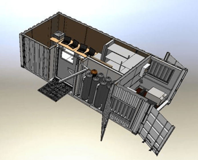
The concept focuses on mobility without sacrificing industrial efficiency. A complete mobile production unit may include CNC machining stations, automated loading systems, casing forming equipment, propellant handling sections, robotic assembly cells, inspection modules, and packaging stations integrated inside standard ISO containers or expandable mobile shelters. Such systems allow defense organizations and industrial suppliers to establish temporary or semi-permanent ammunition production capabilities wherever rapid deployment is required.
Drone ammunition manufacturing requires extremely high dimensional consistency and lightweight yet durable materials. Effective production systems therefore utilize servo-controlled forming machines, automated feeding mechanisms, laser measurement systems, and PLC-controlled process monitoring to maintain repeatability during continuous operation. Integrated quality assurance systems can automatically inspect tolerances, wall thicknesses, concentricity, and assembly precision in real time, minimizing rejection rates and improving operational reliability.
Modern mobile ammunition production platforms are increasingly designed around modularity. Different production modules can be exchanged depending on the required munition type, payload configuration, caliber range, or operational requirement. This enables manufacturers to adapt quickly to evolving battlefield technologies and drone system specifications. A mobile line configured for small drone payload ammunition may later be reconfigured for loitering munition components, fragmentation casings, miniature projectile bodies, or specialized aerial deployment cartridges.
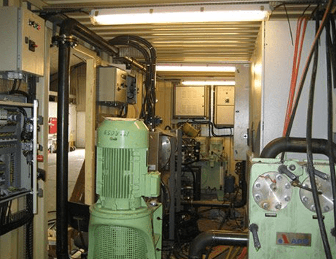
Energy efficiency and autonomous operation are also major advantages of advanced mobile production systems. Many designs integrate independent power generation units, compressed air systems, hydraulic stations, cooling infrastructure, and digital monitoring interfaces into a single transportable architecture. Remote diagnostics and industrial IoT integration allow operators to monitor machine performance, maintenance schedules, production statistics, and quality metrics from centralized command centers.
Effective mobile drone ammunition production additionally reduces dependency on vulnerable centralized supply chains. Distributed manufacturing capabilities improve production resilience and shorten delivery timelines, especially in regions where rapid replenishment and operational continuity are critical. Instead of transporting large volumes of finished ammunition across long distances, raw materials and semi-finished components can be delivered to mobile facilities for localized final production and assembly.
Advanced automation further enhances safety and productivity. Robotic handling systems minimize manual interaction during sensitive manufacturing stages, while enclosed production cells and automated material transfer systems improve operational security. Smart control software can synchronize multiple stations simultaneously, enabling stable high-volume output within a compact footprint.
The future of mobile drone ammunition production is closely linked with smart manufacturing technologies, digital twins, predictive maintenance systems, and AI-assisted process optimization. As unmanned aerial systems continue to evolve rapidly, flexible and mobile production infrastructure will become increasingly important for manufacturers seeking scalable, responsive, and high-efficiency defense manufacturing solutions.
Effective mobile drone ammunition production requires a combination of industrial mobility, precision engineering, flexible automation, and rapid deployment capability in order to satisfy the increasing demand for modern unmanned aerial system support equipment. Mobile manufacturing systems are no longer viewed only as emergency production alternatives but as highly strategic industrial assets capable of maintaining uninterrupted supply capacity in dynamic operational environments. The integration of compact manufacturing technologies inside transportable production platforms enables manufacturers to establish highly efficient ammunition production capabilities with minimal infrastructure requirements while maintaining industrial-grade accuracy, repeatability, and process stability. Containerized production architecture, modular machine integration, and intelligent automation software collectively create a self-sufficient manufacturing ecosystem that can operate independently in remote locations, industrial zones, temporary facilities, or tactical deployment areas where conventional fixed factories may not be practical or sufficiently responsive.
The effectiveness of a mobile drone ammunition production platform is directly related to its ability to maintain continuous output while operating under transportation limitations, energy constraints, environmental fluctuations, and rapidly changing operational requirements. For this reason, modern systems are engineered around modular production cells that can be assembled, expanded, relocated, or reconfigured according to mission requirements and production priorities. Individual modules may include high-speed CNC turning centers, automated deep drawing presses, precision forming systems, robotic welding stations, servo-controlled trimming machines, automated assembly cells, digital inspection units, laser measurement systems, and packaging modules integrated into compact transportable structures. These production units are typically designed using reinforced container platforms or mobile industrial trailers capable of withstanding vibration, temperature variation, and harsh operating conditions during transportation and deployment.
One of the most important advantages of mobile drone ammunition manufacturing is the reduction of logistical complexity associated with centralized ammunition supply chains. Traditional ammunition production infrastructure depends heavily on large permanent facilities, extensive transportation networks, and centralized inventory systems that may become vulnerable to delays, bottlenecks, or infrastructure disruptions. Mobile production systems decentralize manufacturing capability by distributing production capacity closer to operational demand centers. This significantly shortens supply timelines, improves replenishment speed, reduces transportation exposure, and increases manufacturing resilience under rapidly changing conditions. Raw materials, metal coils, alloy billets, explosive components, and electronic assemblies can be delivered to decentralized production nodes where final manufacturing and assembly operations are completed near the point of deployment.
Automation plays a decisive role in achieving both productivity and operational safety within compact mobile manufacturing environments. Advanced PLC systems synchronize machine movements, monitor production parameters, optimize cycle times, and maintain dimensional accuracy across all production stages. Human-machine interface systems provide operators with centralized control over feeding systems, hydraulic units, servo drives, quality monitoring systems, and robotic handling equipment. Automated loading and unloading mechanisms reduce manual intervention while increasing production speed and process consistency. Vision systems equipped with artificial intelligence algorithms can inspect component geometry, detect surface imperfections, verify dimensional tolerances, and automatically reject defective parts during continuous operation. Such automation technologies allow mobile facilities to achieve manufacturing standards comparable to large-scale industrial plants despite operating within significantly smaller physical footprints.
Mobile Drone Ammunition Production
The structural design of mobile drone ammunition production units emphasizes compactness without compromising industrial capability. Space optimization becomes a critical engineering priority because each production module must maximize manufacturing density while preserving safe operational access and maintenance accessibility. Foldable workstations, integrated storage systems, overhead cable routing, modular ventilation assemblies, and compact hydraulic power units are frequently used to optimize internal layouts. Thermal management systems maintain stable operating temperatures for sensitive machining and electronic control equipment, while vibration isolation technologies protect precision components during transportation and operation. Air filtration systems and pressure-controlled compartments may also be incorporated to maintain clean manufacturing environments for sensitive assembly processes involving guidance electronics, sensor modules, ignition systems, or precision aerodynamic components.
The increasing use of lightweight drone platforms has generated demand for highly specialized miniature ammunition systems requiring exceptional manufacturing precision. This has accelerated the development of micro-machining technologies, high-precision metal forming systems, and advanced materials processing techniques suitable for mobile production environments. Lightweight aluminum alloys, advanced steels, titanium components, composite structures, and specialized polymer materials are increasingly processed using compact CNC systems and digitally controlled forming equipment capable of maintaining micron-level tolerances. High-speed spindle systems, servo-electric presses, and multi-axis machining centers allow complex drone ammunition components to be manufactured with extremely high dimensional consistency while minimizing material waste and energy consumption.
Energy independence is another defining characteristic of effective mobile ammunition production infrastructure. Many advanced systems integrate autonomous power generation modules including diesel generators, hybrid energy systems, battery storage units, and intelligent power management software capable of stabilizing electrical loads during high-demand manufacturing cycles. Integrated compressed air systems, cooling units, hydraulic reservoirs, and industrial ventilation modules allow complete production independence without reliance on external infrastructure. Some next-generation concepts additionally explore renewable energy integration and smart energy optimization technologies to reduce operational costs and improve deployment flexibility in isolated environments.
Digitalization continues to reshape the future of mobile manufacturing technologies through the integration of industrial IoT networks, cloud-based monitoring systems, predictive maintenance algorithms, and digital twin simulations. Production managers can remotely monitor machine performance, production rates, energy consumption, maintenance schedules, and quality control statistics in real time through centralized digital platforms. Predictive analytics can identify potential equipment failures before breakdowns occur, minimizing downtime and improving operational continuity. Digital twin technology allows manufacturers to simulate entire production processes virtually before physical deployment, enabling layout optimization, process validation, and capacity planning with significantly reduced development risk.
Scalability is also a major advantage of modular mobile production architecture. Manufacturers can begin with a limited number of essential production modules and later expand capacity by integrating additional forming stations, machining cells, robotic assembly units, or automated packaging systems. This flexible expansion capability enables organizations to adapt production capacity according to changing operational demands without investing in large permanent infrastructure projects. Different production modules may also be rapidly exchanged depending on ammunition type, payload configuration, drone platform specifications, or evolving technological requirements. Such flexibility is becoming increasingly valuable as drone warfare technologies continue to evolve at a rapid pace and require increasingly specialized munition systems.
Advanced safety engineering is fundamental within all mobile ammunition production environments. Enclosed production cells, blast-resistant compartmentalization, automated fire suppression systems, gas detection units, emergency shutdown protocols, and remote-controlled handling systems are integrated to minimize operational risk. Sensitive production stages involving energetic materials, ignition systems, or precision explosive components can be isolated inside reinforced compartments with dedicated ventilation and monitoring systems. Automated robotic transfer systems further reduce human exposure to hazardous processes while maintaining stable production flow and consistent assembly quality.
The future development of effective mobile drone ammunition production will likely focus on greater automation density, higher manufacturing flexibility, improved energy efficiency, autonomous process management, and increased integration with artificial intelligence systems. Emerging technologies such as additive manufacturing, robotic swarm logistics, autonomous mobile factories, adaptive machine learning optimization, and decentralized digital production networks may significantly redefine how ammunition manufacturing infrastructure is designed and deployed in the coming decades. As demand for rapid-response manufacturing capability continues to increase, mobile production platforms are expected to become one of the most important strategic components of next-generation defense manufacturing ecosystems.
The operational effectiveness of mobile drone ammunition production systems also depends heavily on the integration of advanced supply chain coordination and intelligent manufacturing logistics capable of supporting continuous production under rapidly changing conditions. Unlike traditional fixed factories that operate within stable industrial ecosystems, mobile manufacturing units must maintain production efficiency while adapting to variable deployment locations, transportation schedules, environmental limitations, workforce availability, and fluctuating material supply conditions. This creates a strong demand for highly adaptive production management systems capable of dynamically balancing manufacturing priorities, raw material inventories, machine utilization rates, and maintenance requirements in real time. Intelligent inventory tracking technologies, RFID-based material management systems, automated warehouse modules, and AI-supported production scheduling software are increasingly integrated into modern mobile manufacturing platforms to ensure uninterrupted operational continuity and rapid production responsiveness.
The compact nature of mobile ammunition manufacturing also drives continuous innovation in machine miniaturization and multifunctional industrial design. Production equipment installed inside transportable modules must provide industrial-scale precision and reliability while occupying minimal space and maintaining low overall system weight. This has encouraged the development of hybrid manufacturing machines capable of performing multiple operations within a single compact platform. A single integrated system may combine forming, trimming, drilling, threading, laser marking, and automated inspection functions within one synchronized production cell. Multifunctional robotic arms equipped with interchangeable tooling systems can automatically switch between handling, assembly, welding, fastening, and inspection operations without requiring extensive manual intervention. Such design philosophies maximize manufacturing density while reducing setup complexity and transportation requirements.
Modern drone ammunition systems themselves are becoming increasingly sophisticated, incorporating programmable electronics, miniature stabilization systems, lightweight aerodynamic structures, smart fusing technologies, and highly specialized payload configurations. As a result, mobile manufacturing platforms must evolve beyond traditional mechanical production and incorporate advanced electronic assembly capability. Precision electronic integration modules, clean-room-compatible assembly environments, micro-soldering stations, automated PCB handling systems, and digital calibration equipment are becoming essential elements of next-generation mobile production facilities. These technologies allow complete ammunition systems to be assembled, tested, calibrated, and packaged entirely within self-contained mobile production ecosystems without reliance on external infrastructure.
Material science advancements are also playing a central role in improving the effectiveness of mobile drone ammunition production. Lightweight composite materials, high-strength aluminum alloys, titanium structures, and advanced engineered polymers reduce overall drone payload weight while maintaining structural durability and aerodynamic stability. Mobile production systems increasingly integrate compact composite processing technologies, precision heat treatment systems, automated resin handling units, and digitally controlled curing processes capable of producing advanced lightweight structures in field-deployable environments. The ability to manufacture structurally optimized lightweight ammunition components directly inside mobile facilities significantly improves logistical efficiency while enhancing drone operational range and payload performance.
Environmental adaptability represents another critical engineering challenge within mobile manufacturing systems. These production units may operate across highly diverse climates including deserts, humid coastal environments, mountainous terrain, arctic conditions, or tropical regions. Consequently, all mechanical, hydraulic, electrical, and electronic systems must be engineered for extreme environmental resilience. Climate-controlled container interiors, vibration-resistant machine foundations, corrosion-protected structural components, dust filtration systems, and temperature stabilization technologies are integrated to ensure stable production quality regardless of external conditions. Advanced monitoring systems continuously track humidity, air quality, vibration levels, and thermal stability to protect sensitive production processes and maintain consistent manufacturing tolerances.
The integration of artificial intelligence into mobile drone ammunition production is expected to dramatically increase manufacturing efficiency and operational autonomy in the coming years. AI-driven optimization systems can continuously analyze production performance, machine conditions, defect patterns, energy consumption, and material utilization to automatically improve manufacturing parameters during operation. Machine learning algorithms can identify subtle process deviations before they become critical failures, allowing predictive correction and real-time optimization of production flow. AI-assisted robotic systems can further enhance flexibility by adapting automatically to new product configurations, tooling changes, or assembly variations without extensive manual reprogramming. Such adaptive automation technologies are especially valuable in mobile environments where rapid reconfiguration and flexible production capability are essential.
Cybersecurity has also become an increasingly important component of mobile ammunition manufacturing infrastructure due to the growing digitalization of industrial control systems and remote monitoring networks. Secure industrial communication protocols, encrypted data transmission systems, isolated operational networks, and multi-layer cybersecurity architectures are necessary to protect sensitive production data and prevent unauthorized system access. Since mobile production platforms may operate in highly sensitive environments, secure digital infrastructure becomes equally as important as mechanical reliability and production capability. Future systems will likely integrate autonomous cybersecurity monitoring tools capable of detecting anomalies, isolating compromised systems, and maintaining operational continuity even under attempted cyber intrusion scenarios.
The mobility aspect of these manufacturing systems additionally creates significant strategic flexibility for industrial manufacturers and defense organizations. Production capacity can be rapidly repositioned according to changing operational priorities, infrastructure availability, regional demand fluctuations, or emergency manufacturing requirements. Entire manufacturing ecosystems can be transported via truck, rail, ship, or cargo aircraft and become operational within very short deployment timelines. This strategic mobility allows organizations to establish temporary production capacity in regions where conventional industrial infrastructure is unavailable, damaged, or insufficient for urgent manufacturing demands. The combination of transportability, modular scalability, and autonomous operation transforms mobile production systems into highly flexible industrial assets capable of supporting both peacetime manufacturing and emergency surge production scenarios.
Advanced testing and validation technologies are also increasingly integrated directly into mobile ammunition production environments. Automated ballistic testing systems, pressure analysis equipment, vibration testing modules, thermal cycling chambers, and digital calibration stations allow manufacturers to verify product performance immediately after production without transporting components to external laboratories. Integrated data acquisition systems automatically record performance metrics, quality statistics, and traceability information for every production batch. This continuous validation capability significantly improves production reliability while reducing quality assurance timelines and logistical complexity.
The long-term evolution of mobile drone ammunition production will likely converge with broader trends in autonomous manufacturing and distributed industrial ecosystems. Future production platforms may operate with minimal human supervision through the integration of fully autonomous robotic material handling systems, AI-managed production scheduling, self-diagnosing machinery, and adaptive process control software. Swarm logistics concepts involving multiple interconnected mobile factories could create decentralized manufacturing networks capable of dynamically redistributing production tasks according to operational requirements and resource availability. Additive manufacturing technologies may further enable on-demand production of highly customized ammunition components with reduced tooling dependency and accelerated product development cycles.
As unmanned systems continue to expand across military, security, industrial, and surveillance applications, the demand for agile manufacturing infrastructure capable of producing specialized ammunition systems rapidly and efficiently will continue to increase. Mobile production technology represents not only a logistical solution but a fundamental transformation in manufacturing philosophy where flexibility, decentralization, digitalization, and rapid adaptability become equally important as traditional mass-production efficiency. The continued integration of automation, artificial intelligence, advanced materials engineering, and modular industrial architecture will likely establish mobile drone ammunition production as one of the defining industrial technologies of future decentralized manufacturing systems.
The increasing sophistication of unmanned aerial systems has also accelerated the demand for specialized production ecosystems capable of manufacturing not only ammunition bodies but also integrated aerodynamic assemblies, stabilization mechanisms, electronic guidance interfaces, lightweight propulsion elements, and advanced payload delivery structures within highly compact manufacturing footprints. Mobile drone ammunition production therefore continues evolving from simple transportable machining facilities into fully integrated micro-industrial complexes capable of executing nearly every stage of precision manufacturing independently. These systems increasingly combine metal forming technologies, micro-electronics integration, advanced robotics, automated calibration systems, and intelligent process synchronization inside unified operational environments designed for rapid deployment and continuous manufacturing flexibility.
One of the most critical engineering priorities within such mobile production ecosystems is minimizing setup time while maintaining maximum production stability. Traditional industrial factories often require extensive infrastructure preparation, machine alignment procedures, foundation work, and utility integration before achieving operational readiness. In contrast, modern mobile manufacturing platforms are engineered for accelerated deployment through pre-aligned machine structures, modular utility connections, self-leveling support systems, and integrated commissioning software capable of rapidly synchronizing all production modules after transportation. Hydraulic systems, pneumatic networks, electrical distribution panels, cooling circuits, and industrial communication lines are typically preconfigured inside standardized modular architectures to minimize installation complexity. This allows complete production lines to become operational within significantly reduced timeframes while preserving manufacturing accuracy and equipment reliability.
The effectiveness of mobile ammunition production also depends heavily on advanced process stability under continuously changing operating conditions. Transportation vibration, temperature fluctuations, humidity variation, dust exposure, and inconsistent power environments create engineering challenges rarely encountered inside permanent industrial plants. To overcome these limitations, manufacturers increasingly utilize vibration-compensated machine frames, adaptive servo control systems, thermal expansion monitoring technologies, and automated calibration protocols capable of maintaining machining accuracy despite environmental disturbances. Laser alignment systems continuously verify spindle positioning, robotic calibration points, and tooling geometry during operation, ensuring production consistency even after repeated transport cycles and redeployments.
Another major development within mobile drone ammunition production involves the integration of smart manufacturing analytics capable of transforming production data into real-time operational intelligence. Every machining cycle, forming operation, robotic movement, assembly sequence, inspection result, and material transfer process generates valuable performance data that can be continuously analyzed to optimize efficiency. AI-assisted monitoring systems can identify subtle variations in tool wear, vibration patterns, thermal behavior, energy consumption, or material deformation before these variables affect final product quality. Such predictive intelligence allows production systems to automatically compensate for deviations, schedule maintenance proactively, and maintain uninterrupted manufacturing continuity with minimal operator intervention.
Compact robotic automation continues to play a central role in maximizing production efficiency within limited physical space. Modern collaborative robotic systems are increasingly designed specifically for confined industrial environments where high operational density is essential. Lightweight multi-axis robotic arms, autonomous guided transfer units, and compact automated handling systems can operate simultaneously within tightly optimized layouts while maintaining high positional precision and operational safety. These robotic systems are capable of performing repetitive assembly tasks, material loading operations, component inspections, precision fastening procedures, laser marking sequences, and packaging activities continuously with minimal downtime. Flexible end-effector systems further increase manufacturing adaptability by allowing rapid tool changes between different production configurations and ammunition designs.
The emergence of advanced digital manufacturing standards is also reshaping how mobile ammunition production platforms are designed and operated. Industry 4.0 technologies including digital twins, cloud-connected manufacturing systems, edge computing devices, and decentralized industrial communication protocols enable highly coordinated production management across multiple mobile facilities simultaneously. Operators located at centralized command centers can remotely supervise production performance, diagnose machine conditions, adjust operational parameters, and synchronize manufacturing activities between geographically distributed production nodes in real time. This creates the foundation for highly decentralized manufacturing networks capable of dynamically reallocating production capacity according to operational priorities and logistical conditions.
Additive manufacturing technologies are expected to become increasingly important within future mobile drone ammunition production systems due to their ability to reduce tooling requirements and accelerate component development. Compact industrial metal 3D printing systems, polymer additive manufacturing units, and hybrid machining-additive platforms allow rapid production of complex lightweight geometries that would be difficult or inefficient to manufacture using conventional processes alone. On-demand production capability significantly improves flexibility by enabling rapid adaptation to new drone platform designs, payload configurations, aerodynamic structures, or mission-specific component requirements without extensive retooling. Additive manufacturing additionally supports distributed spare part production, allowing maintenance components and tooling elements to be manufactured directly within deployed mobile facilities.
Thermal management and energy optimization technologies are becoming increasingly critical as mobile production systems incorporate more advanced automation and high-density electronic infrastructure. Intelligent cooling systems utilizing adaptive airflow management, liquid cooling circuits, heat recovery technologies, and energy-efficient thermal regulation software help maintain stable machine performance while reducing total energy consumption. Some advanced concepts explore hybrid energy architectures combining diesel generation, battery storage systems, renewable energy integration, and smart load-balancing algorithms capable of optimizing power distribution dynamically across the entire production ecosystem. Such energy independence significantly increases deployment flexibility while reducing operational dependency on external infrastructure.
Human-machine interaction within mobile production environments is also evolving rapidly through the integration of augmented reality interfaces, immersive diagnostic systems, and intelligent operator assistance technologies. Maintenance personnel may utilize AR headsets displaying live machine diagnostics, component identification overlays, repair procedures, and performance analytics directly within their field of view. Operators can interact with centralized production management systems through touchscreen interfaces, voice-command systems, or AI-assisted monitoring dashboards that simplify supervision of highly complex manufacturing operations. These technologies reduce training requirements, improve maintenance efficiency, and increase overall operational reliability within compact high-density industrial environments.
The miniaturization trend affecting drone systems themselves is simultaneously driving innovation in ultra-precision manufacturing technologies. Micro-scale machining systems, miniature robotic assembly cells, ultra-fine laser processing equipment, and precision micro-forming technologies are increasingly necessary for manufacturing compact drone ammunition systems requiring extremely high dimensional accuracy. These miniature manufacturing processes must operate reliably within mobile industrial platforms while maintaining tolerances measured in microns. Achieving such precision under mobile deployment conditions requires sophisticated stabilization technologies, advanced sensor integration, and highly refined machine control algorithms capable of compensating for even minimal environmental disturbances.
Future mobile ammunition production platforms may eventually evolve toward semi-autonomous industrial ecosystems capable of self-optimization, adaptive reconfiguration, and distributed collaborative manufacturing. Autonomous logistics vehicles may transport raw materials between interconnected mobile factories while AI-driven production networks automatically allocate manufacturing tasks according to machine availability, material inventory, operational urgency, and transportation efficiency. Intelligent robotic systems could autonomously replace tooling, recalibrate machinery, inspect components, and maintain continuous production flow with limited human oversight. Such developments would significantly increase manufacturing resilience, operational flexibility, and decentralized production capability across highly dynamic operational environments.
The convergence of modular industrial engineering, artificial intelligence, advanced robotics, digital manufacturing infrastructure, and lightweight materials technology continues to redefine the concept of ammunition manufacturing itself. Mobile drone ammunition production is no longer simply an extension of traditional factory operations into transportable formats but an entirely new manufacturing paradigm focused on adaptability, decentralization, intelligent automation, and rapid responsiveness. As drone technologies continue evolving at accelerated speed across military and industrial applications, mobile production systems will likely become indispensable components of future manufacturing strategy, enabling highly flexible and scalable production capability wherever rapid deployment, operational resilience, and manufacturing autonomy are required.
Rapid Mobile Drone Ammunition Production
The primary objective of rapid mobile drone ammunition production is to minimize the time between operational demand and manufacturing output. This requires extremely efficient process integration where raw material preparation, metal forming, machining, assembly, inspection, and packaging are synchronized within compact high-density production layouts. Modern systems utilize servo-driven forming presses, automated CNC machining centers, robotic transfer systems, laser measurement equipment, and PLC-controlled assembly stations to achieve stable high-speed production while maintaining precision and repeatability. Every manufacturing stage is optimized for minimal cycle time, reduced manual intervention, and rapid product flow across interconnected production cells.
Rapid mobile drone ammunition production represents a new generation of decentralized manufacturing technology designed to provide fast, flexible, and highly efficient ammunition output directly near operational deployment zones. Unlike traditional fixed industrial facilities that require extensive infrastructure and long logistical chains, rapid mobile production systems are engineered for immediate deployment, accelerated setup, and continuous manufacturing capability within transportable industrial platforms. These systems combine modular automation, compact precision machinery, intelligent production software, and autonomous support infrastructure to create self-contained manufacturing environments capable of operating under dynamic and demanding conditions.
Containerized industrial architecture has become one of the defining characteristics of rapid mobile production systems. Standard ISO containers, expandable industrial shelters, and transportable modular structures are transformed into fully operational manufacturing facilities equipped with integrated electrical distribution, compressed air systems, hydraulic power units, climate control modules, and digital monitoring infrastructure. Preconfigured utility connections and modular machine foundations allow entire production lines to become operational within very short deployment periods after transportation. This rapid deployment capability significantly improves manufacturing responsiveness during urgent operational scenarios where conventional industrial expansion would require excessive time and infrastructure investment.
Advanced automation is fundamental to achieving rapid production performance inside mobile manufacturing platforms. Automated feeding systems continuously supply raw materials to forming and machining stations while robotic handling systems transfer components between synchronized manufacturing processes without interruption. Intelligent control software dynamically balances machine workloads, adjusts production speed, monitors tooling conditions, and optimizes operational efficiency in real time. Vision-based inspection systems equipped with artificial intelligence algorithms continuously verify dimensional accuracy, surface quality, and assembly precision during operation, ensuring stable product quality even during high-speed manufacturing cycles.
Rapid mobile production systems are increasingly designed around modular scalability and flexible reconfiguration. Different manufacturing modules can be rapidly exchanged or expanded according to changing drone ammunition specifications, payload requirements, or operational priorities. A production platform configured for miniature aerial munition bodies may later be reconfigured for fragmentation casings, specialized payload components, lightweight projectile structures, or drone deployment cartridges with minimal modification time. This flexibility allows manufacturers to adapt quickly to evolving unmanned aerial system technologies and continuously changing operational demands.
Lightweight materials processing has become increasingly important within rapid drone ammunition manufacturing due to the strict payload limitations of modern unmanned aerial systems. Advanced aluminum alloys, titanium structures, high-strength steels, and composite materials are processed using compact high-precision manufacturing systems capable of maintaining extremely tight tolerances during continuous operation. Servo-electric presses, multi-axis machining centers, automated trimming systems, and laser processing equipment enable rapid production of lightweight yet structurally durable ammunition components optimized for aerodynamic efficiency and payload performance.
The effectiveness of rapid mobile ammunition production also depends heavily on intelligent logistics integration. Digital inventory systems continuously monitor raw material consumption, tooling availability, spare parts inventory, and production capacity while AI-assisted scheduling software dynamically adjusts manufacturing priorities according to operational requirements. Distributed manufacturing networks consisting of multiple interconnected mobile production units can coordinate production activity across wide geographic regions, improving manufacturing resilience and reducing dependency on centralized industrial infrastructure.
Energy autonomy remains another critical feature of advanced mobile production systems. Integrated diesel generators, battery storage modules, smart energy management systems, and autonomous utility infrastructure allow complete production independence even in remote deployment locations. Intelligent power distribution systems optimize electrical consumption across all manufacturing modules while adaptive cooling systems maintain stable operating conditions for high-precision equipment and electronic control infrastructure. Some next-generation concepts additionally integrate renewable energy technologies and hybrid power architectures to improve operational sustainability and deployment flexibility.
Artificial intelligence is expected to dramatically expand the capabilities of rapid mobile drone ammunition production over the coming years. AI-driven manufacturing systems can analyze machine performance, production statistics, thermal behavior, vibration patterns, and defect trends in real time to continuously optimize production parameters automatically. Predictive maintenance algorithms reduce downtime by identifying potential component failures before operational interruptions occur, while adaptive robotic systems can automatically adjust to new production configurations with minimal manual programming. Such intelligent automation technologies significantly increase manufacturing speed, flexibility, and operational reliability within compact transportable production environments.
The future evolution of rapid mobile drone ammunition production will likely involve greater autonomy, higher manufacturing density, improved digital connectivity, and deeper integration with decentralized industrial ecosystems. Autonomous robotic logistics, additive manufacturing technologies, AI-managed production networks, and self-optimizing industrial systems may eventually enable fully autonomous mobile factories capable of producing highly specialized ammunition systems with minimal human supervision. As unmanned aerial technologies continue expanding across defense and industrial sectors, rapid mobile production infrastructure will become increasingly essential for organizations seeking agile, scalable, and resilient manufacturing capability in rapidly changing operational environments.
Rapid mobile drone ammunition production systems are increasingly being designed around the concept of manufacturing independence, where complete industrial capability can be deployed, operated, expanded, and relocated without dependence on large permanent infrastructure networks. This manufacturing philosophy represents a major shift away from centralized industrial concentration toward highly distributed and adaptive production ecosystems capable of responding immediately to operational demand fluctuations. The speed advantage provided by mobile manufacturing infrastructure is not limited solely to transportation mobility but extends across every aspect of production architecture including installation, commissioning, calibration, reconfiguration, maintenance, quality verification, and logistical support. Every engineering decision within these systems is optimized to reduce operational delay while maximizing continuous manufacturing efficiency under highly dynamic conditions.
The acceleration of drone technology development has created growing demand for ammunition systems that are lighter, more precise, more modular, and more adaptable than conventional munition designs. As drone platforms continue shrinking in size while increasing in operational complexity, the associated ammunition manufacturing processes require exceptionally refined production methods capable of maintaining extremely high dimensional accuracy and structural consistency. Mobile production systems must therefore integrate ultra-precision machining capability, automated balancing systems, lightweight alloy processing technologies, miniature electronic assembly stations, and high-speed digital inspection equipment into compact transportable environments without sacrificing production reliability or throughput capacity. This combination of mobility and precision engineering represents one of the most technically challenging aspects of next-generation decentralized manufacturing systems.
Rapid manufacturing effectiveness also depends heavily on minimizing production bottlenecks through intelligent process synchronization. In advanced mobile facilities, forming operations, machining stages, robotic transfer systems, inspection cells, and packaging modules are digitally coordinated through centralized industrial control software capable of monitoring every production variable simultaneously. Production flow is continuously adjusted according to machine availability, tooling condition, material supply status, and output demand. Automated buffering systems temporarily balance production speed differences between manufacturing stages, preventing interruptions while maintaining stable product flow throughout the entire facility. Such synchronization technologies significantly improve manufacturing efficiency within space-constrained mobile industrial environments where production interruptions can have amplified operational consequences.
The evolution of compact industrial robotics has become one of the most important enabling technologies behind rapid mobile ammunition production. Traditional industrial robots designed for large factory environments often occupy excessive space and require complex infrastructure integration. Modern compact robotic systems are specifically engineered for high-density modular manufacturing layouts where flexibility, precision, and space optimization are equally important. Collaborative robotic arms with integrated vision systems, force feedback sensors, and adaptive motion control algorithms can perform delicate assembly operations, precision material handling, automated fastening procedures, and continuous inspection tasks within extremely compact production cells. These robotic systems not only improve production speed but also increase manufacturing consistency while reducing operator workload and minimizing exposure to hazardous manufacturing processes.
The integration of autonomous diagnostics and self-monitoring technologies further increases operational efficiency within rapid mobile production ecosystems. Embedded sensor networks continuously monitor machine vibration, thermal expansion, hydraulic pressure, spindle performance, electrical stability, lubrication conditions, and structural stress throughout the facility. AI-assisted maintenance algorithms analyze this data in real time to predict component wear, detect abnormal operating conditions, and schedule preventive maintenance before failures occur. This predictive maintenance capability is particularly valuable within mobile production environments where unexpected downtime can significantly impact operational continuity and logistical planning.
Advanced manufacturing simulation technologies are also increasingly integrated into mobile production development processes. Digital twin systems create fully virtual representations of entire production facilities, allowing engineers to simulate manufacturing operations, machine interactions, material flow, thermal behavior, and maintenance procedures before physical deployment occurs. These simulations help optimize production layouts, reduce commissioning time, improve energy efficiency, and identify operational inefficiencies before deployment. During active operation, digital twin platforms can continue receiving live production data from deployed facilities, enabling real-time performance analysis and continuous operational optimization across distributed manufacturing networks.
The future of rapid mobile drone ammunition production will likely involve increasing levels of autonomous manufacturing capability. Autonomous material transport systems, self-configuring production cells, adaptive robotic assembly platforms, and AI-managed operational scheduling may eventually allow mobile factories to function with extremely limited human supervision. Raw materials could be automatically unloaded, processed, assembled, inspected, and packaged through entirely integrated robotic workflows coordinated by centralized artificial intelligence systems capable of optimizing every aspect of production continuously. Such autonomous manufacturing ecosystems would dramatically increase scalability, deployment flexibility, and production resilience while reducing workforce dependency in remote or high-tempo operational environments.
Miniaturization trends within unmanned aerial systems are simultaneously driving innovation in micro-manufacturing technologies suitable for mobile industrial deployment. Micro-CNC machining systems, ultra-fine laser processing equipment, precision additive manufacturing units, and micro-robotic assembly cells are becoming increasingly necessary for producing miniature ammunition components with extremely tight tolerances and highly complex geometries. These systems require advanced stabilization technologies capable of compensating for vibration, temperature variation, and transport-induced structural shifts while preserving micron-level manufacturing accuracy. Maintaining such precision within mobile deployment environments represents a major engineering achievement and will continue driving innovation in compact industrial design.
Material optimization also plays a central role in improving rapid production efficiency and drone ammunition performance. Engineers increasingly utilize topology optimization software, advanced alloy formulations, lightweight composite materials, and hybrid structural designs to reduce component weight while maximizing durability and aerodynamic efficiency. Mobile production facilities are therefore evolving beyond traditional metalworking operations and incorporating advanced materials processing capability including composite curing systems, laser-assisted bonding technologies, automated resin infusion modules, and compact thermal treatment equipment. These technologies allow highly specialized lightweight structures to be manufactured directly inside decentralized mobile facilities with minimal infrastructure dependency.
The strategic value of distributed manufacturing capability continues to increase as supply chain resilience becomes more important across global industrial systems. Centralized factories remain vulnerable to transportation disruption, infrastructure limitations, geopolitical instability, and production bottlenecks that can significantly delay operational readiness. Rapid mobile production systems reduce such vulnerabilities by decentralizing manufacturing capacity across multiple relocatable facilities capable of operating independently or cooperatively depending on operational requirements. Manufacturing networks consisting of interconnected mobile factories can dynamically redistribute production tasks, relocate capacity rapidly, and maintain operational continuity even when individual facilities encounter disruption or infrastructure limitations.
The integration of additive manufacturing into rapid mobile ammunition production is expected to accelerate significantly in future industrial development cycles. Hybrid manufacturing systems combining subtractive machining, robotic assembly, and industrial 3D printing capability allow highly flexible production with minimal tooling dependency. Complex internal geometries, lightweight lattice structures, aerodynamic surfaces, and customized payload interfaces can be produced rapidly using compact additive manufacturing platforms integrated directly into mobile facilities. This capability dramatically shortens development cycles for new ammunition designs while enabling rapid adaptation to changing drone technologies and mission-specific operational requirements.
Future mobile manufacturing ecosystems may eventually evolve into highly interconnected autonomous industrial networks capable of operating globally through coordinated digital infrastructure. AI-managed logistics systems could automatically direct raw material movement, production allocation, maintenance scheduling, and deployment positioning according to real-time operational demand and manufacturing capacity analysis. Autonomous transport vehicles, robotic loading platforms, and modular self-expanding production units may further increase deployment speed and operational scalability. Such developments would fundamentally transform industrial manufacturing strategy by replacing rigid centralized production architecture with highly adaptive, distributed, and continuously reconfigurable manufacturing ecosystems optimized for rapid response and operational resilience.
As unmanned systems continue becoming more sophisticated and operationally widespread, the industrial infrastructure supporting their ammunition production must evolve accordingly. Rapid mobile drone ammunition production represents the convergence of advanced robotics, digital manufacturing, modular engineering, intelligent automation, lightweight materials science, and decentralized industrial logistics into a unified manufacturing philosophy focused entirely on speed, flexibility, resilience, and adaptability. The continued advancement of these technologies will likely redefine the future of high-speed precision manufacturing across both defense and broader industrial applications.
The long-term scalability of rapid mobile drone ammunition production depends not only on manufacturing speed but also on the ability to sustain continuous technological adaptation as drone systems evolve toward greater autonomy, longer operational range, reduced size, higher payload efficiency, and increasingly sophisticated mission capabilities. Manufacturing infrastructure must therefore remain inherently flexible, capable of integrating new component geometries, emerging materials, evolving aerodynamic concepts, and advanced electronic subsystems without requiring complete redesign of the production ecosystem. This demand for continuous adaptability is driving the development of highly modular machine architectures where tooling systems, robotic end effectors, software libraries, and production modules can be exchanged or reprogrammed rapidly according to changing operational requirements. Instead of building fixed production lines dedicated to a single product type, modern mobile facilities are increasingly designed as configurable industrial platforms capable of supporting multiple ammunition variants simultaneously within the same compact manufacturing environment.
The reduction of production transition time between different ammunition configurations is becoming one of the most important indicators of manufacturing effectiveness. Advanced quick-change tooling systems, servo-driven positioning assemblies, automatic calibration routines, and digitally stored production profiles allow machines to switch rapidly between different operational modes with minimal manual adjustment. Intelligent software systems automatically load machining parameters, robotic movement paths, inspection tolerances, and process synchronization sequences according to the selected production configuration. Such flexibility enables mobile production systems to respond immediately to changing drone platform requirements, operational priorities, or specialized payload demands while maintaining continuous manufacturing efficiency.
Another major factor influencing the future of rapid mobile ammunition production is the growing integration of precision electronics into modern drone payload systems. Ammunition components increasingly incorporate programmable electronic modules, smart triggering systems, miniaturized sensor assemblies, communication interfaces, and advanced stabilization technologies that require extremely controlled manufacturing environments and highly specialized assembly processes. Mobile production facilities are therefore expanding beyond purely mechanical manufacturing capability and evolving into hybrid industrial-electronic integration ecosystems. Compact clean-room modules, automated electronic testing stations, precision micro-assembly robots, laser soldering systems, and digital calibration equipment are increasingly incorporated into mobile facilities to support advanced electronic integration directly within decentralized production environments.
High-density industrial computing infrastructure is also becoming a critical component of next-generation mobile manufacturing platforms. Edge computing systems positioned directly within production environments process enormous volumes of real-time operational data generated by machine sensors, robotic systems, inspection devices, environmental monitoring equipment, and production management software. These localized computing networks allow ultra-fast decision-making, predictive optimization, and immediate process correction without relying entirely on external data infrastructure. Machine learning algorithms continuously analyze operational behavior, identify production inefficiencies, predict maintenance requirements, and optimize machine coordination dynamically throughout active production cycles. The result is a highly adaptive manufacturing ecosystem capable of continuously improving its own operational performance over time.
Environmental efficiency is simultaneously becoming increasingly important within rapid mobile production systems due to the high energy density of compact industrial operations. Modern facilities integrate intelligent power management systems capable of balancing energy consumption across machining centers, robotic systems, cooling infrastructure, hydraulic units, and digital computing platforms in real time. Regenerative braking technologies within servo systems recover kinetic energy during machine deceleration cycles while advanced thermal recovery systems reuse waste heat generated by industrial equipment. Compact insulation systems, adaptive airflow management, and intelligent cooling algorithms further reduce total energy demand while preserving stable operating conditions for precision manufacturing processes.
The ability to establish fully operational manufacturing capability in geographically isolated or infrastructure-limited regions also requires highly advanced support autonomy. Mobile production systems increasingly integrate onboard water purification units, waste recycling systems, autonomous maintenance workshops, spare parts manufacturing capability, and self-contained utility infrastructure capable of sustaining long-duration operation without extensive external logistical support. Some future concepts explore fully autonomous industrial compounds where interconnected production modules, robotic logistics vehicles, energy generation systems, and digital control centers operate together as self-sufficient decentralized manufacturing ecosystems capable of supporting extended independent operation in highly remote environments.
Advanced human-machine collaboration technologies are also transforming operational efficiency inside mobile manufacturing environments. Instead of relying solely on conventional operator interfaces, modern production systems increasingly utilize augmented reality visualization, immersive diagnostic environments, gesture-controlled interfaces, and AI-assisted decision support systems to improve operational awareness and reduce training complexity. Maintenance personnel equipped with AR systems can instantly access live machine diagnostics, repair guidance, component schematics, and operational history directly within their field of vision while performing service procedures. AI-assisted operational systems can recommend production adjustments, identify emerging process instability, and guide operators through complex configuration changes with minimal manual analysis requirements.
The convergence of additive manufacturing with traditional high-speed machining processes continues to create entirely new production possibilities for drone ammunition manufacturing. Hybrid production systems capable of combining laser-based metal deposition, precision CNC finishing, robotic assembly, and automated inspection within unified manufacturing cells allow extremely complex structures to be produced with unprecedented flexibility. Lightweight lattice geometries, integrated cooling channels, aerodynamic optimization features, and structurally reinforced internal frameworks can be manufactured directly without requiring extensive multi-stage tooling operations. Such technologies significantly accelerate development cycles while enabling highly customized ammunition configurations optimized for specific drone platforms or operational missions.
The distributed nature of rapid mobile production also creates opportunities for entirely new industrial logistics models. Instead of transporting large inventories of completed ammunition products across long distances, future manufacturing systems may distribute digital production files, raw materials, and standardized machine modules to decentralized production nodes positioned strategically according to operational demand. Localized facilities could then manufacture mission-specific ammunition configurations on demand with minimal delay. This digitally distributed manufacturing model dramatically reduces storage requirements, transportation complexity, and supply chain vulnerability while increasing operational responsiveness and manufacturing resilience.
As industrial artificial intelligence systems continue advancing, future mobile production ecosystems may eventually evolve toward fully self-optimizing manufacturing networks where autonomous software agents continuously coordinate production scheduling, logistics management, predictive maintenance, energy distribution, machine calibration, and quality assurance without direct human supervision. Autonomous robotic maintenance systems could inspect machinery, replace worn tooling, recalibrate production equipment, and maintain uninterrupted manufacturing continuity automatically. Such developments would significantly increase production scalability while reducing workforce requirements and operational dependency on centralized technical support infrastructure.
The rapid expansion of drone applications across military, industrial, surveillance, security, and infrastructure sectors ensures that demand for flexible high-speed ammunition manufacturing capability will continue growing for the foreseeable future. Mobile production systems provide a unique combination of manufacturing precision, deployment flexibility, logistical resilience, and operational scalability that traditional fixed factories cannot easily replicate. As manufacturing technologies continue integrating advanced robotics, AI-driven optimization, digital industrial networking, additive manufacturing, lightweight materials engineering, and autonomous operational systems, rapid mobile drone ammunition production will likely become one of the most strategically important forms of decentralized industrial infrastructure in future advanced manufacturing environments.
Mobile Drone Ammunition Production Architecture
Mobile drone ammunition production architecture is built around the principle of creating a fully integrated, transportable, and rapidly deployable manufacturing ecosystem capable of producing precision ammunition systems within compact modular environments. Unlike traditional fixed industrial plants that depend on permanent infrastructure, large-scale utility networks, and centralized production layouts, mobile production architecture is specifically engineered to maximize flexibility, scalability, operational resilience, and manufacturing efficiency inside relocatable industrial platforms. Every structural, mechanical, electrical, digital, and logistical component within the architecture is optimized to support high-density manufacturing capability while maintaining rapid deployment readiness and continuous operational stability under highly dynamic conditions.
The architectural foundation of these systems typically begins with modular containerized infrastructure designed around standardized transport dimensions compatible with truck, rail, ship, and cargo aircraft logistics. Reinforced ISO containers, expandable tactical shelters, modular industrial trailers, and foldable production enclosures form the structural framework of the manufacturing ecosystem. These transportable modules are engineered with vibration-resistant support structures, integrated utility routing, thermal insulation systems, reinforced flooring, environmental sealing technologies, and self-leveling stabilization mechanisms capable of preserving machine alignment and operational integrity during transportation and deployment. The use of standardized modular dimensions simplifies transportation logistics while allowing flexible expansion and rapid reconfiguration of the overall production architecture according to operational requirements.
Inside the production architecture, manufacturing operations are typically organized into highly synchronized functional zones optimized for uninterrupted process flow and minimal internal material movement. Raw material preparation modules receive metal coils, alloy billets, composite materials, electronic assemblies, and auxiliary production inputs through automated handling systems connected to compact storage and inventory management units. Servo-controlled feeding systems distribute materials directly to forming stations, CNC machining cells, laser processing modules, or additive manufacturing systems according to real-time production scheduling data managed by centralized industrial control software. The entire internal layout is designed to minimize wasted motion, reduce transfer delays, and maximize manufacturing density within extremely constrained spatial environments.
The forming and machining architecture constitutes one of the most technically demanding sections of the mobile production ecosystem. Compact high-precision CNC machining centers, servo-electric forming presses, robotic trimming systems, laser cutting equipment, and multi-axis milling platforms are integrated into vibration-isolated machine foundations engineered specifically for mobile deployment conditions. These systems incorporate adaptive calibration technology, thermal compensation algorithms, dynamic balancing mechanisms, and digital position monitoring systems capable of preserving micron-level accuracy despite environmental disturbances, transport-induced structural shifts, or variable operating conditions. Intelligent machine coordination software synchronizes cycle timing, material transfer, tooling changes, and quality inspection processes across all production stages to maintain continuous manufacturing flow.
Robotic integration architecture plays a central role in maximizing productivity and automation density within mobile production facilities. Compact multi-axis robotic arms, autonomous transfer units, collaborative assembly systems, and automated inspection platforms are interconnected through centralized industrial communication networks that allow synchronized operation across the entire facility. Robotic systems handle raw material loading, component transfer, precision assembly operations, fastening procedures, laser welding sequences, packaging activities, and automated quality verification with minimal human intervention. Flexible end-effector architectures enable rapid adaptation between different ammunition configurations while preserving high operational speed and positional accuracy.
The digital architecture of mobile drone ammunition production systems is equally critical to overall operational effectiveness. Advanced industrial control infrastructure integrates PLC networks, edge computing systems, industrial IoT devices, machine vision platforms, predictive analytics software, and AI-assisted process optimization engines into a unified digital manufacturing environment. Every machine, robotic system, environmental sensor, inspection module, and utility subsystem continuously transmits operational data to centralized processing units capable of monitoring production status, machine conditions, material flow, energy consumption, and maintenance requirements in real time. Intelligent control algorithms analyze this data continuously to optimize cycle timing, reduce downtime, improve energy efficiency, and maintain stable product quality throughout continuous operation.
Environmental control architecture is another essential element within mobile production systems due to the sensitivity of precision manufacturing operations. Climate stabilization modules regulate temperature, humidity, air quality, and pressure conditions throughout the production environment to ensure dimensional consistency and protect sensitive electronic assembly operations. Advanced filtration systems remove airborne particles generated by machining and material processing operations while maintaining clean manufacturing conditions inside compact enclosed workspaces. Thermal management systems utilizing adaptive cooling circuits, intelligent airflow regulation, and heat recovery technologies maintain stable operating temperatures for both machinery and electronic infrastructure while minimizing overall energy consumption.
Energy infrastructure within mobile production architecture is designed around complete operational autonomy and redundancy. Integrated diesel generators, battery storage systems, smart power distribution networks, uninterruptible power supplies, hydraulic power units, compressed air systems, and intelligent energy management software allow the entire facility to operate independently of external infrastructure. Adaptive load balancing algorithms dynamically distribute power according to machine demand while regenerative technologies recover energy from servo systems and industrial braking processes to improve overall operational efficiency. Some advanced concepts additionally incorporate hybrid renewable energy integration and autonomous energy optimization systems capable of supporting extended deployment in isolated environments.
Safety architecture within mobile drone ammunition production facilities is engineered around layered protection strategies designed to minimize operational risk under high-density manufacturing conditions. Blast-resistant compartmentalization, automated fire suppression systems, gas monitoring sensors, emergency shutdown networks, pressure-controlled ventilation systems, and isolated hazardous material handling modules provide comprehensive protection throughout sensitive manufacturing operations. Robotic material transfer systems further reduce human exposure to hazardous processes while centralized safety control systems continuously monitor environmental conditions and machine status to prevent operational anomalies.
Logistical architecture also forms a critical part of overall production system design. Automated inventory management systems, RFID-based material tracking networks, digital warehouse modules, and intelligent supply chain coordination software maintain continuous visibility over raw material consumption, spare part inventory, tooling availability, and finished product flow. Distributed production architectures consisting of multiple interconnected mobile facilities can coordinate manufacturing tasks dynamically across geographically separated deployment zones through secure industrial communication networks and cloud-based production management systems.
Future mobile drone ammunition production architecture will likely evolve toward increasingly autonomous and decentralized operational models. Self-configuring production modules, AI-managed logistics coordination, robotic maintenance systems, autonomous material handling vehicles, and distributed digital manufacturing networks may eventually allow entire industrial ecosystems to deploy, operate, optimize, and sustain themselves with minimal human supervision. Modular additive manufacturing platforms, adaptive robotic assembly cells, and intelligent industrial software ecosystems will further increase manufacturing flexibility while reducing deployment complexity and infrastructure dependency.
The continued convergence of modular industrial engineering, advanced robotics, artificial intelligence, lightweight materials science, precision manufacturing technology, and distributed digital infrastructure is fundamentally redefining industrial production architecture itself. Mobile drone ammunition production architecture represents one of the clearest examples of this transformation, combining mobility, autonomy, precision, and scalability into a highly adaptive industrial ecosystem capable of supporting rapidly evolving operational requirements across increasingly decentralized manufacturing environments.
Mobile production architecture in its broader industrial sense is essentially the discipline of designing fully self-contained, transportable manufacturing ecosystems that can be rapidly deployed and operated in non-traditional environments while still maintaining the efficiency, precision, and stability of fixed industrial facilities. The core idea is that an entire factory is no longer bound to a single geographic location but instead becomes a modular, relocatable system composed of standardized production units that can be combined, scaled, and reconfigured depending on demand. This approach is increasingly relevant in modern industry because supply chains are more exposed to disruption, product cycles are shorter, and manufacturing needs often shift faster than permanent infrastructure can adapt.
At the foundation of this architecture is modularization, where every part of the production process is broken down into independent functional units that can operate either alone or as part of a larger integrated system. These units typically include material preparation, machining or forming, assembly, inspection, packaging, and digital control systems. Each module is designed to fit within transportable frames such as containerized structures or skid-mounted industrial platforms, allowing them to be shipped by standard logistics channels and deployed quickly with minimal on-site construction. The goal is to eliminate the traditional dependency on heavy civil engineering work, replacing it with plug-and-play industrial modules that can be connected through standardized mechanical, electrical, and digital interfaces.
The structural layer of mobile production architecture is focused on physical resilience and environmental adaptability. Since these systems may be deployed in varying climates and operational conditions, they must be engineered with reinforced frames, vibration isolation foundations, thermal insulation layers, and environmental sealing systems. The internal layout is carefully optimized to ensure that equipment alignment remains stable even after transportation and repeated deployment cycles. This requires a balance between rigidity for precision operations and flexibility for mobility. Floors are often designed to distribute load evenly across heavy machinery, while internal support structures are configured to minimize deformation under dynamic stress conditions.
The process flow design is another essential component, where manufacturing operations are arranged in a linear or semi-linear sequence to minimize material handling and reduce internal transportation delays. In a well-designed mobile production system, raw materials enter one end of the system and move through a tightly controlled progression of transformation stages until finished products exit the opposite end. This flow-oriented architecture reduces inefficiencies and allows real-time monitoring of production status at every stage. Buffer zones are strategically placed between modules to absorb variations in production speed and prevent bottlenecks, ensuring continuous operation even when individual subsystems experience fluctuations in output.
Digital integration forms the nervous system of mobile production architecture. Every machine, sensor, and subsystem is connected through an industrial communication network that enables centralized monitoring and decentralized execution. Edge computing units process data locally to reduce latency, while higher-level control systems analyze performance trends, optimize scheduling, and coordinate production activities across multiple modules. This digital layer enables predictive maintenance, where equipment health is continuously monitored and potential failures are identified before they disrupt production. It also enables adaptive manufacturing, where production parameters can be adjusted dynamically based on real-time feedback from sensors and quality inspection systems.
Automation is deeply embedded within the architecture, not as an isolated feature but as a structural principle. Robotic systems handle repetitive and precision-dependent tasks such as material handling, assembly, positioning, and inspection. These systems are designed to be compact and highly flexible so they can operate in confined mobile environments. Human operators are primarily responsible for supervision, system configuration, and exception handling rather than direct manual production. This reduces variability in output quality and allows the system to maintain consistent performance even in remote or resource-constrained environments.
Energy architecture is another critical layer, as mobile production systems must often operate independently of established utility infrastructure. As a result, they are typically equipped with hybrid energy systems that may include generators, battery storage, and intelligent power distribution units. Energy consumption is carefully managed through load balancing systems that prioritize critical operations and optimize overall efficiency. In more advanced configurations, energy recovery systems capture waste energy from mechanical processes and redirect it into auxiliary functions, reducing overall consumption and improving sustainability.
Logistics and material management are integrated directly into the production architecture rather than treated as external support functions. Automated storage systems, digital inventory tracking, and real-time supply monitoring ensure that materials flow continuously into the production system without manual coordination. This reduces downtime and allows the system to operate with minimal external intervention. In distributed configurations, multiple mobile production units can be networked together, sharing resources and balancing workloads across different locations to optimize overall system efficiency.
The long-term evolution of mobile production architecture is moving toward fully autonomous, self-optimizing industrial ecosystems. In these systems, artificial intelligence plays a central role in coordinating production, predicting demand, adjusting workflows, and even reconfiguring modular layouts based on operational requirements. Machines are increasingly capable of self-calibration and self-diagnosis, reducing the need for human intervention in routine operations. Over time, this leads to a shift from manually managed production facilities to semi-autonomous industrial networks that can deploy, operate, and adapt with minimal external input.
Ultimately, mobile production architecture represents a shift in how manufacturing itself is conceptualized. Instead of being tied to large, permanent factories, production becomes a flexible, distributed capability that can be deployed wherever it is needed. This creates a more resilient industrial model that can respond quickly to changing conditions, reduce dependency on centralized infrastructure, and support a wide range of applications across civilian industry, emergency response, infrastructure maintenance, and advanced manufacturing sectors.
Mobile production architecture, when viewed in a fully civilian industrial context, is fundamentally about creating highly adaptable manufacturing ecosystems that can be deployed wherever industrial capacity is needed, without requiring permanent factories or long-term infrastructure commitments. The underlying philosophy is that manufacturing capability itself becomes a movable asset, similar to a service that can be relocated, scaled, and reconfigured according to demand rather than being fixed to a single geographic hub. This shift is particularly important in a world where supply chains are increasingly volatile, regional demand patterns change rapidly, and industries face pressure to reduce downtime while increasing responsiveness.
In this broader sense, a mobile production system can be imagined as a self-contained micro-factory composed of modular units that each perform a specific role in a continuous production chain. These modules are designed around standardized physical interfaces and digital communication protocols so that they can be combined in different configurations depending on the required output. One deployment might prioritize machining and assembly for mechanical components, while another might emphasize electronics integration, packaging, or quality control. The flexibility of the architecture lies not only in the mobility of the physical units but also in their ability to reorganize functionally without requiring complete redesign.
The structural engineering behind these systems focuses heavily on durability under transport and stability during operation. Because the same equipment must withstand both logistics handling and precision manufacturing requirements, it must be designed with dual-purpose constraints in mind. Reinforced frames, vibration-dampening systems, and modular anchoring mechanisms ensure that sensitive equipment can be transported safely and then quickly stabilized for operation. At the same time, the internal arrangement must allow for efficient workflow, meaning that machines are positioned in a way that minimizes unnecessary movement of materials and maximizes linear process efficiency.
A key characteristic of mobile production architecture is its reliance on containerization as a universal structural language. Standardized container formats allow entire production modules to be transported using existing global logistics infrastructure without special handling requirements. Inside these containers, industrial systems are pre-installed and pre-calibrated so that deployment is primarily a matter of connecting utilities, initializing software systems, and verifying alignment rather than building infrastructure from scratch. This dramatically reduces setup time and enables near-immediate operational readiness once the system reaches its destination.
Digital integration is the core intelligence layer that binds the entire system together. Every module in a mobile production environment is equipped with sensors and communication interfaces that continuously transmit data about performance, temperature, energy consumption, operational status, and production output. This data is processed locally and centrally to maintain real-time awareness of the entire production chain. Advanced control systems use this information to dynamically balance workloads, adjust machine parameters, and optimize throughput without requiring manual intervention at every step. Over time, the system becomes increasingly efficient as it learns from operational patterns and refines its internal logic.
Automation in mobile production environments is not simply about replacing human labor but about enabling consistent, high-quality output under variable conditions. Robotic systems handle repetitive and precision-sensitive tasks, while human operators focus on supervision, maintenance, and system-level decision-making. This division of labor allows the system to maintain stable performance even in environments where skilled labor availability may be limited. It also reduces variability in production quality, which is especially important when operating under time constraints or in remote locations.
Energy systems in mobile production architecture are designed to ensure independence from local infrastructure. This often involves hybrid configurations that combine multiple energy sources with intelligent distribution systems capable of prioritizing critical loads. Energy storage plays a key role in smoothing fluctuations and ensuring uninterrupted operation during peak demand periods. The architecture is optimized not just for raw power availability but for efficient energy utilization across all subsystems, from heavy machinery to digital control networks.
Logistics integration is another defining feature, as mobile production systems must manage their own material inflow and output flow with minimal external dependency. This requires tightly integrated inventory management systems that track materials in real time and coordinate supply deliveries with production schedules. In more advanced configurations, multiple mobile units can operate as a coordinated network, sharing resources and balancing production loads across different sites. This transforms isolated mobile factories into distributed industrial ecosystems capable of responding collectively to large-scale demand shifts.
As these systems evolve, they are increasingly incorporating artificial intelligence not only for optimization but also for structural adaptation. Future mobile production environments may be capable of reconfiguring their internal layout based on production requirements, automatically adjusting machine placement, workflow sequencing, and resource allocation. This level of adaptability moves the concept closer to a truly fluid industrial system, where physical manufacturing capability behaves almost like software, capable of being updated, redeployed, and restructured with minimal physical intervention.
In the long term, mobile production architecture represents a fundamental rethinking of industrial organization. Instead of relying on centralized factories that require massive capital investment and long construction timelines, industries can shift toward distributed networks of smaller, highly capable units that can be deployed where and when they are needed. This improves resilience, reduces logistical strain, and allows manufacturing capacity to scale dynamically in response to real-world conditions. It also opens the door to new industrial models where production is no longer a fixed asset but a flexible, on-demand capability integrated into broader digital and physical supply ecosystems.
Versatile Mobile Production Facilities that can fit into a container
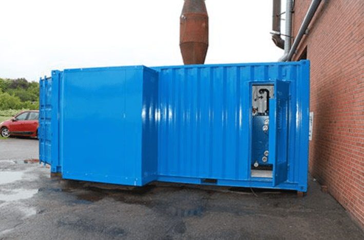
Versatile mobile production facilities that can fit into a container represent a major evolution in modern industrial engineering, combining compact manufacturing capability, rapid deployment flexibility, and modular production architecture within highly transportable industrial systems. These facilities are designed to transform standard shipping containers into fully operational microfactories capable of supporting a wide range of manufacturing, assembly, processing, and technical operations in locations where permanent industrial infrastructure may be unavailable, impractical, or economically inefficient. By integrating advanced automation, compact machinery, intelligent digital control systems, and self-contained utility infrastructure into standardized transportable platforms, containerized production facilities create highly adaptable manufacturing ecosystems that can be deployed almost anywhere with minimal preparation.
The core advantage of container-based production architecture lies in its mobility and scalability. Standard ISO containers provide a globally compatible structural platform that can be transported using existing logistics networks including trucks, rail systems, cargo ships, and aircraft. This allows manufacturing capability to move directly to the point of demand rather than relying entirely on centralized factories and long-distance supply chains. Once deployed, the containerized facility can become operational rapidly through pre-integrated electrical systems, compressed air infrastructure, climate control modules, and modular machine foundations designed for fast commissioning. This dramatically reduces installation time and eliminates much of the civil engineering work normally associated with industrial facility construction.
Inside these compact industrial environments, space optimization becomes a critical engineering discipline. Every section of the container must be carefully organized to maximize production density while maintaining safe operator access, stable machine operation, and efficient material flow. Foldable workstations, modular storage systems, retractable tooling platforms, overhead utility routing, and multifunctional machinery are commonly used to optimize internal layouts. Production flow is typically arranged in a linear or semi-linear sequence to minimize unnecessary movement of materials and improve manufacturing efficiency within the confined footprint of the container structure.
Modern containerized production facilities can support a wide variety of industrial applications including CNC machining, metal fabrication, precision assembly, electronics integration, additive manufacturing, packaging, inspection, laboratory testing, maintenance operations, and field repair services. Depending on the intended application, different modules can be configured with specialized equipment such as compact machining centers, robotic handling systems, laser cutting units, industrial 3D printers, automated inspection systems, or precision assembly stations. This modular approach allows facilities to be tailored for highly specific production tasks while still preserving flexibility for future reconfiguration and expansion.
Automation plays a major role in increasing the effectiveness of mobile production facilities. Compact robotic systems, servo-controlled machinery, programmable logic controllers, and industrial IoT platforms enable high levels of precision and repeatability even within small-scale manufacturing environments. Automated material handling systems reduce manual labor requirements while improving production consistency and throughput. Digital monitoring infrastructure continuously tracks machine performance, energy consumption, production output, and maintenance conditions in real time, allowing operators to optimize efficiency and minimize downtime.
Environmental control is another important element within containerized industrial systems. Because these facilities may operate in remote, harsh, or highly variable climates, integrated climate stabilization systems are necessary to maintain stable production conditions. Thermal insulation, industrial ventilation, air filtration, humidity control, and vibration isolation technologies protect sensitive equipment and preserve manufacturing accuracy regardless of external environmental conditions. Some facilities are additionally equipped with soundproofing systems and dust management infrastructure to improve operational safety and comfort within compact enclosed workspaces.
Energy independence significantly increases the operational flexibility of mobile production facilities. Many systems incorporate self-contained power generation units, battery storage systems, smart energy management software, and autonomous utility infrastructure capable of supporting continuous operation without dependence on local electrical grids. Hybrid energy architectures combining generators, renewable energy sources, and intelligent load-balancing technologies can further improve deployment flexibility and operational sustainability in remote environments.
The digital architecture of these facilities is increasingly sophisticated, integrating cloud connectivity, predictive maintenance systems, remote diagnostics, and AI-assisted process optimization into compact industrial environments. Operators can remotely monitor production activity, machine health, inventory levels, and operational performance from centralized control centers located far from the deployment site. Predictive analytics software can identify early signs of machine wear or process instability before failures occur, reducing maintenance downtime and improving overall system reliability.
One of the most important advantages of containerized production systems is their scalability through modular expansion. Multiple container units can be interconnected to create larger integrated production ecosystems consisting of machining modules, assembly sections, quality control laboratories, storage units, packaging stations, and administrative workspaces. These modular industrial networks can be expanded, reduced, or reorganized according to changing production requirements without the need for permanent infrastructure modifications. This scalability allows organizations to increase manufacturing capacity incrementally while maintaining high operational flexibility.
The future development of versatile mobile production facilities will likely focus on greater automation density, autonomous operation, improved energy efficiency, and deeper integration with distributed digital manufacturing networks. Artificial intelligence, advanced robotics, adaptive process control, and additive manufacturing technologies are expected to further increase the flexibility and capability of compact industrial systems. Future containerized microfactories may eventually operate as fully autonomous production units capable of self-monitoring, self-optimization, and remote coordination within globally distributed manufacturing ecosystems.
As industries continue prioritizing agility, resilience, rapid deployment capability, and decentralized production strategies, versatile containerized production facilities are becoming increasingly important across manufacturing, infrastructure maintenance, emergency response, remote industrial support, research operations, and advanced engineering applications. Their ability to combine mobility, precision, scalability, and operational independence within standardized transportable platforms represents a fundamental shift toward more flexible and adaptive industrial manufacturing models.
The continued evolution of versatile mobile production facilities is closely connected to the broader transformation of global manufacturing from centralized mass-production models toward distributed, digitally coordinated industrial ecosystems. In traditional industrial structures, manufacturing capacity is concentrated inside large permanent facilities that require substantial capital investment, extensive infrastructure, and long construction timelines before becoming operational. While such factories remain effective for extremely high-volume standardized production, they are often limited in their ability to respond quickly to changing market conditions, regional demand fluctuations, supply chain disruptions, or urgent deployment requirements. Mobile production facilities address these limitations by introducing manufacturing systems that are inherently flexible, scalable, and relocatable, allowing industrial capability to move dynamically according to operational needs rather than remaining permanently fixed in one location.
This transformation is being accelerated by advances in compact industrial machinery and high-density automation technologies. Equipment that once required large factory floors can now be miniaturized and integrated into modular containerized environments without losing precision or operational capability. Compact CNC systems, robotic assembly cells, laser processing units, industrial 3D printers, digital inspection systems, and automated packaging modules can all operate within highly optimized spatial configurations designed specifically for mobile deployment. The challenge is not simply reducing equipment size but ensuring that all systems maintain industrial-grade reliability and precision despite operating in confined and transportable environments. Achieving this balance requires sophisticated engineering in areas such as thermal stability, vibration isolation, structural reinforcement, and integrated utility management.
Another defining aspect of modern mobile production architecture is the increasing convergence of physical manufacturing systems with advanced digital infrastructure. Production facilities are no longer viewed solely as collections of machines but as intelligent operational networks capable of sensing, analyzing, and adapting to their environment continuously. Sensors embedded throughout the system monitor machine performance, structural stress, temperature conditions, energy consumption, workflow efficiency, and product quality in real time. This information feeds into centralized software platforms that optimize production scheduling, coordinate robotic movements, manage inventory flow, and predict maintenance requirements before operational disruptions occur. As artificial intelligence technologies continue advancing, these systems are becoming progressively more autonomous and capable of self-optimization with limited human intervention.
The integration of cloud-based manufacturing management systems also allows multiple mobile facilities to operate as part of a unified distributed production network. Rather than functioning as isolated units, containerized microfactories can coordinate production tasks across different geographic regions through secure digital communication infrastructure. If one facility experiences increased demand or temporary downtime, production workloads can be redistributed dynamically across the network to maintain operational continuity. This creates a manufacturing ecosystem that behaves less like a collection of independent factories and more like an adaptive industrial cloud where production capacity itself becomes a shared and flexible resource.
In remote and infrastructure-limited environments, the self-sufficiency of mobile production facilities becomes especially valuable. Many advanced systems are designed to operate independently for extended periods without requiring extensive external support. Integrated power generation systems, water treatment units, waste management infrastructure, spare parts manufacturing capability, and autonomous maintenance equipment allow these facilities to sustain industrial operations even in isolated locations. Such independence is important not only for remote industrial applications but also for emergency response scenarios where damaged infrastructure may prevent access to conventional manufacturing support.
The modularity of these systems further increases their long-term adaptability. Individual production modules can be upgraded, replaced, or reconfigured without requiring reconstruction of the entire facility. This allows organizations to integrate new technologies incrementally as manufacturing methods evolve. A facility initially configured for mechanical fabrication may later incorporate electronics assembly modules, additive manufacturing systems, or advanced automated inspection technologies according to changing operational priorities. This upgrade flexibility significantly extends the lifecycle of the production infrastructure while reducing the cost and disruption associated with technological modernization.
Environmental sustainability is also becoming a major consideration in the development of mobile production facilities. Compact industrial systems naturally encourage more efficient use of energy, materials, and floor space compared to oversized conventional infrastructure. Intelligent energy management systems optimize power consumption across all equipment, while advanced process control software minimizes material waste during production. Additive manufacturing technologies further contribute to sustainability by reducing scrap generation and enabling highly efficient use of raw materials. Some next-generation concepts additionally integrate renewable energy systems, energy recovery technologies, and closed-loop recycling infrastructure directly into the production architecture to further reduce environmental impact.
The human role within mobile manufacturing ecosystems is also changing significantly. Rather than performing repetitive manual production tasks, operators increasingly act as supervisors, coordinators, and technical specialists managing highly automated systems. Training requirements therefore shift toward digital system management, robotics integration, maintenance diagnostics, and process optimization. Augmented reality interfaces, AI-assisted operational guidance, and immersive maintenance visualization tools are being developed to simplify complex technical tasks and reduce the expertise barrier associated with advanced manufacturing systems. These technologies improve operational efficiency while allowing smaller teams to manage increasingly sophisticated production environments.
As global industries continue facing pressure for faster response times, increased customization, and greater supply chain resilience, the strategic importance of decentralized manufacturing capability is expected to grow substantially. Mobile production facilities provide a practical solution by allowing manufacturing resources to be positioned directly where they are needed most, reducing transportation delays and increasing operational responsiveness. Instead of relying exclusively on large centralized factories producing standardized products for broad distribution, industries can move toward more localized, adaptive production strategies capable of responding dynamically to regional demand and rapidly changing operational conditions.
In the long term, the distinction between factory, logistics center, and digital infrastructure may become increasingly blurred. Mobile production facilities are evolving into integrated industrial nodes that combine manufacturing capability, real-time data processing, autonomous logistics coordination, and distributed operational intelligence within unified modular ecosystems. As robotics, artificial intelligence, additive manufacturing, and industrial networking technologies continue to advance together, these systems may eventually operate with a level of autonomy and adaptability that fundamentally changes how manufacturing capacity is deployed and managed globally.
The future industrial landscape will likely consist of interconnected networks of flexible production units capable of deploying rapidly, scaling dynamically, and adapting continuously according to economic conditions, technological changes, and operational priorities. Versatile containerized production facilities represent one of the clearest early examples of this transformation, demonstrating how mobility, modularity, digitalization, and automation can combine to create a more resilient, efficient, and adaptive model of industrial manufacturing for the decades ahead.
One of the most significant long-term advantages of versatile mobile production facilities is their ability to shorten the distance between manufacturing capability and actual operational demand. In conventional industrial systems, production is often geographically separated from end use, requiring complex transportation networks, warehousing infrastructure, and long planning cycles to move products from centralized factories to distributed markets. Mobile production architecture changes this relationship by enabling manufacturing resources to be positioned directly at or near the point of demand. This localized production model reduces transportation dependency, shortens lead times, lowers inventory requirements, and increases responsiveness to rapidly changing conditions. The result is a more agile industrial ecosystem where production capacity can adapt dynamically instead of being constrained by fixed infrastructure limitations.
This flexibility is particularly important in industries where downtime has extremely high economic consequences. Infrastructure maintenance, mining operations, energy production facilities, transportation systems, remote construction projects, and disaster recovery operations often require immediate access to replacement components, repair capability, or specialized fabrication services. Waiting for parts to arrive from distant factories can create costly delays and operational interruptions. Mobile production facilities solve this problem by bringing manufacturing capability directly into the operational environment, allowing components to be produced, repaired, or customized on-site with minimal delay. This transition from centralized inventory dependence toward localized on-demand manufacturing has the potential to fundamentally reshape industrial supply strategies across multiple sectors.
Another important aspect of mobile production ecosystems is the growing role of adaptive manufacturing. Traditional factories are typically optimized for stable, repetitive production of large quantities of standardized products. Mobile production systems, by contrast, are increasingly optimized for flexibility, smaller production batches, rapid changeovers, and customized output. This requires machinery and software architectures capable of switching efficiently between different production configurations without extensive downtime. Automated tooling systems, digitally stored production recipes, robotic reconfiguration capability, and AI-assisted calibration routines allow mobile facilities to adapt quickly to changing requirements while maintaining consistent quality and operational stability.
The relationship between additive manufacturing and mobile production architecture is becoming especially important in this context. Industrial 3D printing technologies eliminate many of the tooling constraints associated with conventional manufacturing and allow highly customized components to be produced rapidly from digital design files. Within mobile production facilities, additive manufacturing systems can complement traditional machining and assembly processes by enabling rapid prototyping, spare part production, lightweight structural fabrication, and low-volume specialized manufacturing. This hybrid approach creates highly versatile production environments capable of balancing speed, precision, customization, and material efficiency within compact deployment footprints.
As digital manufacturing systems become more advanced, the concept of the “digital factory” is increasingly merging with the concept of the mobile factory. Production data, machine configurations, quality standards, and workflow instructions can now be transmitted globally almost instantly, allowing manufacturing capability to be deployed and synchronized across multiple locations with remarkable consistency. A production module operating in one region can receive updated process parameters, design revisions, or optimization algorithms from another location in real time. This digital continuity allows geographically distributed mobile facilities to operate as coordinated parts of a larger industrial network rather than isolated production units.
The architectural design of future mobile production systems is also expected to become increasingly modular at every scale. Entire facilities may eventually be assembled from interchangeable industrial blocks, each optimized for a particular function such as energy generation, machining, assembly, logistics, storage, or quality inspection. These modules could connect automatically through standardized interfaces, allowing facilities to expand, contract, or reorganize rapidly depending on operational needs. Such architectures would allow organizations to build highly customized industrial ecosystems without requiring entirely new infrastructure for each application.
Artificial intelligence will likely play an increasingly central role in coordinating these modular ecosystems. AI systems may continuously analyze production demand, machine availability, energy consumption, environmental conditions, and logistics constraints to optimize the entire operational network dynamically. Instead of human operators manually scheduling every activity, intelligent systems could allocate production tasks automatically, route materials between facilities, predict maintenance needs, and adapt production strategies in real time. Over time, this could create industrial systems that behave more like adaptive living networks than traditional static factories.
Autonomous logistics integration will further expand the capabilities of mobile manufacturing infrastructure. Automated transport systems, robotic loading platforms, autonomous forklifts, and digitally coordinated inventory management will reduce the need for manual material handling and improve operational efficiency. In more advanced deployments, autonomous delivery vehicles or drone-based logistics systems may transport materials and finished products between distributed production nodes with minimal human intervention. Such integration would allow mobile facilities to operate efficiently even in highly remote or infrastructure-limited environments.
The evolution of compact robotics is also critical to the future scalability of containerized production systems. Smaller, more flexible robotic platforms allow high levels of automation within confined industrial spaces that would previously have been unsuitable for robotic integration. Collaborative robots designed to operate safely alongside human operators provide additional flexibility by combining automation efficiency with human adaptability. These systems can perform repetitive precision tasks continuously while human workers focus on oversight, troubleshooting, and process optimization. This hybrid operational model improves productivity while maintaining the flexibility necessary for highly dynamic manufacturing environments.
Material science advancements are simultaneously influencing the design and capability of mobile production systems. Lightweight structural materials, advanced composites, high-strength alloys, and modular construction technologies reduce the weight of mobile facilities while improving durability and operational performance. New thermal insulation systems, compact energy storage technologies, and intelligent structural materials capable of monitoring their own stress and condition may further increase the resilience and efficiency of future production architectures.
As industrial systems become more decentralized, cybersecurity and digital resilience are becoming increasingly important components of mobile production design. Because distributed facilities rely heavily on interconnected digital infrastructure, protecting operational data, communication networks, and control systems becomes essential for maintaining reliability and continuity. Future mobile production ecosystems will likely integrate advanced cybersecurity architectures directly into their operational framework, ensuring secure communication, encrypted process management, and resilient autonomous operation even under network disruption conditions.
The social and economic implications of highly flexible mobile manufacturing systems are also substantial. By reducing the infrastructure requirements associated with industrial production, these technologies may allow manufacturing capability to expand into regions that previously lacked access to large-scale industrial investment. Smaller communities, remote industrial sites, and developing regions could gain access to localized production capacity without the need for massive permanent factory construction. This decentralization of manufacturing capability may contribute to more regionally distributed economic development while reducing dependence on large concentrated industrial hubs.
Over time, the distinction between manufacturing, logistics, data processing, and infrastructure management may continue to dissolve as these systems become increasingly integrated. Mobile production facilities are evolving into multifunctional industrial ecosystems capable of manufacturing products, processing information, managing energy, coordinating logistics, and adapting operational behavior autonomously. This convergence of physical and digital infrastructure represents one of the most important transitions in modern industrial development and may ultimately redefine how societies organize production, supply networks, and industrial resilience in the future.
As mobile production facilities continue to mature technologically, their role within global industrial strategy is likely to expand far beyond temporary manufacturing support or niche deployment applications. They increasingly represent an entirely different philosophy of industrial organization in which flexibility, adaptability, and distributed capability become more valuable than sheer scale alone. Traditional industrial development has historically emphasized concentration, where larger factories benefited from economies of scale, centralized labor pools, and consolidated infrastructure investment. While this model remains highly effective for certain forms of mass production, it also creates vulnerabilities related to transportation dependency, regional disruption, infrastructure rigidity, and slow response to changing demand patterns. Mobile production systems introduce a fundamentally different balance by prioritizing modular scalability and operational responsiveness over fixed geographic concentration.
This transformation is closely connected to the broader digitalization of industry. As manufacturing equipment becomes increasingly software-defined, physical production systems gain the ability to change functionality much more rapidly than in previous industrial eras. Machines that once required extensive manual setup and mechanical reconfiguration can now adapt through software-controlled parameter changes, automated calibration systems, and modular tooling architectures. In mobile production environments, this flexibility is especially valuable because facilities are expected to support a wide variety of operational tasks under changing deployment conditions. A containerized production module may perform precision machining for one application during a particular deployment cycle and later be reconfigured for assembly, prototyping, repair operations, or custom fabrication with relatively minimal structural modification.
The concept of manufacturing capacity itself is therefore evolving from something static into something dynamic and deployable. Instead of asking where a factory should be built permanently, organizations increasingly ask where production capability should be positioned temporarily in order to maximize efficiency, responsiveness, and logistical advantage. This shift alters how industrial planning is approached at every level, from facility design and workforce organization to transportation infrastructure and supply chain management. Mobile facilities make it possible to create industrial presence quickly in regions where permanent factories would be impractical, too expensive, or unnecessary for long-term operation.
The role of digital twins and advanced simulation technologies will likely become even more important as these systems evolve. Before a mobile production facility is physically deployed, entire operational environments can be modeled virtually to optimize equipment arrangement, energy distribution, workflow efficiency, material handling routes, and maintenance accessibility. These simulations reduce deployment risk and allow facilities to be configured with much greater precision before arriving on-site. Once operational, the digital twin continues functioning as a live operational mirror, receiving real-time sensor data and enabling predictive analysis, performance optimization, and remote troubleshooting. This creates a continuous feedback loop between the physical production environment and its digital counterpart.
Another emerging trend is the integration of modular infrastructure systems beyond manufacturing equipment itself. Future mobile facilities may include expandable office units, operator accommodation modules, remote training centers, digital command stations, automated storage systems, and environmental management infrastructure that can all connect together into highly coordinated industrial compounds. Such modular ecosystems would allow organizations to establish fully operational industrial hubs in extremely short timeframes while maintaining the flexibility to relocate or expand them as operational needs evolve.
Human-machine collaboration within these facilities is also expected to become increasingly sophisticated. Rather than separating automation and human labor into rigidly defined roles, future systems may rely on adaptive collaboration where AI-assisted software continuously balances responsibilities between robotic systems and human operators according to operational conditions. Augmented reality interfaces may guide technicians through maintenance procedures, overlaying live diagnostic information directly onto equipment surfaces. Voice-controlled industrial systems and gesture-based interfaces could simplify complex operational tasks, while AI-driven decision support systems provide real-time optimization recommendations to operators managing large distributed production networks.
As energy technologies advance, the energy architecture of mobile production facilities is likely to evolve toward greater sustainability and independence. Compact renewable energy systems, high-density battery storage technologies, hydrogen-based power generation, and intelligent microgrid management may allow future facilities to operate with significantly reduced dependence on fossil-fuel infrastructure. Integrated energy optimization algorithms will continuously manage power distribution across all subsystems, balancing energy-intensive operations according to production priorities and resource availability. In remote environments, these capabilities will become especially important for maintaining long-duration autonomous operation.
The manufacturing processes themselves are also becoming increasingly intelligent and adaptive. Machine learning systems can analyze production data continuously, identifying patterns that human operators may not detect easily. Subtle variations in vibration, temperature, acoustic behavior, or tool wear can be used to predict quality deviations or maintenance needs before operational problems occur. Over time, manufacturing systems become progressively better at optimizing themselves through accumulated operational experience. This transition toward self-learning industrial systems represents one of the most significant long-term shifts in modern manufacturing philosophy.
The miniaturization of advanced industrial technology further expands the potential applications of mobile production facilities. High-precision measurement systems, compact robotic arms, portable additive manufacturing platforms, and lightweight industrial automation components now allow highly capable manufacturing environments to exist within footprints that would previously have been considered too small for serious industrial activity. This miniaturization not only improves mobility but also reduces deployment costs and increases accessibility for smaller organizations that may not have the resources for large permanent facilities.
In parallel, distributed manufacturing networks are likely to become increasingly interconnected through cloud-based industrial ecosystems where production resources are coordinated globally. Facilities located in different countries or regions may function as nodes within a shared manufacturing infrastructure, exchanging production tasks, digital process data, inventory information, and operational analytics in real time. This networked approach creates manufacturing resilience by allowing production loads to shift dynamically in response to demand spikes, regional disruptions, or infrastructure constraints.
The broader economic impact of this transformation could be substantial. Mobile production systems lower the barriers associated with establishing advanced manufacturing capability, making industrial infrastructure more accessible and scalable. Smaller businesses, emerging industrial regions, and remote operations may gain access to precision manufacturing technologies that previously required enormous fixed investment. This decentralization of industrial capability has the potential to diversify manufacturing ecosystems globally and reduce excessive dependence on a limited number of centralized production hubs.
Ultimately, versatile mobile production facilities represent more than just transportable factories. They are part of a much larger transition toward adaptive industrial ecosystems where manufacturing, logistics, digital infrastructure, energy management, and autonomous systems converge into highly flexible operational networks. As these technologies continue developing together, the future of manufacturing may become increasingly fluid, decentralized, intelligent, and responsive, fundamentally reshaping how industrial capability is organized and deployed across the world.
Mobile Drone Ammunition Production for Warfare
Mobile industrial manufacturing systems represent a transformative approach to modern production infrastructure by combining mobility, modularity, automation, and digital integration into compact deployable industrial environments capable of operating across highly diverse locations and conditions. Unlike conventional factories that depend on permanent infrastructure, extensive construction, and geographically fixed production capacity, mobile industrial manufacturing systems are engineered to function as flexible industrial ecosystems that can be transported, deployed, expanded, and reconfigured according to operational demand. This evolution reflects a broader industrial transition toward decentralized manufacturing models where adaptability, resilience, and rapid response capability become increasingly important alongside traditional production efficiency.
The architectural foundation of these systems is typically built around modular transportable structures designed for compatibility with global logistics networks. Standardized shipping containers, expandable industrial shelters, modular steel platforms, and mobile trailer-based facilities provide structural flexibility while simplifying transportation through existing rail, road, sea, and air freight systems. These structures are engineered not only for transport durability but also for operational stability once deployed. Reinforced frames, vibration isolation systems, integrated utility channels, thermal insulation layers, and rapid stabilization mechanisms allow sensitive manufacturing equipment to maintain industrial precision even after repeated transportation cycles and operation in challenging environmental conditions.
Inside these mobile facilities, production environments are carefully optimized to maximize manufacturing capability within compact physical footprints. Space efficiency becomes a major engineering discipline because every cubic meter of available volume must support operational functionality without compromising workflow, safety, or maintenance accessibility. Multifunctional machinery, retractable workstations, overhead utility routing, foldable assembly platforms, compact robotic systems, and modular storage architectures are commonly integrated to increase operational density while preserving efficient production flow. The result is a highly compressed industrial ecosystem capable of delivering manufacturing performance previously associated only with much larger permanent facilities.
Automation plays a central role in enabling the effectiveness of mobile industrial manufacturing systems. Advanced robotic platforms, programmable logic controllers, intelligent sensor networks, machine vision systems, and AI-assisted process optimization software allow production operations to function with high precision and consistency despite limited physical space and variable deployment conditions. Robotic systems manage repetitive handling operations, automated inspection procedures, assembly sequences, and material transfer tasks while centralized digital control systems coordinate production timing, energy distribution, machine synchronization, and maintenance scheduling across the entire facility.
The digital infrastructure embedded within modern mobile manufacturing systems is equally important as the physical machinery itself. Industrial IoT networks continuously collect operational data from machines, environmental systems, robotic units, and utility infrastructure. This information is analyzed in real time through edge computing systems and cloud-connected industrial management platforms that optimize production performance dynamically. Predictive maintenance algorithms identify early signs of equipment wear or operational instability before failures occur, reducing downtime and improving reliability. Production managers can remotely supervise multiple facilities simultaneously, monitor workflow efficiency, track inventory status, and coordinate distributed manufacturing activities across large geographic regions.
One of the defining advantages of mobile industrial manufacturing systems is their ability to bring production capability directly to the location where manufacturing demand exists. This reduces dependency on long and vulnerable supply chains while significantly improving responsiveness. In industries such as mining, infrastructure maintenance, construction, energy production, transportation, disaster recovery, and remote industrial operations, the ability to manufacture or repair components on-site can dramatically reduce operational delays and logistical complexity. Instead of transporting heavy equipment or waiting for replacement parts from distant centralized factories, mobile manufacturing facilities allow production to occur directly within the operational environment.
Additive manufacturing technologies are becoming increasingly integrated into these mobile systems because they provide exceptional flexibility within compact deployment footprints. Industrial 3D printing platforms enable rapid prototyping, low-volume custom manufacturing, spare part production, and lightweight structural fabrication without requiring extensive tooling infrastructure. Hybrid manufacturing systems combining additive processes with conventional CNC machining, laser processing, and robotic assembly create highly adaptable production environments capable of supporting a wide variety of industrial applications from precision engineering to emergency repair operations.
Energy independence is another critical design principle within advanced mobile manufacturing architecture. Many facilities are designed to operate autonomously through integrated power generation systems, battery storage infrastructure, intelligent energy management software, and compact utility networks. Hybrid energy systems combining generators, renewable energy sources, and advanced load-balancing technologies allow stable operation even in remote or infrastructure-limited environments. Efficient thermal management systems, energy recovery technologies, and adaptive cooling infrastructure further optimize operational sustainability while protecting sensitive industrial equipment.
Environmental adaptability is essential because mobile manufacturing systems may operate in highly diverse climates and deployment conditions. Climate-controlled interiors, dust filtration systems, humidity regulation infrastructure, acoustic insulation, corrosion-resistant materials, and vibration compensation technologies allow precision operations to continue reliably across desert environments, coastal regions, arctic conditions, tropical climates, or remote industrial sites. This resilience greatly expands the potential application range of containerized and transportable production facilities.
The future evolution of mobile industrial manufacturing systems is likely to involve increasing levels of autonomy, digitalization, and interconnectivity. AI-driven production management, autonomous robotic logistics, self-configuring modular facilities, and distributed manufacturing cloud networks may eventually enable highly intelligent industrial ecosystems capable of self-optimization and adaptive deployment. Multiple mobile facilities operating as coordinated nodes within globally connected production networks could dynamically redistribute workloads, share operational data, and adapt manufacturing capacity according to real-time demand patterns and logistical conditions.
As industries continue prioritizing resilience, flexibility, rapid deployment capability, and decentralized operational models, mobile industrial manufacturing systems are expected to become increasingly important across both advanced industrial economies and emerging markets. Their ability to combine precision manufacturing, digital intelligence, logistical mobility, and modular scalability within compact deployable environments represents one of the most significant transformations currently occurring in industrial production strategy and manufacturing infrastructure development.
The growing importance of mobile industrial manufacturing systems is also closely connected to changes in global economic structure and industrial risk management strategies. In previous decades, manufacturing optimization was primarily focused on maximizing efficiency through large-scale centralized production, where enormous factories concentrated labor, machinery, and logistics into highly optimized fixed locations. While this model achieved remarkable economies of scale, it also created structural vulnerabilities because production became heavily dependent on stable transportation networks, uninterrupted infrastructure access, predictable geopolitical conditions, and long-distance supply chains. As industries increasingly encounter disruptions related to transportation bottlenecks, energy instability, regional conflicts, environmental events, and rapidly changing market conditions, the ability to distribute and reposition manufacturing capacity has become a strategic advantage rather than simply a logistical convenience.
Mobile industrial manufacturing systems address this challenge by converting production capability into a dynamic resource that can be relocated according to operational needs. Instead of requiring every component, spare part, or specialized assembly to originate from a centralized industrial hub, manufacturing can occur much closer to the point of use. This decentralization significantly reduces transportation complexity and shortens response times, particularly in industries where delays carry major operational or financial consequences. Infrastructure maintenance projects, remote energy operations, large-scale construction environments, mining facilities, transportation systems, and emergency response activities all benefit from the ability to establish localized manufacturing capability rapidly without waiting for permanent infrastructure development.
The compact nature of mobile manufacturing systems has driven major innovation in industrial equipment miniaturization and multifunctionality. Machinery that once required large industrial buildings and dedicated utility infrastructure is increasingly being redesigned into smaller, modular, and more energy-efficient forms suitable for containerized deployment. Modern compact machining centers integrate multiple processing functions within single platforms, allowing milling, drilling, cutting, measurement, and finishing operations to occur in tightly integrated workspaces. Robotic systems are similarly evolving toward lightweight, flexible architectures capable of operating safely in confined environments while maintaining industrial-grade precision and speed. These advancements allow containerized facilities to deliver manufacturing capabilities that would previously have been impossible within such compact footprints.
At the same time, software-defined manufacturing is becoming one of the most important enabling technologies behind mobile production ecosystems. Increasingly, manufacturing flexibility depends not only on physical machinery but also on the digital systems that coordinate and control it. Production recipes, machining parameters, robotic workflows, inspection standards, and maintenance protocols can now be stored, transmitted, and updated digitally across distributed facilities. This means that manufacturing capability itself becomes increasingly transferable through software rather than hardware alone. A mobile production unit deployed in one location can rapidly adopt entirely new manufacturing tasks simply by loading updated digital process configurations and tooling profiles, allowing unprecedented operational adaptability.
The integration of industrial artificial intelligence is accelerating this transition even further. AI-driven systems can continuously monitor machine behavior, workflow efficiency, energy consumption, production timing, and quality metrics while dynamically adjusting operational parameters to improve performance. These systems identify inefficiencies, predict maintenance requirements, optimize material usage, and adapt production sequencing in real time without requiring constant human oversight. Over time, the manufacturing environment becomes progressively more autonomous and self-optimizing as machine learning systems accumulate operational experience across multiple deployment cycles and production scenarios.
Another important development is the increasing convergence between manufacturing systems and advanced logistics infrastructure. Mobile production facilities are not isolated factories but components of broader distributed industrial networks that include digital inventory systems, autonomous transport platforms, real-time supply chain analytics, and cloud-based production coordination tools. Materials, components, and finished products can be tracked continuously throughout the entire manufacturing ecosystem, allowing organizations to synchronize production with logistics more efficiently than in traditional static factory environments. Future systems may integrate autonomous delivery vehicles, robotic loading systems, and intelligent warehousing technologies that further reduce manual coordination requirements and improve operational responsiveness.
The evolution of additive manufacturing is particularly significant within mobile industrial environments because it complements the need for flexibility and compactness exceptionally well. Unlike traditional manufacturing processes that often require extensive tooling and setup infrastructure, additive systems can produce highly customized components directly from digital models with minimal physical reconfiguration. This allows mobile facilities to support rapid prototyping, low-volume production, spare part fabrication, and custom engineering applications efficiently within limited space. Hybrid manufacturing architectures that combine additive manufacturing with subtractive machining and robotic assembly are increasingly common because they allow facilities to balance flexibility, precision, and production speed within integrated modular environments.
Environmental sustainability is also becoming deeply integrated into the philosophy of mobile industrial systems. Smaller modular facilities naturally encourage more efficient use of energy, floor space, and raw materials compared to oversized permanent infrastructure. Intelligent process management systems minimize waste generation while optimizing energy consumption dynamically across all operational subsystems. In future developments, containerized production facilities may increasingly integrate renewable energy infrastructure, advanced battery storage, water recycling systems, and closed-loop material recovery technologies to support more sustainable decentralized industrial operations.
Human interaction with manufacturing systems is evolving alongside these technological changes. Operators are increasingly functioning as system supervisors, digital coordinators, and technical specialists rather than traditional manual machine operators. Training therefore shifts toward robotics management, digital diagnostics, industrial networking, AI-assisted decision-making, and adaptive process optimization. Augmented reality systems, voice-guided maintenance interfaces, and immersive digital training environments may eventually allow smaller operational teams to manage highly sophisticated production ecosystems with far greater efficiency than conventional industrial workforce models.
The scalability of mobile industrial manufacturing systems is another major factor driving their adoption. Organizations can begin with relatively small modular deployments and expand capacity incrementally as demand grows by adding additional production modules, storage units, energy systems, or logistics infrastructure. This incremental scalability reduces the financial risk associated with large permanent factory investments while allowing manufacturing capacity to adapt continuously to operational requirements. In rapidly changing industries, such flexibility is often more valuable than maximum fixed production capacity because it allows organizations to remain responsive without overcommitting infrastructure resources.
Over the longer term, the distinction between factory, logistics center, energy hub, and digital infrastructure node may become increasingly blurred. Mobile manufacturing systems are evolving into multifunctional industrial ecosystems where production, data processing, autonomous coordination, energy management, and logistics integration operate together as a unified architecture. Distributed production facilities connected through intelligent industrial networks may eventually function as adaptive manufacturing clouds capable of reallocating production tasks dynamically across global regions according to demand, resource availability, transportation conditions, and operational priorities.
This broader transition represents one of the most important shifts currently occurring within industrial strategy. Instead of relying entirely on a small number of massive centralized factories, industries are gradually moving toward more distributed, modular, and digitally coordinated production ecosystems capable of operating with far greater flexibility and resilience. Mobile industrial manufacturing systems are at the center of this transformation because they combine physical mobility, advanced automation, digital intelligence, and scalable modular design into a single industrial framework capable of supporting the evolving demands of modern global manufacturing.
As distributed industrial ecosystems continue expanding, mobile industrial manufacturing systems are increasingly being viewed not merely as temporary solutions or supplementary infrastructure, but as permanent strategic assets capable of reshaping the entire logic of manufacturing deployment. One of the primary reasons for this shift is the realization that industrial flexibility itself has become economically valuable in a world where market conditions, technological standards, and logistical realities change more rapidly than traditional infrastructure cycles. Permanent factories are designed for stability and long operational lifespans, but modern industries increasingly require the ability to adapt production quickly, relocate capability when necessary, and scale operations without committing to years of construction and infrastructure investment. Mobile production systems answer this need by transforming industrial capacity into something fluid, modular, and strategically repositionable.
The concept of manufacturing agility is therefore becoming central to industrial planning. Agility in this context refers not only to the speed of production but also to the ability to change production focus, integrate new technologies, respond to regional demand shifts, and maintain operational continuity under uncertain conditions. Mobile manufacturing systems are uniquely suited to this because their architecture is inherently modular and digitally coordinated. Production units can be added, removed, or rearranged with far greater ease than conventional fixed infrastructure. Entire operational workflows can be redesigned through software updates, tooling exchanges, and modular system reconfiguration rather than extensive physical reconstruction. This creates manufacturing ecosystems that evolve continuously instead of remaining static for decades.
The role of data within these systems is also becoming increasingly sophisticated. Industrial data is no longer simply used for monitoring performance after the fact; it now drives real-time operational decision-making throughout the entire production ecosystem. Sensors embedded within machinery, robotics, structural systems, and environmental controls generate continuous streams of information regarding equipment behavior, process efficiency, material consumption, and workflow conditions. Artificial intelligence platforms process this information dynamically to identify inefficiencies, predict maintenance needs, optimize energy usage, and coordinate production scheduling automatically. As these systems become more advanced, the production environment itself begins functioning as a self-aware industrial network capable of continuous adaptation and optimization.
Another important trend is the increasing integration of advanced communication infrastructure directly into manufacturing architecture. High-speed wireless industrial networks, edge computing platforms, and cloud-based coordination systems allow geographically distributed facilities to function as interconnected operational nodes within a larger manufacturing ecosystem. Production data, engineering updates, machine configurations, and quality control parameters can be synchronized instantly across multiple sites regardless of physical distance. This creates the possibility of globally distributed manufacturing networks operating with a level of coordination that would previously have required physical centralization.
The physical architecture of mobile manufacturing systems is also evolving toward greater modular intelligence. Future containerized facilities may incorporate structural components capable of monitoring their own stress conditions, vibration exposure, thermal behavior, and maintenance status in real time. Smart structural materials integrated with embedded sensors could continuously assess operational stability and environmental conditions, allowing facilities to adapt automatically to changing deployment environments. Expandable modular structures may eventually deploy autonomously, increasing internal workspace dynamically according to operational needs while preserving transport efficiency during relocation.
As compact automation technologies continue advancing, robotic systems within mobile production facilities are becoming increasingly collaborative and adaptive. Earlier industrial robotics often required rigidly controlled environments and extensive safety separation from human workers. Newer robotic platforms are designed specifically for close collaboration within compact industrial spaces. These systems integrate force sensing, machine vision, environmental awareness, and adaptive movement algorithms that allow safe interaction with operators while maintaining high productivity. Such collaborative automation is especially important in mobile facilities where space limitations require efficient coordination between humans and machines rather than complete physical separation.
The integration of advanced material processing technologies further expands the capabilities of mobile production systems. Compact laser processing units, precision composite fabrication equipment, portable thermal treatment systems, and hybrid additive-subtractive manufacturing platforms allow increasingly complex engineering operations to occur within transportable environments. This means that mobile facilities are no longer limited to basic fabrication or repair work but can support sophisticated manufacturing tasks involving high-performance materials, precision engineering tolerances, and advanced structural components.
At the same time, the economic model surrounding industrial production is gradually shifting from ownership of large centralized factories toward more flexible production-as-a-service concepts. Organizations may increasingly rely on deployable manufacturing networks that can be activated, relocated, or expanded according to project requirements without maintaining permanently oversized industrial infrastructure. This approach reduces fixed capital exposure while improving responsiveness to changing market conditions. Mobile production ecosystems therefore align closely with broader economic trends favoring flexibility, scalability, and operational efficiency over static long-term infrastructure commitments.
Environmental pressures are also accelerating interest in decentralized manufacturing models. Long-distance transportation of goods contributes significantly to energy consumption and logistical complexity across global supply chains. By positioning production capability closer to the point of use, mobile manufacturing systems can reduce transportation requirements, shorten delivery routes, and improve resource efficiency. In addition, compact modular facilities generally require fewer raw construction materials and less land development compared to large permanent industrial complexes. Future systems may integrate renewable energy generation, localized recycling infrastructure, water recovery systems, and low-emission production technologies directly into their architecture, further supporting sustainable industrial development goals.
The relationship between manufacturing and workforce organization is changing as well. Highly automated mobile facilities require smaller but more technically specialized operational teams. Instead of large labor concentrations performing repetitive manual tasks, future manufacturing environments will increasingly rely on multidisciplinary operators skilled in robotics management, digital diagnostics, process optimization, AI-assisted control systems, and modular infrastructure maintenance. This shift could influence educational priorities, workforce mobility, and regional industrial development patterns over time.
As global infrastructure becomes more digitally interconnected, mobile industrial manufacturing systems may eventually participate in highly adaptive industrial marketplaces where production capacity itself becomes dynamically tradable and allocatable. Facilities could receive manufacturing assignments automatically through cloud-based industrial coordination platforms that analyze regional demand, transportation conditions, material availability, and operational efficiency in real time. Production ecosystems would then behave less like isolated companies operating independent factories and more like interconnected industrial networks continuously optimizing manufacturing allocation across large geographic scales.
The long-term significance of mobile manufacturing systems extends beyond simple technological innovation. They represent a broader transformation in how societies conceptualize industrial capability itself. Manufacturing is increasingly becoming decentralized, software-coordinated, modular, and adaptable rather than fixed, rigid, and geographically concentrated. Mobile industrial production systems embody this transition by combining physical mobility with digital intelligence and scalable automation into highly flexible operational architectures capable of evolving continuously alongside technological and economic change.
In the decades ahead, the industrial landscape may consist less of massive permanent factories dominating production and more of interconnected networks of versatile manufacturing nodes capable of relocating, reconfiguring, and coordinating dynamically according to global operational conditions. Mobile industrial manufacturing systems are among the clearest early indicators of this transformation, demonstrating how advances in automation, digital infrastructure, materials science, robotics, and modular engineering are converging to create a far more adaptive and resilient model of industrial production for the future.
Containerized Precision Production Facilities
Containerized precision production facilities represent one of the most advanced forms of modular industrial infrastructure, combining high-accuracy manufacturing capability with transportable architecture and digitally integrated operational systems. These facilities are designed to deliver industrial-grade precision manufacturing inside standardized container-based structures that can be rapidly deployed, expanded, relocated, and reconfigured according to operational requirements. Unlike conventional fixed factories that require extensive construction timelines and permanent infrastructure investment, containerized precision production facilities transform manufacturing capability into a flexible industrial asset capable of operating efficiently across diverse environments and deployment conditions.
The foundation of these systems lies in the integration of precision engineering with compact modular architecture. Standard ISO containers provide a globally compatible transport platform that can move seamlessly through existing logistics networks while serving as structurally reinforced industrial environments once deployed. However, converting a transport container into a high-precision manufacturing facility requires sophisticated engineering solutions that address vibration control, thermal stability, structural rigidity, acoustic isolation, airflow management, and utility integration simultaneously. Precision manufacturing equipment is highly sensitive to environmental disturbances, meaning the container structure itself becomes an active component of the manufacturing system rather than simply a protective enclosure.
Inside these facilities, spatial efficiency is treated as a critical engineering parameter. Every machine, workstation, robotic system, storage unit, and utility channel must be arranged to maximize production capability within limited volume while preserving operational accessibility and workflow continuity. Compact multi-function machining centers, precision robotic handling systems, laser processing units, automated metrology equipment, and modular assembly stations are integrated into tightly optimized layouts designed around continuous process flow. Vertical space utilization, retractable tooling systems, foldable work surfaces, overhead cable routing, and modular storage architectures allow the facility to support sophisticated manufacturing operations without compromising transportability.
Precision production environments require exceptionally stable operating conditions, which has driven the development of advanced environmental control systems within containerized facilities. Climate stabilization modules continuously regulate temperature, humidity, and air quality to maintain dimensional consistency during manufacturing operations. Vibration isolation systems protect precision machinery from external disturbances caused by transportation, nearby equipment, or uneven deployment surfaces. Air filtration systems remove particulates generated by machining or fabrication processes while maintaining clean operational environments for sensitive assembly and inspection procedures. These environmental management systems allow micron-level manufacturing tolerances to be maintained even in remote or variable deployment conditions.
Digital infrastructure forms the operational core of modern containerized precision production facilities. Industrial IoT networks connect machines, robotic systems, sensors, environmental controls, and utility infrastructure into unified digital ecosystems capable of continuous real-time monitoring and optimization. Edge computing systems process operational data locally to minimize latency, while cloud-connected manufacturing platforms coordinate production scheduling, maintenance management, inventory tracking, and workflow synchronization across distributed facilities. Artificial intelligence systems analyze machine behavior, process stability, energy consumption, and quality metrics continuously to optimize operational performance dynamically.
Automation is deeply integrated into the architecture of these facilities because precision manufacturing depends heavily on consistency, repeatability, and accurate process control. Compact robotic systems handle component transfer, positioning, assembly, and inspection operations with extremely high positional accuracy. Machine vision systems verify dimensional tolerances and surface quality automatically during production cycles, reducing dependency on manual inspection while improving reliability and throughput. Automated calibration systems continuously compensate for thermal expansion, tool wear, or environmental variation to preserve precision throughout extended operating periods.
Containerized precision production facilities are increasingly being used across industries that require localized high-accuracy manufacturing capability without the cost or delay associated with building permanent industrial plants. Aerospace support operations, semiconductor component production, medical device fabrication, advanced electronics assembly, infrastructure maintenance, energy sector operations, and remote engineering projects all benefit from deployable precision manufacturing environments capable of operating close to the point of demand. By bringing manufacturing capability directly into operational environments, these systems reduce transportation delays, improve responsiveness, and increase supply chain resilience.
Additive manufacturing technologies are playing an increasingly important role within containerized precision production ecosystems because they align naturally with the goals of flexibility and compactness. Industrial metal printing systems, precision polymer fabrication platforms, and hybrid additive-subtractive manufacturing cells allow highly complex components to be produced directly from digital design data without extensive tooling infrastructure. This capability significantly expands the versatility of mobile facilities by enabling rapid prototyping, low-volume specialized production, spare part fabrication, and lightweight structural manufacturing within compact deployment footprints.
Energy architecture is another essential component of these systems because many deployment environments lack stable external infrastructure. Integrated power generation units, battery storage systems, intelligent load balancing networks, and energy-efficient thermal management infrastructure allow facilities to operate autonomously for extended periods. Smart energy management software dynamically distributes power according to production priorities while minimizing consumption and maintaining stable operating conditions for sensitive equipment. Some advanced systems additionally integrate renewable energy technologies and modular microgrid architectures to further improve sustainability and operational independence.
The modular nature of containerized precision facilities allows them to scale efficiently according to operational requirements. Multiple containers can be interconnected to form larger manufacturing ecosystems consisting of machining modules, inspection laboratories, assembly stations, storage units, digital control centers, and operator support infrastructure. These modular production compounds can expand incrementally without major structural redesign, allowing organizations to adjust manufacturing capacity dynamically as operational demand changes.
Future development of containerized precision production facilities will likely focus on greater autonomy, increased manufacturing density, advanced AI integration, and deeper digital interconnectivity. Self-optimizing process control systems, autonomous robotic logistics, adaptive machine calibration, and distributed manufacturing cloud networks may eventually enable highly intelligent production ecosystems capable of operating with minimal direct supervision. Such systems could coordinate manufacturing activities across multiple geographic regions dynamically, redistributing workloads according to demand, resource availability, and logistical conditions in real time.
As industries continue prioritizing flexibility, precision, resilience, and rapid deployment capability, containerized precision production facilities are emerging as a foundational technology within the broader transition toward decentralized and digitally coordinated industrial manufacturing. Their combination of mobility, modularity, advanced automation, environmental stability, and precision engineering represents a significant shift in how high-performance industrial production infrastructure is designed, deployed, and operated in the modern manufacturing landscape.
Containerized precision production facilities are increasingly evolving toward highly autonomous industrial nodes that can function not only as isolated manufacturing units but also as fully integrated participants in distributed production networks. This means that instead of operating as standalone “portable factories,” they are becoming intelligent extensions of larger digital manufacturing ecosystems, where each unit contributes dynamically to a shared pool of industrial capacity. In such systems, production is no longer tied to a fixed location or even a fixed role; rather, each containerized unit can be reassigned, reconfigured, or repurposed in response to shifting demand patterns, material availability, and real-time operational priorities. This level of flexibility fundamentally changes how industrial planning is approached, because capacity is no longer a static asset but a variable resource that can be redistributed like computing power in a cloud system.
A key driver behind this transformation is the increasing sophistication of machine control systems and embedded industrial intelligence. Modern precision equipment is no longer purely mechanically controlled but is instead governed by layered digital architectures that integrate firmware, real-time control loops, predictive analytics, and adaptive optimization algorithms. This allows machines within containerized environments to continuously adjust their own operating parameters in response to environmental conditions, tool wear, material variation, and production load. As a result, precision stability is no longer achieved solely through rigid mechanical design but through a combination of physical engineering and continuous digital compensation. This hybrid stability model is especially important in mobile environments, where external conditions can vary significantly between deployments.
The concept of operational self-correction is becoming a defining characteristic of advanced containerized production systems. Instead of relying on periodic manual calibration, these systems can continuously monitor their own accuracy through integrated sensor networks and metrology systems. Deviations in alignment, vibration patterns, thermal drift, or tool degradation are detected in real time and corrected automatically through software-driven compensation or robotic adjustment routines. Over time, this creates a form of industrial self-maintenance where the system actively preserves its own precision performance without requiring constant human intervention. This capability is essential for maintaining high-quality output in environments where skilled technical personnel may not always be immediately available.
Material handling and internal logistics within containerized precision facilities are also undergoing significant transformation. Traditional industrial environments often rely on large-scale conveyor systems or extensive manual material movement, but compact mobile facilities require more efficient and spatially optimized solutions. Automated guided systems, compact robotic manipulators, and modular storage units are increasingly used to manage internal material flow with minimal spatial overhead. These systems are coordinated through centralized digital logistics layers that track material location, consumption rates, and production sequencing in real time, ensuring that manufacturing processes remain uninterrupted even within tightly constrained physical environments.
Another important development is the increasing use of digital twin synchronization across multiple containerized facilities operating as part of distributed manufacturing networks. Each physical unit can have a continuously updated virtual counterpart that mirrors its operational state, machine performance, and production output. This allows engineers and system operators to simulate changes before applying them physically, predict system behavior under different load conditions, and optimize production strategies across entire fleets of mobile facilities. When multiple units are networked together, these digital twins can also share learning data, allowing improvements discovered in one facility to be propagated instantly across all connected systems.
Energy optimization is becoming increasingly sophisticated within these environments as well. Rather than simply supplying power to machines, modern containerized systems actively manage energy as a dynamic resource that must be balanced across competing operational demands. Intelligent energy distribution systems prioritize critical production processes, shift non-essential loads to low-demand periods, and integrate energy storage systems to smooth fluctuations in supply and consumption. In more advanced configurations, energy systems are designed not only for autonomy but also for interoperability, allowing multiple containerized units to share energy resources or operate in coordinated microgrid networks.
The role of human operators is also shifting significantly as these systems become more autonomous and digitally integrated. Instead of performing direct machine operation, human roles are increasingly centered around system supervision, exception handling, process validation, and strategic optimization. Operators interact with production systems through digital dashboards, augmented reality interfaces, and predictive analytics platforms that present complex operational data in simplified, actionable formats. This reduces cognitive load while enabling smaller teams to manage highly complex production environments effectively. Over time, expertise shifts from manual machine operation toward systems thinking, data interpretation, and multi-system coordination.
In parallel, cybersecurity and digital integrity have become critical design considerations within containerized production environments. Because these systems rely heavily on interconnected digital infrastructure, protecting operational data, production logic, and machine control systems is essential for maintaining reliability and preventing disruption. Future architectures are increasingly incorporating segmented network layers, encrypted communication protocols, and autonomous anomaly detection systems that can identify and isolate irregular behavior without human intervention. This ensures that even highly distributed manufacturing networks can maintain operational stability in complex digital environments.
As global supply chains continue to face increasing volatility, containerized precision production facilities are likely to play a growing role in stabilizing industrial output. Their ability to be deployed rapidly in response to disruptions allows them to function as adaptive buffers within larger production ecosystems. Instead of relying solely on centralized factories that may be geographically distant from demand centers, industries can deploy localized production capacity that reduces lead times and increases responsiveness. This distributed model improves resilience while also enabling more localized customization of products based on regional requirements.
Looking further ahead, the convergence of robotics, artificial intelligence, advanced materials science, and modular industrial design suggests that containerized production systems will continue evolving toward higher levels of autonomy and integration. Future systems may be capable of self-reconfiguration, where internal layouts adjust dynamically based on production needs, or self-replication of certain modular components through integrated additive manufacturing capabilities. Combined with global digital coordination networks, this could lead to industrial ecosystems that behave less like fixed infrastructure and more like adaptive, evolving production organisms distributed across multiple environments.
In this trajectory, containerized precision production facilities are not simply a logistical innovation but a structural redefinition of how manufacturing capacity itself is conceptualized. They represent a shift from static industrial geography toward dynamic industrial availability, where production capability can be positioned, scaled, and optimized in real time according to global demand and operational constraints.
As containerized precision production facilities continue to evolve, one of the most important long-term developments is the increasing convergence between physical manufacturing systems and fully software-defined industrial environments. In earlier industrial paradigms, machines were primarily mechanical assets with fixed capabilities, and flexibility depended on physical reconfiguration, tooling changes, or manual adjustment. In modern containerized systems, however, a growing portion of manufacturing capability is defined by software layers that control how machines behave, how processes are executed, and how entire production workflows are structured. This shift means that industrial capability becomes increasingly transferable and upgradable without requiring large-scale hardware replacement. A facility can change its production profile significantly through updated digital process definitions, improved control algorithms, or reconfigured automation logic while the underlying physical machinery remains largely unchanged.
This software-centric evolution also enables a more fluid relationship between design and production. In traditional manufacturing, product design is often separated from production implementation by long validation cycles, tooling preparation, and process engineering stages. In containerized precision systems, this separation becomes much narrower because digital design data can be directly translated into machine instructions through integrated CAD/CAM pipelines, automated toolpath generation systems, and AI-assisted process optimization tools. As a result, design iterations can move more quickly into physical realization, and production systems can adapt more rapidly to design changes. This tight coupling between design and manufacturing is one of the key factors enabling modern agile industrial strategies.
Another important aspect of this evolution is the increasing emphasis on resilience through redundancy and distributed capability. Rather than relying on a single large facility with maximum efficiency, organizations are increasingly exploring networks of smaller, containerized production units that can operate independently or in coordination with each other. This distributed approach provides several advantages: if one unit becomes unavailable due to maintenance, relocation, or environmental conditions, others can compensate; if demand increases in a specific region, additional capacity can be deployed rapidly; and if supply chains are disrupted, localized production can maintain continuity. Over time, this creates industrial systems that are less fragile and more adaptable to uncertainty.
Material processing technologies within these systems are also becoming more sophisticated, allowing a wider range of manufacturing tasks to be performed within compact environments. Advanced multi-axis machining systems, precision laser processing tools, hybrid subtractive-additive platforms, and automated surface treatment units enable containerized facilities to handle increasingly complex engineering requirements. These capabilities were once restricted to large industrial plants, but miniaturization and integration of high-precision systems now make it possible to perform similar operations within transportable environments. This expansion of capability significantly increases the range of applications that containerized production systems can support.
Environmental adaptability continues to be a major engineering focus, especially as these systems are deployed in increasingly diverse operational contexts. Temperature extremes, humidity variation, airborne particulates, vibration exposure, and power instability can all affect precision manufacturing outcomes if not properly managed. To address this, modern systems incorporate multi-layered environmental stabilization strategies that combine structural insulation, active climate control, adaptive airflow management, and continuous sensor-based monitoring. These systems do not simply maintain stable conditions but actively adjust internal environments in response to external fluctuations, ensuring consistent production quality regardless of deployment location.
Another emerging trend is the integration of advanced human-machine collaboration frameworks that redefine how operators interact with industrial systems. Instead of directly controlling individual machines, operators increasingly interact with higher-level system interfaces that abstract complex machine behavior into manageable operational controls. Augmented visualization systems, predictive dashboards, and AI-driven assistance tools help translate large volumes of industrial data into actionable insights. This allows fewer operators to manage more complex systems while reducing cognitive overload and improving decision quality. Over time, the human role becomes more focused on supervision, optimization, and exception management rather than routine machine operation.
The logistics layer supporting containerized production systems is also becoming more intelligent and autonomous. Material flow is no longer managed purely through static planning but through dynamic systems that continuously adjust inventory levels, delivery schedules, and internal movement paths based on real-time production needs. Automated tracking systems monitor the location and status of all materials within the ecosystem, while predictive logistics algorithms anticipate future demand and coordinate supply chain actions proactively. This reduces idle time, minimizes material shortages, and improves overall production efficiency across distributed networks.
Energy systems within these environments are evolving toward higher levels of autonomy and optimization as well. Instead of simply providing power to equipment, modern energy architectures function as integrated management systems that balance consumption, storage, and generation dynamically. Intelligent control algorithms allocate energy resources based on operational priorities, shifting loads between systems to optimize efficiency and stability. In some configurations, energy systems can even coordinate across multiple containerized units, forming localized microgrids that share and distribute power according to demand fluctuations.
As these technologies mature, containerized precision production facilities are likely to become increasingly self-organizing systems. Instead of requiring extensive external configuration, future systems may be capable of automatically assembling their own internal layout, selecting optimal machine configurations based on task requirements, and adjusting workflow structures dynamically. This level of adaptability would represent a significant shift toward industrial systems that behave more like autonomous operational environments rather than fixed production lines.
Over time, the boundaries between manufacturing, logistics, data processing, and system intelligence are expected to continue blurring. Containerized production systems already integrate aspects of all these domains, and future developments are likely to deepen this convergence further. Manufacturing facilities may increasingly function as nodes within larger digital-physical ecosystems where production capacity, computational analysis, supply chain coordination, and adaptive optimization operate as unified processes.
In this broader context, containerized precision production facilities can be understood as a transitional industrial technology that bridges traditional factory-based manufacturing and future fully distributed, intelligent production networks. They embody a shift toward industrial systems that are mobile, modular, software-defined, and continuously adaptable, reflecting the growing need for flexibility and resilience in global manufacturing infrastructure.
As containerized precision production facilities continue to advance, one of the most important long-term shifts is the gradual transformation of manufacturing systems from operator-centered environments into increasingly autonomous industrial ecosystems. In earlier stages of industrial development, human expertise was the primary driver of precision, quality control, and process stability. Skilled technicians were responsible for interpreting machine behavior, adjusting parameters, diagnosing issues, and ensuring consistency across production cycles. In modern containerized systems, however, much of this responsibility is progressively being absorbed by integrated digital intelligence layers that continuously monitor, analyze, and optimize production conditions in real time. This does not eliminate the human role, but it fundamentally changes it, moving operators away from direct manual intervention and toward supervisory and strategic oversight functions within highly automated environments.
This transition is closely linked to the expansion of machine learning systems within industrial control architectures. Instead of relying solely on predefined logic or static programming, contemporary manufacturing systems increasingly learn from operational data generated during production. Every machining cycle, assembly operation, calibration adjustment, and quality inspection contributes to a growing dataset that the system uses to refine its performance over time. This allows containerized facilities to improve efficiency, reduce waste, and enhance precision without requiring continuous external reprogramming. In practice, this creates a feedback loop where industrial systems become progressively more capable the longer they operate, adapting to material behavior, environmental conditions, and equipment wear patterns in ways that were previously difficult to manage in conventional factory settings.
Another important evolution is the increasing abstraction of manufacturing processes through digital orchestration layers. In traditional environments, production planning is often tightly coupled with physical equipment constraints, requiring detailed manual coordination between engineering, logistics, and operations teams. In modern containerized systems, however, production workflows can be defined at a higher conceptual level and then translated automatically into machine-level instructions. This abstraction allows the same physical infrastructure to support a wide variety of production tasks without requiring extensive reconfiguration. A system may shift from precision machining to assembly or inspection workflows simply by loading a new digital production profile, significantly increasing operational flexibility.
The physical design of these systems is also evolving to support higher levels of adaptability and reusability. Instead of being optimized for a single production purpose, containerized facilities are increasingly being designed as general-purpose industrial environments with modular internal architectures. Machine mounting systems, utility connections, and workflow pathways are standardized to allow equipment to be replaced, repositioned, or upgraded without major structural modification. This modular internal design philosophy extends the operational lifespan of the facility while enabling continuous technological upgrades as new manufacturing technologies emerge.
Environmental resilience remains a critical factor in the engineering of these systems, particularly as they are deployed in increasingly diverse and demanding conditions. Precision manufacturing is highly sensitive to environmental variability, so maintaining stable internal conditions is essential regardless of external climate or location. Advanced insulation systems, adaptive climate control technologies, vibration isolation platforms, and real-time environmental monitoring networks work together to ensure consistent production conditions. In more advanced systems, environmental control is not static but dynamically adjusted based on operational load, machine heat output, and external weather conditions, allowing the facility to maintain optimal performance continuously.
Energy efficiency and autonomy are also becoming central design considerations. As containerized production systems are often deployed in locations without reliable access to large-scale infrastructure, they must be capable of operating with limited external support. This has led to the integration of intelligent energy management systems that balance consumption across multiple subsystems, prioritize critical operations, and optimize power usage based on production demand. In some configurations, energy storage systems are used to buffer fluctuations in supply, while smart distribution networks ensure that no individual subsystem is overloaded or underpowered during peak operation periods. This creates a more stable and predictable operational environment even in challenging deployment conditions.
The increasing importance of interoperability between systems is another defining characteristic of modern industrial architecture. Containerized production facilities are no longer designed as isolated units but as nodes within larger interconnected manufacturing ecosystems. Standardized communication protocols, shared data frameworks, and cloud-based coordination platforms allow different facilities to exchange information, synchronize production schedules, and distribute workloads dynamically. This interoperability enables a form of distributed manufacturing where production tasks can shift between different physical locations depending on capacity, demand, or logistical considerations.
As robotics technology continues to advance, the role of automated systems within containerized environments is becoming more nuanced and capable. Instead of performing narrowly defined repetitive tasks, modern robotic systems are increasingly designed to handle variable and adaptive operations within constrained environments. They can adjust to different component geometries, respond to real-time sensor feedback, and collaborate with human operators in shared workspaces. This flexibility is especially important in mobile or containerized environments where production requirements may change frequently and space constraints require highly efficient coordination between systems.
The integration of advanced sensing technologies is also transforming how these facilities maintain quality control. High-resolution optical systems, laser-based measurement tools, acoustic monitoring systems, and multi-sensor fusion platforms enable continuous inspection of products throughout the manufacturing process rather than relying solely on end-stage quality checks. This continuous inspection model allows defects or deviations to be detected and corrected immediately, improving overall yield and reducing material waste. Over time, these systems also contribute to predictive quality management, where potential issues are identified before they manifest in physical defects.
In parallel, the broader economic structure surrounding industrial production is shifting toward more flexible and service-oriented models. Instead of owning large, permanently dedicated manufacturing infrastructure, organizations are increasingly exploring models where production capacity can be deployed, scaled, or reallocated as needed. Containerized precision production facilities fit naturally into this paradigm because they can function as deployable industrial assets rather than fixed capital investments. This allows organizations to align manufacturing capacity more closely with real-time demand rather than maintaining excess permanent infrastructure.
Looking forward, the continued convergence of automation, artificial intelligence, advanced materials, and modular industrial design suggests that containerized production systems will become even more autonomous, interconnected, and adaptive. They are likely to evolve into self-coordinating industrial networks capable of reorganizing their internal structure, optimizing their own workflows, and collaborating across distributed environments with minimal human intervention. In this trajectory, manufacturing becomes less about fixed facilities and more about dynamic industrial capability that can be deployed, reconfigured, and scaled continuously in response to changing global conditions.
Rapid Deployable Microfactories
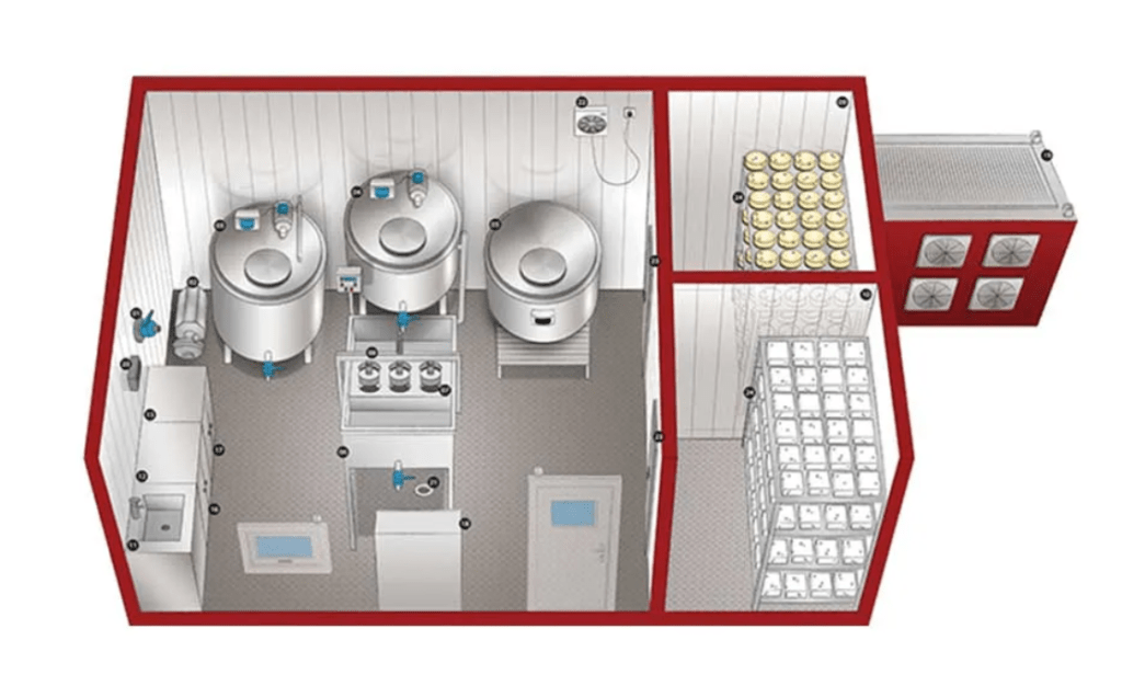
Rapid deployable microfactories represent a shift in industrial thinking where manufacturing capability is treated as a portable, quickly activatable resource rather than a permanently fixed asset tied to large-scale infrastructure. These systems are designed around the idea that production should be able to follow demand, rather than forcing demand to depend on distant production hubs. In practice, this means compact, modular factory units that can be transported in standard logistics formats, set up in a short time, and brought into operation with minimal civil engineering or long commissioning cycles. The emphasis is not only on mobility, but on speed of activation, operational flexibility, and the ability to maintain industrial-grade performance within a small physical footprint.
At the core of a rapid deployable microfactory is a tightly integrated combination of compact machinery, automated handling systems, and digital control infrastructure. Unlike traditional factories where processes are distributed across large buildings and specialized departments, microfactories compress the entire production chain into a condensed and highly coordinated system. Material input, processing, assembly, inspection, and output are arranged in a streamlined flow, often within a single containerized or modular structure. This requires careful engineering to ensure that efficiency is not lost despite spatial constraints, and that each stage of production can operate continuously without creating bottlenecks.
The deployment model is one of the defining characteristics of these systems. A microfactory is typically pre-engineered to be transported as a complete or semi-complete unit, then rapidly activated once it reaches its destination. This can involve unfolding structural components, connecting standardized power and data interfaces, stabilizing the system on a prepared surface, and running automated calibration routines to bring all machines into operational alignment. The goal is to reduce the time between arrival and full production readiness to a minimum, sometimes measured in hours or days rather than weeks or months. This capability is particularly valuable in environments where time-sensitive production is critical or where infrastructure is not permanently established.
Digital integration plays a central role in enabling this rapid activation. Modern microfactories rely heavily on pre-configured software environments that define machine behavior, production workflows, and quality standards. When the system is deployed, these configurations are loaded into the control infrastructure, allowing the entire facility to initialize in a coordinated and predictable manner. Remote connectivity often allows engineers to monitor or assist in setup processes without being physically present, further reducing deployment complexity. Over time, these systems can also update their operational profiles dynamically, adapting to new production requirements without requiring physical restructuring.
Automation is essential to maintaining both speed and consistency in such compact systems. Because space and manpower are limited, many tasks that would traditionally require human intervention are handled by robotic subsystems. These may include material transport, precision assembly, machine tending, inspection, and packaging. The use of automation ensures that production can continue at a steady rate even in constrained environments, while also reducing variability in output quality. In many designs, human operators focus primarily on supervision, system oversight, and exception handling rather than direct manual production work.
Energy management is another important aspect of rapid deployable microfactories. Since these systems are often intended for flexible or temporary deployment, they must be capable of operating in environments with varying levels of infrastructure support. Some systems are designed to connect to local power grids when available, while others integrate independent energy solutions such as generators, battery storage systems, or hybrid microgrid configurations. Intelligent energy distribution systems manage consumption across machines and subsystems, ensuring stable operation even under fluctuating supply conditions. Efficiency becomes especially important because compact systems have limited capacity for redundant infrastructure.
One of the most significant advantages of microfactory systems is their ability to support localized production close to demand points. This reduces reliance on long supply chains, lowers transportation requirements, and allows products or components to be manufactured closer to where they are needed. In practical terms, this can support industrial maintenance operations, remote construction projects, regional manufacturing hubs, emergency response scenarios, or specialized production requirements that do not justify full-scale factory investment. By bringing production capability closer to the point of use, these systems help reduce delays and increase responsiveness in dynamic operational environments.
Material flow within microfactories is carefully optimized due to the constrained internal environment. Instead of large-scale conveyor systems, these facilities often rely on compact automated transfer mechanisms, robotic arms, modular storage systems, and precisely timed workflow sequences. Every movement of material is designed to minimize unnecessary distance and handling steps, improving efficiency within the limited spatial envelope. Digital tracking systems monitor inventory in real time, ensuring that materials are available exactly when needed and reducing downtime caused by supply interruptions.
As these systems evolve, there is a growing trend toward increasing modularity and reconfigurability. A single microfactory may be capable of switching between different production modes by changing tooling sets, reloading software configurations, or rearranging internal modules. This allows the same physical infrastructure to serve multiple industrial purposes over its lifecycle, increasing utilization rates and reducing the need for specialized dedicated facilities. In more advanced designs, entire production modules can be swapped in and out, effectively transforming the factory’s capabilities without redesigning the core structure.
The long-term development trajectory of rapid deployable microfactories is closely linked to advances in artificial intelligence, robotics, and digital manufacturing systems. As these technologies mature, microfactories are expected to become more autonomous, capable of self-optimization, predictive maintenance, and even partial self-reconfiguration based on production needs. Instead of being manually managed systems, they may increasingly function as semi-autonomous industrial units within larger distributed manufacturing networks, coordinating with other facilities through shared digital platforms.
Ultimately, rapid deployable microfactories represent a broader shift in industrial philosophy toward flexibility, decentralization, and responsiveness. They challenge the traditional assumption that efficient manufacturing requires large, permanent infrastructure by demonstrating that compact, mobile, and intelligent systems can also deliver high-quality production when properly designed. As global industry continues to adapt to faster cycles of demand, more complex supply chain dynamics, and increasing pressure for resilience, these systems are likely to become an important component of future manufacturing ecosystems.
As rapid deployable microfactories continue to evolve, one of the most important long-term developments is their gradual transformation from isolated production units into fully networked industrial ecosystems. In earlier stages, each microfactory was designed primarily to function as an independent unit, capable of operating on its own once deployed. While this independence remains important, the emerging direction is toward interconnection, where multiple microfactories communicate, coordinate, and share production responsibilities dynamically. This creates a distributed manufacturing layer that behaves less like a collection of separate facilities and more like a single adaptive production system spread across multiple locations. In such a structure, production tasks can be shifted between units based on capacity, availability, proximity to demand, or even real-time disruptions in supply chains.
This interconnected model is increasingly supported by advancements in industrial data infrastructure. Continuous data exchange between machines, production modules, and centralized coordination platforms allows each unit to operate with awareness of the broader system context. Instead of optimizing only local efficiency, each microfactory can contribute to global optimization goals across the entire network. This means production scheduling becomes a dynamic process rather than a fixed plan, adjusting continuously as conditions change. If one facility experiences increased load, another can take over part of the workflow. If a particular region experiences urgent demand, nearby microfactories can be re-tasked quickly to prioritize output for that area. This level of responsiveness significantly improves overall system resilience and reduces the risk of bottlenecks.
Another key evolution is the increasing role of adaptive manufacturing logic within these systems. Rather than relying on rigid production lines designed for a single product type, modern microfactories are being designed to handle variability as a core feature. This is achieved through flexible tooling systems, modular machine architectures, and software-defined production workflows that can be reconfigured rapidly. In practice, this means the same physical infrastructure can support multiple product types over time without requiring extensive mechanical modification. Production changes are increasingly handled at the digital layer, where updated process definitions are distributed to machines and executed automatically. This reduces downtime between production shifts and enables much higher utilization efficiency of the same physical equipment.
As automation becomes more advanced, the internal coordination within microfactories is also becoming more autonomous. Instead of requiring constant human scheduling and intervention, production systems increasingly manage their own internal timing, material flow, and machine synchronization. Robotic subsystems negotiate task allocation among themselves based on workload, availability, and process priority. Sensor networks continuously monitor system conditions and trigger adjustments when deviations occur. Over time, this creates an operational environment where the factory behaves as a self-regulating system, maintaining stability and productivity with minimal external control input.
The integration of advanced simulation and predictive modeling is further enhancing this autonomy. Before changes are implemented in physical production, they can be tested virtually within digital replicas of the factory environment. These simulations allow operators and AI systems to evaluate different production strategies, identify potential inefficiencies, and predict outcomes before applying changes in real time. This reduces risk and increases confidence in system adjustments, particularly in high-precision or high-value manufacturing environments. As simulation fidelity improves, the gap between virtual planning and physical execution continues to narrow, making production systems more predictable and controllable.
Material intelligence is also becoming an increasingly important aspect of microfactory development. Rather than treating materials as passive inputs, modern systems track material properties, behavior, and lifecycle characteristics throughout the production process. This allows manufacturing parameters to be adjusted dynamically based on real-time material feedback. For example, variations in raw material composition can be compensated automatically during machining or assembly, ensuring consistent output quality despite input variability. This level of responsiveness significantly improves production reliability, especially in distributed environments where material sources may vary.
Energy systems within rapidly deployable microfactories are also evolving toward greater integration and optimization. Instead of treating power supply as a simple external input, modern systems manage energy as a dynamic resource that must be continuously balanced against production demand. Intelligent energy orchestration systems distribute power across machines based on operational priority, system load, and efficiency considerations. In more advanced configurations, microfactories can even coordinate energy usage across multiple units, sharing surplus capacity or balancing peak loads through networked energy management systems. This improves stability and reduces dependency on external infrastructure variability.
Another emerging dimension is the increasing convergence between manufacturing and logistics within the same operational framework. Traditionally, production and distribution were treated as separate domains, with factories focusing on manufacturing and external systems handling transportation and delivery. In microfactory ecosystems, these boundaries are becoming more fluid. Production planning increasingly takes logistics constraints into account in real time, while distribution systems adapt based on current manufacturing capacity. This integrated approach reduces delays and improves overall system efficiency by aligning production output more closely with actual delivery requirements.
Human roles within these systems continue to shift toward higher-level coordination and exception handling rather than direct operational control. As systems become more autonomous, operators focus on supervising performance, interpreting system analytics, managing configuration changes, and intervening only when anomalies occur. Advanced visualization tools and AI-driven interfaces allow complex industrial data to be presented in simplified formats, enabling fewer operators to manage larger and more complex systems effectively. This shift reduces labor intensity while increasing the importance of technical expertise and system-level understanding.
Looking ahead, rapid deployable microfactories are likely to become increasingly self-configuring and self-optimizing. Future systems may be capable of automatically determining optimal internal layouts, selecting appropriate production modules, and adjusting operational strategies based on real-time environmental and demand conditions. Combined with advancements in robotics, artificial intelligence, and modular engineering, this could lead to industrial systems that are capable not only of executing production tasks but also of continuously reorganizing themselves to improve performance.
In this trajectory, microfactories become less like traditional machines and more like adaptive industrial organisms embedded within larger distributed manufacturing networks. They respond dynamically to external conditions, coordinate with other units across distances, and evolve their internal structure over time based on accumulated operational experience. This represents a significant departure from static factory models and points toward a future where industrial production is defined not by fixed infrastructure but by flexible, intelligent, and interconnected systems capable of continuous adaptation.
As rapid deployable microfactories continue to develop further, one of the most important long-term trajectories is their increasing integration into global manufacturing ecosystems that function more like distributed computational networks than traditional industrial supply chains. In this emerging model, production capacity is no longer concentrated in a small number of large, static facilities but is instead distributed across a wide range of smaller, mobile, and highly adaptable units that can be activated or reallocated as needed. This fundamentally changes how industrial systems respond to demand, because capacity can be dynamically shifted rather than being locked into predefined geographic and infrastructural constraints. The result is a manufacturing environment that behaves more like a responsive system, continuously adjusting itself to balance efficiency, availability, and proximity to demand.
This distributed structure relies heavily on real-time coordination between production nodes. Each microfactory operates with continuous awareness of both its internal state and the external conditions of the broader network. Machine status, production queues, material availability, energy consumption, and logistical constraints are all constantly updated and shared across the system. This allows decision-making to occur not in isolation but in coordination with the entire network, enabling global optimization rather than purely local efficiency. If one node becomes constrained, others can adjust their output or reassign tasks to maintain overall system stability. This type of coordination is increasingly supported by advanced industrial communication protocols and edge-based computing systems that minimize latency while maintaining high reliability.
The concept of dynamic production allocation is becoming central to this evolution. Instead of assigning fixed production roles to specific facilities, manufacturing tasks can be distributed fluidly across available units based on real-time conditions. A single product may have its production stages split across multiple microfactories, with each unit contributing a specific part of the process depending on its current capacity and capability. This approach requires highly standardized process definitions and interoperable machine architectures so that different systems can seamlessly continue each other’s work without loss of precision or quality. Over time, this leads to a manufacturing environment where production is treated as a distributed workflow rather than a linear process confined to a single location.
At the same time, the internal intelligence of individual microfactories is becoming more advanced and self-reliant. These systems are increasingly capable of making operational decisions independently based on local sensor data, predictive models, and adaptive control algorithms. Instead of relying on constant external instructions, machines can adjust parameters such as speed, feed rate, temperature control, or tool usage dynamically to maintain optimal performance. This autonomy is especially valuable in rapidly deployable systems, where environmental conditions and operational demands may vary significantly between deployments. The ability to self-adjust reduces setup complexity and increases reliability across diverse operational scenarios.
Material handling systems within these environments are also evolving toward greater flexibility and intelligence. Rather than relying on rigid, preconfigured material flows, modern microfactories increasingly use adaptive routing systems that determine optimal material paths in real time. Automated storage systems, robotic transport units, and sensor-guided logistics mechanisms ensure that materials are delivered to the correct location exactly when needed, reducing idle time and minimizing unnecessary movement. This dynamic material flow design is essential in compact environments where spatial efficiency directly impacts production capability.
Another major development is the increasing use of predictive and prescriptive analytics in industrial operations. Instead of simply reacting to current conditions, microfactories are now capable of forecasting future states based on historical data, real-time trends, and machine learning models. These predictions can include expected machine wear, likely production delays, material shortages, or energy consumption spikes. More advanced systems go beyond prediction and actively recommend or automatically implement corrective actions to prevent inefficiencies before they occur. This shifts industrial operations from reactive maintenance and planning toward proactive and self-optimizing behavior.
Energy systems within these distributed microfactory networks are also becoming more coordinated and intelligent. Rather than operating independently, energy systems across multiple units can be synchronized to balance demand and supply dynamically. This may involve shifting energy-intensive tasks to periods of lower demand, sharing stored energy between facilities, or optimizing production schedules to align with energy availability. In some configurations, microfactories can operate as part of localized energy ecosystems where production and energy management are tightly integrated, improving overall efficiency and reducing operational instability.
As automation continues to advance, the distinction between individual machines and the broader production system is also becoming less defined. Machines are increasingly treated as modular components within a larger adaptive system rather than isolated tools performing fixed tasks. This modularity allows systems to be reconfigured not only physically but also functionally, with machines taking on different roles depending on production requirements. A single machine may participate in different stages of production at different times, contributing to machining, assembly, inspection, or packaging workflows as needed. This fluidity increases utilization efficiency and reduces idle capacity across the system.
Human involvement in these systems is gradually transitioning toward strategic orchestration and system-level optimization. Rather than directly managing individual machines, human operators increasingly focus on configuring system parameters, interpreting analytical outputs, and managing exceptions that require judgment beyond automated logic. Advanced interfaces present complex industrial data in simplified, actionable formats, allowing decision-making to remain effective even as system complexity increases. This shift reduces operational workload while increasing the importance of analytical thinking and cross-system understanding.
Over time, rapid deployable microfactories are likely to become foundational elements in a broader industrial transformation where manufacturing is treated as a distributed, intelligent, and continuously adaptive resource. Instead of being tied to fixed infrastructure and long production cycles, industrial capacity becomes something that can be deployed, scaled, and reconfigured in real time. This evolution points toward a future in which manufacturing systems behave less like static production facilities and more like dynamic industrial networks capable of responding continuously to global economic, logistical, and technological conditions.
As rapid deployable microfactories evolve further, one of the most consequential shifts is the increasing movement toward fully autonomous production orchestration, where the entire lifecycle of manufacturing—from demand interpretation to final output distribution—is managed through layered digital intelligence systems with minimal human intervention. In this structure, manufacturing is no longer initiated solely by direct planning cycles or manual scheduling, but increasingly by continuous data streams that reflect real-time demand signals, supply chain conditions, resource availability, and system capacity across distributed networks. These inputs are processed by coordination algorithms that determine where, when, and how production should occur, effectively turning industrial activity into a continuously optimized flow rather than a fixed sequence of predefined operations.
This transformation is closely tied to the growing sophistication of predictive industrial systems. Instead of reacting to shortages, delays, or fluctuations after they occur, advanced microfactory networks are increasingly designed to anticipate them. By analyzing historical production patterns, logistics performance, environmental variables, and consumption trends, these systems can forecast where bottlenecks are likely to emerge and adjust production allocation in advance. This allows manufacturing networks to smooth out inefficiencies before they manifest, reducing waste, minimizing idle time, and improving overall system resilience. In highly developed configurations, these predictive mechanisms extend beyond operational efficiency and begin influencing strategic decisions about capacity distribution, facility deployment, and long-term production planning.
At the same time, the physical architecture of microfactories is becoming more deeply aligned with this dynamic operational logic. Instead of being optimized for a single fixed configuration, modern designs increasingly emphasize structural neutrality, meaning that internal layouts can be reconfigured without requiring major reconstruction. Machine mounts, power distribution systems, data routing infrastructure, and material handling pathways are all designed to support rapid reorganization. This allows the same physical container or modular unit to shift between different production roles over time, extending its useful lifecycle and increasing overall infrastructure efficiency. In some advanced concepts, internal robotic systems may even participate in physical reconfiguration, adjusting layouts automatically based on new production requirements.
Another important development is the increasing synchronization between manufacturing systems and external environmental conditions. Microfactories are no longer isolated from their surroundings but are instead designed to continuously adapt to them. Environmental sensors track temperature, humidity, air quality, vibration levels, and energy stability, feeding this information into adaptive control systems that adjust machine behavior accordingly. This ensures that production quality remains stable even when external conditions vary significantly. In mobile or rapidly deployable contexts, this adaptability becomes especially important, as facilities may operate in a wide range of geographic and climatic environments over their operational lifespan.
The integration of advanced material intelligence further enhances system adaptability. Materials are no longer treated as static inputs but as dynamic variables whose properties may change depending on sourcing, processing conditions, and environmental exposure. Modern production systems increasingly incorporate real-time material characterization tools that monitor properties such as density variation, thermal response, structural integrity, and surface behavior during processing. This allows manufacturing parameters to be adjusted dynamically to maintain consistent output quality despite variability in input materials. Over time, this leads to a more resilient production process that can accommodate a broader range of material sources without sacrificing precision.
In parallel, logistics systems are becoming deeply embedded within the operational logic of microfactories rather than functioning as external support structures. Material procurement, inventory management, and distribution are increasingly coordinated in real time with production scheduling. Instead of relying on large buffer inventories or long-term forecasting alone, systems adjust procurement and delivery cycles dynamically based on current production rates and predicted demand changes. This tight integration reduces excess inventory, lowers storage requirements, and improves responsiveness to shifting conditions. In distributed networks, logistics systems can also coordinate between multiple microfactories to optimize regional material flow and reduce transportation inefficiencies.
As artificial intelligence continues to advance, its role within these systems is expanding from optimization support to active system governance. AI systems are increasingly capable of managing entire segments of production operations autonomously, making decisions about resource allocation, process sequencing, and quality control adjustments without requiring direct human approval. These systems learn continuously from operational data, refining their decision-making models over time and improving their ability to handle complex or unexpected scenarios. In highly advanced environments, human oversight becomes primarily supervisory, focusing on monitoring system behavior and intervening only when exceptional conditions arise that fall outside predefined operational parameters.
The relationship between individual microfactories and broader industrial networks is also becoming more fluid and hierarchical at the same time. On one level, each unit operates independently, capable of executing production tasks locally. On another level, all units are connected within larger coordination frameworks that manage resource distribution, workload balancing, and strategic production planning. This dual structure allows systems to remain resilient even if individual units become temporarily unavailable, while still benefiting from global optimization across the entire network. It also enables gradual scaling, where new microfactories can be integrated seamlessly into existing systems without disrupting overall operations.
Energy systems within these evolving networks are also undergoing significant transformation. Rather than being treated as a fixed utility input, energy is increasingly managed as a dynamic and distributed resource that must be optimized alongside production processes. Intelligent energy coordination systems balance consumption across multiple units, shift loads in response to demand fluctuations, and integrate local generation or storage capabilities where available. In more advanced configurations, energy management may even be directly linked to production scheduling, ensuring that energy-intensive tasks are aligned with periods of optimal supply conditions.
Over time, these developments point toward a broader redefinition of what a factory actually is. Instead of being a static physical location, a factory becomes a distributed, intelligent, and reconfigurable system of production capability that can be deployed across multiple environments and coordinated through digital infrastructure. The distinction between individual facilities begins to blur as manufacturing becomes increasingly networked, adaptive, and continuously optimized. In this emerging model, industrial production is less about building permanent structures and more about maintaining a flexible and responsive system of interconnected manufacturing intelligence capable of operating wherever and whenever it is needed.
Distributed manufacturing architecture
Distributed manufacturing architecture describes a way of organizing production where manufacturing capability is spread across multiple smaller, interconnected nodes rather than being concentrated in a single large factory. Instead of relying on one central site to perform all stages of production, the system divides manufacturing tasks across geographically or operationally distributed facilities that are coordinated through shared digital infrastructure. This structure is designed to increase flexibility, resilience, and responsiveness while reducing dependency on long, linear supply chains that are vulnerable to disruption.
At the core of distributed manufacturing is the idea that production is not a fixed location but a coordinated process. Each node in the network can perform a specific subset of manufacturing functions such as machining, assembly, inspection, packaging, or material preparation. These nodes may differ in size and capability, ranging from small automated microfactories to larger semi-specialized production hubs. What makes them part of a single system is not their physical similarity but their digital interoperability. Shared communication protocols, standardized data formats, and synchronized production planning systems allow them to operate as a unified manufacturing organism.
Digital coordination is the central mechanism that enables this architecture to function. Real-time data exchange allows each node to remain aware of production demand, inventory levels, machine status, and logistics constraints across the entire network. This information is continuously analyzed by coordination software that allocates production tasks dynamically. Instead of static production schedules, the system uses adaptive planning models that adjust based on changing conditions. If one facility experiences a slowdown or resource limitation, other nodes can compensate by redistributing workload. This creates a self-balancing production ecosystem that can absorb shocks more effectively than centralized systems.
A key advantage of distributed manufacturing architecture is resilience. In traditional centralized models, disruptions at a single large facility can have widespread consequences across the entire supply chain. In a distributed model, production is inherently redundant and geographically dispersed, meaning that localized disruptions have limited systemic impact. Even if one node becomes temporarily unavailable due to maintenance, energy constraints, or external factors, other nodes can continue operating and maintain overall production continuity. This redundancy makes the system more stable under uncertain or volatile conditions.
Another important feature is proximity-based production optimization. Because manufacturing nodes can be located closer to end users or regional demand centers, products can be produced nearer to where they are needed. This reduces transportation distances, lowers logistical complexity, and shortens delivery times. In some cases, production tasks can be dynamically assigned to the geographically closest available node that meets required capability and capacity conditions. This spatial flexibility allows the system to optimize not only efficiency but also responsiveness.
Standardization plays a crucial role in enabling interoperability across distributed manufacturing networks. Components, materials, machine interfaces, and digital process definitions must follow consistent standards to ensure that production can be transferred seamlessly between different nodes. This includes standardized machine communication protocols, unified quality control frameworks, and harmonized engineering data structures. Without this level of standardization, coordination between heterogeneous facilities would be difficult and inefficient. With it, production becomes portable across the network.
Automation and robotics further enhance the scalability of distributed systems. Many nodes are highly automated, allowing them to operate with minimal human intervention while maintaining consistent output quality. Robotic systems handle material movement, precision processing, assembly operations, and inspection tasks, while software systems manage scheduling and coordination. This reduces variability and allows smaller facilities to perform complex manufacturing tasks that were previously limited to large industrial plants.
Energy and resource management also become more dynamic in distributed architectures. Instead of each facility operating in isolation, energy usage and material consumption can be monitored and optimized across the entire network. Production tasks can be shifted between nodes based on energy availability, local cost conditions, or resource constraints. This creates opportunities for more efficient overall system behavior, particularly when combined with renewable energy sources or localized energy storage systems.
Data infrastructure is another foundational layer of distributed manufacturing. Large volumes of operational data are generated continuously across all nodes, including machine performance metrics, production quality results, supply chain information, and environmental conditions. This data is aggregated and analyzed to improve system-wide decision-making. Machine learning models can identify inefficiencies, predict maintenance needs, and optimize production allocation strategies over time. As the system accumulates more data, its ability to coordinate complex production activities improves progressively.
The human role within distributed manufacturing architectures is also evolving. Instead of managing individual production lines, operators increasingly focus on overseeing networks of facilities, interpreting system analytics, and making high-level decisions about production strategy. Much of the routine coordination is handled automatically by software systems, while humans intervene primarily in cases that require judgment, exception handling, or strategic adjustment. This shift reduces operational complexity at the local level while increasing the importance of system-level understanding.
In advanced implementations, distributed manufacturing networks can also support adaptive reconfiguration of production capabilities. Facilities are not permanently assigned fixed roles; instead, they can be repurposed based on demand. A node that typically handles assembly might temporarily switch to testing or packaging depending on system requirements. This flexibility allows the network to behave more like a shared pool of manufacturing capacity rather than a rigid hierarchy of specialized factories.
Over time, distributed manufacturing architecture is expected to become increasingly autonomous, interconnected, and intelligent. As artificial intelligence, robotics, and industrial IoT technologies continue to mature, these systems will likely evolve toward fully adaptive production ecosystems capable of self-balancing, self-optimizing, and self-reconfiguring across global networks. In this future model, manufacturing is no longer defined by individual factories but by continuously coordinated systems of distributed capability that respond dynamically to global demand, resource availability, and operational conditions.
As distributed manufacturing architecture continues to evolve, one of the most important long-term developments is the shift from coordination-based networks toward increasingly autonomous production ecosystems that can regulate themselves with minimal centralized oversight. In earlier stages, distributed systems relied heavily on coordination platforms that assigned tasks, balanced workloads, and synchronized production schedules across multiple facilities. While these systems were already more flexible than traditional centralized manufacturing models, they still depended on relatively structured planning and human-defined rules. The emerging direction is toward systems that can interpret demand signals, evaluate constraints, and make allocation decisions continuously in real time without waiting for explicit external instructions.
This transition is being driven by advances in artificial intelligence and real-time optimization algorithms that can process vast amounts of industrial data simultaneously. As manufacturing networks generate continuous streams of information about production rates, material availability, machine health, logistics conditions, and energy consumption, AI systems can analyze this data to detect patterns that are not immediately visible at the human level. These systems are increasingly capable of identifying inefficiencies, predicting future constraints, and adjusting production distribution dynamically across the network. Instead of operating in fixed cycles of planning and execution, distributed manufacturing systems are gradually becoming continuous adaptive processes where decisions are constantly refined based on live operational conditions.
Another important aspect of this evolution is the increasing fluidity of production capability across the network. In more traditional distributed systems, each facility tends to have a defined role or specialization, even if tasks can be reassigned when necessary. However, as modular production technologies advance, these distinctions are becoming less rigid. Machines, tooling systems, and digital process definitions are increasingly designed to be interoperable across multiple production contexts. This allows individual nodes to shift their functional role more easily depending on network demand. A facility might function as a machining center during one production cycle, then transition into assembly, testing, or packaging roles in another, all without requiring fundamental structural changes. This flexibility significantly increases the utilization efficiency of the entire network.
Material traceability and digital continuity are also becoming central to distributed manufacturing architecture. Every material, component, and semi-finished product can now be tracked digitally throughout its entire lifecycle as it moves through different nodes in the network. This enables a high level of transparency and coordination, where each facility is aware not only of its immediate inputs and outputs but also of the upstream and downstream context of the materials it processes. This continuous traceability improves quality control, reduces waste, and allows for more precise optimization of production flows across the system. It also enables rapid identification of bottlenecks or quality deviations, which can then be addressed either locally or through system-wide adjustments.
The increasing integration of predictive maintenance systems further enhances the stability of distributed manufacturing networks. Instead of waiting for machine failures or performance degradation to occur, modern systems continuously monitor equipment health through embedded sensors and data analytics. These systems can detect early warning signs of wear, misalignment, or inefficiency and schedule maintenance interventions proactively. In a distributed environment, this capability is especially important because production is spread across multiple locations, and maintaining consistent uptime across all nodes is critical for overall system performance. Predictive maintenance helps ensure that disruptions remain localized and do not propagate across the network.
Energy coordination is also becoming more sophisticated in distributed manufacturing systems. Rather than treating energy consumption as a passive constraint, modern architectures actively manage energy usage as part of overall production optimization. Facilities can adjust production intensity based on energy availability, cost fluctuations, or sustainability goals. In networks with integrated renewable energy sources, production scheduling may even adapt to real-time energy generation patterns, shifting energy-intensive tasks to periods of higher availability. In more advanced configurations, energy sharing between nodes becomes possible, allowing facilities with surplus capacity to support others experiencing higher demand.
The role of simulation and digital modeling is expanding significantly in the design and operation of distributed manufacturing systems. Before physical production decisions are implemented, they can be tested in virtual environments that replicate the behavior of the entire network under different conditions. These simulations allow operators and AI systems to evaluate the impact of production changes, identify potential inefficiencies, and explore alternative configurations without disrupting real-world operations. As simulation accuracy improves, the boundary between planning and execution becomes increasingly blurred, with decisions being continuously tested and refined in parallel digital environments before being applied physically.
Human involvement in distributed manufacturing architecture is also undergoing a gradual transformation. Rather than directly managing individual production activities, human operators increasingly focus on higher-level system oversight, strategic planning, and exception management. Much of the operational complexity is handled automatically by interconnected digital systems that coordinate production across multiple nodes. Human expertise becomes more focused on interpreting system behavior, adjusting strategic objectives, and intervening in cases where ethical, regulatory, or highly complex judgment is required. This shift reduces operational workload while increasing the importance of systems thinking and analytical capability.
Another important trend is the gradual convergence of distributed manufacturing with broader industrial ecosystems, including logistics, energy infrastructure, and digital services. Manufacturing nodes are no longer isolated production units but part of larger interconnected systems that manage material flow, energy distribution, transportation, and data analytics in an integrated manner. This convergence allows for more efficient resource utilization and creates opportunities for cross-domain optimization that were not possible in traditional siloed industrial structures. For example, logistics planning can directly influence production scheduling, while energy availability can shape manufacturing priorities in real time.
Over time, distributed manufacturing architecture is likely to become increasingly self-organizing. Instead of relying on explicit human design for every aspect of system behavior, future networks may be capable of evolving their own internal structure based on operational experience. Production nodes could dynamically adjust their roles, connectivity, and functional relationships based on performance data and demand patterns. This would create a manufacturing ecosystem that is not only distributed but also adaptive in its structure, continuously optimizing itself to improve efficiency, resilience, and responsiveness.
In this long-term trajectory, manufacturing shifts from being a collection of fixed industrial sites to a continuously evolving network of coordinated production capability. The system becomes less about where factories are located and more about how manufacturing intelligence is distributed across a global network. Distributed manufacturing architecture, in this sense, represents a foundational step toward a future where industrial production behaves as a flexible, adaptive, and interconnected system capable of responding continuously to changing global conditions.
As distributed manufacturing architecture continues to mature, one of the most significant deeper transformations is the gradual emergence of what can be described as production fluidity, where manufacturing is no longer treated as a sequence of fixed, localized operations but instead as a continuously flowing process that can shift form, location, and intensity depending on real-time system conditions. In this model, production is not anchored to any single facility or even a stable configuration of facilities; rather, it exists as a coordinated activity that can move across the network in response to changing demand, resource availability, and operational constraints. This fundamentally alters the traditional concept of a factory, replacing it with a dynamic industrial field where capability is distributed and constantly reallocated.
This fluidity is made possible by increasingly advanced layers of abstraction in industrial control systems. Instead of programming individual machines or even individual factories, engineers and AI systems now define higher-level production intents, which are then translated automatically into coordinated actions across multiple distributed nodes. These intents describe what needs to be produced, under what constraints, and with what quality requirements, but they do not specify exactly where or how each step must occur. The system itself determines the optimal distribution of tasks across available resources. This separation between intent and execution allows the same manufacturing objective to be fulfilled in multiple different configurations depending on real-time system conditions, making production inherently adaptive rather than rigid.
At the same time, synchronization between distributed nodes is becoming increasingly granular and continuous. Earlier models of distributed manufacturing often relied on batch-based coordination, where production updates were exchanged at fixed intervals. In more advanced architectures, however, synchronization is continuous and event-driven, with machines and facilities constantly exchanging state information at very high frequency. This allows the entire network to behave as a coherent system even though it is physically dispersed. Changes in one part of the network can propagate almost instantly to other parts, enabling rapid adjustment and reducing the risk of mismatched production states.
Another important development is the increasing importance of adaptive capacity scaling. In traditional manufacturing, capacity is relatively fixed, and scaling production up or down requires significant physical changes such as adding new machinery, expanding facilities, or reducing operational shifts. In distributed architectures, capacity becomes elastic. Additional nodes can be activated when demand increases, while underutilized nodes can be temporarily repurposed or placed into low-energy states when demand decreases. This elasticity allows the system to maintain a closer alignment between production output and actual demand, reducing waste and improving efficiency across the entire network.
The internal structure of individual production nodes is also becoming more dynamic. Instead of being rigidly organized around fixed production lines, modern facilities increasingly use reconfigurable layouts where machines and workstations can be rearranged logically or physically depending on the current production task. This reconfiguration may be software-defined, where machines change roles without physical movement, or physically assisted by modular robotics that reposition equipment within the facility. This adaptability allows each node to function as a general-purpose production environment rather than a specialized single-function factory.
Material flow across distributed systems is also becoming more intelligent and decentralized. Rather than following predetermined supply routes, materials are increasingly routed dynamically based on real-time system conditions. This includes not only transportation logistics between facilities but also internal material handling within each node. Decision-making about where materials should be processed next can be continuously updated based on queue lengths, machine availability, energy efficiency, and delivery deadlines. This creates a self-optimizing material network that continuously adjusts itself to minimize delays and maximize throughput efficiency.
The role of digital twins in distributed manufacturing is expanding significantly as well. Entire production networks can now be mirrored in high-fidelity virtual environments that simulate machine behavior, material flow, energy consumption, and production outcomes. These digital representations are not static models but continuously updated systems that reflect real-world conditions in near real time. This allows operators and AI systems to test different production strategies, anticipate system behavior, and optimize decisions before applying them physically. Over time, these digital and physical layers become tightly coupled, effectively forming a dual-layer manufacturing system where virtual and physical operations evolve together.
Cyber-physical integration is another defining feature of this evolving architecture. Machines, sensors, control systems, and digital platforms are increasingly interwoven into a single operational fabric where physical actions and digital decisions are indistinguishable in practice. A change in a digital parameter can immediately alter machine behavior across multiple nodes, while physical changes in machine performance are instantly reflected in the digital system. This tight coupling allows for extremely fast feedback loops, which are essential for maintaining stability in highly distributed and dynamic environments.
As automation deepens, decision hierarchies within distributed manufacturing systems are also flattening. Instead of long chains of command where decisions must pass through multiple organizational layers, many operational decisions are now made locally by intelligent subsystems based on predefined constraints and global optimization goals. This reduces latency in decision-making and allows systems to respond more quickly to changing conditions. Human oversight remains important, but it is increasingly focused on setting boundaries, objectives, and constraints rather than micromanaging operational details.
In the long-term evolution of distributed manufacturing architecture, there is a clear movement toward self-organizing industrial ecosystems. In such systems, production networks may be capable of automatically restructuring themselves based on shifts in demand, resource availability, technological upgrades, or environmental conditions. Nodes may dynamically change their relationships, form temporary clusters for specific production tasks, or redistribute workload without centralized coordination. This would represent a shift from engineered distribution toward emergent distribution, where system structure arises naturally from ongoing operational interactions rather than being fully predefined.
Ultimately, distributed manufacturing architecture is moving toward a state where industrial production behaves less like a designed infrastructure and more like an adaptive, continuously evolving system. Instead of being constrained by fixed factories and static supply chains, manufacturing becomes a fluid, networked capability that can reorganize itself in response to global conditions. This represents a fundamental rethinking of industrial organization, where flexibility, responsiveness, and intelligence become more important than physical scale or permanence, and where production is defined not by location but by coordinated capability distributed across a constantly changing network.
As distributed manufacturing architecture progresses further, one of the most profound shifts is the gradual emergence of what can be described as self-optimizing industrial ecosystems, where the system no longer simply executes externally defined plans but continuously refines its own operational logic based on accumulated experience. In such environments, every production cycle contributes not only to output but also to system learning. Machine behavior, material performance, energy usage, logistical efficiency, and quality outcomes are continuously analyzed and fed back into the decision-making framework, allowing the entire network to evolve over time. This creates a form of industrial intelligence that is not static but cumulative, where performance improvements emerge organically from ongoing operation rather than periodic redesign.
This evolution is closely tied to the increasing sophistication of distributed decision-making systems. Instead of relying on centralized control structures, modern manufacturing networks distribute decision authority across multiple layers of intelligence, including local machine controllers, facility-level coordination systems, and global optimization platforms. Each layer operates with a different scope of awareness and responsibility, but all are connected through continuous data exchange. Local systems make fast, immediate adjustments to maintain stability, while higher-level systems analyze broader trends and adjust strategic parameters. This layered autonomy allows the system to remain both responsive and coherent, balancing local flexibility with global consistency.
Another important development is the deepening integration between production systems and predictive infrastructure. Distributed manufacturing networks are increasingly capable of forecasting not only demand but also internal system behavior under different scenarios. This includes predicting machine degradation, material shortages, energy fluctuations, and logistics delays before they occur. These predictions are not isolated estimates but interconnected models that consider the entire system simultaneously. As a result, the network can proactively adjust production flows, redistribute workloads, or pre-position resources to minimize future disruptions. Over time, this reduces the reactive nature of industrial operations and replaces it with anticipatory behavior.
The physical and digital boundaries within distributed manufacturing are also becoming increasingly indistinct. Machines are no longer viewed as isolated hardware units but as nodes within a continuous cyber-physical system. Each machine contributes real-time operational data to the network while simultaneously receiving adaptive instructions based on system-wide conditions. This bidirectional flow of information creates a tightly coupled environment where physical operations and digital decision-making are inseparable. As a result, even small changes in one part of the system can propagate through the entire network almost instantly, enabling highly coordinated responses to dynamic conditions.
Material ecosystems within distributed manufacturing are also evolving toward greater intelligence and traceability. Materials are tracked not only in terms of location and quantity but also in terms of quality, processing history, and performance characteristics. This allows the system to make more informed decisions about how and where materials should be used. If certain materials exhibit specific behavioral traits during processing, the system can automatically adjust production parameters or redirect those materials to processes where they are most suitable. Over time, this leads to a more efficient matching between material properties and production requirements, reducing waste and improving consistency.
Energy dynamics are becoming increasingly integrated into the core logic of distributed manufacturing systems. Instead of being treated as an external utility, energy is managed as an active constraint that directly influences production decisions. Systems continuously evaluate energy availability, cost, and efficiency when determining production schedules and task allocation. In more advanced configurations, production networks can even respond to real-time energy market conditions or local generation patterns, shifting workloads to optimize energy utilization. This tight coupling between energy and production introduces a new dimension of efficiency optimization that operates across both physical and temporal scales.
The evolution of interoperability standards is another critical factor enabling the continued expansion of distributed manufacturing. As more systems and devices are integrated into global production networks, the need for consistent communication protocols, data structures, and operational semantics becomes increasingly important. Standardization ensures that different machines, software systems, and facilities can interact seamlessly, even if they are manufactured by different vendors or operate in different environments. This interoperability is what allows distributed manufacturing to function as a unified system rather than a collection of disconnected components.
Human roles within these increasingly autonomous systems are continuing to shift toward higher-order cognitive and supervisory functions. Instead of directly managing production processes, humans are increasingly responsible for defining objectives, interpreting system behavior, and handling complex exceptions that fall outside automated decision boundaries. Advanced visualization systems translate complex operational data into intuitive representations, allowing humans to understand system states at a glance. This enables effective oversight even as system complexity increases, ensuring that human judgment remains integrated into the decision loop without being overwhelmed by operational detail.
As distributed manufacturing systems continue to mature, there is a growing trend toward recursive optimization, where systems not only optimize production but also optimize their own optimization processes. This means that the algorithms responsible for decision-making are themselves subject to continuous improvement based on performance feedback. Over time, this leads to increasingly efficient coordination strategies, reduced computational overhead, and more accurate predictive capabilities. The system effectively becomes capable of refining its own intelligence structures, leading to accelerating improvements in overall performance.
In the long-term trajectory, distributed manufacturing architecture is moving toward a state where industrial production behaves as an emergent property of a global, interconnected system rather than a collection of discrete facilities. Production capacity becomes a continuously shifting resource distributed across a network that spans multiple regions, environments, and operational contexts. Instead of designing factories as fixed entities, the focus shifts toward designing adaptive systems that can reconfigure themselves in response to changing conditions. This represents a fundamental redefinition of manufacturing, where stability is no longer achieved through rigidity but through continuous adaptation and coordinated flexibility across an intelligent industrial network.
Autonomous mobile production infrastructure
Autonomous mobile production infrastructure represents the next stage in the evolution of distributed and containerized manufacturing systems, where mobility, automation, and intelligence are no longer separate features but fully integrated characteristics of a single adaptive industrial platform. In this model, production units are not only capable of being transported and deployed rapidly, but are also capable of configuring, operating, maintaining, and optimizing themselves with minimal external intervention. The infrastructure itself becomes an active participant in decision-making, rather than a passive environment in which manufacturing takes place.
At the foundation of this concept is a tightly integrated cyber-physical architecture that combines robotics, sensing systems, embedded computation, and modular industrial equipment into a unified operational organism. Each unit within the system is equipped with layers of intelligence that govern both local behavior and network-level coordination. On a local level, machines regulate their own performance through continuous feedback loops that monitor temperature, vibration, load, precision, and energy consumption. On a broader level, these units communicate with other mobile production nodes and centralized orchestration systems to align production goals, balance workload distribution, and optimize resource usage across the entire network. This dual-layer structure allows autonomy to exist at multiple scales simultaneously without losing system coherence.
Mobility is a defining characteristic that distinguishes these infrastructures from traditional factories. Instead of being anchored to a fixed geographic location, autonomous production units are designed to be redeployed as operational needs change. This mobility is not limited to transportation alone but extends to rapid initialization and shutdown cycles. A fully autonomous mobile production unit can transition from transport mode to full operational readiness through automated calibration, self-diagnostics, and environmental adaptation processes. Once deployed, it can integrate into local supply chains, energy systems, and data networks, effectively becoming a temporary but fully functional industrial node within a larger ecosystem.
The autonomy of these systems is largely enabled by advanced artificial intelligence frameworks that govern both strategic and operational functions. At the strategic level, AI systems analyze demand patterns, logistics constraints, and resource availability to determine optimal production placement and scheduling. At the operational level, machine learning models continuously optimize machine parameters, production sequences, and maintenance cycles. Over time, these systems develop a form of operational memory, learning from past deployments and improving performance in future scenarios. This allows each deployment to be more efficient than the last, even under different environmental or logistical conditions.
Energy independence is another critical component of autonomous mobile production infrastructure. These systems are often designed to operate in environments where external power supply may be unstable or unavailable. As a result, they integrate hybrid energy systems that may include battery storage, generator units, and compatibility with local grids or renewable sources. Intelligent energy management systems dynamically balance consumption across all operational subsystems, ensuring that production remains stable even under fluctuating energy conditions. In more advanced implementations, energy usage is coordinated across multiple mobile units, allowing them to function as a distributed microgrid that shares and reallocates power based on real-time demand.
Material handling and logistics are also deeply embedded into the autonomous structure of these systems. Rather than relying on external logistics chains for every material movement, mobile production units often include integrated storage, automated retrieval systems, and robotic material handling capabilities. These systems track material flow in real time, ensuring that inputs are available exactly when needed and minimizing downtime caused by supply delays. In more advanced configurations, autonomous coordination between multiple production units allows materials to be dynamically redirected between locations depending on processing needs and availability, creating a fluid and responsive material ecosystem.
Self-maintenance and self-diagnostics are essential features that enable long-term autonomous operation. Embedded sensor networks continuously monitor the condition of mechanical, electrical, and computational subsystems, identifying early signs of wear or malfunction. Predictive maintenance algorithms analyze this data to schedule repairs or adjustments before failures occur, reducing downtime and extending operational lifespan. In some cases, robotic maintenance systems within the infrastructure can perform routine servicing tasks autonomously, further reducing the need for human intervention.
Communication and interoperability form the connective tissue that allows autonomous mobile production systems to function as part of larger distributed networks. Standardized communication protocols ensure that different units can exchange data seamlessly, regardless of manufacturer or configuration. This interoperability enables complex coordination scenarios where multiple mobile production units collaborate on shared production goals, dividing tasks based on capability, location, and current load. The result is a highly flexible production ecosystem that can scale up or down dynamically in response to changing global conditions.
The role of humans within this system shifts significantly compared to traditional industrial models. Instead of directly operating machines or managing detailed production workflows, human involvement focuses on defining system objectives, setting operational constraints, and supervising overall performance. Human operators interact with high-level control interfaces that present aggregated system data, predictive insights, and recommended actions generated by AI systems. Intervention is typically reserved for exceptional cases or strategic decisions that require contextual judgment beyond automated logic.
Over time, autonomous mobile production infrastructure is expected to evolve toward even greater levels of independence and coordination. Future systems may be capable of fully self-organizing deployment, where production units determine their own optimal locations based on global demand signals and autonomously relocate as conditions change. They may also develop deeper integration with global logistics, energy, and data systems, effectively becoming interchangeable nodes within a worldwide industrial network that continuously adapts its structure and behavior.
In this long-term vision, manufacturing ceases to be tied to permanent industrial sites and instead becomes a distributed, mobile, and intelligent capability embedded across the global environment. Autonomous mobile production infrastructure represents a shift from static industrial architecture to a dynamic system of continuously evolving production intelligence, where factories are no longer places but processes, and industrial capacity is no longer fixed but perpetually in motion.
As autonomous mobile production infrastructure advances further, one of the most defining long-term changes is the gradual emergence of what can be described as self-directed industrial ecosystems, where production units not only execute tasks autonomously but also participate in defining their own operational context within broader system constraints. In earlier stages of development, autonomy meant the ability to perform predefined actions without constant human supervision. In more advanced architectures, autonomy extends beyond execution into decision formation, where systems evaluate their environment, interpret demand signals, and determine their own optimal operational positioning within a distributed network. This represents a shift from programmed autonomy to adaptive autonomy, where behavior is continuously shaped by real-world feedback rather than fixed instruction sets.
This increasing independence is closely tied to the maturation of hierarchical intelligence layers within the infrastructure. Instead of a single centralized AI controlling all operations, intelligence is distributed across multiple levels, each responsible for different scopes of decision-making. Local machine intelligence handles immediate operational stability, ensuring that equipment runs efficiently and safely in real time. Facility-level intelligence manages coordination between machines, balancing workload, material flow, and energy distribution within a single unit. Network-level intelligence oversees broader optimization across multiple mobile production nodes, aligning production capacity with global demand patterns and logistical conditions. These layers interact continuously, creating a multi-scale decision ecosystem that is both resilient and highly adaptive.
As these systems become more sophisticated, they begin to exhibit behavior that resembles collective coordination rather than individual machine operation. Multiple autonomous production units can synchronize their activities dynamically, forming temporary production clusters that collaborate on specific tasks before dissolving and reconfiguring for new objectives. These clusters are not fixed organizational structures but fluid formations that emerge based on demand, proximity, capability, and resource availability. This allows the overall system to continuously reorganize itself without requiring explicit top-down restructuring, significantly increasing flexibility and responsiveness.
A key enabler of this behavior is the increasing granularity of real-time data exchange between systems. Every operational parameter, from machine vibration patterns to material throughput rates and energy consumption fluctuations, is continuously monitored and shared across the network. This high-resolution data environment allows systems to detect subtle inefficiencies or emerging constraints long before they become critical issues. More importantly, it enables predictive alignment, where systems adjust their behavior proactively based on anticipated changes rather than reacting after disruptions occur. This predictive capability transforms industrial operations from reactive maintenance cycles into continuous forward-adapting processes.
The physical architecture of autonomous mobile production systems is also evolving to support deeper adaptability. Instead of being designed around fixed workflows, modern units increasingly use reconfigurable internal layouts where machines and subsystems can be reassigned to different roles as needed. This may occur through software-based redefinition of machine functions or through physical modularity that allows components to be repositioned or replaced quickly. The goal is to ensure that the same infrastructure can support a wide range of production scenarios without requiring structural redesign or prolonged downtime. Over time, this leads to a form of infrastructural neutrality, where the physical system is decoupled from specific production identities.
Material ecosystems within these infrastructures are becoming increasingly self-aware in operational terms. Materials are tracked not only as physical inputs but as dynamic entities with associated behavioral profiles, processing histories, and predictive performance models. This allows the system to make highly informed decisions about material routing, processing conditions, and end-use allocation. If a material batch exhibits certain characteristics during processing, the system can automatically adjust production parameters or redirect that material to processes where it will perform optimally. This creates a feedback loop between material properties and production logic that improves consistency and reduces inefficiencies.
Energy systems are also undergoing a parallel transformation toward distributed intelligence. Instead of being centrally managed or passively consumed, energy is actively orchestrated across the infrastructure. Autonomous units continuously evaluate their energy needs, availability, and efficiency trade-offs, adjusting their operational intensity accordingly. In networked configurations, energy balancing can occur across multiple mobile production units, allowing surplus energy in one unit to support higher demand in another. This distributed energy coordination enhances system stability and enables more efficient utilization of available resources, especially in environments with variable or constrained energy supply.
Logistics integration is becoming increasingly seamless within autonomous mobile production infrastructure. Rather than relying on external logistics systems as separate entities, transportation, material flow, and production scheduling are increasingly unified into a single coordinated system. Autonomous production units can communicate directly with logistics platforms to synchronize material delivery, component movement, and product distribution in real time. This reduces delays, minimizes inventory overhead, and allows production to remain tightly aligned with actual demand conditions. In more advanced configurations, logistics and production may become indistinguishable components of a single adaptive operational system.
Human involvement continues to evolve toward higher-level governance and system shaping rather than direct operational control. Humans define strategic objectives, set operational constraints, and interpret system-level insights generated by AI-driven analytics. In many cases, the system itself proposes optimal configurations or adjustments, with humans acting as validators or decision arbiters in complex scenarios. This creates a collaborative decision environment where human judgment and machine intelligence work in tandem, each contributing different strengths to overall system performance. Over time, as system reliability increases, the frequency of human intervention may decrease further, concentrating human effort on exceptional or strategic cases.
In the longer-term trajectory, autonomous mobile production infrastructure is likely to develop increasing degrees of structural self-organization. Instead of being deployed according to predefined plans, future systems may be capable of determining their own optimal placement, deployment timing, and network integration strategies based on continuous global data analysis. Production units could autonomously relocate to regions of higher demand, cluster dynamically around resource availability, or disperse when conditions change. This would create a global manufacturing layer that is constantly in motion, continuously reshaping itself to reflect real-time industrial needs.
Ultimately, this evolution points toward a future where industrial production is no longer defined by fixed factories or static supply chains but by a continuously adaptive, intelligent, and mobile infrastructure that exists as a global system of coordinated capability. In this model, manufacturing becomes less about physical location and more about distributed operational intelligence, where production is perpetually reorganized in response to changing conditions across an interconnected industrial environment.
As autonomous mobile production infrastructure continues to mature, one of the deeper structural shifts is the gradual transition from systems that merely adapt to external conditions toward systems that actively reshape their operational environments in response to internal optimization goals. In earlier phases of industrial automation, machines and production units were designed to operate efficiently within a given context, adjusting parameters to maintain stability and output quality. In more advanced architectures, however, the relationship becomes bidirectional: the infrastructure not only responds to its environment but also influences and reconfigures that environment through coordinated deployment decisions, resource interactions, and network-level behavior. This creates a feedback loop between industrial systems and their surroundings, where production activity becomes a shaping force within the broader operational landscape.
This increasing influence is closely tied to the expansion of multi-agent coordination systems embedded within the infrastructure. Instead of functioning as isolated autonomous units, individual production systems behave as agents within a larger collective intelligence. Each unit maintains local autonomy but also contributes to shared objectives defined at the network level. These objectives are not static instructions but evolving targets that adjust based on demand shifts, resource availability, performance metrics, and environmental constraints. The interaction between local decision-making and global coordination produces emergent behavior, where overall system performance is not explicitly programmed but arises from the continuous interaction of many semi-autonomous elements following aligned optimization principles.
As this coordination becomes more sophisticated, the system begins to exhibit forms of distributed intelligence that resemble adaptive problem-solving at scale. When disruptions occur, such as material shortages, equipment degradation, or logistical delays, the system does not simply reroute tasks according to predefined fallback rules. Instead, it evaluates multiple alternative configurations simultaneously across the network, dynamically reallocating production responsibilities in ways that preserve overall system stability while minimizing efficiency loss. This capability transforms disruption management from a reactive process into a continuous optimization problem solved in real time across distributed nodes.
The underlying computational infrastructure supporting these capabilities is also evolving significantly. Edge computing plays a central role in enabling autonomous decision-making at the local level without dependence on centralized processing. Each mobile production unit contains embedded computational resources capable of executing complex analytical tasks, running predictive models, and coordinating directly with nearby systems. At the same time, higher-level cloud-based coordination systems aggregate information across the entire network to maintain global awareness. This hybrid architecture ensures that decision-making can occur both locally and globally, depending on the scale and urgency of the situation.
Another important development is the increasing integration of adaptive temporal planning within distributed manufacturing systems. Instead of operating on fixed production schedules, these systems continuously adjust their temporal structure based on real-time conditions. Production tasks may be accelerated, delayed, split across multiple nodes, or recombined depending on system state. This creates a flexible time architecture where manufacturing is no longer bound to rigid cycles but flows continuously according to dynamic optimization logic. In such systems, time becomes a manipulable resource within the production network, allowing for more efficient alignment between demand and execution.
Material ecosystems within autonomous infrastructure are also becoming increasingly predictive and self-organizing. Materials are not only tracked but also modeled in terms of expected behavior under different processing conditions. This allows the system to simulate material outcomes before processing begins, selecting optimal pathways that minimize waste and maximize performance. Over time, the system builds a continuously evolving understanding of how different material sources behave under varying operational conditions, enabling more precise and adaptive manufacturing decisions. This reduces uncertainty in production and increases consistency across distributed environments.
Energy dynamics are similarly evolving toward predictive coordination and cross-system balancing. Instead of simply responding to energy availability, autonomous systems actively forecast energy conditions and adjust production strategies accordingly. If energy scarcity is predicted in one region, production loads can be shifted to other nodes in advance. If surplus energy is expected, the system can schedule more energy-intensive operations during those periods. In more advanced configurations, energy and production planning become fully integrated, forming a unified optimization problem where both are solved simultaneously rather than independently.
As these systems become more complex, resilience is increasingly achieved through redundancy not just in hardware but also in decision pathways. Multiple independent algorithms may evaluate the same operational scenario simultaneously, producing alternative solutions that are then compared and reconciled by higher-level coordination logic. This prevents over-reliance on a single decision model and increases robustness in uncertain conditions. It also allows systems to adapt more effectively to novel situations that were not explicitly encountered during training or prior operation.
The role of human oversight continues to evolve in parallel with these technical developments. Rather than focusing on direct control, human operators increasingly define strategic frameworks, ethical constraints, and system objectives that guide autonomous behavior. They also monitor system performance at an abstract level, intervening primarily when behavior deviates from expected boundaries or when high-level decisions require contextual interpretation beyond algorithmic logic. This creates a governance model where humans shape the direction of the system while allowing autonomous infrastructure to handle execution and continuous optimization.
In the long-term evolution of autonomous mobile production infrastructure, there is a clear trajectory toward fully self-organizing industrial ecosystems capable of continuous structural adaptation. These systems may eventually be able to deploy new production units autonomously, reposition existing ones based on global demand patterns, and reorganize internal workflows without external prompting. The distinction between planning and execution could gradually dissolve, replaced by a continuous loop of sensing, reasoning, acting, and reorganizing distributed across the entire network.
Ultimately, this represents a fundamental shift in the nature of industrial production itself. Instead of being anchored in fixed facilities and predefined supply chains, manufacturing becomes an ongoing adaptive process distributed across mobile, intelligent infrastructure. The system is no longer a static arrangement of factories but a living network of coordinated production capability that continuously evolves in response to global conditions. In this emerging paradigm, industrial strength is defined not by scale or permanence but by adaptability, responsiveness, and the ability to reorganize itself in real time across an interconnected operational landscape.
As autonomous mobile production infrastructure advances further, one of the most important underlying transitions is the movement toward what can be described as continuous industrial reconfiguration, where the system is no longer designed around stable operating states but instead around perpetual change. In traditional manufacturing environments, stability is achieved by minimizing variation and keeping production conditions as consistent as possible over long periods of time. In autonomous mobile systems, however, stability emerges from controlled variability, where constant adjustment is not a disruption but a normal operating condition. Machines, workflows, energy distribution, and even physical deployment patterns are expected to shift continuously as the system adapts to evolving constraints and opportunities.
This shift requires a fundamentally different approach to system design, particularly in how control logic is structured. Instead of rigid hierarchical command chains, modern autonomous production infrastructures rely on distributed decision frameworks where authority is dynamically allocated depending on context. At any given moment, different subsystems may temporarily take precedence in decision-making based on their relevance to the current operational state. For example, a local machine control system may override higher-level instructions if immediate safety or precision constraints require it, while at other times global optimization systems may reshape local behavior to align with broader network efficiency goals. This dynamic allocation of control creates a fluid governance structure that continuously adapts itself rather than remaining fixed.
As this complexity increases, the importance of contextual awareness becomes central to system performance. Each production unit must not only understand its own internal state but also maintain awareness of its position within a larger network of interconnected systems. This includes understanding upstream supply conditions, downstream demand pressures, neighboring production capacities, and external environmental factors. The integration of multi-layered sensor systems, real-time analytics, and predictive modeling enables this level of awareness, allowing each node to operate as part of a continuously updating global picture rather than in isolation. Over time, this leads to a form of distributed situational intelligence that enhances both responsiveness and efficiency.
Another key development is the increasing role of adaptive workflow synthesis, where production sequences are not predefined but generated dynamically based on current conditions. Instead of following fixed assembly lines or static process maps, autonomous systems construct workflows on the fly by selecting and ordering available process modules. These workflows can change from one production cycle to the next, even for identical output requirements, depending on machine availability, energy conditions, material states, and network-level optimization priorities. This flexibility allows the system to maintain high efficiency even under fluctuating operational constraints, as it is not bound to a single predetermined method of execution.
The evolution of sensing technologies plays a critical role in enabling this level of adaptability. Modern autonomous production systems rely on dense networks of sensors that capture not only standard operational metrics such as speed, temperature, and load, but also more complex behavioral signals such as vibration patterns, acoustic signatures, electromagnetic variations, and microscopic material changes during processing. These rich data streams provide deep insight into system behavior at multiple levels of granularity, allowing predictive models to detect subtle inefficiencies or emerging faults long before they escalate into failures. This early detection capability is essential for maintaining continuous operation in highly dynamic environments.
In parallel, the concept of industrial learning loops is becoming increasingly important. Each production cycle contributes data that is used to refine system models, improve decision accuracy, and enhance future performance. This creates a cumulative intelligence effect where the system becomes more efficient and capable over time without requiring external redesign. Importantly, this learning process is not confined to individual units but is shared across the entire network. Insights gained in one mobile production node can be propagated to others, allowing improvements to scale rapidly across distributed infrastructure. This shared learning capability significantly accelerates system evolution and reduces redundancy in problem-solving.
Logistics and production are also becoming more deeply intertwined in autonomous mobile systems. Instead of being treated as separate domains, they are increasingly managed as a single integrated flow of material and information. Decisions about where and when to produce are directly influenced by transportation constraints, delivery timelines, and regional demand patterns. Likewise, logistics planning is continuously adjusted based on real-time production output and capacity shifts. This tight coupling eliminates many inefficiencies associated with traditional supply chains, where production and distribution often operate on disconnected planning cycles.
Energy systems within these infrastructures are evolving toward fully adaptive balancing mechanisms that respond continuously to both internal demand and external conditions. Rather than maintaining fixed energy distribution schedules, systems dynamically allocate power based on real-time priorities and predicted usage patterns. This includes shifting energy-intensive processes to periods of higher availability, coordinating load distribution across multiple mobile units, and integrating localized energy generation or storage systems where applicable. The result is a more resilient and efficient energy architecture that supports continuous autonomous operation even under variable conditions.
As autonomy increases, so does the importance of robustness against uncertainty. Autonomous mobile production infrastructure must operate reliably in environments where conditions are not fully predictable, including changes in location, resource availability, environmental factors, and system load. To address this, modern systems incorporate redundancy not only in hardware components but also in decision-making pathways, communication channels, and operational strategies. Multiple independent subsystems may evaluate the same situation in parallel, ensuring that no single point of failure can compromise overall system stability. This layered redundancy contributes to a higher level of operational resilience.
In the long-term trajectory, these developments point toward a future where autonomous mobile production infrastructure behaves less like engineered machinery and more like an adaptive industrial ecosystem with emergent properties. The system continuously reorganizes itself in response to external pressures and internal optimization goals, forming temporary structures, dissolving them, and creating new configurations as needed. Production becomes a dynamic process distributed across space and time, no longer tied to fixed locations or static workflows.
Ultimately, this represents a fundamental redefinition of industrial capability. Manufacturing is no longer a matter of building and operating factories in fixed locations, but of maintaining a continuously evolving network of intelligent, mobile, and interconnected production systems. In this model, industrial infrastructure becomes a living, adaptive system that exists in constant motion, continuously adjusting itself to meet the changing demands of a complex and interconnected global environment.
Modular field manufacturing systems
Modular field manufacturing systems are an evolution of industrial design where production capability is broken into standardized, interchangeable units that can be rapidly assembled, scaled, and redeployed in non-traditional or temporary environments. Instead of relying on a single fixed factory structure, the system is composed of multiple functional modules, each responsible for a specific part of the production process such as machining, assembly, inspection, energy management, material handling, or digital coordination. These modules can be combined in different configurations depending on the task, allowing the same core infrastructure to support a wide range of manufacturing requirements in the field.
The key idea behind modular field manufacturing is flexibility under real-world conditions. Unlike conventional factories that require stable infrastructure, permanent foundations, and long construction timelines, modular systems are designed to operate in variable environments where conditions may be temporary, remote, or rapidly changing. This makes them particularly suitable for situations where production needs to be brought close to the point of use, such as infrastructure projects, remote industrial operations, emergency response environments, or rapidly evolving logistical scenarios. The system can be transported in segments and assembled on-site with minimal permanent construction requirements, making deployment speed a central advantage.
Each module in the system is engineered as a self-contained functional unit with standardized mechanical, electrical, and digital interfaces. This standardization allows modules to be connected in different arrangements without requiring custom integration work for each deployment. For example, a machining module can be linked to different types of processing or assembly modules depending on the production objective, while sharing common power distribution, data communication, and material flow interfaces. This plug-and-play approach significantly reduces setup complexity and allows systems to be reconfigured quickly as production needs change.
Digital coordination is essential for ensuring that modular field manufacturing systems operate as a coherent whole rather than as disconnected components. A centralized or distributed control system manages workflow sequencing, resource allocation, and process synchronization across all modules. Real-time data from sensors embedded in each unit provides continuous feedback on machine performance, production status, material consumption, and environmental conditions. This information is used to adjust operations dynamically, ensuring that each module contributes efficiently to the overall production objective. In more advanced implementations, artificial intelligence systems assist in optimizing these decisions automatically, reducing the need for manual intervention.
Material flow within modular field systems is carefully engineered to maintain efficiency despite the distributed nature of the setup. Materials are typically moved between modules using automated transport systems, guided vehicles, or robotic handling units that ensure precise and timely delivery to each stage of production. Because modules may be arranged differently depending on deployment conditions, material routing is often dynamic rather than fixed, with pathways adjusted based on current layout and operational priorities. This flexibility allows the system to maintain continuous production even when physical configurations change.
Energy management is another critical aspect of modular field manufacturing systems. Since these systems are often deployed in environments without stable industrial infrastructure, they must be capable of operating with flexible energy inputs. This may include connection to local power grids when available, integration with portable generators, or use of renewable energy sources such as solar or hybrid microgrid systems. Intelligent energy distribution systems ensure that all modules receive stable power supply while prioritizing critical production processes during periods of limited availability. Energy balancing across modules helps maintain system stability even under fluctuating conditions.
Scalability is one of the defining advantages of modular field manufacturing. Production capacity can be increased simply by adding additional modules to the system, allowing incremental expansion rather than requiring large upfront infrastructure investment. Similarly, capacity can be reduced or reallocated by removing or repurposing modules. This scalability makes the system highly adaptable to changing project requirements and reduces the risk of overbuilding or underutilization. It also allows organizations to deploy only the necessary level of capacity for each specific operational context.
Automation plays a major role in maintaining efficiency within modular systems, particularly because field environments often limit available workforce or technical support. Robotic systems handle many repetitive or precision-based tasks such as material handling, component positioning, machining operations, and quality inspection. Automated monitoring systems continuously track performance and detect anomalies, enabling early intervention when necessary. This reduces dependence on manual labor while improving consistency and reliability across distributed production setups.
Environmental adaptability is also a key design consideration. Modular field manufacturing systems are often exposed to varying temperature ranges, humidity levels, dust conditions, and mechanical vibrations depending on deployment location. To address this, each module is typically designed with built-in environmental control features such as insulation, vibration damping, sealed enclosures, and adaptive cooling or heating systems. These features help maintain stable operating conditions for sensitive manufacturing processes even in challenging environments.
As these systems evolve, there is a growing trend toward increasing autonomy and self-configuration. Future modular field manufacturing systems are expected to be capable of analyzing operational requirements, selecting appropriate module configurations, and optimizing layout arrangements with minimal human input. This could allow systems to automatically adapt to different production tasks by reorganizing their internal structure, adjusting workflows, and reallocating resources dynamically based on real-time conditions.
In the broader context of industrial development, modular field manufacturing systems represent a shift away from rigid, location-dependent production infrastructure toward flexible, deployable, and reconfigurable manufacturing capability. They combine the strengths of standardized industrial design with the adaptability required for modern operational environments, enabling production to occur wherever it is needed rather than being constrained to fixed facilities. Over time, this approach is likely to play an increasingly important role in distributed industrial ecosystems where responsiveness, mobility, and scalability are as important as traditional efficiency and scale.
As modular field manufacturing systems continue to develop, one of the most important deeper shifts is the gradual movement toward systems that are not only reconfigurable in structure but also adaptive in behavior, meaning that the same physical configuration can change its functional logic depending on operational context. In earlier implementations, modularity primarily referred to physical rearrangement, where units could be connected or disconnected to form different production layouts. In more advanced systems, modularity extends into the digital and operational layers, allowing the behavior of each module to be redefined dynamically. A machining unit, for example, may not always perform the same role; instead, it can transition between rough processing, precision finishing, inspection support, or pre-assembly functions depending on the overall system requirement at that moment. This functional fluidity significantly increases the versatility of the entire infrastructure without requiring physical redesign.
This evolution is closely tied to the increasing intelligence embedded within each module. Rather than acting as passive components within a larger system, modules are becoming semi-autonomous units with their own localized decision-making capabilities. Each unit continuously evaluates its operational state, workload, and contribution to the broader system, adjusting its internal parameters to maintain efficiency and stability. This includes optimizing cycle times, managing thermal conditions, adjusting energy consumption, and coordinating material flow with neighboring modules. The result is a system where intelligence is distributed across all physical components rather than concentrated in a central controller, creating a more resilient and scalable operational structure.
As coordination between modules becomes more sophisticated, the system begins to exhibit emergent organizational behavior. Instead of being explicitly configured for every scenario, the system naturally organizes itself into efficient production patterns based on constraints and objectives. Modules dynamically form temporary clusters that cooperate on specific tasks, then dissolve and reconfigure when those tasks are complete. This continuous reorganization allows the system to respond fluidly to changing production demands without requiring manual restructuring. Over time, these patterns become increasingly optimized as the system learns from repeated operational cycles, gradually improving its ability to self-organize in different environments.
Another important development is the deepening integration of real-time environmental awareness into system behavior. Modular field manufacturing systems are increasingly equipped with extensive sensing capabilities that monitor not only internal machine conditions but also external environmental factors such as temperature fluctuations, humidity, dust levels, ground stability, and energy variability. This information is continuously incorporated into operational decision-making, allowing the system to adapt its processes to maintain consistent performance even under changing external conditions. In field environments where stability cannot be guaranteed, this adaptive environmental responsiveness becomes a critical factor in maintaining production reliability.
Material flow within modular systems is also becoming more intelligent and decentralized. Instead of following rigid, predefined routes, materials are increasingly routed through the system based on dynamic optimization logic. This means that material paths can change in real time depending on machine availability, processing speed, energy conditions, and production priorities. Automated transport units and robotic handling systems continuously adjust their routes to minimize delays and avoid congestion within the system. This creates a highly flexible material ecosystem where flow is continuously optimized rather than statically defined.
Energy systems within modular field manufacturing setups are evolving toward integrated management frameworks where energy is treated as a shared and actively optimized resource across all modules. Instead of each module operating independently in terms of energy consumption, the entire system functions as a coordinated energy network. Power distribution is dynamically balanced based on operational priority, efficiency considerations, and available supply. In some configurations, energy storage and generation components are distributed across multiple modules, allowing the system to stabilize itself against fluctuations in supply or demand. This distributed energy logic enhances resilience and reduces dependency on external infrastructure stability.
As automation deepens, human involvement in modular field manufacturing systems continues to shift toward higher-level oversight and strategic coordination. Rather than managing individual machines or production steps, human operators increasingly define system objectives, monitor performance indicators, and intervene only when system behavior deviates from expected parameters. Advanced interfaces present aggregated system data in simplified formats, allowing operators to understand complex multi-module interactions without needing to analyze low-level machine details. This abstraction enables smaller teams to manage larger and more complex systems effectively, even in remote or constrained environments.
The increasing integration of predictive intelligence is also reshaping how these systems operate over time. Instead of reacting to current conditions, modular field manufacturing systems increasingly anticipate future states based on continuous analysis of operational data. This includes predicting machine wear, material consumption trends, energy demand fluctuations, and potential workflow bottlenecks. These predictions allow the system to adjust proactively, reducing disruptions and improving overall efficiency. In more advanced implementations, predictive models are directly linked to decision-making engines, enabling automatic adjustment of system behavior before issues become visible at the operational level.
Communication between modules is also becoming more sophisticated, moving beyond simple data exchange toward semantic coordination. This means that modules not only share raw data but also interpret and contextualize that data in relation to shared operational goals. This allows for more meaningful coordination, where modules understand not just what is happening but why it is happening within the broader system context. As a result, coordination becomes more adaptive and less dependent on rigid communication protocols or predefined command structures.
In the long-term evolution of modular field manufacturing systems, there is a clear trajectory toward fully self-configuring industrial environments. In such systems, modules would be capable of automatically determining optimal configurations based on production requirements, environmental conditions, and resource availability. Entire manufacturing setups could be assembled, adjusted, and reconfigured autonomously without requiring manual design or intervention. This would allow production systems to be deployed in highly dynamic environments where conditions change frequently and unpredictably.
Ultimately, modular field manufacturing systems are moving toward a state where they function as adaptive industrial organisms rather than static engineered assemblies. They continuously reorganize their structure, adjust their internal logic, and optimize their behavior in response to both internal and external conditions. In this model, manufacturing is no longer a fixed process carried out within a predefined factory layout but a continuously evolving system of coordinated modular intelligence capable of adapting itself to the demands of any environment in which it is deployed.
As modular field manufacturing systems continue evolving, a deeper transformation is emerging in how these systems relate to uncertainty, where uncertainty is no longer treated as a problem to eliminate but as a constant condition to operate within. In traditional industrial systems, stability is achieved by controlling variables tightly, minimizing deviations, and designing environments where inputs and outputs remain predictable. In modular field environments, such stability is rarely possible, especially when systems are deployed in remote, temporary, or rapidly changing contexts. As a result, the architecture itself begins to assume variability as a baseline condition, and system intelligence shifts toward maintaining performance despite continuous fluctuations rather than eliminating them.
This shift leads to a new operational philosophy where resilience is built through adaptability rather than rigidity. Instead of relying on fixed redundancy or static safety margins, modular systems continuously redistribute functions, workloads, and dependencies across available resources in response to real-time conditions. If one module becomes constrained due to environmental factors, load imbalance, or technical degradation, other modules automatically adjust their behavior to compensate. This compensation is not predefined in a strict sense but emerges from continuous negotiation between system components, each of which evaluates its own capacity and the overall system state before adjusting its contribution. The result is a form of distributed resilience that is constantly being recalculated rather than statically engineered.
As these systems mature, there is also a growing emphasis on context-aware configuration logic. Rather than deploying identical modular setups across all environments, future systems increasingly tailor their configuration to the specific characteristics of each deployment site. This includes not only physical conditions such as terrain, climate, and infrastructure availability, but also operational context such as expected production duration, logistical accessibility, and integration with local supply chains. The system effectively “reads” its environment during deployment and organizes itself accordingly, selecting module arrangements, workflow priorities, and energy strategies that best fit the conditions it encounters. This context sensitivity significantly increases efficiency and reduces unnecessary structural overhead.
Another important development is the increasing internalization of logistics within modular manufacturing ecosystems. In earlier models, logistics was treated as an external function responsible for transporting materials and products between fixed points. In more advanced modular systems, logistics becomes an embedded and continuously adaptive layer within the production process itself. Material movement is coordinated in real time with production activity, and transport decisions are made dynamically based on system-wide optimization rather than predefined routes or schedules. This allows material flow to become as flexible as the production process itself, reducing delays and improving synchronization across the entire system.
The increasing sophistication of internal modeling capabilities is also reshaping how modular systems make decisions. Instead of relying solely on current state data, these systems maintain continuously updated predictive models of their own behavior. They simulate the consequences of potential actions before executing them, evaluating multiple possible futures in parallel. This allows the system to select operational strategies that are not only optimal for the present moment but also robust under anticipated future conditions. As computational capacity increases, these predictive layers become more detailed and more deeply integrated into real-time decision-making, effectively blending simulation and execution into a single continuous process.
Material adaptability is another area undergoing significant evolution. In modular field manufacturing systems, materials are increasingly treated as dynamic participants in the production process rather than passive inputs. Their properties are continuously measured, classified, and interpreted throughout the production lifecycle. If variations are detected, the system does not simply reject or discard materials but instead adjusts processing parameters to accommodate those variations where possible. This reduces dependency on strict material uniformity and allows the system to operate effectively even when supply conditions are inconsistent or heterogeneous. Over time, this leads to a more robust and flexible material utilization strategy.
Energy coordination is also becoming more deeply embedded into system intelligence. Rather than being treated as a separate operational constraint, energy availability is increasingly integrated into core production decision logic. Modules continuously evaluate their energy requirements and adjust their activity levels in response to supply conditions. When energy is abundant, processing intensity can increase; when energy is limited, non-critical operations are reduced or deferred. In more advanced configurations, energy-aware scheduling allows the system to anticipate fluctuations and reorganize production sequences accordingly, aligning energy consumption with availability patterns in a highly efficient manner.
As modular field systems become more autonomous, the role of system identity also begins to evolve. Instead of being defined by a fixed physical structure, a system’s identity becomes defined by its current configuration and operational state. A modular manufacturing system deployed in one location may have a completely different structure, workflow, and functional distribution when redeployed elsewhere, yet it is still considered the same system because it retains continuity in its control logic, learning history, and operational intelligence. This introduces a more fluid concept of industrial identity, where continuity is maintained through information and behavior rather than physical permanence.
Human interaction with these systems is also becoming more abstracted and intent-driven. Rather than specifying detailed operational instructions, humans increasingly provide high-level goals or constraints, such as output targets, quality requirements, time windows, or resource limitations. The system then determines how to achieve these objectives through internal coordination and optimization. This reduces cognitive load on human operators while increasing reliance on system intelligence. It also changes the nature of industrial expertise, shifting it away from procedural control and toward system-level understanding and strategic framing.
In the longer trajectory of development, modular field manufacturing systems are moving toward what can be described as continuously self-restructuring industrial environments. In such systems, there is no final or fixed configuration; instead, structure is always temporary and subject to ongoing revision. Modules may be added, removed, repositioned, or reassigned at any time based on evolving conditions. Over time, this creates a form of industrial infrastructure that behaves less like a constructed object and more like a continuously adapting process, capable of reorganizing itself across space and time without requiring external reconstruction.
Ultimately, this evolution points toward a future in which manufacturing is no longer tied to static facilities or predefined industrial zones but exists as a distributed, adaptive capability embedded within modular systems that can be deployed, reconfigured, and reoriented continuously. In this model, industrial production becomes a dynamic expression of coordinated intelligence operating through flexible physical infrastructure, where adaptability is not an added feature but the fundamental principle governing the entire system.
As modular field manufacturing systems advance further, the next layer of evolution is increasingly centered on the idea of recursive adaptability, where not only the production process but the system’s own structure, coordination logic, and deployment strategies are continuously revised through feedback from prior operations. In this stage, each deployment becomes both a manufacturing activity and an experimental learning cycle, where the system observes its own performance under real-world conditions, extracts behavioral patterns, and integrates those insights into future configurations. Over time, this creates a form of industrial intelligence that is not just cumulative but self-refining, improving not only output efficiency but also the underlying methods by which decisions are made and structures are organized.
This recursive adaptability is closely tied to the growing sophistication of distributed cognition within the system. Instead of intelligence being concentrated in a central control layer, cognitive functions are increasingly embedded throughout the infrastructure itself. Individual modules contribute to perception, analysis, prediction, and decision-making in parallel, forming a network of localized reasoning processes that interact continuously. Each module interprets its own operational context while also contributing partial understanding to the broader system, resulting in a collective cognitive state that is richer and more resilient than any single centralized model could achieve. This distributed cognition allows the system to maintain coherence even when parts of the network are degraded, relocated, or temporarily disconnected.
As this cognitive distribution deepens, the boundary between control and execution begins to dissolve. In earlier industrial paradigms, control systems issued instructions that machines executed. In more advanced modular systems, execution units participate in shaping the instructions themselves through continuous feedback loops. Machines effectively negotiate their own operational parameters within defined constraints, balancing efficiency, stability, and resource usage in real time. This creates a bidirectional control architecture where decisions are not simply imposed but emerge from ongoing interaction between system layers. The result is a more fluid and adaptive form of industrial governance that adjusts continuously rather than enforcing static directives.
Another significant development is the increasing importance of environmental co-evolution, where modular manufacturing systems do not merely adapt to their surroundings but gradually reshape them in ways that support more efficient operation over time. This can include stabilizing local energy usage patterns, influencing logistical flow in surrounding infrastructure, or even modifying physical deployment strategies to align better with terrain and environmental constraints. While still constrained by external conditions, the system begins to establish a form of mutual adaptation with its environment, where both system and context evolve together in response to sustained operational interaction.
The internal temporal structure of these systems is also becoming more flexible and non-linear. Instead of following uniform production cycles, different modules operate on overlapping and dynamically adjusted timeframes. Some processes may accelerate when upstream conditions are favorable, while others may slow down or pause to synchronize with downstream requirements. This creates a layered temporal architecture where time is effectively segmented and managed as a resource across the system. Production no longer progresses uniformly but instead flows through multiple asynchronous streams that are continuously realigned to maintain overall coherence.
Material intelligence continues to expand in parallel with these structural changes. Materials are increasingly tracked not only in terms of physical properties but also in terms of behavioral response under different operational histories. This allows the system to build predictive profiles for how specific material batches will behave under varying conditions, enabling more precise matching between material characteristics and process requirements. Over time, this reduces uncertainty in manufacturing outcomes and allows the system to work effectively with a wider range of input variability, which is especially important in field environments where material consistency cannot always be guaranteed.
Energy systems within modular field manufacturing are also becoming more deeply intertwined with decision-making logic. Instead of serving as an external constraint, energy availability is increasingly treated as an active parameter that shapes production strategy in real time. Modules continuously evaluate their energy consumption relative to system-wide availability, and production tasks are dynamically prioritized based on energy efficiency considerations. In some configurations, energy forecasting is integrated directly into production planning, allowing the system to anticipate fluctuations and adjust its operational profile in advance. This tight coupling between energy and production contributes significantly to overall system stability and efficiency.
Logistical intelligence is evolving in a similar direction, with transport and material distribution becoming fully integrated into the operational core of the system. Rather than relying on separate logistical planning layers, modular systems increasingly embed transport decision-making directly into production logic. Movement of materials between modules is coordinated in real time based on production state, system load, and anticipated workflow changes. This eliminates many of the inefficiencies associated with traditional separation between production and logistics, allowing for smoother and more responsive material flow across the entire system.
As autonomy deepens, the concept of system boundaries becomes more fluid. A modular field manufacturing system is no longer defined strictly by its physical components at any given moment but by its continuity of operational intelligence and coordination structure. Modules may be added, removed, or replaced without fundamentally altering the identity of the system, as long as the underlying control logic and learning continuity remain intact. This creates a form of industrial continuity that is informational rather than purely physical, where system identity persists through behavior, data, and adaptive structure rather than fixed hardware.
Human involvement continues to evolve toward increasingly abstract interaction layers. Instead of directly managing operational details, humans interact with systems through intent-based interfaces that define desired outcomes, constraints, and priorities. The system then interprets these intents and translates them into coordinated operational behavior across multiple modules. This separation between intent and execution allows for far greater scalability in system management, enabling small groups of operators to oversee highly complex and distributed production environments without being overwhelmed by procedural detail.
In the long-term trajectory, modular field manufacturing systems are moving toward a state where industrial structure is no longer fixed even temporarily but exists as a continuously reconfiguring network of adaptive components. Deployment becomes an ongoing process rather than a discrete event, with systems constantly adjusting their composition, spatial arrangement, and operational logic in response to evolving conditions. This leads to a form of industrial infrastructure that behaves less like a constructed system and more like a living computational-material organism, continuously reshaping itself in response to both internal dynamics and external environments.
Ultimately, this represents a fundamental transformation in the nature of manufacturing itself. Production is no longer bound to fixed factories, rigid supply chains, or stable organizational hierarchies. Instead, it becomes a distributed, adaptive, and continuously evolving process embedded within modular systems that can reorganize themselves in real time. In this emerging paradigm, industrial capability is defined not by permanence or scale but by flexibility, intelligence, and the ability to continuously reconfigure both structure and behavior in response to a constantly changing world.
Emergency-response industrial facilities
Emergency-response industrial facilities represent a specialized evolution of modular and mobile manufacturing systems designed to operate under extreme time pressure, uncertain conditions, and rapidly changing operational environments. Unlike conventional industrial infrastructure, which prioritizes efficiency, stability, and long-term optimization, these facilities are engineered around immediacy, adaptability, and resilience. Their primary purpose is not continuous production under ideal conditions, but rapid deployment of functional industrial capability in situations where normal supply chains, infrastructure, or production capacity are disrupted or insufficient.
At the core of these systems is the principle of rapid activation, where the facility must transition from transport mode to fully operational status in minimal time. This requires highly integrated self-deployment mechanisms, including automated structural unfolding, internal system calibration, environmental scanning, and immediate synchronization of control systems. Once deployed, the facility must quickly establish operational stability, often in environments that lack reliable utilities or supporting infrastructure. This makes self-sufficiency a defining characteristic, with integrated power generation, autonomous water handling, and closed-loop material management often forming part of the system design.
These facilities are typically built on modular architectures that allow them to be transported in compact form and assembled on-site into functional production units. Each module performs a specific role within the broader system, such as processing, assembly, logistics coordination, diagnostics, or energy management. The modular nature of the system allows it to be scaled according to the severity and scope of the emergency situation. Smaller configurations can be deployed for localized disruptions, while larger multi-module configurations can support regional or even cross-border industrial stabilization efforts.
A key feature of emergency-response industrial facilities is their ability to operate under degraded or uncertain input conditions. Unlike standard manufacturing environments where materials, energy, and logistics are tightly controlled, emergency scenarios often involve incomplete, inconsistent, or rapidly changing resource availability. To address this, these systems are designed with high tolerance for variability in inputs. They can adjust processing parameters dynamically to accommodate differences in material quality, substitute inputs when necessary, and reconfigure production priorities based on real-time resource assessments. This adaptability ensures that critical output can still be maintained even under suboptimal conditions.
Digital coordination systems play a central role in maintaining operational coherence across all modules. Real-time monitoring systems continuously track system performance, resource levels, environmental conditions, and output requirements. This data is processed by adaptive control algorithms that prioritize tasks based on urgency, impact, and feasibility. In emergency contexts, prioritization logic is often dynamic, shifting rapidly as situational conditions evolve. For example, systems may initially focus on stabilizing essential infrastructure support outputs before transitioning to broader recovery-oriented production tasks as conditions improve.
Energy independence is particularly critical in emergency-response scenarios. These facilities often integrate multiple redundant energy sources, including portable generators, battery storage systems, and compatibility with external or improvised power inputs. Intelligent energy management systems distribute available power across modules based on operational priority, ensuring that critical functions remain stable even during energy shortages or fluctuations. In more advanced configurations, energy usage is continuously optimized to extend operational endurance under constrained supply conditions.
Material logistics within emergency-response facilities are designed for maximum flexibility and minimal dependency on external supply chains. These systems often include onboard material reserves, adaptable processing capabilities, and the ability to work with non-standard or locally sourced inputs. Automated handling systems and robotic transport units manage internal material flow, ensuring that production processes can continue even when traditional logistics routes are disrupted. This internalization of logistics reduces vulnerability and allows the system to remain operational in isolated or damaged environments.
Automation is a defining feature of these facilities, as emergency conditions often limit available human labor and increase the need for rapid, precise, and continuous operation. Robotic systems handle most physical tasks, including material movement, machine operation, quality control, and system maintenance. Autonomous monitoring systems detect faults, inefficiencies, or environmental risks and initiate corrective actions without requiring manual intervention. This high level of automation ensures that the facility can maintain consistent output even under difficult operational conditions.
Environmental adaptability is another critical design factor. Emergency-response industrial facilities are often deployed in environments affected by natural disasters, conflict zones, infrastructure failure, or extreme weather conditions. As a result, they are engineered to withstand a wide range of environmental stresses, including temperature extremes, dust, moisture, vibration, and unstable ground conditions. Internal systems continuously adjust operational parameters to maintain stability, ensuring that production processes remain functional despite external disruptions.
Communication and coordination with external systems are also important, particularly when integrating with broader emergency response networks. These facilities are typically designed to interface with logistical coordination centers, humanitarian systems, or regional infrastructure networks. This allows them to align production output with real-time recovery needs, ensuring that resources are directed where they are most urgently required. Data exchange between systems supports coordinated response efforts, improving overall efficiency in crisis situations.
As these systems evolve, there is a growing trend toward increasing autonomy in decision-making during emergency operations. Rather than relying on external commands, future emergency-response industrial facilities may be capable of independently assessing situational conditions, determining production priorities, and deploying resources accordingly. This would allow them to function as semi-independent industrial response units capable of operating effectively even in the absence of stable communication or centralized coordination.
In the broader industrial landscape, emergency-response facilities represent a convergence between manufacturing, logistics, and disaster response capabilities. They transform industrial production from a static, location-bound activity into a mobile, responsive, and situation-aware capability that can be deployed wherever it is needed most. Over time, this approach is likely to become an integral part of resilient industrial ecosystems, ensuring that production capacity can be rapidly restored or relocated in response to unexpected disruptions, and that critical material support can be generated directly within affected environments rather than relying solely on distant supply chains.
As emergency-response industrial facilities continue to evolve, one of the most significant deeper developments is the shift toward anticipatory deployment logic, where systems are no longer activated only after a disruption occurs but are increasingly staged, positioned, and pre-configured based on predictive risk modeling. In this approach, industrial response capability is treated as a continuously distributed resource that can be repositioned in advance of expected demand rather than mobilized reactively. This requires integration with large-scale data systems that monitor environmental conditions, infrastructure stress indicators, geopolitical risks, supply chain fragility, and climate patterns, allowing potential disruption zones to be identified before they fully materialize.
This anticipatory model fundamentally changes the operational posture of emergency industrial systems. Instead of existing as isolated units stored in standby conditions, they become part of a continuously active readiness network. Certain modules may remain partially deployed or pre-positioned in strategic regions, maintaining a minimal operational footprint while staying ready for rapid activation. Others may operate in dual modes, contributing to normal industrial or logistical activity while simultaneously being capable of transitioning into emergency response configurations within short time windows. This dual-function approach increases overall system efficiency while preserving responsiveness.
As the sophistication of predictive systems increases, emergency-response industrial facilities begin to behave less like discrete assets and more like a dynamic distributed buffer layer within global infrastructure. This buffer layer absorbs shocks by rapidly shifting production capacity toward affected areas, stabilizing supply chains that would otherwise collapse under sudden stress. In this sense, the system does not merely respond to emergencies but actively smooths out their impact by redistributing industrial capability across space and time. The effectiveness of this buffering function depends heavily on how seamlessly the system can reallocate resources without requiring physical reconstruction or long initialization cycles.
Another major evolution is the increasing integration of autonomous situational assessment systems within deployed facilities. Once activated, these systems continuously analyze their operational environment, including infrastructure damage levels, accessibility constraints, local resource availability, and human demand patterns. Based on this analysis, they dynamically adjust production priorities in real time. For example, in the immediate aftermath of a disruption, the system may prioritize stabilization outputs such as structural components, temporary infrastructure elements, or essential supply materials. As conditions evolve, production may shift toward longer-term reconstruction support or logistical reinforcement. This continuous re-prioritization allows the system to remain aligned with changing ground realities without requiring external reprogramming.
The internal architecture of these facilities is also becoming increasingly self-healing in nature. Instead of simply detecting faults and requesting maintenance, modern systems are designed to isolate, bypass, or compensate for malfunctioning components automatically. Redundant pathways in both physical and digital systems allow operations to continue even when parts of the infrastructure are degraded. In more advanced configurations, robotic maintenance subsystems can perform repairs autonomously, often while the system remains in operation. This capability is especially critical in emergency contexts where downtime can significantly impact recovery efforts.
Material sourcing strategies in emergency-response systems are also evolving toward greater adaptability and locality awareness. Rather than relying exclusively on pre-stocked supplies, modern systems are increasingly capable of analyzing and utilizing locally available materials when appropriate. This requires advanced material recognition and processing flexibility, allowing the system to adjust production parameters based on the properties of available inputs. In some cases, this enables partial self-sufficiency in environments where supply chains are severely disrupted, reducing dependency on external logistics during critical response phases.
Energy resilience continues to be a central design focus. Emergency-response facilities are often deployed in environments where power infrastructure is damaged, unstable, or entirely unavailable. To address this, systems are designed with multi-source energy strategies that can integrate portable generation units, local grid connections when available, and stored energy reserves. Intelligent load balancing ensures that critical functions remain operational even under constrained energy conditions, while non-essential processes are scaled down or temporarily suspended. This hierarchical energy allocation helps extend operational endurance during prolonged emergency scenarios.
Communication systems within these facilities are designed for redundancy and degradation tolerance. In unstable environments, traditional communication infrastructure may be unreliable or partially unavailable. As a result, emergency industrial systems often incorporate multiple communication channels, including satellite links, mesh networking between modules, and local autonomous coordination protocols that allow operation even in isolation. This ensures that even when external connectivity is limited, internal system coherence remains intact and production can continue without interruption.
Human interaction with emergency-response industrial facilities is also increasingly mediated through high-level abstraction interfaces. Rather than issuing detailed operational commands, human operators define strategic objectives such as resource targets, priority zones, or recovery timelines. The system then interprets these directives and translates them into coordinated multi-module action plans. This allows small teams to oversee complex, large-scale industrial response operations without needing to manage individual components directly. In high-stress environments, this abstraction significantly reduces cognitive load and improves decision-making efficiency.
Over the long term, emergency-response industrial facilities are likely to evolve into fully integrated components of global resilience infrastructure. Instead of being separate systems activated only in crises, they may become continuously active elements of industrial networks, shifting between normal production roles and emergency response functions as needed. This fluid role assignment would allow industrial capacity to be dynamically reallocated across global systems based on real-time conditions, effectively merging everyday manufacturing with emergency preparedness into a single unified operational framework.
Ultimately, this evolution points toward a future where industrial systems are not categorized by fixed roles such as “production” or “response,” but instead exist as continuously adaptive infrastructures capable of reconfiguring themselves instantly based on situational demand. Emergency-response industrial facilities, in this sense, represent an early form of a broader paradigm in which industrial capability is treated as a flexible, mobile, and intelligent resource embedded within a global system designed for constant adaptation and resilience under uncertainty.
As emergency-response industrial facilities continue evolving, the next conceptual step is the gradual fusion of response capability with permanent infrastructure logic, where the distinction between “emergency” and “normal” operation becomes increasingly blurred. In this emerging model, systems are no longer switched on only during crises, but instead remain in a constant low-intensity readiness state, continuously producing value while simultaneously maintaining the ability to escalate instantly into full emergency operation. This creates a kind of dual-mode industrial existence where readiness is not an intermittent condition but a continuous background property of the system.
This always-on readiness fundamentally changes how capacity is managed. Instead of dedicating entire facilities exclusively to emergency use, capacity is distributed across many hybrid nodes that participate in regular production networks while retaining latent surge capability. These nodes can rapidly reconfigure their internal workflows, energy allocation, and material priorities when triggered by external conditions or predictive alerts. The transition between normal and emergency mode is no longer a structural change but a behavioral shift, executed through software-defined orchestration layers that reassign priorities across the system in real time.
As predictive analytics become more advanced, the trigger point for emergency activation shifts earlier and earlier in the timeline of an unfolding event. Instead of responding to visible damage or disruption, systems begin reacting to early indicators such as infrastructure stress patterns, supply chain instability signals, environmental anomalies, or socio-economic volatility metrics. This allows industrial response to begin before full-scale disruption occurs, effectively flattening the curve of impact. In practice, this means that what would traditionally be classified as emergency response increasingly merges with proactive stabilization operations.
Another important evolution is the increasing autonomy of regional response clusters. Rather than relying on global coordination centers, clusters of facilities within a geographic region can independently coordinate their own preparedness and response actions based on localized data. These clusters operate as semi-autonomous industrial ecosystems that can detect regional risks, allocate resources internally, and activate mobile production assets without waiting for higher-level authorization. This decentralization improves reaction speed and reduces dependency on distant command structures, making the overall system more robust under communication constraints or partial network failure.
Within these regional clusters, coordination is becoming more fluid and dynamic. Facilities no longer maintain fixed roles in a hierarchical response structure but instead adopt roles based on current conditions. A unit that typically focuses on routine production may temporarily switch to emergency fabrication support, logistics coordination, or infrastructure stabilization depending on the evolving needs of the region. This role fluidity is enabled by modular design and standardized process definitions that allow rapid functional reassignment without physical reconfiguration. Over time, this creates a highly adaptive industrial landscape where function is situational rather than permanent.
Material circulation within these systems is also undergoing a shift toward what can be described as adaptive reserve distribution. Instead of maintaining centralized stockpiles that are only accessed during emergencies, materials are increasingly distributed across the network in smaller, continuously active reserves. These reserves are monitored and adjusted dynamically based on predicted risk exposure, consumption rates, and regional vulnerability assessments. This approach reduces the delay between demand and supply activation, as materials are already embedded within operational nodes rather than requiring long-distance redistribution during crises.
Energy systems are similarly evolving toward layered resilience architectures. In addition to local generation and storage capabilities, emergency-response industrial networks are increasingly designed to operate across multiple energy states, including normal, constrained, and critical modes. In each state, the system automatically adjusts its operational profile, prioritizing essential functions and scaling back non-critical processes when necessary. In more advanced configurations, energy coordination extends across multiple facilities, allowing surplus capacity in one area to compensate for shortages in another, effectively creating a distributed energy stabilization network that mirrors the structure of the production system itself.
As automation deepens, the concept of emergency decision-making is also becoming more algorithmically structured. Instead of relying on human interpretation of crisis conditions, systems continuously evaluate risk levels using multi-variable models that integrate environmental data, infrastructure health indicators, and predictive scenario simulations. When certain thresholds are crossed, response protocols are triggered automatically, often before human operators are fully aware of the developing situation. Human oversight remains present, but it increasingly functions as a supervisory validation layer rather than the primary decision origin point.
Communication resilience is another key aspect of this evolving architecture. Emergency-response systems are designed to maintain operational coherence even under severe network degradation. This is achieved through multi-layered communication strategies that combine centralized coordination channels with decentralized peer-to-peer interactions between facilities. If global connectivity is disrupted, local clusters can continue operating independently, maintaining partial system functionality until broader communication is restored. This ensures that industrial response capability does not collapse even under extreme infrastructural stress.
In parallel, there is a growing emphasis on what can be described as contextual reconstruction capability, where emergency-response industrial systems are not only able to support immediate stabilization but also actively participate in rebuilding and reconfiguration of affected environments. This includes the ability to shift from emergency support outputs toward longer-term reconstruction materials and infrastructure systems without requiring a full operational reset. The same infrastructure that provides immediate relief can gradually transition into supporting recovery and redevelopment, effectively extending its role across the entire lifecycle of disruption and restoration.
Over time, these developments are converging toward a model in which emergency-response industrial facilities are no longer separate from global industrial systems but are fully embedded within them as continuous adaptive layers. Rather than being activated only during crises, they become persistent elements of industrial infrastructure that constantly adjust their behavior based on global risk landscapes. This transforms emergency response from a discrete function into a continuous property of the industrial system itself.
Ultimately, this trajectory points toward a future where industrial systems are inherently resilience-oriented, continuously balancing production efficiency with preparedness. Emergency-response capability is no longer an isolated specialization but an intrinsic characteristic of the entire manufacturing ecosystem. In such a world, industrial infrastructure does not simply react to disruption after it occurs but exists in a permanent state of adaptive readiness, continuously reorganizing itself to minimize impact, accelerate recovery, and maintain stability across an unpredictable and constantly changing global environment.
As emergency-response industrial systems continue to mature, one of the deeper structural changes is the gradual shift from predefined response protocols toward continuously evolving adaptive behavior models, where response strategies are no longer fixed in advance but are dynamically generated based on real-time system state, environmental conditions, and historical learning patterns. In earlier stages, emergency systems relied heavily on carefully designed response plans that were activated when specific conditions were detected. While effective in predictable scenarios, these approaches struggled in complex or novel situations where predefined logic did not fully match reality. The newer generation of systems moves away from rigid protocol execution and instead relies on continuous situational synthesis, where each event is interpreted as a unique combination of factors requiring a tailored response strategy.
This shift is closely linked to the increasing sophistication of scenario simulation engines embedded within the infrastructure. These engines are not limited to abstract modeling but are tightly integrated with live operational data, allowing them to construct near real-time simulations of unfolding conditions. When a disruption begins to emerge, the system can generate multiple parallel projections of how the situation might evolve under different response actions. These projections are continuously updated as new data arrives, allowing the system to refine its response strategy dynamically. Instead of choosing from a limited set of predefined options, the system effectively explores a continuously shifting decision landscape, selecting actions that remain optimal under evolving conditions.
As these simulation capabilities deepen, emergency-response systems begin to exhibit a form of anticipatory branching behavior, where multiple potential response pathways are partially activated before a final decision is fully committed. This means that certain preparatory actions are initiated in parallel across different possible scenarios, reducing latency when a final response direction becomes clear. In practice, this creates a highly responsive system that can pivot rapidly without losing operational momentum, since many of the underlying components are already partially engaged in supporting multiple possible outcomes.
Another significant evolution is the increasing role of environmental integration as part of the response mechanism itself. Instead of treating the surrounding environment as a static backdrop, modern systems actively incorporate environmental feedback into their operational logic. This includes not only physical conditions such as terrain stability, weather patterns, and infrastructure damage, but also dynamic human activity patterns, resource movement, and regional behavioral shifts. By continuously integrating this information, the system can align its response actions more precisely with real-world conditions, reducing mismatches between planned operations and actual situational needs.
Within this framework, material and resource prioritization becomes a continuously recalculated process rather than a fixed hierarchy. Resources are dynamically assigned based on current urgency, projected impact, and system-wide optimization goals. This means that what is considered a priority in the early phase of an emergency may shift significantly as conditions evolve. The system continuously reevaluates these priorities, ensuring that resource allocation remains aligned with the most critical needs at any given moment. This fluid prioritization reduces inefficiencies and allows for more effective use of limited resources during high-stress scenarios.
The increasing autonomy of local response nodes is also reshaping how emergency systems function at scale. Instead of relying on a central authority to coordinate all actions, local nodes are empowered to make context-specific decisions based on their immediate environment. These nodes operate within broader system constraints but have significant freedom to adapt their behavior to local conditions. This decentralization improves responsiveness and reduces bottlenecks in decision-making, particularly in large-scale or geographically distributed emergencies where centralized coordination would introduce delays.
Communication systems within these infrastructures are evolving toward multi-layered redundancy and adaptive routing. In unstable conditions, communication pathways may degrade, become partially unavailable, or experience significant delays. To address this, emergency-response systems utilize multiple overlapping communication channels that can dynamically reroute information based on network conditions. This ensures that critical data continues to flow even when parts of the communication infrastructure are compromised. In addition, local peer-to-peer communication between nodes allows for continued coordination even in the absence of central connectivity.
Energy behavior under emergency conditions is also becoming increasingly adaptive. Rather than maintaining constant operational output, systems dynamically adjust their energy consumption profiles based on both supply constraints and operational urgency. Critical functions are prioritized, while non-essential processes are scaled down or temporarily suspended. In more advanced configurations, energy usage itself becomes part of the optimization process, where the system continuously balances operational effectiveness against available energy capacity, extending operational endurance without compromising core functionality.
A further development is the increasing integration of learning systems that operate across multiple emergency events. Each emergency scenario provides data that is incorporated into a global learning framework, allowing the system to refine its response strategies over time. This includes improvements in prediction accuracy, response efficiency, resource allocation strategies, and environmental interpretation. As a result, the system becomes progressively more effective not just because of technological upgrades, but because of accumulated operational experience across diverse scenarios.
Over time, these developments are leading toward a model where emergency-response industrial systems function less as isolated reaction mechanisms and more as continuously active adaptive infrastructures embedded within broader industrial and societal systems. Rather than being activated only during crises, they exist in a permanent state of analytical readiness, continuously monitoring, simulating, and adjusting to potential future disruptions. This transforms emergency response from a discrete operational phase into a persistent systemic function.
Ultimately, this trajectory suggests a future in which industrial systems are inherently designed around continuous adaptability and resilience, where the distinction between normal operation and emergency response becomes increasingly indistinct. Instead of switching between stable and crisis modes, the system exists in a constant state of controlled adaptability, continuously reshaping itself to maintain balance in the face of uncertainty, complexity, and change.
Remote-area production ecosystems
Remote-area production ecosystems represent a further extension of modular, mobile, and autonomous industrial systems into environments where traditional infrastructure is minimal, unreliable, or entirely absent. Instead of depending on established industrial zones, transportation networks, or stable utility grids, these ecosystems are designed to function as self-sustaining clusters of production capability that can operate in isolation while still maintaining coordination with broader global systems. Their defining characteristic is not just mobility or modularity, but the ability to form complete industrial loops in constrained or undeveloped environments.
At the core of these ecosystems is the principle of localized self-sufficiency combined with global connectivity. Each remote production node is designed to independently manage essential functions such as energy generation, material processing, basic logistics, and system maintenance, while still remaining digitally connected to external networks for coordination, optimization, and resource synchronization. This dual structure allows the system to function autonomously when isolated, yet integrate seamlessly into larger industrial frameworks when connectivity is available. The result is a hybrid model that balances independence with systemic integration.
Energy independence is one of the most critical foundations of remote-area production ecosystems. Since external power infrastructure is often unavailable or unstable, these systems rely on integrated energy solutions that may include renewable generation, portable storage systems, hybrid generators, and adaptive load management. Energy usage is continuously optimized based on real-time availability, ensuring that essential operations are prioritized during periods of scarcity. In more advanced configurations, energy systems are not only self-sufficient but also adaptive to environmental conditions, adjusting generation and consumption strategies based on local weather patterns, resource availability, and operational demand.
Material sourcing and processing within remote ecosystems also require a high degree of adaptability. Unlike centralized industrial environments where supply chains are stable and predictable, remote systems must often work with locally available or variable-quality materials. This necessitates flexible processing capabilities that can adjust to different material properties without requiring major system reconfiguration. Advanced sensing and analysis tools are used to characterize raw inputs in real time, allowing the system to adapt processing parameters dynamically. This enables production to continue even when ideal material conditions are not available, significantly increasing operational resilience.
Logistics within remote-area ecosystems are highly optimized for minimal dependency on external infrastructure. Internal transport systems, autonomous vehicles, and robotic handling units manage the movement of materials and products within the ecosystem itself. External logistics, when available, are integrated dynamically rather than relied upon as a constant dependency. This allows the system to scale its external interactions up or down based on accessibility and need. In highly isolated environments, the system can function in a closed-loop mode for extended periods, relying primarily on internal circulation of resources.
Digital coordination plays a central role in maintaining coherence across all components of the ecosystem. Even in remote environments, systems are typically connected through satellite, mesh networks, or intermittent communication links that allow periodic synchronization with external industrial networks. When connectivity is available, systems exchange data related to production status, resource levels, and operational efficiency, enabling global optimization. When connectivity is limited or absent, local intelligence systems maintain operational stability independently, ensuring continuity until communication is restored.
Automation is essential in remote production ecosystems due to limited availability of skilled human labor and the need for continuous operation under variable conditions. Robotic systems handle most physical processes, including manufacturing operations, material handling, inspection, and system maintenance. Autonomous diagnostic systems continuously monitor equipment health and initiate corrective actions when needed, reducing reliance on external maintenance support. This high degree of automation allows systems to operate reliably for extended periods with minimal direct human intervention.
Environmental adaptability is another defining feature. Remote locations often present extreme or unpredictable conditions such as temperature fluctuations, dust exposure, humidity variations, or unstable terrain. Production systems are therefore designed with robust environmental protection and adaptive control mechanisms that adjust operational parameters based on real-time environmental feedback. This ensures that production quality and system stability can be maintained even under challenging physical conditions.
As these ecosystems evolve, there is an increasing trend toward multi-node coordination across remote regions. Instead of functioning as isolated units, multiple remote production ecosystems can be linked into distributed networks that share resources, balance workloads, and coordinate production strategies. This allows them to collectively behave as a larger industrial system while still maintaining local autonomy. In such configurations, one remote node may specialize temporarily in certain production tasks while others adjust their roles accordingly, creating a flexible and adaptive regional industrial structure.
Human roles in remote-area production ecosystems are increasingly focused on system oversight, strategic planning, and exception handling. Operators interact with high-level control systems that provide aggregated data, predictive insights, and automated recommendations. Direct intervention in physical processes is minimal, as most operational functions are handled autonomously by the system. This allows relatively small teams to manage complex industrial operations across vast and inaccessible regions.
In the long-term trajectory, remote-area production ecosystems are likely to become foundational components of global distributed manufacturing networks. They extend industrial capability into previously underutilized or inaccessible regions, effectively expanding the spatial boundaries of production. As autonomy, modularity, and intelligence continue to advance, these systems will become increasingly capable of sustaining long-term operations independently while still contributing to larger interconnected industrial frameworks.
Ultimately, remote-area production ecosystems represent a shift toward a fully distributed industrial model where production is no longer constrained by geography or infrastructure density. Instead, manufacturing becomes a mobile, adaptive, and self-sustaining capability that can be deployed anywhere, continuously reorganizing itself to operate effectively across diverse and challenging environments while remaining integrated into a global network of coordinated industrial intelligence.
As remote-area production ecosystems continue to mature, one of the most important deeper transitions is the move from isolated operational survival toward sustained ecological integration with the surrounding environment, where industrial systems are no longer simply placed into remote locations but gradually begin to function as semi-permanent adaptive layers within those environments. In earlier deployments, the primary goal was to maintain operational continuity despite harsh or undeveloped conditions. In more advanced configurations, the system begins to actively align itself with local environmental rhythms, resource cycles, and infrastructural limitations, reducing its external footprint while increasing its internal efficiency through environmental synchronization.
This environmental synchronization is not limited to passive adaptation but increasingly involves active environmental feedback loops. Remote production systems continuously observe local resource flows, such as water availability, solar exposure patterns, wind conditions, biomass presence, and terrain stability, and adjust their operational behavior accordingly. Instead of treating the environment as a static constraint, the system treats it as a dynamic input that can be partially integrated into its own operational logic. Over time, this leads to a form of cohabitation where industrial activity and environmental conditions begin to stabilize around each other, reducing disruption and improving long-term sustainability of remote operations.
As these ecosystems become more advanced, their internal structure starts to resemble a layered adaptation hierarchy. At the lowest level, individual machines and subsystems manage immediate operational stability, responding to local conditions in real time. At higher levels, coordination layers manage inter-module balance, resource distribution, and workflow alignment. Above that, strategic layers interpret long-term environmental patterns and adjust system configuration, deployment density, and operational intensity across the entire ecosystem. This hierarchical adaptation structure allows the system to operate simultaneously at multiple temporal and spatial scales, from immediate mechanical adjustments to long-term regional planning.
A key development in this context is the increasing importance of autonomous site evolution. Instead of remaining in a fixed configuration after deployment, remote production ecosystems are now designed to evolve their physical and operational structure over time. This may include gradual expansion into new areas, reconfiguration of internal layouts based on usage patterns, or selective decommissioning of underutilized modules. The system effectively reshapes itself in response to both internal performance data and external environmental feedback, creating a continuously adapting industrial footprint that evolves alongside its surroundings.
Material ecosystems in remote environments are also undergoing significant transformation. Rather than relying heavily on imported standardized inputs, advanced systems increasingly incorporate local material assimilation processes that allow them to identify, evaluate, and utilize regionally available resources. This does not mean replacing industrial-grade inputs entirely, but rather supplementing them with locally sourced materials when appropriate. Through adaptive processing techniques, the system can adjust tolerances, modify production parameters, and reclassify material roles based on real-time analysis. This greatly increases operational independence and reduces logistical vulnerability in isolated environments.
Energy systems within remote-area production ecosystems are evolving toward what can be described as environmental energy blending, where multiple local energy sources are combined into a unified adaptive supply layer. Instead of relying on a single dominant energy source, systems integrate a mix of solar, wind, thermal, kinetic, or stored energy depending on environmental availability. Intelligent energy orchestration systems continuously balance these inputs, smoothing out variability and ensuring stable supply even under fluctuating conditions. Over time, the system becomes deeply embedded in local energy dynamics, effectively acting as both a consumer and stabilizer of regional energy flows.
Another important evolution is the increasing autonomy of environmental maintenance functions. Remote industrial systems are often required to maintain not only their own operational stability but also the integrity of the immediate operational environment. This can include managing erosion effects, stabilizing terrain modifications caused by infrastructure deployment, controlling waste outputs, and minimizing ecological disruption. In more advanced configurations, systems actively design their operations to be reversible or low-impact, allowing eventual deconstruction or reintegration without leaving persistent structural damage to the environment.
Communication architecture in these ecosystems is becoming increasingly adaptive to connectivity uncertainty. Instead of relying on continuous communication links, systems are designed to operate under intermittent synchronization conditions. Local subsystems maintain full operational autonomy for extended periods, storing and processing data locally until communication with broader networks becomes available. When connectivity is restored, systems synchronize state information, exchange updates, and recalibrate global coordination parameters. This intermittent communication model allows remote ecosystems to function reliably even in highly disconnected or degraded network environments.
As automation deepens, decision-making processes within remote-area production ecosystems become increasingly distributed across multiple layers of intelligence. Instead of a single decision engine controlling all operations, multiple decision systems operate concurrently, each focused on different aspects of system behavior such as production efficiency, environmental adaptation, energy balance, and logistical optimization. These systems continuously negotiate between competing priorities, producing balanced operational outcomes that reflect the overall system state rather than a single objective function. This distributed decision architecture improves robustness and reduces the risk of systemic failure due to localized anomalies.
Human involvement in these environments continues to shift toward meta-level supervision and strategic calibration. Rather than directly managing operations, humans define broad operational objectives, environmental constraints, and long-term deployment goals. The system then autonomously interprets and executes these directives within the context of real-time environmental and operational conditions. Human operators primarily interact with predictive models, scenario simulations, and aggregated performance insights, intervening only when system behavior diverges significantly from expected trajectories or when strategic adjustments are required.
In the long-term evolution of remote-area production ecosystems, there is a clear trajectory toward fully symbiotic industrial-environmental systems, where industrial infrastructure becomes a persistent but adaptive component of remote landscapes. Instead of existing as external interventions, these systems become embedded operational layers that continuously adjust their behavior to align with environmental dynamics. This creates a form of industrial presence that is not fixed or intrusive but fluid and context-sensitive, capable of scaling up or down depending on need while minimizing long-term disruption.
Ultimately, this represents a fundamental redefinition of how industrial systems relate to space, environment, and geography. Remote-area production ecosystems are no longer simply tools for extending manufacturing capability into isolated regions; they are becoming adaptive infrastructural organisms capable of integrating with complex environments, evolving over time, and maintaining operational continuity under conditions that would traditionally be considered non-viable for industrial activity.
As remote-area production ecosystems advance further, the next layer of development increasingly revolves around the idea of persistent operational continuity without fixed infrastructure dependence, where the system is no longer designed to be deployed, operated, and later withdrawn as a temporary installation, but instead begins to function as an enduring presence that continuously adapts its form, scale, and intensity according to long-term environmental and logistical conditions. In this model, deployment is no longer a discrete event with a clear start and end point, but rather an ongoing process of gradual emergence, adjustment, and reintegration into the surrounding landscape.
This continuous presence requires a fundamentally different approach to system durability and lifecycle management. Instead of designing components for a fixed operational lifespan followed by replacement, systems are increasingly built with recursive renewal mechanisms, where subsystems are gradually upgraded, replaced, or reconfigured while the overall structure remains in operation. Maintenance becomes indistinguishable from evolution, as every repair cycle also introduces incremental improvements in efficiency, resilience, or adaptability. Over time, the system effectively rewrites itself in place, maintaining continuity of function while undergoing continuous internal transformation.
As this long-duration operational model becomes more established, remote production ecosystems begin to develop what can be described as environmental memory. This is not memory in a biological sense, but a structured accumulation of contextual operational data tied to specific locations, conditions, and historical performance patterns. The system remembers how it behaved under certain environmental stresses, how resource availability fluctuated across seasons, and how local conditions influenced production efficiency. This accumulated knowledge is not static; it is continuously updated and refined, allowing future behavior to be shaped by a deep, location-specific understanding of long-term environmental interaction.
This environmental memory enables increasingly sophisticated predictive adaptation. Instead of reacting only to immediate conditions, systems begin to anticipate seasonal shifts, long-term resource cycles, and recurring environmental patterns. For example, operational intensity may be gradually adjusted in advance of predictable resource scarcity periods, or infrastructure layout may be subtly reconfigured in anticipation of environmental changes that occur over months or years. This creates a temporal depth in system behavior that extends far beyond short-term optimization, embedding long-range environmental awareness directly into operational logic.
Another important evolution is the emergence of layered spatial intelligence within remote production ecosystems. Rather than treating space as a uniform operational field, systems increasingly develop differentiated spatial models that assign varying levels of importance, sensitivity, and functionality to different zones within their operational environment. Certain areas may be designated as high-stability production cores, while others serve as flexible buffer zones, resource intake regions, or adaptive expansion corridors. These spatial distinctions are not fixed but continuously recalculated based on ongoing system performance and environmental feedback, allowing the physical footprint of the system to evolve organically over time.
As these spatial models become more advanced, remote ecosystems begin to exhibit a form of adaptive territoriality, where their operational influence subtly expands or contracts depending on resource availability, environmental constraints, and logistical connectivity. This is not territorial expansion in a traditional sense, but rather a gradual redefinition of operational reach, where the system optimizes its functional boundaries to align with the most efficient use of surrounding space. In some cases, this may lead to highly compact, dense operational zones; in others, it may result in dispersed networks of lightweight functional nodes distributed across large geographic areas.
Energy behavior in long-duration remote systems also evolves toward deep temporal balancing. Instead of optimizing energy use only on immediate cycles, systems begin to manage energy consumption across extended time horizons, anticipating periods of scarcity and abundance. This allows them to build internal energy resilience not just through storage, but through intelligent scheduling of high-demand processes. Energy-intensive operations may be automatically shifted to periods of predicted surplus, while low-energy modes are maintained during constrained phases. Over long periods, this creates a rhythm of industrial activity that aligns closely with environmental energy dynamics rather than resisting them.
Material circulation within these systems similarly develops a cyclical logic rather than a linear one. Instead of a one-way flow from input to output, materials are increasingly tracked across multiple usage cycles, degradation states, and repurposing stages. Components that reach the end of their primary function may be reprocessed, reclassified, or reintegrated into different operational roles within the same ecosystem. This reduces waste and increases resource efficiency while also strengthening the system’s ability to operate independently of continuous external supply chains. Over time, the system becomes less dependent on raw input and more reliant on internal material regeneration loops.
As autonomy increases, remote production ecosystems also begin to exhibit higher-order coordination between geographically separated nodes. Even when physically distant, multiple systems can synchronize their operational strategies based on shared environmental data, resource forecasts, and global demand signals. This creates a distributed intelligence layer that spans multiple remote environments, allowing systems to coordinate indirectly through data alignment rather than direct control. In effect, they begin to behave as parts of a larger adaptive network rather than isolated operational units.
Human roles within this evolving structure continue to shift toward strategic ecosystem design and long-range system governance. Instead of managing individual deployments or operational tasks, human oversight increasingly focuses on defining behavioral constraints, environmental interaction principles, and long-term sustainability objectives. The system then autonomously interprets these frameworks and applies them across continuously evolving conditions. Human influence becomes less about direct intervention and more about shaping the rules within which autonomous adaptation occurs.
In the long-term trajectory, remote-area production ecosystems are moving toward a state where they function as persistent, self-evolving industrial landscapes embedded within the natural world. Their boundaries are no longer sharply defined, their structures are no longer fixed, and their behavior is no longer strictly pre-designed. Instead, they exist as continuous adaptive processes that integrate production, environment, logistics, and intelligence into a unified evolving system.
Ultimately, this points toward a future where industrial presence in remote regions is no longer characterized by temporary extraction or isolated deployment, but by long-term co-evolution between technology and environment. In this future, production systems do not simply operate within remote landscapes; they become part of their ongoing transformation, continuously reshaping and being reshaped by the conditions in which they exist.
As these remote-area production ecosystems continue to evolve beyond long-term persistence into fully adaptive industrial landscapes, a more subtle transformation begins to appear in the relationship between operational intent and physical manifestation, where the system no longer simply executes production goals but gradually develops the capacity to reinterpret those goals in response to shifting environmental, logistical, and systemic realities. In earlier stages, objectives were relatively fixed and the system’s task was to fulfill them as efficiently as possible. In more advanced configurations, objectives become flexible frameworks that are continuously re-evaluated in light of changing conditions, allowing the system to adjust not only how it achieves goals but, in certain constrained ways, how those goals are structurally understood and prioritized.
This creates a form of contextual goal evolution, where high-level directives are not treated as static endpoints but as adaptive targets that can shift in emphasis depending on real-world constraints. For example, a directive related to production output may gradually be reframed into a broader objective involving regional stability, resource efficiency, or environmental integration if conditions make strict output maximization inefficient or unsustainable. This does not represent deviation from intent, but rather a deeper interpretation of intent within a continuously updated operational context. Over time, the system develops an increasingly sophisticated internal model of how to balance competing priorities without external recalibration.
As this interpretive capability deepens, remote production ecosystems begin to exhibit what can be described as emergent operational coherence, where overall system behavior appears coordinated and purposeful even though no single central mechanism explicitly dictates every action. Instead, coherence arises from the continuous interaction of distributed decision layers, each responding to different aspects of reality while remaining aligned through shared constraints and feedback loops. This allows the system to maintain stability across highly variable conditions without requiring rigid top-down control structures. The result is a form of industrial organization that is continuously self-aligning rather than externally enforced.
Another important development is the increasing integration of long-horizon forecasting into everyday operational behavior. Rather than limiting prediction to short-term scheduling or immediate resource management, these systems continuously simulate extended future trajectories of both their internal state and their surrounding environment. These projections are not treated as fixed forecasts but as evolving probability landscapes that influence present-day decisions. Actions are chosen not only based on immediate efficiency but also on how they shape future operational flexibility, resource availability, and environmental compatibility. This introduces a temporal depth to decision-making that extends far beyond conventional planning cycles.
As forecasting becomes more deeply embedded, the system begins to optimize for what can be described as adaptive survivability, which is not merely the ability to continue operating under stress but the ability to preserve future optionality. In other words, decisions are increasingly evaluated based on how many future pathways they keep open rather than how effectively they solve a single immediate problem. This leads to a more conservative but strategically flexible operational style, where the system avoids overly restrictive commitments unless necessary and instead favors configurations that maintain adaptability over time.
In parallel, spatial behavior within remote ecosystems continues to evolve toward dynamic topology management, where physical layout is no longer treated as a fixed engineering outcome but as an ongoing optimization variable. Modules, transport paths, energy flows, and processing clusters are continuously reconfigured in response to changes in workload distribution, environmental conditions, and resource availability. Over time, this creates a living spatial structure that behaves more like a continuously adjusting network than a static industrial installation. Physical organization becomes fluid, with structure emerging from function rather than function being constrained by structure.
Material systems also begin to reflect this dynamic behavior more strongly, developing multi-state lifecycle awareness that allows materials to transition fluidly between roles depending on system needs. A component may serve as a structural element in one phase of operation, a processing intermediate in another, and eventually a recycled input in a later cycle. These transitions are not predefined but are determined dynamically based on system-wide optimization. This significantly increases material efficiency and reduces dependency on external supply chains, while also introducing a circular logic into industrial resource usage that mirrors natural regenerative processes.
Energy systems similarly evolve toward predictive synchronization with both internal demand cycles and external environmental rhythms. Instead of reacting to energy availability, the system anticipates fluctuations and aligns its operational intensity accordingly. This includes not only adjusting consumption but also actively reshaping production timing, workflow sequencing, and subsystem activation patterns to match expected energy conditions. Over time, this leads to a deep synchronization between industrial activity and environmental energy flows, reducing volatility and increasing overall system stability.
Communication structures within these ecosystems also become increasingly layered and context-sensitive. Information is no longer transmitted as uniform data streams but is instead structured according to relevance, urgency, and contextual importance. Different layers of the system interpret the same underlying reality at different levels of abstraction, allowing localized systems to focus on immediate operational detail while higher-level layers concentrate on broader systemic patterns. This stratified communication model reduces cognitive and computational overload while maintaining coherence across the entire system.
Human interaction continues to shift further away from operational involvement and toward conceptual stewardship, where the primary role is to define the boundaries within which autonomous systems operate rather than to control individual actions. Humans effectively shape the environmental and strategic framework of the system, while the system itself handles continuous adaptation and execution. This separation allows for extreme scalability, as human oversight does not need to expand linearly with system complexity.
In the long-term perspective, remote-area production ecosystems are converging toward a state where industrial infrastructure behaves as a continuously evolving adaptive layer embedded within global environmental and logistical systems. Rather than being deployed into remote regions, they become persistent participants in the ongoing evolution of those regions, continuously adjusting their form, function, and intensity in response to both local and global conditions.
Ultimately, this represents a shift from industrial systems as engineered artifacts to industrial systems as adaptive processes, where the boundary between infrastructure, environment, and intelligence becomes increasingly indistinct. Production is no longer something that happens within fixed boundaries, but something that continuously emerges from the interaction between distributed systems, evolving environments, and long-range adaptive logic operating across space and time.
Mobile Drone Ammunition Production Solutions
The integration of high-end computational power and localized industrial capacity within mobile drone ammunition production solutions creates a transformative military capability where the act of manufacturing is no longer a backend logistical function but a proactive tactical maneuver that evolves alongside the conflict itself. Within these self-contained, containerized micro-factories, the production of loitering munitions and FPV strike payloads is governed by a digital-first philosophy that utilizes industrial-grade additive manufacturing to fabricate complex aerodynamic structures from high-strength aerospace composites and advanced polymers. These platforms are engineered with a degree of precision that allows for the seamless integration of modular, multi-spectral seeker heads and GNSS-independent navigation suites, which are assembled and calibrated within sterile electronics modules to ensure that each munition can maintain terminal guidance even in the most contested electromagnetic environments. The energetic material handling component of the facility represents the highest level of technical risk and sophistication, employing automated, closed-loop mixing and pouring systems that monitor the viscosity, temperature, and chemical purity of explosive fills in real-time. This ensures that every warhead—whether it is a specialized high-explosive anti-tank charge designed to defeat reactive armor or a fragmentation sleeve optimized for area denial—is structurally sound and free of internal voids that could lead to reliability issues during high-speed maneuvers or terminal dives. By utilizing standardized and stable chemical precursors that are significantly safer to transport than finished ordnance, these mobile units can maintain a high production output while minimizing the logistical footprint and physical signature of the manufacturing site. Furthermore, the strategic resilience of this model is underpinned by localized edge-computing clusters that process telemetry and performance data harvested from recently deployed units, allowing field technicians to automatically refine flight control algorithms and update target-recognition software for the next batch of munitions on the assembly line. This rapid feedback loop enables a force to adapt to an adversary’s countermeasures in a matter of hours, effectively decoupling tactical success from the slow and vulnerable delivery schedules of a centralized industrial base. As these truck-mounted production nodes move in tandem with advancing forces, they provide a persistent and scalable source of intelligent strike assets that can be deployed in coordinated swarms to saturate enemy defenses, ensuring that the supply of precision lethality remains as mobile and adaptable as the drones it supports. The shift toward this decentralized, software-defined manufacturing paradigm fundamentally alters the geometry of the battlespace, replacing high-value stationary targets with a resilient, distributed network of production hubs that can sustain a high-intensity operational tempo indefinitely, regardless of the distance from traditional logistical hubs.
High-Explosive Anti-Tank (HEAT) – Technical Overview
The technical engineering of High-Explosive Anti-Tank (HEAT) warheads within mobile drone ammunition production solutions focuses on the precise application of the Munroe effect to defeat heavy armor through localized kinetic energy. These warheads are engineered with a specialized internal configuration featuring a conical or hemispherical liner, typically made of copper, which is backed by a high-velocity explosive charge. Upon impact, the initiation of the explosive collapses the liner at extreme speeds, transforming the metal into a hyper-velocity, molten-like jet of solid-state plasma capable of piercing several hundred millimeters of rolled homogeneous armor. In a mobile, containerized manufacturing environment, the production of these components utilizes high-precision CNC machinery and specialized additive manufacturing to ensure that the liner’s geometry and the warhead’s casing are perfectly symmetrical, as even microscopic imperfections can cause the jet to dissipate and fail to penetrate. The energetic material handling module of the mobile factory plays a critical role in this process, employing automated, climate-controlled pouring and vibration systems to ensure the explosive fill is free of air pockets or density variations that could interfere with the uniform collapse of the liner. These warheads are often integrated into FPV strike payloads or loitering munitions, where they are paired with high-performance flight controllers that allow pilots to maneuver the drone into the most vulnerable aspects of an armored vehicle, such as the thin top armor or the engine compartment. The assembly process in these decentralized units is further enhanced by automated safety and arming protocols, integrating electronic safety and arming devices (ESADs) that keep the HEAT charge inert until the munition has reached a safe distance from the operator and has achieved a specific mission-ready state. By manufacturing these anti-armor assets in close proximity to the frontline, military forces can rapidly adapt the warhead’s size and jet characteristics to counter specific enemy armor configurations or reactive armor tiles, effectively maintaining a persistent and evolving lethal threat against heavy mechanized forces. The shift toward this localized, high-precision production model ensures that specialized anti-tank ordnance is treated as a dynamic and adaptable asset, decoupled from the logistical delays of traditional, centralized supply chains and capable of sustaining high-intensity combat operations indefinitely.
HEAT Warhead Engineering and Tactical Edge
The engineering and tactical deployment of High-Explosive Anti-Tank (HEAT) warheads within a mobile drone production framework represent a pinnacle of decentralized lethal technology, where the physics of hyper-velocity jet penetration are combined with the agility of small-scale unmanned aerial systems to create a formidable anti-armor capability at the tactical edge. These warheads are designed around a precision-manufactured internal liner, usually crafted from high-purity copper or specialized heavy alloys, which is meticulously shaped into a conical or hemispherical geometry to focus the energy of the explosive detonation into a singular, devastating point. Within the containerized production environment, the assembly of these liners is a critical phase that utilizes high-resolution additive manufacturing or compact, high-precision CNC lathes to ensure that the wall thickness and symmetry of the cone are maintained to within micron-level tolerances, as even the slightest imperfection can cause the resulting jet to lose coherence and fail against modern composite or reactive armor. The energetic material handling module of the mobile unit manages the high-safety integration of the explosive charge, employing automated vibration tables and thermal monitoring to ensure that the high-explosive fill—often a specialized composition like RDX or HMX—is poured without the formation of air bubbles or density gradients that could disrupt the detonation wave and prevent the uniform collapse of the liner. This level of industrial control, once reserved for massive state-run munitions factories, is now squeezed into a mobile, 40-foot ISO container that can be operational in a forest clearing or a hidden industrial lot, providing forward units with a persistent supply of specialized anti-tank ordnance that is as refined as it is lethal. Furthermore, the strategic utility of producing HEAT warheads on-site lies in the ability of field engineers to rapidly modify the warhead’s standoff distance and jet characteristics to counter specific adversary defensive suites, such as adjusting the fuse timing or the cone angle to defeat newer generations of explosive reactive armor or slat cages. These warheads are typically integrated into FPV strike drones or larger loitering munitions, where they are paired with electronic safety and arming devices that are programmed during the final assembly phase to ensure that the munition remains inert until it has cleared a pre-defined safety corridor from the operator. The integration process within the mobile factory is largely automated, using robotic arms to transition the completed warheads into the drone’s structural frame, where they are interfaced with flight controllers that allow for terminal maneuvers at speeds exceeding 100 kilometers per hour, enabling the pilot to strike the most vulnerable top-down or rear-aspect armor of a main battle tank. By utilizing standardized chemical precursors that are stable for transport and mixing them on-demand into high-performance explosives, these mobile production nodes effectively bypass the traditional logistical vulnerabilities associated with transporting finished, sensitive ordnance over long distances. This ensures that a frontline force can maintain a high-intensity operational tempo against armored threats indefinitely, as the capability to design, manufacture, and deploy precision-guided HEAT munitions is treated as a mobile, organic asset that is as resilient and adaptable as the forces it supports. The shift toward this localized manufacturing paradigm fundamentally changes the economics of anti-tank warfare, allowing decentralized units to achieve disproportionate effects against high-value armored assets through a continuous and evolving swarm of low-cost, high-precision strike capabilities produced at the very edge of the battlespace.
HEAT Warhead Lifecycle and Structural Engineering
The operational lifecycle of High-Explosive Anti-Tank (HEAT) warheads produced within mobile drone ammunition facilities is characterized by a high degree of integration between structural engineering and energetic chemistry, ensuring that the final product is optimized for the specific aerodynamic constraints of small-scale unmanned aerial systems. Within the specialized energetic handling module of these containerized factories, the production process utilizes closed-loop automated mixing systems to maintain the precise chemical ratios required for high-velocity detonation, which is essential for providing the energy needed to transform the warhead’s copper liner into a hyper-velocity jet capable of defeating heavy armor. This level of localized control allows field technicians to adapt the explosive composition based on real-time feedback from the battlefield, ensuring that the munitions remain effective against evolving defensive measures such as newer generations of reactive armor or specialized composite shielding. The physical assembly of these warheads is conducted in a climate-controlled environment where high-precision CNC machinery ensures that every component—from the aerodynamic nose cone to the internal stand-off structure—is manufactured to exacting standards that prevent any degradation of the Munroe effect upon impact. Furthermore, the strategic utility of these mobile production nodes is enhanced by their ability to function as self-contained micro-factories that produce not just the warheads, but also the sophisticated electronic safety and arming devices (ESADs) required for safe handling and deployment. These electronic components are assembled using automated precision soldering and diagnostic stations within the mobile unit, ensuring that each munition is equipped with a fail-safe initiation chain that remains inert until a pre-programmed set of flight conditions is met. This modular approach to manufacturing means that a single mobile line can be rapidly reconfigured to switch between different anti-armor warhead sizes, allowing for a versatile response to various armored threats ranging from light infantry fighting vehicles to main battle tanks. By maintaining this capability at the tactical edge, military forces effectively eliminate the risks and delays associated with transporting sensitive anti-tank ordnance over long distances, providing a persistent and adaptable source of precision lethality that is organic to the forward-deployed units. As autonomous and loitering systems continue to play a dominant role in modern conflict, the ability to manufacture reliable, high-quality HEAT munitions in a mobile and scalable format ensures that a force can sustain a high-intensity operational tempo indefinitely, regardless of the distance from its primary industrial base. The end result is a highly resilient and distributed anti-armor capability that treats the production of specialized ordnance as a dynamic front-line asset, capable of evolving as quickly as the threats it is designed to counter.
HEAT Precision and Edge Manufacturing
The long-term operational success of High-Explosive Anti-Tank (HEAT) warheads produced in forward-deployed mobile units is fundamentally reliant on the microscopic precision of the collapse-geometry during detonation, a factor that is meticulously managed through the integration of high-resolution digital manufacturing and automated energetic chemical processing. Within the specialized confines of a mobile ISO-containerized facility, the production sequence begins with the fabrication of the warhead’s core component—the conical copper liner—which must be produced with absolute wall-thickness uniformity to ensure that the resulting hyper-velocity jet remains coherent and does not “break up” before it can transit the air gap and penetrate the target’s armor. These liners are often manufactured using compact, high-precision CNC lathes or specialized additive manufacturing systems that can deposit metallic powders with the exactitude required for aerospace-grade munitions, all while operating within the vibration-dampened environment of the mobile chassis. Simultaneously, the energetic material handling module utilizes automated, closed-loop mixing and vacuum-pouring systems to prepare the high-explosive main charge, ensuring that the chemical composition is perfectly homogenous and entirely free of the microscopic air pockets that could otherwise cause an asymmetric detonation wave, thereby disrupting the formation of the molten jet. This level of localized industrial control allows field technicians to adapt the explosive yield and the liner’s focal length in real-time, enabling the production of “tailored” HEAT munitions that are specifically optimized to defeat the thickness and material composition of the armored threats currently active in that specific sector of the front. Furthermore, the strategic utility of these mobile production nodes is amplified by their ability to produce integrated electronic safety and arming devices (ESADs) that are specifically programmed for the flight profiles of FPV drones and loitering munitions, ensuring that the sensitive HEAT charge remains entirely inert during the high-vibration phases of launch and transit. These electronic sub-systems are assembled in a clean-room-standard module within the mobile unit, where automated precision soldering and diagnostic stations verify the integrity of every circuit before it is fused with the warhead, providing a level of reliability that matches permanent state-level munitions plants. Because these mobile units are designed for rapid displacement and can be operational shortly after arrival at a concealed location, they effectively eliminate the risk of large-scale interdiction that plagues traditional, centralized supply chains, which are often the primary targets for long-range enemy strikes. By utilizing stable chemical precursors that are safer and more efficient to transport than finished ordnance, the mobile factory maintains a reduced logistical footprint while providing a persistent and virtually inexhaustible supply of specialized anti-tank lethality. This shift toward “manufacturing at the edge” fundamentally alters the geometry of mechanized warfare, as it allows even small, decentralized units to maintain a continuous and evolving threat against high-value armored assets, ensuring that their precision strike capabilities remain as mobile and adaptable as the drones they support. The end result is a highly resilient tactical ecosystem where the capability to design, manufacture, and deploy precision-guided HEAT munitions is treated as an organic front-line asset, capable of evolving at the speed of modern digital combat and sustaining a high-intensity operational tempo indefinitely.
Fragmentation Warheads – Area Denial Precision
The production and deployment of fragmentation warheads within mobile drone ammunition facilities are centered on maximizing lethal coverage against non-armored targets and personnel through the controlled dispersal of high-velocity shrapnel. Unlike shaped charges that focus energy into a singular jet, fragmentation warheads are engineered to shatter their outer casing into thousands of uniform shards upon detonation, creating a high-density “kill zone” that expands radially from the point of impact. Within a containerized production environment, these warheads are often manufactured using 3D-printed shells with pre-scored internal geometries or by integrating pre-formed tungsten or steel fragments into a specialized resin matrix, a process that allows field technicians to tailor the fragment size and dispersal pattern based on the specific mission requirements. The energetic material handling module of the mobile factory utilizes automated, high-precision pouring systems to ensure the explosive main charge is perfectly seated against the fragmentation sleeve, as any internal gaps can lead to uneven detonation waves that compromise the uniformity of the shard dispersal. This level of localized manufacturing precision ensures that the warheads are optimized for the payload capacity of small-scale FPV drones and loitering munitions, balancing the weight of the fragmentation material with the explosive yield to maintain the drone’s aerodynamic stability and flight endurance. The strategic flexibility of producing these munitions at the tactical edge allows military units to rapidly iterate on warhead designs to counter specific threats, such as adjusting the fragment density to neutralize unarmored supply vehicles or creating a wide-area dispersal pattern for suppressing infantry movements in open terrain. These warheads are integrated with advanced electronic safety and arming devices (ESADs) assembled within the sterile electronics module of the mobile unit, ensuring that the fragmentation charge remains inert during the high-vibration phases of launch and transit until a specific proximity or impact trigger is met. By maintaining this manufacturing capability in a mobile, truck-mounted format, a force can effectively eliminate the logistical delays and vulnerabilities associated with transporting sensitive fragmentation ordnance from distant, centralized depots. This ensures a persistent and scalable supply of precision-guided fragmentation assets that can be deployed in coordinated swarms to saturate defensive positions, providing a level of area denial and persistent strike capability that is organic to the forward-deployed forces. Ultimately, the shift toward localized fragmentation warhead production transforms the mobile micro-factory into a dynamic asset that can sustain high-intensity operations indefinitely, ensuring that the precision lethality of the drone swarm evolves as quickly as the challenges of the modern, distributed battlespace.
Fragmentation Warhead Engineering and Dispersal Physics
The technical refinement of fragmentation warheads within mobile drone ammunition production solutions is characterized by a sophisticated synergy between material science and high-speed detonation physics, ensuring that the dispersal of lethal shards is mathematically optimized for the specific kill-radius required by the mission. Within the specialized confines of a containerized 40-foot ISO unit, the manufacturing process begins with the fabrication of the fragmentation sleeve, which is increasingly produced using advanced additive manufacturing techniques that allow for the creation of fractal-pre-scored casing geometries. These pre-scored patterns are designed to dictate exactly how the metal shatters upon detonation, transforming the outer shell into thousands of uniform, high-velocity fragments that maintain a consistent kinetic energy profile as they expand radially from the point of impact. In more specialized configurations, the mobile unit’s robotic assembly arm can integrate thousands of pre-formed tungsten or hardened steel spheres into a high-density resin matrix, creating a “cloud” of shrapnel that is specifically tuned to penetrate light-skinned vehicles or neutralize dispersed infantry in open environments. The energetic material handling module plays a vital role in this process, employing automated, vacuum-sealed pouring systems to ensure the high-explosive main charge is perfectly seated within the fragmentation sleeve. This precision is critical because any microscopic air gaps or density variations within the explosive fill could result in an asymmetric blast wave, which would cause the fragments to cluster or leave “dead zones” in the lethal coverage area. Furthermore, the strategic utility of these mobile production nodes is amplified by the ability to customize the explosive-to-fragment weight ratio on the fly, allowing field technicians to produce lightweight “anti-personnel” munitions for small racing drones or heavier, high-yield fragmentation payloads for larger loitering munitions. These warheads are interfaced with sophisticated electronic safety and arming devices (ESADs) that are assembled and programmed within the mobile facility’s clean electronics bay to ensure that the munition remains completely inert during the high-vibration launch phase. These ESADs utilize multi-sensor triggers—such as proximity radar or impact sensors—that are calibrated to detonate the warhead at the optimal altitude or distance to maximize the fragmentation footprint over the target area. Because these production units are fully mobile and can be operational shortly after reaching a concealed forward location, they provide a persistent and scalable source of area-denial assets that are immune to the traditional logistical interdiction that affects centralized supply chains. By utilizing stable chemical precursors that are significantly safer to transport than finished ordnance, the mobile factory maintains a reduced physical and thermal signature while ensuring that the forward-deployed force has an inexhaustible supply of precision-guided fragmentation lethality. This shift toward localized manufacturing allows the drone swarm to evolve in real-time, with new warhead designs being produced and deployed as quickly as the tactical situation demands, fundamentally decoupling military effectiveness from the constraints of industrial distance and ensuring a continuous, lethal presence in the modern distributed battlespace.
Thermobaric Munitions – Enhanced Blast Effects
The engineering of thermobaric munitions within mobile drone production systems represents a specialized shift from traditional high-explosive designs toward enhanced blast and thermal effects through the utilization of atmospheric oxygen. Unlike conventional warheads that carry their own oxidizer, a thermobaric payload consists primarily of a fuel-rich energetic mixture, often a combination of specialized liquid or gelled fuels and fine metallic powders like aluminum or magnesium, which are synthesized within the mobile factory’s energetic handling module. The production sequence inside the containerized facility utilizes high-precision automated mixing and vacuum-sealing units to ensure the fuel-air ratio is perfectly calibrated, as the lethality of the munition depends on the uniform dispersal of the fuel into an aerosol cloud before ignition. Upon impact or at a pre-set altitude, a small dispersal charge ruptures the casing—often a lightweight, 3D-printed structure designed for rapid fragmentation—releasing the fuel into the surrounding air to create a massive, combustible cloud. This cloud is then ignited by a secondary initiator, producing a sustained high-temperature fireball and a powerful, long-duration pressure wave that is particularly effective at neutralizing targets in enclosed spaces, such as bunkers, tunnel networks, or urban structures where traditional fragmentation might be shielded by walls. The strategic integration of these munitions into FPV and loitering systems allows forward-deployed units to conduct high-precision “bunker-busting” operations using low-cost, expendable platforms produced at the tactical edge. Within the mobile production unit, field technicians can adjust the fuel composition to optimize for different environments, such as increasing the metallic powder content for higher thermal output in cold climates or adjusting the dispersal charge for use in dense urban foliage. These warheads are interfaced with sophisticated electronic safety and arming devices (ESADs) assembled in the clean electronics bay, ensuring that the complex two-stage initiation process remains inert during flight until the drone’s sensors confirm it has reached the target zone. By manufacturing these high-yield thermal assets in a mobile format, a force eliminates the logistical risk of transporting highly sensitive liquid-fuel ordnance from centralized depots, which are often vulnerable to long-range interdiction. This localized manufacturing capability ensures a persistent supply of specialized strike assets that can be rapidly iterated to overcome specific defensive fortifications, effectively turning the industrial capacity of a single mobile container into a force multiplier that provides disproportionate lethality against entrenched or fortified adversary positions.
Gravity-Dropped Mortars – Vertical Strike Lethality
The technical refinement and operational deployment of gravity-dropped mortar munitions within a mobile drone production framework are fundamentally centered on the precision modification of existing ballistic hardware to meet the aerodynamic requirements of vertical-release profiles. Within the specialized environment of a containerized 40-foot ISO manufacturing unit, the production cycle begins with the high-speed fabrication of stabilization kits, which are increasingly produced using industrial-grade additive manufacturing to create complex tail-fin assemblies that ensure the munition maintains a predictable, nose-down orientation immediately upon release. These 3D-printed kits are engineered with modularity in mind, allowing for the rapid conversion of standard 60mm or 82mm mortar rounds into precision-guided or unguided drone-dropped assets by interfacing with specialized release solenoids and mechanical mounting brackets that are calibrated for the specific payload capacity and center-of-gravity tolerances of the carrier drone. The energetic material handling module of the mobile facility plays a vital role in this process, utilizing automated diagnostic stations to verify the chemical stability and physical integrity of the mortar’s primary explosive fill, while ensuring that the percussion or electronic fuzes are correctly seated and calibrated for reliable detonation upon impact with the target. This level of localized industrial control allows field technicians to customize the fuze sensitivity—such as setting them for airburst effects to maximize shrapnel dispersal or delayed-impact for penetrating light fortifications—based on the immediate tactical requirements of the mission. The strategic utility of producing these gravity-dropped assets at the tactical edge lies in the ability to maintain a persistent and scalable “aerial artillery” capability that is organic to the forward-deployed units, effectively bypassing the logistical delays and interdiction risks associated with transporting sensitive ordnance from centralized depots. Within the mobile production node, the electronics module manages the assembly of low-cost drop-controllers and release mechanisms, which are integrated into the drone’s structural frame and interfaced with the flight control software to provide the operator with real-time telemetry and precise control over the timing and sequence of the drop. Because the manufacturing facility is truck-mounted and can be operational within minutes of reaching a concealed location, the supply of these vertical-strike munitions remains resilient even in contested environments where traditional supply lines might be severed. This shift toward a decentralized, software-defined manufacturing paradigm allows for the rapid iteration of munition designs, where aerodynamic data harvested from previous strikes can be used to refine the fin geometry or weight distribution of the next batch on the assembly line to improve ballistic accuracy and resistance to high-altitude winds. By utilizing stable chemical precursors and modular hardware, the mobile factory transforms the industrial capacity of a single container into a massive force multiplier, providing decentralized units with a level of persistent, high-precision fire support that previously required heavy mortar teams or dedicated close-air support assets. The end result is a highly resilient tactical ecosystem where the capability to design, manufacture, and deploy gravity-dropped munitions is treated as a dynamic front-line asset, capable of evolving at the speed of modern digital combat and sustaining a high-intensity operational tempo regardless of the distance from primary industrial hubs.
Specialized Payloads – Multi-Domain Versatility
The manufacturing and tactical integration of specialized drone payloads within mobile containerized facilities represent a paradigm shift in distributed warfare, moving beyond kinetic destruction toward the precision exploitation of the electromagnetic, chemical, and psychological domains of the battlespace. Within the clean-room-standard modules of a 40-foot ISO manufacturing unit, high-fidelity electronics assembly stations facilitate the production of expendable electronic warfare (EW) and signals intelligence (SIGINT) nodes that can be seamlessly integrated into a drone’s structural frame. These specialized payloads are capable of deploying low-power jammers or cellular interceptors ahead of a primary strike swarm to suppress localized air defense radars or disrupt the tactical command-and-control links of ground units, providing a critical layer of digital cover that significantly increases the survivability of kinetic assets. This localized assembly allows for the immediate calibration of frequency-hopping algorithms and antenna arrays to match the specific electromagnetic signatures detected in a given sector, a level of rapid customization that centralized industrial plants cannot replicate at the speed required for modern combat. Furthermore, the mobile production node can be reconfigured to produce an array of non-kinetic and psychological operations (PSYOP) tools, such as high-output acoustic projectors or automated leaflet dispersal systems, manufactured using lightweight polymers and high-speed 3D-printing modules to maintain flight endurance. In the facility’s energetic handling module, technicians can also formulate specialized multispectral smoke and illumination payloads, blending chemical compositions that provide high-intensity light in the infrared spectrum to assist friendly night-vision operations or creating dense, thermal-obscuring aerosol clouds to mask the movement of armored columns from enemy thermal optics. These chemical payloads are prepared using the same automated, vacuum-sealed mixing systems utilized for traditional explosives, ensuring that the dispersal rate and chemical stability are perfectly calibrated for the expected atmospheric conditions and humidity levels of the target zone. The facility further enhances tactical flexibility by producing “intelligence payloads,” such as multi-spectral camera systems and LIDAR modules housed in custom 3D-printed, vibration-dampened gimbals, which allow for real-time 3D mapping of complex urban or subterranean environments. By maintaining this highly diversified manufacturing capability in a mobile, truck-mounted format, forward-deployed units can switch between kinetic, electronic, and chemical payloads in a matter of hours, effectively transforming the mobile micro-factory into a multi-domain asset that can adapt its output to meet the evolving complexities of the modern battlespace. This shift toward on-demand specialized manufacturing ensures that the precision strike capability of the drone swarm is not merely a blunt instrument, but a highly refined, surgical tool capable of affecting every layer of the adversary’s operational structure, from their physical hardware to their digital networks and psychological resilience.
EMS Metalworking Machines
We design, manufacture and assembly metalworking machinery such as:
- Hydraulic transfer press
- Glass mosaic press
- Hydraulic deep drawing press
- Casting press
- Hydraulic cold forming press
- Hydroforming press
- Composite press
- Silicone rubber moulding press
- Brake pad press
- Melamine press
- SMC & BMC Press
- Labrotaroy press
- Edge cutting trimming machine
- Edge curling machine
- Trimming beading machine
- Trimming joggling machine
- Cookware production line
- Pipe bending machine
- Profile bending machine
- Bandsaw for metal
- Cylindrical welding machine
- Horizontal pres and cookware
- Kitchenware, hotelware
- Bakeware and cuttlery production machinery
as a complete line as well as an individual machine such as:
- Edge cutting trimming beading machines
- Polishing and grinding machines for pot and pans
- Hydraulic drawing presses
- Circle blanking machines
- Riveting machine
- Hole punching machines
- Press feeding machine
You can check our machinery at work at: EMS Metalworking Machinery – YouTube
Applications:
- Beading and ribbing
- Flanging
- Trimming
- Curling
- Lock-seaming
- Ribbing
- Flange-punching