
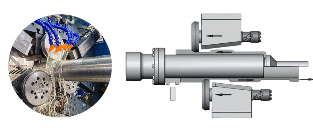
Flow Forming Machine: A single-roller flow forming machine is a metal forming system used to manufacture cylindrical and axisymmetric components by plastically deforming a rotating metal preform over a mandrel using one forming roller. During operation the workpiece rotates at high speed while the roller gradually moves along the axial direction, compressing the material and causing it to flow along the mandrel surface. This process reduces the wall thickness of the workpiece while increasing its length and maintaining high dimensional accuracy.
The machine typically operates as a cold forming system, meaning the metal is shaped without heating it to high temperatures. As the roller presses against the rotating workpiece, the material undergoes controlled plastic deformation. This deformation refines the grain structure of the material, improving mechanical strength, fatigue resistance, and surface finish. Because of this strengthening effect, components produced by flow forming often have better mechanical properties than those manufactured by conventional machining or casting.
A typical single-roller flow forming machine consists of a rigid machine bed, a spindle unit that rotates the mandrel, a single forming roller mounted on a tool slide, a tailstock that supports the workpiece, and a CNC or servo-controlled feed system that moves the roller precisely along the axis of the part. The roller position is usually controlled along the X and Z axes, allowing the machine to regulate wall thickness, length reduction, and final geometry. Modern machines use CNC control systems to ensure repeatability and precise forming parameters such as spindle speed, feed rate, and forming pressure.
The process begins by mounting a cylindrical preform, usually produced by deep drawing, forging, or machining, onto a mandrel. The tailstock clamps the preform securely, and the spindle rotates the assembly. The forming roller then gradually contacts the workpiece surface and moves along the length of the mandrel. As the roller travels, the material flows plastically and conforms to the mandrel shape. Multiple passes may be required depending on the required wall thickness reduction and material properties.
Single-roller machines are generally simpler in design than multi-roller flow forming systems. They are commonly used for development work, small-batch production, and parts that do not require extremely high production rates. Because only one roller is used, the forming forces are concentrated in a single contact point, which can provide good flexibility when forming complex profiles or varying wall thicknesses along the component.
These machines can process a wide range of materials including carbon steels, stainless steels, aluminum alloys, titanium alloys, and copper alloys. The process is widely applied in industries where strong, lightweight cylindrical components are required. Typical applications include automotive components, pressure vessels, gas cylinders, aerospace structural parts, hydraulic cylinders, and certain defense industry components.
Compared with conventional machining methods, flow forming offers significant material savings because most of the original material remains in the final part rather than being removed as chips. The process also improves concentricity and surface finish while reducing production time for many cylindrical components. For these reasons, single-roller flow forming machines remain an important technology in advanced metal forming and precision manufacturing industries.
Single-roller flow forming machines are designed to deliver precise control over material deformation while maintaining stable forming conditions. The structural rigidity of the machine frame is extremely important because large forming forces are applied during the process. Heavy welded or cast steel beds are commonly used to absorb vibration and maintain alignment between the spindle, mandrel, and forming roller. High rigidity ensures dimensional accuracy and consistent wall thickness throughout the formed component.
The forming roller itself is a critical tool element. It is usually manufactured from hardened tool steel or carbide-coated materials to withstand high pressure and friction. The roller profile can vary depending on the geometry of the final component. Different roller shapes allow the machine to produce straight cylinders, stepped diameters, conical sections, or components with variable wall thickness. Proper roller design and surface finishing are essential to achieve smooth material flow and avoid surface defects.
The mandrel is another key component of the system. It determines the internal shape and diameter of the finished part. Mandrels are typically produced from high-strength alloy steel and are heat treated to resist wear and deformation. In many applications, interchangeable mandrels are used so that the machine can produce different products without major structural changes. Precision alignment between the mandrel and the spindle ensures that the finished component maintains high concentricity and roundness.
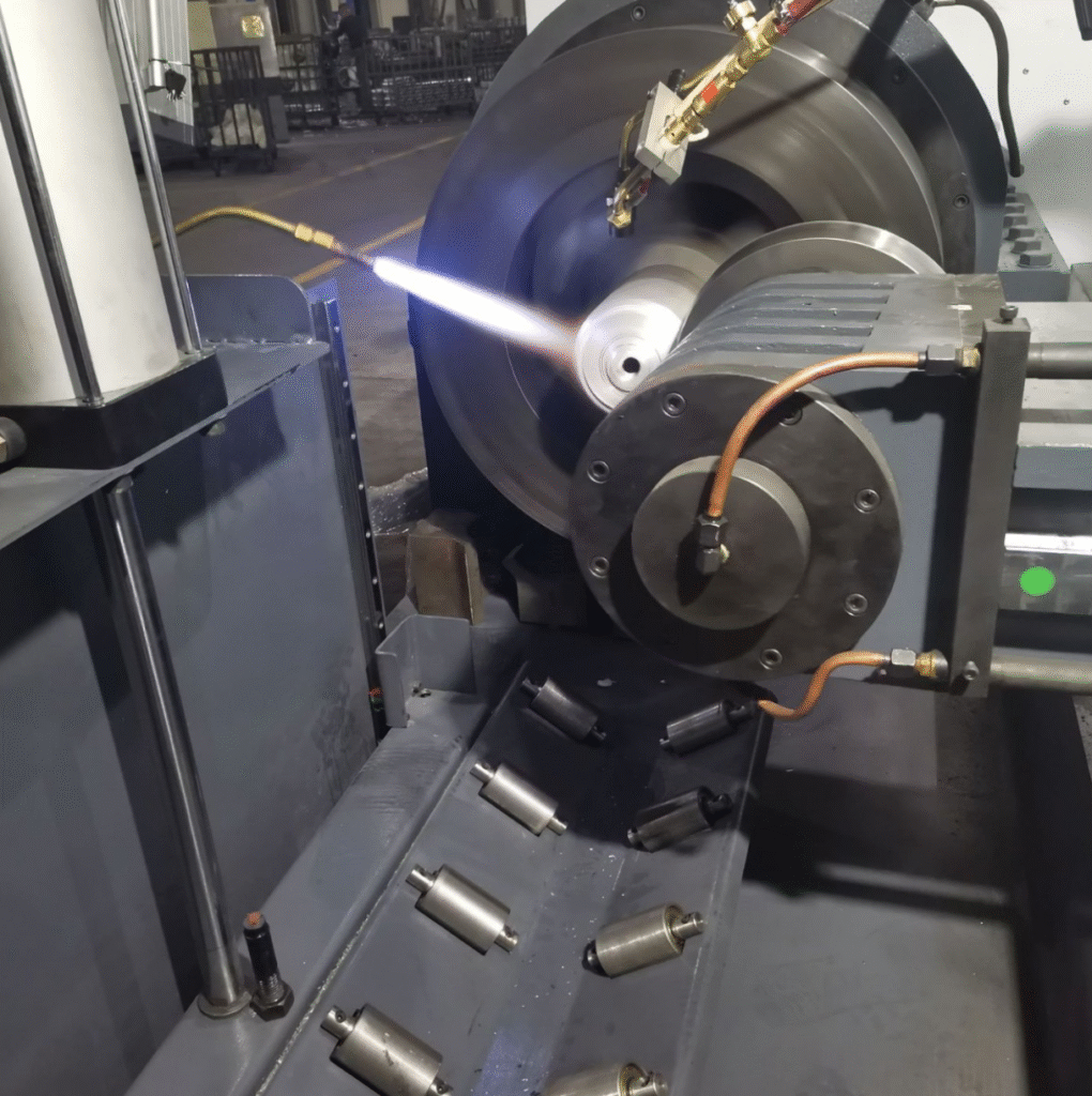
During the forming operation, lubrication and cooling play an important role. Specialized lubricants are applied to reduce friction between the roller and the workpiece surface. Effective lubrication helps prevent overheating, improves surface finish, and extends tool life. Cooling systems may circulate oil or coolant to maintain stable operating temperatures during long production cycles.
Control systems in modern single-roller flow forming machines are typically CNC based. These systems allow operators to program the entire forming cycle, including spindle speed, roller feed rate, roller pressure, and number of forming passes. Automation improves repeatability and reduces operator dependency. Advanced systems may also include sensors for monitoring forming forces, vibration levels, and temperature to ensure stable production conditions.
From a manufacturing perspective, the flow forming process offers several economic advantages. Because the material is plastically deformed rather than removed, the process achieves high material utilization. Scrap generation is minimal compared to machining processes such as turning or boring. In addition, the improved mechanical properties resulting from cold work often allow engineers to design thinner and lighter components while maintaining required strength.
Another benefit is the excellent surface quality obtained during forming. The rolling action of the forming roller compresses the surface of the material, often producing a smooth and dense surface layer. This can reduce or eliminate the need for additional finishing operations. In many applications, only minimal machining is required after the forming process to achieve final tolerances or add features such as threads or holes.
Single-roller flow forming machines are particularly useful in research and development environments where flexibility is important. Engineers can adjust forming parameters and tool configurations to experiment with different materials and component geometries. This flexibility makes single-roller machines valuable for prototype manufacturing and process development before transitioning to higher-productivity multi-roller systems.
In modern manufacturing industries, the demand for lightweight and high-strength components continues to grow. Technologies such as flow forming help manufacturers meet these requirements by producing precise cylindrical components with excellent structural integrity. As materials and control technologies continue to improve, single-roller flow forming machines remain a reliable and efficient solution for advanced metal forming applications.
Another important aspect of a single-roller flow forming machine is the control of forming parameters during the process. Parameters such as spindle speed, roller feed rate, radial pressure, and number of forming passes must be carefully balanced according to the material type and the desired wall reduction. If the roller pressure is too high, surface cracking or excessive thinning may occur. If the pressure is too low, the material may not fully conform to the mandrel shape. For this reason, precise parameter control is essential to achieve stable and repeatable forming results.
The feed motion of the forming roller usually follows a programmed path along the axis of the rotating workpiece. This path determines how the material flows and how the wall thickness changes along the length of the component. In many applications, the roller moves gradually from the tailstock side toward the spindle side while maintaining constant contact pressure. In other cases, multiple passes are performed, with each pass reducing the wall thickness incrementally until the final dimension is achieved.
Material behavior during flow forming is strongly influenced by strain hardening. As the roller compresses the metal, the material grains elongate in the direction of the forming flow. This creates a refined microstructure that improves tensile strength and fatigue resistance. Because of this effect, components produced by flow forming often perform better under dynamic loads compared with parts produced by casting or simple machining.
Surface integrity is another benefit of the process. The rolling contact between the forming roller and the workpiece smooths the outer surface and compresses the material layer. This can produce a high-quality finish with low surface roughness. In many cases the outer surface after forming requires little or no additional finishing, which helps reduce manufacturing costs and processing time.
The versatility of a single-roller flow forming machine allows it to produce various cylindrical geometries. Straight tubes are the most common products, but the process can also create tapered sections, stepped diameters, and reinforced zones with different wall thicknesses. By adjusting the roller path and forming pressure, engineers can control how material is distributed along the component. This capability is particularly useful for applications where strength is required only in specific areas of the part.
Production efficiency depends on several factors including material type, part geometry, and reduction ratio. Although single-roller machines generally operate at lower production speeds compared to multi-roller systems, they provide excellent flexibility and process control. For small production volumes, specialized parts, or research applications, a single-roller configuration can be highly effective.
Maintenance of the machine is also an important consideration for long-term operation. Key components such as the spindle bearings, hydraulic systems, and roller assemblies must be inspected regularly to ensure reliable performance. Proper lubrication of moving components and periodic calibration of the CNC control system help maintain forming accuracy and machine longevity. Tool wear should also be monitored, since worn rollers can negatively affect surface finish and dimensional precision.
In modern manufacturing environments, single-roller flow forming machines are often integrated with automated loading and unloading systems to improve productivity. Robots or mechanical handling systems can position preforms onto the mandrel and remove finished components after forming. This integration reduces manual handling, increases safety, and allows the machine to operate continuously during production cycles.
As industries continue to demand stronger, lighter, and more efficient components, flow forming technology remains an important solution. The single-roller flow forming machine, with its simple structure and flexible forming capability, continues to play a valuable role in producing high-precision cylindrical components for a wide range of engineering applications.
In addition to its forming capabilities, the single-roller flow forming machine allows manufacturers to optimize the use of raw materials. Since the process involves stretching and thinning a preform rather than cutting away excess material, material waste is minimized. This is especially valuable when working with expensive alloys such as titanium or high-strength aluminum. The combination of material efficiency and mechanical strengthening makes flow-formed components both cost-effective and high-performance.
The machine is also adaptable to different part sizes and geometries. By changing the mandrel and adjusting the roller path, a single machine can produce a wide range of diameters, lengths, and wall thicknesses. This flexibility is one reason why single-roller machines are often used in prototype production or for custom, low-volume components, where the cost of dedicated tooling for multi-roller machines may be prohibitive.
Another advantage is the control over mechanical properties. The cold working involved in the flow forming process increases tensile strength and hardness in the material without the need for additional heat treatment in many cases. Areas of the part that experience more deformation, such as thinner walls or longer sections, benefit from strain hardening, resulting in a stronger, more fatigue-resistant component. This property is particularly important for aerospace, automotive, and defense applications where structural integrity under stress is critical.
The setup and operation of a single-roller machine are generally simpler than those of multi-roller systems. Fewer rollers mean fewer adjustments are required, and the tooling setup is less complex. Operators can quickly change mandrels and rollers to accommodate different parts, which reduces downtime between production runs. The simplicity also reduces maintenance demands, as there are fewer moving parts subject to wear and alignment issues.
In terms of precision, single-roller machines are capable of producing components with tight tolerances. CNC control allows precise adjustment of spindle speed, roller feed rate, and forming force, resulting in consistent wall thickness, roundness, and length. The repeatability of the process ensures that parts produced over multiple cycles are nearly identical, which is critical for assembly operations or for parts that must fit precisely with other components.
Single-roller flow forming machines are also compatible with additional process technologies. For example, after forming, components can undergo machining operations such as turning, threading, or hole drilling to achieve final functional requirements. In some cases, flow forming itself reduces or eliminates the need for extensive machining, especially on high-cost or difficult-to-machine materials, further increasing efficiency and reducing production costs.
Finally, the single-roller flow forming machine continues to evolve with advances in automation and control technology. Modern systems incorporate real-time monitoring of forming forces, vibration, and temperature to ensure consistent quality. Software tools can simulate material flow and predict stresses, helping engineers optimize the process for new materials and complex geometries. These innovations ensure that single-roller machines remain a relevant and efficient solution for high-precision, low-to-medium volume cylindrical component production across multiple industries.
Single-roller flow forming machines also provide opportunities for customizing wall profiles along the length of a component. By varying the roller pressure, feed rate, or number of passes at specific positions, manufacturers can create regions of different wall thicknesses. This ability to tailor the material distribution allows engineers to optimize strength, stiffness, and weight, which is especially valuable in aerospace, automotive, and defense applications where minimizing weight without compromising structural integrity is critical.
The process also supports the production of parts with internal features, such as grooves, steps, or slight tapers, by carefully designing the mandrel surface and controlling the roller path. These features are often difficult or expensive to produce using conventional machining or forging methods. Flow forming, therefore, combines the advantages of near-net-shape production with improved mechanical properties and high surface quality.
Material selection plays a key role in the performance of flow-formed parts. Metals with good ductility and strain-hardening capability, such as aluminum alloys, low-carbon steels, stainless steels, copper, and titanium alloys, are commonly used. The process can accommodate high-strength alloys that are difficult to machine, allowing production of components that would otherwise require extensive post-processing.
The forming cycle is highly controllable, which allows for optimization of production efficiency and part quality. CNC systems can adjust the speed of the mandrel, the axial travel of the roller, and the radial forming force in real time to maintain consistent deformation. Sensors and monitoring systems can detect anomalies, such as uneven material flow or excessive temperature rise, enabling immediate adjustments to prevent defects.
Single-roller machines are often employed in research and development or low-to-medium volume production because of their flexibility. They are ideal for testing new materials or experimenting with complex geometries without the need for multiple forming rollers or extensive tooling. Once the process is optimized, high-volume production may transition to multi-roller machines for faster throughput, but single-roller machines remain essential for prototyping, specialized components, and customized production runs.
Integration with automation further increases efficiency. Automated loading and unloading systems reduce manual handling, improve safety, and allow continuous operation. Advanced setups can combine forming, in-process inspection, and post-forming machining, creating a streamlined production workflow.
Overall, the single-roller flow forming machine is a versatile, cost-effective, and precise tool for producing high-quality cylindrical components. Its combination of dimensional accuracy, improved mechanical properties, material efficiency, and flexibility ensures its continued relevance in industries ranging from aerospace and automotive to defense and energy. By controlling forming parameters, optimizing material flow, and leveraging CNC automation, manufacturers can produce parts that meet stringent performance requirements while minimizing waste and reducing production costs.
Flow Forming Machine
A Two-Roller Flow Forming Machine is a metal forming system designed to produce cylindrical or axisymmetric components by plastically deforming a rotating preform using two forming rollers instead of one. Compared with a single-roller machine, the two-roller configuration provides better material control, increased stability, and higher production efficiency, while still retaining flexibility for complex shapes.
The machine works by mounting a cylindrical preform onto a mandrel, which is supported by a spindle and tailstock. The mandrel rotates while two forming rollers press against the workpiece from different angles. The rollers move axially along the length of the part, gradually thinning the wall and extending the length of the workpiece. By using two rollers, the forming force is distributed more evenly, reducing the risk of workpiece distortion and improving dimensional accuracy.
Two-roller machines are commonly CNC-controlled. The system allows precise adjustment of spindle speed, roller feed rate, radial pressure, and the number of forming passes. This control ensures consistent wall thickness, high concentricity, and accurate final dimensions. The process also cold-works the material, enhancing tensile strength, fatigue resistance, and surface finish.
Key benefits of a two-roller machine compared with a single-roller machine include:
- Higher stability during forming
- Faster production due to simultaneous material deformation at two points
- Better control over part geometry, especially for longer or thin-walled components
- Reduced number of forming passes required to reach final dimensions
Typical products produced using two-roller flow forming machines include:
- Automotive wheel rims
- Pressure vessels and hydraulic cylinders
- Aerospace structural components
- Gas cylinders and rocket motor cases
- Drive shafts and tubular components
The machine generally consists of:
- A rigid machine frame and bed
- Rotating spindle/mandrel system
- Two forming rollers mounted on CNC-controlled slides
- Tailstock to support the preform
- Hydraulic or servo system for roller force
- Control system for precision feeding and rotation
Two-roller flow forming machines are widely used in industries that require high-quality, thin-walled, cylindrical components. They strike a balance between the simplicity of single-roller machines and the higher productivity of three-roller machines, making them ideal for medium-volume production, specialized components, and parts that require precise dimensional control and improved mechanical properties.
Here are the typical technical specifications for a Two-Roller Flow Forming Machine in plain text. These values represent common industrial configurations and can vary based on machine size and application.
Maximum Workpiece Diameter: 300 – 1500 mm
Minimum Workpiece Diameter: 50 – 200 mm
Maximum Workpiece Length: 500 – 4000 mm
Maximum Wall Thickness (Preform): 5 – 50 mm
Minimum Achievable Wall Thickness: 0.5 – 5 mm
Maximum Reduction Ratio: 50 – 85 %
Spindle Motor Power: 50 – 250 kW
Spindle Speed Range: 10 – 1000 rpm
Roller Feed Force (Forming Force): 150 – 1000 kN
Axial Feed Rate: 0.1 – 25 mm/rev
Roller Diameter: 150 – 400 mm
Number of Forming Rollers: 2
CNC Axis Control: 2 – 3 axes (X, Z, optionally Y)
Tailstock Force: 100 – 400 kN
Mandrel Diameter Range: 50 – 1200 mm
Machine Bed Length: 4 – 10 meters
Hydraulic System Pressure: 160 – 350 bar
Positioning Accuracy: ±0.02 – ±0.05 mm
Repeatability: ±0.01 – ±0.03 mm
Control System: CNC / PLC controlled
Cooling / Lubrication System: Automatic lubrication and coolant circulation
Machine Weight: 10 – 45 tons
Electrical Power Requirement: 120 – 300 kW
Material Compatibility: Carbon steel, stainless steel, aluminum alloys, titanium alloys, copper alloys
Typical Production Mode: Cold flow forming
Two-roller machines provide a balance between flexibility and productivity. Compared with single-roller machines, the dual roller setup allows more even material flow and reduced deformation risk for longer or thinner-walled components. It also reduces the number of forming passes required to achieve the target wall thickness, increasing throughput.
A two-roller flow forming machine operates by mounting a cylindrical preform onto a rotating mandrel, which is supported by the spindle and tailstock. The two forming rollers are positioned on opposite sides or at specific angles relative to the workpiece. As the mandrel rotates, the rollers press against the outer surface of the preform, gradually thinning the wall and extending its length. The dual-roller configuration provides more uniform pressure distribution than a single-roller machine, which reduces distortion and improves dimensional consistency.
The process begins with the preparation of the preform, which is typically a tube, cup, or disc produced by forging, extrusion, or machining. The preform is carefully mounted onto the mandrel and secured by the tailstock or other clamping devices to prevent movement during forming. The CNC control system sets the rotational speed of the mandrel, the axial feed rate of the rollers, and the radial forming force. These parameters are critical to controlling material flow, wall thickness reduction, and surface quality.
During forming, the rollers move along the length of the workpiece, gradually applying pressure to achieve the desired wall thickness and geometry. The use of two rollers allows for simultaneous contact at two points on the workpiece surface, which increases stability and reduces vibration. This configuration also enables higher reduction ratios in a single pass, meaning fewer passes are required to reach the final dimensions, improving production efficiency.
The material undergoes cold plastic deformation as it flows along the mandrel. Strain hardening occurs, elongating the grains in the direction of the material flow. This enhances mechanical properties such as tensile strength, fatigue resistance, and surface hardness. The compressive action of the rollers also improves surface finish, often reducing the need for additional machining or finishing operations.
Two-roller machines can accommodate a wide range of materials including aluminum alloys, carbon steels, stainless steels, titanium alloys, and copper alloys. The flexibility in roller geometry, mandrel design, and CNC-controlled movement allows the production of straight tubes, tapered sections, stepped diameters, and variable wall thickness profiles. This adaptability is particularly useful in aerospace, automotive, defense, and energy applications where precision and material performance are critical.
Lubrication and cooling are essential for smooth operation and tool life. Specialized lubricants are applied between the rollers and workpiece to reduce friction, prevent surface defects, and dissipate heat generated by plastic deformation. Cooling systems may circulate oil or coolant to maintain temperature stability, especially during long production runs.
Maintenance of two-roller machines focuses on spindle bearings, roller assemblies, hydraulic systems, and CNC calibration. Proper lubrication, tool monitoring, and alignment checks are necessary to ensure consistent forming quality and machine longevity. Worn rollers or misaligned mandrels can cause dimensional errors or surface imperfections, making regular inspection important.
Two-roller flow forming machines are often used for medium-volume production where higher stability and throughput are needed compared to single-roller machines. They offer a balance of flexibility, precision, and efficiency, making them suitable for producing high-quality, thin-walled cylindrical components. Automation, CNC control, and monitoring systems further enhance productivity, reduce operator dependency, and ensure repeatable part quality.
The advantages of two-roller flow forming include more uniform material distribution, higher production rates, improved dimensional accuracy, and the ability to produce more complex wall profiles than single-roller machines. They are ideal for components requiring high strength, precision, and surface quality, while maintaining material efficiency and minimizing scrap.
A Three-Roller Flow Forming Machine is an advanced type of flow forming system that uses three forming rollers arranged around the rotating preform. Compared with single- and two-roller machines, the three-roller configuration provides maximum stability, uniform pressure distribution, and higher production rates, making it suitable for high-volume production of precision cylindrical components with very thin walls or long lengths.
The machine operates by mounting the preform on a mandrel, which is supported by a spindle and tailstock. The mandrel rotates while the three forming rollers, evenly spaced around the workpiece, press simultaneously against its outer surface. The rollers move axially along the length of the workpiece, gradually reducing wall thickness and elongating the part. The three-point contact ensures highly uniform material deformation, reducing the risk of ovality, bending, or surface defects even in long or thin-walled components.
The cold forming process used in three-roller machines produces components with excellent mechanical properties. Strain hardening from plastic deformation increases tensile strength, fatigue resistance, and surface hardness. The compressive action of the rollers also improves surface finish, often eliminating the need for extensive post-machining.
Key advantages of three-roller flow forming machines:
- Maximum dimensional accuracy and concentricity
- High stability for long or thin-walled components
- Higher reduction ratios per pass
- Faster throughput compared with single- or two-roller machines
- Ability to produce very complex profiles, including variable wall thickness, stepped diameters, and tapers
Typical industries and products include:
- Aerospace: rocket motor cases, fuselage components, structural cylinders
- Automotive: high-performance wheel rims, driveshafts
- Defense: pressure vessels, missile casings, artillery components
- Energy: turbine casings, high-pressure hydraulic cylinders
The machine consists of a rigid bed, a spindle and mandrel system, three CNC-controlled forming rollers, a tailstock or workpiece support, and hydraulic or servo systems for roller pressure. CNC control allows precise adjustment of spindle speed, roller feed rate, forming pressure, and roller path. Modern systems may include sensors to monitor forming forces, vibration, and temperature in real time, ensuring high-quality production.
Three-roller machines require careful setup, especially alignment of rollers and mandrel, to achieve uniform material flow. Lubrication and cooling are critical to prevent surface damage and maintain tool life. Specialized lubricants reduce friction, while oil or coolant circulation stabilizes temperature during long runs.
Material compatibility is broad, including carbon steels, stainless steels, aluminum alloys, titanium alloys, and copper alloys. The flexibility in roller and mandrel design allows the machine to produce straight, tapered, stepped, or variable-thickness components.
Compared with single- and two-roller machines, the three-roller flow forming machine is better suited for high-volume production, extremely precise components, and long or very thin-walled parts. While the initial investment and maintenance are higher, the combination of accuracy, mechanical strengthening, and production efficiency makes three-roller machines the preferred choice for demanding industrial applications.
Three-roller flow forming machine
A Three-Roller Flow Forming Machine is a high-precision metal forming system used to manufacture thin-walled cylindrical or axisymmetric components. Unlike single- or two-roller machines, it uses three forming rollers evenly spaced around the rotating workpiece, which provides maximum stability, uniform material flow, and high dimensional accuracy. This configuration allows manufacturers to produce very thin-walled, long, or complex parts efficiently, making it ideal for high-volume production and critical applications.
Operation
The process begins with mounting a cylindrical preform onto a mandrel, which is supported by a spindle and tailstock. The mandrel rotates while the three forming rollers press simultaneously against the workpiece from three points. The rollers move axially along the length of the preform, gradually reducing wall thickness and extending its length. The three-point contact ensures uniform deformation, reduces the risk of ovality or bending, and improves surface finish.
Material is plastically deformed under cold forming conditions, which increases tensile strength, hardness, and fatigue resistance through strain hardening. The rolling action of the three rollers compresses the surface, often resulting in a high-quality finish that requires minimal post-machining.
Key Advantages
- Maximum stability for long or thin-walled components
- Highly uniform wall thickness and roundness
- Higher reduction ratios per pass compared with single- or two-roller machines
- Faster throughput due to simultaneous deformation at three points
- Ability to produce complex profiles, including tapered, stepped, and variable-thickness components
- Enhanced mechanical properties due to cold working and strain hardening
Typical Applications
- Aerospace: rocket motor cases, structural cylinders, fuselage components
- Automotive: high-performance wheel rims, driveshafts
- Defense: artillery casings, missile components, pressure vessels
- Energy: turbine casings, high-pressure hydraulic cylinders
Machine Structure
- Rigid machine bed for stability
- Spindle and mandrel system to rotate and support the preform
- Three CNC-controlled forming rollers for precise deformation
- Tailstock or support system for the workpiece
- Hydraulic or servo system for controlling roller pressure
- CNC control system for spindle speed, roller feed rate, and forming path
- Lubrication and cooling system to reduce friction and maintain tool life
Material Compatibility
- Carbon steels
- Stainless steels
- Aluminum alloys
- Titanium alloys
- Copper alloys
Three-roller flow forming machines are widely used in industries that require high-precision, thin-walled, and mechanically strengthened components. They offer a combination of accuracy, productivity, and flexibility, making them the preferred solution for critical aerospace, defense, automotive, and energy applications.
A three-roller flow forming machine uses three forming rollers arranged around a rotating workpiece to produce thin-walled cylindrical or axisymmetric components. The preform is mounted on a mandrel supported by a spindle and tailstock, and the mandrel rotates while the rollers press simultaneously against the outer surface. The rollers move axially along the workpiece, gradually reducing wall thickness and elongating the component. The three-point contact provides maximum stability, uniform material flow, and high dimensional accuracy, reducing the risk of ovality or bending even for long or thin-walled parts.
The cold forming process creates strain hardening in the material, improving tensile strength, fatigue resistance, and surface hardness. The rolling action of the three rollers also smooths the outer surface, producing a high-quality finish that often requires minimal post-machining. Material flow can be carefully controlled by adjusting spindle speed, roller feed rate, radial pressure, and the number of passes, ensuring consistent wall thickness and concentricity.
Three-roller machines can produce straight cylinders, tapered sections, stepped diameters, and variable wall thickness profiles. They accommodate a wide range of metals including carbon steel, stainless steel, aluminum alloys, titanium alloys, and copper alloys. Lubrication and cooling are essential to reduce friction, prevent surface defects, and maintain tool life. Modern machines often incorporate CNC control and real-time monitoring of forming forces, vibration, and temperature to maintain process stability and repeatability.
Compared with single- and two-roller machines, three-roller flow forming machines offer higher production rates, greater stability, and the ability to achieve more complex geometries in fewer forming passes. They are commonly used in aerospace, automotive, defense, and energy industries for components such as rocket motor cases, pressure vessels, turbine casings, high-performance wheel rims, and structural cylinders. The machine structure typically includes a rigid bed, spindle and mandrel system, three CNC-controlled forming rollers, tailstock support, and hydraulic or servo-driven roller pressure systems.
Maintenance focuses on spindle bearings, roller assemblies, hydraulic systems, and CNC calibration. Proper lubrication, alignment, and monitoring of tool wear are critical to maintain dimensional accuracy and surface quality. Automation, such as robotic loading and unloading, further enhances efficiency and reduces operator dependency. The combination of precision, mechanical strengthening, material efficiency, and high throughput makes three-roller flow forming machines ideal for producing high-quality, thin-walled cylindrical components in medium to high-volume production environments.
Three-roller flow forming machines allow manufacturers to optimize both material usage and mechanical performance. Because the process stretches and thins a preform rather than removing material, scrap is minimized, which is particularly important when working with expensive alloys such as titanium or high-strength aluminum. The strain-hardening effect from cold forming increases tensile strength, fatigue resistance, and surface hardness, enabling lighter components without compromising structural integrity.
The machine’s three rollers provide exceptional stability, allowing precise control over wall thickness along the entire length of the part. By adjusting the roller feed rate, radial pressure, and number of forming passes, engineers can create variable thickness profiles or reinforced areas in specific regions of the component. This capability is particularly valuable for aerospace and defense applications, where strength-to-weight optimization is critical.
The process is highly versatile, capable of producing straight cylinders, conical sections, stepped diameters, and complex variable-thickness components. Mandrels can be customized for specific internal geometries, and interchangeable rollers allow the machine to switch between different part designs without extensive retooling. CNC control ensures repeatable results across production runs, and advanced monitoring systems can track forming forces, vibrations, and temperature to prevent defects and maintain high-quality output.
Lubrication and cooling are essential to reduce friction between the rollers and workpiece and to maintain consistent material flow. Proper lubrication prevents surface damage, reduces tool wear, and allows stable operation during long production cycles. Modern systems often integrate automatic lubrication and coolant circulation for optimal performance.
Three-roller machines are commonly used for high-volume or high-precision applications where single- or two-roller machines may not provide sufficient stability or throughput. While initial investment and maintenance are higher, the advantages in accuracy, surface finish, mechanical strength, and efficiency make them the preferred choice for demanding industrial applications. They are widely used in aerospace for rocket motor cases, fuselage components, and structural cylinders; in defense for missile casings and artillery components; in automotive for high-performance wheel rims and driveshafts; and in energy for turbine casings and hydraulic cylinders.
The combination of CNC control, automation, real-time monitoring, and the three-roller configuration ensures consistent quality, high repeatability, and optimized material usage. Three-roller flow forming machines remain an essential tool for producing thin-walled, high-strength cylindrical components where precision, efficiency, and mechanical performance are critical.
Single-roller flow forming machines use one forming roller to deform a rotating preform. They are simple in design, easy to maintain, and flexible for low-volume or prototype production. They provide good dimensional accuracy but require multiple passes for long or thin-walled components. Typical applications include hydraulic cylinders, small pressure vessels, automotive prototypes, and research/development parts. Advantages include low initial cost, easy setup, and good flexibility for different part geometries. Limitations are lower production speed and less stability for very long or thin-walled components.
Two-roller flow forming machines use two forming rollers, which improves stability and distributes forming forces more evenly. They can achieve higher reduction ratios per pass and require fewer passes than single-roller machines. They are suitable for medium-volume production and provide better control over wall thickness and concentricity. Typical products include automotive wheel rims, medium-size pressure vessels, aerospace structural cylinders, and gas cylinders. Advantages include higher throughput, improved dimensional accuracy, and the ability to produce longer or thinner-walled parts. Limitations include higher complexity and cost compared with single-roller machines.
Three-roller flow forming machines use three forming rollers arranged evenly around the workpiece. They provide maximum stability, uniform material flow, and high dimensional precision. They can produce long, thin-walled, or complex profiles in fewer passes, making them ideal for high-volume production and critical applications. Typical products include rocket motor cases, aerospace structural cylinders, high-performance automotive rims, defense pressure vessels, and turbine casings. Advantages include highest precision, improved mechanical properties, high production efficiency, and excellent surface finish. Limitations are higher investment, more complex maintenance, and the need for precise setup and alignment.
In summary, the key differences are:
- Single-roller: simplest, flexible, suitable for prototypes and small batches, lower speed.
- Two-roller: balanced stability and productivity, suitable for medium-volume production, better accuracy.
- Three-roller: maximum stability and precision, high-volume or critical parts, best mechanical properties and surface quality.
This comparison allows manufacturers to select the appropriate machine type based on production volume, part geometry, material, and required precision.
Here’s a plain-text side-by-side technical specification comparison for single-, two-, and three-roller flow forming machines. Values are typical ranges used in industry and may vary depending on machine size and manufacturer.
Maximum Workpiece Diameter: Single-roller 300–1200 mm | Two-roller 300–1500 mm | Three-roller 300–1600 mm
Minimum Workpiece Diameter: Single-roller 50–150 mm | Two-roller 50–200 mm | Three-roller 50–250 mm
Maximum Workpiece Length: Single-roller 500–3000 mm | Two-roller 500–4000 mm | Three-roller 500–5000 mm
Maximum Wall Thickness (Preform): Single-roller 5–40 mm | Two-roller 5–50 mm | Three-roller 5–60 mm
Minimum Achievable Wall Thickness: Single-roller 0.5–5 mm | Two-roller 0.5–5 mm | Three-roller 0.3–4 mm
Maximum Reduction Ratio: Single-roller 40–80% | Two-roller 50–85% | Three-roller 60–90%
Spindle Motor Power: Single-roller 30–160 kW | Two-roller 50–250 kW | Three-roller 80–400 kW
Spindle Speed Range: Single-roller 10–800 rpm | Two-roller 10–1000 rpm | Three-roller 10–1200 rpm
Roller Feed Force: Single-roller 100–800 kN | Two-roller 150–1000 kN | Three-roller 200–1200 kN
Axial Feed Rate: Single-roller 0.1–20 mm/rev | Two-roller 0.1–25 mm/rev | Three-roller 0.1–30 mm/rev
Number of Forming Rollers: Single-roller 1 | Two-roller 2 | Three-roller 3
CNC Axis Control: Single-roller 2–3 axes | Two-roller 2–3 axes | Three-roller 2–4 axes
Tailstock Force: Single-roller 50–300 kN | Two-roller 100–400 kN | Three-roller 150–500 kN
Mandrel Diameter Range: Single-roller 50–1000 mm | Two-roller 50–1200 mm | Three-roller 50–1500 mm
Machine Bed Length: Single-roller 3–8 m | Two-roller 4–10 m | Three-roller 5–12 m
Hydraulic System Pressure: Single-roller 160–300 bar | Two-roller 160–350 bar | Three-roller 180–400 bar
Positioning Accuracy: Single-roller ±0.02–0.05 mm | Two-roller ±0.02–0.05 mm | Three-roller ±0.01–0.03 mm
Repeatability: Single-roller ±0.01–0.03 mm | Two-roller ±0.01–0.03 mm | Three-roller ±0.005–0.02 mm
Control System: CNC/PLC controlled (all three types)
Cooling/Lubrication: Automatic lubrication and coolant circulation (all three types)
Machine Weight: Single-roller 8–35 tons | Two-roller 10–45 tons | Three-roller 15–60 tons
Material Compatibility: Carbon steel, stainless steel, aluminum alloys, titanium alloys, copper alloys (all three types)
Typical Production Mode: Cold flow forming (all three types)
This comparison shows the progression from simple, flexible, low-volume single-roller machines to high-stability, high-volume three-roller machines capable of producing very precise, thin-walled components with complex geometries.
Four-roller flow forming machine
A Four-Roller Flow Forming Machine is an advanced metal forming system that uses four forming rollers arranged around a rotating preform to provide maximum stability, highly uniform material flow, and extreme precision. This configuration is less common than single-, two-, or three-roller machines, but it is used for very high-volume production, extremely thin-walled, long, or complex components, or when production requires exceptionally high repeatability and minimal distortion.
The operation begins with a preform mounted on a mandrel, supported by a spindle and tailstock. The mandrel rotates while the four forming rollers simultaneously press against the outer surface of the workpiece. As the rollers move axially along the part, the material is gradually thinned and elongated. The four-point contact provides exceptional dimensional stability, minimizing ovality, bending, and vibration even for very long or extremely thin-walled components.
The cold forming process strengthens the material through strain hardening, increasing tensile strength, fatigue resistance, and surface hardness. The rolling action of the four rollers improves surface finish, often eliminating the need for extensive post-machining. CNC control allows precise adjustment of spindle speed, roller feed rate, radial forming force, and roller path to maintain consistent wall thickness and high repeatability across large production runs.
Four-roller machines can produce straight, tapered, stepped, or variable-thickness components. Mandrels and rollers can be customized for different internal and external geometries, making the machine highly versatile despite its industrial-scale design. Lubrication and cooling systems are essential to reduce friction, prevent surface defects, and maintain tool life. Automated loading and unloading are often integrated for continuous operation.
Compared with single-, two-, and three-roller machines, the four-roller configuration provides the highest stability, precision, and throughput, making it suitable for critical aerospace, defense, and energy components that require tight tolerances and optimized mechanical properties. Typical applications include long rocket motor cases, large-diameter pressure vessels, turbine casings, high-performance automotive components, and specialized defense components.
While four-roller machines offer unmatched precision and stability, they require a higher initial investment, more complex maintenance, and careful alignment of all rollers and the mandrel. They are generally used for very high-volume or highly specialized production where the additional complexity and cost are justified by the precision, surface quality, and structural integrity required.
A four-roller flow forming machine uses four forming rollers arranged around a rotating preform to achieve maximum stability, uniform material flow, and high precision. The preform is mounted on a mandrel supported by a spindle and tailstock. As the mandrel rotates, the four rollers press simultaneously against the workpiece and move axially along its length, gradually reducing wall thickness and elongating the part. The four-point contact distributes the forming forces evenly, minimizing ovality, bending, or vibration even for very long or thin-walled components.
The cold forming process strengthens the material through strain hardening, improving tensile strength, fatigue resistance, and surface hardness. The rolling action of the four rollers produces a smooth surface, often requiring little post-machining. CNC control allows precise adjustment of spindle speed, roller feed rate, radial forming force, and roller path, ensuring consistent wall thickness and high repeatability across production runs.
Four-roller machines can produce straight cylinders, tapered sections, stepped diameters, and variable wall thickness profiles. Mandrels and rollers are customizable to accommodate different internal and external geometries. Lubrication and cooling systems are essential to reduce friction, prevent surface defects, and maintain tool life. Automated loading and unloading systems are often used for continuous production, improving efficiency and reducing operator involvement.
Compared with single-, two-, and three-roller machines, four-roller machines provide the highest stability, dimensional accuracy, and throughput, making them suitable for critical aerospace, defense, and energy applications where tight tolerances and optimized mechanical properties are required. Typical products include long rocket motor cases, large-diameter pressure vessels, turbine casings, high-performance automotive components, and specialized defense components.
While offering unmatched precision and stability, four-roller machines require higher initial investment, more complex maintenance, and precise alignment of all rollers and the mandrel. They are generally used in very high-volume or highly specialized production where the added complexity and cost are justified by the enhanced accuracy, mechanical performance, and surface quality.
Here is a plain-text comparison of single-, two-, three-, and four-roller flow forming machines showing specifications, capabilities, and typical applications side by side.
Maximum Workpiece Diameter: Single 300–1200 mm | Two 300–1500 mm | Three 300–1600 mm | Four 300–1800 mm
Minimum Workpiece Diameter: Single 50–150 mm | Two 50–200 mm | Three 50–250 mm | Four 50–300 mm
Maximum Workpiece Length: Single 500–3000 mm | Two 500–4000 mm | Three 500–5000 mm | Four 500–6000 mm
Maximum Wall Thickness (Preform): Single 5–40 mm | Two 5–50 mm | Three 5–60 mm | Four 5–70 mm
Minimum Achievable Wall Thickness: Single 0.5–5 mm | Two 0.5–5 mm | Three 0.3–4 mm | Four 0.3–3 mm
Maximum Reduction Ratio: Single 40–80% | Two 50–85% | Three 60–90% | Four 65–95%
Spindle Motor Power: Single 30–160 kW | Two 50–250 kW | Three 80–400 kW | Four 100–500 kW
Spindle Speed Range: Single 10–800 rpm | Two 10–1000 rpm | Three 10–1200 rpm | Four 10–1400 rpm
Roller Feed Force: Single 100–800 kN | Two 150–1000 kN | Three 200–1200 kN | Four 250–1500 kN
Axial Feed Rate: Single 0.1–20 mm/rev | Two 0.1–25 mm/rev | Three 0.1–30 mm/rev | Four 0.1–35 mm/rev
Number of Forming Rollers: Single 1 | Two 2 | Three 3 | Four 4
CNC Axis Control: Single 2–3 axes | Two 2–3 axes | Three 2–4 axes | Four 3–5 axes
Tailstock Force: Single 50–300 kN | Two 100–400 kN | Three 150–500 kN | Four 200–600 kN
Mandrel Diameter Range: Single 50–1000 mm | Two 50–1200 mm | Three 50–1500 mm | Four 50–1800 mm
Machine Bed Length: Single 3–8 m | Two 4–10 m | Three 5–12 m | Four 6–15 m
Hydraulic System Pressure: Single 160–300 bar | Two 160–350 bar | Three 180–400 bar | Four 200–450 bar
Positioning Accuracy: Single ±0.02–0.05 mm | Two ±0.02–0.05 mm | Three ±0.01–0.03 mm | Four ±0.005–0.02 mm
Repeatability: Single ±0.01–0.03 mm | Two ±0.01–0.03 mm | Three ±0.005–0.02 mm | Four ±0.003–0.01 mm
Control System: CNC/PLC controlled (all types)
Cooling/Lubrication: Automatic lubrication and coolant circulation (all types)
Machine Weight: Single 8–35 tons | Two 10–45 tons | Three 15–60 tons | Four 20–80 tons
Material Compatibility: Carbon steel, stainless steel, aluminum alloys, titanium alloys, copper alloys (all types)
Typical Production Mode: Cold flow forming (all types)
Typical Applications: Single – prototypes, hydraulic cylinders, small pressure vessels, automotive R&D parts; Two – medium-volume wheel rims, pressure vessels, gas cylinders, aerospace structural parts; Three – high-precision rocket motor cases, turbine casings, high-performance automotive rims, defense pressure vessels; Four – very long rocket motor cases, large pressure vessels, turbine casings, specialized defense components, large-diameter aerospace cylinders
This comparison shows the progression from single to four rollers, illustrating how adding rollers increases stability, precision, reduction capability, throughput, and the ability to handle longer, thinner, or more complex parts.
Choosing the right flow forming machine depends on the part size, wall thickness, production volume, and required precision. Single-roller machines are best suited for small to medium parts, prototypes, and low-volume production where flexibility and low cost are important. They are easy to set up and maintain, but they require more passes for long or thin-walled components and have lower throughput. Two-roller machines are ideal for medium-volume production and slightly larger or thinner-walled parts. They offer better stability and higher reduction per pass than single-roller machines, making them suitable for automotive components, medium-size pressure vessels, and gas cylinders.
Three-roller machines are preferred when high dimensional accuracy, surface quality, and mechanical properties are critical. They can handle long, thin-walled, or complex parts in fewer passes and with higher throughput. Applications include aerospace rocket motor cases, high-performance automotive rims, turbine casings, and defense pressure vessels. Four-roller machines are used for very high-volume or extremely demanding applications where maximum stability, precision, and repeatability are required. They can form extremely long, thin-walled, or large-diameter components and are common in specialized aerospace, defense, and energy industries.
Material selection is also important when choosing a machine type. All four machine types can process carbon steels, stainless steels, aluminum alloys, titanium alloys, and copper alloys, but machines with more rollers provide better control over hard-to-form or high-strength materials. Cold forming increases material strength through strain hardening, so precision and roller arrangement affect the final mechanical properties.
Machine size and capacity should match the workpiece dimensions. Smaller parts and low-volume production are efficiently handled by single-roller machines. Medium-size or higher-volume components benefit from two-roller machines. Very precise, long, or thin-walled components require three rollers for stability, and extremely large or critical parts need four rollers. CNC control, lubrication, and cooling are essential for all machines to ensure consistent wall thickness, surface finish, and repeatability.
Ultimately, the choice between single-, two-, three-, or four-roller flow forming machines balances flexibility, precision, throughput, and cost. Single-roller machines excel in flexibility and low-cost setup, two-roller machines increase throughput while maintaining accuracy, three-roller machines maximize precision and surface quality for high-value parts, and four-roller machines achieve the highest stability and repeatability for very large or critical components. Manufacturers select the machine type based on part geometry, production volume, material, and required mechanical properties to optimize efficiency and quality.
Five-roller flow forming machine
A Five-Roller Flow Forming Machine is an advanced industrial system designed for extremely high-precision, large-scale, or complex cylindrical components. It uses five forming rollers arranged around the rotating preform to provide the highest stability, uniform material flow, and dimensional accuracy of all flow forming configurations. This setup is typically used in specialized applications where even minimal distortion, vibration, or wall-thickness variation is unacceptable.
The machine operates by mounting a cylindrical preform on a mandrel supported by a spindle and tailstock. As the mandrel rotates, the five rollers simultaneously press against the workpiece and move axially along its length, gradually thinning the wall and elongating the component. The five-point contact distributes forming forces evenly across the workpiece, allowing the machine to handle very long, thin-walled, or large-diameter components with minimal risk of ovality or bending.
Cold forming in a five-roller machine produces strain hardening, enhancing tensile strength, fatigue resistance, and surface hardness. The rolling action of multiple rollers creates a very smooth surface, often eliminating the need for post-machining. CNC control allows precise adjustment of spindle speed, roller feed rate, radial forming force, and roller path, ensuring consistent wall thickness and high repeatability.
Five-roller machines can produce straight cylinders, tapered sections, stepped diameters, or variable-thickness profiles. Mandrels and rollers are highly customizable to accommodate internal and external geometries. Lubrication and cooling systems reduce friction and wear, while automated loading and unloading systems support continuous operation.
Compared with single-, two-, three-, and four-roller machines, five-roller flow forming machines offer maximum stability, accuracy, and throughput, making them suitable for critical aerospace, defense, and energy applications that require extremely tight tolerances and optimized mechanical properties. Typical products include very long rocket motor cases, large-diameter pressure vessels, high-performance turbine casings, and specialized defense components.
While five-roller machines deliver unmatched precision, they require a very high initial investment, complex maintenance, and careful alignment of all rollers and the mandrel. They are generally used for very high-volume or highly specialized production where the additional complexity and cost are justified by the extreme accuracy, mechanical performance, and surface quality.
A five-roller flow forming machine uses five forming rollers arranged around a rotating preform to provide maximum stability, uniform material flow, and extremely high dimensional accuracy. The preform is mounted on a mandrel supported by a spindle and tailstock. As the mandrel rotates, the five rollers press simultaneously against the workpiece and move axially along its length, gradually thinning the wall and elongating the part. The five-point contact distributes forming forces evenly, allowing the machine to handle very long, thin-walled, or large-diameter components with minimal risk of ovality, bending, or vibration.
The cold forming process creates strain hardening in the material, increasing tensile strength, fatigue resistance, and surface hardness. The rolling action of the five rollers produces a smooth surface finish that often requires little to no post-machining. CNC control allows precise adjustment of spindle speed, roller feed rate, radial forming force, and roller path, ensuring consistent wall thickness and high repeatability for large or complex components.
Five-roller machines can produce straight cylinders, tapered sections, stepped diameters, or variable-thickness profiles. Mandrels and rollers can be customized to accommodate different internal and external geometries. Lubrication and cooling systems reduce friction and wear, and automated loading and unloading systems support continuous production for high-volume operations.
Compared with single-, two-, three-, and four-roller machines, five-roller flow forming machines provide the highest stability, precision, and throughput. They are used in critical aerospace, defense, and energy applications that require extremely tight tolerances and optimized mechanical properties. Typical products include very long rocket motor cases, large-diameter pressure vessels, high-performance turbine casings, and specialized defense components.
Five-roller machines require a very high initial investment, complex maintenance, and careful alignment of all rollers and the mandrel. They are generally reserved for very high-volume or highly specialized production where extreme accuracy, mechanical performance, and surface quality justify the additional cost and complexity.
Maximum Workpiece Diameter: Single 300–1200 mm | Two 300–1500 mm | Three 300–1600 mm | Four 300–1800 mm | Five 300–2000 mm
Minimum Workpiece Diameter: Single 50–150 mm | Two 50–200 mm | Three 50–250 mm | Four 50–300 mm | Five 50–350 mm
Maximum Workpiece Length: Single 500–3000 mm | Two 500–4000 mm | Three 500–5000 mm | Four 500–6000 mm | Five 500–7000 mm
Maximum Wall Thickness (Preform): Single 5–40 mm | Two 5–50 mm | Three 5–60 mm | Four 5–70 mm | Five 5–80 mm
Minimum Achievable Wall Thickness: Single 0.5–5 mm | Two 0.5–5 mm | Three 0.3–4 mm | Four 0.3–3 mm | Five 0.2–3 mm
Maximum Reduction Ratio: Single 40–80% | Two 50–85% | Three 60–90% | Four 65–95% | Five 70–95%
Spindle Motor Power: Single 30–160 kW | Two 50–250 kW | Three 80–400 kW | Four 100–500 kW | Five 120–600 kW
Spindle Speed Range: Single 10–800 rpm | Two 10–1000 rpm | Three 10–1200 rpm | Four 10–1400 rpm | Five 10–1500 rpm
Roller Feed Force: Single 100–800 kN | Two 150–1000 kN | Three 200–1200 kN | Four 250–1500 kN | Five 300–1800 kN
Axial Feed Rate: Single 0.1–20 mm/rev | Two 0.1–25 mm/rev | Three 0.1–30 mm/rev | Four 0.1–35 mm/rev | Five 0.1–40 mm/rev
Number of Forming Rollers: Single 1 | Two 2 | Three 3 | Four 4 | Five 5
CNC Axis Control: Single 2–3 axes | Two 2–3 axes | Three 2–4 axes | Four 3–5 axes | Five 3–6 axes
Tailstock Force: Single 50–300 kN | Two 100–400 kN | Three 150–500 kN | Four 200–600 kN | Five 250–700 kN
Mandrel Diameter Range: Single 50–1000 mm | Two 50–1200 mm | Three 50–1500 mm | Four 50–1800 mm | Five 50–2000 mm
Machine Bed Length: Single 3–8 m | Two 4–10 m | Three 5–12 m | Four 6–15 m | Five 7–18 m
Hydraulic System Pressure: Single 160–300 bar | Two 160–350 bar | Three 180–400 bar | Four 200–450 bar | Five 220–500 bar
Positioning Accuracy: Single ±0.02–0.05 mm | Two ±0.02–0.05 mm | Three ±0.01–0.03 mm | Four ±0.005–0.02 mm | Five ±0.003–0.01 mm
Repeatability: Single ±0.01–0.03 mm | Two ±0.01–0.03 mm | Three ±0.005–0.02 mm | Four ±0.003–0.01 mm | Five ±0.002–0.008 mm
Control System: CNC/PLC controlled (all types)
Cooling/Lubrication: Automatic lubrication and coolant circulation (all types)
Machine Weight: Single 8–35 tons | Two 10–45 tons | Three 15–60 tons | Four 20–80 tons | Five 25–100 tons
Material Compatibility: Carbon steel, stainless steel, aluminum alloys, titanium alloys, copper alloys (all types)
Typical Production Mode: Cold flow forming (all types)
Typical Applications: Single – prototypes, hydraulic cylinders, small pressure vessels, automotive R&D parts; Two – medium-volume wheel rims, pressure vessels, gas cylinders, aerospace structural parts; Three – high-precision rocket motor cases, turbine casings, high-performance automotive rims, defense pressure vessels; Four – very long rocket motor cases, large pressure vessels, turbine casings, specialized defense components, large-diameter aerospace cylinders; Five – extremely long rocket motor cases, extra-large pressure vessels, turbine casings, specialized defense and aerospace cylinders, ultra-precision industrial components
This comparison shows the progression from single to five rollers, illustrating how adding rollers increases stability, precision, reduction capability, throughput, and the ability to handle longer, thinner, or more complex parts.
Choosing a flow forming machine depends on part size, wall thickness, production volume, and required precision. Single-roller machines are best for small to medium parts, prototypes, and low-volume production where flexibility and low cost are important. They are easy to set up and maintain but require more passes for long or thin-walled components and have lower throughput. Two-roller machines are suitable for medium-volume production and slightly larger or thinner-walled parts. They provide better stability and higher reduction per pass than single-roller machines, making them ideal for automotive components, medium-size pressure vessels, and gas cylinders.
Three-roller machines are preferred when high dimensional accuracy, surface quality, and mechanical properties are critical. They can handle long, thin-walled, or complex parts in fewer passes and with higher throughput. Applications include aerospace rocket motor cases, high-performance automotive rims, turbine casings, and defense pressure vessels. Four-roller machines are used for very high-volume or extremely demanding applications where maximum stability, precision, and repeatability are required. They can form very long, thin-walled, or large-diameter components and are common in specialized aerospace, defense, and energy industries.
Five-roller machines provide the highest stability, precision, and throughput. They are used for extremely critical or ultra-large components that require very tight tolerances, excellent surface finish, and optimized mechanical properties. Typical applications include extremely long rocket motor cases, extra-large pressure vessels, turbine casings, specialized defense components, and large-diameter aerospace cylinders.
All machines can process carbon steels, stainless steels, aluminum alloys, titanium alloys, and copper alloys, but machines with more rollers provide better control for high-strength or hard-to-form materials. Cold forming strengthens the material through strain hardening, and the number of rollers affects the uniformity of wall thickness and the mechanical properties of the finished component. CNC control, lubrication, and cooling are essential for all machines to ensure consistent wall thickness, surface finish, and repeatability.
The choice between single-, two-, three-, four-, and five-roller flow forming machines balances flexibility, precision, throughput, and cost. Single-roller machines are flexible and low-cost, two-roller machines offer improved throughput and accuracy for medium-volume production, three-roller machines maximize precision and surface quality for high-value parts, four-roller machines achieve the highest stability and repeatability for large or critical components, and five-roller machines provide extreme precision, stability, and throughput for very high-volume or ultra-critical applications. Manufacturers select the machine type based on part geometry, production volume, material, and required mechanical properties
Flow forming machines, from single-roller to five-roller configurations, allow manufacturers to produce cylindrical or axisymmetric components with high dimensional accuracy and improved mechanical properties. The process works by rotating a preform on a mandrel while rollers press against the outer surface, thinning the wall and elongating the part. Increasing the number of rollers improves stability, distributes forming forces more evenly, and allows handling of longer, thinner, or larger-diameter components. Cold forming during the process creates strain hardening, enhancing tensile strength, fatigue resistance, and surface hardness.
Single-roller machines are best for prototypes, small parts, and low-volume production where flexibility and cost are primary concerns. Two-roller machines increase stability and reduce the number of passes required, making them suitable for medium-volume components such as wheel rims, hydraulic cylinders, and medium-size pressure vessels. Three-roller machines provide higher precision and stability for longer, thinner, or more complex parts, making them ideal for aerospace rocket motor cases, turbine casings, and high-performance automotive rims. Four-roller machines are used for very high-volume or highly demanding applications, producing long, thin-walled, or large-diameter components with excellent repeatability, common in aerospace, defense, and energy industries. Five-roller machines offer the maximum stability and precision, capable of forming extremely large or critical components that require ultra-tight tolerances and optimal mechanical performance.
All machines can process carbon steel, stainless steel, aluminum alloys, titanium alloys, and copper alloys. The addition of rollers allows better control of wall thickness, reduces ovality, and ensures more uniform material flow, which is critical for high-strength or hard-to-form metals. CNC control enables precise adjustment of spindle speed, roller feed rate, radial forming force, and axial movement, ensuring repeatable results. Lubrication and cooling systems reduce friction, prevent surface defects, and maintain tool life, and automation can increase throughput while reducing manual intervention.
The selection of a flow forming machine type depends on part size, wall thickness, production volume, material, and required mechanical properties. Single-roller machines offer flexibility and low-cost operation, two-roller machines balance accuracy and throughput for medium production, three-roller machines maximize precision and surface quality for high-value components, four-roller machines provide stability and repeatability for large or critical parts, and five-roller machines deliver extreme precision, mechanical performance, and throughput for ultra-critical or very large components. Manufacturers choose the appropriate configuration to optimize efficiency, material usage, and quality in the production of cylindrical parts.
Flow forming machines improve manufacturing efficiency by minimizing material waste because the process stretches and thins a preform instead of removing material. This is especially important for expensive metals like titanium, high-strength aluminum alloys, or specialty steels. The cold forming process not only shapes the component but also enhances its mechanical properties, increasing tensile strength, fatigue resistance, and hardness without additional heat treatment. Using more rollers increases control over material flow, reduces the risk of deformation, and ensures more uniform wall thickness along the entire length of the part.
Single-roller machines require more forming passes for long or thin-walled components, limiting throughput but offering simplicity and flexibility. Two-roller machines reduce the number of passes and improve stability, making them suitable for medium-length cylinders and medium-volume production. Three-roller machines handle longer and thinner parts with fewer passes, providing higher dimensional accuracy and surface quality, and are commonly used in aerospace, automotive, and defense applications. Four-roller machines are designed for very long, large-diameter, or highly precise components where stability and repeatability are critical. Five-roller machines provide the ultimate level of stability and precision, capable of forming extremely long, large, or thin-walled components in high-volume or ultra-critical production environments.
The selection of the number of rollers depends on the combination of part geometry, wall thickness, production volume, material properties, and required precision. All machines benefit from CNC control, which regulates spindle speed, roller feed rate, radial forming force, and axial movement for consistent results. Lubrication and cooling systems are essential to prevent friction, wear, and surface defects, while automated loading and unloading increase efficiency in high-volume operations.
In addition to mechanical advantages, flow forming reduces scrap and optimizes material usage, making it cost-effective for high-value metals. The process is suitable for producing straight cylinders, tapered sections, stepped diameters, and variable-thickness profiles. Mandrels and rollers can be customized for internal and external geometries, further expanding the range of achievable part designs. Manufacturers choose the type of flow forming machine—single, two, three, four, or five rollers—based on the specific requirements of precision, throughput, stability, and mechanical performance, balancing cost and production efficiency for each application.
Six-roller flow forming machine
A six-roller flow forming machine is an ultra-advanced system designed for maximum stability, precision, and repeatability in forming cylindrical or axisymmetric components. It uses six forming rollers evenly arranged around a rotating preform to ensure extremely uniform material flow and minimal deformation, even for very long, thin-walled, or large-diameter parts. The preform is mounted on a mandrel supported by a spindle and tailstock, and as the mandrel rotates, the six rollers press simultaneously against the workpiece while moving axially along its length. This multi-point contact distributes forming forces evenly, reducing the risk of ovality, bending, vibration, or surface irregularities.
The cold forming process creates strain hardening in the material, improving tensile strength, fatigue resistance, and surface hardness. The rolling action of six rollers produces a highly smooth surface finish, often eliminating the need for post-machining. CNC control allows precise adjustment of spindle speed, roller feed rate, radial forming force, and axial movement, ensuring consistent wall thickness, dimensional accuracy, and repeatability across long production runs.
Six-roller machines can produce straight cylinders, tapered sections, stepped diameters, and variable-thickness profiles. Mandrels and rollers can be customized for internal and external geometries, making them suitable for extremely complex or specialized components. Lubrication and cooling systems reduce friction and wear, and automated loading and unloading systems support continuous high-volume production.
Compared with single-, two-, three-, four-, and five-roller machines, six-roller flow forming machines provide unmatched stability, mechanical performance, and surface quality, making them suitable for the most critical aerospace, defense, and energy components where tolerances are extremely tight and mechanical properties must be optimized. Typical products include very long rocket motor cases, extra-large pressure vessels, high-performance turbine casings, and specialized industrial or defense cylinders.
Six-roller machines require very high investment, precise alignment, and complex maintenance, and are generally used in specialized, high-volume, or ultra-critical production environments where the additional cost is justified by the extreme precision, repeatability, and mechanical performance achieved. They represent the pinnacle of flow forming technology for industrial-scale, high-accuracy cylindrical components.
A six-roller flow forming machine uses six forming rollers evenly arranged around a rotating preform to provide maximum stability, uniform material flow, and extremely high dimensional accuracy. The preform is mounted on a mandrel supported by a spindle and tailstock. As the mandrel rotates, the six rollers press simultaneously against the workpiece and move axially along its length, gradually thinning the wall and elongating the component. The six-point contact distributes forming forces evenly, reducing the risk of ovality, bending, vibration, or surface irregularities, even for very long, thin-walled, or large-diameter parts.
The cold forming process produces strain hardening in the material, improving tensile strength, fatigue resistance, and surface hardness. The rolling action of six rollers creates a smooth surface finish that often requires minimal post-machining. CNC control allows precise adjustment of spindle speed, roller feed rate, radial forming force, and axial movement, ensuring consistent wall thickness, dimensional accuracy, and repeatability across long production runs.
Six-roller machines can form straight cylinders, tapered sections, stepped diameters, and variable-thickness profiles. Mandrels and rollers can be customized to accommodate complex internal and external geometries. Lubrication and cooling systems reduce friction and wear, while automated loading and unloading support continuous, high-volume production.
Compared with single-, two-, three-, four-, and five-roller machines, six-roller flow forming machines provide unmatched stability, mechanical performance, and surface quality, making them suitable for critical aerospace, defense, and energy components where tolerances are extremely tight and mechanical properties must be optimized. Typical products include very long rocket motor cases, extra-large pressure vessels, high-performance turbine casings, and specialized industrial or defense cylinders.
Six-roller machines require very high investment, precise alignment, and complex maintenance, and they are generally used in specialized, high-volume, or ultra-critical production environments where extreme precision, repeatability, and mechanical performance justify the additional cost. They represent the most advanced configuration in flow forming technology, capable of producing the largest, most complex, and most critical cylindrical components with the highest accuracy and quality.
Flow forming machines with six rollers allow manufacturers to produce extremely long, thin-walled, or large-diameter cylindrical components with exceptional precision and mechanical properties. Because the process stretches and thins the preform rather than removing material, scrap is minimized, which is especially valuable when working with expensive alloys such as titanium, high-strength aluminum, or specialty steels. The cold forming process strengthens the material through strain hardening, increasing tensile strength, fatigue resistance, and surface hardness without additional heat treatment.
The six rollers provide maximum stability and uniform distribution of forming forces, which reduces ovality, bending, or vibration during the forming process. This ensures very consistent wall thickness along the entire length of the part, even for complex or highly elongated components. CNC control enables precise regulation of spindle speed, roller feed rate, radial forming force, and axial movement, maintaining high repeatability and uniformity in high-volume production. Lubrication and cooling systems reduce friction, prevent surface defects, and extend tool life, while automation for loading and unloading further increases efficiency.
Six-roller machines are used in critical applications where tolerances and surface finish requirements are extremely strict. They are common in aerospace for very long rocket motor cases, in defense for large-diameter missile or artillery components, in energy for high-performance turbine casings, and in specialized industrial applications where extremely precise cylindrical components are required. Their ability to produce straight cylinders, tapered sections, stepped diameters, and variable-thickness profiles makes them versatile despite their high complexity.
Although six-roller machines require very high initial investment, precise alignment, and complex maintenance, they are essential for ultra-critical or very high-volume production where the highest precision, mechanical performance, and surface quality are necessary. The combination of multiple rollers, CNC control, cold forming, and automated systems allows manufacturers to achieve extreme dimensional accuracy, optimized mechanical properties, and minimal material waste for the most demanding cylindrical components.
Maximum Workpiece Diameter: Single 300–1200 mm | Two 300–1500 mm | Three 300–1600 mm | Four 300–1800 mm | Five 300–2000 mm | Six 300–2200 mm
Minimum Workpiece Diameter: Single 50–150 mm | Two 50–200 mm | Three 50–250 mm | Four 50–300 mm | Five 50–350 mm | Six 50–400 mm
Maximum Workpiece Length: Single 500–3000 mm | Two 500–4000 mm | Three 500–5000 mm | Four 500–6000 mm | Five 500–7000 mm | Six 500–8000 mm
Maximum Wall Thickness (Preform): Single 5–40 mm | Two 5–50 mm | Three 5–60 mm | Four 5–70 mm | Five 5–80 mm | Six 5–90 mm
Minimum Achievable Wall Thickness: Single 0.5–5 mm | Two 0.5–5 mm | Three 0.3–4 mm | Four 0.3–3 mm | Five 0.2–3 mm | Six 0.2–2 mm
Maximum Reduction Ratio: Single 40–80% | Two 50–85% | Three 60–90% | Four 65–95% | Five 70–95% | Six 75–95%
Spindle Motor Power: Single 30–160 kW | Two 50–250 kW | Three 80–400 kW | Four 100–500 kW | Five 120–600 kW | Six 150–700 kW
Spindle Speed Range: Single 10–800 rpm | Two 10–1000 rpm | Three 10–1200 rpm | Four 10–1400 rpm | Five 10–1500 rpm | Six 10–1600 rpm
Roller Feed Force: Single 100–800 kN | Two 150–1000 kN | Three 200–1200 kN | Four 250–1500 kN | Five 300–1800 kN | Six 350–2000 kN
Axial Feed Rate: Single 0.1–20 mm/rev | Two 0.1–25 mm/rev | Three 0.1–30 mm/rev | Four 0.1–35 mm/rev | Five 0.1–40 mm/rev | Six 0.1–45 mm/rev
Number of Forming Rollers: Single 1 | Two 2 | Three 3 | Four 4 | Five 5 | Six 6
CNC Axis Control: Single 2–3 axes | Two 2–3 axes | Three 2–4 axes | Four 3–5 axes | Five 3–6 axes | Six 3–6 axes
Tailstock Force: Single 50–300 kN | Two 100–400 kN | Three 150–500 kN | Four 200–600 kN | Five 250–700 kN | Six 300–800 kN
Mandrel Diameter Range: Single 50–1000 mm | Two 50–1200 mm | Three 50–1500 mm | Four 50–1800 mm | Five 50–2000 mm | Six 50–2200 mm
Machine Bed Length: Single 3–8 m | Two 4–10 m | Three 5–12 m | Four 6–15 m | Five 7–18 m | Six 8–20 m
Hydraulic System Pressure: Single 160–300 bar | Two 160–350 bar | Three 180–400 bar | Four 200–450 bar | Five 220–500 bar | Six 240–550 bar
Positioning Accuracy: Single ±0.02–0.05 mm | Two ±0.02–0.05 mm | Three ±0.01–0.03 mm | Four ±0.005–0.02 mm | Five ±0.003–0.01 mm | Six ±0.002–0.008 mm
Repeatability: Single ±0.01–0.03 mm | Two ±0.01–0.03 mm | Three ±0.005–0.02 mm | Four ±0.003–0.01 mm | Five ±0.002–0.008 mm | Six ±0.001–0.005 mm
Control System: CNC/PLC controlled (all types)
Cooling/Lubrication: Automatic lubrication and coolant circulation (all types)
Machine Weight: Single 8–35 tons | Two 10–45 tons | Three 15–60 tons | Four 20–80 tons | Five 25–100 tons | Six 30–120 tons
Material Compatibility: Carbon steel, stainless steel, aluminum alloys, titanium alloys, copper alloys (all types)
Typical Production Mode: Cold flow forming (all types)
Typical Applications: Single – prototypes, hydraulic cylinders, small pressure vessels, automotive R&D parts; Two – medium-volume wheel rims, medium-size pressure vessels, gas cylinders, aerospace structural parts; Three – high-precision rocket motor cases, turbine casings, high-performance automotive rims, defense pressure vessels; Four – very long rocket motor cases, large-diameter pressure vessels, turbine casings, specialized defense components, large-diameter aerospace cylinders; Five – extremely long rocket motor cases, extra-large pressure vessels, high-performance turbine casings, specialized defense and aerospace cylinders; Six – ultra-long rocket motor cases, extremely large pressure vessels, very high-precision turbine casings, ultra-critical aerospace, defense, and industrial components.
This shows the progression from single to six rollers, illustrating how increasing the number of rollers improves stability, precision, material flow, reduction capability, throughput, and the ability to handle longer, thinner, larger, or more complex components.
Twin-roller synchronized machine
A twin-roller synchronized flow forming machine is a specialized type of two-roller machine where both rollers are mechanically or electronically synchronized to move together with precise coordination. The synchronization ensures that the forming forces are applied evenly across the workpiece, reducing the risk of deformation, ovality, or misalignment during forming. The preform is mounted on a rotating mandrel supported by a spindle and tailstock, and as the mandrel rotates, the two rollers press against the surface simultaneously while moving axially along the part.
Synchronization allows the machine to achieve higher dimensional accuracy, more uniform wall thickness, and improved surface finish compared with conventional two-roller machines. It also allows higher reduction per pass and faster axial feed rates because the material flows more evenly and predictably. CNC control is typically integrated to manage roller speed, feed rate, and radial force, enabling precise adjustments and repeatable results for high-volume production.
Twin-roller synchronized machines are particularly suitable for producing medium to long cylinders, tapered sections, stepped diameters, and variable-thickness profiles with tighter tolerances. They are commonly used in automotive wheel rims, medium-size pressure vessels, aerospace structural components, and defense cylinders, where uniformity and high-quality surfaces are critical.
The machine often includes hydraulic or servo-driven roller pressure systems, automated lubrication and cooling, and optional automated loading and unloading to maintain efficiency in continuous production. By combining the advantages of two-roller flow forming with precise synchronization, this type of machine improves overall accuracy, repeatability, and throughput while reducing the risk of defects caused by uneven roller action.
Compared with conventional two-roller machines, the twin-roller synchronized design provides better stability, higher process control, and consistent quality, particularly for materials that are harder to form or parts with tight dimensional requirements. It is generally used for medium- to high-volume production where precision and uniformity are more important than the lower complexity of a standard two-roller machine.
A twin-roller synchronized flow forming machine is a type of two-roller machine where both rollers are precisely coordinated to move together, ensuring that forming forces are applied evenly across the workpiece. The preform is mounted on a rotating mandrel supported by a spindle and tailstock, and as the mandrel rotates, the synchronized rollers press against the surface while moving axially along the component. Synchronization improves dimensional accuracy, uniform wall thickness, and surface finish compared with conventional two-roller machines.
The machine allows higher reduction per pass and faster axial feed rates because the material flows evenly and predictably. CNC control manages roller speed, axial feed, and radial force, enabling repeatable results and precise adjustments for high-volume production. Twin-roller synchronized machines are suitable for medium to long cylinders, tapered sections, stepped diameters, and variable-thickness profiles. They are used in automotive wheel rims, medium-size pressure vessels, aerospace structural components, and defense cylinders where uniformity and surface quality are critical.
Hydraulic or servo-driven roller pressure systems, automated lubrication and cooling, and optional automated loading and unloading maintain efficiency in continuous production. Compared with conventional two-roller machines, synchronized rollers provide better stability, higher process control, and consistent quality, particularly for materials that are harder to form or for parts with tight dimensional tolerances. These machines are generally used for medium- to high-volume production where precision, repeatability, and uniformity are more important than the simpler design of a standard two-roller flow forming machine.
Twin-roller synchronized flow forming machines improve material flow and part quality by ensuring that both rollers move in perfect coordination, reducing the risk of uneven deformation, bending, or ovality. The synchronized rollers apply equal radial forces on the workpiece as the mandrel rotates, allowing for faster axial feed rates and higher reduction per pass while maintaining precise wall thickness. CNC control monitors and adjusts spindle speed, roller feed, and radial pressure to maintain consistent results across long production runs.
These machines are capable of forming straight cylinders, tapered sections, stepped diameters, and variable-thickness profiles with high dimensional accuracy and excellent surface finish. They are commonly used in automotive wheel rims, medium-size pressure vessels, aerospace structural cylinders, and defense components where uniformity and repeatability are essential. Hydraulic or servo-driven roller systems, combined with automated lubrication and cooling, reduce wear and friction and maintain the stability of the process.
Twin-roller synchronized machines allow for higher throughput compared with conventional two-roller machines because the even distribution of forces reduces the number of forming passes required. The uniform material flow also improves mechanical properties of the finished part through consistent strain hardening. They are generally preferred for medium- to high-volume production where precision, surface quality, and repeatability are more important than simplicity, making them a reliable choice for components that must meet strict tolerances or are made from high-strength or hard-to-form materials.
Twin-roller synchronized flow forming machines provide more consistent and stable forming compared with standard two-roller machines by ensuring both rollers move in perfect coordination. This synchronization reduces deformation, ovality, and uneven wall thickness, allowing longer and more complex cylindrical parts to be formed in fewer passes. The preform rotates on a mandrel supported by a spindle and tailstock while the synchronized rollers apply evenly distributed radial forces and move axially along the workpiece. CNC control adjusts spindle speed, roller feed, and radial pressure to maintain precise wall thickness, dimensional accuracy, and repeatability across multiple parts.
These machines can produce straight cylinders, tapered sections, stepped diameters, and variable-thickness profiles with excellent surface finish. They are commonly used in automotive wheel rims, medium-size pressure vessels, aerospace structural components, and defense cylinders where uniformity and high-quality surfaces are critical. Hydraulic or servo-driven roller systems combined with automatic lubrication and cooling maintain process stability, reduce wear, and extend tool life.
The even force distribution allows higher reduction per pass and faster axial feed rates, improving production efficiency. Material flow is more predictable, resulting in consistent mechanical properties through uniform strain hardening. Twin-roller synchronized machines are ideal for medium- to high-volume production of parts requiring strict tolerances, high repeatability, and good surface finish. They provide an effective balance between precision, throughput, and stability while remaining simpler and less expensive than three- or four-roller machines for similar part sizes.
Twin-roller synchronized flow forming machines represent a significant advancement over standard two-roller configurations, primarily because of the precise coordination of the two forming rollers. In these machines, both rollers are mechanically or electronically synchronized so that they move in perfect unison, applying equal radial forces on the workpiece at all times. This synchronization ensures that the material is deformed uniformly around the circumference, dramatically reducing the risk of ovality, uneven wall thickness, bending, or other distortions that can occur during conventional two-roller forming. The preform, typically a cylindrical or near-cylindrical blank, is mounted on a mandrel supported by a spindle and tailstock. As the mandrel rotates, the synchronized rollers move axially along the length of the workpiece, gradually thinning the wall and elongating the material in a controlled and predictable manner.
The synchronization of the rollers allows for higher reduction per pass, meaning the wall thickness can be reduced more efficiently without compromising stability or surface quality. This also enables faster axial feed rates because the material flows more predictably under evenly distributed forces, improving overall throughput. CNC control plays a critical role in managing the process, adjusting spindle speed, axial feed rate, radial roller pressure, and even the roller path to achieve consistent wall thickness, dimensional accuracy, and repeatable results across multiple production cycles. This combination of synchronized mechanical movement and digital control makes the twin-roller synchronized machine highly reliable for parts that require uniformity and precision.
In terms of applications, twin-roller synchronized machines are capable of producing straight cylinders, tapered sections, stepped diameters, and variable-thickness profiles with exceptional surface finish and dimensional control. They are widely used in industries where medium- to long-length cylindrical components are required to meet strict specifications. Typical examples include automotive wheel rims that must maintain consistent thickness and structural integrity, medium-size pressure vessels for industrial or chemical applications, aerospace structural cylinders that require high precision and uniform mechanical properties, and defense components such as medium-caliber missile or artillery casings where tolerances are critical.
The machine’s hydraulic or servo-driven roller systems, combined with automated lubrication and cooling, maintain stable forming conditions, reduce friction, and minimize wear on the tooling. This allows continuous operation in medium- to high-volume production environments without compromising quality. Because the material flow is more uniform, strain hardening occurs consistently across the part, enhancing tensile strength, fatigue resistance, and surface hardness without additional heat treatment. The process reduces scrap and optimizes material usage, which is particularly important when forming expensive or high-strength alloys such as titanium, high-grade aluminum, stainless steel, or copper-based materials.
Compared with conventional two-roller machines, the synchronized design provides better stability and higher process control, enabling the production of parts with tighter tolerances and improved surface finish without the need for multiple corrective passes. While simpler and less expensive than three-, four-, or higher-roller machines, twin-roller synchronized machines strike a balance between precision, throughput, and operational efficiency. They are particularly suitable for applications that require consistent quality in medium- to high-volume production while keeping setup complexity and machine cost lower than more advanced multi-roller configurations. By combining mechanical synchronization, CNC control, and optimized material flow, these machines deliver reliable, high-quality cylindrical components with excellent repeatability, uniform wall thickness, and superior surface finish.
A twin-roller synchronized flow forming machine provides distinct advantages in terms of precision, efficiency, and material quality when compared with conventional two-roller machines. The synchronized movement of both rollers ensures that forming forces are applied evenly around the circumference of the workpiece, preventing uneven stretching, bending, or wall-thickness variations that can compromise the integrity of the component. This even distribution of forces is particularly important for parts that are long, thin-walled, or made of high-strength alloys that are difficult to form. The preform rotates on a mandrel supported by a spindle and tailstock while the synchronized rollers apply constant radial pressure and move axially along the part, gradually thinning the walls and elongating the material in a controlled and uniform manner.
Because the rollers are synchronized, higher reductions per pass are possible without risking distortion, and the axial feed rate can be increased, improving overall production throughput. The CNC system monitors spindle speed, roller feed rate, radial forming pressure, and roller path, allowing precise control of wall thickness, taper, and overall part geometry. This ensures repeatable accuracy across multiple components in a production run, reducing the need for post-processing or corrective machining. The result is a workpiece with consistent dimensional accuracy, uniform wall thickness, and superior surface finish, suitable for critical applications.
The twin-roller synchronized configuration is particularly advantageous when producing medium-length to long cylinders, tapered sections, stepped diameters, or components with variable wall thickness. Industries that benefit from this setup include automotive manufacturing, where wheel rims and structural cylinders require precise dimensional control; aerospace, where structural components must meet exacting tolerances; defense, where missile casings, artillery shells, or medium-caliber cylinders must maintain uniform mechanical properties; and industrial applications requiring medium-size pressure vessels or chemical containers. The combination of synchronized rollers, CNC control, and optimized material flow ensures that strain hardening occurs evenly, enhancing tensile strength, fatigue resistance, and surface hardness.
Hydraulic or servo-driven roller systems provide precise control over radial forming forces, while automated lubrication and cooling systems reduce friction, prevent surface defects, and extend the life of tooling components. Automated loading and unloading systems can be integrated for continuous production, maintaining high efficiency without compromising accuracy. Twin-roller synchronized machines reduce scrap material and optimize the use of high-value alloys, making them cost-effective for medium- to high-volume production.
Compared with conventional two-roller machines, the synchronized design provides higher stability, superior process control, and more consistent quality, particularly for high-strength or hard-to-form materials. While simpler and more affordable than three-, four-, five-, or six-roller machines, twin-roller synchronized machines strike an ideal balance between precision, throughput, and operational cost. They are especially effective for applications where uniformity, surface finish, and repeatability are critical but where the complexity and expense of higher-roller configurations are not justified. This makes them a reliable solution for producing high-quality cylindrical components in medium- to high-volume manufacturing environments, delivering excellent repeatability, uniform wall thickness, and superior surface finish across a wide range of materials and part geometries.
Multi-roller heavy-duty machine
A multi-roller heavy-duty flow forming machine is designed for extremely demanding applications where large, thick-walled, or long cylindrical components must be formed with maximum precision, stability, and mechanical performance. Unlike standard machines, it uses three or more rollers—sometimes four, five, or six—combined with a reinforced frame and high-capacity drive system to handle heavy workpieces and high forming forces. The preform is mounted on a mandrel supported by a spindle and tailstock, and as the mandrel rotates, the multiple rollers press against the surface while moving axially along the part. The multi-point contact distributes the forming forces evenly, minimizing deformation, bending, ovality, and vibration even for very large or high-strength components.
The cold forming process in heavy-duty multi-roller machines enhances the material’s mechanical properties through strain hardening, increasing tensile strength, fatigue resistance, and surface hardness. CNC control allows precise adjustment of spindle speed, roller feed rate, radial forming force, and roller path, ensuring uniform wall thickness, dimensional accuracy, and high repeatability across long production runs. Lubrication and cooling systems reduce friction, prevent surface defects, and extend tool life, while automation for loading and unloading improves throughput and reduces manual intervention.
These machines can produce straight cylinders, tapered sections, stepped diameters, and variable-thickness profiles, and mandrels and rollers are highly customizable to accommodate large-diameter or complex internal and external geometries. The reinforced structure, high-capacity motors, and heavy-duty hydraulic or servo-driven roller systems make the machine suitable for ultra-large, thick-walled components that cannot be formed on standard flow forming machines.
Applications for multi-roller heavy-duty machines include aerospace rocket motor cases, very large pressure vessels, high-performance turbine casings, industrial cylinders for chemical or energy applications, and specialized defense components. The combination of multiple rollers, reinforced structure, CNC precision, and heavy-duty capabilities ensures that even the largest or most critical components meet strict tolerances, uniform wall thickness, and surface finish requirements.
While these machines require very high investment, precise alignment, and complex maintenance, they are essential for producing ultra-critical or extremely large parts where stability, mechanical performance, and precision cannot be compromised. They are generally used in high-volume or highly specialized production environments where the benefits of multi-roller, heavy-duty flow forming justify the additional cost, complexity, and infrastructure needed to operate the equipment.
A multi-roller heavy-duty flow forming machine is designed for the most demanding industrial applications where extremely large, long, or thick-walled cylindrical components must be produced with the highest levels of precision, stability, and mechanical performance. These machines typically feature three or more rollers—sometimes four, five, or six—combined with a reinforced frame, high-capacity spindle motors, and robust drive systems capable of handling very high forming forces. The preform is mounted on a mandrel supported by a spindle and tailstock, and as the mandrel rotates, the multiple rollers apply radial pressure evenly around the circumference while moving axially along the part. The distribution of forces across multiple rollers ensures uniform deformation, minimizing the risk of bending, ovality, vibration, or uneven wall thickness, even when forming very large or high-strength components.
The cold forming process inherent to multi-roller heavy-duty machines strengthens the material through strain hardening, improving tensile strength, fatigue resistance, and surface hardness without additional heat treatment. CNC control provides precise regulation of spindle speed, axial feed rate, radial roller pressure, and roller path, ensuring repeatable dimensional accuracy, consistent wall thickness, and high surface quality across long production runs. Lubrication and cooling systems reduce friction, prevent surface defects, and maintain tool longevity, while automated loading and unloading systems allow for continuous production in high-volume or demanding manufacturing environments.
These machines can produce a wide range of geometries, including straight cylinders, tapered sections, stepped diameters, and variable-thickness profiles. Mandrels and rollers can be customized to accommodate complex internal and external geometries, and the reinforced frame and heavy-duty hydraulic or servo-driven systems enable the forming of ultra-large-diameter or thick-walled components that standard flow forming machines cannot handle. The combination of multi-point roller contact, CNC precision, and heavy-duty structural integrity allows the machine to produce parts that meet extremely tight tolerances and maintain uniform mechanical properties, even under high forming loads.
Applications for multi-roller heavy-duty machines span aerospace, defense, energy, and industrial sectors. They are used to manufacture very large rocket motor cases, extra-large pressure vessels, high-performance turbine casings, industrial cylinders for chemical, oil, and gas applications, and specialized defense components that require extreme precision and structural integrity. The process produces consistent strain hardening throughout the component, enhancing fatigue resistance and tensile strength while reducing the need for secondary processing or machining. The multi-roller setup ensures that wall thickness is uniform along the entire length of the workpiece, surface finish is highly smooth, and dimensional tolerances are maintained, even for ultra-long or complex parts.
Although multi-roller heavy-duty machines require very high capital investment, precise alignment, and advanced maintenance procedures, they are indispensable for production environments where the size, weight, or criticality of the component demands maximum stability, precision, and control. By combining multiple rollers, reinforced structure, CNC control, and heavy-duty power systems, these machines allow manufacturers to produce ultra-critical or extremely large cylindrical components with optimized mechanical properties, superior surface finish, and minimal material waste. They are particularly suited for high-volume or highly specialized production where the highest levels of accuracy, repeatability, and structural integrity are required, making them the pinnacle of flow forming technology for industrial, aerospace, defense, and energy applications.
Multi-roller heavy-duty flow forming machines represent the highest level of capability in flow forming technology, designed to handle components that are extremely long, thick-walled, or of very large diameter, while maintaining the highest levels of precision, surface quality, and mechanical performance. These machines typically employ three, four, five, or six rollers arranged around a rotating preform, combined with a reinforced frame, high-capacity spindle motors, and robust drive systems that can deliver the enormous radial and axial forces required for heavy-duty forming. The preform is mounted on a mandrel supported by a spindle and tailstock, and as the mandrel rotates, the multiple rollers move axially along the part, applying evenly distributed forming forces that shape and elongate the material. The multi-point contact ensures that the workpiece maintains uniform wall thickness, avoids bending or ovality, and minimizes vibration, even under extreme forming pressures or when working with high-strength alloys such as titanium, stainless steel, or high-grade aluminum.
Cold forming in a multi-roller heavy-duty machine improves the mechanical properties of the material through strain hardening, increasing tensile strength, fatigue resistance, and surface hardness without requiring additional heat treatment. CNC control allows precise adjustment of spindle speed, roller feed rate, radial forming force, and axial movement, ensuring repeatable accuracy, uniform wall thickness, and consistent surface finish across long production runs. Lubrication and cooling systems are essential in these machines to reduce friction, prevent surface defects, and extend the lifespan of both tooling and machine components. Automation, including loading and unloading systems, allows the machine to maintain high throughput while reducing manual intervention, which is particularly important in high-volume or continuous production environments.
These machines are capable of producing a wide range of geometries, including straight cylinders, tapered sections, stepped diameters, and variable-thickness profiles. Mandrels and rollers can be tailored to accommodate complex internal and external geometries, while the reinforced frame and heavy-duty drive systems ensure that extremely large or thick-walled components can be formed without compromising accuracy. The combination of multiple rollers and heavy-duty construction allows for more aggressive reductions per pass, faster axial feed rates, and better control of material flow, which results in improved surface finish, tighter tolerances, and more uniform mechanical properties throughout the part.
Applications for multi-roller heavy-duty machines are found in aerospace, defense, energy, and industrial sectors. They are used for the production of very long rocket motor cases, large-diameter or thick-walled pressure vessels, high-performance turbine casings, industrial cylinders for oil, gas, and chemical applications, and specialized defense components that must meet extremely tight specifications. The process ensures that strain hardening occurs uniformly throughout the component, improving fatigue resistance and tensile strength, while minimizing scrap and material waste. By distributing forces evenly through multiple rollers, the machine maintains dimensional stability even on components that are hundreds or thousands of millimeters long or extremely heavy.
Although these machines require significant capital investment, careful alignment, and specialized maintenance, they are essential for situations where conventional flow forming machines cannot provide the required precision, stability, or mechanical performance. By combining multiple rollers, CNC precision, high-capacity drives, and heavy-duty structural reinforcement, multi-roller heavy-duty machines allow manufacturers to produce ultra-critical cylindrical components that meet the strictest tolerances, surface finish requirements, and mechanical property standards. They are particularly suited for applications where size, complexity, or material strength makes any compromise in accuracy or uniformity unacceptable, providing a solution for the most demanding aerospace, defense, energy, and industrial manufacturing needs.
Multi-roller heavy-duty flow forming machines are engineered to meet the demands of industries that require extremely large, long, or thick-walled cylindrical components produced with the highest levels of precision, mechanical performance, and surface quality. These machines typically incorporate three, four, five, or six rollers arranged symmetrically around a rotating preform, mounted on a mandrel supported by a spindle and tailstock. The reinforced frame, high-capacity spindle motors, and robust drive systems allow these machines to apply very high radial and axial forces while maintaining stability and structural integrity. As the mandrel rotates, the rollers move axially along the component, applying evenly distributed forming forces that gradually thin the walls, elongate the material, and create a precise cylindrical shape. The multi-point contact of the rollers ensures uniform wall thickness, reduces the risk of bending or ovality, minimizes vibration, and prevents surface irregularities, even for extremely large, long, or high-strength components.
The cold forming process in multi-roller heavy-duty machines enhances the mechanical properties of the material through strain hardening, improving tensile strength, fatigue resistance, and surface hardness without additional heat treatment. CNC control systems provide precise regulation of spindle speed, roller feed rate, radial forming pressure, and axial movement, allowing consistent dimensional accuracy, repeatable results, and uniform surface finish across long production runs. Lubrication and cooling systems are critical to reduce friction, prevent overheating, maintain smooth surface finish, and extend the service life of rollers, mandrels, and the machine structure. Automation of loading and unloading further supports continuous production and high throughput, making these machines suitable for both medium- and high-volume manufacturing environments.
Multi-roller heavy-duty machines can produce a wide variety of geometries, including straight cylinders, tapered sections, stepped diameters, and variable-thickness profiles. Mandrels and rollers can be customized to accommodate complex internal and external geometries, and the heavy-duty construction allows the forming of extremely large-diameter, long, or thick-walled components that conventional machines cannot handle. The use of multiple rollers distributes forming forces evenly, enabling higher reductions per pass, faster axial feed rates, and more predictable material flow. This results in consistent mechanical properties, excellent surface finish, tighter tolerances, and minimal need for secondary machining operations.
Industries that benefit from multi-roller heavy-duty flow forming machines include aerospace, where very long rocket motor cases and large structural cylinders require exacting tolerances; defense, for specialized missile, artillery, and large-caliber cylinder components; energy, for high-performance turbine casings, industrial pressure vessels, and chemical or oil and gas cylinders; and industrial manufacturing for components that demand high strength, tight tolerances, and uniform wall thickness. The uniform strain hardening achieved during the forming process improves fatigue resistance and tensile strength, while the efficient material flow reduces scrap, optimizes the use of high-value alloys, and minimizes production costs.
Although these machines involve very high initial investment, precise alignment, and complex maintenance, they are indispensable when producing ultra-critical, extremely large, or highly demanding components that require the highest precision and mechanical integrity. The combination of multiple rollers, CNC control, high-capacity drives, and reinforced structural design allows manufacturers to produce cylindrical components with superior surface finish, uniform wall thickness, and optimized mechanical properties, even under the heaviest forming loads. Multi-roller heavy-duty flow forming machines provide the ultimate balance of precision, stability, throughput, and mechanical performance, making them essential for applications where any compromise in accuracy, surface quality, or structural integrity is unacceptable.
A horizontal flow forming machine is one of the most widely used configurations in the flow forming industry and is designed with the spindle, mandrel, and workpiece positioned along a horizontal axis. In this machine arrangement, the cylindrical preform is mounted onto a mandrel that rotates horizontally while one or more rollers apply radial pressure to the outer surface of the workpiece. As the mandrel rotates, the rollers move axially along the length of the preform, gradually reducing the wall thickness and elongating the material to produce a precise cylindrical shape. The horizontal orientation provides excellent stability for long or heavy components because the weight of the workpiece is evenly supported along the axis of rotation, reducing deflection, vibration, and misalignment during the forming process.
The process performed by a horizontal flow forming machine is a cold metal forming technique, meaning the material is shaped without being heated to high temperatures. As the rollers compress and stretch the metal along the mandrel, the material undergoes plastic deformation and strain hardening, which improves its mechanical properties. Tensile strength, fatigue resistance, and surface hardness typically increase while maintaining a smooth and uniform surface finish. Because the process forms the material rather than cutting it away, waste is minimized and expensive alloys such as titanium, aluminum alloys, stainless steel, and high-strength steels can be used efficiently. The controlled deformation also ensures very consistent wall thickness and dimensional accuracy along the entire length of the component.
Horizontal flow forming machines are commonly equipped with CNC control systems that precisely regulate spindle speed, roller feed rate, radial forming pressure, and axial movement of the rollers. This high level of control allows the machine to produce complex geometries including straight cylinders, tapered sections, stepped diameters, and variable wall thickness profiles. Modern machines often incorporate hydraulic or servo-driven roller systems that allow accurate control of forming forces, ensuring consistent material flow and preventing defects such as wrinkling or cracking. Automated lubrication and cooling systems reduce friction between the rollers and the workpiece, preventing overheating and extending the life of the tooling. Many machines also include automated loading and unloading systems to support high-volume production environments.
The horizontal configuration is particularly suitable for manufacturing medium-length to very long cylindrical components because gravity helps maintain alignment of the workpiece along the mandrel. This reduces the likelihood of bending or uneven deformation when forming large parts. Because of this advantage, horizontal flow forming machines are widely used in industries such as aerospace, defense, automotive, energy, and heavy industry. Typical products manufactured on these machines include aerospace structural cylinders, rocket motor casings, automotive wheel rims, gas cylinders, pressure vessels, industrial tubes, and various structural components that require high strength and precise dimensional control. The ability to maintain consistent wall thickness and superior surface finish makes the horizontal machine ideal for parts where structural reliability and mechanical performance are critical.
Another important advantage of horizontal flow forming machines is their flexibility in accommodating different roller configurations. Depending on the production requirement, the machine may use one, two, three, or more rollers to distribute forming forces and improve process stability. Multi-roller horizontal machines allow higher reductions per pass and better control of material flow, which increases production efficiency and ensures uniform mechanical properties throughout the part. The rigid machine structure, powerful drive system, and precise CNC control make horizontal machines capable of handling both thin-walled components requiring delicate control and thick-walled parts requiring very high forming forces.
Despite their many advantages, horizontal flow forming machines require careful setup and precise alignment of the mandrel, rollers, and tailstock to achieve optimal results. Tooling must be designed specifically for each component, and process parameters must be carefully controlled to prevent defects such as wrinkling, tearing, or excessive thinning. However, once properly configured, these machines offer extremely reliable performance, high repeatability, and excellent production efficiency. Their ability to produce strong, lightweight cylindrical components with minimal material waste and superior mechanical properties has made horizontal flow forming machines a fundamental technology in modern metal forming and advanced manufacturing industries.
A vertical flow forming machine is another important configuration used in flow forming technology, designed with the spindle and mandrel positioned along a vertical axis rather than horizontally. In this arrangement, the cylindrical preform is mounted on a vertically oriented mandrel that rotates while one or more rollers apply radial pressure to the surface of the workpiece. As the mandrel rotates, the rollers move along the length of the component, gradually reducing wall thickness and elongating the material in a controlled cold forming process. The vertical orientation provides a natural advantage when forming very large diameter or heavy components because gravity helps keep the workpiece centered and stable on the mandrel. This reduces the risk of sagging, bending, or misalignment that could occur with extremely heavy parts in horizontal machines. The structure of the machine is usually built with a reinforced base and a strong vertical column to support the weight of the rotating workpiece and the high forming forces generated by the rollers.
During the vertical flow forming process the material is plastically deformed under compressive forces as the rollers gradually shape the rotating preform along the mandrel. Because the process occurs at room temperature, the metal undergoes strain hardening which improves its mechanical characteristics. Tensile strength, fatigue resistance, and surface hardness increase while maintaining a smooth and consistent surface finish. The material grains are elongated in the direction of forming, creating a refined microstructure that often results in stronger and more reliable components compared with parts produced through conventional machining or casting. Since material is formed rather than removed, waste is minimized and expensive alloys such as titanium, aluminum alloys, stainless steel, nickel alloys, and high-strength steels can be utilized efficiently. This makes vertical flow forming machines particularly valuable for industries where high-performance materials must be used without excessive material loss.
Modern vertical flow forming machines are equipped with advanced CNC control systems that regulate spindle speed, roller feed rate, radial forming pressure, and axial movement with high precision. These systems allow operators to program complex forming paths so that different geometries can be produced with excellent repeatability. The machine can manufacture straight cylinders, tapered profiles, stepped diameters, and components with variable wall thickness depending on the design of the mandrel and roller tooling. Hydraulic or servo-driven roller assemblies provide accurate force control while maintaining smooth and stable movement during the forming cycle. Automated lubrication and cooling systems are integrated to reduce friction between the rollers and the workpiece, preventing overheating and improving the quality of the finished surface while extending the life of the rollers and mandrels.
Vertical flow forming machines are commonly used when producing large diameter cylindrical parts that are too heavy or bulky to be easily supported in a horizontal orientation. Industries such as aerospace, energy, defense, and heavy industrial manufacturing rely on this configuration for the production of large structural cylinders, turbine casings, pressure vessels, large rings, industrial tanks, and specialized cylindrical housings. The vertical orientation allows the machine to safely support the weight of these components while maintaining precise alignment and forming stability. Because the workpiece sits directly on the mandrel and is supported by the machine structure, the process can maintain consistent wall thickness and dimensional accuracy even when forming very large parts.
Another advantage of vertical flow forming machines is their ability to integrate multiple rollers in different configurations depending on the forming requirements. Two, three, or more rollers can be used simultaneously to distribute forming forces evenly around the circumference of the workpiece. This multi-roller arrangement improves stability, reduces vibration, and allows greater reductions in wall thickness during each forming pass. The improved force distribution also ensures better material flow and helps maintain uniform mechanical properties throughout the entire component. For large or thick-walled parts this capability is essential for maintaining accuracy and preventing defects such as wrinkling or cracking during forming.
Although vertical flow forming machines offer significant advantages for large and heavy components, they require strong foundations, precise alignment, and specialized tooling to operate effectively. The machine structure must be capable of handling both the weight of the workpiece and the large forming forces applied by the rollers. Setup procedures must be carefully controlled to ensure proper alignment between the mandrel, rollers, and spindle axis. When properly configured, however, vertical flow forming machines provide exceptional reliability, precision, and production efficiency. Their ability to produce large cylindrical components with excellent surface finish, consistent wall thickness, and improved mechanical properties makes them an essential technology in advanced manufacturing sectors where strength, accuracy, and structural integrity are critical.
A CNC-controlled flow forming machine represents a major advancement in modern metal forming technology by combining the mechanical advantages of flow forming with the precision and automation of computer numerical control systems. In this type of machine, the entire forming process is monitored and controlled by a computerized system that precisely regulates spindle rotation, roller feed rate, radial pressure, and the axial movement of the rollers along the workpiece. The cylindrical preform is mounted on a mandrel connected to the rotating spindle, and as the spindle turns, one or more rollers apply controlled pressure against the outer surface of the workpiece. Through carefully programmed movements, the rollers progressively deform the metal, reducing its wall thickness while increasing its length and maintaining a smooth, consistent surface. Because the CNC system controls every motion with high precision, the forming process becomes highly repeatable, making it ideal for both complex geometries and high-volume production environments.
One of the most significant advantages of CNC-controlled flow forming machines is the ability to program highly detailed forming paths. Engineers can design specific roller trajectories that allow the machine to create complex shapes such as tapered cylinders, stepped diameters, contoured profiles, and components with variable wall thickness. The CNC system continuously adjusts forming parameters such as spindle speed, roller pressure, and feed rate in real time to maintain optimal forming conditions. Sensors integrated into the machine often monitor force levels, temperature, and position accuracy to ensure that the process remains stable and that each component meets strict dimensional tolerances. This level of automation significantly reduces operator dependency and improves the consistency of the finished products.
Because flow forming is a cold working process, the metal undergoes plastic deformation without being melted or removed as waste. As the rollers compress and stretch the material along the mandrel, the internal grain structure becomes elongated and refined. This strain hardening effect improves tensile strength, fatigue resistance, and surface hardness while maintaining excellent dimensional stability. CNC control enhances these benefits by ensuring that the deformation occurs uniformly along the entire length of the part. The result is a component that not only meets precise geometric specifications but also possesses improved mechanical performance compared with parts produced through machining or casting.
CNC-controlled flow forming machines are capable of working with a wide range of materials including aluminum alloys, carbon steels, stainless steels, titanium alloys, nickel-based alloys, copper alloys, and other high-performance metals. Because the process minimizes material waste and maximizes structural integrity, it is particularly valuable when forming expensive or high-strength materials. The ability to precisely control deformation also allows the machine to work with both thin-walled and thick-walled preforms, producing parts with exceptional surface finish and minimal need for secondary machining operations.
Modern CNC flow forming machines often incorporate advanced servo-driven roller systems, automated lubrication units, cooling systems, and integrated loading and unloading mechanisms. These features allow the machine to operate continuously in automated production lines where efficiency and repeatability are critical. Data from each forming cycle can be recorded and analyzed by the control system, allowing manufacturers to optimize process parameters and maintain consistent quality across large production batches. In highly automated facilities, CNC machines can also be integrated with robotic handling systems and digital production monitoring platforms, creating a fully automated manufacturing workflow.
The versatility of CNC-controlled flow forming machines has led to their widespread use in industries where precision cylindrical components are required. Aerospace manufacturers rely on these machines to produce structural cylinders, rocket motor cases, and aircraft components that must withstand extreme mechanical loads while maintaining tight tolerances. In the defense sector, the machines are used for producing various cylindrical housings and structural parts where uniform wall thickness and material strength are essential. Automotive manufacturers use CNC flow forming technology to produce lightweight yet strong wheel rims, transmission housings, and structural tubes. Energy and industrial sectors utilize these machines for pressure vessels, turbine components, gas cylinders, and other parts that require a combination of high strength, precise geometry, and efficient material utilization.
Although CNC-controlled flow forming machines require higher initial investment compared with manually controlled systems, their advantages in precision, automation, and repeatability make them highly valuable in modern manufacturing environments. Once programmed and properly configured, the machines can produce large quantities of identical components with minimal variation, reducing labor costs and improving overall production efficiency. The ability to form complex geometries with superior mechanical properties, minimal material waste, and excellent surface quality makes CNC-controlled flow forming machines one of the most important technologies in advanced metal forming and high-performance component manufacturing.
Vertical flow forming machine
A vertical flow forming machine is designed with the spindle and mandrel arranged along a vertical axis, allowing the workpiece to rotate while standing upright during the forming process. In this configuration, the cylindrical preform is mounted on a mandrel that rotates vertically while one or more rollers press against the outer surface of the material. As the mandrel rotates, the rollers move along the length of the workpiece and gradually deform the metal, reducing the wall thickness and extending the length of the component. The vertical arrangement offers important advantages when dealing with large-diameter or heavy parts because gravity helps keep the workpiece centered and properly seated on the mandrel, reducing the risk of misalignment, sagging, or bending during the forming process. This structural stability allows the machine to handle components that might be difficult or impractical to form on horizontal machines.
The forming process in a vertical flow forming machine is typically performed at room temperature, making it a cold forming process that reshapes the metal through plastic deformation rather than cutting or melting it. As the rollers compress and stretch the rotating material against the mandrel, the internal grain structure of the metal becomes elongated and refined, which improves mechanical properties such as tensile strength, fatigue resistance, and surface hardness. This strain hardening effect produces components that are often stronger and more durable than those manufactured through machining or casting. Because the process reshapes the existing material instead of removing it, material waste is minimized and expensive alloys such as titanium, stainless steel, aluminum alloys, and high-performance steels can be used more efficiently.
Vertical flow forming machines are typically equipped with powerful spindle drives, heavy-duty machine frames, and reinforced vertical columns capable of supporting both the weight of the workpiece and the high radial forces generated by the rollers. CNC control systems are commonly integrated into these machines, allowing precise control of spindle rotation speed, roller feed rate, radial forming pressure, and the axial movement of the rollers. This level of control ensures that the forming process remains stable and repeatable while maintaining tight dimensional tolerances and uniform wall thickness along the entire length of the component. Advanced servo-driven or hydraulic roller systems allow accurate control of forming forces, preventing defects such as wrinkling, tearing, or excessive thinning.
The vertical configuration is particularly advantageous for forming large cylindrical components with significant diameter or mass. In industries such as aerospace, energy, heavy engineering, and defense, vertical flow forming machines are often used to manufacture large structural cylinders, turbine casings, industrial rings, pressure vessels, large tanks, and heavy cylindrical housings. Because the workpiece is supported from below rather than along its length, the machine can safely accommodate heavy components while maintaining precise alignment with the forming rollers. This allows the process to maintain consistent wall thickness and high surface quality even when forming large and complex parts.
Multiple roller configurations can also be used in vertical machines to improve forming stability and increase production efficiency. Two, three, or more rollers can be arranged symmetrically around the workpiece to distribute forming forces evenly. This balanced force distribution improves material flow, reduces vibration, and allows greater reductions in thickness during each forming pass. The result is a smoother surface finish, more uniform mechanical properties, and improved dimensional accuracy. The ability to combine vertical orientation with multiple rollers makes these machines highly capable when forming large or high-strength components that require careful control of material deformation.
Although vertical flow forming machines require strong foundations, precise alignment, and specialized tooling, they provide significant advantages in applications involving large or heavy cylindrical parts. Their ability to maintain stability under heavy loads, combined with precise CNC control and efficient material utilization, makes them an essential tool in modern metal forming technology. By enabling the production of large, high-strength cylindrical components with consistent wall thickness, excellent surface finish, and improved mechanical properties, vertical flow forming machines play a critical role in advanced manufacturing sectors where reliability, structural integrity, and dimensional precision are essential.
A servo-driven flow forming machine represents an advanced evolution in flow forming technology, utilizing high-precision servo motors to control the movement and pressure of the forming rollers, spindle rotation, and axial feed systems. In this type of machine, the cylindrical preform is mounted on a mandrel attached to a rotating spindle, and as the workpiece rotates, the rollers apply controlled radial pressure to the outer surface while moving axially along the part. The servo motors allow extremely accurate positioning and force control, enabling the rollers to follow complex forming paths with minimal deviation. This high level of precision ensures consistent wall thickness, excellent surface finish, and repeatable dimensional accuracy across multiple production cycles. The use of servo technology also allows rapid adjustments to forming parameters during operation, making the machine highly adaptable to different materials and component geometries.
One of the key advantages of servo-driven flow forming machines is the precise control they provide over forming forces. Traditional hydraulic systems rely on fluid pressure that can sometimes fluctuate slightly, whereas servo-driven systems use electronically controlled motors that can regulate force, speed, and position with extremely fine resolution. This precision improves the stability of the forming process and reduces the likelihood of defects such as uneven wall thickness, wrinkling, or surface irregularities. The ability to precisely control roller pressure also allows manufacturers to work with a wider range of materials, including high-strength alloys that require carefully managed deformation forces during forming.
The cold forming process performed by servo-driven machines strengthens the material through strain hardening as it is gradually compressed and elongated along the mandrel. As the rollers deform the rotating preform, the internal grain structure becomes more aligned and refined, resulting in improved mechanical properties such as increased tensile strength, higher fatigue resistance, and greater surface hardness. At the same time, the process produces a smooth, uniform surface that often requires little or no additional finishing. Because the metal is shaped rather than cut away, material waste is significantly reduced, making the process particularly efficient when working with expensive metals such as titanium, nickel-based alloys, or specialized aerospace-grade aluminum.
Servo-driven flow forming machines are typically integrated with advanced CNC control systems that coordinate the motion of multiple machine axes simultaneously. The CNC controller programs the exact movement of the rollers, spindle speed, and feed rates, allowing the machine to create complex cylindrical geometries with high accuracy. These geometries may include straight cylinders, tapered sections, stepped diameters, and components with variable wall thickness along their length. Because the servo motors respond instantly to control signals, the machine can dynamically adjust forming conditions during the process to maintain consistent material flow and prevent defects. Sensors and feedback systems constantly monitor position, force, and speed, allowing the machine to correct minor deviations automatically and maintain optimal forming conditions.
Automation is another major benefit of servo-driven flow forming machines. Many systems include automated loading and unloading mechanisms, robotic part handling, and integrated lubrication and cooling systems that maintain smooth operation during continuous production. The servo motors themselves are energy efficient and capable of precise start-and-stop movements, reducing energy consumption and improving overall machine responsiveness. These features make servo-driven machines particularly suitable for modern automated manufacturing environments where precision, efficiency, and repeatability are essential.
Industries that rely on servo-driven flow forming machines include aerospace, automotive, defense, energy, and advanced industrial manufacturing. In aerospace applications, the machines are used to produce structural cylinders, rocket motor casings, and high-strength tubular components that must meet extremely strict quality and performance standards. Automotive manufacturers use the technology to produce lightweight wheel rims and structural tubes that require both strength and precise geometry. In the defense and energy sectors, servo-driven machines help produce pressure vessels, turbine components, gas cylinders, and other cylindrical structures that must withstand high stress and demanding operating conditions.
Although servo-driven flow forming machines typically require higher initial investment compared with traditional hydraulic systems, their benefits in precision, flexibility, and efficiency make them highly valuable in advanced manufacturing operations. The ability to precisely control forming forces and movements allows manufacturers to achieve consistent quality while reducing scrap and minimizing the need for secondary machining operations. By combining the mechanical advantages of flow forming with the responsiveness and accuracy of servo motor technology, these machines provide a powerful solution for producing high-performance cylindrical components with exceptional dimensional accuracy, uniform wall thickness, and superior mechanical properties.
A hydraulic flow forming machine is one of the most commonly used configurations in industrial flow forming operations, relying on hydraulic power systems to control the pressure and movement of the forming rollers. In this type of machine, a cylindrical preform is mounted onto a mandrel attached to a rotating spindle. As the spindle rotates, one or more rollers press against the outer surface of the rotating workpiece with carefully controlled radial force. Hydraulic cylinders generate the pressure required to push the rollers against the material, while additional hydraulic drives control the axial movement of the rollers along the length of the part. As the rollers travel along the rotating preform, the metal undergoes plastic deformation, gradually reducing its wall thickness and increasing its length while maintaining a consistent cylindrical shape. The hydraulic system allows large forming forces to be applied smoothly and continuously, which makes this type of machine particularly suitable for forming thicker materials and high-strength alloys.
The cold forming process used in hydraulic flow forming machines significantly improves the mechanical properties of the material through strain hardening. As the rollers compress and elongate the metal along the mandrel, the internal grain structure becomes aligned in the direction of forming. This refined grain structure increases tensile strength, improves fatigue resistance, and enhances surface hardness while maintaining a smooth and uniform surface finish. Because the material is reshaped rather than removed, the process generates very little scrap compared with traditional machining methods. This efficiency makes hydraulic flow forming particularly advantageous when working with costly materials such as titanium alloys, aerospace-grade aluminum, stainless steel, or nickel-based alloys.
Hydraulic flow forming machines are typically built with heavy-duty frames designed to withstand high forming loads and maintain structural stability during operation. The hydraulic system provides strong and consistent pressure that can be precisely controlled to match the properties of the material being formed. Operators or CNC systems regulate parameters such as spindle rotation speed, hydraulic pressure applied to the rollers, and the axial feed rate of the rollers along the workpiece. By adjusting these parameters carefully, the machine can produce cylindrical components with uniform wall thickness, excellent dimensional accuracy, and high-quality surface finish. The stability of hydraulic pressure also allows the machine to handle large workpieces or materials requiring significant deformation without compromising forming accuracy.
In many modern hydraulic flow forming machines, CNC control systems are integrated with the hydraulic drives to provide precise control of the entire forming process. These systems allow operators to program complex forming paths and automatically control roller movements with high repeatability. Sensors and monitoring systems can track forming pressure, roller position, and spindle speed, allowing the machine to maintain optimal forming conditions throughout the operation. Automated lubrication and cooling systems are also commonly included to reduce friction between the rollers and the workpiece, prevent overheating, and extend the life of the tooling components. Some machines also incorporate automated loading and unloading systems to support continuous production in high-volume manufacturing environments.
Hydraulic flow forming machines are widely used across many industries due to their ability to apply powerful forming forces and handle a broad range of materials and component sizes. In the aerospace sector, they are used to produce structural cylinders, engine components, and rocket motor casings that require exceptional strength and dimensional accuracy. Automotive manufacturers use hydraulic flow forming to produce wheel rims, transmission housings, and structural tubes that combine lightweight design with high durability. In the energy and industrial sectors, these machines are used to manufacture pressure vessels, gas cylinders, turbine components, and heavy-duty cylindrical housings used in demanding operating environments. Defense applications also rely on hydraulic flow forming technology for producing cylindrical components that require uniform wall thickness and reliable structural integrity.
Although hydraulic flow forming machines may not offer the same ultra-fine electronic precision as fully servo-driven systems, they provide extremely powerful forming capability and reliable operation for large-scale industrial production. Their ability to deliver stable and high forming forces makes them well suited for heavy-duty forming tasks and thick-walled materials that require strong deformation pressure. When combined with modern CNC control systems and automated process monitoring, hydraulic flow forming machines provide an excellent balance of strength, reliability, and precision, allowing manufacturers to produce high-performance cylindrical components with improved mechanical properties, consistent quality, and efficient use of materials
A hybrid servo-hydraulic flow forming machine combines the advantages of both servo-driven and hydraulic technologies to achieve high precision, strong forming capability, and improved energy efficiency. In this type of machine, hydraulic systems provide the powerful radial forces necessary for deforming thick or high-strength materials, while servo motors control positioning, feed movements, and certain forming parameters with extremely high accuracy. The cylindrical preform is mounted on a mandrel connected to a rotating spindle, and as the spindle rotates, the rollers press against the workpiece while moving axially along its length. The servo system precisely controls roller positioning and movement paths, while the hydraulic system supplies the high pressure needed to perform the forming process. This combination allows the machine to maintain both strength and precision, making it suitable for demanding industrial applications where heavy forming forces and tight tolerances are required simultaneously.
The forming process performed by a hybrid servo-hydraulic machine remains a cold forming operation in which the metal undergoes plastic deformation rather than material removal. As the rollers compress the rotating preform against the mandrel, the metal gradually thins and elongates while maintaining a controlled cylindrical shape. During this process the grain structure of the metal becomes aligned in the direction of deformation, creating a strain-hardened structure that improves tensile strength, fatigue resistance, and surface hardness. Because the process reshapes the existing material rather than cutting it away, very little waste is produced. This efficiency is particularly valuable when forming expensive alloys such as titanium, stainless steel, nickel-based alloys, and high-performance aluminum materials commonly used in aerospace and energy applications.
The integration of servo control allows the machine to execute extremely precise roller movements and maintain accurate synchronization between different machine axes. Roller feed rate, axial positioning, and forming paths can be programmed through a CNC control system, allowing the machine to produce complex geometries such as tapered cylinders, stepped profiles, contoured shapes, and components with variable wall thickness. Meanwhile the hydraulic system ensures that sufficient radial pressure is applied to deform even thick or high-strength materials. Sensors continuously monitor parameters such as forming force, roller position, spindle speed, and temperature, allowing the control system to automatically adjust the process and maintain stable forming conditions. This dynamic adjustment capability helps prevent common forming defects such as wrinkling, tearing, or excessive thinning of the material.
Hybrid servo-hydraulic machines also provide improved energy efficiency compared with traditional fully hydraulic systems. Because servo motors control many of the positioning movements, hydraulic pumps do not need to operate continuously at full capacity. The system can activate hydraulic pressure only when high forming forces are required, reducing energy consumption and heat generation. This efficiency improves overall machine performance and reduces operational costs in long production runs. Additionally, the precise control provided by servo technology allows smoother acceleration and deceleration of machine components, reducing mechanical stress on the machine structure and extending the lifespan of critical components such as bearings, rollers, and drive systems.
Automation and digital integration are often key features of hybrid servo-hydraulic flow forming machines. These machines may include automated loading and unloading systems, robotic part handling, lubrication and cooling systems, and integrated monitoring software that records production data for quality control and process optimization. The CNC system can store multiple forming programs, allowing manufacturers to switch quickly between different component designs without extensive manual adjustments. This flexibility makes the machine highly suitable for modern manufacturing environments where both high-volume production and frequent product variation may occur.
Industries that utilize hybrid servo-hydraulic flow forming machines include aerospace, automotive, defense, energy, and heavy industrial manufacturing. Aerospace manufacturers rely on the technology to produce structural cylinders, engine casings, and rocket motor components that must combine high strength with precise dimensional accuracy. Automotive companies use these machines to manufacture lightweight wheel rims, transmission housings, and structural tubes that require both durability and consistent geometry. Energy and industrial sectors use hybrid flow forming systems to produce pressure vessels, turbine housings, gas cylinders, and other cylindrical structures that must withstand high internal pressures and harsh operating conditions. Defense applications also benefit from the technology when producing cylindrical components that require uniform wall thickness, reliable mechanical strength, and precise dimensional control.
Although hybrid servo-hydraulic flow forming machines involve advanced engineering and higher initial investment compared with simpler machine designs, they provide a powerful combination of forming strength, precision control, and operational efficiency. By merging the high force capacity of hydraulic systems with the precision and responsiveness of servo technology, these machines allow manufacturers to produce complex cylindrical components with excellent dimensional accuracy, uniform wall thickness, improved mechanical properties, and minimal material waste. Their flexibility, reliability, and ability to adapt to different materials and geometries make them an important tool in advanced metal forming operations where both performance and productivity are essential.
Dual-spindle vertical machine
A dual-spindle vertical flow forming machine is a specialized configuration designed to increase productivity, balance forming loads, and enable the simultaneous processing of cylindrical components using two vertically arranged spindle systems. In this machine architecture, two independent spindles are positioned vertically within a reinforced machine structure, each capable of holding and rotating a mandrel with a mounted preform. The vertical orientation allows heavy workpieces to sit securely on the mandrel under the influence of gravity, maintaining stable alignment during the forming process. While each spindle can operate independently, the machine control system is usually designed to coordinate both spindles so that forming operations can occur simultaneously or sequentially depending on production requirements. This dual-spindle configuration significantly improves manufacturing efficiency by allowing two parts to be processed within the same machine cycle, reducing idle time and increasing overall throughput.
During operation, cylindrical preforms are mounted onto mandrels attached to each spindle. As the spindles rotate, forming rollers apply radial pressure to the outer surface of the workpieces while moving axially along their length. The rollers gradually compress and elongate the metal, reducing wall thickness and shaping the component with high dimensional accuracy. Because the forming process is performed at room temperature, the metal undergoes plastic deformation and strain hardening, which enhances its mechanical properties. The grain structure of the material becomes elongated and aligned in the direction of forming, increasing tensile strength, fatigue resistance, and structural reliability while maintaining a smooth and uniform surface finish. The dual-spindle design does not change the fundamental forming mechanism but significantly improves production efficiency by doubling the number of components that can be processed in a given time period.
Modern dual-spindle vertical machines are typically equipped with advanced CNC control systems that regulate spindle speed, roller feed rate, radial forming pressure, and the axial movement of the rollers. The control system can synchronize both spindles so that identical parts are produced simultaneously, ensuring consistent quality and repeatable dimensions. Alternatively, the machine can run two different forming programs on the two spindles when manufacturing different components. Sensors and monitoring systems track parameters such as roller position, forming force, temperature, and spindle rotation speed to ensure that each forming cycle remains stable and precise. Automated lubrication and cooling systems are integrated to reduce friction between rollers and workpieces, prevent overheating, and extend the service life of tooling components.
The vertical orientation of the machine provides several advantages when forming large or heavy cylindrical parts. Because the workpiece is supported from below rather than along its length, gravitational forces help maintain alignment between the mandrel and the rotating component. This reduces the risk of sagging, bending, or vibration that could occur in horizontal machines when forming very large parts. The heavy-duty vertical frame and reinforced spindle supports allow the machine to handle high forming loads while maintaining precise alignment of the rollers and mandrels. Multiple roller configurations can also be used with each spindle, allowing forming forces to be distributed evenly around the circumference of the workpiece and improving process stability.
Dual-spindle vertical flow forming machines are widely used in industries where both high productivity and high precision are required. In aerospace manufacturing they are used to produce cylindrical structures, engine components, and rocket motor casings that must meet strict mechanical and dimensional standards. Automotive manufacturers use dual-spindle machines to increase production efficiency when forming components such as wheel rims or structural tubes. In the energy and industrial sectors, these machines are used for the production of pressure vessels, turbine housings, gas cylinders, and other cylindrical components that require uniform wall thickness and reliable mechanical performance. Defense manufacturing also benefits from the dual-spindle configuration when producing cylindrical structures that must maintain consistent geometry and structural integrity under demanding conditions.
Although dual-spindle vertical machines require a robust mechanical structure and advanced control systems, their ability to perform simultaneous forming operations makes them highly efficient for large-scale production. By combining the stability of vertical flow forming with the productivity advantages of dual spindles, these machines allow manufacturers to significantly increase output while maintaining high levels of dimensional accuracy, surface quality, and mechanical performance. The dual-spindle design effectively maximizes machine utilization, reduces production cycle time, and provides manufacturers with a powerful solution for producing high-quality cylindrical components in demanding industrial applications.
A dual-spindle horizontal flow forming machine is designed to increase manufacturing productivity and operational flexibility by incorporating two horizontally aligned spindle systems within a single machine structure. In this configuration, each spindle is equipped with its own mandrel onto which cylindrical preforms can be mounted. The workpieces rotate around their horizontal axes while forming rollers apply radial pressure and move axially along the parts to perform the flow forming process. The horizontal orientation provides excellent support for long cylindrical components because the workpieces are supported along their length by the spindle and tailstock assemblies, allowing the machine to maintain stable rotation and accurate alignment during forming. By incorporating two spindles into a single system, the machine can perform two forming operations simultaneously or run independent forming cycles depending on production requirements, significantly improving manufacturing efficiency and machine utilization.
During the forming operation, the cylindrical blanks mounted on the mandrels rotate at controlled speeds while one or more rollers press against their outer surfaces. As the rollers travel along the length of the rotating workpieces, the metal undergoes plastic deformation that gradually reduces wall thickness and increases the length of the components. This cold forming process strengthens the material through strain hardening, aligning and refining the grain structure of the metal. As a result, the finished components typically exhibit improved tensile strength, better fatigue resistance, and enhanced surface hardness compared with parts produced by machining or casting. The process also generates minimal waste because the material is reshaped rather than removed, making it particularly efficient when working with expensive or high-performance alloys such as titanium, stainless steel, aluminum alloys, or nickel-based materials.
In a dual-spindle horizontal machine, both spindles can be synchronized through a centralized CNC control system that manages spindle rotation speeds, roller feed rates, radial forming pressures, and axial roller movements. This control system allows both spindles to produce identical components simultaneously, ensuring consistent dimensional accuracy and uniform mechanical properties across large production batches. Alternatively, the machine can operate the two spindles independently, enabling the production of different parts at the same time. Sensors continuously monitor forming parameters such as roller position, forming force, spindle speed, and temperature to ensure that the forming process remains stable and that each component meets strict quality standards. Automated lubrication and cooling systems reduce friction between the rollers and the workpieces, prevent overheating, and extend the service life of tooling components.
The dual-spindle design significantly improves production efficiency by reducing idle time between forming cycles. While one spindle is completing a forming operation, the second spindle can be prepared for the next part, allowing a nearly continuous production flow. In automated manufacturing environments, robotic handling systems may load and unload workpieces while the machine continues operating, further increasing productivity. Because both spindles share a common machine frame and control system, the overall footprint and energy consumption are often lower than operating two separate single-spindle machines with equivalent capacity.
Dual-spindle horizontal flow forming machines are widely used in industries that require high-volume production of cylindrical components with precise geometry and strong mechanical properties. Aerospace manufacturers utilize them for structural cylinders and tubular components that must maintain strict dimensional tolerances. Automotive industries use these machines to produce wheel rims, axle components, and structural tubes with consistent wall thickness and high strength. In energy and industrial manufacturing sectors, dual-spindle machines are used for pressure vessels, gas cylinders, turbine components, and various industrial tubes that must withstand demanding operating conditions. Defense manufacturing also benefits from this configuration when producing cylindrical housings and structural components requiring reliable mechanical integrity and uniform material properties.
Although dual-spindle horizontal flow forming machines involve more complex mechanical design and control systems than single-spindle machines, their advantages in productivity and operational flexibility make them highly valuable in modern manufacturing environments. By enabling simultaneous forming operations, maintaining precise CNC control, and supporting automated production workflows, these machines allow manufacturers to significantly increase output while maintaining consistent quality. The combination of horizontal stability, dual-spindle productivity, and advanced control systems makes this configuration particularly suitable for large-scale production of high-performance cylindrical components used in aerospace, automotive, energy, defense, and heavy industrial applications.
A planetary roller flow forming machine is a highly specialized configuration designed to achieve extremely precise deformation of cylindrical components through the use of multiple rollers arranged in a rotating planetary system around the workpiece. In this machine concept, the cylindrical preform is mounted on a mandrel connected to a rotating spindle, similar to other flow forming machines, but instead of a small number of fixed rollers, several rollers rotate around the workpiece in a planetary motion while simultaneously applying radial pressure. This arrangement distributes the forming forces across multiple contact points that move around the circumference of the rotating component, allowing the material to be deformed gradually and uniformly. The planetary motion creates a very stable forming environment in which the material experiences smooth, continuous deformation, reducing the risk of localized stress concentrations, surface defects, or dimensional inconsistencies.
As the workpiece rotates on the mandrel, the planetary roller assembly travels axially along the component while the rollers orbit around the part. This combined rotational and orbital motion results in highly controlled plastic deformation that gradually reduces the wall thickness and increases the length of the cylindrical component. Because the deformation is distributed among several rollers moving around the circumference, the forming pressure applied at each contact point can be lower compared with traditional single-roller or two-roller systems. This allows the machine to form delicate thin-walled components or high-strength materials with reduced risk of cracking, wrinkling, or excessive thinning. The gradual and uniform deformation also contributes to excellent surface quality and extremely consistent wall thickness throughout the component.
The forming process remains a cold working operation, meaning the metal is reshaped without melting or removing material. As the rollers compress and stretch the metal against the mandrel, the internal grain structure becomes elongated and aligned in the direction of deformation. This strain hardening effect improves the mechanical properties of the material by increasing tensile strength, fatigue resistance, and surface hardness. At the same time, the process produces a very smooth surface finish, often eliminating the need for extensive secondary machining or finishing operations. Because material is not removed during forming, waste is minimal, making the process highly efficient when working with expensive alloys such as aerospace-grade aluminum, titanium alloys, stainless steels, or nickel-based superalloys.
Planetary roller flow forming machines are usually equipped with sophisticated CNC control systems that coordinate the complex movement of the planetary roller assembly, spindle rotation, and axial feed motion. The control system precisely regulates parameters such as roller pressure, rotational speed, orbital motion of the rollers, and feed rate along the workpiece. Sensors monitor force levels, position accuracy, and temperature conditions to ensure that the forming process remains stable and that each component meets strict dimensional requirements. Automated lubrication systems are often integrated to reduce friction between the rollers and the workpiece, preventing overheating and extending the life of the rollers and mandrels. Because of the complexity of the planetary motion, precise synchronization of all moving parts is essential to maintain consistent forming conditions.
This type of machine is particularly useful for manufacturing thin-walled cylindrical components that require extremely high dimensional accuracy and uniform mechanical properties. The even distribution of forming forces makes planetary roller systems ideal for forming components that might otherwise deform unevenly under conventional roller configurations. Industries such as aerospace, high-precision engineering, and advanced industrial manufacturing often use planetary roller flow forming machines to produce components such as precision tubes, lightweight structural cylinders, high-performance aerospace housings, and specialized cylindrical parts that must maintain strict tolerance limits. The ability to control material flow so precisely also allows the machine to create complex geometries including tapered sections, contoured shapes, and components with variable wall thickness.
Although planetary roller flow forming machines involve complex mechanical design and sophisticated control systems, their ability to distribute forming forces evenly and maintain extremely stable deformation conditions provides significant advantages in high-precision manufacturing. The planetary roller arrangement reduces localized stress, improves surface quality, and ensures uniform wall thickness even in very thin or delicate components. These capabilities make the technology particularly valuable in advanced industries where structural integrity, dimensional accuracy, and material performance are critical. By combining orbital roller motion, precise CNC control, and the inherent benefits of cold metal forming, planetary roller flow forming machines provide a powerful and highly specialized solution for producing high-quality cylindrical components with exceptional consistency and mechanical strength.
A multi-axis flow forming machine represents one of the most advanced and versatile configurations in flow forming technology, designed to handle complex cylindrical components that require simultaneous control of multiple forming directions and precise deformation along different axes. In this type of machine, the workpiece is mounted on a mandrel connected to a rotating spindle, and a combination of rollers and forming heads are capable of moving not only axially along the length of the component but also radially, tangentially, or at controlled angles relative to the workpiece axis. This multi-axis capability allows the machine to perform highly complex metal forming operations, including the production of tapered sections, variable wall thickness profiles, stepped diameters, contoured surfaces, and other geometries that would be difficult or impossible to achieve with conventional single-axis flow forming machines. The multiple axes of motion also enable the machine to distribute forming forces more evenly across the workpiece, reducing localized stress and ensuring uniform mechanical properties throughout the component.
During operation, the preform rotates on the mandrel while the forming rollers or heads move along programmed paths, applying controlled pressure to reshape the material. The simultaneous multi-axis movement allows the machine to adjust the forming angle, roller trajectory, and pressure dynamically along the length of the component, producing smooth transitions between different diameters or thicknesses. Because the material is cold-formed, the metal undergoes strain hardening as it is compressed and elongated, improving tensile strength, fatigue resistance, and surface hardness. The precise control of roller movements and forming forces ensures uniform wall thickness and minimizes defects such as wrinkling, tearing, or excessive thinning. This high level of control makes multi-axis flow forming machines particularly suitable for high-performance materials, including titanium alloys, aluminum alloys, stainless steel, nickel-based superalloys, and other high-strength metals.
CNC control systems are an essential component of multi-axis flow forming machines, coordinating the motion of multiple rollers, forming heads, and spindles simultaneously. The system regulates spindle rotation speed, axial feed rate, radial and tangential roller forces, and the angular position of forming heads with high precision. Sensors and feedback loops monitor key parameters such as force, position, and temperature to maintain consistent forming conditions and ensure that every component meets strict dimensional tolerances. Automation features, including loading and unloading systems, lubrication, and cooling, are typically integrated to optimize production efficiency and maintain smooth operation during long production cycles. The combination of multi-axis motion and automated control allows the machine to produce complex geometries consistently and with minimal operator intervention.
The multi-axis design offers significant advantages for industries requiring advanced cylindrical components. Aerospace manufacturers use these machines to produce rocket motor cases, fuselage sections, structural tubes, and engine housings that must combine high strength with precise geometry. Automotive industries employ multi-axis flow forming for components such as structural tubes, transmission housings, and lightweight cylindrical assemblies where complex shapes and variable thickness profiles are required. Energy and industrial sectors rely on these machines to manufacture turbine casings, pressure vessels, chemical process cylinders, and large-diameter industrial tubes. Defense applications also benefit from multi-axis machines when producing cylindrical components that require exact dimensional control, uniform wall thickness, and reliable mechanical properties under extreme operating conditions.
Although multi-axis flow forming machines require highly sophisticated engineering, precise alignment, and advanced maintenance, their versatility and precision make them indispensable for producing complex cylindrical components in modern manufacturing environments. By combining multiple axes of motion, CNC control, and the inherent benefits of cold metal forming, these machines allow manufacturers to produce components with exceptional surface finish, uniform wall thickness, and enhanced mechanical performance. The ability to perform highly controlled deformation along multiple axes simultaneously provides unprecedented flexibility and capability, enabling the production of advanced components that meet the most stringent requirements in aerospace, automotive, energy, defense, and industrial applications.
A high-precision flow forming machine is designed to deliver the highest level of accuracy, surface finish, and dimensional control for cylindrical components used in industries where even minor deviations can compromise performance or safety. These machines combine rigid structural frames, reinforced mandrel supports, high-quality spindle bearings, and precision-ground rollers with advanced CNC or servo-hydraulic control systems to maintain extremely tight tolerances during the flow forming process. In operation, the cylindrical preform is mounted onto a mandrel attached to a rotating spindle, and the workpiece rotates while one or more rollers apply controlled radial pressure and move axially along its length. The forming process gradually reduces wall thickness, elongates the material, and shapes the component while maintaining exceptional roundness, straightness, and surface quality. Because the workpiece is cold-formed rather than machined, the material undergoes strain hardening that improves mechanical properties such as tensile strength, fatigue resistance, and surface hardness, producing components that are both structurally strong and highly precise.
High-precision flow forming machines are often equipped with advanced CNC systems capable of programming complex forming paths, including tapered sections, stepped diameters, variable wall thickness, contoured profiles, and other challenging geometries. The control system precisely regulates spindle rotation, roller feed rate, radial forming pressure, and axial movement of the rollers to ensure consistent deformation across the entire length of the workpiece. Sensors constantly monitor roller position, forming force, spindle speed, and temperature, allowing the machine to adjust parameters in real time and maintain uniform forming conditions. The result is extremely accurate, repeatable, and defect-free components that meet the tight tolerances demanded by aerospace, defense, energy, and high-tech industrial applications. Automated lubrication and cooling systems minimize friction and prevent overheating, extending the service life of rollers, mandrels, and other critical components while maintaining smooth surface finishes.
The combination of high rigidity, precise control, and carefully balanced forming forces enables these machines to work with a wide variety of materials, including aerospace-grade aluminum, titanium alloys, stainless steel, nickel-based superalloys, and other high-strength metals. Because material is formed rather than removed, high-value alloys can be used efficiently with minimal waste, making the process cost-effective despite the precision and sophistication of the equipment. Multi-roller configurations, planetary roller systems, and dual-spindle arrangements can also be integrated to enhance process stability, distribute forming forces evenly, and increase throughput while maintaining the high level of precision required for critical components.
Industries that benefit from high-precision flow forming machines include aerospace, where structural cylinders, rocket motor casings, and engine components must meet extremely strict dimensional and mechanical requirements. Automotive manufacturers use these machines to produce wheel rims, transmission housings, and structural tubes that require consistent geometry and mechanical reliability. Energy and industrial sectors rely on high-precision machines to manufacture turbine casings, pressure vessels, large-diameter industrial tubes, and chemical process cylinders that must withstand demanding operating conditions. Defense applications also leverage the accuracy and repeatability of these machines when producing cylindrical components that require uniform wall thickness, high strength, and precise dimensions under extreme stress conditions.
Although high-precision flow forming machines involve a higher initial investment and require careful setup, maintenance, and operator expertise, their ability to produce components with unparalleled dimensional control, surface quality, and mechanical properties makes them essential in modern manufacturing. By combining rigid structural design, advanced control systems, and the inherent advantages of cold forming, these machines deliver superior consistency, high material utilization, and improved performance for critical cylindrical components. Their capacity to create complex geometries with tight tolerances, uniform wall thickness, and enhanced mechanical characteristics ensures that manufacturers can meet the most stringent requirements in aerospace, automotive, energy, defense, and industrial applications, providing a reliable and efficient solution for high-performance flow forming operations.
Dual-spindle horizontal machine
A dual-spindle horizontal flow forming machine is engineered to maximize productivity and operational efficiency by incorporating two independently controlled horizontal spindles within a single rigid machine frame. Each spindle has its own mandrel capable of holding and rotating a cylindrical preform, allowing two components to be processed simultaneously or independently depending on production requirements. The horizontal orientation provides excellent support for long or heavy cylindrical parts, as the workpieces are supported along their length by the spindle and tailstock assembly, which reduces deflection, vibration, and alignment issues during the forming process. The dual-spindle design effectively doubles production capacity within the same machine footprint, allowing manufacturers to achieve higher throughput without the need for additional machines.
During operation, the preforms rotate around their horizontal axes while forming rollers apply precise radial pressure and move axially along the length of the component. The metal gradually deforms through a cold forming process, reducing wall thickness, elongating the workpiece, and shaping it to the desired geometry. This deformation aligns and refines the grain structure of the material, producing strain-hardened components with enhanced tensile strength, fatigue resistance, and surface hardness. Because the process reshapes material rather than removing it, waste is minimized, making the machine highly efficient when forming expensive alloys such as aerospace-grade aluminum, titanium, stainless steel, and nickel-based superalloys.
Modern dual-spindle horizontal machines are integrated with sophisticated CNC control systems that manage spindle rotation, roller feed rate, radial forming pressure, and axial movement along both spindles simultaneously. The system can synchronize the two spindles to produce identical parts in parallel, ensuring uniform wall thickness, consistent mechanical properties, and repeatable dimensional accuracy. Alternatively, the spindles can operate independently, allowing different components to be produced at the same time. Sensors and monitoring systems continuously track forming parameters such as roller position, spindle speed, applied force, and temperature, enabling real-time adjustments to maintain stable forming conditions. Automated lubrication and cooling systems reduce friction between the rollers and workpieces, prevent overheating, and extend the service life of tooling and mandrels.
The dual-spindle configuration significantly improves operational efficiency by reducing idle time. While one spindle completes a forming cycle, the other can be prepared with a new preform, creating near-continuous production flow. This capability is particularly beneficial in high-volume manufacturing environments where consistent throughput is essential. In fully automated setups, robotic loading and unloading systems can further increase productivity by handling parts while the machine continues forming, reducing operator intervention and maximizing uptime.
Industries that utilize dual-spindle horizontal flow forming machines include aerospace, automotive, energy, heavy industrial, and defense sectors. Aerospace manufacturers rely on these machines to produce structural cylinders, engine casings, and rocket motor components requiring high dimensional accuracy and structural integrity. Automotive manufacturers employ dual-spindle machines to produce wheel rims, transmission housings, and structural tubes with consistent wall thickness and superior mechanical properties. Energy and industrial applications include pressure vessels, turbine housings, industrial tubes, and gas cylinders, while defense manufacturers rely on these machines for producing cylindrical components that must maintain uniform geometry and withstand high stress conditions.
Although dual-spindle horizontal flow forming machines involve more complex mechanical design and control systems than single-spindle machines, their advantages in productivity, precision, and operational flexibility make them highly valuable in modern manufacturing. By enabling simultaneous forming operations, maintaining tight CNC control, and supporting automated workflows, these machines allow manufacturers to significantly increase output while producing components with consistent quality, superior surface finish, and enhanced mechanical performance. The combination of horizontal stability, dual-spindle productivity, and advanced automation makes this configuration ideal for high-volume production of high-performance cylindrical components across a wide range of industrial applications.
A multi-mandrel flow forming machine is an advanced industrial system designed to increase productivity and versatility by allowing multiple cylindrical components to be formed simultaneously on separate mandrels within a single machine frame. Each mandrel is equipped with its own spindle and can hold a preform independently, while forming rollers apply controlled radial pressure and travel axially along the workpieces. The simultaneous operation of multiple mandrels allows manufacturers to achieve high throughput without sacrificing precision, making this machine highly suitable for production environments where large volumes of identical or similar components are required. The workpieces rotate while the rollers progressively deform them, reducing wall thickness and elongating the material in a cold forming process, which improves mechanical properties such as tensile strength, fatigue resistance, and surface hardness while minimizing material waste.
The mechanical structure of a multi-mandrel flow forming machine is designed to provide rigidity, stability, and precise alignment for all mandrels and spindles. High-quality bearings, reinforced frames, and carefully engineered support systems ensure that even heavy or long cylindrical parts remain stable during forming. Advanced CNC control systems coordinate the rotation of each spindle, the axial movement of the rollers, and the application of radial pressure, allowing simultaneous or staggered forming cycles depending on production needs. Sensors monitor critical parameters including spindle speed, roller position, forming force, and temperature, enabling real-time adjustments to maintain uniform deformation and prevent defects such as wrinkling, uneven wall thickness, or surface irregularities. Automated lubrication and cooling systems reduce friction, prevent overheating, and extend the service life of tooling and mandrels.
Multi-mandrel flow forming machines are particularly advantageous when working with high-value or high-strength materials, including aerospace-grade aluminum, titanium alloys, stainless steels, and nickel-based superalloys. Because the process reshapes material rather than removing it, waste is minimized and the material properties are enhanced through strain hardening. The grain structure aligns along the direction of deformation, producing components that are stronger, more fatigue-resistant, and more durable than those produced by conventional machining or casting. Multiple rollers can be employed on each mandrel to distribute forming forces evenly around the circumference, further improving surface finish, dimensional accuracy, and uniform mechanical properties.
These machines are widely used across a variety of industries where high-volume production of cylindrical components is required. In aerospace, multi-mandrel flow forming machines produce structural cylinders, engine casings, and rocket motor components that must meet stringent dimensional tolerances and mechanical specifications. Automotive manufacturers use them to produce wheel rims, transmission housings, and structural tubes with consistent wall thickness and superior mechanical performance. In the energy and industrial sectors, they are used to form pressure vessels, turbine components, gas cylinders, and industrial tubes capable of withstanding demanding operating conditions. Defense applications also benefit from multi-mandrel machines when producing cylindrical components that require uniform wall thickness, high structural integrity, and precise dimensions.
Although multi-mandrel flow forming machines involve a more complex mechanical and control system compared with single-mandrel machines, their ability to simultaneously form multiple components dramatically increases productivity while maintaining precision, repeatability, and material efficiency. The combination of rigid machine structure, advanced CNC control, multiple mandrels, and optimized forming paths enables manufacturers to produce high-quality cylindrical components efficiently and reliably. By integrating automation, precise control of forming forces, and the inherent benefits of cold metal forming, multi-mandrel flow forming machines provide a powerful solution for large-scale production of critical components in aerospace, automotive, energy, defense, and industrial manufacturing applications, delivering uniform mechanical properties, tight dimensional tolerances, and excellent surface quality.
A ring rolling flow forming machine is a specialized type of flow forming equipment designed specifically for producing large-diameter rings, circular discs, and hollow cylindrical components with precise dimensions, uniform wall thickness, and high mechanical strength. In this machine, a preform ring or cylindrical blank is mounted on a mandrel or spindle, and a set of rollers applies controlled radial and axial forces while moving along the circumference and length of the workpiece. As the rollers rotate and traverse the surface of the material, the ring expands, elongates, or reduces in wall thickness depending on the required final geometry. The process is performed at room temperature, making it a cold forming operation that aligns the internal grain structure of the metal and enhances its mechanical properties, including tensile strength, fatigue resistance, and surface hardness, while producing minimal material waste. The ring rolling flow forming machine allows manufacturers to produce high-quality rings and hollow components more efficiently than traditional forging, machining, or casting methods.
The mechanical design of ring rolling flow forming machines incorporates heavy-duty frames, precision-controlled spindles, and roller assemblies capable of maintaining stable alignment throughout the forming process. The rollers can be arranged in multiple configurations, sometimes including planetary or multi-roller systems, to ensure even distribution of forming forces around the circumference of the ring. CNC or servo-hydraulic control systems are commonly integrated to manage spindle rotation, roller feed rate, radial and axial pressure, and forming paths with high accuracy. Sensors continuously monitor forming force, roller position, temperature, and spindle speed, allowing the machine to make real-time adjustments to maintain optimal deformation conditions and prevent defects such as uneven wall thickness, wrinkling, or surface distortion. Automated lubrication and cooling systems reduce friction between rollers and the workpiece, extend tooling life, and help maintain consistent surface quality.
Ring rolling flow forming machines are particularly effective for manufacturing components from high-strength or expensive alloys, including titanium, aluminum, stainless steel, and nickel-based superalloys. Because the material is cold-formed rather than cut away, waste is minimized, and the final components retain enhanced mechanical properties due to strain hardening. The controlled deformation also allows the creation of rings with precise inner and outer diameters, variable wall thickness profiles, tapered sections, and other complex geometries that would be difficult to achieve with conventional machining. Multi-roller or planetary roller arrangements improve process stability, reduce localized stresses, and provide excellent surface finish and dimensional accuracy, even for very large or thin-walled rings.
Industries that rely on ring rolling flow forming machines include aerospace, where large structural rings, engine casings, landing gear components, and turbine rings must meet extremely tight tolerances and mechanical requirements. Automotive manufacturers use these machines to produce precision wheel rims, brake discs, and structural rings that combine strength, dimensional accuracy, and consistent wall thickness. Energy and industrial sectors utilize them to form large-diameter pressure vessel rings, turbine components, industrial piping flanges, and chemical process cylinders. Defense applications benefit from the machine’s ability to produce rings and cylindrical housings with uniform wall thickness and high structural integrity, capable of withstanding extreme loads and stresses.
Although ring rolling flow forming machines require a robust mechanical design, precise control systems, and careful setup to operate effectively, they provide significant advantages in manufacturing efficiency, material utilization, and component quality. By combining controlled cold forming, multi-roller or planetary roller configurations, CNC or servo-hydraulic precision control, and automated monitoring systems, these machines can produce large-diameter rings and hollow cylindrical components with exceptional surface finish, tight dimensional tolerances, and enhanced mechanical properties. The technology is indispensable in advanced manufacturing environments where high-performance, large-scale cylindrical components are required, providing a reliable and efficient solution for aerospace, automotive, energy, defense, and industrial applications.
A large-diameter heavy-duty flow forming machine is engineered to handle extremely large and thick-walled cylindrical components that require high forming forces, precise dimensional control, and excellent structural integrity. These machines are constructed with reinforced frames, heavy-duty spindles, and robust mandrel supports to accommodate the substantial weight and size of the workpieces while maintaining accurate alignment during the forming process. The cylindrical preform is mounted on a mandrel, and as the spindle rotates, one or more rollers apply radial pressure while traveling axially along the workpiece. The metal gradually deforms through cold working, reducing wall thickness, increasing length, and producing a uniform, smooth surface. The cold forming process aligns and refines the internal grain structure of the material, improving tensile strength, fatigue resistance, and surface hardness, while minimizing waste since material is reshaped rather than removed. These machines are capable of forming thick-walled components that would be difficult or inefficient to process with conventional machining or forging methods.
The machine incorporates advanced control systems, often CNC or servo-hydraulic, to regulate spindle rotation, roller feed rate, radial forming force, and axial travel with high precision. Multiple rollers may be used to distribute forces evenly around the circumference, preventing localized stress concentrations and reducing the likelihood of defects such as wrinkling, cracking, or uneven wall thickness. Sensors monitor roller position, forming force, spindle speed, and temperature, enabling real-time adjustments to maintain optimal forming conditions. Automated lubrication and cooling systems reduce friction, prevent overheating, and extend the service life of rollers, mandrels, and other critical components. The combination of rigid mechanical design and advanced process control allows these machines to maintain consistent dimensional accuracy and surface quality, even when forming very large or heavy parts.
Large-diameter heavy-duty flow forming machines are particularly valuable in industries that require oversized cylindrical components with high mechanical performance. In aerospace applications, they are used to produce large structural cylinders, rocket motor casings, and engine housings that must withstand extreme mechanical loads while maintaining precise tolerances. Automotive manufacturers utilize these machines to form heavy-duty wheel rims, axle housings, and structural tubes that combine strength and dimensional consistency. Energy and industrial applications include the production of large-diameter pressure vessels, turbine casings, industrial cylinders, and chemical process equipment. Defense applications benefit from the ability to produce thick-walled cylindrical components capable of handling high stress and impact loads while maintaining uniform wall thickness and reliable material properties.
These machines are designed for continuous heavy-duty operation in production environments where reliability, repeatability, and material efficiency are critical. The use of multiple rollers, advanced CNC or servo-hydraulic controls, and robust mechanical structures ensures that even very large and thick-walled components can be formed with uniform deformation and minimal defects. Despite their higher initial cost and the need for careful setup and maintenance, large-diameter heavy-duty flow forming machines provide significant advantages in manufacturing efficiency, structural performance, and dimensional control. By combining high forming forces with precise control over roller movement and material deformation, these machines enable manufacturers to produce oversized cylindrical components with exceptional surface quality, consistent wall thickness, and enhanced mechanical properties, meeting the demanding requirements of aerospace, automotive, energy, defense, and industrial applications.
A vertical wheel flow forming machine is specifically designed for the production of high-precision wheels, rims, and other rotational components where both strength and dimensional accuracy are critical. In this type of machine, the workpiece is mounted vertically on a spindle or mandrel, allowing gravity to assist in maintaining alignment and stability during the forming process. One or more rollers apply controlled radial pressure to the outer surface of the rotating wheel blank while moving axially along the component. The metal gradually deforms, reducing wall thickness and elongating the material where necessary, while maintaining precise roundness and surface quality. Because the forming is performed cold, the metal undergoes strain hardening, which enhances tensile strength, fatigue resistance, and surface hardness, producing wheels that are not only dimensionally accurate but also structurally robust. The vertical orientation makes the machine particularly suitable for handling wheels of varying diameters and thicknesses, including large automotive or industrial wheels that would be difficult to process on horizontal machines.
The mechanical design of vertical wheel flow forming machines typically incorporates a rigid frame, reinforced vertical columns, and precision bearings to support both the mandrel and the forming rollers. CNC or servo-hydraulic systems control spindle rotation, roller feed rate, radial pressure, and axial movement, ensuring high repeatability and uniform deformation. Sensors monitor critical parameters such as roller position, forming force, and spindle speed, allowing real-time adjustments to maintain optimal forming conditions and prevent defects such as uneven wall thickness, surface distortion, or wrinkling. Multi-roller configurations can be employed to distribute forces evenly around the wheel’s circumference, improving surface finish, dimensional consistency, and overall structural integrity. Automated lubrication and cooling systems reduce friction, prevent overheating, and extend the service life of rollers and tooling components, supporting continuous high-volume production.
Vertical wheel flow forming machines are widely used in industries where precision and mechanical performance are essential. Automotive manufacturers utilize them to produce alloy and aluminum wheels that meet stringent dimensional tolerances while ensuring strength and fatigue resistance for high-speed operation. Industrial applications include wheels for heavy machinery, construction equipment, and transportation vehicles, where uniform wall thickness and structural integrity are critical. Aerospace applications also benefit from vertical wheel flow forming when producing lightweight structural wheels and rotating components that require optimized strength-to-weight ratios. The cold forming process enables efficient material utilization, especially when using high-cost alloys, since the process reshapes rather than removes material, producing minimal scrap while enhancing mechanical properties.
Although vertical wheel flow forming machines require robust construction, precise alignment, and advanced control systems, their combination of vertical stability, controlled roller deformation, and CNC precision allows manufacturers to produce high-quality wheels with excellent surface finish, uniform wall thickness, and enhanced mechanical performance. By integrating gravity-assisted support, multi-roller configurations, and precise servo-hydraulic or CNC controls, these machines provide an efficient, reliable, and repeatable method for producing wheels and similar cylindrical components in automotive, industrial, and aerospace applications, ensuring that each component meets strict dimensional and mechanical requirements while maintaining high production efficiency.
A vertical multi-roller wheel flow forming machine is an advanced type of flow forming equipment specifically engineered for producing wheels, rims, and large circular components that require both high dimensional accuracy and superior mechanical strength. In this machine, the workpiece is mounted vertically on a heavy-duty mandrel attached to a rotating spindle, allowing gravity to assist in maintaining alignment and minimizing deflection during the forming process. Multiple rollers arranged around the circumference of the wheel blank apply controlled radial pressure while moving axially along the component, gradually shaping the metal to the desired profile. The cold forming process elongates and thins the material where necessary while simultaneously strain-hardening it, which improves tensile strength, fatigue resistance, and surface hardness. The vertical configuration, combined with multi-roller technology, ensures even distribution of forming forces, preventing localized thinning, wrinkling, or surface defects, and enabling precise control over wall thickness and overall geometry even for large or complex wheels.
The machine’s structural design features reinforced vertical columns, precision bearings, and a robust frame to support heavy wheel blanks and maintain spindle and roller alignment during high-force forming operations. Advanced CNC or servo-hydraulic control systems regulate spindle rotation speed, roller axial feed, radial forming pressure, and multi-roller coordination, ensuring that each wheel is formed consistently and to exact specifications. Sensors continuously monitor critical parameters, including roller position, applied force, spindle speed, and temperature, enabling real-time adjustments that maintain uniform deformation and prevent defects. Lubrication and cooling systems are integrated to reduce friction between rollers and the workpiece, prevent overheating, and extend tooling life, which supports long production cycles without compromising component quality. Multi-roller arrangements allow simultaneous contact at multiple points around the circumference, providing smoother deformation, improved surface finish, and uniform mechanical properties throughout the wheel.
Vertical multi-roller wheel flow forming machines are extensively used in industries where wheels and circular components must meet high performance and safety standards. In the automotive sector, they are used to produce alloy and aluminum wheels that require consistent wall thickness, precise roundness, and fatigue resistance for high-speed operation. Industrial applications include wheels for heavy machinery, agricultural equipment, and transportation vehicles, where large-diameter and thick-walled components must withstand high loads while maintaining structural integrity. Aerospace applications leverage these machines to form lightweight structural wheels and rotating components that demand a high strength-to-weight ratio. The efficiency of the cold forming process also allows for optimal use of high-value alloys, as the process reshapes material without significant waste, producing minimal scrap while simultaneously enhancing mechanical performance.
The advantages of vertical multi-roller wheel flow forming machines extend beyond precision and strength. The vertical orientation reduces the effects of gravity on long or heavy wheels, minimizing deflection and vibration, while the use of multiple rollers ensures uniform force distribution and high surface quality. The combination of CNC or servo-hydraulic control, automated monitoring, and multi-roller technology enables manufacturers to produce high volumes of wheels with consistent quality and tight dimensional tolerances. Despite the complexity of the machine and the need for robust construction, setup, and maintenance, these machines provide an efficient, reliable, and highly repeatable process for manufacturing wheels and other circular components in automotive, industrial, and aerospace applications, ensuring that every part meets stringent mechanical and geometric standards while maintaining high productivity and material efficiency.
A large-diameter vertical wheel flow forming machine is a highly specialized type of vertical flow forming equipment designed to handle oversized wheels, industrial rims, and large circular components that require both exceptional structural strength and precise dimensional control. In this configuration, the wheel blank is mounted vertically on a heavy-duty mandrel attached to a high-torque spindle, and one or more forming rollers apply carefully controlled radial pressure while moving axially along the surface of the workpiece. The vertical orientation allows gravity to assist in maintaining alignment and stability, which is particularly important when working with large or heavy components that might otherwise sag or deform during processing. As the rollers traverse the workpiece, the metal undergoes plastic deformation through cold working, gradually reducing wall thickness, elongating the material where required, and producing a uniform cylindrical or contoured profile. This cold forming process aligns and refines the internal grain structure of the material, enhancing tensile strength, fatigue resistance, and surface hardness while minimizing waste, since material is reshaped rather than removed. The combination of high forming force, controlled roller movement, and vertical support ensures that even very large wheels are formed with consistent wall thickness, dimensional accuracy, and excellent surface finish.
The structural design of large-diameter vertical wheel flow forming machines includes reinforced vertical frames, precision bearings, and robust spindle assemblies capable of supporting heavy workpieces and high forming loads. Advanced CNC or servo-hydraulic control systems regulate spindle rotation, roller feed rate, radial pressure, and axial motion, allowing precise control of the forming process and enabling the production of wheels with complex geometries, such as tapered profiles, contoured surfaces, or variable wall thickness. Multi-roller configurations can be utilized to distribute forming forces evenly around the circumference of the wheel, reducing localized stress concentrations, minimizing the risk of defects like wrinkling or cracking, and ensuring uniform mechanical properties throughout the component. Sensors continuously monitor critical parameters including roller position, applied force, spindle speed, and temperature, allowing real-time adjustments to maintain optimal forming conditions. Integrated lubrication and cooling systems reduce friction between rollers and the workpiece, prevent overheating, and extend the life of tooling, supporting long production cycles without sacrificing quality or consistency.
These machines are widely used in industries where large, high-performance wheels are required. Automotive manufacturers use them to produce oversized alloy or aluminum wheels for commercial vehicles, trucks, and high-performance cars that must meet strict standards for roundness, wall thickness, and fatigue resistance. Industrial and construction equipment manufacturers utilize these machines to form wheels for heavy machinery, cranes, and agricultural equipment, where components must withstand extreme loads and harsh operating conditions. Aerospace manufacturers also benefit from large-diameter vertical wheel flow forming machines when producing lightweight, high-strength wheels and rotating structures that demand precise dimensional control and optimized material performance. The cold forming process allows for efficient use of expensive materials, such as titanium, high-strength aluminum alloys, or stainless steels, because reshaping rather than removing the material produces minimal waste while simultaneously enhancing mechanical properties.
Large-diameter vertical wheel flow forming machines offer significant advantages in precision, efficiency, and structural performance. The vertical orientation reduces the impact of gravitational deflection, while multi-roller systems distribute forming forces evenly, producing components with superior surface finish, dimensional uniformity, and enhanced mechanical strength. The combination of CNC or servo-hydraulic control, integrated monitoring systems, and automation for lubrication and cooling enables manufacturers to achieve high-volume production of large wheels with consistent quality. Despite the complexity and heavy-duty construction required, these machines provide a reliable and efficient solution for forming oversized wheels and circular components in automotive, industrial, construction, and aerospace applications, delivering high-performance parts that meet stringent mechanical and geometric specifications while maintaining productivity and material efficiency.
A multi-roller vertical wheel flow forming machine is an advanced and highly capable piece of equipment designed to produce wheels, rims, and circular components with exceptional precision, structural integrity, and surface quality. In this type of machine, the workpiece is mounted vertically on a reinforced mandrel attached to a high-torque spindle, which ensures stability and alignment during the forming process. Multiple rollers are positioned around the circumference of the wheel blank, and as the spindle rotates, the rollers apply controlled radial pressure while moving axially along the workpiece. This multi-roller arrangement allows forces to be distributed evenly across the surface of the wheel, minimizing localized stresses, preventing defects such as wrinkling or uneven wall thickness, and producing a highly uniform component. The cold forming process gradually elongates the material, reduces wall thickness where necessary, and aligns the internal grain structure of the metal, enhancing mechanical properties such as tensile strength, fatigue resistance, and surface hardness. The vertical orientation also allows gravity to assist in maintaining alignment and support for heavier or larger wheels, improving dimensional consistency and reducing the risk of deflection during forming.
The mechanical design of a multi-roller vertical wheel flow forming machine includes a robust vertical frame, precision bearings, and reinforced spindle assemblies capable of handling high loads and supporting large-diameter wheels. CNC or servo-hydraulic control systems manage spindle rotation, roller feed rate, radial forming pressure, and the coordinated motion of all rollers with high precision. Sensors continuously monitor parameters such as roller position, applied force, spindle speed, and temperature, allowing the control system to make real-time adjustments that maintain uniform forming conditions and prevent defects. Integrated lubrication and cooling systems reduce friction between rollers and the workpiece, prevent overheating, and extend the life of the tooling. The combination of multiple rollers and precise control allows for the production of wheels with complex geometries, including tapered profiles, contoured surfaces, and variable wall thicknesses, while maintaining tight dimensional tolerances and high surface quality.
Multi-roller vertical wheel flow forming machines are widely used in industries that require high-performance wheels and circular components. Automotive manufacturers employ these machines to produce alloy and aluminum wheels for passenger vehicles, commercial trucks, and high-performance applications, ensuring uniform wall thickness, roundness, and fatigue resistance. Industrial equipment manufacturers use them to form wheels for construction machinery, agricultural equipment, and heavy-duty vehicles, where components must withstand extreme loads and harsh operating conditions. Aerospace manufacturers utilize multi-roller vertical machines to produce lightweight structural wheels and rotating components with precise dimensional control and optimized material properties. The cold forming process enables efficient use of high-value materials, such as titanium, aluminum alloys, and stainless steels, by reshaping the metal rather than removing it, producing minimal waste while enhancing mechanical strength and surface quality.
The advantages of multi-roller vertical wheel flow forming machines lie in their ability to combine high forming forces, even distribution of pressure, and precise control over deformation to produce wheels and circular components with exceptional quality and consistency. The vertical orientation reduces the effects of gravity-induced deflection, while multi-roller configurations provide smooth, uniform forming that minimizes stress concentrations and surface defects. By integrating CNC or servo-hydraulic control, real-time monitoring, and automated lubrication and cooling, these machines allow for continuous high-volume production with reliable repeatability. Despite their complexity and heavy-duty construction requirements, multi-roller vertical wheel flow forming machines provide an efficient and dependable solution for producing large, high-performance wheels and circular components across automotive, industrial, construction, and aerospace applications, ensuring that every part meets stringent mechanical and dimensional specifications while maintaining high productivity and material efficiency.
Horizontal tube flow forming machine
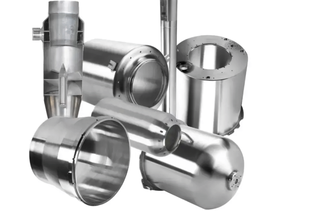
A horizontal tube flow forming machine is specifically designed for producing cylindrical tubes and hollow components with high dimensional accuracy, uniform wall thickness, and enhanced mechanical properties. In this type of machine, the workpiece is mounted horizontally on a mandrel attached to a rotating spindle, providing support along its length and reducing deflection during the forming process. One or more rollers apply controlled radial pressure to the outer surface of the rotating tube while moving axially along its length. The cold forming process gradually thins and elongates the material while aligning the internal grain structure, which improves tensile strength, fatigue resistance, and surface hardness. Because the process reshapes rather than removes material, waste is minimal, making it highly efficient when working with expensive or high-strength alloys such as aluminum, titanium, stainless steel, and nickel-based superalloys. The horizontal orientation also allows the machine to accommodate long tubes or cylindrical components, maintaining stability and precise alignment during high-force forming operations.
The structural design of a horizontal tube flow forming machine incorporates a reinforced frame, precision spindle bearings, and robust mandrel supports capable of handling heavy or long workpieces. Advanced CNC or servo-hydraulic control systems regulate spindle rotation, axial roller feed, and radial forming forces, ensuring consistent and repeatable deformation. Multiple rollers can be used simultaneously to distribute forces evenly around the circumference of the tube, preventing localized thinning, wrinkling, or cracking and improving surface finish. Sensors continuously monitor critical parameters such as roller position, forming force, spindle speed, and temperature, allowing real-time adjustments to maintain optimal forming conditions. Integrated lubrication and cooling systems reduce friction between rollers and the workpiece, prevent overheating, and extend tooling life, supporting long production cycles without compromising quality.
Horizontal tube flow forming machines are widely used in industries where high-quality cylindrical components are essential. Aerospace manufacturers employ these machines to produce engine casings, structural tubes, and other cylindrical components that require strict dimensional tolerances and enhanced mechanical properties. Automotive manufacturers utilize them to form lightweight transmission shafts, wheel axles, and structural tubes with consistent wall thickness and high strength. In energy and industrial applications, horizontal tube flow forming machines are used to manufacture pressure vessels, turbine housings, industrial piping, and high-pressure cylinders that must withstand demanding operating conditions. Defense industries rely on these machines to produce cylindrical housings, weapon components, and other parts requiring uniform geometry, structural integrity, and precise wall thickness.
The advantages of horizontal tube flow forming machines lie in their ability to combine precise control, high forming forces, and efficient material utilization. The horizontal orientation ensures stable support for long or heavy components, while multi-roller configurations distribute forming forces evenly, reducing the risk of defects and enhancing surface quality. CNC or servo-hydraulic control, real-time monitoring, and integrated lubrication and cooling systems allow for consistent, high-volume production with repeatable quality. Despite the heavy-duty construction and advanced controls required, horizontal tube flow forming machines provide an efficient and reliable solution for manufacturing tubes and cylindrical components with tight dimensional tolerances, uniform wall thickness, superior mechanical properties, and excellent surface finish, making them indispensable in aerospace, automotive, energy, industrial, and defense applications.
A multi-roller horizontal tube flow forming machine is an advanced system designed to produce high-precision cylindrical tubes and hollow components with consistent wall thickness, smooth surfaces, and enhanced mechanical performance. In this configuration, the workpiece is mounted horizontally on a robust mandrel connected to a rotating spindle, providing stable support along its length and minimizing deflection during the forming process. Multiple rollers are arranged around the circumference of the tube, and as the spindle rotates, these rollers apply controlled radial pressure while moving axially along the workpiece. This multi-roller arrangement allows the forming forces to be distributed evenly, reducing localized stress, preventing wrinkling or uneven wall thickness, and enabling precise control over the tube’s geometry. The cold forming process gradually elongates and thins the material while simultaneously aligning and refining its internal grain structure, resulting in improved tensile strength, fatigue resistance, and surface hardness. By reshaping rather than removing material, the machine ensures minimal waste and efficient use of high-value metals, including aluminum alloys, titanium, stainless steels, and nickel-based superalloys.
The mechanical design of multi-roller horizontal tube flow forming machines features reinforced frames, precision spindle bearings, and robust mandrel supports to maintain alignment and stability during high-force forming operations. CNC or servo-hydraulic control systems manage spindle rotation, axial roller feed, radial forming pressure, and the coordinated motion of multiple rollers with high precision. Sensors continuously monitor critical parameters such as roller position, applied force, spindle speed, and temperature, allowing real-time adjustments to maintain optimal forming conditions. Integrated lubrication and cooling systems reduce friction between rollers and the workpiece, prevent overheating, and extend the service life of tooling components. The combination of multi-roller configurations and precise control enables the production of tubes with complex geometries, variable wall thickness, tapered sections, and contoured profiles while maintaining strict dimensional tolerances and high surface quality.
Industries that rely on multi-roller horizontal tube flow forming machines include aerospace, automotive, energy, industrial manufacturing, and defense. In aerospace, these machines are used to produce engine casings, structural tubes, fuel lines, and other cylindrical components that must meet tight tolerances and exhibit uniform mechanical properties. Automotive manufacturers utilize them to form transmission shafts, drive axles, structural tubing, and wheel components with consistent wall thickness and high fatigue resistance. Energy and industrial sectors employ these machines to manufacture pressure vessels, turbine housings, piping systems, and chemical process cylinders capable of withstanding high pressure and demanding operational conditions. Defense applications benefit from multi-roller horizontal tube flow forming machines when producing weapon housings, structural cylinders, and other critical cylindrical components that require uniform geometry and structural integrity under extreme stress.
The advantages of multi-roller horizontal tube flow forming machines are rooted in their ability to combine high forming forces, precise multi-roller control, and stable horizontal support to produce tubes with exceptional quality and consistency. The use of multiple rollers distributes forming forces evenly, reducing the risk of defects and enhancing surface finish and dimensional uniformity. CNC or servo-hydraulic control, coupled with real-time monitoring and automated lubrication and cooling, allows for high-volume production with repeatable results. Despite the complexity of their construction and control systems, these machines provide a highly efficient and reliable solution for producing cylindrical tubes and hollow components with tight dimensional tolerances, uniform wall thickness, superior mechanical properties, and excellent surface finish, making them indispensable in aerospace, automotive, energy, industrial, and defense manufacturing applications.
A dual-spindle horizontal tube flow forming machine is a high-performance industrial system engineered to maximize productivity and precision in the production of cylindrical tubes, hollow shafts, and other tubular components. In this machine, two horizontally aligned spindles each support a mandrel that holds a workpiece, allowing simultaneous or independent forming of two tubes within the same machine frame. The dual-spindle configuration effectively doubles production capacity without requiring additional machines and provides the flexibility to run identical parts in parallel or different components simultaneously. As the workpieces rotate on their mandrels, one or more forming rollers apply carefully controlled radial pressure while moving axially along the tubes, gradually reducing wall thickness, elongating the material, and shaping the components to precise geometries. The cold forming process aligns and refines the internal grain structure of the metal, producing tubes with enhanced tensile strength, fatigue resistance, and surface hardness, while minimizing waste compared with machining or subtractive processes. The horizontal orientation provides robust support along the length of the tubes, ensuring stability, reducing deflection, and maintaining alignment even for long or heavy components under high forming forces.
The mechanical design of a dual-spindle horizontal tube flow forming machine includes a reinforced frame, precision spindle bearings, and rigid mandrel supports to maintain accurate alignment during high-force operations. CNC or servo-hydraulic control systems manage spindle rotation, axial feed of the rollers, radial forming pressure, and synchronization between the two spindles, ensuring uniform deformation and dimensional consistency across both workpieces. Multi-roller configurations can be employed to distribute forming forces evenly around the tube circumference, reducing localized stress concentrations and improving surface finish. Sensors continuously monitor roller position, applied force, spindle speed, and temperature, allowing real-time adjustments to maintain stable forming conditions. Integrated lubrication and cooling systems minimize friction between the rollers and the workpieces, prevent overheating, and extend tooling and mandrel life, supporting continuous high-volume production.
Industries that benefit from dual-spindle horizontal tube flow forming machines include aerospace, automotive, energy, industrial manufacturing, and defense. In aerospace, the machines are used to produce engine shafts, structural tubes, fuel lines, and other cylindrical components requiring strict dimensional tolerances and high mechanical performance. Automotive manufacturers use them to form drive shafts, transmission tubes, wheel axles, and structural tubing with consistent wall thickness and superior fatigue resistance. Energy and industrial applications include the production of pressure vessels, turbine casings, industrial piping, and high-pressure cylinders capable of withstanding demanding operating conditions. Defense industries rely on these machines to manufacture weapon housings, armored tubes, and other critical cylindrical components that must maintain uniform geometry, precise wall thickness, and structural integrity under extreme stress.
The advantages of dual-spindle horizontal tube flow forming machines stem from their ability to combine high forming forces, precise control, and simultaneous processing of multiple components. The horizontal orientation ensures stable support for long and heavy tubes, while multi-roller arrangements distribute forming forces evenly, producing consistent wall thickness, superior surface quality, and reliable mechanical properties. CNC or servo-hydraulic control systems, combined with real-time monitoring and automated lubrication and cooling, allow high-volume, repeatable production with minimal operator intervention. Despite the complexity and heavy-duty construction required, dual-spindle horizontal tube flow forming machines provide an efficient, reliable, and highly productive solution for manufacturing high-quality tubes and hollow components with tight tolerances, uniform wall thickness, and enhanced mechanical performance, making them indispensable in aerospace, automotive, energy, industrial, and defense manufacturing environments.
A multi-roller dual-spindle horizontal tube flow forming machine represents one of the most advanced configurations in flow forming technology, designed to combine high production efficiency with exceptional precision, surface quality, and mechanical performance for cylindrical components. In this machine, two horizontally aligned spindles each support a mandrel that holds a workpiece, allowing simultaneous forming of two tubes, shafts, or hollow components. Multiple rollers are positioned around each tube’s circumference, and as the spindles rotate, these rollers apply controlled radial pressure while traveling axially along the workpieces. The multi-roller arrangement ensures that forming forces are distributed evenly around the circumference, reducing localized stress, preventing surface defects, and maintaining uniform wall thickness. The cold forming process gradually elongates and thins the material, aligning the internal grain structure and producing strain-hardened components with increased tensile strength, fatigue resistance, and surface hardness. By reshaping rather than removing material, the machine minimizes waste and allows the efficient use of expensive or high-strength alloys such as aerospace-grade aluminum, titanium, stainless steel, and nickel-based superalloys.
The mechanical structure of a multi-roller dual-spindle horizontal tube flow forming machine is built to withstand high forming forces while maintaining precise alignment and stability for both workpieces. Reinforced frames, precision spindle bearings, and robust mandrel supports prevent deflection and vibration, even when processing long or heavy tubes. Advanced CNC or servo-hydraulic control systems regulate spindle rotation, roller axial feed, radial forming pressure, and the coordinated motion of multiple rollers across both spindles. Real-time feedback from sensors monitoring roller position, applied force, spindle speed, and temperature allows the system to adjust parameters dynamically, maintaining optimal forming conditions and consistent component quality. Integrated lubrication and cooling systems reduce friction, prevent overheating, and extend the service life of rollers, mandrels, and other tooling, enabling continuous high-volume production without sacrificing precision or surface finish. Multi-roller arrangements further improve process stability and allow complex geometries such as tapered sections, variable wall thickness, and contoured profiles to be formed with tight dimensional tolerances.
Industries that benefit from multi-roller dual-spindle horizontal tube flow forming machines include aerospace, automotive, energy, industrial manufacturing, and defense. In aerospace applications, these machines produce engine shafts, structural tubes, high-pressure fuel lines, and other cylindrical components requiring tight dimensional control and superior mechanical properties. Automotive manufacturers use them to produce drive shafts, transmission tubes, structural tubing, and wheel axles that demand uniform wall thickness, fatigue resistance, and precise roundness. In energy and industrial sectors, the machines are used to manufacture pressure vessels, turbine casings, industrial piping, and chemical process cylinders capable of withstanding extreme operating conditions. Defense applications rely on these machines for the production of armored tubes, weapon housings, and other critical cylindrical components where consistent geometry, structural integrity, and high-strength performance are essential.
The advantages of multi-roller dual-spindle horizontal tube flow forming machines are rooted in their combination of high forming forces, precise CNC or servo-hydraulic control, and simultaneous multi-component processing. The horizontal orientation provides stable support for long or heavy tubes, while multiple rollers evenly distribute forming forces to prevent localized defects and maintain surface quality. Automation features, real-time monitoring, and integrated lubrication and cooling systems ensure continuous, repeatable production with minimal operator intervention. Despite the complex mechanical design and heavy-duty construction requirements, these machines deliver unmatched productivity, precision, and material efficiency for high-volume manufacturing of tubes, shafts, and hollow components with uniform wall thickness, superior surface finish, and enhanced mechanical properties, making them indispensable in aerospace, automotive, energy, industrial, and defense production environments.
Forward flow forming machine
A forward flow forming machine is a specialized type of flow forming equipment designed to produce cylindrical components, tubes, or hollow parts by applying axial and radial forces in the same direction as the rotation of the workpiece, creating a controlled forward flow of the material along the mandrel. In this machine, the preform is mounted on a mandrel attached to a rotating spindle, and one or more rollers press against the surface while moving axially in the same direction as the material is being displaced. This forward motion causes the metal to elongate and reduce in wall thickness gradually while maintaining uniformity and roundness along the component. The cold forming process improves the internal grain structure of the material, resulting in strain-hardening, increased tensile strength, enhanced fatigue resistance, and a smooth surface finish. By reshaping rather than removing material, forward flow forming minimizes waste, making it particularly efficient for producing high-value or high-strength alloys such as aluminum, titanium, stainless steel, and nickel-based superalloys. The design of the machine ensures stable support for the workpiece, preventing deflection and vibration, which is essential for producing long or heavy cylindrical components with precise dimensions.
The structural design of a forward flow forming machine includes a rigid frame, precision bearings for the spindle, and a mandrel support system capable of withstanding high forming forces while maintaining alignment. CNC or servo-hydraulic control systems manage spindle rotation, roller axial travel, radial forming pressure, and the speed of forward material flow, ensuring repeatable and accurate results. Multiple rollers can be employed to distribute forming forces evenly around the workpiece, preventing localized thinning, wrinkling, or cracking and producing a uniform surface finish. Sensors monitor roller position, applied force, spindle speed, and temperature in real time, allowing the control system to make instantaneous adjustments to maintain optimal forming conditions. Integrated lubrication and cooling systems reduce friction between the rollers and the workpiece, prevent overheating, and extend the service life of tooling and mandrels, enabling continuous high-volume production.
Forward flow forming machines are widely used in industries that require high-quality cylindrical components with consistent wall thickness and superior mechanical performance. In aerospace, they produce structural tubes, engine casings, rocket motor components, and fuel lines that must meet strict dimensional tolerances and high-strength requirements. Automotive manufacturers use these machines to form transmission shafts, wheel axles, and structural tubes where uniform wall thickness, surface finish, and fatigue resistance are critical. Energy and industrial sectors rely on forward flow forming to manufacture pressure vessels, turbine housings, industrial piping, and chemical process cylinders capable of withstanding high pressure and demanding operational conditions. Defense applications use these machines to produce cylindrical housings, weapon components, and other critical parts that require uniform geometry, high mechanical strength, and tight tolerances under extreme conditions.
The advantages of forward flow forming machines stem from their ability to precisely control material flow in the same direction as the rotation of the workpiece, enabling smooth deformation, uniform wall thickness, and excellent surface finish. The combination of CNC or servo-hydraulic control, real-time monitoring, and multi-roller configurations ensures consistent, repeatable production with minimal operator intervention. Despite the complexity of the mechanical design and the high forming forces required, forward flow forming machines provide an efficient and reliable solution for producing high-performance cylindrical components and tubes with enhanced mechanical properties, tight dimensional tolerances, and minimal material waste. Their precision, efficiency, and adaptability make them indispensable in aerospace, automotive, energy, industrial, and defense manufacturing environments.
go on without sections and with long plain texts
A multi-roller forward flow forming machine is an advanced industrial system designed to maximize both precision and production efficiency for cylindrical components, tubes, and hollow parts that require consistent wall thickness, superior surface finish, and enhanced mechanical properties. In this machine, the workpiece is mounted on a mandrel attached to a rotating spindle, and multiple rollers apply controlled radial pressure while moving axially in the same direction as the rotation of the workpiece, producing a forward flow of material along the mandrel. This simultaneous radial and axial pressure gradually elongates and thins the material, aligning the internal grain structure and creating strain-hardened components with improved tensile strength, fatigue resistance, and surface hardness. By reshaping material instead of removing it, the process minimizes waste, making it highly efficient for forming high-value or high-strength alloys, including aluminum, titanium, stainless steel, and nickel-based superalloys. The machine is designed to support long or heavy components securely, preventing deflection, vibration, or misalignment during the forming process and ensuring tight dimensional tolerances and uniform mechanical properties along the entire length of the component.
The mechanical structure of a multi-roller forward flow forming machine incorporates a reinforced frame, precision spindle bearings, and robust mandrel support systems capable of withstanding high forming forces while maintaining alignment and stability. CNC or servo-hydraulic control systems precisely regulate spindle rotation, roller feed rate, radial forming pressure, and axial forward motion, allowing exact control over material deformation. Multiple rollers act in coordination to distribute forming forces evenly around the circumference of the component, minimizing localized stress and preventing defects such as wrinkling, cracking, or uneven wall thickness. Sensors continuously monitor critical parameters such as roller position, applied force, spindle speed, and temperature, allowing the system to make real-time adjustments to maintain optimal forming conditions. Integrated lubrication and cooling systems reduce friction between rollers and workpiece surfaces, prevent overheating, and extend tooling life, ensuring long production cycles with consistent quality. Multi-roller arrangements also enable the formation of complex geometries, including tapered profiles, stepped diameters, contoured surfaces, and variable wall thickness, while maintaining tight dimensional tolerances and uniform mechanical properties.
Industries that benefit from multi-roller forward flow forming machines include aerospace, automotive, energy, industrial manufacturing, and defense. Aerospace applications require structural tubes, engine casings, rocket motor components, and high-performance fuel lines with precise geometry, uniform wall thickness, and excellent fatigue resistance. Automotive manufacturers use these machines to produce transmission shafts, wheel axles, structural tubes, and other cylindrical components that must maintain uniform wall thickness, high mechanical strength, and consistent surface finish. Energy and industrial sectors rely on forward flow forming machines to manufacture pressure vessels, turbine casings, industrial piping, and chemical process cylinders capable of withstanding high pressure and harsh operational conditions. Defense applications utilize these machines to produce armored tubes, weapon housings, and other critical cylindrical components requiring strict dimensional tolerances, uniform geometry, and enhanced mechanical performance.
The advantages of multi-roller forward flow forming machines lie in their ability to precisely control material flow in coordination with spindle rotation, ensuring uniform deformation, tight dimensional tolerances, and excellent surface quality. The multi-roller configuration distributes forces evenly, minimizing localized stress, reducing the risk of surface defects, and enhancing overall component strength. CNC or servo-hydraulic control, real-time monitoring, and integrated lubrication and cooling systems allow continuous, repeatable, and high-volume production with minimal operator intervention. Despite the complexity and heavy-duty construction requirements, multi-roller forward flow forming machines provide a reliable, efficient, and highly productive solution for manufacturing high-performance tubes, shafts, wheels, and cylindrical components with uniform wall thickness, superior surface finish, and enhanced mechanical properties. Their precision, adaptability, and material efficiency make them indispensable in aerospace, automotive, energy, industrial, and defense manufacturing applications where tight tolerances and structural integrity are essential.
A dual-spindle multi-roller forward flow forming machine is a state-of-the-art industrial system designed to combine high-volume productivity with precise material control and superior mechanical performance for cylindrical tubes, hollow shafts, and complex rotational components. In this machine, two horizontally aligned spindles each hold a mandrel supporting a workpiece, allowing simultaneous or independent forming of two components within a single machine frame. Multiple rollers are positioned around each workpiece, and as the spindles rotate, these rollers apply controlled radial pressure while moving axially in the same direction as the rotation of the material, generating a forward flow of metal along the mandrel. The multi-roller configuration ensures uniform distribution of forming forces, preventing localized stress, wrinkling, or uneven wall thickness, while the cold forming process aligns and refines the internal grain structure, producing strain-hardened components with enhanced tensile strength, fatigue resistance, and surface hardness. By reshaping material rather than removing it, the machine minimizes waste and enables efficient use of high-value alloys such as aerospace-grade aluminum, titanium, stainless steel, and nickel-based superalloys. The horizontal orientation combined with dual spindles provides stable support for long or heavy components, maintaining alignment and dimensional accuracy throughout the forming process, even under high forming forces.
The mechanical design of a dual-spindle multi-roller forward flow forming machine is engineered for rigidity, stability, and precise control. Reinforced frames, precision spindle bearings, and heavy-duty mandrel supports prevent deflection and vibration while accommodating high forming loads. CNC or servo-hydraulic control systems manage spindle rotation, axial roller feed, radial forming pressure, and synchronization between the two spindles, ensuring uniform material flow and dimensional consistency across both workpieces. Sensors continuously monitor critical parameters such as roller position, applied force, spindle speed, and temperature, allowing real-time adjustments to maintain optimal forming conditions and prevent defects. Integrated lubrication and cooling systems reduce friction between rollers and the workpieces, prevent overheating, and extend tooling life, enabling long production cycles with consistent results. Multi-roller arrangements further allow for the formation of complex geometries, including tapered profiles, stepped diameters, contoured surfaces, and variable wall thickness, all while maintaining precise tolerances and uniform mechanical properties.
Industries that utilize dual-spindle multi-roller forward flow forming machines include aerospace, automotive, energy, industrial manufacturing, and defense. In aerospace applications, these machines produce engine shafts, structural tubes, rocket motor components, and high-performance fuel lines that require tight tolerances, uniform wall thickness, and high mechanical strength. Automotive manufacturers rely on them to form drive shafts, transmission tubes, wheel axles, and structural tubing with consistent wall thickness, fatigue resistance, and superior surface finish. Energy and industrial sectors use these machines to produce pressure vessels, turbine casings, industrial piping, and chemical process cylinders capable of withstanding high pressure and extreme operational conditions. Defense applications depend on these machines to manufacture armored tubes, weapon housings, and other critical cylindrical components that require precise dimensional control, uniform geometry, and enhanced mechanical performance.
The advantages of dual-spindle multi-roller forward flow forming machines lie in their combination of high forming forces, precise multi-roller control, and simultaneous processing of multiple components. The horizontal orientation ensures stable support for long or heavy tubes, while multiple rollers distribute forming forces evenly, reducing the risk of defects and producing consistent wall thickness and surface quality. CNC or servo-hydraulic control, integrated sensors, and real-time monitoring allow for repeatable, high-volume production with minimal operator intervention. Despite the complexity and heavy-duty construction required, these machines provide an efficient, reliable, and highly productive solution for manufacturing tubes, shafts, wheels, and hollow components with tight tolerances, uniform wall thickness, superior surface finish, and enhanced mechanical properties. Their precision, productivity, and material efficiency make them indispensable in aerospace, automotive, energy, industrial, and defense manufacturing environments where performance, durability, and dimensional accuracy are critical.
A large-scale multi-roller forward flow forming machine is an industrial-grade system specifically engineered to handle extremely long, thick-walled, or high-diameter cylindrical components that require both high forming forces and precise control over wall thickness, geometry, and surface finish. In this type of machine, the workpiece is mounted on a heavy-duty mandrel attached to a rotating spindle, while multiple rollers are positioned around its circumference to apply controlled radial pressure as they move axially in the same direction as the rotation of the workpiece, producing a forward flow of material along the mandrel. This process gradually reduces wall thickness and elongates the component while aligning and refining the internal grain structure, which increases tensile strength, fatigue resistance, and surface hardness. By reshaping material rather than cutting it away, the machine minimizes scrap, making it highly efficient for forming expensive alloys such as titanium, aluminum, stainless steel, and nickel-based superalloys. The multi-roller configuration distributes forming forces evenly across the circumference, reducing localized stress, preventing defects such as wrinkling, cracking, or uneven wall thickness, and ensuring uniform mechanical properties throughout the component. The design allows for precise forming of long or heavy workpieces while maintaining dimensional stability, roundness, and concentricity along the entire length of the tube or cylinder.
The structural design of large-scale multi-roller forward flow forming machines includes a reinforced frame, precision spindle bearings, and robust mandrel supports capable of handling substantial forming loads while minimizing deflection and vibration. CNC or servo-hydraulic control systems regulate spindle rotation, radial pressure, axial roller feed, and synchronization of multiple rollers to ensure accurate, repeatable material flow. Real-time monitoring through sensors tracks roller position, forming force, spindle speed, and temperature, allowing dynamic adjustments to maintain optimal forming conditions. Integrated lubrication and cooling systems prevent overheating, reduce friction, and extend the service life of rollers, mandrels, and other tooling components, enabling continuous, high-volume production. Multi-roller arrangements allow the formation of complex geometries such as tapered walls, stepped diameters, variable thickness sections, and contoured profiles while maintaining tight tolerances, superior surface finish, and uniform mechanical properties across the component.
Industries that benefit from large-scale multi-roller forward flow forming machines include aerospace, automotive, energy, industrial manufacturing, and defense. In aerospace, these machines produce structural tubes, engine casings, rocket motor components, and high-pressure fuel lines that require precise dimensional control, uniform wall thickness, and high mechanical strength. Automotive manufacturers utilize them to form drive shafts, transmission tubes, structural tubing, wheel axles, and other cylindrical components with consistent wall thickness, fatigue resistance, and high-quality surface finish. Energy and industrial applications include the production of pressure vessels, turbine casings, industrial piping, and chemical process cylinders capable of withstanding high-pressure, high-temperature, or harsh operational environments. Defense industries use these machines to manufacture armored tubes, weapon housings, and other critical cylindrical components requiring strict tolerances, uniform geometry, and enhanced mechanical properties to withstand extreme stress and impact conditions.
The advantages of large-scale multi-roller forward flow forming machines are their ability to combine high forming forces, precise multi-roller control, and stable support for long or heavy components, ensuring consistent wall thickness, excellent surface quality, and tight dimensional tolerances. CNC or servo-hydraulic control, real-time monitoring, and integrated lubrication and cooling systems allow for continuous, repeatable, high-volume production with minimal operator intervention. Despite the complexity and heavy-duty construction required, these machines provide a reliable, efficient, and highly productive solution for manufacturing large, high-performance tubes, shafts, and hollow components. They are essential in aerospace, automotive, energy, industrial, and defense manufacturing environments where structural integrity, mechanical performance, and dimensional accuracy are critical, delivering components that meet stringent specifications while maintaining material efficiency and production throughput.
Shear spinning machine
A shear spinning machine is a specialized metal-forming machine designed to produce rotationally symmetric components by applying high-pressure forces along the surface of a blank while it rotates at high speed on a mandrel or spindle. Unlike conventional spinning or flow forming, shear spinning involves applying tangential and radial forces simultaneously, causing the metal to undergo plastic deformation through a combination of compression and shear. As the rollers or forming tools move along the workpiece, the material is thinned and elongated while being shaped precisely to the contour of the mandrel, allowing the production of hollow, seamless, and intricately contoured components with accurate wall thickness. The process preserves the continuity of the metal, enhances its internal grain structure, and improves mechanical properties such as tensile strength, fatigue resistance, and surface hardness. Because the material is reshaped rather than cut away, shear spinning minimizes waste and allows for efficient use of high-value alloys such as stainless steel, aluminum, titanium, and nickel-based superalloys. The machine’s design ensures stability and alignment, which is critical for producing large-diameter or long components without distortion or deflection during the spinning process.
Mechanically, a shear spinning machine consists of a rigid frame, precision spindle bearings, and a robust mandrel or chuck to support the blank during high-speed rotation. One or more forming rollers or tools apply pressure at controlled angles and feed rates along the surface of the workpiece, and CNC or servo-hydraulic systems often regulate the spindle speed, roller pressure, axial feed, and tool angle to achieve precise geometries. Sensors monitor spindle rotation, roller force, and position, providing real-time feedback that allows dynamic adjustment of forming parameters to maintain uniform wall thickness, surface quality, and dimensional accuracy. The machine may incorporate multiple rollers or specialized tooling to distribute forming forces evenly, reduce localized stress, and improve surface finish, while integrated lubrication and cooling systems reduce friction, prevent overheating, and extend tool life. The versatility of shear spinning allows the production of complex shapes, including cones, flanges, domes, tapered cylinders, and intricate hollow forms, which would be difficult or inefficient to achieve through traditional machining, forging, or deep drawing processes.
Industries that utilize shear spinning machines include aerospace, automotive, energy, industrial manufacturing, and defense. In aerospace, shear spinning is used to produce turbine engine components, nozzles, structural cones, and fuselage sections requiring precise dimensional control and uniform mechanical properties. Automotive manufacturers use shear spinning to form structural tubes, wheel hubs, flanged components, and exhaust parts with high strength-to-weight ratios. Energy and industrial applications include pressure vessel end caps, chemical process vessels, large-diameter piping components, and industrial fittings capable of withstanding high pressures and harsh environments. Defense applications employ shear spinning to manufacture armored housings, seamless cylindrical casings, and other rotational components that must combine structural integrity with uniform wall thickness and precise geometry.
The advantages of shear spinning machines include their ability to produce seamless, high-strength components with tight dimensional tolerances and uniform wall thickness, while minimizing material waste. The combination of high rotational speed, controlled roller pressure, and precise axial feed allows for efficient, repeatable production of complex geometries with excellent surface finish. CNC or servo-hydraulic control, multi-roller configurations, and real-time monitoring systems enable high-volume manufacturing with consistent quality. Despite requiring robust construction, precise alignment, and careful process control, shear spinning machines provide a reliable and highly efficient solution for producing hollow, rotationally symmetric components with superior mechanical properties, making them indispensable in aerospace, automotive, energy, industrial, and defense manufacturing environments where precision, strength, and material efficiency are critical.
A multi-roller shear spinning machine is an advanced type of metal-forming equipment designed to produce high-precision, rotationally symmetric components with exceptional surface quality, dimensional accuracy, and enhanced mechanical properties. In this machine, the blank is mounted on a mandrel or spindle and rotated at high speed while multiple forming rollers apply controlled radial and tangential forces along the surface, moving axially to shape the material. The combination of shear and compression causes the metal to flow and elongate along the mandrel, gradually thinning the wall where required while maintaining uniform thickness and roundness. The cold working process aligns the internal grain structure of the metal, producing strain-hardened components with improved tensile strength, fatigue resistance, and surface hardness. Because material is reshaped rather than removed, shear spinning minimizes waste and allows efficient use of high-value metals, including aluminum, titanium, stainless steel, and nickel-based superalloys. The multi-roller configuration ensures even distribution of forming forces, reducing localized stresses, preventing surface defects, and allowing the production of large, long, or complex components with stable dimensional control and excellent structural integrity throughout the process.
Mechanically, a multi-roller shear spinning machine consists of a rigid frame, precision spindle bearings, and reinforced mandrel supports capable of handling high rotational speeds and forming pressures. CNC or servo-hydraulic systems precisely control spindle speed, roller feed, axial travel, radial force, and tool angles, enabling the production of components with tight tolerances and complex geometries such as cones, domes, flanges, tapered cylinders, and contoured hollow forms. Sensors continuously monitor roller position, applied force, spindle speed, and temperature, providing real-time feedback to adjust parameters dynamically, ensuring consistent wall thickness, uniform deformation, and superior surface finish. Integrated lubrication and cooling systems reduce friction between rollers and the workpiece, prevent overheating, and extend the service life of tooling, supporting continuous high-volume production while maintaining consistent quality. Multi-roller arrangements allow simultaneous shaping at multiple contact points, improving efficiency, reducing cycle time, and ensuring a smooth, uniform material flow across the entire surface of the component.
Industries that rely on multi-roller shear spinning machines include aerospace, automotive, energy, industrial manufacturing, and defense, where precision, structural integrity, and material efficiency are critical. In aerospace, these machines produce turbine engine components, nozzles, structural cones, fuselage sections, and other hollow parts requiring tight dimensional tolerances and uniform mechanical properties. Automotive manufacturers use shear spinning to form wheel hubs, structural tubes, flanged components, exhaust parts, and high-strength cylindrical parts with excellent fatigue resistance and surface finish. Energy and industrial applications include pressure vessel end caps, chemical process vessels, large-diameter piping components, and industrial fittings that must withstand high pressure, temperature, and corrosive environments. Defense applications utilize shear spinning for armored housings, seamless cylindrical casings, weapon components, and other rotational parts where uniform wall thickness, precise geometry, and enhanced mechanical strength are essential.
The advantages of multi-roller shear spinning machines include their ability to produce seamless, high-strength components with tight dimensional tolerances, uniform wall thickness, and superior surface quality while minimizing material waste. The integration of multi-roller forming, CNC or servo-hydraulic control, real-time monitoring, and automated lubrication and cooling allows for high-volume, repeatable production of complex geometries with excellent structural performance. Despite requiring robust mechanical construction, precise alignment, and careful process management, multi-roller shear spinning machines provide a highly efficient and reliable method for manufacturing rotationally symmetric components that combine precision, strength, and material efficiency. They are indispensable in aerospace, automotive, energy, industrial, and defense manufacturing environments, enabling the production of components that meet demanding specifications while maintaining high throughput, material utilization, and mechanical performance.
A dual-spindle multi-roller shear spinning machine represents one of the most advanced configurations in metal-forming technology, designed to maximize both productivity and precision for cylindrical, hollow, and rotationally symmetric components. In this machine, two spindles are horizontally aligned or vertically configured depending on design, each holding a mandrel with a workpiece mounted on it, allowing simultaneous or independent spinning of two components. Multiple forming rollers are positioned around each workpiece, applying controlled radial and tangential forces while moving axially along the rotating blank. The forward motion of the rollers in combination with the rotational speed of the spindle generates a shear flow in the material, elongating it, reducing wall thickness, and shaping the workpiece to match the mandrel contour precisely. This cold forming process aligns and refines the internal grain structure, producing strain-hardened components with superior tensile strength, enhanced fatigue resistance, and improved surface hardness. The dual-spindle configuration increases throughput by enabling the production of two components in parallel, while the multi-roller setup distributes forming forces evenly to prevent localized stress, wrinkling, or uneven wall thickness, ensuring high-quality, consistent parts even for large or long components.
The mechanical construction of a dual-spindle multi-roller shear spinning machine includes a rigid frame, precision spindle bearings, and reinforced mandrel supports capable of maintaining alignment under high-speed rotation and significant forming loads. CNC or servo-hydraulic control systems regulate spindle speed, axial roller travel, radial pressure, and tool angles for each workpiece independently or in synchronization, allowing precise control over material deformation and enabling the production of complex geometries such as tapered cylinders, cones, flanges, domes, and contoured hollow forms. Sensors continuously monitor roller positions, applied forces, spindle speed, and temperature, providing real-time feedback that allows dynamic adjustments to maintain uniform wall thickness, surface quality, and dimensional accuracy. Integrated lubrication and cooling systems reduce friction between rollers and workpieces, prevent overheating, and extend the life of mandrels and tooling. Multi-roller arrangements allow simultaneous shaping at multiple contact points, increasing efficiency, reducing cycle time, and producing smooth, uniform material flow across the entire surface of each component.
Industries that use dual-spindle multi-roller shear spinning machines include aerospace, automotive, energy, industrial manufacturing, and defense. In aerospace, these machines produce turbine engine components, nozzles, structural cones, fuselage sections, and other hollow or rotationally symmetric parts that require strict dimensional tolerances and consistent mechanical properties. Automotive manufacturers utilize them to form wheel hubs, transmission shafts, structural tubes, flanged components, and other high-strength cylindrical parts where uniform wall thickness, excellent surface finish, and fatigue resistance are critical. Energy and industrial applications include the production of pressure vessel end caps, turbine housings, industrial piping, chemical process vessels, and other components capable of withstanding high pressure, temperature, or corrosive environments. Defense applications rely on dual-spindle shear spinning machines for the production of armored housings, seamless cylindrical casings, weapon components, and other critical rotational parts that demand uniform geometry, structural integrity, and high mechanical performance.
The advantages of dual-spindle multi-roller shear spinning machines include their ability to produce seamless, high-strength components with tight dimensional tolerances, uniform wall thickness, and superior surface finish while significantly increasing production capacity. The combination of high forming forces, multi-roller precision, dual-spindle operation, and CNC or servo-hydraulic control allows for continuous, repeatable, and high-volume manufacturing with minimal operator intervention. Despite requiring heavy-duty construction, precise alignment, and careful process management, these machines provide an efficient and highly reliable solution for manufacturing hollow, rotationally symmetric components with exceptional mechanical properties, excellent dimensional accuracy, and high material efficiency. They are essential in aerospace, automotive, energy, industrial, and defense production environments where precision, strength, and productivity are critical, enabling manufacturers to produce components that meet stringent specifications while maintaining high throughput and consistent quality.
A large-scale multi-roller shear spinning machine is a heavy-duty industrial system engineered to handle oversized, long, or thick-walled cylindrical components that require high forming forces, precise dimensional control, and exceptional surface quality. In this machine, the workpiece is mounted on a reinforced mandrel attached to a high-torque spindle, which provides stable support during high-speed rotation, and multiple forming rollers are arranged around the circumference to apply controlled radial and tangential forces while moving axially along the surface. The combination of rotational motion and shear forces generates a forward flow of material, gradually elongating and thinning the workpiece, aligning and refining the internal grain structure, and producing strain-hardened components with superior tensile strength, fatigue resistance, and surface hardness. By reshaping rather than cutting away material, shear spinning minimizes waste and allows efficient use of high-value alloys such as aluminum, titanium, stainless steel, and nickel-based superalloys. The multi-roller configuration distributes forces evenly, preventing localized stress, wrinkling, or cracking, and enables the formation of complex geometries including cones, domes, flanges, tapered cylinders, and contoured hollow forms while maintaining tight tolerances and consistent mechanical properties throughout the component. The machine’s design ensures precise alignment, minimal deflection, and stable support even for extremely long or heavy workpieces, allowing the production of large, high-performance components with superior structural integrity.
Mechanically, large-scale multi-roller shear spinning machines are built with reinforced frames, precision spindle bearings, and robust mandrel supports capable of withstanding extreme forming forces and high rotational speeds. CNC or servo-hydraulic control systems regulate spindle rotation, radial roller pressure, axial roller feed, and tool angles to achieve exact material deformation and repeatable results. Sensors monitor roller position, applied force, spindle speed, and temperature in real time, enabling dynamic adjustments to maintain optimal forming conditions and uniform wall thickness. Integrated lubrication and cooling systems reduce friction, prevent overheating, and extend tool and mandrel life, allowing continuous high-volume production while preserving surface quality and dimensional precision. The multi-roller arrangement allows simultaneous shaping at multiple contact points, improving efficiency, reducing cycle times, and producing smooth, uniform material flow across the workpiece. These machines can handle extremely large or complex components that would be difficult or inefficient to produce with conventional spinning, deep drawing, or machining methods.
Industries that utilize large-scale multi-roller shear spinning machines include aerospace, automotive, energy, industrial manufacturing, and defense, where high-performance, high-precision components are critical. In aerospace, they are used to produce turbine engine components, rocket nozzles, structural cones, fuselage sections, and other rotationally symmetric hollow parts that require strict dimensional tolerances, uniform wall thickness, and high mechanical performance. Automotive manufacturers employ these machines to form drive shafts, transmission tubes, wheel hubs, structural tubing, flanged components, and other cylindrical parts requiring consistent wall thickness, surface finish, and fatigue resistance. Energy and industrial applications include pressure vessel end caps, turbine housings, industrial piping, chemical process cylinders, and other components capable of withstanding high pressure, temperature, or corrosive environments. Defense applications rely on large-scale shear spinning machines for armored housings, seamless cylindrical casings, weapon components, and other critical rotational parts that must maintain precise geometry, uniform wall thickness, and high structural integrity under extreme conditions.
The advantages of large-scale multi-roller shear spinning machines are rooted in their ability to combine high forming forces, precise multi-roller control, and stable support for long or heavy components, producing seamless, high-strength parts with excellent surface quality and tight dimensional tolerances. CNC or servo-hydraulic control, real-time monitoring, and integrated lubrication and cooling enable high-volume, repeatable production with minimal operator intervention. Despite the heavy-duty construction and complexity required, these machines provide a highly efficient, reliable, and productive method for manufacturing large, rotationally symmetric components with superior mechanical properties, dimensional accuracy, and minimal material waste. They are indispensable in aerospace, automotive, energy, industrial, and defense manufacturing environments, providing the capability to produce high-performance components that meet stringent specifications while maintaining high throughput, material efficiency, and structural reliability.
Power metal spinning machine
A power metal spinning machine is a high-performance industrial system designed for the efficient and precise production of rotationally symmetric metal components such as cones, cylinders, domes, flanges, and complex hollow shapes. Unlike manual or conventional spinning, a power metal spinning machine uses mechanically or hydraulically driven rollers or spinning tools to apply controlled radial and tangential forces to a rotating metal blank mounted on a mandrel or spindle. The combination of high rotational speed and applied pressure causes the metal to undergo plastic deformation, thinning and elongating the material while shaping it to the contour of the mandrel. This process preserves the continuity of the metal, aligns its internal grain structure, and produces strain-hardened components with enhanced tensile strength, fatigue resistance, and surface hardness. Because the material is reshaped rather than cut away, power metal spinning is highly material-efficient and suitable for high-value metals such as aluminum, titanium, stainless steel, copper, and nickel-based alloys. The machine is designed to maintain precise alignment and support for the workpiece during high-speed rotation, allowing accurate dimensional control even for large, thick, or long components, while minimizing deflection, vibration, or surface defects.
Mechanically, a power metal spinning machine consists of a rigid frame, precision spindle bearings, and reinforced mandrel supports capable of handling high rotational speeds and forming forces. Multiple rollers or spinning tools are mounted on mechanically or hydraulically actuated arms, which apply force at controlled angles, speeds, and feed rates along the workpiece. CNC or servo-hydraulic control systems are often integrated to regulate spindle rotation, roller pressure, axial feed, and tool orientation, providing precise and repeatable shaping of complex geometries. Sensors continuously monitor parameters such as roller position, applied force, spindle speed, and temperature, enabling real-time adjustments that maintain uniform wall thickness, surface finish, and dimensional accuracy. Integrated lubrication and cooling systems reduce friction, prevent overheating, and extend tooling and mandrel life, supporting long production runs without compromising quality. Multi-roller configurations allow simultaneous forming at multiple contact points, improving efficiency, reducing cycle time, and producing smooth, uniform material flow across the surface of the component.
Power metal spinning machines are widely used in industries that require high-precision, high-strength, and seamless rotational components. In aerospace, they produce engine cones, turbine components, nozzles, fuel lines, and structural hollow parts that must meet strict tolerances and possess consistent mechanical properties. Automotive manufacturers use these machines to form wheel rims, drive shafts, flanged components, exhaust parts, and structural tubes with high fatigue resistance and uniform wall thickness. Energy and industrial sectors rely on power metal spinning machines to manufacture pressure vessel end caps, turbine housings, piping components, chemical process vessels, and other cylindrical parts capable of withstanding high pressures, temperatures, and corrosive conditions. Defense applications utilize these machines to produce armored housings, weapon components, and other critical rotational parts where structural integrity, precise geometry, and material strength are essential.
The advantages of power metal spinning machines lie in their ability to produce seamless, high-strength components with tight dimensional tolerances, uniform wall thickness, and superior surface finish while maintaining high material efficiency. The combination of high rotational speed, controlled multi-roller or tool pressure, and CNC or servo-hydraulic control allows for repeatable, high-volume production of complex geometries that would be difficult or inefficient to produce with traditional machining, forging, or deep-drawing methods. Despite the robust mechanical construction and precise alignment required, power metal spinning machines provide a reliable and efficient method for manufacturing hollow, rotationally symmetric components with enhanced mechanical properties, excellent surface finish, and minimal waste. They are indispensable in aerospace, automotive, energy, industrial, and defense manufacturing environments where precision, strength, productivity, and material efficiency are critical, enabling manufacturers to produce components that meet demanding specifications while maintaining high throughput and consistent quality.
A multi-roller power metal spinning machine is a highly advanced and versatile metal-forming system designed for high-volume production of rotationally symmetric components with exceptional precision, uniform wall thickness, and superior surface quality. In this machine, the workpiece is mounted on a mandrel or spindle and rotated at high speed while multiple rollers or spinning tools apply controlled radial and tangential forces along the surface, moving axially to shape the metal. The multi-roller configuration allows forces to be distributed evenly around the circumference, reducing localized stress, preventing wrinkling, cracking, or uneven wall thickness, and enabling the production of large or complex components with consistent mechanical properties. The cold forming process gradually thins and elongates the material while aligning and refining the internal grain structure, resulting in strain-hardened components with enhanced tensile strength, fatigue resistance, and surface hardness. By reshaping material rather than cutting it away, multi-roller power metal spinning maximizes material efficiency and is particularly effective for high-value alloys such as aluminum, titanium, stainless steel, copper, and nickel-based superalloys. The machine’s design ensures precise alignment and support for the workpiece, minimizing deflection, vibration, or distortion even during high-speed forming of long or heavy components.
Mechanically, multi-roller power metal spinning machines consist of a rigid frame, precision spindle bearings, and reinforced mandrel supports capable of withstanding high rotational speeds and forming forces. CNC or servo-hydraulic control systems manage spindle rotation, axial roller feed, radial pressure, and tool orientation to achieve precise deformation and repeatable results. Sensors continuously monitor roller position, applied force, spindle speed, and temperature, enabling real-time adjustments to maintain uniform wall thickness, consistent surface finish, and tight dimensional tolerances. Integrated lubrication and cooling systems reduce friction, prevent overheating, and extend the service life of rollers, mandrels, and tooling, allowing continuous high-volume production. The multi-roller arrangement allows simultaneous forming at multiple contact points, improving efficiency, reducing cycle time, and ensuring smooth, uniform material flow across the surface of the component. These machines are capable of producing complex geometries such as tapered sections, cones, domes, flanges, stepped cylinders, and contoured hollow forms that would be difficult or inefficient to manufacture with conventional machining, deep drawing, or forging.
Industries that utilize multi-roller power metal spinning machines include aerospace, automotive, energy, industrial manufacturing, and defense, where precise, high-strength, and seamless components are required. In aerospace, they produce turbine engine components, nozzles, structural cones, fuselage sections, and high-performance fuel lines that must meet stringent tolerances and possess consistent mechanical properties. Automotive manufacturers use these machines to form wheel rims, drive shafts, transmission tubes, structural tubing, flanged components, and exhaust parts with uniform wall thickness, excellent surface finish, and high fatigue resistance. Energy and industrial applications include pressure vessel end caps, turbine casings, piping systems, chemical process vessels, and other cylindrical or hollow components capable of withstanding high pressure, temperature, or corrosive conditions. Defense applications rely on multi-roller power metal spinning to produce armored housings, seamless cylindrical casings, weapon components, and other critical rotational parts requiring precise geometry, uniform wall thickness, and enhanced structural integrity.
The advantages of multi-roller power metal spinning machines lie in their combination of high rotational speed, controlled multi-roller forming, CNC or servo-hydraulic precision, and real-time monitoring to produce seamless, high-strength components with tight dimensional tolerances and consistent surface quality. The use of multiple rollers allows for even distribution of forming forces, minimizing defects and improving mechanical performance, while automated lubrication and cooling systems ensure long production runs without loss of quality. Despite the heavy-duty construction, precise alignment requirements, and complex control systems, multi-roller power metal spinning machines provide a highly efficient, reliable, and versatile solution for producing rotationally symmetric components with superior material properties, excellent dimensional accuracy, and minimal waste. They are indispensable in aerospace, automotive, energy, industrial, and defense manufacturing, enabling the production of high-performance components at high throughput while maintaining consistent quality and material efficiency.
A dual-spindle multi-roller power metal spinning machine is one of the most advanced configurations in rotational metal forming, combining high productivity, precision, and versatility for manufacturing cylindrical, conical, domed, or complex hollow components. In this machine, two spindles each hold a mandrel with a workpiece, allowing simultaneous or independent spinning of two components, effectively doubling throughput while maintaining exacting quality standards. Multiple rollers or forming tools are positioned around each workpiece to apply controlled radial and tangential forces while moving axially along the rotating blank, generating a forward flow of metal that thins, elongates, and shapes the material precisely to the mandrel contour. The multi-roller configuration distributes forming forces evenly, preventing localized stresses, wrinkling, or uneven wall thickness, and ensures uniform mechanical properties across the entire component. The cold working process aligns and refines the internal grain structure, producing strain-hardened parts with enhanced tensile strength, fatigue resistance, and surface hardness. By reshaping material rather than removing it, this process maximizes material efficiency and is especially suitable for high-value alloys such as aluminum, titanium, stainless steel, copper, and nickel-based superalloys. The machine’s design provides rigid support and precise alignment, minimizing deflection or vibration, which is critical for forming long, heavy, or large-diameter components to tight tolerances.
The mechanical design of dual-spindle multi-roller power metal spinning machines incorporates a reinforced frame, precision spindle bearings, and robust mandrel supports capable of withstanding high rotational speeds and forming forces. CNC or servo-hydraulic control systems manage spindle rotation, axial roller feed, radial pressure, and tool orientation for each workpiece independently or in synchronization, ensuring precise, repeatable shaping of complex geometries. Sensors continuously monitor roller positions, applied forces, spindle speed, and temperature, providing real-time feedback to dynamically adjust parameters for consistent wall thickness, uniform surface finish, and dimensional accuracy. Integrated lubrication and cooling systems reduce friction, prevent overheating, and extend the service life of mandrels, rollers, and tooling, enabling long production runs with high quality. Multi-roller arrangements allow simultaneous shaping at multiple points of contact, improving efficiency, reducing cycle times, and producing smooth, uniform material flow across each workpiece. These machines can form cones, domes, flanges, stepped cylinders, tapered sections, and contoured hollow shapes that would be difficult or inefficient to produce with traditional machining, forging, or deep drawing methods.
Industries that benefit from dual-spindle multi-roller power metal spinning machines include aerospace, automotive, energy, industrial manufacturing, and defense, where precision, mechanical performance, and material efficiency are critical. In aerospace, these machines produce engine cones, turbine components, nozzles, structural tubes, fuselage sections, and high-performance fuel lines with strict dimensional tolerances and uniform mechanical properties. Automotive manufacturers use them for wheel rims, drive shafts, transmission tubes, flanged components, structural tubing, and exhaust parts requiring consistent wall thickness, surface quality, and fatigue resistance. Energy and industrial applications include turbine housings, pressure vessel end caps, chemical process vessels, industrial piping, and large cylindrical or hollow components capable of withstanding high pressure, temperature, or corrosive environments. Defense applications rely on these machines to manufacture armored housings, seamless cylindrical casings, weapon components, and other rotational parts demanding precise geometry, uniform wall thickness, and high structural integrity under extreme conditions.
The advantages of dual-spindle multi-roller power metal spinning machines include their ability to combine high rotational speed, precise multi-roller forming, dual-spindle throughput, CNC or servo-hydraulic precision, and real-time monitoring to produce seamless, high-strength components with tight dimensional tolerances and superior surface finish. Multi-roller control ensures even force distribution, minimizing defects, enhancing mechanical performance, and allowing complex geometries to be formed with repeatable accuracy. Integrated lubrication and cooling systems enable continuous high-volume production while maintaining quality. Despite the complexity, heavy-duty construction, and precise alignment required, these machines provide a highly efficient, reliable, and versatile solution for producing hollow, rotationally symmetric components with exceptional material properties, excellent dimensional accuracy, and minimal waste. They are indispensable in aerospace, automotive, energy, industrial, and defense manufacturing, offering manufacturers the capability to produce high-performance components at high throughput with consistent quality and optimal material utilization.
Hot flow forming machine
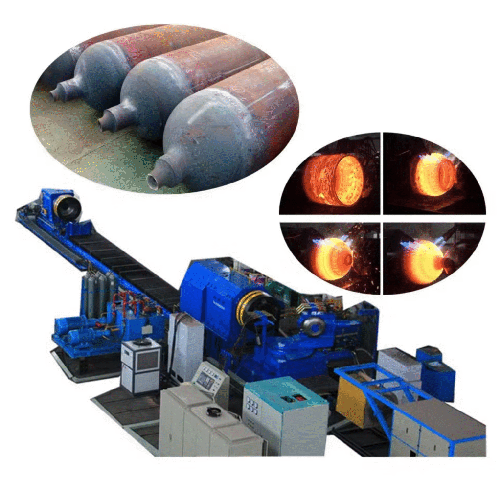
A hot flow forming machine is an advanced industrial system designed to shape cylindrical, tubular, or rotationally symmetric components by combining rotational motion with axial and radial pressure while the workpiece is heated to elevated temperatures. Unlike cold flow forming, hot flow forming allows high-strength metals and alloys that are difficult to deform at room temperature to be formed with reduced force while maintaining dimensional accuracy and surface quality. In this machine, the workpiece is mounted on a mandrel or spindle and heated using induction, furnace, or localized heating methods to reach a temperature that facilitates plastic deformation without causing microstructural damage. Multiple forming rollers or tools then apply controlled radial pressure while moving axially along the rotating workpiece, gradually thinning, elongating, and shaping the material to the desired geometry. The heating process softens the metal, reducing the forming forces required, improving ductility, and allowing the formation of components with complex profiles, variable wall thickness, or large diameters that would be difficult or impossible to produce cold. The heat also assists in refining the internal grain structure in some alloys, improving mechanical performance while avoiding surface cracking or work hardening that can occur during cold forming.
Mechanically, a hot flow forming machine consists of a rigid frame, precision spindle bearings, reinforced mandrel supports, and an integrated heating system that maintains the workpiece at a controlled temperature throughout the forming process. CNC or servo-hydraulic control systems regulate spindle speed, roller feed rate, axial movement, radial forming pressure, and temperature, ensuring precise, repeatable forming operations. Sensors monitor roller position, applied force, spindle speed, and workpiece temperature in real time, allowing dynamic adjustment of forming parameters to maintain uniform wall thickness, surface quality, and dimensional accuracy. Integrated cooling and lubrication systems may also be employed for the rollers and mandrel supports to prevent thermal damage and extend tool life. Multi-roller configurations distribute forming forces evenly around the circumference, reduce localized stresses, and allow continuous, uniform deformation along the workpiece. This enables the formation of long, thick-walled, or large-diameter components with precise geometric control, smooth surface finish, and enhanced mechanical properties.
Industries that benefit from hot flow forming machines include aerospace, energy, industrial manufacturing, automotive, and defense, particularly where components must withstand high loads, high temperatures, or extreme operating conditions. In aerospace, hot flow forming is used to produce turbine engine casings, jet engine shafts, rocket motor tubes, and structural components made from high-temperature alloys such as titanium, nickel-based superalloys, or high-strength steel. Energy and industrial sectors employ hot flow forming to manufacture pressure vessels, chemical process cylinders, turbine housings, and large industrial piping that require uniform wall thickness, high structural integrity, and resistance to thermal and mechanical stress. Automotive manufacturers use hot flow forming for high-performance drive shafts, transmission tubes, and structural components where both strength and weight reduction are critical. Defense applications include the production of armored tubes, high-strength weapon components, and other hollow cylindrical parts that require uniform geometry, enhanced material properties, and tight dimensional tolerances.
The advantages of hot flow forming machines lie in their ability to form high-strength metals and alloys that are difficult to process cold, enabling the production of large, complex, and high-performance components with uniform wall thickness, tight tolerances, and superior surface finish. The combination of controlled heating, multi-roller forming, precise CNC or servo-hydraulic control, and real-time monitoring allows repeatable, high-volume production while minimizing material waste and avoiding defects such as cracking or work hardening. Despite requiring robust construction, precise alignment, and integrated heating and cooling systems, hot flow forming machines provide an efficient, reliable, and highly productive solution for manufacturing cylindrical, tubular, and hollow components with enhanced mechanical properties, making them indispensable in aerospace, automotive, energy, industrial, and defense manufacturing environments where precision, strength, and material efficiency are critical.
A multi-roller hot flow forming machine is a highly specialized industrial system designed to handle large, thick-walled, or high-strength cylindrical and tubular components that require precise dimensional control, uniform wall thickness, and enhanced mechanical properties under elevated temperature conditions. In this machine, the workpiece is mounted on a robust mandrel or spindle and heated using induction, furnace, or localized heating methods to a temperature that reduces the flow stress of the metal while preserving its structural integrity. Multiple rollers or forming tools apply controlled radial and tangential forces while moving axially along the workpiece in the same direction as the rotation, producing a forward flow of material that gradually elongates, thins, and shapes the component to the desired geometry. The elevated temperature improves ductility, reduces the forming forces required, and enables the processing of high-strength alloys such as titanium, nickel-based superalloys, high-strength steel, and aluminum alloys that are difficult or impossible to form cold. The hot flow forming process allows complex geometries, variable wall thickness, tapered profiles, and large-diameter sections to be formed with high precision while aligning the internal grain structure and reducing residual stresses that could compromise mechanical performance. The multi-roller configuration ensures that forces are evenly distributed around the circumference, minimizing the risk of localized thinning, wrinkling, or cracking, and maintaining uniform mechanical properties along the entire length of the component.
The mechanical design of multi-roller hot flow forming machines incorporates a reinforced frame, high-precision spindle bearings, and robust mandrel supports capable of withstanding high rotational speeds, forming forces, and thermal expansion of the workpiece. CNC or servo-hydraulic control systems regulate spindle rotation, roller feed rate, axial and radial movement, applied pressure, and workpiece temperature to maintain precise control over the deformation process. Sensors continuously monitor roller positions, applied forces, spindle speed, and temperature, providing real-time feedback to dynamically adjust forming parameters for consistent wall thickness, surface quality, and dimensional accuracy. Integrated lubrication and cooling systems protect rollers and mandrel supports from thermal damage, reduce friction, and extend tool life, supporting long production cycles without compromising quality. The multi-roller arrangement allows simultaneous shaping at multiple contact points, improving efficiency, reducing cycle times, and ensuring smooth, uniform material flow across the workpiece surface. This enables the production of large, long, or complex components with tight tolerances, excellent surface finish, and enhanced mechanical properties that are essential for high-performance applications.
Industries that rely on multi-roller hot flow forming machines include aerospace, automotive, energy, industrial manufacturing, and defense, where high-strength, high-precision components are critical. In aerospace, they produce turbine engine casings, rocket motor tubes, structural tubes, and high-temperature alloy components that require strict dimensional tolerances, uniform wall thickness, and superior mechanical performance. Automotive applications include high-performance drive shafts, transmission tubes, structural tubes, and other components that require both strength and weight reduction. Energy and industrial sectors use hot flow forming to manufacture pressure vessels, turbine housings, chemical process cylinders, industrial piping, and large-diameter hollow components capable of withstanding high pressures, temperatures, and harsh operating conditions. Defense applications benefit from hot flow forming for the production of armored tubes, seamless cylindrical housings, weapon components, and other critical rotational parts that must maintain uniform geometry, enhanced material properties, and high structural integrity under extreme conditions.
The advantages of multi-roller hot flow forming machines are their ability to process high-strength, difficult-to-deform alloys, produce seamless, high-performance components, and maintain tight dimensional tolerances and uniform wall thickness under elevated temperature conditions. The combination of precise CNC or servo-hydraulic control, multi-roller forming, integrated heating and cooling systems, and real-time monitoring enables repeatable, high-volume production with minimal material waste and excellent surface quality. Despite the complexity, robust construction, and precise thermal management required, multi-roller hot flow forming machines provide an efficient, reliable, and highly productive solution for manufacturing large, complex, high-performance cylindrical and tubular components. They are indispensable in aerospace, automotive, energy, industrial, and defense manufacturing environments where precision, mechanical performance, and material efficiency are essential, delivering components that meet stringent specifications while maintaining high throughput and structural integrity.
A dual-spindle multi-roller hot flow forming machine is an extremely advanced metal-forming system designed to combine high throughput, precision, and the capability to handle large, high-strength, or complex cylindrical components at elevated temperatures. In this machine, two spindles hold mandrels with workpieces that can be formed simultaneously or independently, significantly increasing production efficiency while maintaining exacting quality standards. The workpieces are heated using induction, furnace, or localized heating to a temperature that softens the metal, reducing the flow stress while preserving structural integrity and avoiding microstructural damage. Multiple forming rollers or tools are positioned around each rotating workpiece and apply carefully controlled radial and tangential forces while moving axially along the surface. This combination of rotational motion, shear, and axial pressure generates a forward flow of material that thins, elongates, and shapes the metal to precisely match the mandrel contour. The heated state of the metal improves ductility, allows for the processing of high-strength alloys such as titanium, nickel-based superalloys, high-strength steel, and aluminum alloys, and enables the formation of complex geometries, tapered sections, variable wall thickness, and large-diameter or long components that would be difficult or impossible to form cold. The multi-roller configuration ensures forces are evenly distributed around the circumference, minimizing localized thinning, wrinkling, or cracking, and maintaining consistent mechanical properties along the length of each workpiece. The dual-spindle design allows simultaneous processing of two components with synchronized or independent roller control, effectively doubling output without compromising precision or surface quality.
Mechanically, dual-spindle multi-roller hot flow forming machines are built with reinforced frames, precision spindle bearings, and heavy-duty mandrel supports designed to handle high rotational speeds, thermal expansion of heated workpieces, and substantial forming forces. CNC or servo-hydraulic control systems regulate spindle speed, roller feed, axial and radial tool movement, applied pressures, and workpiece temperature to achieve exact and repeatable shaping operations. Sensors continuously monitor roller positions, applied forces, spindle speed, and temperature, providing real-time feedback to dynamically adjust forming parameters for uniform wall thickness, smooth surface finish, and tight dimensional tolerances. Integrated lubrication and cooling systems protect tooling and mandrel supports from heat and friction, prolong service life, and allow for continuous high-volume production without compromising component quality. Multi-roller arrangements enable simultaneous shaping at multiple points of contact, increasing efficiency, reducing cycle times, and ensuring smooth, uniform material flow across each workpiece surface, allowing the formation of complex geometries with precision and repeatability.
Industries that utilize dual-spindle multi-roller hot flow forming machines include aerospace, automotive, energy, industrial manufacturing, and defense, where components must combine high strength, dimensional accuracy, and enhanced material properties. In aerospace, these machines produce turbine engine casings, rocket motor tubes, structural tubes, high-temperature alloy components, and other critical rotational parts with strict dimensional tolerances and uniform wall thickness. Automotive applications include high-performance drive shafts, transmission tubes, structural tubing, flanged components, and lightweight yet strong parts requiring precise wall thickness and superior fatigue resistance. Energy and industrial applications encompass pressure vessels, turbine housings, chemical process cylinders, industrial piping, and large cylindrical or hollow components that must withstand high pressures, elevated temperatures, or corrosive environments. Defense applications benefit from dual-spindle hot flow forming to produce armored tubes, seamless cylindrical housings, weapon components, and other critical rotational parts where uniform geometry, structural integrity, and enhanced mechanical properties are essential under extreme conditions.
The advantages of dual-spindle multi-roller hot flow forming machines include their ability to form high-strength, heat-resistant metals, produce seamless and high-performance components, and maintain precise dimensional control, uniform wall thickness, and superior surface finish under elevated temperature conditions. The combination of multi-roller forming, dual-spindle throughput, CNC or servo-hydraulic control, integrated heating and cooling systems, and real-time monitoring allows repeatable, high-volume production while minimizing material waste and defects. Despite the heavy-duty construction, precise alignment, and thermal management requirements, these machines provide a highly efficient, reliable, and versatile solution for manufacturing large, complex, and high-performance cylindrical, tubular, or hollow components. They are indispensable in aerospace, automotive, energy, industrial, and defense manufacturing environments, enabling the production of high-strength, precision components at high throughput while ensuring consistent quality, mechanical performance, and material efficiency.
A multi-station hot flow forming machine represents the pinnacle of industrial metal-forming technology, engineered for the production of extremely large, high-strength, or complex cylindrical, tubular, and hollow components with precise dimensional control and superior mechanical properties. In this type of machine, multiple stations equipped with heavy-duty mandrels and spindles support the workpiece as it is rotated at high speed and heated to an optimal temperature, typically using induction, furnace, or localized heating systems. The elevated temperature reduces the flow stress of high-strength metals, including titanium, nickel-based superalloys, high-strength steels, and aluminum alloys, improving ductility and allowing for the formation of large-diameter, thick-walled, or long components that would be difficult or impossible to produce with cold forming methods. At each station, multiple rollers or forming tools apply controlled radial and tangential forces while moving axially along the workpiece, gradually thinning, elongating, and shaping the material to the contour of the mandrel. The multi-station, multi-roller configuration ensures forces are distributed evenly around the circumference and along the length of the workpiece, preventing localized stress, wrinkling, cracking, or uneven wall thickness, and allowing the formation of complex geometries such as tapered cylinders, stepped diameters, domes, flanges, and contoured hollow forms. The cold working effect combined with hot flow forming aligns and refines the internal grain structure, producing strain-hardened components with enhanced tensile strength, fatigue resistance, and surface hardness while maintaining high material efficiency and minimizing waste.
The mechanical construction of multi-station hot flow forming machines includes a reinforced frame, precision spindle bearings, and robust mandrel supports capable of maintaining alignment under high rotational speeds, substantial forming loads, and elevated temperatures. CNC or servo-hydraulic control systems regulate spindle rotation, roller feed rate, radial and axial forces, tool angles, and heating parameters, ensuring precise, repeatable forming operations. Sensors continuously monitor roller positions, applied forces, spindle speed, and workpiece temperature, providing real-time feedback to dynamically adjust forming parameters for consistent wall thickness, surface finish, and dimensional accuracy. Integrated lubrication and cooling systems protect rollers, mandrels, and supporting structures from thermal and mechanical wear, extending tool life and enabling long, continuous production runs without compromising quality. The multi-roller and multi-station arrangement allows simultaneous shaping at multiple contact points along the workpiece, increasing efficiency, reducing cycle times, and ensuring smooth, uniform material flow along the entire surface. This capability is critical for producing oversized, high-strength components with tight tolerances and uniform mechanical properties over their entire length, which is essential for high-performance industrial applications.
Industries that utilize multi-station hot flow forming machines include aerospace, automotive, energy, industrial manufacturing, and defense, where large, high-strength, and precision components are required. In aerospace, these machines produce turbine engine casings, rocket motor tubes, fuselage structural tubes, high-temperature alloy components, and other critical hollow parts with strict dimensional tolerances, uniform wall thickness, and exceptional mechanical performance. Automotive applications include large drive shafts, transmission tubes, structural tubing, flanged components, and other high-strength cylindrical parts requiring weight reduction, precise wall thickness, and excellent fatigue resistance. Energy and industrial sectors employ multi-station hot flow forming to manufacture pressure vessels, turbine housings, chemical process cylinders, industrial piping, and other large-diameter or long cylindrical components capable of withstanding high pressures, elevated temperatures, or corrosive conditions. Defense applications benefit from these machines for producing armored tubes, seamless cylindrical housings, weapon components, and other critical rotational parts that demand uniform geometry, high structural integrity, and enhanced material properties under extreme operational conditions.
The advantages of multi-station hot flow forming machines lie in their ability to handle large, high-strength, and difficult-to-deform metals while producing seamless, high-performance components with tight dimensional tolerances, uniform wall thickness, and excellent surface quality. The combination of multiple forming stations, multi-roller control, precise CNC or servo-hydraulic operation, integrated heating and cooling, and real-time monitoring allows for repeatable, high-volume production with minimal material waste. Despite requiring heavy-duty construction, precise alignment, thermal management, and complex process control, these machines provide a highly efficient, reliable, and versatile solution for manufacturing oversized, complex, high-performance cylindrical, tubular, and hollow components. They are indispensable in aerospace, automotive, energy, industrial, and defense manufacturing, providing manufacturers with the ability to produce high-strength, precision components at high throughput while maintaining consistent quality, mechanical performance, and optimal material utilization.
Cold flow forming machine
A cold flow forming machine is a specialized industrial metal-forming system designed to produce high-precision, rotationally symmetric components by plastically deforming metal blanks at or near room temperature. Unlike hot flow forming, which relies on elevated temperatures to soften metals, cold flow forming works by applying high radial and axial forces through rollers or forming tools while the workpiece rotates on a mandrel or spindle. The process elongates the material, reduces wall thickness, and shapes the blank to match the contour of the mandrel without removing material, resulting in seamless, strain-hardened components with superior tensile strength, fatigue resistance, and surface finish. Because the metal is deformed rather than cut away, cold flow forming is highly material-efficient, making it ideal for producing high-value components in alloys such as aluminum, stainless steel, titanium, and nickel-based superalloys. The rigidity of the machine and precise alignment of mandrels, spindles, and rollers are critical to prevent deflection, vibration, or surface irregularities, particularly when forming long, heavy, or large-diameter workpieces. Cold flow forming allows for the creation of complex geometries, including tapered cylinders, stepped sections, domes, flanges, and contoured hollow shapes, while maintaining tight dimensional tolerances and uniform mechanical properties throughout the workpiece.
Mechanically, cold flow forming machines consist of a reinforced frame, precision spindle bearings, and robust mandrel supports capable of withstanding high rotational speeds and forming forces. CNC or servo-hydraulic control systems regulate spindle rotation, axial roller feed, radial pressure, and tool angles to ensure precise and repeatable forming operations. Sensors continuously monitor roller positions, applied forces, and spindle speed, providing real-time feedback for dynamic adjustments to maintain uniform wall thickness, surface quality, and dimensional accuracy. Multi-roller configurations allow simultaneous shaping at multiple points of contact, distributing forming forces evenly around the circumference, reducing localized stresses, and ensuring smooth, uniform material flow across the surface of the workpiece. Integrated lubrication systems reduce friction between the rollers and workpiece, preventing damage to the surface and extending the life of tooling components. Cold flow forming machines can process both short and long components, thin- or thick-walled sections, and parts with large or varying diameters, enabling manufacturers to produce a wide variety of high-quality cylindrical components with minimal scrap.
Industries that rely on cold flow forming machines include aerospace, automotive, energy, industrial manufacturing, and defense, where precision, mechanical performance, and material efficiency are essential. In aerospace, cold flow forming is used to produce engine casings, structural tubes, turbine components, nozzles, and other high-precision hollow parts requiring uniform wall thickness and high-strength material properties. Automotive applications include drive shafts, transmission tubes, wheel hubs, structural tubing, and flanged components where consistent wall thickness, fatigue resistance, and surface finish are critical. Energy and industrial sectors utilize cold flow forming for pressure vessels, turbine housings, chemical process cylinders, industrial piping, and other hollow components that must withstand high pressure, mechanical load, or corrosive environments. Defense applications benefit from cold flow forming to produce armored housings, seamless cylindrical casings, weapon components, and other rotational parts that require precise geometry, high structural integrity, and uniform mechanical properties.
The advantages of cold flow forming machines lie in their ability to produce seamless, high-strength components with tight dimensional tolerances, uniform wall thickness, and excellent surface quality without requiring heat, making them suitable for alloys that maintain their properties at room temperature. The combination of high forming forces, precise roller control, CNC or servo-hydraulic operation, and real-time monitoring allows for repeatable, high-volume production while minimizing material waste. Despite requiring robust construction, precise alignment, and careful process control, cold flow forming machines provide an efficient, reliable, and versatile solution for manufacturing cylindrical, tubular, and hollow components with superior mechanical properties, high dimensional accuracy, and minimal scrap. They are indispensable in aerospace, automotive, energy, industrial, and defense manufacturing environments, providing manufacturers with the ability to produce high-performance components at consistent quality and high throughput while optimizing material utilization.
A multi-roller cold flow forming machine is a sophisticated industrial system designed to produce high-precision, rotationally symmetric components with exceptional dimensional control, uniform wall thickness, and superior surface finish without the use of elevated temperatures. In this machine, the workpiece is mounted on a rigid mandrel or spindle and rotated at high speed while multiple rollers or forming tools apply controlled radial and tangential forces along its surface, moving axially to gradually elongate, thin, and shape the material according to the mandrel contour. The cold forming process realigns and refines the internal grain structure of the metal, producing strain-hardened components with enhanced tensile strength, fatigue resistance, and hardness. By reshaping material rather than removing it, cold flow forming maximizes material efficiency and is particularly suitable for high-value alloys such as aluminum, stainless steel, titanium, copper, and nickel-based superalloys. The machine’s rigid construction and precise alignment of mandrel, spindles, and rollers minimize deflection, vibration, and surface irregularities, which is critical for the production of long, heavy, or large-diameter components with tight tolerances. Multi-roller arrangements distribute forming forces evenly around the circumference and along the length of the workpiece, preventing localized thinning, wrinkling, or cracking, and enabling the formation of complex geometries including cones, domes, flanges, stepped cylinders, tapered sections, and contoured hollow shapes with consistent mechanical properties throughout.
Mechanically, multi-roller cold flow forming machines incorporate a reinforced frame, high-precision spindle bearings, and robust mandrel supports capable of withstanding high rotational speeds and substantial forming forces. CNC or servo-hydraulic control systems precisely regulate spindle rotation, axial roller feed, radial pressure, and tool orientation to achieve repeatable shaping operations. Sensors continuously monitor roller positions, applied forces, and spindle speed, providing real-time feedback for dynamic adjustment of forming parameters, ensuring uniform wall thickness, excellent surface finish, and tight dimensional tolerances. Integrated lubrication systems reduce friction between the rollers and workpiece, prevent surface damage, and extend the life of tooling and mandrel components, enabling long, continuous production runs without loss of quality. Multi-roller configurations allow simultaneous shaping at multiple contact points, increasing efficiency, reducing cycle times, and producing smooth, uniform material flow along the entire workpiece. These machines are capable of forming components with a wide range of diameters, lengths, and wall thicknesses, including thin-walled structures and complex hollow forms that would be difficult or inefficient to manufacture using traditional machining, forging, or deep-drawing methods.
Industries that rely on multi-roller cold flow forming machines include aerospace, automotive, energy, industrial manufacturing, and defense, where high-strength, high-precision, and seamless components are required. In aerospace, these machines produce turbine engine casings, fuselage structural tubes, engine nozzles, and other hollow parts requiring uniform wall thickness, high tensile strength, and excellent fatigue resistance. Automotive applications include wheel rims, drive shafts, transmission tubes, structural tubing, flanged components, and exhaust parts that demand consistent wall thickness, surface finish, and mechanical performance. Energy and industrial sectors use cold flow forming to manufacture pressure vessel end caps, turbine housings, chemical process cylinders, industrial piping, and other cylindrical or hollow components that must withstand high pressures, mechanical load, or corrosive environments. Defense applications benefit from cold flow forming to produce armored housings, seamless cylindrical casings, weapon components, and other critical rotational parts that require precise geometry, uniform wall thickness, and enhanced structural integrity.
The advantages of multi-roller cold flow forming machines lie in their ability to produce seamless, high-strength components with tight dimensional tolerances, uniform wall thickness, and superior surface finish at room temperature, avoiding thermal distortion or microstructural changes associated with hot forming. The combination of multi-roller control, precise CNC or servo-hydraulic operation, and real-time monitoring enables repeatable, high-volume production with minimal material waste. Despite the robust construction and careful alignment required, multi-roller cold flow forming machines provide a highly efficient, reliable, and versatile solution for manufacturing cylindrical, tubular, and hollow components with superior mechanical properties, excellent dimensional accuracy, and optimal material utilization. They are indispensable in aerospace, automotive, energy, industrial, and defense manufacturing environments, enabling the production of high-performance components with consistent quality, structural integrity, and high throughput.
A dual-spindle multi-roller cold flow forming machine is a state-of-the-art industrial system engineered to maximize productivity, precision, and versatility in the production of high-strength, rotationally symmetric components at ambient temperatures. In this machine, two spindles hold mandrels with workpieces that can be formed simultaneously or independently, effectively doubling throughput while maintaining the same high standards of dimensional accuracy, surface quality, and mechanical performance. Each workpiece is rotated at high speed while multiple rollers or forming tools apply controlled radial and tangential forces, moving axially along the surface to produce a forward flow of material that gradually thins, elongates, and conforms to the contour of the mandrel. The process realigns and refines the internal grain structure of the metal, producing strain-hardened components with superior tensile strength, fatigue resistance, and surface hardness. Because the metal is deformed rather than cut away, cold flow forming maximizes material efficiency, making it ideal for high-value alloys such as aluminum, titanium, stainless steel, copper, and nickel-based superalloys. The dual-spindle design allows simultaneous production of two components with independent or synchronized roller control, ensuring uniform wall thickness, smooth surface finish, and consistent mechanical properties along the entire length of each workpiece, even for long, large-diameter, or thick-walled components. The multi-roller configuration distributes forces evenly around the circumference, minimizing localized stresses, wrinkling, cracking, or other defects that could compromise dimensional accuracy or mechanical performance.
Mechanically, dual-spindle multi-roller cold flow forming machines feature reinforced frames, precision spindle bearings, and robust mandrel supports capable of maintaining alignment under high rotational speeds and significant forming loads. CNC or servo-hydraulic control systems manage spindle speed, axial and radial roller movement, applied pressure, and tool angles for each workpiece independently or in synchronization, allowing precise, repeatable shaping of complex geometries such as cones, domes, flanges, stepped cylinders, tapered sections, and contoured hollow forms. Sensors continuously monitor roller positions, applied forces, and spindle speed, providing real-time feedback for dynamic adjustments to maintain uniform wall thickness, surface finish, and dimensional accuracy. Integrated lubrication systems reduce friction, prevent surface damage, and extend tool and mandrel life, enabling long, uninterrupted production runs without loss of quality. Multi-roller arrangements allow simultaneous forming at multiple contact points, improving efficiency, reducing cycle times, and ensuring smooth, uniform material flow along each workpiece, even when forming complex geometries or long, heavy components. These machines provide exceptional versatility, capable of producing a wide range of component diameters, lengths, and wall thicknesses that would be difficult, inefficient, or impossible to achieve using traditional machining, deep drawing, or forging methods.
Industries that utilize dual-spindle multi-roller cold flow forming machines include aerospace, automotive, energy, industrial manufacturing, and defense, where high-strength, precision, and material efficiency are critical. In aerospace, these machines produce turbine engine casings, fuselage structural tubes, engine nozzles, and other hollow or rotationally symmetric parts that require strict dimensional tolerances, uniform wall thickness, and enhanced mechanical properties. Automotive applications include wheel rims, drive shafts, transmission tubes, structural tubing, flanged components, and exhaust parts that demand precise wall thickness, surface finish, and consistent fatigue resistance. Energy and industrial sectors use cold flow forming to produce pressure vessel end caps, turbine housings, chemical process cylinders, industrial piping, and other large or long cylindrical components capable of withstanding high pressure, mechanical load, or corrosive environments. Defense applications rely on dual-spindle cold flow forming machines to manufacture armored housings, seamless cylindrical casings, weapon components, and other critical rotational parts requiring uniform geometry, structural integrity, and high-performance mechanical properties.
The advantages of dual-spindle multi-roller cold flow forming machines are their ability to combine high productivity with tight dimensional tolerances, uniform wall thickness, and superior surface finish at room temperature, without the thermal distortion or microstructural changes associated with hot forming processes. The combination of dual-spindle operation, multi-roller forming, precise CNC or servo-hydraulic control, and real-time monitoring allows repeatable, high-volume production with minimal material waste. Despite the robust construction, precise alignment, and careful process management required, these machines provide a highly efficient, reliable, and versatile solution for manufacturing long, large-diameter, or complex cylindrical, tubular, and hollow components. They are indispensable in aerospace, automotive, energy, industrial, and defense manufacturing environments, enabling the production of high-performance components with consistent quality, mechanical performance, and optimal material utilization at high throughput.
A multi-station cold flow forming machine is a highly advanced industrial system designed for the production of extremely large, long, or complex cylindrical, tubular, and hollow components with exceptional precision, uniform wall thickness, and high mechanical performance at ambient temperatures. In this machine, a workpiece is mounted on a rigid mandrel supported by multiple stations along its length, allowing precise stabilization and alignment during high-speed rotation and multi-point forming. Multiple rollers or forming tools at each station apply carefully controlled radial and tangential forces while moving axially along the workpiece, generating a forward flow of metal that gradually thins, elongates, and conforms to the exact contour of the mandrel. The process produces strain-hardened components with improved tensile strength, fatigue resistance, and surface hardness while maintaining dimensional accuracy and uniform wall thickness along the entire component. Because the material is reshaped rather than removed, multi-station cold flow forming maximizes material efficiency and is ideal for high-value metals and alloys such as aluminum, titanium, stainless steel, copper, and nickel-based superalloys. The multiple support stations and multi-roller arrangement ensure even distribution of forming forces, reducing the risk of localized thinning, wrinkling, cracking, or deflection, even when forming long, heavy, or large-diameter components with complex geometries such as cones, domes, flanges, stepped cylinders, or contoured hollow shapes.
The mechanical design of multi-station cold flow forming machines includes a reinforced frame, precision spindle bearings, and heavy-duty mandrel supports capable of maintaining precise alignment under high rotational speeds and significant forming forces. CNC or servo-hydraulic control systems regulate spindle rotation, axial and radial roller movement, tool angles, and applied pressures at each station to provide repeatable, high-precision forming. Sensors continuously monitor roller positions, applied forces, and spindle speed, allowing dynamic adjustments to maintain uniform wall thickness, smooth surface finish, and tight dimensional tolerances. Integrated lubrication systems minimize friction between the rollers and workpiece, protect surfaces from damage, and extend the life of tooling and mandrel supports, enabling long, uninterrupted production cycles. The multi-roller, multi-station design allows simultaneous shaping at several points along the workpiece, increasing efficiency, reducing cycle time, and ensuring smooth, uniform material flow even on long, complex components. These machines are capable of producing a wide range of component diameters, lengths, and wall thicknesses with exceptional repeatability, achieving results that would be difficult or impossible to attain with conventional machining, forging, or deep drawing techniques.
Industries that employ multi-station cold flow forming machines include aerospace, automotive, energy, industrial manufacturing, and defense, where high-strength, precision, and seamless components are required. In aerospace, these machines produce turbine engine casings, fuselage structural tubes, engine nozzles, and other hollow parts with tight dimensional tolerances, uniform wall thickness, and enhanced mechanical performance. Automotive applications include large drive shafts, transmission tubes, structural tubing, flanged components, and wheel rims where consistent wall thickness, surface finish, and fatigue resistance are critical. Energy and industrial sectors use multi-station cold flow forming for pressure vessel end caps, turbine housings, chemical process cylinders, industrial piping, and other large or long cylindrical components that must withstand high pressures, mechanical load, or corrosive environments. Defense applications benefit from these machines in the production of armored housings, seamless cylindrical casings, weapon components, and other rotational parts where uniform geometry, structural integrity, and high-performance mechanical properties are essential under extreme operational conditions.
The advantages of multi-station cold flow forming machines include their ability to produce seamless, high-strength components with tight dimensional tolerances, uniform wall thickness, and excellent surface finish at room temperature, without the thermal distortion or microstructural changes associated with hot forming processes. The combination of multi-station support, multi-roller forming, precise CNC or servo-hydraulic control, and real-time monitoring allows repeatable, high-volume production with minimal material waste. Despite requiring robust construction, careful alignment, and complex process management, these machines provide an efficient, reliable, and versatile solution for manufacturing oversized, long, or complex cylindrical, tubular, and hollow components with superior mechanical properties, high dimensional accuracy, and optimal material utilization. They are indispensable in aerospace, automotive, energy, industrial, and defense manufacturing, enabling the production of high-performance components at consistent quality and high throughput while maintaining structural integrity and material efficiency.
Multi-pass flow forming machine
A multi-pass flow forming machine is an advanced industrial system engineered for the production of high-precision, rotationally symmetric components by repeatedly deforming a workpiece through multiple passes of rollers or forming tools along a mandrel. Unlike single-pass machines, a multi-pass flow forming machine gradually shapes the metal in several controlled stages, allowing the formation of complex geometries, variable wall thicknesses, and long or large-diameter components with superior mechanical properties and dimensional accuracy. The workpiece is mounted on a rigid mandrel or spindle and rotated at high speed while multiple rollers or forming tools apply carefully controlled radial and tangential forces, moving axially along the surface to produce a forward flow of material. Each pass incrementally thins, elongates, and contours the metal to the desired shape while maintaining uniform wall thickness, smooth surface finish, and tight tolerances. By processing the workpiece in multiple passes, the machine reduces localized stress, minimizes the risk of wrinkling, cracking, or distortion, and ensures strain hardening is distributed evenly throughout the component. Multi-pass flow forming is particularly effective for high-strength alloys such as aluminum, titanium, stainless steel, copper, and nickel-based superalloys, which may be difficult to deform in a single pass without compromising mechanical properties. The gradual forming process enhances tensile strength, fatigue resistance, and surface hardness while optimizing material efficiency, as the metal is reshaped rather than removed.
Mechanically, multi-pass flow forming machines consist of a reinforced frame, precision spindle bearings, and robust mandrel supports capable of withstanding high rotational speeds and forming forces over multiple passes. CNC or servo-hydraulic control systems regulate spindle rotation, axial roller feed, radial pressure, and tool orientation to precisely control each pass and ensure repeatability. Sensors monitor roller positions, applied forces, spindle speed, and workpiece geometry in real time, allowing dynamic adjustments to maintain uniform wall thickness, surface finish, and dimensional accuracy throughout the process. Multi-roller configurations allow simultaneous contact at multiple points, distributing forming forces evenly and maintaining smooth material flow during each pass. Integrated lubrication and cooling systems reduce friction, protect tooling, and extend the life of mandrels and rollers, enabling long production runs without compromising quality. Multi-pass flow forming machines can accommodate components of varying diameters, lengths, and wall thicknesses, including tapered cylinders, stepped sections, domes, flanges, and contoured hollow forms, producing geometries that would be difficult or impossible to achieve with traditional machining, deep drawing, or forging.
Industries that utilize multi-pass flow forming machines include aerospace, automotive, energy, industrial manufacturing, and defense, where high-strength, seamless, and precision components are essential. In aerospace, these machines produce turbine engine casings, fuselage structural tubes, engine nozzles, and high-temperature alloy components requiring tight tolerances, uniform wall thickness, and enhanced mechanical properties. Automotive applications include wheel rims, drive shafts, transmission tubes, structural tubing, flanged components, and exhaust parts where consistent wall thickness, surface quality, and fatigue resistance are critical. Energy and industrial sectors rely on multi-pass flow forming for pressure vessel end caps, turbine housings, chemical process cylinders, industrial piping, and other cylindrical or hollow components that must withstand high pressures, mechanical load, or corrosive environments. Defense applications use multi-pass flow forming to manufacture armored housings, seamless cylindrical casings, weapon components, and other rotational parts where precise geometry, uniform wall thickness, and high structural integrity are vital.
The advantages of multi-pass flow forming machines lie in their ability to incrementally shape high-strength materials, produce seamless components with tight dimensional tolerances and uniform wall thickness, and achieve excellent surface finish without excessive stress or defects. The use of multiple forming passes distributes forces evenly, minimizes the risk of cracking or distortion, and enables the production of complex geometries with consistent mechanical performance. Combined with CNC or servo-hydraulic precision, multi-roller contact, real-time monitoring, and integrated lubrication systems, multi-pass flow forming machines provide repeatable, high-volume production while maximizing material efficiency and minimizing scrap. Despite requiring robust construction, precise alignment, and careful process management, these machines offer a highly reliable and versatile solution for manufacturing cylindrical, tubular, and hollow components with superior mechanical properties, exceptional dimensional accuracy, and optimal material utilization, making them indispensable in aerospace, automotive, energy, industrial, and defense manufacturing environments.
A dual-spindle multi-pass flow forming machine is an exceptionally advanced metal-forming system designed to combine high productivity, precision, and versatility in the production of cylindrical, tubular, and hollow components with complex geometries, variable wall thicknesses, and superior mechanical properties. In this machine, two spindles hold mandrels with workpieces that can be formed simultaneously or independently, allowing for doubled throughput while maintaining strict tolerances and surface quality. Each workpiece is rotated at high speed while multiple rollers or forming tools apply carefully controlled radial and tangential forces in a series of passes along the workpiece, gradually thinning, elongating, and shaping the material to the contour of the mandrel. The incremental multi-pass approach reduces localized stresses, minimizes the risk of wrinkling, cracking, or distortion, and ensures that strain hardening is distributed uniformly throughout the component. Because the metal is reshaped rather than removed, this process maximizes material efficiency and is particularly suitable for high-value alloys such as aluminum, titanium, stainless steel, copper, and nickel-based superalloys. The dual-spindle configuration allows the simultaneous production of two components with independent or synchronized roller control, ensuring uniform wall thickness, smooth surface finish, and consistent mechanical properties along the entire length of each workpiece, even for long, large-diameter, or thick-walled parts. The multi-roller and multi-pass design distributes forming forces evenly around the circumference, preventing localized thinning or deformation and enabling the formation of complex geometries such as cones, domes, flanges, stepped cylinders, tapered sections, and contoured hollow forms with high repeatability.
Mechanically, dual-spindle multi-pass flow forming machines are built with reinforced frames, precision spindle bearings, and robust mandrel supports capable of withstanding high rotational speeds and substantial forming forces over multiple passes. CNC or servo-hydraulic control systems precisely regulate spindle speed, axial and radial roller movements, applied pressures, and tool angles for each pass, ensuring repeatable shaping of intricate geometries. Sensors continuously monitor roller positions, applied forces, spindle speed, and workpiece geometry in real time, allowing dynamic adjustments to maintain uniform wall thickness, dimensional accuracy, and surface quality throughout all forming passes. Integrated lubrication and cooling systems reduce friction, protect tooling and mandrel supports, and extend service life, enabling continuous production cycles without loss of quality. Multi-roller configurations provide simultaneous contact at multiple points along each workpiece, improving efficiency, reducing cycle times, and ensuring smooth, uniform material flow across every section of the component. These machines can accommodate components of varying diameters, lengths, and wall thicknesses, including tapered sections, stepped cylinders, domes, flanges, and other complex hollow geometries that are difficult or impossible to produce using traditional machining, forging, or deep-drawing techniques.
Industries that rely on dual-spindle multi-pass flow forming machines include aerospace, automotive, energy, industrial manufacturing, and defense, where seamless, high-strength, and precision components are critical. In aerospace, these machines produce turbine engine casings, fuselage structural tubes, engine nozzles, high-temperature alloy components, and other critical hollow parts that demand tight tolerances, uniform wall thickness, and enhanced mechanical performance. Automotive applications include wheel rims, drive shafts, transmission tubes, structural tubing, flanged components, and exhaust parts where uniform wall thickness, surface finish, and fatigue resistance are essential. Energy and industrial sectors use dual-spindle multi-pass flow forming for pressure vessel end caps, turbine housings, chemical process cylinders, industrial piping, and other large or long cylindrical components that must withstand high pressures, mechanical load, or corrosive environments. Defense applications benefit from these machines for the production of armored housings, seamless cylindrical casings, weapon components, and other rotational parts requiring uniform geometry, high structural integrity, and enhanced mechanical properties under extreme operational conditions.
The advantages of dual-spindle multi-pass flow forming machines lie in their ability to incrementally shape high-strength metals and alloys, produce seamless components with precise dimensional control, maintain uniform wall thickness, and achieve excellent surface finish without inducing excessive stress or defects. The use of multiple forming passes distributes forces evenly, reduces the risk of cracking or distortion, and enables the manufacture of complex geometries with consistent mechanical performance. When combined with CNC or servo-hydraulic precision, multi-roller contact, real-time monitoring, and integrated lubrication systems, these machines provide repeatable, high-volume production while maximizing material efficiency and minimizing scrap. Despite the robust construction, precise alignment, and process management required, dual-spindle multi-pass flow forming machines deliver a highly reliable, efficient, and versatile solution for producing long, large-diameter, or complex cylindrical, tubular, and hollow components with superior mechanical properties, tight dimensional tolerances, and optimal material utilization. They are indispensable in aerospace, automotive, energy, industrial, and defense manufacturing environments, enabling manufacturers to produce high-performance components at high throughput while ensuring consistent quality, mechanical performance, and material efficiency.
A multi-pass, multi-station cold flow forming machine is an exceptionally advanced industrial system designed to produce large, long, or complex cylindrical, tubular, and hollow components with high precision, uniform wall thickness, and superior mechanical properties at room temperature. In this machine, the workpiece is mounted on a mandrel supported by multiple stations along its length, allowing precise stabilization and alignment during high-speed rotation and repeated forming operations. Multiple rollers or forming tools are positioned at each station to apply controlled radial and tangential forces while moving axially along the surface of the workpiece, performing several incremental passes that gradually thin, elongate, and shape the metal to the contour of the mandrel. Each pass reduces localized stress, distributes strain hardening evenly, and ensures uniform wall thickness, dimensional accuracy, and surface finish, even in long or heavy components with complex geometries such as tapered cylinders, stepped sections, flanges, domes, and contoured hollow forms. Because the material is reshaped rather than removed, the process maximizes material efficiency and is particularly suitable for high-value metals and alloys such as aluminum, titanium, stainless steel, copper, and nickel-based superalloys. The multi-station, multi-pass configuration allows simultaneous forming at several points along the workpiece, reducing cycle times, improving efficiency, and ensuring smooth, uniform material flow throughout the entire length of the component, while preventing defects such as wrinkling, cracking, or uneven thinning.
Mechanically, multi-pass, multi-station cold flow forming machines feature reinforced frames, precision spindle bearings, and robust mandrel supports designed to maintain alignment under high rotational speeds, significant forming forces, and multiple sequential passes. CNC or servo-hydraulic control systems regulate spindle rotation, axial and radial roller movement, applied pressures, and tool angles for each pass and station, providing precise, repeatable control of complex geometries. Sensors continuously monitor roller positions, applied forces, spindle speed, and workpiece geometry, enabling dynamic adjustment of forming parameters to maintain consistent wall thickness, surface quality, and dimensional accuracy. Integrated lubrication systems minimize friction, prevent surface damage, and extend the life of mandrels and tooling, allowing for long production runs without compromising quality. Multi-roller arrangements at each station ensure that forming forces are evenly distributed across the workpiece circumference, while multi-pass processing reduces localized stress and produces uniform strain hardening, creating components with exceptional mechanical performance, tensile strength, fatigue resistance, and surface hardness. These machines are capable of forming components of varying diameters, lengths, and wall thicknesses, accommodating both thin-walled and thick-walled sections and producing geometries that would be difficult or inefficient to achieve with traditional machining, forging, or deep-drawing methods.
Industries that utilize multi-pass, multi-station cold flow forming machines include aerospace, automotive, energy, industrial manufacturing, and defense, where high-strength, precision, and seamless components are essential. In aerospace, they are used to manufacture turbine engine casings, fuselage structural tubes, engine nozzles, and high-temperature alloy components with tight tolerances, uniform wall thickness, and enhanced mechanical properties. Automotive applications include wheel rims, drive shafts, transmission tubes, structural tubing, flanged components, and exhaust parts requiring consistent wall thickness, surface finish, and fatigue resistance. Energy and industrial sectors rely on these machines for producing pressure vessel end caps, turbine housings, chemical process cylinders, industrial piping, and other large or long cylindrical components that must withstand high pressures, mechanical loads, or corrosive environments. Defense applications benefit from multi-pass, multi-station cold flow forming for armored housings, seamless cylindrical casings, weapon components, and other rotational parts where uniform geometry, high structural integrity, and enhanced mechanical properties are critical under extreme operating conditions.
The advantages of multi-pass, multi-station cold flow forming machines include their ability to incrementally shape high-strength metals and alloys to produce seamless, high-performance components with precise dimensional control, uniform wall thickness, and excellent surface finish. The combination of multi-pass incremental forming, multi-station support, CNC or servo-hydraulic control, multi-roller arrangements, and real-time monitoring allows repeatable, high-volume production while minimizing material waste and reducing the risk of defects. Despite requiring heavy-duty construction, precise alignment, and careful process management, these machines provide a highly efficient, reliable, and versatile solution for manufacturing long, large-diameter, or complex cylindrical, tubular, and hollow components with superior mechanical properties, tight tolerances, and optimal material utilization. They are indispensable in aerospace, automotive, energy, industrial, and defense manufacturing, enabling the production of high-performance components at high throughput while ensuring consistent quality, structural integrity, and material efficiency.
A multi-pass, dual-spindle, multi-station cold flow forming machine represents one of the most sophisticated and high-capacity metal-forming systems available, designed to produce extremely long, large-diameter, or complex cylindrical and tubular components with superior precision, uniform wall thickness, and enhanced mechanical properties. In this machine, two spindles hold mandrels with workpieces that can be formed simultaneously or independently, allowing for maximum throughput while maintaining strict dimensional tolerances and surface quality. Each workpiece is rotated at high speed while multiple rollers or forming tools apply controlled radial and tangential forces along the surface in a series of incremental passes, gradually thinning, elongating, and shaping the metal to the exact contour of the mandrel. The multi-pass process ensures that strain hardening is evenly distributed, localized stresses are minimized, and wall thickness remains uniform along the entire length of the component, even when forming complex geometries such as stepped sections, tapered cylinders, domes, flanges, and contoured hollow forms. Because the material is reshaped rather than removed, the process maximizes material efficiency and is particularly effective for high-value alloys such as titanium, aluminum, stainless steel, copper, and nickel-based superalloys. The multi-station configuration stabilizes the workpiece along its entire length, preventing deflection, vibration, and surface irregularities while allowing simultaneous forming at multiple points, reducing cycle times and improving efficiency without compromising quality. The combination of dual spindles, multiple forming passes, multi-roller contact, and multi-station support enables the production of long, thick-walled, or large-diameter components with consistent mechanical properties, high tensile strength, fatigue resistance, and superior surface finish.
Mechanically, these machines are constructed with a reinforced frame, precision spindle bearings, and robust mandrel supports designed to withstand high rotational speeds, substantial forming forces, and thermal expansion of the workpiece under continuous operation. CNC or servo-hydraulic control systems precisely regulate spindle rotation, axial and radial roller movements, applied pressures, and tool angles at each station for each pass, providing repeatable and highly accurate forming of complex geometries. Advanced sensors continuously monitor roller positions, applied forces, spindle speed, and workpiece geometry, allowing real-time adjustments to maintain uniform wall thickness, dimensional accuracy, and surface quality across every pass and station. Integrated lubrication systems reduce friction between the rollers and workpiece, prevent surface damage, and extend the life of tooling and mandrel supports, enabling long, uninterrupted production runs with minimal maintenance. Multi-roller arrangements distribute forming forces evenly around the circumference, ensuring smooth and consistent material flow along each workpiece, while the multi-pass approach gradually achieves the final geometry with minimal risk of cracking, wrinkling, or other defects. These machines can accommodate a wide range of component diameters, lengths, and wall thicknesses, producing highly complex geometries that would be difficult or impossible to achieve with traditional machining, forging, or deep-drawing methods, including long structural tubes, pressure vessel cylinders, flanged sections, tapered sections, and contoured hollow forms.
Industries that utilize multi-pass, dual-spindle, multi-station cold flow forming machines include aerospace, automotive, energy, industrial manufacturing, and defense, where seamless, high-strength, and precision components are essential. In aerospace, they produce turbine engine casings, fuselage structural tubes, high-temperature alloy components, engine nozzles, and other critical hollow or rotationally symmetric parts that require uniform wall thickness, tight tolerances, and exceptional mechanical performance. Automotive applications include drive shafts, transmission tubes, wheel rims, structural tubing, flanged components, and exhaust parts that demand consistent wall thickness, fatigue resistance, and surface finish. Energy and industrial sectors rely on these machines to manufacture pressure vessel end caps, turbine housings, chemical process cylinders, industrial piping, and other large or long cylindrical components capable of withstanding high pressures, mechanical loads, or corrosive environments. Defense applications benefit from these machines in the production of armored housings, seamless cylindrical casings, weapon components, and other critical rotational parts that require precise geometry, uniform wall thickness, and high structural integrity under extreme operational conditions.
The advantages of multi-pass, dual-spindle, multi-station cold flow forming machines lie in their ability to incrementally shape high-strength metals and alloys, produce seamless components with precise dimensional control, maintain uniform wall thickness, and achieve superior surface finish while distributing strain hardening evenly and minimizing localized stress. The combination of dual spindles, multi-pass forming, multi-station support, multi-roller contact, CNC or servo-hydraulic precision, and real-time monitoring allows high-volume, repeatable production with minimal material waste and reduced risk of defects. Despite the complexity, heavy-duty construction, and precise alignment required, these machines provide a highly efficient, reliable, and versatile solution for manufacturing long, large-diameter, or complex cylindrical, tubular, and hollow components with superior mechanical properties, tight tolerances, and optimal material utilization. They are indispensable in aerospace, automotive, energy, industrial, and defense manufacturing, enabling manufacturers to produce high-performance, seamless components at high throughput while maintaining consistent quality, structural integrity, and material efficiency.
Semi-automatic flow forming machine
A semi-automatic flow forming machine is an industrial metal-forming system designed to combine high precision, efficiency, and operator-assisted control in the production of rotationally symmetric components such as cylinders, tubes, and hollow parts. In this type of machine, the workpiece is mounted on a rigid mandrel or spindle and rotated while forming rollers or tools apply controlled radial and tangential forces along the surface, moving axially to gradually thin, elongate, and shape the material to match the contour of the mandrel. Unlike fully automatic CNC flow forming systems, semi-automatic machines rely on operator input for certain steps such as positioning the workpiece, initiating roller movement, adjusting forming pressure, or controlling spindle rotation speed, while the machine performs the forming passes under guided mechanical or servo-assisted control. The semi-automatic approach provides flexibility for smaller batch production, prototype work, or components with varying geometries, allowing operators to adjust forming parameters in real time to accommodate material variations, complex shapes, or precise tolerances. Because the metal is reshaped rather than removed, semi-automatic flow forming produces seamless, strain-hardened components with superior tensile strength, fatigue resistance, and surface finish, while maximizing material efficiency and minimizing waste. These machines are capable of forming a wide variety of metals and alloys, including aluminum, stainless steel, titanium, copper, and nickel-based superalloys, making them suitable for applications where both precision and flexibility are required.
Mechanically, semi-automatic flow forming machines consist of a reinforced frame, precision spindle bearings, and mandrel supports to maintain alignment during forming operations. The forming rollers or tools are mounted on adjustable tool holders, allowing operators to fine-tune radial pressure, axial feed rate, and tool angles to achieve the desired component geometry. Operator controls are integrated with mechanical or servo-assisted feed systems, enabling precise execution of forming passes with a balance of human judgment and mechanical consistency. Sensors may provide feedback on spindle speed, roller position, or forming pressure, allowing operators to make corrections in real time to maintain uniform wall thickness, smooth surface finish, and tight dimensional tolerances. Semi-automatic machines may be equipped with single or multiple rollers and can handle components of varying diameters, lengths, and wall thicknesses, including tapered sections, flanged ends, stepped cylinders, and other contoured hollow shapes. Integrated lubrication systems reduce friction and protect the tooling and mandrel, extending component life and enabling longer production runs without compromising quality.
Industries that utilize semi-automatic flow forming machines include aerospace, automotive, industrial manufacturing, energy, and defense, where high-strength, precise, and seamless components are needed but batch sizes or production flexibility favor operator-assisted processes. In aerospace, semi-automatic machines are used to produce small batches of engine casings, structural tubes, nozzle components, or prototype parts requiring tight tolerances and uniform wall thickness. Automotive applications include drive shafts, wheel rims, flanged components, structural tubing, and transmission tubes where a combination of precision, surface quality, and fatigue resistance is required. Energy and industrial sectors employ semi-automatic flow forming to manufacture pressure vessel end caps, turbine housings, chemical process cylinders, industrial piping, and other hollow or tubular components that must withstand high pressures, mechanical load, or corrosive environments. Defense applications benefit from semi-automatic machines for producing armored housings, seamless cylindrical casings, and other critical rotational parts where geometry, wall thickness, and mechanical integrity are essential.
The advantages of semi-automatic flow forming machines lie in their ability to provide precise, high-quality, and material-efficient component production while offering flexibility for smaller batches, prototype work, or variable component geometries. The combination of operator control, mechanical or servo-assisted forming, and real-time adjustments enables consistent wall thickness, smooth surface finish, and tight tolerances without the complexity or cost of fully automated CNC systems. Despite requiring skilled operators and careful process management, semi-automatic flow forming machines provide an efficient, reliable, and versatile solution for producing cylindrical, tubular, and hollow components with superior mechanical properties, excellent dimensional accuracy, and optimized material utilization, making them suitable for aerospace, automotive, industrial, energy, and defense manufacturing environments where flexibility and precision are equally important.
A semi-automatic, multi-roller flow forming machine is a versatile industrial system designed to combine high precision, material efficiency, and operator-assisted flexibility for producing cylindrical, tubular, and hollow components with seamless construction, uniform wall thickness, and superior mechanical properties. In this machine, the workpiece is mounted on a rigid mandrel or spindle and rotated while multiple rollers or forming tools apply controlled radial and tangential forces along the surface, moving axially to gradually thin, elongate, and shape the metal to the contour of the mandrel. The semi-automatic configuration allows operators to intervene at key stages of the forming process, such as positioning the workpiece, initiating roller movement, adjusting axial feed rates, controlling radial forming pressures, and fine-tuning tool angles, while the machine performs the forming passes under guided mechanical or servo-assisted control. This combination of human oversight and mechanical precision provides the flexibility to accommodate variations in material, complex geometries, or prototype components, while maintaining the repeatability, wall thickness uniformity, and surface finish associated with automated flow forming. Because the metal is reshaped rather than removed, semi-automatic multi-roller flow forming produces strain-hardened components with enhanced tensile strength, fatigue resistance, and surface hardness, and the incremental material flow maximizes material utilization while minimizing waste. These machines are capable of handling a wide variety of metals and alloys, including aluminum, titanium, stainless steel, copper, and nickel-based superalloys, making them suitable for applications requiring both precision and adaptability. Multi-roller arrangements allow simultaneous forming at several points along the circumference of the workpiece, distributing forces evenly to prevent localized thinning, wrinkling, or cracking, while the operator-controlled adjustments ensure that each pass produces uniform material flow and dimensional accuracy along the length of the component.
Mechanically, semi-automatic multi-roller flow forming machines are constructed with reinforced frames, precision spindle bearings, and robust mandrel supports capable of maintaining alignment under high rotational speeds and forming forces. The rollers are mounted on adjustable tool holders, allowing operators to modify radial pressure, axial feed rate, and tool angles to achieve the desired geometry. Operator inputs are integrated with mechanical or servo-assisted feed systems to ensure precise execution of forming passes while providing real-time flexibility to accommodate material variations or complex component shapes. Sensors may monitor spindle speed, roller position, and applied pressure, providing feedback that allows operators to make corrections during forming to maintain consistent wall thickness, surface finish, and dimensional tolerances. Semi-automatic machines can handle components of varying diameters, lengths, and wall thicknesses, including thin-walled, thick-walled, stepped, flanged, tapered, or contoured hollow shapes, producing parts that would be difficult or inefficient to manufacture with traditional machining, forging, or deep-drawing methods. Integrated lubrication systems reduce friction between rollers and workpiece, protect tooling, and extend mandrel life, enabling longer production runs with consistent quality.
Industries that employ semi-automatic multi-roller flow forming machines include aerospace, automotive, energy, industrial manufacturing, and defense, where seamless, high-strength, and precision components are required but production runs are smaller, highly variable, or involve prototypes. In aerospace, these machines are used for engine casings, fuselage structural tubes, nozzles, and other hollow or rotationally symmetric components requiring tight tolerances, uniform wall thickness, and high mechanical performance. Automotive applications include wheel rims, drive shafts, transmission tubes, structural tubing, flanged components, and exhaust parts where precise wall thickness, surface finish, and fatigue resistance are essential. Energy and industrial sectors utilize semi-automatic machines for pressure vessel end caps, turbine housings, chemical process cylinders, industrial piping, and other large or long hollow components that must withstand high pressures, mechanical loads, or corrosive environments. Defense applications benefit from semi-automatic multi-roller flow forming machines for producing armored housings, seamless cylindrical casings, weapon components, and other rotational parts where geometry, structural integrity, and wall thickness uniformity are critical.
The advantages of semi-automatic multi-roller flow forming machines lie in their ability to combine precision, repeatability, and material efficiency with operator-assisted flexibility, allowing manufacturers to handle small batches, prototypes, or components with varying geometries while maintaining high-quality production standards. The combination of operator control, mechanical or servo-assisted forming, multi-roller arrangements, and real-time feedback enables uniform wall thickness, smooth surface finish, and tight dimensional tolerances without the full complexity or cost of fully automated CNC systems. Despite requiring skilled operators, careful process management, and proper setup, semi-automatic flow forming machines provide an efficient, reliable, and versatile solution for producing cylindrical, tubular, and hollow components with superior mechanical properties, consistent dimensional accuracy, and optimized material utilization, making them highly suitable for aerospace, automotive, energy, industrial, and defense manufacturing environments where both flexibility and precision are essential.
A semi-automatic, multi-pass, multi-roller flow forming machine is a highly flexible and efficient industrial system designed to produce cylindrical, tubular, and hollow components with high precision, seamless construction, uniform wall thickness, and superior mechanical properties while allowing for operator intervention and adjustment during the forming process. In this machine, the workpiece is mounted on a rigid mandrel or spindle and rotated at high speed while multiple rollers apply controlled radial and tangential forces along the surface, moving axially in multiple passes to gradually thin, elongate, and shape the metal to the contour of the mandrel. The multi-pass process ensures that strain hardening is evenly distributed, localized stresses are minimized, and wall thickness is consistent along the entire component. The semi-automatic configuration allows operators to position the workpiece, initiate passes, adjust roller pressure, modify feed rates, and fine-tune tool angles in real time, providing the flexibility to accommodate variations in material, complex geometries, or prototype components while maintaining the high precision and surface quality of automated flow forming. By reshaping the material rather than removing it, semi-automatic multi-pass flow forming produces strain-hardened components with enhanced tensile strength, fatigue resistance, and surface hardness while maximizing material efficiency and reducing waste. These machines are capable of processing a wide variety of metals and alloys, including aluminum, titanium, stainless steel, copper, and nickel-based superalloys, and can produce long, thick-walled, or large-diameter components that would be challenging or inefficient to manufacture with conventional machining, forging, or deep-drawing techniques. Multi-roller arrangements allow simultaneous forming at multiple points along the circumference, distributing forces evenly and ensuring smooth material flow, while operator control ensures that each pass produces uniform dimensional accuracy and surface finish.
Mechanically, semi-automatic multi-pass, multi-roller flow forming machines are constructed with reinforced frames, precision spindle bearings, and robust mandrel supports designed to maintain alignment under high rotational speeds and significant forming forces over multiple passes. The rollers are mounted on adjustable tool holders, allowing operators to modify axial feed rates, radial pressure, and tool angles as needed to achieve the desired geometry. Operator inputs are integrated with mechanical or servo-assisted systems to control the forming passes while providing real-time flexibility for adjustments. Advanced sensors monitor roller positions, applied pressures, spindle speeds, and workpiece geometry, enabling immediate corrective actions to maintain uniform wall thickness, smooth surface finish, and tight tolerances throughout the multi-pass operation. Integrated lubrication systems minimize friction, protect tooling, and extend mandrel life, allowing longer production runs with consistent quality. These machines can accommodate components of varying diameters, lengths, and wall thicknesses, producing tapered cylinders, stepped sections, domes, flanges, and contoured hollow shapes with high repeatability, making them highly versatile for a wide range of industrial applications.
Industries that utilize semi-automatic multi-pass, multi-roller flow forming machines include aerospace, automotive, energy, industrial manufacturing, and defense, where high-strength, seamless, and precision components are required but batch sizes, prototype production, or variable geometries demand operator involvement. In aerospace, these machines produce engine casings, fuselage structural tubes, nozzles, and other hollow components requiring tight tolerances, uniform wall thickness, and high mechanical performance. Automotive applications include drive shafts, wheel rims, transmission tubes, structural tubing, flanged components, and exhaust parts where consistent wall thickness, surface finish, and fatigue resistance are critical. Energy and industrial sectors rely on semi-automatic flow forming to manufacture pressure vessel end caps, turbine housings, chemical process cylinders, industrial piping, and other cylindrical or hollow components designed to withstand high pressures, mechanical loads, or corrosive environments. Defense applications benefit from these machines for producing armored housings, seamless cylindrical casings, weapon components, and other rotational parts where geometry, structural integrity, and wall thickness uniformity are essential.
The advantages of semi-automatic multi-pass, multi-roller flow forming machines lie in their ability to combine precision, repeatability, and material efficiency with operator flexibility, enabling manufacturers to produce high-quality components while accommodating small batches, prototypes, or variable geometries. The multi-pass incremental forming distributes forming forces evenly, minimizes localized stress, and produces uniform strain hardening across the component, while multi-roller arrangements ensure smooth and consistent material flow. The combination of operator-assisted control, mechanical or servo-assisted forming, real-time monitoring, and integrated lubrication provides a balance between flexibility and consistency, allowing for precise wall thickness, tight dimensional tolerances, and excellent surface finish without the complexity or cost of fully automated CNC systems. Despite requiring skilled operators, careful process management, and robust machine construction, these systems provide an efficient, reliable, and versatile solution for producing cylindrical, tubular, and hollow components with superior mechanical properties, dimensional accuracy, and optimized material utilization, making them indispensable in aerospace, automotive, energy, industrial, and defense manufacturing environments where both flexibility and precision are critical.
A semi-automatic, multi-pass, dual-spindle, multi-roller flow forming machine represents one of the most adaptable and capable systems for precision metal forming, combining operator flexibility with mechanical accuracy to produce large, long, or complex cylindrical, tubular, and hollow components with uniform wall thickness, superior surface finish, and enhanced mechanical properties. In this machine, two spindles simultaneously or independently hold mandrels with workpieces, which rotate at high speed while multiple rollers apply carefully controlled radial and tangential forces along the surface of the material. The forming process occurs incrementally over multiple passes, gradually thinning, elongating, and shaping the workpiece to conform precisely to the mandrel contour, ensuring that strain hardening is distributed evenly and that localized stresses are minimized. The semi-automatic configuration allows operators to intervene during key stages, including positioning the workpiece, initiating forming passes, adjusting roller pressures, modifying axial feed rates, and fine-tuning tool angles, providing the flexibility to handle prototypes, small batches, or components with variable geometries without compromising precision or repeatability. Because the metal is reshaped rather than removed, the process maximizes material utilization, reduces waste, and produces strain-hardened components with improved tensile strength, fatigue resistance, and surface hardness. The multi-roller, multi-pass arrangement ensures that forces are evenly distributed around the circumference, preventing localized thinning, wrinkling, or cracking, while the dual-spindle design doubles throughput and allows for parallel production of two components with consistent wall thickness, dimensional accuracy, and surface finish. This configuration is particularly effective for high-value alloys such as aluminum, titanium, stainless steel, copper, and nickel-based superalloys, and can accommodate long, thick-walled, or large-diameter components that would be difficult or inefficient to produce with traditional machining, forging, or deep-drawing techniques.
Mechanically, semi-automatic dual-spindle, multi-pass flow forming machines feature reinforced frames, precision spindle bearings, and heavy-duty mandrel supports capable of maintaining precise alignment under high rotational speeds and significant forming forces across multiple passes. The forming rollers are mounted on adjustable tool holders that allow operators to fine-tune axial feed, radial pressure, and tool orientation to achieve complex geometries such as tapered cylinders, stepped sections, flanges, domes, and contoured hollow forms. Operator input is integrated with mechanical or servo-assisted systems to control the forming process while allowing real-time adjustments to compensate for variations in material or design specifications. Advanced sensors monitor spindle speed, roller position, applied forces, and workpiece geometry, providing feedback that allows the operator to make precise corrections during forming to maintain uniform wall thickness, dimensional accuracy, and surface quality throughout the entire length of the component. Integrated lubrication systems reduce friction, prevent surface damage, and extend the service life of mandrels and tooling, enabling long, continuous production runs with consistent quality. Multi-roller contact ensures even distribution of forces along the circumference of each workpiece, while multi-pass incremental forming achieves the desired geometry with minimal risk of cracking, wrinkling, or other defects. These machines are capable of handling a wide range of component diameters, lengths, and wall thicknesses, producing high-precision components that would be difficult or impossible to achieve using conventional machining, forging, or deep-drawing methods.
Industries that employ semi-automatic, dual-spindle, multi-pass, multi-roller flow forming machines include aerospace, automotive, energy, industrial manufacturing, and defense, where high-strength, seamless, and precise components are critical but production volumes, prototype work, or variable geometries require operator involvement. In aerospace, these machines produce engine casings, fuselage structural tubes, nozzles, and high-temperature alloy components that demand tight tolerances, uniform wall thickness, and enhanced mechanical performance. Automotive applications include wheel rims, drive shafts, transmission tubes, structural tubing, flanged components, and exhaust parts where consistent wall thickness, surface finish, and fatigue resistance are essential. Energy and industrial sectors rely on these machines for manufacturing pressure vessel end caps, turbine housings, chemical process cylinders, industrial piping, and other large or long cylindrical components that must withstand high pressures, mechanical loads, or corrosive environments. Defense applications benefit from these machines for producing armored housings, seamless cylindrical casings, weapon components, and other critical rotational parts where geometry, structural integrity, and wall thickness uniformity are vital.
The advantages of semi-automatic, dual-spindle, multi-pass, multi-roller flow forming machines include their ability to combine operator flexibility with mechanical precision, incremental forming, and multi-point force distribution to produce seamless, high-strength components with precise dimensional control, uniform wall thickness, and excellent surface finish. Multi-pass forming distributes forces evenly, reduces localized stress, and ensures uniform strain hardening, while the dual-spindle design allows parallel production to increase throughput. The combination of operator-assisted adjustments, servo-assisted control, multi-roller contact, real-time monitoring, and integrated lubrication provides a balance of flexibility and repeatability that enables high-quality production without the cost and complexity of fully automated CNC systems. Despite requiring skilled operators, robust machine construction, and careful process management, these systems deliver an efficient, versatile, and reliable solution for producing cylindrical, tubular, and hollow components of varying sizes and geometries with superior mechanical properties, high dimensional accuracy, and optimized material utilization, making them indispensable in aerospace, automotive, energy, industrial, and defense manufacturing environments where both precision and adaptability are crucial.
Fully automatic flow forming machine
A fully automatic flow forming machine is an advanced, high-precision industrial system engineered to produce cylindrical, tubular, and hollow components with seamless construction, uniform wall thickness, superior surface finish, and enhanced mechanical properties at high throughput without requiring operator intervention during the forming process. In this machine, the workpiece is mounted on a rigid mandrel or spindle and rotated at high speed while multiple rollers or forming tools apply controlled radial and tangential forces along the surface, moving axially in a carefully programmed path to gradually thin, elongate, and shape the metal to the exact contour of the mandrel. The fully automatic configuration allows for precise, repeatable control of all forming parameters, including spindle speed, axial roller feed, radial forming pressure, and tool angles, for single or multiple forming passes, ensuring consistent wall thickness, tight tolerances, and smooth surface finish along the entire length of each component. Because the material is reshaped rather than removed, fully automatic flow forming maximizes material efficiency, reduces waste, and produces strain-hardened components with improved tensile strength, fatigue resistance, and surface hardness. These machines are capable of handling a wide range of metals and alloys, including aluminum, titanium, stainless steel, copper, and nickel-based superalloys, and can produce long, thick-walled, large-diameter, or complex geometries such as tapered cylinders, stepped sections, flanges, domes, and contoured hollow forms that would be difficult or impossible to achieve with conventional machining, forging, or deep-drawing methods. Multi-roller configurations allow simultaneous forming at multiple contact points, distributing forces evenly to prevent localized thinning, wrinkling, or cracking, while multi-pass incremental forming ensures uniform strain hardening and dimensional stability.
Mechanically, fully automatic flow forming machines are constructed with reinforced frames, precision spindle bearings, and robust mandrel supports designed to maintain alignment under high rotational speeds and significant forming forces over multiple passes. The machine is controlled by advanced CNC or servo-hydraulic systems that precisely regulate spindle rotation, axial and radial roller movements, forming pressures, and tool orientation for each pass according to pre-programmed component specifications. Sensors continuously monitor roller positions, spindle speed, applied forces, and workpiece geometry, providing real-time feedback that enables dynamic adjustments to maintain wall thickness uniformity, surface quality, and dimensional accuracy. Integrated lubrication and cooling systems reduce friction, prevent surface damage, and extend the life of tooling and mandrels, allowing uninterrupted production runs at maximum efficiency. Multi-roller arrangements provide simultaneous contact along the circumference of the workpiece, while multi-pass forming gradually achieves the final geometry with minimal risk of cracking, distortion, or surface defects. These machines can accommodate a wide range of component diameters, lengths, and wall thicknesses, producing highly precise components that meet the strict requirements of modern aerospace, automotive, energy, industrial, and defense industries.
Industries that utilize fully automatic flow forming machines include aerospace, automotive, energy, industrial manufacturing, and defense, where seamless, high-strength, and precise components are required in high volumes with minimal variability. In aerospace, fully automatic machines produce turbine engine casings, fuselage structural tubes, engine nozzles, and high-temperature alloy components requiring uniform wall thickness, tight dimensional tolerances, and exceptional mechanical properties. Automotive applications include wheel rims, drive shafts, transmission tubes, structural tubing, flanged components, and exhaust parts where precise wall thickness, surface finish, and fatigue resistance are essential for performance and safety. Energy and industrial sectors rely on fully automatic flow forming for manufacturing pressure vessel end caps, turbine housings, chemical process cylinders, industrial piping, and other long or large cylindrical components designed to withstand high pressures, mechanical loads, or corrosive environments. Defense applications benefit from these machines for producing armored housings, seamless cylindrical casings, weapon components, and other rotational parts where uniform geometry, structural integrity, and material performance are critical under extreme conditions.
The advantages of fully automatic flow forming machines lie in their ability to combine precision, repeatability, and material efficiency with minimal human intervention. The CNC or servo-hydraulic control ensures exact replication of component geometries, uniform wall thickness, consistent surface finish, and optimized mechanical properties, while multi-roller, multi-pass forming distributes forces evenly to prevent defects and maintain strain hardening. Fully automatic operation allows for high-volume production with reduced cycle times, minimal operator dependency, and consistent quality across large batches of components. Despite the complexity and robust construction required, these systems provide an efficient, reliable, and versatile solution for manufacturing cylindrical, tubular, and hollow components of varying diameters, lengths, and wall thicknesses with superior mechanical properties, tight tolerances, and maximum material utilization, making them indispensable in aerospace, automotive, energy, industrial, and defense manufacturing environments where precision, performance, and high throughput are essential.
A fully automatic, multi-pass, multi-roller, dual-spindle flow forming machine is one of the most sophisticated and high-capacity metal-forming systems, engineered to produce cylindrical, tubular, and hollow components of exceptional precision, uniform wall thickness, superior surface finish, and enhanced mechanical properties without requiring operator intervention during the forming process. In this machine, workpieces are mounted on rigid mandrels held by one or two spindles, which rotate at high speed while multiple rollers apply precisely controlled radial and tangential forces in a series of incremental passes along the surface, gradually thinning, elongating, and shaping the material to match the exact contour of the mandrel. The multi-pass, multi-roller configuration ensures uniform distribution of strain hardening and minimizes localized stress, while the dual-spindle arrangement allows simultaneous or sequential production of two components, effectively doubling throughput without compromising dimensional accuracy or surface quality. Fully automated CNC or servo-hydraulic control manages all aspects of the process, including spindle rotation speed, axial roller feed, radial forming pressures, tool angles, and the sequence of passes, enabling consistent and repeatable production of long, thick-walled, large-diameter, or complex components such as tapered cylinders, stepped sections, flanges, domes, or contoured hollow forms. Because the process reshapes material rather than removing it, fully automatic flow forming maximizes material efficiency, reduces waste, and produces strain-hardened components with high tensile strength, fatigue resistance, and surface hardness. Multi-roller arrangements provide simultaneous contact along multiple points of the workpiece circumference, distributing forces evenly to prevent localized thinning, wrinkling, or cracking, and ensure smooth, uniform material flow along the entire length of the component.
Mechanically, these machines are constructed with reinforced frames, precision spindle bearings, and heavy-duty mandrel supports capable of maintaining perfect alignment under high rotational speeds and substantial forming forces over multiple passes. The CNC or servo-hydraulic system coordinates each roller’s radial and axial movement, forming pressure, and angular orientation according to pre-programmed component specifications. Sensors continuously monitor roller positions, applied forces, spindle speed, and workpiece geometry, providing real-time feedback that allows the control system to dynamically adjust parameters for wall thickness uniformity, surface finish quality, and dimensional accuracy throughout the forming process. Integrated lubrication and cooling systems minimize friction, prevent surface damage, and extend the life of both tooling and mandrels, enabling uninterrupted high-volume production with consistent quality. The machines are capable of producing a wide range of component diameters, lengths, and wall thicknesses, including thin-walled or thick-walled sections, long tubes, pressure vessel cylinders, flanged components, tapered sections, and other complex hollow shapes, achieving geometries and tolerances that would be difficult or impossible with conventional machining, forging, or deep-drawing methods. Multi-pass incremental forming allows gradual material flow, maintaining uniform strain hardening, enhancing mechanical properties, and reducing the risk of defects.
Industries that utilize fully automatic, multi-pass, multi-roller, dual-spindle flow forming machines include aerospace, automotive, energy, industrial manufacturing, and defense, where high-strength, seamless, and precise components are required in high volumes with minimal variability. In aerospace, these machines produce turbine engine casings, fuselage structural tubes, engine nozzles, and high-temperature alloy components requiring tight tolerances, uniform wall thickness, and exceptional mechanical performance. Automotive applications include drive shafts, wheel rims, transmission tubes, structural tubing, flanged components, and exhaust parts where wall thickness consistency, surface finish, and fatigue resistance are critical. Energy and industrial sectors rely on fully automatic flow forming for producing pressure vessel end caps, turbine housings, chemical process cylinders, industrial piping, and other long or large cylindrical components designed to withstand high pressures, mechanical loads, or corrosive environments. Defense applications use these machines for producing armored housings, seamless cylindrical casings, weapon components, and other rotational parts where precise geometry, uniform wall thickness, and high structural integrity are essential.
The advantages of fully automatic, multi-pass, multi-roller, dual-spindle flow forming machines lie in their ability to combine high precision, repeatability, and material efficiency with fully automated operation. The CNC or servo-hydraulic control ensures exact replication of complex component geometries, uniform wall thickness, tight tolerances, and superior surface finish, while the multi-pass, multi-roller design distributes forming forces evenly to minimize stress and defects. Dual spindles enable parallel production to increase throughput, and multi-pass incremental forming ensures uniform material flow and consistent strain hardening throughout each component. Fully automatic operation allows high-volume production with minimal operator intervention, reducing human error and ensuring consistent quality across large batches of components. Despite requiring robust construction, precise alignment, and advanced process management, these machines provide a reliable, efficient, and versatile solution for manufacturing long, large-diameter, or complex cylindrical, tubular, and hollow components with superior mechanical properties, high dimensional accuracy, and optimized material utilization. They are indispensable in aerospace, automotive, energy, industrial, and defense manufacturing environments where precision, performance, and high throughput are critical.
A fully automatic, multi-pass, multi-roller, dual-spindle, multi-station flow forming machine represents the pinnacle of industrial metal-forming technology, engineered for the high-volume production of cylindrical, tubular, and hollow components with exceptional precision, seamless construction, uniform wall thickness, superior surface finish, and optimized mechanical properties across long lengths or large diameters. In this system, workpieces are mounted on rigid mandrels held by dual spindles and stabilized across multiple stations, which support the component throughout the forming process to prevent deflection, vibration, or distortion. The workpieces rotate at high speed while multiple rollers apply precisely controlled radial and tangential forces in a series of incremental passes along the surface, gradually thinning, elongating, and shaping the material to the exact contour of the mandrel. The multi-pass approach ensures even distribution of strain hardening and prevents localized stress or defects, while the multi-roller configuration provides simultaneous contact at multiple points around the circumference, ensuring smooth, uniform material flow and consistent wall thickness. CNC or servo-hydraulic systems fully automate spindle rotation, axial roller feed, radial forming pressures, tool angles, pass sequencing, and inter-station coordination, allowing highly complex geometries such as tapered cylinders, stepped sections, domes, flanges, contoured hollow forms, and long thin-walled or thick-walled sections to be produced with tight tolerances and minimal operator intervention. Material is reshaped rather than removed, maximizing efficiency, reducing scrap, and producing strain-hardened components with enhanced tensile strength, fatigue resistance, and surface hardness. The dual-spindle design enables parallel production of two components, doubling throughput while maintaining identical dimensional accuracy and surface quality. Multi-station support allows long or slender components to be formed without bending or warping, maintaining concentricity and roundness over extended lengths, which is critical for high-performance applications in aerospace, automotive, energy, industrial, and defense sectors.
Mechanically, fully automatic, multi-pass, multi-roller, dual-spindle, multi-station machines are constructed with reinforced frames, precision spindle bearings, and robust mandrel supports capable of withstanding high rotational speeds, substantial forming forces, and thermal stresses generated during continuous operation. Each roller is mounted on an adjustable tool holder, with movement controlled entirely by the CNC or servo-hydraulic system to follow pre-programmed paths for each pass, ensuring consistent radial pressure, axial feed rate, and angular orientation. Advanced sensors monitor spindle speeds, roller positions, applied forces, and component geometry in real time, feeding data back to the control system to make dynamic adjustments that preserve wall thickness uniformity, surface finish, and dimensional accuracy. Integrated lubrication and cooling systems reduce friction, prevent tool wear, and extend mandrel and roller life, allowing uninterrupted, high-volume production. The machine can accommodate a wide range of diameters, lengths, and wall thicknesses, producing components that would be challenging or impossible to manufacture using traditional machining, forging, or deep-drawing methods, including long pressure vessel cylinders, structural tubes, engine casings, flanged components, and complex contoured hollow forms. Multi-pass incremental forming provides controlled material flow that enhances mechanical properties, distributes strain hardening evenly, and minimizes the risk of cracking, wrinkling, or distortion.
Industries that rely on fully automatic, multi-pass, multi-roller, dual-spindle, multi-station flow forming machines include aerospace, automotive, energy, industrial manufacturing, and defense, where high-strength, seamless, and precise components are essential and production volumes demand automation and consistency. In aerospace, these machines produce engine casings, fuselage structural tubes, turbine components, nozzles, and high-temperature alloy parts requiring strict tolerances, uniform wall thickness, and superior mechanical performance. Automotive applications include drive shafts, wheel rims, transmission tubes, flanged components, structural tubing, and exhaust parts where dimensional accuracy, surface finish, and fatigue resistance are critical. Energy and industrial sectors employ these machines to manufacture pressure vessel end caps, turbine housings, chemical process cylinders, industrial piping, and other long or large-diameter cylindrical components designed to withstand extreme pressures, mechanical loads, or corrosive environments. Defense applications benefit from fully automatic flow forming for armored housings, seamless cylindrical casings, weapon components, and other rotational parts that require precise geometry, structural integrity, and uniform wall thickness under extreme conditions.
The advantages of fully automatic, multi-pass, multi-roller, dual-spindle, multi-station flow forming machines are their ability to combine precision, repeatability, material efficiency, and high throughput with minimal human intervention. CNC and servo-hydraulic control ensures exact replication of complex component geometries, uniform wall thickness, tight tolerances, and superior surface finish, while multi-pass incremental forming distributes forces evenly, prevents localized stress, and produces uniform strain hardening throughout the component. Multi-roller contact and multi-station support ensure smooth material flow and dimensional stability over long or large components, and dual spindles allow parallel production to increase productivity without compromising quality. Fully automatic operation reduces human error, allows continuous high-volume production, and maintains consistent quality across large batches of components. Despite the robust construction, precise alignment, and sophisticated control systems required, these machines provide an efficient, reliable, and highly versatile solution for manufacturing cylindrical, tubular, and hollow components of varying diameters, lengths, and wall thicknesses with superior mechanical properties, high dimensional accuracy, and optimized material utilization, making them indispensable for aerospace, automotive, energy, industrial, and defense manufacturing environments where precision, performance, and throughput are critical.
A fully automatic, multi-pass, multi-roller, dual-spindle, multi-station, CNC-controlled flow forming machine represents the highest level of precision and efficiency in industrial metal forming, engineered to produce large, long, and complex cylindrical, tubular, and hollow components with seamless construction, uniform wall thickness, exceptional surface finish, and optimized mechanical properties. In this machine, workpieces are mounted on rigid mandrels supported across multiple stations to ensure perfect alignment, stability, and concentricity throughout the forming process. Dual spindles allow simultaneous or sequential processing of two workpieces, increasing throughput while maintaining strict dimensional tolerances and consistent surface quality. Multiple rollers apply precisely controlled radial and tangential forces as the workpiece rotates at high speed, moving incrementally in multi-pass sequences that gradually elongate, thin, and shape the material to match the mandrel contour. This multi-pass forming distributes strain hardening evenly, minimizes localized stresses, and ensures uniform wall thickness over the entire component, even in long or thin-walled sections. The machine’s multi-roller configuration provides simultaneous contact at multiple points around the circumference, preventing wrinkling, cracking, or uneven thinning while ensuring smooth material flow. The CNC control system fully automates spindle rotation, roller feed rates, forming pressures, tool angles, pass sequencing, and inter-station coordination, allowing precise replication of complex geometries such as tapered cylinders, stepped sections, flanges, domes, contoured hollow forms, or long structural tubes without operator intervention. Material is reshaped rather than removed, maximizing efficiency, minimizing waste, and producing strain-hardened components with high tensile strength, superior fatigue resistance, and enhanced surface hardness.
Mechanically, these machines feature reinforced frames, precision spindle bearings, and robust mandrel supports capable of handling high rotational speeds, substantial forming forces, and thermal stresses generated during continuous operation. Each roller is mounted on a precision-adjustable holder controlled by the CNC system to maintain accurate radial pressure, axial feed, and tool orientation for each pass. Advanced sensors continuously monitor spindle speeds, roller positions, applied forces, workpiece geometry, and environmental conditions, providing real-time feedback that allows the control system to dynamically adjust parameters to maintain uniform wall thickness, dimensional accuracy, and surface quality throughout the process. Integrated lubrication and cooling systems minimize friction, reduce wear on rollers and mandrels, and maintain component quality over long production runs. Multi-station support ensures that long, slender, or heavy workpieces remain perfectly aligned during forming, preventing deflection, vibration, or distortion and allowing high-precision shaping over extended lengths. The machine accommodates a wide variety of materials, including aluminum, titanium, stainless steel, copper, and nickel-based superalloys, and is capable of producing components of varying diameters, lengths, and wall thicknesses, including thin-walled sections, thick-walled cylinders, flanged ends, tapered sections, and complex contoured hollow forms, achieving geometries and tolerances that are difficult or impossible with conventional machining, forging, or deep-drawing techniques. Multi-pass incremental forming gradually achieves the final geometry while maintaining uniform strain hardening, material flow, and mechanical properties.
Industries that rely on fully automatic, multi-pass, multi-roller, dual-spindle, multi-station CNC flow forming machines include aerospace, automotive, energy, industrial manufacturing, and defense, where high-strength, seamless, and precise components are critical and high-volume production with consistent quality is required. In aerospace, these machines produce turbine engine casings, fuselage structural tubes, high-temperature alloy components, engine nozzles, and other rotationally symmetric hollow components requiring tight tolerances, uniform wall thickness, and exceptional mechanical performance. Automotive applications include drive shafts, wheel rims, transmission tubes, structural tubing, flanged components, and exhaust parts where dimensional accuracy, surface finish, and fatigue resistance are critical to performance and safety. Energy and industrial sectors rely on these machines to manufacture pressure vessel end caps, turbine housings, chemical process cylinders, industrial piping, and other long or large cylindrical components designed to withstand high pressures, mechanical loads, or corrosive environments. Defense applications benefit from fully automatic flow forming for armored housings, seamless cylindrical casings, weapon components, and other critical rotational parts requiring uniform geometry, structural integrity, and wall thickness under extreme conditions.
The advantages of fully automatic, multi-pass, multi-roller, dual-spindle, multi-station CNC flow forming machines are their ability to combine complete automation, precision, repeatability, material efficiency, and high throughput. The CNC system ensures exact replication of component geometries, uniform wall thickness, tight tolerances, and superior surface finish, while multi-pass incremental forming and multi-roller contact evenly distribute forces, prevent defects, and maintain consistent strain hardening throughout the workpiece. Dual spindles enable parallel production to increase throughput without compromising quality, and multi-station support ensures alignment and stability for long or heavy components. Fully automatic operation reduces reliance on operators, minimizes human error, and enables continuous high-volume production with consistent quality across large batches. Despite requiring robust construction, sophisticated control systems, and precise calibration, these machines deliver highly efficient, versatile, and reliable production of cylindrical, tubular, and hollow components of varying diameters, lengths, and wall thicknesses with superior mechanical properties, dimensional accuracy, and optimized material utilization, making them essential for aerospace, automotive, energy, industrial, and defense manufacturing environments where precision, performance, and production speed are critical.
CNC flow forming machine
A CNC flow forming machine is a highly advanced, computer-controlled metal-forming system designed to produce cylindrical, tubular, and hollow components with extreme precision, seamless construction, uniform wall thickness, superior surface finish, and optimized mechanical properties. In this machine, a workpiece is mounted on a rigid mandrel or spindle and rotated at controlled speeds while multiple rollers or forming tools apply precisely calculated radial and tangential forces along the surface, moving axially in programmed sequences to gradually thin, elongate, and shape the material to match the exact contour of the mandrel. The CNC control system allows full automation of all key forming parameters, including spindle rotation, roller axial feed, radial forming pressures, tool angles, and the sequence of passes, enabling the production of complex geometries such as tapered cylinders, stepped sections, flanges, domes, and contoured hollow forms with high repeatability and minimal human intervention. Because the metal is reshaped rather than removed, CNC flow forming maximizes material efficiency, minimizes scrap, and produces strain-hardened components with improved tensile strength, fatigue resistance, and surface hardness. Multi-pass forming ensures even distribution of strain hardening and prevents localized stress, while multi-roller arrangements provide simultaneous contact along the circumference of the workpiece, ensuring smooth, uniform material flow, consistent wall thickness, and high dimensional accuracy. CNC programming allows operators to store multiple component profiles, adjust forming parameters digitally, and execute precise and repeatable forming operations for both high-volume production and small-batch or prototype runs.
Mechanically, CNC flow forming machines are built with reinforced frames, precision spindle bearings, and robust mandrel supports capable of maintaining perfect alignment under high rotational speeds and significant forming forces. Each roller is mounted on a precision-adjustable holder whose movements are fully controlled by the CNC system to achieve exact radial pressure, axial feed, and angular orientation for every pass. Sensors continuously monitor spindle speed, roller positions, applied forces, and workpiece geometry, feeding data back to the CNC controller to dynamically adjust parameters in real time and maintain wall thickness uniformity, dimensional accuracy, and surface finish quality throughout the process. Integrated lubrication and cooling systems reduce friction, protect tooling and mandrels, and enable uninterrupted, long-duration production runs. Multi-pass incremental forming gradually achieves the final geometry, maintaining uniform strain hardening and mechanical properties, while multi-roller contact and optimized CNC control minimize the risk of defects such as wrinkling, cracking, or uneven thinning. CNC flow forming machines can accommodate a wide range of materials, including aluminum, titanium, stainless steel, copper, and nickel-based superalloys, and can produce components of varying diameters, lengths, and wall thicknesses, including thin-walled or thick-walled sections, long tubes, flanged ends, tapered sections, and complex hollow forms that would be difficult or impossible to manufacture with conventional machining, forging, or deep-drawing methods.
Industries that utilize CNC flow forming machines include aerospace, automotive, energy, industrial manufacturing, and defense, where high-strength, precise, and seamless components are required. In aerospace, CNC flow forming is used for producing engine casings, fuselage structural tubes, turbine components, nozzles, and high-temperature alloy parts with tight tolerances and uniform wall thickness. Automotive applications include wheel rims, drive shafts, transmission tubes, structural tubing, flanged components, and exhaust parts that require consistent wall thickness, surface finish, and fatigue resistance. Energy and industrial sectors rely on CNC flow forming to manufacture pressure vessel end caps, turbine housings, chemical process cylinders, industrial piping, and other long or large-diameter cylindrical components designed to withstand high pressures, mechanical loads, or corrosive environments. Defense applications benefit from CNC flow forming for producing armored housings, seamless cylindrical casings, weapon components, and other rotational parts requiring precise geometry, uniform wall thickness, and structural integrity under extreme conditions.
The advantages of CNC flow forming machines include complete automation, precise and repeatable control of all forming parameters, high material efficiency, and the ability to produce complex geometries with minimal operator intervention. CNC programming allows for digital storage of multiple component profiles, easy adjustment of forming parameters, and rapid switching between different component types, enabling both high-volume production and small-batch or prototype manufacturing with consistent quality. Multi-pass forming ensures uniform strain hardening and minimizes localized stresses, while multi-roller contact provides smooth material flow and consistent wall thickness. Despite the need for precise setup, robust construction, and skilled operators to manage programming and maintenance, CNC flow forming machines offer highly efficient, versatile, and reliable production of cylindrical, tubular, and hollow components with superior mechanical properties, tight tolerances, excellent surface finish, and optimized material utilization, making them essential in aerospace, automotive, energy, industrial, and defense manufacturing environments where precision, repeatability, and high throughput are critical.
A CNC multi-pass, multi-roller, dual-spindle flow forming machine represents one of the most advanced and capable configurations in modern metal-forming technology, engineered to produce large, long, and complex cylindrical, tubular, and hollow components with seamless construction, uniform wall thickness, superior surface finish, and optimized mechanical properties with minimal human intervention. In this system, workpieces are mounted on rigid mandrels held by dual spindles and supported along their length, allowing them to rotate at high speed while multiple rollers apply precisely controlled radial and tangential forces in a programmed sequence of incremental passes. The multi-pass, multi-roller configuration ensures that strain hardening is distributed evenly across the workpiece and that localized stresses, thinning, or wrinkling are minimized. CNC control governs every aspect of the process, including spindle speed, roller axial feed, radial forming pressure, tool angles, pass sequencing, and coordination between dual spindles, ensuring consistent dimensional accuracy, uniform wall thickness, and high-quality surface finish for components of varying diameters, lengths, and wall thicknesses. The dual-spindle arrangement enables simultaneous or sequential processing of two components, effectively doubling throughput without compromising quality, while multi-roller contact provides even force distribution around the circumference, ensuring smooth material flow and precise shaping along the entire length of the workpiece. The machine can produce complex geometries such as tapered cylinders, stepped sections, flanges, domes, contoured hollow forms, long thin-walled tubes, thick-walled cylinders, and other challenging shapes that are difficult or impossible to manufacture with conventional machining, forging, or deep-drawing methods. Material is reshaped rather than removed, maximizing material utilization, minimizing waste, and producing strain-hardened components with enhanced tensile strength, fatigue resistance, and surface hardness.
Mechanically, CNC multi-pass, multi-roller, dual-spindle flow forming machines are built with reinforced frames, precision spindle bearings, and robust mandrel supports capable of maintaining perfect alignment under high rotational speeds and substantial forming forces. Each roller is mounted on a precision-adjustable holder controlled entirely by the CNC system, allowing for exact radial pressure, axial feed, and tool orientation during each pass. Sensors continuously monitor spindle speeds, roller positions, applied forces, and workpiece geometry, feeding real-time data to the CNC controller to dynamically adjust parameters and maintain uniform wall thickness, tight dimensional tolerances, and superior surface finish throughout the forming process. Integrated lubrication and cooling systems reduce friction, prevent surface damage, and extend the service life of mandrels and tooling, enabling uninterrupted long-duration production runs. Multi-pass incremental forming ensures gradual, controlled material flow, preserving uniform strain hardening, minimizing the risk of cracking or distortion, and allowing precise shaping of long or slender components. Multi-roller contact and CNC coordination guarantee that complex component profiles are achieved with high repeatability, while dual spindles enable high-volume production with consistent quality across both workpieces. The machine can handle a wide range of metals and alloys, including aluminum, titanium, stainless steel, copper, and nickel-based superalloys, producing components suitable for aerospace, automotive, energy, industrial, and defense applications where precision, strength, and reliability are essential.
Industries that employ CNC multi-pass, multi-roller, dual-spindle flow forming machines rely on their ability to produce high-strength, seamless, and precisely dimensioned components at high volumes with minimal operator intervention. In aerospace, these machines produce turbine engine casings, fuselage structural tubes, high-temperature alloy components, engine nozzles, and other rotationally symmetric hollow components requiring tight tolerances, uniform wall thickness, and exceptional mechanical performance. Automotive applications include drive shafts, wheel rims, transmission tubes, structural tubing, flanged components, and exhaust parts where consistent wall thickness, surface finish, and fatigue resistance are critical to performance and safety. Energy and industrial sectors use these machines to manufacture pressure vessel end caps, turbine housings, chemical process cylinders, industrial piping, and other long or large cylindrical components designed to withstand high pressures, mechanical loads, or corrosive environments. Defense applications benefit from CNC flow forming for armored housings, seamless cylindrical casings, weapon components, and other rotational parts that require precise geometry, structural integrity, and uniform wall thickness under extreme conditions.
The advantages of CNC multi-pass, multi-roller, dual-spindle flow forming machines lie in their ability to combine full automation, high precision, repeatability, material efficiency, and high throughput. CNC programming ensures exact replication of component geometries, uniform wall thickness, tight tolerances, and superior surface finish, while multi-pass incremental forming distributes forces evenly, minimizes localized stress, and produces uniform strain hardening throughout the workpiece. Multi-roller contact and dual-spindle operation enable smooth, consistent material flow and parallel production for increased throughput, and integrated lubrication and cooling systems maintain quality and extend tooling life. Fully automated CNC control reduces human error, allows continuous high-volume production, and ensures consistent quality across large batches of components. Despite requiring robust machine construction, precise calibration, and skilled operators for programming and maintenance, CNC multi-pass, multi-roller, dual-spindle flow forming machines provide a versatile, reliable, and efficient solution for producing cylindrical, tubular, and hollow components of varying sizes and geometries with superior mechanical properties, tight dimensional tolerances, excellent surface finish, and optimized material utilization, making them indispensable in aerospace, automotive, energy, industrial, and defense manufacturing environments where both precision and production efficiency are critical.
A CNC multi-pass, multi-roller, dual-spindle, multi-station flow forming machine represents the most advanced level of metal-forming technology, designed to produce large, long, and complex cylindrical, tubular, and hollow components with seamless construction, uniform wall thickness, superior surface finish, and enhanced mechanical properties with minimal human intervention. In this machine, workpieces are mounted on rigid mandrels held by dual spindles and stabilized across multiple stations, which provide support along the entire length to prevent deflection, vibration, or distortion during the forming process. The workpieces rotate at high speed while multiple rollers apply precisely controlled radial and tangential forces, following a programmed sequence of incremental passes that gradually thin, elongate, and shape the material to match the mandrel contour. The multi-pass, multi-roller configuration ensures even distribution of strain hardening, minimizes localized stresses, and produces smooth, uniform material flow, while dual spindles allow simultaneous or sequential production of two components, effectively increasing throughput without sacrificing dimensional accuracy or surface quality. CNC control governs every aspect of the forming process, including spindle rotation, roller axial feed, radial forming pressures, tool angles, pass sequencing, and inter-station coordination, enabling the machine to create complex geometries such as tapered cylinders, stepped sections, domes, flanges, contoured hollow forms, long thin-walled tubes, thick-walled cylinders, and other challenging shapes with high repeatability. Material is reshaped rather than removed, optimizing material utilization, reducing waste, and producing strain-hardened components with superior tensile strength, fatigue resistance, and surface hardness. Multi-station support allows long or heavy components to be formed without bending or warping, preserving concentricity, roundness, and dimensional stability throughout the process, while multi-roller contact ensures even force distribution along the circumference and precise shaping over the entire length of the workpiece.
Mechanically, CNC multi-pass, multi-roller, dual-spindle, multi-station flow forming machines feature reinforced frames, precision spindle bearings, and heavy-duty mandrel supports designed to withstand high rotational speeds, significant forming forces, and thermal stresses during continuous operation. Each roller is mounted on a precision-adjustable holder controlled by the CNC system, allowing for accurate radial pressure, axial feed, and tool orientation during every pass. Advanced sensors continuously monitor spindle speed, roller positions, applied forces, workpiece geometry, and environmental conditions, providing real-time feedback that allows the CNC controller to dynamically adjust parameters to maintain uniform wall thickness, dimensional accuracy, and surface finish quality. Integrated lubrication and cooling systems minimize friction, prevent tool wear, and extend the life of mandrels and rollers, enabling uninterrupted high-volume production. Multi-pass incremental forming gradually achieves the final geometry while maintaining uniform strain hardening and mechanical properties, reducing the risk of cracking, distortion, or surface defects. CNC coordination ensures that even complex component profiles are produced consistently and accurately, while dual spindles and multi-station support maximize throughput and maintain alignment and stability for long, slender, or heavy workpieces. These machines can handle a wide range of metals and alloys, including aluminum, titanium, stainless steel, copper, and nickel-based superalloys, producing components suitable for aerospace, automotive, energy, industrial, and defense applications that demand high strength, precision, and reliability.
Industries that rely on CNC multi-pass, multi-roller, dual-spindle, multi-station flow forming machines include aerospace, automotive, energy, industrial manufacturing, and defense, where seamless, high-strength, and precisely dimensioned components are essential and high-volume production requires consistent quality. In aerospace, these machines are used to produce turbine engine casings, fuselage structural tubes, engine nozzles, high-temperature alloy components, and other rotationally symmetric hollow parts requiring tight tolerances, uniform wall thickness, and exceptional mechanical performance. Automotive applications include drive shafts, wheel rims, transmission tubes, structural tubing, flanged components, and exhaust parts that require uniform wall thickness, precise surface finish, and fatigue resistance. Energy and industrial sectors employ CNC flow forming for pressure vessel end caps, turbine housings, chemical process cylinders, industrial piping, and other long or large cylindrical components designed to withstand high pressures, mechanical loads, or corrosive environments. Defense applications benefit from CNC flow forming for armored housings, seamless cylindrical casings, weapon components, and other rotational parts that demand precise geometry, structural integrity, and uniform wall thickness under extreme conditions.
The advantages of CNC multi-pass, multi-roller, dual-spindle, multi-station flow forming machines include complete automation, precise and repeatable control of all forming parameters, material efficiency, high throughput, and the ability to produce complex geometries with minimal operator intervention. Multi-pass incremental forming distributes forces evenly, prevents localized stress, maintains uniform strain hardening, and ensures smooth material flow and consistent wall thickness along the entire component. Multi-roller contact and multi-station support guarantee alignment and stability for long or heavy workpieces, while dual spindles enable parallel production to increase throughput without compromising quality. Fully automated CNC control reduces human error, allows continuous production at high volume, and ensures consistent quality across large batches of components. Despite the complexity of setup, robust construction, and the need for skilled operators to manage programming and maintenance, these machines provide a highly versatile, reliable, and efficient solution for producing cylindrical, tubular, and hollow components of varying diameters, lengths, and wall thicknesses with superior mechanical properties, high dimensional accuracy, excellent surface finish, and optimized material utilization, making them indispensable in aerospace, automotive, energy, industrial, and defense manufacturing environments where precision, performance, and production speed are critical.
A CNC multi-pass, multi-roller, dual-spindle, multi-station, high-precision flow forming machine represents the ultimate in automated metal-forming technology, capable of producing large, long, and highly complex cylindrical, tubular, and hollow components with seamless construction, uniform wall thickness, exceptional surface finish, and superior mechanical properties while eliminating nearly all manual intervention. In this machine, workpieces are mounted on rigid mandrels held by dual spindles and stabilized along multiple stations, which provide support for the entire length of the component to prevent deflection, vibration, or distortion during high-speed rotation and heavy forming forces. Multiple rollers apply carefully calculated radial and tangential forces as the workpiece rotates, moving incrementally in multi-pass sequences that gradually thin, elongate, and shape the material to match the mandrel contour precisely. The CNC control system orchestrates every aspect of the forming process, including spindle speed, axial and radial roller movements, tool angles, forming pressures, pass sequencing, and inter-station coordination, enabling the production of highly complex geometries such as tapered cylinders, stepped sections, flanges, domes, contoured hollow forms, thin- and thick-walled tubes, and long structural components with consistently tight tolerances. Multi-roller arrangements ensure simultaneous contact at multiple points along the circumference, distributing forces evenly, promoting uniform material flow, minimizing localized stress, and preventing defects such as wrinkling, cracking, or uneven thinning. Dual spindles allow parallel processing of two components, effectively increasing throughput without compromising dimensional accuracy or surface quality, while multi-station support maintains alignment, roundness, and concentricity for long or heavy workpieces that would otherwise be prone to bending or distortion. The material is reshaped rather than removed, maximizing efficiency, reducing scrap, and producing strain-hardened components with enhanced tensile strength, fatigue resistance, and surface hardness, making the machine suitable for high-performance applications in aerospace, automotive, energy, industrial, and defense sectors.
Mechanically, CNC multi-pass, multi-roller, dual-spindle, multi-station flow forming machines are engineered with reinforced frames, precision spindle bearings, and heavy-duty mandrel supports capable of withstanding high rotational speeds, significant forming forces, and thermal stresses during continuous operation. Each roller is mounted on an adjustable holder with movements fully controlled by the CNC system to maintain precise radial pressure, axial feed, and angular orientation during each pass. Advanced sensors continuously monitor spindle speeds, roller positions, applied forces, workpiece geometry, and environmental conditions, providing real-time feedback to the CNC controller to dynamically adjust forming parameters, ensuring consistent wall thickness, dimensional accuracy, and surface finish quality throughout the operation. Integrated lubrication and cooling systems reduce friction, prevent wear on mandrels and rollers, and allow uninterrupted high-volume production. Multi-pass incremental forming gradually achieves the final geometry, maintaining uniform strain hardening and mechanical properties along the entire component. CNC coordination ensures that complex profiles are consistently reproduced with high accuracy, while dual spindles and multi-station support maximize throughput and maintain stability and alignment for long, slender, or heavy components. These machines can process a wide variety of metals and alloys, including aluminum, titanium, stainless steel, copper, and nickel-based superalloys, producing components with precise dimensions and mechanical properties that would be difficult or impossible to achieve using conventional machining, forging, or deep-drawing techniques.
Industries that rely on CNC multi-pass, multi-roller, dual-spindle, multi-station flow forming machines include aerospace, automotive, energy, industrial manufacturing, and defense, where high-strength, seamless, and precisely dimensioned components are required and production volumes demand consistent, repeatable quality. In aerospace, these machines produce turbine engine casings, fuselage structural tubes, nozzles, high-temperature alloy components, and other rotationally symmetric hollow parts requiring tight tolerances, uniform wall thickness, and exceptional mechanical performance. Automotive applications include drive shafts, wheel rims, transmission tubes, structural tubing, flanged components, and exhaust parts where wall thickness uniformity, surface finish, and fatigue resistance are essential. Energy and industrial sectors rely on CNC flow forming to produce pressure vessel end caps, turbine housings, chemical process cylinders, industrial piping, and other long or large-diameter cylindrical components designed to withstand high pressures, mechanical loads, or corrosive environments. Defense applications use CNC flow forming to manufacture armored housings, seamless cylindrical casings, weapon components, and other rotational parts where precise geometry, uniform wall thickness, and structural integrity are critical.
The benefits of CNC multi-pass, multi-roller, dual-spindle, multi-station flow forming machines are found in their combination of full automation, precision, repeatability, high throughput, and material efficiency. CNC control ensures exact replication of component geometries, uniform wall thickness, tight tolerances, and superior surface finish, while multi-pass incremental forming distributes forces evenly, minimizes localized stresses, and maintains uniform strain hardening throughout the workpiece. Multi-roller contact and multi-station support guarantee alignment, stability, and smooth material flow, while dual spindles enable parallel production for increased efficiency. Fully automated CNC operation reduces human error, allows continuous production at high volume, and ensures consistent quality across large batches of components. Despite the complexity, robust construction, and need for skilled operators for programming, setup, and maintenance, these machines provide a versatile, efficient, and reliable solution for producing cylindrical, tubular, and hollow components of varying diameters, lengths, and wall thicknesses with superior mechanical properties, tight dimensional tolerances, excellent surface finish, and optimized material utilization, making them indispensable for aerospace, automotive, energy, industrial, and defense manufacturing environments where precision, performance, and production efficiency are critical.
Servo-controlled flow forming machine
A servo-controlled flow forming machine is a highly advanced metal-forming system that uses servo motors to precisely regulate the movement of mandrels, rollers, and spindles, enabling the production of cylindrical, tubular, and hollow components with exceptional accuracy, uniform wall thickness, superior surface finish, and optimized mechanical properties. In this machine, workpieces are mounted on rigid mandrels and rotated at controlled speeds while multiple rollers apply carefully calibrated radial and tangential forces along the surface. Servo motors control every axis of movement, including axial feed, radial pressure, roller tilt, and spindle rotation, allowing for extremely fine adjustments during forming. This precise control enables multi-pass incremental forming, in which the material is gradually thinned, elongated, and shaped to the exact contour of the mandrel, ensuring even strain hardening, minimized localized stress, and uniform wall thickness along the entire length of the component. Servo control allows for real-time adjustment of forming parameters, maintaining consistent quality even when handling complex geometries such as tapered cylinders, stepped sections, domes, flanges, or contoured hollow forms. Multi-roller configurations provide simultaneous contact at multiple points along the circumference, promoting smooth material flow, preventing wrinkling or cracking, and ensuring dimensional accuracy and high surface quality. Components produced on servo-controlled machines benefit from improved mechanical properties, including higher tensile strength, better fatigue resistance, and enhanced surface hardness, as the material is reshaped rather than removed, maximizing efficiency and reducing waste.
Mechanically, servo-controlled flow forming machines are built with reinforced frames, precision bearings, and robust mandrel supports capable of maintaining perfect alignment under high rotational speeds and forming forces. Each roller is mounted on a servo-actuated holder, which allows for highly accurate, programmable control of radial and axial movements during each forming pass. Sensors continuously monitor spindle speed, roller positions, applied forces, and component geometry, feeding real-time data to the servo controller to dynamically adjust parameters for uniform wall thickness, dimensional accuracy, and surface finish. Integrated lubrication and cooling systems reduce friction, prevent wear, and maintain the quality and longevity of tooling and mandrels, enabling long, uninterrupted production runs. Multi-pass incremental forming with servo control ensures gradual material flow and uniform strain hardening, while multi-roller contact distributes forces evenly around the circumference and minimizes localized stress concentrations. The system can handle a wide variety of metals and alloys, including aluminum, titanium, stainless steel, copper, and nickel-based superalloys, and can produce components of varying diameters, lengths, and wall thicknesses, including long thin-walled tubes, thick-walled cylinders, flanged ends, and complex hollow forms that would be difficult or impossible to achieve with conventional machining, forging, or deep-drawing processes.
Industries that utilize servo-controlled flow forming machines include aerospace, automotive, energy, industrial manufacturing, and defense, where high-strength, seamless, and precisely dimensioned components are required, and production must maintain tight tolerances and consistent quality. In aerospace, these machines produce turbine engine casings, fuselage structural tubes, high-temperature alloy components, nozzles, and other hollow rotational parts that demand uniform wall thickness, superior surface finish, and high mechanical performance. Automotive applications include drive shafts, wheel rims, transmission tubes, structural tubing, flanged components, and exhaust parts where dimensional precision, surface quality, and fatigue resistance are critical. Energy and industrial sectors rely on servo-controlled flow forming for pressure vessel end caps, turbine housings, chemical process cylinders, industrial piping, and other long or large cylindrical components designed to withstand extreme pressures, mechanical loads, or corrosive environments. Defense applications use these machines to manufacture armored housings, seamless cylindrical casings, weapon components, and other rotational parts requiring precise geometry, uniform wall thickness, and structural integrity under demanding conditions.
The advantages of servo-controlled flow forming machines stem from their ability to provide precise, fully programmable, and repeatable control over all forming parameters, enabling high-quality production with minimal operator intervention. The servo system allows real-time adjustment of spindle speed, roller position, axial feed, radial pressure, and tool angles to accommodate variations in material or design requirements, while multi-pass incremental forming ensures even strain hardening, smooth material flow, and uniform wall thickness. Multi-roller contact distributes forces evenly around the circumference, preventing localized defects, and the machine’s rigidity and advanced servo control maintain alignment and stability for long, heavy, or complex components. These machines combine high precision, automation, efficiency, and versatility, allowing continuous high-volume production with consistent quality, optimized material utilization, and superior mechanical properties, making them indispensable in aerospace, automotive, energy, industrial, and defense manufacturing environments where precision, repeatability, and performance are critical.
A servo-controlled, multi-pass, multi-roller, dual-spindle, multi-station flow forming machine represents one of the most sophisticated and capable metal-forming systems available, designed for the high-precision production of cylindrical, tubular, and hollow components with seamless construction, uniform wall thickness, exceptional surface finish, and optimized mechanical properties while minimizing operator intervention. In this machine, workpieces are mounted on rigid mandrels held by dual spindles and supported across multiple stations to maintain perfect alignment, concentricity, and stability during high-speed rotation and heavy forming forces. Multiple servo-driven rollers apply precisely controlled radial and tangential forces as the workpiece rotates, moving incrementally in multi-pass sequences that gradually thin, elongate, and shape the material to the exact contour of the mandrel. Servo motors allow extremely accurate, programmable control over all axes of motion, including axial roller feed, radial forming pressure, roller tilt, and spindle rotation, ensuring repeatable, high-precision forming even for complex geometries such as tapered cylinders, stepped sections, domes, flanges, contoured hollow forms, long thin-walled tubes, and thick-walled cylinders. Multi-roller arrangements provide simultaneous contact at multiple points around the circumference, promoting uniform material flow, minimizing localized stress, and preventing defects such as wrinkling, cracking, or uneven thinning. Dual spindles allow parallel processing of two workpieces, effectively doubling production capacity while maintaining tight dimensional tolerances and consistent surface quality. Multi-station support ensures that long, heavy, or slender components retain their alignment, roundness, and dimensional stability throughout the forming process. Because the material is reshaped rather than removed, servo-controlled flow forming maximizes material efficiency, reduces scrap, and produces strain-hardened components with improved tensile strength, fatigue resistance, and surface hardness, making it suitable for high-performance applications across aerospace, automotive, energy, industrial, and defense sectors.
Mechanically, servo-controlled, multi-pass, multi-roller, dual-spindle, multi-station flow forming machines are constructed with reinforced frames, precision spindle bearings, and heavy-duty mandrel supports capable of handling high rotational speeds, substantial forming forces, and thermal stresses during continuous operation. Each roller is mounted on a servo-actuated holder that enables precise, programmable movement to maintain exact radial pressure, axial feed, and tool orientation during each pass. Sensors continuously monitor spindle speed, roller positions, applied forces, workpiece geometry, and environmental conditions, feeding real-time data to the servo controller, which dynamically adjusts forming parameters to maintain uniform wall thickness, dimensional accuracy, and surface finish throughout the entire component. Integrated lubrication and cooling systems minimize friction, reduce wear on mandrels and rollers, and enable uninterrupted long-duration production. Multi-pass incremental forming gradually achieves the final geometry while preserving uniform strain hardening and mechanical properties, and CNC-based servo coordination ensures that even the most complex component profiles are consistently reproduced with high accuracy. These machines can process a wide variety of metals and alloys, including aluminum, titanium, stainless steel, copper, and nickel-based superalloys, producing components of varying diameters, lengths, and wall thicknesses, including long tubes, flanged ends, thick-walled sections, thin-walled sections, and other complex hollow forms that are difficult or impossible to produce with conventional machining, forging, or deep-drawing methods.
Industries that depend on servo-controlled, multi-pass, multi-roller, dual-spindle, multi-station flow forming machines include aerospace, automotive, energy, industrial manufacturing, and defense, where high-strength, seamless, and precisely dimensioned components are required and production volumes demand repeatable quality. In aerospace, these machines produce turbine engine casings, fuselage structural tubes, engine nozzles, high-temperature alloy components, and other hollow rotational parts requiring tight tolerances, uniform wall thickness, and exceptional mechanical performance. Automotive applications include drive shafts, wheel rims, transmission tubes, structural tubing, flanged components, and exhaust parts that require dimensional precision, surface finish, and fatigue resistance. Energy and industrial sectors rely on these machines to produce pressure vessel end caps, turbine housings, chemical process cylinders, industrial piping, and other long or large-diameter cylindrical components designed to withstand high pressures, mechanical loads, or corrosive environments. Defense applications use servo-controlled flow forming to manufacture armored housings, seamless cylindrical casings, weapon components, and other rotational parts that require precise geometry, uniform wall thickness, and structural integrity under extreme conditions.
The advantages of servo-controlled, multi-pass, multi-roller, dual-spindle, multi-station flow forming machines are found in their combination of high precision, full automation, repeatability, material efficiency, and high throughput. Servo motors provide real-time adjustment and precise control of spindle speed, roller position, axial feed, radial pressure, and tool angles, enabling the machine to compensate for variations in material, geometry, or production conditions while maintaining uniform wall thickness and strain hardening. Multi-pass incremental forming distributes forces evenly along the workpiece, preventing localized stress, cracks, or defects, while multi-roller contact and multi-station support ensure alignment, stability, and smooth material flow even for long or heavy components. Dual spindles allow parallel production to increase efficiency without sacrificing quality, and integrated cooling and lubrication systems maintain tool life and consistent production quality. Despite the robust construction, complex controls, and requirement for skilled operators for setup and maintenance, servo-controlled flow forming machines provide a highly versatile, reliable, and efficient solution for producing cylindrical, tubular, and hollow components of varying sizes and complexities with superior mechanical properties, high dimensional accuracy, excellent surface finish, and optimized material utilization, making them indispensable in aerospace, automotive, energy, industrial, and defense manufacturing environments where precision, performance, and production efficiency are critical.
A servo-controlled, multi-pass, multi-roller, dual-spindle, multi-station, high-precision flow forming machine is one of the most advanced metal-forming systems available, designed to manufacture cylindrical, tubular, and hollow components with seamless construction, uniform wall thickness, superior surface finish, and enhanced mechanical properties while requiring minimal human intervention. Workpieces are mounted on rigid mandrels held by dual spindles and supported along multiple stations to prevent deflection, vibration, or distortion during high-speed rotation and heavy forming forces. Multiple servo-driven rollers apply carefully controlled radial and tangential forces, moving incrementally along the workpiece in multi-pass sequences that gradually thin, elongate, and shape the material to the exact contour of the mandrel. The servo system allows highly precise control of all axes, including axial roller feed, radial pressure, tool angles, and spindle rotation, enabling the production of complex geometries such as tapered cylinders, stepped sections, flanges, domes, contoured hollow forms, long thin-walled tubes, and thick-walled cylinders with tight tolerances and repeatable quality. Multi-roller contact ensures simultaneous engagement at multiple points along the circumference, distributing forces evenly, promoting smooth material flow, and minimizing the risk of wrinkling, cracking, or uneven thinning. Dual spindles enable parallel or sequential processing of two components, effectively doubling throughput while maintaining dimensional accuracy and surface quality. Multi-station support maintains alignment, roundness, and concentricity for long, heavy, or slender components, while incremental forming reshapes the material rather than removing it, maximizing material efficiency, reducing scrap, and producing strain-hardened components with superior tensile strength, fatigue resistance, and surface hardness suitable for aerospace, automotive, energy, industrial, and defense applications.
Mechanically, these machines are built with reinforced frames, precision spindle bearings, and heavy-duty mandrel supports designed to handle high rotational speeds, substantial forming forces, and thermal stresses over continuous production runs. Each roller is mounted on a servo-actuated holder, allowing programmable, precise radial and axial movement during each pass. Advanced sensors monitor spindle speed, roller positions, applied forces, workpiece geometry, and environmental conditions, feeding real-time data to the servo controller, which dynamically adjusts forming parameters to maintain uniform wall thickness, dimensional accuracy, and surface finish quality throughout the entire operation. Integrated lubrication and cooling systems reduce friction, prevent wear, and maintain tool and mandrel life, allowing uninterrupted production. Multi-pass incremental forming gradually achieves the final geometry while preserving uniform strain hardening and mechanical properties. Servo coordination ensures complex component profiles are consistently produced with high precision, while dual spindles and multi-station support maximize throughput and maintain stability and alignment for long, slender, or heavy components. These machines can process a wide range of metals and alloys, including aluminum, titanium, stainless steel, copper, and nickel-based superalloys, producing long tubes, flanged ends, thick-walled sections, thin-walled sections, and other complex hollow forms that would be difficult or impossible to achieve with conventional machining, forging, or deep-drawing methods.
Industries that rely on servo-controlled, multi-pass, multi-roller, dual-spindle, multi-station flow forming machines include aerospace, automotive, energy, industrial manufacturing, and defense, where high-strength, seamless, and precisely dimensioned components are required and production volumes demand repeatable quality. Aerospace applications include turbine engine casings, fuselage structural tubes, engine nozzles, high-temperature alloy components, and other hollow rotational parts that require tight tolerances, uniform wall thickness, and exceptional mechanical performance. Automotive uses include drive shafts, wheel rims, transmission tubes, structural tubing, flanged components, and exhaust parts where uniform wall thickness, precise surface finish, and fatigue resistance are essential. Energy and industrial sectors use these machines to produce pressure vessel end caps, turbine housings, chemical process cylinders, industrial piping, and other long or large cylindrical components designed to withstand high pressures, mechanical loads, or corrosive environments. Defense applications rely on servo-controlled flow forming to manufacture armored housings, seamless cylindrical casings, weapon components, and other rotational parts that require precise geometry, uniform wall thickness, and structural integrity under demanding conditions.
The advantages of servo-controlled, multi-pass, multi-roller, dual-spindle, multi-station flow forming machines include precise, fully programmable control over all forming parameters, full automation, high throughput, repeatability, and material efficiency. Servo motors allow real-time adjustment of spindle speed, roller position, axial feed, radial pressure, and tool angles to accommodate material or design variations while maintaining uniform wall thickness and strain hardening. Multi-pass incremental forming distributes forces evenly, preventing localized stress and defects, while multi-roller contact and multi-station support ensure smooth material flow, alignment, and stability for long, heavy, or complex components. Dual spindles enable parallel production to increase throughput without compromising quality. Integrated lubrication and cooling systems protect tooling, maintain consistent quality, and allow continuous high-volume production. Despite requiring robust construction, precise calibration, and skilled operators for setup, programming, and maintenance, servo-controlled flow forming machines provide a highly versatile, reliable, and efficient solution for producing cylindrical, tubular, and hollow components of varying diameters, lengths, and wall thicknesses with superior mechanical properties, tight dimensional tolerances, excellent surface finish, and optimized material utilization, making them essential in aerospace, automotive, energy, industrial, and defense manufacturing environments where precision, repeatability, and production efficiency are critical.
A servo-controlled, multi-pass, multi-roller, dual-spindle, multi-station, high-precision flow forming machine is an advanced industrial system engineered to produce cylindrical, tubular, and hollow components with seamless construction, uniform wall thickness, superior surface finish, and enhanced mechanical properties while minimizing human intervention. Workpieces are mounted on rigid mandrels held by dual spindles and supported across multiple stations to maintain perfect alignment, concentricity, and stability throughout the high-speed rotation and heavy forming forces applied by multiple servo-driven rollers. These rollers apply carefully controlled radial and tangential forces while moving incrementally along the workpiece in multi-pass sequences, gradually thinning, elongating, and shaping the material to the exact contour of the mandrel. Servo motors provide precise, programmable control over axial roller feed, radial forming pressure, roller tilt, and spindle rotation, allowing the machine to produce highly complex geometries, including tapered cylinders, stepped sections, flanges, domes, contoured hollow forms, long thin-walled tubes, and thick-walled cylinders with extremely tight tolerances and repeatable accuracy. Multi-roller contact ensures even force distribution around the circumference, promoting smooth material flow, preventing wrinkling, cracking, or uneven thinning, and maintaining dimensional accuracy and surface quality. Dual spindles allow parallel or sequential processing of two workpieces, effectively doubling throughput while preserving component quality, and multi-station support maintains roundness, alignment, and concentricity for long, slender, or heavy components. Incremental forming reshapes material rather than removing it, maximizing efficiency, reducing scrap, and producing strain-hardened components with superior tensile strength, fatigue resistance, and surface hardness suitable for aerospace, automotive, energy, industrial, and defense applications that require high-performance components with critical mechanical properties.
Mechanically, these machines are built with reinforced frames, precision spindle bearings, and heavy-duty mandrel supports capable of withstanding high rotational speeds, substantial forming forces, and thermal stresses during long-duration, continuous production. Each roller is mounted on a servo-actuated holder, allowing precise, programmable movements for each forming pass, ensuring exact radial pressure, axial feed, and tool orientation. Advanced sensors monitor spindle speed, roller positions, applied forces, workpiece geometry, and environmental conditions, feeding real-time data to the servo controller, which dynamically adjusts forming parameters to maintain uniform wall thickness, dimensional accuracy, and surface finish. Integrated lubrication and cooling systems reduce friction, minimize wear, and extend the lifespan of mandrels and rollers, enabling uninterrupted production. Multi-pass incremental forming gradually achieves the final geometry while maintaining uniform strain hardening and mechanical properties throughout the component. Servo coordination ensures complex profiles are consistently reproduced with high precision, while dual spindles and multi-station support maximize throughput and stability for long or heavy components. These machines can process a wide range of metals and alloys, including aluminum, titanium, stainless steel, copper, and nickel-based superalloys, producing long tubes, flanged ends, thin-walled sections, thick-walled sections, and other complex hollow forms that would be difficult or impossible to achieve using conventional machining, forging, or deep-drawing techniques.
Industries that rely on servo-controlled, multi-pass, multi-roller, dual-spindle, multi-station flow forming machines include aerospace, automotive, energy, industrial manufacturing, and defense, where high-strength, seamless, and precisely dimensioned components are required and production volumes demand consistent, repeatable quality. Aerospace applications include turbine engine casings, fuselage structural tubes, engine nozzles, high-temperature alloy components, and other hollow rotational parts that require tight tolerances, uniform wall thickness, and exceptional mechanical performance. Automotive applications include drive shafts, wheel rims, transmission tubes, structural tubing, flanged components, and exhaust parts that require uniform wall thickness, precise surface finish, and high fatigue resistance. Energy and industrial sectors use these machines to produce pressure vessel end caps, turbine housings, chemical process cylinders, industrial piping, and other long or large-diameter cylindrical components designed to withstand extreme pressures, mechanical loads, or corrosive environments. Defense applications rely on servo-controlled flow forming to manufacture armored housings, seamless cylindrical casings, weapon components, and other rotational parts requiring precise geometry, uniform wall thickness, and structural integrity under demanding conditions.
The benefits of servo-controlled, multi-pass, multi-roller, dual-spindle, multi-station flow forming machines lie in their ability to combine high precision, full automation, repeatability, material efficiency, and high throughput. Servo motors enable real-time adjustment of spindle speed, roller position, axial feed, radial pressure, and tool angles to accommodate variations in material or design while maintaining uniform wall thickness and strain hardening. Multi-pass incremental forming distributes forces evenly along the workpiece, preventing localized stress, cracks, or defects, while multi-roller contact and multi-station support guarantee smooth material flow, alignment, and stability for long, heavy, or complex components. Dual spindles allow parallel production to increase throughput without compromising quality. Integrated cooling and lubrication systems maintain tool life, reduce wear, and ensure consistent component quality during high-volume production. Despite the complexity of setup, the need for skilled operators, and the robust construction required, servo-controlled flow forming machines provide a highly versatile, reliable, and efficient solution for producing cylindrical, tubular, and hollow components of varying sizes and geometries with superior mechanical properties, tight dimensional tolerances, excellent surface finish, and optimized material utilization, making them indispensable in aerospace, automotive, energy, industrial, and defense manufacturing environments where precision, performance, and production efficiency are critical.
Robotic loading flow forming machine
A robotic loading flow forming machine is an advanced, fully automated metal-forming system that integrates robotic handling with precision flow forming technology to produce cylindrical, tubular, and hollow components with seamless construction, uniform wall thickness, superior surface finish, and optimized mechanical properties while maximizing production efficiency and minimizing human intervention. In this system, workpieces are loaded and unloaded by robotic arms, which accurately position the raw material onto rigid mandrels mounted in the machine, ensuring perfect alignment, concentricity, and stability for the forming process. Multiple rollers, often servo-controlled, apply precisely calculated radial and tangential forces to the rotating workpiece, gradually thinning, elongating, and shaping the material through multi-pass incremental forming. The robotic loading system allows continuous operation by seamlessly feeding new workpieces and removing completed components without stopping the machine, significantly increasing throughput while maintaining consistent quality. Multi-roller contact ensures even distribution of forming forces along the circumference, promoting smooth material flow, preventing wrinkling, cracking, or uneven thinning, and guaranteeing dimensional accuracy and high-quality surface finishes. The combination of robotic automation with multi-pass, multi-roller flow forming enables complex geometries such as tapered cylinders, stepped sections, flanges, domes, contoured hollow forms, long thin-walled tubes, and thick-walled cylinders to be produced with repeatable precision and uniform strain hardening.
Mechanically, robotic loading flow forming machines are constructed with reinforced frames, precision spindle bearings, and heavy-duty mandrel supports capable of maintaining alignment under high rotational speeds and substantial forming forces. Robotic arms are programmed to handle workpieces with consistent speed, orientation, and positioning, reducing the risk of errors during loading and unloading. Advanced sensors monitor spindle rotation, roller positions, applied forces, and workpiece geometry in real time, feeding data to the CNC or servo-controlled system, which dynamically adjusts forming parameters to maintain uniform wall thickness, tight dimensional tolerances, and superior surface finish. Integrated lubrication and cooling systems reduce friction, protect tooling, and extend the life of mandrels and rollers, enabling long, continuous production runs. Multi-pass incremental forming preserves uniform strain hardening, gradually achieving the final geometry while minimizing localized stresses and preventing deformation or defects. The machine can process a wide range of metals and alloys, including aluminum, titanium, stainless steel, copper, and nickel-based superalloys, producing components with varying diameters, lengths, wall thicknesses, and complex shapes that are difficult or impossible to manufacture with conventional machining, forging, or deep-drawing techniques.
Industries that employ robotic loading flow forming machines include aerospace, automotive, energy, industrial manufacturing, and defense, where high-strength, seamless, and precisely dimensioned components are essential, and high-volume production requires consistent quality and minimal operator intervention. Aerospace applications include turbine engine casings, fuselage structural tubes, high-temperature alloy components, nozzles, and other rotationally symmetric hollow parts that demand tight tolerances, uniform wall thickness, and excellent surface finish. Automotive applications include drive shafts, wheel rims, transmission tubes, structural tubing, flanged components, and exhaust parts where precise wall thickness, fatigue resistance, and surface quality are critical. Energy and industrial sectors rely on robotic loading flow forming for pressure vessel end caps, turbine housings, chemical process cylinders, industrial piping, and other long or large-diameter cylindrical components designed to withstand high pressures, mechanical loads, or corrosive environments. Defense applications use these machines to produce armored housings, seamless cylindrical casings, weapon components, and other rotational parts requiring exact geometry, uniform wall thickness, and structural integrity under extreme conditions.
The advantages of robotic loading flow forming machines include fully automated material handling, continuous operation, high precision, repeatability, and efficient production of complex cylindrical, tubular, and hollow components. Robotic arms eliminate delays and inconsistencies in manual loading, reduce human error, and enable nonstop high-volume production. Multi-pass incremental forming distributes forces evenly along the workpiece, maintaining uniform strain hardening and preventing localized stress, while multi-roller contact ensures smooth material flow and consistent wall thickness. The integration of robotics with servo-controlled or CNC flow forming allows precise coordination between workpiece handling and forming operations, maximizing throughput, material efficiency, and component quality. Despite requiring advanced programming, robust construction, and skilled personnel for maintenance and setup, robotic loading flow forming machines provide a highly versatile, reliable, and efficient solution for producing precision components with optimized mechanical properties, tight dimensional tolerances, excellent surface finish, and high production efficiency, making them essential for aerospace, automotive, energy, industrial, and defense manufacturing environments where performance, consistency, and productivity are critical.
A robotic loading, servo-controlled, multi-pass, multi-roller, dual-spindle, multi-station flow forming machine represents one of the most advanced and fully automated systems in modern metal-forming technology, engineered to produce cylindrical, tubular, and hollow components with seamless construction, uniform wall thickness, superior surface finish, and enhanced mechanical properties while maximizing throughput and minimizing human intervention. In this machine, workpieces are automatically loaded and positioned onto rigid mandrels by robotic arms, ensuring perfect alignment, concentricity, and stability, which is critical for high-precision forming. Dual spindles allow the simultaneous or sequential rotation of two workpieces, while multiple servo-driven rollers apply carefully controlled radial and tangential forces as the workpiece rotates, gradually thinning, elongating, and shaping the material through multi-pass incremental forming. Servo control provides precise, programmable adjustment of roller axial feed, radial pressure, roller tilt, and spindle rotation, enabling the formation of complex geometries such as tapered cylinders, stepped sections, flanges, domes, contoured hollow forms, long thin-walled tubes, and thick-walled cylinders with highly repeatable accuracy and uniform strain hardening. Multi-roller contact ensures even force distribution along the circumference, promoting smooth material flow, preventing defects such as wrinkling, cracking, or uneven thinning, and maintaining dimensional stability and surface quality throughout the component. Multi-station supports maintain alignment and rigidity for long, heavy, or slender workpieces, while robotic automation enables continuous production by feeding raw material and removing finished components without stopping the forming process, significantly increasing efficiency and throughput. Material is reshaped rather than removed, which maximizes material utilization, reduces scrap, and produces strain-hardened components with superior tensile strength, fatigue resistance, and surface hardness suitable for demanding aerospace, automotive, energy, industrial, and defense applications.
Mechanically, these machines are built with reinforced frames, precision spindle bearings, and heavy-duty mandrel supports capable of handling high rotational speeds, substantial forming forces, and thermal stresses during uninterrupted production. Servo-actuated rollers allow highly accurate, programmable movement for each forming pass, maintaining exact radial pressure, axial feed, and tool orientation, while advanced sensors monitor spindle speeds, roller positions, applied forces, workpiece geometry, and environmental conditions, feeding real-time data to the servo-CNC controller. The controller dynamically adjusts forming parameters to ensure uniform wall thickness, dimensional accuracy, and consistent surface finish. Integrated lubrication and cooling systems reduce friction, prevent wear on tooling and mandrels, and allow long-duration continuous production. Multi-pass incremental forming ensures gradual, uniform material flow, preserving strain hardening and mechanical properties throughout the workpiece, while dual spindles and multi-station support maximize throughput and stability for long, slender, or heavy components. These machines can process a wide variety of metals and alloys, including aluminum, titanium, stainless steel, copper, and nickel-based superalloys, producing components with varying diameters, lengths, wall thicknesses, and complex shapes, including long tubes, flanged ends, thin-walled and thick-walled sections, and other hollow forms that would be difficult or impossible to achieve with conventional machining, forging, or deep-drawing methods.
Industries that rely on robotic loading, servo-controlled, multi-pass, multi-roller, dual-spindle, multi-station flow forming machines include aerospace, automotive, energy, industrial manufacturing, and defense, where high-strength, seamless, and precisely dimensioned components are essential, and production volumes require repeatable, high-quality output. Aerospace applications include turbine engine casings, fuselage structural tubes, high-temperature alloy components, nozzles, and other rotationally symmetric hollow parts requiring tight tolerances, uniform wall thickness, and superior surface finish. Automotive applications include drive shafts, wheel rims, transmission tubes, structural tubing, flanged components, and exhaust parts where precise wall thickness, fatigue resistance, and surface quality are critical. Energy and industrial sectors use these machines to produce pressure vessel end caps, turbine housings, chemical process cylinders, industrial piping, and other long or large-diameter cylindrical components designed to withstand extreme pressures, mechanical loads, or corrosive environments. Defense applications use robotic loading flow forming machines for producing armored housings, seamless cylindrical casings, weapon components, and other rotational parts that demand exact geometry, uniform wall thickness, and structural integrity under extreme conditions.
The advantages of robotic loading, servo-controlled, multi-pass, multi-roller, dual-spindle, multi-station flow forming machines include fully automated material handling, continuous high-volume production, precise control over all forming parameters, repeatability, high throughput, and optimized material utilization. Servo motors enable real-time adjustment of spindle speed, roller position, axial feed, radial pressure, and tool angles to compensate for variations in material or design while maintaining uniform wall thickness and strain hardening. Multi-pass incremental forming distributes forces evenly along the workpiece, preventing localized stress, cracks, or defects, while multi-roller contact and multi-station support ensure smooth material flow, alignment, and stability for long, heavy, or complex components. Robotic arms allow precise, consistent, and rapid handling of workpieces, eliminating delays and errors associated with manual loading and unloading and allowing continuous, uninterrupted production. Integrated lubrication and cooling systems maintain tool life, reduce wear, and ensure consistent production quality. Despite the complexity, robust construction, and requirement for skilled operators for programming, setup, and maintenance, these machines provide a highly versatile, reliable, and efficient solution for producing cylindrical, tubular, and hollow components of varying sizes and complexities with superior mechanical properties, tight dimensional tolerances, excellent surface finish, and maximum production efficiency, making them indispensable in aerospace, automotive, energy, industrial, and defense manufacturing environments where precision, performance, and productivity are critical.
A robotic loading, servo-controlled, multi-pass, multi-roller, dual-spindle, multi-station flow forming machine represents the pinnacle of automated metal-forming technology, engineered to deliver high-precision cylindrical, tubular, and hollow components with seamless construction, uniform wall thickness, superior surface finish, and enhanced mechanical properties while maximizing efficiency and minimizing human intervention. In this system, robotic arms automatically load raw workpieces onto rigid mandrels mounted on dual spindles, accurately positioning and securing them to maintain concentricity, alignment, and stability for the forming process. The dual spindles enable simultaneous or sequential rotation of two workpieces, increasing production throughput, while multiple servo-driven rollers apply carefully calibrated radial and tangential forces, gradually thinning, elongating, and shaping the material through multi-pass incremental forming. The servo-controlled system allows precise, programmable control of all axes, including axial roller feed, radial pressure, roller tilt, and spindle rotation, enabling the machine to form complex geometries such as tapered cylinders, stepped sections, flanges, domes, contoured hollow forms, long thin-walled tubes, and thick-walled cylinders with exceptional repeatability, uniform strain hardening, and dimensional accuracy. Multi-roller contact ensures even distribution of forces around the circumference, promoting smooth material flow, preventing wrinkling, cracking, or uneven thinning, and maintaining tight tolerances and high-quality surface finishes. Multi-station support maintains rigidity and alignment for long, slender, or heavy workpieces, while robotic automation allows continuous operation by feeding new material and removing finished components without stopping the machine, significantly increasing production efficiency and reducing cycle times. The material is reshaped rather than removed, optimizing material utilization, reducing scrap, and producing strain-hardened components with superior tensile strength, fatigue resistance, and surface hardness, making the system suitable for demanding aerospace, automotive, energy, industrial, and defense applications that require high-performance components with precise mechanical properties.
Mechanically, robotic loading, servo-controlled, multi-pass, multi-roller, dual-spindle, multi-station flow forming machines are constructed with reinforced frames, precision spindle bearings, and heavy-duty mandrel supports capable of handling high rotational speeds, substantial forming forces, and thermal stresses during continuous, long-duration production runs. Each roller is mounted on a servo-actuated holder that provides programmable, precise movement for every forming pass, ensuring exact radial pressure, axial feed, and tool orientation. Sensors continuously monitor spindle rotation, roller positions, applied forces, workpiece geometry, and environmental conditions, feeding data to the CNC or servo controller, which dynamically adjusts forming parameters to maintain uniform wall thickness, tight dimensional tolerances, and consistent surface finish. Integrated lubrication and cooling systems reduce friction, prevent wear on tooling and mandrels, and allow extended, uninterrupted production. Multi-pass incremental forming ensures gradual and uniform material flow, preserving strain hardening and mechanical properties throughout the component. Dual spindles and multi-station support maximize throughput and stability for long, heavy, or complex components, while robotic arms synchronize with the forming process to seamlessly feed and unload workpieces, maintaining high efficiency and consistent quality. These machines can process a wide variety of metals and alloys, including aluminum, titanium, stainless steel, copper, and nickel-based superalloys, producing long tubes, flanged ends, thin- and thick-walled sections, and other hollow forms that would be difficult or impossible to achieve with conventional machining, forging, or deep-drawing methods.
Industries that depend on robotic loading, servo-controlled, multi-pass, multi-roller, dual-spindle, multi-station flow forming machines include aerospace, automotive, energy, industrial manufacturing, and defense, where high-strength, seamless, and precisely dimensioned components are required, and production volumes demand repeatable quality and minimal operator intervention. Aerospace applications include turbine engine casings, fuselage structural tubes, high-temperature alloy components, nozzles, and other hollow rotational parts that require tight tolerances, uniform wall thickness, and superior surface finish. Automotive uses include drive shafts, wheel rims, transmission tubes, structural tubing, flanged components, and exhaust parts where dimensional precision, fatigue resistance, and surface quality are critical. Energy and industrial sectors rely on these machines for pressure vessel end caps, turbine housings, chemical process cylinders, industrial piping, and other long or large-diameter cylindrical components designed to withstand high pressures, mechanical loads, or corrosive environments. Defense applications utilize robotic loading flow forming to manufacture armored housings, seamless cylindrical casings, weapon components, and other rotational parts demanding exact geometry, uniform wall thickness, and structural integrity under extreme conditions.
The advantages of robotic loading, servo-controlled, multi-pass, multi-roller, dual-spindle, multi-station flow forming machines lie in their ability to combine high precision, full automation, continuous operation, repeatability, high throughput, and optimized material utilization. Servo motors provide real-time adjustment of spindle speed, roller position, axial feed, radial pressure, and tool angles, allowing the machine to maintain uniform wall thickness and strain hardening while compensating for material or design variations. Multi-pass incremental forming distributes forces evenly along the workpiece, preventing localized stress, cracks, or defects, while multi-roller contact and multi-station support ensure smooth material flow, alignment, and stability for long, heavy, or complex components. Robotic arms enable precise, consistent, and rapid handling of workpieces, eliminating delays and human error in loading and unloading and allowing uninterrupted, high-volume production. Integrated lubrication and cooling systems maintain tool life, reduce wear, and ensure consistent component quality. Despite requiring robust construction, advanced programming, and skilled operators for setup and maintenance, these machines provide an exceptionally versatile, reliable, and efficient solution for producing cylindrical, tubular, and hollow components of varying sizes and complexities with superior mechanical properties, tight dimensional tolerances, excellent surface finish, and maximum production efficiency, making them essential in aerospace, automotive, energy, industrial, and defense manufacturing environments where precision, repeatability, and productivity are paramount.
A robotic loading, servo-controlled, multi-pass, multi-roller, dual-spindle, multi-station flow forming machine represents the apex of modern metal-forming technology, engineered to deliver high-precision, seamless cylindrical, tubular, and hollow components with uniform wall thickness, superior surface finish, and optimized mechanical properties while achieving maximum production efficiency with minimal human intervention. In this system, robotic arms automatically load raw workpieces onto rigid mandrels mounted on dual spindles, carefully positioning them to ensure perfect alignment, concentricity, and stability throughout the forming process. The dual spindles allow the simultaneous or sequential rotation of two workpieces, increasing throughput without compromising precision. Multiple servo-driven rollers apply carefully controlled radial and tangential forces, moving incrementally along the workpiece in multi-pass sequences that gradually thin, elongate, and shape the material to match the exact contour of the mandrel. Servo control enables highly accurate, programmable adjustment of roller axial feed, radial pressure, roller tilt, and spindle rotation, allowing the formation of complex geometries including tapered cylinders, stepped sections, flanges, domes, contoured hollow forms, long thin-walled tubes, and thick-walled cylinders with exceptional dimensional repeatability and uniform strain hardening. Multi-roller contact distributes forces evenly along the circumference, ensuring smooth material flow, preventing wrinkling, cracking, or uneven thinning, and maintaining tight tolerances and high-quality surface finishes. Multi-station supports reinforce alignment and rigidity for long, slender, or heavy components, while robotic automation allows continuous operation by feeding raw material and removing finished components without stopping the machine, significantly reducing cycle time and increasing overall efficiency. Material is reshaped rather than removed, optimizing material utilization, reducing scrap, and producing strain-hardened components with superior tensile strength, fatigue resistance, and surface hardness suitable for the most demanding applications in aerospace, automotive, energy, industrial, and defense sectors.
Mechanically, robotic loading, servo-controlled, multi-pass, multi-roller, dual-spindle, multi-station flow forming machines are constructed with reinforced frames, precision spindle bearings, and heavy-duty mandrel supports designed to handle high rotational speeds, substantial forming forces, and thermal stresses during continuous production. Each roller is mounted on a servo-actuated holder that allows highly precise, programmable movement for each forming pass, ensuring exact radial pressure, axial feed, and tool orientation. Advanced sensors continuously monitor spindle speed, roller positions, applied forces, workpiece geometry, and environmental conditions, feeding real-time data to the CNC or servo controller, which dynamically adjusts forming parameters to maintain uniform wall thickness, dimensional accuracy, and surface finish. Integrated lubrication and cooling systems minimize friction, reduce wear on tooling and mandrels, and allow uninterrupted, long-duration production runs. Multi-pass incremental forming gradually achieves the final geometry while maintaining uniform strain hardening and mechanical properties throughout the component. Servo coordination ensures consistent reproduction of complex profiles with high precision, while dual spindles and multi-station support maximize throughput and stability for long, slender, or heavy components. Robotic arms synchronize with the forming process to seamlessly feed and unload workpieces, maintaining high efficiency and consistent quality. These machines can process a wide range of metals and alloys, including aluminum, titanium, stainless steel, copper, and nickel-based superalloys, producing long tubes, flanged ends, thin- and thick-walled sections, and other hollow forms that would be difficult or impossible to achieve using conventional machining, forging, or deep-drawing techniques.
Industries that depend on robotic loading, servo-controlled, multi-pass, multi-roller, dual-spindle, multi-station flow forming machines include aerospace, automotive, energy, industrial manufacturing, and defense, where high-strength, seamless, and precisely dimensioned components are required and production volumes demand repeatable quality with minimal operator intervention. Aerospace applications include turbine engine casings, fuselage structural tubes, high-temperature alloy components, nozzles, and other hollow rotational parts requiring tight tolerances, uniform wall thickness, and superior surface finish. Automotive applications include drive shafts, wheel rims, transmission tubes, structural tubing, flanged components, and exhaust parts where uniform wall thickness, surface finish, and fatigue resistance are critical. Energy and industrial sectors rely on these machines to produce pressure vessel end caps, turbine housings, chemical process cylinders, industrial piping, and other long or large-diameter cylindrical components engineered to withstand extreme pressures, mechanical loads, or corrosive environments. Defense applications utilize robotic loading flow forming machines to manufacture armored housings, seamless cylindrical casings, weapon components, and other rotational parts demanding exact geometry, uniform wall thickness, and structural integrity under highly demanding conditions.
The advantages of robotic loading, servo-controlled, multi-pass, multi-roller, dual-spindle, multi-station flow forming machines include fully automated material handling, continuous high-volume production, precise control of all forming parameters, repeatability, and optimized material efficiency. Servo motors provide real-time adjustment of spindle speed, roller position, axial feed, radial pressure, and tool angles, allowing the machine to maintain uniform wall thickness and strain hardening while compensating for variations in material properties, component geometry, or production conditions. Multi-pass incremental forming distributes forces evenly along the workpiece, preventing localized stress, cracks, or defects, while multi-roller contact and multi-station support ensure smooth material flow, alignment, and stability for long, heavy, or complex components. Robotic arms enable precise, consistent, and rapid handling of workpieces, eliminating delays and errors associated with manual loading and unloading and allowing uninterrupted, high-volume production. Integrated lubrication and cooling systems maintain tool life, reduce wear, and ensure consistent component quality. Despite the complexity, advanced programming requirements, and need for skilled operators for setup and maintenance, robotic loading, servo-controlled flow forming machines provide an exceptionally versatile, reliable, and efficient solution for producing cylindrical, tubular, and hollow components of varying sizes and complexities with superior mechanical properties, tight dimensional tolerances, excellent surface finish, and maximum production efficiency, making them essential for aerospace, automotive, energy, industrial, and defense manufacturing environments where precision, repeatability, and productivity are critical.
PLC controlled flow forming machine
A PLC controlled flow forming machine is an advanced metal forming system designed to manufacture cylindrical, tubular, and hollow components with high precision, consistent wall thickness, and improved mechanical properties through a controlled incremental deformation process. In this machine, the entire forming operation is coordinated and monitored by a programmable logic controller (PLC), which manages spindle rotation, roller feed movement, forming pressure, mandrel positioning, and auxiliary systems such as lubrication and cooling. The workpiece, typically a preform such as a thick-walled tube or cylindrical blank, is mounted on a mandrel attached to a rotating spindle. As the spindle rotates, one or more forming rollers gradually press against the surface of the workpiece while moving axially along its length. This action plastically deforms the metal, reducing wall thickness while elongating the material and maintaining precise dimensional accuracy. Because the deformation occurs in a controlled incremental manner, the grain structure of the material becomes refined and aligned along the flow direction, significantly improving tensile strength, fatigue resistance, and structural integrity compared to conventionally machined components. The PLC system ensures that every stage of the forming process follows pre-programmed parameters, allowing repeatable production with minimal variation between parts while also reducing dependence on manual adjustments by operators.
In a PLC controlled flow forming machine, the control architecture plays a central role in maintaining process stability and forming precision. The PLC communicates with servo motors, hydraulic actuators, encoders, sensors, and the human-machine interface to synchronize all machine movements and monitor operational conditions in real time. Operators can input parameters such as spindle speed, roller feed rate, forming pressure, and pass sequences through the control interface, allowing the machine to automatically execute complex forming cycles. Feedback from position sensors and load cells enables the PLC to detect deviations from programmed conditions and immediately adjust the process to maintain consistent material flow and dimensional accuracy. This automation not only enhances precision but also significantly improves productivity by reducing setup time, minimizing operator errors, and enabling continuous production cycles. Safety systems integrated into the PLC ensure that the machine can detect overloads, excessive vibration, temperature variations, or misalignment conditions and automatically shut down or adjust operations to protect both the equipment and the operator. The flexibility of PLC programming also allows manufacturers to quickly adapt the machine to different component geometries, wall thickness requirements, or material types without extensive mechanical modifications.
Industrially, PLC controlled flow forming machines are widely used in sectors where high-performance cylindrical components are required with strict dimensional tolerances and mechanical strength. Aerospace manufacturers use these machines to produce engine casings, fuselage structural tubes, rocket motor housings, and other critical rotational parts that must maintain precise geometry and uniform wall thickness under extreme operating conditions. In the automotive sector, PLC controlled flow forming is used to manufacture drive shafts, wheel rims, transmission components, axle tubes, and exhaust system parts where high fatigue resistance and lightweight construction are essential. Energy and industrial equipment manufacturers rely on these machines for the production of pressure vessels, turbine housings, industrial piping, and chemical processing cylinders designed to operate under high pressures and harsh environments. Defense industries also employ PLC controlled flow forming machines to manufacture cylindrical housings, armored components, and other rotational structures requiring seamless construction and consistent material properties throughout the part.
The primary advantages of a PLC controlled flow forming machine lie in its reliability, repeatability, and process stability. The PLC system allows precise coordination of spindle speed, roller movement, forming pressure, and auxiliary functions, ensuring consistent production quality across large batches of components. Automation reduces operator workload and the possibility of human error while improving safety and operational efficiency. Because the forming process reshapes material instead of removing it, material waste is minimal and the final components often exhibit superior strength and fatigue resistance due to strain hardening and grain flow alignment. PLC controlled systems also make it easier to integrate the flow forming machine into larger automated production lines where robotic loading, automated inspection, and material handling systems can be synchronized with the forming cycle. Although these machines require careful programming, maintenance of control systems, and trained personnel for operation, they provide a highly reliable and cost-effective solution for producing high-quality cylindrical and tubular components with consistent properties, tight tolerances, and efficient material utilization across a wide range of industrial applications.
A PLC controlled multi-roller flow forming machine is a precision metal forming system designed to produce seamless cylindrical, tubular, and hollow components through a highly controlled deformation process in which multiple forming rollers shape a rotating workpiece while all machine functions are coordinated through a programmable logic controller. In this system, a preform such as a thick-walled tube or cylindrical blank is mounted securely onto a mandrel attached to a rotating spindle. As the spindle rotates, several rollers arranged symmetrically around the circumference move progressively along the length of the workpiece, applying controlled radial pressure that plastically deforms the material while gradually reducing wall thickness and extending the length of the component. The PLC continuously regulates spindle speed, roller feed rate, axial movement, forming pressure, and synchronization between rollers to maintain uniform deformation across the entire surface of the workpiece. Because the deformation occurs incrementally, the metal flows along the mandrel surface while preserving concentricity and dimensional accuracy, resulting in a component with smooth surface finish, highly consistent wall thickness, and improved structural strength. The internal grain structure of the material becomes elongated and aligned along the forming direction, which enhances tensile strength, fatigue resistance, and durability compared with parts produced through conventional machining or casting methods. The PLC control architecture ensures that every movement and forming pass follows precisely programmed parameters, allowing manufacturers to produce complex cylindrical geometries repeatedly with extremely tight tolerances while minimizing manual intervention.
The mechanical structure of a PLC controlled multi-roller flow forming machine is designed for rigidity, stability, and precise motion control under high forming loads. The machine frame is typically constructed from heavy welded steel or cast structures that minimize vibration and deflection during operation, while precision spindle bearings maintain stable rotation even under substantial radial pressure from the forming rollers. Each roller assembly is mounted on a carriage that moves along precision guideways, and its position and force are controlled through servo drives or hydraulic actuators governed by the PLC system. Feedback devices such as linear encoders, rotary encoders, and load sensors continuously transmit operational data to the controller, allowing the PLC to monitor forming conditions and make immediate adjustments if deviations occur. This closed-loop control system maintains consistent pressure and roller positioning throughout the forming cycle, preventing defects such as uneven thinning, wrinkling, or surface irregularities. The PLC interface also allows operators to store and recall multiple production programs for different component geometries, making the machine adaptable to a wide range of product types without mechanical reconfiguration. Auxiliary systems including automatic lubrication, cooling circuits, and safety monitoring are also integrated into the PLC network, ensuring reliable machine performance and protecting critical components such as mandrels, rollers, and spindle assemblies from excessive wear or overheating during long production runs.
PLC controlled multi-roller flow forming machines are widely used in industries that demand high-strength cylindrical components with exceptional dimensional accuracy and surface quality. In the aerospace sector these machines produce structural tubes, engine casings, rocket motor housings, and other rotationally symmetric components that must withstand high temperatures, pressure loads, and vibration while maintaining strict weight and strength requirements. Automotive manufacturers rely on this technology to produce drive shafts, wheel rims, axle tubes, and transmission components where lightweight construction and fatigue resistance are essential for vehicle performance and durability. The energy sector uses PLC controlled flow forming machines to manufacture pressure vessels, turbine housings, industrial piping, and cylindrical components used in power generation systems and chemical processing equipment, where uniform wall thickness and structural integrity are critical for safe operation under extreme conditions. Defense manufacturing also benefits from this technology for producing cylindrical casings, structural housings, and other precision rotational parts requiring seamless construction and consistent material properties. The ability of PLC controlled machines to maintain precise process control makes them particularly suitable for forming high-performance alloys such as stainless steel, titanium, aluminum alloys, and nickel-based superalloys, which require stable and carefully regulated deformation conditions to avoid material defects.
One of the most significant advantages of PLC controlled multi-roller flow forming machines is their ability to combine automation with extremely precise process control, allowing manufacturers to achieve high productivity while maintaining consistent quality. The PLC system coordinates every mechanical movement and monitors critical parameters in real time, ensuring that the forming process remains stable even when producing large batches of complex components. Automated control reduces the dependence on operator skill, minimizes the risk of human error, and allows the machine to operate continuously with predictable performance. The multi-roller configuration distributes forming forces evenly around the workpiece, reducing localized stress and improving material flow, which contributes to better surface finish and dimensional accuracy. Since flow forming reshapes the metal rather than cutting it away, the process produces very little scrap and maximizes material utilization while also strengthening the component through strain hardening. The flexibility of PLC programming allows rapid adjustments to production parameters, enabling manufacturers to switch between different product designs efficiently and respond quickly to changing production requirements. Although the installation and programming of such systems require specialized technical expertise and careful maintenance of both mechanical and electronic components, PLC controlled multi-roller flow forming machines provide a reliable, efficient, and highly adaptable manufacturing solution for producing high-precision cylindrical components used in advanced industrial, aerospace, automotive, energy, and defense applications where quality, repeatability, and structural performance are essential.
A PLC controlled heavy-duty flow forming machine is a specialized metal forming system designed to process large, thick-walled cylindrical preforms and transform them into high-strength hollow components through a precisely regulated plastic deformation process managed by a programmable logic controller. In this machine configuration, a large cylindrical blank or forged tube is mounted onto a rigid mandrel connected to a powerful rotating spindle assembly. As the workpiece rotates at controlled speed, multiple forming rollers apply gradual radial pressure while simultaneously traveling axially along the workpiece surface. This action compresses and stretches the material, reducing wall thickness while extending the length of the part and shaping it according to the contour of the mandrel. The PLC continuously supervises and coordinates the forming cycle by controlling spindle rotation, roller feed rate, roller penetration depth, hydraulic or servo forming force, and auxiliary systems such as lubrication, cooling, and safety monitoring. Because the entire process is executed through programmed sequences, the machine can maintain precise repeatability across large production batches, ensuring that each component meets strict dimensional tolerances and material property requirements. During the forming operation the internal grain structure of the metal becomes elongated along the flow direction, resulting in improved tensile strength, fatigue resistance, and overall structural durability compared with components manufactured through machining or casting processes.
The structural design of a PLC controlled heavy-duty flow forming machine emphasizes rigidity and stability to withstand the high forming forces required for processing thick materials and large diameters. The machine bed and frame are typically fabricated from reinforced steel structures or large cast frames that absorb vibration and maintain alignment under heavy loads. The spindle system uses high-capacity bearings and precision balancing to maintain stable rotation even when forming large workpieces. Roller carriages move along precision guideways and are powered by hydraulic cylinders or servo drives whose movements are precisely controlled by the PLC. Sensors located throughout the machine continuously measure roller position, applied forming force, spindle speed, vibration levels, and thermal conditions. These signals are transmitted to the PLC controller, which uses the feedback to regulate forming parameters in real time and ensure that material deformation remains stable and uniform. If abnormal conditions such as overload, excessive vibration, or tool misalignment are detected, the PLC system can automatically adjust operating conditions or stop the machine to protect both the equipment and the workpiece. The control interface also allows operators to store multiple forming programs, enabling rapid setup changes for different component sizes, wall thicknesses, and geometries without extensive mechanical adjustments.
PLC controlled heavy-duty flow forming machines are widely used in industries where large, high-strength cylindrical components are required to operate under extreme mechanical or thermal conditions. In the aerospace industry these machines are used to produce large engine casings, structural fuselage tubes, rocket motor housings, and high-temperature alloy components that must maintain strength and dimensional stability under demanding operating environments. In the energy sector they are used to manufacture pressure vessels, turbine shells, nuclear power components, and industrial piping systems designed to withstand high pressure and temperature loads over long service lifetimes. Oil and gas equipment manufacturers use flow forming technology to produce drill collars, tubular housings, and high-pressure cylinders where seamless construction and uniform wall thickness are critical for operational safety. Automotive and heavy transport industries also utilize heavy-duty flow forming machines to produce axle housings, large drive shafts, suspension cylinders, and structural tubular parts where strength-to-weight ratio and fatigue resistance are essential performance factors. Defense manufacturing facilities use these machines to produce cylindrical housings, armored components, and precision structural elements requiring exceptional material integrity and dimensional accuracy.
The advantages of PLC controlled heavy-duty flow forming machines include high forming capacity, precise automation, and efficient material utilization. The PLC control system ensures that all machine movements are synchronized and that forming parameters remain within specified limits throughout the production cycle, resulting in consistent product quality and minimal variation between parts. Because the flow forming process reshapes the material rather than removing it through cutting operations, material waste is significantly reduced and the final component benefits from strain hardening that improves mechanical strength. Automation also allows longer continuous production runs with reduced operator intervention, improving manufacturing efficiency and lowering operational costs. The programmable nature of the PLC system provides flexibility, allowing manufacturers to quickly modify forming sequences or adapt the machine to new component designs. Although these machines require robust mechanical construction, advanced control systems, and skilled technicians for programming and maintenance, they offer a highly reliable and productive solution for manufacturing large cylindrical components with excellent dimensional accuracy, improved mechanical performance, and optimized material usage across demanding industrial applications.
A PLC controlled horizontal flow forming machine is a highly efficient metal forming system designed to produce long cylindrical and tubular components through a controlled plastic deformation process in which the workpiece rotates horizontally while forming rollers progressively shape the material along a mandrel. In this machine configuration, a cylindrical preform or thick-walled tube is mounted on a mandrel that is connected to a horizontally aligned spindle assembly. As the spindle rotates, one or more forming rollers press against the outer surface of the rotating workpiece while moving along its axis. This gradual application of radial pressure causes the material to flow along the mandrel surface, reducing the wall thickness while increasing the length of the part and forming the desired geometry. The entire forming cycle is coordinated by a programmable logic controller that precisely regulates spindle speed, roller feed rate, forming pressure, axial roller movement, and auxiliary machine functions such as lubrication, cooling, and safety monitoring. Because the PLC executes a pre-programmed forming sequence, the machine is capable of producing components with extremely consistent wall thickness, smooth surface finish, and high dimensional accuracy across large production runs. The gradual deformation process also aligns the metal grain structure along the direction of material flow, resulting in improved tensile strength, fatigue resistance, and durability compared with parts manufactured through traditional machining or casting processes.
The horizontal configuration of the machine provides several mechanical advantages when forming long tubular parts or components with extended axial lengths. The horizontally mounted spindle supports the workpiece along its entire length, often with additional tailstock or intermediate supports that prevent deflection and maintain concentricity during rotation. The forming rollers are mounted on carriages that travel along precision linear guideways parallel to the spindle axis, allowing them to apply carefully controlled forming pressure while moving gradually from one end of the workpiece to the other. Hydraulic actuators or servo motors drive the roller carriages, while their motion and force are continuously monitored by sensors that transmit feedback signals to the PLC. This closed-loop control system ensures that roller position, forming pressure, and feed rate remain within the programmed limits throughout the forming cycle. If any irregularities occur, such as fluctuations in forming force or unexpected changes in spindle load, the PLC can automatically adjust the process parameters or stop the operation to prevent damage to the workpiece or machine components. The machine structure is typically built with a rigid steel frame and reinforced base designed to absorb forming forces and minimize vibration, ensuring stable operation even when processing thick-walled materials or large-diameter components.
PLC controlled horizontal flow forming machines are commonly used in industries that require the production of long, seamless cylindrical components with high structural integrity and precise dimensional characteristics. In the automotive industry these machines are used to manufacture drive shafts, axle tubes, transmission components, and exhaust system parts where lightweight construction and fatigue resistance are critical for vehicle performance and durability. Aerospace manufacturers employ horizontal flow forming machines to produce structural tubes, engine casings, and aircraft components that must maintain strict weight-to-strength ratios and dimensional accuracy. The energy and industrial sectors rely on this technology to produce pressure vessels, industrial piping, hydraulic cylinders, and turbine housings designed to operate under high pressures and demanding environmental conditions. Oil and gas equipment manufacturers also use horizontal flow forming machines to produce tubular components used in drilling systems, high-pressure housings, and pipeline equipment where seamless construction and uniform wall thickness are essential for safety and reliability.
One of the primary advantages of PLC controlled horizontal flow forming machines is their ability to combine automated control with mechanical stability for producing long components with excellent accuracy and repeatability. The PLC system synchronizes all machine functions, including spindle rotation, roller movement, and forming pressure, ensuring that the forming process remains stable and consistent from start to finish. This level of automation reduces the dependence on manual adjustments and operator skill while increasing production efficiency and product consistency. Because flow forming reshapes the material rather than removing it, the process generates very little scrap and maximizes material utilization while simultaneously strengthening the component through strain hardening. The programmable control system also allows manufacturers to quickly adapt the machine to different component designs by modifying forming parameters rather than changing mechanical hardware. Although PLC controlled horizontal flow forming machines require careful programming, maintenance of mechanical and electrical systems, and skilled operators to manage production processes, they provide a reliable, precise, and highly efficient solution for manufacturing high-performance cylindrical components across a wide range of industrial sectors where quality, durability, and dimensional precision are essential.
EMS Metalworking Machines
We design, manufacture and assembly metalworking machinery such as:
- Hydraulic transfer press
- Glass mosaic press
- Hydraulic deep drawing press
- Casting press
- Hydraulic cold forming press
- Hydroforming press
- Composite press
- Silicone rubber moulding press
- Brake pad press
- Melamine press
- SMC & BMC Press
- Labrotaroy press
- Edge cutting trimming machine
- Edge curling machine
- Trimming beading machine
- Trimming joggling machine
- Cookware production line
- Pipe bending machine
- Profile bending machine
- Bandsaw for metal
- Cylindrical welding machine
- Horizontal pres and cookware
- Kitchenware, hotelware
- Bakeware and cuttlery production machinery
as a complete line as well as an individual machine such as:
- Edge cutting trimming beading machines
- Polishing and grinding machines for pot and pans
- Hydraulic drawing presses
- Circle blanking machines
- Riveting machine
- Hole punching machines
- Press feeding machine
You can check our machinery at work at: EMS Metalworking Machinery – YouTube
Applications:
- Beading and ribbing
- Flanging
- Trimming
- Curling
- Lock-seaming
- Ribbing
- Flange-punching