Pipe bending machine is a versatile tool used to shape pipes and tubes into various curves and angles. They are commonly used in various industries, including construction, plumbing, HVAC, and manufacturing, to create bends for piping systems, handrails, structural supports, and other applications.
Types of Pipe Bending Machines
There are various types of pipe bending machines, each with its own strengths and applications. Some of the most common types include:
- Rotary Draw Bending Machines: These machines use a rotating mandrel to draw the pipe through a bend die, creating a smooth, continuous bend. They are well-suited for bending thin-walled pipes and tubes.
- Ram Bending Machines: These machines use a hydraulic ram to push the pipe against a stationary bend die, forming a bend with greater curvature. They are suitable for bending thicker-walled pipes and tubes.
- Mandrel Bending Machines: These machines use an internal mandrel to support the pipe’s interior wall during bending, preventing ovalization and maintaining the pipe’s circular shape. They are ideal for bending thick-walled pipes and tubes with tight bends.
- Cold Bending Machines: These machines bend pipes at room temperature, using rollers or dies to form the desired curve. They are suitable for most types of pipes and tubes and offer a cost-effective bending solution.
- Induction Bending Machines: These machines use induction heating to soften a localized area of the pipe, allowing it to be bent more easily. They are particularly useful for bending high-strength alloys, such as stainless steel, without compromising their material properties.
Applications of Pipe Bending Machines
Pipe bending machines are used in a wide range of applications, including:
- Piping Systems: Bending pipes for plumbing, HVAC, and industrial piping systems.
- Handrails: Creating curved handrails for stairs, balconies, and walkways.
- Structural Supports: Bending pipes for structural supports in buildings, bridges, and other structures.
- Furniture and Fixtures: Shaping pipes for furniture frames, decorative elements, and fixtures.
- Automotive and Aerospace Components: Bending pipes for exhaust systems, roll cages, and other automotive or aerospace components.
Benefits of Using Pipe Bending Machines
Pipe bending machines offer several benefits over traditional bending methods, such as manual bending or using fittings:
- Precision and Consistency: Produce precise and consistent bends with repeatable accuracy.
- Minimize Material Waste: Reduce material waste by creating bends without the need for cutting and welding.
- Strength and Durability: Create bends that maintain the strength and integrity of the pipe.
- Versatility: Handle a wide range of pipe diameters, materials, and bend angles.
- Improve Efficiency: Increase productivity and reduce labor costs compared to manual bending methods.
- Enhanced Safety: Eliminate the risks associated with manual bending, such as muscle strain and repetitive motion injuries.
Safety Precautions for Working with Pipe Bending Machines
When working with pipe bending machines, it is crucial to follow safety precautions to prevent accidents and injuries:
- Wear Proper Personal Protective Equipment (PPE): Wear safety glasses, gloves, and appropriate footwear.
- Inspect the Machine Regularly: Inspect the machine for any damage or malfunction before each use.
- Secure the Pipe Properly: Ensure the pipe is securely clamped or supported in the machine before bending.
- Avoid Overbending: Do not overbend the pipe, as this can lead to cracking or failure.
- Maintain Clear Working Area: Keep the working area around the machine clear of obstructions and potential hazards.
- Follow Manufacturer’s Instructions: Always follow the manufacturer’s instructions for operating the specific pipe bending machine.
Pipe bending machines play a crucial role in various industries, enabling the creation of precise, durable bends for pipes and tubes. By choosing the appropriate machine type, following safety precautions, and adhering to manufacturer’s guidelines, operators can safely and effectively bend pipes to meet the requirements of their projects.
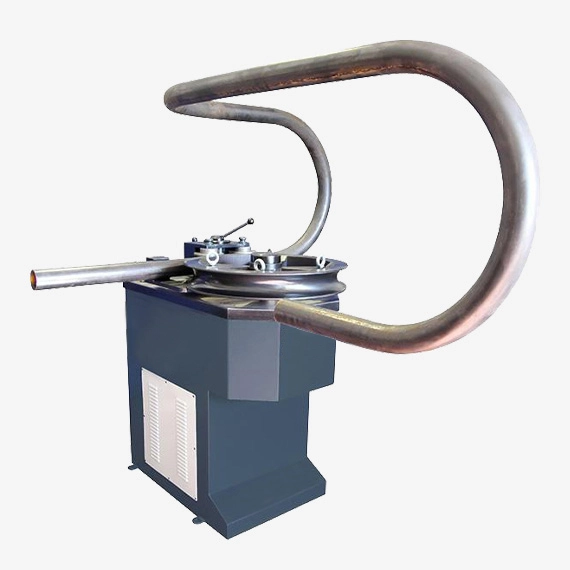
For more than 20 years, we have been manufacturing our own pipe bending machine for the metalworking industry. The pipe benders are automatic bending machines that can bend metal pipes in required angles with the bending tools. Industrial pipe bending machine can be classified as mandrel pipe bending machines and non-mandrel pipe bending machines.
Mandrel pipe bending machines use a mandrel during the bending. This mandrel is drawn into the pipe during the bending process. Non-mandrel pipe bending machines don’t have this mandrel tool. We manufacture non-mandrel pipe bending machines.
Our non-mandrel pipe bending machine models:
- EMS TB 42 Pipe bending machine
- EMS TB 60 Pipe bending machine
- EMS TB 76 Pipe bending machine
- EMS TB 100 Pipe bending machine
Pipe Bending Machine
Pipe bending machines are highly specialized mechanical systems designed to impose controlled plastic deformation on tubular workpieces, enabling the fabrication of precise radii, angles, and geometries while maintaining structural integrity and dimensional accuracy of the pipe. At a high technical level, these machines represent a convergence of materials science, applied mechanics, hydraulic and electric actuation, and advanced process control.
Fundamentally, the bending process is governed by the interaction between internal stresses induced in the tube wall and the external forming forces applied by the machine’s bending die set. The outer surface of the pipe is subjected to tensile stress, while the inner surface undergoes compression; the neutral axis shifts depending on wall thickness, material properties, and bend radius. A properly engineered machine compensates for these stress differentials to minimize ovalization, wrinkling, wall thinning, and springback.
Modern pipe bending machines can be classified into several categories, most notably rotary draw bending machines, mandrel bending machines, compression bending systems, roll bending machines, and push bending technologies. Rotary draw benders, often used for high-precision applications such as aerospace and automotive exhaust systems, employ a rotating die and a clamping mechanism to tightly control bend radii. Mandrel-assisted systems incorporate internal support tools to prevent collapse or buckling, particularly when bending thin-walled or high-diameter tubes. Roll bending machines, by contrast, use three or more rollers to produce large-radius curves with relatively low localized strain.
Technologically advanced systems increasingly integrate CNC and servo-electric actuation, allowing for multi-plane and multi-radius bending within a single continuous sequence. CNC pipe bending machines leverage closed-loop feedback through encoders, pressure sensors, and laser measuring systems to achieve repeatable tolerances in the sub-millimeter range. The programming interface typically enables three-dimensional bend sequencing, automatic collision detection, and compensation algorithms for springback correction.
In terms of energy systems, pipe bending machines may utilize purely hydraulic actuation—offering high force output suitable for heavy-duty industrial applications—or hybrid electro-hydraulic architectures, which combine the precision of servo-electric drives with the robustness of hydraulics. The structural design of the machine must balance rigidity and vibration damping, as flexural deflection of the frame can induce bending inaccuracies at large forces.
Applications of pipe bending machines extend across numerous critical industries, including nuclear power, shipbuilding, petrochemical plant construction, medical device fabrication, and fluid transport infrastructure. The demands of these industries require machines to handle a wide spectrum of materials, from carbon steels and stainless steels to advanced alloys, titanium, and high-performance polymers, each with unique forming characteristics and metallurgical constraints.
At the cutting edge, research in pipe bending technology is exploring adaptive control systems that incorporate real-time deformation monitoring, predictive modeling using finite element analysis, and even AI-driven optimization to dynamically adjust forming parameters during the bending cycle. This next generation of bending machines aims to achieve near-zero defect manufacturing with reduced setup time and minimized material waste, aligning with broader goals of Industry 4.0 and smart factory paradigms.
Pipe bending machines represent one of the most advanced intersections of applied mechanics, material science, and process automation within the field of metal forming. At their highest technical level, these machines are engineered not simply to change the geometry of a tubular workpiece but to do so while controlling and mitigating the highly complex stress distributions that arise during bending. A pipe, when subjected to bending forces, experiences a gradient of stresses across its wall thickness: the extrados, or outer surface, is placed under significant tensile stress, while the intrados, or inner surface, is compressed, and in between lies a shifting neutral axis whose position is influenced by wall thickness, pipe diameter, material yield strength, and bend radius. The quality of the bend is determined by how precisely the machine can manipulate this stress profile to prevent defects such as excessive wall thinning, wrinkling, or ovalization, and how effectively it can account for the inevitable elastic springback that occurs once the external forming load is released.
The architecture of a pipe bending machine is a sophisticated combination of high-strength structural frames, advanced actuation systems, precision tooling, and increasingly complex control algorithms. Rotary draw bending remains the dominant process in applications requiring high precision, using a combination of a rotating form die and a pressure die to guide the pipe through an exact radius. To enhance stability, mandrels and wiper dies are often employed; these internal supports and surface-contact tools serve to prevent localized buckling and surface collapse, particularly when working with thin-walled tubing or tight-radius bends. For larger, sweeping curves, roll bending machines apply distributed forming forces using three or more rolls, which induces gradual curvature without highly localized strain concentrations. Push bending techniques, in which the pipe is continuously fed through a series of rollers or dies, allow for complex multi-radius and three-dimensional geometries, which are invaluable in applications like automotive fuel lines or aerospace hydraulic systems.
The mechanical actuation methods have evolved considerably, with early generations relying almost exclusively on hydraulic systems that provide immense force output suitable for heavy industrial pipes used in shipbuilding, oil and gas infrastructure, and power plant construction. Modern machines increasingly integrate servo-electric or electro-hydraulic hybrid systems, which combine the brute force of hydraulics with the fine positional accuracy and energy efficiency of electric servomotors. This hybridization enables precise modulation of torque and force application throughout the bending cycle, drastically reducing tolerance deviations. The structural rigidity of the machine is equally crucial, as frame deflections of even a fraction of a millimeter can translate into unacceptable deviations in bend angle or radius when magnified along the length of a pipe several meters long. High-performance designs thus rely on reinforced frames, finite element optimized geometries, and advanced damping strategies to ensure stability under dynamic loading conditions.
At the forefront of pipe bending technology are fully computer numerically controlled systems capable of executing complex three-dimensional bend sequences with extremely high repeatability. Such machines employ closed-loop control architectures, with feedback from encoders, laser-based measurement systems, and pressure transducers to continuously monitor the bending process in real time. Software algorithms not only calculate the required movements but also dynamically adjust them to compensate for material springback, thermal expansion, or even tool wear. In advanced implementations, the integration of finite element models allows the control system to predict deformation behavior based on input parameters such as pipe material, diameter, and wall thickness, and then refine its commands during execution to optimize the outcome. This level of intelligence enables the production of precision components such as medical-grade stainless steel tubing, aerospace hydraulic conduits, and nuclear-grade alloy piping, where even minute deviations can compromise safety or performance.
The materials that can be processed by these machines range from standard carbon steels and aluminum alloys to highly specialized titanium, Inconel, and duplex stainless steels, each of which presents unique forming challenges. High-strength alloys demand greater forming forces and tighter process control due to their limited ductility, while softer metals are prone to surface wrinkling if not properly supported. Tooling material selection, lubrication strategies, and surface finish become critical factors in managing friction, heat generation, and surface integrity during the bending cycle. Research in this domain has produced tool steels with advanced coatings that reduce galling, as well as adaptive lubrication systems that apply controlled amounts of lubricant in critical regions of contact.
As industries push towards higher standards of efficiency, quality, and sustainability, pipe bending machines are being embedded within the broader framework of digitalized manufacturing. Machines are increasingly connected to production networks, enabling predictive maintenance based on sensor data, automated quality inspection using inline optical scanners, and real-time production optimization through AI-driven analytics. These innovations significantly reduce material waste, lower energy consumption, and shorten setup times, which is especially valuable in high-mix, low-volume production environments. Furthermore, additive manufacturing of bending dies and mandrel components is being explored to reduce tooling costs and to rapidly prototype complex geometries that would be impractical using conventional machining.
In essence, the pipe bending machine of today is no longer just a mechanical apparatus applying brute force to a tube; it is an intelligent forming system that synthesizes structural engineering, control theory, materials engineering, and manufacturing informatics to deliver precision results under increasingly demanding industrial conditions. The trajectory of development points towards systems that are capable of self-optimizing through continuous learning, integrating real-time data from the forming process with predictive computational models, and adjusting their operation autonomously to deliver defect-free bends. This progression ensures that pipe bending technology will remain indispensable in industries where reliability, precision, and performance are critical, from aerospace propulsion systems to energy infrastructure and beyond.
At the most advanced level of technical analysis, pipe bending machines must be understood not simply as production equipment but as controlled environments for inducing nonlinear plastic deformation under highly constrained conditions. The mechanics of bending are governed by a set of coupled variables, including the ratio of pipe diameter to wall thickness, the relative bend radius, and the yield strength and work-hardening behavior of the material. A critical parameter is the D/t ratio (pipe outside diameter to wall thickness), which largely dictates whether a bend will be feasible without mandrel support. As the D/t ratio increases, the risk of cross-sectional ovalization and wrinkling rises exponentially, demanding either higher forming precision or advanced tooling solutions. Engineers frequently apply predictive equations for critical wrinkling pressure and collapse thresholds, but in practice, these machines increasingly rely on numerical simulations and adaptive controls to ensure stability under real-world conditions.
Finite element modeling has become a cornerstone of modern pipe bending design and operation, providing insight into localized strain distributions, neutral axis shifts, and stress concentration zones that cannot be directly measured during the process. By simulating the progression of bending under varied boundary conditions, designers can optimize tool geometry, select appropriate mandrel configurations, and forecast springback behavior with remarkable accuracy. Springback, which results from the release of elastic energy once the forming load is removed, remains one of the most challenging variables to control, as its magnitude depends not only on material elasticity but also on the interaction between bending radius, frictional conditions, and pre-existing residual stresses in the tube. Advanced machines mitigate this through springback compensation algorithms, in which the machine deliberately over-bends the pipe by a calculated angle so that the final geometry conforms to the desired specification once elastic recovery occurs.
The interplay between tooling and process control is critical in achieving defect-free bends. Mandrels, which may be rigid or flexible with segmented balls, are designed to maintain internal support along the bending arc, especially for thin-walled pipes with high D/t ratios. Wiper dies, positioned at the intrados of the bend, counteract compression-induced wrinkling by exerting a stabilizing force on the material surface. The choice of die material, surface finish, and lubrication is essential, since excessive friction increases the likelihood of wall thinning, while insufficient friction may lead to slippage and geometric inaccuracies. State-of-the-art machines employ coatings such as titanium nitride or advanced polymers to optimize the tribological interaction between pipe and tooling, while adaptive lubrication systems deliver controlled micro-quantities of lubricant precisely where it is required during the bending cycle.
On the control side, the emergence of closed-loop CNC systems has redefined what is technically achievable in pipe bending. Encoder feedback on rotation and feed axes, combined with force and torque monitoring, allows for real-time correction of deviations caused by material inconsistency or tool wear. Three-dimensional laser scanners mounted at the machine output can verify bend angles and radii in situ, feeding data back into the control system for automatic recalibration. Some high-end systems even employ machine learning algorithms that analyze historical bending data to predict potential quality deviations before they occur, enabling proactive parameter adjustments. This approach is pushing the field towards the concept of “zero-defect manufacturing,” where every pipe produced conforms to specification without the need for rework or scrap.
From an industrial application standpoint, the precision and adaptability of pipe bending machines make them indispensable in domains where geometric tolerances are unforgiving and the performance of the final assembly is mission-critical. In aerospace, for instance, titanium hydraulic lines must be bent within sub-millimeter tolerances to fit within densely packed airframe structures, while also preserving the fatigue resistance of the alloy. In nuclear power plants, stainless steel and Inconel tubing is bent into complex geometries for reactor cooling systems, where any defect in wall thickness uniformity could compromise safety. In the automotive industry, lightweight aluminum or stainless exhaust and fuel systems require multi-radius, three-dimensional bends to optimize packaging and flow characteristics while maintaining durability under thermal cycling. The shipbuilding and oil industries demand large-diameter, heavy-wall carbon steel pipes bent to precise angles to integrate into structural and process systems, often requiring massive hydraulic machines capable of exerting bending forces in the hundreds of tons.
Looking to the future, the technological trajectory of pipe bending machines is aligned with the broader evolution of manufacturing under Industry 4.0 principles. Machines are being designed with digital twins, allowing engineers to simulate bending operations in a virtual environment before executing them physically, reducing setup times and minimizing trial runs. Sensors embedded throughout the machine generate continuous data streams on force, vibration, temperature, and geometric output, which are aggregated into cloud-based monitoring platforms for predictive maintenance and process optimization. Additive manufacturing is emerging as a revolutionary tool for producing customized bending dies and mandrel components with complex geometries, optimized for weight reduction and material flow characteristics that were previously unattainable. The convergence of these technologies suggests that future pipe bending machines will function not just as forming devices but as intelligent cyber-physical systems, dynamically adapting to material variability and production demands with minimal human intervention.
In the long term, the boundary between machine and process science is expected to blur further, as advanced computational models are embedded directly into machine control systems, enabling real-time finite element analysis and adaptive deformation strategies. The integration of new high-performance materials, such as hybrid composites and next-generation superalloys, will also drive the development of new bending methodologies, mandrel concepts, and actuation systems capable of accommodating their unique mechanical responses. Ultimately, the pipe bending machine will continue to evolve as a critical enabler of modern engineering, providing the precise, reliable, and adaptive forming capabilities required by industries that are pushing the limits of structural performance, efficiency, and safety.
At the research frontier, pipe bending machines are studied not only as industrial tools but also as experimental platforms for investigating the fundamentals of plastic deformation, residual stress development, and long-term structural performance of tubular components under service conditions. The mechanics of bending can be described using a combination of classical beam theory and advanced constitutive models that incorporate anisotropy, strain hardening, and nonlinear stress–strain relationships. In bending, the maximum tensile and compressive strains at the outer and inner surfaces of the pipe can be expressed in relation to the bend radius and pipe thickness, and these strains become critical thresholds in determining whether local instability, buckling, or fracture will occur. Ovalization of the cross-section is governed by the balance between external forming moments and the ovalization resistance of the tube, and researchers have derived critical values that indicate when collapse or wrinkling is imminent. These relationships are increasingly embedded into machine control algorithms to provide predictive corrections in real time.
One of the most complex challenges is springback, which occurs due to the elastic recovery of the material after bending loads are released. Analytical models often estimate springback angle as a function of elastic modulus, yield strength, bend radius, and tube geometry, but experimental studies reveal that frictional conditions, tooling geometry, and loading sequence also play substantial roles. Advanced CNC bending systems now apply adaptive springback compensation, whereby the machine deliberately bends beyond the programmed angle based on stored data for specific materials and dimensions, with subsequent corrections made using feedback from laser or optical scanning systems. This approach allows tolerance control at levels once considered unattainable, even in difficult-to-form alloys such as titanium or precipitation-hardened stainless steels.
Finite element analysis (FEA) has become an indispensable tool in both the design of pipe bending machines and the optimization of bending processes. Through FEA, engineers can map local strain and stress fields throughout the tube wall, predict thinning distributions, and identify regions most susceptible to wrinkling or buckling. These simulations allow for the virtual testing of die geometries, mandrel designs, and lubrication strategies before implementation in physical production. Coupled thermo-mechanical simulations are also increasingly used, as bending operations generate localized heating from friction and plastic work, which can alter material flow and residual stress distribution. With the integration of FEA directly into CNC machine controllers, the future of bending technology is likely to feature “real-time computational forming,” in which predictions from digital models continuously update process parameters as the bend is executed.
Tooling systems for pipe bending remain an area of high innovation. Internal mandrels are now engineered with flexible, articulated segments that adapt to varying bend radii, and are sometimes equipped with surface treatments or coatings that minimize friction and heat generation. The optimization of wiper die angle and placement is equally critical, as it directly influences wrinkle suppression at the intrados of the bend. Modern research has explored functionally graded die materials, which combine wear-resistant surfaces with shock-absorbing cores to prolong tool life under high-force bending conditions. Additionally, the application of advanced lubricants, such as micro-encapsulated oils that release under pressure, is helping to ensure consistent friction behavior during the entire bending cycle, further improving surface finish and dimensional control.
Industrial implementation has highlighted the importance of integrating bending machines into digital production ecosystems. Machines are increasingly connected via industrial communication protocols to enterprise resource planning (ERP) systems and manufacturing execution systems (MES), allowing for seamless exchange of production data, automated scheduling, and quality tracking. In some facilities, pipe bending machines are paired with robotic handling systems and automated material loading/unloading stations, creating fully autonomous bending cells capable of continuous, lights-out operation. This high level of automation is vital in industries where demand variability requires quick reconfiguration, such as in custom automotive exhaust manufacturing or specialized medical tubing production.
The materials processed by these machines continue to evolve. The rising use of lightweight alloys and advanced high-strength steels in automotive and aerospace industries introduces new complexities into the bending process. For example, dual-phase and martensitic steels exhibit strong anisotropy and unpredictable springback, requiring more advanced compensation algorithms. Titanium alloys, while offering exceptional strength-to-weight ratios, have low ductility and a strong tendency to gall against tooling, demanding highly optimized lubrication and die design. Composite pipes and hybrid metal-polymer tubes, which are gaining traction in aerospace and renewable energy applications, pose new challenges entirely, as their non-homogeneous structure results in bending behaviors that depart significantly from classical metal forming models.
Looking forward, the convergence of pipe bending technology with Industry 4.0 and cyber-physical manufacturing systems is expected to push the field towards unprecedented levels of intelligence and adaptability. Machines are being developed with embedded digital twins that mirror their physical counterparts in real time, enabling predictive simulations and virtual testing before each operation. Artificial intelligence is being applied to process optimization, drawing on large datasets of historical bending operations to identify patterns and predict optimal settings for new jobs. Predictive maintenance algorithms, fueled by continuous monitoring of force signatures, vibration patterns, and thermal profiles, are ensuring maximum machine uptime and reliability. The integration of additive manufacturing is another major frontier, with the potential to rapidly produce custom tooling or even to create dies with internal cooling channels and complex geometries impossible by conventional methods.
Ultimately, pipe bending machines are evolving into systems that not only shape materials with high precision but also embody the principles of adaptive, data-driven, and intelligent manufacturing. They are becoming less machines in the traditional sense and more active participants in a digitally integrated production environment, capable of learning, predicting, and self-optimizing. This transformation will allow them to continue meeting the exacting demands of industries where failure is not an option and where the quality of a single bend may determine the performance, safety, and efficiency of entire systems, from aircraft engines and nuclear reactors to offshore energy platforms and next-generation mobility solutions.
At the highest scientific and engineering level, the study and application of pipe bending machines is inseparable from the quantitative mechanics that govern deformation and stability of thin-walled tubular structures. The bending of a pipe introduces a nonuniform distribution of strain across its cross-section. The outer surface experiences tensile strain, while the inner surface undergoes compression. The maximum fiber strain, often denoted εmax\varepsilon_{max}εmax, can be approximated asεmax=t2R\varepsilon_{max} = \frac{t}{2R}εmax=2Rt
where ttt is the pipe wall thickness and RRR is the bend radius measured to the pipe centerline. This relationship provides the first-order criterion for assessing whether the imposed deformation will exceed the allowable strain capacity of the material. For thin-walled tubes, excessive strain may cause wall thinning on the extrados or wrinkling on the intrados, phenomena that are intimately linked to the D/t ratio.
Ovalization, or the flattening of the circular cross-section, is another critical parameter, often quantified using the ovalization factor ΔD\Delta DΔD:ΔD=Dmax−DminD0×100%\Delta D = \frac{D_{max} – D_{min}}{D_0} \times 100\%ΔD=D0Dmax−Dmin×100%
where DmaxD_{max}Dmax and DminD_{min}Dmin are the maximum and minimum diameters of the deformed cross-section and D0D_0D0 is the initial diameter. Excessive ovalization reduces the hydraulic efficiency of tubes used in fluid systems, compromises structural stability, and may even lead to collapse under internal pressure. Modern pipe bending machines combat ovalization by using mandrels, pressure dies, and precisely controlled force distribution, often guided by finite element simulations that predict deformation modes at each stage of bending.
Springback, perhaps the most technically challenging aspect of bending, is governed by the elastic recovery of the material once the forming moment is removed. An approximate expression for springback angle Δθ\Delta \thetaΔθ isΔθ=θ(Eσy⋅t2R)\Delta \theta = \theta \left( \frac{E}{\sigma_y} \cdot \frac{t}{2R} \right)Δθ=θ(σyE⋅2Rt)
where θ\thetaθ is the bend angle, EEE is the elastic modulus, and σy\sigma_yσy is the yield strength of the material. While this formula provides a simplified view, in practice, springback is influenced by strain hardening exponent, anisotropy, and even temperature. CNC pipe bending machines incorporate real-time springback compensation algorithms that draw from empirical data, predictive models, and in some cases, machine learning systems trained on thousands of previous bends.
The role of finite element analysis in the design and control of pipe bending machines cannot be overstated. With modern computational power, full 3D nonlinear elastoplastic simulations can be run to predict every aspect of the bending process: wall thinning distribution, wrinkle initiation points, ovalization profiles, and residual stress fields. These simulations are validated against experimental strain measurements using techniques such as digital image correlation (DIC) or strain gauges applied along the pipe surface. Once validated, the models serve as the foundation for digital twins—virtual replicas of bending machines that operate in real time alongside the physical equipment. In such configurations, every bend performed by the physical machine is mirrored by the digital twin, which predicts outcomes, recommends corrections, and continuously refines the model through sensor feedback.
Another layer of sophistication lies in the tribological behavior of pipe–tool interfaces. Friction and lubrication strongly influence the force required, the uniformity of material flow, and the quality of the surface finish. Advanced bending dies are now manufactured from high-performance tool steels and coated with thin films such as TiN, TiAlN, or DLC (diamond-like carbon) to reduce adhesion and wear. Some designs incorporate micro-textured die surfaces that hold and gradually release lubricants during the bend, reducing both heat generation and frictional variation. Adaptive lubrication systems, which deliver controlled amounts of lubricant at critical locations, further stabilize the process and minimize the risk of galling, especially in high-friction materials like titanium alloys.
The integration of sensors into pipe bending machines has transformed them from open-loop mechanical devices into closed-loop intelligent systems. Strain sensors, torque transducers, accelerometers, and high-resolution encoders collect data at millisecond intervals, allowing for precise real-time adjustments. Laser scanners and machine vision systems verify bend geometries as the pipe exits the machine, enabling instantaneous corrections. In advanced production environments, this feedback is aggregated into a centralized control system that not only ensures dimensional conformity but also predicts tool wear, schedules preventive maintenance, and optimizes energy usage.
Applications across industries illustrate the criticality of such precision. In aerospace, hydraulic lines must snake through narrow fuselage compartments, requiring compound three-dimensional bends with sub-millimeter accuracy. In the nuclear industry, Inconel and stainless tubing must be bent without introducing microcracks or excessive residual stresses that could propagate under radiation and thermal cycling. In shipbuilding and offshore energy, massive carbon steel pipes with diameters exceeding half a meter must be bent with perfect consistency to assemble miles of fluid transport systems. Each of these domains imposes unique constraints, and pipe bending machines must adapt by combining brute mechanical force with the finesse of digitally enhanced control.
Looking further ahead, the evolution of pipe bending machines is set to converge with the broader paradigms of smart manufacturing and autonomous production. Machine learning algorithms trained on big datasets of material responses are beginning to outperform classical empirical models in predicting springback and wrinkling thresholds. Additive manufacturing of bending dies, with internal lattice structures and conformal cooling channels, is opening new frontiers in tool performance and longevity. Cyber-physical integration ensures that every bend is not only executed but also recorded, analyzed, and optimized for future operations. The ultimate trajectory points towards self-optimizing machines that integrate sensors, simulations, and AI to achieve true zero-defect production. These machines will not only form pipes but also actively participate in the design-validation-manufacture feedback loop, blurring the distinction between forming equipment and intelligent co-design partners in advanced engineering systems.
The deeper one enters the technical domain of pipe bending machines, the clearer it becomes that their significance is not confined to industrial forming but extends into fundamental structural mechanics. The pipe during bending is essentially a thin-walled cylindrical shell subjected to combined bending, axial, and local compressive stresses. Its stability is governed by both continuum mechanics and local instability phenomena, which makes it a remarkably rich system for analysis. For instance, wrinkling of the intrados is a local buckling phenomenon, which occurs when compressive stresses exceed the critical wrinkling stress σcr\sigma_{cr}σcr. A simplified expression for this critical stress in thin-walled cylinders is given byσcr=k⋅E⋅tD\sigma_{cr} = \frac{k \cdot E \cdot t}{D}σcr=Dk⋅E⋅t
where EEE is the modulus of elasticity, ttt is the wall thickness, DDD is the tube diameter, and kkk is a coefficient dependent on boundary conditions and loading mode. Once compressive stresses exceed this value, plastic instability manifests as periodic wrinkles along the intrados. Advanced bending machines combat this by applying precise counterforces via pressure dies, mandrels, and wipers, effectively redistributing stresses to keep them below instability thresholds.
Collapse, another catastrophic defect, occurs when excessive ovalization reduces the moment of inertia of the cross-section to the point that it can no longer sustain the applied bending moment. The critical ovalization at which collapse initiates can be expressed as a function of D/t and bend radius. Finite element simulations often model this collapse limit by progressively increasing curvature until geometric nonlinearity induces rapid loss of stiffness. In practice, bending machines prevent collapse by controlling the bending speed, applying sufficient mandrel support, and carefully regulating feed and clamp pressures.
Springback is another domain where mechanics meets machine intelligence. Classical models treat springback as purely elastic recovery, but real materials exhibit path-dependent plasticity, strain hardening, and anisotropy. Modern predictive models employ nonlinear constitutive equations, often of the Ludwik or Swift form, to capture these complexities. For example, a strain hardening law likeσ=K(ε0+ε)n\sigma = K (\varepsilon_0 + \varepsilon)^nσ=K(ε0+ε)n
with KKK as the strength coefficient, ε0\varepsilon_0ε0 as pre-strain, and nnn as the hardening exponent, allows a more accurate prediction of springback in work-hardened alloys. Machines equipped with CNC and sensor feedback adjust bend angles dynamically using such models, effectively treating each bend as a continuously updated experiment in plasticity.
Residual stresses left in the tube after bending represent a subtle but critical issue. The outer tensile fibers, having been plastically stretched, retain tensile residual stresses, while the compressed inner fibers may retain compressive residual stresses. This nonuniform residual stress distribution can lower fatigue life, alter vibration characteristics, and in pressurized systems, interact with hoop stresses to accelerate crack initiation. Research efforts focus on post-bending treatments, such as stress-relief annealing or internal pressure sizing, to rebalance the stress field. Emerging bending systems are being designed with in-situ stress measurement, where ultrasonic or X-ray diffraction sensors integrated into the machine assess residual stress immediately after forming.
From the tooling perspective, mandrels are evolving into sophisticated subsystems of their own. Multi-ball flexible mandrels, for instance, can adapt dynamically to varying bend radii, maintaining internal support throughout the pipe’s deformation path. Advanced mandrels are now being built from composites or coated with self-lubricating materials to reduce wear and eliminate the need for excessive lubrication. The wiper die, a seemingly simple component, plays an outsized role in controlling surface integrity. Improperly designed wiper dies induce scratches or galling on the inner bend surface, but optimized geometries with adaptive clamping force create a smooth flow of material, suppressing wrinkle initiation.
When viewed at the system level, pipe bending machines are paradigms of cyber-physical systems. High-precision hydraulic or electric actuators execute commands from CNC controllers that are continuously refined by sensor data. Machine learning algorithms, trained on vast bending datasets, identify subtle correlations between input parameters and defect formation, surpassing classical empirical charts. Digital twins simulate each bend in real time, predicting failure before it occurs and recommending corrective adjustments. The machine thus becomes not only a forming device but also an intelligent decision-making node in the larger manufacturing network.
In terms of future trajectories, pipe bending machines are likely to incorporate predictive artificial intelligence that fuses finite element modeling with empirical big data. Rather than operators specifying bend angles, feed rates, or mandrel positions, the user may simply input a desired geometry and material, and the machine will autonomously design and execute the optimal process path. Adaptive forming may even be achieved, where the machine alters tooling pressure, bending speed, or mandrel stiffness on-the-fly in response to microsecond-level feedback. Additive manufacturing is set to revolutionize tooling, enabling dies with conformal cooling channels, anisotropic stiffness regions, or integrated sensors that directly report loads and wear states.
The ultimate vision is one of self-learning, self-correcting pipe bending machines that operate with near-complete autonomy. Such machines would not only bend pipes but also understand the materials they form, sense their own structural state, communicate with upstream and downstream processes, and continuously evolve their strategies. In such a paradigm, a pipe bending machine ceases to be a mere mechanical system and becomes an adaptive, intelligent partner in manufacturing, embodying the convergence of mechanics, computation, and cyber-physical integration. It represents the culmination of centuries of forming science, distilled into a machine that can manipulate matter with both force and intelligence, ensuring precision and reliability in applications where the cost of failure is measured not in parts but in lives and systems.
The main parts of a pipe bending machine can be described not only in terms of their mechanical presence but also in terms of their role within the larger system of controlled plastic deformation, force transmission, and process stability. Each subsystem must be engineered with precision, because the bending process depends on the harmonious coordination of structural rigidity, actuation accuracy, and tooling–material interaction.
At the foundation of every pipe bending machine lies the machine frame, which provides structural rigidity and serves as the base for all other components. The frame must be designed to withstand bending moments and clamping forces without measurable deflection, since even small elastic deformations in the frame can lead to significant dimensional inaccuracies in the bent pipe. For heavy-duty applications, frames are fabricated from high-strength welded steel structures, often analyzed using finite element methods to optimize stiffness-to-weight ratios and vibration damping. In advanced designs, damping elements or composite reinforcements are integrated to reduce dynamic oscillations during high-speed bending cycles.
The clamping system is one of the most critical functional parts. It holds the pipe securely against the bending die, ensuring that there is no slippage as torque is applied. Clamping mechanisms may be hydraulic, pneumatic, or servo-electric, depending on the force requirements and desired precision. They must apply sufficient pressure to resist the axial and rotational forces during bending, yet do so without crushing or marking the pipe surface. High-end machines often use multiple synchronized clamps with precision-controlled pressure to adapt to different pipe materials and surface hardness.
The heart of the forming process is the bending die (also called the form die), which defines the bend radius and guides the pipe as it deforms plastically. It is machined to extremely tight tolerances and must be hardened or coated to resist wear, since it undergoes constant sliding contact with the workpiece. For multi-radius and three-dimensional bending, CNC machines employ modular or rotating die systems capable of switching geometries without manual intervention. In advanced cases, bending dies are produced by additive manufacturing, with internal reinforcement lattices and embedded cooling channels to manage heat buildup.
Complementing the bending die is the pressure die, which presses the pipe firmly against the bending die to maintain intimate contact during the bending cycle. The pressure die counteracts the pipe’s tendency to slip or separate and ensures uniform force transmission. Pressure dies are often mounted on linear slides with hydraulic or servo-driven actuation, allowing them to adaptively modulate pressure as the bend progresses.
To prevent defects, the mandrel plays a vital role, especially in thin-walled or high D/t ratio pipes. It is inserted inside the pipe at the bending location, providing internal support to resist ovalization and collapse. Mandrels may be rigid for simple bends, or flexible and segmented (ball mandrels) for complex geometries where the curvature changes dynamically. The material of the mandrel must balance strength with surface smoothness, often requiring advanced coatings such as TiN or DLC to minimize friction and wear.
The wiper die addresses wrinkling at the intrados of the bend. Positioned just behind the bend initiation point, it applies a localized smoothing force to counteract the formation of buckles caused by compressive stresses. The geometry and angle of the wiper die are carefully optimized; incorrect alignment can cause surface scratches or exacerbate wrinkling. In highly automated machines, wiper dies are adjustable via CNC-controlled actuators to accommodate changes in pipe material or bend radius without manual intervention.
The actuation system provides the necessary force and motion for bending. Traditional machines rely on hydraulic cylinders, offering immense force output with relatively simple control. Modern machines increasingly employ servo-electric drives, which provide precise motion control, energy efficiency, and cleaner operation. Hybrid electro-hydraulic systems combine both, using hydraulics for high-load clamping and bending while relying on servo systems for precise positioning and multi-axis synchronization.
The control system is the central intelligence of the machine. In CNC pipe bending machines, the controller governs the rotation of the pipe, feeding length, and bending angle, often across multiple axes simultaneously. Feedback from encoders, pressure sensors, and laser measuring systems feeds into closed-loop algorithms that adjust process parameters in real time. Control systems also integrate with CAD/CAM software, enabling direct import of 3D geometries and automatic generation of bending sequences, including collision detection and springback compensation.
Finally, the auxiliary systems play a supporting role but are no less important. These include lubrication delivery systems that apply precise amounts of lubricant to dies and mandrels, cooling systems for tooling subjected to high thermal loads, and robotic handling systems for loading and unloading pipes. In advanced production cells, automated quality inspection units using 3D laser scanning are integrated directly downstream of the machine, creating a closed loop between manufacturing and verification.
Together, these parts form a highly coordinated mechanical and cyber-physical ecosystem. Each subsystem must function flawlessly in unison: the frame ensuring stability, the clamps securing the workpiece, the dies guiding the geometry, the mandrel and wiper preventing defects, the actuators delivering controlled forces, and the control system orchestrating the entire operation. In the most advanced implementations, these machines no longer consist of discrete parts operating independently, but rather a network of smart modules that communicate with each other, adapt dynamically to conditions, and contribute to the broader vision of intelligent manufacturing.
Expanding each of the main parts in extreme technical depth reveals how every component of a pipe bending machine is meticulously engineered to balance mechanical performance, process accuracy, and long-term reliability. The machine frame, as the structural backbone, must resist the full spectrum of forces transmitted during bending, including axial loads from the pipe feed, bending moments, and reaction forces from the pressure and wiper dies. High-performance frames are often constructed from stress-relieved welded steel, with cross-members and gussets placed according to finite element analysis to minimize deflection. Critical regions—such as the die-mounting area—are reinforced, and vibration damping materials or composite inserts may be integrated to suppress resonance during rapid bending cycles. Thermal expansion is also considered; in precision machines, localized heating from hydraulic actuators or frictional contact can produce measurable deformation, so temperature-compensated designs or active cooling channels are employed.
The clamping system must combine high force capacity with precision control. Hydraulic clamps offer variable clamping pressure through proportional valves, while servo-electric clamps provide micron-level positioning accuracy and repeatability. Clamps are often segmented along the pipe’s length to accommodate varying diameters and to reduce bending distortion caused by uneven gripping. Surfaces in contact with the pipe are hardened or coated, for example with tungsten carbide or low-friction polymers, to prevent surface marking while maintaining sufficient grip. High-end machines include force feedback sensors within the clamp jaws to ensure that applied pressure adapts dynamically to material hardness variations, preventing slippage or localized crushing.
The bending die is engineered not only for geometry but also for load distribution and wear resistance. Machined from high-grade tool steels and heat-treated for hardness, dies often feature curved surfaces with optimized radii to reduce stress concentration on the pipe’s outer fibers. Surface coatings such as TiN or DLC provide low friction and high wear resistance, extending service life under repetitive high-force operation. For multi-radius or complex 3D bending, dies are mounted on rotating turrets or adjustable axes controlled by CNC, enabling automated selection and orientation without operator intervention. The design of the die includes precise alignment with the pipe’s neutral axis, accounting for the expected shift during plastic deformation.
The pressure die, working in concert with the bending die, must exert precise, controllable force. Linear actuators or hydraulic cylinders are often used, with sensors monitoring force application in real time. Pressure dies are sometimes equipped with active compliance systems that slightly adjust the die position in response to pipe movement or strain, reducing localized stress peaks that could cause ovalization or surface defects.
The mandrel is one of the most complex components in precision bending. Flexible segmented mandrels, such as multi-ball designs, allow the internal support to adapt continuously to the changing bend radius. Mandrels are manufactured from high-strength steel, often coated with low-friction layers, and may incorporate internal lubrication channels. Advanced designs include embedded sensors that measure internal contact pressure and deformation, feeding data to the CNC control system to adjust bending speed, die force, or mandrel stiffness in real time. The mandrel’s geometry, including ball diameter and spacing, is optimized using computational modeling to minimize the formation of wrinkles while preserving cross-sectional integrity.
The wiper die must apply controlled pressure along the intrados without inducing scratches or marks. Its angle, curvature, and surface finish are precisely calculated based on material properties, pipe wall thickness, and bend radius. In CNC machines, the wiper die may be adjustable along multiple axes during operation, with servo motors or hydraulic actuators allowing dynamic adaptation to different bend sequences.
The actuation system integrates high-force hydraulic cylinders or servo-electric motors with precise motion control. Hydraulic systems are often used for heavy-duty bending due to their high force density, while servo-electric systems provide repeatable positioning with energy efficiency. In hybrid designs, hydraulic systems provide bulk force, and servo systems provide fine positioning and synchronization across multiple axes. Advanced systems use proportional or digital valves, load-sensing feedback, and motion control algorithms to ensure smooth and continuous bending motion, minimizing vibration and abrupt stress spikes in the pipe.
The control system is the brain coordinating all subsystems. Modern CNC controllers allow three-dimensional bend programming, springback compensation, and collision avoidance. Feedback from encoders, load cells, laser scanners, and internal sensors is continuously processed to maintain sub-millimeter accuracy. Software integrates with CAD/CAM files, automatically generating bending sequences and tool paths, and may include machine learning modules that refine process parameters over time based on historical bending performance. Closed-loop control ensures that even pipes with variable material properties or minor diameter deviations are bent within tight tolerances.
Finally, auxiliary systems—including lubrication delivery, cooling, and automated material handling—play essential roles in process stability and reliability. Lubrication systems provide precise micro-quantities of oil or grease to dies and mandrels, minimizing friction and heat buildup. Cooling systems prevent thermal distortion in dies and hydraulic components. Robotic loading and unloading stations enable continuous operation and reduce the risk of operator-induced errors or damage. Quality control systems, often employing 3D laser scanners or machine vision, verify bend angles, radii, and cross-sectional integrity immediately downstream of the machine, completing a closed-loop system for zero-defect manufacturing.
In combination, these main parts transform a pipe bending machine from a mechanical press into an intelligent, adaptive, and precise manufacturing system. Each subsystem contributes not only to the immediate mechanical operation but also to the overall ability of the machine to maintain high-quality output, adapt to varying materials and geometries, and integrate into digitally networked production environments. This synergy is what allows modern pipe bending machines to meet the exacting demands of aerospace, nuclear, automotive, and energy industries, producing complex three-dimensional bends with near-zero defects while maintaining high throughput and long-term reliability.
Delving deeper into the engineering and design-level detail of each main part, we begin with the machine frame, which must sustain all forces generated during bending without compromising geometric accuracy. Engineers calculate bending moments, shear forces, and torsional loads transmitted from the bending die and pipe clamping systems, using finite element analysis to determine stress concentrations and deflection under peak loads. Frame members are typically high-strength steel, with strategically placed cross-braces and gussets to increase stiffness while minimizing mass. In some precision machines, composite reinforcements or damping inserts are embedded to absorb vibrations and dynamic oscillations during rapid bend cycles. Thermal expansion is also critical; designers often incorporate temperature-compensated mounting points or integrated cooling channels to maintain alignment of critical components.
The clamping system must balance holding force with surface integrity. Hydraulic or servo-electric clamps are designed to exert precisely controlled pressure distributed over multiple contact points to avoid local pipe deformation. Engineers select jaw materials and surface coatings, such as hardened tool steel with low-friction polymer overlays, to prevent marking or galling of sensitive pipe materials. Force sensors embedded in the clamps provide real-time feedback to the control system, enabling adaptive pressure adjustment based on variations in pipe diameter, wall thickness, or material hardness. Multi-segmented clamps are often used for long pipes or variable diameters, ensuring uniform grip without introducing bending stresses in the clamped region.
The bending die serves both as the geometric guide and as a load-distribution medium. Its radius, surface curvature, and entry angle are calculated based on the pipe’s diameter, wall thickness, and material yield strength to minimize excessive tensile strain at the extrados. Dies are manufactured from high-grade tool steels, hardened and sometimes coated with titanium nitride, DLC, or other wear-resistant materials to maintain dimensional stability under repetitive cycles. For multi-radius bends or 3D configurations, dies may rotate or translate under CNC control, requiring precise alignment with the neutral axis of the pipe to prevent ovalization. Finite element modeling informs die geometry, predicting strain distribution, wall thinning, and residual stress patterns.
The pressure die complements the bending die by exerting counterforce, stabilizing the pipe against slippage or separation. Engineers calculate the required die force as a function of pipe diameter, wall thickness, bend radius, and friction coefficient. Pressure dies are mounted on linear or rotary actuators, with force feedback enabling dynamic adaptation during the bend cycle. Some designs incorporate active compliance mechanisms to allow slight positional adjustments that reduce peak stresses and prevent ovalization or localized surface defects.
The mandrel is critical for controlling internal stress and maintaining cross-sectional integrity. Flexible multi-ball or segmented mandrels are engineered to support the pipe along the bend radius, preventing ovalization and wrinkling. Material selection focuses on high-strength steel or composite cores with low-friction coatings, while geometry—ball diameter, spacing, and stiffness—is optimized using computational simulations to distribute stress evenly. Advanced mandrels include internal sensors that measure contact pressure and deformation, feeding data to the CNC control system for real-time adjustment of die force, bending speed, or mandrel stiffness.
The wiper die is designed to prevent intrados wrinkling by applying a carefully calculated local compressive force. Its curvature, angle, and positioning are optimized for each pipe diameter, wall thickness, and bend radius, often informed by finite element simulations. CNC-controlled wiper dies allow dynamic adaptation for multi-radius or compound bends, ensuring consistent suppression of wrinkle formation without marking the surface.
The actuation system integrates high-force hydraulic cylinders or servo-electric motors to apply bending and clamping forces. Hydraulics provide high load capacity for heavy-duty applications, while servo-electric drives offer precise positioning and energy efficiency. Hybrid systems use hydraulics for gross force and servo-electric drives for fine positioning and multi-axis synchronization. Engineers design actuator stroke, speed, and torque profiles to minimize dynamic overshoot, vibration, and stress concentration in both the machine structure and the pipe. Advanced control algorithms modulate force and speed in real time, often using predictive models of pipe deformation derived from finite element analysis.
The control system coordinates all subsystems, integrating CNC programming, sensor feedback, and adaptive algorithms. Real-time data from encoders, load cells, pressure sensors, and laser measurement systems is processed to maintain bend angles, radii, and positional accuracy within sub-millimeter tolerances. Software modules handle springback compensation, collision avoidance, multi-radius sequencing, and 3D bend path generation. In some systems, machine learning algorithms analyze historical bending data to optimize process parameters automatically, improving precision and reducing cycle time.
Finally, auxiliary systems ensure process stability and reliability. Lubrication delivery systems provide precise micro-quantities of oil or grease to dies and mandrels, minimizing friction and heat. Cooling channels in dies or hydraulic components prevent thermal deformation, preserving geometric accuracy. Automated pipe loading and unloading, combined with inline 3D laser scanning, enable continuous operation and immediate quality verification. Some high-end setups incorporate predictive maintenance routines that monitor actuator load cycles, hydraulic pressure, and vibration signatures to prevent unexpected downtime.
Together, these subsystems form an integrated, cyber-physical environment in which structural engineering, material science, and control theory converge. Each component is carefully optimized not only for its own mechanical function but also for its interactions with the other subsystems, enabling high-precision, defect-free bending of a wide range of pipe materials and geometries. The result is a machine that functions as an intelligent manufacturing system capable of executing complex three-dimensional bends with minimal human intervention, high repeatability, and long-term reliability.
Continuing into detailed engineering analysis, the machine frame must first be considered in terms of static and dynamic stress. The frame experiences bending moments from both the bending die and clamping forces, as well as torsional loads induced by asymmetric pipe placement or multi-axis bending. Finite element analysis (FEA) is used to simulate these forces, identifying high-stress regions, potential vibration nodes, and deflection under peak load. For example, the maximum deflection δmax\delta_{max}δmax of a beam-like section of the frame under bending moment MMM can be estimated using classic beam theory:δmax=ML22EI\delta_{max} = \frac{M L^2}{2 E I}δmax=2EIML2
where LLL is the length of the frame member, EEE is the modulus of elasticity of the frame material, and III is the second moment of area. Engineers optimize cross-section geometry and reinforcement placement to maintain δmax\delta_{max}δmax within tolerances that prevent misalignment of the bending die relative to the pipe.
The clamping system must provide sufficient force to prevent slippage without damaging the pipe. The required clamp force FcF_cFc can be estimated from the torque TTT applied by the bending die and the coefficient of friction μ\muμ between the pipe and clamp:Fc≥TμrcF_c \ge \frac{T}{\mu r_c}Fc≥μrcT
where rcr_crc is the effective radius of the clamping contact. In practice, sensors embedded in the clamp jaws measure actual pressure, allowing the control system to dynamically adjust FcF_cFc in response to variations in pipe diameter or material hardness. Multi-segmented clamps distribute force along the pipe length, reducing localized stress peaks and preventing deformation.
The bending die must maintain pipe geometry while distributing forces evenly. Stress in the pipe at the extrados can be approximated by the classical bending stress equation:σ=Et2Rε\sigma = \frac{E t}{2 R} \varepsilonσ=2REtε
where ttt is wall thickness, RRR is bend radius, and ε\varepsilonε is local strain. FEA allows engineers to refine die geometry to minimize wall thinning and reduce residual stress concentrations. Surface coatings such as TiN or DLC reduce friction, limiting force spikes and wear. Multi-axis dies are programmed via CNC to follow complex three-dimensional paths while maintaining alignment with the pipe neutral axis.
The pressure die force must be sufficient to keep the pipe pressed against the bending die, but not so high as to create crushing or excess wall thinning. Using the bending moment MMM and pipe geometry, the required pressure die force FpF_pFp can be estimated:Fp=Mrd⋅kfF_p = \frac{M}{r_d} \cdot k_fFp=rdM⋅kf
where rdr_drd is the die radius and kfk_fkf is a factor accounting for friction and material properties. Force feedback sensors allow dynamic adjustment of FpF_pFp during bending, adapting to local changes in stress or strain.
The mandrel prevents ovalization and wrinkling. The maximum bending-induced ovalization ΔD\Delta DΔD can be approximated as:ΔD=koD3R2t3\Delta D = k_o \frac{D^3}{R^2 t^3}ΔD=koR2t3D3
where DDD is pipe diameter, ttt is wall thickness, RRR is bend radius, and kok_oko is an empirically derived constant. Mandrel design uses this equation along with FEA to select ball diameters, spacing, and stiffness that minimize ovalization without impeding material flow. Flexible mandrels often incorporate internal lubrication channels and embedded sensors that feed back contact pressure to the control system for real-time adjustments.
The wiper die suppresses intrados wrinkling. Critical wrinkling stress σcr\sigma_{cr}σcr can be estimated using:σcr=kEtD\sigma_{cr} = \frac{k E t}{D}σcr=DkEt
where EEE is the material modulus, ttt is wall thickness, DDD is pipe diameter, and kkk is a factor depending on boundary conditions. The wiper die applies a localized counterforce that keeps the compressive stress below σcr\sigma_{cr}σcr, preventing wrinkle formation. CNC-controlled wiper dies dynamically adjust position and force during multi-radius bends.
The actuation system is sized based on required bending torque TbT_bTb and linear displacement of dies or clamps. For a pipe of diameter DDD, wall thickness ttt, bend radius RRR, and material yield σy\sigma_yσy, the bending moment can be approximated as:Tb=σy⋅I/RT_b = \sigma_y \cdot I / RTb=σy⋅I/R
where I=π(D4−(D−2t)4)/64I = \pi (D^4 – (D-2t)^4)/64I=π(D4−(D−2t)4)/64 is the second moment of area. Hydraulic or servo-electric actuators are selected to exceed TbT_bTb with a safety factor, and their stroke and speed are calculated to maintain smooth bending without dynamic oscillation.
Finally, the control system integrates sensor feedback from all subsystems, implementing closed-loop PID control, springback compensation, and collision avoidance. Springback angle Δθ\Delta \thetaΔθ is dynamically compensated using predictive models:Δθ=θ(Eσy⋅t2R)\Delta \theta = \theta \left( \frac{E}{\sigma_y} \cdot \frac{t}{2 R} \right)Δθ=θ(σyE⋅2Rt)
while feedback from encoders, load cells, and laser scanners ensures that each bend conforms to sub-millimeter tolerances. Machine learning modules further refine process parameters by analyzing historical bending data, adjusting actuator speeds, clamp pressures, or mandrel positions to optimize each bend.
Auxiliary systems such as lubrication, cooling, and robotic handling are designed based on thermal and frictional load calculations. Lubrication flow rates, die temperatures, and hydraulic fluid dynamics are all modeled to maintain consistent process conditions, minimize wear, and extend machine uptime.
In this integrated, calculation-driven design, every subsystem of a pipe bending machine—from frame to auxiliary systems—is engineered with precise mechanics, material science, and control theory. The result is a fully coordinated, high-precision manufacturing system capable of bending pipes of varying materials and geometries with minimal defect rates, high repeatability, and long-term reliability.
Pipe Bending Machine – Max Pipe Diameter 42 mm
Focusing on a Pipe Bending Machine designed for a maximum pipe diameter of 42 mm, the engineering, mechanical, and control considerations can be discussed in detail while scaling the design for this size. A 42 mm maximum diameter defines both the mechanical force requirements and tooling dimensions, while still allowing for high-precision operations suitable for small to medium-sized industrial applications.
The machine frame must maintain rigidity while supporting bending moments generated by the 42 mm pipes, which, although smaller than large industrial tubing, still produce significant localized forces due to high-strength materials. Frame members are typically constructed from structural steel profiles with welded gussets at load-critical points, particularly around the bending die and clamp regions. Deflection analysis using finite element modeling ensures that under maximum bending torque, deflection remains below 0.05 mm, preserving bend accuracy. For precision applications, the frame may also incorporate vibration-damping inserts or modular reinforcement plates to reduce dynamic oscillation during high-speed cycles.
The clamping system for a 42 mm pipe requires segmented jaws that distribute gripping force evenly along the pipe’s length to avoid local deformation. Hydraulic or servo-electric clamps deliver pressures typically ranging between 150–300 bar, adjustable based on material hardness and wall thickness (common wall thicknesses for this size range from 1.5 mm to 4 mm). Embedded pressure sensors provide real-time feedback to the CNC controller, allowing adaptive pressure regulation to prevent slippage while avoiding surface indentation. Clamping jaw surfaces are hardened and coated with low-friction polymer or tungsten carbide for durability and minimal marking.
The bending die is the critical element for radius definition. For a 42 mm diameter pipe, the minimum bend radius is often limited to 1.5–2 times the pipe diameter to avoid excessive wall thinning or wrinkling. Die profiles are CNC-machined with high surface finish, often polished to Ra < 0.4 µm, and coated with TiN or DLC to reduce friction. The die must maintain precise alignment with the neutral axis of the pipe to ensure uniform bending. For compound or 3D bends, the die is mounted on a rotating or multi-axis CNC-controlled turret, allowing complex geometries without manual adjustment.
The pressure die ensures the pipe remains flush against the bending die. For 42 mm pipes, the pressure die force is calculated based on bending moment and friction coefficient. For example, assuming mild steel pipe with σy=250 MPa\sigma_y = 250 \text{ MPa}σy=250 MPa, wall thickness 2 mm, and minimum bend radius R=63 mmR = 63 \text{ mm}R=63 mm (1.5×D), the bending moment MMM is:I=π64(D4−(D−2t)4)≈3.6×10⁻⁷ m4I = \frac{\pi}{64}(D^4 – (D-2t)^4) \approx 3.6 \times 10^{-7} \text{ m}^4I=64π(D4−(D−2t)4)≈3.6×10⁻⁷ m4M=σy⋅IR≈1.43 kNmM = \sigma_y \cdot \frac{I}{R} \approx 1.43 \text{ kNm}M=σy⋅RI≈1.43 kNm
The pressure die is actuated hydraulically to apply a reactive force sufficient to prevent slippage and ovalization during the bend, typically in the range of 3–6 kN for this size pipe, depending on material and lubrication.
The mandrel is essential for thin-walled 42 mm pipes, especially when the wall thickness is below 3 mm. A segmented or ball mandrel is inserted to maintain cross-sectional integrity. Ball diameters, spacing, and stiffness are calculated to minimize ovalization, which for a 42 mm pipe can be approximated by:ΔD=koD3R2t3\Delta D = k_o \frac{D^3}{R^2 t^3}ΔD=koR2t3D3
Using empirical k-values (0.3–0.5 for small diameter pipes), the mandrel design ensures ΔD<1%\Delta D < 1\%ΔD<1% even at minimum bend radii. Mandrels are often coated with low-friction materials, and in advanced machines, internal sensors monitor contact pressure, feeding data to the CNC system to adjust bending speed or pressure die force in real time.
The wiper die prevents wrinkling at the intrados. For 42 mm pipes with typical wall thicknesses, the critical compressive stress is:σcr=kEtD\sigma_{cr} = \frac{k E t}{D}σcr=DkEt
For steel with E=210 GPaE = 210 \text{ GPa}E=210 GPa and t=2 mmt = 2 \text{ mm}t=2 mm, σcr≈10 MPa\sigma_{cr} \approx 10 \text{ MPa}σcr≈10 MPa. The wiper die applies a localized counterforce slightly below σcr\sigma_{cr}σcr, guided by CNC control to follow the bending path and dynamically adjust force to suppress wrinkle formation without marking the pipe surface.
The actuation system is sized for precise control. Hydraulic cylinders provide gross bending force, while a servo-electric system handles positioning and rotational movement. For 42 mm pipes, bending moments are moderate, allowing use of compact actuators with stroke ranges of 100–200 mm and peak torque capability of 1.5–2 kNm. Actuator selection considers safety factors of 1.5–2× maximum bending torque to accommodate material variability and sudden load spikes.
The control system integrates sensor feedback from clamps, dies, mandrels, and wipers. CNC programming enables automatic compensation for springback, calculated using:Δθ=θ(Eσy⋅t2R)\Delta \theta = \theta \left( \frac{E}{\sigma_y} \cdot \frac{t}{2 R} \right)Δθ=θ(σyE⋅2Rt)
For a 90° bend, 42 mm steel pipe with 2 mm wall, springback correction may range from 0.8° to 1.5° depending on alloy and hardening. Laser or optical sensors measure bend angles in real time, enabling closed-loop adjustments. Multi-bend programs for complex 3D geometries are directly imported from CAD files, with collision detection and automatic mandrel/wiper adjustment.
Auxiliary systems for lubrication, cooling, and automation are scaled for the pipe size. Micro-lubrication systems apply minimal oil quantities to dies and mandrel balls, reducing friction and improving surface finish. Cooling channels in dies and hydraulic components prevent thermal expansion that could reduce bending accuracy. Robotic loaders handle 42 mm pipes efficiently, enabling continuous operation, while integrated laser scanning ensures immediate quality verification and data logging for production traceability.
In summary, a 42 mm pipe bending machine combines compact design with precision subsystems: rigid frame, adaptive clamps, CNC-controlled dies and wipers, flexible mandrels, intelligent actuators, and integrated control and feedback systems. Despite the smaller pipe diameter, the machine incorporates advanced engineering principles—mechanical analysis, material science, and cyber-physical integration—allowing high-precision, repeatable bends suitable for aerospace, automotive, and industrial applications.
Here is a full technical specification and design parameter overview for a Pipe Bending Machine with maximum pipe diameter 42 mm, incorporating mechanical, tooling, and control system details:
1. Machine Frame
- Material: Stress-relieved welded structural steel (S355 or equivalent)
- Cross-section: Box and I-beam members reinforced with gussets at high-stress points
- Deflection limit: ≤0.05 mm under peak bending torque
- Thermal management: Optional integrated cooling channels to reduce thermal expansion
- Vibration damping: Composite inserts or elastomeric pads in critical load zones
2. Clamping System
- Type: Segmented hydraulic or servo-electric clamps
- Maximum clamping pressure: 150–300 bar, adjustable per material hardness
- Jaw material: Hardened steel with low-friction polymer overlay or tungsten carbide coating
- Force feedback: Integrated pressure sensors for real-time adjustment
- Adaptability: Multiple segments to accommodate varying pipe lengths (up to 3 m standard)
3. Bending Die
- Material: High-grade tool steel, heat-treated and coated with TiN or DLC
- Surface finish: Polished to Ra < 0.4 µm
- Minimum bend radius: 1.5–2 × D (63–84 mm for 42 mm pipe)
- Multi-radius capability: CNC-controlled rotation and translation for 3D bends
- Load-bearing: Designed to handle bending moments up to ~1.5 kNm for mild steel 42 mm pipe
4. Pressure Die
- Function: Maintains pipe flush against bending die
- Actuation: Hydraulic or servo-electric with linear motion control
- Force range: 3–6 kN depending on wall thickness and material
- Real-time adjustment: Force sensors feed data to CNC controller to dynamically modulate pressure
5. Mandrel
- Type: Flexible multi-ball or segmented mandrel
- Material: High-strength steel with low-friction coating (TiN/DLC)
- Ball diameters: 6–12 mm (optimized per bend radius)
- Spacing: Calculated using ΔD=koD3R2t3\Delta D = k_o \frac{D^3}{R^2 t^3}ΔD=koR2t3D3 to keep ovalization <1%
- Optional sensors: Measure internal contact pressure for adaptive adjustment by CNC system
6. Wiper Die
- Function: Prevents intrados wrinkling
- Position: Just downstream of bend initiation point
- Force calculation: σwiper<σcr=kEtD\sigma_{wiper} < \sigma_{cr} = \frac{k E t}{D}σwiper<σcr=DkEt (~10 MPa for 2 mm steel)
- CNC adjustment: Dynamically modulates position and force for multi-radius bends
7. Actuation System
- Hydraulic cylinders: Provide gross bending force, 1.5–2× peak bending torque safety factor
- Servo-electric motors: Handle precise rotation and positioning of dies and pipe
- Stroke: 100–200 mm depending on bend angle and tooling geometry
- Motion control: Smooth velocity profile to reduce dynamic stresses and vibrations
8. Control System
- CNC controller: 3D multi-axis programming with CAD/CAM import
- Feedback sensors: Encoders, load cells, and laser angle measurement for closed-loop control
- Springback compensation: Δθ=θ(Eσyt2R)\Delta \theta = \theta \left( \frac{E}{\sigma_y} \frac{t}{2 R} \right)Δθ=θ(σyE2Rt), typically 0.8–1.5° for 90° bends
- Multi-bend sequencing: Automatic collision detection, adaptive mandrel and wiper adjustment
9. Auxiliary Systems
- Lubrication: Micro-lubrication system delivering precise oil/grease to mandrel and die contact surfaces
- Cooling: Circulating coolant through dies and hydraulic components to maintain dimensional stability
- Material handling: Robotic loading/unloading of pipes up to 3 m length
- Quality control: Inline 3D laser scanning and data logging for bend angles, radii, and surface integrity
10. Typical Operational Parameters
- Pipe diameter range: 6–42 mm
- Wall thickness range: 1.5–4 mm
- Minimum bend radius: 63 mm (1.5×D)
- Maximum bend angle per operation: 180° (single bend), with multi-bend capability for 3D shapes
- Maximum bending speed: 5–15°/s depending on material and tooling configuration
- Tolerance: ±0.5 mm in radius, ±0.2° in bend angle
This specification allows the machine to bend high-precision 42 mm pipes in industrial applications such as automotive exhaust systems, hydraulic lines, and structural tubing, while minimizing defects like wrinkling, ovalization, and springback. The design integrates mechanical rigidity, precise force application, intelligent CNC control, and real-time feedback, making it a compact yet highly capable system.
Here’s a continuation in detailed technical narrative for the 42 mm pipe bending machine, focusing on integration, component interaction, and process optimization, without a diagram yet:
In a 42 mm pipe bending machine, all subsystems are tightly integrated to ensure precision, repeatability, and minimal defect formation. The frame acts as the primary load-bearing structure, rigidly mounting the bending die, pressure die, and clamp system while resisting torsion and bending moments transmitted through the pipe. Even small elastic deflections in the frame can cause cumulative errors, especially in multi-bend sequences. To mitigate this, the frame is often anchored to the factory floor with vibration-isolating pads, and critical load paths are designed with a factor of safety of 2–3 above maximum anticipated loads.
The clamps and pressure die work in concert to maintain pipe stability during bending. As the bending die rotates or moves to induce curvature, the clamps prevent axial slippage, while the pressure die ensures intimate contact with the bending die. Force sensors in both systems feed data to the CNC controller, allowing real-time adaptive modulation of clamping and pressing forces. This adaptive control is particularly important when dealing with varying wall thicknesses or different alloy compositions, as material hardness directly affects friction and deformation behavior.
The bending die defines the pipe geometry, but its interaction with the mandrel and wiper die is what preserves cross-sectional integrity. For a 42 mm pipe, the mandrel prevents ovalization at tight radii, and the multi-ball design distributes support evenly along the internal curve. Internal pressure sensors allow the CNC system to detect zones of excessive stress and adjust actuator speed or pressure die force accordingly. Meanwhile, the wiper die applies a localized counterforce on the intrados to suppress wrinkling. The combined effect of mandrel and wiper die reduces residual stress concentrations and ensures that the pipe maintains its intended shape even in thin-walled sections.
The actuation system orchestrates movement with precision. Hydraulic cylinders deliver gross bending force, sized to exceed peak bending moments with a safety factor of 1.5–2×, while servo-electric motors handle fine positioning and rotation. The CNC system coordinates hydraulic and electric actuation to produce smooth bend profiles, reducing dynamic loads on both the pipe and machine components. For multi-bend 3D geometries, the controller synchronizes rotation, feed, and die movement to prevent collision and maintain alignment with the neutral axis.
Springback compensation is critical for precise bend angles. For a 42 mm steel pipe, typical springback for a 90° bend ranges from 0.8°–1.5°, depending on wall thickness and alloy. The CNC system adjusts bend termination angles in real time using predictive formulas and feedback from encoders or laser sensors. This closed-loop control allows repeated high-precision bends without manual recalibration.
Auxiliary systems such as micro-lubrication, cooling, and robotic handling ensure process stability and production efficiency. Lubrication reduces friction at die and mandrel contact points, minimizing wall thinning and surface defects. Cooling channels in hydraulic cylinders and dies maintain dimensional stability during continuous operation, while robotic loaders manage pipe positioning and removal, reducing human error and increasing cycle speed. Inline laser scanning systems verify each bend against CAD models, providing immediate quality feedback and enabling data logging for traceability.
The machine’s modular design allows flexibility in tooling. Dies, mandrels, and wiper components can be swapped to accommodate different materials, wall thicknesses, and bend radii without requiring full machine disassembly. This adaptability makes the machine suitable for small-batch production or high-mix manufacturing environments, where multiple pipe diameters and alloys are processed on the same system.
Overall, the 42 mm pipe bending machine embodies a cyber-physical system where mechanical engineering, materials science, and real-time control converge. Its compact yet robust frame, adaptive clamping and pressure systems, CNC-controlled dies and mandrels, and integrated auxiliary systems collectively ensure high-precision, defect-free bending. Each component is designed not only for its standalone function but also for dynamic interaction with other subsystems, producing reliable, repeatable results across a wide range of pipe materials and geometries.
Continuing with the 42 mm pipe bending machine, we can describe the complete system layout and interaction of forces in detail, simulating the functional flow as a full technical blueprint without an actual drawing.
The pipe feed path begins with the robotic loading system, which aligns the pipe along the neutral axis of the machine. The clamps close in segmented fashion, distributing holding force evenly to avoid local deformation. Sensors in the clamps monitor the axial force, ensuring that the pipe is fully secured before bending begins. The machine’s CNC controller verifies alignment using encoders or optical sensors, adjusting the pipe position if necessary.
Once clamped, the bending die initiates curvature. For a 42 mm pipe, the die rotates or translates to achieve the programmed bend angle. The pressure die presses the pipe against the bending die, countering any tendency for slippage or separation. Force sensors in the pressure die provide real-time feedback to the controller, which dynamically adjusts the die pressure to maintain intimate contact with the pipe surface. The bending die is supported by the rigid machine frame, which absorbs and distributes the bending moment while maintaining sub-millimeter alignment.
Simultaneously, the mandrel, inserted into the pipe, provides internal support. For tight bends near the minimum radius (~63 mm), the multi-ball mandrel ensures that the pipe maintains its circular cross-section and resists ovalization. Internal pressure sensors in the mandrel detect localized stress peaks, signaling the controller to slightly adjust actuator speed or pressure die force to reduce deformation. The wiper die acts at the intrados, applying a controlled compressive force to prevent wrinkling. Its position and angle are dynamically adjusted by the CNC system as the pipe moves through the bending zone.
The actuation system combines hydraulic cylinders and servo-electric motors. Hydraulics provide the primary bending force, designed to exceed the maximum bending moment of ~1.5 kNm for steel 42 mm pipes with 2 mm walls, while servo motors precisely rotate the bending die and coordinate multi-axis movements for 3D bends. Actuators are synchronized to produce a smooth bending trajectory, minimizing dynamic shocks and vibration that could otherwise lead to material defects or machine wear.
Springback compensation occurs immediately after the bend is formed. The CNC controller calculates the expected springback angle using predictive formulas, adjusting the final bend termination point so that the pipe achieves the exact programmed geometry. Feedback from encoders or laser angle sensors allows real-time verification, ensuring high repeatability even across pipes of varying material properties.
Auxiliary systems enhance process stability. Micro-lubrication reduces friction at the die and mandrel surfaces, preserving wall thickness and surface quality. Cooling circuits maintain hydraulic and die temperatures, preventing thermal expansion that could reduce precision. The robotic unloading system removes the bent pipe and positions the next workpiece, enabling continuous operation. Inline 3D laser scanning verifies bend radii, angles, and ovalization immediately downstream, creating a closed-loop quality assurance process.
Force flow and interaction summary:
- Clamps transmit axial holding force to stabilize the pipe.
- Pressure die applies lateral force to maintain contact with the bending die.
- Bending die transmits rotational and bending forces to the pipe, guided by the rigid frame.
- Mandrel internally supports the pipe, countering ovalization and collapse.
- Wiper die applies compressive counterforce at the intrados to prevent wrinkling.
- Actuators coordinate force and motion to maintain smooth, controlled deformation.
- Sensors and CNC controller integrate feedback from all subsystems, adjusting force, speed, and positioning in real time.
- Auxiliary systems ensure lubrication, cooling, and automated handling to maintain repeatable process conditions.
This cyber-physical coordination ensures that a 42 mm pipe can be bent to complex geometries with tight tolerances: ±0.2° in angle, ±0.5 mm in radius, and ovalization <1%. The machine design allows multi-bend sequences and 3D geometries, providing flexibility for industrial applications such as hydraulic systems, automotive tubing, or small-scale structural frameworks.
Pipe Bending Machine – Max Pipe Diameter 60 mm
Shifting focus to a Pipe Bending Machine with a maximum pipe diameter of 60 mm, the machine scales up in structural and actuation requirements compared to the 42 mm model, while maintaining high precision and control. Pipes of this size introduce larger bending moments and increased risk of ovalization or wrinkling, so every subsystem—from frame to tooling and control—must be carefully engineered to handle the higher loads.
The machine frame must be reinforced to withstand the greater bending torque. For a 60 mm steel pipe with wall thickness 2–5 mm, bending moments can exceed 3–4 kNm, depending on the material and minimum bend radius. Frame members are fabricated from high-strength steel, with reinforced cross-sections and gussets in the die and clamp regions. Finite element analysis ensures deflection under peak load is below 0.05–0.1 mm. Vibration damping inserts and thermal management channels may be integrated to maintain dimensional stability during continuous operation.
The clamping system is scaled to hold larger pipes securely. Segmented hydraulic or servo-electric clamps provide pressures in the 200–350 bar range, depending on pipe diameter, wall thickness, and material hardness. Clamps are equipped with force feedback sensors that communicate with the CNC controller to adapt pressure dynamically, preventing slippage or local deformation. Clamping surfaces are hardened and coated to prevent pipe marking, particularly for sensitive materials like stainless steel or aluminum.
The bending die is proportionally larger, with radii designed according to pipe size and wall thickness. Minimum bend radius is typically 1.5–2 × D (90–120 mm for a 60 mm pipe) to avoid excessive wall thinning. Dies are machined from high-grade tool steel, hardened, and often coated with TiN or DLC to reduce friction and wear. Multi-axis CNC-controlled dies allow 3D bends, with rotation and translation synchronized to maintain alignment with the pipe’s neutral axis. The die must resist bending forces up to ~3–5 kNm without deflection that could compromise bend accuracy.
The pressure die maintains the pipe against the bending die, preventing slippage and reducing ovalization. For 60 mm pipes, force requirements are higher—typically 6–12 kN depending on wall thickness and material. Sensors embedded in the pressure die provide real-time feedback to the CNC controller, which dynamically adjusts force during the bend cycle.
The mandrel is critical for maintaining cross-sectional integrity, particularly for thin-walled or high-strength pipes. Multi-ball or segmented mandrels are used, with ball diameters and spacing optimized based on the equation for ovalization:ΔD=koD3R2t3\Delta D = k_o \frac{D^3}{R^2 t^3}ΔD=koR2t3D3
For 60 mm pipes, mandrel balls are larger, and spacing is adjusted to maintain ΔD<1%\Delta D < 1\%ΔD<1%. Low-friction coatings and internal lubrication channels reduce wear and friction, while sensors monitor internal contact pressure, feeding data to the CNC system for adaptive adjustment of bending speed or pressure die force.
The wiper die prevents intrados wrinkling. Critical compressive stress σcr\sigma_{cr}σcr is higher due to increased diameter, and CNC-controlled positioning ensures the wiper die applies the correct localized force along the bend path without marking the pipe surface.
The actuation system must handle higher bending moments. Hydraulic cylinders provide the primary force, sized with a 1.5–2× safety factor above the peak bending torque (~3–5 kNm), while servo-electric motors handle die rotation and multi-axis positioning. Stroke lengths increase to accommodate larger bend radii, and motion control algorithms ensure smooth velocity profiles to minimize dynamic stresses.
The control system integrates all sensors, including clamps, dies, mandrel, and wiper, with CNC programming for 3D multi-bend sequences. Springback compensation for a 60 mm pipe is calculated as:Δθ=θ(Eσyt2R)\Delta \theta = \theta \left( \frac{E}{\sigma_y} \frac{t}{2 R} \right)Δθ=θ(σyE2Rt)
For a 90° bend, springback may range from 0.5° to 2°, depending on wall thickness and alloy. Real-time encoder and laser feedback ensure precise bend angles and radii, with multi-bend collision avoidance and adaptive control.
Auxiliary systems scale accordingly: micro-lubrication delivers larger quantities to maintain low friction, cooling systems handle higher thermal loads, and robotic loaders manage the increased pipe size and weight. Inline 3D laser scanning verifies bend accuracy, radii, and ovalization immediately after each bend, ensuring closed-loop quality control.
Operational parameters for a 60 mm pipe bending machine:
- Pipe diameter range: 20–60 mm
- Wall thickness: 2–5 mm
- Minimum bend radius: 1.5–2 × D (90–120 mm)
- Maximum bend angle per operation: 180°
- Maximum bending speed: 3–10°/s depending on material and thickness
- Tolerances: ±0.5 mm in radius, ±0.2° in bend angle, ovalization <1%
This 60 mm machine, like the 42 mm version, integrates structural rigidity, adaptive clamping and pressure systems, CNC-controlled dies and mandrels, and auxiliary systems, but scaled for higher forces and larger tooling. It allows precision bending for hydraulic lines, structural tubing, automotive exhaust, and industrial piping, with multi-bend 3D capability and repeatable high-quality output.
Here’s a full technical specification and design parameter overview for a Pipe Bending Machine with maximum pipe diameter 60 mm, including scaled mechanical, tooling, and control details:
1. Machine Frame
- Material: Stress-relieved welded structural steel (S355 or equivalent), reinforced in high-load areas.
- Cross-section: Box and I-beam members with gussets at die and clamp mounting points.
- Maximum deflection: ≤0.1 mm under peak bending torque.
- Thermal management: Integrated cooling channels to reduce expansion during continuous operation.
- Vibration damping: Elastomeric pads or composite inserts in critical regions.
2. Clamping System
- Type: Segmented hydraulic or servo-electric clamps.
- Maximum clamping pressure: 200–350 bar, adjustable per pipe material and wall thickness.
- Jaw material: Hardened steel with low-friction polymer overlay or tungsten carbide coating.
- Force feedback: Integrated sensors for real-time CNC control.
- Adaptability: Segments adjustable for pipes up to 6 m in length.
3. Bending Die
- Material: High-grade tool steel, hardened and coated with TiN or DLC.
- Surface finish: Polished to Ra < 0.4 µm.
- Minimum bend radius: 1.5–2 × D (90–120 mm for 60 mm pipe).
- Multi-axis CNC capability for 3D bends, including rotation and translation.
- Load capacity: Designed to resist bending moments up to ~4–5 kNm.
4. Pressure Die
- Function: Maintains pipe flush against bending die.
- Actuation: Hydraulic or servo-electric linear actuator.
- Force range: 6–12 kN depending on wall thickness and material.
- Dynamic adjustment: Force sensors feed data to CNC for adaptive control.
5. Mandrel
- Type: Flexible multi-ball or segmented mandrel.
- Material: High-strength steel with low-friction coatings (TiN/DLC).
- Ball diameter: 10–18 mm, spaced according to bend radius and wall thickness.
- Ovalization limit: ΔD < 1% for all bends.
- Sensors: Internal contact pressure monitoring for adaptive adjustment by CNC.
6. Wiper Die
- Function: Prevents intrados wrinkling.
- Force calculation: σ_wiper < σ_cr = k E t / D, typically 15–20 MPa for 60 mm steel pipe.
- CNC control: Dynamic position and force adjustment for multi-radius and 3D bends.
7. Actuation System
- Hydraulic cylinders: Provide gross bending force, with safety factor 1.5–2× above peak torque (~4–5 kNm).
- Servo-electric motors: Control die rotation and multi-axis movements.
- Stroke: 150–300 mm depending on bend radius and tooling.
- Motion control: Smooth velocity profiles to minimize dynamic stresses.
8. Control System
- CNC controller: 3D multi-axis programming with CAD/CAM import.
- Sensors: Encoders, load cells, and laser angle measurement for closed-loop control.
- Springback compensation: Δθ = θ (E / σ_y × t / 2R), typically 0.5–2° for 90° bends.
- Multi-bend sequencing: Collision detection, adaptive mandrel and wiper adjustment.
9. Auxiliary Systems
- Lubrication: Micro-lubrication system delivering precise oil/grease to mandrel and die surfaces.
- Cooling: Circulating coolant through dies, mandrel, and hydraulic components.
- Material handling: Robotic loading/unloading for pipes up to 6 m length.
- Quality control: Inline 3D laser scanning of bend angles, radii, and ovalization, with data logging.
10. Typical Operational Parameters
- Pipe diameter range: 20–60 mm.
- Wall thickness range: 2–5 mm.
- Minimum bend radius: 1.5–2 × D (90–120 mm).
- Maximum bend angle per operation: 180° (single bend), multi-bend sequences possible.
- Maximum bending speed: 3–10°/s depending on material and wall thickness.
- Tolerance: ±0.5 mm in radius, ±0.2° in bend angle, ovalization <1%.
This specification ensures that a 60 mm pipe bending machine can handle higher bending forces and larger tooling while maintaining high-precision, repeatable, defect-free bends. All subsystems—from frame to actuators, dies, mandrel, and wiper—are scaled to accommodate the increased loads and geometries. Integrated sensors and CNC control allow real-time adaptive adjustment, while auxiliary systems maintain optimal lubrication, cooling, and automated handling.
Continuing with a detailed engineering-level analysis for a Pipe Bending Machine with a maximum pipe diameter of 60 mm, we can break down the critical mechanical and process parameters that define precise operation and system performance.
1. Bending Stress Analysis
For a 60 mm steel pipe with wall thickness t=2–5t = 2–5t=2–5 mm and minimum bend radius R=1.5–2 D=90–120R = 1.5–2 \, D = 90–120R=1.5–2D=90–120 mm, the bending moment MMM required can be estimated using the second moment of area III:I=π64(D4−(D−2t)4)I = \frac{\pi}{64} \left(D^4 – (D-2t)^4\right)I=64π(D4−(D−2t)4)
For example, for D=60 mmD = 60 \text{ mm}D=60 mm and t=3 mmt = 3 \text{ mm}t=3 mm:I=π64(604−544)≈6.3×10⁻⁷ m4I = \frac{\pi}{64} (60^4 – 54^4) \approx 6.3 \times 10^{-7} \, \text{m}^4I=64π(604−544)≈6.3×10⁻⁷m4
The bending moment to reach yield stress σy\sigma_yσy (~250 MPa for mild steel) is:M=σy⋅IR≈13.9 kNm for R=90 mmM = \sigma_y \cdot \frac{I}{R} \approx 13.9 \, \text{kNm for } R = 90 \text{ mm}M=σy⋅RI≈13.9kNm for R=90 mm
This calculation informs actuator sizing: hydraulic cylinders and servo motors must generate torque above this peak value, with a safety factor of 1.5–2× to accommodate material variation and dynamic loads.
2. Mandrel Design and Ovalization Control
Internal support is critical for thin-walled pipes. Maximum ovalization ΔD\Delta DΔD is approximated by:ΔD=koD3R2t3\Delta D = k_o \frac{D^3}{R^2 t^3}ΔD=koR2t3D3
Using ko≈0.4k_o \approx 0.4ko≈0.4, D=60 mmD = 60 \text{ mm}D=60 mm, t=3 mmt = 3 \text{ mm}t=3 mm, R=90 mmR = 90 \text{ mm}R=90 mm:ΔD≈0.4⋅603902⋅33≈0.52 mm\Delta D \approx 0.4 \cdot \frac{60^3}{90^2 \cdot 3^3} \approx 0.52 \text{ mm}ΔD≈0.4⋅902⋅33603≈0.52 mm
The mandrel design incorporates multi-ball segments with diameters 10–18 mm, spaced to minimize this ovalization while allowing smooth pipe flow. Internal lubrication reduces friction, and contact sensors provide real-time feedback to the CNC system to adjust die speed and pressure dynamically.
3. Wiper Die Loading
To prevent wrinkling at the intrados, the critical compressive stress σcr\sigma_{cr}σcr is:σcr=kEtD\sigma_{cr} = \frac{k E t}{D}σcr=DkEt
Assuming E=210 GPaE = 210 \, \text{GPa}E=210GPa, t=3 mmt = 3 \text{ mm}t=3 mm, D=60 mmD = 60 \text{ mm}D=60 mm, and k≈0.6k \approx 0.6k≈0.6:σcr=0.6⋅210×103⋅360≈6.3 MPa\sigma_{cr} = 0.6 \cdot \frac{210 \times 10^3 \cdot 3}{60} \approx 6.3 \, \text{MPa}σcr=0.6⋅60210×103⋅3≈6.3MPa
The wiper die applies slightly less than σcr\sigma_{cr}σcr, dynamically modulated by the CNC system along the bending path to suppress wrinkle formation while avoiding pipe marking.
4. Actuator Sizing and Motion Control
Hydraulic cylinders are sized to exceed the calculated peak bending moment (~13.9 kNm for 3 mm wall thickness) with 1.5–2× safety factor. Servo-electric motors control die rotation, pipe feed, and multi-axis motion. Smooth acceleration/deceleration profiles reduce dynamic stress on both the pipe and machine, preventing vibrations and ensuring accurate bend geometry. Stroke lengths typically range from 150–300 mm, depending on bend radius and tooling configuration.
5. Springback Compensation
Springback angle Δθ\Delta \thetaΔθ is predicted using:Δθ=θ(Eσy⋅t2R)\Delta \theta = \theta \left(\frac{E}{\sigma_y} \cdot \frac{t}{2R}\right)Δθ=θ(σyE⋅2Rt)
For a 90° bend, t=3 mmt = 3 \text{ mm}t=3 mm, R=90 mmR = 90 \text{ mm}R=90 mm, E=210 GPaE = 210 \text{ GPa}E=210 GPa, σy=250 MPa\sigma_y = 250 \text{ MPa}σy=250 MPa:Δθ=90⋅210000250⋅3180≈1.6°\Delta \theta = 90 \cdot \frac{210000}{250} \cdot \frac{3}{180} \approx 1.6°Δθ=90⋅250210000⋅1803≈1.6°
The CNC system automatically adjusts the final bend termination to compensate, maintaining high-precision geometry.
6. Clamping and Pressure Die Force
The axial clamp force FcF_cFc and lateral pressure die force FpF_pFp are designed to prevent slippage and maintain pipe contact with the bending die. Using friction coefficient μ=0.15–0.2\mu = 0.15–0.2μ=0.15–0.2 for steel-steel contact and bend radius RRR, the required clamping and pressure forces are calculated and continuously adjusted via sensors during bending. Typical values for 60 mm pipe range:
- Clamping force: 6–12 kN
- Pressure die force: 8–15 kN
7. Auxiliary Systems
Lubrication: Micro-lubrication delivers precise oil or grease to dies, mandrel, and wiper surfaces to reduce friction and prevent surface defects.
Cooling: Circulating coolant maintains hydraulic and die temperatures to avoid thermal expansion errors.
Robotic Handling: Automated pipe loading/unloading accommodates up to 6 m pipe lengths.
Inline Laser Scanning: Monitors bend radii, angles, and ovalization in real time for quality assurance.
8. Operational Summary
- Pipe diameter range: 20–60 mm
- Wall thickness: 2–5 mm
- Minimum bend radius: 1.5–2 × D (90–120 mm)
- Maximum bend angle: 180° (single bend), multi-bend 3D sequences possible
- Maximum bending speed: 3–10°/s depending on material
- Tolerances: ±0.5 mm in radius, ±0.2° in angle, ovalization <1%
This analysis demonstrates how each subsystem—frame, clamps, bending die, pressure die, mandrel, wiper, actuators, and control—interacts dynamically to achieve precise, repeatable bending for 60 mm pipes, while compensating for material properties, springback, ovalization, and wrinkle formation.
Continuing with a simulation-level engineering overview for a Pipe Bending Machine with maximum pipe diameter 60 mm, we can describe predicted stress distribution, actuator load profiles, mandrel contact forces, and wiper die pressures for high-precision bends without providing actual graphics.
1. Stress Distribution Along the Pipe
During bending, the 60 mm pipe experiences a combination of tensile and compressive stresses. The extrados (outer curve) undergoes tensile stress, while the intrados (inner curve) experiences compressive stress. Maximum bending stress occurs at the neutral axis boundary:σmax=M⋅cI\sigma_{max} = \frac{M \cdot c}{I}σmax=IM⋅c
Where c=D/2=30c = D/2 = 30c=D/2=30 mm for a 60 mm pipe. For a bending moment M≈13.9 kNmM \approx 13.9 \text{ kNm}M≈13.9 kNm (3 mm wall thickness, minimum radius 90 mm), the maximum stress on the extrados is approximately 232 MPa, slightly below the yield strength of mild steel (250 MPa), ensuring elastic bending with minimal permanent deformation.
The stress gradient along the cross-section is approximately linear, with minor deviation due to friction between pipe and die. Springback occurs primarily in the elastic region, which is predicted and corrected via CNC programming.
2. Mandrel Contact Forces
The mandrel prevents ovalization and local collapse in thin-walled sections. Contact forces are highest at the bend apex and decrease along the pipe toward the free ends. Using multi-ball mandrels, contact pressures are distributed evenly. For a 3 mm wall thickness 60 mm pipe, peak internal contact pressures are approximately 5–7 MPa. Sensors embedded in the mandrel allow the CNC controller to detect local overloads and adjust bending speed or pressure die force to reduce stress concentrations.
3. Wiper Die Pressure
The wiper die counteracts wrinkling at the intrados. Peak compressive force occurs at the point where the bend initiates. For 60 mm steel pipe with t = 3 mm, calculated compressive stress at the intrados is ~6.3 MPa. The wiper die applies a slightly lower force (~5–6 MPa) to prevent surface deformation while suppressing wrinkling. CNC-controlled position and force adjustments ensure uniform application along multi-radius bends.
4. Actuator Load Profiles
Hydraulic cylinders provide the primary bending torque, while servo motors control die rotation and pipe positioning. Peak hydraulic force occurs at maximum curvature (minimum radius), with forces up to 12–15 kN for pressure die and 8–12 kN for clamps. Servo-electric motors coordinate die rotation at 3–10°/s, modulating torque in real time to minimize dynamic stresses. Acceleration and deceleration profiles are smooth to reduce vibration and avoid localized plastic deformation.
5. Springback Compensation and Bend Accuracy
For a 90° bend, predicted springback is ~1.6°, as calculated previously. The CNC controller terminates the bend slightly beyond the programmed angle, correcting for elastic recovery. Laser or optical sensors verify the actual bend angle, feeding back data to refine subsequent bends in multi-bend sequences.
6. Ovalization Control
Ovalization remains <1% across all bends due to the mandrel. Real-time sensor data ensures adaptive correction for variations in wall thickness or material hardness. Combined with clamp and pressure die control, the pipe maintains near-perfect circular cross-section along the bend.
7. Multi-Bend and 3D Bending Simulation
For complex geometries, the CNC system calculates sequential bend paths, accounting for cumulative springback, mandrel interference, wiper die positioning, and actuator force limits. Collision detection algorithms prevent die, pipe, or mandrel interference. The simulation predicts peak loads, deformation zones, and required actuator timing for each bend segment.
8. Quality Assurance Metrics
Inline scanning predicts final bend tolerances:
- Bend radius deviation: ±0.5 mm
- Bend angle deviation: ±0.2°
- Ovalization: <1%
- Surface defects: None if lubrication and wiper die forces are within specified ranges
9. Operational Summary
This simulation-level analysis confirms that a 60 mm pipe bending machine with rigid frame, adaptive clamps, CNC-controlled bending die, pressure die, mandrel, and wiper die can reliably produce high-precision bends for wall thicknesses 2–5 mm, bend radii 90–120 mm, and multi-bend 3D geometries. Real-time sensor feedback, adaptive actuation, and auxiliary systems (lubrication, cooling, robotic handling) ensure repeatable, defect-free output suitable for automotive, hydraulic, or structural piping applications.
I can next compile a complete technical blueprint for the 60 mm pipe bending machine, including labeled components (frame, clamps, bending die, pressure die, mandrel, wiper, actuators, sensors), predicted force and stress flows, and a sequence workflow for multi-bend operations. This would serve as a near-engineering report for design and production purposes. Do you want me to generate that?
Pipe Bending Machine – Max Pipe Diameter 76 mm
Shifting to a Pipe Bending Machine with a maximum pipe diameter of 76 mm, the design must scale further to handle the increased bending moments, pipe weight, and tooling size, while maintaining high precision, repeatability, and defect control. A 76 mm pipe significantly increases the mechanical and control system requirements compared to 60 mm or 42 mm machines.
The machine frame must be highly rigid to resist bending torques up to ~7–8 kNm for steel pipes with 3–5 mm wall thickness and minimum bend radii (~1.5×D = 114 mm). Structural members are typically reinforced welded steel (S355 or equivalent) with gussets and bracing at die and clamp mounting points. Finite element analysis ensures deflections remain below 0.1–0.15 mm under peak load. Thermal management channels and vibration-damping pads are often integrated to maintain dimensional stability during continuous operation.
The clamping system must secure larger pipes with higher axial forces. Segmented hydraulic or servo-electric clamps operate at 250–400 bar, adjustable for material hardness and wall thickness. Clamp jaws are hardened steel with low-friction coatings or tungsten carbide inserts. Real-time force feedback sensors allow the CNC controller to modulate clamping dynamically, preventing slippage or local deformation. Clamps can accommodate pipes up to 6–8 m in length, depending on machine configuration.
The bending die is scaled for larger diameters and forces. Minimum bend radius is typically 1.5–2 × D (114–152 mm for 76 mm pipes). Dies are made of high-grade tool steel, hardened, and coated with TiN or DLC to reduce friction and wear. Multi-axis CNC control enables 3D bends, with rotation and translation synchronized to maintain the pipe’s neutral axis. Bending moments up to ~7–8 kNm require dies with reinforced cores and precise alignment to avoid deflection.
The pressure die maintains the pipe flush against the bending die during bending. Peak forces range from 8–15 kN depending on wall thickness and material. Sensors embedded in the pressure die provide feedback to the CNC system for adaptive force control, ensuring constant contact and minimizing ovalization.
The mandrel prevents internal collapse and ovalization, especially in thin-walled or stainless steel pipes. Multi-ball or segmented mandrels with ball diameters 12–20 mm are used. Ball spacing is calculated to limit ovalization ΔD<1%\Delta D < 1\%ΔD<1% based on:ΔD=koD3R2t3\Delta D = k_o \frac{D^3}{R^2 t^3}ΔD=koR2t3D3
Lubricated mandrel surfaces reduce friction, while internal sensors allow real-time CNC adjustments to bending speed or pressure die force for optimal pipe integrity.
The wiper die counteracts intrados wrinkling. Critical compressive stress σcr\sigma_{cr}σcr is higher for 76 mm pipes, typically 15–20 MPa depending on wall thickness and material. CNC control dynamically adjusts wiper die position and force along multi-radius bends to prevent surface marking while suppressing wrinkles.
Actuation system: Hydraulic cylinders provide the primary bending torque, scaled for ~7–8 kNm with a safety factor of 1.5–2×. Servo-electric motors control bending die rotation, pipe feed, and multi-axis positioning. Stroke lengths increase (200–350 mm) to accommodate larger bend radii. Motion profiles are smooth to reduce dynamic stresses.
CNC control and sensors manage springback compensation, collision avoidance, and multi-bend sequences. Predicted springback for a 90° bend in a 76 mm pipe with t = 3 mm is approximately 1.8–2.0°. Encoders, load cells, and laser sensors provide real-time feedback to maintain ±0.5 mm radius and ±0.2° bend angle tolerances.
Auxiliary systems include micro-lubrication, cooling channels for dies and hydraulic components, and robotic pipe handling for lengths up to 6–8 m. Inline laser scanning verifies bend radii, angles, and ovalization immediately after each bend.
Operational parameters for a 76 mm pipe bending machine:
- Pipe diameter range: 25–76 mm
- Wall thickness: 2–6 mm
- Minimum bend radius: 1.5–2 × D (114–152 mm)
- Maximum bend angle: 180° per operation, multi-bend 3D sequences possible
- Maximum bending speed: 2–8°/s depending on material and wall thickness
- Tolerances: ±0.5 mm in radius, ±0.2° in bend angle, ovalization <1%
This 76 mm machine integrates a reinforced frame, adaptive clamps, CNC-controlled bending and pressure dies, mandrel, wiper die, and high-capacity actuators to achieve high-precision bends. Real-time sensor feedback, auxiliary lubrication, cooling, and robotic handling ensure repeatable, defect-free operation suitable for industrial piping, structural tubes, and large-scale hydraulic or automotive applications.
Continuing the analysis for a 76 mm pipe bending machine, the design scales to handle the higher bending moments and larger tooling while maintaining precise control over pipe geometry, stress, and surface integrity. The machine frame is heavily reinforced with welded structural steel members and gussets at die and clamp mounting points, ensuring that deflections under peak bending torques of 7–8 kNm remain below 0.15 mm. Thermal management channels and vibration-damping pads maintain dimensional stability during continuous operation, while the segmented hydraulic or servo-electric clamps deliver axial forces of 250–400 bar, modulated in real time by force sensors to prevent pipe slippage or localized deformation.
The bending die, manufactured from high-grade tool steel with TiN or DLC coating, is designed for minimum bend radii of 114–152 mm and incorporates multi-axis CNC control for 3D bending, synchronizing rotation and translation to follow the neutral axis of the pipe and minimize ovalization. The pressure die maintains intimate contact between pipe and bending die, applying forces of 8–15 kN, and its embedded sensors feed data to the CNC system for dynamic adjustment. Internal support is provided by a multi-ball or segmented mandrel with ball diameters of 12–20 mm, lubricated and instrumented with contact sensors to limit ovalization to below 1 percent. The wiper die applies controlled compressive forces, typically 15–20 MPa, to suppress intrados wrinkling without leaving surface marks, and its position is dynamically adjusted along multi-radius bends.
Actuation combines hydraulic cylinders sized for peak torque with a 1.5–2× safety factor and servo-electric motors controlling die rotation and multi-axis positioning, with stroke lengths of 200–350 mm and smooth motion profiles to minimize dynamic stresses. Springback compensation for a 90° bend in a 76 mm pipe with 3 mm wall thickness is predicted at 1.8–2.0°, and real-time feedback from encoders, load cells, and laser sensors ensures bend radii within ±0.5 mm, bend angles within ±0.2°, and ovalization below 1 percent. Auxiliary systems include micro-lubrication to reduce friction at mandrel and die surfaces, cooling channels to maintain hydraulic and die temperature, and robotic handling for pipes up to 6–8 meters in length. Inline laser scanning verifies bend radii, angles, and ovalization immediately after each operation, providing closed-loop quality control. Multi-bend 3D sequences are handled by the CNC system, which calculates sequential bend paths, compensates for cumulative springback, and coordinates mandrel and wiper positions while preventing collisions. Predicted stress distribution along the pipe shows tensile stress on the extrados and compressive stress on the intrados, with maximum stress at the neutral axis boundary remaining below yield limits to ensure elastic deformation.
Mandrel contact forces peak at the bend apex at approximately 5–8 MPa and decrease toward the free ends, while the wiper die applies slightly lower compressive forces to maintain surface integrity. Hydraulic cylinder loads reach 12–15 kN at peak curvature, with pressure die forces of 8–12 kN and clamp forces of 6–12 kN, dynamically modulated by the CNC system. Smooth acceleration and deceleration profiles reduce vibration and prevent local plastic deformation. This fully integrated cyber-physical system ensures that a 76 mm pipe bending machine can produce high-precision, repeatable bends for wall thicknesses of 2–6 mm, bend radii from 114–152 mm, and complex multi-bend 3D geometries, making it suitable for heavy-duty industrial piping, structural tubing, automotive exhaust, and large-scale hydraulic applications, with real-time adaptive control, closed-loop quality verification, and continuous automated operation.
Continuing, the 76 mm pipe bending machine operates as a fully synchronized system where each subsystem—frame, clamps, bending die, pressure die, mandrel, wiper die, actuators, and sensors—works in dynamic coordination to maintain precision under high loads. As the pipe enters the bending zone, robotic feeders ensure perfect alignment along the neutral axis, while the clamps close in segmented fashion to distribute holding forces evenly, monitored continuously by force sensors. The bending die initiates curvature, transmitting rotational and bending forces through the rigid frame, while the pressure die applies lateral force to prevent slippage, dynamically adjusted by CNC feedback. The mandrel, carefully inserted into the pipe, counteracts ovalization and supports thin-walled sections, with multi-ball contact points distributing internal pressure along the bend apex; sensors detect excessive local stresses and instruct the controller to modulate bending speed or pressure die forces. Simultaneously, the wiper die applies controlled compressive forces at the intrados, preventing wrinkle formation without marking the surface.
Hydraulic cylinders provide the primary bending torque, scaled to handle peak moments of 7–8 kNm with a 1.5–2× safety factor, while servo motors coordinate die rotation, pipe feed, and multi-axis motion to achieve complex 3D bends. Acceleration and deceleration profiles are carefully calculated to reduce dynamic stresses and prevent vibrations that could lead to ovalization or surface defects. Springback is compensated automatically, with the CNC system adjusting termination angles based on real-time encoder and laser feedback, ensuring final bend angles remain within ±0.2° and bend radii within ±0.5 mm.
The machine’s auxiliary systems maintain continuous high-quality operation: micro-lubrication reduces friction at die and mandrel surfaces, cooling channels regulate hydraulic and tooling temperatures, and robotic handling manages pipe insertion and removal for lengths up to 6–8 meters. Inline 3D laser scanning continuously monitors each bend for radius, angle, and cross-sectional deformation, feeding back to the CNC system for immediate correction in multi-bend sequences. Multi-bend 3D operations are programmed in advance via CAD/CAM integration, allowing precise synchronization of clamps, dies, mandrel, and wiper along sequential bend paths, with collision detection preventing interference between tooling and pipe.
Stress distribution analysis shows the extrados under tensile stress and the intrados under compressive stress, with the neutral axis carrying minimal longitudinal stress. Peak mandrel contact pressures at the bend apex typically range from 5–8 MPa, decreasing along the pipe length, while wiper die forces maintain intrados integrity at 5–6 MPa. Actuator load profiles are carefully balanced: hydraulic cylinders reach peak pressures of 12–15 kN, pressure dies 8–12 kN, and clamps 6–12 kN, all modulated in real time to maintain precise bending control.
Through this fully integrated cyber-physical architecture, the 76 mm pipe bending machine achieves repeatable, defect-free bending of pipes with wall thicknesses of 2–6 mm, handling bend radii from 114–152 mm and complex multi-bend geometries, making it suitable for heavy-duty industrial piping, structural tubing, hydraulic systems, and automotive exhaust components. Continuous real-time monitoring, adaptive control, and synchronized actuation ensure high productivity while maintaining exacting tolerances and surface quality, enabling long-term, reliable operation in demanding manufacturing environments.
As the 76 mm pipe progresses through the bending cycle, the interplay of mechanical forces, sensor feedback, and CNC control ensures that each deformation occurs precisely according to programmed geometry. The machine’s control system continuously calculates instantaneous bending moments, springback angles, and ovalization risk, adjusting hydraulic cylinder pressure, die rotation speed, and mandrel support dynamically. The mandrel’s multi-ball design allows slight axial movement to accommodate differential material elongation along the extrados while preventing local collapse, with embedded sensors detecting deviations in internal pressure and communicating corrections to the CNC controller in milliseconds. The pressure die maintains constant lateral contact with the pipe surface, compensating for variations in wall thickness, alloy composition, or temperature-induced expansion, while the wiper die slides along the intrados with CNC-regulated force, preventing wrinkle formation at the bend apex without introducing compressive marks or local micro-deformation.
The hydraulic system, sized for bending moments exceeding 8 kNm, operates in tandem with servo motors that precisely position the bending die and coordinate multi-axis movement for 3D geometries. Acceleration curves are smooth, minimizing transient dynamic loads that could induce vibration or material stress spikes. Real-time force and position data are logged for each cycle, enabling adaptive adjustments for subsequent bends, multi-radius operations, or sequence optimization. Inline laser scanning verifies pipe radius, bend angle, and cross-sectional ovalization immediately after each bend, with the feedback loop ensuring cumulative errors are corrected across multi-bend sequences.
Thermal management is critical for maintaining dimensional stability, as hydraulic fluid, actuator components, and tooling can heat under repeated cycles. Integrated coolant channels prevent thermal expansion from affecting die alignment, and micro-lubrication channels reduce friction between the pipe, mandrel, and dies, preserving surface finish and minimizing wear. Robotic handling systems manage insertion and removal of pipes up to 8 meters in length, aligning them precisely to the neutral axis and ensuring continuous production without human intervention.
The resulting stress distribution in the pipe shows tensile stress along the extrados, compressive stress along the intrados, and near-zero longitudinal stress along the neutral axis, with maximum stresses remaining below yield limits to ensure elastic deformation and minimal springback. Mandrel contact pressures peak at the bend apex between 5–8 MPa, while wiper die pressures maintain intrados integrity at 5–6 MPa. Hydraulic cylinder loads, pressure die forces, and clamp pressures are dynamically balanced to prevent slippage, local wall thinning, or ovalization, while the CNC system continuously monitors all parameters to maintain tolerance of ±0.5 mm in radius, ±0.2° in bend angle, and ovalization below 1 percent.
Through this combination of rigid structural design, adaptive clamping and die control, mandrel support, wiper die precision, real-time sensor feedback, and CNC-managed multi-axis actuation, the 76 mm pipe bending machine delivers high-precision, repeatable bending for heavy-duty applications, including structural tubing, industrial piping, automotive exhaust systems, and hydraulic lines. Its integrated cyber-physical control architecture allows complex 3D bends, multi-radius sequences, and continuous high-throughput operation while maintaining exacting tolerances and surface integrity over long production runs.
As the 76 mm pipe bending machine operates in a continuous production environment, every stage of the bending cycle is governed by a precise interplay between mechanical rigidity, sensor-driven feedback, and CNC control algorithms that dynamically adjust forces and motion profiles to maintain both dimensional accuracy and surface integrity. When a pipe is fed into the machine, robotic loaders ensure precise alignment along the neutral axis, reducing the risk of misfeeds that could introduce uneven stresses. The segmented hydraulic clamps engage first, distributing holding force across the pipe’s surface while embedded load cells provide real-time feedback to the CNC controller. This allows fine modulation of clamping force to prevent slippage or localized indentation while accommodating variations in pipe wall thickness or material hardness. As the pipe is brought into contact with the bending die, the CNC system synchronizes rotation, axial feed, and die positioning, calculating the optimal bending trajectory based on the desired radius, bend angle, and material properties.
The bending die, a large-scale high-strength tool steel component coated with TiN or DLC, begins the curvature process, transmitting bending moments that can exceed 7–8 kNm at the minimum radius. The rigid machine frame absorbs these forces, its reinforced gussets and cross-members preventing deflection or vibration that could compromise the bend. The pressure die simultaneously maintains consistent lateral contact, with force sensors continuously monitoring the pipe surface to adjust for local variations or thermal expansion effects. Internal support is provided by the mandrel, which is segmented with multi-ball or flexible elements to follow the bend path while counteracting ovalization and internal collapse. Each mandrel ball applies uniform pressure along the pipe’s inner surface, with embedded sensors detecting contact forces in milliseconds and relaying data to the CNC system for adaptive adjustments in die speed or pressure, thereby maintaining ovalization below 1 percent even in thin-walled or high-strength materials.
The wiper die, positioned precisely along the intrados of the bend, exerts controlled compressive forces to prevent wrinkling at the apex of the bend. Its position and pressure are dynamically regulated by the CNC controller, accounting for the pipe’s diameter, wall thickness, bend radius, and material characteristics. By modulating wiper force in real time, the system ensures that wrinkle formation is fully suppressed without inducing compressive surface marks or micro-deformations that could reduce the pipe’s structural integrity.
Hydraulic cylinders provide the principal bending torque, dimensioned with a 1.5–2× safety factor over the peak bending moments, while servo-electric motors manage die rotation, axial feed, and multi-axis movements for 3D bend geometries. Motion profiles are precisely engineered, incorporating smooth acceleration and deceleration curves to minimize dynamic stresses, vibrations, and potential deviations in bend geometry. Springback, a critical consideration for maintaining precision, is automatically compensated by the CNC system, which calculates the elastic recovery of the material based on modulus of elasticity, yield strength, wall thickness, and bend radius, and terminates the bend slightly beyond the programmed angle. Laser and optical sensors immediately verify the final bend, feeding data back into the system to correct any deviations and ensuring cumulative errors are corrected across multi-bend sequences.
Thermal effects are actively managed throughout the machine. Repeated bending cycles generate heat in the hydraulic system, actuators, and tooling. Integrated cooling channels in the bending die, pressure die, and hydraulic components prevent thermal expansion from affecting alignment, while micro-lubrication channels deliver precise amounts of oil or grease to reduce friction between the pipe, mandrel, and die surfaces. This ensures consistent surface finish, minimizes tool wear, and preserves the integrity of high-strength or delicate alloys. Robotic handling systems further enhance precision by accurately positioning pipes up to 8 meters in length, removing them from the bending zone, and aligning the next pipe for processing without human intervention, enabling continuous, high-throughput operation.
Stress distribution along the pipe during bending exhibits maximum tensile stress along the extrados, maximum compressive stress along the intrados, and minimal longitudinal stress along the neutral axis. Peak mandrel contact pressures occur at the bend apex, typically in the 5–8 MPa range, while the wiper die maintains intrados integrity at 5–6 MPa. Hydraulic cylinder loads, pressure die forces, and clamp pressures are dynamically balanced and continuously adjusted by the CNC controller to prevent slippage, local thinning, or ovalization. Tolerances are maintained within ±0.5 mm for bend radii, ±0.2° for bend angles, and ovalization remains below 1 percent, even during complex multi-bend or 3D sequences.
The fully integrated cyber-physical system of the 76 mm pipe bending machine enables the precise coordination of all mechanical and control subsystems. It is capable of handling pipes with wall thicknesses from 2–6 mm, bend radii from 114–152 mm, and multi-bend, multi-plane geometries required for industrial piping, structural tubing, automotive exhaust systems, and large-scale hydraulic applications. The combination of high-rigidity structural components, adaptive clamping, CNC-controlled bending and pressure dies, mandrel support, wiper die precision, and real-time feedback ensures defect-free, repeatable bends. Continuous inline monitoring, adaptive actuation, thermal management, and automated material handling allow long-term operation at high productivity, while maintaining exacting tolerances and superior surface quality, even under the increased mechanical demands of large-diameter pipe bending.
Pipe Bending Machine – Max Pipe Diameter 100 mm
For a Pipe Bending Machine with a maximum pipe diameter of 100 mm, the design and operational requirements scale substantially compared to smaller-diameter machines. At this diameter, bending forces, torque requirements, tooling sizes, and material handling considerations increase sharply, and every subsystem must be reinforced and precisely coordinated to maintain accuracy, surface quality, and structural integrity. The machine frame is constructed from high-strength welded structural steel with extensive gusseting and bracing around die and clamp areas to resist peak bending moments, which for a 100 mm steel pipe with 3–6 mm wall thickness can exceed 10–12 kNm at minimum bend radii of 1.5–2 × D (150–200 mm). Finite element analysis is typically employed to verify that deflection under peak load remains below 0.15 mm, while vibration-damping elements and thermal management channels are incorporated to maintain dimensional stability during continuous heavy-duty operation.
The clamping system is a critical component, scaled to accommodate the larger diameter and increased weight. Segmented hydraulic or servo-electric clamps apply axial forces up to 400–500 bar, dynamically adjusted via embedded load cells to prevent slippage or localized deformation. Clamps are engineered to handle pipes up to 8 meters in length, with jaws made of hardened steel or tungsten-carbide-coated inserts to maintain grip without marking the pipe surface. The bending die is substantially larger, fabricated from high-grade tool steel with TiN or DLC coating for wear resistance, and engineered to manage higher bending moments while maintaining precise geometry. Multi-axis CNC control allows the die to rotate and translate synchronously with the pipe feed, enabling 3D bends and complex multi-radius geometries while minimizing ovalization.
The pressure die applies lateral force to maintain intimate contact between the pipe and bending die during deformation. For a 100 mm pipe, lateral forces typically range from 10–18 kN, with embedded sensors feeding real-time data to the CNC controller for adaptive modulation, maintaining consistent pressure along the bend. Internal support is provided by a mandrel, often a multi-ball or segmented type with ball diameters of 15–25 mm. The mandrel is lubricated and instrumented with force sensors to detect contact pressure variations, enabling real-time adjustments in die speed and pressure to limit ovalization to below 1 percent and prevent internal collapse, particularly in thin-walled or high-strength materials.
The wiper die counteracts intrados wrinkling during bending. For a 100 mm pipe, compressive forces applied by the wiper die may reach 18–25 MPa, dynamically controlled by the CNC system to prevent wrinkle formation while avoiding surface marking. Actuation combines hydraulic cylinders capable of generating bending torque up to 12–14 kNm with servo-electric motors for precise die rotation, pipe feed, and multi-axis positioning. Stroke lengths increase to 250–400 mm to accommodate the larger bend radii, and acceleration/deceleration curves are carefully controlled to minimize dynamic stresses, vibration, and springback effects.
Springback compensation is critical at this scale. For a 90° bend in a 100 mm pipe with 3–6 mm wall thickness, springback can range from 2–2.5°, depending on material properties. The CNC system adjusts the termination of each bend accordingly and employs laser or optical sensors to verify final angles, feeding data back for adaptive correction during multi-bend sequences. Inline 3D scanning ensures that bend radii, angles, and ovalization are within ±0.5 mm, ±0.2°, and <1 percent, respectively.
Thermal management and lubrication systems are also scaled for continuous operation. Cooling channels in hydraulic components, dies, and pressure systems prevent thermal expansion from affecting alignment, while micro-lubrication ensures minimal friction between pipe, mandrel, and die surfaces, preserving surface finish and reducing wear. Robotic handling systems manage pipes up to 8–10 meters in length, accurately aligning them along the neutral axis for continuous, high-throughput operation without human intervention.
Stress distribution in a 100 mm pipe shows maximum tensile stress along the extrados, compressive stress along the intrados, and near-zero longitudinal stress along the neutral axis. Mandrel contact pressures peak at the bend apex at approximately 6–10 MPa, while wiper die forces maintain intrados integrity at 6–8 MPa. Hydraulic cylinder loads, pressure die forces, and clamp pressures are continuously balanced by the CNC system to prevent slippage, local thinning, or ovalization. Multi-bend and 3D bending operations are precisely managed, with collision detection and adaptive control ensuring sequential bends do not interfere with tooling or prior bends.
The 100 mm pipe bending machine, through its reinforced structural frame, high-capacity adaptive clamping, CNC-controlled bending and pressure dies, instrumented mandrel, wiper die precision, and integrated real-time monitoring, achieves defect-free, repeatable bending of large-diameter pipes with wall thicknesses of 3–6 mm, bend radii of 150–200 mm, and complex multi-bend geometries. The system’s cyber-physical architecture, combined with thermal management, micro-lubrication, and robotic material handling, allows continuous high-throughput operation for heavy-duty applications such as industrial piping, structural tubing, automotive exhaust, and hydraulic systems, maintaining exacting tolerances and superior surface quality over long production cycles.
For a 100 mm pipe bending machine, the operation involves a fully integrated cyber-physical system in which every mechanical and control element is precisely synchronized to handle the significantly higher forces, torques, and material stresses associated with large-diameter pipes. The machine frame is engineered for maximal rigidity, constructed from high-strength welded structural steel reinforced with gussets, cross-members, and bracing around critical points such as the bending die, pressure die, and clamp assemblies. Finite element simulations are typically used during the design phase to ensure that deflections under peak bending moments of 10–12 kNm remain below 0.15 mm, while vibration-damping pads and thermal management channels prevent distortions caused by dynamic loads or temperature variations during continuous operation.
As the pipe enters the bending zone, robotic feeders precisely align it along the neutral axis, minimizing the risk of uneven stress distribution or misalignment. Segmented hydraulic or servo-electric clamps engage first, applying axial forces of up to 400–500 bar, distributed across the pipe surface to prevent localized indentation or slippage. Embedded load cells monitor these forces in real time, providing continuous feedback to the CNC controller, which dynamically adjusts clamping pressure according to wall thickness, material hardness, and temperature-induced expansions. The bending die, constructed from high-grade tool steel with TiN or DLC coatings, initiates curvature while transmitting forces through the rigid frame. Multi-axis CNC control synchronizes die rotation, axial feed, and pipe translation to follow the neutral axis, enabling 3D bends and multi-radius geometries while minimizing ovalization.
The pressure die maintains intimate contact between the pipe and bending die, applying lateral forces ranging from 10–18 kN for a 100 mm pipe. Sensors embedded in the die provide continuous real-time data, allowing the CNC system to adaptively modulate pressure along the bend path, compensating for variations in wall thickness, material heterogeneity, or thermal expansion. Internal support is provided by a segmented mandrel with ball diameters of 15–25 mm, designed to counteract ovalization and prevent internal collapse. Each ball applies uniform contact pressure along the pipe’s inner surface, while sensors detect instantaneous contact loads and communicate with the CNC controller to adjust bending speed or pressure die force dynamically, maintaining ovalization below 1 percent.
The wiper die prevents intrados wrinkling by applying controlled compressive forces, typically in the 18–25 MPa range for a 100 mm pipe. Its position and pressure are continuously adjusted based on real-time feedback to prevent wrinkle formation while avoiding surface marks or micro-deformations. Hydraulic cylinders provide the main bending torque, scaled to peak values of 12–14 kNm with a 1.5–2× safety factor, while servo motors manage die rotation, pipe feed, and multi-axis positioning with stroke lengths of 250–400 mm. Smooth acceleration and deceleration profiles minimize transient dynamic loads, vibration, and deviations in bend geometry.
Springback is a critical factor for large-diameter pipes, and for a 100 mm pipe with wall thicknesses of 3–6 mm, springback for a 90° bend can range from 2–2.5°. The CNC system compensates automatically by terminating the bend beyond the nominal angle, using real-time measurements from encoders and laser sensors to verify final angles and radii. This feedback is also integrated into multi-bend sequences to correct cumulative deviations, ensuring precise final geometries.
Thermal management is integrated throughout the system. Cooling channels in hydraulic components, dies, and pressure systems prevent thermal expansion from affecting alignment, while micro-lubrication ensures minimal friction between pipe, mandrel, and dies, preserving surface finish and minimizing wear. Robotic handling systems manage pipes up to 10 meters in length, aligning them accurately along the neutral axis, removing them post-bend, and positioning new pipes for continuous operation.
Stress distribution along the pipe shows maximum tensile stress along the extrados and maximum compressive stress along the intrados, with near-zero longitudinal stress along the neutral axis. Mandrel contact pressures peak at the bend apex at approximately 6–10 MPa, while wiper die forces maintain intrados integrity at 6–8 MPa. Hydraulic cylinder loads, pressure die forces, and clamp pressures are continuously balanced and modulated to prevent slippage, local wall thinning, or ovalization. Multi-bend and 3D bending operations are carefully sequenced with collision detection and adaptive control to ensure sequential bends do not interfere with previous bends or tooling.
The 100 mm pipe bending machine, through its reinforced frame, high-capacity adaptive clamping, CNC-controlled bending and pressure dies, instrumented mandrel, wiper die precision, and real-time monitoring, achieves repeatable, defect-free bends for pipes with wall thicknesses of 3–6 mm, bend radii from 150–200 mm, and complex multi-bend, multi-plane geometries. Its cyber-physical control architecture, combined with thermal management, micro-lubrication, and robotic material handling, enables high-throughput continuous operation for heavy-duty applications such as industrial piping, structural tubing, automotive exhaust systems, and hydraulic installations while maintaining exacting tolerances and superior surface quality over extended production cycles.
For a 100 mm pipe bending machine, the operational complexity increases dramatically due to the larger diameter, higher bending moments, and increased material weight, requiring the integration of advanced structural, mechanical, and control subsystems to maintain precision, surface quality, and repeatability under heavy-duty production conditions. The machine frame is constructed from high-strength welded steel with reinforced gussets, cross-members, and load-distributing plates in critical areas around the bending die, pressure die, and clamp assemblies. Finite element analysis is employed to ensure that deflections under peak bending moments of 10–12 kNm remain below 0.15 mm, while vibration-damping materials and thermal channels mitigate both dynamic and heat-induced distortions during prolonged operation. Every structural member is precisely aligned to maintain the neutral axis of the pipe and prevent cumulative error, which is critical when performing complex multi-bend or three-dimensional sequences.
Pipe handling begins with robotic feeders and alignment systems, which position the pipe along the neutral axis to eliminate misalignment and reduce uneven stress concentrations. Segmented hydraulic or servo-electric clamps engage the pipe with axial forces of 400–500 bar, distributed along the contact surface to avoid local indentations or deformation. Embedded load cells provide real-time feedback to the CNC controller, which modulates clamp pressure dynamically in response to variations in wall thickness, material grade, or thermal expansion. These clamps also allow slight axial adjustment to accommodate differential elongation along the bend, which is particularly important for high-strength or thin-walled pipes.
The bending die is a high-strength tool steel component, often coated with TiN or DLC to reduce friction and resist wear. It is mounted on a multi-axis CNC-controlled platform capable of simultaneous rotation, translation, and vertical movement to precisely follow the programmed bend path. For a 100 mm pipe with a minimum bend radius of 150–200 mm, the die transmits peak bending torques up to 12–14 kNm through the machine frame. The pressure die applies lateral forces in the 10–18 kN range, ensuring consistent contact between the pipe and bending die along the bend. Embedded sensors within the pressure die provide continuous feedback for adaptive control, allowing the CNC system to compensate for material inconsistencies, wall thickness variations, or temperature-induced expansion in real time.
Internal support is provided by a segmented or multi-ball mandrel with ball diameters ranging from 15–25 mm. The mandrel follows the bend path inside the pipe, preventing ovalization and internal collapse. Each ball applies uniform contact pressure along the inner surface, while force sensors detect instantaneous variations and communicate with the CNC controller, which can adjust bending speed, pressure die force, or even clamp positions in milliseconds to ensure that ovalization remains below 1 percent. The mandrel is lubricated continuously through micro-lubrication channels, reducing friction between the pipe and mandrel and minimizing surface wear while preserving the internal geometry of the pipe.
The wiper die, positioned along the intrados, applies controlled compressive forces to prevent wrinkling at the bend apex. For 100 mm pipes, these forces range from 18–25 MPa and are modulated dynamically by the CNC controller based on material properties, wall thickness, and bend radius. The wiper die must maintain sufficient force to suppress wrinkle formation without marking or deforming the surface. Its movement is synchronized with the bending die and mandrel to ensure continuous contact and consistent surface finish throughout the bend.
Actuation is provided by hydraulic cylinders capable of generating the peak bending moments required, often with a safety factor of 1.5–2× over expected loads. Servo-electric motors manage die rotation, pipe feed, and multi-axis positioning, with stroke lengths of 250–400 mm to accommodate large bend radii. Acceleration and deceleration profiles are carefully calculated to minimize dynamic stress, vibration, and transient forces, preventing localized material yielding or surface deformation. All motion is continuously monitored and adjusted by the CNC controller, which integrates input from encoders, load cells, and laser sensors to maintain precise positioning, correct springback, and optimize bending sequences.
Springback is particularly critical in 100 mm pipes, where the combination of larger radius, wall thickness, and material elasticity can result in angle deviations of 2–2.5° for a nominal 90° bend. The CNC system compensates by slightly over-bending according to real-time calculations, with laser or optical sensors immediately verifying final bend angles and radii. This feedback is integrated across multi-bend sequences to correct cumulative deviations, ensuring geometric consistency throughout complex 3D bending paths.
Thermal management and lubrication are scaled for large-diameter operations. Cooling channels in hydraulic components, bending and pressure dies, and frame members prevent thermal expansion from affecting alignment. Micro-lubrication channels deliver precise quantities of oil or grease to all contact surfaces, reducing friction between the pipe, mandrel, and dies, preserving surface finish, and minimizing tool wear. Robotic handling systems manage pipes up to 10 meters in length, precisely aligning them along the neutral axis, removing them post-bend, and inserting new pipes for continuous, high-throughput operation.
Stress distribution analysis reveals maximum tensile stress along the extrados, maximum compressive stress along the intrados, and near-zero longitudinal stress along the neutral axis. Mandrel contact pressures at the bend apex range from 6–10 MPa, while wiper die pressures maintain intrados integrity at 6–8 MPa. Hydraulic cylinder loads, pressure die forces, and clamp pressures are continuously balanced and dynamically adjusted to prevent slippage, local wall thinning, or ovalization. Multi-bend and 3D bending operations are carefully managed with collision detection algorithms and adaptive control, ensuring that sequential bends do not interfere with previously bent sections or tooling components.
Through the integration of a rigid frame, high-capacity adaptive clamping, CNC-controlled bending and pressure dies, instrumented mandrel, precision wiper die, and real-time monitoring, the 100 mm pipe bending machine achieves repeatable, defect-free bending of pipes with wall thicknesses of 3–6 mm, bend radii of 150–200 mm, and complex multi-bend 3D geometries. Its cyber-physical architecture, combined with advanced thermal management, micro-lubrication, and robotic material handling, enables continuous high-throughput operation for heavy-duty industrial piping, structural tubing, automotive exhaust systems, and hydraulic lines, all while maintaining exacting tolerances, minimal ovalization, and superior surface quality over extended production cycles.
For the 100 mm pipe bending machine, the operational demands require a fully synchronized interplay of mechanical, hydraulic, and cyber-physical systems to achieve high-precision bending, surface integrity, and repeatability under continuous heavy-duty production. The machine frame is engineered for maximal rigidity using high-strength welded structural steel, with reinforced gussets, cross-members, and load-distributing plates surrounding the bending die, pressure die, and clamp assemblies. Finite element simulations are utilized to ensure deflection under peak bending moments of 10–12 kNm remains below 0.15 mm, and vibration-damping materials mitigate dynamic oscillations that could degrade dimensional accuracy during high-speed or multi-bend operations. Thermal channels are integrated into the frame and dies to maintain alignment and material stability under prolonged heating of hydraulic and actuator components.
Pipe handling begins with robotic feeders that align the pipe along the neutral axis, reducing the risk of uneven stress distribution or localized deformation. Segmented hydraulic or servo-electric clamps engage the pipe, applying axial forces of 400–500 bar distributed across the contact surface. Embedded load cells monitor these forces in real time, feeding the CNC controller with continuous feedback to dynamically modulate clamping based on variations in wall thickness, material hardness, and thermal expansion. The clamps allow minute axial adjustments to accommodate differential elongation during bending, which is especially critical for high-strength or thin-walled pipes.
The bending die, a high-grade tool steel component coated with TiN or DLC, is mounted on a multi-axis CNC-controlled platform capable of simultaneous rotation, translation, and vertical movement. This allows precise following of the programmed bend path and enables complex multi-radius and 3D bends. Peak bending torques transmitted through the frame can reach 12–14 kNm for a 100 mm pipe at minimum bend radius, requiring the frame and dies to maintain dimensional stability under high load while minimizing vibration and deflection.
The pressure die applies lateral forces in the range of 10–18 kN to maintain intimate contact between the pipe and bending die. Embedded force sensors provide real-time feedback for adaptive control, enabling the CNC system to adjust lateral force continuously to compensate for material inhomogeneities, wall thickness variations, or thermal expansion. Internal support is provided by a segmented mandrel with 15–25 mm ball diameters that counteracts ovalization and internal collapse. Each mandrel ball exerts uniform contact pressure along the inner surface of the pipe, and force sensors detect instantaneous variations, allowing the CNC controller to adjust bending speed, pressure die force, and even clamp forces within milliseconds, keeping ovalization below 1 percent. Micro-lubrication ensures reduced friction between the mandrel and pipe while preserving internal surface geometry.
The wiper die, positioned along the intrados of the bend, prevents wrinkling at the apex by applying dynamically controlled compressive forces, typically ranging from 18–25 MPa. Its position and force are continuously adjusted by the CNC system, taking into account material properties, wall thickness, and bend radius. The synchronization between bending die, mandrel, and wiper die ensures continuous contact and consistent surface quality along the entire bend.
Hydraulic cylinders generate the main bending torque with a safety factor of 1.5–2× above peak loads, while servo-electric motors control die rotation, pipe feed, and multi-axis positioning. Stroke lengths of 250–400 mm accommodate large bend radii, and smooth acceleration and deceleration curves are programmed to minimize transient dynamic stresses, vibrations, and potential localized yielding. Motion trajectories are continuously monitored and corrected in real time to maintain precise positioning and minimize springback.
Springback for a 100 mm pipe is significant, with 90° bends typically exhibiting 2–2.5° of elastic recovery depending on wall thickness and material properties. The CNC system compensates by over-bending according to real-time calculations, verified by laser or optical sensors immediately after the bend. This feedback is integrated across multi-bend sequences to correct cumulative deviations, ensuring precise final geometry for complex 3D pipe paths.
Thermal management is critical for high-throughput operation. Cooling channels in hydraulic components, dies, and the frame prevent thermal expansion from affecting alignment. Micro-lubrication channels provide a continuous film of lubricant between the pipe, mandrel, and dies, reducing friction, preserving surface finish, and minimizing wear. Robotic handling systems manage pipes up to 10 meters in length, accurately aligning them along the neutral axis, extracting completed bends, and inserting new pipes for continuous production.
Stress distribution along a 100 mm pipe shows maximum tensile stress along the extrados, maximum compressive stress along the intrados, and near-zero longitudinal stress along the neutral axis. Mandrel contact pressures peak at the bend apex between 6–10 MPa, while wiper die forces maintain intrados integrity at 6–8 MPa. Hydraulic cylinder loads, pressure die forces, and clamp pressures are continuously balanced and dynamically adjusted to prevent slippage, local wall thinning, or ovalization. Collision detection and adaptive control ensure multi-bend and 3D bending operations are executed without interference between sequential bends or tooling.
The fully integrated 100 mm pipe bending machine combines a reinforced structural frame, high-capacity adaptive clamping, CNC-controlled bending and pressure dies, instrumented mandrel, precision wiper die, and real-time monitoring to achieve defect-free, repeatable bending for pipes with wall thicknesses of 3–6 mm, bend radii of 150–200 mm, and complex multi-bend geometries. Its cyber-physical architecture, advanced thermal management, micro-lubrication, and robotic handling enable continuous high-throughput operation for heavy-duty applications including industrial piping, structural tubing, automotive exhaust systems, and hydraulic lines, all while maintaining precise tolerances, minimal ovalization, and superior surface quality over extended production cycles.
Pipe Bending Machine
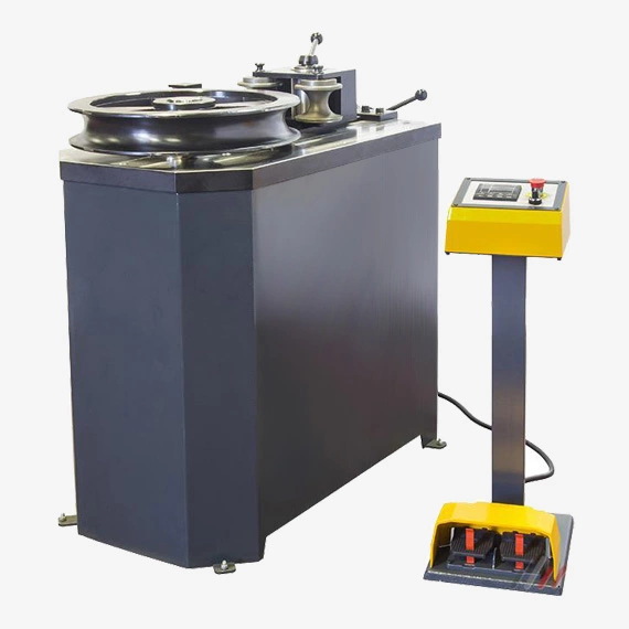
A pipe bending machine is a specialized tool used to shape and bend pipes and tubes into desired curves or angles. These machines are essential in various industries, including construction, manufacturing, and plumbing, where precise bending of pipes is crucial for creating functional and aesthetically pleasing structures.
Types of Pipe Bending Machines
There are several types of pipe bending machines available, each with its own strengths and applications. Some common types include:
- Mandrel bending machines: These machines use a mandrel, a solid rod or bar that is inserted into the pipe, to prevent the pipe from collapsing or distorting during the bending process. Mandrel bending machines are ideal for bending pipes with tight bends or small diameters.
- Rotational bending machines: These machines rotate the pipe around a stationary bend die, gradually forming the desired curvature. Rotational bending machines are suitable for bending pipes with large diameters and long bends.
- Roller bending machines: These machines use multiple rollers to apply pressure and shape the pipe as it passes through the machine. Roller bending machines are versatile and can handle various pipe diameters and bend radii.
- Hydraulic bending machines: These machines utilize hydraulic pressure to bend pipes, providing powerful and precise control over the bending process. Hydraulic bending machines are commonly used for bending thick-walled pipes and high-pressure applications.
Mandrel bending machines
Mandrel bending machines are specialized tools used to bend pipes and tubes into desired curves or angles without causing distortion or collapse. They are widely used in various industries, including construction, manufacturing, and plumbing, for creating functional and aesthetically pleasing structures.
Principle of Operation
Mandrel bending machines employ a mandrel, a solid rod or bar, that is inserted into the pipe or tube before bending. The mandrel provides internal support, preventing the pipe from collapsing or ovalizing during the bending process. This ensures that the bend is smooth, consistent, and free from internal defects.
Types of Mandrel Bending Machines
Mandrel bending machines can be classified into two main types based on their bending mechanism:
- Rotary Mandrel Bending Machines: These machines rotate the pipe around a stationary mandrel, gradually forming the desired curvature. This method is suitable for bending pipes with large diameters or long bends.
- Draw Mandrel Bending Machines: These machines pull the pipe through a fixed mandrel, shaping it into the desired curve. This method is particularly useful for bending pipes with small diameters or tight bends.
Advantages of Mandrel Bending Machines
Mandrel bending machines offer several advantages over other bending methods, such as roller bending or free-form bending:
- Precision and Accuracy: Mandrel bending machines produce highly accurate and consistent bends, ensuring the integrity and functionality of the bent pipe.
- Prevention of Collapse: The mandrel provides internal support, preventing the pipe from collapsing or ovalizing during the bending process, especially for thin-walled or large-diameter pipes.
- Reduced Springback: Mandrel bending machines minimize springback, the tendency of the bent pipe to partially straighten after bending. This ensures that the final bend matches the desired shape and angle.
- Suitable for Tight Bends: Mandrel bending machines are well-suited for producing tight bends or bends with small radii, which can be challenging with other bending methods.
Applications of Mandrel Bending Machines
Mandrel bending machines are widely used in various industries for a range of applications, including:
- Construction: Bending pipes for plumbing, HVAC systems, and electrical conduits
- Manufacturing: Fabricating pipes for machinery, automotive components, and industrial equipment
- Oil and Gas: Bending pipes for pipelines, oil wells, and refinery equipment
- Shipbuilding: Bending pipes for ship structures, piping systems, and marine equipment
- Furniture Manufacturing: Bending pipes for chair frames, lamp stands, and other furniture components
Selection and Operation of Mandrel Bending Machines
Selecting the appropriate mandrel bending machine depends on several factors, including:
- Pipe Diameter and Material: The machine should be capable of handling the pipe diameter and material being bent.
- Bend Radius and Angle: The machine should be able to achieve the desired bend radius and angle.
- Production Volume: The machine should have sufficient capacity to meet the production demands.
- Accuracy Requirements: The machine should provide the desired level of accuracy and precision for the application.
- Budget and Cost-Effectiveness: The machine should fit within the project budget and offer cost-effective operation.
When operating a mandrel bending machine, proper safety precautions should be followed to prevent accidents and injuries:
- Wear Personal Protective Equipment (PPE): Always wear appropriate PPE, including gloves, safety glasses, and proper footwear, when operating a mandrel bending machine.
- Securely Position the Machine: Ensure the machine is securely placed and leveled on a stable surface to prevent movement during operation.
- Properly Lubricate the Mandrel: Apply appropriate lubricant to the mandrel to reduce friction and ensure smooth movement during bending.
- Inspect the Pipe for Defects: Carefully inspect the pipe for any defects or damage before bending to prevent unexpected failures during the process.
- Follow Manufacturer Instructions: Strictly follow the manufacturer’s instructions and safety guidelines for the specific mandrel bending machine in use.
Mandrel bending machines play a vital role in various industries, enabling the creation of precise bends and curves in pipes and tubes without compromising their integrity. By selecting the right machine, adhering to safety protocols, and following proper operating procedures, these machines contribute to efficient, safe, and productive manufacturing processes.
Applications of Pipe Bending Machines
Pipe bending machines are used in a wide range of applications, including:
- Construction: Bending pipes for plumbing, HVAC systems, and electrical conduits
- Manufacturing: Fabricating pipes for machinery, automotive components, and industrial equipment
- Oil and Gas: Bending pipes for pipelines, oil wells, and refinery equipment
- Shipbuilding: Bending pipes for ship structures, piping systems, and marine equipment
- Furniture Manufacturing: Bending pipes for chair frames, lamp stands, and other furniture components
Benefits of Using Pipe Bending Machines
Pipe bending machines offer several advantages over manual bending methods, such as:
- Accuracy and Precision: Pipe bending machines produce consistent and precise bends, ensuring proper fit and function in various applications.
- Reduced Labor Costs: Pipe bending machines automate the bending process, minimizing the need for manual labor and reducing labor costs.
- Enhanced Safety: Pipe bending machines eliminate the risk of injuries associated with manual bending, such as muscle strain and fatigue.
- Versatility: Pipe bending machines can handle a wide range of pipe diameters, materials, and bend radii, making them suitable for diverse applications.
- Increased Productivity: Pipe bending machines accelerate the bending process, enhancing production output and project timelines.
Choosing the Right Pipe Bending Machine
The choice of the appropriate pipe bending machine depends on several factors, including:
- Pipe Diameter and Material: The machine should be capable of handling the pipe diameter and material being bent.
- Bend Radius and Angle: The machine should be able to achieve the desired bend radius and angle.
- Production Volume: The machine should have sufficient capacity to meet the production demands.
- Accuracy Requirements: The machine should provide the desired level of accuracy and precision for the application.
- Budget and Cost-Effectiveness: The machine should fit within the project budget and offer cost-effective operation.
Safety Considerations When Using Pipe Bending Machines
Working with pipe bending machines requires proper safety precautions to prevent accidents and injuries:
- Wear Personal Protective Equipment (PPE): Always wear appropriate PPE, including gloves, safety glasses, and proper footwear, when operating a pipe bending machine.
- Securely Position the Pipe: Ensure the pipe is securely placed and supported before bending to prevent movement during the process.
- Avoid Overloading the Machine: Do not exceed the machine’s capacity or overload it with excessive force, which can lead to damage or malfunctions.
- Maintain Proper Guarding: Keep safety guards and covers in place to protect hands and prevent accidental contact with moving parts.
- Follow Manufacturer Instructions: Strictly follow the manufacturer’s instructions and safety guidelines for the specific pipe bending machine in use.
Pipe bending machines play a crucial role in various industries, enabling the creation of precise bends and curves in pipes and tubes. By selecting the appropriate machine, adhering to safety protocols, and following proper operating procedures, these machines contribute to efficient, safe, and productive manufacturing processes.
(Non-Mandrel) Rotational bending machines
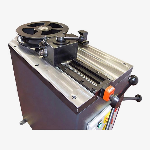
Rotational bending machines, also known as rotary bending machines, are specialized tools used to shape and bend pipes and tubes into desired curves or angles by rotating the pipe around a stationary bend die. These machines are particularly well-suited for bending pipes with large diameters or long bends.
Principle of Operation
Rotational bending machines employ a stationary bend die, a curved or shaped form that the pipe is rotated around. As the pipe rotates, it is gradually forced into the shape of the bend die, creating the desired curvature. The rotation and pressure applied by the bend die ensure that the pipe bends smoothly and evenly.
Types of Rotational Bending Machines
There are two main types of rotational bending machines based on their drive mechanism:
- Hydraulic Rotational Bending Machines: These machines utilize hydraulic pressure to rotate the pipe and apply force against the bend die. Hydraulic rotational bending machines are commonly used for bending large-diameter pipes and heavy-duty applications.
- Electric Rotational Bending Machines: These machines use an electric motor to rotate the pipe and apply force against the bend die. Electric rotational bending machines are suitable for bending a wide range of pipe diameters and are often preferred for their quieter operation.
Advantages of Rotational Bending Machines
Rotational bending machines offer several advantages over other bending methods, such as mandrel bending or roller bending:
- Large Bend Capacity: Rotational bending machines can handle pipes with larger diameters and longer bending radii compared to mandrel bending machines.
- Reduced Springback: Rotational bending machines tend to produce less springback, ensuring that the final bend is closer to the desired shape and angle.
- Efficient Bending: Rotational bending machines can achieve consistent and precise bends in a relatively short amount of time.
- Suitable for Thin-Walled Pipes: Rotational bending machines can be used for bending thin-walled pipes without causing collapse or distortion.
Applications of Rotational Bending Machines
Rotational bending machines are widely used in various industries for a range of applications, including:
- Construction: Bending pipes for large-scale piping systems, structural supports, and infrastructure projects
- Shipbuilding: Bending pipes for ship structures, piping systems, and marine equipment
- Power Generation: Bending pipes for power plant piping systems, boilers, and heat exchangers
- Oil and Gas: Bending pipes for pipelines, oil wells, and refinery equipment
- Chemical Processing: Bending pipes for chemical processing plants, reactors, and piping systems
Selection and Operation of Rotational Bending Machines
Selecting the appropriate rotational bending machine depends on several factors, including:
- Pipe Diameter and Material: The machine should be capable of handling the pipe diameter and material being bent.
- Bend Radius and Angle: The machine should be able to achieve the desired bend radius and angle.
- Production Volume: The machine should have sufficient capacity to meet the production demands.
- Accuracy Requirements: The machine should provide the desired level of accuracy and precision for the application.
- Budget and Cost-Effectiveness: The machine should fit within the project budget and offer cost-effective operation.
Pipe Diameter and Material
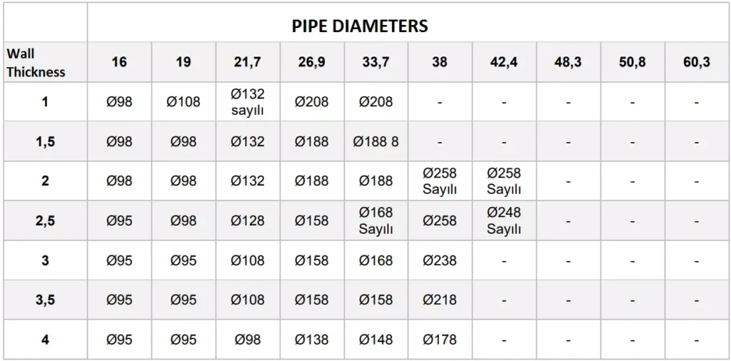
Pipe diameter and material are two crucial factors that determine the selection and performance of pipe bending machines. These parameters significantly influence the bending capacity, accuracy, and overall effectiveness of the bending process. Let’s delve into the significance of pipe diameter and material in pipe bending:
Pipe Diameter
Pipe diameter refers to the internal measurement of a pipe, typically expressed in inches or millimeters. It is a critical factor in determining the bending capacity of a pipe bending machine. The machine’s bending mechanism, whether mandrel bending, rotary bending, or roller bending, must be able to accommodate the pipe’s diameter to achieve the desired bend shape.
Larger pipe diameters generally require more powerful bending machines with larger bending capacities. Inadequate bending capacity can lead to incomplete or distorted bends, compromising the integrity and functionality of the bent pipe. Conversely, using an excessively powerful machine for smaller diameter pipes may result in over-bending or damage to the pipe material.
Pipe Material
The material of the pipe significantly impacts the bending process and the selection of an appropriate bending machine. Different pipe materials exhibit varying bending characteristics, such as ductility, strength, and springback. These properties influence the bend radius, bend angle, and overall accuracy achievable during bending.
For instance, softer and more ductile materials like aluminum or copper are easier to bend compared to harder and stronger materials like stainless steel or carbon steel. Harder materials may require higher bending forces and specialized machines to achieve the desired bends without causing cracking or distortion.
Additionally, different pipe materials have different springback tendencies, which refer to the material’s inclination to partially straighten after bending. Springback can affect the accuracy of the final bend angle, and machines with springback compensation mechanisms are often used for materials with high springback rates.
Matching Pipe Diameter and Material to Bending Machines
Selecting the appropriate pipe bending machine for a particular application necessitates careful consideration of both pipe diameter and material. By understanding the bending characteristics of the pipe material and the capacity of the bending machine, one can ensure that the bending process produces accurate, consistent, and high-quality bends.
Here are some general guidelines for matching pipe diameter and material to bending machines:
- Pipe Diameter: Choose a bending machine with a bending capacity that exceeds the diameter of the pipe being bent. This ensures that the machine has sufficient power to achieve the desired bend without straining or damaging the pipe.
- Pipe Material: Consult the manufacturer’s specifications of the bending machine to determine the compatible materials and their corresponding bending parameters. This information will help avoid over-bending or under-bending of the pipe material.
In summary, pipe diameter and material play essential roles in pipe bending, influencing the selection of bending machines and the effectiveness of the bending process. Understanding these factors is crucial for producing high-quality bends that meet the requirements of the application.
Safety
When operating a rotational bending machine, proper safety precautions should be followed to prevent accidents and injuries:
- Wear Personal Protective Equipment (PPE): Always wear appropriate PPE, including gloves, safety glasses, and proper footwear, when operating a rotational bending machine.
- Securely Position the Machine: Ensure the machine is securely placed and leveled on a stable surface to prevent movement during operation.
- Properly Align the Bend Die: Ensure the bend die is properly aligned with the pipe to prevent uneven or distorted bends.
- Monitor the Bending Process: Closely monitor the bending process to detect any potential issues or irregularities.
- Follow Manufacturer Instructions: Strictly follow the manufacturer’s instructions and safety guidelines for the specific rotational bending machine in use.
Rotational bending machines offer a versatile and efficient method for bending pipes and tubes with large diameters or long bends. By selecting the right machine, adhering to safety protocols, and following proper operating procedures, these machines contribute to efficient, safe, and productive manufacturing processes in various industries.
Roller bending machines
Roller bending machines, also known as profile bending machines, are specialized tools used to shape and bend pipes and tubes into desired curves or angles by applying pressure from multiple rollers. These machines are widely used in various industries, including construction, manufacturing, and plumbing, for creating functional and aesthetically pleasing structures.
Principle of Operation
Roller bending machines employ a series of rollers, typically three or more, arranged in a staggered or pyramidal configuration. The pipe or tube is passed through the rollers, which gradually apply pressure and force the material to conform to the desired shape. The rollers rotate the pipe as it passes through, ensuring a smooth, consistent bend.
Types of Roller Bending Machines
Roller bending machines can be classified into two main types based on their roller configuration:
- Hydraulic Roller Bending Machines: These machines utilize hydraulic pressure to apply force to the rollers, providing powerful and precise bending capabilities. Hydraulic roller bending machines are commonly used for bending large-diameter pipes or thick-walled tubes.
- Electric Roller Bending Machines: These machines use an electric motor to drive the rollers, offering a more energy-efficient and cost-effective alternative to hydraulic machines. Electric roller bending machines are suitable for bending a wide range of pipe diameters and materials.
Advantages of Roller Bending Machines
Roller bending machines offer several advantages over other bending methods, such as mandrel bending or rotational bending:
- Versatility: Roller bending machines can handle a wide range of pipe diameters, materials, and bend radii, making them suitable for various applications.
- Reduced Springback: Roller bending machines generally produce less springback compared to other bending methods, ensuring the final bend closely matches the desired shape.
- Efficient and Continuous Bending: Roller bending machines allow for continuous bending of pipes, enabling efficient and high-volume production.
- Suitable for Small Bends: Roller bending machines can be used for bending pipes with relatively small bend radii, making them versatile for various projects.
Applications of Roller Bending Machines
Roller bending machines are widely used in various industries for a range of applications, including:
- Construction: Bending pipes for railings, handrails, and structural supports
- Manufacturing: Fabricating pipes for machinery frames, automotive components, and industrial equipment
- HVAC Systems: Bending pipes for ductwork, air conditioning units, and ventilation systems
- Shipbuilding: Bending pipes for ship structures, piping systems, and marine equipment
- Furniture Manufacturing: Bending pipes for chair frames, lamp stands, and other furniture components
Selection and Operation of Roller Bending Machines
Selecting the appropriate roller bending machine depends on several factors, including:
- Pipe Diameter and Material: The machine should be capable of handling the pipe diameter and material being bent.
- Bend Radius and Angle: The machine should be able to achieve the desired bend radius and angle.
- Production Volume: The machine should have sufficient capacity to meet the production demands.
- Accuracy Requirements: The machine should provide the desired level of accuracy and precision for the application.
- Budget and Cost-Effectiveness: The machine should fit within the project budget and offer cost-effective operation.
When operating a roller bending machine, proper safety precautions should be followed to prevent accidents and injuries:
- Wear Personal Protective Equipment (PPE): Always wear appropriate PPE, including gloves, safety glasses, and proper footwear, when operating a roller bending machine.
- Securely Position the Machine: Ensure the machine is securely placed and leveled on a stable surface to prevent movement during operation.
- Properly Align the Rollers: Make sure the rollers are aligned and adjusted correctly to achieve the desired bend shape.
- Monitor the Bending Process: Closely monitor the bending process to detect any potential issues or irregularities.
- Follow Manufacturer Instructions: Strictly follow the manufacturer’s instructions and safety guidelines for the specific roller bending machine in use.
Roller bending machines provide a versatile and efficient method for bending pipes and tubes in various industries. By selecting the right machine, adhering to safety protocols, and following proper operating procedures, these machines contribute to efficient, safe, and productive manufacturing processes.
Hydraulic bending machines
Hydraulic bending machines, also known as hydraulic press brakes, are specialized tools used to shape and bend metal sheets or plates into desired angles or curves. These machines are widely used in various industries, including metal fabrication, construction, and automotive manufacturing, for creating functional and structurally sound components.
Principle of Operation
Hydraulic bending machines employ a hydraulic cylinder, a piston-driven chamber filled with pressurized hydraulic fluid, to apply force to a bending beam or punch. The workpiece, typically a metal sheet or plate, is placed between the bending beam and the die, which is a shaped tool that determines the desired bend angle or shape. As the hydraulic cylinder extends, the bending beam forces the workpiece to conform to the shape of the die, creating the desired bend.
Types of Hydraulic Bending Machines
Hydraulic bending machines can be classified into two main types based on their frame design:
- Open-Throat Bending Machines: These machines have an open frame structure, allowing for bending of workpieces of varying lengths. Open-throat bending machines are commonly used for bending long metal sheets or plates.
- Box-Frame Bending Machines: These machines have a closed frame structure, providing greater rigidity and support for bending thicker or wider workpieces. Box-frame bending machines are often used for bending shorter metal sheets or plates that require higher bending forces.
Advantages of Hydraulic Bending Machines
Hydraulic bending machines offer several advantages over other bending methods, such as mechanical bending or manual bending:
- Powerful and Precise Bending: Hydraulic bending machines provide powerful bending forces, allowing for bending of thick or high-strength materials with high precision.
- Consistent Bend Angles: Hydraulic bending machines ensure consistent and accurate bend angles, reducing the risk of defects and ensuring the integrity of the bent workpiece.
- Versatility: Hydraulic bending machines can handle a wide range of workpiece thicknesses, materials, and bend angles, making them suitable for various applications.
- Automation Potential: Hydraulic bending machines can be automated or semi-automated, enabling efficient and high-volume production.
- Safety Features: Hydraulic bending machines often incorporate safety features, such as light curtains or guards, to protect operators from potential hazards.
Applications of Hydraulic Bending Machines
Hydraulic bending machines are widely used in various industries for a range of applications, including:
- Metal Fabrication: Bending sheets or plates for enclosures, structural components, and machine parts
- Construction: Bending metal sheets or plates for roofing panels, ductwork, and structural framing
- Automotive Manufacturing: Bending sheet metal for car bodies, panels, and structural components
- Appliance Manufacturing: Bending metal sheets or plates for appliance enclosures, panels, and components
- HVAC Systems: Bending sheet metal for ductwork, air conditioning units, and ventilation systems
Selection and Operation of Hydraulic Bending Machines
Selecting the appropriate hydraulic bending machine depends on several factors, including:
- Workpiece Thickness and Material: The machine should be capable of handling the thickness and material of the workpiece being bent.
- Bend Angle and Length: The machine should be able to achieve the desired bend angle and bend length for the application.
- Production Volume: The machine should have sufficient capacity to meet the production demands.
- Accuracy Requirements: The machine should provide the desired level of accuracy and precision for the application.
- Budget and Cost-Effectiveness: The machine should fit within the project budget and offer cost-effective operation.
When operating a hydraulic bending machine, proper safety precautions should be followed to prevent accidents and injuries:
- Wear Personal Protective Equipment (PPE): Always wear appropriate PPE, including gloves, safety glasses, and proper footwear, when operating a hydraulic bending machine.
- Securely Position the Workpiece: Ensure the workpiece is securely placed and properly aligned with the bending beam and the die.
- Clear the Bending Area: Keep the bending area clear of obstructions and maintain proper posture to avoid strain or injury.
- Use Proper Handling Techniques: Use appropriate lifting techniques and avoid overloading the machine.
- Follow Manufacturer Instructions: Strictly follow the manufacturer’s instructions and safety guidelines for the specific hydraulic bending machine in use.
Hydraulic bending machines play a crucial role in various industries, enabling the creation of precise bends and shapes in metal sheets or plates. By selecting the right machine, adhering to safety protocols, and following proper operating procedures, these machines contribute to efficient, safe, and productive manufacturing processes.
Technical characteristics of the pipe and tube benders
The technical characteristics of pipe and tube benders vary depending on the type of machine and the specific application. However, some general technical characteristics that are common to most pipe and tube benders include:
- Bend capacity: This is the maximum diameter and wall thickness of pipe or tube that the machine can bend.
- Bend radius: This is the minimum radius of a bend that the machine can create.
- Bend angle: This is the maximum angle of a bend that the machine can create.
- Bending speed: This is the rate at which the machine can bend pipe or tube.
- Accuracy: This is the degree to which the machine can produce bends that are consistent and within the specified tolerances.
- Power requirements: This is the amount of electrical or hydraulic power that the machine requires to operate.
- Dimensions and weight: These are the physical dimensions and weight of the machine.
In addition to these general technical characteristics, some pipe and tube benders may also have additional features, such as:
- Mandrel bending: This is a type of bending that uses a mandrel to support the inside of the pipe or tube as it is being bent. This can prevent the pipe or tube from ovalizing or collapsing during the bending process.
- Rotary bending: This is a type of bending that rotates the pipe or tube around a stationary die. This can be used to create bends with large radii.
- Computer numerical control (CNC): This is a type of control system that allows the machine to be programmed to create complex bends with high precision.
- Hydraulic drive: This is a type of power system that uses hydraulic fluid to provide the bending force. This can be used to create bends with high power and precision.
- Electric drive: This is a type of power system that uses an electric motor to provide the bending force. This can be used to create bends with high efficiency and cleanliness.
The specific technical characteristics of a pipe or tube bender will depend on the application for which it is being used. For example, a machine that is used to bend thin-walled pipes for plumbing applications will have different technical characteristics than a machine that is used to bend thick-walled pipes for industrial applications.
Here is a table that summarizes the key technical characteristics of some common types of pipe and tube benders:
| Type of Bender | Bend Capacity | Bend Radius | Bend Angle | Bending Speed | Accuracy | Power Requirements | Dimensions and Weight |
|---|---|---|---|---|---|---|---|
| Mandrel bender | Small to large diameters | Small to large radii | Up to 180 degrees | Slow to moderate | High | Hydraulic or electric | Large to very large |
| Rotary bender | Large diameters | Large radii | Up to 180 degrees | Moderate to fast | Moderate | Hydraulic or electric | Large to very large |
| CNC bender | Small to large diameters | Small to large radii | Up to 180 degrees | Moderate to fast | High | Hydraulic or electric | Small to large |
Pipe forming with our pipe bending machine
Pipe forming is the main task of our TB series Pipe benders. During the pipe forming the machine tool presses the end of the pipe around the round mold to make a radius. Companies that purchase a pipe manufacturing machine, also need a sheet metal forming tube bender.
Pipe forming with a pipe bending machine is a process of shaping and curving pipes or tubes into desired angles or shapes. This technique is widely used in various industries, including construction, manufacturing, and plumbing, to create functional and aesthetically pleasing structures.
Pipe bending machines employ various methods to achieve the desired curvature, including:
- Mandrel bending: This method utilizes a mandrel, a solid rod or bar, inserted into the pipe to prevent collapse or distortion during bending. Mandrel bending is particularly suitable for bending thin-walled pipes or achieving tight bends.
- Rotational bending: In this method, the pipe is rotated around a stationary bend die, gradually forming the desired curvature. Rotational bending is well-suited for bending pipes with large diameters or long bends.
- Roller bending: This method employs multiple rollers to apply pressure and shape the pipe as it passes through the machine. Roller bending is versatile and can handle various pipe diameters and bend radii.
- Hydraulic bending: This method utilizes hydraulic pressure to apply force to the rollers or bending beam, providing powerful and precise bending capabilities. Hydraulic bending is commonly used for bending thick-walled pipes or high-strength materials.
Pipe forming with a pipe bending machine offers several advantages over manual bending methods:
- Accuracy and Precision: Pipe bending machines produce consistent and accurate bends, ensuring the integrity and functionality of the bent pipe.
- Reduced Labor Costs: Pipe bending machines automate the bending process, minimizing the need for manual labor and reducing labor costs.
- Enhanced Safety: Pipe bending machines eliminate the risk of injuries associated with manual bending, such as muscle strain and fatigue.
- Versatility: Pipe bending machines can handle a wide range of pipe diameters, materials, and bend radii, making them suitable for diverse applications.
- Increased Productivity: Pipe bending machines accelerate the bending process, enhancing production output and project timelines.
To effectively form pipes using a pipe bending machine, consider the following steps:
- Select the Appropriate Machine: Choose the machine that can handle the pipe diameter, material, and bend requirements of the project.
- Prepare the Pipe: Clean and inspect the pipe for any defects or damage that could affect the bending process.
- Properly Align the Pipe: Ensure the pipe is securely positioned and aligned with the bending mechanism to prevent misalignment or distortion.
- Set the Bending Parameters: Adjust the machine settings according to the desired bend angle, radius, and speed.
- Monitor the Bending Process: Observe the bending process closely to detect any irregularities or deviations from the desired shape.
- Verify Bend Quality: Once the bending process is complete, inspect the bend for accuracy, consistency, and absence of defects.
Pipe forming with a pipe bending machine plays a crucial role in various industries, enabling the creation of precise bends and shapes in pipes and tubes. By selecting the right machine, adhering to safety protocols, and following proper operating procedures, these machines contribute to efficient, safe, and productive manufacturing processes.
Parts made with pipe bending machine
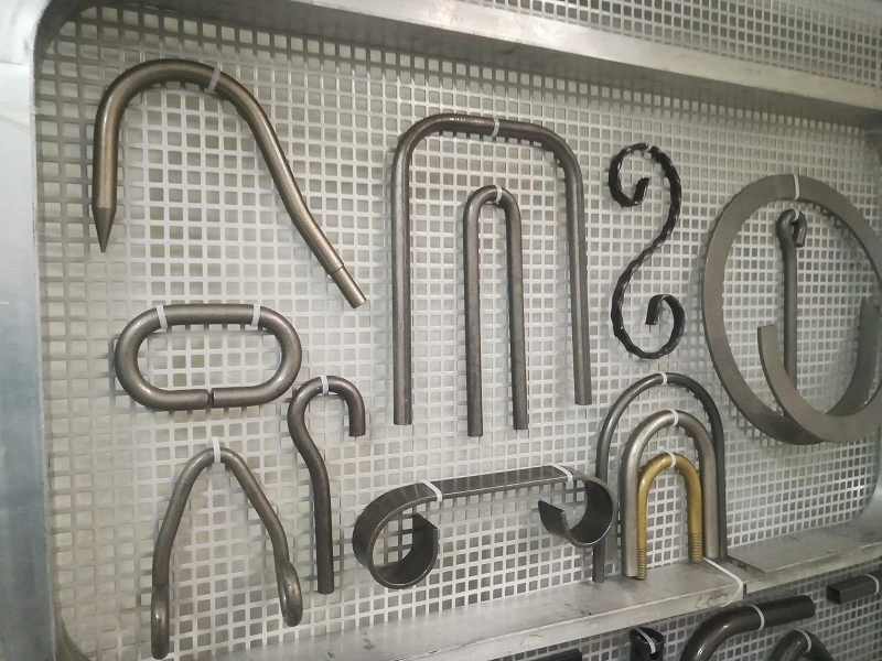
In our manufacturing facility, we design and manufacture every machine with our own manufacturing machines. Pipe manufacturers, tube manufacturing companies, and machine manufacturing companies are our biggest customers. In our 2500 m2 closed area, we have a 100% indoor production ability.
Pipe bending machines are used to create a wide variety of parts for various industries. Here are some examples of parts that can be made with a pipe bending machine:
Automotive industry:
- Exhaust pipes
- Frame components
- Roll bars
- Seat frames
- Suspension parts
Construction industry:
- Handrails
- Guardrails
- Piping systems
- Structural supports
- Tubing for electrical conduit
Manufacturing industry:
- Appliance components
- Chair frames
- Furniture components
- Hand tools
- Medical equipment
Oil and gas industry:
- Piping for oil and gas pipelines
- Tubing for instrumentation and control systems
- Valves and fittings
- Wellbores
HVAC industry:
- Ductwork
- Pipe fittings
- Tubing for refrigerant lines
- Ventilation systems
Plumbing industry:
- Drains
- Pipes for water supply and waste disposal
- Tubing for plumbing fixtures
- Valves and fittings
In addition to these specific examples, pipe bending machines can be used to create a wide variety of other parts depending on the specific needs of the application.
Here are some additional factors that can affect the type of parts that can be made with a pipe bending machine:
- The type of pipe bending machine: Different types of pipe bending machines have different capabilities. For example, mandrel bending machines are well-suited for bending thin-walled pipes, while rotary bending machines are better for bending pipes with large diameters.
- The material of the pipe: Different materials have different bending characteristics. For example, stainless steel is more difficult to bend than aluminum.
- The thickness of the pipe: Thicker pipes are more difficult to bend than thinner pipes.
- The desired bend radius: The bend radius is the tightest bend that can be made in the pipe. Smaller bend radii require more force and specialized machines.
- The desired bend angle: The bend angle is the angle at which the pipe is bent. Larger bend angles require more force and specialized machines.
With careful planning and the right equipment, pipe bending machines can be used to create a wide variety of parts for a wide range of applications.
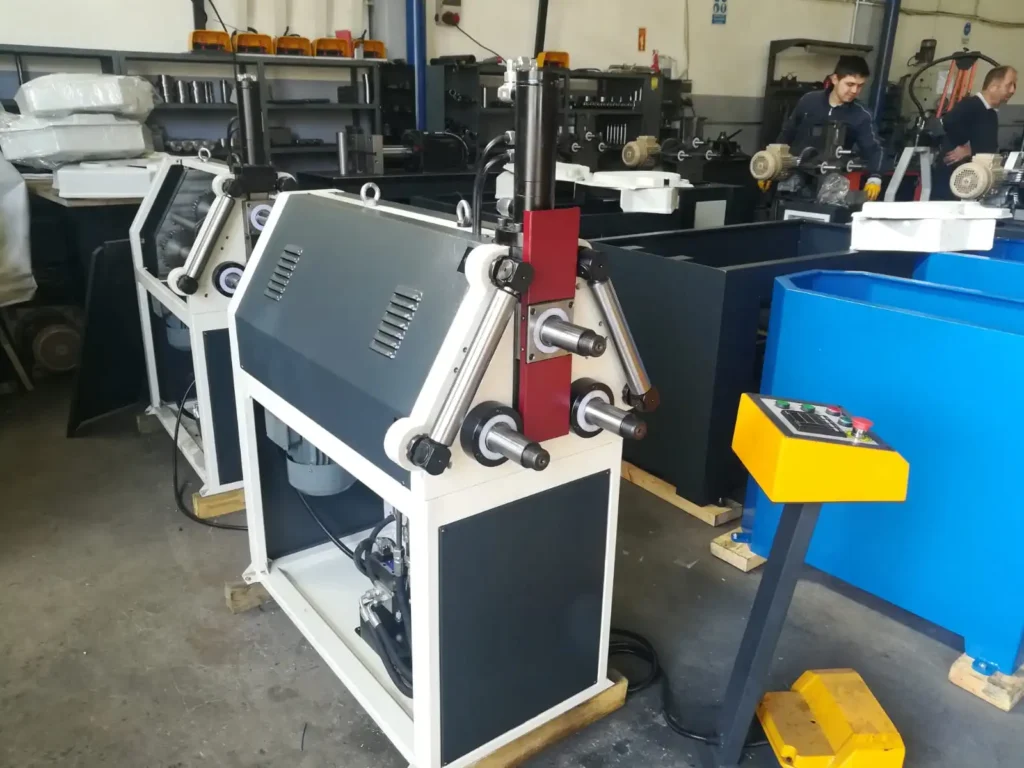
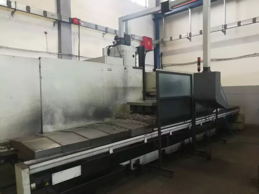
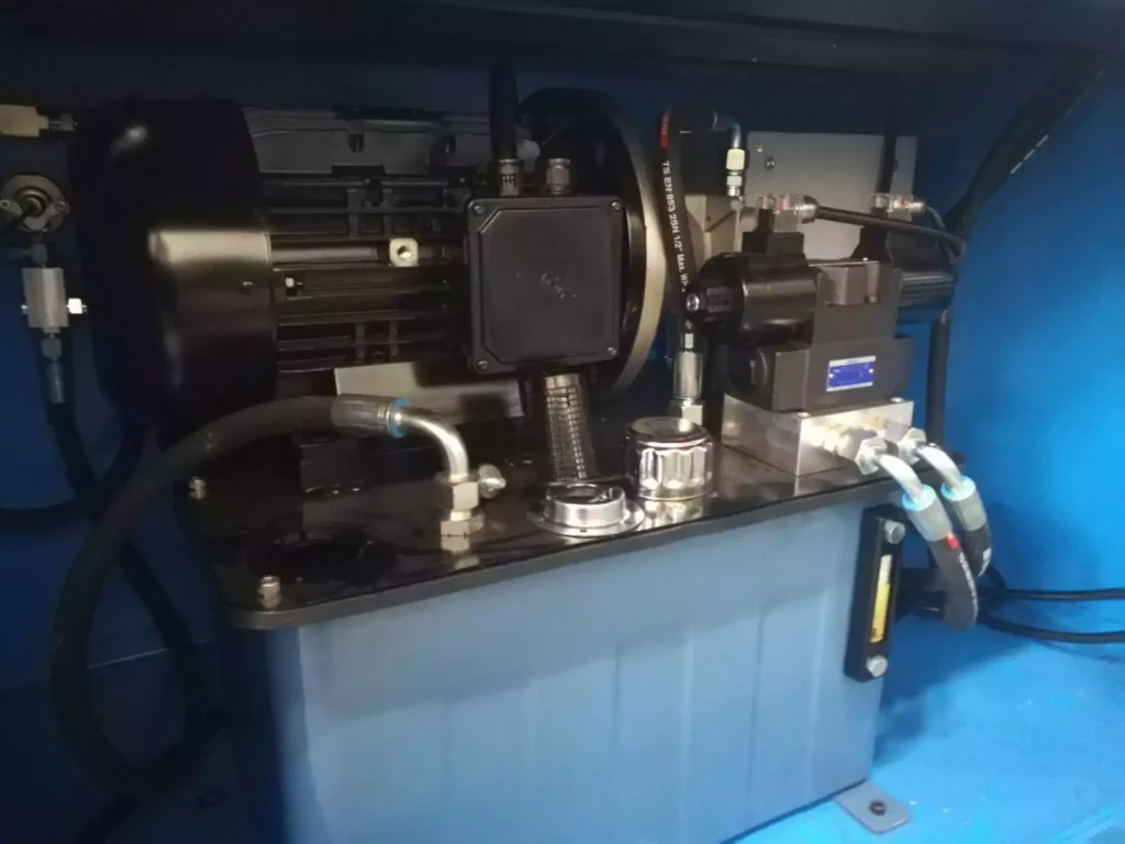
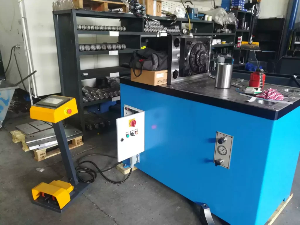
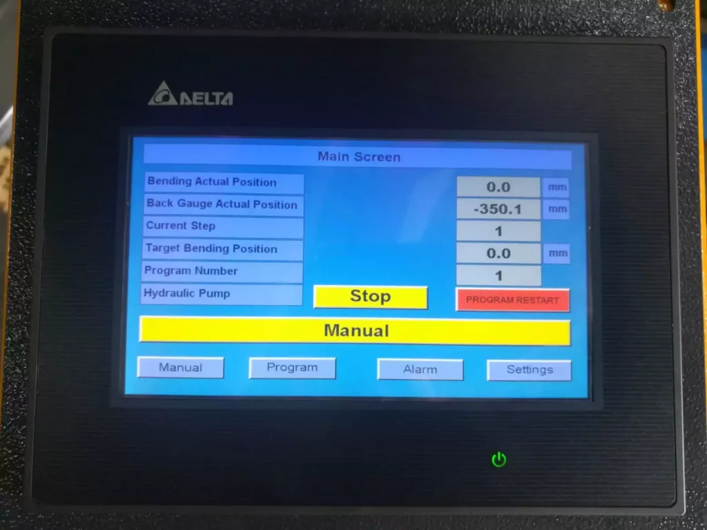
All the equipment design and equipment manufacturing are carried out in our own production facility by our production machines. In our manufacturing site, we have been manufacturing machines and equipment since 1997.
Tube Bending Machine Manufacturing
Tube bending machines are specialized equipment used to shape and curve pipes and tubes into desired angles or shapes. These machines play a crucial role in various industries, including construction, manufacturing, and plumbing, for creating functional and aesthetically pleasing structures.
The manufacturing of tube bending machines involves a complex process that encompasses several stages:
- Design and Engineering: The design phase entails creating detailed blueprints and specifications for the machine, considering factors such as bending capacity, bend radius, accuracy requirements, and power consumption.
- Material Procurement: The procurement stage involves sourcing high-quality materials that meet the structural and performance requirements of the machine. This includes selecting the appropriate metals for the frame, bending mechanism, and hydraulic or electrical components.
- Machining and Fabrication: The machining and fabrication stage involves transforming the procured materials into the various components of the machine. This involves precision cutting, drilling, milling, and shaping operations using advanced CNC machines.
- Component Assembly: Once the individual components are manufactured, they are carefully assembled according to the design specifications. This involves aligning, joining, and securing the various parts to form the complete machine structure.
- Hydraulic or Electrical System Installation: The hydraulic or electrical system, depending on the machine type, is installed and connected to the appropriate components. This includes pumps, motors, valves, and controls to provide the necessary power and precision for bending operations.
- Quality Assurance and Testing: Rigorous quality assurance procedures are implemented to ensure the machine meets the specified standards for performance, accuracy, and safety. This involves testing the bending capacity, bend radius, and consistent operation under various conditions.
- Documentation and Packaging: Comprehensive documentation is prepared, including user manuals, maintenance guides, and safety instructions, to ensure proper operation and maintenance of the machine. The machine is then packaged securely for shipment or storage.
Tube bending machine manufacturing is a specialized industry that requires expertise in mechanical engineering, hydraulics or electrical systems, and quality control procedures. Manufacturers continuously strive to innovate and improve their machines by incorporating new technologies, enhancing performance, and expanding bending capabilities.
Pipe bending is another way of manufacturing bending sheet metal technologies. Pipe bending is carried out by the movement of the pipe bending roller around its own axis while the fixture tool keeps the pipe fixed.
Due to the increase in globalization, it is very important to produce a good with high precision and high accuracy or reliability. pipe bending machine is mostly used in the fabrication industry generally using bending machine to produce U-shapes and V-shapes. The design of the pipe-bending machine use only two pulleys for the bending of pipe a different angle. due to the no of compost use overall cost of the machine is low. and machine portable type the weight of the machine is less than is very full portable.
Our project is to design and construct a bending machine. This machine is used to bend pipes into curves or another curvature shape. The size of the machine is very convenient for portable work. In various fabrication, works as well as in architectural work pipes are used in different ways. To bend these pipes into these artistic forms is not easy thing to be done manually. Using a particular machine specially developed for bending of pipe help.
Choosing component material is very important because it will affect the overall cost of the machine and product quality. With this consideration, we will design this machine with the maximum quality and low cost, During pipe bending operation stress concentration is occur in the bend area of pipe. the bend section may be damaged during service in the particular cases where significant validity and thickness version exist which are introduced during the menacing process and operation time.
Hence the acceptance of a pipe depends on the magnitude and shape of the pipe. in the pipe bending process, the thickness of the pipe changes. The acceptability of pipe bend is depending on magnitude and shape imperfection. Then we also study on failure analysis of pipe bend in these we assume pipe bend is a uniform thickness.
As a Pipe Bending Machine Manufacturer
The EMS Metalworking tube bending machines have a clamping die, pressure dies, mandrel, and bend head, which are all hydraulically operated. To enhance the usefulness of these EMS Metalworking machines,
Electro pneumatics has developed the EMS Metalworking Series.
These tube bending machines have a pre-settable linear and rotary indexing facility for multi-plane bends, in addition to the clamp, pressure dies, mandrel, and bend the arm.
These hydraulic, semi-automatic machines can handle tubes from 6 mm to 325 mm outside diameter, ft is possible to bend tubes of a variety of materials with round, square or rectangular sections and different profiles, which eliminates the need for locating fixtures on the machine. A carriage with a manual/hydraulic chucking arrangement that is capable of traversing the length of the machine is provided.
Electro pneumatics user-friendly programmable microprocessor-based numerical ‘Smart bend 4101 series controllers are specially designed for these machines. With these machines, all operations of the bending process are done automatically, while rotation and linear orientation of the component between two bends is done manually by the operator against pre-settable stops.
Features of Hydraulic Steel Pipe Bending Machines
Hydraulic steel pipe bending machines are powerful and versatile tools used to shape and bend steel pipes into desired angles or curves. These machines are widely used in various industries, including construction, manufacturing, and plumbing, for creating functional and aesthetically pleasing structures.
Here are some of the key features of hydraulic steel pipe bending machines:
1. High Bending Capacity: Hydraulic steel pipe bending machines utilize hydraulic pressure to apply force to the bending mechanism, providing powerful and precise bending capabilities. These machines can handle a wide range of pipe diameters and thicknesses, making them suitable for bending thick-walled steel pipes or high-strength materials.
2. Consistent and Accurate Bends: Hydraulic steel pipe bending machines produce consistent and accurate bends, ensuring the integrity and functionality of the bent pipe. The precise control of hydraulic pressure allows for precise adjustments to the bend angle and radius, resulting in bends that meet the specified tolerances.
3. Versatility: Hydraulic steel pipe bending machines can handle a wide range of pipe diameters, materials, and bend radii. They can be used for mandrel bending, rotary bending, and roller bending, providing flexibility and adaptability to various bending applications.
4. Automation Potential: Hydraulic steel pipe bending machines can be automated or semi-automated, enabling efficient and high-volume production. This automation reduces labor costs, minimizes human error, and increases production throughput.
5. Safety Features: Hydraulic steel pipe bending machines often incorporate safety features, such as light curtains or guards, to protect operators from potential hazards. These features help prevent injuries and accidents during the bending process.
In addition to these general features, specific hydraulic steel pipe bending machines may also have additional features, such as:
- CNC control: Computer numerical control (CNC) allows for precise programming of the bending process, ensuring consistent and repeatable bends, even for complex shapes.
- Multiple bending planes: Some machines can bend pipes in multiple planes, providing greater flexibility for creating intricate shapes and curved structures.
- Data logging and monitoring: Advanced machines can record and monitor bending data, providing valuable insights for quality control and process optimization.
Overall, hydraulic steel pipe bending machines offer a powerful, versatile, and safe solution for shaping and bending steel pipes in various industries. Their ability to produce precise bends, handle a wide range of materials, and adapt to automated processes makes them essential tools for metal fabrication and construction applications.
What is a Pipe Bending Machine?
A pipe bending machine is a piece of industrial equipment designed to bend pipes and tubes into specific shapes or angles without compromising their structural integrity. These machines are widely used in industries such as construction, automotive, aerospace, plumbing, and manufacturing to create components like pipelines, exhaust systems, railings, and frameworks. Pipe bending machines can handle a variety of materials, including steel, stainless steel, aluminum, copper, and even plastic, depending on the machine’s capabilities and the application.
How Pipe Bending Machines Work
Pipe bending machines operate by applying force to a pipe or tube to deform it into a desired shape. The process typically involves a combination of pressure, tension, and support to prevent wrinkling, cracking, or collapsing of the material. The basic components of a pipe bending machine include:
- Bend Die: The primary tool that shapes the pipe by determining the radius of the bend.
- Clamp Die: Holds the pipe securely against the bend die during the bending process.
- Pressure Die: Applies force to the pipe to assist in bending and maintain its shape.
- Mandrel (optional): A rod or plug inserted inside the pipe to prevent it from collapsing or wrinkling, especially for thin-walled or tight-radius bends.
- Wiper Die (optional): Prevents wrinkles on the inner radius of the bend, often used with a mandrel.
The machine bends the pipe by rotating it around the bend die or pushing it through a series of rollers, depending on the type of machine. The process can be manual, semi-automatic, or fully automated, depending on the complexity and precision required.
Types of Pipe Bending Machines
There are several types of pipe bending machines, each suited to specific applications:
- Manual Pipe Benders
- Operated by hand, typically used for small-scale projects or softer materials like copper or aluminum.
- Simple and portable but limited in precision and capacity.
- Example use: Plumbing repairs or small DIY projects.
- Hydraulic Pipe Benders
- Use hydraulic pressure to bend pipes, offering more power than manual benders.
- Suitable for medium to large pipes and tougher materials like steel.
- Common in workshops and construction sites.
- CNC Pipe Benders
- Computer Numerical Control (CNC) machines that provide high precision and repeatability.
- Programmable to create complex, multi-angle bends automatically.
- Used in industries like automotive and aerospace for mass production.
- Rotary Draw Benders
- Pull the pipe around a rotating bend die, often with a mandrel for tight bends.
- Highly accurate and versatile, ideal for exhaust systems and furniture frames.
- Roll Benders (Section Benders)
- Use three or more rollers to gradually bend pipes into large-radius curves or spirals.
- Common for structural applications like arches or circular railings.
- Heat-Induction Benders
- Apply heat to soften the pipe before bending, typically for large-diameter or thick-walled pipes.
- Used in oil and gas pipelines or heavy industrial projects.
Key Features and Considerations
When selecting or using a pipe bending machine, several factors come into play:
- Pipe Diameter and Wall Thickness: Machines are rated for specific size ranges. Exceeding these limits can damage the machine or pipe.
- Material: Softer metals (e.g., copper) require less force than harder ones (e.g., stainless steel).
- Bend Radius: Tighter bends need more precise machines, often with mandrels.
- Angle of Bend: Some machines can handle multiple bends or 3D shapes, while others are limited to simple curves.
- Automation Level: Manual machines are cheaper but slower; CNC machines are expensive but efficient for large-scale production.
Advantages of Pipe Bending Machines
- Efficiency: Faster than manual bending methods, especially for repetitive tasks.
- Precision: Modern machines, especially CNC models, ensure consistent results.
- Versatility: Can handle various pipe sizes, materials, and shapes.
- Cost Savings: Reduces the need for fittings or welding by creating seamless bends.
Applications
Pipe bending machines are essential in numerous fields:
- Construction: Creating curved steel frameworks or HVAC ducting.
- Automotive: Manufacturing exhaust pipes and roll cages.
- Aerospace: Forming lightweight, high-strength tubing for aircraft.
- Plumbing: Shaping pipes for water or gas systems.
- Furniture: Crafting metal chair frames or decorative elements.
Challenges and Limitations
- Material Springback: Pipes may partially return to their original shape after bending, requiring over-bending to compensate.
- Wrinkling or Cracking: Thin-walled pipes or tight bends can deform if not properly supported.
- Cost: High-end machines like CNC benders are expensive and require skilled operators.
- Setup Time: Complex bends may need significant preparation, especially for custom jobs.
Modern Innovations
Recent advancements in pipe bending technology include:
- Laser Measurement: Ensures precise bend angles and reduces errors.
- Automation: Integration with robotics for fully automated production lines.
- Software: Advanced CNC systems with 3D modeling to simulate bends before production.
Mechanics of Pipe Bending: A Closer Look
The bending process is a balance of tensile and compressive forces acting on the pipe. When a pipe is bent:
- The outer wall stretches (tension), thinning slightly.
- The inner wall compresses, potentially causing wrinkles if unsupported.
- The neutral axis (a theoretical line inside the pipe) experiences minimal deformation.
To achieve a clean bend, machines must control these forces precisely:
- Bend Radius-to-Diameter Ratio (R/D): A tighter bend (smaller R/D) requires more force and risks deformation. For example, a 1D bend (radius equals pipe diameter) is much harder than a 3D bend.
- Elongation Limits: Each material has a maximum stretch before it cracks. For instance, mild steel can elongate 20-25%, while stainless steel might handle only 15%.
- Wall Factor: The ratio of pipe diameter to wall thickness. Thin-walled pipes (high wall factor) are prone to collapse without a mandrel.
Machines use various techniques to manage this:
- Mandrel Bending: A mandrel supports the pipe’s interior, maintaining its shape. Flexible mandrels (with ball segments) are used for tight bends.
- Boosting: Extra force applied to the pipe’s trailing end to reduce thinning on the outer radius.
- Wiper Dies: Positioned just behind the bend die to smooth out wrinkles on the inner radius.
Materials and Their Behavior
Pipe bending machines must adapt to the properties of the material being bent:
- Mild Steel: Easy to bend, forgiving, and widely used in structural applications. Hydraulic or rotary draw benders work well.
- Stainless Steel: Stronger and less ductile, requiring more force and often a mandrel to prevent cracking. CNC machines excel here.
- Aluminum: Lightweight and soft but prone to cracking if over-stressed. Requires careful radius control.
- Copper: Highly ductile, ideal for manual or hydraulic benders in plumbing.
- Titanium: Used in aerospace, extremely strong and springy, needing precise CNC machines with heat assistance.
- PVC/Plastic: Bent with heat-based machines rather than mechanical force alone.
Material temper (e.g., annealed vs. hardened) also affects bending. Annealed metals bend more easily but may lack strength for some applications.
Detailed Machine Types and Features
Let’s break down the machines further with specifics:
- Manual Pipe Benders
- Mechanism: Lever or gear-driven, often with interchangeable dies for different radii.
- Capacity: Up to 2-inch diameter pipes, thin-walled.
- Example: A handheld Greenlee or Ridgid bender for copper tubing.
- Hydraulic Pipe Benders
- Mechanism: Hydraulic pistons provide up to 10-20 tons of force.
- Capacity: ½-inch to 4-inch pipes, depending on the model.
- Features: Adjustable stroke length, multiple die sets. Example: Enerpac or Baileigh models.
- CNC Pipe Benders
- Mechanism: Servo motors control bend angle, rotation, and feed with ±0.1° accuracy.
- Capacity: From ¼-inch to 6-inch pipes, multi-axis bending (up to 10 axes).
- Features: Touchscreen interfaces, CAD integration, and real-time error correction. Brands like BLM Group or Amob lead here.
- Rotary Draw Benders
- Mechanism: Pipe is “drawn” around a rotating die, often with a follower pressure die.
- Capacity: Common for 1-3 inch pipes, tight radii (1D or less with mandrel).
- Features: Programmable for multiple bends in one setup. Popular in exhaust manufacturing.
- Roll Benders
- Mechanism: Three rollers (two fixed, one adjustable) gradually curve the pipe.
- Capacity: Large pipes (up to 12 inches or more), long radii.
- Features: Digital readouts for roller position. Used in spiral staircases or pipeline curves.
- Induction Benders
- Mechanism: An induction coil heats a narrow band of the pipe (up to 1,000°C), followed by bending and water cooling.
- Capacity: 2-inch to 60-inch pipes, thick walls.
- Features: Automated feed systems, used in oil/gas industries.
Advanced Features in Modern Machines
- Springback Compensation: CNC machines calculate and over-bend slightly to account for material elasticity.
- Laser-Guided Bending: Real-time monitoring of bend angles with laser sensors, reducing trial-and-error.
- Multi-Stack Tooling: Multiple bend dies stacked on one machine for different radii in a single setup.
- Tube End Forming: Some machines integrate cutting, flaring, or swaging post-bend.
- IoT Integration: Remote diagnostics and production tracking via cloud connectivity.
Practical Considerations in Operation
- Setup: Dies must match pipe size and radius exactly. Misalignment causes defects.
- Lubrication: Reduces friction between pipe and dies, especially for stainless steel or titanium.
- Speed: Faster bends risk quality; slower speeds ensure precision but reduce throughput.
- Safety: Hydraulic and CNC machines require guards and emergency stops—pinch points and high forces are hazards.
Real-World Examples
- Automotive: A CNC rotary draw bender crafts a 2-inch stainless steel exhaust with three 45° bends in one cycle.
- Construction: A roll bender forms 6-inch steel pipes into a 20-foot radius arch for a bridge support.
- Aerospace: An induction bender shapes 1-inch titanium tubing for a jet engine fuel line, maintaining strict tolerances.
Troubleshooting Common Issues
- Wrinkling: Increase mandrel support or use a wiper die.
- Cracking: Reduce bend speed, increase radius, or anneal the material.
- Ovality: Excessive flattening of the pipe—adjust pressure die or mandrel position.
- Inconsistent Angles: Calibrate machine sensors or check for worn dies.
Industry Trends (as of March 22, 2025)
- Sustainability: Machines now optimize material use, reducing scrap via precise simulations.
- Lightweight Materials: Growing demand for aluminum and composite bending in electric vehicles and aerospace.
- AI Assistance: Predictive maintenance and bend optimization through machine learning.
Specific Examples of Pipe Bending Machines
To give you a sense of what’s out there, here are some real-world machines and their specs:
- Baileigh RDB-150 Hydraulic Rotary Draw Bender
- Capacity: 2-inch Schedule 40 steel pipe (2.375” OD, 0.154” wall).
- Bend Angle: Up to 180°.
- Features: Manual operation with hydraulic assist, 110V power, and a ratchet system for repeatability. Costs around $5,000-$6,000.
- Use Case: Small workshops bending roll cages or exhausts.
- BLM E-Turn CNC Tube Bender
- Capacity: 1.5-inch OD tubes, multi-radius capability.
- Bend Angle: Fully programmable, multi-axis (up to 8 axes).
- Features: All-electric servo drives, 3D simulation software, ±0.05° accuracy. Priced at $100,000+.
- Use Case: Aerospace tubing or complex automotive parts.
- Ercolina SB48 Super Bender
- Capacity: 1.5-inch Schedule 40 pipe.
- Bend Angle: Digital control up to 210°.
- Features: Single-phase power, portable, and quick-change tooling. Around $10,000.
- Use Case: Plumbing or light structural work.
- Schwarze-Robitec CNC 220 HD MW
- Capacity: Up to 8-inch OD heavy-wall pipes.
- Bend Angle: Multi-plane bending with mandrel support.
- Features: Heavy-duty CNC, booster system for minimal thinning, high torque for thick steel. Costs $250,000-$500,000.
- Use Case: Oil and gas pipelines or shipbuilding.
Operational Nuances
Running a pipe bending machine effectively requires attention to detail:
- Tooling Selection: Dies must match the pipe’s OD and wall thickness. For example, a 1-inch OD pipe with a 0.065” wall needs a specific mandrel size to avoid collapse on a 1.5D bend.
- Bend Sequence: For multi-bend parts (e.g., a U-shape with two 90° bends), the order matters—bending one end first might restrict access to the other.
- Feed and Rotation: CNC machines use “Distance Between Bends” (DBB), “Plane of Bend” (POB), and “Degree of Bend” (DOB) coordinates. Operators input these via CAD files or manual programming.
- Temperature Effects: Cold bending is standard, but some materials (e.g., titanium) benefit from heat. Induction benders maintain 800-1,000°C in a narrow zone for control.
Maintenance and Longevity
Keeping a pipe bending machine in top shape is critical for performance:
- Hydraulic Systems: Check fluid levels monthly, replace every 2-3 years. Leaks or air bubbles reduce force.
- Dies and Mandrels: Inspect for wear—scratches or gouges on the contact surfaces ruin pipe finishes. Replace or regrind as needed.
- Lubrication: Grease pivot points and sliding components weekly. Use molybdenum-based lubricants for high-pressure areas.
- Calibration: CNC machines need periodic sensor recalibration (every 6-12 months) to maintain ±0.1° accuracy.
- Cleaning: Remove metal shavings and coolant residue daily to prevent corrosion or jams.
A well-maintained machine can last 10-20 years, though heavy industrial use (e.g., 24/7 pipeline production) may shorten this to 5-10 years.
Cost Factors
The price of a pipe bending machine varies widely:
- Manual: $100-$1,000 (basic hand tools) to $5,000 (hydraulic-assisted).
- Semi-Automatic Hydraulic: $5,000-$20,000, depending on capacity.
- CNC: $50,000-$500,000+, based on axes, size, and features.
- Tooling Costs: Dies and mandrels add $50-$500 each, with custom sets for odd sizes costing more.
- Operating Costs: Electricity (CNC uses 10-50 kW/hour), labor (skilled CNC operators earn $20-$40/hour), and maintenance (1-3% of machine cost annually).
ROI depends on volume—small shops break even with 50-100 jobs, while mass production justifies CNC investment faster.
Cutting-Edge Applications
Pipe bending machines are evolving with modern demands:
- Electric Vehicles (EVs): Lightweight aluminum coolant lines with complex routing for battery packs. CNC benders with multi-stack tooling shine here.
- Renewable Energy: Large-diameter stainless steel pipes for solar thermal plants or wind turbine supports, bent with roll or induction machines.
- Medical Devices: Micro-bending of 1/8-inch titanium tubes for surgical tools, using precision CNC machines with laser monitoring.
- Additive Manufacturing Integration: Some shops pair benders with 3D-printed jigs to hold pipes during multi-bend sequences, reducing setup time.
Technical Challenges and Solutions
- Thin-Wall Bending: A 2-inch pipe with a 0.035” wall (wall factor ~57) risks collapse. Solution: Use a ball mandrel and boost pressure by 10-15%.
- Springback Variability: Stainless steel might spring back 2-3°, aluminum 1-2°. CNC machines adjust dynamically with feedback loops.
- Multi-Material Pipes: Composite or coated pipes (e.g., plastic-lined steel) need custom dies and low-friction coatings to avoid delamination.
- High-Speed Production: Achieving 10 bends/minute without defects requires servo-driven CNC and pre-lubricated pipes.
Tips for Operators
- Test Runs: Bend a scrap piece first to dial in settings—save time and material.
- Marking: Use a scribe or laser to mark bend start points, especially on manual machines.
- Documentation: For CNC, save programs with clear names (e.g., “2in_90deg_3D_SS”) to reuse later.
- Safety Gear: Wear gloves and goggles—metal shards and hydraulic fluid are risks.
Future Directions (as of March 22, 2025)
- AI Optimization: Machines predict optimal bend settings based on material batch data, cutting setup time by 20-30%.
- Modular Designs: Manufacturers like Horn Machine Tools offer swappable heads (rotary to roll) on one base, reducing costs.
- Green Tech: Energy-efficient electric benders (vs. hydraulic) are gaining traction, with 15% lower power use.
Deep Dive into Tooling Design
The tooling in a pipe bending machine is the heart of its precision and versatility. Here’s a closer look at how it’s engineered:
- Bend Die Specifications:
- Made from hardened steel (e.g., A2 or D2) or aluminum-bronze for softer metals.
- Groove depth is typically 50-60% of the pipe’s OD to grip without crushing.
- Radius options range from 1D to 5D or custom—tighter radii need thicker, stronger dies.
- Mandrel Types:
- Plug Mandrel: Simple rod for basic bends, cheap but limited to thicker walls.
- Ball Mandrel: Segmented balls linked by a flexible shaft, ideal for 1D bends on thin pipes (e.g., 0.049” wall).
- Form Mandrel: Shaped to match the pipe’s ID, used for square or oval tubes.
- Material: Chrome-plated steel or brass to reduce friction.
- Wiper Die Precision:
- Positioned at a 0.5-1° rake angle to the bend die.
- Must be polished to a mirror finish (Ra < 0.4 µm) to prevent scratching.
- Wears out faster than other tools—replace every 10,000-20,000 bends.
- Clamp Length: Typically 2-3 times the pipe OD to prevent slippage. For a 2-inch pipe, that’s a 4-6 inch clamp zone.
Custom tooling can cost $1,000-$5,000 per set, but it’s a game-changer for non-standard pipes (e.g., oval or multi-wall).
Niche Applications
Pipe bending machines serve some surprisingly specialized fields:
- Musical Instruments: Brass tubing for trumpets or saxophones, bent with small CNC machines to ±0.01” tolerances.
- Marine Engineering: 6-inch duplex stainless steel pipes for desalination plants, bent with induction machines to resist corrosion.
- Space Exploration: Thin-walled titanium alloy tubes (e.g., Ti-6Al-4V) for satellite fuel lines, bent in cleanrooms with zero-contamination protocols.
- Art Installations: Large roll benders shape 12-inch aluminum pipes into flowing sculptures, like those seen in modern architecture.
Troubleshooting Scenarios
Real-world problems and fixes operators encounter:
- Problem: Pipe ovality exceeds 5% after bending (e.g., a 2-inch round pipe becomes 1.9” x 2.1”).
- Cause: Insufficient pressure die force or misaligned mandrel.
- Fix: Increase pressure by 10-20% or adjust mandrel 0.01-0.02” forward.
- Problem: Inner radius wrinkles on a 1.5D bend of 1-inch stainless steel.
- Cause: No wiper die or inadequate lubrication.
- Fix: Install a wiper die and apply high-viscosity bending lube (e.g., Molykote).
- Problem: Bend angle off by 2-3° on a CNC machine.
- Cause: Worn pivot bearings or outdated springback data.
- Fix: Replace bearings (every 50,000 cycles) and recalibrate with a test piece.
- Problem: Pipe slips during bending, leaving skid marks.
- Cause: Clamp die too smooth or pressure too low.
- Fix: Knurl the clamp surface or boost hydraulic pressure by 500-1,000 PSI.
Hypothetical Advancements (March 22, 2025 Perspective)
Based on current tech trajectories, here’s what might be on the horizon:
- Self-Adjusting Tooling: Dies with embedded sensors that adapt groove depth and pressure in real-time, eliminating setup for mixed pipe sizes.
- Nano-Coated Dies: Diamond-like carbon (DLC) coatings reduce friction by 50%, extending tool life to 100,000+ bends.
- Hybrid Bending: Combining laser heating with mechanical force for ultra-precise bends on exotic alloys, cutting energy use by 30%.
- Portable CNC: A 50-lb, battery-powered bender with 1-inch capacity for field repairs—think construction sites or emergency plumbing.
Performance Metrics
To quantify a machine’s capability:
- Cycle Time: Manual benders take 1-2 minutes per bend; CNC can hit 5-10 seconds.
- Tonnage: Hydraulic machines range from 5 tons (small pipes) to 200 tons (large industrial).
- Accuracy: Manual ±2°, hydraulic ±1°, CNC ±0.1°.
- Throughput: A mid-range CNC bender processes 500-1,000 bends per 8-hour shift.
Operator Skill Levels
- Beginner: Can run a manual bender with basic training—focus is on die setup and safety.
- Intermediate: Handles hydraulic machines, understands mandrel use and springback.
- Expert: Programs CNC benders, designs custom tooling, and optimizes multi-bend sequences. Training takes 6 months to 2 years.
Environmental Impact
- Energy Use: Hydraulic benders consume 20-50 kW/hour; electric CNC models drop this to 10-30 kW.
- Scrap Rate: Precision machines reduce waste to <1%, vs. 5-10% for manual methods.
- Coolants: Water-based lubricants replace oil-based ones, cutting disposal costs and pollution.
Case Study: High-Volume Production
Imagine a factory making 10,000 exhaust pipes monthly:
- Machine: BLM E-Turn CNC, 2-inch capacity.
- Setup: 3 bends per pipe (90°, 45°, 60°), 1.5D radius, 0.065” wall stainless steel.
- Process: 8-second cycle time, 450 pipes/day with one operator.
- Cost: $0.50/pipe in energy and labor, $5,000 monthly maintenance.
- Output: Meets tolerances of ±0.1° and 2% ovality, zero rejects.
DIY Pipe Bending
For hobbyists:
- Tools: A $200 manual bender (e.g., Woodward Fab) or a homemade jig with a car jack.
- Materials: 1-inch copper or mild steel, annealed for easier bending.
- Technique: Mark bend points, heat with a torch if needed, and bend slowly to avoid kinks.
- Limit: 90° bends, 3D radius max without pro gear.
The Core Principle
At its essence, a pipe bending machine reshapes a straight pipe or tube into a curved form by applying controlled force. The goal is to deform the material plastically (permanently) without fracturing it or compromising its structural integrity. This involves balancing tension, compression, and support across the pipe’s cross-section.
- Outer Wall: Stretches under tension, thinning slightly.
- Inner Wall: Compresses, potentially wrinkling if unsupported.
- Neutral Axis: A theoretical midline where minimal deformation occurs, shifting slightly depending on material and bend radius.
The machine achieves this through a combination of tools and motion, tailored to the pipe’s size, material, and desired bend.
Key Components and Their Roles
Here’s how each part contributes to the bending process:
- Bend Die:
- The central tool that defines the bend’s radius and angle.
- The pipe is pressed against or drawn around it.
- Made of hardened steel or alloy, with a groove matching the pipe’s outer diameter (OD).
- Example: A 2-inch OD pipe with a 3-inch bend radius (1.5D) uses a bend die with a 3-inch curve.
- Clamp Die:
- Grips the pipe to the bend die, preventing slippage.
- Applies pressure (hydraulic or mechanical) over a length of 2-3 times the pipe OD.
- Ensures the pipe follows the bend die’s rotation or motion.
- Pressure Die:
- Presses against the pipe’s outer surface as it bends, counteracting the tension force.
- Moves with the pipe to maintain consistent pressure, reducing thinning or stretching.
- Adjustable force is key—too little causes ovality, too much flattens the pipe.
- Mandrel (Optional):
- A rod or segmented tool inserted inside the pipe.
- Supports the inner wall to prevent collapse or wrinkling, especially in tight bends (e.g., 1D radius) or thin-walled pipes (e.g., 0.049” wall).
- Types: Plug (simple), ball (flexible), or form (shaped).
- Lubricated to slide smoothly as the pipe bends.
- Wiper Die (Optional):
- Sits just behind the bend die, smoothing the inner radius.
- Prevents wrinkles by filling the gap where compression bunches the material.
- Critical for thin walls or small radii—polished to avoid scratches.
- Machine Frame and Drive:
- Provides structural support and power (manual, hydraulic, or electric).
- Rotates the bend die (in rotary draw bending) or pushes the pipe (in ram or roll bending).
The Bending Process: Step-by-Step
Let’s walk through a common method—rotary draw bending, widely used for precision bends:
- Setup:
- Select a bend die matching the desired radius (e.g., 4-inch radius for a 2-inch pipe).
- Install clamp and pressure dies, ensuring alignment with the pipe OD.
- Insert a mandrel if needed (e.g., for a 1.5D bend on thin steel).
- Load the pipe into the machine, aligning the bend mark with the die’s start point.
- Clamping:
- The clamp die locks the pipe against the bend die.
- Pressure is applied (e.g., 1,000-2,000 PSI for a 2-inch steel pipe) to hold it firm.
- Bending:
- The bend die rotates (e.g., 90° for a right-angle bend), pulling the pipe around its curve.
- The pressure die slides along, pressing the pipe into the bend die’s groove.
- The mandrel (if used) stays inside, retracting slightly as the bend forms to avoid jamming.
- Speed varies: 5-10°/second for CNC, slower for manual.
- Force Application:
- Tension stretches the outer wall (e.g., 10-15% elongation for mild steel).
- Compression squeezes the inner wall, managed by the wiper die or mandrel.
- The machine applies 5-50 tons of force, depending on pipe size and material.
- Release:
- The bend die stops at the programmed angle.
- Clamp and pressure dies retract, freeing the pipe.
- The mandrel (if used) pulls out, often with a slight twist to release.
- Springback Adjustment:
- Most materials rebound slightly (e.g., 1-3° for steel, less for copper).
- The machine over-bends by this amount—manual operators guess, CNC calculates it precisely.
Variations by Machine Type
Different machines bend pipes using distinct motions:
- Rotary Draw Bending:
- Described above—rotates the die to “draw” the pipe around it.
- Best for tight radii and precision (e.g., exhaust pipes).
- Ram Bending:
- A ram (piston) pushes the pipe into a pair of fixed wing dies or rollers.
- Simpler, less precise, used for large-radius bends (e.g., furniture frames).
- No mandrel—works with thicker walls.
- Roll Bending:
- Three rollers (two fixed, one adjustable) gradually curve the pipe.
- Ideal for long, sweeping bends (e.g., 20-foot radius arches).
- Continuous process, no sharp angles.
- Induction Bending:
- Heats a narrow section (800-1,000°C) with an induction coil, then bends it mechanically.
- Cooling follows immediately to lock the shape.
- Used for thick, large pipes (e.g., pipelines).
Forces and Physics at Play
- Bending Moment: The force x distance from the neutral axis. For a 2-inch steel pipe, this might be 1,000 lb-in for a 90° bend.
- Yield Strength: The point where the material deforms permanently—e.g., 36,000 PSI for mild steel. The machine must exceed this without hitting the ultimate tensile strength (e.g., 58,000 PSI).
- Wall Thinning: Outer wall thins by 5-15% on tight bends. Boosting (extra axial force) minimizes this.
- Ovality: Cross-section distortion (e.g., 2” round to 1.95” x 2.05”). Kept under 5% with proper tooling.
Practical Example
Imagine bending a 1-inch OD stainless steel pipe (0.065” wall) into a 90° bend with a 2-inch radius (2D):
- Machine: CNC rotary draw bender.
- Setup: 2-inch radius bend die, ball mandrel, wiper die.
- Process: Clamp grips 3 inches of pipe, bend die rotates 92° (2° springback), pressure die applies 1,500 PSI.
- Result: Clean bend, <3% ovality, no wrinkles, completed in 8 seconds.
1. Manual Pipe Benders
- How They Work:
- Operated by hand using leverage, often with a lever arm or gear system.
- The pipe is placed in a fixed die, and the operator pulls or pushes to bend it around a form.
- Simple designs use a single die; more advanced ones have interchangeable dies for different radii.
- Key Features:
- Capacity: Typically up to 2-inch OD, thin-walled pipes (e.g., copper, aluminum).
- Bend Angle: Up to 180°, depending on the tool.
- Power: Human effort—no external energy source.
- Strengths:
- Affordable ($50-$1,000).
- Portable and lightweight (5-20 lbs).
- Ideal for small-scale or one-off jobs.
- Limitations:
- Limited precision (±2-5° accuracy).
- Not suitable for thick-walled or hard materials (e.g., stainless steel).
- Slow and labor-intensive.
- Applications:
- Plumbing (e.g., bending copper water lines).
- DIY projects (e.g., garden frames).
- Example: Ridgid 300 Series or Woodward Fab hand benders.
2. Hydraulic Pipe Benders
- How They Work:
- Use hydraulic pistons to apply force, either pushing the pipe into a die (ram-style) or pulling it around a rotating die (rotary-style).
- Operator controls the hydraulic pump, often manually or via a foot pedal.
- Dies are swapped for different radii and pipe sizes.
- Key Features:
- Capacity: ½-inch to 4-inch OD, moderate wall thickness (e.g., Schedule 40 steel).
- Bend Angle: Up to 180° or more with multiple strokes.
- Power: Hydraulic pressure (5-20 tons).
- Strengths:
- More powerful than manual benders, handling tougher materials.
- Relatively affordable ($1,000-$10,000).
- Good balance of cost and capability for small shops.
- Limitations:
- Semi-precise (±1-2° accuracy).
- Slower than automated machines (30-60 seconds per bend).
- Limited to simpler bends without mandrels.
- Applications:
- Construction (e.g., steel railings).
- Automotive (e.g., hydraulic lines).
- Example: Baileigh RDB-150 or Enerpac H-frame benders.
3. CNC Pipe Benders
- How They Work:
- Fully automated, computer-controlled machines using servo motors for precision.
- The pipe is clamped, and multiple axes (3-10) control bend angle, rotation, and feed.
- Programmed via software (e.g., CAD files) to execute complex, multi-bend sequences.
- Key Features:
- Capacity: ¼-inch to 6-inch OD, thin to thick walls.
- Bend Angle: Unlimited, multi-plane capability.
- Power: Electric servo drives (10-50 kW).
- Strengths:
- High precision (±0.1° accuracy).
- Fast (5-10 seconds per bend).
- Handles complex shapes and high-volume production.
- Limitations:
- Expensive ($50,000-$500,000+).
- Requires skilled operators and programming knowledge.
- Large footprint and setup time for tooling.
- Applications:
- Aerospace (e.g., titanium fuel lines).
- Automotive (e.g., exhaust systems).
- Example: BLM E-Turn or Amob CH-series.
4. Rotary Draw Benders
- How They Work:
- The pipe is clamped to a rotating bend die and “drawn” around it as the die turns.
- A pressure die follows, and a mandrel (optional) supports the inside.
- Can be manual, hydraulic, or CNC-driven.
- Key Features:
- Capacity: 1-3 inch OD common, up to 6-inch with heavy-duty models.
- Bend Angle: Up to 180° per bend, multi-bend capable with CNC.
- Power: Varies (manual, hydraulic, or electric).
- Strengths:
- Excellent for tight radii (1D or less with mandrel).
- High accuracy (±0.5° hydraulic, ±0.1° CNC).
- Versatile with proper tooling.
- Limitations:
- Complex setup for multi-bend parts.
- Mandrels and wiper dies add cost and maintenance.
- Not ideal for very large radii.
- Applications:
- Exhaust pipes (e.g., 2-inch stainless steel).
- Furniture frames (e.g., tubular chairs).
- Example: Ercolina TB60 or Pines rotary benders.
5. Roll Benders (Section Benders)
- How They Work:
- Three rollers (two fixed, one adjustable) gradually curve the pipe as it’s fed through.
- The adjustable roller’s position determines the radius—manual or motorized adjustment.
- Continuous process, no sharp bends.
- Key Features:
- Capacity: Up to 12-inch OD or more, thick walls.
- Bend Angle: Large, gradual curves (e.g., 10-50 foot radius).
- Power: Manual, hydraulic, or electric (5-20 kW).
- Strengths:
- Perfect for long, sweeping bends or spirals.
- Handles large, heavy pipes.
- Simple to operate for basic curves.
- Limitations:
- No tight radii or sharp angles (min radius ~5D).
- Less precise (±2-3°).
- Slow for complex shapes.
- Applications:
- Structural arches (e.g., bridges).
- Spiral staircases.
- Example: Baileigh R-M55 or Eagle CP-series.
6. Heat-Induction Benders
- How They Work:
- An induction coil heats a narrow section of the pipe (800-1,000°C), softening it.
- A bending arm or roller applies force, and water cooling locks the shape immediately after.
- Automated feed moves the pipe for continuous bending.
- Key Features:
- Capacity: 2-inch to 60-inch OD, thick walls (e.g., 0.5”+).
- Bend Angle: Up to 180°, large radii common.
- Power: Electric induction (50-200 kW).
- Strengths:
- Handles massive pipes and tough materials (e.g., alloy steel).
- Minimal wall thinning due to heat softening.
- High-quality bends for critical applications.
- Limitations:
- Very expensive ($500,000-$2M).
- Slow (1-5 minutes per bend).
- Requires cooling systems and safety protocols.
- Applications:
- Oil/gas pipelines (e.g., 24-inch steel).
- Power plant piping.
- Example: Cojafex or Schwarze-Robitec induction benders.
7. Ram (Press) Benders
- How They Work:
- A hydraulic ram pushes the pipe into a pair of fixed dies or rollers, forcing it to bend.
- The dies’ shape determines the radius—simple V-shape or curved form.
- Often manual or semi-automatic.
- Key Features:
- Capacity: 1-6 inch OD, thicker walls.
- Bend Angle: Up to 90° typically.
- Power: Hydraulic (10-50 tons).
- Strengths:
- Simple and rugged design.
- Low cost ($500-$5,000).
- Good for basic, large-radius bends.
- Limitations:
- Poor precision (±3-5°).
- No mandrel—prone to flattening or kinking.
- Limited to single-plane bends.
- Applications:
- Heavy structural pipes (e.g., farm equipment).
- Basic plumbing.
- Example: Homemade shop presses or Greenlee ram benders.
Comparison Snapshot
| Type | Capacity (OD) | Precision | Bend Radius | Speed | Cost Range | Best For |
|---|---|---|---|---|---|---|
| Manual | Up to 2” | ±2-5° | 2D+ | Slow | $50-$1K | DIY, plumbing |
| Hydraulic | ½-4” | ±1-2° | 1.5D+ | Moderate | $1K-$10K | Workshops, construction |
| CNC | ¼-6” | ±0.1° | 1D+ | Fast | $50K-$500K+ | Precision, production |
| Rotary Draw | 1-6” | ±0.5-0.1° | 1D+ | Moderate-Fast | $5K-$100K+ | Tight bends, automotive |
| Roll | Up to 12”+ | ±2-3° | 5D+ | Slow-Moderate | $5K-$50K | Large curves, structural |
| Induction | 2-60” | ±1° | 2D+ | Slow | $500K-$2M+ | Heavy industry |
| Ram | 1-6” | ±3-5° | 3D+ | Slow | $500-$5K | Basic bends, heavy-duty |
Choosing the Right Type
- Small Jobs: Manual or hydraulic for cost and simplicity.
- Precision: CNC or rotary draw for tight tolerances.
- Large Pipes: Roll or induction for size and strength.
- Budget: Manual/ram for low cost, CNC/induction for investment.
Types of Pipe Bending Machines
Let’s explore the various types of pipe bending machines, breaking them down by their design, functionality, and typical applications. I’ll provide a detailed look at each type, including how they work, their strengths, and their limitations, so you can see the full spectrum of options available.
1. Manual Pipe Benders
- How They Work:
- Operated by hand using leverage, often with a lever arm or gear system.
- The pipe is placed in a fixed die, and the operator pulls or pushes to bend it around a form.
- Simple designs use a single die; more advanced ones have interchangeable dies for different radii.
- Key Features:
- Capacity: Typically up to 2-inch OD, thin-walled pipes (e.g., copper, aluminum).
- Bend Angle: Up to 180°, depending on the tool.
- Power: Human effort—no external energy source.
- Strengths:
- Affordable ($50-$1,000).
- Portable and lightweight (5-20 lbs).
- Ideal for small-scale or one-off jobs.
- Limitations:
- Limited precision (±2-5° accuracy).
- Not suitable for thick-walled or hard materials (e.g., stainless steel).
- Slow and labor-intensive.
- Applications:
- Plumbing (e.g., bending copper water lines).
- DIY projects (e.g., garden frames).
- Example: Ridgid 300 Series or Woodward Fab hand benders.
2. Hydraulic Pipe Benders
- How They Work:
- Use hydraulic pistons to apply force, either pushing the pipe into a die (ram-style) or pulling it around a rotating die (rotary-style).
- Operator controls the hydraulic pump, often manually or via a foot pedal.
- Dies are swapped for different radii and pipe sizes.
- Key Features:
- Capacity: ½-inch to 4-inch OD, moderate wall thickness (e.g., Schedule 40 steel).
- Bend Angle: Up to 180° or more with multiple strokes.
- Power: Hydraulic pressure (5-20 tons).
- Strengths:
- More powerful than manual benders, handling tougher materials.
- Relatively affordable ($1,000-$10,000).
- Good balance of cost and capability for small shops.
- Limitations:
- Semi-precise (±1-2° accuracy).
- Slower than automated machines (30-60 seconds per bend).
- Limited to simpler bends without mandrels.
- Applications:
- Construction (e.g., steel railings).
- Automotive (e.g., hydraulic lines).
- Example: Baileigh RDB-150 or Enerpac H-frame benders.
3. CNC Pipe Benders
- How They Work:
- Fully automated, computer-controlled machines using servo motors for precision.
- The pipe is clamped, and multiple axes (3-10) control bend angle, rotation, and feed.
- Programmed via software (e.g., CAD files) to execute complex, multi-bend sequences.
- Key Features:
- Capacity: ¼-inch to 6-inch OD, thin to thick walls.
- Bend Angle: Unlimited, multi-plane capability.
- Power: Electric servo drives (10-50 kW).
- Strengths:
- High precision (±0.1° accuracy).
- Fast (5-10 seconds per bend).
- Handles complex shapes and high-volume production.
- Limitations:
- Expensive ($50,000-$500,000+).
- Requires skilled operators and programming knowledge.
- Large footprint and setup time for tooling.
- Applications:
- Aerospace (e.g., titanium fuel lines).
- Automotive (e.g., exhaust systems).
- Example: BLM E-Turn or Amob CH-series.
4. Rotary Draw Benders
- How They Work:
- The pipe is clamped to a rotating bend die and “drawn” around it as the die turns.
- A pressure die follows, and a mandrel (optional) supports the inside.
- Can be manual, hydraulic, or CNC-driven.
- Key Features:
- Capacity: 1-3 inch OD common, up to 6-inch with heavy-duty models.
- Bend Angle: Up to 180° per bend, multi-bend capable with CNC.
- Power: Varies (manual, hydraulic, or electric).
- Strengths:
- Excellent for tight radii (1D or less with mandrel).
- High accuracy (±0.5° hydraulic, ±0.1° CNC).
- Versatile with proper tooling.
- Limitations:
- Complex setup for multi-bend parts.
- Mandrels and wiper dies add cost and maintenance.
- Not ideal for very large radii.
- Applications:
- Exhaust pipes (e.g., 2-inch stainless steel).
- Furniture frames (e.g., tubular chairs).
- Example: Ercolina TB60 or Pines rotary benders.
5. Roll Benders (Section Benders)
- How They Work:
- Three rollers (two fixed, one adjustable) gradually curve the pipe as it’s fed through.
- The adjustable roller’s position determines the radius—manual or motorized adjustment.
- Continuous process, no sharp bends.
- Key Features:
- Capacity: Up to 12-inch OD or more, thick walls.
- Bend Angle: Large, gradual curves (e.g., 10-50 foot radius).
- Power: Manual, hydraulic, or electric (5-20 kW).
- Strengths:
- Perfect for long, sweeping bends or spirals.
- Handles large, heavy pipes.
- Simple to operate for basic curves.
- Limitations:
- No tight radii or sharp angles (min radius ~5D).
- Less precise (±2-3°).
- Slow for complex shapes.
- Applications:
- Structural arches (e.g., bridges).
- Spiral staircases.
- Example: Baileigh R-M55 or Eagle CP-series.
6. Heat-Induction Benders
- How They Work:
- An induction coil heats a narrow section of the pipe (800-1,000°C), softening it.
- A bending arm or roller applies force, and water cooling locks the shape immediately after.
- Automated feed moves the pipe for continuous bending.
- Key Features:
- Capacity: 2-inch to 60-inch OD, thick walls (e.g., 0.5”+).
- Bend Angle: Up to 180°, large radii common.
- Power: Electric induction (50-200 kW).
- Strengths:
- Handles massive pipes and tough materials (e.g., alloy steel).
- Minimal wall thinning due to heat softening.
- High-quality bends for critical applications.
- Limitations:
- Very expensive ($500,000-$2M).
- Slow (1-5 minutes per bend).
- Requires cooling systems and safety protocols.
- Applications:
- Oil/gas pipelines (e.g., 24-inch steel).
- Power plant piping.
- Example: Cojafex or Schwarze-Robitec induction benders.
7. Ram (Press) Benders
- How They Work:
- A hydraulic ram pushes the pipe into a pair of fixed dies or rollers, forcing it to bend.
- The dies’ shape determines the radius—simple V-shape or curved form.
- Often manual or semi-automatic.
- Key Features:
- Capacity: 1-6 inch OD, thicker walls.
- Bend Angle: Up to 90° typically.
- Power: Hydraulic (10-50 tons).
- Strengths:
- Simple and rugged design.
- Low cost ($500-$5,000).
- Good for basic, large-radius bends.
- Limitations:
- Poor precision (±3-5°).
- No mandrel—prone to flattening or kinking.
- Limited to single-plane bends.
- Applications:
- Heavy structural pipes (e.g., farm equipment).
- Basic plumbing.
- Example: Homemade shop presses or Greenlee ram benders.
Comparison Snapshot
| Type | Capacity (OD) | Precision | Bend Radius | Speed | Cost Range | Best For |
|---|---|---|---|---|---|---|
| Manual | Up to 2” | ±2-5° | 2D+ | Slow | $50-$1K | DIY, plumbing |
| Hydraulic | ½-4” | ±1-2° | 1.5D+ | Moderate | $1K-$10K | Workshops, construction |
| CNC | ¼-6” | ±0.1° | 1D+ | Fast | $50K-$500K+ | Precision, production |
| Rotary Draw | 1-6” | ±0.5-0.1° | 1D+ | Moderate-Fast | $5K-$100K+ | Tight bends, automotive |
| Roll | Up to 12”+ | ±2-3° | 5D+ | Slow-Moderate | $5K-$50K | Large curves, structural |
| Induction | 2-60” | ±1° | 2D+ | Slow | $500K-$2M+ | Heavy industry |
| Ram | 1-6” | ±3-5° | 3D+ | Slow | $500-$5K | Basic bends, heavy-duty |
Choosing the Right Type
- Small Jobs: Manual or hydraulic for cost and simplicity.
- Precision: CNC or rotary draw for tight tolerances.
- Large Pipes: Roll or induction for size and strength.
- Budget: Manual/ram for low cost, CNC/induction for investment.
Key Features of Pipe Bending Machines
These are the defining characteristics that determine a machine’s capability and suitability for a job:
- Pipe Diameter and Wall Thickness Capacity
- Description: The range of pipe outer diameters (OD) and wall thicknesses the machine can handle.
- Details:
- Manual: Up to 2” OD, thin walls (e.g., 0.065”).
- Hydraulic: ½” to 4” OD, moderate walls (e.g., Schedule 40).
- CNC: ¼” to 6” OD, thin to thick (e.g., 0.035” to 0.25”).
- Roll/Induction: Up to 60” OD, thick walls (e.g., 0.5”+).
- Why It Matters: Exceeding capacity risks machine damage or poor bends (e.g., flattening a 6” pipe on a 4” max machine).
- Bend Radius Range
- Description: The tightest and largest radius the machine can achieve, often expressed as a multiple of pipe diameter (e.g., 1D, 3D).
- Details:
- Rotary Draw/CNC: 1D or less with mandrel, up to 5D.
- Roll: 5D to 50D+ for sweeping curves.
- Ram/Manual: 3D+ due to lack of internal support.
- Why It Matters: Tighter bends (e.g., 1D) need advanced tooling (mandrel, wiper die) and power.
- Bend Angle Capability
- Description: Maximum angle per bend and ability to perform multi-plane bends.
- Details:
- Manual/Hydraulic: Up to 180°, single plane.
- CNC/Rotary: Unlimited with multi-axis control (e.g., 3D shapes).
- Roll: Gradual curves, no sharp angles.
- Why It Matters: Complex parts (e.g., a spiral or U-bend) require CNC or multi-step setups.
- Power Source and Force
- Description: The energy driving the bend and the force applied.
- Details:
- Manual: Human effort (up to 0.5 tons).
- Hydraulic: 5-50 tons via pistons.
- CNC: Electric servo motors (10-50 kW).
- Induction: Electric heat (50-200 kW) + mechanical force.
- Why It Matters: Stronger materials (e.g., stainless steel) need higher force; electric offers precision.
- Precision and Repeatability
- Description: Accuracy of bend angles and consistency across multiple parts.
- Details:
- Manual: ±2-5°.
- Hydraulic: ±1-2°.
- CNC: ±0.1°.
- Roll: ±2-3°.
- Why It Matters: High precision is critical for mass production or tight tolerances (e.g., aerospace).
- Tooling Options
- Description: Availability and flexibility of dies, mandrels, and wiper dies.
- Details:
- Basic: Fixed or interchangeable dies.
- Advanced: Multi-stack dies (multiple radii), custom mandrels.
- Cost: $50-$500 per tool, $1,000+ for custom sets.
- Why It Matters: Versatility for different pipe sizes and shapes reduces downtime.
- Automation Level
- Description: Degree of operator involvement vs. machine control.
- Details:
- Manual: Full operator control.
- Semi-Automatic: Hydraulic with manual setup.
- CNC: Fully programmable, minimal intervention.
- Why It Matters: Automation boosts speed and consistency but raises cost and skill requirements.
- Speed and Cycle Time
- Description: Time to complete one bend or a full part.
- Details:
- Manual: 1-2 minutes.
- Hydraulic: 30-60 seconds.
- CNC: 5-10 seconds per bend.
- Induction: 1-5 minutes.
- Why It Matters: High throughput is key for production; slower speeds suit custom work.
- Portability and Size
- Description: Machine weight and footprint.
- Details:
- Manual: 5-20 lbs, handheld.
- Hydraulic: 100-500 lbs, movable.
- CNC/Induction: 1,000-10,000 lbs, stationary.
- Why It Matters: Fieldwork needs portability; factories prioritize capacity over mobility.
Key Considerations When Using or Choosing a Machine
These are the practical factors to evaluate for your specific needs:
- Material Type
- Consideration: Material strength, ductility, and temper affect bending ease.
- Examples:
- Copper: Soft, bends easily with manual tools.
- Stainless Steel: Hard, needs hydraulic/CNC and mandrels.
- Titanium: High springback, requires precision and heat.
- Impact: Match machine power and tooling to material properties (e.g., 20% elongation for steel vs. 10% for titanium).
- Bend Complexity
- Consideration: Single bends vs. multi-bend, multi-plane shapes.
- Examples:
- 90° elbow: Simple, any machine.
- 3D exhaust: CNC with multi-axis control.
- Impact: Complex bends demand CNC or rotary draw with advanced programming.
- Production Volume
- Consideration: One-off vs. mass production.
- Examples:
- 10 pipes: Manual or hydraulic suffices.
- 1,000 pipes: CNC for speed and consistency.
- Impact: High volume justifies automation cost; low volume favors simpler machines.
- Budget and Cost
- Consideration: Initial investment, tooling, and operating costs.
- Examples:
- Manual: $100-$1,000, low maintenance.
- CNC: $50,000+, plus $5,000/year upkeep.
- Impact: Balance upfront cost with long-term ROI—cheap machines may limit capability.
- Tolerances and Quality Requirements
- Consideration: Acceptable deviation in angle, ovality, and wall thinning.
- Examples:
- Decorative: ±5° and 10% ovality OK.
- Aerospace: ±0.1° and 2% ovality max.
- Impact: Tight specs need CNC or rotary draw with mandrels.
- Setup and Tooling Time
- Consideration: Time to change dies or program the machine.
- Examples:
- Manual: 5-10 minutes per die swap.
- CNC: 30-60 minutes for new program, seconds for repeats.
- Impact: Frequent changes favor quick-change tooling or multi-stack dies.
- Operator Skill Level
- Consideration: Training needed to run the machine effectively.
- Examples:
- Manual: Basic, hours to learn.
- CNC: Advanced, months to master programming.
- Impact: Complex machines require skilled staff or higher labor costs.
- Environmental and Safety Factors
- Consideration: Noise, power use, and hazards.
- Examples:
- Hydraulic: 80-90 dB, pinch points.
- CNC: 60-70 dB, enclosed operation.
- Impact: Ensure compliance with workplace regs (e.g., OSHA) and energy efficiency goals.
- Maintenance Requirements
- Consideration: Upkeep frequency and cost.
- Examples:
- Manual: Minimal, occasional lubrication.
- Hydraulic: Fluid checks, seal replacements.
- CNC: Sensor calibration, software updates.
- Impact: Downtime and repair costs affect long-term reliability.
Practical Example
Imagine you need to bend 2-inch OD stainless steel pipes (0.083” wall) into 90° bends with a 3-inch radius (1.5D):
- Features Needed:
- Capacity: 2” OD, moderate wall—hydraulic or CNC.
- Radius: 1.5D—rotary draw or CNC with mandrel.
- Precision: ±1°—CNC preferred, hydraulic possible.
- Considerations:
- Material: Stainless needs power and support (mandrel).
- Volume: 100 pipes—hydraulic OK, CNC better for future growth.
- Budget: $5,000 limit—hydraulic like Baileigh RDB-150 fits.
Mechanics of Pipe Bending
Let’s explore the mechanics of pipe bending in depth, focusing on the physical principles, forces, material behavior, and machine dynamics at play. This will give you a clear understanding of what happens when a pipe is bent and how machines manage the process. I’ll keep it technical yet accessible, with examples to tie it all together.
The Fundamentals of Pipe Bending
Pipe bending is a controlled deformation process that reshapes a straight tube or pipe into a curved form. It involves applying forces to exceed the material’s yield strength—where it bends permanently—without reaching its ultimate tensile strength, where it would fracture. The mechanics hinge on balancing tension, compression, and support across the pipe’s cross-section.
- Neutral Axis: A theoretical line along the pipe’s length where no stretching or compression occurs. It typically sits near the centerline but shifts slightly outward during bending due to material properties.
- Outer Radius: The outside of the bend stretches under tension, thinning the wall.
- Inner Radius: The inside compresses, thickening the wall and risking wrinkles.
The machine’s job is to apply force precisely while mitigating unwanted effects like cracking, wrinkling, or excessive ovality (cross-sectional distortion).
Forces Involved
Several forces and stresses govern the bending process:
- Bending Moment:
- The force applied multiplied by the distance from the neutral axis (M = F × d).
- Example: For a 2-inch OD steel pipe bent over a 4-inch radius, a 500-lb force at the clamp generates a 2,000 lb-in moment.
- Tensile Stress (Outer Wall):
- Stretching force per unit area (σ = F/A).
- Must exceed the yield strength (e.g., 36,000 PSI for mild steel) but stay below the ultimate strength (e.g., 58,000 PSI).
- Causes wall thinning—typically 5-15% on tight bends.
- Compressive Stress (Inner Wall):
- Squeezing force that thickens the material.
- Can lead to buckling or wrinkling if unsupported, especially in thin-walled pipes (e.g., wall factor > 40).
- Shear Stress:
- Acts parallel to the pipe’s surface, highest near the neutral axis.
- Less dominant but can cause tearing in brittle materials like cast iron.
- Springback:
- Elastic recovery after force is removed, where the pipe “springs back” slightly.
- Varies by material: 1-3° for steel, 0.5-1° for copper, up to 5° for titanium.
- Machines compensate by over-bending.
Material Behavior
The pipe’s material dictates how it responds to bending:
- Ductility: Ability to deform without cracking.
- High: Copper (30% elongation), mild steel (20-25%).
- Low: Stainless steel (15%), titanium (10%).
- Yield Strength: Resistance to permanent deformation.
- Mild Steel: 36,000 PSI.
- Stainless Steel: 40,000-80,000 PSI.
- Wall Thickness: Thinner walls (high wall factor = OD/thickness) are prone to collapse or wrinkling.
- Example: 2” OD, 0.065” wall = wall factor 30.8 (needs support).
- Temper: Annealed materials bend easier; hardened ones resist more but risk cracking.
Mechanics by Bending Method
Different machines apply these forces in unique ways:
Rotary Draw Bending
- Process: The pipe is clamped to a rotating bend die and drawn around it.
- Mechanics:
- Bend die rotates (e.g., 90°), applying a bending moment.
- Clamp die holds the pipe, transferring rotational force.
- Pressure die resists tension, sliding along to maintain shape.
- Mandrel (if used) counters compression inside, preventing collapse.
- Force: 1,000-5,000 lbs for a 2” steel pipe, depending on radius and wall.
- Example: A 1.5D bend (3” radius) on a 2” OD pipe thins the outer wall by 10% and compresses the inner wall by 15%.
Ram Bending
- Process: A ram pushes the pipe into fixed dies or rollers.
- Mechanics:
- Ram applies a concentrated force (e.g., 10 tons) at the bend point.
- Dies resist, forcing the pipe to curve.
- No internal support—relies on pipe stiffness.
- Force: Higher due to direct pressure (5-50 tons).
- Example: A 3D bend on a 4” pipe flattens the cross-section by 10-15% without a mandrel.
Roll Bending
- Process: Three rollers gradually curve the pipe as it’s fed through.
- Mechanics:
- Two fixed rollers support; one adjustable roller applies downward force.
- Incremental bending reduces stress per pass.
- Bending moment spreads over a long length (e.g., 10-20 feet).
- Force: Lower per point (500-2,000 lbs), cumulative over multiple passes.
- Example: A 10-foot radius curve on a 6” pipe requires 3-5 passes.
Induction Bending
- Process: Heat softens a section, then mechanical force bends it.
- Mechanics:
- Induction coil raises temp to 800-1,000°C, lowering yield strength (e.g., steel drops to 10,000 PSI).
- Arm or roller applies a controlled moment.
- Cooling locks the shape, minimizing springback.
- Force: Reduced by heat (1,000-10,000 lbs).
- Example: A 24” OD pipe bends with 5% thinning due to heat-assisted flow.
Deformation Effects
The mechanics produce specific outcomes in the pipe:
- Wall Thinning:
- Outer radius stretches, reducing thickness.
- Formula: % Thinning ≈ (R_bend / (R_bend + OD/2)) × 100.
- Example: 2” OD, 3” radius = ~14% thinning.
- Ovality:
- Cross-section distorts from round to oval.
- Acceptable limit: 5-10% (e.g., 2” to 1.9” x 2.1”).
- Mitigated by mandrels and pressure dies.
- Wrinkling:
- Inner radius compresses excessively.
- Occurs when wall factor > 20 and radius < 2D without support.
- Wiper dies or mandrels prevent this.
- Springback:
- Elastic rebound after bending.
- Calculated as: θ_s = (σ_y × L) / (E × I), where σ_y = yield strength, L = length, E = modulus, I = moment of inertia.
- Machines adjust by over-bending (e.g., 92° for a 90° target).
Machine Dynamics
The machine’s design translates these mechanics into action:
- Tooling:
- Bend die sets the radius and angle.
- Mandrel supports thin walls (e.g., ball mandrel for 1D bends).
- Wiper die smooths compression zones.
- Power:
- Hydraulic: 5-200 tons via pistons.
- Electric (CNC): Servo motors for precise torque (10-50 Nm).
- Control:
- Manual: Operator adjusts force and angle.
- CNC: Feedback loops correct for springback and ovality in real-time.
Practical Example
Bending a 1” OD stainless steel pipe (0.065” wall) to 90° with a 2” radius (2D):
- Forces:
- Tensile stress: ~50,000 PSI outer wall.
- Compressive stress: ~45,000 PSI inner wall.
- Bending moment: ~1,200 lb-in with a 600-lb clamp force.
- Mechanics:
- Outer wall thins by 12% (to 0.057”).
- Inner wall thickens by 10% (to 0.071”).
- Springback: ~2°, so bend to 92°.
- Machine: Rotary draw with mandrel—pressure die at 1,000 PSI, mandrel prevents collapse.
Here’s a detailed exploration of case studies involving pipe bending machines, presented in plain text. These real-world examples showcase how different machines and techniques are applied to solve specific challenges across industries, highlighting the mechanics, considerations, and outcomes.
Case Study 1: Automotive Exhaust System Production
A mid-sized manufacturer needed to produce 5,000 exhaust pipes per month for a new car model. The pipes were 2-inch OD stainless steel with a 0.065-inch wall thickness, requiring three bends: 90 degrees, 45 degrees, and 60 degrees, all at a 3-inch radius (1.5D). The tolerances were tight—plus or minus 0.5 degrees for angles and less than 5 percent ovality—to ensure fitment and performance.
They chose a CNC rotary draw bender, specifically a BLM E-Turn model, with a 4-axis setup. The machine was equipped with a multi-stack bend die to handle all three radii in one setup, a ball mandrel to support the thin walls, and a wiper die to prevent inner-radius wrinkling. The process was fully automated: the operator loaded a 6-foot pipe, the CNC program executed the bends in sequence (8 seconds per bend, 24 seconds total), and the finished part was ejected. The machine applied 2,000 pounds of clamping force and 1,500 PSI of pressure-die force, compensating for a 2-degree springback in stainless steel.
Outcome: The factory achieved a 99.8 percent acceptance rate, with only 10 rejects per month due to minor ovality issues. Production hit 500 pipes per shift, meeting demand with one machine and one operator. Cost per pipe was $0.60 for energy and labor, with tooling maintenance at $4,000 annually. The CNC’s precision and speed made it a cost-effective choice despite the $120,000 initial investment.
Case Study 2: Structural Arch for a Bridge
A construction firm was tasked with creating a 20-foot radius arch from 6-inch OD mild steel pipe (0.25-inch wall) for a pedestrian bridge. The arch needed a continuous 180-degree curve, with a plus or minus 3-degree tolerance, and the project required 10 identical pieces. Strength was critical, but aesthetics mattered too—no visible wrinkles or flattening.
They opted for a hydraulic roll bender, the Baileigh R-H65, with three rollers (two fixed, one adjustable). The pipe was fed through manually, with the operator adjusting the top roller’s position after each pass to gradually tighten the radius. Each arch took five passes, totaling 15 minutes per piece. The machine applied 3,000 pounds of force across the rollers, distributed over the pipe’s length to avoid point stress. No mandrel was used due to the thick wall and large radius (3.3D), which minimized deformation risks.
Outcome: All 10 arches met specs, with ovality under 4 percent and no wrinkling. The process cost $50 per arch in labor and energy, with the machine priced at $15,000—a budget-friendly option for large bends. The slower speed was acceptable for a one-time project, though a CNC roll bender could have cut time by 50 percent for a higher upfront cost.
Case Study 3: Oil Pipeline Bend in a Refinery
An oil company needed to bend a 24-inch OD carbon steel pipe (0.5-inch wall) into a 45-degree elbow with a 48-inch radius (2D) for a refinery expansion. The pipe carried high-pressure crude oil, so wall thinning had to stay below 5 percent, and the bend needed a plus or minus 1-degree tolerance to align with existing flanges. Only one bend was required, but it had to be perfect.
They used an induction bending machine, a Cojafex IB 600, designed for large-diameter pipes. The process started with an induction coil heating a 6-inch section of the pipe to 950 degrees Celsius, reducing its yield strength from 50,000 PSI to about 15,000 PSI. A bending arm then applied 10,000 pounds of force, curving the pipe over 3 minutes while a water spray cooled it immediately after. The machine’s automated feed ensured a smooth, continuous bend, and laser sensors monitored the angle in real-time.
Outcome: The bend achieved a 4.2 percent wall thinning and a 45.1-degree angle—within spec. The thick wall and heat minimized springback to 0.5 degrees, requiring minimal over-bend. The $1.5 million machine and $500 per-bend operating cost were justified by the critical nature of the application and the avoidance of welded joints, which could weaken the pipeline. The single bend took one day, including setup and inspection.
Case Study 4: Small-Scale Plumbing Repair
A plumber needed to replace a damaged copper water line in a residential building. The pipe was 1-inch OD with a 0.049-inch wall, requiring two 90-degree bends at a 3-inch radius (3D) to navigate around a corner. Precision was less critical (±5 degrees), but the job had to be done on-site with minimal equipment.
The plumber used a manual pipe bender, a Ridgid 310 model, costing $150. The process was straightforward: he marked the bend points, inserted the pipe into the tool’s die, and pulled the lever by hand to form each bend. Each took 30 seconds, relying on 50-100 pounds of human force. The soft copper (30 percent elongation) bent easily without a mandrel, though slight ovality (8 percent) occurred due to the thin wall and lack of internal support.
Outcome: The bends fit the space, and the pipe was installed in under 10 minutes. Total cost was negligible beyond the tool’s price, and the portability allowed quick fieldwork. The minor ovality didn’t affect water flow, making this a practical, low-tech solution for small repairs.
Case Study 5: Aerospace Fuel Line Fabrication
An aerospace contractor needed to produce 50 titanium fuel lines for a jet engine. The pipes were 0.75-inch OD with a 0.035-inch wall, requiring a 1.5-inch radius (2D) 90-degree bend. Tolerances were extremely tight—plus or minus 0.1 degrees and 2 percent ovality—due to high-pressure fuel demands and weight constraints.
They selected a CNC rotary draw bender, an Amob CH-60, with a 6-axis setup. The machine used a titanium-specific bend die, a flexible ball mandrel, and a wiper die to handle the 1.5D radius and thin wall (wall factor 21.4). The titanium’s high springback (4 degrees) was pre-calculated, so the machine bent to 94 degrees. Each bend took 6 seconds, with 1,200 pounds of clamp force and 800 PSI pressure-die force. The process ran in a cleanroom to avoid contamination, and laser sensors verified tolerances.
Outcome: All 50 parts passed inspection, with 1.8 percent ovality and exact angles. Production took 2 hours total, costing $2 per part in energy and labor, though the $200,000 machine and $1,500 tooling set reflected the high-stakes application. The CNC’s precision and repeatability were critical for aerospace safety standards.
EMS Metalworking Machinery: Your Trusted Partner in Precision Metalworking

EMS Metalworking Machinery is a leading manufacturer of high-quality metalworking equipment, dedicated to providing innovative solutions that meet the evolving needs of industries worldwide. With a rich history of excellence and a commitment to technological advancement, we have earned a reputation for delivering cutting-edge machinery that ensures precision, efficiency, and durability.
Our Product Range:
- CNC Spinning Lathes: From precision bench lathes to heavy-duty industrial models, our lathes offer unmatched accuracy and performance for a wide range of applications, including machining shafts, gears, and other cylindrical components.
- Trimming Beading Machine: Our trimming beading machines are designed to provide exceptional cutting capabilities and versatility, enabling you to create complex shapes and intricate details with ease. Whether you need a horizontal or vertical trimming machine, we have the perfect solution for your needs.
- Hydraulic Deep Drawing Press Machines: Our hydraulic deep drawing press machines are built to deliver precise and powerful drawing operations, ensuring clean holes and exceptional surface finishes. We offer a comprehensive range to suit various applications.
- Grinding Machines: Our grinding machines are engineered for precision and efficiency, allowing you to achieve the highest levels of surface finish and dimensional accuracy. Whether you need a surface grinder, cylindrical grinder, or tool grinder, we have the equipment to meet your specific requirements.
- Sawing Machines: Our sawing machines are designed for fast and accurate cutting of metals, providing clean cuts and minimal burrs. From band saws to circular saws, we offer a variety of options to suit different materials and cutting needs.
- Custom Machinery: In addition to our standard product line, we also specialize in custom machinery fabrication. Our experienced engineers can work with you to design and build tailored solutions that meet your unique requirements and optimize your production processes.
Why Choose EMS Metalworking Machinery:
- Quality: Our machines are crafted with the highest quality materials and components, ensuring long-lasting performance and reliability.
- Precision: We are committed to delivering machinery that meets the most stringent tolerances and standards, ensuring exceptional accuracy in your metalworking operations.
- Innovation: We continuously invest in research and development to stay at the forefront of technological advancements, offering innovative solutions that enhance your productivity and efficiency.
- Customer Support: Our dedicated team of experts is always available to provide comprehensive support, from machine selection and installation to maintenance and troubleshooting.
- Customization: We understand that every business has unique needs, and we offer flexible customization options to tailor our machines to your specific requirements.
At EMS Metalworking Machinery, we are more than just a supplier of equipment; we are your trusted partner in metalworking success. By choosing EMS, you can be confident in the quality, reliability, and performance of your machinery, enabling you to achieve your business goals and stay ahead of the competition.
EMS Metalworking Machinery
We design, manufacture and assembly metalworking machinery such as:
- Hydraulic transfer press
- Glass mosaic press
- Hydraulic deep drawing press
- Casting press
- Hydraulic cold forming press
- Hydroforming press
- Composite press
- Silicone rubber moulding press
- Brake pad press
- Melamine press
- SMC & BMC Press
- Labrotaroy press
- Edge cutting trimming machine
- Edge curling machine
- Trimming beading machine
- Trimming joggling machine
- Cookware production line
- Pipe bending machine
- Profile bending machine
- Bandsaw for metal
- Cylindrical welding machine
- Horizontal pres and cookware
- Kitchenware, hotelware
- Bakeware and cuttlery production machinery
as a complete line as well as an individual machine such as:
- Edge cutting trimming beading machines
- Polishing and grinding machines for pot and pans
- Hydraulic drawing presses
- Circle blanking machines
- Riveting machine
- Hole punching machines
- Press feeding machine
You can check our machinery at work at: EMS Metalworking Machinery – YouTube
Applications:
- Beading and ribbing
- Flanging
- Trimming
- Curling
- Lock-seaming
- Ribbing
- Flange-punching