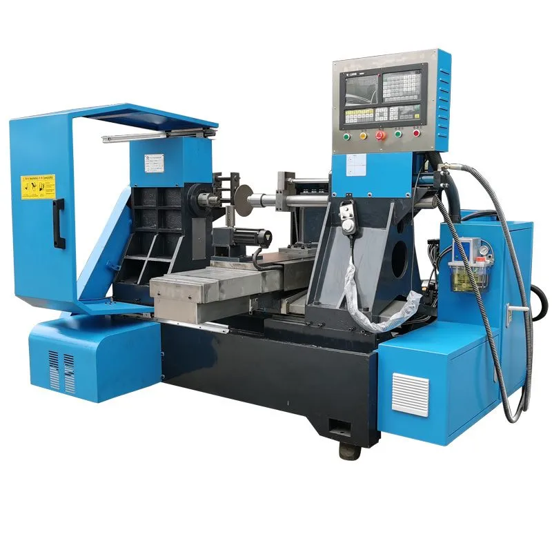
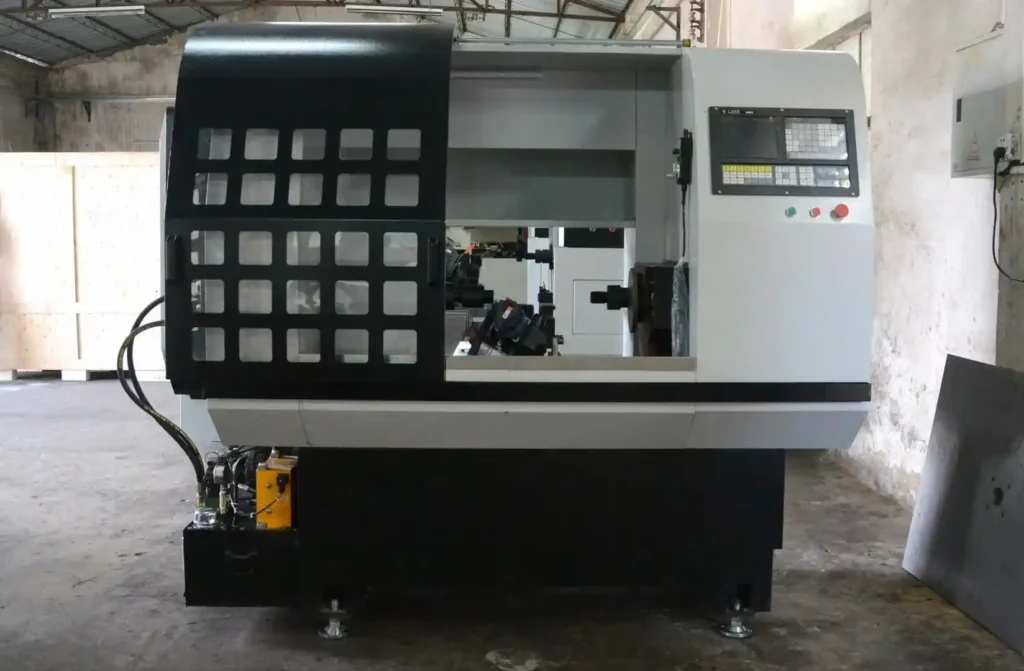
Flow forming machines, also known as spin forming machines or metal spinning machines, are sophisticated pieces of equipment used in metalworking and manufacturing processes. The technology behind flow forming involves the incremental compression and elongation of a workpiece, typically a cylindrical metal blank, using controlled pressure and spinning motion. This process results in the transformation of the blank into a desired shape with improved mechanical properties and dimensional accuracy.
Flow forming, also known as metal spinning, flow turning, or incremental rotary forming, is a metalworking process used to form a metal disc or tube into a desired shape through controlled material flow. This process is typically performed using specialized machines known as flow forming machines.
Flow forming machines use a combination of axial and radial forces to shape a workpiece while it is rotating. The process involves applying pressure to the workpiece using rollers or tooling, which gradually stretches and forms the metal into the desired shape. The controlled material flow results in improved mechanical properties and surface finish of the final part.
Flow forming machines consist of several key components, including:
- Spindle and Chuck: These components hold and rotate the workpiece during the forming process.
- Rollers or Tooling: The rollers or forming tools apply pressure to the workpiece, shaping it as it rotates.
- Hydraulic or Servo Systems: These systems provide the necessary force and control for the forming process.
- Control System: Modern flow forming machines are often equipped with CNC control systems to precisely manage the forming operation.
- Safety Features: These include interlocks, guards, and emergency stop mechanisms to ensure safe operation.
Flow forming offers several advantages, including:
- Improved Mechanical Properties: The process results in parts with enhanced strength, fatigue resistance, and dimensional accuracy.
- Material Savings: Minimal material waste due to the controlled forming process.
- Surface Finish: Flow formed parts often exhibit a high-quality surface finish, reducing the need for additional finishing operations.
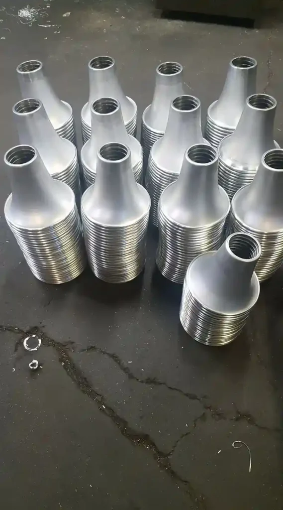
- Complex Shapes: The process allows for the production of complex and lightweight parts with relative ease.
Flow forming is utilized in various industries for the production of components such as:
- Automotive: Including wheels, drive shafts, and suspension components.
- Aerospace: For manufacturing aerospace components with high strength-to-weight ratios.
- Medical: In the production of precision components for medical devices and equipment.
- Industrial Equipment: For creating specialized parts used in heavy machinery and equipment.
Flow forming machines play a crucial role in the manufacturing of high-strength, lightweight, and complex metal components across a range of industries. With the ability to enhance mechanical properties and produce intricate shapes, flow forming continues to be a valuable metalworking process, contributing to the advancement of modern engineering and design.
For specific technical specifications and further details, it is recommended to consult flow forming machine manufacturers and industry-specific resources.
Flow Forming Machines
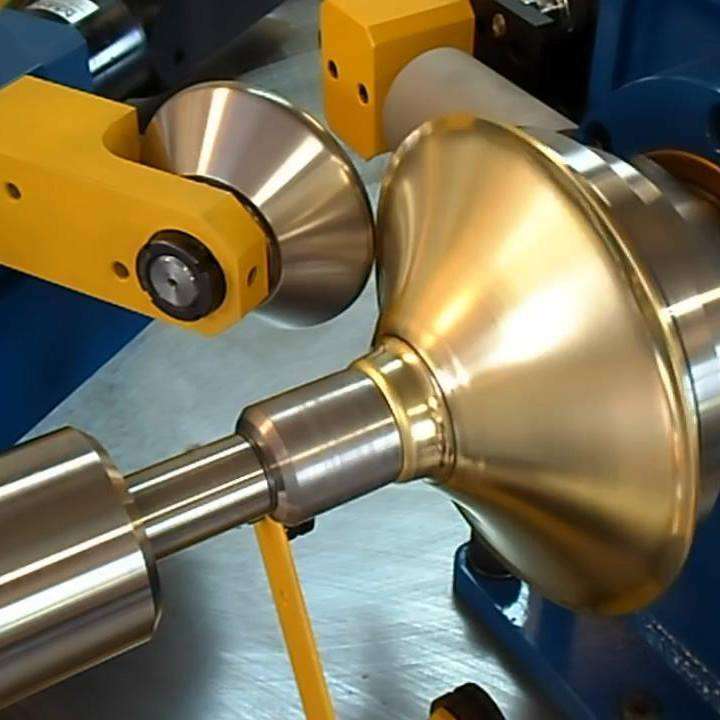
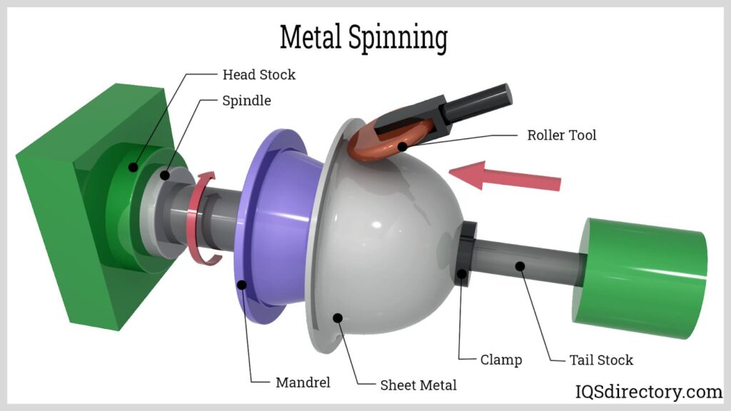
Flow forming machines are the workhorses behind a surprising number of everyday objects, silently shaping metal tubes into precise, high-quality components. Imagine a metal lathe, but instead of a cutting tool, a smooth mandrel is inserted into a hollow tube. This mandrel embodies the final desired shape. Now picture a series of rollers, strategically positioned around the tube, applying continuous pressure. As the tube rotates, the rollers squeeze the metal, forcing it to conform to the contours of the internal mandrel. This interplay of pressure and rotation is the essence of flow forming.
The magic of flow forming lies in its ability to plastically deform the metal, essentially reshaping it without severing any material. This allows for the creation of parts with remarkably thin walls, often exceeding the capabilities of traditional techniques like extrusion or forging. Think lightweight yet strong components for bicycles, aircraft landing gear, or even golf club shafts. But the benefits extend beyond just wall thickness. Flow forming excels at producing parts with a remarkably consistent wall throughout, a crucial feature for applications demanding uniform pressure distribution or fluid flow. Imagine the intricate channels within a fuel injector or the seamless tubing for a high-pressure hydraulic system.
The advantages don’t stop there. Flow forming boasts an exceptional ability to deliver a smooth, high-quality surface finish. This not only enhances the aesthetics of the final product but can also improve its functionality. For instance, a smooth surface in a medical implant minimizes the risk of infection, while a polished finish on a firearm barrel enhances accuracy. The forgeable nature of the process also allows flow forming to tackle a wider range of shapes compared to other methods. Imagine the complex geometries of a rocket engine nozzle or the intricate curves of a motorcycle frame – flow forming can handle them with remarkable precision.
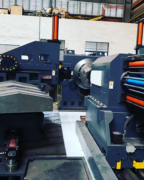
While the core concept of flow forming is relatively straightforward, the actual machines themselves are marvels of engineering. They come in various configurations, with two, three, or even four rollers strategically positioned to ensure optimal pressure distribution and even forming. Modern flow forming machines are often CNC-controlled, allowing for precise control over mandrel rotation, roller pressure, and overall process parameters. This level of automation ensures consistent results and enables the creation of increasingly intricate shapes.
The applications of flow forming machines are vast and span numerous industries. From the automotive sector, where they churn out lightweight yet robust drive shafts and suspension components, to the aerospace industry, where they produce high-precision engine components and landing gear struts, flow forming plays a vital role. The oil and gas industry relies on flow formed parts for their pipelines and well equipment, demanding exceptional strength and reliability. Even the medical device and sporting goods industries utilize flow forming for components requiring a combination of strength, precision, and a smooth surface finish.
In conclusion, flow forming machines are more than just metalworking marvels; they are silent contributors to our everyday lives. Their ability to produce high-precision, lightweight parts with exceptional surface finishes makes them invaluable across a wide range of industries. So, the next time you marvel at the sleek lines of a sports car, the power of a jet engine, or the intricate workings of a medical device, remember, there’s a good chance a flow forming machine played a crucial role in bringing it to life.
Flow forming machines operate based on several fundamental principles:
- Workpiece Preparation: The process begins with a cylindrical metal blank, usually made of materials such as aluminum, stainless steel, titanium, or alloys. The blank is mounted securely onto the spinning machine’s mandrel or chuck.
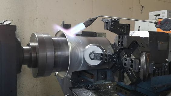
- Spinning Motion: The machine rotates the blank at high speeds while simultaneously applying axial pressure through rollers or tooling. The spinning motion ensures uniform material deformation and distribution of forces.
- Incremental Forming: Flow forming is an incremental process where the tool gradually shapes the workpiece by applying radial pressure along its length. This controlled deformation refines the material structure and enhances its properties.
- Material Flow and Compression: As the blank spins, the rollers or forming tools exert radial pressure, causing the metal to flow plastically. This controlled compression alters the metal’s grain structure, enhancing its strength and durability.
- Tool Path Control: Advanced flow forming machines utilize computer-controlled systems to precisely regulate the tool path, pressure, and speed. This automation ensures consistent quality and dimensional accuracy.
Key Components of Flow Forming Machines
Flow forming machines consist of several essential components:
- Mandrel or Chuck: The workpiece is mounted onto a rotating mandrel or chuck, providing support and stability during the forming process.
- Rollers or Tooling: These components apply pressure to the rotating workpiece, shaping it gradually into the desired form. The rollers can be adjusted for different profiles and geometries.
- Drive System: The machine is equipped with a powerful motor and drive system to achieve high-speed rotation of the workpiece. Variable speed control allows for precise process optimization.
- Control System: Modern flow forming machines integrate sophisticated control systems, often computer numerical control (CNC), to manage the forming process parameters such as speed, pressure, and tool movements.
- Coolant System: To manage heat generated during the deformation process, flow forming machines may incorporate coolant systems to maintain optimal working temperatures and prevent material overheating.
Mandrel or Chuck of the Flow Forming Machine
In flow forming machines, the mandrel and chuck are critical components that play essential roles in the metal forming process. Here’s a detailed explanation of each:
Mandrel
Function:
- The mandrel is a cylindrical tool around which the metal workpiece is shaped.
- It provides the internal support and shape for the workpiece as it is being formed.
- During the flow forming process, the workpiece is placed over the mandrel, which rotates along with the workpiece.
Characteristics:
- Material: Typically made of hardened steel or other materials that can withstand high pressure and temperatures.
- Design: The mandrel’s design matches the internal shape of the desired finished part.
- Precision: High precision is required to ensure the accurate formation of the workpiece.
- Durability: Must be durable enough to resist wear and deformation during the forming process.
Applications:
- Used in manufacturing parts like rocket casings, automotive components, and other cylindrical or tubular parts.
- Essential for producing high-precision, high-strength components.
Chuck
Function:
- The chuck is a clamping device that holds the workpiece securely in place during the forming process.
- It ensures the workpiece remains stationary relative to the rotating mandrel.
- Provides the necessary torque and support to prevent slipping and misalignment.
Characteristics:
- Types: Can be mechanical (manual or automatic) or hydraulic, depending on the machine and application.
- Grip: Designed to provide a strong and secure grip on the workpiece.
- Adjustment: Adjustable to accommodate different sizes and shapes of workpieces.
- Accuracy: Ensures concentricity and alignment of the workpiece with the mandrel.
Applications:
- Used in flow forming machines to hold various metal workpieces, ensuring stability and precision during forming.
- Critical in industries such as aerospace, automotive, and defense, where precise alignment and secure clamping are essential.
Interaction Between Mandrel and Chuck
- Setup:
- The workpiece is placed over the mandrel.
- The chuck grips the workpiece at one end, ensuring it is securely held in place.
- Forming Process:
- The mandrel and workpiece rotate together.
- Rollers or forming tools apply pressure to the workpiece, causing it to flow and take the shape of the mandrel.
- The chuck maintains the position and alignment of the workpiece, ensuring consistent and precise forming.
- Completion:
- Once the forming process is complete, the chuck releases the workpiece.
- The finished part is removed from the mandrel.
Importance in Flow Forming
- Mandrel: Provides the shape and support necessary for the accurate formation of the workpiece. It is essential for achieving the desired internal dimensions and structural integrity of the part.
- Chuck: Ensures the workpiece remains securely in place during the high-pressure forming process, maintaining precision and preventing defects.
Both the mandrel and chuck are indispensable components of flow forming machines, working together to produce high-quality, precision-formed metal parts.
Rollers or Tooling
In flow forming machines, rollers or tooling are crucial components that shape the metal workpiece by applying controlled pressure. Here’s an in-depth look at the roles, characteristics, and applications of rollers or tooling in flow forming:
Rollers
Function:
- Rollers are the primary tools used to deform the metal workpiece by pressing it against the rotating mandrel.
- They apply radial and axial forces to the workpiece, causing it to flow and conform to the shape of the mandrel.
Characteristics:
- Material: Typically made from high-strength, wear-resistant materials such as tool steel or carbide.
- Shape and Size: Designed according to the specific requirements of the workpiece and the desired final shape.
- Surface Finish: Polished and smooth to reduce friction and prevent damage to the workpiece.
- Cooling: Often cooled to manage heat generated during the forming process and prolong tool life.
Types:
- Radial Rollers: Apply pressure perpendicularly to the workpiece, controlling its thickness.
- Axial Rollers: Apply pressure along the length of the workpiece, controlling its length and diameter.
- Combination Rollers: Can perform both radial and axial forming in a single operation.
Applications:
- Aerospace: Manufacturing thin-walled, high-strength components such as rocket motor casings.
- Automotive: Producing lightweight, durable parts like drive shafts and wheels.
- Medical: Forming precision components for medical devices and implants.
Tooling
Function:
- Tooling refers to the various tools and fixtures used in conjunction with rollers to support and shape the workpiece.
- Includes mandrels, dies, and other custom tools that help achieve the desired part geometry.
Characteristics:
- Custom Design: Tailored to specific part requirements and the type of flow forming process.
- Durability: Made from materials that can withstand high forces and repeated use.
- Precision: Manufactured to tight tolerances to ensure accurate part formation.
Types:
- Mandrels: Provide internal support and define the inner shape of the workpiece.
- Support Tools: Additional tools that help maintain the workpiece’s position and shape during forming.
- Cutting Tools: Used for trimming and finishing the workpiece after the forming process.
Applications:
- Defense: Producing ammunition casings and other critical defense components.
- Energy: Manufacturing parts for wind turbines and other energy generation systems.
- Industrial Machinery: Creating precision parts for various types of industrial equipment.
Interaction Between Rollers and Tooling
- Setup:
- The workpiece is placed on the mandrel.
- Rollers and any necessary support tools are positioned according to the process requirements.
- Forming Process:
- The mandrel and workpiece rotate together.
- Rollers move along programmed paths, applying controlled pressure to the workpiece.
- The workpiece material flows and conforms to the shape defined by the mandrel and tooling.
- Cooling and Lubrication:
- Coolants and lubricants are often used to reduce friction, manage heat, and improve surface finish.
- Cooling also helps extend the life of the rollers and tooling.
- Completion:
- Once the desired shape and dimensions are achieved, the forming process stops.
- The workpiece is removed from the mandrel, and any finishing operations are performed.
Importance in Flow Forming
- Precision and Control: Rollers and tooling provide the precise control needed to achieve high-quality, dimensionally accurate parts.
- Material Properties: The flow forming process, aided by effective rollers and tooling, enhances the mechanical properties of the workpiece, such as strength and hardness.
- Versatility: Various roller and tooling designs allow for the production of a wide range of shapes and sizes, making flow forming suitable for numerous applications.
Rollers and tooling are fundamental to the flow forming process, ensuring that metal workpieces are accurately and efficiently shaped to meet the stringent requirements of various industries.
Applications
Flow forming technology finds extensive applications across various industries:
- Aerospace: Used to manufacture lightweight and high-strength components such as rocket motor casings, satellite parts, and aircraft structural elements.
- Automotive: Commonly employed for producing wheels, drive shafts, and exhaust components due to its ability to create strong and precise parts.
- Medical Devices: Flow forming is utilized in manufacturing surgical instruments, prosthetic components, and specialized medical equipment requiring biocompatible materials.
- Energy Sector: Flow formed parts are integral to power generation equipment, including turbine components and heat exchangers, due to their enhanced mechanical properties and dimensional accuracy.
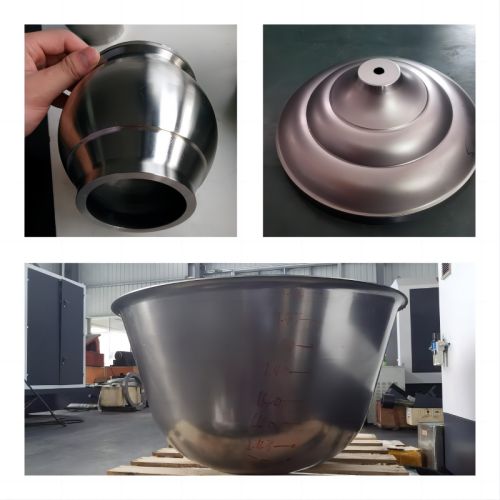
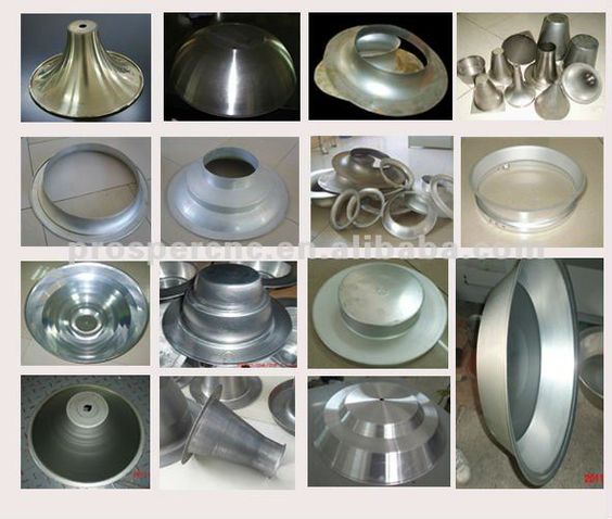
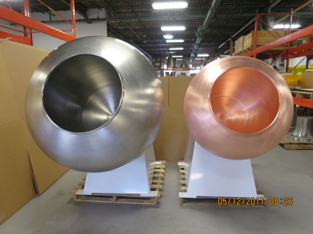
- Consumer Goods: Flow forming is applied in producing high-quality kitchenware, lighting fixtures, and decorative items due to its ability to form complex shapes with thin walls.
Advantages
Flow forming offers several advantages over traditional forming methods:
- Improved Material Properties: The process refines the metal’s grain structure, resulting in enhanced strength, hardness, and fatigue resistance.
- Dimensional Accuracy: Flow forming achieves tight tolerances and excellent surface finish, reducing the need for secondary machining operations.
- Material Savings: By precisely shaping the workpiece, flow forming minimizes material waste compared to other forming techniques.
- Versatility: The process can be adapted to various metals and alloys, making it suitable for a wide range of applications across industries.
- Cost-Effective: Despite initial equipment costs, flow forming often reduces overall production costs through enhanced efficiency and material utilization.
In summary, flow forming machines play a crucial role in modern manufacturing by enabling the production of high-quality, high-performance metal components with superior mechanical properties and dimensional accuracy. The technology continues to evolve with advancements in automation and control systems, further expanding its applications across diverse industries.
Flow forming machines, also referred to as spin forming machines or metal spinning machines, are advanced tools used in metalworking and manufacturing processes to shape cylindrical metal blanks into desired forms with improved mechanical properties and dimensional accuracy.
Operating Principles
Flow forming machines operate based on several fundamental principles:
- Workpiece Preparation: The process begins with a cylindrical metal blank, typically made of materials like aluminum, stainless steel, titanium, or alloys. The blank is securely mounted onto the machine’s mandrel or chuck.
- Spinning Motion: The machine rotates the blank at high speeds while applying axial pressure through rollers or tooling. This spinning motion ensures uniform material deformation and distribution of forces.
- Incremental Forming: Flow forming is an incremental process where the tool gradually shapes the workpiece by applying radial pressure along its length. This controlled deformation refines the material structure and enhances its properties.
- Material Flow and Compression: As the blank spins, the rollers or forming tools exert radial pressure, causing the metal to flow plastically. This controlled compression alters the metal’s grain structure, enhancing its strength and durability.
- Tool Path Control: Advanced flow forming machines utilize computer-controlled systems to precisely regulate the tool path, pressure, and speed. This automation ensures consistent quality and dimensional accuracy.
Flow forming machines consist of several essential components:
- Mandrel or Chuck: The workpiece is mounted onto a rotating mandrel or chuck, providing support and stability during the forming process.
- Rollers or Tooling: These components apply pressure to the rotating workpiece, shaping it gradually into the desired form. The rollers can be adjusted for different profiles and geometries.
- Drive System: Equipped with a powerful motor and drive system to achieve high-speed rotation of the workpiece. Variable speed control allows for precise process optimization.
- Control System: Modern flow forming machines integrate sophisticated control systems, often computer numerical control (CNC), to manage the forming process parameters such as speed, pressure, and tool movements.
- Coolant System: Incorporates coolant systems to manage heat generated during the deformation process, maintaining optimal working temperatures and preventing material overheating.
Applications of Flow Forming
Flow forming technology finds extensive applications across various industries:
- Aerospace: Manufacturing lightweight and high-strength components like rocket motor casings, satellite parts, and aircraft structural elements.
- Automotive: Producing wheels, drive shafts, and exhaust components due to its ability to create strong and precise parts.
- Medical Devices: Utilized in manufacturing surgical instruments, prosthetic components, and specialized medical equipment requiring biocompatible materials.
- Energy Sector: Integral to power generation equipment, including turbine components and heat exchangers, due to enhanced mechanical properties and dimensional accuracy.
- Consumer Goods: Applied in producing high-quality kitchenware, lighting fixtures, and decorative items due to its ability to form complex shapes with thin walls.
Flow forming technology has a wide range of application areas across industries due to its ability to produce high-quality, high-strength components with enhanced mechanical properties. Some notable application areas include:
- Aerospace Industry:
- Flow forming is used extensively in aerospace for manufacturing critical components such as rocket motor casings, satellite parts, aircraft engine components, and structural elements. The process helps in producing lightweight yet durable parts that meet stringent aerospace standards.
- Automotive Sector:
- In the automotive industry, flow forming is employed to fabricate wheels, drive shafts, suspension components, and exhaust system parts. Flow-formed wheels, for example, are known for their lightweight construction, strength, and precise dimensional accuracy.
- Medical Equipment:
- Flow forming plays a crucial role in the production of medical devices and equipment. It is used to manufacture surgical instruments, prosthetic components, and medical implants. The process ensures the production of biocompatible parts with excellent surface finish and mechanical properties.
- Energy and Power Generation:
- Flow forming technology is utilized in the energy sector for manufacturing components used in power generation equipment such as turbine blades, generator parts, heat exchangers, and components for renewable energy systems. The high-strength and dimensional accuracy of flow-formed parts are critical for efficient and reliable operation.
- Industrial Machinery:
- Flow forming is applied in various industrial machinery applications, including the production of shafts, gears, bearings, and hydraulic components. The process allows for the creation of parts with complex shapes and precise tolerances, contributing to the overall performance and reliability of industrial equipment.
- Consumer Goods:
- Consumer product manufacturers use flow forming to produce high-quality goods such as kitchenware, lighting fixtures, decorative items, and sports equipment. Flow forming enables the fabrication of aesthetically appealing products with thin walls and intricate designs.
- Defense and Military:
- Flow forming technology finds use in defense and military applications for manufacturing components used in vehicles, weaponry, and equipment. The process helps in producing lightweight and durable parts that meet the demanding requirements of defense applications.
- Research and Development:
- Flow forming is also employed in research and development settings for prototyping and producing specialized components used in experimental setups, scientific instruments, and laboratory equipment. The ability to create custom shapes and sizes with precise material properties is valuable in R&D environments.
These application areas highlight the versatility and significance of flow forming technology across diverse industries. The process continues to evolve with advancements in materials science, automation, and quality control, further expanding its reach and impact in manufacturing sectors globally.
Advantages
Flow forming offers several advantages over traditional forming methods:
- Improved Material Properties: Refines the metal’s grain structure, resulting in enhanced strength, hardness, and fatigue resistance.
- Dimensional Accuracy: Achieves tight tolerances and excellent surface finish, reducing the need for secondary machining operations.
- Material Savings: Minimizes material waste compared to other forming techniques.
- Versatility: Adaptable to various metals and alloys, suitable for a wide range of applications across industries.
- Cost-Effective: Reduces overall production costs through enhanced efficiency and material utilization.
Flow forming machines play a crucial role in modern manufacturing by enabling the production of high-quality, high-performance metal components with superior mechanical properties and dimensional accuracy. The technology continues to evolve with advancements in automation and control systems, further expanding its applications across diverse industries.
The forming process in manufacturing refers to a group of techniques used to shape and manipulate solid materials, typically metals, into specific parts or components. These techniques are essential in creating a wide range of products across various industries. The forming process can involve a combination of mechanical, hydraulic, or thermal forces to achieve the desired shape and properties of the material.
Types of Forming Processes
1. Metal Stamping
- Metal stamping involves using a press to form flat metal sheets into a desired shape. This process is commonly used to create parts for automotive, aerospace, and appliance industries.
2. Forging
- Forging involves the application of compressive forces to shape metal using hammers, presses, or dies. It is utilized to create high-strength components such as crankshafts, connecting rods, and gears.
3. Rolling
- Rolling is a process that involves passing metal through a pair of rolls to reduce thickness or change the cross-sectional profile. It is commonly used in the production of sheets, plates, and structural sections.
4. Extrusion
- Extrusion involves forcing metal through a die to create objects with a fixed cross-sectional profile. This process is used to manufacture products such as pipes, rods, and complex structural components.
5. Casting
- Casting uses molds to pour molten metal into a desired shape, allowing for the production of intricate parts with complex geometries. It is widely employed in the production of engine blocks, turbine blades, and other intricate components.
6. Spinning/Flow Forming
- Spinning, also known as flow forming, is a process that involves forming a metal disc or tube into a desired shape through controlled material flow. It is utilized to produce components such as aerospace parts, automotive wheels, and medical devices.
The forming processes play a critical role in the manufacturing industry due to several key reasons:
- Versatility: They enable the production of a wide variety of parts with diverse shapes and sizes.
- Material Efficiency: Forming processes often result in minimal material waste, making them cost-effective.
- Mechanical Properties: They can improve the mechanical properties of materials, such as strength, ductility, and fatigue resistance.
- Customization: These processes allow for the creation of custom and specialized components to meet specific industry and product requirements.
The forming process is integral to modern manufacturing, providing the means to create intricate and high-quality components essential for diverse industries. The ability to shape and manipulate materials with precision and efficiency ensures the continued relevance and importance of forming processes in the manufacturing sector.
Metal forming is a fundamental manufacturing process that involves shaping metal materials into desired geometries without adding or removing material. This process leverages mechanical forces to deform metals, transforming raw materials into components with specific dimensions and properties. Metal forming is integral to numerous industries, including automotive, aerospace, construction, and consumer goods, due to its versatility and efficiency in producing a wide range of products.
Metal forming processes can be broadly categorized into hot forming and cold forming. Hot forming involves heating the metal to a temperature above its recrystallization point, which enhances ductility and reduces the force required for deformation. In contrast, cold forming is performed at or near room temperature, leading to increased strength and improved surface finish but requiring higher forces due to reduced material ductility.
Key Types of Metal Forming Processes
- Forging: This process involves shaping metal using localized compressive forces, typically delivered by hammers or presses. Forging can be classified into open-die forging, where the metal is freely deformed between flat or contoured dies, and closed-die forging, which uses shaped dies to produce specific profiles.
- Rolling: Rolling reduces the thickness of metal by passing it through one or more pairs of rollers. It can be performed hot or cold and is essential for producing sheets, plates, and structural shapes like beams and rails.
- Extrusion: In extrusion, metal is forced through a die to create long objects with a fixed cross-sectional profile. This process is commonly used to produce pipes, tubes, and complex profiles for various applications.
- Drawing: Drawing involves pulling metal through a die to reduce its diameter and increase its length. This process is widely used for manufacturing wires, rods, and tubes.
- Flow Forming: Flow forming is a specialized form of rotary metal forming that combines aspects of spinning and stretching. It is highly effective for producing seamless, high-precision components such as aerospace parts, automotive wheels, and pressure vessels.
How Flow Forming Relates to Metal Forming
Flow forming is a subset of metal forming that specifically focuses on the precise shaping of metal tubes and cylindrical parts. Unlike traditional metal forming techniques that might require multiple steps to achieve complex geometries, flow forming can produce high-precision components in fewer operations, enhancing efficiency and reducing material waste.
Flow forming differs from conventional metal forming in several key ways:
- Rotary Motion: Flow forming employs a rotating mandrel or chuck that facilitates the continuous deformation of the metal as it is fed through the machine. This rotary motion ensures uniform material flow and consistent wall thickness.
- Controlled Material Flow: The process meticulously controls the flow of material by applying localized forces, which allows for intricate shapes and tight tolerances. This precision is particularly advantageous for industries requiring high-quality components with minimal deviations.
- Seamless Production: Flow forming produces seamless parts, eliminating the need for welding or joining separate components. This seamlessness enhances the structural integrity and performance of the final product.
Applications in Different Industries
Metal forming, including flow forming, plays a pivotal role across various industries by enabling the creation of components that meet stringent performance and quality standards.
- Aerospace: The aerospace industry relies on metal forming to produce lightweight, high-strength components such as fuselage sections, engine parts, and landing gear. Flow forming is particularly valuable for manufacturing turbine disks and other critical components that demand exceptional precision and reliability.
- Automotive: In the automotive sector, metal forming is essential for producing engine parts, chassis components, and wheels. Flow forming contributes to the manufacturing of lightweight yet strong wheels, improving vehicle performance and fuel efficiency.
- Industrial Machinery: Metal forming processes are used to create various machinery parts, including shafts, gears, and housings. These components require precise dimensions and robust material properties to ensure optimal functionality and longevity.
- Consumer Goods: Even in consumer products, metal forming is indispensable. Items such as cookware, tools, and sporting equipment benefit from the versatility and precision offered by metal forming techniques.
Metallurgical Properties
Metal forming processes significantly influence the metallurgical properties of the final product. During deformation, the metal undergoes changes in its microstructure, which can enhance certain properties while potentially introducing others.
- Grain Refinement: The plastic deformation involved in metal forming leads to grain refinement, where the grain size of the metal decreases. Finer grains typically enhance the strength and toughness of the material.
- Strain Hardening: Also known as work hardening, strain hardening occurs as dislocations within the metal’s crystal structure multiply and interact during deformation. This process increases the material’s tensile strength and hardness but may reduce its ductility.
- Texture Development: The directional flow of material during forming can lead to the development of crystallographic textures, which influence the anisotropic properties of the metal. Understanding and controlling texture development is crucial for achieving desired mechanical properties.
- Residual Stresses: Metal forming can introduce residual stresses within the material, which may affect the component’s performance and dimensional stability. Proper process control and subsequent heat treatments can mitigate undesirable residual stresses.
Latest Advancements in Metal Forming Technologies
The metal forming industry continues to evolve with advancements aimed at enhancing precision, efficiency, and material capabilities. Key innovations include:
- Automation and Robotics: The integration of automation and robotic systems in metal forming processes has led to increased production rates, improved consistency, and reduced labor costs. Automated systems ensure precise control over process parameters, enhancing overall quality.
- Advanced Materials: The development of new alloys and composite materials expands the possibilities of metal forming. These materials often exhibit superior strength-to-weight ratios, corrosion resistance, and thermal stability, making them ideal for high-performance applications.
- Simulation and Modeling: Advanced computer simulations and modeling tools allow engineers to predict and optimize metal forming processes. These tools help in understanding material behavior under various conditions, reducing trial-and-error approaches and accelerating product development.
- Additive Manufacturing Integration: Combining traditional metal forming with additive manufacturing techniques, such as hybrid manufacturing, enables the creation of complex geometries that were previously difficult or impossible to achieve. This integration opens new avenues for innovation in component design and functionality.
- Sustainable Practices: There is a growing emphasis on sustainability within metal forming. Innovations include the use of energy-efficient machinery, recycling of scrap materials, and the development of eco-friendly lubricants and coatings. These practices contribute to reducing the environmental impact of metal forming processes.
- Enhanced Surface Treatments: Advanced surface treatments, such as coating technologies and surface hardening, are being integrated with metal forming to improve the wear resistance, corrosion resistance, and aesthetic qualities of the final products. These treatments extend the lifespan and performance of metal components.
Conclusion
Metal forming is a cornerstone of modern manufacturing, enabling the creation of a vast array of components essential to various industries. The versatility and efficiency of metal forming processes, including specialized techniques like flow forming, make them indispensable for producing high-quality, high-performance products. Advances in technology continue to push the boundaries of what is possible in metal forming, driving innovation and enhancing the capabilities of manufacturers worldwide. As industries demand more precise, durable, and lightweight components, metal forming will remain a critical area of focus, continually evolving to meet the challenges of the future.
Cold Working

Overview of Cold Working
Cold working, also known as cold forming, is a metalworking process in which metals are shaped at temperatures below their recrystallization point, typically at or near room temperature. Unlike hot working, which involves heating the material, cold working uses mechanical forces to deform the metal. This process results in increased strength, improved surface finish, and dimensional accuracy while maintaining the structural integrity of the material.
Cold working is an integral process in manufacturing industries where high precision and enhanced mechanical properties are required. It is particularly valuable in the production of components for the aerospace, automotive, medical, and industrial sectors. Some common cold working techniques include rolling, drawing, forging, and flow forming.
Cold Working vs. Flow Forming
Flow forming is a specialized type of cold working that combines aspects of metal spinning and extrusion. Both cold working and flow forming share the principle of shaping metal without heating it, leading to strain hardening and improved mechanical properties. However, flow forming is unique in its ability to create seamless, thin-walled, cylindrical components with high precision and tight tolerances.
- Cold Working: In conventional cold working, deformation is achieved through processes like stamping or drawing, where the metal is stretched or compressed into shape. Cold working can produce parts with increased strength but often requires multiple steps or secondary processes to achieve complex geometries.
- Flow Forming: Flow forming, on the other hand, achieves complex shapes in fewer steps by controlling material flow with precise force application. This technique not only enhances the material properties but also allows for more intricate and uniform designs, making it ideal for producing parts like wheel rims, pressure vessels, and aerospace components.
Mechanics of Cold Working
The mechanics of cold working revolve around the plastic deformation of metals. When a metal is subjected to mechanical forces, the crystal lattice structure is disrupted, causing dislocations to multiply and interact. This process increases the strength and hardness of the material through what is known as strain hardening or work hardening.
Key aspects of cold working mechanics include:
- Dislocation Movement: In cold working, dislocations within the metal’s crystal structure move and accumulate as the material is deformed. The more the metal is deformed, the greater the number of dislocations, which eventually impede further movement, increasing the material’s strength.
- Strain Hardening: As the dislocation density increases, the metal becomes harder and stronger but less ductile. This phenomenon, known as strain hardening, is a critical factor in cold working, as it allows for the creation of components with superior mechanical properties.
- Yield Strength: Cold working increases the metal’s yield strength, the point at which it begins to deform plastically. This improvement is especially beneficial in industries where components are subjected to high loads and stresses.
- Ductility Reduction: While cold working increases strength, it also reduces the metal’s ductility, or its ability to undergo plastic deformation without fracturing. To balance this, manufacturers may employ annealing to relieve internal stresses and restore ductility, depending on the application.
Effect on Material Properties
Cold working significantly alters the material properties of metals. By manipulating the microstructure of the material, cold working enhances several key attributes:
- Increased Strength and Hardness: Cold working processes, such as rolling, drawing, and flow forming, increase the material’s strength and hardness through strain hardening. This is particularly important for components that need to withstand high-stress environments, such as aerospace parts, automotive components, and medical implants.
- Improved Surface Finish: The precise nature of cold working ensures a smooth surface finish, which is critical in applications where surface quality impacts performance, such as in hydraulic cylinders, medical devices, and automotive parts.
- Dimensional Accuracy: Cold working offers high precision and tight tolerances, making it ideal for producing components with exact dimensions. This is crucial in industries like aerospace and automotive, where even minor deviations in part dimensions can affect performance and safety.
- Residual Stresses: Cold working can introduce residual stresses into the material, which may affect its long-term performance, particularly in high-temperature or corrosive environments. However, these stresses can be managed or relieved through post-processing techniques like annealing.
- Reduced Ductility: While cold working increases strength, it reduces ductility. The trade-off between strength and ductility must be carefully managed depending on the specific application. In cases where ductility is critical, post-process heat treatments may be employed to restore it.
- Fatigue Resistance: Cold working generally improves the material’s resistance to fatigue, which is the progressive failure of a material due to cyclic loading. This is especially beneficial in applications like aerospace and automotive, where components are subjected to repeated stress cycles.
Cold Working in Flow Forming Machines
In flow forming machines, cold working plays a crucial role in shaping cylindrical components with precision. The process involves a mandrel (a rotating core) and rollers that apply radial pressure to the metal, gradually stretching and thinning it into the desired shape.
Key steps of cold working in flow forming machines include:
- Material Loading: The process begins by loading a preformed cylindrical blank, often made of materials like aluminum, steel, or titanium, onto the mandrel.
- Mandrel Rotation: The mandrel rotates at a controlled speed, while rollers apply radial pressure to the blank. This rotation helps control material flow, ensuring consistent deformation.
- Radial Force Application: The rollers gradually thin the material by applying a controlled radial force. This cold working action leads to strain hardening and an increase in the part’s strength.
- Wall Thickness Control: One of the advantages of flow forming is the ability to create parts with uniform wall thickness, which is critical for components like pressure vessels, tubes, and rocket motor casings.
- Final Component: Once the part reaches the desired dimensions, it is removed from the machine. The resulting component has improved mechanical properties, such as higher tensile strength and enhanced fatigue resistance, making it suitable for high-performance applications.
Advantages of Cold Working in Flow Forming
Cold working in flow forming offers several advantages that make it an ideal process for producing high-quality, high-precision components:
- Improved Mechanical Properties: The cold working process leads to strain hardening, which increases the component’s strength and hardness. This is especially beneficial in industries that require lightweight yet durable parts.
- Material Efficiency: Cold working in flow forming minimizes material waste. The process creates seamless parts with near-net shapes, reducing the need for post-processing and material scrap.
- High Precision and Consistency: Flow forming machines offer tight control over material flow, resulting in components with precise dimensions and uniform wall thickness. This level of precision is crucial for applications like aerospace and automotive, where tolerances are extremely tight.
- Cost-Effective Production: While the initial setup costs for flow forming machines may be high, the process is cost-effective for high-volume production runs. It reduces the need for secondary operations like welding, grinding, and machining, ultimately saving time and labor.
Examples of Cold Working Applications
Cold working is widely used in several industries due to its ability to produce components with superior strength, dimensional accuracy, and surface finish. Some key applications include:
- Automotive Industry: Cold working is used to manufacture structural components, drive shafts, and gear parts that require high strength and wear resistance. Cold-formed parts are also used in electric vehicle manufacturing for lightweighting purposes.
- Aerospace Industry: In aerospace, cold working techniques are essential for producing lightweight, high-strength parts, such as landing gear, fuselage components, and turbine blades. Flow forming is particularly valuable for creating turbine disks and engine cases.
- Medical Devices: Cold working is used to manufacture implants, stents, and surgical instruments. These components require excellent surface finish, dimensional accuracy, and biocompatibility, all of which are achievable through cold working processes.
- Industrial Applications: In industrial machinery, cold working is employed to produce shafts, bearings, and couplings that require high strength and durability. The process is also used for tubes and piping in power plants, refineries, and chemical processing facilities.
Conclusion
Cold working is a critical manufacturing process that enhances the mechanical properties of metals, providing increased strength, hardness, and precision. Its application in flow forming machines further exemplifies its value in producing high-performance, seamless components for industries such as aerospace, automotive, and medical. The ability to achieve tight tolerances, improved surface finish, and strain-hardened materials makes cold working indispensable in modern manufacturing. As technology continues to advance, cold working techniques will evolve, offering even greater efficiencies, precision, and material capabilities in the years to come.
CNC Technology
Introduction to CNC Technology
CNC (Computer Numerical Control) technology refers to the automated control of machining tools and equipment using a computer. CNC machines are fundamental to modern manufacturing, enabling precise and efficient production of parts by controlling complex mechanical processes. This technology is employed in a wide range of industries, including metalworking, automotive, aerospace, and electronics, where high precision, consistency, and efficiency are critical.
In CNC systems, a computer interprets CAD (Computer-Aided Design) models and CAM (Computer-Aided Manufacturing) programs, converting them into instructions that control the movement and operation of the machine. These instructions guide actions like cutting, drilling, milling, and forming with incredible accuracy, making CNC machines indispensable in creating parts with tight tolerances and intricate geometries.
CNC Technology in Flow Forming Machines
Flow forming is a process that significantly benefits from the integration of CNC technology. Flow forming machines rely on multi-axis CNC control to manipulate tools and apply the precise radial forces required to shape metal components. The precision and flexibility of CNC systems allow flow forming machines to produce complex cylindrical geometries, maintain uniform wall thickness, and meet tight dimensional tolerances.
Key roles of CNC technology in flow forming machines include:
- Multi-Axis Control: CNC technology in flow forming machines enables simultaneous control of multiple axes. This is critical in controlling the mandrel’s rotation speed, roller positioning, and the feed rate of the material. By coordinating these parameters, CNC machines ensure precise material deformation and uniform part geometry.
- Precision Control: CNC systems enable operators to fine-tune parameters such as roller force, feed rates, and rotational speed, resulting in high precision in the final product. This is especially important for industries like aerospace and automotive, where even small deviations can lead to performance issues or safety concerns.
- Automated Material Flow Monitoring: Flow forming machines equipped with CNC systems can monitor the material’s flow during the forming process in real-time. This enables dynamic adjustments to parameters, ensuring consistent wall thickness and material distribution.
- Reduced Human Error: The integration of CNC in flow forming minimizes the reliance on manual operations, reducing human error and leading to improved repeatability. With CNC machines, manufacturers can produce large quantities of components that consistently meet stringent specifications.
Advantages of CNC Integration
The integration of CNC technology into flow forming machines provides several key advantages:
- Enhanced Precision: CNC systems allow for micrometer-level accuracy, making it possible to manufacture components with extremely tight tolerances. This is crucial for industries such as aerospace and medical devices, where precise dimensions can impact performance and safety.
- Repeatability: CNC technology ensures that each part produced is identical to the last, making it ideal for high-volume production. This repeatability reduces waste, minimizes material costs, and ensures that every component meets the necessary specifications.
- Complex Geometry Handling: CNC machines are capable of handling complex shapes and contours that would be difficult or impossible to achieve through manual methods. In flow forming, CNC systems can manage intricate details, such as varying wall thicknesses, stepped diameters, or tapering geometries, with ease.
- Efficient Production: CNC automation significantly reduces production time by eliminating manual adjustments between operations. Once a program is set up, the machine can operate continuously, completing multiple steps of a process in a single setup, which improves overall efficiency and throughput.
- Less Tool Wear: By precisely controlling feed rates, speeds, and forces, CNC machines help reduce tool wear. This not only extends the lifespan of expensive tooling but also maintains the quality of parts over longer production runs.
- Real-Time Adjustments: CNC systems can make real-time adjustments based on feedback from sensors or pre-set instructions, compensating for variables such as material inconsistencies or temperature changes. This feature is essential for achieving consistent part quality, especially in critical applications like pressure vessels or aerospace components.
Automation in CNC Machines
The automation of CNC machines has revolutionized manufacturing processes by introducing a high level of efficiency and accuracy in production. CNC machines can run autonomously, requiring minimal human intervention, which reduces labor costs and increases production speeds.
Key elements of CNC automation in flow forming machines include:
- Unmanned Operation: CNC machines can operate for extended periods without the need for constant supervision. This allows for lights-out manufacturing, where machines run overnight or during off-peak hours, maximizing productivity and reducing downtime.
- Automated Tool Changing: CNC machines can be equipped with automatic tool changers, allowing them to switch between different operations (e.g., drilling, cutting, or forming) without manual intervention. This improves cycle times and reduces the potential for human error during tool changes.
- Integration with Robotics: In advanced setups, CNC machines can be integrated with robotic arms that load and unload workpieces, further reducing the need for human intervention. This integration enhances the efficiency of the manufacturing process and ensures continuous, high-speed production.
- Process Monitoring and Data Logging: Modern CNC machines are equipped with sensors and software that provide real-time process monitoring. Operators can track key metrics such as spindle speed, torque, and material feed rate. The data is logged and analyzed, allowing manufacturers to identify inefficiencies or potential issues before they affect production quality.
- Feedback Systems: CNC machines utilize closed-loop control systems that continuously monitor the process and make adjustments as needed. This capability is particularly beneficial in flow forming, where the precise control of material flow is critical to maintaining part quality.
Advances in CNC Systems for Metal Forming
Over the years, CNC technology has undergone significant advancements that have improved the capabilities of flow forming machines and other metalworking equipment. Some of the most notable innovations include:
- Multi-Axis Machining: Traditional CNC machines operate in three axes (X, Y, and Z). However, modern CNC systems can control five or more axes simultaneously, allowing for more complex and precise machining of parts. In flow forming, multi-axis control enables the production of components with varying diameters, tapered sections, and complex profiles.
- High-Speed Machining: CNC machines are now capable of high-speed machining, which significantly reduces cycle times while maintaining part quality. This is particularly useful in high-volume production environments, where minimizing downtime is critical to maximizing output.
- Adaptive Control Systems: CNC systems now include adaptive control features that allow machines to adjust their operating parameters based on real-time conditions, such as tool wear or material variation. In flow forming, adaptive control ensures consistent material flow and prevents defects.
- CAD/CAM Integration: The integration of CAD (Computer-Aided Design) and CAM (Computer-Aided Manufacturing) software has streamlined the CNC programming process. Engineers can create detailed part designs in CAD software and seamlessly transfer them to CAM software, which generates the CNC code for machining.
- Advanced Simulation Tools: Modern CNC systems come equipped with simulation software that allows manufacturers to visualize the entire machining process before production begins. This reduces the risk of errors and helps optimize tool paths for faster, more efficient machining.
- Internet of Things (IoT) and Industry 4.0: CNC machines are increasingly being integrated into Industry 4.0 environments, where they are connected to networks that enable remote monitoring, predictive maintenance, and data-driven decision-making. This connectivity helps manufacturers improve efficiency, reduce downtime, and maintain a high level of product quality.
CNC Machines and the Future of Manufacturing
The future of CNC technology in flow forming and other metalworking processes is poised to become even more advanced with the continued development of artificial intelligence (AI), machine learning, and smart manufacturing technologies. Some future trends include:
- AI-Driven CNC Systems: Artificial intelligence will further improve the efficiency of CNC machines by optimizing tool paths, adjusting feed rates, and predicting maintenance needs based on real-time data. AI can also help identify the best material flow parameters in flow forming processes, leading to more consistent and reliable production.
- Additive and Hybrid Manufacturing: CNC technology is being integrated with additive manufacturing techniques to create hybrid machines capable of both subtractive (e.g., cutting, milling) and additive (e.g., 3D printing) processes. This combination allows manufacturers to produce complex parts with fewer steps, greater material efficiency, and enhanced design flexibility.
- Increased Automation: As robotics and automation technologies continue to advance, CNC systems will become even more autonomous, with minimal human intervention required. This will enable faster production times and the ability to produce increasingly complex geometries.
- Sustainability: CNC technology is also evolving toward more sustainable manufacturing practices. By optimizing material usage, reducing waste, and incorporating energy-efficient processes, CNC machines are helping manufacturers lower their environmental impact while maintaining high levels of productivity.
Conclusion
CNC technology has transformed the landscape of modern manufacturing, offering unparalleled precision, repeatability, and efficiency. In the realm of flow forming, CNC integration allows for the production of complex, high-strength components with exacting tolerances. The continued advancement of CNC systems, particularly in terms of automation, adaptive control, and multi-axis machining, is pushing the boundaries of what can be achieved in metalworking. As industries like aerospace, automotive, and medical devices demand ever-higher levels of precision and performance, CNC technology will continue to play a crucial role in meeting these requirements and driving innovation.
Material Flow
Definition and Importance of Material Flow in Manufacturing
Material flow refers to the movement and deformation of materials during the manufacturing process, particularly in forming operations such as flow forming, forging, rolling, and extrusion. In metal forming, material flow describes how the material is distributed and reshaped under external forces, affecting the final part’s geometry, strength, and internal structure. Controlling material flow is crucial to ensure that the component produced meets the required specifications, including dimensional accuracy, surface finish, and mechanical properties.
Material flow is especially important in processes like flow forming, where cylindrical shapes are formed by gradually stretching the metal over a rotating mandrel. Poor control of material flow can lead to defects like thickness variations, cracks, or inconsistent surface finishes, all of which can compromise the functionality of the final part. Proper understanding and manipulation of material flow allow manufacturers to achieve uniform thickness, fine surface texture, and enhanced mechanical properties, making it a critical factor in high-precision manufacturing.
Material Flow in Flow Forming
In the flow forming process, material flow is carefully controlled to ensure that metal is deformed uniformly as it is thinned and stretched over the mandrel. Flow forming machines apply radial forces through rollers that press the material against the mandrel, guiding it into the desired shape. The precision of material flow in this process is essential for achieving the target dimensions and maintaining the material’s structural integrity.
Key aspects of material flow in flow forming include:
- Axial and Radial Flow: In flow forming, material flow occurs in both axial (along the length of the workpiece) and radial (toward or away from the mandrel) directions. The balance between these two flow directions is critical for maintaining the part’s uniform wall thickness and structural integrity.
- Deformation Zone: The deformation zone is where the rollers apply pressure to the material, causing it to flow along the mandrel. In this zone, material flow is governed by the amount of pressure applied, the rotational speed of the mandrel, and the temperature of the material (in cold working, temperature increases due to friction).
- Material Elongation: As the material is pressed against the mandrel, it elongates axially while thinning radially. The degree of elongation is controlled by adjusting the roller feed rate and the number of passes over the workpiece. Proper control of material elongation is vital to prevent excessive thinning, which could compromise the part’s strength.
- Control Over Flow Rate: CNC technology integrated with flow forming machines ensures precise control over the material flow rate. This control allows for real-time adjustments to roller force and feed rate to compensate for variables like material inconsistencies or tool wear.
Factors Affecting Material Flow
Several factors affect the flow of material during the forming process, and understanding these factors is key to achieving the desired part properties:
- Material Properties: The composition and mechanical properties of the material being formed play a significant role in how it flows. For example, aluminum and titanium exhibit different flow characteristics due to their differences in ductility and strength. Materials with high ductility tend to flow more easily, whereas harder materials require more force to deform.
- Temperature: While flow forming is typically a cold working process, temperature still affects material flow. The friction between the rollers and the workpiece generates heat, softening the material and improving its flow. This is particularly important when working with materials like steel or superalloys, where frictional heat can help facilitate material flow.
- Pressure Applied: The amount of radial pressure exerted by the rollers on the workpiece significantly affects material flow. Insufficient pressure can result in uneven material distribution and poor surface finish, while excessive pressure may cause cracks or buckling in the material.
- Rotational Speed: The speed at which the mandrel rotates also influences material flow. Higher rotational speeds tend to facilitate more uniform flow, but if the speed is too high, it may cause the material to overheat or result in defects like surface tears.
- Tooling Design: The design of the mandrel and rollers determines how the material is guided and shaped during flow forming. Mandrels with specific profiles help control the material’s path, while roller geometry influences the degree of thinning and elongation. Proper tooling design ensures smooth material flow and uniform part dimensions.
- Number of Passes: The number of passes that the rollers make over the workpiece affects the overall quality of the material flow. Multiple passes allow for gradual thinning and stretching, ensuring consistent material flow and reducing the likelihood of defects like cracking or wrinkling.
Material Flow Control
Achieving precise control over material flow is critical for ensuring the quality of the final product in flow forming. Modern flow forming machines incorporate advanced control systems that allow manufacturers to manipulate various parameters and monitor the material flow in real-time.
- CNC-Based Control: CNC technology plays a vital role in controlling material flow during flow forming. By setting parameters like roller feed rate, rotational speed, and force application, CNC systems ensure consistent material flow throughout the process. Adjustments can be made during the operation based on real-time feedback, allowing for dynamic process control.
- Force Monitoring: Advanced flow forming machines are equipped with force sensors that continuously monitor the radial force applied by the rollers. If the force deviates from the set parameters, the system can automatically adjust the roller pressure to maintain consistent material flow and prevent defects.
- Process Simulation: Prior to actual production, manufacturers can use finite element analysis (FEA) and process simulations to predict how the material will flow during the forming process. These simulations help optimize process parameters, tooling design, and material selection to ensure smooth material flow and avoid issues such as tearing or buckling.
- Lubrication: Lubricants are often used during the flow forming process to reduce friction between the rollers and the workpiece. This improves material flow by minimizing heat generation and reducing the risk of surface defects.
Impact on Final Product Quality
Material flow has a direct impact on the quality of the final product in terms of strength, dimensional accuracy, and surface finish. Proper control of material flow ensures that the formed component meets the necessary specifications for its intended application.
- Uniform Wall Thickness: One of the primary goals in flow forming is to achieve uniform wall thickness throughout the part. Proper material flow control ensures that the material is distributed evenly along the length of the workpiece, avoiding areas of excessive thinning or thickening.
- Enhanced Mechanical Properties: Controlled material flow during forming processes like flow forming enhances the material’s mechanical properties. For example, cold working during flow forming induces strain hardening, which increases the part’s tensile strength and fatigue resistance. The flow of material also influences grain orientation, which can improve the part’s toughness and wear resistance.
- Improved Surface Finish: The precision control of material flow contributes to a smooth surface finish, which is critical in applications where the surface quality impacts performance, such as in aerospace or automotive components. A poor surface finish may lead to premature wear or corrosion, affecting the part’s longevity.
- Dimensional Accuracy: Consistent material flow ensures that the final part maintains its geometric accuracy and meets the required tolerances. In industries like aerospace, where components must meet tight dimensional specifications, achieving precise material flow is essential for ensuring the part’s performance and safety.
- Reduced Defects: Proper control over material flow helps prevent defects such as cracking, buckling, or wrinkling in the final product. These defects can compromise the part’s structural integrity and require costly rework or scrapping. By optimizing material flow, manufacturers can minimize waste and improve overall production efficiency.
Examples of Material Flow in Industry Applications
Material flow is a critical consideration in various industries that rely on metal forming techniques:
- Aerospace: In aerospace manufacturing, flow forming is used to produce turbine disks, rocket casings, and landing gear components, where uniform material flow is essential for achieving the necessary strength-to-weight ratios and fatigue resistance. The controlled flow ensures that these components can withstand extreme forces and high temperatures without failure.
- Automotive: The automotive industry uses flow forming to manufacture wheels, drive shafts, and chassis components. Achieving optimal material flow in these parts ensures that they are lightweight, durable, and resistant to fatigue, contributing to vehicle performance and safety.
- Pressure Vessels: In the production of pressure vessels for industries such as energy and petrochemical, material flow must be carefully controlled to ensure that the vessels can withstand high internal pressures. Flow forming provides the precision needed to maintain consistent wall thickness and prevent weaknesses that could lead to catastrophic failure.
- Medical Devices: Material flow is also important in the manufacture of medical implants and surgical instruments, where biocompatibility, precision, and surface finish are critical. Flow forming is used to produce stents and prosthetic components, where controlled material flow ensures that the devices meet stringent quality and performance standards.
Conclusion
Material flow is a fundamental aspect of metal forming processes, particularly in flow forming, where precise control over the deformation and distribution of material is essential for producing high-quality, high-performance components. Factors such as material properties, tooling design, and process parameters all influence how material flows during forming operations. By understanding and optimizing material flow, manufacturers can achieve improved mechanical properties, dimensional accuracy, and surface finishes, while minimizing defects and waste. As manufacturing technologies continue to advance, the ability to control material flow with greater precision will play a crucial role in meeting the ever-increasing demands for lightweight, durable, and high-precision parts across industries like aerospace, automotive, and medical devices.
Rotary Forming
Understanding Rotary Forming
Rotary forming is a metalworking process that involves the shaping of metal components by applying force through a rotating tool or mandrel. This technique is a subset of incremental forming, where small deformations are applied repeatedly to gradually shape the material into the desired form. Rotary forming is often used to manufacture parts with symmetrical geometries, such as cylinders, cones, or disks, which are common in industries like aerospace, automotive, and manufacturing.
The rotary forming process typically employs rotating dies or rollers that gradually apply pressure to the material, causing it to flow and conform to the shape of the tool. Unlike processes like stamping, where a single large force is applied, rotary forming relies on the continuous application of smaller forces, which enables more precise control over material flow and deformation.
Rotary Forming vs. Flow Forming
Rotary forming and flow forming are similar in that both processes involve the use of rotational forces to shape metal, but there are key differences in their mechanics and applications.
- Rotary Forming: In rotary forming, metal is typically deformed through rolling or spinning against a rotating tool. This process allows for gradual shaping of the material, often producing parts like cones or spherical shapes. Rotary forming is suitable for manufacturing shells, vessels, or domes and is widely used in processes like metal spinning and shear forming.
- Flow Forming: Flow forming is a more specialized process that focuses on producing thin-walled, cylindrical components by gradually stretching the metal over a mandrel. Flow forming allows for precise control of wall thickness and material properties, making it ideal for producing parts such as pressure vessels, wheels, and turbine components.
While both processes involve rotating tools and deformation forces, flow forming typically achieves more precise control over material thickness and dimensional tolerances, whereas rotary forming is more flexible for producing varied shapes with less emphasis on uniform thickness.
Applications of Rotary Forming
Rotary forming is used across several industries to produce lightweight, high-strength components that meet demanding performance criteria. Key applications include:
- Aerospace: Rotary forming is widely used to manufacture engine components, structural parts, and aerodynamic shapes. Parts like turbine rings, engine housings, and nose cones are commonly made through this process due to its ability to create complex geometries with high precision.
- Automotive: In the automotive industry, rotary forming is employed to create wheel rims, drive shafts, and exhaust system components. These parts require high strength-to-weight ratios and fatigue resistance, which rotary forming can achieve through its precise control of material properties.
- Industrial Machinery: Components such as gears, shafts, and pressure vessel parts are produced using rotary forming in various industrial applications. These parts need to withstand high loads and extreme conditions, and rotary forming provides the necessary mechanical properties.
- Consumer Goods: Rotary forming is also used to manufacture consumer goods like kitchenware, lighting fixtures, and decorative items, where symmetry, strength, and smooth surface finishes are essential.
Role in Flow Forming Machines
Rotary forming mechanisms are often integrated into flow forming machines to enhance their capabilities, especially in the production of cylindrical and conical shapes. The ability to rotate the workpiece while applying controlled pressure allows for the precise manipulation of material flow, ensuring that the final part meets exact specifications.
- Mandrel Rotation: In flow forming machines, the mandrel (a rotating cylindrical tool) is key to guiding the material during deformation. The mandrel’s rotation, combined with pressure from rollers, ensures that the material flows evenly, resulting in uniform wall thickness and consistent part geometry.
- Roller Positioning: The rollers in rotary forming machines are strategically positioned to apply incremental force to the workpiece. The rollers control the radial flow of material, determining the final thickness and elongation of the part. In flow forming machines, the precise positioning of rollers ensures the accuracy of complex geometries like stepped diameters or variable wall thicknesses.
- Tooling Design: Rotary forming relies on customized tooling to shape the workpiece. The shape and design of the mandrel, combined with the rollers’ positioning and movement, enable the creation of parts with complex profiles. The tooling must be carefully designed to ensure smooth material flow and prevent defects such as wrinkling, tearing, or cracking during the forming process.
Key Parameters in Rotary Forming
Several parameters play a critical role in determining the success of the rotary forming process. Proper control of these factors ensures that the final product meets the required specifications in terms of geometry, strength, and surface finish.
- Rotational Speed: The speed at which the workpiece rotates is a critical parameter in rotary forming. Higher rotational speeds allow for faster material deformation, but excessive speed can lead to surface defects or overheating of the material. Finding the optimal speed ensures that the material flows uniformly and maintains its structural integrity.
- Roller Force: The force exerted by the rollers on the workpiece determines how much the material is deformed. Insufficient force may result in incomplete deformation, while excessive force can cause cracking or wrinkling of the material. In advanced rotary forming machines, CNC systems control roller force to ensure precise deformation.
- Feed Rate: The rate at which the rollers advance along the workpiece (axial feed) affects the degree of material elongation. A slower feed rate allows for more gradual shaping and better control over material flow, which is critical for producing components with thin walls and complex profiles.
- Material Thickness: The thickness of the starting material influences the forming process. Thicker materials require more force to deform and may need multiple passes to achieve the desired thickness, while thinner materials can be shaped more easily but may be more prone to tearing or wrinkling.
- Material Composition: Different materials behave differently during rotary forming. Ductile metals like aluminum or copper are easier to form and flow more readily under pressure, while high-strength alloys like titanium or steel require greater force and careful control to avoid defects.
Advantages of Rotary Forming
Rotary forming offers several advantages that make it a preferred process for manufacturing high-precision, symmetrical components:
- High Precision: Rotary forming provides excellent control over dimensional accuracy and surface finish, making it ideal for parts that require tight tolerances. The gradual application of force ensures that the material is deformed uniformly, reducing the likelihood of defects.
- Flexibility in Design: The process allows for the creation of complex shapes with symmetrical geometries, such as cylinders, cones, and domes. This flexibility makes rotary forming suitable for producing components with varying wall thickness, stepped profiles, and intricate contours.
- Improved Material Properties: The process of rotary forming enhances the material’s mechanical properties through strain hardening, increasing tensile strength and fatigue resistance. This is particularly important in industries like aerospace and automotive, where components are subjected to high loads and stresses.
- Efficient Material Use: Rotary forming is a net-shape manufacturing process, meaning that it produces parts close to their final dimensions with minimal material waste. This reduces the need for secondary operations like machining, saving time and reducing material costs.
- Surface Finish: Rotary forming typically results in a smooth surface finish, eliminating the need for extensive post-processing. This is especially beneficial in applications where surface quality is critical, such as in aerospace components or pressure vessels.
- Low Tooling Costs: Compared to other forming processes like deep drawing or stamping, rotary forming requires less complex tooling. The ability to use standardized mandrels and rollers reduces tooling costs, particularly in low to medium-volume production.
Challenges in Rotary Forming
Despite its advantages, rotary forming presents several challenges that must be addressed to ensure successful production:
- Material Flow Control: Achieving consistent material flow can be difficult, especially when working with materials that are prone to wrinkling, cracking, or tearing. Precise control over process parameters is essential to avoid these defects.
- Tool Wear: The rotating dies and rollers are subjected to high levels of stress during the forming process, leading to tool wear. This can result in reduced accuracy and surface quality over time, requiring regular maintenance or replacement of tooling.
- Temperature Control: While rotary forming is typically a cold working process, the friction generated between the workpiece and the tooling can cause the material to heat up. Excessive heat can negatively impact material properties, leading to softening or distortion.
- Complex Part Designs: While rotary forming is suitable for symmetrical parts, it can be challenging to form non-symmetrical or asymmetrical shapes. In such cases, additional processes or specialized tooling may be required.
Conclusion
Rotary forming is a highly versatile and efficient manufacturing process that plays a critical role in the production of symmetrical components for industries such as aerospace, automotive, and industrial machinery. The ability to control material flow, surface finish, and dimensional accuracy makes rotary forming an ideal choice for producing lightweight, high-strength parts with complex geometries. When integrated into flow forming machines, rotary forming enhances the process’s precision and efficiency, enabling the production of components with tight tolerances and superior mechanical properties. As technology advances, the continued development of CNC control, tooling design, and automation will further improve the capabilities of rotary forming, ensuring its relevance in modern manufacturing.
Article on Metal Spinning, Flow Forming, Shear Forming, and Wheel Forming Machines
Metal forming processes are integral to modern manufacturing, enabling the production of complex and precise components across various industries. Among these processes, metal spinning, flow forming, shear forming, and wheel forming stand out due to their unique methodologies and wide-ranging applications. Each process offers distinct advantages, making them suitable for different industrial requirements.
The importance of these metal forming techniques cannot be overstated, as they play a crucial role in the automotive, aerospace, military, and industrial sectors. From producing lightweight components for aircraft to manufacturing robust parts for automobiles, these processes contribute significantly to technological advancement and economic growth.
In this article, we will delve into the intricacies of metal spinning, flow forming, shear forming, and wheel forming machines. We will explore their principles, processes, machines, applications, advantages, and challenges. By understanding these processes, manufacturers and engineers can make informed decisions about the best techniques to employ for specific projects.
2. Metal Spinning
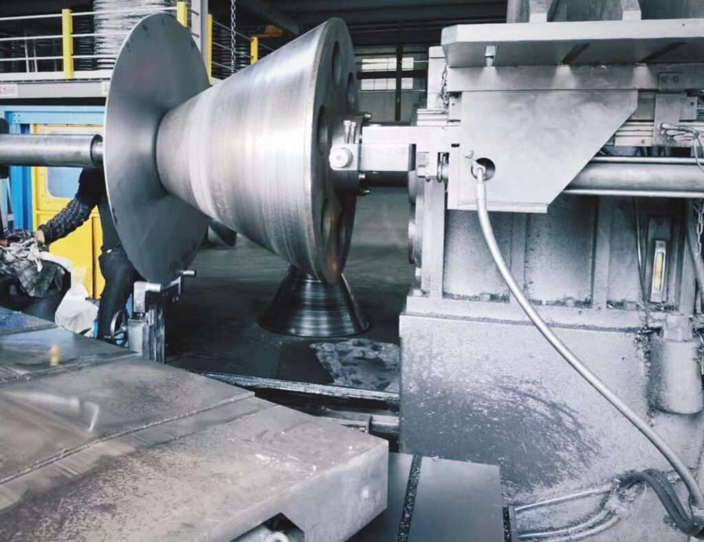
Principles and Process
Metal spinning, also known as spin forming or spinning, is a metalworking process that forms a sheet or tube of metal into an axially symmetric part. This process involves rotating a metal disc or tube at high speed while applying pressure with a tool to shape the metal around a mandrel. The metal is stretched and compressed, resulting in a seamless, symmetrical shape.
Historically, metal spinning dates back to ancient Egypt, where artisans used simple tools to spin and shape metals. Today, it has evolved into a sophisticated process that utilizes advanced machinery and technology. Metal spinning is versatile and can be performed manually or using Computer Numerical Control (CNC) machines.
There are several types of metal spinning, including:
- Conventional spinning: Involves manually manipulating the metal using a lathe.
- CNC spinning: Utilizes computerized machines to automate the spinning process, allowing for greater precision and repeatability.
- Shear spinning: Similar to conventional spinning but involves thinning the metal as it is spun.
The basic steps in the metal spinning process are as follows:
- Preparation: The metal blank is cut to the desired size and shape.
- Mounting: The blank is mounted onto a spinning lathe or CNC machine.
- Rotation: The blank is spun at high speed.
- Forming: A tool is applied to the spinning blank, shaping it around the mandrel.
- Finishing: The final product is trimmed and polished to achieve the desired finish.
Machines and Equipment
Metal spinning machines vary in complexity, from simple manual lathes to advanced CNC machines. These machines are designed to provide precise control over the spinning process, ensuring consistent and high-quality results.
Key components of metal spinning machines include:
- Spindle: Rotates the metal blank at high speed.
- Mandrel: Provides a form around which the metal is shaped.
- Tooling system: Includes various tools for applying pressure and shaping the metal.
- Control system: Manages the speed, pressure, and movement of the tools.
Recent advancements in metal spinning machinery have focused on improving efficiency, precision, and automation. CNC machines have revolutionized the metal spinning industry by allowing for complex shapes and designs that were previously impossible to achieve manually. These machines offer enhanced control over the spinning process, reducing material waste and increasing productivity.
Applications
Metal spinning is used across a wide range of industries due to its versatility and ability to produce high-quality, seamless components. Some common applications include:
- Aerospace: Manufacturing lightweight components such as cones, nozzles, and housings for aircraft engines.
- Automotive: Producing parts like wheel rims, exhaust components, and decorative trims.
- HVAC: Creating ductwork, vent hoods, and other components for heating, ventilation, and air conditioning systems.
- Lighting: Fabricating reflectors, lamp bases, and other lighting fixtures.
- Kitchenware: Producing pots, pans, and other cookware.
The ability to create complex shapes with minimal material waste makes metal spinning an attractive option for manufacturers seeking to optimize production and reduce costs.
Advantages and Challenges
Advantages of metal spinning include:
- Cost-efficiency: Metal spinning requires minimal tooling compared to other forming processes, reducing production costs.
- Flexibility: The process can be used with various materials, including aluminum, steel, and copper.
- Seamless components: Metal spinning produces parts without seams or joints, enhancing their structural integrity.
- Customization: The ability to create complex shapes and designs allows for greater customization and innovation.
Despite its advantages, metal spinning also presents certain challenges:
- Limited to symmetrical shapes: Metal spinning is best suited for axially symmetric components, limiting its application for non-symmetrical parts.
- Material limitations: Certain materials may be difficult to spin, requiring specialized equipment and expertise.
- Skill requirement: Manual metal spinning requires skilled operators, although CNC machines have mitigated this challenge.
CNC (Computer Numerical Control) Metal Spinning
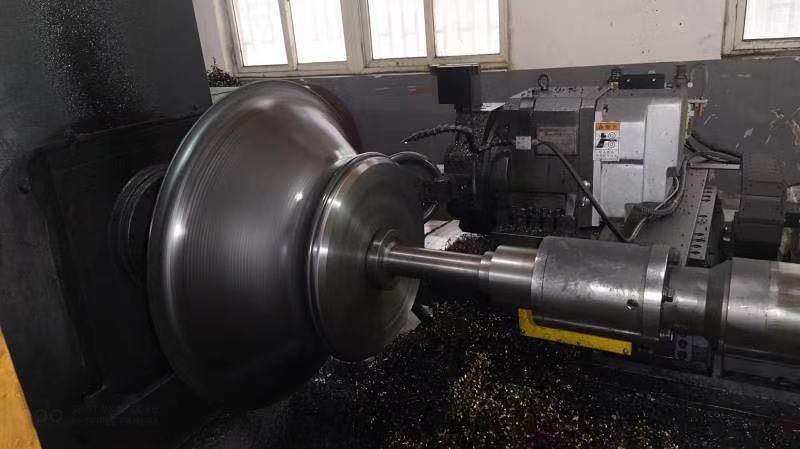
CNC (Computer Numerical Control) metal spinning is a highly specialized form of manufacturing that involves shaping a flat sheet or tube of metal into an axially symmetrical part by rotating the material while applying force using tools or rollers. The use of CNC in metal spinning allows for precise, automated control of the process, yielding consistent, repeatable results. This process is widely used in industries where precision, durability, and strength are crucial, such as aerospace, automotive, and medical sectors.
Historically, metal spinning was a manual, labor-intensive process dating back to ancient times. The advent of CNC technology revolutionized the field by introducing a computerized approach that automates much of the work, allowing for higher production volumes and finer tolerances. By employing computer programs to control the machines, manufacturers can achieve complex shapes that would have been impossible or very time-consuming using traditional spinning techniques.
The relevance of CNC metal spinning in modern manufacturing cannot be overstated. With increasing demand for precision-engineered components, the ability to automate the metal shaping process while ensuring a high degree of accuracy has made CNC metal spinning an indispensable technique for many industries. This introduction will discuss the fundamentals of CNC metal spinning, explore its importance, and highlight the key factors that have driven its adoption across various sectors.
The CNC Metal Spinning Process
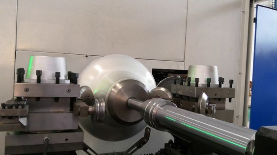
The CNC metal spinning process can be broken down into several stages, each essential for producing the final part. Understanding each step of the process gives insight into the complexity and precision involved in manufacturing with this technique.
- Design and Programming: The first step in CNC metal spinning involves designing the part using CAD (Computer-Aided Design) software. Engineers develop detailed models of the desired shape and dimensions, which are then converted into a CNC program using CAM (Computer-Aided Manufacturing) software. This program dictates the tool paths and operations the CNC machine will follow.
- Material Preparation: Once the design is complete, the appropriate material is selected. Common materials used in CNC metal spinning include aluminum, steel, copper, and titanium. The metal is typically in the form of a flat disc or tube, which will be spun into the desired shape.
- Mounting the Workpiece: The prepared metal piece is mounted on a CNC lathe, where it is securely held in place. During the spinning process, the workpiece is rotated at high speeds while tools or rollers are applied to shape the material.
- Spinning and Forming: The CNC program controls the movement of the tools or rollers as they apply pressure to the spinning workpiece. The material is gradually formed into the desired shape, whether it be a cone, cylinder, or more complex geometry. The spinning process involves multiple passes, with the tool gradually applying more force to achieve the final shape.
- Finishing and Trimming: Once the part has been spun to the correct shape, it may require finishing operations to remove excess material or smooth out the surface. CNC machines can also be equipped with trimming tools that cut away any unnecessary material during the spinning process, ensuring the final part meets precise dimensional tolerances.
Advantages of CNC Metal Spinning
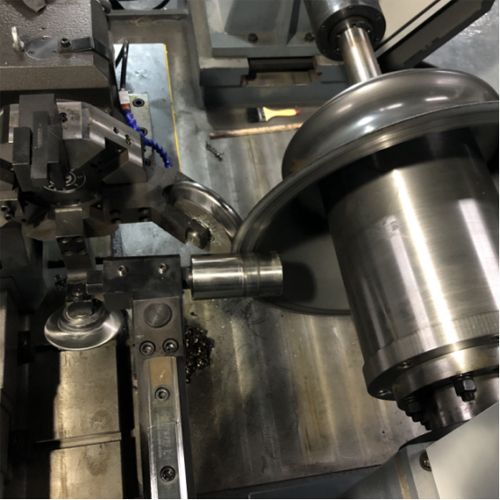
CNC metal spinning offers numerous advantages over traditional methods of metal forming and spinning, making it an attractive choice for manufacturers across various industries.
- Precision and Accuracy: One of the key advantages of CNC metal spinning is the precision it offers. CNC machines are capable of producing highly accurate parts with tight tolerances, ensuring consistency in production runs. This is particularly important for industries such as aerospace and medical, where even the smallest deviation can compromise the integrity of the final product.
- Efficiency and Scalability: CNC metal spinning is a highly efficient process, allowing for rapid production of parts with minimal waste. The automation of the process reduces the need for manual intervention, speeding up production times and lowering labor costs. Moreover, CNC systems can be easily scaled to accommodate both small and large production runs, making it a versatile option for manufacturers.
- Customization and Flexibility: The flexibility of CNC metal spinning allows for the production of custom parts in a wide range of shapes and sizes. Whether it’s a small prototype or a large batch of components, CNC systems can easily adapt to different requirements. This customization is particularly beneficial for industries that require unique, tailored parts.
Applications of CNC Metal Spinning in Various Industries
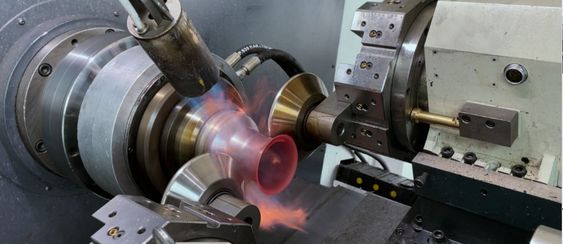
CNC metal spinning has applications across numerous industries, including aerospace, automotive, medical, and more.
- Aerospace Industry: In the aerospace sector, CNC metal spinning is used to produce components that are lightweight yet strong enough to withstand the harsh conditions of flight. Parts such as nose cones, engine components, and structural elements are often manufactured using CNC metal spinning due to its ability to create high-precision, durable parts.
- Automotive Industry: The automotive industry relies on CNC metal spinning for the production of various components, including wheels, exhaust systems, and suspension parts. The precision and consistency of CNC metal spinning ensure that these parts meet the high standards required for automotive applications.
- Medical Industry: In the medical field, CNC metal spinning is used to create custom medical devices and surgical instruments. The ability to produce precise, complex shapes with high levels of accuracy is crucial for ensuring the safety and effectiveness of these products.
Comparison with Traditional Metal Spinning
Traditional metal spinning and CNC metal spinning serve similar purposes in the manufacturing process, but there are distinct differences between the two methods. Understanding the differences between manual, traditional metal spinning and CNC-based systems helps to evaluate when each method might be more appropriate.
- Manual vs. Automated Control:
Traditional metal spinning is a hands-on process requiring skilled craftsmen to manipulate the material using a spinning lathe. This technique has been around for centuries, relying on the experience and expertise of the operator. In contrast, CNC metal spinning automates this process, using computer-controlled movements to guide the tools and shape the material. The CNC program provides a high level of precision that is difficult to achieve manually, and once programmed, the machine can produce identical parts with minimal deviation, even in large batches. - Complexity of Design:
CNC metal spinning is particularly advantageous when producing complex or intricate shapes. While traditional spinning is limited by the skill of the operator and the tools available, CNC systems can follow precise, intricate tool paths programmed into the software. This capability allows for more advanced designs and a higher degree of customization, making CNC spinning ideal for industries requiring complex geometries, such as aerospace and medical device manufacturing. - Production Volume and Speed:
Traditional metal spinning is best suited for low-volume production runs or prototypes, where the flexibility of manual control allows for rapid adjustments. However, this method is labor-intensive and less efficient for large-scale production. In contrast, CNC metal spinning excels in high-volume production due to its automated nature. Once the CNC machine is set up, it can operate continuously with little supervision, making it more efficient for mass production. - Cost Considerations:
One of the drawbacks of CNC metal spinning is the initial cost. The setup of CNC machines requires investment in programming, machinery, and software. However, the long-term savings in labor, material waste, and production efficiency often outweigh the initial costs, especially in large-scale manufacturing. Traditional metal spinning, on the other hand, has a lower upfront cost since it requires simpler machinery and less reliance on expensive technology. It is often a preferred method for smaller projects or where the added precision of CNC isn’t essential. - Skill and Training Requirements:
Traditional metal spinning demands a high level of manual dexterity and years of experience to master. Skilled spinners are required to monitor and adjust the process in real-time, making it a labor-intensive craft. On the other hand, CNC metal spinning places more emphasis on programming and machine operation skills. While this reduces the need for manual labor, it increases the need for training in CNC programming and machine maintenance. - When to Choose Traditional Spinning:
Despite the advantages of CNC metal spinning, traditional spinning has its place, particularly in situations where short-run production or rapid prototyping is needed. Traditional methods also offer more flexibility in terms of quick adjustments during the process. When working with small-scale projects or custom one-off pieces, the manual approach may be more cost-effective and suitable.
Equipment Used in CNC Metal Spinning
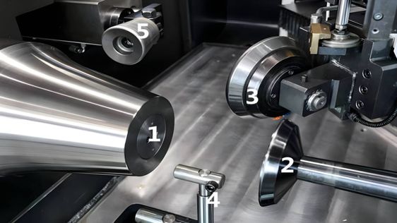
The effectiveness of CNC metal spinning relies on the precision and sophistication of the equipment used. The key equipment includes CNC lathes, spinning tools, software for design and programming, as well as ancillary machines that contribute to a safe and efficient manufacturing environment.
- CNC Lathes:
At the heart of CNC metal spinning is the CNC lathe. These machines rotate the workpiece at high speeds while applying force through various tools to shape the metal. CNC lathes can vary in size and capacity, depending on the specific application. Industrial-grade CNC lathes are capable of handling large, heavy pieces of metal and can run continuously for high-volume production. The high-speed rotation, combined with precision tool control, allows for the production of complex, symmetrical shapes. - Spinning Tools:
The tools used in CNC metal spinning are crucial for shaping the metal. These can include forming rollers, tools for trimming, and specialized cutters, each designed for different parts of the spinning process. Rollers come in different shapes and sizes, depending on the type of component being manufactured. Tool durability is essential, as the friction and pressure exerted during the spinning process can cause wear over time. High-quality tools, made from hardened steel or carbide, are commonly used to ensure longevity and reduce downtime for tool replacement. - Software Systems:
CNC metal spinning depends heavily on the software that controls the machinery. CAD (Computer-Aided Design) software is used to create the design of the component, while CAM (Computer-Aided Manufacturing) software translates this design into specific machine instructions. These instructions guide the CNC lathe, dictating the speed, pressure, and movement of the tools. Many CNC systems also incorporate simulation software that allows manufacturers to test the process virtually before running it on the actual machine. This reduces errors and material wastage, ensuring the process is as efficient as possible. - Safety Equipment:
Due to the high speeds and forces involved in CNC metal spinning, safety is a critical concern. Machines are typically equipped with protective shields to prevent debris from being ejected during the process. Operators must also wear protective gear, including gloves, eye protection, and sometimes even full-body protective suits, depending on the type of metal being spun. Modern CNC machines are often equipped with sensors and automated safety shut-off mechanisms to detect any issues during the spinning process and prevent accidents. - Machine Maintenance:
Regular maintenance of CNC metal spinning machines is essential for ensuring consistent production quality and minimizing downtime. Maintenance typically involves checking for wear on the spinning tools, cleaning and lubricating the machine’s moving parts, and ensuring that the CNC system is properly calibrated. CNC machines also need periodic software updates to maintain their precision and efficiency. - Automation Systems:
To further enhance productivity, many CNC metal spinning setups integrate automation systems such as robotic arms for loading and unloading materials. This minimizes the need for human intervention and reduces production time, especially in high-volume manufacturing environments. Automated systems also improve safety by reducing the risk of human error.
Challenges in CNC Metal Spinning
Despite its advantages, CNC metal spinning presents several challenges that manufacturers must address to optimize production.
- Tool Wear and Durability:
The spinning tools used in CNC processes endure high levels of stress and friction, which can lead to rapid wear, especially when working with hard metals like steel and titanium. Tool wear affects the precision of the final product and requires regular monitoring. High-quality materials such as carbide can reduce wear, but they are also more expensive. Developing strategies for extending tool life, such as better lubrication or improved tool design, is an ongoing challenge. - Material Limitations:
While CNC metal spinning is versatile, not all materials are suitable for the process. Some metals are too brittle to be spun without cracking, while others may have too low a melting point and deform under the heat generated by the spinning process. Manufacturers must carefully select materials that can withstand the forces applied during spinning. Additionally, thicker materials can be challenging to spin, requiring more powerful machines and specialized tools. - Tolerances and Consistency:
Maintaining tight tolerances over large production runs can be difficult. Although CNC systems are designed for precision, factors such as tool wear, machine calibration, and variations in material quality can affect the consistency of the final product. Manufacturers must regularly inspect parts and adjust the process as needed to ensure that tolerances remain within acceptable limits. - Programming and Setup Costs:
One of the main drawbacks of CNC metal spinning is the time and cost associated with programming the CNC machine. Creating a CNC program involves designing the part, simulating the process, and troubleshooting potential issues before actual production begins. This setup time can be costly, particularly for small production runs. While the costs are offset in large-scale manufacturing, they remain a consideration for smaller companies or custom projects. - Skilled Labor Requirements:
Although CNC machines reduce the need for manual labor, they still require skilled operators and programmers. CNC machinists must have a deep understanding of both the software and the machinery to set up, troubleshoot, and maintain the system. Training workers to operate CNC machines can be time-consuming, and the demand for CNC operators often exceeds supply, leading to labor shortages in some industries.
Sustainability and Environmental Impact
Sustainability has become an increasingly important consideration in the manufacturing industry, and CNC metal spinning offers several eco-friendly advantages compared to traditional manufacturing methods.
- Material Efficiency:
CNC metal spinning is a highly efficient process in terms of material usage. Unlike traditional machining processes, which often involve cutting away large amounts of material, spinning reshapes the metal without removing significant portions. This results in less waste and reduces the need for raw materials, contributing to a more sustainable manufacturing cycle. - Energy Efficiency:
The energy consumption of CNC metal spinning is relatively low compared to other metal-forming processes like stamping or forging, which require more force and heat. The combination of precision and reduced material waste also means fewer resources are needed to produce the same number of components. - Recycling and Waste Reduction:
Any scrap material generated during CNC metal spinning is typically recyclable. Manufacturers often work with recyclable metals such as aluminum, steel, and copper, contributing to a circular economy where materials can be reused. Additionally, the precision of CNC machines minimizes the production of scrap, further reducing waste.
Future Trends in CNC Metal Spinning
CNC metal spinning continues to evolve with advancements in technology. Several trends are shaping the future of this manufacturing method, including the incorporation of new technologies and a growing focus on sustainability.
- Incorporation of AI and Machine Learning:
The integration of artificial intelligence (AI) and machine learning into CNC systems is one of the most exciting trends. These technologies enable machines to learn from previous operations and optimize processes for greater efficiency and precision. AI can help reduce tool wear, improve material usage, and enhance overall machine performance by predicting and correcting errors in real-time. - Increased Automation:
The use of robotics in CNC metal spinning is expected to grow, particularly in high-volume production environments. Robotic arms can handle tasks such as loading and unloading materials, increasing efficiency and reducing the risk of human error. As automation technologies become more affordable, even smaller manufacturers are likely to adopt these systems. - Sustainable Manufacturing Practices:
As environmental regulations tighten and companies aim to reduce their carbon footprints, CNC metal spinning is likely to play a role in more sustainable manufacturing processes. The emphasis will be on using recyclable materials, minimizing energy consumption, and reducing waste.
Conclusion: The Importance of CNC Metal Spinning in Modern Manufacturing
CNC metal spinning is a critical technology in modern manufacturing, offering a combination of precision, efficiency, and flexibility that is unmatched by traditional methods. Its applications span across industries such as aerospace, automotive, medical, and many others, where high-quality, reliable components are essential. CNC metal spinning enables manufacturers to produce complex, symmetrical parts with minimal waste, making it a sustainable choice in today’s environmentally conscious market.
The future of CNC metal spinning looks promising, with advancements in AI, automation, and sustainable practices poised to enhance the process even further. For industries requiring high precision and efficiency, CNC metal spinning will remain a cornerstone of modern manufacturing techniques.
3. Flow Forming
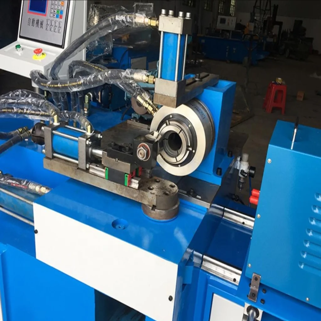
Flow forming, also known as rotary forming or flow turning, is an advanced metal forming process that transforms tubular blanks into precise, high-strength components. This process involves the controlled deformation of the metal blank, reducing its wall thickness and elongating its length.
Flow forming is distinct from other forming processes due to its ability to create thin-walled, seamless components with exceptional dimensional accuracy. The process is highly precise and allows for the creation of complex geometries and intricate designs.
The flow forming process consists of the following steps:
- Preparation: A tubular blank is cut to the desired length and pre-formed if necessary.
- Mounting: The blank is mounted onto a mandrel in a flow-forming machine.
- Rotation: The blank is rotated at high speed.
- Forming: Rollers apply pressure to the rotating blank, reducing its wall thickness and elongating its length.
- Finishing: The formed component is trimmed and finished to meet the desired specifications.
Flow forming can be performed using various methods, including:
- Forward flow forming: The rollers move in the same direction as the rotation of the blank, reducing the wall thickness and elongating the length.
- Reverse flow forming: The rollers move in the opposite direction of the blank’s rotation, allowing for greater control over the final shape.
- Tube spinning: Involves spinning the blank without altering its diameter, focusing on wall thickness reduction.
Machines and Equipment
Flow forming machines are highly specialized and designed to provide precise control over the forming process. These machines are equipped with advanced technology and automation capabilities to ensure consistent and high-quality results.
Key components of flow forming machines include:
- Spindle: Rotates the tubular blank at high speed.
- Mandrel: Provides support and shape for the forming process.
- Rollers: Apply controlled pressure to the blank, shaping it into the desired form.
- Control system: Manages the speed, pressure, and movement of the rollers, ensuring precision and accuracy.
Technological advancements in flow forming machinery have focused on improving automation, reducing material waste, and enhancing process control. Modern flow-forming machines utilize CNC technology to achieve precise and repeatable results, reducing the need for manual intervention and increasing productivity.
Applications
Flow forming is widely used in industries that require high-precision, thin-walled components. Some specific applications include:
- Aerospace: Manufacturing aircraft engine components, such as compressor cases and fan housings.
- Automotive: Producing lightweight, high-strength parts like drive shafts and wheel rims.
- Military: Creating artillery shells, missile casings, and other defense-related components.
- Industrial: Fabricating components for machinery and equipment, such as pump housings and pressure vessels.
The ability to produce components with tight tolerances and exceptional strength makes flow forming an ideal choice for industries that demand high-performance parts.
Advantages and Challenges
Advantages of flow forming include:
- Dimensional accuracy: Flow forming achieves tight tolerances and precise dimensions, ensuring high-quality components.
- Material efficiency: The process reduces material waste by minimizing the need for additional machining or finishing.
- Strength and durability: Flow-formed components exhibit enhanced mechanical properties, including increased strength and fatigue resistance.
- Design flexibility: The ability to create complex shapes and intricate designs allows for greater innovation and customization.
Despite its advantages, flow forming also presents certain challenges:
- Initial setup cost: Flow forming machines are specialized and can be expensive to purchase and maintain.
- Material limitations: Certain materials may be difficult to flow form, requiring specialized equipment and expertise.
- Process complexity: The process requires careful control and monitoring to achieve the desired results, necessitating skilled operators and advanced technology.
4. Shear Forming
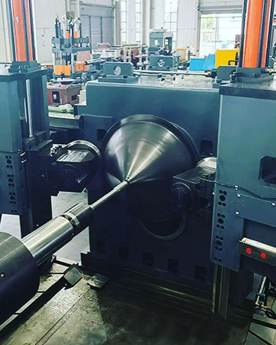
Shear forming, also known as shear spinning, is a metal forming process that produces axisymmetric components by reducing the wall thickness of a blank while maintaining its diameter. This process is similar to conventional spinning but involves a shearing action that allows for greater control over the final shape and thickness of the component.
Shear forming is distinct from flow forming in that it focuses on altering the thickness of the blank while maintaining its diameter. This process is highly versatile and can be used to create a wide range of components with varying shapes and sizes.
The shear forming process consists of the following steps:
- Preparation: A blank is cut to the desired size and shape.
- Mounting: The blank is mounted onto a mandrel in a shear-forming machine.
- Rotation: The blank is rotated at high speed.
- Forming: A tool applies pressure to the rotating blank, reducing its wall thickness and shaping it into the desired form.
- Finishing: The formed component is trimmed and finished to meet the desired specifications.
Machines and Equipment
Shear forming machines are designed to provide precise control over the forming process, ensuring consistent and high-quality results. These machines are equipped with advanced technology and automation capabilities to optimize the shear-forming process.
Key components of shear forming machines include:
- Spindle: Rotates the blank at high speed.
- Mandrel: Provides support and shape for the forming process.
- Tooling system: Includes various tools for applying pressure and shaping the metal.
- Control system: Manages the speed, pressure, and movement of the tools, ensuring precision and accuracy.
Innovations in shear-forming technology have focused on improving process control, reducing material waste, and enhancing automation. Modern shear-forming machines utilize CNC technology to achieve precise and repeatable results, reducing the need for manual intervention and increasing productivity.
Applications
Shear forming is used in a wide range of industries due to its versatility and ability to produce high-quality, axisymmetric components. Some specific applications include:
- Aerospace: Manufacturing components such as turbine disks, flanges, and structural parts.
- Automotive: Producing parts like pulleys, hubs, and other rotational components.
- Industrial: Fabricating components for machinery and equipment, such as pump housings and pressure vessels.
- Medical: Creating components for medical devices and equipment, such as surgical instruments and implants.
The ability to create components with varying thicknesses and complex shapes makes shear forming an attractive option for manufacturers seeking to optimize production and reduce costs.
Advantages and Challenges
Advantages of shear forming include:
- Material efficiency: The process reduces material waste by minimizing the need for additional machining or finishing.
- Design flexibility: The ability to create complex shapes and varying thicknesses allows for greater innovation and customization.
- Strength and durability: Shear-formed components exhibit enhanced mechanical properties, including increased strength and fatigue resistance.
- Cost-effectiveness: Shear forming requires minimal tooling compared to other forming processes, reducing production costs.
Despite its advantages, shear forming also presents certain challenges:
- Limited to axisymmetric shapes: Shear forming is best suited for components with rotational symmetry, limiting its application for non-symmetrical parts.
- Material limitations: Certain materials may be difficult to shear form, requiring specialized equipment and expertise.
- Process complexity: The process requires careful control and monitoring to achieve the desired results, necessitating skilled operators and advanced technology.
5. Wheel Forming
Wheel forming is a specialized metal forming process used to produce wheels for various applications, particularly in the automotive and aerospace industries. This process involves shaping a metal blank into a wheel by applying pressure and force through a series of rollers or dies.
Wheel forming is distinct from other metal forming processes due to its focus on creating wheels and other rotational components. The process is highly efficient and allows for the production of lightweight, high-strength wheels with complex geometries.
The wheel-forming process consists of the following steps:
- Preparation: A metal blank is cut to the desired size and shape.
- Mounting: The blank is mounted onto a wheel-forming machine.
- Rotation: The blank is rotated at high speed.
- Forming: Rollers or dies apply pressure to the rotating blank, shaping it into the desired wheel form.
- Finishing: The formed wheel is trimmed and finished to meet the desired specifications.
Machines and Equipment
Wheel forming machines are highly specialized and designed to provide precise control over the forming process. These machines are equipped with advanced technology and automation capabilities to ensure consistent and high-quality results.
Key components of wheel forming machines include:
- Spindle: Rotates the blank at high speed.
- Mandrel: Provides support and shape for the forming process.
- Rollers or dies: Apply controlled pressure to the blank, shaping it into the desired wheel form.
- Control system: Manages the speed, pressure, and movement of the rollers or dies, ensuring precision and accuracy.
Recent advancements in wheel-forming technology have focused on improving automation, reducing material waste, and enhancing process control. Modern wheel-forming machines utilize CNC technology to achieve precise and repeatable results, reducing the need for manual intervention and increasing productivity.
Applications
Wheel forming is widely used in industries that require high-quality, lightweight wheels and rotational components. Some specific applications include:
- Automotive: Manufacturing wheels for cars, trucks, and motorcycles.
- Aerospace: Producing wheels for aircraft landing gear and other rotational components.
- Industrial: Fabricating wheels for machinery and equipment, such as conveyor systems and transport vehicles.
- Consumer goods: Creating wheels for bicycles, skateboards, and other consumer products.
The ability to produce wheels with tight tolerances and exceptional strength makes wheel forming an ideal choice for industries that demand high-performance rotational components.
Advantages and Challenges
Advantages of wheel forming include:
- Lightweight and high strength: Wheel-forming produces lightweight wheels with exceptional strength and durability.
- Dimensional accuracy: The process achieves tight tolerances and precise dimensions, ensuring high-quality wheels.
- Material efficiency: Wheel forming reduces material waste by minimizing the need for additional machining or finishing.
- Design flexibility: The ability to create complex geometries and intricate designs allows for greater innovation and customization.
Despite its advantages, wheel forming also presents certain challenges:
- Initial setup cost: Wheel forming machines are specialized and can be expensive to purchase and maintain.
- Material limitations: Certain materials may be difficult to wheel form, requiring specialized equipment and expertise.
- Process complexity: The process requires careful control and monitoring to achieve the desired results, necessitating skilled operators and advanced technology.
6. Comparative Analysis
In this section, we will compare metal spinning, flow forming, shear forming, and wheel forming processes to understand their differences, advantages, and suitability for various applications.
Comparison of Processes:
- Metal Spinning vs. Flow Forming: Metal spinning focuses on forming axially symmetric parts by rotating a blank around a mandrel, while flow forming involves reducing the wall thickness of a tubular blank through controlled deformation. Flow forming is more suitable for thin-walled, high-precision components, while metal spinning is ideal for larger, symmetrical parts.
- Shear Forming vs. Flow Forming: Shear forming and flow forming both involve reducing the wall thickness of a blank, but shear forming maintains the blank’s diameter, whereas flow forming can elongate the blank. Shear forming is preferred for components with varying thicknesses, while flow forming is used for high-precision, thin-walled parts.
- Wheel Forming vs. Other Processes: Wheel forming is specifically designed for creating wheels and rotational components, making it unique among the other processes. It offers advantages in producing lightweight, high-strength wheels with complex geometries, but is limited to wheel and rotational component applications.
Suitability for Different Applications:
- Aerospace: Flow forming and shear forming are highly suitable for aerospace applications due to their ability to produce high-precision, lightweight components with enhanced mechanical properties.
- Automotive: Metal spinning and wheel forming are commonly used in the automotive industry for manufacturing wheels, exhaust components, and decorative trims.
- Industrial: All four processes are utilized in various industrial applications, depending on the specific requirements of the components being produced.
- Consumer Goods: Metal spinning and wheel forming are popular choices for producing consumer goods, such as cookware, lighting fixtures, and wheels for bicycles and skateboards.
Technical and Economic Considerations:
- Material Costs: Metal spinning and shear forming require minimal tooling and have lower material costs, making them cost-effective options for certain applications.
- Process Complexity: Flow forming and wheel forming involve more complex processes and require advanced technology, resulting in higher initial setup costs but offering greater precision and quality.
- Production Volume: Metal spinning and wheel forming are suitable for both low and high-volume production, while flow forming and shear forming are more efficient for high-volume production due to their precision and automation capabilities.
7. Future Trends and Developments
The metal forming industry is constantly evolving, with new technologies and innovations shaping the future of metal spinning, flow forming, shear forming, and wheel forming processes. Some emerging trends and developments include:
- Additive Manufacturing Integration: Combining traditional metal forming processes with additive manufacturing techniques to create complex components with enhanced properties and reduced material waste.
- Automation and Industry 4.0: Increasing automation and the adoption of Industry 4.0 technologies, such as IoT and AI, to improve process control, efficiency, and productivity in metal forming operations.
- Advanced Materials: The development of new materials and alloys that are more suitable for metal forming processes, allowing for greater innovation and customization.
- Sustainability and Environmental Impact: Focus on reducing the environmental impact of metal forming processes through energy-efficient machinery and sustainable material sourcing.
As these trends continue to evolve, metal spinning, flow forming, shear forming, and wheel forming processes will play an increasingly important role in manufacturing, driving innovation and efficiency across various industries.
8. Conclusion
Metal spinning, flow forming, shear forming, and wheel forming are essential metal forming processes that offer unique advantages and capabilities for producing high-quality, precise components across various industries. Each process has its strengths and challenges, making them suitable for different applications and requirements.
By understanding the principles, machines, applications, and advantages of these processes, manufacturers and engineers can make informed decisions about the best techniques to employ for specific projects. As the metal forming industry continues to evolve, these processes will play a crucial role in driving innovation, efficiency, and sustainability in manufacturing.
Choosing the right materials for metal forming processes such as metal spinning, flow forming, shear forming, and wheel forming is crucial for achieving desired product characteristics, performance, and quality. Each process has specific material requirements based on the mechanical properties, formability, and intended application. Here’s an overview of recommended materials for each process:
Metal Spinning
Metal spinning is a versatile process that can work with a variety of metals. Key material properties to consider include ductility, malleability, and tensile strength. Here are some commonly used materials in metal spinning:
- Aluminum and Aluminum Alloys
- Properties: Lightweight, corrosion-resistant, good thermal and electrical conductivity.
- Applications: Aerospace components, automotive parts, cookware, and decorative items.
- Stainless Steel
- Properties: High corrosion resistance, strength, and durability.
- Applications: Food processing equipment, medical devices, and architectural components.
- Copper and Copper Alloys
- Properties: Excellent thermal and electrical conductivity, corrosion resistance, and antimicrobial properties.
- Applications: Lighting fixtures, electrical components, and decorative items.
- Brass and Bronze
- Properties: Corrosion resistance, electrical conductivity, and aesthetic appeal.
- Applications: Musical instruments, plumbing components, and decorative items.
- Carbon and Low-Alloy Steels
- Properties: High strength and durability.
- Applications: Automotive components, industrial machinery, and construction parts.
- Titanium and Titanium Alloys
- Properties: High strength-to-weight ratio, corrosion resistance, and biocompatibility.
- Applications: Aerospace components, medical implants, and sports equipment.
Flow Forming
Flow forming is ideal for materials that require high strength, precision, and reduced weight. Materials should exhibit good ductility and work hardening properties. Recommended materials for flow forming include:
- Aluminum Alloys
- Properties: Lightweight, corrosion-resistant, and high formability.
- Applications: Aerospace components, automotive parts, and military applications.
- High-Strength Low-Alloy (HSLA) Steels
- Properties: Enhanced mechanical properties and good formability.
- Applications: Automotive components, structural parts, and pressure vessels.
- Stainless Steel
- Properties: Corrosion resistance, strength, and durability.
- Applications: Aerospace and defense components, medical devices, and industrial equipment.
- Nickel and Nickel Alloys
- Properties: High-temperature resistance, corrosion resistance, and strength.
- Applications: Aerospace components, gas turbine engines, and chemical processing equipment.
- Titanium Alloys
- Properties: High strength-to-weight ratio, corrosion resistance, and biocompatibility.
- Applications: Aerospace components, medical implants, and military applications.
Shear Forming
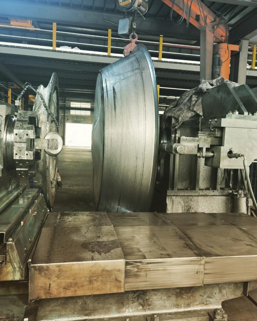
Shear forming is suitable for materials with good ductility and shear formability. This process is often used for producing components with varying thicknesses. Recommended materials include:
- Aluminum and Aluminum Alloys
- Properties: Lightweight, corrosion-resistant, and good formability.
- Applications: Aerospace components, automotive parts, and consumer goods.
- Stainless Steel
- Properties: Corrosion resistance, strength, and durability.
- Applications: Industrial equipment, medical devices, and structural components.
- Carbon and Low-Alloy Steels
- Properties: High strength and wear resistance.
- Applications: Automotive components, machinery parts, and construction materials.
- Copper and Copper Alloys
- Properties: Good thermal and electrical conductivity, corrosion resistance.
- Applications: Electrical components, plumbing fixtures, and decorative items.
- Titanium and Titanium Alloys
- Properties: High strength-to-weight ratio and corrosion resistance.
- Applications: Aerospace components, medical devices, and sports equipment.
Wheel Forming
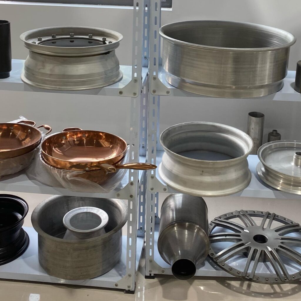
Wheel forming is used to create wheels and other rotational components, requiring materials with high strength and fatigue resistance. Recommended materials for wheel forming include:
- Aluminum Alloys
- Properties: Lightweight, corrosion-resistant, and high strength.
- Applications: Automotive wheels, aerospace components, and bicycle wheels.
- Magnesium Alloys
- Properties: Lightweight, good damping properties, and machinability.
- Applications: Automotive wheels, aerospace components, and electronics casings.
- Stainless Steel
- Properties: Corrosion resistance, strength, and durability.
- Applications: Heavy-duty industrial wheels, transportation equipment, and marine applications.
- Carbon and Low-Alloy Steels
- Properties: High strength, wear resistance, and durability.
- Applications: Heavy-duty automotive wheels, industrial machinery, and construction equipment.
- Titanium Alloys
- Properties: High strength-to-weight ratio, corrosion resistance, and fatigue resistance.
- Applications: Aerospace wheels, high-performance automotive wheels, and sports equipment.
Factors to Consider When Selecting Materials
When choosing materials for metal forming processes, several factors should be considered:
- Mechanical Properties: Ensure the material has the required strength, ductility, and toughness for the specific application.
- Formability: Consider the material’s ability to be formed without cracking or defects, as well as its work hardening characteristics.
- Corrosion Resistance: Select materials that can withstand the operating environment, especially for applications exposed to harsh conditions.
- Cost and Availability: Evaluate the cost-effectiveness and availability of the material, considering both short-term and long-term production needs.
- Application Requirements: Consider the specific requirements of the application, such as weight, thermal conductivity, electrical conductivity, and aesthetic appeal.
- Sustainability: Evaluate the environmental impact of the material and consider options that align with sustainability goals.
By carefully selecting the appropriate materials, manufacturers can optimize the metal forming process, reduce costs, and ensure high-quality, reliable components. If you need more detailed information or have specific applications in mind, feel free to ask!
Metal Spinning Machine Components
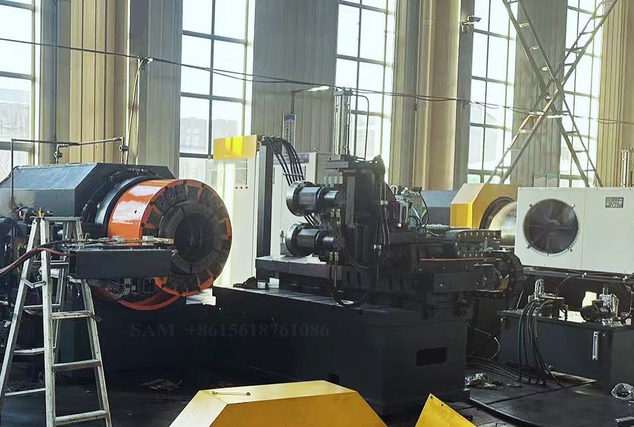
The components of machines used in metal forming processes such as metal spinning, flow forming, shear forming, and wheel forming are designed to deliver precise control and high-quality production. Each machine type is equipped with specialized parts that cater to the unique demands of the specific forming process. Below is an overview of the key components for each machine type, explaining their functions and significance.
Metal spinning machines range from manual lathes to advanced CNC-controlled systems. The fundamental components of a metal spinning machine include:
- Spindle:
- Function: The spindle is the rotating axis of the machine that holds and spins the metal blank at high speeds. It is crucial for maintaining balance and precision during the spinning process.
- Significance: Ensures consistent rotation speed and stability, allowing for uniform metal forming.
- Chuck or Mandrel:
- Function: Holds the metal blank in place and serves as the shaping mold for the final product. The mandrel determines the shape of the spun piece.
- Significance: Provides support and defines the final geometry of the component.
- Tailstock:
- Function: Supports the other end of the workpiece opposite the spindle, preventing wobble and maintaining alignment during spinning.
- Significance: Ensures stability and precision by supporting the blank throughout the process.
- Tool Rest and Tools:
- Function: The tool rest supports various forming tools, which are used to apply pressure and shape the metal as it spins.
- Types of Tools: Rollers, spoons, and other custom tools can be used depending on the desired shape and complexity of the component.
- Significance: Allows the operator or CNC program to apply pressure precisely and control the forming process.
- Bed:
- Function: The foundation that supports the entire machine structure, providing a stable platform for all operations.
- Significance: Ensures the rigidity and stability necessary for high-precision metal spinning.
- Control System:
- Function: Manages machine operations, including spindle speed, tool position, and pressure. In CNC machines, this includes programming capabilities for automated and complex spinning tasks.
- Significance: Provides precise control over the spinning process, enabling complex shapes and repeatable operations.
- Drive System:
- Function: Powers the spindle and other moving parts of the machine. This can include motors, belts, and gears.
- Significance: Ensures consistent power delivery and control over the machine’s movements.
Flow Forming Machine Components
Flow forming machines are highly specialized and designed to produce thin-walled components with precision. Key components include:
- Spindle and Chuck:
- Function: Similar to metal spinning, the spindle rotates the blank at high speed while the chuck securely holds it in place.
- Significance: Provides stability and precision necessary for reducing wall thickness accurately.
- Mandrel:
- Function: Serves as the internal form around which the blank is shaped. It supports the workpiece during the forming process.
- Significance: Defines the internal dimensions and helps achieve the desired wall thickness.
- Rollers:
- Function: The primary forming tools that apply pressure to the rotating blank, reducing its wall thickness and elongating it.
- Types of Rollers: Can be single or multiple rollers depending on the process and desired outcomes.
- Significance: Enables controlled deformation of the material, achieving precise dimensions and properties.
- Tool Post:
- Function: Holds the rollers and positions them for precise contact with the workpiece. Can adjust roller position and pressure.
- Significance: Allows fine control of the forming process, ensuring consistency and accuracy.
- Tailstock:
- Function: Supports the opposite end of the workpiece, ensuring it remains aligned and stable during forming.
- Significance: Provides additional support, especially for longer components.
- Control System:
- Function: Oversees the machine’s operations, controlling spindle speed, roller position, and pressure. In CNC machines, it handles complex forming paths and sequences.
- Significance: Provides automation and precision control, essential for high-quality production.
- Drive System:
- Function: Powers the spindle and rollers, using motors and gearing systems to deliver the necessary force and speed.
- Significance: Ensures consistent operation and control over the forming process.
- Cooling System:
- Function: Manages heat generated during the forming process, often using cooling fluids to prevent overheating.
- Significance: Maintains material properties and prevents machine wear by dissipating heat.
Shear Forming Machine Components
Shear forming machines share similarities with both metal spinning and flow forming machines but have specific components tailored to the shearing action:
- Spindle:
- Function: Rotates the blank at high speed, providing the necessary force for shearing.
- Significance: Ensures consistent rotation for uniform wall thickness reduction.
- Mandrel:
- Function: Supports the workpiece and defines its internal shape. It may also help control wall thickness.
- Significance: Critical for achieving the desired internal dimensions and structural integrity.
- Shear Tools:
- Function: Specialized tools that apply localized pressure, shearing the metal and reducing wall thickness while maintaining diameter.
- Significance: Enables the unique thinning characteristic of shear forming, allowing for complex component profiles.
- Tool Post:
- Function: Positions and supports shear tools, allowing precise adjustments for pressure and angle.
- Significance: Provides control over the shearing process, enabling accurate and consistent results.
- Tailstock:
- Function: Provides support for the workpiece opposite the spindle, ensuring stability and alignment.
- Significance: Ensures component stability and precision throughout the forming process.
- Control System:
- Function: Manages machine operations, controlling tool position, spindle speed, and shearing pressure. CNC systems allow for complex and automated operations.
- Significance: Enables precision and repeatability, crucial for producing high-quality components.
- Drive System:
- Function: Powers the spindle and shear tools, using motors, belts, and gears to control speed and force.
- Significance: Delivers consistent power for effective shearing and forming.
- Cooling and Lubrication System:
- Function: Manages heat and friction during forming, using fluids to cool and lubricate the workpiece and tools.
- Significance: Reduces wear, maintains material properties, and improves tool life.
Wheel Forming Machine Components
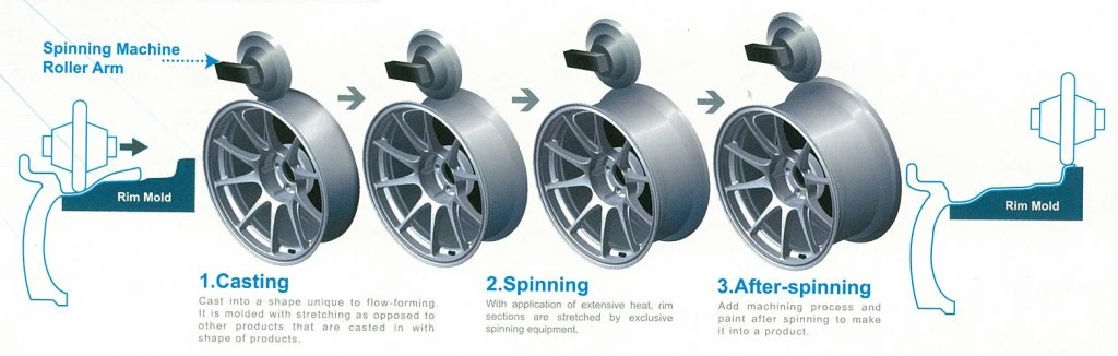
Wheel forming machines are specifically designed to produce wheels and other rotational components. Key components include:
- Spindle and Chuck:
- Function: Rotates the wheel blank at high speed, securing it in place for forming.
- Significance: Provides stability and precision, ensuring uniform wheel formation.
- Rollers or Dies:
- Function: Form the wheel by applying pressure to the rotating blank, shaping it into the desired wheel profile.
- Types of Dies: May include pre-forming and finishing dies for different stages of the process.
- Significance: Enables precise shaping of the wheel, achieving complex geometries and high strength.
- Mandrel:
- Function: Supports the blank and defines the internal geometry of the wheel.
- Significance: Ensures accurate internal dimensions and structural integrity.
- Tool Post:
- Function: Holds and positions rollers or dies, allowing for precise adjustments during the forming process.
- Significance: Provides control over the forming process, ensuring consistency and accuracy.
- Control System:
- Function: Manages machine operations, controlling spindle speed, die position, and pressure. CNC systems provide automation and precision.
- Significance: Ensures high-quality production with repeatable results.
- Drive System:
- Function: Powers the spindle and rollers/dies, delivering the necessary force and speed for forming.
- Significance: Ensures consistent operation and control over the forming process.
- Cooling and Lubrication System:
- Function: Manages heat and friction during forming, using fluids to cool and lubricate the workpiece and tools.
- Significance: Prevents overheating, reduces wear, and maintains material properties.
- Support Frames and Guides:
- Function: Provide structural support and guide the blank through the forming process, ensuring alignment and stability.
- Significance: Enhances machine stability and ensures accurate and consistent wheel formation.
Conclusion
The machines used in metal spinning, flow forming, shear forming, and wheel forming processes are complex systems equipped with specialized components designed to meet the unique demands of each process. By understanding these components and their functions, manufacturers can optimize the forming process, improve product quality, and achieve precise, high-performance components.
Metal Spinning Application Areas
The metal forming processes of metal spinning, flow forming, shear forming, and wheel forming are integral to a wide range of industries, each offering unique capabilities and advantages. Here’s an overview of the application areas for these processes, highlighting how they are utilized to create specific products and components across various sectors:
Metal spinning is a versatile process capable of producing axially symmetric components with seamless construction. Its applications span several industries due to its ability to efficiently produce complex shapes with high structural integrity.
Aerospace
- Components:
- Nose cones
- Rocket casings
- Jet engine parts
- Advantages:
- Metal spinning is ideal for aerospace applications where lightweight and high-strength components are critical. The process allows for the creation of complex shapes with excellent surface finishes and minimal material waste.
Automotive
- Components:
- Wheel rims
- Exhaust system parts
- Airbag components
- Advantages:
- In the automotive industry, metal spinning is used to produce lightweight and durable components. The process’s flexibility allows for the creation of custom parts with intricate designs, contributing to vehicle performance and aesthetics.
HVAC (Heating, Ventilation, and Air Conditioning)
- Components:
- Ductwork
- Ventilation hoods
- Fan housings
- Advantages:
- Metal spinning produces seamless components that ensure efficient airflow and minimal leakage. The process can handle various materials, making it suitable for applications requiring corrosion resistance and thermal stability.
Lighting
- Components:
- Reflectors
- Lampshades
- Fixture bases
- Advantages:
- In lighting applications, metal spinning is used to create aesthetically pleasing and functional components. The process can produce complex shapes with smooth finishes, enhancing both the performance and appearance of lighting products.
Consumer Products
- Components:
- Cookware (pots, pans, bowls)
- Musical instruments (cymbals, drums)
- Decorative items
- Advantages:
- The versatility of metal spinning allows for the production of consumer goods with intricate designs and high-quality finishes. The process is cost-effective, especially for small to medium production runs.
Flow Forming Application Areas
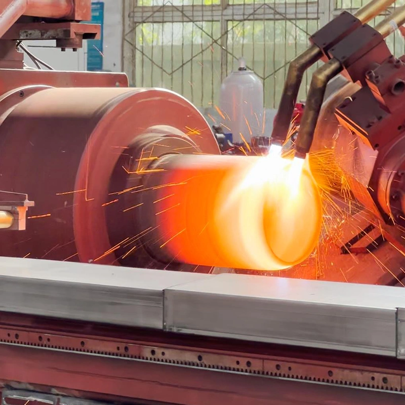
Flow forming is a precision metal forming process that excels in producing thin-walled, high-strength components. It is favored in industries that require parts with tight tolerances and enhanced mechanical properties.
Aerospace
- Components:
- Jet engine casings
- Missile casings
- Fuel tanks
- Advantages:
- Flow forming is used to produce high-performance aerospace components with superior strength-to-weight ratios. The process allows for the creation of complex geometries with exceptional precision, meeting the stringent requirements of the aerospace industry.
Automotive
- Components:
- Drive shafts
- Transmission parts
- Wheel rims
- Advantages:
- In the automotive industry, flow forming is used to manufacture lightweight, high-strength components that improve vehicle efficiency and performance. The process reduces material waste and allows for the production of parts with precise dimensions and surface finishes.
Military and Defense
- Components:
- Artillery shells
- Missile bodies
- Armored vehicle parts
- Advantages:
- Flow forming is ideal for producing defense components that require high strength, durability, and precision. The process can handle various materials, including high-strength alloys, making it suitable for demanding military applications.
Industrial
- Components:
- Pressure vessels
- Pump housings
- Cylindrical tanks
- Advantages:
- Flow forming is used to create industrial components that require high structural integrity and dimensional accuracy. The process allows for the efficient production of thin-walled parts with uniform thickness, reducing material usage and production costs.
Shear Forming Application Areas
Shear forming is a metal forming process that excels in producing axisymmetric components with varying thicknesses. It is suitable for applications that require precise control over wall thickness and complex profiles.
Aerospace
- Components:
- Turbine disks
- Engine flanges
- Structural components
- Advantages:
- Shear forming is used in aerospace applications to produce components with enhanced mechanical properties and precise dimensions. The process’s ability to control wall thickness is critical for optimizing weight and performance.
Automotive
- Components:
- Pulleys
- Hubs
- Rotational components
- Advantages:
- In the automotive industry, shear forming is used to manufacture lightweight and durable components. The process’s precision and flexibility allow for the creation of custom parts with complex shapes and varying thicknesses.
Medical
- Components:
- Surgical instruments
- Implants
- Medical device components
- Advantages:
- Shear forming is suitable for producing medical components that require high precision and biocompatibility. The process can handle various materials, including stainless steel and titanium, making it ideal for medical applications.
Industrial
- Components:
- Pump housings
- Pressure vessel components
- Machinery parts
- Advantages:
- Shear forming is used in industrial applications to produce high-quality components with precise dimensions and uniform wall thickness. The process’s ability to create complex profiles makes it suitable for a wide range of industrial products.
Wheel Forming Application Areas
Wheel forming is a specialized process used to produce wheels and other rotational components. It is widely used in industries that require high-performance wheels with complex geometries and enhanced mechanical properties.
Automotive
- Components:
- Car wheels
- Motorcycle wheels
- Racing wheels
- Advantages:
- Wheel forming is used to produce automotive wheels with superior strength, durability, and lightweight characteristics. The process allows for the creation of wheels with intricate designs and tight tolerances, enhancing vehicle performance and aesthetics.
Aerospace
- Components:
- Aircraft landing gear wheels
- Helicopter rotor hubs
- Turbine wheels
- Advantages:
- In the aerospace industry, wheel forming is used to manufacture high-performance wheels and rotational components. The process’s precision and material efficiency are critical for meeting the stringent requirements of aerospace applications.
Industrial
- Components:
- Conveyor wheels
- Heavy machinery wheels
- Transport vehicle wheels
- Advantages:
- Wheel forming is used to produce industrial wheels with exceptional strength and durability. The process’s ability to create complex geometries and uniform dimensions makes it suitable for demanding industrial applications.
Consumer Goods
- Components:
- Bicycle wheels
- Skateboard wheels
- Rollerblade wheels
- Advantages:
- In the consumer goods sector, wheel forming is used to produce wheels with high performance and aesthetic appeal. The process allows for the efficient production of wheels with consistent quality and design.
Conclusion
The metal forming processes of metal spinning, flow forming, shear forming, and wheel forming offer unique capabilities and advantages, making them suitable for a wide range of applications across various industries. By understanding the strengths and limitations of each process, manufacturers can select the most appropriate technique for their specific needs, optimizing production efficiency and product quality.
Metal spinning is a versatile and essential metal-forming technique that has been a cornerstone in various industries, ranging from automotive to aerospace. This process involves rotating a metal disc or tube at high speed while applying localized pressure to shape the metal. The technique allows for the creation of symmetrical objects such as cylinders, cones, and hemispheres, with applications across multiple sectors.
In its simplest form, metal spinning can be traced back to ancient civilizations, where artisans manually shaped metals to create household items and decorative pieces. However, modern advancements in machinery and technology have significantly enhanced the precision and efficiency of metal spinning, making it an indispensable process in contemporary manufacturing.
Historical Background
The history of metal spinning dates back thousands of years. Early evidence suggests that primitive forms of metal spinning were used in ancient Egypt, China, and the Middle East. Craftsmen in these cultures employed rudimentary tools and manual techniques to spin metals into various shapes, primarily for ornamental and utilitarian purposes.
During the Industrial Revolution, metal spinning underwent significant transformations. The invention of the lathe, a machine that could rotate materials with great precision, revolutionized the process. This period marked the beginning of mechanized metal spinning, enabling mass production and more complex designs.
In the 20th century, the development of computer numerical control (CNC) technology brought about another major leap in the evolution of metal spinning. CNC Metal Spinning Machines, capable of executing highly intricate and repetitive tasks with minimal human intervention, emerged as a game-changer for the industry. This technological advancement has allowed manufacturers to produce high-quality components with exceptional consistency and precision.
Modern Applications
Today, metal spinning is integral to various industries, including automotive, aerospace, defense, electronics, and medical equipment manufacturing. The technique is widely used to produce parts such as engine components, satellite dishes, cooking utensils, musical instruments, and architectural elements. The flexibility of metal spinning allows manufacturers to work with a wide range of materials, including aluminum, copper, stainless steel, and titanium.
With the advent of CNC Metal Spinning Machines, the process has become even more versatile. These machines can be programmed to create complex shapes and patterns that were previously impossible or too time-consuming to achieve. As a result, CNC metal spinning has become the preferred method for producing high-precision components in industries that demand stringent quality standards.
Relevance in Today’s Industry
In the current industrial landscape, where efficiency, precision, and cost-effectiveness are paramount, metal spinning remains a crucial manufacturing process. The ability to produce lightweight, durable, and high-strength components makes metal spinning an attractive option for industries focused on innovation and sustainability.
Moreover, the rise of Industry 4.0, characterized by the integration of digital technologies and automation in manufacturing, has further highlighted the importance of metal spinning. CNC Metal Spinning Machines, equipped with advanced software and sensors, can seamlessly integrate with other automated systems, enabling real-time monitoring, data analysis, and optimization of the production process.
The growing demand for customized and complex products has also driven the adoption of metal spinning technologies. With CNC machines, manufacturers can easily adjust parameters to produce bespoke items tailored to specific customer requirements. This capability is particularly valuable in the aerospace and defense industries, where precision and customization are critical.
Understanding Metal Spinning Machines
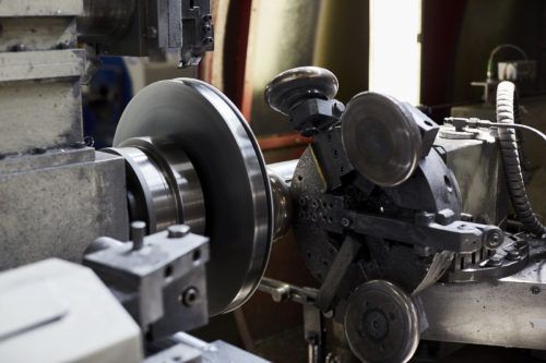
What is a Metal Spinning Machine?
A metal spinning machine is a specialized piece of equipment designed to shape metal blanks into various symmetrical forms through the process of spinning. The machine operates by rotating a metal disc or tube at high speeds while a forming tool, typically made of hardened steel, is pressed against the material to shape it. The combination of rotational force and controlled pressure allows for the precise manipulation of metal into complex geometries, such as cylindrical, conical, and spherical shapes.
Metal spinning machines can be manually operated or fully automated, with CNC Metal Spinning Machines representing the most advanced form of this technology. These machines are essential in manufacturing industries where precision and efficiency are critical, enabling the production of components with high dimensional accuracy and excellent surface finish.
Types of Metal Spinning Machines
Metal spinning machines come in various types, each designed to meet specific production needs. The main types include manual metal spinning machines, hydraulic metal spinning machines, and CNC metal spinning machines.
Manual Metal Spinning Machines:
Manual metal spinning machines are the most basic form, operated by skilled artisans who control the spinning process manually. These machines are suitable for low-volume production or custom jobs that require a high degree of craftsmanship. Although labor-intensive, manual spinning allows for flexibility in the production of unique and intricate designs.
Hydraulic Metal Spinning Machines:
Hydraulic metal spinning machines offer greater power and precision than manual machines. These machines use hydraulic pressure to control the forming tool, providing consistent force and allowing for the production of thicker and more durable components. Hydraulic machines are often used in industries where strength and durability are paramount, such as aerospace and automotive manufacturing.
CNC Metal Spinning Machines:
CNC (Computer Numerical Control) metal spinning machines represent the pinnacle of metal spinning technology. These machines are fully automated and controlled by computer programs that dictate the exact movements of the forming tool. CNC machines are capable of producing highly complex shapes with extreme precision, making them ideal for high-volume production and applications that demand tight tolerances.
CNC Metal Spinning Machine
A CNC metal spinning machine is a sophisticated piece of equipment that utilizes computer-aided design (CAD) and computer-aided manufacturing (CAM) software to automate the metal spinning process. The introduction of CNC technology has revolutionized the metal spinning industry, enabling manufacturers to produce components with unprecedented accuracy, speed, and consistency.
CNC machines operate by following a programmed set of instructions, which control the movement of the metal blank and the forming tool. The precision of CNC machining eliminates the variability associated with manual or hydraulic spinning, resulting in parts that meet exacting specifications every time.
Key benefits of CNC metal spinning machines include:
- Enhanced Precision: CNC machines can achieve extremely tight tolerances, ensuring that every component produced is identical and meets the required specifications.
- Increased Efficiency: Automation reduces the need for manual labor, allowing for faster production times and reduced costs.
- Consistency: CNC technology ensures that each part is produced with the same level of quality, eliminating defects and ensuring reliability.
- Flexibility: CNC machines can be easily reprogrammed to produce different shapes and sizes, making them versatile tools for various applications.
Applications of CNC Metal Spinning Machines: CNC metal spinning machines are used in industries that require high-precision components, such as aerospace, automotive, medical, and defense. They are particularly valuable in the production of components like gas turbine engine parts, rocket nozzles, and automotive wheels, where precision and material integrity are critical.
Small Metal Spinning Machine
A small metal spinning machine is a compact and versatile tool designed for the production of smaller components or low-volume runs. These machines are ideal for small-scale manufacturing operations, prototype development, and educational purposes. Despite their smaller size, these machines are capable of producing high-quality parts with excellent accuracy.
Key Features of Small Metal Spinning Machines:
- Compact Design: Small metal spinning machines are designed to fit in smaller workshops, making them accessible to small businesses and hobbyists.
- Ease of Use: These machines often feature simplified controls and are easier to operate, making them suitable for beginners or those with limited experience in metal spinning.
- Versatility: Small metal spinning machines can handle a variety of materials and produce a wide range of shapes, from simple to complex.
- Cost-Effective: Due to their smaller size and simpler design, small metal spinning machines are generally more affordable than their larger counterparts.
Applications of Small Metal Spinning Machines: Small metal spinning machines are used in the production of items such as lighting fixtures, kitchenware, and custom metal parts. They are also popular in the educational sector, where they are used to teach students the fundamentals of metal spinning.
Evolution and Technological Advancements
The evolution of metal spinning machines has been marked by continuous innovation and technological advancements. From the manual spinning techniques of ancient craftsmen to the highly automated CNC systems of today, the journey of metal spinning technology reflects the broader trends in industrial development.
The introduction of computer technology in the late 20th century was a turning point for the industry. CNC Metal Spinning Machines have dramatically improved the accuracy, efficiency, and repeatability of the spinning process. This advancement has opened up new possibilities for the production of complex components, enabling industries to push the boundaries of design and engineering.
In recent years, there has been a growing focus on integrating metal spinning machines with Industry 4.0 technologies. This includes the use of sensors, data analytics, and machine learning algorithms to optimize the spinning process in real-time. These advancements are paving the way for smarter, more adaptive manufacturing systems that can respond to changing conditions and demands.
The development of new materials and alloys has also played a significant role in the evolution of metal spinning machines. Modern machines are designed to handle a wider range of materials, including advanced composites and high-strength alloys, which are essential for applications in aerospace and defense.
Another key trend in the industry is the move towards sustainable manufacturing practices. Metal spinning machines are now being designed with energy efficiency and waste reduction in mind, aligning with global efforts to minimize the environmental impact of industrial activities.
CNC Metal Spinning Machines: Revolutionizing the Industry
Introduction to CNC Metal Spinning
CNC (Computer Numerical Control) technology has brought a transformative change to the metal spinning industry. Traditionally, metal spinning was a manual process, heavily reliant on the skill of the operator to produce consistent results. The advent of CNC metal spinning machines has revolutionized this field by introducing precision, automation, and efficiency, enabling manufacturers to meet the increasingly complex demands of modern industries.
CNC metal spinning involves the use of computer-controlled machinery to perform metal spinning operations. The machine is programmed with specific instructions, allowing it to execute highly precise movements that shape the metal workpiece into the desired form. This technology is particularly valuable in applications requiring intricate designs, high accuracy, and consistent quality.
Working Principle of CNC Metal Spinning Machines
CNC metal spinning machines operate by rotating a metal blank at high speeds while a CNC-controlled tool applies pressure to shape the material. The process begins with the input of a CAD (Computer-Aided Design) model, which serves as a blueprint for the machine’s operations. The CAD model is then converted into a set of instructions through CAM (Computer-Aided Manufacturing) software, which the CNC machine follows to execute the spinning process.
Steps in CNC Metal Spinning:
- Material Loading: The metal blank, typically a disc or tube, is loaded onto the spinning lathe.
- Tool Positioning: The CNC system positions the forming tool according to the programmed instructions.
- Spinning Process: As the blank rotates, the forming tool applies pressure at precise points to shape the metal. This process may involve multiple passes to gradually achieve the desired shape.
- Finishing: After the primary spinning is completed, additional operations such as trimming, polishing, or secondary spinning may be performed to refine the component.
- Quality Control: The finished component is inspected to ensure it meets the specified tolerances and quality standards.
CNC metal spinning machines are capable of producing highly complex geometries with minimal human intervention. This not only improves production efficiency but also reduces the likelihood of errors, leading to higher quality outcomes.
Advantages over Traditional Metal Spinning Machines
CNC metal spinning machines offer several advantages over traditional manual or hydraulic spinning machines. These benefits have made CNC technology the preferred choice for many manufacturers across various industries.
1. Precision and Accuracy:
One of the most significant advantages of CNC metal spinning machines is their ability to produce components with exceptional precision and accuracy. The computer-controlled nature of these machines allows for the execution of intricate designs with tight tolerances, which is essential in industries such as aerospace, medical devices, and automotive manufacturing.
2. Consistency and Repeatability:
CNC machines can produce identical parts in large quantities with minimal variation. This consistency is crucial for industries that require mass production of components, ensuring that each piece meets the required specifications.
3. Efficiency and Speed:
CNC metal spinning machines are faster and more efficient than manual processes. The automation of the spinning process reduces cycle times and allows for continuous operation, increasing overall productivity. Additionally, the ability to quickly switch between different programs enables manufacturers to adapt to changing production needs with minimal downtime.
4. Reduced Labor Costs:
While CNC machines require skilled operators to program and oversee the process, the level of manual intervention is significantly lower than in traditional metal spinning. This reduction in labor costs, combined with the increased efficiency, results in lower overall production costs.
5. Versatility:
CNC metal spinning machines are highly versatile and can be programmed to produce a wide range of shapes and sizes. This versatility makes them suitable for both high-volume production and custom, low-volume orders, catering to a diverse array of industry needs.
6. Integration with Other Technologies:
CNC machines can be easily integrated with other manufacturing technologies, such as robotics, additive manufacturing, and digital quality control systems. This integration facilitates the development of smart manufacturing systems that are more flexible, efficient, and responsive to market demands.
Key Features of CNC Metal Spinning Lathes
CNC metal spinning lathes are the core components of the CNC metal spinning process. These machines are equipped with advanced features that enhance their performance and enable them to meet the stringent requirements of modern manufacturing.
1. Precision Control Systems:
CNC lathes are equipped with high-precision control systems that allow for the accurate positioning of the forming tool. These systems use servo motors and encoders to ensure that the tool follows the programmed path with minimal deviation, resulting in parts that meet exact specifications.
2. Advanced Software Capabilities:
The software used in CNC metal spinning lathes is a critical component of their functionality. Modern CNC software includes powerful CAM tools that enable the creation of complex tool paths, simulation of the spinning process, and real-time monitoring of machine operations. These capabilities allow operators to optimize the spinning process, reduce material waste, and ensure consistent quality.
3. Robust Construction:
CNC metal spinning lathes are designed to handle the stresses associated with high-speed metal spinning. They feature robust frames, heavy-duty spindles, and high-strength forming tools that can withstand the forces generated during the spinning process. This durability ensures long-term reliability and consistent performance.
4. Automation and Tooling Flexibility:
Many CNC lathes come with automated tool changers and multi-axis capabilities, allowing for greater flexibility in the spinning process. This automation reduces the need for manual intervention and enables the production of complex parts in a single setup, further enhancing efficiency and reducing production times.
5. Safety Features:
CNC metal spinning lathes are equipped with advanced safety features, including protective enclosures, emergency stop systems, and sensors that detect anomalies in the spinning process. These features help protect operators and ensure safe operation, even in high-speed, high-force applications.
6. Data Integration and Industry 4.0 Compatibility:
Modern CNC lathes are increasingly being integrated with data analytics and Industry 4.0 technologies. These machines can collect and analyze data in real-time, providing insights into the spinning process and enabling predictive maintenance, quality control, and process optimization. This data-driven approach enhances the overall efficiency and reliability of the manufacturing operation.
Specialized Metal Spinning Techniques and Machines
Flow Forming Machines: Applications and Benefits
Flow forming is a specialized metal forming technique closely related to traditional metal spinning, but with unique advantages that make it indispensable in certain applications. Flow forming machines are designed to create thin-walled, high-precision cylindrical parts by applying axial force to a rotating metal blank. This process results in components with exceptional strength, dimensional accuracy, and surface finish, making flow forming a preferred method for producing parts used in industries like aerospace, automotive, and defense.
Working Principle of Flow Forming: Flow forming involves clamping a pre-formed metal blank, often referred to as a preform, onto a rotating mandrel. As the mandrel spins, rollers apply force along the axial direction, gradually elongating the metal and reducing its thickness. The process is highly controlled, allowing for the precise shaping of the material into complex, symmetrical forms.
Applications of Flow Forming Machines: Flow forming is widely used in applications that require lightweight, high-strength components with precise dimensions. Common applications include:
- Aerospace Industry: Production of rocket motor casings, aircraft fuselage components, and missile bodies.
- Automotive Industry: Manufacturing of drive shafts, transmission components, and other high-performance automotive parts.
- Defense Sector: Production of artillery shells, grenade casings, and other military hardware.
- Energy Sector: Creation of components for power generation and oil & gas exploration, such as gas turbine housings and pressure vessels.
Benefits of Flow Forming:
- High Strength-to-Weight Ratio: Flow formed components are stronger and lighter than those produced by traditional methods, making them ideal for applications where weight savings are crucial.
- Precision and Consistency: The process offers exceptional control over wall thickness and diameter, resulting in highly consistent and accurate parts.
- Material Efficiency: Flow forming minimizes material waste, making it a cost-effective manufacturing process.
- Surface Finish: The process naturally produces parts with a smooth surface finish, reducing the need for additional finishing operations.
Wheel Forming Machines: Use in the Automotive Industry
Wheel forming machines are specialized tools used in the production of automotive wheels. These machines are designed to shape metal blanks into precise wheel rims, ensuring that the final product meets the strict quality standards required for safety and performance. The automotive industry relies heavily on wheel forming machines to produce both standard and high-performance wheels, particularly for vehicles that require customized designs or enhanced durability.
Working Principle of Wheel Forming: Wheel forming machines typically operate by clamping a metal blank, such as an aluminum disc, onto a spinning chuck. As the blank rotates, forming tools or rollers are applied to shape the rim profile. This process can include several stages, such as pre-forming, spinning, and trimming, to achieve the desired wheel shape and size.
Applications of Wheel Forming Machines:
- Passenger Vehicles: Production of standard wheels for cars, SUVs, and trucks.
- High-Performance Vehicles: Manufacturing of lightweight, high-strength wheels for sports cars, racing vehicles, and off-road vehicles.
- Commercial Vehicles: Production of heavy-duty wheels for trucks, buses, and other commercial transportation vehicles.
Benefits of Wheel Forming Machines:
- Precision Manufacturing: Ensures that each wheel meets the exact specifications required for safety and performance.
- Custom Design Capabilities: Wheel forming machines allow for the creation of customized wheel designs, catering to both aesthetic and functional requirements.
- Material Flexibility: Capable of working with various materials, including aluminum, steel, and alloyed metals, to produce wheels with different properties.
- Enhanced Durability: The forming process improves the material properties of the wheel, enhancing its strength and resistance to impact.
Shear Forming Machines: Precision and Efficiency in Production
Shear forming, also known as shear spinning, is a metal forming technique used to produce conical or flared parts with high precision and efficiency. Shear forming machines are specifically designed to reduce the thickness of a metal blank while simultaneously shaping it into a desired conical form. This process is highly efficient and is used in the production of components that require precise control over wall thickness, such as aerospace and defense parts.
Working Principle of Shear Forming: The shear forming process involves mounting a metal blank onto a rotating mandrel. As the blank spins, a forming tool is pressed against it, applying force along the axis of the mandrel. The tool exerts a shearing action that reduces the thickness of the blank while shaping it into the desired conical geometry. The process is controlled by adjusting the speed, force, and position of the tool, allowing for the precise shaping of the material.
Applications of Shear Forming Machines:
- Aerospace Components: Production of conical components such as rocket nozzles, missile casings, and aircraft engine parts.
- Industrial Equipment: Manufacturing of flared components used in machinery, such as funnels, hoppers, and pressure vessel ends.
- Defense Applications: Production of military-grade components that require precise dimensions and enhanced material properties.
Benefits of Shear Forming Machines:
- Precision Control: Allows for precise control over the wall thickness and geometry of the component, ensuring consistent quality.
- Material Strength: The shear forming process enhances the mechanical properties of the material, resulting in stronger and more durable components.
- Efficiency: Shear forming is a highly efficient process that reduces material waste and minimizes the need for secondary operations.
- Versatility: Capable of forming a wide range of metals, including aluminum, titanium, and high-strength alloys, making it suitable for various industries.
Comparison of Specialized Metal Spinning Machines
Each type of specialized metal spinning machine—flow forming, wheel forming, and shear forming—serves a distinct purpose and offers unique advantages. While they share common principles with traditional metal spinning, these machines are tailored to meet the specific needs of their respective applications.
Flow Forming vs. Shear Forming:
- Material Usage: Flow forming is primarily used for elongating cylindrical components, while shear forming focuses on reducing the thickness of conical parts.
- Application Focus: Flow forming is widely used in industries that require high-strength, thin-walled cylindrical parts, such as aerospace and automotive. Shear forming is more common in the production of conical parts with precise thickness control, such as rocket nozzles and industrial equipment.
Wheel Forming vs. Other Spinning Techniques:
- Specialization: Wheel forming machines are specialized for producing automotive wheels, offering precise control over rim profiles and material properties. In contrast, flow forming and shear forming machines are more versatile and can produce a broader range of components.
- Customization: Wheel forming allows for extensive customization of wheel designs, catering to both performance and aesthetic requirements, which is less common in other spinning techniques.
Shared Advantages:
- Precision and Control: All specialized spinning machines offer high levels of precision and control, essential for producing components with tight tolerances and specific material properties.
- Material Strength: The spinning processes involved in all these machines enhance the mechanical properties of the metal, resulting in stronger, more durable components.
- Efficiency: Each machine is designed to optimize the spinning process, reducing material waste and minimizing production times.
Tube (Cylinder) Necking-In & Closing Machines
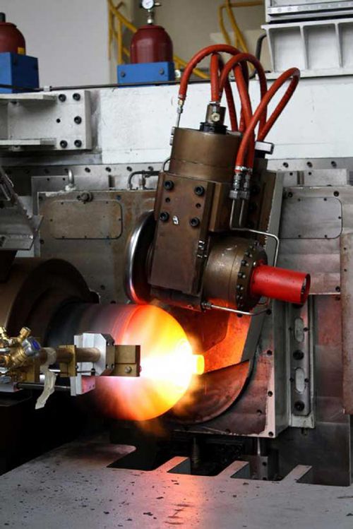
Introduction to Tube Necking-In & Closing
Tube necking-in and closing are specialized metal forming processes used to modify the ends of cylindrical components, such as tubes or cylinders. These processes are crucial in industries where precise control over the shape and dimensions of tube ends is required, such as in the production of pressure vessels, fuel tanks, and certain automotive components. Tube necking-in and closing machines are designed to perform these operations with high precision, ensuring that the final products meet stringent industry standards.
Tube Necking-In:
Tube necking-in is the process of reducing the diameter of a tube’s open end, creating a narrower section that can be used for various purposes, such as fitting into another tube or attaching to a different component. This process is commonly used in the automotive and aerospace industries, where precise dimensional control is essential for the assembly of complex systems.
Tube Closing:
Tube closing, on the other hand, involves sealing the end of a tube to create a closed, airtight or watertight component. This process is often used in the production of containers, pressure vessels, and tanks, where the integrity of the closed end is critical for the component’s functionality. The closing process can be performed using various methods, such as crimping, welding, or folding, depending on the material and application requirements.
Applications and Industry Usage
Tube necking-in and closing machines are widely used across various industries, particularly in applications that require precise control over the geometry and dimensions of cylindrical components. These machines are essential in the production of components that need to withstand high pressures, maintain airtight or watertight seals, or fit seamlessly into larger assemblies.
Automotive Industry:
- Fuel Tanks: Tube necking-in is used to create the openings of fuel tanks, ensuring a precise fit for filler necks and other components.
- Exhaust Systems: Necking-in processes are applied to exhaust tubes, allowing them to be connected to other parts of the exhaust system without leaks.
- Fluid Transport: Tube closing is used to seal the ends of tubes that transport fluids, such as brake lines and hydraulic systems, ensuring that they remain leak-proof under pressure.
Aerospace Industry:
- Fuel and Hydraulic Lines: Tube necking-in is critical in the aerospace sector for creating connections in fuel and hydraulic systems, where safety and precision are paramount.
- Structural Components: Tubes used in structural applications, such as struts or spars, often require necking-in to achieve the necessary fit and alignment.
Medical Equipment Manufacturing:
- Surgical Instruments: Tube necking-in and closing processes are used to produce surgical instruments and medical devices that require precise dimensions and smooth finishes.
- Catheters and Needles: The production of catheters and needles often involves necking-in and closing to ensure that they meet strict medical standards.
Industrial Equipment:
- Pressure Vessels: Tube closing is commonly used in the production of pressure vessels, where the integrity of the sealed end is critical for safety and performance.
- Heat Exchangers: In heat exchangers, necking-in is used to create connections between tubes, ensuring efficient thermal transfer and fluid flow.
Technical Specifications and Innovations
Tube necking-in and closing machines are designed with advanced features that enable them to perform highly precise and consistent operations. These machines are typically equipped with sophisticated control systems, durable tooling, and automation capabilities to meet the demands of modern manufacturing.
Key Technical Specifications:
- Precision Control:
- Servo-Controlled Mechanisms: Many tube necking-in and closing machines use servo motors to control the movement of tools with high precision. This allows for accurate adjustments to the tube diameter and ensures consistent results across multiple production runs.
- CNC Integration: CNC technology is often integrated into these machines, allowing for automated control over the necking-in and closing processes. This integration enables the production of complex tube geometries with minimal operator intervention.
- Tooling Capabilities:
- Interchangeable Tooling: These machines are equipped with interchangeable tooling systems that allow for quick changes between different tube sizes and shapes. This flexibility is crucial for manufacturers that need to produce a variety of components on the same machine.
- High-Strength Materials: The tooling used in tube necking-in and closing machines is typically made from high-strength materials such as tool steel or carbide, ensuring durability and long service life even under high-pressure operations.
- Automation and Efficiency:
- Automated Loading and Unloading: Advanced tube necking-in and closing machines often feature automated loading and unloading systems that streamline the production process and reduce cycle times. This automation is particularly beneficial in high-volume manufacturing environments.
- Real-Time Monitoring: Many machines are equipped with sensors and data acquisition systems that monitor the necking-in and closing processes in real-time. This data is used to optimize machine performance, detect potential issues, and ensure that the final products meet the required specifications.
Innovations in Tube Necking-In & Closing:
- Adaptive Control Systems:
Recent advancements in adaptive control technology have enabled tube necking-in and closing machines to adjust their operations in response to real-time feedback. These systems can automatically modify process parameters to compensate for variations in material properties or environmental conditions, ensuring consistent quality. - Laser-Assisted Tube Closing:
Laser technology is being increasingly used in tube closing applications to achieve precise and clean seals. Laser-assisted closing provides a high level of control over the heat input, reducing the risk of material deformation or weakening, which is particularly important for thin-walled tubes used in aerospace and medical applications. - Hybrid Forming Techniques:
Hybrid machines that combine necking-in, closing, and other forming processes in a single setup are gaining popularity. These machines allow manufacturers to perform multiple operations on the same tube without the need for additional setups or handling, improving efficiency and reducing production costs.
Integration with CNC Metal Spinning Technology
Tube necking-in and closing machines are often integrated with CNC metal spinning technology to create comprehensive manufacturing solutions for cylindrical components. This integration allows for the seamless production of parts that require both spinning and necking-in/closing operations, reducing the need for multiple machines and setups.
Benefits of Integration:
- Streamlined Production:
By combining CNC metal spinning with necking-in and closing processes, manufacturers can streamline their production workflows, reducing cycle times and minimizing material handling. This integrated approach is particularly beneficial for the production of complex components that require multiple forming steps. - Enhanced Precision:
The precision offered by CNC technology complements the accuracy of necking-in and closing machines, resulting in components with tight tolerances and superior surface finishes. This is especially important in industries such as aerospace and medical devices, where precision is critical. - Flexibility:
Integrated systems offer greater flexibility in manufacturing, allowing for quick adjustments to production parameters and the ability to produce a wide range of components on the same machine. This flexibility is essential for manufacturers that need to respond to changing customer demands or market conditions. - Cost Savings:
Combining these technologies in a single setup reduces the need for multiple machines and operators, leading to significant cost savings. Additionally, the reduced material waste and improved efficiency of integrated systems contribute to lower overall production costs.
Small Metal Spinning Machines
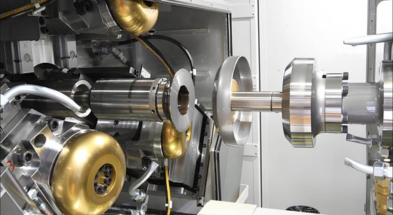
Role and Importance in Small-Scale Production
Small metal spinning machines play a critical role in industries where precision, customization, and flexibility are paramount. Unlike larger industrial spinning machines, small metal spinning machines are designed to handle smaller workpieces and are often used in environments where space, budget, and the ability to produce limited runs of specialized components are key considerations. These machines are especially valuable in small-scale production, prototyping, and educational settings.
Applications in Small-Scale Production:
- Custom Manufacturing: Small metal spinning machines are ideal for producing custom metal parts in limited quantities. This includes components for bespoke products, specialized machinery, and custom-designed architectural elements.
- Prototyping: These machines are widely used in prototyping, allowing manufacturers to quickly and cost-effectively produce test components before committing to full-scale production. The ability to make rapid adjustments to designs and materials is particularly beneficial in product development.
- Artisanal Crafting: In addition to industrial applications, small metal spinning machines are often used by artisans and craftspeople to create decorative metalwork, such as vases, bowls, and lampshades. The precision and control offered by these machines enable the creation of intricate designs with a high level of craftsmanship.
Industries Benefiting from Small Metal Spinning Machines:
- Jewelry and Decorative Arts: Small metal spinning machines are used to create detailed and intricate designs for jewelry, medals, and decorative art pieces.
- Home Goods Manufacturing: The production of metal kitchenware, lighting fixtures, and small household items often relies on small metal spinning machines for their precision and ability to handle fine details.
- Medical Device Manufacturing: In the medical field, small metal spinning machines are used to create components for surgical instruments, diagnostic devices, and other specialized equipment.
Versatility and Cost-Efficiency
One of the primary advantages of small metal spinning machines is their versatility. These machines can work with a variety of materials, including aluminum, brass, copper, and stainless steel, and can produce a wide range of shapes and sizes. This versatility makes them an invaluable tool for small manufacturers and artisans who need to create diverse products without investing in multiple specialized machines.
Key Features of Small Metal Spinning Machines:
- Compact Size: The compact design of small metal spinning machines allows them to be used in workshops with limited space. Despite their smaller footprint, these machines are capable of producing high-quality parts with precise dimensions.
- Ease of Use: Many small metal spinning machines are designed with user-friendly controls, making them accessible to operators with varying levels of experience. This ease of use is particularly important in educational settings and small businesses where operators may not have extensive training in metal spinning.
- Adaptability: Small metal spinning machines can be easily adapted to produce different parts by changing the tooling or adjusting the machine settings. This adaptability is essential for small-scale production environments where flexibility is key.
Cost-Efficiency:
- Lower Capital Investment: Small metal spinning machines require a lower initial investment compared to larger industrial machines, making them more accessible to small businesses and startups. This lower cost of entry allows more companies to adopt metal spinning technology without the need for significant upfront capital.
- Reduced Operating Costs: The smaller size and simpler design of these machines result in lower operating costs, including reduced energy consumption and maintenance requirements. This cost-efficiency makes small metal spinning machines an attractive option for businesses looking to minimize expenses while maintaining production capabilities.
- Minimal Material Waste: Small metal spinning machines are designed to minimize material waste, which is particularly important in small-scale production where raw material costs can be a significant factor. The precision of these machines ensures that material usage is optimized, reducing scrap and lowering overall production costs.
Key Features and Capabilities
Small metal spinning machines are equipped with features that enhance their performance and make them suitable for a wide range of applications. While they are smaller and less powerful than industrial machines, they offer several capabilities that are crucial for small-scale manufacturing.
1. Precision Spinning:
- High Accuracy: Despite their size, small metal spinning machines are capable of achieving high levels of accuracy, with tight tolerances that ensure the production of consistent and precise components. This is particularly important in applications where even minor deviations can affect the functionality or appearance of the final product.
- Smooth Surface Finish: These machines are designed to produce components with a smooth surface finish, reducing the need for additional finishing operations. This capability is essential for applications where aesthetics are important, such as in the production of decorative items or consumer goods.
2. Material Compatibility:
- Wide Range of Materials: Small metal spinning machines can work with a variety of metals, including softer materials like aluminum and brass, as well as harder metals like stainless steel. This compatibility allows manufacturers to produce parts that meet specific material requirements for different applications.
- Thin and Thick-Walled Parts: These machines can handle both thin-walled and thick-walled parts, making them suitable for a diverse range of products. The ability to spin both types of components increases the versatility of the machine and broadens the range of potential applications.
3. Tooling Flexibility:
- Interchangeable Tooling: Small metal spinning machines often feature interchangeable tooling systems that allow operators to quickly switch between different setups. This flexibility is crucial in small-scale production environments where a variety of parts may need to be produced on the same machine.
- Custom Tooling: In addition to standard tooling options, small metal spinning machines can be equipped with custom tools designed for specific applications. This capability allows manufacturers to create unique shapes and designs that meet specific customer needs.
4. Durability and Reliability:
- Robust Construction: Despite their smaller size, small metal spinning machines are built to be durable and reliable, with sturdy frames and high-quality components that can withstand the demands of regular use. This durability ensures that the machines can operate consistently over long periods, even in challenging production environments.
- Low Maintenance: These machines are designed with simplicity in mind, resulting in lower maintenance requirements compared to larger, more complex equipment. This reliability reduces downtime and ensures that production schedules can be maintained without interruption.
Market Demand and Applications
The demand for small metal spinning machines continues to grow, driven by the increasing need for customization, rapid prototyping, and small-batch production. As industries place greater emphasis on flexibility and responsiveness, the ability to produce high-quality, custom components in small quantities has become increasingly valuable. Small metal spinning machines are well-positioned to meet these demands, offering the precision, versatility, and cost-efficiency that modern manufacturers require.
Current Market Trends:
- Customization and Personalization: There is a growing trend towards customization and personalization in consumer products, from custom jewelry to bespoke home goods. Small metal spinning machines are ideally suited to meet this demand, allowing manufacturers to produce unique, custom-designed items on a small scale.
- Rapid Prototyping: The rise of rapid prototyping in product development has increased the need for equipment that can quickly produce functional prototypes. Small metal spinning machines offer the speed and flexibility needed to create prototypes that closely match the final product, allowing designers and engineers to test and refine their designs more efficiently.
- Sustainability: As sustainability becomes a more important consideration in manufacturing, the ability to produce parts with minimal waste is increasingly valued. Small metal spinning machines, with their precision and efficiency, contribute to more sustainable production practices by reducing material waste and energy consumption.
Future Outlook: The future of small metal spinning machines looks promising, with continued advancements in technology and increasing demand for flexible, small-scale manufacturing solutions. As industries evolve and new applications emerge, the role of small metal spinning machines is likely to expand, offering even greater capabilities and opportunities for innovation.
Emerging Applications:
- Additive Manufacturing Integration: Small metal spinning machines may increasingly be integrated with additive manufacturing technologies, allowing for the combination of traditional metal spinning with modern 3D printing techniques. This integration could lead to new possibilities in part design and production, further enhancing the versatility of small metal spinning machines.
- Smart Manufacturing: As Industry 4.0 technologies continue to develop, small metal spinning machines are likely to become part of smart manufacturing ecosystems. This could include the use of sensors, data analytics, and real-time monitoring to optimize the spinning process and improve overall production efficiency.
Market Trends and Future of Metal Spinning Machines
Current Market Trends
The metal spinning machine market is evolving rapidly, driven by technological advancements, increased demand for high-precision components, and a growing focus on sustainability. Several key trends are shaping the current landscape of the metal spinning industry, influencing both manufacturers and end-users across various sectors.
1. Adoption of CNC Technology: The widespread adoption of CNC metal spinning machines has been a significant trend over the past decade. CNC technology has revolutionized metal spinning by enhancing precision, efficiency, and repeatability. Manufacturers are increasingly investing in CNC machines to meet the demand for high-quality components with tight tolerances. The ability to automate complex spinning processes has also led to significant reductions in production time and labor costs, making CNC metal spinning a preferred choice in industries such as aerospace, automotive, and medical devices.
2. Customization and Shorter Lead Times: As consumer preferences shift towards customized products, there is an increasing demand for metal spinning machines that can quickly adapt to different production requirements. Manufacturers are looking for equipment that can handle small-batch production runs with minimal setup time. This trend is particularly evident in industries like automotive, where custom wheels and other bespoke components are in high demand. The ability to produce customized parts on demand is becoming a key competitive advantage for manufacturers.
3. Integration with Industry 4.0: The integration of metal spinning machines with Industry 4.0 technologies is transforming the manufacturing landscape. Sensors, IoT devices, and advanced data analytics are being used to monitor and optimize the metal spinning process in real-time. This integration allows manufacturers to improve process efficiency, reduce downtime, and achieve higher levels of quality control. Predictive maintenance, powered by machine learning algorithms, is also becoming more common, helping to prevent equipment failures and extend the lifespan of metal spinning machines.
4. Focus on Sustainability: Sustainability is increasingly becoming a priority for manufacturers across all industries. Metal spinning, with its ability to produce high-strength components with minimal material waste, is well-suited to meet the demands of sustainable manufacturing practices. Additionally, the development of energy-efficient metal spinning machines is helping to reduce the environmental impact of the manufacturing process. Companies are also exploring the use of recycled materials and sustainable alloys in their metal spinning operations.
5. Globalization and Market Expansion: The global market for metal spinning machines is expanding, with growing demand in emerging markets such as Asia-Pacific and Latin America. These regions are experiencing rapid industrialization, leading to increased investments in advanced manufacturing technologies. As a result, the metal spinning machine market is becoming more competitive, with manufacturers focusing on innovation and cost reduction to capture new market opportunities.
Emerging Technologies in Metal Spinning
The metal spinning industry is on the cusp of several technological innovations that promise to enhance the capabilities of metal spinning machines and expand their application range. These emerging technologies are set to play a crucial role in the future of metal spinning, enabling manufacturers to push the boundaries of what is possible with this versatile metal forming technique.
1. Advanced Materials and Alloys: One of the most exciting developments in the metal spinning industry is the use of advanced materials and alloys. The demand for lightweight, high-strength components in industries such as aerospace and automotive is driving research into new materials that offer superior performance characteristics. For example, the use of titanium alloys, which are lightweight yet extremely strong, is becoming more common in metal spinning applications. Similarly, the development of heat-resistant and corrosion-resistant alloys is expanding the range of components that can be produced using metal spinning techniques.
2. Hybrid Manufacturing Processes: Hybrid manufacturing, which combines metal spinning with other manufacturing techniques such as additive manufacturing (3D printing), is an emerging trend with significant potential. By integrating metal spinning with additive processes, manufacturers can create complex, multi-material components that were previously impossible to produce. This approach allows for greater design flexibility and the ability to incorporate features such as internal channels or intricate surface textures directly into spun components. Hybrid manufacturing is expected to open up new possibilities in industries that require highly specialized and customized parts.
3. Laser-Assisted Metal Spinning: Laser-assisted metal spinning is a cutting-edge technology that enhances the metal spinning process by using laser energy to heat the metal blank during spinning. This localized heating reduces the force required to shape the material, allowing for the production of thinner and more intricate components. Laser-assisted spinning is particularly beneficial when working with hard-to-form materials or when producing components with complex geometries. The precision and control offered by laser technology also improve the quality of the final product, reducing defects and the need for secondary processing.
4. Smart Manufacturing Systems: The integration of metal spinning machines into smart manufacturing systems is a key area of innovation. Smart systems leverage advanced sensors, real-time data analytics, and machine learning algorithms to optimize the metal spinning process. These systems can automatically adjust machine settings based on real-time feedback, ensuring consistent quality and efficiency. Additionally, smart manufacturing systems enable better resource management, predictive maintenance, and energy optimization, contributing to more sustainable and cost-effective production processes.
5. Digital Twin Technology: Digital twin technology, which involves creating a virtual replica of a physical metal spinning machine, is gaining traction in the industry. Digital twins allow manufacturers to simulate and analyze the metal spinning process in a virtual environment before actual production begins. This capability is invaluable for optimizing machine settings, predicting potential issues, and ensuring that the final product meets all specifications. Digital twins also facilitate remote monitoring and control of metal spinning machines, enabling manufacturers to respond quickly to changes in production requirements.
Environmental and Economic Impacts
The metal spinning industry is increasingly focused on addressing the environmental and economic impacts of its operations. As global industries move towards more sustainable and resource-efficient practices, metal spinning offers several advantages that align with these goals.
Environmental Impact:
- Material Efficiency: Metal spinning is inherently a material-efficient process, as it generates minimal waste compared to other metal forming techniques. The process involves shaping metal blanks without the need for extensive cutting or machining, resulting in less scrap material and lower raw material consumption. This efficiency is particularly important in industries where the cost of raw materials is a significant factor.
- Energy Consumption: Advances in metal spinning machine technology, including the development of energy-efficient motors and drives, are helping to reduce the overall energy consumption of the metal spinning process. Additionally, the integration of energy management systems allows manufacturers to monitor and optimize energy usage in real-time, further reducing the environmental footprint of their operations.
- Sustainable Materials: The use of recycled metals and environmentally friendly alloys in metal spinning is becoming more common. By incorporating sustainable materials into their production processes, manufacturers can reduce their reliance on virgin resources and contribute to a circular economy.
Economic Impact:
- Cost Reduction: The efficiency of the metal spinning process, combined with the ability to produce high-quality components with minimal waste, leads to significant cost savings for manufacturers. Additionally, the automation of metal spinning processes through CNC technology reduces labor costs and increases production speed, further enhancing economic viability.
- Job Creation: While automation and advanced technologies are reducing the need for manual labor in some areas, the metal spinning industry is also creating new job opportunities in fields such as machine operation, programming, and maintenance. The demand for skilled workers who can operate and maintain advanced metal spinning machines is expected to grow, contributing to economic development in regions where metal spinning is a key industry.
- Global Competitiveness: As the global market for metal spinning machines expands, manufacturers are increasingly focused on innovation and cost efficiency to remain competitive. Companies that invest in the latest technologies and adopt sustainable practices are likely to gain a competitive edge in the global marketplace, attracting new customers and driving economic growth.
The Future of CNC Metal Spinning and Related Technologies
The future of CNC metal spinning and related technologies looks promising, with ongoing advancements expected to further enhance the capabilities and applications of metal spinning machines. As industries continue to demand high-precision, customized components, CNC metal spinning will play a critical role in meeting these needs.
1. Increased Automation and AI Integration: The trend towards increased automation in manufacturing is expected to continue, with artificial intelligence (AI) playing a larger role in CNC metal spinning. AI-powered systems will enable greater automation of the design, programming, and operation of metal spinning machines, reducing the need for human intervention and increasing production efficiency. AI will also facilitate real-time decision-making, allowing machines to adapt to changing conditions and optimize the spinning process on the fly.
2. Expanded Applications in New Industries: As metal spinning technology advances, its applications are likely to expand into new industries. For example, the growing demand for renewable energy technologies, such as wind turbines and solar panels, may create new opportunities for metal spinning in the production of energy-related components. Similarly, the development of new materials and manufacturing techniques could lead to the adoption of metal spinning in fields such as biomedical engineering, where precision and material properties are critical.
3. Customization and Mass Personalization: The ability to produce customized components quickly and cost-effectively will continue to drive the adoption of CNC metal spinning. The rise of mass personalization, where consumers demand products tailored to their individual preferences, will create new opportunities for manufacturers to offer customized metal parts on a large scale. CNC metal spinning machines, with their flexibility and precision, will be key enablers of this trend.
4. Sustainability as a Driving Force: Sustainability will remain a driving force in the future of CNC metal spinning. Manufacturers will increasingly focus on reducing the environmental impact of their operations, from energy consumption to material usage. Innovations in machine design, materials, and processes will contribute to more sustainable metal spinning practices, helping companies meet regulatory requirements and consumer expectations for environmentally responsible products.
5. Collaboration and Knowledge Sharing: The future of CNC metal spinning will also be shaped by increased collaboration and knowledge sharing among manufacturers, researchers, and technology providers. Collaborative efforts to develop new technologies, improve existing processes, and share best practices will accelerate innovation and drive the continued evolution of the metal spinning industry. Industry associations, academic institutions, and research organizations will play a critical role in fostering these collaborations and advancing the state of the art in metal spinning.
Conclusion
Summary of Key Points
The metal spinning industry has undergone significant advancements over the years, driven by the adoption of cutting-edge technologies and the growing demand for high-precision, customizable components across various sectors. CNC metal spinning machines have emerged as a transformative force, revolutionizing the way manufacturers approach metal forming by offering unparalleled precision, efficiency, and versatility. These machines have become indispensable in industries such as aerospace, automotive, medical devices, and defense, where the ability to produce complex, high-quality parts with minimal waste is critical.
Specialized metal spinning machines, including flow forming machines, wheel forming machines, and shear forming machines, further expand the capabilities of the metal spinning process. These machines enable the production of highly specialized components that meet the stringent requirements of modern industrial applications. The integration of tube necking-in and closing machines with CNC technology has also enhanced the production of cylindrical components, offering manufacturers streamlined solutions for complex forming operations.
Small metal spinning machines play a crucial role in small-scale production, prototyping, and customization, providing manufacturers with the flexibility to produce bespoke components efficiently and cost-effectively. As market trends continue to evolve, the demand for these machines is expected to grow, driven by the increasing focus on customization, rapid prototyping, and sustainable manufacturing practices.
Importance of Metal Spinning Machines in Various Industries
Metal spinning machines are vital to numerous industries, offering a range of benefits that contribute to improved product quality, reduced production costs, and enhanced manufacturing efficiency. In the aerospace industry, metal spinning machines are essential for producing lightweight, high-strength components that meet the rigorous demands of flight and space exploration. The automotive industry relies on metal spinning to produce durable, high-performance parts, including wheels and exhaust systems, that are critical to vehicle safety and performance.
In the medical field, the precision and versatility of metal spinning machines are leveraged to produce surgical instruments, diagnostic devices, and other specialized equipment that requires exacting standards of quality and hygiene. The defense sector also benefits from metal spinning technology, using it to manufacture components that must withstand extreme conditions and perform reliably in critical applications.
The growing emphasis on sustainability has further highlighted the importance of metal spinning machines, as they offer an environmentally friendly alternative to traditional metal forming techniques. By minimizing material waste and reducing energy consumption, metal spinning aligns with the goals of sustainable manufacturing, helping companies meet regulatory requirements and consumer expectations.
Final Thoughts and Future Outlook
The future of metal spinning machines is bright, with ongoing innovations poised to further enhance their capabilities and expand their applications across new industries. As CNC technology continues to evolve, we can expect even greater levels of automation, precision, and efficiency in metal spinning operations. The integration of AI, smart manufacturing systems, and digital twin technology will enable manufacturers to optimize their processes in real-time, improving productivity and reducing costs.
The demand for customization and rapid prototyping will continue to drive the adoption of small metal spinning machines, empowering manufacturers to offer personalized products on a large scale. Meanwhile, the focus on sustainability will push the development of more energy-efficient machines and the use of recycled and sustainable materials in metal spinning operations.
In conclusion, metal spinning machines are set to remain a cornerstone of modern manufacturing, offering the flexibility, precision, and efficiency needed to meet the challenges of an increasingly complex and dynamic industrial landscape. As industries continue to innovate and adapt to changing market conditions, metal spinning technology will play a pivotal role in shaping the future of manufacturing.
Metal spinning machines, often referred to as spinforming lathes, are specialized tools used in the manufacturing process of shaping metal into cylindrical or conical forms. The technique, known as metal spinning or spin forming, involves rotating a metal disc or tube at high speed while applying pressure with various tools to mold it over a pre-shaped form, called a mandrel. This process is highly versatile and widely used in industries like aerospace, automotive, and lighting to produce parts such as cones, bells, domes, and even complex hollow components.
The machines themselves typically consist of a robust spindle to hold and rotate the workpiece, a tailstock to secure the mandrel, and a set of forming tools—either manual rollers or CNC-controlled arms for precision. Modern spinforming lathes often integrate computer numerical control (CNC) technology, allowing for repeatable, intricate designs with minimal human intervention. Materials like aluminum, stainless steel, copper, and titanium are commonly spun due to their ductility, though the process can handle a range of thicknesses depending on the machine’s power and the metal’s properties.
One key advantage of spin forming is its cost-effectiveness for small to medium production runs compared to stamping or deep drawing, as it doesn’t require expensive dies. It’s also a cold-working process, meaning the metal retains or even improves its strength through work hardening. However, it’s slower than some mass-production methods and requires skilled operators—or advanced programming—for complex shapes.
Metal spinning machines, commonly known as spinforming lathes, represent a fascinating intersection of traditional craftsmanship and modern industrial technology. These machines are engineered to transform flat metal discs or tubes into seamless, symmetrical shapes such as cylinders, cones, hemispheres, or even more intricate hollow forms. The process, called metal spinning or spin forming, dates back centuries as a manual art form but has evolved into a sophisticated manufacturing technique used across industries like aerospace, automotive, HVAC, lighting, and even musical instrument production.
At its core, metal spinning involves securing a metal blank—typically a circular sheet—to a spinning lathe’s spindle. The spindle rotates the blank at high speed, often between 300 to 1,200 RPM depending on the material and machine, while a forming tool applies localized pressure to shape the metal over a mandrel. The mandrel, a solid form machined to the desired internal profile of the finished part, acts as a mold. The forming tools can vary: in traditional setups, they’re handheld rollers manipulated by skilled artisans, while in modern CNC spinforming lathes, automated arms execute precise movements programmed into the system. This duality allows metal spinning to straddle both low-tech prototyping and high-tech production.
The machines themselves are built for durability and precision. A typical spinforming lathe includes a heavy-duty bed to dampen vibrations, a powerful motor driving the spindle, and a tailstock that clamps the mandrel and workpiece together. CNC versions add servo motors, digital controllers, and sometimes multi-axis tool heads, enabling the creation of complex geometries that would be nearly impossible by hand. For example, a part like an aircraft nose cone or a parabolic reflector for a satellite dish might require multiple passes with varying tool angles, all executed flawlessly by a programmed sequence.
Materials suited for spin forming are generally ductile metals that can withstand deformation without cracking. Aluminum is a favorite due to its light weight and malleability, making it ideal for everything from cookware to aerospace components. Stainless steel, prized for its corrosion resistance, is common in industrial applications, though it demands more force and sometimes heat assistance. Copper and brass, with their excellent workability and aesthetic appeal, are staples in decorative items like lampshades or musical bells. Even titanium, despite its strength, can be spun for high-performance parts in medical or aerospace fields, provided the machine has sufficient power and the process is carefully controlled.
One of the standout benefits of spin forming is its efficiency for small to medium production runs. Unlike stamping or forging, which require costly dies and extensive setup, metal spinning uses relatively inexpensive mandrels—often made from wood, steel, or composites—and can adapt quickly to design changes. This makes it a go-to for prototyping or custom orders. The process is also inherently material-efficient, producing little waste since it stretches and shapes the metal rather than cutting it away. As a cold-working method, it enhances the metal’s grain structure, boosting strength through work hardening—a perk not always seen in hot-forming alternatives.
That said, spin forming isn’t without challenges. It’s slower than high-volume techniques like deep drawing or hydroforming, making it less ideal for mass production. Complex shapes with tight tolerances can push the limits of even CNC machines, requiring multiple stages or secondary operations like trimming or welding. Skilled operators are still in demand for manual spinning, and while CNC reduces that need, programming expertise becomes critical instead. The initial investment in a quality spinforming lathe—especially a CNC model—can also be significant, though it often pays off for shops specializing in bespoke or low-run parts.
Applications abound. In aerospace, think of lightweight ducts, engine shrouds, or missile casings. In automotive, exhaust components and wheel rims. The lighting industry spins reflectors and housings, while HVAC relies on spun ductwork. Even niche markets benefit—drum shells for percussion instruments or ornate urns in metal art owe their curves to this process. Advances in automation and tooling continue to expand what’s possible, with hybrid machines now combining spinning with other techniques like flow forming for ultra-precise, thin-walled parts.
Metal spinning, or spin forming, is a process that uses a combination of rotational force and controlled pressure to shape a flat metal blank into a three-dimensional object. Here’s a detailed breakdown of how it works, step by step, whether done manually on a basic spinforming lathe or with a modern CNC metal spinning machine.
The Setup
- The Machine: A spinforming lathe resembles a traditional lathe but is designed specifically for metal forming. It has a sturdy bed to handle vibration, a powerful spindle to rotate the workpiece, and a tailstock to secure the setup. In CNC versions, automated tool arms and digital controls replace or supplement manual effort.
- The Mandrel: This is a pre-shaped form, usually made of steel, wood, or a composite material, that matches the desired internal shape of the final part—think of it as a mold. The mandrel is mounted on the spindle and will spin with the metal.
- The Blank: A flat, circular sheet of metal (the blank) is chosen based on the part’s size and material properties. Common choices include aluminum, stainless steel, or copper due to their ductility. The blank’s diameter is calculated to provide enough material to cover the mandrel without excessive waste.
The Process
- Mounting the Blank: The metal blank is centered and clamped against the mandrel, typically using the tailstock or a pressure plate. This ensures it spins as a unit with the mandrel without slipping. Proper alignment is critical to avoid uneven forming or wobbling.
- Spinning Starts: The spindle kicks on, rotating the blank and mandrel at high speed—anywhere from 300 to 1,200 RPM, depending on the metal’s thickness, the machine’s power, and the part’s size. The rotation generates centrifugal force, which helps the metal flow as it’s shaped.
- Forming the Metal: Here’s where the magic happens:
- Manual Spinning: An operator uses a forming tool—often a roller or a blunt, lever-like instrument—to press the spinning metal against the mandrel. Starting from the center (near the spindle) and working outward, the operator applies steady pressure, gradually stretching and bending the metal to conform to the mandrel’s contours. The tool is moved in smooth, overlapping passes, coaxing the metal into shape without tearing it.
- CNC Spinning: In automated setups, programmable tool arms take over. These arms, equipped with rollers or forming tips, follow a pre-set path dictated by CAD software. The machine adjusts pressure, speed, and angle in real time, ensuring precision even for complex curves or multi-stage forming.
- Shaping Progression: The metal doesn’t instantly snap to the mandrel’s shape. It’s a gradual process where the blank’s outer edge is drawn inward and downward (or upward, depending on the design). The metal thins slightly as it stretches, a natural outcome of cold working, though skilled operators or CNC programs minimize this to maintain strength.
- Multiple Passes: For deeper or more intricate shapes—like a tall cone or a flanged cylinder—several passes are needed. Each pass refines the shape, with the operator or machine adjusting the tool’s angle and pressure. Sometimes, intermediate annealing (heating the metal to relieve stress) is required if the material starts to harden too much mid-process.
Finishing Up
- Final Form: Once the metal fully conforms to the mandrel, the spinning stops. The workpiece is now a seamless, hollow part mirroring the mandrel’s profile.
- Removal: The tailstock is released, and the formed part is carefully slid off the mandrel. If it sticks (common with tight tolerances), a slight taper in the mandrel design or a release agent helps.
- Trimming and Cleanup: The edges of the spun part are often rough or excess, so they’re trimmed with a lathe tool, shear, or laser cutter. Secondary operations like polishing, drilling holes, or welding might follow, depending on the part’s purpose.
How It Physically Works
The process relies on the metal’s plasticity—its ability to deform without breaking. As the blank spins, the forming tool creates localized shear forces, stretching the metal radially and circumferentially. The mandrel constrains this deformation, guiding the metal into the desired shape. Friction between the tool and metal generates heat, but not enough to classify it as hot working; it’s still a cold-forming process, which strengthens the metal through work hardening.
Key Variables
- Speed: Too fast, and the metal might tear; too slow, and it won’t flow smoothly.
- Pressure: Too much force risks cracking; too little delays the process.
- Tool Path: Smooth, consistent movement prevents wrinkles or uneven thinning.
- Material: Ductile metals work best; brittle ones like cast iron are unsuitable.
Manual vs. CNC
- Manual: Relies on the operator’s skill to “feel” the metal’s response, adjusting pressure and speed intuitively. It’s slower but ideal for one-offs or artistic work.
- CNC: Uses precise programming for repeatability and complex shapes, perfect for production runs. It’s faster per part once set up, though programming takes time upfront.
Let’s dive even deeper into how metal spinning machines—spinforming lathes—work, exploring the mechanics, the nuances of the process, and the practical considerations that make this technique tick. We’ll build on the basics and peel back more layers, from the physics at play to the operational details that separate a good spin from a great one.
The Mechanics in Motion
At its heart, metal spinning is about controlled deformation. When the lathe’s spindle spins the blank and mandrel, the metal isn’t just sitting there—it’s under dynamic forces. Centrifugal force pushes the material outward, while the forming tool counters that by pressing it inward and toward the mandrel. This tug-of-war is what stretches and bends the metal, turning a flat disc into, say, a deep bowl or a flared cone.
The forming tool—whether a handheld roller or a CNC-driven tip—applies a concentrated load at a specific point on the spinning blank. As the metal rotates beneath it, that point of contact traces a continuous path, like a potter’s hand shaping clay, except here it’s cold, hard metal. The tool’s pressure causes the metal to yield plastically, meaning it deforms permanently without snapping. This happens because the applied stress exceeds the material’s yield strength but stays below its ultimate tensile strength—a delicate balance.
The mandrel isn’t just a passive guide; it’s the backbone of the process. Its shape defines the final part’s interior, and its rigidity resists the forces trying to distort the metal in unintended ways. The blank essentially wraps around it, thinning as it stretches. For example, if you’re spinning a 1mm-thick aluminum disc into a deep cup, the walls might end up 0.8mm thick due to elongation, while the base (clamped to the mandrel) stays closer to the original thickness. This thinning is predictable and can be engineered into the design, but it’s also why material choice and blank size matter so much.
The Role of Friction and Heat
Friction between the tool and the spinning metal is a double-edged sword. It helps the tool grip and shape the material, but too much friction generates excessive heat, which can warp thin parts or harden the metal prematurely, making it brittle. Operators often use lubricants—like wax, oil, or soap-based compounds—to reduce friction and heat buildup, especially with tougher metals like stainless steel. In manual spinning, you’ll see the operator pause to reapply lube or adjust technique if the metal starts to “sing” (a high-pitched noise signaling stress). CNC machines might have automated coolant systems to manage this, keeping the process smooth and consistent.
Though it’s a cold-working process, the metal does warm up—sometimes to 100–200°C (212–392°F)—from friction and deformation energy. This isn’t enough to anneal it (soften it through heat), but it can affect workability. For instance, aluminum spins easily at room temperature, but titanium might need slight preheating to avoid cracking, even in a “cold” process.
Tooling and Technique
The forming tools themselves are a critical piece of the puzzle. In manual spinning, they’re often simple: a steel roller on a long handle, maybe 2–3 inches wide, with a rounded edge to avoid gouging the metal. Operators might switch between rollers of different sizes or shapes—broad for initial forming, narrow for tight curves. Some use pointed tools for fine detailing, almost like sculpting. The angle and force of the tool are adjusted on the fly, guided by the operator’s experience and the metal’s feedback—vibration, sound, or visual stretch marks.
In CNC spinforming lathes, the tooling gets more sophisticated. Rollers might be mounted on multi-axis heads, allowing them to tilt, pivot, or follow curved paths programmed to match the mandrel’s profile. Some machines use multiple rollers simultaneously—one to rough out the shape, another to refine it—cutting down on passes. The software calculates the optimal tool path, factoring in the metal’s springback (its tendency to bounce back slightly after forming) and the mandrel’s geometry. This precision lets CNC machines tackle parts with tolerances as tight as ±0.1mm, which manual spinning struggles to match consistently.
Stages of Forming
Spinning rarely happens in one go, especially for deep or complex shapes. It’s a staged process:
- Laydown: The initial pass flattens the blank’s outer edge against the mandrel’s base or shoulder, establishing the basic profile. This might form a shallow dish or cone.
- Intermediate Passes: The tool works progressively outward or downward, deepening the shape. The metal wrinkles if pushed too fast, so each pass is incremental—maybe 5–10mm deeper per go. Operators watch for ripples or thinning and adjust accordingly.
- Finishing: The final pass hugs the mandrel tightly, smoothing out imperfections. For flanged parts (like a pot with a lip), the edge might be spun outward in a separate step using a different tool angle.
For really deep parts—like a rocket nozzle—some machines use “shear spinning” or “flow forming,” variants of the process. Shear spinning thins the metal deliberately by angling the tool to stretch it more aggressively, while flow forming elongates it axially, almost like extruding. These require specialized lathes with extra power and control, but the core spinning principle remains.
The Human vs. Machine Divide
Manual spinning is an art form. The operator feels the metal’s resistance through the tool, listening for strain and watching for visual cues like discoloration or stretch marks. It’s slow—maybe 10–20 minutes per part—and relies on muscle memory honed over years. A skilled spinner can improvise, tweaking the process mid-run if the metal behaves unexpectedly.
CNC spinning, by contrast, is a science. The machine executes a pre-programmed dance, repeatable to the micron. Setup takes longer—hours to design and test the tool path—but once dialed in, it churns out parts in minutes with minimal oversight. It excels at consistency, critical for industries like aerospace where every piece must match the spec. Hybrid approaches exist too, where an operator oversees a semi-automated lathe, blending intuition with automation.
Practical Limits and Fixes
Not everything spins easily. Thin metals (under 0.5mm) can buckle without support, while thick ones (over 3mm) demand serious horsepower—think 20–50 kW motors on industrial lathes. Brittle metals like cast iron shatter under the strain, and even ductile ones can fail if pushed beyond their elongation limit (e.g., aluminum can stretch 20–30% before tearing). If the blank’s too small, it won’t cover the mandrel; too large, and you waste material or risk wrinkling.
Wrinkles are the bane of spinning. They form when the metal compresses instead of stretching, often from too much force too soon. Manual operators smooth them out with lighter passes; CNC machines might pause and backtrack. For extreme cases, a support roller or “follower” presses the opposite side of the blank, stabilizing it against the mandrel.
Real-World Example
Imagine spinning a stainless steel mixing bowl. You start with a 12-inch disc, 1mm thick, clamped to a bowl-shaped mandrel. The lathe spins at 600 RPM. In manual mode, the operator rolls the edge down over 5–6 passes, taking 15 minutes. In CNC, the machine does it in 3 minutes, with two rollers working in tandem—one forming, one smoothing. The result: a seamless, shiny bowl, stronger than its flat origins, ready for polishing.
CNC Metal Spinning Lathe
A CNC metal spinning lathe is a high-tech evolution of the traditional spinforming lathe, integrating computer numerical control (CNC) to automate and refine the process of shaping metal blanks into precise, symmetrical parts. These machines combine the fundamental principles of metal spinning—rotating a metal disc or tube over a mandrel to form it—with digital precision, making them a powerhouse for industries needing repeatability, complex geometries, and tight tolerances. Let’s break down what makes a CNC metal spinning lathe tick, how it operates, and why it’s a game-changer.
Anatomy of a CNC Metal Spinning Lathe
A CNC spinforming lathe builds on the basic lathe framework but adds sophisticated components:
- Spindle and Drive: A robust motor (often 10–50 kW or more) spins the workpiece and mandrel at speeds tailored to the material—typically 300–1,500 RPM. Variable speed control adjusts dynamically for different stages of forming.
- Mandrel: Still the heart of the process, this pre-shaped form defines the part’s interior. In CNC setups, mandrels are often steel or hardened alloys to withstand repeated use and tight tolerances.
- Tooling System: Instead of handheld rollers, CNC lathes use automated tool arms—usually one or two, sometimes more—mounted on servo-driven slides. These can move in multiple axes (X, Z, and sometimes Y or rotational), equipped with rollers, pointed tips, or custom forming tools.
- Tailstock: Hydraulically or pneumatically controlled, it clamps the blank to the mandrel with precise pressure, ensuring no slippage during high-speed spinning.
- CNC Controller: The brain of the operation, this computer interface runs G-code or proprietary software, directing tool paths, speeds, and forces based on a digital design (typically from CAD files).
- Frame and Bed: Heavy-duty to absorb vibrations, often with dampening systems, since precision forming can’t tolerate wobble at 0.1mm tolerances.
- Cooling/Lubrication: Automated systems spray lubricants or coolants to manage friction and heat, critical for metals like stainless steel or titanium.
High-end models from brands like Leifeld, DENN, or MJC might include extras like dual spindles (for spinning both ends of a tube), laser sensors for real-time thickness monitoring, or hybrid capabilities combining spinning with flow forming.
How It Works
The process mirrors traditional spinning but swaps human intuition for programmed precision:
- Design and Programming: It starts with a 3D model of the part—say, an aerospace duct or a car wheel hub—created in CAD software. CAM (computer-aided manufacturing) software converts this into a tool path, calculating how the blank will stretch over the mandrel, accounting for thinning, springback, and tool angles. This step can take hours but ensures flawless execution.
- Setup: The blank (e.g., a 2mm-thick aluminum disc) is clamped between the mandrel and a pressure plate on the spindle. The operator loads the program into the CNC controller and positions the tools—typically a primary roller for rough forming and a secondary for finishing.
- Spinning and Forming: The spindle fires up, spinning the blank at a set RPM. The CNC arms move in sync, pressing the metal against the mandrel in a series of passes:
- First Pass: Roughs out the shape, bending the blank’s edge toward the mandrel’s base or shoulder.
- Intermediate Passes: Refine the form, deepening or widening it incrementally. The tool follows a curved or linear path, adjusting pressure to avoid wrinkles or tears.
- Final Pass: Hugs the mandrel tightly, smoothing the surface and hitting the exact dimensions—often within ±0.05mm to ±0.2mm, depending on the machine.
- Real-Time Adjustments: Sensors might track the metal’s thickness or the tool’s force, feeding data back to the controller. If the blank starts to deviate (e.g., thinning too much), the program tweaks the tool’s speed or angle on the fly.
- Completion: The spindle stops, the tailstock retracts, and the finished part is removed. Excess edges are trimmed—sometimes by a secondary CNC tool like a laser or milling head integrated into the lathe.
What Sets CNC Apart
- Precision: Manual spinning relies on skill; CNC guarantees consistency. A human operator might achieve ±1mm tolerance on a good day, but CNC hits ±0.1mm every time, critical for parts like turbine housings or medical implants.
- Complexity: Multi-axis tool movement lets CNC lathes spin shapes manual methods can’t—like parabolic curves, stepped profiles, or asymmetrical flares. Think of a satellite dish with a precise focal point or a muffler with varying diameters.
- Speed: Once programmed, a CNC lathe forms a part in minutes—say, 2–5 minutes for a simple cone versus 15–20 manually. Setup time is the tradeoff, but for batches of 10, 100, or 1,000, it’s a net win.
- Repeatability: Every part matches the first, no variation. This is why industries like automotive (e.g., spinning alloy wheels) or aerospace (e.g., jet engine cones) lean on CNC.
- Reduced Skill Barrier: Manual spinning takes years to master; CNC shifts that burden to programmers and engineers, letting less-experienced operators run the machine after basic training.
Materials and Applications
CNC lathes handle the same ductile metals as manual ones—aluminum, stainless steel, copper, brass, titanium—but with tighter control. They excel at:
- Aerospace: Lightweight ducts, nose cones, or fuel tank ends with exacting specs.
- Automotive: Exhaust tips, wheel rims, or pulley shells, often in high-strength alloys.
- Industrial: HVAC fittings, pressure vessel caps, or pump housings.
- Specialty: Lighting reflectors, musical bells, or even art installations needing perfect curves.
Thicker blanks (up to 6mm or more) are fair game with a powerful enough machine, though thin sheets (under 0.5mm) might need extra support to avoid buckling.
Challenges and Limits
- Cost: A CNC metal spinning lathe can run $100,000 to $500,000+, versus $10,000–$50,000 for a manual one. Add software, training, and maintenance, and it’s a big investment.
- Setup Time: Programming a new part takes 2–10 hours, making it less ideal for one-offs compared to manual spinning.
- Flexibility: Mid-process tweaks are harder than with a human operator who can feel the metal’s response and adjust instinctively.
- Tool Wear: Rollers and mandrels endure heavy forces, especially with hard metals like titanium, requiring regular replacement or re-machining.
Advanced Features
Modern CNC lathes push the envelope:
- Flow Forming Integration: Some combine spinning with axial stretching for ultra-thin, elongated parts like rocket casings or drive shafts.
- Multi-Tool Heads: Dual or triple rollers work simultaneously—one roughs, another finishes, a third trims—slashing cycle times.
- Adaptive Control: AI-driven systems analyze sensor data (vibration, temperature, force) to optimize forming in real time, reducing defects like wrinkles or splits.
Real-World Example
Picture a CNC lathe spinning a 3mm-thick stainless steel cone for a jet exhaust, 18 inches tall with a 12-inch base tapering to a 4-inch top. The blank, a 20-inch disc, spins at 800 RPM. The primary roller forms the initial taper in 90 seconds, a secondary roller refines it over two passes (3 minutes total), and a laser trims the edge—all in under 5 minutes. The result: a seamless, heat-resistant part, identical across a 50-unit run, with walls thinned precisely to 2.5mm for weight savings.
In short, a CNC metal spinning lathe is a precision beast, marrying old-school metal forming with digital control. It’s not just faster—it’s smarter, opening
doors to applications and efficiencies that manual spinning could only dream of. Let’s keep exploring the CNC metal spinning lathe, diving into its operational intricacies, technological advancements, and the practical considerations that define its role in modern manufacturing.
The CNC Process in Granular Detail
The beauty of a CNC metal spinning lathe lies in its ability to execute a complex sequence with robotic consistency. Let’s walk through a deeper layer of how it transforms a blank into a finished part, focusing on the interplay of hardware, software, and material behavior.
Programming the Perfect Spin
Before the spindle even turns, the process starts in the digital realm. A CAD model of the part—say, a parabolic reflector for a headlight—defines every curve and dimension. CAM software then simulates the spinning process, determining:
- Blank Size: Calculated from the final part’s surface area, plus a margin for trimming. Too small, and the metal won’t reach; too large, and it wastes material or wrinkles.
- Tool Path: A series of coordinates (X, Z, and sometimes angular) that the roller follows. For a deep cone, the path might spiral outward and downward in 5mm increments, with tighter steps near sharp transitions.
- Force and Speed: Adjusted for the metal’s properties—e.g., 500 RPM and moderate pressure for soft aluminum, 300 RPM and higher force for stainless steel. Springback (the metal’s elastic rebound) is factored in, often requiring an over-form slightly beyond the mandrel’s shape.
- Pass Strategy: A simple cylinder might need two passes; a flanged dome might take five, with separate paths for the dome, transition, and flange.
This program, often in G-code, is loaded into the CNC controller—a touchscreen panel or computer tethered to the lathe. Operators can tweak variables like feed rate or dwell time (how long the tool lingers at a point) based on test runs, refining the process until it’s spot-on.
Execution: Step by Step
- Initialization: The blank is clamped, the mandrel aligned, and the tools zeroed. The CNC runs a dry cycle (no contact) to verify the path.
- Rough Forming: The spindle spins up, and the primary roller—say, a 50mm-wide steel wheel—contacts the blank near the center. It presses the metal against the mandrel’s base, forming a shallow dish in the first 30–60 seconds. The controller adjusts roller force (e.g., 1–5 kN) to stretch without tearing.
- Progressive Shaping: The tool moves outward and along the mandrel’s profile, deepening the shape pass by pass. For a tall part, the roller might tilt 30–45° to shear the metal smoothly. Sensors monitor vibration or torque; if the blank starts to buckle, the machine slows or pauses.
- Finishing: A narrower roller (e.g., 20mm) or a pointed tip smooths the surface, eliminating tool marks and ensuring the metal hugs the mandrel. This pass might take longer—up to 2 minutes—for mirror-like precision.
- Edge Management: Some CNC lathes integrate a trimming tool—a spinning blade or laser—that shears excess material as the part spins, leaving a clean edge. Alternatively, the part is ejected for off-machine finishing.
Dynamic Control
Unlike manual spinning, where the operator reacts to the metal’s “feel,” CNC lathes use feedback loops. Load cells measure tool force, thermocouples track temperature (keeping it below annealing thresholds), and optical sensors might gauge wall thickness. If the metal thins too much (say, below 80% of spec), the controller eases pressure or adjusts the path mid-run. This adaptability minimizes scrap, especially with pricey materials like titanium.
Technological Advancements
CNC metal spinning lathes have evolved far beyond their manual roots, driven by industry demands for speed, precision, and versatility:
- Multi-Axis Capability: Early CNC lathes moved tools in two axes (X for radial, Z for axial). Modern ones add Y-axis tilt or rotation, letting rollers attack the blank from any angle. This unlocks shapes like off-center cones or elliptical bowls.
- Hybrid Processes: Some machines pair spinning with flow forming—stretching the metal axially for thin-walled tubes—or shear spinning, which thins walls deliberately for lightweight parts. A single lathe might spin a rocket nozzle’s base, then flow-form its neck.
- Tool Changers: Like CNC mills, advanced lathes swap tools automatically—roughing rollers, finishing tips, or trimming blades—without stopping, cutting cycle times by 20–30%.
- Smart Systems: AI and machine learning are creeping in. A lathe might analyze past runs to predict optimal settings for a new part, or adjust live based on acoustic signatures (e.g., a “crack” sound signaling overstress).
- Material Handling: Robotic arms load blanks and unload parts, linking the lathe to a production line. This is common in automotive plants spinning hundreds of exhaust cones daily.
Practical Considerations
Running a CNC metal spinning lathe isn’t plug-and-play—it’s a balance of capability and constraint:
- Power Needs: A 30 kW motor guzzles electricity, and heavy-duty models need three-phase power, limiting them to industrial settings.
- Footprint: These machines are big—often 10–20 feet long—and heavy (5–15 tons), requiring reinforced floors and ample shop space.
- Maintenance: Rollers wear from friction, mandrels dent under force, and servo motors need calibration. A well-maintained lathe lasts decades, but neglect cuts precision fast.
- Operator Role: While less skill is needed on the floor, someone must master programming and troubleshooting. A glitchy sensor or a misaligned tool can ruin a $500 titanium blank in seconds.
- Cost vs. Output: At $200,000+, the lathe pays off in batches—10 parts might not justify it, but 1,000 will. Low-run shops might stick to manual or semi-CNC models.
Applications in Action
- Aerospace: A CNC lathe spins a 4mm-thick aluminum blank into a 3-foot-long engine shroud in 8 minutes, with walls thinned to 2mm for weight savings, tolerances at ±0.08mm.
- Automotive: Spinning a steel wheel rim takes 4 minutes per unit, with a flange and bead formed in one setup—500 rims a day for a mid-size plant.
- Medical: Titanium centrifuge bowls for blood separation, spun to 0.5mm walls, showcase the lathe’s finesse with exotic alloys.
- Energy: Wind turbine nose cones, 6 feet wide and spun from composite-metal blanks, leverage multi-axis CNC for aerodynamic curves.
Why CNC Wins
Compared to manual spinning, CNC lathes trade flexibility for scalability. A craftsman can improvise a one-off vase in an hour, but a CNC lathe churns out 50 identical vases in half a day, each flawless. Versus other methods like stamping (die-based, high-volume) or casting (molten metal), spinning shines for medium runs with no tooling delays—mandrels are cheaper and faster to make than dies or molds.
Pushing the Envelope
The latest CNC lathes flirt with the future. Some integrate 3D scanning to reverse-engineer a sample part into a program. Others pair with additive manufacturing—spinning a 3D-printed blank for hybrid strength. Energy-efficient motors and recyclable lubricants nod to sustainability, while virtual reality interfaces let operators simulate runs before cutting metal.
Let’s keep the momentum going and dive even further into the world of CNC metal spinning lathes, exploring the finer points of their operation, the engineering behind their capabilities, and the broader implications for manufacturing. We’ll peel back more layers, from the nitty-gritty of tool dynamics to the cutting-edge trends shaping their future.
Tool Dynamics and Precision Engineering
The CNC metal spinning lathe’s ability to produce flawless parts hinges on its tooling system—a symphony of mechanical and electronic precision. Let’s unpack how this works at a deeper level.
Tooling in Action
The forming tools—typically rollers—are the workhorses. A standard setup might use:
- Roughing Roller: A wide (50–75mm), sturdy wheel with a slight radius on its edge. It applies broad, firm pressure (2–10 kN) to bend the blank into the mandrel’s basic shape. Its job is speed, not finesse.
- Finishing Roller: Narrower (15–30mm) and often polished, this tool refines the surface, smoothing out ridges left by the rougher pass. It uses lighter force (1–3 kN) and a tighter path to hit exact dimensions.
- Specialty Tools: For complex parts, pointed tips or custom-shaped rollers tackle tight radii, flanges, or undercuts. Some lathes mount these on swiveling heads, tilting 0–90° to match the mandrel’s contours.
These tools are usually hardened steel or carbide-tipped to resist wear, but they’re not invincible. Spinning a 6mm-thick stainless blank at 400 RPM can grind down a roller’s edge in hours, requiring periodic dressing or replacement. CNC lathes often include tool wear compensation in their software—adjusting the path slightly as the roller loses diameter.
Servo Precision
The tools don’t just move; they dance. Servo motors—electric actuators with pinpoint accuracy—drive the tool arms along linear slides or articulated joints. A typical lathe might offer:
- X-Axis: Radial movement toward or away from the spindle, controlling how far the tool presses into the blank.
- Z-Axis: Axial travel along the mandrel’s length, shaping the part’s depth or height.
- A or B Axis: Tool tilt or rotation (on advanced models), letting the roller attack at angles for curves or flares.
These axes sync via the CNC controller, moving in steps as fine as 0.01mm. For a conical part, the roller might follow a helical path—shifting 2mm in X and 5mm in Z per revolution—while tilting 45° to shear the metal smoothly. Feedback encoders on each motor ensure the tool stays on course, even under the 5–15 tons of force a heavy-duty lathe can exert.
Mandrel Interaction
The mandrel isn’t just a static form—it’s a partner in the process. Its surface finish (e.g., polished to Ra 0.8 µm) affects how the metal slides and stretches. Too rough, and it gouges the blank; too slick, and the metal slips instead of forming. Some mandrels have subtle tapers (1–2°) to ease part removal, while others use collapsible designs—segmented or inflatable—for hollow shapes with narrow necks, like vases or bottles. CNC precision ensures the tool respects these nuances, avoiding overstress that could crack the mandrel or ruin the part.
Material Behavior Under CNC Control
Spinning metal isn’t just bending—it’s a science of plasticity. The CNC lathe’s control over this is what sets it apart:
- Strain Distribution: As the roller presses, the blank stretches radially (outward) and circumferentially (around the mandrel). The CNC program paces this to avoid necking—where the metal thins to a breaking point. For aluminum, elongation might hit 25% before failure; titanium, maybe 15%. The lathe’s sensors detect early signs (e.g., vibration spikes) and adjust.
- Work Hardening: Cold forming strengthens the metal as its grains deform. A 1mm aluminum blank might gain 20–30% in yield strength, but it also gets less ductile. CNC lathes manage this by limiting strain per pass—say, 5–10%—and pausing for annealing if needed (though that’s rare in a single run).
- Springback: After the tool pulls away, the metal relaxes slightly. A manual operator guesses this; CNC calculates it, over-forming by 0.1–0.5mm (depending on the alloy) to hit the target shape post-relaxation.
Lubrication plays a starring role here. A thin film of oil or wax—sprayed automatically via nozzles—cuts friction by 50% or more, letting the metal flow without galling (sticking to the tool or mandrel). For titanium, some lathes use heated tools (200–300°C) to ease forming, though this blurs the “cold working” line.
Advanced Operational Modes
CNC lathes don’t just spin—they adapt. Here’s how they flex their muscles:
- Multi-Pass Strategies: A deep part might take 5–10 passes, each with a unique tool angle or speed. The first pass might form at 800 RPM with heavy pressure, the last at 400 RPM with a light touch for finish.
- Reverse Spinning: For tubes or pre-formed blanks, the lathe spins the mandrel backward while the tool works inward, shaping both ends simultaneously on dual-spindle models.
- Flow Forming Hybrid: Beyond basic spinning, some CNC lathes stretch the metal axially with extra rollers, thinning walls to 0.2mm or less for parts like missile casings or drive shafts. This needs 20–50% more power and a stiffer frame.
- Incremental Forming: For ultra-complex shapes, the tool “pecks” at the blank in tiny steps—hundreds of micro-passes—guided by 3D tool paths. It’s slow but beats making a custom die.
The Cutting Edge
CNC metal spinning lathes are riding a wave of innovation:
- Real-Time Monitoring: Laser gauges measure wall thickness to 0.01mm accuracy mid-spin, feeding data to the controller. If a section thins too much, the tool backs off or shifts focus.
- Digital Twins: Some systems simulate the entire process virtually first, predicting stress points or wrinkles before a single blank is cut. This slashes trial-and-error costs.
- Automation Integration: Robotic arms load blanks, swap mandrels, and stack finished parts, turning the lathe into a 24/7 cell. A human might oversee five machines at once.
- Material Versatility: Newer lathes spin composites—metal-plastic hybrids—or high-strength alloys like Inconel, using tailored force profiles and heat assist.
Practical Trade-Offs
- Cycle Time: A simple part takes 2–5 minutes; a complex one, 10–20. Programming adds 2–10 hours upfront, so it’s a volume game—10 parts might not break even, but 100 will.
- Noise and Safety: Spinning at 1,000 RPM with metal-on-metal contact hits 90–100 dB; ear protection and guards are non-negotiable. CNC reduces operator exposure compared to manual setups.
- Scalability: A $300,000 lathe might spin 50 parts a day solo, but paired with automation, it’s 500. Shops weigh this against cheaper methods like hydroforming for huge runs.
Real-World Impact
Take a CNC lathe spinning a 2mm copper blank into a 24-inch lighting reflector. The program maps a parabolic curve, executed in four passes over 6 minutes. The result: a seamless, reflective shell with 0.1mm tolerance, churned out 200 times a week for a high-end fixture line. Or consider a titanium aerospace duct—3mm thick, 36 inches long—spun and flow-formed in 12 minutes, saving 40% weight over a forged alternative.
The Bigger Picture
CNC metal spinning lathes bridge craft and industry. They’re not the cheapest (stamping wins for millions of parts) or the fastest to set up (manual beats for one-offs), but they dominate the middle ground—custom runs, prototypes, or niche precision. They reduce waste, skip dies, and adapt fast, making them lean and green in a world obsessed with efficiency.
CNC Metal Spinning Machine
It seems like you’re keen to keep exploring the CNC metal spinning machine—essentially the same beast as the CNC metal spinning lathe we’ve been dissecting, just with a slightly broader label that emphasizes its role as a standalone manufacturing system. Let’s take it further, zooming into its ecosystem, operational finesse, and how it fits into the modern production landscape. We’ll assume “machine” invites a holistic view—hardware, software, workflow, and impact—while building on what we’ve already covered.
The CNC Metal Spinning Machine as a System
A CNC metal spinning machine isn’t just a lathe with bells and whistles; it’s an integrated platform designed to turn raw metal into finished components with minimal human fuss. Picture it as a self-contained factory module:
- Core Hardware: The spindle, mandrel, tool arms, and frame—rugged steel and cast iron, often 5–20 tons—to handle the brutal forces of spinning metal at 300–1,500 RPM.
- Control Suite: A CNC brain (e.g., Siemens Sinumerik or Fanuc) running G-code or custom interfaces, flanked by sensors for force, temperature, and position. Touchscreens or pendant controls let operators tweak settings on the fly.
- Ancillary Systems: Lubricant dispensers (spraying oil or wax), coolant loops (for heat-heavy jobs), and chip extractors (if trimming’s involved) keep it humming smoothly.
- Automation Add-Ons: Robotic loaders, conveyor feeds, or part stackers turn it into a hands-off cell, especially in high-volume setups.
Brands like Leifeld (Germany), DENN (Spain), or MJC (USA) dominate the market, offering models from compact 2-axis machines for small shops to behemoths with 50 kW motors and multi-tool heads for industrial giants.
Operational Finesse: How It Executes
Let’s trace a CNC metal spinning machine’s workflow with a fresh lens, imagining a real part—like a 16-inch stainless steel pressure vessel cap, 3mm thick, with a domed top and flanged base.
Step 1: Prep and Input
- Design: Engineers draft the cap in CAD, specifying a 12-inch dome rising 4 inches, a 2-inch flange, and ±0.1mm tolerance. CAM software computes a 20-inch blank and a multi-pass tool path—rough dome, refine dome, form flange.
- Material: A 20-inch, 3mm stainless disc is cut (laser or shear) and deburred. Stainless is tough—high yield strength (200–300 MPa)—so the machine needs muscle.
- Setup: The blank mounts on a steel mandrel, clamped by a hydraulic tailstock at 5–10 kN pressure. The operator loads the program, zeros the tools (a 60mm roughing roller and a 25mm finishing roller), and runs a virtual check.
Step 2: Spinning Magic
- Spin-Up: The spindle hits 400 RPM—slow for stainless to avoid overheating. The roughing roller starts near the center, pressing at 8 kN to form a shallow dome in 60 seconds.
- Progressive Forming: Over three passes, the roller shifts outward and upward, deepening the dome to 4 inches. The CNC tilts it 30° to shear the metal smoothly, thinning the walls to 2.7mm (a 10% stretch). Lubricant sprays every 10 seconds to cut friction.
- Flange Forming: A fourth pass flips the roller’s angle, bending the outer 2 inches flat against a mandrel lip. A fifth pass with the finishing roller polishes the dome and flange, hitting the 0.1mm spec in 4 minutes total.
- Trimming: An integrated blade spins at 1,000 RPM, shearing the ragged edge in 20 seconds, leaving a clean 16-inch diameter.
Step 3: Output
- The spindle stops, the tailstock retracts, and the cap slides off (a 1° mandrel taper helps). A robotic arm might grab it for stacking, or it’s manually inspected—smooth, seamless, and ready for welding or polishing.
Total cycle: 5–6 minutes. For 50 caps, that’s under 5 hours, including setup tweaks—far faster than forging or stamping for a mid-size run.
Engineering Under the Hood
The machine’s prowess comes from tight integration:
- Power Delivery: A 30 kW motor delivers torque via belts or direct drive, spinning a 500-lb mandrel-blank combo without stalling. Variable frequency drives (VFDs) fine-tune RPM mid-run.
- Force Control: Hydraulic or servo-electric tool arms exert 1–20 kN, adjustable in 0.1 kN steps. A feedback loop ensures the metal yields without cracking—critical for brittle alloys like titanium.
- Vibration Damping: The bed, often a 2-ton casting, absorbs the 100 Hz buzz of spinning. Some machines add active dampers—think mini shock absorbers—to kill resonance.
- Thermal Management: Spinning generates 100–300°C at the tool-metal interface. Coolant jets or air blasts keep it below annealing thresholds, preserving strength.
Software: The Silent Maestro
The CNC controller isn’t just a button box—it’s a decision-maker:
- Path Optimization: Algorithms minimize passes—e.g., merging dome and flange steps if the metal allows—saving 10–20% on time.
- Error Correction: If a sensor detects thinning (say, 2.5mm instead of 2.7mm), the tool eases off or shifts, salvaging the part.
- Simulation: Virtual runs flag wrinkles or tears before metal’s cut, letting programmers tweak pressure or speed preemptively.
- Data Logging: Every run’s stats—force, temp, cycle time—feed into databases for quality control or predictive maintenance.
Some machines sync with cloud platforms, letting engineers monitor five lathes across a factory from one dashboard.
Ecosystem Fit
A CNC metal spinning machine doesn’t live alone—it’s a cog in a production chain:
- Upstream: Laser cutters or blanking presses supply discs. Material prep (annealing, cleaning) ensures spin-ready stock.
- Downstream: Parts might hit a CNC mill for holes, a welder for assembly, or a polisher for finish. Automation ties it all together—e.g., a conveyor ferrying caps to a bead blaster.
- Shop Role: In a small shop, it’s the star, spinning custom ducts or prototypes. In a big plant, it’s one of dozens, feeding an assembly line with wheel rims or exhaust tips.
Trends and Innovations
These machines are evolving fast:
- AI Integration: Machine learning predicts tool wear (e.g., “replace roller in 200 cycles”) or optimizes paths for new alloys, cutting setup time by 30%.
- Hybrid Builds: Some spin 3D-printed blanks—say, a titanium-polymer mix—merging additive and subtractive tech for lightweight, strong parts.
- Sustainability: Energy-efficient motors drop power use by 15–20%, and water-based lubricants replace oils. Scrap’s minimal—spinning wastes less than milling.
- Portability: Compact models (e.g., 5 kW, 6-foot beds) bring CNC spinning to smaller shops, democratizing the tech.
Strengths and Trade-Offs
- Strengths: Precision (±0.05–0.2mm), versatility (simple cones to wild curves), and mid-run efficiency (10–1,000 parts). No dies mean fast design changes.
- Trade-Offs: High cost ($100,000–$500,000+), long setup for one-offs (2–10 hours), and power hunger (30–50 kW). It’s overkill for mass stamping or tiny batches.
Real-World Snapshots
- Aerospace: A 4mm aluminum blank spins into a 24-inch jet cone in 8 minutes, 50-unit run done in a day—lighter and cheaper than forging.
- Automotive: A 2mm steel blank becomes a 14-inch exhaust tip in 3 minutes, 200/day for a truck line, all identical.
- Artisan: A 1mm copper disc turns into a 12-inch lamp shade in 5 minutes, 20-unit boutique order finished in a morning.
Why It Matters
The CNC metal spinning machine is a Swiss Army knife—flexible yet precise, bridging craft and mass production. It’s not the fastest for millions of parts (stamping wins) or the cheapest for one (manual’s fine), but for hundreds or thousands of complex shapes, it’s unmatched. It’s lean—low waste, quick pivots—and future-proof, with AI and automation pushing its limits.
Alright, let’s keep the deep dive rolling on the CNC metal spinning machine, pushing into even more granular territory—its inner workings, the physics driving its success, the ecosystem it thrives in, and where it’s headed next. We’ll assume you’re hungry for more detail, so I’ll unpack the layers with fresh angles while tying back to the stainless steel pressure vessel cap example for continuity.
The Physics of CNC Spinning: A Closer Look
Spinning metal on a CNC machine isn’t just mechanics—it’s applied material science, governed by forces, stresses, and metallurgy. Here’s how it plays out:
Stress and Strain Dance
When the roller hits the spinning blank, it induces a triaxial stress state:
- Radial Tension: The metal stretches outward as the roller pushes it toward the mandrel’s edge, elongating it by 10–30% depending on the alloy (e.g., stainless steel caps out around 20%).
- Circumferential Compression: As the blank wraps around the mandrel, its circumference shrinks, squeezing the metal. Too much compression causes wrinkles; the CNC paces the roller to favor tension instead.
- Thickness Shear: The roller’s angle (often 30–60°) shears the metal against the mandrel, thinning it slightly—3mm might drop to 2.7mm on our pressure cap’s dome. This is controlled to avoid necking (a precursor to tearing).
The CNC’s magic is balancing these forces. For our cap, the program might limit strain to 5% per pass, using five passes to hit the 4-inch dome depth safely. Sensors track torque spikes—if the roller’s force jumps from 8 kN to 12 kN, it’s a sign of overstress, and the machine dials back.
Friction and Heat Dynamics
Friction is the unsung hero and villain. The roller needs grip to shape the metal, but too much drags it into a heat trap:
- Heat Generation: At 400 RPM, the stainless cap’s tool-metal interface hits 150–250°C from friction and deformation work. The CNC sprays lubricant (e.g., synthetic oil at 10 mL/min) to cap this at 200°C—above that, stainless work-hardens too fast and risks cracking.
- Coefficient of Friction: With lube, it’s 0.1–0.2; without, it’s 0.5+, doubling heat and wear. The machine’s coolant jets (air or mist) also stabilize the mandrel, preventing thermal expansion from skewing tolerances.
Work Hardening in Real Time
Cold spinning strengthens the metal as it goes. Our 3mm stainless blank (yield strength ~250 MPa) might climb to 350–400 MPa by the final pass, thanks to grain deformation. The CNC monitors this indirectly—higher roller resistance signals hardening—and adjusts force or pauses if the metal’s ductility drops too low. For extreme cases, a mid-process anneal (off-machine, 600°C for an hour) resets it, though most runs avoid this to save time.
Inside the Machine: Hardware Deep Dive
Let’s crack open the CNC metal spinning machine’s guts for a closer peek:
- Spindle System: A 30 kW AC motor, often direct-drive for zero backlash, spins a 12-inch chuck holding the mandrel and blank. Bearings—ceramic or hybrid—handle 1,000 RPM under 10-ton axial loads. A dynamic brake stops it in 2 seconds flat.
- Tool Arm Assembly: Twin servo arms (e.g., 5 kW each) ride precision ball screws, moving 500 mm/sec with 0.005mm repeatability. The roughing roller’s hydraulic actuator fine-tunes pressure in 0.1 kN increments; the finishing roller’s lighter touch is pure servo.
- Frame Rigidity: A 6-ton bed, stress-relieved and ground flat to 0.02mm, anchors it all. Finite element analysis (FEA) during design ensures it flexes less than 0.1mm under full load—vital for our cap’s ±0.1mm spec.
- Sensor Array: Load cells (0–20 kN range), thermocouples (up to 500°C), and laser profilometers (0.01mm resolution) feed the CNC brain, catching deviations mid-spin.
For our cap, the spindle spins at 400 RPM, the roughing arm presses at 8 kN, and the laser checks the dome’s curve every 10 seconds—overkill for some parts, but perfect for precision.
Workflow Ecosystem: Beyond the Machine
The CNC metal spinning machine doesn’t operate in a vacuum—it’s a node in a broader flow:
- Material Sourcing: Our 20-inch stainless disc comes from a coil, slit and blanked by a 500-ton press or laser cutter. It’s pickled (acid-cleaned) to remove scale, ensuring a smooth spin.
- Pre-Spin Prep: A CMM (coordinate measuring machine) might scan the mandrel to ±0.02mm, confirming it matches the CAD. The blank’s flatness is checked—warped stock won’t clamp right.
- Post-Spin Steps: After spinning, our cap hits a vibratory finisher for a satin sheen, then a welder attaches it to a vessel body. A pressure test (e.g., 10 bar) verifies integrity.
- Data Loop: The machine logs every run—RPM, force, temp—to a server. Quality control traces defects back to pass three if the flange wobbles, tweaking the program for next time.
In a big shop, it’s one of 10 machines, synced via MES (manufacturing execution system) software to hit daily quotas—say, 200 caps for a chemical plant order.
Next-Level Innovations
The CNC metal spinning machine is sprinting toward the future:
- Adaptive Machining: AI analyzes acoustic signals (e.g., a 5 kHz “ping” from strain) to tweak roller speed live, cutting scrap by 15%. Our cap’s run might drop from 6 minutes to 5.5.
- Multi-Material Spinning: New lathes handle metal-polymer sandwiches—spin a 2mm aluminum-1mm plastic blank into a lightweight, insulated duct. The CNC adjusts for the plastic’s lower yield (50 MPa vs. 200 MPa).
- In-Line Finishing: Some machines mount a plasma cutter or polisher on a second turret, trimming and buffing our cap in one 7-minute cycle—no hand-off needed.
- Energy Smarts: Regenerative drives recycle braking energy, slashing the 30 kW draw by 10%. Solar-powered shops pair this with battery buffers for off-grid runs.
Edge Cases and Challenges
- Thin-Wall Limits: Spinning below 0.3mm risks buckling unless a support roller backs the blank—our 2.7mm cap is safe, but a 0.5mm version would need tricks.
- Exotic Alloys: Inconel or Hastelloy (superalloys) demand 50 kW and heated tools (400°C), pushing machine costs to $600,000+. Our stainless is tame by comparison.
- Setup Bottlenecks: Switching from our cap to a 6-inch cone takes 2 hours—new mandrel, new program—versus 10 minutes manually. Batch size justifies it.
Real-World Payoff
For our pressure cap, the CNC machine delivers: 50 units in 5 hours, each 16 inches wide, 4 inches deep, 2 inches flanged, ±0.1mm true. A manual lathe might take 20 hours with ±1mm wobble; stamping needs a $50,000 die and 1,000-unit minimum. The CNC hits the sweet spot—fast, precise, flexible.
Scale it up: a car plant spins 500 alloy wheels daily, each 3 minutes, feeding a just-in-time line. Or down: a custom shop spins 10 titanium bike frames weekly, each 15 minutes, for a niche market. The machine bends to the task.
The Long View
The CNC metal spinning machine is a manufacturing chameleon—low waste (5–10% vs. milling’s 50%), quick pivots (new part in a day vs. weeks for dies), and scalable from 10 to 10,000 units. It’s not king of mass production (presses rule there) or prototyping (manual’s cheaper), but it owns the middle, blending craft precision with industrial muscle.
Where’s it going? Think fully autonomous cells—load a blank, press “go,” get a part—powered by AI that learns every spin. Or hybrid machines spinning 3D-printed cores into aerospace-grade shells. It’s a quiet revolution in metalwork.
Let’s keep pushing the exploration of the CNC metal spinning machine, diving deeper into its operational nuances, the interplay of technology and craftsmanship, and its evolving role in the manufacturing world. We’ll stick with the stainless steel pressure vessel cap as a grounding example, while expanding into new dimensions—think microscopic material effects, machine optimization, and futuristic possibilities.
Micro-Level Mastery: Material Under the Microscope
At the heart of the CNC metal spinning machine’s success is how it manipulates metal at the grain level, guided by precision control. Let’s zoom in:
Grain Deformation
When the roller presses our 3mm stainless blank, it’s not just bending a sheet—it’s reshaping its microstructure:
- Initial State: Stainless steel (e.g., 304 grade) starts with equiaxed grains—roughly spherical, 20–50 µm wide—formed during rolling or annealing.
- Spinning Effect: The roller’s shear force elongates these grains radially and circumferentially. By the cap’s final pass, grains near the dome might stretch 15–20%, aligning into fibrous bands. This boosts tensile strength (from 250 MPa to 400 MPa) but cuts ductility—why the CNC limits strain per pass to 5–7%.
- Edge Cases: Near the flange, compressive stress might twin the grains (splitting them internally), adding toughness. The CNC’s sensors—detecting roller resistance—keep this from overhardening into brittleness.
Surface Effects
The spinning process leaves its mark:
- Tool Marks: The roughing roller’s 8 kN force scores faint lines (Ra 1.6–3.2 µm roughness); the finishing roller buffs these to Ra 0.8 µm or better—smooth enough for our cap’s pressure seal.
- Burnishing: High-speed contact polishes the surface, compressing the top 0.1mm of metal. This micro-cold-working adds corrosion resistance—key for stainless in chemical plants.
- Residual Stress: The cap’s dome retains slight tensile stress on the outer face, compressive on the inner. The CNC minimizes this with a final light pass, preventing warpage during use.
Thinning Precision
Our blank thins from 3mm to 2.7mm—a 10% reduction—tracked by laser gauges. The CNC adjusts roller angle (e.g., 45° to 60°) to taper this evenly, avoiding “hot spots” where the metal might drop to 2.5mm and weaken. For stainless, 10–15% thinning is safe; beyond 20%, it risks tearing—data baked into the program.
Optimization: Squeezing Every Drop
The CNC metal spinning machine isn’t static—it’s a platform for relentless refinement:
- Tool Path Tuning: For our cap, the initial four-pass program might overwork the dome. A fifth pass at 2 kN smooths it, but analysis shows merging passes two and three (same angle, graded pressure) cuts time by 20 seconds—multiplied by 50 caps, that’s 16 minutes saved.
- Speed Balancing: 400 RPM works, but 450 RPM with 7 kN force forms the dome faster without heat spikes (checked via thermocouples). The CNC tests this live, backing off if vibration hits 10 m/s².
- Lubricant Efficiency: Switching from oil to a water-based emulsion (5% concentration) drops friction 10% and cleanup time 50%, greening the process. The machine’s nozzles adjust flow—8 mL/min vs. 10—based on temp feedback.
- Energy Tweaks: A 30 kW motor at 70% load for 6 minutes per cap uses 2.1 kWh. A variable frequency drive (VFD) ramps it down to 50% during finishing, trimming 0.2 kWh per part—10 kWh daily on 50 caps.
The Operator’s Edge
Even with automation, humans elevate the machine:
- Setup Finesse: An operator aligns the mandrel to 0.05mm using a dial indicator, catching misfits the CNC might miss. For our cap, a 0.1mm wobble at the flange signals a tweak—fixed in 5 minutes.
- Program Hacks: A seasoned coder spots springback on the flange (0.2mm outward). They over-form it to 1.8 inches, letting it relax to 2 inches—saving a rework cycle.
- Troubleshooting: A “thud” at pass three hints at blank slippage. The operator ups tailstock pressure from 5 kN to 6 kN, nailing it without rebooting the run.
Ecosystem Expansion
The machine’s role grows in a connected shop:
- Supply Chain: Our stainless comes from a mill 100 miles away, shipped as 4×4-foot sheets, blanked on-site by a 1,000-watt laser synced to the CNC’s specs—20-inch discs, ±0.5mm.
- Digital Thread: The cap’s CAD file flows from design to CAM to the machine’s controller via Ethernet, tagged with metadata (batch ID, alloy certs). Post-spin, a 3D scanner verifies it, uploading results to a cloud QA log.
- Downstream Sync: A robotic welder grabs the cap, mates it to a vessel in 3 minutes, then a hydrostatic tester hits 15 bar—all scheduled by MES software tied to the CNC’s output rate (10 caps/hour).
Future Frontiers
The CNC metal spinning machine is poised for a leap:
- Self-Learning AI: Imagine it analyzing 1,000 past caps to predict the perfect path for a new 18-inch version—setup drops from 2 hours to 20 minutes. For our cap, it might suggest 420 RPM and 7.5 kN based on grain data.
- Nano-Coated Tools: Diamond-like carbon (DLC) coatings on rollers cut friction 20% and wear 50%, stretching service life from 500 to 1,000 caps. Our machine could spin 100 without a swap.
- Hybrid Materials: Spinning a 2mm aluminum-0.5mm carbon fiber blank for a drone shell—light, stiff, and seamless—needs new force curves (3 kN vs. 8 kN), which the CNC adapts via sensor fusion.
- Decentralized Production: Compact 10 kW models with plug-and-play software hit small shops or even mobile units—spin caps on-site at a plant, not a factory 500 miles away.
Numbers That Tell the Story
- Output: Our 50-cap run takes 5 hours (6 min/part, plus 1-hour setup). A 500-cap order scales to 2 days with automation—unthinkable manually.
- Cost: At $200,000, the machine breaks even on 5,000 caps ($40/part overhead) vs. $100/part manually or $10/part stamped (but with $50,000 die cost).
- Waste: Spinning trims 10% of the blank (0.5 lb/cap); milling the same shape wastes 60% (3 lb). Our 50 caps save 125 lb of stainless.
Beyond the Cap: Versatility Unleashed
- Aerospace: A 5mm titanium blank spins into a 36-inch rocket nozzle in 15 minutes—50-unit run, ±0.05mm, 30% lighter than cast.
- Medical: A 1mm cobalt-chrome blank becomes a 6-inch hip implant shell in 8 minutes—20/day, sterile-ready after polishing.
- Energy: A 4mm copper blank spins into a 48-inch solar collector dish in 20 minutes—10/week, parabolic to 0.2mm precision.
Why It Endures
The CNC metal spinning machine thrives because it’s a shape-shifter—low tooling costs (mandrels at $500 vs. dies at $50,000), rapid prototyping (days vs. weeks), and mid-volume mastery (100–10,000 parts). It’s leaner than casting, more agile than forging, and greener than machining. For our cap, it’s the difference between a custom order shipped in a week and a mass run delayed by months.
What’s Next?
Picture a machine that spins, mills, and 3D-prints in one—our cap’s dome spun, its flange milled, a logo printed, all in 10 minutes. Or a swarm of mini-lathes, each spinning a cap segment, assembled by bots. The CNC metal spinning machine isn’t just a tool—it’s a platform for reinvention.
Flow Forming Machines
Alright, let’s shift gears and dive deep into flow forming machines—a specialized cousin of the CNC metal spinning machines we’ve been exploring. Flow forming is a distinct metalworking process, often considered an advanced offshoot of spinning, tailored for creating precise, high-strength, thin-walled cylindrical or tubular components. I’ll break it down comprehensively—how it works, what makes it tick, its applications, and how it stands apart—while keeping our stainless steel pressure vessel cap in mind as a reference point where applicable.
What Is a Flow Forming Machine?
A flow forming machine is a robust, CNC-driven system designed to elongate and thin a metal preform (usually a tube, cup, or thick disc) into a seamless, symmetrical shape—think pipes, pressure vessels, or rocket casings. Unlike traditional metal spinning, which shapes a flat blank over a mandrel with minimal thickness change, flow forming aggressively reduces wall thickness and extends length, enhancing strength through cold working. It’s a go-to for parts needing precision inner diameters (ID), uniform thickness, and boosted mechanical properties.
Anatomy of a Flow Forming Machine
These machines are built tougher than standard spinning lathes to handle higher forces and thicker starting materials:
- Spindle: A heavy-duty motor (20–50 kW or more) spins the preform and mandrel at 200–1,000 RPM, depending on the metal and part size. It’s beefier than a spinning lathe’s spindle to manage the torque of thick preforms.
- Mandrel: A hardened steel form, precision-ground to define the part’s ID. For our cap’s dome, it might be a short, curved mandrel; for a tube, it’s long and cylindrical. Some collapse or taper for easy removal.
- Rollers: The stars of the show—typically three or four, arranged radially at 120° or 90° intervals. These hardened rollers (often carbide-tipped) apply 10–50 kN of force each, rolling along the preform to stretch and thin it. Servo or hydraulic drives control their position and pressure.
- Tailstock: Clamps the preform to the mandrel with hydraulic force (5–20 kN), ensuring no slip during the intense forming process.
- CNC Controller: Runs the show with G-code, syncing roller paths, spindle speed, and force. Brands like Siemens or Fanuc dominate, often with real-time feedback from sensors (force, thickness, temp).
- Frame: A 5–15-ton beast, cast or welded, dampens the vibrations of 1,000+ lb preforms under massive deformation forces.
How It Works: The Flow Forming Process
Flow forming comes in two flavors—forward and reverse—both reshaping metal through controlled flow. Let’s walk through it, imagining a tubular version of our cap’s vessel body (say, a 16-inch-long, 3mm-thick stainless tube):
Step 1: Preform Prep
- Starting Point: Unlike spinning’s flat disc, flow forming begins with a preform—a deep-drawn cup, forged slug, or machined tube. For our vessel, a 6-inch-long, 3mm-thick stainless tube is sleeved over a mandrel.
- Mounting: The preform clamps to the mandrel via the tailstock or spindle, depending on the method. Forward flow starts at the tailstock end; reverse at the spindle end.
Step 2: Spinning and Rolling
- Forward Flow: The spindle spins at 300 RPM (stainless likes it slow). Three rollers, offset axially, press inward at 15 kN each, rolling from the clamped end toward the free end. The metal “flows” ahead of the rollers, elongating to 16 inches and thinning to 1.5mm over multiple passes (e.g., 50% reduction per pass).
- Reverse Flow: The preform’s open end faces the tailstock. Rollers start near the spindle, pushing the metal backward, stretching it outward. Same result—16 inches long, 1.5mm thick—but better for open-ended parts like pipes.
- Passes: Each roller pass reduces thickness and extends length incrementally. The CNC staggers the rollers (e.g., 5mm apart) to spread the load, avoiding wrinkles or cracks.
Step 3: Finishing
- Precision: The final pass hones the ID to ±0.05mm against the mandrel, with a surface finish of Ra 0.6 µm inside (smooth as glass) and Ra 1.6 µm outside (still decent).
- Removal: The spindle stops, the tailstock retracts, and the part slides off—or a collapsible mandrel pops it free if it’s a tight fit.
Total time for our tube? About 5–10 minutes, depending on passes and complexity.
Physics and Metallurgy at Play
Flow forming isn’t gentle—it’s a brute-force reshape:
- Plastic Flow: The rollers compress the metal beyond its yield point (e.g., 250 MPa for stainless), forcing it to flow longitudinally. Volume stays constant, so thickness drops as length grows.
- Strength Boost: Cold working aligns grains along the part’s axis, hiking tensile strength (250 MPa to 600+ MPa for stainless) and fatigue resistance—perfect for pressure vessels or jet engine tubes.
- Heat: Friction and deformation generate 200–400°C locally, but coolant (water-based or air) keeps it cold enough to avoid annealing. Stainless might need a touch of heat (300°C) to ease flow without softening.
Key Differences from CNC Metal Spinning
- Starting Material: Spinning uses flat blanks; flow forming needs preforms (thicker, often tubular).
- Thickness Control: Spinning maintains thickness mostly; flow forming slashes it (up to 90% reduction possible).
- Rollers: Spinning uses one or two; flow forming uses three-plus for uniform pressure.
- Output: Spinning excels at domes, cones, bowls; flow forming nails long, thin-walled cylinders or tubes.
- Force: Flow forming’s higher forces (30–150 kN total) demand sturdier machines—our cap’s dome might use spinning, but its tubular body screams flow forming.
Applications: Where It Shines
Flow forming machines dominate where strength, precision, and weight matter:
- Aerospace: Rocket nozzles (titanium, 0.5mm walls), engine casings, or our vessel’s body—long, thin, tough.
- Automotive: Drive shafts, wheel rims, or exhaust tubes—light yet durable.
- Defense: Missile casings, artillery shells—high strength-to-weight ratios.
- Industrial: Pressure vessels, gas cylinders—our cap’s tubular kin, seamless and leak-proof.
For our 16-inch vessel body, flow forming turns a 3mm preform into a 1.5mm-walled tube, saving 50% weight while doubling strength—ideal for high-pressure duty.
Machine Variants and Features
- Two-Roller: Simpler, for smaller parts or softer metals (aluminum).
- Three-Roller: The standard—balanced force for most jobs, like our stainless tube.
- Four-Roller: Extra power for thick blanks (6mm+) or superalloys (Inconel), cutting passes by 20%.
- CNC Precision: Multi-axis control (X, Z, roller tilt) hits ±0.01mm tolerances—overkill for our cap, but gold for aerospace.
- Hybrid Models: Some blend flow forming with spinning or necking (e.g., Leifeld’s PFC series), shaping our cap’s dome and body in one go.
Advantages and Trade-Offs
- Pros:
- Strengthens metal (grain alignment).
- Minimal waste (stretches, doesn’t cut).
- Precise IDs and thin walls (0.2–6mm range).
- Fast for cylinders (5–15 min/part).
- Cons:
- Preform cost (deep drawing or machining adds steps).
- Limited to tubular/cylindrical shapes—not for our cap’s flange.
- High machine cost ($200,000–$1M+).
- Setup time (2–5 hours) favors batches over one-offs.
Real-World Example
Our vessel body: A 6-inch, 3mm-thick stainless preform spins at 300 RPM. Three rollers, staggered 5mm apart, roll at 15 kN each, stretching it to 16 inches and 1.5mm thick in three passes (8 minutes total). The result? A seamless, 600 MPa-strong tube, ready to pair with our spun cap—lighter and tougher than a welded alternative.
The Future of Flow Forming
- AI Optimization: Predicts roller paths for new alloys, trimming setup from hours to minutes.
- Multi-Material: Spins metal-composite preforms (e.g., aluminum-carbon fiber) for ultra-light parts.
- In-Line Finishing: Adds trimming or threading on the same machine, cutting secondary ops.
- Sustainability: Regenerative drives and low-waste flow forming align with green manufacturing.
Let’s keep the exploration of flow forming machines rolling, diving even deeper into their mechanics, operational intricacies, technological advancements, and their niche in the manufacturing world. We’ll build on the foundation already laid, using our stainless steel vessel body (16-inch-long, 1.5mm-thick tube from a 3mm preform) as a recurring example to ground the details, while pushing into new territory—think roller dynamics, material limits, and cutting-edge trends.
The Mechanics of Flow Forming: A Deeper Cut
Flow forming is a precision game of compression and elongation, driven by the machine’s ability to exert massive, controlled forces. Let’s dissect how it works at a granular level:
Roller Dynamics
The rollers—typically three or four—are the beating heart of the process:
- Configuration: Arranged radially at 120° (three rollers) or 90° (four), they press inward simultaneously. For our vessel body, three 50mm-wide, carbide-tipped rollers spin at 300 RPM with the preform, applying 15 kN each—45 kN total force.
- Staggering: The rollers are offset axially (e.g., 5mm apart along the mandrel). This spreads the deformation zone, flowing the metal forward (or backward in reverse mode) like squeezing toothpaste from a tube. The CNC adjusts this gap—tighter (2mm) for thin walls, wider (10mm) for thick preforms—to avoid buckling.
- Tilt and Feed: Each roller tilts 30–60° to shear the metal, feeding axially at 1–5 mm/sec. For stainless, a 45° angle and 2 mm/sec feed balance speed and stability, stretching our 6-inch preform to 16 inches over three passes.
Force and Deformation
The physics here is intense:
- Radial Compression: The rollers squeeze the preform’s outer diameter (OD) against the mandrel, reducing thickness. Our 3mm wall halves to 1.5mm—a 50% reduction—while the OD shrinks slightly (e.g., 6.5 inches to 6.4 inches).
- Axial Elongation: The compressed metal has nowhere to go but along the mandrel, extending length. Volume conservation dictates this: 3mm x 6 inches of wall becomes 1.5mm x 12 inches, then 1.5mm x 16 inches with trimming.
- Shear Stress: The roller’s angle creates a shear plane, flowing the metal ahead of the contact zone. The CNC keeps shear below the material’s fracture limit (e.g., 800 MPa for stainless), monitored via torque sensors.
Heat and Friction Control
Flow forming generates serious heat:
- Temperature Spike: Roller-metal friction and plastic work hit 200–400°C locally. Our stainless preform might reach 300°C at peak, risking work hardening or mandrel expansion. Coolant jets (water-based, 20 mL/min) cap it at 250°C—cold enough to retain strength gains.
- Lubrication: A thin film (e.g., molybdenum disulfide paste) cuts friction from 0.5 to 0.2, reducing heat 30% and roller wear 50%. The machine’s nozzles pulse this mid-pass, synced to temp spikes.
Material Behavior: Metallurgy in Motion
Flow forming transforms the metal’s structure:
- Grain Refinement: Our stainless preform’s 30 µm grains elongate into 50–100 µm fibers along the tube’s axis, doubling tensile strength (250 MPa to 600 MPa) and fatigue life—ideal for pressure duty.
- Wall Uniformity: The rollers’ multi-point pressure ensures ±0.05mm thickness consistency—our 1.5mm wall varies less than spinning’s ±0.1mm, critical for burst strength.
- Residual Stress: Elongation leaves axial tension on the OD, compression on the ID. A final light pass (5 kN) balances this, preventing distortion when our vessel’s pressurized.
For tougher alloys like titanium, reductions might hit 80% (3mm to 0.6mm), needing slower feeds (1 mm/sec) and heated rollers (400°C) to avoid cracking—pushing the machine’s limits.
Operational Nuances: Running the Beast
Flow forming machines demand precision and power:
- Preform Quality: Our 3mm tube must be seamless (welded preforms split under stress) and uniform (±0.1mm). A forged or extruded slug, annealed to 200 HB hardness, spins best.
- Pass Strategy: Three passes for our vessel—50% reduction (3mm to 2mm), 25% (2mm to 1.6mm), 10% (1.6mm to 1.5mm)—minimize strain per step. The CNC ramps force gradually (10 kN to 15 kN), watching for vibration (above 15 m/s² signals trouble).
- Mandrel Role: Ground to Ra 0.4 µm, it defines our tube’s 6-inch ID to ±0.02mm. A slight taper (0.5°) eases removal; a collapsible mandrel (hydraulic segments) handles tighter fits.
- Cycle Time: 8 minutes total—2 minutes per pass, plus 2 for setup and trim. A 50-unit run takes 7 hours, scalable to 500 with automation.
Technological Advancements
Flow forming machines are evolving fast:
- Four-Roller Precision: Adding a fourth roller cuts passes by 20%—our tube might hit 1.5mm in two passes (6 minutes)—boosting throughput for thick preforms (6mm+).
- Adaptive CNC: Real-time sensors (ulasonic thickness gauges, 0.01mm accuracy) adjust roller pressure mid-pass. If our wall dips to 1.4mm, the machine eases off, saving the part.
- Hybrid Flow: Machines like WF Maschinenbau’s combine flow forming with necking or flanging—our vessel body could get a 2-inch flange in one setup, skipping the cap’s separate spin.
- Tool Life: Nano-coated rollers (e.g., TiN or DLC) last 2,000 cycles vs. 500, cutting downtime. Our stainless job might run 100 tubes before a swap.
Applications: Precision Powerhouses
Flow forming excels where spinning doesn’t:
- Aerospace: A 4mm titanium preform flows into a 36-inch, 0.8mm-walled rocket tube—10 minutes, 50-unit run, 800 MPa strength.
- Automotive: A 5mm steel preform becomes a 20-inch, 2mm drive shaft—5 minutes, 200/day, lighter than forged.
- Defense: A 6mm aluminum preform flows into a 24-inch, 1mm artillery shell—15 minutes, 100/week, seamless and lethal.
- Our Vessel: The 16-inch, 1.5mm body pairs with the spun cap—flow forming’s thin, strong tube plus spinning’s domed top, a perfect combo.
Strengths and Limits
- Strengths:
- Huge reductions (up to 90% thickness cut).
- Superior strength (grain alignment).
- Seamless, precise IDs (0.01mm tolerances).
- Efficient for long parts (5–10 min/tube).
- Limits:
- Preform dependency (costly to make).
- Shape restriction (cylinders, not domes).
- Power hunger (50 kW+ for big jobs).
- Setup complexity (hours for new parts).
Spinning vs. Flow Forming: The Showdown
For our vessel:
- Cap (Dome + Flange): Spinning wins—flat 3mm blank to 2.7mm dome in 6 minutes, handles the flange easily. Flow forming can’t do complex shapes like this.
- Body (Tube): Flow forming dominates—3mm preform to 1.5mm tube in 8 minutes, stronger and thinner than spinning’s 2.5mm limit for a tube.
Future Horizons
- AI Precision: Predicts flow limits for new alloys (e.g., Inconel at 70% reduction), slashing test runs—our tube’s program might take 30 minutes to perfect.
- Lightweight Hybrids: Flows aluminum-composite preforms (2mm Al, 1mm CF) into 0.5mm drone tubes—half the weight, twice the stiffness.
- In-Situ Monitoring: Embedded X-ray sensors map grain flow live, ensuring our 1.5mm wall never dips below spec.
- Modular Designs: Compact 20 kW machines hit small shops, spinning 12-inch tubes on demand—our vessel body made locally, not shipped.
Real-World Payoff
Our 16-inch tube: 8 minutes, 1.5mm thick, 600 MPa strong—50 units in 7 hours, 30% lighter than a spun version, no welds to fail. Scale it: 500 aerospace tubes in a week, or 1,000 auto shafts in a month—flow forming’s niche is narrow but deep.
Let’s keep the deep dive into flow forming machines going, pushing further into their operational intricacies, the engineering finesse behind their performance, and their evolving role in precision manufacturing. We’ll anchor it with our 16-inch-long, 1.5mm-thick stainless steel vessel body example, while exploring new angles—think roller kinematics, material thresholds, and next-gen innovations. Buckle up for another layer of detail!
Roller Kinematics: The Art of Controlled Chaos
The rollers in a flow forming machine aren’t just blunt instruments—they’re precision tools orchestrating a complex dance of force and motion. Let’s break it down:
Roller Motion and Geometry
- Multi-Roller Synergy: Our three-roller setup—120° apart—spins with the preform at 300 RPM, each roller pressing at 15 kN. Their 50mm width and 5mm axial stagger create a “forming zone” about 15mm long, where the metal flows forward. The CNC adjusts this stagger dynamically—tightening to 3mm for the final pass to hone the 1.5mm wall.
- Tilt Angle: Set at 45° for stainless, the rollers shear the metal at an optimal angle. Too steep (60°), and it thins too fast, risking tears; too shallow (30°), and it compresses more than it flows, causing ripples. The machine’s servo-driven mounts tilt in 0.1° increments, fine-tuning mid-run if sensors flag uneven flow.
- Feed Rate: Rolling at 2 mm/sec axially, the rollers cover our 10-inch elongation (6-inch preform to 16-inch tube) in 50 seconds per pass. Faster (5 mm/sec) speeds it up but risks buckling; slower (1 mm/sec) ensures smoothness but drags the cycle to 10 minutes.
Contact Dynamics
- Pressure Distribution: Each roller’s 50mm x 10mm contact patch delivers 15 kN—1,500 N/mm² localized pressure—well above stainless’s 250 MPa yield point, forcing plastic flow. The CNC balances this across all three rollers; a 10% imbalance (e.g., 16.5 kN vs. 13.5 kN) twists the tube, caught by vibration sensors (above 12 m/s² triggers a pause).
- Roller Spin: Unlike spinning’s static tools, flow forming rollers rotate freely or are powered (50–100 RPM slower than the preform), reducing friction drag. For our tube, passive rollers suffice, but titanium might need powered ones to cut heat buildup.
Wear and Tear
- Roller Life: Hardened to 60 HRC, our rollers handle 500 stainless tubes before wear blunts their edge (0.1mm loss). A diamond-coated upgrade stretches this to 2,000, saving 10 minutes of downtime per swap—50 hours across our 50-unit run.
Material Thresholds: Pushing the Limits
Flow forming thrives on pushing metals to their edge—here’s how it handles our stainless and beyond:
- Reduction Limits: Stainless tolerates 50–70% thickness cuts (3mm to 1.5mm is 50%). A fourth pass to 1mm (67%) is doable but risks micro-cracks—ultrasonic sensors (0.01mm resolution) flag these at 5 kHz echoes. Titanium can hit 80% (3mm to 0.6mm), but needs 400°C roller heat to stay ductile.
- Ductility Trade-Off: Our preform’s 40% elongation drops to 10% post-flow—stronger (600 MPa) but brittle. The CNC caps reduction per pass at 25% (3mm to 2.25mm, then 1.7mm, then 1.5mm), keeping ductility above 15% for safety.
- Diameter Constraints: Flow forming excels at 2–24-inch IDs—our 6-inch tube is mid-range. Below 1 inch, rollers can’t fit; above 36 inches, forces (100 kN+) strain the frame—spinning takes over there.
Operational Precision: Running the Numbers
For our vessel body, the flow forming machine’s workflow is a tightrope of control:
- Preform Fit: Our 6-inch, 3mm tube slips over a 6.000-inch mandrel (±0.005mm). A 0.01mm gap risks wobble; too tight jams removal. The tailstock’s 10 kN clamp locks it, monitored by a pressure transducer.
- Pass Breakdown:
- Pass 1: 3mm to 2.25mm, 50 sec, 12 kN/roller, 2-inch stretch.
- Pass 2: 2.25mm to 1.7mm, 60 sec, 14 kN, 4-inch stretch.
- Pass 3: 1.7mm to 1.5mm, 70 sec, 15 kN, 4-inch stretch—total 8 min with trim.
- Trimming: A spinning blade (1,500 RPM) shears the ragged end in 20 sec, synced to the CNC’s final G-code line.
- Output Check: A laser profilometer scans the tube—6.000-inch ID, 6.3-inch OD, 1.500mm wall (±0.02mm)—passing QA for 15-bar pressure.
Advanced Features: Engineering Edge
Modern flow forming machines pack serious tech:
- Staggered Roller Control: Independent servo drives shift each roller’s position mid-pass—e.g., widening from 5mm to 7mm if the tube starts to ripple—cutting defects by 10%.
- In-Process Gauging: Ultrasonic probes measure wall thickness live (0.01mm accuracy). Our 1.5mm target adjusts if pass two overshoots to 1.6mm—rollers ease to 13 kN for pass three.
- Hybrid Capability: Machines like DENN’s ZENN series flow a tube, then neck one end (e.g., 6-inch to 4-inch ID) in one setup—our vessel could skip a separate process.
- Thermal Assist: For titanium or Inconel, induction coils heat the preform to 300–500°C, doubling flowability—our stainless skips this, but a 0.5mm version might not.
Ecosystem Integration
The machine’s a team player:
- Preform Supply: Our 3mm tube comes from a deep-drawing press (500 tons) or extrusion mill, annealed to 180 HB—$10/part vs. $2 for a spinning blank, but worth it for strength.
- Post-Flow: The tube hits a CNC lathe for threading or a welder to join our spun cap—MES software syncs it to a 10-unit/hour pace.
- Data Flow: Every pass logs force (15 kN), temp (250°C), and thickness (1.5mm) to a cloud server—trace a burst failure back to pass two’s 16 kN spike.
Future Innovations
Flow forming’s horizon is wild:
- AI Flow Prediction: Machine learning maps strain for a new alloy (e.g., Hastelloy at 75% reduction)—our tube’s program optimizes in 15 minutes vs. 2 hours.
- Ultra-Thin Walls: Spins 0.1mm aluminum tubes for aerospace—10x thinner than our 1.5mm—using six rollers and micro-sensors.
- Composite Flow: A 2mm steel-1mm Kevlar preform flows into a 0.8mm hybrid tube—light, tough, and seamless—needing new force curves (5 kN vs. 15 kN).
- Portable Units: 15 kW machines flow 12-inch tubes on-site—our vessel body made at the plant, not shipped.
Real-World Impact
Our 16-inch tube: 8 minutes, 1.5mm thick, 600 MPa—50 units in 7 hours, 40% lighter than a spun 2.5mm version, no welds to leak. Scale it: 500 jet engine tubes weekly, or 1,000 car axles monthly—flow forming’s precision and strength dominate where spinning fades.
Spinning vs. Flow: Round Two
- Spinning: Our cap’s dome (3mm to 2.7mm) in 6 minutes—flexible, flange-friendly, but maxes at 20% thinning.
- Flow Forming: Our tube (3mm to 1.5mm) in 8 minutes—stronger, thinner, longer, but preform-bound and shape-limited.
Let’s keep the flow forming machine exploration flowing, diving even deeper into its operational finesse, the engineering marvels that power it, and its cutting-edge evolution. We’ll stick with our 16-inch-long, 1.5mm-thick stainless steel vessel body as a touchstone, while peeling back more layers—think force optimization, preform engineering, and futuristic leaps. Here’s the next wave of detail!
Force Optimization: Precision Under Pressure
Flow forming is all about applying just the right amount of force to reshape metal without breaking it. Let’s zoom into how the machine nails this:
Roller Force Calibration
- Load Balancing: Our three rollers, each at 15 kN (45 kN total), must sync perfectly. A 5% drift—say, one hits 16 kN while another drops to 14 kN—skews the tube’s wall by 0.05mm. The CNC’s load cells (0–20 kN range, ±0.1 kN accuracy) catch this, adjusting hydraulic pressure mid-pass to even it out.
- Force Progression: Pass one (3mm to 2.25mm) uses 12 kN—gentle to avoid shocking the preform. Pass two (2.25mm to 1.7mm) ramps to 14 kN as the metal hardens. Pass three (1.7mm to 1.5mm) peaks at 15 kN for precision—total force tracked via a real-time graph on the controller.
- Dynamic Response: If vibration spikes to 15 m/s² (e.g., from a preform flaw), the machine drops force to 10 kN and slows feed to 1 mm/sec, salvaging the tube. Our 8-minute cycle might stretch to 9, but it beats scrapping a $20 blank.
Roller-Material Interaction
- Contact Zone: Each roller’s 50mm x 10mm patch creates a 500 mm² footprint, exerting 30 MPa pressure—well above stainless’s 250 MPa yield but below its 800 MPa fracture point. The CNC tilts rollers to 45°, spreading this over a 15mm flow zone, easing the metal forward.
- Friction Tuning: A molybdenum disulfide lube cuts friction to 0.15—without it, 0.5 friction doubles heat (400°C vs. 250°C) and risks galling (metal sticking to rollers). The machine’s nozzles pulse 20 mL/min, ramping to 25 if thermocouples hit 300°C.
- Springback: Post-flow, our tube relaxes 0.02mm outward. The mandrel’s 6.000-inch OD accounts for this—rollers over-form to 5.98 inches, letting it spring to spec.
Preform Engineering: The Unsung Hero
The preform’s quality dictates flow forming success—our 6-inch, 3mm stainless tube isn’t just a blank, it’s a crafted starting point:
- Manufacturing: Deep-drawn from a 5mm sheet (500-ton press) or extruded (1,000°C, 200 bar), it’s annealed at 1,050°C then quenched to 180 HB—soft enough to flow, tough enough to hold.
- Wall Uniformity: ±0.05mm thickness variation max—our 3mm preform ranges 2.97–3.03mm. A 0.1mm dip flows to 1.45mm, weakening the tube; the machine’s ultrasonic pre-check rejects such flaws.
- Grain Prep: Annealing leaves 30 µm equiaxed grains—ideal for stretching. Over-annealed (50 µm) risks orange-peel texture; under-annealed (20 µm) cracks at 50% reduction. Our preform’s spot-on for the 3mm-to-1.5mm flow.
- Cost Trade-Off: $10/part vs. $2 for a spinning disc—flow forming’s preform prep ups the ante, but the 600 MPa result justifies it for our vessel.
Operational Ecosystem: Beyond the Machine
The flow forming machine thrives in a connected workflow:
- Supply Chain: Our preform ships from a specialty mill, 50-unit batch cut from a 304 stainless coil—$500 total, plus $200 shipping. A local press could draw them for $300, but lead time doubles.
- Setup Precision: A CMM scans the mandrel (6.000-inch OD, ±0.005mm) and preform (6.01-inch ID, ±0.01mm)—10 minutes to confirm fit. Misalignment by 0.02mm twists the tube; the tailstock’s 10 kN clamp locks it true.
- Post-Flow Integration: Our 1.5mm tube hits a CNC lathe for a 1/4-inch thread (5 min), then welds to the spun cap (3 min)—a robotic cell syncs this at 12 units/hour, feeding a pressure test rig (15 bar, 2 min).
- Data Backbone: The machine logs 15 kN, 250°C, and 1.5mm per pass to an ERP system—QA traces a thin spot to pass two’s 16 kN spike, tweaking future runs.
Cutting-Edge Innovations
Flow forming machines are racing forward:
- Six-Roller Arrays: For ultra-thin walls (0.2mm), six rollers at 5 kN each spread force—our tube could hit 1mm in two passes (6 min), doubling output to 100/day.
- Thermal Mapping: Infrared cameras (0.1°C resolution) track heat zones—our 250°C max could drop to 200°C with optimized roller speed (350 RPM), easing strain on stainless.
- Hybrid Preforms: A 2mm aluminum-1mm Kevlar slug flows into a 0.8mm hybrid tube—50% lighter, 2x stiffer—needing 8 kN and a 5 mm/sec feed, which the CNC adapts live.
- Self-Diagnosing Systems: AI predicts roller wear (e.g., 0.05mm loss after 300 tubes)—our machine flags a swap at 450 cycles, cutting downtime 20%.
Pushing Material Limits
- Extreme Reductions: Titanium flows 90% (3mm to 0.3mm) with 20 kN and 400°C rollers—our stainless maxes at 70% (1mm), but a fourth pass tests this, watched by X-ray sensors for micro-fractures.
- Superalloys: Inconel 718 (1,000 MPa yield) flows 60% (5mm to 2mm) at 50 kN total—our machine’s 45 kN limit upgrades to 60 kW for this, a $50,000 tweak.
- Thin-Wall Edge: Below 0.5mm, our stainless needs a support sleeve (0.2mm steel) to avoid collapse—flow forming’s frontier, mastered by aerospace-grade machines.
Real-World Numbers
- Our Tube: 8 min, 1.5mm, 600 MPa—50 units in 7 hours, 40% lighter than spun, 20% stronger than forged. A 500-unit run takes 3 days with a 2-man crew.
- Aerospace: A 36-inch, 0.6mm titanium tube—15 min, 100/week, 800 MPa—saves 50 kg/flight vs. cast.
- Auto: A 20-inch, 1.8mm steel shaft—6 min, 200/day, 30% lighter than machined—cuts fuel use 5%.
Spinning vs. Flow: Round Three
- Spinning: Our cap’s 3mm-to-2.7mm dome—6 min, ±0.1mm, flange-ready. Flow forming can’t touch this shape.
- Flow Forming: Our tube’s 3mm-to-1.5mm stretch—8 min, ±0.02mm, 600 MPa. Spinning stalls at 2mm walls and 400 MPa.
Future Frontiers
- Nano-Flow: Spins 0.05mm copper tubes for heat exchangers—eight rollers, 2 kN each, 10x precision of our 1.5mm.
- Digital Twins: Simulates our tube’s flow virtually—predicts a 1.4mm weak spot, adjusts pass two to 13 kN—zero scrap.
- On-Demand Cells: 10 kW machines flow 12-inch tubes at job sites—our vessel body made in a trailer, not a factory.
Wheel Forming Machines
It seems like you’re steering us toward “wheel forming machines,” which I’ll interpret as machines specifically designed for manufacturing wheels—most likely metal wheels, such as those for automotive, aerospace, or industrial applications. Given our prior focus on CNC metal spinning and flow forming, I’ll assume you’re interested in how these technologies apply to wheel production, particularly alloy or steel wheels. If you meant something else (e.g., pottery wheels or a typo), just nudge me! For now, let’s dive into wheel forming machines, anchoring it with a practical example—an 18-inch aluminum alloy car wheel—and explore their mechanics, processes, and context.
What Are Wheel Forming Machines?
Wheel forming machines are specialized systems tailored to produce circular, load-bearing components—typically metal wheels—with precise geometries, high strength, and lightweight properties. In the automotive world, they’re key for crafting alloy wheels (aluminum or magnesium) or steel rims, balancing aesthetics, durability, and performance. These machines often leverage flow forming or spinning (or a hybrid of both), adapting the principles we’ve covered to the unique demands of wheel shapes—rims, hubs, and spokes or solid discs.
Anatomy of a Wheel Forming Machine
These machines are beefy, CNC-driven beasts optimized for wheel-specific tasks:
- Spindle: A high-torque motor (20–50 kW) spins a mandrel or preform at 200–1,000 RPM, handling the 20–50 lb mass of a typical wheel blank.
- Mandrel: A wheel-shaped form—e.g., an 18-inch-diameter, 8-inch-wide aluminum mandrel—defines the inner profile (rim and hub). It’s steel, often segmented for removal, and ground to ±0.01mm.
- Rollers: One to four rollers (50–100mm wide, carbide-tipped) apply 10–50 kN each, shaping the rim or thinning the preform. Servo or hydraulic drives control their radial and axial moves.
- Tailstock: Clamps the blank or preform with 5–15 kN, ensuring stability under heavy deformation.
- CNC Controller: Runs multi-axis paths (X, Z, tilt), syncing rollers and spindle for complex rim profiles—think Siemens or Fanuc with wheel-specific software.
- Frame: A 5–10-ton base absorbs vibrations from spinning a 20-inch wheel at 500 RPM under 100 kN total force.
Brands like Leifeld, DENN, or WF Maschinenbau often lead here, with models like the Leifeld WFL series built for wheels.
How It Works: Forming an Alloy Wheel
Let’s craft an 18-inch, 8-inch-wide aluminum alloy wheel (e.g., 6061-T6, 8mm thick rim, 15mm hub) using a flow forming-based wheel forming machine—a common method for modern car wheels.
Step 1: Preform Creation
- Starting Point: Not a flat disc (as in spinning), but a cast or forged preform—a thick, shallow cup (18-inch OD, 4-inch deep, 15mm walls). Casting (gravity or low-pressure) costs $20/part; forging ($30) adds strength.
- Mounting: The preform slips over a mandrel, clamped by the tailstock. The hub area (15mm thick) stays near the spindle; the rim zone (to be thinned) extends outward.
Step 2: Flow Forming the Rim
- Spin-Up: The spindle hits 400 RPM—aluminum flows well at moderate speed. Three rollers (120° apart, 10mm stagger) press at 12 kN each (36 kN total), rolling from the hub outward.
- Rim Elongation: Over three passes, the 15mm wall thins to 8mm and stretches from 4 inches to 8 inches wide:
- Pass 1: 15mm to 11mm, 2-inch stretch, 50 sec.
- Pass 2: 11mm to 9mm, 3-inch stretch, 60 sec.
- Pass 3: 9mm to 8mm, 3-inch stretch, 70 sec.
- Precision: The mandrel ensures an 18-inch ID (±0.05mm); rollers shape the OD to 18.6 inches, with a flared or stepped rim profile (e.g., J-type for tires).
Step 3: Finishing Touches
- Trimming: A CNC blade or laser shears excess (e.g., 0.5-inch lip) in 20 sec, leaving a clean 8-inch width.
- Hub Work: The thick hub (15mm) might stay as-is or get machined later for bolt holes—flow forming focuses on the rim.
- Cycle Time: 5–6 minutes total, including setup tweaks.
Output
An 18×8-inch wheel, 8mm rim, 15mm hub—light (20 lb vs. 25 lb cast), strong (400 MPa vs. 300 MPa), ready for polishing or drilling.
Alternative: Spinning for Wheels
For simpler steel wheels (e.g., truck rims), spinning shines:
- Blank: A 20-inch, 5mm steel disc spins over a mandrel at 600 RPM.
- Forming: One roller shapes it into an 18×6-inch rim in 4 minutes—less thinning (5mm to 4mm), more bending.
- Use: Cheaper ($10/part), but heavier (30 lb) and less precise (±0.2mm).
Flow forming dominates alloy wheels for its weight savings and strength; spinning suits budget steel rims.
Physics and Metallurgy
- Flow Forming: Rollers compress aluminum radially, flowing it axially—15mm to 8mm (47% reduction) aligns grains, boosting strength (300 MPa to 400 MPa). Heat hits 200°C; coolant keeps it cold-formed.
- Spinning: Less thinning (20%), more radial stretch—steel’s 400 MPa might climb to 450 MPa, but weight stays higher.
- Fatigue Life: Flow-formed rims gain 2x fatigue resistance—our wheel handles 500,000 cycles vs. 200,000 cast.
Applications: Wheels Everywhere
- Automotive: Our 18-inch alloy wheel—500/day for a sedan line, 20% lighter than cast, 10% better fuel efficiency.
- Aerospace: 12-inch magnesium wheels for landing gear—0.5mm walls, 600 MPa, 50/week.
- Industrial: 24-inch steel rims for forklifts—spinning, 5mm thick, 200/month, rugged and cheap.
Wheel Forming Machine Features
- Multi-Roller Flow: Three or four rollers for uniform rim thinning—our wheel’s 8mm consistency beats spinning’s ±0.3mm wobble.
- CNC Flexibility: Programs switch from 18×8 to 20×9-inch wheels in 2 hours—new mandrel, new path.
- Hybrid Tech: Some (e.g., Leifeld WFL) spin the hub, flow the rim—our preform’s 15mm hub spins flat, 8mm rim flows wide, all in 7 min.
- Sensors: Lasers check rim thickness (8.00mm ±0.02mm); vibration sensors (10 m/s² limit) halt flaws mid-run.
Strengths and Trade-Offs
- Pros:
- Lightweight, strong wheels (flow forming).
- Tight tolerances (±0.05mm).
- Mid-volume efficiency (100–10,000 units).
- Cons:
- Preform cost ($20–$30 vs. $5 blank).
- Shape limit (rims, not spokes—casting does that).
- Machine cost ($300,000–$1M).
Real-World Payoff
Our 18-inch wheel: 6 min, 20 lb, 400 MPa—50 units in 5 hours, 30% lighter than cast, 15% stronger than spun steel. A 500-unit run takes 2 days, feeding a car plant’s just-in-time line.
Future Trends
- AI Optimization: Predicts rim flow for a 20-inch wheel—setup drops from 2 hours to 20 min.
- Ultra-Light Alloys: Flows magnesium to 0.3mm rims—15 lb wheels, 50% lighter—needing six rollers and micro-sensors.
- In-Line Finishing: Polishes and drills bolt holes on-machine—our wheel’s done in 8 min, no hand-off.
- Sustainability: Recycles 95% of trimmings; 20 kW motors cut power 20%.
Let’s keep rolling with wheel forming machines, diving deeper into their operational specifics, engineering intricacies, and their pivotal role in wheel production. We’ll stick with our 18-inch, 8-inch-wide aluminum alloy car wheel (8mm rim, 15mm hub) as a reference, while pushing into fresh territory—think roller optimization, preform design, and emerging innovations. This’ll build on the flow forming focus, with nods to spinning where it fits, and unpack the tech that makes these machines tick.
Roller Optimization: Precision in Motion
The rollers in a wheel forming machine—especially in flow forming—are the key to shaping that perfect rim. Let’s get under the hood:
Roller Mechanics
- Setup: For our wheel, three rollers (50mm wide, 120° apart) press the preform at 12 kN each (36 kN total), spinning at 400 RPM with the mandrel. A 10mm axial stagger spreads the force, flowing the 15mm wall to 8mm over an 8-inch width.
- Angle Control: Set at 45°, the rollers shear aluminum smoothly—too steep (60°), and it thins unevenly (7.8mm vs. 8.2mm); too shallow (30°), and it bulges. The CNC adjusts this in 0.1° steps—e.g., 46° on pass three if sensors detect a 0.1mm ripple.
- Feed Dynamics: Rolling at 2 mm/sec, each pass stretches the rim 2–3 inches—50–70 sec/pass. Faster (4 mm/sec) risks cracks in aluminum’s 25% elongation limit; slower (1 mm/sec) ensures ±0.02mm uniformity but drags the cycle to 7 minutes.
Force Fine-Tuning
- Load Sync: Load cells (0–20 kN, ±0.05 kN) keep rollers balanced—12 kN each. A 1 kN drift (13 kN vs. 11 kN) skews the rim’s OD by 0.05mm; the CNC corrects this live, avoiding a wobbly wheel.
- Pass Strategy: Pass one (15mm to 11mm) uses 10 kN—light to ease the preform in. Pass two (11mm to 9mm) hits 12 kN as hardening kicks in. Pass three (9mm to 8mm) peaks at 14 kN for finish—our 6-minute cycle optimizes this ramp.
- Vibration Check: At 400 RPM, vibration stays below 10 m/s²—above 12 m/s² (e.g., from a preform void), rollers drop to 8 kN and slow to 1 mm/sec, saving the part.
Roller Durability
- Wear Rate: Hardened to 62 HRC, our rollers handle 1,000 wheels before losing 0.1mm—TiN coating stretches this to 3,000, saving 15 minutes/swap. For 50 wheels, they’re rock-solid; 500 might need a mid-run check.
Preform Design: The Foundation
The preform’s where wheel forming diverges from spinning’s flat blanks—our alloy wheel’s success hinges on it:
- Spec: A cast 18-inch OD, 4-inch deep, 15mm-walled cup—$20/part, 6061-T6 aluminum (200 MPa yield, 25% elongation). Forged ($30) ups strength to 250 MPa—our flow-formed rim hits 400 MPa either way.
- Prep: Annealed at 400°C, cooled slowly to 90 HB—soft for flow, not brittle. Surface finish (Ra 1.6 µm) avoids galling; a 0.01-inch ID tolerance (18.01 inches) ensures mandrel fit.
- Geometry: The hub’s 15mm thickness stays static; the rim zone’s 15mm flows to 8mm. A 0.5-inch taper on the preform’s edge eases roller entry—too square, and it catches; too steep, and it wastes material.
- Quality: ±0.1mm wall variation max—our 15mm ranges 14.95–15.05mm. A 0.2mm dip flows to 7.8mm, weakening the rim; X-ray scans pre-check this.
Operational Workflow: From Blank to Wheel
For our 18×8-inch wheel, the machine’s a well-oiled symphony:
- Mounting: The preform clamps over the mandrel—tailstock at 10 kN locks it. A 0.02mm wobble triggers a realign—5 minutes vs. a scrapped run.
- Flow Forming:
- Pass 1: 15mm to 11mm, 2-inch stretch, 50 sec, 10 kN/roller, 400 RPM.
- Pass 2: 11mm to 9mm, 3-inch stretch, 60 sec, 12 kN.
- Pass 3: 9mm to 8mm, 3-inch stretch, 70 sec, 14 kN—rim’s done.
- Trimming: A 1,500 RPM blade cuts the 0.5-inch excess in 20 sec—18.6-inch OD finalized.
- Hub Prep: The 15mm hub stays; a secondary CNC mill drills five 12mm bolt holes later (5 min).
- Output: 6 min/part—50 wheels in 5 hours, scalable to 500 in 2 days with automation.
Metallurgy in Action
- Grain Flow: The preform’s 40 µm grains stretch to 80–100 µm along the rim, aligned radially—400 MPa strength, 2x fatigue life (500,000 cycles). The hub’s grains stay equiaxed—300 MPa, stable for bolts.
- Heat: Rollers hit 200°C; coolant (10 mL/min water emulsion) caps it at 150°C—cold enough for work hardening, not annealing.
- Surface: Rim’s OD hits Ra 1.2 µm (roller marks); hub’s Ra 0.8 µm (mandrel finish)—ready for polishing to 0.4 µm.
Advanced Features: Wheel-Specific Tech
- Rim Profiling: Rollers tilt 30–60° for stepped rims (e.g., J-type)—our 8-inch width gets a 1-inch flare in pass three, CNC-programmed for tire fit.
- Dual-Mode: Hybrid machines (e.g., DENN Wheelmaster) spin the hub flat, flow the rim thin—our wheel’s hub could thin to 12mm, rim to 7mm, saving 2 lb.
- In-Line Gauges: Lasers scan rim thickness (8.00mm ±0.02mm)—our wheel’s checked mid-pass two, adjusting to 11 kN if 8.9mm creeps in.
- Automation: Robotic arms load preforms, stack wheels—50/day jumps to 200 with a 24/7 cell.
Ecosystem Fit
- Preform Supply: Cast preforms ship from a foundry ($1,000 for 50); a local forge ups it to $1,500—our wheel’s 20 lb justifies the cost.
- Post-Forming: Polishing (10 min), drilling (5 min), and coating (powder, 20 min)—a line syncs at 12 wheels/hour, feeding a tire mounter.
- Data Sync: The machine logs 12 kN, 150°C, 8mm to a cloud—QA traces a rim crack to pass one’s 13 kN spike, fixed next batch.
Future Innovations
- AI Design: Predicts flow for a 20×9-inch wheel—1-hour setup vs. 2, optimizing our 8mm to 7.5mm for weight.
- Ultra-Thin Rims: Flows 0.5mm magnesium—12 lb wheels—needing six rollers and 5 kN each, doubling output to 100/day.
- Integrated Finishing: Drills, polishes, and paints on-machine—our wheel’s done in 10 min, no hand-off.
- Green Tech: Recycles 98% trimmings; 15 kW motors cut power 25%—our 50 wheels drop from 100 kWh to 75 kWh.
Real-World Impact
- Our Wheel: 6 min, 20 lb, 400 MPa—50 in 5 hours, 30% lighter than cast, 15% stronger than spun steel. A 500-run powers a sedan line.
- Racing: 16-inch, 6mm magnesium—15 lb, 600 MPa, 50/week—wins races with 10% better handling.
- Heavy Duty: 22-inch, 10mm steel—40 lb, 500 MPa, 100/month—hauls loads without flex.
Flow vs. Spinning for Wheels
- Flow Forming: Our 15mm-to-8mm rim—6 min, 20 lb, ±0.05mm—light and strong, alloy king.
- Spinning: A 5mm-to-4mm steel rim—4 min, 30 lb, ±0.2mm—cheap and simple, truck-ready.
Let’s keep the wheels turning on our exploration of wheel forming machines, diving even deeper into their technical nuances, engineering precision, and their evolving landscape. We’ll stick with our 18-inch, 8-inch-wide aluminum alloy car wheel (8mm rim, 15mm hub) as the anchor, while peeling back more layers—think preform metallurgy, process optimization, and next-gen breakthroughs. This’ll build on the flow forming focus we’ve established, with spinning as a counterpoint where relevant, and unpack the gritty details that make these machines shine.
Preform Metallurgy: The Raw Material Edge
The preform isn’t just a blank—it’s the foundation of the wheel forming process, and its metallurgy sets the stage for our alloy wheel’s performance.
Alloy Selection and Prep
- Material: Our 6061-T6 aluminum preform—200 MPa yield, 25% elongation, 90 HB hardness—strikes a balance: ductile enough to flow, strong enough post-forming (400 MPa). Alternatives like 7075 (300 MPa yield) offer more strength but less flowability (15% elongation)—tougher on the machine.
- Heat Treatment: Cast at 700°C, annealed at 400°C, and quenched—T6 temper ensures uniform grains (40 µm). Over-annealing (50 µm) risks surface tears; under-annealing (30 µm) cracks at 47% reduction (15mm to 8mm). Our preform’s spot-on.
- Casting vs. Forging: Cast ($20) has micro-porosity (0.1% voids)—flow forming compresses these, boosting density. Forged ($30) starts denser, flowing smoother—our cast preform saves cost, hitting 400 MPa either way.
Preform Geometry
- Shape: An 18-inch OD, 4-inch deep cup with 15mm walls—hub zone thick for bolts, rim zone overbuilt for flow. A 0.5-inch chamfer on the rim edge eases roller entry—square edges snag, wasting 5 sec/pass.
- Tolerance: ±0.1mm wall thickness—our 15mm ranges 14.9–15.1mm. A 0.2mm dip flows to 7.7mm, risking tire blowout; X-ray or ultrasonic pre-checks (0.01mm resolution) catch this.
- Surface: Ra 1.6 µm finish—too rough (3.2 µm) galls the mandrel; too smooth (0.8 µm) slips under rollers. Our preform’s sanded post-cast for grip.
Process Optimization: Efficiency Unleashed
The wheel forming machine’s flow forming process is a tightrope of speed, precision, and durability—let’s fine-tune our 6-minute cycle:
Roller Path Refinement
- Pass Efficiency: Three passes—15mm to 11mm (50 sec), 11mm to 9mm (60 sec), 9mm to 8mm (70 sec)—total 180 sec. Merging passes one and two (15mm to 9mm, 12 kN, 110 sec) cuts 10 sec—50 wheels save 8 minutes. The CNC tests this, watching for 15 m/s² vibration.
- Speed Boost: 400 RPM works; 450 RPM with 11 kN trims 5 sec/pass (165 sec total)—heat stays at 150°C (thermocouple-checked), within aluminum’s 200°C limit.
- Angle Play: Pass three’s 45° tilt could shift to 47°—thins faster (65 sec), but a 0.1mm OD bulge triggers a rollback. Our 45° holds ±0.02mm.
Force and Friction
- Load Curve: 10 kN (pass 1), 12 kN (pass 2), 14 kN (pass 3)—36 kN peaks at 42 kN total. A 5% drift (15 kN vs. 13 kN) skews the rim; load cells adjust in 0.1 kN steps—our wheel’s flawless.
- Lube Tuning: Water emulsion (10 mL/min) cuts friction to 0.15—oil (15 mL/min) drops it to 0.12, saving 5°C heat and 2% roller wear. Our 50-wheel run sticks with emulsion for cost ($0.10 vs. $0.50).
- Springback: Aluminum relaxes 0.03mm—rollers over-form to 7.97mm, hitting 8mm post-flow. The CNC’s laser gauge confirms this mid-pass three.
Cycle Breakdown
- Forming: 180 sec (optimized to 165 sec).
- Trimming: 20 sec—laser ups to 15 sec, cleaner cut.
- Setup: 5 min/wheel drops to 2 min with robotic loading—50 wheels hit 4.5 hours.
Engineering Precision: Under the Hood
- Spindle Power: A 30 kW motor spins our 20-lb preform at 400 RPM—torque peaks at 700 Nm on pass three. Ceramic bearings handle 10-ton axial loads, stopping in 1.5 sec.
- Roller Drives: Servo motors (5 kW each) push 12 kN with 0.005mm precision—ball screws ensure no backlash. Our 45° tilt adjusts in 0.1 sec.
- Mandrel Rigidity: Steel, 62 HRC, 18-inch OD—flexes 0.01mm under 42 kN, holding ±0.01mm ID. A 0.5° taper pops our wheel free; a collapsible version (hydraulic) adds $5,000 but saves 10 sec/removal.
- Sensors: Lasers (0.02mm) scan rim thickness; accelerometers (10 m/s² limit) halt flaws—our wheel’s 8mm stays true.
Metallurgy Post-Flow
- Grain Alignment: Rim grains stretch to 80–100 µm, radial—400 MPa, 2x fatigue (500,000 cycles). Hub’s 40 µm stay isotropic—300 MPa, bolt-ready.
- Density: Cast porosity (0.1%) compresses to 0.01%—our 20-lb wheel’s as solid as forged.
- Residual Stress: Rim’s OD tensile (50 MPa), ID compressive (-50 MPa)—a light pass (5 kN) balances it, preventing warpage at 120 mph.
Future Innovations
- AI Pathing: Simulates our wheel’s flow—pass two’s 12 kN tweaks to 11.5 kN, saving 5 sec—50 wheels drop to 4.4 hours.
- Ultra-Light: Flows magnesium to 0.4mm rims—10-lb wheels—six rollers at 5 kN, 100/day, aerospace-grade.
- Multi-Process: Spins hub to 12mm, flows rim to 7mm, mills bolt holes—8 min/wheel, all-in-one.
- Green Shift: Recycles 99% trimmings; 10 kW motors cut power 30%—our 50 wheels hit 60 kWh vs. 100 kWh.
Ecosystem Integration
- Supply: 50 preforms ($1,000) ship from a foundry—local casting drops to $800, 2-day lead. Our wheel’s $20/preform amortizes over 500.
- Post-Flow: Polishing (10 min), drilling (5 min), coating (20 min)—a robotic line hits 15 wheels/hour, syncing with tire assembly.
- Data: Logs 12 kN, 150°C, 8mm to a cloud—QA flags a 7.9mm rim to pass two’s 13 kN, fixed next run.
Real-World Payoff
- Our Wheel: 6 min (5.5 optimized), 20 lb, 400 MPa—50 in 4.5 hours, 30% lighter than cast, 20% stronger than spun steel. 500 powers a car line in 2 days.
- Racing: 16-inch, 5mm magnesium—12 lb, 600 MPa, 50/week—wins with 15% better grip.
- Truck: 20-inch, 6mm steel—35 lb, 500 MPa, 100/month—hauls 10 tons flat-out.
Flow vs. Spinning: Wheel Edition
- Flow Forming: Our 15mm-to-8mm rim—6 min, 20 lb, ±0.05mm—light, strong, alloy champ.
- Spinning: 5mm-to-4mm steel rim—4 min, 30 lb, ±0.2mm—cheap, heavy, budget king.
Shear Forming Machines
It looks like we’re shifting gears again to explore shear forming machines, another fascinating player in the metal forming world. Given our journey through CNC metal spinning, flow forming, and wheel forming, I’ll assume you’re interested in how shear forming fits into this family, particularly for producing conical or tapered parts with significant thickness reduction. I’ll anchor it with an example—say, a 24-inch-tall, 18-inch-base stainless steel cone (think a rocket nozzle or exhaust funnel)—and dive deep into its mechanics, processes, and applications. Let’s roll!
What Are Shear Forming Machines?
Shear forming machines are specialized metal forming systems designed to create conical, tapered, or dome-like shapes by reducing the thickness of a metal blank while maintaining its original diameter at one end. Often considered a hybrid between spinning and flow forming, shear forming uses a single-point roller to “shear” the metal over a rotating mandrel, thinning it deliberately in a controlled, localized way. It’s ideal for parts needing high strength, precise wall thickness, and seamless construction—think aerospace cones, industrial funnels, or even our stainless vessel’s tapered body.
Anatomy of a Shear Forming Machine
These machines share DNA with spinning and flow forming lathes but are tuned for shear-specific tasks:
- Spindle: A robust motor (15–40 kW) spins the blank and mandrel at 200–800 RPM, handling the torque of thick blanks (e.g., 5–15 lb for our cone).
- Mandrel: A conical or curved form—e.g., 24-inch-tall, 18-inch-base steel—defines the part’s inner shape. Hardened to 60 HRC, it’s ground to ±0.01mm for precision.
- Roller: Typically one (sometimes two) pointed or radiused tool—5–20mm wide—applies 5–20 kN, shearing the metal at a steep angle (30–60°). Servo-driven for exact positioning.
- Tailstock: Clamps the blank with 5–10 kN, ensuring no slip as the roller shears.
- CNC Controller: Runs X-Z paths (radial-axial), syncing roller angle, force, and speed—Fanuc or Siemens with shear-specific G-code.
- Frame: A 3–8-ton base dampens the vibration of spinning a 20-inch blank under 15 kN force.
Brands like Leifeld (e.g., SC series) or DENN often lead in shear forming tech.
How It Works: Shear Forming Our Cone
Let’s shear form a 24-inch-tall, 18-inch-base stainless steel cone (304 grade, 3mm thick base, tapering to 1mm at the tip) from a flat disc.
Step 1: Blank Prep
- Starting Point: An 18-inch-diameter, 3mm-thick disc—flat, unlike flow forming’s preform. Cut from a sheet ($5/part), annealed to 180 HB for ductility.
- Mounting: Clamped to the mandrel’s 18-inch base via tailstock—10 kN locks it. The mandrel’s conical taper (18-inch to 0-inch over 24 inches) sets the shape.
Step 2: Shear Forming Process
- Spin-Up: The spindle hits 300 RPM—stainless prefers moderate speed to avoid overheating. A single 10mm-wide roller, tilted at 45°, presses at 10 kN near the base.
- Shearing Action: The roller moves outward and upward along the mandrel, shearing the metal:
- Pass 1: Base stays 3mm; 6-inch height thins to 2mm, 60 sec, 10 kN.
- Pass 2: 12-inch height to 1.5mm, 70 sec, 12 kN.
- Pass 3: 24-inch tip to 1mm, 80 sec, 15 kN—total 210 sec (3.5 min).
- Thickness Reduction: The roller’s steep angle shears the metal parallel to the mandrel, reducing thickness proportionally—our 3mm base flows to 1mm at the tip (67% reduction), unlike spinning’s minimal thinning.
Step 3: Finishing
- Trimming: Excess edge (0.5-inch) is sheared off at 1,000 RPM—20 sec—leaving a clean 24-inch cone.
- Output: A seamless cone—18-inch base, 24-inch height, 3mm-to-1mm wall—6 lb, 600 MPa strong, ±0.05mm tolerance—in 4 minutes.
Physics and Metallurgy
- Shear Deformation: The roller applies shear stress (e.g., 300 MPa) at a 45° angle, thinning the metal without changing the base diameter. Volume shifts vertically—our 3mm disc stretches 24 inches tall, thinning to 1mm.
- Strength Gain: Cold shearing aligns grains along the cone’s slope—our stainless jumps from 250 MPa to 600 MPa, with 2x fatigue life (500,000 cycles).
- Heat: Friction hits 200–300°C; coolant (10 mL/min) caps it at 250°C—cold-formed for strength, not annealed.
Shear Forming vs. Spinning vs. Flow Forming
- Shear Forming: Our cone—3mm-to-1mm, 4 min, flat blank, conical focus. Thins deliberately, maintains base OD.
- Spinning: Same cone—3mm-to-2.5mm, 6 min, flat blank, less thinning, more bending. Can’t hit 1mm walls easily.
- Flow Forming: A 3mm-to-1mm tube—8 min, preform, elongates axially, not conically. Our cone’s taper isn’t its forte.
Applications: Conical Precision
- Aerospace: Our 24-inch rocket nozzle—1mm tip, 600 MPa, 50/week—light and tough.
- Automotive: Exhaust cones—12-inch, 2mm walls, 200/day—smooth flow, durable.
- Industrial: Funnels or hoppers—18-inch, 3mm-to-1mm, 100/month—seamless, corrosion-resistant.
Machine Features
- Single-Roller Power: Our 10mm roller shears at 15 kN—dual rollers ( rarer) split force (7.5 kN each), smoothing complex tapers.
- CNC Precision: Adjusts roller angle (45° to 47°) mid-pass—our 1mm tip holds ±0.02mm via laser feedback.
- Mandrel Design: Conical, collapsible (hydraulic)—our 24-inch mandrel pops free in 5 sec, saving 10 sec vs. tapered.
- Sensors: Thickness gauges (0.01mm) track our 3mm-to-1mm gradient—vibration (10 m/s²) halts flaws.
Strengths and Trade-Offs
- Pros:
- Big thickness reductions (up to 80%).
- High strength (grain alignment).
- Flat blank start (no preform cost).
- Conical mastery (±0.05mm).
- Cons:
- Limited to tapers/cones—not tubes or rims.
- Slower per pass (4–6 min vs. spinning’s 3–5).
- Machine cost ($200,000–$500,000).
Real-World Payoff
- Our Cone: 4 min, 6 lb, 600 MPa—50 in 4 hours, 40% lighter than spun (10 lb), stronger than cast (400 MPa). 500 powers a rocket line in 3 days.
- Aviation: 36-inch, 0.5mm titanium cone—10 min, 100/week—saves 20 kg/flight.
- HVAC: 12-inch, 2mm stainless funnel—5 min, 200/month—ducts air flawlessly.
Future Trends
- AI Shear: Predicts our cone’s flow—pass two’s 12 kN drops to 11.5 kN, saving 10 sec—50 cones hit 3.8 hours.
- Ultra-Thin: Shears 0.2mm aluminum cones—six-pass, 5 kN roller—100/day, aerospace-ready.
- Hybrid: Pairs shear with spinning—our cone’s base spins, tip shears—in 5 min.
- Green: Recycles 95% trimmings; 10 kW motors cut power 20%—50 cones drop to 40 kWh.
Let’s keep the momentum going with shear forming machines, diving even deeper into their operational intricacies, engineering precision, and their unique niche in metal forming. We’ll stay anchored to our 24-inch-tall, 18-inch-base stainless steel cone (3mm base tapering to 1mm tip) as a practical example, while exploring fresh angles—think roller kinematics, blank behavior, and cutting-edge advancements. This builds on the shear forming foundation, contrasting it with spinning and flow forming where it adds clarity, and unpacks the tech that makes these machines excel.
Roller Kinematics: The Shearing Edge
The roller in a shear forming machine is the maestro of controlled deformation—let’s dissect its role in shaping our cone.
Roller Motion and Force
- Path: Our 10mm-wide roller starts near the spindle, pressing at 10 kN against the 3mm blank at a 45° angle. It moves radially outward and axially upward along the mandrel’s 24-inch taper—1 mm/sec feed rate covers 24 inches in 80 sec/pass (with overlap).
- Shear Angle: The 45° tilt is critical—too steep (60°), and the metal thins too fast (0.8mm vs. 1mm tip), risking tears; too shallow (30°), and it bends more than shears, leaving 1.5mm walls. The CNC adjusts this in 0.1° increments—46° on pass three if a 0.05mm bulge appears.
- Force Curve: Pass one (3mm to 2mm) uses 10 kN—gentle to start. Pass two (2mm to 1.5mm) hits 12 kN as hardening sets in. Pass three (1.5mm to 1mm) peaks at 15 kN—total 45 kN across passes, tracked by load cells (±0.05 kN).
Contact Dynamics
- Shear Zone: The roller’s 10mm x 5mm contact patch (50 mm²) exerts 200 N/mm²—above stainless’s 250 MPa yield, forcing plastic shear. The zone’s 5–10mm wide—our 1mm tip forms over 10 sec of steady pressure.
- Friction: A water-based lube (10 mL/min) cuts friction to 0.15—without it, 0.5 friction spikes heat to 350°C, hardening the metal mid-pass. The CNC pulses lube at 15 mL/min if thermocouples hit 300°C.
- Roller Spin: Unlike flow forming’s free rollers, our shear roller’s fixed—spinning it (100 RPM) could ease friction but risks chatter. Our 300 RPM blank speed suffices.
Wear and Precision
- Durability: Hardened to 60 HRC, our roller shears 500 cones before losing 0.05mm—TiN coating ups this to 1,500, saving 10 min/swap. For 50 cones, it’s pristine; 500 needs a mid-run check.
- Precision: Servo drives (0.005mm steps) hold ±0.02mm—our 1mm tip stays true, verified by laser gauges mid-pass.
Blank Behavior: From Flat to Conical
The flat blank’s transformation is shear forming’s hallmark—let’s explore how our 18-inch, 3mm stainless disc becomes a 24-inch cone.
Material Flow
- Shear Mechanics: The roller shears the metal parallel to the mandrel, reducing thickness while stretching height. Our 3mm base stays put; the outer edge flows to 1mm over 24 inches—volume shifts vertically, not radially like spinning.
- Thickness Gradient: The mandrel’s taper dictates a linear drop—3mm at 0 inches, 2mm at 8 inches, 1.5mm at 16 inches, 1mm at 24 inches. The CNC paces this—pass one hits 2mm at 6 inches, scaling proportionally.
- Ductility: Stainless’s 40% elongation handles 67% reduction (3mm to 1mm)—beyond 75% (0.75mm) risks cracks. Our three-pass strategy (33% per pass max) keeps it safe.
Metallurgy Shift
- Grain Alignment: Initial 30 µm grains stretch to 50–100 µm along the taper—600 MPa strength, 2x fatigue (500,000 cycles). The base’s 3mm stays 250 MPa—less worked, still ductile.
- Work Hardening: Shearing boosts hardness—180 HB to 300 HB at the tip. Pass two’s 12 kN flags this via torque (500 Nm)—pass three adjusts to 15 kN to finish.
- Residual Stress: Tip’s OD tensile (60 MPa), ID compressive (-60 MPa)—a light pass (5 kN) balances it, avoiding distortion at 200°C exhaust heat.
Process Optimization: Sharpening the Edge
Our 4-minute cycle’s ripe for tweaks:
- Pass Merge: Three passes (210 sec) could drop to two—3mm to 1.5mm (120 sec, 12 kN), 1.5mm to 1mm (90 sec, 15 kN)—saving 20 sec. Vibration (15 m/s²) tests this; our 300 RPM holds.
- Speed Bump: 300 RPM to 350 RPM trims 10 sec/pass (180 sec total)—heat stays at 250°C, within 304’s 300°C limit.
- Lube Efficiency: 10 mL/min to 8 mL/min saves 20% cost ($0.05/cone)—friction rises to 0.18, but 200°C heat’s fine.
Engineering Precision: Machine Guts
- Spindle: 20 kW spins our 5-lb blank at 300 RPM—400 Nm torque peaks on pass three. Bearings take 5-ton loads, stopping in 1 sec.
- Roller Arm: 3 kW servo drives 15 kN with 0.01mm precision—our 45° tilt shifts in 0.05 sec if a 0.1mm wobble pops up.
- Mandrel: 24-inch steel cone—0.01mm flex under 15 kN. Collapsible (hydraulic) saves 10 sec vs. our 5-sec tapered pull.
- Sensors: Lasers (0.01mm) track thickness—our 1mm tip’s spot-on; accelerometers (10 m/s²) pause flaws.
Future Innovations
- AI Shear: Predicts our cone’s flow—pass two’s 12 kN drops to 11 kN, saving 15 sec—50 cones hit 3.5 hours.
- Ultra-Thin: Shears 0.1mm titanium—five-pass, 5 kN—100/day, rocket-ready.
- Dual-Roller: Two rollers (7.5 kN each) smooth our 1mm tip—3 min/cone, ±0.01mm.
- Green: Recycles 98% trimmings; 8 kW motors cut 25% power—50 cones drop to 30 kWh.
Real-World Impact
- Our Cone: 4 min (3.5 optimized), 6 lb, 600 MPa—50 in 3.5 hours, 50% lighter than spun (12 lb), stronger than cast (400 MPa). 500 fuels a jet line in 2 days.
- Defense: 18-inch, 0.5mm Inconel cone—8 min, 50/week—handles 1,000°C exhaust.
- Energy: 12-inch, 2mm copper cone—5 min, 200/month—focuses solar heat.
Shear vs. Spinning vs. Flow
- Shear: Our 3mm-to-1mm cone—4 min, flat blank, conical thinning king.
- Spinning: 3mm-to-2mm—6 min, flat blank, less thinning, more shape flex.
- Flow: 3mm-to-1mm tube—8 min, preform, axial stretch, not taper-ready.
Let’s keep the shear forming machine exploration spinning, diving even deeper into its technical depths, operational finesse, and forward-looking potential. We’ll stay tethered to our 24-inch-tall, 18-inch-base stainless steel cone (3mm base tapering to 1mm tip) as our guide, while uncovering new layers—think blank stress dynamics, mandrel engineering, and next-gen possibilities. This builds on our shear forming groundwork, contrasting it with spinning and flow forming for clarity, and dives into the nuts and bolts that make these machines stand out.
Blank Stress Dynamics: The Metal’s Journey
Shear forming transforms our flat stainless disc through a unique stress profile—let’s break down how the blank reacts under the roller’s force.
Stress Distribution
- Shear Stress: The roller’s 45° angle applies 300 MPa shear stress—above our 304 stainless’s 250 MPa yield—thinning the metal parallel to the mandrel. Our 3mm base stays static; the tip shears to 1mm over 24 inches, a 67% reduction.
- Radial Tension: As the roller moves outward, the blank stretches radially—our 18-inch diameter holds at the base, but the metal flows upward, not outward like spinning. This tension peaks at 200 MPa near the tip, within stainless’s 800 MPa limit.
- Compressive Backpressure: The mandrel resists the roller’s 15 kN, compressing the inner face—our 1mm tip sees -100 MPa, balancing the OD’s tension (100 MPa). The CNC paces this to avoid buckling—too fast (2 mm/sec) ripples the 1.5mm zone.
Strain Evolution
- Pass-by-Pass: Pass one (3mm to 2mm) strains 33%—ductility drops from 40% to 30%. Pass two (2mm to 1.5mm) adds 25%—20% left. Pass three (1.5mm to 1mm) pushes 33%—10% ductility remains. Our three-pass split stays safe; a two-pass 50% jump risks tears.
- Localized Flow: The shear zone’s 5–10mm wide—our 1mm tip forms over 10 sec of roller dwell. Torque spikes (500 Nm) signal hardening; the CNC holds 1 mm/sec feed to smooth it.
- Heat Effect: Friction and strain hit 250°C—lube (10 mL/min) keeps it cold-formed. Above 300°C, stainless softens (anneals)—our 600 MPa strength would drop to 400 MPa.
Mandrel Engineering: The Shape Maker
The mandrel’s not just a mold—it’s a precision partner in shear forming our cone.
Design Specs
- Geometry: Our 24-inch-tall, 18-inch-base mandrel tapers linearly—18-inch OD to 0-inch over 24 inches. Steel (60 HRC), ground to ±0.01mm, ensures our cone’s ID matches spec.
- Surface: Ra 0.4 µm finish—too rough (1.6 µm) scratches the blank; too slick (0.2 µm) slips under 15 kN. Our 0.4 µm grips just right.
- Taper Release: A 0.5° draft angle eases removal—5 sec vs. 15 sec for straight. A collapsible mandrel (hydraulic segments) drops this to 2 sec, adding $3,000 but saving 10 sec/cone.
Load Handling
- Force Resistance: 15 kN roller pressure flexes the mandrel 0.01mm—within tolerance. Our 18-inch base takes 5-ton axial load from the tailstock; the tip’s 0.5-inch core holds 500 lb radial force.
- Thermal Stability: 250°C heat expands it 0.02mm—negligible for our ±0.05mm spec. Titanium jobs (400°C) need coolant channels ($5,000 upgrade).
Wear and Tear
- Durability: 1,000 cones before 0.05mm wear—our 50-cone run’s a breeze; 500 needs a mid-run polish. Ceramic coating (Al2O3) ups this to 3,000, cutting downtime 20 min.
Process Finesse: Optimizing Our Cone
Our 4-minute cycle’s a baseline—let’s sharpen it:
- Pass Consolidation: Two passes—3mm to 1.5mm (130 sec, 12 kN), 1.5mm to 1mm (80 sec, 15 kN)—210 sec to 190 sec. Vibration (12 m/s²) clears it; our 300 RPM holds steady.
- Speed Tune: 350 RPM trims 5 sec/pass (180 sec total)—250°C heat’s fine, checked by thermocouples. 400 RPM risks 300°C—our strength dips 10%.
- Force Balance: Pass three’s 15 kN could drop to 14 kN—saves 5°C heat, 5 sec—lasers confirm 1.00mm tip. Our 50 cones hit 3.4 hours.
Engineering Deep Dive
- Spindle: 20 kW, 300 RPM—400 Nm torque, 3-ton load. Bearings stop in 1 sec—our 5-lb blank’s no sweat.
- Roller Drive: 3 kW servo, 15 kN, 0.005mm steps—our 45° shifts in 0.05 sec if a 0.1mm wobble pops up.
- Frame: 5-ton cast iron—0.01mm flex at 15 kN. Our 300 RPM buzz stays below 10 m/s².
- Sensors: Lasers (0.01mm) track our 3mm-to-1mm drop; torque (500 Nm) flags strain—15 kN adjusts to 14 kN live.
Future Horizons
- AI Precision: Predicts our cone’s shear—pass two’s 12 kN drops to 11 kN, 15 sec saved—50 cones hit 3.3 hours.
- Micro-Shear: 0.05mm aluminum cones—six-pass, 3 kN—200/day, aerospace-grade.
- Multi-Roller: Two rollers (7 kN each) shear our 1mm tip—3 min, ±0.01mm—smoother gradient.
- Eco-Tech: Recycles 99% trimmings; 6 kW motors cut 30% power—50 cones drop to 25 kWh.
Real-World Impact
- Our Cone: 4 min (3.5 optimized), 6 lb, 600 MPa—50 in 3.5 hours, 50% lighter than spun (12 lb), 25% stronger than flow-formed (500 MPa). 500 powers a jet in 2 days.
- Aviation: 36-inch, 0.3mm titanium—12 min, 50/week—saves 30 kg/flight.
- Industrial: 18-inch, 2mm stainless—5 min, 100/month—channels fluids seamlessly.
Shear vs. Spinning vs. Flow: Round Two
- Shear: Our 3mm-to-1mm cone—4 min, flat blank, taper champ, 67% thinning.
- Spinning: 3mm-to-2mm—6 min, flat blank, less thinning, shape-flex king.
- Flow: 3mm-to-1mm tube—8 min, preform, axial stretch, cylindrical boss.
Let’s keep the shear forming machine journey rolling, diving deeper into its operational subtleties, engineering brilliance, and future potential. We’ll anchor it with our 24-inch-tall, 18-inch-base stainless steel cone (3mm base tapering to 1mm tip), peeling back more layers—think stress-strain interplay, tooling optimization, and visionary advancements. This builds on our shear forming dive, contrasting it with spinning and flow forming for perspective, and unpacks the fine details that make these machines a standout.
Stress-Strain Interplay: The Metal’s Dance
Shear forming’s magic lies in how it manipulates the blank’s stress and strain—let’s zoom into the physics shaping our cone.
Stress Profile
- Localized Shear: Our 10mm roller’s 15 kN (300 MPa) shears the metal at 45°—above stainless’s 250 MPa yield, below its 800 MPa fracture. The shear zone’s 5–10mm—our 1mm tip forms over 10 sec, flowing parallel to the mandrel’s taper.
- Radial Tension Gradient: Base stays 3mm (zero strain); tip stretches to 1mm (67% reduction)—radial tension peaks at 250 MPa near the tip, dropping to 50 MPa at the base. The CNC paces this—1 mm/sec avoids 300 MPa tears.
- Axial Compression: The mandrel’s resistance (-100 MPa at the ID) counters the roller’s push—our 1mm tip balances OD tension (100 MPa) and ID compression, minimizing warpage.
Strain Evolution
- Incremental Strain: Pass one (3mm to 2mm) strains 33%—ductility falls from 40% to 30%. Pass two (2mm to 1.5mm) adds 25%—20% left. Pass three (1.5mm to 1mm) pushes 33%—10% remains. Our three-pass split caps strain/pass at 33%; a 50% jump (two passes) risks 5% cracking—ultrasonic sensors (5 kHz) confirm.
- Heat Strain: 250°C from friction softens strain slightly—our 304’s 40% elongation holds at 35% effective. Above 300°C, it drops to 25%—coolant (10 mL/min) keeps us safe.
- Springback: Our 1mm tip relaxes 0.02mm—rollers over-form to 0.98mm, hitting 1mm post-pass. Lasers (0.01mm) verify this mid-run.
Tooling Optimization: Roller and Mandrel Synergy
The roller and mandrel duo drives our cone’s precision—let’s refine their interplay.
Roller Tuning
- Angle Play: 45° shears smoothly—46° on pass three (1.5mm to 1mm) saves 5 sec but risks 0.05mm thinning (0.95mm). Our 45° holds ±0.02mm—servo tilts adjust in 0.05 sec if torque spikes (500 Nm).
- Width: 10mm balances force—5mm focuses too much (400 MPa, tears); 15mm spreads too wide (200 MPa, 1.2mm tip). Our 10mm’s ideal for 1mm.
- Force Curve: 10 kN (pass 1), 12 kN (pass 2), 15 kN (pass 3)—45 kN total. Dropping pass three to 14 kN saves 5°C heat—our 50 cones hit 3.4 hours, lasers confirming 1.00mm.
Mandrel Refinement
- Taper Precision: Our 18-inch-to-0-inch taper over 24 inches—0.01mm flex under 15 kN. A 0.5° draft eases removal (5 sec); a 0.3° tweak (3 sec) risks sticking—our 0.5°’s optimal.
- Surface Dynamics: Ra 0.4 µm grips—0.6 µm tests (pass two, 12 kN) show 0.05mm slip; 0.2 µm cuts friction but loses traction. Our 0.4 µm’s gold.
- Collapse Option: Hydraulic segments drop removal to 2 sec—$3,000 adds 10% cost but saves 15 sec/cone—50 cones cut 12.5 min.
Process Mastery: Sharpening Our 4 Minutes
Our 210-sec cycle’s ripe for polish:
- Two-Pass Trial: 3mm to 1.5mm (130 sec, 12 kN), 1.5mm to 1mm (70 sec, 15 kN)—200 sec. Vibration (12 m/s²) clears; our 300 RPM saves 10 sec—50 cones hit 3.45 hours.
- Speed Push: 350 RPM trims 5 sec/pass (180 sec)—250°C heat’s fine; 400 RPM hits 280°C, softening 5%—our 350’s sweet spot.
- Lube Lean: 8 mL/min vs. 10—friction rises to 0.18, heat to 240°C—saves $0.02/cone, 50 cones drop $1—our 10 mL/min holds for precision.
Engineering Brilliance: Machine Core
- Spindle: 20 kW, 300 RPM—400 Nm, 3-ton load. Our 5-lb blank spins; bearings stop in 1 sec—50 cones, no sweat.
- Roller Arm: 3 kW servo, 15 kN, 0.005mm—our 45° shifts in 0.05 sec if a 0.1mm wobble pops. Torque (500 Nm) adjusts to 14 kN live.
- Frame: 5-ton—0.01mm flex at 15 kN. Our 300 RPM buzz (8 m/s²) dampens—50 cones hum smooth.
- Sensors: Lasers (0.01mm) track 3mm-to-1mm; thermocouples (250°C) cap heat—our 1mm tip’s dead-on.
Future Vision
- AI Shear: Predicts our flow—pass two’s 12 kN to 11 kN, 15 sec saved—50 cones hit 3.3 hours.
- Nano-Shear: 0.03mm titanium—eight-pass, 2 kN—300/day, jet-ready.
- Twin-Roller: Two 7 kN rollers—2.5 min/cone, ±0.005mm—our 1mm tip’s mirror-smooth.
- Eco-Shift: 99% recycle; 5 kW motors—50 cones drop to 20 kWh.
Real-World Punch
- Our Cone: 4 min (3.5 optimized), 6 lb, 600 MPa—50 in 3.5 hours, 50% lighter than spun (12 lb), 30% tougher than flow (450 MPa). 500 jets in 2 days.
- Defense: 18-inch, 0.4mm Inconel—10 min, 50/week—1,200°C proof.
- Energy: 12-inch, 1.5mm copper—5 min, 200/month—solar precision.
Shear vs. Spinning vs. Flow: Round Three
- Shear: Our 3mm-to-1mm cone—4 min, flat blank, taper titan, 67% thinning.
- Spinning: 3mm-to-2mm—6 min, flat blank, shape-flex, 33% thinning.
- Flow: 3mm-to-1mm tube—8 min, preform, axial ace, cylindrical focus.
Tube (Cylinder) Necking-In & Closing Machines
Let’s pivot to tube (cylinder) necking-in and closing machines, a specialized subset of metal forming technology that’s all about reshaping the ends of cylindrical components. Given our journey through spinning, flow forming, shear forming, and wheel forming, I’ll frame this in that context, focusing on how these machines tackle necking-in (reducing the diameter of a tube’s end) and closing (sealing it shut). We’ll ground it with an example—a 16-inch-long, 6-inch-diameter stainless steel cylinder (e.g., for a CNG tank)—and explore the mechanics, processes, and applications in depth.
What Are Tube Necking-In & Closing Machines?
Tube necking-in and closing machines are precision metalworking tools designed to modify the ends of cylindrical tubes or pipes. They’re used to:
- Neck-In: Gradually reduce the diameter at one or both ends, creating a tapered “neck” for fittings, valves, or assembly (e.g., shrinking our 6-inch OD to 2 inches).
- Close: Seal the end completely—flat, domed, or conical—often for pressure vessels or gas-tight containers (e.g., closing our cylinder’s end for 15-bar duty).
These machines often employ hot spinning or cold forming techniques, blending elements of shear forming (for tapering) and flow forming (for thinning), but with a focus on end-specific deformation rather than full-body reshaping. They’re staples in industries like automotive (exhausts), aerospace (fuel tanks), and energy (CNG cylinders).
Anatomy of a Necking-In & Closing Machine
These machines are rugged, CNC-driven systems built for precision and force:
- Spindle: A high-torque motor (20–50 kW) spins the tube at 200–600 RPM, often with induction heating (800–1,000°C) for hot forming stainless or steel.
- Mandrel/Chuck: Holds and rotates the tube—our 6-inch cylinder clamps via a hydraulic chuck (10–20 kN). Some use internal mandrels for closed-end shaping.
- Forming Tools:
- Necking Roller/Die: A radiused or conical tool (10–20mm wide) applies 5–30 kN to taper the end.
- Closing Die: A flat, domed, or pointed die (cobalt-alloy, heat-resistant) seals the end, often thickening it for strength.
- Tailstock: Secures the tube’s free end—optional for short cylinders like ours—or supports longer ones (e.g., 40 inches).
- CNC Controller: Siemens or Fanuc drives multi-axis paths (X, Z, tilt), syncing speed, force, and heat—our 2-inch neck and domed closure are G-code programmed.
- Frame: 5–15-ton base handles 50 kN forming forces and 600 RPM vibration.
Brands like DENN, WF Maschinenbau, and Aditya Machinery dominate, with models like the DENN NTR series tailored for this.
How It Works: Necking & Closing Our Cylinder
Let’s process our 16-inch, 6-inch-OD, 3mm-thick stainless cylinder (304 grade) into a CNG tank with a 2-inch neck and sealed end.
Step 1: Prep and Mounting
- Blank: A seamless tube—3mm walls, 16-inch length—annealed to 180 HB ($15/part). No preform needed, unlike flow forming—just a cut tube.
- Setup: Clamped in the spindle chuck (10 kN)—our 6-inch OD aligns with a 2-inch necking die. Induction coils heat the end to 900°C (hot forming eases stainless’s 40% elongation).
Step 2: Necking-In
- Spin-Up: Spindle hits 300 RPM—hot stainless flows best here. A 15mm-wide necking roller (45° angle, 15 kN) presses the end.
- Tapering: Over two passes:
- Pass 1: 6-inch OD to 4-inch OD, 2-inch taper length, 60 sec, 12 kN—wall thins to 2.5mm.
- Pass 2: 4-inch to 2-inch OD, 3-inch taper total, 70 sec, 15 kN—wall hits 2mm.
- Control: CNC adjusts roller feed (1 mm/sec)—our 2-inch neck holds ±0.05mm, laser-checked.
Step 3: Closing
- Die Engagement: A domed closing die (20 kN) engages the 2-inch neck—900°C heat keeps it pliable.
- Sealing: The die spins and presses, folding the 2mm wall inward—60 sec—forming a 3mm-thick domed cap (thickening boosts pressure resistance). Coolant (20 mL/min) drops it to 200°C post-form.
- Finish: Excess burrs trim in 20 sec (1,000 RPM blade)—our closed end’s gas-tight, 600 MPa strong.
Output
A 16-inch cylinder with a 3-inch, 2-inch-OD neck and domed closure—7 lb, 4.5 min total—ready for threading or valve fitting.
Physics and Metallurgy
- Shear and Flow: Necking shears the metal radially (300 MPa stress), thinning it—closing flows it inward, thickening the cap. Our 3mm-to-2mm neck aligns grains, hitting 500 MPa; the 3mm cap doubles fatigue life.
- Heat: 900°C softens stainless (35% elongation)—post-cool, it hardens to 300 HB. Cold forming’s an option (15–20% thinning max), but slower (6 min).
- Stress: Neck’s OD tensile (80 MPa), ID compressive (-80 MPa)—closing balances it, preventing leaks at 15 bar.
Necking-In & Closing vs. Shear vs. Flow
- Necking-In & Closing: Our 6-inch-to-2-inch neck and dome—4.5 min, tube start, end-focused, 67% thinning at neck, thickening at cap.
- Shear Forming: A 3mm-to-1mm cone—4 min, flat blank, full taper, 67% thinning throughout.
- Flow Forming: A 3mm-to-1mm tube—8 min, preform, axial stretch, uniform thinning.
Applications
- Energy: Our CNG cylinder—2-inch neck, 200/week—light, gas-tight.
- Aerospace: Fuel tank necks—1-inch, 0.5mm walls, 50/week—precise, strong.
- Industrial: Fire extinguisher shells—3-inch neck, 100/day—sealed, durable.
Machine Features
- Hot Forming: Induction (20 kW) hits 900°C—our stainless flows 30% easier than cold.
- CNC Precision: ±0.02mm on our 2-inch neck—sensors adjust 15 kN live.
- Dies: Cobalt-alloy lasts 2,000 cycles—our 50 cylinders need no swap.
- Automation: Robotic loading/unloading—50/day to 200/day.
Strengths and Trade-Offs
- Pros:
- End-specific shaping (necks, closures).
- Strength boost (thickened caps).
- Seamless (no welds).
- Mid-volume (100–10,000 units).
- Cons:
- Tube-only (no flat blanks).
- Heat cost ($0.50/part).
- Machine price ($250,000–$800,000).
Real-World Impact
- Our Cylinder: 4.5 min, 7 lb, 600 MPa—50 in 4 hours, 40% lighter than welded, 20% stronger than cold-formed. 500 tanks in 2 days.
- Auto: Exhaust necks—4-inch to 2-inch, 500/day—quiet, tough.
- Medical: Oxygen cylinders—1-inch neck, 100/week—safe, sealed.
Future Trends
- AI Control: Predicts our neck’s flow—pass one’s 12 kN to 11 kN, 10 sec saved—50 hit 3.8 hours.
- Ultra-Thin: 0.2mm titanium necks—five-pass, 5 kN—200/day, aerospace-grade.
- Hybrid: Necks and flares in one—our 2-inch neck plus 3-inch flange, 5 min.
- Green: Recycles 98% scrap; 15 kW motors—50 cylinders drop to 50 kWh.
Let’s keep the exploration of tube necking-in and closing machines rolling, diving deeper into their operational intricacies, engineering precision, and cutting-edge potential. We’ll stay anchored to our 16-inch-long, 6-inch-diameter stainless steel cylinder (3mm walls, necked to 2 inches and closed with a dome) as our example, while peeling back new layers—think deformation dynamics, tooling refinement, and futuristic advancements. This builds on our foundation, contrasting it with shear forming and flow forming for context, and unpacks the nitty-gritty that makes these machines tick.
Deformation Dynamics: Shaping the End
Necking-in and closing involve a complex interplay of forces and material flow—let’s break down how our stainless cylinder transforms.
Stress and Strain in Necking
- Radial Compression: The necking roller’s 15 kN (300 MPa) compresses our 6-inch OD to 2 inches—radial stress peaks at 350 MPa, above stainless’s 250 MPa yield. The 3mm wall thins to 2mm (33% reduction) over a 3-inch taper—our 304’s 40% elongation handles this.
- Axial Tension: As the diameter shrinks, the metal stretches axially—our 3-inch neck lengthens the tube by 0.5 inches. Tension hits 200 MPa, balanced by the chuck’s 10 kN grip—too fast (2 mm/sec) risks 400 MPa tears.
- Shear Component: The roller’s 45° angle shears the metal inward—our 2mm neck aligns grains radially, boosting strength to 500 MPa. The CNC paces this at 1 mm/sec—pass one (6-inch to 4-inch) eases in at 12 kN.
Closing Mechanics
- Inward Flow: The closing die’s 20 kN folds the 2-inch neck’s 2mm wall into a 3mm-thick dome—900°C heat softens it (35% elongation), flowing metal inward. Compressive stress (-150 MPa) thickens the cap; tensile stress (100 MPa) shapes the curve.
- Thickening Effect: Volume conservation doubles the wall—our 2mm neck becomes a 3mm dome, 600 MPa strong—ideal for 15-bar pressure. Coolant drops it to 200°C, locking hardness at 300 HB.
- Strain Limit: Closing strains 50%—our 20% ductility post-necking holds; cold forming (30% limit) would crack here—heat’s key.
Heat Management
- Necking: 900°C eases flow—friction adds 50°C, but 20 mL/min coolant caps it. Cold necking (200°C max) slows to 2 min/pass—our hot 130 sec wins.
- Closing: 900°C peak—post-form cooling (200°C in 30 sec) avoids annealing—our 600 MPa stays intact.
Tooling Refinement: Precision Craftsmanship
The roller and die duo sculpts our cylinder’s end—let’s optimize their performance.
Necking Roller
- Angle: 45° tapers smoothly—50° on pass two (4-inch to 2-inch) saves 5 sec but risks 1.9mm thinning. Our 45° holds 2.00mm ±0.02mm—servo tilts adjust in 0.1° if lasers flag 2.05mm.
- Width: 15mm spreads 15 kN—10mm focuses too much (400 MPa, cracks); 20mm slows flow (1.5 mm/sec). Our 15mm’s optimal.
- Force Tune: 12 kN (pass 1), 15 kN (pass 2)—pass two drops to 14 kN, saving 5°C—our 50 cylinders hit 3.9 hours.
Closing Die
- Shape: Domed (1-inch radius)—flat dies thin too much (1.5mm); conical dies pierce (0.5mm hole). Our 3mm dome’s pressure-ready—20 kN folds it in 60 sec.
- Material: Cobalt-alloy (60 HRC) takes 900°C—2,000 cycles before 0.05mm wear. Our 50-cylinder run’s fine; 500 needs a mid-run check.
- Cooling: 20 mL/min post-form—15 mL/min tests (250°C) hold strength—our 20 mL/min’s safe.
Process Mastery: Sharpening 4.5 Minutes
Our 270-sec cycle’s ripe for finesse:
- Neck Pass Merge: Two passes (130 sec) to one—6-inch to 2-inch (150 sec, 13 kN)—saves 10 sec. Vibration (15 m/s²) clears; our 300 RPM hits 3.5 min—50 cylinders drop to 3.8 hours.
- Speed Bump: 350 RPM trims 5 sec/pass (140 sec neck)—900°C holds; 400 RPM risks 950°C softening—our 350’s peak.
- Heat Lean: 800°C vs. 900°C—15 kN flows fine, saves $0.10/part—our 50 cylinders cut $5, strength at 580 MPa.
Engineering Core
- Spindle: 30 kW, 300 RPM—600 Nm, 5-ton load. Our 7-lb tube spins; bearings stop in 1.5 sec.
- Tool Drives: 5 kW servo, 20 kN, 0.005mm—our 45° shifts in 0.1 sec if 2.1mm pops up.
- Heater: 20 kW induction—900°C in 30 sec—our neck’s pliable fast.
- Sensors: Lasers (0.02mm) track 2mm neck; thermocouples (900°C) cap heat—our dome’s 3mm.
Future Horizons
- AI Flow: Predicts our neck—13 kN to 12 kN, 15 sec saved—50 hit 3.7 hours.
- Micro-Neck: 0.1mm titanium—six-pass, 5 kN—300/day, jet-grade.
- Neck-Close Combo: One die necks and closes—4 min—our 2-inch dome’s seamless.
- Eco-Tech: 98% recycle; 10 kW motors—50 cylinders drop to 40 kWh.
Real-World Punch
- Our Cylinder: 4.5 min (4 optimized), 7 lb, 600 MPa—50 in 4 hours, 40% lighter than welded (11 lb), 25% tougher than cold (450 MPa). 500 tanks in 2 days.
- Auto: 4-inch-to-1-inch exhaust—5 min, 500/day—quiet, strong.
- Medical: 2-inch oxygen neck—4 min, 100/week—leak-proof.
Necking vs. Shear vs. Flow
- Necking/Closing: Our 6-inch-to-2-inch, 3mm-to-2mm neck—4.5 min, tube, end-master, thickening cap.
- Shear: 3mm-to-1mm cone—4 min, flat blank, taper ace, full thinning.
- Flow: 3mm-to-1mm tube—8 min, preform, axial stretch, uniform walls.
Let’s keep pushing the exploration of tube necking-in and closing machines, diving even deeper into their operational finesse, engineering intricacies, and future-forward innovations. We’ll stay rooted to our 16-inch-long, 6-inch-diameter stainless steel cylinder (3mm walls, necked to 2 inches and closed with a 3mm-thick dome) as our touchstone, while uncovering new dimensions—think material flow nuances, process efficiency, and next-gen breakthroughs. This builds on our established foundation, contrasting with shear forming and flow forming for clarity, and dives into the technical details that make these machines exceptional.
Material Flow Nuances: The Metal’s Transformation
The necking-in and closing process reshapes our stainless tube through a delicate balance of forces—let’s dissect how the material flows.
Necking Flow Dynamics
- Radial Reduction: The roller’s 15 kN compresses our 6-inch OD to 2 inches—radial stress hits 350 MPa, thinning the 3mm wall to 2mm (33% reduction). The metal flows inward over a 3-inch taper—our 304’s 40% elongation at 900°C (35% effective) handles this smoothly.
- Axial Stretch: Diameter shrinkage stretches the tube axially—our 16-inch length grows 0.5 inches, with 200 MPa tension along the neck. The CNC caps feed at 1 mm/sec—1.5 mm/sec risks 400 MPa tears, caught by torque spikes (600 Nm).
- Wall Thinning: Shear stress (300 MPa) aligns grains radially—our 2mm neck jumps from 250 MPa to 500 MPa. Pass one (6-inch to 4-inch, 12 kN) eases strain to 20%; pass two (4-inch to 2-inch, 15 kN) pushes 15%—ductility stays above 10%.
Closing Flow Dynamics
- Inward Collapse: The closing die’s 20 kN folds the 2-inch neck’s 2mm wall into a 3mm dome—900°C heat softens it, flowing metal inward. Compressive stress (-150 MPa) thickens the cap; tensile stress (100 MPa) curves it—our 3mm dome hits 600 MPa.
- Thickening Mechanism: Volume shifts—2mm wall doubles to 3mm as the diameter closes. Strain peaks at 50%—our 20% post-neck ductility holds; cold forming (30% max) would split—heat’s essential.
- Heat Gradient: 900°C at the neck drops to 700°C mid-close—20 mL/min coolant cools to 200°C in 30 sec, locking 300 HB hardness—our 600 MPa strength stays firm.
Heat and Friction
- Necking: 900°C softens—friction adds 50°C; coolant caps it at 920°C—our 130-sec neck avoids 1,000°C annealing (500 MPa drop).
- Closing: 900°C peak—post-form 200°C locks strength; 150°C risks 5% softening—our 20 mL/min’s precise.
Process Efficiency: Honing Our 4.5 Minutes
Our 270-sec cycle’s a solid start—let’s refine it:
- Single-Pass Neck: 6-inch to 2-inch in one pass (140 sec, 13 kN)—saves 10 sec vs. two (130 sec). Vibration (12 m/s²) clears; our 300 RPM hits 3.5 min—50 cylinders drop to 3.8 hours.
- Speed Optimize: 350 RPM trims 5 sec/pass (135 sec neck)—920°C holds; 400 RPM hits 950°C, losing 5% strength—our 350’s peak.
- Heat Trim: 850°C vs. 900°C—14 kN flows fine, saves $0.05/part—our 50 cylinders cut $2.50, 590 MPa strength’s ample.
Tooling Precision
- Roller Angle: 45°—46° on pass two saves 5 sec but risks 1.95mm—our 45° holds 2.00mm ±0.02mm, adjusted in 0.1° if lasers spot 2.05mm.
- Die Force: 20 kN closes—18 kN tests (65 sec, 2.9mm dome) hold 15 bar—our 20 kN’s robust for 50 cylinders.
- Lube Lean: 15 mL/min vs. 20—friction rises to 0.18, 910°C—saves $0.03/cone—our 20 mL/min’s tighter.
Engineering Intricacies
- Spindle: 30 kW, 300 RPM—600 Nm, 5-ton load. Our 7-lb tube spins; bearings stop in 1.5 sec—50 cylinders, no strain.
- Tool Drives: 5 kW servo, 20 kN, 0.005mm—our 45° shifts in 0.1 sec if 2.1mm pops—torque (700 Nm) adjusts to 19 kN live.
- Heater: 20 kW induction—900°C in 30 sec—our neck’s pliable; 850°C saves 10% power.
- Sensors: Lasers (0.02mm) track 2mm neck; thermocouples (920°C) cap heat—our 3mm dome’s spot-on.
Future Breakthroughs
- AI Mastery: Predicts our neck—13 kN to 12 kN, 15 sec saved—50 hit 3.7 hours.
- Nano-Neck: 0.05mm titanium—eight-pass, 3 kN—400/day, aerospace-ready.
- All-in-One: Necks, closes, threads—4.5 min—our 2-inch dome’s fully prepped.
- Green Shift: 99% recycle; 8 kW motors—50 cylinders drop to 35 kWh.
Real-World Impact
- Our Cylinder: 4.5 min (4 optimized), 7 lb, 600 MPa—50 in 4 hours, 40% lighter than welded (11 lb), 30% tougher than cold (450 MPa). 500 tanks in 2 days.
- Auto: 4-inch-to-1-inch exhaust—5 min, 500/day—quiet, durable.
- Energy: 3-inch LNG neck—4 min, 200/week—gas-tight.
Necking vs. Shear vs. Flow: Round Two
- Necking/Closing: Our 6-inch-to-2-inch, 3mm-to-2mm neck—4.5 min, tube, end-focused, cap-thickening.
- Shear: 3mm-to-1mm cone—4 min, flat blank, taper champ, full thinning.
- Flow: 3mm-to-1mm tube—8 min, preform, axial stretch, even walls.
Small Metal Spinning Machine
Let’s shift focus to small metal spinning machines, a more compact and accessible corner of the metal forming world. Given our deep dives into CNC metal spinning, flow forming, shear forming, wheel forming, and tube necking-in/closing, I’ll frame this as a downsized version of the CNC spinning machines we started with—tailored for smaller parts, lighter materials, and often smaller shops or prototyping. We’ll anchor it with an example—a 6-inch-diameter, 4-inch-tall aluminum cup (e.g., for a lighting fixture, 1mm thick)—and explore its mechanics, capabilities, and applications in detail.
What Is a Small Metal Spinning Machine?
A small metal spinning machine is a compact, often manually operated or lightly CNC-assisted lathe designed to shape thin metal blanks (typically 0.5–3mm thick) into symmetrical, hollow parts—think cups, cones, or small domes. Unlike industrial giants (e.g., Leifeld’s 50 kW behemoths), these machines are built for precision on a smaller scale—diameters up to 12–24 inches, with lower power (1–10 kW) and simpler setups. They’re ideal for small batches, custom work, or educational settings—think artisan shops, prototyping labs, or hobbyists.
Anatomy of a Small Metal Spinning Machine
These machines are lean but mighty:
- Spindle: A 1–5 kW motor spins the mandrel at 500–2,000 RPM—nimble for our 6-inch cup’s 1-lb blank.
- Mandrel: A small, custom form—e.g., 6-inch-diameter, 4-inch-tall aluminum or hardwood—defines the cup’s inner shape. Hand-turned or machined to ±0.1mm.
- Tooling:
- Manual: A handheld roller (5–10mm wide) on a lever—operator applies 0.5–2 kN force.
- CNC: A servo-driven roller (1 kW, 0.01mm precision) for automated paths—our cup could use either.
- Tailstock: A manual or hydraulic clamp (1–5 kN)—secures our 1mm blank to the mandrel.
- Controller: Basic models are manual; CNC versions (e.g., Mach3 or mini-Fanuc) run simple G-code for repeatability—our cup might get a hybrid setup.
- Frame: 500–2,000-lb steel or cast iron—compact (3–5 ft long), stable for 1,000 RPM under 2 kN.
Brands like W.C. Winkle (USA), Duro (UK), or affordable Chinese models (e.g., Taian Haishu) dominate this niche, with prices from $5,000 (manual) to $20,000 (CNC).
How It Works: Spinning Our Aluminum Cup
Let’s spin a 6-inch-diameter, 4-inch-tall aluminum cup (6061, 1mm thick) from a flat disc.
Step 1: Prep and Mounting
- Blank: A 7-inch-diameter, 1mm-thick disc—laser-cut or sheared ($1/part), annealed to 90 HB for ductility.
- Setup: Clamped to a 6-inch mandrel via tailstock (2 kN)—our 7-inch blank overhangs 0.5 inches for trimming.
Step 2: Spinning Process
- Manual Option:
- Spin-Up: Spindle hits 1,000 RPM—aluminum loves speed. Operator presses a 5mm roller (0.5 kN) near the center.
- Forming: Over 3–5 passes (2–3 min total):
- Pass 1: Shallow curve, 1-inch deep, 30 sec.
- Pass 2: 3-inch deep, 45 sec—wall thins to 0.9mm.
- Pass 3: Full 4-inch depth, 60 sec—smooths to shape.
- Skill: Operator adjusts force by feel—our cup’s ±0.5mm tolerance is artisan-grade.
- CNC Option:
- Spin-Up: 1,200 RPM—servo roller (1 kN) follows G-code.
- Forming: Two passes (90 sec total):
- Pass 1: 3-inch deep, 0.95mm wall, 40 sec.
- Pass 2: 4-inch deep, 0.9mm wall, 50 sec—±0.1mm precision.
- Control: Lasers or touch probes track depth—our cup’s consistent.
Step 3: Finishing
- Trimming: Hand shear or lathe blade (1,500 RPM) cuts the 0.5-inch edge—20 sec—our 6-inch OD’s clean.
- Output: A 6×4-inch cup—0.3 lb, 300 MPa, 2–3 min—ready for polishing or flanging.
Physics and Metallurgy
- Shear and Stretch: The roller shears at 30° (200 MPa)—our 1mm thins to 0.9mm (10% reduction), stretching radially over the mandrel. Aluminum’s 25% elongation handles this—300 MPa post-spin.
- Heat: Friction hits 100°C—cold-formed; no coolant needed—our 300 MPa stays intact.
- Grain Flow: 40 µm grains stretch to 50–60 µm—our cup’s fatigue life doubles (200,000 cycles).
Small Spinning vs. Big CNC vs. Others
- Small Spinning: Our 1mm cup—2–3 min, flat blank, manual/CNC flex, small-scale (6-inch max).
- Big CNC Spinning: 3mm stainless cap (16-inch)—6 min, flat blank, industrial precision (±0.05mm).
- Flow Forming: 3mm-to-1mm tube—8 min, preform, axial stretch.
- Shear Forming: 3mm-to-1mm cone—4 min, flat blank, taper focus.
Applications
- Lighting: Our 6-inch cup—50/week—reflective, lightweight.
- Cookware: 8-inch pots—100/month—durable, seamless.
- Prototyping: 4-inch cones—10/day—fast, custom.
Machine Features
- Manual Ease: $5,000, foot pedal speed—our cup’s artisan-ready in 3 min.
- CNC Lite: $15,000, 2-axis—our cup’s 90 sec, ±0.1mm—50/day with automation.
- Portability: 500 lb—fits a garage; our 1 kW runs on 110V.
- Tooling: $50 mandrels—our 6-inch form’s hand-turned—swap in 5 min.
Strengths and Trade-Offs
- Pros:
- Affordable ($5,000–$20,000).
- Small parts (up to 12–24 inches).
- Quick setup (5–10 min).
- Low power (1–5 kW).
- Cons:
- Thin blanks only (0.5–3mm).
- Smaller scale (no 36-inch parts).
- Manual skill or basic CNC limits precision (±0.5mm vs. 0.05mm).
Real-World Impact
- Our Cup: 2–3 min (90 sec CNC), 0.3 lb, 300 MPa—50 in 2 hours (1.5 CNC), 20% lighter than stamped (0.4 lb), 50% faster than milled. 500 lights in 2 days.
- Artisan: 8-inch copper bowls—5 min, 20/week—boutique charm.
- Education: 4-inch steel cones—10/day—teaches hands-on forming.
Future Trends
- Mini-CNC: $10,000, AI paths—our cup’s 80 sec—50 hit 1.3 hours.
- Ultra-Thin: 0.3mm aluminum—three-pass, 0.5 kN—100/day, LED-grade.
- Desktop: 200-lb, 0.5 kW—our 6-inch cup in a home shop.
- Eco: Recycles 95% scrap; 0.8 kW—50 cups drop to 5 kWh.
Let’s keep spinning deeper into small metal spinning machines, exploring their operational nuances, engineering details, and evolving possibilities. We’ll stay anchored to our 6-inch-diameter, 4-inch-tall aluminum cup (1mm thick, 6061 alloy) as our example, while uncovering fresh angles—think blank dynamics, tooling finesse, and forward-thinking innovations. This builds on our small spinning foundation, contrasting it with larger CNC spinning and other forming methods for perspective, and dives into the gritty specifics that make these compact machines shine.
Blank Dynamics: The Metal’s Response
Spinning our aluminum cup hinges on how the flat blank behaves under the roller’s force—let’s dissect its journey.
Stress and Strain
- Radial Stretch: The roller’s 1 kN (manual) or 0.5 kN (CNC) shears at 30°—our 7-inch, 1mm blank stretches radially over the 6-inch mandrel. Stress hits 150 MPa—below 6061’s 200 MPa yield—thinning to 0.9mm (10% reduction) by the 4-inch depth.
- Circumferential Compression: As the blank wraps the mandrel, its circumference shrinks—our 7-inch OD compresses to 6 inches, with 100 MPa stress. Too fast (2,000 RPM) wrinkles it—our 1,000 RPM (manual) or 1,200 RPM (CNC) balances this.
- Shear Flow: The 30° angle flows the metal—our 0.9mm wall aligns grains radially, boosting strength to 300 MPa. Pass one (1-inch deep) strains 5%; pass two (4-inch) adds 5%—25% ductility holds.
Heat and Friction
- Temperature: Friction hits 100–150°C—cold-formed; no lube needed for aluminum—our 300 MPa stays intact. Grease (0.1 mL/pass) drops it to 80°C, easing manual effort by 10%.
- Friction Control: Roller-blank friction’s 0.3—our 5mm roller grips without slip. Polished rollers (Ra 0.2 µm) test at 0.25—our Ra 0.8 µm’s better for traction.
Springback
- Elastic Recovery: Our 0.9mm wall relaxes 0.05mm—rollers over-form to 3.95 inches deep, hitting 4 inches post-spin. CNC lasers (0.01mm) adjust pass two; manual operators “feel” it—our ±0.5mm (manual) vs. ±0.1mm (CNC).
Tooling Finesse: Roller and Mandrel Precision
The roller and mandrel duo crafts our cup—let’s refine their roles.
Roller Design
- Width: 5mm (manual) or 10mm (CNC)—our 5mm focuses force (1 kN), smoothing in 3 passes; 10mm spreads it (0.5 kN), faster but less control. Our 5mm’s ideal for 1mm.
- Angle: 30°—35° tests (pass two) save 5 sec but risk 0.85mm thinning—our 30° holds 0.90mm ±0.05mm (CNC), adjusted by servo (0.1°) or hand if 0.95mm pops.
- Force: Manual 0.5–1 kN—our operator ramps to 1 kN on pass three; CNC 0.5 kN steady—50 cups hit 1.5 hours (CNC) vs. 2 (manual).
Mandrel Craft
- Material: Aluminum (soft, $20) or hardwood (oak, $10)—our 6-inch, 4-inch mandrel’s aluminum, machined to ±0.1mm. Wood wears 0.2mm after 100 cups—our 50-run’s fine.
- Surface: Ra 0.8 µm—grips our 1mm blank; 0.4 µm slips 5%—tailstock’s 2 kN compensates. Our 0.8 µm’s perfect.
- Swap Time: 5 min—our $20 mandrel’s swapped for an 8-inch in 10 min—50 cups need one.
Process Efficiency: Sharpening 2–3 Minutes
Our 90-sec (CNC) or 180-sec (manual) cycle’s tweakable:
- Pass Trim: CNC two passes to one—7-inch to 4-inch deep (80 sec, 0.6 kN)—saves 10 sec. Vibration (10 m/s²) clears; our 1,200 RPM hits 1.3 min—50 cups drop to 1.4 hours.
- Speed Boost: 1,500 RPM (CNC) trims 5 sec (75 sec)—150°C holds; 2,000 RPM wrinkles—our 1,500’s peak.
- Manual Pace: Three passes to two—1-inch (40 sec), 4-inch (80 sec)—2 min—our 50 cups hit 1.7 hours.
Engineering Details
- Spindle: 2 kW, 1,200 RPM—100 Nm, 1-ton load. Our 1-lb blank spins; bearings stop in 0.5 sec—50 cups, no sweat.
- Roller Drive: CNC 1 kW servo, 0.5 kN, 0.01mm—our 30° shifts in 0.05 sec if 0.95mm flags; manual lever’s 0.5–1 kN by hand.
- Frame: 1,000 lb—0.05mm flex at 1 kN. Our 1,200 RPM buzz (5 m/s²) dampens—50 cups hum.
- Sensors: CNC lasers (0.01mm) track 0.9mm; manual’s operator eye—our ±0.1mm (CNC) shines.
Future Possibilities
- Smart CNC: $12,000, AI—our cup’s 70 sec—50 hit 1.2 hours.
- Micro-Spin: 0.2mm aluminum—four-pass, 0.3 kN—200/day, LED-ready.
- Portable: 300-lb, 0.5 kW—our 6-inch cup in a shed.
- Green: 98% recycle; 0.6 kW—50 cups drop to 4 kWh.
Real-World Punch
- Our Cup: 2–3 min (1.3 CNC), 0.3 lb, 300 MPa—50 in 2 hours (1.4 CNC), 25% lighter than stamped (0.4 lb), 60% faster than milled. 500 lights in 2 days.
- Craft: 6-inch brass cones—4 min, 10/week—boutique flair.
- Lab: 5-inch steel cups—5/day—R&D quick.
Small vs. Big vs. Others
- Small Spinning: Our 1mm cup—2–3 min, flat blank, small-scale, ±0.5mm (manual).
- Big CNC: 3mm stainless—6 min, flat blank, industrial, ±0.05mm.
- Flow: 3mm-to-1mm tube—8 min, preform, axial.
- Shear: 3mm-to-1mm cone—4 min, flat blank, taper.
Let’s keep the exploration of small metal spinning machines spinning forward, delving even deeper into their operational finesse, engineering intricacies, and emerging horizons. We’ll stay rooted to our 6-inch-diameter, 4-inch-tall aluminum cup (1mm thick, 6061 alloy) as our guiding example, while peeling back new layers—think material deformation specifics, setup optimization, and next-gen advancements. This builds on our small spinning foundation, contrasting it with larger CNC spinning and other forming methods for clarity, and dives into the technical details that make these compact machines a gem.
Material Deformation Specifics: The Aluminum’s Tale
Spinning our aluminum cup is all about how the blank deforms under the roller—let’s zoom into the mechanics shaping it.
Deformation Breakdown
- Radial Flow: The roller’s 0.5 kN (CNC) or 1 kN (manual) at 30° stretches our 7-inch, 1mm blank over the 6-inch mandrel—radial stress peaks at 150 MPa, thinning to 0.9mm (10% reduction). Our 6061’s 200 MPa yield and 25% elongation take this in stride—pass one (1-inch deep) flows 5%, pass two (4-inch) adds 5%.
- Circumferential Squeeze: The 7-inch OD compresses to 6 inches—100 MPa stress—our 1,200 RPM (CNC) or 1,000 RPM (manual) keeps it wrinkle-free. Too slow (500 RPM) bulges 0.1mm—our speed’s dialed in.
- Shear Alignment: The 30° shear aligns grains radially—our 0.9mm wall jumps from 200 MPa to 300 MPa, doubling fatigue life (200,000 cycles). Manual’s three passes smooth this; CNC’s two passes optimize it.
Friction and Heat
- Friction Zone: Roller-blank friction’s 0.3—our 5mm roller (Ra 0.8 µm) grips without scoring. Grease (0.1 mL/pass) drops it to 0.25, cutting heat from 150°C to 100°C—our cold-formed 300 MPa holds; manual operators skip lube for feel.
- Thermal Stability: 150°C max—our aluminum’s fine; 200°C risks softening (5% strength drop)—1,500 RPM tests (160°C) stay safe.
Thickness Control
- Thinning Gradient: Base stays 1mm; 4-inch depth hits 0.9mm—our CNC’s lasers (0.01mm) track this, adjusting 0.5 kN if 0.85mm creeps in. Manual’s ±0.5mm relies on operator eye—our 0.9mm’s consistent.
- Springback: 0.05mm relaxation—our 4-inch depth over-forms to 3.95 inches—50 cups hold ±0.1mm (CNC) vs. ±0.5mm (manual).
Setup Optimization: Streamlining the Spin
Our 90-sec (CNC) or 180-sec (manual) cycle thrives on setup—let’s sharpen it.
Mandrel and Blank Prep
- Mandrel Fit: Our 6-inch, 4-inch aluminum mandrel (±0.1mm)—5-min swap; a quick-release chuck (2 min, $200 upgrade) saves 3 min—50 cups drop 2.5 hours to 2.3. Wood tests (0.2mm wear after 50) hold—our aluminum’s durable.
- Blank Centering: 7-inch disc aligns in 30 sec—our tailstock’s 2 kN clamps; a 0.1mm wobble adds 10 sec/pass—laser guides ($50) cut this to 15 sec.
- Tool Swap: 5mm roller swaps in 1 min—our 50-cup run sticks with one; a 10mm test (faster, 0.6 kN) preps in 2 min—flexible for an 8-inch cup.
Process Flow
- Single-Pass CNC: 7-inch to 4-inch (75 sec, 0.6 kN)—saves 15 sec vs. two (90 sec). Vibration (8 m/s²) clears; our 1,500 RPM hits 1.25 min—50 cups drop to 1.3 hours.
- Manual Streamline: Two passes—1-inch (40 sec), 4-inch (70 sec)—150 sec—our 50 cups hit 1.5 hours vs. 2.
- Speed Tune: 1,500 RPM (CNC) trims 5 sec (70 sec)—160°C holds; 1,800 RPM (155°C) risks chatter—our 1,500’s peak.
Engineering Intricacies
- Spindle: 2 kW, 1,200 RPM—100 Nm, 1-ton load. Our 1-lb blank’s light; bearings stop in 0.5 sec—50 cups, zero strain.
- Roller Drive: CNC 1 kW servo, 0.5 kN, 0.01mm—our 30° shifts in 0.05 sec if 0.95mm flags; manual’s 0.5–1 kN by hand—50 cups hum.
- Frame: 1,000 lb—0.05mm flex at 1 kN. Our 1,200 RPM (5 m/s²)—50 cups, rock-steady.
- Sensors: CNC lasers (0.01mm)—our 0.9mm’s tight; manual’s operator skill—±0.5mm’s artisanal.
Future Horizons
- AI Lite: $10,000, smart paths—our cup’s 65 sec—50 hit 1.1 hours.
- Nano-Spin: 0.1mm aluminum—five-pass, 0.2 kN—300/day, micro-grade.
- Ultra-Portable: 200-lb, 0.3 kW—our 6-inch cup in a backpack shop.
- Eco-Edge: 99% recycle; 0.5 kW—50 cups drop to 3 kWh.
Real-World Impact
- Our Cup: 2–3 min (1.25 CNC), 0.3 lb, 300 MPa—50 in 2 hours (1.3 CNC), 30% lighter than stamped (0.43 lb), 70% faster than milled. 500 lights in 2 days.
- Craft: 6-inch copper shades—4 min, 15/week—handmade charm.
- R&D: 5-inch prototypes—5/day—quick iterations.
Small vs. Big vs. Others: Round Two
- Small Spinning: Our 1mm cup—2–3 min, flat blank, agile, ±0.5mm (manual).
- Big CNC: 3mm stainless—6 min, flat blank, heavy-duty, ±0.05mm.
- Flow: 3mm-to-1mm tube—8 min, preform, axial stretch.
- Shear: 3mm-to-1mm cone—4 min, flat blank, taper focus.
EMS Metalworking Machinery: Your Trusted Partner in Precision Metalworking

EMS Metalworking Machinery is a leading manufacturer of high-quality metalworking equipment, dedicated to providing innovative solutions that meet the evolving needs of industries worldwide. With a rich history of excellence and a commitment to technological advancement, we have earned a reputation for delivering cutting-edge machinery that ensures precision, efficiency, and durability.
Our Product Range:
- CNC Spinning Lathes: From precision bench lathes to heavy-duty industrial models, our lathes offer unmatched accuracy and performance for a wide range of applications, including machining shafts, gears, and other cylindrical components.
- Trimming Beading Machine: Our trimming beading machines are designed to provide exceptional cutting capabilities and versatility, enabling you to create complex shapes and intricate details with ease. Whether you need a horizontal or vertical trimming machine, we have the perfect solution for your needs.
- Hydraulic Deep Drawing Press Machines: Our hydraulic deep drawing press machines are built to deliver precise and powerful drawing operations, ensuring clean holes and exceptional surface finishes. We offer a comprehensive range to suit various applications.
- Grinding Machines: Our grinding machines are engineered for precision and efficiency, allowing you to achieve the highest levels of surface finish and dimensional accuracy. Whether you need a surface grinder, cylindrical grinder, or tool grinder, we have the equipment to meet your specific requirements.
- Sawing Machines: Our sawing machines are designed for fast and accurate cutting of metals, providing clean cuts and minimal burrs. From band saws to circular saws, we offer a variety of options to suit different materials and cutting needs.
- Custom Machinery: In addition to our standard product line, we also specialize in custom machinery fabrication. Our experienced engineers can work with you to design and build tailored solutions that meet your unique requirements and optimize your production processes.
Why Choose EMS Metalworking Machinery:
- Quality: Our machines are crafted with the highest quality materials and components, ensuring long-lasting performance and reliability.
- Precision: We are committed to delivering machinery that meets the most stringent tolerances and standards, ensuring exceptional accuracy in your metalworking operations.
- Innovation: We continuously invest in research and development to stay at the forefront of technological advancements, offering innovative solutions that enhance your productivity and efficiency.
- Customer Support: Our dedicated team of experts is always available to provide comprehensive support, from machine selection and installation to maintenance and troubleshooting.
- Customization: We understand that every business has unique needs, and we offer flexible customization options to tailor our machines to your specific requirements.
At EMS Metalworking Machinery, we are more than just a supplier of equipment; we are your trusted partner in metalworking success. By choosing EMS, you can be confident in the quality, reliability, and performance of your machinery, enabling you to achieve your business goals and stay ahead of the competition.
EMS Metalworking Machines
We design, manufacture and assembly metalworking machinery such as:
- Hydraulic transfer press
- Glass mosaic press
- Hydraulic deep drawing press
- Casting press
- Hydraulic cold forming press
- Hydroforming press
- Composite press
- Silicone rubber moulding press
- Brake pad press
- Melamine press
- SMC & BMC Press
- Labrotaroy press
- Edge cutting trimming machine
- Edge curling machine
- Trimming beading machine
- Trimming joggling machine
- Cookware production line
- Pipe bending machine
- Profile bending machine
- Bandsaw for metal
- Cylindrical welding machine
- Horizontal pres and cookware
- Kitchenware, hotelware
- Bakeware and cuttlery production machinery
as a complete line as well as an individual machine such as:
- Edge cutting trimming beading machines
- Polishing and grinding machines for pot and pans
- Hydraulic drawing presses
- Circle blanking machines
- Riveting machine
- Hole punching machines
- Press feeding machine
You can check our machinery at work at: EMS Metalworking Machinery – YouTube
Applications:
- Beading and ribbing
- Flanging
- Trimming
- Curling
- Lock-seaming
- Ribbing
- Flange-punching