Deep Drawing Operation in Sheet Metal: Hydraulic systems play a critical role in modern engineering and manufacturing, providing the force and control necessary to power a wide range of machinery. Hydraulic systems are widely used across various industries, from construction and aerospace to automotive and manufacturing, where high-force operations like lifting, pressing, clamping, and cutting are essential.
This comprehensive guide will explore the fundamental components, working principles, types, and applications of hydraulic systems. We’ll also delve into the mechanisms that govern their operation, including fluid dynamics, pressure control, and system efficiency. Additionally, we’ll examine the technological advancements that are improving hydraulic system performance in the modern world.
Introduction to Hydraulic Systems
A hydraulic system is a mechanism that uses liquid under pressure to transmit power and control the movement or operation of machinery. Hydraulic systems convert mechanical power into hydraulic energy using a fluid—typically hydraulic oil—which is pumped through the system to actuators, such as cylinders or motors, to generate motion or force. The hydraulic fluid is incompressible, allowing for precise control over the applied force, speed, and direction of movement.
These systems are used in various industrial applications, including construction equipment, automotive systems, aerospace, manufacturing machinery, and more. The widespread use of hydraulics is due to its ability to generate large amounts of force while providing precise control, making it essential for operations that require heavy lifting, pressing, or controlling complex motions.
1.2 The Importance of Hydraulics in Modern Engineering
Hydraulic systems are integral to the operation of numerous machines and tools across industries. Their ability to:
- Transmit large forces through small, flexible components such as hoses,
- Deliver precise control over speed and force, and
- Operate in harsh environments where other systems may fail, gives them a unique advantage in modern engineering.
For example, hydraulic systems power cranes, bulldozers, and excavators in construction; presses, clamps, and lifts in manufacturing; landing gear systems and flight control surfaces in aircraft; and brakes, suspension systems, and steering in vehicles.
1.3 Historical Development of Hydraulic Technology
The foundation of hydraulic technology can be traced back to the discovery of Pascal’s Law by Blaise Pascal in the 17th century. This principle, which states that pressure applied to a confined fluid is transmitted uniformly in all directions, is the core of hydraulic power systems.
Hydraulic technology saw significant advancements during the Industrial Revolution, when the need for reliable power transmission grew. Early hydraulic systems used water as the working fluid, but the introduction of oil-based hydraulic fluids improved the efficiency and reliability of these systems. The 20th century saw rapid advancements in hydraulic pumps, actuators, and control valves, enabling hydraulic systems to be used in a wide range of applications.
Basic Principles of Hydraulics
The fundamental principle that governs hydraulic systems is Pascal’s Law, which states that when pressure is applied to a confined fluid, the pressure is transmitted equally in all directions within the fluid. This means that hydraulic systems can amplify a small input force into a much larger output force by varying the size of the piston or actuator.
Pascal’s Law can be mathematically expressed as:
P=FAP = \frac{F}{A}P=AF
Where:
- PPP = Pressure (measured in pascals, Pa)
- FFF = Force (measured in newtons, N)
- AAA = Area (measured in square meters, m2m^2m2)
This equation shows that for a given pressure, a small input force can generate a large output force by increasing the area over which the pressure is applied.
2.2 Hydraulic Force and Pressure Relationship
In a hydraulic system, the force generated by an actuator, such as a cylinder or motor, is directly proportional to the pressure applied to the fluid and the surface area of the actuator. This relationship is the key to understanding how hydraulic systems can generate high forces with relatively small input power.
For example, in a hydraulic cylinder, the force exerted by the piston can be calculated using the formula:
F=P×AF = P \times AF=P×A
Where:
- FFF = Force generated by the piston
- PPP = Hydraulic pressure applied to the fluid
- AAA = Cross-sectional area of the piston
By increasing the cross-sectional area of the piston or the pressure applied to the hydraulic fluid, the system can generate a greater force. This ability to multiply force is one of the primary reasons why hydraulic systems are used for heavy lifting and high-force applications.
2.3 Energy Transmission in Hydraulic Systems
Hydraulic systems convert mechanical energy into hydraulic energy using a pump. The hydraulic pump pressurizes the fluid, which then flows through the system to actuators such as hydraulic cylinders or motors. The energy is transmitted through the fluid and converted back into mechanical energy by the actuator.
The efficiency of energy transmission in hydraulic systems depends on several factors, including:
- Fluid viscosity: The resistance of the fluid to flow, which affects the energy loss due to friction.
- System pressure: Higher pressure allows for more force to be transmitted, but excessive pressure can lead to energy losses and potential system damage.
- Flow rate: The rate at which the fluid moves through the system, which affects how quickly the energy is transmitted to the actuators.
Efficient energy transmission is essential for optimizing the performance of hydraulic systems and minimizing energy losses due to friction, heat generation, and fluid turbulence.
2.4 Flow Rate, Velocity, and Fluid Resistance
In a hydraulic system, the flow rate of the fluid is the volume of fluid that moves through the system per unit of time. It is usually measured in liters per minute (L/min) or gallons per minute (GPM). Flow rate determines the speed at which the hydraulic actuator moves, while pressure controls the amount of force generated.
Flow rate and velocity are related by the following equation:
Q=v×AQ = v \times AQ=v×A
Where:
- QQQ = Flow rate
- vvv = Fluid velocity
- AAA = Cross-sectional area of the pipe or hose
The fluid velocity is the speed at which the hydraulic fluid moves through the system. Higher flow rates result in faster movement of the actuator but can also increase fluid resistance and turbulence, leading to energy losses and heat generation.
Fluid resistance is caused by friction between the fluid and the walls of the piping, as well as the internal friction of the fluid itself (due to its viscosity). Minimizing fluid resistance is essential for maintaining system efficiency and preventing excessive heat buildup.
Key Components of a Hydraulic System
Hydraulic systems consist of several key components that work together to generate, control, and transmit power. Each component plays a critical role in ensuring the efficient operation of the system, and understanding their functions is essential for designing and maintaining hydraulic systems.
3.1 Hydraulic Pumps
The hydraulic pump is the heart of the system, responsible for converting mechanical energy (from a motor or engine) into hydraulic energy by pressurizing the hydraulic fluid. There are several types of hydraulic pumps, each designed for specific applications:
- Gear Pumps: These pumps use meshing gears to pump the fluid, providing a simple and cost-effective solution for low-pressure applications.
- Vane Pumps: Vane pumps use rotating vanes to create pressure, offering smoother operation and higher efficiency than gear pumps.
- Piston Pumps: These pumps use pistons to pressurize the fluid, providing high-pressure capabilities and efficiency. They are often used in heavy-duty hydraulic systems.
- Variable Displacement Pumps: These pumps can adjust the amount of fluid they deliver based on system demands, improving energy efficiency in hydraulic systems.
The choice of pump depends on factors such as the required pressure, flow rate, and system efficiency.
3.2 Hydraulic Actuators (Cylinders and Motors)
Hydraulic actuators are devices that convert the hydraulic energy from the pressurized fluid back into mechanical energy, creating movement or force. The two main types of hydraulic actuators are:
- Hydraulic Cylinders: These actuators provide linear motion and force. They consist of a cylindrical barrel, a piston, and a piston rod. When hydraulic fluid is pumped into the cylinder, it pushes the piston, causing the piston rod to extend or retract.
- Double-Acting Cylinders: These cylinders have hydraulic fluid ports at both ends, allowing for controlled movement in both directions.
- Single-Acting Cylinders: These cylinders use hydraulic fluid to move the piston in one direction, while gravity or a spring returns the piston to its starting position.
- Hydraulic Motors: These actuators provide rotary motion, converting hydraulic energy into rotational mechanical energy. Hydraulic motors are commonly used in applications such as winches, conveyors, and rotating machinery.
Hydraulic actuators are selected based on the type of motion required (linear or rotary), the force or torque needed, and the operating environment.
3.3 Hydraulic Valves
Hydraulic valves control the flow of fluid within the system, regulating pressure, flow rate, and direction. There are several types of valves, each designed for specific control functions:
- Directional Control Valves: These valves control the direction of fluid flow, determining whether the actuator moves in one direction or the other.
- Pressure Control Valves: These valves regulate the pressure within the system, preventing damage caused by excessive pressure. Relief valves, for example, open when pressure exceeds a certain limit to prevent system failure.
- Flow Control Valves: These valves control the speed of the actuator by adjusting the flow rate of the fluid.
- Proportional Valves and Servo Valves: These advanced valves allow for precise control of pressure, flow, and direction, enabling smooth and accurate movements in the system.
Valves are crucial for ensuring the safe, reliable, and efficient operation of the hydraulic system.
3.4 Hydraulic Fluids and Reservoirs
Hydraulic fluids are the working medium in hydraulic systems, responsible for transmitting power from the pump to the actuator. The fluid also serves to lubricate, cool, and clean the components of the system. Hydraulic fluids are chosen based on their viscosity, thermal stability, and compatibility with system materials.
The hydraulic reservoir stores the fluid and helps manage the temperature and cleanliness of the fluid. It also provides a buffer for fluid expansion and contraction due to temperature changes.
Key properties of hydraulic fluids include:
- Viscosity: The fluid’s resistance to flow, which affects its ability to transmit power efficiently.
- Thermal Stability: The fluid’s ability to maintain its properties under varying temperature conditions.
- Lubricity: The fluid’s ability to reduce friction between moving components.
- Contamination Resistance: The fluid’s ability to resist degradation due to contaminants such as dirt, metal particles, or water.
3.5 Filters and Accumulators
Filters are essential for removing contaminants from the hydraulic fluid, preventing wear and damage to system components. Contaminants can enter the system through seals, hoses, or even during fluid changes, so regular filtration is critical for maintaining system health.
Accumulators are devices that store hydraulic energy in the form of pressurized fluid. They can be used to:
- Dampen pressure fluctuations in the system.
- Provide additional power during peak demand.
- Act as a backup power source in case of pump failure.
There are several types of accumulators, including bladder, piston, and diaphragm accumulators, each designed for specific applications.
3.6 Hydraulic Hoses and Piping
Hydraulic hoses and pipes carry the pressurized fluid from the pump to the actuators and back to the reservoir. These components must be able to withstand high pressures, temperature variations, and chemical exposure.
Hydraulic hoses are typically made from reinforced rubber or thermoplastic materials, while hydraulic pipes are often made from steel, stainless steel, or aluminum. The choice of material depends on factors such as the pressure rating, flexibility requirements, and environmental conditions.
Types of Hydraulic Systems
Hydraulic systems can be classified based on their circuit design, application, and control method. Understanding the different types of hydraulic systems is essential for selecting the right system for a particular application.
4.1 Open Loop vs. Closed Loop Systems
- Open Loop Systems: In an open-loop hydraulic system, the hydraulic fluid flows from the reservoir to the pump, through the actuators, and back to the reservoir in a continuous loop. Open-loop systems are simpler and less expensive to design but may be less efficient in terms of energy use.
- Closed Loop Systems: In a closed-loop hydraulic system, the fluid is recirculated between the pump and the actuators without returning to the reservoir. These systems are more energy-efficient and provide tighter control over the system’s performance. Closed-loop systems are commonly used in high-precision and high-performance applications, such as aerospace or automotive systems.
4.2 Mobile vs. Industrial Hydraulic Systems
- Mobile Hydraulic Systems: These systems are used in mobile equipment such as excavators, bulldozers, cranes, and trucks. Mobile hydraulic systems are designed to be compact, lightweight, and energy-efficient to meet the specific needs of mobile machinery.
- Industrial Hydraulic Systems: Industrial hydraulic systems are used in stationary machinery, such as presses, injection molding machines, conveyors, and factory automation equipment. These systems are typically larger and more powerful than mobile systems, designed for high-pressure, continuous operation in industrial environments.
4.3 Manual Hydraulic Systems
Manual hydraulic systems rely on human power to generate hydraulic pressure. These systems are commonly used in simple applications where high force is needed but the system does not require continuous operation. Examples include hydraulic jacks, manual pumps, and hand-operated presses.
Manual systems are cost-effective and easy to maintain, making them suitable for low-volume or occasional-use applications.
4.4 Servo-Hydraulic Systems
Servo-hydraulic systems combine traditional hydraulic components with servo motors and electronic controls to provide precise control over the system’s movements. These systems are used in applications that require high accuracy, smooth movement, and dynamic response, such as robotics, aerospace, and precision manufacturing.
Servo-hydraulic systems offer the advantages of both hydraulic power and electronic control, making them ideal for complex, high-performance applications.
Hydraulic Pumps: Types and Working Mechanisms
Hydraulic pumps are responsible for converting mechanical energy into hydraulic energy by pressurizing the hydraulic fluid. The type of pump used in a hydraulic system depends on factors such as the required pressure, flow rate, and system efficiency.
5.1 Gear Pumps
Gear pumps are one of the simplest types of hydraulic pumps, using meshing gears to pump the fluid. They are commonly used in low- to medium-pressure applications due to their simple design, durability, and cost-effectiveness.
Working Mechanism:
- Fluid enters the pump through the inlet and is trapped between the teeth of the rotating gears.
- As the gears rotate, the fluid is carried around the outside of the gears and forced out through the outlet under pressure.
Advantages of Gear Pumps:
- Simple design and low cost.
- Durable and easy to maintain.
- Suitable for low- to medium-pressure applications.
5.2 Vane Pumps
Vane pumps use rotating vanes to move the hydraulic fluid. The vanes are mounted on a rotor inside a cylindrical casing, and as the rotor turns, the vanes extend and retract, creating chambers that move the fluid.
Working Mechanism:
- Fluid enters the pump through an inlet port, and as the rotor spins, the vanes create expanding chambers that fill with fluid.
- As the rotor continues to rotate, the chambers contract, forcing the fluid out through the outlet port under pressure.
Advantages of Vane Pumps:
- Smoother operation and quieter than gear pumps.
- Higher efficiency and better performance at higher pressures.
5.3 Piston Pumps
Piston pumps are used in high-pressure hydraulic systems due to their efficiency and ability to generate large amounts of pressure. These pumps use reciprocating pistons to pressurize the fluid, making them ideal for heavy-duty applications.
Working Mechanism:
- The pistons move back and forth within cylinders, drawing fluid in on the intake stroke and then forcing it out under pressure on the compression stroke.
Advantages of Piston Pumps:
- High pressure capabilities, making them ideal for heavy-duty applications.
- Efficient and reliable performance.
- Suitable for use in closed-loop systems.
5.4 Variable Displacement Pumps
Variable displacement pumps are designed to adjust the amount of fluid they deliver based on system demands, improving energy efficiency. These pumps can change the size of the pumping chamber to vary the flow rate while maintaining constant pressure.
Working Mechanism:
- The displacement of the pump is controlled by a swashplate or tilting mechanism that adjusts the angle of the pistons or vanes, changing the volume of fluid delivered.
Advantages of Variable Displacement Pumps:
- Energy-efficient operation by delivering only the amount of fluid needed.
- Improved system control and flexibility.
- Suitable for applications requiring variable flow rates and precise control.
Hydraulic Actuators: Cylinders and Motors
Hydraulic actuators are responsible for converting the pressurized fluid into mechanical motion or force. There are two main types of hydraulic actuators: cylinders, which provide linear motion, and motors, which provide rotary motion.
6.1 Hydraulic Cylinders: Types and Functions
Hydraulic cylinders are the most common type of hydraulic actuator, used in applications that require linear motion. They consist of a cylindrical barrel, a piston, and a piston rod.
- Double-Acting Cylinders: These cylinders have fluid ports on both ends, allowing the cylinder to apply force in both the extension and retraction strokes. Double-acting cylinders are commonly used in applications where precise control over motion in both directions is required, such as in construction equipment or industrial presses.
- Single-Acting Cylinders: Single-acting cylinders use hydraulic fluid to move the piston in one direction, with the piston returning to its starting position via a spring or gravity. These cylinders are typically used in applications where force is only needed in one direction, such as in lifting or clamping operations.
6.2 Double-Acting vs. Single-Acting Cylinders
- Double-Acting Cylinders:
- Provide force in both directions.
- More versatile and suitable for a wide range of applications.
- Require hydraulic fluid on both sides of the piston.
- Single-Acting Cylinders:
- Provide force in one direction only.
- Simpler and less expensive than double-acting cylinders.
- Typically used in applications where force is only needed for extension or retraction.
6.3 Hydraulic Motors: Types and Applications
Hydraulic motors are rotary actuators that convert hydraulic energy into rotational mechanical energy. These motors are used in applications where continuous rotary motion is required, such as in conveyors, winches, and drilling equipment.
Types of hydraulic motors include:
- Gear Motors: Simple and cost-effective, these motors use meshing gears to generate rotary motion. They are typically used in low- to medium-pressure applications.
- Vane Motors: These motors use rotating vanes to generate smooth, continuous rotary motion. Vane motors are more efficient and quieter than gear motors, making them suitable for higher-pressure applications.
- Piston Motors: Piston motors are used in high-pressure applications where precise control and high torque are required. They are commonly used in heavy machinery and industrial equipment.
6.4 Rotary Actuators in Hydraulic Systems
Rotary actuators are a type of hydraulic actuator that provides limited rotary motion, typically up to 360 degrees. They are used in applications where a rotating motion is required but continuous rotation (as provided by a hydraulic motor) is not necessary.
Rotary actuators are commonly used in valve controls, positioning systems, and robotic arms. They provide precise control over rotational motion, making them ideal for applications that require accurate positioning and torque control.
Hydraulic Valves: Control and Regulation
Hydraulic valves are essential for controlling and regulating the flow of hydraulic fluid within the system. These valves determine the direction, pressure, and flow rate of the fluid, allowing for precise control over the movement and force generated by hydraulic actuators.
7.1 Directional Control Valves
Directional control valves are used to control the direction of fluid flow within the hydraulic system. These valves are typically solenoid-operated, meaning they are controlled electronically by applying an electric current to a solenoid coil. Directional control valves can be classified based on the number of ports and positions they have.
- Two-Way Valves: These valves have two ports and control the flow of fluid between the pump and the actuator. They are commonly used to start and stop the flow of fluid.
- Three-Way Valves: These valves have three ports and are used to control the flow of fluid in systems with single-acting cylinders.
- Four-Way Valves: These valves have four ports and are used in systems with double-acting cylinders to control the direction of movement.
7.2 Pressure Control Valves
Pressure control valves are used to regulate the pressure within the hydraulic system, ensuring that it stays within safe operating limits. These valves are essential for preventing damage to the system caused by excessive pressure.
Types of pressure control valves include:
- Pressure Relief Valves: These valves open when the system pressure exceeds a preset limit, allowing excess fluid to flow back to the reservoir and preventing system damage.
- Pressure Reducing Valves: These valves maintain a lower pressure in a specific part of the system, ensuring that sensitive components are not exposed to excessive pressure.
- Sequence Valves: These valves control the sequence of operations in the hydraulic system by directing fluid to different parts of the system based on pressure levels.
7.3 Flow Control Valves
Flow control valves regulate the flow rate of the hydraulic fluid, controlling the speed of the actuator. By adjusting the flow rate, these valves allow for precise control over the movement of the actuator, ensuring that it operates at the desired speed.
Flow control valves are used in applications that require variable speed control, such as in hydraulic presses, robotic systems, and manufacturing equipment.
7.4 Proportional Valves and Servo Valves
Proportional valves and servo valves are advanced hydraulic valves that provide precise control over pressure, flow rate, and direction. These valves use electronic signals to control the movement of the valve, allowing for smooth and accurate adjustments.
- Proportional Valves: These valves allow for variable control of pressure and flow rate, making them suitable for applications that require fine adjustments to system performance.
- Servo Valves: Servo valves provide even greater precision than proportional valves, offering dynamic response and high accuracy in applications such as aerospace, robotics, and precision manufacturing.
Hydraulic Fluids and Filtration Systems
Hydraulic fluids are the lifeblood of hydraulic systems, responsible for transmitting power, lubricating components, and managing heat. The performance and reliability of a hydraulic system depend heavily on the type and quality of the hydraulic fluid used, as well as the effectiveness of the system’s filtration and contamination control measures.
8.1 Types of Hydraulic Fluids and Their Properties
There are several types of hydraulic fluids, each designed for specific operating conditions and system requirements. Common types of hydraulic fluids include:
- Mineral-Based Fluids: These are the most commonly used hydraulic fluids and are derived from petroleum. They offer good lubrication, thermal stability, and cost-effectiveness.
- Synthetic Fluids: Synthetic hydraulic fluids are engineered for high-performance applications where extreme temperatures, pressures, or environmental conditions are present. These fluids offer superior thermal stability, oxidation resistance, and longer service life compared to mineral-based fluids.
- Water-Based Fluids: Water-based hydraulic fluids are used in applications where fire resistance is required, such as in mining or steel mills. These fluids offer excellent fire resistance but may have lower lubrication properties.
- Biodegradable Fluids: These fluids are designed to minimize environmental impact and are used in applications where fluid leakage could harm the environment. They are often made from plant-based oils or synthetic esters.
The choice of hydraulic fluid depends on factors such as operating temperature, pressure, system compatibility, and environmental impact.
8.2 Importance of Fluid Viscosity and Temperature Control
Viscosity is one of the most important properties of hydraulic fluid, as it affects the fluid’s ability to transmit power and lubricate system components. Hydraulic fluid must have the right viscosity for the system’s operating conditions:
- High Viscosity: Fluid that is too thick can cause excessive energy loss due to friction and may lead to poor system performance.
- Low Viscosity: Fluid that is too thin may not provide adequate lubrication, leading to increased wear and tear on system components.
Hydraulic systems must also be designed to manage temperature fluctuations. Hydraulic fluid viscosity changes with temperature, so it is important to control the system’s operating temperature to ensure optimal performance. Excessive heat can lead to fluid degradation, oxidation, and sludge formation, which can damage components and reduce system efficiency.
8.3 Hydraulic Fluid Contamination and Filtration
Contaminants such as dirt, metal particles, water, and air can degrade hydraulic fluid and damage system components. Even small amounts of contamination can cause significant wear on pumps, valves, and actuators, leading to reduced system performance and premature failure.
Filtration systems are used to remove contaminants from the hydraulic fluid and maintain fluid cleanliness. Hydraulic filters are placed at strategic points in the system, such as at the pump intake, in return lines, and in pressure lines, to ensure that contaminants are removed before they can damage components.
Types of hydraulic filters include:
- Suction Filters: Installed at the pump intake to prevent large contaminants from entering the system.
- Pressure Filters: Installed in pressure lines to protect sensitive components from contaminants.
- Return Line Filters: Installed in return lines to filter fluid before it returns to the reservoir.
Proper filtration and regular maintenance are essential for maintaining the cleanliness and performance of hydraulic fluids.
8.4 Maintenance of Hydraulic Fluids
To ensure the longevity and performance of hydraulic systems, it is essential to maintain the hydraulic fluid by:
- Regular Fluid Changes: Hydraulic fluids degrade over time due to oxidation, contamination, and thermal breakdown. Regular fluid changes are necessary to prevent system damage and ensure optimal performance.
- Monitoring Fluid Condition: Hydraulic fluids should be regularly tested for viscosity, contamination levels, and chemical composition. Monitoring the condition of the fluid allows for early detection of potential issues and prevents system failure.
- Temperature Management: Overheating is one of the leading causes of fluid degradation. Implementing cooling systems, such as heat exchangers or cooling fans, can help maintain the optimal temperature range for hydraulic fluids.
By maintaining hydraulic fluids and ensuring proper filtration, system operators can maximize the efficiency and reliability of their hydraulic systems.
Working Mechanism of a Hydraulic System
Hydraulic systems operate based on the principles of fluid dynamics and Pascal’s Law, which allows for the transmission of force through an incompressible fluid. The key to understanding the working mechanism of a hydraulic system lies in how hydraulic power is generated, transmitted, and controlled.
9.1 Hydraulic Power Generation and Transmission
The hydraulic system begins with the hydraulic pump, which is driven by an external power source such as an electric motor or internal combustion engine. The pump draws fluid from the reservoir and pressurizes it, creating hydraulic energy. This pressurized fluid is then transmitted through pipes or hoses to the hydraulic actuators (cylinders or motors).
9.2 How Force Is Created and Transferred in Hydraulic Systems
Force in a hydraulic system is generated by the pressure applied to the hydraulic fluid. The pump creates this pressure by moving the fluid into the system, where it is directed to the actuators through control valves.
- The force generated by a hydraulic actuator is determined by the pressure applied to the fluid and the surface area of the actuator. For example, in a hydraulic cylinder, the force exerted by the piston is equal to the product of the fluid pressure and the piston’s cross-sectional area. As the pressure increases, the force generated by the cylinder also increases.
- This ability to multiply force allows hydraulic systems to perform heavy lifting or apply significant force with minimal input energy. For example, a small electric motor can drive a hydraulic pump that generates enough pressure to lift several tons of material using a hydraulic cylinder.
9.3 Flow Path: From Pump to Actuator and Back
The flow path of hydraulic fluid through the system begins at the reservoir, where the fluid is stored. The fluid is drawn into the hydraulic pump, which pressurizes it and sends it through the system.
The fluid travels through control valves, which regulate its flow, pressure, and direction. The valves direct the fluid to the actuator (such as a hydraulic cylinder or motor), where the pressurized fluid is converted into mechanical motion or force.
After the fluid has passed through the actuator, it returns to the reservoir via return lines, where it is filtered and cooled before being recirculated through the system.
9.4 Controlling Direction, Speed, and Force
In hydraulic systems, the direction, speed, and force of the actuators are controlled using a combination of valves and pressure control mechanisms. Directional control valves determine the path of the fluid, allowing the actuator to move in the desired direction.
The speed of the actuator is controlled by regulating the flow rate of the fluid using flow control valves. By adjusting the flow rate, the operator can control the speed at which the piston in a hydraulic cylinder extends or retracts.
Force is controlled by adjusting the pressure applied to the fluid. Pressure relief valves and pressure regulators are used to ensure that the system operates within safe pressure limits and that the force generated by the actuator meets the desired specifications.
9.5 Heat Generation and Energy Loss in Hydraulic Systems
As hydraulic systems operate, friction between the fluid and the internal surfaces of the components generates heat. This heat can reduce the efficiency of the system and lead to fluid degradation or component wear if not properly managed.
Common sources of energy loss in hydraulic systems include:
- Friction Losses: Fluid flowing through pipes, hoses, and valves experiences friction, which leads to energy loss in the form of heat.
- Leakage: Small amounts of fluid may leak past seals or through valves, reducing the system’s efficiency.
- Turbulence: Fluid turbulence caused by sharp bends, restrictions, or improperly sized components can lead to increased resistance and energy loss.
To minimize energy loss, hydraulic systems are often equipped with cooling systems to manage heat generation and maintain optimal operating temperatures.
Energy Efficiency in Hydraulic Systems
Improving the energy efficiency of hydraulic systems is essential for reducing operating costs, extending system life, and minimizing environmental impact. Several factors affect the efficiency of a hydraulic system, and various strategies can be used to reduce energy losses.
10.1 Factors Affecting Hydraulic System Efficiency
The efficiency of a hydraulic system depends on several factors, including:
- System Pressure: Operating the system at unnecessarily high pressure can lead to energy loss and component wear.
- Flow Rate: Excessive flow rates can increase fluid turbulence, resulting in energy loss.
- Friction: Friction between the hydraulic fluid and internal surfaces of components (such as hoses, pipes, and valves) causes energy loss in the form of heat.
- Leakage: Fluid leakage past seals, valves, or fittings reduces system efficiency by wasting hydraulic energy.
10.2 Reducing Energy Losses
There are several ways to reduce energy losses in hydraulic systems:
- Optimizing Pressure and Flow Settings: By adjusting pressure and flow rates to match system requirements, operators can reduce energy consumption and minimize waste.
- Improving System Design: Properly sizing components (such as hoses, pipes, and valves) and minimizing sharp bends or restrictions can reduce friction and energy loss.
- Using Variable Displacement Pumps: Variable displacement pumps adjust the flow of hydraulic fluid based on system demand, reducing energy consumption during low-demand periods.
- Implementing Energy Recovery Systems: In some hydraulic systems, energy recovery systems can capture and reuse energy generated during deceleration or braking operations.
10.3 Energy Recovery in Hydraulic Systems
Energy recovery systems capture and store energy generated during specific hydraulic operations, such as deceleration or the lowering of heavy loads. This energy can be stored in accumulators or energy recovery devices and then used to power other parts of the system.
By recovering and reusing energy, these systems can significantly improve the overall efficiency of the hydraulic system and reduce energy consumption.
10.4 Recent Advancements in Energy-Efficient Hydraulic Technology
In recent years, advancements in servo-driven hydraulic systems and digital hydraulics have helped improve the energy efficiency of hydraulic systems. Servo-hydraulic systems use servo motors to control the pump’s output, allowing for more precise control over pressure, flow rate, and direction. This results in reduced energy consumption and improved system performance.
Digital hydraulics is an emerging technology that uses digital control valves to precisely regulate the flow and pressure of hydraulic fluid, improving system efficiency and reducing energy losses.
Hydraulic System Design and Configuration
Designing an efficient and reliable hydraulic system requires careful consideration of the system’s pressure, flow rate, component selection, and safety requirements. The design process involves selecting the right components and configuring them to meet the specific needs of the application.
11.1 Sizing and Selection of Hydraulic Components
When designing a hydraulic system, it is important to select components that are appropriately sized for the system’s operating conditions. Key factors to consider when sizing components include:
- Pressure Rating: Components must be rated to handle the maximum operating pressure of the system.
- Flow Capacity: The flow capacity of pumps, valves, and actuators must be sufficient to meet the system’s flow rate requirements.
- Temperature Range: Components must be able to operate within the expected temperature range of the system.
Properly sizing components ensures that the system operates efficiently and reduces the risk of failure or damage.
11.2 Designing for System Efficiency and Safety
System efficiency can be optimized by:
- Minimizing Energy Losses: Reducing friction, turbulence, and leakage in the system improves energy efficiency.
- Using Energy-Efficient Components: Selecting components such as variable displacement pumps, energy recovery systems, and servo valves can improve the overall efficiency of the system.
- Incorporating Cooling Systems: Proper cooling prevents overheating and extends the life of system components.
Safety is also a critical consideration in hydraulic system design. Pressure relief valves, safety interlocks, and emergency shutoff systems should be included to protect both the system and its operators.
11.3 Pressure and Flow Requirements
The pressure and flow requirements of a hydraulic system depend on the application and the type of work being performed. High-pressure systems are typically used in heavy-duty applications such as construction equipment, while low-pressure systems are used in light-duty or precision applications.
The flow rate of the system determines the speed at which the actuators operate, and it is important to ensure that the flow rate meets the system’s performance requirements without causing excessive energy loss due to friction or turbulence.
11.4 Modular vs. Custom-Designed Hydraulic Systems
Hydraulic systems can be designed as modular or custom systems, depending on the application.
- Modular Hydraulic Systems: These systems use pre-engineered components that can be easily assembled to create a hydraulic system. Modular systems offer flexibility and ease of maintenance but may be limited in terms of customization.
- Custom Hydraulic Systems: Custom-designed hydraulic systems are tailored to the specific needs of the application. These systems offer greater flexibility and optimization but may be more expensive and time-consuming to design and build.
Choosing between a modular or custom hydraulic system depends on the complexity of the application, the required level of customization, and the budget.
Hydraulic System Maintenance and Troubleshooting
Regular maintenance is essential for ensuring the reliable operation of hydraulic systems and preventing costly breakdowns. Effective maintenance practices can extend the life of system components, improve system efficiency, and reduce the risk of failure.
12.1 Preventive Maintenance Practices
Preventive maintenance involves regularly inspecting and servicing the hydraulic system to identify potential issues before they lead to failure. Key preventive maintenance tasks include:
- Checking for Fluid Leaks: Leaks can lead to pressure loss and reduced system efficiency. Regularly inspecting hoses, seals, and fittings for signs of wear or damage can help prevent leaks.
- Monitoring Fluid Levels and Condition: Maintaining the proper fluid level and ensuring that the hydraulic fluid is free from contaminants is essential for system performance. Regularly checking fluid levels and testing the fluid for contamination can prevent system damage.
- Inspecting Filters and Replacing Them as Needed: Filters remove contaminants from the hydraulic fluid. Over time, filters can become clogged and reduce system performance. Replacing filters regularly is essential for maintaining fluid cleanliness.
12.2 Common Issues in Hydraulic Systems and How to Address Them
Several common issues can arise in hydraulic systems, including:
- Fluid Contamination: Contaminants such as dirt, water, and metal particles can degrade hydraulic fluid and damage system components. Proper filtration and regular fluid changes can prevent contamination.
- Air Entrapment: Air bubbles in the hydraulic fluid can cause cavitation, leading to reduced system performance and increased wear on components. Bleeding the system to remove trapped air can resolve this issue.
- Overheating: Excessive heat can cause fluid degradation and damage components. Cooling systems, such as heat exchangers or cooling fans, should be used to manage system temperature.
12.3 Leakage Control and Prevention
Leaks in hydraulic systems can lead to pressure loss, reduced system efficiency, and potential damage to components. To prevent leaks:
- Inspect Seals and Fittings Regularly: Seals and fittings can wear over time, leading to leaks. Regular inspection and replacement of worn seals and fittings can prevent leaks.
- Use High-Quality Hydraulic Hoses: Hydraulic hoses should be properly rated for the system’s pressure and temperature requirements. Using high-quality hoses and fittings can reduce the risk of leaks.
12.4 System Diagnostics and Troubleshooting Techniques
When issues arise in a hydraulic system, effective diagnostics and troubleshooting techniques can help identify the root cause and resolve the problem. Common troubleshooting techniques include:
- Pressure Testing: Measuring system pressure at various points can help identify pressure drops or blockages in the system.
- Flow Testing: Testing the flow rate of hydraulic fluid can reveal issues with the pump or flow control valves.
- Visual Inspection: Inspecting the system for signs of leaks, damage, or wear can provide clues to the cause of the problem.
By following these diagnostic and troubleshooting techniques, system operators can quickly identify and address issues, minimizing downtime and maintaining system performance.
Applications of Hydraulic Systems
Hydraulic systems are used in a wide range of industries and applications due to their ability to generate high forces and provide precise control. Some of the most common applications of hydraulic systems include:
13.1 Hydraulic Systems in Construction and Heavy Machinery
Hydraulic systems are essential in the construction industry, where they power excavators, bulldozers, cranes, and other heavy machinery. These systems provide the force needed to lift, move, and manipulate heavy loads, making them indispensable in construction, mining, and infrastructure development.
13.2 Automotive and Aerospace Applications
In the automotive industry, hydraulic systems are used in braking systems, suspension systems, and power steering systems. Hydraulic brakes provide the force needed to stop a vehicle, while hydraulic suspension systems help maintain vehicle stability and comfort.
In aerospace applications, hydraulic systems are used to operate the landing gear, flight control surfaces, and other critical components of aircraft. These systems provide the precise control and reliability needed in high-performance aerospace environments.
13.3 Manufacturing and Industrial Uses
Hydraulic systems are widely used in manufacturing and industrial applications, where they power presses, injection molding machines, conveyors, and other equipment. Hydraulic presses, for example, use hydraulic force to shape metal, plastic, and other materials, while injection molding machines use hydraulic systems to inject molten plastic into molds.
13.4 Hydraulic Systems in Renewable Energy
Hydraulic systems play a role in renewable energy applications, such as in hydraulic wind turbine systems and hydropower plants. In wind turbines, hydraulic systems are used to control the pitch of the blades, while in hydropower plants, hydraulic systems convert the energy of moving water into electrical energy.
Future Trends in Hydraulic Technology
The future of hydraulic technology is being shaped by advances in digitalization, automation, and sustainability. Several key trends are emerging in the hydraulic industry:
14.1 Digital Hydraulics and Smart Systems
Digital hydraulics is an emerging technology that uses digital control valves and smart sensors to provide precise control over hydraulic systems. By digitizing hydraulic components, manufacturers can improve system performance, reduce energy consumption, and enable real-time monitoring of system health.
Smart hydraulic systems can automatically adjust pressure, flow, and direction based on system conditions, improving efficiency and reducing the risk of failure.
14.2 Integration of AI and Machine Learning in Hydraulic Systems
The integration of artificial intelligence (AI) and machine learning (ML) in hydraulic systems is enabling the development of more intelligent and adaptive systems. AI algorithms can analyze data from hydraulic systems to predict maintenance needs, optimize system performance, and detect potential issues before they lead to failure.
14.3 Innovations in Hydraulic Materials and Fluids
Advances in materials science are leading to the development of new hydraulic components that are lighter, stronger, and more durable. For example, composite materials and advanced alloys are being used to reduce the weight of hydraulic components while improving their strength and resistance to wear.
In addition, new biodegradable hydraulic fluids are being developed to reduce the environmental impact of hydraulic systems and improve sustainability.
14.4 The Role of Hydraulics in Industry 4.0
Industry 4.0 is transforming the manufacturing landscape by integrating automation, data analytics, and digital technologies into industrial processes. Hydraulic systems are playing a key role in this transformation by enabling smart manufacturing, real-time monitoring, and predictive maintenance.
Hydraulic systems that are integrated into Industry 4.0 platforms can communicate with other systems, provide real-time data on performance, and enable manufacturers to make data-driven decisions to optimize production and reduce downtime.
Conclusion: The Importance of Hydraulic Systems in Modern Engineering
Hydraulic systems are a critical component of modern engineering, powering a wide range of machines and tools across industries. From construction equipment and manufacturing machinery to automotive and aerospace applications, hydraulic systems provide the force, precision, and control needed to perform complex tasks.
In this comprehensive guide, we have explored the key components, working mechanisms, and applications of hydraulic systems. We have also examined the technological advancements that are improving the efficiency, reliability, and sustainability of hydraulic systems in the modern world.
As industries continue to evolve, hydraulic systems will play an increasingly important role in driving innovation and improving productivity. By embracing digital technologies, AI, and sustainable practices, the hydraulic industry will continue to lead the way in providing powerful, precise, and efficient solutions for modern engineering challenges.
Types of Hydraulic Deep Drawing Presses
Hydraulic deep drawing presses play a vital role in the metal forming industry by enabling the production of complex, hollow shapes from flat sheet metals. These machines are essential in industries such as automotive, aerospace, appliance manufacturing, and more. They work by applying hydraulic pressure to form metal sheets into desired shapes through a combination of force, precision, and control.
This detailed guide will cover the various types of hydraulic deep drawing presses, each suited for specific applications, materials, and operational requirements. By understanding these different types, manufacturers can choose the ideal press for their needs, improving productivity, product quality, and cost-effectiveness.
Introduction to Hydraulic Deep Drawing Presses
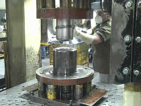
1.1 Overview of Hydraulic Deep Drawing Processes
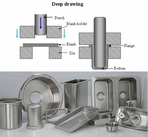
The deep drawing process involves the use of force to shape a flat metal blank into a hollow, often cylindrical shape by pulling the material into a die cavity using a punch. Hydraulic deep drawing presses are the machines that perform this operation, applying controlled hydraulic pressure to ensure the metal conforms to the die’s shape.
Hydraulic presses are popular in the manufacturing industry because they provide high force, precision, and control over the drawing process. Unlike mechanical presses, which rely on mechanical force from flywheels or gears, hydraulic presses use pressurized fluid to generate consistent force throughout the stroke.
1.2 Importance of Hydraulic Deep Drawing Presses
Hydraulic deep drawing presses are indispensable in the production of complex parts, such as automotive body panels, kitchen sinks, beverage cans, and aerospace components. Their ability to handle large forces and provide precise control over material flow makes them ideal for applications where consistency and accuracy are crucial.
These presses are also capable of working with a variety of materials, from soft metals like aluminum and copper to more challenging materials like stainless steel and titanium. The hydraulic system allows for smooth, controlled deformation, minimizing the risk of material defects such as wrinkling, tearing, or thinning.
1.3 Historical Development and Evolution of Hydraulic Presses
Hydraulic presses have evolved significantly since their inception in the early 19th century. The first hydraulic press was developed by Joseph Bramah, an English engineer, in 1795. Bramah’s invention was based on Pascal’s Law, which states that pressure applied to a confined fluid is transmitted equally in all directions. This principle enabled the development of machines capable of exerting large forces with minimal input energy.
Over time, hydraulic presses have become more sophisticated, with advancements in control systems, hydraulic fluids, and material science. Today’s hydraulic deep drawing presses are capable of automated operation, real-time monitoring, and precision control, allowing manufacturers to produce complex parts with minimal human intervention.
Basic Principles of Hydraulic Deep Drawing Presses
2.1 Pascal’s Law in Hydraulic Systems
The operation of hydraulic deep drawing presses is governed by Pascal’s Law, which states that any pressure applied to a confined fluid is transmitted equally throughout the fluid. This principle enables hydraulic systems to generate significant force by applying relatively low pressure over a large area.
In a hydraulic press, the hydraulic fluid (typically oil) is pressurized by a pump and directed into a cylinder, where it acts on a piston. The force generated by the piston is proportional to the pressure of the fluid and the surface area of the piston, allowing the press to generate the large forces necessary for deep drawing.
2.2 Key Components of a Hydraulic Deep Drawing Press
A hydraulic deep drawing press consists of several key components, each playing a vital role in the machine’s operation:
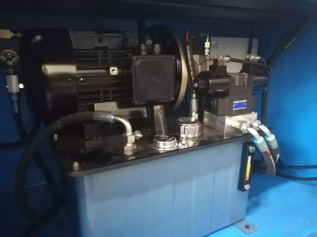
- Hydraulic Pump: Generates the hydraulic pressure needed to operate the press.
- Hydraulic Cylinder: Converts hydraulic energy into mechanical force.
- Frame: Supports the press structure and absorbs the forces generated during operation.
- Die and Punch: Shape the metal blank by forcing it into the desired form.
- Control System: Manages the flow of hydraulic fluid, the speed of the press, and other operational parameters.
These components work together to ensure smooth, precise deep drawing operations, allowing manufacturers to produce high-quality parts consistently.
2.3 How Hydraulic Presses Apply Force for Metal Forming
The hydraulic press operates by using pressurized fluid to push a piston or ram, which then applies force to the punch. The punch presses the metal blank into the die, forming the desired shape. The amount of force generated depends on the pressure applied by the hydraulic fluid and the surface area of the piston.
Hydraulic presses are unique in that they can maintain constant force throughout the stroke, unlike mechanical presses, which provide peak force at a specific point. This capability is particularly beneficial for deep drawing, as it allows the press to control the flow of the metal into the die, reducing the risk of defects such as wrinkling or tearing.
Single-Action Hydraulic Deep Drawing Presses
3.1 Definition and Basic Functionality
Single-action hydraulic deep drawing presses are the simplest type of hydraulic press used for deep drawing operations. In a single-action press, a single hydraulic cylinder is used to generate the force needed to move the punch, which pushes the metal blank into the die.
These presses are called “single-action” because they apply force in only one direction—downward—during the drawing operation. Once the part has been formed, the punch retracts, and the formed part is removed from the die.
3.2 Advantages and Applications
Single-action presses offer several advantages, making them suitable for a variety of applications:
- Simplicity: Single-action presses have a simple design with fewer moving parts, making them easy to operate and maintain.
- Cost-Effective: Due to their simpler design, single-action presses are generally less expensive than double- or triple-action presses, making them an attractive option for manufacturers with limited budgets.
- Compact Design: These presses are often more compact than multi-action presses, making them suitable for smaller production facilities.
Common applications for single-action hydraulic presses include:
- Shallow Drawn Parts: Single-action presses are well-suited for shallow drawing operations, such as forming shallow bowls, cups, and other simple shapes.
- Low-Volume Production: These presses are ideal for manufacturers with low to moderate production volumes, where the simplicity and cost-effectiveness of the press are more important than speed or complexity.
3.3 Limitations of Single-Action Presses
While single-action hydraulic presses offer many advantages, they also have some limitations:
- Limited Flexibility: Since single-action presses only apply force in one direction, they are not suitable for more complex deep drawing operations that require independent control of the punch and blank holder.
- Lower Precision: Single-action presses may not offer the same level of precision and control as more advanced presses, particularly in high-volume or high-precision manufacturing environments.
3.4 Case Studies and Examples of Use
Single-action presses are commonly used in industries where simple, shallow-drawn parts are required. For example, in the food and beverage industry, single-action presses are used to form aluminum cans and metal lids. In the consumer goods industry, they are used to manufacture kitchen utensils and household items.
Despite their simplicity, single-action presses remain an essential tool in modern manufacturing, providing a cost-effective solution for a wide range of applications.
Double-Action Hydraulic Deep Drawing Presses
4.1 Structure and Working Mechanism
Double-action hydraulic deep drawing presses are more advanced than single-action presses, offering greater flexibility and control over the deep drawing process. These presses feature two independent hydraulic cylinders: one for the punch and one for the blank holder.
The punch cylinder moves the punch downward to form the metal blank, while the blank holder cylinder holds the edges of the blank in place during the drawing process. This independent control of the punch and blank holder allows for more precise control over material flow, reducing the risk of defects such as wrinkling or tearing.
4.2 Advantages over Single-Action Presses
Double-action presses offer several advantages over single-action presses, making them suitable for more complex deep drawing operations:
- Improved Control: The independent control of the punch and blank holder allows for better control over the material flow, resulting in higher-quality parts with fewer defects.
- Increased Flexibility: Double-action presses can handle more complex shapes and deeper draws than single-action presses, making them suitable for a wider range of applications.
- Reduced Material Waste: By controlling the blank holder force independently, double-action presses reduce the risk of material wrinkling and tearing, minimizing material waste.
4.3 Typical Applications in Automotive and Appliance Manufacturing
Double-action presses are commonly used in industries where deep, complex parts are required. In the automotive industry, double-action presses are used to manufacture body panels, fuel tanks, and other structural components. In the appliance industry, they are used to form parts for washing machines, refrigerators, and stoves.
The ability to handle complex shapes and deep draws makes double-action presses ideal for these industries, where precision and product quality are critical.
4.4 Operational Considerations and Maintenance
While double-action presses offer improved control and flexibility, they also require more complex operation and maintenance than single-action presses. Operators must be trained to adjust the blank holder force and punch force independently to achieve the desired results.
Maintenance of double-action presses typically involves regular inspection and servicing of the hydraulic cylinders, seals, and control systems to ensure optimal performance. Proper maintenance is essential to prevent hydraulic leaks, maintain system pressure, and avoid downtime.
Despite the increased operational complexity, double-action presses are a popular choice for manufacturers who need to produce high-quality, complex parts in high volumes.
Triple-Action Hydraulic Deep Drawing Presses
5.1 Introduction to Triple-Action Press Design
Triple-action hydraulic deep drawing presses represent the most advanced type of hydraulic press for deep drawing operations. These presses feature three independent hydraulic cylinders: one for the punch, one for the blank holder, and one for the die cushion. The die cushion provides additional support during the drawing process, ensuring smooth material flow and preventing defects such as wrinkling or tearing.
The triple-action design allows for even greater control over the deep drawing process than double-action presses, making them ideal for high-precision applications and complex part geometries.
5.2 Working Mechanism and Control Systems
In a triple-action press, the three hydraulic cylinders work together to control the movement of the punch, blank holder, and die cushion. The punch moves downward to press the metal blank into the die, while the blank holder holds the edges of the blank in place. At the same time, the die cushion applies upward force to support the material as it is drawn into the die.
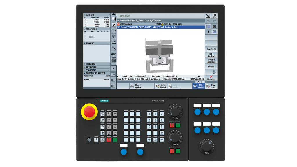
The control system in a triple-action press allows for precise adjustment of the force applied by each cylinder, ensuring that the material flows smoothly into the die without overstressing the metal. Modern triple-action presses are often equipped with computer numerical control (CNC) systems, which enable automatic adjustment of the press parameters based on the part being produced.
5.3 Benefits of Independent Control in Triple-Action Systems
The ability to control the punch, blank holder, and die cushion independently offers several key benefits:
- Improved Material Flow: Independent control of the die cushion force ensures smooth material flow into the die, reducing the risk of wrinkles, tears, or thinning.
- Precision Forming: The triple-action design allows for precise control over the deep drawing process, resulting in parts with consistent wall thickness and high dimensional accuracy.
- Complex Part Geometries: Triple-action presses can handle more complex part shapes and deeper draws than single- or double-action presses, making them ideal for producing intricate components.
5.4 Common Applications in Aerospace and Complex Component Manufacturing
Triple-action presses are commonly used in industries where precision and complexity are paramount. In the aerospace industry, these presses are used to form aircraft fuselage panels, engine components, and structural parts that require high strength and lightweight properties. In the medical device industry, they are used to produce implantable components, surgical tools, and diagnostic equipment housings.
The ability to produce deep, intricate parts with tight tolerances makes triple-action presses indispensable in these industries, where product quality and performance are critical.
5.5 Cost and Maintenance Considerations
While triple-action presses offer unmatched control and precision, they are also the most expensive type of hydraulic deep drawing press. The complexity of the triple-action design, combined with the advanced control systems, makes these presses a significant investment for manufacturers.
Maintenance of triple-action presses is also more complex than that of single- or double-action presses, requiring regular inspection and servicing of all three hydraulic cylinders, as well as the control systems. Proper maintenance is essential to prevent hydraulic leaks, maintain system pressure, and ensure consistent performance.
Despite the higher cost and maintenance requirements, triple-action presses are an essential tool for manufacturers who need to produce high-quality, complex parts with tight tolerances.
Hydroforming Hydraulic Presses
6.1 Definition and Basic Functionality of Hydroforming
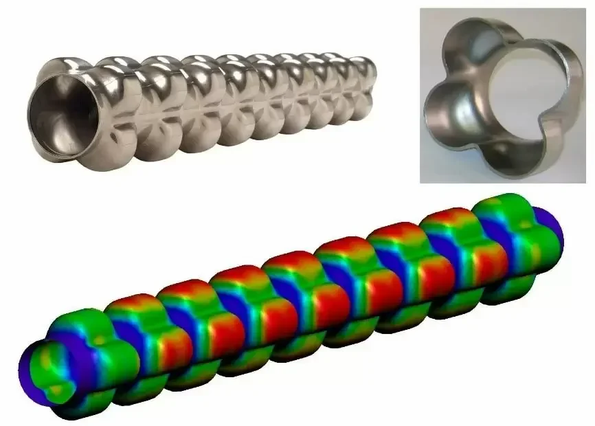
Hydroforming is a specialized metal forming process that uses a combination of hydraulic pressure and fluid media to shape the metal blank. Unlike traditional deep drawing, which relies on a solid punch to force the material into a die, hydroforming uses pressurized fluid to form the part. The fluid pressure is applied to the metal blank, forcing it to conform to the shape of the die.
Hydroforming is commonly used to produce lightweight, high-strength parts with complex shapes, such as automotive body panels, bicycle frames, and aerospace components.
6.2 Comparison Between Hydroforming and Traditional Deep Drawing
Hydroforming differs from traditional deep drawing in several key ways:
- Fluid Pressure vs. Mechanical Force: In hydroforming, the fluid pressure is used to shape the part, while in traditional deep drawing, a solid punch is used.
- Material Stretching: Hydroforming allows for more even material stretching, resulting in parts with uniform wall thickness and fewer defects.
- Complex Geometries: Hydroforming can produce more complex shapes and intricate details than traditional deep drawing.
While hydroforming offers several advantages over traditional deep drawing, it also requires specialized equipment and is typically more expensive.
6.3 Benefits and Limitations of Hydroforming
Hydroforming offers several benefits, making it ideal for certain applications:
- Lightweight Parts: Hydroforming produces parts with thin walls and high strength-to-weight ratios, making it ideal for automotive and aerospace applications.
- Complex Shapes: Hydroforming can produce parts with complex geometries that would be difficult or impossible to achieve with traditional deep drawing.
- Improved Material Efficiency: Hydroforming reduces material waste by evenly distributing the material during the forming process.
However, hydroforming also has some limitations:
- Higher Cost: The equipment and tooling required for hydroforming are more expensive than those for traditional deep drawing, making it less cost-effective for low-volume production.
- Specialized Materials: Hydroforming is best suited for materials that can withstand the high pressures involved in the process, such as aluminum and stainless steel.
6.4 Specialized Uses in Automotive and Aerospace Industries
Hydroforming is widely used in the automotive and aerospace industries to produce lightweight, high-strength components. In the automotive industry, hydroforming is used to manufacture structural components, exhaust systems, and body panels that require a combination of strength and weight savings.
In the aerospace industry, hydroforming is used to produce aircraft fuselage panels, engine components, and structural parts that must withstand extreme temperatures and pressures while remaining lightweight.
Servo-Hydraulic Deep Drawing Presses
7.1 Introduction to Servo-Hydraulic Technology
Servo-hydraulic deep drawing presses combine the power of hydraulic systems with the precision and control of servo motors. These presses use servo motors to control the movement of the hydraulic pump, allowing for precise adjustment of the press parameters in real-time.
Servo-hydraulic technology offers several advantages over traditional hydraulic systems, including improved energy efficiency, faster response times, and greater precision.
7.2 Enhanced Precision and Control Through Servo Motors
Servo-hydraulic presses provide real-time control over the speed, force, and position of the press, allowing for fine-tuned adjustments during the deep drawing process. This level of control is particularly beneficial in applications where high precision and tight tolerances are required, such as in the production of medical devices and aerospace components.
The use of servo motors also allows for faster response times, improving the overall speed and efficiency of the press.
7.3 Energy Efficiency and Environmental Benefits
One of the key advantages of servo-hydraulic presses is their energy efficiency. Unlike traditional hydraulic presses, which run continuously even when not in use, servo-hydraulic presses only consume energy when the press is actively performing work. This results in significant energy savings and reduces the overall environmental impact of the press.
Additionally, servo-hydraulic systems generate less heat than traditional hydraulic systems, reducing the need for cooling and further improving energy efficiency.
7.4 Applications in High-Precision Manufacturing
Servo-hydraulic presses are ideal for high-precision manufacturing applications, where accuracy, repeatability, and efficiency are critical. These presses are commonly used in industries such as medical device manufacturing, aerospace, and electronics, where small tolerances and consistent product quality are essential.
Computer Numerical Control (CNC) Hydraulic Presses
8.1 Role of CNC in Modern Hydraulic Deep Drawing Presses
Computer numerical control (CNC) technology has revolutionized the manufacturing industry, enabling greater automation, precision, and repeatability. CNC hydraulic presses use computer systems to control the movement of the press, allowing for automated and high-precision operations.
CNC systems allow operators to program the press with specific parameters, such as stroke length, force, and speed, ensuring consistent results across multiple production cycles.
8.2 How CNC Improves Accuracy, Repeatability, and Efficiency
CNC hydraulic presses offer several key advantages over manually controlled presses:
- Increased Accuracy: CNC systems provide precise control over the press parameters, ensuring that each part is produced with consistent dimensions and tight tolerances.
- Improved Repeatability: CNC presses can repeat the same operation multiple times with minimal variation, making them ideal for high-volume production.
- Reduced Human Error: By automating the press operation, CNC systems reduce the risk of human error, improving overall product quality.
8.3 Comparison Between Manual and CNC Hydraulic Systems
While manual hydraulic presses require an operator to control the movement of the press, CNC hydraulic presses are fully automated, allowing for faster production times and greater precision. CNC systems also enable manufacturers to store and recall programs, making it easy to switch between different production runs without reprogramming the press.
However, CNC hydraulic presses are typically more expensive than manual presses, making them a better investment for manufacturers with high production volumes or complex part requirements.
8.4 Case Studies of CNC Hydraulic Press Use in High-Volume Production
CNC hydraulic presses are commonly used in industries where high-volume production is required. For example, in the automotive industry, CNC presses are used to produce body panels, engine components, and chassis parts with consistent quality and minimal variation.
In the appliance industry, CNC presses are used to manufacture parts for refrigerators, washing machines, and stoves, ensuring that each part meets strict quality standards.
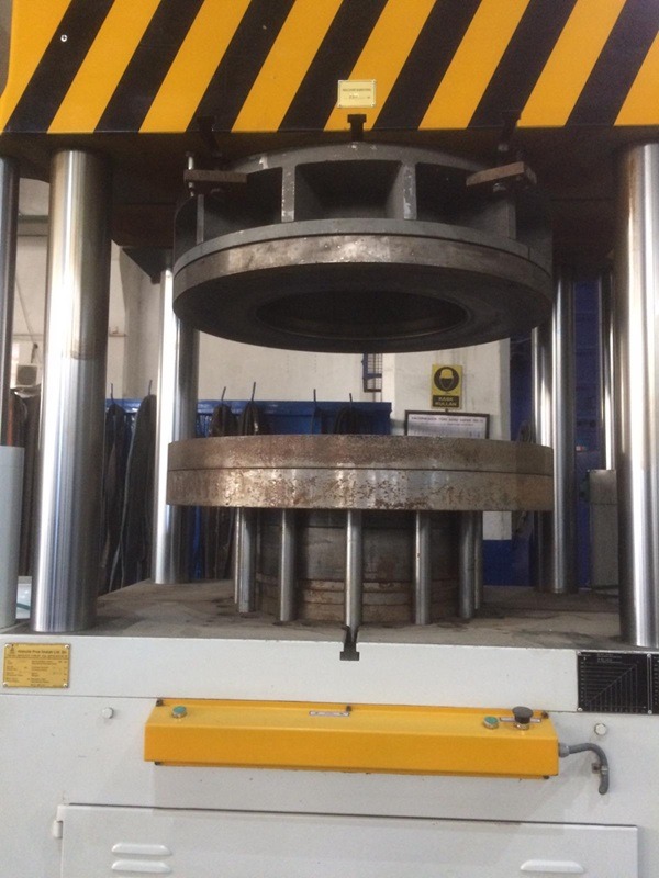
Open vs. Closed Frame Hydraulic Presses
9.1 Differences in Frame Design: Open vs. Closed Frames
Hydraulic deep drawing presses can be classified based on their frame design: open-frame and closed-frame presses. The choice of frame design depends on factors such as the size of the part being produced, the required force, and the available space in the production facility.
- Open-Frame Presses: Also known as C-frame presses, open-frame presses have an open front that allows for easy access to the die and workpiece. This design is ideal for smaller parts and applications where frequent tool changes are required.
- Closed-Frame Presses: Also known as H-frame presses, closed-frame presses have a fully enclosed frame that provides greater structural integrity and support. These presses are designed for larger parts and applications that require higher force.
9.2 Structural Integrity, Accessibility, and Versatility
- Open-Frame Presses: Open-frame presses offer greater accessibility, making them ideal for applications that require frequent tool changes or adjustments. However, they are generally limited in terms of the force they can generate, making them less suitable for heavy-duty applications.
- Closed-Frame Presses: Closed-frame presses offer superior structural integrity, allowing them to handle higher forces and larger workpieces. However, the enclosed design can make it more difficult to access the die and workpiece, limiting their versatility in certain applications.
9.3 Applications for Open-Frame Presses
Open-frame presses are commonly used in industries where smaller parts and frequent tool changes are required. For example, in the electronics industry, open-frame presses are used to produce small components such as connectors, housings, and terminals.
9.4 Applications for Closed-Frame Presses
Closed-frame presses are used in industries where larger parts and higher forces are required. For example, in the automotive industry, closed-frame presses are used to produce body panels, chassis components, and structural parts.
Hydraulic Deep Drawing Press Configurations
10.1 Horizontal Hydraulic Presses
Horizontal hydraulic presses are designed with a horizontal ram, rather than the traditional vertical ram found in most hydraulic presses. These presses are used in applications where the workpiece is too large or heavy to be positioned vertically.
Horizontal presses are commonly used in the pipe and tube industry to form long, cylindrical parts, such as pipes, tubes, and cylindrical tanks.
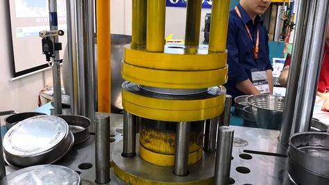
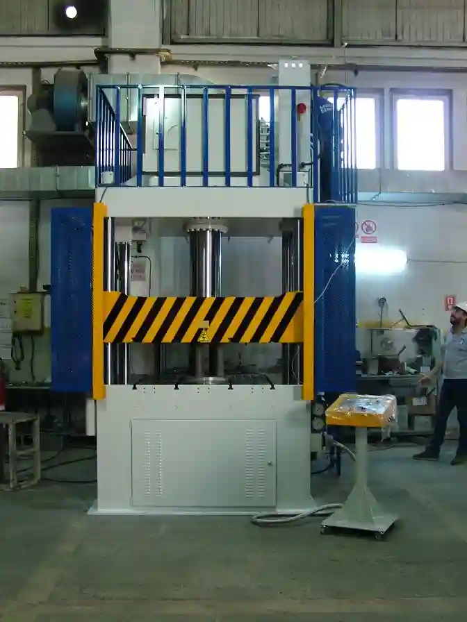
10.2 Vertical Hydraulic Presses
Vertical hydraulic presses are the most common type of hydraulic deep drawing press. These presses feature a vertical ram that moves up and down to apply force to the workpiece. Vertical presses are used in a wide range of applications, from automotive body panels to appliance parts.
Vertical presses offer greater versatility than horizontal presses, making them suitable for a wide range of deep drawing operations.
10.3 Special Configurations for Large-Scale Manufacturing
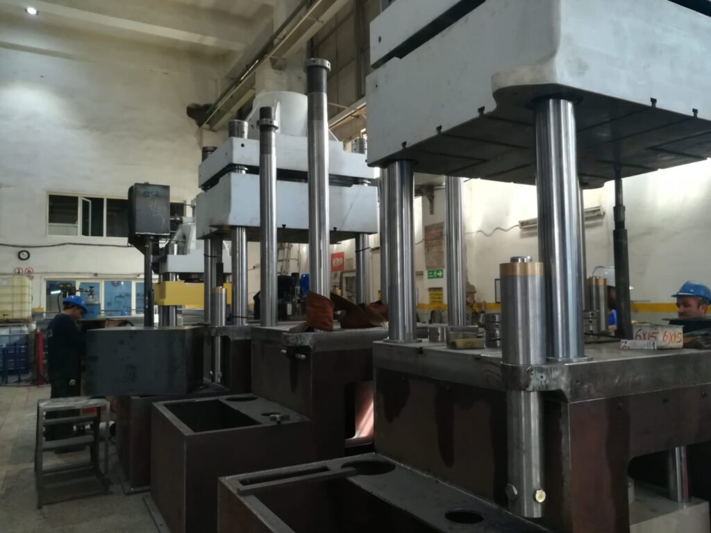
In some cases, manufacturers require custom-configured hydraulic presses to handle large-scale production. These presses may be designed with multiple stations, automated loading and unloading systems, and integrated tooling to streamline the production process.
For example, in the automotive industry, large-scale hydraulic presses are used to produce body panels in multi-station configurations, allowing for continuous production with minimal downtime.
10.4 Multi-Station and Transfer Presses for Continuous Production
Multi-station hydraulic presses feature multiple tooling stations that allow for the simultaneous production of multiple parts or multiple stages of a part. This configuration is ideal for high-volume production, as it reduces cycle times and increases throughput.
Transfer presses are designed to move the workpiece from one station to another automatically, allowing for continuous production without manual intervention. These presses are commonly used in industries such as automotive and appliance manufacturing, where high-speed production is essential.
Energy Efficiency and Modern Trends in Hydraulic Deep Drawing Presses
11.1 Innovations in Energy-Efficient Hydraulic Systems
In recent years, manufacturers have focused on improving the energy efficiency of hydraulic deep drawing presses. Innovations such as servo-hydraulic systems and variable displacement pumps have significantly reduced the energy consumption of these machines, resulting in lower operating costs and reduced environmental impact.
11.2 Use of Servo-Hydraulic and Variable Displacement Pumps
Servo-hydraulic systems use servo motors to control the movement of the hydraulic pump, allowing for precise adjustment of the press parameters in real-time. This results in significant energy savings, as the press only consumes energy when it is actively performing work.
Variable displacement pumps adjust the amount of fluid they deliver based on system demand, reducing energy consumption during low-demand periods.
11.3 Sustainable Practices in Hydraulic Press Manufacturing
In addition to improving the energy efficiency of hydraulic presses, manufacturers are also adopting sustainable practices in the production of these machines. This includes using recyclable materials, reducing waste, and minimizing the use of hazardous substances in the manufacturing process.
11.4 Future Trends in Hydraulic Press Technology
The future of hydraulic press technology is likely to be shaped by advancements in automation, AI, and machine learning. As hydraulic presses become more intelligent, they will be able to optimize their performance in real-time, further improving energy efficiency and reducing operating costs.
Maintenance and Troubleshooting of Hydraulic Deep Drawing Presses
12.1 Common Maintenance Procedures
Regular maintenance is essential for ensuring the reliable operation of hydraulic deep drawing presses. Common maintenance procedures include:
- Checking for Fluid Leaks: Leaks can lead to pressure loss and reduced system efficiency. Regularly inspecting hoses, seals, and fittings for signs of wear or damage can help prevent leaks.
- Monitoring Fluid Levels and Condition: Maintaining the proper fluid level and ensuring that the hydraulic fluid is free from contaminants is essential for system performance.
- Inspecting Filters and Replacing Them as Needed: Filters remove contaminants from the hydraulic fluid. Over time, filters can become clogged and reduce system performance.
12.2 Preventive vs. Reactive Maintenance Strategies
Preventive maintenance involves regularly inspecting and servicing the hydraulic press to identify potential issues before they lead to failure. This approach helps reduce downtime and extend the life of the machine.
Reactive maintenance, on the other hand, involves addressing issues only after they arise. While this approach may save time in the short term, it can lead to more costly repairs and longer downtime in the long run.
12.3 Troubleshooting Common Hydraulic Press Issues
Several common issues can arise in hydraulic presses, including:
- Fluid Contamination: Contaminants such as dirt, water, and metal particles can degrade hydraulic fluid and damage system components.
- Air Entrapment: Air bubbles in the hydraulic fluid can cause cavitation, leading to reduced system performance.
- Overheating: Excessive heat can cause fluid degradation and damage components.
12.4 Case Studies on Maximizing Press Longevity
In one case study, a manufacturer of automotive body panels implemented a preventive maintenance program that included regular fluid changes, filter replacements, and inspections of hydraulic components. As a result, the company was able to reduce downtime by 30% and extend the life of its hydraulic presses by an average of 5 years.
Safety Features and Regulations for Hydraulic Deep Drawing Presses
13.1 Importance of Safety in Press Operations
Hydraulic deep drawing presses are powerful machines that require strict safety protocols to protect operators and prevent accidents. Ensuring operator safety is a critical consideration for manufacturers, as the high forces involved in deep drawing operations can lead to serious injuries if proper precautions are not taken.
13.2 Key Safety Features in Modern Hydraulic Presses
Modern hydraulic presses are equipped with several safety features designed to protect operators and prevent accidents:
- Safety Light Curtains: These sensors detect when a person or object enters the press area and automatically stop the machine to prevent accidents.
- Emergency Stop Buttons: Located on the control panel, these buttons allow operators to stop the press immediately in case of an emergency.
- Overload Protection: This system automatically stops the press if it detects that the applied force exceeds the press’s rated capacity, preventing damage to the machine and tooling.
13.3 Compliance with Industry Standards and Regulations
Hydraulic presses must comply with industry standards and regulations to ensure operator safety. These standards are set by organizations such as OSHA (Occupational Safety and Health Administration) and ISO (International Organization for Standardization), and they cover areas such as machine guarding, operator training, and emergency stop protocols.
13.4 Training and Best Practices for Operator Safety
Operators should be trained in the safe operation of hydraulic presses, including how to use the machine’s safety features, perform routine maintenance, and identify potential hazards. Best practices for operator safety include:
- Wearing Protective Equipment: Operators should wear appropriate protective equipment, such as safety glasses, gloves, and hearing protection.
- Following Safety Protocols: Operators should follow all safety protocols, including proper use of machine guards and emergency stop buttons.
- Regular Safety Inspections: The press should be regularly inspected to ensure that all safety features are functioning properly.
Choosing the Right Hydraulic Deep Drawing Press for Your Needs
14.1 Factors to Consider When Selecting a Hydraulic Press
When selecting a hydraulic deep drawing press, several factors must be considered to ensure that the press meets the specific needs of the application:
- Force Requirements: The press must be capable of generating the force required to form the part.
- Material Type: Different materials require different forming forces and press capabilities.
- Part Complexity: More complex parts may require a double- or triple-action press to ensure precise control over material flow.
- Production Volume: High-volume production may require a CNC or multi-station press to ensure efficiency and consistency.
14.2 Matching Press Capabilities to Application Requirements
Matching the capabilities of the press to the specific requirements of the application is essential for optimizing performance and minimizing costs. For example, a manufacturer producing simple, shallow-drawn parts may be able to use a single-action press, while a manufacturer producing complex, deep-drawn parts may require a triple-action press.
14.3 Cost vs. Performance Considerations
While more advanced presses offer greater control and flexibility, they are also more expensive. Manufacturers must weigh the cost of the press against its performance capabilities to ensure that they are getting the best value for their investment.
14.4 Examples of Industries and Ideal Press Types
- Automotive Industry: Double- and triple-action presses are ideal for producing body panels, fuel tanks, and other structural components.
- Aerospace Industry: Triple-action presses and hydroforming presses are used to produce lightweight, high-strength components.
- Appliance Industry: Single- and double-action presses are used to produce parts for refrigerators, washing machines, and stoves.
Conclusion: The Evolution of Hydraulic Deep Drawing Press Technology
Hydraulic deep drawing presses have come a long way since their invention in the early 19th century. Today’s presses offer a wide range of capabilities, from simple single-action presses to advanced triple-action systems and servo-hydraulic technology. These machines play a critical role in modern manufacturing, enabling the production of complex, high-quality parts with precision and efficiency.
As technology continues to evolve, hydraulic deep drawing presses will become even more versatile and energy-efficient, with advancements in automation, digitalization, and sustainability driving the industry forward. For manufacturers, choosing the right hydraulic deep drawing press is essential for optimizing production, reducing costs, and ensuring product quality.
In the future, hydraulic deep drawing presses will remain a cornerstone of industries such as automotive, aerospace, and appliance manufacturing, providing the force and precision needed to shape the metal components that power the modern world.
Single-Action Hydraulic Deep Drawing Presses
Single-action hydraulic deep drawing presses are essential machines in the metal forming industry, offering simplicity, cost-effectiveness, and reliability in producing shallow, complex shapes. In this extensive guide, we’ll explore the principles, mechanisms, applications, and advancements of single-action hydraulic deep drawing presses.
Introduction to Single-Action Hydraulic Deep Drawing Presses
1.1 Overview of Hydraulic Presses
Hydraulic presses are machines that use hydraulic force to apply pressure on a material, typically a metal sheet, to shape it into desired forms through compression. Among the various types of hydraulic presses, single-action hydraulic deep drawing presses are a fundamental tool in forming shallow shapes in sheet metals. These presses operate on a straightforward principle of force exertion, making them ideal for a variety of applications requiring less complex drawing operations.
Single-action hydraulic presses use a single hydraulic cylinder to move the ram (or punch) downward, pressing the metal blank into the die to form the desired shape. This type of press is widely used in industries that need high-efficiency metal forming with minimal operational complexity, such as automotive, appliance, and packaging industries.
1.2 Role of Single-Action Hydraulic Presses in Metal Forming
Single-action presses play a crucial role in deep drawing processes, where metal blanks are stretched and shaped into hollow, often cylindrical forms. In these systems, the punch moves the metal sheet into the die, and hydraulic pressure allows precise control of the deformation process. Single-action presses are designed for operations where only a downward force is required, without the need for complex blank holder or reverse force systems as seen in double- or triple-action presses.
The ability to handle materials like steel, aluminum, and copper makes single-action presses highly versatile. They are used in processes like cup forming, cylinder drawing, and the production of shallow containers or enclosures, making them essential for mass production in several sectors.
1.3 Advantages of Single-Action Systems
- Simplicity: One of the key advantages of single-action hydraulic presses is their simple design. They require fewer components than multi-action presses, leading to easier operation and maintenance.
- Cost-Effectiveness: Due to their straightforward functionality, single-action presses tend to be more affordable, both in terms of initial investment and operational costs, compared to more complex presses.
- Versatility: While they may not handle highly complex shapes, single-action presses can efficiently produce a wide variety of basic forms, from shallow cups to cylindrical containers.
- Reliability: With fewer moving parts and hydraulic cylinders to maintain, these machines are generally reliable, with lower risk of malfunction or downtime.
Working Principle of Single-Action Hydraulic Deep Drawing Presses
2.1 Pascal’s Law and Hydraulic Power
Single-action hydraulic presses, like all hydraulic systems, rely on Pascal’s Law to operate. Pascal’s Law states that any pressure applied to a confined fluid is transmitted uniformly in all directions within that fluid. In hydraulic systems, this law is used to generate the significant force needed for metal forming by applying pressure to a hydraulic fluid inside a closed system.
In a single-action press, this principle allows a small amount of hydraulic pressure applied to a large surface area in the cylinder to generate a large output force at the ram (or punch). The pressurized hydraulic fluid, typically oil, moves the piston, creating the force that shapes the metal blank during the deep drawing process.
2.2 Single-Action Mechanism in Metal Forming
In the operation of a single-action hydraulic deep drawing press:
- The operator places a flat metal blank (a flat disc or sheet of metal) on the die.
- The punch, driven by the hydraulic cylinder, moves downward, pushing the blank into the die cavity. The die’s shape determines the final shape of the drawn part.
- As the punch descends, the metal blank is deformed and stretched over the die. The hydraulic system allows precise control of the force applied, ensuring that the material flows smoothly into the die without tearing or wrinkling.
Unlike double- or triple-action presses, where multiple cylinders may be involved, a single-action press applies force in only one direction: downward. The blank holder force is typically not independently controlled in a single-action press, making it more suited for less complex parts.
2.3 Force Distribution and Control
The hydraulic pressure applied in a single-action press can be precisely controlled, allowing for adjustable force depending on the thickness, material, and size of the blank being drawn. The press can also be adjusted for stroke length, allowing manufacturers to control how deep the draw will be. This level of control ensures that the press can handle a range of materials with different mechanical properties.
The force distribution during the deep drawing process is a critical factor in determining the success of the operation. Uniform pressure must be applied across the metal blank to avoid defects such as wrinkles, tears, or uneven wall thickness. Single-action presses are particularly well-suited for shallow draws, where the force required is not as high as for deeper or more complex shapes.
Key Components of Single-Action Hydraulic Presses
3.1 Hydraulic Cylinders and Pumps
The hydraulic cylinder is the core component of a single-action press, providing the force needed to move the punch. In a typical single-action press, the cylinder contains a piston that is moved by pressurized hydraulic fluid. As the hydraulic fluid enters the cylinder, it forces the piston downward, generating the required force.
Hydraulic pumps supply the pressurized fluid to the system. These pumps can be fixed displacement, where they deliver a constant amount of fluid, or variable displacement, where the amount of fluid delivered can be adjusted based on system demand. The pump’s power rating is directly related to the press’s capacity and influences how quickly the press can complete a cycle.
3.2 Frame and Structure
Single-action hydraulic deep drawing presses come in various structural designs, typically built to withstand the significant forces involved in metal forming. The frame is often made from high-strength materials such as cast iron or welded steel to ensure durability and stability during operation.
Common frame designs include:
- C-frame Presses: Featuring an open front, C-frame presses allow easy access to the die and workpiece. This design is more compact but generally offers less rigidity than other frame designs, making it suitable for lighter applications.
- H-frame Presses: These are more robust and suitable for higher force applications. The closed frame design provides better structural integrity and can handle higher loads without deformation.
3.3 Die, Punch, and Blank Holder Setup
The die and punch are critical components that define the shape of the part being formed. In a single-action press, the punch is attached to the ram and moves downward to push the blank into the die. The die is typically a stationary component mounted on the base of the press. These components are usually made of tool steel or carbide due to their ability to withstand the high forces involved without wearing out or deforming.
The blank holder in a single-action press is often simpler than in more advanced systems, where independent control over blank holding is required. In single-action presses, the blank holder applies pressure around the edges of the blank, helping to control the material flow during the drawing process.
3.4 Control Systems and Automation
Single-action hydraulic presses may feature varying degrees of automation. Basic presses might be operated manually, with the operator controlling the movement of the punch and blank loading/unloading. However, modern single-action presses often include automated controls for improved precision and productivity.
Programmable Logic Controllers (PLCs) are commonly used to control the hydraulic system’s pressure, stroke length, and timing, allowing for repeatable and consistent production. Automated systems reduce operator involvement and improve the overall efficiency of the deep drawing process.
Some advanced presses also feature sensors and feedback loops that monitor the operation in real-time, making adjustments to the hydraulic pressure or punch speed as necessary to ensure the final part meets quality specifications.
Materials Suitable for Single-Action Hydraulic Deep Drawing
4.1 Low Carbon Steels
Low carbon steels are among the most commonly used materials in hydraulic deep drawing. They are malleable and can be easily shaped without cracking or tearing, making them ideal for applications such as automotive panels, appliance housings, and general metal containers. Low carbon steels have sufficient ductility to handle the drawing process, even in a single-action press where independent blank holder control is not available.
4.2 Stainless Steels
Stainless steels are another popular choice for deep drawing, especially when corrosion resistance is a priority. Stainless steel is more difficult to form than low carbon steel, due to its higher strength and work hardening characteristics. However, with precise control over the press’s force and stroke length, single-action hydraulic presses can be used to form shallow stainless steel parts like kitchen sinks, medical trays, and small automotive components.
4.3 Aluminum Alloys
Aluminum alloys are lightweight and highly formable, making them suitable for a wide range of deep drawing applications. Aluminum is commonly used in industries such as automotive (for lightweight body parts) and packaging (for beverage cans). The lower strength of aluminum compared to steel means that less force is required to form it, making single-action presses an ideal solution for drawing aluminum parts.
4.4 Copper and Brass
Copper and brass are often used for deep drawing in industries that require high thermal or electrical conductivity, such as electrical components and plumbing fixtures. These materials are relatively soft and malleable, making them easier to draw than steel. Single-action presses can be used to form copper and brass parts with smooth, defect-free surfaces, provided that the press is properly set up to control the material flow.
4.5 High-Strength Materials and Challenges
Single-action hydraulic presses can also be used to form high-strength materials, such as high-strength steels and titanium, though there are limitations to their capabilities. High-strength materials require significantly higher forming forces and are more prone to work hardening, making them more difficult to form in a single-action press. In some cases, additional blank holder control or more advanced press systems may be required to achieve the desired results.
When using high-strength materials, careful attention must be paid to the die design, lubrication, and press settings to minimize the risk of defects such as tearing, wrinkling, or springback. The material’s properties must also be carefully considered during the design phase, ensuring that the press has the necessary force and precision to handle the material’s forming characteristics.
Process Stages in Single-Action Deep Drawing
5.1 Loading the Blank
The deep drawing process begins with loading the metal blank into the press. The blank is typically a flat, circular sheet of metal that has been pre-cut to the appropriate size. The blank is placed on the die, which is mounted on the base of the press. Depending on the press design, this process may be done manually by an operator or automatically using robotic or mechanical handling systems.
To ensure that the blank is properly positioned, alignment guides or locating pins are often used. These tools help ensure that the blank is centered over the die, preventing issues such as off-center draws, which can lead to defects in the final part.
5.2 Clamping and Force Application
Once the blank is loaded into the press, it is clamped in place by the blank holder. The blank holder applies pressure around the edges of the blank, holding it securely against the die while allowing the center of the blank to be drawn into the die cavity by the punch.
In a single-action press, the blank holder force is typically applied passively, without independent control. The force is generated by the downward movement of the punch, which pushes the blank holder down onto the blank as it moves into the die. This simple clamping method is sufficient for most shallow-draw operations but may not provide the precise control needed for more complex or deeper draws.
5.3 Drawing Process: Punch and Die Interaction
As the punch moves downward, it forces the blank into the die cavity, drawing the metal into the desired shape. The punch applies a uniform downward force, while the die provides the resistance needed to shape the blank.
The flow of the metal during the drawing process is a critical factor in determining the success of the operation. The metal must be able to flow smoothly into the die without tearing, wrinkling, or thinning excessively. The press settings, including the force applied and stroke length, must be carefully controlled to ensure that the material is deformed evenly.
Lubrication is often used during the drawing process to reduce friction between the blank, punch, and die. Proper lubrication helps prevent galling, scratching, and other surface defects while also improving the flow of the material into the die.
5.4 Ejecting the Finished Part
Once the drawing process is complete, the punch retracts, and the finished part is ejected from the die. In a single-action press, the part may be manually removed by an operator or automatically ejected using mechanical ejectors or air blasts.
Ejecting the part without damaging it is critical, especially for parts with thin walls or complex geometries. Care must be taken to ensure that the part does not become stuck in the die or sustain damage during the ejection process.
After ejection, the part may undergo additional finishing operations, such as trimming, deburring, or polishing, to remove excess material or improve surface quality.
Applications of Single-Action Hydraulic Deep Drawing Presses
6.1 Automotive Industry
The automotive industry is one of the largest users of hydraulic deep drawing presses, including single-action models. These presses are used to produce a variety of components, including:
- Body Panels: Single-action presses are used to form shallow body panels, such as doors, roof panels, and trunk lids. These parts require precise forming to meet the high aesthetic and performance standards of the automotive industry.
- Engine Components: Components such as oil pans, valve covers, and exhaust manifolds can be produced using single-action deep drawing presses. These parts must be durable and able to withstand high temperatures and stresses.
- Fuel Tanks: Single-action presses are often used to produce fuel tanks, which require a combination of strength, durability, and corrosion resistance.
In the automotive industry, the ability to produce high-quality parts at high volumes is critical. Single-action presses are ideal for this purpose, as they offer the precision and repeatability needed to meet the industry’s stringent quality standards.
6.2 Appliance Manufacturing
Single-action hydraulic presses are also widely used in the appliance manufacturing industry to produce metal housings, enclosures, and components for a variety of household appliances. Common applications include:
- Washing Machine Drums: The drum of a washing machine is typically made from stainless steel or aluminum and can be formed using a single-action press. The press provides the force needed to shape the drum while ensuring that the walls are smooth and free of defects.
- Refrigerator Panels: Refrigerator panels, including the inner and outer shells, are often formed using single-action presses. These panels must be precisely shaped to ensure proper fit and insulation.
- Cookware and Kitchen Appliances: Single-action presses are used to form pots, pans, and other kitchen appliances that require smooth, consistent shapes with minimal surface defects.
The appliance industry values the simplicity and reliability of single-action presses, which allow manufacturers to produce high-quality parts with minimal downtime and maintenance.
6.3 Packaging Industry (Cans and Containers)
In the packaging industry, single-action presses are commonly used to produce metal cans and containers. This includes:
- Beverage Cans: Aluminum beverage cans are one of the most common products made using deep drawing presses. The thin walls and cylindrical shape of beverage cans make them ideal for production in single-action presses, which can rapidly produce large volumes of cans with consistent quality.
- Aerosol Cans: Single-action presses are also used to produce aerosol cans, which require smooth, defect-free surfaces to ensure proper function.
- Food Containers: Metal food containers, including tin cans and aluminum trays, are formed using single-action presses. These containers must be durable, lightweight, and able to withstand the pressures of sealing and transportation.
The packaging industry benefits from the high-speed, high-volume production capabilities of single-action presses, which allow manufacturers to produce large quantities of containers with minimal waste.
6.4 Aerospace Components
In the aerospace industry, single-action presses are used to produce lightweight, high-strength components for aircraft and spacecraft. These components often include:
- Engine Cowls: Single-action presses are used to form engine cowls, which are thin-walled, aerodynamic structures that protect the aircraft’s engines.
- Fuselage Panels: Aluminum and titanium fuselage panels are formed using single-action presses, which provide the precision and force needed to shape these high-strength materials.
- Aircraft Seating Components: Components such as seat frames and supports are often made using deep drawing presses, as they require a combination of strength and lightness.
The aerospace industry demands parts with high precision and tight tolerances, making single-action presses an excellent choice for producing high-quality components with consistent results.
6.5 Medical Devices and Small-Scale Production
Single-action hydraulic presses are also used in the medical device industry, where they are employed to manufacture surgical tools, implantable devices, and diagnostic equipment. These parts often require high precision, smooth surfaces, and the ability to be sterilized, making deep drawing an ideal process for their production.
In small-scale production environments, single-action presses offer a cost-effective solution for manufacturing specialized parts with minimal complexity.
Benefits and Limitations of Single-Action Hydraulic Presses
7.1 Cost-Effectiveness
One of the primary benefits of single-action hydraulic deep drawing presses is their cost-effectiveness. These machines are simpler and less expensive to manufacture than double- or triple-action presses, making them an attractive option for manufacturers with smaller budgets or lower production volumes.
Additionally, single-action presses are often easier to operate and maintain, resulting in lower operating costs over the machine’s lifespan. The simplicity of the hydraulic system also means fewer components to replace, reducing downtime and maintenance expenses.
7.2 Simplicity and Ease of Operation
The simplicity of single-action presses is another major advantage. These machines have fewer moving parts and hydraulic cylinders than multi-action presses, making them easier to operate and maintain. Operators can quickly learn how to set up and run the press, reducing the need for extensive training.
The straightforward design of single-action presses also makes them less prone to malfunctions or breakdowns, ensuring more consistent production and minimizing downtime.
7.3 Limitations in Complex Drawings
Despite their many advantages, single-action presses have some limitations when it comes to more complex deep drawing operations. Because the press only applies force in one direction, it cannot provide the same level of control over material flow as a double- or triple-action press. This can make it more difficult to achieve deep draws or complex shapes, particularly when working with thicker or higher-strength materials.
In situations where precise control over the blank holder force is required to prevent wrinkling or tearing, a single-action press may not be sufficient. For these applications, a double- or triple-action press may be a better choice.
7.4 Comparison with Double- and Triple-Action Presses
While single-action presses are ideal for simpler operations, they cannot match the flexibility and precision of double- and triple-action presses. In double-action presses, the blank holder force can be controlled independently, allowing for more complex shapes and deeper draws. Triple-action presses provide even greater control, with independent control of the punch, blank holder, and die cushion.
For manufacturers producing more complex parts or working with challenging materials, the added capabilities of double- and triple-action presses may be worth the higher cost and complexity.
Technical Specifications and Variants
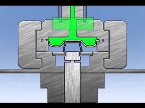
8.1 Force Ratings and Capacities
Single-action hydraulic presses are available in a wide range of force ratings, typically measured in tons. The force required for a given deep drawing operation depends on factors such as the material thickness, material strength, and depth of the draw. Common force ratings for single-action presses range from 20 tons to over 500 tons, with higher force capacities required for thicker materials or deeper draws.
When selecting a single-action press, it is essential to ensure that the press has sufficient force capacity to handle the specific application. Undersized presses may struggle to form the material correctly, leading to defects, while oversized presses may be unnecessarily expensive and consume more energy than required.
8.2 Stroke Length and Speed Considerations
The stroke length of a hydraulic press refers to the distance the ram (or punch) travels during the drawing process. Stroke length is an important factor in determining the depth of the draw and the size of the part that can be produced. Single-action presses typically offer adjustable stroke lengths, allowing operators to customize the press’s operation based on the part being formed.
The speed of the press is another critical factor. Faster presses can complete more cycles per hour, increasing productivity, but may require more precise control to avoid defects such as tearing or wrinkling. Single-action presses can be adjusted to operate at different speeds, depending on the material and the complexity of the part being formed.
8.3 Variants for Specific Applications
Single-action presses come in a variety of configurations designed for specific applications. For example:
- High-Speed Presses: These presses are designed for high-volume production and can complete more cycles per hour than standard presses.
- Large-Frame Presses: Designed for large parts such as automotive body panels, these presses feature larger frames and higher force capacities to handle bigger blanks and deeper draws.
- Compact Presses: For smaller parts or lower-volume production, compact single-action presses offer a space-saving solution without sacrificing performance.
8.4 Safety Features and Operator Controls
Safety is a top priority in hydraulic press operation, and modern single-action presses are equipped with a variety of safety features to protect operators and prevent accidents. Common safety features include:
- Emergency Stop Buttons: These buttons allow operators to stop the press immediately in case of an emergency.
- Safety Light Curtains: These sensors detect when a person or object enters the press area and automatically stop the machine to prevent injury.
- Overload Protection: This system automatically shuts down the press if the applied force exceeds the press’s rated capacity, preventing damage to the machine and tooling.
Operator controls are typically designed for ease of use and may include touchscreens, joysticks, or push buttons. Automated systems may also feature PLC controls that allow operators to program the press for specific operations and ensure consistent results across multiple production cycles.
Tooling Design for Single-Action Deep Drawing
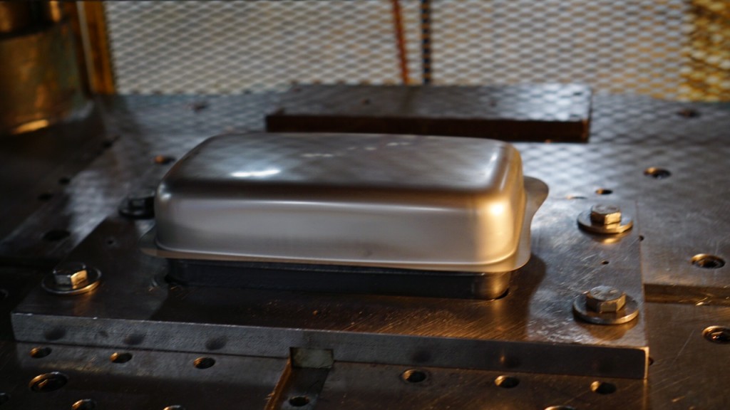
9.1 Design of Dies and Punches
The die and punch are critical components in any deep drawing operation, as they determine the shape and quality of the final part. The die is a stationary mold that defines the external shape of the part, while the punch is the moving tool that pushes the blank into the die to form the part.
In single-action presses, the die and punch must be carefully designed to ensure that the material flows smoothly into the die without tearing, wrinkling, or thinning excessively. The design of the die cavity must account for factors such as material thickness, material strength, and part geometry to ensure that the part is formed correctly.
Die clearance is another important consideration. The clearance between the die and punch must be sufficient to allow the material to flow into the die but not so large that the material is unsupported. Improper die clearance can result in poor surface finish, inconsistent wall thickness, or defects such as wrinkling.
9.2 Factors in Blank Holder Design
The blank holder plays a crucial role in controlling the material flow during the deep drawing process. In a single-action press, the blank holder applies pressure around the edges of the blank, holding it in place while allowing the material to be drawn into the die by the punch.
Blank holder design is particularly important in preventing wrinkling, which occurs when excess material bunches up around the edges of the blank. To prevent wrinkling, the blank holder must apply enough force to hold the blank securely but not so much force that it restricts the material from flowing into the die.
In single-action presses, blank holder force is typically applied passively, meaning that the force is generated by the downward movement of the punch. While this method is effective for simple, shallow draws, more complex or deeper draws may require independent control of the blank holder force, as seen in double- and triple-action presses.
9.3 Tooling Materials and Wear Resistance
Tooling materials must be chosen to withstand the high forces involved in deep drawing without deforming or wearing out prematurely. Common materials for dies and punches include:
- Tool Steel: Tool steels are highly durable and resistant to wear, making them ideal for high-volume production. They offer good toughness and hardness, ensuring that the die and punch can withstand repeated use without losing their shape.
- Carbide: Carbide tooling is even harder and more wear-resistant than tool steel, making it suitable for applications where the tooling will be subject to high stresses or abrasive materials.
Surface coatings such as titanium nitride (TiN) or diamond-like carbon (DLC) can also be applied to the tooling to reduce wear and improve the surface finish of the drawn parts.
9.4 Maintenance and Replacement Strategies
Tooling wear is a common issue in deep drawing operations, particularly in high-volume production environments. Over time, the die and punch can become worn or damaged, leading to defects in the final parts. To prevent this, regular inspection and maintenance of the tooling are essential.
Preventive maintenance strategies may include:
- Regular inspections: Tooling should be inspected regularly for signs of wear, such as cracks, chipping, or deformation.
- Surface reconditioning: Worn tooling can often be reconditioned by polishing or grinding the surface to restore its original shape and finish.
- Tooling replacement: In cases where the tooling is too worn or damaged to be reconditioned, it may need to be replaced. Keeping a stock of spare dies and punches can help minimize downtime when tooling replacement is necessary.
Efficiency and Productivity in Single-Action Presses
10.1 Optimizing Setup Times
One of the keys to maximizing the efficiency of single-action hydraulic presses is minimizing setup times between production runs. Setup time includes activities such as changing the die, adjusting the press settings, and loading the blank into the press. Reducing setup time allows manufacturers to produce more parts in a given period, increasing overall productivity.
Strategies for optimizing setup times include:
- Quick-change tooling: Quick-change tooling systems allow dies and punches to be swapped out quickly and easily, reducing the time required to prepare the press for a new production run.
- Preset press settings: Modern single-action presses often feature programmable controls that allow operators to store and recall press settings for specific parts. This eliminates the need to manually adjust the press for each production run, reducing setup time and ensuring consistent results.
10.2 Energy Efficiency in Hydraulic Systems
Energy efficiency is a growing concern in manufacturing, and hydraulic systems can be a significant source of energy consumption. Single-action presses can be made more energy-efficient by using variable displacement pumps, which adjust the amount of hydraulic fluid delivered based on the system’s needs. This reduces energy consumption during periods of low demand and improves overall efficiency.
Other strategies for improving energy efficiency include:
- Servo-hydraulic systems: Servo motors can be used to control the hydraulic pump, providing precise control over the system’s pressure and reducing energy waste.
- Energy recovery systems: Some hydraulic systems are designed to capture and reuse energy generated during deceleration, further improving energy efficiency.
10.3 Reducing Downtime through Automation
Automation can play a significant role in reducing downtime and improving productivity in single-action hydraulic presses. By automating tasks such as blank loading, part ejection, and press operation, manufacturers can reduce the time required for each production cycle and minimize the risk of human error.
Automated systems may include:
- Robotic arms: Robotic arms can be used to load blanks into the press and remove finished parts, reducing the need for manual labor and speeding up the production process.
- Automatic part ejectors: Mechanical or pneumatic ejectors can automatically remove finished parts from the die, reducing cycle time and improving overall throughput.
10.4 Factors Affecting Throughput and Cycle Time
Several factors can affect the throughput and cycle time of a single-action hydraulic press, including:
- Material type: Softer materials such as aluminum or copper can be drawn more quickly than harder materials such as stainless steel or high-strength alloys, reducing cycle time.
- Part complexity: More complex parts may require longer cycle times to ensure that the material is properly formed without defects.
- Press speed: The speed at which the press operates can have a significant impact on cycle time. While faster presses can produce more parts per hour, they may also increase the risk of defects if not properly controlled.
By optimizing these factors, manufacturers can maximize the productivity of their single-action presses and reduce the overall cost per part.
Maintenance and Troubleshooting
11.1 Preventive Maintenance Strategies
Preventive maintenance is essential for ensuring the long-term reliability and performance of single-action hydraulic presses. By regularly inspecting and servicing the press, manufacturers can identify potential issues before they lead to costly breakdowns or production delays.
Key preventive maintenance tasks include:
- Checking hydraulic fluid levels: Hydraulic fluid is the lifeblood of the press, and maintaining the proper fluid level is critical for ensuring smooth operation. Low fluid levels can lead to increased wear on the hydraulic system and reduced performance.
- Inspecting hoses and seals: Hydraulic hoses and seals can wear out over time, leading to fluid leaks and pressure loss. Regular inspection and replacement of worn hoses and seals can help prevent these issues.
- Lubricating moving parts: Proper lubrication of the press’s moving parts is essential for reducing friction and wear. Lubrication points should be checked regularly, and the appropriate type of lubricant should be applied according to the manufacturer’s recommendations.
- Inspecting tooling: Dies, punches, and blank holders should be inspected regularly for signs of wear, such as cracks, chipping, or deformation. Worn tooling can lead to defects in the final parts and should be repaired or replaced as necessary.
11.2 Hydraulic System Inspection and Repair
The hydraulic system is the heart of a single-action press, and regular inspection is essential for ensuring that the system operates at peak performance. Common hydraulic system maintenance tasks include:
- Checking for leaks: Fluid leaks can lead to reduced system pressure and poor press performance. Hoses, seals, and fittings should be inspected regularly for signs of leaks, and any damaged components should be replaced immediately.
- Testing system pressure: Hydraulic pressure should be tested regularly to ensure that the system is operating within the specified range. Low pressure can lead to incomplete draws, while high pressure can cause damage to the press or tooling.
- Changing hydraulic fluid: Over time, hydraulic fluid can become contaminated with dirt, metal particles, or water, leading to reduced performance and increased wear on the hydraulic system. Regular fluid changes are essential for maintaining system efficiency and extending the life of the press.
11.3 Common Issues and Solutions
Several common issues can arise in single-action hydraulic presses, including:
- Wrinkling: Wrinkling occurs when excess material bunches up around the edges of the blank during the drawing process. This issue can often be resolved by adjusting the blank holder force or using a lubricant to reduce friction between the blank and the die.
- Tearing: Tearing occurs when the material is overstressed during the drawing process, leading to cracks or splits in the part. To prevent tearing, the press settings should be adjusted to reduce the force applied during the draw, and the blank size or material thickness may need to be modified.
- Thinning: Thinning occurs when the material is stretched too thin during the drawing process, leading to weak or defective parts. Thinning can be minimized by adjusting the press settings to control the flow of material into the die and ensuring that the tooling is properly designed for the part being formed.
11.4 Extending the Lifespan of Single-Action Presses
With proper maintenance and care, single-action hydraulic presses can provide many years of reliable service. To extend the lifespan of the press, manufacturers should follow these best practices:
- Perform regular preventive maintenance: Regular inspection and maintenance of the hydraulic system, tooling, and press structure can help prevent costly breakdowns and extend the life of the machine.
- Use high-quality hydraulic fluid: Using the recommended type and grade of hydraulic fluid can help reduce wear on the system and improve overall performance.
- Train operators: Proper training is essential for ensuring that operators know how to use the press correctly and safely. Training should cover topics such as press operation, maintenance, and troubleshooting.
- Keep a stock of spare parts: Having spare parts on hand, such as hydraulic seals, hoses, and tooling components, can help minimize downtime when repairs or replacements are needed.
Safety Protocols and Best Practices
12.1 Importance of Safety in Hydraulic Press Operations
Hydraulic presses are powerful machines that can pose significant safety risks if not operated correctly. Ensuring operator safety is a critical consideration in press operations, as the high forces involved in deep drawing can lead to serious injuries if proper precautions are not taken.
Manufacturers should prioritize safety in their press operations by implementing comprehensive safety protocols and providing operators with the necessary training and equipment to work safely.
12.2 Operator Training and Guidelines
Operator training is one of the most important steps in ensuring the safe operation of hydraulic presses. Training should cover topics such as:
- Basic press operation: Operators should be familiar with the press’s controls, settings, and operation procedures.
- Safety features: Operators should be trained to use the press’s safety features, such as emergency stop buttons and safety light curtains.
- Proper handling of materials: Operators should know how to safely load and unload blanks, as well as how to position the material correctly in the die to avoid off-center draws.
- Personal protective equipment (PPE): Operators should be required to wear appropriate PPE, such as safety glasses, gloves, and hearing protection, while operating the press.
12.3 Safety Mechanisms in Single-Action Presses
Modern single-action presses are equipped with a variety of safety mechanisms to protect operators and prevent accidents. These include:
- Emergency stop buttons: Located on the control panel, these buttons allow operators to stop the press immediately in case of an emergency.
- Safety light curtains: These sensors detect when a person or object enters the press area and automatically stop the machine to prevent injury.
- Overload protection: This system automatically shuts down the press if the applied force exceeds the press’s rated capacity, preventing damage to the machine and tooling.
12.4 Regulatory Standards and Compliance
Hydraulic presses must comply with industry standards and regulations to ensure operator safety. These standards are set by organizations such as OSHA (Occupational Safety and Health Administration) and ISO (International Organization for Standardization), and they cover areas such as machine guarding, operator training, and emergency stop protocols.
Manufacturers should regularly review their press operations to ensure compliance with these standards and make any necessary adjustments to improve safety.
Future Trends and Innovations in Single-Action Hydraulic Presses
13.1 Automation and Industry 4.0 Integration
As manufacturing continues to evolve, single-action hydraulic presses are increasingly being integrated into Industry 4.0 environments. Industry 4.0 refers to the trend of automation and digitalization in manufacturing, where machines are connected to each other and to centralized control systems to improve efficiency and productivity.
In single-action presses, automation can be used to streamline operations such as blank loading, part ejection, and press settings adjustment, reducing the need for manual intervention and minimizing downtime. Advanced presses may also feature sensors and data collection systems that provide real-time information on press performance, allowing operators to make adjustments as needed to optimize production.
13.2 Digital Monitoring and Smart Systems
Smart systems and digital monitoring technologies are playing an increasingly important role in the future of hydraulic press operations. By integrating sensors and data analytics into the press, manufacturers can monitor the machine’s performance in real-time, identifying potential issues before they lead to breakdowns or defects.
For example, temperature sensors can monitor the temperature of the hydraulic fluid, while pressure sensors can detect fluctuations in system pressure. This data can be used to trigger automatic adjustments to the press’s operation or alert operators to potential issues that require attention.
Predictive maintenance systems, which use historical data to predict when a component is likely to fail, are also becoming more common. These systems can schedule maintenance before a failure occurs, reducing downtime and extending the life of the press.
13.3 New Materials and Sustainable Hydraulic Fluids
As manufacturers become more focused on sustainability, there is growing interest in the use of biodegradable hydraulic fluids and sustainable materials in hydraulic press operations. Biodegradable fluids offer a more environmentally friendly alternative to traditional petroleum-based hydraulic fluids, reducing the environmental impact of fluid leaks or spills.
In addition to sustainable fluids, there is also ongoing research into new high-performance materials for dies, punches, and blank holders. These materials offer improved wear resistance, reducing the need for tooling replacement and improving overall press efficiency.
13.4 Energy Efficiency Improvements
Energy efficiency is a major focus for manufacturers looking to reduce operating costs and minimize their environmental footprint. Single-action hydraulic presses are becoming more energy-efficient thanks to innovations such as:
- Servo-hydraulic systems: These systems use servo motors to control the hydraulic pump, allowing for more precise control over the press’s operation and reducing energy consumption.
- Variable displacement pumps: These pumps adjust the amount of hydraulic fluid delivered based on the system’s needs, reducing energy consumption during periods of low demand.
- Energy recovery systems: Some presses are equipped with systems that capture and reuse energy generated during deceleration, further improving energy efficiency.
As energy costs continue to rise and environmental regulations become more stringent, manufacturers will need to prioritize energy efficiency in their press operations.
Case Studies and Real-World Examples

14.1 Automotive Component Manufacturing with Single-Action Presses
In one case study, a leading automotive manufacturer used single-action hydraulic deep drawing presses to produce door panels and trunk lids for a new vehicle model. The press was selected for its ability to provide consistent force and precision, ensuring that each part met the company’s high standards for quality and fit.
By integrating the single-action press into an automated production line, the manufacturer was able to achieve high-volume production with minimal downtime. The press’s programmable controls allowed operators to store and recall settings for each part, reducing setup time between production runs and ensuring consistent results.
14.2 Appliance Industry: Sheet Metal Forming
In the appliance industry, a major manufacturer of washing machines and refrigerators used single-action hydraulic presses to form the outer shells of their products. The presses were chosen for their ability to produce smooth, defect-free surfaces that met the company’s aesthetic and durability requirements.
The manufacturer implemented a preventive maintenance program to ensure that the presses operated at peak efficiency, reducing downtime and extending the life of the machines. By regularly inspecting and replacing worn tooling, the company was able to maintain consistent product quality and minimize the risk of defects.
14.3 Packaging Industry: Deep Drawing of Cans and Containers
In the packaging industry, a major producer of aluminum beverage cans used single-action hydraulic presses to form the cans’ cylindrical shape. The press was selected for its ability to complete high-speed production cycles, allowing the company to produce millions of cans per year with consistent quality.
The company also implemented automation to streamline the production process, using robotic arms to load blanks into the press and remove finished cans. This automation reduced the need for manual labor and improved overall productivity, allowing the company to meet the high demand for its products.
14.4 Custom Tooling and Adaptation for Specialized Manufacturing
In a custom manufacturing environment, a supplier of medical devices used single-action hydraulic presses to produce surgical tools and implantable devices. The company worked closely with a tooling supplier to design custom dies and punches that met the specific requirements of the parts being produced.
By using custom tooling and adjusting the press settings for each production run, the company was able to produce parts with tight tolerances and smooth surface finishes, ensuring that the parts met the stringent quality standards of the medical device industry.
Conclusion: The Role of Single-Action Hydraulic Deep Drawing Presses in Modern Manufacturing
Single-action hydraulic deep drawing presses play a critical role in modern manufacturing, offering a combination of simplicity, cost-effectiveness, and reliability. These machines are used across a wide range of industries, from automotive and appliance manufacturing to packaging and aerospace, providing manufacturers with the precision and control needed to produce high-quality parts.
While single-action presses have some limitations compared to more complex multi-action presses, they are an ideal solution for applications that require shallow draws or simple part geometries. Their straightforward design and ease of operation make them an attractive option for manufacturers looking to minimize costs and maximize productivity.
As manufacturing continues to evolve, single-action presses are becoming more advanced, with innovations in automation, energy efficiency, and digital monitoring driving improvements in productivity and performance. By embracing these trends, manufacturers can ensure that their press operations remain competitive in an increasingly complex and demanding global marketplace.
In the future, single-action hydraulic deep drawing presses will continue to be a cornerstone of the metal forming industry, providing the force, precision, and efficiency needed to meet the evolving demands of modern manufacturing.
Double-Action Hydraulic Presses
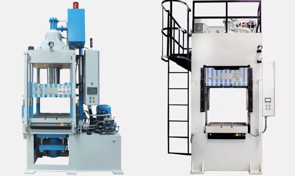
Double-action hydraulic presses are highly versatile and essential machines in the manufacturing and metalworking industries, providing greater control and force for complex deep drawing and forming operations. These presses have become indispensable in industries such as automotive, aerospace, appliance manufacturing, and packaging, offering advanced control over material flow, allowing for the production of deeper, more intricate parts. In this detailed guide, we will explore the fundamentals, key components, applications, advantages, and innovations surrounding double-action hydraulic presses.
Introduction to Double-Action Hydraulic Presses
1.1 Overview of Hydraulic Presses
Hydraulic presses have been a cornerstone of the metal forming industry for over a century, transforming metalworking operations by applying significant, controlled force through hydraulic systems. The use of hydraulic fluid allows these machines to produce consistent, high-pressure output, making them ideal for operations such as deep drawing, forging, bending, and stamping. Double-action hydraulic presses stand out in this category due to their ability to apply force in two directions, enhancing their versatility and precision in complex metal forming tasks.
1.2 Evolution and Importance of Double-Action Hydraulic Presses
Double-action hydraulic presses emerged as a response to the limitations of single-action presses, which apply force only in one direction—typically downward. While single-action presses are suitable for basic forming tasks, they struggle with more intricate operations that require additional control over material flow. The development of double-action presses allowed for independent control of both the punch and blank holder, enabling manufacturers to achieve deeper draws and more complex shapes without tearing or wrinkling the material.
These presses have since become a key asset in industries such as automotive, aerospace, and consumer goods, where precision and quality are paramount. Double-action hydraulic presses are indispensable in producing deep-drawn parts, complex geometries, and large components that demand meticulous material flow control and consistent output.
1.3 Key Differences Between Single and Double-Action Presses
The primary difference between single-action and double-action hydraulic presses lies in the number of hydraulic cylinders and the application of force:
- Single-Action Presses: Only one hydraulic cylinder applies force in one direction, typically downward. This is sufficient for shallow draws or simple shapes but limits the control over the material flow during deep drawing.
- Double-Action Presses: Two hydraulic cylinders operate independently—one controls the punch, and the other controls the blank holder. This allows for greater control over both the downward drawing force and the clamping force applied to the edges of the metal blank, making it easier to draw complex shapes without damaging the material.
Double-action presses provide the flexibility to handle more complex parts and deeper draws, reducing the risk of material wrinkling or tearing during the process.
Working Principle of Double-Action Hydraulic Presses
2.1 Basic Principles of Hydraulic Power
Hydraulic systems operate based on Pascal’s Law, which states that any pressure applied to a confined fluid is transmitted equally in all directions within that fluid. In hydraulic presses, this principle enables the generation of high force through the pressurization of hydraulic fluid (typically oil) within a closed system. The fluid is pressurized by a hydraulic pump and transferred to hydraulic cylinders, which move pistons that apply the necessary force to shape metal parts.
In a double-action hydraulic press, this process is enhanced by the addition of a second hydraulic cylinder, which allows for independent control over both the punch and the blank holder. The press can thus exert force in two directions, providing superior control over the material flow during the drawing process.
2.2 Functioning of the Double-Action System
The double-action system consists of two primary hydraulic cylinders:
- Punch Cylinder: This cylinder controls the downward movement of the punch, which pushes the metal blank into the die, shaping it according to the die’s geometry.
- Blank Holder Cylinder: The second cylinder is responsible for controlling the blank holder, a component that applies pressure around the edges of the metal blank to hold it in place while the punch shapes the central part. The blank holder’s force must be carefully controlled to prevent wrinkles from forming while allowing the material to flow smoothly into the die.
During operation:
- The blank is placed on the die, and the blank holder descends to apply uniform pressure around its perimeter.
- The punch then descends, pressing the blank into the die cavity and shaping it according to the desired specifications.
- Both the punch and blank holder forces can be adjusted independently, allowing for precise control over the material flow, which is critical when working with complex shapes or deep draws.
The independent control of these two forces is what distinguishes double-action presses from single-action presses and allows for greater versatility in metal forming.
2.3 Force Distribution and Control in Double-Action Presses
One of the main advantages of double-action hydraulic presses is their ability to distribute force in a controlled manner across the metal blank. This is especially important for deep drawing operations, where excessive force on the material can lead to tearing, thinning, or wrinkling.
- Blank Holder Force: The blank holder must apply enough force to hold the material securely in place while still allowing it to be drawn into the die. Too little force results in wrinkling, while too much force can prevent the material from flowing into the die smoothly.
- Punch Force: The punch applies force to the material to deform it into the desired shape. This force must be sufficient to stretch the material without causing tears or excessive thinning, particularly when dealing with high-strength materials or complex geometries.
The ability to independently control the punch and blank holder forces ensures that material flow is managed efficiently, reducing the risk of defects and allowing for the production of deeper, more intricate parts.
Key Components of Double-Action Hydraulic Presses
3.1 Hydraulic Cylinders (Punch and Blank Holder)
The core components of a double-action hydraulic press are its hydraulic cylinders, which are responsible for generating the force required to perform the drawing operation. Double-action presses feature two main cylinders:
- Punch Cylinder: The punch cylinder is responsible for the downward movement of the punch, which applies pressure to the center of the metal blank and forces it into the die. This cylinder must be capable of generating enough force to deform the material without causing defects.
- Blank Holder Cylinder: The blank holder cylinder applies force around the perimeter of the blank, preventing the material from shifting or wrinkling as it is drawn into the die. The force exerted by the blank holder must be carefully controlled to ensure that the material flows smoothly into the die while avoiding defects such as tearing or wrinkling.
These two cylinders operate independently, allowing for precise control over the forces applied to the blank, which is critical for achieving high-quality results in deep drawing and forming operations.
3.2 Frame and Structure
The frame of a double-action hydraulic press is designed to support the significant forces generated during operation. Most presses feature one of two common frame designs:
- H-Frame (Closed Frame): This frame design offers greater rigidity and stability, making it ideal for operations that require higher forces. The closed structure of the H-frame provides greater resistance to bending and deformation, allowing the press to maintain accuracy over extended periods of use.
- C-Frame (Open Frame): This design is more compact and provides easier access to the workpiece, making it suitable for smaller presses or applications where space is limited. However, C-frame presses may not offer the same level of structural integrity as H-frame presses, making them less suitable for heavy-duty operations.
The choice of frame depends on the application’s specific requirements, including the size of the parts being formed and the force required.
3.3 Die, Punch, and Blank Holder Setup
The die, punch, and blank holder are the primary tooling components in a double-action hydraulic press, responsible for shaping the metal blank during the forming process:
- Die: The die is the stationary component that defines the external shape of the part. It is typically made from tool steel or other high-strength materials to withstand the forces involved in deep drawing.
- Punch: The punch is the moving component that presses the metal blank into the die, shaping it according to the die’s geometry. Punches are typically made from the same high-strength materials as dies and are often coated with wear-resistant coatings such as titanium nitride (TiN) to extend their lifespan.
- Blank Holder: The blank holder applies uniform pressure around the perimeter of the blank, holding it securely in place during the drawing process. The force exerted by the blank holder is critical for ensuring that the material flows smoothly into the die without wrinkling or tearing.
The precision of the die, punch, and blank holder setup is critical for achieving consistent, high-quality results in deep drawing operations.
3.4 Hydraulic Pumps and Control Systems
The hydraulic pump is responsible for generating the pressure needed to move the pistons in the hydraulic cylinders. There are two main types of pumps used in double-action hydraulic presses:
- Fixed Displacement Pumps: These pumps deliver a constant amount of hydraulic fluid, regardless of the system’s demand. They are typically used in applications where consistent force is required.
- Variable Displacement Pumps: These pumps adjust the amount of hydraulic fluid delivered based on the system’s demand, improving energy efficiency and allowing for more precise control over the press’s operation.
The control system in a double-action hydraulic press is responsible for managing the flow of hydraulic fluid to the cylinders and regulating the force applied during the drawing process. Modern presses are often equipped with programmable logic controllers (PLCs) that allow operators to set specific parameters for the press, such as the stroke length, force, and speed. This level of control ensures that the press operates consistently and efficiently, producing high-quality parts with minimal defects.
Materials Suitable for Double-Action Hydraulic Presses
4.1 Aluminum Alloys
Aluminum alloys are widely used in industries such as automotive and aerospace, where lightweight materials are essential for improving fuel efficiency and performance. Aluminum is an ideal material for deep drawing in double-action presses due to its high ductility and low density. The ability to control both the punch and blank holder forces independently in a double-action press allows for precise forming of aluminum parts, reducing the risk of wrinkling or tearing.
Aluminum alloys are commonly used to produce automotive body panels, aircraft fuselage components, and packaging materials, such as beverage cans. The lightweight and corrosion-resistant properties of aluminum make it a popular choice for parts that require strength and durability without adding significant weight.
4.2 Low Carbon and Stainless Steels
Low carbon steels are commonly used in deep drawing operations due to their malleability and strength. These steels are widely used in the production of automotive parts, such as fuel tanks, chassis components, and exhaust systems. Low carbon steels are relatively easy to form in double-action presses, as their ductility allows them to flow smoothly into the die without tearing or wrinkling.
Stainless steels, on the other hand, are used in applications where corrosion resistance is critical. While stainless steel is more difficult to form than low carbon steel due to its higher strength and work hardening properties, double-action presses provide the necessary control to achieve precise results. Stainless steel is commonly used in the production of kitchen sinks, appliance housings, and medical devices, where a combination of strength, durability, and corrosion resistance is essential.
4.3 High-Strength Alloys
The demand for high-strength materials in industries such as automotive, aerospace, and defense has led to the increased use of high-strength alloys in deep drawing operations. These materials, which include high-strength steels, titanium alloys, and superalloys, offer superior strength and durability but are more challenging to form due to their lower ductility and higher work hardening rates.
Double-action presses are well-suited for working with high-strength alloys, as the independent control of the punch and blank holder forces allows for more precise control over the material flow. This is particularly important when forming complex parts or deep draws, where the risk of tearing or excessive thinning is higher. High-strength alloys are commonly used in the production of structural components for aircraft and vehicles, as well as in high-performance engines and turbine blades.
4.4 Non-Ferrous Metals
Non-ferrous metals, such as copper, brass, and nickel, are often used in applications where electrical conductivity or thermal resistance is critical. These materials are relatively soft and malleable, making them easier to form than high-strength alloys. However, they still require precise control during the deep drawing process to ensure that the material flows smoothly into the die without defects.
Copper and brass are commonly used in the production of electrical connectors, plumbing fixtures, and decorative components, while nickel is used in applications such as battery components and corrosion-resistant coatings.
4.5 Challenges in Working with Advanced Materials
While double-action hydraulic presses provide the necessary control for forming a wide range of materials, there are several challenges associated with working with advanced materials such as high-strength alloys and superalloys:
- Work Hardening: Many high-strength materials undergo work hardening during the forming process, which makes them more difficult to shape without causing defects. The ability to control the punch and blank holder forces independently in a double-action press helps mitigate this issue by allowing the material to flow more smoothly into the die.
- Springback: Some materials, particularly high-strength alloys, exhibit springback after the forming process, where the material attempts to return to its original shape. This can result in parts that do not meet the required dimensional tolerances. Double-action presses allow for precise control over the material flow, reducing the risk of springback and ensuring that the final part meets the desired specifications.
- Tool Wear: The high forces required to form advanced materials can result in increased wear on the dies and punches, leading to higher maintenance costs and reduced tooling life. To address this issue, tooling for double-action presses is often made from wear-resistant materials such as carbide, and coatings such as titanium nitride (TiN) are used to extend the life of the tooling.
Process Stages in Double-Action Press Operation
5.1 Blank Loading and Positioning
The deep drawing process begins with the loading and positioning of the metal blank onto the die. The blank is typically a flat, pre-cut sheet of metal, and its size and thickness are critical factors in determining the success of the drawing operation. The blank is placed on the die and held in place by the blank holder, which applies uniform pressure around the perimeter of the blank.
In double-action presses, the blank holder force is applied by a hydraulic cylinder, allowing for precise control over the pressure exerted on the blank. Proper blank positioning is essential for ensuring that the material flows smoothly into the die without causing defects such as off-center draws or uneven wall thickness.
5.2 Blank Holder and Punch Force Application
Once the blank is positioned on the die, the blank holder descends and applies pressure around the edges of the blank. The amount of force applied by the blank holder is critical for controlling the material flow during the drawing process. Too little force can result in wrinkling, while too much force can prevent the material from flowing into the die, leading to tearing.
After the blank holder is in place, the punch descends and applies force to the center of the blank, pressing it into the die cavity. The punch force must be carefully controlled to ensure that the material is deformed evenly without causing defects such as tearing or thinning.
In double-action presses, the punch and blank holder forces are controlled independently, allowing for precise adjustments to be made during the drawing process. This level of control is essential for producing complex shapes or deep-drawn parts, where material flow must be carefully managed to avoid defects.
5.3 Deep Drawing and Forming Stages
The deep drawing process involves the deformation of the metal blank as it is drawn into the die cavity by the punch. As the punch descends, the material is stretched and shaped according to the geometry of the die. The key to successful deep drawing is controlling the flow of the material into the die, which is achieved by adjusting the punch and blank holder forces.
During the drawing process, the material undergoes plastic deformation, meaning it is permanently shaped without breaking. However, the material’s ductility and strength play a significant role in determining how easily it can be drawn. Materials with higher ductility, such as aluminum and low carbon steel, are easier to draw, while high-strength materials may require additional control to avoid defects.
In double-action presses, the independent control of the blank holder force allows operators to adjust the clamping pressure on the blank as needed during the drawing process. This ensures that the material flows smoothly into the die without wrinkling or tearing, resulting in a high-quality final part.
5.4 Ejecting and Finishing the Part
After the deep drawing process is complete, the punch retracts, and the finished part is ejected from the die. In many double-action presses, automatic part ejectors are used to remove the part from the die, reducing the need for manual intervention and improving productivity.
Ejecting the part without causing damage is critical, especially for parts with thin walls or complex geometries. Care must be taken to ensure that the part does not become stuck in the die or sustain damage during the ejection process.
Once the part is ejected, it may undergo additional finishing operations, such as trimming, deburring, or polishing, to remove excess material or improve the surface finish. These finishing steps are essential for ensuring that the final part meets the required quality standards and dimensional tolerances.
Applications of Double-Action Hydraulic Presses
6.1 Automotive Industry
The automotive industry is one of the largest users of double-action hydraulic presses, particularly in the production of body panels, structural components, and engine parts. The ability to control both the punch and blank holder forces independently allows manufacturers to achieve the deep draws and complex shapes required for modern vehicle designs.
- Body Panels: Double-action presses are used to produce door panels, fenders, hoods, and trunk lids. These parts often require deep draws and must meet strict quality standards for dimensional accuracy and surface finish. The independent control of the blank holder force is essential for preventing defects such as wrinkling and tearing during the drawing process.
- Chassis Components: Chassis components, such as frame rails and crossmembers, require high strength and durability. Double-action presses provide the force and precision needed to form these parts from high-strength steel or aluminum alloys, ensuring that they meet the required safety and performance standards.
- Engine Components: Double-action presses are also used to produce engine components such as oil pans, valve covers, and exhaust manifolds. These parts must withstand high temperatures and mechanical stresses, making the precise control of the forming process critical for ensuring their durability and performance.
In the automotive industry, double-action presses are valued for their ability to produce high-quality parts with consistent results. The flexibility of these presses allows manufacturers to produce a wide range of components, from small precision parts to large structural elements, making them an essential tool in modern automotive manufacturing.
6.2 Aerospace Components
The aerospace industry demands parts that are both lightweight and high-strength, making double-action hydraulic presses an ideal solution for producing aircraft components and spacecraft parts. The ability to control the material flow during the forming process is critical for achieving the tight tolerances and high strength-to-weight ratios required in aerospace applications.
- Fuselage Panels: Double-action presses are used to form fuselage panels from aluminum alloys and titanium, materials that offer the necessary strength and weight savings for aircraft. The deep draws required for fuselage panels make the independent control of the blank holder and punch forces essential for preventing defects.
- Engine Cowls: Engine cowls, which protect aircraft engines from environmental factors and reduce drag, are often formed using double-action presses. These components require precise shaping to ensure that they fit correctly and provide the necessary aerodynamic properties.
- Landing Gear Components: Components such as landing gear struts and wheel well covers are produced using high-strength alloys that require careful control during the forming process. Double-action presses provide the necessary force and precision to form these parts without causing defects.
In the aerospace industry, the ability to produce parts with consistent quality and tight tolerances is critical for ensuring the safety and performance of aircraft. Double-action presses play a key role in achieving these goals, making them an indispensable tool for aerospace manufacturers.
6.3 Appliance and Consumer Goods Manufacturing
Double-action hydraulic presses are widely used in the production of appliances and consumer goods, where the ability to form complex shapes from sheet metal is essential for creating high-quality products.
- Refrigerator Panels: The outer panels of refrigerators are typically made from stainless steel or aluminum and are formed using double-action presses. These panels must be precisely shaped to ensure that they fit correctly and provide the necessary insulation for the appliance.
- Washing Machine Drums: The drums of washing machines are often made from stainless steel and require deep drawing to achieve their cylindrical shape. Double-action presses provide the force and control needed to form these drums without causing defects such as wrinkling or thinning.
- Cookware: Double-action presses are used to form pots, pans, and other cookware from materials such as aluminum and stainless steel. These products require smooth surfaces and consistent wall thickness, making the precise control offered by double-action presses essential for producing high-quality cookware.
In the appliance and consumer goods industries, manufacturers value double-action presses for their ability to produce high-quality parts with minimal defects. The flexibility of these presses allows for the production of a wide range of products, from large appliance panels to small precision parts, making them an essential tool in modern manufacturing.
6.4 Packaging Industry (Cans and Containers)
The packaging industry relies heavily on double-action hydraulic presses for the production of metal cans, containers, and closures. These products are typically made from aluminum or tinplate, materials that can be easily drawn into the desired shape using double-action presses.
- Beverage Cans: Double-action presses are used to produce aluminum beverage cans, which require deep drawing to achieve their cylindrical shape. The ability to control the blank holder force is critical for ensuring that the material flows smoothly into the die without wrinkling or tearing, resulting in cans with consistent wall thickness and smooth surfaces.
- Aerosol Cans: Aerosol cans, which are used for products such as deodorants and spray paints, require precise forming to ensure that they can withstand the internal pressure of the contents. Double-action presses provide the force and control needed to produce these cans without defects.
- Food Containers: Metal food containers, such as tin cans and aluminum trays, are formed using double-action presses. These containers must be durable, lightweight, and able to withstand the pressures of sealing and transportation, making double-action presses the ideal tool for their production.
The packaging industry values the speed and precision of double-action presses, which allow manufacturers to produce large quantities of cans and containers with consistent quality. The ability to control the blank holder and punch forces independently ensures that the final products meet the required specifications for strength, durability, and appearance.
6.5 Medical Devices and Precision Parts
The medical device industry requires parts that are both precise and biocompatible, making double-action hydraulic presses an ideal solution for the production of surgical tools, implantable devices, and diagnostic equipment.
- Surgical Instruments: Surgical instruments, such as scalpels and forceps, are often made from stainless steel or titanium, materials that require careful control during the forming process to ensure that they meet the required specifications for strength and durability.
- Implantable Devices: Implantable devices, such as hip implants and dental implants, require precise forming to ensure that they fit correctly and function as intended. Double-action presses provide the force and control needed to produce these devices with tight tolerances and smooth surfaces.
- Diagnostic Equipment: Components for diagnostic equipment, such as MRI machines and X-ray machines, are often made from aluminum or stainless steel and require precise forming to ensure that they meet the necessary performance standards. Double-action presses provide the precision needed to produce these parts without defects.
In the medical device industry, the ability to produce parts with consistent quality and tight tolerances is critical for ensuring the safety and effectiveness of the final products. Double-action presses play a key role in achieving these goals, making them an essential tool for medical device manufacturers.
Advantages and Limitations of Double-Action Hydraulic Presses
7.1 Enhanced Control Over Material Flow
One of the primary advantages of double-action hydraulic presses is the ability to exert independent control over both the punch and blank holder forces. This control is critical for achieving precise material flow, particularly in deep drawing operations where the material must be stretched into the die without wrinkling, tearing, or thinning excessively.
The blank holder force can be adjusted to control the clamping pressure on the blank’s edges, allowing the material to flow smoothly into the die while preventing wrinkling. At the same time, the punch force can be adjusted to ensure that the material is deformed correctly and evenly, resulting in parts with consistent dimensions and high-quality surfaces.
This enhanced control makes double-action presses ideal for forming complex shapes and deep-drawn parts, where managing material flow is essential for preventing defects.
7.2 Higher Precision for Complex Shapes
Double-action presses offer greater precision than single-action presses, making them the preferred choice for applications that require complex shapes and deep draws. The independent control of the punch and blank holder forces allows manufacturers to fine-tune the forming process, ensuring that the material flows evenly into the die and that the final part meets the required dimensional tolerances.
This level of precision is particularly important in industries such as automotive, aerospace, and medical devices, where parts must meet strict quality standards for fit, function, and appearance. Double-action presses provide the flexibility needed to produce parts with tight tolerances and smooth surfaces, making them an essential tool for manufacturers of high-quality, precision components.
7.3 Cost and Maintenance Considerations
While double-action presses offer significant advantages in terms of control and precision, they are also more complex and expensive than single-action presses. The additional hydraulic cylinder and control systems required for the blank holder add to the overall cost of the machine, making double-action presses a larger investment for manufacturers.
In addition to the higher initial cost, double-action presses also require more maintenance than single-action presses. The increased complexity of the hydraulic system, combined with the need to maintain both the punch and blank holder cylinders, means that regular inspection and servicing are essential for ensuring the long-term reliability and performance of the press.
Despite these additional costs, the improved precision and flexibility offered by double-action presses often make them a worthwhile investment for manufacturers who need to produce high-quality parts with complex shapes or deep draws.
7.4 Comparison with Single and Triple-Action Presses
Double-action hydraulic presses offer a middle ground between single-action and triple-action presses, providing greater control and flexibility than single-action presses while being less complex and expensive than triple-action presses.
- Single-Action Presses: Single-action presses apply force in only one direction, making them suitable for simple forming operations but less capable of handling deep draws or complex shapes. Double-action presses offer superior control over material flow, allowing for the production of more intricate parts with fewer defects.
- Triple-Action Presses: Triple-action presses offer even greater control than double-action presses, with a third hydraulic cylinder that controls the die cushion. This additional control allows for even more precise management of material flow, making triple-action presses ideal for the most complex forming operations. However, the added complexity and cost of triple-action presses make them less suitable for manufacturers who do not require this level of control.
In general, double-action presses are the preferred choice for manufacturers who need a balance between precision, flexibility, and cost-effectiveness. They offer the control needed for most deep drawing and complex forming operations without the added complexity and expense of a triple-action press.
Technical Specifications of Double-Action Presses
8.1 Force Ratings and Capacities
Double-action hydraulic presses are available in a wide range of force ratings, typically measured in tons. The force required for a given forming operation depends on several factors, including the material thickness, material strength, and depth of the draw. Common force ratings for double-action presses range from 100 tons to over 1,000 tons, with higher force capacities required for thicker materials or deeper draws.
When selecting a double-action press, it is essential to ensure that the press has sufficient force capacity to handle the specific application. An undersized press may struggle to form the material correctly, leading to defects, while an oversized press may be unnecessarily expensive and consume more energy than required.
8.2 Stroke Length and Speed Variability
The stroke length of a hydraulic press refers to the distance the ram (or punch) travels during the forming process. Stroke length is an important factor in determining the depth of the draw and the size of the part that can be produced. Double-action presses typically offer adjustable stroke lengths, allowing operators to customize the press’s operation based on the part being formed.
The speed of the press is another critical factor. Faster presses can complete more cycles per hour, increasing productivity, but may require more precise control to avoid defects such as tearing or wrinkling. Double-action presses can be adjusted to operate at different speeds, depending on the material and the complexity of the part being formed.
8.3 Variants for Different Applications
Double-action presses come in a variety of configurations designed for specific applications. For example:
- High-Speed Presses: These presses are designed for high-volume production and can complete more cycles per hour than standard presses.
- Heavy-Duty Presses: Designed for large parts such as automotive body panels and aerospace components, these presses feature larger frames and higher force capacities to handle bigger blanks and deeper draws.
- Compact Presses: For smaller parts or lower-volume production, compact double-action presses offer a space-saving solution without sacrificing performance.
The choice of press configuration depends on the specific needs of the application, including the size and complexity of the parts being formed, the required production volume, and the available space in the manufacturing facility.
8.4 Safety Features and Operator Controls
Modern double-action hydraulic presses are equipped with a variety of safety features to protect operators and prevent accidents. Common safety features include:
- Emergency Stop Buttons: These buttons allow operators to stop the press immediately in case of an emergency.
- Safety Light Curtains: These sensors detect when a person or object enters the press area and automatically stop the machine to prevent injury.
- Overload Protection: This system automatically shuts down the press if the applied force exceeds the press’s rated capacity, preventing damage to the machine and tooling.
Operator controls are typically designed for ease of use and may include touchscreens, joysticks, or push buttons. Automated systems may also feature PLC controls that allow operators to program the press for specific operations and ensure consistent results across multiple production cycles.
Tooling and Die Design for Double-Action Presses
9.1 Punch and Die Design Considerations
The punch and die are critical components in any deep drawing operation, as they determine the shape and quality of the final part. In a double-action press, the die is a stationary mold that defines the external shape of the part, while the punch is the moving tool that presses the blank into the die to form the part.
Proper punch and die design is essential for ensuring that the material flows smoothly into the die without tearing, wrinkling, or thinning excessively. The clearance between the punch and die must be carefully calculated based on the material thickness and ductility to ensure that the part is formed correctly.
- Material Flow: The punch and die must be designed to facilitate smooth material flow into the die cavity, reducing the risk of defects. This may involve adding radii or tapers to the die cavity to guide the material into the desired shape.
- Surface Finish: The punch and die surfaces should be polished to minimize friction during the forming process, improving the surface finish of the final part.
9.2 Factors in Blank Holder and Cushion Design
The blank holder plays a critical role in controlling the material flow during the deep drawing process. In a double-action press, the blank holder applies uniform pressure around the edges of the blank, holding it securely in place while allowing the material to be drawn into the die by the punch.
- Blank Holder Force: The force applied by the blank holder must be carefully controlled to prevent wrinkling or tearing. In double-action presses, the blank holder force is applied by a hydraulic cylinder, allowing for precise adjustments to be made during the drawing process.
- Die Cushion: Some double-action presses are equipped with a die cushion, which provides additional support for the material during the drawing process. The die cushion helps prevent thinning or tearing of the material, particularly in deep draws.
Proper design of the blank holder and die cushion is essential for ensuring that the material flows smoothly into the die without defects.
9.3 Tooling Materials and Coatings for Wear Resistance
Tooling materials must be chosen to withstand the high forces involved in deep drawing without deforming or wearing out prematurely. Common materials for punches and dies include:
- Tool Steel: Tool steels offer good toughness and wear resistance, making them ideal for high-volume production. They are commonly used for punches and dies in double-action presses.
- Carbide: Carbide tooling is even harder and more wear-resistant than tool steel, making it suitable for applications where the tooling will be subject to high stresses or abrasive materials.
To extend the life of the tooling, surface coatings such as titanium nitride (TiN) or diamond-like carbon (DLC) can be applied. These coatings reduce friction and wear, improving the surface finish of the final part and reducing the frequency of tooling maintenance.
9.4 Maintenance and Replacement Strategies for Tooling
Tooling wear is a common issue in deep drawing operations, particularly in high-volume production environments. Over time, the punch and die can become worn or damaged, leading to defects in the final parts. To prevent this, regular inspection and maintenance of the tooling are essential.
- Tooling Inspection: Tooling should be inspected regularly for signs of wear, such as cracks, chipping, or deformation. Worn tooling can lead to defects in the final parts and should be repaired or replaced as necessary.
- Surface Reconditioning: Worn tooling can often be reconditioned by polishing or grinding the surface to restore its original shape and finish.
- Tooling Replacement: In cases where the tooling is too worn or damaged to be reconditioned, it may need to be replaced. Keeping a stock of spare dies and punches can help minimize downtime when tooling replacement is necessary.
By implementing a comprehensive tooling maintenance program, manufacturers can extend the life of their tooling and ensure consistent, high-quality results in deep drawing operations.
Optimizing Efficiency in Double-Action Press Operations
10.1 Reducing Setup and Changeover Times
One of the keys to maximizing the efficiency of double-action hydraulic presses is minimizing setup times between production runs. Setup time includes activities such as changing the die, adjusting the press settings, and loading the blank into the press. Reducing setup time allows manufacturers to produce more parts in a given period, increasing overall productivity.
- Quick-Change Tooling: Quick-change tooling systems allow dies and punches to be swapped out quickly and easily, reducing the time required to prepare the press for a new production run.
- Preset Press Settings: Modern double-action presses often feature programmable controls that allow operators to store and recall press settings for specific parts. This eliminates the need to manually adjust the press for each production run, reducing setup time and ensuring consistent results.
10.2 Automation and Robotic Integration
Automation can play a significant role in improving the efficiency of double-action press operations. By automating tasks such as blank loading, part ejection, and press operation, manufacturers can reduce the time required for each production cycle and minimize the risk of human error.
- Robotic Arms: Robotic arms can be used to load blanks into the press and remove finished parts, reducing the need for manual labor and speeding up the production process.
- Automatic Part Ejectors: Mechanical or pneumatic ejectors can automatically remove finished parts from the die, reducing cycle time and improving overall throughput.
10.3 Energy Efficiency in Hydraulic Systems
Energy efficiency is a growing concern in manufacturing, and hydraulic systems can be a significant source of energy consumption. Double-action presses can be made more energy-efficient by using variable displacement pumps, which adjust the amount of hydraulic fluid delivered based on the system’s needs. This reduces energy consumption during periods of low demand and improves overall efficiency.
Other strategies for improving energy efficiency include:
- Servo-Hydraulic Systems: Servo motors can be used to control the hydraulic pump, providing precise control over the system’s pressure and reducing energy waste.
- Energy Recovery Systems: Some hydraulic systems are designed to capture and reuse energy generated during deceleration, further improving energy efficiency.
10.4 Factors Affecting Productivity and Throughput
Several factors can affect the throughput and cycle time of a double-action hydraulic press, including:
- Material Type: Softer materials such as aluminum or copper can be drawn more quickly than harder materials such as stainless steel or high-strength alloys, reducing cycle time.
- Part Complexity: More complex parts may require longer cycle times to ensure that the material is properly formed without defects.
- Press Speed: The speed at which the press operates can have a significant impact on cycle time. While faster presses can produce more parts per hour, they may also increase the risk of defects if not properly controlled.
By optimizing these factors, manufacturers can maximize the productivity of their double-action presses and reduce the overall cost per part.
Maintenance and Troubleshooting of Double-Action Presses
11.1 Preventive Maintenance Strategies
Preventive maintenance is essential for ensuring the long-term reliability and performance of double-action hydraulic presses. By regularly inspecting and servicing the press, manufacturers can identify potential issues before they lead to costly breakdowns or production delays.
Key preventive maintenance tasks include:
- Checking Hydraulic Fluid Levels: Hydraulic fluid is the lifeblood of the press, and maintaining the proper fluid level is critical for ensuring smooth operation. Low fluid levels can lead to increased wear on the hydraulic system and reduced performance.
- Inspecting Hoses and Seals: Hydraulic hoses and seals can wear out over time, leading to fluid leaks and pressure loss. Regular inspection and replacement of worn hoses and seals can help prevent these issues.
- Lubricating Moving Parts: Proper lubrication of the press’s moving parts is essential for reducing friction and wear. Lubrication points should be checked regularly, and the appropriate type of lubricant should be applied according to the manufacturer’s recommendations.
- Inspecting Tooling: Dies, punches, and blank holders should be inspected regularly for signs of wear, such as cracks, chipping, or deformation. Worn tooling can lead to defects in the final parts and should be repaired or replaced as necessary.
11.2 Common Issues and Their Solutions
Several common issues can arise in double-action hydraulic presses, including:
- Wrinkling: Wrinkling occurs when excess material bunches up around the edges of the blank during the drawing process. This issue can often be resolved by adjusting the blank holder force or using a lubricant to reduce friction between the blank and the die.
- Tearing: Tearing occurs when the material is overstressed during the drawing process, leading to cracks or splits in the part. To prevent tearing, the press settings should be adjusted to reduce the force applied during the draw, and the blank size or material thickness may need to be modified.
- Thinning: Thinning occurs when the material is stretched too thin during the drawing process, leading to weak or defective parts. Thinning can be minimized by adjusting the press settings to control the flow of material into the die and ensuring that the tooling is properly designed for the part being formed.
11.3 Hydraulic System Inspection and Repair
The hydraulic system is the heart of a double-action press, and regular inspection is essential for ensuring that the system operates at peak performance. Common hydraulic system maintenance tasks include:
- Checking for Leaks: Fluid leaks can lead to reduced system pressure and poor press performance. Hoses, seals, and fittings should be inspected regularly for signs of leaks, and any damaged components should be replaced immediately.
- Testing System Pressure: Hydraulic pressure should be tested regularly to ensure that the system is operating within the specified range. Low pressure can lead to incomplete draws, while high pressure can cause damage to the press or tooling.
- Changing Hydraulic Fluid: Over time, hydraulic fluid can become contaminated with dirt, metal particles, or water, leading to reduced performance and increased wear on the hydraulic system. Regular fluid changes are essential for maintaining system efficiency and extending the life of the press.
11.4 Extending the Lifespan of Double-Action Presses
With proper maintenance and care, double-action hydraulic presses can provide many years of reliable service. To extend the lifespan of the press, manufacturers should follow these best practices:
- Perform Regular Preventive Maintenance: Regular inspection and maintenance of the hydraulic system, tooling, and press structure can help prevent costly breakdowns and extend the life of the machine.
- Use High-Quality Hydraulic Fluid: Using the recommended type and grade of hydraulic fluid can help reduce wear on the system and improve overall performance.
- Train Operators: Proper training is essential for ensuring that operators know how to use the press correctly and safely. Training should cover topics such as press operation, maintenance, and troubleshooting.
- Keep a Stock of Spare Parts: Having spare parts on hand, such as hydraulic seals, hoses, and tooling components, can help minimize downtime when repairs or replacements are needed.
Safety Protocols and Best Practices
12.1 Safety Features in Modern Double-Action Presses
Double-action hydraulic presses are powerful machines that can pose significant safety risks if not operated correctly. Ensuring operator safety is a critical consideration in press operations, as the high forces involved in deep drawing can lead to serious injuries if proper precautions are not taken.
Modern double-action presses are equipped with a variety of safety features designed to protect operators and prevent accidents, including:
- Emergency Stop Buttons: These buttons allow operators to stop the press immediately in case of an emergency.
- Safety Light Curtains: These sensors detect when a person or object enters the press area and automatically stop the machine to prevent injury.
- Overload Protection: This system automatically shuts down the press if the applied force exceeds the press’s rated capacity, preventing damage to the machine and tooling.
12.2 Operator Training and Guidelines
Operator training is one of the most important steps in ensuring the safe operation of double-action hydraulic presses. Training should cover topics such as:
- Basic Press Operation: Operators should be familiar with the press’s controls, settings, and operation procedures.
- Safety Features: Operators should be trained to use the press’s safety features, such as emergency stop buttons and safety light curtains.
- Proper Handling of Materials: Operators should know how to safely load and unload blanks, as well as how to position the material correctly in the die to avoid off-center draws.
- Personal Protective Equipment (PPE): Operators should be required to wear appropriate PPE, such as safety glasses, gloves, and hearing protection, while operating the press.
12.3 Compliance with Industry Regulations and Standards
Hydraulic presses must comply with industry standards and regulations to ensure operator safety. These standards are set by organizations such as OSHA (Occupational Safety and Health Administration) and ISO (International Organization for Standardization), and they cover areas such as machine guarding, operator training, and emergency stop protocols.
Manufacturers should regularly review their press operations to ensure compliance with these standards and make any necessary adjustments to improve safety.
12.4 Best Practices for Ensuring Safe Operations
To ensure the safe operation of double-action hydraulic presses, manufacturers should follow these best practices:
- Conduct Regular Safety Inspections: The press should be regularly inspected to ensure that all safety features are functioning properly and that there are no hazards that could pose a risk to operators.
- Implement a Lockout/Tagout System: A lockout/tagout (LOTO) system should be implemented to ensure that the press is not accidentally activated while maintenance or repairs are being performed.
- Provide Ongoing Training: Operators should receive ongoing training to ensure that they are up to date on the latest safety procedures and best practices for operating the press.
By following these safety protocols and best practices, manufacturers can ensure that their double-action hydraulic presses are operated safely and efficiently, reducing the risk of accidents and injuries.
Innovations and Future Trends in Double-Action Hydraulic Presses
13.1 Servo-Hydraulic Technology and Automation
One of the most significant trends in the development of double-action hydraulic presses is the integration of servo-hydraulic technology. Servo-hydraulic systems use servo motors to control the movement of the hydraulic pump, providing precise control over the press’s operation and improving energy efficiency.
- Improved Precision: Servo-hydraulic systems allow for more precise control over the press’s speed, force, and position, making them ideal for high-precision applications where tight tolerances are required.
- Energy Savings: Unlike traditional hydraulic systems, which run continuously even when the press is not in use, servo-hydraulic systems only consume energy when the press is actively performing work. This results in significant energy savings and reduces the overall environmental impact of the press.
Servo-hydraulic systems are becoming increasingly popular in industries such as automotive, aerospace, and medical devices, where precision and energy efficiency are critical factors in the manufacturing process.
13.2 Integration with Industry 4.0 and Digital Monitoring
The rise of Industry 4.0 has transformed the manufacturing landscape by integrating automation, data analytics, and digital technologies into industrial processes. Hydraulic presses are playing a key role in this transformation by enabling smart manufacturing, real-time monitoring, and predictive maintenance.
Hydraulic systems that are integrated into Industry 4.0 platforms can communicate with other systems, provide real-time data on performance, and enable manufacturers to make data-driven decisions to optimize production and reduce downtime.
- Digital Monitoring: Modern double-action presses are often equipped with sensors that monitor the press’s performance in real-time, providing data on factors such as force, pressure, and temperature. This data can be used to make adjustments to the press’s operation, ensuring that it is running efficiently and producing high-quality parts.
- Predictive Maintenance: By analyzing data collected from the press, manufacturers can implement predictive maintenance strategies that allow them to identify potential issues before they lead to breakdowns. This helps reduce downtime and extends the life of the press.
13.3 New Materials and Sustainable Hydraulic Fluids
As manufacturers become more focused on sustainability, there is growing interest in the use of biodegradable hydraulic fluids and sustainable materials in hydraulic press operations. Biodegradable fluids offer a more environmentally friendly alternative to traditional petroleum-based hydraulic fluids, reducing the environmental impact of fluid leaks or spills.
In addition to sustainable fluids, there is also ongoing research into new high-performance materials for dies, punches, and blank holders. These materials offer improved wear resistance, reducing the need for tooling replacement and improving overall press efficiency.
13.4 Energy Efficiency and Environmental Impact
Energy efficiency is a major focus for manufacturers looking to reduce operating costs and minimize their environmental footprint. Double-action hydraulic presses are becoming more energy-efficient thanks to innovations such as:
- Servo-Hydraulic Systems: These systems use servo motors to control the hydraulic pump, allowing for more precise control over the press’s operation and reducing energy consumption.
- Variable Displacement Pumps: These pumps adjust the amount of hydraulic fluid delivered based on the system’s needs, reducing energy consumption during periods of low demand.
- Energy Recovery Systems: Some presses are equipped with systems that capture and reuse energy generated during deceleration, further improving energy efficiency.
As energy costs continue to rise and environmental regulations become more stringent, manufacturers will need to prioritize energy efficiency in their press operations.
Case Studies: Real-World Applications
14.1 Automotive Body Panel Manufacturing
In one case study, a leading automotive manufacturer used double-action hydraulic deep drawing presses to produce body panels for a new vehicle model. The press was selected for its ability to provide consistent force and precision, ensuring that each part met the company’s high standards for quality and fit.
By integrating the double-action press into an automated production line, the manufacturer was able to achieve high-volume production with minimal downtime. The press’s programmable controls allowed operators to store and recall settings for each part, reducing setup time between production runs and ensuring consistent results.
14.2 Aerospace Component Fabrication
In the aerospace industry, a major aircraft manufacturer used double-action hydraulic presses to form fuselage panels and engine components from aluminum and titanium alloys. The press was selected for its ability to handle deep draws and complex shapes while maintaining tight tolerances and high-quality surface finishes.
The manufacturer implemented a preventive maintenance program to ensure that the press operated at peak efficiency, reducing downtime and extending the life of the machine. By regularly inspecting and replacing worn tooling, the company was able to maintain consistent product quality and minimize the risk of defects.
14.3 Medical Device Manufacturing
In the medical device industry, a supplier of surgical tools and implantable devices used double-action hydraulic presses to produce precision components from stainless steel and titanium. The company worked closely with a tooling supplier to design custom dies and punches that met the specific requirements of the parts being produced.
By using custom tooling and adjusting the press settings for each production run, the company was able to produce parts with tight tolerances and smooth surface finishes, ensuring that the parts met the stringent quality standards of the medical device industry.
14.4 Appliance Industry: Press Forming of Complex Shapes
In the appliance industry, a major manufacturer of washing machines and refrigerators used double-action hydraulic presses to form the outer shells of their products. The presses were chosen for their ability to produce smooth, defect-free surfaces that met the company’s aesthetic and durability requirements.
The manufacturer implemented a preventive maintenance program to ensure that the presses operated at peak efficiency, reducing downtime and extending the life of the machines. By regularly inspecting and replacing worn tooling, the company was able to maintain consistent product quality and minimize the risk of defects.
Conclusion: The Role of Double-Action Hydraulic Presses in Modern Manufacturing
Double-action hydraulic presses have become an essential tool in modern manufacturing, offering a combination of precision, flexibility, and control that makes them ideal for producing complex shapes and deep-drawn parts. These presses are widely used in industries such as automotive, aerospace, appliances, and medical devices, where the ability to produce high-quality parts with consistent results is critical for meeting the demands of modern production.
The key advantage of double-action presses lies in their ability to independently control both the punch and blank holder forces, allowing for precise material flow during the forming process. This enhanced control reduces the risk of defects such as wrinkling, tearing, and thinning, resulting in parts that meet the required dimensional tolerances and surface finish standards.
As technology continues to evolve, double-action presses are becoming more energy-efficient and integrated with automation, improving productivity and reducing operating costs. The integration of servo-hydraulic systems, digital monitoring, and predictive maintenance is further enhancing the performance of these presses, making them a valuable investment for manufacturers looking to stay competitive in a rapidly changing industry.
In the future, double-action hydraulic presses will continue to play a critical role in the production of high-quality, precision components across a wide range of industries. By embracing new technologies and innovations, manufacturers can ensure that their press operations remain efficient, sustainable, and capable of meeting the evolving demands of modern manufacturing.
Triple-Action Hydraulic Presses
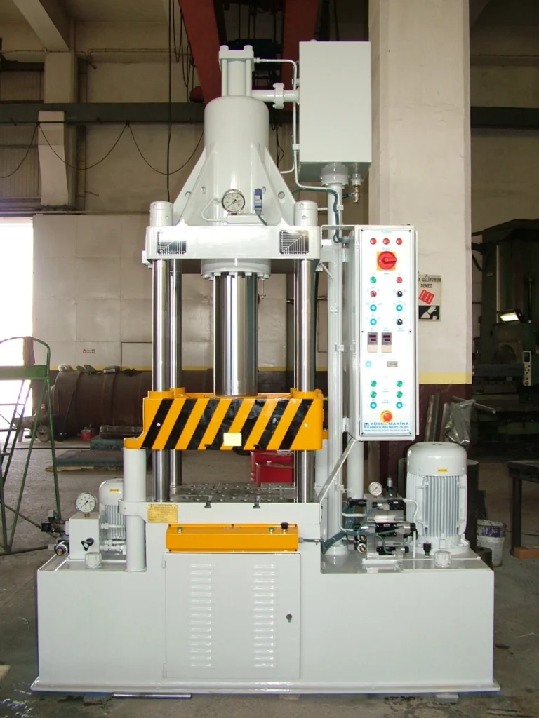
Triple-action hydraulic presses represent the pinnacle of precision, versatility, and control in metal forming technology. These advanced machines offer unparalleled force and flexibility, allowing manufacturers to create complex shapes and deep-drawn parts that are critical for industries such as automotive, aerospace, appliance manufacturing, and medical devices. This comprehensive guide delves into the workings, advantages, applications, and technological innovations of triple-action hydraulic presses, as well as their role in modern manufacturing.
Introduction to Triple-Action Hydraulic Presses
1.1 Overview of Hydraulic Presses
Hydraulic presses have revolutionized metal forming by offering high force, precision, and flexibility in the shaping of materials. The core concept behind hydraulic presses relies on Pascal’s Law, which states that pressure applied to a confined fluid is transmitted equally throughout the fluid. This allows for controlled force exertion on materials, making hydraulic presses essential for manufacturing applications such as stamping, deep drawing, and metal forming.
As metal forming demands have evolved, hydraulic presses have advanced from single-action presses, which apply force in one direction, to double-action and, most recently, triple-action presses. These enhancements provide greater control, higher precision, and the ability to handle more complex shapes and deeper drawing operations.
1.2 The Role of Triple-Action Hydraulic Presses in Modern Manufacturing
Triple-action hydraulic presses are a vital component in modern manufacturing due to their ability to handle highly complex parts with deep-drawing requirements. These presses are widely used in industries where high precision, complex shapes, and the capability to draw deep or large components are essential. Triple-action presses provide independent control over the punch, blank holder, and die cushion forces, ensuring that material flows smoothly and evenly into the die cavity.
The precision and versatility offered by triple-action hydraulic presses have made them indispensable in sectors such as automotive, aerospace, medical device manufacturing, and appliance production, where manufacturers rely on these machines to produce high-quality, durable components that meet stringent industry standards.
1.3 Distinction Between Single-, Double-, and Triple-Action Presses
- Single-Action Presses: These presses feature a single hydraulic cylinder that applies force in one direction, typically downward. While they are effective for shallow draws and simple part geometries, they lack the flexibility to handle deep or complex shapes.
- Double-Action Presses: Double-action presses have two hydraulic cylinders—one for the punch and one for the blank holder. This independent control of the blank holder allows for better management of material flow during deep drawing, reducing the risk of wrinkles or tearing.
- Triple-Action Presses: Triple-action presses add a third hydraulic cylinder to the system: the die cushion. The die cushion offers even greater control by applying upward force to the blank, supporting the material as it is drawn into the die. This level of control ensures smooth material flow, minimizing defects such as thinning, tearing, or wrinkling, making triple-action presses ideal for complex, high-precision forming operations.
Working Principles of Triple-Action Hydraulic Presses
2.1 Basic Hydraulic Systems
The fundamental operation of hydraulic presses is governed by the principles of hydraulics, primarily Pascal’s Law. Hydraulic fluid (usually oil) is pressurized by a pump and transmitted through hydraulic cylinders to generate significant mechanical force. This force is transferred to a punch, blank holder, and die, which shape the metal blank into the desired form.
In a triple-action press, this process is expanded by incorporating three separate hydraulic cylinders, each controlling a different aspect of the forming process:
- Punch Cylinder: This cylinder moves the punch downward, deforming the metal blank into the die.
- Blank Holder Cylinder: The second cylinder applies pressure to the blank holder, which holds the metal blank in place during the drawing process.
- Die Cushion Cylinder: The third cylinder, located beneath the die, applies upward force via the die cushion, providing support to the blank as it is drawn into the die.
2.2 Triple-Action Mechanism and Components
Triple-action hydraulic presses function by distributing force through three distinct cylinders, each contributing to the forming process in different ways:
- Punch Force: The punch applies the downward force that presses the metal blank into the die. This force must be carefully controlled to avoid excessive thinning or tearing of the material.
- Blank Holder Force: The blank holder clamps the edges of the blank, controlling the material’s flow into the die. Independent control of the blank holder allows manufacturers to prevent wrinkling or buckling in the material during deep drawing.
- Die Cushion Force: The die cushion applies upward pressure to support the material as it is drawn into the die. This cushion force helps distribute the stress evenly across the blank, ensuring that the material deforms smoothly without tearing or thinning excessively.
The triple-action mechanism is especially valuable for deep drawing, where the material must flow evenly into the die cavity without introducing defects. The independent control of the punch, blank holder, and die cushion allows for precise adjustments, optimizing the forming process for different materials and part geometries.
2.3 Force Distribution and Material Flow Control
A key advantage of triple-action hydraulic presses is their ability to provide precise control over the forces applied during the drawing process. Each cylinder can be individually regulated to manage the flow of material, minimizing the risk of defects. Here’s how force distribution works in triple-action presses:
- Punch Force is applied to deform the blank into the die, but it must be applied gradually and evenly to prevent tearing or cracking.
- Blank Holder Force ensures that the material doesn’t wrinkle as it is drawn, while still allowing enough material to flow into the die cavity.
- Die Cushion Force supports the material from below, providing a counterforce to the punch, which helps in controlling material thinning and ensures uniform wall thickness in deep-drawn parts.
By coordinating these forces, triple-action presses ensure that material flows smoothly into the die without defects, even for challenging parts that require deep draws or intricate shapes.
Key Components of Triple-Action Hydraulic Presses
3.1 Hydraulic Cylinders (Punch, Blank Holder, and Die Cushion)
Triple-action presses feature three primary hydraulic cylinders:
- Punch Cylinder: The punch cylinder is responsible for applying the downward force needed to shape the material. It is typically the most powerful of the three cylinders, generating enough force to deform even high-strength materials such as stainless steel or titanium.
- Blank Holder Cylinder: This cylinder controls the blank holder, which applies pressure to the outer edge of the blank to prevent wrinkling or buckling during the drawing process. The blank holder force is critical for ensuring the material flows smoothly into the die.
- Die Cushion Cylinder: The die cushion provides support from below the die, pushing the blank upwards as it is drawn into the die cavity. This force helps maintain uniform wall thickness and prevents excessive thinning of the material.
Each cylinder is independently controlled, allowing for precise adjustments during the forming process.
3.2 Press Frame and Structural Design
The frame of a triple-action hydraulic press must be designed to withstand the enormous forces generated during the forming process. Most triple-action presses use a closed-frame (H-frame) design, which provides greater structural integrity and stability. This design ensures that the press can handle high forces without flexing or bending, which is critical for maintaining precision and accuracy in deep drawing operations.
The frame is typically constructed from cast iron or welded steel, providing the necessary strength and durability for long-term use. The robust design also minimizes vibrations and ensures smooth operation, which is essential for producing high-quality parts.
3.3 Die, Punch, Blank Holder, and Die Cushion Setup
The setup of the die, punch, blank holder, and die cushion is one of the most important aspects of a triple-action hydraulic press. Each component must be precisely aligned to ensure that the material flows smoothly and evenly into the die.
- Die: The die defines the external shape of the part being formed. It is typically made from tool steel or carbide, materials that are capable of withstanding the high forces generated during the drawing process.
- Punch: The punch is the moving part of the press that pushes the blank into the die. It must be carefully designed to ensure that the material is deformed evenly without tearing or cracking.
- Blank Holder: The blank holder applies pressure to the outer edge of the blank, controlling the flow of material into the die. The blank holder force must be carefully calibrated to prevent wrinkling or buckling while still allowing the material to flow.
- Die Cushion: The die cushion applies upward force to support the material as it is drawn into the die. This force helps maintain uniform wall thickness and prevents excessive thinning of the material.
3.4 Control Systems and Hydraulic Pumps
Modern triple-action hydraulic presses are equipped with advanced control systems that allow operators to precisely adjust the forces applied by each cylinder. These control systems typically include programmable logic controllers (PLCs), which allow for the precise regulation of force, stroke length, and cycle times.
The hydraulic pumps used in triple-action presses are responsible for generating the pressure needed to move the pistons in the hydraulic cylinders. These pumps can be either fixed displacement or variable displacement, with variable displacement pumps providing greater energy efficiency by adjusting the amount of fluid delivered based on system demand.
By using servo-hydraulic systems, triple-action presses can further enhance precision and energy efficiency, allowing for real-time adjustments to the press’s operation based on feedback from sensors and control systems.
Materials Suitable for Triple-Action Hydraulic Presses
4.1 Aluminum and its Alloys
Aluminum is one of the most commonly used materials in deep drawing operations due to its high ductility and lightweight properties. Aluminum alloys are widely used in industries such as automotive and aerospace, where reducing weight is critical for improving fuel efficiency and performance. Triple-action hydraulic presses are ideal for forming aluminum parts, as the independent control of the punch, blank holder, and die cushion forces allows for precise material flow and minimizes the risk of defects.
Aluminum is commonly used in the production of automotive body panels, aircraft fuselages, and packaging materials such as beverage cans. The ability to achieve deep draws and complex shapes without wrinkling or tearing makes triple-action presses an excellent choice for forming aluminum parts.
4.2 Low-Carbon Steels
Low-carbon steels are commonly used in deep drawing operations due to their malleability and strength. These steels are widely used in the production of automotive parts, appliance housings, and general metal containers. The independent control of the blank holder force in triple-action presses allows for the smooth forming of low-carbon steel, reducing the risk of defects such as wrinkling or tearing.
Low-carbon steel is often used for parts that require a combination of strength and ductility, such as fuel tanks, chassis components, and body panels.
4.3 Stainless Steels
Stainless steel is used in applications where corrosion resistance is critical. While stainless steel is more difficult to form than low-carbon steel due to its higher strength and work hardening properties, the triple-action mechanism of these presses allows for better control over material flow. This prevents defects like tearing or wrinkling in the production of parts such as kitchen sinks, medical devices, and automotive exhaust systems.
Triple-action presses ensure that stainless steel parts are formed with the required precision, surface finish, and strength.
4.4 High-Strength Alloys and Superalloys
In industries like aerospace and defense, materials such as high-strength steels, titanium alloys, and superalloys are frequently used due to their exceptional strength and heat resistance. However, these materials are notoriously difficult to form due to their low ductility and tendency to work-harden during the forming process. Triple-action presses offer the necessary force and precision to shape these materials without causing defects.
The die cushion feature of triple-action presses is especially useful when working with high-strength alloys, as it allows for even force distribution and prevents excessive thinning of the material. This makes triple-action presses ideal for producing structural components for aircraft, spacecraft, and military vehicles.
4.5 Non-Ferrous Metals
Non-ferrous metals such as copper, brass, and nickel are used in industries that require materials with high electrical or thermal conductivity. These metals are relatively soft and easy to form, but still require precise control during deep drawing operations to ensure a smooth surface finish and consistent wall thickness.
Triple-action hydraulic presses are well-suited for forming non-ferrous metals, allowing manufacturers to produce electrical connectors, plumbing fixtures, and battery components with high precision.
The Triple-Action Press Operation Process
5.1 Blank Loading and Positioning
The deep drawing process in a triple-action hydraulic press begins with loading the metal blank onto the die. The blank is usually a flat, pre-cut piece of metal, which must be positioned carefully on the die to ensure accurate forming. In many presses, this loading process is automated using robotic arms or mechanical feeders, reducing manual labor and increasing production speed.
Alignment guides or locating pins are often used to ensure that the blank is centered on the die. Proper blank positioning is essential for achieving uniform material flow during the forming process.
5.2 Force Application: Punch, Blank Holder, and Die Cushion Interaction
Once the blank is positioned, the press begins to apply force through the punch, blank holder, and die cushion. The interaction between these three components is critical for ensuring that the material is deformed evenly and without defects.
- Blank Holder Force: The blank holder descends first, clamping the edges of the blank against the die. The force applied by the blank holder prevents the material from shifting or wrinkling during the drawing process. In a triple-action press, the blank holder force is independently controlled, allowing for precise adjustments based on the material and part geometry.
- Punch Force: After the blank is clamped in place, the punch descends, applying downward force to the center of the blank. This force deforms the material, pushing it into the die cavity and shaping it into the desired form. The punch force must be carefully controlled to avoid tearing or excessive thinning of the material.
- Die Cushion Force: The die cushion applies upward force to the blank, supporting it as it is drawn into the die. This upward force helps distribute the stress evenly across the material, ensuring that the walls of the part maintain a consistent thickness. The die cushion also prevents the material from thinning excessively during the drawing process.
The coordination of these forces is critical for producing high-quality parts with consistent dimensions and surface finishes.
5.3 Forming, Deep Drawing, and Shaping
The primary purpose of a triple-action hydraulic press is to shape the metal blank into a desired form through deep drawing or other metal forming processes. Deep drawing involves stretching the material into a die cavity to create parts with a high depth-to-diameter ratio, such as cups, containers, or automotive body panels.
As the punch forces the material into the die, the blank holder and die cushion work together to control the flow of material, ensuring that it deforms evenly without tearing or wrinkling. The precision of this process is critical for producing parts with complex shapes and deep draws.
In some cases, additional stages of forming may be required to achieve the final shape of the part. This may involve re-drawing the part in subsequent operations or using additional tooling to refine the shape and dimensions.
5.4 Ejecting and Finishing the Part
Once the forming process is complete, the finished part must be ejected from the die. In triple-action presses, this is typically done using automatic part ejectors or air blasts, which remove the part from the die without damaging it. The ejection process is carefully controlled to ensure that the part does not become stuck in the die or sustain damage during removal.
After ejection, the part may undergo additional finishing operations such as trimming, deburring, or polishing to remove excess material and improve the surface finish. These finishing steps are essential for ensuring that the part meets the required quality standards and dimensional tolerances.
Applications of Triple-Action Hydraulic Presses
6.1 Automotive Industry
The automotive industry relies heavily on triple-action hydraulic presses for the production of body panels, structural components, and engine parts. The ability to control material flow precisely is essential for achieving the complex shapes and deep draws required in modern automotive designs.
- Body Panels: Triple-action presses are used to produce doors, fenders, hoods, and trunk lids for vehicles. These parts often require deep draws and must meet stringent quality standards for dimensional accuracy, surface finish, and structural integrity.
- Chassis Components: Structural components such as frame rails and crossmembers are typically made from high-strength steel or aluminum and must withstand significant mechanical stresses. Triple-action presses provide the necessary force and control to form these parts without defects.
- Engine Parts: Engine components such as oil pans, valve covers, and exhaust systems are often produced using deep drawing techniques in triple-action presses. These parts must be capable of withstanding high temperatures and pressures, making precision forming essential.
6.2 Aerospace Components
The aerospace industry demands parts that are lightweight and high-strength, making triple-action hydraulic presses ideal for producing components such as fuselage panels, engine parts, and structural elements.
- Fuselage Panels: Triple-action presses are used to form the outer skins of aircraft fuselages, which must be both strong and lightweight. The precise control over material flow offered by triple-action presses ensures that these panels are formed without defects such as wrinkles or thinning.
- Engine Cowls and Covers: Engine cowls, which protect aircraft engines and reduce aerodynamic drag, are often produced using triple-action presses. These parts require complex shapes and must meet tight tolerances to ensure proper fit and function.
- Landing Gear Components: Components such as landing gear struts and wheel well covers are typically made from high-strength alloys such as titanium. Triple-action presses provide the force and control needed to form these parts without causing defects.
6.3 Appliances and Consumer Goods
Triple-action hydraulic presses are widely used in the production of appliances and consumer goods, where high precision and quality are essential for ensuring the functionality and aesthetic appeal of the final products.
- Refrigerator Panels: The outer panels of refrigerators, typically made from stainless steel or aluminum, are formed using triple-action presses. These panels must be precisely shaped to ensure proper fit and insulation.
- Washing Machine Drums: Triple-action presses are used to form washing machine drums, which require deep draws to achieve their cylindrical shape. The ability to control the blank holder and die cushion forces ensures that these parts are formed without wrinkles or thinning.
- Cookware: Triple-action presses are also used to form pots, pans, and other kitchen appliances that require smooth, consistent shapes and minimal surface defects.
6.4 Packaging Industry
In the packaging industry, triple-action presses are commonly used to produce metal cans and containers, particularly those that require deep drawing to achieve their final shape.
- Beverage Cans: Aluminum beverage cans are formed using triple-action presses, which ensure that the material flows smoothly into the die without wrinkling or tearing. The resulting cans are lightweight, durable, and have consistent wall thickness.
- Aerosol Cans: Aerosol cans, used for products such as deodorants and spray paints, require precise forming to ensure that they can withstand the internal pressure of the contents. Triple-action presses provide the necessary control to produce these cans without defects.
- Food Containers: Metal food containers, such as tin cans and aluminum trays, are often produced using triple-action presses. These containers must be strong enough to withstand the pressures of sealing and transportation, making precision forming essential.
6.5 Medical Devices and High-Precision Manufacturing
The medical device industry requires parts that are precise, biocompatible, and capable of withstanding sterilization processes. Triple-action presses are ideal for producing components such as surgical instruments, implantable devices, and diagnostic equipment, where high precision is critical for ensuring patient safety and device functionality.
- Surgical Instruments: Stainless steel surgical instruments, such as forceps, scalpels, and clamps, are often produced using triple-action presses. These parts must be precisely formed to ensure proper function during medical procedures.
- Implantable Devices: Devices such as hip implants, dental implants, and stents are typically made from titanium or stainless steel and require precision forming to ensure proper fit and biocompatibility.
- Diagnostic Equipment: Components for diagnostic equipment, such as MRI machines and X-ray machines, are often produced using deep drawing techniques in triple-action presses. These parts must meet strict tolerances for size and function, making precision forming essential.
Advantages and Challenges of Triple-Action Hydraulic Presses
7.1 Superior Control Over Material Flow
The primary advantage of triple-action hydraulic presses is their ability to exert independent control over the punch, blank holder, and die cushion forces. This allows manufacturers to precisely control the flow of material during deep drawing and forming processes, reducing the risk of defects such as wrinkling, tearing, or thinning.
The die cushion provides upward support to the material as it is drawn into the die, ensuring that the walls of the part maintain consistent thickness. This is particularly important in deep drawing operations, where excessive thinning can lead to weak or defective parts.
7.2 Capability to Handle Complex Shapes and Deep Draws
Triple-action hydraulic presses are specifically designed for handling complex shapes and deep draws. The independent control of the punch, blank holder, and die cushion forces allows for precise material flow, ensuring that the material deforms evenly without introducing defects.
This capability makes triple-action presses ideal for producing parts with high depth-to-diameter ratios, intricate geometries, or complex curves. The ability to handle deep draws is especially valuable in industries such as automotive and aerospace, where lightweight, high-strength components are essential for improving performance and fuel efficiency.
7.3 High Precision and Quality Assurance
Triple-action presses provide the precision needed to produce parts with tight tolerances and consistent quality. The independent control of the punch, blank holder, and die cushion forces allows operators to fine-tune the forming process for different materials and part geometries, ensuring that each part meets the required dimensional tolerances and surface finish standards.
This level of precision is essential in industries such as medical device manufacturing, where parts must meet stringent quality standards to ensure patient safety and device functionality.
7.4 Costs and Maintenance Requirements
While triple-action hydraulic presses offer significant advantages in terms of control, precision, and flexibility, they are also more complex and expensive than single- or double-action presses. The additional hydraulic cylinder for the die cushion adds to the overall cost of the machine, making triple-action presses a larger investment for manufacturers.
In addition to the higher initial cost, triple-action presses also require more maintenance due to their increased complexity. The additional hydraulic systems and control mechanisms must be regularly inspected and serviced to ensure that the press operates at peak efficiency.
Despite these challenges, the improved quality and precision offered by triple-action presses often make them a worthwhile investment for manufacturers who need to produce high-quality parts with complex shapes or deep draws.
7.5 Comparison with Single- and Double-Action Presses
Triple-action presses offer significantly greater control and flexibility than single- or double-action presses. While single-action presses apply force in only one direction and are suitable for shallow draws and simple shapes, double-action presses provide independent control of the blank holder and punch forces, allowing for more precise material flow during deep drawing operations.
However, triple-action presses go one step further by adding a die cushion, which provides upward support to the material during the forming process. This additional level of control is essential for handling deep draws and complex shapes, making triple-action presses the preferred choice for applications that require the highest levels of precision and quality.
Technical Specifications of Triple-Action Hydraulic Presses
8.1 Force Ratings and Stroke Length
Triple-action hydraulic presses are available in a wide range of force ratings, typically measured in tons. The force required for a given forming operation depends on factors such as the material thickness, material strength, and depth of the draw. Common force ratings for triple-action presses range from 200 tons to over 1,500 tons, with higher force capacities required for forming high-strength materials or deep-drawn parts.
The stroke length of a hydraulic press refers to the distance the punch travels during the forming process. Triple-action presses typically offer adjustable stroke lengths, allowing operators to customize the press’s operation based on the size and complexity of the part being formed. Longer stroke lengths are necessary for deep-drawn parts or parts with large depth-to-diameter ratios.
8.2 Operating Speeds and Cycle Times
The speed of a triple-action hydraulic press is an important factor in determining its productivity. Faster presses can complete more cycles per hour, increasing overall throughput. However, the speed of the press must be carefully controlled to avoid defects such as tearing, wrinkling, or excessive thinning of the material.
Many modern triple-action presses feature programmable controls that allow operators to adjust the speed of the press based on the material and part geometry. By optimizing the press speed for each specific application, manufacturers can improve productivity while maintaining high levels of quality.
8.3 Press Sizes and Configuration Options
Triple-action hydraulic presses come in a variety of sizes and configurations to suit different applications. The size of the press is typically determined by the size and complexity of the parts being formed, as well as the force capacity required for the specific material.
- Compact Presses: For smaller parts or lower-volume production, compact triple-action presses offer a space-saving solution without sacrificing performance.
- Large-Frame Presses: For large parts such as automotive body panels or aerospace fuselage components, large-frame triple-action presses provide the necessary force and stroke length to handle bigger blanks and deeper draws.
The choice of press size and configuration depends on the specific needs of the application, including the size of the parts, the material being formed, and the required production volume.
8.4 Safety Features and Operator Control Systems
Modern triple-action hydraulic presses are equipped with a variety of safety features to protect operators and prevent accidents. These features are essential for ensuring safe operation in high-force environments.
- Emergency Stop Buttons: Located on the control panel, these buttons allow operators to stop the press immediately in case of an emergency.
- Safety Light Curtains: These sensors detect when a person or object enters the press area and automatically stop the machine to prevent injury.
- Overload Protection: This system automatically shuts down the press if the applied force exceeds the press’s rated capacity, preventing damage to the machine and tooling.
Operator control systems are typically designed for ease of use and may include touchscreens, joysticks, or push buttons. Automated systems may also feature PLC controls that allow operators to program the press for specific operations, ensuring consistent results across multiple production cycles.
Tooling Design and Maintenance in Triple-Action Presses
9.1 Die and Punch Design Considerations
The die and punch are critical components in any deep drawing operation, as they determine the shape and quality of the final part. In a triple-action press, the die is a stationary mold that defines the external shape of the part, while the punch is the moving tool that presses the blank into the die to form the part.
Proper punch and die design is essential for ensuring that the material flows smoothly into the die without tearing, wrinkling, or thinning excessively. The clearance between the punch and die must be carefully calculated based on the material thickness and ductility to ensure that the part is formed correctly.
- Material Flow: The punch and die must be designed to facilitate smooth material flow into the die cavity, reducing the risk of defects.
- Surface Finish: The punch and die surfaces should be polished to minimize friction during the forming process, improving the surface finish of the final part.
9.2 Blank Holder and Die Cushion Tooling
The blank holder and die cushion are critical components in triple-action presses, as they control the material flow during the forming process. Proper design of the blank holder and die cushion tooling is essential for ensuring that the material deforms smoothly into the die without introducing defects.
- Blank Holder Force: The force applied by the blank holder must be carefully controlled to prevent wrinkling or tearing. In a triple-action press, the blank holder force is applied by a hydraulic cylinder, allowing for precise adjustments during the drawing process.
- Die Cushion Force: The die cushion provides upward support to the material as it is drawn into the die. This force must be carefully controlled to ensure that the material flows evenly into the die and that the walls of the part maintain a consistent thickness.
9.3 Tooling Materials and Wear Resistance
Tooling materials must be chosen to withstand the high forces involved in deep drawing without deforming or wearing out prematurely. Common materials for punches and dies include:
- Tool Steel: Tool steels are highly durable and resistant to wear, making them ideal for high-volume production.
- Carbide: Carbide tooling is even harder and more wear-resistant than tool steel, making it suitable for applications where the tooling will be subject to high stresses or abrasive materials.
Surface coatings such as titanium nitride (TiN) or diamond-like carbon (DLC) can be applied to the tooling to reduce wear and improve the surface finish of the final part.
9.4 Tooling Maintenance and Replacement Strategies
Tooling wear is a common issue in deep drawing operations, particularly in high-volume production environments. Over time, the punch and die can become worn or damaged, leading to defects in the final parts. To prevent this, regular inspection and maintenance of the tooling are essential.
- Tooling Inspection: Tooling should be inspected regularly for signs of wear, such as cracks, chipping, or deformation. Worn tooling can lead to defects in the final parts and should be repaired or replaced as necessary.
- Surface Reconditioning: Worn tooling can often be reconditioned by polishing or grinding the surface to restore its original shape and finish.
- Tooling Replacement: In cases where the tooling is too worn or damaged to be reconditioned, it may need to be replaced. Keeping a stock of spare dies and punches can help minimize downtime when tooling replacement is necessary.
By implementing a comprehensive tooling maintenance program, manufacturers can extend the life of their tooling and ensure consistent, high-quality results in deep drawing operations.
Optimizing Efficiency and Productivity in Triple-Action Press Operations
10.1 Minimizing Setup Times and Changeovers
One of the keys to maximizing the efficiency of triple-action hydraulic presses is minimizing setup times between production runs. Setup time includes activities such as changing the die, adjusting the press settings, and loading the blank into the press. Reducing setup time allows manufacturers to produce more parts in a given period, increasing overall productivity.
- Quick-Change Tooling: Quick-change tooling systems allow dies and punches to be swapped out quickly and easily, reducing the time required to prepare the press for a new production run.
- Preset Press Settings: Modern triple-action presses often feature programmable controls that allow operators to store and recall press settings for specific parts. This eliminates the need to manually adjust the press for each production run, reducing setup time and ensuring consistent results.
10.2 Automation, Robotic Integration, and Production Workflow
Automation can play a significant role in improving the efficiency of triple-action press operations. By automating tasks such as blank loading, part ejection, and press operation, manufacturers can reduce the time required for each production cycle and minimize the risk of human error.
- Robotic Arms: Robotic arms can be used to load blanks into the press and remove finished parts, reducing the need for manual labor and speeding up the production process.
- Automatic Part Ejectors: Mechanical or pneumatic ejectors can automatically remove finished parts from the die, reducing cycle time and improving overall throughput.
By integrating automation and robotic systems into the production workflow, manufacturers can increase the productivity of their triple-action presses while maintaining high levels of quality.
10.3 Energy Efficiency and Sustainable Practices
Energy efficiency is a growing concern in manufacturing, and hydraulic systems can be a significant source of energy consumption. Triple-action presses can be made more energy-efficient by using variable displacement pumps, which adjust the amount of hydraulic fluid delivered based on the system’s needs. This reduces energy consumption during periods of low demand and improves overall efficiency.
Other strategies for improving energy efficiency include:
- Servo-Hydraulic Systems: Servo motors can be used to control the hydraulic pump, providing precise control over the system’s pressure and reducing energy waste.
- Energy Recovery Systems: Some hydraulic systems are designed to capture and reuse energy generated during deceleration, further improving energy efficiency.
By implementing these energy-saving strategies, manufacturers can reduce the operating costs of their triple-action presses and minimize their environmental footprint.
10.4 Increasing Throughput While Ensuring Quality
Several factors can affect the throughput and cycle time of a triple-action hydraulic press, including:
- Material Type: Softer materials such as aluminum or copper can be drawn more quickly than harder materials such as stainless steel or high-strength alloys, reducing cycle time.
- Part Complexity: More complex parts may require longer cycle times to ensure that the material is properly formed without defects.
- Press Speed: The speed at which the press operates can have a significant impact on cycle time. While faster presses can produce more parts per hour, they may also increase the risk of defects if not properly controlled.
By optimizing these factors, manufacturers can maximize the productivity of their triple-action presses while maintaining high levels of quality.
Maintenance and Troubleshooting for Triple-Action Presses
11.1 Preventive Maintenance Practices
Preventive maintenance is essential for ensuring the long-term reliability and performance of triple-action hydraulic presses. By regularly inspecting and servicing the press, manufacturers can identify potential issues before they lead to costly breakdowns or production delays.
Key preventive maintenance tasks include:
- Checking Hydraulic Fluid Levels: Hydraulic fluid is the lifeblood of the press, and maintaining the proper fluid level is critical for ensuring smooth operation. Low fluid levels can lead to increased wear on the hydraulic system and reduced performance.
- Inspecting Hoses and Seals: Hydraulic hoses and seals can wear out over time, leading to fluid leaks and pressure loss. Regular inspection and replacement of worn hoses and seals can help prevent these issues.
- Lubricating Moving Parts: Proper lubrication of the press’s moving parts is essential for reducing friction and wear. Lubrication points should be checked regularly, and the appropriate type of lubricant should be applied according to the manufacturer’s recommendations.
- Inspecting Tooling: Dies, punches, and blank holders should be inspected regularly for signs of wear, such as cracks, chipping, or deformation. Worn tooling can lead to defects in the final parts and should be repaired or replaced as necessary.
By implementing a preventive maintenance program, manufacturers can reduce downtime, extend the life of their triple-action presses, and ensure consistent, high-quality results.
11.2 Common Issues and Solutions
Several common issues can arise in triple-action hydraulic presses, including:
- Wrinkling: Wrinkling occurs when excess material bunches up around the edges of the blank during the drawing process. This issue can often be resolved by adjusting the blank holder force or using a lubricant to reduce friction between the blank and the die.
- Tearing: Tearing occurs when the material is overstressed during the drawing process, leading to cracks or splits in the part. To prevent tearing, the press settings should be adjusted to reduce the force applied during the draw, and the blank size or material thickness may need to be modified.
- Thinning: Thinning occurs when the material is stretched too thin during the drawing process, leading to weak or defective parts. Thinning can be minimized by adjusting the press settings to control the flow of material into the die and ensuring that the tooling is properly designed for the part being formed.
By addressing these common issues through proper maintenance and adjustments to press settings, manufacturers can improve the quality of their parts and reduce the risk of defects.
11.3 Hydraulic System Inspection and Fluid Management
The hydraulic system is the heart of a triple-action press, and regular inspection is essential for ensuring that the system operates at peak performance. Common hydraulic system maintenance tasks include:
- Checking for Leaks: Fluid leaks can lead to reduced system pressure and poor press performance. Hoses, seals, and fittings should be inspected regularly for signs of leaks, and any damaged components should be replaced immediately.
- Testing System Pressure: Hydraulic pressure should be tested regularly to ensure that the system is operating within the specified range. Low pressure can lead to incomplete draws, while high pressure can cause damage to the press or tooling.
- Changing Hydraulic Fluid: Over time, hydraulic fluid can become contaminated with dirt, metal particles, or water, leading to reduced performance and increased wear on the hydraulic system. Regular fluid changes are essential for maintaining system efficiency and extending the life of the press.
By maintaining the hydraulic system properly, manufacturers can ensure that their triple-action presses operate efficiently and reliably.
11.4 Extending the Lifespan of Triple-Action Presses
With proper maintenance and care, triple-action hydraulic presses can provide many years of reliable service. To extend the lifespan of the press, manufacturers should follow these best practices:
- Perform Regular Preventive Maintenance: Regular inspection and maintenance of the hydraulic system, tooling, and press structure can help prevent costly breakdowns and extend the life of the machine.
- Use High-Quality Hydraulic Fluid: Using the recommended type and grade of hydraulic fluid can help reduce wear on the system and improve overall performance.
- Train Operators: Proper training is essential for ensuring that operators know how to use the press correctly and safely. Training should cover topics such as press operation, maintenance, and troubleshooting.
- Keep a Stock of Spare Parts: Having spare parts on hand, such as hydraulic seals, hoses, and tooling components, can help minimize downtime when repairs or replacements are needed.
By following these best practices, manufacturers can ensure that their triple-action presses remain in good working condition for many years, reducing the need for costly repairs and replacements.
Safety Protocols and Industry Standards
12.1 Key Safety Features in Triple-Action Presses
Triple-action hydraulic presses are powerful machines that can pose significant safety risks if not operated correctly. Ensuring operator safety is a critical consideration in press operations, as the high forces involved in deep drawing can lead to serious injuries if proper precautions are not taken.
Modern triple-action presses are equipped with a variety of safety features designed to protect operators and prevent accidents, including:
- Emergency Stop Buttons: These buttons allow operators to stop the press immediately in case of an emergency.
- Safety Light Curtains: These sensors detect when a person or object enters the press area and automatically stop the machine to prevent injury.
- Overload Protection: This system automatically shuts down the press if the applied force exceeds the press’s rated capacity, preventing damage to the machine and tooling.
12.2 Operator Training and Best Practices
Operator training is one of the most important steps in ensuring the safe operation of triple-action hydraulic presses. Training should cover topics such as:
- Basic Press Operation: Operators should be familiar with the press’s controls, settings, and operation procedures.
- Safety Features: Operators should be trained to use the press’s safety features, such as emergency stop buttons and safety light curtains.
- Proper Handling of Materials: Operators should know how to safely load and unload blanks, as well as how to position the material correctly in the die to avoid off-center draws.
- Personal Protective Equipment (PPE): Operators should be required to wear appropriate PPE, such as safety glasses, gloves, and hearing protection, while operating the press.
By providing operators with the necessary training and ensuring that they follow safety best practices, manufacturers can reduce the risk of accidents and ensure a safe working environment.
12.3 Compliance with Industry Regulations and Safety Standards
Hydraulic presses must comply with industry standards and regulations to ensure operator safety. These standards are set by organizations such as OSHA (Occupational Safety and Health Administration) and ISO (International Organization for Standardization), and they cover areas such as machine guarding, operator training, and emergency stop protocols.
Manufacturers should regularly review their press operations to ensure compliance with these standards and make any necessary adjustments to improve safety.
12.4 Best Practices for Ensuring Safe Operations
To ensure the safe operation of triple-action hydraulic presses, manufacturers should follow these best practices:
- Conduct Regular Safety Inspections: The press should be regularly inspected to ensure that all safety features are functioning properly and that there are no hazards that could pose a risk to operators.
- Implement a Lockout/Tagout System: A lockout/tagout (LOTO) system should be implemented to ensure that the press is not accidentally activated while maintenance or repairs are being performed.
- Provide Ongoing Training: Operators should receive ongoing training to ensure that they are up to date on the latest safety procedures and best practices for operating the press.
By following these safety protocols and best practices, manufacturers can ensure that their triple-action hydraulic presses are operated safely and efficiently, reducing the risk of accidents and injuries.
Innovations and Future Trends in Triple-Action Hydraulic Presses
13.1 Servo-Hydraulic Systems and Digital Control Integration
One of the most significant trends in the development of triple-action hydraulic presses is the integration of servo-hydraulic technology. Servo-hydraulic systems use servo motors to control the movement of the hydraulic pump, providing precise control over the press’s operation and improving energy efficiency.
- Improved Precision: Servo-hydraulic systems allow for more precise control over the press’s speed, force, and position, making them ideal for high-precision applications where tight tolerances are required.
- Energy Savings: Unlike traditional hydraulic systems, which run continuously even when the press is not in use, servo-hydraulic systems only consume energy when the press is actively performing work. This results in significant energy savings and reduces the overall environmental impact of the press.
Servo-hydraulic systems are becoming increasingly popular in industries such as automotive, aerospace, and medical devices, where precision and energy efficiency are critical factors in the manufacturing process.
13.2 Advanced Tooling Materials and Smart Manufacturing
As manufacturing continues to evolve, there is growing interest in the use of advanced tooling materials and smart manufacturing technologies in triple-action press operations. Advanced tooling materials, such as ceramics, carbides, and coated metals, offer improved wear resistance, reducing the frequency of tooling replacement and improving overall press efficiency.
Smart manufacturing technologies, such as sensors and data analytics, are also playing an increasingly important role in triple-action press operations. By integrating sensors into the press, manufacturers can collect real-time data on factors such as force, pressure, and temperature, allowing for more precise control over the forming process.
13.3 Predictive Maintenance and Industry 4.0 Integration
Predictive maintenance is a key trend in the future of triple-action hydraulic presses. By collecting data on the press’s performance and analyzing it using machine learning algorithms, manufacturers can predict when components are likely to fail and schedule maintenance before a breakdown occurs. This helps reduce downtime and ensures that the press operates at peak efficiency.
The integration of triple-action presses into Industry 4.0 environments is also becoming more common. Industry 4.0 refers to the trend of automation, digitalization, and data exchange in manufacturing, where machines are connected to each other and to centralized control systems to improve efficiency and productivity.
By integrating triple-action presses into Industry 4.0 platforms, manufacturers can optimize their production processes, reduce downtime, and improve the overall quality of their products.
13.4 Sustainable Hydraulic Fluids and Energy-Efficient Systems
As manufacturers become more focused on sustainability, there is growing interest in the use of biodegradable hydraulic fluids and energy-efficient systems in triple-action press operations. Biodegradable fluids offer a more environmentally friendly alternative to traditional petroleum-based hydraulic fluids, reducing the environmental impact of fluid leaks or spills.
In addition to sustainable fluids, there is also ongoing research into energy-efficient hydraulic systems that use variable displacement pumps and servo-hydraulic technology to reduce energy consumption.
As energy costs continue to rise and environmental regulations become more stringent, manufacturers will need to prioritize energy efficiency and sustainability in their press operations.
Case Studies: Real-World Applications
14.1 Automotive Body Panels and Structural Components
A leading automotive manufacturer used triple-action hydraulic presses to produce body panels for a new vehicle model. The press was selected for its ability to provide consistent force and precision, ensuring that each part met the company’s high standards for quality and fit.
By integrating the triple-action press into an automated production line, the manufacturer was able to achieve high-volume production with minimal downtime. The press’s programmable controls allowed operators to store and recall settings for each part, reducing setup time between production runs and ensuring consistent results.
14.2 Aerospace Engine Components and Fuselage Panels
In the aerospace industry, a major aircraft manufacturer used triple-action hydraulic presses to form engine components and fuselage panels from titanium and aluminum alloys. The press was selected for its ability to handle deep draws and complex shapes while maintaining tight tolerances and high-quality surface finishes.
The manufacturer implemented a preventive maintenance program to ensure that the press operated at peak efficiency, reducing downtime and extending the life of the machine. By regularly inspecting and replacing worn tooling, the company was able to maintain consistent product quality and minimize the risk of defects.
14.3 Appliance Manufacturing and Large-Scale Press Forming
A major manufacturer of appliances, including washing machines and refrigerators, used triple-action hydraulic presses to form the outer shells of their products. These presses were chosen for their ability to produce smooth, defect-free surfaces that met the company’s aesthetic and durability requirements.
By implementing a preventive maintenance program and regularly inspecting the press’s hydraulic system, the manufacturer was able to reduce downtime and improve the overall efficiency of the production line.
14.4 Precision Medical Devices and Instrumentation
In the medical device industry, a supplier of precision surgical instruments and implantable devices used triple-action hydraulic presses to produce parts from stainless steel and titanium. The company worked closely with a tooling supplier to design custom dies and punches that met the specific requirements of the parts being produced.
By using custom tooling and adjusting the press settings for each production run, the company was able to produce parts with tight tolerances and smooth surface finishes, ensuring that the parts met the stringent quality standards of the medical device industry.
Conclusion: The Role of Triple-Action Hydraulic Presses in the Future of Manufacturing
Triple-action hydraulic presses represent a key technological advancement in the field of metal forming, offering a combination of precision, flexibility, and control that makes them indispensable in industries such as automotive, aerospace, appliances, and medical devices.
The key advantage of triple-action presses lies in their ability to independently control the punch, blank holder, and die cushion forces, allowing for precise material flow and reducing the risk of defects such as wrinkling, tearing, or thinning. This level of control makes triple-action presses ideal for producing complex shapes, deep-drawn parts, and components with high depth-to-diameter ratios.
As manufacturing continues to evolve, triple-action presses are becoming more energy-efficient and integrated with automation, improving productivity and reducing operating costs. The integration of servo-hydraulic systems, digital monitoring, and predictive maintenance is further enhancing the performance of these presses, making them a valuable investment for manufacturers looking to stay competitive in a rapidly changing industry.
In the future, triple-action hydraulic presses will continue to play a critical role in the production of high-quality, precision components across a wide range of industries. By embracing new technologies and innovations, manufacturers can ensure that their press operations remain efficient, sustainable, and capable of meeting the evolving demands of modern manufacturing.
Introduction to Specialized Hydraulic Presses
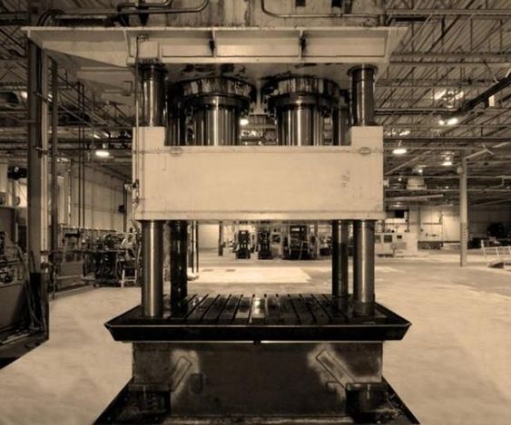
A hydraulic press is a mechanical device that uses a hydraulic cylinder to generate compressive force, transforming energy from hydraulic fluid into mechanical work. Hydraulic presses are an essential part of modern industrial manufacturing, offering precision and the capability to generate immense force. While general-purpose hydraulic presses are versatile and used in a wide range of industries, specialized hydraulic presses are designed for specific tasks, providing enhanced efficiency, precision, and performance for specialized applications.
1.1. What Makes a Hydraulic Press “Specialized”?
A hydraulic press becomes specialized when its design and functionality are tailored to a particular industrial task. These presses often feature unique configurations, custom components, or advanced control systems that allow them to perform specific tasks more effectively than standard presses. Specialized presses are used in industries such as automotive manufacturing, aerospace, medical device production, metalworking, and electronics, where the need for precision, speed, or high force is critical.
- Specialized tasks: While general-purpose presses can handle a variety of tasks, specialized presses are built to handle more complex operations such as deep drawing, isostatic pressing, metal forging, stamping, and transfer pressing. Each of these tasks requires specific pressure, stroke control, and precision that a standard press may not be able to deliver effectively.
- Customization: Specialized hydraulic presses often incorporate custom-built components such as specific dies, transfer mechanisms, or servo-controlled systems, making them suitable for precise manufacturing processes. These presses can also be designed with unique frame configurations, such as H-frame, C-frame, or four-column designs, each optimized for specific operational needs.
1.2. Importance of Specialized Hydraulic Presses in Industry
The increasing complexity of modern manufacturing processes, along with the demand for higher-quality products, has driven the need for specialized hydraulic presses. These machines not only improve the quality of finished products but also enhance productivity by reducing cycle times and increasing automation. Their ability to generate and control immense force with precision allows industries to achieve more complex and refined results than ever before.
- Automotive industry: Specialized hydraulic presses are critical in the automotive sector, where they are used to form body panels, chassis components, and internal engine parts. Presses such as deep drawing presses and forging presses enable the production of high-strength parts that meet safety and performance standards.
- Aerospace industry: In aerospace manufacturing, isostatic hydraulic presses are used to create high-strength, lightweight components like turbine blades and structural parts. These presses provide the precision needed to meet the stringent safety and durability requirements of the aerospace sector.
- Medical device manufacturing: The medical device industry relies on specialized presses to produce intricate components such as surgical instruments, implants, and diagnostic devices. The high precision and force control offered by these presses ensure that even the smallest tolerances are met.
1.3. How Specialized Presses Differ from Standard Hydraulic Presses
While both standard and specialized hydraulic presses operate on the same basic principle of using hydraulic pressure to generate force, the key difference lies in their design, control systems, and intended applications.
- Design differences: Specialized hydraulic presses often feature more robust or complex designs to handle specific tasks. For example, four-column hydraulic presses are designed to provide even pressure distribution for large or irregularly shaped workpieces, while C-frame presses are designed for easy access to the work area in small part production.
- Control systems: Specialized presses typically use advanced control systems, such as servo-hydraulic systems or CNC controls, to provide greater precision and automation. These control systems allow operators to adjust pressure, stroke length, and speed with high accuracy, which is essential in tasks that require exact force application.
- Application focus: While a general-purpose hydraulic press may be suitable for a wide variety of tasks, specialized presses are built to excel at specific operations. This specialization results in higher productivity, better quality, and lower error rates for those particular tasks.
Deep Drawing Presses
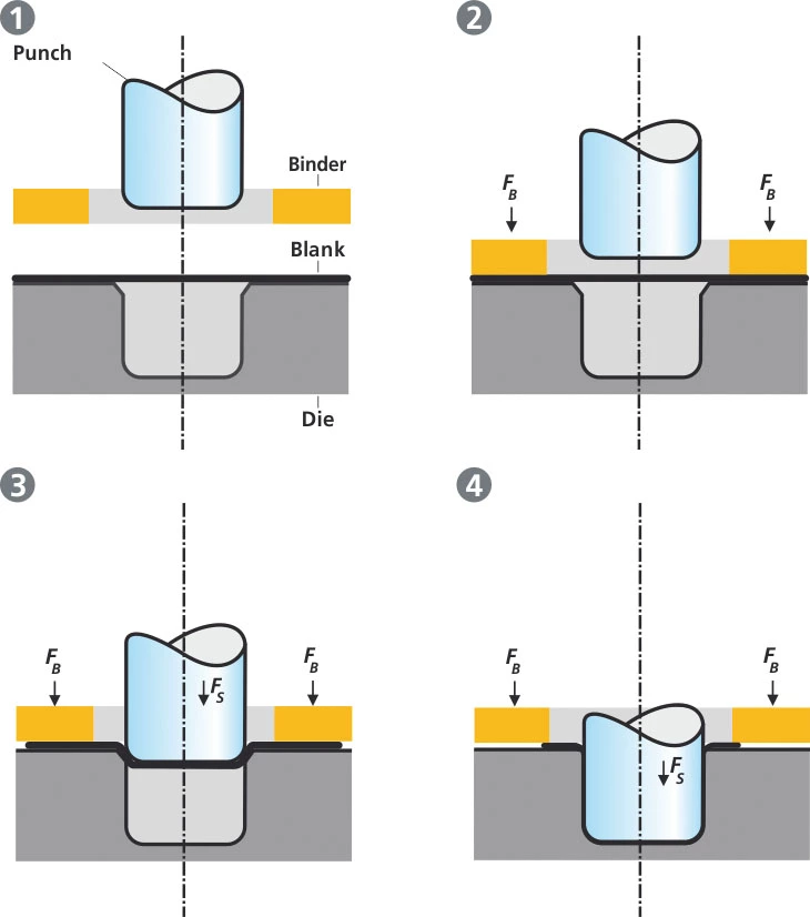
Deep drawing presses are a specialized type of hydraulic press used primarily for shaping metal sheets into deep, hollow shapes without compromising the integrity of the material. This process is commonly employed in the automotive, aerospace, packaging, and appliance industries to form components such as fuel tanks, kitchen sinks, and metal housings. The ability to create complex, seamless shapes from a single sheet of metal with minimal material wastage makes deep drawing presses essential for mass production applications.
2.1. Definition and Working Principle of Deep Drawing
Deep drawing is a metal forming process in which a flat sheet of metal (known as a blank) is gradually transformed into a deep, hollow shape through the application of pressure. During the deep drawing process, a punch pushes the metal sheet into a die cavity, stretching and compressing the material to form a desired shape. The term “deep” refers to the fact that the depth of the drawn part is greater than its diameter.
- Key components of a deep drawing press:
- Punch: The punch is the tool that applies pressure to the metal sheet and forces it into the die.
- Die: The die provides the cavity into which the metal is drawn to take the desired shape.
- Blank holder: This component holds the metal blank in place to prevent wrinkling and ensure uniform deformation.
- Hydraulic cylinder: The hydraulic system applies controlled force to the punch, enabling precise and consistent drawing.
The process begins with a metal blank being placed over the die. As the hydraulic press drives the punch downward, the metal sheet is forced into the die cavity, where it undergoes plastic deformation. The blank holder applies pressure to prevent the sheet from moving sideways or wrinkling as it is drawn into the die.
Stages of Deep Drawing
The deep drawing process can be broken down into several stages:
- Initial contact: The punch makes initial contact with the metal blank.
- Forming: The punch gradually pushes the blank into the die, causing the material to stretch and form around the punch.
- Final shaping: The material conforms to the shape of the die as the punch reaches the bottom of the stroke.
- Ejection: Once the desired shape is achieved, the punch is retracted, and the finished part is ejected from the die.
In more complex operations, multi-draw deep drawing presses may be used, which involve multiple stages of drawing to achieve deeper shapes or more intricate designs.
2.2. Design Characteristics of Deep Drawing Presses
Deep drawing presses are designed to handle the high forces and precise control needed for metal forming. Key design features include large hydraulic cylinders, robust frames, and advanced control systems to ensure accurate force application and material deformation.
- Frame design: Most deep drawing presses use an H-frame or four-column frame design to provide the structural support needed for high-force applications. These frames ensure that the force is evenly distributed across the die and blank, preventing misalignment or material deformation.
- Hydraulic system: Deep drawing presses use hydraulic cylinders to apply precise, consistent pressure during the drawing process. The hydraulic system allows operators to adjust the speed, force, and stroke length of the press, providing greater control over the depth and shape of the final product.
- Blank holders and force management: The blank holder plays a crucial role in maintaining the integrity of the material as it is drawn into the die. By applying controlled pressure to the blank, the holder prevents wrinkling or tearing, ensuring uniform deformation and a smooth final product.
Advanced deep drawing presses are often equipped with servo-hydraulic systems or CNC controls that provide automated control over the drawing process. These systems allow operators to program the press for specific tasks, adjust parameters such as pressure and stroke length, and monitor the process in real-time.
2.3. Applications of Deep Drawing Presses
Deep drawing presses are used in industries that require the production of deep, seamless, and hollow components from metal sheets. The process is widely employed in sectors such as automotive, aerospace, packaging, and appliances.
2.3.1. Automotive Industry
One of the largest users of deep drawing presses is the automotive industry, where they are employed to produce a variety of critical components. These include:
- Body panels: Car body panels such as doors, hoods, and fenders are often produced using deep drawing presses. The process ensures that these panels have smooth, uniform surfaces without joints or seams.
- Fuel tanks: Automotive fuel tanks are deep, hollow structures that are typically formed using deep drawing presses. The seamless nature of the deep drawing process helps prevent leaks and ensures the structural integrity of the tank.
- Chassis components: Various chassis components, including cross members and support structures, are manufactured using deep drawing presses for their strength and durability.
2.3.2. Aerospace Industry
In the aerospace sector, deep drawing presses are used to manufacture lightweight, high-strength components for aircraft and spacecraft. Some common applications include:
- Turbine engine components: Certain parts of turbine engines are made using deep drawing presses to create thin-walled, hollow structures that must withstand extreme temperatures and pressure.
- Structural components: Aircraft fuselages, frames, and bulkheads are formed using deep drawing processes to ensure they are lightweight and resistant to mechanical stress.
2.3.3. Packaging Industry
Deep drawing presses are commonly used in the packaging industry to manufacture metal cans, containers, and aluminum trays. This process allows for the mass production of seamless containers that are lightweight, durable, and cost-effective. Some common products include:
- Beverage cans: Aluminum cans for soda and beer are produced using deep drawing presses, ensuring a seamless design that holds pressure and maintains product integrity.
- Food containers: Metal food containers, such as those used for canned goods, are also made using deep drawing, allowing for rapid production of strong, lightweight containers.
2.3.4. Appliance Manufacturing
The appliance industry uses deep drawing presses to produce components such as:
- Sinks: Kitchen sinks, especially stainless steel varieties, are typically made using deep drawing presses. The process ensures that the sink has a smooth, seamless finish and is durable enough for everyday use.
- Cookware: Pots, pans, and other metal cookware are often produced using deep drawing processes, ensuring uniform shapes and smooth surfaces.
2.4. Advantages of Deep Drawing Presses
Deep drawing presses offer several key advantages over other metal forming processes, particularly in industries where high precision, large-scale production, and material efficiency are critical.
- High precision and repeatability: Deep drawing presses are capable of producing parts with high precision, ensuring that each component is consistent in terms of dimensions and quality. This is particularly important in industries such as automotive and aerospace, where tight tolerances are required.
- Minimal material waste: Deep drawing uses the initial metal blank efficiently, minimizing material wastage. This reduces production costs, especially when working with expensive metals like aluminum or stainless steel.
- Complex, seamless shapes: The ability to form deep, hollow, and complex shapes from a single metal sheet without the need for welding or additional assembly is one of the primary advantages of deep drawing presses. This results in stronger, more durable components.
- High-volume production: Deep drawing presses are ideal for high-volume production runs, offering faster cycle times and the ability to produce large quantities of parts in a short period.
2.5. Technological Advancements in Deep Drawing Presses
Over the years, significant advancements have been made in the technology used in deep drawing presses, improving their efficiency, precision, and ease of use. Some of the key innovations include:
- Servo-hydraulic systems: These systems combine hydraulic power with servo control, allowing for more precise force and speed control. This results in greater accuracy and reduced material waste.
- CNC controls: Computer Numerical Control (CNC) systems have been integrated into deep drawing presses, enabling fully automated operation. Operators can program the press for specific tasks, adjust parameters remotely, and monitor the entire process in real-time.
- Intelligent monitoring systems: Modern deep drawing presses often come equipped with sensors and real-time monitoring systems that track factors such as pressure, temperature, and material deformation. These systems allow operators to detect potential issues early and optimize the press for peak performance.
Isostatic Presses
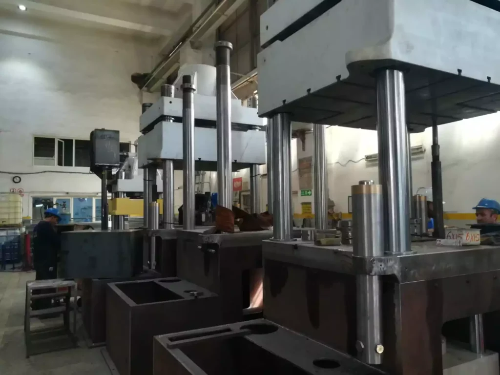
Isostatic presses are specialized hydraulic presses used to form materials under uniform pressure from all directions, ensuring that the material being pressed is evenly compressed. This technique is primarily employed in industries that require high-density, complex parts with excellent structural integrity, such as powder metallurgy, advanced ceramics, and the aerospace and medical device industries. Isostatic presses are particularly useful when working with materials that are difficult to shape through traditional pressing methods or that require precise control over porosity and density.
3.1. Working Principle of Isostatic Pressing
The key principle of isostatic pressing is the application of equal pressure from all directions on the material being formed. Unlike traditional hydraulic presses, which apply force from a single direction, isostatic presses use a fluid medium to transmit pressure uniformly across the material. This approach allows for consistent compression and ensures that the final product has uniform density and minimal internal stresses or defects.
The process can be categorized into two main types: Cold Isostatic Pressing (CIP) and Hot Isostatic Pressing (HIP). Both methods rely on similar principles but differ in terms of operating temperature and the type of material being processed.
3.1.1. Cold Isostatic Pressing (CIP)
In Cold Isostatic Pressing, the material being formed (typically a powdered metal or ceramic) is placed inside a flexible mold made of rubber or elastomer. This mold is then submerged in a pressure vessel filled with a liquid, such as water or oil. Hydraulic pumps are used to pressurize the fluid, which in turn applies uniform pressure to the mold, compressing the material from all sides.
- Working temperature: As the name suggests, cold isostatic pressing is carried out at room temperature. The primary purpose of CIP is to compact powders before sintering or further processing.
- Pressure range: The pressure applied in CIP typically ranges from 20,000 to 100,000 PSI (pounds per square inch), depending on the material and the desired density.
Once the material has been sufficiently compressed, it is removed from the mold and subjected to sintering (a heat treatment process) to solidify the material and achieve the final desired properties.
3.1.2. Hot Isostatic Pressing (HIP)
Hot Isostatic Pressing differs from CIP in that it combines the application of pressure with high temperatures. This method is used to both compact and sinter the material simultaneously, resulting in denser, more homogeneous parts with improved mechanical properties.
- Working temperature: In HIP, the material is placed inside a rigid mold or capsule, typically made of metal. The pressure vessel is filled with an inert gas, such as argon, which is then heated to temperatures ranging from 500°C to over 2000°C (930°F to 3600°F). The high temperature helps in sintering the material while the pressure consolidates it, eliminating porosity and improving density.
- Pressure range: HIP typically operates at pressures between 10,000 and 30,000 PSI, which is lower than CIP, but the combined effect of heat and pressure enables the material to achieve full densification.
HIP is commonly used to strengthen and densify metals, ceramics, and composites that require exceptional mechanical properties, such as those used in the aerospace and medical industries.
3.2. Key Components of Isostatic Presses
Isostatic presses have several essential components that enable them to apply uniform pressure to the material being formed. These components are critical for maintaining consistency and ensuring that the material is shaped and compressed evenly.
- Pressure vessel: The pressure vessel is the container in which the pressing takes place. It is designed to withstand extremely high pressures and, in the case of HIP, high temperatures as well. The vessel is filled with a fluid (in CIP) or gas (in HIP) that transmits the pressure uniformly.
- Mold or capsule: In CIP, the material is placed inside a flexible mold made of rubber or elastomer. In HIP, a rigid metal capsule is used to contain the material, which ensures that it holds its shape during the pressing and sintering process.
- Hydraulic system: The hydraulic system in an isostatic press is responsible for pressurizing the fluid or gas within the pressure vessel. In CIP, water or oil is used as the pressure-transmitting medium, while in HIP, an inert gas such as argon is used.
- Temperature control (for HIP): In hot isostatic presses, the pressure vessel is equipped with heating elements and temperature control systems to maintain the desired operating temperature during the pressing and sintering process.
3.3. Applications of Isostatic Presses
Isostatic presses are used in industries where material density and structural integrity are critical. The uniform pressure applied during isostatic pressing makes these machines ideal for applications that require the formation of complex shapes with minimal porosity.
3.3.1. Powder Metallurgy
One of the primary applications of isostatic presses is in powder metallurgy, where powdered metals are compressed into dense, high-strength parts. This process is used to produce components for various industries, including automotive, aerospace, and machinery manufacturing.
- High-performance parts: Parts produced using isostatic pressing often exhibit superior mechanical properties compared to those made with traditional pressing techniques. The uniform pressure ensures that the powder particles are densely packed, resulting in a stronger final product with fewer defects.
- Complex shapes: Isostatic presses allow manufacturers to create complex shapes that would be difficult or impossible to achieve with traditional forging or casting methods. This is particularly useful in producing components such as gears, bearings, and engine parts.
3.3.2. Advanced Ceramics
Advanced ceramics are used in industries ranging from electronics to aerospace, and isostatic pressing is an essential process for forming high-performance ceramic components.
- Electronics: Ceramic substrates used in electronic circuits must have excellent thermal and electrical properties, and isostatic pressing ensures that these components are produced with high density and uniformity.
- Aerospace and defense: In aerospace, isostatic presses are used to produce ceramic components that can withstand extreme temperatures and mechanical stress, such as heat shields and engine components.
3.3.3. Aerospace and Medical Applications
In the aerospace and medical industries, isostatic pressing is used to manufacture parts that require high strength, durability, and precision.
- Turbine blades: Hot isostatic pressing is used to densify turbine blades made from superalloys, ensuring they can withstand the extreme heat and pressure experienced in aircraft engines.
- Medical implants: The production of medical implants, such as hip and knee replacements, relies on isostatic pressing to form high-density metal parts that meet stringent biocompatibility and durability standards.
3.4. Advantages of Isostatic Presses
Isostatic presses offer several advantages over traditional pressing methods, particularly in industries that require precision and high material density.
- Uniform pressure distribution: The primary advantage of isostatic pressing is the uniform application of pressure from all directions. This ensures that the material is evenly compressed, resulting in higher density and fewer internal defects.
- Ability to form complex shapes: Isostatic presses are ideal for creating intricate, detailed parts that would be challenging to form using conventional methods. The flexible molds used in CIP allow for greater design flexibility, while HIP’s ability to combine heat and pressure enables the production of fully dense, sintered parts.
- Improved material properties: Parts produced using isostatic presses often exhibit superior mechanical properties, such as increased strength, hardness, and durability. This is particularly important in industries where parts are subjected to extreme conditions, such as aerospace and medical applications.
3.5. Industry Innovations in Isostatic Pressing
Recent advancements in isostatic pressing technology have further improved the efficiency and precision of these machines. Some of the most notable innovations include:
- 3D printed molds: Additive manufacturing technologies, such as 3D printing, are now being used to create molds for isostatic pressing. These custom molds allow manufacturers to produce complex, one-of-a-kind parts with greater accuracy and faster turnaround times.
- AI-driven process optimization: The integration of Artificial Intelligence (AI) and machine learning into isostatic pressing systems has enabled real-time monitoring and optimization of the pressing process. These technologies help identify potential defects early in the process and automatically adjust parameters to ensure consistent quality.
Transfer Hydraulic Presses
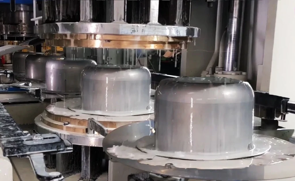
Transfer hydraulic presses are specialized machines designed for high-volume, multi-step production processes where multiple operations can be performed in sequence on a single part. These presses are commonly used in industries that require complex forming, stamping, or assembly tasks, particularly in large-scale manufacturing environments such as the automotive, appliance, and electrical component industries. The defining characteristic of a transfer hydraulic press is its ability to move parts from one station to the next automatically, reducing manual labor and increasing productivity.
4.1. Working Principle of Transfer Hydraulic Presses
The main advantage of a transfer hydraulic press is its ability to perform multiple operations in a single production cycle by moving the part between different workstations automatically. This functionality is achieved using an integrated transfer mechanism that picks up the part after each operation and moves it to the next station.
Stages of Operation in a Transfer Press
- Feeding and positioning: Raw material or partially formed parts are fed into the press, either manually or using automated feeders. The part is positioned at the first station, where the initial operation (such as cutting or forming) is performed.
- First operation: The press applies hydraulic pressure to the material, performing the first operation, such as stamping, drawing, or punching. Once this step is complete, the transfer mechanism takes over.
- Transfer to the next station: The part is picked up by a transfer arm or gripper and moved to the next station, where a secondary operation is performed. This could involve further shaping, bending, trimming, or assembly.
- Final operation and ejection: After all the required operations have been completed at the various stations, the finished part is ejected from the press. Depending on the complexity of the part, it may undergo several stages of transformation before reaching its final form.
The ability to carry out multiple operations without requiring the operator to intervene at each step significantly increases the efficiency and speed of the production process. The transfer system ensures that parts move seamlessly from one station to another, allowing for high-volume production with minimal downtime between operations.
4.2. Components of a Transfer Hydraulic Press
Transfer hydraulic presses are more complex than standard hydraulic presses, as they include additional mechanisms to facilitate the automatic movement of parts between workstations. The key components of a transfer hydraulic press include:
- Transfer mechanism: The transfer mechanism is a key feature that distinguishes transfer presses from other types of hydraulic presses. It is responsible for moving the part between stations during the production cycle. This mechanism can be a robotic arm, a gripper system, or a set of automated rails that lift and transfer the part without damaging it.
- Die sets and tooling: Transfer presses often use multiple die sets, each designed for a specific operation, such as cutting, bending, forming, or assembly. These die sets are positioned at different stations within the press, allowing for multiple processes to be carried out in sequence.
- Hydraulic system: As with all hydraulic presses, the hydraulic system provides the force needed to perform the various operations. In transfer presses, the hydraulic system must be precisely controlled to ensure that each operation is carried out with the correct amount of force and speed.
- Control systems: Transfer presses rely on advanced control systems, often equipped with Programmable Logic Controllers (PLCs) or Computer Numerical Control (CNC) systems. These systems coordinate the movements of the transfer mechanism, control the hydraulic pressure applied at each station, and monitor the overall operation of the press.
4.3. Applications of Transfer Hydraulic Presses
Transfer hydraulic presses are ideal for mass production environments where large quantities of parts need to be processed quickly and accurately. Some common applications of transfer presses include:
4.3.1. Automotive Manufacturing
The automotive industry is one of the largest users of transfer hydraulic presses. These presses are used to produce a wide range of components, from structural parts like chassis components and body panels to engine parts such as valve covers and housings.
- Stamping: Transfer presses are commonly used for stamping operations in automotive manufacturing, where large metal sheets are progressively shaped into car body panels or structural components. The ability to perform multiple stamping operations in sequence reduces production time and minimizes manual labor.
- Deep drawing and forming: Transfer presses are also used for deep drawing operations, where metal sheets are formed into deeper, more complex shapes such as fuel tanks, wheel rims, or exhaust components.
4.3.2. Appliance Manufacturing
In the appliance industry, transfer hydraulic presses are used to produce metal and plastic parts for household items such as washing machines, refrigerators, dishwashers, and stoves.
- Multi-stage forming: Many appliance components, such as metal brackets, frames, and enclosures, require multiple forming operations to achieve their final shape. Transfer presses streamline this process by allowing each step to be carried out in one machine, reducing the need for separate pressing operations.
- Assembly: Some transfer presses are equipped to perform simple assembly tasks, such as inserting fasteners or connecting parts, in addition to shaping and forming materials.
4.3.3. Electrical Component Production
The electronics industry uses transfer hydraulic presses for the production of metal housings, connectors, and casings for electronic devices. The high precision and automation capabilities of transfer presses make them ideal for producing the small, intricate parts required in modern electronics.
- High precision stamping: Transfer presses are used to stamp metal components for electrical connectors, terminals, and housings, ensuring that each part meets strict dimensional tolerances.
- Mass production of casings: In the production of electronics, the ability to quickly and accurately form metal casings and frames for devices like smartphones, laptops, and tablets is essential for meeting consumer demand.
4.4. Advantages of Transfer Hydraulic Presses
Transfer hydraulic presses offer several significant advantages over traditional hydraulic presses, particularly in large-scale production environments where multiple operations are needed to complete a part.
4.4.1. High Productivity
One of the primary advantages of transfer presses is their ability to increase productivity by performing multiple operations in a single cycle. Since the parts are automatically transferred from one station to the next, there is no need for manual intervention between steps, reducing cycle times and increasing output.
4.4.2. Automation and Labor Reduction
By automating the transfer process, transfer presses minimize the need for manual labor. This not only reduces labor costs but also improves consistency and accuracy, as human error is minimized during the production process. The use of robotic arms or automated transfer systems ensures that parts are moved precisely and consistently between stations.
4.4.3. Versatility
Transfer hydraulic presses are highly versatile machines capable of performing a wide range of operations, including cutting, stamping, forming, and even assembly. This versatility makes them ideal for industries that require complex, multi-step production processes.
4.4.4. Space Efficiency
By consolidating multiple operations into a single machine, transfer presses help save floor space in manufacturing facilities. Instead of requiring separate presses for each step of the process, a transfer press can perform all the necessary operations in one place, reducing the need for additional equipment and floor space.
4.5. Technological Advancements in Transfer Presses
As with other types of hydraulic presses, transfer hydraulic presses have benefited from technological advancements that improve efficiency, precision, and automation. Some key innovations in transfer press technology include:
- Integration with robotics: Many modern transfer hydraulic presses are equipped with robotic arms or gripper systems that handle the movement of parts between stations. These robots can be programmed to handle parts with extreme precision, ensuring that they are positioned correctly at each station and reducing the risk of damage or misalignment.
- CNC and PLC control systems: The integration of CNC and PLC control systems allows for greater automation and control over the press’s operation. Operators can program the press to perform specific tasks, adjust parameters like pressure and stroke length, and monitor the entire production process in real-time.
- IoT connectivity: Some transfer hydraulic presses are now equipped with Internet of Things (IoT) technology, allowing them to be connected to a larger network of machines and systems. This connectivity enables remote monitoring, predictive maintenance, and real-time data analysis, improving overall efficiency and reducing downtime.
Four-Column Hydraulic Presses
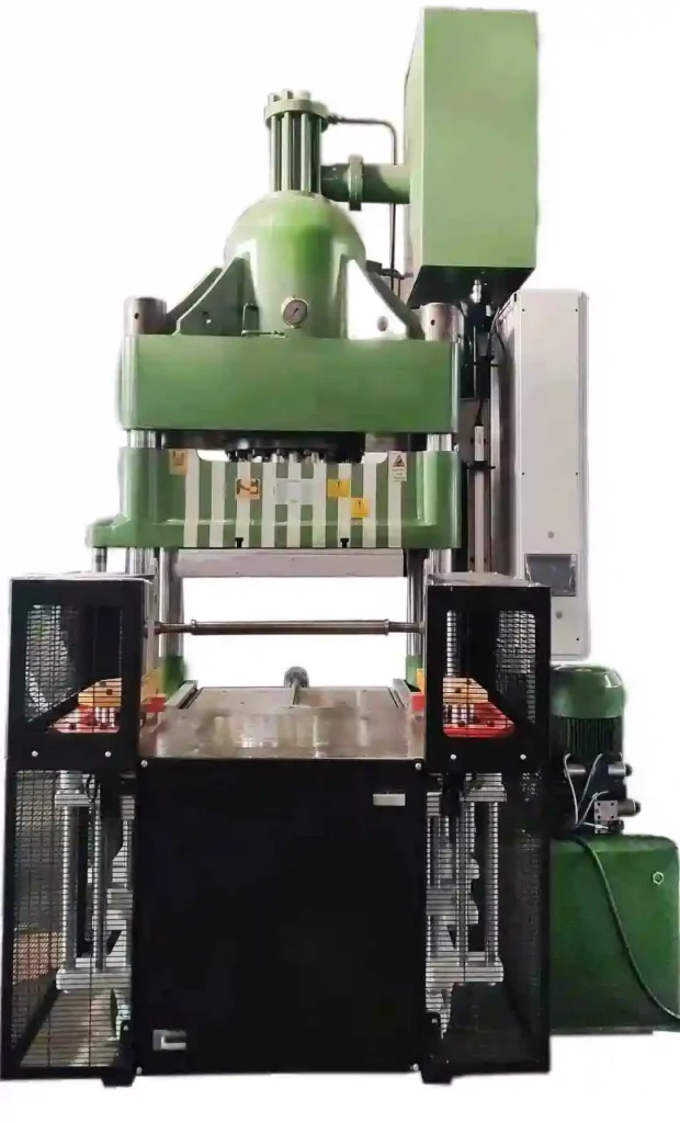
Four-column hydraulic presses, also known as four-post presses, are a type of hydraulic press characterized by their robust design, featuring four vertical columns that provide superior stability and even force distribution. These presses are widely used in industrial applications that require high precision, durability, and large force outputs. Their sturdy design makes them ideal for handling large workpieces and performing tasks such as deep drawing, die cutting, forging, and molding. Four-column presses are particularly favored in industries like aerospace, automotive, heavy machinery, and plastics.
5.1. Design and Structure of Four-Column Hydraulic Presses
The defining feature of four-column hydraulic presses is their frame design, which includes four vertical columns that support the upper and lower crossheads of the press. The columns are positioned at the corners of the press, allowing for the even distribution of force across the entire work area. This design provides exceptional rigidity and stability, making four-column presses ideal for high-force applications that require precise control over pressure and material deformation.
Key Components
- Four vertical columns: The four columns serve as the structural backbone of the press, ensuring stability and providing support to the upper and lower crossheads. These columns are typically made from high-strength steel to withstand the immense forces generated during operation.
- Upper and lower crossheads: The crossheads are the horizontal beams that connect the four columns. The upper crosshead supports the hydraulic cylinder, while the lower crosshead serves as the base of the press. These crossheads help distribute the load evenly, ensuring that the force applied by the hydraulic cylinder is spread across the entire surface of the workpiece.
- Hydraulic cylinder: The hydraulic cylinder is mounted on the upper crosshead and contains the piston that moves vertically to apply pressure to the material. The cylinder is driven by pressurized hydraulic fluid, which generates the force needed to deform or shape the material.
- Die sets: In applications such as metal forming or die cutting, four-column presses are equipped with die sets that shape the material as it is compressed between the punch and die.
Force Distribution and Stability
One of the primary advantages of the four-column design is its ability to evenly distribute force across the entire workpiece. In presses that do not have this type of frame, the force can be unevenly applied, leading to inconsistent results, material deformation, or damage. With four-column presses, the hydraulic cylinder applies pressure directly to the material, while the columns and crossheads ensure that this pressure is evenly distributed. This makes four-column presses particularly effective for forming large, complex parts or handling irregularly shaped workpieces.
5.2. Applications of Four-Column Hydraulic Presses
Four-column hydraulic presses are used in a wide variety of industrial applications, particularly in sectors where precision, force control, and large work areas are essential. Some common applications include:
5.2.1. Metal Forming and Deep Drawing
In the metalworking industry, four-column hydraulic presses are widely used for deep drawing, sheet metal forming, and stamping operations. These presses can handle large metal sheets and apply even pressure across the material, ensuring that the metal is formed uniformly without wrinkles or cracks.
- Automotive industry: Four-column presses are commonly used to form large automotive body panels, chassis components, and engine parts. Their ability to handle large workpieces and apply consistent pressure makes them ideal for producing high-strength, precision-engineered parts for vehicles.
- Appliance industry: These presses are also used in the production of metal components for household appliances, such as washing machine drums, refrigerator panels, and kitchen sink basins.
5.2.2. Die Cutting
Die cutting is another common application for four-column hydraulic presses, particularly in industries that require precision cutting of materials like plastic, rubber, leather, and metal. The stability and accuracy provided by the four-column design allow for precise control over the cutting process, ensuring that each part is cut to the correct dimensions.
- Plastics and rubber industry: In the production of plastic and rubber components, four-column presses are used to cut parts such as gaskets, seals, and packaging materials. The even force distribution ensures that each part is cut cleanly and consistently.
- Textiles and leather: In industries like textiles and leather manufacturing, four-column presses are used for die cutting fabric and leather materials into patterns for clothing, upholstery, and accessories.
5.2.3. Forging and Molding
In forging and molding applications, four-column hydraulic presses are used to apply large amounts of pressure to shape metal, plastic, or composite materials. These presses are often used in the production of high-strength parts that require uniform compression and precision.
- Aerospace industry: The aerospace sector relies on four-column hydraulic presses to forge critical components such as turbine blades, engine housings, and structural parts. The high precision and force capacity of these presses ensure that aerospace components meet strict safety and performance standards.
- Heavy machinery: In the production of heavy industrial equipment, four-column presses are used to forge large, high-strength parts like gears, shafts, and machine frames.
5.3. Advantages of Four-Column Hydraulic Presses
Four-column hydraulic presses offer several key advantages over other types of hydraulic presses, making them the preferred choice for many industrial applications.
5.3.1. Even Pressure Distribution
One of the most significant advantages of four-column presses is their ability to distribute pressure evenly across the workpiece. This is especially important in applications like deep drawing and die cutting, where uneven pressure can lead to defects or inconsistent results. The four-column design ensures that the hydraulic force is applied uniformly, improving product quality and reducing the likelihood of material failure.
5.3.2. Versatility in Handling Large Workpieces
Four-column presses are designed to accommodate large workpieces, making them ideal for industries that require the forming, cutting, or forging of large parts. The large work area provided by the press allows operators to handle complex or oversized materials that would be difficult to process using other types of presses.
5.3.3. High Force Capacity
Due to their robust design, four-column hydraulic presses can generate extremely high forces, often ranging from several tons to thousands of tons. This makes them well-suited for heavy-duty applications, such as metal forging or the production of large automotive components. The combination of high force capacity and even pressure distribution ensures that these presses can handle the most demanding tasks with precision and reliability.
5.3.4. Precision and Stability
The four-column design provides exceptional stability, reducing the risk of misalignment or deformation during the pressing process. This is particularly important in applications that require high precision, such as aerospace and automotive part production. The stability provided by the four-column frame ensures that the material is pressed evenly and accurately, resulting in high-quality parts with minimal defects.
5.4. Technological Advancements in Four-Column Presses
As with other hydraulic presses, four-column hydraulic presses have benefited from recent advancements in technology, particularly in areas such as automation, energy efficiency, and precision control. Some of the key innovations in four-column press technology include:
Servo-Hydraulic Systems
Many modern four-column hydraulic presses are equipped with servo-hydraulic systems, which provide more precise control over the press’s force, speed, and stroke length. Servo-hydraulic systems use servo motors to regulate the flow of hydraulic fluid, allowing operators to adjust the press’s parameters with a high degree of accuracy. This results in improved precision and energy efficiency, making four-column presses suitable for high-precision tasks that require tight tolerances.
CNC Integration
Computer Numerical Control (CNC) systems are increasingly being integrated into four-column hydraulic presses, allowing for fully automated operation. CNC-controlled presses can be programmed to perform specific tasks, such as deep drawing or die cutting, with minimal operator intervention. This increases productivity and reduces the risk of human error, while also allowing for greater flexibility in terms of press operation.
IoT and Smart Manufacturing
Some four-column hydraulic presses are now equipped with Internet of Things (IoT) connectivity, allowing them to be integrated into smart manufacturing environments. IoT-enabled presses can communicate with other machines and systems in the production line, providing real-time data on press performance, material usage, and maintenance needs. This connectivity allows for more efficient production management and predictive maintenance, reducing downtime and improving overall operational efficiency.
Forging Hydraulic Presses
Forging hydraulic presses are specialized machines designed to shape metal by applying high compressive forces. They are used in industries that require strong, high-quality metal parts with specific mechanical properties. Forging presses can process both hot and cold metals, making them suitable for a wide range of forging applications. These presses play a critical role in industries like automotive, aerospace, heavy machinery, and industrial equipment manufacturing, where parts need to withstand extreme stress and environmental conditions.
6.1. Working Principle of Forging Hydraulic Presses
The forging process involves deforming a metal workpiece by applying pressure to force it into a desired shape. Forging hydraulic presses are equipped with a hydraulic system that generates the immense pressure required to deform metal, typically using a punch and die set to compress the metal into a specific shape. The key advantage of hydraulic presses in forging is their ability to apply consistent and controllable pressure over a long stroke length, which ensures precision and uniformity in the final product.
Types of Forging Processes
There are two main types of forging processes that can be performed using hydraulic presses: hot forging and cold forging.
- Hot forging: In this process, the metal workpiece is heated to a temperature where it becomes malleable and easier to shape. Hot forging is typically used for metals like steel, aluminum, and titanium, which require high temperatures to achieve the desired level of deformation. Hydraulic presses apply pressure to the heated metal, compressing it into the die cavity to form the desired shape. The high temperature allows the metal to flow more easily, reducing the force required for shaping.
- Cold forging: In cold forging, the metal is shaped at or near room temperature. Cold forging is generally used for softer metals or applications where a high degree of dimensional accuracy and surface finish is required. Since cold forging does not involve heating, the metal undergoes work hardening, which increases its strength. However, cold forging requires higher forces than hot forging because the metal is less malleable at lower temperatures.
Forging Press Components
Forging hydraulic presses share many components with other types of hydraulic presses, but they are specifically designed to handle the immense pressures and extreme conditions required for forging. Some of the key components of a forging hydraulic press include:
- Hydraulic cylinder: The hydraulic cylinder is responsible for generating the force that drives the piston downward, applying pressure to the metal workpiece. Forging presses use large hydraulic cylinders capable of producing thousands of tons of force.
- Piston and ram: The piston, housed within the hydraulic cylinder, moves up and down to apply pressure. The ram is the component that physically contacts the metal workpiece, pressing it into the die to form the desired shape.
- Die set: The die set consists of two parts: the upper die (attached to the ram) and the lower die (mounted on the press bed). The shape of the dies determines the final shape of the forged part. Hydraulic presses use interchangeable dies to create a wide variety of parts, from simple geometries to complex shapes.
- Cooling system: Since hot forging involves working with high temperatures, forging hydraulic presses are typically equipped with cooling systems to dissipate heat and maintain the proper operating temperature. The cooling system helps prevent overheating, which could damage the hydraulic components or affect press performance.
6.2. Hot vs. Cold Forging in Hydraulic Presses
Both hot forging and cold forging have their advantages, and the choice between the two depends on the type of metal being forged and the desired properties of the final part.
Hot Forging
- Process: In hot forging, the metal is heated to temperatures ranging from 700°C to 1250°C (1300°F to 2300°F), depending on the material. At these high temperatures, the metal becomes more ductile and easier to shape. The hydraulic press then applies pressure to deform the heated metal, forcing it into the shape of the die.
- Advantages:
- Easier material flow: The high temperature makes the metal more malleable, allowing it to flow easily into complex shapes with less force.
- Reduction in material defects: Hot forging reduces the likelihood of defects such as porosity or cracking, as the metal’s internal structure is more uniform at high temperatures.
- Improved mechanical properties: The heat treatment that occurs during hot forging improves the toughness, ductility, and fatigue resistance of the forged part.
- Disadvantages:
- Energy consumption: Hot forging requires a significant amount of energy to heat the metal, making it less energy-efficient than cold forging.
- Potential for scale formation: When metals are heated, they can form an oxide layer on their surface, known as scale, which must be removed in post-forging processes like cleaning or machining.
Cold Forging
- Process: Cold forging is performed at room temperature or near-room temperature. It is typically used for softer metals, such as aluminum or copper, or when high precision and excellent surface finish are required.
- Advantages:
- Increased strength through work hardening: Since the metal is not heated during cold forging, the material undergoes work hardening, which increases its strength and durability.
- High precision and surface finish: Cold forging allows for tighter dimensional tolerances and better surface finish, reducing the need for secondary machining processes.
- Energy efficiency: Cold forging does not require heating the metal, resulting in lower energy consumption and cost savings compared to hot forging.
- Disadvantages:
- Higher force required: Since the metal is less malleable at room temperature, cold forging requires higher forces to shape the material. Hydraulic presses used for cold forging must be capable of generating extremely high pressures.
- Limited to softer metals or small parts: Cold forging is best suited for softer metals or smaller parts. Attempting to cold forge large, high-strength metals like steel can result in cracking or other defects.
6.3. Applications of Forging Hydraulic Presses
Forging hydraulic presses are used in industries that require high-strength, high-performance parts. The forging process produces components that are stronger and more durable than parts made using other metal forming methods, making hydraulic forging presses indispensable in industries such as automotive, aerospace, and heavy machinery manufacturing.
6.3.1. Automotive Industry
The automotive industry is one of the largest users of forging hydraulic presses, particularly for the production of engine and drivetrain components. Forging provides the strength and durability needed for parts that must withstand high stress, such as:
- Crankshafts: Crankshafts, which convert linear motion into rotational motion in an engine, are forged using hydraulic presses to ensure they can endure high loads and torque. Forging also improves the grain structure of the metal, enhancing its fatigue resistance.
- Connecting rods: Forged connecting rods are used to link the piston to the crankshaft in an engine. These components are subjected to extreme forces, and forging ensures they have the necessary strength to operate reliably.
- Gears and axles: Forged gears and axles are used in transmissions and drivetrains, where high strength and precision are essential for smooth operation and long service life.
6.3.2. Aerospace Industry
In the aerospace industry, forged components are used in critical applications where strength, lightweight, and reliability are paramount. Aerospace parts are often made from high-performance alloys, such as titanium and nickel-based superalloys, which are well-suited for forging. Some common aerospace applications include:
- Turbine blades: Hydraulic forging presses are used to shape turbine blades for jet engines. These blades must withstand extreme temperatures and high mechanical stress, making forging the ideal manufacturing method to ensure their durability and performance.
- Landing gear components: Forged components in landing gear systems must be able to absorb impact and resist wear, making them ideal candidates for the forging process. Hydraulic presses can produce landing gear components with superior strength and toughness.
- Structural parts: Hydraulic presses are used to forge structural components for aircraft frames, ensuring they are lightweight yet strong enough to endure the stresses of flight.
6.3.3. Heavy Machinery and Industrial Equipment
Forging hydraulic presses are essential in the production of heavy machinery and industrial equipment that require high-strength, wear-resistant parts. Examples of applications in this industry include:
- Forged gears and shafts: In heavy equipment such as excavators, bulldozers, and mining machinery, forged gears and shafts provide the strength and durability needed to operate in harsh environments and under heavy loads.
- Hydraulic cylinders: Hydraulic presses are used to forge high-strength cylinders and pistons used in the hydraulic systems of heavy machinery. These components must withstand high pressure and wear over extended periods.
- Tools and dies: The tooling industry relies on forging presses to produce dies, molds, and tools used in metal forming, stamping, and cutting operations. Forging ensures that these tools have the hardness and wear resistance required for demanding applications.
6.4. Advantages of Forging Hydraulic Presses
Forging hydraulic presses offer several advantages over other metal forming methods, particularly when it comes to producing high-strength, precision components.
6.4.1. Superior Mechanical Properties
The forging process results in parts with superior mechanical properties compared to casting or machining. Forged parts have a more refined grain structure, which improves their strength, toughness, and fatigue resistance. This makes forging the ideal choice for components that will be subjected to high stress or extreme conditions.
6.4.2. Precision and Repeatability
Hydraulic forging presses provide precise control over the pressure, speed, and stroke length of the press, ensuring consistent results and high repeatability. This precision is critical in industries like aerospace and automotive, where parts must meet tight tolerances and high-quality standards.
6.4.3. Versatility
Forging hydraulic presses are versatile machines capable of handling a wide range of metals and producing a variety of shapes and sizes. Whether forging small, intricate parts or large, heavy-duty components, hydraulic presses can be adapted to meet the specific needs of the application.
6.4.4. Improved Surface Finish
Forging results in parts with a smooth surface finish and uniform dimensions, reducing the need for post-processing such as machining or grinding. This not only saves time but also reduces material waste and costs.
6.5. Technological Advancements in Forging Hydraulic Presses
Recent innovations in forging hydraulic press technology have further improved the efficiency, precision, and energy efficiency of these machines.
Servo-Hydraulic Systems
Many modern forging presses are equipped with servo-hydraulic systems that provide more precise control over the press’s force, speed, and stroke length. These systems use servo motors to regulate the flow of hydraulic fluid, allowing for greater accuracy and energy savings. Servo-hydraulic systems also enable faster cycle times, increasing productivity.
Automation and Robotics
Automation is playing an increasingly important role in forging operations. Robotic arms and automated part handling systems are being integrated into forging presses to load and unload parts, reducing the need for manual labor and improving consistency. Automated systems can also monitor the forging process in real-time, detecting and correcting any deviations to ensure high-quality parts.
Smart Forging Systems
With the advent of Industry 4.0 technologies, smart forging systems are becoming more common. These systems use sensors, IoT connectivity, and machine learning algorithms to optimize the forging process in real-time. Smart forging presses can adjust parameters such as pressure and stroke length based on real-time data, improving product quality and reducing downtime.
C-Frame Hydraulic Presses
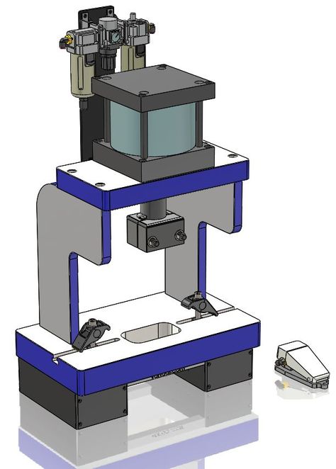
C-frame hydraulic presses are a popular type of hydraulic press characterized by their open-front design, which resembles the shape of the letter “C.” This design allows easy access to the working area from three sides, making C-frame presses ideal for applications that require frequent loading and unloading of materials. These presses are commonly used in precision metalworking, assembly line tasks, and light manufacturing applications where space efficiency, versatility, and accessibility are essential.
C-frame presses are often favored for tasks like punching, bending, stamping, and assembly, especially when dealing with smaller workpieces or components. Their compact design makes them suitable for small workshops and production lines, as they require less floor space than larger, multi-column presses.
7.1. Design and Structure of C-Frame Hydraulic Presses
The defining feature of a C-frame hydraulic press is its open-front design, which offers operators easy access to the press’s working area. The frame is shaped like the letter “C,” with the hydraulic cylinder and ram mounted at the top and the working table or bed at the bottom. This open design allows for unrestricted access to the workpiece, simplifying material handling, part loading, and unloading.
Key Components of a C-Frame Hydraulic Press
- C-shaped frame: The frame is the structural element of the press, providing support and housing the hydraulic system. It is typically made from high-strength steel to withstand the forces generated during pressing operations.
- Hydraulic cylinder: The hydraulic cylinder is mounted at the top of the press, containing a piston that moves the ram vertically. The cylinder generates the force needed to press, punch, or bend the material.
- Ram and punch: The ram is the moving component of the press that applies force to the workpiece. It is connected to the piston inside the hydraulic cylinder. A punch or other tooling is often attached to the ram to perform specific operations, such as cutting or forming.
- Work table or bed: The work table or bed is the surface where the material or part is placed during the pressing operation. This surface may have slots or holes for mounting dies or other tools used in metal forming, stamping, or bending processes.
- Controls: C-frame presses are often equipped with manual or automated controls to regulate pressure, stroke length, and speed. More advanced models may feature programmable logic controllers (PLCs) or computer numerical control (CNC) systems for precision control.
7.2. Applications of C-Frame Hydraulic Presses
C-frame hydraulic presses are versatile machines suitable for a variety of applications across multiple industries. Their open-front design and ease of access make them particularly useful for tasks that require frequent handling of parts or small components. Some of the most common applications include:
7.2.1. Precision Metal Forming
In precision metalworking, C-frame hydraulic presses are often used for punching, stamping, and bending small metal components. These presses offer the precision and control necessary for high-quality metal forming, ensuring that each part is shaped accurately and consistently.
- Electronics industry: In the electronics sector, C-frame presses are used to punch and form metal housings and components for devices like smartphones, tablets, and computers. The precision offered by these presses ensures that each part meets strict tolerances and quality standards.
- Automotive industry: C-frame presses are used to produce small metal parts for vehicles, such as brackets, clips, and connectors. Their compact design and precision make them ideal for producing components that require tight tolerances and consistent quality.
7.2.2. Assembly Line Tasks
C-frame presses are commonly used in assembly lines for tasks like inserting bearings, fasteners, or rivets into larger components. The open-front design allows operators to quickly load and unload parts, increasing the efficiency of the assembly process.
- Automotive assembly: C-frame presses are used in automotive assembly lines to insert bearings, bushings, and other small components into larger assemblies such as engine blocks, transmission housings, or suspension components.
- Electronics assembly: In the electronics industry, C-frame presses are used to assemble small components like connectors, terminals, or circuit boards. The compact design and precision control allow for efficient handling of delicate electronic parts.
7.2.3. Light Manufacturing
C-frame presses are ideal for light manufacturing applications, where small parts need to be formed, stamped, or assembled. Their compact size and versatility make them suitable for workshops, laboratories, and smaller production facilities.
- Jewelry making: In the jewelry industry, C-frame presses are used for precision metal forming tasks, such as stamping intricate designs onto metal surfaces or forming small components for rings, bracelets, and necklaces.
- Prototype development: In research and development labs, C-frame presses are often used to produce prototypes of new products. Their precision and flexibility make them suitable for small production runs and experimental projects.
7.3. Advantages of C-Frame Hydraulic Presses
C-frame hydraulic presses offer several advantages that make them an attractive choice for many industries and applications.
7.3.1. Compact and Space-Efficient Design
One of the most significant advantages of C-frame presses is their compact size. These presses are designed to fit in smaller workspaces, making them ideal for workshops, assembly lines, and facilities with limited floor space. Despite their small footprint, C-frame presses can generate significant force, making them capable of handling a wide range of tasks.
7.3.2. Easy Access to the Work Area
The open-front design of a C-frame press provides easy access to the working area, allowing operators to quickly load and unload materials. This design is especially beneficial for applications that require frequent handling of parts, such as assembly line tasks or small-batch production. The open design also makes it easier to position materials accurately within the press, reducing setup time and improving overall efficiency.
7.3.3. High Precision and Control
C-frame hydraulic presses offer precise control over force, stroke length, and speed, making them ideal for applications that require high precision. Many C-frame presses are equipped with advanced control systems, such as servo-hydraulic or CNC controls, which allow operators to program specific parameters for each task. This level of control ensures consistent, high-quality results, even in applications that require tight tolerances.
7.3.4. Versatility
C-frame presses are highly versatile machines that can be used for a wide range of tasks, from metal forming and stamping to assembly and punching. Their compact size and flexibility make them suitable for both small-batch production and high-volume manufacturing environments. Additionally, C-frame presses can be easily customized with different tooling and accessories to meet the specific needs of each application.
7.4. Limitations of C-Frame Hydraulic Presses
While C-frame hydraulic presses offer many advantages, they also have some limitations that may make them less suitable for certain applications.
7.4.1. Lower Force Capacity
C-frame presses typically generate lower force than larger hydraulic presses, such as H-frame or four-column presses. As a result, they may not be suitable for heavy-duty applications that require extremely high pressures or large workpieces. C-frame presses are best suited for light to medium-duty tasks, such as small part production or assembly work.
7.4.2. Risk of Frame Deformation
Because of their open-front design, C-frame presses can be prone to frame deformation under high loads. The lack of structural support on one side of the frame means that the press may flex or bend if subjected to excessive force, potentially affecting the accuracy and quality of the work. This limitation makes C-frame presses less suitable for applications that require very high pressures or heavy materials.
7.4.3. Limited Work Area
While the open-front design of C-frame presses provides easy access to the work area, it also limits the size of the workpiece that can be processed. Larger workpieces may not fit within the compact frame of a C-frame press, making it less suitable for large-scale manufacturing or heavy-duty metal forming.
7.5. Technological Advancements in C-Frame Presses
Recent technological advancements have enhanced the performance and functionality of C-frame hydraulic presses, making them even more versatile and efficient.
Servo-Hydraulic Systems
Many modern C-frame presses are equipped with servo-hydraulic systems, which offer more precise control over the force, speed, and stroke length of the press. Servo-hydraulic systems use servo motors to regulate the flow of hydraulic fluid, allowing operators to make fine adjustments to the press’s operation. This level of control improves accuracy, reduces material waste, and increases energy efficiency.
CNC Controls
CNC-controlled C-frame presses are becoming more common in industries that require high precision and automation. CNC systems allow operators to program the press for specific tasks, such as punching or forming, and automate the entire process. This reduces the need for manual intervention, improves consistency, and increases production speed.
Smart Press Technology
Some C-frame hydraulic presses are now equipped with smart technology, such as sensors and IoT connectivity, which allow for real-time monitoring of press performance. Smart presses can track factors such as pressure, stroke length, and material deformation, providing valuable data for optimizing the pressing process and ensuring consistent product quality.
H-Frame Hydraulic Presses
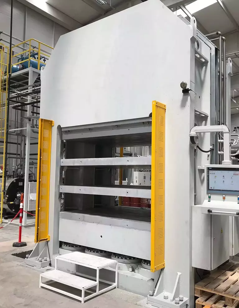
H-frame hydraulic presses, named for their distinct H-shaped frame, are among the most versatile and widely used hydraulic presses in industrial settings. This type of press features a frame with two vertical columns connected by horizontal crossbars, forming an “H” structure that provides exceptional stability and support during pressing operations. H-frame presses are known for their robust design, high force capacity, and versatility, making them ideal for tasks such as metal forming, bending, straightening, punching, and stamping. They are commonly used in industries such as automotive, metalworking, aerospace, manufacturing, and repair shops.
8.1. Design and Structure of H-Frame Hydraulic Presses
The key feature of an H-frame hydraulic press is its rigid frame design, which provides the necessary support to handle high-force applications. The frame consists of two vertical columns and two horizontal crossbars, creating a sturdy structure that can withstand immense pressure without flexing or deforming. The large, open space between the columns allows for easy access to the work area and accommodates various workpiece sizes.
Key Components
- Vertical columns: The two vertical columns provide the structural support for the press. They are typically made from high-strength steel to ensure they can handle the heavy loads generated during pressing operations.
- Horizontal crossbars: The upper and lower crossbars connect the vertical columns and provide stability to the frame. The upper crossbar supports the hydraulic cylinder and ram, while the lower crossbar serves as the bed where the workpiece is placed.
- Hydraulic cylinder and ram: The hydraulic cylinder is mounted on the upper crossbar and houses the piston that drives the ram downward to apply pressure to the workpiece. The ram moves vertically, pressing the material against the die or tool located on the bed.
- Work table or bed: The bed is where the workpiece is placed during the pressing operation. It may include slots or holes for mounting tooling, dies, or jigs. The open design of the H-frame allows for larger workpieces to be processed compared to other press types like C-frame presses.
- Control systems: H-frame presses are equipped with manual or automated controls that regulate the press’s force, stroke length, and speed. More advanced models may include CNC controls or programmable logic controllers (PLCs) for automated operation and precise control over the pressing process.
8.2. Applications of H-Frame Hydraulic Presses
H-frame hydraulic presses are used in a wide range of industrial applications, particularly those that require high force and precise control. Their versatility and strength make them suitable for both heavy-duty and light-duty tasks, from metalworking to assembly work.
8.2.1. Metalworking and Fabrication
H-frame presses are commonly used in metalworking for tasks such as bending, forming, straightening, and punching metal parts. Their ability to generate significant force, combined with the large work area, allows operators to process various sizes and shapes of metal sheets, plates, and components.
- Bending and forming: H-frame presses are used to bend metal sheets and plates into specific shapes. By applying controlled force, the press can form complex bends and curves without damaging the material.
- Straightening: In metal fabrication, H-frame presses are often used to straighten bent or deformed metal parts. By applying pressure in the opposite direction of the bend, the press can restore the part to its original shape.
- Punching and cutting: H-frame presses can also be used for punching holes or cutting shapes into metal sheets. The high force capacity of the press ensures clean, precise cuts, even in thicker materials.
8.2.2. Automotive Repair and Manufacturing
In the automotive industry, H-frame presses are used for both repair work and manufacturing of vehicle components. The ability to generate consistent force and handle large workpieces makes H-frame presses ideal for tasks such as pressing bearings, straightening chassis components, and assembling automotive parts.
- Bearing installation: H-frame presses are frequently used in automotive repair shops to press bearings into place in engine blocks, transmissions, and wheel hubs. The precise control over pressure ensures that bearings are installed correctly without damaging the surrounding components.
- Chassis straightening: In automotive repair, H-frame presses are used to straighten bent or damaged chassis components. By applying controlled pressure, the press can restore the structural integrity of the vehicle’s frame.
- Component manufacturing: H-frame presses are used in automotive manufacturing to form, stamp, and assemble various parts, such as suspension components, engine mounts, and body panels. The press’s large work area and high force capacity allow for efficient processing of automotive parts.
8.2.3. Aerospace Industry
In the aerospace industry, H-frame hydraulic presses are used for the precision forming of high-strength components, such as structural parts, engine housings, and turbine blades. The high-pressure capabilities of H-frame presses ensure that aerospace components meet the stringent quality and safety standards required for aviation.
- Forming complex shapes: H-frame presses are used to form complex, high-strength parts from metals like aluminum, titanium, and composites. These parts are essential for aircraft structures, where strength and weight are critical factors.
- Stamping and punching: H-frame presses are also used for stamping and punching operations, where precise holes or cutouts are needed in metal sheets or plates used in aircraft construction.
8.2.4. Plastic and Rubber Molding
H-frame presses are used in the plastic and rubber molding industries to compress materials into molds, creating finished products with precise shapes and dimensions. These presses apply consistent force, ensuring that the molded parts are uniform and free of defects.
- Compression molding: In compression molding, plastic or rubber material is placed in a mold, and the H-frame press applies pressure to form the material into the desired shape. This process is commonly used to manufacture components like seals, gaskets, and housings.
- Die cutting: H-frame presses are also used for die-cutting operations in the plastics and rubber industries, where sheets of material are cut into specific shapes for products such as packaging, gaskets, or seals.
8.3. Advantages of H-Frame Hydraulic Presses
H-frame hydraulic presses offer several advantages over other types of hydraulic presses, making them the preferred choice for many industrial applications.
8.3.1. High Force Capacity
H-frame presses are designed to handle high-force applications, often generating forces ranging from a few tons to thousands of tons. This makes them ideal for tasks like metal forming, punching, and stamping, where large amounts of pressure are needed to shape or cut materials. The robust construction of the H-frame ensures that the press can handle heavy loads without flexing or deforming.
8.3.2. Versatility
One of the key advantages of H-frame presses is their versatility. These presses can be used for a wide range of tasks, from light-duty assembly work to heavy-duty metal forming and fabrication. The open design of the H-frame allows operators to work with large workpieces, making the press suitable for industries that require the processing of oversized parts or materials.
8.3.3. Precision and Control
H-frame hydraulic presses offer precise control over pressure, stroke length, and speed, making them suitable for applications that require high precision. Many H-frame presses are equipped with servo-hydraulic or CNC control systems, which allow operators to program specific parameters for each task. This level of control ensures consistent, high-quality results, even in applications that require tight tolerances.
8.3.4. Durability and Stability
The rigid frame design of H-frame presses provides excellent stability and durability, making them capable of withstanding the stresses of heavy-duty industrial applications. The frame’s ability to distribute force evenly across the workpiece ensures that the material is pressed accurately, reducing the risk of misalignment or material deformation.
8.4. Technological Advancements in H-Frame Hydraulic Presses
Recent advancements in H-frame hydraulic press technology have improved the efficiency, precision, and versatility of these machines, making them even more valuable in modern manufacturing environments.
Servo-Hydraulic Systems
Many modern H-frame presses are equipped with servo-hydraulic systems, which provide greater control over the press’s force, speed, and stroke length. Servo-hydraulic systems use servo motors to regulate the flow of hydraulic fluid, allowing operators to make fine adjustments to the press’s operation. This results in improved accuracy, faster cycle times, and increased energy efficiency.
CNC and PLC Controls
H-frame hydraulic presses are increasingly being equipped with CNC and PLC control systems that allow for fully automated operation. CNC-controlled presses can be programmed to perform specific tasks, such as bending, stamping, or forming, with minimal operator intervention. This automation increases productivity, reduces the risk of human error, and allows for greater flexibility in terms of press operation.
Smart Manufacturing and IoT Integration
As part of the Industry 4.0 movement, H-frame presses are now being integrated into smart manufacturing environments using IoT (Internet of Things) connectivity. IoT-enabled presses can communicate with other machines in the production line, providing real-time data on press performance, material usage, and maintenance needs. This connectivity enables more efficient production management and predictive maintenance, reducing downtime and improving overall operational efficiency.
Stamping Hydraulic Presses
Stamping hydraulic presses are specialized machines designed for high-speed metal stamping operations, which involve cutting, shaping, and forming sheet metal using dies. These presses apply a large force over a short period, making them suitable for mass production in industries like automotive, electronics, appliances, and aerospace. Stamping hydraulic presses are highly efficient and capable of producing large quantities of precision parts with minimal material waste, making them an essential tool in modern manufacturing.
9.1. Working Principle of Stamping Hydraulic Presses
The stamping process involves placing a sheet of metal, known as a blank, into the press where a punch and die are used to shape or cut the material. The hydraulic press applies force to the punch, which drives the blank into the die, forming the desired shape. Stamping presses are capable of performing a variety of tasks, including blanking, piercing, bending, embossing, and coining, all of which are critical for producing metal components with precise dimensions and surface finishes.
Key Stamping Operations
- Blanking: This operation involves cutting a flat piece of metal from a larger sheet. The blank serves as the starting material for further operations or as the final product.
- Piercing: Piercing is the process of punching holes or shapes into the metal sheet, which is commonly used to create holes for fasteners or electrical components.
- Bending: In bending operations, the metal sheet is deformed into a specific angle or shape without cutting it. This is used to form parts like brackets, panels, and frames.
- Embossing: Embossing involves creating raised or recessed designs on the surface of the metal. This operation is often used for decorative purposes or to add rigidity to the part.
- Coining: Coining is a precision stamping operation where the material is compressed between the punch and die to create fine details, such as logos or serial numbers, with a high degree of accuracy.
The force generated by the hydraulic system is transferred through the ram to the punch, which compresses the material against the die. Hydraulic presses are known for their smooth and controlled force application, allowing for high-precision operations, even in high-speed production environments. The force can be adjusted based on the material and thickness of the blank, ensuring that each part is stamped accurately and consistently.
9.2. Components of Stamping Hydraulic Presses
Stamping hydraulic presses consist of several key components that work together to perform high-speed metal stamping operations. Each component plays a critical role in ensuring the efficiency and precision of the stamping process.
Key Components
- Frame: The frame is the structural foundation of the press and provides the support needed to handle the large forces generated during stamping. Stamping hydraulic presses typically use an H-frame or C-frame design, depending on the size of the press and the type of operation. H-frame presses are more common for large-scale, high-force operations, while C-frame presses are used for smaller, lighter tasks.
- Hydraulic system: The hydraulic system provides the force required to perform the stamping operation. It consists of a hydraulic pump, cylinders, and fluid reservoirs that work together to pressurize the hydraulic fluid and move the ram.
- Ram: The ram is the moving part of the press that transfers the hydraulic force to the punch. It moves vertically, pressing the punch against the material to perform the stamping operation.
- Die and punch: The die and punch are the tools used to shape the material. The punch applies pressure to the blank, forcing it into the die cavity, where it is cut or shaped into the desired form. Dies are typically custom-made for specific parts, ensuring that each stamped piece meets precise dimensional requirements.
- Control system: Stamping hydraulic presses are equipped with control systems that allow operators to regulate the force, speed, and stroke length of the press. Advanced presses often feature CNC controls or programmable logic controllers (PLCs) for automated operation and precise control over the stamping process.
9.3. Applications of Stamping Hydraulic Presses
Stamping hydraulic presses are used in a variety of industries to produce metal parts that require high precision, fast production speeds, and complex shapes. Some of the most common applications include:
9.3.1. Automotive Industry
In the automotive industry, stamping hydraulic presses are essential for producing large quantities of body panels, chassis components, and engine parts. The speed and precision of stamping presses make them ideal for mass production, where consistent quality and tight tolerances are critical.
- Body panels: Automotive body panels, such as doors, hoods, fenders, and roofs, are typically produced using stamping hydraulic presses. These panels must be shaped accurately to fit together seamlessly, and stamping presses ensure that each panel is produced to exact specifications.
- Chassis components: Stamping presses are used to form various chassis components, including cross members, support beams, and suspension brackets. The ability to stamp complex shapes quickly and consistently makes these presses indispensable for automotive manufacturing.
- Engine parts: Stamping hydraulic presses are also used to produce small engine components, such as valve covers, brackets, and housings. These parts must meet strict dimensional tolerances to ensure proper engine performance.
9.3.2. Electronics and Appliances
In the electronics and appliance industries, stamping presses are used to produce small metal parts, such as housings, connectors, and frames. The precision and speed of stamping hydraulic presses make them ideal for producing large quantities of parts used in consumer electronics, household appliances, and industrial equipment.
- Metal housings: Stamping hydraulic presses are used to form metal housings for electronic devices, such as smartphones, laptops, and tablets. These housings must be lightweight, durable, and precisely shaped to fit internal components.
- Connectors: Electrical connectors and terminals are often produced using stamping presses, where small metal parts are stamped and shaped into connectors that ensure reliable electrical connections in devices.
- Appliance components: Stamping presses are used to produce metal components for household appliances, such as washing machines, refrigerators, and dishwashers. These components include brackets, enclosures, and panels, all of which require precision and durability.
9.3.3. Aerospace Industry
In the aerospace industry, stamping hydraulic presses are used to produce lightweight, high-strength components for aircraft and spacecraft. The ability to produce precision parts with minimal material waste is critical in aerospace manufacturing, where weight reduction and structural integrity are essential.
- Aircraft panels: Stamping presses are used to form thin, lightweight panels for aircraft fuselages, wings, and control surfaces. These parts must be shaped with extreme precision to ensure aerodynamic performance and structural strength.
- Turbine components: Stamping hydraulic presses are also used to produce small components for aircraft engines, such as turbine blades and housings. These parts must withstand high temperatures and mechanical stress, making precision stamping a crucial part of the manufacturing process.
9.3.4. Industrial and Consumer Goods
Stamping hydraulic presses are widely used in the production of industrial and consumer goods, where they are used to manufacture metal parts for products like tools, packaging, and hardware.
- Packaging: Stamping presses are used to produce metal cans, containers, and lids for the food and beverage industry. The ability to quickly stamp large quantities of metal packaging ensures a consistent supply of lightweight, durable containers.
- Tools and hardware: Stamping presses are used to form metal parts for hand tools, fasteners, and hardware. The precision and strength of these presses ensure that each part is produced to the exact specifications required for reliable performance.
9.4. Advantages of Stamping Hydraulic Presses
Stamping hydraulic presses offer several advantages over other types of metal forming equipment, making them the preferred choice for high-speed, high-precision manufacturing.
9.4.1. High Speed and Efficiency
Stamping hydraulic presses are capable of high-speed operation, allowing manufacturers to produce large quantities of parts in a short amount of time. This is especially important in industries like automotive and electronics, where production volumes are high, and cycle times must be minimized. The rapid cycling of the press, combined with its ability to handle continuous feeds of material, makes it an efficient solution for mass production.
9.4.2. Precision and Consistency
Hydraulic presses provide consistent and precise force throughout the entire stroke, ensuring that each part is stamped with the same level of accuracy. This is critical in industries where even minor deviations can result in parts that do not fit or function properly. Stamping presses can be equipped with advanced control systems, such as servo-hydraulic or CNC controls, which allow operators to adjust the force, speed, and stroke length with high precision.
9.4.3. Versatility in Part Design
Stamping presses are capable of producing a wide range of shapes, sizes, and designs, making them highly versatile. The use of interchangeable dies allows manufacturers to switch between different part designs quickly, enabling flexible production lines that can adapt to changing product requirements. This versatility is particularly valuable in industries like automotive and electronics, where product designs evolve rapidly.
9.4.4. Minimal Material Waste
The stamping process is designed to maximize material efficiency, with minimal waste generated during production. Stamping presses can be used to nest parts within the metal sheet, ensuring that as much material as possible is utilized. This reduces material costs and minimizes the environmental impact of the manufacturing process.
9.5. Technological Advancements in Stamping Hydraulic Presses
Advances in stamping press technology have improved the efficiency, precision, and automation of these machines, making them even more valuable in modern manufacturing environments.
Servo-Hydraulic Systems
Many modern stamping hydraulic presses are equipped with servo-hydraulic systems, which combine the power of hydraulics with the precision control of servo motors. Servo-hydraulic presses offer improved accuracy, faster cycle times, and greater energy efficiency compared to traditional hydraulic presses. The ability to precisely control the force and speed of the press allows for better material handling and reduces the risk of defects.
CNC Controls
CNC-controlled stamping presses are increasingly common in industries that require high precision and automation. CNC systems allow operators to program specific parameters for each part, such as stroke length, force, and feed rate. This level of automation improves consistency, reduces setup time, and increases production speed. CNC systems also enable quick die changes, allowing manufacturers to switch between different part designs with minimal downtime.
IoT and Smart Manufacturing
As part of the Industry 4.0 revolution, stamping hydraulic presses are being integrated into smart manufacturing systems that use IoT connectivity and real-time data monitoring. IoT-enabled presses can communicate with other machines in the production line, providing real-time data on press performance, material usage, and maintenance needs. This connectivity allows manufacturers to optimize production schedules, reduce downtime, and improve overall efficiency.
Servo-Hydraulic Presses
Servo-hydraulic presses are advanced hydraulic presses that combine the power and reliability of traditional hydraulic systems with the precision and efficiency of servo motors. These presses provide improved control over force, speed, and positioning, making them ideal for applications that require high accuracy and repeatability. Servo-hydraulic presses are used in industries such as automotive, aerospace, electronics, and medical device manufacturing, where precision and energy efficiency are critical.
The key advantage of servo-hydraulic presses lies in their ability to adjust parameters dynamically during operation, allowing for more precise control over the pressing process. This flexibility, combined with the energy efficiency offered by servo motors, has made servo-hydraulic presses a popular choice in industries where both performance and sustainability are priorities.
10.1. Working Principle of Servo-Hydraulic Presses
A servo-hydraulic press functions similarly to a traditional hydraulic press, with one key difference: the hydraulic system is controlled by servo motors instead of a constant-speed electric motor. Servo motors provide precise control over the movement of the hydraulic fluid, allowing operators to adjust the speed, pressure, and position of the ram with a high degree of accuracy.
Key Components
- Servo motor: The servo motor is responsible for controlling the hydraulic pump, which in turn pressurizes the hydraulic fluid. Unlike traditional hydraulic presses, where the pump runs at a constant speed, the servo motor can vary the speed and pressure of the pump based on the specific requirements of the task.
- Hydraulic system: The hydraulic system, which consists of a pump, reservoir, and hydraulic fluid, generates the force needed to move the ram and perform the pressing operation. In a servo-hydraulic press, the hydraulic system is controlled by the servo motor, which allows for precise adjustments in real-time.
- Ram: The ram is the component that moves up and down to apply force to the workpiece. The position and speed of the ram can be controlled with extreme precision in a servo-hydraulic press, allowing for more accurate pressing operations.
- Control system: Servo-hydraulic presses are equipped with advanced control systems, often featuring CNC or PLC controls, which allow operators to program specific parameters for each operation. These control systems enable automated operation, real-time monitoring, and adjustments to force, speed, and stroke length.
10.2. Applications of Servo-Hydraulic Presses
Servo-hydraulic presses are used in industries that require precise control over the pressing process, particularly for tasks that involve complex part shapes, tight tolerances, or energy efficiency requirements. Some of the most common applications include:
10.2.1. Automotive Industry
In the automotive industry, servo-hydraulic presses are used to manufacture components such as body panels, chassis parts, and engine components. The ability to adjust pressing parameters dynamically ensures that each part is formed with precision, reducing defects and ensuring that the parts meet strict safety and performance standards.
- Precision stamping: Servo-hydraulic presses are used for precision stamping of automotive body panels, where exact dimensional accuracy is critical. The ability to control the press’s force and speed ensures that each panel is formed without defects like wrinkling or tearing.
- Chassis and suspension components: In the production of chassis and suspension components, servo-hydraulic presses offer the precision needed to form parts that must withstand high stress and mechanical loads. The ability to control the pressing process ensures that the parts meet stringent safety requirements.
10.2.2. Aerospace Industry
The aerospace industry relies on servo-hydraulic presses to produce lightweight, high-strength components that must meet exacting quality standards. Servo-hydraulic presses are used to form parts such as turbine blades, engine housings, and structural components for aircraft.
- Turbine blade production: Servo-hydraulic presses are used to forge turbine blades for jet engines. These blades must be formed with extreme precision to ensure they can withstand high temperatures and mechanical stress.
- Aircraft panels and structural parts: The ability to control the force and speed of the press allows manufacturers to produce aircraft panels and structural parts with minimal material waste, ensuring that each part is lightweight and strong.
10.2.3. Electronics Industry
In the electronics industry, servo-hydraulic presses are used to produce small, intricate components such as metal housings, connectors, and terminals. The precision offered by these presses ensures that each part is produced to exact specifications, which is critical in the production of electronic devices.
- Metal stamping: Servo-hydraulic presses are used for metal stamping of electronic components, where tight tolerances and high precision are essential. The ability to control the press’s movement ensures that each component is formed with the required accuracy.
- Connector and terminal production: The electronics industry relies on servo-hydraulic presses to produce small connectors and terminals that must meet exact dimensional tolerances. The precise control offered by these presses ensures that each part is manufactured with consistency and quality.
10.2.4. Medical Device Manufacturing
The medical device industry requires precision and repeatability in the production of components such as surgical instruments, implants, and diagnostic equipment. Servo-hydraulic presses are used to manufacture these components with the accuracy needed to meet stringent regulatory standards.
- Implant production: Servo-hydraulic presses are used to produce medical implants, such as hip and knee replacements. These parts must be formed with precision to ensure they fit properly and function reliably.
- Surgical instruments: In the production of surgical instruments, the ability to control the pressing process ensures that each instrument is formed to the exact specifications required for medical procedures.
10.3. Advantages of Servo-Hydraulic Presses
Servo-hydraulic presses offer several advantages over traditional hydraulic presses, making them the preferred choice for industries that require precision, energy efficiency, and flexibility.
10.3.1. Precise Control
One of the main advantages of servo-hydraulic presses is the precise control they offer over force, speed, and position. The servo motor allows operators to adjust the pressing parameters dynamically, ensuring that each part is formed with the required accuracy. This level of control is especially important in industries like aerospace and medical device manufacturing, where even minor deviations can result in parts that do not meet quality standards.
10.3.2. Energy Efficiency
Servo-hydraulic presses are more energy-efficient than traditional hydraulic presses, as the servo motor only uses energy when the press is in motion. In contrast, traditional hydraulic presses run continuously, even when no pressing operation is taking place, which results in wasted energy. The ability to control the motor’s speed and power consumption allows servo-hydraulic presses to operate more efficiently, reducing energy costs and the press’s overall environmental impact.
10.3.3. Flexibility
Servo-hydraulic presses offer greater flexibility compared to traditional hydraulic presses. The ability to adjust parameters such as force, speed, and stroke length allows manufacturers to use the same press for multiple tasks, reducing the need for additional equipment. This flexibility is especially valuable in industries like automotive and electronics, where product designs and requirements can change frequently.
10.3.4. Faster Cycle Times
Servo-hydraulic presses can achieve faster cycle times than traditional hydraulic presses due to their ability to accelerate and decelerate quickly. The precise control over the press’s movement allows for shorter press cycles, increasing productivity and reducing downtime.
10.3.5. Reduced Maintenance
Servo-hydraulic presses typically require less maintenance than traditional hydraulic presses. The use of servo motors eliminates the need for constant-speed electric motors, which reduces wear and tear on the hydraulic system. Additionally, the ability to monitor the press’s performance in real-time using IoT sensors and smart technology allows operators to detect potential issues before they result in costly downtime.
10.4. Technological Advancements in Servo-Hydraulic Presses
Recent advancements in servo-hydraulic press technology have further improved their performance, precision, and efficiency, making them even more valuable in modern manufacturing environments.
Smart Press Technology
Servo-hydraulic presses are increasingly being equipped with smart technology, such as IoT connectivity and real-time data monitoring. Smart presses can collect data on pressing force, stroke length, and material deformation, allowing manufacturers to optimize the pressing process and ensure consistent product quality. This data can also be used for predictive maintenance, reducing downtime and improving overall efficiency.
AI and Machine Learning
Artificial intelligence (AI) and machine learning algorithms are being integrated into servo-hydraulic presses to optimize pressing parameters in real-time. These systems can analyze data from previous operations and adjust the press’s settings to improve performance, reduce material waste, and increase efficiency.
Energy Recovery Systems
Some servo-hydraulic presses are now equipped with energy recovery systems, which capture the energy generated during the pressing process and reuse it for future operations. This technology reduces the overall energy consumption of the press, making it more sustainable and cost-effective.
Introduction to H-Frame Hydraulic Presses
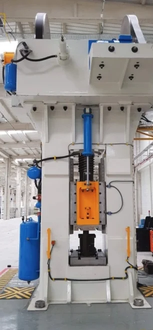
Hydraulic presses are essential tools in modern manufacturing, offering immense power and precision for a wide range of metal forming, molding, and assembly operations. Among the various types of hydraulic presses available today, the H-frame hydraulic press stands out as one of the most versatile and widely used designs. Named for its distinctive H-shaped frame, this press configuration offers exceptional stability and force distribution, making it ideal for high-force applications that require precision and reliability.
The H-frame design consists of two vertical columns and two horizontal crossbars that provide support for the hydraulic cylinder and the press bed. This rigid frame structure ensures that the press can handle the high forces required for tasks such as bending, straightening, forming, punching, and stamping large workpieces. The open space between the columns allows for easy access to the work area, enabling operators to process larger components than what might be possible with other types of presses, such as C-frame presses.
One of the key advantages of H-frame hydraulic presses is their ability to generate evenly distributed force across the workpiece, reducing the risk of deformation or misalignment. This makes them particularly valuable in industries that require high levels of precision, such as the automotive, aerospace, and metalworking industries. H-frame presses are also commonly used in maintenance and repair operations, where their ability to apply consistent pressure is essential for tasks like pressing bearings into place or straightening bent metal parts.
H-frame hydraulic presses come in a variety of sizes and configurations, ranging from small, manual presses used in workshops to large, automated systems capable of producing thousands of tons of force. Modern H-frame presses are equipped with advanced control systems that allow for precise adjustments to pressure, speed, and stroke length, making them suitable for both heavy-duty industrial applications and precision manufacturing tasks.
In addition to their versatility, H-frame hydraulic presses are known for their durability and reliability. The robust construction of the frame ensures that the press can withstand the high stresses of continuous operation, while the hydraulic system provides consistent force throughout the press cycle. With proper maintenance, H-frame presses can operate for many years, making them a cost-effective solution for manufacturers who require a reliable, high-performance press.
The enduring popularity of H-frame hydraulic presses can be attributed to their flexibility, power, and precision. Whether used for metal forming, molding, or assembly, these presses play a critical role in modern manufacturing, providing the strength and control needed to produce high-quality parts and components.
Historical Evolution of H-Frame Hydraulic Presses
The development of H-frame hydraulic presses is closely linked to the broader history of hydraulic press technology and its evolution over the centuries. Understanding how H-frame presses emerged as a standard in the manufacturing industry requires an exploration of early hydraulic press innovations, the impact of industrialization, and advancements in hydraulic system design.
2.1. Early Development of Hydraulic Presses
The principles of hydraulics have been understood for centuries, with the invention of the hydraulic press commonly attributed to Joseph Bramah, an English engineer who patented the first practical hydraulic press in 1795. Bramah’s design utilized Pascal’s Law, which states that when pressure is applied to a confined fluid, it is transmitted equally in all directions. This discovery enabled the development of a machine capable of generating significant force using a relatively small amount of pressure, laying the groundwork for modern hydraulic press technology.
The original hydraulic press designed by Bramah was used primarily for packing and compressing materials, such as cotton and paper. While these early presses were relatively simple, the concept of using hydraulics to amplify force revolutionized various industries, leading to the gradual improvement and diversification of hydraulic press designs.
2.2. Evolution of the H-Frame Design
The H-frame hydraulic press emerged as a result of the need for greater stability and force distribution during pressing operations. As hydraulic press applications expanded, there was a demand for more robust structures that could handle larger forces without flexing or deforming. The H-frame design, with its vertical columns and horizontal crossbars, provided a solution by creating a rigid, stable frame that could support high loads.
This configuration allowed for even distribution of force across the workpiece, reducing the risk of material deformation and ensuring consistent quality. The open space between the columns also provided easier access to the work area, enabling operators to process larger components and allowing for more versatility in industrial applications.
2.3. Influence of Industrialization on Hydraulic Press Technology
The Industrial Revolution, which began in the late 18th century, had a profound impact on the development and use of hydraulic presses, including the H-frame design. The mass production of goods, driven by advancements in machinery and manufacturing processes, led to an increased demand for powerful and reliable press equipment. Hydraulic presses were employed in various industries, such as metalworking, automotive, and construction, for tasks like metal forming, stamping, and bending.
During the 19th and early 20th centuries, significant advancements were made in hydraulic systems, including improvements in hydraulic pumps, cylinders, and fluid control mechanisms. These innovations allowed for the development of more powerful and efficient H-frame hydraulic presses, which became widely adopted in manufacturing and heavy industry.
2.4. The Shift from Mechanical to Hydraulic Systems
Before the widespread adoption of hydraulic presses, mechanical presses were the dominant technology used for metal forming and related applications. Mechanical presses operated using a flywheel, gears, and crank mechanisms to generate force. While they were effective for certain tasks, mechanical presses had limitations in terms of controlling force and adjusting stroke length.
The transition to hydraulic systems offered several advantages over mechanical presses, including:
- Variable force control: Hydraulic presses could apply a consistent force throughout the entire stroke, unlike mechanical presses where the force varied depending on the position of the crank.
- Adjustable stroke length: Hydraulic systems allowed operators to control the stroke length more precisely, making them suitable for a wider range of applications.
- Greater flexibility: Hydraulic presses could easily accommodate different tooling and dies, enabling rapid changes between tasks.
As these benefits became more evident, the H-frame hydraulic press gained popularity as a versatile and powerful solution for manufacturing operations. Its ability to generate significant force while providing precise control over the pressing process made it suitable for tasks that required high accuracy, such as automotive manufacturing, aerospace production, and metal fabrication.
2.5. Key Milestones in the Development of H-Frame Hydraulic Presses
Over the decades, several key milestones have marked the evolution of H-frame hydraulic presses, including:
- Introduction of high-pressure hydraulic systems: In the mid-20th century, advancements in hydraulic technology led to the development of high-pressure systems capable of generating thousands of tons of force. This increased the capabilities of H-frame presses, making them suitable for heavy-duty applications like forging and metal forming.
- Adoption of servo-hydraulic systems: The integration of servo-hydraulic technology allowed for more precise control of pressure, speed, and stroke length in H-frame presses. This innovation improved the accuracy and efficiency of pressing operations, enabling manufacturers to produce high-quality components with tight tolerances.
- Integration with computer numerical control (CNC): The adoption of CNC control systems revolutionized the operation of H-frame hydraulic presses, allowing for automated and programmable control over the pressing process. CNC integration enabled more complex operations, such as multi-stage forming, automated assembly, and precision stamping.
- Development of smart manufacturing systems: With the advent of Industry 4.0, H-frame hydraulic presses have been integrated into smart manufacturing environments that use IoT connectivity and real-time data monitoring. These systems enable predictive maintenance, performance optimization, and seamless integration with other manufacturing equipment.
Today, H-frame hydraulic presses are recognized as a cornerstone of modern manufacturing, providing the strength, versatility, and precision required for a wide range of industrial applications. Their continued development and integration with advanced technologies ensure that they remain relevant in an ever-evolving industrial landscape.
Design and Construction of H-Frame Hydraulic Presses
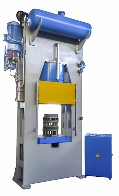
The H-frame hydraulic press is known for its robust construction, stability, and versatility. Its design consists of a simple yet effective configuration that includes two vertical columns and two horizontal crossbars forming an “H” shape, hence the name. This structural design allows the press to distribute force evenly, maintain rigidity under high loads, and accommodate various industrial applications.
3.1. Structural Overview: The H-Frame Design
The H-frame design is characterized by a symmetrical structure, which provides excellent support and stability. The two vertical columns serve as the primary supports, while the two horizontal crossbars connect these columns and house key components like the hydraulic cylinder, ram, and bed. This design ensures that the press can withstand the forces generated during pressing operations without flexing or deforming.
Key Characteristics of the H-Frame Design
- Symmetry: The symmetrical arrangement of the vertical columns and horizontal crossbars helps to balance the distribution of force across the entire structure.
- Open Work Area: The open space between the columns allows for easy access to the workpiece and enables the press to handle larger components compared to other press types like C-frame presses.
- Modular Design Options: The H-frame configuration can be easily customized with different accessories, die sets, and control systems to suit specific industrial requirements.
3.2. Key Components of H-Frame Hydraulic Presses
H-frame hydraulic presses consist of several key components that work together to perform pressing operations with precision and consistency.
3.2.1. Vertical Columns
The vertical columns are the backbone of the H-frame press. They provide the structural support needed to handle the immense forces generated during pressing. The columns are typically made of high-strength steel to ensure they can withstand heavy loads without buckling or bending.
- Reinforcement and thickness: The columns are designed with sufficient thickness and reinforcement to prevent deformation during high-pressure operations.
- Guide rails: Some H-frame presses feature guide rails mounted on the columns to ensure the ram moves vertically without tilting or misalignment.
3.2.2. Horizontal Crossbars
The upper and lower crossbars connect the vertical columns, providing structural stability and support for the hydraulic components.
- Upper crossbar: The upper crossbar supports the hydraulic cylinder and ram, allowing them to apply pressure to the workpiece.
- Lower crossbar (bed): The lower crossbar, also known as the bed, serves as the base where the workpiece is placed during pressing operations. It may include slots or holes for mounting dies, tooling, or fixtures.
3.2.3. Hydraulic Cylinder
The hydraulic cylinder is a critical component that generates the force needed to perform pressing operations. It consists of a piston, ram, and cylinder housing, which work together to convert hydraulic fluid pressure into mechanical force.
- Single-acting vs. double-acting cylinders: H-frame presses can use either single-acting cylinders, where hydraulic fluid only acts on one side of the piston, or double-acting cylinders, which allow fluid to act on both sides for greater control over the ram’s movement.
- Cylinder bore size and stroke length: The size of the cylinder bore and stroke length determine the press’s force capacity and the range of motion for the ram.
3.2.4. Ram and Punch
The ram is the moving component that transmits the force from the hydraulic cylinder to the workpiece. It is typically connected to a punch or other tooling used to shape, cut, or press the material.
- Ram guides: To ensure the ram moves vertically without deviation, guide rails or bushings may be installed to reduce lateral movement and improve precision.
- Punches and tooling: The ram can be fitted with various tooling, such as punches, dies, or forming tools, depending on the specific operation.
3.2.5. Work Table or Bed
The work table or bed is the surface where the workpiece is placed during pressing operations. It is usually made from hardened steel to withstand the impact and pressure of repeated pressing. The bed may also include:
- T-slots or mounting holes for securing dies, tooling, or fixtures.
- Adjustable positioning to accommodate different workpiece sizes and shapes.
3.2.6. Control Systems
Modern H-frame hydraulic presses are equipped with various control systems to regulate pressure, speed, and stroke length.
- Manual controls: Some basic H-frame presses use manual controls, such as hand-operated levers or foot pedals, to operate the press.
- Automated controls: Advanced presses are equipped with programmable logic controllers (PLCs) or computer numerical control (CNC) systems that allow for automated operation and precise adjustments.
- Servo-hydraulic systems: These systems use servo motors to control the hydraulic pump, enabling greater precision in pressure and speed adjustments.
3.3. Importance of Stability and Force Distribution in H-Frame Presses
The design of H-frame hydraulic presses ensures that the forces generated during pressing operations are evenly distributed across the structure. This stability is crucial for maintaining the accuracy and quality of the pressed components.
- Reduced risk of deformation: The rigid frame design minimizes flexing or bending, which could otherwise lead to inconsistencies in the workpiece.
- Consistent force application: The even distribution of force across the press bed ensures that the entire surface of the workpiece is subjected to uniform pressure, improving the overall quality of the formed or shaped part.
- Improved precision: The combination of stability and precise control systems in H-frame presses allows for high levels of accuracy, even when pressing large or complex workpieces.
3.4. Customization Options in H-Frame Hydraulic Presses
H-frame hydraulic presses can be customized to meet the specific needs of various industries and applications. Some common customization options include:
- Different tonnage capacities: H-frame presses are available in a range of force capacities, from small manual presses producing a few tons of force to large industrial presses capable of thousands of tons.
- Specialized tooling and accessories: Custom tooling, such as embossing dies, forming tools, and punches, can be fitted to the press for specific applications.
- Multi-station setups: Some H-frame presses can be configured with multiple stations to perform sequential operations, such as stamping, forming, and assembly.
- Hydraulic system configurations: The hydraulic system can be tailored with different pump types, cylinder arrangements, and fluid reservoirs to achieve the desired force and speed.
3.5. Material Choices and Durability of H-Frame Structures
The durability and longevity of an H-frame hydraulic press depend on the materials used in its construction.
- High-strength steel: Most H-frame presses are made from high-strength steel that can endure the stress of heavy-duty operations. This ensures the press maintains its structural integrity over time.
- Surface treatments: Surface treatments, such as chrome plating or heat treatment, may be applied to certain components, like the ram or work bed, to enhance durability and reduce wear.
Working Principle of H-Frame Hydraulic Presses
The H-frame hydraulic press operates based on the principles of hydraulic pressure and force amplification. It uses a hydraulic system to generate force, which is then applied to a workpiece to perform various tasks such as bending, forming, stamping, punching, or compression molding. The fundamental working principle is governed by Pascal’s Law, which states that pressure applied to a confined fluid is transmitted equally in all directions.
4.1. Basic Hydraulic Press Operation
The basic operation of an H-frame hydraulic press involves the following steps:
- Generating Hydraulic Pressure: The press’s hydraulic system consists of a hydraulic pump, fluid reservoir, and hydraulic cylinders. The pump pressurizes the hydraulic fluid (usually oil), which is stored in a reservoir and then sent through a system of valves and hoses to the hydraulic cylinder.
- Actuating the Hydraulic Cylinder: The pressurized hydraulic fluid enters the cylinder chamber, where it acts on the piston inside the hydraulic cylinder. The fluid pressure creates a mechanical force that pushes the piston and the attached ram downward to apply force on the workpiece.
- Applying Force to the Workpiece: The ram moves vertically, pressing against the workpiece placed on the bed. Depending on the application, the ram may be fitted with various tools, such as dies, punches, or forming attachments, to shape, cut, or compress the material.
- Returning the Ram to its Initial Position: Once the pressing operation is complete, the hydraulic pressure is released, and the ram is returned to its initial position, ready for the next operation. In double-acting hydraulic cylinders, pressurized fluid can be used on both sides of the piston to control the movement in both directions.
4.2. Force Transmission and Movement in H-Frame Designs
The structure of the H-frame hydraulic press ensures that the force is transmitted uniformly across the workpiece. The H-shaped frame supports the hydraulic cylinder and ram, providing a stable base for force application. The vertical columns and horizontal crossbars help maintain rigidity and distribute the force evenly, which is crucial for achieving consistent results.
Key Elements in Force Transmission
- Hydraulic cylinder: The hydraulic cylinder converts fluid pressure into mechanical force. The piston inside the cylinder moves vertically, driving the ram to apply pressure to the workpiece.
- Ram guides: Ram guides or bushings ensure that the ram moves straight and does not tilt or shift laterally. This alignment is essential for maintaining the precision and quality of the pressing operation.
- Bed support: The work bed serves as the base where the material is placed, and its robust construction ensures that it can handle the high forces without deforming.
4.3. Hydraulic Cylinder and Pump Mechanics
The hydraulic cylinder and pump work together to generate the force needed for pressing operations. Understanding the mechanics of these components is crucial for optimizing the performance of an H-frame hydraulic press.
4.3.1. Hydraulic Pump Operation
The hydraulic pump draws fluid from the reservoir and pressurizes it, sending it into the hydraulic system. The type of pump used can vary depending on the force requirements of the press:
- Gear pumps: Known for their simplicity and reliability, gear pumps are commonly used in basic hydraulic systems.
- Vane pumps: Vane pumps offer a good balance between pressure and flow rate, making them suitable for presses that need moderate control.
- Piston pumps: These pumps provide high-pressure capabilities and are often used in heavy-duty presses that generate thousands of tons of force.
4.3.2. Cylinder Mechanics
The cylinder bore size, stroke length, and piston diameter all play a role in determining the force output and range of motion. Larger bore sizes and pistons can generate higher forces, while longer stroke lengths provide more flexibility in pressing different workpiece sizes.
4.4. Application of Force to Workpieces
The ability of an H-frame hydraulic press to apply force uniformly makes it suitable for a variety of industrial applications. The way the press applies force to a workpiece can be customized to achieve different outcomes.
4.4.1. Metal Forming
In metal forming, the ram and die are used to shape the metal workpiece into the desired form. The press applies steady, controlled pressure to bend or stretch the metal without causing cracks or deformities. Common metal forming tasks include:
- Bending: Creating angles and curves in metal sheets.
- Stamping: Forming metal shapes or embossing designs onto sheets.
- Punching: Cutting holes or shapes in metal sheets.
4.4.2. Compression Molding
In compression molding, the press is used to shape materials like plastics, rubber, or composites by compressing them into a mold. The H-frame hydraulic press ensures consistent pressure throughout the molding process, resulting in uniform parts with minimal defects.
4.4.3. Assembly Operations
For assembly tasks, H-frame presses are used to press bearings, bushings, or other components into place. The press applies precise pressure to ensure the components fit snugly and securely, reducing the risk of damage.
4.5. Importance of Pressure Control and Force Distribution
The control of hydraulic pressure and force distribution is crucial for achieving high-quality pressing results. Advanced control systems in modern H-frame hydraulic presses allow operators to fine-tune the pressure, speed, and stroke length, enabling greater precision in various applications.
4.5.1. Pressure Regulation
Pressure regulation ensures that the hydraulic system maintains a consistent force during the press cycle. Relief valves, pressure regulators, and flow controls are used to monitor and adjust the pressure to prevent overloading or underperformance.
4.5.2. Force Distribution
The even distribution of force across the press bed ensures that the entire workpiece is subjected to uniform pressure. This is essential for applications like sheet metal forming or compression molding, where uneven pressure can lead to warping or defects.
4.6. Control Systems and Automation in Modern H-Frame Presses
Modern H-frame hydraulic presses are equipped with automated control systems, such as CNC, PLC, or servo-hydraulic systems, that enhance the precision and efficiency of pressing operations.
4.6.1. Programmable Logic Controllers (PLCs)
PLCs allow operators to program specific parameters for each pressing task, such as force levels, stroke lengths, and cycle speeds. This automation reduces the need for manual adjustments and improves productivity.
4.6.2. Servo-Hydraulic Control
Servo-hydraulic systems use servo motors to control the hydraulic pump, providing real-time adjustments to the press’s force and speed. This capability allows for dynamic pressure control, which is beneficial in tasks requiring high precision.
4.6.3. IoT Integration and Smart Presses
With the integration of IoT connectivity, H-frame hydraulic presses can be connected to smart manufacturing networks. These smart presses provide real-time data on performance metrics, predictive maintenance alerts, and process optimization insights.
Key Applications of H-Frame Hydraulic Presses
H-frame hydraulic presses are versatile machines used across numerous industries due to their ability to generate significant force while maintaining precision and stability. Their robust design, open work area, and customizable configurations make them suitable for a wide range of applications. Below are some of the most common uses of H-frame hydraulic presses in various industries.
5.1. Metal Forming and Fabrication
One of the primary applications of H-frame hydraulic presses is in metal forming and fabrication. The press is used to manipulate metal sheets, plates, and other materials into various shapes and sizes. Key metal forming tasks performed using H-frame presses include bending, straightening, forming, stamping, and punching.
- Bending: H-frame hydraulic presses are used to create precise bends and curves in metal sheets. By applying controlled pressure, the press can shape the metal without causing cracks or material fatigue, making it suitable for producing brackets, frames, panels, and angles.
- Straightening: When metal parts become bent or warped during manufacturing, H-frame presses can be used to straighten them. This is common in industries like metalworking and construction, where steel beams, bars, or rods need to be restored to their original shape.
- Forming complex shapes: The press can also be used to form intricate shapes or components by using specialized dies. This capability is valuable in automotive and aerospace applications, where parts need to meet strict design specifications.
5.2. Automotive Manufacturing
The automotive industry is a major user of H-frame hydraulic presses. These machines are essential for producing various car components and parts that require high precision, durability, and strength. Common applications in the automotive industry include pressing bearings, forming chassis components, and punching engine parts.
- Pressing bearings: H-frame presses are widely used in automotive repair and assembly lines to press bearings into place in engine blocks, wheel hubs, and transmissions. The ability to apply precise pressure ensures that the bearings are installed correctly without causing damage to surrounding components.
- Chassis components: In manufacturing chassis components like cross members, support beams, and suspension parts, H-frame presses are used to form or shape metal parts with consistent quality. The press’s ability to handle large workpieces makes it ideal for producing these structural components.
- Punching and stamping engine parts: H-frame presses can perform high-precision punching and stamping operations to produce small engine components, such as valve covers, brackets, and housings. The press ensures each part is formed accurately, meeting the required tolerances for reliable engine performance.
5.3. Aerospace Industry
In the aerospace industry, H-frame hydraulic presses are used to produce lightweight, high-strength components that must meet exacting quality standards. Aerospace manufacturing often involves forming, punching, or stamping materials like aluminum, titanium, and composites.
- Forming lightweight structural components: H-frame presses are used to shape aircraft panels, fuselages, and wing structures, where the material must be lightweight yet strong. The precision and even force distribution provided by the H-frame design ensure that these components meet stringent aerodynamic and structural requirements.
- Turbine blades and high-strength parts: Hydraulic presses are used to form parts for jet engines, such as turbine blades and engine housings, where materials need to be shaped to withstand high temperatures and mechanical stress.
5.4. Heavy Machinery and Industrial Equipment
The heavy machinery and industrial equipment industries rely on H-frame hydraulic presses for producing large, high-strength components used in construction, mining, and agricultural equipment. Common applications include forging, stamping, and shaping parts such as gears, shafts, bearings, and machine components.
- Forging and stamping gears and shafts: H-frame hydraulic presses are used to forge metal into shapes like gears and shafts, which are crucial components in heavy machinery. The press applies consistent pressure to ensure that each part is formed to the exact specifications required for high performance.
- Compression molding in rubber and plastics: In the production of rubber seals, plastic housings, and gaskets, H-frame presses are used for compression molding, where the material is shaped and hardened under high pressure and heat.
5.5. General Maintenance and Repair
H-frame hydraulic presses are not only used in manufacturing but also play a crucial role in maintenance and repair work. Their ability to generate high force with precision makes them ideal for tasks such as straightening bent parts and pressing bearings.
- Straightening bent parts: In repair shops, H-frame presses are commonly used to restore bent metal parts, such as axles, rods, and framework, to their original shape. By applying controlled pressure in the opposite direction of the bend, the press can gradually straighten the part without causing further damage.
- Pressing bearings into place: H-frame presses are used to install bearings into various mechanical systems, including engines, gearboxes, and machinery. The press ensures that the bearings are seated securely, improving the reliability and longevity of the equipment.
5.6. Assembly and Production Lines
H-frame hydraulic presses are frequently integrated into assembly lines and production facilities, where they are used to perform sequential operations on a workpiece. These presses can be customized to handle different tasks, such as multi-stage manufacturing and assembly operations.
- Multi-stage manufacturing: H-frame presses can be configured with multiple stations to carry out sequential operations, such as forming, cutting, punching, and bending. This setup increases productivity by reducing the need to transfer parts between different machines.
- Assembly operations in automated settings: H-frame presses are used in automated production lines to perform tasks such as riveting, joining, and inserting components. The ability to automate these processes ensures consistency, speed, and reduced labor costs.
5.7. Specialized Applications
In addition to the common uses mentioned above, H-frame hydraulic presses are employed in various specialized applications, where their precision, force capacity, and customization options make them suitable for unique industrial tasks.
- Medical device manufacturing: In the production of medical devices and surgical tools, H-frame presses are used to shape and form metal components with tight tolerances, ensuring that each part meets stringent healthcare standards.
- Art and sculpture: Artists and sculptors use H-frame hydraulic presses to shape metal, plastics, and other materials into creative designs. The press’s ability to apply controlled pressure enables the creation of intricate shapes and patterns.
- Prototype development: In research and development labs, H-frame presses are used to create prototypes and test samples. Their flexibility and precision make them ideal for small-batch production runs, where new materials or designs are being evaluated.
Advantages of H-Frame Hydraulic Presses
H-frame hydraulic presses offer several advantages that make them the preferred choice for a wide range of industrial applications. These presses are recognized for their versatility, high force capacity, precision, and stability, making them suitable for tasks ranging from metal forming to assembly operations. Below are some of the key benefits that set H-frame hydraulic presses apart from other types of presses.
6.1. High Force Capacity and Structural Integrity
One of the primary advantages of H-frame hydraulic presses is their ability to generate high force, which makes them suitable for heavy-duty applications. The robust H-frame design ensures that the press can handle significant loads without compromising structural integrity.
- Handling High-Pressure Tasks: The H-frame press can produce forces ranging from a few tons to several thousand tons, allowing it to perform high-pressure tasks such as metal forging, stamping, and bending. The ability to generate consistent force throughout the stroke length ensures that even thick or tough materials can be shaped or compressed effectively.
- Structural Integrity for Heavy-Duty Applications: The H-shaped frame, with its vertical columns and horizontal crossbars, provides excellent stability, which prevents the press from flexing or deforming under high loads. This structural integrity is essential for applications that require consistent pressure, such as precision stamping and compression molding.
6.2. Versatility Across a Wide Range of Applications
H-frame hydraulic presses are incredibly versatile, capable of performing multiple tasks with different materials. This adaptability makes them suitable for a wide range of industries, including automotive, aerospace, metalworking, plastic molding, and maintenance.
- Metal Forming and Fabrication: The press is commonly used for tasks such as bending, straightening, stamping, punching, and forming metal components. The ability to adjust force, speed, and stroke length allows operators to customize the press for specific metalworking tasks.
- Compression Molding: H-frame presses can be used to mold rubber, plastics, and composites by applying uniform pressure to a mold, ensuring the material takes on the desired shape. This process is often used in the production of gaskets, seals, and plastic housings.
- Assembly and Maintenance: The precision and control offered by H-frame presses make them ideal for assembly tasks, such as pressing bearings into place or installing bushings. They are also used in repair shops to straighten bent parts or press components back into shape.
6.3. Precision and Control: Why H-Frames are Ideal for High-Accuracy Work
Precision is a key requirement in many manufacturing processes, and H-frame hydraulic presses provide the control and accuracy needed for high-quality results.
- Adjustable Pressure and Stroke Control: Modern H-frame presses come equipped with advanced control systems that allow operators to fine-tune the pressure, speed, and stroke length. This level of control ensures that the press can produce consistent results, even when working with materials that require tight tolerances.
- Dynamic Force Application: The press can apply force dynamically, meaning that the pressure can be adjusted in real-time based on the requirements of the task. This capability is particularly valuable in applications like metal forming, where different stages of the process may require varying levels of force.
- Automation and Precision Control Systems: Many H-frame hydraulic presses are integrated with computer numerical control (CNC) or programmable logic controllers (PLCs) that allow for automated operation and greater accuracy in complex tasks. Servo-hydraulic systems also provide real-time adjustments to force and speed, enhancing the precision of the press.
6.4. Stability and Even Force Distribution: Ensuring Quality Results
The H-frame design offers exceptional stability and ensures that the force applied to the workpiece is distributed evenly. This characteristic is crucial for maintaining the quality of the finished product and preventing defects.
- Minimizing Deformation and Warping: The even distribution of force across the press bed helps reduce the risk of deformation or warping, especially in materials like sheet metal or plastics. The rigid frame design prevents the press from bending under load, ensuring consistent force application.
- High Stability for Large Workpieces: H-frame presses are well-suited for handling large workpieces that may be difficult to process using other types of presses, such as C-frame presses. The open work area allows for greater flexibility in positioning the material, while the frame’s stability ensures that the press can handle the high forces required for large parts.
- Precision Alignment: The vertical columns and ram guides ensure that the ram moves smoothly and remains aligned throughout the pressing operation, reducing the risk of misalignment or lateral movement that could compromise the quality of the workpiece.
6.5. Ability to Handle Large Workpieces and Complex Shapes
H-frame hydraulic presses are ideal for tasks involving large or irregularly shaped workpieces. Their open-front design allows operators to position materials easily and handle parts that may not fit within other press configurations.
- Accommodating Different Sizes and Shapes: The open design of the H-frame press enables operators to work with large sheets, panels, bars, and other sizable materials. The press can also be fitted with specialized tooling to accommodate complex shapes or multi-stage operations, such as forming, trimming, and piercing.
- Flexibility in Tooling and Setup: The H-frame configuration allows for the use of interchangeable tooling, such as different dies, punches, or forming attachments, making it easy to adapt the press for various applications. This flexibility is beneficial in industries where product designs or manufacturing requirements change frequently.
6.6. Customization Potential for Specific Industry Needs
H-frame hydraulic presses can be customized to meet the specific requirements of different industries. Manufacturers can choose from various options for tonnage capacity, stroke length, bed size, and control systems to create a press that is optimized for their application.
- Wide Range of Tonnage Capacities: H-frame presses are available in different force capacities, from a few tons to thousands of tons, making it possible to find the right press for tasks ranging from light assembly work to heavy metal forming.
- Modular Design Options: Some H-frame presses feature modular components, such as interchangeable rams, beds, or hydraulic systems, allowing users to reconfigure the press for different tasks. This modularity increases the versatility of the press and extends its service life.
- Industry-Specific Customizations: Customizations can include servo-hydraulic systems for real-time force adjustments, CNC controls for automated operation, and IoT connectivity for integration with smart manufacturing systems. These enhancements improve the press’s performance in applications like precision metalworking, automotive assembly, and aerospace manufacturing.
6.7. Cost-Effectiveness for Heavy-Duty Manufacturing
H-frame hydraulic presses are a cost-effective solution for industries that require reliable, high-performance pressing equipment. Their durability, versatility, and ease of maintenance contribute to long-term savings and operational efficiency.
- Long Service Life: The robust construction of the H-frame press ensures that it can withstand continuous use in demanding environments. With proper maintenance, an H-frame press can last for many years, making it a wise investment for manufacturers.
- Lower Maintenance Costs: Compared to more complex machinery, H-frame hydraulic presses have fewer moving parts, which reduces the likelihood of breakdowns and lowers maintenance costs. Routine maintenance, such as inspecting hydraulic fluid levels, cleaning filters, and checking for leaks, is usually sufficient to keep the press in good working condition.
- Reduced Material Waste: The precision and control offered by H-frame presses help reduce material waste during pressing operations. By ensuring that each part is formed accurately, the press minimizes the need for secondary processing or rework, saving time and material costs.
6.8. Safety Features and Operator Protection
Modern H-frame hydraulic presses are equipped with various safety features designed to protect operators and prevent accidents.
- Emergency Stop Mechanisms: Emergency stop buttons allow operators to halt the press immediately if a problem is detected. This feature is essential for preventing accidents during high-pressure operations.
- Guarding and Light Curtains: Many H-frame presses are equipped with safety guards or light curtains that detect the presence of hands or objects in the work area. These systems automatically stop the press if a safety breach is detected, reducing the risk of injury.
- Pressure Relief Valves: Pressure relief valves prevent overloading by releasing excess hydraulic pressure, ensuring that the press operates within safe limits.
6.9. Sustainability and Energy Efficiency
The integration of advanced control systems and energy-efficient components has made modern H-frame hydraulic presses more sustainable.
- Energy-Efficient Hydraulic Systems: Newer models of H-frame presses feature energy-saving hydraulic pumps that operate only when the press is in use. This reduces energy consumption and lowers operational costs.
- Use of Eco-Friendly Hydraulic Fluids: Some presses are compatible with biodegradable hydraulic fluids, which minimize environmental impact in case of a leak or spill.
- Energy Recovery Systems: In some servo-hydraulic presses, energy recovery systems are used to capture and reuse the energy generated during the press cycle, further improving energy efficiency.
Comparison to Other Types of Hydraulic Presses
H-frame hydraulic presses are one of several types of hydraulic presses used in industrial applications. Each type of press has its own advantages and limitations, making certain designs more suitable for specific tasks. This section compares H-frame hydraulic presses with other common types, such as C-frame presses, four-column presses, and servo-hydraulic presses, to highlight their unique characteristics and appropriate use cases.
7.1. H-Frame vs. C-Frame Hydraulic Presses
C-frame hydraulic presses, also known as gap-frame presses, feature an open-front design that resembles the shape of the letter “C.” This design provides easy access to the work area from three sides, making it ideal for tasks that require frequent loading and unloading of small workpieces.
Advantages of H-Frame Presses Over C-Frame Presses
- Higher Stability and Force Distribution: The H-frame design provides better stability and even force distribution compared to C-frame presses. This is particularly important for high-pressure tasks and large workpieces, where stability is essential to prevent frame deformation and ensure consistent results.
- Higher Force Capacity: H-frame presses generally have higher force capacities than C-frame presses, making them suitable for heavy-duty applications, such as forging, deep drawing, and metal forming.
Advantages of C-Frame Presses Over H-Frame Presses
- Compact Size and Space Efficiency: C-frame presses have a smaller footprint and are more space-efficient, making them ideal for workshops or production lines with limited space.
- Ease of Access: The open-front design allows operators to load and unload materials quickly, making C-frame presses better suited for tasks like assembly, small part production, and repetitive stamping operations.
7.2. H-Frame vs. Four-Column Hydraulic Presses
Four-column hydraulic presses, also known as four-post presses, have four vertical columns that support the upper and lower crossheads, providing a large, open work area. This design is known for its ability to evenly distribute force across the entire workpiece.
Advantages of H-Frame Presses Over Four-Column Presses
- Flexibility in Customization: H-frame presses are often more easily customizable than four-column presses. The frame design allows for modifications to accommodate different tooling, stroke lengths, and bed sizes, making them suitable for a wider range of applications.
- Cost-Effectiveness: H-frame presses tend to be more affordable than four-column presses with similar force capacities. This makes them a cost-effective choice for industries that require high-performance pressing equipment without the need for a large open work area.
Advantages of Four-Column Presses Over H-Frame Presses
- Larger Work Area: Four-column presses offer a larger, open work area, which is advantageous for handling large or irregularly shaped workpieces. This design is particularly useful in applications like deep drawing and large sheet metal forming, where space is needed for material movement.
- Greater Stability for Large Workpieces: The four-column structure provides enhanced stability when handling heavy or oversized materials, ensuring consistent pressure across the entire surface of the workpiece.
7.3. H-Frame vs. Servo-Hydraulic Presses
Servo-hydraulic presses integrate servo motor technology into the hydraulic system, allowing for precise control over force, speed, and position. These presses are often used in applications that require high precision and variable pressure settings.
Advantages of H-Frame Presses Over Servo-Hydraulic Presses
- Lower Initial Cost: H-frame hydraulic presses are generally less expensive than servo-hydraulic presses, making them more accessible for businesses with budget constraints.
- Simplicity in Operation: H-frame presses have a more straightforward hydraulic system, which makes them easier to maintain and operate compared to the complex servo-hydraulic systems. This simplicity can be beneficial in environments where operator training is limited.
Advantages of Servo-Hydraulic Presses Over H-Frame Presses
- Precision Control and Automation: Servo-hydraulic presses offer real-time adjustments to force, speed, and stroke length, allowing for greater accuracy in complex pressing tasks. The ability to fine-tune parameters makes servo-hydraulic presses suitable for industries like electronics, medical device manufacturing, and aerospace.
- Energy Efficiency: The integration of servo motors allows for better energy management, as the motor only consumes energy when needed. This makes servo-hydraulic presses more energy-efficient than traditional hydraulic presses, reducing operational costs.
7.4. When to Choose H-Frame Presses Over Other Types
H-frame hydraulic presses are the ideal choice for tasks that require high force capacity, stability, and versatility. The decision to use an H-frame press over other types depends on the specific requirements of the application.
H-Frame Presses Are Ideal For:
- Heavy-Duty Applications: Tasks such as metal forging, stamping, deep drawing, and compression molding require presses that can generate significant force and maintain structural integrity under high loads.
- Large Workpieces: When handling large sheets, panels, or irregularly shaped components, the H-frame’s stability and ability to accommodate different tooling make it a suitable choice.
- Customizable Setups: Industries that require customizable setups with interchangeable tooling, modular components, or multiple workstations can benefit from the flexibility of the H-frame design.
Other Press Types Are Better Suited For:
- High-Precision, Low-Tonnage Tasks: For tasks that demand high precision but do not require significant force, such as electronics manufacturing or fine metalwork, servo-hydraulic or C-frame presses may be more appropriate.
- Compact Workspaces: C-frame presses are ideal for workshops or production lines where space is limited, as their open-front design facilitates quick material handling and operator access.
- Large-Scale Metal Forming: For tasks that require a large open work area and consistent pressure distribution over extensive surfaces, such as large sheet metal forming or deep drawing, four-column presses may be the better option.
Technological Advancements in H-Frame Hydraulic Presses
Recent technological advancements have significantly improved the performance, efficiency, and precision of H-frame hydraulic presses, making them more versatile and suitable for modern industrial applications. These innovations include the integration of servo-hydraulic systems, automated control, IoT connectivity, and energy-efficient components, which collectively enhance the functionality of H-frame presses and expand their range of applications.
8.1. Integration of Servo-Hydraulic Systems for Precision Control
Servo-hydraulic systems have brought significant advancements to H-frame hydraulic presses by combining the power of hydraulics with the precision of servo motor technology. In servo-hydraulic presses, a servo motor is used to control the hydraulic pump, allowing for real-time adjustments to pressure, speed, and stroke length.
Key Benefits of Servo-Hydraulic Systems
- Enhanced Precision and Accuracy: Servo-hydraulic technology enables precise control over the force and movement of the ram, making it suitable for high-precision applications such as metal forming, stamping, and assembly tasks that require tight tolerances.
- Variable Pressure Settings: Unlike traditional hydraulic systems, where pressure is fixed, servo-hydraulic presses allow operators to adjust pressure dynamically based on the requirements of the specific task. This capability helps prevent material damage and defects during pressing operations.
- Energy Efficiency: The use of servo motors allows the press to consume energy only when needed, reducing overall energy consumption and operational costs. This makes servo-hydraulic presses more sustainable and eco-friendly.
8.2. Adoption of CNC and PLC Controls for Automation
The integration of Computer Numerical Control (CNC) and Programmable Logic Controllers (PLCs) has revolutionized the operation of H-frame hydraulic presses by enabling automated control and programming of complex tasks.
Advantages of CNC and PLC Integration
- Automated Operation: CNC and PLC systems allow operators to program specific parameters for each pressing task, including force levels, stroke length, ram speed, and dwell time. This automation increases productivity by reducing the need for manual adjustments.
- Consistency and Repeatability: By using automated control systems, H-frame presses can produce consistent results with high repeatability, ensuring that each part meets the required specifications. This is especially beneficial in industries such as automotive and aerospace, where product quality is critical.
- Multi-Stage Operations: CNC and PLC controls make it possible to perform multi-stage operations, such as forming, trimming, and punching, in a single setup. This capability streamlines the production process and reduces the time needed to switch between tasks.
8.3. IoT and Smart Manufacturing Integration
The adoption of Industry 4.0 technologies has brought IoT connectivity and smart manufacturing capabilities to H-frame hydraulic presses. These advancements enable real-time monitoring, predictive maintenance, and process optimization.
Benefits of IoT-Enabled H-Frame Presses
- Real-Time Data Monitoring: IoT-enabled presses can collect real-time data on parameters such as pressure, stroke length, cycle time, and hydraulic fluid temperature. This data can be analyzed to optimize the pressing process, identify areas for improvement, and ensure consistent product quality.
- Predictive Maintenance: By monitoring the condition of the press and its components, IoT systems can detect signs of wear and tear or potential issues before they result in machine failure. This predictive maintenance approach helps reduce downtime and extend the service life of the press.
- Remote Control and Diagnostics: IoT connectivity allows operators and technicians to remotely monitor the press’s performance and diagnose problems. This capability is especially useful for multi-site manufacturing operations, where presses in different locations can be managed from a central control hub.
8.4. Energy Efficiency Innovations in Modern H-Frame Presses
As energy efficiency becomes a greater priority in manufacturing, new technologies have been developed to reduce the energy consumption of H-frame hydraulic presses. These innovations not only help companies lower their operational costs but also support sustainability initiatives.
Energy-Saving Hydraulic Pumps
- Variable Displacement Pumps: Modern H-frame presses are often equipped with variable displacement pumps, which adjust the amount of hydraulic fluid being pumped based on the press’s requirements. This reduces energy waste by supplying only the necessary amount of fluid.
- Servo-Driven Pumps: Servo-driven pumps use servo motors to control the flow of hydraulic fluid. They are more efficient than traditional pumps because they can modulate speed and pressure according to the task, leading to lower energy consumption.
Energy Recovery Systems
- Regenerative Circuits: Some H-frame presses are equipped with regenerative hydraulic circuits that capture and reuse energy generated during the press cycle. This technology helps reduce energy consumption by recycling the energy used in the pressing operation.
- Energy Storage Systems: Hydraulic accumulators can be used to store excess energy generated during the press cycle. This stored energy can then be released to assist with subsequent press operations, reducing the demand on the hydraulic pump.
8.5. Advances in Safety Features for Operator Protection
Safety is a top priority in industrial environments, and H-frame hydraulic presses have benefited from advancements in safety features that protect operators from accidents.
Light Curtains and Guarding Systems
- Light Curtains: Light curtains create an invisible barrier around the work area. If the barrier is broken, the press will automatically stop to prevent injury. This feature is widely used in automated production lines to enhance operator safety.
- Safety Guarding: H-frame presses can be equipped with physical guards that prevent hands or tools from entering dangerous areas. These guards are designed to ensure that the operator remains at a safe distance from the moving parts of the press.
Emergency Stop Mechanisms
- Multiple Emergency Stop Buttons: Modern H-frame presses feature emergency stop buttons that are placed in strategic locations to allow operators to quickly halt the press in case of an emergency. Some models even have foot-operated safety pedals.
- Automatic Pressure Relief Systems: Pressure relief valves and safety interlocks ensure that the press does not exceed its maximum pressure limit, preventing equipment damage and operator injury.
8.6. Customizable Tooling and Modular Design Advancements
The ability to customize tooling and use a modular design enhances the flexibility and adaptability of H-frame hydraulic presses. This allows manufacturers to quickly adapt the press for different tasks.
Quick-Change Tooling
- Interchangeable Tool Sets: H-frame presses can be equipped with interchangeable tool sets that allow operators to switch between different tools, such as dies, punches, and forming attachments, with minimal downtime.
- Automated Tool Change Systems: Automated tool changers enable the press to switch between tools without manual intervention, reducing setup time and increasing productivity.
Modular Frames for Easy Upgrades
- Modular Frame Components: Some H-frame presses feature modular frames that can be easily upgraded or reconfigured to meet changing production requirements. For example, the press bed, ram, or hydraulic system can be modified to accommodate different materials or processes.
- Scalable Tonnage Capacities: Modular designs also allow for scalable tonnage capacities, enabling manufacturers to upgrade the press to a higher force capacity without replacing the entire machine.
8.7. Smart Technology Integration for Process Optimization
The integration of smart technology, including machine learning and artificial intelligence (AI), is transforming the capabilities of H-frame hydraulic presses. These technologies enable presses to self-optimize and improve process efficiency.
AI-Driven Process Optimization
- Adaptive Control Systems: AI-driven control systems can adjust pressing parameters in real time based on feedback from sensors, ensuring optimal performance for each task. This capability reduces material waste and improves cycle times.
- Machine Learning for Predictive Maintenance: By analyzing data collected from previous operations, machine learning algorithms can predict when maintenance will be needed, allowing for proactive repairs that reduce the risk of unexpected downtime.
Cloud-Based Data Analysis
- Cloud Connectivity: Some smart H-frame presses are connected to cloud-based platforms that store and analyze data on press performance. This data can be accessed remotely, allowing manufacturers to make data-driven decisions and continuously optimize production processes.
- Big Data for Quality Control: Using big data analytics, manufacturers can detect patterns in the pressing process that may indicate quality issues, allowing for timely adjustments to maintain high product standards.
Safety Considerations for Operating H-Frame Hydraulic Presses
H-frame hydraulic presses are powerful machines that can pose risks to operators if not used safely. Ensuring operator safety requires understanding the potential hazards associated with hydraulic presses, following safety standards, using protective features, and practicing proper maintenance and training. This section covers key safety considerations and best practices for the safe operation of H-frame hydraulic presses.
9.1. Overview of Hydraulic Press Safety Standards
Various organizations set safety standards for hydraulic press operation, which are designed to protect workers and reduce the risk of accidents. Key safety standards include:
- Occupational Safety and Health Administration (OSHA): OSHA provides guidelines on safe press operation, including requirements for guarding, emergency stop mechanisms, and training for operators.
- American National Standards Institute (ANSI): The ANSI B11.2 standard outlines the safety requirements for hydraulic and pneumatic presses, including guidelines for mechanical guards, control systems, and safety interlocks.
- European Machinery Directive (CE Marking): In Europe, hydraulic presses must meet the CE marking requirements to ensure they comply with European safety standards.
Compliance with these standards helps to minimize risks and ensure a safe working environment.
9.2. Common Hazards Associated with Hydraulic Press Operation
Operating an H-frame hydraulic press involves certain risks that must be managed to prevent accidents. Some common hazards include:
- Crushing Injuries: The most significant risk is the potential for crushing injuries if an operator’s hand or body part is caught between the ram and the bed. The immense force generated by the press can cause severe injury or death.
- High-Pressure Fluid Leaks: Hydraulic fluid leaks under high pressure can be dangerous, as they can cause injection injuries if the fluid penetrates the skin. Additionally, leaks can lead to slips and falls if the fluid spills on the floor.
- Ejection of Parts or Material: If a workpiece is not securely clamped or the press is overloaded, there is a risk that parts or materials could be ejected from the press at high speed, potentially injuring nearby workers.
- Mechanical Failures: Failures in components such as cylinders, valves, or hydraulic lines can lead to unexpected press movements or loss of pressure, creating hazardous conditions.
9.3. Key Safety Features in H-Frame Hydraulic Presses
Modern H-frame hydraulic presses come equipped with various safety features that help protect operators from accidents and injuries.
9.3.1. Guarding and Light Curtains
- Guarding: Physical guards are used to prevent operators from reaching into the danger zone during press operation. These guards may be made of metal, plastic, or transparent materials to provide visibility while maintaining protection.
- Light Curtains: Light curtains create a virtual barrier around the work area. If an operator’s hand or body part crosses the light beam while the press is in motion, the machine automatically stops to prevent injury.
9.3.2. Emergency Stop Buttons
- Multiple Emergency Stop Buttons: Emergency stop buttons are typically placed in accessible locations around the press, allowing operators to quickly halt the press if a hazardous situation arises. Some presses also have foot-operated emergency stops for added convenience.
- Redundant Safety Systems: In some presses, redundant safety systems are used to ensure that the press stops immediately if the emergency stop is activated, even if there is a failure in one part of the control system.
9.3.3. Pressure Relief Valves and Interlocks
- Pressure Relief Valves: These valves help prevent over-pressurization of the hydraulic system by releasing excess pressure, thereby protecting the press and operators from damage.
- Safety Interlocks: Interlock systems prevent the press from operating if the guards or doors are not in place. This ensures that operators cannot accidentally start the press when it is in an unsafe condition.
9.4. Importance of Regular Maintenance and Inspection
Regular maintenance and inspection are crucial for ensuring that an H-frame hydraulic press remains in safe operating condition. A preventive maintenance program helps identify potential issues before they result in machine failure or accidents.
9.4.1. Hydraulic System Maintenance
- Checking Hydraulic Fluid Levels: Hydraulic fluid should be kept at the recommended level and replaced regularly to ensure proper operation. Contaminated or low fluid levels can affect the press’s performance and increase the risk of failure.
- Inspecting Hoses and Seals for Leaks: Regular inspection of hoses, seals, and cylinders can help identify leaks early, preventing accidents related to high-pressure fluid ejection.
9.4.2. Mechanical Component Inspection
- Checking for Wear and Tear: The frame, ram guides, tooling, and bolts should be inspected for signs of wear or damage. Replacing worn components helps maintain the integrity of the press and reduces the risk of mechanical failure.
- Ram Alignment: Ensuring the ram is properly aligned reduces the likelihood of misaligned pressing, which can cause defects in the workpiece and pose safety risks.
9.5. Training and Certification for Operators
Operators of H-frame hydraulic presses must be properly trained to understand the safe operation procedures and potential hazards associated with these machines.
9.5.1. Safety Training Programs
- Hands-On Training: New operators should undergo hands-on training with experienced personnel to learn how to operate the press safely. This training should cover basic operations, emergency procedures, and safety features.
- Refresher Courses: Periodic safety training and refresher courses help keep operators up to date on new safety practices, regulations, and machine upgrades.
9.5.2. Operator Certification
- Certification Programs: In some industries, operators must obtain certification to work with hydraulic presses. Certification programs ensure that workers have the necessary skills and knowledge to operate the press safely.
- Compliance with Safety Regulations: Certified operators are better equipped to comply with safety regulations and standards set by organizations like OSHA, ANSI, or CE, reducing the risk of workplace accidents.
9.6. Best Practices for Safe Operation in Industrial Settings
Adhering to best practices for safe operation helps minimize risks when using H-frame hydraulic presses.
9.6.1. Using Proper Personal Protective Equipment (PPE)
- Gloves, Goggles, and Hearing Protection: Operators should wear appropriate PPE, such as gloves, safety goggles, and hearing protection, to protect against potential injuries from flying debris, loud noises, or sharp edges.
- Fire-Resistant Clothing: When working with hot materials or combustible fluids, fire-resistant clothing can reduce the risk of burns or fire-related injuries.
9.6.2. Implementing Lockout/Tagout Procedures
- Lockout/Tagout (LOTO): LOTO procedures ensure that the press is fully de-energized and locked out before maintenance or repair work is performed. This prevents accidental activation and protects workers during servicing.
9.6.3. Ensuring the Workpiece is Securely Clamped
- Proper Clamping and Positioning: Before operating the press, the workpiece should be securely clamped and properly positioned to prevent it from shifting or being ejected during the pressing operation.
Introduction to Four-Column Hydraulic Presses
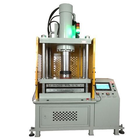
Four-column hydraulic presses are powerful and versatile machines that utilize hydraulic pressure to perform a variety of metal forming, molding, and assembly operations. The name “four-column” comes from the press’s structural design, which includes four vertical columns that provide support for the upper and lower crossheads, creating a large, open work area. This design allows for the even distribution of force across the entire workpiece, making four-column presses ideal for tasks that require high precision and consistency.
Four-column hydraulic presses are used in various industries, including automotive, aerospace, electronics, appliance manufacturing, and plastics and rubber molding. Their ability to generate significant force while maintaining precise control over pressure and movement makes them suitable for tasks such as deep drawing, stamping, embossing, and compression molding.
The unique design of four-column hydraulic presses offers several advantages over other press types, such as H-frame or C-frame presses. The four-column structure provides greater stability and accessibility, allowing operators to work with large or irregularly shaped workpieces. Additionally, the open work area makes it easier to handle complex tooling and multi-stage operations.
Modern four-column presses are equipped with advanced control systems, such as servo-hydraulic, CNC, or PLC automation, which allow for precise adjustments to force, speed, and stroke length. These features enable manufacturers to achieve high-quality results while maximizing productivity and minimizing material waste. Furthermore, recent technological advancements, including IoT connectivity and energy-efficient hydraulic systems, have improved the efficiency and safety of four-column hydraulic presses.
As the demand for high-quality, precision-manufactured parts continues to grow, the role of four-column hydraulic presses in modern manufacturing remains crucial. Their versatility, durability, and ability to handle heavy-duty operations make them an indispensable tool in industries where performance and reliability are paramount.
Historical Evolution of Four-Column Hydraulic Presses
The development of four-column hydraulic presses is part of the broader history of hydraulic press technology, which dates back centuries. Understanding the evolution of these presses involves examining early innovations in hydraulic systems, the emergence of the four-column design, and the impact of industrialization on hydraulic press adoption.
2.1. Early Development of Hydraulic Presses
The concept of using hydraulic pressure to generate force dates back to ancient times, but the first practical application of hydraulic principles for pressing tasks came with the invention of the hydraulic press by Joseph Bramah in 1795. Bramah’s design utilized Pascal’s Law, which states that pressure applied to a confined fluid is transmitted equally in all directions, allowing a relatively small input force to be amplified to generate significant pressing power.
Bramah’s early hydraulic presses were used for tasks like packing and material compression, but they laid the foundation for the development of more advanced hydraulic systems that would emerge in the coming centuries.
2.2. Emergence of the Four-Column Design
The four-column hydraulic press design was developed in response to the need for greater stability, even force distribution, and a larger open work area. The introduction of four vertical columns provided structural support for the upper and lower crossheads, ensuring that the press could handle high loads without flexing or bending. This design improvement allowed for the even distribution of force across the entire workpiece, making it ideal for tasks such as deep drawing, embossing, and large metal forming.
The four-column structure also created a large, open work area, which allowed operators to access the workpiece from all sides. This accessibility made it easier to handle large or irregularly shaped materials, as well as complex multi-stage operations that required different tools or dies.
2.3. Influence of Industrialization on Hydraulic Press Adoption
The Industrial Revolution, which began in the late 18th century, significantly accelerated the development and adoption of hydraulic presses, including the four-column design. The rapid growth of manufacturing and industrial production created a demand for powerful and reliable press equipment that could be used for mass production. Hydraulic presses were well-suited for a wide range of tasks, such as metal forming, stamping, forging, and molding.
The versatility and force capacity of four-column hydraulic presses made them a valuable tool in industries like automotive, aerospace, metalworking, and plastics manufacturing. As industrial processes became more complex, the need for high-precision, heavy-duty press equipment grew, leading to further innovations in hydraulic press technology.
2.4. Evolution of Hydraulic Systems and Technology
Throughout the 19th and 20th centuries, significant advancements were made in hydraulic systems, leading to the development of more efficient and powerful four-column presses. Some of the key innovations that contributed to the evolution of four-column hydraulic presses include:
- Improved Hydraulic Pumps: Early hydraulic pumps were relatively simple, but advancements in pump design, such as the introduction of gear pumps, vane pumps, and piston pumps, allowed for higher pressures and more consistent force application. These improvements made hydraulic presses more efficient and reliable.
- Development of Double-Acting Cylinders: The introduction of double-acting hydraulic cylinders allowed for precise control over the movement of the ram, enabling better control of the pressing process. This innovation was particularly important for applications that required variable stroke lengths or multi-stage operations.
- Adoption of Servo-Hydraulic Technology: The integration of servo-hydraulic systems in the late 20th century enabled greater precision in controlling force, speed, and position. Servo-hydraulic technology allowed operators to adjust pressing parameters dynamically, making four-column presses suitable for tasks that required high accuracy and repeatability.
2.5. Key Milestones in Four-Column Hydraulic Press Development
Several key milestones have marked the evolution of four-column hydraulic presses, helping to shape their modern capabilities:
- Introduction of High-Pressure Hydraulic Systems: The development of high-pressure hydraulic systems in the mid-20th century allowed four-column presses to generate forces of thousands of tons, making them suitable for heavy-duty applications like metal forging, deep drawing, and compression molding.
- Incorporation of Computer Numerical Control (CNC): The integration of CNC control systems in four-column presses enabled automated and programmable control over pressing operations. This development improved the precision, consistency, and productivity of the pressing process.
- Advances in Safety Features: Modern four-column hydraulic presses are equipped with advanced safety features, such as light curtains, emergency stop mechanisms, and pressure relief valves, to protect operators and prevent accidents.
- Integration with Industry 4.0 Technologies: In recent years, four-column presses have been integrated into smart manufacturing environments using IoT connectivity, real-time data monitoring, and predictive maintenance. These technologies help optimize press performance, improve energy efficiency, and reduce downtime.
Today, four-column hydraulic presses are recognized for their versatility, precision, and ability to handle heavy-duty operations, making them a cornerstone of modern manufacturing across a wide range of industries.
Design and Structure of Four-Column Hydraulic Presses
Four-column hydraulic presses are known for their robust design, which provides stability and flexibility for a wide range of applications. The design features four vertical columns that support the upper and lower crossheads, creating an open work area that allows for even force distribution across the workpiece. This section delves into the structural components, customization options, and material choices used in four-column hydraulic presses.
3.1. Structural Overview: The Four-Column Design
The four-column design is characterized by its symmetrical structure, which includes four vertical columns arranged around the press bed. This configuration provides excellent support for the upper crosshead, where the hydraulic cylinder and ram are mounted, and the lower crosshead, which serves as the base for the work table.
Key Characteristics of the Four-Column Design
- Symmetry and Stability: The symmetrical arrangement of the columns ensures balanced force distribution, which minimizes the risk of deformation or misalignment during pressing operations. This stability is particularly important for applications requiring high precision, such as metal forming and compression molding.
- Open Work Area: The open space created by the four-column structure provides easy access to the workpiece from multiple sides, making it suitable for handling large or irregularly shaped materials and for multi-stage operations that involve different tools or dies.
- Modular Configurations: The four-column design allows for various customization options, such as interchangeable rams, hydraulic systems, and tooling. This modularity makes the press adaptable to different industrial requirements.
3.2. Key Components of Four-Column Hydraulic Presses
The key components of a four-column hydraulic press work together to provide the force, precision, and control necessary for a variety of tasks. These components include the vertical columns, upper and lower crossheads, hydraulic cylinder, ram and punch, work table, and control systems.
3.2.1. Vertical Columns
The vertical columns are the main structural elements of the press. They provide support for the upper and lower crossheads, ensuring that the frame remains stable during high-force operations.
- Material Strength and Durability: The columns are typically made from high-strength steel or other durable materials to withstand heavy loads. They may also feature surface treatments, such as chrome plating or heat treatment, to enhance wear resistance.
- Guide Bushings and Sleeves: To ensure smooth movement of the ram, guide bushings or sleeves are installed along the columns. These components help maintain alignment, preventing the ram from tilting or shifting laterally.
3.2.2. Upper and Lower Crossheads
The upper and lower crossheads connect the vertical columns and serve as key support structures for the press.
- Upper Crosshead: The upper crosshead houses the hydraulic cylinder and provides support for the ram. It is designed to handle the forces generated during pressing without deforming.
- Lower Crosshead: The lower crosshead, also known as the base or bed, provides a stable platform for the work table. It may include T-slots or mounting holes for securing tooling, dies, or fixtures.
3.2.3. Hydraulic Cylinder
The hydraulic cylinder is responsible for generating the force needed to perform pressing operations. It consists of a piston, cylinder housing, and ram.
- Single-Acting vs. Double-Acting Cylinders: Single-acting cylinders use hydraulic fluid to move the ram in one direction, while double-acting cylinders allow for controlled movement in both directions, offering greater flexibility.
- Cylinder Bore Size and Stroke Length: The size of the cylinder bore and stroke length determine the press’s force capacity and range of motion. Larger bores and longer strokes are used for heavy-duty applications.
3.2.4. Ram and Punch
The ram is the moving component that transmits force from the hydraulic cylinder to the workpiece. It can be fitted with different punches, forming tools, or dies depending on the specific operation.
- Precision Alignment: To ensure that the ram remains aligned during pressing, it is guided along the columns using bushings or linear guides. This precision helps maintain the quality of the workpiece.
- Customizable Tooling: The ram can be fitted with a variety of tooling options, allowing the press to perform tasks such as punching, stamping, forming, or embossing.
3.2.5. Work Table or Bed
The work table, located on the lower crosshead, is where the workpiece is placed during pressing. It is usually made from hardened steel to withstand the impact and pressure generated by the press.
- T-Slots and Mounting Holes: The work table may feature T-slots or mounting holes for securing tooling, jigs, or fixtures, ensuring that the workpiece remains stable during the pressing operation.
- Adjustable Positioning: Some four-column presses have adjustable work tables that can be moved vertically to accommodate different workpiece sizes.
3.2.6. Control Systems
Modern four-column hydraulic presses are equipped with various control systems to regulate force, speed, stroke length, and automation levels.
- Manual Controls: Basic models may use manual levers or foot pedals to operate the press, providing simple control over pressing operations.
- Automated Controls: Advanced presses are equipped with Programmable Logic Controllers (PLCs) or Computer Numerical Control (CNC) systems for automated operation. These systems allow for precise adjustments and programmable press cycles.
- Servo-Hydraulic Systems: Servo-hydraulic technology enables real-time adjustments to pressure and speed, enhancing the press’s precision and efficiency.
3.3. Importance of Stability and Force Distribution
The four-column design ensures even force distribution across the entire workpiece, which is crucial for maintaining high-quality results and preventing material defects.
- Minimizing Deformation and Warping: The balanced force distribution reduces the risk of deforming the workpiece, especially during tasks like deep drawing or compression molding, where uniform pressure is essential.
- Stability for Large Workpieces: The four-column structure provides stability when handling large or irregularly shaped materials, ensuring that the press remains steady under heavy loads.
- Alignment Accuracy: The vertical columns and ram guides ensure that the ram moves in a straight line, maintaining alignment and preventing lateral movement during pressing.
3.4. Customization Options in Four-Column Hydraulic Presses
Four-column hydraulic presses can be customized to meet the specific requirements of different applications. Some common customization options include:
- Variable Tonnage Capacities: Presses are available in a range of force capacities, from a few tons to thousands of tons, making them suitable for both light-duty and heavy-duty tasks.
- Modular Components: The press’s components, such as the ram, work table, or hydraulic system, can be modified to accommodate different tasks.
- Advanced Control Systems: Customizations may include servo-hydraulic controls, CNC automation, or IoT connectivity for integration with smart manufacturing environments.
3.5. Material Choices and Durability
The durability and longevity of a four-column hydraulic press are influenced by the materials used in its construction.
- High-Strength Steel: The columns, crossheads, and work table are typically made from high-strength steel to withstand the forces generated during pressing.
- Surface Treatments: Components may receive chrome plating, heat treatment, or other surface treatments to improve wear resistance and extend the service life of the press.
Working Principle of Four-Column Hydraulic Presses
The working principle of a four-column hydraulic press is based on hydraulic pressure and force transmission through a system of fluid mechanics, enabling the machine to perform tasks like stamping, molding, forming, and compression. The hydraulic system converts fluid pressure into mechanical force, which is applied to a workpiece via the press’s ram. The process relies on Pascal’s Law, which states that pressure applied to a confined fluid is transmitted equally in all directions.
4.1. Basic Hydraulic Press Operation
A four-column hydraulic press operates by generating hydraulic pressure that moves the ram, allowing it to apply force to the workpiece placed on the work table. The basic operation involves several key steps:
- Generating Hydraulic Pressure: The press uses a hydraulic pump to pressurize the hydraulic fluid (usually oil), which is stored in a reservoir. The pump pushes the fluid into the hydraulic cylinder, where it generates force on the piston.
- Moving the Ram: The pressurized fluid enters the hydraulic cylinder and acts on the piston, which drives the ram downward. This movement allows the press to apply force to the workpiece on the bed, performing tasks such as forming, stamping, or compressing.
- Returning the Ram: Once the pressing operation is complete, the pressure is released, and the ram is returned to its original position. In double-acting cylinders, the hydraulic fluid can be used on both sides of the piston to control the ram’s upward and downward movement.
4.2. Hydraulic Cylinder and Pump Mechanics
The hydraulic cylinder and pump play crucial roles in the functioning of a four-column hydraulic press, determining the amount of force generated and the efficiency of the pressing process.
4.2.1. Hydraulic Pumps
- Gear Pumps: These pumps are simple and reliable, providing a steady flow of hydraulic fluid at low to moderate pressure. They are suitable for basic press applications.
- Vane Pumps: Vane pumps are efficient and provide a balance between flow rate and pressure, making them suitable for applications that require moderate control.
- Piston Pumps: Piston pumps offer high-pressure capabilities and are commonly used in heavy-duty four-column hydraulic presses that need to generate significant force for tasks like metal forging or compression molding.
4.2.2. Hydraulic Cylinders
- Single-Acting Cylinders: In single-acting cylinders, the hydraulic fluid acts on one side of the piston to move the ram downward. The return motion relies on gravity or spring force.
- Double-Acting Cylinders: Double-acting cylinders use hydraulic fluid on both sides of the piston, allowing for controlled movement in both directions. This is beneficial for applications requiring precise ram positioning.
4.3. Force Transmission and Movement in Four-Column Presses
The design of the four-column hydraulic press ensures that force is transmitted evenly across the workpiece, providing consistent pressure and high-quality results. The force generated by the hydraulic cylinder is transmitted through the ram, which moves vertically to press against the workpiece.
Key Elements in Force Transmission
- Even Force Distribution: The four-column structure helps distribute force evenly across the ram and workpiece, reducing the risk of material deformation or warping.
- Ram Guides and Bushings: Guides and bushings along the vertical columns help maintain the ram’s alignment, ensuring smooth movement and preventing lateral shifts.
4.4. Application of Force to Workpieces
The force applied by a four-column hydraulic press can be used for a variety of tasks, including forming, compression, molding, and cutting. The versatility of the press makes it suitable for different materials, such as metal, plastic, rubber, and composites.
4.4.1. Metal Forming
In metal forming operations, the press can be used to shape metal sheets, plates, and components. Processes such as deep drawing, stamping, and embossing require consistent force application, which is achievable with a four-column press.
4.4.2. Compression Molding
For compression molding, the press is used to shape materials like plastics, rubber, or composites by applying force to a mold. This process ensures the material fills the mold cavity, taking on the desired shape.
4.4.3. Stamping and Punching
In stamping and punching applications, the press can cut or shape metal sheets using dies. The four-column design ensures even pressure distribution, allowing for clean cuts and precise shapes.
4.5. Importance of Pressure Control and Even Force Distribution
Accurate control of hydraulic pressure and even force distribution is essential for achieving high-quality results in pressing operations. Advanced control systems in modern four-column hydraulic presses allow for precise adjustments to pressure, speed, and stroke length.
4.5.1. Pressure Regulation
- Relief Valves and Regulators: Pressure relief valves and regulators are used to maintain consistent hydraulic pressure during pressing, preventing overloading or underperformance.
- Flow Control Valves: Flow control valves adjust the speed at which hydraulic fluid moves through the system, allowing for fine-tuning of ram movement.
4.5.2. Force Distribution
The even distribution of force across the press bed ensures that the entire workpiece experiences uniform pressure. This is crucial for applications like deep drawing, where inconsistent force can lead to defects.
4.6. Advanced Control Systems in Modern Four-Column Presses
Modern four-column hydraulic presses are equipped with automated control systems, such as CNC, PLC, or servo-hydraulic systems, to improve the precision and efficiency of pressing operations.
4.6.1. Programmable Logic Controllers (PLCs)
PLCs allow operators to program specific parameters, such as force levels, stroke length, and ram speed, for each task. This automation enhances consistency and productivity.
4.6.2. Servo-Hydraulic Control
Servo-hydraulic systems use servo motors to control the hydraulic pump, providing real-time adjustments to the press’s operation. This technology is especially useful for applications requiring high precision.
4.6.3. IoT and Smart Press Integration
With the integration of IoT connectivity, four-column hydraulic presses can be connected to smart manufacturing systems, enabling real-time data monitoring, predictive maintenance, and process optimization.
Key Applications of Four-Column Hydraulic Presses
Four-column hydraulic presses are versatile machines used across a wide range of industries due to their ability to deliver high force, precision, and consistent pressure. Their robust design, large work area, and ability to handle diverse materials make them suitable for various industrial applications. This section explores the key applications of four-column hydraulic presses in different industries.
5.1. Metal Forming and Fabrication
Metal forming is one of the primary applications for four-column hydraulic presses, which can be used to shape metal sheets, plates, and components into different forms. The press’s ability to distribute force evenly and handle large workpieces makes it ideal for several metal forming tasks.
- Deep Drawing: In deep drawing, a metal sheet is shaped into a hollow object by being forced into a die cavity. The four-column design allows for even force distribution across the sheet, ensuring that the material is stretched uniformly without tearing or wrinkling. This process is used to produce items such as cans, tanks, and automotive body panels.
- Stamping: Metal stamping involves cutting or forming metal sheets using dies and punches. Four-column hydraulic presses are used for high-precision stamping operations, where the even force distribution ensures clean cuts and precise shapes. This is especially important in industries such as automotive and electronics, where parts must meet strict tolerances.
- Embossing: Embossing is the process of creating raised or recessed designs on metal surfaces. Four-column presses can be used to apply the necessary pressure to emboss patterns, logos, or text onto metal parts. The open work area allows for easy handling of large metal sheets during embossing.
5.2. Automotive Manufacturing
The automotive industry relies heavily on four-column hydraulic presses for the production of various components. The ability of these presses to handle large forces and ensure precision makes them suitable for critical automotive manufacturing tasks.
- Forming Body Panels: In the production of automotive body panels, such as doors, hoods, fenders, and roof panels, four-column hydraulic presses are used to shape metal sheets into the desired contours. The press’s stability and ability to generate consistent pressure help prevent defects in the panels, ensuring that they fit together seamlessly during assembly.
- Stamping Chassis Components: Chassis components, such as cross members, suspension parts, and structural reinforcements, are often stamped using four-column presses. The press’s force capacity allows for the forming of high-strength materials that are required for the structural integrity of the vehicle.
- Pressing Engine and Transmission Components: Four-column hydraulic presses are used to form or stamp engine parts, gear housings, and transmission components. The press ensures that these parts meet the tight tolerances needed for proper engine performance.
5.3. Aerospace Industry
In the aerospace industry, where precision, strength, and lightweight components are critical, four-column hydraulic presses play a crucial role in forming various materials used in aircraft and spacecraft.
- Forming Lightweight Structural Components: Four-column presses are used to form aircraft panels, wing sections, and fuselage parts made from aluminum, titanium, and composite materials. The ability to apply consistent pressure across large workpieces ensures that these components meet strict aerodynamic and structural requirements.
- Pressing High-Strength Alloys: In aerospace manufacturing, high-strength alloys are often used to produce parts that need to withstand extreme conditions, such as jet engine components and landing gear structures. Four-column hydraulic presses are used to form these materials into the required shapes while maintaining the integrity of the alloy.
- Precision Forming for Satellite Components: For satellite manufacturing, four-column presses are used to shape delicate components that require precise tolerances. The press’s ability to apply controlled force helps ensure the integrity and functionality of these specialized parts.
5.4. Plastic and Rubber Molding
The plastic and rubber industries use four-column hydraulic presses for compression molding, where the material is shaped under high pressure to create durable, complex parts.
- Compression Molding for Plastic Parts: In compression molding, plastic materials are placed in a mold cavity and subjected to high pressure from the press. This process is used to manufacture items like automotive components, appliance parts, and electrical housings. The large work area of the four-column press allows for the production of parts with varying sizes and shapes.
- Forming Rubber Seals and Gaskets: Four-column hydraulic presses are also used for molding rubber products, such as seals, gaskets, and bushings. The consistent pressure ensures uniform material flow into the mold, resulting in high-quality finished products.
- Thermoset and Thermoplastic Molding: The press can handle both thermoset and thermoplastic materials, making it versatile for producing parts that require different curing processes.
5.5. Electronics and Appliance Manufacturing
The electronics and appliance industries often require precision stamping and forming of small metal and plastic components. Four-column hydraulic presses provide the necessary force and control to manufacture these parts with high accuracy.
- Stamping Metal Housings: Four-column hydraulic presses are used to stamp metal housings for electronic devices, such as smartphones, laptops, and tablets. The press ensures that each housing is formed with the exact dimensions needed to fit internal components securely.
- Forming Electrical Connectors: The press is also used to shape and stamp electrical connectors, terminals, and contacts. The precision offered by four-column presses ensures that these small components meet the dimensional tolerances required for reliable electrical connections.
- Molding Appliance Components: In the appliance industry, four-column presses are used to mold parts such as control panels, handles, and trim pieces. The press can be customized with specific tooling to accommodate different molding requirements.
5.6. Specialty Manufacturing and Custom Applications
Four-column hydraulic presses are used in specialized manufacturing for unique or custom applications where precision, customization, and versatility are crucial.
- Medical Device Manufacturing: The medical industry uses four-column presses to form surgical tools, implants, and diagnostic equipment. The press’s ability to achieve tight tolerances is essential for producing high-quality medical components.
- Art and Sculpture: Artists and sculptors use four-column hydraulic presses to shape materials such as metal, plastic, or clay for sculptures, art pieces, and decorative items. The open work area of the press allows for creative freedom when working with large or irregularly shaped materials.
- Prototyping and Small Batch Production: In research and development, four-column presses are used to create prototypes and test samples. Their versatility makes them suitable for small-batch production runs, where manufacturers need to evaluate new materials, designs, or processes.
5.7. Woodworking and Composite Materials
Four-column hydraulic presses are also used in woodworking and composite manufacturing for tasks such as laminating, pressing plywood, and forming fiber-reinforced plastics.
- Laminating Wood Panels: In woodworking, four-column presses are used to laminate wood panels, plywood, or veneers. The press applies consistent pressure across the entire surface, ensuring that the adhesive bonds evenly and the layers are securely pressed together.
- Forming Composite Parts: For composite materials, such as carbon fiber or glass fiber-reinforced plastics, four-column presses can be used to shape components used in automotive, aerospace, and sports equipment manufacturing. The press ensures that the composite material is fully consolidated, resulting in strong, lightweight parts.
Advantages of Four-Column Hydraulic Presses
Four-column hydraulic presses are favored in numerous industries due to their unique advantages, which include high force capacity, precision, versatility, and a large, open work area. These benefits make them suitable for a wide range of applications, from heavy-duty metal forming to precision molding. Below are the key advantages of four-column hydraulic presses and how they contribute to improved manufacturing processes.
6.1. High Force Capacity and Even Force Distribution
One of the primary advantages of four-column hydraulic presses is their ability to generate high force levels, making them suitable for heavy-duty applications. The robust design ensures that the press can handle substantial loads without compromising structural integrity.
- Handling Heavy-Duty Tasks: Four-column presses can produce forces ranging from a few tons to thousands of tons, allowing them to perform high-pressure tasks such as metal forging, deep drawing, compression molding, and stamping.
- Even Force Distribution Across the Work Area: The symmetrical four-column structure ensures that the force is evenly distributed across the entire surface of the workpiece. This balanced force application is essential for tasks that require uniform pressure, such as compression molding, deep drawing, and embossing, as it reduces the risk of material deformation.
6.2. Large Work Area and Accessibility
The open design of four-column hydraulic presses provides a large work area, allowing operators to handle large workpieces or irregularly shaped materials with ease.
- Accommodating Large Components: The open space between the columns enables operators to work with large sheets, panels, or long workpieces that would be difficult to process using other press types, such as C-frame or H-frame presses.
- Ease of Multi-Stage Operations: The open design allows for multi-stage operations, where multiple tools or dies can be used sequentially in the same press setup. This flexibility is particularly valuable in applications such as progressive stamping or forming complex shapes.
6.3. Versatility for a Wide Range of Applications
Four-column hydraulic presses are highly versatile, capable of performing a variety of tasks across different industries. This adaptability makes them suitable for industries ranging from automotive to plastics and rubber molding.
- Metal Forming and Fabrication: Four-column presses can be used for deep drawing, stamping, bending, forging, and other metal forming tasks, making them indispensable in industries such as automotive, aerospace, and metalworking.
- Compression Molding for Plastics and Rubber: The press can mold plastic and rubber parts by applying uniform pressure, ensuring that the material flows into the mold cavity completely. This process is used to manufacture items like seals, gaskets, appliance components, and automotive parts.
- Assembly and Custom Operations: Four-column presses are often used for assembly tasks, such as pressing bearings into place or joining components. Their versatility also allows for custom applications in niche industries, such as medical device manufacturing and artistic metalworking.
6.4. Precision and Control: Ideal for High-Accuracy Work
Precision is a critical requirement in many manufacturing processes, and four-column hydraulic presses provide the control and accuracy needed for high-quality results.
- Advanced Control Systems for Precision: Modern four-column presses come equipped with servo-hydraulic systems, CNC, or PLC controls, allowing operators to fine-tune parameters such as force, stroke length, ram speed, and dwell time. This level of control ensures consistent results, even in tasks that require tight tolerances.
- Real-Time Adjustments: The press can make real-time adjustments to the applied force, speed, and stroke length during pressing operations, enhancing the precision of the press. This capability is particularly valuable in applications like metal forming and compression molding, where different stages of the process may require varying levels of force.
- Eliminating Material Defects: The press’s ability to distribute force evenly and control pressure accurately reduces the risk of defects, such as warping, cracking, or improper material flow, ensuring that each part meets the required specifications.
6.5. Durability and Stability in Heavy-Duty Operations
The robust construction of four-column hydraulic presses ensures their durability and stability, even in demanding industrial environments. This durability makes them suitable for continuous use in applications that involve high pressures, heavy loads, and large workpieces.
- Long Service Life: Four-column presses are built from high-strength materials, such as hardened steel, that can withstand the stress of heavy-duty operations. With proper maintenance, these presses can operate for many years, providing a long-term solution for manufacturers.
- Resisting Deformation: The stable design of the four-column structure ensures that the press frame does not deform or bend under high loads, maintaining the accuracy and quality of pressing operations.
- Stable Performance for Large Workpieces: When working with large or heavy materials, the press’s stability ensures that the ram movement remains smooth and precise, which is crucial for tasks such as forming structural components or compression molding.
6.6. Customization Potential for Industry-Specific Needs
Four-column hydraulic presses can be customized to meet the specific requirements of different industries, enhancing their suitability for various applications.
- Variable Tonnage Capacities and Stroke Lengths: Manufacturers can choose from presses with different force capacities and stroke lengths, depending on the tasks they need to perform. This flexibility allows for customization to meet industry-specific requirements.
- Modular Frame Components: Some four-column presses feature modular frames that can be easily upgraded or reconfigured to accommodate changes in production needs. For example, the ram, work table, or hydraulic system can be modified for different materials or processes.
- Integration with Advanced Technology: Customization options may include servo-hydraulic controls, CNC systems, or IoT connectivity for smart manufacturing. These enhancements improve the press’s capabilities in applications such as precision metalworking, automated production lines, and smart factories.
6.7. Cost-Effectiveness for Mass Production
Four-column hydraulic presses provide a cost-effective solution for industries that require high-performance pressing equipment. Their efficiency, versatility, and ease of maintenance contribute to long-term cost savings.
- High Production Efficiency: The ability to perform multi-stage operations, coupled with automated control systems, increases production efficiency. The press can produce large quantities of parts with consistent quality, making it suitable for mass production in industries like automotive and electronics.
- Low Maintenance Requirements: The simplicity of the hydraulic system and the durability of the press’s components result in low maintenance costs. Routine maintenance, such as checking hydraulic fluid levels, inspecting hoses, and cleaning filters, is typically sufficient to keep the press in good working condition.
- Reduced Material Waste: The precision and control offered by four-column presses help minimize material waste during pressing operations. By ensuring that each part is formed accurately, the press reduces the need for rework or secondary processing, saving time and resources.
6.8. Safety Features for Operator Protection
Modern four-column hydraulic presses are equipped with various safety features that help protect operators and prevent accidents.
- Light Curtains and Guarding Systems: Light curtains create a virtual safety barrier around the press’s work area. If the light beam is interrupted, the press will stop immediately to protect the operator. Physical guarding systems can also be installed to prevent access to dangerous areas.
- Emergency Stop Buttons and Redundant Safety Systems: Emergency stop mechanisms are located at various points around the press, allowing operators to halt the machine instantly if necessary. Some presses also feature redundant safety systems to ensure that the press stops even if one component fails.
- Pressure Relief and Overload Protection: Pressure relief valves and overload protection systems prevent the press from exceeding its maximum pressure capacity, safeguarding both the machine and the operator from potential hazards.
6.9. Environmental Sustainability and Energy Efficiency
The integration of advanced technology and energy-efficient components has made modern four-column hydraulic presses more environmentally sustainable.
- Energy-Efficient Hydraulic Pumps: Modern presses use variable displacement pumps that adjust the amount of hydraulic fluid delivered based on the press’s requirements. This reduces energy consumption and minimizes hydraulic fluid waste.
- Energy Recovery Systems: Some four-column presses feature energy recovery systems that capture and reuse energy generated during the press cycle, further improving efficiency.
- Use of Eco-Friendly Hydraulic Fluids: Hydraulic systems can use biodegradable fluids that are less harmful to the environment in case of a leak, supporting sustainability efforts.
Technological Advancements in Four-Column Hydraulic Presses
Recent technological advancements have significantly enhanced the performance, efficiency, and safety of four-column hydraulic presses, making them more versatile and capable of meeting the demands of modern manufacturing. These innovations include the integration of servo-hydraulic systems, automated control, IoT connectivity, and energy-efficient components, which collectively expand the range of applications for four-column presses.
7.1. Servo-Hydraulic Systems for Precision Control
Servo-hydraulic systems combine the benefits of hydraulic power with the precision control of servo motors, resulting in improved accuracy and energy efficiency. This technology has become increasingly popular in four-column hydraulic presses, particularly in applications that require high precision and variable pressure settings.
Key Benefits of Servo-Hydraulic Systems
- Enhanced Precision and Accuracy: Servo-hydraulic technology allows for precise control over the force, speed, and position of the ram, making it suitable for tasks such as metal forming, stamping, and compression molding. The ability to make real-time adjustments ensures that pressing parameters are optimized for each operation.
- Variable Pressure Settings: Unlike traditional hydraulic systems, which maintain a constant pressure, servo-hydraulic systems enable operators to adjust pressure dynamically during the pressing process. This capability helps prevent material defects and damage, especially in processes that involve complex shapes or fragile materials.
- Energy Efficiency: By using servo motors to control the hydraulic pump, the system can reduce energy consumption by only using power when needed. This makes servo-hydraulic presses more sustainable and cost-effective in terms of energy use.
7.2. CNC and PLC Automation
The integration of Computer Numerical Control (CNC) and Programmable Logic Controllers (PLCs) in four-column hydraulic presses has revolutionized the way these machines are operated, allowing for automated control, programmable settings, and precision adjustments.
Advantages of CNC and PLC Integration
- Automated Operation: CNC and PLC systems enable operators to program specific parameters for each task, such as force levels, stroke length, and dwell time. This automation enhances productivity by minimizing manual intervention and reducing setup time.
- Consistency and Repeatability: Automated control ensures that each pressing operation is performed with consistent accuracy, which is crucial for applications that require tight tolerances or high repeatability, such as automotive manufacturing and electronics production.
- Multi-Stage Operations and Complex Forming Tasks: CNC systems make it possible to perform multi-stage operations, such as progressive stamping or deep drawing, in a single setup. This capability improves efficiency and reduces the time required for tool changes.
7.3. IoT and Smart Manufacturing Integration
As part of the Industry 4.0 revolution, IoT connectivity and smart manufacturing capabilities have been incorporated into four-column hydraulic presses. These technologies enable real-time monitoring, predictive maintenance, and process optimization, helping manufacturers achieve higher productivity and operational efficiency.
Benefits of IoT-Enabled Four-Column Presses
- Real-Time Data Monitoring: IoT-enabled presses collect real-time data on parameters such as pressure, stroke length, cycle time, and hydraulic fluid temperature. This data can be used to optimize the pressing process, ensuring consistent quality and identifying areas for improvement.
- Predictive Maintenance and Reduced Downtime: By monitoring the condition of critical components, IoT systems can detect signs of wear or potential issues before they lead to machine failure. This predictive maintenance approach helps prevent unexpected downtime and extends the lifespan of the press.
- Remote Control and Diagnostics: IoT connectivity allows operators and maintenance teams to remotely monitor the press’s performance and diagnose problems. This feature is particularly useful in multi-site manufacturing operations, where presses in different locations can be managed from a central control hub.
7.4. Energy Efficiency Innovations
Reducing energy consumption is a priority in modern manufacturing, and new technologies have made four-column hydraulic presses more energy-efficient and eco-friendly.
Energy-Saving Hydraulic Pumps
- Variable Displacement Pumps: Variable displacement pumps adjust the flow of hydraulic fluid according to the press’s requirements, reducing energy waste by supplying only the necessary amount of fluid. This technology helps lower operational costs and supports sustainability initiatives.
- Servo-Driven Pumps: Servo-driven pumps are controlled by servo motors, which modulate speed and pressure to match the pressing operation’s demands. This capability results in higher energy efficiency compared to traditional pumps.
Energy Recovery Systems
- Regenerative Circuits: Some four-column presses are equipped with regenerative hydraulic circuits that capture and reuse energy generated during the pressing process. This energy recovery technology reduces the overall energy consumption of the press, making it more sustainable.
- Energy Storage with Hydraulic Accumulators: Hydraulic accumulators can store excess energy generated during the press cycle and release it to assist with future press operations, further reducing the demand on the hydraulic pump.
7.5. Safety Enhancements for Operator Protection
Modern four-column hydraulic presses are equipped with advanced safety features designed to protect operators and minimize the risk of accidents.
Light Curtains, Safety Guards, and Emergency Stops
- Light Curtains: Light curtains create an invisible safety barrier around the press’s work area. If the barrier is breached, the press automatically stops, preventing potential injuries.
- Safety Guards: Physical guards help prevent operators from accessing dangerous areas during press operation. These guards are designed to ensure that workers remain at a safe distance from the moving parts of the press.
- Emergency Stop Mechanisms: Emergency stop buttons are strategically placed around the press, allowing operators to quickly halt the press in case of an emergency. Some presses also feature foot-operated emergency stops for added convenience.
Pressure Relief Valves and Redundant Safety Systems
- Pressure Relief Valves: These valves protect the hydraulic system from over-pressurization by releasing excess pressure, safeguarding both the press and the operator.
- Redundant Safety Systems: To ensure maximum safety, some presses incorporate redundant systems that provide backup protection in case one safety feature fails. This includes dual-circuit safety controls and fail-safe mechanisms.
7.6. Customizable Tooling and Modular Design Innovations
The ability to customize tooling and use modular designs enhances the flexibility of four-column hydraulic presses, making them suitable for a variety of applications.
Quick-Change Tooling
- Interchangeable Tool Sets: Four-column presses can be equipped with interchangeable tooling, such as different dies, forming tools, and punches, allowing operators to quickly switch between tasks without significant downtime.
- Automated Tool Change Systems: Automated tool changers further reduce downtime by enabling the press to switch tools without manual intervention. This is particularly beneficial in automated production lines where speed and efficiency are critical.
Modular Frame Components
- Scalable Tonnage Capacities: Modular designs allow for scalable tonnage capacities, enabling manufacturers to increase the press’s force capacity without having to replace the entire machine.
- Upgradable Hydraulic and Control Systems: The modularity of some four-column presses allows for easy upgrades to hydraulic components, control systems, or servo-hydraulic technology, ensuring that the press remains up-to-date with evolving manufacturing needs.
7.7. Smart Technology Integration for Process Optimization
The integration of smart technology, such as machine learning and artificial intelligence (AI), is transforming four-column hydraulic presses into self-optimizing machines capable of improving efficiency and product quality.
AI-Driven Process Optimization
- Adaptive Control Systems: AI-driven control systems can adjust pressing parameters in real-time based on feedback from sensors, optimizing performance for each task. This reduces material waste and shortens cycle times.
- Predictive Analytics for Maintenance: By analyzing historical data, machine learning algorithms can predict when maintenance is needed, allowing for proactive servicing that minimizes downtime.
Cloud Connectivity and Data Analysis
- Cloud-Based Monitoring: Smart presses connected to the cloud can store and analyze data on press performance, providing insights for continuous improvement and quality control.
- Big Data for Quality Assurance: Using big data analytics, manufacturers can identify patterns in the pressing process that may indicate quality issues, allowing for timely adjustments to maintain high product standards.
Introduction to Hydraulic Press Applications
Hydraulic presses are versatile machines used to perform a variety of operations, including forming, stamping, forging, molding, bonding, and pressing. They work by applying hydraulic pressure to generate the force needed for these tasks. The hydraulic system uses pressurized fluid to create a controlled and consistent force, allowing the press to handle a wide range of materials and applications with precision and reliability.
The flexibility of hydraulic press technology has made it a cornerstone of modern manufacturing across multiple industries. From the automotive and aerospace sectors to plastics, electronics, and consumer products, hydraulic presses are used to produce components and products that are essential to everyday life. The different types of hydraulic presses, such as four-column, H-frame, C-frame, and servo-hydraulic presses, provide options to suit specific manufacturing needs.
The ability of hydraulic presses to generate significant force while maintaining control over the pressing parameters makes them suitable for tasks requiring high precision and repeatability. Whether it’s shaping metal sheets for automotive body panels, molding plastic housings for electronic devices, or forging heavy-duty components for construction equipment, hydraulic presses play a crucial role in ensuring the quality and performance of the finished products.
With advancements in press technology, including automation, servo control, and IoT integration, the applications of hydraulic presses continue to expand, offering new opportunities for efficient and sustainable manufacturing. This text will explore a wide range of products that are produced using hydraulic presses, highlighting the importance of this technology in various industries.
Metal Forming and Fabrication Products
Hydraulic presses are widely used in metal forming and fabrication due to their ability to generate high force and apply it with precision. The even distribution of force across the workpiece makes them ideal for shaping metal sheets, plates, and components. This section explores various products produced through metal forming using hydraulic presses, including automotive parts, aerospace components, construction materials, and industrial tools.
2.1. Automotive Parts
The automotive industry relies heavily on hydraulic presses for manufacturing various metal parts, ensuring the components meet strict safety and performance standards. Common products include:
- Body Panels: Hydraulic presses are used to shape metal sheets into car body panels, such as doors, hoods, trunks, and fenders. The pressing operation ensures the panels are formed with the precise contours needed for aerodynamics, aesthetics, and structural integrity.
- Chassis Components: The chassis of a vehicle is made up of several parts, such as cross members, frames, and suspension components, that require metal forming. Hydraulic presses can shape high-strength steel or aluminum alloys used in these components to provide durability and crash resistance.
- Engine and Transmission Parts: Hydraulic presses are also used in the production of engine components, gear housings, and transmission parts. These metal parts need to meet strict tolerances to ensure efficient performance, and the precision offered by hydraulic presses helps achieve this.
2.2. Aerospace Components
In the aerospace industry, components need to be lightweight yet strong enough to withstand extreme conditions. Hydraulic presses are used to shape various materials, including aluminum, titanium, and composite alloys.
- Aircraft Panels: The body of an aircraft consists of wing panels, fuselage sections, and control surfaces, which are formed from lightweight materials. Hydraulic presses ensure that these components meet the strict dimensional tolerances required for aerodynamic performance.
- Structural Components: Hydraulic presses are used to manufacture high-strength structural components for aircraft, such as bulkheads, ribs, and frames, which help distribute stress across the aircraft’s structure.
- High-Strength Alloys: Aerospace components often involve forming high-strength alloys for parts like landing gear assemblies, turbine blades, and engine housings. The presses ensure that these materials are shaped without compromising their mechanical properties.
2.3. Construction and Heavy Machinery
Construction materials and heavy machinery parts require durability to withstand harsh environments and heavy loads. Hydraulic presses produce various metal components used in construction and industrial applications.
- Gears and Shafts: Hydraulic presses are used to forge gears and shafts used in construction equipment, industrial machinery, and agricultural vehicles. The pressing process ensures the components have the strength and precision required for heavy-duty use.
- Structural Beams: Hydraulic presses are employed in shaping steel beams and metal girders for construction projects, such as bridges, buildings, and industrial facilities. The even force distribution ensures uniformity and reduces the risk of structural failures.
- Fasteners and Connectors: Presses are used to manufacture various metal fasteners, such as bolts, nuts, and connectors, which are essential for assembling machinery and constructing buildings.
2.4. Household and Industrial Tools
Hydraulic presses are also used in the production of various household and industrial tools, where metal forming is essential for creating parts that meet specific functional requirements.
- Wrenches and Pliers: Hand tools like wrenches, pliers, and screwdrivers are made from forged metal, using hydraulic presses to shape and harden the components. The precision forming process ensures the tools have the proper dimensions and strength for repeated use.
- Blades and Cutting Tools: Blades, such as saw blades, scissors, and knives, are produced using hydraulic presses to shape and sharpen the metal. This ensures the cutting edge has the desired profile and hardness for effective performance.
Compression Molding Products
Compression molding is a manufacturing process used to shape thermosetting plastics, rubber, and composite materials by applying heat and pressure in a mold cavity. Hydraulic presses play a crucial role in this process, as they can generate the necessary force to ensure that the material fills the mold completely, creating durable, high-quality parts. Below are some of the key products produced through compression molding using hydraulic presses, including plastic components, rubber products, and composite materials.
3.1. Plastic Components
Compression molding is widely used to produce various plastic parts for different industries, where hydraulic presses ensure that the material flows evenly into the mold, producing parts with consistent quality and minimal defects.
- Automotive Interior Parts: Many interior components in vehicles, such as dashboard panels, door trims, and center consoles, are produced using compression molding. Hydraulic presses apply pressure and heat to form durable plastic parts that fit precisely within the vehicle’s interior.
- Electrical Housings: Electrical products, such as switches, circuit breaker casings, and junction boxes, often have molded plastic housings that provide insulation and protection for internal components. Hydraulic presses are used to form these housings to meet safety and dimensional standards.
- Appliance Components: Household appliances, such as microwaves, refrigerators, and washing machines, use plastic parts that are formed through compression molding. Hydraulic presses shape components like control panels, handles, and internal brackets, ensuring durability and heat resistance.
3.2. Rubber Products
Rubber molding is another key application of hydraulic presses, especially for products that require elasticity, durability, and the ability to withstand extreme temperatures.
- Seals and Gaskets: Hydraulic presses are used to produce various rubber seals, gaskets, and O-rings, which are essential for sealing applications in automotive, industrial, and plumbing systems. The consistent pressure applied during molding ensures that the seals maintain their shape and elasticity for reliable performance.
- Rubber Bushings and Mounts: Automotive suspension components, such as bushings and engine mounts, are made from molded rubber to absorb vibration and reduce noise. Hydraulic presses help mold these parts with precise dimensions and material properties to ensure optimal functionality.
- Tires and Belts: Some tire components and rubber belts used in machinery are also produced using compression molding. The press ensures uniform material distribution within the mold, leading to products that meet strict performance requirements.
3.3. Composite Materials
Composite materials, such as fiber-reinforced plastics and carbon fiber composites, are used in industries requiring strong, lightweight components. Hydraulic presses enable the molding of these materials into complex shapes.
- Fiber-Reinforced Plastics: Fiber-reinforced plastic components, used in automotive, marine, and construction applications, are made through compression molding. Hydraulic presses ensure that the fibers are properly aligned within the plastic matrix, providing maximum strength and durability.
- Carbon Fiber Parts: Carbon fiber-reinforced materials are commonly used in high-performance applications, such as aerospace components, sports equipment, and luxury car parts. Hydraulic presses mold these components to exact specifications, ensuring that they are lightweight while offering excellent strength.
- Sports Equipment (e.g., Bicycles, Helmets): Compression molding is also used to manufacture sports equipment, including bicycle frames, helmets, and protective gear. Hydraulic presses help form these items from composite materials, ensuring they meet safety standards and performance requirements.
EMS Metalworking Machinery: Your Trusted Partner in Precision Metalworking

EMS Metalworking Machinery is a leading manufacturer of high-quality metalworking equipment, dedicated to providing innovative solutions that meet the evolving needs of industries worldwide. With a rich history of excellence and a commitment to technological advancement, we have earned a reputation for delivering cutting-edge machinery that ensures precision, efficiency, and durability.
Our Product Range:
- CNC Spinning Lathes: From precision bench lathes to heavy-duty industrial models, our lathes offer unmatched accuracy and performance for a wide range of applications, including machining shafts, gears, and other cylindrical components.
- Milling Machines: Our milling machines are designed to provide exceptional cutting capabilities and versatility, enabling you to create complex shapes and intricate details with ease. Whether you need a horizontal or vertical milling machine, we have the perfect solution for your needs.
- Drilling Machines: Our drilling machines are built to deliver precise and powerful drilling operations, ensuring clean holes and exceptional surface finishes. From sensitive bench drills to heavy-duty radial drills, we offer a comprehensive range to suit various applications.
- Grinding Machines: Our grinding machines are engineered for precision and efficiency, allowing you to achieve the highest levels of surface finish and dimensional accuracy. Whether you need a surface grinder, cylindrical grinder, or tool grinder, we have the equipment to meet your specific requirements.
- Sawing Machines: Our sawing machines are designed for fast and accurate cutting of metals, providing clean cuts and minimal burrs. From band saws to circular saws, we offer a variety of options to suit different materials and cutting needs.
- Custom Machinery: In addition to our standard product line, we also specialize in custom machinery fabrication. Our experienced engineers can work with you to design and build tailored solutions that meet your unique requirements and optimize your production processes.
Why Choose EMS Metalworking Machinery:
- Quality: Our machines are crafted with the highest quality materials and components, ensuring long-lasting performance and reliability.
- Precision: We are committed to delivering machinery that meets the most stringent tolerances and standards, ensuring exceptional accuracy in your metalworking operations.
- Innovation: We continuously invest in research and development to stay at the forefront of technological advancements, offering innovative solutions that enhance your productivity and efficiency.
- Customer Support: Our dedicated team of experts is always available to provide comprehensive support, from machine selection and installation to maintenance and troubleshooting.
- Customization: We understand that every business has unique needs, and we offer flexible customization options to tailor our machines to your specific requirements.
At EMS Metalworking Machinery, we are more than just a supplier of equipment; we are your trusted partner in metalworking success. By choosing EMS, you can be confident in the quality, reliability, and performance of your machinery, enabling you to achieve your business goals and stay ahead of the competition.
EMS Metalworking Machinery
We design, manufacture and assembly metalworking machinery such as:
- Hydraulic transfer press
- Glass mosaic press
- Hydraulic deep drawing press
- Casting press
- Hydraulic cold forming press
- Hydroforming press
- Composite press
- Silicone rubber moulding press
- Brake pad press
- Melamine press
- SMC & BMC Press
- Labrotaroy press
- Edge cutting trimming machine
- Edge curling machine
- Trimming beading machine
- Trimming joggling machine
- Cookware production line
- Pipe bending machine
- Profile bending machine
- Bandsaw for metal
- Cylindrical welding machine
- Horizontal pres and cookware
- Kitchenware, hotelware
- Bakeware and cuttlery production machinery
as a complete line as well as an individual machine such as:
- Edge cutting trimming beading machines
- Polishing and grinding machines for pot and pans
- Hydraulic drawing presses
- Circle blanking machines
- Riveting machine
- Hole punching machines
- Press feeding machine
You can check our machinery at work at: EMS Metalworking Machinery – YouTube
Applications:
Flange-punching
Beading and ribbing
Flanging
Trimming
Curling
Lock-seaming
Ribbing