
Deep Drawing Mold: Deep Drawing is a manufacturing process used to form sheet metal into a desired shape by applying force through a punch to draw the metal into a forming die. It is a type of cold forming process and is commonly used to produce cylindrical or box-shaped components, such as cans, sinks, automotive parts, and cookware.
Basic Process Steps:
- Blanking: A flat metal blank is cut from a sheet.
- Positioning: The blank is placed over a die cavity.
- Drawing: A punch presses into the blank, forcing it into the die to form the desired shape.
- Ejection: The formed part is removed from the die.
Key Elements:
- Blank: Flat sheet metal to be formed.
- Die: The cavity that shapes the metal.
- Punch: The tool that pushes the blank into the die.
- Blank Holder (or Hold-down ring): Prevents wrinkles in the flange by holding the blank in place.
Common Materials Used:
- Low-carbon steel
- Stainless steel
- Aluminum
- Brass
- Copper
These materials must have good ductility to undergo large plastic deformation without tearing.
Important Considerations:
- Draw Ratio (DR): Ratio of blank diameter to punch diameter. A higher DR makes the process more difficult.
- Lubrication: Reduces friction between the die, blank, and punch.
- Material Thickness: Thinner sheets are easier to draw but may wrinkle or tear.
- Wrinkling and Tearing: Major defects to be avoided by proper control of die design, blank holder pressure, and lubrication.
Applications:
- Beverage cans
- Kitchen sinks
- Automotive fuel tanks
- Electrical enclosures
- Cooking pots and pans
Deep drawing is a metal forming process where a flat sheet of metal is transformed into a three-dimensional shape by pushing it into a die using a punch. It’s widely used to create hollow, cup-like or box-shaped parts by plastically deforming the sheet metal without removing any material. The metal flows radially into the die cavity as the punch presses down, causing the blank to stretch and take the shape of the punch and die.
The process relies on several factors, including the material’s ductility, thickness, and the amount of force applied. The blank is held firmly by a blank holder to prevent wrinkling during drawing. Lubrication is essential to reduce friction between the die, punch, and sheet, which helps avoid tearing or excessive thinning of the metal. The ratio between the initial blank diameter and the punch diameter—known as the draw ratio—is a critical parameter that determines how much the sheet can be drawn without failure. If the draw ratio is too high, the metal may tear; if too low, multiple drawing stages may be required to achieve the desired depth.
Deep drawing can be performed as a single-step operation for simple shapes or in multiple stages for complex geometries or deeper parts. It is extensively used in industries to manufacture products like beverage cans, automotive components, kitchen sinks, and cookware, where strength, lightweight, and cost-effectiveness are important. The process results in parts with good surface finish and dimensional accuracy, making it favorable for mass production.
In deep drawing, controlling the metal flow and thickness distribution is crucial to avoid defects such as wrinkling, tearing, and excessive thinning. Wrinkling typically occurs in the flange (the metal area outside the drawn portion) when compressive stresses build up, causing the metal to buckle. This is prevented by adjusting the blank holder force to keep the metal taut without restricting its flow too much. Conversely, tearing happens when tensile stresses exceed the material’s strength, usually near the punch radius or at corners, often due to insufficient lubrication or an overly aggressive draw ratio.
The thickness of the metal decreases as it is drawn deeper, with the greatest thinning happening near the punch radius. The design of the punch and die radii is important to reduce stress concentrations; larger radii generally help prevent tearing but may increase wrinkling risk. Material properties like yield strength, ductility, and strain-hardening capacity also influence drawability. For example, materials with higher ductility and moderate strain hardening tend to perform better.
Multi-stage deep drawing processes, sometimes called progressive or sequential drawing, use several dies and punches to gradually shape the metal without exceeding its forming limits. This allows for deeper draws and complex shapes while maintaining structural integrity. After forming, additional operations like trimming, ironing (to achieve uniform thickness), and surface finishing may be applied.
Deep drawing machines vary in complexity, ranging from simple mechanical presses to sophisticated hydraulic or servo-driven presses that allow precise control over speed, force, and stroke. Automation is common in mass production to improve consistency and reduce labor.
In summary, deep drawing is a versatile and economical method to manufacture hollow and seamless metal parts, balancing material properties, tooling design, and process parameters to achieve high-quality shapes with minimal waste.
Deep drawing is a metal forming process that fundamentally depends on the plastic deformation of sheet metal under compressive and tensile stresses, where the material is stretched and compressed as it is forced into the shape of a die cavity by a punch. Unlike cutting or machining, deep drawing reshapes the metal without removing any material, which makes it highly efficient and economical, especially for mass production. The process is widely used in manufacturing industries where thin-walled, seamless, and hollow components are required.
The initial stage of deep drawing involves the placement of a flat metal blank on a die surface. The blank holder, a crucial component in the setup, applies pressure to the blank’s flange area to prevent it from wrinkling as the punch starts to descend and push the material into the die cavity. The balance of this blank holder force is delicate: too little force allows the flange to buckle, causing wrinkles; too much force restricts the metal flow, increasing the risk of tearing and increasing the drawing load.
Material flow in deep drawing is complex because the metal undergoes different stress states in different regions. At the flange, compressive stresses dominate due to the metal being pushed inward, while tensile stresses are prevalent near the punch nose and the walls of the drawn part, where the metal is stretched. This interplay creates a challenging environment to predict and control. To manage this, engineers must consider key parameters such as the draw ratio (DR)—defined as the ratio of the blank diameter to the punch diameter. The maximum draw ratio achievable in a single stage depends on the material properties, blank thickness, lubrication conditions, and tool design. For typical steel sheets, a draw ratio of about 2.0 is the practical limit for a single-stage draw. When a deeper part is required, multi-stage or progressive drawing operations are used, where the shape is gradually formed through several steps.
Lubrication plays a vital role in reducing friction between the punch, blank, and die surfaces. Proper lubrication helps prevent the metal from sticking or galling, which can lead to surface defects and tool wear. It also reduces the drawing force required, thus extending tool life and improving product quality. Common lubricants include oil-based or solid lubricants like graphite, depending on the material and application.
Tool design is equally critical. The radii of the punch and die must be optimized to reduce stress concentrations that could cause cracking or tearing. A larger punch radius generally reduces the tensile stresses on the metal but can increase the chance of wrinkling in the flange area. The die radius also affects material flow and the formation of wrinkles or cracks. These design decisions are typically guided by experience, empirical formulas, and increasingly by computer simulations using finite element analysis (FEA), which can model the complex material behavior and stress distributions during deep drawing.
The thickness distribution of the drawn part is another important consideration. As the metal flows into the die cavity, the wall thickness tends to reduce, especially near the punch radius where the metal is stretched the most. Excessive thinning weakens the part and can lead to failure during service. To minimize this, materials with good ductility and strain hardening are preferred, as they can sustain higher strains without cracking. Sometimes, additional processes such as ironing are used after drawing to achieve uniform wall thickness by squeezing the walls through a narrow clearance between punch and die.
Multi-stage deep drawing processes expand the possibilities for complex shapes and deeper parts. Progressive dies incorporate several stations where each stage incrementally forms the blank closer to the final shape. This reduces the strain in each step, minimizing the risk of defects. Automation and servo-controlled presses have enhanced the precision and speed of these operations, allowing for high-volume production with consistent quality.
Applications of deep drawing are found across many industries. In the automotive sector, fuel tanks, body panels, and structural components are often deep drawn to provide strong, lightweight parts. In consumer goods, beverage cans are a classic example, produced in huge volumes with extremely tight dimensional tolerances. Kitchen sinks, pots, and pans are also commonly deep drawn from stainless steel or aluminum sheets. Electrical enclosures and housings benefit from the process’s ability to create durable, seamless, and aesthetically pleasing parts.
Overall, deep drawing stands out as an essential manufacturing technique that combines material science, mechanical engineering, and tooling technology to produce high-quality, complex metal parts efficiently. Its continued evolution, through advanced materials and simulation tools, is expanding the boundaries of what can be achieved with sheet metal forming.
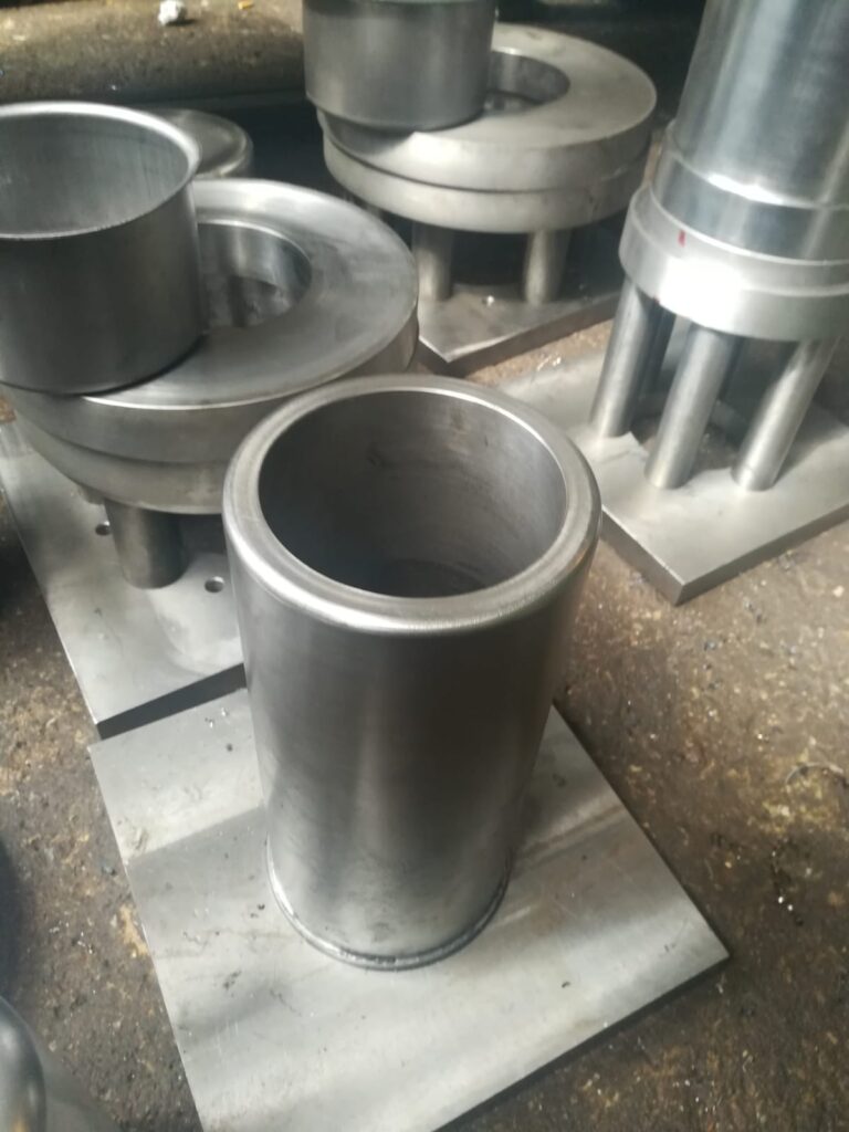
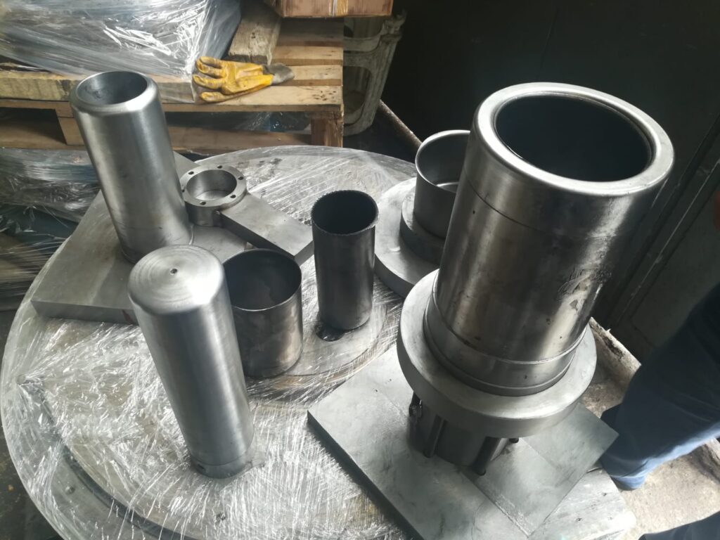
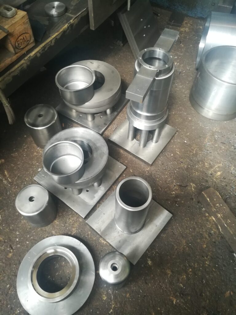
Deep Drawing Mold For Deep Cups
A Deep Drawing Mold for producing deep cups is a specialized tooling setup designed to shape flat sheet metal blanks into hollow, cup-shaped components through the deep drawing process. This mold typically consists of several key components that work together to control metal flow, apply forming forces, and ensure dimensional accuracy of the deep-drawn cup.
Components of a Deep Drawing Mold for Deep Cups:
- Punch
The punch is the primary tool that pushes the sheet metal blank into the die cavity. For deep cups, the punch typically has a cylindrical shape with a smooth, rounded nose radius to prevent tearing and excessive thinning of the metal at the cup’s base and walls. The punch diameter largely determines the inner diameter of the drawn cup. - Die
The die provides the cavity into which the metal is drawn. Its shape corresponds to the external shape of the final cup. The die opening has a defined radius (die radius) that guides the metal flow during drawing, minimizing stress concentrations and wrinkles. For deep cups, the die cavity is deep enough to accommodate the desired cup depth. - Blank Holder (or Hold-down Ring)
This component presses down on the flange (outer edge) of the blank to control metal flow and prevent wrinkling as the blank is drawn. The blank holder pressure must be carefully regulated: too little pressure causes wrinkles, while too much pressure restricts flow and can lead to tearing. - Pressure Pads or Cushion (optional)
Sometimes, pressure pads or cushions are added to maintain uniform pressure over the blank, especially in progressive or multi-stage deep drawing molds.
Design Considerations for Deep Drawing Molds of Deep Cups:
- Punch and Die Radii
The radii at the punch nose and die opening are critical to smooth material flow and to avoid excessive strain localization that can cause cracks or tears. Larger radii reduce stress concentration but may increase wrinkling risks. - Clearance
The gap between the punch and die should be slightly larger than the sheet thickness (typically about 5-10% more) to allow smooth flow without excessive thinning or jamming. - Material Flow Control
The blank holder’s force and surface finish are crucial in controlling how the metal flows into the die cavity. Lubrication reduces friction and helps prevent tearing. - Lubrication
Proper lubrication reduces friction between the blank and tooling surfaces, aiding smooth drawing and improving surface finish.
Operation:
During operation, the blank is placed over the die and held by the blank holder. The punch descends, pushing the blank metal into the die cavity, causing the metal to flow and stretch into the deep cup shape. The metal undergoes plastic deformation, thinning especially near the cup base and walls. Once the punch reaches its full stroke, the formed cup is ejected and trimmed if necessary.
Applications:
Deep drawing molds for deep cups are used extensively in producing:
- Automotive parts like fuel tanks, oil pans, and reservoirs.
- Beverage cans and containers.
- Kitchenware such as pots, pans, and deep sinks.
- Industrial components requiring hollow, seamless metal cups.
A deep drawing mold for deep cups is a precise tool designed to transform flat metal sheets into deep, hollow cup-shaped components through controlled plastic deformation. The process starts by positioning a flat metal blank over the die cavity, where the blank holder applies pressure on the flange to prevent wrinkling as the punch descends. The punch then pushes the metal blank into the die cavity, forcing the material to flow smoothly and conform to the shape of the mold.
The design of the mold is crucial to ensure the quality and integrity of the drawn cup. The punch and die radii play a significant role in controlling the material flow and stress distribution; rounded edges help prevent sharp stress concentrations that could lead to tearing or cracking. The clearance between the punch and die is carefully set to allow the metal to flow without excessive thinning or jamming, usually just slightly larger than the thickness of the sheet metal being drawn.
Blank holder force is another critical factor that balances metal flow and prevents defects. If the pressure is too low, the flange can buckle, causing wrinkles; if too high, the metal may not flow adequately, increasing the risk of tearing or forming excessive stress on the punch and die. Lubrication between the metal sheet and the mold surfaces reduces friction, allowing the sheet to move freely and preventing galling or surface defects. The choice of lubricant depends on the material and process conditions, but it is generally essential for achieving smooth metal flow and longer tool life.
During the drawing operation, the metal undergoes complex deformation, stretching and compressing as it moves into the die cavity. The walls of the cup tend to thin, especially near the punch radius where the material experiences the greatest tensile stresses. The mold must accommodate this thinning to avoid failure. Materials with good ductility and strain hardening capabilities are preferred because they withstand the deformation without cracking.
For very deep cups or complex geometries, the drawing process often requires multiple stages with intermediate annealing or ironing steps to maintain material properties and achieve the desired shape and thickness. Progressive dies can be used where each station performs part of the drawing operation, gradually forming the blank into a deep cup without overstraining the material.
Deep drawing molds are widely used in industries requiring strong, lightweight, and seamless cups, such as automotive fuel tanks, kitchen sinks, beverage cans, and various industrial containers. The process combines careful tool design, controlled forces, and material science to produce high-quality, durable components efficiently. Advances in computer-aided design and finite element simulation now allow engineers to optimize mold geometry and process parameters before manufacturing, reducing trial-and-error and improving product consistency.
The performance of a deep drawing mold for deep cups hinges on a delicate balance of multiple factors, including tooling geometry, material characteristics, and process parameters. The interaction between the punch, die, and blank holder must be finely tuned to manage the complex flow of metal during forming. The flange area, where the blank is held and allowed to move, is particularly sensitive because improper control can lead to defects like wrinkling or tearing. Wrinkles occur when compressive stresses exceed the sheet’s ability to hold its shape, causing it to buckle, while tearing results from excessive tensile stresses causing cracks. The blank holder force is therefore critical, often adjusted dynamically in advanced presses to optimize flow throughout the stroke.
Another significant aspect is the strain distribution throughout the drawn cup. The material undergoes both radial and circumferential stretching, with the highest strain typically near the punch radius, where the metal bends sharply into the cavity. This can cause thinning, which weakens the part and may lead to failure if excessive. To mitigate this, engineers select materials with good ductility and strain-hardening behavior, which allows the metal to absorb more deformation without failing. Additionally, tool surface finish and lubrication are essential to minimize friction and avoid surface damage or galling, which can ruin both the part and the tooling.
For extremely deep cups or those with complex shapes such as stepped or flanged bottoms, multi-stage drawing processes become necessary. In such setups, the blank is progressively formed through a series of punches and dies, each shaping the metal incrementally. This approach reduces the strain imposed in any single step, lowers the risk of defects, and allows for more complex geometries. Sometimes, annealing steps are incorporated between drawing stages to restore ductility and relieve stresses, enabling further deformation without cracking.
Modern deep drawing molds may also incorporate sensors and feedback systems that monitor forces, displacement, and temperature during the forming process. These inputs enable real-time adjustments to blank holder force, punch speed, or lubrication, improving quality and reducing scrap rates. Computer simulation through finite element analysis (FEA) has revolutionized mold design, allowing engineers to model metal flow, stress, and strain before any physical tooling is made. This helps optimize parameters such as punch and die radii, clearance, and blank holder force, ultimately leading to improved part quality, reduced development time, and lower costs.
In industrial production, deep drawing molds are often integrated into automated lines with robotic part handling, trimming, and inspection systems, enabling high-volume manufacturing of deep cups with consistent quality. These components find widespread use in automotive fuel tanks and oil pans, food and beverage containers, household appliances, and electronic enclosures. The ability of deep drawing to produce lightweight, seamless, and strong parts makes it an indispensable process in modern manufacturing.
As materials evolve with new alloys and coatings, and as tooling technology advances with better materials and surface treatments, the capabilities of deep drawing molds continue to expand. This enables the production of deeper, more complex, and higher-performance cups that meet stringent requirements for strength, corrosion resistance, and aesthetics. In this way, the deep drawing mold remains a cornerstone of sheet metal forming, combining mechanical ingenuity, materials science, and precision engineering to shape the future of manufacturing.
Deep Drawing Mold Hydraulic Press
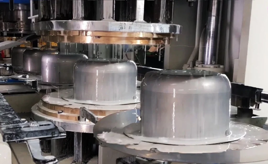
A Deep Drawing Mold Hydraulic Press is a forming setup that combines a deep drawing mold (the punch, die, and blank holder tooling) with a hydraulic press machine to shape sheet metal into deep cup-like or hollow components. Unlike mechanical presses, hydraulic presses use hydraulic cylinders to apply force, offering precise control over pressure, speed, and stroke, which makes them particularly well-suited for deep drawing processes requiring variable force and smooth, controlled deformation.
In a hydraulic press deep drawing operation, the sheet metal blank is positioned on the die, held by the blank holder, and the hydraulic press slowly and steadily moves the punch downward to draw the blank into the die cavity. The hydraulic system allows the operator or automated control system to adjust the force during the stroke dynamically, which is critical in deep drawing to prevent defects such as wrinkling or tearing. The slower, controlled motion of a hydraulic press also reduces shock loads and can improve surface finish and part accuracy.
Hydraulic deep drawing presses typically have higher tonnage capacities than mechanical presses of similar size, allowing them to form thicker or more difficult materials and deeper cups. They are favored for complex, multi-stage drawing operations and prototype or low-volume production runs where flexibility and precise control are needed over sheer speed. Additionally, hydraulic presses can hold the punch at any position during the stroke for a dwell time, enabling metal to flow more evenly and reducing springback or wrinkles.
The mold itself in a hydraulic press setup generally consists of a punch shaped for the desired cup form, a die with an appropriate cavity and radii, and a blank holder with adjustable pressure. The blank holder pressure can often be controlled independently through a secondary hydraulic circuit, further enhancing control over the flange metal flow. Lubrication is used to minimize friction and wear, and tooling materials are typically hardened steel or tool steel treated for durability.
In industry, deep drawing molds on hydraulic presses are widely used for manufacturing automotive components such as fuel tanks and oil pans, household items like kitchen sinks, and industrial containers that require deep, smooth, and seamless forms. The versatility of the hydraulic press allows for modifications in stroke length and force to accommodate different shapes and materials without changing the physical tooling.
Modern hydraulic presses are often integrated with computerized control systems, force sensors, and programmable logic controllers (PLCs), allowing precise monitoring and adjustment of process parameters. This automation improves consistency, reduces scrap rates, and enables rapid switching between different part geometries, which is valuable in flexible manufacturing environments.
Overall, the combination of deep drawing molds with hydraulic presses delivers a powerful, flexible, and precise solution for forming deep metal cups and complex shapes, balancing high force with the fine control necessary to produce high-quality parts efficiently.
A deep drawing mold paired with a hydraulic press offers a highly controlled environment for shaping sheet metal into deep, hollow forms such as cups, containers, and automotive parts. The hydraulic press uses fluid pressure to generate the necessary force, which allows for smooth, adjustable, and sustained application of pressure throughout the drawing process. This contrasts with mechanical presses that deliver force via a fixed crank or cam mechanism, making hydraulic presses more adaptable to variations in material behavior and part complexity.
One of the key advantages of using a hydraulic press for deep drawing is its ability to precisely regulate the speed and force of the punch during the stroke. This control helps in managing metal flow to avoid common defects like wrinkling, tearing, or excessive thinning. Since deep drawing involves significant plastic deformation, gradual and consistent force application reduces shock loads on the tooling and the blank, leading to better surface quality and dimensional accuracy of the finished parts.
Hydraulic presses also provide the flexibility to hold the punch at any point during the forming stroke, a feature known as “dwell.” During this pause, the metal can redistribute stresses and flow more evenly, which helps in forming deeper or more complex shapes without defects. This capability is particularly valuable when working with harder or thicker materials, or when the geometry of the drawn cup includes sharp transitions or deep draws.
The deep drawing mold itself, consisting of the punch, die, and blank holder, is designed to work seamlessly with the hydraulic press. The blank holder’s pressure can be independently controlled, sometimes through a separate hydraulic circuit, allowing precise adjustment of flange tension to prevent wrinkling while ensuring sufficient material flow into the die cavity. Tooling surfaces are carefully finished and lubricated to reduce friction, minimize tool wear, and improve the quality of the metal surface after forming.
In practical applications, hydraulic presses equipped with deep drawing molds are widely used in industries that require deep, seamless parts with consistent quality. Automotive manufacturing benefits from hydraulic deep drawing for parts such as fuel tanks, transmission cases, and structural components. The appliance and consumer goods sectors use it for kitchen sinks, cookware, and household containers, where smooth finishes and precise shapes are essential. The aerospace and electronics industries also use hydraulic deep drawing for specialized components requiring high dimensional control.
Modern hydraulic deep drawing presses are often integrated with computer controls and sensors that monitor parameters such as punch force, stroke position, and speed. These systems allow real-time adjustments and data logging, improving process reliability and enabling predictive maintenance. Advanced simulation tools are used during the design phase to optimize mold geometry and press settings, reducing trial-and-error during production and minimizing scrap rates.
The combination of hydraulic press technology with deep drawing molds thus creates a versatile and precise manufacturing solution, capable of handling a wide range of materials and geometries. It supports the production of high-quality, deep, and complex cup-shaped parts while offering flexibility for different batch sizes, from prototype runs to large-scale production. This makes hydraulic deep drawing an indispensable technique in modern sheet metal forming industries.
In addition to its force control and flexibility advantages, the hydraulic press’s ability to generate very high pressures with relatively compact machinery enables the deep drawing of thicker or higher-strength materials that might be difficult or impossible to form on mechanical presses. This capability expands the range of materials that can be effectively deep drawn, including advanced high-strength steels, stainless steels, and some aluminum alloys, which are increasingly demanded in automotive, aerospace, and industrial applications for their superior strength-to-weight ratios and corrosion resistance.
Hydraulic presses also typically allow for larger stroke lengths and greater tonnage capacity compared to similarly sized mechanical presses. This makes them especially suitable for deep drawing molds intended to produce very deep cups or complex geometries that require significant metal flow and high forming forces. The ability to tailor the stroke speed, force, and dwell time for each stage of the drawing process ensures that even challenging shapes can be formed without defects.
Another important feature of hydraulic deep drawing systems is their relatively quiet and smooth operation compared to mechanical presses. Mechanical presses often operate with rapid, repetitive impacts that generate noise and vibration, which can lead to operator fatigue and increased wear on equipment. Hydraulic presses, on the other hand, apply force more smoothly, improving working conditions and potentially extending the lifespan of tooling and machinery.
Deep drawing molds for hydraulic presses are designed with careful attention to tool material and surface treatment. Because deep drawing subjects tooling surfaces to high pressures and sliding contact with the blank metal, tool steels with high hardness and good wear resistance are used, often enhanced with surface coatings like titanium nitride (TiN) or other advanced treatments to reduce friction and increase durability. These coatings help maintain surface finish quality and reduce maintenance downtime.
The combination of hydraulic press technology and well-engineered deep drawing molds also facilitates rapid tool changes and setup adjustments, which is valuable in flexible manufacturing environments. Automated hydraulic systems can adjust blank holder force and punch speed in real time, accommodating different materials or part designs without needing to physically change tooling components, thereby reducing downtime and increasing production efficiency.
In recent years, the integration of Industry 4.0 concepts into hydraulic deep drawing systems has begun to transform the process further. Sensors embedded in the mold and press collect data on forces, temperatures, and displacements throughout each draw cycle. This data is analyzed to detect early signs of tool wear, material inconsistencies, or process deviations, enabling predictive maintenance and process optimization. Operators receive real-time feedback and alerts, which help minimize scrap, improve product quality, and lower production costs.
In summary, deep drawing molds used with hydraulic presses offer an advanced, versatile solution for producing deep, complex, and high-quality cup-shaped metal components. Their precise force control, flexibility, and compatibility with modern materials and automation make them indispensable in many sectors, from automotive to consumer goods and aerospace. As tooling materials and control technologies continue to evolve, hydraulic deep drawing presses will remain at the forefront of efficient, high-quality sheet metal forming processes.
Building on the capabilities of hydraulic deep drawing presses and molds, ongoing advancements in material science and digital manufacturing technologies continue to push the boundaries of what can be achieved in deep drawing. The development of new high-strength and ultra-high-strength alloys has challenged the traditional limits of deep drawing processes, requiring even more precise control over forming forces, friction, and material flow. Hydraulic presses are well-positioned to meet these challenges due to their inherent adaptability and fine-tuning ability.
One area of innovation is the use of variable blank holder pressures during the drawing cycle. Rather than applying a constant force, modern hydraulic presses can modulate the blank holder force dynamically, increasing or decreasing it at different points in the stroke to optimize material flow and reduce defects. For example, a higher blank holder force may be applied at the start to prevent wrinkling, then reduced during the punch’s downward movement to allow smoother metal flow. This strategy improves part quality and enables deeper draws with thinner materials.
Additive manufacturing (3D printing) technologies are also impacting mold design and production. Rapid prototyping of mold components enables quicker iterations and customization, reducing lead times and costs in tooling development. Complex internal cooling channels or conformal features that improve lubrication and thermal management can be incorporated into mold designs using advanced manufacturing methods, which were difficult or impossible to achieve with traditional machining.
Thermal management is another evolving aspect. During deep drawing, friction and deformation generate heat, which affects material behavior and tool wear. Integrating cooling systems within the mold or using temperature-controlled hydraulic fluid can help maintain optimal process temperatures, improve material formability, and prolong tool life. Some advanced hydraulic presses allow real-time temperature monitoring and control to maintain consistent forming conditions.
In addition, computer-aided engineering (CAE) and simulation tools have become indispensable in modern deep drawing mold design. Finite element analysis (FEA) software can simulate the entire forming process, predicting potential issues such as wrinkling, tearing, or excessive thinning before physical tooling is made. This reduces costly trial-and-error in the shop floor and accelerates product development. Simulation data can also be used to generate precise control programs for hydraulic press operation, further enhancing quality and efficiency.
The integration of robotics and automation with hydraulic deep drawing presses allows for streamlined production workflows. Robots can load and unload blanks, perform in-line inspection, and handle finished parts, reducing manual labor and improving throughput. Automated lubrication systems ensure consistent application of lubricants to tooling surfaces, which is critical for maintaining quality and reducing wear.
Furthermore, the growing emphasis on sustainability in manufacturing is influencing deep drawing practices. Hydraulic presses, while energy-intensive, can be optimized for energy efficiency by recovering hydraulic fluid energy during press cycling or by utilizing variable frequency drives and smart power management systems. Additionally, the efficient material usage inherent in deep drawing—producing parts with minimal waste—aligns well with environmental goals.
In conclusion, the synergy between advanced hydraulic press technology and deep drawing molds continues to evolve, driven by materials innovation, digital design and simulation tools, and automation. These advances enable manufacturers to produce deeper, more complex, and higher-performance cup-shaped components with improved quality, efficiency, and sustainability. As industries demand ever more sophisticated metal parts, hydraulic deep drawing remains a critical and adaptable manufacturing process poised for continued growth and innovation.
Deep Drawing Mold For Container Production
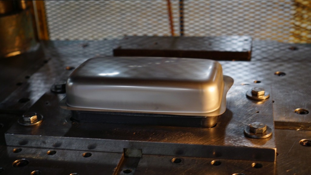
A deep drawing mold for container production is a specially designed tooling setup that transforms flat metal sheets into hollow, seamless containers—such as cans, boxes, or drums—through the deep drawing process. The mold consists of a punch, die, and blank holder, engineered to control material flow and shape the metal into the desired container geometry with smooth walls and consistent thickness.
In container production, the mold must accommodate the specific dimensions and features of the container, such as straight or tapered walls, bottom shapes (flat, dished, or stepped), and flange designs for sealing or joining. The punch pushes the sheet metal blank into the die cavity while the blank holder applies pressure on the flange to prevent wrinkling and control metal flow. Proper design of punch and die radii ensures smooth stretching of the material without tearing or excessive thinning, which is critical to maintain container integrity and strength.
The process parameters—blank holder force, punch speed, lubrication, and die clearance—are carefully optimized to handle the container’s size, depth, and material properties, often requiring adjustments based on the metal type (steel, aluminum, or alloys) and thickness. Containers with deep or complex shapes may require multi-stage drawing molds, where the container is progressively formed through several dies and punches to achieve the final shape without defects.
For large-scale production, these molds are typically integrated into hydraulic or mechanical presses with automated feeding, ejection, and trimming systems to ensure high throughput and consistent quality. Lubrication systems are crucial to reduce friction and wear, preventing damage to the container surface and tooling.
The result is a high-quality container with uniform wall thickness, good surface finish, and structural integrity suitable for applications in food and beverage packaging, chemical storage, industrial uses, and household goods. Advances in mold design, materials, and process control continue to improve the efficiency and versatility of deep drawing molds for container production, enabling the creation of increasingly complex and durable containers in a cost-effective manner.
A deep drawing mold for container production functions by transforming a flat sheet metal blank into a hollow, seamless container with consistent wall thickness and smooth surface finish. The process begins with placing the blank over the die cavity, where the blank holder applies pressure to keep the metal firmly in place and prevent wrinkling during drawing. As the punch descends, it forces the metal blank to flow into the die cavity, stretching and shaping the material into the desired container form. This metal flow must be carefully controlled to avoid defects like tearing, excessive thinning, or wrinkling, which would compromise the container’s strength and appearance.
The mold design incorporates carefully calculated punch and die radii that reduce stress concentrations and enable smooth material deformation. The clearance between the punch and die is typically slightly larger than the sheet thickness to allow material to flow without excessive friction or jamming. Lubrication applied between the tooling and the blank plays a critical role in reducing friction, minimizing tool wear, and improving the surface finish of the container. Proper lubrication also helps metal flow more evenly into the die cavity.
For containers with greater depth or complex shapes such as those with stepped bottoms or flanges for sealing, the deep drawing process may be performed in multiple stages. Each stage gradually forms the container closer to its final shape, reducing the risk of tearing or wrinkling by limiting the strain applied in any single step. Between stages, annealing may be used to restore ductility to the metal if required.
In high-volume container production, the deep drawing molds are often mounted in hydraulic or mechanical presses equipped with automated feeding, ejection, and trimming systems. Automation ensures consistent part quality and high throughput, making the process efficient for mass production. The tooling materials used for molds are typically hardened tool steels with surface treatments to withstand repeated high-pressure cycles while maintaining dimensional accuracy and minimizing wear.
The end result is a seamless container with uniform wall thickness, excellent mechanical strength, and an attractive surface finish suitable for packaging liquids, chemicals, food products, and industrial materials. As technology advances, deep drawing molds for container production continue to evolve, incorporating improved materials, lubrication techniques, and computer-aided design and simulation. This enables manufacturers to produce increasingly complex container shapes with better quality and reduced costs, meeting the demands of diverse industries for reliable, high-performance packaging solutions.
The ongoing evolution of deep drawing molds for container production is closely tied to advancements in both tooling technology and process control. Modern molds benefit from precision engineering aided by computer-aided design (CAD) and computer-aided manufacturing (CAM), allowing for highly accurate and complex tool geometries that optimize metal flow and reduce defects. Finite element analysis (FEA) simulations enable engineers to predict how the metal will behave during forming, identifying potential issues like thinning, wrinkling, or excessive stresses before physical tooling is made. This reduces costly trial runs and shortens development time.
In addition to design improvements, the integration of advanced materials and surface treatments for tooling has significantly enhanced mold longevity and performance. Tool steels with high hardness and toughness, combined with coatings such as titanium nitride (TiN) or diamond-like carbon (DLC), reduce friction and resist wear and galling, extending the operational life of molds and ensuring consistent container quality over long production runs.
Automation and process monitoring have become integral to container deep drawing operations. Sensors embedded in the press and tooling monitor critical parameters like punch force, stroke speed, blank holder pressure, and temperature in real time. These data streams feed into control systems that can dynamically adjust the process, ensuring optimal conditions and minimizing defects. Automated feeding and ejection systems further increase production efficiency, enabling continuous, high-speed manufacturing suitable for large-scale container production.
Lubrication technology also plays a vital role in modern deep drawing. Specialized lubricants designed for deep drawing reduce friction between the sheet and tooling, prevent surface damage, and aid metal flow. Some systems use automated or spray lubrication to ensure consistent coverage, improving part quality and reducing maintenance needs.
For containers made from advanced materials or those requiring particularly deep draws, additional process steps such as intermediate annealing or ironing may be incorporated. Ironing smooths and thins the container walls to precise thicknesses, enhancing dimensional accuracy and structural strength, which is especially important in applications like beverage cans or industrial drums.
Environmental and economic considerations increasingly influence deep drawing mold design and production. Efficient material usage inherent in deep drawing minimizes scrap, and efforts to optimize energy consumption in hydraulic or mechanical presses contribute to greener manufacturing. Tooling longevity and ease of maintenance also reduce downtime and waste.
Ultimately, deep drawing molds for container production combine sophisticated tool design, advanced materials, precise process control, and automation to produce seamless, durable containers at high volumes. This synergy supports industries ranging from food and beverage to chemicals and consumer goods, meeting rigorous standards for safety, strength, and aesthetics while maintaining cost-effectiveness and sustainability. As new materials and digital technologies continue to emerge, the capabilities and applications of deep drawing molds for container manufacturing will only expand further.
Deep Drawing Mold Lubrication System
A deep drawing mold lubrication system is an essential component in the deep drawing process, designed to reduce friction between the sheet metal blank and the tooling surfaces (punch, die, and blank holder). Proper lubrication minimizes wear on the mold, improves material flow, prevents surface defects on the drawn part, and extends tooling life. Because deep drawing involves significant metal deformation and sliding contact under high pressure, an effective lubrication system is critical for achieving consistent quality and efficient production.
The lubrication system typically includes a lubricant reservoir, delivery mechanism, and application method. Lubricants used in deep drawing are specially formulated to withstand high pressures and temperatures, provide good film strength, and prevent metal-to-metal contact. Common types include oil-based lubricants, synthetic fluids, graphite or soap-based dry lubricants, and water-soluble emulsions. The choice depends on the material being formed, the complexity of the part, and environmental considerations.
Lubricant application methods vary depending on the production setup and part requirements. Manual application using brushes or sprays may be suitable for low-volume or prototype runs, but automated systems are preferred in high-volume manufacturing to ensure consistent, uniform coverage. Automated lubrication systems may use spray nozzles, rollers, or drip feeders positioned strategically around the mold to apply lubricant directly to the punch, die, and blank holder surfaces.
In some advanced deep drawing presses, the lubrication system is integrated with process controls and sensors that monitor lubricant flow and pressure, adjusting application rates in real time to optimize performance. Proper lubricant replenishment and filtration systems ensure the lubricant remains clean and effective throughout production, reducing the risk of contamination that could damage the tooling or the finished part.
Environmental and safety concerns have led to the development of eco-friendly lubricants that are biodegradable and easier to clean from finished parts. Some systems use minimal quantity lubrication (MQL) techniques to reduce lubricant consumption and waste. Additionally, water-soluble lubricants facilitate easier post-forming cleaning processes, which is important in food and beverage container production.
Overall, the lubrication system in a deep drawing mold setup is a vital element that supports smooth metal flow, prevents tooling damage, and enhances part quality. Optimizing lubricant type, application method, and system maintenance is crucial for achieving efficient, high-quality deep drawing operations, particularly in demanding industrial environments.
In deep drawing operations, the lubrication system plays a critical role in managing the interaction between the sheet metal and the tooling surfaces. Since the metal blank undergoes significant stretching and sliding against the punch, die, and blank holder, friction must be minimized to prevent surface scratches, galling, or tearing of the material. Effective lubrication not only protects the tooling from excessive wear but also facilitates smoother material flow, which reduces the risk of defects such as wrinkling or uneven thickness.
The lubricant’s formulation is carefully chosen to provide a stable lubricating film under the high pressure and shear forces present in the drawing zone. Oils and synthetic fluids often include additives that enhance film strength and reduce oxidation or degradation during prolonged use. In some cases, dry lubricants like graphite or soap-based powders are applied when oil-based products might cause contamination or are difficult to clean from the finished product. Water-soluble lubricants are popular for their ease of cleanup, especially in food-grade or consumer product manufacturing, where cleanliness is paramount.
Automated lubrication systems ensure consistent application of lubricant across the tooling surfaces, which is crucial for repeatable and reliable deep drawing results. Spray nozzles, rollers, or drip feed devices are strategically placed to coat the punch, die, and blank holder evenly before each stroke or continuously during operation. Precise control of lubricant volume and distribution helps to avoid excessive lubricant that can cause slippage or part contamination, as well as insufficient lubrication that would increase friction and tool wear.
Advanced lubrication setups incorporate monitoring sensors that track lubricant flow rates, pressure, and even temperature. These sensors provide real-time feedback to the press control system, which can adjust lubrication parameters on the fly to maintain optimal conditions. This level of automation helps reduce downtime caused by tool damage or poor part quality and enables longer production runs without manual intervention.
Maintenance of the lubrication system is vital to its effectiveness. Filters remove metal particles and other contaminants from the lubricant, preventing abrasive wear on the tooling surfaces. Regular replenishment and replacement of lubricant keep its properties consistent, ensuring reliable performance throughout the manufacturing cycle. In high-volume deep drawing operations, the lubrication system is integrated into the overall press maintenance schedule to maximize uptime and tool life.
Environmental considerations also influence lubrication system design and lubricant selection. The industry increasingly favors biodegradable, non-toxic lubricants that reduce environmental impact and improve workplace safety. Minimal quantity lubrication (MQL) techniques are gaining popularity, applying precise, small amounts of lubricant only where necessary, thereby reducing waste and cleanup costs.
In summary, the lubrication system for deep drawing molds is a sophisticated and essential part of the process that directly impacts the quality of formed parts, the longevity of tooling, and the efficiency of production. By carefully selecting lubricants, employing automated and monitored delivery systems, and maintaining cleanliness and flow consistency, manufacturers can achieve optimal deep drawing performance, even under challenging production demands.
Beyond the fundamental role of reducing friction, modern deep drawing mold lubrication systems contribute significantly to improving process stability and part consistency. By maintaining a consistent lubricating film throughout the drawing cycle, they help ensure uniform material flow into the die cavity. This uniformity is essential for preventing localized thinning or strain concentrations that could lead to premature failure or rejection of the container or part being produced.
In addition, well-designed lubrication systems can help manage heat generated during the forming process. As the metal is deformed, friction generates heat which can alter the material properties locally, affect lubricant performance, and cause thermal expansion in tooling. By reducing friction and sometimes incorporating cooling elements within the lubrication delivery setup, the system helps maintain stable temperatures, which preserves both tool life and dimensional accuracy of parts.
Lubrication systems must be adaptable to different materials and part geometries. For example, aluminum alloys often require different lubricant formulations and application methods compared to steel, due to their differing surface characteristics and formability. Deep drawing molds used for complex or very deep containers may require more frequent or targeted lubrication in critical areas to ensure smooth metal flow and avoid defects.
Some cutting-edge lubrication systems also integrate with digital manufacturing technologies. Sensors and control software analyze real-time data to adjust lubrication parameters dynamically based on variations in material batches, tool wear, or forming conditions. This “smart lubrication” approach optimizes lubricant usage, reduces waste, and enhances product quality, aligning with Industry 4.0 principles of interconnected and intelligent manufacturing systems.
Furthermore, the disposal and recycling of used lubricants are important environmental considerations. Systems that minimize lubricant consumption through precise delivery not only reduce costs but also decrease environmental impact by limiting hazardous waste generation. Biodegradable lubricants and closed-loop recycling systems are increasingly incorporated into deep drawing operations to support sustainability goals.
Overall, a comprehensive deep drawing mold lubrication system is much more than just an accessory; it is integral to the success of the forming process. It affects everything from tool life and maintenance schedules to final part quality and production efficiency. Innovations in lubrication chemistry, delivery technology, and process integration continue to enhance the capability of deep drawing systems to produce high-quality, defect-free containers and other parts, even under increasingly demanding manufacturing conditions.
Deep Drawing Mold Ejection System
A deep drawing mold ejection system is a crucial part of the tooling setup that facilitates the removal of the formed part from the mold after the deep drawing operation is complete. Since deep drawn parts—such as containers, cups, or other hollow shapes—often fit tightly within the die cavity, an efficient and reliable ejection system is necessary to avoid damaging the part or tooling, reduce cycle times, and maintain production efficiency.
Typically, the ejection system consists of ejector pins, sleeves, plates, or air blasts integrated into the die or punch assembly. After the punch retracts, the ejector mechanism activates to push or pull the drawn part out of the die cavity gently and uniformly. The design of the ejection system must ensure that the part is removed without distortion, scratching, or deformation, which is critical for maintaining dimensional accuracy and surface quality.
Ejector pins are the most common method; they are strategically placed on the die surface and actuated hydraulically, pneumatically, or mechanically to push the part away from the die. The pins are carefully sized and positioned to support the part evenly during ejection and avoid marks on visible surfaces. In some cases, ejector sleeves or rings surround the part to provide uniform support and ejection force, especially for cylindrical or cup-shaped components.
In addition to mechanical ejection, some systems use air blasts or vacuum-assisted ejection to help separate the part from the tooling, particularly when dealing with thin or delicate components prone to sticking. Air or vacuum ejection can also reduce mechanical contact, minimizing surface damage.
The timing and synchronization of the ejection system with the press cycle are critical. Ejection must occur only after the punch has fully retracted to prevent collisions. Modern deep drawing presses often integrate ejection control with overall press automation, ensuring smooth and repeatable operation.
Maintenance of the ejection system is important to prevent pin sticking, uneven wear, or misalignment, which can cause part damage or slow down production. Regular inspection and lubrication of ejector components help maintain their reliability and precision.
Advanced deep drawing molds may incorporate sensors to detect successful ejection or part presence, feeding information back to the press control system to verify process completion and trigger the next cycle safely.
In summary, the ejection system in a deep drawing mold is vital for safely and efficiently removing formed parts, protecting tooling and finished components, and supporting high-volume production with consistent quality. Proper design, synchronization, and maintenance of the ejection mechanism contribute significantly to the overall effectiveness of deep drawing operations.
The ejection system’s design must be tailored to the specific geometry and material of the deep drawn part to ensure smooth removal without causing damage or deformation. For example, thin-walled or highly flexible parts require more delicate ejection mechanisms, often combining ejector pins with air blasts or vacuum assistance to gently separate the part from the die. In contrast, thicker or more rigid components may rely primarily on mechanical ejectors with sufficient force to push the part free.
Placement and number of ejector pins are critical design considerations. Pins are positioned to provide balanced support and avoid leaving marks on visible or functional surfaces of the part. The pins often retract into the die when not in use to avoid interfering with the blank or forming process. The diameter and stroke length of the pins are carefully selected to apply enough force for ejection while minimizing potential damage to the part or tooling.
Some advanced ejection systems employ segmented or multi-stage ejection, where different ejector groups activate sequentially to gradually release complex parts, reducing stress and distortion. This is particularly useful for containers or components with undercuts, flanges, or internal features that make straight ejection difficult.
The synchronization of ejection timing with the press cycle is managed through hydraulic, pneumatic, or servo-controlled actuators linked to the press control system. Proper timing ensures that ejection only begins after the punch has fully retracted and the part is stable, preventing collisions or incomplete ejection.
To avoid downtime and maintain consistent production quality, routine maintenance of the ejection system is essential. This includes inspecting pins and sleeves for wear, ensuring smooth movement through lubrication, and checking alignment and actuation mechanisms. Malfunctioning ejectors can lead to part defects, tooling damage, and increased cycle times.
Incorporating sensors and automation enhances the ejection system’s reliability and integration into the production line. Sensors can detect whether the part has been successfully ejected and signal the press control system to continue or pause the cycle accordingly. This feedback loop helps prevent tooling damage caused by missed ejections and improves overall process safety.
Furthermore, the choice of ejection method can influence the design of the deep drawing mold itself. For instance, molds designed for air ejection may require channels or holes within the die to direct compressed air effectively, while vacuum ejection systems need integrated vacuum ports and seals. These design considerations must balance ejection effectiveness with tooling strength and durability.
In high-speed or high-volume production environments, efficient ejection is essential to minimize cycle time and maximize throughput. Automated, well-maintained ejection systems reduce manual intervention, lower the risk of part damage, and enable continuous, reliable manufacturing of deep drawn containers or parts with consistent quality.
Overall, the ejection system is a vital part of the deep drawing mold setup, directly impacting the quality of the finished product, tooling longevity, and production efficiency. Its careful design, integration with press automation, and ongoing maintenance ensure smooth removal of parts and contribute significantly to the success of deep drawing operations.
In addition to mechanical and pneumatic ejection methods, some modern deep drawing molds incorporate innovative ejection technologies tailored to specific production challenges. For example, hydraulic ejectors offer precise control over ejection force and speed, allowing delicate parts to be removed gently while maintaining cycle speed. Servo-driven ejectors further enhance control, enabling programmable and adaptable ejection sequences that can respond to variations in part geometry or material properties.
These advanced ejection systems also contribute to reducing part defects caused by improper ejection, such as warping, cracking, or surface blemishes. By adjusting the force and timing dynamically, they help ensure that even complex or thin-walled parts are released cleanly without residual stresses.
Another important consideration is the compatibility of the ejection system with automated manufacturing cells. Integration with robotic handling equipment often requires ejection systems to deliver parts in a predictable orientation and position, facilitating smooth transfer to subsequent processes like trimming, inspection, or packaging. Some molds include specialized features such as tapered ejector pins or cam-operated mechanisms that orient parts as they are ejected.
Material selection for ejector components also impacts system performance and durability. High-strength, wear-resistant steels or surface coatings are used to withstand repeated mechanical stresses and minimize maintenance intervals. Proper material choice helps prevent pin deformation or breakage, which could cause costly downtime or tooling damage.
In large-scale deep drawing operations, redundant ejection mechanisms may be employed to enhance reliability. For instance, combining ejector pins with air blast assistance ensures that if one method is less effective due to part adhesion or material variability, the other can complete the ejection process without interrupting production.
Safety is also a key aspect of ejection system design. Automated ejection must be synchronized with press operation to prevent accidental ejection during forming or when operators are near the equipment. Interlocks, sensors, and control logic ensure that ejection only occurs at appropriate times and that the press cannot cycle until the part is safely removed.
Finally, continuous improvement in ejection system design is driven by the evolving demands of deep drawing applications. As manufacturers push for thinner materials, more complex shapes, and higher production speeds, ejection systems must evolve to handle these challenges without compromising part quality or process efficiency. Ongoing innovation in actuator technologies, sensor integration, and materials science will continue to refine the capabilities of deep drawing mold ejection systems, making them smarter, more reliable, and better suited to the increasingly sophisticated needs of modern manufacturing.
Deep Drawing Mold Reverse Drawing
Deep drawing mold reverse drawing is a specialized forming technique used to shape sheet metal by drawing the material in the opposite direction to conventional deep drawing. Instead of the metal being pulled into the die cavity by the punch, reverse drawing involves pushing or drawing the metal back over or around a forming tool, often to create complex shapes or features that are difficult to achieve with traditional drawing.
This method is typically employed when the desired part geometry includes inward flanges, reentrant shapes, or undercuts that require the metal to flow in the reverse direction relative to the initial draw. Reverse drawing molds are designed with tooling arrangements that allow the blank to be formed outward initially and then drawn or shaped back inward through controlled deformation.
The reverse drawing process usually involves a combination of punches, dies, and blank holders that work in sequence or simultaneously to carefully manipulate the metal flow, preventing defects like tearing, wrinkling, or excessive thinning. Because the metal undergoes complex strain paths, the tooling design must precisely control strain distribution and blank holding forces.
Reverse drawing is often used in manufacturing complex containers, automotive components, or parts requiring specific internal features that cannot be easily formed by direct deep drawing. It may be combined with other forming operations such as ironing, trimming, or coining to achieve the final part geometry.
Mold design for reverse drawing requires careful attention to the shape and movement of punches and dies, material properties, and lubrication to ensure smooth metal flow and high-quality finished parts. The process can be more challenging than conventional deep drawing due to the increased complexity of metal flow and the risk of defects, but it enables the production of parts with sophisticated shapes that enhance functionality and performance.
Overall, deep drawing mold reverse drawing expands the capabilities of sheet metal forming by enabling the creation of complex shapes and features that extend beyond the limits of traditional deep drawing processes.
Reverse drawing in deep drawing molds involves intricate control of material flow to achieve shapes that require the metal to move against its natural drawing direction. Unlike conventional deep drawing where the punch pushes the blank into the die cavity, reverse drawing requires pulling or pushing the sheet metal outward and then redirecting it inward through carefully coordinated tooling actions. This reversal of metal flow allows the formation of features like inward flanges, stepped sections, or reentrant angles that are otherwise difficult or impossible to create with standard drawing methods.
The tooling for reverse drawing is more complex, often incorporating multi-stage or compound die sets where different punches and dies move in synchronization to manage the metal’s path precisely. Blank holders apply variable pressure to control wrinkling and thinning, while punch geometry is tailored to accommodate the reversed flow. Because the metal experiences complex strains, selecting the right material with adequate ductility and formability is critical to avoid cracking or tearing.
Lubrication plays a vital role in reverse drawing molds to reduce friction and facilitate smooth material movement, particularly because the metal tends to slide over tooling surfaces in directions that can increase resistance. Optimized lubrication helps maintain part surface quality and prolong tool life in this more demanding process.
Reverse drawing is often integrated into production sequences where multiple forming steps are necessary. For example, a part might first be conventionally deep drawn, then subjected to a reverse drawing operation to add internal features or improve geometric complexity. Subsequent processes such as trimming, ironing, or flanging may follow to finalize the part dimensions and surface finish.
While reverse drawing increases tooling complexity and may require more precise process control, it enables manufacturers to produce parts with enhanced functionality and aesthetics, meeting specific engineering requirements that traditional deep drawing cannot fulfill. This makes reverse drawing an invaluable technique in industries like automotive, aerospace, and packaging where advanced shapes and lightweight, high-strength components are in demand.
In summary, deep drawing mold reverse drawing extends the forming capabilities of sheet metal processes by allowing material flow in reverse directions, enabling the creation of intricate geometries with tight tolerances. It demands sophisticated mold design, material selection, and process control but offers substantial benefits in producing complex, high-quality parts for modern manufacturing applications.
The success of reverse drawing relies heavily on precise synchronization of the mold components and careful control of forming parameters. Since the metal is subjected to multi-directional stresses and flow paths, the timing and movement of punches, dies, and blank holders must be perfectly coordinated. Hydraulic or servo-driven presses are often preferred for reverse drawing because they offer adjustable speeds, forces, and dwell times, allowing fine-tuning of the process to minimize defects.
Advanced simulation tools like finite element analysis (FEA) are commonly employed during the design phase to model the metal flow and stress distribution in reverse drawing operations. These simulations help optimize tooling geometry and process parameters before physical molds are manufactured, reducing trial-and-error iterations and development costs.
Material considerations are also critical. Metals with high ductility and good strain-hardening behavior, such as certain aluminum alloys, stainless steels, and low-carbon steels, are ideal candidates for reverse drawing. Proper heat treatment and surface preparation of blanks further enhance formability and reduce the risk of surface defects.
The lubrication system in reverse drawing molds is tailored to handle complex sliding directions and high contact pressures. Specialized lubricants with excellent adhesion and film strength ensure that the metal flows smoothly over tooling surfaces without galling or scoring. Automated lubrication systems may be integrated to provide consistent application, particularly in high-volume production.
Reverse drawing molds often incorporate modular components to facilitate maintenance and tool changes, since the process can impose higher wear on tooling surfaces compared to conventional drawing. Quick-change punch and die inserts allow faster downtime recovery and adaptability for different part variants or materials.
Quality control in reverse drawing is especially important due to the complexity of the formed shapes. Inline inspection techniques such as laser scanning, machine vision, or ultrasonic testing may be used to verify dimensional accuracy and detect defects early in the production line. Feedback from these systems can be used to adjust process parameters in real time, ensuring consistent part quality.
As manufacturing demands grow more sophisticated, reverse drawing molds continue to evolve with innovations such as integrated sensors, digital twins, and adaptive control systems. These advancements enable smarter, more flexible forming processes that can handle complex geometries, diverse materials, and tighter tolerances while maximizing productivity.
In essence, deep drawing mold reverse drawing is a powerful technique that, when properly engineered and controlled, greatly expands the design possibilities for sheet metal components. It enables manufacturers to meet challenging requirements in industries ranging from automotive and aerospace to consumer goods and packaging, producing high-quality, complex parts efficiently and reliably.
Deep Drawing Mold With Die Cushion
A deep drawing mold with a die cushion incorporates an additional hydraulic or mechanical mechanism beneath the die to apply controlled counter-pressure during the drawing process. The die cushion exerts a regulated force upward against the blank holder or die assembly, which helps control the metal flow, reduce wrinkling, and improve the overall material distribution in the drawn part. This system is especially useful for forming deep, complex, or high-strength components where precise blank control is critical.
In a typical deep drawing operation, the blank holder applies pressure to prevent wrinkling as the punch draws the sheet metal into the die cavity. However, for certain materials or deep draws, the blank holder pressure alone may be insufficient to maintain uniform metal flow, leading to defects or uneven thickness. The die cushion supplements this by applying a counteracting force from below the die, balancing the pressures and allowing finer control of metal deformation.
The die cushion can be hydraulic, pneumatic, or mechanical (using springs or weights), with hydraulic systems offering the greatest flexibility and precision. The pressure exerted by the cushion is adjustable and often synchronized with the press stroke to optimize blank holding and reduce stresses.
Using a die cushion helps in reducing defects like wrinkling, tearing, and uneven thickness distribution. It enables the drawing of deeper parts with better dimensional accuracy and surface finish. This system also allows for better handling of high-strength or difficult-to-form materials by controlling strain paths more effectively.
Die cushions are typically integrated into the press bed or die assembly and are controlled via dedicated valves and sensors to maintain consistent force during the forming cycle. The pressure and position of the cushion are monitored to ensure optimal process conditions and prevent tooling damage.
Overall, a deep drawing mold with a die cushion provides enhanced process control, improving part quality and expanding the range of formable materials and geometries. It is widely used in industries requiring complex, deep drawn components with tight tolerances, such as automotive, aerospace, and appliance manufacturing.
The integration of a die cushion in a deep drawing mold allows for more precise control over the blank material as it is drawn into the die cavity. By applying a counteracting force from beneath the die, the cushion supports the metal sheet and helps regulate the flow of material between the punch and the die. This prevents the blank from slipping uncontrollably or wrinkling, which is a common issue when drawing deep or complex parts. The ability to finely tune this upward pressure during the stroke ensures that the material is stretched evenly, reducing the risk of thinning or tearing.
Hydraulic die cushions are particularly popular because they offer smooth, adjustable pressure that can be dynamically controlled throughout the forming cycle. The pressure can be programmed to increase or decrease at specific points in the stroke, matching the varying requirements of metal flow and stress. This adaptability is crucial when working with high-strength steels or alloys that require careful strain management to avoid premature failure. Pneumatic or mechanical cushions may be used in less demanding applications, but hydraulic systems remain the standard for their precision and reliability.
The cushion system often includes sensors and feedback loops connected to the press control system, enabling real-time monitoring of pressure and position. This data allows operators or automated systems to make on-the-fly adjustments, improving consistency across production runs and minimizing scrap rates. Some advanced systems incorporate closed-loop controls that automatically regulate die cushion pressure based on force or displacement measurements, enhancing process stability.
The presence of a die cushion also influences the design of the mold and press. The mold must be constructed to accommodate the cushion mechanism, including hydraulic lines, seals, and load-bearing components. The press bed needs to be capable of supporting the die cushion assembly and handling the additional forces generated. Regular maintenance of the cushion system is essential to prevent leaks, maintain pressure integrity, and ensure smooth operation, as any malfunction can lead to uneven forming and tool damage.
By enabling finer control of blank material during forming, deep drawing molds equipped with die cushions expand the range of parts that can be produced with high quality. They allow manufacturers to tackle deeper draws, complex shapes, and tougher materials without compromising part integrity. This makes the die cushion an invaluable addition in sectors such as automotive body panels, aerospace components, and household appliances, where precision and durability are critical.
In essence, the die cushion enhances the deep drawing process by providing an adjustable support force that improves material flow control, reduces defects, and increases the overall capability of the mold and press system. This results in better part quality, extended tool life, and greater manufacturing efficiency, especially in challenging forming applications.
The effectiveness of a die cushion in deep drawing also extends to improving the material’s strain distribution throughout the part. By carefully balancing the blank holding force from above and the counter-pressure from below, the system helps ensure that the metal undergoes more uniform deformation. This uniformity reduces localized thinning and stress concentrations, which are common causes of cracks or premature failures in deep drawn parts. As a result, manufacturers can produce parts with thinner gauges and lighter weights while maintaining structural integrity—a critical advantage in industries like automotive and aerospace where weight reduction is a constant goal.
Another benefit of using a die cushion is the potential for increased tool life. Uneven or uncontrolled material flow can cause excessive wear or damage to punches and dies, leading to frequent maintenance and downtime. The die cushion’s ability to stabilize the forming process reduces mechanical stresses on tooling components, resulting in fewer repairs, less downtime, and lower overall production costs.
In some applications, the die cushion also helps compensate for material variability, such as differences in sheet thickness or mechanical properties between batches. By adjusting cushion pressure in real-time, operators can adapt the process to maintain consistent quality even when raw materials fluctuate slightly. This flexibility is particularly valuable in high-volume production where material consistency may be difficult to guarantee.
The use of die cushions is not limited to traditional deep drawing presses; they are also commonly found in tandem or progressive stamping lines where multiple forming operations occur sequentially. In these setups, precise control of material flow in each stage is vital to achieving complex final geometries with tight tolerances. Die cushions in each station work in harmony to guide the metal through the forming sequence smoothly.
With advances in manufacturing technology, die cushions are increasingly integrated into smart press systems that utilize sensors, data analytics, and automated controls. These systems monitor forming parameters and part quality indicators continuously, adjusting cushion pressure and other variables to optimize the process. This level of automation reduces human error, improves repeatability, and enables predictive maintenance by identifying tool wear or system faults before they cause production issues.
In summary, deep drawing molds equipped with die cushions offer a sophisticated solution for managing complex forming challenges. They provide enhanced control over metal flow, improve part quality, extend tool life, and increase process adaptability, making them indispensable in modern high-precision, high-volume sheet metal manufacturing environments.
Deep Drawing Mold For Copper
Deep drawing molds for copper are specially designed to accommodate the unique properties of copper, which is a highly ductile and soft metal with excellent electrical and thermal conductivity. Copper’s malleability makes it well-suited for deep drawing processes, but its softness and tendency to gall or stick to tooling surfaces require careful mold design and process control to achieve high-quality parts without defects.
The mold for deep drawing copper typically consists of a punch, die, and blank holder, similar to molds used for other metals, but with certain adaptations. The tooling surfaces are often finished with very smooth, polished textures or coated with low-friction materials such as titanium nitride (TiN) or other wear-resistant coatings to minimize sticking and galling during drawing. Lubrication plays a crucial role in copper deep drawing, so the mold is designed to facilitate effective lubricant application and retention to reduce friction and protect both the tooling and the workpiece surface.
Copper’s high ductility allows for relatively deep draws with less risk of cracking, but care must be taken to avoid excessive thinning and wrinkling. The blank holder force must be precisely controlled to balance the material flow — too much pressure can cause tearing, while too little can lead to wrinkles. The die radius is selected to promote smooth metal flow without sharp bends that could create stress concentrations.
Because copper is softer than many steels, mold components may require materials or treatments that resist wear and deformation, ensuring dimensional accuracy over extended production runs. Additionally, copper’s excellent thermal conductivity means the mold design often includes cooling channels or thermal management features to maintain stable temperatures during forming, preventing overheating and ensuring consistent material behavior.
Deep drawing molds for copper are widely used in manufacturing electrical connectors, cookware, decorative items, and other components where copper’s properties are essential. The mold design optimizes forming parameters to maximize part quality, surface finish, and dimensional precision while minimizing tooling wear and production costs.
In conclusion, deep drawing molds for copper are carefully engineered to leverage the metal’s favorable forming characteristics while addressing challenges related to friction, lubrication, and tooling durability, enabling efficient production of high-quality copper parts.
When deep drawing copper, the mold design must carefully address copper’s tendency to stick to tooling surfaces due to its softness and high surface adhesion. To combat this, tooling materials and surface treatments are chosen to reduce friction and wear. Common strategies include using hardened tool steels with polished finishes, applying specialized coatings such as titanium nitride or chromium plating, and ensuring the die and punch have radii that promote smooth metal flow without sharp edges that might cause tearing or galling. Proper surface finish reduces friction and helps maintain the excellent surface quality that copper parts often require.
Lubrication is another critical factor in copper deep drawing molds. Copper’s ductility and softness mean that friction between the sheet and tooling can quickly degrade the surface or cause material to stick, leading to defects. Molds are often designed with grooves or channels to hold lubricant during the forming process, and compatible lubricants are selected to provide a stable, low-friction interface without contaminating the copper surface, especially when the finished product requires high conductivity or a clean appearance.
Because copper has excellent thermal conductivity, temperature management within the mold is essential to maintaining consistent forming conditions. The mold may incorporate internal cooling channels to dissipate heat generated by deformation and friction. This helps prevent local overheating that could alter the material properties or cause uneven flow, ensuring uniform thickness and minimizing defects such as cracks or wrinkles.
The blank holder force must be finely tuned when drawing copper. Insufficient force can allow the metal to wrinkle or fold, while excessive force risks tearing or thinning the material beyond acceptable limits. Since copper can deform easily, a delicate balance in blank holding pressure ensures smooth material flow into the die cavity while maintaining dimensional accuracy and part integrity.
Tool wear is a concern in copper deep drawing despite copper’s softness because the repetitive sliding contact and potential for adhesion can degrade tooling surfaces. Tool steels with high wear resistance and coatings are used to extend mold life. Regular maintenance and inspection of the mold surfaces are necessary to detect early signs of wear or damage that could impact part quality.
Deep drawing molds for copper find broad application in producing electrical connectors, terminals, heat exchangers, and decorative elements where copper’s conductivity and aesthetic qualities are critical. The ability to produce intricate shapes with good surface finish and dimensional precision makes deep drawing an effective process for copper components.
Overall, molds for deep drawing copper require a thoughtful combination of tooling materials, surface finishes, lubrication strategies, and temperature control to capitalize on copper’s excellent formability while preventing defects and ensuring consistent, high-quality output. The success of the process depends on balancing these factors to handle copper’s softness and thermal properties within a robust, efficient forming system.
In addition to tooling and lubrication considerations, the design of a deep drawing mold for copper often involves attention to the geometry of the punch and die to accommodate copper’s particular flow characteristics. Since copper exhibits good ductility but can be prone to localized thinning if stretched too rapidly or sharply, the punch radius and die opening are optimized to promote gradual metal flow. Larger radii on the punch and die corners help reduce strain concentration, allowing the copper sheet to stretch more evenly and minimizing the risk of cracks or splits.
Another important factor is the blank size and shape. Copper blanks are usually cut slightly larger than the final part dimensions to allow for material flow during drawing. Accurate blank positioning and secure clamping by the blank holder prevent shifting or folding during the operation, which could otherwise cause defects. Some mold designs incorporate adjustable blank holders to fine-tune pressure according to variations in copper thickness or alloy composition.
Because copper’s surface finish is often a critical quality attribute—especially in electrical or decorative applications—post-drawing treatments may be planned as part of the mold process flow. For instance, some molds are designed to facilitate minimal contact areas or incorporate features that reduce surface marking, preserving the natural luster of the copper. Additionally, smooth, polished tooling surfaces help maintain aesthetic standards while minimizing friction.
In high-volume production, automation is frequently integrated with copper deep drawing molds to ensure consistency and throughput. Automated feeding, blank positioning, and part ejection systems help reduce manual handling, minimizing the risk of surface damage or contamination. Sensors and control systems monitor forming forces and detect anomalies like excessive load or part defects, allowing rapid adjustments or stoppages to prevent scrap.
Moreover, process parameters such as press speed, lubrication type and quantity, and die cushion pressure (if used) are carefully controlled and optimized for copper. Since copper responds well to slower forming speeds, controlling press velocity helps prevent strain localization and overheating. Maintaining stable forming conditions ensures repeatability and extends tool life.
Copper alloys with varying hardness or strength levels may require tailored mold designs or process adjustments. For example, oxygen-free copper, known for excellent conductivity and purity, may be more prone to surface galling, necessitating extra attention to lubrication and tooling coatings. Similarly, copper-beryllium alloys used for spring components may need more robust tooling to handle their higher strength while preserving formability.
In summary, deep drawing molds for copper combine optimized tooling geometry, advanced surface treatments, precise lubrication, temperature management, and process automation to exploit copper’s excellent formability while mitigating its challenges. This results in high-quality copper parts with excellent mechanical properties, surface finish, and dimensional accuracy suitable for demanding electrical, decorative, and industrial applications.
Deep Drawing Mold For Titanium
Deep drawing molds for titanium require special design considerations due to titanium’s unique material properties, such as high strength-to-weight ratio, low ductility compared to other metals, and tendency to gall and work-harden rapidly during forming. Titanium is prized for its corrosion resistance, strength, and light weight, making it essential in aerospace, medical, and high-performance engineering applications. However, its challenging formability means that deep drawing molds must be carefully engineered to manage these difficulties and produce high-quality parts efficiently.
Because titanium has lower ductility and higher strength than metals like aluminum or copper, the deep drawing mold must accommodate higher forming forces and precise control of metal flow to avoid cracking or tearing. The punch and die radii are typically designed with larger, more gradual curves to reduce strain concentration and encourage smooth metal deformation. Sharp corners or tight radii increase the risk of fracture and must be avoided.
Titanium’s tendency to gall — where the metal sticks and transfers material to tooling surfaces — requires the mold to have carefully finished surfaces and the use of specialized coatings such as titanium nitride (TiN) or diamond-like carbon (DLC) to reduce friction and wear. Tool steels used for punches and dies are often treated with advanced surface coatings to extend tool life and maintain dimensional accuracy despite the abrasive nature of titanium.
Lubrication is critical in titanium deep drawing molds to prevent galling and reduce friction. High-performance lubricants that can withstand the high pressures and temperatures generated during forming are applied. Mold designs may include features to retain lubricant or facilitate its even distribution during the process, such as grooves or channels on die surfaces.
Due to titanium’s work-hardening behavior, forming speeds are typically slower than for other metals, and the mold must be designed to operate under these conditions without sacrificing productivity. Presses with precise force and speed control, such as hydraulic or servo presses, are preferred for titanium forming to carefully manage strain rates and minimize defects.
Blank holding force must be optimized; insufficient force can lead to wrinkling, while excessive force can cause tearing in the relatively less ductile titanium sheet. Adjustable blank holders are common to fine-tune pressure according to the specific titanium alloy and sheet thickness.
Temperature management is often incorporated into mold design for titanium deep drawing, as warm forming (elevated temperature drawing) can improve ductility and reduce required forming forces. Some molds include heating elements or are used in conjunction with heated presses to facilitate warm forming processes. This approach increases formability and allows more complex shapes to be drawn without cracking.
Tooling for titanium deep drawing molds is generally more robust and expensive due to the increased forces and wear, but these investments are necessary to produce precision parts for critical applications such as aerospace structural components, medical implants, and high-performance industrial parts.
In summary, deep drawing molds for titanium combine specialized tooling materials and coatings, precise control of lubrication and forming forces, optimized geometry to reduce strain, and sometimes elevated temperature forming techniques to manage titanium’s unique challenges. These adaptations enable the efficient production of high-quality, complex titanium components that leverage the metal’s exceptional mechanical and corrosion-resistant properties.
Deep drawing titanium demands careful attention to several interconnected factors in mold design and process control due to the metal’s relatively low ductility and strong tendency to work-harden. The mold surfaces must be exceptionally smooth and often coated with advanced materials like titanium nitride or diamond-like carbon to reduce friction and prevent galling, which is a significant challenge because titanium tends to stick to tooling surfaces under high pressure and sliding conditions. This sticking not only damages the tool but also deteriorates the surface finish and dimensional accuracy of the formed part.
Lubrication plays a crucial role, and selecting the right lubricant system is vital. High-performance lubricants capable of maintaining a stable lubricating film under high loads and elevated temperatures are employed to minimize friction and wear. Molds may feature integrated lubrication channels or grooves to ensure the lubricant is distributed evenly during the forming cycle, preventing dry spots that could lead to surface damage or galling.
Forming speeds are generally slower when deep drawing titanium compared to more ductile metals to control strain rates and reduce the risk of cracking. Hydraulic or servo-driven presses are typically used for their precise control of speed, force, and dwell times, allowing the forming process to be carefully tailored for titanium’s behavior. These presses can also accommodate the heavier loads required due to titanium’s higher strength.
The blank holding force is carefully calibrated to avoid wrinkling without inducing tears. Since titanium’s formability is limited, the blank holder system is often adjustable to fine-tune pressure throughout the stroke, accommodating variations in sheet thickness and alloy grade. This precise control helps in managing metal flow and preventing defects.
Due to titanium’s relatively poor cold formability, warm or hot forming techniques are increasingly used, where the blank and sometimes the tooling are heated to improve ductility and reduce forming forces. The mold may be equipped with heating elements or designed to operate in heated presses to facilitate this. Elevated temperatures reduce work hardening and allow more complex shapes or deeper draws that would be difficult or impossible at room temperature.
Thermal management is also essential to prevent uneven temperature distribution that could cause distortion or inconsistent material properties. Mold design may include cooling channels to control temperature after forming, ensuring the part cools uniformly and retains dimensional stability.
Because of the high stresses and abrasive nature of titanium, tooling wear is a significant concern. High-quality tool steels combined with surface treatments extend mold life, but regular maintenance and inspection are necessary to detect early signs of wear or damage. Modular tooling designs may be employed to allow quick replacement of worn components, minimizing downtime.
In industrial applications, deep drawing molds for titanium are used extensively in aerospace for lightweight structural parts, in medical device manufacturing for implants and surgical tools, and in other high-performance fields requiring components with exceptional strength-to-weight ratios and corrosion resistance. The combination of specialized tooling, controlled forming parameters, and often elevated temperature processing ensures that these molds produce precise, defect-free titanium parts efficiently.
Overall, deep drawing molds for titanium represent a highly engineered solution that balances the metal’s superior mechanical properties with its formability challenges. Through careful selection of tooling materials, lubrication strategies, temperature control, and press capabilities, manufacturers can successfully produce complex titanium components that meet stringent performance and quality requirements.
To further optimize deep drawing molds for titanium, engineers often incorporate advanced simulation and process monitoring technologies during both the design and production stages. Finite Element Analysis (FEA) is widely used to predict material flow, strain distribution, and potential failure points within the titanium sheet during forming. This virtual testing allows designers to refine punch and die geometries, blank holder pressures, and forming sequences before physical molds are manufactured, reducing costly trial-and-error cycles and enhancing first-pass success rates.
In production, sensors integrated into the mold or press can track parameters such as forming force, displacement, temperature, and lubrication conditions in real time. This data enables tight process control, allowing operators or automated systems to adjust press speed, cushion pressures, or lubricant feed dynamically. Such feedback loops improve part consistency, reduce scrap rates, and extend tool life by preventing conditions that might cause excessive wear or part defects.
The complexity of titanium’s deep drawing process also motivates the use of multi-stage or progressive drawing operations, where the metal is formed gradually through several intermediate shapes rather than a single deep draw. Molds in these stages are designed to progressively shape the titanium sheet, reducing the strain imposed in each step and lowering the risk of cracking or wrinkling. This approach is common in aerospace and medical applications, where high-precision, complex titanium parts with thin walls and tight tolerances are required.
Moreover, the choice of titanium alloy influences mold design and process parameters. Commercially pure titanium grades, which are softer and more ductile, allow for slightly more aggressive forming conditions, while stronger alloys like Ti-6Al-4V require more conservative settings, better tooling coatings, and often elevated temperature forming to avoid failure. Understanding the specific alloy’s mechanical properties is essential for tailoring the mold and process to achieve optimal results.
Material preparation before deep drawing is also critical. Titanium sheets must be free of surface defects, properly annealed, and stored to avoid contamination, as surface imperfections can become initiation sites for cracks during forming. Some processes may include preheating or stress-relieving treatments to enhance formability.
Additionally, after deep drawing, titanium parts often undergo secondary operations such as trimming, machining, heat treatment, or surface finishing to meet final specifications. Molds and tooling may be designed to accommodate or simplify these post-forming steps, for example by producing near-net shapes that reduce machining time.
Environmental considerations are also becoming more important in titanium deep drawing. Due to the use of specialized lubricants and coatings, mold design increasingly incorporates features for efficient lubricant recycling and containment to reduce waste and environmental impact. Sustainable manufacturing practices are integrated alongside process optimization.
In summary, the design and operation of deep drawing molds for titanium encompass a broad range of advanced engineering practices—from precision tooling materials and coatings, sophisticated lubrication and temperature management, and careful process control, to digital simulation, sensor integration, and sustainable manufacturing. These combined efforts enable the production of complex, high-performance titanium components essential for critical industries while managing the challenges inherent in forming this demanding material.
Deep Drawing Mold For High Volume Production
Deep drawing molds designed for high volume production prioritize durability, repeatability, and efficiency to meet the demands of large-scale manufacturing. In such applications, molds must withstand continuous, rapid cycles without compromising part quality or causing excessive downtime for maintenance. To achieve this, high volume deep drawing molds incorporate robust construction materials, advanced surface treatments, and design features that optimize metal flow and reduce wear.
Tool steels with high hardness and toughness are commonly used for mold components to resist the significant forces and abrasive contact during prolonged production runs. Surface coatings like titanium nitride (TiN), chromium nitride (CrN), or diamond-like carbon (DLC) are applied to punches and dies to minimize friction, prevent galling, and extend tool life. These coatings help maintain tight tolerances and smooth surface finishes across millions of formed parts.
The mold design includes carefully engineered radii, clearances, and blank holding systems to ensure consistent material flow and minimize defects such as wrinkling, tearing, or thinning. Precise control over blank holder pressure is essential and often achieved through hydraulic or pneumatic systems capable of rapid adjustments. This adaptability helps compensate for variations in sheet thickness or material properties, maintaining high-quality output with minimal scrap.
Efficient lubrication systems are integrated into the mold to reduce friction and heat buildup. High volume molds often feature automated lubricant delivery and distribution mechanisms, ensuring uniform application and reducing the need for manual intervention. Proper lubrication not only improves part quality but also protects tooling surfaces from premature wear.
Cycle times are optimized by designing molds compatible with high-speed presses that can sustain the required forming forces while maintaining process stability. The mold’s structural design emphasizes stiffness and precise alignment to prevent vibrations or deflections that could degrade part quality at high production rates. Modular tooling elements are often incorporated to facilitate quick maintenance or replacement, minimizing downtime.
Automation plays a critical role in high volume deep drawing production. Molds are commonly integrated with robotic systems for blank feeding, part ejection, and transfer between forming stages in multi-step processes. Sensors and control systems monitor forming parameters in real time, detecting deviations and enabling immediate corrections to avoid defects and ensure consistent production quality.
Thermal management is also considered, as high-speed forming generates heat that can affect material behavior and tool life. Cooling channels or other temperature control features are built into the mold to dissipate heat and maintain stable operating conditions over long production runs.
In summary, deep drawing molds for high volume production combine durable materials, advanced surface coatings, precise pressure control, efficient lubrication, and integration with automated systems to deliver reliable, high-quality parts at scale. Their design balances robustness and precision to withstand continuous use while minimizing downtime and scrap, supporting the demands of industries like automotive, appliance manufacturing, and electronics where large quantities of consistent, complex sheet metal parts are required.
In high volume production, the reliability and longevity of deep drawing molds are paramount because even minor tool wear or misalignment can lead to significant quality issues or costly downtime when multiplied over thousands or millions of parts. To address this, molds are engineered with enhanced rigidity and precision machining to maintain tight tolerances throughout their lifespan. Components such as punches and dies are often manufactured with advanced CNC equipment and then meticulously finished and polished to ensure consistent material flow and surface quality in every cycle.
To further increase mold life and maintain quality, designers incorporate modular tooling systems. These allow specific components that experience the most wear—like die inserts, punches, or blank holders—to be quickly replaced without dismantling the entire mold assembly. This modularity greatly reduces maintenance time and increases machine uptime, which is crucial for meeting aggressive production schedules.
Another key factor is process repeatability. High volume molds are paired with presses capable of fine control over stroke speed, force, and position, often featuring hydraulic or servo-electric drives. This precise control ensures that every stroke is identical, reducing variation in the formed parts and enabling tighter tolerances. Additionally, the integration of sensors and real-time monitoring systems within the mold or press allows for continuous data collection on variables such as force, displacement, temperature, and lubrication status. This data is analyzed to detect early signs of tool wear, material inconsistencies, or process drift, enabling predictive maintenance and minimizing unexpected failures.
Lubrication systems in these molds are often automated to ensure consistent application throughout the production run. Automated lubrication reduces the risk of human error, such as uneven application or missed cycles, which can cause defects like scoring or galling. Some high volume molds incorporate closed-loop lubrication systems that recycle and filter lubricant, improving cost efficiency and environmental sustainability.
Thermal management becomes increasingly important as production speeds increase because heat generated by friction and deformation can alter material properties and accelerate tool wear. Cooling channels embedded within the mold, or external cooling systems, help maintain stable temperatures, preventing thermal expansion or contraction that could affect part dimensions and tool alignment.
In addition to the physical mold design, material selection for high volume production often favors sheet metals with uniform mechanical properties and surface finishes that are compatible with high-speed drawing. Consistent raw materials reduce variability and help maintain stable forming conditions, which is essential for process optimization and quality assurance.
Multi-stage forming processes are also common in high volume production. Instead of a single deep draw, the part is formed through a series of progressive steps, each gradually shaping the sheet metal. This approach distributes strain more evenly, reduces the risk of defects, and allows for the production of complex geometries. Molds for each stage are designed to work in harmony, often integrated into transfer lines where parts move automatically from one station to the next.
Overall, deep drawing molds for high volume production are sophisticated systems that blend advanced materials, precision engineering, automated lubrication and thermal management, real-time process monitoring, and modular maintenance features. This holistic approach ensures manufacturers can achieve high throughput without compromising part quality, tool life, or operational efficiency, meeting the demanding needs of sectors like automotive, consumer electronics, and appliance manufacturing where consistent, large-scale production is critical.
In the pursuit of maximizing efficiency and minimizing downtime in high volume deep drawing production, tool designers also focus heavily on optimizing the ejection and handling systems integrated into the mold. Rapid, reliable part ejection is crucial to maintain fast cycle times and prevent deformation or damage to freshly formed parts. Ejector pins, stripper plates, or air blow-off systems are precisely engineered and synchronized with the press cycle to smoothly release parts without causing scratches or distortions.
To further boost productivity, some high volume molds incorporate quick-change mechanisms that allow entire tooling sets or critical components to be swapped out swiftly. This capability is especially valuable when switching between different part variants or materials on the same production line, reducing setup times and increasing flexibility without sacrificing throughput.
Material flow control within the mold is another critical aspect refined for high volume production. The blank holder pressure distribution is often zoned or segmented, with multiple independently controlled zones allowing more nuanced control over the metal as it draws into the die cavity. This reduces the risk of localized thinning, wrinkling, or tearing, improving yield and ensuring dimensional consistency. Hydraulic or pneumatic systems typically regulate these zones, often integrated with feedback from force sensors to adapt in real time to subtle variations in material behavior or thickness.
Surface treatments and coatings on tooling surfaces are continuously evolving to enhance durability and performance in these demanding applications. For example, newer hard coatings with higher hardness, improved adhesion, or better resistance to galling and corrosion extend mold life even under aggressive forming conditions. Advances in additive manufacturing also enable complex internal cooling or lubrication channels to be integrated within tooling components, optimizing temperature control and lubricant delivery beyond what traditional machining allows.
High volume deep drawing molds are often part of a broader automated production ecosystem, integrated with robotics for material handling, inspection, and packaging. Automated vision systems and laser measurement tools inspect formed parts inline for dimensional accuracy and surface defects, enabling immediate corrective actions to maintain quality standards. Data collected from these systems feeds into manufacturing execution software, facilitating comprehensive process analytics and continuous improvement initiatives.
Furthermore, sustainability considerations are increasingly incorporated into mold design and operation. Efforts to minimize lubricant consumption, improve recycling, reduce energy usage in presses, and select environmentally friendly materials align high volume deep drawing with modern manufacturing’s green goals. Optimizing tool life and reducing scrap contribute significantly to lowering the environmental footprint of mass production.
Ultimately, the success of high volume deep drawing molds hinges on a finely balanced integration of robust mechanical design, advanced materials and coatings, precise process control, automation, and sustainability practices. This integration enables manufacturers to reliably produce vast quantities of high-quality parts with consistent dimensions, excellent surface finish, and minimal waste, meeting the stringent demands of industries such as automotive body panels, consumer appliances, and electronic enclosures where scale and quality are non-negotiable.
Deep Drawing Mold CNC Machining
Deep drawing mold CNC machining is a critical process in the manufacture of precise, high-quality molds used for deep drawing operations. CNC (Computer Numerical Control) machining offers the accuracy, repeatability, and complexity needed to produce the intricate features of punches, dies, blank holders, and other mold components essential for shaping sheet metal in deep drawing.
The process begins with detailed CAD (Computer-Aided Design) models of the mold components, which are then converted into CNC programs using CAM (Computer-Aided Manufacturing) software. These programs control multi-axis CNC machines—such as 3-axis, 4-axis, or 5-axis milling centers—that can carve complex geometries with tight tolerances and fine surface finishes.
CNC machining is especially important for deep drawing molds because the punch and die surfaces must be exceptionally smooth and accurately contoured to ensure uniform metal flow and avoid defects like tearing or wrinkling in the drawn part. Features such as radii, draft angles, and precise clearances between components are machined to exact specifications to control material deformation effectively.
Advanced CNC machining techniques used in deep drawing mold manufacturing include high-speed milling, precision grinding, and electrical discharge machining (EDM). EDM is often employed to create sharp internal corners, fine details, or to finish hard tool steels that are difficult to machine by conventional methods. The combination of these techniques ensures the mold components meet the demanding surface quality and dimensional accuracy required.
Material selection is also a factor; molds are typically machined from high-grade tool steels like H13, D2, or other alloys designed for toughness and wear resistance. CNC machining allows for the efficient shaping of these hard materials, often in combination with subsequent heat treatment and surface finishing processes to enhance durability.
CNC machining supports the production of complex molds with multiple cavities or integrated features such as lubrication channels, cooling passages, and ejector pin holes. These internal details can be precisely machined, contributing to better mold performance and longevity.
Because deep drawing molds must operate under high pressure and repeated cycles, CNC machining also facilitates tight control over component fit and alignment. This precision reduces the risk of premature wear, improves forming consistency, and extends tool life, which is particularly important in high volume production environments.
In summary, CNC machining is indispensable in deep drawing mold manufacturing, enabling the creation of high-precision, durable tooling components with complex geometries and superior surface finishes. Its integration with CAD/CAM workflows and advanced machining techniques ensures molds meet stringent quality requirements, directly impacting the efficiency and quality of deep drawn parts.
CNC machining for deep drawing molds also offers significant advantages in terms of flexibility and efficiency during the design and manufacturing phases. Because CNC machines operate from digital designs, modifications to mold geometry or features can be rapidly implemented by updating the CAD model and generating new toolpaths. This capability reduces lead times and allows mold makers to respond quickly to design changes or production feedback, which is critical in industries where part designs evolve rapidly.
The precision of CNC machining ensures consistent replication of mold components, which is essential when producing molds with multiple cavities or interchangeable parts. This consistency guarantees that each cavity produces parts with identical dimensions and surface quality, a key factor in maintaining uniformity in mass production.
Surface finish is a vital aspect achieved through CNC machining, as rough or uneven mold surfaces can cause defects such as scratches, galling, or uneven metal flow during deep drawing. CNC processes often include fine milling passes, polishing, and grinding operations that create mirror-like finishes on forming surfaces, directly improving the quality of the final drawn parts and reducing the need for secondary finishing operations.
Additionally, CNC machining enables the incorporation of complex internal features within the mold components, such as conformal cooling channels or integrated lubrication pathways. These features are critical for controlling temperature and reducing friction during the deep drawing process, which helps to extend tool life, improve part quality, and enable faster production cycles.
Advanced CNC machines equipped with probing and in-process measurement capabilities further enhance mold quality by allowing real-time inspection and adjustment during machining. This reduces errors, ensures tighter tolerances, and minimizes the need for post-machining corrections.
The use of CNC machining in conjunction with additive manufacturing techniques is also growing. Hybrid approaches where rough mold shapes are produced by 3D printing metal and then finished by CNC machining combine the speed and design freedom of additive methods with the precision and surface quality of subtractive machining, enabling more complex and optimized mold designs.
Overall, CNC machining is integral to producing deep drawing molds that meet modern manufacturing demands for precision, durability, and adaptability. Its role extends beyond simple shaping to enabling advanced mold features, rapid design iteration, and superior surface quality, all of which contribute to efficient deep drawing operations and high-quality end products.
Moreover, CNC machining plays a crucial role in maintaining tight tolerances and dimensional accuracy throughout the entire mold manufacturing process. Since deep drawing molds often involve very small clearances—sometimes just a few microns—between the punch and die, even minor deviations can cause defects such as tearing, wrinkling, or excessive thinning of the sheet metal. CNC machining’s ability to achieve repeatability within microns ensures these critical dimensions are consistently met, which directly influences the performance and longevity of the mold.
The automation aspect of CNC machining also significantly reduces human error compared to manual machining methods. Automated tool changes, precise control of feed rates and spindle speeds, and computer-controlled machining paths minimize inconsistencies and improve overall production efficiency. This results in faster turnaround times for mold production, which is particularly valuable in industries with short product development cycles or high demand for custom tooling.
CNC machining also facilitates effective mold maintenance and refurbishment. Over time, molds wear or sustain damage, and re-machining or repairing specific areas is often required to restore functionality. Because the original CAD models and CNC programs are typically preserved, worn components can be re-machined precisely back to specification without guesswork, reducing downtime and extending the mold’s usable life.
In deep drawing mold production, the synergy between CNC machining and quality control processes is critical. Coordinate Measuring Machines (CMMs) and other inspection tools are often used to verify mold dimensions and surface finishes after machining. The data collected informs iterative adjustments to CNC programs or triggers corrective machining passes, ensuring molds consistently meet design requirements before entering production.
Furthermore, the ability of CNC machining to handle a wide range of materials—including hardened tool steels, aluminum for prototype molds, and exotic alloys—makes it versatile for various mold-making scenarios. This adaptability allows manufacturers to select the best material for each application, balancing cost, durability, and machinability.
In recent years, improvements in CNC technology such as multi-axis machining centers, high-speed spindles, and advanced tooling materials have further enhanced the capability to produce complex mold geometries faster and more accurately. These technological advances enable the creation of innovative mold designs that improve metal flow, reduce forming forces, and enhance part quality.
In summary, CNC machining is foundational to the deep drawing mold manufacturing process, offering unparalleled precision, repeatability, and flexibility. Its integration with modern design tools, automation, and quality control ensures molds meet the stringent demands of deep drawing operations, ultimately enabling the efficient production of high-quality, defect-free sheet metal components across industries.
Deep Drawing Mold Finishing
Deep drawing mold finishing is a vital stage in mold manufacturing that directly influences the quality, performance, and longevity of the mold as well as the final formed parts. After the primary machining processes, finishing operations refine the mold surfaces and features to meet the precise specifications required for effective deep drawing.
The finishing process begins with surface grinding and polishing to achieve smooth, defect-free surfaces on critical areas such as the punch face, die cavity, and blank holder. A high-quality surface finish reduces friction between the sheet metal and tooling, minimizing the risk of defects like galling, scoring, or tearing during forming. Polishing typically progresses through progressively finer abrasives, sometimes ending with a mirror-like finish on the forming surfaces to ensure optimal metal flow and part surface quality.
In addition to polishing, precision grinding is used to ensure that critical dimensions and tolerances are maintained, especially for features like radii, draft angles, and clearances between the punch and die. These dimensions are crucial because even small deviations can lead to uneven material flow or premature tool wear.
Surface treatments often complement mechanical finishing processes. These can include heat treatments such as tempering or nitriding to harden the mold surfaces, improving wear resistance and extending tool life. Specialized coatings—like titanium nitride (TiN), chromium nitride (CrN), or diamond-like carbon (DLC)—are frequently applied after finishing to further reduce friction, enhance hardness, and protect against corrosion.
Deburring is another important finishing step to remove any sharp edges or residual material left from machining. This prevents damage to the sheet metal during forming and reduces the risk of stress concentrations that could initiate cracks in the formed part.
In some cases, deep drawing molds also undergo micro-texturing or laser texturing of the surface. These controlled patterns can improve lubrication retention, reduce sticking, and optimize the interaction between the tool and sheet metal during forming.
Quality control is integral to mold finishing. Dimensional inspections using coordinate measuring machines (CMM), profilometers for surface roughness, and visual checks ensure that the mold meets design specifications and is free from defects. Any deviations found during inspection may require additional finishing passes or rework.
Effective finishing extends beyond aesthetics; it directly impacts forming forces, cycle times, and defect rates in the deep drawing process. A well-finished mold reduces friction and wear, allowing for smoother metal flow, lower lubrication requirements, and improved repeatability. This results in higher quality parts, longer mold life, and reduced downtime for maintenance.
In summary, deep drawing mold finishing combines precision grinding, polishing, deburring, surface treatments, and thorough quality inspection to prepare molds that perform reliably in demanding forming operations. The quality of finishing directly correlates with the efficiency of the deep drawing process and the quality of the final products produced.
Beyond the basic finishing steps, the selection of finishing techniques and materials plays a significant role in tailoring the mold for specific deep drawing applications. For example, molds used for forming materials with poor lubricity or higher friction characteristics may require ultra-smooth, mirror-like surfaces combined with advanced low-friction coatings to prevent galling and material sticking. In contrast, molds for forming softer or more ductile metals might benefit from micro-textured surfaces that help retain lubricant films and control metal flow more effectively.
The interaction between the mold’s surface finish and the lubricant used during deep drawing is also critical. An optimized surface finish minimizes lubricant consumption while maximizing its effectiveness, leading to improved part quality and reduced operating costs. Lubricant residues can build up on rough or improperly finished surfaces, causing inconsistent friction conditions and part defects, so achieving the right surface characteristics is essential.
Finishing also involves attention to the mold’s edges and transitions. Sharp corners or abrupt transitions in the punch or die can induce stress concentrations in the sheet metal, leading to premature failure or cracking. Therefore, radii and draft angles are carefully finished and often slightly rounded to facilitate smooth metal flow and reduce strain on the material.
In addition to surface treatments, finishing may include balancing and alignment checks of the assembled mold components. Precise alignment ensures that punches and dies meet correctly during forming, avoiding uneven wear, chatter marks, or dimensional inaccuracies in the drawn parts. These checks may involve the use of precision measuring equipment and test runs to verify performance before the mold enters full production.
Mold finishing is also closely linked to maintenance strategies. Well-finished molds are easier to clean and less prone to lubricant buildup or corrosion, which simplifies routine maintenance and reduces downtime. When molds do require repair, the quality of the initial finishing influences how effectively the mold can be refurbished and restored to its original condition.
Environmental and safety considerations increasingly influence finishing processes as well. For instance, the choice of polishing compounds, coatings, and surface treatments often takes into account their environmental impact and worker safety. Manufacturers may select eco-friendly abrasives or coatings with reduced volatile organic compounds (VOCs) while ensuring that these alternatives do not compromise mold performance.
Finally, as manufacturing technology advances, finishing methods are evolving to incorporate automated polishing robots, laser surface texturing, and advanced inspection systems that further improve consistency and quality while reducing manual labor and cycle times. These innovations allow mold makers to meet ever-stricter tolerances and surface requirements demanded by modern deep drawing applications, especially in high-volume or precision-critical industries such as automotive, aerospace, and electronics.
In essence, deep drawing mold finishing is a complex, multifaceted process that integrates material science, precision engineering, and process optimization. Its success determines not only the immediate quality of the formed parts but also the long-term productivity, cost-effectiveness, and sustainability of the deep drawing operation.
Additionally, finishing processes for deep drawing molds often include post-finishing inspections and testing to ensure the mold performs as expected under operational conditions. Trial runs or prototype forming tests are commonly conducted using the finished mold to observe how the sheet metal behaves during the drawing process. These tests help identify any surface imperfections, misalignments, or dimensional inaccuracies that may not be apparent from visual or metrological inspections alone.
During these trials, manufacturers monitor factors such as metal flow, blank holder effectiveness, and the formation of wrinkles or cracks. Feedback from these tests may prompt further fine-tuning of the mold’s surface finish or minor geometric adjustments to optimize performance. This iterative approach helps ensure that the final mold delivers consistent, high-quality parts with minimal scrap or rework once it enters full production.
Moreover, in deep drawing molds where multi-stage forming is involved, finishing must consider the interaction between stages. Each stage’s mold surface and geometry influence not only the immediate deformation but also how the part behaves in subsequent draws. Coordinating finishing across all stages ensures smooth transitions and uniform material flow, which is essential for complex parts with tight dimensional requirements.
Finishing processes also take into account the expected life cycle of the mold. For molds intended for extremely high-volume production, finishing treatments might be more intensive or include specialized coatings to maximize durability. In contrast, prototype or low-volume molds may focus on achieving adequate finish quality with cost-effective methods, balancing performance with budget constraints.
Technological advancements continue to influence mold finishing techniques. For example, laser polishing and ultrafast laser texturing provide highly controlled surface modifications that improve lubrication retention and wear resistance without altering critical dimensions. Similarly, electrochemical polishing offers a non-mechanical means of achieving ultra-smooth surfaces, reducing the risk of subsurface damage that can occur with aggressive mechanical polishing.
As sustainability becomes a greater priority, mold finishing processes increasingly incorporate environmentally responsible practices. This includes recycling polishing compounds, minimizing hazardous waste, and using water-based lubricants during finishing to reduce chemical impact. Such initiatives not only support corporate social responsibility but can also reduce operational costs in the long term.
In conclusion, deep drawing mold finishing is a comprehensive process encompassing surface preparation, precise dimensional control, application of protective coatings, functional testing, and ongoing refinement. It is essential for producing molds that not only meet design specifications but also deliver reliable, high-quality forming performance throughout their operational life. Through continual advancements in finishing technologies and practices, mold makers can meet the evolving demands of modern manufacturing, driving improvements in efficiency, quality, and sustainability across deep drawing industries.
Deep Drawing Mold Blank Holder
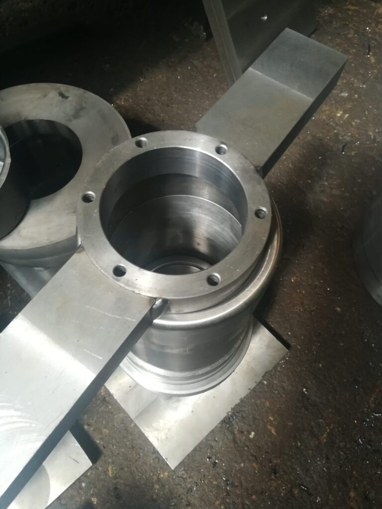
A deep drawing mold blank holder is a critical component in the deep drawing process that controls the flow of the sheet metal blank into the die cavity. Its primary function is to apply uniform pressure on the blank’s perimeter during forming to prevent wrinkling and ensure smooth, controlled metal flow.
The blank holder is typically a flat ring or plate that presses down on the sheet metal blank around its outer edge. This pressure holds the blank firmly against the die and restricts excessive inward movement of the sheet during the drawing stroke. Without adequate blank holder force, the sheet metal tends to buckle and form wrinkles, especially in the flange area, compromising the part’s dimensional accuracy and surface quality.
The force applied by the blank holder must be carefully controlled: too little pressure allows wrinkling, while too much can cause tearing or excessive thinning of the material. Therefore, blank holder force is often adjustable, either manually or through hydraulic or pneumatic systems, to optimize forming conditions based on the material type, thickness, and part geometry.
In addition to controlling wrinkling, the blank holder helps regulate the material flow rate into the die cavity, balancing the metal’s deformation to avoid localized thinning or cracking. This balance is crucial for producing parts with consistent thickness and strength.
Blank holders are designed to withstand high forces and often feature hardened surfaces to resist wear. Some are segmented or equipped with multiple pressure zones, allowing differential force application across the blank perimeter for more complex shapes or variable material properties.
In automated or high-volume deep drawing operations, blank holders may be integrated with sensors and control systems to monitor and adjust pressure dynamically during each stroke. This real-time control improves process stability and reduces defects.
Overall, the blank holder is an essential part of the deep drawing mold assembly, playing a pivotal role in ensuring the quality and consistency of formed sheet metal parts by precisely controlling material flow and preventing defects like wrinkling.
The blank holder’s design and functionality can vary significantly depending on the complexity of the part being formed and the material characteristics. In simple deep drawing applications, a solid, uniform blank holder ring may suffice, but for more complex geometries or materials prone to wrinkling or tearing, blank holders with segmented or adjustable pressure zones are employed. These segmented designs allow independent control of force across different sections of the blank, which helps accommodate uneven material flow and reduces the risk of defects in challenging areas.
Adjustability of the blank holder force is crucial because different materials and sheet thicknesses respond uniquely during the drawing process. For instance, thicker or less ductile materials typically require higher blank holder pressure to prevent wrinkling, whereas thinner, more ductile sheets might need lower pressure to avoid tearing. This adjustability can be achieved mechanically with springs, hydraulics, or pneumatics, and in advanced systems, force sensors and feedback loops enable real-time monitoring and adjustment, optimizing the process for each stroke.
The surface finish of the blank holder contacting the sheet metal also influences forming quality. A smooth, polished surface reduces friction and minimizes surface damage to the blank, helping to maintain part surface quality. However, in some cases, a slightly textured surface can help retain lubricant, improving metal flow and reducing sticking between the blank and the holder.
Blank holders are integrated carefully into the overall mold assembly to maintain precise alignment and consistent pressure distribution. Any misalignment or uneven force application can lead to uneven material flow, causing defects such as wrinkles, tears, or variations in thickness. Regular maintenance and inspection of the blank holder are important to ensure consistent performance and to avoid premature wear that could affect pressure uniformity.
In more advanced deep drawing setups, blank holders may also be combined with draw beads—small protrusions or grooves in the tooling that add controlled resistance to the sheet metal flow. Together, these elements finely tune how the material moves into the die cavity, balancing the forces to achieve the desired part shape without defects.
In summary, the blank holder is not just a simple clamp but a sophisticated component designed to carefully regulate the flow and deformation of the sheet metal during deep drawing. Its design, force control, surface characteristics, and integration into the mold assembly all contribute to successful forming operations, ensuring parts meet stringent quality and dimensional requirements while minimizing waste and rework.
Modern blank holders often incorporate smart technologies to further enhance the deep drawing process. Sensors embedded in the blank holder can monitor pressure distribution, temperature, and friction levels in real time, providing valuable data to adjust force dynamically and prevent issues like wrinkling or tearing before they occur. This adaptive control allows for more consistent part quality, especially in complex or high-volume production environments where even minor variations in material or conditions can lead to defects.
In some high-precision applications, blank holders are part of fully automated forming systems where computer-controlled actuators adjust the blank holder pressure stroke-by-stroke. This integration enables the forming process to respond instantly to variations in material behavior, thickness, or lubricant condition, minimizing downtime and scrap rates.
The design evolution of blank holders also includes lightweight materials and modular construction to reduce cycle times and facilitate faster mold changes. For example, using advanced alloys or composite materials can reduce the mass of the blank holder without sacrificing strength, improving press efficiency and reducing energy consumption.
Another trend is the development of blank holders with integrated heating or cooling channels to manage temperature during forming. Controlling the temperature can influence material ductility and flow characteristics, helping to prevent defects and expand the range of formable materials, including advanced high-strength steels and aluminum alloys widely used in automotive and aerospace industries.
Maintenance of blank holders is critical because wear or damage can cause uneven pressure and surface defects. Routine inspection for scratches, dents, or surface degradation, as well as recalibration of force systems, ensures that the blank holder performs optimally throughout the mold’s service life. Repair or replacement schedules are often based on usage cycles or part quality trends.
In summary, the blank holder remains a cornerstone of deep drawing mold design, evolving from a simple mechanical clamp to an intelligent, adaptive component. Its precise control over sheet metal flow directly impacts part quality, process stability, and production efficiency, making it indispensable in modern manufacturing where demands for tighter tolerances, complex shapes, and lightweight materials continue to grow.
Deep Drawing Mold Wrinkling Prevention
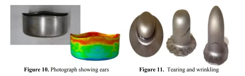
Wrinkling prevention in deep drawing molds is a critical aspect of ensuring high-quality formed parts. Wrinkling occurs when compressive stresses build up in the flange or sheet metal outside the die cavity, causing the material to buckle or fold instead of flowing smoothly into the die. This defect not only compromises the aesthetic and dimensional quality of the part but can also lead to structural weaknesses and increased scrap rates.
One of the primary methods to prevent wrinkling is the precise control of blank holder force. By applying adequate and uniform pressure on the blank’s perimeter, the blank holder restricts excessive inward flow of the sheet metal, which helps maintain tension in the flange area. This tension counteracts compressive stresses that cause wrinkling. However, the force must be carefully calibrated, as too much pressure can lead to tearing or excessive thinning of the material.
In addition to blank holder pressure, draw beads are commonly used as a mechanical wrinkle prevention feature. Draw beads are small, strategically placed protrusions or grooves in the die or blank holder that create controlled resistance to metal flow. By increasing the friction and flow resistance locally, draw beads help balance the metal movement, reducing the tendency for buckling and distributing stresses more evenly across the sheet.
Material selection and preparation also influence wrinkling tendencies. More ductile materials with higher elongation capabilities generally resist wrinkling better, while stiffer materials require more precise control of forming parameters. Proper lubrication is crucial as well, as inadequate lubrication increases friction, restricting smooth material flow and promoting wrinkling.
Design factors such as die geometry, including die radius and punch shape, also impact wrinkling. Larger die radii and smooth transitions help reduce localized stress concentrations that contribute to buckling. Additionally, multi-stage drawing processes, where the part is formed incrementally through a series of dies, reduce the severity of deformation at each stage, lowering the risk of wrinkling.
Advanced simulation software allows engineers to predict wrinkling during the design phase, enabling optimization of mold geometry, blank holder force, and draw bead placement before physical tooling is made. This predictive capability reduces trial-and-error in production and improves first-pass success rates.
Temperature control during forming can also aid wrinkling prevention. Heating the blank or tooling can improve material ductility and flow, helping to alleviate compressive stresses that cause buckling.
In summary, wrinkling prevention in deep drawing molds relies on a combination of controlled blank holder pressure, use of draw beads, careful material and lubrication selection, optimized die design, and process parameter control. These factors work together to maintain uniform material flow, reduce compressive stresses, and ensure smooth, defect-free forming of sheet metal parts.
Another essential factor in preventing wrinkling during deep drawing is the initial blank design. The size and shape of the blank must be optimized to match the final part geometry and the material’s behavior during forming. If the blank is too large, excess material may bunch up in the flange area, increasing the likelihood of buckling. Conversely, if it’s too small, the part may tear or thin excessively. Engineers often use finite element analysis to simulate material flow and adjust the blank size and shape to achieve the right balance between flow and resistance, reducing the chances of wrinkling.
The condition and alignment of the tooling also play a significant role in wrinkle control. Any misalignment between the die, punch, and blank holder can result in uneven force distribution, which disrupts smooth material flow and causes localized wrinkling. Precision machining of mold components, along with strict maintenance and regular inspection, ensures that all parts are in proper alignment and capable of distributing forming forces uniformly across the entire blank.
Tool surface condition also affects wrinkling. Worn, scratched, or pitted surfaces on the die or blank holder increase localized friction, interrupting the even flow of material and potentially initiating folds or ripples in the sheet metal. Regular polishing and surface treatments can maintain low friction conditions and help the sheet flow more predictably. In some cases, surface coatings like TiN or DLC are applied to the tooling to enhance surface durability and reduce friction even further, particularly when forming tougher or less ductile materials.
Lubrication is a major process variable in wrinkling prevention. Consistent application of a suitable lubricant creates a controlled interface between the sheet and tooling. This reduces the chances of metal sticking or bunching up under the blank holder. Inadequate or uneven lubrication can cause the blank to grab or hesitate during forming, resulting in uneven material distribution that leads to wrinkling. Depending on the application, oil-based, water-based, or dry film lubricants may be used, each selected to match the material type and forming speed.
The press speed and stroke rate can also influence wrinkling behavior. Forming too quickly may not allow the material enough time to deform uniformly, increasing the chances of instability in the flange region. Slower or staged forming speeds, especially in the initial portion of the stroke, can help stabilize the blank and allow controlled deformation. In high-volume production, servo presses with programmable speed profiles are sometimes used to optimize the forming speed at various points in the cycle to minimize wrinkling and other defects.
In advanced manufacturing environments, closed-loop control systems use sensors embedded in the tooling to monitor parameters like blank holder force, metal flow, and pressure distribution during every stroke. These systems can detect early signs of wrinkling and automatically adjust forming parameters in real time to correct the issue before it leads to defective parts. This level of control is especially useful when working with high-strength materials or complex geometries where forming margins are tight.
Training and experience of the machine operator also influence wrinkle prevention. Skilled operators can recognize the early signs of forming issues and make fine adjustments to the press setup or lubrication strategy to avoid costly scrap. In less automated environments, operator insight remains a crucial safeguard against unexpected material behavior or equipment variability.
Ultimately, effective wrinkling prevention is the result of integrating tooling design, material science, lubrication engineering, press control, and human expertise. It’s a balancing act of forces and resistances that must be managed precisely to keep the metal flowing smoothly without folding or tearing. A deep understanding of the interaction between each variable allows engineers to design robust forming processes that consistently yield clean, dimensionally accurate, and wrinkle-free deep drawn parts.
In many cases, especially when transitioning from prototype to full-scale production, wrinkling issues that were not evident in early runs may become pronounced due to variations in material batches, slight differences in lubrication, or accumulated tool wear. Therefore, ongoing process monitoring and refinement are essential. Even slight changes in sheet thickness or hardness from one coil to another can alter how the material responds under the same forming conditions, necessitating dynamic adjustment of blank holder force or lubrication rates. To address this, manufacturers often establish acceptable material property ranges and use incoming inspection to sort and verify that raw materials meet these specifications before they enter production.
Furthermore, multi-step or redraw processes may be introduced when a part cannot be formed in a single deep drawing operation without wrinkling. By gradually reducing the blank’s diameter and reshaping it over multiple stages, the metal undergoes less severe deformation in each step, which helps maintain better control of compressive stresses in the flange. This staged approach is particularly important when forming high aspect ratio components or when using materials with low formability.
Reverse drawing, where the metal is first drawn in one direction and then redrawn in the opposite direction, can also be used to reduce wrinkling in particularly difficult geometries. This technique allows for better material alignment and pre-distribution, essentially preparing the sheet metal for more uniform deformation by first rearranging the stress patterns within the blank. Although more complex, such advanced methods can significantly reduce wrinkling in challenging parts where traditional methods fall short.
Another preventative measure includes using pressure pads or flexible blank holder systems that conform more closely to the blank’s surface. These systems, often combined with elastomeric or fluid-filled interfaces, apply pressure more evenly than rigid blank holders and adapt better to slight irregularities in the blank or die surface. They are particularly effective in applications where uniformity of force across the entire flange is critical, such as in parts with thin walls or tight tolerances.
Additionally, for specific applications, engineers may intentionally modify the blank shape into non-circular profiles—such as ellipses or rectangles with rounded corners—to better match the material flow required by the final part geometry. This strategy distributes the forming stresses more evenly and reduces the likelihood of localized wrinkling, especially in asymmetrical parts or those with off-center draw depths.
Educational investment and process documentation further enhance wrinkle prevention. By maintaining detailed records of successful press setups—including blank dimensions, lubrication methods, press settings, and material characteristics—operators and engineers create a reliable knowledge base that improves repeatability and reduces trial-and-error in future jobs. This standardization is particularly valuable in high-volume or repeat-order environments, where consistency and minimal waste are crucial for profitability.
In short, wrinkling prevention in deep drawing is not about any single factor but a continual effort to harmonize a wide range of variables—tool design, material properties, lubrication, forming speed, blank holder systems, and operator practices. By mastering these interactions, manufacturers not only prevent defects but also increase forming efficiency, extend tool life, and improve the overall economic viability of deep drawing operations.
Beyond the forming process itself, post-forming analysis plays a valuable role in long-term wrinkling prevention. Even when visible wrinkling doesn’t occur, subtle signs—such as localized thickness variations, minor flange undulations, or early indications of waviness—can be early warnings of instability in the process. These may not lead to immediate rejections but can compromise part performance over time or cause complications in downstream operations like trimming, welding, or assembly. Regular inspection using non-contact thickness measurement systems, optical surface scanners, or even simple visual checks by trained personnel allows manufacturers to identify these early signs and adjust process parameters before more serious defects emerge.
In research and development settings, digital modeling and virtual prototyping have become indispensable for wrinkle analysis. Advanced forming simulation software incorporates material behavior models that include anisotropy, strain hardening, and friction characteristics to predict wrinkling under various conditions. Engineers use these simulations to test different blank holder designs, draw bead placements, and tool geometries before investing in physical tooling. This reduces the development cycle, cuts costs, and improves confidence in achieving wrinkle-free production from the first run.
Material innovation is another frontier in wrinkling control. High-performance aluminum alloys, dual-phase steels, and micro-alloyed stainless steels are now formulated with better formability to reduce the risks associated with compressive stress and instability. These modern materials are often paired with specific forming strategies—including tailored lubrication and temperature control—to push the limits of what can be drawn without wrinkles. In some cases, forming at elevated temperatures, known as warm or hot deep drawing, is used to soften hard-to-form materials and achieve cleaner flows, especially for titanium, magnesium, or advanced aluminum grades.
The importance of consistent lubrication cannot be overstated in these scenarios. Some processes have evolved to include automatic lubrication systems that apply precise volumes of lubricant at specific locations on the blank or tooling. These systems are often tied into the control logic of the press, ensuring that lubrication remains consistent throughout a production run. In operations where cleanliness is critical—such as food container manufacturing or medical components—dry-film lubricants are chosen not just for their environmental and cleanup advantages but also because they can be precisely metered and reduce variability in friction.
Looking even further into the future, integration of machine learning and artificial intelligence into press monitoring systems is beginning to impact wrinkle prevention strategies. By collecting data over thousands of strokes—such as force curves, displacement readings, and finished part scans—AI systems can detect patterns that predict the onset of wrinkling and suggest optimal settings proactively. Such systems can account for drift in machine performance over time, temperature changes in the shop floor environment, or subtle shifts in raw material quality, maintaining consistent part quality with less operator intervention.
Ultimately, wrinkle prevention in deep drawing molds reflects the maturity of the forming process. It requires an understanding of how elastic and plastic deformation interact across the entire sheet during the draw, and how minor changes in tooling, lubrication, or processing can ripple through the system. The goal isn’t just to eliminate defects—it’s to build a process that is robust, predictable, and optimized for quality and throughput. Whether through smart tooling, better materials, process feedback, or engineering intuition, every step taken to reduce wrinkling strengthens the reliability and efficiency of the entire deep drawing operation.
Deep Drawing Mold For Aerospace
Deep drawing molds used in aerospace manufacturing are engineered to meet exceptionally high standards of precision, consistency, and material performance. Aerospace components, whether structural panels, housings, or enclosures, must adhere to tight tolerances and often involve materials that are challenging to form, such as titanium alloys, Inconel, or high-strength aluminum. These requirements place unique demands on the design and operation of deep drawing molds in this industry.
A key feature of aerospace deep drawing molds is their ability to handle advanced, high-strength, and lightweight materials. These materials are selected for their superior strength-to-weight ratio and resistance to extreme temperatures, corrosion, and fatigue. However, they often have limited ductility and work harden quickly, making them more prone to wrinkling, tearing, or springback during forming. As a result, aerospace molds must be designed with large, carefully calculated radii, smooth transitions, and precision-polished surfaces to minimize stress concentrations and promote uniform metal flow.
Forming aerospace components typically requires greater control over temperature and pressure than conventional deep drawing. In many cases, warm or hot forming is employed, where the blank or the entire mold is heated to improve material formability. Heating reduces the yield strength of the alloy, allowing it to deform more easily without cracking. Molds must therefore be made from heat-resistant tool steels or be equipped with integrated heating systems such as cartridge heaters, induction coils, or oil-based heating circuits. Temperature control is critical—not only to soften the material but also to ensure that forming occurs consistently from part to part.
Aerospace deep drawing molds also frequently incorporate multi-stage forming processes. Due to the complexity and precision required, parts are often formed gradually through a sequence of operations that include initial drawing, redrawing, ironing, trimming, and sometimes reverse drawing. This progressive approach helps distribute deformation more evenly and allows for intermediate inspection steps to ensure that no defects are introduced at each stage.
Blank holder systems in aerospace molds are highly refined and often hydraulically or pneumatically actuated to allow precise adjustment of pressure throughout the forming stroke. These systems are sometimes segmented or designed with variable resistance zones to accommodate complex part geometries and ensure consistent material tension, reducing the risk of localized thinning or wrinkling. In certain applications, intelligent control systems with sensors monitor the process in real time and make automatic adjustments to blank holder force, draw speed, or lubricant application.
Tooling for aerospace deep drawing must also meet extremely high durability and surface quality standards. Molds are usually manufactured with tight tolerances using CNC machining, EDM, and precision grinding. Surface treatments such as nitriding, PVD coatings, or DLC (diamond-like carbon) are commonly applied to reduce wear and friction, extend tool life, and ensure consistent part finishes over long production runs.
Furthermore, aerospace regulations demand rigorous documentation and traceability in the forming process. Every mold component, press setup, and forming parameter must be documented to ensure repeatability and compliance with certification standards. This includes validation of material properties, verification of temperature and pressure profiles, and traceability of every batch and formed part.
In essence, deep drawing molds for aerospace represent the pinnacle of forming technology, combining advanced materials, precise mechanical engineering, thermal management, and digital process control. The cost and complexity are significantly higher than in general manufacturing, but the result is a forming process capable of producing lightweight, high-strength, and safety-critical components that perform reliably under the most demanding conditions imaginable.
The integration of simulation tools during the design of aerospace deep drawing molds is not just beneficial—it is essential. Finite element analysis (FEA) software is used extensively to model material flow, predict wrinkling, tearing, and springback, and optimize every detail of the tooling geometry before any physical mold is manufactured. These simulations take into account the anisotropy of aerospace-grade materials, the friction conditions expected during actual production, and the thermal properties when forming is done at elevated temperatures. By simulating the forming process under realistic conditions, engineers can fine-tune parameters like blank holder force distribution, punch speed, and even the initial blank shape to ensure the most stable and defect-free result possible. In many aerospace programs, these simulations are part of the formal qualification process for new tooling.
When moving from prototype to production, maintaining consistency is a high priority. Aerospace components often have functional and aerodynamic roles, meaning even minor deformations or cosmetic flaws may render a part unacceptable. Therefore, tooling repeatability and dimensional stability must be maintained over potentially thousands of cycles, and molds are often built with hardened tool steels or carbide inserts in wear-prone areas. These molds may also incorporate interchangeable die inserts that allow for minor geometry changes without requiring full re-machining, which is particularly useful during iterative development phases or when producing variations of a base component.
In high-volume aerospace production, such as for fasteners, brackets, and interior hardware, automated deep drawing lines are employed that incorporate robotic handling, automated lubrication, and inline inspection systems. These systems are designed not only for speed but for precision. Any deviation from the defined forming profile is quickly detected and can trigger process corrections or rejections before a defect propagates further down the manufacturing line. Data collected from sensors embedded in the press or tooling—such as force sensors, displacement transducers, and temperature monitors—feeds back into control software that adjusts forming conditions dynamically, ensuring high process stability even under continuous operation.
Part inspection after drawing is typically extensive. Non-destructive testing methods like dye penetrant inspection, ultrasonic testing, or 3D optical scanning are used to confirm dimensional accuracy, surface finish, and structural integrity. In some cases, components undergo additional forming operations such as coining, flanging, or machining to meet final specifications. All of these steps must be tightly coordinated to ensure that the initial deep drawing operation provides a robust foundation for downstream operations. Poor form consistency or minor wrinkling in early stages could compromise fatigue life or create difficulties during precision assembly, especially in airframe or engine applications where tolerances are exacting.
Another area of growing importance is sustainability and material utilization. Aerospace materials are expensive and often produced in limited quantities. Optimizing blank size to reduce waste while still ensuring defect-free forming is a critical design consideration. Nesting studies, simulation-based blank optimization, and waste-reduction strategies are all part of the mold design process. Even scrap from trimming operations is often collected and recycled under tightly controlled conditions to preserve the traceability and quality of the material.
Moreover, the workforce involved in operating and maintaining aerospace deep drawing molds requires specialized training. Operators must be familiar not just with the press controls but with the behavior of exotic materials and the criticality of process parameters. Maintenance teams are responsible for regular inspection and reconditioning of mold surfaces, lubrication channels, heaters, and fasteners to ensure that the mold continues to perform precisely throughout its service life. A single undetected defect in a forming die could lead to significant costs and delays if it results in a batch of nonconforming aerospace parts.
In summary, the use of deep drawing molds in aerospace is defined by a combination of advanced engineering, tight process control, meticulous inspection, and an uncompromising emphasis on reliability and repeatability. The parts produced are not just shaped pieces of metal—they are components expected to perform flawlessly in environments where failure is not an option. The mold is the silent foundation of this performance, engineered and executed with a level of care and complexity that matches the mission-critical nature of the aerospace industry itself.
In aerospace deep drawing, reverse engineering and digital twin technologies are also becoming increasingly prevalent. When a mold is created for a legacy part—or when updating older equipment—engineers may use 3D scanning and CAD reconstruction to develop precise virtual models of both the final part and the tooling. This allows for exact reproduction of tooling geometry while improving on original designs by incorporating modern materials, coatings, and simulation-informed refinements. The digital twin of the mold can then be used to monitor wear over time, predict maintenance schedules, and even simulate future production runs under new conditions without interrupting the actual line.
Advanced lubrication strategies also play a pivotal role in aerospace deep drawing molds. Because many aerospace materials exhibit high friction coefficients—especially at room temperature—lubricants must be selected with great care. In hot or warm forming applications, solid film lubricants such as boron nitride or graphite may be used, offering high-temperature stability and excellent release properties. In cold forming, synthetic or chlorinated oils with additives are applied in metered layers to create consistent film thickness and reduce friction variation. Automated lubrication systems are often tied into the press control system to ensure synchronized application, reducing the risk of dry spots or over-application, both of which could compromise part quality.
The mold cooling system is another important factor, especially for high-throughput aerospace operations where cycle time matters. Molds may feature internal water cooling channels or thermoregulated zones to manage temperature gradients and minimize thermal distortion during forming. This is particularly important in warm forming processes, where heat can cause dimensional shifts in the mold if not carefully controlled. Uniform thermal conditions also help ensure more predictable springback and reduce the chances of forming defects across repeated cycles.
Springback compensation is often a central concern when forming aerospace components, especially those made from titanium or ultra-high-strength alloys. These materials tend to return more aggressively to their original shape after deformation, which can lead to dimensional inaccuracies if not properly accounted for. To address this, mold geometry is deliberately modified—through iterative trials or predictive simulation—to include offsets that counteract springback. In highly complex parts, compensating for springback may also involve post-forming calibration operations using coining or restriking dies to refine the part to final dimensions.
Modularity in mold design is increasingly emphasized in aerospace tooling. Rather than building a dedicated tool for every single part variant, manufacturers often design modular dies that share a common base but allow for interchangeable punch or die inserts, blank holder rings, or adjustable draw bead locations. This not only reduces cost but also improves responsiveness when engineering changes are introduced during development or when switching between variants of a product line. Modularity is particularly useful in small- to medium-volume production runs, where flexibility and fast changeover are more valuable than maximum throughput.
Documentation and traceability of the mold lifecycle are also core elements of aerospace manufacturing. Every detail of the mold’s fabrication, heat treatment, machining, finishing, and maintenance history must be logged and accessible, ensuring full accountability in case of quality audits or failure investigations. Aerospace customers often require mold certification packages that include steel batch numbers, dimensional inspection reports, coating certifications, and even calibration data for the measurement tools used during mold validation. These records are maintained for years and linked to specific production batches, reinforcing the overall quality assurance system.
Lastly, the role of collaboration in aerospace tooling cannot be overstated. Mold design and process development involve close coordination between part designers, materials engineers, toolmakers, and production personnel. Regular design reviews, cross-functional input, and trial evaluations are all integral to ensuring that the mold performs as intended, often across multiple facilities or countries. In many programs, this collaboration is managed under a formal product lifecycle management (PLM) system that synchronizes all stakeholders and ensures that every update or change to the tooling is tracked, validated, and implemented in a controlled manner.
Thus, a deep drawing mold for aerospace is more than a simple forming tool—it is a precision system at the heart of a high-stakes manufacturing process. Its design, operation, and maintenance reflect the uncompromising demands of aerospace applications, where safety, precision, and durability are paramount. Every detail, from the tool steel selection to the control logic of the hydraulic system, is governed by strict standards and rigorous testing, ensuring that each formed part contributes confidently to the performance and reliability of modern flight systems.
Deep Drawing Mold For HVAC
Deep drawing molds used in HVAC (Heating, Ventilation, and Air Conditioning) applications are designed with an emphasis on efficiency, repeatability, and cost-effectiveness while still maintaining structural integrity and precision. The components produced by these molds—such as fan housings, motor enclosures, compressor shells, and ducting elements—are typically made from relatively ductile metals like mild steel, aluminum, or galvanized sheet metal. Unlike aerospace or medical sectors, HVAC manufacturing often deals in medium to high production volumes with moderate tolerances, which influences both the tooling strategy and material handling systems.
The mold design for HVAC parts generally prioritizes streamlined material flow and ease of part ejection, especially since many of the components have relatively shallow draw depths and wide diameters. Punches and dies are usually designed with generous corner radii and smooth transitions to prevent stress concentrations and reduce the risk of tearing or galling, particularly with galvanized or coated materials. The use of surface-hardened tool steels or nitrided dies is common to combat wear from continuous operation, especially when forming abrasive or coated blanks. Surface finishes are typically optimized for functional rather than cosmetic requirements, although polished finishes may still be applied when parts are visible in end-use installations.
A key feature in HVAC mold systems is robust blank holding and force control. Since many HVAC parts are circular or symmetrical, the blank holder is often a ring-style or segmented unit with spring, pneumatic, or hydraulic actuation, depending on the press type. The blank holder’s role is critical in preventing flange wrinkling during draw-in while still allowing sufficient material flow to avoid tearing. Tooling is frequently integrated with draw beads or flow control features to fine-tune this behavior, especially for deeper or irregular shapes like fan shrouds or motor end caps.
HVAC production lines also benefit from high levels of automation. Deep drawing molds are commonly installed in transfer presses or progressive die setups where multiple forming steps occur in a continuous sequence. The tooling is therefore designed for quick alignment, minimal setup time, and low maintenance requirements. Quick-change tooling features, modular die sets, and integrated centering systems allow operators to switch between part types with minimal downtime, a key requirement in HVAC plants where product variety is often high.
Lubrication in HVAC deep drawing is handled with practicality in mind. Because many HVAC parts are subsequently welded, painted, or powder-coated, lubricant selection must balance formability and post-processing compatibility. Water-soluble lubricants or light synthetic oils are commonly used to facilitate cleaning while still reducing friction and wear. In some cases, dry-film or pre-applied coatings are preferred for cleanliness and consistency, particularly in automated lines. The mold design accommodates lubrication delivery through grooves, sprays, or rollers depending on the forming process and part geometry.
Thermal management is generally less critical in HVAC mold design than in aerospace or automotive, as most HVAC forming is conducted at room temperature using materials with good cold-forming characteristics. However, for stainless steel or thicker aluminum parts—especially those used in commercial or industrial HVAC systems—additional attention may be given to draw speed, lubrication, and punch/die clearance to avoid excessive work hardening or cracking.
HVAC deep drawing molds also consider downstream integration. For example, parts that require trimming, hole punching, or beading after forming may be designed with locating features or integrated trimming operations within the same mold. This not only improves dimensional consistency but also reduces handling steps and labor, which is vital for maintaining competitive production costs in HVAC markets.
In terms of maintenance and longevity, HVAC molds are designed for durability over thousands or even millions of cycles. Tool steels with high toughness and wear resistance are used, and mold components are designed for easy replacement or reconditioning. Preventive maintenance schedules are typically based on stroke count, with critical surfaces inspected and polished regularly to maintain part quality. Because HVAC production often runs across multiple shifts, minimizing unplanned downtime through robust mold design and predictable wear behavior is a priority.
Ultimately, deep drawing molds for HVAC applications reflect a careful balance between engineering performance and industrial practicality. They must be versatile enough to handle a wide range of part geometries and materials, robust enough to operate reliably in high-volume environments, and economical enough to meet the cost pressures of a competitive marketplace. Through smart design, proven materials, and integration with automated systems, these molds form the backbone of efficient HVAC component manufacturing across residential, commercial, and industrial sectors.
In the context of HVAC manufacturing, deep drawing molds must also account for the unique requirements of airflow optimization, component interfacing, and structural vibration resistance. Parts formed through deep drawing often play integral roles in directing airflow, housing rotating components, or forming structural enclosures for blowers, compressors, and heat exchangers. Because of this, mold precision directly influences not only assembly fit but also the overall energy efficiency and noise profile of the HVAC system. Even small variations in part geometry—such as inconsistencies in fan cover curvature or uneven draw depth in compressor shells—can affect how air moves through the unit, leading to pressure drops, inefficiency, or unwanted vibration. Therefore, the design of the mold must ensure dimensional stability over large production runs, even when working with coated or layered metals that may behave differently than raw steel.
Moreover, many HVAC components are designed with joining and fastening in mind. Features such as flanges, locating grooves, and stiffening ribs may be incorporated during the deep drawing process to reduce the number of post-forming operations and to assist in part alignment during assembly. Molds are often customized to produce these features in a single stroke, requiring precise synchronization between the punch, die, and blank holder systems. Tolerances must be managed not only at the perimeter of the drawn component but across the entire surface profile, especially for parts that will later mate with injection-molded plastic parts or electronic housings.
Another important aspect is cycle time. HVAC manufacturers often operate under tight delivery windows, requiring that each part be formed quickly and consistently. The mold and press combination must be capable of completing each cycle in seconds, which puts additional pressure on cooling, lubrication, and ejection systems to operate reliably and without delay. Fast, clean ejection is especially critical, as any hesitation in part release can jam the press or cause cosmetic damage, especially when dealing with lightweight aluminum or thin-walled stainless steel components. Ejection systems may use pneumatic or spring-assisted strippers, vacuum assist, or mechanical lifters built into the die to ensure smooth removal of the finished part.
Press selection is closely tied to mold performance. Hydraulic and servo-mechanical presses are often used for HVAC deep drawing due to their ability to provide high forming force with smooth, controllable motion. This control helps reduce thinning and prevents cracking in more complex or deeper parts. The mold is typically designed to take full advantage of this press control, with variable blank holder force and programmable forming speeds that adapt to the part shape and material characteristics. This flexibility is particularly important when forming parts with large surface areas, where non-uniform material flow can lead to buckling or uneven wall thickness if not managed carefully.
Scrap reduction is another key consideration in HVAC tooling design. Many HVAC parts are produced from standard coil widths or sheet sizes, and optimizing the blank shape to minimize waste without sacrificing formability is a critical cost-saving strategy. Molds may be designed in conjunction with laser- or plasma-cut blanking systems that produce non-circular blanks optimized through simulation. These optimized blanks flow more uniformly into the die cavity and reduce the chances of wrinkles or excess trimming, both of which impact material cost and downstream processing time. This optimization also supports lean manufacturing goals, which are increasingly important as HVAC systems become more modular and configurable.
Tooling longevity and refurbishability are built into HVAC deep drawing mold design. Insertable wear plates, replaceable punch noses, and modular die components are standard features, enabling quick refurbishment or adaptation to design changes without requiring an entirely new mold. For high-wear areas—such as where the sheet enters the die or contacts draw beads—coatings like titanium nitride or hard chrome may be applied to extend life and ensure consistent surface interaction. These coatings are especially important when forming galvanized or painted blanks, where surface roughness and friction can vary dramatically from lot to lot.
Finally, quality control plays a continuous role in how deep drawing molds are managed and optimized in HVAC production. Inline sensors or post-process inspection stations may be used to monitor draw depth, wall thickness, flange diameter, and overall surface condition. These systems feed data back into the tooling maintenance schedule and help identify trends that could signal tool wear or press misalignment. In more advanced setups, closed-loop control systems adjust press force or draw speed in real time based on feedback from these sensors, further improving consistency and reducing scrap.
Thus, the design and implementation of deep drawing molds for HVAC systems involve a dynamic interplay between precision engineering, materials science, automation, and production economics. These molds must not only shape metal but do so with the speed, reliability, and repeatability demanded by a competitive global HVAC market. They serve as vital enablers of quality, efficiency, and innovation, supporting the manufacture of energy-efficient, durable, and functionally optimized components that form the core of modern climate control systems.
As HVAC technology continues to evolve—particularly with the push toward more energy-efficient systems and the integration of smart components—the demands on deep drawing molds are also shifting. One clear trend is the increasing use of lightweight materials like aluminum alloys and thinner galvanized steel sheets. These materials help reduce overall unit weight and improve thermal performance, but they also introduce new challenges in deep drawing. For instance, thinner sheets are more susceptible to wrinkling and tearing, especially in complex or asymmetric shapes. To address this, mold designers must carefully tune punch/die clearances, blank holder pressures, and lubrication strategies, often relying on advanced forming simulations to validate their designs before committing to tooling.
Environmental factors are also influencing mold design. As more HVAC manufacturers adopt eco-friendly production standards, the use of environmentally hazardous lubricants or coatings is being phased out. This means molds must function efficiently with biodegradable or water-based lubricants, which may not offer the same level of lubricity as traditional oils. To compensate, tooling surfaces may be finished to higher smoothness grades, or engineered coatings such as PVD films may be applied to reduce friction without chemical lubrication. In some production environments, dry forming methods using specially treated blank surfaces or mold surfaces are being explored as a way to reduce post-forming cleaning and eliminate lubricant contamination of downstream processes.
From a manufacturing systems perspective, there is a strong push toward digitization and traceability in HVAC mold operations. Sensors embedded in the mold or the press can now monitor parameters such as forming force, part temperature, punch displacement, and even surface friction in real time. This data is not only used to detect anomalies or predict failures but also to refine mold designs over time. For example, if certain areas of a part consistently exhibit thinning or cracking, engineers can adjust local geometry, introduce localized lubrication zones, or modify draw bead profiles in future tool iterations. This feedback loop between manufacturing data and mold design is becoming a cornerstone of modern HVAC production strategy.
In terms of operational logistics, the shift toward modular, decentralized HVAC units—such as ductless systems and split-type heat pumps—means a greater variety of part geometries and component sizes. Deep drawing molds must be adaptable to this variety without incurring excessive costs. Quick-change mold inserts, universal baseplates, and adjustable clamping systems are widely used to allow a single press line to produce multiple parts with minimal downtime. In high-mix, low-volume environments, this adaptability can be the difference between profitable and inefficient production.
The use of servo presses has also enhanced the capabilities of HVAC mold tooling. Unlike traditional mechanical presses, servo-driven systems allow precise control over ram velocity and dwell time at any point in the stroke. This is especially useful for HVAC parts with complex profiles or critical surface features, where slower draw speeds at certain stages can prevent defects without sacrificing overall cycle time. Molds designed for use with servo presses often include variable resistance zones—such as differential blank holder segments or adaptive guide systems—to take full advantage of this control.
Finally, the role of collaborative design is growing, particularly as HVAC units become more integrated with electrical components, sensors, and smart technologies. Mold designs are increasingly developed in parallel with part designs, electrical harness layouts, and assembly process planning. This concurrent engineering ensures that the formed part not only meets its functional requirements but also accommodates wiring paths, mounting clips, sensor ports, and other integrated features without additional post-forming modifications. This integrated approach shortens product development cycles and reduces the number of iterations required before full-scale production can begin.
In sum, deep drawing molds for HVAC production are evolving in response to changing materials, tighter performance requirements, and more flexible manufacturing demands. They must maintain high throughput and reliability, adapt to a growing variety of part types, and meet sustainability goals—all while ensuring that each component they form contributes to the overall efficiency, durability, and market competitiveness of the final HVAC system. The mold, though often invisible to the end user, remains one of the most critical elements in delivering modern heating and cooling solutions at scale.
Deep Drawing Mold For Cookware
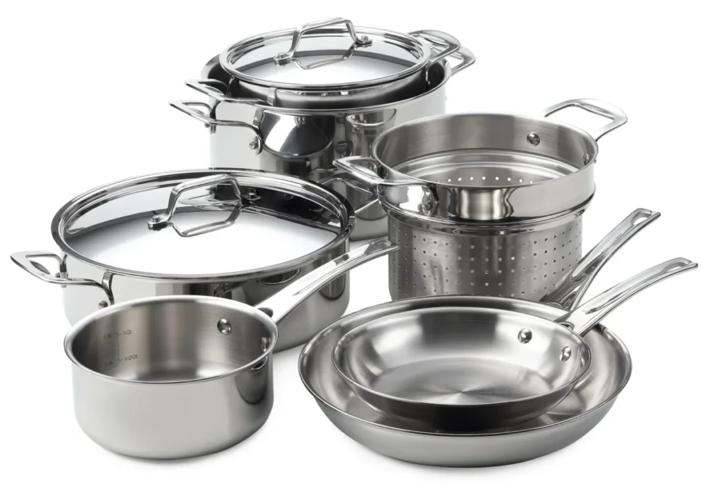
Deep drawing molds for cookware production are specifically designed to produce items such as pots, pans, lids, and other kitchen vessels with smooth surfaces, uniform wall thickness, and durable structural integrity. Unlike molds used in sectors like HVAC or automotive, cookware molds must address both mechanical and aesthetic requirements. The end products must not only perform under heat and mechanical stress but also present a flawless appearance suitable for consumer markets. Therefore, the design and construction of these molds require a careful balance between formability, surface finish, and production efficiency.
Materials used in cookware—commonly stainless steel, aluminum, or clad metals (such as stainless steel bonded with aluminum or copper)—present unique challenges during deep drawing. Stainless steel, for example, work-hardens quickly and has a relatively low elongation compared to other metals. As a result, the mold must be engineered to minimize friction and distribute forming forces evenly across the blank to prevent tearing, excessive thinning, or surface scratching. Mold surfaces are typically polished to a mirror finish, and the use of advanced lubricants or coatings is essential to maintain part quality over repeated cycles. In high-end production, the punch and die may be coated with materials like titanium nitride (TiN) to reduce friction, extend tool life, and enhance the surface quality of the drawn cookware.
The mold geometry is especially important in cookware forming because the visual quality of the product cannot be compromised. Smooth, even curves and uniform side walls are essential. Mold clearances are finely tuned—often within tenths of a millimeter—to accommodate the exact material and draw ratio. Since cookware items often have a wide, shallow profile (as in frying pans) or deeper, cylindrical profiles (like saucepans), different drawing strategies and die shapes are used for each. In some cases, a multi-stage drawing process is employed, where a blank is partially formed in a first draw and then redrawn or re-formed in subsequent operations to refine the final shape, improve dimensional accuracy, and manage work hardening.
Ejection systems are carefully integrated into cookware deep drawing molds. Because the formed cookware part often has minimal draft or taper, automatic ejection mechanisms such as air jets, strippers, or mechanical lifters are used to release the part cleanly without damaging the surface. Any marring or distortion caused during ejection could render a part unsellable, particularly when the product is made with polished stainless steel or decorative finishes. In high-volume production, the ejection mechanism must be synchronized with the press to ensure consistent and gentle removal of each part.
Blank holders are another crucial component in cookware molds. Their role is to control the metal flow into the die cavity during drawing. For cookware, this means ensuring that material moves smoothly to avoid wrinkling at the flange and preventing excessive thinning at the corners or base. The blank holder force must be precisely controlled—often through hydraulic or pneumatic systems—and may be adjusted dynamically based on part geometry, material thickness, or coating type. Some molds use segmented or spring-loaded blank holders to apply variable pressure where needed across the part profile.
Automation and consistency are key in cookware manufacturing. Deep drawing molds are usually part of a highly automated production line that may include blanking, drawing, trimming, annealing, polishing, and coating. Because many cookware items require precise dimensions to fit with lids, handles, or induction bases, the molds must maintain extremely tight tolerances. In some lines, sensors are used to measure critical part dimensions in real-time, feeding data back to the press or mold control systems to compensate for wear, temperature changes, or material variation.
The aesthetics of cookware products add another layer of complexity. Consumers expect mirror finishes, brushed textures, or decorative embossing, all of which require the forming mold to have correspondingly fine or textured surfaces. Any imperfections in the mold—scratches, pits, or uneven polishing—will transfer directly to the part. As such, mold maintenance is continuous and highly controlled, with frequent polishing, re-coating, and inspection. For high-end brands, even the orientation of the polishing grain in the mold may be specified to ensure consistent visual effects across product lines.
Finally, durability and cost-efficiency are critical for cookware tooling. These molds are expected to produce hundreds of thousands to millions of units with minimal variation. Tool steels used in the molds are chosen for their hardness and toughness—typically high-chromium or cold-work grades—and are heat-treated to resist deformation over long runs. Modular mold construction allows for easy replacement of high-wear components like punch noses or die inserts, reducing downtime and total tooling costs.
In short, deep drawing molds for cookware production must satisfy a demanding mix of technical, aesthetic, and commercial requirements. They are precision tools that not only form metal into functional kitchenware but also define the visual and tactile quality of consumer products. Their performance directly impacts product quality, manufacturing efficiency, and brand reputation, making their design and maintenance a top priority in cookware manufacturing operations.
In cookware manufacturing, the performance and consistency of deep drawing molds are foundational to maintaining brand standards and production efficiency. Because consumers expect cookware to be uniform not just functionally but visually, the mold must perform identically across thousands or even millions of cycles. That means thermal stability of the mold materials is critical; prolonged operation in high-throughput environments can introduce subtle thermal expansion, potentially affecting critical tolerances if not accounted for. Tool steels used in these molds are often stabilized with alloying elements and precision heat treatment to maintain shape and hardness throughout extensive production runs.
Another factor that comes into play in deep drawing for cookware is the complexity added by multi-layer materials. Many premium cookware products are made from clad metals—such as stainless steel bonded with aluminum or copper—to combine the benefits of corrosion resistance and thermal conductivity. Drawing these materials introduces issues like differential flow, where the layers don’t deform at exactly the same rate, causing delamination or surface distortions. To prevent this, mold geometry must be tuned to encourage uniform strain distribution, and sometimes pre-heating of blanks is employed to reduce forming resistance and improve layer cohesion. This adds complexity to the tooling setup, often requiring integrated heating stages or modified press parameters that change dynamically during the drawing stroke.
Post-forming steps are also affected by the quality of the initial drawing. For example, the ease of attaching handles, adding nonstick coatings, or applying branding elements like laser etching depends significantly on how well the initial deep drawing operation maintains tolerances and surface conditions. A pot with even a slight warping or thickness variation may cause problems during handle riveting or thermal bonding processes. As such, deep drawing molds are often developed in close collaboration with downstream manufacturing teams to ensure that each formed part integrates seamlessly with the rest of the production line.
Polishing and finishing further increase the need for precision. Surface finish on cookware is more than cosmetic—it affects how food interacts with the surface and how easily the product can be cleaned. In some cases, the mold surface is polished to a mirror-like finish to replicate directly onto the cookware surface, reducing the need for secondary polishing. Alternatively, a controlled matte texture may be imparted through a fine EDM (Electrical Discharge Machining) or bead-blasted mold finish. Because any surface imperfection on the mold translates directly to the final product, even microscopic defects are unacceptable, and regular inspection and reconditioning of mold surfaces is required.
Manufacturers often apply advanced simulation software to predict and mitigate forming issues before any physical tooling is built. These simulations analyze material flow, thickness distribution, and the likelihood of defects like wrinkling or tearing. For cookware with more complex geometries—like saucepans with flared sides, stockpots with stepped bases, or lids with decorative embossing—these simulations can identify problem areas early, allowing engineers to make subtle changes to punch radii, draw depths, or lubrication strategies. The result is a faster tooling development cycle, reduced prototyping costs, and a higher confidence in mold longevity.
Lubrication remains a central concern in cookware deep drawing. Since cookware must be safe for food contact, any forming lubricant must be either completely removed after forming or be food-grade. This restricts the choice of drawing oils and introduces cleaning stages after forming, such as ultrasonic washing or high-pressure rinse stations. To reduce reliance on heavy lubricants, mold surfaces may be treated with low-friction coatings that retain their properties over long cycles. In some setups, micro-grooves are etched into the mold surface to help distribute lubricant evenly across the contact area, reducing friction hotspots and improving surface finish consistency.
Die design also plays a major role in how easily parts can be trimmed or finished after drawing. The drawn part must emerge with excess material only where needed, such as in a trimming flange or rolled edge. Excess material elsewhere creates unnecessary waste and complicates later stages. The mold must therefore match not only the final product dimensions but also the requirements of subsequent operations. In high-efficiency factories, the deep drawing mold is often integrated into a progressive die system, where blanking, forming, trimming, and even embossing occur in successive stages within a single stroke or press cycle.
Cycle time, of course, is always under pressure. Even in premium cookware segments, the cost per unit must be minimized to maintain profitability. As a result, mold and press setups are optimized to reduce stroke time without sacrificing quality. Servo-hydraulic presses are commonly used in this context because they allow the forming speed to vary along the stroke—faster on approach and return, slower during critical forming stages. The mold is engineered to take advantage of this behavior, with features like variable resistance regions, dynamic blank holder control, and staged ejection systems all working in unison to keep pace.
In conclusion, deep drawing molds for cookware represent a specialized category of tooling where high-volume performance, visual perfection, and material compatibility converge. Every aspect of the mold—from geometry to finish, from ejection to blank holder force—is fine-tuned not just to produce a shape but to deliver a product that is robust, attractive, and compliant with both consumer expectations and regulatory standards. Whether the final product ends up in a professional kitchen or a household cupboard, the success of that cookware begins with the precision and reliability of its forming mold.
In addition to these technical considerations, the lifecycle management of deep drawing molds in cookware production is a critical factor that influences overall manufacturing efficiency and cost. Regular maintenance schedules are established to monitor wear patterns, especially in high-contact areas such as the punch nose, die entry radius, and blank holder surfaces. These areas are subject to intense friction and pressure, which can lead to micro-cracks, surface fatigue, or gradual dimensional drift. Preventive maintenance often involves periodic polishing, re-coating, or even partial component replacement to extend tool life and prevent unexpected downtime. This planned approach helps avoid costly production halts and maintains consistent part quality over millions of cycles.
Tool wear is closely monitored using non-destructive testing methods such as dye penetrant inspections, ultrasonic testing, or surface roughness measurements. In some advanced production lines, mold condition sensors are embedded directly into the tooling or press environment to provide real-time data on parameters like temperature, vibration, and force anomalies. These data streams enable predictive maintenance strategies—alerting technicians before wear reaches critical levels and facilitating just-in-time tooling interventions. This digital monitoring reduces scrap rates, optimizes maintenance labor, and enhances overall equipment effectiveness (OEE).
When considering new cookware designs or materials, mold adaptability is key. Modular tooling systems allow manufacturers to quickly swap out inserts or components to accommodate different part geometries or material thicknesses without investing in entirely new molds. This flexibility is especially valuable for product lines that offer multiple sizes or styles, or that introduce limited-edition items requiring short production runs. The use of CAD/CAM and CNC machining technologies enables rapid prototyping and precision manufacturing of these interchangeable mold parts, ensuring tight tolerances and seamless integration with the existing press setup.
Another emerging trend impacting cookware mold design is the demand for sustainability in manufacturing. Consumers and regulators alike are pressuring companies to reduce energy consumption, waste, and hazardous substances. This pushes cookware manufacturers to optimize forming processes for minimal scrap and energy use. Mold designs are now evaluated not only on their production output but also on their environmental footprint. For example, reducing forming forces and stroke lengths decreases press energy consumption. Using longer-lasting coatings reduces the frequency of chemical treatments or polishing operations. Designs that minimize trimming waste directly reduce material scrap and associated recycling costs.
Some cookware producers are also exploring alternative forming methods that complement or extend deep drawing capabilities. Hydroforming, for instance, can produce complex, seamless shapes with excellent surface finish and dimensional control, though typically at higher cost and lower throughput. Combining hydroforming with traditional deep drawing molds allows manufacturers to expand their product offerings, particularly for items with more intricate shapes or functional features like integrated pouring spouts or ergonomic grips. In these hybrid approaches, molds must be designed for compatibility with multiple forming methods, including features that facilitate hydroforming pressure containment or post-form trimming.
As consumer preferences evolve, cookware products increasingly incorporate multifunctional designs, such as induction-ready bases, layered heat diffusion zones, or integrated lids with venting systems. Each of these features requires precise metal forming operations, often integrated into or following the deep drawing process. Mold designers collaborate closely with product engineers to embed features such as base embossing, dimpling, or stepped flanges directly into the drawn part, reducing the need for costly secondary operations. This integration not only streamlines production but also improves product robustness and performance.
Finally, the role of human expertise remains vital despite advances in automation and simulation. Skilled mold designers and toolmakers bring deep knowledge of material behavior, forming dynamics, and practical trade-offs that cannot be fully captured by software alone. Their experience guides decisions about punch and die radii, blank holder strategies, and surface treatments that balance manufacturability with final product quality. Continuous collaboration between design, production, and quality teams ensures that molds evolve alongside changing materials, technologies, and market demands.
In essence, deep drawing molds for cookware are the nexus of precision engineering, material science, and manufacturing innovation. They translate raw sheet metal into beloved kitchen essentials that endure daily use while embodying aesthetic appeal and functional excellence. The ongoing refinement of these molds supports the cookware industry’s commitment to quality, efficiency, and responsiveness in a competitive global marketplace.
Deep Drawing Mold For Automotive
Deep drawing molds for automotive applications are engineered to produce a vast array of vehicle components ranging from structural parts like body panels, doors, and fenders to smaller functional pieces such as fuel tanks, brackets, and interior trim. Automotive deep drawing molds must meet rigorous standards for dimensional accuracy, surface finish, mechanical strength, and repeatability, given that automotive parts are subject to stringent safety regulations, aesthetic expectations, and high production volumes.
The materials used in automotive deep drawing include a variety of steels—from mild steel and high-strength low-alloy (HSLA) steels to advanced high-strength steels (AHSS) and aluminum alloys. Each material poses unique forming challenges: for instance, AHSS offers excellent strength-to-weight ratios but reduced ductility, making it prone to cracking if forming parameters are not optimized. Aluminum alloys help reduce vehicle weight but require tighter control of lubrication and tool surface finishes to prevent galling and surface defects. Mold designers must therefore customize punch and die geometry, blank holder forces, and lubrication strategies based on the specific grade and thickness of metal used.
Because automotive parts often have complex shapes with compound curves, deep drawing molds for this sector frequently employ multi-stage or progressive die setups. These setups gradually form the metal through a sequence of drawing, redrawing, ironing, trimming, and piercing operations to achieve the final geometry without compromising material integrity. The design of each die stage is crucial to control material flow, avoid wrinkling or tearing, and ensure proper dimensional stability. Specialized features such as draw beads, restraining ribs, and tailored blank holders are integrated into molds to manage metal stretching and compression effectively.
Surface finish and part aesthetics are particularly important for visible exterior panels. Deep drawing molds for these components typically undergo precision machining and polishing, with surface roughness carefully controlled to reduce friction and enhance material flow. For body panels, defects such as orange peel texture, scratches, or waviness must be minimized as they directly affect paint adhesion and visual quality. To this end, tool steels used in automotive molds are often coated with hard, wear-resistant layers like chromium or titanium-based compounds to extend tool life and maintain surface integrity over large production runs.
Tooling durability and maintenance are critical in automotive deep drawing due to the enormous volumes produced—often millions of parts over a mold’s lifetime. High-strength steels and alloyed tool steels, heat-treated for toughness and wear resistance, are standard. Mold designs include modular components to facilitate quick replacement of high-wear inserts, reducing downtime and production costs. Additionally, real-time monitoring systems have been increasingly integrated into automotive forming lines, providing data on forming forces, temperature, and vibrations to predict tool wear and optimize maintenance schedules.
Automation and integration with manufacturing execution systems (MES) are standard in automotive deep drawing. Presses equipped with servo drives allow precise control over ram speed and dwell times to accommodate complex forming sequences. Robots handle blank loading, part removal, and transfer between forming stages to maintain high throughput and reduce human error. Molds may include sensors to verify part presence, dimensional compliance, or surface defects inline, supporting just-in-time quality assurance.
Given the importance of weight reduction for fuel efficiency and emissions targets, automotive manufacturers continue to adopt lightweight materials and complex alloys, driving further innovation in mold design. For example, forming aluminum-magnesium or aluminum-lithium alloys requires careful temperature control and lubrication, sometimes necessitating heated molds or specialized coatings. Some automotive molds also incorporate heating or cooling channels to manage thermal conditions actively during forming, which helps prevent cracking and improves material formability.
Furthermore, the demand for electrification and new vehicle architectures introduces novel part geometries and materials. Battery enclosures, electric motor housings, and lightweight structural supports often require deep drawing molds tailored to these applications, blending traditional metal forming expertise with innovative materials science.
In summary, deep drawing molds for automotive production represent a sophisticated blend of mechanical engineering, materials science, and manufacturing technology. They must deliver consistent, high-quality parts at massive scales while accommodating evolving materials and increasingly complex designs. Their performance directly influences vehicle safety, aesthetics, and performance, underscoring their critical role in the automotive supply chain.
Automotive deep drawing molds are designed to handle the demanding conditions of mass production, where cycle times must be extremely short while maintaining tight tolerances. The molds are integrated into highly automated press lines capable of producing hundreds or thousands of parts per day. To achieve this, molds are engineered not only for precision but also for longevity and ease of maintenance. The tooling components most susceptible to wear—such as punches, die inserts, and blank holders—are often made modular, allowing quick replacement without dismantling the entire mold. This modularity reduces downtime and enables rapid recovery from unexpected tool damage.
Another essential factor in automotive deep drawing mold design is the control of material flow to avoid common defects such as wrinkling, tearing, and springback. Wrinkling occurs when the flange material compresses excessively during drawing, so mold designers use features like draw beads or tailored blank holder pressures to restrain material movement carefully. Conversely, tearing happens when the metal is stretched beyond its ductility limit; to prevent this, punch and die radii are optimized to distribute stresses more evenly. Simulation software plays a critical role in this optimization, allowing engineers to predict and adjust for potential defects before physical molds are made, saving time and cost.
Springback—the elastic recovery of metal after forming—presents a unique challenge in automotive sheet metal forming because even small deviations from intended geometry can impact assembly fit and function. To compensate, molds may be designed with compensation features that account for expected springback, or post-forming operations such as hemming and calibration are incorporated into the process flow. Advanced materials like AHSS can have complex springback behavior, making this aspect of mold design especially important.
Surface treatment and lubrication are also carefully considered in automotive deep drawing molds. Tool surfaces are polished to reduce friction and prevent metal galling, which is particularly important when forming aluminum alloys known for their tendency to adhere to tooling. Lubricants used must be compatible with high-speed forming and allow easy cleaning downstream. Some manufacturers utilize dry or minimal lubrication techniques, applying surface coatings to the tools instead to reduce friction and environmental impact.
Automation integration extends beyond the forming process itself. Deep drawing molds in automotive production are often part of larger manufacturing cells that include robotic loading and unloading, in-line inspection, and immediate feedback systems. Cameras and sensors monitor parts for defects like surface scratches, dimensional deviations, or incomplete draws. Data collected in real time allows rapid adjustment of process parameters or tool settings, ensuring consistent quality and reducing scrap rates.
Thermal management is increasingly vital in automotive molds, especially as new lightweight alloys with narrow forming windows become common. Some molds incorporate internal cooling or heating channels that control the temperature of the tooling surfaces throughout the forming cycle. Proper thermal control enhances material formability, reduces the risk of cracking, and stabilizes cycle times by minimizing temperature-induced dimensional variation. This is particularly critical when producing large panels or parts with variable thickness.
Deep drawing molds also must accommodate secondary operations frequently required in automotive manufacturing. After forming, parts often undergo trimming, piercing, hemming, or embossing to meet final design specifications. Progressive dies combine several of these operations into a single press cycle, reducing handling and improving throughput. Mold design, therefore, includes precise alignment features and robust construction to withstand these complex multi-stage processes without loss of accuracy or durability.
The design and manufacturing of automotive deep drawing molds are highly collaborative efforts involving toolmakers, material scientists, process engineers, and quality specialists. Continuous improvement cycles rely on feedback from production to refine tooling and processes. This cooperation is essential to respond to new vehicle models, changes in material supply, or shifts in regulatory requirements that may demand alterations in part design or forming methods.
In essence, automotive deep drawing molds represent a pinnacle of metal forming technology—combining precision engineering, material science, automation, and data-driven process control. Their role is indispensable in producing the high-quality, safety-critical components that define modern vehicles, supporting industry goals for performance, efficiency, and sustainability.
Automotive deep drawing molds continue to evolve alongside advances in materials, manufacturing technologies, and vehicle design trends. With the growing emphasis on electric vehicles (EVs) and lightweight construction, molds are increasingly adapted to form novel materials such as ultra-high-strength steels, aluminum-lithium alloys, and even composites with metal layers. These materials present unique forming challenges, such as reduced ductility and variable thickness distribution, necessitating more precise control of drawing forces and enhanced mold cooling or heating capabilities to maintain material integrity.
One important development in mold technology is the integration of smart sensors and Industry 4.0 principles. Embedded sensors within molds track real-time parameters such as force, temperature, and vibration, feeding data into machine learning algorithms that predict tool wear, potential defects, and maintenance needs before they occur. This predictive maintenance minimizes unplanned downtime and extends mold life, enabling automotive manufacturers to maintain high production rates with consistent quality.
The adoption of additive manufacturing (3D printing) techniques is also transforming mold fabrication. Certain mold components, especially complex inserts or conformal cooling channels, can be produced with additive methods that allow internal geometries impossible to achieve with traditional machining. These innovations improve thermal management and reduce cycle times. Additionally, rapid tooling made possible by 3D printing accelerates prototype development, helping engineers iterate designs faster and bring new vehicles to market more quickly.
Sustainability is a growing concern driving mold and process innovation in automotive deep drawing. Tooling strategies increasingly aim to minimize energy consumption, material waste, and the environmental impact of lubricants and coatings. For example, developments in dry forming processes reduce reliance on lubricants, and long-lasting, environmentally friendly coatings reduce the frequency of mold maintenance. Additionally, optimization of blank nesting and drawing parameters helps lower scrap rates, contributing to more efficient material use.
The complexity of automotive parts often requires combining deep drawing with other forming methods such as stretch forming, hydroforming, or stamping. Molds are designed to be compatible with these hybrid processes, enabling the production of lightweight, complex geometries that improve vehicle performance and safety. This multi-process integration demands tight coordination across tool design, press capabilities, and material handling systems to ensure seamless production flow.
Finally, as vehicles become more customized, with varied trim levels, options, and regional specifications, the flexibility of deep drawing molds gains importance. Modular tooling and quick-change systems allow manufacturers to switch between different part variants with minimal downtime. This agility supports smaller batch sizes and faster responses to market demands without sacrificing the efficiency and quality of mass production.
In summary, deep drawing molds in the automotive industry are at the forefront of manufacturing innovation, balancing the demands of precision, speed, durability, and sustainability. Their ongoing development is essential to meet the challenges posed by new materials, evolving vehicle architectures, and shifting consumer expectations, ensuring that vehicles remain safe, lightweight, and cost-effective in an increasingly competitive global market.
Deep Drawing Mold Lubrication
Deep drawing mold lubrication plays a critical role in ensuring the success and efficiency of the deep drawing process by reducing friction between the sheet metal blank and the tooling surfaces. Proper lubrication prevents metal-to-metal contact, minimizes wear on both the mold and the workpiece, controls material flow, and reduces the risk of defects such as galling, tearing, wrinkling, and surface scratches. Without effective lubrication, the sheet metal can adhere to the punch or die surfaces, causing poor surface finish, increased tool wear, and frequent downtime due to mold cleaning or repair.
The choice of lubricant depends on various factors, including the type of material being formed (e.g., steel, aluminum, stainless steel), the complexity and depth of the drawing operation, surface finish requirements, and environmental or safety considerations. For example, forming high-strength steels generally requires lubricants with higher load-carrying capacity and better anti-wear properties, while aluminum alloys often need lubricants that prevent galling and provide excellent wetting characteristics.
Lubricants used in deep drawing can be broadly classified into three categories: oil-based, water-based, and solid lubricants. Oil-based lubricants, often formulated with extreme pressure additives, provide excellent film strength and are widely used for forming steel sheets. Water-based lubricants are more environmentally friendly and easier to clean from formed parts, making them popular in applications with stringent environmental or downstream processing requirements. Solid lubricants, such as graphite or molybdenum disulfide powders, may be applied in special cases to reduce friction further or enable forming at elevated temperatures.
Application methods for lubricants vary depending on the production scale and part geometry. Common methods include spray application, roller coating, dip coating, or brush application. Uniform and consistent lubricant application is crucial for avoiding localized friction variations that can cause uneven material flow or defects. In high-volume production, automated lubrication systems ensure repeatable coverage and can be synchronized with press cycles to optimize consumption and reduce waste.
Effective lubrication also supports the function of blank holders and draw beads by allowing controlled sliding of the sheet metal while preventing excessive slippage that can cause wrinkling. The lubricant film thickness must be carefully controlled—too thick can cause slippage and inaccurate forming, too thin can lead to increased friction and damage.
Post-forming, the removal or treatment of lubricants on the formed parts is another important consideration. Many automotive and consumer product applications require clean, lubricant-free surfaces before painting, coating, or assembly. This leads to the use of lubricants that are easily washable or biodegradable, or the inclusion of cleaning stations such as ultrasonic baths or aqueous spray washers in the production line.
Advancements in lubrication technology include the development of food-grade lubricants for applications in cookware or packaging, eco-friendly biodegradable lubricants that reduce environmental impact, and high-performance synthetic lubricants that maintain their properties under extreme pressures and temperatures. Additionally, some deep drawing molds incorporate surface treatments or coatings—like diamond-like carbon (DLC), titanium nitride (TiN), or other hard coatings—that reduce friction and wear, sometimes allowing the use of reduced lubricant quantities or even dry forming in certain cases.
In conclusion, lubrication is a vital component of deep drawing mold design and operation, influencing product quality, tool life, process efficiency, and environmental compliance. Selecting the right lubricant and application method tailored to the specific material and forming conditions ensures smooth metal flow, consistent part quality, and prolonged mold durability, making it an indispensable element in the success of deep drawing processes.
Lubrication in deep drawing molds also plays a crucial role in managing the heat generated during the forming process. Friction between the sheet metal and tooling surfaces produces heat that can affect both the material properties of the workpiece and the condition of the mold. An effective lubricant helps dissipate this heat, reducing the risk of thermal distortion or premature wear of the tooling components. This thermal management aspect is especially important in high-speed or high-volume production environments, where continuous forming cycles generate significant cumulative heat.
The interaction between lubricant and tool surface finish is another important consideration. Polished or coated tool surfaces reduce friction and wear, but they must be compatible with the chosen lubricant to maintain an effective lubricating film. For instance, some hard coatings may repel certain lubricants, leading to inadequate film formation and localized friction spikes. Therefore, tool surface treatments and lubrication strategies are often developed in tandem to optimize performance.
In recent years, the trend toward sustainability and stricter environmental regulations has driven innovations in lubricant formulations and usage. Water-based lubricants and biodegradable oils have become more popular due to their lower environmental impact and easier disposal. These lubricants often require more precise control over application and drying to avoid defects such as surface staining or corrosion on the formed parts. Manufacturers are also exploring ways to recycle or reclaim lubricants from production waste streams to further reduce environmental footprint and operating costs.
Automation in lubricant application enhances consistency and efficiency in deep drawing operations. Automated spray or roller systems precisely control lubricant volume and distribution, reducing waste and ensuring uniform coverage. Integration with press controls allows synchronization with forming cycles, so lubrication is applied only when needed, further optimizing consumption. This level of control is particularly valuable when forming materials sensitive to lubrication variations, such as aluminum alloys or advanced high-strength steels.
Another emerging area is the use of dry or near-dry lubrication techniques supported by advanced tool coatings. These methods aim to eliminate or drastically reduce the need for traditional liquid lubricants, minimizing cleaning requirements and environmental impact. Technologies like solid film lubricants, nano-coatings, or plasma-sprayed layers can create low-friction surfaces directly on the tooling. While still under development for broad industrial adoption, these approaches show promise for specialized applications where lubrication removal is difficult or costly.
The choice of lubricant and its management also impact downstream processes and product performance. For example, in automotive manufacturing, residues from lubricants must not interfere with subsequent painting, welding, or adhesive bonding operations. This requires lubricants that can be completely removed or are chemically compatible with post-forming treatments. In food-grade applications, lubricants must meet stringent safety and hygiene standards, often limiting the selection to FDA-approved materials.
Overall, effective lubrication is a dynamic balance of reducing friction, managing heat, protecting tooling, ensuring part quality, and meeting environmental and operational requirements. It requires close collaboration among mold designers, process engineers, lubricant suppliers, and production teams to tailor solutions for specific materials, part geometries, and manufacturing conditions. Continuous monitoring, experimentation, and innovation in lubrication practices are essential to keep pace with evolving materials and production demands in the deep drawing industry.
Lubrication also influences the lifecycle cost and productivity of deep drawing operations. Proper lubricant selection and management reduce tool wear and the frequency of mold maintenance, which directly lowers downtime and tooling replacement expenses. Conversely, inadequate lubrication can accelerate tool degradation, cause frequent part defects, increase scrap rates, and lead to costly interruptions. Therefore, investing in high-quality lubricants and sophisticated application systems often yields significant long-term savings by enhancing overall process stability and repeatability.
Training and operator expertise form another vital aspect of successful lubrication management. Even with automated systems, human oversight ensures that lubricants are applied correctly and consistently, that the correct types and quantities are used, and that lubricant reservoirs are properly maintained. Operators are also responsible for monitoring signs of lubricant degradation or contamination, which can affect forming quality and tool life. Establishing standard operating procedures and maintenance schedules helps maintain optimal lubrication conditions throughout production runs.
In some specialized deep drawing applications, such as those involving complex geometries or very thin materials, customized lubricant formulations may be developed. These may include additives to improve adhesion, reduce oxidation, or enhance thermal stability. Additionally, advanced analytical techniques like tribology testing and surface energy measurements guide the design of lubricants that optimize metal flow and minimize forming defects.
From an industrial perspective, lubricant disposal and environmental compliance are increasingly regulated. Manufacturers must adhere to local and international regulations regarding waste handling and emissions. This has pushed the industry to adopt closed-loop lubrication systems that minimize waste, use environmentally friendly products, and incorporate recycling or treatment of spent lubricants. These practices contribute to corporate sustainability goals and reduce regulatory risks.
Finally, research continues into integrating lubrication considerations earlier in the product development cycle. Simulation tools that model friction and lubrication effects on metal flow help engineers predict forming behavior more accurately and optimize mold design and process parameters accordingly. By simulating various lubricant scenarios, manufacturers can avoid costly trial-and-error approaches, speeding up development and ensuring better first-pass success rates.
In summary, deep drawing mold lubrication is far more than a simple fluid applied during forming; it is a complex, multifaceted element essential to process success. Its impact spans product quality, tooling durability, production efficiency, environmental responsibility, and cost-effectiveness. Ongoing advancements in lubricant chemistry, application technologies, surface coatings, and process integration continue to push the boundaries of what is achievable in deep drawing, enabling the manufacture of increasingly sophisticated metal components across industries.
Deep Drawing Mold Wear
Deep drawing mold wear is a critical concern in the metal forming industry because it directly affects tool life, product quality, and production efficiency. Wear occurs as a result of repeated contact and friction between the sheet metal and mold surfaces during the deep drawing process. Over time, this wear can lead to dimensional inaccuracies, surface defects on parts, increased downtime for maintenance, and ultimately, higher operational costs. Understanding the types, causes, and prevention strategies for mold wear is essential for optimizing deep drawing operations.
There are several types of wear that affect deep drawing molds. Abrasive wear is the most common, caused by hard particles or rough surfaces scraping against the mold components. This type of wear gradually erodes the surface, altering critical dimensions and surface finishes. Adhesive wear happens when metal from the workpiece adheres to the mold surface and then tears away, taking part of the mold material with it, which can cause galling and surface damage. Fatigue wear results from cyclic stresses and repeated loading, leading to micro-cracks, chipping, or even fractures in the mold over time. Corrosive wear can occur if the tooling is exposed to moisture, chemicals, or certain lubricants, leading to oxidation or chemical degradation of the mold surface.
The specific wear mechanisms are influenced by factors such as the type of material being formed, the surface finish and hardness of the mold, lubrication quality, forming speed, and drawing depth. For example, forming high-strength steels or abrasive aluminum alloys can accelerate abrasive wear due to the material’s hardness or surface abrasiveness. Poor lubrication or inconsistent lubricant application increases friction and adhesive wear. High forming speeds generate more heat and stress, which can exacerbate fatigue wear and thermal degradation of tool surfaces.
To combat wear, deep drawing molds are typically made from high-grade tool steels such as D2, H13, or P20, which are chosen for their hardness, toughness, and wear resistance. These steels are often heat-treated to increase surface hardness while maintaining sufficient toughness to withstand impact loads. Additionally, surface coatings like titanium nitride (TiN), chromium nitride (CrN), or diamond-like carbon (DLC) are frequently applied to mold surfaces to reduce friction, improve hardness, and protect against corrosion. These coatings can dramatically extend mold life and improve part quality by maintaining smoother surfaces and reducing metal adhesion.
Regular maintenance and monitoring are crucial to managing mold wear. Inspection techniques include visual checks for surface damage, dimensional measurements to detect wear-induced deviations, and advanced non-destructive testing methods such as ultrasonic or dye penetrant inspection to identify cracks or subsurface defects. Monitoring forming forces and temperatures during operation can also provide early warnings of abnormal wear or tool damage.
In production, strategies to minimize wear include optimizing lubrication to maintain effective friction reduction, controlling forming speeds to avoid excessive heat buildup, and designing molds with wear-resistant inserts in high-contact areas that can be replaced independently without removing the entire mold. Additionally, advances in manufacturing such as additive manufacturing enable the production of complex mold components with integrated cooling channels or variable hardness zones to better manage wear and thermal stresses.
In summary, deep drawing mold wear is a multifaceted challenge that impacts the economics and quality of metal forming. Addressing wear involves careful selection of materials and coatings, precise control of forming conditions, effective lubrication, and proactive maintenance. Innovations in tool materials, surface engineering, and monitoring technologies continue to improve mold durability, enabling longer production runs and higher-quality parts in deep drawing applications.
Wear in deep drawing molds progressively degrades the precision of the tooling surfaces, which can lead to dimensional inaccuracies in the finished parts and surface defects such as scratches, pits, or galling marks. These defects not only compromise the aesthetic and functional qualities of the components but can also cause problems in subsequent assembly or finishing operations, resulting in increased scrap rates and rework costs. Because deep drawing often involves tight tolerances and complex geometries, even small changes in mold surface condition due to wear can have significant impacts on part quality.
One of the key contributors to accelerated wear is the interaction between high contact pressures and relative sliding motion during metal flow. As the sheet metal is drawn and stretched over the punch and die surfaces, friction generates heat and mechanical stress on the mold. If lubrication is insufficient or inconsistent, friction increases, causing localized heating, adhesive wear, and in severe cases, material transfer from the sheet to the mold or vice versa. This transfer can roughen the mold surface, exacerbating wear and further increasing friction in a vicious cycle.
Thermal cycling is another factor that intensifies mold wear. During high-speed or high-volume production, molds repeatedly heat up due to friction and then cool between cycles. This cyclical heating and cooling can cause thermal fatigue, micro-cracking, and eventual chipping of the mold surface. Additionally, temperature fluctuations can reduce the hardness of some tool steels temporarily, making them more vulnerable to wear during forming.
The choice of mold material and surface treatment profoundly influences wear resistance. Tool steels are selected not only for their bulk hardness but also for toughness, to resist cracking and chipping. Surface coatings act as a hard barrier to abrasion and adhesive wear, while also reducing friction. Recent developments in nanocomposite and multi-layer coatings have enhanced wear resistance further by combining hardness with improved toughness and thermal stability. These coatings can withstand the severe conditions of deep drawing, such as high pressure, rapid sliding, and elevated temperatures.
Design considerations can also mitigate wear. For instance, molds can incorporate replaceable inserts or liners in high-wear zones like die shoulders, blank holders, or punch noses. These inserts can be made from more wear-resistant materials or coated differently, allowing targeted protection and simplified maintenance. Additionally, mold geometry that promotes smooth material flow with minimal sharp edges or abrupt changes reduces stress concentrations that accelerate wear.
Process parameters play a vital role in wear management. Optimizing blank holder force, punch speed, and lubrication conditions helps balance the metal flow and friction levels to minimize tool degradation. Modern forming simulation software enables engineers to predict wear-prone areas and optimize these parameters before production, reducing trial-and-error adjustments and tool damage.
Monitoring wear progression during production is essential to avoid unexpected failures. Advanced techniques such as in-line force measurement, acoustic emission sensors, or thermal imaging can detect anomalies indicating increased friction or surface damage. Scheduled inspections based on usage or production cycles allow timely intervention, such as polishing worn surfaces, recoating, or replacing inserts before severe damage occurs.
Ultimately, managing mold wear effectively extends tool life, reduces downtime, and ensures consistent product quality. As deep drawing applications grow more demanding—forming advanced alloys, thinner gauges, or complex shapes—the importance of robust wear control becomes even greater. Continued research in materials science, coating technologies, and process optimization promises to further enhance mold durability and performance, enabling efficient, high-quality deep drawing production across industries.
Another important aspect related to deep drawing mold wear is the economic impact on manufacturing operations. Frequent mold wear leads to increased maintenance costs, including downtime for mold repair or replacement, labor costs for inspection and refurbishment, and expenses related to scrap or rework of defective parts. In high-volume production environments, even small reductions in mold life can translate into substantial financial losses and reduced overall equipment effectiveness (OEE). Therefore, investing upfront in high-quality materials, advanced coatings, and optimized process parameters often results in lower total cost of ownership over the mold’s lifespan.
Technological advancements are playing a significant role in combating mold wear more proactively. For example, the integration of sensor technology directly into molds enables real-time monitoring of wear-related parameters such as contact pressure, temperature, vibration, and friction. This data can feed into predictive maintenance systems powered by artificial intelligence, which forecast tool degradation trends and schedule maintenance before failures occur. Such smart tooling systems improve productivity by reducing unexpected downtime and extending mold service intervals.
The role of lubrication cannot be overstated in wear prevention. Proper lubrication reduces friction and heat generation at the interface between the sheet metal and mold, thereby diminishing abrasive and adhesive wear. Selecting appropriate lubricants tailored to the material being formed and the forming conditions ensures a stable lubricating film throughout the drawing cycle. Additionally, maintaining consistent lubricant application—whether through manual methods or automated systems—prevents localized dry spots that could cause accelerated wear.
Surface engineering innovations continue to enhance mold wear resistance. Beyond traditional hard coatings, emerging solutions such as laser surface texturing create micro-patterns on mold surfaces that help retain lubricant, reduce friction, and manage material flow more effectively. These micro-features can delay the onset of wear and improve part quality by minimizing galling and surface defects.
Material development is also advancing, with new tool steels and composite materials offering superior combinations of hardness, toughness, and thermal stability. These materials can better withstand the harsh mechanical and thermal stresses during deep drawing. For very high-demand applications, hybrid molds combining different materials or coatings in specific zones allow customized wear protection where it’s most needed.
Furthermore, additive manufacturing (3D printing) is enabling novel mold designs that incorporate complex internal cooling channels or graded hardness zones, which help control temperature distribution and mechanical stress. These features reduce thermal fatigue and wear, enhancing mold life and enabling more consistent forming conditions.
In summary, deep drawing mold wear management is a complex, multidisciplinary challenge involving material science, tribology, process engineering, and digital technologies. By combining high-performance materials, advanced surface treatments, precise lubrication, real-time monitoring, and optimized forming parameters, manufacturers can significantly reduce wear-related issues. This not only improves product quality and operational efficiency but also contributes to sustainable manufacturing by minimizing waste and resource consumption. As industry demands evolve, ongoing innovation in mold wear prevention will remain a key driver of success in deep drawing applications.
Deep Drawing Mold Fabrication
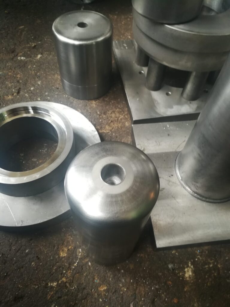
Deep drawing mold fabrication is a complex and precise process that involves designing and manufacturing the tooling used to shape sheet metal into desired forms through deep drawing. The quality, durability, and accuracy of the mold directly affect the efficiency of the forming process and the quality of the finished parts. Fabricating a deep drawing mold requires careful consideration of material selection, design specifications, machining techniques, surface finishing, and assembly to ensure the mold performs reliably under high-pressure, repetitive forming conditions.
The fabrication process begins with detailed mold design, which takes into account the geometry of the final product, the material properties of the sheet metal, forming forces, and the specific drawing operation (such as single or multiple draws). Computer-aided design (CAD) software is used to create precise 3D models of the mold components, including the punch, die, blank holder, and any auxiliary parts like ejectors or lubrication channels. Finite element analysis (FEA) and forming simulations may be employed to optimize the design for stress distribution, material flow, and potential wear areas.
Material selection for the mold components is critical. Tool steels like D2, H13, or P20 are commonly chosen due to their high hardness, toughness, and resistance to wear and thermal fatigue. These steels are typically heat-treated to achieve the desired mechanical properties. In some cases, different parts of the mold may use different materials or hardness levels depending on their function and exposure to wear. For example, punch noses and die rings are often made from the hardest, most wear-resistant steel grades.
Once the design is finalized and materials selected, the fabrication proceeds with rough machining of the steel blocks using techniques such as milling, turning, and grinding to achieve the basic shape of the mold components. Modern deep drawing molds require extremely tight tolerances and smooth surface finishes, so precision machining centers with CNC (Computer Numerical Control) technology are used extensively. CNC machining allows for complex shapes and high repeatability, essential for molds that produce parts with exacting dimensional requirements.
After rough machining, the mold surfaces undergo heat treatment processes like hardening and tempering to improve wear resistance. Post-heat-treatment machining or grinding is often necessary to achieve final dimensions due to distortion that can occur during heat treatment. Surface finishing is then applied to critical areas to reduce friction and improve metal flow. This can include fine grinding, polishing, or applying specialized surface coatings such as titanium nitride (TiN) or diamond-like carbon (DLC) to enhance hardness and reduce wear.
Additional features such as lubrication channels, cooling passages, ejector systems, and blank holder mechanisms are integrated into the mold during or after machining. These systems improve forming performance by managing temperature, controlling material flow, and facilitating part removal. Precision assembly ensures all components fit correctly and move smoothly, with careful alignment critical to prevent premature wear or tool damage.
Quality control is integral throughout the fabrication process. Dimensional inspections using coordinate measuring machines (CMMs), surface roughness testing, and non-destructive evaluation methods verify that the mold meets design specifications and quality standards. Trial runs or tryouts on the press may follow, allowing adjustments to optimize forming performance before full production.
In summary, deep drawing mold fabrication is a multidisciplinary process combining advanced design, material science, precision machining, surface engineering, and assembly. The end result is a highly engineered tool capable of producing complex, high-quality sheet metal parts reliably and efficiently. Continuous improvements in machining technology, materials, and simulation tools are driving greater mold precision and durability, enabling more sophisticated deep drawing applications across industries.
As deep drawing mold fabrication evolves, manufacturers increasingly rely on digital tools and automation to enhance precision, reduce lead times, and improve repeatability. Computer-aided manufacturing (CAM) software plays a vital role in translating the CAD designs into machining instructions, enabling automated and accurate tool paths for milling, drilling, and finishing operations. The integration of CAM with CNC machines streamlines the workflow, reduces human error, and allows for intricate geometries that would be impractical with manual methods. High-speed machining centers, often equipped with multi-axis capabilities, can perform multiple operations in a single setup, reducing handling and improving dimensional consistency across mold components.
In some advanced facilities, additive manufacturing is beginning to complement traditional subtractive methods. For instance, 3D printing technologies like direct metal laser sintering (DMLS) can produce conformal cooling channels or complex internal features within mold inserts, which would be impossible to machine conventionally. These innovations enhance cooling efficiency during the forming process, helping control thermal expansion and prolonging mold life. Hybrid manufacturing systems that combine additive and subtractive processes in a single platform offer new possibilities for toolmakers seeking greater design freedom and efficiency.
Fabrication also involves a meticulous attention to tolerances, especially in areas where mating surfaces interact under high loads. Even slight misalignments or surface irregularities can lead to uneven wear, excessive friction, or defective parts. To counter this, moldmakers employ finishing processes such as hand polishing, lapping, and precision grinding to bring critical surfaces within micron-level tolerances. This ensures not only a good surface finish, which promotes smoother metal flow and reduces wear, but also mechanical stability during the repetitive stresses of deep drawing.
Thermal management during mold operation is another concern addressed during fabrication. Many deep drawing molds incorporate internal cooling systems, particularly for high-speed or high-volume production where heat buildup can alter material properties or dimensional accuracy. These cooling passages must be precisely machined or printed and then thoroughly tested to confirm flow and sealing integrity. Inadequate cooling can lead to inconsistent part formation and accelerated thermal fatigue of the mold.
During the final stages of fabrication, all mold components are assembled and aligned using fixtures and jigs to verify fit and function. Movable parts like punches, ejectors, and blank holders must slide smoothly within their guide paths without binding or excessive clearance. Once assembled, a trial forming operation—often called a die tryout—is performed. This run identifies any remaining issues with alignment, forming quality, or surface finish. It is during this phase that the mold is fine-tuned, with minor adjustments to clearances, lubrication pathways, or surface profiles made to ensure optimal performance.
Throughout the entire process, quality assurance is embedded at each step. Dimensional verification, hardness testing, and visual inspections ensure that the mold not only meets its design intent but is also robust enough to endure the high stresses of production. Documentation of the fabrication process, including heat treatment cycles, surface coating specifications, and inspection records, supports traceability and future maintenance efforts. This documentation becomes especially important when molds are used for regulated industries such as aerospace, medical devices, or automotive components where compliance and repeatability are critical.
Ultimately, the goal of deep drawing mold fabrication is to deliver a high-performance tool that balances longevity, precision, and efficiency. As demands for tighter tolerances, lighter materials, and more complex geometries continue to grow, the fabrication process must keep pace through innovation, investment in modern equipment, and a deep understanding of both materials and forming science. The mold becomes not just a forming device but a precision-engineered system that underpins the entire production process.
The longevity and effectiveness of a deep drawing mold also depend heavily on how well the fabrication process anticipates and mitigates the challenges that will be encountered in production. For example, during fabrication, particular attention is paid to edge radii, die shoulder profiles, and corner transitions, as these are high-stress zones where material flow is concentrated. Sharp corners or abrupt changes in geometry can lead to localized thinning or tearing of the sheet metal, which in turn can damage the mold and compromise product quality. Therefore, smooth transitions and well-blended radii are carefully machined and polished to ensure uniform flow and minimize mechanical stress.
Another critical part of fabrication is surface treatment, which serves to both protect the mold and optimize its interaction with the sheet metal. In addition to polishing, coatings are frequently applied to key contact areas. These may include hard coatings such as chromium plating, TiCN, TiAlN, or even specialized ceramic layers, depending on the material being formed and the expected production volume. The application process—whether via PVD, CVD, or electroplating—must be tightly controlled to ensure uniform thickness and strong adhesion. In high-volume settings, multi-layer coatings may be used to combine the advantages of surface hardness with internal toughness, resisting both abrasive wear and chipping.
Fabrication teams also consider modularity during mold construction. Instead of creating a single, monolithic mold, components such as die inserts, punch tips, and blank holders are often designed to be replaceable. This not only simplifies maintenance but also allows faster adaptation to design changes or wear-related repairs. Interchangeable modules can also be optimized individually, for instance, using a high-hardness material for just the insert that contacts the blank, while the surrounding body uses a tougher or more cost-effective steel. Such modular strategies enhance flexibility and reduce downtime during mold servicing or retooling.
Communication between the design and fabrication teams is essential throughout this process. Any oversight or misinterpretation of the forming requirements—such as incorrect clearances, inadequate venting for air evacuation, or unoptimized draw depths—can lead to poor forming performance and premature mold failure. Therefore, concurrent engineering practices are often adopted, where designers, machinists, and forming engineers collaborate closely from the initial stages of the mold development cycle. Feedback from trial runs and production data also loops back to inform future mold designs and improve successive iterations.
As sustainability becomes a greater concern in manufacturing, the mold fabrication process is also evolving to reduce material waste and energy consumption. Advanced cutting strategies, optimized stock sizing, and additive manufacturing all contribute to more resource-efficient mold production. Additionally, durable surface treatments and better wear resistance directly reduce the frequency of mold replacement, lowering the environmental footprint over the life of the tooling.
In high-precision industries—such as aerospace, electronics, and medical equipment—mold fabrication may involve an even higher level of scrutiny. Cleanroom-compatible finishes, tighter tolerances, and specialized forming profiles demand superior craftsmanship and more stringent process control. This often involves custom tooling setups, longer inspection protocols, and detailed documentation of each fabrication step. In these environments, even the smallest deviation can lead to parts that are out of specification or unfit for their intended application, so the mold must not only be dimensionally perfect but also exceptionally consistent in its performance across long production runs.
In conclusion, the fabrication of a deep drawing mold is a deeply technical endeavor that blends art and science. It calls for precision, foresight, and an intimate understanding of how materials behave under pressure. From initial design and machining to finishing and testing, each step must be executed with meticulous care to produce a mold that performs flawlessly under demanding conditions. As technology advances, mold fabrication continues to improve in efficiency, accuracy, and versatility—enabling manufacturers to meet the ever-growing challenges of modern forming operations.
Deep Drawing Mold Setup
Setting up a deep drawing mold is a crucial phase in the sheet metal forming process, directly affecting part quality, process efficiency, and tool life. The setup involves preparing the press machine, aligning and installing the mold components, adjusting critical parameters, and performing validation runs to ensure smooth and accurate forming. Because deep drawing involves significant forces and precision, every aspect of the setup must be carefully controlled and verified before beginning full-scale production.
The process begins with preparing the hydraulic or mechanical press, ensuring it matches the tonnage and stroke requirements of the deep drawing operation. The press bed and ram must be clean, flat, and free of debris to prevent misalignment or damage. Mold components—including the die, punch, blank holder, and any auxiliary elements such as ejectors, guide posts, and die cushions—are inspected and cleaned before installation. Any signs of wear, residue, or damage are addressed, as even minor imperfections can result in poor part quality or tool wear.
Next, the die and punch are carefully installed onto the press bed and ram, respectively. Precision alignment is essential here; any misalignment can cause uneven material flow, wrinkling, or tearing of the blank. To achieve proper alignment, setup personnel often use dial indicators, alignment blocks, and shimming as needed. The die is securely clamped to the bed, while the punch is attached to the slide or ram, ensuring that their centers match precisely. If a blank holder is used—which is typical in deep drawing—it is also installed, with adjustments made to control the holding force uniformly across the blank’s surface.
Once the mold is installed, critical parameters are set. These include the blank holder force, drawing speed, lubrication method, and the use of any die cushions or ejector systems. For molds equipped with hydraulic or pneumatic blank holders or cushions, pressure settings are calibrated to match the material and depth of draw. Too much holding force can restrict material flow and cause tearing, while too little can lead to wrinkling. Similarly, stroke settings are adjusted to control the punch’s depth of travel and ensure it does not exceed the mold’s designed draw limit.
Lubrication is another vital part of setup. The correct type and amount of lubricant must be applied evenly to the blank to reduce friction and prevent galling. Depending on the process, this might be done manually or with an automated spray system. The lubricant must be compatible with the sheet metal being formed and the surface finish of the tooling to ensure consistent metal flow and minimal wear.
Before running production parts, a tryout or test run is performed. This allows the operators to observe material behavior, check for defects like tearing, wrinkling, or thinning, and make fine adjustments to press settings. Often, several test blanks are formed, with each one inspected for dimensional accuracy, surface finish, and structural integrity. Based on these results, the setup may be fine-tuned, such as adjusting the blank holder pressure, modifying lubrication application, or slightly altering alignment.
Throughout the setup process, safety checks are essential. The mold’s moving components must operate freely without interference. Safety interlocks, limit switches, and emergency stop systems on the press are tested to ensure they function properly. Guarding must be in place to protect operators from pinch points and unexpected movement.
Once the setup is validated and stabilized, the process parameters are documented to ensure repeatability in future runs. This includes machine settings, alignment references, lubrication protocols, and inspection criteria. By thoroughly documenting the setup, operators can minimize variation between batches and reduce downtime for subsequent runs.
In short, deep drawing mold setup is a meticulous process that bridges the gap between mold fabrication and full-scale production. Precision, cleanliness, and attention to detail are essential at every stage to ensure that the forming process runs efficiently and produces high-quality parts with minimal waste or tool damage. A properly executed setup not only protects the investment in tooling but also forms the foundation for reliable and cost-effective production.
Once the deep drawing mold setup is verified and production begins, continuous monitoring becomes essential to maintain consistency and prevent defects. Operators observe each part closely during the initial production cycle to detect any early signs of forming issues, such as uneven draw depths, wrinkling along the flange, thinning near corners, or tearing around sharp radii. These symptoms often indicate that the setup requires minor tweaks—perhaps a change in blank holder pressure, a realignment of the punch and die, or an adjustment to lubrication frequency or coverage. Since even a slight variation in material properties between blanks can affect performance, the setup must accommodate some level of variability without causing quality problems.
Tool temperatures may also begin to change once production starts, especially in high-speed runs, as repeated deformation and friction generate heat. This thermal expansion can subtly alter the fit between components, making it necessary to monitor spacing and clearance as the mold warms up. In some cases, cooling systems integrated into the mold or press bed help stabilize temperatures and keep forming conditions consistent. Regular measurements using infrared thermometers or embedded sensors allow operators to intervene before thermal changes impact part geometry or surface finish.
Tool wear is another factor that becomes increasingly relevant as production progresses. Even with proper setup, the repeated stress and contact between sheet metal and mold components gradually erode sharp edges and polished surfaces, which can lead to burrs, drag lines, or dimensional inaccuracies. As part of the extended setup routine, experienced operators and technicians often establish a preventive maintenance schedule—inspecting high-wear zones such as the die radius, punch tip, and blank holder surfaces after a set number of cycles. Lubrication, too, is revisited periodically to ensure it continues to reach all critical areas. If a centralized or automated lubrication system is used, its nozzles, flow rates, and delivery timing are checked to ensure effective coverage.
Another critical aspect of deep drawing mold setup that carries forward into production is blank positioning. If the blank is not centered correctly with respect to the punch and die, the draw will be uneven, potentially causing one side to wrinkle while the other tears. Positioning systems—such as mechanical stops, locating pins, or optical sensors—are used during setup to consistently place each blank in the exact location. For high-volume operations, robotic blank feeders or coil feeders may be used, and their calibration becomes an integral part of setup. Misalignment from automated feeders can be just as problematic as manual error and must be corrected promptly.
For setups involving multi-stage or progressive deep drawing operations, synchronization between the different stations must also be flawless. Any delay, misfeed, or mismatch in timing between stages can compromise the entire draw process. For this reason, each forming station’s stroke and force are tested in sequence during the setup, and trial blanks are monitored closely for signs of inconsistency. Progressive dies and transfer tooling must be aligned with extreme precision, and any flexing or deviation in the press’s slide or bolster can create cascading issues across all stations.
Documentation and repeatability are often the final steps in the mold setup process, especially for jobs that will be repeated periodically. All settings—press stroke, force curves, blank holder pressures, lubrication schedules, blank dimensions and position, alignment markings, and sensor thresholds—are recorded in detail, often in digital process sheets or CNC press control systems. This comprehensive record allows for a faster setup the next time the mold is used, reducing downtime and ensuring consistent part quality over multiple production runs.
Ultimately, deep drawing mold setup is not a one-time adjustment but a dynamic process that spans initial installation, validation, and early production monitoring. The accuracy, care, and foresight applied during this stage have a significant influence on operational efficiency, tool life, and final part quality. Even with the most advanced press and mold systems, successful outcomes still depend on skilled setup personnel who understand the delicate interaction between the tooling, machine, material, and process. A well-executed setup lays the foundation for high-yield, low-defect manufacturing and is a defining factor in whether a deep drawing operation meets its productivity and quality goals.
As production continues after the initial setup, process stability becomes the focus. Operators observe forming behavior, inspecting parts at intervals to identify trends before they become problems. Even under a sound setup, minor drifts can occur due to machine wear, temperature fluctuations, material inconsistencies, or accumulated debris. Thus, visual inspections are often supplemented by in-line dimensional checks using gauges or automated vision systems, especially in high-precision environments. Deviations from the desired geometry—such as an increasing tendency for draw marks or wall thinning—serve as early warnings. Rather than waiting for part rejection, experienced operators intervene quickly, making fine adjustments to pressure or speed, or briefly pausing production for a quick mold inspection or cleaning.
Another key aspect that remains active during and after setup is lubrication management. Even the best setup cannot perform optimally without proper friction control. Over time, lubricant can accumulate in unintended areas, dry out, or become contaminated with metal shavings or dust, which increases tool wear and reduces surface finish quality. A well-executed setup accounts for this by including regular checks on the lubrication system—verifying reservoir levels, nozzle positioning, flow rate, and mist patterns. In more advanced systems, sensor-driven lubrication monitors are tied directly into the press controls, ensuring that lubrication is adjusted in real-time depending on stroke count or sensor feedback.
Handling of formed parts post-drawing is also impacted by how well the setup anticipates downstream operations. Ejection systems, for instance, must remove each part cleanly and without damage. This becomes especially challenging with deep cups or complex geometries, where vacuum effects, tight clearances, or adhesive contact can resist smooth ejection. As part of the setup, ejector pins, air blasts, or mechanical knockouts are adjusted to ensure smooth part release. If the setup includes a robotic arm or automated conveyor system for part removal, its motion must be synchronized precisely with the press cycle to avoid collisions or delays. This synchronization is tested during setup and monitored continually, especially in high-speed lines.
Tool change intervals and cleaning protocols are also planned during the initial setup stage. In high-volume operations, even when molds are performing well, a time-based preventive maintenance schedule is established—often dictated by the number of cycles or hours run. These intervals ensure that before any noticeable wear or defect occurs, the mold is removed, inspected, cleaned, and retuned. This proactive approach, determined during the setup phase, helps avoid unexpected failures and keeps overall equipment efficiency (OEE) high. Standard operating procedures (SOPs) for setup and changeover become critical in this context. Teams use setup sheets, torque specs, alignment targets, and visual guides to replicate the exact positioning and settings each time the mold is reinstalled, ensuring consistency even when different technicians are involved.
Training of personnel is a less visible but vital element of deep drawing mold setup. Technicians and operators must understand not just how to install the mold, but why each step matters. Training programs tied to setup procedures teach how to recognize early signs of misalignment, inadequate holding force, or lubrication issues. This human element in the setup process can make the difference between consistent output and erratic performance, especially in less automated environments.
In some modern production lines, digital twins and simulation software are used during setup to model and optimize the mold’s performance before physical trials even begin. These tools allow engineers to test different parameter combinations, predict material flow, and identify potential problem areas without damaging actual tools. Once confirmed, the simulated setup data is transferred directly to the machine’s control system, significantly reducing trial-and-error time on the shop floor. When paired with sensors on the mold and press, this predictive setup can adjust itself automatically, responding to real-world data during forming—pushing deep drawing toward the realm of adaptive, intelligent manufacturing.
In conclusion, while setup may appear as a discrete phase before production starts, its influence continues throughout the life of the operation. A well-executed deep drawing mold setup is not just about physical installation—it is a system of alignment, calibration, anticipation, monitoring, and adjustment. It determines how efficiently a mold produces parts, how often downtime occurs, how quickly defects are detected and resolved, and ultimately how profitable the entire process is. The more complex the part, material, and tooling, the more critical setup becomes—serving as both the technical foundation and operational backbone of successful deep drawing.
Deep Drawing Mold Tooling
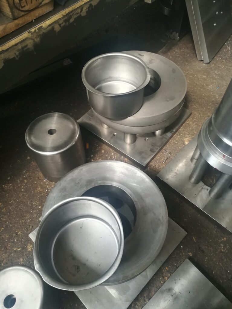
Deep drawing mold tooling encompasses the specialized components and equipment designed to shape sheet metal into precise, deep-formed parts through the deep drawing process. This tooling must withstand high mechanical stresses and repeated cycles while maintaining dimensional accuracy and surface quality. It involves a combination of various elements, each tailored to perform specific functions that together control material flow, prevent defects, and produce consistent parts.
At its core, deep drawing tooling consists primarily of the punch, die, and blank holder (or pressure pad). The punch is the male component that presses the sheet metal blank into the die cavity, which defines the final shape of the part. The blank holder applies pressure on the blank’s flange, controlling metal flow and preventing wrinkling during deformation. The precise interaction and clearances between these elements are critical; too tight a clearance can cause tearing, while too loose can result in wrinkling or excessive thinning.
The die is typically crafted from hardened tool steel or sometimes carbide for high-volume or abrasive materials. Its cavity is machined to tight tolerances and polished to minimize friction and avoid surface defects on the formed part. The die radius—the curved transition at the die opening—is carefully designed since it significantly influences material flow and strain distribution. Larger radii reduce stress concentration but can compromise part geometry, while smaller radii increase the risk of cracking.
The punch is similarly hardened and polished, with its radius and surface finish tailored to the material and part design. Depending on the complexity of the part, the punch might be a simple cylindrical shape or a more elaborate profile featuring grooves, beads, or contours to form intricate features. In some tooling setups, punches are interchangeable to accommodate different production runs or part variants.
The blank holder is often equipped with hydraulic or pneumatic actuators, enabling precise control over holding force during forming. Some advanced tooling integrates adjustable blank holders that vary pressure dynamically through the stroke to optimize metal flow, reduce strain, and improve surface quality. Additionally, blank holders may feature textured or coated surfaces to modulate friction, aiding in wrinkle prevention and consistent drawing.
Supporting tooling components enhance performance and longevity. Guide pillars and bushings maintain precise alignment between punch and die throughout the press stroke, preventing lateral movement that could damage the tooling or produce defective parts. Die cushions, if present, provide controlled counterpressure, absorbing shocks and improving material flow for deeper draws. Ejector systems—comprising pins, air blasts, or knockouts—facilitate part removal without damage, critical in automated or high-speed production.
Surface treatments and coatings are integral to tooling durability. Hard chrome plating, titanium nitride (TiN), diamond-like carbon (DLC), or ceramic coatings increase surface hardness and reduce friction, thereby extending tool life and enhancing part finish. These coatings are selected based on the material being formed and the expected production volume, balancing cost and performance.
Tooling design also accounts for maintenance and modularity. Inserts and wear parts are engineered for easy replacement without dismantling the entire tool, minimizing downtime. Modular tooling systems allow manufacturers to adapt quickly to design changes or different part sizes by swapping components rather than fabricating entirely new molds.
In sum, deep drawing mold tooling is a sophisticated assembly engineered for precision, durability, and adaptability. Its design balances the complex demands of material behavior, part geometry, and production efficiency, forming the heart of successful deep drawing operations. Careful selection of materials, finishes, and auxiliary components ensures that tooling meets the rigorous standards required for high-quality, cost-effective manufacturing.
Deep drawing mold tooling is fundamentally about controlling the complex deformation of metal sheets under high pressure, making the interplay of tooling components and materials critically important. One key challenge is managing the stress and strain imposed on both the tooling and the workpiece throughout the drawing cycle. Since the sheet metal undergoes large plastic deformation, the tooling must resist not only static loads but dynamic impact forces and repetitive stress cycles that can cause fatigue, cracking, or wear.
The choice of tooling materials plays a vital role in this regard. Tool steels, such as AISI D2 or H13, are commonly used due to their high hardness, toughness, and wear resistance after proper heat treatment. For extreme production demands, carbide tooling or ceramics may be used for die surfaces, especially when forming abrasive or high-strength alloys like stainless steel or titanium. These materials help extend the lifespan of the tooling and maintain consistent forming conditions, reducing downtime and scrap rates.
Heat treatment processes, such as quenching and tempering, are carefully applied to optimize the hardness and toughness balance in tooling components. Improper treatment can result in brittleness, leading to chipping or cracking under load. Additionally, surface hardening techniques like nitriding enhance resistance to surface fatigue and galling without compromising the core toughness of the tool.
Tooling geometry is intricately designed to optimize metal flow and minimize defects. Radii at the punch and die edges must be precisely calculated: too sharp a radius can induce high localized stresses causing cracks or tears, while an excessively large radius can lead to excessive thinning or distortion of the part. Finite element analysis (FEA) and simulation software are increasingly used during tooling design to predict these stress concentrations and material behavior, allowing engineers to fine-tune geometry before manufacturing.
Surface finish quality is another critical factor. Polished tooling surfaces reduce friction between the metal blank and tooling, helping to prevent galling, scoring, and excessive wear. Lower friction also means reduced forming forces and improved metal flow, which can decrease the likelihood of wrinkles or tears. However, overly smooth surfaces may reduce the grip needed on the blank flange, making the balance of surface texture essential.
Lubrication interfaces directly with tooling surface properties. Tooling is designed to facilitate the effective application and retention of lubricants, which form a critical barrier reducing friction and tool wear. Some tooling incorporates channels or grooves to distribute lubricant evenly or reservoirs that release lubricant gradually over the forming cycle.
Wear monitoring is integrated into advanced tooling designs through embedded sensors or wear indicators. These systems can alert operators to surface degradation or abnormal loads, allowing proactive maintenance before failures occur. This capability is particularly valuable in high-volume or precision-critical applications, where unexpected tooling wear can cause significant production losses.
Modularity and adjustability in tooling design improve flexibility and maintenance efficiency. Components such as punches, inserts, and blank holders can often be swapped or adjusted without removing the entire mold assembly. This modularity reduces changeover times and allows quick responses to minor part design changes or tooling wear, maintaining consistent production quality.
In some tooling setups, adaptive mechanisms are included to adjust blank holder force or cushion pressure dynamically during the stroke. This adaptability can optimize material flow in real time, accommodating variations in sheet thickness or mechanical properties and minimizing defects. Integration with press controls and feedback systems enables semi-automated or fully automated process control, pushing deep drawing towards Industry 4.0 standards.
Tooling for deep drawing must also consider secondary operations, such as trimming, piercing, or flanging, which often follow the initial draw. These features may be incorporated into progressive tooling stations or as separate dies, but all must maintain alignment and precision to avoid cumulative errors that affect final part quality.
In summary, deep drawing mold tooling is a high-precision, high-durability system designed to withstand significant mechanical and thermal stresses while enabling complex metal forming with minimal defects. Its success depends on meticulous material selection, geometry optimization, surface treatment, and integration of advanced features for lubrication, wear monitoring, and adaptability. The continual evolution of tooling design, aided by modern simulation and sensor technologies, drives improvements in productivity, quality, and cost-effectiveness in deep drawing manufacturing.
Deep drawing mold tooling also demands meticulous attention to alignment and assembly precision. Even minute misalignments between the punch, die, and blank holder can cause uneven metal flow, leading to defects such as wrinkling, tearing, or excessive thinning. To ensure precise alignment, tooling often incorporates hardened guide pins and bushings that maintain exact relative positioning throughout the press stroke, compensating for any machine frame flex or vibrations. These guiding components are designed to withstand heavy loads without wear-induced looseness, which could degrade part quality over time.
The assembly process of tooling is equally critical. Tool components must be mounted with exact torque values and checked for runout and parallelism to ensure that the punch travels perfectly coaxial within the die. Any deviation can result in off-center draws or damage to the tooling and parts. This level of precision requires the use of calibrated measuring instruments such as dial indicators, coordinate measuring machines (CMM), or laser alignment tools during installation and maintenance.
Deep drawing tooling often incorporates cooling channels or systems to manage heat buildup generated during high-speed or heavy-duty forming operations. Excessive heat can soften tooling materials, alter clearances due to thermal expansion, and degrade lubricants, all negatively impacting process stability and tool life. By circulating coolant—typically water or oil—through internal passages, the tooling temperature is kept within controlled limits, maintaining dimensional stability and consistent friction conditions. Cooling also helps prevent thermal distortion of formed parts, which is essential for maintaining tight tolerances in precision applications.
Advanced tooling systems integrate sensors that monitor parameters such as force, temperature, vibration, and position in real time. This data allows predictive maintenance and adaptive control strategies, reducing unexpected downtime and improving product consistency. For example, load sensors detect excessive drawing force that might indicate material inconsistency or tooling damage, triggering alerts or automated adjustments. Temperature sensors ensure cooling systems function properly and warn of overheating. These smart tooling solutions are becoming increasingly common in modern manufacturing environments striving for higher automation and quality control.
The longevity and reliability of deep drawing tooling depend heavily on proper maintenance practices developed during design and setup. Regular inspection routines include checking for wear patterns, cracks, corrosion, and lubrication effectiveness. Wear-prone areas such as die radii, punch tips, and blank holder surfaces are closely monitored, with refurbishment or component replacement scheduled before tool degradation impacts product quality. Maintenance intervals are often based on cycle counts, operating hours, or sensor data, optimizing tool life without compromising production uptime.
Tooling cost management is also an important consideration, particularly for high-volume or complex parts. Although initial tooling investment can be substantial, well-designed tooling reduces scrap, downtime, and maintenance costs over its service life. Modular designs, wear-resistant materials, and surface coatings contribute to lower total cost of ownership. Additionally, tooling reuse or reconditioning strategies extend operational life and improve return on investment.
Customization of deep drawing tooling is often necessary to accommodate the wide variety of materials and part geometries encountered in different industries. Tooling for soft metals like aluminum or copper requires different clearances, surface finishes, and lubrication strategies compared to tooling for harder materials like stainless steel or titanium. Similarly, tooling designed for simple cylindrical cups differs significantly from tooling used for complex aerospace or automotive components featuring multiple contours, beads, or flanges. This customization demands collaboration between tool designers, material specialists, and manufacturing engineers to optimize tooling for each unique application.
In conclusion, deep drawing mold tooling is a highly engineered system combining precision mechanics, materials science, surface engineering, and increasingly smart technologies. Its effectiveness directly influences the efficiency, quality, and economics of deep drawing manufacturing processes. Ongoing advancements in tooling design, materials, and monitoring promise to further enhance capabilities, enabling the production of ever more complex and demanding metal parts with higher productivity and lower costs.
Deep Drawing Mold Optimization
Deep drawing mold optimization is a critical process that aims to improve the performance, efficiency, and lifespan of tooling while ensuring high-quality part production with minimal defects. It involves a combination of design improvements, process adjustments, material selection, and technological integration to address challenges such as material flow, strain distribution, friction control, and wear resistance.
One primary goal in mold optimization is to achieve uniform material flow throughout the drawing process. Uneven flow can cause defects like wrinkling, tearing, or excessive thinning of the sheet metal. Optimization starts with refining the geometry of key tooling components—punch radius, die radius, and blank holder shape—to balance the forces acting on the metal. By using simulation tools such as finite element analysis (FEA), engineers can predict how different shapes and clearances affect metal behavior, enabling them to select dimensions that minimize stress concentrations and distribute strain evenly.
Lubrication strategy is another essential focus in mold optimization. Proper lubrication reduces friction between the sheet metal and tooling surfaces, decreasing the drawing force required and minimizing tool wear. Optimization may involve selecting advanced lubricants tailored to the material type and drawing conditions, designing lubrication delivery systems for even application, or incorporating features into the tooling to retain and redistribute lubricant during the stroke. Some systems use controlled lubrication—adjusting flow rates dynamically—to maintain optimal friction levels throughout forming.
Blank holder pressure optimization is crucial to prevent defects and control material flow. Too little pressure leads to wrinkling, while excessive pressure can cause tearing. Modern tooling often employs adjustable or hydraulic blank holders, allowing the pressure to be varied during the stroke or between production runs based on real-time feedback or part geometry. Optimization involves calibrating these pressures precisely, often through iterative testing supported by process monitoring sensors.
Material selection and heat treatment of tooling components also play a role in optimization. Using tool steels or coatings with superior hardness and wear resistance extends tooling life, reduces downtime, and maintains part quality. Advances in surface engineering—such as applying diamond-like carbon (DLC) or ceramic coatings—reduce friction and resist galling, enabling smoother metal flow and longer intervals between maintenance.
Thermal management within tooling is optimized to prevent distortion caused by heat buildup during high-speed or high-volume production. Incorporating cooling channels and selecting materials with favorable thermal conductivity helps maintain dimensional stability and consistent forming conditions. Proper thermal control also preserves lubricant integrity, ensuring friction remains within optimal ranges.
Integration of sensors and automation enhances optimization by providing real-time data on forces, temperatures, and tool condition. This information enables adaptive control systems to adjust parameters dynamically during forming, correcting deviations before defects occur. Predictive maintenance triggered by sensor data prevents unexpected tool failures and extends service life.
Modularity and ease of maintenance are design considerations that contribute to optimization. Tooling systems designed for quick component replacement or adjustment reduce changeover times and improve production flexibility. This capability allows manufacturers to respond rapidly to part design changes or process improvements without extensive downtime.
Finally, optimization includes continuous evaluation and improvement during production. Monitoring key quality metrics—such as dimensional accuracy, surface finish, and defect rates—guides incremental tooling adjustments and process refinements. Feedback loops between production data and tooling design ensure that optimization evolves with changing materials, part complexities, and manufacturing goals.
In summary, deep drawing mold optimization is a comprehensive approach combining design refinement, advanced materials, lubrication and pressure control, thermal management, sensor integration, and maintenance strategies. By addressing the multifaceted challenges of deep drawing, optimization enhances productivity, part quality, and tooling longevity, ultimately reducing manufacturing costs and enabling the production of complex, high-performance components.
Deep drawing mold optimization continues by emphasizing the importance of a holistic approach that integrates both tooling design and process parameters to achieve superior results. One key aspect is the detailed analysis and control of strain distribution throughout the sheet metal during forming. Uneven strain can cause localized thinning, leading to cracks or premature failure of parts. To address this, engineers use advanced simulation tools to map strain paths and identify potential problem areas. By adjusting tooling geometry, material properties, and process variables such as blank holder force and drawing speed, these strain concentrations can be minimized, resulting in improved part durability and dimensional stability.
Another critical factor is friction management between the blank and the tooling surfaces. Excessive friction not only increases the required forming forces but can also cause galling and surface damage to both the tool and the workpiece. Optimization here involves selecting the right combination of surface finishes and coatings on tooling components, along with carefully chosen lubricants that maintain effectiveness under high pressures and temperatures. Innovative lubrication systems may include micro-texturing of tool surfaces or the incorporation of lubricant reservoirs that release lubricant progressively during forming, ensuring consistent friction control throughout the stroke.
Thermal effects, often overlooked, are integral to optimization. During prolonged or high-speed operations, tooling can heat up, causing expansion that alters clearances and distorts forming conditions. This thermal expansion can lead to dimensional inaccuracies or increase the risk of defects. Cooling systems embedded in tooling—such as internal water channels or external coolant sprays—help stabilize temperatures. Additionally, selecting tooling materials with low thermal expansion coefficients or designing for thermal compensation can further maintain forming precision.
Adaptive tooling technologies have emerged as powerful optimization tools. These systems use sensors embedded within the tooling to monitor critical parameters such as force, displacement, temperature, and vibration in real time. Data from these sensors feed into control algorithms that adjust blank holder pressures, drawing speeds, or lubrication flow dynamically, responding instantly to variations in material properties or machine performance. This closed-loop control significantly enhances process stability and repeatability, reduces scrap rates, and extends tool life.
In high-volume manufacturing environments, optimization also focuses on minimizing downtime through modular tooling design and proactive maintenance strategies. Designing tools with replaceable inserts or components that can be quickly swapped allows for faster recovery from wear or damage. Predictive maintenance, enabled by sensor data analytics, schedules tool servicing before failures occur, preventing costly production interruptions.
Moreover, the optimization process often involves iterative feedback cycles where data collected from actual production runs—such as part dimensional measurements, surface finish inspections, and defect tracking—are analyzed to refine tooling and process parameters continually. This ongoing improvement loop ensures that tooling performance adapts to evolving production demands, material batches, or design changes, maintaining consistent quality and efficiency.
Material advances also influence deep drawing mold optimization. The use of high-strength, lightweight alloys in industries like automotive and aerospace challenges tooling with higher forming forces and increased wear rates. To meet these demands, tooling designers optimize by integrating harder materials, superior coatings, and improved cooling, tailored specifically for these advanced materials. This customization ensures that tooling can reliably form complex parts without sacrificing productivity.
Environmental considerations are increasingly part of optimization strategies. Reducing lubricant consumption through efficient delivery systems and recyclable or biodegradable lubricants minimizes environmental impact and operating costs. Likewise, tooling designs that require less energy-intensive forming cycles contribute to sustainable manufacturing practices.
Ultimately, deep drawing mold optimization is a dynamic, multidisciplinary effort that balances mechanical design, material science, process engineering, and digital technologies. It requires collaboration between tooling manufacturers, process engineers, material specialists, and production teams to tailor solutions that meet specific product requirements and production goals. As manufacturing technologies evolve—embracing automation, data analytics, and smart materials—the scope and effectiveness of deep drawing mold optimization continue to expand, driving higher-quality parts, increased productivity, and reduced costs across industries.
Continuing with deep drawing mold optimization, it’s important to recognize the role of press machine capabilities and how they interact with tooling design. The press’s tonnage capacity, stroke length, speed, and control systems all influence how effectively a mold can perform. Optimization involves ensuring that tooling dimensions, clearances, and operational parameters align with the specific press characteristics to prevent overloading, minimize cycle times, and maintain process stability. For instance, the press speed must be balanced to allow sufficient material flow without causing dynamic defects like wrinkling or tearing.
Automation and integration with manufacturing execution systems (MES) also enhance optimization efforts. Automated monitoring of tooling conditions and part quality enables real-time adjustments, reducing the need for manual intervention. Integration with MES allows for seamless tracking of production data, tooling usage, and maintenance history, facilitating data-driven decisions that improve tooling life and productivity.
Another factor in optimization is the consideration of material variability. Sheet metal batches can differ in thickness, mechanical properties, and surface conditions, all of which impact forming behavior. Tooling and process parameters optimized for one batch might not perform equally well for another. Adaptive control systems that respond to in-process measurements or predictive algorithms using historical data can adjust blank holder force, lubrication, or press speed on the fly, compensating for these variations and ensuring consistent part quality.
Surface quality of formed parts is directly tied to tooling condition and design. Optimized tooling minimizes scratches, scoring, and other surface defects by carefully controlling contact pressures, friction, and material flow. Achieving a high-quality surface finish often involves a combination of highly polished tooling surfaces, precise clearances, and effective lubrication. When cosmetic appearance is critical, tooling optimization may include the use of specialized coatings or surface treatments that enhance smoothness and reduce wear.
Cost considerations are integral to optimization. While high-end materials and advanced coatings improve durability, they increase initial tooling costs. The optimization process balances these investments against expected tooling life, maintenance costs, scrap rates, and production volumes. By employing cost-benefit analyses, manufacturers can identify the most economically advantageous tooling configurations that meet quality and productivity goals.
In industries such as automotive, aerospace, and consumer goods, where part complexity and tolerance requirements are increasing, deep drawing mold optimization often involves multi-stage forming processes using progressive dies or transfer presses. Each stage is optimized not only individually but also in concert with others to control cumulative strain and dimensional changes. Coordination across stages reduces defects and ensures that the final part meets design specifications without excessive secondary operations.
Training and skill development for operators and maintenance personnel are often overlooked but essential components of successful optimization. Well-trained teams can better interpret process data, identify early signs of tooling wear or malfunction, and implement adjustments that prolong tooling life and maintain part quality. Standard operating procedures (SOPs) and detailed documentation support consistent application of optimized processes.
Finally, the ongoing evolution of digital twins and virtual commissioning technologies is revolutionizing deep drawing mold optimization. Digital twins—virtual replicas of the physical tooling and process—allow engineers to simulate forming under various conditions, test design modifications, and predict outcomes before physical trials. This capability accelerates development, reduces costly trial-and-error, and enables continuous process improvement by comparing virtual predictions with real-world data.
In summary, deep drawing mold optimization is an ever-expanding discipline that blends mechanical engineering, materials science, process control, and digital innovation. By continuously refining tooling design, process parameters, and control systems—and leveraging data analytics and simulation technologies—manufacturers can push the boundaries of forming complexity, part quality, and production efficiency, meeting the demands of modern industry with agility and precision.
Deep Drawing Mold Polishing
Deep drawing mold polishing is a crucial finishing process aimed at enhancing the surface quality, performance, and longevity of deep drawing molds. Polishing the mold surfaces—particularly the punch, die, and blank holder contact areas—directly impacts the friction conditions during forming, influences metal flow, and helps prevent defects such as scratches, galling, and surface imperfections on the finished parts.
The polishing process typically begins after the mold has been machined and heat-treated. At this stage, the surface may still have machining marks, burrs, or micro-roughness that can cause high friction or damage to the sheet metal. Polishing refines these surfaces to a smooth, mirror-like finish, reducing the coefficient of friction between the tool and the metal blank. This smoother interface facilitates better material flow, decreases forming forces, and extends both tool and lubricant life.
Polishing is generally performed using a combination of mechanical and manual techniques. Mechanical methods include grinding with progressively finer abrasives, followed by buffing with polishing compounds. These steps gradually remove surface irregularities and create a uniform texture. Manual polishing is often done with specialized cloths and fine abrasive pastes to achieve the final surface finish and to address intricate mold areas that machinery may not access effectively.
The selection of polishing materials and compounds depends on the tooling material and desired surface finish. For hardened tool steels, diamond-based polishing compounds are common due to their superior abrasive quality and ability to achieve ultra-smooth finishes. For softer tool materials, alumina or chromium oxide pastes may be used. The choice also depends on whether a matte or mirror finish is desired, as different finishes influence friction and lubrication behavior differently.
Polishing not only improves surface smoothness but can also remove micro-cracks or residual stresses induced by machining or heat treatment, which can serve as initiation points for wear or failure. By eliminating these imperfections, polishing enhances the mold’s fatigue resistance and overall durability under repeated forming cycles.
Consistent polishing and maintenance are essential throughout the mold’s service life. Over time, tooling surfaces can degrade due to wear, corrosion, or galling, leading to increased friction and part defects. Regular polishing restores surface quality, maintains proper friction levels, and prolongs tool life. Maintenance intervals depend on production volume, material type, and forming conditions but typically involve scheduled inspections and touch-up polishing.
Advanced polishing techniques, such as electro-polishing or laser polishing, are increasingly employed to achieve even higher surface quality and precision. Electro-polishing uses controlled anodic dissolution to smooth microscopic surface irregularities without mechanical abrasion, resulting in exceptionally clean and uniform surfaces. Laser polishing utilizes high-energy laser pulses to locally melt and re-solidify the surface, producing ultra-smooth finishes with minimal material removal. These technologies can significantly enhance mold performance, especially for demanding applications involving high-strength or abrasive materials.
Proper cleaning before and after polishing is critical to avoid contamination, which can negatively impact lubrication and metal flow. Ultrasonic cleaning, solvent baths, or specialized cleaning agents are often used to remove polishing residues, oils, and debris.
In summary, deep drawing mold polishing is a meticulous, essential process that optimizes the tooling surface to improve forming efficiency, part quality, and tooling durability. It involves selecting appropriate polishing methods and materials, maintaining consistent surface finishes through regular upkeep, and leveraging advanced polishing technologies where needed. Polished molds reduce friction, facilitate metal flow, minimize defects, and extend the operational life of deep drawing tooling in modern manufacturing environments.
Continuing with deep drawing mold polishing, the process plays a vital role not only in the initial preparation of tooling but also throughout the production lifecycle. The surface finish achieved through polishing affects the interaction between the metal blank and the tooling, influencing the distribution of stresses and strains during the drawing operation. A highly polished surface reduces the likelihood of surface defects on the formed parts, such as scratches or galling marks, which are critical in applications requiring tight tolerances or high aesthetic standards, such as automotive body panels or consumer electronics housings.
Polishing also contributes to improved lubrication retention. Smooth surfaces facilitate the formation of a stable lubricant film, which lowers friction consistently over multiple production cycles. This stable lubrication layer reduces wear on tooling surfaces, decreasing the frequency of maintenance and replacement. Additionally, polished molds help prevent lubricant breakdown caused by abrasive surface features that can degrade lubricants more rapidly, thereby optimizing both tooling and lubricant usage.
The choice between different polishing finishes—ranging from a matte finish to a mirror-like surface—is often driven by specific forming requirements and material behavior. For softer metals like aluminum or copper, a slightly textured surface may help retain lubricant better, whereas harder metals or materials prone to sticking might benefit from mirror-polished tooling to minimize adhesion. Polishing strategies are thus tailored based on the sheet metal type, thickness, and forming complexity, often validated through trial runs and quality inspections.
Over time, polishing becomes part of a broader maintenance program. Tool surfaces wear naturally due to repeated metal-to-metal contact, abrasive particles in lubricants, and thermal cycling. Periodic re-polishing restores the surface finish, extending tool life and ensuring consistent part quality. The maintenance schedule is typically informed by monitoring tooling wear patterns, production output, and part inspection results. In high-volume manufacturing, predictive maintenance systems may use sensor data to identify when polishing is needed before visible defects arise, reducing unplanned downtime.
Advanced polishing methods such as electro-polishing and laser polishing have gained traction for their precision and efficiency. Electro-polishing, being a chemical process, uniformly removes microscopic peaks from the surface without mechanical stress, which is especially beneficial for complex geometries where mechanical polishing might be challenging. Laser polishing offers localized surface melting, which smooths the surface quickly and can even modify surface properties to improve hardness or corrosion resistance. These technologies complement traditional mechanical polishing and are increasingly integrated into modern tooling refurbishment workflows.
Environmental and safety considerations also impact polishing practices. The use of abrasive compounds, solvents, and chemical baths requires proper handling, disposal, and ventilation to minimize environmental impact and protect workers. The trend toward greener manufacturing encourages the adoption of less hazardous materials and processes, as well as the recycling of polishing wastes when possible.
Incorporating digital technologies into polishing workflows can enhance process control and documentation. For example, surface roughness measurements obtained through laser profilometers or tactile instruments provide quantitative feedback to verify polishing quality. Digital records support traceability, enabling manufacturers to link surface finish parameters with part quality and tooling life data, facilitating continuous improvement.
In essence, deep drawing mold polishing is a continuous, adaptive process that integrates traditional craftsmanship with modern technology to ensure tooling surfaces meet demanding production requirements. Its impact on friction, lubrication, wear resistance, and part aesthetics makes it indispensable for achieving high-quality, reliable deep drawing operations in diverse manufacturing sectors.
Extending the discussion on deep drawing mold polishing, the interplay between polishing and tooling material selection is a vital consideration. Different tooling materials respond uniquely to polishing techniques; for instance, high-speed steels, carbide alloys, and tool steels each have distinct hardness levels and microstructures that influence the ease and effectiveness of polishing. Harder materials generally require more robust abrasive compounds and longer polishing times to achieve the desired finish but offer superior wear resistance once polished. Conversely, softer materials polish more quickly but may wear faster during production, necessitating more frequent maintenance.
The geometry of the mold also presents challenges for polishing. Complex shapes, tight radii, and deep recesses often require specialized tooling or manual dexterity to ensure uniform surface finish without over-polishing or leaving unpolished areas. Polishing fixtures, miniature polishing tools, or flexible abrasive belts are commonly employed to reach difficult spots while maintaining consistency across the mold surface. Skilled operators must balance pressure and speed carefully to avoid altering critical dimensions or inducing surface irregularities.
Surface texture after polishing can be intentionally engineered for specific applications. For example, micro-texturing can be applied to mold surfaces to enhance lubricant retention or control metal flow during forming. These textures are often created using laser texturing or precision mechanical methods following the primary polishing steps. Such engineered surfaces contribute to improved process stability and extended tool life by mitigating common defects like galling or wrinkling.
The role of polishing in preventing corrosion and oxidation on mold surfaces is another important factor. Polished surfaces have fewer microscopic crevices where corrosive agents can accumulate, thereby reducing the risk of surface degradation. When combined with appropriate coatings or surface treatments, polishing helps maintain the mold’s integrity under harsh environmental conditions or exposure to aggressive lubricants and coolants.
In terms of quality control, surface finish measurements are integral to validating polishing effectiveness. Instruments such as profilometers, interferometers, or atomic force microscopes provide precise quantification of surface roughness parameters (Ra, Rz, etc.), enabling manufacturers to meet tight specifications required for high-performance deep drawing applications. These measurements also support repeatability by ensuring that polishing processes produce consistent results batch after batch.
Training and expertise in polishing are critical to achieving optimal outcomes. While automation aids in many manufacturing steps, polishing often still relies on skilled artisans who understand the nuances of tool material behavior, abrasive selection, and surface finish requirements. Continuous training programs, combined with standardized procedures, help maintain high-quality polishing standards across tooling shops.
Looking forward, emerging technologies such as robotic polishing systems and AI-driven process controls promise to further enhance deep drawing mold polishing. Robotics can improve precision and repeatability, especially in handling complex geometries, while AI can analyze polishing data to optimize parameters in real time, reducing waste and downtime.
In conclusion, deep drawing mold polishing is a multifaceted discipline that combines material science, precision craftsmanship, advanced technology, and quality assurance. Its execution significantly affects tool performance, part quality, and production efficiency. As manufacturing demands evolve, ongoing innovation and refinement in polishing techniques will remain essential to meeting the challenges of modern deep drawing operations.
Deep Drawing Mold Springback
Deep drawing mold springback refers to the elastic recovery of the metal sheet after it has been formed and the drawing forces are released. This phenomenon occurs because, during deep drawing, the sheet metal undergoes both plastic deformation (permanent shape change) and elastic deformation (temporary deformation). Once the external pressure is removed, the elastic portion causes the metal to partially “spring back” toward its original shape, resulting in dimensional deviations from the intended geometry.
Springback is a critical challenge in deep drawing operations because it affects the dimensional accuracy and final shape of the drawn part. If not properly accounted for, springback can cause issues such as incorrect wall angles, flange distortions, or mismatched assembly fits. This is especially problematic in industries requiring high precision and tight tolerances, such as automotive, aerospace, and consumer electronics.
Several factors influence the amount and behavior of springback in deep drawing molds. Material properties are primary contributors—materials with high yield strength, high elastic modulus, or significant work hardening tend to exhibit more pronounced springback. For example, advanced high-strength steels (AHSS) or titanium alloys generally have higher springback than softer metals like aluminum or low-carbon steel. The sheet thickness also plays a role, with thinner sheets often showing more springback due to lower bending stiffness.
Tooling design directly impacts springback control. The geometry of the punch and die, the radius of bends, and the application of blank holder force influence the strain distribution and residual stresses within the sheet. Sharp bends or small radii tend to increase localized elastic recovery, while optimized radii and controlled blank holder pressure can reduce springback. Progressive forming stages can also help by gradually shaping the part, minimizing abrupt elastic recovery.
Process parameters such as drawing speed, lubrication, and temperature affect springback indirectly. Higher drawing speeds can increase strain rates, potentially altering material behavior and residual stress patterns. Proper lubrication reduces friction and uneven strain, which can exacerbate springback effects. Elevated temperatures, used in hot or warm forming processes, lower material strength and elastic modulus, thereby reducing springback magnitude.
To mitigate springback, manufacturers employ several strategies. One common method is tool compensation, where tooling dimensions are intentionally adjusted (overbent or undercut) to counteract the expected elastic recovery. These compensations are often derived from empirical data, trial runs, or finite element method (FEM) simulations that predict springback behavior for specific materials and forming conditions.
Finite element analysis is invaluable in springback prediction and control. Modern simulation software models the elastic-plastic behavior of sheet metal during and after forming, allowing engineers to forecast springback and optimize tool geometry before production. These simulations can incorporate complex factors such as anisotropy, strain hardening, and strain rate sensitivity, providing accurate predictions and reducing costly trial-and-error in tooling design.
In some cases, secondary operations such as ironing, stretching, or mechanical forming are applied post-drawing to correct springback-induced deviations. However, these add to cycle times and costs, so minimizing springback during initial forming is preferred.
Material advancements and process innovations are continuously improving springback control. New alloys with tailored mechanical properties, advanced coatings that influence friction and strain distribution, and hybrid forming processes combining mechanical and thermal techniques are examples of ongoing research to reduce springback effects.
In summary, springback is an inherent elastic recovery challenge in deep drawing molding that affects dimensional accuracy and part quality. Managing springback requires a combination of material selection, tooling design, process optimization, and simulation-driven compensation techniques to ensure that final parts meet stringent specifications reliably and cost-effectively.
Continuing with the topic of deep drawing mold springback, it’s important to note that springback not only affects dimensional accuracy but also influences the functional performance and aesthetic appeal of the finished components. In critical applications like automotive body panels, aerospace structural parts, and precision housings, even slight deviations caused by springback can lead to assembly problems, reduced structural integrity, or visual defects that compromise product quality and customer satisfaction.
Controlling springback becomes more complex when dealing with materials that exhibit anisotropic behavior, meaning their mechanical properties vary with direction due to rolling or manufacturing processes. Anisotropy influences how strain is distributed during forming and how the metal elastically recovers afterward, making accurate prediction and compensation more challenging. Advanced simulation tools incorporate anisotropic yield criteria to better model this behavior, allowing for more precise tooling adjustments and process control.
In addition to geometric and material considerations, the springback phenomenon is influenced by residual stresses introduced during forming. These stresses arise from uneven deformation and can cause parts to warp or distort once removed from the tooling. Stress-relief treatments such as low-temperature annealing or vibrational stress relief may be applied post-forming to minimize residual stresses and reduce springback, though these add process steps and costs.
The integration of sensor technology and real-time monitoring systems in forming presses is advancing springback management. Sensors measuring force, displacement, and strain provide live data that can be fed into control algorithms to adjust process parameters dynamically. This adaptive control helps maintain consistent forming conditions, reduces variation in springback, and improves overall process robustness.
Springback also affects the design and manufacturing of progressive dies and multi-stage forming operations. Since each stage imparts incremental deformation, errors in springback prediction or control at one stage can accumulate, leading to significant final part deviations. Therefore, stage-wise compensation and detailed simulation are essential to ensure dimensional accuracy throughout the forming sequence.
From a cost perspective, poorly controlled springback results in increased scrap rates, rework, and downtime. It can also necessitate the use of more expensive secondary operations or more complex tooling designs. Consequently, investments in advanced simulation, precision tooling, and process optimization to minimize springback often yield substantial returns by enhancing yield, reducing waste, and shortening development cycles.
Emerging technologies like machine learning and artificial intelligence are beginning to play roles in springback prediction and compensation. By analyzing large datasets from forming trials, these systems can identify patterns and correlations beyond traditional modeling, enabling more accurate predictions and smarter tooling design adjustments. This data-driven approach complements physics-based simulations and helps manufacturers keep pace with increasingly complex materials and design requirements.
In conclusion, springback in deep drawing molds represents a multifaceted challenge that impacts part accuracy, quality, and production efficiency. Addressing it requires a holistic approach combining material science, precise tooling design, advanced simulation, process control, and innovative technologies. Through these integrated efforts, manufacturers can reliably produce high-quality deep drawn parts that meet stringent specifications while minimizing costs and waste.
Building further on the topic of deep drawing mold springback, it’s important to recognize that springback mitigation also influences the choice of forming methods and equipment. Traditional mechanical presses, hydraulic presses, and servo-electric presses each offer different levels of control over forming speed, force application, and precision, which directly affect springback behavior. For example, servo presses enable highly controlled punch velocities and dwell times, allowing for slower deformation rates that can reduce residual stresses and elastic recovery. This precise control also facilitates advanced forming techniques such as multi-step drawing with controlled strain paths, further minimizing springback.
Additionally, the use of advanced lubricants and coatings on both the sheet metal and tooling surfaces plays a role in springback management. Effective lubrication reduces friction, which in turn leads to more uniform material flow and strain distribution, lessening uneven elastic recovery. Special coatings on tools, such as diamond-like carbon (DLC) or ceramic coatings, can also improve surface hardness and reduce sticking, indirectly contributing to springback control by maintaining consistent forming conditions.
Material innovations are pivotal in addressing springback challenges. The development of tailored blanks, such as dual-phase steels with engineered gradients in strength and ductility, offers designers more flexibility to manage strain distribution during deep drawing. These materials can be selectively strengthened or softened in critical areas to reduce springback and improve final part accuracy without compromising overall performance.
Furthermore, hybrid forming processes that combine mechanical deformation with thermal or electromagnetic assistance show promise in controlling springback. For instance, warm forming heats the sheet metal to a moderate temperature before or during drawing, lowering yield strength and elastic modulus, thereby reducing springback. Electromagnetic forming uses high-intensity magnetic fields to deform metal rapidly, often producing more uniform strain distributions and less residual stress.
The feedback loop between simulation and experimental validation remains essential. Even the most advanced finite element models require calibration and confirmation through physical testing to ensure accuracy in springback prediction. Dimensional measurement technologies such as 3D scanning and coordinate measuring machines (CMMs) provide detailed data to compare against simulation results, enabling iterative improvements in both tooling design and process parameters.
In complex assemblies, where deep drawn parts must fit precisely with other components, springback control is critical for maintaining assembly integrity and performance. Misalignment due to springback can cause issues such as increased wear, noise, or reduced structural strength. Hence, early integration of springback considerations into product and process design helps avoid costly downstream problems.
Looking ahead, the integration of Industry 4.0 concepts, where connected sensors, digital twins, and machine learning converge, will further enhance springback management. Digital twins—virtual replicas of the forming process and tooling—can simulate and predict springback in real time, enabling proactive adjustments and continuous improvement. This convergence of digital and physical manufacturing promises higher precision, lower scrap rates, and faster time-to-market for deep drawn products.
In essence, controlling springback in deep drawing molds is a dynamic and evolving field that leverages advances in materials, tooling, process control, simulation, and digital technologies. Manufacturers who adopt a comprehensive, data-driven approach to springback will be better positioned to produce high-quality, cost-effective parts that meet the demanding requirements of modern industries.
Deep Drawing Mold Shoe
A deep drawing mold shoe, often simply called a “shoe,” is a key component in deep drawing tooling that supports and guides the blank holder or hold-down mechanism during the forming process. The shoe’s primary function is to evenly apply pressure on the blank around the perimeter of the sheet metal blank, preventing wrinkles and controlling metal flow as the sheet is drawn into the die cavity.
The shoe works by pressing down on the blank with a controlled force, ensuring that the metal flows smoothly over the die radius without excessive stretching or buckling. It typically moves vertically in synchronization with the punch, maintaining consistent pressure throughout the drawing stroke. The shoe’s design must accommodate the shape and size of the blank while providing uniform pressure distribution to avoid localized thinning or tearing of the sheet.
Shoes can be designed as solid blocks or incorporate multiple segments or pads, especially for complex shapes or large blanks, to allow for adjustable pressure zones and better control over metal flow. In advanced tooling, hydraulic or pneumatic systems may actuate the shoe or its segments to provide dynamic pressure adjustments during the forming cycle, enhancing flexibility and precision.
Material selection for the shoe is crucial because it must withstand high compressive loads and wear while maintaining dimensional stability. Hardened tool steels or materials with wear-resistant coatings are commonly used. The shoe’s surface finish also plays a role; smooth finishes help reduce friction between the shoe and the blank, minimizing damage to the sheet and facilitating better lubrication.
The shoe is often integrated with the blank holder system, which may include springs or hydraulic cylinders to regulate the applied force. Proper calibration of this force is critical—too little pressure can cause wrinkling, while excessive force may lead to tearing or excessive thinning. Therefore, the shoe and blank holder assembly are carefully designed and tested to optimize forming conditions for the specific material and part geometry.
In some cases, the shoe includes features like lubrication channels to deliver lubricant directly to the blank-holder interface, further reducing friction and wear. This lubrication system is especially important in high-volume production runs where consistent part quality and tooling life are paramount.
Overall, the deep drawing mold shoe is an essential component that directly influences part quality, tool life, and process reliability. Its design and operation must be precisely engineered to ensure smooth material flow, wrinkle prevention, and uniform blank control during deep drawing operations.
Continuing on the deep drawing mold shoe, its role extends beyond simply applying pressure; it also influences the overall dynamics of the forming process. The shoe must accommodate the complex interaction between the blank, punch, and die while maintaining consistent force distribution even as the metal undergoes substantial plastic deformation. This dynamic behavior means that the shoe’s stiffness and movement need to be finely tuned to avoid vibration or uneven pressure that could lead to defects like wrinkling, tearing, or surface imperfections.
The shoe’s geometry is often customized to match the blank shape, especially for non-circular or asymmetrical parts. In such cases, the shoe may be segmented or use flexible elements to adapt pressure zones independently, ensuring that the blank holder force corresponds precisely to the varying strain conditions around the blank’s edge. This segmentation helps in controlling metal flow more accurately, reducing the risk of uneven thinning or localized strain concentrations.
In modern deep drawing operations, the shoe’s function is frequently enhanced by integrating sensors and feedback systems. Force sensors embedded in or near the shoe can monitor the actual pressure applied in real time, allowing automated adjustments to maintain optimal conditions. This integration is particularly valuable when forming materials with variable properties or complex geometries, where static blank holder pressures might not suffice.
The surface condition of the shoe also contributes significantly to the quality of formed parts. A polished, wear-resistant surface reduces friction and wear on both the tooling and the blank, promoting smoother metal flow and extending tool life. Surface coatings, such as titanium nitride (TiN) or diamond-like carbon (DLC), are sometimes applied to further improve hardness and reduce friction, especially in high-volume or abrasive forming scenarios.
Maintenance and inspection of the shoe are crucial in ensuring consistent performance over time. Due to the high forces involved, the shoe can experience wear, deformation, or surface damage, all of which can degrade forming quality. Regular inspections, reconditioning, and, when necessary, refurbishment or replacement are part of good tool management practices to minimize downtime and scrap rates.
In terms of process optimization, the shoe’s pressure must be balanced carefully with other forming parameters like punch speed, die clearance, and lubrication. Too much pressure from the shoe can cause excessive friction and material thinning, while too little allows for uncontrolled metal flow and wrinkling. Engineers often use simulations to predict optimal blank holder pressures and shoe designs, supported by empirical adjustments during tryouts.
The shoe also interacts with auxiliary forming components such as draw beads and blank holders, all working together to guide material flow and control strain distribution. Proper coordination among these elements is critical for forming complex shapes with consistent wall thickness and minimal defects.
In summary, the deep drawing mold shoe is a vital element that directly affects metal flow control, part quality, and tooling durability. Its design, material, surface treatment, and integration with modern sensing and control systems all contribute to successful deep drawing operations, particularly in applications requiring high precision and repeatability.
Expanding further on the deep drawing mold shoe, its role becomes even more critical when working with advanced materials like high-strength steels, aluminum alloys, or titanium. These materials often exhibit less ductility and higher springback tendencies, making precise control over blank holding pressure essential to avoid defects. The shoe must apply sufficient force to restrain the blank without causing damage, which requires careful engineering of both its mechanical properties and operational parameters.
In some high-precision or high-volume applications, adaptive shoes are used—these can adjust their force dynamically during the stroke based on real-time feedback. This adaptability helps accommodate variations in material thickness, batch-to-batch inconsistencies, or slight changes in lubrication conditions, leading to more consistent part quality and reduced scrap. Hydraulic or servo-controlled shoe mechanisms are examples of this technology, where the applied force is modulated continuously rather than set as a fixed value.
The interplay between the shoe and lubrication is another important aspect. Lubrication reduces friction between the blank and the shoe surface, lowering the required blank holding force and minimizing tool wear. Specialized lubricant delivery systems can be integrated into the shoe design, providing controlled, consistent lubrication directly at the contact interface. This approach ensures stable forming conditions, especially during long production runs, and helps prevent common issues like galling or scoring on the sheet metal.
Designing the shoe for ease of maintenance and quick replacement can significantly improve production efficiency. Modular shoe designs that allow individual segments or pads to be swapped out without dismantling the entire tooling setup reduce downtime and tooling costs. This is particularly valuable in manufacturing environments where tool changeover speed impacts overall productivity.
From a simulation and design perspective, finite element analysis plays a crucial role in optimizing shoe geometry and blank holder forces. By modeling the interaction between the shoe and blank, engineers can predict areas prone to wrinkling or tearing and adjust shoe design parameters accordingly. These simulations also help in determining the best locations for pressure application, especially when dealing with complex shapes or anisotropic materials.
Finally, operator training and process documentation related to shoe setup and maintenance are vital for achieving consistent results. Even the best-designed shoe will underperform if not installed, adjusted, or maintained properly. Detailed work instructions, regular calibration of force settings, and monitoring of tool condition help maintain high quality and extend tooling life.
In essence, the deep drawing mold shoe is more than a simple pressure-applying component; it is a sophisticated element that integrates mechanical design, material science, lubrication management, sensor technology, and process control to ensure optimal metal flow, prevent defects, and enhance the overall efficiency and quality of deep drawing operations.
Deep Drawing Mold Insert
A deep drawing mold insert is a removable, often modular component placed within the die cavity of a deep drawing mold. Its primary purpose is to define the shape and surface finish of specific features on the drawn part, such as complex contours, detailed geometries, or localized areas requiring different tooling characteristics. Inserts allow for greater flexibility in tooling design, enabling quick changes or repairs without the need to replace the entire die.
Inserts are commonly used when manufacturing parts with varying designs but similar overall dimensions, as they reduce tooling costs and setup times. By swapping out inserts, manufacturers can adapt the same base mold to produce different part variants or update tooling to accommodate design revisions.
The material selection for inserts is critical due to the high contact pressures and wear involved in deep drawing. Inserts are typically made from hardened tool steels or carbide materials to withstand abrasion, impact, and repeated forming cycles. Surface treatments and coatings, such as nitriding, PVD (Physical Vapor Deposition), or DLC (Diamond-Like Carbon), can be applied to enhance hardness, reduce friction, and extend tool life.
Precision machining of inserts is essential to ensure dimensional accuracy and surface finish quality, as these directly affect the final part’s form and aesthetics. Advanced CNC machining, electrical discharge machining (EDM), and grinding techniques are often used to produce inserts with tight tolerances and complex geometries.
In some designs, inserts may incorporate cooling channels or lubrication delivery systems to control temperature and reduce friction in critical areas, improving material flow and minimizing defects like tearing or wrinkling. Temperature control via cooled inserts can also reduce thermal expansion effects and improve process consistency in high-volume production.
Insert mounting methods must ensure secure and repeatable positioning within the mold. Common approaches include dowel pins, clamps, screws, or hydraulic locking mechanisms. Proper alignment is crucial to maintain part accuracy and avoid damage to both the insert and the blank.
Maintenance and inspection of inserts are vital for maintaining forming quality. Inserts are subject to wear, chipping, and deformation over time, which can degrade part dimensions and surface finish. Regular inspection using visual checks, dimensional measurement tools, or non-destructive testing helps identify when inserts require refurbishment or replacement.
Overall, deep drawing mold inserts provide modularity, adaptability, and cost-efficiency in tooling, enabling manufacturers to respond quickly to design changes and optimize production processes while maintaining high part quality and tooling longevity.
Continuing on deep drawing mold inserts, their strategic use significantly enhances manufacturing flexibility, especially in industries where product designs evolve frequently or where multiple product variants are produced on the same line. Instead of fabricating entirely new dies for each design modification, changing only the inserts allows for rapid adaptation with minimal downtime and reduced costs. This modular approach also simplifies inventory management of tooling components.
Inserts can vary in complexity from simple flat or curved surfaces to intricate shapes featuring ribs, embossments, or flanges that must be formed precisely. The ability to produce detailed features through inserts is critical in sectors like automotive, aerospace, and consumer electronics, where part functionality and appearance are tightly linked to the formed geometry.
Thermal management through inserts is another evolving area. Since forming generates heat due to plastic deformation and friction, inserts with integrated cooling channels help maintain consistent temperatures in the die cavity. This temperature control prevents localized overheating that could alter material properties or cause thermal expansion, which leads to dimensional inaccuracies or premature tool wear. Conversely, some processes benefit from heated inserts to improve material ductility during forming, especially with materials that are difficult to shape cold.
The surface finish of inserts directly impacts the quality of the drawn part’s surface. Polished or textured inserts can create different visual and functional effects, such as matte finishes or enhanced paint adhesion. This allows manufacturers to tailor the tooling surface to meet specific downstream requirements without additional processing steps on the part.
When it comes to tooling life and maintenance, inserts offer the advantage of isolated wear zones. Since inserts are the components most exposed to mechanical and thermal stresses, replacing just the worn inserts instead of the entire die significantly reduces repair costs and lead times. This also makes it easier to maintain consistent forming conditions over long production runs.
Inserts also facilitate experimentation and optimization during process development. Engineers can try different insert designs or materials without retooling the entire die, allowing for quicker iterations in fine-tuning part quality, material flow, and forming forces. This modularity is especially valuable during prototyping or when implementing new materials.
Advancements in additive manufacturing are beginning to influence insert production as well. 3D printing allows for more complex internal cooling channels, lattice structures for weight reduction, or integrated sensor housings within inserts that would be difficult or impossible to machine traditionally. This opens new possibilities for highly customized and performance-optimized tooling inserts.
In summary, deep drawing mold inserts are essential components that enhance tooling adaptability, production efficiency, and part quality. Their design, material selection, surface treatment, and integration with modern technologies make them indispensable in modern deep drawing operations across a wide range of industries.
Expanding further on deep drawing mold inserts, their role in process optimization and quality control becomes even more pronounced when combined with sensor integration and digital manufacturing techniques. Embedding sensors within or near the inserts enables real-time monitoring of critical parameters such as temperature, pressure, and force distribution during the drawing operation. This data provides valuable feedback for adaptive process control, allowing immediate adjustments to forming conditions to mitigate defects and improve consistency.
Moreover, digital twins of deep drawing molds—including detailed models of inserts—are increasingly used to simulate forming processes before physical trials. These virtual models incorporate precise insert geometries and material properties to predict strain distribution, potential wrinkling, thinning, and springback. By validating insert designs digitally, manufacturers reduce costly trial-and-error in the physical tooling phase, speeding up development and ensuring higher first-pass yield.
The trend toward lightweighting in industries like automotive and aerospace also highlights the importance of inserts in enabling the forming of advanced, often less ductile materials. Inserts with specialized coatings or surface textures can help control friction and material flow for ultra-high-strength steels or aluminum alloys, which require more precise tooling conditions to prevent cracking or tearing.
In high-volume production settings, inserts facilitate tool standardization and interchangeability, supporting lean manufacturing principles. By designing modular insert systems compatible with a family of parts, manufacturers streamline inventory, simplify maintenance schedules, and reduce the time and cost of changeovers. This modularity also supports rapid scaling of production capacity when demand increases.
In addition to mechanical considerations, environmental factors are influencing insert design. Improved coatings and surface treatments not only enhance wear resistance but also reduce the need for lubricants or allow the use of more environmentally friendly lubricants. This contributes to cleaner manufacturing processes with lower environmental impact.
Finally, as sustainability gains importance, the ability to repair and refurbish inserts rather than fully replace them aligns with circular economy goals. Techniques like surface reconditioning, polishing, and recoating extend the functional life of inserts, reducing material consumption and waste.
Overall, deep drawing mold inserts represent a convergence point of mechanical design, materials engineering, process control, and sustainability considerations. Their continuous evolution supports more efficient, flexible, and environmentally conscious manufacturing of complex sheet metal components across diverse industries.
Deep Drawing Mold For Aluminum
Deep drawing molds for aluminum require special considerations because aluminum’s material properties differ significantly from steels or other metals typically formed by deep drawing. Aluminum is softer, more ductile, and has a lower coefficient of friction, but it also has a tendency to gall and stick to tooling surfaces, which can lead to surface defects and premature wear of the mold components.
Designing a deep drawing mold for aluminum starts with selecting tooling materials and surface treatments that minimize adhesion and galling. Hardened tool steels with polished surfaces, sometimes coated with anti-galling or low-friction coatings like TiN (titanium nitride) or DLC (diamond-like carbon), are commonly used to extend tool life and maintain part quality. The smoothness and finish of the die and punch surfaces are critical to prevent aluminum from sticking during forming.
Blank holder (or shoe) design and pressure settings are optimized to control metal flow, prevent wrinkling, and reduce thinning. Since aluminum flows more easily than steel, lower blank holder pressures are often sufficient, but too little pressure can cause wrinkling, while excessive pressure can cause tearing. Proper lubrication is essential, and specialized lubricants designed for aluminum forming are used to maintain a consistent, low-friction interface between the blank and tooling surfaces.
Die clearances are also adapted for aluminum, typically set tighter than for steel to control metal flow and minimize springback effects. Because aluminum has higher elastic recovery, mold designs often include features to compensate for springback, ensuring dimensional accuracy of the final part.
Thermal considerations may be included in the mold design, especially for thicker aluminum sheets or high-volume production, as temperature can influence aluminum’s ductility and friction behavior. Some molds incorporate cooling channels or temperature control systems in the die and punch to maintain optimal forming conditions.
Finally, process parameters like punch speed, lubrication method, and blank shape are carefully tuned to account for aluminum’s unique characteristics. Simulation tools help predict material flow, thinning, and potential defects, guiding mold design and process setup.
In summary, deep drawing molds for aluminum require tailored tooling materials, surface finishes, blank holder strategies, lubrication, and dimensional controls to manage aluminum’s ductility, friction tendencies, and springback behavior, ensuring high-quality formed parts with consistent surface finish and dimensional accuracy.
Continuing on deep drawing molds for aluminum, the forming process must address aluminum’s higher susceptibility to surface defects such as scratches, galling, and scoring, which can be exacerbated by the softer nature of the metal. To mitigate these issues, the mold surfaces—especially the die and punch—are often polished to a mirror-like finish, reducing surface roughness and friction. This smoother contact surface helps the aluminum flow more freely and lowers the risk of material sticking or damage during drawing.
Lubrication plays an especially critical role in aluminum deep drawing. Unlike steel, aluminum tends to weld or gall onto tooling surfaces if lubrication is insufficient or poorly matched. Specialized lubricants, such as synthetic oils with additives tailored for aluminum, or even solid lubricants like graphite or molybdenum disulfide, are commonly used to provide a stable lubricating film. The lubricant must be applied consistently and replenished regularly in production to maintain optimal conditions and reduce wear on tooling components.
Blank holder pressure requires precise control. Aluminum’s lower strength means that the blank holder force must be enough to prevent wrinkling without causing excessive thinning or tearing. Too much force can restrict metal flow, leading to fractures, while too little allows the sheet to buckle or wrinkle. Modern deep drawing presses often use hydraulic or servo-controlled blank holders that can adjust pressure dynamically during the stroke to optimize metal flow and minimize defects.
Die clearance is also adjusted to suit aluminum’s properties. Typically, the clearance between the punch and die is slightly smaller than for steel, helping control the metal flow and reduce springback. However, since aluminum has a greater tendency to rebound elastically, molds may incorporate features such as adjustable punch stops or pressure cushions to compensate and maintain dimensional accuracy.
Thermal management within the mold is an additional factor in aluminum forming. Heat generated from deformation and friction can soften the aluminum, changing its flow characteristics during forming. Controlled cooling channels within the die and punch help maintain stable temperatures, preventing overheating that could lead to inconsistent material behavior or increased tool wear. In some cases, heated molds are used to improve formability when working with certain aluminum alloys.
Simulation and finite element analysis (FEA) have become indispensable tools in designing aluminum deep drawing molds. These simulations help predict areas where thinning, wrinkling, or tearing are likely to occur, allowing engineers to optimize blank holder force distribution, die geometry, and process parameters before physical trials. This reduces trial-and-error costs and accelerates development cycles.
The tooling materials and coatings used in aluminum deep drawing molds must also resist the specific wear mechanisms associated with softer metals. Although aluminum is less abrasive than steel, the risk of adhesive wear and surface galling requires that molds be made from highly wear-resistant tool steels, often with advanced surface treatments or coatings to prolong life and reduce maintenance frequency.
Overall, the success of deep drawing aluminum parts depends on a careful balance of mold design, surface treatment, lubrication, and process control, all tailored to the unique mechanical and tribological properties of aluminum. When properly engineered, these molds produce high-quality, defect-free aluminum components with excellent surface finish and dimensional consistency.
Building further on deep drawing molds for aluminum, managing springback is a key challenge due to aluminum’s relatively high elastic recovery compared to steels. After the forming force is released, aluminum tends to partially return toward its original shape, which can cause dimensional inaccuracies or distortions in the final part. To address this, molds are often designed with compensation features—such as overbending or specially contoured punch and die profiles—that anticipate and counteract springback. Additionally, holding pressure may be maintained slightly longer after forming to help the metal “set” in its new shape.
In high-volume aluminum forming, mold durability and maintenance are crucial considerations. Although aluminum is softer and less abrasive, the lower friction can sometimes cause increased metal flow that puts stress on certain mold areas, leading to localized wear or deformation. Routine inspection and preventive maintenance schedules help detect early signs of wear on inserts, punches, and dies. When wear is detected, modular inserts or components can be replaced or refurbished without scrapping the entire tool, reducing downtime and cost.
Automation also plays a role in aluminum deep drawing processes, where automated handling systems carefully manage the more delicate aluminum blanks to avoid scratches or dents before and after forming. Automated lubrication systems ensure consistent lubricant application, essential for maintaining surface quality and reducing tooling wear over long production runs.
Material selection is critical too, as different aluminum alloys behave differently under deep drawing conditions. Alloys with higher formability and lower strength are generally easier to draw, but they may lack the final part strength needed, requiring further heat treatment or processing. Conversely, stronger alloys may need more sophisticated mold designs, enhanced lubrication, and tighter process control to avoid defects.
In advanced manufacturing environments, real-time monitoring systems embedded within the tooling, including sensors in the mold and inserts, track forces, temperatures, and material flow. This data helps operators fine-tune the process parameters on the fly, reducing scrap rates and improving part consistency. Combined with simulation data, such monitoring enables a proactive approach to process control, quickly addressing variations in material batch quality or environmental conditions.
In conclusion, deep drawing molds for aluminum represent a complex integration of materials science, mechanical engineering, and process control. The unique properties of aluminum require carefully tailored mold design, precise control of lubrication and blank holding forces, surface finish optimization, and strategies to counteract springback. When these factors are effectively managed, manufacturers can produce high-quality aluminum components efficiently and reliably, meeting the demanding standards of automotive, aerospace, packaging, and consumer goods industries.
Deep Drawing Mold CAD Design
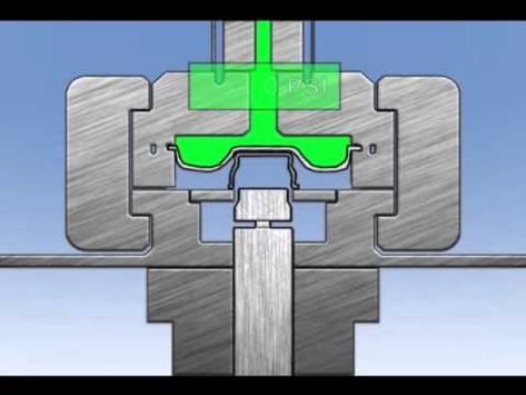
Deep drawing mold CAD design is a critical phase in the tooling development process that leverages computer-aided design (CAD) software to create precise 3D models of the mold components. This digital approach allows engineers to visualize, analyze, and optimize the mold geometry before any physical manufacturing begins, significantly reducing development time and costs.
In CAD design for deep drawing molds, each element—such as the punch, die, blank holder, inserts, and guide components—is modeled with high accuracy to ensure correct fit and function. Designers use parametric modeling techniques, allowing easy adjustments to dimensions and features as part designs evolve or to accommodate different sheet metal thicknesses and materials.
The CAD model incorporates critical features like die clearances, fillets, radii, and draft angles, all essential for controlling metal flow and minimizing defects during forming. Additionally, surface finishes and textures can be simulated or specified to guide manufacturing and surface treatment processes.
Modern CAD tools often integrate with finite element analysis (FEA) modules or link to specialized forming simulation software. This integration enables engineers to run virtual deep drawing processes using the mold design, predicting stress distribution, material thinning, wrinkling, and springback. Insights from these simulations inform iterative design improvements, such as adjusting die radius or blank holder force to optimize part quality and tool life.
CAD assemblies allow designers to check for proper alignment, tolerance stack-ups, and interference between mold components, ensuring reliable operation during the forming cycle. Detailed drawings and documentation can be automatically generated from the CAD model, supporting tool fabrication, inspection, and maintenance.
Collaborative features in modern CAD systems facilitate communication between design, manufacturing, and quality teams, promoting faster problem-solving and ensuring that the mold design meets all functional and production requirements.
Furthermore, CAD designs can be directly linked to CNC machining and additive manufacturing equipment through CAM (computer-aided manufacturing) software, enabling precise and efficient production of mold components with minimal manual intervention.
In summary, deep drawing mold CAD design enhances accuracy, flexibility, and efficiency in tooling development by providing a comprehensive digital representation of the mold, enabling simulation-driven optimization, seamless collaboration, and streamlined manufacturing workflows.
Continuing with deep drawing mold CAD design, one of the major advantages of using CAD is the ability to easily modify and customize mold components to suit different materials, part geometries, and production volumes. Because deep drawing often requires precise control over dimensions such as die clearance and punch radius, CAD models can be quickly adjusted to fine-tune these parameters based on simulation feedback or real-world forming results. This adaptability reduces the risk of costly rework or mold failure.
In the CAD environment, designers also simulate the assembly of the mold components, verifying that all parts fit together correctly and operate smoothly within the press. This includes checking for potential collisions or misalignments that could cause tool damage or part defects. The use of interference detection tools in CAD software prevents costly errors that might otherwise be discovered only after physical tool production.
Another key aspect is the ability to design complex features such as cooling channels, lubrication passages, and sensor housings directly into the mold components. Integrating these systems into the CAD model helps ensure that they do not interfere with the structural integrity or functionality of the mold while providing essential temperature control and lubrication management during the forming process.
Parametric CAD design also supports the creation of modular mold components like inserts and blank holders. By standardizing certain parts within the CAD library, manufacturers can reuse designs across multiple projects, speeding up development times and reducing tooling costs. Modular design also simplifies maintenance and repair, as worn or damaged inserts can be replaced without remanufacturing the entire mold.
Furthermore, CAD models serve as the digital foundation for advanced manufacturing techniques such as CNC machining and additive manufacturing. Direct transfer of CAD data to CAM software enables precise toolpath generation, reducing human error and improving machining efficiency. Additive manufacturing can be used to produce complex mold inserts or cooling channel geometries that are difficult to achieve with traditional methods, further enhancing mold performance.
The use of CAD also facilitates comprehensive documentation and version control, allowing design iterations to be tracked and compared systematically. This traceability is important for quality assurance and regulatory compliance, especially in industries like aerospace and automotive, where part traceability is critical.
Lastly, integrating CAD design with enterprise resource planning (ERP) and product lifecycle management (PLM) systems helps coordinate mold development with procurement, production scheduling, and inventory management. This holistic approach improves overall project management and ensures that mold designs align with broader manufacturing goals.
In essence, deep drawing mold CAD design is a powerful enabler of precision, flexibility, and efficiency in modern tooling development, driving improved product quality and faster time-to-market through digital innovation and integration.
Expanding further on deep drawing mold CAD design, the integration of advanced technologies such as generative design and artificial intelligence (AI) is beginning to transform the way molds are conceived and optimized. Generative design algorithms can automatically generate multiple mold design alternatives based on specified constraints like material usage, strength requirements, and manufacturing limitations. This allows engineers to explore innovative geometries that might be too complex or counterintuitive to design manually, potentially improving mold performance and reducing weight or material costs.
AI-powered tools also assist in identifying potential problem areas within the mold design by analyzing historical data from past forming operations and simulations. These insights help predict wear patterns, stress concentrations, or failure points, enabling proactive design improvements before physical tooling is produced. Such predictive capabilities reduce costly downtime and extend mold life.
Collaboration and cloud-based CAD platforms enable geographically distributed teams to work simultaneously on mold designs, accelerating decision-making and ensuring alignment across engineering, manufacturing, and quality departments. Real-time design reviews and markup capabilities help catch errors early and foster innovation through collective input.
In addition, digital twins—virtual replicas of physical molds—are developed from CAD models and updated continuously with data from actual production processes. This connection between design and operation allows for ongoing monitoring, predictive maintenance, and process optimization, creating a feedback loop that enhances mold performance over its lifecycle.
With the increasing adoption of Industry 4.0 principles, CAD designs for deep drawing molds are becoming part of a broader ecosystem that includes smart manufacturing, IoT sensors, and advanced analytics. This integration not only improves the mold development process but also enables adaptive forming systems that respond dynamically to changing conditions, material variations, and production demands.
In conclusion, deep drawing mold CAD design is evolving rapidly through the incorporation of generative design, AI, cloud collaboration, digital twins, and smart manufacturing technologies. These advancements empower manufacturers to create more efficient, robust, and adaptable molds while reducing time and costs associated with traditional tooling development. The ongoing digital transformation promises continued innovation and competitiveness in sheet metal forming industries.
Deep Drawing Mold Surface Finish
Deep drawing mold surface finish is a vital factor that directly impacts the quality of the formed parts, tool life, and the efficiency of the deep drawing process. The surface finish refers to the texture, smoothness, and treatment of the mold’s working surfaces—primarily the punch, die, and blank holder—that come into direct contact with the metal sheet during forming.
A smooth and properly finished mold surface reduces friction between the sheet metal and the tooling, which helps prevent defects such as galling, scoring, scratches, and surface tearing on the drawn part. For materials like aluminum or stainless steel, which are prone to sticking or surface damage, achieving an optimal surface finish is especially critical.
The surface finish is typically specified in terms of roughness average (Ra), with finer finishes (lower Ra values) corresponding to smoother surfaces. Polishing processes such as grinding, lapping, and buffing are employed to reach the desired finish, often resulting in mirror-like surfaces on critical mold components. These polished surfaces facilitate smoother metal flow and improve lubricant retention, further reducing friction and wear.
In addition to mechanical polishing, surface treatments and coatings are applied to enhance the mold’s performance and durability. Hard coatings like titanium nitride (TiN), chromium nitride (CrN), or diamond-like carbon (DLC) provide increased hardness, reduced adhesion, and improved wear resistance. Such coatings are particularly beneficial for molds used in high-volume production or when forming abrasive or sticky materials.
The surface finish also influences lubrication effectiveness. A slightly textured surface may retain lubricants better than a perfectly smooth one, helping maintain a stable lubricating film during the drawing stroke. Therefore, the choice of surface finish balances smoothness to reduce friction with enough texture to hold lubrication.
Furthermore, mold surface finish affects the final part’s appearance. For decorative or visible components, achieving a defect-free, smooth surface on the mold is essential to produce parts with high-quality surface aesthetics without requiring additional finishing operations.
Regular maintenance of the mold surface finish is necessary to sustain performance over time. Wear, corrosion, or surface damage can increase roughness, raising friction and the risk of part defects. Periodic polishing or recoating can restore optimal surface conditions and extend mold life.
In summary, deep drawing mold surface finish is a critical design and maintenance parameter that impacts friction, wear, lubrication, part quality, and overall process efficiency. Selecting and maintaining the appropriate surface finish and coatings tailored to the material and production requirements ensures consistent, high-quality deep-drawn parts and prolonged tooling performance.
Continuing on deep drawing mold surface finish, the choice of polishing techniques and the sequence in which they are applied greatly influence the final surface quality. Initially, grinding is used to remove rough machining marks and achieve a baseline smoothness. This is followed by finer abrasive steps such as honing and lapping, which refine the surface texture and reduce micro-roughness. Finally, buffing with polishing compounds brings the surface to a mirror-like finish, eliminating microscopic imperfections that could otherwise cause metal adhesion or scratches on the formed part.
In some cases, chemical or electrochemical polishing is employed to further enhance surface finish by selectively removing microscopic peaks on the mold surface. This process results in a highly uniform and smooth surface that can outperform mechanical polishing in certain applications.
Coatings applied after polishing not only improve hardness and wear resistance but also modify surface chemistry, reducing the tendency for metal-to-metal adhesion during forming. For example, DLC coatings have very low friction coefficients and excellent chemical stability, making them suitable for forming sticky metals like aluminum or stainless steel.
The surface finish must also be designed with consideration for the type of lubricant used in the forming process. Different lubricants interact uniquely with mold surfaces—some work better with ultra-smooth finishes, while others benefit from micro-textured surfaces that retain lubricant films more effectively. Collaboration between mold designers, lubricant specialists, and process engineers is essential to optimize this interface.
Wear monitoring is another important aspect. Even the best initial surface finish will degrade over time due to repeated contact with the workpiece and exposure to forming forces. Advanced inspection techniques, such as profilometry or non-contact optical scanning, help track surface roughness and identify areas where re-polishing or maintenance is needed before defects appear in parts.
For molds used in high-volume or precision-critical applications, surface finish consistency between production runs is vital. Standardized polishing procedures, strict quality control, and proper handling during mold storage and setup help maintain consistent surface conditions and ensure repeatable part quality.
Emerging technologies like laser surface texturing allow intentional patterning of the mold surface at a microscopic level to control friction, metal flow, and lubricant distribution. These textures can improve forming performance and reduce wear in ways that traditional polishing alone cannot achieve.
Overall, the mold surface finish is a dynamic attribute that requires careful design, precise manufacturing, ongoing monitoring, and periodic maintenance. When managed effectively, it leads to improved forming reliability, longer tool life, better part surface quality, and greater manufacturing efficiency in deep drawing operations.
Building further on deep drawing mold surface finish, the importance of material selection for the mold components cannot be overstated, as the base material influences achievable surface finish quality and durability. High-grade tool steels such as D2, A2, or H13 are commonly used due to their excellent hardness, toughness, and polishability. These steels respond well to precision grinding and polishing, allowing for extremely smooth surfaces that withstand the mechanical stresses and abrasive contact during deep drawing.
In addition to tool steel, the use of carbide inserts or coatings on critical mold areas can enhance wear resistance and maintain surface finish over prolonged production cycles. Carbide inserts offer superior hardness, but their surface finish requires specialized polishing techniques due to their brittle nature. Careful handling during polishing prevents micro-cracking or chipping, which could lead to premature tool failure.
Corrosion resistance is another important factor in surface finish longevity, especially when forming materials like stainless steel or aluminum alloys that require aggressive lubricants or encounter humid environments. Stainless tool steels or surface treatments like nitriding can improve corrosion resistance, preserving the smooth surface finish and preventing pitting or surface degradation.
The interaction between mold surface finish and blank material characteristics also shapes tooling design. Softer metals tend to conform more easily to surface imperfections, potentially causing surface defects in the final part. Conversely, harder or coated materials are less forgiving, demanding even higher surface finish standards to avoid imprinting or galling.
In some specialized deep drawing applications, texture engineering of the mold surface is employed intentionally to influence material flow, frictional behavior, and part appearance. For instance, micro-etched patterns or laser-textured surfaces can help reduce sticking or promote controlled metal flow, which can improve formability and reduce forming loads.
During mold maintenance, the choice of polishing compounds and methods is carefully matched to the mold material and coating to avoid damaging the surface. Diamond abrasives, cerium oxide, or alumina powders are common polishing agents used at different stages, selected based on their ability to achieve the desired finish without excessive material removal.
Finally, training and expertise of the tooling and maintenance personnel play a crucial role in sustaining optimal surface finish. Proper cleaning, handling, and polishing protocols minimize inadvertent surface damage, contamination, or uneven wear patterns, which could degrade part quality and increase downtime.
In summary, achieving and maintaining an optimal deep drawing mold surface finish is a multi-faceted challenge involving careful material selection, precision manufacturing, surface treatment, lubrication compatibility, and ongoing maintenance. Together, these factors ensure that molds deliver consistent, high-quality parts with minimal defects throughout their operational life.
Deep Drawing Mold Tolerance
Deep drawing mold tolerance refers to the precise dimensional and geometric limits within which the mold components—such as the punch, die, and blank holder—must be manufactured and assembled to ensure accurate, repeatable forming of sheet metal parts. Maintaining tight tolerances in mold design and fabrication is crucial because even small deviations can lead to defects like wrinkling, tearing, thinning, or dimensional inaccuracies in the deep-drawn parts.
The tolerance requirements depend heavily on factors such as the material being formed, the complexity of the part geometry, production volume, and the desired quality of the finished product. For example, forming high-strength alloys or precision aerospace components typically demands much tighter tolerances than forming simpler parts for low-volume applications.
Critical dimensional tolerances often focus on the die clearance, which is the gap between the punch and die. This clearance must be carefully controlled relative to the sheet thickness and material properties to balance sufficient metal flow with prevention of excessive thinning or cracking. Typical die clearances range from about 5% to 15% larger than the sheet thickness, with tolerances in the order of microns or a few thousandths of an inch, depending on application.
Geometric tolerances, such as flatness, parallelism, concentricity, and surface finish consistency, are equally important. Misalignment or uneven surfaces can cause uneven metal flow, localized stresses, and inconsistent part quality. Precision machining and inspection techniques like coordinate measuring machines (CMM) and optical scanning are used to verify these tolerances.
Tolerance stack-up analysis during mold assembly ensures that when individual components are put together, their cumulative deviations do not exceed acceptable limits. This analysis helps prevent problems such as punch-die interference or excessive gaps that can affect forming pressure distribution.
In addition to dimensional tolerances, functional tolerances such as hardness, surface roughness, and coating thickness also influence mold performance and longevity. For example, inconsistent coating thickness can alter surface friction, affecting metal flow and wear patterns.
Manufacturers often establish tolerance standards and quality control protocols based on industry norms, customer requirements, and experience. These standards are documented and used as benchmarks throughout mold production, inspection, and maintenance.
Adherence to strict mold tolerances improves part repeatability, reduces scrap rates, and extends tool life by minimizing uneven wear or premature failure. When tolerances are relaxed, forming defects become more likely, leading to costly rework or downtime.
In conclusion, deep drawing mold tolerance is a foundational aspect of mold design and manufacturing that ensures precise, consistent forming operations. Tight control of dimensional, geometric, and functional tolerances results in higher-quality parts, improved process reliability, and optimized tool longevity in deep drawing applications.
Continuing on deep drawing mold tolerance, achieving and maintaining tight tolerances requires advanced manufacturing techniques and rigorous quality control throughout the mold production process. Precision CNC machining, electrical discharge machining (EDM), and grinding are commonly employed to produce mold components with the necessary accuracy. These processes allow for micron-level control over dimensions and surface finishes, which is essential for critical features like the punch radius, die cavity profile, and blank holder interface.
In-process inspection plays a vital role in ensuring tolerances are met. Coordinate measuring machines (CMM), laser scanners, and profilometers are used to verify dimensions and surface characteristics at various stages of manufacturing. Early detection of deviations allows for corrective actions before the mold is fully assembled or put into production, reducing costly rework or scrap.
Tolerance management does not end with manufacturing; during mold assembly, precise alignment and fit of components must be verified to prevent cumulative tolerance stack-up issues. Proper fixturing, shimming, and adjustment mechanisms may be incorporated to fine-tune the mold assembly and compensate for minor deviations. This ensures uniform pressure distribution and consistent metal flow during forming.
Wear and thermal expansion during production can also affect mold tolerances over time. High forming pressures and frictional heat cause gradual dimensional changes, which must be monitored and compensated for through regular maintenance, polishing, and recalibration. Some molds incorporate temperature control systems to minimize thermal distortion and maintain dimensional stability.
Material selection for the mold components influences tolerance stability as well. Tool steels with high hardness and low thermal expansion rates help retain critical dimensions under operational stresses. Additionally, coatings and surface treatments must be uniformly applied to avoid altering component dimensions beyond tolerance limits.
The importance of mold tolerance is amplified in high-precision industries such as aerospace, automotive, and medical device manufacturing, where parts must meet stringent dimensional and functional specifications. In these sectors, mold tolerance directly impacts part fit, function, and safety.
Tolerance specifications are often communicated through detailed technical drawings, including geometric dimensioning and tolerancing (GD&T) symbols, allowing clear interpretation by machinists, assemblers, and quality inspectors. This standardized language ensures all stakeholders understand the acceptable limits and priorities for each feature.
In summary, deep drawing mold tolerance management is an ongoing, comprehensive effort encompassing precision manufacturing, meticulous inspection, careful assembly, and proactive maintenance. Maintaining strict tolerances is essential to produce high-quality, defect-free parts consistently, improve tool longevity, and optimize overall manufacturing efficiency in deep drawing operations.
Expanding further on deep drawing mold tolerance, the interplay between tolerance and material behavior during forming is a key consideration. Sheet metal exhibits complex deformation characteristics—elastic springback, anisotropy, and strain hardening—that interact with mold tolerances to influence final part geometry. Designers must account for these factors by specifying mold tolerances that compensate for predictable material responses, ensuring the formed part meets dimensional requirements once it leaves the tool.
For example, punch radius tolerance affects the strain distribution in the metal; too sharp a radius can cause tearing, while too large a radius may lead to excessive thinning or wrinkling. Precise control over this radius within tight tolerance ranges helps balance formability and part integrity. Similarly, die clearance tolerances directly influence metal flow and thickness distribution.
Advanced simulation tools, such as finite element analysis (FEA), are often employed to predict how different tolerance scenarios affect forming outcomes. By integrating tolerance analysis with material models, engineers can optimize mold dimensions and allowable deviations before manufacturing, reducing trial-and-error and costly prototyping.
Additionally, production monitoring systems can track mold performance in real time, detecting changes in dimensional accuracy due to wear or deformation. Sensors embedded in the mold can measure forces, temperatures, and displacements, providing data that feeds back into tolerance management strategies. This enables predictive maintenance and timely intervention to maintain part quality.
In high-volume production environments, automated inspection of formed parts using vision systems and laser scanners helps ensure that the cumulative effects of mold tolerances and process variations remain within acceptable limits. Statistical process control (SPC) techniques analyze this data to detect trends, identify root causes of deviation, and guide corrective actions.
Continuous improvement initiatives often focus on tightening or better controlling mold tolerances as part of quality enhancement programs. However, excessively tight tolerances can increase manufacturing costs and complexity. Therefore, an optimal balance between tolerance precision, process capability, and economic feasibility must be established.
Ultimately, deep drawing mold tolerance is a dynamic aspect that integrates design, manufacturing, material science, and process control. Effective management of these tolerances not only assures dimensional accuracy but also enhances forming reliability, reduces scrap, and supports lean manufacturing principles.
This holistic approach to tolerance ensures that deep drawing molds perform consistently throughout their service life, producing high-quality components efficiently and cost-effectively.
Deep Drawing Mold Analysis
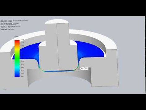
Deep drawing mold analysis is a comprehensive evaluation process aimed at ensuring the mold design and manufacturing will meet the functional requirements for producing high-quality drawn parts with efficiency and durability. This analysis encompasses multiple facets, including geometric assessment, material behavior, stress and strain distribution, thermal effects, lubrication impact, and tool wear predictions.
One of the primary tools used in deep drawing mold analysis is finite element analysis (FEA), which simulates the sheet metal forming process under the specific mold geometry, material properties, and process parameters. FEA helps predict how the metal will flow, where thinning, wrinkling, or tearing might occur, and how the mold surfaces interact with the workpiece. This virtual testing enables designers to optimize mold features such as punch radius, die profile, and clearance before physical prototyping, significantly reducing development time and costs.
In addition to mechanical deformation, thermal analysis is important, especially for high-speed or high-volume production where heat generated by friction and plastic deformation can affect mold dimensions and surface finish. Thermal simulations assess temperature distribution within the mold and identify potential hotspots that may cause thermal expansion or degradation of lubricants, influencing mold performance and tool life.
Lubrication analysis evaluates the effectiveness of lubricant film formation and retention on the mold surfaces. Proper lubrication reduces friction, minimizes wear, and prevents metal-to-metal contact that could damage both mold and part. Understanding how lubricants behave under different pressures, temperatures, and surface finishes helps optimize the mold design and process settings.
Wear analysis predicts the lifespan of mold components by estimating the effects of repeated loading, friction, and environmental factors. Simulation of wear patterns guides the selection of materials, coatings, and maintenance schedules to extend tool life and reduce downtime.
Tolerance and assembly analysis ensure that all mold parts fit and function correctly within specified limits. This includes evaluating the cumulative effects of component variations, thermal expansion, and mechanical stresses to avoid interference or excessive clearances that could compromise part quality.
Additionally, vibration and dynamic analysis may be conducted to assess the mold’s structural stability and response under cyclic loading, preventing fatigue failure or deformation during production.
By integrating these analyses, engineers can identify potential issues early, optimize design parameters, select suitable materials and surface treatments, and plan maintenance to maximize mold performance. The result is a mold that delivers consistent part quality, higher productivity, and longer service life.
Overall, deep drawing mold analysis is a multi-disciplinary approach combining simulation, material science, tribology, and mechanical engineering principles to refine tooling solutions and enhance manufacturing outcomes in sheet metal forming.
Continuing with deep drawing mold analysis, an essential aspect is the iterative nature of the process, where simulation results inform design modifications that are then re-analyzed to progressively improve mold performance. This iterative loop helps balance competing objectives such as minimizing material thinning while preventing wrinkling, reducing forming forces without compromising part accuracy, and extending tool life while controlling manufacturing costs.
The role of real-world data is increasingly significant in mold analysis. Data collected from sensors embedded in molds during actual production—monitoring parameters like pressure, temperature, and displacement—can be compared with simulation predictions to validate models and refine them for better accuracy. This feedback loop enables more precise control over the forming process and helps anticipate maintenance needs before failures occur.
Furthermore, material characterization is crucial for reliable mold analysis. Detailed information about the sheet metal’s mechanical properties—such as yield strength, strain hardening exponent, anisotropy coefficients, and ductility under various strain rates and temperatures—feeds into simulations to predict forming behavior accurately. Variations in material batch quality or supplier can be accounted for by adjusting these inputs, enhancing robustness of the mold design.
Lubrication modeling is complex due to the interplay of pressure, temperature, surface roughness, and lubricant chemistry. Advanced tribological simulations explore how lubricant films form and break down, how friction coefficients change during the stroke, and how these factors influence metal flow and tool wear. Optimizing lubrication through mold design—such as incorporating micro-textures to retain lubricant—can dramatically improve forming quality and reduce downtime.
Another critical factor in mold analysis is the evaluation of springback, where the metal tends to partially recover its original shape after forming forces are removed. Accurate prediction of springback allows designers to compensate by adjusting mold geometry, ensuring final parts meet dimensional specifications without costly trial-and-error adjustments.
Wear simulation uses contact mechanics and material removal models to predict how repetitive metal contact and friction degrade mold surfaces over time. This enables proactive scheduling of maintenance and refurbishing before defects appear in production parts, thus avoiding scrap and downtime.
Modern mold analysis often employs multi-physics simulations that combine mechanical, thermal, and tribological effects, recognizing that these factors do not act in isolation but interact dynamically during forming. This holistic approach yields deeper insights and more reliable predictions.
In summary, deep drawing mold analysis is a sophisticated, data-driven process that integrates advanced simulations, real-world feedback, and material science. It plays a pivotal role in designing molds that produce high-quality parts efficiently, extend tool life, and reduce costs, ultimately supporting the competitiveness and sustainability of manufacturing operations.
Building further on deep drawing mold analysis, the integration of artificial intelligence (AI) and machine learning (ML) techniques is becoming increasingly prominent. These technologies analyze large datasets from past forming cycles, sensor outputs, and simulation results to identify patterns and correlations that might not be obvious through traditional methods. By leveraging AI, engineers can predict tool wear rates, optimize process parameters in real time, and even suggest design improvements based on historical performance, enabling smarter, faster decision-making.
Digital twin technology is another emerging trend in mold analysis. A digital twin is a virtual replica of the physical mold and forming process that updates in real time with data from the production environment. This dynamic model allows continuous monitoring and simulation of forming conditions, enabling proactive adjustments to maintain optimal performance and prevent defects before they occur. It essentially bridges the gap between design, manufacturing, and operational phases, fostering more agile and resilient manufacturing systems.
In addition, advanced visualization tools such as augmented reality (AR) and virtual reality (VR) are used to enhance mold analysis and troubleshooting. Engineers can interact with 3D models of molds, simulate forming processes, and inspect potential problem areas visually before physical intervention. This immersive approach improves understanding of complex issues, facilitates collaboration across teams, and accelerates problem resolution.
Sustainability considerations are also influencing mold analysis. Optimizing the mold design and forming process to minimize material waste, reduce energy consumption, and extend tool life contributes to greener manufacturing. Simulations help identify opportunities to decrease forming loads and lubricant usage, thus lowering environmental impact while maintaining product quality.
Furthermore, the use of additive manufacturing (3D printing) for mold components introduces new possibilities and challenges for mold analysis. While additive methods enable rapid prototyping and complex internal cooling channels, their different material properties and surface finishes require adapted analysis approaches to ensure performance comparable to traditional tooling.
Finally, collaboration across disciplines—mechanical design, materials science, tribology, data science, and manufacturing engineering—is essential for comprehensive deep drawing mold analysis. This integrated approach ensures that all relevant factors are considered, leading to innovative solutions and continuous improvement in deep drawing operations.
In essence, deep drawing mold analysis is evolving into a highly sophisticated, interconnected process that combines cutting-edge technologies with traditional engineering principles to optimize mold design, performance, and sustainability in modern manufacturing environments.
Deep Drawing Mold Assembly
Deep drawing mold assembly is the critical process of putting together all the individual components of the mold—such as the punch, die, blank holder, ejector systems, and guide elements—into a fully functional tooling setup that is ready for production. This phase ensures that the mold operates precisely, safely, and reliably during the deep drawing process to produce high-quality parts.
The assembly starts with careful inspection and preparation of each component to verify that all dimensions and surface finishes meet specified tolerances. Cleanliness is vital, as dirt or debris can cause misalignment, damage surfaces, or introduce defects in formed parts. Often, assembly occurs in controlled environments to prevent contamination.
Precision alignment is fundamental during assembly. Components must be positioned with micrometer accuracy to ensure uniform clearances and proper interaction between the punch and die. Misalignment can cause uneven metal flow, localized stresses, and premature tool wear or failure. Specialized fixtures, alignment pins, and precision measuring instruments such as dial indicators and coordinate measuring machines (CMM) assist in achieving the required positional accuracy.
The blank holder, which applies pressure to hold the sheet metal in place and control material flow, must be assembled with adjustable mechanisms to fine-tune the holding force during initial trials and production. The ability to adjust the blank holder pressure helps prevent wrinkling or tearing.
Ejector systems, if included, are installed to assist in removing the formed part smoothly from the die cavity without damaging the workpiece or tooling. Their installation requires careful calibration of stroke length and timing relative to the punch movement.
Guide elements such as bushings, guide pins, and sliders ensure smooth, repeatable motion of the moving parts of the mold. These are assembled with attention to minimizing play while preventing excessive friction or binding.
During assembly, fasteners like screws, bolts, or clamps are torqued to specified values to maintain structural integrity without introducing distortion. Thread locking compounds or safety washers may be used to prevent loosening under vibration.
After mechanical assembly, functional checks are conducted to verify smooth movement, proper clearances, and absence of interference. Trial runs with sample blanks help identify any issues with alignment, holding force, or ejection that require adjustment.
Temperature control components, if part of the mold design, such as cooling channels or heating elements, are connected and tested to ensure stable thermal conditions during forming. Proper thermal management helps maintain dimensional stability and prolong tool life.
Documentation of assembly procedures, including torque specifications, adjustment settings, and inspection results, is important for repeatability and quality control. This information assists operators and maintenance personnel in correctly setting up molds for production and troubleshooting any issues.
Overall, deep drawing mold assembly demands meticulous attention to detail, precise measurement, and skilled workmanship. A well-executed assembly directly impacts the quality of the formed parts, the efficiency of the production process, and the longevity of the tooling, making it a pivotal step in successful deep drawing operations.
Continuing with deep drawing mold assembly, once the initial assembly and alignment are complete, it is crucial to perform trial runs under controlled conditions to observe the mold’s behavior during actual forming cycles. These trial runs help detect subtle issues such as uneven blank holder pressure, misalignment causing uneven metal flow, or improper ejection timing. Feedback from these tests informs fine adjustments to optimize performance and avoid defects like wrinkling, tearing, or excessive thinning.
The use of precision measuring tools during and after assembly allows verification that key dimensions and clearances remain within specified tolerances. For instance, feeler gauges, dial indicators, and laser measurement devices can check die clearance, punch positioning, and blank holder gaps to ensure uniformity around the mold circumference. This uniformity is essential for consistent metal flow and part geometry.
Lubrication systems, if integrated into the mold assembly, must be carefully connected and tested. Proper lubricant delivery reduces friction between the sheet metal and tooling surfaces, minimizing wear and improving part quality. The assembly process must ensure no leaks or blockages exist in lubricant channels, and that delivery mechanisms operate synchronously with the forming cycle.
Another critical aspect during assembly is ensuring all safety features and interlocks are installed and functioning. Deep drawing molds operate under high forces and speeds, so mechanical guards, emergency stops, and sensors must be properly integrated to protect operators and equipment.
As molds are often subjected to high loads during production, the rigidity and structural integrity of the assembly are vital. Assembly techniques may incorporate preloading certain components or using high-strength fasteners and shims to maintain tight fits and prevent loosening or distortion over time. In some cases, stress-relieving treatments or surface coatings are applied post-assembly to enhance durability.
Documentation and standard operating procedures developed during assembly are essential for repeatability. Detailed records of component serial numbers, assembly torque values, alignment settings, and trial run outcomes create a baseline for maintenance and future troubleshooting. This data supports root cause analysis in case defects arise during production and helps guide mold refurbishing or reassembly activities.
In high-volume manufacturing, mold assembly may be streamlined through modular designs allowing quick changeover of wear parts or inserts without full disassembly. This modularity reduces downtime and supports lean production practices. Designing molds with assembly and disassembly in mind facilitates maintenance and extends overall tool life.
Finally, ongoing monitoring of mold performance during production feeds back into assembly considerations. Observing signs of uneven wear, dimensional drift, or changes in forming forces can prompt re-inspection and reassembly to restore optimal conditions. This lifecycle approach ensures the mold continues to operate reliably, producing parts within specifications and maximizing return on tooling investment.
In sum, deep drawing mold assembly is a precise, iterative, and highly controlled process that integrates mechanical precision, process validation, lubrication management, safety, and documentation. Successful assembly is foundational to producing consistent, high-quality parts efficiently and sustaining mold performance throughout its operational life.
Building further on deep drawing mold assembly, another important factor is the integration of automation and smart technologies to improve accuracy and efficiency during the assembly process. Automated assembly stations equipped with robotic arms and vision systems can handle delicate mold components with precision beyond human capability, ensuring consistent alignment and reducing human error. These systems can also perform quality inspections in real time, detecting defects or deviations before finalizing the assembly.
Incorporating sensors within the mold assembly allows for condition monitoring from the outset. Embedded strain gauges, temperature sensors, and displacement transducers provide continuous feedback on the mold’s operational state during both setup and production. This data helps verify that the assembly parameters—such as alignment and clamping forces—remain within prescribed limits, enabling predictive maintenance and reducing unexpected downtime.
Material selection and surface treatment of assembled components also play a critical role in the longevity and performance of the mold. Components that experience sliding contact or high stress are often coated with wear-resistant materials like titanium nitride (TiN), chromium carbide, or diamond-like carbon (DLC). These coatings reduce friction, improve corrosion resistance, and extend maintenance intervals. During assembly, ensuring the coatings are intact and free from contamination is essential to preserve their benefits.
Thermal management components installed during assembly require careful sealing and integration to prevent leaks and maintain consistent cooling or heating. Efficient temperature control during forming affects dimensional stability and lubricant performance, which in turn influences the quality of the drawn parts. Cooling channels are pressure-tested and flushed to remove debris before full assembly completion.
Furthermore, ergonomic design considerations for mold assembly can significantly impact production efficiency and operator safety. Designing molds with accessible fastening points, lightweight components, and standardized connectors simplifies handling and reduces assembly time. Modular designs facilitate quicker changeovers and ease cleaning and maintenance tasks.
Training and skill development for assembly technicians are equally crucial. Complex molds require a deep understanding of mechanical principles, precision measurement techniques, and process dynamics. Well-trained personnel can recognize subtle signs of assembly issues and perform necessary adjustments promptly, minimizing trial cycles and material waste.
Lastly, collaboration between design engineers and assembly teams early in the mold development phase ensures that assembly challenges are addressed proactively. Design for Assembly (DFA) principles encourage simplification of mold components, reduction of part counts, and standardization, making the assembly process more straightforward, reliable, and cost-effective.
Overall, deep drawing mold assembly is evolving beyond traditional manual techniques toward a more integrated, data-driven, and automated approach. This progression enhances precision, repeatability, and responsiveness, supporting high-quality production and sustainable tooling performance in competitive manufacturing environments.
Deep Drawing Mold Maintenance
Deep drawing mold maintenance is a critical activity that ensures the mold continues to produce parts with consistent quality while extending the service life of the tooling. Due to the high pressures, repetitive cycles, and precise tolerances involved in deep drawing operations, molds are subject to wear, deformation, and other forms of degradation over time. Regular maintenance mitigates these issues and prevents unplanned downtime that can disrupt production schedules and increase costs.
The foundation of mold maintenance lies in a structured preventive maintenance program. This includes scheduled inspections at defined intervals based on cycle counts, material type, lubrication performance, and historical wear patterns. During each maintenance cycle, technicians thoroughly clean the mold surfaces, remove debris or residues left from formed materials, and inspect for signs of wear, scoring, galling, or micro-cracks, especially on critical surfaces such as the punch, die cavity, and blank holder.
Wear-prone areas, like die radii and punch tips, are carefully examined using visual inspection tools, microscopes, or non-destructive testing techniques such as dye penetrant inspection or magnetic particle testing. These methods help detect early-stage surface damage that could lead to part defects if left untreated. If wear is found, the components may be polished, recoated, or replaced depending on severity.
Lubrication is another key focus of maintenance. Even if the mold uses high-performance lubricants, residue buildup can occur over time, especially in high-volume production. Maintenance involves not only cleaning and refreshing the lubricant but also ensuring that the delivery channels are free from clogs and operate as intended. Poor lubrication performance accelerates wear and can lead to tearing or scoring on formed parts.
Fasteners, guide pins, bushings, and springs are also subject to loosening, fatigue, or misalignment. During maintenance, these elements are tested for play and wear. Any worn or misaligned components are replaced or adjusted to maintain precision in the mold’s operation. Ejector systems and any hydraulic or pneumatic elements are checked for leaks, consistent pressure output, and smooth motion.
Tool alignment is rechecked during maintenance using jigs, gauges, and measurement tools. Even slight misalignments over time can lead to uneven material flow, part asymmetry, or accelerated wear on one side of the tooling. Recalibrating alignment ensures that the mold continues to form parts symmetrically and within dimensional tolerances.
In addition to physical upkeep, maintenance documentation is essential. Each maintenance session is logged, detailing what was inspected, cleaned, replaced, or adjusted. This record helps in tracking mold performance over time, predicting future maintenance needs, and identifying recurring issues that may require design modifications or changes in process parameters.
Some high-end manufacturing environments use predictive maintenance systems that combine sensor data with analytics to forecast when specific components will require service. This approach reduces downtime and eliminates unnecessary disassembly.
Ultimately, consistent and proactive deep drawing mold maintenance preserves tooling investment, ensures part quality, minimizes scrap and rework, and supports uninterrupted production. It transforms mold care from a reactive task into a strategic aspect of efficient manufacturing operations.
Continuing with deep drawing mold maintenance, it’s important to recognize that the type of material being formed significantly influences the frequency and nature of maintenance tasks. Harder or more abrasive materials, such as stainless steel or titanium, tend to accelerate wear on tool surfaces and may require more frequent polishing or recoating of contact areas. Conversely, softer materials like aluminum may leave residue or gall more easily, necessitating regular cleaning to maintain surface quality. This material-specific behavior informs not just maintenance intervals but also the choice of tool coatings and lubricants used during production.
Environmental factors also affect mold longevity. High humidity or contaminated shop air can promote corrosion on precision surfaces, especially if the mold is idle for long periods. Protective coverings, controlled storage conditions, and anti-corrosion treatments applied during downtime help mitigate such risks. When molds are removed from the press for extended storage, applying rust inhibitors and sealing sensitive areas ensures they remain production-ready when needed again. Proper handling during disassembly and reassembly is equally important to avoid damaging edges, alignment features, or threaded connections.
For molds with complex geometries or fine features, such as in automotive or aerospace applications, maintenance often involves remeasuring critical dimensions using coordinate measuring machines (CMMs) or optical comparators. These tools provide high-resolution feedback on wear and dimensional drift, enabling precise corrective actions. Rather than replacing entire mold components, manufacturers may choose to regrind or refinish specific areas, especially if the wear is uniform and within reworkable limits. This practice conserves tooling costs while restoring full functionality.
Another critical aspect is maintaining backup components and standardizing replaceable parts like guide posts, ejector pins, or springs. Having spares on hand and designing molds with interchangeable wear elements streamlines maintenance, especially during emergency repairs. Modularization and part standardization also enable parallel maintenance activities—one team can prepare replacement parts while another disassembles the mold—reducing total downtime.
Training and experience of maintenance technicians play a decisive role in effective upkeep. Skilled technicians can detect subtle changes in part quality that indicate underlying mold issues, such as slight increases in burr height, minor shifts in wall thickness, or emerging surface defects. Their ability to troubleshoot and restore molds quickly minimizes production disruption and helps maintain customer delivery commitments.
In highly automated environments, molds are often integrated with press monitoring systems that track parameters like forming force, cycle time, and part ejection consistency. Deviations from normal values can signal mold issues before defects appear in finished parts. For instance, a gradual increase in forming force could suggest a worn die radius or insufficient lubrication, prompting targeted maintenance before failure occurs.
Ultimately, deep drawing mold maintenance is not just about preserving the physical integrity of tooling but about sustaining process stability and part repeatability. A well-maintained mold produces fewer defects, requires less press downtime, and supports lean manufacturing goals. As production volumes grow and quality standards tighten, the importance of detailed, proactive maintenance strategies becomes even more central to competitive, efficient operations.
Adding further depth to deep drawing mold maintenance, it’s essential to emphasize the role of collaborative communication between production operators and maintenance personnel. Operators are typically the first to notice subtle changes during forming, such as unusual noise, increased resistance, part sticking, or inconsistent part shapes. Establishing a feedback loop where these observations are documented and reviewed enables maintenance teams to prioritize inspections and anticipate component failures. This approach helps catch potential problems early, before they affect product quality or require major repairs.
Another increasingly relevant practice is the use of digital tools for maintenance planning and execution. Maintenance Management Systems (MMS) or Computerized Maintenance Management Systems (CMMS) can schedule tasks based on cycles or hours of operation, maintain digital logs of previous interventions, and track the service life of critical components. These systems enhance traceability, improve accountability, and facilitate data-driven decision-making. For example, if a die insert has historically needed resurfacing every 80,000 cycles, the system can automatically flag a preemptive inspection around that interval.
Cleaning remains a deceptively critical element in mold maintenance. Over time, residue from metalworking lubricants, oxidation products, and microscopic debris accumulates on the mold’s surface and in corners or relief areas. This buildup can subtly alter part geometry, increase friction, or trap formed metal, especially in deep cavities. Therefore, cleaning involves not just wiping but often ultrasonic cleaning, chemical baths, or dry ice blasting depending on the mold size and level of contamination. Cleaning is also when technicians inspect for hairline cracks or galling that could propagate under stress.
The repair process during maintenance must be done with precision. When re-polishing die or punch surfaces, it’s critical to maintain the original geometry, especially the radii and draft angles, which control how material flows during drawing. If these are altered even slightly, it can cause localized thinning, wrinkling, or part jamming. Using lapping compounds and profile gauges ensures the surfaces are restored within acceptable limits. For parts that have worn beyond repairable tolerance, mold inserts or specific segments can often be replaced without scrapping the entire mold, particularly if the mold was designed for modular service.
Thermal stress is another factor often addressed during maintenance. In high-speed or high-volume production, heat generated by repeated forming cycles can lead to thermal fatigue, warping, or microfractures in mold components. Maintenance inspections include checks for discoloration, loss of hardness, or surface checking. If heat damage is detected, components may be replaced, re-hardened, or redesigned for better thermal dissipation. In some cases, thermally damaged molds are reengineered with improved cooling channels or heat-tolerant materials.
Additionally, documentation of part defects tied to specific mold wear patterns builds long-term insight into failure modes. For instance, if a certain wrinkle consistently appears after a given number of cycles, or if tearing always begins at a specific cavity edge, this knowledge feeds back into both maintenance strategy and mold design improvements. Advanced manufacturers even correlate press sensor data with maintenance history to develop predictive models that anticipate wear before it becomes visually or dimensionally evident.
Finally, as product designs evolve and materials shift toward thinner gauges or higher-strength alloys, molds may require more frequent maintenance or minor reengineering to maintain their effectiveness. Maintenance, therefore, isn’t static—it adapts to changes in the product lifecycle, production volumes, and quality expectations. In modern operations, it’s not enough to simply maintain molds reactively; proactive, informed, and adaptive maintenance is fundamental to sustaining profitability, reducing waste, and delivering precision-formed components consistently and reliably.
Deep Drawing Mold With Blank Holder
A deep drawing mold with a blank holder is essential for ensuring controlled metal flow during the forming process, especially when producing components with high depth-to-diameter ratios. The blank holder, sometimes referred to as the hold-down plate or binder, plays a crucial role in preventing wrinkling, tearing, and other defects that can arise from uncontrolled material movement as the blank is drawn into the die cavity by the punch. Unlike a simple die and punch setup, the inclusion of a blank holder introduces a third functional element that interacts dynamically with the blank, balancing restraining pressure against the natural tendency of the material to wrinkle.
The blank holder applies uniform or variable pressure around the periphery of the blank. This pressure must be carefully calibrated: too little, and the blank may wrinkle due to excessive material accumulation; too much, and the material may thin out excessively or tear near the punch radius. The optimal pressure is influenced by several variables, including the blank material, thickness, lubrication, part geometry, and draw depth. In complex or high-precision applications, the blank holder system may be equipped with springs, hydraulic pistons, or pneumatic actuators to deliver adjustable force profiles during different stages of the stroke.
Blank holders also influence the frictional conditions during forming. In some cases, the surface of the blank holder is intentionally textured or coated to increase friction and help regulate the inward material flow. Conversely, low-friction coatings or the application of lubricants may be used to allow smoother blank movement in other zones. Advanced molds may even have segmented or independently controlled blank holder zones, allowing different pressures to be applied locally to guide the material precisely, especially in asymmetrical or multi-depth shapes.
Another important consideration is the clearance and alignment between the blank holder and the die surface. This must be finely controlled to avoid pinching the blank too tightly or allowing it to buckle. During setup and maintenance, technicians use feeler gauges and precision spacers to ensure even pressure distribution. Wear on the blank holder surface—whether from abrasive material, lack of lubrication, or repeated cycles—can lead to inconsistent holding force, which directly affects part quality and repeatability. Hence, surface condition and flatness of the blank holder are routinely checked during maintenance.
Some high-performance deep drawing molds incorporate dynamic blank holding systems, where pressure can change during the drawing stroke. For example, a higher initial pressure may suppress wrinkles at the start, followed by reduced pressure to ease material flow as the punch reaches full depth. These systems require precise control, usually via pressurized hydraulic circuits connected to programmable logic controllers (PLCs), and are typically found in applications where quality standards are extremely tight—such as aerospace, medical, or complex automotive parts.
In essence, the blank holder transforms deep drawing from a two-dimensional pressing operation into a controlled three-dimensional forming process. Its presence allows the mold to handle a wider range of part geometries, materials, and wall thicknesses while minimizing waste and improving dimensional accuracy. When designed and maintained properly, a blank holder-equipped deep drawing mold offers enhanced process control, repeatable part quality, and longer tooling life.
The deep drawing mold with a blank holder fundamentally changes the nature of the material flow and makes it possible to achieve deeper draws and more complex geometries with fewer defects. As the punch begins to descend and engage the blank, the blank holder keeps the outer edges of the sheet pressed uniformly against the die surface, which restricts excess radial movement and controls how the material stretches into the cavity. This restraining action not only prevents wrinkling but also contributes to uniform wall thickness distribution. Without a blank holder, material would freely flow toward the center as the punch pulls it in, leading to folds, wrinkles, or uneven wall thinning depending on the stiffness of the material and the speed of deformation.
The interaction between the punch, die, and blank holder must be meticulously timed and aligned, especially in high-speed or automated environments. The synchronization ensures that the blank holder applies pressure just before the punch contacts the blank and maintains it consistently until the part is fully formed. If there is any delay or mismatch in timing, such as the punch engaging too early or the blank holder lagging in pressure application, the material can behave unpredictably, introducing defects. This makes the mechanical setup of the blank holder mechanism—whether spring-loaded, pneumatic, or hydraulic—an important factor in mold design and press integration.
Blank holder force is not simply a fixed value; it must often be tuned experimentally for each material and part geometry. Even with standardized force calculations, actual behavior under forming conditions can differ due to friction, strain rate sensitivity, and work-hardening properties of the metal. In practical terms, technicians conduct tryout runs with different blank holder pressures and observe the results, adjusting the force until wrinkling is suppressed without causing tearing or thinning. This iterative tuning becomes especially critical in production lines that handle multiple materials or shift between steel, aluminum, and other alloys, each of which responds differently to holding force.
In high-end forming operations, variable blank holding is achieved with hydraulic cushions beneath the press bed that respond dynamically throughout the stroke. These cushions can be programmed to ramp up or down in force, follow a pressure curve, or allow partial material flow at specific stages to optimize the final part shape. For example, in reverse drawing or redrawing operations where the material direction changes during forming, such controlled variation of blank holder force is essential. These systems require integration between the mold design and the press control logic, ensuring real-time coordination.
Thermal effects can also influence how the blank holder performs, especially in longer production runs. As heat builds up due to friction and deformation, metal flow characteristics change slightly, and so does the lubricity at the interface between the blank holder and the workpiece. This makes temperature control and consistent lubrication a necessary consideration for maintaining blank holder effectiveness. In some applications, blank holders may be water-cooled or designed with ventilation grooves to dissipate heat and reduce the chance of lubricant breakdown, which could otherwise increase friction unpredictably and alter the material draw.
The condition of the blank holder surface also plays a vital role. Even minor surface damage—like scratches, indentations, or localized galling—can create non-uniform friction zones and cause wrinkles or surface marks on the final part. Maintenance routines often include polishing or resurfacing of the blank holder area to restore its original flatness and finish. In tools used for polished or cosmetic-grade parts, such as cookware or appliance components, any surface defect on the blank holder can directly translate to a visual flaw in the finished piece, requiring immediate attention.
In progressive die setups where multiple forming stages are carried out in sequence, blank holders are employed at various stations, each optimized for its specific forming step. Here, the coordination between multiple blank holders, each with potentially different force profiles, adds to the complexity but enables even more sophisticated part geometries to be achieved in a single press cycle. This approach reduces cycle time and boosts throughput but demands higher precision in mold setup and alignment.
Ultimately, the blank holder is not just a passive component that applies pressure—it’s an active participant in managing material flow, part quality, and process consistency. Its design, condition, and operational parameters all directly affect the ability of the mold to produce defect-free deep drawn parts, especially as part designs become more demanding and tolerances tighter. Whether in low-volume prototyping or high-speed mass production, the blank holder’s role is foundational to the success of deep drawing as a manufacturing process.
As production demands increase, so too does the necessity for consistency in how the blank holder interacts with the material. In many high-volume environments, blank holder systems are now instrumented with load sensors and displacement transducers that provide real-time feedback during each press cycle. These sensors allow operators and automated systems to monitor the actual force being applied at every instant and adjust the press or hydraulic system accordingly. If a deviation from the set profile is detected—such as a loss of pressure on one side due to wear or misalignment—the system can either compensate on the fly or flag the anomaly for maintenance intervention. This kind of closed-loop control is especially important when working with thin-gauge metals, high-strength alloys, or expensive materials where scrap rates must be minimized.
In multi-stage or transfer die systems, the blank holder’s role can vary throughout the forming sequence. In the initial stage, its main job might be to suppress wrinkling and guide the metal inward. Later, it might aid in restraining the already-formed cup or shape during redrawing to achieve greater depth or reduced diameter. In reverse drawing operations, the blank holder can help stabilize the part as the punch reforms the shape from a different direction. This flexibility demands that mold designers consider not just the force magnitude, but also the force direction, contact area, and timing—all of which evolve from one forming stage to the next.
Surface treatments for the blank holder contact face are another consideration. Tool steels used in these molds are often hardened to resist wear, but additional coatings like titanium nitride (TiN), chromium, or diamond-like carbon (DLC) can be applied to reduce friction and extend service life. These coatings also offer thermal protection and improve resistance to galling when working with adhesive-prone materials like stainless steel or titanium. The choice of coating depends on the type of material being formed and the expected production volume. In molds that handle high-strength steel or abrasive alloys, coated blank holders can dramatically reduce downtime for cleaning or resurfacing.
Furthermore, the size and contour of the blank holder surface must be tailored to the specific part geometry. Flat blank holders are standard in basic cylindrical shapes, but for more complex or asymmetrical parts, contoured blank holders are used to better support the blank and ensure uniform pressure application across its surface. These contoured holders may be CNC-machined to match the 3D profile of the forming area, especially in automotive or aerospace applications where structural components have varying draw depths or rib features. These holders prevent localized stress concentrations and encourage smoother material transition into the die cavity.
Another design feature often integrated into advanced blank holders is venting or channeling. As air is displaced during deep drawing, especially in airtight or tight-clearance dies, air pockets can form and interfere with the material flow or cause compression issues. Venting grooves or strategically placed escape paths in the blank holder and die help mitigate these issues. In precision applications, even slight pressure differences can affect wall thickness distribution or introduce unwanted part distortion.
The blank holder also plays a role in influencing the strain path that the material follows during forming. This is a critical factor in finite element simulations, where engineers model how the material deforms throughout the draw. Adjusting blank holder pressure in the simulation helps predict whether a part will wrinkle, thin, or fracture—and guides engineers to design a blank holder surface and force profile that steers material deformation along a desirable path. These simulations are then validated in real-world tryouts, and adjustments are made to refine both the tooling and process parameters.
Ultimately, while the blank holder might seem like a secondary component compared to the die and punch, it serves as the conductor of the material’s flow orchestra. Its influence extends beyond simply pressing down the sheet; it determines how the blank stretches, flows, and conforms to the final shape. A well-designed blank holder can mean the difference between a consistent, high-quality forming operation and a production line plagued with rework and defects. As demands for more intricate, lightweight, and strong parts continue to grow across industries, the importance of mastering blank holder design and operation in deep drawing molds only becomes more critical.
Deep Drawing Mold Wrinkling Prevention
Wrinkling prevention in deep drawing molds is a critical focus of both tool design and process control, as wrinkles compromise the structural integrity, dimensional accuracy, and surface quality of drawn components. Wrinkling typically occurs when excess compressive stress builds up in the flange area of the blank, causing the metal to buckle instead of flowing smoothly into the die cavity. This is especially common when forming large-diameter or shallow-depth parts, thin-walled materials, or when using soft, ductile metals. Effective wrinkling prevention relies on a combination of blank holder design, optimized force application, proper lubrication, controlled material flow, and accurate alignment of tooling components.
The most fundamental method of preventing wrinkling is through the proper use of a blank holder, which restrains the flange of the blank during drawing. By applying sufficient downward pressure, the blank holder suppresses the natural tendency of the outer edge of the blank to compress and buckle as the punch pulls material inward. However, the pressure must be precisely controlled. Excessively high blank holder force can inhibit material flow and cause tearing, while too little force allows uncontrolled radial movement and buckling. This balance is typically fine-tuned during trial runs or through simulation and may be adjusted throughout production based on feedback from sensors or part inspection.
In high-precision or variable-depth applications, segmented blank holders or systems with programmable hydraulic cushions are used to provide differential holding force across different areas of the blank. This allows the tool to apply more pressure in wrinkle-prone zones while easing restraint in others to promote smooth drawing. Variable pressure application is especially effective for asymmetrical parts or parts with localized features such as embosses, flanges, or corners, where wrinkling often initiates due to uneven stress distribution.
Material characteristics also play a significant role in wrinkling susceptibility. Metals with low yield strength or high ductility, such as aluminum, copper, or annealed steels, are more prone to wrinkling under compressive stress. In such cases, careful selection of blank thickness, temper, and surface finish can help reduce the likelihood of wrinkling. Moreover, pre-conditioning treatments such as blank edge trimming or controlled pre-forming (also known as ironing or pre-bulging) are sometimes used to reduce excess material in the flange region before final drawing, minimizing the risk of compression-based deformation.
Lubrication is another vital factor in wrinkling control. Proper lubrication at the die and blank holder interfaces reduces friction, which allows the blank to flow more uniformly toward the die cavity rather than resisting movement and buckling under stress. However, over-lubrication or inconsistent application can introduce slippage or cause uneven material feed, which may in turn contribute to wrinkling. Specialized forming lubricants, selected based on material type and forming temperature, are often used to maintain a stable and predictable coefficient of friction.
Die and punch geometry also significantly influence wrinkling behavior. Radii that are too sharp can create high localized stresses and abrupt transitions that force the flange to buckle. Larger, smoother radii allow more gradual deformation, reducing wrinkling potential. Likewise, ensuring that the die cavity is properly aligned and that the punch stroke is centered helps distribute stresses evenly during forming. Even slight misalignments can cause off-center loading, which results in uneven material feed and increased risk of wrinkling on one side of the part.
Simulation tools and finite element analysis (FEA) are commonly used during the mold design phase to identify areas of potential wrinkling before manufacturing. By modeling the material behavior under various blank holder pressures, punch speeds, and die geometries, engineers can make data-driven decisions about how to structure the tooling and set process parameters. Simulation not only saves time and material during development but also helps refine tooling for high consistency in long production runs.
In multi-stage drawing operations, such as redrawing or reverse drawing, wrinkling can be introduced or amplified if the intermediate shapes are not properly controlled. For this reason, intermediate dies and blank holders must also be optimized for pressure, alignment, and material support. Consistency from one stage to the next is essential to avoid cumulative defect buildup.
In conclusion, wrinkling prevention in deep drawing is not the result of a single design element or process setting but rather the outcome of an integrated system where material properties, blank holder pressure, die geometry, lubrication, and alignment all work together. Preventing wrinkles is as much about controlling material flow as it is about managing compressive stress. By combining precise tooling, smart process design, and real-time monitoring, manufacturers can minimize wrinkling risks and produce deep drawn components with higher accuracy, better surface quality, and improved mechanical performance.
Beyond the foundational strategies for wrinkling prevention in deep drawing molds, the consistency and repeatability of process variables become increasingly critical, especially in high-volume or high-precision manufacturing environments. Any deviation from optimized parameters—such as variations in blank thickness, fluctuations in lubricant film thickness, or minor mechanical shifts in the press or die—can disturb the delicate balance required to keep compressive forces under control. For this reason, tight quality control measures are essential, not only on the final parts but also on the raw materials and tool conditions. Sheets must be flat and free of residual stresses, and the edges must be uniform to prevent unintended flow inconsistencies during forming.
Tool wear, particularly in the die radius and blank holder surface, is a subtle yet impactful contributor to wrinkling. As tools wear, they may develop micro-roughness, edge breakdown, or localized low spots that alter how pressure is distributed across the blank. These changes can go unnoticed until wrinkles begin to appear sporadically or increase in frequency. Regular inspection, polishing, and maintenance of forming surfaces are thus necessary to sustain a stable process over time. In critical applications such as in the aerospace or medical sectors, tool condition monitoring may include scheduled surface scans or force signature analysis to detect early signs of mechanical drift.
Another nuanced but influential factor is the rate of punch travel. Fast punch speeds can increase strain rates and reduce the material’s ability to adapt plastically, sometimes reducing wrinkling in materials that strain-harden rapidly, but also risking instability in softer materials that cannot keep up with rapid deformation. Conversely, slower speeds give the material more time to adjust but may allow compressive stress to accumulate and cause buckling. Some press systems incorporate variable speed profiles—starting slowly and accelerating mid-stroke—allowing better control over how and when material flow transitions from flange restraint to cavity draw. These velocity adjustments can fine-tune how the flange compresses, stretching the material just enough to keep it stable.
Environmental conditions, while often overlooked, also play a role. Temperature variations in the workshop or press area can subtly affect material yield properties, lubricant viscosity, and tooling expansion. Even a few degrees of temperature change can make a difference in deep drawing operations where the material is near its forming limits. In precision settings, some operations are conducted in temperature-controlled environments or involve pre-heating of the blank to improve flowability and reduce compressive instability. This is particularly true for metals like titanium or magnesium alloys, which are prone to wrinkling due to low formability at room temperature.
Die design refinements often go a long way toward addressing persistent wrinkling issues. Small modifications in the draw radius, die cavity entry angle, or venting features can reduce resistance and encourage smoother material entry, reducing the tendency for buckling at the flange. Similarly, adding draw beads—raised features on the die or blank holder—can increase local resistance to material flow at selected locations, redistributing stress and suppressing wrinkles. Draw beads must be precisely located and sized; poorly designed beads may create new stress concentrations and lead to tearing or folding elsewhere in the part.
The initial blank shape also contributes heavily to the risk of wrinkling. While circular blanks are most common for symmetrical cup shapes, complex geometries may benefit from non-circular blanks—ovals, rectangles with radiused corners, or even custom profiles—designed through simulation to promote even material flow. These blanks can reduce excess material in areas that would otherwise be prone to wrinkling by simply not being there in the first place. Although these require more precise blanking operations and sometimes additional trimming afterward, the improvement in forming quality and reduction in scrap often justify the effort.
When wrinkling still occurs despite all control efforts, post-forming operations like ironing may be used to smooth out minor surface irregularities and compress areas of excess material. However, ironing is limited in how much material it can remove and may introduce additional stresses or wall thinning, so it’s generally used as a corrective measure rather than a primary strategy. More often, if wrinkles are appearing repeatedly, the root causes must be addressed upstream—in the mold setup, process parameters, or material selection.
Ultimately, wrinkling in deep drawing is a manifestation of unbalanced compressive forces that exceed the material’s capacity to remain flat. Preventing it requires a blend of proactive design, careful process tuning, and vigilant monitoring. Every aspect of the operation—from how the blank is cut to how the punch moves through the press stroke—can tip the balance one way or the other. The more precisely those elements are controlled, the more confidently manufacturers can produce clean, defect-free parts across a wide range of geometries and materials.
In recent years, advances in sensor technology and Industry 4.0 practices have brought new tools for wrinkling prevention into the deep drawing process. Real-time monitoring systems now enable continuous measurement of blank holder force, punch load, and even strain distribution across the blank during forming. These data streams feed into machine learning algorithms or adaptive control systems that can adjust process parameters on the fly—fine-tuning blank holder pressure or punch speed to counteract the onset of wrinkling before it becomes visible. This proactive control helps maintain product quality and reduces downtime for trial-and-error adjustments.
Furthermore, modern finite element modeling has become more sophisticated, incorporating anisotropic material behavior, strain rate sensitivity, and complex friction models that closely mimic real-world forming conditions. Such simulations enable engineers to virtually test multiple design iterations of the mold and process parameters, optimizing wrinkle prevention strategies well before physical tooling is produced. This digital twin approach minimizes costly tool modifications and shortens development cycles.
Material innovations also influence wrinkling management. New high-strength, high-ductility alloys, and coated or laminated metal sheets often have different forming behaviors that can either reduce or exacerbate wrinkling. Understanding these materials’ unique characteristics is crucial for customizing mold design and process conditions accordingly. For example, tailor-rolled blanks, which vary thickness strategically across the sheet, can be designed to minimize excess flange material and reduce wrinkling propensity while also saving weight.
Another emerging technique involves the use of active or smart tooling components. These include hydraulically or pneumatically controlled blank holders with multiple zones, capable of dynamically changing force profiles during the draw cycle. In some cases, piezoelectric actuators or shape-memory alloys embedded in tooling surfaces adjust pressure or surface contours in response to sensor inputs. Such innovations offer unprecedented control over material flow, enabling the deep drawing of more complex shapes with fewer defects.
Lastly, operator skill and training remain essential despite automation and advanced tooling. Deep drawing is as much an art as a science, requiring careful judgment to interpret machine feedback, inspect parts, and make nuanced adjustments. Skilled technicians and engineers who understand the interplay of tool design, material behavior, and process variables are invaluable for diagnosing wrinkle-related issues and implementing effective solutions.
In summary, wrinkling prevention in deep drawing molds continues to evolve through a combination of improved traditional methods and cutting-edge technology. By integrating precision tooling design, advanced simulation, real-time monitoring, smart control systems, and skilled human oversight, manufacturers can push the limits of formability, achieving higher quality, efficiency, and flexibility in sheet metal forming operations.
Deep Drawing Mold For Aerospace
Deep drawing molds for aerospace applications demand exceptional precision, durability, and material compatibility due to the stringent performance and safety requirements of aerospace components. Aerospace parts often require deep drawn shapes with complex geometries, tight dimensional tolerances, and superior surface finishes to meet aerodynamic, structural, and weight-saving criteria. Because many aerospace materials—such as titanium alloys, high-strength aluminum alloys, and nickel-based superalloys—are more difficult to form than standard steels or aluminum, mold design and process control must be meticulously engineered to ensure quality and repeatability.
The selection of mold materials for aerospace deep drawing tooling is critical. Tool steels with high hardness and excellent wear resistance, such as AISI D2, H13, or specialized maraging steels, are commonly used. These steels often receive surface treatments or coatings (like TiN, TiCN, or DLC) to enhance their resistance to galling and adhesive wear, especially important when forming reactive metals like titanium which tend to stick to tooling surfaces. The tooling must also maintain dimensional stability under cyclic thermal and mechanical loads, so heat treatment and stress-relief processes are carefully controlled during fabrication.
Because aerospace alloys often exhibit lower ductility and higher strength, the mold design must minimize strain concentrations that could cause cracking or premature failure of the part. This involves carefully optimizing die and punch radii, smooth contour transitions, and precise blank holder force control to manage material flow. Hydraulic or servo-driven blank holders with adjustable and zoned pressure capabilities are frequently employed to accommodate the anisotropic and often less forgiving behavior of aerospace sheet materials.
Deep drawing molds for aerospace frequently integrate advanced features such as multi-stage drawing and redrawing stations to progressively form the part with minimal strain in any single step, reducing the risk of defects. These multi-stage processes often require complex tooling setups with precise alignment features, modular components, and quick-change inserts to allow for maintenance and rapid adaptation to design variations.
Lubrication in aerospace deep drawing is also a specialized area. Because many aerospace alloys react adversely with common lubricants, high-performance lubricants with tailored chemistries are used to reduce friction and prevent surface damage without contaminating the material. In some cases, dry-film lubricants or environmentally friendly formulations are preferred due to cleanliness and regulatory requirements.
Quality control is paramount, with frequent in-process monitoring using sensors to track blank holder force, punch load, and temperature. Non-destructive inspection methods, such as ultrasonic or dye penetrant testing, are often applied post-forming to ensure the absence of micro-cracks or surface defects that could compromise part integrity.
In summary, deep drawing molds for aerospace combine advanced material science, precision engineering, and rigorous process control to produce parts that meet the demanding requirements of the aerospace industry. The complexity of materials and designs necessitates a tailored approach to mold fabrication and operation, emphasizing durability, control, and defect prevention to ensure safety and performance in flight-critical components.
In aerospace deep drawing molds, the challenges extend beyond just the forming process to encompass the entire lifecycle of the tooling and the components produced. Given the high value and critical nature of aerospace parts, tooling must exhibit exceptional longevity and consistency to support both prototype development and long production runs, sometimes spanning thousands of parts with minimal downtime. This necessitates careful attention to wear resistance, corrosion protection, and ease of maintenance in mold design.
The complexity of aerospace components often means that deep drawing molds are integrated into larger, multifunctional tooling systems. These systems may combine deep drawing with other forming operations such as stamping, embossing, or trimming, enabling multiple steps to occur within a single setup. This integration reduces handling, improves dimensional accuracy, and streamlines production flow but requires precise coordination of all tool components and thorough planning during design.
Thermal management within the mold is another critical consideration. Aerospace materials, particularly titanium and high-strength aluminum alloys, can be sensitive to temperature changes that affect material flow and mechanical properties. Some molds incorporate cooling channels or temperature control systems to maintain stable forming conditions, preventing thermal distortion of the tooling and ensuring consistent material behavior. These features help avoid defects like springback or uneven thinning, which are especially problematic in aerospace applications where structural integrity is non-negotiable.
The use of simulation software tailored for aerospace materials and forming conditions has become indispensable. Advanced finite element models can simulate the entire forming process, accounting for material anisotropy, strain hardening, and temperature effects. These simulations allow engineers to optimize die shapes, blank holder forces, and lubrication strategies before any physical tooling is built, reducing costly trial-and-error cycles. Simulation also supports the validation of complex geometries, ensuring that thin-walled or intricately shaped aerospace parts meet design specifications without wrinkling, tearing, or excessive springback.
Material traceability and certification are fundamental in aerospace manufacturing, and this extends to the deep drawing process. Tooling and forming processes are often documented rigorously to comply with aerospace quality standards such as AS9100. This means molds must be designed and maintained to deliver repeatable results that can be validated and audited. In some cases, molds include embedded sensors or data logging capabilities that track process parameters throughout the production run, providing traceable records that support quality assurance and root cause analysis if defects arise.
Collaboration between material scientists, tool designers, process engineers, and quality specialists is essential throughout the development and production stages. The interplay between aerospace-grade materials and deep drawing tooling requires expertise in metallurgy, tribology, mechanical design, and control systems. Cross-disciplinary teams leverage their combined knowledge to develop molds that can handle the demanding aerospace specifications while optimizing production efficiency and reducing scrap.
Lastly, sustainability considerations are becoming more relevant in aerospace deep drawing. The industry increasingly seeks ways to reduce material waste, energy consumption, and environmental impact. Deep drawing molds are being designed for extended tool life and easy refurbishment, incorporating modular components that can be replaced without discarding the entire tool. Additionally, environmentally friendly lubricants and coatings are being adopted to minimize hazardous waste and improve workplace safety.
Overall, deep drawing molds for aerospace represent a pinnacle of precision manufacturing, requiring advanced materials, innovative design features, tight process control, and rigorous quality management to meet the exacting demands of the aerospace sector. Through continuous innovation and multidisciplinary collaboration, manufacturers are able to produce lightweight, high-performance components that are crucial for safe and efficient flight.
Further advancements in deep drawing molds for aerospace are focusing on integrating smart manufacturing technologies to enhance process reliability and reduce downtime. The adoption of Industry 4.0 principles allows for the deployment of IoT-enabled sensors embedded within molds, which continuously monitor parameters such as temperature, force distribution, vibration, and wear patterns. This real-time data collection facilitates predictive maintenance, where mold servicing or component replacement is scheduled based on actual tool condition rather than fixed intervals, thereby preventing unexpected failures and improving overall productivity.
The trend toward additive manufacturing (3D printing) is also influencing aerospace deep drawing mold development. While traditional mold components are typically machined from hardened steel, additive methods enable the creation of complex cooling channels, lightweight lattice structures, and integrated sensor housings that were previously impossible or prohibitively expensive to produce. This allows for more efficient thermal management and customization of tool behavior, improving forming consistency for difficult-to-shape aerospace alloys.
Hybrid tooling solutions combining conventional machining and additive manufacturing enable rapid prototyping and small-batch production runs, supporting the aerospace industry’s demand for frequent design changes and low-volume specialized parts. This flexibility is crucial in a sector where certification and traceability standards are stringent, and component designs evolve rapidly due to ongoing performance optimizations or regulatory requirements.
Material science innovations continue to influence mold design, especially with emerging high-performance alloys and composite-metal hybrid sheets used in aerospace structures. Deep drawing molds must adapt to accommodate these new materials, which may exhibit different flow characteristics, anisotropy, or surface interactions. Coatings and surface treatments tailored to minimize adhesion, galling, or wear specific to these materials are becoming more sophisticated, sometimes incorporating nanotechnology or self-lubricating layers that extend tool life and reduce maintenance frequency.
Furthermore, environmental and economic pressures are pushing aerospace manufacturers to optimize scrap reduction and material utilization in deep drawing processes. Advanced simulation combined with precise blank shape optimization helps minimize excess flange material that typically contributes to wrinkling, allowing for more sustainable manufacturing cycles. These efforts are complemented by process automation and feedback control systems that ensure consistent forming quality, reducing rejects and rework.
Training and knowledge transfer also remain a priority, with aerospace companies investing in digital twins and virtual reality environments that allow operators and engineers to simulate deep drawing processes and troubleshoot mold behavior without interrupting production. This hands-on virtual training improves understanding of complex interactions between tooling, materials, and process parameters, ultimately leading to faster problem-solving and continuous process improvement.
In conclusion, the future of deep drawing molds for aerospace lies in the fusion of advanced materials, precision engineering, smart manufacturing, and digital technologies. These innovations collectively enable the production of ever more complex, lightweight, and high-performance aerospace components while maintaining the strict quality and safety standards vital to the industry.
Deep Drawing Mold For HVAC
Deep drawing molds for HVAC (Heating, Ventilation, and Air Conditioning) applications are designed to produce a wide variety of sheet metal components such as ductwork, housings, fan blades, and mounting brackets. These components often require efficient, cost-effective production of moderately complex shapes with good dimensional accuracy and surface quality to ensure proper airflow, fit, and durability in HVAC systems. Compared to aerospace or automotive sectors, HVAC deep drawing molds typically focus on higher volume production, faster cycle times, and handling common materials like galvanized steel, aluminum, and sometimes stainless steel.
The mold design for HVAC deep drawing prioritizes robustness and repeatability to handle the large quantities of parts demanded in commercial and residential installations. Tool steels with good wear resistance, such as AISI D2 or H13, are commonly used to withstand continuous production stresses. The tooling must also accommodate the thickness and mechanical properties of typical HVAC sheet metals, which range from thin gauge aluminum for lightweight ducts to thicker galvanized steel for structural components.
A critical aspect of deep drawing molds for HVAC is the management of material flow to prevent defects such as wrinkling, tearing, or excessive thinning, which could compromise component strength or cause air leakage. Blank holders or pressure pads are carefully sized and controlled—sometimes hydraulically or pneumatically—to maintain consistent clamping force across the flange and avoid material bunching or slippage. Since many HVAC parts have simple or moderately complex geometries, the blank holder force is usually optimized for efficiency and minimal adjustment, enabling high-speed production.
Lubrication systems integrated into HVAC molds help reduce friction between the sheet metal and tooling surfaces, improving drawability and extending tool life. Given the volume of parts and cost sensitivity in HVAC manufacturing, water-based or eco-friendly lubricants are often preferred to reduce cleanup time and environmental impact. In some cases, dry film lubricants may be used for specific materials or applications.
The mold components—such as punches, dies, and blank holders—are typically designed for ease of maintenance and quick replacement to minimize downtime in production lines. Modular tooling systems are common, allowing manufacturers to swap out inserts or adjust tooling dimensions for different part sizes or shapes without extensive retooling. This flexibility is valuable in HVAC manufacturing, where multiple product variants and custom orders are frequent.
Thermal considerations in HVAC deep drawing molds are generally less critical than in aerospace applications but still important for consistent part quality. Tool cooling channels may be employed to maintain stable tooling temperatures during prolonged production runs, preventing thermal expansion that could affect tolerances or cause premature wear.
Quality control measures for HVAC deep drawn parts include dimensional inspection to ensure proper fit in assemblies and surface finish evaluations to prevent corrosion or airflow disruptions. Because HVAC systems often operate in harsh environments, corrosion resistance of both the material and tooling surfaces is an important factor in mold design and maintenance schedules.
In summary, deep drawing molds for HVAC focus on producing reliable, high-volume sheet metal parts with consistent quality and cost efficiency. Robust tooling materials, optimized blank holder control, effective lubrication, and modular design all contribute to achieving the balance of durability and flexibility required to meet the demands of HVAC manufacturing.
In HVAC deep drawing mold design, efficiency and throughput are key drivers due to the often large production volumes and tight cost constraints. To support fast cycle times, molds are engineered with precision guiding and alignment features that reduce setup time and ensure consistent part positioning. This consistency is crucial for maintaining tight tolerances, especially when parts are assembled into larger HVAC systems where airtight seals and proper fitment affect overall performance and energy efficiency.
Because HVAC components can vary widely in size—from small brackets to large duct panels—mold scalability and adaptability are important. Many manufacturers employ flexible tooling systems with interchangeable inserts and adjustable blank holders, enabling quick transitions between different part designs without extensive downtime. This adaptability supports shorter production runs and the increasing demand for customized HVAC solutions, such as duct shapes tailored to unique building layouts.
Another important consideration is the surface finish of the deep drawn parts, which affects both aesthetics and functionality. For exposed HVAC components, smooth, uniform finishes help reduce air resistance and prevent buildup of dust or contaminants. Mold surfaces are often polished or treated to minimize friction and avoid marking the sheet metal during forming. In some cases, coatings are applied to the tooling to extend life and reduce maintenance frequency, balancing upfront costs against long-term operational efficiency.
Material selection plays a vital role in mold design and process parameters. Galvanized steel is widely used for its corrosion resistance and cost-effectiveness, but forming galvanized coatings requires careful control to avoid flaking or damage during deep drawing. Aluminum alloys offer lightweight alternatives, especially in applications where weight reduction is beneficial, but these materials demand different blank holder pressures and lubrication strategies due to their distinct mechanical properties. Stainless steel parts, used in more demanding HVAC environments, present additional challenges because of their higher strength and lower ductility, requiring robust tooling and precise process control to prevent defects.
Automation and integration with production lines have become increasingly common in HVAC manufacturing. Deep drawing molds are often part of automated press systems equipped with robotic loading and unloading, inline inspection, and process monitoring. This integration improves consistency, reduces labor costs, and allows for real-time quality control. Sensors embedded in tooling can provide data on forming forces, temperature, and part dimensions, feeding into manufacturing execution systems (MES) to detect anomalies early and minimize scrap.
Sustainability considerations are also influencing mold design for HVAC applications. Manufacturers are exploring ways to optimize material usage through accurate blank nesting and reducing excess flange area to minimize waste. Additionally, environmentally friendly lubricants and coatings are being adopted to lower environmental impact and comply with increasingly strict regulations. The ability to easily refurbish or recondition molds extends their usable life, reducing resource consumption over multiple production cycles.
Training and maintenance protocols are essential to ensure the molds perform consistently throughout their lifecycle. Routine inspection of tooling components for wear, cracks, or surface degradation helps prevent unexpected failures. Scheduled maintenance, guided by data from embedded sensors or production analytics, optimizes downtime and maintains part quality.
Overall, deep drawing molds for HVAC represent a balance of durability, flexibility, and efficiency tailored to the sector’s unique demands. By combining robust tooling materials, adaptable design, careful process control, and integration with modern manufacturing systems, these molds enable the reliable production of high-quality components that meet the functional and economic needs of HVAC applications.
Deep drawing molds for HVAC continue to evolve as manufacturers seek to address emerging challenges such as the demand for more energy-efficient systems and the use of advanced materials. As HVAC designs incorporate lightweight, high-strength alloys or composite materials to improve thermal performance and reduce overall system weight, molds must adapt to form these materials without compromising quality. This often involves redesigning die geometries to accommodate different flow stresses and employing advanced lubricants or coatings tailored for specific materials to minimize wear and prevent surface defects.
Process optimization plays a crucial role in maximizing efficiency and minimizing costs. By using finite element analysis (FEA) and computer-aided engineering (CAE) tools, engineers can simulate the deep drawing process for HVAC parts, predicting potential issues like wrinkling, thinning, or springback before manufacturing begins. This predictive capability allows for fine-tuning of tooling design, blank holder force, and punch speed to reduce trial-and-error in the production line. It also supports the development of multi-stage drawing processes for more complex HVAC components, where progressive forming steps improve material flow and part accuracy.
The integration of quality control technologies within the deep drawing process is becoming more sophisticated. Vision systems and laser scanners can inspect parts immediately after forming, detecting dimensional deviations or surface imperfections. This rapid feedback enables quick adjustments to tooling or process parameters, maintaining product quality and reducing scrap rates. Furthermore, data collected through these systems contributes to continuous improvement initiatives, helping manufacturers identify recurring issues and implement corrective actions systematically.
In terms of mold maintenance, predictive analytics based on sensor data help anticipate wear or damage, enabling proactive interventions that reduce unexpected downtime. Regular condition monitoring ensures that tooling components such as punches, dies, and blank holders maintain their critical dimensions and surface finishes, preserving consistent forming quality over long production runs. When refurbishment is necessary, modular mold designs simplify the replacement of worn inserts or parts, lowering repair costs and speeding up turnaround times.
Environmental considerations increasingly influence the design and operation of deep drawing molds in HVAC manufacturing. The industry is moving toward greener practices by selecting recyclable materials, reducing lubricant waste through better application methods, and optimizing energy consumption during forming. These efforts align with broader sustainability goals and regulatory requirements while improving the overall cost-effectiveness of HVAC production.
Looking forward, the adoption of digital twins and advanced simulation platforms is expected to deepen. These technologies provide a virtual replica of the deep drawing mold and process, allowing engineers to test new designs, simulate wear, and optimize maintenance schedules without interrupting physical production. Coupled with machine learning algorithms, digital twins can analyze vast amounts of operational data to suggest improvements and predict potential failures with high accuracy.
In summary, deep drawing molds for HVAC are becoming increasingly intelligent, adaptable, and sustainable. Through the integration of advanced materials science, digital tools, and smart manufacturing practices, these molds are central to producing reliable, high-quality HVAC components efficiently and responsively, meeting the sector’s evolving technical and environmental demands.
Deep Drawing Mold For Cookware
Deep drawing molds for cookware are specialized tools designed to form metal sheets into various kitchenware items such as pots, pans, bowls, and lids. These molds must accommodate materials like stainless steel, aluminum, copper, and sometimes non-stick coated metals, all of which have unique forming characteristics. Cookware demands high-quality surface finishes and precise dimensional accuracy, as both aesthetic appeal and functional performance—such as even heat distribution and durability—are critical.
The mold design for cookware deep drawing focuses on producing smooth, wrinkle-free, and uniformly thick parts that maintain consistent wall thickness to ensure strength and thermal conduction. Because cookware often features rounded edges, tapered sides, or complex shapes, molds typically include carefully contoured punches and dies optimized to control material flow and reduce thinning or tearing. Often, multi-stage drawing processes are employed to gradually shape the metal without overstressing the material.
Lubrication plays a significant role in cookware forming to minimize friction and prevent galling or scratching of both the tool surfaces and the cookware blanks. High-performance lubricants or dry film coatings are used depending on the material and the required finish quality. The mold surfaces are usually polished to a mirror finish to achieve a smooth final product surface and to facilitate easy release of the part after drawing.
Blank holders and pressure pads in cookware molds are precisely engineered to maintain proper clamping force throughout the forming cycle, preventing wrinkling while avoiding excessive pressure that could cause material thinning or deformation. Hydraulic or mechanical blank holder systems may be used depending on production volume and the complexity of the part.
Because cookware is often produced in high volumes, molds must be designed for durability and ease of maintenance. Tool steels such as H13 or AISI D2 are common, sometimes enhanced with coatings like titanium nitride (TiN) to improve wear resistance and reduce sticking. Modular mold designs allow quick replacement or repair of worn components to minimize production downtime.
Thermal management within the mold is generally less critical for cookware compared to aerospace or automotive molds, but controlling mold temperature can still influence material flow and final part quality. Cooling channels may be incorporated in high-speed production molds to maintain consistent temperature and reduce cycle times.
Quality control is essential in cookware manufacturing to ensure parts meet strict dimensional tolerances and surface finish requirements. Inspection methods include dimensional gauging and surface roughness measurements, ensuring cookware not only fits well in assembly or with lids but also meets aesthetic standards expected by consumers.
In summary, deep drawing molds for cookware are precision tools designed to produce durable, attractive, and functional kitchenware efficiently and consistently. They balance careful control of material flow, surface finish quality, and tool longevity to meet the high demands of cookware production.
In cookware deep drawing mold design, the selection of materials and surface treatments plays a pivotal role in achieving optimal performance and longevity. Since cookware often involves forming metals that are sensitive to surface damage, such as aluminum or copper, mold surfaces are meticulously polished and treated to prevent adhesion and scratching. This not only ensures the final product’s visual appeal but also contributes to smoother metal flow during the forming process, reducing the risk of defects like galling or scoring.
The forming process itself may be multi-staged, especially for deeper or more complex cookware shapes, where a single draw could cause excessive thinning or tearing. Each stage incrementally shapes the blank, allowing the material to flow uniformly and maintain structural integrity. Intermediate annealing steps might be integrated into production lines to restore ductility when working with tougher metals or multiple draws, thereby preventing cracks or fractures.
Blank holder force control is critical in cookware deep drawing molds. The force must be balanced precisely—too little pressure leads to wrinkling, while too much can cause tearing or thinning. Advanced hydraulic or servo-driven blank holder systems offer dynamic control over the pressure during different stages of the draw, adjusting in real-time to material behavior, which improves consistency and reduces scrap rates.
Lubrication systems are designed to apply uniform coatings of high-performance lubricants or dry films, minimizing friction between the mold and the metal sheet. This is especially important for materials like stainless steel, which have higher tendencies to stick. The choice of lubricant also affects the ease of post-forming cleaning and environmental considerations, leading many manufacturers to favor eco-friendly or water-soluble options.
Durability and maintainability of cookware molds are essential given the high production volumes typical in this industry. Tool steels like H13 provide excellent wear resistance and toughness, and coatings such as TiN or diamond-like carbon (DLC) can further enhance hardness and reduce adhesion. Modular tooling facilitates rapid replacement of inserts or worn sections, minimizing downtime and maintaining production efficiency.
Thermal considerations, though less extreme than in other sectors, still impact mold performance. Maintaining stable mold temperatures prevents thermal expansion that can affect tolerances and surface finishes. Some high-speed operations incorporate cooling channels or thermal management systems within the mold to stabilize conditions and reduce cycle times.
Automation integration is increasingly common in cookware manufacturing, with robotic systems handling blank loading, part removal, and inline quality inspections. Vision systems and laser scanners verify dimensional accuracy and surface integrity immediately after forming, enabling rapid feedback and adjustment. This reduces waste and enhances overall production efficiency.
Quality assurance in cookware deep drawing includes dimensional checks to ensure proper fit of lids and stacking capabilities, as well as surface finish assessments that affect consumer appeal and usability. Parts must be free of wrinkles, cracks, and surface defects that could impair performance or aesthetics.
Sustainability efforts influence mold and process design, encouraging efficient use of raw materials through optimized blank layouts and minimal scrap generation. Environmentally friendly lubricants and coatings reduce the ecological footprint, while mold longevity and refurbishing reduce resource consumption over the production lifecycle.
Overall, deep drawing molds for cookware embody a careful blend of material science, precision engineering, and process control to produce durable, attractive, and functional kitchen products at scale. The ongoing adoption of advanced technologies and sustainability practices continues to elevate quality and efficiency in this essential manufacturing sector.
In the production of cookware using deep drawing molds, one of the emerging trends is the use of advanced simulation and digital tools to optimize both mold design and the forming process. Finite Element Analysis (FEA) allows engineers to model the behavior of different metals under stress, predicting potential issues like thinning, wrinkling, or springback before physical molds are even built. This reduces the need for costly trial-and-error and accelerates development cycles, enabling quicker time-to-market for new cookware designs.
Simulation tools also help optimize blank holder pressures and punch speeds, balancing forces to improve material flow and minimize defects. For more complex or deeper draws, progressive or compound dies can be designed and simulated to ensure that each forming step contributes positively to the overall shape and structural integrity of the part.
Another important advancement is the integration of sensors within molds for real-time process monitoring. These sensors can track parameters such as forming force, temperature, and displacement, providing valuable data during production runs. By analyzing this data, manufacturers can detect anomalies early—like tool wear or lubrication failure—and make adjustments promptly, which helps maintain consistent quality and reduce scrap.
The materials used in cookware deep drawing continue to evolve as well. While aluminum and stainless steel remain dominant, new alloys and composite materials are being explored to enhance thermal performance, corrosion resistance, and durability. Molds must be designed with these materials’ specific forming characteristics in mind, sometimes requiring more robust tooling or tailored lubrication approaches to prevent damage and ensure consistent forming.
Surface finish requirements in cookware are also becoming more stringent, especially for premium products with polished or decorative exteriors. Mold surfaces are finished to mirror-like levels and may incorporate special coatings to both enhance mold life and achieve the desired finish on the cookware. Post-drawing finishing processes, such as polishing or coating, are also optimized to reduce labor and costs while maintaining high aesthetic standards.
Maintenance strategies have shifted toward predictive and condition-based models, supported by digital monitoring tools. Regular inspection of mold wear patterns, combined with data analytics, allows for planned maintenance that minimizes downtime and extends mold life. When refurbishing is needed, modular mold designs enable quick replacement of inserts or components rather than entire molds, improving cost efficiency.
Sustainability remains a core consideration in cookware manufacturing. Efficient material usage, reduced lubricant consumption, and longer-lasting tooling contribute to lower environmental impact. Additionally, manufacturers are exploring recyclable or biodegradable lubricants and environmentally friendly mold coatings to align with regulatory requirements and consumer preferences.
Finally, automation and robotics continue to transform the deep drawing process for cookware. Automated loading and unloading, inline inspection systems, and integrated process controls increase throughput and reduce human error, helping manufacturers meet growing demand while maintaining high quality.
In essence, the deep drawing molds used in cookware production represent a sophisticated blend of traditional metal forming knowledge and cutting-edge technology, enabling the efficient creation of high-quality, durable, and visually appealing kitchenware that meets modern market expectations.
Deep Drawing Mold For Automotive
Deep drawing molds for automotive applications are critical tools used to manufacture a wide range of vehicle components, from body panels and structural parts to intricate interior elements. The automotive industry demands molds that can produce high-strength, lightweight, and precisely shaped parts at high volumes, with strict adherence to dimensional tolerances and surface quality. These molds must accommodate diverse materials such as high-strength steels, aluminum alloys, and advanced composites, each presenting unique forming challenges.
Automotive deep drawing molds are engineered to handle complex geometries that often include tight radii, deep cavities, and varying thicknesses. The design process focuses on controlling material flow to prevent defects like wrinkling, tearing, or excessive thinning, which can compromise structural integrity or aesthetic quality. Multi-stage drawing and redrawing operations are common to achieve the desired shape while maintaining the material’s mechanical properties.
Due to the high production volumes typical in automotive manufacturing, molds are constructed from durable tool steels such as H13 or P20, often enhanced with surface treatments or coatings like titanium nitride (TiN) or chromium carbide to increase wear resistance and reduce friction. These coatings also help in minimizing galling and extending the mold’s service life, which is vital for cost efficiency in mass production.
The blank holder systems in automotive molds are sophisticated and often hydraulically or servo-controlled, allowing precise adjustment of pressure throughout the forming cycle. This dynamic control is essential for managing material flow, reducing wrinkling, and preventing tearing, especially when working with high-strength or lightweight alloys. Some molds incorporate adjustable or segmented blank holders to accommodate complex part shapes and variable thicknesses.
Lubrication in automotive deep drawing molds is carefully selected to reduce friction and wear while ensuring consistent material flow. Depending on the material and part complexity, manufacturers may use conventional lubricants, dry films, or environmentally friendly alternatives that simplify cleaning and reduce environmental impact.
Thermal management within automotive molds is crucial, especially when forming materials sensitive to temperature fluctuations or when working at high production speeds. Cooling channels integrated into the mold help maintain stable temperatures, preventing thermal expansion that could affect tolerances or cause surface defects.
Automation and integration with production lines are hallmarks of automotive deep drawing operations. Robotic systems handle blank loading, part removal, and in-line inspection, while sensors embedded in molds collect real-time data on forming forces, temperature, and part dimensions. This data is used for process monitoring, predictive maintenance, and quality control, ensuring consistent output and minimizing downtime.
Quality assurance in automotive deep drawing includes dimensional verification, surface finish inspection, and mechanical testing to meet rigorous industry standards. Parts must not only fit precisely within vehicle assemblies but also withstand mechanical stresses and environmental conditions over the vehicle’s lifetime.
Sustainability considerations are increasingly influencing mold design and materials selection in the automotive sector. Lightweight materials reduce vehicle emissions, while efficient mold design and maintenance practices minimize energy consumption and waste during production. Additionally, manufacturers are exploring recyclable lubricants and coatings to reduce the environmental footprint of deep drawing processes.
In summary, deep drawing molds for automotive manufacturing combine advanced materials, precision engineering, and smart manufacturing technologies to produce complex, high-quality parts efficiently and reliably. These molds play a vital role in meeting the automotive industry’s demands for performance, safety, and sustainability.
Automotive deep drawing molds are engineered with an emphasis on precision and durability due to the high volume and stringent quality requirements of the automotive industry. The complex shapes and large sizes of many automotive parts, such as door panels, fenders, hoods, and chassis components, necessitate highly specialized mold designs that ensure consistent material flow and uniform thickness distribution. This is essential not only to meet aesthetic and aerodynamic demands but also to maintain structural integrity and crashworthiness.
The materials used in automotive deep drawing have evolved significantly. Traditional low-carbon steels have been supplemented or replaced by advanced high-strength steels (AHSS), aluminum alloys, and even magnesium alloys to reduce vehicle weight and improve fuel efficiency. These materials pose unique challenges in forming—often requiring greater forces and more precise control of blank holder pressures and punch speeds to avoid cracking or wrinkling. As a result, molds are designed to be more robust and incorporate features that accommodate variable material behavior.
The integration of advanced sensor technologies within molds is becoming commonplace. Sensors can monitor forming pressures, temperatures, and displacement during the drawing process, providing real-time feedback that allows operators to adjust parameters on the fly. This level of control enhances repeatability and reduces scrap, which is critical in automotive production where margins are tight and production rates are high.
Cooling and thermal management in automotive molds are also critical, particularly for materials sensitive to heat buildup. Consistent mold temperatures help prevent thermal distortion, which can lead to dimensional inaccuracies or surface defects. Incorporating cooling channels and temperature control systems within molds maintains optimal forming conditions and enables faster cycle times without sacrificing quality.
To achieve the surface finishes required for visible automotive body parts, mold surfaces are often polished to mirror-like quality and treated with specialized coatings that reduce friction and resist wear. This ensures that parts come off the press with minimal surface defects and reduces the need for extensive post-processing like sanding or repainting.
Maintenance strategies for automotive deep drawing molds focus heavily on predictive and preventative approaches. Given the high costs and production downtime associated with mold failure, manufacturers implement condition monitoring systems that analyze wear patterns and predict when maintenance or refurbishment is necessary. Modular mold components and quick-change inserts allow for rapid repairs, minimizing disruption to production schedules.
Automation and robotics are deeply integrated into the automotive deep drawing process. Automated systems handle blank feeding, part removal, and transfer between press stages with high precision and speed. Inline inspection systems employing vision technology and laser scanning verify dimensional conformity and surface quality immediately after forming, enabling rapid quality control and reducing the risk of defective parts reaching assembly lines.
Sustainability efforts also impact mold design and operation in the automotive sector. The push for lightweight, recyclable materials drives ongoing innovation in forming processes and tooling. Additionally, manufacturers strive to optimize lubricant use and implement environmentally friendly alternatives. Energy-efficient presses and process optimization contribute to reducing the overall environmental footprint of deep drawing operations.
Looking ahead, the adoption of digital twin technology and advanced simulation is transforming mold design and process control in automotive deep drawing. Digital twins enable virtual testing and optimization of mold designs and forming parameters before physical production, reducing development time and cost. Coupled with machine learning algorithms analyzing production data, these technologies help predict potential failures and optimize maintenance schedules, further improving reliability and efficiency.
In conclusion, deep drawing molds in automotive manufacturing represent a sophisticated convergence of material science, precision engineering, and digital technology. These molds are pivotal in producing the complex, high-quality parts essential for modern vehicles, balancing performance, cost, and sustainability in a highly competitive industry.
Automotive deep drawing molds continue to evolve as manufacturers push for lighter, stronger, and more complex vehicle components. The increasing use of multi-material assemblies—combining metals like aluminum with composites or plastics—places new demands on mold design, requiring innovative approaches to accommodate different material behaviors within the same forming process. Hybrid forming techniques, such as combining deep drawing with hydroforming or stretch forming, are gaining traction to meet these challenges, often necessitating molds that can integrate multiple forming principles or be adaptable for varied processes.
The trend toward electric vehicles (EVs) also influences deep drawing mold requirements. EV body structures often require intricate shapes optimized for crash safety, battery integration, and aerodynamics, pushing the limits of traditional deep drawing methods. Molds must therefore be engineered for tighter tolerances and sometimes incorporate advanced features like adjustable forming surfaces or real-time adaptive controls to handle these complex designs effectively.
In terms of process optimization, advanced data analytics and artificial intelligence (AI) are increasingly used to analyze the vast amounts of data generated during forming operations. By identifying subtle patterns or deviations, AI helps refine forming parameters, predict tool wear, and schedule maintenance proactively, leading to reduced downtime and improved part quality.
Material developments, such as the introduction of ultra-high-strength steels (UHSS) and novel aluminum alloys, require molds to withstand higher forming forces and more severe wear conditions. This drives innovation in mold materials and surface treatments, including the use of ceramic coatings and ultra-hard alloys to extend tool life while maintaining precision.
Environmental regulations and customer demand for sustainable manufacturing push automotive mold makers to explore greener manufacturing methods. This includes the use of biodegradable lubricants, recycling scrap materials efficiently, and designing molds that facilitate quick part ejection and minimal energy consumption during forming cycles.
Collaborative development between automotive OEMs, material suppliers, and tooling manufacturers fosters innovation in mold technology. Early involvement of toolmakers in the design phase ensures that molds are optimized for manufacturability and performance, reducing costly redesigns and accelerating time to production.
Finally, as Industry 4.0 concepts permeate automotive manufacturing, smart molds equipped with embedded sensors and connectivity enable seamless integration into digital production ecosystems. These “smart molds” not only enhance process control but also contribute to comprehensive lifecycle management, tracking tool usage, wear, and performance over time to maximize productivity and quality.
Overall, the future of deep drawing molds in automotive production lies in embracing multidisciplinary innovation—melding advanced materials, digital intelligence, and flexible, high-precision tooling to meet the evolving demands of modern vehicle manufacturing.
Deep Drawing Mold Lubrication
Deep drawing mold lubrication is a critical aspect of the deep drawing process, directly influencing the quality of formed parts, tool life, and overall process efficiency. Lubrication serves primarily to reduce friction between the metal blank and the mold surfaces—such as the punch, die, and blank holder—minimizing wear, preventing galling, and facilitating smooth material flow during deformation.
Choosing the right lubricant depends on several factors including the type of metal being formed, the complexity of the part geometry, the forming speed, and the surface finish requirements. Common lubricants include oils, greases, waxes, dry films, and specialized water-based or synthetic lubricants designed for specific applications. For example, aluminum and stainless steel often require high-performance lubricants that prevent sticking and scratching, while low-carbon steel may tolerate simpler oil-based lubricants.
Lubricants must be applied uniformly and consistently to ensure optimal performance. Application methods vary from manual brushing and spraying to automated lubrication systems integrated into the press. These automated systems can precisely control lubricant volume and distribution, reducing waste and improving repeatability.
Effective lubrication reduces the risk of defects such as tearing, wrinkling, and surface scoring by allowing the metal to flow freely over the tooling surfaces. It also lowers forming forces, which decreases energy consumption and extends the service life of both the tooling and the press.
However, lubrication also introduces challenges, including the need for thorough cleaning of parts after forming, environmental considerations related to lubricant disposal, and potential impacts on downstream processes such as welding or painting. To address these issues, manufacturers increasingly turn to environmentally friendly lubricants that are biodegradable or water-soluble, facilitating easier cleaning and reducing ecological impact.
Advanced lubrication technologies involve dry film lubricants, which apply thin, solid coatings that can withstand high pressures and temperatures without the mess or variability of liquid lubricants. These coatings improve mold life and are especially useful in high-speed or high-volume production environments.
In some deep drawing setups, the lubrication system is combined with cooling circuits within the mold to manage temperature and friction simultaneously, optimizing forming conditions. Sensors may monitor lubricant application in real-time to detect anomalies such as insufficient coverage or contamination, enabling corrective actions before defects occur.
Overall, lubrication in deep drawing molds is a carefully engineered element that balances reducing friction and wear with maintaining process cleanliness, environmental safety, and part quality. Proper lubrication strategy is essential to achieving efficient, reliable, and cost-effective deep drawing operations.
Lubrication in deep drawing molds is essential not only for protecting the tooling but also for ensuring consistent part quality and process stability. Inadequate or uneven lubrication can lead to localized friction hotspots, which may cause premature tool wear, galling, or even cracking of the metal blank. These defects not only reduce the life of expensive tooling but also increase scrap rates and production downtime, ultimately driving up manufacturing costs.
The selection of lubricant must consider the entire production cycle, including forming, cleaning, and any subsequent processing steps such as coating or welding. For instance, some lubricants leave residues that can interfere with paint adhesion or corrosion resistance, which is critical in industries like automotive or aerospace. Therefore, many manufacturers prefer lubricants that are easy to remove or that break down during post-processing without harming the part or the environment.
Automation has significantly improved the precision and consistency of lubricant application. Modern lubrication systems are integrated into press lines and often utilize spray nozzles, rollers, or misting techniques to apply thin, uniform films at the exact time needed during each press cycle. This reduces lubricant consumption and prevents excess buildup, which can cause part defects or contamination.
In high-speed deep drawing operations, lubricant performance at elevated temperatures is crucial. As forming speed increases, frictional heat builds up rapidly, potentially degrading the lubricant or changing its properties. Therefore, high-performance synthetic lubricants with stable viscosity and thermal resistance are preferred to maintain their protective characteristics throughout extended production runs.
Recent advances have also introduced solid lubricants or dry films that can be pre-applied to either the blank or the tooling surfaces. These films often consist of materials like graphite, molybdenum disulfide, or polymer composites, which provide excellent lubricity under extreme pressure and temperature conditions. They eliminate the need for liquid lubricants, reducing cleanup requirements and environmental concerns, especially in automated and high-volume production settings.
Some manufacturers experiment with nano-engineered lubricants that incorporate nanoparticles to enhance load-carrying capacity and reduce friction further. These lubricants can improve tool life and part quality while potentially lowering lubricant usage, aligning with sustainability goals.
The interplay between lubrication and blank holder pressure is also critical. Proper lubrication allows for optimized blank holder forces that prevent wrinkling without causing excessive thinning or tearing of the material. Engineers often conduct trials and simulations to fine-tune these parameters, balancing lubrication type and quantity with mechanical settings to achieve optimal forming conditions.
In addition to lubrication during forming, post-forming lubrication removal is an important step. Cleaning processes may involve washing, degreasing, or chemical treatments to prepare parts for painting, coating, or assembly. The choice of lubricant impacts the complexity and cost of these cleaning operations, so manufacturers often select lubricants that simplify downstream processes.
Sustainability considerations increasingly shape lubrication choices. Eco-friendly lubricants that are biodegradable, non-toxic, and derived from renewable resources are gaining popularity. These alternatives reduce environmental impact and help manufacturers comply with stringent regulations without sacrificing performance.
In summary, lubrication in deep drawing molds is a multifaceted component of the manufacturing process, requiring careful selection, precise application, and effective management to ensure high-quality parts, long tool life, and efficient, environmentally responsible production. Continuous innovations in lubricant chemistry, application technology, and process integration contribute to advancing deep drawing capabilities across industries.
Beyond the fundamental role of reducing friction, lubrication in deep drawing molds also plays a crucial part in managing heat generation and dissipation during the forming process. As metal blanks undergo deformation, significant heat can be produced due to plastic deformation and friction between the blank and tooling surfaces. Effective lubrication helps minimize this heat buildup, protecting both the mold and the workpiece from thermal damage. In some advanced systems, lubricants are formulated to enhance thermal conductivity, aiding in the dissipation of heat away from critical contact zones.
The interaction between lubricant and material surface also affects the microstructure and final properties of the drawn part. Certain lubricants contain additives that can alter surface energy or promote smoother flow of material, which can lead to improved surface finishes and reduced risk of micro-cracks or surface defects. This chemical interaction is particularly important when working with high-strength alloys or materials with limited ductility, where careful control of friction and adhesion is necessary.
From an operational perspective, lubrication systems must be designed to handle the specific demands of different production environments. In cold forming, where temperatures are near ambient, lubricants must maintain viscosity and protective qualities without breaking down. In contrast, hot forming or warm deep drawing requires lubricants that can withstand elevated temperatures and potentially aggressive chemical environments without losing effectiveness or causing corrosion.
Environmental regulations increasingly restrict the use and disposal of traditional petroleum-based lubricants, prompting manufacturers to explore bio-based or synthetic alternatives. These greener lubricants often deliver comparable or superior performance while reducing health risks for workers and minimizing environmental contamination. Some systems incorporate closed-loop recycling of lubricant fluids, capturing and filtering used lubricant for reuse, thereby decreasing waste and operating costs.
In terms of application, lubrication can be tailored to different stages of the deep drawing process. For example, heavier lubrication may be applied during initial forming stages to accommodate higher metal flow and friction, with lighter coatings used in subsequent redrawing or ironing steps to fine-tune surface finish and dimensional accuracy. Multi-stage lubrication strategies require sophisticated control systems to ensure proper timing and distribution.
The condition of the mold surface itself also influences lubrication effectiveness. Polished or coated tool surfaces reduce adhesion and friction, often allowing for lower lubricant volumes and more consistent forming results. In some cases, surface texturing is intentionally applied to control lubricant retention and flow, balancing lubrication needs with material flow and part quality.
Maintenance of lubrication systems is vital for continuous production. Contaminants such as metal fines, dust, or chemical residues can degrade lubricant performance and damage tooling. Filtration and monitoring systems help maintain lubricant purity, while regular inspection and replenishment ensure consistent application rates.
Training and operator expertise also affect lubrication quality. Proper setup, monitoring, and adjustment of lubrication parameters are necessary to respond to changes in material batches, forming speeds, or tooling wear, all of which can alter friction characteristics.
Overall, lubrication in deep drawing molds represents a sophisticated interplay of chemistry, mechanical engineering, and process control. Its optimization is central to achieving the delicate balance between efficient forming, tool longevity, and high-quality finished parts, especially in demanding industrial sectors such as automotive, aerospace, and electronics. Continuous research and development in lubrication technologies contribute to pushing the limits of deep drawing capabilities, enabling the production of ever more complex and precise components.
Deep Drawing Mold Wear
Deep drawing mold wear is a significant concern in the manufacturing process because it directly affects the precision, efficiency, and cost-effectiveness of production. The wear of molds occurs due to the intense mechanical stresses, friction, and sometimes thermal cycles involved as metal blanks are plastically deformed and drawn into desired shapes. Understanding the mechanisms of mold wear and implementing strategies to minimize it are essential to maintaining mold longevity and ensuring consistent part quality.
The primary types of wear affecting deep drawing molds include abrasive wear, adhesive wear, fatigue wear, and corrosion. Abrasive wear happens when hard particles or rough surfaces slide against the mold, gradually eroding the tool surface. This is common when the metal blank or lubricant contains contaminants or when the blank itself is harder than the mold surface. Adhesive wear, also known as galling, occurs when metal from the blank adheres to the mold surface and subsequently tears away material during relative movement, causing surface damage. Fatigue wear results from repeated cyclic loading and unloading during the stamping cycles, which can lead to the initiation and propagation of micro-cracks and eventual material flaking or chipping. Corrosion can degrade molds exposed to moisture, chemicals, or corrosive lubricants, accelerating wear and weakening the tool.
Material selection for molds is critical to resist these wear mechanisms. Tool steels such as D2, A2, and H13 are commonly used due to their high hardness, toughness, and wear resistance. Advanced coatings like titanium nitride (TiN), titanium carbonitride (TiCN), or diamond-like carbon (DLC) are often applied to further enhance surface hardness, reduce friction, and provide a barrier against adhesive wear and corrosion. These coatings can significantly extend mold life, especially in high-volume or high-pressure deep drawing operations.
Lubrication plays a crucial role in mitigating wear by reducing direct metal-to-metal contact and friction. Proper lubricant choice, application, and maintenance help prevent galling and abrasive wear. However, even with optimal lubrication, molds undergo gradual wear that affects dimensions and surface finish, which necessitates regular inspection and maintenance.
Wear monitoring techniques include visual inspections, surface roughness measurements, and dimensional checks using coordinate measuring machines (CMM) or laser scanning. These allow detection of wear patterns such as scoring, pitting, or surface flattening before they cause severe defects in formed parts. Some modern manufacturing setups incorporate sensor systems embedded in the mold to monitor forces, vibrations, or temperature changes that can indicate abnormal wear or impending failure.
Maintenance strategies for mold wear include scheduled polishing or grinding to restore surface finish and dimensional accuracy, re-coating of worn areas, and in some cases, rebuilding or replacing critical mold components. Modular mold designs with interchangeable inserts facilitate faster and more cost-effective repairs by allowing worn sections to be replaced without dismantling the entire mold.
Optimizing process parameters such as blank holder pressure, drawing speed, and lubrication also contributes to minimizing wear. Excessive forces or inadequate lubrication accelerate wear, while well-balanced parameters promote smoother material flow and reduce stress concentrations on the mold surface.
In addition to extending tool life, controlling mold wear ensures consistent part quality by maintaining tight dimensional tolerances and surface finishes. Unchecked wear can lead to increased scrap rates, rework, and production downtime, all of which increase operational costs.
In summary, deep drawing mold wear is a complex challenge requiring a multidisciplinary approach that includes material science, surface engineering, lubrication technology, process control, and maintenance management. Advances in coating technologies, sensor integration, and predictive maintenance continue to enhance the ability to manage wear effectively, supporting higher productivity and quality in deep drawing manufacturing.
Mold wear in deep drawing is an inevitable phenomenon that accumulates over time as the tooling is subjected to repeated cycles of high pressure and friction. Even the most wear-resistant materials and coatings cannot completely eliminate wear but can only slow its progression. Therefore, a proactive approach to wear management is vital for maintaining production efficiency.
One important aspect is the understanding of wear patterns that develop on the mold surfaces. Wear typically begins in localized areas where contact pressure and sliding velocities are highest, such as the die radius and punch nose. Over time, these zones may exhibit scratches, grooves, or polishing that indicate gradual material loss. Recognizing these patterns helps engineers predict mold life and plan maintenance before catastrophic failures occur.
Surface treatments and coatings play a critical role in wear resistance. Advanced Physical Vapor Deposition (PVD) coatings like TiN and TiCN provide hardness and chemical inertness, reducing adhesion of metal particles from the blank to the mold. Similarly, Diamond-Like Carbon (DLC) coatings offer low friction and excellent wear resistance, making them suitable for forming harder materials or abrasive blanks. However, coating application requires precise control over thickness and adhesion; improperly applied coatings can crack or delaminate, accelerating wear rather than preventing it.
Apart from coatings, surface texturing techniques can influence wear behavior. Micro-textured surfaces help retain lubricants better, reducing direct metal contact and thus wear rates. These micro-patterns act like tiny reservoirs that continuously supply lubricant during forming, improving boundary lubrication conditions.
Lubricant selection and management are equally crucial in controlling mold wear. A lubricant that breaks down under pressure or temperature can leave the tool surface exposed, increasing friction and accelerating wear. Therefore, monitoring lubricant condition and replenishing or replacing it as necessary helps maintain optimal protection.
Process parameters, such as forming speed, blank holder force, and die clearance, must be carefully optimized. Excessively high forming speeds generate more heat and friction, increasing wear rates. Similarly, incorrect blank holder force can cause wrinkling or excessive thinning, stressing the mold surface unevenly and leading to premature wear or failure.
Wear also impacts dimensional accuracy and surface finish of drawn parts. As molds wear down, they may lose their sharp edges or alter critical radii, resulting in parts that deviate from design specifications. This can trigger a cycle of increased scrap rates, additional quality checks, and costly rework, highlighting the economic importance of effective wear management.
Regular inspection schedules and non-destructive testing (NDT) methods, such as ultrasonic or dye penetrant testing, help detect subsurface cracks or early signs of fatigue wear that are not visible externally. These methods enable maintenance teams to intervene before small defects evolve into major mold failures.
When wear reaches a critical point, molds may require refurbishing through processes like polishing, grinding, or even laser surface treatment to restore surface properties. In some cases, worn sections can be rebuilt by welding and machining, extending mold life without full replacement. Modular mold designs facilitate these repairs by allowing worn inserts to be swapped quickly, minimizing downtime.
Emerging technologies such as real-time monitoring using embedded sensors in molds are gaining traction. These sensors can measure parameters like temperature, strain, and vibration during forming, providing early warnings of abnormal conditions that could accelerate wear. Coupling these data streams with predictive analytics allows manufacturers to schedule maintenance more effectively, reducing unplanned stoppages.
In high-volume manufacturing, wear management is closely tied to cost control and production scheduling. Balancing the cost of more durable tooling or coatings against expected productivity gains is a strategic decision. Investing in advanced wear-resistant materials and monitoring systems often pays off by increasing mold life and maintaining part quality over longer production runs.
Finally, collaboration between material scientists, tool designers, process engineers, and maintenance personnel is key to developing holistic strategies that address wear from all angles. Continuous improvement efforts, supported by feedback loops from production data, ensure that wear issues are anticipated and mitigated efficiently.
In conclusion, deep drawing mold wear represents a complex interplay of mechanical, chemical, and thermal factors. Successful management relies on selecting appropriate materials and coatings, optimizing lubrication and process parameters, implementing rigorous inspection and maintenance programs, and leveraging modern sensor and data analytics technologies. Together, these approaches enable manufacturers to maximize tool life, maintain consistent product quality, and reduce production costs in demanding deep drawing applications.
Advancements in deep drawing mold wear management are increasingly leveraging digital technologies to enhance predictive maintenance and process optimization. Industry 4.0 concepts, including the integration of Internet of Things (IoT) devices and machine learning algorithms, allow for continuous monitoring of mold conditions in real time. Sensors embedded within or mounted on tooling can track forces, temperatures, vibrations, and acoustic emissions, generating large volumes of data that reveal subtle changes in wear patterns or emerging faults long before they become critical.
This data-driven approach enables predictive maintenance, where interventions are scheduled based on actual mold condition rather than fixed time intervals. Predictive analytics analyze historical and current sensor data to forecast wear progression, helping manufacturers avoid unexpected downtime and optimize tool replacement cycles. Such smart tooling systems improve overall equipment effectiveness (OEE) and support just-in-time production strategies by minimizing interruptions.
In addition to monitoring, simulation tools play a vital role in wear mitigation. Finite element analysis (FEA) and tribological modeling allow engineers to predict stress distributions, frictional forces, and wear zones under varying process conditions. By virtually experimenting with different tool materials, coatings, lubricant types, and forming parameters, optimal configurations can be identified before physical tooling is produced. This reduces trial-and-error costs and accelerates development cycles.
Additive manufacturing (AM) is emerging as a complementary technology for deep drawing molds, especially for producing complex inserts or repair parts with tailored material properties. AM can incorporate graded materials or internal cooling channels to improve wear resistance and thermal management. It also enables rapid prototyping and on-demand fabrication of worn components, shortening lead times for mold refurbishment.
From a materials perspective, research continues into novel tool steels and advanced surface engineering techniques. Cryogenic treatment of tool steels improves hardness and wear resistance by refining microstructure, while laser surface alloying introduces hard phases or carbides onto mold surfaces, enhancing durability. Nanostructured coatings with engineered surface chemistries are being developed to provide exceptional resistance to abrasive and adhesive wear under extreme forming conditions.
Sustainability considerations are increasingly influencing wear management strategies. Extending mold life reduces raw material consumption and waste, while environmentally friendly lubricants and coating processes minimize the ecological footprint of deep drawing operations. Recycling worn mold components or refurbishing them with minimal machining supports circular economy principles within manufacturing.
Workforce training and knowledge sharing are also crucial for effective wear control. Skilled operators and maintenance personnel can identify early signs of wear and implement corrective actions, preventing escalation. Standardized procedures for mold handling, cleaning, and storage help preserve surface integrity and coating effectiveness.
In summary, deep drawing mold wear management is evolving into an interdisciplinary field that combines advanced materials science, sensor technology, data analytics, and sustainable manufacturing practices. By embracing these innovations, manufacturers can achieve longer-lasting tooling, higher part quality, and more efficient production processes, meeting the increasing demands of modern industries such as automotive, aerospace, and electronics. The continuous cycle of monitoring, analysis, and optimization forms the backbone of next-generation mold wear solutions, driving competitive advantage in precision sheet metal forming.
Deep Drawing Mold Fabrication
Deep drawing mold fabrication is a critical process that determines the quality, precision, and durability of the tooling used in sheet metal forming. The fabrication process involves several stages, from design and material selection to machining, heat treatment, surface finishing, and assembly. Each step must be meticulously planned and executed to ensure that the mold can withstand the high stresses and repeated cycles typical of deep drawing operations.
The fabrication process begins with detailed design, often using CAD (Computer-Aided Design) software to create accurate 3D models of the mold components. This stage includes defining critical dimensions, tolerances, and surface finishes based on the specifications of the part to be formed. Designers also consider factors like draft angles, radii, and clearances to optimize material flow and minimize defects in the drawn parts.
Material selection is a fundamental aspect of mold fabrication. Tool steels such as AISI D2, A2, and H13 are commonly used due to their excellent combination of hardness, toughness, and wear resistance. The choice depends on the type of material being formed, production volume, and expected operating conditions. For molds intended for high-volume production, superior tool steels with enhanced fatigue strength and toughness are preferred to ensure longevity.
Once the material is selected, the fabrication process moves to rough machining, where the basic shape of the mold components is formed. Techniques such as CNC milling, turning, and electrical discharge machining (EDM) are employed to achieve precise geometries and intricate details. CNC machining allows for high accuracy and repeatability, essential for molds with complex shapes and tight tolerances.
After rough machining, heat treatment is applied to enhance the hardness and mechanical properties of the mold components. Processes such as quenching and tempering refine the microstructure of tool steel, improving wear resistance and toughness. Controlled heat treatment parameters are vital to avoid distortion or cracking, which could compromise the mold’s functionality.
Following heat treatment, the mold surfaces undergo finishing operations to achieve the required surface quality and dimensional accuracy. Grinding, polishing, and lapping processes are used to remove any surface irregularities and improve smoothness, which directly affects material flow and the quality of the drawn parts. A finely polished mold surface reduces friction, minimizes the risk of galling, and enhances lubricant retention.
Surface coatings may be applied to further improve wear resistance and reduce friction. Techniques like Physical Vapor Deposition (PVD) or Chemical Vapor Deposition (CVD) deposit thin hard coatings such as titanium nitride (TiN) or diamond-like carbon (DLC). These coatings extend mold life and improve performance, especially when forming abrasive or hard materials.
Assembly of the mold components follows, involving precise alignment and fitting to ensure proper function during forming. Components such as punches, dies, blank holders, and ejector systems are assembled with attention to maintaining design tolerances. Modular designs allow for easier replacement of worn parts, reducing downtime and maintenance costs.
Quality control throughout the fabrication process is essential. Dimensional inspections using Coordinate Measuring Machines (CMM), surface roughness measurements, and hardness testing verify that the mold meets design specifications. Any deviations are corrected before the mold is put into production.
In addition to technical considerations, the fabrication process must also account for cost-effectiveness and lead times. Balancing precision and durability with manufacturing costs is critical, especially for large-scale production runs. Advances in machining technologies, such as high-speed CNC and additive manufacturing, contribute to reducing fabrication time and improving mold quality.
Overall, deep drawing mold fabrication is a complex, multidisciplinary process that requires expertise in design, materials science, machining, heat treatment, and surface engineering. The success of the deep drawing operation heavily depends on the quality and precision of the mold, making fabrication a cornerstone of sheet metal forming industries like automotive, aerospace, and consumer electronics.
Deep drawing mold fabrication involves not only the physical creation of the mold components but also rigorous planning and coordination among various engineering disciplines to ensure the tooling meets the exact requirements of the manufacturing process. This fabrication process must consider not just the geometry of the part but also the material properties of both the mold and the workpiece to achieve optimal forming conditions.
During the design and fabrication stages, special attention is paid to the integration of features that support material flow control, such as the blank holder and draw beads. These elements are critical in preventing defects like wrinkling or tearing and must be precisely fabricated and positioned. Their design impacts the distribution of stresses in the blank and the mold, which directly affects mold life and part quality.
Fabricators also need to ensure that the molds are robust enough to withstand repetitive loading cycles without deformation or failure. This involves selecting appropriate steel grades and heat treatment protocols that provide high fatigue strength and resistance to wear. Post-machining processes such as stress-relief annealing may be employed to reduce residual stresses that could lead to premature cracking.
Machining techniques used in mold fabrication have evolved to include multi-axis CNC machines capable of producing complex contours and tight tolerances. EDM, including wire EDM and sinker EDM, plays a significant role in creating intricate features and fine details that are difficult to machine conventionally. EDM also allows the creation of sharp corners and undercuts that are often necessary in deep drawing molds.
Surface finishing is a crucial step that affects both the performance and longevity of the mold. A smooth surface finish reduces friction between the sheet metal and the mold, which minimizes the risk of galling and helps in achieving better surface quality on the final part. Polishing and honing techniques are tailored to the specific material being formed and the desired finish. For example, forming aluminum might require a different surface finish compared to stainless steel due to differences in adhesion tendencies.
The application of advanced coatings after surface finishing enhances the mold’s resistance to abrasive and adhesive wear. These coatings are carefully applied using PVD or CVD processes, which deposit thin, uniform layers without compromising the dimensional tolerances of the mold. The choice of coating depends on factors such as the blank material, lubrication conditions, and expected production volume.
Assembly of the mold includes aligning components with high precision to ensure consistent forming results. Proper assembly minimizes variations in clearance and pressure distribution, which are essential for repeatability in deep drawing. Fastening methods, alignment pins, and modular inserts facilitate maintenance and allow quick replacement of worn parts, reducing production downtime.
Quality assurance is integrated throughout fabrication, employing inspection tools like CMM for verifying geometric accuracy and surface profilometers for measuring roughness. This attention to detail ensures that the mold performs reliably under operational conditions and produces parts that meet stringent quality standards.
Finally, the fabrication process is often supported by continuous feedback loops, where data from production runs informs iterative improvements to mold design and fabrication methods. This adaptive approach helps optimize tool life and efficiency, especially in high-volume or complex forming applications.
In summary, deep drawing mold fabrication is a highly technical and precise process that blends advanced design, material science, machining, surface engineering, and quality control. The success of deep drawing operations relies heavily on the quality of the mold, making its fabrication a critical investment in the manufacturing process.
In addition to the core fabrication steps, attention is given to the integration of auxiliary systems within the deep drawing mold to enhance functionality and process control. Features such as cooling channels are often incorporated into the mold design and fabricated using advanced machining or additive manufacturing techniques. These channels help regulate mold temperature during forming, preventing overheating that could accelerate wear or cause dimensional inconsistencies in the formed parts.
Moreover, fabrication processes now increasingly consider the mold’s compatibility with automated press systems. Precision in mold dimensions and robust construction are essential to withstand the high-speed and high-force environments of modern hydraulic or mechanical presses. The mold must be fabricated to maintain stability under rapid cycles, minimizing vibrations and deflections that could lead to defects or tool damage.
Another important fabrication consideration is the integration of sensor systems within the mold. Embedding sensors to monitor parameters such as force, temperature, or strain during forming helps provide real-time data, supporting predictive maintenance and process optimization. Incorporating these sensors requires precise machining allowances and protective housings, which must be planned during the fabrication stage.
Fabricators also focus on ease of maintenance and refurbishment during mold design and construction. Modular design principles are often applied, allowing worn components to be replaced without dismantling the entire mold. This approach reduces downtime and lowers overall tooling costs, especially important in high-volume production environments.
Material waste minimization and environmental factors increasingly influence mold fabrication choices. Techniques such as near-net-shape machining reduce raw material usage and machining time. Additionally, the use of environmentally friendly cutting fluids and coatings aligns fabrication processes with sustainability goals.
Training and skilled labor remain vital throughout the fabrication process. Despite advances in automation and machining technology, human expertise is essential for interpreting design nuances, conducting inspections, and making critical decisions about finishing and assembly.
As deep drawing applications evolve—forming thinner sheets, complex geometries, or advanced materials like high-strength steels and titanium alloys—fabrication methods must adapt. This includes developing new machining strategies, refining heat treatment processes, and experimenting with novel coatings and surface modifications to meet these challenges.
Ultimately, the fabrication of deep drawing molds is a dynamic field where precision engineering, material science, and manufacturing technology converge. Continuous innovation and adherence to stringent quality standards ensure that molds provide the durability, accuracy, and performance required to produce high-quality formed parts efficiently and consistently.
Deep Drawing Mold Setup
Deep drawing mold setup is a crucial phase that directly influences the success and efficiency of the forming process. Proper setup ensures that the mold operates correctly within the press, achieving the desired part geometry, surface finish, and dimensional accuracy while minimizing defects such as wrinkling, tearing, or excessive thinning.
The setup process begins with careful installation of the mold components into the press machine. This involves securely mounting the die and punch assemblies, along with auxiliary elements like blank holders, pressure pads, and ejector systems. Precise alignment is essential to ensure that the punch and die surfaces are perfectly concentric and parallel, as any misalignment can cause uneven material flow, tool damage, or part rejection.
Blank holder force adjustment is a key aspect of mold setup. The blank holder applies pressure on the sheet metal blank around the punch area, controlling the flow of material into the die cavity. If the force is too low, the sheet may wrinkle; if too high, the material can tear or become excessively strained. The optimal blank holder pressure is typically determined through trial runs or simulations and is fine-tuned during setup to accommodate specific material thickness, grade, and lubrication conditions.
Lubrication setup is equally important to reduce friction between the sheet and mold surfaces, facilitating smooth material flow and extending mold life. Appropriate lubricants are applied to the blank and mold surfaces before forming, and the application method—whether manual spraying, brushing, or automated lubrication systems—is configured during mold setup to ensure consistent coverage.
Press parameters such as stroke length, speed, and force are programmed or adjusted according to the mold design and material characteristics. These parameters must align with the mold’s capacity and the forming requirements to avoid overloading the tooling or causing defects in the formed parts.
Trial runs form an integral part of the setup process. Initial test draws help verify that the mold produces parts within specifications and reveal any issues related to alignment, pressure settings, or lubrication. Based on these tests, iterative adjustments are made to blank holder force, press speed, and other variables until optimal forming conditions are achieved.
Safety checks are also conducted during setup. Ensuring that all clamps, fasteners, and ejector systems are properly secured prevents accidents and equipment damage. Operators verify that sensors and control systems are functioning correctly, enabling quick responses to abnormal conditions during production.
Documentation of setup parameters is vital for repeatability, especially in batch production. Recording settings such as blank size, lubrication type, blank holder force, and press speed facilitates consistent results across production runs and simplifies troubleshooting if defects occur.
In high-volume or automated production environments, mold setup may include integration with automated feeding and removal systems, requiring coordination between mold components and handling equipment to maintain efficient workflow.
Overall, deep drawing mold setup is a detailed and iterative process that balances mechanical precision, material behavior, and process control. Proper setup minimizes scrap rates, extends mold life, and ensures consistent quality, forming the foundation for successful deep drawing operations in industries ranging from automotive to aerospace.
Deep drawing mold setup also involves careful calibration of the press tonnage and stroke to match the mold’s design limits and the material’s forming characteristics. Exceeding the press capacity or stroke range can lead to premature mold failure or part defects, while insufficient force might result in incomplete draws or wrinkles. Thus, understanding the interplay between press capabilities, mold design, and material properties is essential during setup.
Another critical factor during setup is the temperature control of the mold and workpiece, especially when forming materials sensitive to temperature variations such as aluminum or titanium alloys. Some deep drawing operations require the mold to be preheated or actively cooled to maintain consistent forming conditions. Setup includes installing and testing temperature regulation systems like cooling channels or heaters, ensuring that they function properly and maintain the desired thermal environment throughout the forming cycle.
The setup phase also emphasizes the correct positioning and tensioning of the blank. The blank must be centered accurately on the die, and the holding force adjusted to prevent slippage or uneven material flow. Mispositioned blanks can cause asymmetric deformation, wrinkles, or thinning, leading to rejected parts and increased waste.
During setup, it is important to verify the functionality of any ejector or stripper mechanisms incorporated in the mold. These systems assist in the safe removal of the formed part from the mold cavity without causing damage or deformation. Proper timing and synchronization of ejectors with the press cycle are tested and fine-tuned during setup to ensure smooth and efficient part ejection.
Operators also monitor the initial production runs closely, observing the formed parts for dimensional accuracy, surface finish, and potential defects. Adjustments may be made to compensate for springback—the elastic recovery of the material after forming—which affects the final shape of the part. Tools like digital gauges and optical measurement systems help quantify deviations, guiding incremental modifications to mold position or press settings.
Effective mold setup includes ensuring that lubrication systems are calibrated to deliver the right amount and distribution of lubricant. Excessive lubrication can cause part slippage or contamination, while insufficient lubrication increases friction, tool wear, and the risk of galling. Automated lubrication systems, if present, are checked for flow rates, spray patterns, and timing to match the forming cycle.
In setups involving multi-stage deep drawing processes, synchronization between successive molds and presses is critical. Each stage must be aligned and timed accurately to ensure smooth progression of the workpiece through the forming sequence. Any misalignment or timing errors can cause part damage, tool wear, or production halts.
Training of operators and technicians is a vital part of the setup process. Understanding the nuances of mold adjustment, press operation, and defect identification helps maintain quality and efficiency. Experienced personnel can make informed decisions quickly during setup, reducing downtime and improving production outcomes.
Finally, after successful setup and validation, detailed records of the parameters and observations are maintained to facilitate future runs, maintenance, and troubleshooting. This documentation serves as a baseline for consistent production and provides valuable insights for continuous improvement.
In summary, deep drawing mold setup is a complex, multi-faceted process that integrates mechanical alignment, force calibration, lubrication management, thermal control, and operator expertise. It forms the foundation for reliable and high-quality deep drawing production, minimizing defects, reducing downtime, and extending tool life.
Beyond the initial setup, ongoing monitoring and fine-tuning during production are essential to maintain optimal deep drawing performance. Even small deviations in material properties, blank thickness, or environmental conditions can affect the forming process, requiring adjustments to blank holder force, lubrication levels, or press speed. Real-time feedback from sensors embedded in the mold or press helps operators detect issues early and implement corrective actions before significant defects occur.
Moreover, deep drawing molds often require periodic re-calibration to compensate for gradual wear or changes in tooling clearances. This maintenance activity is closely tied to the setup process, as re-establishing precise alignment and force settings ensures continued dimensional accuracy and surface quality of the parts. Scheduled downtime for mold inspection and adjustment is planned to minimize disruption to production schedules.
In high-volume manufacturing, mold setup procedures are frequently standardized and automated as much as possible. Using programmable logic controllers (PLCs) and digital control systems, parameters such as blank holder pressure, lubrication timing, and press motion can be precisely controlled and repeated with minimal human intervention. This automation not only improves consistency but also reduces the risk of operator error during setup.
Training programs for operators and maintenance personnel increasingly include simulation and virtual setup environments. These tools allow teams to practice mold installation, alignment, and parameter adjustment in a risk-free setting, improving readiness and reducing setup times on the actual production floor.
Additionally, advances in digital twin technology enable detailed modeling of the deep drawing mold and process, allowing engineers to simulate setup scenarios and predict optimal settings before physical trials. This approach saves time, reduces material waste, and enhances overall efficiency by identifying potential issues early in the setup phase.
As industry moves toward smart manufacturing and Industry 4.0 integration, mold setup becomes a data-driven process. Continuous data collection during setup and production feeds into machine learning algorithms that can recommend or automatically adjust parameters to maintain quality and extend mold life. This dynamic setup approach represents the future of deep drawing mold operation, combining precision engineering with real-time adaptive control.
In conclusion, deep drawing mold setup is a critical, evolving process that demands precision, expertise, and adaptability. From initial installation to ongoing adjustments and integration with modern automation and digital technologies, setup ensures that deep drawing molds deliver consistent, high-quality results efficiently throughout their service life.
Deep Drawing Mold Tooling
Deep drawing mold tooling refers to the specialized set of components and equipment designed and manufactured to shape sheet metal into desired forms through the deep drawing process. Tooling plays a pivotal role in defining the quality, accuracy, and efficiency of the formed parts. The tooling system typically includes the punch, die, blank holder (or pressure pad), draw ring or draw beads, ejector mechanisms, and sometimes additional components such as cushion systems or pressure chambers.
The punch is a critical element that directly contacts and pushes the metal sheet into the die cavity, forming the desired shape. Its design must ensure smooth material flow, minimizing defects like tearing or wrinkling. Punches are usually made from hardened tool steels or carbide materials to withstand the repeated high-pressure contact with metal sheets. Surface finish and dimensional precision of the punch are vital to achieving the required part quality.
The die provides the cavity into which the metal is drawn and determines the final shape of the part. Like the punch, the die is manufactured from durable tool steels, often heat-treated to resist wear and deformation. The die surface is polished and sometimes coated to reduce friction and prevent material sticking, which can cause defects or damage.
The blank holder or pressure pad applies controlled pressure on the sheet metal blank to regulate material flow during drawing. By preventing uncontrolled wrinkling or buckling of the metal, it ensures uniform thickness distribution and dimensional accuracy. The tooling design often includes adjustable blank holders to fine-tune the pressure based on material type and thickness.
Draw beads or draw rings are added features in tooling that create resistance against the blank holder, further controlling the metal flow into the die. They are used to manage the distribution of strain and avoid defects in complex-shaped parts. The incorporation of these elements is tailored to the specific forming requirements.
Ejector systems integrated into the tooling facilitate the removal of the formed part from the die without causing deformation or damage. These mechanisms may include mechanical ejector pins, air blasts, or stripper plates, designed to operate smoothly within the press cycle.
Advanced tooling may also incorporate die cushions or hydraulic systems that apply additional controlled pressure during drawing, especially for materials that are difficult to form or parts requiring complex geometries. These systems enhance the flexibility and control of the forming process.
The tooling design process involves careful consideration of material flow, stress distribution, and potential defect modes. Computer-aided design (CAD) and finite element analysis (FEA) are commonly employed to optimize tooling geometry and predict performance under operational conditions.
Tooling maintenance is an essential aspect, as wear and damage can rapidly degrade part quality. Regular inspections, polishing, and re-coating prolong tooling life, while modular tooling designs enable quick replacement of worn components, reducing downtime.
In summary, deep drawing mold tooling is a sophisticated combination of precision-engineered components that together enable the transformation of flat sheet metal into complex, high-quality parts. The success of deep drawing operations heavily depends on the design, material selection, surface treatment, and maintenance of this tooling system.
Deep drawing mold tooling must also be designed with consideration for the specific materials being formed, as different metals—such as aluminum, steel, copper, or titanium—exhibit varying ductility, strength, and frictional characteristics. These material properties influence tooling wear rates, lubrication requirements, and force demands, making material compatibility a key factor in tooling selection and design.
In addition to durability and precision, tooling must accommodate the production volume and cycle time expectations. High-volume manufacturing demands tooling that can sustain prolonged use without frequent maintenance, while low-volume or prototype tooling might prioritize flexibility and faster turnaround times. Tooling components may be manufactured using advanced methods like electrical discharge machining (EDM), precision grinding, or additive manufacturing to meet tight tolerances and complex shapes.
Surface treatments and coatings, such as titanium nitride (TiN), chromium plating, or diamond-like carbon (DLC), are often applied to tooling surfaces to reduce friction, enhance wear resistance, and prevent galling between the tool and workpiece. These treatments extend tooling life and improve consistency in part quality, particularly when forming abrasive or sticky materials.
The integration of sensor technology within tooling is becoming increasingly common, enabling real-time monitoring of parameters such as temperature, pressure, and strain during the drawing process. These sensors provide valuable data for process optimization, predictive maintenance, and quality control, contributing to smarter and more responsive manufacturing systems.
Tooling alignment and mounting interfaces must be precisely engineered to fit securely into the press, ensuring repeatability and minimizing vibrations or misalignments during operation. Quick-change tooling systems are sometimes employed to reduce downtime during maintenance or product changeovers, enhancing overall production efficiency.
Environmental factors, such as temperature fluctuations, contamination, and exposure to cutting fluids or lubricants, also influence tooling design and maintenance strategies. Proper sealing, drainage, and corrosion-resistant materials help protect tooling integrity and performance over time.
Collaboration between tooling designers, material scientists, and manufacturing engineers is critical to balance all these factors effectively. Iterative design processes, supported by simulation and physical testing, allow for continuous improvement of tooling to meet evolving production challenges.
Ultimately, deep drawing mold tooling embodies the intersection of precision engineering, materials science, and manufacturing technology. Its successful implementation directly impacts product quality, process reliability, and cost-effectiveness in deep drawing operations across industries.
In addition to the core tooling components, the modularity of deep drawing mold tooling has become an important feature in modern manufacturing. Modular tooling allows individual parts of the tooling setup—such as punches, dies, and blank holders—to be swapped or adjusted without replacing the entire assembly. This adaptability speeds up tooling changes for different part designs, reduces tooling costs, and facilitates maintenance by isolating wear-prone components.
Another crucial aspect is the incorporation of precision cooling channels within tooling components. These channels help regulate the temperature of the tooling during high-speed or heavy-duty forming processes, preventing thermal expansion that can cause dimensional inaccuracies or premature tool failure. Maintaining stable temperatures also helps preserve lubricant effectiveness, reducing friction and wear.
The choice of tooling material is tailored not only for strength and wear resistance but also for machinability and repairability. Tool steels like A2, D2, or H13 are common for their hardness and toughness, but they can be susceptible to cracking if not properly heat-treated. Carbide inserts or coatings are employed in areas experiencing extreme wear. Advanced materials, including ceramics or composite tool materials, are explored for specific applications requiring high wear resistance or thermal stability.
Tooling designers must also account for potential springback—the tendency of metal to partially revert toward its original shape after deformation—which affects the final part dimensions. Tooling geometries are often compensated or adjusted to counteract springback effects, ensuring the drawn part meets precise tolerances.
Safety and ergonomic considerations in tooling design are paramount. Features such as guarded edges, easy handling mechanisms, and clear markings contribute to safer mold installation, operation, and maintenance. Properly designed tooling reduces the risk of injury and enhances operator efficiency.
With the rise of Industry 4.0, integration of tooling into connected manufacturing systems is increasingly prevalent. Tooling equipped with embedded sensors and RFID tags allows real-time tracking of tool usage, wear status, and location within the plant. This connectivity supports predictive maintenance schedules, inventory management, and traceability for quality assurance.
Training and documentation related to tooling handling, setup, and maintenance form a vital part of tooling management. Detailed manuals, CAD models, and simulation data assist technicians in understanding tooling functions and requirements, minimizing errors and downtime.
In essence, deep drawing mold tooling is a dynamic and highly engineered system designed not just to form metal sheets but to sustain repeated, precise, and efficient production cycles. Its continuous evolution, driven by materials innovation, digital technologies, and manufacturing best practices, underpins the capability of modern deep drawing operations to produce complex, high-quality components reliably and cost-effectively.
Deep Drawing Mold Optimization
Deep drawing mold optimization is a critical process aimed at improving the efficiency, quality, and durability of deep drawing operations. It involves refining the design, materials, surface treatments, and operational parameters of the mold to minimize defects such as wrinkling, tearing, and excessive thinning, while maximizing tool life and production speed. Optimization can significantly reduce manufacturing costs, scrap rates, and downtime, ultimately enhancing product consistency and throughput.
One of the primary goals in mold optimization is to achieve uniform material flow during forming. Uneven flow can cause localized thinning or thickening, leading to weak spots or dimensional inaccuracies in the final part. Engineers use finite element analysis (FEA) and simulation software to model the deep drawing process, predicting how the sheet metal will behave under various conditions. These simulations allow for virtual testing of different mold geometries, blank holder forces, and lubrication strategies before physical tooling is fabricated, saving time and resources.
Adjusting the blank holder pressure is a key optimization factor. Too much pressure can cause excessive thinning or even tearing of the sheet, while too little pressure may result in wrinkling or buckling. The optimal blank holder force depends on the material type, thickness, and part complexity. Advanced tooling may include hydraulic or pneumatic blank holders with variable pressure control, allowing real-time adjustments during the forming cycle.
Surface finish and lubrication also play crucial roles. A polished and coated die surface reduces friction between the sheet and the tooling, facilitating smoother material flow and reducing tool wear. The choice and application method of lubricants are optimized to balance friction reduction without causing contamination or excessive buildup.
Material selection and blank preparation are integral to optimization. Uniform sheet thickness, proper annealing, and accurate blank cutting reduce variability in forming behavior. Tooling may be tailored to accommodate material-specific characteristics, such as anisotropy or work hardening tendencies.
Thermal management within the mold is another area of focus. Temperature variations can affect material ductility and tooling dimensions, leading to inconsistent part quality. Incorporating cooling channels or heating elements ensures the mold remains within optimal temperature ranges, improving repeatability.
Tooling geometry is refined to minimize stress concentrations and facilitate smooth transitions in drawn parts. Features like draw beads and fillets are optimized to control material flow paths and reduce the risk of defects.
In high-volume production, optimization includes designing tooling for easy maintenance and quick changeovers to reduce downtime. Modular tooling systems and standardized components enhance flexibility and reduce costs.
Data from production runs, including sensor feedback on force, temperature, and strain, supports continuous optimization. This real-time data enables adjustments to be made promptly, preventing defects and extending tooling life.
Ultimately, deep drawing mold optimization is an iterative, multidisciplinary process combining mechanical engineering, materials science, and manufacturing expertise. It leverages advanced simulation tools, precision manufacturing, and process control technologies to deliver molds that consistently produce high-quality parts efficiently and economically.
Deep drawing mold optimization also involves careful attention to wear resistance and maintenance strategies. Tool wear directly affects dimensional accuracy and surface finish of the drawn parts, so optimizing the choice of tooling materials and coatings is essential. Advanced coatings such as titanium nitride, chromium, or diamond-like carbon can be applied to critical tooling surfaces to reduce friction, resist galling, and extend tool life. The optimization process includes selecting the appropriate coating based on the material being formed and the expected production volume.
Lubrication optimization goes beyond just selecting the right lubricant; it includes the method and timing of application. Automated lubrication systems that deliver precise amounts of lubricant exactly where needed help maintain consistent friction conditions throughout the forming process. Over-lubrication can cause contamination and downstream issues, while insufficient lubrication increases wear and risk of tearing. Optimizing lubrication also reduces the environmental impact by minimizing waste and the need for frequent cleaning.
Process parameters such as press speed, punch stroke, and hold time are also optimized to balance forming forces and material behavior. Higher press speeds can increase productivity but may raise the risk of defects or accelerate tooling wear. Controlled punch velocity profiles and dwell times allow material to flow more evenly and relieve stresses, improving part quality.
Optimization extends to monitoring and controlling the blank material itself. Using high-quality, consistent blanks with uniform thickness and surface finish reduces variability in forming behavior. Pre-treatment processes such as annealing can be optimized to enhance material ductility, which is critical for successful deep drawing, especially for challenging alloys.
The incorporation of real-time monitoring technologies into the mold setup enables dynamic optimization during production. Sensors measuring parameters like strain, force, and temperature provide feedback that can trigger automatic adjustments in blank holder pressure, lubrication rate, or press speed. This closed-loop control improves consistency and can alert operators to emerging problems before defects occur.
Digital twin models of the tooling and forming process are increasingly used for continuous optimization. These virtual replicas simulate the mold’s behavior under various conditions and can predict the outcomes of parameter changes without interrupting production. Integrating this data-driven approach with manufacturing execution systems enables predictive maintenance and proactive process improvements.
Ultimately, deep drawing mold optimization is not a one-time effort but a continuous cycle of design refinement, process control, and feedback analysis. It requires collaboration across engineering disciplines and a strong understanding of material science, mechanics, and manufacturing technology. By systematically addressing every aspect—from tooling design and materials to lubrication, process parameters, and real-time monitoring—manufacturers can achieve superior part quality, longer tool life, and greater production efficiency.
In the broader context of manufacturing, the optimization of deep drawing molds also supports lean production principles and overall equipment effectiveness (OEE). By reducing downtime through quick tool change systems and predictive maintenance strategies, production lines can maintain higher availability. Furthermore, optimized mold designs that reduce defects contribute to improved quality rates, while streamlined processes and reduced cycle times enhance performance metrics. Collectively, these improvements enable deeper integration of the mold system into high-efficiency manufacturing environments.
Design-for-manufacturability (DFM) is another key aspect where optimization plays a role. By involving tooling and process engineers early in the product development cycle, component designs can be adjusted to better suit the capabilities of deep drawing. For example, adding gentle radii, avoiding sharp transitions, or aligning features with material flow directions can drastically improve drawability and reduce the number of forming stages required. This not only reduces tooling complexity and cost but also enhances repeatability and consistency in production.
Reverse engineering and empirical feedback from the shop floor also feed into mold optimization. When existing tooling underperforms or exhibits specific wear patterns, those observations can lead to targeted design improvements. High-speed imaging and strain analysis can provide detailed visualizations of how the material behaves during forming, revealing subtle problems that simulation alone might miss. These insights are then used to refine punch profiles, draw bead shapes, or even adjust blank geometries.
In many applications, particularly when forming complex or deep parts, multi-stage forming is required. Here, optimization ensures that each stage contributes effectively to the final geometry without introducing new risks of wrinkling or tearing. This often involves intricate timing, progressive tooling design, and even intermediate annealing or trimming steps. Seamless transitions between stages depend on precision alignment and consistent part handling, both of which are considered during mold design.
Environmental and sustainability considerations are becoming increasingly important in mold optimization. By reducing material waste through tighter control of trimming allowances, improving lubrication practices, and extending tooling life, manufacturers can lower their environmental footprint. Recyclability of worn tooling materials and compatibility with eco-friendly lubricants are additional factors being incorporated into optimization efforts.
As manufacturing trends evolve toward smaller lot sizes and more customized products, mold optimization also supports flexibility. Reconfigurable tooling setups and universal base mold systems allow for rapid adaptation to new part designs with minimal downtime. Additive manufacturing is also entering the tooling domain, especially for complex die inserts or rapid prototyping, where conformal cooling channels or intricate geometries provide performance enhancements that traditional machining can’t easily match.
Ultimately, deep drawing mold optimization is both a technical and strategic endeavor. It ensures that the tooling not only performs its core function efficiently but also aligns with broader manufacturing goals such as agility, sustainability, and digital integration. Through continuous learning, application of new technologies, and a deep understanding of forming mechanics, optimized deep drawing molds enable manufacturers to meet high standards of quality, speed, and cost-effectiveness in increasingly competitive markets.
Deep Drawing Mold Polishing
Deep drawing mold polishing is a critical finishing process that directly influences the performance, longevity, and quality output of the mold. Polishing serves several essential purposes: it reduces surface friction between the tooling and the workpiece, enhances the appearance of the final part, prevents galling and material pickup, and helps control the flow of sheet metal during forming. A well-polished mold surface ensures consistent material draw, minimizes defects like scoring or scratching, and contributes to prolonged die life.
The polishing process typically begins after the mold cavity and punch have been machined to near-net shape. At this stage, the surfaces may exhibit tool marks, minor imperfections, or roughness that must be removed. Polishing progresses through a sequence of abrasive media, starting with coarse grit stones or sandpaper to remove machining marks, followed by progressively finer abrasives to refine the surface. Common tools include hand-held rotary polishers, ultrasonic polishers, and reciprocating polishing heads, depending on the complexity and precision required.
In deep drawing applications, surface finish is more than just a cosmetic consideration. The level of polish directly affects friction levels, which in turn influence material flow. A mirror finish is often preferred on surfaces in contact with the outer visible face of the product to ensure a high-quality surface finish. On the other hand, functional surfaces that don’t impact the final appearance may be polished to a slightly lower grade to balance performance with cost.
The polishing technique and the desired finish are selected based on the material being formed. For example, when forming stainless steel or aluminum, higher polish levels help reduce the risk of material adhesion, which can damage both the tool and the part. In these cases, a finish in the range of Ra 0.05 to 0.2 µm may be specified. Excessively rough surfaces can cause scratching or uneven draw, while overly smooth surfaces might lead to lubricant film breakdown and increased galling.
Polishing is also a key preparatory step before applying surface coatings such as nitriding, PVD, or hard chrome. A uniform, smooth base ensures even coating deposition and optimal adhesion, which in turn enhances wear resistance and performance. Poor polishing prior to coating can result in surface irregularities that accelerate wear or cause coating failure.
For highly complex mold geometries, especially those with deep cavities or tight radii, polishing can be labor-intensive and may require specialized tools or manual craftsmanship. In these cases, precision and consistency are critical. Automated polishing systems, while more expensive, can improve repeatability and reduce human error in high-volume tooling production.
Regular maintenance polishing is also part of mold care. Over time, even the best-polished molds will experience wear, micro-scratching, or material transfer. Periodic re-polishing restores the surface finish, improves draw consistency, and delays the need for full re-machining or mold replacement.
In modern production environments, polishing is increasingly supported by digital metrology. Surface profilometers and 3D scanners are used to quantify surface roughness and ensure compliance with design specifications. These tools help monitor polishing quality and establish traceability for quality control systems.
Ultimately, deep drawing mold polishing is a precise, skill-intensive process that significantly affects forming efficiency, product quality, and tool longevity. Whether preparing a new mold for production or maintaining an existing one, proper polishing is an indispensable part of deep drawing operations that links craftsmanship with engineering precision.
In the context of high-performance deep drawing operations, mold polishing must be considered a carefully engineered step, not merely a manual or aesthetic task. The consistency of the polished surface plays a crucial role in ensuring repeatable forming conditions across production cycles. Even small deviations in roughness can cause variations in friction, which may lead to unpredictable material flow, uneven wall thickness, or defects such as draw marks and tearing. Because deep drawing often pushes material to its ductility limits, these inconsistencies can severely affect part yield and dimensional accuracy.
Polishing also influences how well lubricants perform during the forming process. A properly finished surface enables the lubricant to spread uniformly and form a stable film, which is especially vital when working with materials like aluminum or stainless steel that tend to stick to tooling surfaces. If the mold surface is too rough, micro-asperities can breach the lubricant film, causing localized welding or scoring. Conversely, if the surface is excessively polished beyond functional need, it may reduce lubricant retention and lead to dry spots. Therefore, striking the right balance in surface roughness is essential and often varies depending on the sheet material, forming speed, and type of lubricant used.
Advanced polishing techniques such as electropolishing or plasma polishing are sometimes employed for extremely fine finishes or for hard-to-reach mold features. These methods, while more expensive, provide ultra-smooth and consistent surfaces, particularly on complex contours or small radii where manual polishing would be difficult and time-consuming. For critical applications like aerospace or medical components, where surface integrity and cleanliness are paramount, such techniques offer a performance advantage.
Another aspect of deep drawing mold polishing involves preparing transition areas where material flow direction changes, such as radii between vertical and horizontal mold features. These transitions are especially prone to high stress concentrations and frictional resistance, making them key areas for careful polishing. Maintaining uniform curvature and removing any machining irregularities or tool marks from these zones helps ensure smooth material draw and reduces the risk of localized thinning or wrinkling.
Tooling life is another domain that benefits significantly from effective polishing. A smoother surface not only resists adhesive and abrasive wear better but also prevents the accumulation of debris and micro-cracks that can propagate into larger surface failures. Over the life of the mold, this translates into fewer maintenance interventions and a longer interval between required refurbishments. When combined with coatings like TiN or DLC, the performance gains are even more pronounced, provided the base polishing is correctly executed before the coating is applied.
Modern quality control standards in deep drawing operations often include specifications for surface finish expressed in terms such as Ra or Rz, and these are verified with profilometers. Polishing teams are thus guided by precise targets, and results are documented to maintain traceability and meet industry requirements. This level of control is essential not only for quality assurance but also for maintaining consistency in multi-cavity tools, where uniform polishing across all cavities ensures equal forming behavior.
In high-volume production settings, the initial polishing cost is offset by gains in efficiency, product quality, and reduced downtime. A well-polished mold allows for higher forming speeds without compromising part integrity and minimizes issues related to heat buildup, lubricant failure, or friction-induced wear. It also supports more reliable dimensional repeatability, which is especially important in automated production lines with minimal human intervention.
Ultimately, deep drawing mold polishing is a foundational practice that affects nearly every downstream outcome of the forming process. Its impact on tool performance, product quality, and operational stability makes it one of the most critical stages in mold preparation and maintenance. Treating it as an integral engineering process rather than a cosmetic step is essential for achieving world-class manufacturing results in precision metal forming.
The human factor in mold polishing also plays a crucial role, especially when dealing with complex geometries or parts requiring extremely tight tolerances. Experienced technicians often develop a deep understanding of how different polishing patterns and pressures affect the final surface. Their skill allows them to make intuitive adjustments based on feedback like visual cues, tactile feel, or even the sound of the tool interacting with the mold surface. While automation continues to advance in polishing systems, the nuanced judgment of skilled personnel remains irreplaceable in many custom or high-precision applications.
In terms of workflow, polishing is usually one of the final steps in mold preparation, often following CNC machining, grinding, and heat treatment. This sequence is important because the surface must be dimensionally stable before any polishing begins—otherwise, changes in geometry due to thermal expansion or residual stress could invalidate the polishing effort. It’s also why any post-polishing operation, such as surface coating or cleaning, must be carefully planned not to degrade the polished quality. For instance, ultrasonic cleaning might be used to remove fine abrasive residue without scratching the surface, especially for high-finish requirements.
Additionally, mold design itself can be influenced by polishing considerations. Sharp internal corners, narrow grooves, or deep cavities may be difficult or impossible to polish effectively using standard tools. As a result, designers often specify generous radii or segment the mold into multiple inserts to make polishing more feasible. In high-end applications, computational analysis like finite element modeling (FEM) may even predict surface wear zones, guiding polishers to focus more effort where it will have the greatest impact on performance and tool longevity.
From a cost perspective, polishing represents both a short-term expense and a long-term investment. While the labor and time involved in achieving high-grade finishes can be substantial—sometimes representing up to 30% of the total mold fabrication time—the return on investment is found in improved part quality, fewer defects, smoother production, and longer mold life. Over large production runs, this can amount to significant savings and performance gains.
Environmental factors during polishing should also be controlled to maintain process quality. Clean, dust-free environments help prevent contamination that could scratch or mar the surface, and temperature stability ensures the operator can maintain consistent polishing pressure and technique. Even lighting plays a role, as proper illumination is necessary to detect fine imperfections or polish patterns that could influence part aesthetics or function.
In industries like medical device manufacturing, food processing, or aerospace, polishing takes on an even more critical dimension due to regulatory and hygienic requirements. Surface cleanliness, freedom from micro-pitting, and resistance to corrosion are essential, and polishing protocols are often validated and documented as part of quality systems. Here, the finish isn’t just about performance—it’s about compliance and trust in the product’s safety and reliability.
In conclusion, deep drawing mold polishing is not simply a matter of making the surface shine; it is a performance-critical, cost-sensitive, precision-driven process that ties together form, function, and finish. It bridges the gap between mechanical design and production reality, and its effectiveness can determine whether a mold performs at a marginal or optimal level. As manufacturing continues to demand higher quality and consistency, the importance of well-executed mold polishing will only grow—supported by evolving techniques, materials, and a combination of automation and expert craftsmanship.
Deep Drawing Mold Springback
Springback in deep drawing molds is a critical phenomenon that must be carefully managed to ensure dimensional accuracy and part quality. It refers to the elastic recovery of the metal sheet after it is released from the mold, which causes the drawn part to deviate slightly from the intended shape. While the sheet is being formed, it undergoes both elastic and plastic deformation; upon unloading, the elastic portion attempts to return to its original state, leading to changes in angles, curvatures, or dimensions—this is what’s known as springback.
Springback becomes particularly significant when working with high-strength materials like stainless steel, titanium, or advanced aluminum alloys, which have higher yield strengths and elastic moduli. These materials store more elastic energy during forming and thus exhibit greater springback after release. In deep drawing operations where high precision is required, even minor springback can result in parts that fail to meet tolerance limits, particularly in automotive, aerospace, and appliance industries where assembly fit and aerodynamic or sealing performance are crucial.
To mitigate springback in deep drawing molds, a variety of approaches are used at both the design and operational levels. One fundamental method is compensation in die design—this means the mold is intentionally built with geometries slightly offset from the desired final shape, so that after springback occurs, the part settles into the correct dimensions. This is often achieved using simulations or iterative prototyping, supported by finite element analysis (FEA) software that predicts material behavior under forming loads and release conditions. These tools allow engineers to model complex interactions between material properties, strain paths, and contact surfaces to estimate springback and design countermeasures in the tooling.
Another approach involves increasing the draw depth slightly or modifying the draw radius to increase plastic deformation in critical areas. By doing so, the ratio of elastic to plastic deformation is reduced, which minimizes the amount of springback. This is effective but must be done cautiously, as over-forming can introduce other issues like thinning, tearing, or wrinkling.
Tooling techniques also play a role in managing springback. The use of draw beads and blank holder force adjustments can help control material flow during forming, ensuring more uniform strain distribution and reducing the likelihood of elastic recoil. Similarly, the use of a die cushion or active binder control in hydraulic presses can fine-tune the pressure applied during the draw to help maintain desired geometry.
In terms of material choice, selecting sheet stock with lower yield strength or higher work hardening characteristics can also help reduce springback, although material substitution is not always feasible in applications where specific strength or corrosion resistance is required. Heat treatment or pre-straining the sheet before forming are additional techniques used in some cases to stabilize the material structure and reduce elastic memory.
In high-precision deep drawing, especially for parts with tight angular tolerances or complex geometry, post-forming correction operations may be used. These include restrike dies that reshape the part to the final dimensions after initial forming, or laser trimming systems that remove excess material after springback has stabilized. In some advanced operations, real-time sensors and feedback systems are integrated into presses to detect springback tendencies and adjust forming parameters dynamically, although this is typically reserved for high-value manufacturing lines.
Ultimately, understanding and controlling springback is a complex but essential part of deep drawing mold design and operation. It requires an integrated approach that considers material behavior, die geometry, forming forces, lubrication, and real-world process variability. As materials evolve and demands for tighter tolerances increase, the ability to predict and mitigate springback becomes not just an advantage, but a necessity for consistent, high-quality production.
Springback presents a unique challenge in deep drawing because it’s inherently tied to the elastic properties of the material, which cannot be eliminated but only managed or compensated for. The difficulty lies in its unpredictability—springback can vary depending on subtle changes in material batch, temperature, lubrication, and even the rate at which the forming operation is conducted. This variability means that even the most carefully designed mold might require adjustments during production, emphasizing the need for flexibility and iterative testing.
Advanced simulation software has become indispensable in addressing springback. Finite element analysis allows engineers to model not just the deformation during forming, but also the unloading phase, where springback occurs. By incorporating accurate material models that include strain hardening, anisotropy, and rate dependency, simulations can predict springback more precisely than ever before. This enables virtual prototyping of mold designs, significantly reducing physical trial-and-error cycles and accelerating time to market. However, the accuracy of these predictions still depends heavily on the quality of material data and the fidelity of the model to real-world conditions.
Material anisotropy, or the directional dependence of mechanical properties, further complicates springback behavior. Sheet metals often have grain orientations due to rolling processes, which affect how they stretch and recover. Tools and molds must be designed to accommodate these directional effects; otherwise, springback may cause uneven distortion or warping in certain areas of the part. Understanding and accounting for anisotropy is especially critical in sectors like aerospace, where uniform mechanical performance and tight dimensional control are paramount.
Lubrication also indirectly influences springback by affecting friction between the die and the workpiece. Proper lubrication reduces friction, leading to smoother material flow and more uniform strain distribution. This uniformity helps minimize localized elastic recovery that can manifest as irregular springback. Conversely, poor lubrication can cause stick-slip conditions, uneven strain, and unpredictable springback patterns. Therefore, choosing the right lubricant and applying it consistently is a subtle but important factor in springback control.
Another emerging strategy involves the use of adaptive or flexible tooling. Instead of rigid molds, some deep drawing systems employ adjustable components that can be fine-tuned during the forming process to counteract springback effects dynamically. For example, hydraulic or servo-controlled draw beads and blank holders can modulate pressure in real-time based on feedback from sensors monitoring strain or part shape. Although still a developing area, such adaptive tooling offers promising avenues for reducing scrap and improving first-pass yields.
Process parameters such as punch speed, press tonnage, and blank holding force also affect springback. Slower punch speeds generally allow more plastic deformation and less elastic recovery, but may reduce throughput. Optimizing these parameters requires balancing production efficiency against quality targets, and often involves compromises or multi-stage forming sequences.
In some cases, designers deliberately incorporate intentional springback as part of the forming strategy, using it to achieve shapes that would be difficult or impossible to form directly. This approach requires deep understanding of material behavior and tight process control but can enable innovative part geometries and reduce tooling complexity.
Ultimately, managing springback in deep drawing molds is a multidisciplinary task that involves material science, mechanical engineering, manufacturing process optimization, and increasingly, digital simulation and control systems. Its importance grows as industries demand thinner, stronger, and more complex parts with minimal post-processing. Mastery of springback phenomena not only improves product quality but also enhances manufacturing efficiency, reduces costs, and expands the potential of metal forming technologies.
In addition to the technical strategies for controlling springback, the role of experimental validation remains vital. While simulations provide powerful predictive capabilities, physical testing of prototype parts and molds under real forming conditions is essential to confirm assumptions and fine-tune the tooling. Measurement techniques such as 3D scanning, coordinate measuring machines (CMM), and laser profilometry are used to capture the as-formed geometry and compare it with the intended design. These precise measurements reveal the magnitude and distribution of springback, guiding incremental adjustments in die shape, draw depth, or blank holder force.
Repeatability is another key consideration. Variations in material batches, tool wear, and machine calibration can cause fluctuations in springback behavior over time. Implementing robust quality control systems and regular mold maintenance helps maintain consistent forming conditions. In high-volume production, establishing statistical process control (SPC) charts allows manufacturers to monitor critical dimensions continuously and respond quickly to drift caused by springback or other factors.
Material development also contributes to springback management. Alloy formulations that balance strength, ductility, and elastic modulus can help reduce springback while meeting performance requirements. For example, tailor-made aluminum alloys with enhanced formability and controlled work hardening behavior are increasingly used in automotive applications to minimize elastic recovery without compromising weight savings or crashworthiness.
In the context of sustainability and cost efficiency, reducing springback also translates to less scrap and fewer secondary operations like straightening or machining. This lowers material waste and energy consumption, aligning deep drawing processes with environmental goals. Furthermore, fewer adjustments and rework shorten cycle times, improve tool life, and increase overall productivity.
Looking to the future, integration of machine learning and AI into deep drawing systems shows promise for further springback control improvements. By analyzing large datasets from forming trials and production runs, algorithms can identify patterns and predict optimal process parameters to minimize springback. Coupled with sensor-driven adaptive tooling, these smart manufacturing solutions could revolutionize how springback is handled, moving toward fully autonomous mold adjustments in real time.
In summary, springback in deep drawing molds is a complex, multifaceted challenge requiring a blend of material science, advanced simulation, precision tooling, process control, and ongoing validation. Managing it effectively not only ensures dimensional accuracy and product quality but also enhances manufacturing efficiency and sustainability. As technology progresses, deeper integration of digital tools and adaptive systems will continue to refine springback compensation, pushing the limits of what can be achieved in metal forming processes.
Deep Drawing Mold Shoe
A Deep Drawing Mold Shoe is a critical component in the deep drawing process that provides structural support and guides the workpiece during forming. It acts as a base or housing that holds and aligns various parts of the mold assembly, such as the punch, die, blank holder, and other tooling components. The shoe ensures proper positioning and rigidity, which are essential for consistent and accurate deep drawing operations.
The mold shoe is typically made from hardened steel or other wear-resistant materials to withstand high forming forces and repeated impacts during production cycles. It must be precisely machined to maintain tight tolerances and alignment of the punch and die, preventing uneven loading or misalignment that could cause defects like wrinkling, tearing, or uneven thickness.
One of the shoe’s main functions is to absorb and distribute the forming loads uniformly across the mold assembly. This prevents excessive stress concentrations in any single component, reducing the risk of premature wear or failure. The shoe also often incorporates features such as guide pins, bushings, or alignment keys to ensure that the upper and lower parts of the mold align perfectly during each stroke of the press.
In some deep drawing setups, the shoe may be designed with cooling channels or provisions for lubrication to help manage heat buildup and reduce friction during the forming process. Proper temperature control is important to maintain material properties and prevent distortion or excessive wear on mold surfaces.
Moreover, the shoe may include mounting provisions to attach the mold assembly securely to the press machine. This connection must be robust to handle the dynamic forces during stamping while allowing easy installation and removal of the mold for maintenance or tool changes.
Overall, the deep drawing mold shoe is a foundational element that ensures the stability, precision, and durability of the mold assembly, directly impacting the quality of the drawn parts and the efficiency of the production process. Its design and material selection are crucial for the longevity and performance of the entire deep drawing tooling system.
The deep drawing mold shoe plays a pivotal role in maintaining the integrity and alignment of the entire mold assembly throughout the forming cycle. Because deep drawing involves high pressures and significant material deformation, even minor misalignments can cause severe defects or tool damage. The shoe provides a rigid foundation that resists deflection and vibrations, which can otherwise lead to inconsistencies in part dimensions and surface finish.
To achieve this, the shoe is often engineered with precise flatness and parallelism between its mounting surfaces, ensuring that the punch and die faces remain correctly oriented relative to each other. This accuracy is vital for producing parts with uniform wall thickness and preventing problems such as wrinkling or tearing of the sheet metal.
In addition to structural support, the mold shoe often incorporates features for guiding the movement of other tooling components. Guide pins and bushings fitted into the shoe maintain precise linear motion paths, preventing lateral shifts that could cause uneven material flow or tool interference. This guidance system is essential during the reciprocating motion of the press, especially in high-speed production environments where even small deviations can multiply into significant quality issues.
The shoe’s design may also include provisions for quick tool change systems, facilitating rapid removal and replacement of the mold in production lines. This adaptability improves manufacturing efficiency by reducing downtime during maintenance or product changeovers. Modular shoe designs allow for different punches or dies to be mounted on the same base, offering flexibility to produce various part geometries without the need for entirely new tooling setups.
Material selection for the mold shoe balances strength, hardness, and machinability. Typically, tool steels such as H13 or similar grades are used due to their excellent wear resistance, toughness, and ability to withstand thermal cycling. In some cases, surface treatments like nitriding or coating with wear-resistant materials are applied to extend the life of the shoe, especially in demanding applications where abrasive or corrosive conditions exist.
Thermal management integrated into the shoe can significantly impact the forming process. Heat generated during stamping, caused by friction and deformation, can alter material properties and lead to thermal expansion, affecting dimensional accuracy. Incorporating cooling channels within the shoe allows for temperature regulation, stabilizing the tooling environment and reducing thermal distortion. Additionally, well-managed temperatures help maintain consistent lubrication performance, reducing tool wear and improving part surface quality.
From a maintenance perspective, the shoe is designed for durability but also accessibility. Wear and damage to the shoe can cause misalignment and increased downtime, so features that allow easy inspection, repair, or resurfacing help extend tool life and reduce production interruptions. Regular maintenance schedules and condition monitoring of the shoe are critical parts of any deep drawing operation aiming for consistent, high-quality output.
In essence, the mold shoe is the backbone of the deep drawing mold assembly, providing the essential support and precision alignment required for reliable, repeatable metal forming. Its design intricacies, material properties, and integration with other tooling components directly influence the overall efficiency, product quality, and longevity of the deep drawing process. As such, considerable engineering effort is invested into optimizing the shoe to meet the demanding conditions of modern manufacturing.
Beyond its fundamental structural and alignment functions, the deep drawing mold shoe also influences the dynamic behavior of the entire forming system. During high-speed or high-volume production, the shoe must absorb and dampen vibrations and shocks generated by the repeated impact of the punch against the sheet metal and die. Excessive vibration can accelerate tool wear, cause premature fatigue failure, and degrade part quality by introducing dimensional inconsistencies or surface defects. To mitigate these issues, mold shoe designs sometimes incorporate vibration-damping materials or are engineered with specific mass and stiffness characteristics to minimize resonance frequencies within the press operation range.
The mold shoe’s geometry and mounting interface with the press frame are crucial to ensure proper load transfer. A poorly designed or improperly installed shoe can lead to uneven stress distribution, causing localized deformation or cracking of tooling components. Precision machining and careful assembly protocols are essential to maintain the integrity of the mold under the enormous forces encountered during deep drawing.
In advanced manufacturing setups, integration of sensors within or on the mold shoe is becoming more common to enable real-time monitoring of forming parameters. Strain gauges, temperature sensors, and acoustic emission detectors can provide valuable data on tool condition and process stability. This sensor data supports predictive maintenance strategies, allowing early detection of wear or damage and preventing unexpected downtime. It also facilitates closed-loop control systems where forming parameters can be dynamically adjusted to compensate for tool wear or material variations, ensuring consistent product quality.
The shoe also serves as a key component in modular tooling systems, where different dies or punches are swapped on a common base. This modularity reduces tooling costs and changeover times, which is especially important in industries like automotive or appliance manufacturing where multiple product variants are produced on the same line. The shoe must therefore be designed for repeatable and precise indexing, maintaining alignment after each tool change to prevent quality issues.
From a manufacturing standpoint, producing a high-quality mold shoe involves stringent quality control at every stage—from material selection and heat treatment to precision machining and final inspection. Achieving tight tolerances and surface finishes requires advanced CNC machining centers and grinding equipment. Additionally, the shoe may undergo stress-relief heat treatments after machining to reduce residual stresses that could lead to distortion during use.
Finally, environmental and operational factors such as corrosion resistance and ease of cleaning are important considerations, particularly in forming processes involving reactive materials or lubricants. Protective coatings or surface hardening treatments can enhance the shoe’s resistance to corrosion and chemical attack, extending service life and reducing maintenance efforts.
In summary, the deep drawing mold shoe is much more than a simple structural base—it is a highly engineered component integral to the precision, durability, and efficiency of the deep drawing process. Its design impacts everything from dimensional accuracy and tool life to production throughput and maintenance costs. As manufacturing technologies evolve, innovations in shoe design, materials, and sensor integration continue to push the boundaries of what is achievable in deep drawing mold performance.
Deep Drawing Mold Insert
A Deep Drawing Mold Insert is a replaceable component within the deep drawing mold assembly designed to interact directly with the workpiece during the forming process. Inserts are typically positioned in critical areas such as the punch, die, or blank holder surfaces, where they come into contact with the sheet metal. Their primary function is to provide a durable, wear-resistant surface that can be easily replaced or reconditioned without needing to replace the entire mold, thereby extending the life of the tooling and reducing downtime and costs.
Mold inserts are manufactured from high-grade tool steels or specialized materials such as carbide, ceramic, or coated alloys to withstand the extreme pressures, friction, and abrasion encountered during deep drawing. The inserts must have excellent hardness and toughness to resist deformation and cracking while maintaining a smooth surface finish to minimize friction and avoid damaging the sheet metal.
One key advantage of using inserts is modularity. Inserts can be designed for specific parts of the mold subject to the greatest wear or deformation, such as the die corner radius, punch tip, or blank holder face. When these areas wear out, the inserts can be removed and replaced without machining or adjusting the rest of the mold assembly, saving time and maintaining consistent part quality.
In addition to wear resistance, inserts can be engineered with surface treatments or coatings like titanium nitride (TiN), diamond-like carbon (DLC), or chromium plating to further improve hardness, reduce friction, and resist corrosion. These coatings enhance lubrication retention on the surface, which helps prevent galling or scoring on both the tooling and the sheet metal.
Inserts can also be designed to assist in controlling material flow during forming. For example, inserts with carefully contoured surfaces or specific texturing can help regulate blank holder pressure distribution or reduce localized strain concentrations, improving the overall formability of the sheet metal and reducing defects like wrinkling or tearing.
The design and placement of inserts require precise engineering to ensure proper fit and alignment within the mold assembly. Inserts must be securely fastened—often via screws, dowels, or press fits—to prevent movement under the high forces experienced during stamping. Accurate positioning ensures that the forming surfaces maintain correct geometry relative to other mold components, preserving dimensional accuracy of the final part.
Thermal considerations are also important for inserts, especially in high-volume or high-speed production where heat buildup can accelerate wear or cause thermal expansion affecting tolerances. Some inserts incorporate internal cooling passages or are designed from materials with good thermal conductivity to dissipate heat effectively.
From a maintenance perspective, inserts simplify the repair process. Instead of refurbishing or replacing large, expensive mold components, operators can swap out worn inserts quickly, reducing downtime and maintaining steady production flow. This modularity also allows for testing different insert materials or surface finishes to optimize tool life and part quality without redesigning the entire mold.
In summary, deep drawing mold inserts are essential elements for enhancing the durability, flexibility, and cost-effectiveness of deep drawing tooling. Their wear-resistant materials, surface treatments, and modular design contribute significantly to improved production efficiency, consistent part quality, and reduced maintenance efforts in metal forming operations.
Deep drawing mold inserts play a critical role not only in wear resistance but also in the optimization of the deep drawing process itself. Because inserts directly contact the sheet metal, their surface characteristics—such as roughness, hardness, and geometry—have a significant influence on material flow, friction, and the resulting part quality. For instance, smoother, polished inserts reduce friction and minimize the risk of tearing or surface defects on the metal, while textured or slightly roughened inserts may improve lubrication retention and control the metal’s sliding behavior more effectively.
The ability to customize inserts for specific applications makes them invaluable for producing complex shapes or parts from challenging materials. Inserts can be engineered with varying radii, tapers, or grooves to influence metal flow paths, reduce strain concentrations, and manage blank holder pressure precisely. This fine-tuning helps prevent common deep drawing issues like wrinkling, springback, or uneven wall thickness.
Inserts also support rapid prototyping and process development. When experimenting with new materials or part geometries, manufacturers can try different insert designs or materials without investing in a complete mold redesign. This flexibility accelerates the iterative cycle of testing and improvement, enabling quicker optimization of process parameters and tool configurations.
In addition, inserts contribute to economic efficiency in large-scale production. Because they are the parts most exposed to wear, frequent replacement of inserts is far less costly than remanufacturing or replacing entire punches or dies. This modular approach also reduces inventory needs for spare parts and simplifies logistics, as a smaller set of standardized inserts can be used across multiple mold assemblies.
Thermally, inserts often face high localized heating due to friction and plastic deformation. To combat this, inserts made from materials with higher thermal conductivity or fitted with cooling channels help dissipate heat, maintaining dimensional stability and prolonging tool life. Some advanced inserts even incorporate embedded sensors to monitor temperature or wear in real time, supporting predictive maintenance and minimizing unplanned downtime.
Manufacturers also consider the ease of machining and finishing when selecting insert materials. While extremely hard materials offer superior wear resistance, they can be difficult and expensive to machine to tight tolerances. Balancing hardness with machinability is key to producing inserts efficiently without sacrificing performance.
In conclusion, deep drawing mold inserts are indispensable components that significantly influence tool longevity, part quality, and manufacturing flexibility. Their ability to be tailored in terms of material, geometry, and surface treatment allows manufacturers to meet the specific demands of various applications, from simple shapes to highly complex, high-precision components. By facilitating quick replacement and adaptation, inserts contribute to leaner production processes, lower costs, and improved overall efficiency in deep drawing operations.
In addition to their functional and economic benefits, deep drawing mold inserts also contribute to sustainability in manufacturing. By extending the lifespan of the main mold components and enabling localized replacement, inserts reduce the material consumption and waste associated with frequent complete tooling overhauls. This modular approach aligns well with modern lean manufacturing principles and circular economy goals, where minimizing resource use and maximizing tool reuse are key priorities.
Designers often use advanced computer-aided engineering (CAE) tools to simulate the behavior of inserts under real forming conditions. Finite element analysis (FEA) helps predict stress distribution, wear patterns, and potential failure points in the inserts, enabling engineers to optimize their geometry and material selection before production. This virtual testing reduces costly trial-and-error in the physical tooling phase, speeds up development cycles, and enhances final product quality.
Material innovation continues to push the boundaries of insert performance. Composite materials, metal matrix composites, and nano-structured coatings are being explored to combine high hardness with improved toughness and reduced friction. Such advanced materials promise longer tool life, better heat resistance, and enhanced surface properties, all of which translate into higher productivity and better part finishes.
Integration of inserts with smart manufacturing systems is another emerging trend. Embedding sensors directly into inserts or their mounting points allows continuous monitoring of wear, temperature, and force during operation. Coupled with machine learning algorithms, this data can inform predictive maintenance schedules, optimize forming parameters in real time, and even trigger automatic insert replacement alerts. These smart inserts help reduce downtime and improve consistency in high-volume, high-precision deep drawing operations.
In the context of different industries, insert design varies significantly. For example, aerospace applications demand inserts with extremely tight tolerances and exceptional surface finishes to meet stringent safety and performance standards. Automotive manufacturing often prioritizes high durability and quick changeover capabilities to maintain fast production cycles. Consumer goods sectors may focus more on cost-effective inserts that balance wear resistance with ease of manufacture and replacement.
Overall, deep drawing mold inserts remain a cornerstone technology that combines materials science, mechanical engineering, and manufacturing innovation. Their ongoing development continues to enable more complex shapes, higher production volumes, and improved quality in metal forming, supporting the evolving demands of modern industry.
Deep Drawing Mold For Aluminum
Deep drawing molds designed specifically for aluminum require careful consideration of aluminum’s unique material properties, such as its relatively low strength, high ductility, and tendency to gall and stick to tooling surfaces. Aluminum is widely used in industries like automotive, aerospace, packaging, and consumer goods due to its light weight and corrosion resistance, but its forming characteristics present distinct challenges that must be addressed in mold design.
The mold must be engineered to minimize friction and adhesion between the aluminum sheet and the tooling surfaces. This often involves selecting tool materials and surface finishes that reduce the likelihood of galling—where aluminum sticks and tears against the die or punch. Polished surfaces, special coatings like titanium nitride (TiN) or diamond-like carbon (DLC), and proper lubrication systems are crucial to maintaining smooth metal flow and preventing surface defects.
Aluminum’s high ductility generally allows for deep draws without cracking, but its lower yield strength compared to steel means the mold components need to carefully control material flow to avoid wrinkling or excessive thinning. The die radius and blank holder pressure must be optimized to balance metal stretching and compression. Larger die radii reduce strain concentration and risk of cracking, while adjustable blank holders help maintain uniform pressure to prevent wrinkling, a common issue with aluminum sheets.
Thermal considerations are also important. Aluminum dissipates heat quickly, but frictional heating during forming can locally raise temperatures, affecting metal behavior and tool life. Mold designs often incorporate cooling channels to maintain consistent temperature and reduce thermal distortion of tooling components, ensuring dimensional accuracy over long production runs.
The mold materials for aluminum deep drawing are typically high-quality tool steels with enhanced surface hardness and toughness. Carbide inserts or hardened steel punches may be used to resist wear and maintain sharp edges. Since aluminum is softer than steel, wear rates are generally lower, but tooling must still withstand repeated cycles without degradation.
Lubrication systems tailored for aluminum forming often use oil-based or synthetic lubricants that create a stable film between the tool and metal, preventing direct contact and reducing friction. Proper lubrication extends tool life and improves part surface finish.
In terms of design complexity, aluminum molds may include features like adjustable blank holders, hydraulic pressure systems, or segmented dies to allow fine-tuning of forming parameters. This adaptability helps accommodate different aluminum alloys, sheet thicknesses, and part geometries.
Maintenance and monitoring are also critical to ensure consistent quality. Regular inspection of mold surfaces for wear, cleaning to remove lubricant residues, and monitoring of forming forces help prevent defects and prolong tool life.
In summary, deep drawing molds for aluminum are specialized tooling solutions optimized to address aluminum’s formability traits and processing challenges. By focusing on surface finish, lubrication, pressure control, and thermal management, these molds enable efficient production of high-quality aluminum components with minimal defects and long tool durability.
Designing deep drawing molds for aluminum also involves understanding the specific aluminum alloy being used, as different alloys exhibit varying mechanical properties such as tensile strength, elongation, and strain-hardening behavior. For example, softer, more ductile alloys like 1100 or 3003 series are easier to draw and require less stringent mold conditions, while higher strength alloys like 5000 or 6000 series demand more precise control of process parameters to avoid cracking or surface defects.
The sheet thickness plays a significant role in mold design as well. Thinner aluminum sheets are prone to wrinkling and tearing, so the mold must be designed to apply the right balance of blank holder force and punch speed to control metal flow effectively. Thicker sheets, while more robust, require higher forming forces and more durable tooling to handle increased stress and potential springback.
Springback, which is the elastic recovery of the metal after forming, is particularly noticeable with aluminum due to its lower modulus of elasticity compared to steel. Mold designs compensate for this by adjusting punch and die geometries to preemptively counteract springback, ensuring that the final part maintains dimensional accuracy after removal from the mold.
Another critical factor is the surface finish of the mold components that come into contact with the aluminum sheet. A finely polished surface with a mirror-like finish reduces friction and adhesion, preventing aluminum from sticking to the tool, which can cause scoring or tearing of the part. Additionally, special coatings applied to mold surfaces reduce wear and increase lubricity, enhancing both tool life and part quality.
Lubrication is paramount when working with aluminum. The lubricant must form a stable film to separate the sheet metal from the mold surfaces, minimizing friction and heat generation. This reduces the risk of galling and helps achieve smooth material flow. The lubricant also protects the tool surface and aids in ejecting the formed part without damage.
Thermal management in aluminum deep drawing molds is essential because excessive heat from friction can alter the aluminum’s mechanical properties during forming, leading to inconsistent results. Cooling channels integrated into the mold help maintain uniform temperature and prevent thermal expansion of the tooling, which could affect tolerances and cause premature wear.
In high-volume production, automation and precise control systems are integrated with the molds to monitor forming parameters such as force, displacement, and temperature. This real-time data helps maintain process consistency, detect issues early, and reduce scrap rates, which is crucial when producing aluminum parts for industries like automotive and aerospace where quality standards are stringent.
In conclusion, deep drawing molds for aluminum require a harmonious combination of material science, mechanical design, surface engineering, lubrication technology, and thermal control to produce high-quality, defect-free components efficiently. Tailoring each aspect to the specific aluminum alloy and application ensures optimized forming performance, prolonged tool life, and superior part accuracy.
To further enhance the performance of deep drawing molds for aluminum, engineers often incorporate advanced simulation tools during the design phase. Finite element analysis (FEA) and metal forming simulation software allow prediction of material flow, stress distribution, and potential defects such as wrinkling, tearing, or excessive thinning. These digital tools enable optimization of die and punch geometry, blank holder force, and process parameters before manufacturing the physical mold, saving time and reducing costly trial-and-error.
Tool designers may also explore hybrid mold constructions combining different materials to exploit their respective advantages. For example, using hardened steel for the punch to resist wear and carbide inserts in high-contact zones enhances durability, while aluminum or bronze components in other areas reduce overall mold weight, facilitating faster press operation and easier handling.
The integration of sensor technology into molds is an emerging trend in deep drawing aluminum parts. Embedding force sensors, temperature sensors, or strain gauges within the mold components enables real-time monitoring of forming conditions. This data can be fed into control systems that adjust blank holder pressure or punch speed dynamically, improving process control and reducing defects. Predictive maintenance based on sensor data helps schedule timely tool servicing or insert replacement, minimizing downtime.
Mold maintenance for aluminum deep drawing involves careful cleaning to remove lubricant residues and metal debris that could affect subsequent forming cycles. Polishing and re-coating mold surfaces periodically restores their smoothness and wear resistance. Additionally, routine inspection for cracks, chipping, or deformation is essential to detect early signs of tool degradation and prevent catastrophic failures during production.
When dealing with complex part geometries or multi-stage deep drawing processes, modular mold designs offer flexibility. Inserts and components can be swapped or adjusted between stages to accommodate changes in sheet thickness, shape complexity, or alloy type. This modularity supports shorter setup times, lower tooling costs, and easier adaptation to new product designs.
Finally, environmental and economic considerations influence mold design for aluminum. Selecting coatings and lubricants that are non-toxic and environmentally friendly aligns with sustainable manufacturing practices. Efficient material utilization, longer tool life, and reduced scrap rates contribute to lower production costs and waste, benefiting both manufacturers and end users.
Overall, deep drawing molds for aluminum embody a sophisticated balance of engineering disciplines, advanced technologies, and practical manufacturing knowledge. Continuous innovation in materials, design methods, and process controls ensures these molds meet the growing demands for lightweight, high-quality aluminum components across diverse industries.
Deep Drawing Mold CAD Design
Deep drawing mold CAD design is a critical phase that transforms conceptual ideas into precise digital models used for manufacturing and simulation. Computer-Aided Design (CAD) software provides engineers and toolmakers with powerful tools to create detailed, accurate representations of mold components such as punches, dies, blank holders, and inserts. The digital nature of CAD allows for easy modification, visualization, and integration with other computer-aided technologies, making it indispensable in modern deep drawing mold development.
The CAD design process begins with defining the geometry of the part to be formed, including its dimensions, shapes, and tolerances. Using this information, the mold designer creates the punch and die profiles that will shape the metal sheet during the drawing operation. The geometry must accommodate factors like material flow, blank holder pressure, die radii, and potential springback effects to ensure the final part meets specifications without defects.
Advanced CAD systems enable parametric modeling, where key dimensions and features are linked so that changes in one parameter automatically update related elements. This capability accelerates design iterations, allowing rapid adjustments to optimize the mold design based on simulation results or manufacturing constraints. Parametric CAD also supports customization for different part variants, material types, or production volumes.
Integration with Finite Element Analysis (FEA) and metal forming simulation software is a major advantage of CAD in deep drawing mold design. The CAD model can be exported to simulation tools to predict how the sheet metal will behave under various conditions, identifying potential issues like wrinkling, thinning, or cracking before physical tooling is produced. This predictive capability reduces costly trial runs and shortens development cycles.
CAD designs include not only the forming surfaces but also detailed features such as lubrication channels, cooling passages, ejector mechanisms, and mounting points for inserts or sensors. Designing these auxiliary systems digitally ensures they fit precisely within the mold assembly and function correctly during operation, improving reliability and ease of maintenance.
Tolerance specification is another important aspect managed within CAD. Designers assign manufacturing tolerances to critical surfaces to ensure proper fit, function, and repeatability. Tight tolerances on punch and die interfaces are essential to achieving consistent part quality, while more relaxed tolerances may apply to non-critical areas to reduce manufacturing costs.
3D visualization and rendering capabilities of CAD software help stakeholders—such as production engineers, quality teams, and customers—understand the mold design clearly. Virtual walkthroughs and exploded views allow thorough inspection of assembly sequences, component interactions, and potential interference, enabling early detection of design flaws.
Furthermore, CAD data serves as the foundation for downstream processes such as CNC machining, electrical discharge machining (EDM), and additive manufacturing. Tool paths for machining centers are generated directly from the CAD model, ensuring high precision and minimizing manual programming errors. This seamless digital workflow enhances manufacturing accuracy and efficiency.
Version control and collaboration features embedded in modern CAD platforms facilitate teamwork among design engineers, toolmakers, and clients. Changes are tracked systematically, and multiple users can work on different parts of the mold design concurrently, improving coordination and reducing development time.
In summary, deep drawing mold CAD design is a multifaceted process that integrates geometric modeling, simulation, manufacturing planning, and collaboration. Leveraging CAD technology enables the creation of optimized, manufacturable molds with high accuracy and reliability, supporting efficient production of complex deep drawn components.
Deep drawing mold CAD design also emphasizes the importance of material selection and its representation within the digital model. Accurate material properties are integrated into the CAD system or linked simulation tools, allowing designers to consider factors such as elasticity, plasticity, and friction behavior of the sheet metal and tooling materials. This information is crucial to simulate how the metal will flow during the drawing process and how the mold components will respond under load, influencing durability and performance.
The design must also account for ease of mold assembly and disassembly, especially in complex molds involving multiple components like inserts, blank holders, and ejectors. CAD models include detailed features such as locating pins, guide rails, fastening points, and clearance zones to ensure that parts fit together seamlessly and allow for straightforward maintenance and component replacement. Designing these features digitally minimizes assembly errors and supports rapid turnaround during production changes or repairs.
Ergonomics and operator safety are increasingly considered in CAD designs of deep drawing molds. Features such as smooth edges on mold handles, accessible mounting surfaces, and integrated sensor housings improve usability and reduce risks during mold setup, operation, and maintenance. Virtual simulations within the CAD environment can help evaluate human interaction with the mold, leading to safer and more efficient designs.
Another growing aspect is the incorporation of smart manufacturing elements within the CAD model. Embedding pathways for wiring, sensor mounts, and control systems ensures that molds can support Industry 4.0 initiatives such as real-time process monitoring, adaptive control, and predictive maintenance. This forward-thinking design approach positions the mold for integration into modern, automated production lines.
CAD design also facilitates cost analysis and material optimization. By simulating different mold designs, toolmakers can assess the trade-offs between complexity, material usage, machining time, and expected tool life. Lightweight mold designs may reduce cycle times and press loads, but must still maintain structural integrity and precision. CAD software can provide data on volume, surface area, and weight, helping decision-makers balance cost and performance.
Once the CAD design is finalized, detailed technical drawings are generated automatically or manually, providing essential information for manufacturing. These drawings include dimensions, tolerances, surface finish requirements, material specifications, and assembly instructions. Accurate documentation derived from CAD reduces misunderstandings and errors during tool fabrication.
CAD design also supports customization and flexibility in mold production. Using modular CAD components, designers can quickly adapt existing molds to new product specifications or switch between different forming operations. This modularity shortens lead times and reduces costs in industries where product cycles are short and rapid changes are frequent.
Finally, the CAD design process is iterative and collaborative. Feedback from prototyping, trial runs, and production data feeds back into the CAD model, enabling continuous improvements. This dynamic process ensures that the mold evolves to meet changing production demands, material developments, and technological advances.
Overall, CAD design is the backbone of modern deep drawing mold engineering, providing the precision, flexibility, and integration necessary to produce high-quality, efficient tooling tailored to the specific challenges of sheet metal forming.
Beyond the core geometric and functional design, CAD software for deep drawing molds increasingly integrates artificial intelligence (AI) and machine learning algorithms to assist engineers in optimizing mold designs. These intelligent tools can analyze vast databases of past projects and simulation outcomes to suggest design improvements, identify potential failure points, and recommend optimal process parameters. This AI-driven approach accelerates development time and enhances mold reliability by leveraging data-driven insights.
Collaboration with other digital manufacturing technologies such as Computer-Aided Manufacturing (CAM) and Product Lifecycle Management (PLM) systems is also crucial in modern CAD workflows. The seamless exchange of design data across these platforms ensures that mold designs are efficiently translated into manufacturing instructions and that any design changes are consistently tracked throughout the mold’s life cycle. This interconnected ecosystem reduces errors, supports version control, and streamlines coordination between design, production, and quality assurance teams.
In addition, advances in additive manufacturing (3D printing) have influenced CAD mold design by enabling the creation of complex internal geometries for cooling channels or lightweight structures that were previously impossible or very costly to machine. Designers can incorporate conformal cooling within the mold, improving temperature uniformity and reducing cycle times, which directly benefits productivity and part quality. CAD models are tailored to these manufacturing methods, integrating support structures and optimizing build orientation.
Sustainability considerations are also becoming integral to CAD mold design. Software tools help assess the environmental impact of mold materials and manufacturing processes by estimating energy consumption, waste generation, and recyclability. This allows engineers to make informed decisions that reduce the ecological footprint of tooling without compromising performance.
User experience enhancements in CAD platforms, such as virtual reality (VR) and augmented reality (AR), provide immersive environments where designers and stakeholders can interact with 3D mold models in real scale before production. This facilitates better understanding of spatial relationships, ergonomic factors, and potential design issues that might not be apparent on traditional screens. It also improves communication across multidisciplinary teams and with clients.
Lastly, CAD design for deep drawing molds supports the creation of comprehensive digital twins—virtual replicas of physical molds and processes that can be monitored and updated throughout production. Digital twins enable predictive maintenance, process optimization, and quality control by simulating real-world conditions and analyzing performance data. This capability is increasingly vital in achieving the high precision and efficiency demanded by modern manufacturing.
In summary, deep drawing mold CAD design is an evolving discipline that harnesses cutting-edge technologies, data integration, and user-centered tools to deliver innovative, precise, and efficient tooling solutions. Its role extends far beyond drafting, serving as a foundation for simulation, manufacturing, quality assurance, and continuous improvement in sheet metal forming industries.
Deep Drawing Mold Tolerance
Deep drawing mold tolerance is a crucial aspect of mold design and manufacturing that directly impacts the quality, consistency, and functionality of the formed parts. Tolerance refers to the permissible variation in dimensions and geometry of the mold components, such as punches, dies, blank holders, and inserts, relative to their nominal design specifications. Properly defined tolerances ensure that the mold operates within acceptable limits to produce parts that meet stringent dimensional requirements while maintaining durability and process stability.
In deep drawing molds, tight tolerances are typically specified on critical surfaces that directly influence the metal forming process. These include the punch nose radius, die opening, and die radius, where precise control is essential to prevent defects like wrinkling, tearing, or excessive thinning of the sheet metal. The clearance between the punch and die must be carefully controlled, often within a few micrometers, to allow smooth metal flow while avoiding excessive friction or metal jamming.
Tolerance on the blank holder and its movement mechanisms also plays a vital role. Inaccurate dimensions or excessive play can lead to uneven pressure distribution, causing non-uniform drawing forces and resulting in defects or inconsistent part thickness. Ensuring precise alignment and fit between the mold components reduces wear and extends tool life.
Manufacturing processes used to create mold components—such as CNC machining, electrical discharge machining (EDM), grinding, and polishing—are selected based on their ability to achieve the required tolerances. For example, EDM is favored for producing complex die cavities with tight tolerances and fine surface finishes, while grinding and polishing refine the final surfaces to achieve smoothness essential for reducing friction and facilitating metal flow.
Tolerance specifications are documented in detailed technical drawings and CAD models, often accompanied by geometric dimensioning and tolerancing (GD&T) symbols. GD&T provides a standardized language to communicate allowable variations in form, orientation, location, and runout, enabling precise control over critical features. This standardization ensures consistency between design, manufacturing, and quality inspection teams.
During mold assembly, tolerance stack-up—the cumulative effect of dimensional variations in multiple components—must be carefully managed. Excessive stack-up can lead to misalignment, gaps, or interference between parts, negatively affecting mold performance. Engineers analyze tolerance stack-ups early in the design phase using CAD tools and statistical methods to ensure the assembled mold meets functional requirements.
In addition to dimensional tolerances, surface finish tolerances are critical in deep drawing molds. Smooth, well-polished surfaces minimize friction between the mold and sheet metal, reducing the risk of scratches, galling, or sticking. Surface finish is typically specified using parameters such as Ra (average roughness) and Rz (maximum height of profile), with tighter finishes applied to contact areas.
Maintaining tolerance throughout the mold’s operational life requires regular inspection and maintenance. Wear from repeated forming cycles can alter critical dimensions, necessitating periodic re-machining or replacement of worn components. Advanced inspection techniques such as coordinate measuring machines (CMM), laser scanning, and optical comparators provide high-precision measurement capabilities to monitor mold condition against original tolerances.
Tolerance considerations also influence the choice of mold materials. Harder tool steels and surface treatments like nitriding or coating help preserve dimensional stability under high stress and temperature conditions. This ensures that molds retain their tight tolerances over prolonged production runs.
In summary, deep drawing mold tolerance is a vital factor in achieving consistent part quality, maximizing mold life, and minimizing downtime. It requires careful planning, precise manufacturing, rigorous inspection, and ongoing maintenance to ensure molds function within specified limits and produce defect-free deep drawn components.
Tolerance control in deep drawing molds becomes increasingly critical as part complexity and dimensional precision requirements rise, especially in sectors like automotive, aerospace, and medical manufacturing. When producing parts with tight geometric specifications or those that must interface with other components, even minor deviations in mold dimensions can result in part rejection or costly secondary operations. To address this, designers use tolerance analysis early in the mold design phase to identify the most sensitive dimensions and apply the tightest tolerances only where they are absolutely necessary. This practice avoids over-constraining the mold, which would otherwise drive up manufacturing costs and increase lead times without significant performance gains.
In high-volume production environments, consistent adherence to tight tolerances contributes to process repeatability and reduces variation from part to part. This is achieved not only through accurate mold fabrication but also by ensuring that auxiliary systems—such as clamping, lubrication, and ejection—do not introduce variability during each forming cycle. Even small misalignments or fluctuations in these systems can compromise the effective tolerance window within which the process is expected to operate. As a result, many companies invest in automation and high-precision hydraulic or servo-controlled presses to maintain tight process control that complements the mold’s design intent.
Furthermore, real-world deep drawing operations must account for thermal expansion, especially during high-speed or high-pressure runs. As the mold heats up from friction and repeated contact with metal sheets, its dimensions can change slightly, affecting clearances and tolerances. To mitigate this, engineers incorporate expansion coefficients of materials into the CAD and simulation stages and, where applicable, introduce cooling channels or thermal control systems. In certain cases, molds are designed with built-in allowances to accommodate such thermal behavior, ensuring that the actual tolerances during operation remain within acceptable ranges.
Tolerance is also tightly interwoven with tooling wear patterns. As a mold is used over time, localized wear—particularly at high-stress or high-friction zones—can alter critical dimensions. This leads to gradual tolerance drift, which, if undetected, results in defects like concentricity loss, excessive draw marks, or flange misalignment. Predictive maintenance strategies are often implemented based on monitoring dimensional changes, allowing the replacement or reconditioning of mold components before they fall outside of acceptable limits. Tool steels with superior wear resistance, along with surface coatings such as TiN, CrN, or DLC, help maintain tight tolerances over longer production runs and reduce frequency of intervention.
Another important dimension of tolerance control in deep drawing is how it relates to final part springback. After forming, some materials—especially high-strength alloys—tend to elastically recover and deviate from the mold shape. Designers often apply compensation to mold geometry based on simulation data or empirical testing, effectively introducing deliberate geometric offsets that account for predictable springback. This approach ensures that despite the natural rebound of the material, the finished part still meets the original dimensional tolerances.
From a quality assurance perspective, parts produced with deep drawing molds are routinely measured against tolerances using statistical process control (SPC) and Six Sigma techniques. These allow early detection of trends and potential process drift, guiding operators to adjust forming parameters or intervene with mold maintenance before out-of-tolerance parts are produced in significant quantities. Inspection data feeds back into both the mold’s maintenance schedule and future mold designs, contributing to continuous improvement efforts.
Ultimately, tolerance in deep drawing mold design is not simply about dimensional precision—it is a systemic discipline that connects material properties, manufacturing methods, environmental conditions, process control, and long-term maintenance. A mold with well-engineered tolerances offers not only the promise of consistent part quality but also reduced scrap, lower operational costs, and higher customer satisfaction. Achieving and maintaining those tolerances requires coordinated effort across design, production, inspection, and maintenance teams, supported by modern digital tools and precision engineering techniques.
The role of computer-aided design (CAD) and computer-aided manufacturing (CAM) systems in managing deep drawing mold tolerances cannot be overstated. These systems allow engineers to model molds in high detail, simulate forming operations, and conduct tolerance analysis before any physical tooling is produced. Through finite element analysis (FEA), stress concentrations, material flow, thinning, and potential for wrinkling or tearing can be visualized in virtual prototypes. Designers can adjust critical mold dimensions or add form features to optimize how the material will behave within defined tolerances, reducing the need for trial-and-error on the production floor.
CAD platforms also allow tolerance stack-up simulations, which evaluate how cumulative variations from multiple components affect overall mold performance. This insight is especially valuable when a mold assembly involves complex moving parts or multi-stage drawing operations, where even small misalignments could amplify downstream errors. As tolerances are tightened, the mold’s complexity and the requirement for precision machining increase, so designers use CAD to apply tighter fits only where functionally essential, while allowing looser tolerances on non-critical surfaces to optimize cost and machining efficiency.
Tolerance management also intersects closely with quality certification and compliance standards. In industries such as aerospace and automotive, molds must often be validated according to standards like ISO 9001 or AS9100, which demand full traceability and repeatable accuracy in manufacturing processes. This includes documenting each step of mold fabrication, measurement, and maintenance, often supported by a digital twin of the mold that tracks dimensional integrity over its life cycle. These digital records allow quick identification of deviation sources when parts fall out of specification and can be used to refine future tolerance decisions.
The advancement of high-precision inspection technologies such as 3D scanning and coordinate measuring machines (CMMs) allows for the comprehensive verification of mold dimensions against nominal CAD models. Non-contact optical measurement systems can scan complex surfaces without causing tool wear or requiring part repositioning. These technologies offer micron-level accuracy and real-time comparison to digital models, allowing manufacturers to catch even minor tolerance violations before molds are approved for production.
Another key aspect of tolerance control in deep drawing molds is thermal and mechanical stability of the mold materials. The selection of tool steel or alloy must consider not only hardness and wear resistance but also dimensional stability under repeated thermal cycling and forming loads. Materials with low distortion rates and high fatigue resistance ensure that molds remain within dimensional tolerances over long production runs, especially when forming high-strength or abrasive materials. Heat treatment processes, such as vacuum hardening and cryogenic treatment, are used to enhance the dimensional stability and hardness of mold components, which directly helps preserve tight tolerances over time.
In addition, modularity in mold design offers tolerance management advantages. By using interchangeable inserts or segmented components for high-wear zones, manufacturers can replace only the worn areas instead of reworking an entire mold. This modular approach allows for easier fine-tuning and dimension restoration, helping maintain overall dimensional accuracy without full tool replacement.
Tolerance is also critical when molds must interact with automated systems such as robotic part loaders, quality scanners, or automated ejectors. These systems rely on exact alignment and positional accuracy. Even slight deviations can lead to operational errors, such as misfeeds, jams, or inaccurate sensor readings. As a result, maintaining tight tolerances ensures seamless integration with modern automated manufacturing environments.
In conclusion, the management of deep drawing mold tolerances is a complex, multidisciplinary effort that integrates design engineering, materials science, precision manufacturing, metrology, and quality control. It influences not only the geometric integrity of the parts but also the economic efficiency and reliability of the production process. Through advanced tools, material strategies, and ongoing measurement, manufacturers are able to maintain tight control over tolerance ranges, ensuring that deep drawn parts consistently meet demanding functional and aesthetic standards.
Deep Drawing Mold Analysis
Deep drawing mold analysis is a critical phase in the design and optimization of forming tools used for producing complex, hollow-shaped metal parts. It involves a detailed examination of how the mold interacts with the blank material under applied pressure, aiming to predict and control defects such as wrinkling, tearing, thinning, and springback. This analysis ensures that the mold geometry, material, and process parameters are well-matched to produce consistent, high-quality components, especially when dealing with high-strength materials or complex part shapes.
One of the most widely used tools for deep drawing mold analysis is finite element analysis (FEA). In an FEA simulation, the blank, punch, die, and blank holder are modeled in a virtual environment, and material properties—such as yield strength, work hardening behavior, and anisotropy—are assigned. The simulation then replicates the drawing process step-by-step, tracking how the blank deforms. Critical zones of strain and stress are visualized, allowing engineers to identify problem areas such as excessive thinning near the punch radius or compressive buckling near the flange. Adjustments can be made virtually, such as changing die radius, altering blank shape, or modifying blank holder force, reducing the need for multiple physical prototypes.
Another important focus of mold analysis is material flow. Uneven or restricted flow can lead to non-uniform wall thickness or surface defects. Engineers use flow simulation results to modify draw beads, optimize lubrication conditions, and control blank holder pressure profiles throughout the stroke. In advanced simulations, friction coefficients, temperature effects, and strain-rate sensitivity are factored in to reflect real-world forming conditions more accurately. This is especially valuable when working with materials like stainless steel, aluminum, or titanium, which exhibit strong directionality and are prone to forming issues if not carefully managed.
Springback analysis is also integral to deep drawing mold evaluation. As the formed part is released from the mold, residual stresses cause it to elastically recover, often leading to shape distortions that deviate from the intended geometry. Through simulation, engineers can quantify this springback and compensate in the mold design itself, for instance by over-bending or offsetting surfaces. This preemptive design correction minimizes the need for downstream reshaping or post-forming calibration processes, improving overall efficiency.
Additionally, thermal analysis may be included when deep drawing operations involve heated blanks or when frictional heating during forming becomes significant. Thermal gradients can influence material ductility, friction behavior, and dimensional accuracy. In such cases, the mold analysis must include transient thermal modeling to ensure the part and tool perform consistently under temperature fluctuations. For example, when forming aluminum alloys at elevated temperatures, thermal control of the die and punch becomes essential to avoid localized sticking or uneven draw depth.
The results of mold analysis also guide material and coating selection. For zones where the simulation predicts high wear, abrasive contact, or adhesive galling, engineers may specify tool steels with superior hardness and toughness or apply coatings such as titanium nitride (TiN) or diamond-like carbon (DLC). This proactive approach extends mold life, preserves tolerance integrity, and maintains surface quality over long production runs.
On the production side, insights from mold analysis are used to fine-tune press settings such as stroke rate, hold time, and force curves. This ensures that the actual forming environment matches the assumptions used in simulation, leading to better correlation between predicted and actual part quality. In automated lines, this data may be integrated into real-time monitoring systems that track forces and part dimensions, enabling immediate feedback and corrections.
In summary, deep drawing mold analysis transforms the tool design process from trial-and-error to a data-driven, predictive engineering task. By identifying potential forming issues in advance, optimizing tooling and process parameters, and accounting for real-world variables, this analysis ensures high part quality, minimal waste, and efficient use of resources. It forms the technical backbone of successful deep drawing operations, especially in demanding industries such as automotive, aerospace, cookware, and medical manufacturing.
Deep Drawing Mold Assembly
Deep drawing mold assembly is the process of bringing together all the individual components of a deep drawing die set to form a fully functional tool capable of producing deep-drawn parts with precision and consistency. The assembly process plays a crucial role in ensuring that the mold operates smoothly, maintains alignment under high loads, and delivers parts within required tolerances. Every element—from the punch and die to the guide posts, blank holder, spacers, and fasteners—must be correctly positioned and securely fixed to handle the mechanical and thermal stresses of the forming operation.
At the core of the assembly is the alignment between the punch and the die cavity. Accurate concentricity is critical to prevent uneven material flow, asymmetrical part walls, or localized thinning and tearing. Guide pillars and bushings are installed with extremely tight fits to maintain vertical alignment throughout the stroke. Any misalignment, even by a fraction of a millimeter, can lead to accelerated wear or scrap parts. In high-precision molds, these alignment components may be dowel-pinned and ground in matched sets to ensure repeatability when disassembled and reassembled for maintenance.
The blank holder system is also integrated during assembly. It must apply uniform pressure to the flange of the blank to control wrinkling and facilitate even drawing. The blank holder can be mounted with springs, hydraulic cylinders, or a mechanical wedge system, depending on press type and draw depth. During assembly, preload force settings are adjusted and tested to match the forming simulation or tooling design criteria. Careful inspection ensures the blank holder surface is parallel to the die surface, avoiding point loading or pressure inconsistencies that could lead to defects.
Shimming is often used during mold assembly to fine-tune tool height and ensure proper clearance between components. Shims may be placed under the die or punch to bring surfaces into precise relative position, based on measurements from coordinate measuring machines (CMMs) or dial indicators. In modular molds, shim packs may also be employed to quickly adapt the die set for different blank thicknesses or materials, maintaining the correct draw ratio and part profile.
Fastening of the mold components is done using high-strength bolts or clamps, often with torque specifications to prevent loosening during repeated press cycles. In some designs, dowel pins or keyed features are added to prevent rotation or shift under eccentric loads. The base plates are typically bolted to the press bed and slide, with hardened backing plates used to distribute stress and protect the main structure from deformation.
Lubrication channels, draw beads, or forming features built into the mold must be aligned and sealed properly during assembly. For hydraulic or pneumatic systems—such as cushion pads, internal lifters, or ejector pins—hoses, valves, and seals must be installed with care to prevent leaks, pressure drops, or timing errors during press operation. These auxiliary systems are tested during mold setup, often using dry runs or pressure simulations before production begins.
Another important aspect of mold assembly is surface conditioning. Before final installation, all contact surfaces—particularly the punch face, die cavity, and blank holder—are inspected and often polished to remove any burrs, tool marks, or contaminants. This step is essential to minimize friction, prevent surface damage on formed parts, and avoid galling. Protective coatings or lubricants may be applied during this phase to extend tool life and ensure a smooth start to production.
Once fully assembled, the mold undergoes a series of functional checks: alignment verification, stroke simulation, force measurement, and part tryouts. These checks confirm that the assembly behaves as intended, that there is no binding or misalignment during motion, and that all components engage correctly. Initial test blanks may be drawn to evaluate forming quality, check for springback or wrinkling, and validate overall mold performance. Based on these results, minor adjustments are made, such as tightening or loosening the blank holder, modifying shims, or fine-polishing specific surfaces.
In conclusion, deep drawing mold assembly is a meticulous and high-precision operation that directly influences the quality, consistency, and longevity of the deep drawing process. Properly assembled molds reduce downtime, minimize tool wear, and enhance part accuracy, while poor assembly practices can lead to costly failures or production inefficiencies. Whether for a low-volume prototype tool or a high-volume progressive die set, disciplined assembly procedures backed by precise measurement and fitment practices are essential for success in deep drawing operations.
Once the deep drawing mold is assembled and tested through initial tryouts, it becomes part of an integrated system with the press, material handling equipment, and quality control checkpoints. The mold is mounted onto the press bed and slide using precise positioning tools like locating keys and pins to ensure repeatable alignment across runs. In high-volume environments, quick-change tooling systems may be employed, allowing the entire mold assembly to be swapped in and out within minutes, reducing downtime and increasing throughput. This requires the mold assembly to be robust and modular, with quick-connect fittings for lubrication lines, hydraulic or pneumatic circuits, and sensor wiring.
The mold is then cycled slowly to check for clearance, proper travel of the punch, and smooth action of the blank holder and any lifter or ejector mechanisms. The assembly must accommodate thermal expansion due to continuous press operation, especially if forming materials like stainless steel or titanium that require higher drawing temperatures. Thermal stability of the mold is maintained through controlled heating or cooling channels integrated into the mold block, with sensors embedded at critical locations to monitor temperature distribution and avoid thermal fatigue or dimensional distortion. These sensors may also help to detect abnormalities during operation, feeding data into a supervisory system for predictive maintenance.
The surfaces of the mold components that come into contact with the blank are inspected not just during assembly but continually monitored during early production runs. Even minor misalignment or contamination on the mold surface can lead to cosmetic defects, tearing, or wrinkling. For precision-critical industries like automotive or aerospace, any defect that originates from mold assembly, such as an uneven blank holder surface or a die cavity with slight machining errors, can propagate through the forming process and render a part unacceptable. Because of this, a fully assembled mold is often laser-scanned or CMM-measured to verify geometric conformity before high-volume forming begins.
As part of mold assembly, ancillary systems such as vacuum-assisted ejection or part extraction robots may be attached. These ensure that the formed part is removed cleanly from the punch and die without damaging the edges or sidewalls. The mold may also include force sensors or strain gauges in key areas to track the draw force in real-time, which is used to assess forming consistency, tool stress, and potential failure points. If the mold incorporates movable draw beads or adjustable blank holder zones, these are calibrated and tested during this final stage of assembly.
Throughout the mold’s operational life, it may be disassembled and reassembled many times for maintenance, modifications, or part redesigns. To ensure the mold maintains its original performance after each cycle, all components are marked, cataloged, and reinstalled according to detailed assembly protocols. Any wear-prone parts—such as guide bushings, liners, or pressure pads—are replaced at predefined intervals, and the mold may be re-lapped or re-polished to restore surface finishes that degrade from repeated contact.
Ultimately, the success of a deep drawing operation depends heavily on how well the mold is assembled and maintained. An expertly assembled mold will run with minimal press load variations, produce consistently shaped parts, and maintain tight dimensional tolerances over long production cycles. Even with high-strength materials or challenging geometries, a well-assembled mold will minimize downtime, reduce defect rates, and protect the tool investment over years of use. Therefore, the deep drawing mold assembly process is not just a preparatory step—it’s a cornerstone of process reliability and part quality in metal forming operations.
After the deep drawing mold has proven itself in initial production cycles, attention shifts toward ensuring it sustains long-term consistency, especially under the high loads and repetitive stresses of industrial-scale manufacturing. This involves a continuous loop of monitoring, preventive checks, and occasional teardown inspections. The mold assembly must resist not only mechanical fatigue but also chemical and thermal effects, especially when drawing reactive or abrasive materials like titanium, high-strength steels, or aluminum alloys. These materials can introduce galling, oxide buildup, and uneven wear, which, if unchecked, compromise the mold’s internal surface quality and dimensional integrity.
Precision fitment within the mold—particularly between the punch and die cavity—continues to be one of the most critical points of attention. Even a microscopic deviation in alignment caused by wear in the guide bushings or backing plates can lead to off-centered drawing, leading to asymmetric wall thickness in the formed parts. This is why in long-term use, guide components are typically designed as replaceable elements. High-wear items such as inserts, trim rings, and pressure pads are also modular, often fabricated from hardened tool steel or carbide, and are periodically replaced to maintain tooling consistency.
The integration of sensors into modern mold assemblies has added a layer of intelligence to the system. Load cells can detect force spikes that indicate misfeeds or material inconsistencies, while displacement sensors verify whether the punch stroke or blank holder movement remains within allowable limits. Some systems are integrated with press control software that automatically shuts down the machine or alerts operators if anomalies are detected. This integration minimizes human error and protects the mold from damage caused by out-of-spec inputs, further preserving the fine tolerances achieved during assembly.
Cleaning and lubrication are ongoing tasks that directly tie into the mold assembly’s performance. Even when a mold is correctly assembled, insufficient lubrication can cause scuffing, surface tearing, or tool face degradation. Conversely, excessive lubrication can lead to part slippage, dimensional variation, or staining of formed components. The mold lubrication system must be properly configured during assembly to deliver a consistent, metered amount to critical zones. Automated lubrication delivery systems are calibrated during initial setup and revalidated during scheduled downtime. In industries such as cookware or automotive body panel forming, where surface finish is critical, clean-room protocols may even be applied to mold maintenance to prevent particulate contamination from interfering with the mold-punch interface.
When tool regrinding or polishing becomes necessary, it’s done with extreme caution to avoid altering the contact geometry that was established during original mold assembly. In some cases, digital records from the mold’s CAD/CAM data are used to guide surface refinishing, with 3D scanning validating that the restored shape remains within drawing tolerance limits. Because of the high cost and precision involved in these operations, many manufacturers keep a master assembly log that records each teardown, component swap, or adjustment, allowing traceability of mold history and performance over its lifetime.
For companies producing components under strict industry regulations—such as those in medical, defense, or aerospace applications—mold assembly practices may also be subject to audits. In such environments, the mold is not just a tool but part of a validated manufacturing process. Each assembly and disassembly must be documented, with all parts certified for material composition, heat treatment, and surface finish. In these scenarios, mold assemblies often include built-in serial identifiers, and parts made with the tool are traceable to specific production runs, operators, and mold configurations.
In summary, the deep drawing mold assembly is both a mechanical and procedural discipline that extends far beyond simply bolting components together. It demands an understanding of tool mechanics, thermal behavior, lubrication dynamics, and part tolerance interdependencies. When executed properly, mold assembly ensures that every draw cycle performs as intended—with repeatability, precision, and reliability—even across thousands or millions of parts. It is the foundation on which the entire deep drawing process stands, linking design precision with production efficiency and long-term tooling sustainability.
Deep Drawing Mold Maintenance
Deep drawing mold maintenance is a critical aspect of ensuring long-term tool life, consistent part quality, and operational efficiency. Because deep drawing molds are subjected to high mechanical loads, frictional forces, and repeated thermal cycling, neglecting maintenance can result in premature wear, increased scrap rates, and costly downtime. Maintenance activities are divided into routine (daily or per shift), preventive (scheduled), and corrective (as-needed) procedures. A well-established maintenance program will track tool performance over time and help identify wear patterns or failure trends before they cause production disruptions.
Routine maintenance includes daily cleaning of the mold surfaces, removal of metal shavings, lubricants, and oxides that may accumulate in draw radii, punch faces, or ejector areas. These residues, if left unaddressed, can act as abrasives or contaminants, leading to galling, scratching, or dimensional errors in formed parts. The operator or maintenance staff inspects all accessible surfaces visually and through tactile inspection, paying close attention to wear-prone zones such as the die edge, blank holder interface, and punch tip. Mold lubrication systems are also checked to ensure proper delivery—flow meters, spray nozzles, or wick systems must be clean and functioning.
Preventive maintenance typically follows a set interval based on the number of draw cycles, material type, or elapsed operational hours. The mold is disassembled, and critical wear components such as guide pins, bushings, inserts, and blank holders are removed and inspected with precision measurement tools. Surface polishing may be performed to remove micro-scratches or adhesive buildup, and edges may be reconditioned with fine abrasive stones. Draw beads, pressure pads, and springs or hydraulic actuators are also inspected for fatigue or wear. Replacement of wear parts is scheduled before failure occurs to avoid damage to high-value tooling components.
Corrective maintenance is reactive and is typically triggered by defect signals in formed parts (e.g., excessive wrinkling, tearing, or non-uniform wall thickness) or press monitoring systems indicating abnormal load or displacement values. In such cases, the mold is removed from the press, disassembled, and subjected to detailed root cause analysis. High-resolution cameras or microscopes may be used to identify microcracks, deformation, or surface degradation. In modern facilities, CMM machines or laser scanners compare the worn mold against CAD reference models to quantify dimensional deviations and support rework decisions.
Another key part of mold maintenance is tracking tool wear history. Digital systems or manual logs keep records of the number of cycles run, materials used, lubrication frequency, and any maintenance activities performed. Some facilities use RFID tags or QR-coded parts to track specific mold components and link them to a central database. This enables predictive maintenance, where mold service is based not only on a calendar but also on real-time performance data, helping to optimize maintenance intervals and reduce unnecessary downtime.
Environmental control during maintenance is also important, especially for molds used in precision applications like aerospace or medical devices. Parts are handled with gloves to avoid contamination, and cleaned with approved solvents. In some industries, controlled humidity and temperature are maintained in mold storage rooms to avoid corrosion or dimensional changes. Mold components not currently in use are stored in custom racks with protective covers to prevent nicks or warping.
In high-volume production, a spare mold strategy is often used, where one mold is in operation while a duplicate is being maintained or refurbished. This reduces press idle time and allows for more thorough maintenance without production pressure. Advanced facilities may also utilize modular mold designs, allowing only the worn sections to be swapped out rather than the entire tool.
Ultimately, mold maintenance is not just about keeping the tool running—it’s about protecting a capital investment and ensuring the integrity of every component produced. Consistent, well-documented maintenance practices reduce rework, support quality control goals, and help ensure that deep drawing operations continue to meet stringent dimensional and cosmetic specifications over extended production lifespans.
Deep Drawing Mold Maintenance
Deep drawing mold maintenance is essential to ensure sustained precision, consistent product quality, and extended tooling life. Due to the repetitive high-stress environment in which these molds operate—forming sheet metal through significant plastic deformation—systematic maintenance prevents excessive wear, part defects, and unexpected downtime. Effective mold maintenance integrates routine inspection, cleaning, lubrication, and, when necessary, reconditioning or replacement of critical components.
At the core of maintenance is daily or per-shift cleaning to remove accumulated debris such as metal fines, oxide buildup, and residual lubricants that can affect forming quality. Cleaning includes both external surfaces and critical internal features such as punch faces, die radii, draw beads, and ejector mechanisms. Without this attention, friction and heat accumulation may increase, leading to surface scoring, galling, or even seizure between moving elements.
Key components like guide pillars, bushings, blank holders, and die inserts must be periodically inspected for wear using micrometers, calipers, or coordinate measuring machines. Any dimensional deviation or surface degradation—such as pitting or chipping—can compromise the uniformity of the drawn part. Preventive replacement of these high-wear elements is preferred over reactive repair, especially when molds are used in high-volume production where downtime is costly.
Lubrication systems within the mold—whether centralized or distributed—must be monitored for consistent output. Inadequate lubrication leads to increased die wear and poor surface finish on drawn parts. Maintenance routines involve flushing and cleaning of lubricant passages, verification of flow rates, and replacement of clogged nozzles or filters. In some modern setups, sensors monitor lubricant presence and trigger alarms if flow drops below safe limits.
Periodic full teardown of the mold is often part of a scheduled maintenance cycle. This involves disassembling the mold, checking all mating and wear surfaces, re-polishing or regrinding contours if needed, and verifying all fits and alignments before reassembly. Polishing restores surface smoothness, reduces friction, and helps maintain consistent material flow during drawing. Regrinding or laser cladding may be required for surfaces that have suffered more substantial erosion or damage.
In production environments governed by quality standards such as ISO or AS9100, maintenance procedures are tightly documented. Logs record maintenance dates, performed actions, parts replaced, and tool condition assessments. This documentation supports traceability, helps predict wear trends, and can inform design changes for future tooling iterations.
For critical or high-tolerance applications—such as in the aerospace, medical, or precision automotive sectors—clean-room procedures may be adopted during mold maintenance. This ensures that no external contamination compromises the mold’s surface or dimensional fidelity.
Storage of molds also factors into maintenance. When not in use, molds should be cleaned, lightly lubricated to prevent corrosion, and stored in controlled environments. Protective caps, covers, or alignment clamps prevent accidental damage during handling or transport.
Ultimately, deep drawing mold maintenance is a continuous process that preserves the performance and reliability of the tooling investment. It supports uninterrupted production, reduces scrap, and ensures that every drawn part meets dimensional, structural, and surface finish requirements across the entire lifecycle of the mold.
Deep Drawing Mold Maintenance is essential for ensuring consistent quality, dimensional accuracy, and extended tool life in metal forming operations. Here’s a detailed breakdown of best practices and key aspects involved in maintaining deep drawing molds:
Regular Inspection
- Visual Checks: Inspect for cracks, galling, scoring, or wear on punch and die surfaces.
- Dimensional Verification: Use coordinate measuring machines (CMM) or gauges to check critical tolerances.
- Lubrication Channels: Ensure lubrication holes/lines are clear and functioning.
Cleaning Procedures
- Surface Cleaning: Remove metal debris, slugs, and lubricant buildup using non-abrasive tools.
- Solvent Cleaning: Use appropriate solvents to degrease components without corroding tool surfaces.
- Ultrasonic Cleaning: For precision cleaning of complex or delicate parts like springs and retainers.
Lubrication Maintenance
- Correct Lubricants: Apply the specified lubricant type and quantity as per mold design.
- Schedule-Based Reapplication: Maintain a routine schedule for reapplying lubricants to prevent dry sliding or galling.
Wear and Damage Control
- Polishing: Polish punch and die surfaces to remove micro-scratches that can initiate cracks or increase friction.
- Surface Treatments: Reapply coatings (e.g., TiN, DLC) if required to reduce wear and improve performance.
- Chamfer Maintenance: Ensure punch and die edges are not chipped and maintain appropriate radii to avoid tearing.
Component Replacement
- Springs and Cushions: Check preload and replace worn or fatigued springs.
- Fasteners and Pins: Tighten loose components and replace worn dowels, guide pins, or bushings.
- Backup Plates: Monitor backing plates and spacers for signs of fatigue or distortion.
Storage and Handling
- Clean and Dry Storage: Store molds in a clean, dry place with anti-rust measures (e.g., VCI paper or oil).
- Protective Covers: Use covers or cases to prevent dust and physical damage during idle periods.
- Avoid Improper Stacking: Store in designed racks or holders to prevent distortion or damage.
Documentation and Records
- Maintenance Logs: Record each inspection, repair, or component replacement.
- Tool Life Tracking: Monitor the number of strokes or parts produced between services.
- Feedback Loop: Incorporate feedback from operators and quality control to predict tool wear or process issues.
Troubleshooting Common Issues
| Issue | Possible Cause | Action |
|---|---|---|
| Wrinkling | Insufficient blank holder force | Adjust or inspect cushion system |
| Tearing | Sharp radii, tool wear | Re-polish or re-grind die edges |
| Galling | Poor lubrication or surface finish | Improve lubrication, polish tools |
| Springback | Tool misalignment or material shift | Verify alignment and clearances |
Deep drawing mold maintenance is crucial for maintaining the integrity and performance of molds used in the metal forming process. Regular inspection helps identify wear, cracks, or damage on punch and die surfaces that can affect the quality of formed parts. Cleaning is necessary to remove metal debris, lubricant residues, and contaminants that could cause defects or accelerate tool wear. Proper lubrication reduces friction and prevents galling, ensuring smooth operation of the mold components. Over time, polishing punch and die surfaces restores smoothness, which is important to prevent material tearing and maintain consistent product quality.
Worn or damaged components such as springs, guide pins, and backup plates need to be replaced promptly to avoid operational failures. Proper storage in clean, dry environments with rust prevention measures protects the molds when not in use. Maintaining detailed logs of inspections, repairs, and replacements helps track tool life and anticipate maintenance needs. Addressing common issues such as wrinkling, tearing, or galling involves adjusting process parameters like blank holder force, improving lubrication, or reconditioning tool surfaces. Overall, diligent maintenance extends mold life, reduces downtime, and ensures consistent part quality in deep drawing operations.
Deep drawing mold maintenance plays a pivotal role in ensuring that the forming process consistently produces high-quality parts while maximizing the lifespan of expensive tooling. The molds themselves are subjected to high stresses, friction, and repeated cycles that inevitably cause wear and tear. Therefore, a systematic and thorough maintenance routine is necessary to mitigate issues before they result in costly downtime or defective products.
Regular inspection is the foundation of effective maintenance. Visual checks should be performed frequently to detect surface damage such as cracks, scoring, or galling on both the punch and die surfaces. Even small surface defects can rapidly worsen under repeated cycling and lead to part defects like tearing or wrinkling. Beyond visual inspections, dimensional verification using precise measurement tools, such as coordinate measuring machines (CMM) or calibrated gauges, ensures that the mold components remain within specified tolerances. Misalignment or dimensional deviations can cause improper material flow during forming, leading to scrap or rework. Additionally, lubrication channels and cooling lines within the mold must be inspected to verify they are clear and functioning properly, as blockages can increase friction and wear.
Cleaning is another vital aspect of mold maintenance. After each production run, the mold should be cleaned to remove metal particles, lubricant residues, and any other contaminants. Accumulated debris can cause surface irregularities that transfer defects onto the workpiece or increase tool wear by creating abrasive conditions. Non-abrasive tools such as brushes and soft cloths should be used for surface cleaning to avoid scratching or damaging the mold. In some cases, solvent cleaning is required to dissolve hardened lubricants or oils, but care must be taken to select solvents compatible with mold materials to prevent corrosion. For more delicate parts or complex geometries, ultrasonic cleaning may be employed to thoroughly remove contaminants without risking damage. Keeping the mold clean not only improves product quality but also reduces the risk of corrosion and galling.
Lubrication maintenance is equally crucial to mold longevity and performance. The type and quantity of lubricant used must align with the mold’s design specifications and the material being formed. Adequate lubrication reduces friction between the punch, die, and workpiece, which helps prevent surface damage and excessive wear. Over time, lubricants degrade or are worn away, so a schedule for reapplication must be strictly followed. Neglecting lubrication can result in galling—a form of severe adhesive wear—where material sticks and tears the mold surface, dramatically reducing tool life and increasing downtime for repairs. Special attention should be paid to ensuring that lubricant delivery systems, such as internal channels or external sprays, are functioning correctly.
Wear and damage control through surface treatments and refinishing extends the mold’s effective service life. Polishing the punch and die surfaces removes micro-scratches and smooths out imperfections that can act as stress concentrators or cause frictional issues during forming. In some cases, applying or reapplying hard coatings like Titanium Nitride (TiN) or Diamond-Like Carbon (DLC) can enhance surface hardness and resistance to wear and galling. Edges such as chamfers on punches and dies must be carefully maintained to prevent chipping or deformation, which can cause part defects like tearing or excessive burrs. Keeping these edges within design tolerances is critical for controlling material flow during the drawing process.
Components like springs, guide pins, bushings, and backup plates are integral to mold function and need periodic checking and replacement. Springs used in cushion systems or ejector mechanisms are prone to fatigue and loss of preload, which can affect forming pressure and part ejection. Guide pins and bushings ensure alignment between punch and die; wear or damage here can cause misalignment and premature tool failure. Backup plates absorb forming forces and must be monitored for cracks or distortion. Maintaining or replacing these components proactively reduces the risk of sudden breakdowns that can halt production.
Storage and handling practices significantly influence mold longevity when molds are not in use. They should be stored in clean, dry environments where humidity and contaminants are controlled to prevent rust and corrosion. Protective covers or cases help shield molds from dust, dirt, and accidental physical damage. Improper stacking or storage can lead to distortion or damage to delicate surfaces, so dedicated racks or holders designed for molds are recommended. Additionally, applying light rust preventive coatings or wrapping molds in vapor corrosion inhibitor (VCI) paper adds a layer of protection during extended downtime.
Documentation plays a critical role in structured maintenance. Keeping detailed logs of all inspections, cleaning, lubrication, repairs, and component replacements helps build a comprehensive history of mold performance. Tracking the number of strokes or parts produced between maintenance intervals allows for data-driven predictions of wear and scheduling of preventive maintenance before failures occur. Feedback from operators and quality control can be invaluable for identifying emerging issues that might not be immediately apparent during routine inspections.
Common deep drawing issues such as wrinkling, tearing, galling, and springback often trace back to mold condition and maintenance status. Wrinkling may indicate insufficient blank holder force or cushion pressure, which could be due to worn springs or misadjusted systems. Tearing often results from sharp or damaged edges on punches or dies, requiring regrinding or polishing to restore smooth radii. Galling typically stems from poor lubrication or degraded surface finish, which can be addressed by improving lubricant application and tool surface treatment. Springback can arise from mold misalignment or changes in die clearances due to wear, necessitating realignment and component replacement. By understanding these relationships, maintenance can be targeted to address root causes rather than symptoms.
In summary, maintaining deep drawing molds involves a multi-faceted approach of inspection, cleaning, lubrication, wear control, component replacement, proper storage, and thorough documentation. When performed diligently, these practices maximize tool life, reduce downtime, maintain product quality, and ultimately improve manufacturing efficiency. A proactive maintenance program tailored to the specific molds, materials, and production demands is the key to success in deep drawing operations.
Building on the comprehensive maintenance routine, it’s important to integrate predictive and condition-based maintenance strategies to optimize mold uptime and reduce unexpected failures. Advanced monitoring technologies can help transition from reactive to proactive maintenance. For example, installing sensors to track temperature, vibration, or pressure during forming cycles can provide real-time data that signals emerging tool wear or malfunction before visible damage occurs. This approach allows maintenance teams to intervene early, schedule repairs during planned downtime, and avoid costly emergency stops.
Another valuable practice is the use of digital twin models of the molds. By simulating the forming process and stress distribution within the mold components, engineers can predict high-wear zones and schedule targeted inspections or reinforcements. Digital twins also facilitate virtual testing of design changes or material substitutions, which can improve mold durability without costly trial and error in production.
Training and empowering operators and maintenance personnel is also vital. They are often the first to notice subtle changes in mold behavior, part quality, or machine sounds that precede tool failure. Encouraging a culture of routine visual inspections, timely reporting of anomalies, and basic upkeep tasks can greatly extend mold life. Clear, accessible maintenance checklists, standard operating procedures, and ongoing education ensure that everyone involved understands the importance of mold care and how to properly execute it.
When it comes to repairs, minor damages like small scratches or edge chips can often be addressed through controlled grinding, polishing, or localized surface treatments. However, more severe damage may require disassembly and precision machining, or even replacement of major components. In such cases, ensuring that repair work meets original specifications is critical to maintaining the mold’s performance. Working closely with specialized tooling shops or mold manufacturers can guarantee high-quality restoration.
Material selection and surface engineering also play a role in reducing maintenance demands. Choosing tool steels with superior wear resistance, toughness, and compatibility with the drawn materials can inherently extend maintenance intervals. Applying advanced coatings that reduce friction and resist adhesion further enhance mold longevity. Research into nanostructured coatings or surface texturing offers promising routes to improved mold performance with less frequent maintenance.
Finally, sustainability considerations are increasingly important in manufacturing environments. Proper mold maintenance reduces waste by minimizing defective parts and extending tool life, which in turn decreases raw material and energy consumption. Efficient lubrication management, including recycling or using biodegradable lubricants, also supports environmental goals. Incorporating maintenance strategies that balance performance, cost, and ecological impact contributes to more responsible and competitive manufacturing operations.
In conclusion, deep drawing mold maintenance is an evolving discipline that combines traditional hands-on care with modern technologies and data-driven approaches. Its effectiveness hinges on understanding the mold’s mechanical and material challenges, establishing rigorous maintenance routines, leveraging predictive tools, and fostering a proactive culture among personnel. When executed well, it delivers consistent part quality, maximizes mold availability, and provides a strong return on investment through reduced downtime and tooling costs. If you want, I can help you develop a detailed maintenance plan or recommend specific monitoring technologies tailored to your equipment and production needs.
Deep Drawing Mold With Blank Holder
A deep drawing mold with a blank holder is a specialized tooling setup used in sheet metal forming to shape flat blanks into complex, often cylindrical or box-shaped parts. The blank holder is a critical component of the mold that applies controlled pressure on the sheet metal blank during the drawing process to prevent wrinkling and ensure smooth material flow into the die cavity.
How It Works
The deep drawing mold assembly typically consists of three main components: the punch, the die, and the blank holder (also called a pressure pad or hold-down ring). When the press operates, the blank holder clamps the sheet metal blank firmly against the die surface. Meanwhile, the punch pushes the blank into the die cavity, forming the metal into the desired shape.
The blank holder’s main function is to restrict the radial flow of the blank during drawing. Without sufficient blank holder force, the sheet metal can buckle or wrinkle because it is not adequately restrained as it flows inward. Conversely, too much blank holder force can cause excessive thinning or tearing of the material because it restricts material flow too much.
Components and Design Considerations
- Blank Holder (Pressure Pad): Usually a flat or contoured ring that presses the blank against the die. It may be a single solid piece or segmented to apply uniform pressure.
- Springs or Hydraulic Cushions: These elements provide adjustable pressure to the blank holder. Springs allow for a preset force, while hydraulic or pneumatic systems enable variable, controlled pressure during the draw stroke.
- Die: The female part of the mold that shapes the outside surface of the drawn part.
- Punch: The male part that pushes the blank into the die cavity, defining the inner shape of the formed part.
- Guide Pins and Bushings: Ensure precise alignment of the punch, die, and blank holder throughout the drawing process.
Importance of Blank Holder Force Control
Maintaining the correct blank holder force is crucial:
- Too Low Force: Causes wrinkling or buckling of the blank edges as they are drawn inward. Wrinkles appear because the sheet metal is not sufficiently restrained, leading to compressive stresses.
- Too High Force: Leads to tearing or excessive thinning because the material is overly restricted and cannot flow freely into the die cavity.
To achieve the correct balance, many molds incorporate adjustable springs, hydraulic cushions, or pneumatic systems that allow fine-tuning of blank holder pressure depending on the material thickness, blank size, and part geometry.
Common Applications
Deep drawing molds with blank holders are widely used in manufacturing automotive parts (fuel tanks, door panels), household appliances, kitchen sinks, and beverage cans. They enable the production of parts with high dimensional accuracy, smooth surfaces, and consistent wall thickness.
Maintenance Notes
The blank holder itself requires regular maintenance as part of the mold upkeep routine:
- Check springs or hydraulic systems for wear or leaks.
- Inspect the blank holder surface for scratches or dents that could mar the blank.
- Ensure lubrication systems for moving parts are functioning properly.
- Verify the alignment between blank holder, punch, and die to prevent uneven forces.
A deep drawing mold with a blank holder functions by clamping the metal blank securely against the die while the punch forces the material into the die cavity, shaping it into the desired form. The blank holder applies a critical restraining force that controls the metal flow and prevents wrinkles or buckling at the blank’s edges during drawing. The amount of pressure the blank holder exerts must be carefully balanced; insufficient force allows the metal to wrinkle as it moves inward, while excessive force can cause the sheet to tear or thin excessively because the material cannot flow freely. To accommodate different materials and part geometries, many blank holders incorporate adjustable springs or hydraulic cushions that allow precise tuning of this force during the drawing stroke.
The blank holder is usually a ring-shaped component that contacts the blank uniformly, but its design can vary to suit specific forming requirements, including segmented or contoured holders to manage pressure distribution. Alignment between the punch, die, and blank holder is vital to ensure even pressure and avoid uneven material flow, which can lead to defects or premature tool wear. Proper lubrication and regular maintenance of the blank holder’s moving components, such as springs and hydraulic systems, are essential to maintaining consistent pressure and preventing malfunctions.
The blank holder surface must be free of scratches or damage to avoid imprinting defects onto the workpiece. In manufacturing, deep drawing molds with blank holders are extensively used to produce high-precision, complex-shaped parts in automotive, appliance, and packaging industries, where control over material flow and part quality is paramount. Continuous monitoring and adjustment of blank holder force during production help maintain quality and reduce scrap rates, making this component indispensable to the deep drawing process.
In addition to its mechanical function, the blank holder plays a vital role in managing the metal’s deformation behavior throughout the drawing process. When the punch moves downward, the metal blank is subjected to tensile stresses as it stretches into the die cavity, while the blank holder exerts compressive forces around the periphery to control the metal’s flow. This balance of forces is crucial for avoiding defects such as wrinkling, tearing, or uneven wall thickness. If the blank holder pressure is too low, compressive stresses at the edges are insufficient, leading to localized buckling and the formation of wrinkles. On the other hand, excessive blank holder pressure restricts material flow excessively, increasing tensile stress in the sheet metal and risking premature rupture or thinning.
To fine-tune this pressure, modern deep drawing systems often integrate hydraulic or pneumatic cushions that allow dynamic adjustment of the blank holder force during the stroke, responding to real-time conditions such as material behavior or variations in blank thickness. This adaptability enhances the process window and reduces the likelihood of defects. Furthermore, segmented or multi-zone blank holders enable non-uniform pressure application tailored to specific regions of the blank, which is especially useful for complex part geometries or materials with varying properties.
Another important consideration is the interaction between the blank holder surface and the blank. Friction at this interface must be carefully managed: too much friction can impede material flow and cause tearing, while too little may allow slippage and wrinkles. Therefore, lubrication plays a critical role, often involving specialized drawing oils or films applied to the blank or blank holder surface. The selection of lubricant depends on the material being formed, the mold design, and the production environment.
Wear and damage to the blank holder surface can also affect forming quality. Surface scratches or dents may imprint on the workpiece or cause uneven pressure distribution, leading to defects. Regular inspection and maintenance, including surface polishing and repair, help sustain consistent forming conditions.
In practical production environments, the blank holder force is often optimized through trial runs and iterative adjustments. Process engineers may measure parameters such as draw force, punch displacement, and part geometry to calibrate the blank holder settings for optimal performance. Advances in simulation software now allow virtual testing of different blank holder forces and designs, reducing the time and cost associated with trial-and-error approaches.
Overall, the blank holder is not just a passive clamp but a dynamic tool that directly influences material flow, product quality, and tool life in deep drawing operations. Its careful design, control, and maintenance are fundamental to achieving efficient, high-quality sheet metal forming.
Deep Drawing Mold With Punch
A deep drawing mold with a punch is the core setup used in the metal forming process where sheet metal blanks are transformed into three-dimensional parts. The punch is the male component of the mold assembly and is responsible for pushing the flat metal blank into the die cavity to create the desired shape. It essentially acts like a form or shaping tool that applies the necessary force to plastically deform the sheet metal.
The mold assembly typically consists of three primary components: the punch, the die, and the blank holder. The punch is precisely machined to match the internal contour of the part being formed. When the press ram moves down, the punch presses the metal blank through the die opening, stretching and reshaping it. The die serves as the female counterpart that defines the outer surface geometry of the formed part.
The punch must be designed with accurate dimensions and smooth surface finishes to ensure the metal flows evenly and does not stick or tear during the forming operation. The punch radius, surface hardness, and coatings are carefully chosen to reduce friction and wear while maintaining part quality. A well-maintained punch will have polished surfaces and sharp, well-defined edges to prevent defects such as wrinkling or tearing in the final product.
Material flow during deep drawing is guided by the interaction between the punch, die, and blank holder forces. The punch applies the downward force, shaping the metal, while the blank holder controls the blank’s movement to prevent wrinkling. The alignment between the punch and die is critical to ensure uniform deformation and avoid uneven stresses that could cause premature tool failure.
In many molds, punches are designed to be removable or interchangeable to accommodate different part designs or repair work. This modularity also facilitates maintenance and replacement when wear or damage occurs. Punches are often made from high-grade tool steels and may be treated with surface coatings like Titanium Nitride (TiN) to improve hardness and reduce galling.
During production, the punch experiences substantial mechanical stress and friction. Proper lubrication between the punch and the blank is essential to reduce wear and avoid metal adhesion, which can degrade surface quality and tool life. Regular inspection of the punch surface for scratches, cracks, or deformations is part of routine mold maintenance to ensure consistent forming quality.
In applications ranging from automotive panels to kitchen sinks, the punch plays a vital role in delivering precise dimensional control and surface finish. Its design must consider the material type, thickness, and the complexity of the final shape. Advances in computer-aided design and simulation tools now allow engineers to optimize punch geometry and process parameters to improve efficiency and reduce defects.
Overall, the punch is the driving force behind the deep drawing process, shaping metal blanks into functional parts with accuracy and repeatability. Proper design, material selection, surface treatment, and maintenance of the punch are essential factors that influence the success of deep drawing operations.
The punch in a deep drawing mold serves as the primary shaping tool, exerting the force necessary to transform a flat metal blank into a desired three-dimensional form. As it descends, the punch presses the blank through the die opening, causing the metal to stretch and conform to the punch’s shape. The quality of this transformation depends heavily on the punch’s design, surface finish, and material properties. A punch with smooth, polished surfaces minimizes friction between itself and the metal, helping to prevent sticking, galling, or tearing of the blank. The radius at the punch edges is carefully controlled to facilitate smooth material flow without causing sharp bends or stress concentrations that could lead to cracks or premature failure in the formed part. Punches are typically made from hardened tool steels or alloys treated with surface coatings like titanium nitride to enhance hardness and wear resistance, thereby extending tool life under the high-pressure conditions of deep drawing.
Alignment between the punch, die, and blank holder is critical. Any misalignment can result in uneven deformation, increased tool wear, and defects such as wrinkling, tearing, or dimensional inaccuracies in the final part. Therefore, precise machining and proper assembly of the mold components are vital to maintain consistent product quality. The punch often includes guide features or is used in conjunction with guide pins and bushings to ensure repeatable and accurate movement during the drawing cycle.
Lubrication plays a crucial role in the punch’s performance. Adequate lubrication reduces friction and heat generation, which in turn minimizes wear on the punch surface and the risk of metal adhesion to the tool. The choice of lubricant depends on the material being formed and the specific process parameters, but it must ensure consistent coverage throughout the forming operation to maintain smooth metal flow and protect the punch surface. Over time, the punch may accumulate wear, develop surface scratches, or sustain minor damage that requires routine inspection and maintenance. Polishing worn areas, repairing chips, or even replacing the punch are necessary to prevent defects in the produced parts and avoid costly downtime.
Modern deep drawing processes benefit greatly from advanced simulation tools that allow engineers to optimize punch geometry and process parameters before production. These simulations predict how the metal will flow, where stresses concentrate, and identify potential problem areas such as wrinkling or tearing. This preemptive design approach helps reduce trial-and-error, improve part quality, and extend punch life.
In many deep drawing applications, punches are designed to be modular and interchangeable to accommodate different part designs or to facilitate maintenance. This modularity allows manufacturers to adapt quickly to changing production requirements and reduce tooling costs by reusing components when possible. The punch’s role is central not only in shaping the metal but also in controlling critical factors such as wall thickness, surface finish, and dimensional accuracy of the final product.
Ultimately, the punch must withstand repeated high-pressure cycles and maintain its dimensional integrity and surface condition to ensure consistent and efficient deep drawing operations. Proper design, material selection, surface treatment, and ongoing maintenance of the punch directly influence the quality of the formed parts, the efficiency of the manufacturing process, and the overall longevity of the mold assembly.
In addition to its fundamental role in shaping the metal blank, the punch’s design must also consider factors like thermal expansion and stress distribution to prevent premature failure. During deep drawing, the punch is subjected to cyclic mechanical loads and frictional heating, which can cause thermal stresses and deformation over time. Selecting materials with good thermal stability and toughness helps the punch resist cracking, distortion, or fatigue. Moreover, punches often incorporate cooling channels or are mounted in tooling systems with temperature control to manage heat buildup during high-speed or high-volume production runs. Controlling the punch temperature ensures dimensional stability and prolongs tool life, while also contributing to consistent part quality.
The punch’s surface finish is also critical for the aesthetic and functional quality of the formed part. A smooth, polished punch surface transfers a clean, defect-free finish to the metal. Any surface imperfections on the punch can imprint onto the part, causing surface defects that may require additional finishing operations or render the part unusable. As a result, regular polishing and surface treatment are essential maintenance tasks. Some advanced punches utilize coatings or surface engineering techniques that reduce friction and wear while also providing corrosion resistance. These coatings help maintain a consistent surface finish throughout extended production cycles, reducing downtime and maintenance costs.
The interaction between the punch and the blank holder is another area that influences the success of the deep drawing operation. The punch must work in harmony with the blank holder to control the material flow precisely. If the punch moves too quickly or unevenly relative to the blank holder pressure, it can cause localized thinning or wrinkling. Process control systems often monitor punch speed, force, and position to optimize forming conditions and prevent defects. Advanced presses may use servo-controlled systems that adjust punch movement dynamically based on sensor feedback, ensuring optimal forming conditions at all times.
Furthermore, the punch geometry is sometimes customized for specific forming challenges. For example, punches may feature tapered profiles, radii variations, or complex contours to facilitate multi-stage drawing or to produce parts with intricate shapes. These designs are often developed using finite element analysis (FEA) to simulate metal flow and stress distribution before physical tooling fabrication, improving first-pass success rates and reducing costly trial molds.
When damage or wear inevitably occurs, maintenance protocols typically include inspection with visual and non-destructive testing methods to detect cracks, deformations, or surface degradation. Small defects can often be repaired through precision grinding or polishing, restoring the punch to near-original condition. In cases of severe damage, the punch may need to be replaced entirely to avoid compromising part quality or causing damage to the die and other mold components.
Overall, the punch is a high-precision, high-stress component whose design, material selection, surface condition, and maintenance significantly affect the deep drawing process. Its role extends beyond merely pushing the metal; it is a carefully engineered tool that shapes the metal blank into complex forms reliably, efficiently, and with high quality. Successful deep drawing operations depend heavily on the punch’s performance, making it a focal point in tooling design and maintenance strategies.
Deep Drawing Mold Clearance
Deep drawing mold clearance refers to the precise gap or space between the punch and the die in a deep drawing operation. This clearance is a critical parameter because it directly affects the quality of the drawn part, the material flow, and the overall success of the forming process.
The clearance must be carefully chosen based on the thickness and type of the sheet metal being formed. If the clearance is too small, the sheet metal may experience excessive friction and high compressive stresses, leading to tearing or premature tool wear. On the other hand, if the clearance is too large, the blank may wrinkle or fail to properly conform to the die shape, resulting in poor dimensional accuracy and surface defects.
Typically, the clearance is set slightly larger than the sheet thickness to allow for smooth material flow while minimizing thinning and tearing. A common guideline is to have clearance equal to about 5-10% greater than the sheet thickness, though this varies depending on material properties such as ductility, tensile strength, and work hardening behavior.
Proper clearance facilitates uniform stretching and bending of the sheet as it is drawn into the die cavity. It ensures that the metal is supported and constrained adequately during forming, preventing defects like wrinkling, buckling, or tearing. Additionally, correct clearance reduces the drawing force required and extends the life of the punch and die by minimizing excessive stresses and wear.
Clearance also interacts with other process parameters such as blank holder force, lubrication, and punch speed. For example, with optimal clearance, lower blank holder pressure may be sufficient to prevent wrinkles, whereas inadequate clearance might necessitate higher pressures, increasing friction and wear.
In practice, clearance values are often determined through a combination of theoretical calculations, material testing, and trial runs. Advanced simulation software now aids engineers by modeling material behavior under different clearance settings, allowing optimization before actual production.
Maintaining precise clearance throughout production is important; wear, thermal expansion, or misalignment can alter the gap, impacting part quality. Regular inspection and adjustment of mold components help sustain the correct clearance and consistent forming performance.
In summary, deep drawing mold clearance is a fundamental design and process parameter that governs material flow, part quality, and tool longevity. Achieving the right clearance tailored to the material and part requirements is essential for successful deep drawing operations.
Deep drawing mold clearance plays a vital role in controlling the interaction between the punch and die during the forming process. The gap between these two components must be carefully calibrated because it influences how the sheet metal flows and stretches as it is drawn into shape. If the clearance is too tight, the metal may be excessively compressed or pinched, increasing the risk of tearing or galling, where material sticks to the punch or die surfaces. Conversely, if the clearance is too large, the sheet metal may not be properly supported, leading to wrinkling, buckling, or uneven wall thickness in the final part. This balance is delicate because the sheet metal is subjected to complex stresses — tensile, compressive, and bending — as it moves through the mold cavity.
Since sheet thickness is a primary factor, the clearance is often set to slightly exceed the material thickness, generally by about 5 to 10 percent, depending on the ductility and strength of the metal. More ductile materials may tolerate tighter clearances, while harder or less ductile metals often require larger gaps to accommodate less plastic deformation. The nature of the material’s surface and its response to friction also affect clearance decisions; for example, metals prone to galling might require increased clearance and enhanced lubrication to prevent damage to the mold surfaces.
Clearance also interacts with other process variables such as blank holder force, lubrication, and punch speed. For example, a properly sized clearance can reduce the amount of blank holder force needed to prevent wrinkling, which in turn decreases friction and wear on the mold surfaces. Lubrication further aids metal flow within the clearance zone by reducing friction, ensuring smoother deformation and less stress concentration. Punch speed must also be matched to the clearance and material properties; too rapid a punch movement can exacerbate tearing or wrinkling, while too slow can lead to excessive thinning or strain hardening.
In industrial settings, achieving the correct clearance often involves iterative testing and fine adjustments. Engineers may start with theoretical calculations or guidelines, then adjust clearances based on trial runs, material behavior observations, and final part quality assessments. The advent of finite element analysis and metal forming simulations now allows for virtual testing of clearance values, predicting stress distributions, thinning, and defect formation, thereby reducing costly physical trial and error.
Maintaining consistent clearance over time is another challenge. Wear on the punch and die surfaces, thermal expansion during prolonged operation, and slight misalignments can all change the effective clearance, potentially leading to quality issues. Regular inspection, precise machining, and preventive maintenance are necessary to keep the clearance within design specifications. In some cases, molds are designed with adjustable components to allow fine-tuning of clearance without complete disassembly.
Ultimately, mold clearance is a fundamental parameter that determines the success of the deep drawing process. It directly affects metal flow, defect prevention, tool life, and overall product quality. Mastering the correct clearance for a given material and part geometry requires understanding the interplay of mechanical forces, material behavior, and process conditions. By optimizing and maintaining the appropriate clearance, manufacturers can produce high-quality parts efficiently and with minimal tooling wear.
In addition to its influence on material flow and part quality, mold clearance also significantly impacts the durability and maintenance schedule of the tooling components. When clearance is set too tight, the increased friction and contact stress between the punch and die surfaces accelerate wear, leading to faster degradation of the mold surfaces. This not only shortens tool life but also increases the frequency of maintenance and replacement, driving up production costs. Excessive wear can cause dimensional inaccuracies and surface defects in the formed parts, which may require rework or scrapping, further impacting efficiency.
On the other hand, overly large clearance can lead to poor support for the blank, causing metal to deform unpredictably. This results in uneven wall thickness, wrinkles, or even cracks, compromising both the structural integrity and appearance of the part. Such defects often necessitate stricter quality controls, increased scrap rates, and additional secondary operations, all of which contribute to higher production expenses and reduced throughput.
Another important aspect related to clearance is its role in controlling strain distribution within the sheet metal. Proper clearance ensures that strain is spread evenly throughout the material, minimizing localized thinning or hardening that could weaken the part or lead to premature failure during use. When clearance is inadequate, strain concentrations can cause early tearing or cracking, especially in corners or complex geometries where metal flow is restricted. This is particularly critical in applications demanding high-performance components, such as automotive or aerospace parts, where reliability and safety are paramount.
In complex or multi-stage deep drawing processes, clearance may need to be adjusted between stages to accommodate changes in material thickness and shape. Each subsequent drawing step often involves different deformation characteristics, requiring recalibration of the punch-die gap to maintain optimal forming conditions. Some advanced tooling setups incorporate adjustable or interchangeable components to facilitate this flexibility, allowing manufacturers to produce a wider variety of parts without extensive retooling.
Environmental factors can also affect clearance over time. Temperature fluctuations during production can cause thermal expansion or contraction of mold components, subtly altering the gap and potentially impacting part quality. This makes it necessary to monitor and compensate for thermal effects, especially in high-volume or continuous forming operations where consistent quality is crucial.
Lubrication strategies are intertwined with clearance management. Proper lubrication reduces friction between the sheet metal and mold surfaces, helping metal flow smoothly through the clearance and reducing wear on tooling. However, lubricant effectiveness depends on the clearance being within the correct range; too narrow a gap can squeeze out the lubricant, while too wide a gap may lead to inconsistent lubrication coverage. Selecting the right lubricant and applying it effectively is thus essential for maintaining optimal clearance function.
In summary, mold clearance is not just a static design parameter but a dynamic factor that influences many aspects of the deep drawing process—from metal flow and strain distribution to tool wear and maintenance schedules. Achieving and maintaining the right clearance requires a comprehensive understanding of material behavior, tooling design, process conditions, and environmental influences. By carefully balancing these elements, manufacturers can optimize forming efficiency, improve part quality, and extend the lifespan of their deep drawing molds.
Deep Drawing Mold For Stainless Steel
Deep drawing molds designed for stainless steel require special considerations due to the unique mechanical properties and forming characteristics of stainless steel compared to other metals like mild steel or aluminum. Stainless steel is generally harder, stronger, and less ductile, which affects how it behaves during the deep drawing process and influences mold design, materials, and process parameters.
Because stainless steel has higher strength and work hardening rates, it demands greater drawing forces, making the mold components—especially the punch, die, and blank holder—subject to more intense stresses and wear. This necessitates the use of more durable tool steels with high hardness, toughness, and wear resistance, often enhanced with surface treatments or coatings such as Titanium Nitride (TiN) or chromium plating to improve life and reduce friction.
The mold design must also account for stainless steel’s tendency to gall and adhere to tool surfaces during forming. Galling can cause surface defects on the formed parts and damage tooling, so minimizing friction through carefully selected lubrication and polished tool surfaces is critical. Mold surfaces are typically ground and polished to a very smooth finish to reduce friction and prevent material buildup.
Clearance between the punch and die is usually set slightly larger than for more ductile metals to accommodate stainless steel’s limited stretchability and higher strength. A clearance around 10-15% greater than the sheet thickness is common, helping to reduce excessive stresses that could lead to tearing.
The blank holder force must be optimized carefully to balance the metal flow—too little force leads to wrinkling; too much increases the risk of tearing, especially with stainless steel’s lower elongation limits. Often, adjustable hydraulic blank holders are used to fine-tune this pressure during production.
Lubrication plays a particularly important role in stainless steel deep drawing. Specialized lubricants designed for stainless steel forming are used to reduce friction and prevent galling, often in the form of dry films, oils, or wax-based coatings, depending on the application and part requirements.
Additionally, tool cooling and thermal management may be necessary because the higher forces and friction can generate more heat, affecting material behavior and tool life. Some mold designs incorporate cooling channels or use temperature-controlled tooling to maintain consistent forming conditions.
Due to stainless steel’s higher springback, mold design sometimes incorporates compensation features to ensure dimensional accuracy of the final part. Finite element simulations are commonly employed to predict and mitigate springback and other forming issues, allowing better mold and process parameter optimization before production.
In summary, deep drawing molds for stainless steel must be robust, highly polished, and designed with carefully controlled clearances, blank holder forces, and lubrication strategies to handle the material’s higher strength, work hardening, and galling tendency. Attention to these factors ensures high-quality formed parts, longer tool life, and efficient manufacturing.
Designing a deep drawing mold for stainless steel involves addressing the material’s distinct behavior during forming, which differs significantly from more ductile metals. Stainless steel’s higher strength and lower ductility mean it resists deformation more than mild steel or aluminum, requiring molds that can withstand greater mechanical loads and stresses without compromising accuracy or durability. The punch, die, and blank holder must be fabricated from high-grade tool steels with excellent hardness and toughness to resist wear, fatigue, and potential galling caused by the stainless steel blank. These tools often undergo surface treatments such as nitriding, chrome plating, or titanium-based coatings to enhance surface hardness, reduce friction, and prevent material adhesion that can mar the workpiece or damage the tooling.
Because stainless steel tends to work harden rapidly during forming, the mold must be designed to facilitate smooth metal flow and avoid localized strain concentrations that could lead to cracking or tearing. This is achieved by optimizing the punch and die radii—larger corner radii help reduce strain and avoid sharp bends that exceed the material’s elongation capacity. Additionally, clearances between the punch and die are set wider than those used for softer metals, generally around 10 to 15 percent larger than the sheet thickness, allowing enough space for the tougher material to deform without excessive friction or binding.
The blank holder plays an essential role in managing the flow of stainless steel blanks, as inadequate blank holder force can result in wrinkling due to the material’s lower tendency to stretch, while excessive force can cause tearing because of the high tensile stresses imposed on the sheet. To address this, hydraulic or pneumatic blank holders with adjustable pressure are often incorporated to fine-tune the force applied during the drawing cycle, adapting to varying blank thicknesses or material conditions to maintain consistent quality.
Lubrication is critical when deep drawing stainless steel, as it directly impacts the friction between the mold and the blank. Specialized lubricants formulated for stainless steel help minimize galling and surface damage, which are common due to the metal’s affinity to stick to tooling under high pressure and temperature. These lubricants can include dry film lubricants, oil-based coatings, or waxes applied before or during the forming process. Proper lubrication not only improves metal flow but also extends tool life by reducing wear and heat generation.
Thermal considerations also come into play because forming stainless steel generates more heat than softer metals, potentially affecting both the material properties and the mold components. Temperature rises can cause thermal expansion, altering clearances and impacting dimensional accuracy. To counter this, molds may incorporate cooling channels or be mounted in temperature-controlled systems to maintain stable operating conditions and prevent thermal distortion.
Due to stainless steel’s higher elastic recovery or springback compared to other metals, mold designers must anticipate and compensate for this effect to ensure that parts meet dimensional tolerances. This often involves fine-tuning punch and die geometries or using simulation software to model the forming process and predict springback behavior. Adjustments to tooling based on these predictions help minimize costly rework or scrap.
Maintenance of deep drawing molds for stainless steel also demands heightened attention. The harder and more abrasive nature of stainless steel blanks accelerates wear on tooling surfaces, necessitating regular inspection, polishing, and, when needed, recoating or repair of punch and die components. Maintaining surface integrity is crucial to avoid surface defects on the formed parts and to sustain consistent forming forces.
In essence, deep drawing molds for stainless steel require a combination of robust material selection, precise geometric design, controlled clearances, optimized blank holder forces, effective lubrication, and thermal management. By integrating these factors and employing advanced design and simulation tools, manufacturers can successfully form high-quality stainless steel components with minimal defects, prolonged tool life, and efficient production cycles.
To further enhance the deep drawing process for stainless steel, tooling designers often incorporate advanced manufacturing and monitoring technologies. Precision CNC machining is used to create mold components with tight tolerances and smooth surface finishes, which are essential for minimizing friction and preventing defects. Additionally, surface treatments such as physical vapor deposition (PVD) coatings or laser texturing can be applied to improve wear resistance and reduce adhesion between the stainless steel blank and tooling surfaces.
Process monitoring systems are increasingly integrated into deep drawing operations to track variables such as punch force, stroke position, temperature, and blank holder pressure in real time. This data enables early detection of issues like tool wear, misalignment, or lubrication failure, allowing operators to make timely adjustments before part quality deteriorates. Automated feedback loops can also adjust process parameters dynamically, maintaining optimal forming conditions despite variations in material batches or environmental factors.
Multi-stage deep drawing is a common approach when working with stainless steel to reduce the strain in any single operation. Each stage incrementally shapes the blank closer to the final geometry, decreasing the risk of tearing and excessive thinning. Between stages, annealing treatments may be applied to restore ductility by relieving work hardening, making the material more formable in subsequent steps. The mold design must accommodate these multi-stage processes with modular tooling components that can be changed or adjusted efficiently to suit each drawing phase.
Furthermore, the selection of stainless steel grade influences the mold design and process parameters. Austenitic stainless steels (like 304 or 316) are more ductile and generally easier to draw than ferritic or martensitic grades, which are harder and less formable. Therefore, molds for ferritic or martensitic stainless steels often require even more robust construction, wider clearances, and more aggressive lubrication strategies. Understanding the specific alloy’s mechanical properties and work hardening characteristics is vital for tailoring the mold and process.
In the context of sustainability and cost-efficiency, extending mold life and minimizing scrap are critical goals. Implementing routine maintenance schedules, predictive wear analysis, and using high-performance coatings can significantly reduce downtime and tooling costs. Recycling scrap stainless steel generated during deep drawing also contributes to environmental responsibility and material cost savings.
Overall, deep drawing molds for stainless steel represent a complex engineering challenge that combines materials science, precision tooling, process control, and advanced manufacturing techniques. Success in producing high-quality stainless steel components hinges on a holistic approach that integrates careful mold design, optimized process parameters, effective lubrication, and continuous monitoring to handle the material’s demanding forming characteristics efficiently and reliably.
Deep Drawing Mold For Sheet Metal
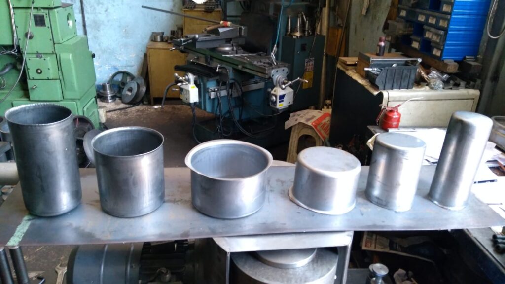
A deep drawing mold for sheet metal is specifically engineered to transform flat metal blanks into complex, three-dimensional shapes through controlled plastic deformation. The mold consists primarily of the punch, die, and blank holder, each playing a critical role in guiding and shaping the sheet metal during the drawing process.
Sheet metals vary widely in material type, thickness, ductility, and mechanical properties, so mold design must be tailored accordingly. Common materials used in deep drawing include low-carbon steel, aluminum alloys, stainless steel, copper, and brass, each posing unique challenges for forming and tooling.
The punch is the component that physically pushes the sheet metal into the die cavity, dictating the final shape of the part. Its geometry, surface finish, and material selection are crucial. Sharp or abrupt features on the punch can cause localized thinning or tearing of the metal, so edges are typically rounded with carefully calculated radii to promote smooth metal flow and reduce stress concentrations. The punch’s surface is highly polished and often coated to minimize friction and prevent metal adhesion, extending tool life and ensuring consistent part quality.
The die provides the counter surface against which the metal is drawn and supports the blank as it deforms. Its profile must complement the punch shape precisely, with a clearance that matches the sheet metal thickness and material characteristics. Too tight a clearance can increase friction and cause tearing, while too large a gap may result in wrinkling or loss of dimensional control. The die surface finish and hardness are also carefully controlled to reduce wear and maintain smooth forming conditions.
The blank holder applies pressure to the metal blank’s periphery to control material flow into the die cavity. Proper blank holder force prevents wrinkling caused by compressive stresses in the flange area while avoiding excessive force that could restrict metal flow and cause tearing. Adjustable blank holders, often hydraulically or pneumatically controlled, enable fine-tuning of pressure during the process to accommodate variations in material and part geometry.
Lubrication is essential in sheet metal deep drawing to reduce friction between the tooling and the blank, facilitating smoother metal flow and minimizing wear. The choice of lubricant depends on the sheet material, surface condition, and forming speed. Common lubricants include oils, waxes, or dry films specifically formulated for metal forming.
Material thickness and ductility are major factors in mold design. Thicker or less ductile sheets require larger clearances and more careful control of blank holder pressure to avoid defects. Conversely, thinner and more ductile sheets can be formed with tighter clearances and less force but may be prone to wrinkling without adequate blank holding.
Thermal management is generally less critical for typical sheet metal deep drawing than for stainless steel or high-strength alloys but can become important in high-speed or high-volume operations where heat buildup affects tool life and dimensional accuracy. Some advanced molds incorporate cooling channels or use materials with good thermal conductivity to manage temperature.
In summary, a deep drawing mold for sheet metal must balance precision in component design, material compatibility, and process parameters such as clearance, blank holder force, and lubrication to achieve efficient, defect-free forming. Properly designed molds extend tool life, reduce scrap, and enable the production of high-quality parts suitable for a wide range of industrial applications.
Deep drawing molds for sheet metal must be designed with careful consideration of how the metal flows during deformation to avoid common defects like wrinkling, tearing, and excessive thinning. The interaction between the punch, die, and blank holder creates complex stress and strain patterns in the sheet, so each component’s geometry and surface condition directly influence the quality and consistency of the formed parts. The punch radius, for instance, needs to be optimized to allow the metal to bend smoothly without causing sharp strain concentrations that lead to cracks. Similarly, the die radius and clearance must be matched to the material’s thickness and ductility to maintain proper metal flow and support.
Blank holder force is one of the most critical adjustable parameters in deep drawing molds. If the force is too low, the flange area of the sheet metal can buckle, creating wrinkles that degrade part appearance and function. If the force is too high, it restricts metal movement excessively, increasing tensile stress and causing premature tearing. Modern molds often use hydraulic or pneumatic blank holders to precisely control this force and adapt it in real time based on feedback from sensors measuring drawing force or material behavior.
Lubrication in sheet metal deep drawing is essential to reduce friction between the blank and tooling surfaces. Without proper lubrication, friction can increase dramatically, resulting in higher forming forces, greater tool wear, and surface defects such as scratches or galling. Selecting the right lubricant involves considering the sheet metal type, surface finish, and the drawing speed. For example, aluminum sheets may require different lubrication than steel or copper to achieve optimal flow and surface quality.
Material properties heavily influence mold design decisions. Highly ductile materials allow tighter clearances and can tolerate higher deformation without failure, while less ductile metals need larger clearances and gentler forming conditions to avoid cracking. Material anisotropy—directional differences in mechanical properties due to rolling or processing—also affects how the sheet metal behaves during drawing, necessitating adjustments in mold geometry or process parameters to compensate.
In some cases, deep drawing molds incorporate additional features such as draw beads—small raised elements on the die surface that intentionally restrict metal flow to control strain distribution and reduce wrinkling. These beads act like controlled friction zones, slowing the material movement in specific areas to balance metal flow and improve part uniformity. Their size, shape, and placement are carefully engineered based on the part geometry and material.
For complex shapes or thicker materials, multi-stage deep drawing may be employed, using a series of molds that progressively shape the blank closer to the final geometry. This staged approach reduces strain per operation, lowering the risk of defects and enabling the forming of deeper or more intricate parts than would be possible in a single draw. Between stages, intermediate operations such as trimming or annealing may be applied to optimize material properties and dimensional accuracy.
Maintenance of deep drawing molds for sheet metal is crucial to ensure consistent quality and tool longevity. Regular inspection for wear, cracks, or surface damage allows timely repairs and prevents sudden failures. Polishing mold surfaces restores smoothness, reducing friction and the likelihood of metal adhesion. Keeping molds clean and properly lubricated also helps maintain forming conditions and extends tool life.
Overall, deep drawing molds for sheet metal require a harmonious balance of precise tooling design, material understanding, process control, and maintenance. By managing these factors effectively, manufacturers can produce a wide range of high-quality sheet metal components efficiently, meeting the demands of industries like automotive, appliance manufacturing, aerospace, and packaging.
In addition to the fundamental design and operational considerations, advances in technology have further improved deep drawing mold performance for sheet metal forming. Computer-aided engineering (CAE) tools, especially finite element analysis (FEA), have become integral in mold design and process optimization. These simulations allow engineers to model how the sheet metal will behave under various forming conditions, predicting potential issues such as thinning, wrinkling, or tearing before physical trials. By iterating designs virtually, manufacturers save time and resources while achieving better part quality and tool longevity.
Another technological advancement is the incorporation of sensors and real-time monitoring systems in deep drawing presses. These systems can track parameters such as punch force, stroke position, and blank holder pressure, enabling immediate adjustments during the forming cycle. This closed-loop control helps maintain optimal conditions, compensating for material variability or tooling wear, which in turn reduces scrap rates and improves repeatability.
Material innovations have also impacted mold design and process settings. For example, the use of high-strength low-alloy (HSLA) steels or advanced aluminum alloys requires molds that can handle higher forces and more complex strain distributions. These materials offer advantages in weight reduction and strength but often have narrower forming windows, meaning the molds and processes must be finely tuned to prevent defects.
In response to environmental and economic pressures, there is a growing emphasis on sustainable manufacturing in deep drawing operations. This includes using longer-lasting tooling materials and coatings to minimize waste, optimizing lubricant use to reduce environmental impact, and recycling metal scraps generated during forming. Efficient mold designs that minimize scrap and energy consumption contribute to greener production practices.
Customization and modular tooling have become more prevalent as manufacturers face increasing demand for varied and complex parts in smaller production runs. Modular molds allow quick changeover of punches, dies, or blank holders, enabling flexible manufacturing without extensive downtime. This adaptability is particularly valuable in industries like automotive or electronics, where frequent design changes and tight delivery schedules are common.
Finally, operator training and process documentation are essential for maintaining consistent mold performance. Skilled technicians who understand the interplay between mold design, material behavior, and process parameters can better diagnose and resolve forming issues, ensuring high-quality output. Detailed process documentation supports repeatability and knowledge transfer, especially in high-volume or multi-shift production environments.
Altogether, the evolution of deep drawing molds for sheet metal reflects a blend of traditional mechanical design principles with cutting-edge simulation, monitoring, and material science advances. These integrated approaches enable manufacturers to meet the complex demands of modern production, delivering precise, reliable, and cost-effective sheet metal components across diverse industries.
Deep Drawing Mold Production
Deep drawing mold production is a complex and precise manufacturing process that involves designing, fabricating, assembling, and testing tooling components to shape sheet metal into desired three-dimensional parts. This process demands high accuracy, robust materials, and careful coordination between engineering and manufacturing teams to ensure that the final mold meets the performance, durability, and quality requirements of the intended application.
The production of a deep drawing mold typically begins with detailed design work, often using computer-aided design (CAD) software. Designers create a comprehensive model of the mold, including the punch, die, blank holder, and any additional features like draw beads or ejector systems. The design process involves selecting appropriate materials and surface treatments based on the sheet metal type and forming conditions, as well as calculating critical parameters such as clearances, radii, and blank holder force. Finite element analysis (FEA) and forming simulations are frequently employed to predict material flow, identify potential defects, and optimize mold geometry before fabrication.
Once the design is finalized, the production phase starts with the selection of high-quality tool steels or other suitable materials known for hardness, toughness, and wear resistance. These materials undergo processes such as heat treatment, hardening, and tempering to achieve the desired mechanical properties. The individual mold components are then precision machined using methods like CNC milling, grinding, and electrical discharge machining (EDM) to achieve tight tolerances and smooth surface finishes essential for reliable metal forming.
Surface finishing is a crucial step in mold production, as the quality of the mold’s contact surfaces greatly affects friction, metal flow, and part quality. Polishing and coating processes—such as chrome plating, nitriding, or physical vapor deposition (PVD)—are applied to enhance wear resistance and reduce adhesion or galling of the sheet metal to the tooling surfaces.
After machining and finishing, the mold components are assembled with precision alignment tools to ensure proper fit and function. This assembly phase may involve adjusting clearances, setting blank holder pressures, and verifying the movement and interaction of all parts. Some molds incorporate adjustable or modular components to allow fine-tuning during trial runs or future maintenance.
Trial runs or test drawings are conducted to validate the mold’s performance. These tests involve forming sample blanks under controlled conditions to check for dimensional accuracy, surface quality, and the absence of defects such as wrinkles, tears, or excessive thinning. Feedback from these trials may necessitate minor adjustments to the mold or process parameters to achieve optimal results.
Finally, routine maintenance plans are established to sustain mold performance over its service life. This includes regular inspections, cleaning, polishing, and timely repairs to address wear or damage. Proper maintenance is essential to minimize downtime and maintain consistent part quality in production.
Overall, deep drawing mold production is a multidisciplinary effort combining design expertise, precision manufacturing, surface engineering, and process validation. Success in this process leads to robust molds capable of producing complex sheet metal components efficiently, with high accuracy and repeatability.
Deep drawing mold production is a highly detailed and iterative process that demands close collaboration between design engineers, toolmakers, and production specialists. After initial design and material selection, the manufacturing of mold components involves precision machining techniques such as CNC milling and grinding to create shapes and surfaces with tolerances often measured in microns. For intricate features or hard-to-machine areas, electrical discharge machining (EDM) is commonly used to achieve sharp corners and fine details that are critical for accurate metal forming.
Surface treatment is a vital step that directly impacts the mold’s performance and lifespan. Polishing the mold surfaces to a mirror finish reduces friction during the drawing process and minimizes the risk of surface defects on the formed parts. Additional coatings or surface hardening treatments enhance wear resistance and help prevent galling, especially when working with tough materials like stainless steel or aluminum alloys. The choice of surface treatment is often dictated by the expected production volume, material type, and specific forming challenges.
Once components are machined and treated, assembly must ensure precise alignment and fit. Even slight misalignments can cause uneven metal flow, leading to defects such as wrinkling or tearing. Adjustable features, like hydraulic blank holders or modular die inserts, are sometimes integrated into the mold to allow fine-tuning during initial setup and production runs. This adjustability is crucial for accommodating variations in material batches or subtle changes in part design without needing complete remanufacture of tooling.
Trial runs form a critical feedback loop in mold production. Producing sample parts under realistic conditions provides valuable data on how the mold performs in practice. Measurements of part dimensions, surface finish, and metal thickness distribution help identify issues that may not have been fully predicted during design. Based on these results, engineers can modify punch or die radii, adjust blank holder force, or tweak lubrication strategies to improve forming quality. This iterative testing ensures that the mold consistently produces parts that meet specification before full-scale production begins.
In addition to initial production, mold maintenance planning is essential for sustaining performance and minimizing downtime. Tool wear, surface degradation, or mechanical stresses can gradually affect mold accuracy and part quality. Scheduled maintenance activities such as surface repolishing, re-coating, or component replacement extend mold life and reduce costly unplanned repairs. Modern production environments increasingly rely on condition monitoring and data analytics to predict when maintenance is needed, optimizing tool utilization and avoiding unexpected failures.
Advancements in manufacturing technologies, such as additive manufacturing for mold inserts or advanced coatings, are also beginning to influence deep drawing mold production. These innovations offer opportunities for more complex geometries, faster prototyping, and enhanced tool performance, helping manufacturers meet evolving demands for shorter lead times and higher quality parts.
In summary, producing deep drawing molds is a meticulous process that combines advanced design, precision machining, specialized surface engineering, careful assembly, rigorous testing, and proactive maintenance. Mastery of each stage is vital for creating molds that deliver reliable, high-quality sheet metal components efficiently and cost-effectively across diverse industrial applications.
Continuing the discussion on deep drawing mold production, the integration of digital technologies and Industry 4.0 principles is increasingly shaping modern mold manufacturing. Digital twins—virtual replicas of the physical mold—allow engineers to simulate not only the forming process but also the mold’s behavior under real production conditions, such as thermal expansion, mechanical stresses, and wear patterns. This predictive capability enables proactive design improvements and maintenance scheduling, reducing trial-and-error cycles and enhancing overall efficiency.
Automation in mold production is also advancing, with robotic machining, automated inspection systems, and precision assembly robots helping to improve consistency and reduce human error. Automated measurement techniques like coordinate measuring machines (CMM) and 3D scanning verify component dimensions against design specifications quickly and accurately, ensuring that every mold component meets the required tolerances before assembly.
Material science innovations contribute to better mold performance and durability. Development of new tool steels with superior toughness and wear resistance, as well as advanced coatings like diamond-like carbon (DLC) or ceramic layers, help molds withstand increasingly demanding forming conditions. These materials reduce downtime and extend the operational life of molds, particularly in high-volume or high-strength material applications.
Environmental considerations are also influencing mold production practices. Manufacturers are adopting eco-friendly machining fluids, recycling scrap materials, and optimizing processes to minimize energy consumption. Sustainable manufacturing practices help reduce the ecological footprint of mold production and align with corporate social responsibility goals.
Training and skill development remain essential components of successful deep drawing mold production. As mold designs become more complex and technologies more sophisticated, investing in highly skilled engineers and technicians ensures proper interpretation of design data, precise machining, and effective troubleshooting during trials and production. Continuous education on emerging tools and methods keeps teams adaptable and competitive.
Looking forward, the combination of advanced simulation, automation, smart materials, and sustainability will continue to push the boundaries of what is possible in deep drawing mold production. These trends aim to deliver molds that not only meet stringent quality and durability requirements but also adapt rapidly to changing product designs and production volumes, supporting agile manufacturing environments across industries such as automotive, aerospace, electronics, and consumer goods.
In essence, deep drawing mold production is evolving into a high-tech, interdisciplinary field where precision engineering meets digital innovation, material science, and sustainable manufacturing—all working together to produce reliable tooling that underpins efficient, high-quality sheet metal forming.
Deep Drawing Mold Manufacturer
A deep drawing mold manufacturer specializes in designing, fabricating, and supplying molds used in the deep drawing process to form sheet metal into complex shapes. These manufacturers play a critical role in the metal forming industry by providing high-precision tooling that meets the demanding requirements of various sectors such as automotive, aerospace, appliances, electronics, and packaging. Their expertise covers a wide range of activities—from initial concept and design consultation to final production, testing, and ongoing mold maintenance services.
Reputable deep drawing mold manufacturers invest heavily in advanced design and manufacturing technologies. They use sophisticated CAD and CAE software to create accurate mold models and simulate the metal forming process, enabling optimization of tool geometry and process parameters before physical production begins. This simulation-driven approach reduces lead times, minimizes trial-and-error, and enhances the reliability and quality of the final tooling.
Manufacturing capabilities include precision CNC machining, EDM (Electrical Discharge Machining), grinding, polishing, and various surface treatment technologies such as nitriding, chrome plating, or PVD coatings. These processes ensure molds achieve the tight tolerances, smooth finishes, and durability required for consistent, high-quality sheet metal forming. Many manufacturers also offer modular tooling solutions and adjustable components to provide flexibility and facilitate easier maintenance or part variation.
Quality control is a cornerstone for deep drawing mold manufacturers. They implement rigorous inspection protocols using tools like coordinate measuring machines (CMM), 3D scanners, and surface roughness testers to verify every critical dimension and surface characteristic. Comprehensive testing through trial runs ensures that molds produce parts within specified tolerances without defects, enabling reliable mass production.
Additionally, leading manufacturers provide support services including mold maintenance, repair, and refurbishment to extend tool life and reduce production downtime. Some also offer training for client personnel on mold operation and upkeep, further ensuring optimal performance.
Deep drawing mold manufacturers vary in scale from specialized boutique shops focusing on highly customized, low-volume tooling to large industrial suppliers capable of producing molds for high-volume automotive or appliance production lines. Many emphasize close collaboration with clients, adapting designs to specific material properties, part geometries, and production conditions.
In recent years, manufacturers are embracing Industry 4.0 technologies such as digital twins, real-time monitoring, and predictive maintenance to enhance mold performance and customer service. They also prioritize sustainable manufacturing practices, including efficient resource use, eco-friendly coatings and lubricants, and recycling of scrap materials.
Choosing the right deep drawing mold manufacturer is critical for product success. Factors such as technical expertise, manufacturing capabilities, quality assurance processes, delivery timelines, and after-sales support all contribute to selecting a partner that can reliably deliver tooling that meets both performance and cost objectives.
In summary, deep drawing mold manufacturers are specialized engineering and manufacturing firms that provide the essential tooling enabling efficient, precise, and repeatable sheet metal forming. Their combination of advanced design, precision fabrication, quality control, and service support forms the backbone of successful deep drawing operations across a wide range of industries.
Deep drawing mold manufacturers typically begin their engagement by thoroughly understanding the customer’s specific requirements, including the type of sheet metal, part complexity, production volume, and quality standards. This initial collaboration is essential to tailor the mold design and materials to the unique demands of the application. Manufacturers often work closely with design engineers and process planners to integrate considerations such as blank size, material properties, lubrication needs, and forming sequence into the tooling design.
The design phase is heavily supported by advanced software tools that allow virtual prototyping and process simulation, helping to identify potential forming issues before manufacturing begins. This reduces costly physical trials and shortens development cycles. The use of finite element analysis (FEA) enables manufacturers to predict metal flow, stress distribution, and potential defects, allowing for iterative improvements in mold geometry, blank holder force settings, and clearance dimensions.
Once the design is validated, the manufacturing stage employs precision machining technologies capable of achieving extremely tight tolerances. CNC machining centers provide high accuracy and repeatability, while EDM processes enable the creation of intricate features and fine details that are difficult to machine conventionally. Surface finishing operations are crucial to ensure the mold’s contact surfaces are smooth and hardened to resist wear and galling during the forming process. Many manufacturers apply advanced coatings such as PVD or nitriding to enhance durability and reduce friction.
After machining and finishing, components are assembled with meticulous care to ensure perfect alignment and proper function. Adjustable blank holders and modular die inserts are often incorporated to allow for flexibility and easier maintenance. This assembly stage is followed by trial runs using actual sheet metal blanks to test the mold’s performance under real forming conditions. The results of these trials guide any necessary fine-tuning or adjustments to optimize part quality and process efficiency.
Manufacturers also emphasize post-delivery support, including routine maintenance, troubleshooting, and refurbishing services. Because deep drawing molds are subject to wear and deformation over time, ongoing care is critical to maintaining consistent production quality and avoiding unexpected downtime. Many manufacturers provide training to customer teams on best practices for mold operation and maintenance, ensuring longer tool life and better overall performance.
In competitive industries where rapid product development and high-quality output are essential, deep drawing mold manufacturers continuously invest in modernizing their equipment, enhancing process automation, and adopting digital manufacturing techniques. This focus on innovation helps them reduce lead times, improve precision, and deliver molds that meet increasingly complex design requirements.
Furthermore, manufacturers are increasingly committed to sustainable practices, optimizing resource utilization, minimizing waste, and implementing environmentally friendly processes wherever possible. This not only benefits the environment but also aligns with customer expectations for responsible manufacturing.
Ultimately, a deep drawing mold manufacturer serves as a vital partner throughout the product lifecycle, from initial concept through production and maintenance. Their expertise and capabilities directly impact the efficiency, quality, and cost-effectiveness of sheet metal forming operations, making them indispensable to industries relying on precision metal components.
Deep drawing mold manufacturers also play a key role in driving innovation within the sheet metal forming industry. By staying at the forefront of material science developments, tooling technology, and process optimization, they enable manufacturers to push the boundaries of what can be achieved with deep drawing. For instance, as lightweight materials like advanced high-strength steels and aluminum alloys become more prevalent in automotive and aerospace applications, mold makers adapt their designs and surface treatments to accommodate these materials’ unique forming characteristics and prevent defects.
Customization and flexibility are additional strengths of top-tier mold manufacturers. They often offer modular tooling solutions, allowing for quicker changes in punch or die configurations to accommodate different part geometries or revisions without the need to produce entirely new molds. This flexibility is especially valuable in industries with rapid product cycles or where small batch sizes are common.
Moreover, manufacturers increasingly incorporate smart technologies into molds and forming equipment. Sensors embedded within molds can monitor parameters such as temperature, pressure, and strain in real time, providing valuable data for process control and predictive maintenance. This integration of smart tooling contributes to reducing scrap rates, optimizing cycle times, and extending mold life.
Global deep drawing mold manufacturers also have to balance cost, quality, and lead times while navigating supply chain complexities. Many invest in robust project management practices to ensure timely delivery without compromising precision or durability. They often collaborate with local and international suppliers for materials, coatings, and specialized machining services to maintain competitiveness and responsiveness.
In addition, quality certifications such as ISO 9001 and compliance with industry-specific standards reinforce the reliability of manufacturing processes and final products. These certifications give customers confidence that the molds produced will meet stringent quality requirements and perform consistently in demanding production environments.
Ultimately, the success of a deep drawing mold manufacturer hinges on their ability to combine technical expertise, advanced manufacturing capabilities, responsive customer service, and a commitment to continuous improvement. Their role is crucial not only in providing the physical tooling but also in supporting the overall sheet metal forming process, enabling manufacturers to achieve efficient production of high-quality parts that meet the evolving needs of modern industries.
Deep Drawing Mold Types
Deep drawing molds come in various types, each designed to suit different part geometries, materials, and production requirements. The main types include:
1. Simple Deep Drawing Mold:
This basic type consists of a punch, die, and blank holder. It’s used for forming straightforward cup-shaped parts where the geometry doesn’t require complex shaping or multiple forming stages.
2. Compound Deep Drawing Mold:
In compound molds, multiple operations like drawing and blanking are performed in a single press stroke. This increases efficiency by combining processes, often used for high-volume production of simpler parts.
3. Progressive Deep Drawing Mold:
Progressive molds perform multiple forming stages in a sequence as the sheet metal strip moves through several stations. Each station progressively shapes the part closer to the final geometry. These molds are suitable for complex parts and high-volume manufacturing.
4. Multiple Deep Drawing Mold:
Multiple molds produce several identical parts simultaneously from a single blank. This type increases productivity and is often used in mass production environments.
5. Hydraulically Assisted Deep Drawing Mold:
This mold type incorporates hydraulic systems to precisely control blank holder force or punch movement. It is used for forming complex shapes or materials with limited ductility, allowing better control of metal flow and reducing defects.
6. Rubber Pad Deep Drawing Mold:
Instead of a rigid blank holder, this mold uses a rubber pad to apply uniform pressure over the blank. It is typically used for shallow draws or when working with fragile materials, as the flexible pad reduces the risk of tearing.
7. Stretch Drawing Mold:
Stretch drawing molds use simultaneous stretching and drawing forces to form parts with high drawing ratios or complex shapes. This method reduces wrinkling and improves dimensional accuracy for deep or intricate components.
Each mold type is selected based on factors such as part complexity, material type, production volume, and desired surface finish. Understanding these different mold types helps manufacturers optimize forming processes and achieve the best balance of quality, efficiency, and cost.
Deep drawing mold types vary not only by design but also by their specific applications and the complexity of parts they produce. For simpler shapes, a basic deep drawing mold with a punch, die, and blank holder is often sufficient. However, when forming more complex or deeper components, more advanced mold types like progressive or compound molds come into play. Progressive molds are particularly useful for parts requiring multiple shaping stages, as the metal strip advances through successive stations, each performing a specific forming operation. This approach allows for the gradual transformation of the sheet metal, reducing the risk of defects such as tearing or wrinkling.
Compound molds increase productivity by combining processes like drawing and blanking into a single press stroke, minimizing cycle times. They are ideal for high-volume production runs where efficiency is critical, though they may be less flexible when part designs change frequently. Multiple molds, which produce several parts simultaneously from one blank, further enhance output rates and are widely used in mass manufacturing industries.
Hydraulically assisted molds offer precision control over forming forces, which is particularly advantageous when working with materials that have low ductility or when forming complex geometries that demand careful metal flow management. The use of hydraulics allows for adjustments during the forming cycle, reducing defects and improving part consistency.
Rubber pad molds differ from traditional rigid tooling by using a flexible rubber element to apply pressure evenly across the blank. This technique is often employed for shallow drawing applications or materials that are prone to cracking, as the compliant pad can conform to the sheet and distribute forces gently, reducing stress concentrations.
Stretch drawing molds utilize both tensile and compressive forces to achieve parts with high drawing ratios or intricate shapes that are difficult to form using conventional methods. By stretching the material during drawing, these molds help avoid wrinkles and maintain dimensional accuracy, making them suitable for complex automotive or aerospace components.
Manufacturers choose the appropriate mold type based on a careful assessment of part geometry, material properties, production volume, and quality requirements. In many cases, molds are customized or combined with additional features such as draw beads, air cushions, or ejector systems to optimize metal flow and part ejection. The selection and design of the mold significantly influence the efficiency, cost, and success of the deep drawing process, underscoring the importance of matching mold type to the specific demands of the application.
Beyond the fundamental types, deep drawing molds often incorporate specialized design features tailored to overcome specific forming challenges or improve production efficiency. For example, draw beads—small raised features within the die or blank holder—are used to control the flow of the sheet metal, preventing excessive thinning or wrinkling by adding localized resistance during drawing. The placement and shape of these beads are critical and carefully engineered based on material behavior and part geometry.
Another important aspect is the integration of ejector systems in molds, which facilitate the smooth removal of formed parts after each cycle. Proper ejection is essential to maintain part integrity and prevent damage or deformation during handling. Ejectors can be mechanical pins, air blasts, or hydraulic pushers depending on the mold design and part complexity.
Air cushion or pneumatic systems are also sometimes employed in molds to assist in blank holding or to apply variable pressure dynamically during the forming process. This helps in managing metal flow more precisely, especially for parts with varying thicknesses or complex shapes, and can reduce tool wear by distributing forces more evenly.
Modular deep drawing molds are gaining popularity as well, allowing manufacturers to quickly swap out inserts or components to accommodate different part designs or to perform maintenance without disassembling the entire mold. This modularity enhances flexibility, reduces downtime, and lowers tooling costs over the product lifecycle.
Material considerations heavily influence mold design and type selection. For instance, forming stainless steel or high-strength alloys often requires molds with enhanced durability, surface coatings, and sometimes hydraulic assistance to handle the increased forming forces and reduce wear. Conversely, softer materials like aluminum or brass might allow for simpler mold designs but still demand careful control of friction and blank holding pressure to avoid defects.
In high-volume production environments, the choice of mold type and features directly impacts cycle time, maintenance frequency, and overall cost efficiency. Progressive molds with automation capabilities can dramatically increase throughput but require substantial upfront investment and careful planning. Simpler molds may be more cost-effective for low to medium volume runs or prototyping.
Overall, the variety of deep drawing mold types and their customizable features reflect the diverse needs of sheet metal forming applications. Selecting or designing the right mold involves a comprehensive understanding of material behavior, part complexity, production goals, and cost constraints. By leveraging advanced design tools and manufacturing techniques, mold makers continue to innovate and optimize deep drawing processes to meet evolving industrial demands.
Deep Drawing Mold Materials
Deep drawing mold materials are carefully selected to withstand the high stresses, wear, and friction involved in forming sheet metal, while maintaining precision and durability over repeated use. The choice of material directly impacts the mold’s performance, lifespan, and the quality of the finished parts.
Tool steels are the most commonly used materials for deep drawing molds due to their excellent hardness, toughness, and wear resistance. High-carbon chromium steels such as AISI D2 and AISI O1 are popular choices. D2 steel, with its high chromium content, offers superior wear resistance and hardness after heat treatment, making it ideal for molds used with abrasive or hard sheet metals. O1 steel, known for its good machinability and toughness, is suitable for molds that require complex machining but moderate wear resistance.
Another frequently used tool steel is AISI H13, a hot work steel valued for its ability to retain hardness at elevated temperatures. This makes H13 suitable for deep drawing molds that experience high thermal loads, such as in high-speed or hot forming applications. It also offers good toughness and resistance to thermal fatigue.
For extremely demanding applications, powder metallurgy (PM) steels provide enhanced uniformity and toughness compared to conventionally produced steels. PM steels like CPM S7 combine high wear resistance with excellent impact strength, which is beneficial for molds subjected to cyclic loading and shock.
In addition to tool steels, surface treatments and coatings play a crucial role in extending mold life. Processes like nitriding introduce a hard, wear-resistant surface layer without compromising the toughness of the core material. Physical vapor deposition (PVD) coatings such as titanium nitride (TiN), chromium nitride (CrN), or diamond-like carbon (DLC) provide low friction, high hardness, and corrosion resistance, reducing galling and adhesive wear during metal forming.
Carbide inserts or plates may be incorporated in certain mold areas exposed to extreme wear to enhance durability further. Carbide offers superior hardness but is more brittle, so it is typically used in localized sections rather than entire molds.
For less demanding applications or prototypes, hardened tool steels with lower hardness or even some alloy steels may be used to reduce costs and machining difficulty. However, these materials may wear faster and require more frequent maintenance.
Non-metallic materials like engineering plastics or elastomers are occasionally employed in components like blank holders or rubber pads within molds, especially where flexibility or shock absorption is needed. However, the primary forming surfaces are almost always metal due to the forces involved.
Overall, the selection of deep drawing mold materials balances hardness, toughness, machinability, thermal stability, and cost. This balance ensures molds maintain dimensional accuracy and surface quality throughout their operational life while withstanding the demanding conditions of sheet metal forming. Manufacturers often customize material choices based on the specific sheet metal being formed, production volume, and complexity of the parts.
Deep drawing mold materials must not only provide the necessary hardness and wear resistance but also possess sufficient toughness to withstand repeated impacts and stresses during the forming cycle. The cyclic loading that molds experience can cause fatigue cracks if the material is too brittle, so a careful balance between hardness and toughness is essential. This is why many tool steels used for molds undergo precise heat treatment processes—such as quenching and tempering—to optimize these properties.
Thermal stability is another critical consideration because molds can heat up during high-speed or continuous forming operations. Materials like H13 hot work steel maintain their mechanical properties at elevated temperatures, reducing the risk of thermal distortion or softening that would degrade forming accuracy. Additionally, thermal fatigue resistance helps prevent surface cracking caused by repeated heating and cooling cycles.
Machinability is important during mold fabrication, as more complex or intricate mold features require precision machining and sometimes electrical discharge machining (EDM). Some high-hardness steels are difficult to machine, leading manufacturers to choose materials that balance ease of manufacture with final performance requirements. Powder metallurgy steels, while offering superior performance, also require specialized machining techniques and can be more expensive.
Surface coatings and treatments significantly enhance the performance of the base material by reducing friction between the mold and the sheet metal, minimizing adhesive wear, and protecting against corrosion. Low-friction coatings such as diamond-like carbon (DLC) reduce the tendency for metal to stick to the mold surfaces, which can cause defects in the drawn parts. These coatings also help in processing materials that are prone to galling, such as stainless steel or aluminum alloys.
In some cases, manufacturers may employ composite mold designs, combining different materials in specific areas of the mold to optimize performance. For example, a mold might use a tougher steel core for structural strength while applying a hard, wear-resistant coating or insert on critical surfaces that contact the sheet metal directly. This targeted approach improves overall mold durability while managing costs.
Environmental factors also influence material selection. Molds used in humid or corrosive environments benefit from corrosion-resistant materials or coatings to prevent surface degradation that could impact forming quality and tool life. Additionally, some manufacturers adopt environmentally friendly coatings that reduce hazardous waste and comply with regulations.
Ultimately, the choice of deep drawing mold materials is a highly engineered decision that takes into account the part design, sheet metal type, forming process parameters, production volume, and budget constraints. The goal is to produce molds that deliver consistent, high-quality parts while minimizing downtime and maintenance costs throughout the tool’s lifecycle. Advances in metallurgy and surface engineering continue to expand the options available, enabling manufacturers to tackle increasingly complex and demanding forming challenges with confidence.
Advancements in material technology continue to drive improvements in deep drawing mold performance. New high-performance tool steels and coatings enable molds to handle tougher materials, faster production speeds, and more complex geometries without sacrificing durability or part quality. For example, developments in powder metallurgy (PM) steels offer higher uniformity in microstructure, leading to improved toughness and wear resistance compared to conventional steels. These materials allow molds to better withstand the repeated stresses and abrasive contact typical in deep drawing processes.
Surface engineering techniques have also evolved, with multilayer coatings and novel deposition methods providing enhanced hardness, lower friction coefficients, and greater resistance to heat and corrosion. Some modern coatings combine properties like self-lubrication and anti-adhesion, which reduce the need for external lubricants and improve process cleanliness. This not only extends mold life but can also contribute to higher forming speeds and reduced energy consumption.
In addition to material properties, mold design increasingly incorporates sensor integration to monitor wear and performance in real time. Embedded sensors can track temperature, pressure, and strain during operation, enabling predictive maintenance and minimizing unexpected mold failures. This trend towards “smart molds” is supported by advancements in material science that allow sensor embedding without compromising structural integrity or performance.
Sustainability considerations are influencing material choices as well. Manufacturers seek materials and coatings that reduce environmental impact through longer tool life, reduced waste, and eco-friendly processing. Recycling of mold materials at end of life, along with the use of non-toxic coatings, aligns with broader industry moves toward greener manufacturing practices.
Ultimately, the ongoing innovation in deep drawing mold materials enables manufacturers to meet the growing demands of modern industries for higher precision, faster throughput, and more complex parts. By leveraging advanced steels, coatings, and smart monitoring technologies, mold makers can deliver tooling solutions that optimize performance, reduce costs, and support sustainable production goals. This continuous evolution ensures that deep drawing remains a versatile and efficient metal forming process capable of addressing future manufacturing challenges.
Deep Drawing Mold Construction
Deep drawing mold construction involves assembling several precisely engineered components designed to work together to shape sheet metal into desired forms through controlled deformation. The construction must ensure durability, accuracy, ease of maintenance, and smooth operation during the forming process.
At the core of the mold is the die, a hardened steel block with a cavity shaped to the final inner contour of the drawn part. The die acts as the female counterpart in the forming operation, providing a rigid surface against which the metal is pressed. The die surface is usually polished and often coated or treated to enhance wear resistance and reduce friction, minimizing metal sticking and damage.
Opposite the die is the punch, the male component that physically presses the sheet metal into the die cavity. The punch is carefully machined to match the outer geometry of the part and is also hardened and finished to withstand repeated impact and sliding contact. The punch must maintain precise alignment with the die to ensure uniform material flow and prevent defects.
Surrounding the punch and die is the blank holder or hold-down ring, which applies controlled pressure to the sheet metal blank to prevent wrinkling during the drawing process. The blank holder pressure must be carefully balanced—too much pressure can cause tearing or excessive thinning, while too little allows wrinkles to form. Blank holders are often adjustable to accommodate different materials and part geometries.
The mold assembly is typically mounted on a press slide or platen, which moves the punch downward during forming. Guide posts and bushings maintain alignment between the punch and die throughout the stroke, ensuring consistent and repeatable forming conditions. The mold frame provides structural support to withstand the high forming forces and maintain precise component positioning.
Additional features in mold construction may include ejector systems that push the formed part out of the die cavity after drawing, preventing damage during removal. Ejectors can be mechanical pins, air blasts, or hydraulic devices depending on part shape and production speed.
Cooling channels may be integrated into the die and punch to manage temperatures during high-speed production, reducing thermal distortion and extending tool life. Lubrication systems can also be incorporated to apply forming oils or lubricants uniformly, reducing friction and wear.
In more complex molds, modular construction is common, allowing easy replacement or adjustment of punch, die, or blank holder components without disassembling the entire mold. This modularity enhances maintenance efficiency and provides flexibility for part design changes.
The construction process involves precise machining, heat treatment, assembly, and testing phases. Each component undergoes quality checks to verify dimensional accuracy and surface finish. After assembly, trial runs with actual sheet metal blanks validate the mold’s performance, and adjustments are made to optimize pressure settings, alignment, and ejection mechanisms.
Overall, deep drawing mold construction requires careful integration of mechanical design, material selection, and precision manufacturing to produce durable, accurate, and efficient tooling that ensures high-quality sheet metal forming.
In addition to the core components, deep drawing mold construction often incorporates engineering refinements that improve performance and increase mold longevity. For example, draw beads—small raised features or grooves located in the blank holder or die—are commonly used to control the metal flow during drawing. These beads resist the radial movement of the sheet, helping to distribute strain more evenly and preventing defects such as wrinkles, tears, or uneven wall thickness. The placement, shape, and depth of draw beads are precisely calculated based on the material’s mechanical properties and the part geometry.
Another important element in mold construction is the corner radii of both the punch and die. These radii must be large enough to allow smooth metal flow and reduce the risk of cracking or excessive thinning at the corners. If the radii are too sharp, the material is more likely to tear under stress; if too large, the final part may not meet dimensional specifications. The optimal radii are determined based on factors such as sheet thickness, material ductility, and the depth of draw.
The clearance between the punch and die is another critical consideration in mold construction. This gap is slightly larger than the sheet thickness and must be uniform around the entire perimeter. Too little clearance results in excessive friction, tearing, or galling; too much clearance leads to poor dimensional accuracy and possible wrinkling. The clearance is customized depending on the type of material, its thickness, and the specific draw ratio.
In high-volume or automated production lines, deep drawing molds may be fitted with sensors and monitoring devices that track variables such as force, position, temperature, and vibration. These sensors enable real-time diagnostics and predictive maintenance, allowing operators to identify wear, misalignment, or overheating before they lead to part defects or tool failure. This capability is especially valuable in tight-tolerance industries like automotive, aerospace, and medical device manufacturing, where consistency and uptime are critical.
Mold construction also considers serviceability and modularity. Interchangeable inserts or segmented mold elements allow damaged or worn sections to be replaced without scrapping the entire tool. For example, the die cavity or punch face can be made from separate inserts that bolt into the main mold body. This approach saves cost and reduces downtime during maintenance or reconfiguration.
Alignment between the punch and die is maintained not only by guide pillars but also by precision-ground plates and bushings that ensure repeatable positioning. In some designs, cam units or lifters are added to assist in forming features like side walls or re-entrant shapes, expanding the mold’s forming capabilities beyond simple axisymmetric cups or cylinders.
The final phase of mold construction involves trial forming, fine-tuning, and validation. The mold is tested using the actual sheet metal and press conditions to ensure that it performs as expected. Forming simulations may be used in the design phase to predict how the metal will behave and guide the construction details. During tryout, adjustments may be made to the blank holder force, punch speed, lubricant type, or die radii to eliminate wrinkles, cracks, or springback.
Ultimately, the construction of a deep drawing mold is a highly detailed and precise engineering process that synthesizes knowledge of materials, mechanics, machining, and forming behavior. The quality of mold construction directly influences product quality, cycle time, tool longevity, and production economics, making it one of the most critical elements in any sheet metal forming operation.
Deep Drawing Mold Components
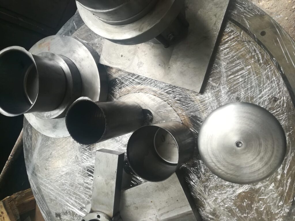
Deep drawing mold components are meticulously designed and precisely manufactured to work together under high pressure and stress, enabling the controlled transformation of flat sheet metal into deep, hollow shapes. Each component has a specific function in managing the metal flow, maintaining part geometry, and ensuring process reliability. The major components include the punch, die, blank holder, guide system, ejector system, and various auxiliary features that enhance performance or support specialized forming requirements.
The punch is the male part of the mold that descends to push the metal sheet into the die cavity. It is made of hardened tool steel or powder metallurgy alloys to resist deformation and wear. The punch must maintain dimensional accuracy and surface smoothness to ensure that the inner surfaces of the formed part are free from defects. Its shape defines the interior geometry of the final part, and its edges and corners are often radiused to facilitate smooth material flow.
The die is the female cavity that receives the sheet metal as it is pushed down by the punch. It is generally made from materials similar to the punch but may include hardened inserts in high-wear areas. The die controls the outer contour of the part and resists the vertical force applied during forming. The edges of the die cavity also include radii to help the sheet metal flow without tearing.
The blank holder, or hold-down ring, clamps the sheet metal blank around its edges to prevent it from wrinkling as it is drawn into the die. It works in conjunction with the punch and die, applying a specific force that can be adjusted depending on the material type, thickness, and part design. This force is critical—it must be strong enough to restrain the material but not so high that it causes thinning or tearing.
The guide system, typically composed of guide posts and bushings, maintains perfect alignment between the punch and the die throughout the press stroke. Any misalignment can result in defective parts, excessive tool wear, or damage to the mold components. These guides are precision-machined and hardened to ensure long service life and stable operation even under high loads.
The ejector system removes the finished part from the die after forming. Ejectors can be spring-loaded pins, pneumatic systems, or hydraulic lifters, depending on the size and shape of the part and the required cycle time. Proper ejection is essential to prevent part damage and allow for smooth, uninterrupted production.
Draw beads are sometimes integrated into the blank holder or die surfaces. These small, raised features increase resistance to metal flow in localized areas, helping to manage how the material stretches and moves into the die. Draw beads are essential for parts with complex shapes or variable draw depths and can be finely tuned to eliminate wrinkles or uneven wall thickness.
Shoulder radii and die entry radii are geometrically critical surfaces that influence how the material flows around corners and into the cavity. These radii must be large enough to prevent sharp bends, which could lead to cracking, but also small enough to preserve part definition.
Lubrication channels or systems may also be included in the mold design to ensure consistent application of forming lubricants. These reduce friction between the sheet metal and tooling, thereby lowering the risk of galling and improving surface finish.
Cooling channels are sometimes integrated into the mold base or die block to manage temperature during high-speed or high-volume production. Controlling thermal expansion helps maintain tight tolerances and prevents warping of the tool or the parts.
In some advanced tooling setups, sensors and monitoring devices are built into the mold to track pressure, position, or temperature in real time. These sensors can detect abnormalities early and support automated quality control or predictive maintenance systems.
Each of these components must be precisely designed and manufactured to work in harmony. The correct function of one depends heavily on the accuracy and condition of the others. For instance, insufficient guide precision can lead to uneven punch entry, even if the punch and die are perfectly shaped. Likewise, improper blank holder pressure can ruin the forming process, regardless of the quality of the punch and die.
In high-quality deep drawing operations, the integration and fine-tuning of all these components define the success of the entire forming process, affecting product quality, tooling life, and production efficiency.
Beyond the main components, deep drawing molds often include various additional elements that contribute to optimized forming, ease of maintenance, and adaptability. For example, modular inserts can be installed within the die or punch, allowing quick replacement of high-wear sections without remanufacturing the entire mold. This modularity reduces downtime and cost, especially in high-volume production where tool wear is a significant concern.
The blank holder force system may include springs, hydraulic cylinders, or pneumatic actuators to provide precise and adjustable pressure. In some advanced molds, the blank holder pressure can be varied dynamically during the forming cycle, allowing better control over metal flow and minimizing defects such as wrinkling or tearing. These dynamic systems require additional control components but can significantly improve part quality and expand the range of materials and geometries that can be formed.
Guide systems are also designed to handle the high lateral and vertical forces generated during forming. Hardened guide pillars, bushings, and alignment keys ensure that the punch and die maintain perfect registration, preventing uneven wear and maintaining consistent part dimensions over long production runs. Lubrication of guide components is essential to reduce friction and prolong mold life.
Ejector systems vary in complexity from simple mechanical pins to sophisticated air or hydraulic ejection mechanisms. Proper ejection avoids damage to the formed part and prevents sticking, which could cause production delays or defects. The ejector timing is carefully coordinated with the press cycle, and in some cases, multiple ejectors operate in sequence to remove complex parts safely.
Some deep drawing molds incorporate sensors embedded within the tooling to monitor parameters like punch force, temperature, and position in real-time. This smart tooling capability enables predictive maintenance, reducing unexpected failures and improving overall process control. Data collected from these sensors can be fed into production monitoring systems, allowing operators to detect wear patterns or anomalies and adjust process parameters proactively.
Cooling channels, often machined into the die and punch, help dissipate heat generated during high-speed or continuous production runs. Maintaining a stable temperature in the mold prevents thermal expansion that could lead to dimensional inaccuracies or premature tool wear. Cooling is especially important when forming materials that generate significant heat due to friction or deformation resistance, such as stainless steel or high-strength alloys.
Surface treatments and coatings on mold components play a vital role in reducing friction and wear. Coatings like titanium nitride, chromium nitride, or diamond-like carbon lower adhesion between the sheet metal and the tool, reducing galling and extending mold life. These coatings also help achieve smoother surface finishes on the final parts and reduce the need for excessive lubrication.
The integration of all these components into a cohesive deep drawing mold requires careful engineering, precision machining, and thorough testing. Each component’s design and material selection are optimized to withstand the high mechanical and thermal stresses encountered during the forming process. The final assembled mold undergoes tryout and fine adjustments to ensure that all parts function harmoniously, producing parts with consistent quality and minimal defects.
In summary, the components of a deep drawing mold—from punch and die to blank holder, guides, ejectors, and auxiliary systems—work together in a highly coordinated manner. Their precise construction, material selection, and maintenance are essential to achieving efficient, high-quality deep drawing operations that meet the demanding requirements of modern manufacturing.
In addition to the fundamental components, the design of deep drawing molds often incorporates specialized features to address particular challenges associated with complex part geometries, varying material behaviors, and production demands. For example, the inclusion of recessed areas or undercuts within the mold requires more intricate tooling elements such as lifters, cams, or segmented punches that move independently to release the part after forming without damage. These mechanisms increase mold complexity but expand the range of parts that can be produced using deep drawing.
The blank loading and positioning system is another crucial part of the overall mold assembly, especially in automated production lines. Accurate and repeatable placement of the blank sheet is essential to avoid misalignment, which can cause defects or damage to the tooling. This system may involve pneumatic clamps, guides, or robotic arms designed to handle blanks efficiently and consistently.
Wear-resistant materials and coatings are often applied to components subject to the highest friction or stress concentrations. Over time, even the hardest steels will degrade due to abrasion, galling, or fatigue. Therefore, parts like the punch tip, die entry radius, and blank holder surface might feature replaceable hardened inserts or carbide tips to extend tool life and simplify maintenance.
Additionally, molds can be designed to facilitate quick changeover between different part designs or sheet metal thicknesses. Modular designs with interchangeable punches, dies, and blank holders reduce downtime and tooling costs when switching production runs. This flexibility is especially valuable in industries with diverse product lines or small batch sizes.
Lubrication management within the mold is also critical. Proper lubrication reduces friction and metal-to-metal contact, preventing galling and extending tool life. Some molds include channels or reservoirs to deliver lubricant consistently during each press stroke, or even automated lubrication systems synchronized with the forming cycle. Selecting the right lubricant compatible with the sheet metal and forming conditions is as important as the physical mold components.
From a maintenance perspective, deep drawing molds are designed for accessibility and ease of inspection. Features such as removable plates, accessible lubrication points, and clear alignment marks help technicians quickly assess wear, perform repairs, and recalibrate pressures or clearances. Regular maintenance schedules combined with monitoring tools help prevent unexpected breakdowns and prolong the tool’s productive lifespan.
Finally, deep drawing mold components are often developed using computer-aided design (CAD) and validated by finite element analysis (FEA) and metal forming simulations. These tools predict how the sheet metal will flow, where stresses will concentrate, and how the mold will behave under load. Simulation allows designers to optimize component shapes, clearances, and pressures before manufacturing, reducing costly trial-and-error during physical tryouts.
In essence, deep drawing mold components form a sophisticated system engineered for durability, precision, and adaptability. Their design, materials, and integration reflect decades of metallurgical knowledge, mechanical engineering, and manufacturing expertise, all aimed at delivering consistent, high-quality formed parts in an efficient, cost-effective manner.
Deep Drawing Mold Design
Deep drawing mold design is a complex and precise engineering process focused on creating tooling that can reliably transform flat sheet metal blanks into deep, three-dimensional shapes with accuracy, repeatability, and minimal defects. The design must consider the mechanical behavior of the sheet metal, the geometry of the final part, production volume, and the capabilities of the forming press. It involves selecting and configuring mold components such as the punch, die, blank holder, and auxiliary systems to achieve smooth material flow, avoid tearing or wrinkling, and ensure dimensional precision.
A critical first step in deep drawing mold design is analyzing the part geometry and determining the draw ratio—the ratio of the blank diameter to the punch diameter. This ratio helps assess the feasibility of the deep drawing process for the part and influences decisions on blank size, die shape, and forming parameters. Parts with high draw ratios require more careful design to control metal flow and prevent failures.
The die cavity and punch profiles are designed with appropriate radii and clearances to facilitate smooth sheet metal flow. Sharp corners are avoided to reduce stress concentration, which can cause cracks or thinning. The clearance between the punch and die is carefully set—typically slightly larger than the sheet thickness—to balance friction, metal flow, and part accuracy.
Blank holder force and design are vital elements in mold design. The blank holder applies pressure around the blank’s edge to restrain wrinkling without causing excessive thinning or tearing. Its force can be uniform or vary across the blank, and sometimes blank holders are designed with adjustable pressure zones or draw beads to fine-tune metal flow control.
Material properties of the sheet metal—such as yield strength, ductility, and thickness—are key inputs in mold design. Different metals behave differently under stress; for example, stainless steel and aluminum alloys require different blank holder pressures and die clearances than mild steel. Understanding these characteristics allows the mold to be optimized for the material and reduce the risk of defects.
Simulation tools, including finite element analysis (FEA) and metal forming software, play an increasingly important role in mold design. These tools predict how the sheet will deform during drawing, where thinning or wrinkling might occur, and how the stresses distribute throughout the part and tooling. By modeling the process virtually, designers can iterate mold geometry, clearances, and pressure settings before manufacturing the physical mold, saving time and cost.
Cooling and lubrication considerations are integrated into mold design for high-volume or heat-sensitive applications. Cooling channels help maintain dimensional stability of the mold and reduce thermal fatigue, while lubricant delivery systems reduce friction and wear on the tooling surfaces.
For complex parts with features such as undercuts, beads, or re-entrant shapes, mold design may incorporate lifters, segmented punches, or cams to enable forming and part ejection. These elements add complexity but expand the range of parts that can be produced.
Maintenance and modularity are also important in mold design. Designing for easy access to wear parts, use of interchangeable inserts, and straightforward adjustment mechanisms helps minimize downtime and tooling costs. This is particularly crucial in production environments requiring frequent changeovers or running multiple part variants.
In summary, deep drawing mold design is a multidisciplinary effort combining material science, mechanical engineering, computer simulation, and practical manufacturing knowledge. The goal is to create robust, precise, and efficient tooling that can produce high-quality deep drawn parts consistently, meeting tight tolerances and production demands while minimizing scrap and downtime.
Building upon the foundational principles, deep drawing mold design demands a detailed understanding of sheet metal behavior under stress and strain during forming. This includes predicting how the metal will thin, stretch, and flow as it is drawn into the die cavity. Designers must carefully consider strain distribution to avoid common defects such as tearing, wrinkling, and excessive thinning. To achieve this, the interplay between punch geometry, die shape, and blank holder pressure must be balanced precisely.
Material selection for the mold components plays a significant role in design decisions. Tool steels with high hardness and toughness are favored to withstand the repetitive mechanical loads and abrasive wear inherent in deep drawing. Surface treatments and coatings such as nitriding, PVD coatings, or DLC films can be applied to reduce friction and extend tool life, which is a key consideration when selecting die and punch materials during the design phase.
The geometry of the punch and die is often optimized to control the flow of metal and minimize stresses. For example, smooth transitions with generous radii reduce sharp bends, which could otherwise concentrate stress and lead to cracking. The die entry angle, the curvature of the die radius, and the punch nose radius are all variables that are iteratively adjusted during design to optimize performance for specific materials and part complexities.
Blank holder design is not only about applying sufficient pressure but also about how that pressure is distributed. Uniform pressure can sometimes cause non-uniform metal flow; therefore, the blank holder might be segmented or combined with draw beads and pressure pads to locally adjust restraint. Modern designs may incorporate hydraulic or pneumatic systems that dynamically adjust blank holder pressure during the stroke, providing even greater control over metal flow and reducing defects.
In complex part designs, features such as beads, flanges, or undercuts often require the inclusion of secondary forming elements like cam-driven slides or lifters. These elements enable the mold to form intricate features without compromising the integrity of the part or the tool. Designing these auxiliary components involves synchronization with the main punch movement and careful timing to avoid collisions or misalignment.
Lubrication is integrated into the design to reduce friction between the tooling surfaces and the sheet metal. Some molds feature built-in lubrication channels or reservoirs that apply lubricant precisely where needed. This reduces the risk of galling, eases material flow, and extends tool life. The choice of lubricant must also consider compatibility with the metal being formed and the production environment.
Thermal management is another design factor, especially in high-speed or continuous production scenarios where friction and deformation heat can elevate tool temperatures. Incorporating cooling channels into the mold body helps maintain dimensional stability and prevents thermal fatigue, ensuring the mold maintains tight tolerances over long production runs.
Design for maintenance is also emphasized, with components engineered for easy access and replacement. Interchangeable inserts allow worn or damaged sections to be swapped without extensive downtime or full mold replacement. This modularity supports lean manufacturing principles and cost-effective tooling management.
Modern deep drawing mold design increasingly relies on virtual simulation tools to model the forming process and predict potential issues. These simulations allow engineers to test multiple design iterations, optimize component geometry, and set process parameters before any physical tooling is made. This approach reduces trial-and-error in the shop floor and accelerates the path to successful production.
Overall, the design of deep drawing molds is a highly iterative and collaborative process, blending theoretical analysis with practical experience and advanced technology. The end result is a tool that not only meets the geometric requirements of the part but also ensures high-quality production, long tool life, and efficient operation under industrial conditions.
Continuing further, deep drawing mold design must also address the challenges posed by variations in material properties and sheet thickness that occur in real-world production. Even within the same batch, minor inconsistencies in material hardness, ductility, or surface finish can affect how the sheet metal behaves during forming. To accommodate this, the mold and process parameters are often designed with some flexibility, allowing operators to adjust blank holder force, lubrication, or press speed to maintain consistent part quality.
Another critical consideration is the prevention and control of defects common in deep drawing such as wrinkling, tearing, earing, and springback. Wrinkling typically occurs when the compressive stresses in the flange exceed the material’s capacity to flow smoothly; this can be mitigated through the use of blank holder force, draw beads, and optimized die radii. Tearing happens when tensile stresses surpass the material’s ductility, often addressed by increasing punch radius or adjusting clearance. Earing—uneven edges caused by anisotropy in the sheet—can be anticipated and compensated for through blank design and press stroke control.
Springback, where the formed metal elastically recovers after the load is removed, is especially challenging in deep drawing. Designers incorporate allowances for springback by adjusting punch and die shapes or adding secondary operations like ironing or flanging to achieve the final dimensions. Accurate prediction of springback through simulation helps reduce costly trial-and-error in production.
The integration of automation in mold design is increasingly common, particularly for high-volume manufacturing. Automated feeding, blank placement, and part removal systems are designed in tandem with the mold to streamline production, reduce human error, and increase throughput. The mold must accommodate these systems by providing features like standardized mounting points, smooth ejection paths, and accessible maintenance zones.
Environmental and economic factors also influence mold design choices. Efforts to reduce material waste, energy consumption, and tooling costs guide the selection of forming methods, mold complexity, and maintenance strategies. For example, designing molds that can accommodate thinner gauges or higher-strength materials can reduce raw material use, but may require more precise control and higher tool strength.
In some cases, hybrid forming methods—combining deep drawing with processes like hydroforming, stamping, or ironing—are integrated into the mold design to produce parts that are difficult to form by deep drawing alone. These hybrid approaches require molds capable of multi-stage operations and precise coordination of forces, increasing design complexity but expanding manufacturing possibilities.
The lifecycle of a deep drawing mold is an important design consideration. From initial concept and prototyping through production and eventual refurbishment or replacement, mold design must incorporate ease of inspection, repair, and upgrades. Components prone to wear are designed as replaceable inserts, and the mold structure itself may include features for alignment and registration during reassembly.
Finally, close collaboration between design engineers, materials specialists, toolmakers, and production personnel is essential throughout the deep drawing mold design process. Feedback from production trials, maintenance records, and quality control data informs ongoing design improvements, creating a continuous loop of refinement that enhances mold performance and product quality over time.
In essence, deep drawing mold design is a dynamic, multi-faceted discipline that balances mechanical, material, economic, and operational factors to deliver tools capable of producing high-quality parts efficiently and reliably in demanding industrial environments.
Deep Drawing Mold
A deep drawing mold is a specialized tool used in the metal forming process called deep drawing, where a flat sheet metal blank is transformed into a hollow, three-dimensional shape by being drawn into a die cavity by a punch. This mold is engineered to precisely control the metal flow, maintain dimensional accuracy, and prevent common defects like wrinkling, tearing, and excessive thinning during the forming process.
At its core, a deep drawing mold consists of several key components: the punch, die, blank holder, guide system, and ejector system. The punch acts as the male part that presses the sheet metal into the die cavity, which forms the female contour of the desired part. The blank holder clamps the sheet metal around the edges to control metal flow and prevent wrinkles. Guide systems ensure perfect alignment between the punch and die during operation, while ejectors remove the finished part from the mold.
The mold’s design is tailored to the specific material properties of the sheet metal being formed—such as its thickness, ductility, and strength—and the geometry of the final part. Precise clearances between the punch and die, appropriate radii on corners, and carefully controlled blank holder pressure are crucial to achieving a defect-free product.
Materials used to make deep drawing molds are typically high-quality tool steels with excellent hardness and toughness to withstand repeated high-pressure forming cycles. Surface treatments and coatings are often applied to reduce friction and wear, extending the mold’s service life.
Modern deep drawing molds may include features such as modular inserts for easy maintenance, built-in lubrication channels, cooling systems to manage temperature, and even sensors for real-time monitoring of forming parameters. These enhancements improve production efficiency, part quality, and tooling longevity.
In industrial applications, deep drawing molds enable the mass production of complex metal parts used in automotive bodies, appliances, electronics housings, and many other sectors. Their precision and robustness are fundamental to manufacturing reliable, high-quality sheet metal components at scale.
A deep drawing mold is more than just a simple tool—it represents a sophisticated system engineered to transform flat metal sheets into complex three-dimensional shapes through controlled deformation. The process involves carefully balancing the forces applied by the punch and die with the restraint provided by the blank holder to manage metal flow, reduce stress concentrations, and prevent defects like tearing or wrinkling.
The design of the mold incorporates not only the geometry of the punch and die but also precise clearances between them. These clearances are typically set slightly larger than the thickness of the sheet metal to allow the material to flow smoothly without excessive friction or stretching. The radii of the punch nose and die entry are carefully chosen to reduce sharp bends that could cause cracks or thinning in the formed part.
The blank holder plays a critical role in the deep drawing mold system by exerting uniform or adjustable pressure on the blank’s flange area. This pressure prevents the metal from buckling or wrinkling during drawing while allowing sufficient material to flow into the die cavity. Some molds use hydraulic or pneumatic blank holders to dynamically control the force throughout the drawing cycle, optimizing metal flow for different materials and part complexities.
Materials for deep drawing molds must withstand high cyclic stresses and abrasive contact with metal sheets. Tool steels like D2, A2, or high-speed steels are commonly used due to their hardness and toughness. To further improve durability and reduce friction, surfaces are often treated with coatings such as titanium nitride or diamond-like carbon, which also enhance the mold’s resistance to galling and wear.
Additional features may include cooling channels within the die and punch to maintain temperature stability, especially during high-volume or high-speed production. This thermal control prevents thermal expansion that could affect dimensional accuracy and tool life. Lubrication channels or reservoirs may also be integrated to deliver consistent lubrication, reducing friction and preventing damage to the sheet and tooling surfaces.
The ejector system ensures smooth removal of the finished part from the mold after forming. Depending on part complexity, ejectors can be simple mechanical pins, air blasts, or hydraulically powered components that operate in coordination with the press cycle to avoid damaging the part or the tooling.
Modern deep drawing molds often leverage advanced simulation software during the design phase to predict material behavior, stress distribution, and potential defects before physical prototyping. This virtual testing enables engineers to optimize mold geometry, clearances, and process parameters, reducing costly trial-and-error and shortening development time.
Maintenance and ease of repair are critical design considerations. Many molds incorporate modular components such as replaceable inserts for high-wear areas, facilitating quick repairs and minimizing downtime. Clear access points, standardized components, and detailed documentation help ensure that molds can be maintained effectively throughout their lifecycle.
In application, deep drawing molds are essential in producing a wide variety of components across industries, including automotive panels, kitchenware, electrical enclosures, and aerospace parts. Their ability to consistently produce precise, high-strength, and aesthetically pleasing parts at scale makes them indispensable in modern manufacturing.
Ultimately, the deep drawing mold is a testament to the integration of material science, mechanical engineering, and manufacturing technology—designed not just to shape metal, but to do so efficiently, reliably, and with exacting quality over extended production runs.
The successful operation of a deep drawing mold relies heavily on the synergy between its components and the control of process variables. During forming, the sheet metal undergoes significant plastic deformation, and managing this deformation requires careful tuning of parameters such as punch speed, blank holder pressure, lubrication, and temperature. The mold must be designed to withstand the high forces involved, often reaching several tons, without excessive deflection or wear that could compromise part quality.
One of the major challenges in deep drawing mold operation is handling the flow of metal into the die cavity. If the metal is restricted too much by excessive blank holder pressure, it can cause tearing or thinning. Conversely, too little pressure may lead to wrinkling or buckling of the flange. Hence, achieving the optimal blank holder force is a balance refined through design, simulation, and empirical adjustment during tryouts.
Material anisotropy—directional differences in sheet metal properties due to rolling processes—also affects how metal flows during deep drawing. This can result in phenomena such as earing, where the rim of the drawn cup has uneven heights. Mold design and blank preparation take this into account by aligning the blank cut to minimize such defects or by designing draw beads and blank holder pressure zones to compensate for material behavior.
In addition, surface finish of the mold components impacts friction levels and part quality. Highly polished surfaces reduce friction and the risk of scratching or galling the sheet metal, which is particularly important when working with delicate or coated materials. Mold maintenance routines often include polishing or re-coating surfaces to preserve optimal forming conditions.
Automation integration has become increasingly important in modern deep drawing operations. Molds are designed with features that facilitate robotic handling of blanks and finished parts, including standardized interfaces, sensors, and ejector systems synchronized with automated lines. This integration enhances productivity, repeatability, and safety, enabling 24/7 operation with minimal human intervention.
Environmental considerations are also influencing deep drawing mold design. Manufacturers are exploring ways to reduce energy consumption through more efficient forming cycles, use of sustainable lubricants, and longer-lasting tooling that reduces waste. Additionally, designing molds for recyclability and easy disassembly aligns with circular economy principles gaining traction in industry.
As materials evolve, with the adoption of advanced high-strength steels, aluminum alloys, and composites, deep drawing mold design continues to adapt. These materials pose new challenges due to their unique deformation characteristics, requiring enhanced mold strength, more precise control of process parameters, and sometimes multi-stage or hybrid forming approaches to achieve the desired shapes without compromising material integrity.
Finally, continuous improvement and innovation in deep drawing mold design rely on close collaboration between designers, toolmakers, materials scientists, and production engineers. Feedback from production data, wear analysis, and quality inspections informs iterative design enhancements, ensuring molds evolve to meet increasingly stringent manufacturing requirements while maintaining cost-effectiveness and reliability.
In conclusion, the deep drawing mold is a critical enabler of modern manufacturing, combining precision engineering, material science, and process control to shape sheet metal into complex parts with speed, accuracy, and efficiency. Its design and operation embody a deep understanding of metal behavior and tooling technology, making it a cornerstone of many industrial applications worldwide.
EMS Metalworking Machines
We design, manufacture and assembly metalworking machinery such as:
- Hydraulic transfer press
- Glass mosaic press
- Hydraulic deep drawing press
- Casting press
- Hydraulic cold forming press
- Hydroforming press
- Composite press
- Silicone rubber moulding press
- Brake pad press
- Melamine press
- SMC & BMC Press
- Labrotaroy press
- Edge cutting trimming machine
- Edge curling machine
- Trimming beading machine
- Trimming joggling machine
- Cookware production line
- Pipe bending machine
- Profile bending machine
- Bandsaw for metal
- Cylindrical welding machine
- Horizontal pres and cookware
- Kitchenware, hotelware
- Bakeware and cuttlery production machinery
as a complete line as well as an individual machine such as:
- Edge cutting trimming beading machines
- Polishing and grinding machines for pot and pans
- Hydraulic drawing presses
- Circle blanking machines
- Riveting machine
- Hole punching machines
- Press feeding machine
You can check our machinery at work at: EMS Metalworking Machinery – YouTube
Applications:
Flange-punching
Beading and ribbing
Flanging
Trimming
Curling
Lock-seaming
Ribbing