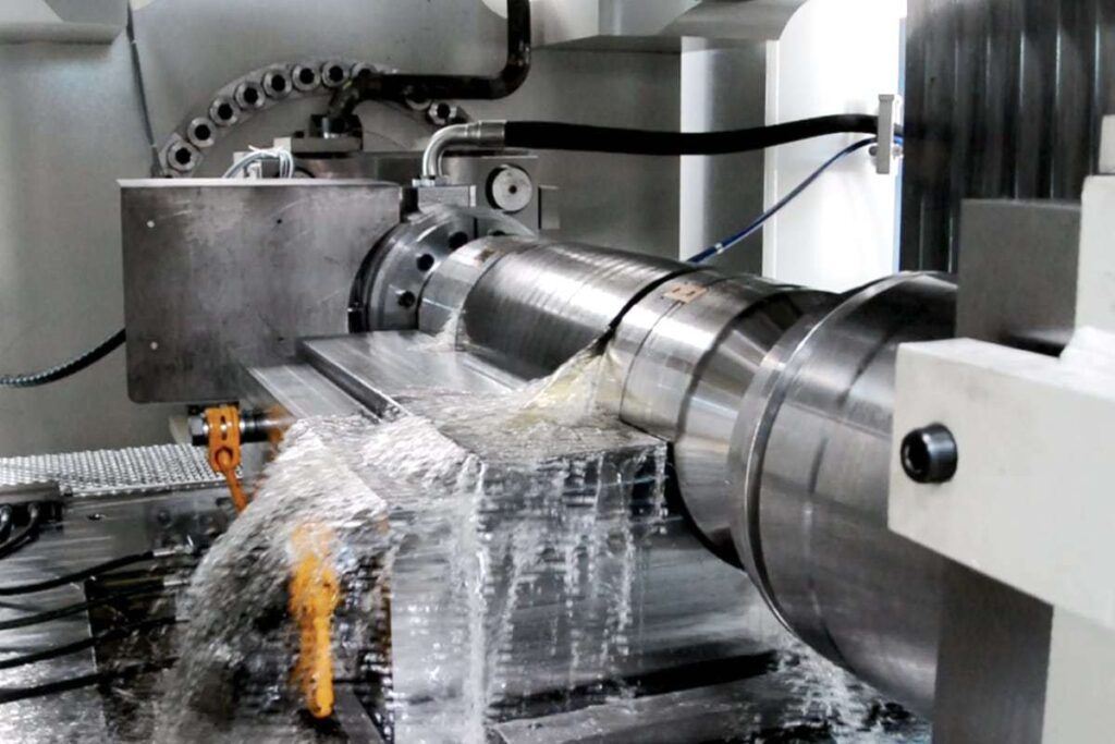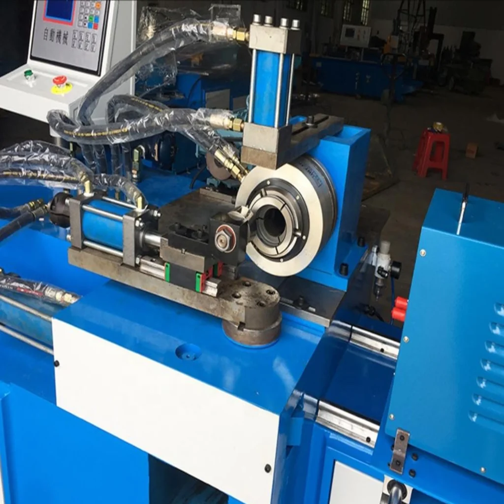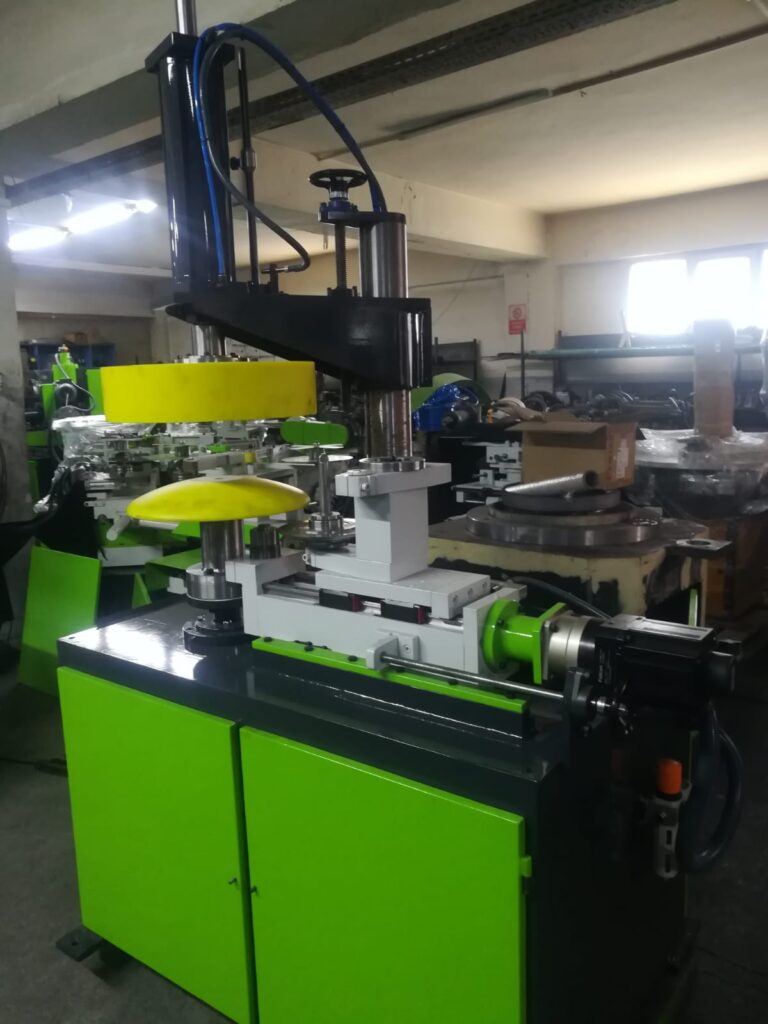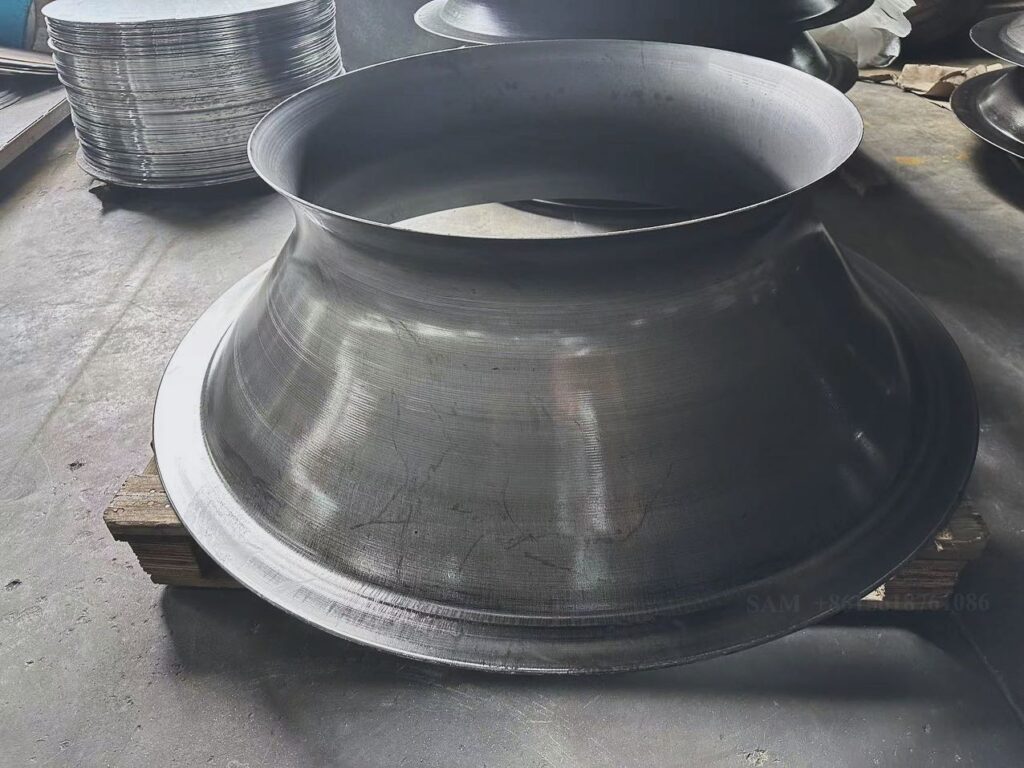
CNC Circular Shearing Machine: A sheet metal spinning machine is a tool used to shape metal sheets into cylindrical or conical forms by rotating the metal sheet while pressing it against a tool or mandrel. It is commonly used in manufacturing processes for producing hollow, symmetrical parts such as tanks, bowls, or decorative pieces. Here’s how it typically works:
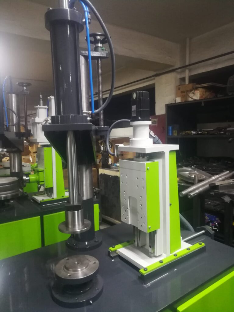
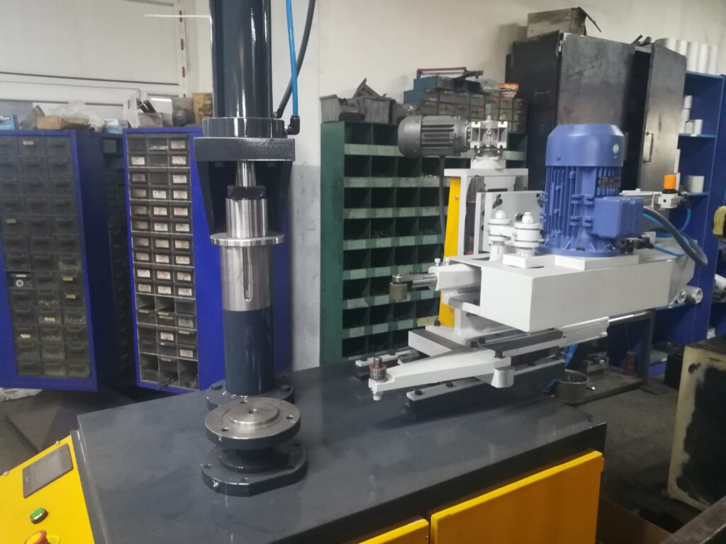
Key Components of the Metal Spinning Machine
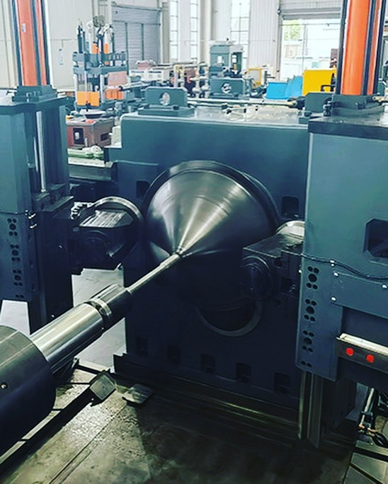
- Spindle/Mandrel: The part that holds the sheet metal and rotates it. The shape of the mandrel defines the final product’s shape.
- Tooling: Includes the rollers or form tools that press against the sheet metal to shape it as it rotates.
- Chuck/Clamps: These hold the metal sheet securely in place during the spinning process.
- Drive System: This powers the spindle to rotate the metal sheet at the required speed.
- Support Arms/Rest: They may be used to support larger sheets of metal during the spinning process to ensure they stay in position.
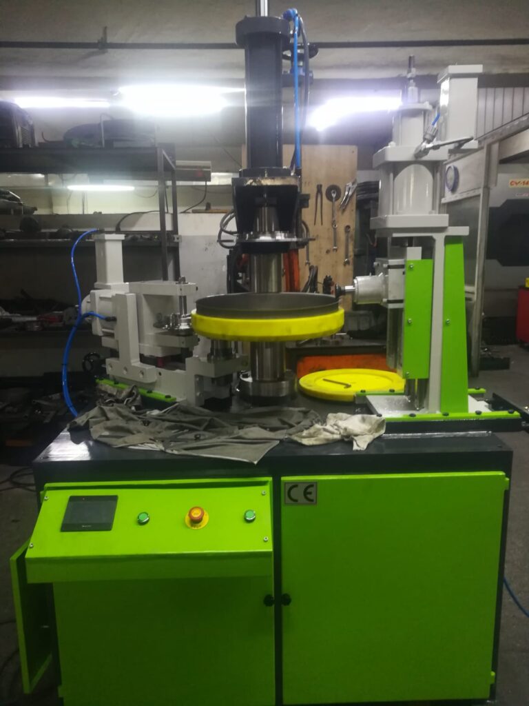
Process Overview:
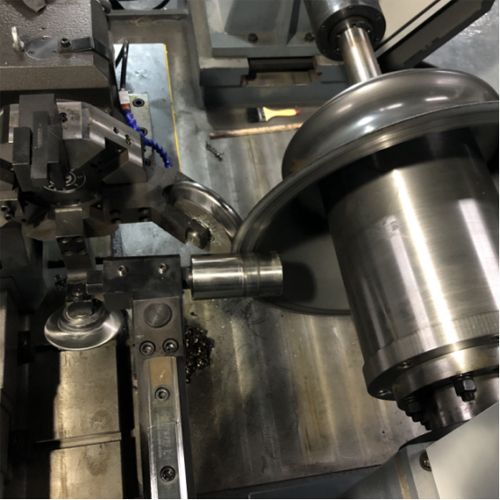
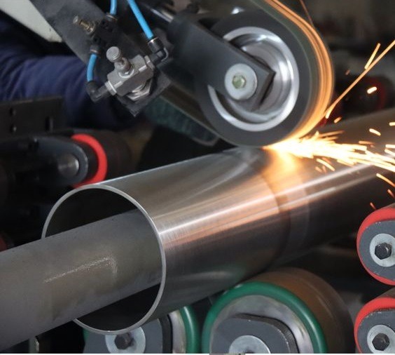
- Sheet Placement: The metal sheet is placed over the mandrel or spindle and secured by clamps.
- Spinning: As the mandrel rotates, the tool presses against the sheet, gradually forming it to match the shape of the mandrel.
- Shaping: The sheet is gradually shaped, and the tools are moved along the surface to create the desired thickness and profile.
- Finishing: Once the desired shape is achieved, the product is removed from the mandrel and any excess material is trimmed or smoothed.
Applications:
- Automotive Industry: Manufacturing parts like wheels, cones, or exhaust systems.
- Aerospace: Creating cones, ducts, and other cylindrical components.
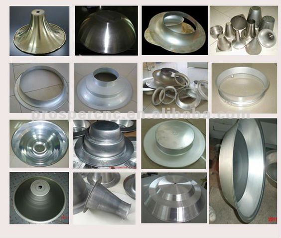
- Decorative: Producing artistic metal pieces like lamp shades, bowls, and vases.
- Heat Exchangers and Pressure Vessels: Making components like tanks and cylindrical housings.
A sheet metal spinning machine shapes metal into cylindrical or conical forms by rotating a sheet and applying pressure to mold it around a mandrel. The process starts by securing the sheet over a rotating mandrel, where tools press the metal to gradually conform to the mandrel’s shape. This technique is used to produce symmetrical, hollow parts like tanks, cones, bowls, and decorative items. The spindle, tooling, and drive system are key components, with clamps or chucks holding the metal in place. The process is used in industries like automotive, aerospace, and decorative metalworking. The result is often a seamless, strong, and precisely shaped metal piece.
A sheet metal spinning machine is an essential tool in the metalworking industry, primarily used for forming metal sheets into intricate, hollow, and symmetrical shapes, such as cylinders, cones, and hemispheres. The process, also referred to as “spinning,” involves rotating a flat metal sheet while simultaneously applying force with specialized tools that gradually shape it over a mandrel or spindle. This process allows for the creation of parts without seams or welds, making it ideal for producing strong, durable components.
The primary action in spinning involves the rotation of the sheet metal over a mandrel, which serves as the template for the desired shape. The metal is pressed against the mandrel using a combination of rollers and tooling, and as the sheet rotates at high speeds, the force of the tools molds the metal into the shape of the mandrel. This continuous pressure and motion refine the thickness and profile of the part, gradually creating the final form.
A key advantage of sheet metal spinning is its versatility. It can be used to create parts of varying complexity, from simple cylindrical shapes to more complex conical forms. The process allows for high production rates, and the resulting parts typically exhibit excellent strength-to-weight ratios, which is particularly important in industries like aerospace, automotive, and heavy equipment manufacturing.
In terms of materials, spinning is often applied to metals that are relatively malleable, such as aluminum, brass, copper, and mild steel. The choice of material depends on the intended application, as each metal has unique properties such as strength, corrosion resistance, and thermal conductivity.
The spinning process is divided into two categories: manual and CNC (Computer Numerical Control) spinning. Manual spinning involves an operator using hand tools to control the pressure and movement of the rollers as the sheet is spun. While this process can be slower and more labor-intensive, it offers flexibility for smaller runs or custom pieces. On the other hand, CNC spinning automates the process, allowing for faster production times, greater precision, and consistency in the resulting parts. This is particularly advantageous for high-volume production, where precision and speed are critical.
Applications of sheet metal spinning are widespread across various industries. In aerospace, it is used to manufacture parts like airframe components, ducts, and housings. In the automotive industry, spinning is commonly used for creating parts such as wheel rims, exhaust systems, and fuel tanks. Additionally, in the decorative arts, spinning machines are used to create objects like lamp shades, vases, and ornamental pieces. The ability to produce seamless, strong, and lightweight components makes sheet metal spinning an indispensable process in modern manufacturing.
Overall, sheet metal spinning is a highly efficient, versatile, and cost-effective method for producing a wide variety of parts. Whether in small quantities for custom pieces or large-scale production runs, the spinning process offers a unique combination of precision, speed, and durability.
The sheet metal spinning process is not only efficient but also provides the ability to produce parts with minimal material waste. Unlike some traditional methods of metal forming, where excess material is cut away, spinning works by gradually shaping the material, which helps conserve metal. This results in less scrap and a more environmentally friendly manufacturing process.
Additionally, sheet metal spinning allows for the creation of parts with excellent structural integrity. The process work hardens the metal as it is pressed against the mandrel, enhancing its strength without the need for additional treatments. This is especially important when the parts need to withstand high pressures or mechanical stress. For example, in aerospace, spinning is often used to produce pressure vessels or ducts that must handle the extreme conditions of flight, such as varying temperatures and pressures.
The precision and control offered by modern spinning machines, especially CNC (Computer Numerical Control) models, enable the production of highly accurate parts with tight tolerances. CNC machines can precisely control the speed, force, and movement of the rollers, ensuring that the final product meets the exact specifications required. This level of accuracy is especially important for industries like aerospace, where even a small deviation in dimensions can affect the performance of a part.
While manual spinning offers flexibility and the ability to produce custom pieces, CNC spinning is generally preferred for large-scale production due to its speed and consistency. CNC machines can handle complex geometries and intricate designs that would be difficult or impossible to achieve with manual methods. They can also integrate multiple operations into a single setup, such as trimming, forming, and finishing, which further enhances the efficiency of the process.
One of the advantages of sheet metal spinning is its ability to work with a wide range of thicknesses. The material thickness can be controlled throughout the process, allowing manufacturers to create parts that are uniform in thickness, which is essential for parts that must endure specific stress loads or thermal conditions. The process also allows for parts to be created with varying wall thicknesses, which can be particularly useful when the strength of the part needs to vary across its surface.
For industries that require aesthetically pleasing designs, spinning can be used to create complex shapes with smooth, seamless surfaces. Decorative items like bowls, trays, and lampshades, as well as functional parts like automotive wheel rims and kitchen sinks, benefit from the smooth, flawless finish that can be achieved through spinning. The lack of welds or joints contributes to the clean, uninterrupted surface, which is especially valuable for high-end designs.
Moreover, the spinning process is relatively fast compared to other methods of metal forming like casting or stamping. Once the machine is set up, the process can be performed quickly, making it suitable for both low- and high-volume production. The ability to quickly modify the tooling or adjust the spinning parameters means that manufacturers can respond to changing requirements with minimal downtime.
In conclusion, sheet metal spinning is an invaluable technique that combines precision, efficiency, and versatility. Whether for producing high-performance components in aerospace, cost-effective parts in automotive manufacturing, or decorative items for home decor, the process continues to be a crucial part of modern manufacturing. As technology advances, with the integration of more automated systems and sophisticated CNC controls, the capabilities of sheet metal spinning are expected to grow, further expanding its applications and improving the efficiency of metalworking processes across various industries.
As sheet metal spinning continues to evolve, several technological advancements are contributing to its broader adoption and improved capabilities. One of the most significant developments is the integration of robotic systems and advanced automation. Robotic arms and automated tool changers are increasingly used in conjunction with CNC spinning machines, allowing for faster and more flexible production. These systems can automatically load and unload materials, adjust tool positions, and even perform secondary operations like trimming, polishing, or deburring without the need for manual intervention. This further reduces human error, increases production speed, and ensures a higher level of consistency in the final products.
The development of more advanced CNC software is another key factor driving the improvement of sheet metal spinning. Modern CNC systems can simulate the entire spinning process before production begins, enabling engineers to optimize tool paths and adjust machine settings in advance. This not only saves time but also reduces the risk of defects or material waste, as manufacturers can identify potential issues early in the design phase. The use of simulation software is particularly valuable when producing complex or high-precision parts that require tight tolerances or specific geometric features.
In terms of materials, there has been a growing interest in expanding the range of metals and alloys that can be used in sheet metal spinning. Traditionally, aluminum, copper, and brass were the most commonly used metals due to their malleability and ease of forming. However, advances in both material science and machine technology have enabled the use of harder, more durable materials like stainless steel, titanium, and even high-strength alloys. This has opened up new opportunities for industries that require materials with exceptional strength-to-weight ratios, corrosion resistance, or thermal conductivity.
For example, in the aerospace and automotive industries, high-strength alloys are essential for producing lightweight but durable components that can withstand harsh environments. Spinning allows manufacturers to form these materials into complex shapes while maintaining their structural integrity. The process can also be used to produce parts with unique mechanical properties, such as high tensile strength or enhanced fatigue resistance, which are critical in industries where performance and reliability are paramount.
Another emerging trend in sheet metal spinning is the use of hybrid manufacturing techniques. These methods combine traditional spinning with other advanced processes such as additive manufacturing (3D printing) or laser cutting. For example, parts can be spun and then modified using 3D printing techniques to add intricate details or create complex internal geometries that would be difficult to achieve through spinning alone. This approach allows manufacturers to produce highly customized parts with enhanced functionality or unique design features, all while taking advantage of the speed and material efficiency of the spinning process.
Energy efficiency is another area where innovations are being made. Spinning machines are becoming more energy-efficient through the use of variable-speed drives, improved motors, and regenerative braking systems. These advancements help reduce the overall energy consumption of the machines, making them more sustainable and cost-effective to operate. Additionally, by minimizing waste material and maximizing the use of raw metals, spinning contributes to more sustainable manufacturing practices overall.
Despite these advancements, challenges still exist in sheet metal spinning, particularly when it comes to the variability of material properties. Variations in metal thickness, alloy composition, or grain structure can lead to inconsistent results, requiring manufacturers to closely monitor and adjust process parameters to maintain quality. To address this, there is an ongoing effort to develop more sophisticated monitoring and control systems that can track material properties in real-time, allowing the machine to adjust the process dynamically and maintain consistent results.
Another challenge is the skill level required to operate and maintain advanced spinning machines. While automation and CNC systems have made the process more accessible, the technical expertise required to set up, program, and troubleshoot these machines is still significant. This means that manufacturers must invest in training and workforce development to ensure that operators can effectively utilize the full capabilities of modern sheet metal spinning equipment.
Looking ahead, the future of sheet metal spinning holds exciting possibilities. The integration of artificial intelligence (AI) and machine learning into CNC systems could revolutionize the process by enabling machines to learn from past production runs and optimize settings in real-time. AI could also help predict potential failures or defects, allowing for proactive maintenance and reducing downtime. Furthermore, the combination of sheet metal spinning with other emerging manufacturing technologies, such as smart sensors, Internet of Things (IoT) connectivity, and digital twins, could lead to fully automated, self-optimizing production systems.
In conclusion, sheet metal spinning is a dynamic and rapidly evolving manufacturing process with significant potential for innovation. As technology continues to advance, we can expect the process to become even more efficient, versatile, and sustainable, enabling the production of more complex and higher-quality parts across a wide range of industries. Whether through automation, material advancements, or hybrid manufacturing techniques, the future of sheet metal spinning looks promising, and it will undoubtedly remain an essential part of modern manufacturing for years to come.
Advancements in Automation and Robotics
The integration of robotics and automated systems into sheet metal spinning machines is transforming the process. Robotic arms are now commonly used for material handling, tool adjustments, and part removal, significantly improving speed and precision. By automating repetitive tasks, manufacturers can reduce labor costs and increase throughput, making it easier to scale production while maintaining high-quality standards. These advancements also help in reducing human error, which can lead to defects or inconsistencies, thereby improving the overall reliability of the process.
CNC Software and Simulation
Modern CNC software is a game-changer in sheet metal spinning. Before the actual production begins, advanced simulation software allows engineers to create virtual models of the entire spinning process. This means they can predict and optimize tool paths, material deformation, and other critical factors without wasting material or time. By identifying potential issues in the design phase, manufacturers can fine-tune their setups, resulting in more accurate and efficient production. The ability to simulate complex geometries and adjust settings with precision helps in achieving tight tolerances and high-quality results.
Expanding Material Choices
Traditionally, sheet metal spinning was limited to relatively malleable metals such as aluminum, brass, and copper. However, technological advancements have expanded the range of materials that can be spun. Today, harder metals such as stainless steel, titanium, and high-strength alloys are increasingly being used in spinning applications. This is particularly important in industries like aerospace and automotive, where parts need to be lightweight yet durable, resistant to corrosion, and able to withstand high stress. The ability to spin these tougher materials means manufacturers can produce components with superior performance characteristics, which are crucial for demanding applications.
Hybrid Manufacturing Techniques
The combination of sheet metal spinning with other advanced manufacturing methods is another exciting development. Hybrid manufacturing techniques, such as the integration of additive manufacturing (3D printing) or laser cutting, are allowing for more complex and customized parts. For instance, after a part is spun, additional features such as intricate internal geometries or custom textures can be added through 3D printing. This approach broadens the design possibilities and enhances functionality, especially for industries that require parts with unique specifications or geometries that are difficult to achieve through traditional methods.
Improving Energy Efficiency
As sustainability becomes a growing concern in manufacturing, energy efficiency has become a key focus for sheet metal spinning. Advances in motor technology, including variable-speed drives and regenerative braking systems, are making modern spinning machines more energy-efficient. These innovations reduce the overall power consumption of the machines, contributing to lower operating costs and a reduced environmental impact. Additionally, the minimal material waste produced by spinning also plays a role in the sustainability of the process, as less scrap is generated compared to other metal-forming methods.
Real-Time Monitoring and Control Systems
One of the challenges in sheet metal spinning is ensuring consistent quality, especially when dealing with varying material properties such as thickness, alloy composition, or grain structure. To address this, manufacturers are increasingly using real-time monitoring systems that track key parameters like material deformation, tool pressure, and temperature. These systems can dynamically adjust process settings to account for changes in material properties or environmental factors, ensuring consistent quality throughout the production run. The use of sensors and smart control systems is becoming standard practice in modern spinning operations.
Overcoming Skill Gaps
Despite the increasing automation and sophistication of spinning machines, there remains a significant need for skilled operators. Modern sheet metal spinning machines, especially those with CNC capabilities, require operators who can program, set up, and troubleshoot the machines effectively. This means that manufacturers must invest in workforce training and development to ensure that their employees can harness the full potential of these advanced technologies. Without skilled personnel, even the most automated systems can fall short in terms of performance and quality.
Artificial Intelligence and Predictive Maintenance
Looking toward the future, artificial intelligence (AI) holds enormous potential for revolutionizing sheet metal spinning. AI algorithms can be used to analyze data from past production runs, identify patterns, and optimize process settings in real time. These systems could even predict equipment failures before they occur, allowing for proactive maintenance and reducing unexpected downtime. This predictive approach would not only enhance the efficiency of the spinning process but also extend the lifespan of the equipment, providing long-term cost savings.
The Role of IoT and Digital Twins
The Internet of Things (IoT) is beginning to play a role in sheet metal spinning as machines become increasingly connected. IoT-enabled machines can send real-time data about their performance, material usage, and other metrics to centralized systems, enabling manufacturers to monitor production remotely. Digital twins—virtual replicas of physical machines—are being used to simulate the spinning process and monitor machine health, helping operators detect issues before they lead to failures. By integrating IoT and digital twin technology, manufacturers can create more efficient and flexible production environments that respond to real-time conditions.
The Future of Sheet Metal Spinning
In conclusion, the future of sheet metal spinning is promising and filled with possibilities. With continued advancements in automation, material science, hybrid manufacturing, and energy efficiency, the process will become even more versatile, faster, and sustainable. The ongoing integration of AI, machine learning, and IoT will further enhance the precision and adaptability of spinning machines, opening the door for new applications and improved production techniques. As the technology continues to evolve, sheet metal spinning will remain an essential part of manufacturing, driving innovation and efficiency across industries.
Advancements in Automation and Robotics
Automation and robotics are transforming the sheet metal spinning process by streamlining operations, improving consistency, and increasing production efficiency. Robotic arms are increasingly used in conjunction with spinning machines for various tasks such as loading and unloading materials, adjusting tooling, and removing finished parts. These robotic systems can operate continuously without the need for human intervention, reducing labor costs and allowing for 24/7 production. They also help reduce human error, which can lead to defects and inconsistencies in the final product.
Automated tool changers are another innovation that makes it easier to switch between different types of tooling or adjust the size and shape of tools. This allows for quick reconfiguration of the machine to accommodate different parts without manual intervention, improving flexibility and reducing downtime. Additionally, advanced machine controls and sensors integrated with robotic systems enable the machine to automatically adjust parameters based on feedback from the production process, further enhancing the precision and quality of the finished parts.
CNC Software and Simulation
The integration of advanced CNC (Computer Numerical Control) software into sheet metal spinning has revolutionized the way manufacturers approach the process. Modern CNC systems are equipped with sophisticated software that allows for the design, simulation, and optimization of the entire spinning process before physical production begins. Engineers can input the part design into the software, and the system will simulate how the metal will behave as it is spun over the mandrel. This allows for the identification of potential problems such as material deformation, tool wear, or stress points in the design, enabling manufacturers to address issues before they arise.
Simulation also provides the opportunity to optimize tool paths, minimize material waste, and adjust the spinning parameters to ensure uniform thickness and precision. By creating a digital twin of the production process, CNC systems can help manufacturers refine their designs, improve product quality, and reduce production times. This level of planning ensures that the final product meets exact specifications, which is especially important when producing complex or high-precision parts that require tight tolerances.
Expanding Material Choices
Historically, sheet metal spinning was limited to metals that were easy to work with, such as aluminum, brass, copper, and mild steel. These materials are relatively soft and malleable, making them easier to shape under pressure. However, recent advances in both materials science and machine technology have expanded the range of materials that can be effectively spun. Harder, stronger metals like stainless steel, titanium, and high-strength alloys are now increasingly used in sheet metal spinning applications.
For industries such as aerospace and automotive, the ability to spin high-strength alloys is particularly valuable. These materials offer superior strength-to-weight ratios, corrosion resistance, and the ability to withstand extreme conditions, making them ideal for critical components such as engine parts, structural components, and heat exchangers. Spinning these tougher materials requires advanced tooling, more precise control of process parameters (such as temperature and pressure), and robust CNC systems, but the result is a part that combines lightweight properties with exceptional strength and durability.
Hybrid Manufacturing Techniques
The combination of sheet metal spinning with other advanced manufacturing processes—known as hybrid manufacturing—has opened up new possibilities for producing complex and highly customized parts. One example of this is the integration of additive manufacturing (3D printing) into the spinning process. In hybrid setups, parts can be spun to achieve basic geometries and structural integrity, and then additive manufacturing can be used to add intricate details, internal geometries, or even custom textures to the part.
For instance, after spinning a basic cylindrical part, 3D printing could be used to add cooling channels or complex internal structures that would otherwise be difficult or impossible to achieve using traditional methods. This combination of processes allows for greater design flexibility and enhances the functionality of the parts being produced. Hybrid manufacturing also offers the possibility of producing parts in lower quantities while maintaining high precision and reducing material waste.
Another example of hybrid manufacturing is the use of laser cutting or laser welding in combination with spinning. Laser cutting can be used to refine the shape or trim excess material after the spinning process, while laser welding can be employed to join multiple spun components together. By integrating multiple advanced manufacturing methods, manufacturers can produce more complex, high-performance parts in a shorter time frame, while maintaining the benefits of sheet metal spinning’s high material efficiency and low scrap rate.
Improving Energy Efficiency
As the demand for more sustainable manufacturing practices increases, the need for energy-efficient machinery has become a significant focus in sheet metal spinning. Modern spinning machines are being equipped with energy-saving features, such as variable-speed drives, high-efficiency motors, and regenerative braking systems. These innovations help reduce the overall energy consumption of the machines, making them more environmentally friendly and cost-effective to operate.
Variable-speed drives allow machines to adjust their speed based on the specific requirements of the part being produced, ensuring that energy is used efficiently throughout the process. Regenerative braking systems capture energy during braking and convert it into electrical power, which can be fed back into the machine or grid, reducing energy waste. Additionally, by minimizing material waste through the precise control of material thickness and eliminating the need for additional processes like welding or machining, spinning further reduces the environmental impact of the manufacturing process.
These energy-efficient advancements not only lower operational costs but also align with global efforts to reduce the carbon footprint of manufacturing. As sustainability becomes a key factor in business decisions, the continued development of energy-efficient spinning machines will play a crucial role in the industry’s shift toward more sustainable practices.
Real-Time Monitoring and Control Systems
Real-time monitoring and control systems are increasingly being integrated into sheet metal spinning machines to ensure consistent quality and efficiency throughout the production process. These systems rely on sensors to measure key parameters such as material thickness, temperature, tool pressure, and speed during the spinning process. The data collected from these sensors is continuously analyzed by the machine’s control system, which can make adjustments to process parameters as needed to maintain quality and prevent defects.
For example, if the system detects that a particular area of the part is not being formed properly or that the material is experiencing excessive stress, it can automatically adjust the pressure or speed of the rollers to compensate. This dynamic control helps ensure that each part meets the required specifications and reduces the risk of defects. Moreover, the data collected during production can be used to track machine performance and identify areas for improvement.
Real-time monitoring also allows for predictive maintenance, where the system can analyze the performance of critical components and predict when they are likely to need maintenance or replacement. By addressing potential issues before they lead to machine downtime or defects, manufacturers can avoid costly repairs and production delays.
Overcoming Skill Gaps
Despite the increased automation and sophistication of sheet metal spinning machines, there remains a need for highly skilled operators who can manage and maintain the equipment. Modern spinning machines, especially those equipped with CNC controls, require operators who are proficient in programming, machine setup, troubleshooting, and adjusting process parameters. This expertise is critical for ensuring that machines operate efficiently and produce high-quality parts consistently.
To address this skill gap, manufacturers are increasingly investing in workforce development and training programs. These programs are designed to teach operators the necessary technical skills and knowledge to operate advanced spinning machines. In addition to technical skills, operators must also have a solid understanding of materials science, quality control, and problem-solving to identify and resolve issues during production. As the technology behind sheet metal spinning continues to evolve, the demand for skilled workers with expertise in these areas will only increase.
Artificial Intelligence and Predictive Maintenance
The integration of artificial intelligence (AI) into sheet metal spinning is an exciting development that promises to enhance the capabilities of CNC systems. AI algorithms can analyze large amounts of data from the machine’s sensors, production logs, and historical performance to make real-time decisions about how to optimize the spinning process. For example, AI could adjust the spinning parameters dynamically based on changes in material properties, environmental conditions, or tool wear, ensuring that the process remains stable and efficient.
Predictive maintenance is another area where AI can have a significant impact. By analyzing data from the machine’s sensors, AI systems can detect patterns that indicate impending failures or maintenance needs. This allows manufacturers to schedule maintenance before a failure occurs, reducing unplanned downtime and extending the lifespan of the equipment. Predictive maintenance also helps reduce the cost of repairs by identifying potential issues early, before they become costly problems.
The Role of IoT and Digital Twins
The Internet of Things (IoT) is playing an increasingly important role in sheet metal spinning by enabling machines to communicate with each other and with centralized systems in real time. IoT-enabled machines can transmit data on parameters such as material usage, machine health, and production rates, allowing manufacturers to monitor their entire production process remotely. This connectivity provides valuable insights into machine performance, helping operators identify bottlenecks, optimize workflows, and improve efficiency.
Digital twins, which are virtual representations of physical machines, are another powerful tool in modern sheet metal spinning. Digital twins allow manufacturers to simulate the behavior of a machine or production line under various conditions, providing insights into how changes to the process could impact performance. By using digital twins to test different scenarios, manufacturers can make data-driven decisions that improve production outcomes and reduce risk.
The Future of Sheet Metal Spinning
The future of sheet metal spinning is filled with exciting possibilities, driven by advancements in automation, AI, and hybrid manufacturing techniques. As these technologies continue to evolve, sheet metal spinning will become even more efficient, precise, and adaptable. With the continued integration of advanced materials, real-time monitoring, and predictive maintenance, manufacturers will be able to produce parts faster and with greater accuracy, all while minimizing waste and reducing costs.
As industries demand more complex, customized, and high-performance parts, sheet metal spinning will remain a key part of the manufacturing landscape. With innovations in energy efficiency, materials, and digital technologies, the process will continue to evolve, opening new doors for industries like aerospace, automotive, and beyond.
Expanding the Scope of Sheet Metal Spinning in Custom and Complex Part Production
As industries continue to demand more customized and complex components, sheet metal spinning is proving to be a versatile and effective method for meeting these needs. One of the primary benefits of spinning is its ability to create parts with intricate shapes that would otherwise be difficult or time-consuming to produce using traditional methods like stamping or casting. In particular, spinning excels at producing parts with conical, cylindrical, or spherical geometries, but modern technology has expanded its ability to handle more complex forms.
For example, in aerospace, automotive, and medical device industries, sheet metal spinning is often used to produce custom parts such as specialized enclosures, heat shields, turbine components, or even medical implants. These parts frequently require precise material thickness distribution, complex shapes, and custom dimensions. In these cases, spinning can provide both the accuracy and flexibility needed to produce high-performance, one-of-a-kind parts at scale.
Additionally, as the demand for high-value, low-volume production increases, sheet metal spinning is becoming more prominent in small-batch and prototype manufacturing. The ability to rapidly change tooling and adjust machine parameters makes spinning ideal for industries that require fast prototyping with minimal lead times. Rather than relying on costly and time-consuming tooling modifications or casting molds, manufacturers can leverage the flexibility of spinning to test new designs and bring products to market more quickly.
Integration of Advanced Tooling for Precision
The precision required in modern sheet metal spinning applications has led to significant advancements in tooling technology. In traditional spinning, tools such as rollers, mandrels, and forming tools are essential for shaping the material. The accuracy of these tools directly affects the quality of the final product. As the demand for tighter tolerances and higher-quality components increases, tooling innovations are becoming more crucial.
Recent developments in tool design include the use of high-performance materials for rollers and mandrels that reduce wear and improve the longevity of tooling components. Tools are also being engineered with interchangeable parts, allowing manufacturers to quickly switch between different setups depending on the job. This modularity not only reduces downtime but also provides manufacturers with more flexibility to handle a wider variety of materials, geometries, and production volumes.
To further improve precision, there are also advances in laser-assisted spinning, which integrates laser heating with the spinning process. The addition of a laser beam helps to preheat the material before it is spun, allowing for better control over material flow and reducing the risk of cracking or distortion in harder metals. This process is particularly beneficial when working with high-strength alloys or metals with poor formability, enabling manufacturers to produce precise, high-quality parts without compromising on material properties.
Tightening Environmental Regulations and Sustainability
With increasing environmental concerns and tighter regulations on industrial emissions and waste, manufacturers are under pressure to adopt more sustainable practices. Sheet metal spinning, as a process that generates minimal waste and has low energy requirements, aligns well with these sustainability goals.
Unlike processes like stamping or die casting, which often produce a significant amount of scrap material, spinning uses the material more efficiently by forming parts from a single piece of metal. This leads to minimal waste, particularly for industries that require high-performance materials that are costly or difficult to obtain, such as titanium or certain high-strength alloys. By reducing material waste, sheet metal spinning contributes to the overall sustainability of the manufacturing process.
Furthermore, spinning can be integrated with recycling systems to reuse scrap material generated during the process. In the case of certain metals, such as aluminum, the scrap generated during spinning can be easily melted down and reused without compromising the material’s properties. This reduces the need for virgin material and helps manufacturers minimize their environmental impact.
In addition to reducing waste, spinning machines are becoming more energy-efficient. Innovations in machine design, such as the use of more efficient motors, servo drives, and regenerative braking systems, are helping manufacturers lower energy consumption during production. Combined with the trend toward reducing emissions and improving sustainability in the broader manufacturing landscape, sheet metal spinning can be a key player in helping manufacturers meet new environmental standards.
Advancing the Versatility of Spinning for Multi-Functional Parts
Another exciting development in sheet metal spinning is the ability to produce multi-functional parts with integrated features. In the past, components produced by spinning were mostly basic geometric shapes, but as the technology evolves, manufacturers are pushing the limits to create parts with more advanced functionality.
In applications like aerospace and automotive manufacturing, where weight savings and functionality are paramount, manufacturers are starting to use spinning to create parts with integrated features such as mounting holes, brackets, or channels. These features, which would traditionally require additional machining or assembly, can be incorporated directly into the spinning process, reducing production steps and material handling. This not only improves efficiency but also reduces part complexity and assembly costs.
Additionally, some industries are experimenting with the use of spun parts that include embedded components or sensors. For instance, in industries that require high levels of monitoring or control (e.g., the medical or automotive sectors), spun parts might be designed with internal passageways to house sensors or electronics. The ability to form these parts in one continuous process reduces the need for post-processing or assembly, improving both the efficiency and quality of the final product.
Sheet Metal Spinning in the Digital Manufacturing Era
As manufacturing becomes increasingly digital, the role of sheet metal spinning continues to evolve. The introduction of digital twins and smart manufacturing technologies into spinning is reshaping how parts are designed, produced, and monitored. Digital twins—virtual representations of physical spinning machines—allow for real-time monitoring and analysis of the entire production process.
This level of connectivity enables manufacturers to have a digital replica of their entire production line, where they can simulate different process parameters and make adjustments based on real-time data. By using sensors and IoT technology, the machine’s behavior and performance can be tracked, ensuring that the machine operates at optimal levels. This data can then be analyzed to improve future designs, optimize machine settings, and predict maintenance needs.
Furthermore, additive manufacturing is being integrated into digital manufacturing workflows, making it possible to combine spinning with 3D printing for more complex and customized designs. For instance, digital manufacturing platforms allow designers to upload CAD files, and the software can generate the necessary tool paths for both the spinning and 3D printing processes. This seamless integration of spinning and additive manufacturing opens up new possibilities for the production of highly customized parts, especially those that require intricate internal features or complex geometries.
The Role of Artificial Intelligence in Process Optimization
Artificial intelligence (AI) has the potential to revolutionize many aspects of sheet metal spinning, particularly in process optimization. AI can be employed to optimize machine settings, predict material behavior, and improve efficiency across the entire production cycle. For instance, by analyzing data collected during the spinning process, AI algorithms can predict how the material will respond to different spinning parameters, such as tool pressure or speed, and adjust these parameters in real-time to improve the quality of the finished part.
AI can also be used to develop more sophisticated quality control systems. By using computer vision and machine learning algorithms, AI systems can inspect parts during and after the spinning process, identifying defects such as cracks, inconsistent thickness, or surface irregularities. This level of quality control ensures that only high-quality parts make it through the production line, reducing the likelihood of defects reaching the customer and improving overall product reliability.
Additionally, AI-driven predictive maintenance systems are becoming a key tool in reducing machine downtime. By continuously monitoring machine health and analyzing performance data, AI can predict when parts will need maintenance or replacement, preventing unexpected failures that could halt production. This predictive capability helps manufacturers avoid costly repairs and delays, ultimately enhancing the efficiency and profitability of their operations.
Closing Thoughts on the Future of Sheet Metal Spinning
Sheet metal spinning continues to evolve as a critical manufacturing process for producing complex, high-quality parts across a wide range of industries. With the integration of advanced automation, CNC systems, hybrid manufacturing technologies, and AI, the capabilities of spinning machines are expanding rapidly. These innovations make it possible to produce more precise, energy-efficient, and sustainable parts, all while minimizing waste and reducing lead times.
As industries demand more custom, multi-functional, and high-performance parts, sheet metal spinning is poised to meet these challenges and play a central role in the next generation of manufacturing. Whether through advancements in materials, robotics, AI, or digital manufacturing technologies, the future of sheet metal spinning is bright, and it will undoubtedly continue to shape the landscape of modern manufacturing for years to come.
Enhancing Customization with Digital Design Tools
As the demand for highly customized and unique parts continues to grow, digital design tools are playing a crucial role in enabling the next generation of sheet metal spinning. Designers and engineers can now use advanced CAD (Computer-Aided Design) software to create complex geometries that are easily transferred to CNC systems for spinning. These digital design tools allow for precise customization of every aspect of a part, from material selection and geometry to surface finish and functional features.
With CAD software, it’s now possible to incorporate intricate designs that were once difficult or impractical to achieve using traditional manufacturing methods. Designers can experiment with different geometries, create 3D models, and visualize the finished product before production even begins. This greatly reduces the time required for prototyping and ensures that any design flaws or inconsistencies are detected early in the process.
Moreover, the integration of CAD software with CNC machines enables real-time modification of design specifications. If adjustments need to be made to accommodate a change in material, size, or tolerance, manufacturers can easily update the digital model and immediately apply these changes to the machine’s programming. This seamless connection between digital design and physical production is a significant step forward in enhancing flexibility and customization in sheet metal spinning.
Real-Time Quality Control and Inspection Using AI and Computer Vision
Quality control is a critical aspect of sheet metal spinning, especially when dealing with high-precision parts for industries such as aerospace, automotive, and medical devices. Real-time quality control systems, which leverage AI and computer vision technologies, are revolutionizing the way parts are inspected during the spinning process.
AI-powered computer vision systems can continuously monitor the geometry, surface finish, and overall quality of each part during production. These systems use high-resolution cameras and image processing algorithms to detect surface defects, dimensional inconsistencies, or imperfections that might not be visible to the naked eye. By comparing the part’s current state to its digital design, these systems can flag any deviations from the desired specifications and adjust the machine parameters in real-time to correct the issue.
This approach to quality control significantly reduces the likelihood of defects and ensures that only parts meeting the highest standards reach the final stage of production. Furthermore, the data collected by these systems can be used to build a comprehensive quality history, allowing manufacturers to track trends and identify areas for improvement in both the spinning process and machine performance.
The integration of AI and computer vision in quality control not only speeds up inspection but also helps to maintain consistency and reduce human error. In high-stakes applications like aerospace or medical device manufacturing, the ability to ensure flawless parts during production is essential, and these technologies offer a solution to meet these stringent requirements.
Customization and Low-Volume Production
The versatility of sheet metal spinning makes it an ideal process for producing low-volume, high-customization parts. Unlike other manufacturing processes that may require expensive molds or tooling for mass production, spinning can produce a wide variety of parts with different sizes, shapes, and materials using the same set of equipment. This flexibility makes spinning especially useful for industries that need to produce specialized parts in small quantities.
For example, in the aerospace and automotive industries, manufacturers often need to create prototypes, custom components, or replacement parts for older models. Sheet metal spinning allows them to produce these parts quickly and at lower cost compared to methods like die casting or stamping, which require custom molds for each design. This capability is invaluable when dealing with rapidly evolving designs or low-volume orders where tooling costs would be prohibitive.
Spinning is also becoming more prominent in the medical device industry, where custom parts like implants, surgical tools, and enclosures are needed in relatively small quantities but with precise, high-performance specifications. The ability to customize every aspect of the part—from material selection to geometry—makes sheet metal spinning an excellent option for these specialized applications.
Advancements in Tooling Technology for Improved Precision
As the demand for high-precision, complex components increases, the development of advanced tooling technology for sheet metal spinning is crucial. Tooling innovations have focused on improving both the quality of the finished part and the efficiency of the spinning process itself.
For example, the use of multi-axis tooling has gained traction in sheet metal spinning. Traditional spinning machines typically use single-axis tooling that shapes the metal around a fixed mandrel, but multi-axis tooling allows the material to be shaped along multiple directions simultaneously. This leads to greater design flexibility and the ability to create more complex geometries in less time.
Additionally, innovations in materials for tooling components—such as harder, more durable alloys and coatings—are extending the lifespan of tools and improving their performance in demanding applications. These advanced tooling materials help minimize wear and tear, ensuring that the spinning process remains stable and accurate over longer production runs.
Furthermore, as technology advances, automatic tool changers are being introduced to reduce the downtime associated with switching between different tools for various parts. This further increases the machine’s efficiency and versatility, allowing manufacturers to easily switch between producing different geometries or material types without significant delays.
Integration of Robotics for Automation and Precision
Robotic automation is increasingly being integrated into sheet metal spinning systems to enhance both productivity and precision. Robotic arms are used for tasks such as loading and unloading raw materials, adjusting machine settings, and removing finished parts. These robots can work tirelessly around the clock, ensuring a consistent level of productivity while minimizing labor costs.
In addition to handling basic tasks, robots can also assist in fine-tuning the spinning process. For instance, robots equipped with sensors can measure the temperature, pressure, and material deformation during spinning, providing valuable data to the machine’s control system. This data can be used to adjust the spinning parameters dynamically, ensuring that the part is formed with the desired specifications.
Moreover, robotic systems are often equipped with vision systems that allow them to identify defects in the material or in the spun part itself. This visual feedback can be used to halt production or adjust machine settings in real-time, preventing errors and defects from propagating through the production cycle.
The automation of repetitive tasks not only increases efficiency but also frees up human workers to focus on more complex, high-value activities, such as troubleshooting, machine programming, and quality control. The result is a more efficient, cost-effective, and precise production process that meets the demands of modern manufacturing.
The Role of Data Analytics in Spinning Optimization
Data analytics is becoming increasingly important in optimizing the sheet metal spinning process. By collecting and analyzing data from the machine’s sensors, operators can gain valuable insights into the performance of the machine, material behavior, and the efficiency of the overall process. This data can be used to identify patterns and trends, allowing manufacturers to make data-driven decisions that improve both productivity and product quality.
For example, by analyzing historical data, manufacturers can identify recurring issues or inefficiencies in the spinning process and take corrective actions. Predictive analytics can also be used to anticipate maintenance needs and minimize downtime, as data analytics tools can detect early signs of equipment wear or malfunction.
Furthermore, data analytics can provide insights into material usage, helping manufacturers optimize material consumption and reduce waste. By monitoring factors such as material thickness variation and deformation during the spinning process, manufacturers can make adjustments to ensure that the material is used as efficiently as possible.
The integration of data analytics tools with the spinning process provides a higher level of control over production and allows manufacturers to fine-tune their processes, resulting in cost savings, improved quality, and greater efficiency.
Future Trends: AI-Driven Design and Autonomous Spinning Systems
Looking to the future, artificial intelligence (AI) is set to play an even more significant role in sheet metal spinning. AI-driven design tools are already emerging that allow manufacturers to input a basic set of parameters (such as material type, part size, and desired properties) and automatically generate optimized part designs. These AI systems can take into account the complexities of material behavior, machine capabilities, and even environmental factors to suggest the most efficient and effective designs for spinning.
Autonomous spinning systems, which can operate with minimal human intervention, are another exciting future trend. These systems would combine AI, machine learning, and advanced robotics to autonomously carry out the spinning process from start to finish. By learning from historical data, autonomous systems could optimize every aspect of the process, from tool adjustments to material flow and quality control, ensuring that each part is produced with maximum efficiency and accuracy.
These autonomous systems could also improve the flexibility of sheet metal spinning by allowing for real-time, on-the-fly adjustments based on changes in material properties or part design. As AI and machine learning technologies continue to improve, the potential for fully autonomous, AI-driven sheet metal spinning systems could revolutionize the industry by offering unparalleled levels of customization, speed, and precision.
Conclusion: A Bright Future for Sheet Metal Spinning
The future of sheet metal spinning is bright, with a host of technological advancements paving the way for greater efficiency, precision, and flexibility. Automation, AI, robotics, data analytics, and advanced tooling technologies are all contributing to the evolution of the process, allowing manufacturers to meet the growing demand for customized, high-performance parts.
As industries continue to demand more complex geometries, lighter-weight components, and more sustainable practices, sheet metal spinning will remain a vital manufacturing process. With ongoing innovations and the increasing integration of digital tools, spinning is poised to play a central role in the future of modern manufacturing, from high-precision aerospace components to customized medical devices.
In the coming years, sheet metal spinning will continue to evolve alongside the broader trends of automation, digital manufacturing, and Industry 4.0, further establishing its role as a key technology in the production of advanced, high-quality components across diverse industries.
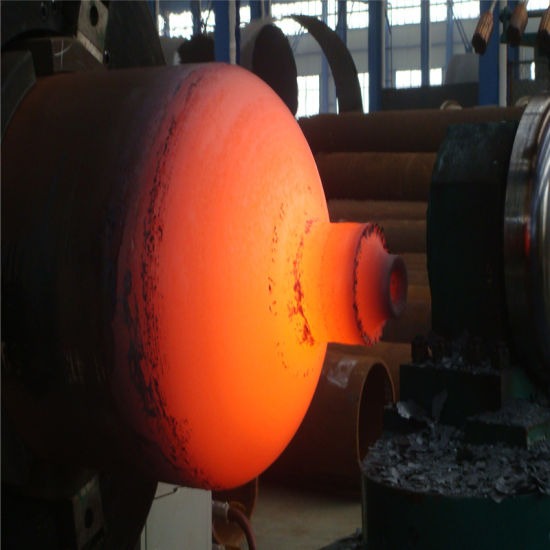
High-Speed Rotary Forging Machine: An Overview
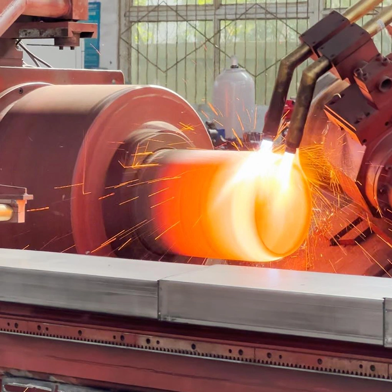
A high-speed rotary forging machine is a specialized piece of equipment used in the forging industry to create high-precision components from metal billets. It operates through the principle of rotary forging, where a rotating die applies localized pressure to a rotating workpiece, causing it to deform plastically and take the shape of the die cavity. This process is often used to produce parts that require superior mechanical properties and fine tolerances, such as automotive components, aerospace parts, and medical devices.
The high-speed aspect of the rotary forging machine refers to its ability to operate at much faster speeds than traditional forging machines. By utilizing high rotational speeds, these machines can significantly reduce cycle times while maintaining high levels of precision and part quality. The fast rotation generates a large amount of energy, which facilitates rapid deformation of the material, allowing for the creation of parts with complex shapes and geometries.
Here’s a detailed breakdown of the key features, advantages, and applications of high-speed rotary forging machines:
1. Principle of Operation
In rotary forging, the workpiece (usually a metal billet) is rotated while a set of dies applies force in a controlled manner. The dies compress the material, causing it to flow into the die cavity and form the desired shape. Unlike traditional forging methods, where the die simply presses the workpiece into shape, rotary forging involves both rotational motion and axial force, which leads to more efficient material flow and reduced internal stresses.
The high-speed operation is achieved by rotating the workpiece at a much faster speed, which increases the impact force applied to the metal. This enhanced speed allows for faster production times and the ability to forge parts with greater precision.
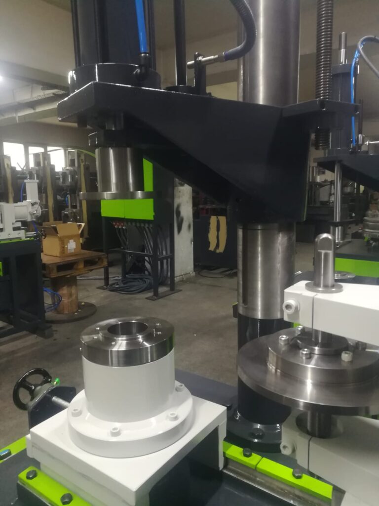
2. Key Components of High-Speed Rotary Forging Machines
- Rotating Workpiece: The core element of the machine, where the billet is secured and rotated at high speeds. The workpiece may rotate at speeds ranging from several hundred to several thousand RPM (revolutions per minute), depending on the material and required forging characteristics.
- Dies: The dies are designed to apply the forging force and shape the workpiece. They are typically made from hardened tool steel or other wear-resistant materials to withstand the stresses of high-speed operation.
- Spindle and Motor: The motor and spindle system are responsible for driving the workpiece and rotating it at the desired speed. These components must be designed for durability and reliability under high rotational speeds.
- Hydraulic or Pneumatic Actuators: These provide the axial force necessary to press the dies against the rotating workpiece. The force can be adjusted based on the material being forged and the complexity of the part.
- Control System: The machine is often equipped with a sophisticated control system that monitors and adjusts the speed, force, and rotation to ensure precise and repeatable results. This system may use sensors and feedback loops to adjust the process parameters in real time.
3. Advantages of High-Speed Rotary Forging Machines
- Reduced Cycle Time: By rotating the workpiece at high speeds, rotary forging machines significantly reduce the amount of time needed to shape a part. This makes the process much faster than traditional forging methods.
- Improved Material Properties: High-speed forging allows for better grain refinement, which leads to superior mechanical properties in the finished part. This is particularly beneficial for applications that require parts with high strength, durability, and resistance to wear.
- High Precision and Tolerance: The controlled application of force and the rotating motion ensure that the material flows evenly, reducing defects and improving dimensional accuracy. This is essential for producing parts with tight tolerances and high-quality finishes.
- Energy Efficiency: High-speed rotary forging uses less energy compared to traditional forging methods that rely on slow, massive press movements. The process is more efficient because the rotational energy is concentrated and used to deform the material quickly and precisely.
- Complex Geometries: Rotary forging machines can create parts with complex shapes, including those with intricate internal features, without the need for extensive secondary machining. This capability is useful in industries like aerospace, where parts often require lightweight, yet structurally strong components with complicated geometries.
4. Applications of High-Speed Rotary Forging Machines
- Aerospace Industry: The aerospace sector relies on rotary forging for producing lightweight, high-strength parts such as turbine blades, engine components, and landing gear parts. The ability to forge parts with complex geometries and high mechanical properties makes rotary forging ideal for these applications.
- Automotive Industry: High-speed rotary forging is used to create components such as gears, shafts, and crankshafts. These parts require excellent wear resistance and strength, which can be achieved through rotary forging, even in challenging materials like high-strength steel or titanium alloys.
- Medical Devices: In the medical industry, rotary forging is employed to manufacture components like orthopedic implants, surgical tools, and dental products. These parts need to meet high standards of strength, biocompatibility, and precision, making high-speed rotary forging a preferred method.
- Oil and Gas: The oil and gas industry uses rotary forging to produce parts like valves, pump shafts, and downhole equipment. These parts need to endure extreme pressure and corrosive environments, which can be achieved by forging high-quality materials with fine grain structures.
- Energy Sector: Components for turbines, generators, and other energy-producing equipment benefit from the strength and precision provided by rotary forging. High-speed forging ensures that these components are manufactured quickly while maintaining the necessary structural integrity.
5. Challenges and Considerations
While high-speed rotary forging offers numerous benefits, there are some challenges and considerations to keep in mind:
- Material Limitations: Some materials may not be well-suited for high-speed rotary forging, especially if they have low ductility or tend to work-harden quickly. Proper material selection is crucial to ensure the forging process is successful.
- Tool Wear: The high-speed operation places significant stress on the dies and other tooling components, leading to increased wear. Tooling materials need to be highly durable and resistant to deformation to maintain part quality and minimize downtime.
- Complex Setup: While rotary forging machines can produce highly precise parts, they require careful setup and calibration to ensure that the machine operates at optimal efficiency. The setup process can be complex, especially for parts with intricate geometries.
- Cost of Equipment: High-speed rotary forging machines can be expensive to purchase and maintain. However, the benefits in terms of precision and speed often justify the investment for manufacturers producing high-volume, high-quality parts.
6. Recent Advancements in High-Speed Rotary Forging Technology
- Automation and Integration: The integration of automation systems, including robotic arms and automated material handling systems, has further improved the efficiency of high-speed rotary forging machines. These systems can automate tasks such as loading and unloading billets, reducing labor costs and improving overall throughput.
- Enhanced Control Systems: Modern rotary forging machines now feature advanced computer control systems that enable real-time monitoring of the forging process. These systems can adjust parameters such as speed, pressure, and rotation to optimize part quality and reduce waste.
- Hybrid Technologies: Some manufacturers are experimenting with hybrid systems that combine high-speed rotary forging with other processes, such as additive manufacturing or heat treatment. These hybrid systems allow for even more complex part designs and improved material properties.
- Advanced Tooling Materials: The development of advanced materials for tooling, such as coated carbide or ceramic dies, has helped extend the lifespan of tooling components and improve the durability of the forging process.
7. Future Outlook for High-Speed Rotary Forging
As industries continue to demand parts with higher precision, strength, and complexity, the role of high-speed rotary forging is expected to grow. The demand for lightweight and high-performance materials, especially in aerospace and automotive applications, will drive further adoption of this technology. Additionally, as manufacturing processes become more automated and integrated with digital technologies, rotary forging will continue to evolve, offering even faster production times and better material utilization.
In conclusion, high-speed rotary forging machines are an essential tool in modern manufacturing, offering a range of benefits from improved cycle times and material properties to the ability to produce complex geometries. As technological advancements continue, the capabilities of these machines will expand, enabling manufacturers to meet the ever-increasing demands of industries requiring high-performance, precision-engineered components.
High-speed rotary forging machines have revolutionized the manufacturing of high-precision components by enabling the rapid production of parts with excellent mechanical properties and fine tolerances. This technology uses the principle of rotating the workpiece while applying localized pressure through dies, facilitating the deformation of the material into the desired shape. The high-speed aspect of the machine significantly reduces cycle times, making it an ideal solution for industries where speed and precision are paramount.
These machines operate by rotating the workpiece at speeds ranging from several hundred to several thousand RPM, depending on the material and specifications of the part. The rotation generates energy that aids in the efficient deformation of the metal, resulting in faster cycle times compared to traditional forging methods. As the workpiece spins, it is subjected to axial pressure from the dies, which compress the metal and cause it to flow into the cavity of the die, forming the part.
The high-speed forging process also enhances the material properties of the final part. The rapid deformation reduces internal stresses, and the controlled application of pressure leads to fine grain refinement, which improves the strength and toughness of the part. This is particularly advantageous for producing components that require high strength-to-weight ratios, such as aerospace and automotive parts. The process also enables the production of complex geometries and intricate features that would be difficult or impossible to achieve with traditional forging techniques. As a result, high-speed rotary forging is becoming increasingly popular in industries like aerospace, automotive, medical, and energy production, where the demand for lightweight, durable, and high-performance parts is growing.
In addition to the enhanced material properties, high-speed rotary forging machines offer a significant reduction in cycle time, which leads to increased production efficiency and reduced costs. The rapid rotation and deformation allow manufacturers to produce parts more quickly than with traditional forging methods. Furthermore, the process is highly precise, with tight tolerances and minimal need for secondary machining. This makes it an attractive option for manufacturers looking to streamline production and reduce the overall cost per part.
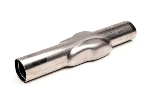
One of the key advantages of high-speed rotary forging is its ability to produce parts with complex shapes and features without the need for additional machining. The process allows for the creation of intricate internal geometries, such as holes, flanges, and ribs, which can be difficult to achieve with other methods like casting or stamping. This ability to forge complex shapes directly reduces the need for costly post-processing steps, further improving the cost-effectiveness of the process.
Despite its numerous benefits, there are challenges associated with high-speed rotary forging. One of the main challenges is the wear on tooling due to the high rotational speeds and pressures involved. The dies and other tooling components are subjected to significant stresses, and therefore, durable materials like hardened tool steel or carbide are used to withstand the abrasive forces. Manufacturers also need to ensure that the machine is properly calibrated for each specific part to avoid defects and ensure optimal material flow.
The material selection for rotary forging is another crucial factor. While the process works well for a wide range of metals, some materials may not be suitable due to their low ductility or tendency to work-harden quickly. It is important to choose materials that can handle the high pressures and rotational speeds required by the machine without cracking or failing during the forging process. Common materials used for high-speed rotary forging include steel alloys, titanium, and aluminum, which offer good balance between strength and formability.
The integration of automation and advanced control systems has further enhanced the capabilities of high-speed rotary forging machines. Modern machines are equipped with sophisticated control systems that monitor parameters like speed, pressure, and material deformation in real-time. These systems help maintain consistent quality and precision, adjusting the machine’s settings as needed to accommodate different materials and part designs. In some cases, robotic arms and automated material handling systems are integrated into the forging process, reducing the need for manual labor and further increasing production efficiency.
Looking ahead, the future of high-speed rotary forging is promising. With advancements in machine design, materials, and automation, the capabilities of these machines will continue to evolve. Manufacturers are exploring hybrid systems that combine rotary forging with other processes, such as additive manufacturing or heat treatment, to produce even more complex and high-performance parts. The growing demand for custom, lightweight, and high-strength components, especially in industries like aerospace, automotive, and medical devices, is expected to drive further adoption of high-speed rotary forging technologies.
Overall, high-speed rotary forging machines are an essential tool in modern manufacturing. They provide manufacturers with a fast, precise, and efficient method for producing high-quality components that meet the rigorous demands of various industries. As technology continues to advance, the ability to produce complex geometries, improve material properties, and reduce cycle times will further solidify the role of rotary forging in the future of manufacturing.
As the industry evolves, the integration of digital technologies will play a crucial role in enhancing the capabilities of high-speed rotary forging machines. One of the key advancements expected to shape the future of rotary forging is the use of smart manufacturing techniques. By embedding sensors and using Internet of Things (IoT) technology, manufacturers can monitor every aspect of the forging process in real-time. This connectivity will enable predictive maintenance, process optimization, and greater control over part quality. For example, sensors placed in the machine can monitor temperature, pressure, and force during the forging process, and the system can use this data to predict when maintenance is required or adjust parameters automatically to optimize the process for each specific part.
Another area of growth lies in machine learning and artificial intelligence (AI). By applying AI algorithms to the data collected from the machines, manufacturers can refine their processes over time, allowing the machine to “learn” from previous forging cycles and optimize future production runs. For example, AI can analyze patterns in the data and suggest modifications in rotational speed, pressure, or material handling to improve the final product quality and reduce waste. This level of automation can further enhance the speed and precision of high-speed rotary forging machines, ensuring that manufacturers can meet increasing demands for complex and high-quality parts.
Additionally, virtual simulations are becoming an increasingly important tool in the design and planning stages of rotary forging. Before a part is even forged, manufacturers can use simulation software to model how the material will behave under specific conditions, taking into account factors such as material properties, die geometry, and applied forces. These simulations can help engineers optimize part designs, tooling, and process parameters, allowing for faster development cycles and reduced trial-and-error during physical production.
Additive manufacturing (3D printing) is also expected to influence the future of rotary forging. In some cases, additive manufacturing technologies can be used to create complex, high-precision parts that can later be forged using high-speed rotary machines. The combination of both technologies could enable the creation of intricate geometries that were once impossible or prohibitively expensive to produce using traditional methods. This could be especially beneficial in industries like aerospace, where weight savings and component complexity are paramount.
With these advancements, the demand for sustainability and resource efficiency in manufacturing is also growing. High-speed rotary forging offers inherent advantages in terms of material utilization, as the process typically generates minimal waste compared to casting or machining. However, manufacturers will continue to explore ways to reduce energy consumption, optimize material usage, and improve the recyclability of scrap metal. Innovations in tooling materials, such as coatings that reduce wear and improve the lifespan of dies, can also contribute to more sustainable manufacturing practices.
In addition to technological advancements, the global shift towards Industry 4.0 is also influencing high-speed rotary forging. As part of this movement, companies are embracing smart factories that integrate advanced automation, real-time data analysis, and supply chain connectivity. High-speed rotary forging machines will increasingly be part of these connected systems, providing real-time updates on production status, part quality, and machine performance. This level of integration will enhance overall efficiency and responsiveness, helping manufacturers to quickly adapt to changes in demand and ensure high levels of product consistency.
The globalization of manufacturing also plays a significant role in the future of high-speed rotary forging. As industries across the world demand high-performance parts, the ability to produce them quickly, efficiently, and at scale is essential. High-speed rotary forging machines, with their ability to reduce cycle times and maintain high levels of precision, are well-suited to meet the needs of global markets. Additionally, the ability to produce high-quality parts in lower volumes, with minimal tooling changes, is particularly advantageous for manufacturers catering to industries with rapidly changing specifications or low-volume production runs.
In conclusion, the future of high-speed rotary forging is closely tied to continued technological advancements in automation, data analytics, AI, and sustainability. These innovations will further enhance the precision, speed, and cost-effectiveness of the process, making it an even more attractive solution for industries that demand high-performance components. As manufacturers continue to push the boundaries of what’s possible with high-speed rotary forging, we can expect to see even more sophisticated and complex components produced with greater efficiency, higher quality, and less waste. The combination of these innovations will help shape the next generation of manufacturing and allow high-speed rotary forging to remain at the forefront of precision engineering for years to come.
As the demand for high-performance components increases across various industries, the role of high-speed rotary forging will continue to evolve. Future developments are expected to improve the machine’s versatility, allowing manufacturers to produce a broader range of materials and parts with more intricate designs. One of the significant future directions is the ability to forge advanced composite materials or non-ferrous alloys that are becoming more popular in industries like aerospace and automotive. These materials often require specialized forging techniques due to their unique properties, such as lightweight characteristics or resistance to high temperatures. High-speed rotary forging’s ability to produce such parts with precision will be a crucial asset as industries move towards more advanced materials.
Another anticipated advancement is in the development of multi-material forging capabilities. The ability to combine different materials in a single forging process opens up new possibilities for creating parts that offer a combination of the best properties from multiple materials. For example, a part could have a tough outer layer to resist wear while maintaining a lighter, more flexible inner core. Multi-material forging requires a high level of precision and control, and high-speed rotary forging is uniquely suited to this challenge due to its precise force application and the ability to manipulate material flow in complex ways.
The integration of robotics is expected to become more prominent in high-speed rotary forging systems. Robots could be used for tasks such as part handling, die changing, and post-forging operations like quality inspection. This would not only increase efficiency but also enhance consistency in the production process. Furthermore, the introduction of robotic systems could reduce operator exposure to the high-speed machinery, improving safety in the workplace.
Moreover, the advent of additive manufacturing technologies could complement high-speed rotary forging in hybrid manufacturing systems. Hybrid systems combine the strengths of both additive manufacturing (3D printing) and traditional subtractive or forging techniques. For instance, 3D printing could be used to create complex internal features or tooling that would be difficult to produce with conventional methods. These printed components could then be subjected to high-speed rotary forging to achieve the required mechanical properties. This hybrid approach could lead to innovative, efficient, and cost-effective manufacturing processes for parts that require both intricate geometries and superior mechanical strength.
Enhanced control over material properties will also be a major area of focus in the coming years. For instance, improvements in the thermal control during the forging process could allow manufacturers to control the cooling rates and heat treatment in-situ, improving the final mechanical properties of the parts. This could be especially useful for producing parts that need to maintain specific hardness, toughness, or fatigue resistance across their entire structure. The ability to achieve controlled grain structures at a microscopic level during high-speed forging would allow manufacturers to meet the most demanding specifications, especially in industries such as aerospace, where performance and reliability are critical.
In addition to improvements in the forging process itself, advancements in quality control and inspection technologies will continue to play a critical role. Real-time, non-destructive testing (NDT) methods, such as ultrasonic testing, x-ray inspection, and laser scanning, are expected to become more integrated into high-speed rotary forging systems. These technologies will allow for immediate detection of defects like voids, cracks, or inconsistencies in the material, ensuring that each part meets the stringent quality standards required for high-performance applications.
Additionally, energy efficiency will remain a key focus, as the demand for more sustainable manufacturing processes grows. Although high-speed rotary forging is inherently more energy-efficient than some traditional forging methods, manufacturers will continue to develop ways to reduce energy consumption even further. This might involve optimizing machine speeds, improving heat recovery systems, or using more efficient motors and powertrain technologies. Reducing energy use and improving the sustainability of high-speed rotary forging will be essential as industries and governments move towards more environmentally responsible manufacturing practices.
The development of advanced materials for the tooling itself will also be crucial for the continued success of high-speed rotary forging. Innovations in die materials, such as advanced ceramic composites, coatings, or self-lubricating alloys, can help extend the lifespan of tooling components, reduce downtime, and improve the consistency of the forged parts. These materials can withstand higher temperatures and wear rates, reducing maintenance requirements and allowing for longer production runs without significant tooling wear.
With the ongoing trends toward digitalization and Industry 4.0, high-speed rotary forging will become more interconnected with broader manufacturing ecosystems. This could involve integrating these machines with enterprise resource planning (ERP) and manufacturing execution systems (MES), enabling manufacturers to track every aspect of production in real-time, from raw material procurement to final product delivery. Such integration would improve supply chain efficiency, reduce lead times, and allow manufacturers to better predict demand, optimize inventory, and streamline production processes.
In conclusion, the future of high-speed rotary forging is characterized by continuous innovation, with advancements in automation, materials, digitalization, and hybrid manufacturing processes paving the way for the production of increasingly complex, high-performance parts. As industries demand more sophisticated components, the capabilities of high-speed rotary forging machines will evolve, providing manufacturers with even greater flexibility, efficiency, and precision. This will enable high-speed rotary forging to maintain its pivotal role in meeting the rigorous demands of industries such as aerospace, automotive, energy, and medical devices, ensuring that manufacturers can continue to meet the challenges of tomorrow’s global markets.
A servo-driven rotary forging machine is a specialized type of forging equipment that uses servo motors to drive the rotary motion of the workpiece and apply precise force during the forging process. The servo-driven system offers a significant upgrade over traditional mechanical or hydraulic systems, providing enhanced control, efficiency, and precision. This type of forging machine is particularly advantageous for applications requiring high accuracy, repeatability, and complex part geometries.
Key Features and Working Principle of a Servo-Driven Rotary Forging Machine:
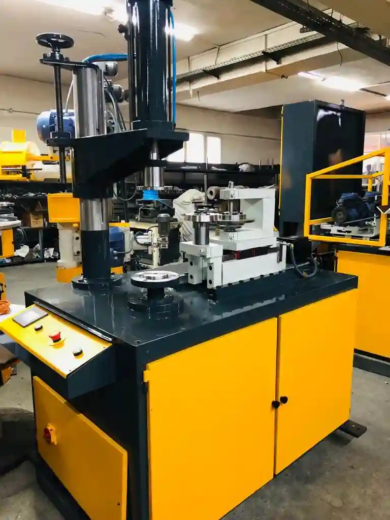
In a servo-driven rotary forging machine, the workpiece is rotated by a servo motor, which replaces traditional methods like hydraulic or mechanical drives. The servo motor allows for much finer control over the speed, torque, and positioning of the workpiece, making it an ideal choice for high-precision forging applications. The rotational motion of the workpiece is combined with axial pressure applied by the dies to shape the material into the desired form.
The servo motor offers real-time feedback and dynamic control, allowing for instant adjustments during the forging process. This precise control ensures that the machine can adapt to the material properties of the workpiece, resulting in more consistent quality, improved material flow, and reduced defects in the final part. The flexibility of servo drives also enables the machine to operate at different speeds and forces, which is beneficial when forging different materials or complex geometries.
Advantages of Servo-Driven Rotary Forging Machines:
- Enhanced Precision and Control: One of the most significant advantages of servo-driven rotary forging machines is the high degree of control they provide. Servo motors can adjust the speed, torque, and position of the workpiece with incredible accuracy, resulting in more consistent and precise forgings. This level of control is particularly important for producing parts with tight tolerances and intricate shapes.
- Energy Efficiency: Unlike traditional hydraulic or mechanical systems that can be wasteful in terms of energy, servo motors are highly efficient. They only use the energy required for the task at hand, reducing energy consumption and lowering operating costs. This efficiency makes servo-driven rotary forging machines a more eco-friendly option, particularly in high-volume production environments.
- Faster Cycle Times: The ability to fine-tune the speed and pressure applied during the forging process means that servo-driven machines can achieve faster cycle times without sacrificing part quality. This increased throughput can lead to higher productivity and reduced lead times, making the process more cost-effective.
- Flexibility in Operation: The programmability of servo-driven systems allows the machine to be easily reconfigured for different parts and materials. Operators can adjust the machine parameters quickly to meet the specific requirements of each production run. This flexibility is especially useful for manufacturers who need to produce a wide range of parts with varying geometries and material types.
- Improved Material Flow and Reduced Defects: The real-time feedback mechanism provided by the servo system helps optimize material flow during the forging process. This leads to more uniform deformation and reduced risks of defects such as cracking, warping, or material wastage. By adjusting parameters like speed and force dynamically, the servo motor ensures that the forging process is as efficient as possible, minimizing errors.
- Reduced Maintenance Costs: Servo-driven rotary forging machines tend to have fewer moving parts than traditional mechanical systems. With less wear and tear on components like gears and hydraulic systems, the maintenance costs and downtime are typically lower. The improved control also reduces the likelihood of damaging the tooling, further extending the life of the machine.
- Higher Production Quality: The enhanced control over the forging process allows for higher-quality components, with fewer defects and more consistent material properties. This is particularly important in industries like aerospace, automotive, and medical device manufacturing, where high-strength, lightweight, and defect-free parts are crucial.
- Integration with Modern Manufacturing Systems: Servo-driven rotary forging machines can be easily integrated with modern digital control systems and automation technologies. These systems can monitor the forging process in real-time, adjusting parameters as needed and ensuring continuous optimization of the process. This level of integration is key to ensuring the efficiency of the overall manufacturing system and aligning with the principles of Industry 4.0.
Applications of Servo-Driven Rotary Forging Machines:
- Aerospace Industry: The aerospace sector requires parts that are lightweight, strong, and able to withstand extreme conditions. Servo-driven rotary forging machines are ideal for producing high-performance components like turbine blades, engine parts, and structural elements that require precision and exceptional material properties.
- Automotive Industry: In the automotive sector, high-strength gears, shafts, and crankshafts are commonly forged. The precise control offered by servo motors allows manufacturers to produce these parts efficiently while maintaining tight tolerances and superior mechanical properties. The automotive industry also benefits from the ability to quickly adjust machine settings to accommodate different part designs and materials.
- Medical Devices: The medical device industry often requires parts that must meet stringent standards of quality and precision. Orthopedic implants, surgical tools, and dental components are often produced using servo-driven rotary forging machines, as these parts must be manufactured with high strength, minimal defects, and excellent dimensional accuracy.
- Oil and Gas Industry: Parts used in the oil and gas sector, such as valves, seals, and downhole equipment, often need to withstand harsh conditions. Servo-driven forging allows manufacturers to produce these parts with high integrity, ensuring they meet the necessary mechanical properties and can endure extreme pressures and temperatures.
- Energy Sector: Components for turbines, generators, and other high-performance equipment used in energy production are often forged with servo-driven machines. The ability to produce high-quality, durable components with complex geometries is crucial in this industry, where reliability and performance are critical.
- Heavy Equipment Manufacturing: Large industrial machines often require forged components that can handle heavy loads and endure high wear. Servo-driven rotary forging machines can produce parts like gears, bearing housings, and axles that meet these demands.
Challenges of Servo-Driven Rotary Forging Machines:
While servo-driven rotary forging machines offer numerous benefits, there are some challenges associated with their implementation:
- Initial Cost: The advanced technology and precision offered by servo-driven systems can result in a higher initial purchase cost compared to traditional forging machines. However, the long-term cost savings in terms of reduced energy consumption, lower maintenance costs, and higher throughput often justify this investment.
- Complexity in Setup and Operation: The highly flexible and programmable nature of servo-driven systems means that operators must be skilled in programming and adjusting the machine parameters. The learning curve may be steep for those accustomed to traditional machines, and specialized training may be required to operate the system effectively.
- Reliability of the Servo Motor: While servo motors are generally reliable, they are more sensitive to issues like power fluctuations and overheating compared to traditional mechanical systems. Ensuring proper cooling, power conditioning, and maintenance of the motor is critical to maintaining optimal performance.
- Maintenance of Electronics and Control Systems: Servo-driven systems are heavily reliant on advanced electronic control systems and sensors. While these systems improve precision, they can be vulnerable to issues such as software malfunctions, sensor failures, or electrical faults. Regular maintenance and updates to the software and control systems are necessary to ensure continuous performance.
Conclusion:
In summary, servo-driven rotary forging machines represent a significant advancement in the forging industry. With their ability to offer precise control over the forging process, improve energy efficiency, reduce cycle times, and produce parts with superior material properties, they are ideal for industries requiring high-performance components. While the initial cost and complexity may present challenges, the long-term benefits of reduced maintenance, lower energy costs, and enhanced production capabilities make servo-driven systems an attractive solution for manufacturers in sectors like aerospace, automotive, medical devices, and energy. As technology continues to evolve, servo-driven rotary forging machines will play an increasingly important role in the future of high-precision manufacturing.
Servo-driven rotary forging machines are becoming increasingly critical in industries where precision, efficiency, and high-quality material properties are essential. These machines offer significant improvements over traditional mechanical or hydraulic systems, allowing manufacturers to achieve finer control over every aspect of the forging process. With servo motors driving the rotary motion, the machines can precisely adjust the speed, torque, and positioning of the workpiece, offering a level of flexibility that is crucial for manufacturing parts with tight tolerances or complex geometries.
The key advantage of a servo-driven system is the enhanced precision it offers, enabling manufacturers to adjust parameters like pressure and speed in real-time based on the specific requirements of the material being forged. This means that manufacturers can optimize the forging process for different materials, ensuring better flow, reduced defects, and minimal material waste. The ability to dynamically adjust these variables reduces the risk of errors, leading to improved consistency in product quality.
Another compelling benefit of servo-driven machines is their energy efficiency. Unlike traditional mechanical systems that can waste energy, servo motors operate with high efficiency by adjusting power output as needed for each task. This makes the machines more energy-efficient and cost-effective in the long run, especially in high-volume production environments where energy consumption can add up quickly. Along with lower energy costs, the improved precision and reduced material waste further contribute to lowering operational costs.
Servo-driven systems also lead to faster cycle times. The enhanced control over the machine’s movements allows for quicker adjustments during the forging process, speeding up production without compromising the quality of the forged components. Faster cycle times lead to higher throughput and increased productivity, which is essential for industries that require rapid production and just-in-time manufacturing.
The flexibility of servo-driven rotary forging machines also enables them to handle a wide variety of materials and part designs. Whether forging metals with different characteristics or producing parts with intricate geometries, the ability to reprogram and adjust the machine quickly means that manufacturers can easily switch between different projects with minimal downtime. This versatility is especially important in industries like aerospace or automotive manufacturing, where diverse parts are often produced in small batches.
The machines also require less maintenance compared to traditional systems. Servo motors have fewer mechanical parts, which results in less wear and tear over time. Additionally, the precise control and real-time feedback provided by the system help reduce the likelihood of machine malfunctions, contributing to more reliable operations. Less frequent maintenance means less downtime and higher overall productivity.
As technology continues to advance, servo-driven rotary forging machines are becoming more integrated with digital control systems and automated manufacturing processes. The ability to incorporate IoT (Internet of Things) sensors and data analytics into the system allows manufacturers to monitor the performance of the machines in real-time, track any changes in the forging process, and make necessary adjustments automatically. These innovations help further optimize efficiency and product quality, creating an interconnected, intelligent manufacturing environment.
Looking ahead, the growing demand for custom, high-performance components will only increase the importance of servo-driven rotary forging machines. As industries such as aerospace, automotive, medical, and energy continue to push the boundaries of what is possible with high-strength, lightweight, and intricate parts, these machines will be essential to meeting the increasing need for precision, durability, and efficiency. With the ability to handle a broad range of materials, geometries, and production volumes, servo-driven systems offer manufacturers the flexibility and performance they need to stay competitive in the modern manufacturing landscape.
In conclusion, servo-driven rotary forging machines represent a leap forward in forging technology, offering unmatched precision, energy efficiency, and flexibility for manufacturers. As industries demand more advanced and complex parts, the capabilities of these machines will continue to evolve, enabling the production of high-performance components with greater efficiency, quality, and cost-effectiveness. The continuous integration of digital tools and smart manufacturing practices will ensure that servo-driven forging systems play a central role in the future of manufacturing.
The continued development of servo-driven rotary forging machines will likely include further integration with advanced technologies such as artificial intelligence (AI) and machine learning (ML). By leveraging these technologies, manufacturers can optimize not only the forging process but also the entire production workflow. AI and ML algorithms can analyze the vast amounts of data generated by these machines during the forging process and identify patterns or trends that can help improve the process. For example, AI could predict the optimal speed and force settings for each material and part type, reducing the need for manual adjustments and improving the consistency of the final product. Over time, these systems would learn from each production cycle, further refining the parameters to achieve even greater efficiency and precision.
Furthermore, real-time quality control integrated into the servo-driven system could be enhanced with technologies like vision systems and non-destructive testing (NDT). Using high-resolution cameras and sensors, the machine could instantly detect any defects or variations in the workpiece as it is being forged. This would allow manufacturers to immediately adjust the process or reject faulty parts before they reach the end of the production line, reducing waste and improving yield rates. Such systems could also reduce the need for traditional, manual inspection processes, streamlining the production cycle and improving overall productivity.
Another area where servo-driven rotary forging machines could evolve is in hybrid manufacturing. As 3D printing and additive manufacturing technologies continue to develop, there may be opportunities to combine these techniques with traditional forging. For example, complex internal geometries or highly detailed tooling could be 3D printed and then forged using a servo-driven rotary machine to ensure the material’s mechanical properties meet the necessary standards. This hybrid approach would enable manufacturers to produce parts that are both strong and lightweight, with intricate internal structures that would be difficult or impossible to achieve with conventional manufacturing methods.
In terms of sustainability, servo-driven rotary forging machines are already ahead of traditional methods in terms of energy efficiency. As the global push for greener manufacturing intensifies, these machines could further contribute to sustainable practices. For instance, energy recovery systems could be incorporated into the machine design, capturing and reusing energy generated during the forging process. Additionally, as industries place more emphasis on using recycled materials, servo-driven machines could be optimized for handling a wider range of recycled metals, which may have different properties compared to virgin materials. The precise control offered by servo motors would help ensure that even with the variation in material quality, the forging process remains consistent and high-quality.
Moreover, as servo-driven rotary forging machines become more intelligent, they will likely be able to integrate more effectively into broader manufacturing ecosystems. Through Industry 4.0 technologies, machines could become part of a fully connected and automated production line. This would allow manufacturers to synchronize production schedules, track parts across the supply chain, and adjust production strategies based on real-time data from suppliers, machines, and inventory systems. For example, if there is a delay in the delivery of a particular material, the machine could automatically adjust its operations to optimize the use of available resources, preventing bottlenecks and reducing downtime.
In terms of machine design, future developments may also focus on modular systems that allow manufacturers to easily reconfigure or upgrade parts of the servo-driven rotary forging machines. This would allow companies to quickly adapt to changing production demands or adopt new technologies without needing to replace entire machines. Such flexibility would be especially beneficial for companies that need to frequently switch between different production runs or work with a wide variety of materials.
Looking at the long-term future, it’s possible that autonomous operation of these machines will become more prevalent. As more advanced sensors and AI systems are integrated, servo-driven rotary forging machines could operate with minimal human intervention. The system could autonomously adjust all the process parameters, detect potential issues before they arise, and even schedule maintenance based on usage patterns and real-time condition monitoring. This would allow manufacturers to reduce labor costs, improve machine uptime, and minimize human error in the production process.
The potential applications for servo-driven rotary forging machines are vast. As industries continue to demand more precise, durable, and complex parts, these machines will become increasingly essential. From aerospace and automotive to medical devices and energy, the flexibility, precision, and efficiency offered by servo-driven rotary forging machines make them a critical technology for meeting the evolving needs of high-performance manufacturing.
With the combination of advanced control systems, digital integration, and cutting-edge manufacturing technologies, servo-driven rotary forging machines are well-positioned to shape the future of the forging industry, ensuring that manufacturers can meet the growing demands for high-quality, customized components with reduced waste, faster cycle times, and increased operational efficiency. The continued evolution of these machines will undoubtedly play a central role in driving the next generation of manufacturing processes.
As we look even further into the future, servo-driven rotary forging machines are likely to see the integration of next-generation materials and advanced process control systems that will push the boundaries of what’s achievable in terms of performance, efficiency, and part complexity. One of the key areas of development will be the ability to forge exotic and high-performance materials, such as titanium alloys, superalloys, and ceramics, which are increasingly used in industries like aerospace, medical, and energy. These materials often require specialized handling due to their unique properties, and the precise control offered by servo-driven systems can help ensure these materials are forged successfully without compromising their mechanical properties.
Increased automation and robotics integration will further elevate the capabilities of servo-driven rotary forging machines. As cobots (collaborative robots) and automated handling systems become more commonplace, they will be used to load, unload, and handle parts during the forging process, minimizing human interaction with the machinery. This reduces the risks associated with operator errors, speeds up the process, and improves worker safety. Automation will also contribute to reducing labor costs while improving the overall consistency and quality of the produced components.
Another area where automation and advanced sensors can play a key role is in the area of predictive maintenance. With the increased connectivity of modern manufacturing systems, predictive analytics will become a critical tool in managing machine health. By analyzing data from sensors embedded within the machine and collecting information on variables like temperature, vibrations, and wear, AI algorithms can predict when a component is likely to fail or require maintenance. This allows manufacturers to perform maintenance tasks just before a failure occurs, reducing unplanned downtime and increasing machine longevity. With this proactive approach, manufacturers can optimize their operations and avoid costly stoppages or repairs.
The growing focus on sustainability in manufacturing is driving innovations in energy efficiency and waste reduction. Servo-driven rotary forging machines are already more energy-efficient than traditional systems, but further strides in this area could involve regenerative braking systems to recover and store energy during the forging cycle. Energy savings like these would not only reduce operating costs but also help meet increasingly stringent environmental standards and regulations.
Another promising area of development is digital twins—virtual replicas of physical machines or manufacturing systems that simulate and predict their behavior in real-time. By using digital twins in the context of servo-driven rotary forging machines, manufacturers could test different forging parameters, experiment with new materials, and simulate the entire production process without any physical trial runs. This would enable more efficient use of resources and lead to faster time-to-market for new products, as engineers can optimize processes and designs before actual production begins.
In parallel, advanced simulation software will improve the precision of the forging process. Modern software tools are already capable of simulating the entire forging operation, from material flow to the deformation behavior under various forces. In the future, these tools will likely become even more powerful, enabling real-time simulations during the forging process itself. With this, manufacturers could quickly adjust the process to account for unexpected variables like changes in material properties or temperature fluctuations, further enhancing product quality and reducing scrap.
Material traceability is also a crucial area that will benefit from advancements in servo-driven rotary forging machines. As industries demand more accountability in terms of material sourcing, quality, and sustainability, manufacturers can track every step of the material’s journey through the forging process. The integration of blockchain technology could ensure secure and transparent tracking of parts, which is particularly important for highly regulated sectors such as aerospace or medical device manufacturing. This ensures that every component meets rigorous quality standards and can be traced back to its original source.
The globalization of manufacturing and the need for companies to remain competitive will drive the adoption of modular production systems. Servo-driven rotary forging machines, with their high degree of flexibility, can easily integrate into modular systems that can be reconfigured to accommodate different product types or volume requirements. These modular systems would enable manufacturers to scale production up or down quickly in response to market demand, reducing lead times and improving overall responsiveness.
Looking ahead, we might also witness an increased focus on customization in mass production. Consumer demand for personalized or low-volume, high-precision products continues to grow in sectors such as automotive and medical devices. Servo-driven rotary forging machines, with their ability to adjust quickly to new designs and materials, will be a key enabler in this shift toward more customized manufacturing processes. The flexibility of these machines will allow manufacturers to produce bespoke components without significant cost penalties or delays.
As these machines continue to evolve, manufacturers will benefit from enhanced data analytics capabilities that can provide valuable insights into the entire production process. The real-time collection of machine performance data, quality metrics, and process parameters will allow manufacturers to continuously refine their operations, optimize production efficiency, and maintain high levels of product quality. This data-driven approach will become the norm in the forging industry, transforming how parts are designed, produced, and delivered.
Finally, the long-term outlook for servo-driven rotary forging machines will likely involve deeper integration with smart factories and the Internet of Things (IoT). In a fully connected manufacturing ecosystem, these machines will not operate in isolation but as part of a larger network of equipment, robots, and systems that work together seamlessly. This interconnectedness will enable real-time decision-making, predictive maintenance, automatic adjustments to production parameters, and even autonomous reconfiguration of entire production lines.
In conclusion, the future of servo-driven rotary forging machines is set to be defined by rapid advancements in automation, AI, digitalization, and sustainability. With the ongoing development of more sophisticated control systems, increased precision, and greater adaptability, these machines will be at the heart of the next generation of high-performance manufacturing. Industries demanding more complex, high-quality components will rely heavily on these machines to meet their evolving needs, ensuring that servo-driven systems will continue to be a central pillar of modern manufacturing for years to come.
As we move into the future of manufacturing, servo-driven rotary forging machines will likely see even more advanced connectivity features, allowing for deeper integration with cloud computing and big data systems. By leveraging cloud technology, manufacturers will be able to monitor and manage their machines remotely from anywhere in the world. This remote connectivity could allow for global service networks, where engineers can diagnose and troubleshoot issues in real-time without needing to be physically present. The use of cloud platforms will also enable data-sharing across multiple production sites, allowing for greater collaboration between factories and across global supply chains. This interconnected approach will also provide manufacturers with a central hub for managing operations, optimizing performance, and sharing best practices between plants.
In the context of quality assurance, there will be further evolution in in-line measurement technologies that continuously monitor the dimensions, material properties, and surface finish of parts during the forging process. These real-time quality checks will enable a higher level of autonomous adjustment during production, ensuring that each part meets the strictest tolerances without the need for offline inspections. This level of process control will be especially critical in industries such as aerospace, where component failure due to material defects or dimensional inaccuracies is not an option. Through the combination of advanced sensors, machine vision systems, and AI algorithms, servo-driven rotary forging machines will be able to instantly correct deviations from the ideal forging process, maintaining the highest quality standards throughout production.
As manufacturing continues to evolve toward smarter processes, we can expect more automation and artificial intelligence to play a role in workflow optimization. The integration of robotic arms for part handling, material feeding, and finishing processes will become more common in servo-driven rotary forging machines, enabling fully automated production lines. The use of AI-driven production planning will allow manufacturers to better predict when specific parts will need to be forged, optimizing material supply, reducing production downtime, and increasing output. Predictive analytics will help manufacturers foresee maintenance needs or potential system failures, helping avoid unplanned downtime and reducing the overall cost of ownership.
Additive manufacturing (AM) or 3D printing technologies will likely be further integrated with servo-driven forging machines, offering a hybrid manufacturing approach where parts can be partially created through 3D printing and then finished or forged using traditional methods. This hybrid approach will allow manufacturers to produce parts with complex geometries or unique features that would be difficult or impossible to achieve with traditional forging techniques alone. In addition, additive manufacturing technologies can be used to create specialized dies or tooling that improve the efficiency and capabilities of the forging process. Combining these two methods will enable manufacturers to push the boundaries of what is possible in part design, particularly for high-performance applications in aerospace, automotive, and medical industries.
In the future, we may also see biometric and user authentication systems incorporated into servo-driven rotary forging machines. These systems could allow only authorized personnel to operate or make adjustments to the machine, ensuring that the forging process adheres to strict quality control standards and regulations. This is especially critical in industries with highly regulated environments such as pharmaceuticals, medical devices, and aerospace, where security, compliance, and traceability are paramount. Such biometric systems could also log detailed information about the operator’s actions, creating an additional layer of auditability in the production process.
As sustainability and environmental concerns continue to dominate the conversation in manufacturing, servo-driven rotary forging machines will likely evolve to become even more eco-friendly. Energy consumption will continue to be optimized through smart power management systems, where the machines adjust their power requirements based on real-time operational conditions. The implementation of closed-loop cooling systems will reduce water and energy waste, contributing to a more sustainable manufacturing environment. Additionally, the use of eco-friendly lubricants and green manufacturing practices will likely become standard features, helping reduce the overall environmental impact of the forging process.
On the material front, advancements in nano-materials and lightweight alloys could open new possibilities for servo-driven rotary forging machines. These new materials often present unique challenges in terms of processing, and servo-driven systems will be crucial for ensuring that these advanced materials are forged with the required strength and precision. The versatility of servo motors in controlling speed, force, and motion will allow these machines to adapt to the specific needs of such new materials, opening up opportunities in industries like electronics, energy, and biomedical engineering.
As the need for precision manufacturing continues to rise, especially for small-batch or customized parts, servo-driven rotary forging machines will be integral in the move toward more decentralized manufacturing. The rise of local production hubs or on-demand manufacturing will require equipment that is flexible, adaptable, and capable of producing parts at a high level of precision without the need for large, centralized factories. This shift towards local, on-demand production could drastically reduce shipping costs, lead times, and inventory management complexities, while also contributing to a more sustainable manufacturing ecosystem.
Circular manufacturing is another emerging trend that could benefit from servo-driven forging machines. As manufacturers increasingly embrace a circular economy model, the ability to reuse and recycle materials becomes more important. Servo-driven forging machines will likely play a role in ensuring that recycled materials are processed effectively and retain their desired properties throughout the forging process. For example, recycling metals like steel, aluminum, and titanium for use in the forging process is critical, and servo-driven systems can ensure that these recycled materials are properly formed without sacrificing quality.
Looking further into the future, the concept of fully autonomous factories—where machines communicate with each other, adjust processes without human input, and perform their own predictive maintenance—may become a reality. In this scenario, servo-driven rotary forging machines would be integral to a seamless, self-optimizing manufacturing system. These factories would operate on a just-in-time basis, minimizing waste, maximizing efficiency, and using AI and IoT systems to continuously monitor and improve production.
The global supply chain will also benefit from these innovations. As servo-driven rotary forging machines become more advanced, manufacturers will be able to produce parts closer to end customers, reducing the need for long and often costly transportation chains. The flexibility and precision of these systems will allow them to respond quickly to shifts in demand, changing market conditions, or disruptions in supply chains, making them an essential tool for future resilient manufacturing systems.
In conclusion, the future of servo-driven rotary forging machines is rich with potential, offering continuous advancements in precision, automation, sustainability, and flexibility. These machines are poised to lead the charge in industries requiring high-performance, high-quality parts while adapting to new materials, digital technologies, and advanced manufacturing concepts. Whether through smarter processes, integrated technologies, or eco-friendly innovations, servo-driven forging machines will play an increasingly central role in meeting the demands of a rapidly evolving manufacturing landscape.
Automated Rotary Forging Machines are an advanced class of forging equipment designed to fully automate the rotary forging process, where metal is deformed by rotating a workpiece while applying localized pressure through dies. These machines are engineered to offer enhanced precision, efficiency, and scalability in producing high-quality components, typically used in industries like aerospace, automotive, and heavy machinery.
Key Features and Benefits of Automated Rotary Forging Machines:
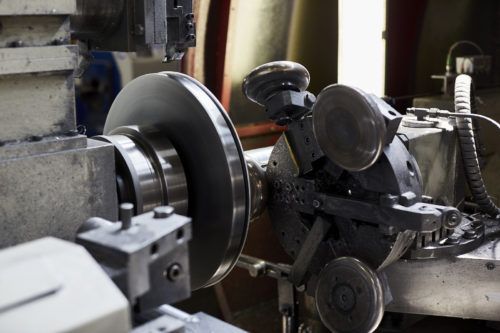
- Automation of Processes:
The defining feature of automated rotary forging machines is their ability to perform the entire forging process with minimal human intervention. Automation includes material handling, feeding, die positioning, forging, cooling, and part ejection. This increases throughput and reduces the need for manual labor, leading to higher productivity and reduced operational costs. - Precision and Quality Control:
Automated rotary forging machines ensure high repeatability and consistency. The automated system can precisely control the key parameters like speed, pressure, and temperature, which are critical to achieving uniform material properties and achieving tight tolerances. Real-time monitoring systems can be integrated to inspect every part produced, making adjustments to the process instantly if any deviations are detected. This results in fewer defects and improved overall quality. - Enhanced Speed and Efficiency:
Automation significantly reduces cycle times compared to manual or semi-automated processes. The machine can continuously feed, process, and eject parts with minimal downtime. Automated systems often feature quick-change tooling or adjustable die configurations that make it easy to switch between different part designs, improving flexibility without sacrificing speed. - Energy Efficiency:
Modern automated rotary forging machines are designed with energy efficiency in mind. The system uses sensors and control systems to optimize the application of force and power during the forging process, which reduces unnecessary energy consumption. This not only lowers operating costs but also contributes to more sustainable manufacturing practices. - Improved Safety:
Since the operation is highly automated, the risk to operators is minimized. Robots or automated handling systems are often used for part transfer, reducing the need for human workers to interact directly with the machinery during the forging process. This reduces the potential for workplace injuries and helps create a safer production environment. - Flexibility:
Automated rotary forging machines are highly versatile and can be used for producing a wide variety of parts with varying materials and complexities. Whether the parts are small, intricate, or large, the machine’s flexibility in adjusting parameters allows it to handle various types of metal, including steel, aluminum, titanium, and high-performance alloys. It can also handle complex shapes and geometries, making it suitable for industries with diverse product demands. - Increased Throughput and Scalability:
Automated systems are designed to handle large volumes of production while maintaining consistent quality. The ability to operate continuously without needing frequent downtime for adjustments or re-tooling makes these systems ideal for high-volume manufacturing environments. They can be easily scaled up to meet growing demand, either by adding more machines or by further optimizing the existing system for faster production. - Cost-Effective in the Long Run:
While the initial investment in an automated rotary forging machine can be substantial, the long-term savings in terms of labor, material waste, energy usage, and maintenance make them cost-effective in the long run. The automation reduces the dependency on skilled labor and minimizes errors caused by human intervention, leading to more consistent and high-quality products with reduced scrap rates. - Integration with Industry 4.0:
The most advanced automated rotary forging machines are equipped with smart technologies, including sensors, AI algorithms, and machine learning. These systems collect data in real-time and allow for predictive maintenance, automatic adjustments to process parameters, and even integration with broader production networks. The incorporation of IoT (Internet of Things) technologies enables remote monitoring and control, further improving overall productivity and reducing downtime. - Reduced Material Waste:
Automated systems typically have tighter control over the forging process, resulting in fewer errors and less material waste. Since the machine can precisely control the deformation of the workpiece, it minimizes scrap and ensures that more of the material is used in the production of the final part. This also helps reduce material costs, especially when working with high-value metals or alloys.
Applications of Automated Rotary Forging Machines:
- Aerospace Industry:
In the aerospace industry, high-performance and highly precise components like turbine blades, compressor disks, and structural components are produced using automated rotary forging machines. These machines are capable of working with advanced alloys that need precise processing to meet the strict strength-to-weight ratios and fatigue resistance required in aviation applications. - Automotive Manufacturing:
The automotive sector uses rotary forging for components such as gears, shafts, wheel rims, and suspension parts. These parts often need to be strong, durable, and lightweight, making rotary forging an ideal manufacturing process. Automated systems help achieve the high-volume output required by the automotive industry while maintaining product integrity. - Energy Sector:
Automated rotary forging machines are often used to produce parts for turbines, compressors, and other energy-generating equipment. The precision and material handling capabilities of automated systems ensure that components for energy applications—where durability and reliability are paramount—are manufactured to the highest standards. - Medical Device Manufacturing:
In the medical field, rotary forging is used for producing components like orthopedic implants, surgical instruments, and prosthetics, which require both strength and biocompatibility. Automation ensures that these high-precision parts are forged consistently and meet stringent regulatory standards. - Heavy Equipment and Machinery:
Components used in construction machinery, mining equipment, and industrial machinery often undergo rotary forging due to the durability and strength requirements of these parts. Automated systems can efficiently produce large quantities of these rugged, heavy-duty components.
Future Trends in Automated Rotary Forging Machines:
- Further Integration of Artificial Intelligence (AI):
AI-powered systems will continue to enhance the control and monitoring capabilities of automated rotary forging machines. AI can predict potential issues in the forging process, such as material inconsistencies or tool wear, and make real-time adjustments to avoid defects and reduce downtime. - Advanced Material Handling and Robotics:
The integration of robotic arms for part handling, loading, and unloading will become even more sophisticated, allowing automated rotary forging machines to work seamlessly with other parts of the manufacturing process, such as finishing, inspection, and packaging systems. - Additive Manufacturing Integration:
The rise of hybrid manufacturing approaches combining additive and subtractive manufacturing technologies will allow for more flexible production systems. Automated rotary forging machines could be integrated with 3D printing systems to produce complex geometries, improving part designs while retaining the benefits of rotary forging for material strength and precision. - Smart Manufacturing Networks:
As part of Industry 4.0, automated rotary forging machines will be integrated into smart manufacturing networks, with increased connectivity and data analytics. This will allow manufacturers to optimize entire production workflows, predict maintenance needs, and improve overall supply chain efficiency. - Sustainability Initiatives:
The push for greener manufacturing will encourage automated rotary forging machines to adopt more sustainable practices. This could involve reducing energy consumption further, increasing the use of recycled materials, and reducing waste in the forging process.
In summary, automated rotary forging machines represent the future of high-precision, high-volume manufacturing, offering significant benefits in terms of productivity, quality, flexibility, and cost-effectiveness. By reducing human intervention and integrating advanced technologies, these machines are helping industries produce complex, high-performance parts while meeting stringent standards for quality, sustainability, and efficiency. As automation and smart technologies continue to evolve, these systems will play an even more central role in the future of manufacturing.
Automated rotary forging machines are revolutionizing the manufacturing process, particularly in industries that demand high precision, reliability, and speed. These machines provide not only the benefit of continuous operation with minimal human intervention but also offer superior control over the forging process. With enhanced automation, manufacturers can achieve greater productivity and cost savings, as these systems are designed to perform various tasks such as material handling, die adjustments, and part ejecting automatically. The integration of advanced sensors and real-time monitoring systems allows for continuous tracking of the forging parameters, ensuring that each part is forged to the exact specifications needed for its application.
The ability to control various forging parameters, such as force, speed, and temperature, has led to improved part quality and uniformity. This is particularly crucial in industries where material performance and structural integrity are paramount, such as aerospace and automotive sectors. By automating the processes and utilizing feedback loops from sensors and control systems, automated rotary forging machines can reduce the chances of errors, improve tolerance levels, and minimize scrap rates. This translates to higher yield rates and lower material costs, as manufacturers are able to maximize the use of the raw materials in the forging process.
Another key advantage of automation in rotary forging machines is the reduction in human error. Operators are typically responsible for overseeing machines and adjusting settings manually in traditional systems. However, in an automated system, machines adjust themselves based on real-time data, reducing the reliance on manual intervention and increasing the reliability of the forging process. Automation can also help to standardize the process across different shifts, ensuring that the same high-quality output is produced consistently, regardless of the time of day or the operator’s experience level.
With the integration of AI-driven analytics and machine learning, automated rotary forging machines are becoming smarter by the day. These machines can predict maintenance needs, monitor the health of critical components, and even adjust forging parameters on the fly to account for variances in material or environmental conditions. By predicting potential failures before they occur, manufacturers can perform predictive maintenance, thereby reducing the likelihood of unplanned downtime and extending the lifespan of equipment. This feature not only helps improve machine reliability but also contributes to cost savings by avoiding costly repairs or equipment replacements.
The incorporation of robotic automation is also transforming the way parts are handled during the forging process. Robotic arms and automated material feeders work in tandem with the forging machine to ensure a smooth and efficient operation. The robotic systems can feed parts into the machine, remove forged parts, and perform secondary operations like inspection and cleaning. This increases the overall efficiency of the production cycle, speeds up the process, and allows for the simultaneous forging of multiple components in different stages of the process, significantly increasing throughput.
As automated rotary forging machines evolve, their ability to handle a wider range of materials and part geometries will also continue to grow. These machines can already handle common metals such as steel, aluminum, and titanium, but future advancements may enable them to forge new and exotic materials with unique properties, such as superalloys, composite materials, and even certain ceramic compounds. The continued advancement in material science coupled with the capabilities of automated rotary forging machines could open up new opportunities in industries like biomedical, electronics, and high-tech manufacturing.
The integration of sustainability measures within automated systems will continue to be a focus. The reduction of energy consumption and minimization of waste are already driving factors in many modern automated systems, and further innovations in machine design and process control will enhance these aspects. For example, energy recovery systems that capture heat or kinetic energy from the forging process could be implemented, reducing overall energy usage. Additionally, the automation of material handling will allow for more efficient material usage, reducing excess material waste.
Digital twin technology could also play a key role in the future of automated rotary forging machines. A digital twin is a virtual representation of a physical machine or process, which allows engineers to simulate, predict, and optimize operations without the need for physical trials. With real-time data flowing from the forging machine, the digital twin can be used to simulate the forging process and test different configurations or process adjustments before making physical changes. This allows manufacturers to experiment with different forging conditions, optimize production cycles, and detect any issues in the process early on, thus improving efficiency, reducing trial and error, and enhancing overall productivity.
In addition to improvements in the physical machinery, the software and control systems of automated rotary forging machines will also become more sophisticated. These systems will provide operators with comprehensive data analytics, enabling them to make informed decisions about the production process. The use of cloud-based systems for monitoring and controlling the machines will allow for remote access to performance data, enabling supervisors and engineers to monitor operations in real time, diagnose problems, and adjust parameters from any location.
The adoption of modular and flexible manufacturing systems will also drive future developments in automated rotary forging machines. Modular systems allow manufacturers to reconfigure their production lines quickly in response to changing demands or new product designs. Automated machines with adaptable features can be used for a wide variety of products, making them suitable for both high-volume production as well as customized, low-volume manufacturing.
Finally, global supply chain integration is an important consideration for the future of automated rotary forging machines. As manufacturers continue to adopt more interconnected systems, the ability to share real-time data across multiple facilities and locations will improve overall supply chain efficiency. Automated systems, when connected to broader manufacturing networks, will allow for real-time adjustments in production schedules based on demand fluctuations, inventory levels, and other factors. This level of integration will also streamline logistics and material management, ensuring that parts are produced and delivered more efficiently.
In conclusion, automated rotary forging machines are poised to play an increasingly important role in the manufacturing industry, offering significant benefits in terms of efficiency, precision, flexibility, and cost-effectiveness. With the ongoing integration of advanced technologies such as AI, robotics, predictive analytics, and sustainability initiatives, these machines will continue to evolve and adapt to the ever-changing needs of the global market. As industries continue to push for more complex, high-performance parts produced at scale, the future of automated rotary forging machines looks incredibly promising.
As the future of automated rotary forging machines continues to unfold, their role in enabling more complex manufacturing processes will expand, particularly with the adoption of advanced materials and new forging techniques. These machines will not just be limited to traditional materials such as metals but will also have the capability to forge composite materials, metal matrix composites (MMCs), and advanced alloys that are crucial for cutting-edge industries like aerospace, automotive, and electronics. The ability to handle these advanced materials with precision and consistency will make automated rotary forging machines even more indispensable for producing high-performance components that meet the extreme demands of these sectors.
Another aspect driving the evolution of these machines is the growing importance of supply chain resilience. The events of the past few years have underscored the vulnerability of global supply chains to disruptions, whether from natural disasters, geopolitical tensions, or pandemics. As a result, industries are increasingly looking to produce critical components closer to their point of use, leading to a push for localized manufacturing and on-demand production. Automated rotary forging machines will play a key role in this shift by enabling flexible, high-precision production at regional facilities that can respond quickly to fluctuations in demand or disruptions in the global supply chain.
The integration of 5G connectivity is another potential game-changer. The ultra-low latency and high bandwidth of 5G networks will allow for even faster, more reliable data transmission between automated rotary forging machines and the broader production ecosystem. This will facilitate real-time collaboration across teams, remote monitoring, and more intelligent control systems that adapt dynamically to production needs. For instance, data from multiple machines across different locations could be consolidated into a single platform for analysis, enabling manufacturers to identify trends, optimize production schedules, and troubleshoot issues in real-time. The ability to instantly access and share data globally can significantly enhance overall manufacturing agility.
Additive manufacturing (AM) will likely continue to complement automated rotary forging machines in various ways, especially for the creation of complex geometries that traditional forging methods cannot easily achieve. In the near future, hybrid systems that combine rotary forging and 3D printing could become commonplace, allowing manufacturers to produce near-net-shape parts with intricate designs, which are then finished using rotary forging processes to achieve the final mechanical properties. This hybrid approach could help reduce material waste, optimize energy usage, and expand the range of possible applications for rotary forging machines.
The ongoing trend of customization and product differentiation in the manufacturing industry will also shape the future of automated rotary forging machines. As demand increases for tailored, high-performance parts, these machines will need to be highly adaptable, capable of quickly changing production parameters and die configurations to accommodate smaller production runs or more specialized designs. The use of advanced computer numerical control (CNC) systems, robotic part handling, and intelligent feedback mechanisms will allow these machines to transition smoothly between different products while maintaining consistent quality, minimizing setup time, and reducing costs.
In terms of environmental sustainability, the role of automated rotary forging machines will become even more critical as manufacturers strive to meet stricter environmental regulations and reduce their carbon footprint. Energy-efficient designs, such as regenerative braking systems that recover and reuse energy, will help reduce the overall energy consumption of these machines. Moreover, recycling capabilities will improve, allowing for increased use of recycled materials, reducing waste, and making manufacturing processes more sustainable. The integration of eco-friendly lubricants and the adoption of cleaner forging processes will further contribute to making the rotary forging process greener.
Furthermore, data analytics and machine learning algorithms will likely play an increasingly central role in optimizing automated rotary forging machines. By continuously gathering and analyzing data from the machine’s sensors, these systems will provide insights into process performance, predictive maintenance schedules, and optimization opportunities. Machine learning algorithms can also be used to identify patterns that human operators might miss, further improving part quality and process efficiency. Over time, the system could evolve into a self-learning machine that refines its operation, continually improving the forging process with little or no human intervention.
Human-machine collaboration is another area that is poised to evolve. While automation reduces the need for human intervention in the actual forging process, skilled operators and engineers will still play an important role in overseeing system performance, troubleshooting, and optimizing the production process. Augmented reality (AR) and virtual reality (VR) technologies could assist operators by providing real-time data visualizations, detailed process feedback, and remote assistance for complex troubleshooting tasks. For example, AR could display real-time information about a machine’s operational status directly in the operator’s field of view, allowing them to make adjustments on the fly or to remotely consult with technical experts.
Additionally, the scalability of automated rotary forging machines will improve as these systems become more modular. Manufacturers will be able to add or remove components based on the scale of their operation. Modular setups allow businesses to start with a small system and gradually expand it as demand increases. This flexibility will also enable manufacturers to adapt their operations to different production needs, whether that involves switching between low-volume, high-precision production or scaling up for large batch runs.
The globalization of manufacturing has also led to a growing demand for multinational production capabilities. Automated rotary forging machines, integrated into a global network of manufacturing sites, can enable companies to produce parts in different regions, which helps minimize shipping costs, reduce lead times, and improve overall supply chain efficiency. The integration of cloud-based control systems means that operators in one part of the world can monitor and control machines located elsewhere, ensuring consistency and quality across geographically dispersed production facilities.
Customization for specific industry needs will be one of the defining trends of automated rotary forging machines. For example, the automotive industry may require machines capable of producing high-strength, lightweight parts such as forged aluminum components for electric vehicles. Similarly, the aerospace sector will demand machines capable of forging complex titanium parts with exceptional fatigue resistance. To meet these varying demands, automated rotary forging machines will become highly specialized, offering customized solutions for different applications, each with its own set of performance requirements.
Finally, cybersecurity will continue to be a major consideration as automated rotary forging machines become more connected and integrated with broader smart manufacturing systems. With the increasing use of cloud-based systems and real-time data sharing across production networks, ensuring the security of sensitive information and preventing cyber-attacks will be a priority. Manufacturers will need to implement robust cybersecurity measures, including encryption, multi-factor authentication, and regular security audits to safeguard their systems and protect intellectual property.
In summary, the future of automated rotary forging machines is incredibly promising, with advancements in technology enabling these machines to perform more efficiently, sustainably, and flexibly than ever before. From advanced materials to intelligent automation, these machines are set to drive the next wave of innovation in industries that rely on high-performance, precision-engineered parts. As they evolve, automated rotary forging machines will become a cornerstone of modern manufacturing, pushing the boundaries of what is possible in part production and helping industries meet the demands of a rapidly changing global market.
As the evolution of automated rotary forging machines continues, one significant trend is the integration of blockchain technology for traceability and transparency in the manufacturing process. Blockchain could revolutionize how manufacturers track and verify the entire lifecycle of each part produced, from raw material sourcing to final part delivery. This is particularly important for industries with stringent quality and certification requirements, such as aerospace and automotive. By using blockchain, manufacturers can create a secure, tamper-proof record of each part’s production history, which can be accessed in real-time by stakeholders across the supply chain. This enhances accountability and traceability, providing an additional layer of trust and reliability in the parts being produced.
Another area of growth is the integration of automated rotary forging machines with advanced supply chain management systems. With the implementation of artificial intelligence and big data analytics, these systems can optimize the flow of materials, predict demand, and adjust production schedules dynamically. The use of AI-powered systems can help identify potential bottlenecks or inefficiencies in the supply chain, allowing manufacturers to adjust production in real-time and reduce lead times. Additionally, integrating these systems with real-time inventory management can help ensure that raw materials are available when needed without overstocking, which improves the overall efficiency of the manufacturing process.
In addition to global production networks, localized manufacturing hubs will become more prominent in the future. As global trade faces increasing uncertainty, there is growing pressure for manufacturers to establish production facilities closer to key markets. Automated rotary forging machines will enable manufacturers to set up smaller, more efficient production lines in different regions, which can quickly respond to local demand while reducing shipping costs and lead times. By creating decentralized manufacturing facilities that leverage automation, manufacturers can increase flexibility, reduce risks, and create a more resilient supply chain that can weather geopolitical and environmental disruptions.
Advanced human-machine interfaces (HMIs) will also play a crucial role in the future of automated rotary forging machines. As machines become more sophisticated, the need for intuitive and user-friendly interfaces will increase. New HMI technologies, such as touchscreens, voice recognition, and gesture control, will allow operators to interact with machines in more natural and efficient ways. This could reduce the learning curve for new operators, allowing them to quickly adapt to the machine’s functions and improving overall workflow efficiency. Moreover, augmented reality (AR) and virtual reality (VR) technologies will enable remote assistance and real-time visualization of machine operations. Operators will be able to get real-time data or walk through machine diagnostics with the help of AR glasses, which will streamline troubleshooting and maintenance activities.
The rise of smart factories is another critical development. In the context of Industry 4.0, automated rotary forging machines will not be standalone entities but will be connected to a broader network of machines, sensors, and systems. These machines will exchange data with one another, providing manufacturers with a unified view of their entire production process. Predictive maintenance algorithms will allow machines to monitor their own performance and signal when repairs or adjustments are needed, helping to prevent downtime before it occurs. With smart factory capabilities, manufacturers can leverage data to continually optimize their operations, reduce inefficiencies, and enhance overall throughput.
In terms of material advancements, there is an increasing push for machines to handle new, complex materials. For example, the growing demand for lightweight and strong materials in the automotive and aerospace industries, such as carbon fiber reinforced polymers and high-strength titanium alloys, will require forging machines to adapt to these innovative materials. Automated rotary forging machines will be equipped with more specialized dies, heating systems, and material handling capabilities to accommodate these challenging materials. The precision required for such materials, along with their unique handling needs, means that automated systems will be increasingly tailored to handle these complex materials with high efficiency and accuracy.
3D visualization and simulation technologies will be integrated into the design process for automated rotary forging machines. Before parts are even forged, simulation software can predict how the material will behave under specific conditions, such as temperature and pressure. This allows engineers to fine-tune the machine’s settings for optimal performance and avoid costly mistakes. This simulation technology can also be used to design and test new tooling and die configurations, enabling manufacturers to test different designs virtually before committing to physical tooling.
One of the most promising trends in manufacturing, including rotary forging, is the shift toward sustainability and green manufacturing. With increasing pressure from regulatory bodies and consumers to reduce environmental impact, manufacturers are incorporating eco-friendly practices into their processes. Automated rotary forging machines can be optimized for minimal waste through near-net-shape forging, where parts are produced with less material than traditional methods. Energy-efficient motors, heat recovery systems, and advanced cooling techniques are being incorporated to further reduce the machine’s carbon footprint. Furthermore, sustainable practices in material selection—such as using recycled materials and adopting renewable energy sources—will play a larger role in the design of future rotary forging systems.
The global demand for electric vehicles (EVs) is also driving the development of automated rotary forging machines, particularly those capable of producing high-performance, lightweight components such as battery casings, motor housings, and suspension parts. These components require high strength while maintaining a low weight, which is a key benefit of rotary forging. As the EV market grows, manufacturers will need automated systems capable of high-volume production of lightweight, durable parts that meet stringent quality and safety standards.
Increased focus on quality assurance and end-of-line testing is another important trend. As the quality standards in manufacturing become more stringent, automated rotary forging machines will increasingly be equipped with integrated inspection systems. These systems use advanced technologies such as non-destructive testing (NDT), laser scanning, and X-ray inspection to monitor part quality in real time. With these technologies in place, manufacturers can ensure that every part meets exact specifications before it leaves the production line, further reducing defects and minimizing the need for rework.
Another future innovation will be the development of collaborative robots (cobots) that work alongside human operators to enhance production efficiency. These robots will handle repetitive or physically demanding tasks, such as part loading and unloading, while human operators will focus on higher-level functions like quality control, machine maintenance, and process optimization. Cobots can be safely integrated into existing production lines, allowing for a seamless blend of automation and human expertise.
Lastly, AI-driven design optimization is set to become a key part of the future of automated rotary forging. Using generative design software, manufacturers can create part designs that are optimized for the rotary forging process, ensuring that every component is as efficient and lightweight as possible. Generative design algorithms analyze factors such as stress distribution, material properties, and manufacturing constraints to create the most efficient geometry for a given part. This approach not only reduces material waste but also leads to parts that are stronger and more cost-effective to produce.
In conclusion, the future of automated rotary forging machines is incredibly promising, driven by advancements in technology, sustainability, and market demand for higher-performance materials and components. As automation continues to evolve, these machines will become even more integral to modern manufacturing processes, enabling industries to meet the ever-increasing demands for precision, speed, and customization. From smart factory integration to sustainable practices, the future of rotary forging is poised to shape the next generation of manufacturing.
As automated rotary forging machines continue to evolve, several emerging trends will shape the landscape of manufacturing in the coming years. One such trend is the increasing importance of personalized manufacturing. The demand for more customized and highly specific parts is on the rise, driven by industries such as healthcare, consumer electronics, and automotive. Automated rotary forging machines will be integral to this trend, as their ability to quickly adapt to new designs, materials, and specifications makes them ideal for producing customized parts at scale. These machines will not only need to produce parts with high precision but also support a range of materials and designs with minimal setup time. With the introduction of more flexible die systems, manufacturers will be able to respond to customer-specific needs while maintaining the high throughput and efficiency of automated systems.
Additionally, advanced artificial intelligence (AI) will continue to reshape the way these machines operate. AI will drive the development of systems capable of self-optimization, where the machine adjusts its parameters automatically based on real-time data analysis, such as material behavior, temperature, and pressure. This means that the machine can continuously improve its operations, optimizing processes for maximum quality and minimum waste. AI-powered systems will also provide predictive insights, helping operators detect potential problems before they occur, significantly reducing the likelihood of machine downtime or production defects.
Another exciting possibility is the integration of edge computing into automated rotary forging machines. Edge computing allows data to be processed locally on the machine itself, rather than relying on centralized cloud computing. This can result in faster processing times, reduced latency, and increased machine autonomy. For example, machines could process and analyze sensor data in real-time to adjust parameters on the fly without needing to send data to the cloud for processing. This would be especially valuable in environments where speed and real-time decision-making are crucial, such as high-frequency production lines or industries with tight time-to-market requirements.
The future of automated rotary forging also points to enhanced human-machine collaboration. As automation continues to take over repetitive and physically demanding tasks, operators will be empowered to focus on more complex, value-added tasks. In this context, augmented reality (AR) and virtual reality (VR) will provide immersive, real-time interfaces for operators to interact with machines, visualize manufacturing processes, and troubleshoot issues. For instance, AR glasses could display critical machine data or provide step-by-step guidance on machine adjustments, streamlining operations and improving the efficiency of human workers. Operators could also collaborate remotely with technical experts using VR or AR to solve problems or optimize machine settings from anywhere in the world.
Moreover, as global competition intensifies, cost-effective production methods will be a key area of focus for manufacturers. Automated rotary forging machines are poised to become even more energy-efficient and resource-conscious. Innovations such as energy-efficient drives, low-maintenance systems, and materials recovery technologies will play a crucial role in reducing the overall operating costs of these machines. Energy savings, in particular, will be a significant focus, as the pressure to minimize environmental impact increases. Incorporating smart energy management systems that monitor and optimize energy consumption in real time will help manufacturers achieve better operational efficiency and reduce their carbon footprint.
Collaborative production environments will also emerge as an important facet of the future of rotary forging. With the increasing integration of robotic systems and automation in production lines, manufacturers will create more flexible, dynamic production environments where machines, robots, and human operators work seamlessly together. These environments will leverage advanced robots to handle material handling, part transfer, and auxiliary tasks like inspection and quality control. This collaborative approach will not only increase productivity but also ensure higher levels of precision and flexibility in production.
Another area of focus will be the reduction of lead times in the production process. One of the key benefits of automation is its ability to speed up production without sacrificing quality. With advancements in machine learning and AI, automated rotary forging systems will be able to optimize production cycles, reducing delays caused by machine setup, maintenance, and quality control. This reduction in lead time will allow manufacturers to meet tighter deadlines, improve customer satisfaction, and adapt to fluctuating demand patterns more effectively.
In parallel with automation, the concept of digital twins will increasingly be implemented in rotary forging systems. A digital twin is a virtual replica of a physical system, such as a rotary forging machine. Using sensors and real-time data from the machine, a digital twin can simulate the performance and behavior of the machine under various conditions. This technology allows manufacturers to predict and troubleshoot issues before they arise, ultimately reducing downtime and enhancing overall machine performance. Digital twins will also enable engineers to test new processes, designs, and configurations virtually before making physical changes, accelerating innovation and improving the speed of product development.
Additive manufacturing (AM), or 3D printing, will continue to play a complementary role in the forging process. The ability to print complex components that are then forged using automated rotary forging machines could enable the production of hybrid parts—combining the strengths of both additive and subtractive manufacturing methods. This hybrid approach could be especially useful for producing parts with intricate internal structures, while still benefiting from the enhanced material properties and surface finishes provided by rotary forging. The synergy between these two technologies will allow manufacturers to address a broader range of complex production needs and open up new possibilities for part design and performance.
In terms of material innovations, automated rotary forging machines will become increasingly adept at handling a wider variety of exotic materials. For example, the growing demand for parts made from superalloys or high-performance composite materials will require forging machines with advanced capabilities to handle such challenging materials. These alloys, which are designed to withstand extreme conditions such as high temperatures and pressures, often require specialized techniques to forge them effectively. As the demand for these materials increases in industries like aerospace, energy, and defense, automated rotary forging machines will evolve to meet the specific challenges posed by these advanced materials.
Lastly, global regulatory compliance will be a key concern for manufacturers, especially in industries with strict standards such as aerospace, medical devices, and automotive. Automated rotary forging machines will need to incorporate advanced inspection systems that ensure every part meets rigorous quality and safety standards. These systems will be equipped with non-destructive testing methods, such as ultrasonic testing, X-ray inspection, and high-resolution imaging systems, which will continuously check parts throughout the forging process. This ensures that the final product adheres to regulatory standards, reducing the risk of defects and improving product reliability.
As automated rotary forging machines continue to advance, their capabilities will be a critical part of the Industry 4.0 transformation, driving the future of manufacturing toward greater automation, intelligence, and sustainability. From smarter, self-optimizing systems to advanced materials handling, these machines will allow manufacturers to produce parts with greater precision, speed, and flexibility. By integrating AI, machine learning, robotics, and data analytics into the forging process, the industry will move towards a more interconnected, adaptable, and efficient future. With these technologies, manufacturers will be better equipped to meet the challenges of an increasingly competitive and complex global marketplace.
CNC Circular Shearing Machine
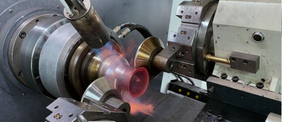
A CNC Circular Shearing Machine is a precision cutting tool designed for shearing circular shapes or materials, typically used for cutting sheets, plates, or tubes into specific sizes. The machine operates with a computer numerical control (CNC) system, which provides advanced control and automation of the shearing process. CNC technology enables higher precision, repeatability, and flexibility compared to traditional manual or mechanical shearing methods.
Here’s a breakdown of the key features, working principles, and applications of CNC Circular Shearing Machines:
1. Key Features of CNC Circular Shearing Machines
- CNC Control: The most significant feature of this machine is its use of CNC control systems. Operators can input precise cutting instructions into the machine, and the system will automatically adjust the blade’s position, cutting speed, and pressure to produce the desired results. This offers automation, reduces human error, and ensures high consistency across repeated cuts.
- High Precision: These machines are designed to provide high-precision cuts, which is critical in industries where material dimensions and shapes must meet tight tolerances.
- Versatility in Material Handling: CNC circular shearing machines can handle a variety of materials, including metal sheets, plastics, composites, and tubes, depending on the specific configuration of the machine.
- Blade Design: The cutting blades are designed for continuous and repetitive cuts without significant wear. Some CNC circular shearing machines offer options for adjusting the blade angle and clearance to accommodate various material thicknesses.
- Automation and Programming: Once the initial setup and programming are completed, the CNC system controls all aspects of the operation, including feed rate, cutting speed, cut length, and blade positioning.
- Safety Features: CNC circular shearing machines are equipped with multiple safety features, such as emergency stop buttons, safety enclosures, and interlock systems to ensure safe operation.
2. Working Principle
- Material Placement: The material to be cut is placed onto a worktable or feeding conveyor system. The material is securely held in place using clamps or a mechanical feed system to prevent movement during cutting.
- Cutting Process: The machine uses a rotating circular blade to shear the material. The CNC system adjusts the blade’s speed and position, and the material is fed through the cutting area, where the rotating blade applies pressure to shear the material into the desired shape.
- Automation Control: The CNC system controls the movement of the cutting head and feeding mechanism based on the programmed parameters. It precisely determines how fast the material is fed, the cutting speed, and the position of the blade to achieve high accuracy.
- Post-Cut Handling: After the material is sheared, it can be automatically moved to a collection bin or conveyor belt for further processing or packaging.
3. Advantages of CNC Circular Shearing Machines
- High Efficiency: CNC Circular Shearing Machines allow for rapid cutting and high throughput, which is especially useful in industries requiring large-scale production with consistent results.
- Reduced Labor: With CNC technology, the need for manual operation is minimized. Once the machine is programmed, it can run continuously with little human intervention, reducing labor costs and human error.
- Improved Cut Quality: The precision of CNC control ensures that cuts are accurate, clean, and meet tight tolerances, improving product quality.
- Flexibility in Design: CNC systems enable quick reprogramming, allowing manufacturers to produce different shapes and sizes without changing the machine’s configuration significantly. This flexibility is crucial for industries with varying production demands.
- Reduced Material Waste: The high precision of CNC machines minimizes overcuts, resulting in less wasted material and better overall material utilization.
4. Applications of CNC Circular Shearing Machines
- Metalworking Industry: Used for shearing metal sheets, plates, and tubes into specific sizes for manufacturing processes in industries such as automotive, aerospace, and construction.
- Fabrication: CNC shearing is commonly used in sheet metal fabrication, where precise and clean cuts are required for creating metal components, frames, and structures.
- Pipe and Tube Cutting: CNC circular shearing machines are effective for cutting pipes and tubes of various materials, including stainless steel, aluminum, and copper, into precise lengths.
- Electronics Manufacturing: In the production of circuit boards, electronic enclosures, and other components, CNC shearing provides the accuracy needed to create complex shapes from metal and plastic materials.
- Packaging Industry: In industries like packaging, where materials such as cardboard, plastics, and aluminum foils need to be cut to specific dimensions, CNC circular shearing machines offer high-speed and precise cutting.
- Automotive Parts Manufacturing: Components such as brake discs, gears, and shock absorbers often require circular shearing to meet strict quality standards.
5. Types of CNC Circular Shearing Machines
- Single-Blade Shearing Machines: These are designed with a single rotary blade and are typically used for straight-line cuts or simple circular cuts in thin materials.
- Double-Blade Shearing Machines: These machines utilize two rotating blades, one for the upper portion and one for the lower, offering more advanced cutting capabilities and the ability to shear thicker materials with more precision.
- High-Speed Shearing Machines: These machines are designed for high-speed cutting applications where large volumes of material need to be sheared rapidly without compromising on quality.
- Multi-Axis Shearing Machines: Some advanced CNC circular shearing machines feature multi-axis controls, allowing them to handle more complex geometries and cutting angles, making them suitable for high-precision industrial applications.
6. Maintenance and Upkeep
Regular maintenance of CNC circular shearing machines is essential for ensuring optimal performance and longevity. Key aspects of maintenance include:
- Blade Sharpening: Regular sharpening or replacing of the cutting blades to maintain the quality of cuts and avoid material deformation.
- Lubrication: Proper lubrication of moving parts, including the rotating blades and feed mechanisms, to reduce wear and friction.
- Cleaning: Regular cleaning of the machine, especially around the cutting area, to remove debris and prevent blockages that could affect the machine’s performance.
- Software Updates: Keeping the CNC system’s software up-to-date to ensure that it continues to function with the latest features and security patches.
7. Future Trends in CNC Circular Shearing Machines
- Integration with IoT: Increasing connectivity and integration with Internet of Things (IoT) technologies will enable real-time monitoring of machine performance, predictive maintenance, and better production analytics.
- Machine Learning and AI: Incorporating machine learning algorithms into the CNC systems can enhance automation, allowing the system to adapt to changing material conditions and improve cutting efficiency.
- Increased Precision: Future developments will likely focus on improving the precision of cuts, particularly for highly specialized materials and components, including the use of laser-guided or sensor-driven technologies for even finer adjustments.
Conclusion
CNC Circular Shearing Machines play a crucial role in modern manufacturing, offering high-precision, flexibility, and efficiency for cutting circular shapes and materials. Their ability to produce consistent and accurate cuts, combined with the automation of the CNC system, makes them invaluable in industries requiring high-quality parts, such as automotive, aerospace, and electronics. As technology continues to advance, these machines will become even more integrated into smart manufacturing systems, offering further enhancements in precision, speed, and adaptability.
CNC Circular Shearing Machines are evolving to meet the demands of modern manufacturing by incorporating more sophisticated technologies and automation systems. As industries continue to focus on higher productivity, precision, and reducing operational costs, these machines are at the forefront of enhancing manufacturing capabilities. The integration of IoT (Internet of Things) is one significant step forward, allowing manufacturers to collect and analyze real-time data from the machine. This can help predict potential failures before they occur, significantly reducing unplanned downtime and maintenance costs. By having constant feedback on the machine’s performance, manufacturers can ensure that the machine operates at optimal efficiency and productivity levels.
In addition to IoT integration, the use of AI (artificial intelligence) and machine learning algorithms will play a critical role in refining the operations of CNC Circular Shearing Machines. These technologies will allow the machines to continuously adapt and improve their performance. For instance, the machine can learn from previous cuts to optimize cutting parameters, such as speed, feed rate, and blade position, to minimize wear and reduce material wastage. This will not only increase the speed and accuracy of the cutting process but also extend the lifespan of critical machine components like the cutting blades, making the entire process more cost-effective.
Another major advancement is the development of advanced material handling systems that work in conjunction with the CNC Circular Shearing Machines. As materials become increasingly complex, such as high-strength alloys or composites, these machines will need to incorporate specialized systems for automatically adjusting to material characteristics. For example, adaptive feeding systems can automatically adjust the tension or speed of material feed to accommodate different thicknesses, preventing deformation or slippage during the cutting process. Additionally, robotic arms and automated guided vehicles (AGVs) may be employed to handle materials before and after the shearing operation, further reducing human involvement and improving the speed of material flow through the production line.
As the demand for customized parts and small batch production grows, CNC Circular Shearing Machines will become even more flexible. These machines are expected to handle a wider range of materials, from thin foils to thick plates, and produce parts with intricate designs. To accommodate this, the programming and control systems will evolve to allow rapid reconfiguration, enabling manufacturers to easily switch between different production runs. This adaptability will be crucial in industries such as aerospace and automotive, where precision and flexibility are essential.
Sustainability is also a growing focus within the manufacturing sector, and CNC Circular Shearing Machines are likely to see innovations aimed at reducing their environmental impact. Machines will incorporate energy-efficient motors and waste reduction technologies to minimize energy consumption and material waste. For example, near-net-shape cutting could become more prevalent, where parts are sheared as closely as possible to their final dimensions, minimizing the need for further processing and reducing scrap material. Furthermore, the use of recyclable materials and eco-friendly lubricants in the cutting process will also contribute to more sustainable manufacturing practices.
One of the most exciting possibilities for the future is the integration of augmented reality (AR) and virtual reality (VR) into CNC Circular Shearing Machines. These technologies will allow operators to visualize the cutting process in real-time and make adjustments instantly. For instance, AR glasses could display essential information about the machine’s parameters, cutting paths, and material specifications, enabling operators to optimize the cutting process and identify potential issues before they occur. Similarly, VR simulations could be used for training purposes, allowing operators to practice handling various machine settings and troubleshooting without the need for physical machines, thus reducing training costs and enhancing operator competence.
With the continued push toward smart factories and Industry 4.0, CNC Circular Shearing Machines will play an integral role in the digitization of manufacturing processes. These machines will be connected to a larger network of machines, where data is exchanged seamlessly, allowing for the optimization of the entire production line. Through the use of big data analytics, manufacturers will be able to track key performance indicators (KPIs) across multiple machines, identify trends, and predict demand shifts in real time. This will enable manufacturers to adjust production schedules and machine operations accordingly, reducing idle time and ensuring more efficient resource allocation.
Furthermore, CNC Circular Shearing Machines will become increasingly user-friendly. As operators become more reliant on automation, the interfaces of these machines will evolve to be more intuitive. Touchscreen interfaces, voice commands, and gesture controls will replace traditional control panels, allowing operators to interact with the machine in ways that are more natural and less prone to error. Additionally, the user interface will incorporate real-time feedback from the machine, such as alerts about tool wear, material inconsistencies, or operational inefficiencies, ensuring that operators are always informed and can take corrective actions immediately.
In terms of customization, the ability to adjust cutting parameters for different materials and designs without physically altering the machine’s setup will make CNC Circular Shearing Machines more versatile. This adaptability will allow manufacturers to offer more personalized products and meet a broader range of customer demands without sacrificing efficiency. Cloud-based systems could also enable remote monitoring and control of CNC machines, allowing engineers and technicians to access the machine’s data and make adjustments even if they are not physically present at the facility.
As the demand for high-precision components continues to grow, particularly in sectors like medical devices, electronics, and defense, the role of CNC Circular Shearing Machines will become even more pivotal. These industries require parts that not only meet stringent quality standards but are also produced with minimal deviation. The advancements in CNC technology will support this demand, offering nanometer-level precision and the ability to cut complex geometries with ease.
In conclusion, the future of CNC Circular Shearing Machines is characterized by continued innovation, driven by advancements in automation, AI, sustainability, and user interface technologies. These machines will continue to evolve, offering more flexibility, precision, and efficiency, making them integral to the modern manufacturing environment. As industries demand more complex and customized parts, the role of CNC Circular Shearing Machines will become even more essential in meeting these challenges while improving productivity and minimizing waste.
Looking ahead, the development of CNC Circular Shearing Machines will likely focus on even greater integration with advanced manufacturing systems. As factories move toward becoming more interconnected and data-driven, these machines will be an essential part of the digital ecosystem within manufacturing plants. By connecting with other systems like Enterprise Resource Planning (ERP) and Manufacturing Execution Systems (MES), CNC machines can seamlessly align production schedules, inventory management, and quality control. This will result in even greater efficiencies, as production data can be analyzed and adjustments made in real time based on current conditions, such as material availability, customer demand, or supply chain constraints.
Furthermore, there will likely be a push toward smarter, self-diagnostic systems that reduce downtime and improve the overall efficiency of the machine. Advanced predictive maintenance technologies will allow the machines to self-monitor their health, alerting operators to wear and tear before it causes failure. This will help minimize unscheduled maintenance and keep production lines running smoothly. These diagnostic systems will not only track standard components like the cutting blades but also monitor sensors, actuators, and other critical elements. With continuous analysis of performance data, the system can alert operators about potential issues, order replacement parts autonomously, and even suggest the optimal maintenance schedule.
Additionally, remote diagnostics and machine access will become more prevalent. Technicians can access the machines from anywhere in the world, diagnose issues, and even guide on-site operators through troubleshooting processes. This remote capability, paired with augmented reality (AR), will allow experts to virtually “see” what the operator sees, offering real-time support through visual overlays or instructions, helping operators make corrections quickly and efficiently.
In the context of material science, CNC Circular Shearing Machines are likely to see improvements in their ability to process new, high-performance materials. As industries like aerospace, energy, and medical devices continue to rely on materials with specialized properties—such as titanium alloys, carbon fiber composites, or ultra-high-strength steel—these machines will need to be equipped with cutting-edge technologies to handle these advanced materials. They will also need to adapt to new processing techniques, such as laser-assisted shearing or high-pressure cutting, which could offer improved quality and less material degradation when working with such difficult materials.
Customization will be another key trend driving the future of CNC Circular Shearing Machines. The increasing trend toward mass customization—where small production runs of unique or specialized products are made to order—will demand machines that can quickly adapt to different cutting tasks. These machines will not only need to be reprogrammed easily but will also likely incorporate modular tooling and interchangeable cutting heads, enabling rapid changeover between different product lines without significant downtime. This flexibility will be crucial for manufacturers seeking to remain competitive while meeting the demands of increasingly complex and diverse customer orders.
As the global supply chain becomes more dynamic, CNC Circular Shearing Machines will play a key role in helping manufacturers remain nimble. The ability to produce parts with minimal lead time and respond quickly to market fluctuations will be a key differentiator. Automated reprogramming and adjustments, in combination with fast material handling systems, will allow manufacturers to shift between different production runs, optimize machine usage, and avoid overproduction, thus better meeting the just-in-time production models that are common in industries like automotive and electronics.
Sustainability will continue to be a focal point, with CNC Circular Shearing Machines contributing to the reduction of waste through more efficient cutting processes. Advances in cutting precision, as well as the integration of recycling systems, will minimize material waste. Some machines may even incorporate waste material collection systems, which can immediately recycle offcuts or scrap for reuse in future production. The increased focus on closed-loop production systems—where all materials, energy, and processes are continuously recycled and reused—will lead to more environmentally friendly practices within manufacturing.
In terms of energy efficiency, CNC Circular Shearing Machines will likely continue to incorporate smart energy management systems that monitor and optimize power usage. By adjusting power consumption based on machine activity, the system will ensure that energy is used efficiently. This will be important as companies continue to focus on reducing energy costs and lowering their environmental impact. Innovations in energy-efficient drives, regenerative braking systems, and optimized power cycles will ensure that these machines meet industry sustainability goals.
Another interesting development could be the further integration of biometrics and gesture control systems for operator interfaces. As touchless technologies gain popularity, operators may be able to interact with CNC machines through hand gestures, voice commands, or even facial recognition. These types of controls could be especially useful in environments where hygiene is important, or where operators are required to work in clean rooms or controlled environments.
Finally, the future of CNC Circular Shearing Machines will be deeply intertwined with advanced simulation and digital twin technology. Digital twins, which are virtual replicas of physical machines, will allow manufacturers to simulate machine performance under different operating conditions. Engineers can test and optimize machine settings virtually before making any physical changes to the system. This not only improves machine performance but also reduces the cost and time associated with physical trials and testing.
By creating these digital replicas, manufacturers will be able to test different materials, cutting strategies, and tooling configurations in a virtual environment, allowing them to gain insights and optimize the shearing process before any material is physically cut. The ability to simulate the entire manufacturing process will be an invaluable tool for improving the overall efficiency and output of CNC Circular Shearing Machines, while also enhancing safety and quality.
In summary, the future of CNC Circular Shearing Machines is one of increasing automation, intelligence, and adaptability. As manufacturing continues to evolve, these machines will incorporate more advanced technologies, such as AI, IoT, remote diagnostics, energy efficiency, and sustainability features. The result will be a smarter, more flexible manufacturing environment that can respond to the growing demands for precision, speed, and customizability while reducing waste and operational costs. The integration of these advanced technologies will ensure that CNC Circular Shearing Machines remain a cornerstone of modern manufacturing, driving the next wave of innovation in industries worldwide.
As the evolution of CNC Circular Shearing Machines continues, the integration of robotics will become a pivotal aspect of their functionality. Advanced robotic systems will work alongside these machines to handle complex tasks like material loading and unloading, positioning, and even post-processing of sheared parts. Collaborative robots (cobots), which are designed to work safely alongside human operators, could assist in the setup and operation of the machines, ensuring smooth material flow, quick changeovers, and minimal manual intervention. This could be especially beneficial in industries where production runs are small and frequent, such as in aerospace and automotive manufacturing.
Robots could also be used for automated quality control, inspecting the sheared parts for defects such as surface imperfections, dimensional inaccuracies, or even material inconsistencies. Integrating vision systems with AI-powered inspection software could provide real-time feedback, allowing for immediate corrective actions during production. This would significantly reduce the need for manual inspections and enhance the overall quality of the final product.
The rise of multi-functional machines is another trend in the evolution of CNC Circular Shearing Machines. Instead of having a machine that solely performs shearing operations, future machines may integrate multiple functions such as cutting, punching, bending, and even welding. This multifunctionality would help manufacturers reduce space and operational costs by consolidating several processes into one machine. Manufacturers could complete various tasks in a single production cycle, improving cycle time and workflow efficiency.
These machines will also likely feature more advanced adaptive control systems, where sensors placed throughout the machine can detect the material’s properties in real-time. This feedback will allow the machine to adjust cutting parameters on-the-fly based on variations in material thickness, hardness, or other characteristics. This system could be paired with machine learning algorithms that continuously improve the machine’s ability to handle various material types and production conditions. The machine would “learn” the optimal cutting parameters over time, resulting in faster setups, fewer adjustments, and a higher overall quality of cuts.
Moreover, as manufacturers strive to meet increasing global demand for personalized products, digital customization will play a significant role in shaping the future of CNC Circular Shearing Machines. These machines could integrate with digital platforms that allow customers or design engineers to submit customized specifications in real-time. This would enable manufacturers to offer on-demand production of highly personalized or one-of-a-kind products, bypassing traditional inventory models and reducing lead times.
Furthermore, cloud-based systems are expected to play a larger role in the future of CNC machinery. By using cloud computing, manufacturers will have the ability to remotely monitor the performance and health of CNC Circular Shearing Machines from anywhere in the world. Cloud-based analytics will allow engineers to collect and analyze vast amounts of operational data, spotting patterns and identifying areas for improvement. This cloud connectivity could also enable the sharing of best practices and troubleshooting advice across global production facilities, ensuring standardization and higher operational efficiency across multiple sites.
Another key area for future development is integration with additive manufacturing (3D printing). Although additive manufacturing is typically used for creating parts layer by layer, combining it with subtractive manufacturing processes, like CNC circular shearing, could offer new possibilities for creating complex, high-precision components. For example, CNC machines could be used to shear material to specific dimensions, after which 3D printing could be used to add intricate features or customize components further. This hybrid manufacturing approach would be especially beneficial in industries requiring complex parts with highly precise tolerances, such as in medical devices or aerospace applications.
As advanced analytics and big data become more ingrained in the manufacturing industry, CNC Circular Shearing Machines will be equipped with sophisticated data-logging systems that provide detailed insights into the entire production process. This will help manufacturers optimize machine performance, reduce energy consumption, and track material usage in real time. By gathering comprehensive data on each machine cycle, manufacturers can identify patterns of inefficiency and develop targeted strategies to improve the overall production process.
The globalization of manufacturing will also drive the development of CNC Circular Shearing Machines. Manufacturers are increasingly tasked with producing parts for global markets with varying standards and requirements. Future machines will need to adapt to different regulatory and environmental standards from region to region, offering flexible solutions that can easily be adjusted to meet local needs. For instance, these machines might be able to automatically switch between different cutting technologies—such as laser cutting, waterjet cutting, and plasma cutting—depending on the materials being processed and the specific requirements of the customer.
Cybersecurity will become an increasingly critical consideration as CNC Circular Shearing Machines become more interconnected with digital systems and networks. With the rise of the smart factory and Industry 4.0, CNC machines will be part of a larger network of interconnected devices, making them vulnerable to potential cyber threats. Manufacturers will need to ensure that these machines are equipped with robust security measures to protect sensitive data, maintain operational integrity, and prevent unauthorized access. Data encryption, firewalls, and multi-factor authentication could be implemented to protect against hacking and to safeguard intellectual property.
Additionally, with the shift toward sustainability, there will likely be increasing pressure for machines to be carbon neutral or to have lower carbon footprints. Future CNC Circular Shearing Machines may be designed with energy efficiency as a primary goal, incorporating renewable energy sources like solar panels or wind energy to power operations. Moreover, the recycling of cut-off material will become an integral part of the production process. These machines may feature systems that not only collect the offcuts but also automatically segregate them for reuse, cutting down on waste and improving the environmental sustainability of the manufacturing process.
In terms of training and user support, future CNC Circular Shearing Machines will increasingly rely on augmented reality (AR) and virtual reality (VR) technologies for operator training and troubleshooting. These technologies will allow operators to receive real-time, interactive guidance when learning how to operate the machine or when addressing complex maintenance issues. AR goggles could project vital operational data or highlight areas that require attention, such as worn-out parts or issues with material alignment, reducing human error and increasing the speed of problem resolution.
The global supply chain will also benefit from the increased precision and flexibility of future CNC Circular Shearing Machines. As global trade continues to expand, manufacturers will need to produce higher-quality parts more efficiently and in smaller quantities. CNC Circular Shearing Machines equipped with intelligent systems will facilitate this shift, enabling manufacturers to scale production based on demand and reducing the lead times for international shipments. These machines could be connected to global inventory management systems, enabling real-time tracking of materials, finished products, and components across the supply chain.
In conclusion, the future of CNC Circular Shearing Machines is an exciting one, marked by advancements in automation, intelligence, and adaptability. As these machines evolve, they will become more integrated, more flexible, and more efficient, enabling manufacturers to meet the demands of modern, fast-paced, and highly customized production environments. The ongoing development of smart technologies, sustainability initiatives, and customization capabilities will ensure that CNC Circular Shearing Machines remain an essential tool in the future of manufacturing, driving productivity, reducing waste, and supporting innovation across a variety of industries.
The future landscape for CNC Circular Shearing Machines will be driven by several emerging technological trends and strategies aimed at improving both productivity and sustainability. As the manufacturing industry pushes for smarter, more connected, and flexible production systems, these machines will play a critical role in realizing these goals.
One of the most impactful developments will be the integration of cloud computing and edge computing technologies. Edge computing involves processing data close to where it is generated—directly on the machine itself or within a local network—rather than sending it all to a distant cloud server. This will allow for faster data processing and decision-making, especially when real-time adjustments are needed for cutting parameters, material feed rates, or machine diagnostics. As CNC Circular Shearing Machines become more advanced, edge computing will enable them to analyze and act on operational data instantly, reducing latency and increasing the speed of production processes.
By coupling cloud and edge computing, manufacturers can achieve a hybrid system where real-time operations are optimized on-site, while deeper analytics and long-term predictive models can be processed in the cloud. This combination of local and cloud-based intelligence will lead to more dynamic and responsive manufacturing systems, allowing operators to monitor multiple machines, track production progress, and make data-driven decisions remotely. This will enable continuous optimization of the manufacturing process based on a constant flow of data from connected systems and machines.
As supply chains become more complex and interconnected, CNC Circular Shearing Machines will need to incorporate real-time supply chain feedback. For example, material availability, delays, or changes in demand could be communicated instantly to the machine, allowing for real-time adjustments. A CNC machine might modify its cutting speed or tooling selection based on new information about material quality or delivery schedules. Similarly, if the machine detects a change in material type or a defect in raw stock, it can alert the operator or even adjust its settings automatically to compensate for variations.
Advanced sensors will be integral to the next generation of CNC Circular Shearing Machines. These sensors will monitor various aspects of the machine’s environment, including material thickness, temperature, vibration, and cutting forces. By collecting real-time data from sensors, the machine will be able to provide detailed insights into its own operational health. For instance, sensors can detect unusual vibrations or temperature changes that could indicate impending failures, allowing operators to take proactive measures before costly repairs are needed. Additionally, smart cutting tools with integrated sensors will be able to alert operators when they begin to wear down, reducing the chances of faulty cuts or machine malfunctions.
Artificial Intelligence (AI) will play an increasingly significant role in machine operations, not just in predictive maintenance but also in intelligent manufacturing optimization. AI can learn from the machine’s historical performance, analyze real-time data, and optimize settings to achieve the best cutting results. Over time, AI-driven systems will become more adept at anticipating changes in the manufacturing environment, such as fluctuations in material hardness or varying environmental conditions, and adjusting machine parameters automatically. This will not only increase productivity but also improve the quality and consistency of the sheared parts.
Moreover, digital twin technology will be pivotal in shaping the future of CNC Circular Shearing Machines. A digital twin is a virtual representation of the physical machine that mirrors its real-time performance. Using the data from the machine’s sensors, the digital twin can simulate and predict how the machine will behave under various conditions, making it an invaluable tool for optimization. Engineers can run simulations of different cutting processes or maintenance schedules on the digital twin, gaining insights without impacting actual production. In addition, manufacturers can use digital twins to test new cutting strategies or material types, thereby improving design processes and reducing the risk of errors before making physical changes to the machine.
As material science advances, CNC Circular Shearing Machines will need to adapt to handle a broader range of complex, high-performance materials. For example, the rise of advanced composites—materials that combine multiple components to achieve superior strength, durability, or flexibility—will require more specialized shearing techniques. These materials can be challenging to cut, and traditional approaches may cause damage or result in poor-quality cuts. The next generation of CNC Circular Shearing Machines will likely incorporate specialized cutting heads or laser-assisted cutting technologies to handle these difficult-to-cut materials, allowing for precision cuts without compromising the integrity of the material.
Another significant trend is the increased focus on sustainable manufacturing practices. As industries face increasing pressure to reduce their environmental impact, CNC Circular Shearing Machines will likely incorporate a range of eco-friendly features. For instance, future machines may feature closed-loop cooling systems, where cutting fluids are filtered, cleaned, and reused, reducing waste and improving operational efficiency. Moreover, zero-waste manufacturing practices could become more common, where offcuts from the shearing process are not discarded but instead fed back into the production system for reuse or recycling. This could be particularly valuable in industries like metalworking and electronics, where even small amounts of material waste can have significant environmental consequences.
Circular economy principles—which emphasize the reuse and recycling of materials—will likely become a foundational part of the design and operation of future CNC Circular Shearing Machines. As raw materials become scarcer and more expensive, the demand for machines that can maximize the utility of materials will increase. These machines could be designed to work with recycled or reclaimed materials, cutting them with the same precision and efficiency as virgin stock. This approach would reduce the demand for new raw materials, help preserve natural resources, and lower costs in the long run.
The role of machine learning will also extend beyond just process optimization. In the future, CNC Circular Shearing Machines may be able to automatically adapt to new materials and products without requiring operator intervention. Machine learning algorithms will help the machine recognize and adjust to variations in material properties, like density, texture, and thermal behavior. For example, the machine might automatically adjust the feed rate or cutting speed depending on the material hardness, ensuring optimal cutting conditions. Over time, as more data is collected, the machine will refine its understanding of different materials, becoming more efficient at processing them with each cycle.
As virtual reality (VR) and augmented reality (AR) become more integrated into manufacturing workflows, CNC Circular Shearing Machines will likely see these technologies applied to both operator training and remote machine monitoring. VR could be used for immersive training experiences where operators practice handling various setups, materials, and cutting techniques without being on the shop floor. AR could be used in real-time for assisting with machine setup or for on-the-job troubleshooting. For instance, an operator might use AR glasses to view step-by-step instructions for machine setup or to receive live feedback on the machine’s condition, enhancing both efficiency and accuracy.
Modular designs will also play a critical role in the evolution of CNC Circular Shearing Machines. Instead of designing one-size-fits-all machines, manufacturers will likely focus on creating modular systems that can be easily reconfigured or upgraded based on production needs. This could involve the use of interchangeable components that allow for rapid adjustments to cutting tools, material handling mechanisms, or even the machine’s software. The modular approach will increase the machine’s lifespan and reduce the need for costly re-investments in new equipment as production demands change.
Finally, the future of CNC Circular Shearing Machines will see the continued trend of data-driven manufacturing. By leveraging big data and advanced analytics, manufacturers will be able to gain a more granular understanding of the factors influencing machine performance, production rates, material costs, and product quality. With these insights, manufacturers will be able to make better-informed decisions, optimize machine utilization, and predict potential issues before they occur, resulting in more efficient and profitable operations.
In summary, the future of CNC Circular Shearing Machines will be shaped by a combination of advancements in automation, data analytics, sustainability, and digital connectivity. These machines will become more adaptable, efficient, and intelligent, seamlessly integrating into the broader manufacturing ecosystem to drive innovation, reduce costs, and enhance product quality. Whether it’s through predictive maintenance, AI-driven optimization, or eco-friendly designs, CNC Circular Shearing Machines will continue to evolve, helping manufacturers meet the challenges of the future while remaining competitive in a rapidly changing global marketplace.
A Hydraulic Circular Shearing Machine is a type of cutting machine that utilizes hydraulic force to perform precision shearing or cutting of circular metal or material workpieces. These machines are commonly used in various industries such as metalworking, automotive, construction, and aerospace, where precision cutting of cylindrical materials is essential. Hydraulic Circular Shearing Machines are specifically designed to provide high cutting force and excellent quality cuts with minimal distortion.
Key Features of Hydraulic Circular Shearing Machines
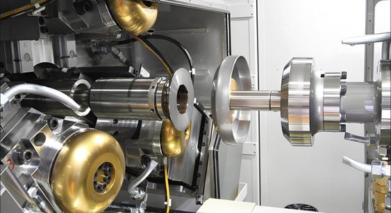
- Hydraulic System:
- The hydraulic system is the core of these machines, generating the power required for the cutting process. It uses hydraulic fluid to transmit force through cylinders to move the cutting blades. The hydraulic system allows for smooth, controlled cutting action, offering the ability to exert high pressure with minimal energy consumption.
- The hydraulic pressure is adjustable, allowing for flexibility when cutting different materials and thicknesses. This adjustability also ensures that the machine can handle a wide range of applications.
- Rotary Cutting Mechanism:
- In this type of shearing machine, the cutting blade moves in a rotary motion, as opposed to a linear motion. This means that the blade continuously rotates as it cuts through the material. This setup is ideal for processing round or cylindrical material, such as pipes, tubes, or disks, into precise, clean cuts.
- The rotary nature of the cutting action helps reduce the wear and tear on the blades since the load is evenly distributed, providing longer tool life.
- Blade Configuration:
- Hydraulic Circular Shearing Machines use circular blades that are designed to cut through materials efficiently. These blades are made from high-strength steel and are often coated with materials that reduce wear and enhance their cutting efficiency.
- The blades are mounted in a way that ensures maximum cutting force with minimal vibration or deflection, leading to highly accurate cuts.
- Adjustable Cutting Force:
- The hydraulic system allows the cutting force to be adjusted based on the material and thickness being cut. This adjustability is critical for working with different material types such as mild steel, stainless steel, aluminum, and composites.
- The cutting force can be finely tuned to avoid deformation of the material, ensuring that the sheared parts retain their required dimensions and surface quality.
- Safety Features:
- Given the high forces involved in the cutting process, safety is a significant consideration. Hydraulic Circular Shearing Machines come equipped with several safety features, such as automatic shutdown systems, safety guards, emergency stop buttons, and protective enclosures around the cutting area to prevent accidental contact with moving parts.
- Customization Options:
- Many Hydraulic Circular Shearing Machines come with options for customization, such as variable-speed drives for the hydraulic pump, automatic material feeding systems, and programmable controls. This level of customization allows manufacturers to fine-tune the machine’s performance based on specific production needs, optimizing productivity and minimizing waste.
- Some machines may also be equipped with CNC controls, enabling more precise cuts and the ability to program complex cut patterns.
- High-Precision Cutting:
- The use of hydraulics and the rotary mechanism ensures that the machine can make precise cuts with high repeatability. The pressure applied is consistent, which ensures uniformity and accuracy in the final product.
- With proper setup and calibration, these machines can achieve tolerance levels of ±0.1mm or better, making them suitable for high-precision industries like aerospace, medical device manufacturing, and electronics.
Applications:
- Metalworking and Fabrication:
- In industries like steel fabrication or construction, hydraulic circular shearing machines are used to cut round bars, pipes, and plates to specified lengths or diameters.
- Automotive Industry:
- These machines are often used for cutting parts like wheels, brackets, bushings, or other circular components for automotive assemblies.
- Aerospace:
- The aerospace industry utilizes these machines to cut metal sheets, tubing, or circular components used in aircraft frames, engines, and other critical applications.
- Pipe Manufacturing:
- Hydraulic circular shearing machines are ideal for cutting pipes into precise lengths, often used in manufacturing plumbing systems, oil and gas, or chemical processing industries.
Benefits of Hydraulic Circular Shearing Machines:
- High Cutting Force:
- Hydraulic systems generate high amounts of force, making them capable of cutting through thick and hard materials with ease.
- Energy Efficiency:
- Compared to traditional mechanical shearing machines, hydraulic systems can offer more energy-efficient performance, as the hydraulic fluid requires less power to generate significant force.
- Minimal Maintenance:
- Hydraulic systems, when properly maintained, have fewer moving parts compared to mechanical systems, which leads to lower wear and reduced maintenance costs over time.
- Versatility:
- These machines are versatile, handling a wide range of materials, thicknesses, and sizes without sacrificing precision.
- Compact Design:
- Many hydraulic circular shearing machines are designed to be compact and easy to integrate into existing production lines, making them ideal for spaces with limited floor area.
Potential Challenges:
- Hydraulic Fluid Leaks:
- Like all hydraulic machines, these shearing machines rely on fluid systems, and there is the potential for hydraulic fluid leaks, which need to be monitored and maintained to ensure safety and efficiency.
- Power Consumption:
- While hydraulic systems can be energy-efficient, high-pressure systems can consume a lot of power, particularly in heavy-duty operations, which might increase operational costs if not optimized.
- Initial Investment:
- Hydraulic circular shearing machines can require a higher initial investment compared to simpler mechanical shearing machines. However, this is often offset by their longevity, precision, and ability to handle diverse tasks.
Future Trends and Advancements:
- Integration with Automation and IoT:
- As manufacturing becomes more automated, hydraulic circular shearing machines are expected to integrate with robotic systems for material loading/unloading and Internet of Things (IoT) technologies for remote monitoring, diagnostics, and predictive maintenance.
- Energy Efficiency Enhancements:
- Future designs will likely focus on improving energy efficiency, possibly incorporating variable speed pumps and regenerative hydraulic systems to reduce energy consumption during idle periods.
- Advanced CNC Controls:
- The incorporation of more sophisticated CNC systems will allow for greater flexibility, enabling faster setup times, more complex cutting patterns, and better integration into automated production lines.
- Hybrid Cutting Technologies:
- Hybrid machines that combine hydraulic shearing with other cutting methods, such as laser cutting or plasma cutting, may become more prevalent. These hybrid systems would provide even greater flexibility, allowing for different cutting methods to be applied depending on the material and the required result.
In conclusion, Hydraulic Circular Shearing Machines are an essential tool in industries that require high-force cutting of circular materials with precision. With their powerful hydraulic systems, versatility, and ability to handle tough materials, they are ideal for manufacturing processes that require accuracy, repeatability, and customization. As technology advances, these machines are expected to become more integrated with automation systems, improve energy efficiency, and incorporate new materials handling capabilities, ensuring their continued relevance and capability in modern manufacturing environments.
Hydraulic Circular Shearing Machines offer a powerful solution for precise cutting, especially in industries that require the handling of round or cylindrical materials. These machines are renowned for their reliability, high cutting force, and versatility, making them essential in sectors like metalworking, automotive, aerospace, and pipe manufacturing. The core feature of these machines is the hydraulic system, which provides a high level of force to perform cuts with precision, without excessive energy consumption. The hydraulic system uses fluid pressure to generate force that moves cutting blades, providing an efficient and controlled cutting process.
The use of rotary cutting mechanisms in these machines allows them to handle circular materials like pipes, tubes, and discs effectively. The rotating blades ensure that the material is cut smoothly and evenly. Since the load is distributed across the rotating blade, wear on the cutting tool is minimized, which helps maintain the quality of the cuts over time. The hydraulic pressure, which is adjustable, provides flexibility for different material types and thicknesses, making these machines adaptable for a wide range of applications.
These machines excel in applications where accuracy is critical. The ability to adjust the cutting force based on material characteristics ensures that the cut remains precise, with minimal distortion or damage to the material. This is particularly important when working with materials like steel, aluminum, stainless steel, or advanced composites, which require exact cutting conditions for optimal results. The high precision and repeatability offered by hydraulic circular shearing machines also make them ideal for industries where part uniformity is crucial, such as in aerospace or medical device manufacturing.
As the demand for sustainability and energy efficiency grows, manufacturers are looking to hydraulic systems as an energy-efficient alternative to mechanical systems. By using hydraulic fluid to transmit power, these machines consume less energy while still providing the high cutting force required. However, it’s important to monitor the hydraulic fluid levels and ensure that there are no leaks, as hydraulic systems can be prone to fluid loss, which could compromise the machine’s performance.
Another aspect driving the evolution of hydraulic circular shearing machines is their increasing integration with automation and digital technologies. These machines are being designed with features like CNC controls, allowing operators to program cutting patterns and adjust settings for different materials. Advanced sensors and monitoring systems are also being integrated to track the health of the machine, predict maintenance needs, and provide data for continuous process optimization. The incorporation of IoT (Internet of Things) technology allows operators to remotely monitor and manage these machines, improving efficiency and reducing downtime.
The growing trend of smart manufacturing also plays a significant role in the future development of hydraulic circular shearing machines. Manufacturers are increasingly looking to integrate these machines into smart production lines where machines communicate with each other, sharing real-time data to optimize the manufacturing process. For example, a machine could automatically adjust cutting parameters based on feedback from upstream machines or real-time data on material properties, allowing for more precise cuts and reducing the risk of errors.
Additionally, the focus on recycling and sustainable manufacturing has led to increased interest in machines that can handle reclaimed or recycled materials. Hydraulic circular shearing machines are being designed to accommodate materials that are not only challenging to cut but are also subject to sustainability regulations. These machines may include features like closed-loop cooling systems to reduce waste and improve environmental impact, making them more aligned with green manufacturing practices.
Looking forward, the potential for hybrid cutting technologies is another area where hydraulic circular shearing machines are evolving. Combining traditional hydraulic cutting methods with newer technologies such as laser cutting or plasma cutting could offer even greater flexibility for different materials and cutting conditions. Hybrid machines would be able to provide precise, high-quality cuts for a wider range of materials, reducing reliance on multiple specialized machines.
Furthermore, modular designs are becoming more common in hydraulic circular shearing machines, allowing manufacturers to easily reconfigure or upgrade their equipment as their needs evolve. This means that instead of investing in entirely new machines, companies can adapt their existing systems with modular components to meet changing production requirements, reducing capital investment and increasing machine longevity.
In conclusion, hydraulic circular shearing machines will continue to be a staple in industries that require precision cutting of circular materials. As technological advancements in automation, sensor integration, sustainability, and smart manufacturing progress, these machines will become even more versatile, energy-efficient, and capable of handling a broader range of materials and applications. Their ability to deliver high cutting force with precision and low energy consumption makes them a critical asset in modern manufacturing, and their future will likely be defined by greater flexibility, connectivity, and intelligent automation.
As we look to the future, Hydraulic Circular Shearing Machines are poised to evolve in tandem with broader technological shifts in manufacturing. One key area of advancement will be the integration of artificial intelligence (AI) and machine learning (ML). These technologies will enable machines to analyze real-time data from sensors and cameras to adjust cutting parameters automatically, optimizing the process for different materials, thicknesses, and part geometries. Over time, AI algorithms will learn from past cutting cycles and continuously improve their performance, reducing human intervention and minimizing the risk of errors.
AI-driven predictive maintenance is another area where hydraulic circular shearing machines will see a transformation. By using data gathered from sensors that monitor pressure, temperature, vibration, and tool wear, AI can predict when parts will need maintenance or replacement. This could help reduce downtime, prevent unexpected failures, and ultimately lower maintenance costs. Predictive maintenance, in combination with remote diagnostics, will allow manufacturers to handle potential issues before they affect production, ensuring higher uptime and improved operational efficiency.
The integration of 5G connectivity will further enhance the capabilities of hydraulic circular shearing machines. With 5G, real-time data transfer will be faster and more reliable, enabling seamless communication between machines on the shop floor and central control systems. This connectivity will enable a more responsive and adaptive manufacturing environment where machines can adjust their operations in real-time based on input from upstream or downstream processes, resulting in improved coordination and optimization of the entire production line.
The trend towards digitization and cloud-based solutions will also impact hydraulic circular shearing machines. Cloud platforms will allow manufacturers to store and analyze large amounts of operational data from their machines. By connecting these machines to cloud-based systems, manufacturers will have access to powerful analytics tools that can identify trends, bottlenecks, and areas for improvement. Moreover, the ability to remotely access machine data through cloud platforms will enable engineers and operators to monitor performance from anywhere in the world, facilitating remote troubleshooting and support.
Another exciting development will be the increasing use of additive manufacturing in conjunction with hydraulic circular shearing machines. Additive manufacturing, or 3D printing, allows for the creation of complex geometries and components that are not possible with traditional manufacturing methods. As these two technologies converge, we may see hydraulic circular shearing machines being used to cut or shape 3D printed parts, enabling manufacturers to combine the precision of shearing with the flexibility of additive manufacturing. This could open up new possibilities for producing parts with intricate designs and specialized materials.
Customization will be another significant area of growth. As manufacturers face increasingly complex production requirements and the need for shorter lead times, hydraulic circular shearing machines will become more customizable. Advances in software interfaces and user-friendly controls will allow operators to fine-tune cutting parameters more easily and quickly. Customizable cutting heads and attachments will enable these machines to handle a broader range of materials, including advanced composites, high-strength alloys, and hybrid materials. This flexibility will be especially beneficial in industries like aerospace, medical device manufacturing, and automotive, where complex, high-performance parts are the norm.
Furthermore, the role of robotics will continue to expand. Automated loading and unloading systems will become more common, and hydraulic circular shearing machines may be integrated into fully automated production lines. These robotic systems will be able to feed materials into the machine, remove cut parts, and handle the logistics of transporting materials to and from the shearing machine. This increased level of automation will not only improve efficiency but also reduce the risk of human error, especially in high-volume manufacturing environments.
Sustainability will also drive future developments in hydraulic circular shearing machines. As industries place more emphasis on green manufacturing, we can expect to see machines that are designed with energy-efficient components, such as regenerative hydraulic systems that capture and reuse energy during the cutting process. Manufacturers may also adopt practices that minimize waste by recycling scrap materials or using more eco-friendly cutting fluids. The rise of circular economy principles in manufacturing means that hydraulic circular shearing machines may be designed to handle more recycled and reclaimed materials, contributing to a more sustainable production process.
As part of the broader trend towards Industry 4.0, hydraulic circular shearing machines will become smarter and more interconnected, allowing for greater collaboration and coordination between machines and systems. This interconnectedness will enable a fully integrated digital twin of the manufacturing process. A digital twin is a virtual replica of the physical machine that can simulate its operations and predict potential failures before they happen. By using data from the machine, operators can optimize performance, troubleshoot issues, and test out changes in a virtual environment before implementing them on the actual machine. This can lead to cost savings, faster decision-making, and more precise control over the manufacturing process.
The materials handled by hydraulic circular shearing machines are expected to evolve as well. As new materials with enhanced properties are developed—such as lightweight composites or high-strength steel alloys—the cutting technologies will need to adapt to meet the challenges these materials pose. The blades and cutting heads of hydraulic shearing machines may need to be coated with new materials or enhanced with technologies like laser-assisted cutting to handle these more challenging materials without causing damage or excessive wear.
The user interface (UI) and control systems of hydraulic circular shearing machines will continue to evolve. In the future, we can expect more intuitive interfaces with touchscreen controls, voice commands, or gesture-based controls, which will make it easier for operators to interact with machines, especially for those who may not have extensive training. Advanced software features will allow operators to simulate the entire cutting process virtually, helping them fine-tune machine settings and predict outcomes before beginning the actual operation. This will reduce errors, improve throughput, and allow for more complex cutting tasks to be completed with minimal setup time.
Lastly, with the increasing global demand for products manufactured to high precision, manufacturers will be looking to hydraulic circular shearing machines to maintain or improve their product quality standards. Machines that offer unwavering accuracy, even over extended runs, will be critical in maintaining competitive advantages. This means that, alongside technological advancements, the need for quality assurance systems integrated into these machines will be greater than ever. Real-time quality checks, through integrated cameras or sensors that measure the cut surface or material thickness, will ensure that every part meets the required specifications, reducing the need for rework and enhancing the overall quality of production.
In conclusion, the future of Hydraulic Circular Shearing Machines will be shaped by automation, smart manufacturing, energy efficiency, and advanced material handling capabilities. As industries continue to demand more precise, sustainable, and adaptable manufacturing solutions, these machines will play an integral role in meeting those challenges. Their evolution into intelligent, networked systems will open new avenues for improving efficiency, reducing waste, and enhancing the quality of the products being manufactured. As technology progresses, hydraulic circular shearing machines will remain a vital part of modern manufacturing, evolving to meet the demands of increasingly complex production environments.
A Sheet Metal Tube Spinning Machine is a specialized piece of equipment used to form and shape tube-like structures from sheet metal by rotating the metal at high speeds while applying force through rollers or dies. This process, known as spinning, allows for the creation of cylindrical, conical, or tapered shapes with high precision and minimal waste. Tube spinning machines are commonly used in industries such as aerospace, automotive, furniture manufacturing, and metalworking, where tube-shaped parts with specific dimensions are required.
Key Features and Components of a Sheet Metal Tube Spinning Machine
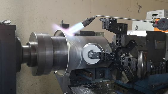
- Spinning Head:
- The spinning head is the central component of the machine that holds the material in place and rotates it at high speed. The spinning head consists of a mandrel (a central shaft that holds the tube) and roller tools that apply pressure to shape the tube. The rollers are used to form the material into the desired shape, gradually stretching and thinning the sheet metal to create a smooth, uniform surface.
- The machine can be equipped with multiple rollers, which allow for different material thicknesses and diameters to be processed with precision.
- Mandrel:
- The mandrel is the core around which the sheet metal is spun. It helps maintain the shape of the tube while the material is stretched. The mandrel also prevents the tube from collapsing during the spinning process. It can be designed to allow for different tube diameters and lengths to be produced.
- Rollers:
- The rollers are the tools that apply pressure to the spinning sheet metal. The rollers are mounted on arms that move in and out to exert force on the tube. As the sheet metal spins, the rollers gradually shape it into a tube or other desired form. The number and configuration of rollers can vary depending on the machine, with some designs featuring three or more rollers for more control over the forming process.
- Drive Mechanism:
- The drive mechanism, typically powered by an electric motor, rotates the spinning head and the mandrel at high speeds. The motor can be controlled to adjust the rotation speed, providing flexibility for different materials and thicknesses.
- Feed System:
- The feed system holds the sheet metal in place and moves it into position to be spun. It ensures the sheet metal is properly aligned and fed into the spinning area, maintaining uniformity in the process. The system can be manual or automated, depending on the machine’s design.
- Tooling and Dies:
- Tooling refers to the specific dies and rollers used to form the tube. These components can be customized based on the desired shape, material, and thickness of the tube being produced. For instance, different sets of dies may be used for creating conical shapes or tapered sections.
- Control System:
- Modern tube spinning machines are often equipped with advanced CNC (Computer Numerical Control) or PLC (Programmable Logic Control) systems, which allow for precise control over the machine’s operation. These systems enable operators to program specific speeds, roller positions, and tooling changes, leading to high repeatability and accuracy in the finished products.
Process of Sheet Metal Tube Spinning:
- Loading and Positioning:
- A blank sheet of metal is positioned onto the mandrel of the machine. The material can be in the form of a flat sheet, a disk, or a pre-formed shape that will be spun into a tube.
- Spinning:
- The spinning head is activated, and the sheet metal begins to rotate. As the sheet metal spins, the rollers gradually apply pressure along the material, forcing it to flow and stretch into the desired shape. The operator may adjust the rollers to control the forming process, ensuring the correct tube diameter and thickness.
- Shaping and Stretching:
- The sheet metal is gradually stretched and thinned by the rollers. The spinning motion, combined with the force from the rollers, shapes the metal into a continuous tube. The process can also be adjusted to form tapered, flared, or conical sections.
- Finishing:
- Once the desired tube shape is achieved, the machine may have a mechanism to trim excess material, deburr edges, or smooth out the surface. The tube may also be cooled if necessary, depending on the material used.
- Unloading:
- After the tube has been formed, it is removed from the mandrel and prepared for further processing, such as cutting to length, welding, or surface finishing.
Advantages of Sheet Metal Tube Spinning Machines:
- High Precision and Accuracy:
- These machines can produce highly accurate tube shapes with minimal deviation from the desired dimensions. The spinning process is particularly effective for achieving smooth, uniform walls with consistent thickness.
- Minimal Waste:
- Sheet metal tube spinning is an efficient manufacturing method because it uses minimal material, reducing waste. The process can produce tubes from a variety of metals, including aluminum, stainless steel, copper, and brass, making it ideal for industries that require high-quality, cost-effective parts.
- Versatility:
- Sheet metal tube spinning machines can be used to create a wide variety of tube shapes, from simple cylindrical tubes to more complex conical and tapered geometries. They are highly adaptable to different materials and can accommodate various thicknesses, which makes them suitable for producing parts for a wide range of applications.
- Strength and Durability:
- The spinning process work-hardens the material, which can increase the strength of the finished tube. This is particularly important in industries like aerospace and automotive, where structural integrity and high-strength materials are crucial.
- Cost-Effectiveness:
- Compared to other methods such as casting or welding, tube spinning is often more cost-effective, particularly for producing smaller batches or parts with complex geometries. The process requires fewer tooling changes and setup adjustments, resulting in lower production costs and faster turnaround times.
Applications of Sheet Metal Tube Spinning Machines:
- Aerospace:
- Tube spinning is widely used in the aerospace industry for producing aircraft components, such as engine housings, fuel lines, and structural tubing. These parts often require the precision and strength that tube spinning offers.
- Automotive:
- In the automotive industry, tube spinning machines are used to manufacture components like exhaust systems, brackets, and tailpipes. These parts require high durability and dimensional accuracy, which tube spinning can provide.
- Furniture Manufacturing:
- Tube spinning is used in the production of metal furniture, including chairs, tables, and decorative elements, where tube-shaped parts are common.
- HVAC and Plumbing:
- The process is used to create tubes for heating, ventilation, and air conditioning (HVAC) systems, as well as plumbing pipes. Spinning allows for the creation of these parts without the need for welding or additional processing.
- Lighting Fixtures:
- Sheet metal tube spinning is also used to create the metal housings for lighting fixtures, particularly for outdoor lighting or industrial lighting applications.
- Architectural and Decorative Parts:
- In architectural design, tube spinning machines create ornamental metal tubes for decorative railing systems, curtains, and other structural elements. The precision and finish of spun tubes make them ideal for high-visibility applications.
Future Trends and Advancements:
- Automation and Robotics:
- As manufacturing becomes more automated, sheet metal tube spinning machines will increasingly be integrated with robotic arms for material handling, loading, and unloading, increasing efficiency and reducing manual labor.
- Digital Controls and Smart Machines:
- Future tube spinning machines may incorporate more advanced CNC controls and IoT (Internet of Things) connectivity to enable real-time monitoring, predictive maintenance, and data collection for process optimization.
- Hybrid Processes:
- The combination of spinning with other manufacturing techniques, such as laser cutting or forming, could lead to hybrid machines capable of performing multiple tasks in a single operation, improving efficiency and reducing setup times.
- Sustainability:
- Environmental concerns may lead to innovations in energy-efficient spinning machines and processes that use recycled materials or produce less waste, aligning with sustainability goals in manufacturing.
In conclusion, Sheet Metal Tube Spinning Machines provide a highly effective method for forming and shaping tubes with precision, minimal waste, and high strength. Their versatility in handling a wide variety of materials and geometries makes them indispensable in many industries, and their ability to produce high-quality, durable parts ensures their continued relevance in modern manufacturing. With ongoing advancements in automation, smart controls, and sustainability, the future of tube spinning looks promising, offering even more efficient and flexible manufacturing solutions.
Sheet Metal Tube Spinning Machines are integral to modern manufacturing, particularly for producing cylindrical or tubular shapes from sheet metal. The process of tube spinning allows manufacturers to shape metal sheets into tubes or cones by rotating them at high speeds and applying force through rollers or dies. This technique is highly efficient, with minimal material waste, and produces parts with exceptional strength and durability due to the work-hardening effect of spinning. It’s especially beneficial in industries like aerospace, automotive, plumbing, HVAC, and furniture manufacturing, where precision and material integrity are paramount.
These machines typically feature a spinning head that holds the sheet metal in place, rotating it while rollers or dies shape it into the desired form. The sheet is fed into the machine, where it’s spun and gradually stretched into a tube or other shapes. The rolling tools are essential for controlling the thickness of the tube, ensuring uniformity, and enabling the production of components with different diameters or complex geometries like tapered or conical tubes.
The technology behind sheet metal tube spinning has evolved over time to include more advanced features such as CNC controls and PLC systems, which offer precise control over the spinning process. These controls allow operators to adjust the speed, roller pressure, and positioning for optimal results. The rise of automation and robotics further enhances efficiency by minimizing manual labor in tasks such as material handling, loading, and unloading, which helps speed up production cycles and reduce operational costs.
The materials used in tube spinning can range from common metals like aluminum, steel, and copper to more specialized alloys and even composite materials. The versatility of the spinning process makes it ideal for producing parts with complex shapes or custom geometries. It is often chosen for applications where high-strength and lightweight parts are needed, such as in aerospace components, aircraft engine parts, and automotive exhaust systems.
In addition to its precision, tube spinning also offers a high degree of repeatability, ensuring that each part produced meets exact specifications. This is crucial in industries where consistency and quality control are essential, such as medical device manufacturing, where tubes must meet strict dimensional and material standards. Furthermore, tube spinning machines are highly adaptable to different batch sizes, making them suitable for both mass production and smaller, custom runs.
The growing demand for sustainability in manufacturing has led to innovations in tube spinning machines that focus on energy efficiency and material conservation. Hydraulic systems that power the machines can be optimized to use less energy, while some designs incorporate regenerative systems that reuse energy. Additionally, the precise control of material flow during spinning reduces material waste, making it an eco-friendly option compared to other processes like casting or stamping.
Looking ahead, the integration of smart technologies is set to revolutionize the sheet metal tube spinning industry. As the manufacturing world embraces Industry 4.0, tube spinning machines are expected to become more interconnected, with IoT capabilities that allow real-time monitoring, data collection, and remote diagnostics. This will enable manufacturers to track machine performance, anticipate maintenance needs, and further optimize production. The combination of advanced sensors, predictive analytics, and AI will allow for self-adjusting machines that can alter their settings automatically to compensate for changes in material properties or thickness, improving efficiency and minimizing human error.
In terms of future developments, manufacturers are increasingly seeking hybrid machines that combine spinning with other forming processes like laser cutting or hydroforming. This will allow for the production of even more complex parts, further enhancing the capabilities of tube spinning and opening up new avenues for innovation in product design. As materials science advances, we may also see tube spinning machines designed to handle new, cutting-edge materials, like lightweight composites or advanced alloys, which could expand the range of products that can be efficiently spun.
Another significant trend is the push for more sustainable manufacturing practices. As businesses face increasing pressure to reduce their environmental footprint, tube spinning machines may incorporate more eco-friendly features, such as reduced water and energy consumption and the ability to work with recycled materials. This aligns with the broader industry trend toward creating more green and circular production processes.
The demand for customization in manufacturing is also on the rise. As industries move towards more specialized and personalized products, sheet metal tube spinning machines will continue to evolve to accommodate this need. Machines that offer greater flexibility in terms of tube size, shape, and material composition will be essential to meeting the growing demand for bespoke products, whether they are for automotive parts, medical devices, or other specialized applications.
In conclusion, sheet metal tube spinning machines are poised to remain a cornerstone of precision manufacturing. With ongoing advancements in automation, control systems, and material handling, these machines will continue to deliver high-quality, cost-effective solutions for a wide range of industries. Their ability to produce complex, high-strength, and durable parts with minimal waste positions them as a key technology for the future of manufacturing. As the industry moves towards smarter, more sustainable, and highly adaptable production methods, the role of tube spinning machines will only grow, helping manufacturers meet the evolving demands of the global market.
As we continue to look toward the future of sheet metal tube spinning machines, there are several emerging technologies and trends that will significantly shape their development. One of the most notable trends is the increased integration of automation and robotics within these machines. Automated systems are already being used to handle the material loading and unloading processes, and future advancements will likely see even more automation in the control and operation of the machines themselves. Automated material feeding systems, robotic arms for part handling, and self-adjusting toolheads will make these machines even more efficient, reducing the need for human intervention and further speeding up production cycles.
Additionally, digital twin technology will play a key role in the evolution of tube spinning. A digital twin is a virtual model of the actual machine and its operation, created by continuously collecting data from sensors on the real machine. This technology can simulate machine behavior, predict potential issues before they occur, and even test out new setups or process changes in a virtual environment before applying them to the real machine. This will help manufacturers troubleshoot more effectively, optimize operations, and minimize downtime, as well as enhance predictive maintenance strategies to ensure continuous operation.
Another significant development is the adoption of smart sensors and machine learning algorithms that can provide real-time feedback during the spinning process. These sensors can monitor key parameters such as material thickness, temperature, pressure, and even roller alignment, ensuring that every part meets the exact specifications. Through machine learning, these sensors will continuously learn and adapt to different materials and production conditions, refining the process and reducing the likelihood of defects or inefficiencies.
Furthermore, the rise of additive manufacturing or 3D printing in conjunction with traditional methods like tube spinning is opening up new possibilities for hybrid manufacturing systems. In the future, we may see machines that combine 3D printing with spinning, allowing manufacturers to create highly intricate parts with complex geometries that would be impossible or impractical to form through traditional methods alone. This could drastically reduce material waste, further increase design flexibility, and enable the production of lightweight, stronger, and more customized components.
As industries continue to prioritize sustainability, the sheet metal tube spinning process will evolve to become even more energy-efficient and environmentally friendly. Manufacturers are increasingly looking for ways to minimize energy consumption during the spinning process, and advancements in hydraulic systems, motor efficiency, and machine cooling technologies will contribute to this goal. The ability to reuse waste material or utilize recycled materials in the spinning process will also become a major focus, as will reducing the overall carbon footprint of manufacturing operations. This aligns with the growing demand for green manufacturing practices, and tube spinning machines will likely adopt closed-loop systems that minimize waste and optimize material usage.
In terms of customization and flexibility, the future of tube spinning machines will see even more modular designs. The ability to easily swap out different toolheads, dies, and rollers will allow manufacturers to quickly adjust to different production needs, whether that involves making minor changes to tube dimensions or switching to a completely different material. Machines may even feature adaptive tooling systems that automatically adjust based on real-time feedback from the material, providing a highly flexible, customizable solution for a variety of production scenarios.
Advanced materials will also play a significant role in the future of sheet metal tube spinning. As the demand for specialized and high-performance materials increases, spinning machines will need to accommodate new alloys, composite materials, and advanced polymers that require different handling characteristics. This will require not only stronger and more precise machines but also greater adaptability in tooling and process control. For instance, titanium, nickel alloys, and carbon fiber composites may require special roller coatings, cooling systems, or heating elements to achieve optimal results. As manufacturers move toward new materials, the machines will need to adapt quickly to these changes, ensuring that the spinning process remains reliable and efficient.
The ability to handle smaller batch sizes and shorter lead times will continue to be a key advantage of sheet metal tube spinning machines. As industries move toward on-demand manufacturing, the need for machines that can produce high-quality parts quickly and without excessive setup times will grow. This trend toward just-in-time production is driving the development of machines that can quickly switch between different configurations, handle smaller quantities efficiently, and reduce overall production costs.
In industries such as aerospace and medical device manufacturing, the demand for high-precision parts will only continue to grow. Future tube spinning machines will incorporate even greater accuracy in shaping parts, producing components with tolerances that are tighter than ever before. This will be critical in sectors where performance, safety, and functionality are paramount. For example, the ability to produce seamless, thin-walled tubes for fuel lines or hydraulic systems with minimal imperfections will be vital to meet the stringent requirements of these industries.
Lastly, as manufacturing increasingly shifts toward global supply chains, tube spinning machines will become more interconnected and part of larger smart factories. The integration of these machines into a connected production environment will allow for better data flow between machines, departments, and even locations. This can help companies optimize their operations in real time, adjust production schedules, and ensure that parts are manufactured with maximum efficiency. With cloud-based management systems and enterprise resource planning (ERP) tools, manufacturers will be able to track every aspect of the production process, from material sourcing to finished product delivery, ensuring complete visibility and control.
In conclusion, sheet metal tube spinning machines are undergoing a transformation driven by advancements in automation, connectivity, and sustainable practices. As new technologies like smart sensors, machine learning, and additive manufacturing integrate with traditional spinning techniques, these machines will become even more precise, efficient, and adaptable. The continued focus on sustainability, energy efficiency, and material optimization will help manufacturers meet the growing demand for high-quality, eco-friendly products. As the industry moves toward customization, modularity, and on-demand production, tube spinning machines will remain a vital tool in meeting the evolving needs of industries worldwide. The future of sheet metal tube spinning is bright, with endless possibilities for innovation and improvement in manufacturing processes.
As sheet metal tube spinning machines continue to evolve, further advancements are expected to enhance their capabilities, making them even more powerful tools for manufacturers. One area of development is the integration of augmented reality (AR) and virtual reality (VR) technologies for operator training and machine maintenance. AR and VR can provide real-time visual aids and simulations, allowing operators to visualize the spinning process, troubleshoot potential issues, or receive step-by-step guidance for machine setup and maintenance tasks. This could help reduce training time, increase machine uptime, and improve overall operator efficiency.
Another exciting possibility is the use of artificial intelligence (AI) to analyze large datasets generated during the spinning process. AI systems can monitor and interpret data from sensors, machine performance, and environmental conditions, making real-time adjustments to optimize the process. For example, AI could predict when a machine part might fail or when the quality of the output is starting to degrade, allowing for proactive maintenance or process tweaks before problems occur. This would significantly reduce downtime and improve the overall efficiency of the manufacturing process.
The need for multi-material processing will also continue to grow. Future tube spinning machines may be designed to handle not only traditional metals but also composite materials and hybrid structures. This could include metal matrix composites, ceramic-matrix composites, or fiberglass-reinforced plastics that are increasingly used in industries like aerospace and automotive for their lightweight, high-strength properties. Spinning machines could be equipped with special tooling and processes to handle these materials, offering even more versatility for manufacturers to produce parts with diverse material requirements.
With the increasing importance of data-driven decision-making in modern manufacturing, there is a growing push toward advanced analytics and predictive modeling. Sheet metal tube spinning machines of the future will be capable of capturing and processing large volumes of data related to the spinning process, material properties, and operational performance. Using this data, manufacturers can make informed decisions about optimizing production schedules, identifying trends, improving product quality, and reducing waste. Predictive models could also anticipate changes in the supply chain or material costs, enabling companies to adapt to shifting market conditions in real time.
Sustainable practices will continue to be a focal point for future developments in sheet metal tube spinning. Beyond energy efficiency and material optimization, there will likely be a greater emphasis on using recycled materials. Some manufacturers may explore ways to integrate closed-loop systems in which scrap metal or waste from the spinning process is collected, melted down, and reused in future productions. This would help reduce the reliance on virgin materials and minimize the environmental impact of manufacturing. Additionally, the possibility of incorporating biodegradable metals or sustainable alloys in the production process may open up new avenues for creating eco-friendly products.
In the realm of precision engineering, future sheet metal tube spinning machines may employ laser-assisted spinning or ultrasonic vibration technology. Laser assistance can help reduce the force needed to shape the material, particularly for harder metals, while improving the precision of the formed part. Ultrasonic vibrations can enhance material flow during spinning, reducing the risk of defects such as wrinkles, cracks, or thinning. These technologies, when integrated into tube spinning machines, will enable the creation of even more complex shapes with superior surface finishes and fewer defects.
As consumer demand for high-quality, customized products rises, the capability for rapid prototyping using tube spinning will also see a significant shift. Machines may evolve to offer faster setup times, quicker material changeovers, and enhanced flexibility for rapid production of low-volume, high-mix products. This will be particularly valuable for industries such as medical devices and consumer electronics, where custom, specialized parts are in high demand but must be produced in relatively small quantities.
In the field of aerospace manufacturing, where precision and material integrity are paramount, future tube spinning machines will need to accommodate high-performance materials like titanium and superalloys. These materials are commonly used in critical aerospace components that must withstand extreme temperatures, pressures, and wear. Advanced tube spinning machines capable of handling these specialized materials will likely include heated spinning heads or induction heating systems to ensure that the materials can be shaped without compromising their mechanical properties.
The trend toward smart factories and Industry 4.0 will continue to integrate sheet metal tube spinning machines into interconnected production environments. The data collected by these machines will be shared across the factory floor in real time, allowing for centralized control, inventory management, and quality assurance. This will enable manufacturers to track individual components through every stage of production, ensuring that the right parts are produced at the right time, reducing the risk of delays and errors.
In terms of globalization, the ability for manufacturers to operate sheet metal tube spinning machines in different geographic locations with standardized outputs will be crucial. As global supply chains become more interconnected, manufacturers may opt to use cloud-based systems to monitor and control machines remotely. This could help manufacturers achieve consistency across multiple production facilities and enable faster decision-making. In the future, the integration of blockchain technology could further enhance security and traceability by ensuring that every component produced on the spinning machine can be traced from the factory to the final product.
Finally, the design for manufacturability (DFM) approach will become even more important in the development of tube spinning machines. As manufacturing processes continue to advance, engineers will increasingly focus on designing products that are optimized for the capabilities of the spinning machine. This could involve designing parts with specific geometries that are easier to form using tube spinning or developing software tools that allow designers to simulate the spinning process during the design phase. By doing so, manufacturers can reduce the need for expensive tooling, cutting down on costs and minimizing the time needed to bring products to market.
In summary, the future of sheet metal tube spinning machines looks incredibly promising. As technology continues to advance, manufacturers can expect these machines to become faster, smarter, and more adaptable to the ever-changing demands of the industry. The integration of automation, data analytics, sustainability, and advanced materials will enable the production of high-quality, complex parts with minimal waste and reduced lead times. As industries evolve and become more global and data-driven, sheet metal tube spinning machines will play a key role in shaping the future of manufacturing across many sectors. Whether it’s through the introduction of AI, robotics, advanced materials, or sustainable practices, the ongoing evolution of tube spinning technology will continue to improve efficiency, precision, and customization in manufacturing processes, ensuring the industry remains at the cutting edge.
Looking deeper into the future of sheet metal tube spinning machines, it’s important to explore some of the specific challenges and innovations that could redefine the landscape of manufacturing in the coming years.
Material Diversity and Advanced Metal Alloys
As industries push the boundaries of material science, the future of tube spinning will require these machines to handle a broader range of materials. The development of advanced metal alloys, superalloys, and new composite materials presents an opportunity and a challenge. For example, high-strength steel and titanium alloys, often used in aerospace and automotive sectors, require very specific tooling and processing conditions due to their hardness and high resistance to deformation. The machine’s components, like rollers, dies, and tooling, will need to evolve to withstand the wear and tear of working with these materials while still maintaining the precision required for high-quality parts.
In addition to high-performance metals, the demand for lightweight composite materials and hybrid materials is growing rapidly. These materials, which can offer a high strength-to-weight ratio, are particularly useful in aerospace, defense, and automotive applications. However, they behave differently during the forming process compared to traditional metals, meaning future tube spinning machines will need to be capable of adapting their processes and tooling systems to accommodate these innovative materials. Carbon fiber composites, aluminum-lithium alloys, and other emerging materials may require customized approaches for heat treatment, cooling, or shaping during the tube spinning process.
Adaptive Manufacturing Systems
Future tube spinning machines will likely evolve from traditional, fixed-function machines into adaptive manufacturing systems that are capable of real-time adjustments based on the specific requirements of each part. This might include self-calibrating systems that automatically adjust based on material properties, ambient conditions, or wear and tear on the tools. These systems could reduce the need for human intervention in the fine-tuning process, allowing operators to focus on higher-level tasks like optimization and production planning.
For example, an adaptive system might automatically alter the pressure or speed of the rollers depending on the thickness and type of material being processed, ensuring consistent results across different production runs. These systems would not only increase the speed and accuracy of tube spinning but also enhance the flexibility of the machines, making them suitable for high-mix, low-volume production environments.
Smart Maintenance and Predictive Analytics
As manufacturers seek to minimize downtime and reduce operational costs, predictive maintenance will become a cornerstone of future sheet metal tube spinning machines. Instead of relying on scheduled maintenance, which can be inefficient and costly, predictive maintenance uses real-time data from sensors embedded in the machine to monitor key components and predict when parts are likely to fail. This data can be processed using machine learning algorithms to identify patterns and predict wear before it becomes a problem.
For instance, sensors could monitor the condition of the spinning rollers, detect changes in vibration or temperature that indicate misalignment or wear, and alert the operator to perform maintenance before a failure occurs. This proactive approach to maintenance ensures that machines remain in optimal condition, reducing downtime, and improving overall productivity.
Artificial intelligence (AI) could also assist in analyzing operational data and making real-time adjustments during the spinning process. For instance, AI systems could use historical data to predict the best process parameters for different materials, adjusting variables like feed rate, roller speed, or pressure to improve quality or reduce material waste.
Integration with Industry 4.0 and Smart Factories
The future of tube spinning machines is likely to see them fully integrated into Industry 4.0 ecosystems, where machines are interconnected through internet of things (IoT) devices and communicate with other machines, management systems, and supply chain networks. This interconnectivity will enable real-time data exchange, allowing for greater coordination between production lines and enhanced supply chain efficiency.
For example, a smart factory could use data from tube spinning machines to adjust production schedules based on real-time demand, inventory levels, or material availability. If a machine detects a delay in one part of the production process, it could automatically adjust the workflow to compensate, ensuring that downstream operations are not impacted. This level of integration and automation will help manufacturers achieve near-perfect synchronization between all production steps, ultimately leading to faster production cycles, reduced costs, and greater operational efficiency.
Moreover, data collected from sheet metal tube spinning machines can be fed into cloud-based platforms for detailed analysis. These platforms can use big data analytics to identify trends, bottlenecks, and inefficiencies across the production process. This could lead to insights that help manufacturers optimize machine performance, adjust production processes, or even design new products more efficiently.
Energy Efficiency and Sustainability
In an era where environmental responsibility is a top priority, tube spinning machines are likely to become more energy-efficient and environmentally friendly. The goal will be to reduce energy consumption during the spinning process and minimize waste. Innovations in hydraulic systems, motors, and cooling technologies will help manufacturers achieve greater energy efficiency. The recovery of waste heat from machines or the use of regenerative braking systems in machines could contribute to energy savings.
The sustainability aspect will also extend to the material itself. Recycled materials or alloys made from sustainable resources will increasingly be used in tube spinning processes. The ability to reuse scrap metal or optimize material flow during production to minimize waste will help reduce the carbon footprint of manufacturing operations. Future tube spinning machines might also be designed to handle bio-based materials or eco-friendly coatings, contributing to the overall goal of greener manufacturing practices.
Customization and Flexibility in Production
As customer demand for highly specialized products increases, customization and flexibility in production will become increasingly important. In the future, sheet metal tube spinning machines may feature modular designs, allowing manufacturers to quickly swap out different tools or adjust machine settings to accommodate a wide range of tube sizes, shapes, and materials. This flexibility will be particularly valuable in industries like medical device manufacturing, where the ability to produce low volumes of customized parts on demand is essential.
With the rise of on-demand manufacturing and shorter product life cycles, manufacturers will need to rapidly respond to changing customer needs. The ability to quickly produce customized tube geometries or incorporate different material properties into the production process will be a significant competitive advantage for tube spinning machine manufacturers.
Advancements in Automation and Robotics
The role of automation and robotics in sheet metal tube spinning is expected to increase, with more emphasis on robotic arms for handling material, loading/unloading parts, and performing secondary operations like trimming, deburring, or inspection. Robots could also be used for complex part assembly, where they work in conjunction with spinning machines to perform tasks that require precise positioning, such as assembling multi-part products or handling delicate materials.
Collaborative robots (cobots) may work alongside human operators in the near future. These robots could handle repetitive, physically demanding tasks such as feeding or unloading parts, while humans focus on higher-level functions like quality control or process optimization. The combination of robots and humans in a collaborative environment will streamline production and reduce the overall labor cost per part.
Advanced Simulation and Process Control
Finally, the use of advanced simulation software will become more prevalent in the design and operation of tube spinning machines. Before production begins, designers and engineers can simulate the spinning process using computer models to test different tool configurations, material choices, and production parameters. This simulation capability can help predict how materials will behave under different conditions, allowing manufacturers to optimize machine settings before any physical part is produced.
In the future, real-time process control systems might use feedback loops from sensors to continuously monitor and adjust the spinning process, ensuring that each part is manufactured within the specified tolerances. This will further improve the precision and efficiency of tube spinning operations, especially in applications where dimensional accuracy and surface finish are critical.
The Road Ahead
Looking ahead, sheet metal tube spinning machines will continue to evolve with a focus on flexibility, precision, and automation. As industries become more competitive and customer demands become more complex, tube spinning machines will need to integrate new technologies like AI, machine learning, robotics, advanced materials, and sustainability into their design and operation. These innovations will ensure that tube spinning remains a key process for the production of high-quality, high-strength parts across a wide variety of industries, from aerospace to medical devices and beyond.
The integration of smart technologies, data analytics, and predictive maintenance will further enhance the performance, efficiency, and adaptability of tube spinning machines, making them an indispensable part of modern manufacturing operations.
Sheet Metal Flow Forming Machine
A Sheet Metal Flow Forming Machine is a specialized manufacturing tool used to shape sheet metal into precise geometries by progressively thinning and elongating the material. The flow forming process, also known as rotary forming, is particularly useful for producing high-performance, complex parts that require excellent dimensional accuracy, surface finish, and material properties. The process involves the continuous flow of metal between rotating rollers and a stationary mandrel or die, which causes the metal to stretch and conform to the desired shape.
Working Principle of Flow Forming
Flow forming is a cold forming process, meaning the metal is not heated prior to shaping, though it may be slightly preheated depending on the material. The process typically involves a rotating tool that applies pressure to the sheet metal, which is progressively formed into a hollow shape. This is done by radial deformation as the metal flows outward toward the desired shape.
In general, the flow forming machine works as follows:
- Feeding the Blank: A sheet metal blank is positioned on the machine. This blank could be made of materials such as aluminum, titanium, or steel, and it serves as the starting point for forming.
- Roller and Mandrel Interaction: The blank is clamped onto a rotating mandrel or tool, which may have a specific shape. Rotating rollers are used to progressively form the sheet into the desired shape, such as a tube, cone, or disc. The rollers apply pressure, deforming the metal in a controlled manner.
- Flowing the Material: As the rollers work, the material begins to “flow” along the surface of the mandrel. This radial flow allows the material to thin in a controlled way, forming the part while maintaining a consistent grain structure and improving material properties.
- Final Shaping: The metal is progressively stretched to the desired diameter and thickness. The final dimensions are controlled through the application of force and the configuration of the rollers.
- Finishing and Cutting: After the flow forming process, the part may undergo additional finishing operations such as trimming, deburring, or surface treatments to achieve the final product specifications.
Advantages of Sheet Metal Flow Forming
- High Precision: Flow forming offers exceptional control over the part’s geometry, resulting in high-dimensional accuracy and a fine surface finish, often requiring minimal post-processing.
- Material Properties Enhancement: The process creates a work-hardened surface, improving the material’s strength and fatigue resistance. Flow forming can be used to produce parts with improved mechanical properties, particularly for high-strength alloys.
- Reduced Material Waste: Unlike traditional machining, flow forming is a net-shape or near-net-shape process, meaning the material is shaped without excessive waste. This is particularly beneficial when working with expensive materials like titanium or specialized alloys.
- Cost Efficiency: While the initial investment in flow forming machines can be high, the process itself is often more cost-effective in the long run, especially for producing complex shapes and high-strength components in high volumes.
- Versatility: Flow forming can be applied to a variety of materials, including aluminum, steel, titanium, and nickel alloys, making it versatile for different industries, such as aerospace, automotive, and medical device manufacturing.
- Minimal Tooling Changes: Once the machine is set up for a specific part, it is relatively easy to make adjustments for different sizes or configurations without changing tooling drastically.
Applications of Flow Forming
Flow forming is especially suited for parts that need to maintain high precision and strength but do not require a complex casting or welding process. Some common applications include:
- Aerospace Components: Flow forming is used to produce high-performance parts like turbine discs, rotor blades, housings, and spools. These parts often need to withstand high stresses and high temperatures, making flow forming a preferred method due to its ability to enhance material properties.
- Automotive Industry: For producing lightweight and durable parts such as wheel rims, driveshafts, and brake rotors, flow forming helps create parts with improved fatigue resistance and structural integrity, which are crucial in high-performance automotive applications.
- Medical Devices: Certain medical components, such as implantable devices or surgical tools, benefit from flow forming due to the process’s ability to produce precision parts with a clean surface finish.
- Energy Sector: Flow forming is used to create parts like pressure vessels, valves, and turbine housings used in the energy sector, where strength, precision, and durability are critical.
- Sports Equipment: In industries where precision and material integrity are essential, flow forming can be used for producing high-strength and lightweight sports equipment components, such as bike rims or golf club heads.
Types of Flow Forming Machines
- Single-Roller Flow Forming Machine: This type of machine uses a single roller to apply pressure to the material as it is rotated around the mandrel. It is typically used for simpler shapes like hollow tubes or discs.
- Multi-Roller Flow Forming Machine: More complex than single-roller systems, these machines use multiple rollers arranged around the part to apply force from different angles. Multi-roller machines are used to create more complex parts, such as cones, flanges, or tapered shapes.
- Hydraulic Flow Forming Machines: These machines use hydraulic pressure to drive the rollers, allowing for greater control over the force applied during the flow forming process. This is often used for parts that require precise material flow and consistency.
- CNC-Controlled Flow Forming Machines: Modern flow forming machines are increasingly equipped with CNC controls, which allow for precise adjustments to roller positioning and rotational speed. These machines offer enhanced flexibility and control, making them suitable for producing intricate and high-quality parts.
Challenges and Limitations
- Material Limitations: Flow forming is best suited for ductile materials that can deform easily. Some materials with poor formability may not be ideal candidates for flow forming, or they may require additional pre-heating to enable the process.
- Initial Setup Costs: While the flow forming process itself can be cost-effective for high-volume production, the initial setup cost for machines, tooling, and fixtures can be high.
- Limited to Certain Geometries: Although flow forming is highly versatile, it is primarily suited for producing parts with revolution-symmetrical shapes, such as tubes, cones, and discs. Producing more complex shapes or parts with non-symmetrical geometries may require other methods or combinations with other processes.
- Surface Finish Control: While flow forming provides a high-quality surface finish, depending on the material and tooling, some parts may require additional post-processing (e.g., polishing, coating) to meet the desired standards, especially for parts that are visible in consumer-facing products.
Future Developments in Sheet Metal Flow Forming
The development of advanced materials, smart automation, and improved simulation tools is likely to play a significant role in the continued growth of flow forming technologies. Future machines may include enhanced AI-powered process control, which could optimize forming parameters in real-time based on the material’s characteristics and other dynamic factors. Additionally, multi-material forming techniques could be integrated into flow forming machines, allowing manufacturers to produce hybrid parts with varying material properties, further expanding the applications of flow forming technology.
In conclusion, sheet metal flow forming is a highly effective and precise manufacturing process for producing high-strength, complex components with minimal waste. Its applications span industries such as aerospace, automotive, energy, and medical devices, where part performance and material integrity are critical. While there are challenges in terms of material suitability and setup costs, the continued advancement in machine capabilities and automation will only increase the versatility and efficiency of flow forming in the future.
Sheet metal flow forming is a manufacturing process that involves the progressive deformation of sheet metal into a desired shape using rollers and a mandrel. The method is particularly valued for its ability to produce complex, high-precision, and lightweight parts with superior material properties, such as increased strength and fatigue resistance. In this process, a blank sheet of metal is clamped onto a rotating mandrel, and rollers are applied to gradually elongate and shape the material. The metal “flows” under the pressure applied by the rollers, allowing it to thin and elongate in a controlled manner.
Flow forming machines can produce a wide variety of parts, including cylindrical tubes, conical shapes, and complex geometries. These machines are highly versatile and can work with materials like aluminum, titanium, steel, and high-strength alloys, making them ideal for industries such as aerospace, automotive, medical device manufacturing, and energy production. The process is especially useful in applications where strength, precision, and lightweight properties are essential, such as in the production of turbine blades, medical implants, brake discs, and specialized components for aerospace.
The primary advantage of sheet metal flow forming is its ability to enhance material properties while producing parts with minimal waste. Since flow forming is a near-net-shape process, it requires less material than traditional machining, making it more cost-effective in the long run. The process also helps to improve the surface finish of the material, reducing the need for additional finishing operations. Furthermore, the work-hardening effect created during the forming process increases the strength and durability of the final product, which is particularly beneficial in high-stress applications.
Another key benefit of flow forming is its ability to produce parts with a high degree of precision and consistency. The machine’s setup can be adjusted to control parameters such as the roller speed, force, and mandrel shape, ensuring that the final product meets the required specifications. This level of control allows for tight tolerances and smooth surface finishes, reducing the need for secondary operations such as polishing or grinding.
Despite its advantages, sheet metal flow forming does have some limitations. The process is generally best suited for materials that can undergo significant deformation without cracking or failing, such as aluminum and mild steel. For materials that are more brittle or difficult to form, preheating may be necessary to improve formability. Additionally, while flow forming is ideal for producing parts with symmetrical shapes, it may not be the best option for highly complex or non-symmetrical geometries. In such cases, additional processes like welding, casting, or machining may be required to achieve the desired shape.
The initial investment in flow forming machines can be high, especially for specialized equipment that is designed to handle high-strength materials or intricate shapes. However, the long-term cost savings and efficiencies gained from reduced material waste and faster production times often make flow forming a cost-effective option for high-volume production runs. Additionally, advances in automation and machine control technologies are helping to reduce the cost and complexity of setup, making flow forming more accessible to a broader range of manufacturers.
Looking ahead, the future of sheet metal flow forming is likely to be shaped by advancements in automation, smart manufacturing, and material science. The integration of artificial intelligence (AI) and machine learning (ML) could enable more adaptive and real-time process control, optimizing the flow forming process based on the specific material characteristics and part requirements. Additionally, the ability to work with a wider range of materials, including high-performance alloys and composite materials, will expand the versatility of flow forming and open up new possibilities in industries such as defense, medical, and automotive manufacturing.
As manufacturers continue to push the boundaries of material performance and precision, the role of flow forming in modern manufacturing processes will become increasingly important. Its ability to produce complex, high-strength, and lightweight parts while minimizing waste and reducing production costs makes it an invaluable tool for a wide range of industries. Through continued innovation and the development of new technologies, sheet metal flow forming will remain a key process for producing high-quality parts that meet the demands of advanced manufacturing.
As technology continues to advance, the future of sheet metal flow forming will likely see further improvements in efficiency, precision, and adaptability. One promising area of development is the integration of smart sensors and real-time feedback systems within the machines. These sensors can monitor factors such as temperature, pressure, and material thickness during the forming process, allowing operators to adjust parameters on the fly and improve part consistency. This type of advanced process control could result in higher yields, reduced scrap, and enhanced product quality.
Another key area of innovation is the use of robotics and automation in flow forming machines. As labor costs continue to rise and the demand for faster, more efficient production increases, automation will play a crucial role in streamlining operations. Robotic arms could be used for tasks like loading and unloading parts, positioning material, and even performing secondary operations like trimming or inspection. The use of collaborative robots, or cobots, which work alongside human operators, could help to reduce the physical demands of the process while improving overall productivity.
Moreover, the advancements in material science will expand the range of materials that can be processed using flow forming. For example, the development of new lightweight materials or multi-material parts could offer manufacturers new opportunities to produce high-strength components with tailored material properties. Flow forming could also be adapted for use with composite materials, which are increasingly in demand for industries like aerospace and automotive. These materials often require special processing techniques, but flow forming could offer a more efficient and cost-effective method of producing high-performance composite parts.
One potential challenge for the future is managing the increasing complexity of parts. As industries like aerospace and automotive demand more intricate geometries and higher levels of customization, flow forming machines will need to evolve to handle these complexities. The integration of advanced simulation tools and virtual prototyping could play a major role in helping manufacturers design more complex parts and optimize the flow forming process before production begins. This could reduce the time and cost of prototyping and allow for faster time-to-market for new products.
Additionally, there is likely to be an increasing emphasis on sustainability in flow forming technology. As environmental concerns grow and regulations become stricter, manufacturers are under pressure to reduce waste, improve energy efficiency, and use more sustainable materials. Flow forming already offers significant advantages in terms of minimizing material waste compared to traditional machining, but further innovations such as energy-efficient machines, recyclable materials, and eco-friendly lubricants could further reduce the environmental footprint of the process.
The development of hybrid manufacturing technologies, combining flow forming with other processes like additive manufacturing or laser processing, may also become a significant trend in the future. For example, manufacturers could use flow forming to produce the base structure of a part and then add or modify certain features using additive techniques. This hybrid approach could open up new possibilities for creating more intricate, lightweight parts while maintaining strength and durability.
Industry 4.0 integration is another aspect that will likely influence the future of flow forming. As factories become increasingly interconnected through IoT devices and cloud-based platforms, flow forming machines could become part of a larger, automated production ecosystem. This could include real-time data exchange between machines, predictive maintenance scheduling, and continuous process optimization. The ability to track parts through the entire production lifecycle will help improve efficiency, quality, and traceability, which is particularly important in industries like aerospace and medical device manufacturing where regulatory compliance and quality assurance are critical.
Finally, the globalization of supply chains will likely drive demand for flexible and scalable manufacturing processes like flow forming. As companies increasingly source materials and components from different parts of the world, the ability to produce high-quality parts with minimal lead times will be crucial. Flow forming’s ability to produce precision parts with reduced lead times and low material waste positions it well to meet these challenges in a globalized economy.
In summary, sheet metal flow forming is poised for continued growth and development as industries push for greater precision, efficiency, and sustainability. With advances in automation, robotics, smart manufacturing, and material science, the process is expected to become even more versatile and capable of producing highly complex, high-performance parts. The ability to adapt to new materials, improve product quality, and reduce environmental impact will be key drivers in the future evolution of flow forming technology.
As flow forming technology continues to evolve, several additional trends and opportunities are likely to shape its future landscape. One of the most notable areas of progress is the expansion of multi-axis forming capabilities, which will allow for even more intricate shapes and geometries. Traditional flow forming is often limited to parts that are rotationally symmetric, such as tubes and cones, but with the introduction of multi-axis machines, manufacturers can create more complex, non-symmetrical parts. This will open new avenues for industries that require advanced geometries, such as the aerospace and medical sectors, where customized shapes and high-precision parts are increasingly in demand.
Additive flow forming is another potential frontier that could transform the field. While flow forming currently focuses on forming a solid sheet of metal, future advancements may allow for the addition of material during the forming process, similar to additive manufacturing techniques like 3D printing. This could lead to the production of hybrid parts that are both formed and deposited layer by layer, offering the benefits of both processes. For example, a part could be flow-formed to achieve its basic shape, and then additional material could be deposited in specific areas to reinforce or customize the part’s structure, functionality, or surface finish. This hybrid approach could be particularly valuable in industries that require parts with varying material properties within the same component.
The integration of AI and machine learning into flow forming machines has the potential to revolutionize the process by making it smarter and more adaptive. These technologies could enable machines to learn from past production runs and adjust settings in real-time to optimize the process for each specific part. For example, machine learning algorithms could analyze the material’s response to forming forces and predict the best approach for forming different types of metals or alloys. AI-powered predictive maintenance could also be implemented to reduce downtime by forecasting when maintenance or part replacements are necessary, improving machine uptime and overall efficiency.
Digital twins are another concept that could play a significant role in the future of sheet metal flow forming. A digital twin is a virtual replica of a physical asset or system, and in the context of flow forming, it could be used to simulate the forming process in a digital environment before any physical work begins. This would allow manufacturers to test different forming parameters, evaluate potential defects, and optimize tooling and machine settings without wasting time and material. By using digital twins, manufacturers could speed up the design and prototyping phases, reduce the need for physical trial and error, and improve part quality before production starts.
With the continued push for sustainability, manufacturers are likely to seek ways to reduce energy consumption and minimize their carbon footprint during production. Flow forming, being a cold-forming process, already offers energy efficiency benefits compared to traditional casting or forging methods that require high temperatures. However, further advancements could make flow forming even more eco-friendly. The development of low-energy, high-efficiency machines, improved lubrication systems, and the use of recycled materials could contribute to reducing the environmental impact of the process. Additionally, the ability to form parts with near-net shapes reduces waste material, making flow forming inherently more sustainable compared to other machining methods.
Circular economy principles could also be integrated into flow forming practices. By focusing on the reuse of materials, extending the life of products, and recycling metal scraps, manufacturers can contribute to a more sustainable manufacturing process. As the demand for eco-conscious products grows, industries that adopt circular manufacturing techniques, such as flow forming with sustainable practices, will likely gain a competitive advantage. Materials like recycled aluminum and sustainable alloys could become more prevalent in flow forming operations, enabling manufacturers to meet both consumer demand and regulatory requirements for environmentally friendly production processes.
Additionally, automated inspection and quality control systems will continue to be a significant focus as the demand for high-quality, defect-free parts grows. In industries like aerospace and medical devices, where part failure can have severe consequences, ensuring that each component meets the highest standards is paramount. The implementation of real-time, non-destructive testing techniques, such as ultrasonic testing, X-ray inspection, or laser scanning, during the flow forming process can help ensure that the final product meets strict tolerances and performance standards. These systems can be integrated into the machines themselves or placed in-line as part of the production workflow, providing continuous feedback and reducing the risk of defects.
As the field of flow forming expands, manufacturers will also be able to take advantage of its capabilities to create more lightweight and efficient parts. Industries like aerospace are increasingly focused on reducing the weight of parts to improve fuel efficiency and performance, and flow forming provides an ideal solution for producing lightweight yet strong components. The ability to produce thin-walled parts with high strength-to-weight ratios will be especially beneficial for creating parts for electric vehicles (EVs), where reducing weight is crucial to improving battery life and overall efficiency.
The potential for customized, on-demand manufacturing is another exciting development in the future of flow forming. As the demand for mass customization increases, flow forming can enable the production of parts with specific, tailored features without the need for large-scale, costly molds or tooling. By leveraging digital technologies, manufacturers can design and produce custom parts on demand, reducing the need for inventory and enabling faster response times to customer needs. This could be particularly valuable in industries such as medical devices, where personalized products, such as implants or surgical tools, are often required.
Finally, the increasing importance of collaborative partnerships between manufacturers, suppliers, and technology developers will drive the continued evolution of sheet metal flow forming. As industries demand higher precision, faster production times, and more cost-effective solutions, companies will need to collaborate with technology providers to develop new innovations that address these challenges. Cross-disciplinary partnerships—bringing together experts in robotics, AI, material science, and sustainability—will help drive innovation and unlock new capabilities for flow forming technologies.
In conclusion, sheet metal flow forming is poised for continued advancements, driven by innovations in automation, AI, sustainability, material science, and digital technologies. These developments will enhance the versatility, efficiency, and precision of flow forming processes, allowing manufacturers to meet the growing demand for high-performance, lightweight, and customized components. As industries continue to evolve, flow forming will remain a key enabler in the production of high-quality parts with excellent material properties, contributing to the future of advanced manufacturing across various sectors.
Radial Rotary Forging Machine
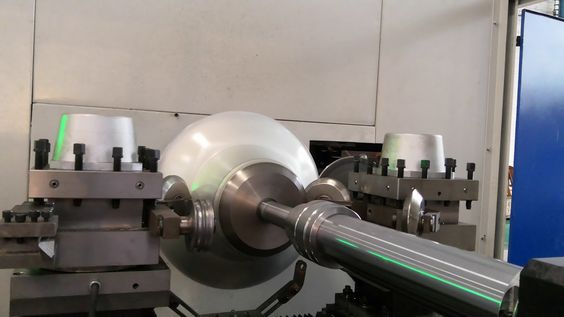
A Radial Rotary Forging Machine is a specialized piece of equipment used for the forging process, where metal is deformed under high pressure to achieve specific shapes and properties. It uses rotary motion and radial forging forces to work on metal billets or pre-formed blanks, creating complex geometries that may not be achievable using traditional forging methods.
Key Features and Functionality:
- Radial Forging Process:
- The key principle of radial rotary forging is the application of radial forces on the material. The metal is subjected to compressive forces as it rotates within a set of dies, which deform the material radially (outward or inward) rather than axially.
- The forging tool rotates, applying multiple blows to the workpiece as it moves through the die set. These radial blows create a more uniform deformation, which is beneficial for enhancing the mechanical properties of the material.
- Rotary Motion and Pressure Application:
- The machine typically consists of a rotating die, where the workpiece (usually a metal billet or pre-formed blank) is placed in the center. The die or hammer then applies force in a radial direction, which compresses and shapes the material.
- This rotary movement helps ensure that the metal is worked uniformly and without the risk of warping, providing a high-quality, consistent finish across the workpiece.
- Metal Forming Capabilities:
- Radial rotary forging is capable of producing a wide range of products, including hollow components, tubes, flanges, and rings. It is also used for producing high-strength components in industries like aerospace, automotive, and energy.
- The process is particularly effective for forming tapered shapes, hollow parts, and components with complex cross-sections that require high precision and material strength.
- Advantages:
- Material Conservation: The radial forging process typically results in less material waste compared to traditional methods like machining, as the process shapes the material in a controlled manner.
- Improved Material Properties: The forging process improves the mechanical properties of the material, such as strength, hardness, and fatigue resistance, making it ideal for producing high-performance components.
- Precision and Accuracy: Radial rotary forging offers tight tolerances and can be used to produce parts with complex geometries, reducing the need for secondary operations like machining or grinding.
- Faster Production Times: Since the process is highly automated, parts can be forged more quickly than with some other forging techniques, resulting in faster turnaround times for high-volume production runs.
- Materials Processed:
- Radial rotary forging machines can work with a variety of materials, including steel, aluminum, titanium, copper alloys, and high-strength alloys. These materials are often chosen for their ability to undergo deformation without cracking or failure under high pressure.
- The process is especially useful for working with high-temperature alloys used in critical applications, such as in aerospace turbines or automotive engine components.
- Customization and Versatility:
- The machine setup can be adjusted to accommodate different workpiece sizes and shapes, making radial rotary forging suitable for both small batch and mass production.
- Dies and tooling can be customized to produce parts with very specific geometries or mechanical properties, allowing for flexibility in design and manufacturing.
Applications:
- Aerospace Industry: Radial rotary forging is often used to manufacture components for jet engines, gas turbines, and other aerospace applications where high strength and precision are critical.
- Automotive Industry: Components such as axles, shafts, and crankshafts can be forged using this technique to ensure high performance under stress and wear.
- Energy Sector: Parts like turbine blades, compressor discs, and power generation equipment benefit from the increased strength and precision offered by radial rotary forging.
- Industrial Equipment: The process is also used for producing high-performance parts in pumps, valves, and heavy machinery.
Benefits of Radial Rotary Forging:
- Enhanced Strength: The radial forging process enhances the material’s grain structure, improving strength and durability.
- Increased Efficiency: With the automation and reduced material waste, radial rotary forging can be more cost-effective than other traditional metal-forming processes.
- Tight Tolerances: It allows manufacturers to produce parts with very tight dimensional tolerances, reducing the need for secondary machining operations.
- Uniform Deformation: The radial nature of the forging ensures that the metal is deformed uniformly, reducing the risk of defects such as cracks or uneven thickness.
Challenges:
- Initial Setup Costs: Like many specialized forging machines, radial rotary forging machines can be costly to purchase and set up. However, the long-term benefits often outweigh the initial investment for high-volume production.
- Material Limitations: While the process can be used with a wide variety of metals, some very brittle or difficult-to-form materials may require additional preparation or adjustments to ensure successful forging.
Conclusion:
The Radial Rotary Forging Machine represents a significant advancement in the field of metal forming, offering manufacturers the ability to produce high-precision, high-strength components with minimal waste and excellent material properties. By leveraging the combination of rotary motion and radial force, these machines enable the production of parts with complex shapes and high demands for performance. As industries continue to push the boundaries of design and functionality, the capabilities of radial rotary forging will likely continue to expand, driving innovation in sectors such as aerospace, automotive, and energy production.
Radial rotary forging machines are becoming increasingly important in advanced manufacturing due to their ability to produce high-performance parts with excellent material properties and precision. These machines utilize rotary motion to apply radial forces on the workpiece, which allows for uniform deformation and the creation of parts with intricate geometries and high-strength characteristics. The key advantage of this process is its ability to improve the mechanical properties of the material being formed, such as strength, hardness, and fatigue resistance, making it ideal for producing components that will undergo high stress or harsh operating conditions.
The use of radial rotary forging is particularly advantageous in industries where part strength and material performance are critical. For instance, in aerospace, components like turbine blades, compressor discs, and other critical engine parts benefit from the superior mechanical properties provided by the forging process. The ability to create complex shapes with tight tolerances also makes radial rotary forging an attractive option for the automotive industry, where precision parts like crankshafts, axles, and gears are required to perform reliably under heavy loads and extreme conditions.
Another significant benefit of radial rotary forging is the reduction in material waste. Traditional machining methods, such as turning or milling, often remove a substantial amount of material, leading to inefficiencies and higher material costs. With radial rotary forging, material is deformed rather than cut away, allowing for a more efficient use of resources. This characteristic is particularly useful when working with high-cost materials such as titanium or superalloys, which are commonly used in aerospace and energy applications. Additionally, the forging process itself results in a denser and more uniform grain structure, which contributes to improved performance characteristics, such as better fatigue resistance and durability.
In terms of production efficiency, radial rotary forging machines can be highly automated, making them suitable for both small and large production runs. The process reduces the need for secondary operations like machining, as the parts often come out with near-net shapes that require minimal finishing. This streamlining of production processes can result in faster turnaround times and reduced lead times for parts, which is especially important in industries like aerospace, where rapid prototyping and just-in-time manufacturing are common. The ability to easily adapt the machine to different part sizes and shapes also increases its versatility, allowing manufacturers to use it for a wide range of applications and materials.
However, despite its numerous advantages, radial rotary forging does come with challenges. The initial cost of purchasing and setting up the machine can be significant, especially for high-performance models capable of handling complex parts and materials. Additionally, while the process is highly effective for forming parts with rotational symmetry or tapered shapes, it may not be suitable for all types of components, particularly those with highly irregular or non-symmetrical geometries. In such cases, other methods, like casting or additive manufacturing, may be more appropriate.
As the demand for high-performance parts continues to grow in industries such as aerospace, automotive, and energy, the role of radial rotary forging machines is likely to expand. Innovations in machine control, automation, and material science are expected to further improve the efficiency and capabilities of these machines, allowing them to process even more complex geometries and materials. Additionally, as industries continue to focus on sustainability and reducing their environmental impact, the material efficiency and reduced waste associated with radial rotary forging will make it an even more attractive option for manufacturers looking to meet these goals.
Looking ahead, the integration of Industry 4.0 technologies could play a pivotal role in enhancing the capabilities of radial rotary forging. By incorporating smart sensors, real-time monitoring, and data analytics, manufacturers could gain valuable insights into the forming process and optimize it further. Predictive maintenance could also be implemented, allowing for proactive servicing of the machines and minimizing downtime, which is especially critical in high-volume production environments. Furthermore, advances in robotics and automation could streamline material handling and increase the overall speed and flexibility of production, making radial rotary forging an even more competitive option for manufacturers.
In conclusion, radial rotary forging represents a highly efficient and effective method for producing high-strength, high-performance components with precise tolerances and minimal material waste. As technological advancements continue to improve the capabilities of these machines, the applications for radial rotary forging will continue to expand, supporting industries that require the highest standards of quality and performance in their components. Whether it’s aerospace, automotive, or energy, radial rotary forging offers a promising solution for the future of manufacturing.
As manufacturing technology continues to evolve, radial rotary forging will likely integrate further with other advanced manufacturing methods, such as additive manufacturing, hybrid production systems, and advanced simulation technologies. Combining these processes could lead to new opportunities for creating components with customized material properties, intricate geometries, and optimized performance characteristics. For instance, a hybrid system could start by using radial rotary forging to achieve the primary shape of a part, followed by additive manufacturing to deposit material in specific areas to reinforce or add features that are not easily forged. This would enable the creation of parts with tailored material properties or complex internal structures that wouldn’t be possible with conventional methods alone.
Additionally, advanced simulation and digital twin technology could revolutionize the way radial rotary forging machines are used. Digital twins—virtual representations of physical systems—could be used to simulate the forging process, allowing manufacturers to predict how a material will behave under certain conditions before it even reaches the machine. This can be particularly valuable for high-performance materials or parts with critical tolerances, where even slight deviations can result in significant defects. By leveraging simulation software, manufacturers can optimize machine settings, adjust parameters in real-time, and predict potential issues such as material flow problems or deformation during the process. The use of artificial intelligence (AI) and machine learning (ML) could also enhance the precision of simulations and further improve part quality, as these algorithms could learn from past production runs and adjust machine operations for optimal results.
Another key development in the future of radial rotary forging is its potential role in producing parts for emerging industries, such as electric vehicles (EVs), renewable energy, and space exploration. As the world shifts toward cleaner, more sustainable technologies, industries like EV manufacturing are increasingly looking for lightweight, high-strength materials to optimize performance. Radial rotary forging can help produce parts such as lightweight motor housings, battery enclosures, and structural components that offer the strength and durability required while minimizing weight. These same advantages can extend to the renewable energy sector, where the production of high-performance components for wind turbines, solar energy systems, and energy storage solutions is becoming increasingly important.
Space exploration is another area where radial rotary forging is likely to see significant growth. Components for spacecraft, such as rocket nozzles, engine components, and landing gear, often require high-performance alloys and precision manufacturing. The forging process can help create parts with superior mechanical properties, such as high strength and fatigue resistance, making them capable of withstanding the extreme conditions of space travel. Additionally, as space missions grow more complex and longer in duration, there will be a need for parts that can endure the harsh environments encountered during re-entry and operation in space.
In the context of sustainability, the focus will continue to be on reducing the environmental footprint of manufacturing processes. Radial rotary forging already offers advantages in this area by reducing material waste and energy consumption compared to other methods like casting or machining. As environmental regulations become stricter, there will be an increased demand for machines that can work efficiently with recycled materials and eco-friendly alloys. The use of secondary materials, such as recycled aluminum, steel, or even composites, could become more prevalent in radial rotary forging, further reducing the demand for raw materials and the energy-intensive processes associated with extracting and refining metals.
Moreover, automated quality control systems will play a crucial role in ensuring that each part meets the required specifications, particularly as the complexity and performance demands of parts continue to increase. Using non-destructive testing (NDT) techniques, such as ultrasonic testing, X-ray inspection, and laser scanning, manufacturers can detect any flaws or defects in the material without damaging the part. This is especially important in high-stakes industries like aerospace, where even a minor flaw can lead to catastrophic failure. Real-time inspection systems integrated with the radial rotary forging machine will enable immediate feedback and adjustments during the manufacturing process, ensuring that only parts that meet the highest standards are sent to final assembly.
Looking ahead, collaborative robotics could play a pivotal role in enhancing the efficiency and flexibility of radial rotary forging machines. As factories become more automated, the use of robots that work alongside human operators to handle parts, perform secondary operations, or even assist in the setup and maintenance of forging machines could reduce labor costs and improve overall production speed. These robots could be used for tasks such as loading and unloading parts, monitoring production cycles, and even conducting initial inspections, allowing for more streamlined workflows and reduced downtime.
Finally, the continued expansion of global supply chains will likely lead to increased demand for flexible and scalable manufacturing solutions like radial rotary forging. As manufacturers seek to meet the needs of a more interconnected world, they will require processes that allow for rapid production and delivery of high-quality parts, often on a just-in-time basis. Radial rotary forging’s ability to produce parts with minimal waste and high precision makes it a key enabler in meeting the challenges posed by global supply chains, especially as the demand for customized, on-demand manufacturing grows.
In summary, the future of radial rotary forging is bright, with a wide range of technological advancements, material innovations, and industry demands pushing the boundaries of what is possible. As the capabilities of these machines continue to expand, manufacturers will be able to produce increasingly complex, high-performance parts for a variety of industries, from aerospace and automotive to energy and space exploration. With its advantages in precision, material efficiency, and part strength, radial rotary forging will continue to play a vital role in the evolution of advanced manufacturing technologies.
Looking toward the future, the ongoing advancement of Industry 4.0 technologies will play a significant role in enhancing the capabilities of radial rotary forging machines. The integration of smart manufacturing concepts will allow for even greater optimization and automation in the forging process. By utilizing real-time data collection, advanced sensors, and cloud computing, manufacturers will be able to track every aspect of the forging process, from material quality to machine performance. This data can be analyzed to detect trends, predict failures, and ensure that each part produced is up to the required standards, without the need for extensive manual oversight.
The adoption of IoT (Internet of Things) technologies in radial rotary forging machines will enable seamless communication between different parts of the production system. For example, machines can be linked to central control systems that monitor performance across a fleet of machines, ensuring that production runs are smooth, and downtime is minimized. Predictive analytics powered by AI will enable machines to anticipate maintenance needs before they occur, allowing manufacturers to schedule downtime efficiently and avoid costly interruptions. This leads to higher productivity, reduced maintenance costs, and a more streamlined manufacturing process overall.
The role of advanced materials in radial rotary forging will also continue to grow. As industries develop more specialized alloys and composite materials, there will be increasing demand for machines capable of handling these advanced materials effectively. New forging processes could be developed to work with lightweight alloys, superalloys, and biocompatible materials to meet the needs of industries like medical devices, aerospace, and renewable energy. These materials often have specific characteristics, such as higher melting points, corrosion resistance, or strength-to-weight ratios, which require tailored forging techniques to achieve the desired properties without compromising material integrity.
Nanotechnology might also play a significant role in enhancing the performance of forged parts. As our understanding of materials at the nano-scale improves, manufacturers may develop new forging processes that incorporate nanostructured materials. These materials can exhibit enhanced properties such as higher strength, lighter weight, and improved resistance to wear and fatigue. Radial rotary forging machines could potentially be adapted to work with these advanced materials, opening up new opportunities for producing parts with superior mechanical properties for demanding applications like aerospace propulsion systems, medical implants, and high-performance automotive components.
The integration of virtual reality (VR) and augmented reality (AR) technologies could also revolutionize the training and setup processes for radial rotary forging machines. With VR and AR, operators and engineers could simulate the forging process and train on the machines without the need for physical setups, significantly reducing training time and costs. In addition, AR could be used for real-time support during machine operation, guiding operators with step-by-step instructions, troubleshooting tips, and system diagnostics overlaying the machine’s control panel or the workpiece itself.
3D modeling and design software advancements will also play a crucial role in shaping the future of radial rotary forging. Manufacturers will be able to use sophisticated modeling tools to simulate the forging process of complex parts, optimizing the design before physical production. With the ability to visualize how materials will behave during forging, engineers can make informed decisions about tool geometry, material choice, and process parameters. This could help in reducing trial-and-error efforts, improving product design, and speeding up the time to market for new parts.
One area where radial rotary forging will continue to see development is in low-volume and high-mix production. Traditional forging methods often require significant upfront investment in tooling and dies, which makes them less suitable for low-volume production. However, with advances in additive manufacturing and rapid prototyping, there is an increasing opportunity to create custom dies or adapt the forging process to work with smaller batches. This flexibility will be particularly valuable for industries that need customized parts or parts produced in smaller quantities, such as the defense industry, high-performance motorsports, or luxury automotive sectors.
As the demand for on-demand and just-in-time manufacturing increases, radial rotary forging machines will become more adaptable to quick changes in production requirements. Advances in robotics and automation will support this shift by enabling machines to be reprogrammed or adjusted more easily for different part designs or production runs. This flexibility will be crucial as global manufacturing moves toward more agile and responsive supply chains, where the ability to quickly adapt to customer needs is becoming increasingly important.
Furthermore, the globalization of manufacturing and the growing demand for localized production will drive investments in radial rotary forging machines that are capable of producing a wide range of parts across different markets. By establishing local manufacturing facilities equipped with advanced forging machines, companies can reduce transportation costs, minimize lead times, and better meet regional demand. These localized production capabilities will be particularly advantageous in industries that require high-quality parts produced on a fast timeline, such as the automotive or medical device sectors.
The growth of robotic-assisted manufacturing will also be a significant factor in improving the efficiency of radial rotary forging operations. Robots can assist with loading, unloading, and handling materials, which will reduce the physical strain on human operators and improve safety. This trend toward increased automation and robotics could also reduce labor costs and improve production throughput.
Another trend to watch is the expansion of cross-industry collaboration. As industries continue to seek more specialized materials, improved production methods, and highly customized parts, manufacturers may work together across various sectors to share knowledge, expertise, and best practices. For example, the aerospace and automotive industries could collaborate on the development of new materials and forging techniques that can improve the performance and reliability of parts used in both sectors.
In conclusion, the future of radial rotary forging is incredibly promising, driven by advancements in technology, materials, and automation. As manufacturers increasingly demand high-performance, customizable, and cost-effective solutions, radial rotary forging will continue to evolve to meet these needs. With improvements in AI, smart manufacturing, advanced materials, and collaborative technologies, radial rotary forging will not only improve its current capabilities but also open up entirely new possibilities in the creation of high-precision, high-strength components. This will enable manufacturers to address the ever-growing demands of industries like aerospace, automotive, energy, and medical devices, paving the way for innovations that we are only beginning to imagine.
High Performance Double Arm Spinning Machine
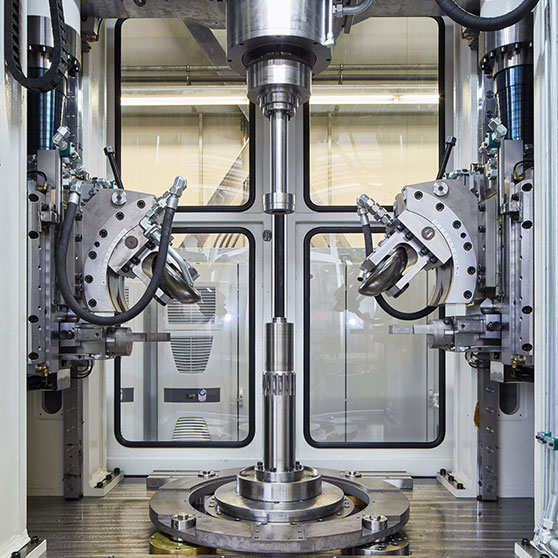
A High-Performance Double Arm Spinning Machine is a specialized machine used in the metalworking industry for the process of sheet metal spinning, which involves the shaping of metal sheets into hollow or cylindrical forms. This process is typically used to create parts such as bowl-shaped components, cylinders, conical shapes, and various other symmetric forms from a flat sheet of metal.
The high-performance double-arm spinning machine is particularly noted for its ability to handle large, complex parts with greater precision and efficiency. The “double arm” refers to the dual-arm configuration of the machine, where two arms are employed to rotate the workpiece and provide a more stable, controlled spinning action compared to single-arm machines. This setup enables better balancing, higher accuracy, and the ability to work with larger or more challenging parts.
Key Features and Functionality:
- Double Arm Design:
- The double-arm design enhances the stability and control during the spinning process, reducing vibrations that can lead to defects such as warping or uneven thickness. This makes the machine ideal for producing large or delicate parts that require high precision.
- Each arm can be independently controlled, allowing for more flexible adjustments in terms of rotational speed, force, and direction, depending on the material and part specifications.
- High-Performance Motors and Drives:
- High-performance double-arm spinning machines often feature advanced servo motors or hydraulic drives, providing greater control over the spinning process. The motors allow for variable speeds, which can be adjusted based on the type of material being spun (e.g., aluminum, steel, copper, etc.).
- The use of high-performance motors also means faster operation speeds, higher precision, and the ability to handle thicker or more challenging materials.
- Precision Control:
- The machine is equipped with sophisticated control systems, often with CNC (Computer Numerical Control) capabilities, that allow for precise manipulation of the spinning parameters. Operators can program the exact speed, force, and trajectory needed to form the desired part, reducing human error and ensuring consistent quality.
- The precise control also allows for multi-axis control, enabling the creation of parts with complex geometries that would be difficult or impossible to achieve with simpler machines.
- Dual Spindle System:
- The double-arm spinning machine usually features a dual spindle system, where two spindles can rotate in opposite directions or at different speeds, ensuring better material flow and reducing the risk of material failure during the process. This dual-action enhances the precision of the final product.
- In some models, the spindles can be equipped with interchangeable tooling, allowing for quick changeover between different part sizes and shapes.
- Tooling and Die System:
- The machine uses specialized tools, such as spinning tools and dies, to manipulate the material. The dies are often custom-designed to match the specific dimensions and shape of the parts being produced. This tooling is critical for ensuring the accuracy of the spun part and achieving the desired thickness and finish.
- Some machines are equipped with adjustable tooling stations, allowing the operator to quickly change between different toolsets for different parts or production requirements.
- Material Handling and Safety Features:
- These machines typically include automated material handling systems to load and unload the metal sheets, improving efficiency and reducing the need for manual labor. Material can be automatically fed into the machine, spun, and then removed without the operator having to handle the workpiece directly.
- Safety features such as enclosed work areas, emergency stop buttons, and operator protection devices are standard in high-performance machines, ensuring the safety of operators during the high-speed spinning process.
Advantages:
- Increased Precision and Accuracy:
- The dual-arm design and advanced control systems allow for better control over the spinning process, leading to more precise and accurate parts. This is particularly important when manufacturing parts with tight tolerances or intricate geometries.
- Faster Production Times:
- With high-performance motors and CNC control, double-arm spinning machines can operate at faster speeds, leading to reduced cycle times for each part. This increases overall productivity and makes them suitable for high-volume production environments.
- Reduced Material Waste:
- Spinning is a more material-efficient process compared to methods like casting or machining, as it involves minimal material waste. The precision and control of the double-arm machine further enhance material conservation, reducing the scrap rate.
- Versatility in Material Handling:
- High-performance double-arm spinning machines can handle a variety of materials, including lightweight metals like aluminum and copper as well as heavier materials like stainless steel or titanium. The ability to adjust speeds and forces based on material type and thickness allows for greater versatility.
- Enhanced Forming Capabilities:
- The machine’s design allows for the production of complex shapes, including cones, tubes, and bowl-shaped components, which are often required in industries such as aerospace, automotive, and energy.
Applications:
- Aerospace Industry:
- High-performance double-arm spinning machines are used to create complex parts such as fuel tanks, aircraft components, engine casings, and other specialized parts that require both high strength and lightweight properties. The precise forming capabilities are essential for producing parts that meet stringent aerospace standards.
- Automotive Industry:
- The machine is also used for manufacturing parts in the automotive sector, such as exhaust systems, brake drums, and wheel rims, which require precise metal forming to ensure they can withstand high temperatures, pressure, and mechanical stress.
- Energy Sector:
- For the energy industry, double-arm spinning machines are employed to produce parts like turbine housings, pressure vessels, and flanges, all of which need to handle high levels of pressure, heat, and fatigue. The precision and strength provided by the spinning process make these parts suitable for use in power plants and oil rigs.
- Electronics and Consumer Goods:
- In electronics and consumer goods industries, these machines are used to manufacture parts such as lamp housings, musical instrument parts, and other specialized components that require uniform thickness and a high-quality surface finish.
- Defense Industry:
- The machine can be used to manufacture parts for the defense industry, including ammunition cases, military vehicle components, and other critical parts that require high precision and durability.
Future Developments:
- Integration with Automation:
- Future high-performance double-arm spinning machines may see further integration with robotic systems, enabling fully automated loading, spinning, and unloading of parts. This would reduce manual labor and further increase the overall efficiency of the process.
- Hybrid Spinning Techniques:
- There may be the development of hybrid spinning techniques that combine traditional spinning with additive manufacturing processes, such as 3D printing. This could allow for the creation of parts with complex internal geometries, further expanding the range of applications for the machine.
- Smart Technology Integration:
- Future machines may incorporate IoT sensors and AI-based monitoring systems to optimize the spinning process in real time. These technologies could automatically adjust process parameters based on factors like material type, temperature, and wear on tooling, ensuring a more consistent result and reducing downtime.
Conclusion:
The High-Performance Double Arm Spinning Machine represents a significant advancement in the field of metal spinning. With its dual-arm design, precise control systems, and high-performance capabilities, it is an essential tool for manufacturing high-quality, complex parts across a range of industries, including aerospace, automotive, energy, and defense. As technology continues to improve, these machines will become even more versatile, efficient, and integrated with modern manufacturing systems, paving the way for even greater precision and productivity in metal forming operations.
The future of high-performance double-arm spinning machines will likely involve deeper integration with smart manufacturing practices, as industries increasingly demand both flexibility and precision in their production processes. The ability to handle complex geometries with improved accuracy and speed will be paramount. In addition, as manufacturers seek to meet sustainability goals, these machines will continue to evolve toward more energy-efficient systems, which may include advanced motors, optimized energy use, and reduced environmental impact in material handling and operation. The next generation of spinning machines could see the integration of artificial intelligence (AI) to predict and adjust spinning parameters based on real-time data, offering dynamic adjustments to the speed, force, and tooling setups as the machine works, allowing for consistent results and minimizing waste.
With the rise of Industry 4.0, the connectivity of manufacturing systems will enhance the capabilities of high-performance spinning machines. These systems could collect data from the machines, analyze performance trends, and integrate seamlessly with other machines and production lines within a facility. This connectivity would allow manufacturers to optimize workflows, ensuring that the spinning machines work in conjunction with other automated systems like robotic arms, inspection tools, and material handling systems. Real-time data feedback will also be crucial for predictive maintenance, helping identify wear on tools or machinery components before they lead to breakdowns, thus minimizing downtime and maintenance costs.
Advancements in multi-material processing could open up new opportunities for the double-arm spinning machine, allowing manufacturers to combine different materials or alloys within a single component. This could be particularly valuable in industries such as aerospace, where lightweight yet strong materials are essential, or in the automotive industry, where parts need to perform under high stress and heat. The ability to spin different materials together with precision would expand the potential for creating highly specialized components that can’t be produced through traditional methods.
As we look at trends in customization and on-demand manufacturing, the high-performance double-arm spinning machine will need to remain adaptable. Manufacturers will require the flexibility to switch between different materials and part designs quickly, especially as consumers and industries move toward more personalized and niche products. This adaptability will be supported by advanced control systems and modular tooling that allow rapid reconfiguration of the machines for different applications.
The expansion of global supply chains will also contribute to the increased demand for these machines, particularly as manufacturers seek to establish more localized production capabilities. Localizing production with flexible, high-performance machines reduces transportation costs, mitigates the risks associated with global supply chain disruptions, and provides faster delivery times. Additionally, it supports the trend toward sustainable manufacturing, as it can reduce the carbon footprint associated with shipping materials and parts across long distances.
For manufacturers focused on quality control, real-time monitoring systems on spinning machines will provide enhanced insights into every stage of production. Advanced sensor technologies will measure parameters such as temperature, material thickness, surface finish, and stress distribution, ensuring that each part meets the required specifications. Data collected from these sensors can be used to optimize the process, flag any deviations from desired standards, and even provide feedback to the operator or control system, allowing for immediate corrective actions.
With the increasing use of advanced materials, such as lightweight alloys, superalloys, and composite metals, the double-arm spinning machine will need to adapt to handle these materials more efficiently. These materials often have unique properties, such as high heat resistance or specialized surface characteristics, which demand precision forming techniques. The future of high-performance spinning machines will likely involve further refinement of the tooling and die systems, allowing for faster setup times and improved material flow management.
Looking ahead, the role of automation and robotics in the spinning process will expand. The use of robotic arms to assist with material handling, tool changes, and part removal will reduce operator intervention and improve safety. The robots could also work in tandem with the spinning machine to perform secondary operations like surface finishing, inspection, or even part assembly, creating a fully automated production line for high-precision parts. The combination of robotics, AI, and machine learning will lead to increasingly autonomous systems that can adapt and optimize without human input.
In industries where high-volume production is critical, such as the automotive sector, these machines will continue to meet the demand for fast, efficient, and precise manufacturing of parts. However, as customization becomes more important, the machines will also be designed with greater flexibility, allowing for the rapid production of low-volume, highly customized parts for sectors like luxury automotive or medical devices. This versatility will make the machines a valuable tool for manufacturers who need to produce both large quantities of standard components and small, specialized batches.
Additionally, as environmental concerns continue to shape industry practices, spinning machines will become more energy-efficient. Innovations in servo-driven systems and energy recovery systems will help reduce the overall energy consumption of the machine while maintaining high levels of precision and performance. This aligns with the broader trend toward green manufacturing, where machines are designed to minimize waste, energy consumption, and environmental impact.
In conclusion, the high-performance double-arm spinning machine will continue to evolve alongside other advances in manufacturing technologies, embracing smarter, more adaptable, and sustainable practices. The ongoing integration of automation, AI, and digital technologies will enhance the machine’s capabilities, ensuring that it remains a critical tool in producing high-quality, precision parts for industries ranging from aerospace to automotive, medical to energy. As manufacturers seek to meet the growing demand for complex, custom-designed components, the double-arm spinning machine will play an essential role in the production of these advanced materials, all while optimizing speed, cost-efficiency, and environmental sustainability.
As industries push for even greater precision, flexibility, and efficiency, high-performance double-arm spinning machines are expected to incorporate cutting-edge technologies that further elevate their capabilities. Artificial intelligence (AI) and machine learning algorithms will become integral parts of these machines, enabling real-time process optimization. These AI systems will continuously monitor and analyze data from various sensors on the machine, such as force, temperature, speed, and vibration, to fine-tune the spinning process. By learning from historical data and current conditions, these systems will make automatic adjustments to the machine’s operation, ensuring optimal part quality without requiring constant human oversight.
The integration of smart sensors will also allow for predictive maintenance, where the machine can alert operators to potential issues before they cause equipment failure. For instance, if a sensor detects an abnormal vibration or a change in material characteristics, the system can recommend adjustments or signal for maintenance, thus preventing unscheduled downtime and increasing the machine’s lifespan. Predictive analytics will not only enhance the longevity of the equipment but also contribute to more efficient production runs, minimizing interruptions and costly repairs.
The advent of digital twin technology—virtual models of physical machines—will further enhance the monitoring and management of double-arm spinning machines. A digital twin of the spinning machine could simulate its operations in real time, providing operators and engineers with a detailed view of the machine’s performance, including wear patterns, operational efficiency, and even environmental conditions. By using this virtual model, manufacturers can experiment with changes to the spinning process or test different tool configurations without risking the actual machine’s downtime. This technology will allow for more sophisticated optimization strategies and quicker identification of process improvements.
Another potential development is the integration of augmented reality (AR) for operator training and support. AR headsets could overlay real-time data on the operator’s field of view, offering step-by-step guidance on setup, troubleshooting, and maintenance procedures. For example, if a part or tool needs to be replaced, the AR system could highlight the exact location and the required procedure, significantly reducing setup time and ensuring accuracy during production. This could be particularly useful in complex, high-volume operations where downtime due to errors or inefficiencies needs to be minimized.
As customization and small-batch production become more important in industries such as aerospace, medical devices, and luxury goods, high-performance double-arm spinning machines will evolve to handle an even greater variety of materials and designs. Future machines may incorporate multi-material processing capabilities, allowing for the fusion of different metals or alloys in a single component. This could open the door for advanced applications where parts need to have specific properties in different sections—for instance, a component with a strong core but a corrosion-resistant outer layer. With the increasing demand for these kinds of tailored materials, double-arm spinning machines may be equipped with laser-assisted spinning or other advanced techniques to achieve the desired material properties while maintaining high precision.
Moreover, advancements in tooling technology will further enhance the capabilities of these machines. Adaptive tooling systems could automatically adjust the tool parameters based on the material and shape being spun. These systems would reduce setup times and eliminate the need for manual tool changes, making it easier to switch between different part designs or materials on the same machine. This level of flexibility will be crucial in industries where fast turnaround times and the ability to produce small quantities of highly customized parts are essential.
Sustainability will remain a significant driver in the evolution of high-performance double-arm spinning machines. Manufacturers are increasingly focused on reducing the environmental impact of their operations, and spinning machines will be no exception. Future machines will likely feature energy-efficient motors, closed-loop cooling systems, and recyclable components to minimize their environmental footprint. Zero-waste manufacturing may become a target, where every scrap of material is reused or recycled, further supporting sustainability efforts in metalworking.
Additionally, the use of alternative energy sources, such as solar or wind power, to run spinning machines could become more widespread in certain regions, especially as manufacturers seek to align with green manufacturing initiatives. This could reduce the overall carbon footprint of spinning operations, aligning with global efforts to address climate change.
Finally, as globalization continues to shape the manufacturing landscape, there will be a greater emphasis on producing high-quality parts closer to the point of demand. This will drive the need for flexible, efficient, and versatile machines that can adapt to local market requirements. The high-performance double-arm spinning machine, with its ability to handle a wide range of materials, complex geometries, and customized designs, will be a crucial asset in meeting these demands. The ongoing integration of advanced manufacturing technologies, such as robotics, AI, and digitalization, will ensure that these machines remain at the forefront of the metalworking industry, capable of meeting the diverse and evolving needs of global markets.
In conclusion, the future of high-performance double-arm spinning machines will be defined by innovation, automation, and smart manufacturing. As industries continue to demand more precise, efficient, and customizable parts, these machines will evolve to meet those needs. The ongoing integration of advanced technologies will allow manufacturers to stay competitive while reducing costs, improving quality, and enhancing sustainability. With advancements in AI, robotics, digital twins, and multi-material processing, the high-performance double-arm spinning machine will remain a vital tool in the production of high-precision, high-strength components across a wide range of industries.
As the high-performance double-arm spinning machine continues to evolve, one area expected to see significant transformation is human-machine interaction. Traditional machine interfaces, often limited to basic touchscreen panels or manual controls, will be replaced or augmented by intelligent user interfaces that allow operators to interact with the system more naturally and intuitively. This might include voice commands, gesture controls, or even biometric authentication to personalize machine settings based on the operator’s profile. These advancements will not only improve productivity but also reduce the risk of human error by ensuring that the machine’s operations are tightly aligned with the user’s intentions and experience level.
A particularly exciting frontier is the use of collaborative robotics (cobots) in tandem with the spinning machine. Cobots, unlike traditional industrial robots, are designed to work safely alongside humans. In a spinning cell, cobots could assist with loading raw materials, positioning workpieces, or removing finished components, all while responding dynamically to the actions of human operators. The result would be a hybrid system that combines the flexibility and judgment of skilled labor with the consistency and endurance of robotic automation. This synergy can lead to higher throughput, better part quality, and improved workplace safety.
The modular design of future spinning machines will also play a key role in extending their capabilities and lifecycle. Rather than being fixed systems, future machines will likely be built with a modular architecture, allowing manufacturers to upgrade specific subsystems—such as drive units, control software, or tooling heads—without having to replace the entire machine. This reduces capital investment over time and ensures that the equipment can keep pace with changing technological and production demands. For example, a new alloy or forming requirement might be accommodated simply by swapping in a different forming module or updating the control logic.
Moreover, the demand for traceability and certification in sectors like aerospace, defense, and medical devices means that spinning machines will increasingly integrate with blockchain or secure data logging systems. These features ensure that every part produced on the machine has a digital record—documenting parameters like material batch, operator, spin speed, forming force, and environmental conditions. Such records are invaluable for quality assurance, regulatory compliance, and product recalls, and can also enhance customer confidence by providing complete transparency into the manufacturing process.
From a global market perspective, the evolution of these machines will also contribute to reshoring and nearshoring efforts in many countries. With advanced automation and digital capabilities, manufacturers in high-cost labor markets can remain competitive by reducing reliance on manual operations and achieving high levels of productivity with fewer but more skilled workers. This shift will allow countries to bring more manufacturing back within their borders while maintaining cost-efficiency and technological superiority.
In terms of educational and workforce development, the complexity and sophistication of future spinning systems will necessitate new training programs focused on digital manufacturing, robotic integration, and smart system maintenance. Technical schools, universities, and corporate training centers will likely incorporate virtual simulation environments where future operators and engineers can learn to program, operate, and troubleshoot spinning machines in a safe, controlled virtual space before applying those skills in a live production environment.
To support these trends, machine manufacturers will invest more heavily in remote diagnostics and cloud-based support services. With internet-connected machines, service technicians can monitor performance remotely, apply software updates, and assist with troubleshooting without ever needing to be onsite. This reduces downtime, ensures quicker recovery from issues, and enhances the overall user experience. For manufacturers with global operations, a centralized dashboard can provide real-time status updates from multiple machines across different facilities, allowing strategic decisions to be made based on live production data.
Lastly, future machines will need to accommodate increasingly complex component geometries. Whether forming deep-drawn aerospace parts, intricate automotive housings, or tapered cylinders with varying wall thicknesses, the demands on spinning machines will only grow. Advanced forming algorithms, combined with precise servo control and AI feedback, will allow the machine to adapt on-the-fly to minor variations in material or geometry. This ensures not only a perfect shape but also structural integrity and uniform material distribution—critical for parts subjected to high stress or harsh environments.
In summary, the high-performance double-arm spinning machine is on a path of rapid technological evolution. As digitalization, AI, automation, and modularity redefine industrial equipment, these machines are becoming more than just forming tools—they are intelligent manufacturing platforms. They will be central to factories of the future, where flexibility, connectivity, and precision converge to produce everything from the simplest metal cones to the most demanding aerospace components. Their role will be foundational in achieving the goals of modern manufacturing: high quality, low waste, minimal downtime, and the ability to rapidly respond to changing customer and market needs.
EMS Metalworking Machines
We design, manufacture and assembly metalworking machinery such as:
- Hydraulic transfer press
- Glass mosaic press
- Hydraulic deep drawing press
- Casting press
- Hydraulic cold forming press
- Hydroforming press
- Composite press
- Silicone rubber moulding press
- Brake pad press
- Melamine press
- SMC & BMC Press
- Labrotaroy press
- Edge cutting trimming machine
- Edge curling machine
- Trimming beading machine
- Trimming joggling machine
- Cookware production line
- Pipe bending machine
- Profile bending machine
- Bandsaw for metal
- Cylindrical welding machine
- Horizontal pres and cookware
- Kitchenware, hotelware
- Bakeware and cuttlery production machinery
as a complete line as well as an individual machine such as:
- Edge cutting trimming beading machines
- Polishing and grinding machines for pot and pans
- Hydraulic drawing presses
- Circle blanking machines
- Riveting machine
- Hole punching machines
- Press feeding machine
You can check our machinery at work at: EMS Metalworking Machinery – YouTube
Applications:
Flange-punching
Beading and ribbing
Flanging
Trimming
Curling
Lock-seaming
Ribbing