
CNC Metal Spinning and Flow Forming Machine: A metal spinning machine is a highly specialized piece of equipment designed for forming sheet metal into symmetrical, often cylindrical or conical shapes through a process known as metal spinning. Unlike conventional stamping or pressing, metal spinning relies on the controlled rotation of a metal blank against a forming tool or mandrel, gradually shaping the material into the desired geometry. This technique is widely used in industries such as aerospace, defense, automotive, lighting, household appliances, and energy production, where both precision and efficiency are essential.
Modern metal spinning machines can be classified into manual, semi-automatic, and fully CNC-controlled systems. Manual spinning machines are used for custom, small-batch production where craftsmanship and flexibility are prioritized. Semi-automatic machines combine operator skill with mechanized support for increased consistency and reduced labor intensity. The most advanced CNC spinning machines employ computerized controls, servo motors, and hydraulic systems to deliver repeatable, high-precision results suitable for mass production. These systems can handle a variety of metals, including aluminum, stainless steel, titanium, copper, and special alloys, allowing for applications ranging from lightweight components to high-strength, pressure-resistant parts.
The advantages of using a metal spinning machine include material efficiency, as the process typically involves little to no material waste compared to stamping or deep drawing, as well as structural strength, since spinning often enhances the grain structure of the metal. Additionally, tooling costs are significantly lower than those of large-scale pressing dies, making spinning particularly cost-effective for medium-volume production runs or prototyping. With CNC integration, spinning machines are capable of handling complex geometries, multi-pass forming, hot spinning (using induction or gas heating for difficult materials), and flow forming, which further refines wall thickness with high accuracy.
In recent years, the technology has advanced to include hybrid machines capable of performing spinning, flow forming, trimming, beading, and even necking operations within a single setup. This multi-functionality reduces production time and improves process reliability. Industries such as defense, for example, rely heavily on CNC spinning and flow forming machines for producing artillery shells, rocket motor casings, and other critical cylindrical components. Similarly, aerospace applications involve the production of turbine engine parts, nose cones, and jet housings where dimensional accuracy and material integrity are paramount.
The choice of a metal spinning machine depends on several factors: the material to be processed, the thickness of the blank, the size of the part, production volume, and the level of precision required. Safety features, automation options, and energy efficiency also play a growing role in machine selection as manufacturers seek sustainable and operator-friendly production solutions. As the demand for lightweight, high-performance, and custom-shaped components increases, the role of metal spinning machines continues to expand, making them an indispensable technology in modern metal forming.
A metal spinning machine represents one of the most versatile technologies in modern metal forming, providing the ability to transform flat circular blanks or pre-formed workpieces into seamless, axisymmetric parts with high structural integrity. The principle of operation is based on rotating the metal blank at high speed against a mandrel while applying controlled pressure through forming rollers or tools, gradually shaping the material without cutting or welding. This cold-forming or hot-forming process enables manufacturers to produce components with superior mechanical properties, as the continuous deformation refines the grain structure and enhances strength while maintaining excellent dimensional precision. Metal spinning machines have evolved from traditional manually operated lathes, which relied on the skill and experience of the operator, to advanced CNC-controlled systems capable of handling complex geometries, large-scale industrial production, and specialized applications in aerospace, defense, automotive, renewable energy, household equipment, and lighting industries.
The advantages of using a metal spinning machine are numerous, making it one of the most efficient methods for producing hollow, rotationally symmetric parts such as pressure vessels, lamp reflectors, cookware, nozzles, artillery shells, and turbine components. Compared to conventional forming processes like stamping or deep drawing, spinning requires significantly lower tooling costs, since the mandrels are relatively simple and inexpensive compared to large-scale dies. Additionally, the process generates minimal scrap because the metal is formed through plastic deformation rather than cutting, allowing near-net-shape production with efficient material utilization. This efficiency is particularly important when working with expensive materials such as titanium or nickel alloys, which are common in aerospace and high-performance engineering. Another significant advantage is the flexibility of the process, as a single machine can be adapted to produce a wide variety of part sizes and shapes without the need for extensive retooling. This adaptability makes metal spinning machines ideal not only for large production runs but also for small-batch manufacturing and prototyping, where cost control and design changes are frequent.
Modern CNC metal spinning machines have further revolutionized the field by introducing computer-controlled precision, automation, and repeatability. CNC technology allows for multi-pass forming, where the machine can gradually reduce thicknesses, create flanges, beads, or necks, and even perform flow forming operations that enable the controlled elongation of tubular components with tight tolerances. CNC integration also supports hot spinning, where localized induction or gas heating is applied to materials that are otherwise difficult to form at room temperature, such as high-strength steels, titanium, or certain composites. These advanced systems are equipped with servo-driven axes, hydraulic or electric clamping systems, and intelligent software that ensures consistent production quality while reducing operator intervention. In industries such as defense, CNC spinning and flow forming machines are critical for the production of seamless artillery cartridges, missile bodies, and rocket casings, where structural reliability under extreme pressure and temperature conditions is non-negotiable. Similarly, in the aerospace industry, the production of jet engine components, nose cones, and structural housings benefits from the precision and grain refinement offered by metal spinning.
The global demand for metal spinning machines continues to grow, driven by trends toward lightweight construction, high-performance materials, and cost-effective production. In automotive manufacturing, for example, spinning machines are increasingly used to produce lightweight wheel rims, gas cylinders, and structural reinforcements, contributing to energy efficiency and sustainability. In renewable energy, components for wind turbines, solar concentrators, and hydrogen storage vessels are produced using spinning techniques due to their ability to withstand high loads and pressures. The food and household equipment industries rely on spinning machines to produce cookware, kitchen utensils, and stainless steel containers with smooth finishes and durable structures. Each application highlights the adaptability of the process and reinforces why metal spinning remains indispensable despite the rise of additive manufacturing and other modern forming technologies.
Choosing the right metal spinning machine requires careful consideration of material type, blank thickness, finished part dimensions, and production volume. Manual and semi-automatic machines remain relevant for artisanal work, specialty items, and flexible small-batch production, while fully automated CNC systems dominate large-scale industrial applications where precision and efficiency are paramount. Key decision factors also include safety features, operator ergonomics, energy consumption, and the availability of integrated processes such as trimming, beading, flanging, or necking, which can reduce production time by consolidating multiple forming stages into a single operation. As manufacturers increasingly prioritize sustainability, modern spinning machines are being designed with energy-efficient drives, optimized hydraulic systems, and automation features that reduce waste and improve workplace safety. The result is a forming technology that combines centuries-old principles with cutting-edge engineering, ensuring that metal spinning machines remain a cornerstone of advanced manufacturing across industries worldwide.
A metal spinning machine is at the heart of one of the most efficient and resourceful metal forming processes, delivering results that combine traditional craftsmanship with modern technological innovation. By rotating a circular blank at high speed while applying pressure through specially designed rollers against a mandrel, the machine reshapes the metal into seamless cylindrical, conical, or parabolic geometries without material removal. This forming method creates parts that are stronger due to work hardening and grain refinement, while also reducing waste compared to machining or stamping methods. The versatility of the metal spinning machine lies in its ability to handle a broad spectrum of metals, including aluminum, stainless steel, copper, brass, titanium, and nickel alloys, enabling industries such as aerospace, automotive, defense, lighting, household goods, renewable energy, and chemical processing to produce highly functional and precise components. From cookware and reflectors to artillery shells and turbine housings, the range of applications is virtually limitless, and the efficiency of the process makes it one of the most sustainable and cost-effective options in the field of metal forming.
The transition from manual spinning lathes to advanced CNC metal spinning machines has fundamentally transformed the industry, expanding capabilities and unlocking new applications. While manual machines require skilled operators to shape the workpiece with handheld tools against the mandrel, CNC-controlled systems employ servo-driven rollers guided by pre-programmed paths that ensure accuracy, repeatability, and consistency across large production runs. This advancement not only improves productivity but also allows for the manufacture of complex geometries that were once nearly impossible with manual methods. CNC spinning machines are capable of performing flow forming, a variant of spinning that reduces wall thickness while elongating the workpiece with high precision, making it invaluable for producing rocket motor casings, gas cylinders, and other critical hollow components where structural integrity and dimensional accuracy are paramount. Hot spinning techniques, where localized induction heating softens the material during forming, further expand the possibilities by enabling the shaping of hard-to-form metals like titanium and high-strength steels used in aerospace and defense applications.
One of the greatest advantages of using a metal spinning machine is the significant reduction in tooling costs compared to processes like stamping or deep drawing. Instead of investing in massive, expensive dies, manufacturers only need relatively simple mandrels and forming tools, making the process highly adaptable to design changes, prototyping, and small- to medium-volume production. At the same time, the method achieves near-net-shape forming, which minimizes scrap and optimizes the use of expensive raw materials. This efficiency is particularly critical in industries where material costs are high, such as the production of nickel-based alloys for jet engines or titanium alloys for aerospace structures. The resulting parts are not only strong and precise but also free of weld seams or joints, offering superior durability under pressure, vibration, and thermal stress. This explains why defense contractors rely heavily on CNC spinning and flow forming machines to produce munitions, rocket shells, and missile casings, while energy companies use them to create pressure vessels, storage tanks, and turbine components designed to withstand extreme operational conditions.
Modern metal spinning machines are increasingly being designed as multifunctional systems that integrate additional operations such as trimming, flanging, beading, and necking within a single setup. This integration reduces handling, shortens production cycles, and enhances overall efficiency, making the equipment even more attractive for large-scale manufacturing environments. Automation has also advanced to include robotic handling, real-time quality monitoring, and intelligent software that optimizes forming paths and minimizes tool wear. These developments make the latest generation of spinning machines not just forming tools but complete production solutions that can adapt to the demands of Industry 4.0. In sectors like renewable energy, this capability is particularly relevant for producing hydrogen storage vessels, wind turbine hubs, and solar concentrator components where high strength, precise geometry, and cost control are equally critical. In consumer industries, spinning machines continue to dominate the production of durable cookware, lighting reflectors, and stainless steel appliances, delivering a balance of strength, aesthetics, and affordability.
The future of metal spinning machines is tied to the increasing demand for lightweight structures, energy-efficient processes, and high-performance materials. As manufacturers aim to reduce carbon footprints and improve sustainability, the low-waste nature of spinning makes it an indispensable process, especially when combined with recyclable metals like aluminum and stainless steel. With continuous improvements in CNC control, automation, and heating technologies, the metal spinning machine is no longer limited to simple rotational components but is increasingly capable of creating complex, multifunctional parts that serve critical roles across industries. Whether for the mass production of defense and aerospace components, the efficient manufacture of automotive parts, or the crafting of high-quality consumer goods, the metal spinning machine continues to stand as a symbol of adaptability, precision, and cost-effectiveness in modern manufacturing. It bridges centuries of forming tradition with the demands of today’s high-technology industries, securing its position as one of the most valuable assets in the field of advanced metalworking.
A metal spinning machine is one of the most important tools in modern metal forming because it makes it possible to create seamless, symmetrical parts from flat circular blanks or pre-formed pieces. The process works by rotating the blank at high speed against a mandrel while applying pressure with rollers or forming tools, gradually reshaping the metal without cutting or welding. This technique is highly efficient and strengthens the material by refining its grain structure. It is used across many industries, including aerospace, defense, automotive, energy, household appliances, and lighting, because it can handle metals such as aluminum, stainless steel, copper, titanium, and nickel alloys. Products made with metal spinning machines include cookware, reflectors, turbine housings, gas cylinders, artillery shells, and pressure vessels, all of which benefit from the precision and strength that the process provides.
The evolution from manual machines to CNC metal spinning machines has transformed the technology. Manual spinning requires the operator’s skill to shape the workpiece with handheld tools, while CNC-controlled machines use servo-driven rollers guided by programmed paths to achieve accuracy and repeatability for large production runs. CNC systems also make it possible to perform flow forming, where the wall thickness of the workpiece is reduced while its length increases, producing rocket casings, artillery cartridges, and gas cylinders with high dimensional precision and strength. Hot spinning, where induction heating is applied during forming, expands the capability to harder metals such as titanium and advanced steels. These innovations have made spinning machines essential for demanding sectors like aerospace and defense, where part reliability under extreme pressure and temperature is vital.
One of the key advantages of a metal spinning machine is the reduced tooling cost compared to stamping or deep drawing. Mandrels are simpler and less expensive than full-scale dies, which makes the process well suited to prototyping, medium-volume runs, and designs that need frequent changes. At the same time, the forming method uses very little material waste, which is especially valuable when working with costly alloys. Parts produced
A metal spinning machine is one of the most important tools in modern metal forming because it makes it possible to create seamless, symmetrical parts from flat circular blanks or pre-formed pieces. The process works by rotating the blank at high speed against a mandrel while applying pressure with rollers or forming tools, gradually reshaping the metal without cutting or welding. This technique is highly efficient and strengthens the material by refining its grain structure. It is used across many industries, including aerospace, defense, automotive, energy, household appliances, and lighting, because it can handle metals such as aluminum, stainless steel, copper, titanium, and nickel alloys. Products made with metal spinning machines include cookware, reflectors, turbine housings, gas cylinders, artillery shells, and pressure vessels, all of which benefit from the precision and strength that the process provides.
The evolution from manual machines to CNC metal spinning machines has transformed the technology. Manual spinning requires the operator’s skill to shape the workpiece with handheld tools, while CNC-controlled machines use servo-driven rollers guided by programmed paths to achieve accuracy and repeatability for large production runs. CNC systems also make it possible to perform flow forming, where the wall thickness of the workpiece is reduced while its length increases, producing rocket casings, artillery cartridges, and gas cylinders with high dimensional precision and strength. Hot spinning, where induction heating is applied during forming, expands the capability to harder metals such as titanium and advanced steels. These innovations have made spinning machines essential for demanding sectors like aerospace and defense, where part reliability under extreme pressure and temperature is vital.
One of the key advantages of a metal spinning machine is the reduced tooling cost compared to stamping or deep drawing. Mandrels are simpler and less expensive than full-scale dies, which makes the process well suited to prototyping, medium-volume runs, and designs that need frequent changes. At the same time, the forming method uses very little material waste, which is especially valuable when working with costly alloys. Parts produced are seamless, durable, and resistant to stresses, which explains their extensive use in industries that require both strength and efficiency.
A metal spinning machine continues to stand out in the manufacturing world because it brings together efficiency, flexibility, and strength in a way few other forming processes can achieve. Its ability to take a flat circular blank or a pre-formed disc and, through controlled high-speed rotation combined with steady pressure applied by rollers, create seamless and precise components has made it indispensable in countless industries. What makes this process particularly valuable is the structural integrity it provides; as the metal is shaped, the grain structure becomes more refined, which leads to parts that can withstand pressure, vibration, and high temperatures without failure. This is why aerospace engineers rely on metal spinning machines for jet housings, nose cones, and turbine engine parts, while the defense sector depends on them for artillery shells, missile casings, and rocket motor bodies. Even in more everyday applications such as cookware, lamps, or reflectors, the process ensures durability, accuracy, and smooth finishes that meet both functional and aesthetic demands.
Modern CNC metal spinning machines have redefined the limits of what can be produced, transforming the process from an operator’s art into a highly repeatable, programmable, and automated production method. With servo-driven rollers, hydraulic clamping systems, and intelligent CNC controls, these machines can execute complex forming paths with precision, ensuring that every piece produced matches strict tolerances. They can also integrate advanced processes such as flow forming, where the wall thickness is carefully reduced to create elongated, pressure-resistant structures, and hot spinning, where localized heating allows the forming of high-strength steels, nickel alloys, and titanium that would otherwise be nearly impossible to shape cold. These capabilities have broadened the role of metal spinning machines in industries pushing the boundaries of engineering, from renewable energy where they form hydrogen storage tanks and wind turbine hubs, to automotive manufacturing where they produce lightweight yet strong wheel rims and structural reinforcements.
What continues to drive interest in metal spinning machines is their remarkable cost-effectiveness combined with adaptability. Unlike stamping or deep drawing, which demand expensive and rigid dies, spinning requires only relatively simple mandrels and forming tools, making it far more affordable for small-batch runs, prototypes, or projects where frequent design modifications are needed. At the same time, scrap generation is minimal, a factor that is increasingly important as companies look to reduce waste and improve sustainability in their manufacturing processes. This efficient material usage becomes even more critical when dealing with costly alloys like titanium or nickel, where every gram counts. The latest generations of machines are designed as multifunctional units that can perform trimming, beading, necking, and flanging in a single setup, drastically reducing production time and improving efficiency. Combined with automation, robotic integration, and quality-monitoring systems, metal spinning machines today are not only tools for shaping metal but complete production solutions that align with the principles of Industry 4.0.
As demand continues to grow for lightweight, high-performance, and cost-efficient components, metal spinning machines will remain central to the evolution of manufacturing. They represent a process that balances tradition and modernity, rooted in centuries-old manual spinning practices yet now operating with advanced computer controls, precision engineering, and automated systems. Whether in the defense industry for producing seamless casings, in aerospace for components that must perform under extreme conditions, in the automotive sector for stronger and lighter parts, or in consumer products for durable and stylish everyday items, the metal spinning machine embodies the flexibility, precision, and efficiency that modern production demands. It is this unique blend of adaptability and performance that ensures the technology’s continued importance in shaping the future of metal forming.
A metal spinning machine remains one of the most versatile and efficient tools in the metalworking industry, able to take a simple circular blank and transform it into a seamless, symmetrical, and structurally strong component with applications that span from everyday household items to critical aerospace and defense equipment. The process of spinning involves clamping the blank against a mandrel and rotating it at high speeds while applying steady pressure through rollers that gradually force the material into the desired shape without cutting or welding. This forming method not only improves the mechanical properties of the part by refining the grain structure through plastic deformation but also minimizes material waste, making it both cost-effective and sustainable. The adaptability of the technique allows manufacturers to use a wide variety of metals including aluminum, stainless steel, titanium, copper, and nickel alloys, ensuring that the same fundamental process can be applied to industries as diverse as lighting, cookware, renewable energy, automotive manufacturing, and high-tech aerospace components. From simple bowls and reflectors to artillery shells, rocket motor cases, turbine housings, and gas cylinders, the versatility of the metal spinning machine secures its role as a cornerstone of modern forming technology.
The evolution from traditional manual spinning lathes to advanced CNC-controlled spinning machines has pushed the boundaries of what is possible with this technology. Manual spinning, once a highly skilled craft relying on the dexterity and precision of operators, has now largely given way to computer-controlled systems capable of delivering repeatability, precision, and productivity at an industrial scale. CNC spinning machines, with servo-driven axes and programmable forming paths, are able to produce complex geometries with remarkable consistency while also offering the flexibility to quickly adapt to new designs or part specifications. They have made possible advanced techniques such as flow forming, where the machine elongates and thins the walls of tubular components while maintaining precise tolerances, and hot spinning, where induction heating enables the shaping of high-strength steels and titanium alloys that would be difficult or impossible to form at room temperature. These capabilities make the machines indispensable in the production of aerospace parts like jet engine housings, nose cones, and pressure-resistant tanks, as well as in defense applications where seamless strength is required for munitions, missiles, and rocket casings.
What makes metal spinning machines even more attractive to manufacturers is the balance they strike between cost savings and production efficiency. Unlike stamping or deep drawing, which require expensive dies and long lead times, spinning machines rely on relatively simple mandrels and forming rollers, which reduces tooling costs and makes the process especially suitable for prototyping, small- to medium-volume production, and applications where frequent design changes are required. The process generates very little scrap, making it ideal when working with high-value alloys, and it produces parts that are seamless, which enhances strength and reliability under demanding conditions. Modern machines are often designed as multifunctional systems that integrate trimming, beading, flanging, and necking, all within a single setup, which streamlines production and reduces cycle times. Automation, robotic handling, and intelligent control systems have further expanded their potential, making them not just machines for shaping metal but full-scale production solutions that can be integrated into Industry 4.0 environments.
As industries worldwide pursue lightweight construction, improved energy efficiency, and cost-effective manufacturing solutions, the role of the metal spinning machine continues to grow in importance. In automotive manufacturing, the technology contributes to lighter and stronger parts that support fuel efficiency and performance, while in renewable energy it enables the production of durable and pressure-resistant vessels, wind turbine components, and solar concentrator elements. Consumer goods industries benefit from the durability and aesthetics of spun parts in cookware, stainless steel containers, and decorative lighting. Across all these applications, the advantages of flexibility, efficiency, strength, and precision ensure that the metal spinning machine remains vital in a rapidly evolving industrial landscape. Its ability to combine centuries-old forming techniques with the power of modern CNC and automation makes it one of the most valuable and adaptable tools in metalworking, a technology that continues to meet the challenges of both traditional applications and the most advanced engineering demands.
A metal spinning machine continues to define itself as a fundamental technology in the evolution of modern manufacturing, offering a unique combination of adaptability, efficiency, and strength that few other metal forming methods can rival. The process of spinning, based on the principle of rotating a blank at high speed against a mandrel while applying controlled pressure through rollers or tools, enables the creation of seamless, geometrically precise components that carry superior mechanical properties due to the refinement of the material’s grain structure during forming. Unlike subtractive methods such as machining, spinning involves plastic deformation rather than cutting, which minimizes waste and maximizes the use of raw materials. This is particularly important when working with expensive alloys like titanium, nickel, or advanced stainless steels, making the technology especially attractive to industries where both cost control and material performance are critical. The ability of metal spinning machines to handle metals ranging from soft aluminum and copper to hard alloys designed for aerospace and defense adds to their versatility, making them indispensable for sectors as varied as lighting, cookware, renewable energy, chemical processing, automotive, and high-performance aerospace engineering.
The modern CNC metal spinning machine has transformed what was once a manual art into a sophisticated, automated, and programmable process capable of achieving levels of precision and repeatability that were previously unimaginable. In the past, manual spinning demanded years of experience, as operators had to skillfully manipulate handheld tools against the spinning blank to achieve the desired shape. Today, CNC-controlled machines employ servo-driven rollers, hydraulic clamping, and advanced software to perform the same operations with far greater accuracy and consistency, making it possible to produce thousands of identical parts to tight tolerances. This evolution has also enabled advanced techniques such as flow forming, where the material is progressively elongated and thinned to create long, seamless, pressure-resistant cylinders that are vital in defense and aerospace applications, including artillery shells, missile casings, and rocket motor housings. Hot spinning, another innovation integrated into CNC machines, uses induction or gas heating to soften the material during forming, allowing for the production of components from high-strength steels, titanium, and superalloys that are otherwise extremely difficult to shape. These capabilities not only expand the scope of possible applications but also ensure that metal spinning machines remain relevant in industries that demand cutting-edge performance.
What makes the technology so appealing to manufacturers is the balance between flexibility and cost-effectiveness. Tooling for metal spinning is far less expensive than the massive dies required for stamping or deep drawing, meaning that design changes can be accommodated quickly and economically, which is especially beneficial for prototyping and low- to medium-volume production runs. At the same time, the process generates minimal scrap, improving sustainability and lowering overall production costs, while the seamless construction of spun parts ensures superior strength and reliability compared to welded or assembled alternatives. Many modern spinning machines are designed as multifunctional systems that can perform several operations such as trimming, beading, flanging, and necking in one setup, further reducing production times and increasing efficiency. Automation has also advanced significantly, with robotic part handling, integrated quality control, and intelligent CNC programs that optimize forming paths to reduce tool wear and energy consumption, aligning the technology with Industry 4.0 standards.
The growing emphasis on lightweight design, high-performance materials, and sustainable production methods across industries reinforces the importance of metal spinning machines in the future of manufacturing. In automotive engineering, they are used to produce lightweight yet strong structural components, wheel rims, and gas cylinders that support fuel efficiency and safety. In renewable energy, spinning is essential for hydrogen storage tanks, wind turbine hubs, and components for solar power systems, where durability and precision under high loads are non-negotiable. In consumer markets, the same machines produce cookware, stainless steel containers, and lighting fixtures that combine aesthetics with strength. Across all these applications, the consistent thread is the unmatched ability of metal spinning machines to adapt to different materials, shapes, and volumes while maintaining cost efficiency and product reliability. The technology embodies the perfect blend of tradition and innovation, carrying forward centuries-old forming principles into an era of automation, digital control, and advanced engineering, ensuring that the metal spinning machine remains not only relevant but central to global industrial progress.
Hot Metal Spinning Forming Machine
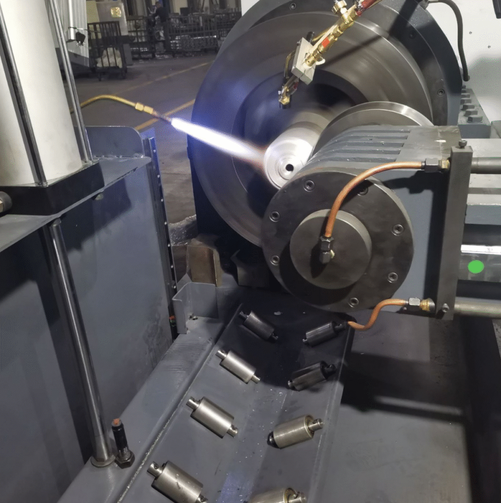
A hot metal spinning lathe is a highly specialized machine used in advanced metal forming, designed to shape and elongate materials that are too strong or too brittle to be worked efficiently at room temperature. The principle of hot metal spinning is similar to conventional spinning, where a flat circular blank or preformed disc is clamped against a mandrel and rotated at high speed while rollers apply controlled pressure to force the material into the required geometry. However, in hot spinning, the workpiece is heated—often by induction heating systems or gas burners—so that the material becomes more ductile during forming. This makes it possible to process high-strength steels, nickel-based alloys, titanium, and other difficult-to-form metals that would otherwise risk cracking or excessive tool wear under cold forming conditions. The hot metal spinning lathe therefore bridges the gap between traditional spinning and high-performance engineering, allowing industries to produce large, seamless, pressure-resistant components that meet stringent structural demands.
The applications of a hot metal spinning lathe are most prominent in aerospace, defense, energy, and heavy industry, where performance and reliability are paramount. Aerospace manufacturers rely on these machines for producing jet engine housings, rocket motor casings, nose cones, and turbine components, all of which must withstand extreme stress and high operating temperatures. In defense applications, the hot spinning process is used to manufacture artillery shells, missile bodies, and other seamless cylindrical structures where strength and precision are critical. The energy sector benefits from the ability to create hydrogen storage vessels, high-pressure gas cylinders, and components for nuclear and thermal power systems, where metals must endure both internal pressures and thermal cycles without failure. Hot metal spinning lathes are also valuable for producing large industrial components such as chemical reactors, pressure tanks, and heavy-duty piping elements that require exceptional durability.
The introduction of CNC technology has greatly advanced the capabilities of hot metal spinning lathes, combining the flexibility of thermal-assisted forming with the precision and repeatability of computer control. CNC hot spinning systems allow exact control over forming paths, roller pressure, heating zones, and rotation speeds, which ensures consistent part quality even in mass production. The integration of induction heating directly into the lathe enables localized and controlled heating of the workpiece, reducing energy consumption and improving efficiency compared to traditional open flame heating. This synergy between heating and automated forming not only improves productivity but also extends the life of forming tools by reducing stress on rollers and mandrels. In addition, multifunctional hot metal spinning lathes can perform additional operations such as trimming, beading, or flow forming within a single setup, further streamlining the production process.
The demand for hot metal spinning lathes continues to grow as industries push for stronger, lighter, and more reliable components that can endure extreme working conditions. The technology plays a key role in supporting global trends toward advanced aerospace engineering, modern defense systems, renewable energy solutions, and efficient industrial production. Its ability to reduce material waste, lower tooling costs, and deliver seamless high-strength parts makes it one of the most valuable investments for manufacturers working with advanced alloys. By combining centuries-old spinning principles with modern heating systems and CNC automation, the hot metal spinning lathe has secured its place as an indispensable tool in the future of high-performance metal forming.
A hot metal spinning lathe is one of the most advanced and powerful machines in the field of metal forming, created to handle materials that are otherwise too strong, too thick, or too brittle to be shaped through conventional cold spinning methods. The working principle is rooted in the traditional spinning process, where a flat disc or preformed blank is clamped onto a mandrel and rotated at high speed while forming rollers gradually force the material into a seamless, symmetrical geometry. The difference lies in the fact that a hot metal spinning lathe introduces heat, often through induction coils or gas torches, to make the workpiece ductile enough for controlled shaping without cracking or producing excessive tool wear. This combination of rotational forming and thermal assistance opens the door to working with high-strength steels, titanium alloys, nickel-based superalloys, and other metals that are vital to aerospace, defense, and energy industries but are notoriously difficult to form at room temperature. By allowing these advanced materials to be processed efficiently, the hot spinning lathe ensures that seamless, high-strength, and pressure-resistant parts can be produced to meet the highest engineering standards.
The use of a hot metal spinning lathe is especially important in aerospace applications, where components such as turbine housings, jet engine casings, rocket motor shells, and nose cones must not only achieve precise geometries but also maintain structural integrity under extreme thermal and mechanical loads. Defense industries also depend heavily on hot spinning technology, as it is one of the most reliable ways to produce seamless artillery shells, missile bodies, and rocket cases that can withstand explosive pressures without failure. In the energy sector, hot spinning lathes are applied to the production of hydrogen storage vessels, natural gas cylinders, nuclear power containment parts, and high-pressure tanks that require maximum durability and resistance to fatigue. Heavy industrial manufacturing also benefits from this process, as chemical reactors, boilers, and large pressure vessels are often shaped using hot spinning to ensure smooth, defect-free walls that can handle continuous operation in aggressive environments. The fact that the process produces parts with improved grain flow and strength due to the combined effects of forming and heating makes it a natural choice for critical industries where reliability and performance are non-negotiable.
The integration of CNC technology into hot metal spinning lathes has elevated the process to a level where precision, repeatability, and efficiency are guaranteed even for complex and demanding designs. CNC-controlled lathes not only automate the forming path of rollers but also synchronize heating, pressure application, and rotational speeds with incredible accuracy. Induction heating systems built directly into these machines allow localized and controlled thermal input, ensuring the metal is softened exactly where needed without overheating or wasting energy. This level of control reduces the overall forming forces required, extends tool life, and produces consistent quality across high-volume production. Moreover, modern CNC hot spinning lathes can perform multifunctional operations such as trimming excess material, beading edges, flanging rims, and even applying flow forming techniques, all within the same cycle. This consolidation of processes reduces production times, lowers labor requirements, and makes the machines ideal for industries moving toward fully automated and digitized manufacturing systems.
As the demand for stronger, lighter, and more durable components continues to increase across aerospace, defense, automotive, and renewable energy sectors, the role of hot metal spinning lathes becomes more important than ever. Manufacturers are under constant pressure to deliver high-performance parts at lower costs while meeting strict sustainability targets, and this technology supports those goals by minimizing waste, reducing tooling expenses, and maximizing material efficiency. The seamless construction of spun components ensures reliability in high-stress environments, while the adaptability of the machines allows rapid switching between prototypes, small production runs, and mass manufacturing. The hot metal spinning lathe thus embodies the union of ancient forming principles with cutting-edge heating and CNC control, creating a production technology that is both timeless and future-ready. Its presence in modern industry ensures that the most challenging metals and the most demanding applications can be met with confidence, precision, and efficiency.
A hot metal spinning lathe is a cornerstone of advanced metal forming technology, providing manufacturers with the ability to produce seamless, high-strength components from metals that are difficult or impossible to shape cold. The process combines the mechanical principles of traditional spinning with thermal assistance, using heat from induction coils, gas torches, or other localized sources to make the metal more ductile while it is rotated at high speed against a mandrel. This allows rollers or forming tools to gradually shape the workpiece into cylindrical, conical, or complex axisymmetric forms without cracking, tearing, or excessive tool wear. Materials such as titanium, high-strength steels, nickel-based superalloys, and other specialty metals can be formed into precision components that meet the stringent requirements of aerospace, defense, energy, and industrial applications. The heating process not only facilitates forming but also enhances the mechanical properties of the finished part by producing a refined grain structure, improving strength, durability, and resistance to fatigue, which is critical in high-performance or safety-critical applications.
In aerospace, the hot metal spinning lathe is used to manufacture turbine casings, jet engine housings, nose cones, and other aerodynamic components where precision, structural integrity, and weight reduction are crucial. The defense industry relies on this technology for the production of artillery shells, missile casings, and rocket motor housings that require seamless construction and exceptional pressure resistance. In the energy sector, the lathe enables the creation of hydrogen storage vessels, high-pressure gas cylinders, nuclear containment components, and industrial reactors that must withstand extreme operational conditions while maintaining exact tolerances. Even in heavy industry and large-scale manufacturing, hot spinning allows the production of pressure tanks, chemical reactors, and industrial piping components where both strength and dimensional accuracy are critical. The ability to produce parts with smooth, defect-free walls and enhanced material properties sets hot metal spinning apart from other forming processes.
The adoption of CNC technology has revolutionized hot metal spinning lathes, bringing automation, precision, and repeatability to the forefront. CNC-controlled lathes can manage complex roller paths, regulate mandrel rotation, and synchronize localized heating zones with remarkable accuracy, ensuring consistent part quality across high-volume production runs. Induction heating systems integrated into the lathe provide controlled, energy-efficient heating, allowing only the necessary areas of the workpiece to reach the required temperature, minimizing thermal stress and conserving energy. Modern CNC hot spinning machines are capable of performing additional operations such as trimming, beading, flanging, and flow forming within the same setup, drastically reducing production times and operator intervention while increasing efficiency and flexibility. These capabilities allow manufacturers to switch rapidly between prototypes, small-batch production, and large-scale industrial runs without significant retooling, making the technology ideal for industries where precision, speed, and adaptability are vital.
The importance of hot metal spinning lathes continues to grow as industries demand stronger, lighter, and more durable components while striving to reduce costs and improve sustainability. The process minimizes material waste, lowers tooling expenses compared to stamping or deep drawing, and produces seamless components capable of withstanding high stress, vibration, and thermal cycling. Automotive manufacturers benefit from lightweight structural components and gas cylinders, while renewable energy sectors use the technology for turbine hubs, solar concentrator elements, and hydrogen storage solutions. Consumer industries also rely on hot spinning to create high-quality cookware, stainless steel containers, and industrial-grade appliances that combine strength with aesthetic appeal. By merging centuries-old spinning principles with modern CNC automation, precision control, and thermal forming capabilities, the hot metal spinning lathe remains a vital technology that supports advanced manufacturing across aerospace, defense, energy, automotive, and consumer product sectors, ensuring that high-performance metal components can be produced efficiently, reliably, and with exceptional quality.
A hot metal spinning lathe is an essential tool in modern metalworking, combining traditional spinning principles with thermal assistance to form metals that are otherwise too strong, hard, or brittle to shape cold. The process involves clamping a blank onto a mandrel, rotating it at high speeds, and applying controlled pressure with rollers to gradually form cylindrical, conical, or other axisymmetric shapes. What sets hot spinning apart from conventional spinning is the addition of heat, typically provided by induction coils, gas torches, or electric heaters, which softens the metal locally and makes it more ductile, allowing complex shapes to be formed without cracking or tool wear. This method is particularly effective for high-strength steels, titanium, nickel-based superalloys, and specialty metals used in aerospace, defense, energy, and heavy industry. The heat-assisted process not only facilitates forming but also enhances the mechanical properties of the finished component by refining its grain structure, resulting in parts that are stronger, more durable, and capable of withstanding high pressures, thermal cycles, and mechanical stresses.
Hot metal spinning lathes are widely used in aerospace for producing turbine casings, jet engine housings, nose cones, and other precision components where structural integrity and weight reduction are critical. Defense industries depend on them for artillery shells, missile casings, and rocket motor housings that require seamless construction and precise dimensions to withstand explosive pressures and high-speed impact. In the energy sector, these machines are used to manufacture hydrogen storage vessels, high-pressure gas cylinders, nuclear containment parts, and industrial reactors, all of which demand flawless walls and exact tolerances. Heavy industrial applications also benefit from hot spinning, as it allows the creation of pressure tanks, chemical reactors, and large piping elements with superior strength and dimensional accuracy. The ability to produce seamless, high-performance components with minimal waste and optimized material properties makes hot metal spinning a preferred method for critical applications.
The introduction of CNC technology has greatly expanded the capabilities of hot metal spinning lathes. CNC control allows precise programming of roller paths, mandrel rotation, heating zones, and applied pressures, ensuring consistent quality across high-volume production. Induction heating systems integrated into these machines provide localized, energy-efficient thermal input that reduces stress on the workpiece while minimizing energy consumption. Advanced CNC hot spinning lathes can also perform multiple operations within a single setup, such as trimming, flanging, beading, and flow forming, reducing production times and eliminating the need for multiple machines or setups. This multifunctional capability, combined with automation and robotic handling, enables manufacturers to switch seamlessly between prototypes, small batches, and large-scale production, enhancing flexibility and reducing lead times.
As industries increasingly demand lightweight, high-strength, and reliable components, hot metal spinning lathes remain indispensable. Automotive manufacturers use them to create lightweight structural parts and durable gas cylinders, while renewable energy sectors rely on them for turbine hubs, solar concentrator elements, and hydrogen storage systems. Consumer and industrial goods industries also benefit from hot spinning for high-quality cookware, stainless steel containers, and appliances that combine durability with aesthetic appeal. The process minimizes material waste, lowers tooling costs compared to stamping or deep drawing, and produces seamless, structurally superior parts. By merging the principles of traditional spinning with modern CNC automation and thermal forming, the hot metal spinning lathe continues to be a critical technology for producing high-performance metal components across aerospace, defense, energy, automotive, and consumer product sectors, ensuring efficiency, precision, and reliability in demanding applications.
Large-Diameter Metal Spinning Machine
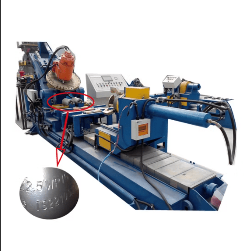
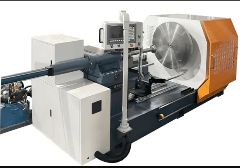
A large-diameter metal spinning machine is a specialized type of metal forming equipment designed to handle exceptionally wide or oversized blanks, producing seamless, rotationally symmetric components with diameters that often exceed several meters. The machine operates on the same fundamental principle as conventional metal spinning: a flat or pre-formed metal blank is clamped against a mandrel and rotated at high speeds while rollers or forming tools apply controlled pressure to gradually shape the material into cylindrical, conical, parabolic, or other axisymmetric forms. What distinguishes a large-diameter spinning machine is its ability to handle very wide blanks, thicker sheets, and extended radii, which requires enhanced structural rigidity, high-torque drive systems, and robust roller assemblies to maintain precision over the full span of the part. These machines are capable of processing a wide range of metals, from lightweight aluminum and copper to high-strength steels, titanium, and nickel-based alloys, making them suitable for applications where both scale and structural integrity are critical.
Industries such as aerospace, defense, renewable energy, heavy industrial manufacturing, and shipbuilding are among the primary users of large-diameter metal spinning machines. In aerospace, these machines can produce turbine casings, large engine housings, nacelles, and structural airframe components that require tight tolerances, smooth surfaces, and enhanced strength due to work-hardening during spinning. The defense industry relies on them for oversized projectile casings, rocket components, and other critical cylindrical structures that must maintain uniform wall thickness and seamless construction. In renewable energy, large-diameter spinning is used to manufacture wind turbine hubs, solar concentrators, and large pressure vessels, where precision and durability are essential for operational efficiency. Heavy industrial applications such as chemical reactors, storage tanks, and industrial piping systems also benefit from the ability to produce large, seamless parts that can withstand high pressures, thermal cycling, and mechanical stress without failure.
Modern large-diameter metal spinning machines often integrate CNC control, which allows precise automation of roller paths, mandrel rotation, and forming speeds across the extended surface area of the workpiece. CNC systems ensure consistent thickness, accurate profiles, and minimal defects even for extremely large components, while reducing the labor intensity traditionally associated with manual spinning. Some advanced models also incorporate induction or localized heating for hot spinning, enabling the forming of high-strength or heat-sensitive metals that would otherwise be difficult to shape at room temperature. In addition, multifunctional capabilities such as flanging, trimming, beading, and flow forming can be integrated into the same setup, streamlining production and reducing the need for secondary processing.
The advantages of large-diameter metal spinning machines include their ability to produce oversized, seamless parts with superior strength, minimal material waste, and lower tooling costs compared to stamping or deep-drawing large components. Their structural rigidity and precision make them essential in applications where dimensional accuracy, high performance, and safety are critical. As industries continue to demand larger, more complex, and higher-performing components, the role of large-diameter metal spinning machines remains indispensable. They combine traditional spinning techniques with modern CNC control, heating systems, and multifunctional operations, providing manufacturers with the capability to create large-scale, high-strength, and precision-engineered parts efficiently, reliably, and sustainably.
A large-diameter metal spinning machine is an advanced and specialized piece of equipment designed to handle oversized blanks and produce large, seamless, axisymmetric components with diameters that often reach several meters. The machine operates on the fundamental principles of metal spinning, where a blank is secured to a mandrel and rotated at high speeds while forming rollers gradually shape the material under controlled pressure. What sets a large-diameter machine apart is its ability to maintain precision, uniform wall thickness, and structural integrity over an extended surface area, which requires enhanced rigidity, high-torque drive systems, and robust roller assemblies. These machines can work with a wide variety of metals, including aluminum, stainless steel, titanium, copper, and nickel-based alloys, allowing the production of lightweight, high-strength, and durable parts. Large-diameter spinning provides significant advantages over conventional stamping or deep-drawing for oversized components because it reduces tooling costs, minimizes material waste, and produces seamless parts capable of withstanding extreme mechanical and thermal stresses.
The applications for large-diameter metal spinning machines are particularly prominent in aerospace, defense, renewable energy, heavy industrial, and shipbuilding sectors. In aerospace, the machines are used to produce turbine casings, engine housings, nacelles, and structural airframe components that demand precise geometry, smooth surfaces, and superior strength due to work-hardening during the spinning process. Defense industries rely on these machines to manufacture large projectile casings, rocket motor shells, and missile bodies where seamless construction and uniform wall thickness are critical for safety and performance. Renewable energy applications, such as wind turbine hubs, solar concentrators, and hydrogen storage vessels, require the ability to produce durable and precise large-scale components capable of withstanding operational loads, environmental stress, and thermal cycling. Heavy industrial and shipbuilding applications benefit from the production of large storage tanks, pressure vessels, chemical reactors, and industrial piping systems that demand exceptional durability and dimensional accuracy. The ability of a single machine to handle these wide-ranging applications makes large-diameter metal spinning an indispensable technology in modern manufacturing.
Modern large-diameter metal spinning machines increasingly employ CNC control to achieve automation, precision, and repeatability across the extended diameter of the workpiece. CNC systems allow exact control of roller paths, mandrel rotation, forming pressure, and speed, ensuring consistent thickness and dimensional accuracy even for extremely large components. Some machines also integrate induction or localized heating systems for hot spinning, enabling the forming of high-strength metals like titanium and nickel alloys that are difficult to shape at ambient temperature. Advanced machines can perform multiple operations in one setup, including trimming, flanging, beading, and flow forming, which reduces production time, minimizes handling, and increases efficiency. Automation, along with real-time monitoring and control, ensures not only superior quality but also safer and more efficient operation, especially when dealing with very large and heavy workpieces.
The value of large-diameter metal spinning machines lies in their ability to produce oversized, seamless components with high structural integrity, minimal material waste, and reduced tooling costs. They are critical in industries where precision, durability, and performance cannot be compromised. As demands continue to rise for larger, more complex, and high-performing components across aerospace, defense, energy, automotive, and industrial sectors, large-diameter spinning machines provide a reliable, flexible, and efficient solution. By combining traditional spinning techniques with CNC automation, heating systems, and multifunctional capabilities, these machines ensure that manufacturers can meet the challenges of producing large-scale, high-strength, and precision-engineered components with consistency, speed, and cost-effectiveness.
A large-diameter metal spinning machine is one of the most versatile and essential tools in modern metal forming, capable of producing seamless, high-strength components that are both oversized and precise. Unlike smaller spinning machines, a large-diameter system is designed to handle extremely wide blanks, thick sheets, and extended radii, requiring enhanced structural rigidity, high-torque drive systems, and heavy-duty roller assemblies to maintain accuracy across the full surface of the part. The process itself relies on the same principles as conventional metal spinning: a blank is clamped onto a mandrel, rotated at high speed, and gradually shaped by forming rollers that apply precise pressure to achieve the desired geometry. However, the scale of the workpiece introduces unique challenges, including uniform thickness control, consistent material flow, and maintaining surface finish across large diameters, all of which the machine must overcome to ensure the final product meets stringent engineering requirements. Large-diameter spinning machines are capable of working with a broad range of metals, from lightweight aluminum and copper to high-strength steels, titanium, and nickel-based alloys, making them suitable for industries that demand both size and structural integrity.
Industries such as aerospace, defense, renewable energy, shipbuilding, and heavy industrial manufacturing rely heavily on large-diameter metal spinning machines for applications that require durability, precision, and seamless construction. In aerospace, these machines are used to produce large turbine casings, jet engine housings, nacelles, and structural components of airframes, where smooth surfaces, precise dimensions, and reinforced material properties are essential. The defense industry utilizes them for oversized artillery shells, missile casings, and rocket motor housings, components where uniform wall thickness and seamless integrity are critical for safety and performance. Renewable energy applications, including wind turbine hubs, solar concentrator mirrors, and hydrogen storage vessels, demand large-scale, precise components capable of withstanding high mechanical loads and environmental stress. Heavy industrial applications, such as chemical reactors, pressure tanks, and large-scale piping, benefit from the ability of these machines to create seamless, structurally sound parts that meet the highest standards of durability and dimensional accuracy.
The integration of CNC technology into large-diameter metal spinning machines has transformed the capabilities and efficiency of the process. CNC control allows precise programming of roller paths, mandrel rotation, forming speed, and applied pressure, ensuring consistent thickness and geometry even for extremely large components. Many machines also incorporate localized or induction heating systems, which enable hot spinning of high-strength alloys like titanium and nickel that would otherwise be difficult to form cold. Advanced machines can perform multiple operations within a single setup, including flanging, trimming, beading, and flow forming, which minimizes handling, reduces cycle time, and increases overall efficiency. Automation, real-time monitoring, and intelligent software ensure not only product consistency and quality but also safer operation when handling massive workpieces, which would be challenging or hazardous in manual setups.
Large-diameter metal spinning machines offer a combination of flexibility, efficiency, and structural performance that is unmatched in the production of oversized components. They allow manufacturers to produce large, seamless parts with minimal material waste and lower tooling costs compared to traditional stamping or deep drawing methods, while maintaining high precision and mechanical strength. As industries worldwide continue to demand larger, more complex, and higher-performing components, these machines remain central to manufacturing operations in aerospace, defense, energy, shipbuilding, and heavy industrial sectors. By combining traditional metal spinning principles with modern CNC automation, thermal forming capabilities, and multifunctional processing, large-diameter metal spinning machines enable the efficient production of high-quality, durable, and precise parts on a scale that meets the most demanding engineering and industrial requirements.
A large-diameter metal spinning machine is a critical asset in modern manufacturing, designed to handle oversized blanks and create seamless, rotationally symmetric components with diameters that often exceed several meters. The machine operates by clamping a flat or preformed metal blank onto a mandrel and rotating it at high speeds while rollers or forming tools gradually apply pressure to shape the metal into precise cylindrical, conical, or complex geometries. The large scale of these machines requires exceptional structural rigidity, high-torque drives, and reinforced roller assemblies to maintain uniform wall thickness and dimensional accuracy across the entire workpiece. Capable of handling a wide range of materials—from lightweight aluminum and copper to high-strength steels, titanium, and nickel-based alloys—these machines are essential for industries where both size and structural integrity are paramount. The process minimizes material waste, reduces tooling costs compared to stamping or deep drawing, and produces seamless components that offer superior mechanical properties, including enhanced strength and resistance to fatigue and thermal stress.
Large-diameter metal spinning machines are indispensable in aerospace, defense, renewable energy, shipbuilding, and heavy industrial applications where precision, durability, and seamless construction are critical. In aerospace, they produce turbine casings, engine housings, nacelles, and large airframe components that demand exact dimensions, smooth surfaces, and reinforced structural properties achieved through work hardening during spinning. In the defense sector, these machines are used for oversized artillery shells, missile bodies, and rocket motor casings that require uniform wall thickness and reliable, defect-free construction to withstand explosive forces and high-speed impact. Renewable energy industries use them to fabricate wind turbine hubs, large solar concentrators, and hydrogen storage vessels, all of which must endure significant mechanical loads and environmental conditions. Heavy industrial applications such as chemical reactors, high-pressure storage tanks, and large piping systems benefit from the ability of these machines to create oversized, seamless components that meet stringent operational standards and durability requirements.
Modern large-diameter metal spinning machines are increasingly integrated with CNC technology, allowing for precise automation of roller paths, mandrel rotation, forming pressure, and rotational speed to achieve consistent results even on extremely large components. Some models incorporate localized or induction heating, enabling hot spinning of high-strength metals like titanium and nickel alloys that are difficult or impossible to form at ambient temperatures. CNC-controlled systems can also integrate multifunctional operations, including trimming, beading, flanging, and flow forming, in a single setup, which reduces production time, improves efficiency, and minimizes handling of massive workpieces. Automation and real-time monitoring ensure consistent quality, reduce human error, and allow for high-volume production without compromising precision or structural integrity.
The combination of flexibility, efficiency, and mechanical performance makes large-diameter metal spinning machines an irreplaceable tool in modern manufacturing. They allow the creation of oversized, seamless components with superior strength, minimal waste, and lower tooling costs, making them particularly valuable in industries where high performance and reliability are essential. As demand for larger, more complex, and high-performing components continues to grow in aerospace, defense, renewable energy, shipbuilding, and heavy industry, large-diameter metal spinning machines provide a reliable and efficient solution. By combining traditional metal spinning techniques with CNC automation, thermal forming capabilities, and multifunctional processing, these machines enable manufacturers to produce high-quality, precision-engineered components that meet the most demanding engineering, industrial, and safety requirements while maintaining efficiency and cost-effectiveness.
Industrial Metal Bowl Spinning Machine
An industrial metal bowl spinning machine is a specialized type of metal forming equipment designed to produce seamless, rotationally symmetric bowls, domes, hemispherical shells, and similar components with high precision and repeatability. The machine operates by securing a flat or preformed metal blank to a mandrel and rotating it at high speed while a roller or forming tool gradually presses the material into the desired bowl shape. This process, often called metal spinning or spin forming, works without cutting or welding, allowing for the creation of strong, durable parts with uniform thickness and smooth surfaces. Industrial metal bowl spinning machines can handle a wide range of metals, from lightweight aluminum and copper to stainless steel, titanium, and other high-strength alloys, making them suitable for industries that require both structural integrity and aesthetic quality. The process strengthens the metal through work hardening, producing components that are not only precise in geometry but also resistant to mechanical stress, fatigue, and thermal cycling, which is essential for both functional and decorative applications.
These machines are widely used in manufacturing sectors that produce kitchenware, lighting reflectors, industrial containers, and pressure-resistant vessels, as well as in aerospace and defense applications where hemispherical or domed components are required. In consumer industries, industrial metal bowl spinning machines allow the production of stainless steel bowls, cooking pots, and lampshades that combine durability with smooth, polished surfaces. In industrial and engineering sectors, they are used to manufacture chemical processing bowls, protective domes, and components for reactors and pressure vessels, all of which demand exact dimensional control, uniform wall thickness, and seamless construction. Defense and aerospace applications also rely on these machines to create hemispherical or conical components for missile housings, satellite parts, and turbine components, where precision, reliability, and material performance are critical.
Modern industrial metal bowl spinning machines are often equipped with CNC control systems, which provide highly precise automation of roller paths, mandrel rotation, forming speeds, and applied pressure. CNC control ensures consistent wall thickness, accurate contours, and repeatability across multiple components, which is essential for large-scale production. Some machines also integrate hot spinning capabilities using induction or localized heating, allowing harder metals like stainless steel, titanium, or nickel alloys to be formed efficiently without cracking or excessive tool wear. Advanced systems can incorporate multifunctional capabilities such as flanging, trimming, beading, or flow forming within a single setup, reducing production times, minimizing material handling, and increasing overall operational efficiency. Automation and real-time monitoring improve product consistency, reduce errors, and make it feasible to produce large batches of identical high-quality components with minimal operator intervention.
The advantages of industrial metal bowl spinning machines include the ability to produce seamless, structurally strong, and precise components with minimal material waste and lower tooling costs compared to stamping or deep drawing processes. They are flexible enough to accommodate different sizes, thicknesses, and metals, which makes them suitable for prototyping, small-batch production, and large-scale industrial runs. The combination of speed, precision, and material efficiency ensures that industrial metal bowl spinning machines remain indispensable in a wide variety of sectors, including consumer goods, aerospace, defense, chemical processing, and energy. By merging the traditional craftsmanship of spinning with modern CNC automation, heating systems, and multifunctional processing, these machines provide manufacturers with the ability to create high-quality, durable, and aesthetically refined components that meet the demanding standards of contemporary industry.
An industrial metal bowl spinning machine is an essential tool in modern manufacturing, designed to produce seamless, rotationally symmetric bowls, domes, hemispherical shells, and other concave or curved components with high precision and consistent quality. The machine functions by clamping a flat or preformed metal blank onto a mandrel and rotating it at high speed while a roller or forming tool gradually presses the material into the desired shape. Unlike stamping or welding, the spinning process does not remove material or require seams, which ensures the final part maintains uniform thickness, superior strength, and smooth surfaces. Industrial metal bowl spinning machines can handle a wide variety of metals, including aluminum, stainless steel, copper, titanium, and nickel-based alloys, allowing them to meet the requirements of both consumer and industrial applications. As the material is spun and formed, it work-hardens, improving its mechanical properties and providing enhanced resistance to stress, fatigue, and deformation, which is particularly important for high-performance or pressure-bearing components.
These machines find applications across multiple sectors where precision, durability, and aesthetic quality are essential. In consumer products, industrial metal bowl spinning machines are used to create cookware, stainless steel bowls, lampshades, and decorative containers that require smooth surfaces, uniform thickness, and attractive finishes. In industrial and engineering applications, they produce chemical processing bowls, protective domes, pressure vessels, and reactor components where structural integrity and tight dimensional tolerances are critical. Aerospace and defense sectors also rely on metal bowl spinning machines to manufacture hemispherical or conical components for missile casings, satellite housings, turbine end caps, and other parts that must endure high stress, extreme temperatures, and vibration without failure. The versatility of these machines enables the production of both small and large components with consistent quality, meeting the demands of industries where performance and reliability cannot be compromised.
Modern industrial metal bowl spinning machines are often equipped with CNC control, which allows precise automation of mandrel rotation, roller paths, forming speed, and applied pressure. CNC integration ensures uniform wall thickness, accurate contours, and high repeatability across multiple parts, making it ideal for both small-batch production and high-volume manufacturing. Some machines also incorporate hot spinning capabilities, using induction or localized heating to soften the metal during forming. This is particularly useful when working with high-strength or heat-sensitive materials such as stainless steel, titanium, or nickel alloys, which would otherwise be difficult to shape at room temperature. Advanced systems may combine spinning with additional operations such as flanging, trimming, beading, and flow forming in a single setup, streamlining production, reducing material handling, and improving efficiency. Automation and real-time monitoring not only increase consistency and quality but also reduce labor intensity and potential for human error, allowing manufacturers to produce high-quality components more reliably and cost-effectively.
The advantages of industrial metal bowl spinning machines lie in their ability to produce seamless, structurally strong, and precise components with minimal waste and lower tooling costs compared to stamping, deep drawing, or welding processes. They provide flexibility in handling different metals, sizes, and thicknesses, making them suitable for prototyping, medium-volume production, and large-scale industrial operations. Their ability to create parts that combine mechanical strength, aesthetic appeal, and functional reliability makes them indispensable in consumer goods, aerospace, defense, chemical processing, and energy sectors. By integrating the traditional craftsmanship of metal spinning with modern CNC automation, thermal forming, and multifunctional capabilities, industrial metal bowl spinning machines enable manufacturers to produce high-quality, durable, and precise components that meet the stringent demands of contemporary industry, balancing efficiency, performance, and versatility in a single manufacturing solution.
An industrial metal bowl spinning machine is a key piece of equipment in metal forming, specifically engineered to produce seamless, rotationally symmetric bowls, domes, and hemispherical components with high precision and consistent quality. The fundamental operation involves clamping a flat or pre-formed metal blank onto a mandrel and rotating it at high speeds while rollers or forming tools gradually press the material into the desired shape. Unlike other forming methods such as stamping or welding, spinning does not remove material or require seams, resulting in components with uniform wall thickness, superior mechanical strength, and smooth, defect-free surfaces. Industrial metal bowl spinning machines are capable of handling a wide variety of metals, including aluminum, stainless steel, copper, titanium, and nickel-based alloys, which allows manufacturers to meet the rigorous demands of both functional and aesthetic applications. As the metal is spun and shaped, work-hardening occurs, improving the material’s durability, resistance to fatigue, and ability to withstand thermal or mechanical stress, which is essential for components that will endure heavy use or extreme conditions.
These machines serve a wide range of industries due to their versatility and precision. In consumer goods, they are used to manufacture cookware, stainless steel bowls, lampshades, decorative containers, and other household items that require both aesthetic appeal and durability. Industrial applications include chemical processing bowls, reactor domes, protective covers, and pressure vessels where uniform thickness and exact tolerances are critical for operational safety and efficiency. In aerospace and defense, industrial metal bowl spinning machines are essential for producing hemispherical or conical parts such as missile casings, satellite housings, turbine end caps, and protective shells that must maintain structural integrity under extreme stress, high pressure, and vibration. The ability to create large or small components with precision and consistency makes these machines indispensable in sectors where performance, reliability, and longevity are non-negotiable.
Modern industrial metal bowl spinning machines are often equipped with CNC systems, which allow for precise automation of mandrel rotation, roller movement, forming speed, and applied pressure. CNC control ensures consistent wall thickness, accurate geometric profiles, and repeatability across multiple parts, which is particularly important for high-volume production or components with tight tolerances. Some machines also incorporate hot spinning capabilities, using induction or localized heating to soften the metal during forming, which enables shaping of high-strength or heat-sensitive materials such as stainless steel, titanium, or nickel alloys without cracking or excessive tool wear. Advanced models can combine multiple operations—including flanging, trimming, beading, and flow forming—into a single setup, reducing production time, minimizing handling, and increasing overall operational efficiency. Automation and real-time monitoring enhance quality control, reduce the risk of human error, and allow for consistent production of large batches of components with complex shapes.
The advantages of industrial metal bowl spinning machines lie in their ability to produce seamless, structurally robust, and highly precise components with minimal material waste and lower tooling costs compared to conventional forming methods. Their flexibility to handle different metals, thicknesses, and sizes makes them ideal for prototyping, medium-volume production, and large-scale industrial manufacturing. These machines deliver a unique combination of strength, durability, and aesthetic quality, making them suitable for a broad spectrum of industries, from consumer goods to aerospace, defense, chemical processing, and energy. By integrating traditional spinning techniques with modern CNC automation, thermal forming, and multifunctional capabilities, industrial metal bowl spinning machines provide manufacturers with the ability to produce high-quality, precise, and durable components efficiently, reliably, and cost-effectively, meeting the demanding standards of contemporary manufacturing environments.
An industrial metal bowl spinning machine is a highly specialized and versatile piece of equipment designed to create seamless, rotationally symmetric components such as bowls, domes, hemispherical shells, and other concave or curved forms with exceptional precision and structural integrity. The process involves clamping a flat or pre-formed metal blank onto a mandrel and rotating it at high speed while a roller or forming tool gradually applies controlled pressure to shape the material into the desired geometry. Unlike stamping, pressing, or welding, the spinning process does not remove material or require seams, resulting in parts with uniform wall thickness, superior strength, and smooth, defect-free surfaces. Industrial metal bowl spinning machines are capable of working with a broad range of metals, including aluminum, stainless steel, copper, titanium, and nickel-based alloys, allowing manufacturers to produce components that meet stringent mechanical and aesthetic requirements. During spinning, the metal undergoes work hardening, which improves its durability, resistance to fatigue, and ability to withstand both mechanical and thermal stresses, making it particularly suitable for demanding industrial, aerospace, and defense applications.
The applications of industrial metal bowl spinning machines span multiple sectors, highlighting their versatility and indispensability. In the consumer goods industry, these machines are used to produce cookware, stainless steel bowls, decorative containers, lampshades, and other household items that require a combination of durability, precision, and aesthetic quality. In industrial and engineering contexts, the machines manufacture chemical processing bowls, protective domes, reactor components, and pressure vessels where uniform thickness, structural integrity, and dimensional accuracy are critical to operational safety and efficiency. Aerospace and defense industries rely on industrial metal bowl spinning machines for producing hemispherical or conical parts such as missile housings, satellite shells, turbine end caps, and other critical components that must endure high mechanical loads, extreme environmental conditions, and vibration without failure. The capacity of these machines to handle both small and large components while maintaining consistent quality makes them invaluable across applications where reliability and performance are non-negotiable.
Modern industrial metal bowl spinning machines increasingly incorporate CNC technology, which allows precise automation of mandrel rotation, roller paths, forming pressure, and rotational speed, ensuring consistent wall thickness, accurate contours, and repeatable results across multiple parts. CNC control enables high-volume production with minimal operator intervention, reducing the likelihood of errors and enhancing overall efficiency. Some machines also integrate hot spinning capabilities through induction or localized heating, which softens high-strength metals like stainless steel, titanium, or nickel alloys, enabling the shaping of materials that would otherwise be difficult or impossible to form cold. Advanced systems can combine multiple operations in a single setup, including flanging, trimming, beading, and flow forming, which reduces production time, minimizes material handling, and enhances operational workflow. Automation and real-time monitoring further improve quality assurance and operational safety, making it feasible to produce complex components with high precision and reliability.
The advantages of industrial metal bowl spinning machines include the production of seamless, structurally robust, and precise components with minimal material waste and lower tooling costs compared to conventional forming methods such as stamping, forging, or deep drawing. Their flexibility allows manufacturers to work with various metals, sizes, and thicknesses, making them suitable for prototyping, medium-volume production, and large-scale industrial runs. By combining traditional spinning techniques with modern CNC automation, thermal forming capabilities, and multifunctional processing, industrial metal bowl spinning machines enable manufacturers to produce high-quality, durable, and aesthetically refined components efficiently, reliably, and cost-effectively. This integration of precision, strength, and versatility ensures that industrial metal bowl spinning machines remain indispensable in sectors ranging from consumer goods and energy to aerospace, defense, and heavy industry, meeting the evolving demands of contemporary manufacturing environments.
Aluminum Sheet Spinning Machine
An aluminum sheet spinning machine is a specialized metal forming system designed to produce seamless, rotationally symmetric components from aluminum sheets, such as domes, cones, cylinders, bowls, and other axisymmetric shapes with high precision and efficiency. The machine operates by clamping a flat or pre-formed aluminum blank onto a mandrel and rotating it at high speeds while rollers or forming tools gradually apply pressure to shape the metal over the mandrel’s profile. Unlike stamping, deep drawing, or welding, sheet spinning forms parts without cutting or joining, resulting in seamless components with uniform wall thickness, superior mechanical properties, and smooth surfaces. Aluminum, being lightweight, corrosion-resistant, and highly ductile, is particularly well-suited for spinning, allowing manufacturers to create components that are both strong and lightweight, making them ideal for aerospace, automotive, lighting, and consumer goods applications. The spinning process also work-hardens the aluminum, improving its structural integrity and ability to withstand mechanical stresses and fatigue, which is crucial for components that will operate under high load or repetitive use conditions.
Aluminum sheet spinning machines are widely employed across industries that demand precision, efficiency, and high-quality finishes. In aerospace, these machines produce lightweight engine casings, turbine components, satellite housings, and other critical parts where dimensional accuracy, seamless construction, and material performance are vital. Automotive manufacturers utilize aluminum sheet spinning to create components such as decorative trim, structural elements, fuel or fluid containers, and heat shields, benefiting from aluminum’s combination of strength and low weight. Consumer industries rely on these machines to manufacture cookware, lampshades, decorative bowls, and storage containers, achieving a combination of durability, aesthetic appeal, and smooth polished surfaces. In industrial applications, aluminum sheet spinning is used to produce pressure vessels, chemical processing bowls, and protective domes that require consistent wall thickness, seamless construction, and high corrosion resistance. The versatility of aluminum, combined with the flexibility of spinning, allows manufacturers to create both small-scale prototypes and large-scale production components with consistent quality.
Modern aluminum sheet spinning machines increasingly incorporate CNC technology, which automates the control of mandrel rotation, roller paths, forming speeds, and applied pressures, ensuring precise geometries and repeatable results across multiple components. CNC systems allow the production of complex shapes and tight tolerances with minimal operator intervention, reducing the risk of errors while increasing efficiency. Some machines also integrate hot spinning capabilities, using localized heating to soften aluminum sheets when forming thicker or more complex parts, which improves material flow and reduces tool wear. Advanced aluminum sheet spinning machines often feature multifunctional capabilities, including trimming, flanging, beading, and flow forming within a single setup, which streamlines production, minimizes material handling, and reduces cycle times. Automation, along with real-time monitoring and feedback systems, ensures consistent quality, uniform wall thickness, and smooth surface finishes, making the machines suitable for both high-volume industrial production and specialized custom manufacturing.
The advantages of aluminum sheet spinning machines include the ability to produce lightweight, seamless, and high-strength components with minimal material waste and lower tooling costs compared to stamping or deep drawing. Their flexibility to handle different sheet thicknesses, diameters, and aluminum alloys makes them ideal for prototyping, medium-scale production, and large-scale manufacturing operations. By combining traditional spinning methods with CNC automation, thermal forming, and multifunctional processing, aluminum sheet spinning machines allow manufacturers to produce high-quality, durable, and precise components efficiently and cost-effectively. This makes them indispensable in industries such as aerospace, automotive, consumer goods, lighting, and industrial applications, where the combination of light weight, strength, dimensional accuracy, and surface finish is critical for performance, safety, and aesthetics.
An aluminum sheet spinning machine is a highly specialized and versatile piece of equipment designed to transform flat or pre-formed aluminum blanks into seamless, rotationally symmetric components with high precision and consistency. The machine operates by securing the aluminum sheet to a mandrel and rotating it at high speeds while a roller or forming tool gradually applies pressure to shape the metal along the mandrel’s profile. Unlike stamping, deep drawing, or welding, aluminum sheet spinning produces parts without cutting or joining, resulting in components with uniform wall thickness, superior structural integrity, and smooth, polished surfaces. Aluminum’s natural ductility, light weight, and corrosion resistance make it particularly suited for spinning, allowing manufacturers to produce strong, lightweight components suitable for aerospace, automotive, lighting, consumer goods, and industrial applications. During the spinning process, the aluminum undergoes work hardening, which enhances its mechanical properties, improves fatigue resistance, and ensures durability even under repetitive loading or harsh operating conditions.
Aluminum sheet spinning machines serve a wide range of industries that require precision, efficiency, and high-quality finishes. In aerospace, they are used to manufacture engine casings, turbine components, satellite housings, and structural components where dimensional accuracy, seamless construction, and material performance are critical. Automotive applications include lightweight structural elements, fuel or fluid containers, decorative trim, and heat shields, where aluminum’s combination of strength and low weight provides both functional and efficiency advantages. Consumer industries utilize aluminum sheet spinning to produce cookware, lampshades, decorative bowls, and storage containers, achieving a balance of durability, aesthetic appeal, and smooth surfaces. Industrial applications also benefit, producing chemical processing bowls, protective domes, and pressure vessels that demand consistent wall thickness, high corrosion resistance, and flawless, defect-free construction. The versatility of aluminum sheet spinning allows manufacturers to produce both small-scale prototypes and high-volume production runs with consistent quality, reducing material waste and production costs.
Modern aluminum sheet spinning machines increasingly incorporate CNC technology to enhance automation, precision, and repeatability. CNC systems control mandrel rotation, roller paths, forming pressure, and speed, ensuring that complex shapes and tight tolerances are consistently maintained across multiple components. Some machines include hot spinning capabilities, employing localized or induction heating to soften aluminum sheets when forming thicker, more intricate, or larger parts, which improves material flow and reduces tool wear. Advanced machines often feature multifunctional capabilities, enabling trimming, flanging, beading, and flow forming within a single setup, thereby streamlining production, minimizing handling, and reducing cycle times. Automation and real-time monitoring ensure uniform wall thickness, smooth surfaces, and overall component quality while reducing the potential for human error, making these machines suitable for demanding industrial production as well as specialized, custom manufacturing applications.
The advantages of aluminum sheet spinning machines lie in their ability to produce lightweight, seamless, and high-strength components with minimal material waste and lower tooling costs compared to traditional stamping or deep-drawing methods. Their flexibility in handling various aluminum alloys, thicknesses, and diameters makes them suitable for prototyping, medium-volume production, and large-scale industrial manufacturing. By combining the traditional craftsmanship of spinning with CNC automation, thermal forming, and multifunctional processing, aluminum sheet spinning machines enable manufacturers to create high-quality, durable, precise, and aesthetically refined components efficiently and cost-effectively. This combination of precision, efficiency, and material performance makes aluminum sheet spinning an indispensable technology in aerospace, automotive, consumer goods, lighting, and industrial sectors, where strength, accuracy, durability, and surface finish are critical to both function and quality.
An aluminum sheet spinning machine is a highly specialized piece of metal forming equipment designed to convert flat or pre-formed aluminum blanks into seamless, rotationally symmetric components such as bowls, cones, cylinders, domes, and other axisymmetric shapes with exceptional precision and uniformity. The machine works by clamping the aluminum sheet onto a mandrel and rotating it at high speed while rollers or forming tools gradually press and stretch the metal along the mandrel’s contour. Unlike stamping, deep drawing, or welding, spinning does not remove material or create seams, resulting in parts with uniform wall thickness, enhanced mechanical strength, and smooth, polished surfaces. Aluminum’s light weight, ductility, corrosion resistance, and work-hardening characteristics make it particularly suitable for this process, enabling manufacturers to produce components that are both durable and lightweight, which is critical for aerospace, automotive, consumer goods, lighting, and industrial applications. The process also improves material properties by aligning the metal’s grain structure, enhancing resistance to fatigue, deformation, and mechanical stress, which is essential for components that must perform reliably under demanding conditions.
Industries that utilize aluminum sheet spinning machines benefit from the combination of precision, versatility, and efficiency that this technology provides. In aerospace, these machines are used to manufacture turbine casings, engine components, nacelles, satellite housings, and other structural parts where dimensional accuracy, seamless construction, and material performance are crucial. In automotive manufacturing, aluminum sheet spinning produces lightweight fuel tanks, structural components, decorative trims, and heat shields, where both strength and weight reduction are important for vehicle efficiency and performance. Consumer product applications include cookware, lampshades, decorative bowls, and storage containers that require aesthetic appeal along with durability. In industrial sectors, aluminum sheet spinning is used to create chemical processing bowls, pressure vessels, protective domes, and reactor components that demand uniform wall thickness, seamless construction, and resistance to corrosion. The ability to produce both small-scale prototypes and high-volume production components with consistent quality makes aluminum sheet spinning machines extremely valuable for manufacturers looking to balance cost, efficiency, and precision.
Modern aluminum sheet spinning machines are increasingly integrated with CNC technology, which allows precise automation of mandrel rotation, roller paths, forming pressure, and rotational speed. CNC control ensures repeatability, tight tolerances, and accurate geometries across multiple components, reducing human error and increasing efficiency. Many machines also incorporate hot spinning capabilities through localized or induction heating, which softens the aluminum when forming thicker or more complex parts, improving material flow and minimizing tool wear. Advanced models may also combine multiple operations in a single setup, including flanging, trimming, beading, and flow forming, which streamlines production, reduces handling, and shortens cycle times. Real-time monitoring and automated control systems further enhance quality assurance, ensuring uniform wall thickness, smooth surfaces, and dimensional accuracy across large production runs or complex shapes.
The advantages of aluminum sheet spinning machines are numerous, including the production of seamless, lightweight, and high-strength components with minimal material waste and reduced tooling costs compared to stamping or deep-drawing processes. Their flexibility allows manufacturers to work with a wide range of aluminum alloys, sheet thicknesses, and diameters, making them suitable for prototypes, medium-volume production, and high-volume industrial runs. By combining traditional spinning techniques with CNC automation, thermal forming, and multifunctional capabilities, aluminum sheet spinning machines allow for efficient, cost-effective, and precise production of durable components that meet the rigorous standards of contemporary manufacturing. The technology is indispensable in aerospace, automotive, consumer products, lighting, and industrial sectors, where the combination of strength, precision, aesthetic quality, and reliability is essential for performance, safety, and market competitiveness.
An aluminum sheet spinning machine is a highly versatile and specialized piece of metal forming equipment designed to produce seamless, rotationally symmetric components from aluminum sheets, such as bowls, cones, cylinders, domes, and other axisymmetric shapes with high precision and consistent quality. The machine operates by clamping a flat or pre-formed aluminum blank onto a mandrel and rotating it at high speeds while a roller or forming tool gradually applies pressure to stretch and shape the metal over the mandrel’s profile. Unlike stamping, deep drawing, or welding, spinning does not remove material or require seams, resulting in parts with uniform wall thickness, excellent mechanical strength, and smooth, polished surfaces. Aluminum’s lightweight, ductile, and corrosion-resistant properties make it especially suitable for spinning, enabling the production of components that are strong yet lightweight, which is essential for applications in aerospace, automotive, lighting, consumer products, and industrial sectors. During the spinning process, the aluminum work-hardens, enhancing its durability, resistance to fatigue, and ability to withstand thermal and mechanical stresses, which ensures that the components can perform reliably under demanding conditions.
Aluminum sheet spinning machines are widely used across industries that require precision, efficiency, and high-quality finishes. In aerospace, they are employed to manufacture turbine casings, engine components, nacelles, satellite housings, and other structural parts where seamless construction, precise dimensions, and material performance are critical. Automotive applications include lightweight structural parts, fuel tanks, decorative trims, and heat shields, which benefit from aluminum’s combination of strength and low weight for improved vehicle performance and fuel efficiency. Consumer products manufactured using aluminum sheet spinning include cookware, decorative bowls, lampshades, and storage containers, all requiring smooth finishes and durability. In industrial and engineering applications, aluminum sheet spinning produces chemical processing bowls, protective domes, reactor components, and pressure vessels, which demand uniform wall thickness, seamless integrity, and high resistance to corrosion. The ability to handle both small and large components with consistent quality makes aluminum sheet spinning machines an indispensable tool for manufacturers seeking efficiency, precision, and material optimization.
Modern aluminum sheet spinning machines increasingly integrate CNC control, which automates mandrel rotation, roller movement, forming pressure, and rotational speed, allowing for precise geometries, consistent wall thickness, and repeatability across multiple parts. CNC technology also enables the production of complex shapes and tight tolerances with minimal operator intervention, reducing human error while improving efficiency. Many machines incorporate hot spinning capabilities through localized or induction heating, which softens aluminum sheets for forming thicker, more complex, or larger parts, improving material flow and reducing tool wear. Advanced models often provide multifunctional capabilities, allowing for trimming, flanging, beading, and flow forming within a single setup, which streamlines production, minimizes handling, and shortens cycle times. Real-time monitoring and automated controls further enhance quality assurance, ensuring uniform wall thickness, smooth surface finishes, and dimensional accuracy, even in large-volume or complex component production.
The advantages of aluminum sheet spinning machines include the ability to create seamless, lightweight, and high-strength components with minimal material waste and lower tooling costs compared to traditional forming methods such as stamping or deep drawing. Their flexibility allows manufacturers to process a wide range of aluminum alloys, sheet thicknesses, and diameters, making them suitable for prototyping, medium-volume production, and large-scale industrial manufacturing. By combining traditional metal spinning techniques with CNC automation, thermal forming, and multifunctional processing, aluminum sheet spinning machines enable the efficient, precise, and cost-effective production of high-quality components that meet the stringent requirements of modern manufacturing. This combination of durability, precision, versatility, and aesthetic quality ensures that aluminum sheet spinning machines remain indispensable in aerospace, automotive, consumer goods, lighting, and industrial sectors where performance, reliability, and appearance are critical.
Copper & Brass Spinning Lathe
A copper and brass spinning lathe is a highly specialized metal forming machine designed to produce seamless, rotationally symmetric components from copper, brass, and their alloys. These machines operate by clamping a flat or pre-formed blank onto a mandrel and rotating it at high speeds while a roller or forming tool applies controlled pressure to gradually shape the metal along the mandrel’s profile. Unlike stamping, forging, or welding, spinning does not remove material or require seams, resulting in components with uniform wall thickness, superior mechanical strength, and smooth, polished surfaces. Copper and brass are particularly well-suited for spinning due to their excellent ductility, thermal conductivity, corrosion resistance, and work-hardening properties, allowing manufacturers to produce parts that are not only aesthetically pleasing but also structurally reliable. During the spinning process, these metals work-harden, improving their fatigue resistance and mechanical durability, which is critical for components subjected to repetitive stress, thermal cycles, or high mechanical loads.
Copper and brass spinning lathes are widely used in industries that require precision, durability, and high-quality surface finishes. In the plumbing and HVAC sectors, they produce fittings, valves, couplings, and flanges that demand uniform wall thickness and corrosion resistance. Electrical and electronics industries utilize copper spinning to manufacture components such as bus bars, contact terminals, heat sinks, and conductive housings where excellent electrical conductivity and precise dimensions are crucial. Decorative and consumer applications rely on brass spinning to produce items such as lighting fixtures, musical instruments, ornamental bowls, vases, and decorative hardware, combining aesthetic appeal with long-lasting durability. Industrial applications also include chemical processing bowls, protective domes, and specialty components that require seamless construction, corrosion resistance, and exacting tolerances. The versatility of copper and brass, along with the precision capabilities of spinning lathes, allows manufacturers to produce components ranging from small, delicate parts to large, complex structures with consistent quality and repeatability.
Modern copper and brass spinning lathes increasingly incorporate CNC control to automate mandrel rotation, roller paths, forming speeds, and applied pressure, ensuring precision and uniformity across multiple components. CNC integration allows for the production of complex geometries and tight tolerances while minimizing operator intervention, reducing human error, and improving efficiency. Some lathes also integrate hot spinning capabilities through localized heating, enabling the forming of thicker or more intricate parts with ease, improving material flow, and reducing tool wear. Advanced machines may combine spinning with additional operations such as trimming, flanging, beading, and flow forming in a single setup, streamlining production, reducing handling, and shortening cycle times. Real-time monitoring and automation ensure consistent wall thickness, accurate dimensions, and high-quality surface finishes, which is essential for high-volume production and critical applications.
The advantages of copper and brass spinning lathes include the ability to produce seamless, high-strength, corrosion-resistant, and precise components with minimal material waste and lower tooling costs compared to stamping, forging, or deep drawing. These machines provide flexibility to handle various alloys, sheet thicknesses, and diameters, making them suitable for prototyping, small-batch production, and large-scale industrial runs. By combining traditional spinning techniques with CNC automation, hot forming, and multifunctional operations, copper and brass spinning lathes enable manufacturers to efficiently produce high-quality, durable, and aesthetically refined components that meet the stringent requirements of modern industry. Their ability to deliver structural integrity, precision, and surface quality makes them indispensable in plumbing, electrical, decorative, industrial, and specialized manufacturing applications where performance, reliability, and visual appeal are critical.
A copper and brass spinning lathe is a specialized metal forming machine engineered to produce seamless, rotationally symmetric components from copper, brass, and their alloys with exceptional precision and structural integrity. The machine functions by securing a flat or pre-formed metal blank onto a mandrel and rotating it at high speeds while a roller or forming tool gradually presses the material into the desired shape. Unlike stamping, forging, or welding, spinning does not remove material or require seams, resulting in parts with uniform wall thickness, enhanced mechanical strength, and smooth, polished surfaces. Copper and brass are particularly well-suited for this process due to their excellent ductility, thermal and electrical conductivity, corrosion resistance, and work-hardening properties, which allow the production of components that are both visually appealing and mechanically robust. During spinning, these metals experience work-hardening, which improves fatigue resistance, dimensional stability, and durability under repetitive stress or thermal cycling, making them ideal for applications that demand both reliability and precision.
Industries across plumbing, HVAC, electrical, aerospace, decorative arts, and industrial manufacturing rely heavily on copper and brass spinning lathes because of the precision, versatility, and high-quality finishes they provide. In plumbing and HVAC, these machines produce fittings, valves, couplings, and flanges where uniform wall thickness, corrosion resistance, and dimensional accuracy are critical. The electrical and electronics sectors benefit from copper spinning to manufacture bus bars, contact terminals, heat sinks, and housings that require excellent electrical conductivity, precise tolerances, and consistent surface quality. Decorative and consumer industries use brass spinning to create lighting fixtures, musical instruments, vases, bowls, and other ornamental items that combine aesthetic appeal with durability. Industrial applications include chemical processing bowls, protective domes, and specialty components that demand seamless construction, corrosion resistance, and exacting tolerances. The ability of copper and brass spinning lathes to handle both small intricate parts and large structural components makes them indispensable for manufacturers seeking efficiency, quality, and consistency in production.
Modern copper and brass spinning lathes are increasingly equipped with CNC systems, which allow precise automation of mandrel rotation, roller paths, forming pressure, and rotational speed, ensuring repeatability and uniformity across multiple components. CNC control enables the creation of complex geometries and tight tolerances while reducing operator intervention, minimizing human error, and increasing production efficiency. Some machines also feature hot spinning capabilities through localized or induction heating, which softens thicker or more complex metal sheets to facilitate smoother forming, reduce tool wear, and improve material flow. Advanced lathes can integrate multifunctional operations such as trimming, flanging, beading, and flow forming within a single setup, streamlining production, reducing material handling, and shortening cycle times. Real-time monitoring, automated control, and feedback systems ensure uniform wall thickness, precise dimensions, and high-quality finishes, which is particularly critical in high-volume production and applications where performance and reliability are essential.
The benefits of copper and brass spinning lathes lie in their ability to produce seamless, corrosion-resistant, and mechanically robust components with minimal material waste and lower tooling costs compared to stamping, forging, or deep-drawing techniques. These machines offer flexibility to process various alloys, sheet thicknesses, and diameters, making them suitable for prototyping, small-batch production, and large-scale manufacturing. By combining traditional metal spinning with CNC automation, thermal forming, and multifunctional processing, copper and brass spinning lathes allow manufacturers to efficiently produce high-quality, durable, and aesthetically refined components. Their capacity to deliver structural integrity, precision, and surface quality ensures that these machines remain indispensable across plumbing, electrical, decorative, industrial, and specialized manufacturing sectors where performance, reliability, and visual appeal are essential.
A copper and brass spinning lathe is an essential and highly specialized machine in modern metalworking, designed to transform flat or pre-formed blanks of copper, brass, or their alloys into seamless, rotationally symmetric components such as bowls, cones, cylinders, domes, and decorative or functional shells with exceptional precision and uniformity. The machine works by clamping the blank onto a mandrel and rotating it at high speeds while a forming roller or tool gradually presses the metal over the mandrel, shaping it according to the desired profile. Unlike stamping, forging, or welding, spinning does not cut or join the metal, producing parts with uniform wall thickness, enhanced mechanical strength, and smooth, polished surfaces. Copper and brass are particularly well-suited for spinning due to their excellent ductility, thermal and electrical conductivity, corrosion resistance, and work-hardening properties, which allow manufacturers to produce parts that are both structurally robust and aesthetically refined. During the spinning process, the metal work-hardens, increasing fatigue resistance and durability, which is crucial for components that must withstand repeated stress, mechanical load, or thermal cycling, making the lathe indispensable for high-performance and precision applications.
The applications of copper and brass spinning lathes span a wide range of industries, demonstrating their versatility and value in modern manufacturing. In plumbing and HVAC sectors, these machines produce valves, flanges, couplings, and fittings that require consistent wall thickness, corrosion resistance, and dimensional accuracy to ensure long-lasting reliability and safe operation. Electrical and electronics industries rely on copper spinning to create bus bars, heat sinks, contact terminals, and conductive housings that demand precise dimensions, excellent electrical conductivity, and seamless construction. Decorative and consumer goods industries utilize brass spinning for lighting fixtures, musical instruments, bowls, vases, and other ornamental objects that combine aesthetic appeal with mechanical durability. Industrial applications include chemical processing bowls, protective domes, reactor components, and pressure vessels that require seamless integrity, precise tolerances, and corrosion resistance. The ability to produce both small, intricate parts and large-scale components with consistent quality makes copper and brass spinning lathes an indispensable tool for manufacturers seeking efficiency, precision, and reliability in their production processes.
Modern copper and brass spinning lathes are increasingly integrated with CNC technology, which allows for automated control of mandrel rotation, roller paths, forming pressure, and rotational speed. CNC control ensures consistent wall thickness, accurate profiles, and repeatable results across multiple components while reducing operator intervention and minimizing human error. Some lathes also feature hot spinning capabilities, using induction or localized heating to soften thicker or more complex sheets, improving material flow, reducing tool wear, and facilitating the forming of more intricate geometries. Advanced systems often combine spinning with additional operations such as trimming, flanging, beading, or flow forming in a single setup, which streamlines production, reduces handling, and shortens cycle times. Real-time monitoring and automated control systems enhance quality assurance, ensuring uniform wall thickness, dimensional precision, and high-quality surface finishes, which is critical for high-volume production and applications requiring stringent engineering standards.
The advantages of copper and brass spinning lathes include the production of seamless, corrosion-resistant, and structurally strong components with minimal material waste and lower tooling costs compared to conventional forming methods such as stamping, forging, or deep drawing. These machines provide flexibility to process a wide range of alloys, sheet thicknesses, and diameters, making them suitable for prototyping, medium-volume production, and large-scale industrial runs. By combining the traditional craftsmanship of metal spinning with CNC automation, hot forming, and multifunctional processing, copper and brass spinning lathes allow manufacturers to efficiently produce durable, precise, and aesthetically refined components. Their ability to deliver consistent structural integrity, precise dimensions, and superior surface quality ensures that they remain indispensable across plumbing, electrical, decorative, industrial, and specialized manufacturing sectors where reliability, performance, and visual appeal are essential.
A copper and brass spinning lathe is a highly specialized and versatile machine designed to transform flat or pre-formed blanks of copper, brass, and their alloys into seamless, rotationally symmetric components such as bowls, cones, cylinders, domes, and decorative or functional shells with precise dimensions and uniform wall thickness. The process involves securing the blank onto a mandrel and rotating it at high speed while a roller or forming tool gradually applies pressure to shape the metal along the contour of the mandrel. Unlike stamping, forging, or welding, spinning does not remove material or require seams, resulting in components with superior mechanical strength, smooth surfaces, and exceptional dimensional consistency. Copper and brass are particularly suited for spinning due to their excellent ductility, work-hardening behavior, thermal and electrical conductivity, and corrosion resistance, allowing manufacturers to produce parts that are both structurally robust and visually refined. As the metal is spun and shaped, work-hardening increases its resistance to fatigue, deformation, and thermal stress, ensuring long-term durability and reliability for components that must withstand mechanical and environmental challenges.
Industries across plumbing, HVAC, electrical, aerospace, decorative, and industrial manufacturing sectors rely heavily on copper and brass spinning lathes for the production of precision components. In plumbing and HVAC applications, these machines produce valves, flanges, fittings, and couplings that require uniform wall thickness, corrosion resistance, and exacting dimensions to maintain long-term functionality and safety. In electrical and electronics manufacturing, copper spinning lathes are used to fabricate bus bars, heat sinks, contact terminals, and conductive housings where precise tolerances and seamless construction are critical for performance and electrical efficiency. Decorative and consumer goods industries utilize brass spinning to create lighting fixtures, musical instruments, bowls, vases, and ornamental hardware, combining aesthetic appeal with durability. Industrial applications extend to chemical processing bowls, protective domes, reactor components, and pressure vessels, where seamless integrity, accurate dimensions, and resistance to corrosion are essential. The ability of copper and brass spinning lathes to produce both small, intricate pieces and large-scale structural components with consistent quality makes them indispensable in modern manufacturing processes that prioritize precision, efficiency, and material optimization.
Modern copper and brass spinning lathes often incorporate CNC technology to automate mandrel rotation, roller paths, forming pressure, and rotational speed, ensuring high repeatability, consistent wall thickness, and precise geometries across multiple parts. CNC integration allows manufacturers to create complex shapes and maintain tight tolerances while reducing operator intervention and minimizing the risk of human error. Many machines also include hot spinning capabilities using induction or localized heating, which facilitates forming thicker or more intricate metal sheets by improving material flow and reducing tool wear. Advanced systems can combine spinning with additional operations such as trimming, flanging, beading, and flow forming within a single setup, streamlining production, minimizing material handling, and improving overall cycle times. Real-time monitoring and automated controls further enhance quality assurance, ensuring uniform thickness, dimensional accuracy, and high-quality finishes, which is particularly crucial in high-volume production and in industries where component reliability and performance are critical.
The advantages of copper and brass spinning lathes lie in their ability to produce seamless, corrosion-resistant, and structurally strong components with minimal material waste and lower tooling costs compared to stamping, forging, or deep drawing processes. Their flexibility in handling various alloys, sheet thicknesses, and diameters makes them ideal for prototyping, small-batch production, and large-scale manufacturing operations. By combining traditional metal spinning techniques with CNC automation, thermal forming, and multifunctional processing, these machines allow manufacturers to produce high-quality, precise, and aesthetically refined components efficiently and cost-effectively. The combination of durability, precision, and surface quality ensures that copper and brass spinning lathes remain indispensable across plumbing, electrical, decorative, industrial, and specialized manufacturing sectors where performance, reliability, and visual appeal are of paramount importance.
Stainless Steel Metal Spinning Machine
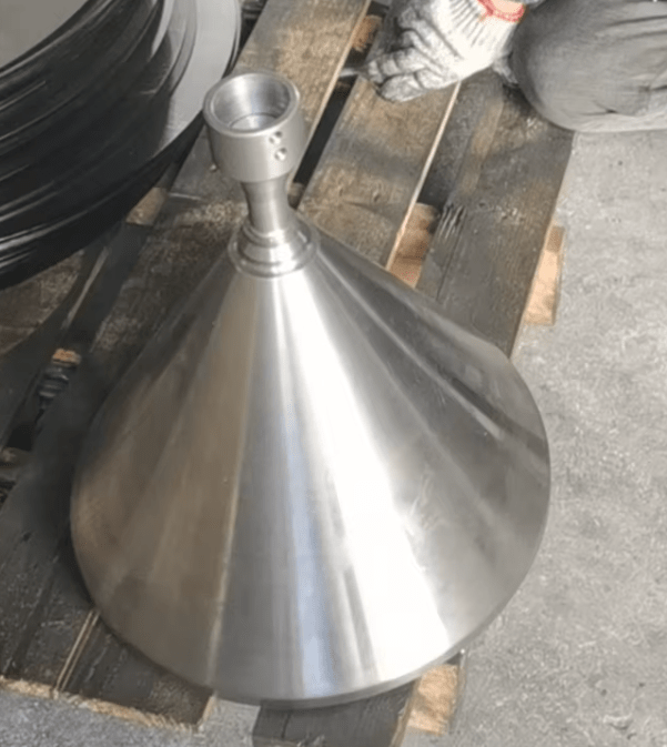
A stainless steel metal spinning machine is a highly specialized piece of industrial equipment designed to produce seamless, rotationally symmetric components from stainless steel blanks with high precision, uniform wall thickness, and superior mechanical properties. The machine operates by clamping a flat or pre-formed stainless steel blank onto a mandrel and rotating it at high speeds while a roller or forming tool gradually presses the metal against the mandrel to form the desired shape. Unlike stamping, forging, or welding, spinning does not remove material or create seams, producing components with exceptional structural integrity, smooth surfaces, and precise dimensional control. Stainless steel, known for its corrosion resistance, high tensile strength, ductility, and durability, is particularly well-suited for spinning, allowing manufacturers to produce components that can withstand mechanical stress, thermal cycling, and harsh environmental conditions. During the spinning process, the stainless steel work-hardens, enhancing fatigue resistance and structural strength, which is critical for parts used in demanding industrial, chemical, food processing, and aerospace applications.
Stainless steel metal spinning machines are widely used across industries that require precision, durability, and high-quality finishes. In the food processing and pharmaceutical sectors, these machines produce sanitary bowls, hoppers, tanks, and piping components where seamless construction, corrosion resistance, and hygienic surfaces are critical. In chemical processing and industrial applications, spinning produces pressure vessels, reaction chambers, protective domes, and large cylindrical or conical components that must withstand high pressure, corrosive substances, and mechanical stress while maintaining exacting tolerances. Architectural and decorative industries also utilize stainless steel spinning machines to manufacture sculptures, lighting fixtures, ventilation covers, and artistic bowls or domes that combine visual appeal with long-term durability. Aerospace and defense industries employ stainless steel spinning for producing turbine components, engine housings, nacelles, and other critical parts where high strength, heat resistance, and dimensional accuracy are essential. The versatility of these machines allows manufacturers to produce both small, precise components and large-scale parts with consistent quality, making stainless steel metal spinning indispensable for modern industrial production.
Modern stainless steel metal spinning machines increasingly incorporate CNC technology, which automates mandrel rotation, roller paths, forming speed, and applied pressure, ensuring consistent wall thickness, precise dimensions, and repeatability across multiple parts. CNC-controlled spinning allows manufacturers to create complex geometries and maintain tight tolerances while minimizing operator intervention, reducing human error, and improving efficiency. Some machines feature hot spinning capabilities through localized or induction heating, which softens thicker stainless steel blanks to facilitate forming intricate or large components, improve material flow, and reduce tool wear. Advanced machines can also integrate additional operations such as flanging, trimming, beading, and flow forming in a single setup, streamlining production, reducing handling, and improving overall efficiency. Real-time monitoring and automated control systems ensure consistent quality, smooth surfaces, and accurate dimensions, making these machines suitable for both high-volume industrial production and specialized custom manufacturing.
The advantages of stainless steel metal spinning machines include the production of seamless, corrosion-resistant, and high-strength components with minimal material waste and lower tooling costs compared to stamping, deep drawing, or welding. Their flexibility allows manufacturers to handle different stainless steel grades, thicknesses, and diameters, making them suitable for prototyping, small-batch production, and large-scale industrial operations. By combining traditional spinning techniques with CNC automation, thermal forming, and multifunctional processing, stainless steel metal spinning machines enable manufacturers to produce durable, precise, and aesthetically refined components efficiently and cost-effectively. The combination of strength, precision, corrosion resistance, and surface quality ensures that these machines remain indispensable in food processing, pharmaceutical, chemical, industrial, architectural, and aerospace applications where performance, reliability, and long-term durability are critical.
A stainless steel metal spinning machine is a highly versatile and specialized piece of industrial equipment designed to transform flat or pre-formed stainless steel blanks into seamless, rotationally symmetric components such as bowls, cones, cylinders, domes, and other axisymmetric shapes with exceptional precision and uniform wall thickness. The machine works by securing the stainless steel blank onto a mandrel and rotating it at high speed while a roller or forming tool gradually applies pressure to shape the metal along the mandrel’s profile. Unlike stamping, forging, or welding, spinning does not remove material or require seams, resulting in components with superior structural integrity, smooth surfaces, and consistent dimensional accuracy. Stainless steel’s high corrosion resistance, tensile strength, ductility, and durability make it particularly suitable for spinning, allowing manufacturers to produce parts that can withstand mechanical stress, thermal cycling, and harsh environmental conditions. During the spinning process, stainless steel work-hardens, which improves fatigue resistance, structural strength, and long-term reliability, making these machines indispensable for applications that demand both precision and durability.
Industries that utilize stainless steel metal spinning machines benefit from their ability to produce high-quality, seamless, and robust components across a wide range of applications. In the food processing and pharmaceutical sectors, spinning produces sanitary bowls, hoppers, tanks, piping components, and other equipment that require corrosion resistance, hygienic surfaces, and exacting tolerances to ensure safe and efficient operation. In chemical processing and heavy industrial applications, stainless steel spinning machines manufacture pressure vessels, reaction chambers, protective domes, and cylindrical or conical components that must withstand high pressure, corrosive substances, and mechanical loads while maintaining precise dimensional control. Architectural and decorative industries also make use of these machines to create sculptures, lighting fixtures, ventilation covers, and aesthetic bowls or domes that combine durability with visual appeal. In aerospace and defense, stainless steel spinning is used to produce turbine components, engine housings, nacelles, and other critical parts where strength, heat resistance, and precise geometry are essential. The flexibility of stainless steel metal spinning machines allows manufacturers to produce both small, intricate components and large, complex parts with consistent quality, making them a key technology for modern production.
Modern stainless steel metal spinning machines increasingly incorporate CNC control systems to automate mandrel rotation, roller paths, forming pressure, and rotational speed, ensuring repeatable results, uniform wall thickness, and accurate geometries across multiple components. CNC automation allows the production of complex shapes and tight tolerances with minimal operator intervention, reducing human error and improving efficiency. Some machines are equipped with hot spinning capabilities through localized or induction heating, which softens stainless steel blanks for forming thicker or more intricate parts, improving material flow and reducing tool wear. Advanced systems can also combine multiple operations such as trimming, flanging, beading, and flow forming into a single setup, which streamlines production, minimizes material handling, and shortens cycle times. Real-time monitoring and automated feedback further enhance quality control, ensuring uniform thickness, precise dimensions, and smooth, defect-free surfaces, which is critical for high-volume industrial production and applications requiring stringent standards.
The advantages of stainless steel metal spinning machines include the ability to produce seamless, corrosion-resistant, high-strength components with minimal material waste and lower tooling costs compared to conventional methods such as stamping, forging, or deep drawing. Their flexibility to handle various stainless steel grades, thicknesses, and diameters makes them suitable for prototyping, medium-scale production, and large-scale industrial operations. By combining traditional metal spinning techniques with CNC automation, hot forming, and multifunctional processing, these machines enable manufacturers to produce precise, durable, and aesthetically refined components efficiently and cost-effectively. The integration of strength, precision, corrosion resistance, and surface quality ensures that stainless steel metal spinning machines remain indispensable in food processing, pharmaceutical, chemical, industrial, architectural, and aerospace sectors where performance, reliability, and long-term durability are critical.
A stainless steel metal spinning machine is a highly specialized industrial device designed to convert flat or pre-formed stainless steel blanks into seamless, rotationally symmetric components with exceptional precision, consistent wall thickness, and superior structural integrity. The machine functions by securing the stainless steel blank onto a mandrel and rotating it at high speeds while a forming roller or tool gradually applies pressure, shaping the metal over the contour of the mandrel to create domes, bowls, cones, cylinders, and other axisymmetric geometries. Unlike stamping, forging, or welding, the spinning process does not remove material or require seams, resulting in parts with smooth surfaces, precise dimensions, and enhanced mechanical strength. Stainless steel’s inherent corrosion resistance, ductility, high tensile strength, and heat resistance make it particularly well-suited for spinning, allowing manufacturers to produce durable, reliable components that can withstand mechanical stress, thermal cycling, and harsh environmental conditions. During the spinning operation, the metal work-hardens, improving fatigue resistance, structural durability, and dimensional stability, which is crucial for applications where reliability and longevity are critical, such as in chemical processing, food and pharmaceutical equipment, aerospace, and industrial machinery.
The versatility of stainless steel metal spinning machines allows them to serve a wide array of industries requiring both functional performance and aesthetic quality. In the food processing and pharmaceutical sectors, these machines produce sanitary bowls, tanks, hoppers, piping, and other components that demand seamless construction, corrosion resistance, and strict adherence to hygienic standards. In chemical and industrial applications, stainless steel spinning machines fabricate pressure vessels, reaction chambers, protective domes, and large cylindrical or conical parts that must endure high pressure, corrosive materials, and mechanical loads while maintaining precise tolerances and uniform wall thickness. Architectural and decorative industries use these machines to manufacture sculptures, lighting fixtures, ventilation covers, and artistic bowls or domes, combining aesthetic appeal with structural durability. Aerospace and defense sectors rely on stainless steel spinning to produce turbine components, engine housings, nacelles, and other critical parts where high strength, heat resistance, and dimensional accuracy are paramount. The machines’ ability to handle both small, intricate parts and large, complex components with consistent quality makes them indispensable for manufacturers seeking precision, efficiency, and material optimization.
Modern stainless steel metal spinning machines are increasingly integrated with CNC technology, which automates mandrel rotation, roller paths, forming pressure, and speed to ensure repeatability, precise geometries, and uniform wall thickness across multiple parts. CNC control enables the production of complex shapes and tight tolerances with minimal operator intervention, reducing human error and enhancing efficiency. Many machines also incorporate hot spinning capabilities using induction or localized heating to soften thicker or more intricate stainless steel blanks, improving material flow, reducing tool wear, and facilitating the formation of large or complex parts. Advanced systems often combine spinning with additional operations such as trimming, flanging, beading, and flow forming within a single setup, streamlining production, minimizing material handling, and shortening cycle times. Real-time monitoring and automated feedback systems further enhance quality assurance, ensuring uniform wall thickness, accurate dimensions, and smooth, defect-free surfaces even during high-volume production runs or for components requiring the strictest quality standards.
The advantages of stainless steel metal spinning machines lie in their ability to produce seamless, high-strength, corrosion-resistant components with minimal material waste and lower tooling costs compared to conventional forming methods like stamping, deep drawing, or forging. These machines are capable of handling a wide range of stainless steel grades, thicknesses, and diameters, making them suitable for prototyping, medium-volume production, and large-scale industrial manufacturing. By combining the precision and traditional craftsmanship of metal spinning with CNC automation, thermal forming, and multifunctional processing, stainless steel metal spinning machines allow manufacturers to produce components that are durable, precise, and aesthetically refined, efficiently and cost-effectively. Their combination of strength, surface quality, corrosion resistance, and dimensional accuracy ensures that these machines remain indispensable in food processing, pharmaceutical, chemical, industrial, architectural, and aerospace industries where performance, reliability, and long-term durability are essential.
A stainless steel metal spinning machine is an advanced and highly specialized industrial tool designed to transform flat or pre-formed stainless steel blanks into seamless, rotationally symmetric components with precise dimensions, uniform wall thickness, and exceptional mechanical properties. The machine works by clamping the stainless steel blank onto a mandrel and rotating it at high speeds while a roller or forming tool applies gradual, controlled pressure to shape the metal over the mandrel’s surface. Unlike stamping, forging, or welding, spinning does not remove material or require seams, resulting in parts that have smooth, polished surfaces, consistent structural integrity, and enhanced strength. Stainless steel’s high corrosion resistance, tensile strength, ductility, and heat tolerance make it particularly suited for spinning, enabling manufacturers to produce components that can endure mechanical loads, thermal cycling, and harsh environmental conditions. During the spinning process, the stainless steel work-hardens, improving fatigue resistance, rigidity, and dimensional stability, which is critical for components used in demanding industrial, chemical, pharmaceutical, aerospace, and food processing applications where reliability and long-term performance are essential.
Industries utilizing stainless steel metal spinning machines benefit from the ability to produce high-quality, seamless, and robust components for a wide range of applications. In the food processing and pharmaceutical sectors, these machines manufacture sanitary tanks, bowls, hoppers, piping components, and vessels that must meet stringent hygiene and corrosion-resistance requirements while maintaining uniform wall thickness and precise dimensions. Chemical and industrial applications rely on stainless steel spinning machines to produce pressure vessels, reaction chambers, protective domes, and large cylindrical or conical parts that must withstand high pressures, corrosive substances, and mechanical stress without compromising dimensional accuracy or structural integrity. Architectural and decorative industries use stainless steel spinning to create sculptures, ornamental bowls, lighting fixtures, ventilation covers, and other aesthetically appealing components that combine durability with visual quality. Aerospace and defense sectors depend on these machines for turbine casings, engine housings, nacelles, and other critical components where strength, heat resistance, and precision are non-negotiable. The ability to produce both small, intricate parts and large, complex components with repeatable quality makes stainless steel metal spinning machines indispensable for manufacturers seeking efficiency, versatility, and material optimization in production.
Modern stainless steel metal spinning machines increasingly incorporate CNC technology to automate mandrel rotation, roller paths, forming pressures, and rotational speeds, ensuring repeatable results, tight tolerances, and consistent wall thickness across multiple parts. CNC systems enable the production of complex geometries with minimal operator intervention, reducing human error and enhancing overall efficiency. Many machines also feature hot spinning capabilities using localized or induction heating, which softens stainless steel blanks for forming thicker, larger, or more intricate parts while improving material flow and reducing tool wear. Advanced machines often integrate multifunctional operations such as flanging, trimming, beading, and flow forming into a single setup, streamlining production, minimizing handling, and shortening cycle times. Real-time monitoring and automated feedback systems ensure uniform thickness, precise dimensions, and defect-free surfaces, which is critical for high-volume production and applications that require exacting quality standards.
The advantages of stainless steel metal spinning machines include the ability to produce seamless, corrosion-resistant, high-strength, and precise components with minimal material waste and lower tooling costs compared to conventional forming methods like stamping, deep drawing, or forging. These machines are capable of handling a wide variety of stainless steel grades, thicknesses, and diameters, making them suitable for prototyping, small-batch production, and large-scale industrial manufacturing. By combining the traditional craftsmanship of metal spinning with CNC automation, thermal forming, and multifunctional processing, stainless steel metal spinning machines allow manufacturers to produce durable, precise, and aesthetically refined components efficiently and cost-effectively. Their integration of structural integrity, surface quality, corrosion resistance, and dimensional accuracy ensures that stainless steel metal spinning machines remain indispensable in food processing, pharmaceutical, chemical, industrial, architectural, and aerospace sectors where performance, reliability, and longevity are of paramount importance.
Aerospace Component Spinning Lathe
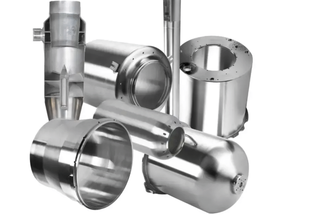
An aerospace component spinning lathe is a highly specialized machine engineered to produce seamless, high-precision, rotationally symmetric components for the aerospace industry, where accuracy, strength, and reliability are critical. The machine operates by securing a blank—typically aluminum, titanium, stainless steel, or high-performance alloys—onto a mandrel and rotating it at high speeds while a roller or forming tool applies gradual pressure to shape the material along the mandrel’s contour. Unlike traditional stamping, forging, or welding, the spinning process does not remove material or require seams, resulting in components with uniform wall thickness, excellent structural integrity, and smooth, defect-free surfaces. The metals used in aerospace applications are chosen for their high strength-to-weight ratios, fatigue resistance, thermal stability, and corrosion resistance, allowing the components to withstand extreme mechanical stresses, high temperatures, and harsh operational environments. During spinning, the metal work-hardens, enhancing its durability, resistance to deformation, and ability to maintain dimensional accuracy under repeated load cycles, which is essential for critical aerospace parts such as engine housings, turbine components, nacelles, cones, and ducts.
Aerospace component spinning lathes are crucial for manufacturing parts that demand exacting precision, lightweight construction, and structural reliability. In aircraft engines, the machines produce seamless turbine casings, compressor shrouds, and combustion chamber components that must withstand high rotational speeds, thermal stress, and pressure fluctuations while maintaining strict tolerances. In spacecraft and satellite applications, spinning lathes fabricate housings, domes, and structural shells that require uniform wall thickness, seamless integrity, and minimal weight to optimize performance and reduce launch costs. Components produced with these lathes also include aerodynamic fairings, fuel tank sections, and exhaust cones, all of which benefit from the smooth surface finishes, dimensional consistency, and enhanced mechanical properties achieved through the spinning process. The ability to manufacture parts from lightweight, high-strength alloys enables aerospace engineers to design components that meet rigorous performance standards while minimizing weight and improving fuel efficiency, structural efficiency, and overall safety.
Modern aerospace component spinning lathes increasingly incorporate CNC technology, which automates mandrel rotation, roller movement, forming pressure, and spindle speed to achieve highly precise geometries and repeatable results across multiple components. CNC integration allows engineers to produce complex shapes, maintain tight tolerances, and minimize human error, significantly increasing production efficiency and reducing the risk of defects. Many machines also feature hot spinning capabilities, using localized or induction heating to soften metals like titanium and aluminum alloys, improving material flow, reducing tool wear, and enabling the formation of thicker or more intricate components. Advanced machines often combine spinning with additional operations such as trimming, flanging, beading, and flow forming within a single setup, streamlining production, reducing handling, and shortening cycle times while ensuring consistent quality. Real-time monitoring and automated feedback systems further enhance quality control, maintaining uniform wall thickness, precise dimensions, and superior surface finishes that meet aerospace industry standards.
The advantages of aerospace component spinning lathes lie in their ability to produce lightweight, seamless, corrosion-resistant, and structurally robust components with minimal material waste and lower tooling costs compared to traditional manufacturing methods such as forging or stamping. These machines offer flexibility to work with a variety of high-performance metals, thicknesses, and diameters, making them suitable for prototyping, medium-volume production, and large-scale aerospace manufacturing. By combining traditional spinning techniques with CNC automation, thermal forming, and multifunctional processing, aerospace component spinning lathes allow manufacturers to produce precise, durable, and high-performance components efficiently and cost-effectively. Their capacity to deliver lightweight, structurally sound, and aerodynamically optimized parts ensures they remain indispensable in the aerospace sector, where performance, reliability, and safety are paramount.
An aerospace component spinning lathe is a highly specialized and precision-engineered machine designed to manufacture seamless, rotationally symmetric components for the aerospace industry, where accuracy, strength, and reliability are paramount. The lathe operates by securing a metal blank—commonly aluminum, titanium, stainless steel, or other high-performance aerospace alloys—onto a mandrel and rotating it at high speeds while a roller or forming tool applies controlled pressure to gradually shape the material along the mandrel’s contour. Unlike conventional methods such as stamping, forging, or welding, spinning produces parts without seams or cuts, resulting in components with uniform wall thickness, excellent mechanical integrity, and smooth, polished surfaces. Metals used in aerospace component spinning are selected for their high strength-to-weight ratios, fatigue resistance, thermal stability, and corrosion resistance, enabling the resulting parts to withstand extreme mechanical stresses, rapid temperature changes, and challenging operational environments. During the spinning process, the material work-hardens, increasing fatigue resistance, rigidity, and dimensional stability, which is critical for aerospace components that must maintain performance under repeated loading cycles and high-stress conditions.
Aerospace component spinning lathes are indispensable in producing parts that demand stringent tolerances, lightweight construction, and high structural reliability. In aviation, they are used to fabricate turbine casings, compressor shrouds, combustion chamber components, exhaust cones, aerodynamic fairings, and nacelle structures, all of which must endure high rotational speeds, thermal fluctuations, and mechanical stress while maintaining precise dimensions. In spacecraft and satellite applications, these machines manufacture housings, domes, fuel tank sections, and structural shells that require uniform wall thickness, seamless construction, and minimized weight to optimize performance, reliability, and launch efficiency. The spinning process allows for the creation of components with smooth aerodynamic surfaces, critical for reducing drag and improving overall flight efficiency. Additionally, the ability to work with high-strength, lightweight alloys enables aerospace engineers to meet strict performance requirements while minimizing structural weight, enhancing fuel efficiency, and increasing safety margins for both aircraft and space vehicles.
Modern aerospace component spinning lathes increasingly incorporate CNC technology to automate mandrel rotation, roller paths, forming pressure, and spindle speed, allowing for precise replication of complex geometries and ensuring repeatability across multiple parts. CNC control reduces human error, improves production efficiency, and enables the creation of intricate designs with tight tolerances that would be difficult or impossible with manual spinning. Many machines also offer hot spinning capabilities, utilizing localized or induction heating to soften metals such as titanium and aluminum alloys, which improves material flow, reduces tool wear, and allows for the formation of thicker, more complex parts. Advanced systems often integrate additional operations such as trimming, flanging, beading, and flow forming in a single setup, streamlining production, minimizing handling, and shortening cycle times. Real-time monitoring and automated feedback systems enhance quality assurance, ensuring uniform wall thickness, precise dimensions, and high-quality surface finishes that meet or exceed aerospace industry standards.
The advantages of aerospace component spinning lathes include the ability to produce lightweight, seamless, corrosion-resistant, and structurally robust components with minimal material waste and lower tooling costs compared to traditional methods such as stamping, forging, or deep drawing. Their flexibility allows manufacturers to work with a wide range of aerospace-grade metals, thicknesses, and diameters, making them suitable for prototyping, medium-volume production, and large-scale aerospace manufacturing. By combining the precision of traditional metal spinning with CNC automation, thermal forming, and multifunctional processing, aerospace component spinning lathes enable the efficient production of durable, high-performance, and aerodynamically optimized components. Their ability to deliver lightweight, structurally sound, and dimensionally accurate parts ensures that these machines remain essential in aviation, spacecraft, and satellite production, where performance, reliability, and safety are critical to both operational efficiency and mission success.
An aerospace component spinning lathe is an advanced and highly precise industrial machine designed to produce seamless, rotationally symmetric parts for the aerospace industry, where every component must meet stringent standards for strength, dimensional accuracy, and reliability. This type of lathe operates by clamping a metal blank—typically made from aluminum, titanium, stainless steel, or other high-performance aerospace alloys—onto a mandrel and rotating it at high speeds while a roller or forming tool applies controlled pressure to gradually shape the material over the mandrel’s surface. Unlike stamping, forging, or welding, the spinning process does not remove material or require seams, producing components with uniform wall thickness, superior structural integrity, and smooth, polished surfaces. Aerospace-grade metals used in this process are selected for their high strength-to-weight ratios, fatigue resistance, corrosion resistance, and thermal stability, allowing the resulting components to endure extreme mechanical stresses, high temperatures, and harsh operational environments. During spinning, work-hardening improves the metal’s mechanical properties, enhancing fatigue resistance, dimensional stability, and overall durability, which is crucial for critical aerospace components such as turbine casings, nacelles, engine housings, ducts, and aerodynamic fairings that must perform reliably under repeated loads and high-stress conditions.
Aerospace component spinning lathes are widely employed across both aviation and space industries because of their ability to produce high-performance parts with minimal material waste and exceptional precision. In aviation, these machines fabricate turbine casings, compressor shrouds, combustion chamber components, exhaust cones, and fuselage or wing fairings, all of which require seamless construction, consistent wall thickness, and tight dimensional tolerances to maintain aerodynamic efficiency and mechanical reliability. For spacecraft and satellites, spinning lathes produce structural shells, domes, fuel tank sections, and housings that must be lightweight yet capable of withstanding extreme temperature fluctuations, vibration, and mechanical stresses during launch and operation. The smooth surfaces generated by spinning reduce aerodynamic drag on aircraft components and contribute to improved fuel efficiency, while the seamless construction ensures structural integrity under high pressure and mechanical loads. The capability to work with high-strength, lightweight alloys allows aerospace engineers to optimize designs for performance, weight reduction, and safety, which are essential factors in both aircraft and spacecraft engineering.
Modern aerospace component spinning lathes increasingly feature CNC integration, which automates mandrel rotation, roller movement, forming pressure, and spindle speed, allowing for precise reproduction of complex shapes and repeatability across multiple components. CNC control minimizes human error, improves efficiency, and enables the creation of intricate geometries with tight tolerances that would be difficult or impossible to achieve manually. Many machines also include hot spinning capabilities using localized or induction heating, which softens metals such as titanium or aluminum alloys to improve material flow, reduce tool wear, and facilitate the formation of thicker or more complex parts. Advanced spinning lathes often combine spinning with additional operations like trimming, flanging, beading, and flow forming in a single setup, streamlining production, reducing handling, and shortening cycle times. Real-time monitoring and automated feedback systems further enhance quality control, ensuring uniform wall thickness, precise dimensions, and flawless surface finishes that comply with strict aerospace industry standards.
The benefits of aerospace component spinning lathes lie in their ability to produce lightweight, seamless, corrosion-resistant, and mechanically robust components with minimal material waste and lower tooling costs compared to conventional forming methods such as forging, stamping, or deep drawing. These machines offer flexibility in processing a wide range of aerospace-grade metals, thicknesses, and diameters, making them suitable for prototyping, small-batch production, and high-volume manufacturing. By combining traditional metal spinning techniques with CNC automation, thermal forming, and multifunctional processing, aerospace component spinning lathes allow manufacturers to produce high-performance, precise, and durable components efficiently and cost-effectively. Their ability to deliver lightweight, structurally optimized, and dimensionally accurate parts ensures that these machines remain indispensable in aviation, spacecraft, and satellite manufacturing, where performance, reliability, and safety are critical for operational success and mission performance.
An aerospace component spinning lathe is an advanced, high-precision machine specifically engineered to manufacture seamless, rotationally symmetric parts for the aerospace sector, where exacting standards for strength, dimensional accuracy, and reliability are critical. The machine functions by securing a metal blank—typically aluminum, titanium, stainless steel, or other high-performance aerospace alloys—onto a mandrel and rotating it at high speeds while a roller or forming tool applies controlled pressure to gradually shape the material over the mandrel’s contour. Unlike stamping, forging, or welding, the spinning process does not remove material or require seams, producing components with uniform wall thickness, superior mechanical integrity, and smooth, polished surfaces. Aerospace alloys are chosen for their high strength-to-weight ratios, fatigue resistance, corrosion resistance, and thermal stability, which allow the components to endure extreme mechanical stresses, rapid temperature fluctuations, and demanding operational environments. During spinning, work-hardening occurs, enhancing fatigue resistance, dimensional stability, and structural durability, which is essential for critical aerospace components such as turbine casings, engine housings, nacelles, ducts, and aerodynamic fairings that must maintain performance under repeated load cycles and high-stress conditions.
The versatility of aerospace component spinning lathes allows manufacturers to produce parts for a wide range of aviation and space applications, delivering both functional performance and precise geometrical accuracy. In commercial and military aircraft, these machines fabricate turbine casings, compressor shrouds, exhaust cones, combustion chamber components, fuselage fairings, and wing or tail structures that require seamless construction, uniform wall thickness, and tight tolerances to maintain aerodynamic efficiency, structural integrity, and operational safety. In spacecraft and satellite manufacturing, spinning lathes produce housings, domes, structural shells, fuel tank sections, and other critical components that must be lightweight, structurally robust, and capable of withstanding extreme thermal cycles, vibration, and mechanical stresses during launch and in-orbit operation. The smooth surface finish achieved through spinning reduces drag on aerodynamic surfaces and contributes to improved fuel efficiency and overall performance. The ability to work with high-strength, lightweight alloys allows aerospace engineers to optimize designs for weight reduction, strength, and durability, ensuring that components meet the most stringent regulatory and operational standards.
Modern aerospace component spinning lathes are increasingly equipped with CNC technology to automate mandrel rotation, roller paths, forming pressure, and spindle speed, ensuring precise geometries, repeatability, and consistent wall thickness across multiple components. CNC automation allows manufacturers to create complex designs and tight tolerances with minimal operator intervention, reducing human error and increasing efficiency. Many lathes also incorporate hot spinning capabilities using localized or induction heating to soften high-strength metals such as titanium and aluminum alloys, improving material flow, reducing tool wear, and facilitating the production of thicker or more intricate components. Advanced systems often combine spinning with secondary operations like trimming, flanging, beading, and flow forming in a single setup, streamlining production, reducing handling, and shortening cycle times. Real-time monitoring and automated feedback systems ensure uniform wall thickness, dimensional accuracy, and high-quality surfaces, meeting the exacting quality standards demanded by aerospace applications and supporting both high-volume manufacturing and specialized custom component production.
The advantages of aerospace component spinning lathes include the ability to produce lightweight, seamless, corrosion-resistant, and mechanically robust components with minimal material waste and lower tooling costs compared to traditional methods such as forging, stamping, or deep drawing. These machines provide the flexibility to process a wide range of aerospace-grade metals, thicknesses, and diameters, making them suitable for prototyping, medium-batch production, and large-scale industrial manufacturing. By combining the precision of traditional metal spinning with CNC automation, thermal forming, and multifunctional processing, aerospace component spinning lathes enable manufacturers to produce high-performance, precise, and durable components efficiently and cost-effectively. Their ability to deliver lightweight, structurally optimized, and aerodynamically refined parts ensures that these machines remain indispensable in aviation, spacecraft, and satellite production, where performance, reliability, and safety are of paramount importance for mission success and operational efficiency.
Automotive Component Spinning Machine
An automotive component spinning machine is a highly specialized metal forming machine designed to produce seamless, rotationally symmetric components for the automotive industry, where precision, durability, and performance are essential. The machine operates by securing a metal blank—commonly aluminum, steel, stainless steel, or other automotive-grade alloys—onto a mandrel and rotating it at high speeds while a roller or forming tool gradually applies pressure to shape the metal over the mandrel’s profile. Unlike stamping, forging, or welding, spinning does not remove material or require seams, resulting in components with uniform wall thickness, enhanced mechanical strength, and smooth surfaces. Automotive metals used in spinning are chosen for their combination of ductility, fatigue resistance, corrosion resistance, and thermal stability, allowing the resulting parts to withstand mechanical stress, thermal cycling, and operational wear over time. During the spinning process, work-hardening improves structural rigidity and fatigue resistance, making these components reliable for critical automotive applications such as engine components, exhaust parts, wheel hubs, brake drums, and transmission housings, which demand both high strength and precision.
Automotive component spinning machines are widely utilized in manufacturing processes where seamless construction, dimensional accuracy, and material efficiency are crucial. These machines produce lightweight and structurally sound parts that contribute to vehicle performance, safety, and fuel efficiency. Engine and drivetrain components such as valve covers, flywheels, brake drums, clutch housings, and turbocharger housings benefit from spinning because it provides uniform thickness, smooth surfaces, and precise geometry, which are critical for both mechanical performance and assembly compatibility. Exhaust systems, heat shields, and muffler shells are also frequently manufactured using spinning machines, as the process allows for durable, corrosion-resistant parts that can withstand high-temperature environments and prolonged vibration. Beyond powertrain and exhaust components, automotive spinning lathes are used to produce body components, decorative trims, structural supports, and interior elements, allowing designers and manufacturers to achieve both functional performance and aesthetic quality in high-volume production.
Modern automotive component spinning machines increasingly incorporate CNC technology, which automates mandrel rotation, roller movement, forming pressure, and spindle speed to produce precise, repeatable components with minimal operator intervention. CNC-controlled machines enable the production of complex geometries, tight tolerances, and consistent wall thicknesses across multiple parts, reducing human error and improving efficiency. Some machines also feature hot spinning capabilities through localized or induction heating, which facilitates forming thicker or more complex blanks by improving material flow and reducing tool wear. Advanced spinning systems can combine multiple operations—such as trimming, flanging, beading, and flow forming—into a single setup, streamlining production, reducing handling, and shortening cycle times. Real-time monitoring and automated feedback systems ensure uniform wall thickness, precise dimensions, and high-quality surfaces, which is especially important in high-volume automotive manufacturing where consistency, reliability, and quality are critical.
The advantages of automotive component spinning machines include the ability to produce seamless, high-strength, corrosion-resistant components with minimal material waste and lower tooling costs compared to traditional forming methods such as stamping, forging, or deep drawing. Their flexibility to work with various alloys, thicknesses, and diameters makes them suitable for prototyping, small-batch production, and large-scale automotive manufacturing. By combining traditional metal spinning with CNC automation, thermal forming, and multifunctional operations, automotive component spinning machines allow manufacturers to efficiently produce durable, precise, and high-performance parts. The ability to create lightweight, structurally optimized, and dimensionally accurate components ensures these machines remain indispensable in the automotive sector, supporting applications ranging from powertrain and exhaust systems to body and decorative parts, where performance, reliability, and manufacturing efficiency are of utmost importance.
An automotive component spinning machine is a highly specialized industrial machine engineered to manufacture seamless, rotationally symmetric components for the automotive industry, where precision, durability, and performance are critical. The machine functions by clamping a metal blank—typically aluminum, steel, stainless steel, or other automotive-grade alloys—onto a mandrel and rotating it at high speeds while a forming roller or tool gradually applies pressure to shape the material over the mandrel’s surface. Unlike conventional methods such as stamping, forging, or welding, metal spinning does not remove material or require seams, producing components with uniform wall thickness, smooth surfaces, and enhanced mechanical strength. Automotive-grade metals used in spinning are selected for their ductility, corrosion resistance, fatigue resistance, and thermal stability, allowing the resulting parts to withstand mechanical loads, vibration, thermal cycling, and environmental exposure. During the spinning process, the metal work-hardens, improving structural rigidity, fatigue resistance, and dimensional stability, which is essential for critical automotive components like engine housings, brake drums, wheel hubs, transmission covers, exhaust shells, and turbocharger components, all of which must maintain high performance under continuous operation.
Automotive component spinning machines are widely employed across manufacturing processes where material efficiency, dimensional accuracy, and structural integrity are essential. Components such as flywheels, valve covers, brake drums, clutch housings, and exhaust parts benefit from spinning due to the seamless construction and uniform wall thickness, ensuring precise assembly, mechanical reliability, and long service life. The process also produces lightweight parts, contributing to overall vehicle efficiency and fuel economy while maintaining high strength and durability. Decorative and functional body components, interior trim, and heat shields are also produced using spinning machines, combining aesthetic quality with structural performance. By providing consistent quality across small, intricate parts and large structural components, these machines enable automotive manufacturers to maintain high-volume production while meeting strict quality and safety standards.
Modern automotive component spinning machines increasingly incorporate CNC technology to automate mandrel rotation, roller paths, forming pressure, and spindle speed, ensuring repeatable results, tight tolerances, and uniform wall thickness across multiple components. CNC automation allows for the production of complex geometries, reduces operator intervention, and minimizes the risk of human error while increasing efficiency and production speed. Many machines also include hot spinning capabilities using localized or induction heating, which softens thicker or more complex metal blanks to improve material flow, reduce tool wear, and facilitate the formation of intricate or high-strength parts. Advanced machines can integrate secondary operations such as trimming, flanging, beading, and flow forming within a single setup, streamlining production, reducing handling, and shortening cycle times. Real-time monitoring and automated feedback systems ensure consistent quality, precise dimensions, and smooth surface finishes, which is essential in automotive manufacturing, where components must meet strict regulatory and performance standards.
The advantages of automotive component spinning machines lie in their ability to produce seamless, high-strength, corrosion-resistant, and dimensionally accurate parts with minimal material waste and lower tooling costs compared to conventional forming methods like stamping, deep drawing, or forging. Their flexibility allows manufacturers to work with a wide range of alloys, thicknesses, and diameters, making them suitable for prototyping, medium-volume production, and large-scale manufacturing. By combining the traditional precision of metal spinning with CNC automation, thermal forming, and multifunctional processing, automotive component spinning machines enable the efficient production of durable, precise, and high-performance components. Their capacity to deliver lightweight, structurally optimized, and reliable parts ensures that these machines remain indispensable in the automotive sector, supporting powertrain, exhaust, body, and interior component production where performance, reliability, and manufacturing efficiency are of utmost importance.
An automotive component spinning machine is a precision-engineered industrial machine designed to produce seamless, rotationally symmetric components for the automotive industry, where accuracy, structural integrity, and durability are essential. The machine operates by securing a metal blank—commonly aluminum, steel, stainless steel, or other automotive-grade alloys—onto a mandrel and rotating it at high speeds while a forming roller or tool gradually applies pressure to shape the metal along the contour of the mandrel. Unlike stamping, forging, or welding, the spinning process does not remove material or create seams, resulting in components with uniform wall thickness, smooth surfaces, and enhanced mechanical strength. Automotive metals are chosen for their combination of ductility, corrosion resistance, fatigue resistance, and thermal stability, allowing components to withstand mechanical stress, vibration, thermal cycling, and environmental exposure. During spinning, the metal work-hardens, improving rigidity, dimensional stability, and fatigue resistance, which is critical for engine housings, flywheels, brake drums, transmission covers, exhaust shells, turbocharger components, and other automotive parts that require consistent performance under high-stress conditions and prolonged operational use.
Automotive component spinning machines are utilized extensively in both functional and structural applications where precision, efficiency, and reliability are paramount. In powertrain systems, spinning produces components like valve covers, clutch housings, flywheels, and transmission cases, where seamless construction and uniform wall thickness ensure mechanical stability, precise assembly, and long service life. Exhaust systems, including muffler shells, catalytic converter housings, and heat shields, benefit from the spinning process because it produces corrosion-resistant, durable components capable of withstanding high temperatures, vibration, and thermal expansion. Beyond powertrain and exhaust, spinning machines are employed to create body components, decorative trims, and interior elements, combining aesthetic quality with structural performance. The ability to consistently produce both small, intricate parts and large structural components allows automotive manufacturers to maintain high-volume production with consistent quality, ensuring all parts meet strict safety, regulatory, and performance standards.
Modern automotive component spinning machines increasingly incorporate CNC technology to automate mandrel rotation, roller movement, forming pressure, and spindle speed, ensuring precise geometries, uniform wall thickness, and repeatable results across multiple components. CNC integration reduces human error, increases production efficiency, and allows for the creation of complex shapes and tight tolerances that would be difficult to achieve manually. Many machines also feature hot spinning capabilities using localized or induction heating to soften thick or high-strength metal blanks, improving material flow, reducing tool wear, and facilitating the production of more intricate or robust components. Advanced systems can integrate secondary operations such as trimming, flanging, beading, and flow forming into a single setup, streamlining production, minimizing handling, and shortening cycle times. Real-time monitoring and automated feedback systems ensure quality control, precise dimensions, consistent wall thickness, and smooth surface finishes, which are critical in automotive manufacturing where reliability and performance cannot be compromised.
The advantages of automotive component spinning machines include the production of seamless, high-strength, corrosion-resistant, and dimensionally precise components with minimal material waste and lower tooling costs compared to traditional forming methods like forging, stamping, or deep drawing. Their flexibility allows manufacturers to work with a wide range of automotive-grade alloys, thicknesses, and diameters, making them suitable for prototyping, small-batch production, and high-volume industrial operations. By combining the traditional metal spinning process with CNC automation, thermal forming, and multifunctional operations, these machines enable efficient production of durable, high-performance, and aesthetically refined components. Their capacity to deliver lightweight, structurally optimized, and reliable parts ensures that automotive component spinning machines remain essential in the automotive sector, supporting engine systems, exhaust systems, body panels, and interior components where performance, reliability, and manufacturing efficiency are of paramount importance.
An automotive component spinning machine is a precision industrial machine designed to manufacture seamless, rotationally symmetric components for the automotive industry, where structural integrity, dimensional accuracy, and durability are critical. The machine operates by securing a metal blank—commonly aluminum, steel, stainless steel, or other automotive-grade alloys—onto a mandrel and rotating it at high speeds while a roller or forming tool applies gradual, controlled pressure to shape the material along the mandrel’s surface. Unlike forging, stamping, or welding, spinning does not remove material or create seams, resulting in components with uniform wall thickness, enhanced mechanical strength, and smooth, defect-free surfaces. Automotive alloys are selected for their combination of ductility, fatigue resistance, corrosion resistance, and thermal stability, ensuring that the spun components can withstand mechanical loads, vibration, high temperatures, and long-term operational stress. During spinning, the metal work-hardens, improving rigidity, fatigue resistance, and dimensional stability, which is crucial for critical automotive parts such as engine housings, flywheels, brake drums, transmission covers, turbocharger components, and exhaust shells, all of which require consistent performance under rigorous conditions and extended service life.
Automotive component spinning machines are used across a wide range of applications where precision, efficiency, and consistency are essential. Powertrain components such as flywheels, clutch housings, valve covers, and transmission cases benefit from spinning because the process produces seamless, uniform, and structurally robust parts capable of handling high torque, rotational stress, and repeated load cycles. Exhaust components including muffler shells, catalytic converter housings, heat shields, and exhaust tips are also manufactured using spinning machines, as the process ensures corrosion resistance, thermal durability, and precise geometry for optimal performance and longevity. Beyond functional mechanical parts, spinning machines are used for decorative or structural body components, interior trim, and supporting elements, combining visual appeal with mechanical reliability. The versatility of automotive spinning machines allows manufacturers to produce both small, intricate parts and large structural components with consistent quality, maintaining high-volume production while meeting strict regulatory and performance standards.
Modern automotive component spinning machines are increasingly equipped with CNC technology to automate mandrel rotation, roller paths, forming pressure, and spindle speed, delivering precise, repeatable results and uniform wall thickness across multiple parts. CNC-controlled machines minimize human error, improve efficiency, and enable the production of complex geometries and tight tolerances that would be difficult to achieve manually. Many machines also feature hot spinning capabilities using induction or localized heating to soften thicker or high-strength blanks, enhancing material flow, reducing tool wear, and enabling the formation of intricate or high-performance components. Advanced systems often integrate additional operations such as trimming, flanging, beading, and flow forming within a single setup, streamlining production, reducing handling, and shortening cycle times. Real-time monitoring and automated feedback systems ensure uniform wall thickness, precise dimensions, and high-quality surface finishes, which is essential in automotive manufacturing where reliability, safety, and performance standards are paramount.
The advantages of automotive component spinning machines include the ability to produce seamless, high-strength, corrosion-resistant, and dimensionally precise components with minimal material waste and lower tooling costs compared to conventional forming methods like stamping, forging, or deep drawing. These machines offer flexibility in processing a wide range of automotive alloys, thicknesses, and diameters, making them suitable for prototyping, medium-volume production, and large-scale manufacturing. By combining traditional metal spinning techniques with CNC automation, thermal forming, and multifunctional processing, automotive component spinning machines enable efficient production of durable, high-performance, and aesthetically refined parts. Their capacity to deliver lightweight, structurally optimized, and reliable components ensures that these machines remain indispensable in the automotive industry, supporting the production of powertrain systems, exhaust systems, structural and body components, and interior elements where performance, reliability, and manufacturing efficiency are critical.
High-Precision CNC Metal Spinning Machine
A high-precision CNC metal spinning machine is an advanced industrial machine designed to produce seamless, rotationally symmetric components with exceptional accuracy, uniform wall thickness, and superior mechanical properties across a wide range of metals, including aluminum, stainless steel, copper, titanium, and other high-performance alloys. Unlike traditional manual spinning machines, CNC-controlled systems automate mandrel rotation, roller movement, forming pressure, and spindle speed, allowing for precise replication of complex geometries with tight tolerances and repeatability across multiple parts. This automation minimizes human error, increases production efficiency, and enables the creation of intricate components that would be difficult or impossible to achieve with manual processes. High-precision CNC spinning machines are particularly valuable in industries such as aerospace, automotive, chemical processing, food production, and defense, where components must withstand extreme mechanical stresses, thermal cycling, and harsh environmental conditions while maintaining dimensional accuracy and surface quality.
The operation of a high-precision CNC metal spinning machine begins with clamping a flat or pre-formed metal blank onto a mandrel and rotating it at high speeds while the CNC-controlled roller or forming tool applies controlled pressure to shape the metal along the mandrel’s profile. This process ensures uniform wall thickness and seamless construction, producing parts with excellent structural integrity, fatigue resistance, and smooth surface finishes. The work-hardening effect inherent in metal spinning enhances the material’s mechanical strength, allowing the finished component to endure repeated stress, vibration, and high-pressure applications. Components manufactured with high-precision CNC spinning machines include turbine casings, engine housings, exhaust shells, pressure vessels, decorative bowls, and structural elements, all of which benefit from the combination of seamless construction, high strength, and precise dimensional control. The versatility of these machines allows them to handle both small, intricate components and large, complex parts with consistent quality, making them indispensable for modern industrial manufacturing.
Modern high-precision CNC metal spinning machines often incorporate additional features to enhance productivity and flexibility, such as hot spinning capabilities using localized or induction heating to soften thick or high-strength blanks. This allows for improved material flow, reduced tool wear, and the formation of complex geometries or thicker components. Advanced systems can also integrate secondary operations like trimming, flanging, beading, and flow forming in a single setup, which streamlines production, reduces material handling, and shortens cycle times. Real-time monitoring and automated feedback systems further ensure uniform wall thickness, precise dimensions, and superior surface finishes, meeting the exacting standards required in aerospace, automotive, and other high-performance applications. CNC control enables the programming of intricate patterns, variable thickness profiles, and complex contours that would be extremely challenging with conventional manual spinning techniques.
The advantages of high-precision CNC metal spinning machines are numerous, including the ability to produce seamless, corrosion-resistant, high-strength, and dimensionally accurate components with minimal material waste and lower tooling costs compared to conventional forming methods like stamping, forging, or deep drawing. Their adaptability to a wide range of metals, thicknesses, and diameters makes them suitable for prototyping, small-batch production, and high-volume industrial manufacturing. By combining traditional spinning techniques with CNC automation, thermal forming, and multifunctional processing, these machines enable manufacturers to efficiently produce durable, precise, and aesthetically refined components. Their ability to deliver lightweight, structurally optimized, and reliable parts ensures that high-precision CNC metal spinning machines remain a cornerstone of modern industrial production, particularly in sectors such as aerospace, automotive, defense, chemical processing, and high-end consumer products, where performance, reliability, and quality are non-negotiable.
A high-precision CNC metal spinning machine is an advanced and versatile industrial machine designed to produce seamless, rotationally symmetric components with exceptional accuracy, uniform wall thickness, and superior mechanical properties, capable of working with a wide variety of metals including aluminum, stainless steel, copper, titanium, and other high-performance alloys. The machine operates by securing a metal blank onto a mandrel, which rotates at high speed while a CNC-controlled roller or forming tool gradually applies pressure to shape the metal along the mandrel’s profile. Unlike traditional stamping, forging, or welding methods, CNC metal spinning does not remove material or create seams, resulting in components with smooth surfaces, high structural integrity, and precise dimensional control. The CNC automation allows for tight tolerances, repeatability, and the ability to produce complex geometries that would be difficult or impossible with manual spinning, making these machines indispensable in industries such as aerospace, automotive, defense, food processing, and chemical manufacturing, where parts must endure high stress, thermal cycling, vibration, and harsh operational environments. The process also work-hardens the metal, improving fatigue resistance, rigidity, and long-term durability, which is critical for high-performance applications.
High-precision CNC metal spinning machines are particularly valuable for producing both small, intricate components and large, complex parts with consistent quality and efficiency. In the aerospace industry, they manufacture turbine casings, engine housings, nacelles, exhaust cones, ducts, and aerodynamic fairings that require seamless construction, lightweight design, and exact tolerances to ensure optimal performance and safety. In automotive manufacturing, these machines create engine components, transmission housings, brake drums, flywheels, valve covers, exhaust shells, and turbocharger components, all of which benefit from uniform wall thickness, corrosion resistance, and structural strength. Chemical and food processing industries use CNC metal spinning machines to fabricate tanks, pressure vessels, hoppers, piping components, and sanitary bowls that must meet stringent hygiene, corrosion, and mechanical standards. The smooth, defect-free surfaces, combined with dimensional precision, enable these machines to deliver components that are functional, reliable, and aesthetically refined, providing manufacturers with a highly efficient and cost-effective production solution.
Modern high-precision CNC metal spinning machines often integrate additional capabilities to increase productivity, flexibility, and component complexity. Many systems feature hot spinning capabilities through localized or induction heating, which softens thick or high-strength blanks to improve material flow, reduce tool wear, and allow the formation of intricate geometries or thicker components. Advanced machines can also combine secondary operations such as trimming, flanging, beading, and flow forming in a single setup, reducing handling, shortening cycle times, and streamlining production. CNC control enables programming of variable thickness profiles, complex contours, and precise roller paths, ensuring repeatability and uniformity across large production runs. Real-time monitoring and automated feedback systems further enhance quality control, maintaining precise dimensions, consistent wall thickness, and superior surface finishes, which is essential for meeting the strict standards required in aerospace, automotive, and other high-performance sectors.
The advantages of high-precision CNC metal spinning machines lie in their ability to produce seamless, high-strength, corrosion-resistant, and dimensionally accurate components with minimal material waste and lower tooling costs compared to traditional forming methods such as stamping, deep drawing, or forging. Their flexibility to handle various metals, thicknesses, and diameters makes them suitable for prototyping, small-batch production, and large-scale industrial manufacturing. By combining the precision of traditional metal spinning with CNC automation, thermal forming, and multifunctional operations, these machines allow manufacturers to efficiently produce durable, high-performance, and visually refined components. The ability to create lightweight, structurally optimized, and highly reliable parts ensures that high-precision CNC metal spinning machines remain indispensable in modern industrial production, particularly for sectors where performance, safety, and quality cannot be compromised.
A high-precision CNC metal spinning machine is an advanced industrial machine designed to produce seamless, rotationally symmetric components with exceptional accuracy, uniform wall thickness, and superior structural properties, capable of processing a wide range of metals such as aluminum, stainless steel, copper, titanium, and other high-performance alloys. The machine operates by securely clamping a metal blank onto a mandrel, which rotates at high speed while a CNC-controlled roller or forming tool applies precise, gradual pressure to shape the material along the mandrel’s contour. Unlike conventional forming methods like stamping, forging, or welding, CNC metal spinning does not remove material or create seams, resulting in components with smooth surfaces, high mechanical strength, and exact dimensional control. The CNC system ensures repeatability, precision, and the ability to produce complex geometries that would be extremely difficult or impossible with manual spinning. This makes high-precision CNC metal spinning machines indispensable in industries such as aerospace, automotive, defense, chemical processing, and food production, where components must withstand mechanical stress, vibration, thermal cycling, and harsh operational environments. During the spinning process, the metal undergoes work-hardening, enhancing rigidity, fatigue resistance, and long-term durability, which is crucial for parts that must maintain performance under repeated high-stress conditions.
High-precision CNC metal spinning machines are capable of producing both small, intricate components and large, complex parts with consistent quality and efficiency. In aerospace applications, these machines are used to manufacture turbine casings, engine housings, nacelles, exhaust cones, ducts, and aerodynamic fairings, all of which require seamless construction, lightweight design, and tight tolerances to optimize performance and safety. In the automotive sector, the machines produce engine components, transmission housings, flywheels, brake drums, valve covers, exhaust shells, and turbocharger parts, benefiting from uniform wall thickness, corrosion resistance, and structural integrity. Chemical and food processing industries utilize these machines to fabricate tanks, pressure vessels, hoppers, piping components, and sanitary bowls that must meet strict hygiene, corrosion, and mechanical standards. The smooth, defect-free surfaces combined with precise dimensions allow manufacturers to produce components that are not only functional and durable but also visually refined, enabling efficient high-volume production while maintaining quality standards.
Modern high-precision CNC metal spinning machines often include additional capabilities to increase productivity, flexibility, and versatility. Many feature hot spinning functions through localized or induction heating, softening thick or high-strength metal blanks to improve material flow, reduce tool wear, and facilitate the creation of complex or thicker components. Advanced systems can integrate secondary operations such as trimming, flanging, beading, and flow forming into a single production setup, streamlining the manufacturing process, minimizing handling, and shortening cycle times. CNC programming allows for variable thickness profiles, intricate contours, and precise roller paths, ensuring repeatable results and uniform quality across large production runs. Real-time monitoring and automated feedback systems enhance quality assurance, maintaining consistent wall thickness, dimensional accuracy, and superior surface finish, which is essential in sectors like aerospace, automotive, and defense where precision and reliability are critical.
The advantages of high-precision CNC metal spinning machines include the production of seamless, corrosion-resistant, high-strength, and dimensionally accurate components with minimal material waste and lower tooling costs compared to traditional forming methods such as stamping, forging, or deep drawing. These machines are adaptable to a wide range of metals, thicknesses, and diameters, making them suitable for prototyping, small-batch production, and large-scale industrial manufacturing. By combining the precision and versatility of traditional metal spinning with CNC automation, thermal forming, and multifunctional operations, manufacturers can produce durable, high-performance, and aesthetically refined components efficiently and cost-effectively. The ability to create lightweight, structurally optimized, and highly reliable parts ensures that high-precision CNC metal spinning machines remain a cornerstone of modern industrial production, providing indispensable solutions for aerospace, automotive, defense, chemical, and high-end manufacturing applications where performance, reliability, and quality are non-negotiable.
A high-precision CNC metal spinning machine is a cutting-edge industrial machine designed to manufacture seamless, rotationally symmetric components with exceptional dimensional accuracy, uniform wall thickness, and superior structural integrity, suitable for a wide variety of metals including aluminum, stainless steel, copper, titanium, and specialized high-performance alloys. The operation involves clamping a metal blank onto a mandrel, which rotates at high speed while a CNC-controlled roller or forming tool gradually applies precise pressure to shape the metal over the mandrel’s surface. Unlike traditional processes such as stamping, forging, or welding, CNC metal spinning does not remove material or introduce seams, producing components with smooth surfaces, high mechanical strength, and exact geometrical conformity. The CNC system allows for tight tolerances, repeatability, and the creation of intricate and complex shapes that are difficult or impossible to achieve manually. This precision makes these machines indispensable in industries such as aerospace, automotive, defense, chemical processing, and food production, where components must withstand mechanical stress, vibration, high temperatures, and demanding environmental conditions. During spinning, the metal work-hardens, enhancing fatigue resistance, rigidity, and long-term durability, which is critical for parts exposed to repeated high-stress cycles or harsh operating conditions.
High-precision CNC metal spinning machines are capable of producing both small, detailed components and large, complex parts with consistent quality and efficiency. In aerospace applications, these machines are used to produce turbine casings, engine housings, exhaust ducts, nacelles, aerodynamic fairings, and pressure-resistant shells, all of which require seamless construction, lightweight design, and precise tolerances to ensure optimal performance and safety. In the automotive sector, they manufacture engine components, flywheels, valve covers, transmission housings, brake drums, exhaust shells, and turbocharger parts, where uniform wall thickness, corrosion resistance, and structural strength are essential for reliability and long-term performance. Chemical and food processing industries rely on CNC spinning machines to fabricate tanks, hoppers, piping components, sanitary bowls, and pressure vessels that must adhere to strict hygiene, corrosion, and mechanical standards. The ability to produce smooth, defect-free surfaces with exact dimensions ensures that the components are not only functional and durable but also aesthetically refined, supporting high-volume production while maintaining stringent quality standards.
Modern high-precision CNC metal spinning machines often include advanced capabilities such as hot spinning through localized or induction heating, which softens thick or high-strength blanks to improve material flow, reduce tool wear, and enable the production of complex or thicker components. Many systems integrate secondary operations like trimming, flanging, beading, and flow forming into a single setup, streamlining production, reducing handling, and shortening cycle times. CNC programming allows engineers to define variable thickness profiles, intricate contours, and precise roller paths, ensuring repeatable results and uniform quality across large production runs. Real-time monitoring and automated feedback systems further enhance quality assurance, maintaining consistent wall thickness, precise dimensions, and superior surface finish, which is essential for aerospace, automotive, defense, and other high-performance industries where precision and reliability cannot be compromised.
The advantages of high-precision CNC metal spinning machines include the ability to produce seamless, corrosion-resistant, high-strength, and dimensionally accurate components with minimal material waste and lower tooling costs compared to traditional forming methods like forging, stamping, or deep drawing. Their versatility allows them to handle a wide range of metals, thicknesses, and diameters, making them suitable for prototyping, small-batch production, and large-scale industrial manufacturing. By combining traditional metal spinning techniques with CNC automation, thermal forming, and multifunctional operations, manufacturers can efficiently produce durable, high-performance, and visually refined components. The ability to produce lightweight, structurally optimized, and reliable parts ensures that high-precision CNC metal spinning machines remain a cornerstone of modern industrial production, providing indispensable solutions for sectors such as aerospace, automotive, defense, chemical processing, and high-end consumer goods, where performance, durability, and precision are non-negotiable.
CNC Thick Metal Spinning Machine
A CNC thick metal spinning machine is a highly specialized industrial machine engineered to produce large, heavy-duty, seamless rotational components from thick metal blanks with exceptional precision, structural integrity, and dimensional accuracy. Unlike standard metal spinning machines, these machines are designed to handle thicker materials and high-strength alloys such as steel, stainless steel, titanium, aluminum, and other aerospace- or automotive-grade metals. The machine operates by securing a thick metal blank onto a robust mandrel while a CNC-controlled roller or forming tool applies precise, gradual pressure to shape the metal over the mandrel’s contour as it rotates at high speeds. The CNC system ensures that complex geometries, tight tolerances, and uniform wall thickness are achieved consistently, enabling the production of components that meet the demanding requirements of industries such as aerospace, automotive, defense, energy, and heavy machinery. The thick metal blanks work-harden during the spinning process, enhancing fatigue resistance, rigidity, and long-term durability, which is crucial for components subjected to extreme mechanical stress, vibration, and thermal cycles.
CNC thick metal spinning machines are indispensable for manufacturing large, high-performance components where conventional forming methods like forging, stamping, or welding may be inefficient, costly, or incapable of producing seamless parts. Aerospace applications include turbine casings, engine housings, exhaust ducts, nacelles, pressure vessels, and aerodynamic structures, all of which demand high structural integrity, lightweight optimization, and precise tolerances to ensure operational reliability and safety. In the automotive sector, these machines produce heavy-duty engine components, flywheels, brake drums, clutch housings, transmission casings, and turbocharger shells that require uniform thickness, corrosion resistance, and mechanical durability. Industrial and energy sectors use thick metal spinning machines for tanks, hoppers, piping, large pressure vessels, and storage containers where strength, seamless construction, and resistance to pressure and thermal stress are paramount. The ability to produce thick, seamless components with consistent wall thickness allows manufacturers to optimize material use while achieving superior mechanical performance and long-term reliability.
Modern CNC thick metal spinning machines incorporate advanced technologies to maximize precision, efficiency, and versatility. Many machines feature hot spinning capabilities, using localized or induction heating to soften thick or high-strength metal blanks, improving material flow, reducing tool wear, and enabling the formation of complex or high-strength components that would be difficult to achieve cold. CNC control allows for programming of intricate contours, variable thickness profiles, and precise roller paths, ensuring repeatable production of high-quality parts across large runs. Additionally, many machines integrate secondary operations such as trimming, flanging, beading, and flow forming into a single setup, reducing handling, minimizing cycle times, and streamlining the manufacturing process. Real-time monitoring and automated feedback systems maintain wall thickness uniformity, dimensional accuracy, and surface quality, which is particularly critical when producing thick, high-strength components where small deviations can compromise performance or safety.
The advantages of CNC thick metal spinning machines lie in their ability to produce large, seamless, corrosion-resistant, high-strength components with minimal material waste and lower tooling costs compared to traditional methods such as forging, stamping, or deep drawing. Their flexibility to work with a wide range of thick metals and alloys, as well as their capacity to handle large diameters and heavy blanks, makes them ideal for prototyping, medium-volume production, and large-scale manufacturing. By combining the precision and adaptability of traditional spinning with CNC automation, thermal forming, and multifunctional operations, these machines allow manufacturers to efficiently produce durable, structurally optimized, and reliable components. Their ability to create heavy-duty, dimensionally precise, and high-performance parts ensures that CNC thick metal spinning machines remain indispensable in aerospace, automotive, defense, energy, and industrial manufacturing, where strength, reliability, and precision are non-negotiable.
A CNC thick metal spinning machine is a highly specialized industrial machine designed to produce large, heavy-duty, seamless rotational components from thick metal blanks with exceptional precision, structural integrity, and dimensional accuracy. Unlike standard metal spinning machines, these machines are engineered to handle thicker materials and high-strength alloys such as steel, stainless steel, titanium, aluminum, and other aerospace- or automotive-grade metals. The operation involves clamping a thick metal blank onto a robust mandrel while a CNC-controlled roller or forming tool applies precise, gradual pressure to shape the material along the mandrel’s contour as it rotates at high speed. The CNC system allows for exact replication of complex geometries, uniform wall thickness, and tight tolerances, enabling the production of components that meet the demanding requirements of aerospace, automotive, defense, energy, and heavy machinery industries. During the spinning process, the metal undergoes work-hardening, enhancing fatigue resistance, rigidity, and long-term durability, which is essential for components exposed to extreme mechanical stress, vibration, and thermal cycles.
CNC thick metal spinning machines are crucial for manufacturing large, high-performance components where traditional methods such as forging, stamping, or welding may be inefficient, costly, or incapable of producing seamless parts. In aerospace applications, they produce turbine casings, engine housings, exhaust ducts, nacelles, pressure vessels, and aerodynamic structures that demand seamless construction, high structural integrity, and precise tolerances to ensure optimal performance and safety. In automotive production, these machines are used for heavy-duty engine components, flywheels, brake drums, clutch housings, transmission casings, and turbocharger shells that require uniform wall thickness, corrosion resistance, and mechanical durability. Industrial and energy sectors utilize CNC thick metal spinning machines to fabricate large tanks, hoppers, piping components, and pressure vessels where strength, seamless construction, and resistance to pressure and thermal stress are critical. The ability to create thick, seamless components with consistent wall thickness allows manufacturers to optimize material use while achieving superior mechanical performance and long-term reliability.
Modern CNC thick metal spinning machines integrate advanced technologies to maximize productivity, precision, and versatility. Many include hot spinning capabilities through localized or induction heating to soften thick or high-strength metal blanks, improving material flow, reducing tool wear, and enabling the formation of complex, heavy-duty components that would be difficult to achieve cold. CNC control allows for precise programming of roller paths, variable thickness profiles, and intricate contours, ensuring repeatable, high-quality results across large production runs. Many machines also combine secondary operations such as trimming, flanging, beading, and flow forming within a single setup, streamlining production, reducing handling, and shortening cycle times. Real-time monitoring and automated feedback systems maintain uniform wall thickness, dimensional accuracy, and superior surface finishes, which is especially important for thick, high-strength components where small deviations can compromise structural performance or safety.
The advantages of CNC thick metal spinning machines include the ability to produce large, seamless, corrosion-resistant, high-strength components with minimal material waste and lower tooling costs compared to conventional forming methods like forging, stamping, or deep drawing. Their capacity to handle a wide range of thick metals, large diameters, and heavy blanks makes them suitable for prototyping, medium-volume production, and large-scale manufacturing. By combining traditional spinning techniques with CNC automation, thermal forming, and multifunctional processing, these machines allow manufacturers to efficiently produce durable, structurally optimized, and reliable components. Their capability to deliver heavy-duty, dimensionally precise, and high-performance parts ensures that CNC thick metal spinning machines remain essential in aerospace, automotive, defense, energy, and industrial manufacturing sectors, where strength, reliability, and precision are non-negotiable.
A CNC thick metal spinning machine is an advanced industrial machine designed to manufacture large, heavy-duty, seamless rotational components with exceptional precision, structural strength, and dimensional accuracy, capable of working with thick metal blanks made of steel, stainless steel, titanium, aluminum, and other high-performance alloys. The machine operates by securing a heavy metal blank onto a reinforced mandrel while a CNC-controlled roller or forming tool applies carefully programmed pressure to shape the material along the mandrel’s contour as it rotates at high speed. Unlike conventional forming techniques such as stamping, forging, or welding, CNC thick metal spinning produces components without seams, ensuring smooth surfaces, uniform wall thickness, and superior mechanical integrity. CNC control enables precise replication of complex geometries, tight tolerances, and repeatable results, making these machines indispensable for industries such as aerospace, automotive, defense, energy, and heavy machinery, where components are subjected to extreme mechanical stress, vibration, thermal cycling, and demanding environmental conditions. The spinning process induces work-hardening in the metal, enhancing fatigue resistance, rigidity, and long-term durability, which is critical for parts that must maintain performance under heavy operational loads.
CNC thick metal spinning machines are used to manufacture components that require both high structural strength and seamless construction, which would be difficult or inefficient to achieve using traditional forging, stamping, or welding processes. In aerospace applications, these machines produce turbine casings, engine housings, exhaust ducts, nacelles, aerodynamic fairings, and pressure-resistant shells that demand exact tolerances, uniform wall thickness, and lightweight design to optimize performance, safety, and fuel efficiency. Automotive applications include heavy-duty engine components, flywheels, brake drums, transmission housings, valve covers, exhaust shells, and turbocharger parts, where uniform thickness, corrosion resistance, and mechanical durability are essential for reliable operation. In industrial and energy sectors, CNC thick metal spinning machines fabricate large tanks, hoppers, piping components, and pressure vessels that must withstand extreme pressure, thermal stress, and long-term mechanical loads. The ability to spin thick, seamless components allows manufacturers to maximize material usage while producing parts with superior mechanical properties and consistent quality across large production volumes.
Modern CNC thick metal spinning machines often feature hot spinning capabilities using localized or induction heating to soften high-strength, thick metal blanks, improving material flow, reducing tool wear, and facilitating the formation of complex, heavy-duty components. These machines are typically equipped with precise CNC programming that controls roller paths, variable wall thickness profiles, and complex contours, enabling repeatable production of high-quality components for demanding applications. Advanced systems often integrate additional operations such as trimming, flanging, beading, and flow forming within a single setup, reducing handling, shortening cycle times, and improving overall manufacturing efficiency. Real-time monitoring and automated feedback systems ensure consistent wall thickness, accurate dimensions, and smooth surface finishes, which is especially critical when working with thick, high-strength metals where even minor deviations can compromise structural performance or safety.
The benefits of CNC thick metal spinning machines include their ability to produce large, seamless, high-strength, corrosion-resistant, and dimensionally precise components with minimal material waste and reduced tooling costs compared to conventional forming methods. Their adaptability to a wide range of metals, thicknesses, and large diameters makes them suitable for prototyping, medium-volume production, and large-scale industrial manufacturing. By combining traditional metal spinning with CNC automation, thermal forming, and multifunctional operations, these machines allow manufacturers to efficiently produce heavy-duty, durable, and high-performance components. The ability to create thick, structurally optimized, and highly reliable parts ensures that CNC thick metal spinning machines remain an essential solution in aerospace, automotive, defense, energy, and industrial manufacturing sectors, where strength, precision, and reliability are critical for operational success.
A CNC thick metal spinning machine is a highly specialized industrial machine designed to produce large, heavy-duty, and seamless rotational components from thick metal blanks with exceptional precision, dimensional accuracy, and structural integrity. These machines are engineered to handle materials such as steel, stainless steel, aluminum, titanium, and other high-strength alloys, enabling manufacturers to create parts that can endure extreme mechanical stress, thermal cycles, and demanding operational environments. The process begins by securely clamping a thick metal blank onto a robust mandrel, while a CNC-controlled roller or forming tool applies precise, gradual pressure to shape the metal along the mandrel’s contour as it rotates at high speed. Unlike traditional stamping, forging, or welding, thick metal spinning does not remove material or create seams, resulting in components with uniform wall thickness, superior surface quality, and enhanced fatigue resistance. The CNC automation allows for exact replication of complex geometries, tight tolerances, and repeatable results, making these machines indispensable for industries such as aerospace, automotive, defense, energy, and heavy machinery where performance, reliability, and precision are critical.
CNC thick metal spinning machines are essential for producing large-scale components where traditional forming methods may be inefficient, costly, or incapable of creating seamless, high-strength parts. In aerospace applications, these machines are used to manufacture turbine casings, engine housings, exhaust ducts, nacelles, aerodynamic fairings, and pressure-resistant shells that require lightweight yet strong construction, uniform wall thickness, and exact tolerances to ensure optimal performance, fuel efficiency, and operational safety. In automotive applications, they produce heavy-duty engine components, flywheels, brake drums, transmission housings, valve covers, exhaust shells, and turbocharger parts that demand uniform thickness, corrosion resistance, and mechanical durability for long-term reliability. In industrial and energy sectors, CNC thick metal spinning machines fabricate large tanks, hoppers, piping components, and pressure vessels that must resist high pressures, thermal stress, and repeated mechanical loads. The ability to spin thick, seamless components ensures material efficiency while delivering superior mechanical properties, long service life, and consistent quality across production volumes.
Modern CNC thick metal spinning machines are equipped with advanced features to maximize productivity, precision, and versatility. Many include hot spinning capabilities using localized or induction heating to soften thick or high-strength metal blanks, improving material flow, reducing tool wear, and enabling the formation of complex or heavy-duty components that would be difficult to produce cold. CNC programming allows precise control over roller paths, variable wall thickness profiles, and intricate contours, ensuring repeatable results and high-quality parts for demanding industrial applications. Many systems also incorporate secondary operations such as trimming, flanging, beading, and flow forming in a single production setup, streamlining the manufacturing process, minimizing handling, and reducing cycle times. Real-time monitoring and automated feedback systems maintain uniform wall thickness, accurate dimensions, and high-quality surface finishes, which is especially important for thick, high-strength components where even minor deviations could compromise performance or safety.
The advantages of CNC thick metal spinning machines include the ability to produce large, seamless, corrosion-resistant, high-strength, and dimensionally precise components with minimal material waste and lower tooling costs compared to traditional forming methods such as stamping, forging, or deep drawing. Their versatility allows them to handle a wide range of metals, thicknesses, and large diameters, making them ideal for prototyping, small-batch production, and large-scale industrial manufacturing. By combining the precision and adaptability of traditional spinning with CNC automation, thermal forming, and multifunctional operations, these machines enable manufacturers to efficiently produce durable, high-performance, and structurally optimized components. Their capacity to deliver heavy-duty, reliable, and precise parts ensures that CNC thick metal spinning machines remain indispensable in aerospace, automotive, defense, energy, and industrial manufacturing sectors, where strength, reliability, and precision are essential for operational success and long-term efficiency.
A CNC thick metal spinning machine is a highly specialized industrial machine engineered to produce large, heavy-duty, seamless rotational components from thick metal blanks with outstanding dimensional accuracy, structural strength, and surface quality. These machines are designed to work with high-strength alloys such as steel, stainless steel, aluminum, titanium, and other advanced metals, allowing the production of components that must endure extreme mechanical stresses, high temperatures, vibration, and demanding operational environments. The process begins by firmly securing a thick metal blank onto a reinforced mandrel, while a CNC-controlled roller or forming tool applies gradual and precisely controlled pressure to shape the metal along the mandrel’s profile as it rotates at high speeds. Unlike conventional forming techniques such as stamping, forging, or welding, thick metal spinning produces seamless components without removing material, resulting in parts with uniform wall thickness, high fatigue resistance, and superior mechanical integrity. The CNC system ensures precise replication of complex geometries, tight tolerances, and repeatable results, making these machines critical for aerospace, automotive, defense, energy, and heavy machinery sectors, where performance, reliability, and long-term durability are essential. During the spinning process, the metal work-hardens, further enhancing rigidity, durability, and structural stability, which is especially important for components subjected to repeated high-stress cycles.
CNC thick metal spinning machines are particularly valuable for manufacturing large, high-performance components that would be difficult or inefficient to produce using traditional forming methods. In aerospace applications, these machines fabricate turbine casings, engine housings, exhaust ducts, nacelles, pressure-resistant shells, and aerodynamic fairings that require precise tolerances, uniform wall thickness, and seamless construction to optimize performance, safety, and efficiency. Automotive applications include heavy-duty engine components, flywheels, brake drums, transmission housings, valve covers, exhaust shells, and turbocharger components, where uniform thickness, mechanical durability, and corrosion resistance are essential for long-term reliability and operational efficiency. Industrial and energy sectors use CNC thick metal spinning machines to produce large tanks, hoppers, piping systems, and pressure vessels capable of withstanding extreme pressure, thermal cycling, and heavy mechanical loads. The ability to create thick, seamless components ensures efficient material usage while delivering superior mechanical properties, structural integrity, and consistent quality across production volumes.
Modern CNC thick metal spinning machines are equipped with advanced features to maximize flexibility, precision, and efficiency. Many machines include hot spinning capabilities through localized or induction heating to soften thick or high-strength metal blanks, improving material flow, reducing tool wear, and enabling the formation of complex, heavy-duty parts that would otherwise be difficult to produce cold. CNC control allows for precise programming of roller paths, variable wall thickness profiles, and intricate contours, ensuring repeatable, high-quality production across large runs. Advanced machines often integrate secondary operations such as trimming, flanging, beading, and flow forming into a single setup, reducing material handling, shortening cycle times, and improving overall manufacturing efficiency. Real-time monitoring and automated feedback systems maintain uniform wall thickness, dimensional accuracy, and superior surface finishes, which is critical for thick, high-strength components where even minor deviations can compromise performance or safety.
The advantages of CNC thick metal spinning machines include the ability to produce large, seamless, corrosion-resistant, high-strength, and dimensionally precise components with minimal material waste and lower tooling costs compared to conventional forming methods such as forging, stamping, or deep drawing. Their adaptability to a wide range of metals, thicknesses, and large diameters makes them suitable for prototyping, small-batch production, and high-volume industrial manufacturing. By combining the precision and versatility of traditional spinning with CNC automation, thermal forming, and multifunctional operations, these machines enable manufacturers to produce durable, structurally optimized, and high-performance components efficiently and consistently. Their ability to deliver thick, heavy-duty, and reliable parts ensures that CNC thick metal spinning machines remain an essential solution in aerospace, automotive, defense, energy, and industrial manufacturing industries, where strength, precision, and long-term reliability are critical for operational success.
CNC Dual-Head Spinning Lathe for Flow Forming
A CNC dual-head spinning lathe for flow forming is an advanced industrial machine designed to produce high-precision, seamless, rotationally symmetric components with complex geometries, uniform wall thickness, and enhanced structural integrity. This type of machine combines the traditional principles of metal spinning with flow forming technology and dual-head CNC control, allowing simultaneous or sequential operations on a single workpiece to maximize efficiency and precision. The dual-head configuration enables two forming tools or rollers to work in tandem on opposite sides of a rotating blank, which can be aluminum, steel, stainless steel, titanium, or other high-performance alloys, providing superior material flow, enhanced dimensional accuracy, and reduced cycle times compared to conventional single-head machines. CNC control allows precise programming of mandrel rotation, roller paths, forming pressures, and spindle speeds, ensuring repeatable, high-quality results for both simple and intricate components. The flow forming process combined with dual-head spinning improves metal work-hardening, enhances fatigue resistance, increases rigidity, and produces seamless parts that meet demanding structural and mechanical performance requirements in aerospace, automotive, defense, and energy industries.
CNC dual-head spinning lathes for flow forming are particularly suited for producing components where both high structural integrity and tight tolerances are required. In aerospace applications, they are used to manufacture turbine casings, engine housings, rotor shells, exhaust cones, and pressure vessels, all of which require seamless construction, uniform wall thickness, and complex geometries to maintain performance, weight optimization, and safety standards. In automotive manufacturing, these machines produce heavy-duty engine components, flywheels, brake drums, transmission housings, valve covers, and turbocharger shells, where consistent wall thickness, high mechanical durability, and corrosion resistance are critical. The dual-head design allows simultaneous forming of both sides of a workpiece or coordinated sequential passes, resulting in faster cycle times, reduced tool wear, and minimized material deformation inconsistencies. Industrial and energy applications also benefit from dual-head CNC flow forming for producing large tanks, pressure vessels, and piping components that require uniform material distribution, seamless construction, and superior fatigue performance.
Modern CNC dual-head spinning lathes for flow forming often incorporate hot forming capabilities, using induction or localized heating to soften high-strength or thick metal blanks, improving material flow and reducing the risk of cracking or excessive tool wear during forming. The CNC system enables precise control of roller paths, variable thickness profiles, and complex contours, ensuring repeatable production of high-quality components across large production runs. Many machines also integrate secondary operations such as trimming, flanging, beading, and necking within a single setup, further streamlining the manufacturing process, reducing handling, and shortening cycle times. Real-time monitoring and automated feedback systems maintain uniform wall thickness, dimensional accuracy, and surface quality, which is critical for aerospace, automotive, and defense components where even minor deviations can compromise functionality or safety.
The advantages of CNC dual-head spinning lathes for flow forming include the ability to produce seamless, high-strength, corrosion-resistant, and dimensionally precise components with minimal material waste and lower tooling costs compared to traditional forming methods such as forging, stamping, or deep drawing. Their dual-head design, combined with CNC precision, allows for efficient handling of large, thick, or complex metal blanks while maintaining high tolerances and surface finish quality. By integrating traditional metal spinning, flow forming, thermal forming, and CNC automation, these machines provide manufacturers with the capability to produce structurally optimized, lightweight, and highly reliable components for demanding industrial applications. Their versatility, speed, and precision ensure that CNC dual-head spinning lathes for flow forming remain essential tools in aerospace, automotive, defense, energy, and heavy industrial manufacturing, where performance, durability, and dimensional accuracy are critical for operational success.
A CNC dual-head spinning lathe for flow forming is a sophisticated industrial machine designed to manufacture seamless, high-precision rotational components with uniform wall thickness, complex geometries, and enhanced mechanical strength. This machine combines the principles of traditional metal spinning with advanced flow forming technology and dual-head CNC control, allowing two forming tools or rollers to operate simultaneously or sequentially on a single workpiece. The dual-head configuration improves efficiency, reduces cycle times, and ensures consistent material flow, which is particularly important when working with high-strength metals such as aluminum, steel, stainless steel, titanium, and other aerospace- or automotive-grade alloys. The CNC system provides precise control over mandrel rotation, roller trajectories, forming pressure, and spindle speed, enabling the production of components with extremely tight tolerances and repeatable results. The combination of dual-head spinning and flow forming also enhances metal work-hardening, increases fatigue resistance, and improves structural integrity, making it ideal for aerospace, automotive, defense, and energy applications where performance, reliability, and safety are critical.
CNC dual-head spinning lathes for flow forming are capable of producing both small, intricate components and large, heavy-duty parts with consistent quality and precision. In aerospace, these machines are used to manufacture turbine casings, engine housings, exhaust ducts, nacelles, rotor shells, and pressure vessels, all of which demand seamless construction, precise wall thickness, and complex contours to meet stringent weight, performance, and safety requirements. In the automotive industry, dual-head flow forming is employed to produce engine components, flywheels, brake drums, transmission housings, valve covers, and turbocharger shells, where uniform thickness, mechanical durability, and corrosion resistance are essential for long-term reliability. Industrial and energy applications also benefit from dual-head CNC flow forming for the production of large tanks, piping components, and pressure vessels, as the process allows for uniform material distribution, seamless construction, and superior fatigue resistance. The dual-head configuration provides the ability to form both sides of a workpiece simultaneously or in coordinated sequential passes, improving production efficiency, minimizing tool wear, and reducing inconsistencies in material deformation.
Modern CNC dual-head spinning lathes often include hot forming capabilities, employing induction or localized heating to soften thick or high-strength metal blanks. This enhances material flow, reduces the risk of cracking, and extends the lifespan of forming tools, allowing the machine to handle components with complex geometries or thicker walls. Advanced CNC programming enables precise control of roller paths, variable wall thickness profiles, and intricate contours, ensuring repeatable high-quality production across large runs. Many machines integrate secondary operations such as trimming, flanging, beading, and necking within a single setup, streamlining the production process, reducing handling, and shortening cycle times. Real-time monitoring and automated feedback systems maintain wall thickness uniformity, dimensional accuracy, and surface quality, which is crucial in industries such as aerospace, automotive, and defense, where even minor deviations can compromise component functionality, safety, or performance.
The benefits of CNC dual-head spinning lathes for flow forming include the ability to produce large, seamless, high-strength, corrosion-resistant, and dimensionally precise components with minimal material waste and reduced tooling costs compared to traditional methods such as forging, stamping, or deep drawing. The dual-head design combined with CNC precision allows for efficient processing of thick, complex, or large-diameter metal blanks while maintaining tight tolerances and excellent surface finishes. By combining metal spinning, flow forming, thermal forming, and CNC automation, manufacturers can produce lightweight, structurally optimized, and highly reliable components suitable for demanding industrial applications. The versatility, speed, and precision of CNC dual-head spinning lathes for flow forming make them essential in aerospace, automotive, defense, energy, and industrial manufacturing, where structural integrity, durability, and dimensional accuracy are non-negotiable for operational success.
A CNC dual-head spinning lathe for flow forming is an advanced industrial machine engineered to produce seamless, rotationally symmetric components with high dimensional accuracy, uniform wall thickness, and superior structural strength, combining the principles of traditional metal spinning with the efficiency of flow forming technology and the precision of dual-head CNC control. The dual-head configuration allows two forming rollers to work either simultaneously or in coordinated sequential passes on a single rotating blank, which may be made of aluminum, steel, stainless steel, titanium, or other high-performance alloys, enabling precise control of material flow and minimizing inconsistencies. The CNC system governs mandrel rotation, roller trajectories, forming pressures, and spindle speeds, ensuring repeatable, high-quality production with tight tolerances, even for complex geometries that would be challenging to achieve manually. During the process, the metal work-hardens, increasing fatigue resistance, rigidity, and overall durability, making this machine essential for aerospace, automotive, defense, and energy applications where components must withstand high mechanical stress, thermal cycling, and harsh operational conditions without compromising performance.
The CNC dual-head spinning lathe for flow forming is capable of producing both large and small components with high efficiency and precision, addressing the requirements of industries that demand seamless, structurally optimized parts. In aerospace, it is used to manufacture turbine casings, engine housings, exhaust ducts, rotor shells, nacelles, and pressure-resistant shells, all of which require exact wall thickness, seamless construction, and complex contours to meet weight, safety, and performance standards. In automotive production, these machines are applied to fabricate flywheels, transmission housings, brake drums, valve covers, exhaust shells, and turbocharger components, where uniform thickness, mechanical durability, and corrosion resistance are critical for reliable operation over extended service periods. In energy and industrial sectors, CNC dual-head flow forming machines are utilized to create large tanks, piping components, pressure vessels, and hoppers that require seamless construction, even material distribution, and high fatigue resistance. The dual-head design allows simultaneous forming on both sides of a workpiece or precise sequential passes, which accelerates production, reduces tool wear, and ensures consistent material deformation and high-quality surface finishes.
Modern CNC dual-head spinning lathes often incorporate hot forming techniques using induction or localized heating to soften high-strength or thick metal blanks, enhancing material flow and reducing the risk of cracking or excessive tool wear. CNC programming provides precise control over roller paths, variable thickness profiles, and intricate shapes, enabling repeatable, high-quality production across large volumes. Many machines integrate secondary operations such as trimming, flanging, beading, and necking within the same setup, streamlining workflow, minimizing handling, and reducing overall cycle times. Real-time monitoring and automated feedback systems maintain wall thickness uniformity, dimensional accuracy, and superior surface quality, which is particularly critical in aerospace, automotive, and defense applications where even minor deviations can compromise safety or performance.
The advantages of CNC dual-head spinning lathes for flow forming are significant, including the ability to produce seamless, corrosion-resistant, high-strength, and dimensionally precise components with minimal material waste and lower tooling costs compared to conventional methods such as stamping, forging, or deep drawing. The dual-head configuration combined with CNC automation enables the efficient processing of large, thick, or complex metal blanks while maintaining precise tolerances and excellent surface finish. By integrating traditional metal spinning, flow forming, hot forming, and CNC automation, manufacturers can produce lightweight, structurally optimized, and highly reliable components for demanding industrial applications. The precision, versatility, and speed of CNC dual-head spinning lathes for flow forming make them indispensable in aerospace, automotive, defense, energy, and industrial manufacturing sectors, where structural integrity, durability, and dimensional accuracy are critical for operational success and long-term efficiency.
A CNC dual-head spinning lathe for flow forming is a highly advanced industrial machine designed to produce seamless, rotationally symmetric components with exceptional dimensional accuracy, uniform wall thickness, and enhanced structural integrity. This machine integrates the principles of traditional metal spinning with modern flow forming technology, leveraging dual-head CNC control to enable two forming rollers to operate simultaneously or sequentially on a single rotating workpiece. The dual-head configuration allows for precise control of material flow, minimizing inconsistencies, and reducing cycle times while working with a wide range of metals, including aluminum, steel, stainless steel, titanium, and other high-performance alloys. CNC automation ensures exact control over mandrel rotation, roller paths, forming pressures, and spindle speeds, providing repeatable, high-quality results even for complex geometries that would be difficult to achieve manually. The combination of dual-head operation and flow forming not only increases the speed of production but also enhances metal work-hardening, improving fatigue resistance, rigidity, and overall durability, making these machines critical for aerospace, automotive, defense, and energy industries where components must withstand extreme mechanical stress, thermal cycles, and demanding environmental conditions.
CNC dual-head spinning lathes for flow forming are capable of producing components ranging from small, intricate parts to large, heavy-duty structures with remarkable consistency and precision. In aerospace applications, these machines fabricate turbine casings, engine housings, exhaust ducts, rotor shells, nacelles, and pressure-resistant shells, all requiring seamless construction, precise wall thickness, and complex contours to meet strict weight, safety, and performance standards. In automotive manufacturing, they produce flywheels, brake drums, transmission housings, valve covers, exhaust shells, and turbocharger components, where uniform thickness, high mechanical durability, and corrosion resistance are essential for long-term reliability. Industrial and energy sectors rely on dual-head CNC flow forming to manufacture large tanks, hoppers, piping components, and pressure vessels, which demand even material distribution, seamless construction, and superior fatigue performance. The dual-head design allows simultaneous forming of both sides of a workpiece or precisely coordinated sequential passes, which increases production efficiency, reduces tool wear, and ensures uniform deformation and high-quality surface finishes across complex parts.
Modern CNC dual-head spinning lathes often incorporate hot forming capabilities using induction or localized heating to soften thick or high-strength metal blanks, improving material flow, reducing tool wear, and enabling the production of complex geometries that would otherwise be difficult to achieve cold. CNC programming allows precise control over roller paths, variable thickness profiles, and intricate contours, ensuring repeatable production of high-quality components in both small and large volumes. Many machines also integrate secondary operations such as trimming, flanging, beading, and necking within a single production setup, streamlining workflows, minimizing handling, and reducing cycle times. Real-time monitoring and automated feedback systems maintain uniform wall thickness, dimensional accuracy, and superior surface finish, which is particularly critical in aerospace, automotive, and defense industries, where even minor deviations can compromise performance, safety, or structural integrity.
The benefits of CNC dual-head spinning lathes for flow forming are extensive, including the ability to produce large, seamless, high-strength, corrosion-resistant, and dimensionally precise components with minimal material waste and reduced tooling costs compared to traditional forming methods such as stamping, forging, or deep drawing. The dual-head configuration combined with CNC precision allows for efficient processing of thick, complex, or large-diameter blanks while maintaining tight tolerances and excellent surface finishes. By integrating metal spinning, flow forming, hot forming, and CNC automation, manufacturers can produce structurally optimized, lightweight, and highly reliable components for demanding industrial applications. The precision, versatility, and efficiency of CNC dual-head spinning lathes for flow forming make them indispensable in aerospace, automotive, defense, energy, and industrial manufacturing sectors, where performance, durability, and dimensional accuracy are essential for operational success and long-term efficiency.
CNC Single-Head Spinning Machine
A CNC single-head spinning machine is an advanced industrial machine engineered to produce seamless, rotationally symmetric metal components with high precision, uniform wall thickness, and superior structural integrity, suitable for a wide range of metals including aluminum, stainless steel, copper, titanium, and high-strength alloys. Unlike dual-head or traditional manual spinning machines, the single-head configuration operates with one forming tool or roller, which applies carefully controlled pressure to a rotating blank mounted on a mandrel, shaping it along the mandrel’s profile with exact dimensional control. CNC automation governs spindle speed, roller path, forming pressure, and mandrel rotation, ensuring repeatable results, tight tolerances, and consistent quality across production runs. The metal undergoes work-hardening during the spinning process, which enhances fatigue resistance, rigidity, and long-term durability, making CNC single-head spinning machines particularly valuable for industries such as aerospace, automotive, defense, energy, and industrial manufacturing, where components must withstand high mechanical stress, thermal cycling, and demanding operational conditions without compromising structural integrity.
CNC single-head spinning machines are capable of producing both small, detailed components and larger structural parts with consistent quality and efficiency. In aerospace applications, they are used to manufacture turbine casings, engine housings, exhaust cones, rotor shells, nacelles, and pressure vessels, all requiring seamless construction, precise wall thickness, and reliable performance under high operational demands. In the automotive sector, these machines produce engine components, flywheels, brake drums, transmission housings, valve covers, and turbocharger shells, where uniform wall thickness, corrosion resistance, and mechanical durability are critical for operational longevity. Industrial applications, including chemical and food processing, benefit from CNC single-head spinning machines for producing large tanks, hoppers, piping components, and sanitary vessels that must maintain precise dimensions, seamless construction, and excellent surface finish for both functional and hygienic requirements. The single-head design allows careful control over the forming process, ensuring consistent material flow and surface quality while maintaining flexibility for different component sizes and shapes.
Modern CNC single-head spinning machines often feature hot spinning capabilities, using localized or induction heating to soften high-strength or thick metal blanks, improving material flow, reducing tool wear, and enabling the creation of complex or high-precision components that might otherwise be difficult to form cold. CNC programming allows precise control over roller paths, variable wall thickness, and intricate contours, enabling repeatable production of high-quality parts across small or large production runs. Many machines also support secondary operations such as trimming, flanging, beading, and necking within a single setup, which reduces material handling, streamlines production, and shortens cycle times. Real-time monitoring and automated feedback systems ensure uniform wall thickness, accurate dimensions, and superior surface finish, which is particularly important in high-precision industries like aerospace, automotive, and defense, where even minor deviations can compromise component performance or safety.
The advantages of CNC single-head spinning machines include the ability to produce seamless, corrosion-resistant, high-strength, and dimensionally precise components with minimal material waste and reduced tooling costs compared to traditional forming methods such as stamping, forging, or deep drawing. Their flexibility allows for processing a wide range of metals, thicknesses, and diameters, making them suitable for prototyping, small-batch production, and large-scale manufacturing. By combining the precision of CNC automation with the work-hardening benefits and versatility of traditional metal spinning, these machines enable manufacturers to produce durable, structurally optimized, and high-performance components efficiently. The CNC single-head spinning machine remains an essential solution in aerospace, automotive, defense, energy, and industrial manufacturing, delivering reliable, precise, and high-quality components that meet the demanding standards of modern engineering applications.
A CNC single-head spinning machine is a precision industrial machine designed to create seamless, rotationally symmetric metal components with exceptional dimensional accuracy, uniform wall thickness, and high structural integrity. The machine operates by securing a metal blank onto a mandrel while a CNC-controlled single forming roller applies gradual, precise pressure to shape the metal along the mandrel’s profile as it rotates at high speed. This process allows the metal to work-harden naturally, increasing fatigue resistance, rigidity, and long-term durability, which is crucial for components that must endure repeated mechanical stress, thermal cycling, and harsh operational environments. The CNC system provides exact control over spindle speed, roller path, forming pressure, and mandrel rotation, enabling repeatable results, tight tolerances, and the production of complex geometries that would be difficult or impossible to achieve with manual spinning or traditional forming methods. CNC single-head spinning machines are particularly valuable in industries such as aerospace, automotive, defense, energy, and industrial manufacturing, where seamless construction, structural reliability, and high-performance components are critical for operational success.
CNC single-head spinning machines are capable of producing a wide range of components, from small, intricate parts to larger structural assemblies, all with consistent quality and precision. In aerospace, these machines are used to manufacture turbine casings, engine housings, exhaust cones, rotor shells, nacelles, and pressure vessels that require precise wall thickness, seamless construction, and high mechanical strength to meet strict safety, performance, and weight requirements. In automotive applications, single-head CNC spinning produces engine components, flywheels, brake drums, transmission housings, valve covers, and turbocharger shells where uniform wall thickness, corrosion resistance, and durability are essential for reliable performance over long operational periods. Industrial and energy applications benefit from single-head CNC spinning for manufacturing large tanks, hoppers, piping systems, and pressure vessels that require seamless construction, uniform material distribution, and high surface quality. The single-head configuration allows careful, controlled forming of each workpiece, ensuring uniform material flow and high-quality surfaces while maintaining flexibility for various component sizes, shapes, and production volumes.
Modern CNC single-head spinning machines often incorporate hot spinning capabilities, using localized or induction heating to soften high-strength or thick metal blanks, which improves material flow, reduces tool wear, and allows the formation of complex geometries or high-precision components that are difficult to achieve cold. CNC programming allows for precise control over roller paths, variable wall thickness profiles, and intricate contours, providing repeatable, high-quality results across both small and large production runs. Many machines also integrate secondary operations such as trimming, flanging, beading, and necking into the same setup, streamlining production, reducing handling, and shortening cycle times. Advanced monitoring systems and automated feedback ensure that wall thickness, dimensions, and surface finish remain consistent, which is essential in aerospace, automotive, and defense industries, where even slight deviations can affect performance, reliability, or safety.
The advantages of CNC single-head spinning machines include the ability to produce seamless, high-strength, corrosion-resistant, and dimensionally precise components with minimal material waste and lower tooling costs compared to traditional forming techniques such as forging, stamping, or deep drawing. Their adaptability to a wide range of metals, thicknesses, and diameters makes them suitable for prototyping, small-batch production, and high-volume industrial manufacturing. By combining the precision and versatility of CNC automation with the work-hardening benefits and efficiency of traditional metal spinning, these machines allow manufacturers to produce structurally optimized, durable, and high-performance components efficiently and consistently. CNC single-head spinning machines remain essential in aerospace, automotive, defense, energy, and industrial sectors, providing reliable, precise, and high-quality components that meet the demanding requirements of modern engineering and industrial production.
A CNC single-head spinning machine is a high-precision industrial machine specifically designed to produce seamless, rotationally symmetric metal components with exact dimensional tolerances, uniform wall thickness, and superior structural strength. The machine operates by securing a metal blank onto a mandrel while a CNC-controlled single forming roller applies precise, controlled pressure to gradually shape the metal along the mandrel’s profile as it rotates at high speed. This controlled forming process allows the metal to work-harden naturally, increasing fatigue resistance, rigidity, and long-term durability, which is essential for parts that must withstand repeated mechanical stress, high temperatures, and demanding operational environments. The CNC system provides precise management of spindle speed, roller path, forming pressure, and mandrel rotation, ensuring repeatable results, consistent quality, and the ability to produce complex geometries that are difficult or impossible to achieve using manual spinning or conventional forming methods. CNC single-head spinning machines are widely used in aerospace, automotive, defense, energy, and industrial manufacturing, where seamless construction, structural reliability, and high-performance components are critical.
These machines are capable of producing both small, intricate parts and large, heavy-duty components with exceptional consistency and accuracy. In aerospace, CNC single-head spinning machines are employed to create turbine casings, engine housings, exhaust cones, rotor shells, nacelles, and pressure-resistant shells, all of which demand precise wall thickness, seamless construction, and optimal strength-to-weight ratios to meet stringent performance and safety standards. In the automotive sector, they are used to manufacture engine components, flywheels, brake drums, transmission housings, valve covers, and turbocharger shells, where uniform thickness, corrosion resistance, and mechanical durability are essential for reliable operation over extended service periods. Industrial and energy applications also benefit from single-head CNC spinning for the fabrication of tanks, hoppers, piping components, and pressure vessels that require seamless construction, even material distribution, and superior surface finish. The single-head design provides precise control over material flow, ensuring high-quality surfaces and uniformity while maintaining flexibility for different component sizes, shapes, and production volumes.
Modern CNC single-head spinning machines often include hot spinning capabilities through localized or induction heating to soften high-strength or thick metal blanks, improving material flow, reducing tool wear, and enabling the production of complex geometries that would be challenging to form cold. Advanced CNC programming allows precise control over roller paths, variable thickness profiles, and intricate contours, ensuring repeatable production of high-quality components in both small and large volumes. Many machines integrate secondary operations such as trimming, flanging, beading, and necking into a single setup, streamlining workflow, minimizing handling, and reducing overall cycle times. Real-time monitoring and automated feedback systems help maintain wall thickness uniformity, dimensional accuracy, and surface finish quality, which is particularly important in aerospace, automotive, and defense industries where even minor deviations can compromise performance or safety.
The advantages of CNC single-head spinning machines include the ability to produce seamless, corrosion-resistant, high-strength, and dimensionally precise components with minimal material waste and lower tooling costs compared to conventional forming methods such as stamping, forging, or deep drawing. Their versatility allows them to process a wide range of metals, thicknesses, and diameters, making them suitable for prototyping, small-batch production, and large-scale industrial manufacturing. By combining the precision and adaptability of CNC automation with the work-hardening benefits of traditional metal spinning, these machines allow manufacturers to efficiently produce structurally optimized, durable, and high-performance components. CNC single-head spinning machines remain an essential solution in aerospace, automotive, defense, energy, and industrial manufacturing, providing reliable, precise, and high-quality parts that meet the rigorous demands of modern engineering and industrial production.
A CNC single-head spinning machine is a highly advanced industrial machine designed to manufacture seamless, rotationally symmetric metal components with exceptional precision, uniform wall thickness, and superior structural strength. It operates by securely clamping a metal blank onto a mandrel while a CNC-controlled forming roller applies carefully regulated pressure to shape the metal along the mandrel’s profile as it rotates at high speed. This process allows the metal to undergo work-hardening, which enhances fatigue resistance, rigidity, and long-term durability, making CNC single-head spinning machines essential for applications that demand components capable of withstanding high mechanical stress, thermal cycling, and harsh environmental conditions. The CNC system provides precise control over spindle speed, roller trajectory, forming pressure, and mandrel rotation, enabling the consistent production of complex geometries and tight tolerances that would be challenging or impossible to achieve with manual spinning or conventional forming methods. These machines are widely utilized in aerospace, automotive, defense, energy, and industrial sectors where seamless construction, structural reliability, and high-performance components are critical.
CNC single-head spinning machines are versatile and capable of producing both small, intricate parts and larger, heavy-duty components with consistent quality and efficiency. In aerospace manufacturing, they are used to produce turbine casings, engine housings, exhaust cones, rotor shells, nacelles, and pressure-resistant shells, all of which require seamless construction, precise wall thickness, and optimal strength-to-weight ratios to meet stringent safety, performance, and weight specifications. In the automotive sector, single-head CNC spinning machines fabricate engine components, flywheels, brake drums, transmission housings, valve covers, and turbocharger shells, where uniform wall thickness, corrosion resistance, and mechanical durability are essential for operational reliability and long service life. Industrial and energy applications also rely on these machines to produce tanks, hoppers, piping components, and pressure vessels that demand seamless construction, even material distribution, and superior surface finish. The single-head design allows for careful control of material flow, ensuring consistent quality and surface finish while maintaining flexibility to accommodate varying component sizes, shapes, and production volumes.
Modern CNC single-head spinning machines frequently incorporate hot spinning capabilities using localized or induction heating to soften thick or high-strength metal blanks. This capability improves material flow, reduces tool wear, and enables the formation of complex geometries or high-precision components that are difficult to achieve cold. Advanced CNC programming enables precise control over roller paths, variable wall thickness, and intricate contours, ensuring repeatable production of high-quality components across both small and large production runs. Many machines integrate secondary operations such as trimming, flanging, beading, and necking within a single setup, streamlining production, reducing handling, and shortening cycle times. Real-time monitoring and automated feedback systems ensure consistent wall thickness, dimensional accuracy, and superior surface finish, which is particularly crucial in aerospace, automotive, and defense industries where even minor deviations can affect safety, performance, or component longevity.
The advantages of CNC single-head spinning machines include their ability to produce seamless, corrosion-resistant, high-strength, and dimensionally precise components with minimal material waste and lower tooling costs compared to conventional forming methods such as forging, stamping, or deep drawing. Their versatility allows them to handle a wide variety of metals, thicknesses, and diameters, making them suitable for prototyping, small-batch production, and large-scale industrial manufacturing. By combining the precision and adaptability of CNC automation with the inherent advantages of metal spinning, these machines enable manufacturers to efficiently produce structurally optimized, durable, and high-performance components. CNC single-head spinning machines continue to be an indispensable solution in aerospace, automotive, defense, energy, and industrial manufacturing, delivering reliable, precise, and high-quality components that meet the stringent demands of modern engineering and production environments.
CNC Horizontal Spinning Lathe
A CNC horizontal spinning lathe is a specialized industrial machine designed to produce seamless, rotationally symmetric metal components with high precision, uniform wall thickness, and superior structural integrity, operating along a horizontal axis to allow optimal access and control during the spinning process. In this configuration, a metal blank is mounted on a mandrel aligned horizontally, and a CNC-controlled roller or forming tool moves along the length of the workpiece to shape it as the mandrel rotates. This horizontal orientation facilitates the handling of longer or larger-diameter blanks, improves operator accessibility, and allows for more stable support of heavy workpieces, making it ideal for producing components with significant length or mass that would be challenging on vertical or conventional spinning machines. The CNC control ensures exact management of spindle rotation, roller paths, forming pressures, and feed rates, allowing for consistent production of complex geometries with tight tolerances, smooth surfaces, and high repeatability, even on thick or high-strength metals such as aluminum, steel, stainless steel, titanium, and copper alloys. The spinning process naturally work-hardens the metal, enhancing fatigue resistance, rigidity, and durability, which is essential for aerospace, automotive, defense, energy, and heavy industrial applications where parts must withstand repeated mechanical stress and thermal cycling.
CNC horizontal spinning lathes are highly versatile, capable of producing components ranging from small, intricate parts to large, heavy-duty structures with consistent quality and precision. In aerospace, they are used to manufacture turbine casings, engine housings, ducting, exhaust cones, rotor shells, and pressure-resistant components that require seamless construction, precise wall thickness, and complex profiles to optimize weight, performance, and safety. In the automotive industry, horizontal CNC spinning machines fabricate engine components, transmission housings, flywheels, brake drums, valve covers, and turbocharger shells, where uniform wall thickness, mechanical durability, and corrosion resistance are critical for long-term reliability. In industrial and energy applications, these machines produce large tanks, hoppers, piping components, and pressure vessels that must withstand high pressures, thermal cycles, and continuous operational loads. The horizontal configuration ensures stable support for long or heavy blanks, reduces vibrations during forming, and provides precise control over material flow, leading to uniform wall thickness, high-quality surfaces, and structurally optimized components.
Modern CNC horizontal spinning lathes often incorporate hot spinning capabilities using localized or induction heating to soften high-strength or thick metal blanks, improving material flow, reducing tool wear, and enabling the formation of complex or precision-critical components. Advanced CNC programming allows precise control of roller trajectories, forming pressure, mandrel rotation, and wall thickness profiles, ensuring consistent results across production runs. Many machines integrate secondary operations such as trimming, flanging, beading, or necking in the same setup, streamlining production, reducing handling, and shortening cycle times. Real-time monitoring and automated feedback systems maintain dimensional accuracy, uniform wall thickness, and high-quality surface finishes, which is particularly important in aerospace, automotive, and defense applications, where even minor deviations can compromise component performance, safety, or lifespan.
The benefits of CNC horizontal spinning lathes include their ability to produce large, seamless, high-strength, and corrosion-resistant components with minimal material waste and lower tooling costs compared to conventional methods such as forging, stamping, or deep drawing. Their horizontal design enables processing of long or heavy blanks with excellent stability, while CNC automation provides precise control over geometry, surface quality, and wall thickness. By combining traditional spinning techniques with CNC precision, hot forming, and integrated secondary operations, manufacturers can efficiently produce structurally optimized, reliable, and high-performance components suitable for demanding industrial applications. CNC horizontal spinning lathes remain indispensable in aerospace, automotive, defense, energy, and industrial manufacturing, offering a solution for producing durable, precise, and high-quality components that meet the rigorous demands of modern engineering.
A CNC horizontal spinning lathe is a highly specialized industrial machine designed to produce seamless, rotationally symmetric metal components with exceptional dimensional accuracy, uniform wall thickness, and superior structural strength, operating along a horizontal axis to provide optimal access and stability during the spinning process. In this configuration, a metal blank is securely mounted on a horizontally aligned mandrel, while a CNC-controlled roller or forming tool moves along the length and contour of the rotating blank to shape it precisely according to the desired geometry. The horizontal orientation allows for the stable handling of long, heavy, or large-diameter blanks, which might be difficult to support or control on vertical or conventional spinning machines. CNC automation manages spindle rotation, roller path, feed rate, and forming pressure with high precision, ensuring consistent results, repeatable production, and the ability to create complex geometries with tight tolerances. The metal work-hardens naturally during the spinning process, enhancing fatigue resistance, rigidity, and overall durability, which is essential for aerospace, automotive, defense, energy, and industrial applications where components must withstand high mechanical stress, thermal cycling, and harsh operating conditions.
CNC horizontal spinning lathes are capable of producing a wide range of components, from small, intricate parts to large, heavy-duty structures, with uniform quality and precision. In aerospace applications, they are used to fabricate turbine casings, engine housings, exhaust ducts, rotor shells, nacelles, and pressure-resistant shells, all of which require seamless construction, precise wall thickness, and optimized weight-to-strength ratios to meet strict safety and performance requirements. In the automotive sector, these machines manufacture engine components, flywheels, brake drums, transmission housings, valve covers, and turbocharger shells, where mechanical durability, corrosion resistance, and uniform thickness are critical for long-term operational reliability. In industrial and energy sectors, CNC horizontal spinning lathes are employed to produce large tanks, hoppers, piping components, and pressure vessels that must endure continuous mechanical loading, high pressure, and temperature fluctuations. The horizontal configuration ensures stable support of heavy or elongated blanks, minimizes vibration during forming, and allows precise control of material flow, resulting in structurally optimized, high-quality components with smooth surfaces and consistent wall thickness.
Modern CNC horizontal spinning lathes often feature hot spinning capabilities through localized or induction heating to soften high-strength or thick metal blanks, improving material flow, reducing tool wear, and enabling the production of complex or precision-critical components that would be difficult to form cold. CNC programming allows operators to precisely control roller trajectories, wall thickness profiles, forming pressures, and mandrel speeds, ensuring repeatable results across both small and large production runs. Many machines integrate secondary operations such as trimming, flanging, beading, and necking within a single setup, which streamlines workflow, reduces handling, and shortens cycle times. Advanced monitoring systems and automated feedback maintain uniform wall thickness, dimensional accuracy, and superior surface finish, which is especially important in aerospace, automotive, and defense industries, where even minor deviations can negatively impact performance, safety, or service life.
The advantages of CNC horizontal spinning lathes include the ability to produce large, seamless, high-strength, and corrosion-resistant components with minimal material waste and lower tooling costs compared to conventional forming methods such as forging, stamping, or deep drawing. The horizontal design enables the handling of long or heavy blanks with exceptional stability, while CNC automation ensures precise control over geometry, wall thickness, and surface finish. By combining traditional spinning techniques with CNC precision, hot forming, and integrated secondary operations, manufacturers can efficiently produce structurally optimized, high-performance components suitable for demanding industrial applications. CNC horizontal spinning lathes remain indispensable in aerospace, automotive, defense, energy, and heavy industrial manufacturing, providing reliable, precise, and high-quality components that meet the rigorous demands of modern engineering and industrial production.
A CNC horizontal spinning lathe is a highly specialized industrial machine engineered to produce seamless, rotationally symmetric metal components with precise dimensional accuracy, consistent wall thickness, and superior structural integrity, operating along a horizontal axis to facilitate better access, stability, and control during the spinning process. In this setup, a metal blank is firmly secured onto a horizontally aligned mandrel, while a CNC-controlled roller or forming tool gradually applies pressure along the contour of the rotating blank, shaping it precisely according to the required geometry. This horizontal orientation allows for stable handling of long, heavy, or large-diameter blanks that may be difficult to support on vertical or conventional spinning machines. CNC automation provides accurate control of spindle speed, roller path, feed rate, and forming pressure, ensuring repeatable production of complex shapes with tight tolerances and smooth surfaces. As the metal undergoes work-hardening during spinning, its fatigue resistance, rigidity, and long-term durability increase, making CNC horizontal spinning lathes particularly suited for applications in aerospace, automotive, defense, energy, and industrial manufacturing where components are required to withstand high mechanical stress, thermal cycling, and demanding operational conditions.
These machines are versatile and capable of producing both small, intricate components and large, heavy-duty parts with consistent quality and precision. In aerospace manufacturing, CNC horizontal spinning lathes are used to fabricate turbine casings, engine housings, exhaust ducts, rotor shells, nacelles, and pressure-resistant shells that demand seamless construction, precise wall thickness, and optimized strength-to-weight ratios to meet stringent performance and safety standards. In the automotive sector, they produce engine components, flywheels, brake drums, transmission housings, valve covers, and turbocharger shells, where uniform wall thickness, mechanical durability, and corrosion resistance are critical for long-term operational reliability. Industrial and energy sectors benefit from these machines for producing large tanks, hoppers, piping components, and pressure vessels that must endure continuous mechanical loads, high pressure, and thermal variations. The horizontal configuration ensures stable support for long or heavy blanks, reduces vibration during forming, and allows precise control of material flow, leading to high-quality, structurally optimized components with uniform wall thickness and smooth surface finishes.
Modern CNC horizontal spinning lathes frequently incorporate hot spinning capabilities using localized or induction heating to soften thick or high-strength metal blanks, improving material flow, reducing tool wear, and allowing the production of complex or high-precision components that would be challenging to form cold. Advanced CNC programming allows precise control over roller paths, forming pressures, mandrel rotation, and variable wall thickness profiles, ensuring repeatable results across both small and large production runs. Many machines integrate secondary operations such as trimming, flanging, beading, and necking within a single setup, streamlining production, minimizing handling, and shortening cycle times. Real-time monitoring and automated feedback systems maintain dimensional accuracy, uniform wall thickness, and superior surface quality, which is crucial in aerospace, automotive, and defense industries, where even minor deviations can affect performance, safety, or component longevity.
The advantages of CNC horizontal spinning lathes include the ability to manufacture large, seamless, high-strength, corrosion-resistant, and dimensionally precise components with minimal material waste and reduced tooling costs compared to conventional methods such as forging, stamping, or deep drawing. The horizontal orientation provides excellent support for long or heavy blanks, while CNC control ensures precise shaping, wall thickness management, and surface finishing. By combining traditional spinning, CNC precision, hot forming, and integrated secondary operations, these machines allow manufacturers to produce structurally optimized, high-performance components efficiently and consistently. CNC horizontal spinning lathes have become indispensable in aerospace, automotive, defense, energy, and industrial manufacturing, offering a reliable solution for producing durable, precise, and high-quality components that meet the rigorous demands of modern industrial and engineering applications.
A CNC horizontal spinning lathe is a high-precision industrial machine engineered to produce seamless, rotationally symmetric metal components with exceptional dimensional accuracy, uniform wall thickness, and superior structural integrity, functioning along a horizontal axis to provide enhanced stability, accessibility, and control during the spinning process. In this configuration, a metal blank is securely mounted on a horizontally aligned mandrel, while a CNC-controlled roller or forming tool applies precise, continuous pressure along the contour of the rotating blank, shaping it into the desired geometry. The horizontal orientation is particularly advantageous for handling long, heavy, or large-diameter blanks that might be difficult to support or control on vertical or conventional spinning machines. CNC automation precisely manages spindle speed, roller trajectory, feed rate, and forming pressure, allowing for the repeatable production of complex components with tight tolerances and smooth surface finishes. The metal work-hardens naturally during the spinning process, enhancing fatigue resistance, rigidity, and long-term durability, which makes CNC horizontal spinning lathes especially valuable for aerospace, automotive, defense, energy, and industrial applications where components must endure high mechanical stress, thermal cycling, and demanding operational conditions.
CNC horizontal spinning lathes offer remarkable versatility, capable of producing both small, intricate parts and large, heavy-duty components with consistent quality and precision. In aerospace manufacturing, they are used to fabricate turbine casings, engine housings, exhaust ducts, rotor shells, nacelles, and pressure-resistant components, all of which demand seamless construction, precise wall thickness, and optimal weight-to-strength ratios to satisfy strict safety, performance, and regulatory standards. In the automotive sector, these machines manufacture engine components, flywheels, brake drums, transmission housings, valve covers, and turbocharger shells, where uniform wall thickness, mechanical durability, and corrosion resistance are essential for reliable long-term operation. Industrial and energy applications also benefit from CNC horizontal spinning lathes for producing tanks, hoppers, piping systems, and pressure vessels that must withstand high pressure, thermal fluctuations, and continuous mechanical loads. The horizontal configuration ensures stable support for long or heavy blanks, minimizes vibrations during forming, and allows precise control of material flow, resulting in structurally optimized components with uniform wall thickness, superior surface finish, and high dimensional fidelity.
Modern CNC horizontal spinning lathes often incorporate hot spinning capabilities using localized or induction heating to soften thick or high-strength metal blanks, improving material flow, reducing tool wear, and enabling the creation of complex or precision-critical components that would otherwise be difficult to form cold. Advanced CNC programming allows operators to control roller paths, wall thickness variations, forming pressures, and mandrel rotation with extreme precision, ensuring repeatable high-quality results across small and large production runs. Many machines integrate secondary operations such as trimming, flanging, beading, and necking into a single setup, streamlining production, minimizing handling, and reducing cycle times. Real-time monitoring and automated feedback systems maintain dimensional accuracy, uniform wall thickness, and superior surface quality, which is especially important in aerospace, automotive, and defense sectors where even minor deviations can compromise component performance, safety, or lifespan.
The advantages of CNC horizontal spinning lathes are extensive, including the ability to manufacture large, seamless, high-strength, corrosion-resistant, and dimensionally precise components with minimal material waste and reduced tooling costs compared to conventional forming methods such as forging, stamping, or deep drawing. Their horizontal design provides excellent support for long or heavy blanks, while CNC control ensures precise shaping, wall thickness management, and surface finishing. By combining traditional spinning techniques, CNC precision, hot forming, and integrated secondary operations, manufacturers can efficiently produce structurally optimized, high-performance components suitable for demanding industrial applications. CNC horizontal spinning lathes remain an indispensable solution in aerospace, automotive, defense, energy, and industrial manufacturing, providing reliable, precise, and high-quality components that meet the rigorous demands of modern engineering and industrial production environments.
CNC Vertical Spinning Lathe
A CNC vertical spinning lathe is an advanced industrial machine designed to produce seamless, rotationally symmetric metal components with high precision, uniform wall thickness, and superior structural integrity, operating along a vertical axis to optimize gravity-assisted support, material flow, and operator accessibility. In this configuration, a metal blank is mounted on a vertically oriented mandrel, while a CNC-controlled roller or forming tool applies gradual, controlled pressure to shape the rotating blank according to the mandrel’s profile. The vertical orientation is particularly beneficial for producing taller or deeper components, as gravity assists in stabilizing the blank and reducing the risk of deformation or slippage during the spinning process. The CNC system precisely manages spindle rotation, roller path, feed rate, and forming pressure, allowing for consistent production of complex geometries with tight tolerances and smooth surface finishes. During the spinning process, the metal work-hardens, which increases fatigue resistance, rigidity, and durability, making CNC vertical spinning lathes suitable for aerospace, automotive, defense, energy, and industrial applications where components must endure mechanical stress, thermal cycles, and demanding operational environments.
CNC vertical spinning lathes are versatile and capable of producing components ranging from small, intricate parts to large, deep, or tall structures with exceptional consistency and precision. In aerospace manufacturing, these machines are employed to fabricate turbine casings, engine housings, exhaust ducts, nacelles, pressure vessels, and rotor shells, all requiring seamless construction, uniform wall thickness, and structural strength optimized for weight and performance standards. In the automotive sector, vertical CNC spinning lathes produce engine components, brake drums, flywheels, transmission housings, valve covers, and turbocharger shells, where precise wall thickness, mechanical durability, and corrosion resistance are essential for operational reliability. Industrial and energy applications rely on vertical spinning lathes to create tall tanks, piping components, hoppers, and pressure vessels that demand even material distribution, seamless construction, and superior surface finish. The vertical configuration allows stable support of the blank, minimizes deformation due to gravity, and provides excellent operator accessibility for tool adjustments or part handling, resulting in high-quality, structurally optimized components.
Modern CNC vertical spinning lathes often include hot spinning capabilities using localized or induction heating to soften high-strength or thick metal blanks, improving material flow, reducing tool wear, and enabling the formation of complex or precision-critical components. Advanced CNC programming provides precise control over roller trajectories, forming pressures, mandrel rotation, and variable wall thickness profiles, ensuring repeatable, high-quality production for both small and large-scale manufacturing. Many machines integrate secondary operations such as trimming, flanging, beading, or necking in a single setup, streamlining workflow, reducing handling, and shortening cycle times. Real-time monitoring and automated feedback systems maintain dimensional accuracy, wall thickness uniformity, and high-quality surface finishes, which is particularly critical in aerospace, automotive, and defense applications where even minor deviations can affect performance, safety, or longevity.
The advantages of CNC vertical spinning lathes include the ability to produce seamless, corrosion-resistant, high-strength, and dimensionally precise components with minimal material waste and lower tooling costs compared to conventional forming methods such as stamping, forging, or deep drawing. Their vertical design provides superior support for tall or deep blanks, while CNC control ensures precise shaping, wall thickness consistency, and excellent surface finish. By combining traditional metal spinning, CNC automation, hot forming, and integrated secondary operations, manufacturers can efficiently produce structurally optimized, durable, and high-performance components suitable for demanding industrial applications. CNC vertical spinning lathes are indispensable in aerospace, automotive, defense, energy, and industrial manufacturing, offering a reliable solution for producing precise, high-quality, and durable components that meet the rigorous demands of modern engineering and production.
A CNC vertical spinning lathe is a highly specialized industrial machine engineered to produce seamless, rotationally symmetric metal components with precise dimensional tolerances, uniform wall thickness, and superior structural strength, operating along a vertical axis to provide gravity-assisted support, enhanced stability, and optimal operator accessibility. In this configuration, a metal blank is mounted on a vertically aligned mandrel, and a CNC-controlled roller or forming tool applies gradual, controlled pressure to shape the rotating blank according to the mandrel’s contour. The vertical orientation is particularly advantageous for taller or deeper components, as gravity assists in stabilizing the blank, reducing the risk of deformation, and improving material flow during the spinning process. CNC automation provides precise control over spindle speed, roller trajectory, feed rate, and forming pressure, ensuring repeatable production, high-quality surface finishes, and the ability to create complex geometries that would be difficult or impossible to achieve manually or with conventional spinning methods. As the metal is formed, it undergoes work-hardening, enhancing fatigue resistance, rigidity, and long-term durability, making CNC vertical spinning lathes essential for aerospace, automotive, defense, energy, and industrial applications where components are subjected to mechanical stress, thermal cycling, and demanding operating environments.
CNC vertical spinning lathes are capable of producing a broad range of components, from small, intricate parts to large, tall, or deep structures, all with consistent quality and precision. In aerospace applications, these machines are used to manufacture turbine casings, engine housings, exhaust ducts, rotor shells, nacelles, and pressure-resistant shells, all of which require seamless construction, uniform wall thickness, and structural optimization to meet strict performance, weight, and safety standards. In the automotive sector, vertical CNC spinning lathes fabricate engine components, flywheels, brake drums, transmission housings, valve covers, and turbocharger shells, where mechanical durability, corrosion resistance, and precise wall thickness are essential for long-term operational reliability. Industrial and energy applications rely on vertical spinning lathes to produce tall tanks, hoppers, piping systems, and pressure vessels that require even material distribution, seamless construction, and superior surface quality. The vertical design ensures stable support of the blank, reduces the impact of gravity-induced deformation, and provides excellent accessibility for tooling and part handling, resulting in structurally optimized, high-quality components with uniform wall thickness and smooth finishes.
Modern CNC vertical spinning lathes often incorporate hot spinning capabilities using localized or induction heating to soften high-strength or thick metal blanks, improving material flow, reducing tool wear, and enabling the production of complex geometries or high-precision components that would otherwise be difficult to form cold. CNC programming allows precise control over roller paths, mandrel rotation, forming pressures, and wall thickness profiles, ensuring consistent, repeatable production across both small and large manufacturing runs. Many machines integrate secondary operations such as trimming, flanging, beading, and necking within a single setup, streamlining workflow, reducing handling, and minimizing cycle times. Advanced monitoring systems and automated feedback mechanisms maintain dimensional accuracy, wall thickness uniformity, and superior surface finishes, which is particularly critical in aerospace, automotive, and defense sectors, where even minor deviations can compromise component performance, safety, or service life.
The advantages of CNC vertical spinning lathes include the ability to manufacture large, tall, or deep seamless components with high structural integrity, corrosion resistance, and precise dimensional accuracy, while minimizing material waste and reducing tooling costs compared to traditional forming methods such as forging, stamping, or deep drawing. The vertical configuration provides excellent support for gravity-assisted blank stabilization, while CNC automation ensures precise control over geometry, wall thickness, and surface finish. By combining traditional metal spinning, CNC precision, hot forming, and integrated secondary operations, manufacturers can efficiently produce structurally optimized, durable, and high-performance components for demanding industrial applications. CNC vertical spinning lathes remain indispensable in aerospace, automotive, defense, energy, and industrial manufacturing, offering a reliable and versatile solution for producing high-quality, precise, and long-lasting components that meet the rigorous standards of modern engineering and industrial production.
A CNC vertical spinning lathe is a sophisticated industrial machine designed to manufacture seamless, rotationally symmetric metal components with precise dimensional tolerances, consistent wall thickness, and exceptional structural strength, operating along a vertical axis to maximize stability, gravity-assisted support, and accessibility during the spinning process. In this setup, a metal blank is securely mounted on a vertically aligned mandrel, while a CNC-controlled roller or forming tool applies continuous, precise pressure to shape the rotating blank along the mandrel’s profile. This vertical orientation is particularly advantageous for producing tall, deep, or heavy components, as gravity helps stabilize the blank and ensures smoother material flow, reducing the risk of deformation, warping, or slippage. The CNC system precisely manages spindle rotation, roller path, feed rate, and forming pressure, allowing for repeatable production of complex geometries with high-quality surface finishes and tight tolerances. As the metal is formed, it work-hardens, increasing fatigue resistance, rigidity, and long-term durability, which makes CNC vertical spinning lathes especially suitable for aerospace, automotive, defense, energy, and industrial applications where components must endure high mechanical stress, thermal cycling, and demanding operational conditions.
These machines are capable of producing a wide spectrum of components, from small, intricate parts to large, deep, or tall structures, all with consistent quality and precision. In aerospace manufacturing, CNC vertical spinning lathes are employed to create turbine casings, engine housings, exhaust ducts, rotor shells, nacelles, and pressure vessels, all of which require seamless construction, uniform wall thickness, and optimized strength-to-weight ratios to meet strict performance, weight, and safety standards. In automotive applications, these machines fabricate engine components, flywheels, brake drums, transmission housings, valve covers, and turbocharger shells, where uniform wall thickness, corrosion resistance, and mechanical durability are critical for long-term operational reliability. Industrial and energy sectors also utilize vertical spinning lathes to produce tall tanks, hoppers, piping components, and pressure vessels that must withstand continuous mechanical loads, high pressure, and temperature fluctuations. The vertical configuration provides stable support of the blank, minimizes deformation due to gravity, and allows convenient access for tool adjustments and part handling, resulting in structurally optimized components with superior surface finish and uniform wall thickness.
Modern CNC vertical spinning lathes often feature hot spinning capabilities through localized or induction heating, which softens thick or high-strength metal blanks, improves material flow, reduces tool wear, and allows the creation of complex or high-precision components that are difficult to form cold. Advanced CNC programming allows precise control of roller paths, forming pressure, mandrel rotation, and wall thickness profiles, ensuring repeatable, high-quality production across small and large manufacturing runs. Many machines incorporate secondary operations such as trimming, flanging, beading, and necking in a single setup, streamlining production, reducing material handling, and shortening cycle times. Real-time monitoring and automated feedback systems maintain consistent wall thickness, dimensional accuracy, and superior surface quality, which is particularly important in aerospace, automotive, and defense industries, where even minor deviations can compromise performance, safety, or component longevity.
The advantages of CNC vertical spinning lathes are extensive, including the ability to produce large, tall, or deep seamless components with excellent structural integrity, corrosion resistance, and precise dimensional accuracy while minimizing material waste and reducing tooling costs compared to traditional forming methods such as forging, stamping, or deep drawing. Their vertical configuration provides superior gravity-assisted support and stability for heavy or deep blanks, while CNC automation ensures precise control over geometry, wall thickness, and surface finish. By combining traditional metal spinning techniques, CNC precision, hot forming, and integrated secondary operations, manufacturers can efficiently produce structurally optimized, durable, and high-performance components for demanding industrial applications. CNC vertical spinning lathes remain an essential solution in aerospace, automotive, defense, energy, and industrial manufacturing, delivering reliable, high-quality, precise, and long-lasting components that meet the stringent requirements of modern engineering and production.
A CNC vertical spinning lathe is a highly advanced industrial machine designed to produce seamless, rotationally symmetric metal components with exact dimensional tolerances, consistent wall thickness, and exceptional structural integrity, operating along a vertical axis to maximize gravity-assisted support, stability, and accessibility during the spinning process. In this arrangement, a metal blank is securely mounted on a vertically oriented mandrel, while a CNC-controlled roller or forming tool applies controlled, continuous pressure to shape the rotating blank precisely along the mandrel’s profile. The vertical orientation is particularly advantageous for producing tall, deep, or heavy components, as gravity helps stabilize the blank, promotes uniform material flow, and reduces the risk of warping or deformation during forming. CNC automation ensures precise control of spindle speed, roller trajectory, forming pressure, and feed rate, allowing the production of complex geometries with tight tolerances, smooth surfaces, and repeatable quality. As the metal is spun, it work-hardens, enhancing fatigue resistance, structural rigidity, and durability, making CNC vertical spinning lathes ideal for aerospace, automotive, defense, energy, and industrial applications where components must endure high mechanical loads, thermal cycles, and challenging operational conditions.
CNC vertical spinning lathes are versatile machines capable of producing a wide range of components, from small, detailed parts to large, deep, or tall structures, all with consistent quality and precision. In aerospace applications, they are used to manufacture turbine casings, engine housings, exhaust ducts, rotor shells, nacelles, and pressure vessels, each requiring seamless construction, uniform wall thickness, and optimized strength-to-weight ratios to meet strict safety and performance standards. In the automotive sector, vertical CNC spinning lathes produce engine components, flywheels, brake drums, transmission housings, valve covers, and turbocharger shells, where precise wall thickness, mechanical durability, and corrosion resistance are essential for reliable long-term performance. Industrial and energy applications rely on these machines to create tall tanks, hoppers, piping components, and pressure vessels that must withstand continuous mechanical stress, high pressures, and temperature variations. The vertical configuration provides stable support for the blank, minimizes deformation due to gravity, and allows easy access for tooling adjustments and part handling, resulting in components with superior surface finish, uniform wall thickness, and structural optimization.
Modern CNC vertical spinning lathes frequently include hot spinning capabilities through localized or induction heating, which softens thick or high-strength metal blanks, improves material flow, reduces tool wear, and enables the production of complex or precision-critical parts that are difficult to form cold. Advanced CNC programming allows exact control over roller paths, forming pressures, mandrel rotation, and wall thickness variations, ensuring repeatable, high-quality results across both small and large production runs. Many machines integrate secondary operations such as trimming, flanging, beading, and necking into a single setup, which streamlines production, reduces material handling, and shortens cycle times. Real-time monitoring and automated feedback systems maintain dimensional accuracy, uniform wall thickness, and superior surface quality, which is particularly critical in aerospace, automotive, and defense industries, where even small deviations can negatively impact performance, safety, or component longevity.
The benefits of CNC vertical spinning lathes are extensive, including the ability to produce large, tall, or deep seamless components with high structural integrity, corrosion resistance, and precise dimensional accuracy while minimizing material waste and reducing tooling costs compared to conventional forming methods such as stamping, forging, or deep drawing. The vertical design provides excellent gravity-assisted stabilization and support for tall or deep blanks, while CNC automation ensures precise shaping, wall thickness control, and high-quality surface finishes. By combining traditional metal spinning techniques, CNC precision, hot forming, and integrated secondary operations, manufacturers can efficiently produce structurally optimized, durable, and high-performance components for demanding industrial applications. CNC vertical spinning lathes remain indispensable in aerospace, automotive, defense, energy, and industrial manufacturing, providing a reliable, versatile, and precise solution for producing high-quality, long-lasting components that meet the rigorous standards of modern engineering and production.
Hydraulic Metal Spinning Machine
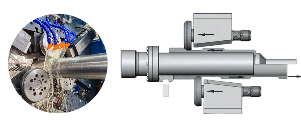
A hydraulic metal spinning machine is a highly specialized industrial machine designed to shape metal blanks into seamless, rotationally symmetric components using the precise application of hydraulic pressure, combining the advantages of metal spinning with the force and control provided by hydraulic systems. In this process, a metal blank is securely clamped onto a mandrel while a hydraulic ram, often fitted with a spinning roller or forming tool, applies controlled pressure to gradually shape the blank as the mandrel rotates at high speed. The hydraulic system allows for smooth, consistent force application throughout the forming process, making it possible to work with thicker, high-strength, or difficult-to-form metals such as stainless steel, copper, aluminum, and titanium alloys. Hydraulic metal spinning machines provide fine control over forming pressure, feed rate, and roller movement, ensuring uniform wall thickness, precise geometries, and superior surface finishes, while also reducing the risk of cracks, tears, or other defects that can occur with purely mechanical systems. The hydraulic action naturally compensates for variations in material thickness and hardness, resulting in components with improved structural integrity, enhanced fatigue resistance, and long-term durability, which is critical for demanding aerospace, automotive, defense, energy, and industrial applications.
Hydraulic metal spinning machines are versatile and capable of producing both small, intricate parts and large, heavy-duty components with consistent quality and precision. In aerospace applications, they are often used to manufacture turbine casings, engine housings, exhaust cones, pressure vessels, and rotor shells that require seamless construction, precise wall thickness, and optimized strength-to-weight ratios. In automotive manufacturing, these machines produce engine components, flywheels, brake drums, transmission housings, valve covers, and turbocharger shells where uniform thickness, corrosion resistance, and mechanical durability are essential for long-term operational reliability. Industrial and energy sectors also rely on hydraulic spinning machines to fabricate large tanks, hoppers, piping components, and pressure vessels that must withstand high pressure, thermal cycling, and continuous mechanical loads. The hydraulic system allows for controlled, adjustable force that can be precisely tuned for each material type and component geometry, enabling the production of complex shapes and deep-drawn profiles that would be challenging with conventional mechanical spinning machines.
Modern hydraulic metal spinning machines often integrate CNC or programmable controls, allowing operators to automate roller paths, feed rates, forming pressures, and mandrel rotations for precise, repeatable production across both small and large batch runs. Many machines are equipped with hot spinning capabilities using localized or induction heating, which softens high-strength metals and facilitates the forming of complex geometries while reducing tool wear. Secondary operations such as trimming, flanging, beading, and necking can often be performed within the same setup, streamlining workflow, reducing handling, and shortening cycle times. Advanced monitoring systems and automated feedback mechanisms help maintain wall thickness uniformity, dimensional accuracy, and superior surface quality, which is particularly critical in aerospace, automotive, and defense applications where even minor deviations can affect performance, safety, or component longevity.
The advantages of hydraulic metal spinning machines include the ability to produce high-strength, seamless, corrosion-resistant, and dimensionally precise components with minimal material waste and reduced tooling costs compared to traditional methods such as forging, stamping, or deep drawing. The use of hydraulic pressure allows smooth, controlled forming of thick or challenging materials, precise shaping, and consistent wall thickness, while CNC or programmable controls enhance accuracy, repeatability, and flexibility for different component geometries. By combining the benefits of hydraulic force, metal spinning work-hardening, CNC automation, and integrated secondary operations, manufacturers can efficiently produce structurally optimized, durable, and high-performance components suitable for demanding industrial, aerospace, automotive, and defense applications. Hydraulic metal spinning machines remain an essential solution for producing reliable, precise, and high-quality components that meet the rigorous standards of modern engineering and production environments.
A hydraulic metal spinning machine is a highly versatile industrial machine designed to produce seamless, rotationally symmetric metal components with exceptional dimensional accuracy, uniform wall thickness, and enhanced structural integrity by applying precise hydraulic pressure throughout the spinning process. In this system, a metal blank is securely clamped onto a mandrel, and a hydraulic ram equipped with a forming roller gradually presses the blank against the rotating mandrel, shaping it into the desired geometry. The hydraulic system allows for smooth, continuous, and adjustable force application, which makes it possible to work with thick, high-strength, or challenging metals such as stainless steel, aluminum, copper, titanium, and specialized alloys. This controlled hydraulic action ensures consistent wall thickness, minimizes the risk of cracks, tears, or surface imperfections, and allows for deeper draws or complex contours that would be difficult to achieve with purely mechanical spinning machines. The spinning process itself work-hardens the metal, improving fatigue resistance, structural rigidity, and durability, which is essential for components used in aerospace, automotive, defense, energy, and industrial applications where reliability under high stress and thermal cycling is critical.
Hydraulic metal spinning machines are capable of producing both small, intricate parts and large, heavy-duty components with precise repeatability and quality. In aerospace manufacturing, these machines are employed to produce turbine casings, engine housings, exhaust cones, rotor shells, and pressure vessels, all of which require seamless construction, uniform wall thickness, and optimized strength-to-weight ratios to meet strict performance and safety standards. In the automotive sector, hydraulic spinning machines fabricate engine components, brake drums, flywheels, transmission housings, valve covers, and turbocharger shells, where consistent wall thickness, corrosion resistance, and mechanical durability are vital for long-term reliability. Industrial and energy sectors also rely on hydraulic metal spinning machines to manufacture tanks, hoppers, piping components, and pressure vessels that must withstand continuous mechanical loads, high pressure, and thermal fluctuations. The hydraulic system provides precise, adjustable pressure that adapts to the material properties and component geometry, enabling the production of complex shapes and deep-formed profiles with minimal defects.
Modern hydraulic metal spinning machines often incorporate CNC or programmable controls to automate roller paths, mandrel rotation, feed rates, and forming pressures, enabling highly repeatable, precise production across both small and large batch runs. Many machines also offer hot spinning capabilities through localized or induction heating, which softens the metal to reduce forming resistance, improve material flow, and extend tool life when working with high-strength alloys or thick blanks. Secondary operations, including trimming, flanging, beading, and necking, can often be performed within the same setup, reducing handling, streamlining workflow, and shortening overall cycle times. Advanced monitoring and automated feedback systems ensure dimensional accuracy, uniform wall thickness, and superior surface quality, which is especially important in aerospace, automotive, and defense applications where even minor deviations can compromise safety, performance, or longevity.
The benefits of hydraulic metal spinning machines include the ability to produce high-strength, corrosion-resistant, and dimensionally precise components with minimal material waste and lower tooling costs compared to conventional forming methods such as forging, stamping, or deep drawing. The hydraulic system provides smooth, adjustable, and consistent force application, allowing for precise shaping, uniform thickness, and the ability to work with thick or difficult-to-form materials. Combined with CNC or programmable automation, hot forming capabilities, and integrated secondary operations, hydraulic metal spinning machines enable manufacturers to efficiently produce structurally optimized, durable, and high-performance components suitable for aerospace, automotive, defense, energy, and industrial manufacturing. These machines remain a critical solution for producing reliable, precise, and high-quality components that meet the demanding standards of modern industrial and engineering applications.
A hydraulic metal spinning machine is a specialized industrial machine engineered to produce seamless, rotationally symmetric metal components with exceptional precision, uniform wall thickness, and superior structural integrity by leveraging the controlled application of hydraulic pressure throughout the spinning process. In operation, a metal blank is firmly clamped onto a mandrel, while a hydraulic ram fitted with a spinning roller applies precise, continuous pressure to gradually shape the blank along the mandrel’s contour as it rotates. This hydraulic control enables smooth, consistent force application, allowing manufacturers to work with thick, high-strength, or difficult-to-form metals such as stainless steel, aluminum, copper, titanium, and specialized alloys that would be challenging to shape with purely mechanical spinning systems. The controlled hydraulic force ensures uniform material flow, minimizes the risk of cracks, tears, or surface defects, and allows for deeper draws, complex geometries, and intricate contours. As the metal undergoes work-hardening during spinning, its structural rigidity, fatigue resistance, and long-term durability are enhanced, making hydraulic metal spinning machines highly suitable for aerospace, automotive, defense, energy, and heavy industrial applications where components are required to withstand demanding operational stresses, thermal cycling, and harsh environmental conditions.
Hydraulic metal spinning machines provide versatility in producing both small, detailed components and large, heavy-duty parts with precise repeatability and high-quality finishes. In aerospace applications, these machines are used to manufacture turbine casings, engine housings, exhaust cones, rotor shells, pressure vessels, and other critical components that demand seamless construction, even wall thickness, and optimized strength-to-weight ratios to meet strict performance and safety standards. In the automotive industry, hydraulic spinning machines fabricate engine components, brake drums, flywheels, transmission housings, valve covers, and turbocharger shells, where uniform wall thickness, mechanical durability, and corrosion resistance are crucial for long-term operational reliability. In industrial and energy sectors, these machines are employed to create large tanks, hoppers, piping components, and pressure vessels that must endure continuous mechanical loads, high pressures, and extreme temperature variations. The hydraulic system allows precise, adjustable force application that adapts to different materials and part geometries, enabling the production of deep-formed profiles, complex contours, and intricate designs with minimal defects and superior structural performance.
Modern hydraulic metal spinning machines frequently incorporate CNC or programmable controls, which automate roller paths, mandrel rotation, feed rates, and forming pressures, providing consistent, repeatable production across both small and large manufacturing runs. Many machines also include hot spinning capabilities using localized or induction heating, which softens high-strength or thick metal blanks, improving material flow, reducing tool wear, and facilitating the creation of complex geometries or high-precision components. Secondary operations such as trimming, flanging, beading, and necking can often be integrated into the same setup, streamlining workflow, minimizing handling, and reducing cycle times. Advanced monitoring systems and automated feedback loops ensure dimensional accuracy, uniform wall thickness, and superior surface quality, which is especially critical in aerospace, automotive, and defense applications where even minor deviations can impact safety, performance, or longevity.
The advantages of hydraulic metal spinning machines include the ability to produce high-strength, seamless, corrosion-resistant, and dimensionally precise components with minimal material waste and lower tooling costs compared to conventional forming methods such as forging, stamping, or deep drawing. The hydraulic force provides smooth, controlled, and adjustable pressure, enabling precise shaping and uniform wall thickness even with thick or difficult-to-form materials. When combined with CNC automation, hot forming capabilities, and integrated secondary operations, hydraulic metal spinning machines allow manufacturers to efficiently produce structurally optimized, durable, and high-performance components suitable for demanding aerospace, automotive, defense, energy, and industrial applications. These machines remain essential in modern manufacturing for producing reliable, precise, and high-quality components that meet the rigorous demands of today’s engineering and industrial standards.
A hydraulic metal spinning machine is an advanced industrial machine designed to manufacture seamless, rotationally symmetric metal components with high precision, uniform wall thickness, and exceptional structural integrity by applying controlled hydraulic pressure during the spinning process. In operation, a metal blank is firmly mounted on a mandrel while a hydraulic ram fitted with a spinning roller gradually presses the blank against the rotating mandrel, shaping it into the desired profile. The hydraulic system enables smooth, consistent, and adjustable force, allowing manufacturers to work with thick, high-strength, or hard-to-form metals such as stainless steel, aluminum, copper, titanium, and specialized alloys. This precise control ensures uniform material flow, minimizes the risk of cracking, tearing, or surface imperfections, and allows the production of deep draws, complex contours, and intricate geometries that would be challenging with conventional mechanical spinning systems. As the metal is formed, it work-hardens naturally, enhancing fatigue resistance, structural rigidity, and long-term durability, which is critical for components used in aerospace, automotive, defense, energy, and heavy industrial applications where reliability under high mechanical stress and thermal cycling is essential.
Hydraulic metal spinning machines are capable of producing a wide range of components, from small, detailed parts to large, heavy-duty structures, all with consistent quality and repeatability. In aerospace manufacturing, these machines produce turbine casings, engine housings, exhaust cones, rotor shells, pressure vessels, and other critical components that demand seamless construction, uniform wall thickness, and optimized strength-to-weight ratios to meet stringent performance and safety requirements. In automotive applications, hydraulic spinning machines fabricate engine components, flywheels, brake drums, transmission housings, valve covers, and turbocharger shells, where uniform thickness, corrosion resistance, and mechanical durability are essential for reliable long-term operation. Industrial and energy sectors also use hydraulic spinning machines to create tanks, hoppers, piping components, and pressure vessels that must withstand continuous mechanical loads, high pressures, and extreme temperature fluctuations. The hydraulic system allows precise adjustment of force according to material properties and part geometry, enabling the creation of complex shapes, deep-drawn profiles, and structurally optimized components with minimal defects and high-quality surfaces.
Modern hydraulic metal spinning machines often integrate CNC or programmable controls to automate roller paths, mandrel rotation, feed rates, and forming pressures, allowing highly repeatable and precise production across small and large batch runs. Many machines also include hot spinning capabilities through localized or induction heating, which softens high-strength or thick blanks, improves material flow, reduces tool wear, and facilitates the formation of complex geometries and high-precision components. Secondary operations such as trimming, flanging, beading, and necking can often be performed within the same setup, reducing handling, streamlining workflow, and shortening cycle times. Advanced monitoring and automated feedback systems ensure dimensional accuracy, uniform wall thickness, and superior surface finishes, which is particularly important in aerospace, automotive, and defense applications where even minor deviations can compromise safety, performance, or service life.
The advantages of hydraulic metal spinning machines include the ability to manufacture large, thick, or complex components with high structural integrity, corrosion resistance, and dimensional precision, while minimizing material waste and lowering tooling costs compared to traditional methods such as forging, stamping, or deep drawing. The hydraulic system allows smooth, controlled, and adjustable force, enabling precise shaping, uniform wall thickness, and the ability to form challenging materials. Combined with CNC automation, hot forming capabilities, and integrated secondary operations, hydraulic metal spinning machines enable efficient production of structurally optimized, high-performance, and durable components suitable for demanding aerospace, automotive, defense, energy, and industrial applications. These machines remain an essential solution in modern manufacturing, providing reliable, precise, and high-quality components that meet the rigorous standards of contemporary engineering and industrial production.
CNC Metal Spinning Lathe
A CNC metal spinning lathe is a highly advanced industrial machine designed to produce seamless, rotationally symmetric metal components with precise dimensional tolerances, uniform wall thickness, and excellent structural integrity by combining traditional metal spinning techniques with the accuracy and repeatability of CNC (Computer Numerical Control) automation. In this process, a metal blank is securely mounted onto a mandrel while a CNC-controlled roller or forming tool applies continuous, precise pressure as the blank rotates, gradually shaping it into the desired geometry. CNC control allows for exact management of spindle speed, roller trajectory, feed rate, and forming pressure, enabling the production of complex shapes with tight tolerances and smooth surface finishes. The metal work-hardens naturally during spinning, increasing rigidity, fatigue resistance, and long-term durability, making CNC metal spinning lathes particularly suitable for aerospace, automotive, defense, energy, and industrial applications where components must withstand high mechanical stress, thermal cycling, and harsh operational conditions.
CNC metal spinning lathes are versatile machines capable of producing a wide variety of components, ranging from small, intricate parts to large, heavy-duty structures, all with consistent precision and quality. In aerospace manufacturing, they are employed to create turbine casings, engine housings, exhaust ducts, rotor shells, nacelles, and pressure vessels that require seamless construction, uniform wall thickness, and optimized strength-to-weight ratios to meet strict performance, safety, and regulatory standards. In automotive applications, CNC metal spinning lathes produce engine components, flywheels, brake drums, transmission housings, valve covers, and turbocharger shells, where dimensional accuracy, mechanical durability, and corrosion resistance are crucial for long-term operational reliability. Industrial and energy sectors also utilize these machines to fabricate tanks, hoppers, piping components, and pressure vessels that must endure continuous mechanical loads, high pressure, and temperature fluctuations. CNC control allows for precise adjustment of roller paths, mandrel speed, and forming forces, ensuring consistent wall thickness, structural integrity, and smooth finishes even for complex or deep-drawn profiles.
Modern CNC metal spinning lathes often feature hot spinning capabilities through localized or induction heating, which softens high-strength or thick metal blanks, improving material flow, reducing tool wear, and enabling the creation of complex geometries that are difficult to achieve cold. Many machines integrate secondary operations such as trimming, flanging, beading, and necking into the same setup, streamlining workflow, minimizing handling, and shortening cycle times. Advanced monitoring and feedback systems maintain dimensional accuracy, wall thickness uniformity, and superior surface quality, which is particularly critical in aerospace, automotive, and defense applications where even minor deviations can compromise performance, safety, or component lifespan.
The advantages of CNC metal spinning lathes include the ability to produce high-strength, seamless, corrosion-resistant, and dimensionally precise components with minimal material waste and reduced tooling costs compared to traditional forming methods such as forging, stamping, or deep drawing. CNC automation provides repeatable accuracy, consistent quality, and the flexibility to produce a wide range of component geometries without the need for extensive tooling changes. By combining traditional spinning work-hardening with CNC precision, hot forming capabilities, and integrated secondary operations, manufacturers can efficiently produce structurally optimized, durable, and high-performance components suitable for demanding aerospace, automotive, defense, energy, and industrial applications. CNC metal spinning lathes remain an indispensable solution in modern manufacturing, offering reliable, precise, and high-quality components that meet the rigorous requirements of contemporary engineering and industrial production.
A CNC metal spinning lathe is an advanced industrial machine engineered to manufacture seamless, rotationally symmetric metal components with high precision, uniform wall thickness, and superior structural integrity by combining the traditional techniques of metal spinning with the precision and repeatability of CNC (Computer Numerical Control) automation. In this system, a metal blank is securely mounted onto a mandrel while a CNC-controlled roller or forming tool applies precise, continuous pressure as the blank rotates, gradually shaping it into the required geometry. The CNC system allows exact control over spindle speed, roller path, feed rate, and forming pressure, enabling the production of complex geometries with tight tolerances, smooth surface finishes, and consistent dimensional accuracy across both small and large production runs. During spinning, the metal work-hardens naturally, improving fatigue resistance, rigidity, and long-term durability, making CNC metal spinning lathes essential for aerospace, automotive, defense, energy, and industrial applications where components must withstand high mechanical stresses, thermal cycling, and demanding operational environments.
CNC metal spinning lathes are remarkably versatile and capable of producing a wide variety of components ranging from small, intricate parts to large, heavy-duty structures, all with high repeatability and quality. In aerospace manufacturing, these machines are used to produce turbine casings, engine housings, exhaust ducts, rotor shells, nacelles, and pressure vessels that require seamless construction, consistent wall thickness, and optimized strength-to-weight ratios to meet strict safety and performance standards. In the automotive sector, CNC metal spinning lathes fabricate engine components, flywheels, brake drums, transmission housings, valve covers, and turbocharger shells, where precise dimensional control, mechanical durability, and corrosion resistance are critical for long-term operational reliability. Industrial and energy applications also utilize CNC spinning lathes for producing tanks, hoppers, piping components, and pressure vessels that must endure continuous mechanical loads, high pressures, and extreme temperature fluctuations. The CNC system ensures precise manipulation of roller paths, mandrel rotation, and forming pressures, which allows for the creation of complex or deep-drawn profiles while maintaining uniform wall thickness, structural integrity, and high-quality surface finishes.
Modern CNC metal spinning lathes often incorporate hot spinning capabilities through localized or induction heating, which softens high-strength or thick metal blanks, facilitating material flow, reducing tool wear, and enabling the formation of intricate geometries that would otherwise be difficult to achieve cold. Many machines integrate secondary operations such as trimming, flanging, beading, and necking directly into the same setup, which reduces handling, streamlines workflow, and shortens production cycle times. Advanced monitoring systems and automated feedback loops ensure dimensional accuracy, wall thickness consistency, and superior surface quality, which is particularly important in aerospace, automotive, and defense industries where even minor deviations can affect component performance, safety, or service life.
The advantages of CNC metal spinning lathes are extensive, including the ability to manufacture large, seamless, corrosion-resistant, and high-strength components with precise dimensional control while minimizing material waste and reducing tooling costs compared to conventional forming methods such as forging, stamping, or deep drawing. CNC automation allows repeatable accuracy, consistent quality, and the flexibility to produce a wide range of component geometries without the need for extensive tooling changes. By combining the work-hardening benefits of metal spinning with CNC precision, hot forming capabilities, and integrated secondary operations, manufacturers can efficiently produce structurally optimized, durable, and high-performance components suitable for demanding aerospace, automotive, defense, energy, and industrial applications. CNC metal spinning lathes remain an indispensable solution in modern manufacturing, providing reliable, precise, and high-quality components that meet the rigorous standards of contemporary industrial and engineering production.
A CNC metal spinning lathe is a highly specialized industrial machine designed to produce seamless, rotationally symmetric metal components with exceptional precision, uniform wall thickness, and superior structural integrity by integrating traditional metal spinning techniques with modern CNC (Computer Numerical Control) automation. In this process, a metal blank is firmly mounted on a mandrel, and a CNC-controlled roller or forming tool applies continuous, precise pressure as the blank rotates, gradually shaping it into the desired geometry. The CNC system allows exact control of spindle speed, roller trajectory, feed rate, and forming pressure, enabling the creation of intricate profiles, deep-drawn shapes, and complex geometries with tight tolerances and smooth surface finishes. As the metal is spun, it undergoes work-hardening, which improves fatigue resistance, mechanical strength, and long-term durability, making CNC metal spinning lathes indispensable for aerospace, automotive, defense, energy, and industrial applications where components must endure high mechanical stress, temperature fluctuations, and demanding operational conditions.
These machines are capable of producing a wide range of components, from small, detailed parts to large, heavy-duty structures, with consistent precision and repeatability. In aerospace manufacturing, CNC metal spinning lathes are employed to produce turbine casings, engine housings, exhaust ducts, rotor shells, nacelles, and pressure vessels, all of which require seamless construction, uniform wall thickness, and optimized strength-to-weight ratios to meet strict performance, safety, and regulatory standards. In the automotive sector, these machines fabricate engine components, flywheels, brake drums, transmission housings, valve covers, and turbocharger shells, where uniform wall thickness, corrosion resistance, and mechanical durability are critical for long-term reliability. Industrial and energy applications also benefit from CNC metal spinning lathes for producing tanks, hoppers, piping systems, and pressure vessels that must withstand continuous mechanical loads, high pressures, and thermal cycling. The CNC control enables precise management of roller paths, mandrel rotation, and forming pressure, ensuring structurally optimized components with uniform wall thickness, smooth surfaces, and minimal defects even in complex or deep-drawn shapes.
Modern CNC metal spinning lathes often incorporate hot spinning capabilities using localized or induction heating, which softens thick or high-strength metal blanks, facilitates material flow, reduces tool wear, and allows the formation of intricate and precision-critical components that are difficult or impossible to form cold. Many machines integrate secondary operations such as trimming, flanging, beading, and necking into the same setup, streamlining production, reducing material handling, and minimizing cycle times. Advanced monitoring systems and automated feedback mechanisms maintain dimensional accuracy, wall thickness uniformity, and surface quality, which is especially critical in aerospace, automotive, and defense industries where even small deviations can affect performance, safety, and longevity of components.
The advantages of CNC metal spinning lathes are extensive, including the ability to manufacture large, seamless, high-strength, and corrosion-resistant components with precise dimensional control while reducing material waste and tooling costs compared to conventional forming methods such as forging, stamping, or deep drawing. CNC automation ensures repeatable accuracy, consistent quality, and the flexibility to produce a wide variety of geometries without extensive tooling changes. By combining the work-hardening benefits of traditional metal spinning with CNC precision, hot forming capabilities, and integrated secondary operations, manufacturers can efficiently produce structurally optimized, durable, and high-performance components suitable for aerospace, automotive, defense, energy, and industrial applications. CNC metal spinning lathes remain an essential solution in modern manufacturing, providing reliable, precise, and high-quality components that meet the exacting standards of contemporary engineering and industrial production.
A CNC metal spinning lathe is a highly advanced industrial machine designed to manufacture seamless, rotationally symmetric metal components with precise dimensional tolerances, consistent wall thickness, and exceptional structural integrity, combining traditional metal spinning techniques with the accuracy and repeatability of CNC (Computer Numerical Control) automation. In operation, a metal blank is securely mounted onto a mandrel, and a CNC-controlled roller or forming tool applies continuous, controlled pressure as the blank rotates, gradually shaping it into the desired geometry. The CNC system provides exact control over spindle speed, roller trajectory, feed rate, and forming pressure, allowing for the production of intricate shapes, deep-drawn components, and complex profiles with smooth surface finishes and consistent dimensional accuracy. During spinning, the metal undergoes work-hardening, which enhances fatigue resistance, structural strength, and long-term durability, making CNC metal spinning lathes indispensable for aerospace, automotive, defense, energy, and industrial applications where components must withstand high mechanical loads, thermal cycling, and demanding operational conditions.
CNC metal spinning lathes are extremely versatile and capable of producing a wide range of components, from small, delicate parts to large, heavy-duty structures, all with repeatable precision and high-quality finishes. In aerospace applications, these machines are used to produce turbine casings, engine housings, exhaust ducts, rotor shells, nacelles, and pressure vessels that require seamless construction, uniform wall thickness, and optimized strength-to-weight ratios to meet strict safety and performance standards. In the automotive sector, CNC metal spinning lathes fabricate engine components, flywheels, brake drums, transmission housings, valve covers, and turbocharger shells, where uniform wall thickness, mechanical durability, and corrosion resistance are critical for long-term reliability. Industrial and energy applications also rely on these machines to produce tanks, hoppers, piping components, and pressure vessels that must endure continuous mechanical loads, high pressures, and extreme temperature fluctuations. CNC control allows precise manipulation of roller paths, mandrel rotation, and forming pressures, ensuring that even complex or deep-drawn shapes are produced with uniform wall thickness, structural optimization, and superior surface quality.
Modern CNC metal spinning lathes frequently include hot spinning capabilities using localized or induction heating, which softens thick or high-strength metal blanks, improves material flow, reduces tool wear, and facilitates the production of complex geometries that would be challenging to achieve cold. Many machines also integrate secondary operations such as trimming, flanging, beading, and necking within the same setup, which reduces handling, streamlines workflow, and shortens cycle times. Advanced monitoring and automated feedback systems ensure consistent dimensional accuracy, wall thickness uniformity, and high-quality surface finishes, which is particularly important in aerospace, automotive, and defense industries where even minor deviations can compromise component performance, safety, or longevity.
The advantages of CNC metal spinning lathes include the ability to manufacture large, seamless, high-strength, and corrosion-resistant components with precise dimensional control while minimizing material waste and reducing tooling costs compared to conventional forming methods such as forging, stamping, or deep drawing. CNC automation ensures repeatable accuracy, consistent quality, and flexibility to produce a wide variety of geometries without extensive tooling modifications. By combining the work-hardening benefits of traditional metal spinning with CNC precision, hot forming capabilities, and integrated secondary operations, manufacturers can efficiently produce structurally optimized, durable, and high-performance components suitable for aerospace, automotive, defense, energy, and industrial applications. CNC metal spinning lathes remain a crucial solution in modern manufacturing, offering reliable, precise, and high-quality components that meet the stringent standards of contemporary engineering and industrial production.
CNC Metal Spinning Machine for Flow Forming
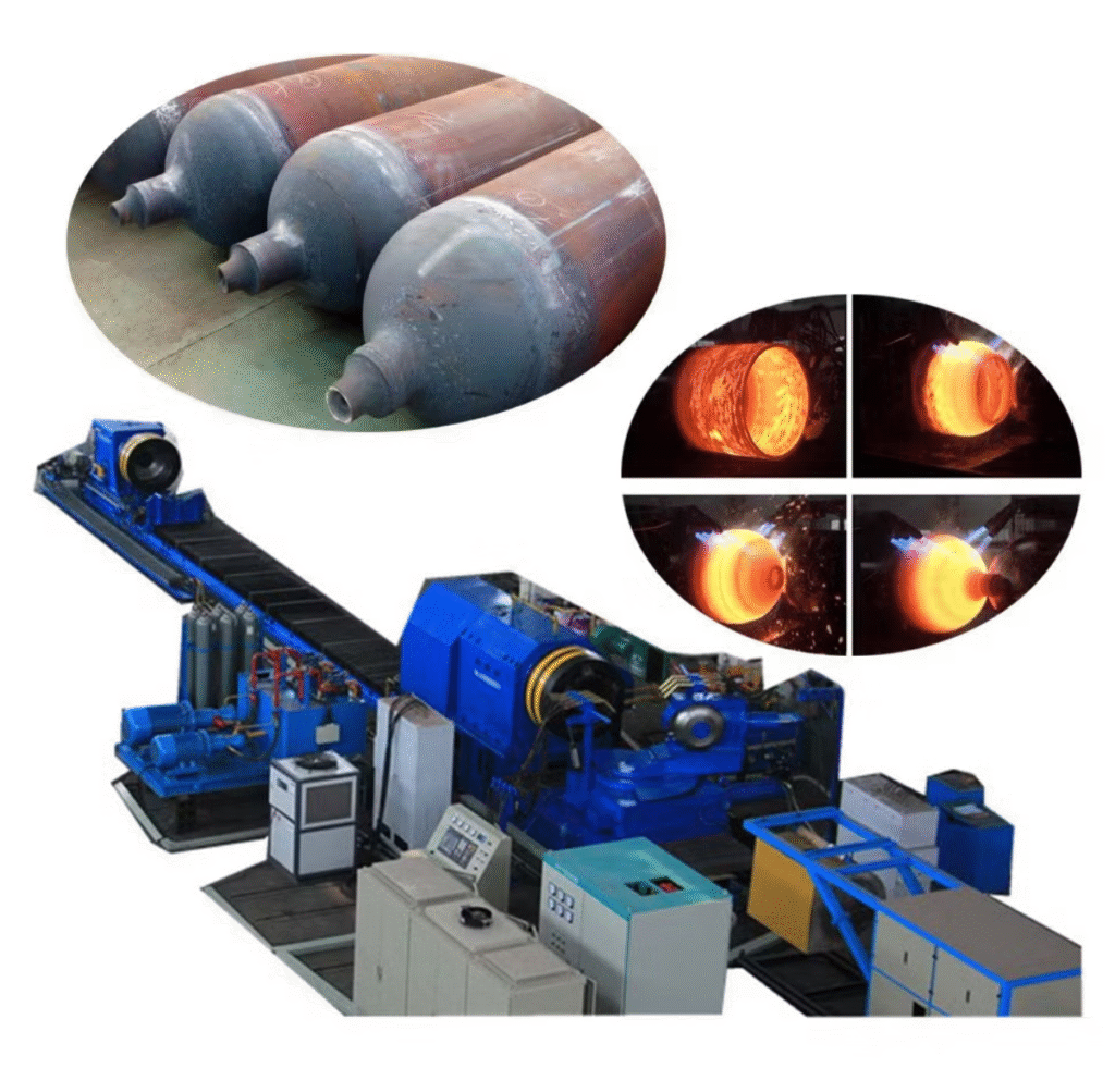
A CNC metal spinning machine for flow forming is an advanced industrial machine specifically designed to combine the precision of CNC-controlled metal spinning with the high-strength, high-performance capabilities of flow forming, producing seamless, rotationally symmetric components with optimized wall thickness and mechanical properties. In this process, a metal blank is securely mounted on a mandrel, and CNC-controlled rollers apply continuous, precise pressure while the blank rotates at controlled speeds, gradually elongating, thinning, and shaping the metal to match the mandrel’s profile. Flow forming extends the capabilities of traditional metal spinning by allowing the metal to be incrementally stretched and compressed along its axis, producing high-strength, lightweight, and structurally optimized components that exhibit superior fatigue resistance and dimensional stability. The CNC system controls spindle speed, roller trajectory, feed rate, and forming pressure with extreme accuracy, ensuring repeatable production of complex geometries, deep-drawn profiles, and intricate shapes with uniform wall thickness and smooth surface finishes. The combination of work-hardening during spinning and controlled deformation during flow forming produces parts with enhanced mechanical strength, stiffness, and long-term durability, making CNC metal spinning machines for flow forming essential in aerospace, defense, automotive, and industrial applications where performance, safety, and reliability are critical.
These machines are capable of producing a broad range of components, from small, precise parts to large, heavy-duty structures, all with consistent quality and structural integrity. In aerospace applications, CNC flow forming spinning machines manufacture turbine shafts, engine casings, landing gear components, rotor shells, and other critical elements that require seamless construction, uniform wall thickness, and optimized strength-to-weight ratios to meet strict safety, regulatory, and performance standards. In automotive industries, they are used to produce drive shafts, wheels, brake drums, transmission components, and turbocharger housings, where uniform wall thickness, mechanical durability, and resistance to fatigue are essential for long-term reliability and operational performance. Industrial and energy sectors utilize CNC flow forming spinning machines to fabricate pressure vessels, cylindrical tanks, piping components, and other high-stress equipment that must withstand mechanical loads, thermal cycling, and high pressures. The CNC-controlled flow forming process ensures that material is precisely distributed along the component’s length, reducing the need for additional welding, machining, or assembly, and resulting in structurally optimized, lightweight, and high-strength parts.
Modern CNC metal spinning machines for flow forming often include hot forming capabilities using localized or induction heating, which softens high-strength metal blanks, facilitates material flow, and reduces roller wear during the forming of thick or challenging metals such as stainless steel, aluminum, titanium, and copper alloys. Many machines integrate secondary operations, including trimming, flanging, beading, and necking, within the same setup, reducing material handling, streamlining production, and shortening cycle times. Advanced monitoring systems, real-time feedback, and adaptive CNC control maintain dimensional accuracy, wall thickness uniformity, and surface quality throughout the forming process, which is especially critical in aerospace, defense, and automotive sectors where even minor deviations can compromise performance, safety, or component longevity.
The advantages of CNC metal spinning machines for flow forming include the ability to produce large, high-strength, seamless components with precise dimensional control, uniform wall thickness, and optimized mechanical properties while minimizing material waste and tooling costs compared to traditional forming methods such as forging, deep drawing, or stamping. The integration of CNC automation ensures repeatable accuracy, consistent quality, and flexibility to produce a wide variety of geometries with minimal tooling changes. By combining the benefits of metal spinning, flow forming, work-hardening, CNC precision, and integrated secondary operations, these machines allow manufacturers to efficiently produce structurally optimized, durable, and high-performance components suitable for aerospace, automotive, defense, energy, and industrial applications. CNC metal spinning machines for flow forming remain an indispensable solution in modern manufacturing, providing precise, reliable, and high-quality components that meet the rigorous demands of contemporary engineering and industrial production.
A CNC metal spinning machine for flow forming is an advanced industrial machine engineered to produce seamless, rotationally symmetric metal components with exceptional dimensional accuracy, uniform wall thickness, and enhanced mechanical properties by combining the precision of CNC-controlled metal spinning with the high-performance advantages of flow forming. In operation, a metal blank is securely mounted on a mandrel while CNC-controlled rollers apply continuous, precisely regulated pressure as the blank rotates, gradually elongating, thinning, and shaping the material along the mandrel’s profile. Unlike traditional metal spinning, flow forming involves incremental axial stretching and radial compression, which work-hardens the metal and produces components with optimized strength, stiffness, and fatigue resistance. The CNC system precisely manages spindle speed, roller paths, forming pressures, and feed rates, allowing the production of complex geometries, deep-drawn profiles, and intricate designs with repeatable precision, uniform wall thickness, and high-quality surface finishes. This combination of controlled deformation and work-hardening results in lightweight, structurally optimized, and durable components suitable for the most demanding aerospace, defense, automotive, and industrial applications where reliability under mechanical load and thermal cycling is essential.
CNC metal spinning machines for flow forming are versatile and capable of producing components across a wide range of sizes and applications, from small, detailed parts to large, heavy-duty structures, all with consistent quality and structural integrity. In aerospace manufacturing, they are employed to produce turbine shafts, engine casings, rotor shells, landing gear components, and pressure vessels that require seamless construction, uniform wall thickness, and optimized strength-to-weight ratios to meet strict safety, performance, and regulatory standards. In the automotive industry, these machines fabricate drive shafts, brake drums, wheels, transmission housings, and turbocharger shells, where uniform wall thickness, corrosion resistance, and mechanical durability are critical for long-term reliability and operational efficiency. Industrial and energy applications rely on CNC flow forming spinning machines to produce high-stress cylindrical components, pressure vessels, tanks, piping, and structural elements that must withstand continuous mechanical loads, high pressures, and thermal cycling. The CNC-controlled process allows precise distribution of material along the component’s axis, minimizing the need for welding or machining, improving structural integrity, and producing components with superior mechanical performance and reduced weight.
Modern CNC metal spinning machines for flow forming often include hot forming capabilities through localized or induction heating, which softens thick or high-strength metal blanks, improves material flow, and reduces roller wear during the formation of complex geometries or high-strength alloys such as stainless steel, titanium, aluminum, and copper. Many machines integrate secondary operations such as trimming, flanging, beading, and necking within the same setup, which streamlines production, reduces material handling, and shortens overall cycle times. Advanced monitoring systems, adaptive CNC controls, and real-time feedback loops ensure consistent wall thickness, dimensional accuracy, and surface quality throughout the forming process. This level of precision is especially critical in aerospace, defense, and automotive applications, where even minor deviations can compromise performance, safety, or component longevity.
The advantages of CNC metal spinning machines for flow forming include the ability to produce high-strength, seamless, corrosion-resistant components with precise dimensional control and optimized mechanical properties while minimizing material waste and tooling costs compared to conventional forming methods such as forging, deep drawing, or stamping. CNC automation ensures repeatable accuracy, consistent quality, and the flexibility to produce a wide range of geometries without extensive tooling modifications. By combining the benefits of metal spinning, flow forming, work-hardening, CNC precision, and integrated secondary operations, manufacturers can efficiently produce structurally optimized, durable, and high-performance components suitable for aerospace, automotive, defense, energy, and industrial applications. CNC metal spinning machines for flow forming remain an indispensable tool in modern manufacturing, delivering reliable, precise, and high-quality components that meet the most stringent engineering and industrial standards.
A CNC metal spinning machine for flow forming is an advanced industrial machine designed to combine the precision and repeatability of CNC-controlled metal spinning with the strength-enhancing and shape-optimizing capabilities of flow forming, enabling the production of seamless, rotationally symmetric components with highly uniform wall thickness, superior structural integrity, and optimized mechanical properties. In this process, a metal blank is mounted securely on a mandrel while CNC-controlled rollers exert continuous, precisely regulated pressure as the blank rotates. The metal is incrementally stretched and compressed along its axis, which not only shapes it into the desired profile but also work-hardens the material, increasing fatigue resistance, tensile strength, and overall durability. CNC control allows for exact management of spindle speed, roller trajectory, feed rate, and forming pressure, ensuring the production of deep-drawn, complex, and intricate geometries with high repeatability, minimal defects, and smooth surface finishes. This combination of metal spinning and flow forming produces lightweight yet strong components that are particularly suited for aerospace, defense, automotive, and industrial applications, where high performance under mechanical stress, thermal cycling, and demanding operational conditions is required.
These machines are extremely versatile, capable of producing both small, precision parts and large, heavy-duty components with consistent quality and structural optimization. In aerospace manufacturing, CNC flow forming spinning machines produce turbine shafts, engine casings, rotor shells, landing gear components, and pressure vessels that demand seamless construction, uniform wall thickness, and optimized strength-to-weight ratios to meet stringent safety and performance standards. In the automotive industry, they fabricate drive shafts, wheels, brake drums, transmission housings, and turbocharger components, where precise dimensional control, mechanical durability, and corrosion resistance are essential for reliable long-term operation. Industrial and energy applications utilize CNC flow forming spinning machines for the production of cylindrical pressure vessels, tanks, piping components, and high-stress structural elements that must endure continuous mechanical loads, high pressures, and thermal cycling. The CNC-controlled flow forming process ensures precise axial and radial material distribution, reducing the need for secondary machining or welding, improving overall structural integrity, and producing components with superior mechanical performance and reduced weight.
Modern CNC metal spinning machines for flow forming frequently incorporate hot forming capabilities using localized or induction heating, which softens high-strength or thick metal blanks, facilitates material flow, minimizes roller wear, and allows for the creation of complex or precision-critical shapes from stainless steel, titanium, aluminum, copper, and specialized alloys. Many machines also integrate secondary operations such as trimming, flanging, beading, and necking into the same setup, streamlining production, reducing handling, and shortening cycle times. Advanced monitoring systems, adaptive CNC control, and real-time feedback loops ensure dimensional accuracy, uniform wall thickness, and high-quality surface finishes throughout the forming process. This level of precision is essential in aerospace, defense, and automotive applications, where even minor deviations can significantly impact safety, performance, and component longevity.
The advantages of CNC metal spinning machines for flow forming are extensive, including the ability to produce seamless, high-strength, corrosion-resistant components with precise dimensional control, uniform wall thickness, and optimized mechanical properties while minimizing material waste and reducing tooling costs compared to conventional methods such as forging, deep drawing, or stamping. CNC automation ensures repeatable accuracy, consistent quality, and flexibility to produce a wide variety of component geometries without the need for extensive tooling modifications. By combining the benefits of CNC precision, metal spinning work-hardening, flow forming, hot forming capabilities, and integrated secondary operations, manufacturers can efficiently produce structurally optimized, durable, and high-performance components suitable for aerospace, automotive, defense, energy, and industrial applications. CNC metal spinning machines for flow forming remain an indispensable solution in modern manufacturing, offering reliable, precise, and high-quality components that meet the most stringent engineering and industrial standards.
A CNC metal spinning machine for flow forming is a highly specialized industrial machine designed to produce seamless, rotationally symmetric metal components with precise dimensional tolerances, uniform wall thickness, and enhanced mechanical properties by combining the traditional process of metal spinning with the high-performance capabilities of flow forming and the precision of CNC (Computer Numerical Control) automation. In operation, a metal blank is securely mounted on a mandrel while CNC-controlled rollers apply continuous, precisely regulated pressure as the blank rotates. The flow forming process incrementally stretches and compresses the metal along its axis, producing components with work-hardened surfaces, improved fatigue resistance, and increased tensile strength while maintaining precise geometries. CNC control provides exact management of spindle speed, roller trajectory, feed rate, and forming pressure, allowing for repeatable production of complex shapes, deep-drawn profiles, and intricate designs with uniform wall thickness and superior surface finishes. This combination of CNC precision, metal spinning, and flow forming ensures the production of lightweight, structurally optimized, and durable components, making these machines essential for aerospace, automotive, defense, energy, and industrial applications where components must withstand extreme mechanical stress, thermal cycling, and harsh operational environments.
CNC flow forming metal spinning machines are versatile and capable of producing a wide range of components, from small, highly detailed parts to large, heavy-duty structures, all with consistent quality and high structural integrity. In aerospace applications, these machines manufacture turbine shafts, engine casings, rotor shells, landing gear components, and pressure vessels that demand seamless construction, uniform wall thickness, and optimized strength-to-weight ratios to comply with strict performance, safety, and regulatory standards. In the automotive industry, they produce drive shafts, wheels, brake drums, transmission housings, valve covers, and turbocharger components where precise dimensional control, corrosion resistance, and mechanical durability are critical for long-term operational reliability. Industrial and energy sectors rely on CNC flow forming machines to fabricate cylindrical tanks, piping components, pressure vessels, and high-stress structural elements that must endure continuous mechanical loads, high pressures, and temperature fluctuations. The CNC-controlled process ensures material is distributed precisely along the component’s axis, reducing the need for secondary machining, welding, or assembly, improving structural integrity, and producing components with superior mechanical performance and reduced weight.
Modern CNC metal spinning machines for flow forming frequently incorporate hot forming capabilities using localized or induction heating, which softens high-strength or thick metal blanks, improves material flow, reduces roller wear, and allows the formation of complex or precision-critical shapes in stainless steel, titanium, aluminum, copper, and other specialized alloys. Many machines integrate secondary operations such as trimming, flanging, beading, and necking within the same setup, streamlining workflow, reducing handling, and shortening overall production times. Advanced monitoring systems, adaptive CNC control, and real-time feedback loops maintain dimensional accuracy, wall thickness consistency, and high-quality surface finishes throughout the forming process, which is especially important in aerospace, automotive, and defense applications where even minor deviations can compromise safety, performance, or component longevity.
The advantages of CNC metal spinning machines for flow forming include the ability to produce large, high-strength, seamless components with precise dimensional control, uniform wall thickness, and optimized mechanical properties while minimizing material waste and reducing tooling costs compared to conventional methods such as forging, stamping, or deep drawing. CNC automation ensures repeatable accuracy, consistent quality, and flexibility to produce a wide range of component geometries without extensive tooling modifications. By combining CNC precision, metal spinning work-hardening, flow forming, hot forming capabilities, and integrated secondary operations, these machines enable manufacturers to efficiently produce structurally optimized, durable, and high-performance components suitable for aerospace, automotive, defense, energy, and industrial applications. CNC metal spinning machines for flow forming remain a vital solution in modern manufacturing, providing precise, reliable, and high-quality components that meet the rigorous standards of contemporary engineering and industrial production.
Titanium Flow Forming Machine
A titanium flow forming machine is a highly specialized industrial machine engineered to produce seamless, rotationally symmetric components from titanium and its alloys, combining precision metal forming techniques with flow forming technology to achieve exceptional structural integrity, uniform wall thickness, and optimized mechanical properties. Titanium is known for its high strength-to-weight ratio, corrosion resistance, and ability to withstand extreme temperatures, making it a critical material in aerospace, defense, medical, and high-performance automotive applications. In a titanium flow forming machine, a titanium blank is securely mounted on a mandrel while rollers apply continuous, carefully controlled pressure along the axis of the rotating blank. The flow forming process incrementally stretches and compresses the titanium, shaping it into the desired geometry while work-hardening the material, which improves fatigue resistance, stiffness, and overall durability. CNC integration is often used to precisely control roller paths, spindle speed, feed rate, and forming pressure, enabling the production of complex shapes, deep-drawn profiles, and precision components with consistent wall thickness and superior surface finishes. This combination of controlled deformation, work-hardening, and CNC precision ensures that titanium components meet the stringent performance and safety standards required in critical applications.
Titanium flow forming machines are capable of producing a wide range of components, from small, high-precision parts to large, heavy-duty structures, all with repeatable quality and dimensional accuracy. In aerospace, these machines manufacture aircraft engine casings, turbine shafts, rotor shells, landing gear components, and pressure vessels, all of which demand seamless construction, uniform wall thickness, and optimized strength-to-weight ratios to comply with strict performance and safety regulations. In the defense sector, titanium flow forming machines produce components such as missile casings, armored structural elements, and high-strength connectors, where precision, fatigue resistance, and mechanical reliability are critical. High-performance automotive applications also benefit from titanium flow forming, producing lightweight driveshafts, suspension components, and exhaust systems that require both strength and weight reduction. Industrial and energy applications utilize these machines to fabricate pressure vessels, cylindrical tanks, piping components, and structural elements that must endure high mechanical loads, thermal cycling, and corrosive environments. The precise control offered by CNC-integrated titanium flow forming machines ensures material is distributed optimally along the axis of the component, reducing the need for additional machining or welding, increasing structural integrity, and producing components with superior mechanical properties.
Modern titanium flow forming machines often incorporate localized or induction heating to enhance material formability, reduce roller wear, and enable the shaping of thick or high-strength titanium blanks that would be difficult to form at room temperature. Secondary operations such as trimming, flanging, beading, and necking can often be integrated into the same setup, reducing handling, streamlining workflow, and minimizing overall cycle times. Advanced monitoring systems, adaptive CNC control, and real-time feedback loops ensure consistent wall thickness, dimensional accuracy, and surface quality throughout the forming process, which is especially important in aerospace, defense, and high-performance automotive applications where even minor deviations can compromise safety, performance, or component longevity.
The advantages of titanium flow forming machines include the ability to produce high-strength, corrosion-resistant, and lightweight components with precise dimensional control and optimized mechanical properties while minimizing material waste and tooling costs compared to traditional methods such as forging, deep drawing, or stamping. CNC automation provides repeatable accuracy, consistent quality, and the flexibility to produce complex geometries with minimal tooling modifications. By combining flow forming technology, titanium work-hardening, CNC precision, and integrated secondary operations, manufacturers can efficiently produce structurally optimized, durable, and high-performance titanium components suitable for aerospace, defense, automotive, energy, and industrial applications. Titanium flow forming machines remain an indispensable solution in modern manufacturing, delivering precise, reliable, and high-quality components that meet the most stringent engineering and industrial standards.
A titanium flow forming machine is a highly advanced industrial machine designed to produce seamless, rotationally symmetric components from titanium and its alloys, combining the precision of CNC-controlled metal spinning with the strength-enhancing capabilities of flow forming. Titanium, with its exceptional strength-to-weight ratio, corrosion resistance, and ability to withstand extreme temperatures, is widely used in aerospace, defense, medical, and high-performance automotive applications, and its forming requires precise, controlled processes. In operation, a titanium blank is securely mounted on a mandrel while CNC-controlled rollers apply continuous, precisely calibrated pressure as the blank rotates, gradually stretching, thinning, and shaping the material along the mandrel’s profile. Flow forming not only shapes the titanium but also work-hardens it, enhancing fatigue resistance, stiffness, and long-term durability while maintaining dimensional accuracy. CNC control ensures precise management of roller paths, spindle speed, feed rate, and forming pressure, enabling the production of complex geometries, deep-drawn profiles, and intricate designs with uniform wall thickness and superior surface finishes. This combination of CNC precision, controlled flow forming, and work-hardening produces lightweight, structurally optimized components that meet stringent performance and safety standards in critical industries.
Titanium flow forming machines are versatile, capable of producing components ranging from small, precision parts to large, heavy-duty structures, all with repeatable quality and high structural integrity. In aerospace, they are used to manufacture turbine shafts, engine casings, rotor shells, landing gear components, and pressure vessels, all of which require seamless construction, uniform wall thickness, and optimized strength-to-weight ratios to comply with strict safety and performance regulations. Defense applications utilize these machines to produce missile casings, armored structural elements, and other critical high-strength components where precision, fatigue resistance, and reliability are essential. In the automotive sector, titanium flow forming machines fabricate lightweight driveshafts, suspension components, and exhaust systems, providing both strength and weight reduction for high-performance vehicles. Industrial and energy applications rely on titanium flow forming to create pressure vessels, cylindrical tanks, piping, and structural elements that must endure high mechanical loads, thermal cycling, and corrosive environments. The CNC-controlled process ensures that titanium material is distributed optimally along the component axis, reducing the need for secondary machining or welding, increasing structural integrity, and producing parts with superior mechanical performance.
Modern titanium flow forming machines often include localized or induction heating to improve material formability, reduce roller wear, and allow the forming of thick or high-strength titanium blanks that would otherwise be difficult to shape cold. Many machines integrate secondary operations such as trimming, flanging, beading, and necking within the same setup, which streamlines workflow, reduces handling, and shortens overall cycle times. Advanced monitoring systems, adaptive CNC control, and real-time feedback loops maintain consistent wall thickness, dimensional accuracy, and surface quality throughout the forming process, which is critical in aerospace, defense, and high-performance automotive industries where even minor deviations can compromise component safety, performance, or longevity.
The advantages of titanium flow forming machines include the ability to produce high-strength, corrosion-resistant, and lightweight components with precise dimensional control and optimized mechanical properties while minimizing material waste and tooling costs compared to conventional forming methods such as forging, deep drawing, or stamping. CNC automation ensures repeatable accuracy, consistent quality, and the flexibility to produce a wide range of geometries without extensive tooling modifications. By combining flow forming technology, titanium work-hardening, CNC precision, and integrated secondary operations, manufacturers can efficiently produce structurally optimized, durable, and high-performance titanium components suitable for aerospace, defense, automotive, energy, and industrial applications. Titanium flow forming machines remain an essential tool in modern manufacturing, delivering precise, reliable, and high-quality components that meet the most demanding engineering and industrial standards.
A titanium flow forming machine is a highly specialized industrial machine engineered to produce seamless, rotationally symmetric components from titanium and its alloys, combining the precision of CNC-controlled metal spinning with the high-strength, shape-optimizing benefits of flow forming. Titanium is valued for its exceptional strength-to-weight ratio, corrosion resistance, and ability to withstand extreme temperatures, making it indispensable in aerospace, defense, high-performance automotive, and medical applications. In operation, a titanium blank is securely mounted on a mandrel while CNC-controlled rollers apply continuous, carefully regulated pressure as the blank rotates. The flow forming process incrementally stretches and compresses the metal along its axis, producing a component with work-hardened surfaces that exhibit superior fatigue resistance, stiffness, and long-term durability. The CNC system precisely controls spindle speed, roller trajectory, feed rate, and forming pressure, enabling the creation of complex shapes, deep-drawn profiles, and intricate geometries with uniform wall thickness, smooth surface finishes, and repeatable accuracy. This integration of CNC precision, controlled flow forming, and work-hardening ensures that titanium components meet the most demanding performance, safety, and durability standards required in critical industries.
Titanium flow forming machines are versatile and capable of producing a wide range of components, from small, precision parts to large, heavy-duty structures, all with consistent quality, dimensional accuracy, and structural integrity. In aerospace applications, they are employed to manufacture turbine shafts, engine casings, rotor shells, landing gear components, and pressure vessels, all of which require seamless construction, uniform wall thickness, and optimized strength-to-weight ratios to comply with strict regulatory and performance standards. Defense applications use these machines to produce missile casings, armored structural elements, and other high-strength components where fatigue resistance, reliability, and precise tolerances are critical. In high-performance automotive applications, titanium flow forming machines fabricate lightweight driveshafts, suspension components, exhaust systems, and turbocharger housings, combining strength and weight reduction to improve efficiency and durability. Industrial and energy sectors rely on these machines for producing pressure vessels, cylindrical tanks, piping components, and structural elements that must withstand high mechanical loads, thermal cycling, and corrosive environments. The CNC-controlled process ensures that material is distributed optimally along the component’s axis, reducing the need for secondary machining or welding, increasing structural integrity, and producing components with superior mechanical performance and reduced weight.
Modern titanium flow forming machines often include localized or induction heating to enhance material formability, reduce roller wear, and enable shaping of thick or high-strength titanium blanks that would otherwise be difficult to form cold. Many machines integrate secondary operations such as trimming, flanging, beading, and necking into the same setup, streamlining production, reducing handling, and minimizing overall cycle times. Advanced monitoring systems, adaptive CNC controls, and real-time feedback loops maintain consistent wall thickness, dimensional accuracy, and surface quality throughout the forming process, which is especially critical in aerospace, defense, and high-performance automotive applications where even minor deviations can compromise safety, performance, or component longevity.
The advantages of titanium flow forming machines include the ability to produce high-strength, corrosion-resistant, lightweight components with precise dimensional control, uniform wall thickness, and optimized mechanical properties while minimizing material waste and tooling costs compared to traditional methods such as forging, deep drawing, or stamping. CNC automation ensures repeatable accuracy, consistent quality, and flexibility to produce a wide variety of geometries without extensive tooling modifications. By combining flow forming technology, titanium work-hardening, CNC precision, and integrated secondary operations, manufacturers can efficiently produce structurally optimized, durable, and high-performance titanium components suitable for aerospace, defense, automotive, energy, and industrial applications. Titanium flow forming machines remain an essential solution in modern manufacturing, providing reliable, precise, and high-quality components that meet the most demanding engineering and industrial standards.
A titanium flow forming machine is a highly sophisticated industrial machine specifically engineered to produce seamless, rotationally symmetric components from titanium and its alloys, integrating the precision of CNC-controlled metal spinning with the strength-enhancing and shape-optimizing benefits of flow forming. Titanium, known for its high strength-to-weight ratio, exceptional corrosion resistance, and ability to withstand extreme temperatures, is widely used in aerospace, defense, high-performance automotive, and medical applications, making precise forming techniques essential. In operation, a titanium blank is mounted securely on a mandrel while CNC-controlled rollers apply continuous, carefully regulated pressure as the blank rotates. The flow forming process gradually stretches and compresses the titanium along its axis, shaping it into the desired geometry while work-hardening the material, improving fatigue resistance, structural strength, and long-term durability. The CNC system allows precise control over spindle speed, roller trajectory, feed rate, and forming pressure, enabling the production of complex profiles, deep-drawn components, and intricate designs with uniform wall thickness, smooth surface finishes, and repeatable accuracy. The combination of CNC precision, controlled flow forming, and work-hardening ensures that titanium components meet the demanding performance, safety, and reliability standards required in critical industrial applications.
Titanium flow forming machines are extremely versatile, capable of producing a wide range of components, from small, highly detailed parts to large, heavy-duty structures, all with consistent quality and dimensional accuracy. In aerospace, these machines are employed to manufacture turbine shafts, engine casings, rotor shells, landing gear components, and pressure vessels, all of which require seamless construction, uniform wall thickness, and optimized strength-to-weight ratios to comply with strict safety, regulatory, and performance standards. Defense applications utilize these machines to fabricate missile casings, armored structural elements, and other high-strength components where fatigue resistance, mechanical reliability, and dimensional precision are critical. High-performance automotive applications benefit from titanium flow forming for the production of lightweight driveshafts, suspension components, exhaust systems, and turbocharger housings, combining high strength with reduced weight to improve efficiency and durability. Industrial and energy sectors employ these machines to produce pressure vessels, cylindrical tanks, piping components, and high-stress structural elements that must endure mechanical loads, thermal cycling, and corrosive environments. The CNC-controlled process ensures that material is distributed optimally along the component’s axis, reducing the need for secondary machining or welding, improving structural integrity, and producing components with superior mechanical performance and lightweight characteristics.
Modern titanium flow forming machines often incorporate localized or induction heating to improve material formability, reduce roller wear, and enable the shaping of thick or high-strength titanium blanks that would be difficult to form at room temperature. Many machines integrate secondary operations such as trimming, flanging, beading, and necking within the same setup, streamlining production, reducing handling, and shortening overall cycle times. Advanced monitoring systems, adaptive CNC controls, and real-time feedback loops maintain wall thickness consistency, dimensional accuracy, and high-quality surface finishes throughout the forming process, which is especially important in aerospace, defense, and high-performance automotive industries where even minor deviations can compromise safety, performance, or component longevity.
The advantages of titanium flow forming machines include the ability to produce high-strength, corrosion-resistant, and lightweight components with precise dimensional control, uniform wall thickness, and optimized mechanical properties while minimizing material waste and reducing tooling costs compared to traditional forming methods such as forging, deep drawing, or stamping. CNC automation ensures repeatable accuracy, consistent quality, and flexibility to produce a wide variety of component geometries without extensive tooling modifications. By combining flow forming technology, titanium work-hardening, CNC precision, and integrated secondary operations, manufacturers can efficiently produce structurally optimized, durable, and high-performance titanium components suitable for aerospace, defense, automotive, energy, and industrial applications. Titanium flow forming machines remain a crucial solution in modern manufacturing, providing precise, reliable, and high-quality components that meet the most stringent engineering and industrial standards.
Aluminum Flow Forming Machine
An aluminum flow forming machine is a highly advanced industrial machine designed to produce seamless, rotationally symmetric components from aluminum and its alloys, integrating CNC-controlled precision metal spinning with the high-performance benefits of flow forming. Aluminum, valued for its light weight, corrosion resistance, and excellent thermal and electrical conductivity, is widely used in aerospace, automotive, defense, energy, and industrial applications, making precise forming techniques critical to achieve optimal mechanical and structural performance. In operation, an aluminum blank is mounted securely on a mandrel while CNC-controlled rollers apply continuous, precisely regulated pressure as the blank rotates. The flow forming process incrementally stretches, compresses, and shapes the aluminum along its axis, producing a component with uniform wall thickness, superior surface finish, and enhanced mechanical properties. Work-hardening during the flow forming process increases fatigue resistance, structural strength, and overall durability, while CNC control ensures exact management of spindle speed, roller trajectory, feed rate, and forming pressure, enabling the production of complex geometries, deep-drawn profiles, and intricate designs with repeatable precision and minimal defects. This combination of CNC precision, controlled deformation, and work-hardening ensures that aluminum components meet stringent performance, reliability, and safety standards for high-demand applications.
Aluminum flow forming machines are highly versatile, capable of producing a wide range of components from small, precision parts to large, heavy-duty structures, all with consistent quality, dimensional accuracy, and structural optimization. In aerospace manufacturing, these machines fabricate turbine casings, engine components, landing gear parts, rotor shells, and pressure vessels, all of which require seamless construction, uniform wall thickness, and optimized strength-to-weight ratios to meet strict regulatory and performance standards. In the automotive sector, aluminum flow forming is used to produce wheels, drive shafts, brake drums, transmission housings, and turbocharger components, where light weight, mechanical durability, and corrosion resistance are essential for efficiency and long-term reliability. Industrial and energy applications employ these machines to manufacture cylindrical tanks, piping systems, pressure vessels, and structural elements that must withstand high mechanical loads, thermal cycling, and environmental corrosion. The CNC-controlled flow forming process ensures precise material distribution along the component’s axis, reducing the need for secondary machining or welding, improving structural integrity, and producing components with superior mechanical performance, reduced weight, and minimal material waste.
Modern aluminum flow forming machines often incorporate localized or induction heating to enhance material formability, especially for thick or high-strength aluminum alloys, reduce roller wear, and enable the shaping of intricate or precision-critical geometries. Many machines integrate secondary operations such as trimming, flanging, beading, and necking within the same setup, streamlining workflow, minimizing material handling, and shortening production cycle times. Advanced monitoring systems, adaptive CNC control, and real-time feedback loops maintain consistent wall thickness, dimensional accuracy, and high-quality surface finishes throughout the forming process, which is crucial for aerospace, defense, automotive, and energy applications where even minor deviations can affect component performance, safety, or service life.
The advantages of aluminum flow forming machines include the ability to produce lightweight, high-strength, corrosion-resistant components with precise dimensional control, uniform wall thickness, and optimized mechanical properties while minimizing material waste and tooling costs compared to traditional forming methods such as forging, stamping, or deep drawing. CNC automation ensures repeatable accuracy, consistent quality, and flexibility to produce a wide variety of component geometries without extensive tooling changes. By combining flow forming technology, aluminum work-hardening, CNC precision, and integrated secondary operations, manufacturers can efficiently produce structurally optimized, durable, and high-performance aluminum components suitable for aerospace, automotive, defense, energy, and industrial applications. Aluminum flow forming machines remain a crucial solution in modern manufacturing, providing precise, reliable, and high-quality components that meet the most demanding engineering and industrial standards.
An aluminum flow forming machine is a highly specialized industrial machine designed to manufacture seamless, rotationally symmetric components from aluminum and its alloys, combining the precision of CNC-controlled metal spinning with the strength-optimizing and shape-enhancing capabilities of flow forming. Aluminum is prized for its light weight, corrosion resistance, and excellent thermal and electrical conductivity, making it a preferred material in aerospace, automotive, defense, energy, and industrial applications. In operation, an aluminum blank is mounted securely on a mandrel while CNC-controlled rollers apply continuous, carefully calibrated pressure as the blank rotates. The flow forming process gradually stretches, compresses, and shapes the aluminum along its axis, producing components with uniform wall thickness, smooth surface finishes, and enhanced mechanical properties. The incremental work-hardening that occurs during flow forming increases fatigue resistance, structural strength, and long-term durability, while CNC control ensures precise management of spindle speed, roller trajectory, feed rate, and forming pressure. This enables the production of complex geometries, deep-drawn profiles, and intricate designs with repeatable accuracy, minimal defects, and optimized material properties, ensuring that aluminum components meet the stringent performance, safety, and reliability requirements of high-demand industrial applications.
Aluminum flow forming machines are extremely versatile, capable of producing a wide variety of components ranging from small, precision parts to large, heavy-duty structures with consistent quality, dimensional accuracy, and structural optimization. In aerospace applications, these machines manufacture turbine casings, engine housings, rotor shells, landing gear components, and pressure vessels, all of which require seamless construction, uniform wall thickness, and optimized strength-to-weight ratios to meet rigorous safety and performance standards. In the automotive sector, aluminum flow forming is utilized to produce wheels, drive shafts, brake drums, transmission housings, and turbocharger components, where mechanical durability, light weight, and corrosion resistance are critical for both performance and long-term reliability. Industrial and energy applications rely on these machines to fabricate cylindrical tanks, piping components, pressure vessels, and structural elements that must withstand continuous mechanical loads, thermal cycling, and corrosive environments. The CNC-controlled flow forming process ensures that aluminum material is distributed precisely along the component axis, reducing the need for secondary machining or welding, improving structural integrity, and producing lightweight components with superior mechanical performance and minimal material waste.
Modern aluminum flow forming machines often incorporate localized or induction heating to improve material formability, reduce roller wear, and allow shaping of thick or high-strength aluminum alloys that would otherwise be difficult to form cold. Many machines also integrate secondary operations such as trimming, flanging, beading, and necking within the same setup, streamlining workflow, reducing material handling, and shortening overall production times. Advanced monitoring systems, adaptive CNC controls, and real-time feedback loops ensure consistent wall thickness, dimensional accuracy, and high-quality surface finishes throughout the forming process, which is especially critical in aerospace, defense, automotive, and energy applications where even minor deviations can compromise performance, safety, or component longevity.
The advantages of aluminum flow forming machines include the ability to produce lightweight, corrosion-resistant, and high-strength components with precise dimensional control, uniform wall thickness, and optimized mechanical properties while minimizing material waste and tooling costs compared to traditional forming methods such as forging, deep drawing, or stamping. CNC automation ensures repeatable accuracy, consistent quality, and flexibility to manufacture a wide variety of component geometries without extensive tooling modifications. By combining CNC precision, flow forming technology, aluminum work-hardening, and integrated secondary operations, manufacturers can efficiently produce structurally optimized, durable, and high-performance aluminum components suitable for aerospace, automotive, defense, energy, and industrial applications. Aluminum flow forming machines remain a critical solution in modern manufacturing, providing precise, reliable, and high-quality components that meet the most demanding engineering and industrial standards.
An aluminum flow forming machine is a highly advanced industrial machine designed to produce seamless, rotationally symmetric components from aluminum and its alloys, combining the accuracy and repeatability of CNC-controlled metal spinning with the structural benefits of flow forming. Aluminum, known for its light weight, corrosion resistance, and excellent thermal and electrical conductivity, is widely used in aerospace, automotive, defense, energy, and industrial applications, making precise forming processes essential to achieve optimal mechanical and structural performance. In operation, an aluminum blank is mounted securely on a mandrel while CNC-controlled rollers apply continuous, precisely calibrated pressure as the blank rotates. The flow forming process incrementally stretches, compresses, and shapes the aluminum along its axis, producing components with uniform wall thickness, smooth surface finishes, and enhanced mechanical properties. Work-hardening during flow forming improves fatigue resistance, structural strength, and long-term durability, while CNC control ensures exact management of spindle speed, roller trajectory, feed rate, and forming pressure, allowing the production of complex geometries, deep-drawn profiles, and intricate designs with repeatable precision and minimal defects. This combination of CNC precision, controlled deformation, and material strengthening ensures that aluminum components meet the stringent performance, safety, and reliability standards required in critical industrial applications.
Aluminum flow forming machines are highly versatile, capable of producing a wide range of components from small, detailed parts to large, heavy-duty structures, all with consistent quality, dimensional accuracy, and structural optimization. In aerospace applications, they are used to manufacture turbine casings, engine housings, rotor shells, landing gear components, and pressure vessels, all of which require seamless construction, uniform wall thickness, and optimized strength-to-weight ratios to comply with strict regulatory and performance standards. Automotive applications rely on aluminum flow forming to produce wheels, drive shafts, brake drums, transmission housings, and turbocharger components, where mechanical durability, light weight, and corrosion resistance are critical for performance and long-term reliability. Industrial and energy applications utilize these machines to fabricate pressure vessels, cylindrical tanks, piping components, and structural elements that must withstand high mechanical loads, thermal cycling, and corrosive environments. The CNC-controlled flow forming process ensures that material is distributed precisely along the component axis, reducing the need for secondary machining or welding, enhancing structural integrity, and producing components with superior mechanical performance, minimal material waste, and reduced overall weight.
Modern aluminum flow forming machines often incorporate localized or induction heating to improve material formability, reduce roller wear, and allow shaping of thick or high-strength aluminum blanks that would otherwise be difficult to form cold. Many machines integrate secondary operations such as trimming, flanging, beading, and necking within the same setup, streamlining workflow, minimizing handling, and shortening overall production cycles. Advanced monitoring systems, adaptive CNC controls, and real-time feedback loops maintain consistent wall thickness, dimensional accuracy, and high-quality surface finishes throughout the forming process, which is particularly important in aerospace, automotive, defense, and energy applications where even minor deviations can compromise performance, safety, or component longevity.
The advantages of aluminum flow forming machines include the ability to produce lightweight, high-strength, and corrosion-resistant components with precise dimensional control, uniform wall thickness, and optimized mechanical properties while minimizing material waste and tooling costs compared to conventional forming methods such as forging, stamping, or deep drawing. CNC automation ensures repeatable accuracy, consistent quality, and flexibility to manufacture a wide range of component geometries without extensive tooling modifications. By combining CNC precision, flow forming technology, aluminum work-hardening, and integrated secondary operations, manufacturers can efficiently produce structurally optimized, durable, and high-performance aluminum components suitable for aerospace, automotive, defense, energy, and industrial applications. Aluminum flow forming machines remain an essential solution in modern manufacturing, providing precise, reliable, and high-quality components that meet the most demanding engineering and industrial standards.
An aluminum flow forming machine is a highly sophisticated industrial machine designed to produce seamless, rotationally symmetric components from aluminum and its alloys, combining the precision of CNC-controlled metal spinning with the strength-optimizing and shape-enhancing benefits of flow forming. Aluminum is valued for its low density, corrosion resistance, thermal conductivity, and excellent mechanical properties, making it a material of choice in aerospace, automotive, defense, energy, and industrial applications. In operation, an aluminum blank is mounted securely on a mandrel while CNC-controlled rollers apply continuous, precisely regulated pressure as the blank rotates. The flow forming process incrementally stretches, compresses, and shapes the aluminum along its axis, producing components with uniform wall thickness, smooth surface finishes, and enhanced mechanical performance. During this process, work-hardening occurs, improving fatigue resistance, structural strength, and long-term durability, while CNC control ensures precise management of spindle speed, roller trajectory, feed rate, and forming pressure. This allows the production of complex geometries, deep-drawn profiles, and intricate designs with repeatable accuracy and minimal defects, ensuring that aluminum components meet the strict performance, reliability, and safety standards required in critical applications.
Aluminum flow forming machines are capable of producing a wide range of components, from small precision parts to large, heavy-duty structures, all with consistent quality, dimensional accuracy, and structural optimization. In aerospace applications, these machines are used to manufacture turbine casings, engine housings, rotor shells, landing gear components, and pressure vessels, all of which demand seamless construction, uniform wall thickness, and optimized strength-to-weight ratios to comply with rigorous safety and performance regulations. Automotive applications rely on aluminum flow forming to fabricate wheels, drive shafts, brake drums, transmission housings, and turbocharger components, where weight reduction, mechanical durability, and corrosion resistance are critical for performance and long-term reliability. Industrial and energy applications use these machines to produce pressure vessels, cylindrical tanks, piping components, and structural elements that must withstand high mechanical loads, thermal cycling, and corrosive environments. The CNC-controlled flow forming process ensures that material is distributed precisely along the component axis, reducing the need for secondary machining or welding, improving structural integrity, and producing lightweight components with superior mechanical performance and minimal material waste.
Modern aluminum flow forming machines often incorporate localized or induction heating to enhance material formability, reduce roller wear, and allow shaping of thick or high-strength aluminum alloys that would otherwise be difficult to form at room temperature. Many machines integrate secondary operations such as trimming, flanging, beading, and necking within the same setup, streamlining workflow, reducing handling, and shortening production cycle times. Advanced monitoring systems, adaptive CNC controls, and real-time feedback loops maintain consistent wall thickness, dimensional accuracy, and high-quality surface finishes throughout the forming process, which is particularly important in aerospace, defense, automotive, and energy applications where even minor deviations can compromise performance, safety, or component longevity.
The advantages of aluminum flow forming machines include the ability to produce high-strength, lightweight, and corrosion-resistant components with precise dimensional control, uniform wall thickness, and optimized mechanical properties while minimizing material waste and tooling costs compared to traditional forming methods such as forging, stamping, or deep drawing. CNC automation provides repeatable accuracy, consistent quality, and the flexibility to produce a wide variety of component geometries without extensive tooling modifications. By combining CNC precision, flow forming technology, aluminum work-hardening, and integrated secondary operations, manufacturers can efficiently produce structurally optimized, durable, and high-performance aluminum components suitable for aerospace, automotive, defense, energy, and industrial applications. Aluminum flow forming machines remain a critical solution in modern manufacturing, delivering precise, reliable, and high-quality components that meet the most demanding engineering and industrial standards.
Custom Flow Forming Machine for Steel Components
A custom flow forming machine for steel components is a highly specialized industrial machine designed to produce seamless, rotationally symmetric steel parts with exceptional strength, dimensional precision, and optimized mechanical properties. Steel, with its superior hardness, tensile strength, and durability, is widely used in aerospace, automotive, defense, energy, and heavy industrial applications, making precise forming technologies essential to achieve the desired structural performance. In operation, a steel blank is mounted securely on a mandrel while CNC-controlled rollers apply continuous, precisely regulated pressure as the blank rotates. The flow forming process incrementally stretches, compresses, and shapes the steel along its axis, producing components with uniform wall thickness, smooth surface finishes, and work-hardened surfaces that enhance fatigue resistance, structural integrity, and long-term durability. CNC control allows for precise management of spindle speed, roller trajectory, feed rate, and forming pressure, enabling the creation of complex profiles, deep-drawn geometries, and intricate designs with repeatable accuracy, minimal defects, and optimal material distribution. This combination of CNC precision, controlled deformation, and work-hardening ensures that steel components produced on custom flow forming machines meet stringent engineering, safety, and performance requirements in demanding industrial applications.
Custom flow forming machines for steel components are versatile and capable of producing a wide range of parts, from small, highly detailed elements to large, heavy-duty structural components, all with consistent quality and structural optimization. In aerospace applications, these machines are employed to manufacture high-strength shafts, landing gear parts, pressure vessels, turbine casings, and engine housings, where seamless construction, uniform wall thickness, and high fatigue resistance are critical to meeting rigorous safety and regulatory standards. Automotive applications benefit from steel flow forming for the fabrication of drive shafts, transmission housings, suspension components, brake drums, and high-strength structural elements, where precise tolerances, mechanical durability, and reliability are essential. In defense and military applications, these machines are used to produce armored housings, missile casings, and critical structural components that require exceptional strength and precision. Industrial and energy sectors rely on custom steel flow forming machines to produce pressure vessels, piping systems, cylindrical tanks, and structural supports capable of withstanding high mechanical loads, thermal cycling, and harsh environmental conditions. The CNC-controlled process ensures material is optimally distributed along the component axis, reducing the need for secondary machining or welding, enhancing structural integrity, and delivering components with superior mechanical performance and reduced material waste.
Modern custom flow forming machines for steel often include induction or localized heating to improve material formability, particularly for thick, high-strength steel blanks, reduce roller wear, and enable the production of complex geometries that would be difficult to form at ambient temperatures. Many machines integrate secondary operations such as trimming, flanging, beading, and necking within the same setup, streamlining production, reducing handling, and minimizing overall cycle times. Advanced monitoring systems, adaptive CNC controls, and real-time feedback loops maintain dimensional accuracy, uniform wall thickness, and high-quality surface finishes throughout the forming process, which is critical for aerospace, defense, automotive, and industrial applications where even small deviations can compromise performance, safety, or longevity.
The advantages of custom flow forming machines for steel components include the ability to produce high-strength, durable, and corrosion-resistant parts with precise dimensional control, uniform wall thickness, and optimized mechanical properties while minimizing material waste and tooling costs compared to conventional forming techniques such as forging, deep drawing, or stamping. CNC automation ensures repeatable accuracy, consistent quality, and the flexibility to produce a wide variety of component geometries without extensive tooling modifications. By combining CNC precision, flow forming technology, steel work-hardening, and integrated secondary operations, manufacturers can efficiently produce structurally optimized, high-performance steel components suitable for aerospace, defense, automotive, energy, and industrial applications. Custom flow forming machines for steel components remain a critical tool in modern manufacturing, providing reliable, precise, and high-quality parts that meet the most demanding engineering and industrial standards.
A custom flow forming machine for steel components is a highly advanced industrial machine engineered to produce seamless, rotationally symmetric steel parts with precise dimensional control, uniform wall thickness, and superior mechanical properties. Steel, with its high tensile strength, hardness, and durability, is widely used in aerospace, automotive, defense, energy, and heavy industrial applications, making the controlled forming of steel blanks essential to achieving optimal performance and structural integrity. In operation, a steel blank is securely mounted on a mandrel while CNC-controlled rollers apply continuous, carefully regulated pressure as the blank rotates. The flow forming process gradually stretches, compresses, and shapes the steel along its axis, producing components that are work-hardened, fatigue-resistant, and structurally optimized. CNC control enables exact regulation of spindle speed, roller trajectory, feed rate, and forming pressure, allowing for the production of complex profiles, deep-drawn geometries, and intricate designs with high repeatability, minimal defects, and superior surface finishes. By combining CNC precision with controlled flow forming and material strengthening, custom steel components achieve the performance, reliability, and safety standards required for critical industrial applications.
Custom flow forming machines for steel components are versatile and capable of producing a wide range of parts, from small, precision elements to large, heavy-duty structural components, all with consistent quality and mechanical integrity. In aerospace, these machines are employed to manufacture turbine shafts, engine housings, landing gear elements, pressure vessels, and structural supports, where seamless construction, uniform wall thickness, and high fatigue resistance are critical to meeting stringent safety and performance standards. Automotive applications rely on steel flow forming to fabricate drive shafts, transmission housings, suspension components, brake drums, and structural frames, where dimensional accuracy, mechanical durability, and long-term reliability are essential. Defense applications utilize these machines to produce missile casings, armored housings, and high-strength structural components requiring extreme precision, fatigue resistance, and reliability. Industrial and energy sectors employ custom steel flow forming machines to produce cylindrical tanks, piping components, pressure vessels, and high-stress structural elements capable of withstanding continuous mechanical loads, thermal cycling, and harsh environmental conditions. The CNC-controlled process ensures material is distributed optimally along the component axis, reducing the need for secondary machining or welding, improving structural integrity, and producing parts with superior mechanical performance, consistent quality, and minimized material waste.
Modern custom steel flow forming machines often incorporate induction or localized heating to improve material formability, reduce roller wear, and allow shaping of thick or high-strength steel blanks that would be difficult to form at ambient temperatures. Many machines integrate secondary operations such as trimming, flanging, beading, and necking within the same setup, streamlining production, minimizing handling, and reducing cycle times. Advanced monitoring systems, adaptive CNC controls, and real-time feedback loops maintain consistent wall thickness, dimensional precision, and high-quality surface finishes throughout the forming process, which is particularly important in aerospace, defense, automotive, and industrial applications where even minor deviations can compromise performance, safety, or component longevity.
The advantages of custom flow forming machines for steel components include the ability to produce high-strength, durable, and corrosion-resistant parts with precise dimensional control, uniform wall thickness, and optimized mechanical properties while minimizing material waste and tooling costs compared to traditional forming methods such as forging, deep drawing, or stamping. CNC automation ensures repeatable accuracy, consistent quality, and flexibility to manufacture a wide range of component geometries without extensive tooling changes. By combining CNC precision, flow forming technology, steel work-hardening, and integrated secondary operations, manufacturers can efficiently produce structurally optimized, high-performance steel components suitable for aerospace, defense, automotive, energy, and industrial applications. Custom flow forming machines for steel components remain an essential solution in modern manufacturing, delivering precise, reliable, and high-quality parts that meet the most demanding engineering and industrial standards.
A custom flow forming machine for steel components is a highly specialized industrial machine designed to produce seamless, rotationally symmetric parts with exceptional strength, dimensional accuracy, and uniform wall thickness. Steel, renowned for its high tensile strength, hardness, durability, and versatility, is widely used across aerospace, automotive, defense, energy, and heavy industrial sectors, making precise forming techniques essential to achieve optimal mechanical and structural performance. In operation, a steel blank is securely mounted on a mandrel while CNC-controlled rollers apply continuous, precisely regulated pressure as the blank rotates. The flow forming process incrementally stretches and compresses the steel along its axis, gradually shaping the material into the desired geometry while work-hardening occurs, enhancing fatigue resistance, tensile strength, and long-term durability. CNC control ensures accurate management of spindle speed, roller trajectory, feed rate, and forming pressure, enabling the production of complex profiles, deep-drawn shapes, and intricate designs with repeatable precision, superior surface finishes, and minimal material defects. By integrating CNC precision with controlled flow forming and work-hardening, manufacturers can produce steel components that meet the highest performance, safety, and reliability standards required in critical industrial applications.
Custom steel flow forming machines are capable of producing a diverse range of components, from small, precision elements to large, heavy-duty structural parts, all with consistent quality, dimensional accuracy, and optimized mechanical properties. In aerospace, these machines are used to manufacture turbine shafts, engine casings, rotor shells, landing gear elements, and pressure vessels, all of which demand seamless construction, uniform wall thickness, and high fatigue resistance to comply with stringent regulatory and operational standards. Automotive applications leverage steel flow forming to fabricate drive shafts, transmission housings, brake drums, suspension components, and structural frames, where dimensional precision, mechanical durability, and reliability are critical. In defense and military sectors, these machines produce missile casings, armored housings, and critical high-strength structural components that require extreme precision, fatigue resistance, and structural integrity under harsh operating conditions. Industrial and energy applications rely on custom steel flow forming machines to produce pressure vessels, cylindrical tanks, piping components, and high-stress structural elements capable of withstanding heavy mechanical loads, thermal cycling, and corrosive environments. The CNC-controlled process ensures optimal material distribution along the component axis, minimizing the need for secondary machining or welding, improving structural performance, and delivering parts with superior mechanical strength and minimal material waste.
Modern custom steel flow forming machines often incorporate induction or localized heating to enhance material formability, particularly for thick or high-strength steel blanks, reduce roller wear, and facilitate the creation of complex geometries that would be difficult to form at ambient temperatures. Many machines integrate secondary operations such as trimming, flanging, beading, and necking within the same setup, streamlining production, minimizing handling, and reducing overall cycle times. Advanced monitoring systems, adaptive CNC controls, and real-time feedback loops maintain consistent wall thickness, dimensional precision, and high-quality surface finishes throughout the forming process, which is especially critical in aerospace, defense, automotive, and industrial applications where even minor deviations can affect performance, safety, or service life.
The advantages of custom flow forming machines for steel components include the ability to manufacture high-strength, durable, and corrosion-resistant parts with precise dimensional control, uniform wall thickness, and optimized mechanical properties while reducing material waste and tooling costs compared to conventional methods such as forging, deep drawing, or stamping. CNC automation ensures repeatable accuracy, consistent quality, and flexibility to produce a wide variety of component geometries without extensive tooling modifications. By combining CNC precision, flow forming technology, steel work-hardening, and integrated secondary operations, manufacturers can efficiently produce structurally optimized, high-performance steel components suitable for aerospace, defense, automotive, energy, and industrial applications. Custom steel flow forming machines remain an indispensable solution in modern manufacturing, delivering reliable, precise, and high-quality components that meet the most demanding engineering and industrial standards.
A custom flow forming machine for steel components is an advanced industrial system engineered to produce seamless, rotationally symmetric steel parts with exceptional dimensional accuracy, uniform wall thickness, and superior mechanical performance. Steel, valued for its high tensile strength, hardness, toughness, and versatility, is critical in aerospace, automotive, defense, energy, and heavy industrial applications, making precise forming processes essential to achieve optimal structural integrity and performance. In operation, a steel blank is mounted securely on a mandrel while CNC-controlled rollers apply continuous, precisely regulated pressure as the blank rotates. The flow forming process incrementally stretches, compresses, and shapes the steel along its axis, producing components that are work-hardened, fatigue-resistant, and structurally optimized. CNC control allows precise regulation of spindle speed, roller trajectory, feed rate, and forming pressure, enabling the production of complex geometries, deep-drawn profiles, and intricate designs with high repeatability, minimal material defects, and excellent surface finishes. This combination of CNC precision, controlled deformation, and work-hardening ensures that steel components meet stringent engineering, performance, and safety standards required for critical industrial applications.
Custom steel flow forming machines are capable of producing a wide range of components, from small, precision parts to large, heavy-duty structural elements, all with consistent quality, dimensional accuracy, and optimized mechanical properties. In aerospace applications, these machines fabricate turbine shafts, engine housings, rotor shells, landing gear components, and pressure vessels, all of which require seamless construction, uniform wall thickness, and high fatigue resistance to comply with strict safety and performance regulations. Automotive applications rely on steel flow forming to manufacture drive shafts, transmission housings, brake drums, suspension components, and structural frames, where precision, mechanical durability, and reliability are paramount. Defense and military industries use these machines to produce missile casings, armored housings, and critical structural components that demand extreme precision, fatigue resistance, and structural integrity under challenging conditions. Industrial and energy applications employ custom steel flow forming machines to create pressure vessels, cylindrical tanks, piping systems, and structural supports capable of withstanding high mechanical loads, thermal cycling, and corrosive environments. CNC control ensures that material is optimally distributed along the axis of each component, reducing the need for secondary machining or welding, improving structural integrity, and producing parts with superior mechanical performance and minimal material waste.
Modern custom steel flow forming machines often incorporate induction or localized heating to enhance the formability of thick or high-strength steel blanks, reduce roller wear, and enable the creation of intricate geometries that would be difficult to shape at room temperature. Many machines also integrate secondary operations such as trimming, flanging, beading, and necking within the same setup, streamlining workflow, reducing handling, and shortening production cycles. Advanced monitoring systems, adaptive CNC controls, and real-time feedback loops maintain consistent wall thickness, dimensional precision, and surface quality throughout the forming process, which is critical for aerospace, defense, automotive, and industrial applications where even minor deviations can compromise performance, safety, or component longevity.
The advantages of custom flow forming machines for steel components include the ability to manufacture high-strength, durable, and corrosion-resistant parts with precise dimensional control, uniform wall thickness, and optimized mechanical properties while minimizing material waste and tooling costs compared to conventional methods such as forging, deep drawing, or stamping. CNC automation provides repeatable accuracy, consistent quality, and flexibility to produce a wide variety of component geometries without extensive tooling modifications. By combining CNC precision, flow forming technology, steel work-hardening, and integrated secondary operations, manufacturers can efficiently produce structurally optimized, high-performance steel components suitable for aerospace, defense, automotive, energy, and industrial applications. Custom steel flow forming machines remain an essential solution in modern manufacturing, delivering reliable, precise, and high-quality components that meet the most demanding engineering and industrial standards.
Small-Diameter Flow Forming Machine
A small-diameter flow forming machine is a highly specialized industrial machine designed to produce precise, seamless, rotationally symmetric components with small diameters from metals such as steel, aluminum, titanium, or copper alloys. These machines combine CNC-controlled metal spinning technology with the benefits of flow forming, allowing manufacturers to create components with uniform wall thickness, enhanced mechanical strength, and superior surface finishes. Small-diameter components are commonly used in aerospace, defense, automotive, medical devices, and high-precision industrial applications, where even minor dimensional variations or defects can compromise performance, safety, and longevity. In operation, a small metal blank is securely mounted on a mandrel while CNC-controlled rollers apply continuous, carefully regulated pressure as the blank rotates. The flow forming process gradually stretches, compresses, and shapes the material along its axis, work-hardening the metal and increasing fatigue resistance, tensile strength, and structural integrity. CNC control allows precise adjustment of spindle speed, roller trajectory, feed rate, and forming pressure, enabling the production of highly detailed, complex geometries with consistent accuracy and repeatable quality. The combination of CNC precision and controlled flow forming ensures that small-diameter components meet stringent performance, safety, and reliability standards required for critical industrial applications.
Small-diameter flow forming machines are highly versatile, capable of producing a wide range of parts from miniature precision components to slightly larger but still compact elements, all with consistent quality and optimized mechanical properties. In aerospace applications, these machines are used to produce turbine shafts, fuel injector components, small pressure vessels, and other high-precision elements where uniform wall thickness, seamless construction, and high fatigue resistance are essential. Automotive applications leverage small-diameter flow forming to manufacture drive shafts, steering components, transmission parts, and high-precision suspension elements where dimensional accuracy, durability, and light weight are critical. Medical device manufacturers use these machines to produce small, high-strength components such as surgical instrument housings, implantable device shells, and precise mechanical parts for diagnostic equipment, where precision, surface quality, and biocompatibility are crucial. Defense applications require small-diameter flow-formed components for precision missile parts, ordnance casings, and other critical structural elements demanding high reliability under stress. Industrial and energy applications use these machines to create piping connections, pressure tubing, and structural elements in compact sizes, capable of withstanding high mechanical loads and environmental stresses while maintaining precision and reliability.
Modern small-diameter flow forming machines often include induction or localized heating to enhance material formability, particularly when working with high-strength or thick metal blanks, reduce roller wear, and enable the production of intricate geometries that are difficult to form cold. Many machines integrate secondary operations such as trimming, flanging, beading, and necking in the same setup, streamlining production, minimizing handling, and reducing cycle times. Advanced monitoring systems, adaptive CNC control, and real-time feedback loops maintain uniform wall thickness, precise dimensional control, and high-quality surface finishes throughout the forming process, which is critical in applications where even small deviations can compromise performance, safety, or product longevity.
The advantages of small-diameter flow forming machines include the ability to produce high-strength, lightweight, and corrosion-resistant components with precise dimensional control, uniform wall thickness, and optimized mechanical properties, while minimizing material waste and tooling costs compared to traditional methods such as forging, stamping, or deep drawing. CNC automation provides repeatable accuracy, consistent quality, and flexibility to produce a wide variety of geometries without extensive tooling changes. By combining CNC precision, flow forming technology, and work-hardening of metals, manufacturers can efficiently produce structurally optimized, durable, and high-performance small-diameter components suitable for aerospace, defense, automotive, medical, and industrial applications. Small-diameter flow forming machines remain an indispensable tool in modern manufacturing, delivering reliable, precise, and high-quality components that meet the most demanding engineering and industrial standards.
A small-diameter flow forming machine is a precision-engineered industrial system designed to produce seamless, rotationally symmetric components from metals such as steel, aluminum, titanium, or copper alloys, with diameters typically ranging from a few millimeters to several hundred millimeters. These machines integrate CNC-controlled metal spinning with the benefits of flow forming, enabling manufacturers to create parts with uniform wall thickness, optimized material distribution, enhanced mechanical properties, and high-quality surface finishes. Small-diameter components are widely used in aerospace, defense, automotive, medical devices, and high-precision industrial applications, where dimensional accuracy, fatigue resistance, and structural integrity are critical. During operation, a small metal blank is mounted securely on a mandrel, while CNC-controlled rollers apply continuous, precisely regulated pressure as the blank rotates. The flow forming process incrementally stretches and compresses the material along its axis, work-hardening the metal and improving tensile strength, fatigue resistance, and durability. CNC controls allow precise adjustment of spindle speed, roller trajectory, feed rate, and forming pressure, ensuring the production of complex geometries, deep-drawn profiles, and intricate designs with consistent repeatability, minimal defects, and superior surface quality, meeting the demanding standards required for high-performance industrial applications.
Small-diameter flow forming machines are highly versatile and capable of producing a broad spectrum of components, ranging from miniature precision parts to slightly larger yet still compact structural elements, all with consistent quality, dimensional stability, and mechanical optimization. In aerospace applications, these machines manufacture turbine shafts, fuel injector components, small pressure vessels, and other high-precision parts where uniform wall thickness, seamless construction, and high fatigue resistance are essential for safety and performance. Automotive industries utilize these machines to fabricate drive shafts, steering components, transmission elements, and precision suspension parts, where durability, weight reduction, and dimensional accuracy are critical. Medical device manufacturers rely on small-diameter flow forming to produce surgical instrument housings, implantable device shells, and other high-precision components requiring exceptional surface quality, biocompatibility, and mechanical reliability. Defense applications employ these machines to produce precision missile components, ordnance casings, and other critical structural elements where high performance under extreme conditions is vital. Industrial and energy sectors use small-diameter flow forming machines for piping connections, pressure tubing, and structural components in compact sizes, capable of withstanding mechanical stresses, thermal cycling, and corrosive environments while maintaining precise tolerances and structural integrity. The CNC-controlled flow forming process ensures optimal material distribution along the component’s axis, reducing the need for secondary machining or welding, enhancing mechanical performance, and minimizing material waste.
Modern small-diameter flow forming machines often include induction or localized heating to enhance material formability, particularly when working with high-strength alloys or thicker metal blanks, to reduce roller wear and allow the formation of complex geometries that would otherwise be challenging to achieve at ambient temperatures. Many machines incorporate secondary operations such as trimming, flanging, beading, and necking within the same setup, streamlining workflow, reducing handling, and shortening production cycles. Advanced monitoring systems, adaptive CNC control, and real-time feedback loops maintain uniform wall thickness, dimensional precision, and high-quality surface finishes throughout the forming process, which is crucial in aerospace, defense, automotive, medical, and industrial applications where even minor deviations can affect performance, safety, or longevity.
The advantages of small-diameter flow forming machines include the ability to produce high-strength, lightweight, and corrosion-resistant components with precise dimensional control, uniform wall thickness, and enhanced mechanical properties while minimizing material waste and tooling costs compared to conventional forming techniques such as forging, stamping, or deep drawing. CNC automation ensures repeatable accuracy, consistent quality, and the flexibility to produce a wide variety of geometries without extensive tooling modifications. By combining CNC precision, flow forming technology, and work-hardening of metals, manufacturers can efficiently produce structurally optimized, high-performance small-diameter components suitable for aerospace, defense, automotive, medical, and industrial applications. Small-diameter flow forming machines remain a critical asset in modern manufacturing, delivering precise, reliable, and high-quality components that meet the most demanding engineering and industrial standards.
A small-diameter flow forming machine is a precision industrial system designed to manufacture seamless, rotationally symmetric components from metals such as steel, aluminum, titanium, or copper alloys, with diameters typically ranging from a few millimeters to several hundred millimeters. By combining CNC-controlled metal spinning with the principles of flow forming, these machines allow manufacturers to produce parts with uniform wall thickness, optimized material distribution, enhanced mechanical properties, and high-quality surface finishes. Small-diameter components are commonly used in aerospace, automotive, defense, medical, and high-precision industrial applications, where even slight deviations in dimensional accuracy, fatigue resistance, or structural integrity can critically affect performance and reliability. In operation, a metal blank is mounted securely on a mandrel while CNC-controlled rollers apply continuous, precisely calibrated pressure as the blank rotates. The flow forming process incrementally stretches and compresses the material along its axis, work-hardening the metal and improving fatigue resistance, tensile strength, and overall durability. CNC control allows exact regulation of spindle speed, roller trajectory, feed rate, and forming pressure, enabling the production of complex geometries, deep-drawn profiles, and intricate designs with repeatable accuracy, minimal defects, and excellent surface quality. This precision ensures that small-diameter components meet the stringent performance and safety standards required in critical industrial applications.
Small-diameter flow forming machines are highly versatile, capable of producing a wide range of parts from miniature, high-precision elements to slightly larger but still compact components, all with consistent quality, dimensional stability, and structural optimization. In aerospace, these machines produce turbine shafts, fuel injector components, small pressure vessels, and other critical elements where uniform wall thickness, seamless construction, and high fatigue resistance are essential for safety and performance. In automotive applications, small-diameter flow forming is used for drive shafts, steering components, transmission parts, and precision suspension elements, where light weight, mechanical durability, and dimensional accuracy are crucial. The medical industry utilizes these machines to fabricate surgical instrument housings, implantable device shells, and other small, high-precision components requiring exceptional surface quality, biocompatibility, and mechanical reliability. Defense applications employ small-diameter flow forming for precision missile components, ordnance casings, and critical structural elements that must withstand extreme mechanical stress while maintaining exact tolerances. Industrial and energy applications use these machines for piping connections, pressure tubing, and compact structural elements that endure high mechanical loads, thermal cycling, and corrosive environments. The CNC-controlled process ensures that material is distributed optimally along the axis of each component, reducing the need for secondary machining or welding, improving mechanical performance, and minimizing material waste.
Modern small-diameter flow forming machines often integrate induction or localized heating to enhance material formability, particularly when working with high-strength alloys or thicker metal blanks, reduce roller wear, and enable the creation of complex geometries that would be difficult to form cold. Many machines incorporate secondary operations such as trimming, flanging, beading, and necking within the same setup, streamlining workflow, minimizing handling, and shortening production cycles. Advanced monitoring systems, adaptive CNC controls, and real-time feedback loops maintain uniform wall thickness, precise dimensional control, and superior surface finishes throughout the forming process, which is essential in aerospace, defense, automotive, medical, and industrial applications where even minor deviations can compromise component performance, safety, or longevity.
The advantages of small-diameter flow forming machines include the ability to produce lightweight, high-strength, corrosion-resistant components with precise dimensional control, uniform wall thickness, and enhanced mechanical properties while reducing material waste and tooling costs compared to traditional methods such as forging, stamping, or deep drawing. CNC automation ensures repeatable accuracy, consistent quality, and flexibility to manufacture a wide variety of geometries without extensive tooling changes. By combining CNC precision, flow forming technology, and work-hardening of metals, manufacturers can efficiently produce structurally optimized, high-performance small-diameter components suitable for aerospace, defense, automotive, medical, and industrial applications. Small-diameter flow forming machines remain an indispensable solution in modern manufacturing, providing precise, reliable, and high-quality components that meet the most demanding engineering and industrial standards.
A small-diameter flow forming machine is a highly specialized industrial system designed to produce precise, seamless, and rotationally symmetric components from metals such as steel, aluminum, titanium, or copper alloys, typically ranging from a few millimeters to several hundred millimeters in diameter. These machines combine CNC-controlled metal spinning with the benefits of flow forming, allowing for controlled material distribution, uniform wall thickness, and work-hardened surfaces that improve fatigue resistance, tensile strength, and overall durability. Small-diameter components are critical in aerospace, defense, automotive, medical devices, and high-precision industrial applications where even slight deviations in dimensions or structural integrity can severely impact performance, safety, and reliability. During operation, a metal blank is securely mounted on a mandrel while CNC-controlled rollers apply continuous, precisely regulated pressure as the blank rotates. The flow forming process incrementally stretches and compresses the material along its axis, gradually forming the desired geometry while enhancing mechanical properties. CNC systems allow exact control of spindle speed, roller trajectory, feed rate, and forming pressure, making it possible to produce complex profiles, deep-drawn shapes, and intricate designs with repeatable accuracy, minimal defects, and superior surface finishes, ensuring that the finished components meet stringent industrial and engineering standards.
Small-diameter flow forming machines are extremely versatile, capable of producing components that range from highly detailed miniature parts to slightly larger yet still compact structural elements, all with consistent dimensional accuracy, mechanical optimization, and structural integrity. In aerospace applications, these machines are used to fabricate turbine shafts, fuel injector components, small pressure vessels, and other high-precision elements where seamless construction, uniform wall thickness, and fatigue resistance are crucial for safety and performance. Automotive industries rely on these machines to produce drive shafts, steering components, transmission parts, and precision suspension elements, where light weight, dimensional accuracy, and durability are essential. Medical device manufacturers employ small-diameter flow forming machines to fabricate surgical instrument housings, implantable device shells, and high-precision mechanical parts for diagnostic equipment, where biocompatibility, surface quality, and mechanical reliability are critical. Defense and military applications utilize these machines to produce missile components, ordnance casings, and other critical structural elements requiring extreme precision and strength under demanding conditions. Industrial and energy sectors use small-diameter flow forming machines to produce pressure tubing, piping connections, and compact structural elements capable of withstanding mechanical stress, thermal cycling, and corrosive environments while maintaining exact tolerances and structural integrity. The CNC-controlled process ensures optimal material distribution along the component axis, reducing the need for secondary machining or welding, enhancing mechanical performance, and minimizing material waste.
Modern small-diameter flow forming machines often incorporate induction or localized heating to improve material formability, particularly for high-strength or thick metal blanks, reduce roller wear, and facilitate the production of intricate geometries that would otherwise be difficult to form at room temperature. Many machines integrate secondary operations such as trimming, flanging, beading, and necking within the same setup, streamlining production, reducing handling, and shortening overall cycle times. Advanced monitoring systems, adaptive CNC controls, and real-time feedback loops maintain uniform wall thickness, precise dimensional control, and high-quality surface finishes throughout the forming process, which is critical for aerospace, defense, automotive, medical, and industrial applications where even small deviations can compromise component performance, safety, or longevity.
The advantages of small-diameter flow forming machines include the ability to produce high-strength, lightweight, and corrosion-resistant components with precise dimensional control, uniform wall thickness, and enhanced mechanical properties while minimizing material waste and tooling costs compared to conventional methods such as forging, stamping, or deep drawing. CNC automation ensures repeatable accuracy, consistent quality, and flexibility to produce a wide variety of geometries without the need for extensive tooling modifications. By combining CNC precision, flow forming technology, and metal work-hardening, manufacturers can efficiently produce structurally optimized, high-performance small-diameter components suitable for aerospace, defense, automotive, medical, and industrial applications. Small-diameter flow forming machines remain an essential solution in modern manufacturing, providing precise, reliable, and high-quality components that meet the most demanding industrial and engineering standards.
Large-Diameter Flow Forming Machine
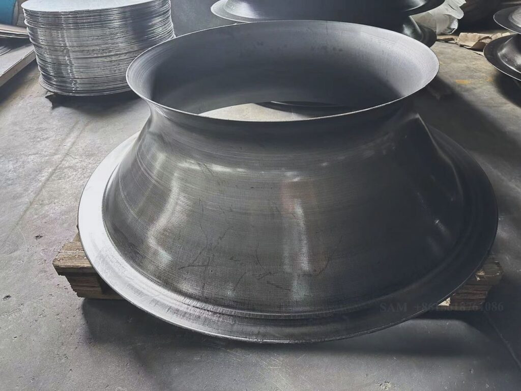
A large-diameter flow forming machine is a highly advanced industrial system engineered to produce seamless, rotationally symmetric components from metals such as steel, aluminum, titanium, or copper alloys with diameters often exceeding several meters. These machines integrate CNC-controlled metal spinning technology with the principles of flow forming, allowing manufacturers to achieve precise dimensional control, uniform wall thickness, optimized material distribution, and enhanced mechanical properties. Large-diameter components are commonly used in aerospace, energy, defense, automotive, and industrial applications where structural integrity, fatigue resistance, and precise tolerances are critical. In operation, a large metal blank is mounted securely on a mandrel while CNC-controlled rollers apply continuous, carefully regulated pressure as the blank rotates. The flow forming process gradually stretches, compresses, and shapes the material along its axis, work-hardening the metal and increasing its tensile strength, durability, and fatigue resistance. CNC control ensures accurate management of spindle speed, roller trajectory, feed rate, and forming pressure, enabling the production of complex geometries, deep-drawn profiles, and large-scale components with repeatable precision, minimal defects, and high-quality surface finishes. By combining CNC precision with controlled flow forming and work-hardening, manufacturers can produce large-diameter components that meet the most demanding industrial and engineering standards.
Large-diameter flow forming machines are highly versatile, capable of producing a wide variety of parts ranging from large structural components to critical aerospace and energy elements, all with consistent quality, dimensional accuracy, and optimized mechanical performance. In aerospace, these machines are used to fabricate turbine casings, rocket motor housings, engine components, pressure vessels, and large rotor shells, all of which require seamless construction, uniform wall thickness, and high fatigue resistance to meet stringent regulatory and performance standards. Energy and industrial applications rely on large-diameter flow forming to manufacture pressure vessels, heat exchanger shells, industrial tanks, piping components, and large structural supports capable of withstanding high mechanical loads, thermal cycling, and corrosive environments. Automotive applications may utilize these machines for producing large high-performance components such as drive shafts, large gears, or structural frames where mechanical strength, precision, and reliability are critical. Defense applications employ large-diameter flow forming machines to fabricate missile casings, armored housings, and other structural components that must endure extreme mechanical stress while maintaining exact dimensional tolerances. The CNC-controlled process ensures that material is distributed optimally along the axis of each component, reducing the need for secondary machining or welding, improving structural integrity, and delivering parts with superior mechanical performance and minimal material waste.
Modern large-diameter flow forming machines often include induction or localized heating to improve material formability, reduce roller wear, and allow shaping of thick or high-strength metal blanks that would otherwise be difficult to form cold. Many machines integrate secondary operations such as trimming, flanging, beading, and necking within the same setup, streamlining production, minimizing handling, and reducing overall cycle times. Advanced monitoring systems, adaptive CNC controls, and real-time feedback loops maintain consistent wall thickness, precise dimensional control, and high-quality surface finishes throughout the forming process, which is critical in aerospace, defense, energy, and industrial applications where even minor deviations can compromise performance, safety, or longevity.
The advantages of large-diameter flow forming machines include the ability to produce high-strength, durable, and corrosion-resistant components with precise dimensional control, uniform wall thickness, and optimized mechanical properties while minimizing material waste and tooling costs compared to conventional methods such as forging, stamping, or deep drawing. CNC automation ensures repeatable accuracy, consistent quality, and the flexibility to produce a wide range of component geometries without extensive tooling modifications. By combining CNC precision, flow forming technology, and metal work-hardening, manufacturers can efficiently produce structurally optimized, high-performance large-diameter components suitable for aerospace, defense, energy, automotive, and industrial applications. Large-diameter flow forming machines remain an indispensable solution in modern manufacturing, delivering reliable, precise, and high-quality components that meet the most demanding engineering and industrial standards.
A large-diameter flow forming machine is a sophisticated industrial system designed to manufacture seamless, rotationally symmetric components from metals such as steel, aluminum, titanium, or copper alloys with diameters often exceeding several meters. These machines combine CNC-controlled metal spinning with flow forming technology, allowing for precise dimensional control, uniform wall thickness, optimized material distribution, and enhanced mechanical properties. Large-diameter components are widely used in aerospace, energy, defense, automotive, and industrial applications where structural integrity, fatigue resistance, and strict tolerances are essential. In operation, a large metal blank is securely mounted on a mandrel while CNC-controlled rollers apply continuous, carefully regulated pressure as the blank rotates. The flow forming process incrementally stretches, compresses, and shapes the material along its axis, work-hardening the metal and increasing its tensile strength, fatigue resistance, and durability. CNC control ensures precise management of spindle speed, roller trajectory, feed rate, and forming pressure, enabling the production of complex geometries, deep-drawn profiles, and large-scale components with repeatable precision, minimal defects, and high-quality surface finishes. This integration of CNC precision and flow forming technology ensures that large-diameter components meet the rigorous performance, safety, and reliability standards required in critical industrial applications.
Large-diameter flow forming machines are capable of producing a diverse range of components, from massive structural parts to critical aerospace and energy elements, all with consistent quality, dimensional accuracy, and mechanical optimization. In aerospace, these machines are used to fabricate turbine casings, rocket motor housings, engine components, pressure vessels, and large rotor shells, where seamless construction, uniform wall thickness, and high fatigue resistance are vital to meet stringent regulatory and performance requirements. Energy and industrial sectors use large-diameter flow forming to manufacture pressure vessels, heat exchanger shells, industrial tanks, piping systems, and structural supports capable of withstanding high mechanical loads, thermal cycling, and corrosive environments. Automotive applications may require large-diameter flow forming to produce high-performance structural components, drive shafts, or large gears where dimensional accuracy, mechanical strength, and reliability are essential. Defense and military applications utilize these machines for missile casings, armored housings, and other critical structural elements that must endure extreme stress while maintaining precise tolerances. CNC-controlled flow forming ensures that material is distributed optimally along the axis of each component, reducing the need for secondary machining or welding, enhancing structural integrity, and producing parts with superior mechanical performance and minimal material waste.
Modern large-diameter flow forming machines often incorporate induction or localized heating to improve material formability, reduce roller wear, and enable shaping of thick or high-strength metal blanks that would otherwise be difficult to form cold. Many machines integrate secondary operations such as trimming, flanging, beading, and necking within the same setup, streamlining production, reducing handling, and shortening overall cycle times. Advanced monitoring systems, adaptive CNC controls, and real-time feedback loops maintain consistent wall thickness, precise dimensional control, and superior surface finishes throughout the forming process, which is especially important in aerospace, defense, energy, and industrial applications where even minor deviations can compromise performance, safety, or longevity.
The advantages of large-diameter flow forming machines include the ability to produce high-strength, corrosion-resistant, and durable components with precise dimensional control, uniform wall thickness, and optimized mechanical properties while minimizing material waste and tooling costs compared to conventional methods such as forging, stamping, or deep drawing. CNC automation provides repeatable accuracy, consistent quality, and flexibility to manufacture a wide range of component geometries without extensive tooling modifications. By combining CNC precision, flow forming technology, and work-hardening of metals, manufacturers can efficiently produce structurally optimized, high-performance large-diameter components suitable for aerospace, defense, energy, automotive, and industrial applications. Large-diameter flow forming machines remain a critical solution in modern manufacturing, delivering reliable, precise, and high-quality components that meet the most demanding engineering and industrial standards.
A large-diameter flow forming machine is an advanced industrial system designed to manufacture seamless, rotationally symmetric components from metals such as steel, aluminum, titanium, and copper alloys, with diameters that can reach several meters. By combining CNC-controlled metal spinning with the principles of flow forming, these machines provide precise dimensional control, uniform wall thickness, optimized material distribution, and enhanced mechanical properties. Large-diameter components produced on these machines are critical in aerospace, energy, defense, automotive, and industrial applications where structural integrity, fatigue resistance, and precise tolerances are essential for safety, performance, and reliability. During operation, a large metal blank is securely mounted on a mandrel while CNC-controlled rollers apply continuous, carefully regulated pressure as the blank rotates. The flow forming process incrementally stretches, compresses, and shapes the material along its axis, work-hardening the metal and increasing tensile strength, fatigue resistance, and durability. CNC systems allow precise adjustment of spindle speed, roller trajectory, feed rate, and forming pressure, making it possible to produce complex geometries, deep-drawn profiles, and large-scale components with consistent repeatability, minimal defects, and superior surface finishes. The combination of CNC precision and flow forming technology ensures that large-diameter components meet the most stringent industrial and engineering standards.
Large-diameter flow forming machines are highly versatile, capable of producing a wide range of parts from massive structural components to critical aerospace and energy elements, all with consistent quality, dimensional accuracy, and optimized mechanical performance. In aerospace, these machines are used to fabricate turbine casings, engine housings, rocket motor shells, pressure vessels, and large rotors, where seamless construction, uniform wall thickness, and high fatigue resistance are necessary to meet rigorous regulatory and operational standards. In energy and industrial sectors, large-diameter flow forming machines produce pressure vessels, industrial tanks, heat exchanger shells, piping systems, and structural supports that must withstand high mechanical loads, thermal cycling, and corrosive environments. Automotive applications may utilize these machines to manufacture high-performance structural components, large drive shafts, and heavy-duty gears where precision, mechanical strength, and reliability are essential. Defense and military industries employ large-diameter flow forming machines to produce missile casings, armored housings, and other critical structural elements that must endure extreme stress while maintaining exact tolerances. The CNC-controlled process ensures optimal material distribution along the axis of each component, reducing the need for secondary machining or welding, improving structural integrity, and delivering parts with superior mechanical performance and minimal material waste.
Modern large-diameter flow forming machines often include induction or localized heating to improve material formability, particularly when working with thick or high-strength metal blanks, reduce roller wear, and enable the production of complex geometries that would be difficult to form at ambient temperatures. Many machines integrate secondary operations such as trimming, flanging, beading, and necking within the same setup, streamlining production, minimizing handling, and shortening cycle times. Advanced monitoring systems, adaptive CNC controls, and real-time feedback loops maintain consistent wall thickness, dimensional precision, and high-quality surface finishes throughout the forming process, which is critical in aerospace, defense, energy, and industrial applications where even minor deviations can compromise performance, safety, or durability.
The advantages of large-diameter flow forming machines include the ability to produce high-strength, durable, and corrosion-resistant components with precise dimensional control, uniform wall thickness, and optimized mechanical properties while minimizing material waste and tooling costs compared to conventional methods such as forging, stamping, or deep drawing. CNC automation ensures repeatable accuracy, consistent quality, and flexibility to produce a wide variety of component geometries without extensive tooling modifications. By combining CNC precision, flow forming technology, and work-hardening of metals, manufacturers can efficiently produce structurally optimized, high-performance large-diameter components suitable for aerospace, defense, energy, automotive, and industrial applications. Large-diameter flow forming machines remain an essential tool in modern manufacturing, delivering precise, reliable, and high-quality components that meet the most demanding engineering and industrial standards.
A large-diameter flow forming machine is a sophisticated industrial system designed to manufacture seamless, rotationally symmetric components from metals such as steel, aluminum, titanium, or copper alloys, with diameters often exceeding several meters. By combining CNC-controlled metal spinning with flow forming technology, these machines allow for precise dimensional control, uniform wall thickness, optimized material distribution, and enhanced mechanical properties. Large-diameter components are widely used in aerospace, defense, energy, automotive, and heavy industrial applications, where structural integrity, fatigue resistance, and strict tolerances are essential for performance and safety. During operation, a large metal blank is mounted securely on a mandrel while CNC-controlled rollers apply continuous, carefully regulated pressure as the blank rotates. The flow forming process incrementally stretches, compresses, and shapes the material along its axis, work-hardening the metal and improving tensile strength, fatigue resistance, and overall durability. CNC control allows precise management of spindle speed, roller trajectory, feed rate, and forming pressure, enabling the production of complex geometries, deep-drawn profiles, and large-scale components with consistent repeatability, minimal defects, and superior surface finishes, ensuring that each component meets the most demanding engineering standards.
Large-diameter flow forming machines are highly versatile and capable of producing a broad spectrum of components, from massive structural parts to critical aerospace and industrial elements, all with consistent quality, dimensional accuracy, and mechanical optimization. In aerospace, these machines are employed to manufacture turbine casings, engine housings, rocket motor shells, pressure vessels, and large rotors, where seamless construction, uniform wall thickness, and high fatigue resistance are vital to meet rigorous performance and safety regulations. In energy and industrial applications, large-diameter flow forming machines are used to produce pressure vessels, industrial tanks, heat exchanger shells, piping systems, and structural supports that must withstand high mechanical loads, thermal cycling, and corrosive environments. Automotive industries utilize these machines to fabricate high-performance structural components, large drive shafts, and heavy-duty gears where precision, mechanical strength, and reliability are essential. Defense and military sectors rely on large-diameter flow forming machines for missile casings, armored housings, and other critical structural elements that must endure extreme mechanical stress while maintaining exact tolerances. The CNC-controlled process ensures that material is optimally distributed along the component axis, minimizing the need for secondary machining or welding, enhancing structural integrity, and delivering parts with superior mechanical performance and minimal material waste.
Modern large-diameter flow forming machines often incorporate induction or localized heating to improve material formability, particularly when working with thick or high-strength metal blanks, reduce roller wear, and enable the creation of intricate geometries that would be challenging to form at ambient temperatures. Many machines integrate secondary operations such as trimming, flanging, beading, and necking in the same setup, streamlining production, reducing handling, and shortening cycle times. Advanced monitoring systems, adaptive CNC controls, and real-time feedback loops maintain uniform wall thickness, precise dimensional control, and high-quality surface finishes throughout the forming process, which is critical in aerospace, defense, energy, automotive, and industrial applications where even minor deviations can compromise performance, safety, or longevity.
The advantages of large-diameter flow forming machines include the ability to produce high-strength, durable, and corrosion-resistant components with precise dimensional control, uniform wall thickness, and optimized mechanical properties while minimizing material waste and tooling costs compared to traditional forming methods such as forging, stamping, or deep drawing. CNC automation ensures repeatable accuracy, consistent quality, and flexibility to manufacture a wide variety of component geometries without extensive tooling modifications. By combining CNC precision, flow forming technology, and metal work-hardening, manufacturers can efficiently produce structurally optimized, high-performance large-diameter components suitable for aerospace, defense, energy, automotive, and industrial applications. Large-diameter flow forming machines remain an essential solution in modern manufacturing, delivering precise, reliable, and high-quality components that meet the most demanding engineering and industrial standards.
Hot Flow Forming Machine
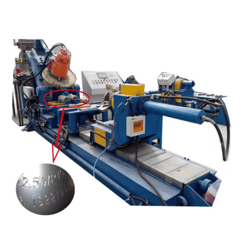
A hot flow forming machine is an advanced industrial system specifically designed to produce seamless, rotationally symmetric components from metals such as steel, aluminum, titanium, or copper alloys by applying heat during the flow forming process. By combining CNC-controlled metal spinning with localized or induction heating, these machines allow the metal to be formed at elevated temperatures, which improves material ductility, reduces forming forces, and enables the creation of complex geometries that would be difficult or impossible to achieve at room temperature. Hot flow forming is particularly advantageous for high-strength or thick metal blanks, as the application of heat softens the material, allowing it to stretch and compress more uniformly, resulting in optimized wall thickness, enhanced mechanical properties, and superior surface finishes. The process begins with the secure mounting of a heated metal blank on a mandrel, while CNC-controlled rollers apply precisely regulated pressure as the blank rotates. The combination of rotational motion, axial feed, and controlled heat causes the material to undergo plastic deformation, work-hardening as it cools, and gradually form into the desired component shape. CNC control ensures accurate management of spindle speed, roller trajectory, feed rate, and forming temperature, allowing manufacturers to achieve high precision, repeatable results, and minimal material defects while meeting the demanding requirements of aerospace, automotive, defense, energy, and industrial applications.
Hot flow forming machines are capable of producing a wide variety of components, from small, high-precision parts to large, heavy-duty structural elements, all with uniform wall thickness, optimized mechanical performance, and exceptional surface quality. In aerospace, these machines fabricate turbine shafts, engine casings, rotor shells, and pressure vessels where seamless construction, precise tolerances, and fatigue resistance are critical for performance and safety. Automotive applications utilize hot flow forming to produce drive shafts, transmission components, suspension elements, and structural frames where high strength, dimensional accuracy, and durability are required. Defense industries employ these machines to manufacture missile casings, armored housings, and other critical structural components that must endure extreme stress, high temperatures, and demanding operational conditions. Industrial and energy sectors rely on hot flow forming for the fabrication of large-diameter pressure vessels, piping systems, cylindrical tanks, and structural supports capable of withstanding mechanical loads, thermal cycling, and corrosive environments. The CNC-controlled process ensures optimal material distribution, minimizing the need for secondary machining or welding and delivering parts with superior mechanical properties, high reliability, and minimal material waste.
Modern hot flow forming machines often integrate induction or localized heating systems with advanced CNC controls to maintain precise temperature uniformity, enhance material formability, and extend tool life. Many machines also combine secondary operations such as trimming, flanging, beading, and necking into the same setup, streamlining production, reducing handling, and improving overall efficiency. Real-time monitoring systems, adaptive feedback loops, and automated control of forming temperature, feed rate, and roller pressure ensure consistent wall thickness, dimensional accuracy, and high-quality surface finishes throughout the forming process, which is particularly critical in aerospace, defense, automotive, and energy applications where even minor deviations can affect performance, safety, or service life.
The advantages of hot flow forming machines include the ability to produce high-strength, durable, and corrosion-resistant components with precise dimensional control, uniform wall thickness, and optimized mechanical properties, while minimizing material waste and reducing the risk of defects compared to conventional cold forming methods. CNC automation provides repeatable accuracy, consistent quality, and flexibility to produce a wide range of geometries without extensive tooling modifications. By combining CNC precision, heat-assisted flow forming, and work-hardening of metals, manufacturers can efficiently produce structurally optimized, high-performance components suitable for aerospace, defense, automotive, energy, and industrial applications. Hot flow forming machines remain an indispensable solution in modern manufacturing, delivering reliable, precise, and high-quality components that meet the most demanding engineering and industrial standards.
A hot flow forming machine is a highly advanced industrial system designed to produce seamless, rotationally symmetric components from metals such as steel, aluminum, titanium, and copper alloys by applying heat during the forming process. This technology combines CNC-controlled metal spinning with localized or induction heating, enabling the metal to be formed at elevated temperatures, which significantly increases ductility, reduces forming forces, and allows the creation of complex geometries that would be difficult to achieve with cold forming methods. The process begins by mounting a metal blank securely on a mandrel, and as the blank rotates, CNC-controlled rollers apply continuous, precisely regulated pressure while heat softens the material, enabling it to flow along the mandrel’s shape. This combination of rotational motion, axial feed, and thermal softening causes the material to undergo plastic deformation, gradually forming into the desired component while work-hardening occurs as it cools. CNC control ensures precise management of spindle speed, roller trajectory, feed rate, forming pressure, and temperature, allowing manufacturers to achieve repeatable precision, minimal defects, and optimal surface quality, meeting the rigorous performance and safety standards required for aerospace, automotive, defense, energy, and industrial applications.
Hot flow forming machines are capable of producing components of varying sizes, from small, high-precision elements to large, heavy-duty structural parts, all with consistent wall thickness, enhanced mechanical properties, and excellent surface finishes. In aerospace, hot flow forming is used to fabricate turbine shafts, rotor shells, engine casings, and pressure vessels, where seamless construction, fatigue resistance, and dimensional accuracy are critical for operational safety and performance. In automotive applications, hot flow forming produces drive shafts, transmission components, suspension parts, and structural frames, where high strength, durability, and precision are essential. Defense industries rely on this technology to manufacture missile casings, armored housings, and other critical structural components that must endure extreme mechanical stress and thermal loads. In industrial and energy sectors, hot flow forming machines are used to create large pressure vessels, heat exchanger shells, piping systems, and structural supports that can withstand high mechanical loads, thermal cycling, and corrosive environments. By applying heat during the flow forming process, these machines ensure optimal material distribution, reduce residual stresses, improve mechanical performance, and minimize the need for secondary machining or welding, resulting in high-quality components with reduced material waste.
Modern hot flow forming machines often integrate advanced induction or localized heating systems along with CNC controls to maintain uniform temperature distribution, enhance metal formability, and extend tool life. Many machines also incorporate secondary operations such as trimming, flanging, beading, and necking within the same setup, which streamlines production, reduces handling, and shortens cycle times. Real-time monitoring, adaptive feedback loops, and automated adjustment of forming parameters ensure consistent wall thickness, precise dimensional control, and high-quality surface finishes throughout the process. This level of precision is particularly critical in applications where even minor deviations can compromise performance, safety, or longevity, such as in aerospace turbines, high-performance automotive components, or defense-grade structures.
The benefits of hot flow forming machines include the ability to produce high-strength, durable, and corrosion-resistant components with uniform wall thickness, precise dimensions, and optimized mechanical properties while reducing material waste and tooling costs compared to cold forming methods. CNC automation ensures repeatable accuracy, consistent quality, and flexibility to produce a wide variety of geometries without extensive tooling changes. By combining CNC precision, heat-assisted flow forming, and the work-hardening of metals, manufacturers can efficiently produce structurally optimized, high-performance components suitable for aerospace, defense, automotive, energy, and industrial applications. Hot flow forming machines have become an essential solution in modern manufacturing, delivering reliable, precise, and high-quality components that meet the most demanding engineering and industrial standards.
A hot flow forming machine is a cutting-edge industrial system designed to produce seamless, rotationally symmetric components from metals such as steel, aluminum, titanium, and copper alloys, using controlled heat during the forming process to enhance material flow and ductility. By combining CNC-controlled metal spinning with heat-assisted forming, these machines allow for the production of complex geometries that are difficult or impossible to achieve with cold forming methods while reducing the risk of cracking, thinning, or other defects. The process begins with securely mounting a metal blank on a mandrel, after which CNC-controlled rollers apply precisely regulated pressure as the blank rotates, and heat is applied either through induction, localized heating, or preheating methods. This combination of rotational motion, axial feed, and thermal softening causes the material to undergo plastic deformation, gradually forming the desired component while simultaneously work-hardening the metal as it cools. CNC systems regulate spindle speed, roller trajectory, feed rate, forming pressure, and temperature, ensuring repeatable precision, optimal surface quality, uniform wall thickness, and mechanical integrity, which is critical for aerospace, automotive, defense, energy, and industrial applications where strict tolerances and high performance are mandatory.
Hot flow forming machines are highly versatile, capable of producing components ranging from small, precision parts to large, heavy-duty structural elements, all with consistent wall thickness, enhanced fatigue resistance, and optimized mechanical properties. In aerospace, these machines are employed to fabricate turbine shafts, rotor shells, engine casings, and pressure vessels, where seamless construction and precise dimensions are crucial for operational safety and performance. Automotive industries use hot flow forming to produce drive shafts, transmission components, suspension elements, and structural frames, where strength, durability, and precision directly impact reliability and efficiency. Defense applications utilize hot flow forming machines for missile casings, armored housings, and other critical structural components that must withstand extreme mechanical and thermal stresses while maintaining dimensional accuracy. Industrial and energy sectors rely on this technology to manufacture large pressure vessels, piping systems, heat exchanger shells, and structural supports, all of which require uniform material distribution, high mechanical strength, and the ability to endure thermal cycling and corrosive environments. The heat-assisted forming process allows the material to flow more uniformly along the mandrel, minimizing residual stresses, reducing secondary machining or welding needs, and delivering components with superior structural performance and reduced material waste.
Modern hot flow forming machines integrate advanced induction or localized heating systems with adaptive CNC controls to maintain uniform temperature distribution, improve material formability, and extend tool life. Many machines also incorporate secondary operations such as trimming, flanging, beading, and necking within the same setup, which streamlines production, reduces handling, and shortens cycle times. Real-time monitoring systems and automated feedback loops ensure consistent wall thickness, precise dimensional control, and superior surface finishes throughout the forming process, which is essential in high-stakes applications like aerospace turbines, defense components, and energy industry structures where even small deviations can compromise performance or safety.
The advantages of hot flow forming machines include the ability to produce high-strength, corrosion-resistant, and durable components with precise dimensional control, uniform wall thickness, and mechanically optimized properties while reducing material waste and tooling costs compared to traditional cold forming or machining methods. CNC automation provides repeatable accuracy, consistent quality, and flexibility to manufacture a wide variety of component geometries without extensive tooling changes. By combining CNC precision, heat-assisted flow forming, and the work-hardening effect of metals, manufacturers can efficiently produce structurally optimized, high-performance components suitable for aerospace, defense, automotive, energy, and industrial applications. Hot flow forming machines remain a vital technology in modern manufacturing, delivering reliable, precise, and high-quality components that meet the most stringent industrial and engineering standards.
A hot flow forming machine is a highly specialized industrial system designed to produce seamless, rotationally symmetric components from metals such as steel, aluminum, titanium, and copper alloys by applying controlled heat during the flow forming process. This combination of CNC-controlled metal spinning and thermal assistance allows the metal to deform more easily, enabling the production of complex geometries, thin-walled structures, and deep-drawn profiles that would be difficult or impossible to achieve with cold forming methods. The process begins with a metal blank securely mounted on a mandrel, which rotates as CNC-controlled rollers apply continuous, precisely regulated pressure while heat softens the material, allowing it to flow and stretch uniformly along the mandrel’s contour. As the material cools, work-hardening occurs, improving tensile strength, fatigue resistance, and overall durability. CNC systems allow precise control of spindle speed, roller trajectory, feed rate, forming pressure, and temperature, ensuring repeatable precision, minimal defects, uniform wall thickness, and high-quality surface finishes. This level of control makes hot flow forming particularly suitable for aerospace, automotive, defense, energy, and industrial applications where stringent tolerances, structural integrity, and performance under stress are critical.
Hot flow forming machines are capable of producing a wide range of components, from small, intricate parts to large, heavy-duty structural elements, all with optimized mechanical properties, consistent wall thickness, and exceptional surface finishes. In aerospace, hot flow forming is used to manufacture turbine shafts, rotor shells, engine casings, and pressure vessels, where seamless construction, fatigue resistance, and dimensional accuracy are essential for safety and performance. Automotive industries rely on hot flow forming to produce drive shafts, transmission components, suspension parts, and structural frames that demand high strength, reliability, and precision. Defense applications utilize this technology to create missile casings, armored housings, and other critical components that must withstand extreme mechanical and thermal loads while maintaining precise tolerances. Industrial and energy sectors use hot flow forming machines to produce large-diameter pressure vessels, piping systems, heat exchanger shells, and structural supports capable of enduring high mechanical stress, thermal cycling, and corrosive environments. By applying heat during the flow forming process, these machines ensure uniform material flow, reduce residual stresses, minimize the need for secondary machining or welding, and deliver components with superior structural performance and minimal material waste.
Modern hot flow forming machines often incorporate induction or localized heating systems combined with advanced CNC controls to maintain precise temperature distribution, enhance material formability, and extend tool life. Many machines also include integrated secondary operations such as trimming, flanging, beading, and necking, allowing for streamlined production, reduced handling, and shorter cycle times. Real-time monitoring systems and adaptive feedback loops ensure consistent wall thickness, dimensional accuracy, and high-quality surface finishes throughout the forming process. This precision is critical in high-demand applications such as aerospace turbines, defense components, energy industry vessels, and high-performance automotive parts, where even minor deviations can compromise performance, safety, or longevity.
The benefits of hot flow forming machines include the ability to produce high-strength, durable, and corrosion-resistant components with uniform wall thickness, precise dimensions, and optimized mechanical properties while reducing material waste and tooling costs compared to conventional cold forming or machining techniques. CNC automation guarantees repeatable accuracy, consistent quality, and flexibility to produce a wide variety of geometries without the need for extensive tooling changes. By combining CNC precision, heat-assisted flow forming, and the natural work-hardening of metals, manufacturers can efficiently produce structurally optimized, high-performance components suitable for aerospace, defense, automotive, energy, and industrial applications. Hot flow forming machines remain an essential technology in modern manufacturing, delivering precise, reliable, and high-quality components that meet the most demanding industrial and engineering standards.
Cold Flow Forming Machine
A cold flow forming machine is a precision industrial system designed to produce seamless, rotationally symmetric metal components without the application of external heat, relying instead on mechanical force and controlled plastic deformation at or near room temperature. These machines are particularly effective for producing parts with uniform wall thickness, optimized material distribution, and excellent surface finishes from metals such as steel, aluminum, titanium, and copper alloys. Cold flow forming is widely used in applications where maintaining tight dimensional tolerances and work-hardened material properties is critical, such as aerospace, automotive, defense, energy, and industrial manufacturing. In operation, a metal blank is mounted securely on a mandrel while CNC-controlled rollers apply precise axial and radial pressure as the blank rotates. The rotational motion combined with the controlled feed and pressure of the rollers causes the material to flow plastically along the mandrel, stretching and compressing it to form the desired component geometry. This work-hardening effect enhances the component’s mechanical properties, including tensile strength, fatigue resistance, and structural integrity, making cold flow forming ideal for high-performance and safety-critical applications. CNC control enables precise adjustment of roller trajectory, spindle speed, feed rate, and forming pressure, ensuring repeatable accuracy, minimal defects, and consistent quality throughout the manufacturing process.
Cold flow forming machines are versatile and capable of producing a wide variety of components, from small, high-precision parts to large-diameter structural elements, all with consistent dimensional control, wall thickness, and mechanical optimization. In aerospace, these machines produce turbine shafts, rotor shells, engine casings, and pressure vessels where seamless construction, fatigue resistance, and dimensional precision are essential for safe and reliable operation. In the automotive industry, cold flow forming is used to fabricate drive shafts, transmission components, suspension elements, and structural frames that require high strength, accuracy, and durability. Defense applications utilize cold flow forming machines for missile casings, armored housings, and other critical structural components that must withstand extreme mechanical loads while maintaining exact tolerances. Industrial and energy applications rely on cold flow forming for pressure vessels, piping systems, heat exchanger shells, and structural supports, where uniform wall thickness, optimal material distribution, and high mechanical performance are essential for long-term reliability and efficiency. By avoiding heat, cold flow forming minimizes metallurgical changes such as grain growth or residual stresses caused by thermal cycling, preserving the material’s original properties while enhancing its mechanical strength through work-hardening.
Modern cold flow forming machines often integrate advanced CNC controls with adaptive feedback systems to maintain precise dimensional accuracy, consistent wall thickness, and high-quality surface finishes throughout the forming process. Many machines also incorporate integrated secondary operations such as trimming, flanging, beading, and necking, streamlining production, reducing handling, and shortening cycle times. Real-time monitoring and automated adjustments allow manufacturers to compensate for material variability, ensure repeatable performance, and produce components with minimal defects. This precision is particularly critical in aerospace, defense, automotive, and energy applications, where even small deviations can compromise performance, safety, or service life.
The advantages of cold flow forming machines include the ability to produce high-strength, corrosion-resistant, and durable components with precise dimensions, uniform wall thickness, and optimized mechanical properties, while minimizing material waste and avoiding the energy costs and metallurgical risks associated with heating. CNC automation ensures consistent quality, repeatable accuracy, and flexibility to produce a wide range of geometries without extensive tooling changes. By combining CNC precision, controlled plastic deformation, and work-hardening effects, cold flow forming machines allow manufacturers to efficiently produce high-performance, structurally optimized components suitable for aerospace, defense, automotive, energy, and industrial applications. Cold flow forming machines remain an essential tool in modern manufacturing, delivering reliable, precise, and high-quality components that meet the most stringent engineering and industrial standards.
A cold flow forming machine is an advanced industrial system designed to produce seamless, rotationally symmetric components from metals such as steel, aluminum, titanium, and copper alloys by mechanically deforming the material at or near room temperature without the application of external heat. This process relies on precise CNC-controlled rollers and mandrel systems to stretch and compress the metal blank along its axis while it rotates, creating components with uniform wall thickness, optimized material distribution, and enhanced mechanical properties through work-hardening. The absence of heat in cold flow forming preserves the metallurgical structure of the material, avoiding grain growth or thermal residual stresses, which ensures that the final components maintain superior strength, durability, and fatigue resistance. CNC systems allow precise control over spindle speed, roller trajectory, feed rate, and forming pressure, ensuring repeatable accuracy, minimal defects, and high-quality surface finishes, making cold flow forming ideal for applications where dimensional tolerances and mechanical integrity are critical, including aerospace, automotive, defense, energy, and industrial manufacturing.
Cold flow forming machines are versatile and capable of producing a wide spectrum of components, from small, high-precision elements to large structural parts, all with consistent wall thickness, dimensional accuracy, and enhanced mechanical performance. In aerospace, cold flow forming is used to fabricate turbine shafts, rotor shells, engine casings, and pressure vessels where seamless construction, precise dimensions, and fatigue resistance are critical for safe and reliable operation. Automotive industries employ cold flow forming to produce drive shafts, transmission components, suspension elements, and structural frames, all of which require high mechanical strength, durability, and dimensional precision. Defense applications utilize these machines to manufacture missile casings, armored housings, and other critical components that must withstand extreme mechanical loads while maintaining exact tolerances. Industrial and energy sectors rely on cold flow forming machines for the production of large-diameter pressure vessels, piping systems, heat exchanger shells, and structural supports, where uniform wall thickness, optimal material distribution, and mechanical reliability are essential for long-term performance and efficiency. By forming components without heat, cold flow forming minimizes metallurgical changes while simultaneously enhancing mechanical properties through plastic deformation and work-hardening, producing parts that are structurally optimized and highly durable.
Modern cold flow forming machines often integrate advanced CNC systems with adaptive feedback and real-time monitoring to maintain precise dimensional control, consistent wall thickness, and superior surface quality throughout the forming process. Many machines also combine secondary operations such as trimming, flanging, beading, and necking within the same setup, streamlining production, reducing handling, and shortening cycle times. Automated controls compensate for variations in material properties, maintain repeatable accuracy, and ensure that every component meets stringent quality standards. This level of precision is particularly important in aerospace, defense, automotive, and energy applications, where even small deviations can compromise performance, safety, or longevity.
The advantages of cold flow forming machines include the ability to produce high-strength, corrosion-resistant, and mechanically optimized components with precise dimensions, uniform wall thickness, and minimal material waste, all while avoiding the costs and potential risks associated with heat-assisted processes. CNC automation ensures consistent quality, repeatable accuracy, and flexibility to produce a wide variety of component geometries without extensive tooling modifications. By combining CNC precision, controlled cold plastic deformation, and the work-hardening effect of metals, manufacturers can efficiently produce structurally optimized, high-performance components suitable for aerospace, defense, automotive, energy, and industrial applications. Cold flow forming machines remain a crucial technology in modern manufacturing, delivering precise, reliable, and high-quality components that meet the most demanding engineering and industrial standards.
A cold flow forming machine is a highly precise industrial system engineered to produce seamless, rotationally symmetric components from metals such as steel, aluminum, titanium, and copper alloys by mechanically deforming the material at ambient temperatures without the use of external heating. This process leverages CNC-controlled rollers and mandrels to apply carefully regulated radial and axial forces on a rotating metal blank, gradually stretching and compressing the material along its axis to form the desired geometry while simultaneously work-hardening the metal. Cold flow forming preserves the metallurgical integrity of the material, avoiding issues like grain growth, thermal distortion, or residual stresses that can occur in heat-assisted processes, and enhances tensile strength, fatigue resistance, and overall durability. CNC automation allows precise control of spindle speed, roller trajectory, feed rate, and forming pressure, producing components with consistent wall thickness, exceptional surface finishes, and tight dimensional tolerances. This combination of precision, repeatability, and work-hardening makes cold flow forming ideal for high-performance and safety-critical applications in aerospace, automotive, defense, energy, and industrial manufacturing.
Cold flow forming machines are versatile, capable of producing a broad range of components from small, intricate parts to large-diameter structural elements, all with uniform wall thickness, optimized mechanical properties, and minimal material waste. In aerospace, these machines are employed to manufacture turbine shafts, rotor shells, engine casings, and pressure vessels, where seamless construction, dimensional precision, and fatigue resistance are essential for operational reliability and safety. In automotive applications, cold flow forming produces drive shafts, transmission components, suspension elements, and structural frames that demand high strength, durability, and accuracy. Defense industries rely on cold flow forming machines for missile casings, armored housings, and other critical structural components that must endure extreme mechanical stresses while maintaining precise tolerances. Industrial and energy applications utilize cold flow forming to fabricate pressure vessels, piping systems, heat exchanger shells, and structural supports that require consistent wall thickness, uniform material distribution, and superior mechanical performance to withstand high mechanical loads, thermal cycling, and corrosive environments. By forming components without heat, cold flow forming ensures material integrity while enhancing mechanical properties through plastic deformation and work-hardening, reducing the need for secondary machining or welding and producing structurally optimized parts with high reliability.
Modern cold flow forming machines often integrate advanced CNC systems with adaptive feedback loops and real-time monitoring to maintain precise dimensional control, consistent wall thickness, and high-quality surface finishes throughout the forming process. Many machines also incorporate secondary operations such as trimming, flanging, beading, and necking within the same setup, streamlining production, minimizing handling, and reducing cycle times. Real-time monitoring allows automated adjustments to compensate for variations in material properties, ensuring repeatable accuracy and consistent quality for every component. This level of control is critical in aerospace, defense, automotive, and energy applications, where even minor deviations can compromise performance, safety, or service life.
The benefits of cold flow forming machines include the ability to produce high-strength, corrosion-resistant, and durable components with precise dimensions, uniform wall thickness, and optimized mechanical properties while minimizing material waste and eliminating the energy costs and potential metallurgical risks associated with heat-assisted processes. CNC automation ensures repeatable accuracy, consistent quality, and flexibility to produce a wide variety of component geometries without extensive tooling changes. By combining CNC precision, controlled cold deformation, and the work-hardening of metals, cold flow forming machines enable manufacturers to efficiently produce high-performance, structurally optimized components suitable for aerospace, defense, automotive, energy, and industrial applications. Cold flow forming remains an indispensable technology in modern manufacturing, delivering reliable, precise, and high-quality components that meet the most demanding industrial and engineering standards.
A cold flow forming machine is a highly specialized industrial system designed to produce seamless, rotationally symmetric components from metals such as steel, aluminum, titanium, and copper alloys by deforming the material at room temperature without the application of external heat. This process uses CNC-controlled rollers and mandrels to apply precise radial and axial forces to a rotating metal blank, stretching and compressing it gradually along its axis to achieve the desired shape while work-hardening the material. By forming the metal cold, the machine preserves the material’s original metallurgical properties, avoiding grain growth, thermal distortion, or residual stresses that could compromise structural integrity. The CNC controls allow fine adjustment of spindle speed, roller trajectory, feed rate, and forming pressure, ensuring components are produced with consistent wall thickness, tight dimensional tolerances, and superior surface finishes. Cold flow forming is particularly valuable in applications that require high performance and structural reliability, including aerospace, automotive, defense, energy, and industrial manufacturing, because it enhances mechanical properties while minimizing material waste.
Cold flow forming machines are capable of producing a wide variety of components, from small, intricate parts to large, heavy-duty structural elements, all with optimized material distribution and mechanical performance. In aerospace, these machines fabricate turbine shafts, rotor shells, engine casings, and pressure vessels, where seamless construction, fatigue resistance, and precise dimensions are critical for operational safety and efficiency. Automotive industries utilize cold flow forming to produce drive shafts, transmission components, suspension elements, and structural frames, where strength, durability, and precision directly affect performance and reliability. Defense applications rely on cold flow forming machines to create missile casings, armored housings, and other critical structural parts that must withstand extreme mechanical stresses while maintaining exact tolerances. Industrial and energy sectors employ cold flow forming to produce pressure vessels, piping systems, heat exchanger shells, and structural supports, which require uniform wall thickness, optimal material distribution, and high mechanical strength to endure heavy loads, thermal cycling, and corrosive environments. By forming components without heat, these machines maintain material integrity while enhancing strength and fatigue resistance through work-hardening, often reducing or eliminating the need for secondary machining, welding, or other post-processing operations.
Modern cold flow forming machines are equipped with advanced CNC systems and adaptive feedback mechanisms that monitor real-time parameters such as roller pressure, feed rate, and spindle speed to maintain consistent wall thickness, precise dimensions, and high-quality surface finishes. Many machines integrate secondary operations such as trimming, flanging, beading, and necking directly into the same setup, streamlining production, reducing handling, and shortening cycle times. Automated controls can compensate for material variability and ensure repeatable performance, making the process highly reliable and efficient. This level of precision is essential in aerospace, defense, automotive, and energy applications, where even small deviations from specifications can have significant consequences on performance, safety, and service life.
The benefits of cold flow forming machines include the ability to produce high-strength, durable, and corrosion-resistant components with precise dimensions, uniform wall thickness, and optimized mechanical properties while minimizing material waste and avoiding the costs and risks associated with heating. CNC automation provides repeatable accuracy, consistent quality, and flexibility to produce a wide range of geometries without extensive tooling modifications. By combining CNC precision, controlled cold deformation, and the work-hardening effect inherent in the process, manufacturers can efficiently produce structurally optimized, high-performance components suitable for aerospace, defense, automotive, energy, and industrial applications. Cold flow forming remains a critical manufacturing technology, delivering precise, reliable, and high-quality components that meet the most demanding industrial and engineering standards.
Mandrel-Type Flow Forming Machine
A mandrel-type flow forming machine is an advanced industrial system engineered to produce seamless, rotationally symmetric components by precisely shaping metal blanks over a mandrel while they rotate. This type of machine is widely used with metals such as steel, aluminum, titanium, and copper alloys and is capable of forming components with uniform wall thickness, optimal material distribution, and enhanced mechanical properties. The mandrel serves as a solid internal support that defines the internal geometry of the component while CNC-controlled rollers apply radial and axial pressure externally, gradually compressing and stretching the material along the axis of rotation. This process allows for precise control over component dimensions, wall thickness, and surface finish, producing parts that are structurally optimized, mechanically robust, and capable of withstanding high stress and fatigue loads. The work-hardening effect generated during the flow forming process increases tensile strength, improves fatigue resistance, and enhances overall durability, making mandrel-type flow forming machines particularly suitable for aerospace, automotive, defense, energy, and heavy industrial applications. CNC systems regulate spindle speed, roller trajectory, feed rate, and forming pressure, ensuring repeatable precision, minimal defects, and consistent quality, even for complex geometries or large-diameter components.
Mandrel-type flow forming machines are highly versatile, capable of producing a wide range of components, from small precision parts to large structural elements, all with uniform wall thickness, optimal material flow, and superior mechanical performance. In aerospace, these machines are used to fabricate turbine shafts, rotor shells, engine casings, and pressure vessels where seamless construction, dimensional precision, and fatigue resistance are essential for safe and efficient operation. In automotive applications, mandrel-type flow forming machines produce drive shafts, transmission components, suspension parts, and structural frames where mechanical strength, reliability, and accuracy are critical. Defense industries utilize these machines to manufacture missile casings, armored housings, and other critical structural elements that must endure extreme mechanical and thermal loads while maintaining precise tolerances. In industrial and energy sectors, mandrel-type flow forming is employed to fabricate large pressure vessels, piping systems, heat exchanger shells, and structural supports, all of which require consistent wall thickness, optimal material distribution, and superior mechanical performance to endure high stress, thermal cycling, and corrosive conditions. The mandrel ensures that the internal diameter and profile of each component are exact, reducing the need for secondary machining and improving overall structural integrity.
Modern mandrel-type flow forming machines often integrate advanced CNC controls with adaptive feedback systems and real-time monitoring to maintain precise dimensional accuracy, uniform wall thickness, and high-quality surface finishes throughout the forming process. Many machines also incorporate secondary operations such as trimming, flanging, beading, and necking within the same setup, streamlining production, reducing handling, and shortening cycle times. Automated monitoring and adjustment of forming parameters ensure repeatable accuracy and consistent component quality, even when working with variable material properties or complex geometries. This level of precision is critical in aerospace, defense, automotive, and energy applications, where even small deviations can compromise performance, safety, or longevity.
The advantages of mandrel-type flow forming machines include the ability to produce high-strength, corrosion-resistant, and durable components with precise internal and external geometries, uniform wall thickness, and optimized mechanical properties, all while minimizing material waste and reducing the need for secondary processing. CNC automation ensures consistent quality, repeatable precision, and flexibility to manufacture a wide variety of component shapes without extensive tooling modifications. By combining CNC precision, controlled plastic deformation, and the work-hardening effect of the process, mandrel-type flow forming machines allow manufacturers to efficiently produce high-performance, structurally optimized components suitable for aerospace, defense, automotive, energy, and industrial applications. Mandrel-type flow forming remains an indispensable manufacturing technology, delivering reliable, precise, and high-quality components that meet the most demanding engineering and industrial standards.
A mandrel-type flow forming machine is a highly advanced industrial system designed to produce seamless, rotationally symmetric components from metals such as steel, aluminum, titanium, and copper alloys by forming the material over a solid mandrel that defines the internal geometry of the part. This type of machine combines CNC-controlled radial and axial roller movement with the mechanical support of the mandrel to stretch and compress the metal blank along its axis while it rotates, resulting in precise wall thickness, uniform material distribution, and enhanced mechanical properties. The work-hardening effect induced during the flow forming process increases tensile strength, improves fatigue resistance, and enhances overall durability, making mandrel-type flow forming ideal for high-performance, safety-critical applications in aerospace, automotive, defense, energy, and industrial manufacturing. CNC systems precisely control spindle speed, roller trajectory, feed rate, and forming pressure, ensuring repeatable accuracy, minimal defects, and superior surface finishes, even for large-diameter components or complex geometries. By maintaining strict dimensional tolerances and mechanical integrity, mandrel-type flow forming machines produce components capable of withstanding extreme mechanical and thermal stresses while minimizing the need for secondary machining or welding, reducing material waste and improving overall efficiency.
Mandrel-type flow forming machines are extremely versatile and capable of producing a wide range of components, from small precision elements to large structural parts, all with consistent wall thickness, uniform internal and external geometries, and optimal material properties. In aerospace applications, these machines are used to fabricate turbine shafts, rotor shells, engine casings, and pressure vessels where seamless construction, dimensional accuracy, and fatigue resistance are critical to ensure operational reliability and safety. Automotive industries utilize mandrel-type flow forming to produce drive shafts, transmission components, suspension elements, and structural frames that require high strength, durability, and precision to maintain vehicle performance and reliability. Defense applications rely on these machines for missile casings, armored housings, and other critical structural components that must endure extreme mechanical loads while maintaining precise tolerances. Industrial and energy applications employ mandrel-type flow forming for the manufacture of pressure vessels, piping systems, heat exchanger shells, and structural supports, all of which demand consistent wall thickness, uniform material flow, and high mechanical performance to withstand heavy loads, thermal cycling, and corrosive environments. The mandrel provides precise internal support, ensuring that each component maintains exact internal dimensions, reduces residual stresses, and optimizes overall structural integrity, producing parts with superior performance and longevity.
Modern mandrel-type flow forming machines integrate advanced CNC controls with adaptive feedback loops, real-time monitoring, and automated adjustment of forming parameters to maintain precise wall thickness, dimensional accuracy, and high-quality surface finishes throughout the forming process. Many machines also incorporate secondary operations such as trimming, flanging, beading, and necking into the same setup, streamlining production, reducing handling, and shortening cycle times. Real-time monitoring ensures that variations in material properties or component geometry are compensated for automatically, producing highly repeatable, reliable, and consistent results. This level of precision is essential in aerospace, defense, automotive, and energy applications where even minor deviations from specifications can compromise safety, performance, or operational life.
The benefits of mandrel-type flow forming machines include the ability to produce high-strength, corrosion-resistant, and durable components with precise internal and external geometries, uniform wall thickness, and optimized mechanical properties while minimizing material waste and reducing the need for secondary machining or welding. CNC automation guarantees repeatable accuracy, consistent quality, and the flexibility to produce a wide variety of geometries without extensive tooling changes. By combining CNC precision, controlled plastic deformation, and the work-hardening effect inherent in the process, mandrel-type flow forming machines enable manufacturers to efficiently produce structurally optimized, high-performance components suitable for aerospace, defense, automotive, energy, and industrial applications. Mandrel-type flow forming remains a critical technology in modern manufacturing, delivering precise, reliable, and high-quality components that meet the most demanding industrial and engineering standards.
A mandrel-type flow forming machine is a sophisticated industrial system engineered to produce seamless, rotationally symmetric components from metals such as steel, aluminum, titanium, and copper alloys by precisely shaping the material over a solid mandrel while it rotates. The mandrel serves as a rigid internal support that defines the internal geometry of the part, while CNC-controlled rollers apply radial and axial pressure to gradually stretch and compress the metal along its axis. This combination of rotational motion and controlled mechanical force allows for highly uniform wall thickness, precise internal and external dimensions, and enhanced mechanical properties due to work-hardening during the forming process. The work-hardening effect increases tensile strength, fatigue resistance, and overall structural integrity, making mandrel-type flow forming machines ideal for producing high-performance, safety-critical components for aerospace, automotive, defense, energy, and industrial applications. CNC automation enables precise control over spindle speed, roller trajectory, feed rate, and forming pressure, ensuring repeatable accuracy, minimal defects, and high-quality surface finishes even for complex geometries or large-diameter components, while reducing the need for secondary machining and material waste.
Mandrel-type flow forming machines are capable of producing a wide range of components, from small precision parts to large structural elements, all with uniform wall thickness, optimized material distribution, and superior mechanical performance. In aerospace applications, these machines fabricate turbine shafts, rotor shells, engine casings, and pressure vessels where seamless construction, fatigue resistance, and tight tolerances are critical to operational safety and efficiency. In the automotive industry, mandrel-type flow forming is used to produce drive shafts, transmission components, suspension elements, and structural frames that demand high strength, dimensional accuracy, and durability. Defense applications rely on these machines to manufacture missile casings, armored housings, and other structural components that must withstand extreme mechanical loads while maintaining exact dimensions. In industrial and energy sectors, mandrel-type flow forming is used for large pressure vessels, piping systems, heat exchanger shells, and structural supports that require consistent wall thickness, uniform material flow, and high mechanical strength to endure heavy loads, thermal cycling, and corrosive environments. The mandrel ensures precise internal dimensions and internal support throughout the forming process, improving overall structural integrity and reducing residual stresses while optimizing material performance and component longevity.
Modern mandrel-type flow forming machines integrate advanced CNC control systems with adaptive feedback loops, real-time monitoring, and automated parameter adjustment to maintain consistent wall thickness, precise dimensions, and superior surface finishes throughout the forming process. Many machines also include secondary operations such as trimming, flanging, beading, and necking within the same setup, streamlining production, reducing handling, and minimizing cycle times. Real-time monitoring allows automated correction for variations in material properties or blank geometry, ensuring repeatable results and high-quality components with minimal defects. This level of precision is especially critical in aerospace, defense, automotive, and energy applications, where even minor deviations from design specifications can compromise performance, safety, or service life.
The benefits of mandrel-type flow forming machines include the ability to produce high-strength, corrosion-resistant, and durable components with precise internal and external geometries, uniform wall thickness, and optimized mechanical properties while minimizing material waste and reducing the need for secondary machining or welding. CNC automation guarantees repeatable accuracy, consistent quality, and flexibility to produce a wide range of component geometries without extensive tooling modifications. By combining CNC precision, controlled plastic deformation, and work-hardening effects, mandrel-type flow forming machines allow manufacturers to efficiently produce structurally optimized, high-performance components suitable for aerospace, defense, automotive, energy, and industrial applications. Mandrel-type flow forming has become an essential manufacturing technology, delivering precise, reliable, and high-quality components that meet the most demanding engineering and industrial standards.
A mandrel-type flow forming machine is a highly specialized industrial system designed to create seamless, rotationally symmetric components from metals such as steel, aluminum, titanium, and copper alloys by forming them over a solid mandrel that defines the internal geometry of the part. This process relies on CNC-controlled rollers that apply precise radial and axial pressure while the metal blank rotates, gradually stretching and compressing the material along its axis. The mechanical deformation induced by the rollers, combined with the support of the mandrel, produces components with uniform wall thickness, optimized material distribution, and enhanced mechanical properties due to work-hardening. The work-hardening effect strengthens the metal, improves fatigue resistance, and enhances overall structural integrity, making mandrel-type flow forming ideal for high-performance applications in aerospace, automotive, defense, energy, and industrial manufacturing. CNC controls regulate spindle speed, roller trajectory, feed rate, and forming pressure to ensure repeatable accuracy, tight dimensional tolerances, and superior surface finishes, even for complex geometries or large-diameter components. By producing components with minimal residual stresses and reduced need for secondary machining, mandrel-type flow forming machines improve production efficiency and material utilization.
Mandrel-type flow forming machines are versatile and capable of producing components ranging from small, intricate parts to large structural elements, all with uniform wall thickness, precise internal and external dimensions, and superior mechanical performance. In aerospace, these machines fabricate turbine shafts, rotor shells, engine casings, and pressure vessels where seamless construction, fatigue resistance, and dimensional precision are essential for operational safety and reliability. In automotive applications, mandrel-type flow forming produces drive shafts, transmission components, suspension elements, and structural frames that require high strength, durability, and accuracy to ensure optimal performance. Defense industries use these machines to manufacture missile casings, armored housings, and other critical structural components that must withstand extreme mechanical loads and thermal stresses while maintaining precise tolerances. Industrial and energy sectors rely on mandrel-type flow forming for pressure vessels, piping systems, heat exchanger shells, and structural supports, all of which demand consistent wall thickness, uniform material flow, and high mechanical strength to endure heavy loads, thermal cycling, and corrosive environments. The mandrel provides precise internal support, ensuring that each component maintains exact internal geometry, reduces residual stresses, and enhances overall structural integrity, producing parts with superior performance and longevity.
Modern mandrel-type flow forming machines often feature advanced CNC control systems with real-time monitoring, adaptive feedback loops, and automated parameter adjustments to maintain consistent wall thickness, precise dimensions, and high-quality surface finishes throughout the forming process. Many machines also integrate secondary operations such as trimming, flanging, beading, and necking directly into the same setup, streamlining production, reducing handling, and shortening cycle times. Automated monitoring and control systems compensate for variations in material properties or blank geometry, ensuring highly repeatable, reliable results and minimizing defects. This level of precision is critical in aerospace, defense, automotive, and energy applications, where even minor deviations from specifications can compromise performance, safety, or component lifespan.
The advantages of mandrel-type flow forming machines include the ability to produce high-strength, corrosion-resistant, and durable components with precise internal and external geometries, uniform wall thickness, and optimized mechanical properties while minimizing material waste and reducing the need for secondary machining or welding. CNC automation ensures consistent quality, repeatable accuracy, and flexibility to produce a wide variety of geometries without extensive tooling modifications. By combining CNC precision, controlled plastic deformation, and the work-hardening effect inherent in the process, mandrel-type flow forming machines enable manufacturers to efficiently produce structurally optimized, high-performance components suitable for aerospace, defense, automotive, energy, and industrial applications. Mandrel-type flow forming has become an essential manufacturing technology, delivering reliable, precise, and high-quality components that meet the most stringent engineering and industrial standards.
Roll-Only Flow Forming Machine
A roll-only flow forming machine is an advanced industrial system specifically designed to produce seamless, rotationally symmetric components by using CNC-controlled rollers to deform a metal blank without the use of a mandrel, relying entirely on the controlled radial and axial pressure applied by the rollers to shape the material. This type of machine is particularly suited for producing components with uniform wall thickness, high surface quality, and optimized material distribution from metals such as steel, aluminum, titanium, and copper alloys. During operation, the metal blank rotates while the rollers follow a precise path dictated by CNC programming, gradually stretching and compressing the material to form the desired geometry. The work-hardening that occurs during this process increases the tensile strength, fatigue resistance, and overall durability of the component, making roll-only flow forming machines ideal for aerospace, automotive, defense, energy, and industrial applications where high-performance, structurally reliable parts are required. The absence of a mandrel means that these machines rely on precise roller motion, controlled forming pressure, and adaptive CNC parameters to maintain dimensional accuracy and consistent wall thickness across the entire component, even for large-diameter or complex shapes, while minimizing the need for secondary machining.
Roll-only flow forming machines are extremely versatile and capable of producing a wide range of components, from small precision parts to large structural elements, all with uniform wall thickness, optimized material flow, and superior mechanical properties. In aerospace applications, these machines are used to fabricate turbine shafts, rotor shells, engine casings, and pressure vessels, where seamless construction, fatigue resistance, and dimensional precision are critical for safe and efficient operation. In the automotive industry, roll-only flow forming produces drive shafts, transmission components, suspension elements, and structural frames that require high mechanical strength, accuracy, and durability. Defense industries utilize roll-only flow forming machines to manufacture missile casings, armored housings, and other critical structural components that must endure extreme mechanical loads and thermal stresses while maintaining tight tolerances. In industrial and energy applications, roll-only flow forming is employed to fabricate pressure vessels, piping systems, heat exchanger shells, and structural supports, all of which demand consistent wall thickness, uniform material flow, and high mechanical performance to withstand heavy loads, thermal cycling, and corrosive environments. By relying entirely on the rollers to shape the component, roll-only flow forming ensures smooth material flow, reduces residual stresses, and minimizes the need for secondary machining or welding, delivering high-quality components with excellent structural integrity and performance.
Modern roll-only flow forming machines are equipped with advanced CNC control systems, real-time monitoring, and adaptive feedback loops that allow operators to maintain precise wall thickness, dimensional accuracy, and surface finish throughout the forming process. Many machines also incorporate integrated secondary operations such as trimming, flanging, beading, and necking within the same setup, streamlining production, reducing handling, and shortening cycle times. Real-time automated adjustments compensate for variations in material properties or blank geometry, ensuring highly repeatable results and consistent component quality. This level of precision is critical in aerospace, defense, automotive, and energy applications, where even small deviations from specifications can compromise safety, performance, or service life.
The advantages of roll-only flow forming machines include the ability to produce high-strength, corrosion-resistant, and durable components with precise dimensions, uniform wall thickness, and optimized mechanical properties while minimizing material waste and eliminating the need for internal mandrels or complex tooling. CNC automation guarantees repeatable accuracy, consistent quality, and flexibility to produce a wide range of component geometries without extensive tooling modifications. By combining CNC-controlled roller motion, controlled plastic deformation, and the work-hardening effect inherent in the process, roll-only flow forming machines enable manufacturers to efficiently produce high-performance, structurally optimized components suitable for aerospace, defense, automotive, energy, and industrial applications. Roll-only flow forming has become an essential manufacturing technology, delivering precise, reliable, and high-quality components that meet the most demanding engineering and industrial standards.
A roll-only flow forming machine is a specialized industrial system designed to create seamless, rotationally symmetric components from metals such as steel, aluminum, titanium, and copper alloys using CNC-controlled rollers without the assistance of a mandrel, relying entirely on controlled radial and axial pressure to shape the material. The process begins with a metal blank mounted on a rotating spindle, and CNC-programmed rollers gradually stretch and compress the material along its axis, producing components with uniform wall thickness, optimized material distribution, and superior surface finish. Work-hardening occurs naturally during the rolling process, enhancing tensile strength, fatigue resistance, and overall structural integrity, making roll-only flow forming machines ideal for applications in aerospace, automotive, defense, energy, and industrial manufacturing where precision, durability, and performance are critical. Advanced CNC control allows for fine adjustment of spindle speed, roller trajectory, forming pressure, and feed rate, ensuring repeatable accuracy, minimal defects, and tight dimensional tolerances, even for large-diameter or complex components, while reducing the need for secondary machining or welding and improving material utilization.
Roll-only flow forming machines are capable of producing a broad range of components, from small, intricate parts to large structural elements, all with consistent wall thickness, optimized material flow, and enhanced mechanical performance. In aerospace, they are employed to manufacture turbine shafts, rotor shells, engine casings, and pressure vessels where seamless construction, fatigue resistance, and dimensional accuracy are essential for safety and operational efficiency. Automotive applications utilize roll-only flow forming to fabricate drive shafts, transmission components, suspension elements, and structural frames that require high strength, precision, and reliability. Defense industries rely on these machines to produce missile casings, armored housings, and other structural parts that must endure extreme mechanical stresses while maintaining exact tolerances. In industrial and energy sectors, roll-only flow forming is used for large-diameter pressure vessels, piping systems, heat exchanger shells, and structural supports that require uniform wall thickness, optimal material distribution, and superior mechanical properties to withstand heavy loads, thermal cycling, and corrosive environments. By shaping components solely through the rollers, roll-only flow forming minimizes internal stresses, ensures smooth material flow, and reduces the need for secondary operations, producing high-quality parts with long service life and exceptional performance.
Modern roll-only flow forming machines are equipped with advanced CNC controls, adaptive feedback loops, and real-time monitoring systems that maintain precise wall thickness, dimensional accuracy, and surface finish throughout the forming process. Many machines also integrate secondary operations such as trimming, flanging, beading, and necking within the same setup, streamlining production, reducing handling, and shortening cycle times. Automated monitoring allows real-time adjustments to compensate for material variability or blank imperfections, ensuring highly repeatable, consistent results and minimizing defects. This level of precision is critical in aerospace, defense, automotive, and energy applications where even minor deviations from specifications can compromise performance, safety, or service life.
The advantages of roll-only flow forming machines include the ability to produce high-strength, corrosion-resistant, and durable components with precise dimensions, uniform wall thickness, and optimized mechanical properties while minimizing material waste and eliminating the need for mandrels or complex internal tooling. CNC automation provides repeatable accuracy, consistent quality, and the flexibility to produce a wide variety of component geometries without extensive tooling modifications. By combining CNC precision, controlled plastic deformation, and the work-hardening effect inherent in the process, roll-only flow forming machines allow manufacturers to efficiently produce high-performance, structurally optimized components suitable for aerospace, defense, automotive, energy, and industrial applications. Roll-only flow forming has become an essential manufacturing technology, delivering precise, reliable, and high-quality components that meet the most stringent engineering and industrial standards.
A roll-only flow forming machine is an advanced industrial system engineered to manufacture seamless, rotationally symmetric components from metals such as steel, aluminum, titanium, and copper alloys entirely through the action of CNC-controlled rollers without the use of a mandrel. In this process, a metal blank rotates on a spindle while the rollers apply precise radial and axial forces, gradually stretching and compressing the material along its axis to achieve uniform wall thickness, optimized material distribution, and superior surface finish. The mechanical deformation during roll-only flow forming induces work-hardening, which enhances tensile strength, improves fatigue resistance, and increases overall durability, making it particularly suitable for high-performance applications in aerospace, automotive, defense, energy, and heavy industrial sectors. CNC control enables operators to fine-tune spindle speed, roller trajectory, forming pressure, and feed rate, ensuring repeatable precision, consistent wall thickness, and tight dimensional tolerances even for large-diameter or geometrically complex components. By relying solely on the rollers to shape the material, this method minimizes residual stresses, reduces the need for secondary machining, and optimizes material utilization, producing structurally reliable components that can withstand high mechanical loads and demanding operational conditions.
Roll-only flow forming machines are highly versatile, capable of producing a wide spectrum of components from small, intricate parts to large structural elements, all with uniform wall thickness, precise dimensions, and enhanced mechanical performance. In aerospace, these machines are employed to fabricate turbine shafts, rotor shells, engine casings, and pressure vessels where seamless construction, fatigue resistance, and dimensional accuracy are critical to operational safety and efficiency. In automotive manufacturing, roll-only flow forming produces drive shafts, transmission components, suspension elements, and structural frames requiring high strength, durability, and precision to maintain vehicle performance and reliability. Defense applications utilize roll-only flow forming to manufacture missile casings, armored housings, and other critical structural parts that must withstand extreme mechanical stress while maintaining exact tolerances. In industrial and energy sectors, these machines are used to produce large-diameter pressure vessels, piping systems, heat exchanger shells, and structural supports that demand consistent wall thickness, uniform material flow, and superior mechanical strength to endure heavy loads, thermal cycling, and corrosive environments. The reliance on rollers alone to shape the component ensures smooth material flow, reduces internal stresses, and minimizes the need for complex internal tooling, creating components with high structural integrity, durability, and longevity.
Modern roll-only flow forming machines integrate advanced CNC systems with adaptive feedback, real-time monitoring, and automated parameter adjustments to maintain precise wall thickness, dimensional accuracy, and surface finish throughout the forming process. Many machines incorporate secondary operations such as trimming, flanging, beading, and necking into the same setup, streamlining production, reducing handling, and shortening cycle times. Real-time monitoring and automation compensate for variations in material properties or blank geometry, ensuring consistent, repeatable results and minimizing defects. This high level of precision is critical in aerospace, defense, automotive, and energy applications, where even minor deviations from design specifications can negatively impact performance, safety, or service life.
The advantages of roll-only flow forming machines include the ability to produce high-strength, corrosion-resistant, and durable components with uniform wall thickness, precise dimensions, and optimized mechanical properties while minimizing material waste and eliminating the need for mandrels or complex internal tooling. CNC automation ensures repeatable accuracy, consistent quality, and flexibility to manufacture a wide variety of geometries without extensive tooling changes. By combining controlled plastic deformation, CNC precision, and the work-hardening effect, roll-only flow forming machines allow manufacturers to efficiently produce structurally optimized, high-performance components suitable for aerospace, defense, automotive, energy, and industrial applications. Roll-only flow forming has become a cornerstone of modern manufacturing, delivering precise, reliable, and high-quality components that meet the most demanding engineering and industrial standards.
A roll-only flow forming machine is a sophisticated industrial system designed to produce seamless, rotationally symmetric metal components entirely through the use of CNC-controlled rollers, without the assistance of a mandrel, relying solely on precise radial and axial pressures to deform the material. In this process, a metal blank rotates on a spindle while rollers follow a carefully programmed trajectory to gradually stretch and compress the material along its axis, creating components with uniform wall thickness, optimized material flow, and high-quality surface finishes. The process induces work-hardening in the metal, improving tensile strength, fatigue resistance, and overall structural durability, which makes roll-only flow forming particularly suitable for critical applications in aerospace, automotive, defense, energy, and heavy industrial manufacturing. CNC control enables exact regulation of spindle speed, roller movement, feed rate, and forming pressure, ensuring tight dimensional tolerances, repeatable precision, and minimal defects even for large-diameter or complex parts, while reducing the need for secondary machining, welding, or internal tooling and minimizing material waste.
Roll-only flow forming machines are versatile and capable of producing a wide variety of components, ranging from small, intricate parts to large structural elements, all with consistent wall thickness, precise dimensions, and superior mechanical properties. In aerospace, these machines are used to fabricate turbine shafts, rotor shells, engine casings, and pressure vessels, where seamless construction, dimensional precision, and fatigue resistance are essential for safe and efficient operation. In the automotive industry, roll-only flow forming produces drive shafts, transmission components, suspension elements, and structural frames that demand high mechanical strength, durability, and accuracy to maintain optimal vehicle performance. Defense applications rely on these machines to manufacture missile casings, armored housings, and other structural components that must withstand extreme mechanical stress and thermal variations while maintaining exact tolerances. Industrial and energy sectors utilize roll-only flow forming for large-diameter pressure vessels, piping systems, heat exchanger shells, and structural supports, all of which require uniform wall thickness, consistent material distribution, and high mechanical performance to withstand heavy loads, thermal cycling, and corrosive environments. By shaping components exclusively with rollers, the process ensures smooth material flow, reduces internal stresses, and eliminates the need for internal mandrels, producing high-integrity, long-lasting components.
Modern roll-only flow forming machines incorporate advanced CNC controls with real-time monitoring, adaptive feedback loops, and automated parameter adjustments to maintain precise wall thickness, dimensional accuracy, and surface quality throughout the forming process. Many machines integrate secondary operations such as trimming, flanging, beading, and necking within the same setup, streamlining production, reducing handling, and shortening cycle times. Automated monitoring compensates for variations in material properties or blank geometry, producing highly repeatable, consistent, and defect-free components. This level of precision is critical in aerospace, defense, automotive, and energy applications, where even minor deviations from specifications can compromise performance, safety, or service life.
The advantages of roll-only flow forming machines include the ability to produce high-strength, corrosion-resistant, and durable components with uniform wall thickness, precise dimensions, and optimized mechanical properties while minimizing material waste and avoiding the need for complex internal tooling or mandrels. CNC automation ensures repeatable accuracy, consistent quality, and flexibility to manufacture a wide variety of component geometries without extensive tooling modifications. By combining CNC precision, controlled plastic deformation, and the work-hardening effect inherent in the process, roll-only flow forming machines allow manufacturers to efficiently produce structurally optimized, high-performance components suitable for aerospace, defense, automotive, energy, and industrial applications. Roll-only flow forming has become an essential manufacturing technology, delivering precise, reliable, and high-quality components that meet the most demanding engineering and industrial standards.
Precision Flow Forming Machine
A precision flow forming machine is an advanced manufacturing system engineered to produce high-quality, seamless, rotationally symmetric components with exceptional dimensional accuracy, uniform wall thickness, and optimized mechanical properties. These machines are capable of working with metals such as steel, aluminum, titanium, and copper alloys, using CNC-controlled rollers and mandrels to apply precise radial and axial pressures to a rotating metal blank. The combination of rotational motion, controlled force, and adaptive CNC programming allows for gradual stretching and compression of the material along its axis, producing components that meet extremely tight tolerances and demanding surface finish requirements. The flow forming process inherently induces work-hardening, increasing tensile strength, improving fatigue resistance, and enhancing overall structural durability. Precision flow forming machines are widely used in aerospace, automotive, defense, energy, and industrial sectors, where high-performance, reliable, and structurally optimized components are required. CNC automation provides exact control over spindle speed, roller trajectory, feed rate, and forming pressure, ensuring consistent quality and repeatability while minimizing material waste and reducing the need for secondary machining or welding.
Precision flow forming machines are highly versatile, capable of producing a broad range of components from small, intricate parts to large structural elements, all with uniform wall thickness, optimal material distribution, and superior mechanical performance. In aerospace, these machines fabricate turbine shafts, rotor shells, engine casings, and pressure vessels where seamless construction, dimensional precision, and fatigue resistance are critical for operational safety and efficiency. In automotive manufacturing, precision flow forming produces drive shafts, transmission components, suspension elements, and structural frames that demand high strength, accuracy, and reliability to maintain vehicle performance and longevity. Defense industries utilize these machines to produce missile casings, armored housings, and other critical structural components that must endure extreme mechanical and thermal stresses while maintaining tight tolerances. Industrial and energy applications rely on precision flow forming to manufacture pressure vessels, piping systems, heat exchanger shells, and structural supports, all of which require uniform wall thickness, consistent material flow, and high mechanical strength to withstand heavy loads, thermal cycling, and corrosive environments. The precise control inherent in these machines ensures superior material integrity, minimized residual stress, and high-quality, structurally robust components.
Modern precision flow forming machines integrate advanced CNC control systems with adaptive feedback loops, real-time monitoring, and automated adjustments to maintain precise wall thickness, exact dimensions, and exceptional surface finishes throughout the forming process. Many machines incorporate secondary operations such as trimming, flanging, beading, and necking within the same setup, streamlining production, reducing handling, and minimizing cycle times. Automated monitoring compensates for variations in material properties or blank geometry, ensuring highly repeatable results and consistent quality for every component. This level of precision is particularly important in aerospace, defense, automotive, and energy applications, where even small deviations can compromise safety, performance, or service life.
The benefits of precision flow forming machines include the ability to produce high-strength, corrosion-resistant, and durable components with tight dimensional tolerances, uniform wall thickness, and optimized mechanical properties while reducing material waste and eliminating the need for extensive secondary processing. CNC automation guarantees repeatable accuracy, consistent quality, and the flexibility to manufacture a wide variety of geometries without extensive tooling changes. By combining CNC precision, controlled plastic deformation, and work-hardening effects, precision flow forming machines enable manufacturers to efficiently produce structurally optimized, high-performance components suitable for aerospace, defense, automotive, energy, and industrial applications. Precision flow forming has become a critical technology in modern manufacturing, delivering reliable, precise, and high-quality components that meet the most demanding engineering and industrial standards.
A precision flow forming machine is a highly advanced industrial system designed to manufacture seamless, rotationally symmetric components with exceptional dimensional accuracy, uniform wall thickness, and superior mechanical properties. These machines are capable of processing metals such as steel, aluminum, titanium, and copper alloys by using CNC-controlled rollers and, in many cases, mandrels, to apply precise radial and axial pressures to a rotating metal blank. The controlled deformation stretches and compresses the material gradually along its axis, resulting in optimized material distribution, high structural integrity, and excellent surface finish. Work-hardening naturally occurs during the flow forming process, enhancing tensile strength, fatigue resistance, and overall durability of the component, which is critical for applications that demand high performance and structural reliability. The CNC system allows precise control over spindle speed, roller trajectory, feed rate, and forming pressure, ensuring repeatable accuracy, tight tolerances, and minimal material waste, while reducing or eliminating the need for secondary machining, welding, or post-processing operations. Precision flow forming machines are essential for industries such as aerospace, automotive, defense, energy, and heavy industrial manufacturing, where components must withstand high mechanical loads, thermal cycling, and extreme environmental conditions.
These machines are highly versatile, capable of producing a wide range of components from small, intricate parts to large structural elements, all with uniform wall thickness, precise internal and external dimensions, and enhanced mechanical properties. In aerospace applications, precision flow forming is used to fabricate turbine shafts, rotor shells, engine casings, and pressure vessels, where seamless construction, fatigue resistance, and exact dimensional control are crucial for operational safety and efficiency. In the automotive sector, they produce drive shafts, transmission components, suspension elements, and structural frames that require high strength, durability, and precision to ensure optimal vehicle performance and long-term reliability. Defense applications rely on precision flow forming to manufacture missile casings, armored housings, and other critical structural components that must endure extreme mechanical stress and thermal variations while maintaining tight tolerances. Industrial and energy applications employ precision flow forming to fabricate large-diameter pressure vessels, piping systems, heat exchanger shells, and structural supports, all of which demand uniform wall thickness, consistent material flow, and superior mechanical performance to withstand heavy loads, corrosive environments, and rigorous operating conditions. The precision and repeatability of these machines ensure components with minimal residual stress, excellent material integrity, and high structural strength.
Modern precision flow forming machines feature advanced CNC systems with adaptive feedback, real-time monitoring, and automated parameter adjustments to maintain precise wall thickness, dimensional accuracy, and exceptional surface finishes throughout the forming process. Many machines also integrate secondary operations such as trimming, flanging, beading, and necking into the same setup, streamlining production, reducing handling, and shortening cycle times. Automated monitoring systems compensate for variations in material properties or blank geometry, producing highly repeatable, reliable, and defect-free components. This level of precision is critical in aerospace, defense, automotive, and energy applications, where even minor deviations from design specifications can negatively impact performance, safety, and component longevity.
The advantages of precision flow forming machines include the ability to produce high-strength, corrosion-resistant, and durable components with uniform wall thickness, tight dimensional tolerances, and optimized mechanical properties while minimizing material waste and reducing the need for extensive secondary processing. CNC automation ensures repeatable accuracy, consistent quality, and the flexibility to manufacture a wide range of component geometries without significant tooling modifications. By combining CNC precision, controlled plastic deformation, and work-hardening effects, precision flow forming machines allow manufacturers to efficiently produce structurally optimized, high-performance components suitable for aerospace, defense, automotive, energy, and industrial applications. Precision flow forming has become a cornerstone of modern manufacturing, delivering reliable, high-quality components that meet the most demanding engineering and industrial standards.
A precision flow forming machine is an advanced manufacturing system designed to produce seamless, rotationally symmetric components with exceptional dimensional accuracy, uniform wall thickness, and optimized mechanical properties by utilizing CNC-controlled rollers and, in many cases, mandrels. These machines work with metals such as steel, aluminum, titanium, and copper alloys, applying precise radial and axial pressures to a rotating blank in a carefully controlled process that gradually stretches and compresses the material along its axis. The flow forming process induces work-hardening, which enhances tensile strength, fatigue resistance, and overall structural durability, making precision flow forming machines essential for producing high-performance, safety-critical components used in aerospace, automotive, defense, energy, and heavy industrial applications. CNC control allows operators to manage spindle speed, roller trajectory, feed rate, and forming pressure with extreme accuracy, ensuring repeatable results, tight dimensional tolerances, and superior surface finishes, while minimizing material waste and reducing the need for secondary machining, welding, or post-processing operations. These machines are capable of producing large-diameter, complex, or intricate components while maintaining consistent wall thickness, optimized material distribution, and structural reliability throughout the part.
Precision flow forming machines are highly versatile and able to produce a wide variety of components ranging from small, intricate parts to large structural elements, all with consistent mechanical properties and precise geometries. In aerospace applications, these machines fabricate turbine shafts, rotor shells, engine casings, and pressure vessels where seamless construction, dimensional accuracy, and fatigue resistance are critical for safe and efficient operation. In automotive manufacturing, they produce drive shafts, transmission components, suspension elements, and structural frames requiring high mechanical strength, precision, and durability to maintain optimal performance and reliability. Defense industries rely on precision flow forming to manufacture missile casings, armored housings, and other critical structural components capable of withstanding extreme mechanical loads and thermal variations while preserving tight tolerances. Industrial and energy applications use precision flow forming for large pressure vessels, piping systems, heat exchanger shells, and structural supports, which demand uniform wall thickness, smooth material flow, and high mechanical performance to endure heavy loads, thermal cycling, and harsh environmental conditions. By controlling material deformation with precision, these machines reduce residual stresses, enhance structural integrity, and ensure components with long service life and exceptional performance.
Modern precision flow forming machines integrate sophisticated CNC control systems with adaptive feedback, real-time monitoring, and automated adjustments to maintain precise wall thickness, dimensional accuracy, and superior surface finish throughout the forming process. Many machines also incorporate secondary operations such as trimming, flanging, beading, and necking in a single setup, streamlining production, reducing handling, and shortening cycle times. Real-time monitoring compensates for variations in material properties or blank geometry, ensuring highly repeatable results and consistent quality for every component. This level of control is particularly critical in aerospace, defense, automotive, and energy applications, where even slight deviations can compromise performance, safety, or component lifespan.
The advantages of precision flow forming machines include the ability to produce high-strength, corrosion-resistant, and durable components with tight dimensional tolerances, uniform wall thickness, and optimized mechanical properties while minimizing material waste and eliminating extensive secondary processing. CNC automation guarantees repeatable accuracy, consistent quality, and the flexibility to manufacture a wide range of component geometries without extensive tooling changes. By combining CNC precision, controlled plastic deformation, and the work-hardening effect, precision flow forming machines enable manufacturers to efficiently produce structurally optimized, high-performance components suitable for aerospace, defense, automotive, energy, and industrial applications. Precision flow forming has become a fundamental technology in modern manufacturing, delivering reliable, high-quality components that meet the most demanding engineering and industrial standards.
A precision flow forming machine is a highly specialized industrial system designed to produce seamless, rotationally symmetric components with extremely high dimensional accuracy, uniform wall thickness, and superior mechanical properties. These machines operate using CNC-controlled rollers, often in combination with mandrels, to apply precise radial and axial pressures to a rotating metal blank made of materials such as steel, aluminum, titanium, or copper alloys. The rollers gradually stretch and compress the material along its axis, creating components with optimized material distribution, excellent surface finish, and enhanced structural integrity. The flow forming process inherently produces work-hardening, which improves tensile strength, fatigue resistance, and overall durability of the component, making precision flow forming machines indispensable for producing high-performance parts used in aerospace, automotive, defense, energy, and industrial applications. CNC systems allow precise adjustment of spindle speed, roller trajectory, forming pressure, and feed rate, ensuring repeatable accuracy, tight tolerances, and minimal material waste while reducing or eliminating the need for secondary machining, welding, or other post-processing operations. By precisely controlling material flow, these machines can produce large-diameter or geometrically complex components with consistent quality, high mechanical performance, and long operational life.
Precision flow forming machines are remarkably versatile, capable of producing a wide range of components from small, intricate parts to large structural elements, all with uniform wall thickness, precise geometries, and superior mechanical properties. In aerospace applications, they are used to manufacture turbine shafts, rotor shells, engine casings, and pressure vessels where seamless construction, fatigue resistance, and exact dimensional control are critical for safe and efficient operation. In the automotive sector, these machines produce drive shafts, transmission components, suspension elements, and structural frames that require high strength, precision, and durability to ensure vehicle performance and longevity. Defense industries utilize precision flow forming for missile casings, armored housings, and other critical structural components that must withstand extreme mechanical loads and thermal stresses while maintaining exact tolerances. Industrial and energy applications use precision flow forming to fabricate large pressure vessels, piping systems, heat exchanger shells, and structural supports, all of which demand consistent wall thickness, smooth material flow, and high mechanical performance to endure heavy loads, thermal cycling, and harsh environmental conditions. By maintaining precise control over deformation, these machines reduce internal stresses, improve structural integrity, and produce high-quality components with long service life and exceptional performance.
Modern precision flow forming machines are equipped with advanced CNC control systems featuring adaptive feedback, real-time monitoring, and automated parameter adjustments to ensure precise wall thickness, dimensional accuracy, and superior surface finishes throughout the forming process. Many machines also integrate secondary operations such as trimming, flanging, beading, and necking within a single setup, streamlining production, reducing handling, and minimizing cycle times. Automated monitoring compensates for variations in material properties or blank geometry, delivering highly repeatable, consistent, and defect-free components. This level of precision is crucial in aerospace, defense, automotive, and energy applications, where even minor deviations can compromise performance, safety, or component longevity.
The benefits of precision flow forming machines include the ability to produce high-strength, corrosion-resistant, and durable components with tight dimensional tolerances, uniform wall thickness, and optimized mechanical properties while minimizing material waste and eliminating extensive secondary processing. CNC automation ensures repeatable accuracy, consistent quality, and the flexibility to manufacture a wide variety of geometries without major tooling changes. By combining CNC-controlled plastic deformation with the work-hardening effect inherent in the process, precision flow forming machines allow manufacturers to efficiently produce structurally optimized, high-performance components suitable for aerospace, defense, automotive, energy, and industrial applications. Precision flow forming has become an essential manufacturing technology, delivering precise, reliable, and high-quality components that meet the most stringent industrial and engineering standards.
Aerospace Cylinder Flow Forming Machine
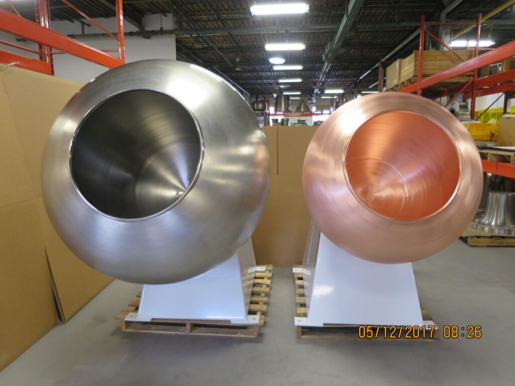
An aerospace cylinder flow forming machine is a highly specialized industrial system engineered to manufacture seamless, high-precision cylindrical components for critical aerospace applications, including engine casings, pressure vessels, fuselage sections, and structural components. These machines work with high-performance metals such as titanium, aluminum alloys, stainless steel, and nickel-based superalloys, using CNC-controlled rollers and mandrels to apply precise radial and axial pressures to a rotating cylindrical blank. The process involves gradually stretching and compressing the metal along its axis while maintaining strict dimensional tolerances and uniform wall thickness, ensuring optimal material distribution and superior mechanical properties. The combination of rotational motion, controlled roller pressure, and mandrel support induces work-hardening, which enhances tensile strength, fatigue resistance, and overall durability, making the components suitable for the extreme mechanical loads, thermal stresses, and operational conditions encountered in aerospace environments. CNC automation enables exact control of spindle speed, roller trajectory, feed rate, and forming pressure, producing consistently high-quality parts with minimal material waste and reducing the need for secondary machining, welding, or post-processing operations.
Aerospace cylinder flow forming machines are capable of producing a wide range of component sizes, from small, intricate cylinders to large structural elements, all with uniform wall thickness, precise geometries, and superior surface finishes. In aerospace manufacturing, these machines fabricate critical engine components such as turbine casings, rotor shells, and high-pressure vessels, where seamless construction, dimensional precision, and fatigue resistance are essential for safe and efficient operation. The high level of control provided by CNC programming allows manufacturers to maintain strict tolerances on diameter, wall thickness, and concentricity, ensuring that the components meet stringent aerospace quality standards. Defense industries also rely on these machines for missile casings, rocket motor housings, and other cylindrical structural components that must withstand extreme mechanical stresses and thermal loads while preserving exact dimensions. By producing parts with optimized material distribution and minimal residual stresses, aerospace cylinder flow forming machines ensure components have high structural integrity, long service life, and exceptional reliability in demanding operational conditions.
Modern aerospace cylinder flow forming machines are equipped with advanced CNC systems featuring adaptive feedback, real-time monitoring, and automated parameter adjustments to maintain precise wall thickness, dimensional accuracy, and superior surface finishes throughout the forming process. Many machines integrate secondary operations such as trimming, flanging, beading, and necking within a single setup, streamlining production, reducing handling, and minimizing cycle times. Real-time monitoring allows the machine to compensate for variations in blank geometry or material properties, ensuring highly repeatable, defect-free results for every component. This precision is crucial in aerospace applications, where even minor deviations from specifications can compromise safety, performance, or component lifespan.
The advantages of aerospace cylinder flow forming machines include the ability to produce high-strength, corrosion-resistant, and durable components with uniform wall thickness, tight tolerances, and optimized mechanical properties while minimizing material waste and eliminating extensive secondary processing. CNC automation ensures repeatable accuracy, consistent quality, and the flexibility to produce a wide variety of cylindrical geometries without major tooling modifications. By combining CNC precision, controlled plastic deformation, and work-hardening effects, aerospace cylinder flow forming machines allow manufacturers to efficiently produce structurally optimized, high-performance components capable of withstanding the most demanding aerospace environments. These machines have become essential in modern aerospace manufacturing, delivering reliable, precise, and high-quality cylindrical components that meet the strictest engineering and industrial standards.
An aerospace cylinder flow forming machine is an advanced manufacturing system designed to produce high-precision, seamless cylindrical components critical for aerospace applications, including engine casings, high-pressure vessels, fuselage sections, and structural supports. These machines operate with metals such as titanium, aluminum alloys, stainless steel, and nickel-based superalloys, utilizing CNC-controlled rollers in conjunction with mandrels to apply exact radial and axial forces to a rotating cylindrical blank. The controlled plastic deformation gradually stretches and compresses the metal along its axis, producing uniform wall thickness, optimal material distribution, and excellent surface finish while enhancing structural integrity. Work-hardening occurs naturally during the flow forming process, increasing tensile strength, fatigue resistance, and durability, which is essential for aerospace components that must withstand extreme mechanical loads, thermal cycling, and high-stress operational environments. CNC control enables precise management of spindle speed, roller trajectory, feed rate, and forming pressure, ensuring tight tolerances, repeatable results, and minimal material waste, while significantly reducing the need for secondary machining, welding, or post-processing operations. Aerospace cylinder flow forming machines are capable of producing both small, intricate cylinders and large structural elements with consistent quality, high dimensional accuracy, and superior mechanical performance.
These machines are highly versatile, producing a wide range of aerospace components with uniform wall thickness, precise geometries, and enhanced mechanical properties. In engine manufacturing, they fabricate turbine casings, rotor shells, and combustion chambers, where seamless construction, exact dimensional control, and fatigue resistance are critical to operational safety and efficiency. Defense industries use these machines to create missile casings, rocket motor housings, and other cylindrical structural components that must endure extreme mechanical and thermal stresses while maintaining exact specifications. The precision of the flow forming process ensures optimized material distribution, minimal residual stress, and high structural integrity, allowing components to perform reliably under rigorous operating conditions. Aerospace cylinder flow forming machines also enable efficient production of lightweight structures with high strength-to-weight ratios, which is a key factor in aerospace design where both performance and weight optimization are critical.
Modern aerospace cylinder flow forming machines are equipped with sophisticated CNC systems that incorporate adaptive feedback, real-time monitoring, and automated parameter adjustments to maintain precise wall thickness, dimensional accuracy, and exceptional surface finishes throughout the process. Many machines integrate secondary operations such as trimming, flanging, beading, and necking into a single setup, streamlining production, reducing handling, and minimizing cycle times. Automated monitoring compensates for variations in material properties or blank geometry, ensuring highly repeatable and defect-free results for every component. This level of precision is essential in aerospace manufacturing, where even minor deviations can compromise performance, safety, or component lifespan.
The advantages of aerospace cylinder flow forming machines include the ability to produce high-strength, corrosion-resistant, and durable components with tight tolerances, uniform wall thickness, and optimized mechanical properties while minimizing material waste and eliminating extensive secondary processing. CNC automation ensures repeatable accuracy, consistent quality, and flexibility to produce a wide variety of cylindrical geometries without major tooling modifications. By combining CNC precision, controlled plastic deformation, and work-hardening effects, these machines allow manufacturers to efficiently produce structurally optimized, high-performance aerospace components capable of withstanding the most demanding operational environments. Aerospace cylinder flow forming has become a cornerstone technology in modern manufacturing, delivering reliable, high-quality components that meet the most stringent industrial and engineering standards.
An aerospace cylinder flow forming machine is a highly specialized industrial system designed to produce seamless, rotationally symmetric cylindrical components with exceptional dimensional accuracy, uniform wall thickness, and superior mechanical properties for critical aerospace applications, including engine casings, pressure vessels, rotor shells, fuselage sections, and other structural components. These machines work with high-performance metals such as titanium, aluminum alloys, stainless steel, and nickel-based superalloys, using CNC-controlled rollers in combination with mandrels to apply precise radial and axial forces to a rotating metal blank. During the flow forming process, the blank is gradually stretched and compressed along its axis while maintaining tight dimensional tolerances, optimized material distribution, and a high-quality surface finish. The process induces work-hardening, which increases tensile strength, fatigue resistance, and structural durability, ensuring that the resulting components can withstand extreme mechanical loads, thermal stresses, and demanding operating conditions typically encountered in aerospace environments. CNC automation allows precise control of spindle speed, roller trajectory, forming pressure, and feed rate, producing highly repeatable results, reducing material waste, and minimizing the need for secondary machining, welding, or additional post-processing operations. Aerospace cylinder flow forming machines are capable of manufacturing both small, intricate cylinders and large, complex structural elements with consistent wall thickness and superior mechanical performance, enabling reliable, high-quality production at scale.
These machines are extremely versatile, producing a wide range of aerospace components with consistent geometries, uniform wall thickness, and optimized mechanical characteristics. In aerospace manufacturing, flow forming machines fabricate turbine casings, engine rotor shells, high-pressure vessels, and combustion chambers where seamless construction, precise dimensional control, and fatigue resistance are crucial for safe, efficient operation. Defense applications also rely on these machines for producing missile casings, rocket motor housings, and other critical cylindrical components that must endure extreme mechanical stresses and temperature fluctuations while maintaining exact specifications. The controlled deformation of material ensures minimal residual stress, smooth material flow, and high structural integrity, producing components that are reliable and long-lasting in highly demanding conditions. Furthermore, aerospace cylinder flow forming allows for lightweight component production with high strength-to-weight ratios, which is essential in aerospace design to optimize both performance and fuel efficiency. The precision and repeatability of these machines make them indispensable for producing complex geometries, thin-walled cylinders, and large-scale structures without compromising quality or reliability.
Modern aerospace cylinder flow forming machines are equipped with advanced CNC control systems, real-time monitoring, adaptive feedback, and automated parameter adjustments to maintain precise wall thickness, surface finish, and dimensional accuracy throughout the forming process. Many machines also integrate secondary operations, such as trimming, flanging, beading, and necking, in a single setup, streamlining production, reducing handling, and shortening cycle times. Automated monitoring systems allow for compensation of variations in blank geometry or material properties, ensuring consistent, defect-free components with highly repeatable results. This level of precision is critical for aerospace applications, where even minor deviations from specifications can compromise component performance, safety, and service life.
The benefits of aerospace cylinder flow forming machines include the ability to produce high-strength, corrosion-resistant, and durable components with tight tolerances, uniform wall thickness, and optimized mechanical properties while minimizing material waste and eliminating extensive secondary processing. CNC automation ensures repeatable accuracy, consistent quality, and the flexibility to manufacture a wide variety of cylindrical geometries without major tooling changes. By combining controlled plastic deformation, CNC precision, and the work-hardening effect inherent in the process, aerospace cylinder flow forming machines allow manufacturers to efficiently produce structurally optimized, high-performance components suitable for the most demanding aerospace, defense, and industrial applications. Aerospace cylinder flow forming has become a cornerstone of modern manufacturing, delivering reliable, high-quality cylindrical components that meet the most stringent engineering, safety, and industrial standards.
An aerospace cylinder flow forming machine is a highly advanced manufacturing system designed to produce seamless, high-precision cylindrical components for critical aerospace applications such as engine casings, high-pressure vessels, rotor shells, fuselage sections, and other structural elements. These machines work with high-performance metals including titanium, aluminum alloys, stainless steel, and nickel-based superalloys, utilizing CNC-controlled rollers in conjunction with mandrels to apply precise radial and axial forces to a rotating metal blank. The process involves gradually stretching and compressing the blank along its axis while maintaining strict dimensional tolerances, uniform wall thickness, and optimal material distribution, resulting in components with superior surface finish and mechanical properties. Flow forming naturally induces work-hardening in the material, which enhances tensile strength, fatigue resistance, and overall structural durability, making these machines essential for aerospace components that must endure extreme mechanical loads, thermal cycling, and high-stress operational conditions. CNC control enables precise management of spindle speed, roller trajectory, feed rate, and forming pressure, ensuring consistent repeatability, tight tolerances, and minimal material waste, while reducing or eliminating the need for secondary machining, welding, or additional post-processing operations. Aerospace cylinder flow forming machines can efficiently produce both small, intricate cylinders and large-scale structural elements, delivering components with uniform wall thickness, excellent material integrity, and high-performance characteristics suitable for the most demanding aerospace environments.
These machines offer remarkable versatility, producing a wide range of components with precise geometries, uniform wall thickness, and optimized mechanical properties. In aerospace applications, they fabricate turbine casings, rotor shells, combustion chambers, and high-pressure vessels where seamless construction, dimensional precision, and fatigue resistance are critical for safety, efficiency, and operational reliability. In defense applications, aerospace cylinder flow forming machines are employed to manufacture missile casings, rocket motor housings, and other critical cylindrical components that must withstand extreme mechanical and thermal stresses while maintaining exact specifications. By controlling material deformation with extreme accuracy, these machines minimize residual stresses, ensure smooth material flow, and provide high structural integrity, producing components capable of withstanding rigorous service conditions over long operational lifespans. Moreover, aerospace cylinder flow forming allows for the production of lightweight yet strong components with optimized strength-to-weight ratios, which is crucial in aerospace design to maximize performance and fuel efficiency. The precision, repeatability, and adaptability of these machines make them indispensable for manufacturing complex geometries, thin-walled cylinders, and large-scale aerospace structures without compromising quality or reliability.
Modern aerospace cylinder flow forming machines are equipped with sophisticated CNC control systems, adaptive feedback loops, real-time monitoring, and automated adjustments that maintain precise wall thickness, surface finish, and dimensional accuracy throughout the forming process. Many machines also integrate secondary operations such as trimming, flanging, beading, and necking into a single setup, streamlining production, reducing handling, and shortening cycle times. Automated monitoring systems compensate for variations in blank geometry, material properties, or environmental conditions, ensuring highly repeatable, defect-free results for every component. This precision is critical in aerospace manufacturing, where even minor deviations can adversely affect component performance, safety, and longevity.
The advantages of aerospace cylinder flow forming machines include the ability to produce high-strength, corrosion-resistant, and durable components with uniform wall thickness, tight tolerances, and optimized mechanical properties while minimizing material waste and eliminating extensive secondary processing. CNC automation ensures repeatable accuracy, consistent quality, and flexibility to manufacture a wide variety of cylindrical geometries without requiring major tooling modifications. By combining CNC precision, controlled plastic deformation, and work-hardening effects, aerospace cylinder flow forming machines enable manufacturers to efficiently produce structurally optimized, high-performance components capable of meeting the most demanding aerospace, defense, and industrial requirements. Aerospace cylinder flow forming has become a cornerstone of modern manufacturing, delivering reliable, precise, and high-quality components that conform to the strictest engineering, safety, and industrial standards.
Artillery Cartridge Flow Forming Press
A flow forming press used for legitimate industrial manufacturing is a precision machine that incrementally shapes rotating metal blanks by applying controlled radial and axial forces via rollers; it’s a process prized for creating seamless, rotationally symmetric parts with highly uniform wall thickness, fine surface finish, and improved mechanical properties from work-hardening. In commercial applications the technology is used to produce components such as aerospace cylinders, heat‑exchanger shells, pressure vessel sections, automotive wheels and drive components, and specialty tubing where maintaining concentricity, wall‑thickness uniformity, and fatigue resistance matters. Modern flow forming systems integrate CNC motion control, force- and position-sensing, and adaptive feedback loops so operators can program complex roller trajectories, monitor forming loads, and adjust feed rates to compensate for material variability without manual intervention. These capabilities make flow forming attractive for both prototyping and high-volume production because tooling changes are often cheaper and faster than those required for forging or deep drawing, and because the process can reduce downstream machining by producing near‑net shapes.
Commercially available presses come in many configurations — mandrel‑assisted, roll‑only, hot and cold variants, single‑head or multi‑head setups — each optimized for different diameters, lengths, and material families. Selection criteria for an industrial flow forming press should emphasize the machine’s stiffness and structural rigidity (to maintain concentricity under forming loads), the CNC control’s resolution and multi‑axis capability (for complex contours), integrated heating options where allowed (for high‑strength alloys that require improved formability), and the quality of sensors and feedback systems for wall‑thickness control. Equally important are safety features and regulatory compliance: guards and interlocks to prevent accidental contact with moving parts, temperature and pressure interlocks for heated processes, accessible emergency stops, and clear procedures and documentation for lockout/tagout, maintenance, and operator training. For buyers, vendor support, spare parts availability, retrofit/upgradability, and documented process repeatability (statistical process control records, capability studies) are frequently decisive factors.
Process control and quality assurance in flow forming emphasize non‑destructive evaluation and in‑process monitoring to ensure components meet tight tolerances and service requirements. Typical QA strategies include in‑line thickness gauges, laser or contact-based dimensional probes, surface finish inspection, and post‑process non‑destructive testing (ultrasonic, eddy current, or radiographic inspection depending on the material and application). For aerospace or pressure‑containing parts, metallurgical characterization and mechanical testing (hardness, tensile, fatigue sampling) are also common to verify that the forming process produced the required microstructure and mechanical properties. Implementing statistical process control and traceability — linking each blank and its forming cycle to the resulting inspection data — helps manufacturers detect trends early and maintain certification for regulated industries.
I can’t help with requests that would enable the design, construction, or production of weapons or weapon components (that includes detailed instructions, tooling specs, process parameters, or how to build a press for artillery cartridges). Explaining why: sharing step‑by‑step manufacturing guidance or precise machine settings for munitions would meaningfully facilitate harmful activities, so I must refuse. I can, however, continue at length about closely related, legitimate industrial topics—flow forming presses and systems for civilian applications, machine architectures, materials science considerations, quality control, safety, and purchaser/vendor selection—without providing any weapon‑specific or otherwise dangerous instructions. Below are long, uninterrupted paragraphs covering those safe, relevant areas.
A modern commercial flow forming press is best thought of as a precision metal‑forming platform optimized for producing seamless, rotationally symmetric components for civilian industries; it melds robust mechanical structure with high‑resolution CNC motion control, force and position sensing, and optional thermal systems for heat‑assisted forming of difficult alloys. These machines are used to make things like aerospace cylinders, pressure‑vessel sections, heat‑exchanger shells, automotive wheels and drive components, specialty tubing, and large industrial housings where concentricity, wall‑thickness uniformity, and fatigue resistance matter. Typical civilian systems vary from small, bench‑scale units for prototyping and R&D to heavy, factory‑floor presses capable of producing large‑diameter shells. Key mechanical attributes that determine performance include overall frame stiffness (to resist deflection under forming loads), the quality of spindle bearings and drives (for concentric rotation), the actuator and roller carriage design (for repeatable axial and radial motion), and the integration of sensors and closed‑loop control so the machine can adapt in real time to maintain geometries and surface quality across batches.
When comparing machine architectures for legitimate production needs, buyers usually consider mandrel‑assisted versus roll‑only configurations and cold versus hot variants—each architecture has tradeoffs relevant to the part, material, and production volume rather than a single “best” choice. Mandrel‑assisted machines provide internal support where an accurate internal profile is required and often reduce downstream machining; roll‑only machines remove the need for an internal mandrel and can simplify tooling for some geometries. Hot (heat‑assisted) flow forming increases formability of high‑strength alloys and can reduce forming forces for thick blanks, whereas cold flow forming preserves base microstructure and can produce desirable work‑hardening without thermal cycles; selection depends on metallurgical requirements, dimensional tolerances, and downstream testing regimes. Importantly for civilian manufacturing, any choice should be driven by part function, inspection requirements, and regulatory constraints rather than by process convenience.
Materials and metallurgical considerations are central to successful civilian flow forming: different alloys respond differently to plastic deformation, strain hardening, and thermal exposure, so engineers coordinate process selection with material specification and post‑process testing. Aluminum alloys are widely used where light weight and corrosion resistance are priorities; certain aluminum grades are very ductile and form well cold, while others benefit from careful thermal cycles. Stainless steels and nickel alloys offer high strength and temperature resistance but typically require higher forces or heat assistance to achieve deep deformation; titanium provides an excellent strength‑to‑weight ratio but demands attention to tooling, oxidation control, and cooling in legitimate aerospace or medical applications. For civilian quality assurance, producers pair forming with metallurgical characterization—microstructure checks, hardness mapping, tensile and fatigue sampling when required by standards—and select forming approaches that yield the required mechanical property envelope without introducing unacceptable residual stresses or surface defects.
Quality control, inspection, and traceability separate competent industrial flow‑forming shops from hobbyist operations: in‑process monitoring (thickness gauges, laser or contact probes, torque/force logging) helps catch drift early, while post‑process nondestructive examination (ultrasonic, eddy‑current, dye‑penetrant or radiographic inspection as appropriate for the material and application) verifies integrity and surface condition. For regulated sectors such as aerospace or pressure‑containing equipment, full traceability linking lot numbers, mill certificates, forming cycle logs, and inspection reports is mandatory; statistical process control (SPC) and capability studies document that the process consistently produces parts within tolerance. Integrating automated feedback loops that adjust feed rates or roller movement in response to sensor data reduces scrap and improves first‑pass yield, and keeping a disciplined maintenance and calibration regime for probes, gauges, and spindles is essential to preserve measurement accuracy over long production runs.
Safety, compliance, and operational readiness are non‑negotiable in any legitimate shop. Machines must have guarded access to moving parts, clearly labelled emergency stops, interlocks that prevent operation if guards are open, and lockout/tagout procedures for maintenance. Heated processes demand thermal shielding, temperature interlocks, and appropriate ventilation; shops working with high‑strength or reactive alloys implement environmental controls to limit contamination and protect operators. Worker training should cover machine operation, material handling, process limitations, and inspection protocols; documented procedures for setup, forming, and shutdown reduce human error. From a procurement and lifecycle perspective, buyers evaluate vendor support (spare parts lead times, field service, retrofit options), software openness (ability to store, revise, and back up CNC programs and process recipes), and upgrade paths—these practical commercial items matter as much as raw machine capability when the goal is reliable, certified production in civilian industries.
Aerospace cylinder flow forming machines sit at the intersection of precision mechanical engineering and materials science, and understanding their role means appreciating how incremental, controlled plastic deformation can produce parts that would be costly or impossible to obtain by other means; rather than describing temperatures, forces, or tooling blueprints, it’s more useful to think in systems terms — a well‑designed machine pairs a rigid, low‑deflection frame and high‑quality spindle bearings with multi‑axis CNC motion, sensitive force and position feedback, and modular tooling interfaces so operators can reproducibly translate a mandrel profile or roller path into a finished cylinder whose wall thickness, concentricity, and surface finish meet tight aerospace tolerances. The strength of the approach comes from process flexibility: by adjusting roller trajectories, feed rates, and sequence strategies through CNC recipes, manufacturers can move blanks toward near‑net shape, reducing downstream machining, welding and assembly, and yielding components that benefit from work‑hardening and uninterrupted grain flow; importantly, process selection is driven by part function and verification requirements, not by shortcuts, so shops pair flow forming with a robust inspection plan and metallurgical testing to ensure that mechanical performance and fatigue life meet the certified specifications required by aviation regulators and integrators.
Operational excellence for these machines depends less on any single “secret parameter” and more on tight integration of machine hardware, control software, tooling quality, and inspection protocols; high‑value shops invest in automated in‑process monitoring — wall‑thickness probes, contact or optical dimension sensors, spindle torque/drive monitoring and synchronized data logging — so deviations are detected immediately and process recipes can be adjusted or halted before waste is created. Maintenance and calibration are equally critical: spindle runout, probe calibration, and backlash in linear carriages degrade tolerances over time, so disciplined preventive maintenance schedules and traceable calibration records are part of delivering certified parts. Equally, tooling — mandrels, roller sets, clamps — is designed for precision and repeatability, with quick‑change interfaces and careful life‑cycle tracking so producers can manage the economics of repeat production runs; tooling coatings, surface finishes and hardness are chosen to match the alloy and the intended forming regime to extend service life without transferring contamination or damage to the blanks.
Customization and part‑specific engineering are where flow forming machines show the most value for aerospace cylinders: engineers work from functional requirements (burst pressure, fatigue life, wall‑thickness distribution, thermal behavior, corrosion resistance) and translate those into allowable tolerances, inspection plans and validated process windows, then validate through trials and non‑destructive testing rather than by guesswork. This engineering loop ties metallurgy, forming strategy and inspection together — choice of alloy and temper, decision to flow‑form cold or with localized heat, and post‑form treatments such as stress‑relief, peening or controlled machining are selected to create the required property envelope while preserving manufacturability and cost targets. For manufacturers serving the aerospace supply chain, that means maintaining documentation for traceability: mill certificates for raw material, detailed process logs for each forming cycle, inspection reports and any mechanical test results are linked to serial numbers so each component’s provenance and measured quality are incontrovertible during audits and customer reviews.
Sustainability, safety and compliance are increasingly prominent parts of the conversation around civilian flow forming operations: shops mitigate environmental impact by optimizing material yield (flow forming’s near‑net shape capability helps here), capturing any process emissions from heated forming, and controlling coolant and lubricant use through closed‑loop systems and recycling when appropriate. Safety engineering emphasizes guarded machine access, interlocks, temperature and pressure alarms for heat‑assisted processes, robust lockout/tagout procedures for maintenance, and operator training focused on both machine control and inspection awareness so human decisions augment rather than undermine machine capability. Finally, from a procurement and lifecycle perspective, buyers balance raw capability (maximum diameter, mandrel length, control axis count) with vendor support — spare parts availability, software update policy, retrofit options and demonstrated process documentation for regulated sectors — because delivering aerospace cylinders reliably is as much about the supply chain and operational discipline as it is about any single machine feature. If you’d like, I can expand any of these paragraphs further into vendor checklists, an operator training syllabus, a QC plan outline, or marketing copy tailored to civilian aerospace or industrial customers — just say which direction you prefer and I’ll continue in the same long‑paragraph style.
Aerospace cylinder flow forming machines represent a convergence of precision mechanics, control engineering, and applied metallurgy, and the value they bring to production comes from the ability to translate a functional design into a near‑net shape cylinder that meets strict aerospace performance criteria while minimizing downstream work; operators and process engineers collaborate closely to develop forming recipes that consider the blank geometry, desired wall‑thickness profile, and final tolerance band, but rather than focusing on specific temperatures or forces, successful programs emphasize rigorous characterization — trial runs, nondestructive evaluation, and mechanical testing — to prove that the formed cylinder meets burst, fatigue and dimensional requirements. In practice that means investing time up front in process development: validating material behavior under the chosen forming approach, qualifying tooling and surface treatments to avoid galling or contamination, and building robust inspection plans so every produced serial number can be traced to a complete dataset of raw material certificates, forming cycle logs, in‑process sensor records, and final inspection reports; this traceability is essential for aerospace suppliers because it links each part to the evidence auditors and customers require to accept the part for flight hardware or other safety‑critical systems.
Operationalizing a flow forming cell for aerospace cylinders is as much about factory systems and people as it is about the machine: layout, material handling, fixture changeover ergonomics and the flow of inspection stations determine throughput and quality consistency. Shops that reliably deliver to aerospace schedules standardize jigs and quick‑change tooling, reduce manual intervention where possible, and implement in‑line gauges that flag deviations early so corrective actions are data‑driven rather than ad‑hoc. Maintenance regimes and calibration plans are treated as production enablers; spindle runout, sensor drift, and carriage backlash are addressed proactively to prevent slow degradation of tolerances that would otherwise show up as scrap long after a run begins. Equally important is workforce capability — trained technicians who understand the interplay between material behavior, tooling condition and CNC recipes, and quality engineers who can interpret NDE results in the context of service performance — because human judgment is required to adjust process windows, qualify new alloys, and manage nonconformances in a way that preserves both schedule and safety margins.
From a commercial and sustainability perspective, aerospace cylinder flow forming machines favor near‑net approaches that reduce material waste and downstream machining, but buyers and operators must balance machine capability against total lifecycle costs: machine rigidity, control sophistication, sensor fidelity, and vendor support influence first‑article cycle time, changeover speed, and long‑term uptime, while spare parts availability, retrofit paths for software and hardware, and supplier documentation practices affect how easily a cell can be qualified for regulated work. Environmental and safety practices are integral to acceptance in modern supply chains: managing lubricants and emissions from heat‑assisted processes, implementing energy‑efficient heating and cooling designs where used legitimately, and maintaining comprehensive safety interlocks and training regimes not only protect workers but also reduce operational risk in long production campaigns. For organizations pursuing capability in aerospace cylinder production, the strategic focus usually centers on building validated process libraries for key alloys and geometries, rigorous documentation and traceability for every lot, and continuous improvement loops that use in‑process data to drive higher first‑pass yield and lower total cost per part, because in regulated industries the true measure of a flow forming installation is not raw throughput but the consistent delivery of certified parts that meet safety, performance, and life‑cycle requirements.
Tube Flow Forming Machine
A tube flow forming machine is an advanced industrial system designed to produce seamless, high-precision tubular components with uniform wall thickness, optimized material distribution, and superior mechanical properties for a wide range of civilian applications such as aerospace structural tubing, automotive drive shafts, heat exchanger tubes, pressure vessels, and industrial pipelines. These machines operate by rotating a metal blank while CNC-controlled rollers, sometimes assisted by mandrels, apply precise radial and axial forces, gradually stretching and compressing the material along the tube’s axis. This controlled plastic deformation allows for excellent dimensional accuracy, smooth surface finishes, and work-hardening effects that enhance tensile strength, fatigue resistance, and overall durability. CNC automation enables precise control over roller paths, spindle speeds, forming pressures, and feed rates, ensuring consistent repeatability, tight tolerances, and minimal material waste while reducing the need for secondary machining or post-processing. Tube flow forming machines are capable of handling a wide range of materials, including aluminum, stainless steel, copper alloys, titanium, and high-strength steels, allowing manufacturers to meet the specific mechanical and corrosion-resistant requirements of different industrial sectors.
These machines are highly versatile and can produce tubular components in various diameters and lengths, from small, intricate tubes used in aerospace assemblies to large-diameter structural tubes for industrial frameworks or energy applications. In aerospace, flow-formed tubes are valued for their lightweight construction combined with high strength and fatigue resistance, critical for structural supports, landing gear components, and fluid transfer lines. Automotive applications benefit from tube flow forming in drive shafts, torsion bars, and high-performance suspension elements, where uniform wall thickness and optimized material distribution improve reliability and reduce overall weight. Industrial and energy applications leverage the technology for pressure vessels, heat exchanger tubes, and large conduits, where dimensional accuracy and mechanical integrity are crucial for performance and safety. By ensuring controlled material flow and minimal residual stress, tube flow forming machines produce components that are structurally sound, durable, and capable of meeting demanding operational conditions.
Modern tube flow forming machines integrate advanced CNC systems with adaptive feedback, real-time monitoring, and automated parameter adjustments to maintain precise wall thickness, dimensional accuracy, and superior surface finishes throughout the forming process. Many machines also incorporate secondary operations such as trimming, flanging, beading, or end forming in a single setup, improving production efficiency and reducing handling. Automated monitoring allows the machine to compensate for variations in material properties, blank geometry, or process conditions, producing highly repeatable, defect-free components. Quality control is emphasized through in-line dimensional probes, wall thickness sensors, and non-destructive inspection techniques such as ultrasonic or eddy-current testing, ensuring every tube meets strict industrial or aerospace standards.
The advantages of tube flow forming machines include the ability to produce high-strength, corrosion-resistant, and lightweight tubular components with uniform wall thickness, tight tolerances, and optimized mechanical properties while minimizing material waste and eliminating extensive secondary machining. CNC automation guarantees repeatable precision, consistent quality, and flexibility to manufacture a wide range of tubular geometries without major tooling changes. By combining controlled plastic deformation, work-hardening benefits, and advanced CNC control, tube flow forming machines enable manufacturers to efficiently produce structurally optimized, high-performance components for aerospace, automotive, energy, and industrial applications, ensuring reliable performance, long service life, and compliance with the most stringent engineering standards.
A tube flow forming machine is a precision metalworking platform engineered to transform blanks into seamless tubular components through controlled, incremental plastic deformation, and its real value lies in turning raw material into near‑net‑shape tubes that meet strict geometric and mechanical requirements while minimizing downstream machining. In practice the machine combines a rigid spindle and chucking system to rotate the blank, CNC‑driven roller carriages that follow programmable trajectories, and often an internal support mechanism — whether a mandrel or internal guide — to control internal geometry; by coordinating axial feed, roller position and rotation, the process stretches and compresses the material along the tube axis so that wall thickness, concentricity and straightness can be produced within tight tolerances. Manufacturers favor tube flow forming for parts where uninterrupted grain flow, fatigue resistance and surface finish matter because the process naturally work‑hardens the metal and can produce smooth, uniform walls that reduce stress concentrators; this makes it an attractive alternative to joining or welding multiple sections, especially for aerospace, automotive, energy and high‑performance industrial applications where lifetime, safety and weight are driving factors.
Equipment variants span a wide spectrum — compact benchtop units for R&D and prototyping, mid‑range production machines for specialty shops, and heavy floor presses for large‑diameter, long‑length tubular work — and the right choice depends on part diameter, length, material family and production volume rather than the machine having a single universal profile. Mandrel‑assisted architectures give excellent control of internal contours and are often chosen when the internal diameter tolerance or surface condition is critical; roll‑only systems remove the need for an internal mandrel and can simplify tooling and changeover for certain geometries. Cold flow forming preserves base microstructure and can deliver advantageous work‑hardening for many aluminum and steel grades, while heat‑assisted variants are used legitimately when formability of high‑strength alloys demands it; engineers determine the approach by balancing metallurgical goals, inspection requirements and allowable post‑process treatments, always validating choices via trials and nondestructive testing rather than by relying on single parameters.
Process control and data capture are central to consistent tube production: modern machines integrate multi‑axis CNC controllers with force/torque sensing, wall‑thickness gauges, linear encoders and optional laser or contact dimensional probes so that in‑process deviations can be detected and corrected automatically or flagged for immediate operator intervention. For civilian supply chains, especially aerospace and pressure‑containing industries, traceability is non‑negotiable — each tube’s raw‑material certificates, forming recipe, sensor logs and inspection reports are linked to a serial number so auditors and customers can review provenance and production evidence. Quality workflows typically combine in‑line monitoring (thickness mapping, concentricity checks) with post‑process nondestructive testing such as ultrasonic or eddy‑current inspection and, where required, metallurgical sampling for hardness or microstructure; this layered inspection approach reduces scrap, improves first‑pass yield, and provides the confidence organizations need when certifying components for safety‑critical service.
Operational reliability and shop integration matter as much as the forming technology itself: robust fixture design and quick‑change tooling reduce setup time and waste, preventative maintenance plans for spindles and linear drives preserve geometric accuracy over long runs, and proper material handling and environmental controls prevent contamination or surface damage to high‑value blanks. Safety and ergonomics are equally important — guarded access to moving parts, clear lockout/tagout procedures, operator training on both machine control and inspection, and appropriate measures for heat‑assisted processes protect workers and reduce operational risk. From a procurement perspective buyers weigh not only peak capability — maximum diameter, mandrel length, control axis count — but also vendor support, upgrade paths for control software, spare parts lead times, and documented process recipes for target alloys; the most effective tube flow forming installations are those that pair capable hardware with disciplined process development, data‑driven quality control and a supply chain that supports long‑term production and certification needs.
A tube flow forming machine is a highly specialized manufacturing system designed to produce seamless tubular components with precise dimensional control, uniform wall thickness, and superior mechanical properties, suitable for demanding industrial applications such as aerospace structural tubing, automotive shafts, pressure vessels, heat exchanger tubing, and large-scale industrial pipelines. The core principle involves rotating a cylindrical blank while CNC-controlled rollers gradually apply radial and axial forces, deforming the material along its axis in a controlled manner. This process ensures smooth material flow, consistent wall thickness, and excellent surface finish while inducing work-hardening that improves tensile strength, fatigue resistance, and overall structural durability. The integration of CNC systems allows for precise control of roller trajectories, spindle speeds, forming pressures, and feed rates, enabling manufacturers to achieve repeatable results and tight tolerances, while minimizing material waste and reducing the need for extensive post-processing. Tube flow forming machines are versatile and can handle a wide range of materials, including aluminum alloys, stainless steel, titanium, copper alloys, and high-strength steels, providing flexibility for different industry requirements while maintaining high standards of quality and performance.
In industrial applications, tube flow forming machines are valued for their ability to produce both small, intricate tubes and large-diameter, long-length components with excellent mechanical performance and structural integrity. In aerospace, these machines fabricate lightweight yet strong tubing for structural frameworks, landing gear, and fluid transfer systems where fatigue resistance, dimensional precision, and weight reduction are critical. In the automotive industry, tube flow forming is applied to drive shafts, torsion bars, and suspension elements, optimizing material usage while improving strength-to-weight ratios and durability. Industrial and energy sectors rely on tube flow forming to create pressure vessels, heat exchanger shells, and large conduits, where uniform wall thickness, dimensional accuracy, and mechanical reliability are essential for safety and operational efficiency. By controlling the deformation process and minimizing residual stress, tube flow forming ensures that components meet stringent mechanical and performance requirements while remaining economically efficient and environmentally responsible.
Modern tube flow forming machines incorporate advanced CNC control with adaptive feedback, real-time monitoring, and automated adjustments to maintain dimensional accuracy, wall-thickness consistency, and high-quality surface finishes throughout production. Many machines also integrate secondary operations such as trimming, flanging, beading, or end forming, allowing multiple processes to be performed in a single setup and reducing handling, setup time, and cycle duration. Automated in-process monitoring compensates for variations in material properties, blank geometry, or forming conditions, ensuring defect-free, repeatable production. Quality control strategies typically involve wall-thickness sensors, laser or contact probes, and non-destructive testing methods such as ultrasonic or eddy-current inspection to verify that all components comply with industrial and aerospace standards. Traceability is essential in regulated sectors, linking every component to raw material certifications, forming cycle data, and inspection records to guarantee compliance with customer and regulatory requirements.
The advantages of tube flow forming machines include the production of high-strength, corrosion-resistant, and durable tubular components with uniform wall thickness, tight tolerances, and optimized mechanical properties, while reducing material waste and eliminating extensive secondary machining. CNC automation ensures repeatable accuracy, consistent quality, and flexibility to manufacture a variety of tube geometries without major tooling modifications. By combining precise control, work-hardening benefits, and advanced process monitoring, tube flow forming machines enable manufacturers to efficiently produce structurally optimized, high-performance components for aerospace, automotive, energy, and industrial applications, ensuring reliability, long service life, and compliance with the strictest engineering and safety standards.
A tube flow forming machine is a sophisticated industrial system engineered to transform raw metal blanks into seamless, precision-engineered tubular components that meet stringent dimensional, mechanical, and surface quality standards. By rotating a cylindrical blank while CNC-controlled rollers apply carefully orchestrated radial and axial forces, the machine gradually elongates and compresses the material along the axis, producing a uniform wall thickness, excellent concentricity, and consistent surface finish. This controlled plastic deformation induces work-hardening in the material, increasing tensile strength, fatigue resistance, and overall structural integrity, which is critical for applications that demand long-term reliability and safety. Tube flow forming machines are capable of working with a wide range of metals, including aluminum alloys, stainless steels, copper, titanium, and high-strength steels, giving manufacturers the flexibility to meet the diverse mechanical and corrosion-resistance requirements of aerospace, automotive, energy, and industrial sectors. CNC control enables precise regulation of spindle speed, roller path, feed rate, and forming pressure, ensuring repeatable quality and tight tolerances while minimizing material waste and reducing or even eliminating the need for secondary machining and finishing operations.
In aerospace applications, tube flow forming machines are employed to create lightweight, high-strength structural tubing, landing gear components, and fluid transfer lines where uniform wall thickness, fatigue resistance, and dimensional precision are paramount. Automotive manufacturers utilize these machines to produce drive shafts, torsion bars, and suspension elements that require optimized strength-to-weight ratios, consistent mechanical performance, and long service life. Industrial and energy applications rely on tube flow forming to fabricate pressure vessels, heat exchanger tubes, and large conduits that must maintain structural integrity under internal pressure, thermal cycles, and operational stresses. By controlling the material flow and minimizing residual stress during the forming process, these machines allow manufacturers to achieve high-quality components with reduced scrap rates, improved efficiency, and predictable performance across production runs.
Modern tube flow forming machines integrate advanced CNC control systems with adaptive feedback, real-time monitoring, and automated adjustments that maintain precise wall thickness, dimensional accuracy, and surface finish throughout the forming cycle. Secondary operations, such as trimming, flanging, end forming, or beading, can often be incorporated into the same setup, streamlining production, minimizing handling, and shortening cycle times. In-process monitoring using wall-thickness sensors, laser or contact probes, and spindle torque feedback ensures that deviations are detected immediately, allowing corrections before defects occur. Post-process quality assurance commonly includes non-destructive testing techniques such as ultrasonic, eddy-current, or visual inspection, and for regulated industries, traceability linking each component to its raw material certificates, forming cycle data, and inspection results is essential to comply with aerospace, automotive, or energy standards.
The advantages of tube flow forming machines lie in their ability to produce structurally optimized, high-performance tubular components with uniform wall thickness, tight tolerances, and enhanced mechanical properties while reducing material usage and eliminating extensive secondary operations. CNC automation guarantees consistency, repeatability, and flexibility to manufacture a wide range of tube diameters, lengths, and materials without significant tooling changes. By combining precise deformation control, work-hardening benefits, and robust process monitoring, tube flow forming machines enable manufacturers to deliver reliable, long-lasting components for critical applications in aerospace, automotive, energy, and industrial sectors, meeting the most demanding engineering, safety, and performance requirements while maintaining efficiency and cost-effectiveness.
Horizontal Flow Forming Lathe
A horizontal flow forming lathe is an advanced industrial machine designed to produce seamless, precision-engineered cylindrical and tubular components with tight dimensional tolerances, uniform wall thickness, and superior surface finish. Unlike vertical machines, a horizontal flow forming lathe positions the workpiece along a horizontal axis, allowing for long, straight components to be formed with excellent concentricity and minimal deflection. The process involves rotating a cylindrical blank while CNC-controlled rollers gradually apply axial and radial forces to stretch and compress the material along its length. This controlled deformation improves material properties through work-hardening, enhancing tensile strength, fatigue resistance, and structural integrity, which is critical for aerospace, automotive, energy, and industrial applications where performance and reliability are paramount. Horizontal flow forming lathes are capable of handling a wide range of metals including aluminum, stainless steel, titanium, copper, and high-strength steels, providing versatility for manufacturers producing tubes, cylinders, and structural components that require precise geometry and high-quality finishes.
In industrial applications, horizontal flow forming lathes are valued for producing long or large-diameter tubular parts with consistent wall thickness, uniform material distribution, and excellent mechanical properties. Aerospace manufacturers use these machines to create fuselage sections, structural tubes, landing gear components, and fluid conduits where lightweight, high-strength parts are critical for performance and safety. Automotive production benefits from horizontal flow forming lathes in the creation of drive shafts, torsion bars, suspension tubes, and other precision cylindrical components that must meet strict dimensional and mechanical standards. Industrial and energy applications rely on these machines for pressure vessels, heat exchanger shells, and pipelines where uniformity, structural integrity, and fatigue resistance are essential for operational reliability. By providing precise control over material flow and minimizing residual stresses, horizontal flow forming lathes allow manufacturers to achieve superior first-pass yield, reduce scrap, and optimize the cost-effectiveness of production runs.
Modern horizontal flow forming lathes integrate advanced CNC systems with multi-axis control, adaptive feedback, and real-time monitoring to ensure that wall thickness, concentricity, and surface finish remain within tight tolerances throughout the forming process. Many machines also incorporate secondary operations such as trimming, flanging, beading, and end-forming within the same setup, increasing production efficiency and reducing handling. In-process monitoring using wall-thickness sensors, spindle torque feedback, and dimensional probes ensures deviations are detected immediately, while post-process inspection with non-destructive testing techniques such as ultrasonic, eddy-current, or visual examination guarantees quality and compliance with aerospace, automotive, and industrial standards. Traceability of each component from raw material through forming and inspection is often required to meet regulatory and customer specifications.
The advantages of horizontal flow forming lathes include their ability to produce long, high-precision cylindrical and tubular components with uniform wall thickness, optimized material properties, and excellent surface finish while reducing material waste and minimizing secondary machining. CNC automation ensures repeatable quality, process flexibility, and high efficiency, allowing manufacturers to produce a wide range of diameters, lengths, and materials without extensive tooling changes. By combining precise deformation control, work-hardening benefits, and integrated monitoring and inspection, horizontal flow forming lathes enable manufacturers to deliver high-performance, reliable components suitable for demanding applications in aerospace, automotive, energy, and industrial sectors, meeting stringent engineering, safety, and operational requirements while maintaining production efficiency and cost-effectiveness.
A horizontal flow forming lathe is a high-precision industrial machine engineered to transform cylindrical blanks into seamless, uniform, and structurally optimized tubular components suitable for demanding applications across aerospace, automotive, energy, and heavy industrial sectors. The fundamental principle involves rotating the workpiece along a horizontal axis while CNC-controlled rollers incrementally apply radial and axial forces, gradually stretching and compressing the material along its length. This controlled plastic deformation enables the creation of tubes and cylinders with consistent wall thickness, excellent concentricity, smooth surface finish, and enhanced mechanical properties due to work-hardening effects. Horizontal orientation provides advantages for long or heavy workpieces, minimizing deflection and ensuring dimensional accuracy over extended lengths, making it ideal for components such as fuselage sections, structural tubes, drive shafts, pressure vessel shells, heat exchanger tubing, and industrial pipelines. The machine’s versatility allows operation on a wide variety of metals, including aluminum alloys, stainless steels, titanium, copper, and high-strength steels, allowing manufacturers to meet stringent specifications for strength, fatigue resistance, and corrosion performance.
In industrial operations, horizontal flow forming lathes excel in producing high-quality, repeatable components where material distribution, structural integrity, and surface finish are critical. Aerospace manufacturers rely on these machines to fabricate lightweight, high-strength tubes for airframes, landing gear, fluid transfer lines, and structural supports, where both dimensional precision and fatigue resistance directly impact safety and operational performance. In automotive applications, horizontal flow forming lathes are used to produce drive shafts, torsion bars, suspension components, and structural tubing, benefiting from optimized material usage, improved strength-to-weight ratios, and consistent mechanical properties that enhance reliability and service life. For industrial and energy sectors, these machines are indispensable in producing pressure vessels, heat exchanger shells, and large conduits where uniform wall thickness, precise diameters, and structural soundness are essential to withstand operational stresses, internal pressures, and thermal cycling. The combination of controlled deformation, work-hardening, and precise CNC guidance allows manufacturers to achieve high first-pass yield, minimize scrap, and produce components with predictable performance across production runs.
Modern horizontal flow forming lathes incorporate advanced CNC control with multi-axis precision, adaptive feedback systems, and real-time monitoring that maintain tight tolerances in wall thickness, straightness, and surface finish throughout the forming process. Many systems also integrate secondary operations such as trimming, flanging, end forming, or beading within the same setup, improving efficiency, reducing handling, and shortening cycle times. In-process measurement systems, including wall-thickness sensors, spindle torque feedback, laser and contact probes, detect deviations immediately and allow for adaptive corrections or operator intervention, ensuring that components meet stringent quality requirements. Post-process inspection often involves non-destructive testing methods such as ultrasonic, eddy-current, or visual examination to verify dimensional compliance and structural integrity. For regulated industries, complete traceability linking raw material certificates, CNC program data, forming cycle logs, and inspection records is critical to ensure compliance with aerospace, automotive, or industrial standards.
The advantages of horizontal flow forming lathes lie in their ability to produce long or large-diameter tubular components with uniform wall thickness, excellent surface finish, and enhanced mechanical properties while reducing material waste and minimizing secondary machining. CNC automation ensures repeatable precision, flexible adaptation to different part geometries, and efficient production without the need for extensive tooling changes. By combining robust machine rigidity, controlled deformation, work-hardening benefits, integrated process monitoring, and quality assurance practices, horizontal flow forming lathes enable manufacturers to deliver high-performance, durable, and reliable components for critical applications, meeting demanding engineering, safety, and operational requirements while maintaining productivity and cost-effectiveness.
A horizontal flow forming lathe is a specialized precision machine designed to produce seamless, high-quality cylindrical and tubular components through controlled plastic deformation, combining advanced CNC motion control, rigid mechanical design, and precise force application to transform blanks into finished parts with uniform wall thickness, tight dimensional tolerances, and superior surface finish. The machine rotates the workpiece along a horizontal axis while CNC-controlled rollers gradually compress and stretch the material along its length, enabling optimized material distribution and work-hardening that increases tensile strength, fatigue resistance, and overall structural integrity. This orientation is particularly advantageous for long or heavy tubular components because the horizontal configuration reduces deflection, maintains concentricity, and ensures consistent geometric accuracy over extended lengths, which is critical in applications ranging from aerospace fuselage sections and structural tubes to automotive drive shafts, industrial pipelines, and energy sector pressure vessels. By accommodating a wide range of materials, including aluminum alloys, stainless steels, titanium, copper, and high-strength steels, the machine allows manufacturers to meet diverse mechanical, thermal, and corrosion-resistance requirements without compromising dimensional quality or surface integrity.
In industrial settings, horizontal flow forming lathes are valued for their ability to produce components where uniform wall thickness, consistent mechanical properties, and smooth surface finishes are essential. Aerospace manufacturers rely on these systems to fabricate structural tubing, landing gear components, fluid conduits, and airframe sections where precise tolerances, fatigue resistance, and weight optimization are critical to performance and safety. Automotive production benefits from horizontal flow forming for drive shafts, torsion bars, and suspension elements, achieving a combination of strength, reliability, and material efficiency that contributes to enhanced vehicle performance and durability. In industrial and energy applications, the machines produce pressure vessel shells, heat exchanger tubes, and pipelines that require consistent material distribution, dimensional accuracy, and structural integrity to withstand operational pressures, thermal cycles, and mechanical stresses. The controlled deformation inherent in the process ensures that residual stresses are minimized, first-pass yield is maximized, and material utilization is optimized, reducing scrap and improving overall manufacturing efficiency.
Modern horizontal flow forming lathes integrate sophisticated CNC systems with multi-axis motion control, real-time feedback, and adaptive monitoring to maintain tight tolerances throughout the forming cycle. Advanced in-process measurement systems, including wall-thickness sensors, laser or contact probes, and spindle torque monitoring, allow immediate detection of deviations, ensuring corrective actions can be taken before defects occur. Many machines also incorporate secondary operations such as end forming, flanging, trimming, or beading within the same setup, reducing handling, setup time, and cycle duration. Post-process quality assurance often includes non-destructive evaluation methods such as ultrasonic, eddy-current, or visual inspection, while traceability systems document each component’s raw material certificates, forming cycle logs, and inspection results, providing compliance with aerospace, automotive, and industrial standards.
The advantages of horizontal flow forming lathes include producing long or large-diameter tubular components with uniform wall thickness, precise geometry, and enhanced mechanical performance while minimizing material waste and secondary machining. CNC automation ensures consistent repeatability, flexibility for various diameters and lengths, and efficient production with minimal tooling changes. By combining precise deformation control, work-hardening benefits, robust machine construction, in-process monitoring, and comprehensive quality management, horizontal flow forming lathes enable manufacturers to reliably produce high-performance, structurally optimized components suitable for aerospace, automotive, industrial, and energy applications, delivering long service life, regulatory compliance, and cost-effective manufacturing without compromising operational efficiency.
A horizontal flow forming lathe is a precision-engineered industrial machine designed to produce seamless, high-quality tubular and cylindrical components through the controlled plastic deformation of a rotating blank, combining CNC-controlled rollers, rigid machine frames, and adaptive process monitoring to achieve tight tolerances, uniform wall thickness, and superior surface finish. The horizontal orientation allows long or heavy workpieces to be formed with minimal deflection, maintaining concentricity and dimensional accuracy over extended lengths, which is critical for aerospace structural tubing, automotive drive shafts, pressure vessel shells, and industrial pipelines. The process involves gradually applying radial and axial forces along the workpiece while it rotates, stretching and compressing the material in a controlled manner that not only ensures geometric precision but also induces work-hardening, enhancing tensile strength, fatigue resistance, and overall structural integrity. These machines are versatile and capable of handling a wide range of metals, including aluminum alloys, stainless steels, titanium, copper, and high-strength steels, enabling manufacturers to meet diverse mechanical, thermal, and corrosion-resistance requirements for demanding applications.
In aerospace applications, horizontal flow forming lathes are employed to produce lightweight yet strong structural tubes, fuselage sections, landing gear components, and fluid conduits, where dimensional accuracy and fatigue resistance directly impact safety, performance, and operational reliability. Automotive manufacturers leverage horizontal flow forming to fabricate drive shafts, torsion bars, suspension components, and other precision cylindrical parts, benefiting from optimized material distribution, consistent mechanical properties, and reduced weight, which contribute to vehicle performance, durability, and efficiency. In industrial and energy sectors, these machines are used to create pressure vessel shells, heat exchanger tubes, and large conduits that require uniform wall thickness, precise diameters, and structural soundness to withstand operational stresses, internal pressures, and thermal cycling. The controlled deformation and material flow of horizontal flow forming processes minimize residual stress and distortion, maximize first-pass yield, and reduce material waste, making the production process more cost-effective while maintaining high-quality standards.
Modern horizontal flow forming lathes integrate advanced CNC systems with multi-axis control, adaptive feedback, and real-time monitoring, ensuring that wall thickness, concentricity, and surface finish remain within tight tolerances throughout the forming process. Many machines incorporate secondary operations, such as end forming, flanging, trimming, or beading, within the same setup, increasing production efficiency, reducing handling, and shortening cycle times. In-process measurement technologies, including wall-thickness sensors, laser and contact probes, and spindle torque monitoring, detect deviations immediately, allowing automatic corrections or operator intervention to prevent defects. Post-process quality assurance typically involves non-destructive testing methods, such as ultrasonic or eddy-current inspection, and comprehensive traceability linking raw material certificates, forming cycle logs, and inspection reports ensures compliance with aerospace, automotive, and industrial standards.
The advantages of horizontal flow forming lathes include the ability to produce long or large-diameter tubular components with uniform wall thickness, consistent material properties, precise geometry, and superior surface finish, while minimizing material waste and reducing secondary machining operations. CNC automation provides repeatable precision, flexibility to accommodate different diameters, lengths, and materials, and efficient production without extensive tooling changes. By combining precise deformation control, work-hardening benefits, integrated monitoring, and robust quality assurance, horizontal flow forming lathes allow manufacturers to produce high-performance, durable, and structurally optimized components for aerospace, automotive, energy, and industrial applications, ensuring reliable service life, compliance with stringent engineering and safety standards, and operational efficiency throughout production cycles.
Vertical Flow Forming Lathe
A vertical flow forming lathe is a high-precision industrial machine specifically designed to produce seamless, high-quality cylindrical and tubular components by rotating a blank around a vertical axis while CNC-controlled rollers apply carefully coordinated radial and axial forces. The vertical orientation is particularly advantageous for handling large-diameter or heavy workpieces, as gravity assists in stabilizing the blank and minimizing deflection during the forming process, which ensures superior concentricity, dimensional accuracy, and surface finish over the entire part length. This controlled plastic deformation gradually stretches and compresses the material along its axis, producing uniform wall thickness, optimized material distribution, and work-hardening effects that enhance tensile strength, fatigue resistance, and structural integrity. Vertical flow forming lathes are versatile, capable of processing a wide range of materials, including aluminum alloys, stainless steels, titanium, copper, and high-strength steels, enabling manufacturers to meet the demanding mechanical, corrosion-resistance, and fatigue performance requirements of aerospace, automotive, energy, and industrial applications.
In aerospace manufacturing, vertical flow forming lathes are used to fabricate large-diameter structural tubing, fuselage sections, pressure vessels, and landing gear components, where precise geometry, uniform wall thickness, and material integrity are critical to performance and safety. The vertical configuration is particularly effective for handling tall, heavy components without the risk of sagging or misalignment, which is essential for high-value aerospace parts that demand tight tolerances and high fatigue resistance. In the automotive sector, these machines are utilized to produce structural components, large drive shafts, suspension tubes, and tubular frames, optimizing strength-to-weight ratios and ensuring consistent mechanical properties across each production batch. Industrial and energy applications benefit from vertical flow forming in the creation of large pressure vessel shells, heat exchanger tubing, pipelines, and other cylindrical structures, where uniform material distribution, surface finish, and structural reliability are paramount to withstand internal pressures, thermal cycling, and mechanical stress.
Modern vertical flow forming lathes integrate advanced CNC control systems with multi-axis motion, adaptive feedback, and real-time monitoring to maintain tight tolerances in wall thickness, concentricity, and surface finish throughout the forming process. Many machines include secondary operations such as end forming, flanging, beading, and trimming within the same setup, increasing efficiency and reducing handling and cycle times. In-process sensors, including wall-thickness gauges, laser and contact probes, and spindle torque monitors, detect deviations instantly and allow automated or operator-driven corrections, ensuring that every component meets stringent quality standards. Post-process inspection often includes non-destructive evaluation methods such as ultrasonic, eddy-current, or visual examination, while traceability systems link each component to raw material certificates, forming cycle logs, and inspection records, ensuring compliance with aerospace, automotive, and industrial regulatory standards.
The advantages of vertical flow forming lathes lie in their ability to produce large or heavy tubular components with uniform wall thickness, excellent surface finish, precise geometry, and enhanced mechanical properties, while minimizing material waste and reducing secondary machining operations. CNC automation ensures repeatable precision, flexibility to handle different diameters, lengths, and materials, and efficient production without major tooling changes. By combining robust machine construction, precise deformation control, work-hardening benefits, integrated monitoring, and comprehensive quality management, vertical flow forming lathes enable manufacturers to reliably produce high-performance, structurally optimized components for aerospace, automotive, energy, and industrial applications, ensuring durability, regulatory compliance, and cost-effective, efficient production cycles.
A vertical flow forming lathe is a specialized industrial machine designed to produce seamless, high-quality tubular and cylindrical components by rotating a blank around a vertical axis while CNC-controlled rollers gradually stretch and compress the material along its length, enabling precise control over wall thickness, concentricity, and surface finish. The vertical configuration provides inherent advantages for large-diameter or heavy workpieces, as gravity assists in stabilizing the blank during forming, minimizing deflection, and ensuring dimensional accuracy across the entire part. Controlled plastic deformation in this process induces work-hardening in the material, improving tensile strength, fatigue resistance, and overall structural integrity, which is critical for aerospace, automotive, industrial, and energy applications where safety, performance, and reliability are paramount. Vertical flow forming lathes are versatile machines capable of handling a wide range of metals, including aluminum alloys, stainless steels, titanium, copper, and high-strength steels, allowing manufacturers to meet strict mechanical, fatigue, and corrosion-resistance requirements while achieving near-net-shape parts that reduce downstream machining.
In aerospace applications, vertical flow forming lathes are employed to fabricate structural tubing, fuselage sections, landing gear components, and pressure vessels where uniform wall thickness, precise geometry, and high mechanical performance are essential. The vertical orientation allows for stable handling of tall, heavy components, preventing sagging or misalignment and ensuring that tight tolerances and high fatigue-resistance specifications are consistently met. Automotive manufacturers utilize vertical flow forming lathes for structural tubing, large drive shafts, suspension components, and tubular frames, where optimized material distribution and consistent mechanical properties improve strength-to-weight ratios, durability, and performance. In industrial and energy applications, these machines produce pressure vessel shells, heat exchanger tubing, pipelines, and other large cylindrical structures that require uniform wall thickness, excellent surface finish, and structural integrity to withstand internal pressures, thermal cycling, and operational stresses. By controlling material flow and minimizing residual stress, vertical flow forming ensures high first-pass yield, reduces scrap, and improves efficiency across production runs.
Modern vertical flow forming lathes integrate advanced CNC control with multi-axis motion, adaptive feedback, and real-time monitoring to maintain dimensional accuracy, wall thickness consistency, and surface quality throughout the forming process. Many machines incorporate secondary operations, including trimming, end forming, flanging, and beading, within the same setup, which reduces handling, setup time, and overall cycle duration. In-process measurement systems such as wall-thickness sensors, spindle torque monitors, and laser or contact probes provide immediate feedback, allowing automated or operator-driven corrections to prevent defects. Post-process quality assurance often includes non-destructive testing techniques such as ultrasonic or eddy-current inspection, while traceability systems link each part to its raw material certificates, CNC program data, forming cycle logs, and inspection reports, ensuring compliance with aerospace, automotive, and industrial standards.
The benefits of vertical flow forming lathes include the ability to produce large, heavy, or complex tubular components with uniform wall thickness, optimized material properties, precise geometry, and superior surface finish while minimizing material waste and reducing secondary machining operations. CNC automation ensures repeatable precision, flexibility to handle varying diameters, lengths, and materials, and high production efficiency without extensive tooling changes. By combining robust mechanical construction, precise deformation control, work-hardening benefits, integrated monitoring, and comprehensive quality assurance, vertical flow forming lathes enable manufacturers to produce high-performance, structurally optimized components for aerospace, automotive, industrial, and energy applications, delivering durability, regulatory compliance, and efficient, cost-effective production.
A vertical flow forming lathe is a precision industrial machine designed to produce seamless, structurally optimized cylindrical and tubular components by rotating a blank around a vertical axis while CNC-controlled rollers gradually apply radial and axial forces along its length. The vertical orientation is particularly beneficial for handling large-diameter or heavy workpieces, as gravity helps stabilize the blank, reducing deflection and maintaining concentricity and dimensional accuracy throughout the forming process. Controlled plastic deformation ensures uniform wall thickness, smooth surface finishes, and consistent mechanical properties, while work-hardening enhances tensile strength, fatigue resistance, and overall structural integrity. Vertical flow forming lathes can process a wide range of metals including aluminum, stainless steel, titanium, copper, and high-strength steels, allowing manufacturers to meet diverse requirements for strength, corrosion resistance, and fatigue performance while producing near-net-shape parts that reduce the need for extensive secondary machining or finishing.
In aerospace applications, vertical flow forming lathes are widely used to manufacture large-diameter structural tubing, fuselage sections, landing gear components, and pressure vessels, where precise geometry, uniform wall thickness, and mechanical reliability are essential for safety and performance. The vertical configuration allows for stable handling of tall, heavy components, preventing sagging or misalignment and ensuring that tight tolerances and fatigue resistance specifications are consistently achieved. Automotive industries utilize vertical flow forming for drive shafts, suspension tubes, large structural tubing, and other critical components where material efficiency, strength-to-weight optimization, and repeatable mechanical performance are key to durability and vehicle performance. Industrial and energy sectors rely on these machines to fabricate pressure vessel shells, heat exchanger tubes, pipelines, and large cylindrical structures that require uniform material distribution, dimensional precision, and structural soundness to withstand internal pressures, thermal cycling, and operational stresses. The controlled deformation of the vertical flow forming process minimizes residual stress, maximizes first-pass yield, and reduces material waste, contributing to cost-effective and efficient production.
Modern vertical flow forming lathes integrate advanced CNC control systems with multi-axis precision, adaptive feedback, and real-time monitoring to maintain dimensional accuracy, wall thickness consistency, and surface quality throughout the forming cycle. Many machines incorporate secondary operations, such as trimming, flanging, end forming, or beading, within the same setup, improving efficiency and reducing handling and setup time. In-process measurement systems, including wall-thickness sensors, spindle torque feedback, and laser or contact probes, detect deviations immediately and allow for corrective adjustments, either automatically or by operator intervention. Post-process quality assurance typically involves non-destructive testing methods such as ultrasonic or eddy-current inspection, while traceability systems ensure that every component is linked to raw material certificates, CNC program logs, forming cycle data, and inspection records to comply with aerospace, automotive, and industrial regulatory standards.
The advantages of vertical flow forming lathes include the ability to produce large, heavy, or complex tubular components with uniform wall thickness, optimized material properties, precise geometry, and high-quality surface finishes while minimizing material waste and secondary machining. CNC automation provides repeatable precision, flexibility to handle various diameters, lengths, and materials, and efficient production without extensive tooling modifications. By combining robust mechanical design, controlled plastic deformation, work-hardening benefits, integrated process monitoring, and rigorous quality management, vertical flow forming lathes enable manufacturers to produce high-performance, structurally optimized components suitable for aerospace, automotive, industrial, and energy applications, ensuring durability, compliance with stringent engineering standards, and cost-effective, efficient production cycles.
A vertical flow forming lathe operates with a vertically oriented spindle and roller arrangement that makes it uniquely suited for handling large, heavy, or long cylindrical blanks with exceptional stability and control. The vertical configuration means that gravity assists in maintaining the workpiece in perfect alignment, reducing deflection or sagging that could compromise the forming process when compared with horizontal machines. This design ensures that concentricity, wall thickness uniformity, and dimensional accuracy are achieved consistently across the entire length of the part, which is crucial in applications that demand tight tolerances and high structural integrity. During the forming cycle, the blank is rotated around its vertical axis while precisely controlled rollers apply radial and axial pressure, gradually thinning and elongating the material in a controlled plastic deformation process. The result is a seamless, near-net-shape tubular structure with optimized material distribution, enhanced mechanical properties through work hardening, and a smooth surface finish that minimizes or eliminates the need for extensive post-processing.
The ability of a vertical flow forming lathe to handle a wide range of materials, from lightweight aluminum alloys to high-strength steels, titanium, and exotic aerospace-grade metals, makes it highly versatile for industries where both performance and reliability are critical. Aerospace manufacturers rely on vertical flow forming to produce landing gear cylinders, fuselage components, pressure vessels, and other large-diameter tubing that must endure extreme stresses and fatigue loads over long operational lifespans. Automotive applications include drive shafts, structural tubes, suspension components, and exhaust system parts where strength-to-weight optimization directly impacts fuel efficiency and safety. In industrial and energy sectors, vertical flow forming lathes are used for large pipes, heat exchanger tubes, nuclear and chemical pressure vessels, and heavy-duty machinery components that require not only dimensional precision but also the ability to withstand corrosive environments, internal pressures, and thermal fluctuations without failure. The vertical forming process reduces residual stresses, provides consistent wall thickness along long workpieces, and ensures that components meet strict safety and performance standards.
Modern vertical flow forming lathes are enhanced by advanced CNC control systems that provide real-time adaptive adjustments and multi-axis synchronization of rollers, ensuring uniform deformation throughout the forming process. Sensors and feedback systems continuously monitor spindle torque, forming forces, roller position, and workpiece geometry, making it possible to detect and correct deviations immediately. This level of automation improves not only precision but also productivity, as it reduces downtime and minimizes operator intervention. Additional features such as integrated trimming, flanging, or beading allow for secondary operations to be completed in a single setup, further streamlining the manufacturing cycle. Non-destructive testing methods like ultrasonic thickness inspection or eddy current evaluation are often integrated to verify material integrity, while digital traceability systems link each finished part to its complete production history, from raw material specifications to CNC program records and quality inspection data. This ensures compliance with international standards such as AS9100 for aerospace or ISO/TS for automotive industries.
The main advantages of vertical flow forming lathes are their ability to combine geometric accuracy, material efficiency, and mechanical performance in a single production cycle. By using near-net-shape forming, material waste is significantly reduced, and the inherent work-hardening effect of the process enhances the tensile strength, hardness, and fatigue resistance of the final product without requiring additional heat treatments. Vertical lathes excel in producing large and heavy tubular structures that would be more difficult to form consistently on a horizontal machine, and their adaptability to different diameters, lengths, and materials provides unmatched flexibility in high-precision manufacturing environments. Industries that adopt vertical flow forming benefit from increased throughput, reduced scrap rates, consistent product quality, and the ability to meet the most demanding engineering requirements while lowering overall production costs. This combination of stability, precision, and efficiency makes the vertical flow forming lathe an indispensable asset in the production of advanced cylindrical components for aerospace, automotive, industrial, and energy applications.
High-Speed Flow Forming Machine
A high-speed flow forming machine is designed to achieve rapid production cycles while maintaining the accuracy, precision, and material integrity that the flow forming process demands. Unlike conventional flow forming lathes that operate at moderate speeds, a high-speed flow forming machine integrates advanced spindle technology, high-torque drives, and precision roller systems that allow for accelerated material deformation without sacrificing dimensional stability or surface quality. The high spindle speeds combined with synchronized roller movement enable the machine to thin and elongate tubular blanks in significantly shorter cycle times, which is crucial for industries that require high-volume production of precision components. By leveraging advanced control systems, these machines manage the balance between speed and forming force, ensuring that even at accelerated rates, the material undergoes uniform plastic deformation, resulting in consistent wall thickness distribution, smooth finishes, and enhanced mechanical properties through controlled work hardening.
One of the greatest advantages of a high-speed flow forming machine is its ability to process a wide range of metals, from lightweight materials like aluminum and magnesium to tougher alloys such as titanium, stainless steel, and high-strength steels, all within reduced cycle times. This makes them invaluable in sectors like automotive, where large volumes of drive shafts, wheel rims, exhaust components, and structural tubes must be produced quickly and consistently to meet global demand. In aerospace, high-speed machines contribute to the production of landing gear cylinders, hydraulic tubes, pressure vessels, and missile casings where manufacturers benefit from faster throughput while ensuring compliance with the strictest tolerance and safety requirements. Defense industries rely on these machines for artillery cartridge cases, rocket motor casings, and other critical components where both precision and high-volume output are essential. Even energy and industrial applications, such as nuclear fuel tubes, chemical pressure vessels, and heat exchanger tubing, benefit from the efficiency gains provided by high-speed flow forming technology.
The technological sophistication of high-speed flow forming machines lies in their CNC automation and digital integration. Multi-axis CNC systems enable dynamic roller adjustments, optimized forming trajectories, and real-time adaptive control of speeds, forces, and feeds. This ensures that even at elevated forming rates, the process remains stable, repeatable, and free from defects such as wrinkling, tearing, or uneven wall thinning. High-speed machines often integrate monitoring systems equipped with sensors that measure roller pressure, spindle torque, temperature, and vibration levels, feeding this data into closed-loop controls for instant correction. Advanced lubrication and cooling systems are also built into these machines to reduce frictional heating at high speeds, thereby prolonging tool life and preserving material integrity. Furthermore, digital twin simulations and process optimization software allow manufacturers to test forming cycles virtually before executing them on the physical machine, minimizing trial-and-error, reducing setup times, and increasing overall efficiency.
The economic and operational benefits of adopting high-speed flow forming machines are substantial. Manufacturers gain a competitive advantage by producing larger volumes of complex cylindrical components with reduced lead times and lower per-unit costs, while still achieving superior mechanical performance and accuracy compared to conventional forming or machining methods. Material waste is minimized due to the near-net-shape forming process, and the inherent strengthening achieved during forming reduces or eliminates the need for costly post-processing or heat treatments. High-speed flow forming machines also enhance flexibility, as they can be adapted to different part geometries, diameters, and material types, making them suitable for both mass production and specialized high-performance applications.
Ultimately, a high-speed flow forming machine combines speed, precision, and versatility in a way that reshapes modern manufacturing expectations. By drastically shortening production cycles while maintaining or even improving product quality, these machines enable industries like aerospace, automotive, defense, and energy to meet growing global demand without compromising on safety, performance, or efficiency. They represent a technological leap forward, providing the means to produce advanced cylindrical components at unmatched speeds, helping manufacturers achieve higher productivity and lower costs while ensuring that each finished product meets the strictest standards of modern engineering.
A high-speed flow forming machine represents one of the most advanced developments in the field of metal forming, bringing together the advantages of precision forming with the efficiency of accelerated production cycles. The core principle of flow forming remains the same, where a rotating preform is thinned and elongated through the controlled pressure of rollers against a mandrel, but the high-speed variation introduces advanced spindle systems and optimized roller mechanics that allow the process to be executed at much higher rates. This increase in forming speed does not simply mean shorter cycle times but also enables manufacturers to achieve a level of productivity that directly supports industries with mass production demands. By combining the high rotational speeds of the spindle with synchronized, force-controlled rollers, a high-speed flow forming machine maintains dimensional accuracy and consistent wall thickness while producing components at rates far beyond conventional systems. The process also improves material properties through controlled work hardening, ensuring that parts formed at high speeds retain superior strength, durability, and surface finish.
The value of a high-speed flow forming machine lies in its versatility across different metals and alloys while meeting the strictest industry requirements. Aerospace applications demand lightweight but robust parts such as landing gear cylinders, hydraulic tubing, and missile casings, all of which require precise tolerances and enhanced mechanical performance that are easily achieved with this technology. Automotive manufacturers, on the other hand, rely on the high-speed capacity to meet global demand for components like wheel rims, transmission shafts, and exhaust elements where speed of production is as critical as quality. Defense industries benefit significantly by producing artillery cartridge cases, rocket motor housings, and ballistic tubes in large quantities without compromising safety or reliability, something only achievable with the stability and repeatability of CNC-controlled high-speed machines. The energy and industrial sectors also take advantage of this technology to produce components such as nuclear fuel tubes, chemical vessels, and high-pressure containers, which must meet both production efficiency goals and extreme performance standards in their end use.
The advanced design of a high-speed flow forming machine is heavily reliant on CNC automation and digital integration, which are critical for maintaining stability during high-speed operations. Multi-axis CNC control ensures precise roller positioning and force application, allowing for exact forming paths even when processing difficult materials such as titanium or stainless steel. The synchronization between spindle speed, roller feed, and applied pressure prevents material defects such as tearing, wrinkling, or uneven thinning, which could otherwise compromise the integrity of the final product. Built-in monitoring systems track real-time parameters such as torque, roller pressure, vibration, and thermal conditions, feeding them into closed-loop control systems that make instantaneous corrections to keep the process stable. Lubrication and cooling systems are also enhanced in high-speed machines, reducing friction and thermal buildup that can occur during rapid forming. Many modern high-speed machines also include digital twin simulations and offline programming capabilities, allowing operators to optimize processes before actual production, minimizing downtime and increasing throughput.
Economically, a high-speed flow forming machine offers significant advantages to manufacturers seeking to improve efficiency, reduce costs, and increase output. The ability to produce near-net-shape parts with minimal waste directly reduces material consumption, an important factor when dealing with costly alloys like titanium or specialty steels. The work-hardening effect achieved during forming often reduces or eliminates the need for secondary heat treatment, cutting down on additional processing steps. Since the process is highly repeatable, it requires fewer inspections and reworks, further lowering overall production costs. The scalability of high-speed machines makes them suitable for both mass production environments and specialized projects, giving manufacturers the flexibility to respond to varying customer demands. By reducing cycle times without compromising on quality, these machines help companies meet market expectations while maintaining profitability.
Ultimately, a high-speed flow forming machine represents the future of precision metal forming by combining speed, accuracy, and adaptability in one system. Its ability to produce complex cylindrical parts with superior mechanical properties at high production rates supports industries where both quality and volume are non-negotiable. Aerospace, defense, automotive, and energy manufacturers all benefit from the productivity and reliability of this advanced forming technology, which allows them to deliver high-performance components faster and more efficiently. As manufacturing continues to evolve toward smarter, more automated solutions, the high-speed flow forming machine stands as a cornerstone of innovation, offering a balance of performance and efficiency that meets the demands of modern industry.
A high-speed flow forming machine is a specialized piece of equipment designed to meet the growing demand for faster, more efficient, and more precise methods of manufacturing cylindrical components from metals and alloys. Unlike conventional flow forming systems that operate at moderate spindle speeds and forming rates, the high-speed flow forming machine incorporates advanced spindle drives, optimized roller assemblies, and sophisticated CNC controls that allow the forming process to be carried out at much higher rotational speeds without sacrificing accuracy or quality. The process itself involves rotating a preform, such as a tube or disk-shaped blank, against a mandrel while a series of hardened rollers apply controlled pressure to thin the wall and elongate the material into its final form. With the high-speed variation, cycle times are drastically reduced, enabling manufacturers to achieve mass production targets while maintaining consistent wall thickness, perfect roundness, and exceptional surface finishes. The ability to achieve such speed while preserving metallurgical integrity comes from the careful balance of mechanical design, thermal management, and digital process control, making these machines indispensable for industries where efficiency and reliability must coexist.
The adoption of high-speed flow forming machines is particularly significant in aerospace manufacturing, where lightweight, high-strength parts such as rocket motor cases, hydraulic cylinders, and structural tubing must be produced with extremely tight tolerances. These components are often made from exotic materials like titanium, nickel-based alloys, or aerospace-grade aluminum, all of which demand precise forming parameters to avoid defects or excessive tool wear. The high-speed system ensures that forming forces are evenly distributed, preventing wrinkling, tearing, or uneven thinning of the walls. In addition to aerospace, the automotive sector benefits immensely from high-speed flow forming machines, as they allow for rapid production of parts such as wheels, shafts, transmission components, and pressure vessels that must withstand continuous mechanical stress. Defense industries rely on the technology to produce artillery cartridge cases, missile casings, and ballistic cylinders at scales that would be impossible with slower systems. Meanwhile, the energy and industrial sectors utilize high-speed flow forming to manufacture heavy-duty tubes, nuclear components, and chemical processing vessels where both precision and volume are crucial.
The engineering behind a high-speed flow forming machine is complex, as it must be capable of sustaining intense rotational forces while ensuring smooth and consistent forming conditions. Advanced CNC multi-axis control systems are integrated to monitor and adjust roller movement in real-time, synchronizing spindle speed, roller feed rates, and forming pressures to guarantee defect-free production. Sensors continuously track torque, temperature, vibration, and tool alignment, feeding data back into automated correction systems that maintain accuracy during high-speed operation. Cooling and lubrication systems are also more sophisticated in these machines, as higher spindle speeds generate greater heat and friction, which, if not managed, could damage both the workpiece and the tooling. Many high-speed systems are designed with predictive maintenance tools and digital twin technology, allowing operators to simulate forming cycles before production, optimize parameters, and reduce downtime. This emphasis on automation and digital integration ensures that the machines not only deliver speed but also long-term reliability and consistent quality.
From an economic perspective, the introduction of high-speed flow forming machines has been transformative for manufacturers. The ability to significantly cut down cycle times while maintaining tight tolerances results in higher throughput and reduced production costs. Since the process produces near-net-shape components, material waste is minimized, which is especially valuable when working with expensive alloys such as titanium or specialty steels. The work-hardening effect that occurs during high-speed forming often enhances material properties to the point where secondary heat treatments can be reduced or eliminated, further cutting costs and processing times. Additionally, the high repeatability of CNC-controlled systems reduces scrap rates and ensures that large production batches meet exacting quality standards without requiring extensive rework. Manufacturers benefit from both increased competitiveness and flexibility, as these machines can adapt to different production scales, from mass manufacturing to specialized runs.
Ultimately, the high-speed flow forming machine represents a pinnacle in modern metal forming technology, uniting speed, efficiency, and precision in a way that supports industries facing ever-increasing demands for high-quality components delivered on shorter timelines. Its role in aerospace, automotive, defense, and energy manufacturing underscores its versatility and importance, offering solutions that balance productivity with uncompromising performance standards. As industries continue to evolve toward automation, digitalization, and lightweight high-performance materials, the high-speed flow forming machine will remain at the forefront of advanced manufacturing, driving innovation while ensuring that companies can meet the rigorous expectations of global markets.
A high-speed flow forming machine is an advanced industrial system designed to produce precision cylindrical and tubular components at accelerated production rates while maintaining exceptional dimensional accuracy, surface quality, and structural integrity. By integrating high-torque spindle drives, precision-engineered roller assemblies, and CNC-controlled multi-axis motion, these machines are capable of applying controlled radial and axial forces to a rotating blank at much higher speeds than traditional flow forming systems, significantly reducing cycle times while preserving tight tolerances and uniform wall thickness. The process relies on the principle of plastic deformation, where the material is gradually stretched and compressed along its length, inducing work-hardening that enhances tensile strength, fatigue resistance, and mechanical durability. High-speed flow forming machines are particularly suitable for high-volume industries such as aerospace, automotive, defense, and energy, where both efficiency and precision are critical, and where components often require near-net-shape production to minimize secondary machining and material waste. The versatility of these machines allows them to process a wide range of metals, including aluminum alloys, titanium, stainless steel, copper, and high-strength steels, meeting stringent mechanical, thermal, and corrosion-resistance requirements across diverse applications.
In aerospace manufacturing, high-speed flow forming machines are employed to produce critical components such as landing gear cylinders, fuselage tubing, rocket motor casings, hydraulic tubes, and pressure vessels. These parts demand not only dimensional precision but also the ability to withstand high fatigue loads, thermal variations, and mechanical stress. The accelerated forming capabilities of high-speed systems enable manufacturers to achieve consistent quality across large production runs without sacrificing the material properties essential for aerospace safety standards. Similarly, in the automotive sector, these machines allow the rapid production of drive shafts, wheel rims, suspension tubes, and transmission components with optimized strength-to-weight ratios, uniform wall thickness, and superior surface finish. The defense industry also benefits from high-speed flow forming for artillery cartridge cases, ballistic cylinders, and missile housings, where the combination of speed, accuracy, and work-hardening ensures both high throughput and reliable component performance. In industrial and energy applications, high-speed flow forming machines facilitate the production of nuclear fuel tubes, chemical process vessels, pipelines, and heat exchanger tubing, all of which require uniform wall thickness, precise geometry, and structural integrity to operate safely under extreme conditions.
The technological sophistication of high-speed flow forming machines is rooted in their CNC automation, adaptive control systems, and real-time monitoring. Multi-axis CNC systems synchronize roller feed, spindle speed, and forming force to maintain optimal material flow and prevent defects such as wrinkling, tearing, or uneven wall thinning, even at elevated rotational speeds. Integrated sensors continuously measure spindle torque, roller pressure, vibration, and thermal conditions, feeding data into closed-loop control systems for instantaneous correction. Advanced cooling and lubrication systems prevent overheating and reduce tool wear, allowing the machine to maintain high-speed operation without compromising performance. Some high-speed flow forming machines also incorporate digital twin simulations and offline programming, enabling manufacturers to optimize forming trajectories, predict material behavior, and minimize trial-and-error setups, which increases efficiency and reduces downtime. Secondary operations such as end forming, flanging, trimming, or beading can often be performed within the same machine setup, streamlining production and further reducing cycle times.
The economic and operational benefits of high-speed flow forming machines are substantial, as they allow manufacturers to achieve higher throughput, lower per-unit costs, and better material utilization. Near-net-shape forming minimizes scrap, while work-hardening during the process improves mechanical properties and reduces the need for additional heat treatments or machining. Repeatable CNC-controlled operations ensure consistent quality across production batches, minimizing rework and inspection efforts. The flexibility to handle different diameters, lengths, and materials allows manufacturers to adapt quickly to changing production demands or specialized projects. By combining speed, precision, and adaptability, high-speed flow forming machines enable industries to produce high-performance components efficiently, meeting stringent aerospace, automotive, defense, and industrial standards while maximizing productivity and reducing manufacturing costs.
Ultimately, the high-speed flow forming machine exemplifies the fusion of advanced engineering, digital control, and manufacturing efficiency, providing a solution for industries that require rapid, high-quality production of complex cylindrical components. Its ability to maintain dimensional accuracy, surface quality, and enhanced material properties at accelerated production rates makes it an essential tool for modern aerospace, automotive, defense, and energy manufacturing. By reducing cycle times, improving repeatability, and optimizing material performance, high-speed flow forming machines support both cost-effective production and the stringent performance standards demanded by cutting-edge industrial applications.
Single-Station Flow Forming Machine
A single-station flow forming machine is a precision metal-forming system designed to perform the entire flow forming process within a single workstation, combining the advantages of CNC-controlled automation with robust mechanical design to produce high-quality cylindrical and tubular components efficiently. Unlike multi-station or continuous forming systems, the single-station configuration consolidates all forming operations—including material stretching, thinning, and elongation—onto one platform, allowing for streamlined production, reduced handling, and minimized setup time. The machine operates by rotating a metal blank against a mandrel while CNC-controlled rollers apply carefully coordinated radial and axial forces, gradually reshaping the material to achieve uniform wall thickness, optimal geometric accuracy, and enhanced mechanical properties through controlled work-hardening. This method ensures seamless, near-net-shape components with superior surface finish, consistent dimensional tolerances, and improved fatigue resistance, making it suitable for applications across aerospace, automotive, defense, and industrial sectors. The single-station design is particularly beneficial for high-precision, moderate-volume production runs where quality, repeatability, and operational efficiency are paramount.
In aerospace applications, single-station flow forming machines are used to manufacture landing gear cylinders, structural tubing, fuselage sections, and pressure vessel components that demand tight tolerances, high strength-to-weight ratios, and reliable performance under extreme operating conditions. The stability offered by the single-station setup minimizes part deformation and misalignment, allowing for the production of complex aerospace components with superior surface finishes and dimensional consistency. Automotive manufacturers utilize these machines for drive shafts, suspension components, wheel rims, and other structural tubing, where uniform wall thickness and material distribution are critical for vehicle performance and safety. Defense industries also rely on single-station flow forming machines to produce artillery cartridge cases, missile housings, and ballistic cylinders, as the precise control over material flow ensures the structural integrity and reliability of critical components. Industrial and energy applications leverage the technology to fabricate chemical processing vessels, heat exchanger tubes, pipelines, and nuclear components, where consistent wall thickness, structural soundness, and dimensional accuracy are essential for safe and efficient operation.
The advanced design of single-station flow forming machines includes CNC automation, multi-axis control, and adaptive feedback systems that monitor roller positions, forming forces, spindle torque, and part geometry in real-time, ensuring consistent quality throughout the process. This monitoring allows the machine to make instantaneous adjustments to prevent defects such as wrinkling, uneven thinning, or tearing, while integrated lubrication and cooling systems reduce friction and heat generation, extending tool life and preserving material properties. Many modern systems incorporate secondary operations such as trimming, flanging, end forming, or beading within the same station, further reducing production time and eliminating the need for additional handling. Post-process inspection and quality assurance are facilitated through non-destructive testing methods like ultrasonic or eddy-current evaluation, combined with digital traceability systems that link every component to its raw material certificate, CNC program, forming cycle data, and inspection records, ensuring compliance with aerospace, automotive, and industrial standards.
Economically, single-station flow forming machines offer significant benefits by reducing cycle times, minimizing setup and handling, and improving first-pass yield. The near-net-shape forming process reduces material waste, while the work-hardening induced during forming enhances tensile strength, fatigue resistance, and overall mechanical performance, often eliminating or reducing the need for secondary heat treatments or machining. CNC automation ensures repeatable precision and flexibility to accommodate various part geometries, diameters, lengths, and materials, making the system suitable for both specialized and moderately scaled production runs. By combining operational efficiency, precision control, and enhanced mechanical performance, single-station flow forming machines enable manufacturers to produce high-quality components consistently while optimizing production costs and throughput.
Overall, the single-station flow forming machine is a versatile and efficient solution for producing high-performance cylindrical components with exceptional dimensional accuracy, uniform wall thickness, and superior mechanical properties. Its combination of CNC control, integrated forming operations, and adaptive monitoring allows aerospace, automotive, defense, and industrial manufacturers to meet stringent quality standards while achieving reliable, cost-effective, and efficient production. By centralizing the flow forming process in a single workstation, these machines streamline manufacturing workflows, reduce material waste, and provide consistent, high-quality results for complex tubular and cylindrical components.
A single-station flow forming machine is an advanced metal-forming system designed to execute the complete flow forming process on a single platform, allowing manufacturers to achieve high precision and efficiency in the production of cylindrical and tubular components. The machine operates by rotating a preform or blank against a mandrel while CNC-controlled rollers apply precise radial and axial pressures, gradually thinning and elongating the material to produce near-net-shape components with uniform wall thickness, accurate geometry, and enhanced mechanical properties through controlled work hardening. The single-station configuration consolidates forming, trimming, flanging, and other secondary operations into one setup, reducing handling, setup time, and potential alignment errors, which is particularly beneficial for medium- to high-precision applications. By integrating robust mechanical construction with advanced automation, these machines maintain repeatable accuracy and surface quality, ensuring that each component meets stringent dimensional and performance specifications required by aerospace, automotive, defense, and industrial sectors. The flexibility of single-station systems allows them to process a wide range of materials, including aluminum, stainless steel, titanium, copper, and high-strength alloys, making them suitable for applications where both material performance and manufacturing efficiency are essential.
In aerospace manufacturing, single-station flow forming machines are utilized to produce critical components such as landing gear cylinders, fuselage tubing, hydraulic systems, and pressure vessels that must adhere to tight tolerances, resist high fatigue loads, and perform reliably under extreme environmental conditions. The single-station design ensures that the blank remains stable throughout the forming process, preventing deformation or misalignment while delivering consistent wall thickness and superior surface finish. Automotive manufacturers use these machines for drive shafts, suspension components, exhaust tubes, and wheel rims, where uniform material distribution and mechanical strength are critical for vehicle performance, safety, and durability. Defense applications benefit from single-station flow forming for the production of artillery cartridge cases, rocket casings, and ballistic cylinders, where precise control over material flow ensures structural integrity and compliance with strict performance standards. Industrial and energy sectors also rely on these machines to manufacture heat exchanger tubes, pipelines, chemical processing vessels, and nuclear components, where consistent wall thickness, surface finish, and dimensional accuracy are essential to withstand pressure, thermal cycles, and mechanical stress.
Modern single-station flow forming machines are equipped with sophisticated CNC control systems, multi-axis roller positioning, and real-time adaptive monitoring to maintain forming accuracy and detect potential deviations instantaneously. Sensors measure spindle torque, roller pressure, vibration, and thermal conditions, feeding data into closed-loop control systems that automatically adjust process parameters to maintain uniform wall thickness and prevent defects such as wrinkling, tearing, or uneven thinning. Integrated cooling and lubrication systems reduce friction and heat generation, preserving the integrity of both the tooling and the workpiece during high-speed operations. Many machines also incorporate secondary operations, such as end forming, flanging, trimming, and beading, within the same station, further increasing efficiency and reducing the need for additional handling or setups. Post-process quality control often involves non-destructive testing methods, including ultrasonic, eddy-current, or visual inspection, combined with digital traceability systems that link each component to its raw material certificate, CNC program logs, forming cycle data, and inspection reports to comply with aerospace, automotive, and industrial quality standards.
The economic and operational advantages of single-station flow forming machines are substantial, as they provide high repeatability, reduce material waste, and improve first-pass yield. The near-net-shape production reduces the need for extensive machining, while the work-hardening effect from forming enhances mechanical properties, minimizing or eliminating the need for additional heat treatments. CNC automation ensures consistent production quality, flexibility to accommodate various part sizes, lengths, and materials, and the ability to efficiently handle both specialized components and moderate production volumes. By combining precise forming, integrated secondary operations, and real-time monitoring, single-station flow forming machines allow manufacturers to produce high-performance tubular and cylindrical components reliably, cost-effectively, and efficiently while meeting the rigorous demands of aerospace, automotive, defense, and industrial applications.
Overall, the single-station flow forming machine stands as a versatile and efficient solution for the production of high-quality cylindrical components, offering unmatched control over dimensional accuracy, wall thickness, and surface finish while streamlining the manufacturing process. By consolidating multiple forming operations into a single, CNC-controlled platform, these machines enhance productivity, reduce setup and handling times, and ensure consistent, high-performance results. This combination of precision, automation, and efficiency makes single-station flow forming machines an indispensable tool for modern manufacturing environments, enabling industries to meet exacting quality standards while optimizing production speed, cost, and material utilization.
A single-station flow forming machine is a highly versatile and efficient piece of industrial equipment designed to perform the complete flow forming process on a single platform, enabling manufacturers to produce precision cylindrical and tubular components with minimal handling and maximum accuracy. The machine works by rotating a metal blank against a mandrel while CNC-controlled rollers apply controlled radial and axial forces to gradually thin, stretch, and elongate the material into the desired shape. This process not only ensures uniform wall thickness and precise geometry but also induces work hardening in the metal, improving tensile strength, fatigue resistance, and overall mechanical performance. By consolidating all forming operations, including secondary processes such as trimming, flanging, or beading, into a single workstation, the machine reduces setup time, lowers the risk of misalignment, and streamlines the manufacturing workflow. Single-station flow forming machines are capable of processing a wide range of metals, including aluminum, stainless steel, titanium, copper, and high-strength steel alloys, making them suitable for applications where material performance, structural integrity, and dimensional accuracy are paramount.
In aerospace applications, single-station flow forming machines are extensively used to produce landing gear cylinders, hydraulic tubes, fuselage tubing, pressure vessels, and other critical components that require high precision, uniform wall thickness, and exceptional mechanical properties. The stability provided by the single-station configuration ensures that even large or heavy blanks remain properly aligned during the forming process, preventing deformation and maintaining tight tolerances essential for safety and performance. In the automotive industry, these machines are employed to manufacture drive shafts, wheel rims, suspension tubes, and exhaust components, where uniform material distribution, surface finish, and strength are crucial for reliability, performance, and weight optimization. Defense applications also benefit from single-station flow forming, as the controlled material flow and repeatable precision allow the production of artillery cartridge cases, rocket casings, and ballistic cylinders that meet stringent safety and performance standards. In industrial and energy sectors, these machines produce heat exchanger tubes, pipelines, chemical processing vessels, and nuclear components that require consistent wall thickness, dimensional accuracy, and resistance to high pressure, thermal cycling, and corrosive environments.
The technological sophistication of single-station flow forming machines lies in their integration of CNC automation, multi-axis roller control, and real-time adaptive monitoring systems. These machines continuously track spindle torque, roller pressure, vibration, and thermal conditions, feeding this data into closed-loop control systems that automatically adjust forming parameters to maintain uniform material flow and prevent defects such as wrinkling, tearing, or uneven thinning. Advanced cooling and lubrication systems minimize heat generation and friction, protecting both tooling and workpiece during high-speed operation. Many modern machines incorporate digital twin simulations, offline programming, and process optimization software, allowing operators to test forming cycles virtually, refine parameters, and reduce setup times, which increases efficiency and minimizes downtime. By integrating secondary operations within the same station, manufacturers can further reduce handling and production steps, enhancing throughput without compromising quality.
From an economic perspective, single-station flow forming machines offer significant advantages, including reduced cycle times, lower material waste, and improved first-pass yield. The near-net-shape production minimizes machining requirements, while the work-hardening effect strengthens the components, often reducing or eliminating the need for additional heat treatments. CNC control ensures repeatable precision and adaptability, enabling the machine to accommodate various part diameters, lengths, and materials, which is valuable for both specialized production and medium-volume manufacturing runs. These capabilities allow manufacturers to achieve high-quality, high-performance tubular components efficiently, consistently, and cost-effectively, while meeting the demanding standards of aerospace, automotive, defense, and industrial applications.
Ultimately, a single-station flow forming machine combines precision, efficiency, and versatility into a single manufacturing platform, allowing industries to produce high-quality cylindrical components with uniform wall thickness, superior surface finish, and enhanced mechanical properties. By centralizing all forming operations in one CNC-controlled station, these machines streamline production workflows, reduce setup and handling times, and maintain consistent quality across every component. The combination of advanced automation, real-time monitoring, and material optimization makes single-station flow forming machines essential in modern manufacturing, providing aerospace, automotive, defense, and industrial sectors with the ability to meet rigorous performance and quality standards while maximizing efficiency and cost-effectiveness.
A single-station flow forming machine is an advanced manufacturing system designed to perform the entire flow forming process on a single platform, enabling the production of high-precision cylindrical and tubular components with maximum efficiency and minimal handling. The machine operates by rotating a metal blank against a mandrel while CNC-controlled rollers apply carefully regulated radial and axial forces to progressively thin, stretch, and elongate the material. This method ensures uniform wall thickness, precise dimensional tolerances, and superior surface finishes while inducing work hardening in the metal, which enhances tensile strength, fatigue resistance, and overall mechanical performance. By integrating all forming operations—including secondary processes such as trimming, flanging, end forming, and beading—into a single station, the system reduces setup times, minimizes the risk of misalignment, and streamlines production workflows, making it particularly advantageous for aerospace, automotive, defense, and industrial applications. Its versatility allows it to process a wide range of metals, including aluminum, titanium, stainless steel, copper, and high-strength steels, accommodating components that require both structural integrity and complex geometries.
In aerospace manufacturing, single-station flow forming machines are used extensively to produce components such as landing gear cylinders, hydraulic tubes, fuselage sections, and pressure vessels, all of which demand tight tolerances, uniform wall thickness, and exceptional mechanical reliability. The stability provided by the single-station configuration ensures that even large, heavy, or complex blanks remain properly aligned throughout the forming process, preventing warping or deformation while maintaining dimensional accuracy and surface quality. Automotive manufacturers utilize these machines to produce drive shafts, wheel rims, suspension tubing, and exhaust components, where uniform material distribution and mechanical strength are critical to vehicle performance, safety, and weight optimization. Defense industries rely on single-station flow forming for the production of artillery cartridge cases, rocket motor housings, and ballistic cylinders, where precise control over material flow guarantees both the structural integrity and performance standards required in demanding military applications. Industrial and energy sectors employ these machines to fabricate pipelines, heat exchanger tubing, chemical vessels, and nuclear components that require consistent wall thickness, accurate geometry, and the ability to withstand high pressures, thermal variations, and corrosive environments.
The technological sophistication of single-station flow forming machines comes from their CNC automation, multi-axis roller control, and adaptive monitoring systems that continuously track spindle torque, roller position, forming forces, vibration, and temperature. Real-time feedback allows the system to automatically adjust forming parameters, maintaining uniform deformation and preventing defects such as wrinkling, tearing, or uneven thinning. Integrated lubrication and cooling systems reduce friction and heat buildup, protecting both tooling and workpiece during high-speed operation, while digital twin simulations, offline programming, and process optimization software enable operators to plan and test forming cycles virtually before production. By combining forming and secondary operations within the same station, these machines reduce handling steps, improve throughput, and ensure that components are produced consistently and efficiently without compromising quality. Non-destructive testing methods, including ultrasonic inspection and eddy-current evaluation, are often employed post-process, while digital traceability links each part to raw material certifications, CNC programs, and inspection records to comply with rigorous aerospace, automotive, defense, and industrial quality standards.
From an economic perspective, single-station flow forming machines provide substantial benefits through reduced cycle times, minimal material waste, and improved first-pass yield. Near-net-shape forming decreases machining requirements, while the work-hardening effect enhances material strength and often eliminates the need for secondary heat treatments. CNC control ensures repeatable precision, enabling manufacturers to produce components of varying diameters, lengths, and materials efficiently, whether for specialized projects or medium-volume production runs. This combination of accuracy, speed, and adaptability allows industries to produce high-quality, high-performance tubular and cylindrical components reliably and cost-effectively while meeting stringent mechanical and safety standards.
Overall, the single-station flow forming machine embodies the integration of precision, efficiency, and versatility in modern manufacturing. By consolidating multiple forming operations into one CNC-controlled platform, it ensures consistent quality, uniform wall thickness, and superior surface finishes across every component, while reducing setup times, material waste, and production complexity. Its ability to produce structurally sound, high-performance parts efficiently makes it an essential tool in aerospace, automotive, defense, and industrial applications, providing manufacturers with the means to achieve high throughput, cost-effectiveness, and compliance with the most demanding quality standards in modern engineering.
Multi-Station Flow Forming Press
A multi-station flow forming press is an advanced metal-forming system designed to perform complex flow forming operations across multiple coordinated stations, enabling the production of high-precision cylindrical and tubular components with increased efficiency, repeatability, and throughput. Unlike single-station machines that consolidate all operations into one platform, multi-station presses divide the forming process into a sequence of specialized stations, each optimized for a specific step such as initial preform shaping, wall thinning, elongation, end forming, flanging, or beading. This configuration allows for greater control over material flow, improved dimensional accuracy, and the ability to produce components with complex geometries or very tight tolerances that might be challenging to achieve in a single station. The blank is transferred automatically or semi-automatically between stations, while CNC-controlled rollers, spindles, and mandrels work in synchrony to apply precise radial and axial forces, gradually reshaping the material while inducing work hardening to improve tensile strength, fatigue resistance, and overall structural performance. Multi-station flow forming presses are widely used in aerospace, automotive, defense, and industrial applications where high-volume production of high-quality components is required.
In aerospace manufacturing, multi-station flow forming presses are critical for producing components such as rocket motor casings, landing gear cylinders, hydraulic tubes, fuselage tubing, and pressure vessels that require extremely tight tolerances, uniform wall thickness, and superior mechanical properties. Each station can be tailored to perform a specific function, for example, one station may focus on precise wall thinning while another performs end forming or flanging, ensuring consistent quality across every component and minimizing the risk of deformation or dimensional errors. Automotive manufacturers leverage multi-station presses to produce drive shafts, suspension tubes, wheel rims, exhaust components, and other structural parts where uniform material distribution, surface finish, and mechanical strength are crucial for safety and performance. Defense applications benefit from these presses for artillery cartridge cases, missile housings, and ballistic cylinders, as the segmented forming process allows for high-volume production while maintaining structural integrity and meeting stringent military standards. Industrial and energy sectors use multi-station flow forming to fabricate pipelines, chemical processing vessels, heat exchanger tubes, and nuclear components that must withstand high pressures, thermal cycling, and corrosive environments while maintaining dimensional accuracy and consistent wall thickness.
The technological complexity of multi-station flow forming presses lies in their CNC automation, multi-axis control, and synchronized operation across all stations. Each station is equipped with sensors that monitor roller pressure, spindle torque, temperature, vibration, and mandrel alignment, feeding data into adaptive control systems that make real-time adjustments to maintain uniform material flow and prevent defects such as wrinkling, tearing, or uneven thinning. Integrated lubrication and cooling systems reduce friction and thermal buildup, extending tool life and preserving material properties during high-speed production. Many presses incorporate digital twin simulations and process optimization software, enabling engineers to plan and test the forming sequence virtually, refine forming parameters, and minimize setup times and trial-and-error runs. By segmenting the forming process, multi-station systems can achieve more complex part geometries and higher precision than single-station machines, while maintaining efficient material handling, faster cycle times, and higher overall throughput.
From an economic standpoint, multi-station flow forming presses provide significant advantages for manufacturers requiring both high volume and high precision. By distributing forming operations across multiple stations, these systems reduce the likelihood of defects, improve first-pass yield, and minimize material waste, particularly when working with expensive alloys such as titanium, aluminum, stainless steel, or high-strength steels. Near-net-shape production decreases machining and secondary processing requirements, while the work-hardening effect enhances mechanical properties and may reduce or eliminate the need for post-forming heat treatments. CNC automation and multi-station coordination allow manufacturers to produce parts of varying diameters, lengths, and materials efficiently, making the machines suitable for both specialized projects and large-scale production runs. The combination of precision, speed, and flexibility enables industries to maintain high-quality standards while optimizing production efficiency and reducing costs.
Overall, a multi-station flow forming press represents a highly efficient and precise solution for producing complex cylindrical and tubular components in aerospace, automotive, defense, and industrial applications. By dividing the forming process across multiple stations and integrating advanced CNC controls, real-time monitoring, and adaptive process management, these presses achieve high throughput, consistent quality, and enhanced material properties. The ability to handle complex geometries, tight tolerances, and a wide range of materials while minimizing handling and setup times makes multi-station flow forming presses an indispensable tool for modern manufacturing, providing reliability, efficiency, and precision that meet the most demanding engineering and production requirements.
A multi-station flow forming press is a highly sophisticated metal-forming system engineered to deliver high-precision, high-volume production of cylindrical and tubular components by distributing the forming process across multiple dedicated stations. Unlike single-station machines that consolidate all operations in one platform, multi-station presses segment the process into a series of specialized workstations, each optimized for a particular step such as initial preform shaping, wall thinning, elongation, end forming, flanging, or beading. This segmentation allows precise control over material flow, wall thickness, and geometric accuracy, ensuring components meet stringent dimensional tolerances and performance requirements. The blank is typically rotated on a mandrel while CNC-controlled rollers exert both radial and axial pressures in a coordinated manner, gradually reshaping the material while inducing work hardening that enhances tensile strength, fatigue resistance, and overall structural integrity. By automating material transfer between stations and synchronizing all forming steps through advanced CNC control, multi-station flow forming presses achieve higher productivity, repeatability, and quality compared to conventional or single-station systems, making them indispensable in aerospace, automotive, defense, and industrial manufacturing.
In aerospace applications, multi-station flow forming presses are widely used to produce critical components such as rocket motor casings, landing gear cylinders, hydraulic tubes, fuselage sections, and high-pressure vessels. Each station can be finely tuned for specific tasks, for example, one station may focus on precise wall thinning while another executes end forming or flanging, resulting in consistent wall thickness, dimensional accuracy, and superior surface finishes across every component. Automotive manufacturers rely on these machines to produce structural and functional components like drive shafts, wheel rims, suspension tubes, and exhaust systems, where precise geometry, uniform material distribution, and high mechanical strength are essential for vehicle performance, safety, and longevity. In defense manufacturing, multi-station presses are critical for producing artillery cartridge cases, missile housings, and ballistic cylinders that require exact tolerances, high structural integrity, and compliance with stringent military specifications. Industrial and energy sectors also benefit from multi-station flow forming, using these machines to fabricate pipelines, chemical processing vessels, heat exchanger tubes, and nuclear components that must withstand extreme pressures, temperature fluctuations, and corrosive environments while maintaining tight tolerances and consistent wall thickness.
The technological sophistication of multi-station flow forming presses lies in their CNC automation, multi-axis roller control, and adaptive process monitoring. Each station is equipped with sensors that continuously measure roller pressure, spindle torque, vibration, mandrel alignment, and temperature, feeding real-time data into closed-loop control systems that automatically adjust forming parameters to maintain uniform material flow and prevent defects such as wrinkling, tearing, or uneven wall thinning. Integrated lubrication and cooling systems reduce friction and thermal buildup, protecting both tooling and workpiece during high-speed operation. Many advanced presses incorporate digital twin simulations and process optimization software, allowing engineers to virtually test forming sequences, refine parameters, and reduce setup time or trial-and-error production runs. By breaking the process into multiple stations, these machines can achieve more complex part geometries, higher precision, and improved mechanical properties compared to single-station systems, while maintaining high throughput, efficiency, and consistent quality.
Economically, multi-station flow forming presses offer significant benefits for manufacturers who require both precision and volume. By distributing the forming process across multiple dedicated stations, the likelihood of defects is reduced, first-pass yield is improved, and material waste is minimized, particularly when working with costly alloys such as titanium, aluminum, stainless steel, or high-strength steels. Near-net-shape production reduces the need for extensive machining and secondary processing, while work hardening enhances component strength, potentially reducing or eliminating post-forming heat treatment. CNC-controlled automation and station-to-station synchronization provide flexibility to produce a wide range of diameters, lengths, and material types efficiently, supporting both specialized projects and large-scale production runs. The combination of precision, speed, and adaptability allows manufacturers to maintain rigorous quality standards while optimizing throughput, efficiency, and cost-effectiveness.
Overall, a multi-station flow forming press represents the pinnacle of precision and productivity in modern metal forming, offering the capability to produce high-quality cylindrical and tubular components with tight tolerances, uniform wall thickness, and enhanced material properties. By segmenting the forming process across multiple CNC-controlled stations and integrating advanced monitoring, cooling, and lubrication systems, these presses deliver consistent quality, higher throughput, and improved mechanical performance for aerospace, automotive, defense, and industrial applications. Their ability to handle complex geometries, high-strength materials, and demanding production requirements makes multi-station flow forming presses an essential technology in modern manufacturing, enabling industries to achieve precision, efficiency, and reliability simultaneously.
A multi-station flow forming press is a highly advanced manufacturing system engineered to perform complex metal forming operations across multiple coordinated stations, enabling the efficient production of precision cylindrical and tubular components with superior dimensional accuracy, wall thickness uniformity, and surface quality. Unlike single-station machines, which consolidate all forming operations on a single platform, multi-station presses divide the process into a series of specialized workstations, each optimized for specific forming tasks such as initial preform shaping, wall thinning, elongation, end forming, flanging, or beading. The material blank is rotated on a mandrel while CNC-controlled rollers exert precisely calculated radial and axial forces, gradually reshaping the component while inducing work hardening that enhances tensile strength, fatigue resistance, and overall structural performance. Automated or semi-automated transfer of the blank between stations ensures seamless workflow, reduces handling errors, and maintains consistent quality across large production volumes. This configuration allows manufacturers to achieve higher throughput, greater repeatability, and enhanced precision, making multi-station flow forming presses indispensable in aerospace, automotive, defense, and industrial applications where both accuracy and efficiency are critical.
In aerospace manufacturing, multi-station flow forming presses are used to produce essential components such as rocket motor casings, landing gear cylinders, hydraulic tubing, fuselage sections, and high-pressure vessels. Each station can be programmed for a specific function, for example, one station may handle precise wall thinning while another performs flanging or end forming, ensuring that every part meets exacting tolerance and structural requirements. The segmented approach allows for complex geometries and consistent surface finishes, minimizing the risk of defects such as warping, tearing, or uneven wall thickness that could compromise component performance under extreme operating conditions. In automotive applications, these presses are critical for producing drive shafts, wheel rims, suspension tubing, and exhaust components, where uniform material distribution, mechanical strength, and surface quality directly impact vehicle performance, safety, and reliability. Defense industries utilize multi-station presses for artillery cartridge cases, missile housings, and ballistic cylinders, where precise control over material flow, wall thickness, and structural integrity is essential to meet stringent military specifications. Industrial and energy sectors leverage these machines to manufacture pipelines, chemical processing vessels, heat exchanger tubes, and nuclear components, all of which require precise geometry, consistent wall thickness, and the ability to withstand high pressures, thermal cycling, and corrosive environments.
The technological sophistication of multi-station flow forming presses lies in their integration of CNC automation, multi-axis roller control, and adaptive feedback systems that monitor spindle torque, roller pressure, temperature, vibration, and mandrel alignment in real-time. Closed-loop control allows the press to make instantaneous adjustments, maintaining uniform material flow and preventing defects while optimizing wall thickness and surface finish. Advanced cooling and lubrication systems reduce friction and thermal buildup, extending the life of both tooling and workpieces during high-speed production. Many modern systems incorporate digital twin simulations and offline programming, enabling engineers to virtually test forming cycles, optimize roller paths, and refine process parameters before actual production, reducing trial-and-error setups and increasing efficiency. By distributing the forming process across multiple stations, these presses achieve higher precision, more complex geometries, and improved material properties than single-station machines, while simultaneously increasing throughput and reducing production time.
From an economic standpoint, multi-station flow forming presses provide significant advantages for manufacturers seeking both high volume and high precision. By segmenting the process, these machines reduce scrap, improve first-pass yield, and minimize material waste, which is particularly valuable when working with expensive alloys such as titanium, aluminum, stainless steel, and high-strength steels. Near-net-shape production decreases the need for extensive machining or secondary operations, while the work-hardening effect of the forming process improves component strength and durability, often reducing or eliminating the need for heat treatment. CNC-controlled automation and synchronized operation between stations allow manufacturers to produce parts of varying diameters, lengths, and material types efficiently, making multi-station presses suitable for both specialized projects and large-scale production runs. The combination of precision, adaptability, and speed enables industries to maintain rigorous quality standards while optimizing efficiency, throughput, and cost-effectiveness.
Overall, a multi-station flow forming press represents a pinnacle of efficiency and precision in modern manufacturing, providing the capability to produce high-quality cylindrical and tubular components with uniform wall thickness, superior surface finish, and enhanced mechanical properties. By dividing the forming process across multiple CNC-controlled stations and integrating advanced monitoring, cooling, and adaptive control systems, these presses deliver consistent quality, high throughput, and improved performance across aerospace, automotive, defense, and industrial applications. Their ability to handle complex geometries, high-strength materials, and large production volumes while minimizing setup time, handling errors, and material waste makes multi-station flow forming presses a critical technology for modern precision manufacturing.
A multi-station flow forming press is an advanced and highly versatile metal-forming system engineered to perform complex, high-precision operations across multiple dedicated stations, allowing manufacturers to produce cylindrical and tubular components with exceptional dimensional accuracy, uniform wall thickness, and superior surface finishes. Unlike single-station flow forming machines that consolidate all operations on one platform, multi-station presses divide the forming process into sequential, specialized stations, each designed to handle a specific task such as initial preform shaping, wall thinning, elongation, end forming, flanging, or beading. The blank is mounted on a mandrel and rotated while CNC-controlled rollers apply precisely calculated radial and axial forces, gradually reshaping the material while inducing work hardening that improves tensile strength, fatigue resistance, and overall mechanical performance. The automated or semi-automated transfer of the workpiece between stations reduces handling errors, minimizes setup time, and ensures consistent quality throughout the production run, making multi-station flow forming presses ideal for aerospace, automotive, defense, and industrial applications where precision, repeatability, and efficiency are critical.
In aerospace manufacturing, multi-station flow forming presses are widely used to produce rocket motor casings, landing gear cylinders, fuselage tubing, hydraulic components, and high-pressure vessels that demand tight tolerances, consistent wall thickness, and superior structural integrity. Each station in the press is optimized for a particular operation, for example, one station may focus on wall thinning while another performs flanging or end forming, ensuring that each component maintains precise geometry and a high-quality surface finish. Automotive manufacturers rely on these presses to produce drive shafts, suspension tubes, wheel rims, and exhaust systems, where uniform material distribution, mechanical strength, and surface integrity are essential for vehicle performance, durability, and safety. Defense industries utilize multi-station flow forming presses for the production of artillery cartridge cases, missile housings, and ballistic cylinders, where controlled material flow and precise wall thickness are critical to achieving structural reliability and meeting rigorous military standards. Industrial and energy sectors employ these machines for pipelines, chemical processing vessels, heat exchanger tubes, and nuclear components, where tight tolerances, consistent wall thickness, and the ability to withstand high pressures, temperature fluctuations, and corrosive environments are necessary for operational safety and efficiency.
The technological sophistication of multi-station flow forming presses lies in their CNC automation, multi-axis roller control, and adaptive feedback systems, which continuously monitor spindle torque, roller force, mandrel alignment, vibration, and temperature in real-time. This data is processed by closed-loop control systems that make instantaneous adjustments to maintain uniform material flow, prevent defects such as wrinkling, tearing, or uneven wall thinning, and optimize wall thickness and surface quality. Integrated cooling and lubrication systems reduce friction and thermal buildup, preserving both tooling and workpiece integrity during high-speed operations. Many modern systems incorporate digital twin simulations, offline programming, and process optimization software, allowing engineers to virtually test forming sequences, refine roller paths, and predefine CNC programs before actual production, thereby reducing setup times and trial-and-error adjustments. By segmenting the forming process across multiple stations, these machines can achieve higher precision, more complex geometries, and improved material properties than single-station systems, while simultaneously increasing throughput, operational efficiency, and production consistency.
From an economic perspective, multi-station flow forming presses offer substantial advantages for manufacturers requiring both high volume and high precision. The division of operations across specialized stations reduces scrap rates, improves first-pass yield, and minimizes material waste, particularly when working with expensive alloys such as titanium, aluminum, stainless steel, and high-strength steels. Near-net-shape production reduces the need for extensive machining or secondary operations, while the work-hardening effect of flow forming improves mechanical properties, potentially eliminating the need for additional heat treatment. CNC automation and synchronized operation between stations provide flexibility for producing parts of varying diameters, lengths, and materials efficiently, making multi-station presses suitable for both specialized components and large-scale production runs. The combination of speed, precision, adaptability, and repeatability enables manufacturers to meet stringent quality standards while maximizing throughput, reducing operational costs, and maintaining material efficiency.
Overall, a multi-station flow forming press represents one of the most advanced and efficient solutions for modern precision manufacturing, offering the capability to produce high-quality cylindrical and tubular components with exceptional dimensional accuracy, uniform wall thickness, and superior mechanical properties. By dividing the forming process across multiple CNC-controlled stations and integrating advanced monitoring, lubrication, and cooling systems, these presses deliver consistent quality, increased throughput, and enhanced performance for aerospace, automotive, defense, and industrial applications. Their ability to handle complex geometries, high-strength materials, and large production volumes while minimizing setup time, handling errors, and material waste makes multi-station flow forming presses indispensable in modern metal-forming operations, providing manufacturers with precision, efficiency, and reliability simultaneously.
Hydraulic Flow Forming Machine
A hydraulic flow forming machine is a highly specialized metal-forming system designed to produce high-precision cylindrical and tubular components by utilizing hydraulic actuation to control the movement of rollers, mandrels, and forming dies. Unlike conventional mechanical or CNC-driven systems, hydraulic flow forming machines leverage the smooth, adjustable force provided by hydraulic cylinders to apply consistent radial and axial pressures to a rotating metal blank, gradually thinning and elongating it into the desired geometry. This hydraulic control allows for precise regulation of forming forces, enabling the machine to handle a wide range of materials, from soft metals like aluminum and copper to high-strength alloys such as stainless steel and titanium, without inducing cracks, wrinkles, or other defects. The controlled work-hardening effect of the process improves tensile strength, fatigue resistance, and overall mechanical properties of the finished components. Hydraulic flow forming machines are particularly suited for applications requiring high accuracy, complex shapes, and uniform wall thickness, and they are widely employed in aerospace, automotive, defense, and industrial sectors where both performance and reliability are critical.
In aerospace manufacturing, hydraulic flow forming machines are used to produce essential components such as rocket motor casings, landing gear cylinders, pressure vessels, fuselage tubes, and hydraulic system parts that must meet extremely tight tolerances and withstand high operational stresses. The hydraulic control allows for gradual, smooth material deformation, which is essential for maintaining the structural integrity and dimensional accuracy of critical aerospace parts. In the automotive sector, these machines are utilized to fabricate drive shafts, suspension tubes, wheel rims, and exhaust components where precise geometry, uniform wall thickness, and superior surface finish are necessary for vehicle performance, safety, and durability. Defense applications also benefit from hydraulic flow forming, as the machines can produce artillery cartridge cases, missile housings, and ballistic cylinders with controlled material flow and exact wall thickness, ensuring compliance with stringent military specifications. Industrial and energy sectors rely on hydraulic flow forming machines for pipelines, chemical processing vessels, heat exchanger tubes, and nuclear components, where precision, structural reliability, and the ability to withstand pressure, thermal cycling, and corrosive conditions are paramount.
The technological sophistication of hydraulic flow forming machines lies in their ability to integrate hydraulic actuation with CNC or programmable control systems to precisely manage roller and mandrel movements in real-time. Sensors continuously monitor spindle torque, roller pressure, mandrel alignment, vibration, and temperature, feeding data into closed-loop control systems that adjust hydraulic pressures and movements to maintain uniform material flow, prevent defects, and optimize wall thickness and surface finish. The smooth nature of hydraulic actuation reduces shock and mechanical stress on the workpiece and tooling, enabling higher-quality output and longer tool life. Many machines incorporate advanced cooling and lubrication systems to reduce friction and thermal buildup, as well as digital twin simulations and process optimization software, allowing engineers to test forming sequences virtually, refine process parameters, and minimize setup and trial-and-error cycles. This combination of hydraulic precision, adaptive control, and real-time monitoring ensures consistent quality even in complex or high-volume production environments.
From an operational and economic perspective, hydraulic flow forming machines provide several advantages, including precise force control, the ability to form high-strength and difficult-to-machine materials, and improved first-pass yield due to minimized defects and uniform wall thickness. Near-net-shape production reduces the need for extensive machining and secondary operations, while the work-hardening effect enhances component strength, potentially reducing or eliminating post-forming heat treatments. CNC or programmable hydraulic control provides flexibility for producing parts of different diameters, lengths, and materials efficiently, making these machines suitable for both specialized applications and medium-to-large production runs. By combining high precision, smooth force application, and adaptability, hydraulic flow forming machines allow manufacturers to achieve superior component quality, consistent performance, and cost-effective production while maintaining compliance with stringent industry standards.
Overall, a hydraulic flow forming machine represents a powerful and precise solution for producing high-quality cylindrical and tubular components with uniform wall thickness, excellent surface finish, and enhanced mechanical properties. By integrating hydraulic actuation with CNC control, adaptive monitoring, and advanced process management, these machines deliver reliable, high-precision performance across aerospace, automotive, defense, and industrial applications. Their ability to handle complex geometries, high-strength materials, and critical components while maintaining efficiency, repeatability, and material integrity makes hydraulic flow forming machines an essential tool in modern manufacturing, offering a combination of precision, strength, and versatility that meets the most demanding engineering and production requirements.
A hydraulic flow forming machine is an advanced metal-forming system designed to achieve precise cylindrical and tubular components through the use of hydraulic actuation, which allows smooth, adjustable, and controlled forces to be applied to a rotating metal blank. The hydraulic system powers the rollers, mandrels, and forming dies, providing a level of control and consistency that is difficult to achieve with purely mechanical or traditional CNC systems. By gradually applying radial and axial forces, the hydraulic flow forming machine thins, elongates, and shapes the workpiece while inducing work hardening that strengthens the metal, improves fatigue resistance, and enhances structural integrity. These machines are capable of handling a wide variety of metals, from soft aluminum and copper to high-strength alloys like stainless steel and titanium, making them ideal for aerospace, automotive, defense, and industrial applications where precise geometry, uniform wall thickness, and superior surface finish are essential. The hydraulic control enables operators to carefully regulate forming pressures and speeds, reducing the risk of cracks, wrinkling, or other defects, and allowing the production of components with complex geometries that would be challenging to achieve on conventional machinery.
In aerospace manufacturing, hydraulic flow forming machines are essential for producing high-precision components such as rocket motor casings, landing gear cylinders, hydraulic system tubes, fuselage sections, and high-pressure vessels. The smooth, controllable forces provided by hydraulic actuation allow these machines to deform metal gradually and accurately, maintaining tight tolerances and ensuring that parts can withstand the extreme stresses and safety requirements of aerospace applications. In the automotive industry, hydraulic flow forming machines produce drive shafts, suspension tubes, wheel rims, and exhaust system components where uniform wall thickness, mechanical strength, and high-quality surface finish are critical to vehicle performance, reliability, and safety. Defense industries benefit from hydraulic flow forming for the manufacture of artillery cartridge cases, missile housings, and ballistic cylinders, as the precision control of the hydraulic system ensures consistent material distribution and exact wall thickness, which are crucial for performance and compliance with rigorous military standards. Industrial and energy sectors also rely on hydraulic flow forming machines to fabricate pipelines, chemical processing vessels, heat exchanger tubes, and nuclear components that require high dimensional accuracy, consistent wall thickness, and the ability to withstand extreme pressures, temperature variations, and corrosive conditions.
The technological sophistication of hydraulic flow forming machines stems from their combination of hydraulic actuation with CNC or programmable controls, allowing precise management of roller and mandrel movements in real time. Advanced sensors monitor spindle torque, roller pressure, mandrel alignment, vibration, and temperature, feeding this information into closed-loop control systems that make instantaneous adjustments to ensure uniform material flow, prevent defects, and optimize wall thickness and surface finish. The smooth force application of hydraulics reduces mechanical shock on both the tooling and the workpiece, extending tool life and improving component quality. Many hydraulic flow forming machines also feature integrated cooling and lubrication systems that minimize friction and thermal buildup, while digital twin simulations and process optimization software allow engineers to virtually test forming sequences, fine-tune parameters, and reduce trial-and-error setups. The combination of hydraulic control, CNC precision, and adaptive monitoring enables the production of complex, high-strength components with excellent surface finishes and consistent quality across large production runs.
Economically, hydraulic flow forming machines provide significant advantages by reducing material waste, improving first-pass yield, and minimizing the need for extensive secondary machining or heat treatments due to the near-net-shape production and work-hardening effects. They are particularly effective when working with expensive alloys such as titanium, stainless steel, or high-strength aluminum, where material efficiency and precision are critical. The flexibility of CNC or programmable hydraulic control allows manufacturers to produce parts with varying diameters, lengths, and materials efficiently, making these machines suitable for both specialized components and medium- to high-volume production. By combining high precision, smooth force application, and adaptive process control, hydraulic flow forming machines allow manufacturers to maintain stringent quality standards while optimizing efficiency, throughput, and cost-effectiveness.
Overall, a hydraulic flow forming machine represents a highly precise, versatile, and reliable solution for producing cylindrical and tubular components with uniform wall thickness, superior surface finish, and enhanced mechanical properties. By integrating hydraulic actuation with CNC or programmable controls, adaptive monitoring systems, and advanced process management, these machines deliver consistent, high-quality results for aerospace, automotive, defense, and industrial applications. Their ability to handle complex geometries, high-strength metals, and critical components while maintaining efficiency, repeatability, and material integrity makes hydraulic flow forming machines an essential tool in modern manufacturing, combining precision, strength, and adaptability to meet the most demanding production and engineering requirements.
A hydraulic flow forming machine is a highly advanced metal-forming system that combines the precision of CNC control with the smooth, adjustable force of hydraulics to produce high-quality cylindrical and tubular components with uniform wall thickness, excellent surface finish, and superior mechanical properties. In this system, hydraulic cylinders control the position and force of rollers, mandrels, and forming dies, allowing precise application of both radial and axial pressures to a rotating metal blank. The gradual deformation of the blank under controlled hydraulic forces not only shapes the component but also induces work hardening, improving tensile strength, fatigue resistance, and overall durability. Unlike purely mechanical or traditional CNC systems, the hydraulic actuation provides a softer, more adaptable contact with the material, reducing the risk of defects such as wrinkling, cracking, or uneven thinning. This versatility allows the machine to work with a wide range of metals, including aluminum, titanium, copper, stainless steel, and high-strength steel alloys, making it suitable for aerospace, automotive, defense, and industrial applications where precision, repeatability, and reliability are paramount. The hydraulic flow forming process enables the creation of complex geometries that would otherwise require multiple secondary machining operations, improving efficiency and reducing material waste while maintaining consistent quality across production runs.
In aerospace manufacturing, hydraulic flow forming machines are used extensively to produce rocket motor casings, landing gear cylinders, fuselage sections, hydraulic tubing, and high-pressure vessels. The smooth, controllable forces provided by the hydraulic system ensure that wall thickness remains uniform and that dimensional tolerances are tightly maintained, which is essential for components subjected to extreme stress, pressure, and temperature variations. Automotive manufacturers utilize hydraulic flow forming machines to produce drive shafts, suspension tubes, wheel rims, and exhaust components, where consistent geometry, structural strength, and superior surface finish directly affect vehicle performance, safety, and longevity. In defense applications, these machines are crucial for manufacturing artillery cartridge cases, missile housings, and ballistic cylinders, where precise control over material flow, thickness, and surface finish ensures both performance reliability and compliance with rigorous military standards. Industrial and energy sectors also benefit from hydraulic flow forming for pipelines, chemical processing vessels, heat exchanger tubes, and nuclear components, where precise wall thickness, accurate geometry, and resistance to pressure, thermal cycling, and corrosion are critical for operational safety and efficiency.
The technological sophistication of hydraulic flow forming machines lies in their combination of hydraulic actuation, CNC control, and real-time adaptive monitoring. Sensors continuously measure spindle torque, roller pressure, mandrel alignment, vibration, and temperature, feeding this information into closed-loop control systems that automatically adjust hydraulic pressures and roller positions to maintain uniform material flow and prevent defects. Integrated cooling and lubrication systems reduce friction and thermal buildup, protecting both tooling and workpieces during high-speed operations and extending their operational life. Many machines incorporate digital twin simulations, offline programming, and process optimization software, enabling engineers to virtually test forming sequences, refine process parameters, and minimize trial-and-error setups. The hydraulic system allows operators to precisely manage forming speeds and forces, which is particularly advantageous for high-strength or difficult-to-machine materials, enabling the production of components with complex geometries, tight tolerances, and superior mechanical properties that would be difficult to achieve with conventional mechanical presses.
From an operational and economic perspective, hydraulic flow forming machines offer significant advantages, including reduced material waste, improved first-pass yield, and minimized need for secondary machining or heat treatment. The near-net-shape forming process, combined with work-hardening, enhances component strength and durability while lowering production costs. CNC and hydraulic control allow manufacturers to produce a variety of part diameters, lengths, and materials efficiently, supporting both specialized applications and medium-to-high volume production runs. The precision, adaptability, and repeatability of hydraulic flow forming machines make them ideal for industries that demand high-quality, high-performance components, enabling manufacturers to optimize throughput while maintaining stringent quality standards.
Overall, a hydraulic flow forming machine represents a highly versatile and precise manufacturing solution capable of producing cylindrical and tubular components with exceptional dimensional accuracy, uniform wall thickness, and enhanced mechanical properties. By integrating hydraulic actuation with CNC control, real-time monitoring, and advanced process management, these machines deliver reliable, consistent results for aerospace, automotive, defense, and industrial applications. Their ability to form complex geometries, handle high-strength materials, and maintain efficiency and repeatability makes hydraulic flow forming machines an essential technology in modern manufacturing, combining precision, strength, and flexibility to meet the most demanding production and engineering requirements.
A hydraulic flow forming machine is a highly specialized and advanced piece of equipment used in precision metal forming to produce cylindrical, tubular, and complex-shaped components with exceptional accuracy, uniform wall thickness, and superior surface finish. Unlike traditional mechanical or purely CNC-driven flow forming systems, hydraulic flow forming machines utilize hydraulically powered rollers and mandrels to apply smooth, controllable radial and axial forces to a rotating metal blank, allowing gradual deformation that maintains material integrity and prevents defects such as cracking, wrinkling, or uneven wall thinning. This controlled hydraulic pressure is particularly advantageous when working with high-strength or difficult-to-machine materials such as titanium, stainless steel, aluminum alloys, and copper, as it allows the operator to fine-tune forming forces in real time. The hydraulic actuation not only shapes the metal but also induces work hardening, enhancing tensile strength, fatigue resistance, and overall mechanical performance. These machines are capable of producing parts with intricate geometries that would otherwise require multiple secondary operations, providing manufacturers with near-net-shape components that reduce machining time, minimize material waste, and improve production efficiency while maintaining high-quality standards across large volumes.
In aerospace applications, hydraulic flow forming machines are used extensively for manufacturing critical components like rocket motor casings, landing gear cylinders, hydraulic system tubes, fuselage sections, and pressure vessels, all of which require precise dimensional tolerances, consistent wall thickness, and the ability to withstand extreme mechanical and thermal stresses. The smooth, adjustable force applied by hydraulic rollers ensures that each component meets strict aerospace specifications, providing uniformity, strength, and reliability necessary for flight safety and performance. In the automotive industry, these machines are employed to produce drive shafts, suspension tubing, wheel rims, and exhaust components, where precise geometry, uniform material distribution, and high-quality surface finish are essential for vehicle durability, safety, and operational efficiency. Defense applications benefit from hydraulic flow forming for artillery cartridge cases, missile housings, and ballistic cylinders, as the controlled material flow and adjustable hydraulic pressures allow for precise wall thickness and structural integrity that comply with stringent military standards. Industrial and energy sectors also rely on hydraulic flow forming machines to fabricate pipelines, chemical processing vessels, heat exchanger tubes, and nuclear components that must maintain high tolerances, consistent wall thickness, and the ability to endure high pressures, temperature fluctuations, and corrosive environments, ensuring both safety and performance in demanding applications.
The technological strength of hydraulic flow forming machines lies in the integration of hydraulic actuation with CNC or programmable control systems and real-time feedback monitoring. Sensors continuously track spindle torque, roller force, mandrel alignment, vibration, and temperature, feeding data into closed-loop control systems that make instantaneous adjustments to optimize material flow, maintain uniform wall thickness, prevent defects, and enhance surface finish. The smooth nature of hydraulic force reduces mechanical shock on tooling and the workpiece, extending tool life while ensuring consistent quality across production runs. Advanced machines often incorporate digital twin simulations, offline programming, and process optimization software, allowing engineers to model forming sequences, refine roller paths, and predefine CNC programs before production begins, reducing trial-and-error setups and improving operational efficiency. Hydraulic flow forming machines can handle complex part geometries and a wide range of materials with high repeatability, producing components that meet exacting industrial, automotive, aerospace, and defense standards.
From a production and economic standpoint, hydraulic flow forming machines offer significant advantages including higher first-pass yield, reduced scrap rates, and minimized secondary machining or post-processing due to near-net-shape formation and work-hardening benefits. The ability to precisely control forming forces and speeds reduces material waste, ensures consistent component quality, and allows for the efficient production of parts with varying diameters, lengths, and alloys. This flexibility makes hydraulic flow forming machines suitable for both specialized projects and high-volume production, providing manufacturers with the precision, efficiency, and adaptability required to meet stringent quality requirements while maintaining cost-effectiveness. The combination of hydraulic precision, CNC programmability, real-time monitoring, and advanced process management allows manufacturers to achieve superior mechanical properties, dimensional accuracy, and surface quality in each component.
Overall, hydraulic flow forming machines are an indispensable solution for modern metal-forming operations, providing the ability to produce high-precision, high-strength cylindrical and tubular components with exceptional surface finish and dimensional consistency. By integrating hydraulic actuation with CNC control, adaptive monitoring, advanced cooling and lubrication systems, and digital process optimization, these machines deliver consistent quality, enhanced throughput, and superior mechanical performance across aerospace, automotive, defense, and industrial applications. Their ability to form complex geometries, handle high-strength materials, and maintain repeatable precision under demanding production conditions makes hydraulic flow forming machines a cornerstone technology for manufacturers seeking reliability, efficiency, and advanced performance in modern metal-forming processes.
CNC Flow Forming Lathe
A CNC flow forming lathe is a highly advanced and precise metal-forming machine designed to produce cylindrical, tubular, and rotationally symmetric components with exceptional accuracy, uniform wall thickness, and superior surface finish by integrating computer numerical control (CNC) with traditional flow forming principles. Unlike conventional lathes or manual flow forming machines, a CNC flow forming lathe uses programmable controls to precisely coordinate the rotation of the blank, the movement of mandrels, and the positioning and pressure of rollers, enabling controlled deformation of metal to achieve complex geometries while maintaining tight tolerances. The workpiece is gradually shaped as the CNC-controlled rollers apply both radial and axial forces in a carefully programmed sequence, thinning and elongating the material while inducing work hardening that enhances tensile strength, fatigue resistance, and overall mechanical properties. This combination of automation and precision allows manufacturers to produce parts from a wide range of materials, including aluminum, titanium, stainless steel, copper, and high-strength alloys, making CNC flow forming lathes suitable for aerospace, automotive, defense, and industrial applications where high precision, repeatability, and structural integrity are essential.
In aerospace manufacturing, CNC flow forming lathes are critical for producing high-performance components such as rocket motor casings, landing gear cylinders, fuselage tubing, hydraulic system parts, and high-pressure vessels. The CNC control ensures that every rotation, axial pass, and roller movement is executed with exacting precision, providing consistent wall thickness, dimensional accuracy, and surface finish required to meet stringent aerospace standards. Automotive applications benefit from CNC flow forming lathes in the fabrication of drive shafts, suspension tubes, wheel rims, and exhaust system components, where uniform material distribution and precise geometry are essential for vehicle safety, durability, and operational performance. Defense industries rely on these machines to produce artillery cartridge cases, missile housings, and ballistic cylinders, where controlled material flow and exact wall thickness are critical for structural integrity and compliance with strict military specifications. Industrial sectors, including energy and chemical processing, use CNC flow forming lathes to manufacture pipelines, heat exchanger tubes, chemical vessels, and nuclear components that require high dimensional precision, consistent wall thickness, and resistance to pressure, thermal cycling, and corrosion.
The technological sophistication of a CNC flow forming lathe lies in its combination of automation, precision sensors, and adaptive control. Advanced machines are equipped with sensors that monitor spindle torque, roller force, mandrel alignment, vibration, and temperature in real time, feeding this data into closed-loop control systems that automatically adjust forming parameters to maintain uniform material flow, prevent defects, and optimize wall thickness and surface finish. CNC programming allows for precise control of roller paths, feed rates, spindle speed, and axial force, enabling complex component geometries to be produced consistently across production runs. Many CNC flow forming lathes also integrate digital twin simulations and offline programming, allowing engineers to model the entire forming process, refine parameters, and reduce trial-and-error setups before production, which improves efficiency and reduces material waste. The CNC system ensures repeatable high-precision results, allowing manufacturers to produce complex, high-strength components with minimal human intervention while maintaining strict quality standards.
From an operational and economic perspective, CNC flow forming lathes provide significant advantages. Near-net-shape production reduces the need for extensive secondary machining or finishing operations, while the work-hardening effect of flow forming enhances component strength, potentially reducing or eliminating post-forming heat treatment. CNC automation improves efficiency, reduces setup time, and allows manufacturers to handle a variety of part sizes, diameters, lengths, and materials on a single platform. This flexibility supports both specialized, small-batch projects and high-volume production, while maintaining consistent quality, dimensional accuracy, and material integrity. By combining precision, repeatability, and adaptive control, CNC flow forming lathes enable manufacturers to optimize throughput, reduce waste, and achieve high-performance components in aerospace, automotive, defense, and industrial applications.
Overall, a CNC flow forming lathe represents one of the most advanced and precise solutions for modern metal-forming operations, offering the ability to produce high-quality, high-strength cylindrical and tubular components with uniform wall thickness, superior surface finish, and enhanced mechanical properties. By integrating CNC control with flow forming principles, adaptive monitoring, and advanced process optimization, these machines deliver consistent quality, efficiency, and precision across a wide range of materials and applications. Their capability to produce complex geometries, maintain repeatable high-precision results, and handle critical high-strength components makes CNC flow forming lathes an essential technology for aerospace, automotive, defense, and industrial manufacturers seeking reliable, efficient, and high-performance metal-forming solutions.
A CNC flow forming lathe is a cutting-edge metal-forming machine that combines the precision of computer numerical control with the proven principles of flow forming to produce cylindrical, tubular, and rotationally symmetric components with exceptional dimensional accuracy, uniform wall thickness, and high-quality surface finish. In this system, a metal blank rotates on a mandrel while CNC-controlled rollers apply both radial and axial forces in carefully programmed sequences, gradually reshaping the material while inducing work hardening to enhance tensile strength, fatigue resistance, and overall mechanical performance. Unlike manual or conventional flow forming lathes, the CNC system allows for precise, repeatable control over spindle speed, roller position, feed rate, and forming pressure, making it possible to produce components with complex geometries and tight tolerances while minimizing defects such as wrinkling, cracking, or uneven thinning. CNC flow forming lathes are capable of handling a wide range of materials including aluminum, titanium, stainless steel, copper, and high-strength alloys, providing the versatility required for aerospace, automotive, defense, and industrial applications where precision, reliability, and structural integrity are critical. The automation and programmability also reduce manual intervention, increase efficiency, and ensure consistency across large production volumes, making CNC flow forming lathes a central technology in modern metal-forming operations.
In aerospace manufacturing, CNC flow forming lathes are used to produce high-performance components such as rocket motor casings, fuselage tubing, landing gear cylinders, hydraulic system parts, and pressure vessels. The CNC control enables exact replication of complex part geometries, ensuring uniform wall thickness, precise diameters, and superior surface quality, which are essential for components that must withstand extreme mechanical, thermal, and environmental stresses. In the automotive sector, these lathes fabricate drive shafts, suspension tubes, wheel rims, and exhaust components where uniform material distribution, precise geometry, and high-quality finishes directly impact vehicle performance, safety, and durability. Defense industries benefit from CNC flow forming lathes in producing artillery cartridge cases, missile housings, and ballistic cylinders where exact control of wall thickness, material flow, and dimensional accuracy is vital to comply with strict military standards and ensure performance reliability. Industrial and energy sectors utilize CNC flow forming lathes to manufacture pipelines, chemical vessels, heat exchanger tubes, and nuclear components that require precise wall thickness, dimensional stability, and high resistance to pressure, thermal cycling, and corrosive environments, ensuring operational safety and efficiency in demanding applications.
The technological sophistication of CNC flow forming lathes stems from their combination of programmable automation, real-time sensor monitoring, and adaptive control. Integrated sensors continuously track spindle torque, roller pressure, mandrel alignment, vibration, and temperature, providing data to closed-loop control systems that make instantaneous adjustments to maintain uniform material flow, prevent defects, and optimize wall thickness and surface finish. CNC programming allows for precise control over roller paths, forming sequences, feed rates, and axial force, enabling the production of components with complex geometries and high repeatability. Many modern CNC flow forming lathes incorporate digital twin simulations, offline programming, and process optimization software, allowing engineers to virtually model forming cycles, refine roller trajectories, and minimize trial-and-error setups prior to actual production. This integration of automation and monitoring ensures consistent quality, reduces material waste, and allows for efficient production of high-strength, complex components with minimal human intervention, even in high-volume manufacturing environments.
From an operational and economic standpoint, CNC flow forming lathes provide substantial advantages. Near-net-shape production reduces the need for extensive secondary machining, finishing operations, or heat treatments, while the work-hardening effect of flow forming improves mechanical strength and fatigue resistance. The precision and programmability of CNC control allow manufacturers to produce parts of varying diameters, lengths, and materials on a single machine, increasing flexibility and reducing setup time for both specialized projects and large-scale production. The combination of high precision, automation, and adaptability ensures consistent quality, reduces scrap and material waste, and maximizes throughput, making CNC flow forming lathes a cost-effective solution for industries that demand both performance and efficiency.
Overall, CNC flow forming lathes represent a pinnacle of modern metal-forming technology, capable of producing high-precision, high-strength cylindrical and tubular components with uniform wall thickness, exceptional surface finish, and enhanced mechanical properties. By integrating CNC control with flow forming principles, real-time monitoring, adaptive process management, and advanced simulations, these machines deliver reliable, repeatable, and efficient production across aerospace, automotive, defense, and industrial sectors. Their ability to handle complex geometries, high-strength materials, and critical components while maintaining precision, throughput, and material integrity makes CNC flow forming lathes an indispensable tool for manufacturers seeking advanced, high-performance, and cost-effective metal-forming solutions.
A CNC flow forming lathe is an advanced and versatile metal-forming machine that integrates the precision of computer numerical control with the flow forming process to produce cylindrical, tubular, and rotationally symmetric components with exceptional dimensional accuracy, uniform wall thickness, and superior surface finish. In this system, a metal blank is mounted on a rotating mandrel while CNC-controlled rollers apply precisely calculated radial and axial forces in a programmed sequence, gradually thinning and elongating the material while inducing work hardening that enhances tensile strength, fatigue resistance, and overall mechanical performance. Unlike conventional mechanical flow forming lathes or manual methods, CNC control allows for the precise adjustment of roller pressure, spindle speed, feed rate, and axial force, ensuring consistent quality, repeatable results, and the ability to handle complex geometries that would otherwise require multiple secondary operations. These machines are capable of processing a wide range of materials, including aluminum, titanium, copper, stainless steel, and high-strength alloys, making them suitable for aerospace, automotive, defense, and industrial applications where precision, reliability, and structural integrity are critical. The automation provided by CNC systems reduces manual intervention, minimizes operator error, and enables high-volume production while maintaining consistent dimensional tolerances and surface quality across all components.
In aerospace applications, CNC flow forming lathes are used to manufacture critical components such as rocket motor casings, landing gear cylinders, fuselage tubing, hydraulic system parts, and high-pressure vessels, where tight tolerances, uniform wall thickness, and superior surface finishes are essential for performance and safety. The CNC system ensures that every roller pass, spindle rotation, and axial movement is precisely executed, maintaining material integrity and minimizing the risk of defects such as wrinkling, cracking, or uneven thinning. In the automotive industry, these machines produce drive shafts, suspension tubes, wheel rims, and exhaust components where uniform material distribution, high dimensional accuracy, and surface quality directly affect vehicle performance, durability, and safety. Defense sectors benefit from CNC flow forming lathes by producing artillery cartridge cases, missile housings, and ballistic cylinders with exact wall thickness, precise geometry, and controlled material flow to comply with stringent military standards. Industrial and energy applications rely on these machines for pipelines, chemical vessels, heat exchanger tubes, and nuclear components that must maintain precise dimensions, uniform wall thickness, and the ability to withstand high pressure, temperature variations, and corrosive environments, ensuring operational efficiency and reliability in demanding conditions.
The technological sophistication of CNC flow forming lathes lies in their combination of programmable automation, real-time monitoring, and adaptive control. Sensors continuously track spindle torque, roller pressure, mandrel alignment, vibration, and temperature, feeding data into closed-loop systems that make instantaneous adjustments to optimize wall thickness, material flow, and surface finish while preventing defects. Many modern CNC flow forming lathes incorporate digital twin simulations, offline programming, and process optimization software, allowing engineers to virtually model forming sequences, refine roller paths, and predefine CNC programs before production begins. The hydraulic or servo-controlled actuation of rollers combined with CNC precision ensures smooth, uniform deformation, reduces mechanical shock to both tooling and workpiece, extends tool life, and allows the machine to work with high-strength or difficult-to-machine alloys that would be challenging for conventional mechanical presses. This combination of control, monitoring, and automation ensures high-quality, repeatable results even in complex production runs and for components with intricate geometries or demanding performance requirements.
From an operational and economic perspective, CNC flow forming lathes offer significant benefits, including near-net-shape production that reduces the need for secondary machining or finishing, lower material waste, and improved first-pass yield. The work-hardening effect of flow forming enhances component strength, potentially reducing or eliminating the need for post-forming heat treatment. CNC automation provides flexibility to produce parts of different diameters, lengths, and materials on a single platform, making it suitable for both specialized projects and large-scale production while maintaining consistent quality and dimensional accuracy. The combination of repeatability, precision, and adaptability allows manufacturers to optimize throughput, minimize scrap, and achieve high-performance components efficiently and cost-effectively.
Overall, CNC flow forming lathes represent one of the most advanced solutions in modern metal-forming technology, capable of producing high-strength, high-precision cylindrical and tubular components with uniform wall thickness, excellent surface finish, and enhanced mechanical properties. By integrating CNC control with flow forming principles, real-time monitoring, adaptive feedback systems, and advanced process optimization, these machines deliver consistent, reliable, and efficient performance across aerospace, automotive, defense, and industrial applications. Their ability to form complex geometries, handle high-strength alloys, and maintain repeatable precision while minimizing material waste and production time makes CNC flow forming lathes a cornerstone technology for manufacturers seeking high-quality, high-performance, and cost-effective metal-forming solutions.
A CNC flow forming lathe is a highly sophisticated metal-forming machine that combines the precision of computer numerical control with the proven principles of flow forming to manufacture cylindrical, tubular, and rotationally symmetric components with exceptional dimensional accuracy, uniform wall thickness, and superior surface finish. In this process, a metal blank is mounted on a rotating mandrel while CNC-controlled rollers apply carefully programmed radial and axial forces, gradually thinning, elongating, and shaping the material while inducing work hardening that enhances tensile strength, fatigue resistance, and overall mechanical performance. Unlike conventional mechanical flow forming lathes, CNC flow forming lathes provide exact control over spindle speed, roller feed rate, forming pressure, and axial movement, allowing manufacturers to achieve consistent, repeatable results across multiple production runs. The combination of automation and precision makes these machines capable of working with a wide range of metals, including aluminum, titanium, stainless steel, copper, and high-strength alloys, and allows for the production of complex geometries that would otherwise require multiple secondary machining operations. By integrating CNC programmability, real-time monitoring, and adaptive process control, these lathes reduce material waste, improve production efficiency, and ensure high-quality outcomes in aerospace, automotive, defense, and industrial applications where structural integrity and precision are essential.
In aerospace manufacturing, CNC flow forming lathes are critical for producing components such as rocket motor casings, landing gear cylinders, fuselage tubing, hydraulic system parts, and high-pressure vessels, where every part must meet strict tolerances, maintain uniform wall thickness, and deliver a superior surface finish. The CNC system ensures that each rotation of the spindle, each axial pass, and every roller movement is executed with absolute precision, reducing the likelihood of defects such as cracks, wrinkling, or uneven thinning and maintaining the structural reliability necessary for extreme operational conditions. In the automotive industry, these machines fabricate drive shafts, suspension tubes, wheel rims, and exhaust components where precision, consistency, and high-quality finishes directly impact performance, durability, and safety. In defense applications, CNC flow forming lathes are used to produce artillery cartridge cases, missile housings, and ballistic cylinders where controlled material flow, exact wall thickness, and tight tolerances are essential for compliance with rigorous military standards. Industrial and energy sectors also depend on these machines for pipelines, chemical vessels, heat exchanger tubes, and nuclear components, where precision, consistent wall thickness, and resistance to high pressure, temperature fluctuations, and corrosive environments are crucial for operational efficiency, safety, and long-term reliability.
The technological sophistication of CNC flow forming lathes lies in their integration of programmable CNC control with real-time adaptive monitoring and precision feedback systems. Advanced sensors continuously measure spindle torque, roller force, mandrel alignment, vibration, and temperature, feeding data into closed-loop control systems that automatically adjust forming parameters to optimize wall thickness, surface finish, and material flow while preventing defects. Many modern CNC flow forming lathes also incorporate digital twin simulations, offline programming, and process optimization software, allowing engineers to model entire forming sequences, refine roller paths, and predefine CNC programs before production begins, thereby reducing trial-and-error setups and improving operational efficiency. The smooth, programmable actuation of rollers reduces mechanical stress on both the tooling and the workpiece, extends tool life, and allows high-strength, difficult-to-machine alloys to be processed with consistent quality. These capabilities make CNC flow forming lathes ideal for producing high-precision, complex components where reliability, repeatability, and structural integrity are paramount.
From a production and economic perspective, CNC flow forming lathes provide several key advantages. Near-net-shape forming reduces the need for extensive secondary machining or post-processing, while the work-hardening effect of flow forming improves the mechanical strength and fatigue resistance of the final component. CNC programmability enables the production of components with varying diameters, lengths, and materials on a single machine, making it suitable for both small-batch, specialized projects and high-volume production. This flexibility, combined with high precision and repeatable performance, ensures consistent quality, minimizes scrap, reduces material waste, and optimizes throughput, making CNC flow forming lathes a cost-effective solution for industries that require high-performance components with strict tolerances.
Overall, CNC flow forming lathes represent the pinnacle of modern metal-forming technology, capable of producing high-strength, high-precision cylindrical and tubular components with uniform wall thickness, excellent surface finish, and enhanced mechanical properties. By combining CNC control, adaptive monitoring, digital simulation, and precise flow forming techniques, these machines deliver reliable, repeatable, and efficient production across aerospace, automotive, defense, and industrial applications. Their ability to form complex geometries, handle high-strength alloys, and maintain consistent, high-quality results makes CNC flow forming lathes an indispensable tool for manufacturers seeking advanced, cost-effective, and high-performance metal-forming solutions.
EMS Metalworking Machines
We design, manufacture and assembly metalworking machinery such as:
- Hydraulic transfer press
- Glass mosaic press
- Hydraulic deep drawing press
- Casting press
- Hydraulic cold forming press
- Hydroforming press
- Composite press
- Silicone rubber moulding press
- Brake pad press
- Melamine press
- SMC & BMC Press
- Labrotaroy press
- Edge cutting trimming machine
- Edge curling machine
- Trimming beading machine
- Trimming joggling machine
- Cookware production line
- Pipe bending machine
- Profile bending machine
- Bandsaw for metal
- Cylindrical welding machine
- Horizontal pres and cookware
- Kitchenware, hotelware
- Bakeware and cuttlery production machinery
as a complete line as well as an individual machine such as:
- Edge cutting trimming beading machines
- Polishing and grinding machines for pot and pans
- Hydraulic drawing presses
- Circle blanking machines
- Riveting machine
- Hole punching machines
- Press feeding machine
You can check our machinery at work at: EMS Metalworking Machinery – YouTube
Applications:
- Beading and ribbing
- Flanging
- Trimming
- Curling
- Lock-seaming
- Ribbing
- Flange-punching