
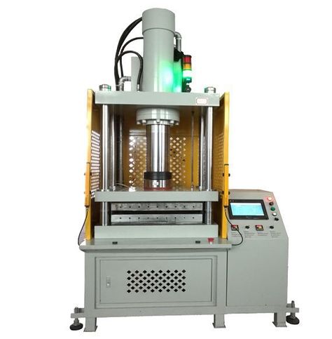
Hydraulic Deep Drawing Transfer Press for Sheet Metal Forming: Sheet metal forming machines are essential tools in the metalworking industry, used to shape, bend, cut, and form flat sheets of metal into specific designs and geometries. These machines operate through mechanical, hydraulic, pneumatic, or electric means and are widely used in automotive, aerospace, appliance manufacturing, and construction.
Key Types of Sheet Metal Forming Machines:
1. Press Brakes
- Function: Bends sheet metal into predetermined angles.
- Mechanism: Hydraulic, mechanical, or servo-electric.
- Applications: Box making, enclosures, structural parts.
2. Shearing Machines
- Function: Cuts straight lines in metal sheets.
- Types: Guillotine shears, swing beam shears.
- Applications: Pre-cutting blanks for further processing.
3. Punching Machines (Turret Punches)
- Function: Punches holes and cutouts using dies.
- CNC Models: Allow complex patterns and high-speed production.
- Applications: Ventilation panels, enclosures, signage.
4. Roll Forming Machines
- Function: Continuously bends long strips of sheet metal into desired cross-sections.
- Benefit: High-speed production of uniform profiles.
- Applications: Roofing, cladding, structural channels.
5. Spinning Machines
- Function: Forms rotationally symmetrical parts by spinning metal over a mandrel.
- Manual or CNC: Modern machines offer automated control.
- Applications: Lampshades, gas cylinders, kitchenware.
6. Stretch Forming Machines
- Function: Stretches and bends metal over a form die.
- Used For: Aircraft skin panels, architectural elements.
- Advantages: High dimensional accuracy, minimal spring-back.
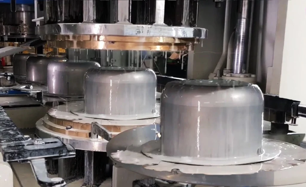
7. Deep Drawing Presses
- Function: Draws metal into deep, complex shapes.
- Technology: Hydraulic or mechanical with cushion systems.
- Applications: Pots, cans, automotive fuel tanks.
8. Beading and Flanging Machines
- Function: Adds stiffening beads or flanged edges.
- Common In: HVAC ducting, pressure vessels.
9. Ironworkers
- Multi-Function: Cut, notch, bend, and punch metal.
- Compact: Often used in fabrication shops for varied tasks.
10. Laser and Plasma Cutting Machines
- Function: Precision cutting of intricate shapes in sheet metal.
- Modern Systems: CNC-controlled with nesting software.
- Applications: Decorative panels, machinery components.
Choosing the Right Machine:
- Material Type & Thickness: Defines required force and tooling.
- Production Volume: High volumes need automation or continuous machines.
- Tolerances & Complexity: Precision demands CNC or advanced forming systems.
- Budget & Footprint: From simple hand tools to large hydraulic lines.
Sheet metal forming machines are at the heart of modern manufacturing processes where flat metal sheets are transformed into functional parts and components. These machines serve a wide variety of industries such as automotive, aerospace, HVAC, white goods, electronics, and construction. The forming process can involve bending, cutting, drawing, flanging, rolling, or stretching depending on the final product geometry. Press brakes are among the most commonly used machines, ideal for making precise bends in metal sheets using matched punch and die sets. They come in various configurations including hydraulic, mechanical, and electric models, with CNC versions offering programmable accuracy and repeatability.
Shearing machines are used to cut sheets into desired sizes or to remove scrap edges, employing blades that move in a linear or swinging motion. For operations that require perforations or cutouts, punching machines provide high-speed repetitive accuracy with tools mounted on a rotating turret or frame. When producing long, continuous profiles, roll forming machines become indispensable. These systems pass a metal strip through multiple forming stations, gradually shaping the material without interruption. In cases where the part geometry is rotationally symmetric, spinning machines allow the metal to be formed over a mandrel while rotating, commonly used for making lampshades, kitchen items, and gas cylinders.
Stretch forming machines take a different approach by clamping and pulling the sheet metal while wrapping it around a form die, which is essential in aerospace manufacturing where skin panels require large, smooth, curved surfaces. Deep drawing presses are used to form parts with significant depth compared to diameter, such as beverage cans, cookware, or automotive components like fuel tanks. They use a combination of pressure and controlled material flow to form the metal into complex shapes.
Flanging and beading machines enhance the rigidity or aesthetic quality of formed parts by introducing edge features or strengthening ribs. Ironworkers are versatile machines found in many fabrication shops due to their ability to punch, notch, bend, and shear metal all in one compact footprint. For precision cutting of complex contours or fine details, laser and plasma cutting machines are essential, offering non-contact high-speed cutting capabilities with minimal deformation and heat-affected zones. Overall, the choice of sheet metal forming machinery depends on the shape complexity, production volume, material characteristics, and precision requirements. In modern production environments, many of these machines are integrated with automation systems and CNC controls to maximize efficiency, consistency, and flexibility.
In advanced production lines, sheet metal forming machines are often connected through automated feeding systems, conveyors, and robotic arms to create seamless manufacturing cells. These setups reduce manual handling, improve throughput, and ensure consistent part quality. CNC and PLC control systems allow operators to store and recall programs for repeat jobs, minimize setup time, and reduce the chance of human error. With sensors and feedback mechanisms, machines can monitor force, position, and tool wear in real time, making intelligent adjustments to maintain process integrity. In high-volume industries like automotive or appliance manufacturing, progressive die stamping combines several forming steps—cutting, bending, drawing—into a single press stroke across multiple stations within a die set, dramatically increasing productivity.
Hydraulic presses are favored for their ability to deliver consistent pressure across a wide stroke range, making them suitable for deep drawing and forming high-strength alloys. Mechanical presses, on the other hand, operate faster and are often used for shallow forming or blanking operations where speed is essential. Servo-driven machines are gaining popularity for their energy efficiency, precision, and programmable flexibility, particularly in forming lightweight or delicate materials. Modern tooling is often designed with coatings or surface treatments to reduce friction, improve wear resistance, and extend service life, especially when working with stainless steel, aluminum, or coated sheets. Simulation software is also widely used in die design and process planning to predict material flow, potential wrinkling, tearing, or springback before actual production begins.
This virtual validation shortens development cycles and reduces scrap rates. In industries such as HVAC, metal cabinets, or lighting fixtures, forming machines are tailored for rapid changeovers and modular tooling, enabling manufacturers to switch between product types with minimal downtime. Safety systems including light curtains, interlocked doors, and two-hand controls are standard on most machines to protect operators during high-force operations. Additionally, sustainability considerations have led to the adoption of energy-efficient drives, regenerative braking systems, and minimized waste strategies in forming processes. As sheet metal components continue to evolve with design and material advancements, forming machines must also keep pace with demands for tighter tolerances, thinner gauges, and more complex geometries, making innovation in machine control, tooling, and integration a critical factor for competitive manufacturing.
Sheet Metal Forming Bending Process
The bending process in sheet metal forming is one of the most fundamental and widely used techniques for shaping flat metal sheets into desired angles or contours. Bending involves deforming the metal around a straight axis, changing its geometry but not its thickness. It is a plastic deformation process where the material is stressed beyond its yield point but below the tensile strength limit, allowing it to retain a new shape permanently after the load is removed. The most common tool for this operation is a press brake, which uses a punch and die set to apply force to the metal sheet, bending it at a specified angle.
There are several methods of bending, including air bending, bottoming, and coining. Air bending is the most flexible and energy-efficient method, where the punch presses the sheet into the die without touching the bottom surface, allowing for varying bend angles with the same tool set. Bottoming involves pressing the metal into the die so that it conforms to the exact angle and radius of the tooling, resulting in higher precision but requiring more force and dedicated tooling for each angle. Coining, the most precise and force-intensive method, compresses the material between punch and die until full contact is achieved, reducing springback almost entirely.
Springback is a key consideration in bending, where the material tends to return slightly toward its original shape after the force is removed due to its elasticity. This effect is influenced by factors such as material type, thickness, bend radius, and method of bending, and it often requires over-bending to achieve the desired final angle. The bend radius is another critical factor; tighter radii can lead to cracking, while larger radii may not hold the required shape.
Bending operations can be performed manually for simple jobs or using CNC press brakes for high-precision, repeatable production. CNC systems allow for the programming of complex bend sequences, compensation for material behavior, and automatic tool changes, significantly increasing productivity and consistency. Tools can be segmented for working with small parts or specially designed for bending flanges, hems, or Z-shapes.
In addition to press brake bending, rotary bending, roll bending, and V-die bending are used depending on the application. Rotary bending uses a rotating die to gently form the bend with minimal surface marking, while roll bending involves passing the sheet through rollers to create large radius curves or cylindrical shapes.
Bending is commonly used in the production of enclosures, brackets, panels, frames, and structural components across industries like automotive, aerospace, electronics, furniture, and construction. To ensure quality in bending, precise control of factors such as bend allowance, bend deduction, and neutral axis placement is necessary during design and manufacturing. As automation and software integration continue to evolve, bending processes are becoming faster, more adaptive, and better suited to handle complex geometries and advanced materials.
Bending as a sheet metal forming process continues to play a critical role in modern manufacturing, not only due to its simplicity but also because of its versatility in creating a vast range of functional shapes. The process relies heavily on understanding material characteristics such as ductility, tensile strength, and thickness, all of which influence how the metal will behave under stress. The choice of bending parameters—like the internal bend radius, the length of the flange, and the orientation of the grain—can greatly affect the outcome.
When the bend is made perpendicular to the grain direction, the metal tends to crack more easily, especially in brittle materials, which is why careful planning of blank layout is essential. Edge quality and pre-cut dimensions also affect bending performance, as burrs or rough edges can lead to inconsistent results or premature tool wear. Press brakes, the most common machines used for bending, are often equipped with back gauges that position the metal precisely before the punch descends, enabling accurate and repeatable results. The latest CNC press brakes include real-time angle measurement systems that compensate for springback automatically by adjusting the punch stroke during the bend. This type of active angle correction is vital when working with high-strength steels or reflective metals like aluminum, where small deviations can lead to unusable parts.
Tooling design also plays a vital role; different V-die openings and punch nose radii must be selected based on the material type and the required bend angle. For very small flanges or tight access areas, gooseneck punches or acute angle tools are used. Large components may require staged tooling setups, where multiple tools are arranged across the press brake bed to perform complex bend sequences in a single handling. In automated setups, robotic arms can load and unload parts, position them for each bend, and even communicate with the press brake controller to synchronize motion with machine cycles. Some advanced systems integrate vision systems to ensure correct orientation and alignment of parts before bending begins.
Despite the mechanical nature of bending, software is a central element in modern operations. CAD/CAM integration allows engineers to simulate bending processes before any physical part is made, automatically generating bend sequences, unfolding flat patterns, and accounting for material-specific factors like K-factor and elongation. This ensures minimal material waste, optimal tool usage, and reduced trial-and-error during production. In mass production, bending is often combined with punching or laser cutting in a single line to streamline workflow. In smaller-scale operations or prototyping, manual brakes or folding machines may be used for flexibility and speed. Regardless of scale, consistent quality depends on accurate setup, regular tool maintenance, and knowledge of how different materials respond to stress. As design trends move toward lighter structures, tighter tolerances, and complex geometries, the bending process must adapt through improved machine control, smarter tooling, and greater use of digital simulation and feedback systems, ensuring it remains one of the most indispensable methods in sheet metal fabrication.
In the continuous evolution of sheet metal fabrication, bending has increasingly benefited from technological advancements that enhance both precision and efficiency. Real-time monitoring and adaptive bending systems have become essential in high-precision industries like aerospace and medical equipment manufacturing, where even minor dimensional deviations are unacceptable. These systems utilize integrated sensors and servo-driven actuators to adjust the force and position dynamically during the bending process, compensating for variables like tool deflection, material inconsistencies, and temperature fluctuations. Such intelligent bending machines can learn from previous bends and optimize future operations, reducing waste and setup time.
Material innovation also affects bending operations significantly. High-strength steels, aluminum alloys, stainless steels, and even advanced composites are now regularly processed, each requiring specific knowledge of their behavior under stress. Some metals, like titanium or hardened steels, demand specialized tooling with enhanced wear resistance and lubricants or protective films to prevent galling or surface marking. As materials become more engineered, with layered or coated surfaces, bending processes must also evolve to prevent delamination or coating damage, requiring refined control over bending radius and pressure application.
In applications such as architectural panels, signage, or consumer electronics enclosures, aesthetic quality is just as important as dimensional accuracy. Here, tools must be clean, polished, and often non-marking to ensure flawless surfaces. Bending lines must also be sharp, consistent, and aligned with visual features, which requires not only accurate equipment but also skilled programming and fixturing.
Ergonomics and operator safety remain priorities, especially for manual or semi-automated bending operations. Modern machines are designed with intuitive interfaces, visual guides, and automatic clamping systems that reduce physical strain and risk of injury. Light curtains, pressure-sensitive mats, and safety interlocks are standard features that prevent unintended operation during tool changes or part repositioning. Training has also become more digitized, with virtual simulations and touchscreen-based instructions enabling even novice operators to perform complex bends safely and accurately.
From a production planning perspective, bending operations are often considered early in the product development phase. The capability of available bending equipment can influence part geometry, tolerances, and even material choice. Designers must account for factors like minimum flange lengths, allowable radii, and tool accessibility. Incorrect assumptions at the design stage can result in unfeasible bends, tool collisions, or excessive material waste, all of which can be avoided with collaborative planning between engineering and fabrication teams.
Energy consumption is another modern concern. Traditional hydraulic systems, while powerful, often operate continuously and consume significant power. Servo-electric press brakes, in contrast, use energy only during the actual bending cycle and offer better precision, faster setup, and lower noise levels, making them attractive for facilities aiming to improve environmental performance and reduce operational costs.
As demand for customization grows, especially in small-batch or made-to-order manufacturing, flexibility in bending becomes a competitive advantage. Machines that support quick tool changes, offline programming, and modular tooling setups allow shops to switch between jobs rapidly without sacrificing quality. This agility is essential in industries like HVAC, furniture, and custom metalwork where turnaround time and part variation are key.
In summary, the bending process continues to adapt to modern requirements through the integration of automation, smarter control systems, advanced tooling, and sustainable technologies. Its role as a central operation in the sheet metal forming chain ensures that innovations in bending will remain closely tied to advancements in materials, machinery, and manufacturing strategy.
Sheet Metal Forming Piercing Process
The piercing process in sheet metal forming is a high-speed, high-precision operation used to create holes, slots, or other internal features by shearing the metal with a punch and die. It is a subtype of blanking, where material is removed from a larger sheet rather than being retained. Piercing is commonly performed using mechanical or hydraulic presses and is fundamental in mass production environments, especially in the automotive, appliance, and electronics industries. The key components involved are the punch, which descends and pushes through the sheet, and the die, which supports the sheet and provides a clean edge for shearing. The clearance between punch and die is critical and is usually a small percentage of the sheet thickness, typically around 5–10%, depending on the material and desired hole quality. Too little clearance can lead to excessive wear or tool breakage, while too much can cause burrs and poor edge quality.
During the piercing operation, the punch applies downward force, initiating plastic deformation in the sheet metal until it exceeds the shear strength of the material. A clean cut forms through a combination of shearing and fracture, and the slug—the piece punched out—is usually discarded or collected for recycling. The process is extremely fast, often completed in milliseconds, and is well suited for automation and integration into progressive die systems where multiple operations—such as piercing, bending, and forming—can be completed in a single press stroke.
The geometry and arrangement of piercing tools are customized for each application, whether circular, rectangular, slotted, or irregular shapes. High-volume operations often use compound or progressive dies to perform multiple piercings at once or in sequence. Tool steels or carbide materials are commonly used for punches and dies to withstand the repetitive stress and abrasion of piercing. Lubrication is also important to reduce friction, minimize heat, and extend tool life. Over time, wear at the cutting edges can lead to increased burr height and reduced dimensional accuracy, so regular inspection and sharpening are part of the maintenance cycle.
Piercing offers advantages like high production speed, repeatable accuracy, and compatibility with automation. However, it can also introduce issues such as edge burrs, deformation around the hole, or sheet warping, especially in thin or ductile materials. These effects can be mitigated through precise tool alignment, optimized die clearance, and controlled press speed. In advanced applications, CNC turret punch presses allow flexible piercing of custom shapes without dedicated dies for each pattern, making them ideal for short runs and prototyping.
In sectors like electrical enclosures, automotive panels, or HVAC components, piercing is often the first step in a series of forming operations, creating reference holes or fastening points that are critical to downstream assembly. Because of its speed and versatility, the piercing process remains one of the most cost-effective and essential methods in sheet metal fabrication.
Piercing continues to be a backbone process in the sheet metal industry due to its simplicity, reliability, and adaptability to a wide range of materials and geometries. As manufacturing demands shift toward tighter tolerances and more complex part designs, piercing operations have evolved with more precise machinery, better tool materials, and intelligent process control. The accuracy of a pierced hole directly affects the fit and function of the final product, particularly in assemblies where fasteners, rivets, or locating pins will be inserted. Even small deviations can cause misalignment or stress concentrations, which makes the design of the punch and die, as well as the control of press parameters, absolutely critical.
Modern piercing is often carried out in high-speed stamping lines where hundreds or even thousands of parts per hour are produced, each with multiple holes placed at precise locations. Progressive dies are especially effective for this, allowing several holes to be pierced and other features formed in a single strip feed with each stroke of the press. These dies advance the material incrementally and perform sequential operations, maximizing throughput while minimizing material waste. In contrast, compound dies perform multiple operations in a single stroke without progressive movement, which is suitable for simpler part geometries produced at very high volumes.
Tool life in piercing operations is a major concern, particularly when dealing with high-strength steel, stainless steel, or abrasive alloys. To combat this, toolmakers use hardened tool steels like D2, A2, or tungsten carbide, often with coatings such as TiN or TiAlN that reduce friction and resist wear. Precision tool sharpening and proper clearance management are essential to maintain edge quality and minimize burr formation. In many operations, burrs are inevitable and may require a secondary deburring process using tumblers, brushes, or chemical treatments depending on the part’s intended use.
In CNC turret punching systems, the piercing process is combined with computer-controlled positioning to punch various hole patterns and shapes in a single setup, offering unmatched flexibility for low to mid-volume production. These machines can switch between multiple punch tools stored in a rotating turret and are especially effective for manufacturing electrical panels, perforated screens, and chassis parts. They also allow nesting of parts to maximize material usage, reducing scrap and production costs.
Piercing is not limited to creating standard holes. Shaped punches can form louvers, knockouts, embosses, or countersinks in the same operation. Multistage tools can perform partial shearing to create tabs or break-away features. In sheet metal parts where ventilation, light weight, or aesthetics are important, custom pierced patterns can be introduced with precise repetition and speed.
Because of the high forces involved, piercing presses must be rigid and well-maintained to avoid deflection that can affect part quality. Press alignment, slide parallelism, and bolster flatness all influence the consistency of the piercing process. Sensors and load monitoring systems are now often integrated into high-end presses to detect anomalies such as tool wear, misfeeds, or punch breakage in real time, allowing for immediate shutdown and reducing the risk of producing defective parts or damaging equipment.
Environmental and safety concerns are also influencing piercing operations. Lubricants used in the process are being reformulated for lower toxicity and easier cleanup. Enclosures, guards, and automation reduce operator exposure to moving parts and noise, which is especially relevant in high-speed production environments.
As the demand for lightweighting, electric vehicles, and precision assemblies grows, the piercing process will continue to be refined with better materials, smarter machines, and advanced integration with digital design and manufacturing systems. Its speed, adaptability, and ability to handle complex patterns make it irreplaceable in modern sheet metal forming operations.
With the continual progression of manufacturing technologies, the piercing process in sheet metal forming is increasingly integrated into fully digital production workflows, where CAD models are directly translated into machine instructions. This digital thread allows for rapid prototyping and seamless transitions from design to manufacturing, particularly in facilities that use CNC turret punches or fiber laser-punch hybrid machines. These systems are capable of not only piercing but also performing light forming, marking, and even tapping operations in one cycle, greatly reducing the need for secondary processes. By using nesting software, manufacturers can optimize sheet layouts to minimize scrap, which is especially critical when working with expensive materials like stainless steel, copper alloys, or pre-painted sheets.
For industries requiring extremely clean and accurate holes—such as electronics, aerospace, or medical device manufacturing—precision is everything. In such cases, piercing must be executed with minimal burrs, distortion, or edge hardening. High-speed fineblanking or micro-piercing techniques are employed to maintain tight tolerances and achieve mirror-smooth edge finishes. In these systems, the material is clamped securely during the piercing stroke, eliminating movement that could cause deformation. These processes require special presses with high rigidity and accuracy, and the tooling used is often produced to micron-level tolerances using EDM and grinding methods.
The introduction of servo-driven presses has further enhanced the capabilities of the piercing process. Unlike traditional mechanical or hydraulic presses with fixed stroke profiles, servo presses can precisely control speed, position, and force at every point in the stroke. This allows for slower entry speeds to reduce tool shock, dwell times at the bottom dead center for difficult materials, and faster return speeds for improved cycle times. In piercing applications, this level of control significantly extends tool life and allows for forming features that were previously difficult or impossible with conventional presses.
As more manufacturers embrace Industry 4.0 practices, piercing operations are being monitored in real time using sensors, vision systems, and data analytics. These tools can track wear patterns, detect anomalies like punch misalignment or sheet misfeeds, and predict maintenance needs before failures occur. This proactive approach helps avoid costly downtime and ensures consistent part quality over long production runs. In fully automated lines, robotic arms may be used to load and unload sheets, orient parts, or move pierced components downstream to bending, welding, or assembly stations without human intervention.
Environmental considerations are also shaping the way piercing is done. Coolant and lubricant usage is being optimized to reduce environmental impact, and many shops are transitioning to dry or near-dry processing methods where possible. In some cases, piercing is combined with laser cutting or waterjet processes to reduce tool wear and improve edge quality, particularly for thick or difficult-to-punch materials. Hybrid machines that incorporate both mechanical punching and laser capabilities offer the best of both worlds—speed and flexibility—making them ideal for job shops and custom fabricators.
Ultimately, the piercing process remains indispensable in sheet metal forming because of its unmatched speed, repeatability, and cost-efficiency for making holes and internal features. Whether used as a standalone operation or as part of a multi-stage progressive die, piercing provides a foundation for countless industrial applications—from automotive body panels and HVAC components to electronic housings and structural parts. Its evolution continues in lockstep with advancements in tooling, machine design, materials science, and digital manufacturing, ensuring that piercing will remain a core capability in high-performance, high-precision metalworking environments well into the future.
Sheet Metal Forming Trimming Machine
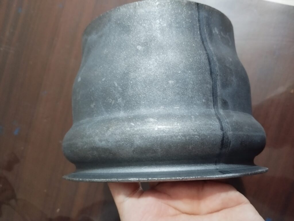
A sheet metal forming trimming machine is used to remove excess material—such as flash, overhangs, or unwanted edges—from formed or stamped metal parts. Trimming is a critical finishing operation in the production sequence, ensuring that the final component meets precise dimensional and geometric specifications. It is especially essential after deep drawing, hydroforming, or complex press forming processes, where the metal may extend beyond the desired shape due to material flow during forming. The trimming machine provides clean, defined edges and allows parts to proceed to further operations like welding, assembly, or coating without interference from irregular borders.
Trimming machines come in various configurations depending on the complexity and volume of production. Mechanical or hydraulic presses equipped with trimming dies are the most common setup for high-volume applications. These machines use a dedicated trim die that is designed to match the profile of the part, shearing off the unwanted material with a single stroke. In many cases, these trimming dies are integrated directly into transfer or progressive dies to combine forming and trimming in one automated cycle, reducing handling time and increasing throughput.
For large or asymmetrical parts, especially in the automotive or appliance industry, CNC trimming machines are employed. These systems use rotating blades, laser cutting heads, or even abrasive waterjets mounted on multi-axis arms or gantries to follow programmed trim paths with high accuracy. This method is highly flexible and suitable for parts with complex contours or varying trim requirements. Robotic trimming cells further enhance flexibility, allowing for quick reprogramming between different part models and minimizing downtime between production runs.
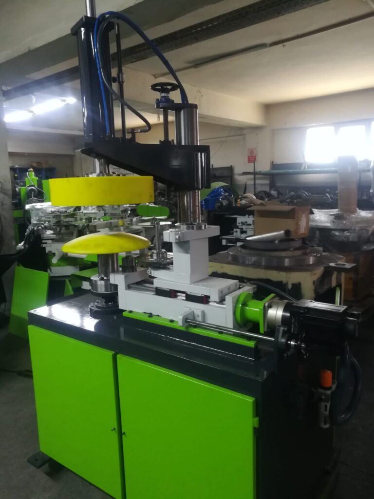
Rotary trimming machines are another specialized type, often used for cylindrical or conical parts such as pressure vessels, cookware, or gas canisters. These machines use a rotating fixture to hold the part while a cutting tool or shear blade trims the edge uniformly. This ensures concentric and smooth finishes that are essential for product integrity and appearance.
Safety and precision are key considerations in trimming operations. Blades or dies must be precisely aligned and maintained to prevent deformation or burrs on the trimmed edge. In CNC systems, sensors and feedback mechanisms ensure accurate path following and adapt to minor material variations in real time. In manual or semi-automatic systems, fixtures and guards are designed to ensure operator safety while maintaining part positioning accuracy.
Trimming is not just about cutting away excess—it also prepares parts for consistent downstream processing. For example, trimmed edges reduce the chance of failure during welding, eliminate the need for extensive deburring, and ensure clean lines for painted or coated finishes. As production becomes more automated and design geometries more complex, the trimming process—once considered a secondary operation—has gained prominence as a precision step that directly influences product quality, aesthetic appeal, and functional fit. As a result, modern trimming machines are increasingly integrated into digital manufacturing environments where speed, accuracy, and adaptability are critical.
Sheet metal forming trimming machines continue to play an essential role in ensuring that manufactured parts meet exact design specifications by removing unwanted material left over from forming or stamping processes. The trimming operation is crucial for maintaining dimensional accuracy, especially in industries where tight tolerances and flawless finishes are mandatory, such as automotive, aerospace, and consumer appliances. The evolution of trimming machines has closely followed advances in automation and digital control, allowing manufacturers to handle complex part geometries with greater precision and repeatability.
In high-volume manufacturing, trimming is often integrated directly into progressive or transfer die setups, where forming, piercing, and trimming occur sequentially without manual intervention. This reduces cycle times and labor costs while improving part consistency. When trimming is combined with forming in a single die, the machine must be carefully engineered to manage the forces involved and avoid part distortion. Proper die design and material flow analysis are essential to achieve clean trims without compromising the integrity of the part.
For medium to low-volume production or when flexibility is required, CNC trimming machines have become increasingly popular. These systems utilize programmable cutting heads, such as milling cutters, routers, or lasers, mounted on multi-axis gantries or robotic arms. This flexibility allows for quick retooling and rapid changeovers between different part designs, which is especially beneficial in custom fabrication or prototype work. The ability to precisely follow complex trim contours ensures that even intricate shapes are finished to exact specifications without the need for expensive dedicated dies.
Robotic trimming cells add another layer of adaptability, often integrated with vision systems and force feedback to monitor and adjust the trimming process in real time. This is particularly useful when working with variable part presentations or materials that may exhibit minor dimensional changes, such as composites or coated metals. The robot can dynamically correct tool paths, adjust cutting speeds, and maintain consistent edge quality, reducing scrap and rework.
The trimming process must also address challenges such as burr formation, tool wear, and edge quality. In many operations, secondary finishing steps like deburring, grinding, or polishing are required to meet surface finish requirements. To minimize these, trimming machines use high-precision tooling made from hardened steels or carbide, often coated for wear resistance and reduced friction. Cooling and lubrication systems are also incorporated to extend tool life and improve cut quality.
Safety remains paramount in trimming operations due to the high forces and sharp tools involved. Modern machines are equipped with guarding systems, interlocks, and emergency stops. Automated material handling and loading/unloading systems reduce operator exposure to hazardous areas, and ergonomic design helps minimize fatigue in manual or semi-automatic environments.
Energy efficiency is another consideration as manufacturers seek to reduce operational costs and environmental impact. Servo-driven trimming presses consume less power than traditional hydraulic systems by applying force only as needed during the cutting cycle. CNC and robotic systems optimize cutting paths and speeds to minimize energy use while maintaining throughput.
Overall, sheet metal forming trimming machines are evolving from simple shearing devices into sophisticated, integrated systems that are vital to achieving high-quality, consistent, and cost-effective production. Their ability to precisely remove excess material without damaging parts or compromising tolerances makes them indispensable in modern sheet metal fabrication workflows, supporting everything from mass production lines to flexible, customized manufacturing environments.
As sheet metal forming trimming machines continue to advance, their integration with Industry 4.0 technologies is reshaping manufacturing workflows. Smart trimming systems are now capable of communicating with other machines and central control units to optimize production in real time. By collecting data on tool wear, cycle times, and part quality, these machines enable predictive maintenance schedules that reduce unplanned downtime and extend tool life. Digital twins and simulation software allow engineers to virtually test trimming processes before implementation, ensuring optimal tool paths and minimizing trial-and-error on the shop floor.
Adaptive control systems in modern trimming machines can automatically adjust cutting parameters based on material thickness variations, temperature changes, or wear conditions. This adaptability improves edge quality and reduces scrap, particularly when working with high-strength alloys or coated materials that may behave unpredictably under stress. The use of sensor arrays and machine vision enhances part alignment and fixture verification, ensuring that trimming is performed with sub-millimeter accuracy every time.
Hybrid trimming machines that combine mechanical cutting with laser or waterjet technology are gaining traction for their ability to handle complex geometries and delicate materials without introducing thermal distortion or mechanical stress. These systems offer flexibility to switch between rough trimming and fine finishing within the same production line, improving throughput and reducing secondary operations.
Sustainability considerations are also influencing the design and operation of trimming machines. Manufacturers are investing in energy-efficient drives, regenerative braking systems, and coolant recycling to minimize environmental impact. The reduction of scrap through precision trimming and material nesting contributes to lean manufacturing goals and cost savings.
In addition to traditional metal forming sectors, trimming machines are now vital in emerging industries such as electric vehicle manufacturing, renewable energy, and medical devices, where parts require exceptional precision and surface quality. Custom tooling and software capabilities allow trimming machines to accommodate rapid design changes and smaller batch sizes without sacrificing efficiency.
Operator training and digital interfaces have also improved, with intuitive touchscreens, augmented reality aids, and remote diagnostics enabling quicker setups and troubleshooting. These advancements make trimming machines accessible to a broader range of manufacturers, including small and medium-sized enterprises seeking to improve quality and flexibility.
In summary, the evolution of sheet metal forming trimming machines reflects broader trends in manufacturing towards smarter, more connected, and sustainable operations. Their role extends beyond simple material removal to become a critical enabler of precision, efficiency, and adaptability in the production of complex sheet metal components across diverse industries.
Sheet Metal Forming Machines with Surface Finish
Sheet metal forming machines that also address surface finish combine shaping operations with capabilities to preserve or enhance the appearance and texture of metal parts during or after forming. Surface finish is critical in many applications where aesthetics, corrosion resistance, or paint adhesion are important, such as in automotive body panels, consumer electronics, household appliances, and architectural components.
Many forming processes inherently affect surface quality due to tool contact, pressure, friction, and material flow. Therefore, machines and tooling must be designed to minimize scratches, dents, or marks. Hydraulic and mechanical press brakes, stamping presses, and roll forming machines often use specially treated or coated tooling—such as polished dies or those with low-friction coatings like TiN or DLC—to reduce surface damage. Precision alignment, controlled forming speeds, and appropriate lubrication also contribute significantly to maintaining a smooth finish.
Some advanced forming machines integrate additional surface treatment capabilities, such as polishing rollers in roll forming lines or brushing stations in stamping presses. These features can smooth out minor imperfections created during forming, improving gloss and uniformity before painting or plating.
For parts requiring very high-quality finishes, such as decorative panels or visible consumer products, forming machines may be paired with in-line surface finishing processes like vibratory finishing, buffing, or shot peening. In some cases, hybrid machines combine forming and surface enhancement in a single workflow to reduce handling and cycle time.
Additionally, technologies like hydroforming use fluid pressure to form complex shapes with uniform surface contact, reducing tooling marks and enabling finer surface finishes compared to traditional stamping. Similarly, stretch forming applies tensile stress to metal sheets to achieve smooth, large-radius bends with minimal surface distortion.
Automation and CNC control also play a role in surface quality by ensuring consistent tool positioning, pressure, and motion, which reduces variations that can cause uneven finishes. Real-time monitoring systems can detect anomalies in force or position that might indicate tooling wear or misalignment, allowing corrective actions before defective parts are produced.
In summary, sheet metal forming machines with a focus on surface finish combine precision engineering, advanced tooling materials, controlled process parameters, and often integrated finishing steps to produce parts that meet both dimensional and aesthetic requirements. This integration is essential for industries where appearance and durability are paramount alongside functional performance.
Sheet metal forming machines designed to maintain or enhance surface finish address several challenges inherent in the forming process, such as tool marks, scratches, wrinkling, and surface deformation. The interaction between the metal sheet and tooling surfaces is carefully controlled through the selection of appropriate die materials, surface coatings, and lubrication methods to minimize friction and wear. For instance, polished and coated dies help reduce galling and scratching, especially when working with soft or coated metals like aluminum, stainless steel, or pre-painted sheets. Proper lubrication not only extends tool life but also ensures a smoother flow of material during forming, which directly impacts the final surface quality.
Some forming machines incorporate features that actively improve surface finish during the process. For example, roll forming lines may include precision-controlled polishing rollers or brushing mechanisms to remove minor surface irregularities as the metal passes through forming stages. Similarly, hydraulic presses equipped with floating or pressure-controlled dies can apply uniform pressure over the sheet, avoiding localized stress points that cause surface defects. Stretch forming and hydroforming are especially effective for parts requiring smooth, contoured surfaces without tooling lines or marks, since these processes use tensile forces and fluid pressure respectively to shape the metal with minimal tooling contact.
Automation and CNC control contribute significantly to surface finish consistency by ensuring exact repeatability in tool alignment, pressure, and stroke speed. Variations in these parameters can create uneven stress distributions that lead to surface defects or distortion. Advanced control systems may include real-time force feedback, angle measurement, or tool condition monitoring, allowing the machine to adjust on the fly to maintain optimal forming conditions. This reduces scrap rates and maintains the integrity of surface finishes over large production runs.
In applications demanding high aesthetic standards, such as automotive exterior panels or consumer electronics housings, forming machines are often integrated into production lines that include in-line surface finishing operations. These may involve shot peening to improve fatigue resistance while enhancing surface texture, vibratory or abrasive finishing to remove tool marks, and automated cleaning or coating preparation stations. Combining forming and finishing steps in a continuous workflow reduces handling damage and speeds up overall production.
Material selection also influences how forming machines manage surface finish. Coated or galvanized steels, aluminum alloys, and stainless steels each have unique behaviors under stress and friction. Machines designed for these materials incorporate tailored tooling surfaces and process parameters to prevent coating damage, galling, or discoloration. For example, forming galvanized steel requires lubrication systems and tooling materials that minimize zinc pickup or stripping during forming.
Environmental factors such as temperature and humidity can affect both forming behavior and surface quality, so some machines include climate controls or humidity regulation in forming cells to maintain consistent conditions. Additionally, operators are trained to monitor surface finish quality throughout production, using visual inspection, surface profilometers, or gloss meters to detect deviations early.
In summary, sheet metal forming machines that address surface finish are a combination of precise mechanical design, advanced tooling, controlled process parameters, and integrated finishing technologies. They are essential in producing parts that meet stringent functional and aesthetic requirements, reducing the need for costly rework or secondary finishing while enhancing product value and customer satisfaction.
Building further on the integration of surface finish considerations in sheet metal forming machines, recent developments have introduced smart manufacturing concepts that leverage data analytics and machine learning to optimize surface quality. By collecting process data such as force curves, temperature, and vibration signatures, these systems can predict when tooling degradation or misalignment is likely to affect surface finish. This predictive insight enables timely maintenance and process adjustments, preventing defects before they occur and minimizing downtime.
Moreover, additive manufacturing techniques are starting to influence tooling design, allowing the creation of complex die geometries with built-in surface textures tailored to enhance material flow or impart desired surface patterns on the formed parts. This capability opens new avenues for combining functional and decorative surface features directly through forming, reducing reliance on secondary finishing steps.
In forming machines handling sensitive materials like ultra-thin metals or composites, precision control over forming speed, pressure, and tool engagement is critical to avoiding surface damage. Servo-electric drives offer exceptional control in this regard, delivering smooth, programmable motion profiles that minimize impact forces and vibration. This is especially important when forming materials with coatings, laminations, or delicate surface treatments.
Environmental sustainability is also influencing machine design and operation related to surface finish. For instance, dry forming technologies that eliminate the need for lubricants are being developed to reduce chemical waste and simplify post-processing. Surface finish quality in these processes relies heavily on the precision of machine components and tooling materials to compensate for the absence of lubrication.
As industries push for ever thinner, lighter, and more complex metal parts with flawless surfaces, the synergy between forming machines and surface finishing technologies becomes increasingly important. Innovations such as in-line surface metrology, automated defect detection, and robotic finishing cells are becoming standard complements to forming machines, creating fully integrated production lines focused on delivering consistent, high-quality parts at scale.
Ultimately, sheet metal forming machines with a focus on surface finish embody a multidisciplinary approach, combining mechanical engineering, materials science, automation, and digital technologies. This integration not only improves the aesthetic and functional quality of the parts but also enhances manufacturing efficiency, reduces waste, and supports rapid innovation cycles in competitive markets.
Stainless Steel Sheet Metal Forming Machine
A stainless steel sheet metal forming machine is specifically designed or adapted to handle the unique properties of stainless steel during various forming processes. Stainless steel, known for its corrosion resistance, strength, and durability, poses particular challenges in sheet metal forming due to its higher hardness, lower ductility compared to mild steel, and tendency to work harden rapidly. As a result, machines that form stainless steel sheets often require enhanced capabilities such as increased forming force, precise control over deformation speed, and tooling optimized to withstand abrasive wear.
Typical machines used for stainless steel sheet metal forming include press brakes, stamping presses, roll forming machines, and deep drawing presses. Press brakes forming stainless steel must have robust frames and stronger cylinders or drives—hydraulic or servo-electric—to generate the higher tonnage required. Tooling for stainless steel is usually made from hardened tool steels or carbide and may be coated with wear-resistant and low-friction coatings such as titanium nitride (TiN) or diamond-like carbon (DLC) to reduce galling and extend tool life.
Roll forming machines for stainless steel need to apply higher forming forces due to the material’s strength while maintaining tight tolerances and smooth surface finishes. The rollers and guides must be engineered to minimize surface scratches or marring, which is critical when the final part will be visible or requires further finishing. Lubrication plays a vital role in roll forming stainless steel to prevent friction and heat buildup, thereby preserving material properties and tooling condition.
Deep drawing and hydroforming presses used for stainless steel sheet forming require precise pressure and stroke control to manage the rapid work hardening and springback that stainless steel exhibits. Forming speed must be optimized to prevent cracking or wrinkling. Specialized dies with enhanced surface finishes reduce friction and help in the smooth flow of stainless steel during drawing operations.
Due to stainless steel’s propensity to work harden, machines with variable speed controls, like servo presses, are highly beneficial. These allow gradual forming and fine control over deformation rates, reducing the risk of part failure. Additionally, machine frames must be exceptionally rigid to withstand higher forces without deflection, ensuring consistent dimensional accuracy.
Automation and CNC controls enhance forming efficiency and quality when working with stainless steel sheets. These systems can precisely control bending angles, feeding positions, and forming sequences to compensate for springback and material variability. Real-time feedback and monitoring systems help maintain consistent production and detect potential issues early.
Surface finish considerations are especially important in stainless steel forming machines because stainless steel parts are often used in applications requiring both aesthetic appeal and corrosion resistance. Machines designed for stainless steel forming may include features to minimize tool marks and scratches, such as polished tooling, controlled forming speeds, and appropriate lubrication systems.
In summary, stainless steel sheet metal forming machines combine high rigidity, increased force capacity, advanced tooling, and precise control systems to successfully process stainless steel sheets. These machines enable manufacturers to produce durable, corrosion-resistant components with tight tolerances and excellent surface quality, suitable for demanding applications in food processing, medical equipment, architecture, automotive, and more.
Stainless steel sheet metal forming machines continue to evolve to meet the demanding requirements posed by the material’s unique characteristics. Because stainless steel work hardens quickly, the forming process must carefully balance force, speed, and lubrication to prevent cracking or surface defects. Machines equipped with servo-electric drives offer precise control over ram speed and pressure, allowing operators to fine-tune forming cycles for different grades and thicknesses of stainless steel. This flexibility helps reduce springback—a common issue in stainless steel—by enabling controlled over-bending and compensation during the forming process.
Tooling plays a critical role in stainless steel forming. Due to the material’s hardness and abrasiveness, tooling is often manufactured from premium-grade tool steels with surface treatments such as nitriding, PVD coatings, or diamond-like carbon layers to enhance durability and reduce friction. Proper tooling maintenance, including frequent inspection and polishing, is essential to prevent galling and maintain surface quality on the formed parts. In many applications, tooling is designed with polished finishes and specific geometries to minimize contact stresses and material deformation marks.
In roll forming stainless steel, precision is paramount. The rollers must be machined to exacting tolerances and made from wear-resistant materials to ensure consistent part dimensions and surface finishes. Cooling and lubrication systems integrated into the roll forming line help manage heat buildup and prevent surface oxidation or discoloration. These factors are particularly important when forming stainless steel sheets intended for architectural or decorative use, where aesthetics are as critical as dimensional accuracy.
Deep drawing and hydroforming machines for stainless steel incorporate advanced sensor arrays and control algorithms to monitor punch forces, sheet tension, and die pressure in real time. These feedback systems allow the press to dynamically adjust forming parameters to accommodate variations in sheet properties or thickness, improving yield rates and reducing scrap. Additionally, some presses feature adjustable blank holders and cushion pressures to optimize material flow and prevent wrinkling or tearing during complex draws.
Springback compensation in stainless steel forming is addressed through both machine capabilities and process design. CNC-controlled press brakes can automatically calculate and apply overbend angles, ensuring that after elastic recovery, the part achieves the intended geometry. Simulation software is often used in conjunction with machine programming to predict springback behavior based on material grade, thickness, and tooling setup, enabling manufacturers to fine-tune parameters before production.
Automation is widely implemented in stainless steel forming lines to improve repeatability and throughput. Robotic material handling systems load and unload sheets, orient parts, and transfer components between forming stations with high precision. These automated cells reduce manual labor, improve safety, and maintain consistent part quality. Integrated quality control systems, including optical inspection and laser scanning, verify surface finish and dimensional conformity immediately after forming.
Environmental controls within forming cells are sometimes employed to maintain stable temperature and humidity, reducing variability in stainless steel’s mechanical properties during processing. Such controls help in achieving consistent forming results, especially in tightly regulated industries like medical device manufacturing or food processing equipment production.
Overall, stainless steel sheet metal forming machines represent a fusion of mechanical strength, sophisticated control technology, and high-performance tooling designed to address the challenges of forming a demanding yet versatile material. These machines empower manufacturers to deliver components that meet rigorous standards for durability, corrosion resistance, and aesthetics across a wide range of critical applications.
To further enhance the performance of stainless steel sheet metal forming machines, manufacturers increasingly incorporate advanced materials science insights and digital manufacturing technologies. For example, new grades of stainless steel with improved formability are being developed, and forming machines are adapted to handle these materials by fine-tuning force application and cycle times. This co-evolution of material and machine capabilities enables more complex shapes and thinner gauges without compromising strength or surface integrity.
Additive manufacturing is also influencing tooling development for stainless steel forming. Complex die geometries and conformal cooling channels can now be produced via 3D printing, improving heat dissipation during forming and reducing thermal distortion or tool wear. This leads to longer tool life and more consistent surface finishes, especially in high-volume or high-temperature applications.
Digital twin technology allows manufacturers to create a virtual replica of the forming machine and process, simulating stainless steel sheet behavior under various forming conditions. This predictive modeling helps optimize machine settings, tooling design, and process parameters before physical trials, saving time and reducing costly material waste. It also supports rapid prototyping and agile production methods, which are increasingly important as product life cycles shorten.
In addition, the integration of IoT sensors throughout forming machines enables continuous condition monitoring, capturing data on vibrations, temperature, force, and position. Machine learning algorithms analyze this data to predict maintenance needs, detect anomalies, and optimize operational efficiency. This reduces unexpected downtime and extends the lifespan of critical machine components such as hydraulics, servo motors, and tooling.
Ergonomics and operator safety are also emphasized in the latest stainless steel forming machine designs. Enclosures, safety interlocks, and automated loading systems minimize human exposure to high-force areas. Intuitive human-machine interfaces (HMIs) with touchscreens and guided workflows help operators set up complex stainless steel forming jobs quickly and correctly, reducing errors and improving productivity.
Sustainability is becoming a priority as well. Energy-efficient servo drives reduce power consumption compared to traditional hydraulic systems, while advanced lubrication and cooling systems minimize fluid use and waste. Some manufacturers also explore dry forming techniques or environmentally friendly lubricants compatible with stainless steel to reduce environmental impact.
Finally, stainless steel forming machines are designed to be flexible and modular to accommodate the growing demand for customized, smaller batch production runs. Quick-change tooling systems, programmable controls, and versatile automation enable manufacturers to switch between part designs rapidly without sacrificing quality or throughput. This adaptability is critical for industries such as medical devices, aerospace, and specialty consumer goods, where precision and traceability are paramount.
In conclusion, stainless steel sheet metal forming machines are sophisticated systems that combine mechanical robustness, cutting-edge control technologies, advanced tooling, and smart manufacturing principles. They address the material’s unique challenges to produce high-quality, durable, and visually appealing components for a wide range of demanding industrial applications.
Copper Sheets Sheet Metal Forming Machine
Copper sheet metal forming machines are specifically designed or adapted to handle copper’s unique properties during various forming processes. Copper is known for its excellent electrical and thermal conductivity, corrosion resistance, and relatively high ductility, making it widely used in electrical components, roofing, plumbing, and decorative applications. However, copper’s softness and tendency to gall or stick to tooling require special considerations in machine design, tooling, and process parameters.
Typical machines used for forming copper sheets include press brakes, stamping presses, roll forming machines, and deep drawing presses. Because copper is softer and more ductile than many other metals, forming machines often operate at lower force levels compared to those used for steel, but they must provide smooth, controlled motion to avoid surface damage. Press brakes for copper sheet bending use polished or specially coated tooling to minimize scratching and galling, preserving the material’s surface finish and conductivity. Tool materials such as hardened steel with anti-galling coatings or even polymer inserts are common to reduce friction between the copper sheet and tools.
Roll forming machines for copper sheets must ensure precise alignment and smooth surface contact to avoid marring or work hardening the material. Lubrication is critical in roll forming copper to reduce friction and heat buildup, which can otherwise alter material properties or cause surface discoloration. Because copper has a lower yield strength and can deform easily, roll forming lines may use lighter forming pressures and more gradual bending radii compared to machines designed for steel.
Deep drawing and stamping presses used for copper must also be optimized for smooth, uniform deformation to prevent tearing or wrinkling. Copper’s ductility allows for complex shapes to be formed, but tooling must have excellent surface finishes and proper clearance to avoid surface defects. Lubricants are carefully selected to prevent adhesion and galling, and presses may be equipped with precise blank holding controls to manage material flow during drawing.
Because copper work hardens less rapidly than stainless steel but is softer overall, forming machines for copper often incorporate variable speed controls to optimize forming rates, balancing productivity with surface quality. Servo-electric drives are advantageous for their precise motion control and repeatability, allowing operators to fine-tune bending or stamping cycles to the specific copper alloy and thickness.
Surface finish is especially important when forming copper sheets used in decorative or electrical applications. Forming machines are frequently paired with in-line cleaning, polishing, or coating stations to maintain or enhance surface quality. For sensitive applications, forming environments may be climate-controlled to reduce oxidation or tarnishing during processing.
Automation and CNC controls improve forming consistency and reduce scrap rates by allowing precise programming of bending angles, stroke lengths, and feed rates. These systems can also compensate for springback and material variability, which, although less pronounced in copper than in harder metals, still affect part accuracy.
In summary, copper sheet metal forming machines combine gentle but precise mechanical action, specialized tooling and lubrication, and advanced control systems to handle copper’s softness and surface sensitivity. These machines enable the production of high-quality copper components with excellent surface finish and dimensional accuracy, essential for electrical, architectural, and decorative industries.
Copper sheet metal forming machines continue to adapt to the specific demands of copper’s physical and chemical properties. Since copper is softer and more prone to surface damage than many other metals, forming machines emphasize smooth, controlled motion and tooling designed to minimize friction and prevent galling. Polished tooling surfaces and specialized coatings like PTFE or other low-friction materials help reduce adhesion between the copper sheet and the tools, preserving the metal’s surface integrity and conductivity—critical in electrical and decorative applications.
Roll forming copper sheets requires careful control over forming pressures and roller surface finishes to avoid marring or imprinting unwanted textures onto the metal. Lubrication systems are integral in managing friction and heat generation, which could otherwise lead to oxidation or surface discoloration. Some advanced roll forming lines include in-line cleaning and surface treatment modules that help maintain the copper’s characteristic bright finish throughout the forming process.
Deep drawing and stamping processes benefit from tooling with mirror-like surface finishes and precise clearances to ensure smooth material flow and reduce the risk of tearing or wrinkling. Blank holding forces must be finely tuned, often through CNC-controlled press systems, to balance material feeding and prevent defects. Servo-driven presses provide the necessary precision and repeatability to adapt forming parameters dynamically, accommodating variations in copper alloy properties or thickness.
Because copper work hardens less aggressively than harder alloys, forming machines often exploit higher deformation rates, but these must be balanced with the need to avoid surface damage and dimensional inaccuracies. Programmable motion profiles and real-time monitoring of force and displacement help optimize forming cycles to achieve consistent results across batches.
Surface finish is a key consideration in copper forming lines, especially for products used in visible architectural elements, electronic connectors, or decorative panels. Machines are often integrated with post-forming surface enhancement systems such as vibratory finishing, polishing, or chemical cleaning to ensure final part quality meets aesthetic and functional standards.
Environmental controls within forming cells help minimize oxidation and tarnishing during processing by regulating temperature and humidity. In some cases, inert atmospheres or protective coatings are applied in-line to maintain copper’s luster and conductivity.
Automation plays a crucial role in copper sheet forming operations, with robotic handling systems reducing manual intervention and potential damage. CNC control systems enable rapid changeovers and precise adjustments to forming parameters, accommodating diverse part designs and alloy specifications.
Overall, copper sheet metal forming machines represent a tailored combination of mechanical precision, surface-sensitive tooling, and advanced control technologies designed to handle the softness and surface sensitivity of copper. These machines support the efficient production of high-quality copper components used across electrical, architectural, and decorative industries, balancing productivity with exceptional surface finish and dimensional accuracy.
To further improve copper sheet metal forming, manufacturers increasingly leverage integrated digital technologies that enable enhanced process control and quality assurance. Real-time sensors embedded in forming machines monitor parameters such as force, displacement, temperature, and vibration, providing feedback to CNC controllers that can adjust tool motion and press speeds dynamically. This closed-loop control minimizes defects such as surface scratches, dimensional deviations, or wrinkling, especially important when working with thin copper sheets or complex geometries.
The advent of simulation software allows engineers to virtually model copper forming processes, predicting material flow, thinning, and springback before physical trials. This helps optimize tooling design and forming parameters, reducing trial-and-error iterations and material waste. By simulating friction effects and lubrication performance, engineers can also select or tailor lubricant formulations that best preserve copper’s surface finish during forming.
Tooling innovations include the use of composite or polymer-based inserts in tooling contact areas to further reduce friction and protect delicate copper surfaces. These materials absorb minor impacts and accommodate slight dimensional variations, reducing the risk of surface marring. Advanced surface coatings on tooling, such as diamond-like carbon or ceramic layers, enhance wear resistance and maintain low friction over extended production runs.
In roll forming copper, multi-zone lubrication and cooling systems help maintain consistent strip temperature and prevent oxidation. Controlled tensioning systems ensure smooth strip feeding, avoiding buckling or edge waviness that can compromise downstream forming or finishing.
Environmental and sustainability considerations are also shaping copper sheet forming operations. Many manufacturers are adopting dry forming or minimal-lubrication processes to reduce chemical usage and simplify cleanup. Closed-loop lubricant recycling systems and biodegradable lubricants contribute to greener production practices without sacrificing surface quality.
In high-precision applications such as electrical connectors or architectural panels, in-line quality inspection systems employing optical sensors, laser profilometers, and machine vision verify surface finish and dimensional accuracy immediately after forming. These systems enable rapid rejection of defective parts and support continuous process improvement through data analytics.
Robotic automation complements forming machines by handling delicate copper parts with precision and repeatability, reducing the risk of scratches or deformation during loading, unloading, and transfer between operations. Collaborative robots with force-sensing capabilities can adapt to minor variations and ensure gentle handling, further preserving surface quality.
In summary, copper sheet metal forming machines have evolved into highly sophisticated systems that combine mechanical precision, surface-sensitive tooling, advanced digital controls, and automation to meet the unique challenges of copper forming. These technologies ensure efficient, high-quality production of copper components with excellent surface finish and dimensional consistency, supporting critical industries such as electronics, architecture, and decorative arts.
Aluminum Sheet Metal Forming Machine
Aluminum sheet metal forming machines are specifically designed or adapted to handle the distinct properties of aluminum alloys, which are widely used due to their lightweight, corrosion resistance, and good strength-to-weight ratio. Aluminum’s relatively low formability compared to mild steel and its tendency to spring back require forming machines with precise control, enhanced rigidity, and tooling optimized to manage these challenges.
Common machines for aluminum sheet forming include press brakes, stamping presses, roll forming machines, and deep drawing presses. Press brakes forming aluminum typically feature rigid frames and hydraulic or servo-electric drives capable of delivering controlled, consistent force with high precision. Tooling for aluminum forming is often made from hardened steels with polished or coated surfaces to minimize friction and prevent galling, which aluminum is prone to due to its ductility and surface softness.
Roll forming aluminum requires carefully machined rollers with smooth, wear-resistant surfaces to maintain dimensional accuracy and preserve surface finish. Lubrication is critical to reduce friction and heat, both of which can cause surface defects or affect material properties. Aluminum’s tendency to stick to tooling means that coatings such as PTFE or specialized lubricants are commonly applied to forming tools.
Deep drawing and stamping presses for aluminum must accommodate its lower ductility compared to steel, necessitating careful control of blank holder pressure, draw speed, and tooling clearances to prevent tearing or wrinkling. Advanced presses often include real-time force monitoring and CNC control to optimize forming parameters dynamically based on material grade and thickness.
Because aluminum exhibits significant springback after forming, machines equipped with CNC-controlled backgauges and bending sequences can program overbend angles to compensate, ensuring final part accuracy. Simulation software is frequently used in conjunction with forming machines to predict springback and optimize tool design, reducing trial-and-error and material waste.
Surface finish is important in aluminum forming, particularly for visible or architectural components. Machines are designed to minimize surface defects by using polished tooling, controlled forming speeds, and appropriate lubrication. Some forming lines integrate in-line finishing steps such as brushing, polishing, or coating preparation to enhance surface quality immediately after forming.
Automation and CNC controls improve consistency and throughput in aluminum forming by precisely controlling bending angles, stroke length, and material feeding. These systems enable rapid changeovers between different part designs and reduce scrap by compensating for material variability and process drift.
Overall, aluminum sheet metal forming machines combine mechanical strength, advanced control technologies, and specialized tooling to address the unique challenges of aluminum alloys. They enable efficient production of lightweight, corrosion-resistant components with tight tolerances and excellent surface quality for automotive, aerospace, consumer electronics, and architectural applications.
Aluminum sheet metal forming machines continue to advance in response to the material’s particular forming characteristics and growing demand in lightweight applications. Since aluminum has a lower modulus of elasticity than steel, it tends to spring back more significantly after bending, making precise control and compensation essential. Modern machines often incorporate servo-electric drives that provide fine control over ram speed, position, and force, enabling operators to program complex bending sequences and overbending strategies to achieve accurate final geometries despite springback.
Tooling for aluminum forming is carefully engineered to reduce friction and prevent surface damage. Hardened tool steels with polished surfaces or low-friction coatings such as titanium nitride (TiN) are common to maintain surface finish and extend tool life. Some forming lines use special tool geometries that distribute pressure more evenly and minimize localized stresses that could cause cracking or surface marking. Additionally, quick-change tooling systems are increasingly used to speed up job transitions and accommodate diverse aluminum part designs.
Roll forming aluminum sheets requires precisely machined rollers with surfaces designed to minimize marring and maintain dimensional consistency over long production runs. Lubrication systems integrated into roll forming lines help reduce friction and heat buildup, which can cause oxidation or changes in mechanical properties. The forming speed is carefully balanced to ensure smooth material flow and avoid defects like wrinkling or thinning, especially when working with thinner gauges or complex profiles.
Deep drawing and stamping processes for aluminum benefit from advanced press control systems that monitor force, stroke, and blank holder pressure in real time. This feedback allows dynamic adjustments during forming to accommodate variations in material properties or thickness, reducing the risk of tearing or wrinkling. CNC-controlled presses and robotic material handling improve repeatability, reduce manual intervention, and enhance throughput.
Surface finish preservation is critical in aluminum forming, especially for parts intended for visible or architectural applications. Forming machines may be integrated with in-line surface treatments such as brushing or anodizing preparation to ensure consistent aesthetics and corrosion resistance. Environmental controls within forming areas help reduce oxidation during processing, maintaining the bright, clean appearance aluminum is valued for.
Automation plays a growing role in aluminum sheet forming operations. Robotic loaders and unloaders, combined with CNC-controlled forming sequences, enable flexible, high-volume production with minimal downtime. Digital monitoring systems track tool wear and process parameters, facilitating predictive maintenance and consistent part quality.
Sustainability considerations influence aluminum forming machine design as well. Energy-efficient servo drives, lubricant recycling, and waste reduction through optimized nesting and process planning help minimize environmental impact. Lightweight aluminum parts formed with these machines contribute to overall product weight reduction in sectors like automotive and aerospace, supporting global goals for energy efficiency and emissions reduction.
In conclusion, aluminum sheet metal forming machines integrate precise mechanical design, advanced control technology, specialized tooling, and automation to address the challenges of forming aluminum alloys. These machines enable the efficient production of high-quality, lightweight, and corrosion-resistant components that meet the stringent requirements of modern industrial applications across multiple sectors.
Building on these advancements, the integration of digital twin technology and simulation software has become increasingly important in aluminum sheet metal forming. By creating virtual models of forming machines and processes, engineers can predict material behavior, springback, and potential defects before physical production begins. This proactive approach enables optimized tooling design and process parameters, reducing trial runs, minimizing scrap, and accelerating time-to-market.
Additive manufacturing is also influencing tooling development for aluminum forming. Complex die components with conformal cooling channels can be 3D printed to improve thermal management during forming, reducing thermal distortion and tool wear. These innovations enhance tool longevity and ensure more consistent surface finishes on formed aluminum parts.
Advanced sensor networks embedded in forming machines allow continuous monitoring of force, position, vibration, and temperature, feeding data into machine learning algorithms that predict maintenance needs and detect anomalies early. This predictive maintenance approach minimizes unexpected downtime and prolongs machine and tooling lifespan.
Environmental sustainability continues to shape aluminum forming machine design. Many manufacturers now adopt dry or near-dry forming processes, reducing reliance on lubricants and minimizing waste disposal. Energy-efficient servo-electric drives further decrease power consumption, while recycling systems capture and reuse lubricants and cooling fluids, supporting greener production.
Operator interfaces have evolved to incorporate intuitive touchscreens, augmented reality (AR) guidance, and remote diagnostics, facilitating faster setup, troubleshooting, and training. These user-friendly features improve productivity and reduce the learning curve for complex aluminum forming operations.
Modular machine architectures enable flexible manufacturing setups, allowing quick adaptation to different aluminum alloys, thicknesses, and part geometries. This flexibility supports shorter production runs and customization trends without compromising efficiency or quality.
In summary, aluminum sheet metal forming machines represent a convergence of mechanical precision, digital intelligence, advanced materials, and sustainable practices. These integrated systems empower manufacturers to produce lightweight, high-quality aluminum components with excellent dimensional accuracy and surface finish, meeting the evolving demands of automotive, aerospace, electronics, and architectural industries.
Steel Sheet Metal Forming Machine
Steel sheet metal forming machines are engineered to handle the wide range of steel alloys used in industrial manufacturing, from mild and carbon steels to high-strength and advanced high-strength steels (AHSS). Steel remains one of the most commonly formed metals due to its strength, versatility, and cost-effectiveness. However, forming steel sheets presents challenges such as springback, work hardening, and surface finish maintenance that require robust and precise forming equipment.
Common machines for steel sheet forming include mechanical and hydraulic press brakes, stamping presses, roll forming machines, and deep drawing presses. These machines must provide high forming forces because steel generally has greater strength and hardness compared to softer metals like aluminum or copper. Hydraulic presses are popular for their ability to deliver consistent force throughout the stroke, while mechanical presses excel in high-speed stamping applications.
Tooling used for steel forming is typically manufactured from hardened tool steels with surface treatments such as nitriding or titanium nitride coatings to improve wear resistance and reduce friction. Polished tooling surfaces are essential to minimize galling, scratching, and other surface defects on the steel sheets, especially for parts that require a high-quality finish.
In roll forming steel sheets, precision-machined rollers ensure tight dimensional tolerances and consistent part profiles over long production runs. Lubrication is critical to control friction, reduce heat generation, and protect both tooling and sheet surfaces from damage. Some roll forming lines are equipped with automated tension control and strip straightening systems to improve feeding accuracy and part quality.
Deep drawing and stamping presses for steel require precise control of blank holder force, punch speed, and die clearances to avoid common defects like wrinkling, tearing, or cracking. Advanced CNC-controlled presses enable real-time adjustment of forming parameters, improving consistency when working with varying steel grades and thicknesses. Servo-electric press technology is increasingly used to offer programmable ram motion profiles, reducing tool wear and energy consumption while enhancing process flexibility.
Springback is a significant consideration in steel sheet forming due to the elastic recovery of the material after deformation. To compensate, CNC-controlled press brakes and forming lines use overbend strategies and simulation software to predict and correct for springback, ensuring parts meet tight dimensional tolerances.
Surface finish maintenance is vital in steel forming, especially for exposed automotive panels, appliance housings, or architectural elements. Forming machines may incorporate polishing or brushing stations, and tooling is designed to minimize marking. Environmental controls within forming areas help reduce contamination and corrosion risk during processing.
Automation enhances steel forming operations by enabling robotic material handling, precise part positioning, and integration with quality inspection systems. This reduces manual labor, improves safety, and supports higher throughput with consistent product quality.
Energy efficiency and sustainability are also important in modern steel forming machines. Hydraulic systems with load-sensing valves and servo-electric drives reduce energy consumption by applying force only when necessary. Lubricant recycling systems and optimized process planning help minimize waste and environmental impact.
In summary, steel sheet metal forming machines combine robust mechanical design, advanced control technologies, specialized tooling, and automation to meet the challenges of forming diverse steel grades. These machines enable the efficient production of strong, durable, and precisely shaped steel components used across automotive, construction, appliance, and industrial sectors.
Steel sheet metal forming machines continue to evolve in response to the increasing complexity of steel alloys and growing demands for precision, speed, and efficiency. The development of advanced high-strength steels (AHSS) and ultra-high-strength steels (UHSS) has pushed forming machines to incorporate higher rigidity and more powerful drives to handle greater forming forces while maintaining accuracy. Servo-electric presses, with their programmable motion profiles and energy efficiency, have gained prominence for forming these advanced materials, offering smoother forming strokes and reducing tool wear compared to traditional hydraulic presses.
Tooling innovations have also kept pace, with the use of tougher tool steels, surface coatings like diamond-like carbon (DLC), and optimized die designs that reduce friction and extend tool life. Tool maintenance and monitoring systems integrated into forming machines enable early detection of wear or damage, preventing part defects and costly downtime.
Roll forming lines for steel sheets are increasingly equipped with sophisticated control systems to manage strip tension, alignment, and temperature, ensuring consistent part quality across long production runs. Automated material handling and straightening systems improve feeding accuracy, which is critical for maintaining dimensional tolerances and reducing scrap.
Deep drawing and stamping presses employ real-time feedback systems that monitor forces and displacements during forming, allowing dynamic adjustments to prevent defects such as tearing or wrinkling. Adaptive control technologies enable presses to accommodate variability in steel sheet properties or thickness, enhancing yield and reducing waste.
Springback compensation remains a key focus area, with advanced simulation software guiding the programming of overbend angles and forming sequences. This integration between virtual process design and physical machine control accelerates setup times and improves first-pass quality, essential in high-volume automotive and appliance manufacturing.
Surface finish preservation is addressed through polished tooling surfaces, controlled forming speeds, and optimized lubrication. Some forming lines incorporate in-line finishing stations like brushing or vibratory deburring to prepare parts for painting or plating. Environmental controls within forming cells reduce contamination and corrosion risks, contributing to consistent surface quality.
Automation plays a vital role in modern steel forming operations. Robotic loading, unloading, and part transfer minimize human intervention, enhancing safety and throughput. Integrated quality inspection systems employing laser scanning and machine vision verify part dimensions and surface condition immediately after forming, enabling quick rejection of defective parts and continuous process improvement.
Energy efficiency initiatives have led to widespread adoption of servo-electric presses and load-sensing hydraulic systems that minimize power consumption by applying force only as needed. Lubricant management systems recycle fluids and reduce waste, aligning with sustainability goals.
Overall, steel sheet metal forming machines represent a convergence of mechanical strength, digital intelligence, advanced tooling, and automation, designed to meet the stringent requirements of modern manufacturing. They enable the production of high-strength, precisely formed steel components with excellent surface finish and dimensional accuracy, serving critical roles in automotive, construction, appliance, and industrial applications.
Continuing advancements in steel sheet metal forming machines also emphasize integration within smart factory ecosystems. These machines increasingly connect to centralized manufacturing execution systems (MES) and enterprise resource planning (ERP) platforms, facilitating real-time data exchange for improved production planning, traceability, and quality control. Sensors embedded throughout the forming line monitor parameters such as forming force, tool temperature, and vibration, feeding data to analytics software that identifies patterns and predicts maintenance needs. This predictive maintenance approach minimizes unplanned downtime and extends the lifespan of critical components.
Moreover, digital twin technology is becoming a standard tool in steel forming operations. By creating virtual replicas of the machines and forming processes, engineers can simulate different scenarios to optimize tool design, process parameters, and material usage before physical trials. This reduces setup time, material waste, and the risk of defects during production.
Adaptive forming machines equipped with artificial intelligence (AI) can adjust process variables on the fly, compensating for material inconsistencies, tooling wear, or environmental changes. These smart systems enhance product quality and reduce scrap, particularly valuable when working with advanced steel grades that may exhibit variable mechanical properties.
Safety and ergonomics remain priorities in modern forming machine design. Advanced guarding, light curtains, and interlocks protect operators from moving parts and high forces. Automated material handling and robotic integration reduce manual intervention in hazardous areas, while user-friendly human-machine interfaces (HMIs) simplify operation and troubleshooting.
Sustainability efforts influence machine architecture and operation, with energy recovery systems capturing and reusing kinetic energy during deceleration phases. Efficient hydraulic systems with variable pumps and servo drives optimize power use, and closed-loop lubricant management reduces environmental impact.
Flexibility is also enhanced through modular machine designs that allow quick reconfiguration for different part sizes, thicknesses, and steel grades. This adaptability supports just-in-time manufacturing and customized production runs without sacrificing efficiency.
In summary, steel sheet metal forming machines have transformed into intelligent, connected, and highly adaptable systems. Combining mechanical robustness with digital innovation and sustainable design, they meet the evolving challenges of forming a wide range of steel alloys into high-quality components vital to automotive, construction, consumer goods, and heavy industry sectors.
Sheet Metal Types for Metal Forming Machines
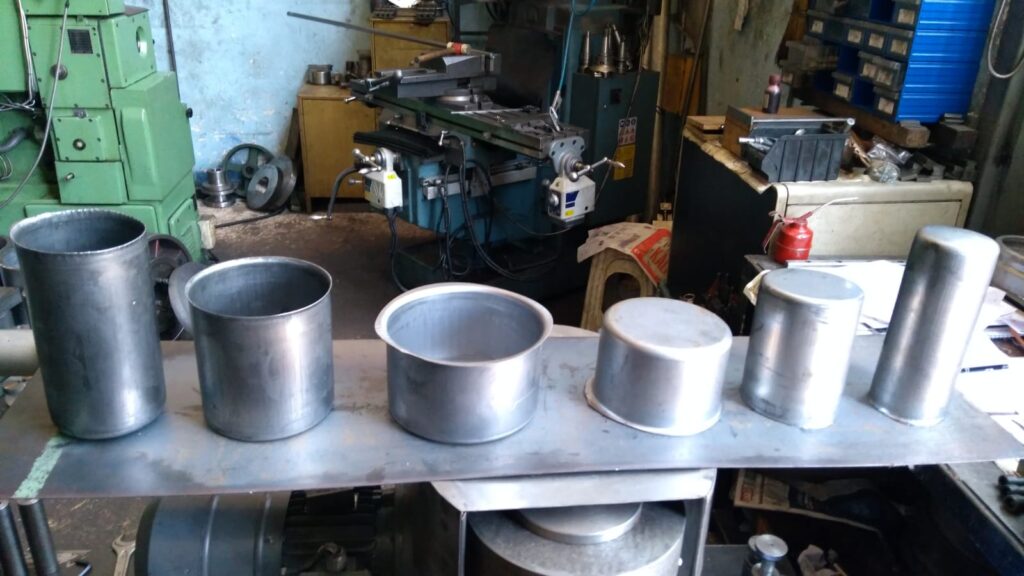
Sheet metal forming machines work with a variety of sheet metal types, each possessing unique properties that influence forming methods, tooling, and machine settings. Selecting the appropriate sheet metal type is critical to achieving desired part quality, dimensional accuracy, surface finish, and mechanical performance. The most common sheet metals used in forming machines include:
1. Mild Steel (Low Carbon Steel):
Mild steel is widely used due to its affordability, good ductility, and ease of forming. It requires moderate forming forces and tooling wear is manageable. Its versatility makes it suitable for automotive parts, appliances, and construction components.
2. Stainless Steel:
Known for corrosion resistance and strength, stainless steel is harder and less ductile than mild steel. It work-hardens rapidly and requires higher forming forces and specialized tooling with wear-resistant coatings. Commonly used in food processing, medical, and architectural applications.
3. Aluminum:
Lightweight with excellent corrosion resistance and thermal conductivity, aluminum alloys vary in formability. Machines forming aluminum need precise control and tooling designed to minimize galling and surface scratches. Widely used in aerospace, automotive, and electronics.
4. Copper:
Copper offers excellent electrical and thermal conductivity, along with good ductility. It is softer than steel but prone to surface damage and galling, necessitating tooling with low-friction coatings and careful lubrication. Used in electrical components, roofing, and decorative products.
5. Brass:
An alloy of copper and zinc, brass is valued for its machinability, corrosion resistance, and aesthetic appeal. It behaves similarly to copper in forming but may require adjusted process parameters to avoid cracking or surface defects.
6. Titanium:
Highly corrosion resistant and strong with excellent strength-to-weight ratio, titanium is challenging to form due to low ductility and high springback. Forming machines must be highly rigid, and tooling materials must withstand wear and heat. Used in aerospace and medical implants.
7. Galvanized Steel:
Steel coated with zinc for corrosion resistance, galvanized steel requires careful forming to avoid coating damage. Specialized lubricants and tooling help preserve the zinc layer during bending or stamping.
8. Advanced High-Strength Steels (AHSS):
Used primarily in automotive industries for lightweight and safety, AHSS grades have high strength but lower ductility. Forming requires high-tonnage presses, precise control, and tooling designed for wear resistance.
9. Nickel Alloys:
These alloys offer high strength and corrosion resistance at elevated temperatures. Forming nickel alloys demands machines capable of handling high forces and tooling resistant to abrasive wear.
Each sheet metal type’s thickness, mechanical properties, surface finish requirements, and coating condition influence the selection and configuration of forming machines and tooling. Understanding these materials enables manufacturers to optimize forming processes, ensuring efficiency, quality, and product performance across diverse applications.
Sheet metal types used in forming machines vary widely not only by their base metal but also by alloy composition, temper, surface finish, and coating, all of which impact formability and machine requirements. Mild steel, with its relatively low carbon content, is favored for its balance of strength and ductility, making it easy to shape on standard press brakes, stamping presses, or roll forming lines. However, variations in thickness and temper can affect springback and tooling wear, so machines must be adjusted accordingly.
Stainless steel’s higher strength and work hardening tendency require forming machines with greater rigidity and force capacity. Tooling must be specially hardened and coated to withstand abrasive wear and prevent galling, and process parameters are carefully controlled to avoid cracking. The surface finish of stainless steel parts is often critical, especially in architectural or medical applications, so machines might integrate features to minimize surface damage during forming.
Aluminum alloys, prized for their light weight and corrosion resistance, present challenges such as pronounced springback and sensitivity to surface scratches. Forming machines for aluminum often use servo-electric drives for precise motion control and tooling with polished, low-friction surfaces to protect the metal. Roll forming aluminum demands careful tension control and lubrication to maintain smooth surfaces and dimensional accuracy, especially for thin gauges.
Copper and its alloys, including brass, are softer metals prone to galling and surface damage. Forming machines use tooling with low-friction coatings and apply specialized lubricants to maintain surface integrity. Because copper is often used in electrical or decorative parts, preserving surface finish during forming is paramount. Machines may include in-line cleaning or polishing stations to prepare parts for subsequent processing.
Galvanized steel adds complexity because the zinc coating can be damaged during forming, leading to corrosion. Forming machines for galvanized steel employ tooling and lubrication systems designed to minimize coating abrasion and prevent zinc pickup on tools. Controlling forming speed and pressure helps maintain coating integrity.
Advanced high-strength steels (AHSS) and ultra-high-strength steels (UHSS) require forming machines capable of delivering very high forces with precise control to manage reduced ductility and higher springback. Servo-driven presses with programmable motion profiles help reduce tool wear and improve forming quality. Simulation and process monitoring play vital roles in optimizing parameters for these challenging materials.
Titanium and nickel alloys, used in aerospace and high-performance applications, are difficult to form due to low ductility and high strength. Forming machines must be exceptionally rigid and equipped with tooling materials that resist wear and heat. Forming speeds and sequences are carefully optimized to avoid cracking.
Ultimately, the choice of sheet metal type dictates the forming machine configuration, tooling design, lubrication strategy, and process parameters. Manufacturers must consider material properties, desired part geometry, surface finish requirements, and production volumes to select or customize forming equipment that delivers consistent, high-quality results. This comprehensive understanding ensures efficient production across a wide range of industries, from automotive and aerospace to electronics and construction.
Beyond the fundamental categories of sheet metal, many manufacturers also work with specialized variants tailored for specific applications, such as pre-coated or laminated sheets, which add layers of paint, plastic, or other materials to metal substrates. These composites require forming machines with precise control to avoid cracking or delamination during bending or stamping. Tooling must be selected or treated to minimize damage to coatings and maintain overall part integrity.
Hot-rolled versus cold-rolled sheet metals also influence forming machine choices. Hot-rolled sheets generally have rougher surfaces and greater dimensional variability, making them more suitable for heavy structural components rather than precision parts. Cold-rolled sheets offer tighter tolerances and smoother finishes, requiring forming machines with finer control and tooling designed to protect surface quality.
Surface treatments such as galvanizing, anodizing (common on aluminum), or electroplating affect formability and tooling selection. These coatings can be thin and brittle, so forming processes must minimize deformation stresses that could crack or flake the surface layer. Forming machines often incorporate slower speeds, optimized die radii, and enhanced lubrication to protect these finishes.
In high-volume production, sheet metal suppliers and manufacturers collaborate closely to match material specifications with forming machine capabilities. This partnership ensures that the chosen sheet metal type and temper align with tooling life expectations and cycle times, balancing cost and quality.
Emerging materials like magnesium alloys and metal matrix composites present new challenges and opportunities. Magnesium, lighter than aluminum but more brittle, demands forming machines with ultra-precise control and tooling that minimizes stress concentrations. Metal matrix composites combine metal with ceramic reinforcements, requiring specialized forming processes and robust machinery due to increased abrasiveness and reduced ductility.
Advances in process monitoring, including in-line thickness measurement, strain sensors, and high-speed imaging, allow forming machines to adapt in real time to variations in sheet metal properties, ensuring consistent quality despite material inconsistencies.
In conclusion, the wide variety of sheet metal types used in forming machines necessitates a comprehensive understanding of material characteristics, surface treatments, and application requirements. Successful forming operations depend on selecting appropriate machines, tooling, and process controls tailored to each metal type, enabling manufacturers to produce precise, high-quality components across diverse industries.
Sheet Metal Forming Machine Manufacturing
Sheet metal forming machine manufacturing is a specialized sector within industrial machinery production that focuses on designing, engineering, and assembling equipment used to shape, bend, cut, and form metal sheets into precise components. This process involves a complex integration of mechanical design, materials science, control systems, and automation technologies to meet the diverse needs of industries such as automotive, aerospace, construction, electronics, and consumer goods.
The manufacturing of sheet metal forming machines begins with a thorough understanding of the types of metals to be formed, part geometries, production volumes, and quality requirements. Machine builders collaborate closely with end-users and tooling manufacturers to tailor machines for specific applications, whether it’s high-speed stamping presses for automotive panels or precise press brakes for architectural metalwork.
Mechanical design is foundational, emphasizing structural rigidity and durability to withstand high forming forces and repetitive operations without loss of accuracy. Frame construction typically employs heavy-duty steel welded or cast assemblies engineered to minimize deflection. Components such as hydraulic cylinders, servo-electric drives, mechanical linkages, and bearings are selected or designed to provide the required force, speed, and precision.
Tooling integration is critical; machines are designed to accommodate various die sets, punches, and forming tools with features like quick-change systems and modular mounting. Accurate alignment systems ensure consistent tooling positioning, essential for maintaining dimensional tolerances and part quality.
Control systems are a major focus area. Modern forming machines incorporate programmable logic controllers (PLCs), CNC units, and human-machine interfaces (HMIs) that enable complex motion profiles, automated sequencing, and real-time monitoring. These controls allow for precise adjustment of stroke speed, ram position, force application, and cycle timing, optimizing forming processes and reducing scrap.
Automation is increasingly integrated during machine manufacturing, including robotic material handling, automatic tool changers, and in-line quality inspection systems. These additions improve production efficiency, reduce manual labor, and enhance safety.
Quality assurance is integral throughout manufacturing, with machine components undergoing rigorous testing, including stress analysis, precision measurements, and endurance trials. Many manufacturers employ digital simulation tools and finite element analysis (FEA) during design and prototyping to predict machine behavior under load and identify potential failure points.
Sustainability considerations influence machine design and manufacturing processes, with emphasis on energy-efficient drives, hydraulic systems with load-sensing valves, and recyclable materials. Manufacturers also focus on reducing waste in production and designing machines for easier maintenance and longer service life.
After assembly, sheet metal forming machines undergo comprehensive commissioning and calibration, often including customer training and support services to ensure optimal integration into production environments.
In summary, sheet metal forming machine manufacturing is a multidisciplinary endeavor combining mechanical engineering, electronics, software, and materials expertise. It delivers robust, precise, and flexible machinery essential for efficient and high-quality metal forming operations across diverse industrial sectors.
The manufacturing process of sheet metal forming machines involves multiple stages, starting with detailed design and engineering. Computer-aided design (CAD) and computer-aided engineering (CAE) tools are extensively used to create accurate 3D models and perform structural simulations. These simulations assess machine frame rigidity, stress distribution, and dynamic behavior during forming operations, helping optimize the design for strength, durability, and precision before physical prototypes are built.
Material selection is crucial; high-strength steels and alloys are typically used for frames and critical components to withstand the high forces generated during forming. Precision machining of parts such as guideways, shafts, and ram assemblies ensures smooth, accurate movement and long service life. Advanced manufacturing technologies like CNC machining, laser cutting, and robotic welding are employed to achieve tight tolerances and consistent quality.
Assembly requires skilled technicians who fit together mechanical, hydraulic, and electronic subsystems. Hydraulics or servo-electric drives are installed based on machine type and application, with hydraulic systems featuring carefully calibrated pumps, valves, and accumulators for controlled force delivery. Servo-electric systems incorporate motors, encoders, and drives for precise motion control and energy efficiency.
Electrical and control systems are integrated, including PLCs, CNC units, safety interlocks, and user interfaces. Wiring harnesses and sensor arrays are installed to provide real-time feedback on machine operation parameters such as position, speed, pressure, and temperature. These systems enable programmable forming cycles, diagnostics, and communication with factory automation networks.
Testing and quality assurance are critical steps before machines leave the factory. Functional testing verifies mechanical movement, force application, and control responsiveness under simulated load conditions. Safety features, including emergency stops and guarding, are rigorously checked. Calibration ensures that forming parameters meet design specifications and that repeatability and accuracy conform to industry standards.
Manufacturers often provide on-site installation, commissioning, and operator training as part of their service. This support ensures that machines integrate smoothly into existing production lines and that operators are proficient in setup, programming, and maintenance.
Continuous innovation in sheet metal forming machine manufacturing includes developing modular designs for easier customization and upgrading, incorporating IoT connectivity for predictive maintenance and process monitoring, and utilizing environmentally friendly materials and energy-saving technologies. These advances help manufacturers meet evolving market demands for flexibility, efficiency, and sustainability.
In essence, manufacturing sheet metal forming machines is a complex, multidisciplinary process that combines advanced engineering, precision manufacturing, sophisticated controls, and thorough testing. The result is highly reliable and adaptable equipment capable of delivering consistent, high-quality metal forming performance across a broad range of industrial applications.
In recent years, the sheet metal forming machine manufacturing industry has increasingly embraced digital transformation to enhance design, production, and after-sales support. The integration of Industry 4.0 principles allows manufacturers to connect machines to cloud-based platforms, enabling remote monitoring, data analytics, and predictive maintenance. This connectivity improves machine uptime, optimizes performance, and provides valuable insights for continuous improvement.
Additive manufacturing technologies, such as 3D printing, are being explored for producing complex machine components and custom tooling. These methods enable faster prototyping and the creation of intricate geometries that improve machine efficiency and reduce weight without compromising strength. This flexibility accelerates development cycles and facilitates tailored machine solutions for specific customer needs.
Sustainability also plays a growing role in machine manufacturing. Efforts to reduce energy consumption during both production and operation have led to the adoption of servo-electric drives and regenerative braking systems that capture and reuse energy. Manufacturers prioritize using recyclable materials and designing machines for easier disassembly and component recycling at end-of-life.
Human factors engineering influences machine design to enhance operator safety, comfort, and productivity. Ergonomic control panels, adjustable work heights, and intuitive interfaces reduce operator fatigue and errors. Safety systems incorporate advanced sensors and machine vision to detect hazards and automatically halt operations if necessary.
Collaborations between machine builders, material suppliers, and end-users foster innovation tailored to emerging materials like advanced high-strength steels, aluminum alloys, and composites. These partnerships focus on co-developing forming processes and equipment that maximize material performance while minimizing defects and waste.
Training and service models have evolved with technology, offering virtual reality (VR) and augmented reality (AR) tools for operator instruction and remote troubleshooting. This digital support accelerates machine adoption and reduces downtime, especially in geographically dispersed facilities.
In conclusion, sheet metal forming machine manufacturing is progressing through the integration of digital technologies, sustainable practices, advanced materials, and user-centric design. These developments equip manufacturers with flexible, efficient, and intelligent forming solutions that meet the complex demands of modern industries, driving innovation and competitiveness in metal fabrication worldwide.
Automated Sheet Metal Forming Machine
Automated sheet metal forming machines represent the forefront of modern metal fabrication technology, combining mechanical precision, advanced control systems, robotics, and real-time monitoring to deliver high productivity, consistent quality, and reduced labor costs. These machines are designed to perform complex forming operations—such as bending, stamping, punching, and drawing—with minimal human intervention, enabling manufacturers to meet the demands of mass production and intricate part geometries.
At the core of automation is the integration of CNC (computer numerical control) systems that precisely govern machine motion, force application, and cycle timing. CNC enables rapid changeovers between different part designs and accurate reproduction of complex forming sequences, improving flexibility and reducing setup times. Advanced software tools allow operators to program and simulate forming processes digitally, optimizing parameters before production begins.
Robotic systems often complement automated forming machines by handling material loading, unloading, and transfer between process stations. Robots equipped with vision systems and force sensors ensure precise positioning and gentle handling of sheet metal parts, minimizing surface damage and alignment errors. This seamless integration of robotics enhances throughput and operational safety by reducing manual handling in high-force environments.
Sensors embedded throughout the forming machine provide real-time data on parameters such as ram position, forming force, temperature, and vibration. This data feeds into intelligent control algorithms and predictive maintenance platforms, enabling early detection of tool wear, misalignment, or machine faults. Consequently, unplanned downtime is minimized, and machine lifespan is extended.
Automated sheet metal forming lines often include in-line quality inspection systems employing laser scanners, cameras, or tactile probes to verify dimensional accuracy and surface finish immediately after forming. Feedback from inspection stations can trigger automatic adjustments in forming parameters or reject defective parts, ensuring consistent product quality.
Energy efficiency is enhanced in automated machines through servo-electric drives that provide precise, programmable motion while reducing power consumption compared to traditional hydraulic systems. Regenerative energy systems capture kinetic energy during deceleration phases, further optimizing energy usage.
User interfaces in automated forming machines are designed for intuitive operation, featuring touchscreens, guided workflows, and remote access capabilities. Operators can monitor machine status, adjust parameters, and receive alerts from anywhere, supporting efficient production management.
Modular machine architectures enable manufacturers to scale automation by adding or reconfiguring forming stations, robotic cells, or inspection units to match changing production needs. This scalability supports diverse production volumes and complex part families without extensive retooling.
In summary, automated sheet metal forming machines blend CNC precision, robotics, sensor-driven intelligence, and flexible architectures to revolutionize metal fabrication. They deliver high-speed, repeatable, and quality-controlled forming processes that meet the stringent demands of automotive, aerospace, electronics, and consumer goods industries, driving efficiency and competitiveness in manufacturing operations.
Automated sheet metal forming machines continue to evolve by integrating cutting-edge technologies that enhance productivity, quality, and flexibility. The combination of advanced robotics and intelligent control systems allows for seamless coordination between forming processes and material handling, reducing cycle times and increasing throughput. Robots with multi-axis capabilities can perform complex pick-and-place operations, part orientation, and even secondary processes like deburring or welding within the forming line, further streamlining production.
Real-time monitoring through embedded sensors enables adaptive control, where the machine automatically adjusts parameters such as forming speed, force, and ram position to compensate for material variability or tooling wear. This closed-loop feedback system minimizes defects and optimizes tool life, significantly lowering operating costs. Machine learning algorithms analyze historical and live data to predict maintenance needs, identify process inefficiencies, and suggest improvements, facilitating continuous process optimization.
Safety systems in automated forming machines are highly sophisticated, incorporating light curtains, pressure-sensitive mats, and vision-based monitoring to ensure operator protection without compromising production speed. Collaborative robots (cobots) are also increasingly employed, working alongside human operators to assist with tasks that require flexibility and dexterity, thereby combining human judgment with machine precision.
The software ecosystems supporting automated forming lines often include integrated manufacturing execution systems (MES) that coordinate scheduling, resource allocation, and quality management. These platforms provide comprehensive traceability, linking formed parts back to raw material batches, machine settings, and operator actions, which is essential for industries with strict regulatory requirements.
Automation reduces reliance on manual labor, which not only cuts costs but also improves workplace ergonomics and reduces human error. The consistency and repeatability offered by automated machines lead to tighter tolerances and higher yields, essential in sectors such as automotive and aerospace where safety and performance are paramount.
Scalable automation solutions allow manufacturers to start with semi-automated setups and progressively add robotic cells, sensors, and advanced controls as production demands grow. This modularity supports small-batch customization as well as high-volume manufacturing, making automated sheet metal forming accessible to a wide range of companies.
In essence, automated sheet metal forming machines embody the convergence of mechanical engineering, robotics, data analytics, and smart manufacturing. These systems empower manufacturers to achieve superior efficiency, product quality, and operational agility, positioning them competitively in the fast-evolving landscape of modern metal fabrication.
Further developments in automated sheet metal forming machines focus on enhancing connectivity and interoperability within the smart factory environment. By adopting Industrial Internet of Things (IIoT) technologies, these machines can communicate seamlessly with upstream and downstream equipment, such as coil feeding systems, welding stations, and painting lines. This integrated approach enables synchronized workflows, reduces bottlenecks, and supports real-time production adjustments based on demand fluctuations or quality feedback.
Cloud-based platforms enable remote monitoring and diagnostics, allowing machine manufacturers and service providers to offer proactive support and rapid troubleshooting. This connectivity reduces downtime and helps optimize maintenance schedules by leveraging predictive analytics derived from machine performance data. Operators and managers gain access to detailed dashboards showing key performance indicators (KPIs), energy consumption, and production trends, facilitating data-driven decision-making.
Artificial intelligence (AI) is increasingly being applied to automate complex tasks such as defect detection, process optimization, and anomaly identification. Machine vision systems powered by AI can identify surface imperfections, dimensional deviations, or assembly errors faster and more accurately than traditional inspection methods. AI algorithms analyze forming patterns to recommend parameter adjustments that improve forming quality and tool longevity.
Customization remains a priority, with automated sheet metal forming machines offering flexible tooling systems and programmable processes that accommodate a wide variety of part designs without extensive retooling. Quick-change tooling and modular machine components enable rapid changeovers, reducing downtime between production runs and supporting just-in-time manufacturing principles.
Sustainability is addressed through energy-efficient components, such as servo drives that minimize power use and regenerative braking systems that recycle energy. Automated lubrication and coolant delivery systems optimize fluid use, reducing waste and environmental impact. Additionally, automation helps minimize material scrap by improving forming accuracy and enabling tighter nesting of parts on sheet metal blanks.
Emerging trends include the integration of additive manufacturing techniques for producing custom tooling and machine parts, accelerating prototyping and reducing lead times. Hybrid forming systems that combine traditional mechanical forming with technologies like laser-assisted or ultrasonic forming are also being explored to expand capabilities and process difficult-to-form materials.
In summary, automated sheet metal forming machines are evolving into intelligent, connected systems that leverage advanced robotics, AI, and digital technologies to deliver flexible, efficient, and sustainable metal fabrication solutions. These innovations empower manufacturers to meet the increasing complexity and quality demands of today’s industries while maintaining high productivity and operational excellence.
Automatic Hydraulic Sheet Metal Forming Machines
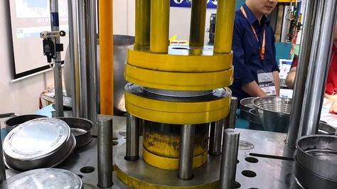
Automatic hydraulic sheet metal forming machines utilize hydraulic power systems combined with automation technologies to perform precise, high-force metal forming operations such as bending, stamping, punching, and deep drawing. These machines are designed to deliver consistent, controllable force throughout the entire stroke, making them ideal for forming a wide variety of metals—including steel, aluminum, copper, and advanced alloys—across diverse thicknesses and part complexities.
Hydraulic systems provide smooth, adjustable force application, allowing operators to fine-tune forming pressure and speed to accommodate different materials and geometries. This precise control reduces the risk of defects like cracking, wrinkling, or excessive springback. Automated hydraulic forming machines integrate CNC or PLC control units that manage ram position, speed, dwell time, and pressure, enabling complex forming sequences and quick changeovers between different parts.
Automation enhances these machines with features such as robotic material handling for loading and unloading sheets or blanks, automatic tool changers, and in-line sensors that monitor force, displacement, and machine health in real time. Such integration reduces manual labor, improves safety, and boosts throughput.
The frame and structural components of automatic hydraulic forming machines are engineered for rigidity and durability to withstand high cyclic loads without deformation. Precision-machined guideways and bearings ensure smooth, accurate ram movement, critical for maintaining dimensional tolerances and part quality.
Energy efficiency is addressed through advanced hydraulic components like variable displacement pumps and servo-hydraulic drives that optimize power usage by delivering flow and pressure only as needed. Regenerative systems can capture and reuse energy during ram deceleration, further reducing operating costs.
In-line quality inspection systems are often incorporated, using laser scanners or vision systems to verify formed part dimensions and surface quality immediately after processing. Feedback from these systems can automatically adjust forming parameters or trigger maintenance alerts.
User-friendly interfaces with touchscreens and programmable logic controllers allow operators to easily set up, monitor, and adjust forming programs. Remote access capabilities enable real-time diagnostics and support, minimizing downtime.
Applications for automatic hydraulic sheet metal forming machines span automotive body panels, appliance enclosures, aerospace components, electrical enclosures, and more. Their combination of high force capacity, precise control, and automation makes them well-suited for producing complex shapes with tight tolerances at medium to high production volumes.
In essence, automatic hydraulic sheet metal forming machines merge the power and controllability of hydraulic systems with the efficiency and precision of automation, delivering versatile and reliable solutions for modern metal fabrication challenges.
Automatic hydraulic sheet metal forming machines have grown increasingly sophisticated with the integration of advanced sensors and control algorithms that enable adaptive forming processes. These sensors continuously monitor parameters such as pressure, ram position, and force, allowing the control system to make real-time adjustments to compensate for variations in material properties or thickness. This adaptability improves part quality, reduces scrap, and extends tool life by preventing overloading or excessive deformation.
The hydraulic power units in these machines are often equipped with variable displacement pumps and servo valves, which provide precise control over flow and pressure while minimizing energy consumption. By supplying hydraulic power only when needed and recovering energy during ram deceleration, these systems contribute to greener manufacturing operations and lower operating costs.
Robotic automation is commonly integrated with automatic hydraulic forming machines to handle sheet loading, positioning, and unloading, ensuring consistent part orientation and reducing operator involvement in potentially hazardous environments. Collaborative robots (cobots) can also work alongside human operators to assist with setup, inspection, or minor adjustments, combining flexibility with safety.
Tooling systems for these machines emphasize quick-change capabilities and modular designs to support rapid transitions between different part geometries and production runs. Tool steels with specialized surface treatments reduce friction and wear, which is especially important when forming abrasive or high-strength materials.
Safety features are comprehensive, incorporating pressure relief valves, emergency stop functions, guarded access points, and sensor-based presence detection to protect operators. The automation system continuously monitors machine health and operational parameters, triggering alerts or shutdowns if abnormalities are detected.
User interfaces have evolved to provide intuitive graphical displays, guided setup wizards, and remote monitoring options, enabling operators to manage complex forming sequences with ease. Integration with manufacturing execution systems (MES) and enterprise resource planning (ERP) software facilitates production tracking, quality control, and maintenance scheduling.
Automatic hydraulic sheet metal forming machines are well-suited for industries requiring high precision and repeatability, such as automotive manufacturing, aerospace, heavy equipment production, and consumer electronics. Their ability to handle a wide range of materials and thicknesses with consistent force application and automation support makes them versatile tools for modern metal fabrication.
In summary, the combination of hydraulic power, advanced automation, and intelligent controls in automatic hydraulic sheet metal forming machines delivers efficient, precise, and flexible forming solutions. These systems meet the demands of high-volume production environments while optimizing energy use, safety, and product quality.
Advancements in automatic hydraulic sheet metal forming machines continue to focus on enhancing precision, efficiency, and integration within fully automated production lines. One key development is the incorporation of multi-axis hydraulic systems, which allow not only vertical forming motion but also controlled lateral and rotational movements. This multi-directional capability expands the complexity of parts that can be formed in a single machine, reducing the need for multiple operations and increasing overall productivity.
Hybrid systems combining hydraulic power with electric servo drives are also emerging, offering the benefits of high force and smooth control from hydraulics alongside the energy efficiency and precise positioning of electric actuators. These hybrid machines can optimize power consumption by using hydraulics only for heavy-force sections of a forming cycle, while servo drives handle positioning and low-force movements, achieving a balance between performance and efficiency.
Machine builders are increasingly incorporating digital twin technology to simulate forming processes and machine behavior virtually. This allows engineers to optimize machine settings, tooling design, and cycle parameters before physical production, minimizing trial-and-error and reducing lead times. Digital twins also assist in predictive maintenance by modeling wear patterns and identifying potential failures in advance.
The integration of Industry 4.0 technologies enables automatic hydraulic forming machines to communicate with other equipment and factory systems, facilitating real-time production monitoring, quality assurance, and inventory management. Cloud connectivity allows remote access to machine diagnostics and performance data, supporting proactive service and minimizing downtime.
Environmental considerations are driving the design of more eco-friendly hydraulic systems with biodegradable fluids, improved sealing technologies to prevent leaks, and energy recovery mechanisms. These measures reduce environmental impact and comply with stricter regulations.
Customization and modularity remain important, with manufacturers offering machines that can be quickly adapted or expanded through modular components to handle new part designs or production scales. This flexibility supports just-in-time manufacturing and rapid response to changing market demands.
In summary, automatic hydraulic sheet metal forming machines are evolving into highly versatile, intelligent, and energy-efficient systems. By combining advanced hydraulic technology with digital integration, automation, and sustainable design, they continue to meet the increasingly complex requirements of modern metal forming industries while enhancing productivity and product quality.
Sheet Metal Flange Folding Machines
Sheet metal flange folding machines are specialized forming equipment designed to bend or fold the edges—or flanges—of sheet metal parts with precision and efficiency. Flanging is a critical process in metal fabrication used to strengthen edges, create joints, facilitate assembly, or prepare parts for welding and fastening. These machines are widely used in industries such as automotive, HVAC, appliance manufacturing, and construction.
Flange folding machines operate by clamping the sheet metal securely and then bending the edge along a predefined line to form a flange at a specific angle, commonly between 0° and 180°. The folding process can be performed on various metals, including steel, aluminum, stainless steel, and copper, across different thicknesses and flange widths.
There are several types of flange folding machines, ranging from manual or semi-automatic bench-top units to fully automatic CNC-controlled systems. Manual machines are suitable for small-scale production or prototype work, where operators control the folding angle and feed the material by hand. Semi-automatic machines incorporate hydraulic or electric drives to automate bending motions, improving consistency and throughput.
Fully automatic flange folding machines integrate CNC controls that allow programming of flange angles, lengths, and folding sequences. These systems often include automated material feeding, positioning, and unloading, supported by robotic arms or conveyor systems, enabling high-volume production with minimal operator intervention. CNC machines can also handle complex flange patterns, including varying angles and incremental bends along the same edge.
The machine’s tooling is designed to apply uniform pressure along the flange line, ensuring smooth bends without cracking or distortion. Tools are often made from hardened steel and may have interchangeable segments to accommodate different flange widths and materials. Some machines include adjustable clamps and bending beams to handle a wide range of sheet thicknesses and shapes.
Modern flange folding machines may also incorporate sensors and feedback systems to monitor bending force and angle in real time, enabling adaptive control and quality assurance. This reduces scrap and ensures parts meet tight dimensional tolerances.
Applications for flange folding machines include forming flanges on ductwork panels, automotive body parts, appliance housings, electrical enclosures, and structural components. The process enhances part rigidity, facilitates assembly through bolt or rivet fastening, and prepares edges for sealing or welding.
In essence, sheet metal flange folding machines provide a reliable, precise, and efficient method to create flanges on sheet metal parts, supporting diverse manufacturing needs across multiple industries by improving structural integrity and assembly readiness.
Sheet metal flange folding machines continue to evolve with advancements in automation, precision control, and versatility to meet the increasing demands of modern manufacturing. CNC-controlled flange folding machines now allow operators to program complex folding sequences, including multiple flange bends at varying angles and lengths on a single workpiece. This capability supports the production of intricate components used in automotive assemblies, HVAC systems, and appliance fabrication.
Automation features such as servo-driven bending beams and hydraulic clamping systems provide consistent force application and repeatable folds, reducing operator fatigue and minimizing the risk of defects like cracking or uneven bends. Automated sheet feeding and positioning systems integrated with vision or laser measurement tools ensure accurate placement and alignment of each part before folding, which is critical for maintaining tight dimensional tolerances in high-volume production.
Modular tooling systems enhance the flexibility of flange folding machines by allowing quick changes between different flange widths, material thicknesses, and bend radii without extensive downtime. This adaptability is essential for manufacturers producing a variety of part designs or switching between small and large production runs.
Advanced sensor technology embedded within the machines continuously monitors bending force, angle, and material response during the folding process. Real-time feedback enables adaptive control, where the machine can adjust parameters dynamically to compensate for material inconsistencies or tool wear, ensuring consistent quality and reducing scrap rates.
Ergonomic designs and user-friendly interfaces with touchscreen controls simplify programming, setup, and operation. Many systems provide simulation software that visually previews folding sequences and detects potential collisions or errors before actual forming, enhancing safety and efficiency.
Safety mechanisms such as light curtains, emergency stops, and guarded enclosures protect operators from moving parts and high clamping forces, complying with industry safety standards while maintaining productivity.
Applications for flange folding machines range from small brackets and enclosures to large duct panels and structural components. The ability to produce strong, precise flanges improves part assembly, sealing, and load-bearing capabilities, which is critical in sectors such as construction, transportation, and consumer appliances.
Overall, sheet metal flange folding machines combine mechanical robustness, precision automation, and flexible tooling to deliver efficient, high-quality flange forming solutions. Their integration into modern production lines supports manufacturers in achieving consistent product quality, reduced cycle times, and the ability to respond swiftly to changing market demands.
Further innovations in sheet metal flange folding machines emphasize integration within fully automated production systems and enhanced process intelligence. These machines increasingly interface with upstream and downstream equipment such as laser cutters, punching presses, welding stations, and robotic assembly cells, enabling seamless material flow and synchronized operations. This interconnectedness reduces manual handling, accelerates throughput, and supports just-in-time manufacturing strategies.
The adoption of Industry 4.0 technologies allows flange folding machines to collect and analyze vast amounts of operational data. Machine learning algorithms process this data to optimize folding parameters, predict tool wear, and detect anomalies early. Predictive maintenance minimizes unexpected downtime and extends machine service life, while continuous process optimization improves part quality and reduces scrap.
Hybrid machines combining mechanical, hydraulic, and electric actuation provide enhanced control over folding dynamics, accommodating a wider range of materials and flange geometries. Such systems offer the high force capacity needed for thicker metals alongside the precision and energy efficiency of servo-electric drives for lighter tasks.
Modularity remains a key design principle, with manufacturers offering customizable machine configurations to meet diverse production requirements. Quick-change tooling, adjustable clamping systems, and configurable control software enable rapid adaptation to new part designs or batch sizes, improving manufacturing agility.
Sustainability is addressed through energy-efficient components, hydraulic fluid recycling, and reduced material waste enabled by precise folding and in-line quality monitoring. Ergonomic machine designs and safety innovations protect operators while facilitating easy maintenance and setup.
Applications of advanced flange folding machines extend beyond traditional sectors into emerging markets such as renewable energy, electric vehicle manufacturing, and smart infrastructure components. The ability to produce complex, high-strength flanges reliably supports the structural integrity and functionality demanded by these innovative fields.
In summary, sheet metal flange folding machines are evolving into intelligent, connected, and highly adaptable systems. By leveraging automation, data analytics, and flexible design, they empower manufacturers to achieve superior quality, efficiency, and responsiveness in metal fabrication, meeting the challenges of today’s dynamic industrial landscape.
Sheet Metal Forming Processes
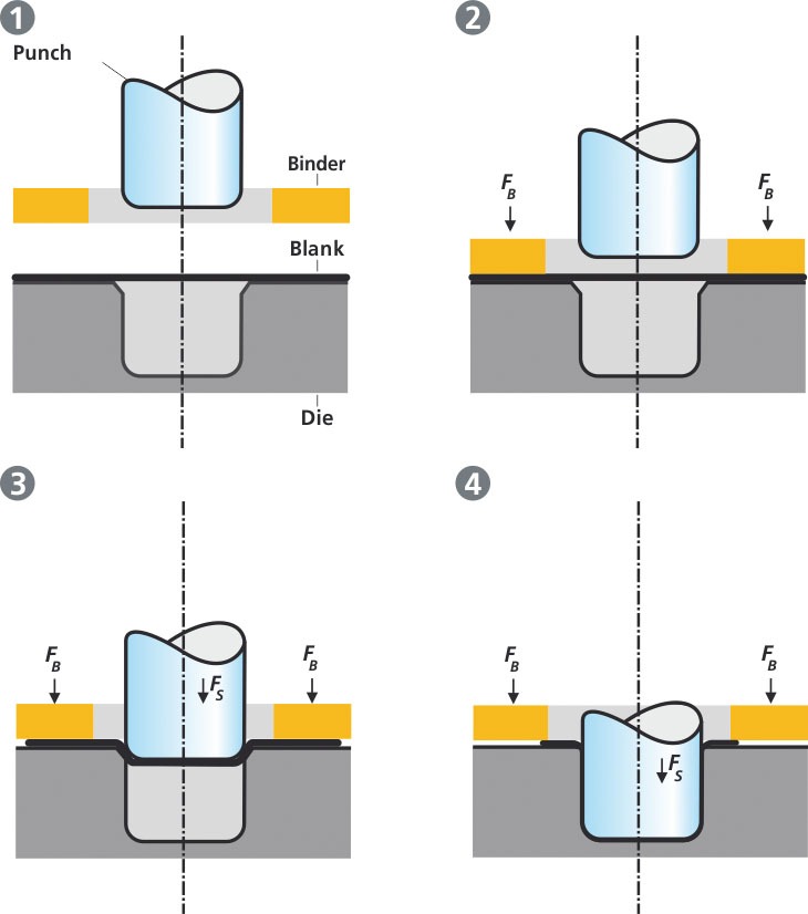
Sheet metal forming processes encompass a variety of manufacturing techniques used to shape flat metal sheets into desired geometries through plastic deformation without removing material. These processes rely on controlled application of force, usually via presses, dies, rollers, or bending tools, to transform sheet metal into components used in industries like automotive, aerospace, appliances, construction, and electronics.
Common sheet metal forming processes include bending, where the sheet is plastically deformed along a straight axis to create angles or flanges; deep drawing, which involves stretching the metal into a die cavity to form cup-like or box-shaped parts; stamping or pressing, where dies cut or form the metal through compressive force; roll forming, which gradually shapes metal by passing it through a series of rollers; and spinning, where the sheet is rotated and formed over a mandrel to create symmetrical, round parts.
Each process requires specific machinery, tooling, and process parameters tailored to the metal type, thickness, part geometry, and production volume. Proper control of factors such as force magnitude, speed, lubrication, and temperature is essential to avoid defects like wrinkling, cracking, springback, or tearing.
Advanced forming techniques include hydroforming, where fluid pressure is used to shape the metal, enabling complex geometries with uniform thickness, and incremental forming, which deforms the sheet progressively with localized tools, allowing for flexible, low-volume production without dedicated dies.
The choice of forming process depends on design requirements, material characteristics, and economic considerations, balancing factors like precision, surface finish, mechanical properties, and tooling costs. Together, these processes provide versatile solutions for efficiently producing high-quality sheet metal components across a broad range of applications.
Sheet metal forming processes continue to advance through improvements in materials, tooling, and machine technology, enabling more complex shapes, tighter tolerances, and higher production speeds. Bending remains one of the most widely used methods due to its simplicity and versatility, with innovations such as air bending, bottoming, and coining techniques offering varying degrees of precision and force requirements. CNC press brakes equipped with back gauges and programmable crowning systems allow for automated bending sequences, reducing setup times and increasing repeatability.
Deep drawing processes have evolved to accommodate lightweight and high-strength materials by optimizing die design, lubrication, and forming speeds to minimize defects like wrinkling or tearing. Multi-stage drawing operations and draw beads help control material flow and thickness distribution, while finite element analysis (FEA) tools assist in predicting outcomes and refining process parameters.
Stamping and pressing technologies incorporate progressive dies that perform multiple forming and cutting operations in a single stroke, significantly enhancing efficiency for high-volume production. Transfer presses and servo-driven stamping presses provide precise control over force and speed, allowing the forming of complex features while reducing noise and energy consumption.
Roll forming is particularly effective for producing long, uniform profiles with consistent cross-sections, such as channels, angles, or tubes. Advances in roll tooling materials and CNC-controlled roll positioning enable precise dimensional control and accommodate varying material thicknesses.
Spinning techniques have benefited from CNC-controlled lathes and roller heads that allow for the rapid production of axisymmetric parts with smooth finishes. This process is especially valuable for producing custom or low-volume components with variable thickness and complex curves.
Emerging processes like hydroforming and incremental sheet forming provide new opportunities for manufacturing complex parts with fewer tooling costs. Hydroforming uses high-pressure fluid to form the sheet within a die, achieving intricate shapes and improved material distribution, while incremental forming deforms localized areas gradually, ideal for prototyping or small-batch production.
Throughout all these processes, material behavior such as strain hardening, anisotropy, and springback is carefully considered. The integration of process monitoring, sensor feedback, and simulation tools enhances control, enabling manufacturers to reduce waste, improve quality, and shorten time-to-market.
In summary, sheet metal forming processes form the backbone of modern metal fabrication, continuously adapting and innovating to meet the demands of increasingly complex designs, diverse materials, and efficient production methods across numerous industries.
Recent trends in sheet metal forming processes emphasize digitalization, automation, and sustainability. The adoption of Industry 4.0 technologies allows real-time monitoring of forming parameters such as force, displacement, and strain using embedded sensors. This data is analyzed to detect anomalies, optimize process conditions, and enable predictive maintenance, thereby reducing downtime and scrap rates.
Automation plays a crucial role in increasing throughput and consistency. Robotic material handling systems load and unload sheet metal, transfer parts between forming stations, and perform secondary operations like trimming or inspection. Coupled with CNC-controlled forming machines, automation ensures precise, repeatable processes with minimal human intervention.
Sustainability concerns drive efforts to minimize material waste, energy consumption, and environmental impact. Advanced nesting algorithms optimize blank layouts to reduce scrap, while energy-efficient servo drives and regenerative braking systems lower power usage during forming cycles. Lubricants and coolants are managed to minimize usage and enable recycling.
Material innovations also influence forming processes. The use of advanced high-strength steels (AHSS), aluminum alloys, and composite-metal laminates requires tailored forming strategies to handle reduced ductility and increased springback. Simulation tools and adaptive forming technologies help manufacturers accommodate these challenges while maintaining part quality.
Hybrid forming processes that combine traditional mechanical forming with emerging methods such as laser-assisted forming or electromagnetic forming expand capabilities to shape difficult materials or achieve novel geometries.
In summary, sheet metal forming processes continue to evolve by integrating digital technologies, automation, sustainable practices, and advanced materials. These developments empower manufacturers to produce complex, high-quality metal components efficiently, meeting the growing demands of modern industries with agility and environmental responsibility.
CNC Sheet Metal Forming Machine
A CNC (Computer Numerical Control) sheet metal forming machine is an advanced piece of equipment that uses computer programming to automate and precisely control metal forming operations such as bending, cutting, punching, and shaping sheet metal parts. These machines enhance productivity, accuracy, and repeatability by eliminating manual adjustments and enabling complex forming sequences with minimal operator intervention.
CNC forming machines typically include components such as servo-electric or hydraulic drives, precision tooling, sensors, and a computer control system. Operators program the desired part geometry, bending angles, sequences, and tool paths into the CNC controller, which then executes the forming operations automatically. This programming capability allows rapid changeovers between different parts and supports batch sizes ranging from prototypes to high-volume production.
One common type of CNC sheet metal forming machine is the CNC press brake, used extensively for bending operations. These machines feature backgauges and crowning systems controlled by CNC to position the workpiece accurately and compensate for deflection in the machine frame, ensuring consistent bend angles across the length of the part. CNC punching machines and laser cutters also fall under this category, combining precise tool movement with computer control to create complex shapes and features.
The integration of sensors and feedback systems allows CNC forming machines to monitor force, position, and other parameters in real time. This feedback enables adaptive control, where the machine can adjust parameters on-the-fly to account for material inconsistencies or tooling wear, improving part quality and reducing waste.
User interfaces on CNC sheet metal forming machines are typically touchscreen-based with graphical programming environments that simplify setup and operation. Advanced software features include offline programming, simulation of forming sequences, and integration with CAD/CAM systems, which streamline workflow from design to production.
CNC sheet metal forming machines are widely used in automotive manufacturing, aerospace, electronics, appliance production, and construction industries due to their flexibility, precision, and efficiency. They allow manufacturers to produce complex parts with tight tolerances, consistent quality, and shorter lead times, meeting the demands of modern, highly competitive markets.
In summary, CNC sheet metal forming machines combine automation, precision engineering, and intelligent control to revolutionize metal fabrication, enabling efficient production of diverse, high-quality sheet metal components.
CNC sheet metal forming machines continue to advance with innovations that enhance their capabilities, ease of use, and integration into smart manufacturing environments. Modern CNC machines often feature multi-axis control, allowing simultaneous movements along several axes for complex bending, shaping, and forming tasks. This multi-axis capability enables the production of intricate geometries that would be difficult or impossible to achieve with traditional manual or simpler CNC equipment.
The integration of servo-electric drives in CNC machines offers precise motion control, high energy efficiency, and reduced maintenance compared to hydraulic systems. These drives provide smooth acceleration and deceleration, minimizing mechanical stresses on the machine and tooling, which prolongs service life and improves forming accuracy.
Software improvements have made programming CNC sheet metal forming machines more intuitive and powerful. Offline programming tools allow engineers to create and simulate forming sequences before physical production, identifying potential issues and optimizing parameters to reduce trial-and-error. Integration with CAD/CAM software enables seamless transition from part design to machine code, accelerating the manufacturing workflow.
Real-time monitoring and diagnostic systems embedded in CNC machines provide continuous feedback on key metrics such as bending force, ram position, and tool wear. Advanced analytics and machine learning algorithms analyze this data to predict maintenance needs, optimize forming parameters, and improve overall equipment effectiveness (OEE). These capabilities reduce downtime and enhance product quality by ensuring consistent forming conditions.
Automation complements CNC forming machines by incorporating robotic material handling, automated tool changers, and in-line inspection systems. Robots can load and unload sheets, reposition parts between stations, and handle finished components, significantly increasing throughput and reducing labor costs. Automated tool changers enable quick transitions between different forming tools, minimizing setup times and allowing greater production flexibility.
Safety features on CNC sheet metal forming machines include light curtains, safety interlocks, and ergonomic designs that protect operators without compromising productivity. User-friendly interfaces with guided workflows and remote access capabilities facilitate efficient machine operation and troubleshooting.
Industries such as automotive, aerospace, electronics, and construction rely heavily on CNC sheet metal forming machines for their ability to produce complex, high-precision parts at scale. The flexibility to handle a wide range of materials—from mild steel to advanced high-strength alloys and aluminum—makes these machines indispensable for modern manufacturing.
In summary, CNC sheet metal forming machines represent a convergence of mechanical precision, advanced control systems, and automation technologies. Their ongoing evolution drives improved efficiency, quality, and adaptability in metal fabrication, helping manufacturers meet the increasing demands of diverse and sophisticated applications.
Building on these advances, CNC sheet metal forming machines increasingly support integration into fully connected smart factories. By leveraging Industrial Internet of Things (IIoT) technologies, these machines communicate with other production equipment, manufacturing execution systems (MES), and enterprise resource planning (ERP) software. This connectivity enables real-time production monitoring, data-driven decision-making, and seamless coordination across manufacturing stages.
Cloud-based platforms facilitate remote monitoring and diagnostics, allowing machine builders and maintenance teams to provide proactive support and reduce downtime. Operators and managers can access detailed dashboards displaying machine health, production metrics, and quality data from anywhere, improving responsiveness and operational efficiency.
The use of digital twins—virtual replicas of physical machines and processes—has become more prevalent in CNC sheet metal forming. Digital twins enable simulation of forming sequences, predictive maintenance planning, and process optimization without interrupting actual production. This reduces trial-and-error cycles and accelerates new product introduction.
Hybrid CNC machines combining hydraulic and servo-electric actuation offer enhanced performance by balancing high force capacity with precise motion control and energy efficiency. This hybrid approach is especially beneficial for forming challenging materials like advanced high-strength steels or thick aluminum alloys, where both power and finesse are required.
Additive manufacturing techniques are beginning to influence tooling and machine component production. 3D printing allows rapid prototyping and manufacturing of complex, lightweight, and customized tooling parts, reducing lead times and enabling design innovations.
Sustainability considerations drive the adoption of energy-efficient components, regenerative systems that recover energy during braking or idling, and environmentally friendly hydraulic fluids. These measures lower operating costs and help manufacturers meet stricter environmental regulations.
Ergonomic machine designs and intuitive user interfaces prioritize operator comfort and safety while minimizing training requirements. Augmented reality (AR) and virtual reality (VR) tools assist in operator training, machine setup, and remote troubleshooting, enhancing workforce capabilities.
In industries ranging from automotive and aerospace to consumer electronics and appliances, CNC sheet metal forming machines are pivotal in meeting demands for precision, complexity, and high throughput. Their adaptability to diverse materials and production volumes makes them essential assets in modern manufacturing.
Overall, the continuous integration of digital technologies, automation, and sustainable practices ensures that CNC sheet metal forming machines remain at the forefront of efficient, flexible, and high-quality metal fabrication solutions, empowering manufacturers to innovate and compete in a rapidly evolving industrial landscape.
Hydrauilc Sheet Metal Forming Machines
Hydraulic sheet metal forming machines use hydraulic power to apply controlled force for shaping, bending, punching, or drawing sheet metal into desired forms. These machines are prized for their ability to deliver consistent, high force over the entire stroke length, making them suitable for forming thick or high-strength materials and complex geometries.
In hydraulic forming machines, hydraulic cylinders powered by pumps and valves generate the required force to move the ram or forming tool. The force and speed are precisely controlled through the hydraulic system, allowing smooth, gradual deformation that reduces the risk of cracking or material failure. Unlike mechanical presses that rely on cams or linkages, hydraulic presses provide adjustable force profiles and dwell times, which enhance forming quality and flexibility.
Common applications include deep drawing of automotive panels, stamping heavy appliance parts, and bending thick metal sheets used in construction or heavy equipment manufacturing. The machines are capable of handling a wide range of materials such as steel, stainless steel, aluminum, and copper, often with thicknesses beyond the limits of mechanical presses.
Hydraulic sheet metal forming machines range from simple manual or semi-automatic presses to fully automated CNC-controlled systems integrated with robotics and advanced controls. CNC hydraulic presses allow programmable control of stroke length, force, speed, and dwell time, enabling precise forming sequences and rapid changeovers between different part designs.
Energy efficiency improvements include the use of variable displacement pumps, servo-hydraulic drives, and regenerative systems that capture and reuse energy during ram deceleration, reducing power consumption. Modern hydraulic fluids with better thermal stability and environmentally friendly formulations also contribute to more sustainable operation.
The robust construction of hydraulic presses—with heavy-duty frames, precision guideways, and high-quality seals—ensures durability and consistent performance under high loads and repetitive cycles. Integrated sensors monitor pressure, position, and temperature to provide feedback for adaptive control and predictive maintenance.
Safety features commonly include pressure relief valves, guarded access, emergency stops, and operator presence sensors to protect workers from high-force hazards. User interfaces with touchscreens and graphical programming simplify machine setup and operation.
In summary, hydraulic sheet metal forming machines offer versatile, powerful, and precise solutions for shaping a broad range of metal parts. Their combination of force control, durability, and adaptability makes them indispensable in industries requiring heavy-duty forming and complex part geometries.
Hydraulic sheet metal forming machines have seen continuous advancements in automation and control technologies, enhancing their efficiency, precision, and ease of use. The integration of CNC controls allows operators to program complex forming sequences with precise regulation of ram speed, force, and dwell times. This programmability supports quick transitions between different parts and reduces setup times, making hydraulic presses more adaptable to varying production needs.
Automation extends to material handling, with robotic systems loading and unloading sheets, positioning workpieces, and transferring parts between forming stations. This reduces manual labor and improves safety by minimizing operator exposure to high-force operations. Automated tool changers and modular tooling systems further increase flexibility, enabling rapid adaptation to new part designs or batch sizes.
Sensor technologies embedded within hydraulic forming machines provide real-time monitoring of critical parameters such as pressure, displacement, temperature, and vibration. This data supports closed-loop control systems that adjust forming conditions dynamically to compensate for material variability or tool wear, enhancing part quality and reducing scrap. Predictive maintenance systems analyze sensor data trends to forecast component wear or potential failures, allowing maintenance to be scheduled proactively, minimizing unplanned downtime.
Energy efficiency is a growing focus, with variable speed pumps and servo-hydraulic drives optimizing power consumption by delivering hydraulic flow and pressure only as needed. Regenerative systems capture energy during ram deceleration phases and feed it back into the system, reducing overall energy usage. Environmentally friendly hydraulic fluids with improved stability and biodegradability contribute to sustainable operations.
The structural design of hydraulic presses emphasizes rigidity and precision, with reinforced frames and precision guideways to maintain alignment under high loads and repeated cycles. Advanced sealing technologies prevent leaks, reduce maintenance requirements, and extend machine lifespan.
User interfaces on modern hydraulic forming machines feature intuitive touchscreen controls with graphical programming, diagnostics, and remote monitoring capabilities. Operators can oversee machine performance, adjust parameters on-the-fly, and receive alerts for maintenance or safety issues, enhancing operational efficiency and responsiveness.
Hydraulic sheet metal forming machines find applications across automotive body panel production, heavy machinery fabrication, aerospace components, appliance manufacturing, and more. Their capability to handle thick, high-strength materials and complex shapes with controlled force and adaptable cycles makes them vital in producing durable, high-quality parts.
In conclusion, hydraulic sheet metal forming machines combine robust power, precise control, and increasing levels of automation to deliver versatile and reliable metal forming solutions. Continuous technological enhancements ensure these machines meet the evolving demands of modern manufacturing environments with improved efficiency, quality, and sustainability.
Recent developments in hydraulic sheet metal forming machines emphasize smarter integration within digital manufacturing ecosystems. These machines increasingly incorporate Industrial Internet of Things (IIoT) connectivity, enabling seamless communication with other equipment, production management systems, and cloud platforms. This connectivity facilitates real-time data exchange, performance tracking, and coordinated workflow across entire manufacturing lines, boosting overall productivity and traceability.
The adoption of digital twin technology allows manufacturers to create virtual replicas of hydraulic forming machines and simulate forming processes before physical production. This predictive modeling helps optimize machine settings, reduce trial-and-error, and identify potential issues early, minimizing scrap and downtime. Digital twins also support training and maintenance planning by providing detailed insights into machine behavior under various conditions.
Hybrid hydraulic systems that combine traditional hydraulic power with electric servo drives are gaining popularity. These hybrid setups harness the high force and smooth operation of hydraulics alongside the energy efficiency and precise positioning of electric actuators. This combination offers enhanced performance, particularly for forming advanced high-strength materials that demand both power and accuracy.
Environmental sustainability remains a priority, driving innovations such as biodegradable hydraulic fluids, energy recovery systems, and optimized cooling and lubrication methods. Efforts to reduce noise pollution and improve workplace ergonomics further contribute to healthier, safer manufacturing environments.
Modular machine designs enable quick reconfiguration and scalability, allowing manufacturers to adapt to changing production volumes and part complexities without extensive retooling. Quick-change tooling and automated adjustments further enhance flexibility and reduce setup times.
Safety systems continue to evolve with the integration of advanced sensors, machine vision, and automated shutdown protocols to detect hazards and prevent accidents. Collaborative robots (cobots) are increasingly deployed alongside hydraulic presses to assist with tasks requiring flexibility and human judgment while maintaining safety.
Applications for hydraulic sheet metal forming machines are expanding into emerging sectors such as renewable energy, electric vehicle manufacturing, and smart infrastructure, where complex, high-strength components are essential. These machines’ versatility and precision make them indispensable in producing durable, high-performance parts that meet stringent industry standards.
In summary, hydraulic sheet metal forming machines are transforming through digitalization, hybrid power systems, sustainability initiatives, and enhanced safety. These advancements equip manufacturers with powerful, flexible, and intelligent forming solutions that align with the demands of modern, connected, and environmentally responsible production environments.
Curling Machine For Sheet Metal Edges
A curling machine for sheet metal edges is a specialized forming machine designed to roll or curl the edges of sheet metal parts into smooth, rounded shapes. This process, known as edge curling, enhances the structural integrity, safety, and aesthetic appeal of metal components by eliminating sharp edges, improving stiffness, and preparing edges for subsequent assembly or finishing operations. Curling machines are widely used in industries such as automotive, HVAC, appliances, lighting fixtures, and metal furniture manufacturing.
Curling machines operate by feeding flat sheet metal or blanks through a set of rollers or dies that progressively bend the edge into a consistent curl or coil. The curling action can produce different shapes such as full curls, half curls, or rolled hems, depending on tooling configuration and application requirements. These machines accommodate a variety of materials including steel, aluminum, stainless steel, and copper, and handle various thicknesses and widths.
There are manual, semi-automatic, and fully automatic curling machines. Manual machines are suitable for small-scale or prototype work, where operators control feed and curling speed. Semi-automatic machines include motorized feed systems and adjustable rollers to increase consistency and throughput. Fully automatic curling machines feature CNC or PLC controls, automated material handling, and programmable parameters to achieve precise, repeatable curls at high speeds with minimal operator intervention.
The machine’s tooling—usually hardened steel rollers or dies—is designed to apply even pressure along the sheet edge to avoid deformation, cracking, or surface damage. Some curling machines include adjustable roller spacing and pressure controls to accommodate different material types and thicknesses.
Modern curling machines may incorporate sensors and feedback systems to monitor curling force, edge alignment, and roller position in real time. This data supports adaptive control strategies that maintain consistent curl quality, reduce scrap, and detect tool wear or misalignment early.
Applications of edge curling include producing smooth door edges on appliance panels, forming flanges on ductwork, creating aesthetic trim on lighting fixtures, and preparing edges for safer handling or assembly. Curling also helps improve stiffness and load-bearing capacity of sheet metal parts without adding material thickness or weight.
In summary, curling machines for sheet metal edges provide efficient, precise, and versatile solutions for rolling sheet metal edges into safe, strong, and visually appealing curls. Their automation and control features support consistent quality and high productivity across diverse manufacturing sectors.
Curling machines for sheet metal edges have evolved to include advanced automation and control features that significantly enhance productivity and part quality. Fully automated machines often integrate servo-driven rollers and programmable logic controllers (PLCs) that allow operators to set precise curling parameters such as roller speed, pressure, and feed rate. This programmability ensures consistent edge curls across large production runs and accommodates different materials and thicknesses without extensive manual adjustment.
Material handling systems, including motorized feeding and automated stacking or conveyor discharge, reduce operator involvement and streamline workflow. These systems improve throughput and minimize handling damage or deformation of delicate parts. Some machines also feature in-line integration capabilities, allowing curling operations to be seamlessly combined with other forming processes such as bending, hemming, or punching within a single production line.
The tooling on modern curling machines is designed for durability and versatility. Hardened steel rollers with specialized surface treatments resist wear and reduce friction, preserving edge quality and minimizing maintenance needs. Adjustable roller configurations enable quick changeovers between different curl radii and profiles, supporting flexible manufacturing and just-in-time production strategies.
Sensors and real-time monitoring systems embedded in curling machines track parameters like roller pressure, sheet thickness, and alignment. These data inputs feed into adaptive control algorithms that adjust machine settings dynamically to compensate for variations in material properties or tooling condition. Such closed-loop control improves curl uniformity, reduces scrap rates, and extends tool life.
Safety features comply with industry standards and include guarded enclosures, emergency stop mechanisms, light curtains, and operator presence detection. Ergonomic designs facilitate easy access for maintenance and setup while protecting workers from pinch points and moving parts.
Curling is essential in applications where edge quality impacts product performance, safety, or aesthetics. For example, curled edges on appliance doors prevent user injury, enhance structural rigidity, and provide clean finishes. In HVAC duct fabrication, curled edges allow for secure flange connections and improve airflow by eliminating sharp edges or burrs. The lighting industry uses curling to create smooth, decorative edges that enhance product appeal.
With ongoing advancements, curling machines continue to deliver higher efficiency, precision, and flexibility, supporting manufacturers in producing consistent, high-quality curled edges that meet stringent industry specifications. Their integration into automated production lines and smart factory environments positions them as vital tools in modern sheet metal fabrication.
Recent innovations in curling machines for sheet metal edges focus on increased integration with digital manufacturing systems and enhanced adaptability to diverse production demands. By incorporating Industry 4.0 technologies, curling machines now communicate with upstream and downstream equipment, enabling synchronized workflows and real-time process optimization. This connectivity allows for adaptive scheduling, quality tracking, and predictive maintenance, reducing downtime and improving overall line efficiency.
Advanced software platforms offer comprehensive control over curling parameters, including customizable curl profiles and multi-step curling sequences. These tools enable manufacturers to produce complex edge geometries and tailor curls to specific functional or aesthetic requirements. Simulation and virtual commissioning features allow operators to model curling processes before physical runs, minimizing errors and tooling wear.
Hybrid machine designs combining mechanical, hydraulic, and servo-electric drives provide enhanced control over curling force and speed, accommodating a wider range of materials such as advanced high-strength steels and lightweight aluminum alloys. This versatility is crucial as material innovation accelerates and customer demands diversify.
Ergonomics and safety continue to be priorities, with modern machines featuring adjustable workstations, intuitive human-machine interfaces (HMIs), and comprehensive safeguarding systems. These improvements reduce operator fatigue and risk, supporting higher productivity and compliance with safety regulations.
Sustainability initiatives have led to the adoption of energy-efficient components, regenerative drives, and optimized lubrication systems in curling machines, minimizing environmental impact and operational costs. Efforts to reduce noise levels and vibration contribute to healthier manufacturing environments.
Applications for curling machines are expanding beyond traditional sectors into emerging industries like electric vehicles, renewable energy components, and smart appliances, where precise edge finishing is critical for performance and user experience. The ability to consistently produce high-quality curled edges on complex parts supports innovation and differentiation in competitive markets.
In summary, curling machines for sheet metal edges are advancing through digital integration, versatile drive technologies, and sustainable design. These developments empower manufacturers to meet evolving production challenges with greater precision, efficiency, and adaptability, solidifying the curling process as an essential step in modern sheet metal fabrication.
Sheet Metal Trimming Beading Machine For Stainless Steel
A sheet metal trimming and beading machine for stainless steel is a specialized forming machine designed to precisely trim excess material and create beads—raised or embossed ridges—on stainless steel sheets. This combined operation enhances part quality by improving edge finish, adding structural rigidity, and preparing components for assembly or aesthetic purposes. These machines are essential in industries like automotive, aerospace, appliances, HVAC, and architectural metalwork, where stainless steel’s corrosion resistance and strength require specialized handling.
Trimming involves removing unwanted material from the edges of stamped or formed stainless steel parts to achieve accurate dimensions and clean edges. The trimming function uses sharp, hardened tooling—such as punches and dies—that can withstand the hardness and toughness of stainless steel without excessive wear. Precision is critical to avoid deforming the part or creating burrs that require secondary finishing.
Beading, on the other hand, forms linear or curved ridges along the sheet metal surface or edges by pressing the material between shaped rollers or dies. Beads add stiffness and reduce flexing without significantly increasing weight. In stainless steel, beading also enhances visual appeal by creating sharp, defined lines and can serve functional roles such as reinforcing panels or guiding assembly.
Sheet metal trimming and beading machines for stainless steel often combine these processes into a single automated unit, improving production efficiency and consistency. These machines may be hydraulic, mechanical, or servo-electric, with CNC controls allowing precise adjustment of trimming length, beading depth, and spacing. Programmable features enable quick changeovers between different part designs and production runs.
The tooling is typically made from high-grade tool steels with surface treatments like nitriding or carbide coating to resist wear and galling caused by stainless steel’s hardness and work-hardening tendencies. Tool life is extended through careful lubrication and cooling systems integrated into the machine.
Material handling features such as motorized feeding, positioning guides, and conveyors facilitate smooth, continuous operation while minimizing manual handling damage or misalignment. Sensors and monitoring systems track part positioning, trimming accuracy, and bead formation quality, allowing real-time adjustments and reducing scrap.
Safety systems—including guards, emergency stops, and light curtains—protect operators from the high forces and moving parts involved in trimming and beading operations. User interfaces provide intuitive controls with graphical displays for setup, monitoring, and diagnostics.
Applications of stainless steel trimming and beading machines include manufacturing kitchen appliance panels, automotive exhaust components, HVAC ducts, elevator interiors, and architectural panels. The combination of precise trimming and reinforcing beading ensures parts meet strict quality and performance standards while maintaining stainless steel’s corrosion-resistant properties.
In summary, sheet metal trimming and beading machines for stainless steel deliver integrated, precise, and efficient forming solutions that enhance the dimensional accuracy, structural strength, and appearance of stainless steel components across diverse industrial applications.
Advancements in sheet metal trimming and beading machines for stainless steel continue to focus on enhancing automation, precision, and adaptability to meet the rigorous demands of modern manufacturing. CNC controls enable highly accurate programming of trimming lengths, bead profiles, and spacing, allowing manufacturers to produce complex part geometries with consistent quality. These controls also facilitate rapid changeovers, reducing downtime when switching between different stainless steel part designs.
Servo-electric and hydraulic drive systems provide smooth, controllable force application, essential for working with stainless steel’s unique mechanical properties, such as its tendency to work-harden and resist deformation. This precise control helps prevent tool wear, part distortion, and surface damage, extending tooling life and ensuring superior finished part quality.
Material handling systems integrated with trimming and beading machines automate feeding, alignment, and unloading, improving throughput and reducing operator intervention. Vision systems and sensors monitor part position and quality in real time, triggering automatic adjustments or alerts to maintain tight tolerances and minimize scrap. Such in-line inspection capabilities are particularly valuable in high-volume stainless steel production where consistency is critical.
Tooling innovations, including the use of advanced coatings like titanium nitride (TiN) or diamond-like carbon (DLC), enhance durability and reduce friction during trimming and beading. Modular tooling designs support quick replacement and customization, enabling manufacturers to adapt tooling for specific stainless steel grades and thicknesses with minimal downtime.
Safety features remain a priority, with comprehensive guarding, emergency stop systems, and light curtains protecting operators from high-force operations and moving components. Ergonomic machine designs and user-friendly interfaces simplify operation, setup, and maintenance while promoting safe working environments.
Applications for stainless steel trimming and beading machines span diverse industries such as automotive exhaust systems, kitchen and medical appliances, HVAC components, elevator interiors, and architectural cladding. The ability to combine precise edge trimming with reinforcing bead formation in a single automated process reduces handling, shortens cycle times, and enhances overall manufacturing efficiency.
Sustainability considerations have led to the integration of energy-efficient drives, optimized lubrication systems, and waste reduction techniques in these machines. Manufacturers are also exploring recycling of stainless steel scrap generated during trimming to minimize environmental impact.
In essence, sheet metal trimming and beading machines designed for stainless steel offer robust, flexible, and highly precise solutions that meet the stringent demands of quality, durability, and productivity. Their continued evolution ensures they remain integral to the fabrication of high-performance stainless steel components in today’s advanced manufacturing landscape.
Further developments in stainless steel sheet metal trimming and beading machines emphasize their seamless integration into smart manufacturing environments. These machines increasingly support connectivity through Industrial Internet of Things (IIoT) protocols, enabling real-time data exchange with factory management systems and other equipment. This integration facilitates comprehensive production monitoring, traceability, and quality control, essential for meeting stringent industry standards and regulatory requirements.
Digital twin technology is becoming a valuable tool in optimizing trimming and beading operations. By creating virtual models of machines and processes, manufacturers can simulate production runs, test parameter changes, and predict tool wear or part deformation before physical implementation. This reduces trial-and-error, accelerates setup, and minimizes material waste.
Hybrid power systems combining hydraulic and servo-electric actuation are gaining traction, offering the high force and smooth control needed for precise trimming and complex bead formations in tough stainless steel alloys. These systems balance power, accuracy, and energy efficiency, catering to diverse production demands.
Machine learning algorithms analyze sensor data to identify patterns in tooling wear, part quality deviations, and operational anomalies. Predictive maintenance schedules derived from this analysis help avoid unexpected downtime and extend machine longevity. Quality assurance processes benefit from automated defect detection and feedback loops that adjust forming parameters dynamically to maintain consistency.
Modular machine architectures allow quick reconfiguration or expansion of trimming and beading units, supporting flexible manufacturing and rapid adaptation to changing product lines or batch sizes. Tooling sets can be swapped swiftly, enabling the handling of various stainless steel grades, thicknesses, and part geometries with minimal interruption.
Sustainability efforts include optimized hydraulic fluid management, energy recovery systems, and noise reduction measures to create environmentally friendly and operator-friendly workspaces. Recycled stainless steel scrap from trimming operations is increasingly reclaimed and reintegrated into production, aligning with circular economy principles.
Safety remains paramount, with comprehensive guarding, light curtains, and interlock systems preventing access to hazardous zones during operation. User training is enhanced by augmented reality (AR) and virtual reality (VR) tools that simulate machine operation and maintenance procedures, improving operator proficiency and safety awareness.
Industries such as automotive, aerospace, medical device manufacturing, and architectural metalwork continue to rely heavily on advanced stainless steel trimming and beading machines to deliver parts that meet exacting standards for durability, precision, and finish. The machines’ ability to combine multiple forming steps efficiently contributes significantly to streamlined production workflows and cost-effectiveness.
In summary, stainless steel sheet metal trimming and beading machines are evolving into highly intelligent, connected, and adaptable systems. Their ongoing technological advancements empower manufacturers to achieve superior quality, operational efficiency, and sustainability in fabricating complex stainless steel components across a broad range of demanding applications.
Sheet Metal Beading Machine For Pipes
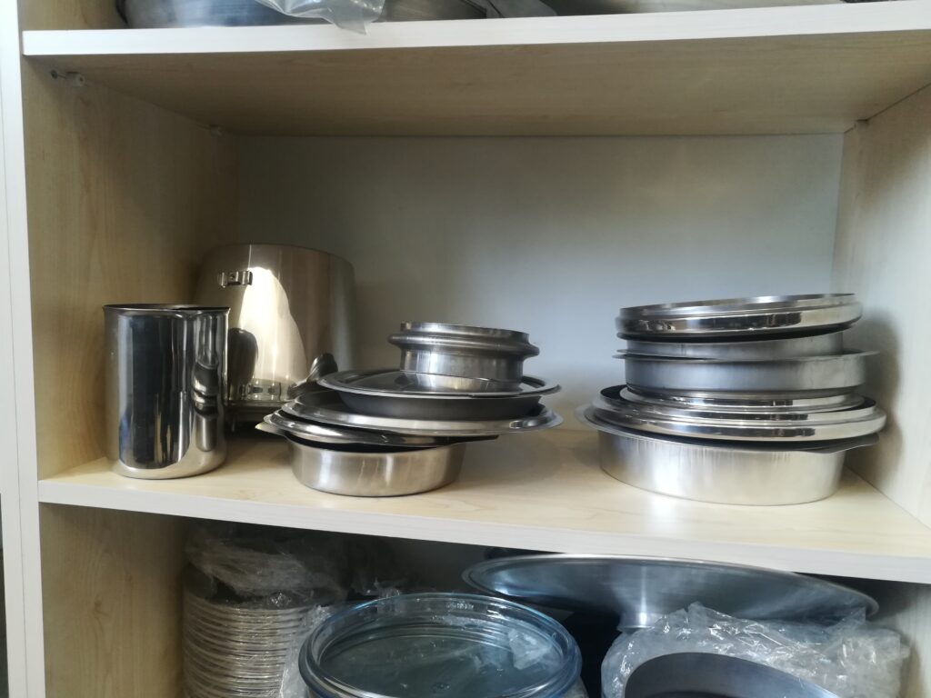
A sheet metal beading machine for pipes is a specialized forming machine designed to create raised or embossed beads—circular ridges—around the circumference of metal pipes or tubular components. Beading on pipes serves multiple purposes: it increases structural rigidity, improves joint strength for welding or coupling, enhances sealing surfaces, and adds aesthetic appeal. These machines are commonly used in industries such as automotive exhaust systems, HVAC ductwork, plumbing, and industrial piping.
Beading machines for pipes work by clamping the pipe securely and rotating it while a forming roller or die presses against the pipe surface to create a continuous bead. The bead’s shape, size, and profile can be customized based on tooling design and application requirements. Typical bead types include raised beads, recessed beads, or multiple concentric rings, each offering different mechanical and functional benefits.
These machines accommodate various pipe materials, including steel, stainless steel, aluminum, and copper, and can handle different diameters and wall thicknesses. They are designed to provide consistent bead quality without deforming or damaging the pipe’s structural integrity.
Beading machines range from manual or semi-automatic units suitable for small-batch or prototype work to fully automatic CNC-controlled systems capable of high-volume production with precise repeatability. CNC systems enable programmable bead placement, multiple bead patterns, and variable bead dimensions along the pipe length, supporting complex design requirements.
Tooling is typically made of hardened steel or carbide materials to withstand continuous contact with pipe surfaces under high pressure. Adjustable forming rollers and clamping mechanisms allow quick setup changes to accommodate different pipe sizes and bead profiles.
Modern pipe beading machines may integrate sensors to monitor bead depth, pipe alignment, and forming force, ensuring quality control throughout the process. Automated feeding and unloading systems increase throughput and reduce manual handling.
Safety features such as guarded enclosures, emergency stop buttons, and operator presence sensors are standard to protect workers during high-force operations.
Applications of pipe beading include reinforcing exhaust system components, preparing pipe ends for sealing or flanging, enhancing grip for hose attachments, and adding decorative features to architectural metalwork.
In summary, sheet metal beading machines for pipes provide efficient, precise, and customizable solutions for adding structural and functional beads to tubular metal components, supporting durability and quality in a variety of industrial applications.
Sheet metal beading machines for pipes have evolved significantly with advances in automation and control technology, enabling higher precision and increased production efficiency. Fully automated CNC pipe beading machines allow operators to program bead patterns, positions, and dimensions with exceptional accuracy, supporting complex designs and varying pipe specifications within the same production run. This flexibility is particularly valuable in industries requiring customized or variable bead features for different functional or aesthetic purposes.
The machines employ servo-driven rollers and precise clamping systems that maintain consistent pressure and pipe alignment during the beading process, preventing distortion or surface damage. The use of multiple forming rollers can create compound bead profiles or simultaneous multi-bead patterns, enhancing the mechanical properties and appearance of the pipes.
Material handling automation, including motorized pipe feeding, positioning, and unloading, streamlines operations and minimizes manual handling risks. Integration with upstream and downstream equipment such as cutting, welding, or inspection stations allows for seamless production flow and reduced cycle times.
Tooling technology has advanced with the introduction of wear-resistant coatings and modular designs, reducing downtime and facilitating rapid tool changes for different pipe sizes and bead styles. Tool condition monitoring through embedded sensors helps predict maintenance needs, ensuring consistent bead quality and extending tooling life.
Real-time monitoring systems track key parameters like bead height, roller force, and pipe rotation speed, enabling closed-loop feedback control that dynamically adjusts forming conditions to accommodate material variations or tooling wear. These systems improve process stability, reduce scrap rates, and ensure compliance with tight quality standards.
Safety remains a critical aspect, with comprehensive guarding, light curtains, and emergency stop functions protecting operators from moving parts and high forces involved in beading operations. Ergonomic machine designs reduce operator fatigue and enhance accessibility for setup and maintenance tasks.
Applications for pipe beading machines extend across automotive exhaust fabrication, HVAC piping, hydraulic and pneumatic tubing, and architectural metal structures. Beading improves pipe strength, facilitates assembly by creating secure joints or flanges, and contributes to leak-proof sealing in fluid systems.
Emerging trends include the use of adaptive control algorithms and machine learning to optimize bead forming parameters based on historical data, material properties, and real-time sensor feedback. This smart manufacturing approach enhances productivity and quality while enabling predictive maintenance and reduced operational costs.
In conclusion, sheet metal beading machines for pipes have become highly sophisticated systems combining precise mechanical design, advanced automation, and intelligent control. These capabilities enable manufacturers to produce durable, high-quality beaded pipes efficiently, meeting the demanding requirements of modern industrial applications.
Further advancements in sheet metal beading machines for pipes are focusing on expanding versatility and integrating with Industry 4.0 manufacturing ecosystems. Machines are increasingly designed with modular components and flexible tooling systems that allow quick adaptation to different pipe diameters, wall thicknesses, and bead profiles without extensive retooling. This flexibility supports just-in-time production and small batch sizes, which are becoming more common in customized manufacturing environments.
Enhanced connectivity enables these machines to communicate seamlessly with other equipment, enterprise resource planning (ERP) systems, and quality management platforms. Real-time data collection and analysis facilitate comprehensive traceability, enabling manufacturers to track bead quality, machine performance, and maintenance history throughout production. This data-driven approach improves process optimization and ensures compliance with stringent industry regulations, especially in critical sectors like aerospace and medical tubing.
Advanced user interfaces with touchscreen controls and graphical programming simplify machine operation and setup, reducing operator training time and human error. Augmented reality (AR) tools are also being adopted to assist in maintenance and troubleshooting, providing step-by-step visual guidance and remote expert support.
Energy efficiency remains a priority, with innovations such as servo-electric drives, regenerative braking systems, and optimized hydraulic circuits reducing power consumption and operational costs. Noise reduction technologies improve workplace conditions, contributing to operator comfort and safety.
The integration of non-destructive testing (NDT) methods like ultrasonic or laser scanning within the beading process is emerging, enabling inline inspection of bead geometry and detecting defects without interrupting production. These inspection systems enhance quality assurance and reduce waste by identifying issues early.
Sustainability efforts extend to the use of recyclable materials and waste reduction strategies, including optimized nesting and scrap collection during pipe preparation and beading. Manufacturers are also exploring eco-friendly lubricants and fluids to minimize environmental impact.
Applications continue to expand as industries demand higher performance from piping systems. Beaded pipes are critical in electric vehicle cooling systems, renewable energy installations, high-pressure hydraulic lines, and advanced HVAC designs, where strength, sealing integrity, and precision are vital.
In summary, sheet metal beading machines for pipes are evolving into intelligent, adaptable, and highly integrated manufacturing solutions. By combining mechanical innovation with digital technologies and sustainability practices, these machines help manufacturers meet the complex requirements of today’s dynamic industrial landscape efficiently and reliably.
Metal Tube Forming Machine
A metal tube forming machine is a specialized piece of equipment designed to shape flat metal strips or sheets into tubular profiles through a series of controlled bending, rolling, and welding operations. These machines are widely used in manufacturing industries such as automotive, construction, furniture, aerospace, and plumbing, where metal tubes are essential components for structural frameworks, fluid transport, and mechanical assemblies.
The tube forming process typically begins with a coil or flat strip of metal—commonly steel, stainless steel, aluminum, or copper—that is fed into the machine. Roll forming stations progressively bend the strip into a cylindrical or shaped profile, carefully controlling material deformation to maintain dimensional accuracy and prevent defects like wrinkling or cracking. Once the tube shape is formed, seam welding methods—such as high-frequency induction welding, laser welding, or electric resistance welding—join the edges to create a continuous, leak-proof tube.
Modern metal tube forming machines are often highly automated, integrating servo-driven roll forming stands, precise strip feeding systems, and inline welding units. CNC controls enable programmers to adjust forming parameters, tube diameters, wall thicknesses, and welding speeds to accommodate different materials and product specifications. Automated cutting systems typically follow the forming and welding stages, cutting tubes to desired lengths with minimal material waste.
Advanced tube forming machines can produce a variety of cross-sectional shapes beyond round tubes, including square, rectangular, oval, and custom profiles, enabling diverse design possibilities. Some machines incorporate downstream processes like end forming, flaring, or threading to deliver finished tubes ready for assembly or installation.
Precision sensors and monitoring systems continuously measure parameters such as strip tension, roll position, welding temperature, and tube dimensions. These feedback systems support closed-loop control, ensuring consistent product quality, reducing scrap, and facilitating predictive maintenance.
Energy efficiency is enhanced through the use of servo motors, regenerative braking, and optimized drive systems, minimizing power consumption and environmental impact. User-friendly interfaces with touchscreen controls and integrated diagnostics simplify operation, setup, and troubleshooting.
Safety features include guarded enclosures, emergency stops, and interlocks to protect operators from moving parts and welding hazards.
In summary, metal tube forming machines provide versatile, efficient, and precise solutions for producing a wide range of metal tubes. Their integration of forming, welding, cutting, and control technologies enables manufacturers to meet stringent quality standards and production demands across numerous industrial sectors.
Metal tube forming machines continue to advance with innovations that enhance flexibility, speed, and integration within modern manufacturing environments. Multi-stand roll forming systems allow for the rapid shaping of metal strips into complex tube profiles with tight tolerances. These machines can be configured to produce varying tube diameters and shapes by simply adjusting roll tools or changing modules, supporting quick product changeovers and small batch sizes.
The welding process within tube forming lines has seen significant improvements, with laser and plasma welding technologies providing high-speed, precise seams with minimal heat-affected zones. These advanced welding methods reduce distortion and improve the mechanical properties of the tubes, which is critical for applications requiring high strength and corrosion resistance, such as aerospace or automotive structural components.
Inline quality inspection systems are increasingly integrated into tube forming lines, employing non-contact measurement tools like laser scanners, ultrasonic thickness gauges, and vision cameras. These systems detect dimensional deviations, weld integrity issues, and surface defects in real time, enabling immediate corrections and ensuring consistent output quality.
Automation and robotics are commonly incorporated for tasks such as coil loading, tube transfer, stacking, and packaging, reducing manual labor and enhancing safety. Advanced CNC controls coordinate all aspects of the forming, welding, cutting, and inspection processes, allowing seamless communication between machine components and facilitating centralized production management.
Digitalization plays a key role, with Industry 4.0 connectivity enabling remote monitoring, data analytics, and predictive maintenance. Operators and maintenance teams can access detailed machine performance data through cloud platforms or mobile devices, optimizing uptime and reducing operational costs.
Energy-efficient servo motors and regenerative drives minimize power consumption while maintaining precise control over forming speeds and welding parameters. Noise reduction and ergonomic design improvements contribute to better working environments and operator comfort.
Metal tube forming machines also accommodate a broad range of materials, including advanced high-strength steels, aluminum alloys, and specialty metals, responding to evolving industry demands for lightweight, durable, and corrosion-resistant tubing.
Additional downstream capabilities such as end forming, threading, polishing, or coating integration provide comprehensive manufacturing solutions within a single production line, reducing handling and lead times.
In essence, metal tube forming machines embody a synergy of mechanical precision, advanced welding, intelligent automation, and digital connectivity. These capabilities empower manufacturers to produce high-quality, complex tubes efficiently and reliably, meeting the diverse and stringent requirements of today’s industrial applications.
Emerging trends in metal tube forming machines emphasize customization and versatility to meet the growing demand for specialized tube profiles used in industries like electric vehicles, renewable energy, medical devices, and smart infrastructure. Flexible roll forming lines with quick-change tooling and modular stands enable manufacturers to switch between different tube shapes and sizes rapidly, supporting small batch production and just-in-time manufacturing.
Integration of artificial intelligence (AI) and machine learning algorithms is enhancing process optimization by analyzing vast amounts of operational data to predict tool wear, detect anomalies, and recommend parameter adjustments. This proactive approach minimizes downtime, improves product consistency, and extends equipment lifespan.
Hybrid forming techniques combining roll forming with incremental sheet forming or hydroforming are gaining attention for producing complex, variable-section tubes that traditional methods cannot easily achieve. These hybrid processes allow intricate geometries, such as tapered or curved tubes, broadening design possibilities for lightweight and high-performance components.
Environmental sustainability is a key focus, with manufacturers adopting energy-saving drives, waste reduction strategies, and environmentally friendly lubricants. Closed-loop recycling of metal scraps generated during forming and cutting processes supports circular economy initiatives and reduces material costs.
Collaborative robots (cobots) are being introduced to assist operators in loading coils, handling tubes, and performing quality inspections, enhancing workplace safety and flexibility without the need for extensive safety fencing.
Advanced user interfaces with augmented reality (AR) and virtual reality (VR) applications are improving training, machine setup, and maintenance procedures. These technologies provide immersive, hands-on learning experiences and remote expert support, reducing errors and accelerating skill development.
Global supply chain integration and digital twin simulations enable manufacturers to optimize entire tube production workflows, from raw material sourcing to final inspection, improving efficiency and responsiveness to market changes.
In conclusion, metal tube forming machines are evolving into smart, adaptable, and environmentally conscious manufacturing platforms. By combining cutting-edge mechanical engineering, automation, digital technologies, and sustainable practices, these machines empower producers to meet increasingly complex tube fabrication challenges with agility, precision, and efficiency.
Metal Cutting Trimming Machine For Aluminum Parts
A metal cutting trimming machine for aluminum parts is a precision industrial machine designed specifically to trim excess material, burrs, and flash from aluminum components after casting, stamping, or forming processes. Aluminum’s lightweight and malleable properties require trimming machines that offer accurate, clean cuts without deforming or damaging the parts, ensuring high-quality finished products suitable for automotive, aerospace, electronics, and consumer goods industries.
These trimming machines use various cutting methods such as mechanical shearing, CNC milling, laser cutting, or abrasive cutting, depending on the application and complexity of the parts. Mechanical trimming often involves punches and dies designed for precise removal of flash or excess edges, whereas CNC milling or laser trimming offers high flexibility for intricate geometries and tight tolerances.
The machine’s tooling is usually made from hardened steel or carbide materials to withstand the abrasion from aluminum and maintain sharpness, while coatings like titanium nitride (TiN) can further extend tool life. Clamping and positioning systems securely hold aluminum parts during trimming to prevent movement or vibration that could affect cut quality.
Automation features such as robotic loading/unloading, programmable cutting paths, and adaptive control systems increase throughput and consistency, particularly in high-volume production environments. Sensors monitor cutting forces, tool wear, and part dimensions in real-time, enabling dynamic adjustments to optimize cutting parameters and reduce scrap.
Safety mechanisms including guarding, emergency stops, and interlocks ensure operator protection during high-speed cutting operations. User-friendly interfaces with touchscreens and software assist operators with setup, diagnostics, and maintenance.
Typical applications include trimming excess material from aluminum automotive body panels, heat sinks, electronic housings, and precision aerospace components. The machines deliver smooth, burr-free edges that often eliminate or reduce the need for secondary finishing.
In summary, metal cutting trimming machines for aluminum parts provide precise, efficient, and reliable trimming solutions that preserve the integrity and quality of delicate aluminum components, supporting a wide range of manufacturing industries requiring high-performance finished products.
Metal cutting trimming machines for aluminum parts have advanced significantly with the integration of CNC technology, enabling precise control over cutting paths and depths tailored to complex part geometries. This flexibility allows manufacturers to handle a wide variety of aluminum components, from thin sheet parts to thicker castings, without compromising accuracy or surface finish. CNC trimming also facilitates rapid changeovers and customization for different production runs, supporting both high-volume and small-batch manufacturing.
High-speed spindle motors combined with optimized cutting tools reduce cycle times while maintaining quality, essential for meeting tight production deadlines. Cutting tool materials and coatings continue to evolve, with carbide and coated tooling offering improved wear resistance and reduced heat generation during cutting, which is critical when working with aluminum to prevent melting or built-up edge formation.
Automation plays a crucial role in increasing efficiency and consistency. Robotic systems handle loading, unloading, and part positioning, minimizing manual intervention and reducing the risk of damage to delicate aluminum parts. Vision systems and laser measurement tools provide real-time feedback on part alignment and trim accuracy, enabling adaptive adjustments during operation to maintain tight tolerances and minimize scrap.
The use of advanced sensors to monitor cutting forces, vibrations, and tool condition supports predictive maintenance and process optimization. By analyzing this data, manufacturers can schedule timely tool replacements, adjust cutting parameters proactively, and avoid unexpected downtime.
Safety features are robust and comprehensive, with interlocked guarding, light curtains, and emergency stops protecting operators from moving parts and high-speed cutting zones. Ergonomic machine designs reduce operator fatigue and simplify access for tool changes and maintenance.
Applications extend across industries such as automotive, aerospace, electronics, and consumer goods, where precision-trimmed aluminum parts are critical for performance, aesthetics, and fit. The ability to produce clean, burr-free edges enhances downstream assembly and finishing processes, reducing overall production costs.
Sustainability considerations have led to the adoption of energy-efficient motors, optimized cutting fluid management, and effective chip collection systems that facilitate aluminum recycling. These measures contribute to lower environmental impact and improved workplace conditions.
In conclusion, metal cutting trimming machines for aluminum parts combine advanced CNC control, cutting-edge tooling, automation, and safety to deliver precise, efficient, and high-quality trimming solutions. Their continued development supports the growing demand for lightweight, durable aluminum components across a wide array of modern manufacturing sectors.
Recent innovations in metal cutting trimming machines for aluminum parts focus heavily on smart manufacturing and Industry 4.0 integration. These machines increasingly feature connectivity options such as Ethernet, OPC UA, and wireless communication, allowing them to interface seamlessly with factory management systems and digital twins. This connectivity enables real-time monitoring of machine status, production metrics, and quality data, facilitating data-driven decision-making and process optimization.
Artificial intelligence (AI) and machine learning algorithms are being incorporated to analyze sensor data and optimize cutting parameters dynamically. By continuously learning from past operations, these systems can predict the ideal feed rates, spindle speeds, and tool paths to maximize efficiency and tool life while minimizing part deformation and surface defects. This adaptive control reduces scrap rates and improves consistency across diverse aluminum alloys and part complexities.
Hybrid cutting technologies, combining mechanical trimming with laser or waterjet assistance, are emerging to tackle increasingly complex part geometries and tight tolerances. These hybrid systems leverage the strengths of each method—mechanical precision with minimal thermal impact, and laser or waterjet flexibility—to achieve superior edge quality and reduced secondary finishing requirements.
Ergonomics and operator assistance are enhanced through augmented reality (AR) applications that provide visual guidance for setup, maintenance, and troubleshooting. Remote diagnostics and virtual support services enable rapid resolution of issues, minimizing downtime and improving overall equipment effectiveness (OEE).
Environmental sustainability remains a key priority. New trimming machines are designed to minimize energy consumption through regenerative drives and optimized motor controls. Advanced coolant systems reduce fluid usage and improve recycling, while efficient chip extraction and filtration support aluminum recycling and reduce workplace contamination.
The growing use of high-strength, lightweight aluminum alloys in automotive, aerospace, and consumer electronics drives demand for trimming machines capable of handling diverse material properties without compromising precision or cycle time. These machines are built to accommodate variable alloy compositions, surface treatments, and thicknesses, ensuring consistent performance regardless of material variability.
Safety standards continue to evolve, with integrated sensors and AI-powered monitoring detecting potential hazards and automatically adjusting machine operation or initiating shutdowns to protect operators and equipment. Collaborative robots (cobots) are increasingly employed alongside trimming machines to assist with material handling, reducing ergonomic risks and enhancing workflow flexibility.
In summary, metal cutting trimming machines for aluminum parts are becoming smarter, more adaptable, and environmentally conscious. Through integration of AI, hybrid cutting technologies, advanced connectivity, and operator support tools, these machines are well-positioned to meet the demanding requirements of modern manufacturing environments focused on quality, efficiency, and sustainability.
Sheet Metal Trimming Beading Machine Production Line
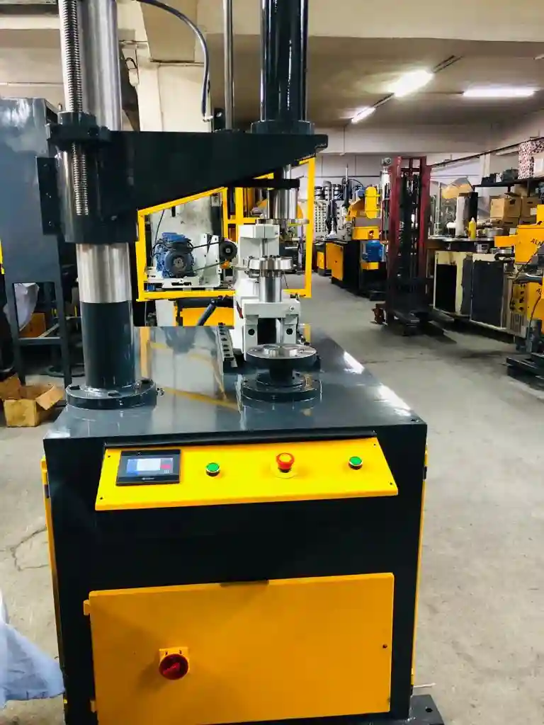
A sheet metal trimming and beading machine production line is a comprehensive automated system designed to perform sequential operations of trimming excess material and forming beads on sheet metal parts. This integrated production line streamlines manufacturing processes by combining precise edge trimming and structural bead formation into a continuous workflow, enhancing efficiency, quality, and consistency across industries such as automotive, appliances, HVAC, and construction.
The production line typically begins with a sheet metal feeding unit that accurately positions and transports flat or partially formed sheets into the trimming section. The trimming machine uses specialized tooling—such as punches, dies, or CNC-controlled cutting heads—to remove unwanted flash, burrs, or excess edges from stamped or formed parts. This ensures dimensional accuracy and prepares the parts for subsequent operations.
Immediately following trimming, the sheets move into the beading station, where rollers or dies press linear or curved beads onto the surface or edges. Beading increases stiffness, reduces flexing, and adds aesthetic appeal to the metal parts. The beading tools are often adjustable to produce various bead profiles tailored to specific product requirements.
Modern production lines integrate servo-driven automation for precise control over feed rates, trimming strokes, and bead formation pressures. Programmable logic controllers (PLCs) and human-machine interfaces (HMIs) enable operators to set parameters, monitor machine status, and switch between different part programs with ease, facilitating flexible manufacturing and quick changeovers.
Material handling automation, including conveyors, robotic arms, and sensors, ensures smooth transfer of parts between stations while maintaining alignment and minimizing manual intervention. Quality control systems employing vision cameras or laser measurement verify trimming accuracy and bead consistency, enabling real-time adjustments and reducing scrap.
Safety is a critical component, with guarded enclosures, emergency stops, light curtains, and interlocks protecting operators from moving parts and high-force operations. Ergonomic designs and accessible maintenance points improve operator comfort and reduce downtime.
Additional features may include integrated stacking or packaging stations, inline cleaning or deburring units, and data logging for production traceability. These capabilities support lean manufacturing principles and help meet stringent industry standards.
Applications for sheet metal trimming and beading machine production lines span the fabrication of automotive body panels, appliance housings, HVAC components, elevator panels, and architectural metalwork, where precision and durability are paramount.
In summary, a sheet metal trimming and beading machine production line provides a fully automated, precise, and efficient solution for producing high-quality sheet metal parts with clean edges and reinforced structures. Its combination of trimming and beading operations in a streamlined workflow enhances productivity, reduces labor costs, and delivers consistent product quality across diverse manufacturing sectors.
Sheet metal trimming and beading machine production lines have evolved to incorporate advanced automation and digital technologies that enhance overall efficiency, flexibility, and quality control. Servo-driven feeding systems provide precise positioning and smooth material flow between trimming and beading stations, ensuring optimal timing and synchronization throughout the line. This precise coordination minimizes handling errors and reduces cycle times, supporting higher throughput.
Programmable logic controllers (PLCs) coupled with intuitive human-machine interfaces (HMIs) enable operators to easily program, monitor, and adjust process parameters for different part designs and materials. Quick tooling change systems allow rapid switching between product variants, facilitating just-in-time production and reducing downtime.
Material handling is increasingly automated through the use of robotic arms, automated guided vehicles (AGVs), and conveyors, which transfer parts seamlessly between operations while maintaining proper orientation and alignment. Sensors and vision systems continuously inspect parts for trimming accuracy, bead formation quality, and surface defects. This real-time inspection allows immediate corrective actions, minimizing scrap and ensuring adherence to tight tolerances.
Safety features comply with international standards, featuring interlocked guards, emergency stop buttons, light curtains, and operator presence detection systems. Ergonomic machine layouts and maintenance-friendly designs improve accessibility, reduce operator fatigue, and enable faster servicing.
Production lines may integrate additional inline processes such as deburring, cleaning, or surface treatment to deliver finished parts ready for assembly or packaging. Data logging and connectivity with manufacturing execution systems (MES) provide full traceability and facilitate quality audits and continuous improvement initiatives.
Industries like automotive, home appliances, HVAC, and construction benefit from these integrated production lines by achieving consistent part quality, reducing labor costs, and accelerating production cycles. The combination of trimming and beading operations in a single streamlined workflow eliminates intermediate handling steps and reduces the risk of part damage.
Ongoing advancements include the incorporation of Industry 4.0 technologies such as digital twins, predictive maintenance, and AI-driven process optimization. These innovations enable manufacturers to maximize uptime, optimize resource utilization, and adapt quickly to changing market demands.
In conclusion, sheet metal trimming and beading machine production lines represent highly automated, intelligent manufacturing solutions that combine precision, speed, and flexibility. They play a vital role in producing structurally reinforced, dimensionally accurate sheet metal components efficiently and reliably across a wide range of industrial applications.
Further developments in sheet metal trimming and beading machine production lines emphasize increased modularity and scalability to meet diverse production requirements. Modular design allows manufacturers to configure or expand lines easily by adding or removing stations based on part complexity, production volume, or process requirements. This flexibility supports both high-volume mass production and small-batch customization, enabling rapid response to changing market demands.
Integration with advanced robotics and automated material handling systems continues to grow, with collaborative robots (cobots) playing a key role in enhancing flexibility and safety. Cobots assist with tasks such as loading, unloading, part transfer, and quality inspection, working safely alongside human operators without extensive safety fencing. This collaboration improves workflow efficiency and reduces ergonomic risks.
Enhanced sensor networks and machine vision systems provide comprehensive real-time data on every stage of the trimming and beading process. High-resolution cameras and laser scanners detect microscopic defects, verify bead dimensions, and ensure trimming precision, enabling proactive quality management. This data is fed into centralized manufacturing execution systems (MES) and enterprise resource planning (ERP) software, facilitating end-to-end production traceability and continuous improvement.
Artificial intelligence (AI) and machine learning algorithms analyze operational data to optimize process parameters dynamically, predict maintenance needs, and reduce downtime. Predictive maintenance schedules derived from sensor inputs allow timely tool changes and machine servicing before failures occur, maximizing uptime and extending equipment lifespan.
Energy efficiency remains a priority, with production lines employing regenerative braking, variable frequency drives, and optimized hydraulic systems to reduce power consumption. Noise reduction measures and improved ventilation contribute to safer and more comfortable working environments.
Sustainability efforts include minimizing scrap through optimized nesting and cutting strategies, recycling trimmed material, and using environmentally friendly lubricants and fluids. These practices align with global environmental standards and corporate social responsibility goals.
Industry-specific adaptations enable production lines to handle specialized materials such as advanced high-strength steels, coated metals, or lightweight aluminum alloys, expanding their application across automotive, aerospace, electronics, and architectural sectors. Custom tooling and flexible control systems accommodate varied part geometries and surface finishes, ensuring consistent quality regardless of complexity.
Training and support have improved with virtual and augmented reality tools that facilitate operator education, machine setup, and remote troubleshooting. These technologies reduce errors and accelerate skill development, supporting efficient line operation.
In summary, modern sheet metal trimming and beading machine production lines combine modularity, automation, intelligent monitoring, and sustainability to deliver adaptable, high-performance manufacturing solutions. These advanced systems empower manufacturers to produce reinforced, precisely trimmed sheet metal parts efficiently while meeting evolving quality, safety, and environmental standards.
Metal Trimming Beading Machine Edge Finishing
A metal trimming and beading machine for edge finishing is a specialized piece of equipment designed to simultaneously remove excess material from metal parts and form reinforcing beads along their edges. This dual-function process enhances the part’s dimensional accuracy, structural strength, and surface quality, which is essential in applications like automotive panels, appliance housings, HVAC ducts, and architectural metal components.
The trimming function precisely cuts away flash, burrs, or uneven edges resulting from stamping, casting, or forming operations. This ensures that parts meet tight dimensional tolerances and fit correctly in assemblies. The trimming tools—typically punches and dies—are engineered to handle various metals, including steel, aluminum, and stainless steel, without deforming the part or creating surface defects.
Beading involves forming raised or embossed ridges along the trimmed edges by pressing the metal between shaped rollers or dies. These beads increase edge stiffness, reduce flexing, and improve the overall rigidity of the component. Beads also enhance aesthetics by providing clean, uniform edge profiles and can facilitate assembly by serving as guides or strengthening points.
Modern metal trimming and beading machines incorporate CNC controls and servo-driven systems for precise, repeatable operations. Programmable parameters allow customization of trimming paths, bead profiles, and feed rates, enabling quick changeovers between different part designs and production runs. Automated feeding and material handling systems improve throughput and minimize manual intervention, reducing the risk of part damage.
Tooling is made from hardened steels or carbide materials with specialized coatings to resist wear and maintain sharpness, especially when processing abrasive or hard metals. Cooling and lubrication systems are integrated to prolong tool life and ensure clean cuts and smooth bead formation.
Quality control is maintained through inline sensors and vision systems that monitor trimming accuracy and bead consistency in real time. These systems detect defects early, allowing for immediate adjustments or rejection of faulty parts, thereby reducing scrap and rework.
Safety features such as guarded enclosures, light curtains, emergency stops, and interlocks protect operators from moving parts and high forces involved in trimming and beading processes. Ergonomic designs facilitate easy access for setup, maintenance, and tool changes, improving operator comfort and productivity.
In summary, metal trimming and beading machines for edge finishing provide efficient, precise, and integrated solutions for producing high-quality metal components with clean, reinforced edges. Their combination of trimming and beading in a single automated process supports improved structural integrity, aesthetic appeal, and manufacturing efficiency across various industrial applications.
Metal trimming and beading machines for edge finishing continue to evolve with advancements in automation, precision, and adaptability. The integration of CNC and servo-driven technologies allows these machines to achieve exceptional repeatability and accuracy, crucial for meeting increasingly stringent quality standards. Operators can program complex trimming contours and bead profiles tailored to specific part geometries, enabling rapid changeovers and flexible production runs.
Automation extends to material handling systems that feed parts seamlessly into the machine, position them accurately for trimming and beading, and transport finished components to subsequent processes or inspection stations. This reduces manual handling, minimizes the risk of damage, and improves overall throughput.
Tooling advancements include the use of high-performance coatings like titanium nitride and diamond-like carbon to extend tool life and maintain cutting and forming quality over long production cycles. Modular tooling designs facilitate quick tool replacement and customization for different metals and thicknesses, supporting a broad range of applications.
Inline inspection technologies such as laser scanners, vision cameras, and force sensors provide real-time monitoring of trim quality and bead dimensions. These systems enable closed-loop control, automatically adjusting parameters to compensate for material variations or tool wear, thereby ensuring consistent edge finishing and reducing scrap rates.
Safety remains a paramount concern, with comprehensive guarding, light curtains, and emergency stop systems integrated into machine designs. Ergonomic features help reduce operator fatigue and improve accessibility for setup and maintenance tasks.
The machines are widely used in industries including automotive manufacturing, where clean, reinforced edges contribute to vehicle structural integrity and aesthetic appeal; appliance production, where precise trimming and beading enhance product durability; and HVAC fabrication, where bead-formed edges improve duct rigidity and assembly.
Sustainability initiatives focus on energy-efficient drives, optimized lubrication systems, and efficient waste management practices such as automated scrap collection and recycling. These efforts reduce environmental impact and operational costs.
In summary, metal trimming and beading machines for edge finishing provide a sophisticated, automated solution that combines precise material removal and reinforcement in a single process. Their continual technological advancements enable manufacturers to produce high-quality, durable metal parts efficiently, meeting the evolving demands of modern industrial production.
Further innovations in metal trimming and beading machines for edge finishing focus on enhancing connectivity and smart manufacturing capabilities. These machines increasingly incorporate Industry 4.0 technologies, enabling seamless integration with factory networks for real-time monitoring, data analysis, and remote diagnostics. Operators and maintenance teams can access machine performance metrics and quality reports via cloud platforms or mobile devices, facilitating proactive decision-making and rapid response to issues.
Artificial intelligence and machine learning algorithms are being deployed to optimize trimming and beading processes dynamically. By analyzing historical and real-time data, these systems can predict tool wear, adjust cutting forces, and refine bead formation parameters automatically to maintain consistent quality and extend tool life. This adaptive control minimizes downtime and scrap, improving overall equipment effectiveness.
Hybrid edge finishing solutions combine mechanical trimming and beading with laser or abrasive finishing techniques to achieve superior edge quality on complex or delicate parts. These hybrid systems balance the speed and strength of mechanical forming with the precision and smoothness of advanced finishing methods, reducing the need for secondary processing.
Ergonomic enhancements and operator assistance tools, including augmented reality (AR) guides and virtual training modules, improve workforce efficiency and safety. These technologies offer interactive setup instructions, maintenance walkthroughs, and troubleshooting support, reducing errors and training time.
Sustainability efforts continue with the adoption of energy-saving servo drives, eco-friendly lubricants, and optimized scrap management. Automated sorting and recycling of trimmed material help manufacturers meet environmental regulations and corporate responsibility goals while reducing material costs.
Safety systems are evolving with intelligent monitoring that detects abnormal vibrations, overheating, or unauthorized access, automatically initiating protective measures to safeguard personnel and equipment.
Industries such as aerospace, automotive, electronics, and consumer goods rely on these advanced trimming and beading machines to produce parts that meet demanding standards for strength, precision, and aesthetics. The machines’ ability to integrate multiple finishing steps into a streamlined process supports faster production cycles and lower overall manufacturing costs.
In conclusion, metal trimming and beading machines for edge finishing are transforming into intelligent, connected, and highly adaptable systems. Their integration of automation, advanced analytics, and ergonomic design enables manufacturers to achieve superior product quality, operational efficiency, and sustainability in today’s competitive industrial landscape.
Metal Beading Trimming Machine for Industrial Use
A metal beading trimming machine for industrial use is a robust, high-performance piece of equipment designed to handle large volumes of sheet metal parts in demanding manufacturing environments. It combines the processes of trimming excess material and forming reinforcing beads on metal components, enhancing both dimensional accuracy and structural strength. These machines are essential in industries such as automotive, aerospace, appliance manufacturing, HVAC, and heavy machinery, where precision and durability are critical.
Industrial-grade beading trimming machines are built with heavy-duty frames and components to withstand continuous operation under high loads. They often feature servo-driven or hydraulic actuators that deliver precise, powerful forming and cutting forces necessary for thick or hard metal sheets like steel, stainless steel, or aluminum alloys. This power ensures clean trimming cuts and consistent bead formation without deforming the parts.
Automation plays a key role in industrial machines, with integrated CNC controls allowing programmable trimming patterns, bead shapes, and process parameters. This flexibility supports quick changeovers and complex part geometries, enabling manufacturers to meet diverse production requirements efficiently. Advanced material handling systems such as conveyors, robotic loaders, and part ejectors reduce manual intervention, increase throughput, and minimize the risk of damage.
Tooling for industrial machines is designed for durability and precision, often manufactured from hardened steel or carbide with specialized coatings to resist wear and maintain sharpness over extended runs. Modular tooling systems facilitate rapid replacement or customization for different metal types and thicknesses.
Quality assurance is maintained through inline sensors, vision systems, and force feedback monitors that detect trimming accuracy and bead uniformity in real time. These systems enable closed-loop adjustments, reducing scrap and ensuring consistent product quality.
Safety features are comprehensive, including full guarding, light curtains, emergency stops, and interlock systems to protect operators in high-force operational settings. Ergonomic machine designs and accessible maintenance points help reduce operator fatigue and downtime.
Energy efficiency is addressed with the use of servo drives, regenerative systems, and optimized hydraulics, lowering operational costs and environmental impact. Noise reduction technologies further improve the workplace environment.
Applications for industrial metal beading trimming machines include automotive body panels and exhaust components, appliance shells, HVAC ducting, heavy equipment enclosures, and architectural metal facades. Their ability to produce reinforced, precisely finished edges improves product performance, assembly fit, and aesthetics.
In summary, metal beading trimming machines for industrial use are powerful, versatile, and reliable systems that integrate advanced automation, durable tooling, and safety features. They provide manufacturers with efficient solutions for high-volume production of structurally reinforced, accurately trimmed metal components essential to a wide range of industrial sectors.
Industrial metal beading trimming machines continue to evolve as manufacturers demand greater efficiency, precision, and adaptability. These machines are now designed with increasingly modular architectures, allowing production lines to be reconfigured quickly for new part designs or material types. This modularity supports agile manufacturing, especially in industries like automotive and aerospace, where design iterations are frequent and production cycles are shorter.
Heavy-duty servo motors and hydraulic systems provide the force required to handle thick or high-tensile metals, while maintaining precise control over the trimming and beading operations. High-speed processing is supported by smart motion controllers that synchronize tooling and material feed with exact timing, ensuring smooth transitions between trimming and beading steps without compromising accuracy or surface quality.
Edge finishing with industrial beading trimming machines is enhanced by the ability to adjust bead depth, radius, and position through the control interface, without physical tooling changes. This programmable flexibility reduces downtime and allows a single machine to serve multiple product lines. Additionally, automated sheet alignment and clamping systems ensure parts remain perfectly positioned during trimming and beading, even at high speeds, eliminating misalignment errors.
Real-time monitoring systems track every aspect of the machine’s performance, from tool wear and forming pressure to temperature and cycle times. These systems not only alert operators to maintenance needs but can also automatically adjust forming parameters mid-process to maintain quality when material properties vary. Integration with factory-wide data systems means that performance metrics and part quality data can be logged, analyzed, and used for continuous improvement.
To meet sustainability goals, energy-saving modes are built into the machine’s operation, reducing consumption during idle periods. Waste is minimized through precise cutting strategies and scrap management systems that automatically collect and sort trimmed material for recycling. Advanced lubrication systems reduce environmental impact by optimizing fluid usage and filtering contaminants before disposal.
These machines are increasingly operated through user-friendly digital interfaces, where production recipes, maintenance schedules, diagnostics, and quality reports are easily accessed. Training new operators is streamlined through built-in tutorials and AR support that visually guides users through operation and troubleshooting.
Applications of these machines are expanding beyond traditional sectors, with growing demand in renewable energy, EV battery casings, infrastructure panels, and customized metal architecture. The ability to handle diverse metals—such as galvanized steel, brushed aluminum, titanium, and copper alloys—makes the machines versatile tools in any high-output metal fabrication environment.
Ultimately, the industrial metal beading trimming machine represents a fusion of brute force and fine control, engineered for non-stop operation and precision edge finishing at scale. Its evolving design reflects the needs of modern manufacturing: adaptable, intelligent, efficient, and capable of delivering consistently high-quality metal components for the most demanding applications.
The latest generations of industrial metal beading trimming machines are increasingly equipped with multi-axis CNC control, allowing the formation of complex bead patterns and trim contours on curved, irregular, or asymmetrical parts. This capability is critical for industries like aerospace and high-end automotive manufacturing, where component designs often deviate from flat or simple geometries and require precise structural reinforcement along variable paths. With synchronized motion across multiple axes, these machines can follow intricate part outlines, adjusting trimming depth and bead pressure in real time.
Another significant advancement is the integration of automatic tool change systems. These systems allow the machine to switch between different trimming knives, beading rollers, or punch heads without operator intervention, dramatically reducing setup time during production runs that require varied edge profiles or material types. Combined with digital tool libraries stored within the control system, the operator can preload programs for multiple parts and execute seamless transitions between them, enabling uninterrupted, multi-part workflows.
Industrial beading trimming machines are also playing a key role in enabling lights-out manufacturing—automated production that runs continuously with minimal human supervision. With advanced diagnostics, predictive maintenance, robotic part handling, and inline quality checks, these machines can operate around the clock, automatically adjusting for tool wear or material variance and alerting maintenance staff only when intervention is necessary. This level of autonomy significantly boosts plant productivity while reducing labor costs.
Digital twins are increasingly used to model and simulate machine behavior before production begins. Manufacturers can load a digital version of a metal part into simulation software, define trimming and beading parameters, and virtually run the program to detect issues before sending the instructions to the real machine. This minimizes trial-and-error on the shop floor and shortens the time from design to production.
In high-volume industrial settings, traceability is a growing requirement. Each part processed by a modern beading trimming machine can be logged with a unique ID, batch number, timestamp, operator ID, and a record of all cutting and forming parameters used. This data, often paired with high-resolution images from inline cameras, ensures every part can be traced back to its production cycle, satisfying quality assurance protocols and regulatory compliance in industries like aerospace, medical devices, and defense.
Noise control, thermal management, and operator comfort are also being addressed with machine enclosures, vibration damping, and climate-controlled electrical cabinets. These improvements extend component life, reduce environmental stress, and create safer, quieter workplaces that meet today’s demanding health and safety standards.
In conclusion, industrial metal beading trimming machines are no longer just heavy-duty forming tools—they are intelligent, adaptive manufacturing platforms. Their blend of power, precision, and digital connectivity makes them essential for modern fabrication plants where speed, flexibility, traceability, and uncompromised quality are mandatory. Whether producing structural automotive panels, aerospace skin components, or architectural metal panels, these machines deliver superior edge finishing and reinforcing capabilities that support high-performance products across global industries.
Curling Machine For Metal Sheets
A curling machine for metal sheets is a specialized forming machine used to roll the edges of flat or formed sheet metal into a curved, circular, or tubular profile. This process—known as edge curling—serves multiple purposes: it strengthens the edge, improves safety by eliminating sharp corners, enhances aesthetic appeal, and in many cases, prepares the part for mechanical joining or interfacing with other components, such as in rolled hem joints, lids, ducts, or enclosures.
Curling machines are commonly used in the production of metal containers, HVAC ducting, automotive components, electrical enclosures, household appliances, and furniture panels. The curling process can be performed on a wide range of materials, including mild steel, galvanized steel, stainless steel, aluminum, and copper alloys.
A typical curling machine consists of a set of hardened forming rollers mounted on a robust frame. These rollers are precisely contoured to gradually bend the metal edge into a defined curl radius or full roll. The material is guided through the rollers either manually or by automated feed mechanisms, depending on the machine’s configuration and production volume. For high-throughput operations, the machines are often fully automated with programmable logic controls (PLCs), servo-driven feeds, and adjustable tooling.
Modern curling machines can be standalone units or integrated into larger forming and finishing lines, working alongside trimming, beading, flanging, or hemming equipment. Machines with CNC capability offer programmable curl profiles, variable radii, and quick changeovers, making them suitable for short-run production or complex part geometries.
Edge quality is a critical aspect of the curling process. Properly curled edges must be smooth, uniform, and free of wrinkles, cracks, or deformation. This requires precise control of roller speed, pressure, and alignment. Advanced machines use sensors and feedback systems to monitor these variables and ensure consistent curl formation. Some systems also incorporate laser or vision-based inspection for inline quality control.
Curling machines are designed with operator safety and ease of use in mind. Enclosures, safety interlocks, emergency stop systems, and ergonomic controls are standard on most modern machines. Tooling and maintenance areas are easily accessible to reduce downtime and simplify setup or changeovers.
Applications vary widely—from forming the rim of a washing machine drum to curling the edge of a metal lid, the hem of an automotive hood, or the lip of a ventilation duct. The structural benefit of curling lies in its ability to add stiffness to thin sheet metal parts without increasing material thickness, which is particularly valuable in weight-sensitive industries like automotive and aerospace.
In summary, a curling machine for metal sheets is an essential tool for producing smooth, strong, and safe edge profiles. Through a controlled rolling process, it enhances part functionality and appearance while integrating seamlessly into modern automated production environments.
Curling machines for metal sheets are engineered for precision and repeatability, making them indispensable in high-volume manufacturing lines where consistent edge forming is critical. These machines are available in various configurations, including manual, semi-automatic, and fully automatic models, each suited for different production scales and complexity levels. Manual models are ideal for low-volume or prototype work, offering flexibility and simple operation, while fully automatic CNC-controlled systems are designed for continuous production and tight tolerances.
In a typical operation, the metal sheet is either clamped or guided into the curling rollers, which then incrementally form the edge into a curled profile. Depending on the application, the curl can be partial—forming a semi-circle or hem—or complete, creating a full loop or tube-like structure. This ability to precisely shape the edge without weakening the material is especially valuable when the curled edge must serve as a joint, a hinge, or a structural reinforcement.
The roller tooling is often customizable to accommodate different curl diameters, material thicknesses, and edge shapes. Some machines are equipped with quick-change tooling systems that allow operators to swap roller sets in minutes, reducing downtime and increasing production flexibility. Materials with different hardness levels may require different roller profiles and forming pressures, which can be pre-set and saved as part of programmable job recipes in CNC machines.
Advanced curling systems often include integrated feeding and positioning systems, where sheets are automatically aligned and held in place using pneumatic or servo-driven clamps. This ensures that each curl is uniform and precisely located, even across large or irregularly shaped parts. These features are particularly useful in industries like automotive or appliance manufacturing, where panel uniformity is crucial for assembly and visual appeal.
Noise and vibration are kept to a minimum through well-balanced roller systems and noise-dampening structural designs, making modern curling machines more suitable for enclosed or shared factory spaces. Maintenance is simplified with centralized lubrication points, self-cleaning rollers, and real-time alerts for wear or misalignment.
In some applications, the curling process is combined with other forming operations in a single cycle. For example, a metal panel might be trimmed, notched, curled, and flanged in sequence using an integrated line of machines. This reduces handling time and improves alignment between features, ensuring that the final part meets precise design specifications.
Curling is also an environmentally efficient process, as it adds strength without adding material, reducing the need for thicker sheets. Moreover, curled edges reduce injury risks from sharp metal edges, which is a key consideration in consumer-facing products like home appliances or furniture. A curled edge also provides a more professional appearance, often serving as the visible boundary of the product.
Overall, curling machines for metal sheets play a vital role in modern metalworking by offering a controlled, efficient method of shaping and strengthening sheet metal edges. Their adaptability, precision, and integration capabilities make them valuable assets in any production environment that demands high-quality, reinforced, and aesthetically finished components.
As curling machines for metal sheets continue to evolve, they increasingly emphasize digital control, process automation, and intelligent feedback systems to meet the demands of modern manufacturing. In CNC-controlled curling machines, every aspect of the operation—feed speed, roller pressure, curl diameter, number of passes—is programmable and repeatable with extreme precision. These capabilities are essential in industries such as automotive and aerospace, where exact tolerances and edge profiles are required for both function and safety.
A key trend is the integration of curling machines into fully automated production lines. These systems may include robotic arms for part loading and unloading, vision systems for pre-curl part inspection, and conveyors that synchronize each forming operation. This level of automation not only increases throughput but also ensures that each part receives uniform processing from start to finish. This is particularly valuable in mass production environments where edge quality and repeatability directly affect product integrity and downstream assembly.
Sensor integration is also advancing. Load cells and position sensors measure the exact force applied to each curl and the material’s response, enabling dynamic adjustment on the fly. If the material being curled has slight thickness variations or if a tool begins to wear, the machine can compensate automatically to maintain a perfect edge. This reduces rework and waste and extends tool life.
Some advanced curling systems include digital twins—virtual models that simulate the forming process based on input parameters and material characteristics. This allows engineers to test curl shapes, predict stress distribution, and avoid common defects such as cracking or wrinkling before physical production even begins. These simulations help optimize production plans and tooling design, saving both time and material.
The choice of curl geometry is becoming increasingly important, with more applications requiring non-standard shapes. Machines capable of producing variable-radius curls or incorporating small flanges or hems within the curl itself are now in use. This added complexity enhances the functionality of parts used in folding structures, locking joints, or curved panels that must retain rigidity under load or vibration.
Energy efficiency is also a design focus. Newer machines use servo-electric drives instead of hydraulic systems to reduce power consumption and offer cleaner, quieter operation. These systems are more precise and require less maintenance, which contributes to lower total cost of ownership and better environmental performance.
For operators, usability has improved through high-resolution touchscreens, step-by-step setup wizards, and built-in diagnostics. These features reduce training time and make the machines accessible even to users with limited technical backgrounds. For factories with many part numbers or frequent setup changes, barcode or RFID integration allows the machine to automatically load the correct program and tooling setup as soon as a part is scanned.
The final curled edge not only affects the mechanical strength of a part but often plays a visual or tactile role as well. In consumer-facing products, curled edges provide a smooth, clean finish that’s safe to handle and appealing to the eye. In structural applications, they act as reinforcement ribs, increasing the load-carrying capability of a thin sheet without increasing its thickness or weight.
In conclusion, metal sheet curling machines are sophisticated tools that combine mechanical reliability with digital intelligence. They serve as a critical part of the manufacturing process wherever smooth, reinforced, or functional edge profiles are needed. As industries push for higher precision, lower waste, and increased production flexibility, these machines will continue to evolve with smarter automation, better integration, and even more adaptable forming capabilities.
Sheet Metal Trimming Beading Machine with Hydraulic System
A sheet metal trimming and beading machine with a hydraulic system is a heavy-duty industrial solution designed to process metal components by precisely trimming excess material and forming beads or reinforcing ridges along the edges. The hydraulic drive system provides powerful, stable force, making these machines ideal for medium to thick sheet metals such as mild steel, stainless steel, and aluminum in applications where high forming pressure and durability are essential.
Hydraulic systems offer several key advantages in trimming and beading operations. They generate high, consistent forming force, which is especially useful for cutting and shaping harder or thicker materials without vibration or quality loss. Unlike mechanical or servo-based systems, hydraulics can sustain pressure over a longer period, which ensures smooth, controlled movement of the trimming and beading tools—even during complex or multi-step edge forming processes.
In a typical configuration, the machine includes hydraulic cylinders that drive trimming blades and beading rollers. Trimming blades precisely remove burrs, flash, or unwanted material from the edges of formed sheet parts, while the beading rollers press or roll beads into the metal surface, adding stiffness, improving part alignment, and enhancing edge strength. These beads can be linear, curved, or formed along corners, depending on the tooling and part design.
Hydraulic trimming and beading machines are often equipped with programmable logic controllers (PLCs) and touch-screen HMIs for easy parameter setting, process control, and monitoring. Operators can input cutting lengths, bead depth, tool positions, and cycle sequences, allowing for repeatable operations across different parts. Some advanced systems feature automatic tool positioning, material feed synchronization, and memory storage for multiple job settings.
The tooling is typically made from wear-resistant, hardened materials like tool steel or carbide, capable of withstanding the high pressures generated by hydraulic actuators. Quick-change die systems and adjustable roller assemblies allow fast changeovers between part types or materials, which is crucial in high-mix production environments.
Hydraulic machines often include integrated material handling systems such as pneumatic clamps, automated feeders, or conveyors to ensure precise positioning and steady flow through the machine. This reduces operator effort and increases throughput, especially in high-volume production settings like automotive panels, HVAC ducts, and appliance housings.
Real-time safety and performance sensors monitor fluid pressure, tool alignment, stroke limits, and cycle timing. Overload protection and emergency stop systems are standard to prevent damage and ensure operator safety. Sound dampening and oil filtration systems help keep hydraulic machines running smoothly with minimal environmental impact.
In summary, a sheet metal trimming and beading machine with a hydraulic system delivers the power, stability, and precision required for demanding edge finishing tasks. Its ability to handle tough materials, sustain high forces, and operate with consistent accuracy makes it a reliable and versatile asset in any sheet metal fabrication operation focused on quality, strength, and production efficiency.
Hydraulic sheet metal trimming and beading machines are particularly well-suited for applications that demand repeatable high-force operations with minimal variation, making them ideal for forming parts with thick gauges or complex geometries. The hydraulic actuation allows for smooth, uniform pressure across the entire stroke, which helps prevent defects such as uneven cuts, distorted edges, or inconsistent bead depth. This is especially important when working with stainless steel or high-strength alloys where uniform force distribution is critical to maintain part integrity.
These machines are designed to handle both flat and pre-formed components, and can be configured for either edge-only operations or full-perimeter processing. In many setups, the workpiece is clamped pneumatically or hydraulically into place before the trimming and beading sequence begins, ensuring accurate alignment and repeatability. The hydraulic system’s ability to provide a controlled, slow approach and retreat also protects delicate or decorative surfaces from tool shock or scratching, which is valuable in high-end applications such as appliance front panels or architectural elements.
Modern hydraulic systems feature closed-loop control for pressure and position, allowing for finer adjustments and higher repeat accuracy. Proportional valves, pressure transducers, and stroke sensors work together to maintain consistent forming forces and precise tooling movements. These systems not only enhance process control but also reduce energy consumption by optimizing hydraulic output based on real-time demand rather than running at full power continuously.
For manufacturers dealing with multiple product lines, modular tooling systems and programmable setups are essential. Hydraulic trimming and beading machines can be equipped with adjustable forming heads, quick-release die mounts, and positionable guide rails that enable fast reconfiguration between part types. Operators can recall stored programs from the HMI, significantly cutting down on setup time and improving overall equipment utilization.
In high-production environments, these machines are often integrated with upstream and downstream equipment. Coil-fed systems may feed flat blanks directly into the machine, while finished parts may exit onto a conveyor or into a robotic cell for stacking, inspection, or secondary processing. When linked together, these machines form part of a fully automated, high-efficiency production line capable of handling thousands of parts per shift with minimal operator intervention.
Maintenance on hydraulic systems is straightforward but crucial to ensure long-term performance. Many machines feature self-diagnostic capabilities and scheduled maintenance alerts based on operating hours or cycle counts. Oil quality, temperature, and pressure are continuously monitored, and high-efficiency filtration systems prevent contamination from affecting valve function or cylinder seals.
Safety and ergonomics are built into every aspect of the design. Full guarding with interlock switches prevents access during operation, while ergonomic control stations and foot pedal actuation options reduce operator fatigue. For larger parts, optional overhead cranes or assisted loading arms help operators manage heavy workpieces safely and efficiently.
Ultimately, the combination of trimming and beading in a single hydraulic system offers substantial benefits in both production speed and part quality. Beads can be used not only to strengthen parts but also to serve as precise reference features for assembly, or to provide clearance for fasteners, gaskets, or folded edges. The clean, reinforced edges produced by these machines reduce the need for secondary finishing and ensure that downstream assembly processes are smoother and more reliable.
In conclusion, sheet metal trimming and beading machines with hydraulic systems deliver powerful, precise, and consistent performance for a wide range of materials and applications. Their robust design, intelligent controls, and ability to integrate into automated production lines make them essential equipment for manufacturers seeking high-quality edge forming with maximum efficiency and flexibility.
As manufacturers continue to demand higher efficiency and adaptability, hydraulic sheet metal trimming and beading machines are increasingly being equipped with digital connectivity features that support smart factory operations. Integration with Industry 4.0 frameworks enables real-time monitoring of hydraulic performance, cycle counts, and part quality data. These systems can be connected to centralized production software, allowing engineers and managers to track productivity, detect anomalies, and schedule maintenance remotely.
One major advantage of hydraulic systems in this context is their capacity for variable force and speed control, which allows one machine to handle a broad range of material thicknesses and shapes without compromising edge quality. For example, lighter aluminum sheets may require a lower forming pressure to avoid warping, while thick stainless steel panels might demand full hydraulic force. With programmable settings and proportional valve control, the machine can automatically adapt to each job’s specific needs without manual intervention.
Tool life and changeover efficiency are also critical in modern operations. To minimize downtime, hydraulic machines are often outfitted with tool change assist mechanisms, retractable upper tooling, and die carts that speed up retooling while maintaining alignment. Some systems incorporate automatic detection of tool type and height, adjusting stroke length and pressure accordingly to prevent overloading and reduce setup errors.
In addition to traditional beading and trimming, hydraulic machines can also accommodate auxiliary forming functions. Depending on the tooling configuration, machines can perform edge flanging, notching, or even shallow embossing as part of the same cycle. This multifunctionality reduces the number of machines and handling steps required to produce a finished part, improving production line compactness and speed.
Temperature stability in hydraulic oil circuits is another important factor in maintaining consistent performance. Advanced systems feature active oil cooling, integrated thermostats, and real-time temperature compensation to avoid performance degradation during long production runs. These thermal management systems ensure that forming forces and response times remain consistent regardless of external environmental conditions or extended machine use.
From a structural standpoint, machines are built with rigid steel frames and vibration-dampening elements to resist deformation and maintain alignment under repeated heavy loads. This mechanical stability directly contributes to the accuracy and consistency of trimming and beading operations, especially for large or precision-critical components.
Environmental concerns are also being addressed through the use of energy-efficient hydraulic power units. Variable-speed drive (VSD) pumps reduce energy usage during idle cycles, and smart pressure management ensures that the machine only draws the power needed for each operation. In many cases, this reduces energy consumption by 30–50% compared to conventional hydraulic systems, while also minimizing heat generation and oil wear.
In safety-critical sectors such as automotive, aerospace, and electrical enclosures, the quality of edge forming is not just aesthetic—it directly impacts part fit, fatigue resistance, and operator safety during handling. The smooth, reinforced edges produced by hydraulic trimming and beading machines eliminate sharp edges, reduce the likelihood of cracks or splits, and provide a strong base for welding, fastening, or assembly.
In conclusion, hydraulic sheet metal trimming and beading machines continue to prove themselves as vital components in industrial metal forming operations. Their unmatched power, flexibility, and precision make them suitable for a wide variety of applications, while modern enhancements in automation, monitoring, and energy efficiency ensure they remain competitive and future-ready in today’s fast-evolving manufacturing environments.
Forming Machine For Metal Tubes
A forming machine for metal tubes is a specialized piece of industrial equipment designed to shape, bend, reduce, expand, flare, swage, or otherwise modify the geometry of metal tubing for a wide range of applications. These machines are essential in industries such as automotive, aerospace, HVAC, furniture, medical devices, and construction, where metal tubes are used for structural, fluid transfer, or aesthetic purposes.
Tube forming machines come in various types depending on the specific operation. Common categories include rotary draw benders, roll formers, end forming machines, mandrel benders, and hydroforming systems. Each is tailored to a particular kind of deformation process. For example, rotary draw benders are widely used for producing precision bends in round, square, or rectangular tubing, maintaining tight radii and high repeatability. These are often CNC-controlled for complex multi-axis bending applications.
End forming machines specialize in modifying the tube’s open ends. They can perform operations like expanding, reducing, flaring, or creating beads, ridges, or grooves. Hydraulic or servo-driven systems provide the force needed to shape the tube ends using a combination of static dies and moving punches. This is commonly used in exhaust pipes, fluid connectors, and HVAC duct ends. Tube end forming can also include facing or trimming to ensure a clean, accurate finish before assembly.
Roll forming machines gradually shape a tube’s cross-section by passing it through a series of contoured rollers. This is suitable for high-volume production of consistent profiles and is often used when tubes are fabricated from coiled sheet and welded inline before forming.
Tube hydroforming is a high-precision forming method in which a metal tube is placed in a mold and pressurized internally with fluid until it conforms to the die cavity. This technique is especially popular in automotive applications where lightweight but structurally complex components like engine cradles or frame rails are required.
CNC control is central to most modern tube forming machines, enabling precise control of movement, pressure, tool positioning, and cycle sequencing. Operators can store and recall multiple programs, making it easy to switch between part numbers or geometries. This flexibility is especially valuable in just-in-time production environments or when handling varying tube lengths, diameters, and wall thicknesses.
Material handling and clamping systems are integral to ensuring precision. Automatic feeding systems, mandrels, wiper dies, and collets secure and guide the tubes during the forming process, preventing slippage or deformation. Some machines integrate part ejection and inline measurement systems to ensure each tube meets dimensional requirements before moving to the next step.
Tooling is often modular and hardened for durability, especially when working with stainless steel, titanium, or other high-strength alloys. Quick-change features help minimize downtime when switching between tools for different operations or tube sizes.
Safety and ergonomics are emphasized in these machines, with guarding, light curtains, interlocked access doors, and emergency stops. Operators often work with touchscreens and foot pedals for simplified control and reduced physical strain.
In conclusion, a forming machine for metal tubes is a powerful, precise, and versatile solution for shaping tubular components to meet demanding industrial specifications. With advanced tooling, automation, and control systems, these machines ensure consistent quality, reduced cycle times, and high adaptability across a wide range of tube forming applications.
Forming machines for metal tubes continue to evolve with advances in automation, digital control, and material versatility. These machines are increasingly capable of handling a wide range of tube materials, including carbon steel, stainless steel, aluminum, copper, brass, and exotic alloys like Inconel and titanium. With these capabilities, manufacturers can produce everything from simple conduit bends to highly engineered, structurally complex components required in aerospace frames or medical tubing.
In modern systems, servo-electric drives are replacing or supplementing hydraulic systems in many forming machines. Servo drives offer cleaner operation, finer control, and faster response times, which allows for highly repeatable forming cycles and smoother machine movements. This is particularly important for thin-walled or delicate tubes that can easily deform or wrinkle if subjected to abrupt force. Additionally, servo-driven machines consume less energy and generate less heat, reducing maintenance demands and operational costs.
Multi-stage end forming machines are widely used for parts that require more than one operation, such as reducing and then flaring the tube, or expanding and then threading. These machines can complete multiple forming actions in a single setup using sequential tooling stages. The programmable cycle ensures that each step is performed in the correct order, at the right pressure and feed rate, minimizing cycle times and increasing output.
Automation plays a central role in high-volume tube forming. Robotic arms are commonly used for loading raw tubes, transferring them between stations, and unloading finished parts. These systems can be integrated with tube cutting and deburring equipment for a continuous production line. Vision systems and sensors inspect tubes in real-time, verifying outer diameter, wall thickness, bend angle, and surface finish, enabling instant rejection of non-conforming parts.
Tooling advancements have also expanded the capabilities of forming machines. For example, segmented jaws and adjustable collets can now accommodate a broader range of diameters without tool changes. Hardened wear surfaces and specialized coatings extend tool life even when forming abrasive or work-hardened materials. Custom-forming dies are designed in CAD/CAM environments and produced using high-precision CNC machining, ensuring exact alignment between the tube and the forming surfaces.
In applications requiring high structural strength, such as automotive crash components, forming machines may be paired with heat treatment or induction heating units. These allow for hot forming processes, where the tube is brought to a specific temperature before forming. This reduces the required forming force, increases material flow, and minimizes springback, allowing for more complex shapes without compromising structural integrity.
Digital integration enables machines to communicate directly with MES (Manufacturing Execution Systems) and ERP (Enterprise Resource Planning) software. Each tube’s production parameters—such as lot number, forming pressure, tooling ID, and inspection results—can be recorded and traced, supporting quality assurance protocols and regulatory compliance in industries with strict certification requirements.
In terms of design and ergonomics, tube forming machines are being built with more compact footprints and modular architectures. Machines can be arranged in straight lines, U-shapes, or cells, depending on space constraints and material flow requirements. Operator interfaces have been simplified with intuitive touchscreen panels, 3D part simulation previews, and built-in diagnostics to assist with troubleshooting and setup changes.
Overall, the forming machine for metal tubes has become a highly adaptable, digitally enabled platform that supports mass production, small batch flexibility, and tight quality control. Whether used for exhaust systems, fluid lines, structural supports, or decorative elements, these machines are key to producing uniform, high-strength tubular components with exacting geometric and performance standards.
Advancements in tube forming machines also focus on expanding the range of shapes and profiles that can be produced. While traditional machines primarily handle round, square, or rectangular tubes, modern forming equipment often accommodates complex, multi-curved, or variable cross-section tubes. This capability is essential for industries such as aerospace and automotive, where lightweight, aerodynamic, and structurally optimized components are crucial. Using multi-axis bending combined with hydroforming or incremental forming, manufacturers can achieve intricate geometries previously impossible or too costly with conventional methods.
Hybrid forming techniques are gaining traction, combining mechanical bending with fluid or incremental forming to improve precision and reduce tool wear. For example, hydroforming tubes inside a CNC bending machine allows for internal support during tight bends, reducing wrinkling and ovalization. Incremental forming uses a CNC-controlled tool that gradually shapes the tube surface, enabling highly customized shapes without dedicated dies. These hybrid processes provide flexibility for prototyping and low-volume production while maintaining dimensional accuracy.
Another trend is the increasing adoption of real-time process monitoring through embedded sensors and machine learning algorithms. Pressure sensors, strain gauges, and optical measurement tools collect data on each forming step, which AI systems analyze to predict tool wear, material inconsistencies, or potential defects. This predictive maintenance and quality control approach reduces downtime, scrap rates, and rework, helping manufacturers meet stricter quality standards with lower operational costs.
Sustainability considerations influence tube forming machine design as well. Energy-efficient servo drives, regenerative braking on motors, and optimized cycle paths reduce power consumption. Machines designed for quick tool changes and minimal setup waste help reduce material scrap. Some systems incorporate closed hydraulic circuits with filtration and coolant recycling to minimize environmental impact. These features align with corporate responsibility goals and increasingly stringent environmental regulations.
In operator experience, virtual reality (VR) and augmented reality (AR) tools are emerging to support training, setup, and maintenance. Operators can visualize tube bending sequences, machine internals, or tooling changes through AR glasses or VR simulations, reducing errors and speeding up learning curves. Remote support and diagnostics via connected platforms allow experts to troubleshoot issues or guide operators in real time without onsite visits.
Customization and modularity remain key selling points. Machines can be configured with various tooling modules, bending heads, feeders, and handling systems tailored to specific tube sizes, materials, and production volumes. Manufacturers can expand or reconfigure lines as product requirements evolve, protecting capital investments and enabling scalable production.
Safety features continue to advance, with comprehensive guarding, light curtains, two-hand controls, and emergency stops as standard. Newer machines incorporate intelligent safety systems that detect operator proximity and machine status, slowing or halting operations to prevent accidents. Ergonomic designs reduce operator strain during loading and unloading, often integrating assistive lifting devices or automated part transfer systems.
Ultimately, forming machines for metal tubes combine mechanical strength, precision engineering, and digital intelligence to deliver high-quality tubular components that meet modern manufacturing demands. Their evolving capabilities support a broad spectrum of applications—from mass-produced automotive exhausts and fluid conduits to highly specialized aerospace frames and medical devices—ensuring efficiency, reliability, and flexibility in tube fabrication processes worldwide.
Sheet Metal Curling Machine Automation
Sheet metal curling machine automation refers to the integration of advanced control systems, robotics, sensors, and software to transform traditional manual or semi-automatic curling processes into fully or highly automated operations. Automation in curling machines enhances production efficiency, repeatability, safety, and quality, especially in industries where large volumes of curled sheet metal edges are required, such as automotive, appliance manufacturing, HVAC, and furniture.
Automated curling machines typically feature CNC or PLC control systems that precisely regulate the curling rollers’ position, pressure, speed, and feed rate. These programmable controls allow operators to set and store multiple curling parameters for different part designs, enabling quick changeovers and consistent edge formation without manual adjustments. This capability is vital for modern manufacturing environments that demand flexibility and fast production cycles.
Robotic or servo-driven material handling systems are often integrated to automate the loading, positioning, and unloading of sheet metal parts. These systems use conveyor belts, robotic arms, or automated guided vehicles (AGVs) to transport workpieces into and out of the curling machine, minimizing human intervention and reducing cycle times. Automated clamps and positioning devices ensure that each part is accurately aligned before curling begins, improving dimensional accuracy and reducing scrap rates.
Sensors such as laser scanners, proximity switches, and force monitors provide real-time feedback on part position, roller contact, and forming force. This data is used to detect anomalies like misfeeds, jams, or material inconsistencies early in the process. Advanced systems employ closed-loop control where sensor feedback dynamically adjusts roller pressure or feed speed to maintain optimal curling conditions, ensuring consistent edge quality even with material variations.
Machine vision systems are increasingly incorporated for inline quality inspection. Cameras capture images of the curled edges to verify correct curl radius, uniformity, and absence of defects such as cracks, wrinkles, or sharp edges. When integrated with the control system, these vision tools can trigger automatic rejects, alarms, or process adjustments, enhancing product reliability without manual inspection.
Automation also extends to machine diagnostics and predictive maintenance. Embedded sensors monitor hydraulic pressure, motor load, roller wear, and lubrication levels, transmitting data to maintenance software that predicts when service or part replacement is needed. This proactive approach reduces unplanned downtime and extends machine life.
User interfaces in automated curling machines feature intuitive touchscreens with graphical controls, setup wizards, and remote access capabilities. Operators can select production programs, monitor process variables, and review quality data easily, simplifying operation and reducing training requirements.
Safety systems in automated curling machines are comprehensive, including light curtains, safety interlocks, emergency stops, and guarded enclosures to protect operators from moving parts and high forces. Automation reduces operator exposure to repetitive or hazardous tasks, improving workplace ergonomics and compliance with safety regulations.
Overall, sheet metal curling machine automation enhances throughput, precision, and consistency while lowering labor costs and error rates. The seamless integration of advanced controls, robotics, and inspection systems enables manufacturers to meet stringent quality standards and adapt quickly to changing production needs in competitive industrial markets.
Automating sheet metal curling machines significantly transforms production workflows by minimizing manual intervention and maximizing consistency across batches. By combining programmable controls with advanced motion systems, these machines achieve rapid setup changes that are essential for modern manufacturing lines producing diverse part variants. The ability to store multiple curling programs enables manufacturers to switch between products with minimal downtime, increasing overall equipment effectiveness (OEE).
Material handling automation is a critical aspect of this transformation. Robotic arms or gantry systems equipped with grippers or vacuum pads precisely pick and place sheet metal parts onto the machine’s feeding conveyors or directly into the curling rollers. This eliminates errors caused by manual loading, reduces the risk of part damage, and supports continuous operation, especially when integrated into multi-machine production cells. Automated alignment systems use sensors and guide rails to ensure that each sheet enters the curling station at the exact angle and position, which is crucial for maintaining uniform curls and meeting tight tolerances.
Closed-loop feedback from sensors continuously monitors the curling process parameters, including roller speed, applied pressure, and material deformation. If the system detects deviations, such as an unexpected change in sheet thickness or roller slippage, it can adjust the settings on the fly or pause the operation for inspection. This adaptive control reduces scrap rates and ensures that every curled edge meets quality requirements without constant human oversight.
Inline inspection through machine vision further strengthens quality control. High-speed cameras capture detailed images of curled edges in real time, analyzing dimensions, surface finish, and the presence of defects. When integrated with the control software, these systems enable automated sorting by rejecting or diverting defective parts immediately, preventing them from reaching downstream processes or customers. This automation of quality assurance saves labor and enhances traceability.
Maintenance and operational monitoring are enhanced with IoT connectivity, allowing machines to report status, alert technicians of wear or fluid levels, and schedule preventive maintenance remotely. These predictive maintenance features reduce unplanned downtime and extend the lifespan of critical components such as rollers and hydraulic seals.
User interfaces for automated curling machines focus on ease of use and accessibility. Operators interact via touchscreens featuring graphical job selection menus, real-time process dashboards, and troubleshooting guides. Remote access capabilities allow supervisors or service engineers to adjust parameters, monitor performance, or assist with diagnostics without being physically present on the factory floor.
Safety is paramount in automation. The machines are equipped with comprehensive guarding systems, light curtains, and emergency stop circuits that automatically halt operation if a human enters a hazardous zone. Automation reduces the operator’s exposure to pinch points and repetitive motions, thereby improving workplace ergonomics and compliance with occupational health standards.
Finally, automated sheet metal curling machines seamlessly integrate with other forming and finishing equipment, such as trimming, flanging, or welding stations, within a flexible manufacturing system. This interconnectedness facilitates just-in-time production, reduces handling errors, and accelerates overall throughput.
In essence, automating the sheet metal curling process elevates manufacturing to new levels of precision, efficiency, and safety. By harnessing robotics, sensor feedback, digital controls, and real-time inspection, manufacturers can consistently produce high-quality curled edges at scale while reducing labor costs and minimizing waste.
Further advancements in sheet metal curling machine automation involve the integration of artificial intelligence (AI) and machine learning (ML) algorithms to optimize process parameters dynamically. By analyzing historical production data, material properties, and sensor feedback, AI systems can predict the best curling settings for new materials or part designs, reducing trial-and-error during setup. Over time, machine learning models continuously improve, adapting to variations in raw material batches, tool wear, or environmental factors, resulting in enhanced consistency and reduced scrap.
Collaborative robots (cobots) are increasingly employed alongside automated curling machines to handle tasks that require human-robot interaction. Cobots assist with loading irregularly shaped parts, performing quality checks, or transferring components between stations while operating safely alongside human workers. This hybrid approach blends the precision and endurance of automation with the flexibility and judgment of human operators, optimizing overall workflow.
Digital twins—a virtual replica of the curling machine and the parts being produced—are used for process simulation, operator training, and predictive maintenance. By modeling machine dynamics, material behavior, and tooling interactions in a digital environment, engineers can test and optimize curling sequences before actual production. This reduces downtime, tooling costs, and accelerates ramp-up times for new products.
Automation systems also increasingly support full traceability by logging detailed production data for each part, including curling parameters, operator ID, machine status, and quality inspection results. This information is critical in industries such as aerospace, automotive, and medical devices where regulatory compliance and quality certification are mandatory. Traceability data can be stored in centralized databases and linked with enterprise resource planning (ERP) systems to streamline quality audits and customer reporting.
Energy efficiency measures are embedded in automated curling machines through the use of servo-electric drives, energy recovery systems, and optimized cycle planning that minimize power consumption without sacrificing performance. Reduced energy usage not only lowers operational costs but also contributes to sustainability goals and regulatory compliance regarding emissions.
Moreover, automated curling machines are designed with modular architectures to facilitate rapid reconfiguration or upgrades. Manufacturers can add or replace robotic handlers, sensors, or control modules to adapt to evolving production requirements or incorporate new technologies without investing in entirely new equipment.
The convergence of automation, AI, robotics, and digitalization in sheet metal curling significantly enhances productivity, product quality, and manufacturing agility. As industries continue to demand shorter lead times, smaller batch sizes, and higher precision, automated curling systems provide the adaptability and intelligence necessary to stay competitive in an increasingly complex market landscape.
Industrial Sheet Metal Beading Equipment
Industrial sheet metal beading equipment is specialized machinery designed to form raised beads, ribs, or grooves on sheet metal surfaces. Beading strengthens the sheet metal by increasing rigidity and structural integrity without significantly adding weight or material thickness. This process is widely used in automotive panels, appliance housings, HVAC ducts, metal furniture, and industrial enclosures to improve durability, reduce flexing, and enhance aesthetic appeal.
Beading equipment typically uses rollers, dies, or punches to impress patterns into the sheet metal. The process involves feeding flat or pre-formed sheet metal through a series of forming stations where beads are gradually rolled or pressed onto the surface. Depending on the equipment type and application, beads can be linear, curved, continuous, or segmented, with varying widths and heights.
Common types of industrial beading equipment include roller beading machines, press beading machines, and hydraulic beading presses. Roller beading machines use grooved rollers that shape the bead by pressing and rolling the sheet metal continuously along its length. This method is efficient for long, uniform beads. Press beading machines employ dies and punches to stamp beads at precise locations, suitable for complex or discrete bead patterns. Hydraulic presses provide high force for forming deeper or wider beads on thicker materials.
Modern beading equipment often features CNC or PLC controls for programmable bead patterns, depths, and spacing. This automation enhances repeatability, reduces setup times, and allows for quick changeovers between different part designs. Integrated feeding systems ensure consistent material positioning, while sensors monitor bead formation quality and detect defects in real time.
Tooling for beading equipment is made from hardened steel or carbide to withstand the high pressures and abrasive wear involved. Quick-change tooling systems facilitate rapid transitions between different bead profiles or sheet metal thicknesses, supporting flexible production.
Industrial beading machines can operate standalone or be integrated into automated production lines alongside cutting, bending, trimming, and welding equipment. When integrated, synchronized control systems optimize throughput, minimize handling, and improve overall process efficiency.
Safety features such as guarded enclosures, emergency stops, and light curtains protect operators from moving parts and high-force zones. Ergonomic designs and automated loading/unloading reduce operator fatigue and enhance workplace safety.
In summary, industrial sheet metal beading equipment provides an effective means to reinforce sheet metal parts, improve their structural performance, and add design elements. With advances in automation and tooling, these machines offer precision, versatility, and high productivity for a wide range of manufacturing applications.
Industrial sheet metal beading equipment plays a crucial role in strengthening thin metal sheets by introducing controlled deformation that increases rigidity and resistance to bending or vibration. The beading process distributes stresses across the sheet, allowing manufacturers to use lighter gauge materials without sacrificing structural performance, which is especially important in industries focused on weight reduction such as automotive and aerospace.
These machines accommodate a variety of materials including mild steel, stainless steel, aluminum, copper, and alloys, each requiring specific forming pressures and tooling profiles to achieve optimal bead quality without cracking or surface damage. To handle this variability, beading equipment often includes adjustable roller pressure, programmable punch depth, and variable feed rates that can be fine-tuned for each material type and thickness.
The forming tools—whether rollers, punches, or dies—are precision-machined to create consistent bead shapes with smooth transitions. Over time, tooling can wear due to the high forces and friction involved, so many machines incorporate monitoring systems that track tool condition and alert operators when maintenance or replacement is needed. This helps maintain quality and reduce downtime.
Integration of CNC or PLC systems enables complex bead patterns and sequences to be executed automatically, improving productivity and eliminating errors associated with manual adjustments. Operators can select from pre-programmed bead profiles or input custom parameters to tailor bead size, spacing, and location precisely to the part design. This flexibility is vital for manufacturers handling multiple product lines or customized orders.
Material handling is streamlined through automated feeding and positioning systems that ensure the sheet metal is accurately aligned before beading begins. This precision reduces scrap and ensures uniform bead placement across the entire sheet or panel. Some advanced systems incorporate vision sensors that verify part orientation and detect defects during the forming process, allowing for immediate correction or rejection.
Beading machines vary in scale from compact units suited for small workshops or prototype runs to large, high-capacity systems designed for continuous operation in mass production facilities. Larger machines may feature multiple forming stations arranged in series to perform successive bead formations in a single pass, increasing throughput while maintaining consistent quality.
Safety is a key consideration, with industrial beading equipment typically equipped with protective guards, emergency stop functions, and operator presence sensors to prevent accidents. Ergonomic controls and automation reduce the need for manual intervention in hazardous areas, enhancing worker safety and comfort.
Environmental considerations have led to the adoption of energy-efficient hydraulic systems or servo-electric drives in beading machines, reducing power consumption and minimizing noise and heat generation. Closed-loop lubrication systems extend tool life and reduce waste, supporting sustainable manufacturing practices.
When integrated into larger metal fabrication lines, beading equipment works in concert with cutting, bending, welding, and finishing machines to create fully formed and reinforced sheet metal components ready for assembly. Data connectivity and real-time process monitoring within these integrated systems enable manufacturers to optimize production flow, maintain consistent quality, and respond swiftly to any operational issues.
In conclusion, industrial sheet metal beading equipment is essential for producing reinforced, durable, and aesthetically pleasing metal parts. Its combination of precision tooling, automation, and robust design allows manufacturers across various sectors to meet demanding performance standards while optimizing efficiency and reducing material costs.
Advancements in industrial sheet metal beading equipment continue to focus on increasing flexibility, precision, and integration with modern manufacturing systems. One important trend is the adoption of modular machine designs that allow manufacturers to easily reconfigure or expand their beading operations. These modular systems enable quick adaptation to changing production demands, such as introducing new bead patterns or processing different sheet sizes and thicknesses, without the need for extensive retooling or purchasing entirely new machines.
The use of advanced materials and coatings in tooling has also improved durability and performance. Specialized coatings reduce friction and resist corrosion, extending tool life and maintaining high-quality bead surfaces over prolonged production runs. Some manufacturers are incorporating additive manufacturing techniques to produce complex tooling geometries that optimize metal flow and reduce forming forces, enabling more intricate bead shapes and patterns.
Automation and digital connectivity are further enhancing beading equipment capabilities. Integration with factory-wide Manufacturing Execution Systems (MES) and Enterprise Resource Planning (ERP) software allows real-time tracking of production data, tool usage, and quality metrics. This data-driven approach supports continuous improvement initiatives, predictive maintenance, and comprehensive traceability — crucial for industries with strict regulatory requirements.
Remote monitoring and control are becoming standard features, allowing technicians and operators to oversee machine status, adjust parameters, or troubleshoot issues from off-site locations. This connectivity reduces downtime and speeds up response times to unexpected problems, particularly beneficial for facilities with multiple production sites or limited on-site technical staff.
Energy efficiency improvements remain a priority, with servo-electric actuation systems increasingly preferred over traditional hydraulic drives. Servo systems offer precise, repeatable motion control with lower energy consumption and quieter operation. They also simplify maintenance by eliminating the need for hydraulic fluids and reducing the number of mechanical components susceptible to wear.
In addition to structural reinforcement, beading can serve functional and aesthetic purposes, such as creating mounting points, channels for wiring or fluids, or decorative accents. This versatility drives demand for machines capable of producing complex, multi-directional bead patterns with high repeatability.
Safety innovations include smart sensors that detect human presence and automatically slow or stop machine operation to prevent accidents. Ergonomic improvements such as adjustable control panels, automated loading systems, and reduced manual handling further enhance operator comfort and reduce the risk of injury.
In highly automated environments, sheet metal beading equipment is often integrated into flexible manufacturing cells where robotic systems manage material flow, tool changes, and inspection processes. These cells optimize floor space and enable just-in-time production of small batches or customized parts without sacrificing efficiency.
Looking ahead, continued integration of artificial intelligence and machine learning will likely enable beading machines to self-optimize process parameters, predict tool wear more accurately, and adapt to variations in material properties in real time. Such intelligent systems will help manufacturers achieve even higher quality, reduce waste, and respond more rapidly to evolving market demands.
In summary, industrial sheet metal beading equipment is evolving into sophisticated, interconnected machines that combine mechanical precision with digital intelligence. These advancements empower manufacturers to produce stronger, more complex, and higher-quality metal parts efficiently and sustainably, meeting the needs of today’s dynamic industrial landscape.
Precision Trimming Tools for Sheet Metal Parts
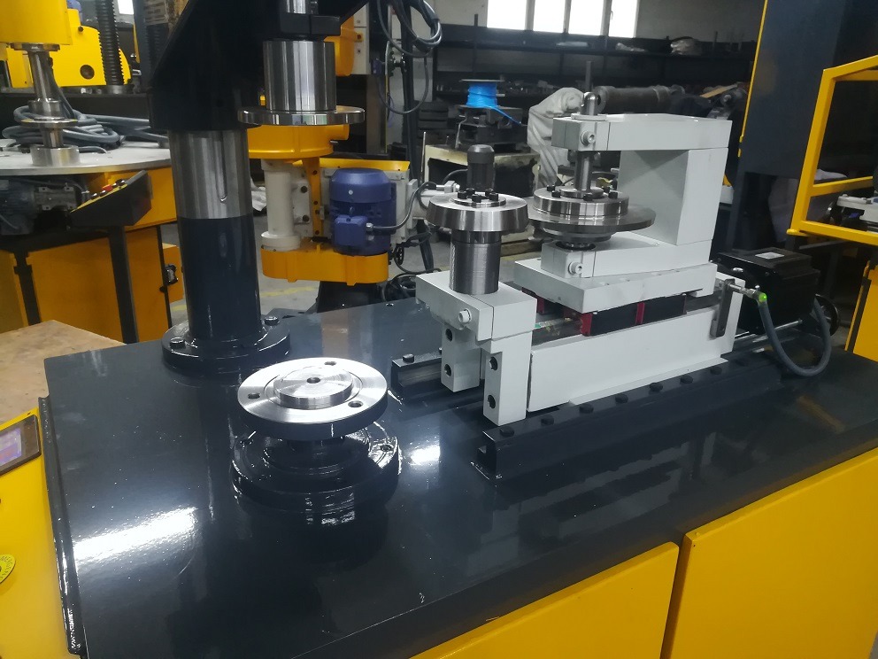
Precision trimming tools for sheet metal parts are specialized cutting implements designed to remove excess material, burrs, or unwanted edges with high accuracy and clean finishes. These tools are essential in manufacturing processes where tight tolerances, smooth edges, and minimal distortion are critical for part functionality, assembly fit, and aesthetic quality. Industries such as automotive, aerospace, electronics, appliances, and metal furniture rely heavily on precision trimming to achieve consistent, high-quality sheet metal components.
These tools come in various forms depending on the trimming method and material characteristics. Common types include shearing blades, rotary cutters, nibbling tools, laser cutters, and waterjet cutting heads. Each tool type offers unique advantages in terms of cut quality, speed, and suitability for different thicknesses and metal types.
Shearing blades are sharp, hardened steel tools designed for straight or curved cuts. They operate by applying shear stress to the sheet metal, effectively slicing through it with minimal deformation. Precision shearing blades are engineered with exact edge geometry and surface finishes to ensure clean cuts and extended tool life. They are often used in mechanical presses or CNC turret punch presses where repeatability and speed are paramount.
Rotary cutters consist of cylindrical blades that roll against a fixed surface to trim edges continuously. These cutters excel at trimming complex shapes and contours and are commonly employed in CNC profiling machines. Their design minimizes burr formation and distortion, making them suitable for thin to medium-thickness metals.
Nibbling tools remove material incrementally by punching a series of overlapping holes or cuts, allowing for intricate shapes and internal cutouts. While slower than shearing or rotary cutting, nibbling is valued for its flexibility and ability to work without expensive dies. Precision nibbling tools are carefully engineered to reduce material deformation and burr size.
Laser cutting heads use high-powered, focused laser beams to vaporize metal along the desired trim lines. This method delivers extremely precise cuts with minimal heat-affected zones, reducing warping or distortion. Laser trimming is ideal for complex, fine-detail parts and is increasingly used for thin to medium-gauge sheet metals including stainless steel and aluminum.
Waterjet cutters employ high-pressure streams of water mixed with abrasive particles to cut through metal without heat, preserving material properties and surface finishes. Waterjet trimming is versatile and precise, capable of handling a wide range of thicknesses and materials, though typically at slower speeds than laser or mechanical cutting.
Precision trimming tools are often integrated into automated manufacturing systems equipped with CNC controls for exact positioning, repeatability, and rapid changeovers between different part designs. Tool path programming and adaptive control systems optimize cutting speed and tool engagement to minimize wear and ensure consistent quality.
Tool materials and coatings play a crucial role in performance. High-quality trimming tools are made from hardened tool steels, carbide, or coated with wear-resistant materials like titanium nitride (TiN) or diamond-like carbon (DLC) to extend service life and maintain sharp edges under high-speed, high-volume production conditions.
Maintenance strategies such as regular sharpening, alignment checks, and lubrication help sustain trimming tool precision and reduce downtime. Advanced equipment may include automatic tool condition monitoring and predictive maintenance features that alert operators before tool degradation affects part quality.
In conclusion, precision trimming tools are vital components in sheet metal fabrication, enabling manufacturers to produce accurate, clean-edged parts efficiently. Their design, material selection, and integration with modern automation technologies ensure consistent high-quality trimming across diverse industrial applications.
Precision trimming tools for sheet metal parts are continuously evolving to meet the increasing demands of modern manufacturing for faster production rates, tighter tolerances, and higher-quality finishes. Advances in materials science have led to the development of cutting tools with superior hardness, toughness, and wear resistance, allowing them to maintain sharp edges longer and handle more abrasive or hardened metals without frequent replacement. Coatings such as titanium aluminum nitride (TiAlN) and diamond-like carbon (DLC) significantly reduce friction and heat buildup, further extending tool life and improving cut quality.
The integration of precision trimming tools into automated CNC systems enhances consistency and reduces human error. CNC programming allows for optimized tool paths that minimize cutting forces and reduce stress on both the tool and the workpiece. Adaptive control technologies monitor cutting parameters such as force, vibration, and temperature in real time, enabling dynamic adjustments to feed rates and cutting speeds. This not only prolongs tool life but also ensures that trimmed edges meet stringent dimensional and surface finish requirements.
Different trimming tool designs cater to specific applications. For example, shear blades with finely honed edges are preferred for straight or gently curved trims, offering clean cuts with minimal burr formation. Rotary trimming tools, with their continuous rolling action, are ideal for complex contours and internal cutouts, reducing the risk of edge distortion. Nibbling tools remain popular for intricate profiles or when cost constraints make custom dies impractical, though ongoing improvements in tool geometry and control systems have reduced their historical drawbacks such as rougher edges and slower cycle times.
Laser trimming tools are increasingly employed for their unmatched precision and flexibility. Advances in laser technology have improved cutting speeds and edge quality while reducing thermal distortion. Combining laser trimming with downstream automated deburring or edge finishing processes results in parts that require minimal secondary work. Waterjet trimming complements laser cutting by offering cold cutting capabilities, preserving material properties and preventing heat-affected zones, which is especially valuable for heat-sensitive alloys or composite-metal laminates.
The mounting and alignment of trimming tools are critical for achieving high precision. Modular tool holders with quick-change capabilities enable rapid tooling swaps while maintaining exact positioning, reducing setup time and ensuring repeatability. Some systems use precision linear guides and anti-backlash mechanisms to stabilize tool movement during cutting, enhancing dimensional accuracy.
Regular maintenance and monitoring are vital to sustaining trimming tool performance. Automated systems now feature sensors that detect wear-related changes in cutting force or vibration patterns, triggering alerts for timely tool servicing or replacement before quality is compromised. Predictive maintenance not only prevents unexpected downtime but also optimizes tooling costs by avoiding premature changes.
Ergonomics and safety are integral to trimming operations, especially in manual or semi-automated setups. Cutting tools are designed with protective guards, dust extraction, and vibration damping features to protect operators and maintain clean working environments. In fully automated cells, robotic handling minimizes human exposure to cutting zones, improving workplace safety.
In high-volume production environments, precision trimming tools contribute significantly to cycle time reduction by enabling faster cutting speeds and minimizing secondary finishing operations. When combined with in-line inspection systems, these tools ensure that only parts meeting strict quality standards proceed through the manufacturing process, thereby reducing waste and rework.
Overall, precision trimming tools for sheet metal parts embody a blend of advanced materials, innovative designs, and smart automation integration. Their continual development supports the manufacture of complex, high-precision components essential in sectors ranging from automotive and aerospace to electronics and consumer goods, helping manufacturers achieve competitive advantages through improved quality, efficiency, and cost-effectiveness.
Further innovations in precision trimming tools focus on enhancing versatility and customization to meet the diverse needs of evolving sheet metal fabrication industries. Modular tool systems allow manufacturers to quickly reconfigure trimming setups to accommodate different part geometries, materials, and production volumes. Interchangeable tool inserts and adjustable cutting angles enable fine-tuning for specific applications, optimizing edge quality and minimizing material waste.
Advancements in additive manufacturing have begun to influence trimming tool production, enabling complex internal cooling channels and customized geometries that improve thermal management and reduce tool wear. This results in higher cutting speeds and longer tool life, especially when trimming hard or abrasive metals.
Integration with Industry 4.0 technologies is another key development. Precision trimming tools embedded with sensors can communicate with machine control systems to provide real-time data on tool condition, cutting forces, and wear patterns. Coupled with machine learning algorithms, this data facilitates predictive maintenance, process optimization, and automated quality control, reducing downtime and ensuring consistent part quality.
The rise of hybrid manufacturing processes, which combine additive and subtractive methods, requires trimming tools capable of working on multi-material stacks or components with complex geometries. Tools are being designed with enhanced durability and multi-axis adaptability to perform precise trims on parts produced by these emerging techniques.
Environmental considerations are also shaping trimming tool design. Manufacturers are focusing on reducing cutting fluid usage through improved tool coatings and geometries that lower friction and heat generation. Dry or minimum quantity lubrication (MQL) compatible tools are becoming more prevalent, contributing to cleaner production environments and easier post-processing.
Training and operator support have benefited from digital aids such as augmented reality (AR) and virtual reality (VR). These technologies help technicians visualize trimming tool setups, understand wear patterns, and perform maintenance with greater accuracy and speed, reducing errors and improving machine uptime.
In highly automated fabrication cells, precision trimming tools are coordinated with robotic handling, vision systems, and quality inspection stations to create seamless production workflows. This orchestration ensures that trimmed parts consistently meet specifications, enabling just-in-time manufacturing and rapid product changeovers.
As manufacturing demands become more complex and quality standards continue to tighten, precision trimming tools remain a vital component of sheet metal fabrication. Their ongoing evolution in materials, design, and digital integration empowers manufacturers to achieve superior edge quality, increased productivity, and greater flexibility across a broad spectrum of industrial applications.
Select Automatic Forming Machines for Sheet Metal Parts
Selecting automatic forming machines for sheet metal parts requires careful evaluation of several factors to ensure optimal performance, quality, and return on investment. Automatic forming machines, which can include press brakes, stamping presses, bending machines, and roll forming systems, provide high-speed, precise shaping of sheet metal with minimal manual intervention—ideal for mass production and complex part geometries. Here are key considerations to guide the selection process:
1. Material Type and Thickness:
Identify the range of sheet metals (steel, aluminum, stainless steel, copper, etc.) and their thicknesses the machine must handle. Different forming machines have varying tonnage capacities, tooling requirements, and cycle capabilities suited to specific materials and gauges. Ensure the machine’s force rating and tooling compatibility match your material specifications.
2. Part Complexity and Geometry:
Assess the complexity of the parts to be formed—simple bends versus multi-step or compound shapes. Machines with CNC control and multi-axis capabilities (e.g., 3D bending, servo-driven press brakes) are better suited for intricate parts requiring tight tolerances and repeatability. For high-volume simple profiles, roll forming or progressive stamping presses may be more efficient.
3. Production Volume and Speed Requirements:
Estimate the expected production volumes and cycle times. Automatic forming machines vary from high-speed progressive presses designed for millions of parts to versatile robotic press brakes for lower volume, high-mix production. Select machines that balance throughput with quality to meet delivery schedules without excessive capital expenditure.
4. Automation and Integration Level:
Determine the desired level of automation—manual loading, semi-automatic with robotic assistance, or fully integrated automated production lines. Integration with material handling systems, feeders, and inspection stations can improve efficiency and reduce labor costs. Machines with flexible programming and quick-change tooling support rapid job changes.
5. Machine Control and Software:
Evaluate the CNC or PLC control systems for user-friendliness, programming flexibility, and connectivity. Modern forming machines offer touchscreens, offline programming, simulation software, and integration with Manufacturing Execution Systems (MES). These features enhance precision, reduce setup times, and improve overall equipment effectiveness (OEE).
6. Tooling Availability and Flexibility:
Consider the tooling options—standardized versus custom tooling—and their changeover times. Machines that support modular or quick-change tooling reduce downtime and accommodate diverse part designs. Check for tooling support for bending, stamping, flanging, or other forming operations your parts require.
7. Machine Footprint and Facility Requirements:
Assess the physical space, power supply, and foundation needs of the forming machine. Larger presses or roll forming lines may require significant floor space and specialized installation, while compact CNC press brakes or servo forming machines can fit smaller facilities.
8. Quality and Precision Capabilities:
Review the machine’s accuracy specifications, repeatability, and ability to maintain tolerances under continuous operation. Features such as back gauges, angle sensors, and force monitoring enhance quality control during forming.
9. Safety Features:
Ensure the machine includes comprehensive safety measures such as light curtains, emergency stops, interlocks, and guarded moving parts. Automated machines reduce operator exposure to hazards, but built-in safety systems remain essential.
10. Support and Service:
Evaluate the manufacturer’s reputation for technical support, training, spare parts availability, and maintenance services. Reliable after-sales support minimizes downtime and ensures sustained machine performance.
11. Budget and Total Cost of Ownership:
Consider not only the purchase price but also installation, tooling, training, maintenance, and operational costs. Energy-efficient machines with low maintenance requirements may offer better long-term value despite higher initial investments.
By carefully analyzing these factors and aligning them with your production needs and goals, you can select the most suitable automatic forming machine for your sheet metal parts, ensuring efficiency, quality, and scalability in your manufacturing operations.
Automatic Forming Machines for Sheet Metal Parts
Automatic forming machines for sheet metal parts are advanced manufacturing systems designed to shape, bend, and form metal sheets with minimal human intervention. These machines increase production efficiency, improve dimensional accuracy, and enable consistent high-quality output, making them essential in industries such as automotive, aerospace, appliance manufacturing, and electronics.
Key types of automatic forming machines include CNC press brakes, stamping presses, roll forming machines, and rotary forming equipment. CNC press brakes use computer-controlled bending tools to perform precise bends and folds, often incorporating multi-axis control for complex part geometries. Stamping presses execute high-speed blanking, punching, and forming operations using dedicated dies, suitable for large-volume production runs. Roll forming machines continuously shape metal sheets through successive roller stations, ideal for producing long, uniform profiles like channels and frames. Rotary forming machines, such as spinning or curling machines, manipulate sheet metal edges or contours through rotational motion.
These machines are typically integrated with automated material handling systems, including robotic arms, conveyors, and feeders, which streamline loading, positioning, and unloading processes. Automation reduces labor requirements, minimizes handling errors, and supports continuous operation with rapid cycle times.
Control systems in automatic forming machines range from programmable logic controllers (PLCs) to sophisticated CNC interfaces featuring touchscreen displays, offline programming, and simulation capabilities. Such controls allow operators to store multiple forming programs, quickly switch between part designs, and monitor process parameters in real time.
Advanced sensors and feedback mechanisms are incorporated to ensure process consistency and product quality. Force sensors, position encoders, and vision systems detect deviations or defects during forming, enabling automatic adjustments or rejection of nonconforming parts.
Safety is paramount in automated forming environments. Machines are equipped with guarded enclosures, light curtains, emergency stop devices, and interlock systems to protect operators from moving parts and high forces. Automation also reduces operator exposure to repetitive or hazardous tasks.
Modern automatic forming machines often support integration with factory-wide digital systems, including Manufacturing Execution Systems (MES) and Enterprise Resource Planning (ERP) software, facilitating production tracking, quality management, and predictive maintenance.
In summary, automatic forming machines for sheet metal parts combine mechanical precision, digital control, and automation to deliver efficient, flexible, and high-quality metal forming solutions suited for a wide range of industrial applications.
Automatic forming machines for sheet metal parts have become increasingly sophisticated, incorporating innovations that enhance flexibility, precision, and productivity. One of the key advancements is the integration of servo-electric drives, which replace traditional hydraulic systems to offer smoother, more energy-efficient motion control. Servo-driven machines provide faster cycle times, reduced maintenance, and quieter operation, making them well-suited for modern manufacturing environments focused on sustainability and operational efficiency.
Automation in these machines extends beyond just the forming action. Intelligent material handling systems, including robotic loaders and unloaders, automated conveyors, and smart feeders, are commonly integrated to create seamless production lines. This connectivity reduces manual intervention, lowers the risk of handling damage, and enables continuous operation, which is critical for high-volume manufacturing.
CNC controls in automatic forming machines now often feature advanced programming tools with graphical user interfaces and offline simulation capabilities. Operators can visualize bending sequences or forming steps before actual production, minimizing setup errors and reducing trial runs. This also allows for rapid changeovers, supporting just-in-time manufacturing and small batch production without sacrificing efficiency.
Quality assurance is bolstered by inline inspection systems utilizing machine vision and sensor data analytics. Cameras and laser measurement tools monitor part dimensions, surface finish, and forming accuracy in real time, allowing immediate identification and rejection of defective parts. Feedback from these systems can dynamically adjust machine parameters to maintain consistent quality, reducing scrap rates and rework.
Safety enhancements continue to evolve with automatic forming machines. Beyond physical guards and emergency stops, modern systems employ presence-sensing devices and intelligent safety logic that adapt machine behavior based on operator proximity or unexpected events. This reduces accident risk and allows safe human-machine collaboration in semi-automated workflows.
The modular design of many automatic forming machines facilitates scalability and customization. Manufacturers can add or reconfigure tooling stations, material handling modules, or inspection units to meet changing production demands. This modularity protects capital investment by enabling gradual upgrades rather than complete system replacements.
Energy efficiency remains a priority, with features such as regenerative braking on servo motors, optimized motion paths, and low-power standby modes reducing overall energy consumption. Additionally, machines are designed to minimize hydraulic fluid use or eliminate hydraulics entirely, contributing to cleaner, more environmentally friendly operations.
Integration with broader digital manufacturing ecosystems allows automatic forming machines to participate in Industry 4.0 initiatives. Real-time data exchange with enterprise systems supports production planning, maintenance scheduling, and supply chain coordination, enhancing responsiveness and operational transparency.
Overall, automatic forming machines for sheet metal parts represent a convergence of mechanical engineering, electronics, and information technology. Their ongoing development empowers manufacturers to produce complex, high-quality metal components efficiently and reliably while adapting swiftly to market and product changes.
Building on these advancements, automatic forming machines increasingly incorporate artificial intelligence (AI) and machine learning (ML) to further optimize forming processes. By analyzing vast amounts of operational data—such as force patterns, cycle times, material behavior, and environmental conditions—AI algorithms can predict optimal machine settings for different materials and part geometries, minimizing setup time and trial runs. This self-optimization leads to enhanced precision, reduced material waste, and increased throughput.
Robotics integration is also expanding, with collaborative robots (cobots) working alongside automatic forming machines to handle complex loading, unloading, or part manipulation tasks. Cobots offer flexibility in handling varied part shapes and sizes, adapting quickly to production changes while maintaining safety through built-in sensors and force limitation. This hybrid human-robot collaboration boosts productivity without requiring full automation investments.
Digital twins—virtual replicas of forming machines and production processes—are gaining traction as powerful tools for design validation, process simulation, and predictive maintenance. By mirroring real-time machine behavior, digital twins allow engineers to simulate forming sequences, identify bottlenecks, and optimize parameters before actual production, reducing downtime and enhancing quality control.
The use of advanced materials and lightweight alloys in sheet metal parts, such as high-strength steels and aluminum-magnesium alloys, demands forming machines with greater adaptability and control. Automatic forming systems now include multi-axis bending, variable speed drives, and adaptive force control to handle these materials without cracking or deformation, enabling manufacturers to meet stricter weight and performance targets.
Connectivity and cybersecurity are critical as forming machines become more networked. Secure communication protocols, user authentication, and data encryption protect sensitive production data and prevent unauthorized access or disruptions. Manufacturers prioritize cybersecurity to safeguard intellectual property and maintain uninterrupted operations.
Sustainability considerations shape machine design and operation, with features like energy recovery systems, reduced lubrication requirements, and environmentally friendly coolants becoming standard. Automated forming machines help companies meet regulatory requirements and corporate social responsibility goals by lowering their environmental footprint.
In terms of user experience, intuitive interfaces with augmented reality (AR) and virtual reality (VR) support are emerging. These technologies aid operator training, troubleshooting, and maintenance by overlaying instructions or diagnostics onto the physical machine environment, accelerating learning curves and reducing errors.
Finally, ongoing collaboration between machine builders, software developers, and end-users drives continuous innovation. Customizable solutions tailored to specific industry needs—whether automotive body panels, aerospace structural components, or consumer electronics enclosures—ensure that automatic forming machines remain versatile and future-proof.
In essence, automatic forming machines for sheet metal parts are evolving into intelligent, connected, and adaptable systems that empower manufacturers to achieve higher quality, efficiency, and flexibility in an increasingly competitive global market.
Sheet Metal Beading Tools
Sheet metal beading tools are specialized forming tools used to create raised beads, ribs, or decorative lines on sheet metal surfaces. These beads serve to reinforce and strengthen the metal by increasing its rigidity and resistance to bending or vibration without adding significant weight. Beading also enhances the visual appeal of parts and can assist in assembly by providing alignment or attachment features. Common applications include automotive panels, appliance housings, HVAC components, and metal furniture.
Beading tools come in various designs depending on the type of beading operation and the specific bead profile required. The most common forms include roller dies, press punches, and rotary beading wheels. Roller dies typically consist of grooved rollers that press a continuous bead into the metal as it passes through a forming machine. Press punches create beads by stamping or pressing the sheet metal at discrete intervals, allowing for more complex or segmented bead patterns. Rotary beading wheels rotate against the sheet metal edge to form rolled beads, often used for edge finishing.
The tools are usually made from hardened tool steels or carbide materials to withstand the high pressures and abrasive conditions of metal forming. Precision machining ensures that beads are consistent in size and shape, providing uniform strength and aesthetics across parts. Tool coatings such as titanium nitride (TiN) can be applied to reduce wear and friction, extending tool life.
Beading tools are integrated into a variety of machines, including manual bead rollers, hydraulic or mechanical presses, and automated roll forming lines. CNC-controlled beading machines allow for programmable bead patterns, depths, and spacing, offering flexibility for different part designs and production volumes. Quick-change tooling systems facilitate rapid switching between bead profiles, reducing downtime in multi-product facilities.
Proper tool selection and maintenance are essential for achieving high-quality beads and minimizing defects such as cracking, wrinkling, or surface damage. Factors like material type, sheet thickness, and bead geometry influence tooling choices and forming parameters. Regular inspection and timely reconditioning or replacement of tools help maintain consistent part quality and reduce scrap.
In summary, sheet metal beading tools are critical components in metal forming processes that enhance the structural integrity and appearance of sheet metal parts. Their design, material composition, and integration with forming machines determine the efficiency and quality of beading operations across various industrial applications.
Sheet metal beading tools are designed to operate under high pressure and often at high speeds, requiring robust construction and precise manufacturing tolerances. The accuracy of the bead profile is crucial, as even minor inconsistencies can affect the strength and appearance of the final part. To achieve this, beading tools are manufactured using advanced machining techniques such as CNC grinding and EDM (electrical discharge machining), which ensure tight dimensional control and smooth surface finishes.
Different bead shapes serve various functional and aesthetic purposes. For example, raised beads provide increased stiffness and rigidity, reducing panel flex and improving resistance to vibration and noise. V-shaped or channel beads can serve as guides for assembly or locations for attaching other components. Decorative beads may enhance the visual design of consumer products or architectural elements.
Material selection for beading tools depends on the production environment and sheet metal characteristics. Hardened alloy steels are common for general-purpose applications, offering a good balance between toughness and wear resistance. For high-volume or abrasive material forming, carbide tooling provides superior hardness and longer life, albeit at a higher cost. Tool coatings like titanium aluminum nitride (TiAlN) or diamond-like carbon (DLC) further improve performance by reducing friction, preventing galling, and resisting corrosion.
In automated production lines, beading tools are often part of multi-station forming machines where beads are added in sequence along the sheet metal. This approach minimizes handling and setup time while ensuring consistent bead placement. CNC programming allows customization of bead patterns and depths, enabling manufacturers to switch quickly between part designs without extensive tooling changes.
Proper alignment of beading tools with the sheet metal is essential to avoid defects such as uneven bead height, wrinkles, or cracking. Automated sensors and feedback systems help maintain precise positioning during forming, adjusting for material variations or thermal expansion. In some systems, real-time monitoring can detect anomalies and alert operators or pause production to prevent defective parts.
Maintenance of beading tools includes regular inspection for wear, chipping, or surface damage. Tools showing signs of degradation are refurbished through regrinding or replaced to maintain forming accuracy. Lubrication of tooling and sheet metal surfaces reduces friction and heat generation, prolonging tool life and improving bead quality.
Safety considerations around beading operations include guarding moving parts and providing emergency stops. In automated cells, robots may handle sheet loading and unloading to keep operators away from hazardous zones. Ergonomic designs reduce operator fatigue during setup and maintenance tasks.
Training operators and maintenance personnel on proper tool handling, setup, and troubleshooting is vital for sustaining production efficiency and product quality. Detailed documentation and digital resources such as augmented reality guides support skill development and rapid problem resolution.
Overall, sheet metal beading tools are fundamental to producing reinforced, functional, and visually appealing metal parts. Their continual refinement in materials, design, and integration with automated systems drives improvements in manufacturing speed, consistency, and cost-effectiveness across diverse industries.
Emerging technologies are further transforming sheet metal beading tools and their applications. Additive manufacturing (3D printing) is beginning to influence tool production, allowing complex geometries, internal cooling channels, and customized features that improve tool performance and longevity. This technology enables rapid prototyping and shorter lead times for specialized tooling, enhancing responsiveness to unique production needs.
Digitalization plays a key role as well. Beading tools equipped with embedded sensors can provide real-time data on forming forces, temperature, and wear. This information feeds into predictive maintenance systems that anticipate tool degradation before failures occur, reducing unplanned downtime and optimizing tool replacement schedules. Data analytics also help refine forming parameters for better quality and throughput.
Integration of beading tools into flexible manufacturing systems allows quick adaptation to new bead patterns and sheet metal types. Modular tooling designs support fast changeovers and customization, which is increasingly important for industries facing shorter product life cycles and varied customer demands.
Environmentally friendly practices are shaping tool usage and maintenance. Reduced lubrication systems, recyclable tool materials, and energy-efficient forming machines complement beading tool innovations to create greener manufacturing processes. Minimizing waste and extending tool life contribute to sustainability goals.
Collaboration between tool manufacturers, machine builders, and end-users fosters ongoing innovation tailored to specific industrial challenges. Customized tool solutions address unique material properties, part designs, and production volumes, ensuring optimal performance and cost-efficiency.
In the future, advancements in materials science, sensor technology, and artificial intelligence are expected to drive further improvements in sheet metal beading tools. Smarter tools will self-adjust during forming, compensate for material inconsistencies, and communicate with machine controls to maintain ideal bead quality automatically.
In summary, sheet metal beading tools are evolving into intelligent, adaptable components of modern metal forming systems. Their development supports higher precision, efficiency, and sustainability, meeting the growing demands of diverse manufacturing sectors worldwide.
Sheet Metal Trimming Machinery
Sheet metal trimming machinery is essential equipment used to precisely remove excess material, burrs, or unwanted edges from sheet metal parts after forming or stamping processes. Trimming improves the dimensional accuracy, surface quality, and overall finish of metal components, ensuring they meet tight tolerances and are ready for subsequent assembly or finishing operations. These machines are widely used in industries such as automotive manufacturing, aerospace, electronics, appliance production, and metal fabrication.
There are various types of trimming machinery designed to suit different materials, part geometries, production volumes, and precision requirements. Mechanical trimming presses utilize fixed and moving blades or dies to shear excess material in a single stroke or multiple progressive steps. Hydraulic trimming presses offer adjustable force control and smooth operation, suitable for thicker or more complex parts. CNC trimming machines combine programmable control with precision cutting tools to trim intricate contours and complex shapes with high repeatability.
Common trimming methods include shear trimming, where sharp blades cut along defined edges; rotary trimming, using rotating cutters or milling heads to remove material continuously; nibbling, which punches overlapping small cuts for intricate profiles; and laser or waterjet trimming, which employs focused energy or abrasive water streams for non-contact precision cutting.
Trimming machinery often integrates with automated feeding and positioning systems to ensure accurate alignment of parts before trimming. Sensors and vision systems verify part placement and detect defects, enabling real-time adjustments or rejection of faulty components. This automation reduces manual handling, increases throughput, and improves quality consistency.
Tooling design is critical in trimming machinery. Cutting blades and dies are made from hardened tool steels or carbide, sometimes coated for enhanced wear resistance. Precision machining and maintenance of tooling ensure clean, burr-free edges and minimize distortion. Quick-change tooling systems support rapid switches between different part designs, reducing downtime.
Safety features such as guarded enclosures, emergency stop mechanisms, and operator presence sensors protect personnel from high-speed moving parts and cutting zones. Ergonomic designs and automated loading/unloading reduce operator fatigue and improve workplace safety.
Modern sheet metal trimming machinery often interfaces with factory-wide digital systems, enabling process monitoring, quality control, and predictive maintenance. Integration with Manufacturing Execution Systems (MES) facilitates production scheduling, traceability, and data-driven optimization.
In summary, sheet metal trimming machinery provides vital finishing capability in metal fabrication, combining mechanical precision, advanced control systems, and automation to deliver high-quality, dimensionally accurate parts efficiently across diverse industrial applications.
Sheet metal trimming machinery has evolved significantly to meet the increasing demands for speed, precision, and flexibility in modern manufacturing. Advances in servo-electric drives and CNC control systems have enabled trimming machines to operate with higher accuracy and faster cycle times while reducing energy consumption compared to traditional hydraulic presses. These improvements allow manufacturers to handle complex part geometries and thinner or higher-strength materials with minimal distortion and burr formation.
Automation plays a central role in contemporary trimming machinery. Automated part feeders, robotic loading and unloading systems, and precision positioning devices work together to streamline production workflows, reduce manual intervention, and minimize the risk of part misalignment. Vision systems and laser scanners are often employed to verify part orientation and quality before trimming begins, enabling immediate correction or rejection of defective parts and ensuring consistent output.
The choice of trimming method depends on factors such as material type, thickness, part complexity, and production volume. Shear trimming remains popular for straight or simple curved edges due to its speed and clean cuts. Rotary trimming and milling are preferred for complex contours or internal cutouts, providing continuous cutting action with smooth finishes. Nibbling tools offer flexibility for intricate shapes without the need for expensive dies but may operate at slower speeds. Laser and waterjet trimming provide non-contact cutting options ideal for delicate materials or parts requiring high edge quality without heat-affected zones.
Tooling materials and design are critical to machine performance and part quality. Cutting blades and dies are manufactured from high-grade tool steels, carbide, or coated with advanced wear-resistant materials to withstand repetitive high-force impacts and abrasive conditions. Regular maintenance, sharpening, and alignment checks extend tooling life and preserve edge quality. Quick-change tooling systems reduce downtime during product changeovers, which is especially valuable in facilities producing multiple part variants.
Safety remains a paramount consideration. Modern trimming machines incorporate comprehensive guarding, safety interlocks, emergency stops, and operator presence detection to prevent accidents. Ergonomically designed control interfaces and automated handling reduce operator fatigue and exposure to hazardous zones.
Integration with digital factory systems enhances operational efficiency and traceability. Real-time monitoring of machine performance, tool condition, and production metrics allows for predictive maintenance and process optimization. Connectivity to Manufacturing Execution Systems (MES) and Enterprise Resource Planning (ERP) software facilitates production planning, quality assurance, and inventory management.
Environmental factors are also addressed through energy-efficient drives, reduced use of cutting fluids, and improved waste management practices. Some trimming machines incorporate dry cutting technologies or minimum quantity lubrication (MQL) systems to minimize environmental impact and post-processing requirements.
In conclusion, sheet metal trimming machinery combines mechanical robustness, advanced automation, and digital connectivity to deliver precise, efficient, and safe finishing processes. Its continual development supports manufacturers in meeting evolving product specifications, reducing costs, and maintaining high-quality standards across a broad range of metal fabrication industries.
Further advancements in sheet metal trimming machinery focus on enhancing flexibility and adaptability to meet the needs of increasingly diverse and customized production environments. Modular machine designs allow manufacturers to add or reconfigure trimming stations easily, supporting varied part geometries and batch sizes without requiring complete equipment overhauls. This modularity is especially beneficial for industries where rapid product development cycles and frequent design changes are common.
The integration of artificial intelligence (AI) and machine learning (ML) is beginning to transform trimming operations. These technologies analyze historical and real-time data to optimize cutting parameters dynamically, predict tool wear, and anticipate maintenance needs. As a result, machines can maintain optimal performance, reduce scrap rates, and extend tooling life while minimizing unplanned downtime.
Robotic automation is increasingly employed for handling parts before and after trimming. Collaborative robots (cobots) work alongside human operators to load, position, or transfer sheet metal components safely and efficiently. This collaboration improves workflow flexibility, supports small batch production, and enhances worker safety by reducing manual handling in hazardous zones.
Advanced sensor systems, including 3D scanners and high-resolution cameras, enhance quality control by inspecting trimmed edges for burrs, dimensional accuracy, and surface defects immediately after trimming. Automated feedback loops enable machines to adjust trimming parameters on the fly or remove defective parts from the production line, ensuring consistent quality standards.
The rise of hybrid trimming technologies combines mechanical cutting with laser or waterjet trimming in a single machine or production cell. This hybrid approach leverages the speed of mechanical methods and the precision of non-contact cutting to handle complex or delicate parts efficiently, broadening the range of materials and thicknesses that can be processed.
Sustainability considerations are shaping machine design and operation. Energy-efficient components, regenerative braking, and optimized motion profiles reduce power consumption. The move toward dry or near-dry cutting processes reduces the environmental impact of cutting fluids and simplifies waste disposal. Additionally, machines are designed for easier disassembly and recycling at the end of their lifecycle.
Operator interfaces continue to evolve toward greater intuitiveness and connectivity. Touchscreen controls with graphical programming, augmented reality (AR) support for setup and troubleshooting, and remote monitoring capabilities improve usability and reduce downtime. Cloud-based platforms facilitate data sharing across multiple sites, supporting centralized process management and benchmarking.
In sectors demanding high traceability, such as aerospace and medical device manufacturing, trimming machines integrate marking systems to imprint serial numbers, batch codes, or QR codes directly onto parts. This capability ensures full production traceability and supports stringent quality assurance protocols.
Overall, sheet metal trimming machinery is becoming smarter, more versatile, and more integrated within digital manufacturing ecosystems. These developments enable manufacturers to respond rapidly to market demands, maintain exceptional quality, and operate more sustainably, securing competitive advantages in a dynamic industrial landscape.
Fully Automatic Hydraulic Drawing Transfer Press
A fully automatic hydraulic drawing transfer press is a high-performance machine designed for deep drawing and complex sheet metal forming operations, especially in high-volume manufacturing environments. It combines the controlled power of hydraulic systems with automated part handling and transfer mechanisms, allowing for seamless, continuous production with minimal human intervention. This type of press is particularly well-suited for producing automotive panels, appliance housings, cookware, and various structural components that require deep, accurate forming.
At its core, the hydraulic drawing press uses hydraulic cylinders to deliver high forming forces with adjustable speed and pressure, offering excellent control over the material flow during drawing. This precision is essential for maintaining part integrity and minimizing defects such as wrinkles, cracks, or thinning in the drawn areas. The hydraulic system’s programmability allows different pressure profiles and dwell times, which is crucial for complex or multi-step drawing processes.
The “transfer” aspect of the machine refers to its automated material handling system, typically involving mechanical or servo-driven transfer arms, crossbar feeders, or robotic systems that move the blank or partially formed part from one station to the next. In a multi-stage die setup, each station performs a part of the overall forming process—such as drawing, redrawing, ironing, or trimming—while the automated transfer ensures perfect synchronization between stages. This results in continuous operation and high throughput without the need for manual repositioning.
A fully automatic configuration means that everything from blank feeding, centering, lubrication, forming, transferring, and finished part ejection is handled automatically. This drastically reduces labor costs, eliminates variability from manual handling, and allows consistent, repeatable production. Additionally, integrated sensors and monitoring systems detect misfeeds, part presence, and press performance in real time, enabling fast diagnostics and minimal downtime.
The machine is controlled via a sophisticated PLC or CNC interface, offering flexible programming for different part geometries, drawing depths, and material types. Tooling and die changes are often simplified with quick-change systems and die setters, enabling rapid transitions between product runs. Modern presses also feature data logging, remote diagnostics, and integration with MES or ERP systems for production tracking and predictive maintenance.
Structural rigidity is critical in such presses, and their frame—often a tie-rod or monoblock design—is engineered to withstand the high loads of deep drawing. The press bed and slide are precision-machined and guided with high accuracy to ensure uniform force distribution and alignment.
Key features typically include:
- Tonnage range: Often from 300 to 2,000+ tons, depending on part complexity and material.
- Drawing cushion: A programmable hydraulic cushion under the lower die to control material flow during forming.
- Die protection and overload safety systems: To prevent damage to expensive tooling.
- Centralized lubrication and cooling systems: For extended machine and tool life.
- Energy-efficient components: Including variable-displacement pumps or servo-hydraulic systems to reduce energy consumption.
In summary, a fully automatic hydraulic drawing transfer press is a robust, efficient, and precise solution for high-volume deep drawing operations. By combining controlled hydraulic forming with automated transfer systems, it maximizes output while ensuring exceptional part quality, process repeatability, and manufacturing flexibility.
These presses are engineered for continuous operation, often running multiple shifts in demanding industrial environments. Their automated transfer systems are synchronized perfectly with the press cycle, ensuring that each blank or workpiece moves from station to station at exactly the right moment, with zero deviation or mechanical hesitation. This synchronization is vital in multi-stage forming, where even a small delay or misalignment could result in part rejection or tooling damage. Servo transfer systems, which are increasingly common, allow programmable control of motion curves, acceleration, and positioning, offering smoother and more adaptable handling than mechanical linkages.
Hydraulic control provides advantages that mechanical presses cannot easily match, such as adjustable slide speed, dwell time at bottom dead center, and programmable pressure ramps. These capabilities are especially important in forming advanced high-strength steels, stainless steel, aluminum, and even exotic materials used in aerospace and electrical enclosures. By carefully managing the material flow during the draw, hydraulic presses reduce thinning and tearing, which results in stronger, more uniform parts that meet strict engineering tolerances.
In fully automated systems, blank feeding is done by precision coil lines, destackers, or robotic blank loaders that supply the press continuously without manual intervention. Some lines use vision-guided robotics to pick and place blanks from randomized stacks, further increasing flexibility. Sheet lubricants are applied automatically to reduce friction and extend tool life, especially in applications involving stainless steel or aluminum, which are more prone to galling or surface marking.
The automation also extends to end-of-line operations. Trimmed or formed parts are ejected via conveyors or robot arms and may go directly into inspection stations, stacking devices, or even automated welding or assembly cells. This seamless flow reduces work-in-progress inventory and facilitates tight control over the production timeline. In high-volume operations, finished parts may be marked automatically for traceability, scanned for dimensional checks, or weighed to confirm material integrity before moving downstream.
Programming and control of the entire system is handled through a central HMI that integrates all machine functions. From this interface, the operator can manage press motion, transfer speed, blank alignment, cushion pressure, diagnostics, and safety systems. Modern systems offer touchscreen interfaces with graphical process displays, built-in simulations, and recipe management to store and recall settings for different part types. Remote access capabilities are also standard, enabling engineers or service personnel to perform diagnostics or updates from off-site locations.
Maintenance and uptime are critical in such systems. Condition monitoring sensors track hydraulic pressure, oil temperature, motor loads, and transfer arm vibrations. Predictive maintenance algorithms alert users to wear or irregularities before they become failures, keeping the machine running smoothly. Quick die change systems—often with hydraulic or motorized die lifters, clamps, and rollers—allow complete die changeovers in minutes instead of hours, minimizing production interruptions.
For industries like automotive or appliance manufacturing, where precision and scale are everything, a fully automatic hydraulic drawing transfer press delivers unmatched performance. It handles complex parts in a single integrated system with repeatable quality, whether forming deep cylindrical shapes like cookware or large structural automotive parts. These presses represent a perfect fusion of force, control, and intelligence—built not just to form metal, but to form the future of high-efficiency manufacturing.
As production demands grow more complex and just-in-time delivery pressures increase, fully automatic hydraulic drawing transfer presses are evolving to support greater customization, modularity, and interconnectivity. Manufacturers are no longer relying solely on fixed-purpose machines—they’re turning to systems that can handle a variety of parts with minimal tooling adjustments and faster changeovers. This is achieved through modular tooling setups, servo-controlled slide movements, and multi-point programmable transfer arms, all of which are designed to adapt quickly to part design variations.
A major driver of this flexibility is servo-hydraulic hybrid technology. In these systems, traditional hydraulics are combined with servo motors to control ram movement with extreme accuracy and responsiveness. The result is smoother operation, lower energy consumption, and more consistent material flow, especially important in applications that involve variable wall thickness, stepped geometries, or sensitive alloys. Servo control also allows for complex motion profiles, including dwell-hold-draw sequences, slow approach speeds for wrinkle-sensitive areas, or rapid return for improved cycle time—all programmable via the machine’s digital interface.
Industry 4.0 readiness is now a standard feature in new-generation presses. These machines are equipped with an array of sensors—monitoring tonnage, die alignment, fluid pressure, cushion stroke, lubrication levels, and tool temperature—that feed real-time data into digital dashboards or cloud-based analytics platforms. This live data can be used not just for predictive maintenance, but also for process optimization and part quality analysis. Engineers can identify subtle performance shifts before they affect output, and maintenance teams can schedule interventions without stopping production.
Energy efficiency is another area where modern fully automatic hydraulic drawing presses excel. While traditional hydraulic presses were known for high power consumption and constant pump operation, new systems use variable-speed pumps, energy recovery circuits, and smart idle modes that dramatically reduce energy use during standby or light-load conditions. These enhancements not only lower operational costs but also contribute to sustainability targets in energy-intensive manufacturing sectors.
In terms of tooling integration, the press system can coordinate with die lifters, positioners, and clamping units for fully automated die changes. These changes can be performed in under 10 minutes in advanced setups, using pre-programmed sequences and auto-calibration routines. This allows operators to switch between parts with different draw depths, diameters, or flange profiles without interrupting production flow for extended periods.
Presses are also being designed with larger working areas and higher rigidity, enabling them to accommodate progressive die stations or multi-cavity dies, which form multiple identical or mirrored parts in a single stroke. This multiplies output without requiring additional machines or space, a major advantage in facilities with high production volume and limited floor area.
Lastly, the role of digital twins and simulation software is growing in prominence. Before physical dies are mounted, engineers can run full-scale simulations of the drawing process, adjusting draw depth, blank size, cushion pressure, and transfer timing in a virtual environment. These digital models help preempt issues like tearing, wrinkling, or misfeeds, which would otherwise require physical trials and adjustments. This not only saves time and material but dramatically shortens the ramp-up time for new product launches.
In sum, the fully automatic hydraulic drawing transfer press has become a cornerstone of high-efficiency, high-precision sheet metal production. With its fusion of hydraulic force, servo intelligence, and digital integration, it offers a scalable, adaptable, and data-driven platform capable of meeting the most demanding forming applications of today and tomorrow.
Hydraulic Sheet Metal Transfer Press with Trimming
A hydraulic sheet metal transfer press with trimming is an advanced manufacturing system that combines deep drawing or forming with trimming operations in a single, integrated production line. This configuration is ideal for producing complex, high-precision metal components that require both shaping and edge-finishing processes—especially in industries such as automotive, appliances, HVAC, and metal cookware.
At the heart of this system is the hydraulic press, which offers programmable force, speed, and dwell control. This allows for highly controlled forming operations, including deep drawing, redrawing, embossing, and coining. The hydraulic mechanism ensures smooth motion and consistent pressure application, which is essential for materials like aluminum, stainless steel, and high-strength steels that require gradual deformation to avoid tearing or wrinkling.
What sets this type of machine apart is its integration of transfer automation and in-line trimming stations. After the sheet metal blank is drawn or shaped at the first station, an automatic transfer system—usually servo-driven or robotic—moves the semi-formed part to the next stage(s) within the same press. At these successive stations, trimming tools remove excess material, such as the flange, flash, or burrs, from the part. The trimming operations may include shear trimming, punch trimming, notching, or piercing, depending on the geometry of the part and the specific finishing requirements.
By combining forming and trimming into a single cycle, this press system dramatically improves production speed, accuracy, and space efficiency. It eliminates the need for secondary trimming stations or manual part handling between machines, reducing labor costs and the risk of part damage or misalignment.
Precision in trimming is ensured by custom-designed dies and hardened tooling, typically made of tool steel or carbide, that match the contour of the part perfectly. The hydraulic press system provides the flexibility to adjust trimming pressure and stroke depth, which is particularly useful when working with different materials or varying blank thicknesses.
The entire process is managed by a centralized CNC or PLC control system with an intuitive HMI. This interface controls not only the forming and trimming operations but also the part transfer sequence, lubrication, die cushion force, and quality checks. It enables fast recipe changes, die identification, tool diagnostics, and production monitoring—making the system well-suited for both high-volume production and shorter-run jobs with frequent part changes.
These presses often include additional options like:
- Die cushions with programmable pressure profiles to manage material flow during deep drawing.
- Quick die change systems to reduce changeover time.
- In-die part sensing and quality monitoring for error detection and closed-loop control.
- Automatic part ejection and stacking systems for end-of-line efficiency.
In summary, a hydraulic sheet metal transfer press with trimming is a high-productivity, precision-engineered solution for forming and finishing sheet metal parts in one continuous, automated cycle. It offers manufacturers enhanced throughput, consistent part quality, and reduced operational costs—making it a valuable asset in modern metalforming operations.
These integrated systems are particularly valuable when manufacturing components that demand both structural integrity and aesthetic precision, such as outer automotive body panels, kitchen sinks, aluminum trays, or cylindrical containers. The hydraulic mechanism allows for fine-tuned control over the forming force, ensuring that the metal flows evenly into the die cavity without thinning excessively at corners or overstretching in complex contours. The ability to pause at bottom dead center during the draw gives time for the metal to settle, especially beneficial when forming stainless steel or high-strength alloys.
As the part advances automatically through each stage via servo-driven transfer arms or crossbar transfer systems, it is trimmed in precisely aligned stations. The trimming tools are mounted in the same press bed or upper slide and are timed to engage immediately after drawing. These trimming tools are custom-fit to the formed shape, cutting excess flange material or refining edges with exceptional repeatability. Because both forming and trimming occur in the same die set or press cycle, part consistency is ensured, and the need for secondary trimming machines or offline operations is eliminated.
Tooling life and part quality are supported by sophisticated monitoring systems that detect force feedback, material misfeeds, or tool wear in real time. If a deviation from the normal forming or trimming process is detected, the system can halt production automatically or alert the operator before any damage occurs. This reduces scrap and protects both the machine and the tooling from premature wear or costly failures. The dies used for both forming and trimming are typically hardened and coated to withstand long production runs, and die change systems with hydraulic lifters or rolling die carts allow for fast transitions between product setups, supporting flexible manufacturing.
The hydraulic circuits are engineered to deliver energy efficiently, often using variable-displacement pumps or servo-hydraulic control units that adjust pressure and flow based on demand. This not only reduces energy consumption but also improves the responsiveness and smoothness of motion during both drawing and trimming cycles. These features are especially beneficial when working with lighter gauge materials or parts with thin walls that require controlled deformation and cutting.
End-of-line automation is also a critical part of the system. After the part is formed and trimmed, it is automatically transferred to a discharge conveyor or robotic arm, which may place it into a stacking system, tray, or even directly onto an assembly line. This removes the need for manual unloading and ensures the formed parts are handled gently, avoiding surface scratches or dents, which are especially undesirable in visible components.
Data logging and part traceability are now standard features in these machines. Every stroke of the press is tracked, with time-stamped data on draw depth, tonnage, trimming force, tool wear cycles, and output rates. This information is fed into factory-level management systems to help supervisors analyze performance, detect process drift, and schedule proactive maintenance.
Ultimately, a hydraulic sheet metal transfer press with trimming offers not just speed and accuracy but a tightly integrated process capable of turning flat metal blanks into fully formed, accurately trimmed, ready-to-use components in a single line. It reduces the number of machines on the shop floor, minimizes handling, cuts cycle times, and enhances part consistency, all while providing the flexibility to adapt to changing production requirements. This makes it an indispensable solution for high-efficiency metal forming operations across a wide range of industries.
These machines are also engineered for long-term operational stability and are built on extremely rigid frames—either monoblock or tie-rod constructions—to prevent deflection under the high forces involved in deep drawing and trimming. The structural integrity of the press ensures that even under full load, the slide and bed maintain perfect alignment, which is crucial for achieving consistent part dimensions and die longevity. Internal guides, often hydrostatically or dynamically lubricated, help eliminate side thrust and reduce wear, making these systems suitable for continuous, high-cycle production environments.
Noise and vibration levels are typically lower than those in mechanical presses, which is another advantage of hydraulic systems. The smooth actuation and controlled acceleration of the ram and transfer arms contribute to a quieter, more stable working environment. This becomes particularly important when machines are installed in clean, modern factories with environmental and occupational standards in place. Lower noise also contributes to operator comfort and allows for closer human-machine interaction when necessary.
One of the most valued aspects of the hydraulic sheet metal transfer press with trimming is its adaptability to part complexity. It can accommodate irregular contours, varying wall thicknesses, undercuts, deep recesses, and compound shapes that would be extremely difficult or even impossible to produce in a single stage on mechanical presses. It’s often used for parts that require a drawn body followed by intricate edge shaping, slotting, or fine trimming—delivering all these steps in one integrated cycle with minimal handling between operations.
For high-volume production, the system can be equipped with coil feeding lines and blanking stations upstream, allowing automatic decoiling, straightening, and blank cutting directly from coil stock. This closed-loop process—from raw material to finished, trimmed part—means reduced scrap, improved material utilization, and significant cost savings over time. With optimized nesting and feeding control, blank usage is maximized, and waste is minimized, which is especially important when working with expensive materials like stainless steel, copper, or coated aluminum.
In terms of maintenance, modern systems are increasingly equipped with centralized diagnostic software and automated service routines. The press can perform self-checks on fluid levels, temperature, pressure stability, and tool load. Maintenance notifications are generated based on cycles or hours run, and sensors detect abnormal vibrations or resistance in critical components. All this reduces unexpected downtime and enables planned servicing with minimal production disruption.
From an investment perspective, while the initial cost of a hydraulic transfer press with integrated trimming is higher than that of a simpler press line, the ROI is justified through reduced labor, higher throughput, greater part quality, and consolidation of multiple processes into a single machine. This is especially true for manufacturers producing complex formed parts at scale, where the cost of reworking, defect rejection, and secondary trimming would otherwise erode profitability.
Looking forward, these systems are increasingly being integrated into fully digital production cells, linked with robotic welding, laser cutting, or surface finishing stations. In such smart factory environments, the hydraulic transfer press is not just a forming machine—it becomes the central engine of a tightly synchronized production ecosystem capable of mass customization, real-time adaptability, and data-driven performance optimization. It exemplifies the direction of modern manufacturing: efficient, precise, connected, and ready to produce without compromise.
Blanking and Deep Drawing Transfer Press
A blanking and deep drawing transfer press is a highly integrated metal forming system designed to perform two critical processes—blanking and deep drawing—in a single, continuous production line, often using automated transfer mechanisms to move the workpiece between stations. This type of press is widely used in the automotive, cookware, appliance, and metal packaging industries, where high-volume production of cup-shaped or cylindrical components from coil or sheet stock is required.
The blanking stage is typically the first operation in the press line. Here, flat sheet metal—often fed automatically from a coil—is cut into precise blanks. These blanks are either circular, square, or custom-shaped depending on the geometry of the final drawn part. The blanking die cuts the sheet with clean shearing action, and the press ensures consistent dimensional accuracy and minimal burr formation. In a transfer press, these freshly cut blanks are not manually handled; instead, they are instantly picked up by servo-driven transfer arms or mechanical lifters and moved directly to the next station.
At the deep drawing station, the blank is clamped by a blank holder or binder ring, and a punch descends to push the metal into a die cavity, creating a cup or other hollow shape. The drawing cushion under the die provides resistance to control the material flow, preventing wrinkles or cracks as the metal stretches and bends. Because it uses a transfer mechanism, this system is capable of multi-stage drawing, where the part is redrawn several times through progressively deeper dies to achieve the required depth and profile.
The transfer system is the heart of this configuration. It synchronizes precisely with the press ram, moving parts from station to station without interruption. It can include crossbar transfers, three-axis servo arms, or rail-mounted pick-and-place units. This enables high-speed operation, repeatability, and minimal downtime—even with complex, multi-draw components. With each stroke of the press, all stages—blanking, drawing, redrawing, and possibly trimming or flanging—are performed simultaneously on different parts at different stages of completion.
Modern blanking and deep drawing transfer presses are hydraulic, mechanical, or hybrid in construction. Hydraulic presses are preferred for their smooth motion and programmable force control, ideal for delicate or complex deep-drawn parts. Mechanical systems are typically faster and suited for simpler shapes in high volumes. Hybrid systems combine the benefits of both, offering speed with high forming control.
These presses are often equipped with:
- CNC/PLC-controlled forming parameters for each station.
- Die cushions with programmable force profiles.
- Lubrication systems to reduce friction and tool wear.
- In-line part inspection systems using cameras or sensors.
- Quick-change tooling systems for minimal downtime between part runs.
By combining blanking and deep drawing in a single automated cycle, these presses eliminate the need for separate machines, reduce part handling, and significantly increase throughput. The result is a streamlined, space-saving solution capable of producing complex parts with tight tolerances, high surface finish, and consistent quality.
These presses are designed for continuous operation, capable of producing thousands of parts per shift with exceptional consistency. The integration of blanking and deep drawing into one uninterrupted sequence reduces material handling and intermediate storage, which not only saves floor space but also minimizes the risk of part contamination, surface damage, or dimensional variation between forming stages. As the sheet metal uncoils and feeds into the blanking die, every action thereafter—from cutting the blank to forming the final drawn part—is fully automated and synchronized with each press cycle.
The transfer system, whether servo-controlled or mechanical, plays a vital role in maintaining high-speed operation. It carefully grips or lifts each blank or semi-formed part and places it into the next station with precise timing, often within fractions of a second. The movement is highly coordinated with the motion of the press ram, allowing the transfer arms to operate in the short window when the slide returns to top dead center. The ability to transport multiple parts through a series of dies simultaneously—where one part is being blanked while another is being drawn and another is being redrawn—maximizes productivity and reduces cycle time per part.
Deep drawing in this environment demands exceptional accuracy, and the hydraulic or hybrid press architecture enables fine-tuned control of forming pressure and speed. Drawing cushions underneath the die exert adjustable upward force against the blank holder, ensuring that the metal flows evenly into the cavity during the draw. These cushions can be electronically regulated and programmed to provide different pressures at different phases of the stroke, adapting to the geometry and material behavior of each part. This flexibility is crucial for preventing defects such as tearing near corners, wrinkling on flanges, or uneven wall thickness in deep sections.
Tooling for blanking and drawing is typically made of hardened tool steel or carbide, precisely machined and often coated with wear-resistant materials like TiN or DLC to extend service life and ensure clean cuts and smooth draws. Because multiple tools operate simultaneously in a transfer press, alignment and die height calibration are critically important. Many systems include automatic die setting features or die clamping systems that minimize setup time and ensure repeatability.
For complex parts requiring several redraws, additional stations within the same press perform successive forming steps. Each draw gradually deepens or reshapes the part, sometimes including ironing operations to thin the walls deliberately for specific functional or weight-saving requirements. Secondary operations such as trimming, piercing, or edge flanging can be integrated into the final stations of the press, making the part ready for downstream processes like welding, coating, or assembly.
Control systems on these presses allow the operator to monitor and adjust every aspect of the cycle from a central touchscreen interface. Parameters like draw depth, blanking clearance, transfer speed, and cushion pressure are fully programmable and can be stored as part recipes for fast job changes. Advanced systems offer real-time diagnostics, sensor monitoring for die protection and part presence, and connectivity to factory-wide networks for production tracking and predictive maintenance.
Blanking and deep drawing transfer presses are essential in manufacturing environments where speed, precision, and volume are critical. They combine the efficiency of high-speed transfer automation with the forming flexibility and precision of hydraulic or hybrid presses, making them ideal for producing consistent, complex, high-strength parts at industrial scale. Their ability to compress multiple forming operations into one seamless cycle reduces lead times, tooling changes, and floor space requirements, delivering a competitive edge in modern sheet metal manufacturing.
In addition to their core forming and blanking functions, many modern blanking and deep drawing transfer presses incorporate sophisticated quality assurance and process control features. Inline inspection systems, such as laser scanners, vision cameras, or tactile probes, can verify critical dimensions, detect surface defects, and confirm the presence of key features immediately after each forming stage. This instant feedback loop allows the press to adjust forming parameters dynamically or halt production if deviations occur, greatly reducing scrap rates and rework costs.
Energy efficiency is another significant focus in the design of these presses. Variable displacement hydraulic pumps, regenerative systems that recover energy during the ram’s return stroke, and servo-hydraulic hybrids contribute to lower power consumption while maintaining high forming accuracy. These energy-saving measures not only reduce operational costs but also help manufacturers meet increasingly strict environmental regulations and sustainability goals.
The integration of Industry 4.0 technologies transforms these presses into smart manufacturing assets. They collect vast amounts of operational data—from hydraulic pressure curves to transfer arm positioning and cycle times—and use advanced analytics or AI algorithms to optimize production processes. This data can be accessed remotely, enabling real-time monitoring and troubleshooting by engineers offsite, which enhances uptime and responsiveness.
Automation of material handling before and after the press further streamlines the manufacturing workflow. Coil feeding lines with servo-driven straighteners and blanking feeders ensure smooth, precise delivery of raw material to the blanking station. Downstream, automated stacking, packaging, or robotic transfer to assembly lines minimizes manual labor and potential part damage.
The tooling systems themselves have also seen innovations. Modular die designs and quick-change tooling fixtures enable rapid setup and tool replacement, essential for manufacturers handling multiple part variants or shorter production runs. Advanced coatings and surface treatments extend die life, particularly important when working with abrasive or high-strength materials.
Safety remains paramount. Modern transfer presses feature comprehensive guarding, light curtains, emergency stop systems, and safe operator interfaces. Collaborative robots (cobots) may be incorporated to assist with loading or maintenance tasks, combining human flexibility with machine consistency while maintaining strict safety standards.
Overall, blanking and deep drawing transfer presses represent a fusion of mechanical power, automation, and digital intelligence. They provide manufacturers with a reliable, flexible, and efficient solution for producing high-quality, complex sheet metal components at scale. Their ability to perform multiple critical processes within a single, integrated system not only cuts production times and costs but also supports the evolving demands of just-in-time manufacturing and mass customization across numerous industries.
Deep Draw Hydraulic or Mechanical Transfer Press
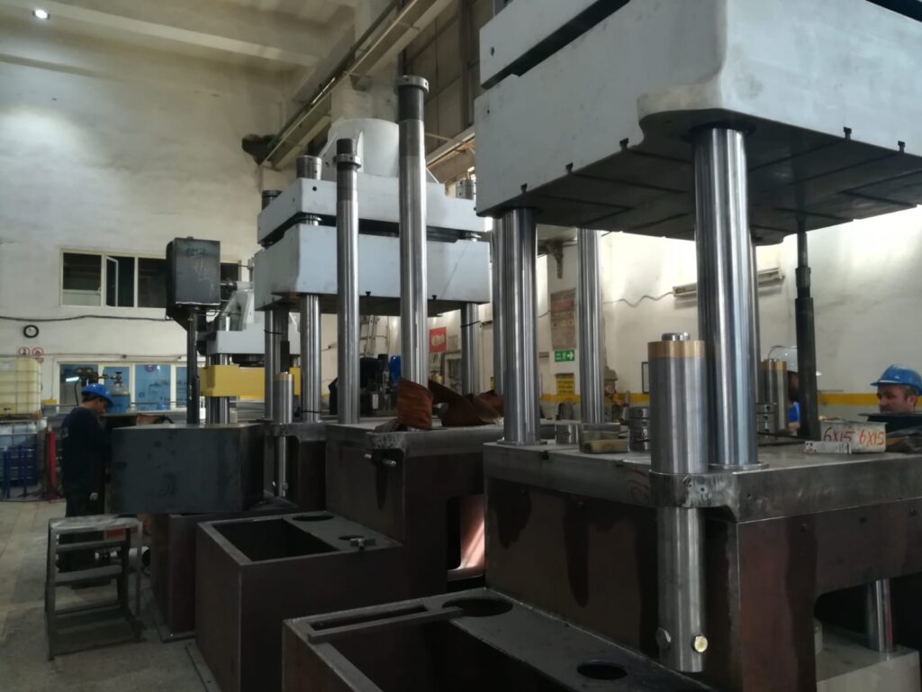
A deep draw hydraulic or mechanical transfer press is a specialized machine designed to perform deep drawing operations—where sheet metal blanks are formed into complex, often hollow shapes—using either hydraulic or mechanical power sources, combined with an automated transfer system that moves parts between multiple forming stations within the press.
Hydraulic deep draw transfer presses use hydraulic cylinders to provide smooth, controllable forming forces. They offer programmable ram speeds, adjustable pressure, and dwell time at the bottom of the stroke, allowing precise control over material flow. This is especially beneficial for forming difficult materials, complex shapes, or thicker gauges where gradual, controlled deformation reduces defects like wrinkling, cracking, or thinning. Hydraulic presses are often favored for their flexibility and superior control, albeit generally operating at slower cycle speeds compared to mechanical presses.
Mechanical deep draw transfer presses, on the other hand, utilize crankshafts, flywheels, and mechanical linkages to deliver high-speed, repetitive strokes with consistent motion profiles. They are typically faster and more energy-efficient for high-volume production of parts with simpler geometries or thinner materials. Mechanical presses are robust and reliable but offer less flexibility in stroke control compared to hydraulic systems.
The transfer system—whether servo-driven or mechanically actuated—is key to the press’s ability to perform multi-stage deep drawing operations. It automatically moves the sheet metal blanks or partially formed parts from one die station to the next within the same press frame. This enables sequential drawing, redrawing, ironing, trimming, or other forming steps to be performed in a continuous, synchronized process, maximizing throughput and part consistency while minimizing handling errors and cycle times.
Modern deep draw transfer presses, regardless of hydraulic or mechanical drive, typically feature advanced CNC or PLC controls that synchronize ram motion, transfer timing, blank holder pressure, and lubrication. These controls enable quick recipe changes, optimize forming parameters for different materials and part designs, and integrate safety systems such as die protection, overload sensors, and operator guards.
In summary, choosing between hydraulic or mechanical deep draw transfer presses depends on factors such as part complexity, material type, production volume, cycle speed requirements, and the level of process control needed. Both types of presses with integrated transfer automation provide efficient, high-precision forming solutions for producing deep-drawn sheet metal components in industries like automotive, appliance, cookware, and aerospace.
Both hydraulic and mechanical deep draw transfer presses excel in multi-stage forming where the metal undergoes successive drawing operations to achieve complex shapes with controlled thickness and surface finish. Hydraulic presses offer the advantage of variable speed throughout the stroke, allowing slow, controlled drawing phases followed by faster return strokes, which helps reduce material stress and improve part quality, especially with advanced high-strength steels or stainless steel alloys. Their ability to dwell at the bottom of the stroke provides extra time for the material to flow properly into the die cavity, reducing defects such as wrinkles or tears.
Mechanical presses, in contrast, rely on a fixed stroke profile dictated by the crankshaft and linkage geometry, typically delivering faster cycles and higher throughput for simpler parts and lighter gauges. However, their lack of stroke flexibility can make forming thick or complex parts more challenging. Despite this, their mechanical advantage allows very high tonnage to be delivered quickly, making them suitable for large-volume production runs where consistent, repeatable motion is critical.
The transfer system integrated into both press types is crucial for automation and efficiency. Servo-driven transfer arms, crossbars, or robotic pick-and-place units move blanks or intermediate parts accurately and rapidly between multiple die stations within the press. This eliminates manual handling, reduces cycle time, and maintains precise alignment throughout the forming sequence. The synchronization between the transfer motion and ram stroke is managed by sophisticated control systems to ensure smooth operation without collisions or timing errors.
Deep draw transfer presses often incorporate adjustable blank holder cushions that apply controlled pressure on the blank edges during forming to regulate material flow. This pressure can be dynamically adjusted in hydraulic presses or set mechanically in mechanical presses, contributing significantly to part quality by preventing excessive thinning or wrinkling. Lubrication systems automatically apply forming oils or emulsions at critical points to minimize friction and extend tool life.
Die design and tooling quality are essential for both types of presses. Hardened tool steels, precision machining, and coatings enhance durability and reduce wear from the high forces and repetitive cycles typical of deep drawing. Quick-change die systems facilitate faster tool swaps, supporting shorter production runs and greater manufacturing flexibility.
From a maintenance perspective, hydraulic presses may require more complex servicing due to hydraulic fluid systems, pumps, and seals but offer diagnostic capabilities through pressure and flow monitoring sensors. Mechanical presses generally have simpler mechanical components but necessitate regular lubrication and monitoring of mechanical linkages, bearings, and clutch or brake systems.
In high-volume manufacturing, the choice between hydraulic and mechanical deep draw transfer presses hinges on balancing factors such as production speed, part complexity, material properties, and process flexibility. Advances in servo-hydraulic systems and hybrid presses are bridging the gap, offering the speed of mechanical presses with the controllability of hydraulics.
Both press types play vital roles across industries—hydraulic presses for specialized, precision, or heavier gauge applications, and mechanical presses for fast, repetitive production of simpler geometries. Integrated with automated transfer systems, these presses enable efficient, high-quality production of deep drawn components, streamlining operations and reducing labor, floor space, and overall manufacturing costs.
Recent trends in deep draw transfer presses focus heavily on hybrid technologies, which combine hydraulic and mechanical advantages into a single machine. These hybrid presses use mechanical linkages for the fast, energy-efficient movement of the ram’s approach and return strokes while employing hydraulic actuators for precise control during the critical forming portion of the cycle. This blend allows manufacturers to achieve high throughput without sacrificing the forming quality and flexibility that hydraulics provide. The ability to program variable speed and dwell times during the draw stroke improves the handling of advanced materials and complex geometries.
Automation and digitalization continue to transform these presses into smart manufacturing hubs. Real-time monitoring systems track critical parameters such as tonnage, slide position, cushion pressure, and transfer timing, enabling predictive maintenance and minimizing unplanned downtime. Operators can adjust forming parameters on the fly based on sensor feedback to optimize part quality and reduce scrap. Integration with factory-wide MES (Manufacturing Execution Systems) and IoT platforms allows for seamless production planning, quality traceability, and resource allocation.
Safety advancements ensure compliance with evolving workplace standards. Presses are equipped with multi-level safety systems including light curtains, interlocked guarding, emergency stops, and monitored safety zones around moving transfer arms. Collaborative robots (cobots) are increasingly used in loading, unloading, and part inspection, working alongside human operators to enhance productivity without compromising safety.
Tooling innovations also support faster changeovers and longer life. Modular tooling concepts allow quick die swaps and adjustments, accommodating multiple part variants with minimal downtime. Advanced coatings and surface treatments reduce friction and resist wear, especially when working with abrasive or coated materials. Additionally, some presses incorporate in-die sensors to monitor forces and detect early signs of tooling failure or material inconsistencies.
Environmental considerations are increasingly important. Energy-efficient servo-hydraulic pumps and regenerative braking systems reduce power consumption and heat generation. Modern presses use advanced filtration and cooling systems to maintain hydraulic fluid quality, extending equipment life and minimizing environmental impact.
In summary, deep draw hydraulic or mechanical transfer presses continue evolving toward highly flexible, energy-efficient, and digitally connected systems that deliver exceptional forming quality and production efficiency. They remain foundational in industries requiring complex, high-volume sheet metal components, providing the precision, speed, and automation needed to meet the demands of modern manufacturing.
Automatic Part Loading Sheet Metal Transfer Press
An automatic part loading sheet metal transfer press is a highly automated forming machine designed to streamline the entire production cycle by integrating automated feeding and transfer of sheet metal blanks or parts within the press. This system eliminates manual loading, improving productivity, repeatability, and safety in sheet metal forming operations such as stamping, deep drawing, trimming, and other multi-stage processes.
At its core, the press features an automated loading system that picks raw material blanks—usually cut from coil or sheet stock—and precisely places them into the forming die or onto the transfer mechanism. Common loading methods include robotic arms with vacuum or mechanical grippers, servo-driven pick-and-place units, or specialized blank feeders. These loaders are synchronized with the press cycle to ensure seamless, continuous operation without delays.
The transfer mechanism—which may be mechanical crossbar transfers, servo-driven robotic arms, or cam-actuated lifters—automatically moves parts between multiple forming stations inside the press. This allows sequential operations such as drawing, redrawing, trimming, and flanging to be performed in a single integrated line, boosting throughput and maintaining consistent part alignment and quality.
Control systems, typically PLC- or CNC-based, coordinate the loading, transfer, forming, and unloading operations. The operator interface allows programming of timing sequences, load positions, and handling parameters tailored to specific parts and materials. Real-time sensors and cameras monitor part presence, alignment, and transfer accuracy, enabling quick error detection and system stoppage if needed, which minimizes scrap and tool damage.
Additional features often include automated lubrication systems, blank identification via barcode or RFID scanning, and safety interlocks that protect operators from moving parts. In many setups, finished parts are ejected and collected via conveyors or robotic stacking systems, further reducing manual handling.
By automating the part loading process, manufacturers achieve higher cycle speeds, reduce labor costs, improve repeatability, and enhance overall production safety. This technology is widely used in automotive stamping, appliance manufacturing, electronics enclosures, and any high-volume sheet metal forming application requiring precise, consistent multi-stage processing with minimal human intervention.
Automatic part loading sheet metal transfer presses are engineered to optimize efficiency by integrating material handling directly into the forming cycle. The loading systems precisely position blanks or partially formed parts into the die area without interrupting the press operation, allowing continuous production and minimizing downtime. This tight integration reduces the risk of misfeeds or misalignment that can cause part defects or damage tooling. The use of advanced robotics or servo-driven mechanisms ensures gentle handling of delicate or coated materials, preserving surface finish and preventing deformation before forming.
The transfer mechanism coordinates closely with the loading system and press slide motion to deliver parts smoothly between successive forming stations. Depending on the part geometry and process complexity, transfer devices can include single or multi-axis servo arms, crossbars, or specialized mechanical linkages. These systems handle parts with precision, controlling speed, orientation, and placement accuracy to support complex forming, trimming, and finishing operations. The automated synchronization between loading, transfer, and forming cycles achieves high throughput rates, often exceeding several hundred strokes per minute.
Control systems play a pivotal role, employing programmable logic controllers (PLCs) and human-machine interfaces (HMIs) that allow operators to set up and monitor the entire process from a single point. Recipes for different parts can be saved and recalled to facilitate quick changeovers. Sensors such as photoelectric detectors, proximity switches, and vision systems verify correct part placement, detect jams or missing blanks, and trigger automatic stoppages or alarms, enhancing safety and reducing scrap.
Lubrication systems are integrated to apply forming oils or coatings precisely when and where needed, extending tool life and improving material flow during forming. Blank identification through barcodes, RFID tags, or vision recognition allows tracking of material lots, supporting quality control and traceability throughout production.
The finished parts are typically removed automatically by unloading robots, conveyors, or stacking devices designed to handle the formed components gently and efficiently. This full-cycle automation minimizes human involvement in potentially hazardous or ergonomically challenging tasks, improving workplace safety and allowing skilled operators to focus on oversight and optimization.
In high-volume manufacturing environments, such as automotive body panel production or appliance casing fabrication, automatic part loading combined with transfer forming presses delivers consistent, high-quality parts at low cost per unit. By reducing manual intervention, improving repeatability, and enabling continuous operation, these systems support lean manufacturing principles and respond effectively to increasing demands for precision, speed, and flexibility in sheet metal forming.
These systems also enhance flexibility in production. The automatic loading and transfer mechanisms can be programmed to handle a variety of part sizes, shapes, and materials without extensive manual adjustments. Quick-change tooling combined with adaptable grippers or feeders allows manufacturers to switch between different product runs rapidly, supporting just-in-time manufacturing and smaller batch sizes while maintaining high efficiency.
The use of servo motors and advanced robotics in loading and transfer not only improves accuracy but also reduces wear on mechanical components by enabling smooth, controlled movements. This results in lower maintenance requirements and longer equipment lifespan. Additionally, these servo-driven systems can be fine-tuned to handle sensitive materials such as thin gauge stainless steel or coated aluminum without causing surface damage or distortion.
Integration with factory automation systems means these presses can communicate with upstream and downstream equipment, like coil lines, inspection stations, or assembly robots. This connectivity enables synchronized production flow, real-time monitoring, and centralized data collection for quality assurance and operational analytics. Manufacturers can track key performance indicators such as cycle times, downtime, reject rates, and energy consumption, facilitating continuous improvement initiatives.
From a safety perspective, automatic loading reduces the need for operators to interact closely with moving parts, decreasing the risk of injury. Modern presses include comprehensive safety measures such as light curtains, safety mats, and interlocked guards that halt the machine instantly if an unsafe condition is detected. Moreover, the automation of repetitive and ergonomically challenging tasks improves workforce wellbeing and productivity.
In summary, automatic part loading sheet metal transfer presses represent a sophisticated convergence of forming technology, robotics, and digital controls. They provide manufacturers with a reliable, high-speed, and adaptable solution to meet demanding production requirements. By minimizing manual handling and maximizing precision and throughput, these systems contribute significantly to improved product quality, reduced costs, and enhanced operational safety in sheet metal fabrication industries.
Robot-Assisted Hydraulic Transfer Press
A robot-assisted hydraulic transfer press is an advanced metal forming system that combines the power and precision of a hydraulic press with the flexibility and automation capabilities of robotic technology. This integration enhances the efficiency, accuracy, and safety of complex sheet metal forming operations by automating the loading, transferring, unloading, and sometimes even in-process inspection or handling of parts.
In such systems, the hydraulic press provides smooth, controllable forming forces ideal for deep drawing, trimming, embossing, or other forming processes that require variable pressure and speed. Hydraulic drives allow programmable ram movement with dwell times, adjustable stroke lengths, and precise force control, making them well-suited for a wide range of materials and part complexities.
Robots—typically industrial articulated arms or Cartesian gantry systems—work in tandem with the press’s cycle to perform critical material handling tasks. These include picking raw blanks from feeders or coil lines, loading them into the press dies, transferring semi-formed parts between multiple forming stations inside the press, unloading finished components, and sometimes moving parts to downstream processes such as welding, assembly, or inspection.
The robotic integration brings several key advantages. First, it improves cycle times and throughput by synchronizing precise, rapid part handling with the press’s forming operations. Robots can execute smooth, repeatable motions with high positional accuracy, reducing the risk of misfeeds, jams, or damage to delicate parts. Second, it enhances safety by minimizing human interaction with the press during operation, reducing operator exposure to moving parts, pinch points, or hazardous materials. Third, the system offers greater flexibility, as robots can be programmed or reconfigured to handle different parts, tooling setups, or material types without extensive mechanical modifications.
Control of a robot-assisted hydraulic transfer press is typically centralized, with PLC or CNC systems managing the hydraulic press parameters and robot motions in a coordinated manner. Modern setups often include integrated vision systems, sensors, and force-feedback devices that enable robots to adapt to part variations, verify correct placement, and ensure quality. This closed-loop control reduces scrap, increases first-pass yield, and supports real-time process optimization.
Furthermore, robot-assisted systems facilitate automation beyond simple transfer tasks. Robots can perform secondary operations such as part orientation, stacking, marking, or quality inspection directly at the press, eliminating the need for additional equipment or manual labor. This leads to more compact production cells and streamlined workflows.
In sum, a robot-assisted hydraulic transfer press represents a sophisticated solution for modern sheet metal forming challenges, blending hydraulic forming power with robotic dexterity and automation intelligence. It delivers high productivity, improved part quality, enhanced workplace safety, and operational flexibility, making it ideal for automotive, aerospace, appliance, and general manufacturing sectors striving for efficient, high-volume production with tight tolerances.
Robot-assisted hydraulic transfer presses elevate sheet metal forming by integrating precise robotic handling directly with the hydraulic press’s forming cycle. The robotic arms synchronize their movements tightly with the press ram, ensuring blanks and semi-finished parts are loaded and positioned exactly when and where needed. This seamless coordination minimizes cycle times and maximizes throughput while reducing the risk of misalignment or tooling damage. Unlike traditional mechanical transfer systems with fixed motion paths, robots offer multi-axis flexibility, enabling them to handle complex part geometries, perform intricate loading/unloading patterns, and adapt easily to changes in production without mechanical retooling.
The hydraulic press’s controllable force and stroke profiles allow delicate forming sequences such as deep drawing or multi-stage trimming to be executed with great accuracy. Robotic handling complements this by gently manipulating thin or coated materials, reducing the chance of surface scratches or deformation prior to and after forming. Moreover, robots equipped with force sensors or vision systems can detect part presence, orientation, or dimensional variances and adjust their handling accordingly, contributing to higher quality and less scrap.
Safety improvements are significant since the robot replaces manual loading and unloading in close proximity to the press’s moving parts. The system includes safety-rated monitored zones, emergency stops, and interlocked guarding, allowing operators to supervise from a safe distance or engage in tasks like programming and monitoring rather than direct machine interaction. This shift not only lowers injury risks but also boosts workforce productivity and job satisfaction.
Flexibility is a key advantage—robot programming can be rapidly adjusted to accommodate different part sizes, shapes, or production volumes, supporting quick changeovers and just-in-time manufacturing. This reduces downtime and tooling change costs, making the system suitable for diverse product lines or customized orders.
Advanced control software integrates the press and robotic systems into a unified production cell. Real-time communication allows dynamic adjustment of forming parameters and robotic motions based on sensor feedback, enabling closed-loop quality control and process optimization. Data from each cycle is logged and analyzed for preventive maintenance, throughput optimization, and defect tracing, aligning with Industry 4.0 and smart factory initiatives.
Robots can also perform secondary tasks within the cell, such as part inspection using cameras or lasers, stacking and packaging, or even minor assembly operations, further streamlining production flow. This multifunctionality reduces the need for additional equipment and manual labor.
In essence, robot-assisted hydraulic transfer presses provide a powerful combination of forming precision and handling versatility. They enable manufacturers to produce complex, high-quality sheet metal components efficiently and safely, while maintaining the adaptability needed for modern, dynamic production environments. This technology is increasingly becoming the standard in industries demanding tight tolerances, high volume, and consistent quality.
Beyond improved precision and safety, robot-assisted hydraulic transfer presses also contribute significantly to overall equipment effectiveness (OEE). The integration of robotics reduces idle times associated with manual loading or part handling errors, enabling near-continuous operation. Robots can operate at consistent speeds without fatigue, ensuring steady cycle times and predictable output rates. This consistency is critical for meeting tight delivery schedules and maintaining production quotas.
Maintenance is streamlined as well, since robotic systems typically include diagnostic tools that monitor joint wear, motor temperatures, and feedback signals. Early detection of anomalies allows for scheduled maintenance rather than unexpected breakdowns, minimizing downtime and repair costs. Similarly, the hydraulic press benefits from condition monitoring systems tracking pressure, flow, and fluid quality, creating a holistic maintenance strategy for the entire forming cell.
Energy efficiency is another growing focus. Modern robot-assisted presses often employ servo-hydraulic systems and energy recovery features that optimize power consumption during forming cycles. Robots with energy-efficient motors and motion profiles contribute to reducing the overall environmental footprint of manufacturing operations, aligning with sustainability goals.
In terms of scalability, these integrated systems can be tailored to various production volumes and complexities. For small-to-medium batch sizes, robots provide the flexibility to switch between part programs rapidly, making short runs economically viable. For high-volume manufacturing, their speed and precision support lean, just-in-time workflows without sacrificing quality.
Finally, the data generated by robot-assisted hydraulic transfer presses feeds into broader digital manufacturing ecosystems. Advanced analytics, AI-driven process optimization, and remote monitoring empower manufacturers to continually refine forming parameters, anticipate tooling wear, and respond dynamically to production demands. This connectivity not only improves product quality and productivity but also enables agile responses to market changes, customer customization, and new material introductions.
Overall, robot-assisted hydraulic transfer presses represent a convergence of mechanical power, automation intelligence, and digital connectivity. They transform traditional forming operations into smart, efficient, and safe production cells, driving competitiveness in today’s demanding manufacturing landscape.
Coil Feeding Hydraulic Transfer Press
A coil feeding hydraulic transfer press is a highly automated metal forming machine designed to transform continuous coil stock into finished or semi-finished parts through integrated feeding, forming, and transferring operations within a single press system. By combining hydraulic press technology with coil feeding mechanisms, this setup enables continuous, high-precision production of complex sheet metal components with minimal manual intervention.
The coil feeding system automatically unwinds and straightens the coil material, feeding it into the press with precise length control to ensure accurate blank positioning for subsequent forming stages. It typically includes decoilers, straighteners, and servo-driven feed rollers that maintain consistent tension and alignment, reducing material distortion or wrinkling. The feeding speed and length are programmable and synchronized with the press cycle to optimize throughput and minimize scrap.
Once the coil strip is fed into the press, the hydraulic transfer press performs multi-stage forming operations such as blanking, deep drawing, trimming, piercing, or flanging. The hydraulic drive provides smooth, controllable force and stroke profiles, enabling the forming of complex shapes, thicker materials, or advanced alloys that require variable pressure and precise motion control. Hydraulic presses also allow for dwell times at critical points of the stroke to facilitate proper material flow and reduce defects.
The transfer system moves parts automatically between multiple die stations inside the press frame. This coordinated movement allows different forming operations to be carried out simultaneously at various stations, increasing productivity and ensuring consistent part quality. The transfer mechanism is typically servo-driven or mechanically linked to the press ram, precisely timed to avoid collisions and maintain cycle speed.
Control systems integrate coil feeding, hydraulic press operation, and transfer sequencing into a unified platform, often managed through PLCs or CNC controllers. Operators can program feeding lengths, forming pressures, transfer timing, and other parameters from a centralized interface, simplifying setup and enabling rapid changeovers between part types or materials.
Additional features commonly included are lubrication systems to reduce friction during forming, sensors for part presence and quality inspection, and safety devices such as light curtains and interlocks to protect operators. Finished parts are automatically unloaded and conveyed to downstream processes, completing a seamless manufacturing flow from raw coil to formed component.
Coil feeding hydraulic transfer presses are widely used in automotive, appliance, electronics, and general metal fabrication industries where high-volume, consistent, and precise forming of sheet metal parts is required. Their ability to handle continuous coil stock reduces material waste and handling time, improves cycle efficiency, and supports complex multi-stage forming sequences within a compact footprint.
Coil feeding hydraulic transfer presses streamline production by integrating the coil processing directly with forming operations, eliminating the need for separate blanking or feeding stations. This integration reduces material handling, shortens lead times, and minimizes the risk of damage or contamination to the material. The coil feeder’s servo-controlled rollers ensure precise and repeatable strip positioning for each press stroke, which is essential for maintaining tight tolerances throughout complex forming sequences.
The hydraulic press provides adaptable force control, allowing for variable speed during different stroke phases and the ability to dwell at the bottom of the stroke, ensuring optimal material flow and minimizing defects such as wrinkling, tearing, or springback. This level of control is especially valuable when working with advanced materials like high-strength steels, aluminum alloys, or coated metals that require gentle forming conditions.
The transfer mechanism within the press works in perfect synchronization with the coil feeding and hydraulic press motion, transporting parts efficiently between stations for multi-stage forming operations. This automation increases throughput and reduces manual intervention, leading to consistent part quality and reduced labor costs. The transfer devices are engineered for precise part handling, accommodating a range of shapes and sizes, and preventing part deformation or misalignment during movement.
Control systems unify the coordination of coil feeding, hydraulic actuation, and part transfer. Operators can input job-specific parameters for coil feed length, press tonnage, stroke speed, and transfer timing, all managed from a single control panel. The system can also include diagnostics and real-time monitoring features that detect anomalies such as feed errors, press overloads, or transfer malfunctions, enabling quick intervention to minimize downtime.
Safety is paramount, with integrated guards, light curtains, emergency stops, and interlocks ensuring operator protection around moving parts and high-pressure systems. Many presses also incorporate automated lubrication systems that apply forming oils precisely where needed, extending tool life and improving forming performance.
By handling coil-to-part processing in a continuous, integrated fashion, these presses achieve high production efficiency and material utilization. The elimination of intermediate handling steps reduces scrap and damage, while the hydraulic press’s adaptable force and motion profiles accommodate complex geometries and a variety of materials. This makes coil feeding hydraulic transfer presses a preferred choice for industries demanding high-volume, precise, and flexible sheet metal forming solutions.
Modern coil feeding hydraulic transfer presses often feature advanced automation elements like robotic loading and unloading systems to further enhance production flow and reduce human intervention. These robots can handle delicate parts with precision, stack finished components, or transfer them directly to downstream processes such as welding, assembly, or packaging. Integration of vision systems allows for part inspection during or immediately after forming, ensuring quality control and enabling immediate rejection of defective parts to prevent downstream issues.
Energy efficiency improvements are also a key focus, with many presses equipped with servo-hydraulic pumps that adjust power consumption dynamically based on load requirements. Regenerative systems capture energy during the ram’s return stroke, feeding it back into the power system, reducing overall electricity usage and operational costs. Hydraulic fluid management systems maintain optimal temperature and cleanliness, ensuring consistent press performance and longevity.
The tooling in coil feeding hydraulic transfer presses is typically modular and designed for quick changeovers, facilitating flexible manufacturing environments where multiple part variants or short production runs are common. High-quality tool steels and surface treatments reduce wear, and precise alignment systems maintain die accuracy throughout the production cycle.
Data connectivity features enable these presses to communicate with factory-wide manufacturing execution systems (MES), allowing real-time tracking of production metrics such as cycle times, downtime, scrap rates, and tool life. This data-driven approach supports predictive maintenance, operational optimization, and continuous improvement initiatives.
In summary, coil feeding hydraulic transfer presses combine continuous material feed, adaptable hydraulic forming power, and automated transfer systems into a cohesive solution that boosts productivity, quality, and flexibility. They are essential in industries such as automotive, appliance manufacturing, and electronics where complex, high-volume sheet metal components are produced efficiently and consistently.
Sheet Metal Transfer Press with Blank Feeding
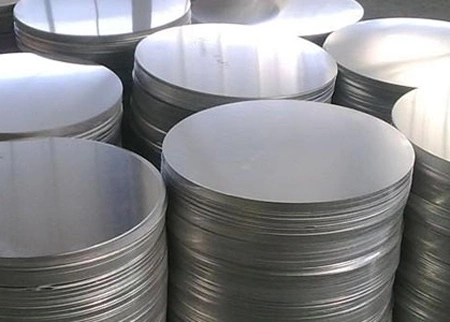
A sheet metal transfer press with blank feeding is an automated forming system designed to efficiently produce complex sheet metal parts by combining a blank feeding mechanism with a transfer press. Instead of feeding raw coil material, this setup typically uses pre-cut sheet metal blanks, which are automatically loaded into the press and moved through successive forming stations by the integrated transfer system.
The blank feeding unit handles individual sheet metal blanks—these can be laser-cut, sheared, or stamped pieces—feeding them one by one into the press. The feeder ensures precise positioning and timing, coordinating with the press cycle to deliver blanks smoothly without delay. This feeding system may use mechanical grippers, vacuum cups, or servo-driven pushers to pick and place blanks accurately onto the transfer mechanism or directly into the die.
Once inside the press, the transfer system moves the blanks or partially formed parts through multiple die stations. This multi-stage forming process can include operations such as drawing, trimming, piercing, embossing, or flanging. The transfer mechanism, often servo-driven or mechanically linked to the press ram, ensures consistent and accurate part handling between each forming step, maximizing quality and throughput.
The hydraulic or mechanical press applies the necessary forming forces, with hydraulic presses offering variable speed and force control for delicate or complex operations, and mechanical presses delivering high-speed repetitive strokes suitable for simpler or high-volume parts. The transfer and blank feeding systems are synchronized with the press to maintain smooth, continuous production cycles.
Control systems unify the operation of blank feeding, transfer, and press functions, allowing operators to program and monitor parameters like feed rate, transfer timing, forming pressures, and stroke speed from a central interface. Sensors verify blank presence, alignment, and part integrity, enabling rapid detection of errors and minimizing scrap or tool damage.
Additional features may include automatic lubrication, part ejection and stacking systems, and safety devices such as interlocks and light curtains to protect operators from moving parts. The use of pre-cut blanks simplifies coil handling and allows integration of blanks produced from various sources or processes, providing manufacturing flexibility.
Sheet metal transfer presses with blank feeding are widely used in industries where production demands require precise multi-stage forming of pre-cut blanks, such as automotive body panels, appliance components, and electronic enclosures. By automating blank handling and transfer within the press, these systems enhance productivity, ensure consistent part quality, reduce manual labor, and support efficient high-volume manufacturing.
The integration of blank feeding with transfer presses significantly improves manufacturing efficiency by reducing manual material handling and minimizing downtime between cycles. The blank feeder’s precision ensures that each sheet metal blank is delivered to the transfer mechanism in perfect alignment, which is critical for maintaining tight tolerances throughout the forming stages. This precision helps prevent issues such as misfeeds, jams, or misalignments that can cause defects or damage to tooling.
The transfer system’s role is crucial for smooth part progression through multiple forming stations. Depending on the complexity of the part, the transfer mechanism can be equipped with multi-axis servo-driven arms, crossbars, or mechanical lifters designed to handle blanks and formed parts delicately and accurately. These systems synchronize with the press ram’s movement to optimize cycle time and maintain continuous operation, allowing simultaneous forming at different stations within the press.
The press itself—whether hydraulic or mechanical—provides the necessary forming force, with hydraulic presses offering adjustable stroke profiles and controlled force application that benefit complex or thick materials. Mechanical presses deliver high-speed strokes for simpler, high-volume parts. The choice between the two depends on production requirements, material types, and part complexity.
Control systems coordinate the entire process, enabling operators to set feed rates, stroke speeds, transfer timing, and forming pressures from a single interface. Sensors such as photoelectric detectors and proximity switches confirm the presence and position of blanks and formed parts, triggering alarms or automatic stoppages when abnormalities occur. This automation minimizes scrap, improves safety, and enhances overall production reliability.
Safety features are integrated throughout the system, including guarded enclosures, emergency stop functions, and interlocks to protect operators from moving parts during feeding, transfer, and forming. Automated lubrication systems maintain tool performance and extend service life by delivering precise amounts of forming oils or lubricants during the press cycle.
Blank-fed transfer presses are well-suited for production environments where blanks are produced separately or need to be fed from external processes like laser cutting, stamping, or shearing. By automating blank handling and transfer, manufacturers reduce labor costs, improve throughput, and maintain high product consistency, which is vital in automotive, appliance, aerospace, and electronics manufacturing.
Overall, sheet metal transfer presses with blank feeding offer a robust, flexible, and efficient solution for complex multi-stage forming applications, integrating precise material handling with high-quality forming to meet demanding industrial production goals.
These systems also support rapid changeovers, which are critical for manufacturers handling multiple part variants or smaller batch sizes. Modular tooling designs combined with programmable blank feeders and adaptable transfer mechanisms allow for quick adjustments without lengthy downtime. Operators can load new part programs into the control system, automatically adjusting feed lengths, transfer paths, and press parameters to match the new product requirements.
Robust diagnostics and predictive maintenance tools are often integrated into these presses. Sensors monitor critical components such as feeder motors, transfer arms, press tonnage, and cycle times. Data analytics can predict wear or impending failures, enabling maintenance to be scheduled proactively rather than reactively, reducing unexpected downtime and prolonging equipment life.
The use of vision and laser-based inspection systems within the transfer press cell enhances quality control by verifying blank dimensions, detecting surface defects, and ensuring proper alignment throughout the forming stages. This inline inspection capability allows for immediate rejection of defective parts and adjustments to process parameters, supporting zero-defect manufacturing goals.
Energy efficiency improvements have become a focus in modern presses, with hydraulic systems incorporating servo-controlled pumps and energy recovery features that optimize power consumption. These enhancements not only reduce operational costs but also align with sustainability initiatives by lowering the environmental footprint of metal forming operations.
Automation in blank feeding and transfer also improves workplace safety by minimizing human interaction with moving press components and heavy blanks. By automating material handling tasks, the risk of operator injury is significantly reduced, and operators can focus on monitoring, programming, and optimizing the process rather than performing repetitive manual tasks.
In summary, sheet metal transfer presses equipped with automatic blank feeding combine precision, speed, flexibility, and safety. They streamline multi-stage forming operations, reduce waste and downtime, and enable manufacturers to produce complex sheet metal parts efficiently and consistently, meeting the demands of modern, high-volume industrial production.
Progressive Sheet Metal Transfer Press
A progressive sheet metal transfer press is a specialized forming machine designed for high-volume production of sheet metal parts by performing multiple sequential operations in a single press cycle. The press integrates a progressive die and a transfer system that moves the workpiece automatically through various forming stations, each performing a different operation such as blanking, piercing, bending, drawing, or trimming. This approach enables efficient multi-stage forming without removing the part from the press, enhancing precision and throughput.
In a progressive sheet metal transfer press, the metal strip or blank is fed into the first station of the die, where the initial operation takes place. The transfer mechanism then moves the part precisely to subsequent stations within the same press frame. Each station applies a specific forming step, gradually shaping the metal into the final desired geometry. The transfer action is tightly synchronized with the press ram to maintain smooth, continuous production cycles.
The transfer system can be mechanical, hydraulic, or servo-driven, depending on the required precision, speed, and part complexity. Servo-driven transfers offer enhanced flexibility and control, allowing adjustable speed and motion profiles, which are especially beneficial for delicate materials or complex forming sequences. Mechanical transfers typically provide high-speed, repetitive motion suited for simpler, high-volume parts, while hydraulic transfers offer variable force and smooth motion for thicker or more intricate workpieces.
The progressive die is custom-engineered with multiple stations arranged linearly or in a compact layout within the press. Each station incorporates specialized tooling to perform its assigned operation with high accuracy and repeatability. The die design includes strip guiding features and blank holders to ensure proper material flow and alignment throughout the forming process.
Control systems coordinate blank feeding, press operation, and transfer motion, often through PLC or CNC controllers with user-friendly interfaces. Operators can program forming parameters, monitor system status, and troubleshoot issues from a centralized control panel. Sensors integrated throughout the press detect part presence, positioning accuracy, and potential faults, enabling rapid response and reducing scrap.
Progressive sheet metal transfer presses are widely used in automotive manufacturing, appliance production, electronics enclosures, and other industries requiring fast, consistent, and precise forming of complex sheet metal components. By combining multiple forming steps into a single automated press cycle, these machines improve production efficiency, reduce labor costs, and enhance part quality.
Progressive sheet metal transfer presses offer significant advantages in high-volume manufacturing by combining multiple forming operations into one continuous process. The integration of a transfer system eliminates the need to remove the part from the press after each forming step, reducing handling time and minimizing the risk of part misalignment or damage. This continuous flow enhances cycle speed and improves repeatability, ensuring consistent quality across large production runs.
The transfer mechanism, whether mechanical, hydraulic, or servo-driven, is engineered to move parts smoothly and accurately between stations. Servo-driven systems provide the greatest flexibility, allowing for programmable speed and motion profiles tailored to specific materials and part complexities. This flexibility enables the press to handle a wide range of sheet metal thicknesses, alloys, and geometries, including those with tight tolerances or delicate features.
Tooling within progressive dies is precision-engineered to withstand repetitive high-speed operations while maintaining accuracy. Hardened tool steels and advanced coatings increase die life and reduce maintenance frequency. Modular tooling designs facilitate quicker changeovers, allowing manufacturers to adapt swiftly to different part designs or production requirements, supporting lean manufacturing and just-in-time production.
The control system plays a central role in managing the coordinated operation of blank feeding, press ram movement, and transfer actions. Programmable logic controllers (PLCs) and human-machine interfaces (HMIs) provide operators with real-time monitoring, fault diagnostics, and parameter adjustments, enhancing operational efficiency and minimizing downtime. Integrated sensors verify part presence and correct positioning at each station, enabling immediate intervention if irregularities arise.
Safety systems are embedded throughout the press, including interlocked guards, light curtains, and emergency stop features that protect operators from moving parts and high-force operations. Automation reduces manual intervention in hazardous areas, improving workplace safety and compliance with regulatory standards.
Progressive sheet metal transfer presses are essential in industries where rapid, accurate, and repeatable forming processes are critical. By consolidating multiple forming stages within a single press cycle, these machines lower labor costs, reduce cycle times, and increase overall production capacity. Their ability to maintain consistent quality while handling complex part geometries makes them a preferred choice for automotive body components, household appliances, electronic housings, and other precision sheet metal applications.
Overall, progressive sheet metal transfer presses exemplify advanced manufacturing technology that combines automation, precision tooling, and robust control systems to meet the demanding needs of modern sheet metal fabrication.
In addition to their core forming capabilities, progressive sheet metal transfer presses often incorporate advanced automation features to further enhance productivity and quality. For example, integration with robotic systems can automate material loading and unloading, part inspection, or secondary operations like stacking and packaging. This reduces manual labor, shortens cycle times, and maintains consistent handling to avoid part damage.
Vision and sensor-based inspection systems are frequently embedded in the production line to provide real-time quality monitoring. These systems check for dimensional accuracy, surface defects, or missing features immediately after forming, allowing defective parts to be identified and removed early in the process. Such inline inspection supports zero-defect manufacturing strategies and reduces downstream waste and rework.
Energy efficiency is another focus in modern presses. Many incorporate servo-driven hydraulic systems or electric servo presses that consume less energy by adjusting power use dynamically based on forming load and motion requirements. Regenerative braking and energy recovery systems help minimize electricity consumption and heat generation, contributing to lower operating costs and environmental impact.
Maintenance and reliability improvements include condition monitoring of key components such as hydraulic systems, motors, sensors, and tooling. Predictive maintenance software analyzes operational data to forecast potential failures, enabling planned maintenance that reduces unexpected downtime and extends equipment life.
Flexibility remains a key benefit, with modular die designs and programmable transfer motions allowing rapid changeovers for different part designs or production volumes. This adaptability supports manufacturers in meeting evolving market demands, including customized or smaller batch production runs without sacrificing efficiency.
Overall, progressive sheet metal transfer presses represent a mature, highly automated solution that balances speed, precision, and flexibility. Their combination of multi-stage forming, integrated transfer mechanisms, and advanced control and inspection systems enables manufacturers to produce complex sheet metal components at high volume and consistent quality, meeting the rigorous standards of industries such as automotive, aerospace, electronics, and consumer appliances.
Multi-Station Sheet Metal Transfer Press
A multi-station sheet metal transfer press is a sophisticated forming machine designed to perform multiple sequential operations on sheet metal parts within a single press frame. It combines several forming stations—each equipped with dedicated tooling—to progressively shape, cut, trim, or finish a part as it moves through the press. The integrated transfer mechanism automatically moves the part between stations in perfect synchronization with the press cycle, allowing for efficient, high-volume production with consistent quality.
The transfer system is a key component, engineered to precisely handle and position the workpieces during each stroke. It can be mechanical, hydraulic, or servo-driven, with servo-driven transfers offering the highest flexibility and accuracy. The transfer mechanism moves parts through the stations without manual intervention, reducing handling time and minimizing the risk of part deformation or misalignment.
Each station in the press is designed for a specific forming task, such as blanking, piercing, drawing, bending, or trimming. The multi-station layout enables complex parts to be formed through several operations in a continuous, streamlined process. This integrated approach improves cycle time efficiency and reduces the footprint compared to using multiple standalone machines.
The press itself may be hydraulic or mechanical. Hydraulic presses provide variable speed control and force profiles suitable for delicate or complex forming, while mechanical presses offer rapid, high-force strokes ideal for simpler, high-volume parts. The choice depends on production needs, part geometry, and material characteristics.
Control systems coordinate the entire process, managing blank feeding, transfer motion, press ram strokes, and synchronization. Modern systems use PLCs or CNC controllers with user-friendly interfaces for setup, monitoring, and troubleshooting. Sensors throughout the press verify part presence and positioning, detect errors, and enable automatic stoppage to protect tooling and reduce scrap.
Safety is integral, with interlocked guards, light curtains, and emergency stop functions ensuring operator protection from moving parts. Automation reduces manual handling in hazardous zones, enhancing workplace safety and compliance with standards.
Multi-station sheet metal transfer presses are widely used in automotive, appliance, electronics, and general metal fabrication industries. Their ability to perform multiple forming steps in one integrated machine results in improved productivity, reduced labor costs, consistent part quality, and space savings. They are ideal for manufacturing complex, high-volume sheet metal components requiring tight tolerances and repeatable precision.
Multi-station sheet metal transfer presses maximize efficiency by integrating several forming operations into a single, continuous production flow. The transfer mechanism ensures smooth, accurate movement of parts between stations, reducing cycle times and eliminating delays caused by manual handling. This automation leads to higher throughput and consistent quality, essential for meeting demanding production schedules in high-volume manufacturing environments.
The transfer system’s design is critical for handling parts delicately and precisely. Servo-driven transfers offer programmability, enabling adjustments to motion speed, acceleration, and position for different part geometries and materials. This adaptability minimizes part damage and supports the forming of complex shapes or thin gauges that require gentle handling. Mechanical or hydraulic transfers provide reliable, repeatable motion for simpler parts or applications where fixed timing is sufficient.
Each forming station is equipped with specialized tooling tailored to its operation, and these stations are arranged sequentially to optimize material flow and minimize scrap. The tooling is built for durability, often using hardened steels and surface treatments to withstand the repetitive stresses of high-speed operation. Modular tooling designs facilitate quicker changeovers, allowing manufacturers to switch between different parts or designs with minimal downtime.
The press itself—hydraulic or mechanical—delivers the forming force and motion needed for each operation. Hydraulic presses offer variable stroke profiles and force control, beneficial for delicate or intricate forming steps, while mechanical presses excel in speed and efficiency for more straightforward operations. The press parameters are closely controlled and synchronized with transfer motions to ensure precision and repeatability.
Advanced control systems provide centralized management of blank feeding, transfer sequencing, press operation, and quality monitoring. Operators can program complex part runs, monitor system status in real time, and receive alerts for faults or maintenance needs. Integrated sensors confirm correct part placement and detect anomalies early, reducing scrap rates and preventing tooling damage.
Safety features are comprehensive, including interlocks, guards, light curtains, and emergency stops that protect operators from moving parts and high forces. Automation reduces manual interaction with dangerous zones, promoting safer work environments and compliance with industrial safety regulations.
Multi-station sheet metal transfer presses are especially valuable in sectors such as automotive, consumer appliances, electronics, and aerospace, where the demand for complex, precision-formed parts is high. By consolidating multiple forming processes into one automated machine, manufacturers benefit from reduced labor costs, faster cycle times, improved quality, and better utilization of factory floor space. This makes these presses a cornerstone technology in modern sheet metal fabrication.
In addition to their core forming functions, multi-station sheet metal transfer presses often incorporate advanced automation and integration features to further enhance production capabilities. Robotic arms or automated handling systems may be employed for loading raw blanks and unloading finished parts, reducing manual labor and increasing cycle speed. These systems can also handle secondary tasks such as part stacking, sorting, or transferring to downstream processes like welding, assembly, or inspection.
Inline inspection systems using cameras, lasers, or sensors are frequently integrated to monitor dimensional accuracy, surface quality, and feature completeness in real time. Early detection of defects allows immediate removal of nonconforming parts, minimizing waste and rework while maintaining high product quality standards.
Energy efficiency is increasingly emphasized in modern presses. Servo-hydraulic drives and electric servo presses adjust power consumption dynamically, optimizing energy use based on forming load and motion requirements. Energy recovery systems capture kinetic energy during ram return strokes and reuse it, reducing overall electricity consumption and operational costs.
Maintenance and reliability are supported by condition monitoring systems that track hydraulic pressure, motor currents, cycle times, and tool wear. Predictive maintenance software analyzes this data to schedule servicing before failures occur, minimizing unexpected downtime and extending equipment life.
Flexibility is a key benefit, with modular die stations and programmable transfer motions enabling quick changeovers between part variants or production runs. This adaptability supports just-in-time manufacturing and caters to market demands for customization without sacrificing efficiency.
Overall, multi-station sheet metal transfer presses represent a convergence of precise mechanical engineering, automation intelligence, and digital control. They enable manufacturers to achieve high throughput, consistent quality, operational safety, and flexibility, making them indispensable in today’s competitive sheet metal fabrication industries.
Servo-Driven Sheet Metal Transfer Press
A servo-driven sheet metal transfer press is an advanced forming machine that utilizes servo motor technology to precisely control the transfer mechanism within the press. Unlike traditional mechanical or purely hydraulic transfer systems, servo-driven transfers offer highly programmable, flexible, and accurate part handling, enhancing the overall performance of multi-stage sheet metal forming operations.
In a servo-driven transfer press, servo motors control the movement of transfer arms, lifters, or crossbars that move parts between different forming stations inside the press. This allows for variable speed, acceleration, and dwell times during part transfer, which can be tailored to the specific requirements of different materials, part geometries, or forming steps. The programmable nature of servo drives enables smooth, precise positioning of workpieces, reducing the risk of part damage and improving repeatability.
The press itself may be hydraulic or mechanical, providing the necessary forming force, while the servo-driven transfer system operates in perfect synchronization with the press ram’s motion. This tight integration ensures optimal cycle times and maximizes throughput without compromising part quality.
Servo-driven transfers support complex motion profiles that are difficult or impossible to achieve with traditional mechanical cams or fixed hydraulic circuits. For example, the transfer can pause mid-stroke for forming dwell times, slow down during delicate handling, or accelerate quickly during non-critical phases. This flexibility is especially valuable when forming high-strength or thin-gauge materials that require gentle handling to avoid distortion or surface defects.
Control systems coordinate the servo drives with the press and blank feeding units, using PLC or CNC controllers to manage synchronized operations. Operators can program and adjust transfer parameters via user-friendly interfaces, enabling quick changeovers and process optimization. Integrated sensors and feedback systems monitor transfer positions and forces, ensuring reliable operation and allowing for real-time adjustments.
Safety features are incorporated to protect operators and equipment, including interlocks, light curtains, and emergency stops. Automation of the transfer process reduces manual handling, minimizing workplace injuries and improving overall production safety.
Servo-driven sheet metal transfer presses are widely used in industries demanding high precision, flexibility, and efficiency, such as automotive manufacturing, aerospace, electronics, and appliance production. They enable manufacturers to produce complex, high-quality sheet metal components with reduced cycle times, lower scrap rates, and greater adaptability to changing production needs.
In summary, servo-driven sheet metal transfer presses combine the forming power of hydraulic or mechanical presses with the versatility and precision of servo technology, delivering superior control over part handling and transfer operations within multi-stage forming processes.
Servo-driven sheet metal transfer presses bring significant improvements in process control and flexibility compared to traditional transfer systems. The ability to precisely program transfer motions means parts can be handled with optimal speed and gentleness, reducing the likelihood of deformation or surface damage—especially important when working with delicate materials like thin gauges or coated metals. This precision also supports tighter tolerances and consistent part quality across large production runs.
Because the servo motors can vary speed and acceleration throughout the transfer cycle, manufacturers can tailor motion profiles to specific part requirements or materials, enabling complex forming sequences that involve pauses, slower movements, or rapid transfers as needed. This dynamic control reduces cycle times by eliminating unnecessary delays while maintaining safe and careful part handling.
Integration with advanced control systems allows seamless coordination between the press ram, blank feeder, and transfer system. Operators can adjust transfer parameters easily through user-friendly interfaces, supporting quick changeovers and flexible production runs. Feedback from position sensors and torque monitors enables real-time monitoring and fault detection, allowing the system to adapt instantly or stop operation if abnormalities occur, thereby protecting tooling and reducing scrap.
Safety is enhanced as automated servo transfers minimize manual handling of blanks and formed parts near moving press components. Interlocks, guarded enclosures, and emergency stops ensure operator protection, while reducing fatigue and the risk of workplace injuries. This also allows personnel to focus on process optimization, programming, and quality assurance rather than repetitive manual tasks.
Energy efficiency is another benefit since servo-driven systems consume power only when movement is required, unlike continuously running mechanical cams. Many systems incorporate regenerative drives that recover energy during deceleration phases, lowering electricity consumption and operational costs.
Servo-driven transfer presses are particularly advantageous in industries requiring high-mix, low-to-medium volume production with frequent changeovers, as well as in high-volume manufacturing demanding tight process control and minimal downtime. Their versatility makes them well-suited for automotive body parts, aerospace components, consumer electronics, and other applications where precision and flexibility are paramount.
Overall, servo-driven sheet metal transfer presses represent a modern, intelligent solution that enhances forming process quality, efficiency, and adaptability, helping manufacturers meet evolving production challenges with greater confidence and competitiveness.
Beyond their core advantages in precision and flexibility, servo-driven sheet metal transfer presses also excel in scalability and integration within smart factory environments. Their programmable nature allows manufacturers to quickly adjust production parameters to accommodate new part designs, materials, or batch sizes without extensive mechanical modifications. This adaptability supports agile manufacturing practices and reduces downtime during product changeovers.
These presses can be seamlessly integrated with Industry 4.0 technologies, enabling real-time data collection and analysis for process optimization. Sensors embedded in the servo drives and press components monitor critical metrics such as motor load, cycle times, and positional accuracy. This data feeds into manufacturing execution systems (MES) and predictive maintenance platforms, helping to identify trends, anticipate equipment wear, and schedule maintenance proactively, thereby minimizing unexpected breakdowns.
Automation extends beyond the transfer mechanism, with robotic loading and unloading systems commonly paired to further streamline workflows. Vision systems and in-line inspection tools work alongside servo-driven transfers to detect defects or misfeeds early, ensuring only quality parts proceed through the production line and reducing waste.
From an environmental perspective, servo-driven presses contribute to sustainability goals by optimizing energy consumption through precise motion control and energy recovery systems. Reduced scrap rates and efficient material handling also minimize resource waste.
In terms of operator experience, these presses offer intuitive interfaces and remote monitoring capabilities, allowing technicians to oversee multiple machines, adjust parameters on the fly, and respond swiftly to issues without being physically present at the press. This enhances workforce efficiency and supports safer working conditions.
In summary, servo-driven sheet metal transfer presses combine mechanical strength with digital intelligence, providing manufacturers with a highly adaptable, efficient, and connected forming solution. Their ability to deliver consistent quality, reduce energy consumption, and support smart manufacturing initiatives makes them a cornerstone technology for modern sheet metal fabrication industries seeking competitive advantage.
Cam-Driven Sheet Metal Transfer Press
A cam-driven sheet metal transfer press is a traditional type of forming machine where the transfer mechanism is mechanically linked to the press ram through a system of cams, gears, and levers. This setup ensures that the transfer of parts between forming stations occurs in precise synchronization with the press stroke, allowing multi-stage sheet metal forming operations to be performed efficiently within a single press frame.
In a cam-driven transfer press, the movement of transfer arms, lifters, or crossbars is governed by cam profiles fixed on a rotating camshaft, which is mechanically connected to the press drive. As the press ram cycles, the cams convert rotary motion into linear or complex transfer motions timed exactly with the press stroke. This mechanical linkage provides consistent, repeatable motion sequences critical for transferring workpieces accurately between forming stations.
The cam profiles are designed to deliver specific motions at precise points in the press cycle, such as lifting the part from one station, moving it laterally to the next, and lowering it into position for the subsequent forming operation. Because the motion is mechanically fixed, cam-driven transfers operate with high reliability and robustness, making them suitable for high-speed, high-volume production runs with repetitive part geometries.
The press itself can be mechanical or hydraulic, with mechanical presses commonly paired with cam-driven transfers due to their synchronized crankshaft motions. Hydraulic presses, while offering variable force and speed control, are less commonly combined with cam-driven systems because hydraulic motion profiles are more flexible but less compatible with fixed mechanical cams.
Cam-driven transfer presses use progressive dies arranged in multiple stations inside the press frame. Each station performs a forming step—such as blanking, piercing, drawing, or trimming—as the part moves through the press. The rigid mechanical synchronization ensures the entire process flows smoothly and maintains consistent part positioning and timing, critical for achieving high-quality forming results.
Control systems for cam-driven presses are typically less complex than those for servo-driven systems, since the transfer motion is fixed mechanically. However, sensors and safety devices such as light curtains and emergency stops are integrated to protect operators and equipment. Changeovers involve replacing or modifying cam profiles and tooling, which can require more downtime and mechanical adjustment compared to programmable servo systems.
Cam-driven sheet metal transfer presses remain widely used in industries where high-speed, repetitive production of standardized parts is required, such as automotive components, appliance panels, and electronic enclosures. Their mechanical simplicity and durability make them cost-effective solutions for long production runs where process flexibility is less critical.
In summary, cam-driven sheet metal transfer presses rely on precise mechanical cam mechanisms to coordinate part transfer with press strokes, delivering reliable, high-speed multi-stage forming processes suited for large-volume manufacturing of consistent sheet metal parts.
Cam-driven sheet metal transfer presses are known for their robustness and mechanical simplicity, which contribute to their long service life and reliability in demanding production environments. The fixed cam profiles provide repeatable, precise transfer motions, ensuring consistent part handling and alignment across thousands or millions of cycles. This reliability makes them particularly well-suited for high-volume manufacturing where product designs remain stable over extended periods.
However, the mechanical nature of cam-driven systems means that the transfer motions are fixed and cannot be easily adjusted without physically changing cam profiles or linkages. This limits flexibility when switching between different parts or production requirements, often resulting in longer setup times and increased downtime during changeovers compared to more flexible servo-driven systems.
Tooling and cam profiles must be carefully engineered and maintained to preserve accuracy. Wear on cams, followers, and mechanical linkages can impact transfer precision over time, necessitating regular inspection, lubrication, and eventual replacement of components to maintain optimal performance.
Safety is managed through standard industrial safeguards, including physical guards around moving parts, light curtains, and emergency stop systems. The mechanical synchronization between press ram and transfer minimizes the risk of unexpected movements, but operators still require training and awareness to work safely around these machines.
While cam-driven presses may lack the programmability of servo-driven counterparts, their proven mechanical design and high throughput capability keep them competitive in applications where production consistency and machine uptime are priorities. They are particularly favored in automotive and appliance manufacturing sectors for stamping body panels, chassis components, and repetitive parts requiring multiple forming operations.
Despite the rise of servo technology, cam-driven transfer presses remain a fundamental component in many metal fabrication facilities, valued for their straightforward operation, dependable performance, and cost-effectiveness in suitable production scenarios.
Overall, cam-driven sheet metal transfer presses offer a dependable and efficient solution for multi-stage forming, combining mechanical precision with high-speed capability to meet the needs of high-volume, standardized sheet metal manufacturing.
Cam-driven sheet metal transfer presses also benefit from well-established maintenance practices and a broad base of skilled technicians familiar with their mechanical systems. Because the technology has been in use for decades, parts availability, repair procedures, and troubleshooting methods are widely documented, making it easier for manufacturers to maintain operational continuity and minimize downtime.
These presses can be outfitted with additional automation such as robotic loading and unloading systems, part inspection stations, and conveyors to improve workflow and reduce manual labor. While the cam-driven transfer motion itself is fixed, the integration of peripheral automation can enhance overall process efficiency and product quality.
In terms of energy consumption, mechanical cam-driven presses often operate at constant speeds set by motor and flywheel arrangements. This can lead to less energy efficiency compared to servo-driven presses that adjust power use dynamically. However, for high-volume production with stable part designs, the steady operation of cam-driven presses can still be cost-effective.
Manufacturers considering cam-driven sheet metal transfer presses weigh factors like production volume, part complexity, flexibility needs, and budget constraints. For long production runs of consistent parts where changeovers are infrequent, cam-driven presses provide a robust, high-speed solution with predictable performance. Conversely, applications requiring frequent design changes or high-mix production often benefit more from the flexibility of servo-driven systems.
In summary, cam-driven sheet metal transfer presses remain a cornerstone technology in sheet metal forming. Their mechanical precision, speed, and reliability serve as a strong foundation for multi-stage forming operations, especially in industries prioritizing high-volume output and process stability. With proper maintenance and integration of complementary automation, these presses continue to deliver efficient and consistent production in modern manufacturing environments.
2-Axis Sheet Metal Transfer Press
A 2-axis sheet metal transfer press is a type of transfer press designed with a transfer mechanism that moves sheet metal parts along two distinct axes—typically horizontal (X-axis) and vertical (Y-axis) directions—between forming stations inside the press. This dual-axis movement allows for more complex and precise positioning of parts during multi-stage forming processes compared to single-axis transfer systems.
The transfer mechanism in a 2-axis press usually consists of robotic arms, lifters, or crossbars capable of moving parts forward and backward (along the press bed) as well as lifting or lowering them between stations. This capability enables the press to handle parts requiring complex motions, such as transferring blanks over tooling obstacles, rotating parts slightly during the transfer, or placing them accurately in offset dies.
By controlling movement along two axes, the transfer system enhances flexibility and precision, accommodating a wider variety of part geometries and forming operations. This makes 2-axis presses suitable for complex multi-stage forming sequences where parts must be repositioned or oriented precisely to meet design requirements.
The press itself can be hydraulic or mechanical, providing the forming force necessary at each station. The transfer system is synchronized with the press ram to ensure smooth and continuous operation, maximizing throughput and maintaining part quality.
Control systems manage the coordinated movement of the transfer axes and press operation, often using programmable logic controllers (PLCs) or CNC systems. Operators can program transfer paths, speeds, and dwell times for each axis, enabling rapid adjustments for different parts or production runs.
2-axis sheet metal transfer presses are widely used in automotive, appliance, electronics, and aerospace industries for producing complex sheet metal components. Their enhanced transfer capability reduces manual handling, improves precision, and supports efficient high-volume production.
In summary, a 2-axis sheet metal transfer press combines multi-directional part transfer with integrated forming operations, offering greater flexibility and accuracy for complex sheet metal fabrication tasks.
The dual-axis movement in a 2-axis sheet metal transfer press significantly expands the range of possible part geometries and forming operations that can be accommodated within a single press cycle. By allowing the transfer mechanism to move parts both laterally and vertically, the system can navigate around tooling features, reposition parts for secondary operations, or align them precisely for intricate forming steps that require exact orientation.
This increased flexibility helps reduce the need for manual intervention or additional equipment, streamlining the production process and improving overall efficiency. It also allows for more compact press layouts since the transfer mechanism can move parts in multiple directions without requiring a long linear transfer path.
The transfer system in these presses is often servo-driven, providing programmable control over the speed, acceleration, and positioning along each axis. This precise control enables delicate handling of thin or complex materials, minimizing the risk of part deformation or surface damage during transfer. Additionally, the ability to program dwell times or pauses in the transfer motion helps accommodate forming operations that require the part to remain stationary for a short period.
Integration with modern control systems enables operators to customize transfer sequences and optimize cycle times based on specific production requirements. Sensors monitor part presence and position throughout the transfer path, ensuring accurate placement and detecting any misfeeds or jams early to prevent damage or scrap.
Safety features such as guarded enclosures, light curtains, and emergency stop functions are standard to protect operators from moving components. Automation of the transfer process reduces manual handling near hazardous zones, enhancing workplace safety and compliance with industry regulations.
Industries that demand precision, complexity, and high throughput, such as automotive body manufacturing, aerospace component fabrication, and consumer electronics, benefit greatly from 2-axis sheet metal transfer presses. These systems support complex multi-stage forming with enhanced part handling capabilities, improving product quality and manufacturing flexibility.
Overall, 2-axis sheet metal transfer presses offer a versatile and efficient solution for complex sheet metal forming operations, combining precise multi-directional part transfer with integrated forming to meet the needs of modern, high-volume fabrication.
Beyond the standard two-axis movement, some 2-axis sheet metal transfer presses can be further enhanced with additional rotational or tilting capabilities, allowing parts to be rotated or angled during transfer. This further increases flexibility in handling complex geometries and can eliminate the need for separate repositioning operations outside the press, thereby reducing cycle times and labor costs.
The adaptability of the transfer system supports a wide range of materials, from thin-gauge steel and aluminum to high-strength alloys, accommodating the specific handling requirements of each. For example, delicate materials benefit from carefully programmed acceleration and deceleration profiles, reducing stresses and preventing surface damage or distortion.
Because the transfer mechanism operates within the press frame, the overall footprint of the manufacturing cell can be minimized. This compactness is beneficial in high-volume production environments where floor space is at a premium. Additionally, the press and transfer system can be integrated with upstream and downstream automation—such as coil feeders, robotic part loaders, and stacking systems—to create fully automated production lines that maximize throughput and minimize manual labor.
Maintenance of 2-axis transfer systems involves regular inspection and servicing of servo motors, linear guides, sensors, and mechanical linkages. Predictive maintenance tools can be employed to monitor component wear and preemptively schedule servicing, reducing unexpected downtime and extending equipment life.
The combination of multi-axis transfer, precise forming, and advanced controls makes these presses ideal for manufacturers seeking to produce complex, high-quality sheet metal parts efficiently and reliably. They support quick changeovers through programmable transfer sequences and modular tooling, enabling manufacturers to respond rapidly to market demands or product design changes.
In summary, 2-axis sheet metal transfer presses provide enhanced part handling capabilities that improve process flexibility, precision, and efficiency. Their integration into automated manufacturing systems helps companies achieve higher productivity, better quality, and greater adaptability in sheet metal fabrication.
Four-Post Hydraulic Transfer Press
A four-post hydraulic transfer press is a type of industrial forming machine that uses hydraulic power to drive the press ram and incorporates a four-post frame design for enhanced structural stability. The press is equipped with an integrated transfer mechanism to move sheet metal parts sequentially through multiple forming stations within the press.
The four-post frame consists of four vertical columns that connect the top and bottom platens, providing rigid support and maintaining precise alignment under high-pressure forming operations. This robust construction reduces deflection and vibration, which improves forming accuracy, extends tooling life, and ensures consistent part quality.
Hydraulic power offers flexible control over ram speed, force, and stroke length, enabling the press to handle a wide range of sheet metal materials and thicknesses. The variable speed capability allows for tailored forming profiles, such as slower, controlled motions during delicate operations or faster strokes for high-volume production.
The transfer system in a four-post hydraulic transfer press automates the movement of parts between stations, minimizing manual handling and increasing production efficiency. It can be hydraulic, servo-driven, or mechanically actuated, depending on the application requirements. Synchronization between the press ram and transfer mechanism ensures smooth operation and precise part positioning.
Four-post hydraulic transfer presses are commonly used in automotive, appliance, aerospace, and general metal fabrication industries where heavy-duty forming, high precision, and multi-stage processes are necessary. They excel in applications requiring consistent forming pressure, complex part geometries, and reliable automated transfer of blanks through progressive dies or multiple tooling stations.
Control systems with PLC or CNC interfaces provide operators with the ability to program forming parameters, transfer sequences, and safety functions. Sensors monitor press operations, part positioning, and detect faults to minimize scrap and prevent damage.
In summary, four-post hydraulic transfer presses combine structural rigidity with the versatility of hydraulic forming and automated part transfer, delivering reliable, precise, and efficient multi-stage sheet metal forming for demanding industrial applications.
The four-post design of the hydraulic transfer press ensures exceptional frame stiffness, which is critical for maintaining tight tolerances and minimizing deflection during heavy forming operations. This rigidity not only enhances part accuracy but also reduces wear on tooling and machine components, leading to longer service life and lower maintenance costs.
Hydraulic systems in these presses provide smooth and controllable ram motion with adjustable force and speed profiles. This flexibility allows manufacturers to optimize forming cycles for different materials, thicknesses, and part complexities. The ability to finely tune the press motion is particularly beneficial for forming advanced high-strength steels, aluminum alloys, or other difficult-to-form metals where precise control over pressure and speed can prevent cracking or deformation.
The transfer mechanism integrated into the press automates the sequential movement of parts through various forming stages. This automation reduces manual handling, which lowers labor costs and improves workplace safety by limiting operator exposure to moving parts and heavy materials. The transfer system can be customized with hydraulic or servo-driven actuators, depending on the need for speed, precision, and programmability.
Advanced control systems coordinate the hydraulic ram, transfer motions, and blank feeding, ensuring synchronization and smooth operation. Operators interact with intuitive interfaces to adjust parameters, monitor performance, and troubleshoot issues quickly. Sensors and safety interlocks safeguard the process, halting operations if misalignment or other faults are detected to protect equipment and minimize scrap.
Four-post hydraulic transfer presses are well-suited for producing complex, high-volume components such as automotive body panels, appliance shells, and aerospace structural parts. Their combination of robust construction, flexible hydraulic control, and automated transfer capabilities enables manufacturers to achieve high precision, consistent quality, and efficient throughput.
Additionally, these presses can be integrated into larger automated production lines with robotic material handling, in-line inspection, and downstream assembly, supporting lean manufacturing principles and Industry 4.0 initiatives. Predictive maintenance technologies can be employed to monitor hydraulic system health and mechanical components, reducing unplanned downtime and extending machine life.
Overall, four-post hydraulic transfer presses represent a powerful and versatile solution for demanding sheet metal forming applications, combining structural strength, precise hydraulic control, and automated transfer to meet modern manufacturing challenges effectively.
Incorporating a four-post hydraulic transfer press into a manufacturing operation offers significant advantages beyond just structural integrity and forming precision. The design allows for larger die sizes and heavier tooling, accommodating complex and sizeable parts without compromising stability. This capability is especially important in industries like automotive and aerospace, where large panels or structural components require consistent and accurate forming under high tonnage.
The hydraulic system’s inherent ability to provide full tonnage at any point in the stroke enables complex forming sequences that may involve holding pressure for a dwell time or applying varying force profiles throughout the cycle. This contrasts with mechanical presses, which often deliver peak force only at specific crank positions, offering less flexibility for sensitive forming operations.
The transfer system’s integration with the press ensures that part movement and forming occur in perfect harmony, minimizing cycle time while maintaining quality. Some four-post hydraulic transfer presses incorporate multi-axis servo or hydraulic transfers, enabling not just horizontal and vertical movements but also rotational or tilting actions for more complex part orientation and handling.
Maintenance and operational efficiency are enhanced through modular design features, which allow easier access to hydraulic components, transfer mechanisms, and tooling for inspection and repair. Many manufacturers implement condition monitoring tools, tracking pressures, temperatures, and mechanical wear indicators to schedule maintenance proactively and prevent unexpected downtime.
Energy efficiency is a growing consideration in modern presses. While hydraulic systems can consume significant power, advances such as servo-hydraulic drives and variable displacement pumps help optimize energy use by adjusting power delivery based on real-time demand. Regenerative systems can recapture energy during ram return strokes, contributing to lower operational costs and environmental impact.
Operator safety remains paramount, with four-post hydraulic transfer presses equipped with comprehensive safety systems including guarded access points, light curtains, emergency stop functions, and sometimes full enclosure systems to isolate operators from moving parts and hydraulic hazards. Automation reduces manual intervention, further enhancing workplace safety.
In conclusion, four-post hydraulic transfer presses provide a robust, flexible, and efficient platform for complex multi-stage sheet metal forming. Their combination of rigid construction, precise hydraulic control, and integrated transfer automation makes them ideal for high-volume, high-precision manufacturing environments where quality, reliability, and adaptability are critical.
H-Frame Transfer Press
An H-frame transfer press is a type of sheet metal forming machine characterized by its distinctive “H”-shaped frame structure, which provides exceptional rigidity and support during high-pressure forming operations. This design features two vertical columns connected at the top and bottom by horizontal beams, forming an “H” shape when viewed from the front. The frame supports the press ram and tooling, maintaining precise alignment and reducing deflection under load.
The H-frame press is often used for transfer applications where sheet metal parts are progressively formed through multiple stations within a single press. The integrated transfer mechanism moves the parts from one station to the next, synchronized with the ram’s motion to ensure smooth, continuous operation. This transfer system can be mechanical, hydraulic, or servo-driven depending on the production requirements.
The robust H-frame construction offers excellent stability, making it suitable for heavy-duty forming tasks that demand consistent accuracy, such as deep drawing, blanking, bending, or trimming of sheet metal components. Its open-front design provides easy access to tooling and facilitates die changes and maintenance, which helps minimize downtime.
Control systems in H-frame transfer presses manage the coordination between the press ram, transfer motions, and blank feeding mechanisms. Modern presses often incorporate programmable logic controllers (PLCs) or CNC systems for flexible operation, allowing quick adjustments to forming parameters and transfer sequences.
Safety features such as interlocked guards, light curtains, and emergency stop buttons are standard to protect operators from moving parts and high-force areas. Automation reduces manual handling, enhancing workplace safety and productivity.
H-frame transfer presses are widely used in industries like automotive, appliance manufacturing, electronics, and aerospace, where high-volume production of complex sheet metal parts is required. The combination of structural strength, precise forming control, and efficient part transfer makes the H-frame transfer press a versatile and reliable solution for modern sheet metal fabrication needs.
In summary, the H-frame transfer press provides a stable, accessible, and efficient platform for multi-stage sheet metal forming, integrating strong structural design with advanced transfer and control technologies to deliver consistent, high-quality production.
The H-frame design’s inherent rigidity ensures minimal frame deflection during high-tonnage forming operations, which is crucial for maintaining tight tolerances and ensuring the dimensional accuracy of complex sheet metal parts. This stability also contributes to longer tooling life, as consistent alignment reduces uneven wear and potential damage to dies.
The open area between the vertical columns in the H-frame provides ample workspace around the die area, facilitating easier installation, inspection, and maintenance of tooling. This accessibility is particularly beneficial when frequent die changes are necessary or when working with large, bulky components.
The transfer mechanism within an H-frame press is carefully synchronized with the ram to optimize cycle times and maintain smooth part flow through the press. Depending on production needs, the transfer system may use mechanical cams for fixed, high-speed operations or servo-driven actuators for greater flexibility and programmability, allowing adjustments to transfer speed, acceleration, and positioning.
Advanced control systems integrate the press ram, transfer mechanism, and material feeding equipment, enabling precise coordination and monitoring of the entire forming process. Operators benefit from intuitive interfaces for programming, diagnostics, and real-time performance tracking, which supports efficient production management and rapid troubleshooting.
Safety is enhanced through comprehensive protective measures, including physical guards, interlocks, light curtains, and emergency stop features, which collectively reduce the risk of operator injury and equipment damage. Automated transfer systems further minimize manual interaction with moving parts, improving workplace safety.
H-frame transfer presses are well-suited for producing a wide variety of parts, from automotive body panels and appliance housings to electronic enclosures and aerospace components. Their combination of structural strength, operational flexibility, and ease of maintenance makes them a favored choice for manufacturers seeking reliable, high-throughput sheet metal forming solutions.
In essence, the H-frame transfer press offers a balanced blend of durability, accessibility, and precision, supporting complex multi-stage forming processes while promoting operational efficiency and safety in modern sheet metal fabrication environments.
In addition to their mechanical advantages, H-frame transfer presses are often designed with modular features that facilitate scalability and customization according to specific production requirements. This modularity can include adjustable stroke lengths, interchangeable transfer systems, and adaptable tooling platforms, allowing manufacturers to tailor the press to different part sizes and forming complexities without extensive retrofitting.
Energy efficiency is another focus in modern H-frame presses, with many models incorporating servo-hydraulic drives or fully electric components to optimize power consumption. These systems provide precise control over ram speed and force, reducing wasted energy and enabling variable forming profiles that enhance part quality, especially for sensitive materials or intricate geometries.
Integration with Industry 4.0 technologies is increasingly common, enabling real-time monitoring of press performance, predictive maintenance, and seamless communication with upstream and downstream production systems. Sensors embedded in the frame and transfer mechanisms collect data on load, position, temperature, and cycle counts, feeding analytics platforms that help improve uptime and optimize operational parameters.
Automation extends beyond the transfer mechanism as well, with robotic loading and unloading systems frequently paired with H-frame presses to create fully automated manufacturing cells. These cells reduce human labor, increase throughput, and improve consistency by minimizing handling errors and environmental contamination.
The combination of structural robustness, flexible automation, and advanced control systems makes H-frame transfer presses a cornerstone technology in industries demanding high-volume, high-quality sheet metal forming. They support lean manufacturing principles by reducing cycle times, minimizing downtime, and improving process repeatability.
Overall, H-frame transfer presses provide a versatile, reliable, and future-ready platform that helps manufacturers meet evolving production challenges, maintain competitive advantage, and deliver consistent, high-quality sheet metal components efficiently.
C-Frame Transfer Press
A C-frame transfer press is a type of sheet metal forming machine characterized by its distinctive “C”-shaped frame structure, where the press frame has an open front and one-sided support resembling the letter “C.” This design provides easy access to the die area from three sides, making it highly suitable for operations requiring quick tooling changes, part loading and unloading, and inspection.
The C-frame press integrates a transfer mechanism that moves sheet metal parts progressively through multiple forming stations inside the press. The transfer system may be mechanical, hydraulic, or servo-driven, and is synchronized with the press ram to ensure smooth, continuous operation and precise part positioning.
The open design of the C-frame offers excellent visibility and accessibility, which simplifies setup, maintenance, and die changes compared to more enclosed frame types like the H-frame or four-post presses. This can lead to reduced downtime and increased operational flexibility.
C-frame presses are often used for medium to light-duty forming operations, including blanking, bending, piercing, and trimming of sheet metal parts. Their design allows for compact footprints and is well-suited for smaller or less complex parts, although heavy-duty or high-tonnage applications may require more rigid frame types.
Control systems manage the coordination of the press ram, transfer motions, and blank feeding, providing programmable operation to accommodate various part geometries and production requirements. Safety features, including guards, light curtains, and emergency stops, protect operators and help ensure compliance with industrial safety standards.
Industries such as electronics, consumer appliances, light automotive components, and general fabrication frequently use C-frame transfer presses where accessibility and ease of operation are priorities. Their open frame design facilitates quick adjustments and supports moderate production volumes with good repeatability.
In summary, the C-frame transfer press combines an accessible, open-frame structure with integrated transfer automation, offering a flexible and user-friendly solution for multi-stage sheet metal forming tasks involving moderate tonnage and complexity.
The open structure of the C-frame transfer press provides several practical advantages in production environments where quick die changes and easy part handling are essential. Operators benefit from unobstructed access to the tooling area, which simplifies setup procedures and routine maintenance tasks, reducing downtime and increasing overall productivity. The ability to quickly swap dies makes C-frame presses especially useful in job shops or facilities with frequent production changeovers.
Because the C-frame offers support primarily on one side, it tends to be less rigid than alternative frame designs like the four-post or H-frame presses. This can lead to slightly higher deflection during heavy forming operations, which makes C-frame presses more suitable for low to medium tonnage applications where ultra-precise tolerance control is less critical. For lighter gauge materials and simpler forming processes, however, this frame design provides an excellent balance between accessibility and structural support.
Transfer systems in C-frame presses are synchronized with the press ram to enable smooth part movement through successive forming stages. Depending on the application, the transfer mechanism may use mechanical cams, hydraulic actuators, or servo motors, with programmable control allowing customization of speed, timing, and positioning for various part geometries. This flexibility improves part quality and cycle efficiency while minimizing manual handling.
Modern C-frame presses incorporate advanced control systems for integrated operation, including features like automatic blank feeding, real-time monitoring, and fault detection. Operator interfaces are designed for ease of use, allowing quick adjustments to forming parameters and transfer sequences to accommodate different parts or production runs.
Safety measures such as protective guards, interlocks, and light curtains are standard, helping to shield operators from moving parts and high-pressure zones. Automated transfer reduces manual intervention, further enhancing workplace safety.
C-frame transfer presses are commonly found in industries such as electronics manufacturing, consumer appliance production, and light automotive component fabrication, where moderate forming force, high accessibility, and frequent die changes are priorities. Their compact footprint and user-friendly design make them suitable for facilities with space constraints or diverse production requirements.
In conclusion, C-frame transfer presses offer a flexible and accessible platform for multi-stage sheet metal forming, combining open-frame convenience with automated transfer capabilities to support efficient, moderate-tonnage manufacturing processes.
Additionally, the relatively compact and open design of the C-frame transfer press allows for easier integration with other automation equipment such as robotic part loading and unloading systems, vision inspection units, and conveyors. This helps manufacturers build flexible and efficient production lines tailored to specific product demands, enhancing throughput and reducing labor costs.
While the C-frame’s single-sided support limits its capacity for extremely high-tonnage applications, manufacturers often optimize these presses for medium-duty forming tasks by reinforcing critical areas or employing advanced materials in the frame construction. This balance between accessibility and strength enables the press to handle a broad range of sheet metal thicknesses and materials, including steels, aluminum, and some non-ferrous alloys.
The open access also facilitates better cooling and chip removal in certain operations, which can improve tool life and part quality, especially during high-speed or continuous production runs. Easy die access reduces changeover times, allowing quicker shifts between different part runs and supporting just-in-time manufacturing approaches.
Control system advancements further boost the utility of C-frame transfer presses by enabling remote monitoring, predictive maintenance, and seamless integration with plant-wide manufacturing execution systems (MES). These features help reduce unplanned downtime and improve overall equipment effectiveness (OEE).
In settings where space is limited, the smaller footprint and ergonomic design of the C-frame press make it a practical choice, allowing manufacturers to maximize floor utilization without sacrificing performance or flexibility.
In summary, the C-frame transfer press provides an accessible, adaptable, and efficient forming solution ideal for moderate tonnage sheet metal fabrication. Its open design simplifies operations and maintenance while supporting automation and flexible production, making it a versatile asset in diverse manufacturing environments.
Gap-Frame Transfer Press
A gap-frame transfer press is a type of sheet metal forming machine characterized by a frame design that includes a “gap” or open space between the press’s upper and lower beams, often resembling a C-frame but with larger clearance. This gap allows for easier access to the die area from multiple sides and facilitates the handling of larger or more complex parts during multi-stage forming operations.
The gap-frame press integrates a transfer mechanism that moves sheet metal parts progressively through several forming stations inside the press. This transfer system can be mechanical, hydraulic, or servo-driven, synchronized precisely with the press ram to ensure smooth, efficient part movement and consistent positioning between forming stages.
One of the main advantages of the gap-frame design is its accessibility. The open gap provides ample working space for tooling setup, die changes, part loading, and unloading, making it easier to perform maintenance and adjustments. This design is particularly useful for manufacturers that require quick tooling changes or need to work with large, bulky components.
While the gap-frame offers good accessibility and versatility, its structural rigidity is generally lower than that of four-post or H-frame presses. As a result, gap-frame presses are typically best suited for low to medium tonnage applications where moderate forming forces are needed, and where ease of access and flexibility are prioritized over maximum press capacity.
Control systems coordinate the transfer mechanism and press ram, providing programmable operation for various part sizes and forming complexities. Safety features such as guards, light curtains, and emergency stops are standard to protect operators and ensure safe operation.
Gap-frame transfer presses find applications in industries like consumer appliances, electronics, light automotive parts, and general fabrication, where moderate forming forces and easy access to tooling are essential. Their open design and flexible transfer capabilities make them a practical choice for medium-volume production with frequent changeovers.
In summary, gap-frame transfer presses combine accessible frame design with integrated transfer automation to offer flexible, efficient multi-stage sheet metal forming solutions suited for moderate tonnage and varied production needs.
The gap-frame transfer press’s open design significantly improves workflow efficiency by allowing easier part handling and faster die changes compared to more enclosed frame types. Operators can access tooling from multiple angles without obstruction, simplifying setup, maintenance, and troubleshooting tasks. This accessibility reduces downtime and enhances overall productivity, especially in facilities where frequent production changeovers are common.
Because the frame offers a larger clearance area, it can accommodate larger or more complex workpieces that might be difficult to handle in more confined press designs. This makes gap-frame presses especially useful for manufacturers producing a variety of part sizes or shapes within the same production environment.
The structural flexibility of the gap-frame means that while it excels in accessibility, it may experience more frame deflection under heavy loads than sturdier designs like four-post or H-frame presses. Consequently, gap-frame presses are often optimized for low to medium tonnage forming operations where extreme rigidity is not critical. For applications requiring higher force or precision, reinforcements or alternative press designs may be preferred.
Transfer systems within the gap-frame press are synchronized to the press ram’s cycle, ensuring accurate and timely part movement between stations. These systems can be mechanical, hydraulic, or servo-driven, with programmable controls that enable fine adjustments to transfer speed, positioning, and dwell time. Such control enhances part quality and reduces scrap by ensuring precise alignment throughout the forming process.
Modern gap-frame presses incorporate advanced control interfaces for programming, monitoring, and diagnostics. Real-time feedback from sensors improves process stability and allows operators to quickly identify and correct issues, minimizing production interruptions.
Safety protocols are integral to gap-frame presses, with comprehensive guarding, light curtains, and emergency stop mechanisms to protect personnel. The automation of transfer and feeding reduces manual interaction with moving components, further improving workplace safety.
In industries such as consumer electronics, household appliance manufacturing, and light automotive components, gap-frame transfer presses offer a balance of accessibility, flexibility, and adequate forming force. Their ability to handle varied part geometries with relatively quick tooling changes supports just-in-time manufacturing and high-mix production strategies.
Overall, gap-frame transfer presses serve as versatile and operator-friendly machines, combining an open, accessible frame with integrated transfer automation to efficiently produce moderate-tonnage sheet metal parts across diverse manufacturing sectors.
In addition to accessibility and moderate forming capacity, gap-frame transfer presses are favored for their relatively compact footprint. Their structural layout allows them to fit easily into manufacturing lines where space is limited, without sacrificing essential functionality. This makes them particularly attractive for small to mid-sized operations or for auxiliary forming processes alongside larger production systems.
The transfer automation in these presses can also be integrated with external systems such as coil feeders, robotic arms, pick-and-place units, or automated stacking and sorting machines. This integration allows for continuous operation with minimal human intervention, helping reduce labor costs while improving throughput and process reliability. In facilities focused on lean manufacturing or aiming to minimize work-in-progress inventory, this level of automation is a key advantage.
Tooling flexibility is another strong point. The open structure of the gap frame permits the use of a wider range of dies and fixtures, which can be changed quickly due to the accessible design. This flexibility is crucial in job shops or high-mix, low-volume environments where the press needs to adapt to new part designs frequently. For such operations, the speed at which setups can be completed directly affects output and responsiveness.
From a maintenance perspective, gap-frame presses are relatively straightforward to inspect and service. The open sides and front provide unobstructed access to hydraulics, electrics, and mechanical systems, simplifying routine inspections and repairs. Many modern units come with built-in diagnostic features that assist in predicting wear and identifying irregularities before they lead to equipment failure, supporting predictive maintenance strategies.
Noise and vibration levels in gap-frame presses are often managed through damping materials and hydraulic system design improvements. Although inherently less rigid than enclosed-frame presses, advances in materials and reinforcement options can significantly improve press stability without compromising its openness or accessibility.
To conclude, gap-frame transfer presses offer a unique combination of open design, adaptability, and automation compatibility. While they are best suited for moderate-force forming tasks, their advantages in flexibility, ease of use, and fast setup make them an indispensable option for manufacturers seeking efficient, scalable, and operator-friendly sheet metal forming solutions.
Straight-Side Transfer Press
A straight-side transfer press is a high-rigidity, heavy-duty sheet metal forming machine designed with vertical columns (or “sides”) that extend straight from the base to the crown, forming a solid, box-like frame. This structural design provides superior resistance to deflection under high loads, making it ideal for precision forming applications, especially in operations requiring consistent, high-tonnage performance.
Unlike C-frame or gap-frame presses, which may experience frame stretch or distortion under stress, the straight-side configuration ensures that the press bed and slide remain in perfect alignment throughout the stroke. This results in highly repeatable forming accuracy, better die protection, and longer tool life—critical advantages in progressive and transfer press operations where complex parts undergo multiple forming stages in a single cycle.
The integrated transfer system moves sheet metal parts from one die station to the next in synchronization with the press ram. This can be achieved using servo-driven arms, mechanical linkages, or hydraulic actuators depending on production requirements. The system ensures smooth, timed part handling and precise placement in each forming station, allowing high-speed operation with minimal risk of misfeeds or alignment errors.
Straight-side transfer presses are commonly used in the automotive, appliance, HVAC, and heavy equipment industries where large parts or complex multi-stage forming sequences are standard. The robust frame can handle demanding applications such as deep drawing, blanking, piercing, flanging, and progressive forming using large dies and high tonnage.
The control systems in modern straight-side presses are highly advanced, with full programmability for stroke length, ram speed, transfer timing, dwell time, and fault diagnostics. These systems allow fast changeovers, real-time monitoring, and seamless integration with upstream coil feeding systems and downstream automation like stacking robots or conveyors.
Because of their size and strength, straight-side presses often form the centerpiece of automated production lines. They support high-volume, continuous manufacturing with extremely low part variation and minimal operator intervention. Safety systems include full guarding, light curtains, emergency stops, and interlocks, ensuring secure operation even at high speeds.
In short, straight-side transfer presses are built for precision, strength, and volume. Their unmatched rigidity, automation compatibility, and ability to maintain tight tolerances across multiple forming stages make them essential in modern high-performance sheet metal manufacturing.
The straight-side transfer press’s design prioritizes structural integrity, making it especially effective for applications where tight tolerances, deep drawing depth, or high-speed multi-stage operations are involved. Its symmetrical, enclosed frame eliminates side thrust and uneven force distribution, ensuring that both the die and the ram remain precisely aligned, regardless of load or stroke position. This level of alignment is critical for maintaining consistent part quality in high-volume production environments.
The large working area between the upright columns accommodates wide or long tooling setups, which is a major advantage when producing larger components or when multiple die stations are needed within a single press stroke. The increased die space also makes it possible to incorporate in-die sensing, complex forming actions, or auxiliary units like tapping or trimming stations without sacrificing accessibility or maintenance convenience.
Transfer automation in straight-side presses is engineered for speed and synchronization. Whether servo-driven or mechanically linked, the transfer system is tightly coordinated with the press cycle, ensuring parts are moved smoothly and precisely from one station to the next without interruption. The timing and motion profiles of each transfer arm can be programmed to match specific part geometries, minimizing impact forces and reducing the risk of part damage, especially in delicate materials or complex shapes.
With programmable control systems, operators can store and recall recipes for different parts, dramatically reducing setup times during changeovers. These systems also support real-time diagnostics, remote monitoring, and predictive maintenance features, which help to identify wear patterns, monitor system loads, and detect abnormal conditions before they lead to downtime or defective parts.
Straight-side transfer presses often serve as the foundation of fully automated production cells. They are commonly integrated with coil feeders, straighteners, automatic lubricators, and scrap handling systems on the front end, and robotic unloading, inspection, and packaging systems on the back end. This full-system integration streamlines operations and supports lights-out manufacturing strategies, where minimal human intervention is required to sustain production.
Noise and vibration levels are kept under control through modern press damping techniques, improved hydraulic or servo-hydraulic drive systems, and reinforced foundations. Despite their large size and power, straight-side presses are often surprisingly quiet and stable during operation, even under high speeds and full-load conditions.
Industries that rely on absolute consistency and output—such as automotive frame or body manufacturing, appliance housings, HVAC components, and structural elements for industrial machinery—depend on straight-side transfer presses for their ability to form complex shapes with excellent repeatability. These presses are built for endurance and scale, handling millions of cycles with minimal deviation in part quality.
In conclusion, the straight-side transfer press combines sheer power, high precision, and complete automation compatibility to deliver unmatched performance in demanding sheet metal forming environments. Its rigid frame, advanced transfer system, and seamless integration with factory automation make it one of the most capable and reliable press types available for industrial-scale production.
Beyond its inherent rigidity and alignment accuracy, the straight-side transfer press offers a design that supports long-term repeatability, which is critical in operations where dimensional consistency across thousands or even millions of parts is non-negotiable. Because the press bed and slide do not shift under asymmetric loads or off-center operations, it ensures minimal die wear and protects both tooling and the press itself from premature failure or maintenance issues.
In high-speed production environments, this consistency allows for tighter tolerances and thinner materials to be used without compromising strength or quality, which can result in substantial material savings over time. Manufacturers can also push forming limits with high-strength steels, aluminum alloys, or multi-layered laminates, knowing the press can deliver stable, reliable results.
Servo-driven straight-side transfer presses further enhance process control, enabling complex stroke profiles that can slow the ram during critical forming phases, apply dwell pressure, or deliver variable force during a single cycle. This precise control opens the door to advanced forming techniques like embossing, reverse drawing, or in-die assembly operations. As a result, one press can handle multiple tasks that might otherwise require separate forming stages or secondary equipment.
The robust structure of the straight-side frame makes it highly suitable for large progressive dies or transfer dies with multiple stations, where uniform force distribution is essential. Some straight-side presses are equipped with twin or multiple slides to operate simultaneously, further increasing output and allowing two or more parts to be formed at once. In such multi-slide configurations, separate but synchronized tooling actions can occur in parallel, enabling even more complex or high-volume part production from a single press stroke.
Straight-side presses also allow for greater vertical die height capacity and longer stroke lengths, which is especially beneficial when handling deep-draw parts like oil pans, structural brackets, or appliance housings. Coupled with servo feed or coil line automation, the system can work continuously with strip material, automatically feeding it through the die stations with exact precision and repeatability.
With their advanced monitoring systems, straight-side transfer presses support predictive analytics, not only for the press itself but also for the tooling and feed lines. This predictive capability minimizes downtime by signaling when components are nearing wear limits, helping to avoid costly breakdowns or part rejections.
All of these features make the straight-side transfer press not just a forming machine, but a central production hub—one that can be configured for flexibility in short runs or fully optimized for high-speed, long-run manufacturing. It offers unmatched mechanical integrity, process adaptability, and seamless integration into modern smart manufacturing lines.
Ultimately, the straight-side transfer press is the press of choice for operations where strength, control, and scalability are paramount, and where reliability over millions of cycles can mean the difference between profitability and production delays. Its legacy in heavy industry continues to evolve with digital control, servo motion, and intelligent automation—solidifying its position as the backbone of advanced sheet metal forming systems.
Crankshaft Drive Transfer Press
A crankshaft drive transfer press is a sheet metal forming machine that utilizes a mechanical crankshaft mechanism to convert rotary motion into linear motion, driving the press slide (ram) up and down with high speed and precision. Integrated with a transfer system, this type of press is designed for progressive or multi-stage operations, moving parts sequentially through forming stations within a single press cycle.
The core of this press is the crankshaft, typically supported by bearings and counterweights, which ensures balanced and repeatable motion across every stroke. The crank-driven slide produces a fixed stroke profile, which includes fast downstroke acceleration, a short dwell at bottom dead center (BDC), and a rapid return stroke. This motion is ideal for high-speed blanking, bending, drawing, and piercing operations, especially in applications that don’t require variable ram speeds or long dwell times.
Because of the mechanical nature of the crankshaft drive, crankshaft transfer presses are known for their energy efficiency and high output rates, making them ideal for mass production environments. These presses typically operate at very high speeds, sometimes hundreds of strokes per minute, and are often used in tandem with automated feeding and transfer systems to maximize throughput.
The transfer mechanism—servo-driven, mechanical, or pneumatic—works in perfect synchronization with the crankshaft’s stroke, indexing parts from one station to the next within each cycle. The timing between ram movement and transfer motion must be precise to avoid misfeeds or collisions, especially at high production speeds.
Crankshaft drive transfer presses are common in automotive, electrical, and appliance industries, where millions of identical parts like brackets, covers, terminals, or shell components are needed with minimal variation and high repeatability. Their rigid frame designs, often in straight-side or H-frame configurations, ensure stability under fast, repetitive loads and support large die sets and transfer tooling.
While crank presses offer incredible speed and repeatability, they are less flexible than servo presses when it comes to controlling ram profiles or accommodating varying forming conditions mid-stroke. However, for standardized, high-speed operations where process variability is low, their mechanical simplicity and reliability offer significant operational and maintenance advantages.
In summary, crankshaft drive transfer presses deliver high-speed, energy-efficient performance for large-scale, repeatable sheet metal forming operations. Their mechanical precision and tight integration with transfer systems make them a go-to solution for manufacturers demanding productivity, consistency, and long-term durability in high-volume production lines.
The crankshaft drive transfer press operates on a proven mechanical principle that ensures consistent, repeatable motion over millions of cycles, making it a mainstay in high-volume manufacturing environments. Its rotary-to-linear motion is tightly controlled, and because the stroke profile is fixed by the geometry of the crank and connecting rods, each cycle is identical, which is a key advantage when producing parts that require uniform deformation and timing accuracy.
This level of mechanical precision allows the press to achieve exceptional repeatability and minimal dimensional variation from part to part. The rigid structure and crank-driven ram also contribute to maintaining die alignment and flatness under continuous use, especially important for preserving tooling integrity in multi-station forming operations.
The energy efficiency of crankshaft presses comes from their flywheel-driven power system. The flywheel stores kinetic energy and delivers it to the crankshaft via a clutch mechanism, releasing energy in controlled bursts with minimal waste. Because this energy is not dependent on a hydraulic system or servo motors, power consumption per stroke is relatively low, particularly advantageous when running at high speeds for long shifts.
The integrated transfer system in a crankshaft drive press must be precisely timed with the press stroke to ensure that the part is moved into position during the non-forming portion of the cycle. At the bottom of the stroke—where the forming force peaks—the transfer arms are clear, avoiding interference. After forming, the arms quickly advance the part to the next die station before the ram returns. In servo-driven transfer systems, the movement can be fine-tuned to optimize speed and acceleration, reducing cycle time while minimizing part stress.
In modern crankshaft transfer presses, computerized controls allow for fast die changeovers and setup through stored motion profiles and transfer paths. This reduces downtime between production runs, making the press more adaptable despite its mechanically fixed stroke. Some systems also include real-time monitoring of crank position, tonnage, and transfer synchronization to detect irregularities before they cause defects or damage.
Because of the high speeds involved, safety is a critical concern. These presses are typically enclosed with guarding, equipped with light curtains, die protection systems, and emergency stop protocols that allow for fast press braking if something is out of sync. Automated feeding and ejection systems reduce operator interaction, increasing safety and throughput simultaneously.
Typical applications include the production of small to medium-sized stamped parts that require several forming operations in sequence, such as motor housings, transmission components, brackets, switch components, and casing elements. The combination of rapid stroke speeds and synchronized transfer allows for continuous, uninterrupted forming of complex parts in a compact press footprint.
While not as flexible as servo presses for operations like deep drawing with dwell time or irregular stroke profiles, the crankshaft drive transfer press remains the preferred solution for repeatable, high-speed work where uptime, reliability, and low cost-per-part are paramount. Its mechanical simplicity also translates to lower maintenance requirements over time, with fewer complex components to monitor and service.
Overall, the crankshaft drive transfer press offers an ideal balance of speed, mechanical strength, and simplicity. In settings where large quantities of sheet metal parts must be produced with uniform accuracy and minimal process variation, this type of press continues to be one of the most efficient and dependable machines available.
As manufacturing demands continue to evolve, the crankshaft drive transfer press remains a core part of many production lines due to its ability to sustain exceptionally high production rates without compromising accuracy or tool life. The consistent stroke path ensures that every forming action takes place under the exact same conditions, which is especially beneficial in operations where tool wear must be closely managed and downtime kept to a minimum. This consistency supports the use of advanced tool steels and coatings, further extending the service life of the dies used within the press.
In multi-station operations, these presses often utilize progressive die sets with integrated transfer fingers or robotic arms that move each part from one station to the next. The fixed cycle timing of the crankshaft makes it straightforward to synchronize these movements, as the press motion does not vary unless mechanically adjusted. This predictability enables extremely reliable automation, allowing manufacturers to scale up production without added complexity.
Crankshaft presses are also known for their relatively straightforward mechanical layout. Their drive system includes fewer complex components than hydraulic or servo-driven alternatives, reducing the likelihood of system failure and simplifying both troubleshooting and repair. Lubrication systems are generally centralized, and the predictable load patterns on the crankshaft and bearings allow maintenance to be scheduled on well-understood intervals, further improving uptime.
Modern crank presses are often equipped with tonnage monitors, die protection systems, and overload safety devices. These systems can detect excessive force or misalignment and react quickly to shut down the machine, protecting both the press and the tooling. In many cases, these alerts are logged and displayed via a user-friendly interface, allowing maintenance personnel to quickly diagnose and resolve the issue.
Even though crankshaft drive presses are mechanically fixed in terms of stroke length and motion profile, some models allow limited adjustability in shut height and stroke position to accommodate tooling variation or new part designs. These mechanical adjustments are usually motorized and controlled through the press’s main interface, allowing for quick setup changes without disassembling components.
In fully integrated lines, crankshaft transfer presses are often preceded by coil handling systems—uncoilers, straighteners, and servo feeders—which deliver raw material into the die set with high precision and speed. On the backend, parts are typically conveyed, sorted, or stacked by robotic handlers or automation cells, which helps support continuous flow production and reduces the risk of bottlenecks.
For manufacturers focused on producing large volumes of precision-formed components with minimal variation and high tool utilization, the crankshaft drive transfer press offers unmatched efficiency. It stands as a time-tested solution that continues to evolve with new control technologies and automation integration, delivering high performance with relatively low maintenance and exceptional reliability.
In conclusion, the crankshaft drive transfer press is a mechanical powerhouse engineered for mass production. With its robust frame, reliable stroke motion, and integrated transfer automation, it supports high-speed, high-volume sheet metal forming with consistency and simplicity—making it an indispensable tool in precision stamping and industrial-scale manufacturing.
Link Motion Transfer Press
A link motion transfer press is an advanced mechanical press system that uses a specially designed linkage mechanism instead of a standard crankshaft to drive the slide. This mechanism alters the traditional stroke profile, slowing the slide near bottom dead center (BDC) and extending the dwell time during forming, while maintaining fast motion during the non-forming parts of the cycle. This refined movement significantly enhances forming precision and die life, making link motion presses ideal for transfer applications involving deep drawing, complex forming, or high-strength materials.
In conventional crankshaft presses, the slide moves at a constant velocity determined by the rotation of the crank. In contrast, the link motion drive decelerates the slide as it approaches BDC, allowing more controlled forming with reduced impact shock. The slower forming speed minimizes material rebound, reduces friction and heat generation, and gives the material more time to flow, especially important in deep-draw operations or when working with aluminum, stainless steel, or high-tensile steels. After the forming phase, the slide accelerates back up quickly, preserving overall cycle time.
In a link motion transfer press, this optimized ram motion is tightly synchronized with an automatic transfer system, which moves the part from station to station inside the die space. These transfer arms—servo, cam, or pneumatic—are precisely timed to work around the slide motion, indexing the workpiece only during the safe, non-forming portions of the cycle. The smooth motion profile reduces part shift, misfeeds, and tool collisions, all of which are more likely with the sudden acceleration of traditional crank presses.
This makes the link motion press particularly effective in operations with multi-stage forming, where the material is shaped progressively through several die stations. The extended forming time ensures each step is completed thoroughly before the transfer system moves the part forward, resulting in better geometry control, lower springback, and improved surface finish.
In terms of structure, link motion presses are typically straight-side designs, providing the frame rigidity required for precise forming and maintaining die alignment over long production runs. The transfer press configuration may include servo feeders, coil lines, or blank destackers at the input and robots or conveyors at the output, creating a fully automated, high-throughput system.
These presses are widely used in the automotive, appliance, and precision components industries, where materials and shapes have become more challenging and quality expectations are extremely high. Link motion presses enable production of oil pans, inner body panels, complex brackets, battery trays, and electronic housings with consistent dimensional accuracy and minimal tool wear.
In summary, the link motion transfer press combines intelligent mechanical design with modern automation to provide a slower, gentler, and more precise forming stroke at high speeds. This results in superior part quality, extended die life, and increased process stability—making it a top-tier solution for complex, high-precision metal forming applications.
The unique motion profile of a link motion transfer press offers significant advantages that go beyond simple speed control. By mechanically adjusting the acceleration and deceleration of the slide throughout the stroke, the press can deliver force more efficiently and apply it more evenly across the die surface. This improves material flow, especially in demanding processes like deep drawing, coining, and forming of high-strength steels where traditional crank presses might struggle with tearing, wrinkling, or excessive thinning.
This smoother stroke motion also results in lower vibration and reduced shock loads on both the press structure and tooling. Over time, this contributes to a measurable reduction in maintenance costs, longer die service intervals, and greater overall machine longevity. Because the press avoids sudden stops and starts, even at high production speeds, the structural fatigue experienced by the frame and mechanical components is minimized.
In a transfer press setup, the synchronization between the link-driven slide and the part transfer system is crucial. Since the slide slows significantly near bottom dead center, the timing window for part movement expands, giving the transfer arms more time to position the workpiece accurately. This extra time is especially valuable when handling large or complex parts that require careful placement to avoid damage or misalignment. As a result, fewer adjustments are needed between cycles, and there’s greater consistency from one part to the next.
The extended dwell time during forming also benefits part accuracy and quality. It allows material to settle into complex die shapes without springing back prematurely or resisting flow. This is particularly beneficial when forming deep cups, shells, or enclosures that require even distribution of material and minimal warping. In many cases, the improved material control from the link motion eliminates the need for secondary forming or reshaping operations, which reduces total process steps and increases efficiency.
Although link motion presses are mechanically more complex than standard crankshaft presses, modern designs incorporate modular linkage assemblies and centralized lubrication systems to simplify maintenance. With proper monitoring and routine inspection, they deliver exceptional reliability even in demanding production conditions. Many are also equipped with advanced PLCs or CNC-based control systems, offering real-time diagnostics, data logging, and recipe management for different jobs. This helps operators fine-tune press performance based on specific material characteristics, die designs, and production goals.
From a productivity standpoint, link motion transfer presses strike a balance between cycle time and forming quality. While they may not reach the extreme high speeds of traditional crankshaft presses, their improved forming precision allows manufacturers to reduce scrap rates, improve part yield, and maintain tight dimensional tolerances. For high-volume applications involving challenging materials or complex geometries, this tradeoff often results in higher overall productivity and lower cost per part.
Because of these advantages, link motion technology is increasingly seen as essential in industries like automotive structural component production, appliance housing manufacturing, and electronics casing fabrication. The rising use of ultra-high-strength steel, aluminum alloys, and stainless materials in these sectors has made forming accuracy and die life more critical than ever—needs that link motion presses are specifically designed to meet.
Ultimately, the link motion transfer press represents an evolution in mechanical press design, offering a refined stroke path that enhances both part quality and system durability. Its integration with automated transfer equipment and intelligent controls makes it an ideal platform for high-value manufacturing environments where complexity, consistency, and long-term reliability are key to success.
In large-scale manufacturing operations where uptime and consistent quality are non-negotiable, the link motion transfer press provides a mechanical advantage that directly impacts the bottom line. Its ability to slow down the slide during the critical forming zone reduces the strain on both material and tooling. This not only minimizes defects like cracks, surface marring, or incomplete forming, but also dramatically extends the usable life of dies—which are often the most expensive and time-intensive components in a forming system.
Because the press slide accelerates rapidly during the non-forming phase and decelerates smoothly as it approaches bottom dead center, it maintains high strokes per minute without subjecting the press to the same level of wear as traditional mechanical systems. This optimized stroke profile allows more precise forming of high-strength materials that would otherwise require slower speeds, extra lubrication, or more force to shape properly. Link motion presses make it possible to form advanced materials like dual-phase steels, TRIP steels, and high-grade aluminum at higher rates, all while keeping energy consumption and tool wear under control.
Another important benefit is noise and vibration reduction. The smoother motion generated by the link system leads to quieter operation, which improves working conditions on the shop floor and reduces long-term wear on auxiliary systems. The minimized impact at BDC not only protects the press but also helps maintain part flatness and surface quality, both of which are critical for downstream operations like welding, painting, or assembly.
In a transfer press configuration, where the part moves automatically from station to station within a single press cycle, the predictability of link motion allows for tighter synchronization with the transfer arms. This coordination is especially valuable in multi-step processes like drawing, flanging, trimming, and piercing, where any mistiming can cause damage to the part or tooling. With link motion, the transfer system gains additional time to move and position the part without needing to slow the overall press speed significantly.
From a systems integration standpoint, link motion transfer presses are often combined with full coil lines, servo feeders, in-die sensing systems, lubrication spray units, and post-press automation like robotic pick-and-place cells or conveyor sorting. Because the forming process is more stable and predictable, these additional systems can be tuned for higher performance and better synergy, resulting in smoother production flow and less operator intervention.
Manufacturers also benefit from modern digital control platforms that allow operators to fine-tune stroke curves, monitor press health in real time, and quickly switch between part programs. These digital systems, coupled with Industry 4.0 connectivity, offer predictive maintenance alerts, historical performance tracking, and integration with MES or ERP systems for seamless production management.
Ultimately, the link motion transfer press stands out not simply for its mechanical improvements, but for how those improvements translate directly into production advantages—fewer rejects, longer tool life, less downtime, and higher-quality finished products. For industries under pressure to increase efficiency while working with tougher materials and tighter tolerances, this type of press delivers a well-balanced solution. It combines the speed and force of mechanical systems with the finesse and control typically associated with servo or hydraulic technologies, offering manufacturers the best of both worlds in one highly optimized platform.
Triple-Action Transfer Press
A triple-action transfer press is a specialized sheet metal forming machine designed to perform three distinct forming actions within a single press stroke. This type of press is equipped with multiple slides or rams that move independently but are synchronized to work together, allowing complex parts to be formed more efficiently and accurately in fewer steps.
The three-action capability means that, during each cycle, one slide can perform a drawing operation while the other two simultaneously execute additional forming tasks such as flanging, piercing, or trimming. This multi-slide arrangement reduces the need for secondary operations or multiple press passes, enhancing throughput and reducing overall cycle time.
Triple-action presses often incorporate an integrated transfer system that moves the part through different stations inside the press. The transfer mechanism—whether mechanical, hydraulic, or servo-driven—coordinates part movement with the independent slide motions, ensuring that each forming action occurs precisely when and where it is needed. This synchronization is critical to avoid collisions, maintain part alignment, and preserve die integrity.
Structurally, triple-action transfer presses are typically robust, with straight-side or four-post frame designs to support the complex tooling and multiple moving components. The press must withstand high forces distributed across different slides while maintaining accurate ram alignment to ensure quality and repeatability.
These presses are commonly used in industries such as automotive manufacturing, appliance production, and aerospace, where complex sheet metal components require multiple forming operations that would otherwise be time-consuming if done sequentially in separate machines. Parts like complex brackets, housings, panels with integrated features, and assemblies benefit from the triple-action approach.
Control systems in modern triple-action presses are highly advanced, allowing programmable motion profiles for each slide and the transfer system. Operators can optimize slide timing, stroke length, and speed independently, tailoring the forming process to the specific part geometry and material characteristics.
In summary, the triple-action transfer press increases forming efficiency by combining multiple forming steps into a single press cycle with independent, synchronized slides and an integrated transfer system. This leads to reduced cycle times, improved part accuracy, and lower production costs—making it ideal for complex, high-volume sheet metal forming applications.
The triple-action transfer press’s design enables simultaneous execution of different forming processes, which significantly reduces the overall cycle time compared to sequential single-action presses. By combining operations such as drawing, piercing, and flanging into one press stroke, manufacturers can streamline production workflows and improve throughput without sacrificing part complexity or quality.
Each slide in a triple-action press is typically powered independently, often through mechanical crankshafts, linkages, or servo drives, allowing precise control over stroke length, speed, and timing. This independence means that each forming action can be optimized for the specific operation it performs—such as a slower, controlled draw stroke combined with a faster trimming motion—resulting in higher part quality and reduced tool wear.
The transfer system in a triple-action press is intricately coordinated with the movements of all three slides to ensure smooth and accurate part handling between forming stations. Timing adjustments allow the transfer arms to insert or remove parts at precisely the right moments, minimizing cycle times while avoiding collisions or misfeeds. Servo-driven transfers provide even greater flexibility, enabling dynamic adjustments based on real-time process feedback.
Because the press must accommodate multiple moving slides and complex tooling, its frame is engineered for exceptional rigidity and stability. Straight-side or four-post frames are common to provide uniform support, minimize deflection, and maintain alignment across all slides. This structural integrity is essential to prevent die damage and ensure consistent forming precision throughout long production runs.
In applications like automotive body panel manufacturing, appliance components, and aerospace parts, triple-action transfer presses allow complex geometries with integrated features to be produced in fewer steps, reducing handling and improving dimensional consistency. The ability to combine forming actions also reduces the number of secondary operations and the handling associated with moving parts between machines, which cuts labor costs and potential for damage.
Advanced control systems enhance the capabilities of triple-action presses by enabling programmable motion profiles and monitoring for each slide. Operators can save and recall settings for different parts, facilitating quick changeovers and minimizing downtime. Integration with sensors and vision systems can provide real-time quality assurance, detecting defects early and allowing corrective action without interrupting production.
Maintenance of triple-action presses, while more involved due to multiple mechanical systems, is made manageable through modular designs, centralized lubrication, and predictive maintenance tools. Early detection of wear or misalignment helps prevent unexpected failures, ensuring reliable uptime even under demanding production schedules.
Overall, the triple-action transfer press delivers a highly efficient and flexible solution for manufacturing complex sheet metal parts. By executing multiple forming operations in a single press cycle with synchronized slides and automated transfer, it offers improved productivity, enhanced part quality, and reduced manufacturing costs—benefits that are especially valuable in high-volume, precision-driven industries.
The ability of triple-action transfer presses to perform multiple forming operations simultaneously also means fewer presses are needed on the production floor, saving valuable factory space and reducing capital expenditures. This consolidation leads to more streamlined manufacturing cells, where fewer machines handle greater complexity, simplifying material flow and lowering the chances of part damage during handling.
Because each slide can be tailored for specific forming tasks, tooling designs can be more compact and integrated, often combining several functions into a single die set. This reduces tooling costs and setup times while enabling more intricate part features without extending cycle times. The press frame’s rigidity ensures that even with these complex tooling assemblies, the precision and repeatability remain high, essential for meeting tight tolerances in critical components.
Energy efficiency is another advantage of triple-action presses. By synchronizing multiple forming steps within one stroke, the machine reduces the total energy consumed per part, compared to running separate presses for each operation. Many modern triple-action presses incorporate energy-saving technologies such as variable frequency drives and regenerative braking systems to further reduce power consumption, making them more sustainable and cost-effective over their lifespan.
The versatility of triple-action transfer presses also supports a wide range of materials, from mild steel and aluminum to high-strength alloys and stainless steel. This flexibility allows manufacturers to adapt quickly to changing product demands or material specifications without needing extensive equipment changes.
Integration with Industry 4.0 technologies enhances the operational intelligence of these presses. Data from each forming action can be captured and analyzed to optimize process parameters, predict maintenance needs, and improve quality control. Real-time feedback loops enable dynamic adjustments during production, further improving yield and reducing scrap.
Operator safety remains paramount, with triple-action presses equipped with comprehensive guarding, light curtains, and interlocks to protect personnel from the multiple moving components. Automated loading and unloading systems reduce manual handling, further minimizing injury risks.
In conclusion, the triple-action transfer press represents a sophisticated evolution in sheet metal forming technology, offering unmatched productivity and precision by combining three independent forming actions in a single, highly coordinated press cycle. Its ability to reduce equipment footprint, lower energy use, and handle complex parts efficiently makes it an invaluable asset in modern manufacturing environments focused on quality, speed, and cost-effectiveness.
Double-Action Transfer Press
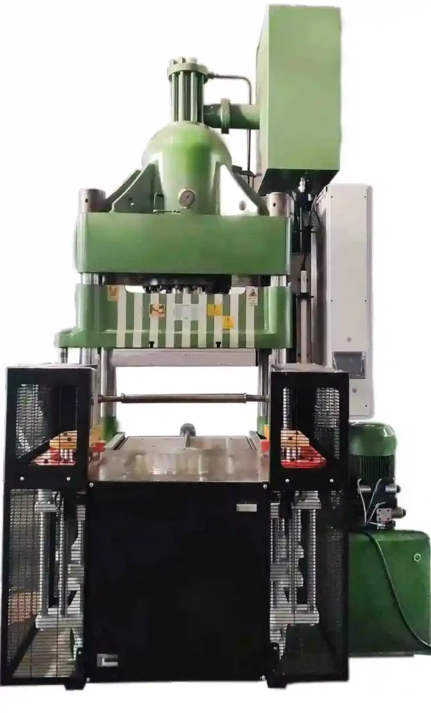
A double-action transfer press is a sheet metal forming machine designed to perform two distinct forming actions simultaneously during a single press stroke. This press features two independently controlled slides or rams that operate in coordination, enabling multiple forming processes—such as drawing and trimming, or piercing and flanging—to occur at the same time on the same part or on different parts within the same die.
The two-slide configuration improves manufacturing efficiency by reducing the number of press strokes needed to complete complex parts, thus decreasing cycle time and increasing throughput. Like other transfer presses, it includes an integrated transfer mechanism—mechanical, hydraulic, or servo-driven—that moves the workpiece automatically from one station to the next within the press. This system ensures precise timing so that the part is positioned correctly before each forming action.
Structurally, double-action transfer presses often use straight-side or four-post frames to provide the necessary rigidity to handle the forces from multiple simultaneous operations while maintaining accurate ram alignment. The independent motion of the slides allows for different stroke lengths, speeds, and dwell times, enabling customized forming actions tailored to each process step.
These presses are widely used in industries such as automotive, appliance, and electronics manufacturing, where parts require multiple forming operations in a compact, automated setup. Examples include complex brackets, housings, and panel components that benefit from integrated forming steps to improve dimensional accuracy and reduce secondary operations.
Modern double-action transfer presses are equipped with advanced control systems that allow operators to program and optimize slide movements and transfer timing for specific parts. This enhances flexibility for short runs and quick changeovers while maintaining the precision needed for high-volume production.
In summary, the double-action transfer press increases forming efficiency by performing two coordinated forming operations within a single press cycle. Its combination of independent slides, precise transfer automation, and robust frame design makes it ideal for producing complex sheet metal parts quickly, accurately, and cost-effectively.
The double-action transfer press’s capability to execute two distinct forming operations simultaneously significantly streamlines the manufacturing process by reducing the number of press strokes required to produce complex components. This directly translates into higher throughput and shorter cycle times, which are crucial for meeting production targets in high-volume industries.
Each slide in the press can be independently controlled to optimize stroke length, speed, and dwell time according to the specific requirements of the forming operation it performs. For example, one slide may execute a deep-drawing action that requires a slower, controlled stroke with an extended dwell period, while the other slide performs a faster trimming or piercing operation. This flexibility allows the press to handle a wider range of materials and part complexities within the same production line.
The integrated transfer system in a double-action press is designed to synchronize perfectly with the independent slide motions. Transfer arms or fingers move the workpiece precisely between stations during the non-forming portion of the cycle to avoid interference and maximize efficiency. Servo-driven transfer systems offer enhanced control and adaptability, enabling fine-tuning of part movement to minimize impact forces and reduce the risk of part deformation or misalignment.
Structurally, the robust frame design—commonly straight-side or four-post—provides the necessary rigidity and stability to support the complex tooling and multiple sliding components. This ensures consistent die alignment, which is vital for maintaining tight tolerances and prolonging tool life, especially in multi-station forming processes.
Industries such as automotive manufacturing, appliance production, and electronics benefit from the double-action press’s ability to produce parts with integrated features in fewer steps, reducing the need for secondary operations and manual handling. This consolidation improves part quality by minimizing variation introduced through multiple handling stages and shortens lead times from raw material to finished component.
Advanced control systems incorporated in modern double-action presses enable operators to program precise motion profiles for each slide and the transfer mechanism. This capability supports quick changeovers, facilitates flexible manufacturing, and allows for process optimization based on material type, part geometry, and production volume. Real-time monitoring and diagnostics help detect abnormalities early, reducing downtime and scrap rates.
Safety features are also a critical aspect of double-action presses, given the complexity of multiple moving parts. These machines are typically equipped with comprehensive guarding, light curtains, and interlocks to protect operators from the press and transfer mechanisms. Automation of loading and unloading processes further enhances workplace safety and reduces labor costs.
In essence, the double-action transfer press combines the benefits of multiple simultaneous forming operations with precise automated material handling, enabling manufacturers to achieve higher productivity, better quality, and lower production costs. Its balanced design of independent slide control and synchronized transfer makes it a versatile and efficient solution for complex sheet metal forming tasks in demanding industrial environments.
Building on its efficiency and precision, the double-action transfer press also offers manufacturers enhanced flexibility to adapt to varying production demands. Because each slide can be programmed independently, the press can be quickly adjusted to accommodate different part geometries or materials without the need for extensive mechanical modifications. This adaptability is particularly beneficial in industries where product variants or frequent design changes are common, such as automotive components or consumer electronics housings.
The ability to perform two operations in a single stroke reduces wear and tear on tooling by minimizing the number of press cycles and handling steps. This not only extends die life but also reduces maintenance intervals and tooling costs over the long term. Furthermore, the synchronized transfer system ensures that parts are accurately positioned with minimal impact forces, preventing damage and preserving dimensional integrity.
Energy efficiency is another advantage of double-action presses. By combining two forming actions into one cycle, energy consumption per part decreases compared to running separate presses sequentially. When equipped with modern servo or variable frequency drives, the press can optimize power usage based on load requirements, contributing to lower operational costs and a smaller environmental footprint.
From a production line integration perspective, double-action transfer presses can be seamlessly linked with upstream and downstream automation, including coil feeding, blanking, part inspection, and robotic handling. This integration supports continuous, high-speed operation with minimal human intervention, boosting throughput while maintaining consistent quality.
Operator safety remains a priority in the design and operation of double-action presses. Comprehensive safety systems—including light curtains, interlocks, and emergency stop mechanisms—work in tandem with automated part handling to reduce the risk of accidents. Remote monitoring and control features further enhance safety by allowing operators to oversee press functions from a safe distance.
In conclusion, the double-action transfer press stands out as a highly effective solution for complex sheet metal forming processes that demand speed, precision, and adaptability. By consolidating multiple forming steps into a single, well-coordinated cycle, it enables manufacturers to improve productivity, reduce costs, and maintain high-quality standards in competitive, fast-paced production environments.
Single Action Transfer Press
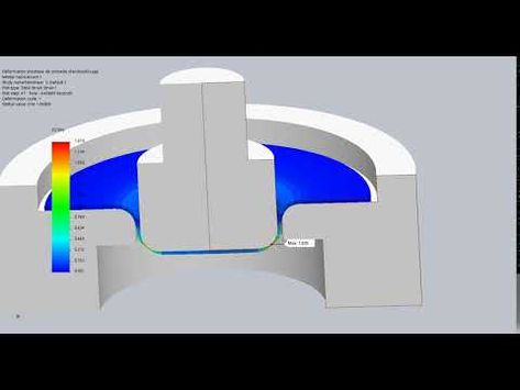
A single-action transfer press is a type of sheet metal forming machine designed with one primary slide (or ram) that performs a single forming action during each press stroke. Despite having only one slide, it incorporates an integrated transfer system that automatically moves the workpiece through multiple die stations inside the press, enabling progressive or multi-stage forming operations to be completed in a single press cycle.
In this configuration, the single ram executes one type of forming operation—such as drawing, blanking, or piercing—at each station as the part is indexed by the transfer mechanism. The transfer system, which can be mechanical, pneumatic, hydraulic, or servo-driven, moves the workpiece between forming stations precisely during the non-forming portion of the ram stroke, ensuring smooth and safe part handling.
The single-action transfer press is typically built with a rigid frame, often a straight-side or four-post design, to support heavy tooling and maintain die alignment during repetitive forming cycles. Although it has only one moving slide, the press’s ability to perform multi-step forming in a single machine through the transfer system makes it highly efficient for producing complex parts without requiring multiple presses or manual handling.
This type of press is commonly used in industries like automotive, electronics, and appliance manufacturing, where complex sheet metal components need to be formed through several stages—such as deep drawing followed by trimming and piercing—in a continuous, automated process. The integration of the transfer system minimizes part handling, reducing the risk of damage and improving dimensional consistency.
Modern single-action transfer presses often include advanced control systems for precise synchronization of the ram stroke and transfer motion. These controls allow for adjustable stroke lengths, ram speeds, and transfer timing, which helps optimize the process for different materials and part designs. They also feature safety devices, tonnage monitoring, and die protection systems to ensure safe and reliable operation.
In summary, the single-action transfer press combines a single, powerful forming slide with an automated transfer mechanism to efficiently perform multi-stage sheet metal forming operations. Its robust construction, automation capability, and process integration make it a versatile and cost-effective solution for producing complex parts with high repeatability and throughput.
The single-action transfer press offers a streamlined approach to multi-stage forming by relying on the coordinated action of a single slide and a precisely timed transfer system. This setup simplifies mechanical complexity compared to multi-slide presses while still enabling a full sequence of forming operations to be completed in one continuous cycle. The transfer system moves the part between stations during the non-forming portion of the ram’s stroke, optimizing cycle time and minimizing idle periods.
Because the press has only one moving ram, maintenance tends to be simpler and costs lower compared to presses with multiple slides. The mechanical drive system, often crankshaft or link-driven, is focused on delivering consistent, repeatable force and stroke motion to the single slide, ensuring stable forming conditions for each operation. The robust frame construction supports heavy tooling and withstands the repeated loads inherent to high-volume production.
The integration of the transfer mechanism is critical to the overall efficiency of the single-action press. Transfer arms or fingers, which may be mechanically cam-driven or servo-controlled, must precisely position the part at each station to prevent misfeeds or collisions. This precise handling reduces scrap rates and tooling damage, enhancing overall production reliability. Servo-driven transfers add the benefit of adjustable speed and acceleration profiles, enabling fine-tuning for different part sizes and complexities.
Industries that require forming of complex parts with multiple features—such as automotive body panels, appliance housings, or electronic enclosures—often favor single-action transfer presses for their balance of simplicity and automation. By automating part movement and integrating multiple forming steps within a single machine footprint, manufacturers save valuable floor space and reduce labor costs associated with manual handling.
Modern control systems further enhance the capabilities of single-action presses by allowing programmable stroke profiles, adaptive feed rates, and process monitoring. Operators can easily switch between different product setups, reducing changeover times and increasing production flexibility. Real-time data collection and analysis support predictive maintenance and quality assurance, reducing unplanned downtime and improving yield.
Safety features are comprehensive, including physical guarding, light curtains, and emergency stops, designed to protect operators from the moving slide and transfer mechanisms. Automated loading and unloading systems often complement the press, minimizing manual intervention and improving workplace safety.
In conclusion, the single-action transfer press is a highly effective solution for producing complex sheet metal components through multiple forming stages using a single, powerful slide combined with automated transfer. Its mechanical simplicity, combined with precise automation and control, delivers reliable, high-throughput manufacturing with reduced operational costs and improved part quality.
The single-action transfer press also excels in scalability and integration within larger manufacturing systems. Its straightforward mechanical design allows for easy customization and adaptation to different production volumes, from small batch runs to high-volume continuous operations. By combining the single slide with flexible transfer automation, manufacturers can tailor the press to meet specific part complexity and throughput requirements without unnecessary mechanical complexity.
Because the forming slide performs only one action per stroke, tooling can be optimized for that particular operation, often resulting in longer die life and simplified maintenance compared to multi-slide presses where tooling must accommodate multiple simultaneous actions. This singular focus on one forming process at a time also helps improve process stability and repeatability, critical for maintaining tight tolerances and consistent quality in complex parts.
Energy efficiency is another consideration where single-action presses can shine. With only one main moving slide, power consumption can be lower compared to multi-slide systems, especially when paired with modern drive technologies such as variable frequency drives or servo motors. This contributes to reduced operational costs and supports sustainability goals, which are increasingly important in today’s manufacturing environment.
In automated production lines, single-action transfer presses often serve as a central forming station integrated with upstream coil lines and downstream finishing or assembly operations. The automated transfer system’s precise timing allows for smooth coordination with coil feeders, straighteners, blanking stations, and robotic handling systems, creating a seamless flow from raw material to finished component. This integration minimizes manual handling, reduces cycle times, and enhances overall line efficiency.
Furthermore, advancements in sensor technology and Industry 4.0 connectivity enable single-action transfer presses to provide comprehensive process data. Real-time monitoring of tonnage, stroke position, and transfer system status helps identify potential issues before they lead to downtime or quality defects. This data-driven approach supports predictive maintenance strategies and continuous process improvement, further increasing machine uptime and product quality.
Operator training and ease of use are also benefits of the single-action press design. The simpler mechanical layout compared to multi-slide presses makes troubleshooting and routine maintenance more straightforward, reducing reliance on specialized technicians. User-friendly control interfaces with graphical displays and program management simplify setup changes and enable operators to quickly adjust to new production requirements.
In summary, the single-action transfer press combines mechanical simplicity with automated transfer precision to provide an efficient, reliable, and flexible solution for multi-stage sheet metal forming. Its adaptability, energy efficiency, ease of integration, and data-driven capabilities make it a valuable asset in modern manufacturing environments focused on quality, productivity, and cost control.
Hybrid Servo-Hydraulic Transfer Press
A hybrid servo-hydraulic transfer press combines the strengths of both servo-electric and hydraulic technologies to deliver enhanced precision, energy efficiency, and force control in sheet metal forming applications. This type of press uses servo motors to control the transfer system and often auxiliary movements, while hydraulic cylinders provide the main forming force through the press slide. The hybrid approach optimizes speed, accuracy, and power, making it suitable for complex, high-volume production environments.
In a hybrid servo-hydraulic transfer press, the hydraulic system is responsible for delivering the substantial force required during forming operations such as drawing, piercing, trimming, or flanging. Hydraulics offer excellent force density and smooth, controllable motion under load, which is critical for deep draws or forming high-strength materials. The servo motors, meanwhile, precisely control the transfer system that moves the part between stations and can also manage auxiliary functions like clamp or ejector motions with high repeatability and responsiveness.
This combination leverages the best of both worlds: the raw power and robustness of hydraulics with the precision, programmability, and energy savings of servo drives. Servo-controlled transfers enable highly accurate part positioning and flexible motion profiles, reducing part misfeeds, collisions, and wear on tooling. The ability to program variable speeds and dwell times during transfer motions improves part quality and line efficiency.
Hybrid servo-hydraulic presses typically feature a rigid frame—often straight-side or four-post designs—to withstand forming forces while maintaining die alignment. The hydraulic slide is controlled via advanced proportional valves or servo-hydraulic drives, allowing fine control over ram speed, force, and stroke profile. This results in smoother forming cycles, reduced shock loads, and less tooling wear compared to traditional mechanical presses.
Energy efficiency is improved in hybrid presses by optimizing hydraulic power usage and leveraging servo motors only when movement is required, reducing idle energy consumption. Regenerative systems can capture and reuse energy during deceleration phases, further lowering operational costs and environmental impact.
Control systems in hybrid presses are sophisticated, integrating PLC or CNC platforms that synchronize the hydraulic slide, servo-driven transfer, and auxiliary devices. These controls allow precise programming of stroke curves, transfer timing, and clamp pressures, enabling rapid changeovers and process optimization for different parts and materials.
Industries such as automotive, aerospace, and appliance manufacturing benefit from hybrid servo-hydraulic transfer presses due to their versatility in handling a wide range of materials—including ultra-high-strength steels and lightweight aluminum alloys—and complex part geometries. The combination of force control and precise automation supports high-quality forming with reduced scrap and downtime.
In summary, the hybrid servo-hydraulic transfer press merges the power and reliability of hydraulic forming with the precision and flexibility of servo-driven automation. This synergy enhances forming quality, productivity, and energy efficiency, making it an excellent choice for demanding sheet metal forming applications requiring both strength and control.
The hybrid servo-hydraulic transfer press offers notable improvements in overall process control and manufacturing flexibility. By using servo motors to manage the transfer system, manufacturers gain the ability to customize the motion profiles for part handling with high accuracy. This reduces the risk of part misalignment, collisions, or damage, which can occur in high-speed forming lines. The servo-driven transfer can accelerate, decelerate, and dwell precisely, matching the forming cycle and optimizing the timing between stations.
On the hydraulic side, advanced servo-hydraulic valves allow dynamic adjustment of ram speed and force throughout the stroke. This fine control helps achieve optimal forming conditions, especially for difficult materials or intricate geometries, by minimizing shocks and distributing force more evenly across the workpiece. The result is improved part quality, reduced tooling wear, and less scrap.
Energy savings are a key benefit of the hybrid design. Unlike purely hydraulic systems that often run at constant pressure and flow, servo-hydraulic components modulate power delivery based on demand, lowering wasted energy during non-forming phases. The integration of energy recovery systems further enhances efficiency by capturing energy during ram deceleration and feeding it back into the system or grid.
In terms of maintenance, the hybrid system’s modular design typically allows separate servicing of the hydraulic and servo components, simplifying troubleshooting and reducing downtime. Condition monitoring sensors embedded in the press and transfer equipment provide real-time data on pressures, temperatures, and component health, enabling predictive maintenance strategies that prevent unexpected failures.
From a production standpoint, the hybrid servo-hydraulic press is well-suited for mixed-model manufacturing where different parts with varying forming requirements are run on the same line. Programmable servo transfers and hydraulic slide motions can be quickly adjusted for different product runs without mechanical changes, supporting fast changeovers and flexible production schedules.
The enhanced precision and control also support integration with downstream automated processes such as robotic unloading, vision inspection, or assembly. By producing consistent, accurately formed parts with minimal variability, the hybrid press helps ensure smooth flow through the entire production chain.
Safety is integral to hybrid press design, with comprehensive guarding, interlocks, and emergency stop systems protecting operators from both the high forces of hydraulic forming and the fast movements of servo-driven components. Automated loading and unloading reduce manual intervention, further enhancing workplace safety.
In conclusion, the hybrid servo-hydraulic transfer press represents a balanced and advanced solution that combines the robust forming capability of hydraulics with the precision and efficiency of servo automation. This combination delivers superior forming quality, increased productivity, and reduced operational costs, meeting the demanding needs of modern sheet metal manufacturing across diverse industries.
Building further on its advantages, the hybrid servo-hydraulic transfer press also excels in adapting to emerging manufacturing trends like Industry 4.0 and smart factory integration. Its sophisticated control systems can interface seamlessly with digital networks, allowing real-time monitoring and remote diagnostics. This connectivity enables data-driven decision-making, where process parameters and machine health metrics are continuously analyzed to optimize performance and schedule predictive maintenance, reducing unplanned downtime and extending equipment lifespan.
The press’s flexible automation capabilities also support increasing demands for customization and small batch production without sacrificing efficiency. Servo-driven transfers can be reprogrammed quickly to accommodate different part sizes or shapes, while hydraulic slide motions can be adjusted to apply the exact force profiles needed for new materials or complex geometries. This versatility makes the hybrid press ideal for industries facing rapid product evolution, such as electric vehicles, aerospace, and consumer electronics.
Moreover, the reduced mechanical shock and precise force control reduce stress on both tooling and structural components, minimizing fatigue and enabling longer production runs before maintenance or replacement is required. The improved reliability also contributes to more consistent part quality, which is critical for downstream processes like welding, coating, or assembly where tight tolerances are essential.
Energy management is further enhanced in hybrid systems by integrating intelligent control algorithms that adjust hydraulic pump speeds and servo motor output in real-time, matching power consumption precisely to process demands. This not only lowers electricity costs but also aligns with sustainability goals increasingly prioritized by manufacturers and regulators.
In terms of workforce impact, the hybrid servo-hydraulic press often requires fewer manual interventions due to its high level of automation and advanced diagnostics. Operators can focus more on monitoring process performance and quality assurance rather than routine mechanical adjustments. Training is simplified through intuitive user interfaces and programmable control sequences, enabling quicker onboarding and reducing the likelihood of operator error.
Finally, hybrid presses can be combined with other advanced technologies such as in-die sensing, automated lubrication, and adaptive forming strategies that modify press parameters on-the-fly based on real-time feedback. This closed-loop control further refines part quality and process efficiency, making the hybrid servo-hydraulic transfer press a cornerstone of modern, high-performance sheet metal forming operations.
In essence, the hybrid servo-hydraulic transfer press represents a forward-looking blend of power, precision, and intelligence. Its capability to deliver consistent, high-quality forming while optimizing energy use and supporting flexible production makes it a critical asset for manufacturers aiming to stay competitive in today’s fast-evolving industrial landscape.
Pneumatic Transfer Press
A pneumatic transfer press is a sheet metal forming machine that uses compressed air to power its transfer system and sometimes auxiliary movements, enabling the automatic movement of parts between multiple forming stations within the press. While the main forming action—such as drawing, piercing, or trimming—is typically driven by mechanical or hydraulic means, the transfer of parts from one station to the next relies on pneumatic actuators for motion.
In a pneumatic transfer press, air cylinders or pneumatic motors drive the transfer arms, fingers, or conveyors that pick up, move, and position the workpiece accurately during the non-forming portion of the press stroke. Pneumatics offer a relatively simple and cost-effective means of powering transfer systems, providing quick response times and reliable operation in many light- to medium-duty forming applications.
The press frame is usually robust enough to handle forming forces independently, with the pneumatic system focused on part handling. Pneumatic transfers are often used in conjunction with mechanical or hydraulic presses for processes where the forming force requirements are moderate and the transfer distances between stations are relatively short.
Advantages of pneumatic transfer presses include their simpler design, lower initial cost, and ease of maintenance compared to fully hydraulic or servo-driven transfer systems. Pneumatic components are widely available, relatively easy to repair or replace, and offer good reliability when properly maintained.
However, pneumatic systems generally provide less precise control over motion profiles compared to servo or hydraulic systems. Speed and position adjustments are more limited, and compressed air can lead to less smooth or repeatable movement, which may impact part handling accuracy. Therefore, pneumatic transfer presses are typically suited for applications with less stringent positioning requirements or simpler part geometries.
Industries such as light appliance manufacturing, small automotive components, and general metal fabrication may use pneumatic transfer presses where moderate forming forces and transfer precision are acceptable. These presses often serve in production lines requiring efficient but cost-conscious automation.
Modern pneumatic transfer presses can be integrated with sensors, PLC controls, and safety devices to enhance automation, monitoring, and operator protection. However, their pneumatic transfer systems are less commonly used in high-precision or heavy-duty forming applications, where hydraulic or servo-driven transfers offer superior performance.
In summary, pneumatic transfer presses provide a practical and economical solution for automated part transfer in sheet metal forming processes that do not require the highest levels of precision or force control. Their simpler design and ease of maintenance make them attractive for certain production environments focused on moderate complexity and cost-effectiveness.
Pneumatic transfer presses are valued for their simplicity and cost-effectiveness, especially in production environments where high precision or heavy forming forces are not critical. The use of compressed air to power transfer movements means these systems typically have fewer complex components compared to hydraulic or servo-driven alternatives, leading to easier maintenance and lower downtime. Pneumatic cylinders and valves are standard industrial components that can be quickly serviced or replaced, helping keep production lines running smoothly.
The speed of pneumatic transfers can be quite fast, making them suitable for moderately paced production cycles. However, because air is compressible, movement can be less smooth and less controllable than hydraulic or electric drives. This can result in slight variability in positioning accuracy and speed, which may be acceptable for parts with simpler geometries or looser tolerances but problematic for precision components.
Pneumatic transfer presses often incorporate sensors and limit switches to ensure the proper positioning of parts before forming operations begin. These sensors provide feedback to the control system, enhancing reliability and preventing collisions or misfeeds. Additionally, modern control systems can coordinate the press stroke with pneumatic transfer motions to optimize cycle times, though they lack the fine programmability of servo-driven systems.
Energy consumption in pneumatic systems tends to be higher due to losses associated with air compression and leakage. However, for many applications, the initial lower investment and simpler infrastructure make pneumatics a practical choice. Compressed air systems also offer inherent safety advantages, as they are less likely to cause fire hazards compared to hydraulic fluids, and pneumatic components typically have fail-safe characteristics such as spring returns that move parts to safe positions during power loss.
Pneumatic transfer presses are common in industries like electronics, household goods, and light automotive parts, where the balance between automation and cost is critical. They are well-suited for handling smaller or lighter sheet metal components that do not require heavy forming forces or ultra-precise positioning.
While pneumatic transfers provide clear benefits, their limitations mean they are less suitable for high-speed, high-precision, or heavy-duty forming processes. For these more demanding applications, manufacturers often prefer servo-hydraulic or fully servo-electric transfer systems that offer superior control, repeatability, and energy efficiency.
Overall, pneumatic transfer presses fill an important niche in sheet metal forming by offering a reliable, low-cost automation option. They enable manufacturers to automate multi-stage forming operations with reasonable accuracy and speed while minimizing complexity and maintenance demands, making them a practical solution in many mid-tier production environments.
Pneumatic transfer presses also benefit from straightforward integration with existing compressed air infrastructure commonly found in many manufacturing facilities. This allows companies to implement or upgrade automation without extensive investment in new utilities or power supplies, simplifying installation and reducing upfront costs. The modular nature of pneumatic components means presses can often be customized or retrofitted easily to meet changing production requirements or to add additional forming stations.
In terms of operational flexibility, pneumatic systems are generally well-suited to intermittent or stop-start production cycles. The rapid response of pneumatic cylinders enables quick part transfers between stations, and the simple control schemes facilitate easy adjustments to transfer speed and timing. This makes pneumatic transfer presses adaptable for small to medium batch sizes or for production lines with frequent product changeovers.
While pneumatic transfer presses may not offer the high precision of servo-driven systems, they often incorporate mechanical guides, cams, or indexing mechanisms to improve repeatability and positioning accuracy. These mechanical aids help compensate for the less precise nature of pneumatic motion and are effective in maintaining consistent part placement over many cycles.
Maintenance personnel benefit from the relative simplicity and robustness of pneumatic components. Unlike hydraulic systems that require fluid management, pneumatic systems avoid contamination risks and fluid leaks, which can reduce maintenance complexity and environmental concerns. Preventive maintenance mainly focuses on ensuring air supply quality, checking for leaks, and periodically servicing valves and cylinders.
Because pneumatic transfer presses rely on compressed air, efficiency can be affected by the quality and pressure of the air supply. Proper filtration, drying, and regulation of compressed air are essential to maintain reliable operation and prevent component wear. Facilities using pneumatic presses typically invest in air treatment systems to ensure stable performance and reduce the likelihood of unexpected downtime.
From a safety perspective, pneumatic transfer presses are often considered less hazardous compared to hydraulic or electric alternatives. The absence of high-pressure fluids reduces fire risks, and pneumatic systems can be designed with fail-safe features like spring-return actuators that default to safe positions in the event of power loss or emergency stops.
Overall, pneumatic transfer presses represent a pragmatic balance between automation capability and cost-efficiency. Their ease of maintenance, relatively low investment, and compatibility with standard plant utilities make them attractive for manufacturers seeking to automate sheet metal forming processes without the complexity or expense of more advanced transfer technologies. Though best suited for lighter-duty and less precision-critical applications, pneumatic presses continue to play a vital role in diverse manufacturing sectors worldwide.
Servo Transfer Press
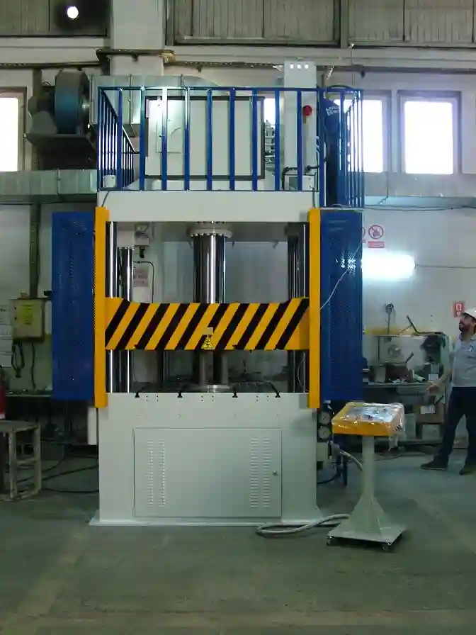
A servo transfer press is an advanced sheet metal forming machine that uses servo-electric motors to precisely control both the press slide and the transfer system. Unlike traditional mechanical or hydraulic presses, servo transfer presses offer highly programmable and flexible motion profiles, enabling exact control over ram speed, position, and force, as well as the timing and movement of part transfer between stations.
In a servo transfer press, servo motors replace conventional mechanical linkages or hydraulic drives for both the forming slide and the transfer mechanism. This allows the press to execute complex forming sequences with multiple velocity changes, dwell times, and controlled acceleration/deceleration phases, optimizing each forming step to improve part quality and reduce tooling wear. The transfer system, powered by servo motors, moves the workpiece smoothly and accurately between stations, enabling high-speed, collision-free automation with exceptional repeatability.
The precision offered by servo technology enables manufacturers to form complex parts with tight tolerances and intricate features. The ability to program variable stroke profiles means that forces can be carefully applied during forming, minimizing material stress and reducing scrap rates. Servo drives also support quick changeovers by allowing fast reprogramming of motion parameters, which is ideal for flexible production environments handling multiple part variants.
Energy efficiency is a significant benefit of servo transfer presses. Since servo motors consume power only during motion and can regenerate energy during deceleration, these presses typically use less energy compared to mechanical or hydraulic systems that run continuously or at fixed speeds. This reduces operational costs and supports sustainability initiatives.
Servo transfer presses are commonly found in automotive, aerospace, electronics, and appliance industries, where high precision, repeatability, and flexibility are critical. Their integration with advanced control systems allows seamless communication with upstream and downstream automation, quality monitoring, and Industry 4.0 platforms for real-time process optimization.
Safety is enhanced with servo technology because motion can be precisely controlled and stopped instantly if necessary. The absence of mechanical linkages reduces the risk of mechanical failures, and integrated sensors provide continuous monitoring of position and force to protect both operators and tooling.
In summary, the servo transfer press represents a cutting-edge solution in sheet metal forming by combining programmable servo-electric drives with automated transfer mechanisms. This results in superior forming accuracy, flexible operation, energy savings, and improved throughput, making it an essential machine for modern, high-performance manufacturing.
Servo transfer presses offer unmatched flexibility and precision by allowing complete control over every phase of the forming cycle. Operators and engineers can program complex motion profiles tailored to specific materials, part geometries, and forming requirements. This capability means that the press slide can vary speed multiple times within a single stroke, incorporating slow, controlled forming motions followed by rapid return strokes, which enhances both product quality and cycle time efficiency.
The servo-driven transfer mechanism is equally sophisticated, capable of smoothly accelerating and decelerating parts between stations with pinpoint accuracy. This precision reduces the risk of part damage, die wear, and misalignment, leading to higher first-pass yields and less scrap. The ability to synchronize transfer motions perfectly with slide movements also allows for shorter cycle times without compromising safety or quality, contributing to increased production throughput.
Energy efficiency is a key advantage, as servo motors draw power only when moving and can regenerate energy back into the system when slowing down or stopping. This contrasts with traditional mechanical or hydraulic presses that often consume power continuously or inefficiently. Over long production runs, this efficiency translates into significant cost savings and supports sustainability goals by reducing the facility’s overall energy footprint.
Servo transfer presses also simplify changeovers and increase manufacturing agility. Because motion sequences are software-controlled, switching from one part to another often requires only a change in the program rather than physical retooling or mechanical adjustments. This flexibility supports just-in-time production, mixed-model assembly lines, and rapid prototyping without sacrificing efficiency or quality.
The advanced control systems found in servo presses integrate seamlessly with factory automation and Industry 4.0 initiatives. They provide real-time data on press performance, part quality, and maintenance needs, enabling predictive maintenance and continuous process improvement. Operators can monitor the press remotely, adjust parameters on the fly, and respond quickly to production issues, minimizing downtime.
Safety is enhanced by the precise controllability of servo motors. The press can be stopped instantly in emergencies, and integrated sensors continuously monitor position, speed, and force to prevent collisions or overstress. This reduces the risk of injury and damage to expensive tooling.
Industries that demand high-precision parts with complex features—such as automotive body panels, aerospace components, and electronic enclosures—benefit greatly from the capabilities of servo transfer presses. Their combination of precision, speed, and programmability enables manufacturers to meet tight tolerances and stringent quality standards while maintaining efficient, cost-effective production.
In summary, servo transfer presses represent a leap forward in sheet metal forming technology by delivering unparalleled control, efficiency, and adaptability. Their advanced motion control and automation capabilities make them ideal for modern manufacturing environments focused on quality, flexibility, and sustainability.
Beyond their core forming and transfer capabilities, servo transfer presses also enable integration with advanced tooling technologies such as in-die sensors, adaptive forming systems, and real-time process feedback. This allows the press to dynamically adjust forming parameters during production to compensate for material variations, tool wear, or environmental changes, further enhancing part quality and consistency.
The precise control of servo drives also facilitates the use of multi-step forming processes within a single stroke, such as combining drawing, trimming, and embossing actions seamlessly. This consolidation reduces the need for multiple machines and manual handling, improving floor space utilization and overall manufacturing efficiency.
Because servo transfer presses rely heavily on sophisticated electronics and software, they support extensive data logging and analytics. Manufacturers can track key performance indicators like cycle time, energy consumption, and part quality metrics in detail, enabling continuous improvement programs and helping identify bottlenecks or quality issues early.
The reduced mechanical complexity compared to traditional mechanical presses results in less wear and fewer moving parts, lowering maintenance requirements and extending the operational lifespan of the press. Servo motors and electronic drives are also easier to replace or upgrade, future-proofing the investment as technology advances.
On the human-machine interface side, modern servo presses come equipped with intuitive touchscreens, graphical programming environments, and remote monitoring capabilities. This improves ease of use, reduces operator training time, and allows technicians to troubleshoot and optimize the press from remote locations, enhancing responsiveness and uptime.
Environmentally, servo transfer presses contribute to greener manufacturing by minimizing energy waste, reducing noise levels due to smoother motion control, and eliminating hydraulic fluids, which can pose environmental hazards. This aligns with increasing regulatory pressures and corporate sustainability commitments.
Finally, the scalability of servo transfer presses means they can be tailored for a wide range of applications—from small precision components requiring gentle forming to large, complex panels needing high force and intricate motion control. This versatility makes them suitable for diverse industries including automotive, aerospace, electronics, appliances, and medical devices.
In essence, servo transfer presses are not just forming machines; they are intelligent, connected manufacturing platforms that combine precision engineering with digital technology to deliver superior performance, flexibility, and sustainability in sheet metal forming operations.
Hydraulic Transfer Press
A hydraulic transfer press is a type of sheet metal forming machine that uses hydraulic power to drive the main press slide and, in many cases, to operate the transfer system that moves parts between multiple forming stations within the press. Unlike mechanical presses that rely on crankshafts or cams, hydraulic presses generate forming force through hydraulic cylinders, offering precise control over pressure, speed, and stroke length.
In a hydraulic transfer press, the hydraulic cylinders provide smooth, controllable ram motion, which can be adjusted to optimize the forming process for different materials and part geometries. The transfer system—often powered hydraulically or through a combination of hydraulic and mechanical means—automatically moves the workpiece from one die station to the next during the non-forming portion of the ram stroke, enabling progressive or multi-stage forming in a single press.
Hydraulic presses are known for their high force capacity and the ability to maintain consistent pressure throughout the stroke, which is essential for deep drawing, blanking, bending, and other heavy-duty forming operations. The adjustable ram speed and dwell time allow the press to accommodate materials that require careful forming to avoid cracking or springback.
The transfer mechanism in hydraulic transfer presses typically includes hydraulic cylinders or motors controlling transfer arms, fingers, or conveyors. This system precisely indexes parts between stations, synchronizing with the press slide to maintain a continuous and efficient forming cycle. The hydraulic transfer provides strong, reliable motion with the ability to handle heavier or larger parts compared to pneumatic or purely mechanical transfers.
Energy consumption in hydraulic transfer presses can be higher than in servo-electric systems, but modern designs often incorporate variable displacement pumps, load-sensing valves, and accumulator technology to improve efficiency. These features reduce wasted energy by adjusting hydraulic power output to the actual forming requirements rather than running at full pressure continuously.
Hydraulic transfer presses are widely used in industries such as automotive manufacturing, heavy equipment production, and appliance fabrication where high forming forces and flexible process control are needed. Their ability to apply controlled pressure over extended periods makes them suitable for complex forming tasks involving tough metals and intricate shapes.
Safety systems in hydraulic presses include pressure relief valves, overload protection, and comprehensive guarding to protect operators from high forces and moving parts. Automated loading and unloading systems often accompany hydraulic transfer presses to reduce manual intervention and improve workplace safety.
In summary, hydraulic transfer presses offer powerful, flexible, and precise forming capabilities through the use of hydraulic technology. Their robust force control and reliable transfer systems make them essential for producing complex sheet metal parts requiring high force and exacting process control.
Hydraulic transfer presses are valued for their smooth and controllable ram movement, which can be finely tuned to suit a wide range of materials and forming operations. The ability to adjust ram speed, force, and dwell time during the stroke allows manufacturers to minimize material stress, reduce defects like cracking or distortion, and improve overall part quality. This flexibility is especially important when working with high-strength steels, aluminum alloys, or other challenging materials.
The hydraulic transfer mechanism provides robust and consistent part handling, capable of moving heavy or bulky workpieces accurately between stations. This reliability reduces downtime caused by part misfeeds or collisions, enhancing production efficiency. Transfer motions can be synchronized precisely with the press slide to optimize cycle times, allowing for high-volume manufacturing with minimal operator intervention.
Energy efficiency is a key focus in modern hydraulic transfer press designs. Technologies such as variable displacement pumps, load-sensing hydraulics, and accumulators help conserve power by delivering hydraulic pressure only when needed. These advances reduce operating costs and environmental impact compared to older, fixed-output hydraulic systems that run continuously at full pressure.
Hydraulic presses typically feature sturdy frame designs, such as four-post or straight-side constructions, to withstand the heavy loads generated during forming. This structural rigidity ensures die alignment and repeatability, which are critical for maintaining tight dimensional tolerances and part consistency over long production runs.
Control systems for hydraulic transfer presses have evolved to include programmable logic controllers (PLCs) and human-machine interfaces (HMIs) that provide operators with easy-to-use platforms for monitoring and adjusting press parameters. Real-time feedback on pressure, stroke position, and cycle status enables quick troubleshooting and supports predictive maintenance strategies, minimizing unexpected downtime.
The safety of hydraulic transfer presses is enhanced through multiple layers of protection, including pressure relief valves, emergency stops, light curtains, and physical guarding. Automated material handling systems integrated with the press reduce the need for manual loading and unloading, lowering the risk of operator injury and improving ergonomics.
Hydraulic transfer presses are widely employed in sectors that require heavy forming forces combined with precise process control, such as automotive body panel manufacturing, aerospace structural components, heavy machinery parts, and large appliance shells. Their versatility allows for multi-stage forming operations like deep drawing, trimming, piercing, and embossing to be combined within a single machine, streamlining production and reducing handling costs.
Overall, hydraulic transfer presses deliver a powerful and adaptable solution for sheet metal forming, combining the strength and controllability of hydraulic power with automated part transfer. Their robustness, precision, and integration capabilities make them indispensable in modern manufacturing environments focused on quality, efficiency, and scalability.
Hydraulic transfer presses also offer considerable flexibility in accommodating various tooling configurations and die sets, which can be changed relatively quickly compared to older mechanical presses. This adaptability allows manufacturers to switch between different part designs or production volumes with minimal downtime, supporting just-in-time manufacturing and shorter product life cycles.
The hydraulic system’s ability to apply consistent pressure throughout the stroke means that forming operations can be fine-tuned to handle complex geometries and difficult materials. For example, deep drawing operations benefit from the controlled ram speed and extended dwell times achievable with hydraulic drives, reducing the likelihood of defects such as wrinkling or tearing.
In addition to standard hydraulic cylinders, many modern hydraulic transfer presses incorporate servo-hydraulic technology, which combines traditional hydraulics with servo motor control for even finer motion precision and energy efficiency. This hybrid approach allows presses to maintain high forming forces while benefiting from programmable motion profiles and regenerative energy capabilities.
Hydraulic transfer presses can also be integrated with sophisticated automation systems, including robotic loading and unloading, in-line inspection, and part marking. Such integration enhances throughput and quality assurance while reducing labor costs and minimizing human error. The transfer system’s synchronization with the press cycle is critical for seamless operation, enabling continuous production flows and reducing cycle times.
Maintenance of hydraulic transfer presses focuses on hydraulic fluid quality, system cleanliness, and the condition of seals and valves. Preventive maintenance programs typically include regular fluid changes, filter replacements, and monitoring of hydraulic pressure and temperature to detect early signs of wear or contamination.
Despite their advantages, hydraulic transfer presses require careful management of hydraulic fluid to prevent leaks, environmental contamination, and fire hazards. Modern designs often incorporate environmentally friendly fluids and sealed systems to mitigate these risks.
In summary, hydraulic transfer presses combine powerful, controllable forming forces with automated part transfer to deliver efficient, high-quality sheet metal forming solutions. Their adaptability, precision, and capacity for integration make them a mainstay in industries demanding complex part geometries, heavy forming loads, and reliable high-volume production.
Mechanical Transfer Press
A mechanical transfer press is a sheet metal forming machine that utilizes mechanical systems—such as cams, crankshafts, and gears—to drive both the press slide and the part transfer mechanism. Unlike hydraulic or servo-driven presses, mechanical transfer presses rely on fixed mechanical linkages to coordinate the forming stroke and the automated movement of parts between multiple die stations.
In a mechanical transfer press, the press ram is powered by a flywheel connected to a crankshaft, which converts rotational motion into the reciprocating motion of the slide. The transfer system—often consisting of cams, levers, and mechanical fingers or grippers—is mechanically linked to the press drive, ensuring that part movement is precisely timed with the ram stroke. This synchronous operation allows for efficient, continuous forming cycles with fixed timing and speed.
Mechanical transfer presses are known for their high-speed capabilities and robust construction. Because the ram movement and transfer actions are mechanically synchronized, these presses can achieve rapid cycle times, making them suitable for high-volume production of simpler parts where consistent timing is essential.
The fixed motion profiles inherent in mechanical presses mean that the stroke length, ram speed, and transfer timing are generally constant and cannot be easily adjusted without mechanical changes. This rigidity limits flexibility but provides consistent, repeatable forming conditions, which is advantageous for long production runs of standardized parts.
Mechanical transfer presses are often used in industries such as automotive manufacturing, appliance production, and general metal stamping, where high throughput and part consistency are prioritized. Their mechanical simplicity and durability make them reliable workhorses for progressive stamping operations involving piercing, blanking, bending, and forming.
Maintenance of mechanical transfer presses involves routine inspection of mechanical components like bearings, cams, gears, and linkage systems to ensure proper alignment and lubrication. Since these presses operate under high-speed mechanical loads, wear and fatigue of parts are considerations that require regular monitoring.
Safety features in mechanical transfer presses include safeguarding around moving mechanical parts, emergency stop systems, and interlocks to protect operators from injury during high-speed operation. Automated feeding and unloading systems further reduce manual intervention, improving workplace safety.
While mechanical transfer presses excel in speed and repeatability, their lack of programmability and adaptability makes them less suited for complex forming sequences or materials requiring variable ram speeds and forces. Modern manufacturing trends towards flexible, programmable systems have led to increased use of servo and hydraulic presses, but mechanical transfer presses remain valuable for specific high-volume, stable-process applications.
In summary, mechanical transfer presses are durable, high-speed machines that rely on mechanical linkages to synchronize forming and part transfer. Their consistent timing and robust design make them ideal for mass production of standard sheet metal parts where flexibility is less critical.
Mechanical transfer presses continue to be an important part of high-volume manufacturing operations because of their ability to deliver rapid, repeatable, and consistent forming cycles. The mechanical synchronization between the press slide and the transfer system ensures that parts are moved between stations with perfect timing, reducing the risk of misfeeds or collisions. This is particularly advantageous in environments where production speed is paramount and part geometry is relatively straightforward.
These presses are designed for endurance and long production runs. Their construction typically includes a straight-side frame to withstand the high loads generated during stamping, along with a large bed area to accommodate progressive dies or multi-station tooling. The flywheel stores kinetic energy and delivers it during the pressing stroke through the crankshaft mechanism, providing strong and consistent force. Because there is no hydraulic fluid involved, mechanical presses are generally cleaner and have fewer environmental concerns regarding leaks or fluid maintenance.
One of the defining characteristics of mechanical transfer presses is their fixed stroke and motion profile. Once the cam and crankshaft setup is designed, the stroke length, slide velocity, and transfer timing are locked in, which contributes to their excellent repeatability but limits flexibility. To change the forming conditions significantly, physical modifications or tooling adjustments are required. This makes them best suited for high-volume production of identical parts over extended periods, where minimal changeover is required.
The mechanical transfer system itself usually includes linkages or rails mounted to the bed or side frames, which move gripping fingers or pick-up devices that carry the part from one forming station to the next. These systems are carefully tuned to the press stroke to ensure they operate within safe clearances and timing windows. Although not as programmable as servo or hydraulic systems, mechanical transfers are extremely dependable once properly set up.
Because of their speed and rigidity, mechanical transfer presses are often chosen for applications like automotive bracket production, appliance housing components, metal frames, and electrical enclosures. These parts typically involve a series of operations—blanking, bending, and coining—that can be performed quickly in progressive dies across multiple stations.
Maintenance of a mechanical transfer press focuses on monitoring mechanical wear points such as bushings, bearings, cams, and linkage pins. Regular lubrication and alignment checks are essential to preserve the precision of the transfer timing and avoid breakdowns. While these systems are mechanically complex, they are often easier to troubleshoot for seasoned technicians due to the direct and visible nature of their operation.
Despite being an older technology compared to servo or hybrid systems, mechanical transfer presses remain cost-effective for specific use cases. Their lower energy consumption during idle times, minimal reliance on complex electronics, and proven reliability under high-speed conditions make them a practical choice in many stamping operations.
Overall, mechanical transfer presses are built for speed, strength, and endurance. They are less flexible than hydraulic or servo systems but deliver unmatched performance in stable, repetitive production environments. Their mechanical simplicity and robust design continue to make them a dependable option where part consistency, long tool life, and fast output are the top priorities.
Mechanical transfer presses also offer an advantage when it comes to tool longevity. Because the motion of the ram and the part transfer is predictable and consistent, tooling is exposed to less variable stress, which contributes to reduced wear and longer maintenance intervals. In high-speed environments where tens of thousands of parts are produced daily, this consistency is a key factor in reducing downtime and keeping production lines efficient.
Their dependability also makes mechanical transfer presses a strong candidate for integration into transfer press lines, where blanking, forming, trimming, and coining can be performed in a single run across a linear die layout. While each die station performs only one operation, the cumulative result is a fully formed, finished part delivered from raw sheet stock with minimal human intervention. This makes them especially effective in applications like automotive structural parts, seat components, and transmission housings, where speed and uniformity are critical.
While the fixed motion profile is a limitation in terms of flexibility, it is also what allows mechanical transfer presses to achieve their highest speeds. Once a setup is dialed in, the machine can operate at speeds of 30 to 80 strokes per minute, depending on the size of the press and the complexity of the part. The efficiency gained in this repeatability often outweighs the lack of programmable versatility, particularly when production involves millions of identical parts over extended periods.
In terms of capital investment, mechanical transfer presses generally have a lower upfront cost compared to servo or hybrid presses. They also do not require the sophisticated electronic control systems or high-precision feedback loops associated with more advanced technologies. For facilities already experienced in mechanical press operations, adopting or expanding mechanical transfer press capacity often means minimal training or infrastructure change, making it an economical and low-risk investment.
Some modern mechanical transfer presses incorporate partial automation and electronic monitoring to improve usability. For example, motorized adjustments for shut height, die cushions, or counterbalances can reduce manual setup time. Digital counters and load monitoring systems may also be installed to track press cycles and detect anomalies that indicate potential mechanical issues, improving preventive maintenance and part quality control.
Noise and vibration are typically higher in mechanical presses compared to hydraulic or servo types, due to the nature of metal-to-metal impacts and continuous motion of large mechanical parts. However, modern designs and isolation technologies can reduce this to acceptable industrial levels. In operations where acoustic control or environmental comfort is a priority, mechanical presses may require additional noise enclosures or foundations to mitigate transmission.
In conclusion, mechanical transfer presses are proven, durable machines that remain highly effective in high-volume, stable-production scenarios. They deliver unmatched speed and dependability with minimal technological complexity, making them a valuable asset in any stamping operation focused on throughput, uniformity, and cost efficiency. Even in a manufacturing world increasingly driven by flexible automation and digital control, the mechanical transfer press holds a solid place as a cornerstone of industrial sheet metal forming.
Industrial Sheet Metal Beading Equipment
Industrial sheet metal beading equipment is used to create stiffening beads, decorative grooves, or rolled edges in metal panels, tubes, or components. These machines are essential in applications where increasing the structural strength of a metal surface, enhancing its aesthetic appearance, or preparing it for joining or sealing is necessary. Beading can be applied to flat sheet metal, curved surfaces, and even cylindrical parts like pipes or ducts.
This equipment typically works by passing the metal through a set of hardened steel rollers—male and female dies—designed to press a bead into the surface without significantly altering the overall shape or thickness of the workpiece. The process is usually cold-forming, meaning it doesn’t require heating the metal, which preserves material properties and keeps energy consumption low. In industrial settings, beading is used on stainless steel, aluminum, copper, galvanized steel, and other materials, depending on the application.
There are different types of industrial beading machines, including manual, motorized, hydraulic, and CNC-controlled systems. Manual models are common in workshops and for low-volume production or prototyping. They offer flexibility and are ideal for short runs. Motorized beading machines use electric drives and foot pedal controls, allowing for faster operation and consistent bead depth and alignment. These are common in HVAC, roofing, and custom metalwork shops.
For heavy-duty or high-volume production, hydraulic and CNC sheet metal beading machines are used. Hydraulic machines apply greater forming force, allowing them to handle thicker materials and perform complex beading operations with precision and repeatability. CNC-controlled systems offer programmable operation, enabling multiple beading profiles, adjustable depths, and automatic sequencing, which is ideal for batch production or integrated forming lines.
Some industrial beading equipment is designed specifically for edge beading, which rolls or curls the edge of a part to remove sharpness or prepare it for assembly. Others are optimized for mid-panel beading, used to stiffen large flat panels such as car doors, appliance covers, or machine housings. Specialized pipe or tube beading machines work on round or oval cross-sections, applying internal or external beads that enhance strength, support sealing with gaskets, or allow for easier clamping.
Beading not only improves structural rigidity but also adds resistance to warping and vibration. In sheet metal parts, beads can prevent oil canning (undesirable flexing or distortion), improve appearance, and ensure the component maintains its shape during handling or installation. This makes beading equipment a critical asset in industries like automotive, aerospace, HVAC, white goods, elevator manufacturing, and industrial enclosures.
Industrial beading machines can be standalone units or part of a production line, integrated with punching, trimming, flanging, or other metal forming operations. When used in an automated setting, they often include infeed conveyors, material guides, and quality inspection sensors to ensure consistent output.
In summary, industrial sheet metal beading equipment plays a vital role in modern fabrication by enhancing structural integrity, functional performance, and product aesthetics. Whether manual or fully automated, these machines are indispensable in sectors that rely on durable, form-retaining metal components.
Industrial sheet metal beading equipment continues to evolve as manufacturers demand greater precision, speed, and integration into automated workflows. In advanced production environments, CNC-controlled beading machines are now standard for complex or high-volume parts. These machines allow operators to store multiple beading programs, quickly switch between profiles, and maintain extremely tight tolerances across thousands of repetitions. This capability is particularly valuable in industries such as automotive and appliance manufacturing, where visual appearance and dimensional stability are tightly controlled and subject to strict quality standards.
The construction of industrial beading equipment is typically robust, with heavy-duty frames and hardened tooling to withstand the high forming forces and long operating cycles required in industrial environments. Machines are often built with adjustable tooling systems to accommodate different bead sizes and shapes, and quick-change die sets allow for reduced downtime between production runs. In hydraulic or motorized systems, precision screw adjustments and digital readouts help operators fine-tune bead depth and alignment with minimal trial and error.
Beading is not only about strength but also about functional and aesthetic requirements. In ducting and pipework, for example, beaded edges are crucial for ensuring leak-proof sealing when using gaskets or clamps. In sheet panels, especially in consumer-facing products like ovens or washing machines, beads are carefully designed for symmetry and clean visual lines. In aerospace applications, where every gram matters, beading can be strategically applied to reduce material usage while maintaining stiffness.
Industrial sheet metal beading machines are also increasingly integrated with safety and monitoring systems. These may include light curtains, emergency stops, load sensors, and digital torque monitors to protect both the operator and the machine during operation. Additionally, many machines feature automatic part feeding and discharge systems, improving workflow efficiency and minimizing manual handling.
Material compatibility is another important feature of modern beading machines. Whether working with soft metals like aluminum or harder materials like stainless steel, the equipment must deliver consistent results without cracking, thinning, or damaging the surface. This is achieved through optimized die profiles, variable speed control, and in some cases, lubricated forming zones to reduce surface friction.
In automated production cells, sheet metal beading machines can be synchronized with upstream and downstream equipment, such as trimming stations, punching units, or robotic arms for part loading and unloading. Communication with centralized control systems enables real-time monitoring of productivity, maintenance needs, and process consistency. This level of integration is particularly useful in lean manufacturing and Industry 4.0 environments where data-driven decision-making is essential.
Overall, industrial sheet metal beading equipment is no longer limited to simple stiffening operations. It has become a highly specialized and adaptable technology that supports the structural, functional, and visual integrity of modern metal products. Whether used as a standalone tool in a fabrication shop or as part of a fully automated line in a high-output factory, the role of beading equipment is critical in delivering durable and precisely formed sheet metal components.
In large-scale manufacturing, the role of industrial sheet metal beading equipment becomes even more central, especially when production demands continuous output with minimal interruption. Machines are often equipped with servo-driven rollers that offer precise speed control, allowing operators to vary the pressure and travel distance of the beading operation in real time. This not only improves the adaptability of the system but also ensures optimal bead formation across varying sheet thicknesses and material types without sacrificing cycle time.
In some high-performance setups, vision systems or laser sensors are installed to verify bead placement and uniformity as parts exit the beading station. This enables automatic quality checks and instant rejection of off-spec parts before they proceed to the next step in the line. The ability to verify bead dimensions inline contributes directly to reducing scrap rates and rework, improving both efficiency and customer satisfaction.
Modern beading equipment is also designed for long-term reliability with features like automatic lubrication, enclosed gearboxes, and vibration damping systems that reduce tool wear and mechanical stress. These machines can operate for extended periods with minimal manual intervention, which is especially important in lights-out manufacturing or unmanned night shifts. Built-in diagnostics and maintenance reminders displayed via touchscreen controls help prevent unexpected failures and extend machine life.
Some specialized beading machines are configured for non-flat components such as round or conical shapes, using adjustable or articulated tooling that conforms to the part geometry during operation. This is commonly used in HVAC duct production, water heater manufacturing, and food-grade tank fabrication where beaded or rolled edges are essential for durability, pressure containment, or hygiene requirements.
The evolution of tooling materials has also played a role in improving beading results. High-strength tool steels and coatings like titanium nitride or chromium increase tool life and reduce friction, especially when working with abrasive metals like stainless steel. This enhances the repeatability of the bead and reduces downtime for regrinding or tool replacement.
In addition to traditional single-pass beading operations, some systems are capable of multiple bead profiles or combined processes. These may include simultaneous beading and trimming, or beading followed by flanging or hemming in a continuous sequence. Such configurations reduce the number of machines needed and eliminate intermediate handling, allowing for more compact production cells and faster lead times.
Customization is also a growing trend in industrial beading, with machine builders offering tailored solutions for specific industries. Whether it’s narrow-profile beading for electrical enclosures, deep reinforcement ribs for structural panels, or decorative grooves for consumer appliances, the equipment can be fine-tuned for the exact visual and mechanical requirements of the final product.
Ultimately, industrial sheet metal beading equipment plays a critical role not just in forming, but in enabling high-integrity design, efficient manufacturing, and quality assurance across many sectors. Its integration with modern automation, tooling innovations, and digital monitoring continues to expand its importance as manufacturers seek to deliver lighter, stronger, and more precise components in a globally competitive market.
Sheet Metal Trimming Beading Machine with Hydraulic System
A sheet metal trimming beading machine with a hydraulic system is a versatile forming machine designed to perform both edge trimming and bead forming operations on sheet metal parts using hydraulic power for precise, high-force motion. These machines are engineered to process a wide range of metals—such as stainless steel, aluminum, copper, and galvanized steel—by cutting off excess material and simultaneously creating beaded edges that strengthen, seal, or prepare the part for assembly.
The hydraulic system in these machines delivers consistent pressure and smooth, controlled motion, which is ideal for precision trimming and forming. Unlike mechanical drives, hydraulics allow variable speed control, adjustable force, and dwell time at full tonnage, all of which are beneficial when working with varying material thicknesses or challenging part geometries. This flexibility allows manufacturers to maintain tight tolerances while avoiding defects like edge distortion, tearing, or uneven bead profiles.
These machines typically include a rotating mandrel or fixture that securely holds the part in place, allowing the tooling to engage and follow the edge profile. As the hydraulic actuators move the trimming and beading tools against the rotating part, the excess material is cleanly sheared off and a uniform bead is formed. This integrated process is efficient and ensures excellent concentricity and surface finish, especially important in round or cylindrical parts such as cookware bodies, tank heads, filter housings, or fan shrouds.
The trimming unit may consist of fixed or adjustable cutting tools positioned to remove flanges or irregular material around the edge of a blank or deep-drawn component. Immediately following trimming, the beading section uses a pair of matched rollers or dies to press a continuous bead into the edge, which can act as a structural stiffener, sealing feature, or cosmetic enhancement.
Hydraulic control provides quiet operation and minimal vibration compared to mechanical alternatives, which reduces wear on tooling and components. It also enhances safety, as hydraulic motion can be instantly stopped and precisely reversed in case of misalignment or emergency, minimizing the risk of damaging the part or the machine.
These machines are often integrated into semi-automatic or fully automatic production lines, with robotic loading/unloading systems, programmable logic controllers (PLCs), and touchscreen HMIs. This enables quick setup, recipe-based tooling adjustments, and real-time process monitoring. Hydraulic trimming beading machines are ideal for medium to high production volumes where repeatability and clean, uniform edges are essential.
Applications are found across industries including cookware manufacturing, automotive exhaust systems, HVAC components, lighting fixtures, and stainless-steel tanks. Their ability to handle both light and heavy-gauge materials with minimal operator intervention makes them indispensable in operations that prioritize both strength and appearance in the final product.
In summary, a sheet metal trimming beading machine with a hydraulic system combines precise trimming and edge reinforcement in a single, controlled process. The use of hydraulic power ensures adaptability, consistency, and reliability, making it a critical asset for manufacturers producing cylindrical, round, or flanged sheet metal components with high quality and efficiency requirements.
The hydraulic nature of the trimming beading machine provides a smooth and steady application of force, which is especially important when working with metals that are prone to deformation or cracking under abrupt pressure. The controlled motion ensures that the trimming action shears the edge cleanly without introducing burrs or distortion, while the beading operation forms consistent, concentric reinforcements that enhance the mechanical integrity of the part. This is particularly useful for components that are later exposed to pressure, mechanical stress, or thermal expansion, where an uneven or weak edge could compromise performance or safety.
Many of these machines are designed with modular tooling setups, allowing operators to quickly change trimming blades or beading rollers to accommodate different part sizes, bead shapes, or material types. This modularity supports flexible production needs, reduces setup time, and makes the system well-suited for both small batch production and continuous operation. Tooling can also be precision-ground to maintain high accuracy even over long runs, and hydraulic clamping systems hold parts securely during the forming cycle to ensure precise alignment and repeatability.
Automation options are often built into the machine design. Part detection sensors, servo-driven positioning tables, and programmable beading sequences allow for advanced automation while minimizing human error. These systems can be connected to factory-wide data monitoring platforms to track production metrics, maintenance cycles, and quality trends in real time. In high-output facilities, this data integration plays a vital role in maintaining consistent quality and reducing waste.
Because hydraulic systems operate at relatively lower noise levels and smoother motion compared to mechanical or pneumatic systems, they contribute to a safer and more ergonomic working environment. They are also capable of producing higher forming forces, enabling the processing of thicker gauge materials or harder alloys without compromising finish quality. Additionally, energy-saving features like variable displacement pumps or standby modes reduce overall power consumption during idle cycles.
Another advantage is the integration of multiple processes in a single pass. Instead of moving a part from one station to trim, then to another to bead, the machine performs both actions in one clamping cycle. This reduces handling time, minimizes the risk of part damage, and shortens overall cycle times. In some designs, the machine can also incorporate secondary operations like curling, embossing, or hole piercing, further enhancing its value in a compact footprint.
Applications that benefit most from these machines include the production of stainless steel cookware like pots and pans, which require both aesthetic precision and durable, rounded edges. The same applies to air filter casings, water heater tanks, and ventilation duct flanges, where a neatly trimmed and reinforced edge ensures both functionality and visual appeal. For the automotive industry, the ability to form and reinforce lightweight yet rigid components using aluminum or high-strength steel makes this equipment particularly relevant for modern vehicle design.
In essence, a hydraulic sheet metal trimming beading machine provides a seamless combination of power, precision, and process efficiency. Its ability to create clean, finished edges and structural beads in a single, fluid motion greatly reduces production time while improving product quality. These machines are engineered for durability, adaptability, and integration, making them a key component in advanced metal forming operations across a broad range of sectors.
Over time, manufacturers have refined hydraulic sheet metal trimming beading machines to achieve even tighter tolerances and higher throughput without sacrificing control. The precision with which the beading rollers are aligned relative to the trimming tool allows for near-perfect edge concentricity, which is critical for parts that will be subject to welding, spinning, sealing, or rotational mounting. This is particularly beneficial in applications where both mechanical integrity and visual uniformity are essential, such as in decorative stainless steel items or visible appliance components.
Hydraulic control also makes it easier to manage different forming speeds during the cycle. For example, the trimming action might require a quicker motion to shear through material efficiently, while the beading step might be performed at a slower, more deliberate speed to avoid surface cracking or waviness. These parameters can be fine-tuned through the machine’s digital interface, where operators can store and recall different job settings depending on the material and part geometry.
In high-volume production, the reliability of the hydraulic system becomes one of its most valuable features. These machines are built to run multiple shifts without performance degradation, and their heavy-duty frames prevent flexing or misalignment under continuous load. The hydraulic components, including pumps, cylinders, and valves, are engineered for minimal maintenance and long service intervals, supported by onboard diagnostics that alert operators before any issue causes downtime.
Another increasingly important feature is the machine’s compatibility with environmentally conscious manufacturing. With more factories moving toward energy efficiency and waste reduction, hydraulic beading and trimming machines can be equipped with systems that recover energy during deceleration or reduce hydraulic flow during idle states. Additionally, the reduction in scrap through precise trimming and accurate beading directly supports sustainable production goals by minimizing rework and discarded material.
As demand grows for customized metal products, especially in consumer goods and high-end industrial design, the aesthetic value of the beaded edge has also gained importance. The hydraulic system’s ability to produce smooth, uniform, ripple-free beads contributes to the product’s perceived quality and craftsmanship. Manufacturers can vary bead radius, depth, or location to suit different design goals, offering both structural function and visual appeal from the same forming action.
In a broader manufacturing context, these machines often serve as the final forming stage before parts are polished, painted, or assembled. Because of this, any inaccuracies in the trimming or beading process can have downstream effects. The consistent performance of hydraulic systems, paired with automatic part handling and real-time monitoring, ensures that every component exiting the machine is ready for finishing or direct integration into a larger assembly without further adjustment.
Ultimately, a sheet metal trimming beading machine with a hydraulic system represents a balance of strength and sensitivity. It is powerful enough to handle thick and tough materials, yet precise enough to meet the tight visual and dimensional standards required in today’s competitive production landscape. As industries continue to pursue higher efficiency, reduced labor, and better-quality output, this type of equipment remains an essential asset in modern metalworking lines.
Metal Beading Trimming Machine for Industrial Use
A metal beading trimming machine for industrial use is a heavy-duty, precision-forming system engineered to perform two critical operations on metal parts: trimming excess material from the edges and beading those edges to enhance strength, aesthetics, or function. In industrial settings where repeatability, speed, and durability are essential, these machines are built with robust frames, powerful drives—often hydraulic or servo-hydraulic—and tooling systems capable of processing a wide range of materials, including stainless steel, aluminum, carbon steel, and coated metals.
These machines are commonly used in the production of round or cylindrical components such as cookware bodies, industrial tanks, fan housings, filter shells, and pressure vessels. The trimming function ensures that irregular or overhanging edges are removed cleanly and accurately, delivering a consistent perimeter that meets tight tolerances. The beading process follows immediately, creating a raised or rolled profile along the part’s edge. This bead acts as a structural reinforcement, helps prevent warping or collapse, and often serves as a sealing or fastening surface in assembly.
Designed for industrial environments, these machines are built for high-volume, multi-shift operations. The combination of trimming and beading in one cycle minimizes part handling, reduces machine-to-machine transfer, and saves space on the production floor. Most units include automatic part clamping, rotating tooling heads, programmable stroke controls, and touchscreen HMIs for recipe-based operation. More advanced systems feature servo or CNC-controlled axes, allowing for programmable bead depth, trimming paths, and variable speeds to accommodate diverse product geometries.
Beading trimming machines used in industrial settings are also known for their precision and surface quality. The tooling is engineered to apply even force around the circumference of the part, ensuring a uniform bead without thinning the material or distorting its shape. This is essential for downstream processes such as welding, sealing, or decorative finishing. Trimming knives are typically carbide-tipped or tool-steel grade for long life and clean cuts, and they can be swapped or adjusted quickly during changeovers.
In terms of material handling, many machines are integrated into automated lines, with robotic arms or conveyors feeding and unloading parts to minimize labor and maximize throughput. Some setups include in-line quality inspection systems such as cameras, laser sensors, or load monitors to check for bead consistency, edge concentricity, and overall dimensional accuracy before the part proceeds to the next production stage.
These machines are widely used in sectors like automotive, HVAC, cookware, white goods, pressure vessels, and industrial enclosures, where consistent edge finishing and structural reinforcement are key. Thanks to their rigid design and programmable control systems, industrial metal beading trimming machines provide unmatched reliability, productivity, and part quality—making them a foundational tool in modern metalforming operations.
In industrial environments, where efficiency and consistency are paramount, metal beading trimming machines are engineered to deliver continuous, high-quality performance across large production runs. Their ability to integrate trimming and beading into a single operation not only reduces cycle time but also ensures superior dimensional control and finish. This consolidation of functions eliminates the need for multiple workstations and manual repositioning, which significantly decreases the risk of human error and improves safety on the shop floor.
These machines are commonly built with rigid cast iron or welded steel frames to absorb vibration and maintain alignment over years of heavy use. The forming tools—trimming blades and beading rollers—are mounted on adjustable arms or carriages that can be quickly repositioned or exchanged depending on the size and shape of the part being processed. The rotating fixture or mandrel, which holds the component, operates with high torque and precise indexing to support uniform bead formation even on thick or asymmetrical parts.
The beading process not only strengthens the component but also serves functional roles such as forming sealing edges for tanks, providing attachment lips for fixtures, or eliminating sharp edges to improve safety and handling. In industrial ducting, for example, beads help maintain structural rigidity without adding significant material weight. In cookware production, the beaded edge adds both durability and a clean aesthetic. In each of these applications, the trimming and beading must be exact, as inconsistencies can lead to rejected parts or failures in the field.
Hydraulic or servo-driven systems offer smooth, controlled motion that is crucial for accurate trimming and beading. The advantage of servo-hydraulic systems lies in their ability to vary speed and force throughout the forming cycle, adjusting in real time to different material types or thicknesses. This adaptability reduces wear on tooling and improves the consistency of the bead profile, even with challenging materials like high-strength stainless steel or coated aluminum.
Advanced models may include memory storage for multiple part programs, allowing for quick changeovers and minimal downtime between production batches. Digital controls also enable operators to set bead depth, knife engagement, and rotational speed with fine precision, ensuring every part meets the required specifications without constant manual adjustments. Integrated safety systems such as guarding, interlocks, and emergency stop functions are standard, protecting workers from the high forming forces involved.
For manufacturers operating in high-output sectors, uptime and maintenance are critical concerns. Industrial beading trimming machines are typically equipped with centralized lubrication systems, wear-resistant components, and diagnostic interfaces that alert operators to potential issues before they lead to costly breakdowns. Tool life is maximized through optimal alignment and controlled force application, while modular tooling designs enable fast replacement or reconditioning when necessary.
These machines are often connected to larger automated systems, with upstream blanking or deep drawing presses feeding parts directly into the trimming and beading unit. Downstream operations may include washing, polishing, painting, or assembly, and the reliability of the trimming and beading step is crucial to the efficiency of the entire line. Defects at this stage could compromise sealing integrity, structural performance, or visual quality, especially for components that are visible or subjected to pressure or stress.
In demanding industrial settings, the importance of robust, precision-engineered beading trimming machines cannot be overstated. They deliver essential functionality at the critical intersection of form, function, and finish. Their continued development in terms of automation, control systems, and tooling technology ensures they remain indispensable in any metalforming line that values quality, productivity, and operational resilience.
As industrial demands continue to evolve, metal beading trimming machines are increasingly incorporating smart technologies to enhance performance and adaptability. Integration with Industry 4.0 platforms enables real-time monitoring of machine health, production metrics, and quality data. Sensors embedded within hydraulic systems can detect pressure fluctuations, cycle times, and tool wear, providing predictive maintenance alerts that help prevent unplanned downtime. This connectivity allows manufacturers to optimize production schedules and maintain consistent product quality across multiple shifts and plants.
The adaptability of these machines also supports the growing trend toward mass customization. With programmable controls and modular tooling, setups can be rapidly changed to produce different bead profiles or trim patterns without extensive downtime. This flexibility is critical for industries such as automotive or consumer appliances, where product variations and shorter product life cycles demand quick responsiveness from manufacturing equipment.
Ergonomics and operator safety have also become a focus in modern designs. Features such as automated part loading and unloading reduce manual handling, decreasing the risk of repetitive strain injuries. Comprehensive guarding and advanced safety interlocks ensure that high-pressure hydraulic components operate within safe parameters, while intuitive user interfaces minimize the potential for operator error during setup or adjustment.
Materials science advancements have pushed the boundaries of what these machines can handle. High-strength steels, aluminum alloys with complex tempering, and composite-metal laminates require precise control over forming forces and tool geometry to avoid cracking or surface defects. Hydraulic beading trimming machines, with their smooth and adjustable force application, are uniquely positioned to meet these challenges, ensuring that even the most demanding materials can be processed efficiently and reliably.
Furthermore, environmental considerations are influencing machine design. Hydraulic systems with energy-efficient pumps and regenerative capabilities reduce power consumption, while sealed systems minimize hydraulic fluid leaks and associated waste. Some manufacturers are exploring alternative fluids and eco-friendly lubricants to further reduce environmental impact.
In manufacturing ecosystems that demand speed, precision, and quality, metal beading trimming machines equipped with hydraulic systems are pivotal. They not only enhance the structural and aesthetic properties of sheet metal components but also contribute significantly to streamlined workflows, reduced waste, and safer working conditions. As technology progresses, these machines will continue to integrate greater intelligence, connectivity, and sustainability features, securing their role as indispensable tools in modern industrial metal forming.
EMS Metalworking Machines
We design, manufacture and assembly metalworking machinery such as:
- Hydraulic transfer press
- Glass mosaic press
- Hydraulic deep drawing press
- Casting press
- Hydraulic cold forming press
- Hydroforming press
- Composite press
- Silicone rubber moulding press
- Brake pad press
- Melamine press
- SMC & BMC Press
- Labrotaroy press
- Edge cutting trimming machine
- Edge curling machine
- Trimming beading machine
- Trimming joggling machine
- Cookware production line
- Pipe bending machine
- Profile bending machine
- Bandsaw for metal
- Cylindrical welding machine
- Horizontal pres and cookware
- Kitchenware, hotelware
- Bakeware and cuttlery production machinery
as a complete line as well as an individual machine such as:
- Edge cutting trimming beading machines
- Polishing and grinding machines for pot and pans
- Hydraulic drawing presses
- Circle blanking machines
- Riveting machine
- Hole punching machines
- Press feeding machine
You can check our machinery at work at: EMS Metalworking Machinery – YouTube
Applications:
Flange-punching
Beading and ribbing
Flanging
Trimming
Curling
Lock-seaming
Ribbing