
Sheet Metal Drawing Mold: A sheet metal drawing mold is a tool used in deep drawing or sheet metal forming processes. It shapes flat sheet metal into a desired 3D form by stretching and bending the metal into a die cavity.
- Purpose: To form metal sheets into complex shapes like cups, boxes, or panels.
- Process: The metal blank is pressed into the mold (die) by a punch, forcing it to conform to the mold shape.
Components of a Sheet Metal Drawing Mold
- Punch: The male part that pushes the sheet into the die cavity.
- Die: The female part that defines the final shape.
- Blank Holder: Holds the sheet in place, controlling material flow to avoid wrinkles.
- Backing Plate: Supports the die.
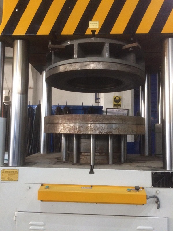
- Press Machine: Provides the force for drawing.
Types of Drawing Dies
- Single Action Die: Punch moves down to draw metal, simple shapes.
- Double Action Die: Blank holder and punch move independently, better control.
- Compound Die: Multiple operations in one stroke (e.g., drawing and piercing).
- Progressive Die: Multiple stations for progressive shaping.
Design Considerations
- Material: Steel or alloy steel for durability.
- Clearance: Space between punch and die edges (depends on sheet thickness).
- Lubrication: Reduces friction, prevents tearing.
- Draw Ratio: Ratio of blank diameter to punch diameter (limits deep drawing depth).
Common Applications
- Automotive body panels
- Kitchen sinks
- Aerospace components
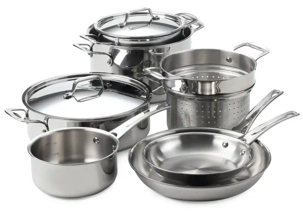
- Appliances and cookware
A sheet metal drawing mold is a specialized tool used to shape flat metal sheets into complex three-dimensional forms by forcing the metal to flow into a die cavity using a punch. The process relies on stretching and bending the metal, which allows the creation of items like cups, boxes, and panels. The tool typically consists of a punch that presses the sheet metal, a die that forms the shape, and a blank holder to control material flow and prevent wrinkling. Designing a drawing mold requires careful consideration of factors like material selection—often tool steels for durability—clearance between punch and die edges to allow proper metal flow without tearing, and lubrication to reduce friction. The effectiveness of the mold is also influenced by the draw ratio, which is the ratio of the blank diameter to the punch diameter, determining how deep the metal can be drawn without failure. This process is widely used in automotive, aerospace, cookware manufacturing, and other industries where precise metal shaping is essential. Proper design and maintenance of the mold ensure high-quality, defect-free products with consistent shapes and dimensions.
The sheet metal drawing process involves placing a flat metal blank over the die opening and then pressing it with the punch. As the punch moves downward, the blank is forced to stretch and conform to the shape of the die cavity. The blank holder applies pressure on the sheet to control how the metal flows into the die, preventing wrinkles or tears by ensuring smooth deformation. The metal undergoes plastic deformation during this process, which means it permanently changes shape without cracking, provided the drawing parameters are within material limits.
Key factors influencing the success of drawing include the type of metal used—commonly low carbon steel, aluminum, or stainless steel—the thickness of the sheet, and the mechanical properties such as ductility and yield strength. Lubrication plays a crucial role by reducing friction between the metal and the mold surfaces, helping to avoid defects like galling or tearing.
When designing a drawing mold, engineers must consider the punch and die geometry carefully. Sharp corners in the die can cause excessive stress concentrations, leading to cracks, so radii are typically added to smooth transitions. The clearance between the punch and die is usually set slightly larger than the sheet thickness, often about 5-10% more, to allow the metal to flow without excessive resistance.
The depth to which a metal sheet can be drawn without failure is limited by the material’s drawing limit and the draw ratio. Exceeding these limits can cause defects like tearing, wrinkling, or excessive thinning. To improve drawability, multi-stage drawing or annealing (heat treatment) may be applied between stages to restore ductility.
The final product’s dimensional accuracy and surface finish depend on precise mold design, process control, and quality of tooling materials. Advanced manufacturing techniques, such as CNC machining and surface treatments, help produce molds with tight tolerances and longer life spans. Maintenance of molds is critical, as wear or damage can degrade product quality and increase scrap rates.
Overall, sheet metal drawing molds enable efficient mass production of complex, lightweight metal parts essential for many industries, balancing cost, precision, and durability.
Sheet metal drawing molds are fundamental in manufacturing processes that require transforming flat metal sheets into three-dimensional shapes. The process, known as deep drawing, involves plastic deformation of the sheet metal, which means the metal is stretched and bent beyond its elastic limit so it permanently takes the shape of the mold. Unlike other forming methods, drawing allows for the creation of parts with a depth greater than their diameter, such as cups, cans, automotive panels, and kitchen sinks.
The drawing mold itself is made up of several components that work in unison to shape the metal accurately and efficiently. The punch, which acts as a male form, presses the sheet metal blank into the die cavity, which acts as the female form. The blank holder applies pressure on the outer edges of the sheet to prevent wrinkling by controlling how the metal flows into the die cavity during deformation. This pressure must be finely balanced — too little, and the metal will wrinkle; too much, and it can tear. Because the sheet metal is forced to stretch and flow, lubrication between the mold and sheet is essential to reduce friction, minimize tool wear, and improve the surface finish of the final product.
Material selection is critical for both the sheet metal being formed and the mold itself. Sheet metals like low-carbon steel, stainless steel, aluminum alloys, and brass are commonly used, chosen based on the desired properties such as strength, ductility, corrosion resistance, and cost. The mold is generally made from hardened tool steels or alloy steels, engineered to resist the repeated stresses and wear of the drawing process. High-quality mold materials ensure durability and dimensional consistency throughout the production lifecycle.
Designing the drawing mold requires a detailed understanding of material behavior, tooling mechanics, and process parameters. The die cavity must be designed with radii and tapers that avoid sharp corners, which could cause stress concentrations leading to cracks or tears in the sheet metal. The clearance between the punch and the die is carefully calculated, typically set slightly larger than the sheet thickness — around 5 to 10 percent larger — to allow the metal to flow smoothly without excessive force or tearing.
Another important consideration is the draw ratio, defined as the ratio of the blank diameter to the punch diameter. This ratio determines how deep a sheet metal part can be drawn in a single operation without failure. Exceeding the ideal draw ratio can cause defects such as cracks, excessive thinning, or wrinkling. To address these limits, complex parts often require multi-stage drawing operations where the part is progressively formed through a series of molds, with intermediate annealing steps to restore ductility lost during deformation.
The quality of the final product depends heavily on the precision of the mold and the control of the drawing process. The molds must be manufactured to tight tolerances using advanced CNC machining and surface finishing techniques to ensure consistent fit between the punch, die, and blank holder. Surface treatments like nitriding or coating can be applied to improve wear resistance and reduce friction further. Regular maintenance and inspection of molds are essential to prevent defects caused by tool wear or damage, which can quickly degrade product quality and increase scrap rates.
In modern manufacturing, sheet metal drawing molds are integral to producing lightweight, high-strength components with complex geometries that would be difficult or impossible to achieve with other forming methods. They enable mass production with high repeatability and cost efficiency, making them indispensable in automotive, aerospace, appliance, and consumer goods industries. Innovations such as computer-aided design (CAD), finite element analysis (FEA) for stress simulation, and automation of forming presses continue to advance the capabilities and efficiency of sheet metal drawing molds, pushing the boundaries of design and manufacturing precision.
Sheet Metal Drawing Mold For Metal Cookware

A sheet metal drawing mold for metal cookware is a specialized forming tool designed specifically to shape flat metal sheets into the characteristic shapes of cookware items like pots, pans, lids, and bowls. The deep drawing process used for cookware production demands careful mold design because cookware parts often have smooth, rounded, and sometimes complex shapes that require precise control of metal flow, thickness distribution, and surface finish.
The drawing mold consists mainly of a punch, a die, and a blank holder. The punch pushes the metal blank into the die cavity, which defines the cookware’s interior shape. The blank holder prevents wrinkling and controls the metal flow during forming. For cookware, where the final product must have uniform thickness for heat distribution and durability, the mold’s geometry and process parameters are critically important.
Materials commonly used for cookware sheets include stainless steel, aluminum, copper, or clad metals (layered metals combining, for example, aluminum and stainless steel), chosen for their thermal conductivity, corrosion resistance, and food safety. The molds themselves are made from hardened steel to endure repeated forming cycles with minimal wear.
The mold design for cookware emphasizes smooth, large-radius curves to prevent tearing or excessive thinning of the metal, which would compromise the cookware’s strength and performance. Clearances between punch and die are finely tuned to maintain metal integrity, and lubrication is applied liberally to protect both the mold and the cookware surface, ensuring a smooth finish without scratches or marks.
Because cookware shapes often require significant depth and precise form, the drawing mold may be part of a multi-stage process where the blank is gradually formed through successive molds to achieve the final shape without defects like wrinkling or cracking. Annealing steps may be introduced between stages to relieve stresses and restore ductility to the metal.
The end goal is to produce cookware with consistent wall thickness, smooth contours, and high-quality surfaces that ensure both functionality (even heating, durability) and aesthetic appeal. Efficient mold design and process control in sheet metal drawing directly affect manufacturing costs, product quality, and lifespan of the molds used in cookware production.
In the production of metal cookware through sheet metal drawing, the mold plays a crucial role in transforming flat metal blanks into finished products with precise shapes and smooth surfaces. Cookware demands exceptional quality because the formed parts must not only have the correct dimensions but also maintain uniform thickness for effective heat conduction and structural integrity. The mold must be designed to accommodate the specific material properties of the metal being used—whether stainless steel, aluminum, copper, or multi-layer composites—which all behave differently during the drawing process due to their unique ductility, hardness, and thickness.
The deep drawing molds for cookware are typically engineered with smooth, gradual contours and large radii to minimize the risk of tearing or excessive thinning, which could weaken the product or cause leaks. Sharp angles or abrupt changes in shape can cause stress concentrations, leading to cracks or deformation during or after forming. By carefully controlling the clearance between the punch and die, manufacturers ensure that the metal flows evenly into the cavity. This precise control over material flow is essential because cookware often requires deep draws with relatively narrow diameters compared to the depth, pushing the limits of what the material can withstand without failure.
Lubrication is a key element in the drawing process. It reduces friction between the mold and the sheet metal, preventing surface defects such as scratches or galling, which would compromise the appearance and functionality of the cookware. Additionally, lubrication helps in prolonging mold life by reducing wear and tear on the tool surfaces, allowing for high-volume production without frequent downtime for maintenance or replacement.
Because cookware often involves complex shapes or deeper forms than standard sheet metal components, production usually involves multi-stage drawing operations. Instead of attempting to form the cookware in a single stroke, the metal blank is gradually shaped over several molds, with each stage refining the part’s shape and controlling the thickness distribution. Between these stages, annealing—a heat treatment process—is sometimes employed to relieve stresses and restore the metal’s ductility, which is reduced by the plastic deformation. This step prevents cracking and allows the metal to be drawn deeper without failure.
The manufacturing efficiency and quality of metal cookware heavily depend on the precision of the drawing molds and the consistency of the forming process. Advances in computer-aided design and simulation technologies allow engineers to model material flow and predict potential defects before mold fabrication, reducing trial-and-error cycles and improving mold performance. Additionally, high-precision CNC machining and surface finishing techniques are used to produce molds with tight tolerances and superior surface quality, ensuring that the cookware parts meet stringent dimensional and aesthetic standards.
Regular inspection and maintenance of the molds are critical because any wear, scratches, or deformation on the mold surfaces can translate directly into defects on the cookware, such as uneven walls, rough textures, or shape inconsistencies. Proactive maintenance schedules help minimize downtime and maintain consistent product quality over long production runs.
Ultimately, the sheet metal drawing mold for cookware must balance durability, precision, and cost-effectiveness to enable the mass production of high-quality metal pots, pans, and other kitchen items. The mold’s design and the controlled drawing process ensure that the cookware meets consumer expectations for performance, durability, and appearance, making it an essential element in modern cookware manufacturing.
Beyond the fundamental design and manufacturing considerations of sheet metal drawing molds for cookware, several advanced aspects come into play to optimize production efficiency and product quality. For instance, the integration of process monitoring technologies such as sensors to track punch force, displacement, and temperature allows real-time adjustments that prevent defects before they occur. This feedback loop is particularly valuable in cookware production, where consistency in wall thickness and surface finish is paramount.
Material innovation also influences mold design. New alloys or composite metal sheets with enhanced strength and formability can allow deeper draws or thinner walls, but they often require molds designed to handle different friction characteristics or stress distributions. This means molds may incorporate specialized surface coatings like titanium nitride or diamond-like carbon to reduce wear and maintain smooth contact with challenging materials.
Another consideration is the mold cooling and heating systems integrated into the tooling. Controlled thermal management can help maintain dimensional stability of the mold during prolonged production runs, reducing thermal expansion that could alter critical clearances. In some cases, heated molds are used to improve metal formability for materials that are difficult to draw cold, such as certain aluminum alloys.
Automation in sheet metal drawing lines is increasingly common in cookware manufacturing to improve throughput and reduce labor costs. Robots may be employed to load blanks, transfer parts between drawing stages, and perform quality inspections. These automated systems demand highly repeatable mold designs with reliable tool life to minimize downtime and maintain steady production rates.
Environmental considerations are also gaining prominence. Using lubricants that are biodegradable or easier to recycle and designing molds that require less frequent maintenance align with sustainability goals. At the same time, efficient material usage during drawing helps reduce scrap, which is critical both economically and environmentally.
Finally, ongoing innovation in simulation software enables increasingly sophisticated finite element analysis (FEA) of the drawing process. Engineers can model not just the metal flow but also potential residual stresses, springback, and the effects of different process parameters. This predictive capability leads to molds that produce better quality cookware with fewer iterations, reducing time-to-market for new designs.
In summary, sheet metal drawing molds for cookware have evolved into complex, precision-engineered tools that balance mechanical design, material science, process control, and automation. Their role extends beyond simple shaping to being key enablers of consistent quality, manufacturing efficiency, and innovation in the competitive cookware industry.
Sheet Metal Drawing Mold For Pans
A sheet metal drawing mold for pans is a specialized tool designed to transform flat metal sheets into the characteristic shallow, wide shapes of frying pans, sauté pans, and similar cookware. Unlike deeper-drawn items such as pots or bowls, pans typically require molds that produce a broad, gently curved bottom with relatively low walls, which presents unique challenges in terms of controlling metal flow and maintaining uniform thickness throughout the part.
The mold consists primarily of a punch, which presses the metal sheet into the die cavity that defines the pan’s shape, and a blank holder that regulates the metal flow to avoid wrinkling and tearing. For pans, the large diameter combined with relatively shallow depth means the sheet metal tends to stretch more laterally, requiring careful balance between blank holder force and punch movement to ensure smooth material distribution.
Material selection is crucial, with aluminum and stainless steel being common choices due to their thermal properties and durability. The molds must be designed with smooth, rounded contours and ample radii at transitions to avoid sharp corners that could cause cracking or thinning. Clearance between the punch and die is finely tuned to allow the sheet metal to flow without excessive resistance while maintaining tight control over wall thickness, which directly impacts pan performance in heat conduction and durability.
In many cases, the forming of pans involves a multi-step drawing or stretching process, sometimes combined with ironing—a process that thins and smooths the walls to achieve the desired thickness and surface finish. The mold design must accommodate these secondary operations, often requiring interchangeable tooling or adjustable components to optimize each stage.
Lubrication plays a vital role in reducing friction between the sheet metal and the mold surfaces, preventing surface defects such as scoring or galling that would affect the pan’s aesthetic and functional quality. The molds are typically constructed from hardened tool steels with surface treatments to improve wear resistance and maintain dimensional accuracy over many production cycles.
Overall, sheet metal drawing molds for pans are engineered to produce high-quality, uniform cookware efficiently and reliably, balancing complex mechanical and material considerations to meet the exacting standards of cookware manufacturing.
The process of using a sheet metal drawing mold to form pans involves carefully controlling the way the metal flows during deformation to avoid common issues such as wrinkling, tearing, or uneven thickness. Because pans usually have wide diameters and relatively shallow walls compared to other cookware, the metal tends to stretch more across the surface area rather than deep into a cavity, which can make it more challenging to maintain uniform thickness and avoid thinning. The blank holder pressure is adjusted to ensure the metal flows smoothly into the die without bunching up or wrinkling, while the punch applies a steady, controlled force to shape the metal.
Material characteristics significantly influence how the metal responds to the drawing process. Aluminum is favored for its excellent heat conduction and light weight, but it is softer and more prone to scratching, requiring molds with very smooth surfaces and effective lubrication to protect both the mold and the workpiece. Stainless steel, on the other hand, is harder and more wear-resistant but demands higher forming forces and more robust tooling. In both cases, the mold’s surface finish and geometry are critical in ensuring the metal flows properly without defects, and the clearances must be precisely engineered—too tight, and the metal can tear; too loose, and the metal may wrinkle or form uneven edges.
Forming pans often involves multiple stages beyond the initial drawing. After the basic shape is drawn, ironing or wall thinning processes may be applied to refine the thickness and surface finish of the pan walls, creating a more consistent and durable final product. This means the drawing mold must work in conjunction with other tooling designed specifically for secondary operations, and the overall process flow must be carefully planned to maintain product quality and production efficiency.
Lubrication is essential throughout these forming operations to reduce friction, prevent surface damage, and extend the life of the molds. The type of lubricant used is selected based on the metal, the drawing speed, and environmental considerations, with some manufacturers opting for water-soluble or biodegradable lubricants to reduce environmental impact. Proper application of lubrication also helps in achieving a high-quality surface finish on the pans, which is important not only for aesthetics but also for cooking performance and ease of cleaning.
The molds themselves are typically made from hardened tool steels with surface treatments or coatings to resist wear and corrosion. Given the high-volume nature of cookware manufacturing, molds are designed for durability and ease of maintenance, with considerations for quick replacement or refurbishment to minimize production downtime. Advances in CNC machining and precision grinding allow molds to be made with very tight tolerances and fine surface finishes, which directly contribute to the quality and consistency of the pans produced.
In addition to mechanical design, modern mold development for pans increasingly incorporates computer simulations to model metal flow, stress distribution, and potential defects before any physical tooling is made. This helps optimize the mold geometry and process parameters, reducing the need for costly trial-and-error and speeding up time to market. The combination of advanced materials, precise tooling, controlled lubrication, and process automation enables manufacturers to produce high-quality pans efficiently, meeting both functional requirements and aesthetic expectations.
Overall, sheet metal drawing molds for pans represent a complex interplay of materials science, mechanical engineering, and manufacturing technology, all aimed at transforming flat metal sheets into durable, high-performance cookware that can withstand daily use while delivering excellent cooking results.
Beyond the core forming process, quality control is a crucial aspect in the production of pans using sheet metal drawing molds. Manufacturers often implement in-line inspection systems to detect defects such as uneven wall thickness, surface imperfections, or dimensional inaccuracies as early as possible. Technologies like laser scanning, ultrasonic thickness measurement, and vision systems are used to ensure each pan meets strict tolerances and aesthetic standards. Any deviation identified can trigger adjustments in the drawing process or remove defective parts before further processing, minimizing waste and maintaining product consistency.
The lifecycle of a sheet metal drawing mold for pans depends on factors like the material being formed, production volume, maintenance practices, and operating conditions. High production runs subject molds to significant wear and stress, so periodic inspection and refurbishment are necessary to keep molds within specification. This may include polishing worn surfaces, repairing damaged areas, or re-machining critical features. Proper mold care not only extends tool life but also maintains the precision needed for producing consistent cookware shapes and finishes.
Advances in materials and coatings for molds have enhanced durability and performance. For example, nitriding and physical vapor deposition (PVD) coatings create harder, more wear-resistant surfaces that reduce friction and resist corrosion, which is especially beneficial when forming abrasive or sticky materials. Such treatments reduce downtime caused by mold wear and improve overall productivity.
In the evolving cookware market, customization and design complexity are increasing, requiring molds that can produce intricate shapes or features such as textured surfaces, decorative patterns, or ergonomic contours. This pushes mold design toward greater sophistication, combining traditional deep drawing with other processes like embossing or beading integrated into the same tooling setup. Manufacturers often balance the cost of developing complex molds with the value added by differentiated products in competitive markets.
Environmental and economic considerations also shape the design and operation of sheet metal drawing molds for pans. Efficient material usage and minimizing scrap contribute to sustainability goals, as does the selection of lubricants and cooling fluids with low environmental impact. Moreover, energy-efficient presses and automation reduce overall production costs and carbon footprint, aligning manufacturing practices with global trends toward greener industry.
Ultimately, the sheet metal drawing mold for pans is more than just a shaping tool—it’s a key component in a sophisticated manufacturing ecosystem that combines precision engineering, material science, process control, and sustainability. Its design and maintenance directly influence the quality, cost, and environmental footprint of the cookware produced, making it a critical factor in the success of modern cookware manufacturing.
In addition to traditional deep drawing molds, the production of pans increasingly incorporates hybrid forming techniques that combine drawing with other metal forming processes such as hydroforming or stretch forming. These methods can help achieve more complex shapes, improved thickness distribution, and better surface quality. For example, hydroforming uses a high-pressure fluid to push the metal blank into the die cavity, allowing more uniform material flow and reducing the risk of thinning or tearing, which is especially beneficial for larger diameter pans with shallow depths.
The integration of computer-aided engineering (CAE) tools has revolutionized mold design and process optimization for pan manufacturing. Finite element analysis (FEA) software can simulate the entire forming process, predicting how the sheet metal will behave under different conditions, where stresses will concentrate, and where defects might occur. This simulation capability allows engineers to tweak mold geometry, adjust blank holder pressures, and optimize lubrication before producing physical molds, significantly reducing development time and cost.
Customization in cookware is growing, with consumers seeking unique designs, improved ergonomics, or specialty features such as non-stick coatings or multi-layered metal construction. This trend demands molds that can handle more intricate forming steps and tighter tolerances. Molds may include features like interchangeable inserts or adjustable components to accommodate different pan sizes or styles within the same production line, enhancing flexibility and reducing tooling costs.
Automation and robotics are increasingly integrated into the forming process, handling tasks such as blank loading, transfer between forming stations, and stacking finished pans. Automated systems require molds to have consistent, reliable performance to minimize downtime and maintain a steady production flow. They also facilitate high-volume manufacturing while maintaining quality standards, which is essential in the highly competitive cookware market.
The economics of sheet metal drawing molds for pans are closely tied to tool life and maintenance. While initial mold design and fabrication represent a significant investment, the ability to produce thousands or even millions of consistent parts efficiently justifies the cost. Manufacturers continuously seek to extend mold life through material selection, surface treatments, and optimized process parameters, balancing upfront costs with long-term productivity.
Sustainability concerns also influence materials and processes. Recycling metal scrap generated during drawing is a standard practice, but efforts to minimize waste through precise blank nesting and process optimization reduce raw material consumption. Additionally, eco-friendly lubricants and energy-efficient forming presses contribute to greener manufacturing footprints.
In summary, the sheet metal drawing mold for pans is at the intersection of traditional metal forming techniques and modern manufacturing innovations. It combines careful mechanical design, material science, process engineering, and automation to produce cookware that meets exacting standards for durability, performance, and aesthetics. As consumer demands evolve and manufacturing technologies advance, these molds will continue to adapt, enabling manufacturers to deliver high-quality pans efficiently while addressing environmental and economic challenges.
A sheet metal drawing mold for pots is a specialized tooling system designed to form flat metal sheets into the deep, cylindrical or slightly tapered shapes characteristic of cooking pots. Unlike pans, pots generally have greater depth relative to their diameter, which means the mold and the drawing process must accommodate more significant metal deformation and control the distribution of stresses to avoid defects such as tearing, wrinkling, or excessive thinning.
The mold typically includes a punch that pushes the metal blank into a die cavity shaped like the interior of the pot. A blank holder or pressure ring applies controlled force on the outer edges of the sheet to regulate metal flow during drawing, preventing wrinkles and ensuring uniform wall thickness. Because pots often have deeper draws, the pressure applied by the blank holder is crucial to manage metal flow smoothly into the die without causing failure.
Materials used for pot manufacturing include stainless steel, aluminum alloys, and sometimes clad metals that combine layers of different metals for optimal thermal and mechanical properties. These materials need to be ductile enough to withstand deep drawing but strong enough to maintain durability during everyday use. The mold’s design considers the mechanical properties of these metals to optimize the forming process.
Designing molds for pots involves carefully engineering punch and die radii to minimize stress concentrations, especially at the corners and bottom edges, where metal is most susceptible to thinning or cracking. Clearances between punch and die are set to accommodate the sheet thickness plus a small allowance to enable smooth flow without excessive force. Since the depth-to-diameter ratio of pots is relatively high, the draw ratio—a key parameter indicating the extent to which the sheet can be drawn without failure—is carefully calculated and often supported by multi-stage drawing processes.
To form pots with greater depths or complex features such as flanged rims or handles, manufacturers use multi-step drawing or redrawing operations. After the initial drawing, the pot may be transferred to subsequent molds that refine its shape or increase its depth. Between these stages, annealing processes may be employed to relieve internal stresses and restore ductility, enabling the metal to withstand further deformation without cracking.
Lubrication between the mold and the metal blank is vital to reduce friction, prevent galling or surface damage, and facilitate smooth metal flow. The selection of lubricants depends on the material being formed, process conditions, and environmental considerations, with many manufacturers moving toward environmentally friendly lubricants.
The molds themselves are made from hardened tool steels with surface treatments to resist wear and corrosion caused by repeated forming cycles and exposure to lubricants. High precision CNC machining and finishing processes are used to create molds with tight tolerances and smooth surfaces, which directly influence the quality of the formed pots.
In addition to the basic forming process, secondary operations such as trimming, flanging, or embossing may be integrated into the tooling or performed in separate stations to finalize pot features. Quality control measures, including thickness measurement and dimensional inspection, ensure that the pots meet specifications for safety, durability, and aesthetics.
Overall, the sheet metal drawing mold for pots is a critical component in cookware manufacturing, enabling the efficient and consistent production of deep, durable, and functional pots. Its design reflects a balance of material science, mechanical engineering, and process optimization, all geared toward meeting the demands of high-volume production while maintaining product quality and reducing waste.
The process of forming pots using sheet metal drawing molds involves carefully balancing the forces applied during the operation to ensure the metal flows uniformly without defects. Because pots require deeper draws compared to pans, the risk of thinning or tearing increases, making the control of blank holder pressure and punch speed critical. Excessive pressure can cause the metal to crack, while insufficient pressure may result in wrinkles or uneven thickness. Therefore, the mold design often incorporates adjustable blank holders or pressure rings to fine-tune the metal flow during production.
Materials commonly used for pots, such as stainless steel or aluminum alloys, have different formability characteristics. Stainless steel, for example, requires higher forming forces but results in stronger, more corrosion-resistant cookware, whereas aluminum is lighter and easier to draw but may need additional surface treatments to improve durability. The mold’s geometry and surface finish are optimized based on the material properties to reduce friction, prevent surface defects, and extend mold life.
Due to the complexity of deep drawing pots, the manufacturing process frequently employs multiple stages. After the initial draw, pots may undergo redrawing or ironing processes to achieve the desired depth, wall thickness, and surface smoothness. Each stage involves different molds tailored to progressively shape the metal without overstraining it. Between forming stages, annealing heat treatments are often used to relieve stresses and restore ductility, preventing cracks and improving overall formability.
Lubrication is vital throughout these processes to minimize friction between the metal and tooling surfaces, enhancing material flow and protecting both the workpiece and mold from damage. The choice of lubricants balances performance, cost, and environmental impact, with many manufacturers adopting biodegradable or water-soluble options to comply with environmental regulations.
The durability and precision of the molds are essential for consistent production quality. Tool steels used for molds are heat-treated and often coated with wear-resistant layers such as titanium nitride to increase hardness and reduce adhesion of metal particles. High-precision machining and polishing create smooth mold surfaces that contribute to superior surface finishes on the final pots and reduce the risk of defects.
Modern manufacturing increasingly relies on computer simulations to predict metal behavior during drawing, enabling engineers to optimize mold design and process parameters before physical production. These simulations help identify potential problem areas such as excessive thinning or stress concentrations, reducing trial-and-error cycles and shortening development time.
Quality assurance in pot manufacturing involves regular inspection of dimensions, wall thickness uniformity, and surface quality. Automated measurement systems may be integrated into production lines to detect defects early and ensure that only parts meeting strict standards proceed to further processing or assembly.
Overall, sheet metal drawing molds for pots represent a sophisticated blend of engineering, materials science, and process control. Their design and use are critical to producing durable, well-formed cookware that meets both functional and aesthetic requirements while optimizing manufacturing efficiency and minimizing waste.
Beyond the core forming steps, ongoing maintenance and process optimization are vital to sustaining high productivity and product quality in pot manufacturing. Molds endure significant stress during deep drawing, and over time, wear, surface scratches, or deformation can lead to defects in the formed pots such as uneven walls, rough finishes, or dimensional inconsistencies. Scheduled inspections and timely refurbishments—such as polishing, regrinding, or recoating—help extend mold life and maintain tight tolerances. Effective maintenance programs also reduce unexpected downtime, which can be costly in high-volume production environments.
Advancements in mold materials and surface technologies continue to improve durability and performance. Newer coatings like diamond-like carbon (DLC) or advanced nitriding treatments enhance wear resistance, reduce friction, and help prevent sticking of metal scraps or lubricants, all of which contribute to smoother forming and longer tool life. These technological improvements support higher production rates and lower tooling costs over the long term.
The integration of automation and robotics in pot manufacturing lines enhances efficiency and consistency. Automated handling systems feed metal blanks into presses, transfer semi-finished parts between forming stages, and manage finished pot stacking or inspection. This reduces manual labor, minimizes human error, and allows for precise control of cycle times. For automation to function reliably, molds must deliver repeatable, defect-free parts with minimal variation, necessitating robust mold design and stringent quality control.
In recent years, environmental and sustainability considerations have influenced mold design and process management. Manufacturers seek to reduce raw material waste by optimizing blank layouts and minimizing scrap during drawing. Use of environmentally friendly lubricants and reduction of energy consumption in presses align with corporate sustainability goals and regulatory requirements. Additionally, efficient forming processes that reduce the number of drawing stages or eliminate unnecessary annealing cycles contribute to greener manufacturing practices.
Customization and product differentiation remain important drivers in cookware manufacturing. Consumers demand a variety of pot shapes, sizes, finishes, and added features such as reinforced rims or integrated measurement markings. Molds are often designed with modular components or interchangeable inserts to accommodate these variations without requiring full retooling, providing flexibility while controlling tooling investment.
Looking ahead, continued advances in simulation software, materials engineering, and manufacturing automation promise to further refine the capabilities of sheet metal drawing molds for pots. These developments will enable faster prototyping, more complex designs, higher precision, and more sustainable production methods, helping manufacturers meet evolving market demands and stay competitive.
In essence, the sheet metal drawing mold for pots is a highly engineered tool that plays a central role in turning raw metal sheets into durable, functional, and aesthetically pleasing cookware. Its design, maintenance, and integration within advanced manufacturing systems ensure the consistent production of high-quality pots while balancing cost, efficiency, and environmental responsibility.
Sheet Metal Drawing Mold For Cooker Top Body
A sheet metal drawing mold for a cooker top body is a specialized tooling system designed to form flat metal sheets into the complex, often curved shapes that make up the main body or surface panel of a cooker or stove. The cooker top body typically includes features like openings for burners, control panels, and vents, requiring the mold to accommodate multiple contours, depressions, and cutouts while maintaining structural integrity and aesthetic quality.
The mold consists mainly of a punch and die set, where the punch presses the sheet metal blank into the die cavity that shapes the cooker top body. Because the cooker top is usually relatively large and may have complex geometry, the mold design focuses on controlling metal flow to avoid common forming defects such as wrinkling, tearing, or uneven thickness distribution. A blank holder or pressure ring is used to apply controlled force on the metal blank’s edges to regulate material movement during drawing.
Material selection is typically stainless steel or coated steel, chosen for corrosion resistance, heat tolerance, and ease of cleaning. These materials require precise mold clearances and smooth surfaces to avoid scratching and ensure good surface finish. The mold’s contours are carefully engineered with generous radii at bends and transitions to reduce stress concentrations that could lead to cracking or distortion.
Because the cooker top body often incorporates features such as recessed burner areas or raised edges, the forming process may involve multi-step drawing, stretching, or secondary operations like trimming, embossing, or flanging. The mold set must be designed to accommodate these sequential forming steps, sometimes including interchangeable inserts or modular components to allow flexibility for different cooker models.
Lubrication is applied during forming to reduce friction, protect the mold surface, and prevent surface defects on the finished part. The molds themselves are made from hardened tool steels with surface treatments to improve wear resistance and durability, essential given the large size and complexity of the forming operation.
Modern sheet metal drawing molds for cooker tops often benefit from computer-aided design and finite element analysis to optimize metal flow, minimize defects, and reduce development time. This allows manufacturers to produce cooker bodies that meet strict tolerances for fit and finish while ensuring structural strength and durability.
In summary, the sheet metal drawing mold for cooker top bodies is a critical manufacturing tool engineered to handle large, complex metal shapes with precision and efficiency. Its design balances material behavior, tooling durability, and production demands to create cooker tops that are both functional and visually appealing.
The forming process for cooker top bodies using sheet metal drawing molds involves carefully managing the flow of metal across a large surface area that often includes multiple levels, curves, and cutouts. Since the cooker top typically integrates areas for burners, control panels, and sometimes ventilation, the mold must ensure the metal deforms evenly without wrinkling or tearing, while maintaining consistent thickness to guarantee structural integrity and durability.
Because of the size and complexity of cooker tops, the molds are often quite large and robust, designed to withstand the high forces required to shape the metal accurately. Blank holders or pressure rings apply precise pressure around the edges of the metal blank to control material flow and prevent defects like buckling or folding, which are common when forming wide or complex shapes. Adjustments to blank holder pressure and punch speed are critical to achieving optimal results.
Materials used in cooker top bodies are usually stainless steel or coated steel sheets, which offer good corrosion resistance, heat tolerance, and aesthetic qualities. These materials require tooling with highly polished surfaces and carefully controlled clearances to avoid scratching and to maintain a smooth finish on the final product. The mold design incorporates rounded corners and generous radii to minimize stress concentrations, helping to prevent cracking during the forming process.
In many cases, forming the cooker top body is not a single-step operation. Multi-stage drawing or combined drawing and stretching processes are used to achieve the required depth, shape complexity, and dimensional accuracy. Secondary operations such as trimming excess metal, adding flanges for assembly, or embossing logos and control markings may be integrated either into the mold or carried out separately downstream.
Lubrication is applied to reduce friction between the metal sheet and the mold surfaces, protecting the mold from wear and ensuring the metal flows smoothly. Selection of lubricants balances effectiveness with environmental considerations, with many manufacturers opting for water-based or biodegradable options.
Given the scale and complexity, molds for cooker top bodies are manufactured from high-grade tool steels with surface hardening or coating treatments to resist wear, corrosion, and adhesive buildup from metal forming. These treatments prolong mold life and help maintain the precision necessary for producing parts that fit together accurately during cooker assembly.
Advances in computer-aided engineering have become integral to the development of sheet metal drawing molds for cooker tops. Finite element analysis and metal flow simulation allow engineers to predict potential problem areas such as thinning, wrinkling, or excessive stresses before mold fabrication, enabling optimization of tool geometry and process parameters to reduce costly trial-and-error and shorten production ramp-up times.
Automation is frequently incorporated in manufacturing lines producing cooker top bodies, with robotic handling for loading blanks, transferring formed parts, and stacking finished components. This level of automation demands molds that produce consistent, repeatable parts to maintain production speed and minimize downtime.
In summary, sheet metal drawing molds for cooker top bodies are engineered tools designed to convert flat metal sheets into large, complex, and precisely shaped components. Their design requires a deep understanding of material behavior, metal forming mechanics, and production requirements to ensure high-quality, durable cooker tops that meet both functional and aesthetic demands while supporting efficient, high-volume manufacturing.
To further ensure the quality and efficiency of cooker top body production, manufacturers implement rigorous process monitoring and quality control systems alongside the sheet metal drawing molds. This includes real-time monitoring of forming forces, punch displacement, and blank holder pressures to detect any deviations that could signal problems such as material inconsistencies or tooling wear. Automated inspection systems, including optical scanners and laser measurement devices, verify dimensions and surface finishes immediately after forming to catch defects early and reduce scrap rates.
The lifecycle management of molds for cooker tops is also a key consideration. Due to the high stresses and repeated cycles these molds undergo, wear and fatigue can gradually degrade their performance. Scheduled maintenance, including polishing, recoating, and repair of worn areas, is essential to maintain dimensional accuracy and surface quality over extended production runs. In some cases, modular mold components allow for the replacement of only the worn sections rather than the entire mold, reducing downtime and tooling costs.
Material developments have also influenced cooker top body forming. Advanced stainless steel alloys with improved ductility and strength allow for thinner gauge materials, reducing weight and material costs without compromising durability. These changes, however, can affect forming behavior and require adjustments in mold design and process parameters to avoid defects. Similarly, coatings applied to finished cooker tops, such as enamel or powder coatings, impose strict requirements on surface finish quality and dimensional tolerances, which the mold and forming process must accommodate.
Environmental considerations are increasingly important in cooker top manufacturing. Efforts to reduce waste include optimizing sheet blank layouts to maximize material utilization and employing recycling strategies for metal scrap. Additionally, more sustainable lubricant choices and energy-efficient forming equipment contribute to greener production methods, aligning with industry trends toward reducing the environmental footprint.
The complexity of cooker top designs continues to evolve, with manufacturers incorporating features like integrated control panels, ventilation slots, and aesthetic patterns that enhance user experience and product differentiation. These features may require specialized mold inserts or additional forming steps, pushing mold design toward greater flexibility and precision.
In the broader manufacturing context, sheet metal drawing molds for cooker top bodies form part of an integrated production system combining advanced tooling, material science, process control, and automation. This system ensures that cooker tops meet exacting standards for fit, finish, strength, and functionality while supporting high-volume, cost-effective manufacturing.
Looking ahead, innovations such as additive manufacturing for mold components, enhanced simulation technologies, and adaptive process controls promise to further improve mold performance, reduce development times, and enable even more complex cooker top geometries. These advancements will help manufacturers stay competitive and responsive to market demands while maintaining high quality and sustainability standards.
In essence, the sheet metal drawing mold for cooker top bodies is a sophisticated engineering solution that transforms raw metal sheets into critical components of modern cookers. Its design and operation reflect a balance of mechanical precision, material expertise, and manufacturing efficiency, all aimed at producing durable, attractive, and functional cooker tops that meet consumer expectations and industrial requirements.
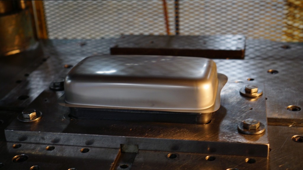
Sheet Metal Drawing Mold For Tray Cover
A sheet metal drawing mold for a tray cover is a precision tool designed to form flat metal sheets into the shallow, often rectangular or oval-shaped covers that fit over trays. These covers are commonly used in food service, medical sterilization, packaging, and industrial applications where a protective lid or barrier is needed.
The mold typically consists of a punch and die pair shaped to create the tray cover’s contours, including any flanges or edges needed for secure fitting. Because tray covers are usually shallow with relatively simple geometry compared to deeper draws like pots or pans, the mold focuses on achieving uniform wall thickness, smooth surface finish, and consistent dimensions to ensure proper fit and function.
Material choices for tray covers often include stainless steel, aluminum, or thin gauge steel sheets, selected for corrosion resistance, strength, and formability. The mold design accounts for the specific properties of the chosen metal, optimizing clearances, radii, and blank holder pressure to minimize defects such as wrinkling, tearing, or excessive thinning.
During the drawing process, the blank metal sheet is clamped and formed over the die cavity by the punch, with a blank holder applying controlled pressure to regulate material flow. Lubrication is applied to reduce friction, protect the mold surfaces, and enhance metal flow, contributing to a clean finish and extended mold life.
For tray covers with added features—such as embossed logos, ventilation holes, or reinforcing ribs—secondary forming operations may be integrated into the mold or performed subsequently. Some molds incorporate interchangeable inserts or modular components to accommodate different tray sizes or cover designs, enhancing manufacturing flexibility.
The mold is manufactured from hardened tool steels, often treated or coated to resist wear and corrosion from repeated forming cycles. High-precision machining and finishing processes ensure tight tolerances and smooth surfaces, critical for producing tray covers that fit securely and look aesthetically pleasing.
In modern manufacturing environments, computer-aided design (CAD) and finite element analysis (FEA) help optimize mold geometry and forming parameters, predicting metal flow and identifying potential issues before tool fabrication. This reduces development time and costs while improving product quality.
Automation is commonly used to load blanks, operate presses, and handle finished covers, requiring molds that consistently produce defect-free parts at high speeds. Quality control measures such as dimensional inspection and surface finish checks ensure that tray covers meet stringent specifications.
Overall, the sheet metal drawing mold for tray covers is an essential tool enabling efficient production of precise, durable, and functional lids or barriers. Its design reflects a balance between material behavior, tooling durability, and production demands to meet the requirements of various industrial and commercial applications.
The process of forming tray covers with sheet metal drawing molds involves carefully controlling the metal flow to produce shallow, uniform shapes with clean edges. Since tray covers typically have minimal depth and simple contours, the risk of common defects like tearing or wrinkling is lower than in deep drawing operations, but maintaining consistent thickness and surface finish remains crucial for proper fit and function. The blank holder applies uniform pressure around the sheet’s perimeter to prevent metal from folding or buckling during the punch’s downward stroke.
Materials used for tray covers, such as stainless steel or aluminum, have differing formability characteristics, which affect mold design. For instance, aluminum’s higher ductility allows for slightly more aggressive drawing without cracking, whereas stainless steel requires careful control of forces and radii to avoid work hardening and fracturing. The mold’s radii are designed with sufficient curvature to minimize stress concentration and facilitate smooth metal flow, which also helps produce a visually appealing finish free of scratches or marks.
Lubrication plays an important role despite the relatively shallow draw. It reduces friction between the metal sheet and mold surfaces, preventing galling and wear, and enabling a smoother metal flow that preserves the integrity of the sheet and the mold. Environmentally friendly lubricants are often preferred in modern manufacturing settings to reduce environmental impact and ease cleanup.
When tray covers incorporate additional features such as embossed branding, ventilation holes, or stacking ridges, the forming process can include secondary stamping or embossing operations, either integrated into the mold or performed in separate stages. Molds may be modular or designed with interchangeable inserts to accommodate multiple product variations without requiring full retooling, improving cost-effectiveness and production flexibility.
Because tray covers are often produced in high volumes, mold durability and maintenance are significant considerations. Hardened tool steels with specialized surface treatments extend tool life and maintain consistent part quality over thousands or millions of cycles. Regular maintenance such as polishing and inspection is necessary to identify and correct wear before it affects production quality.
Advanced CAD and finite element simulations help optimize mold design by predicting material flow and stress distribution, allowing engineers to adjust mold geometry, blank holder pressure, and process parameters before physical tooling is made. This leads to reduced development time and lower risk of costly defects during production.
Automated production lines utilize robotic loading, press operation, and unloading systems that demand high mold consistency to maintain cycle times and minimize downtime. Inline quality control systems verify dimensions and surface quality, ensuring tray covers fit precisely and meet customer specifications.
In summary, sheet metal drawing molds for tray covers are precision tools designed to efficiently transform flat metal sheets into shallow, functional covers with consistent quality. Their design and operation rely on an intricate understanding of material properties, metal forming mechanics, and process control to deliver durable, aesthetically pleasing products suited to a wide range of commercial and industrial uses.
To further enhance the production of tray covers, manufacturers often incorporate design features into the mold that facilitate easy removal of the formed part without damaging it. This may include ejector pins or air blasts integrated into the mold design, which gently push the tray cover off the die after drawing. Since tray covers are often thin and relatively lightweight, careful handling during ejection is important to avoid deformation, scratches, or surface defects that would compromise appearance or fit.
Another key aspect is dimensional control. Tray covers must fit precisely over their corresponding trays to provide effective protection or sealing. This means that molds must be manufactured to very tight tolerances, and the forming process must be consistently repeatable. Factors such as tool wear, lubrication effectiveness, and press force stability are continuously monitored and adjusted to maintain these tolerances throughout production runs.
Customization options are common in tray cover manufacturing. Depending on end-use, tray covers may need to incorporate features like stacking ridges for efficient packaging, vent holes for steam release, or embossed logos for branding. Molds are sometimes designed with modular inserts or adjustable components that allow for these variations without requiring entirely new tooling, providing flexibility to respond to market demands and reduce tooling costs.
Environmental and economic considerations also influence mold design and process planning. Material usage is optimized by precise blank sizing and minimizing scrap, while lubricants and energy-efficient press technologies reduce the environmental footprint. In some industries, such as food service or medical sterilization, compliance with hygiene standards influences material choice and surface finish requirements, impacting mold design and maintenance practices.
In addition to physical tooling, digital tools increasingly support tray cover production. Real-time data collection during forming processes enables predictive maintenance for molds, reducing unexpected downtime. Advanced simulation tools allow rapid prototyping of new designs, shortening the product development cycle and improving the quality of final parts.
Finally, the integration of quality control at multiple points—from incoming raw material inspection to final product verification—ensures that tray covers consistently meet performance and aesthetic standards. Automated vision systems, dimensional scanners, and surface inspectors help identify defects early, minimizing waste and improving customer satisfaction.
Overall, sheet metal drawing molds for tray covers are sophisticated tools that play a crucial role in converting raw metal sheets into precise, durable, and functional components. Their design and use reflect a balance of engineering expertise, material science, and manufacturing efficiency aimed at meeting diverse industrial needs with high quality and reliability.
Sheet Metal Drawing Mold For Plate Warmer Enclosure
A sheet metal drawing mold for a plate warmer enclosure is a specialized tool designed to form flat metal sheets into the protective housing or casing that surrounds and supports a plate warmer appliance. This enclosure typically has a box-like shape with various cutouts, bends, and flanges to accommodate heating elements, controls, ventilation, and mounting points.
The mold consists primarily of a punch and die set engineered to shape the metal sheet into the enclosure’s complex contours, which may include recessed panels, curved edges, and precise openings. Since the enclosure needs to provide structural rigidity and fit closely with internal components, the mold must ensure accurate dimensional control and consistent wall thickness throughout the formed part.
Materials commonly used for plate warmer enclosures include stainless steel, aluminum, or coated steel, chosen for durability, corrosion resistance, heat tolerance, and ease of cleaning. The mold’s design is tailored to these material properties, optimizing clearances, radii, and blank holder pressures to avoid defects like tearing, wrinkling, or excessive thinning during the forming process.
The forming operation often involves multiple stages, including initial deep drawing to create the basic box shape, followed by secondary operations such as trimming, bending, embossing, or adding flanges and tabs for assembly. The mold set may include interchangeable inserts or modular components to adapt to different enclosure sizes or design variations without the need for completely new tooling.
Lubrication is applied to reduce friction between the metal sheet and mold surfaces, facilitating smooth metal flow and prolonging mold life. Modern molds are made from hardened tool steels with surface treatments or coatings that enhance wear resistance and reduce adhesion of metal debris.
Advanced design and simulation tools like CAD and finite element analysis play a crucial role in developing these molds, allowing engineers to predict metal behavior, optimize tool geometry, and refine process parameters before manufacturing. This reduces development time and production costs while ensuring high-quality, defect-free parts.
In high-volume manufacturing, automation integrates mold operation with robotic handling of blanks and finished parts, improving efficiency and consistency. Quality control systems inspect dimensions, surface finish, and structural integrity to ensure enclosures meet stringent standards for safety, fit, and function.
Overall, the sheet metal drawing mold for plate warmer enclosures is a key manufacturing tool that transforms flat metal sheets into precisely shaped, durable housings. Its design balances mechanical precision, material behavior, and production efficiency to deliver enclosures that protect and enhance the performance of plate warmer appliances.
The process of forming plate warmer enclosures with sheet metal drawing molds involves managing the complex deformation of metal sheets into sturdy, accurately shaped housings that must accommodate internal components while providing a durable exterior. Because these enclosures often feature a combination of deep draws, bends, and cutouts, the mold must be carefully engineered to control metal flow and prevent common defects such as wrinkling, cracking, or uneven thickness distribution.
Materials like stainless steel or aluminum are frequently chosen for their corrosion resistance and thermal properties, but their differing ductility and strength characteristics influence mold design. For example, stainless steel requires carefully controlled radii and blank holder pressure to avoid work hardening and cracking, while aluminum’s higher formability allows for somewhat more aggressive shaping but demands attention to springback and surface finish. Mold clearances and surface finishes are optimized to prevent scratches or galling, preserving the aesthetic quality required for consumer appliances.
Because plate warmer enclosures often incorporate features such as ventilation slots, mounting flanges, or embossed logos, the forming process typically involves multiple stages. Initial deep drawing creates the basic box or shell shape, followed by trimming to remove excess material and secondary operations such as bending flanges or punching holes. The mold design may include interchangeable inserts or modular tooling components to accommodate different enclosure models or design updates without full retooling, enhancing manufacturing flexibility.
Lubrication is critical throughout the forming stages to reduce friction, protect tooling surfaces, and ensure smooth material flow. Selection of suitable lubricants balances effectiveness with environmental and safety considerations, often favoring water-based or biodegradable options in modern manufacturing.
Given the stresses involved, molds for plate warmer enclosures are fabricated from hardened tool steels and treated with surface coatings to resist wear and corrosion. Regular maintenance, including polishing and inspection, is essential to maintain dimensional accuracy and prevent defects from tooling degradation, which can lead to increased scrap rates or assembly issues.
The use of CAD and finite element analysis enables detailed simulation of metal behavior under forming stresses, allowing engineers to optimize tool geometry and process parameters before physical tooling is made. This approach reduces costly trial runs and accelerates time-to-market for new enclosure designs.
Automation plays an increasingly important role in enclosure production. Robotic systems handle loading of metal blanks, operation of presses, and removal and stacking of finished parts, demanding high consistency from molds to maintain cycle times and minimize downtime. Integrated quality control technologies, such as laser scanners and vision systems, verify that each enclosure meets strict dimensional and surface quality standards, ensuring reliable fit and finish in final assemblies.
Environmental and economic factors also shape mold design and production planning. Material utilization is maximized through careful blank layout and process optimization, while energy-efficient press technologies and environmentally responsible lubricants contribute to sustainable manufacturing practices.
In summary, sheet metal drawing molds for plate warmer enclosures are highly engineered tools that enable the transformation of flat metal sheets into precise, functional housings. Their design reflects a thorough understanding of material properties, metal forming mechanics, and production demands, ensuring that the final enclosures provide durability, aesthetics, and functionality required by modern plate warmer appliances.
Beyond the core forming process, considerations for the integration of plate warmer enclosures into the final product influence mold and tooling design. For instance, the enclosure often needs to accommodate internal wiring, heating elements, control panels, and mounting brackets, which means the mold must produce precise features such as tabs, slots, and embossed areas to facilitate assembly and secure component placement. These features require accurate and repeatable forming to ensure seamless integration without the need for costly secondary machining or manual adjustments.
Thermal management is another critical factor. Ventilation openings or louvers are frequently incorporated into the enclosure design to allow heat dissipation while protecting internal components. The mold must be capable of forming these features with clean edges and consistent dimensions, maintaining both the structural integrity and aesthetic appeal of the enclosure. Sometimes, forming such delicate details requires secondary stamping operations or specialized tooling inserts.
The cosmetic finish of the enclosure also impacts mold design. Since plate warmers are consumer-facing products, the surface quality of the drawn metal must be high, free from defects such as scratches, dents, or surface inconsistencies. Mold surfaces are highly polished and maintained to preserve finish quality, and forming parameters are optimized to minimize metal abrasion or marking. In some cases, the enclosure may be coated or painted after forming, imposing further requirements on surface smoothness and dimensional consistency to ensure proper adhesion and appearance.
Manufacturers also focus on minimizing cycle times and maximizing throughput while maintaining quality. This involves balancing forming speed, blank holder pressure, and lubrication to reduce forming forces and wear on tooling without compromising part quality. Quick-change mold features or modular tooling components may be incorporated to support multiple enclosure designs or fast maintenance during production.
Sustainability initiatives increasingly influence material choices and manufacturing processes. Lightweight metals that maintain strength reduce shipping costs and environmental impact, while recycling of scrap metal and efficient use of lubricants contribute to greener production. In this context, molds are designed not only for performance but also for longevity, reducing the frequency of replacements and associated resource consumption.
Quality assurance extends beyond dimensional checks to include structural testing, such as verifying that the enclosure withstands thermal expansion and contraction, vibration, and mechanical shocks encountered during use. The mold must produce parts that consistently meet these functional criteria, underscoring the importance of precision engineering and robust process controls.
Finally, collaboration between design engineers, material scientists, and tooling specialists is essential throughout the development of sheet metal drawing molds for plate warmer enclosures. This multidisciplinary approach ensures that enclosure designs are manufacturable, cost-effective, and meet both regulatory standards and consumer expectations.
In essence, the sheet metal drawing mold for plate warmer enclosures is a sophisticated, highly optimized tool that plays a pivotal role in converting raw metal into a vital component of modern heating appliances. Its success depends on a deep understanding of forming science, material behavior, production efficiency, and end-use requirements, culminating in a product that is durable, attractive, and functional.
Sheet Metal Drawing Mold For Food Processor Housing
A sheet metal drawing mold for a food processor housing is a precision tool designed to form flat metal sheets into the complex outer casing that protects and encloses the internal components of a food processor. This housing must combine structural strength, aesthetic appeal, and functional features such as mounting points, ventilation slots, and openings for controls and electrical connections.
The mold typically consists of a punch and die set shaped to create the detailed contours and profiles of the housing, including curved surfaces, flanges, and precise cutouts. Because food processor housings often involve complex geometry and require tight tolerances for assembly, the mold must ensure uniform material flow, consistent wall thickness, and minimal distortion to produce high-quality parts that fit perfectly with internal components and other housing elements.
Common materials for food processor housings include stainless steel, aluminum, or coated steel, selected for their durability, corrosion resistance, and ease of cleaning. The mold’s design takes into account the forming characteristics of these metals, optimizing clearances, radii, and blank holder pressures to prevent defects such as wrinkling, tearing, or excessive thinning during forming.
Forming the housing usually involves multiple stages, starting with deep drawing to create the basic shape, followed by trimming, bending, embossing, and punching operations to add functional features like ventilation slots, control panel openings, and mounting tabs. Modular tooling components or interchangeable inserts can be incorporated into the mold to accommodate different housing models or design changes, enhancing manufacturing flexibility.
Lubrication is applied throughout the forming process to reduce friction, protect tooling surfaces, and facilitate smooth metal flow. Modern manufacturing emphasizes environmentally friendly lubricants that are effective yet easy to clean and dispose of safely.
The molds are manufactured from hardened tool steels with surface treatments to resist wear, corrosion, and galling from repeated forming cycles. Regular maintenance and inspection ensure continued precision and quality throughout production runs.
Advanced computer-aided design (CAD) and finite element analysis (FEA) are used extensively during mold development to simulate metal flow and stress distribution, optimize tooling geometry, and refine process parameters before physical tool fabrication. This reduces development time, lowers costs, and minimizes production defects.
In high-volume manufacturing environments, automation integrates the operation of sheet metal drawing molds with robotic loading, press control, and part handling systems to increase efficiency and maintain consistent quality. Inline inspection systems monitor dimensional accuracy and surface finish, ensuring food processor housings meet stringent quality standards and regulatory requirements.
Overall, the sheet metal drawing mold for food processor housing is a sophisticated engineering tool that transforms flat metal sheets into durable, functional, and aesthetically pleasing enclosures. Its design reflects a balance of material science, metal forming expertise, and manufacturing efficiency to meet the demands of modern appliance production.
The manufacturing process for food processor housings using sheet metal drawing molds involves precise control of metal deformation to achieve complex shapes with consistent wall thickness and surface finish. Because the housing must protect sensitive internal components while providing an attractive exterior, the mold design carefully manages material flow to avoid defects such as wrinkling, tearing, or uneven thickness that could compromise strength or appearance.
Materials like stainless steel and aluminum have distinct forming characteristics that influence mold parameters. Stainless steel, for instance, requires tighter radii and carefully controlled blank holder pressures to prevent cracking due to its lower ductility, whereas aluminum allows more aggressive drawing but demands compensation for springback to maintain dimensional accuracy. The mold’s punch and die surfaces are polished and coated to minimize friction and prevent surface damage during forming.
The complexity of food processor housings often means that multiple forming stages are necessary. Initial deep drawing creates the main body shape, followed by trimming to remove excess material and secondary operations such as bending flanges, punching holes for vents and controls, and embossing logos or patterns. The modularity of tooling components enables quick adjustments for different housing variants, reducing setup time and tooling costs.
Lubrication plays a crucial role throughout these stages, reducing friction, preventing galling, and extending tool life. Environmentally friendly lubricants are favored to meet modern sustainability goals and ease cleaning procedures, particularly important for appliances used in food preparation.
Durability of the molds is critical in high-volume production. Tool steels with heat treatment and surface coatings resist wear and corrosion, maintaining precision over long runs. Scheduled maintenance and monitoring help identify wear patterns before they affect part quality, minimizing downtime and scrap rates.
Modern design workflows integrate computer simulations to model metal behavior and optimize forming processes. These tools predict potential issues like thinning or wrinkling, allowing engineers to refine tool geometry and process parameters in advance. This simulation-driven approach accelerates development and enhances first-article quality.
Automation further improves production efficiency, with robotic systems managing blank loading, press operation, and part unloading. Inline inspection technologies verify dimensional accuracy and surface integrity, ensuring that housings meet tight tolerances and cosmetic standards consistently.
The housing’s design also accommodates assembly needs, incorporating tabs, slots, and mounting points formed precisely during the drawing process. This reduces reliance on secondary machining or manual assembly adjustments, lowering manufacturing costs and improving reliability.
Sustainability considerations influence material selection and process optimization, aiming to minimize waste and energy consumption. Efficient blank nesting reduces scrap, while energy-efficient presses and eco-friendly lubricants contribute to greener manufacturing.
In essence, the sheet metal drawing mold for food processor housing is a highly engineered tool that plays a vital role in transforming flat metal sheets into functional, durable, and visually appealing appliance components. Its design balances material properties, forming mechanics, and production demands to deliver consistent quality in a competitive manufacturing environment.
Beyond the core forming and finishing processes, additional factors influence the design and use of sheet metal drawing molds for food processor housings. One key consideration is the integration of features that support ease of assembly and maintenance. The mold must produce precise flanges, tabs, and mounting points that align accurately with internal components such as motors, switches, and electronic controls. This ensures quick and reliable assembly on production lines and allows for easier repair or replacement of parts.
Ventilation is another important aspect, as food processor housings need to dissipate heat generated by the motor and electronics during operation. The mold is often designed to form clean, well-defined ventilation slots or perforations that balance airflow requirements with structural integrity and aesthetic appeal. Sometimes, these features require secondary operations, such as punching or laser cutting, but increasingly, complex ventilation patterns are integrated into the initial forming mold design to reduce process steps.
Surface finish quality is critical in consumer appliances, where the housing is visible and contributes to the product’s perceived quality. Mold surfaces are carefully polished and treated to prevent marks or scratches on the metal during drawing. After forming, additional finishing processes such as deburring, polishing, painting, or powder coating may be applied, with the mold ensuring dimensional consistency to support these downstream treatments.
In high-volume production environments, mold changeover speed and flexibility are essential. Modular mold designs with interchangeable components enable rapid adaptation to different housing styles or updated designs without extensive downtime or retooling costs. This flexibility supports product variety and customization in competitive markets.
Tool life and maintenance are continuously monitored to ensure consistent part quality. Predictive maintenance techniques, sometimes enabled by sensors and real-time data analytics, help identify wear or degradation in mold components before they affect production. Scheduled refurbishments, polishing, or part replacements keep the mold in optimal condition, minimizing scrap and reducing downtime.
Automation and process integration extend beyond forming to include part handling, inspection, and assembly preparation. Robotic systems can transfer formed housings directly to inspection stations, where laser scanners or vision systems verify critical dimensions and surface quality. This immediate feedback loop allows rapid correction of process variations, enhancing overall manufacturing efficiency.
Sustainability considerations continue to influence mold design and production methods. Material efficiency, including optimized blank layouts and minimal scrap, reduces waste. Energy-efficient presses and environmentally conscious lubricant choices support sustainable operations. Some manufacturers also explore recyclable or biodegradable materials for housings, which can affect forming process parameters and mold requirements.
Finally, regulatory and safety standards for electrical appliances shape mold design and production controls. The housing must meet specifications for electrical insulation, heat resistance, mechanical strength, and user safety. The mold must reliably produce parts that conform to these standards, which often require precise dimensions and consistent quality.
In summary, sheet metal drawing molds for food processor housings represent an intersection of precision engineering, material science, and manufacturing technology. They transform flat metal sheets into highly functional, durable, and attractive enclosures that protect and support complex internal components while meeting demanding production and regulatory requirements. The success of these molds depends on detailed design, rigorous process control, and integration with advanced manufacturing systems to deliver consistent quality and efficiency.
Sheet Metal Drawing Mold For Fryer Tray
A sheet metal drawing mold for a fryer tray is a specialized tool designed to form flat metal sheets into the shallow, sturdy trays used in commercial or household deep fryers. These trays must withstand high temperatures, resist corrosion, and provide a safe and efficient surface for frying food items.
The mold typically consists of a punch and die set engineered to shape the metal sheet into the tray’s precise dimensions, including a flat or slightly contoured base and raised edges or lips to contain oil and food. The drawing process must maintain uniform wall thickness to ensure durability and prevent weak spots that could warp or fail under heat.
Materials such as stainless steel or aluminized steel are commonly used for fryer trays due to their corrosion resistance and heat tolerance. The mold design accommodates the forming characteristics of these metals, optimizing blank holder pressure, radii, and clearances to prevent defects like wrinkling, cracking, or excessive thinning during forming.
Since fryer trays are typically shallow, the drawing operation is often less deep than other sheet metal forming processes, which reduces the risk of common defects and allows for faster production cycles. However, precise control of metal flow remains essential to achieve clean edges and consistent dimensions, particularly for trays that must fit securely within fryer units.
Secondary operations may be integrated or performed after drawing, including trimming excess material, bending or flanging edges for rigidity and handling, and adding perforations or slots for oil drainage and ventilation. Modular tooling components allow for flexibility in tray sizes or features without requiring complete retooling.
Lubrication reduces friction between the metal and mold surfaces, facilitating smooth forming and prolonging tool life. Mold surfaces are polished and coated to prevent metal adhesion and wear, ensuring consistent quality over long production runs.
Advanced CAD and simulation tools assist in optimizing mold design by predicting metal behavior, minimizing trial-and-error during development, and improving first-pass success rates. Automation often integrates with the forming process to enhance efficiency, employing robotic loading, press operation, and part handling.
Quality control measures verify dimensional accuracy, surface finish, and structural integrity to ensure fryer trays meet safety and functional standards. Environmental considerations, such as minimizing scrap and using energy-efficient equipment, are increasingly incorporated into production planning.
Overall, the sheet metal drawing mold for fryer trays is a carefully engineered tool that transforms flat metal sheets into durable, heat-resistant components critical for food frying applications. Its design balances material properties, forming mechanics, and production requirements to deliver consistent, high-quality trays suitable for commercial and domestic use.
The manufacturing process for fryer trays using sheet metal drawing molds focuses heavily on achieving precise, repeatable shapes that meet stringent requirements for heat resistance and durability. Because fryer trays often operate under harsh conditions with frequent exposure to hot oil and thermal cycling, the mold must produce parts with consistent wall thickness and smooth surfaces to prevent hotspots, warping, or corrosion over time.
Material selection influences many aspects of the mold design. Stainless steel, favored for its corrosion resistance and strength, requires careful control of blank holder pressure and drawing speed to avoid cracking or wrinkling during forming. Aluminized steel, with its protective coating, demands mold surfaces that prevent scratching or damage to the coating layer, preserving its protective qualities.
Although fryer trays are typically shallow, the mold must ensure that edges are properly formed with flanges or rolled lips to add rigidity and facilitate safe handling. These features also help the tray fit securely within fryer assemblies, preventing oil leaks and improving user safety. The mold’s punch and die components are designed to produce clean, burr-free edges to reduce the need for extensive secondary finishing.
Perforations or drainage holes are sometimes incorporated into fryer trays to allow oil to drain away from food, enhancing cooking quality. These may be formed during the initial drawing process or in a secondary punching operation, depending on the complexity and precision required. The mold system may include modular inserts or tooling stations to accommodate these additional features without sacrificing production speed.
Lubrication and surface treatment of mold components are critical to maintaining smooth metal flow and reducing wear. Proper lubrication minimizes friction, helps achieve better surface finishes on the tray, and extends the mold’s operational life, reducing downtime and maintenance costs.
In high-volume production, automation plays a significant role. Robotic systems handle blank feeding, press operation, and part removal, ensuring consistent cycle times and reducing human error. Integrated inspection systems monitor each tray for dimensional accuracy, surface quality, and defect detection, allowing quick correction of process deviations.
Sustainability efforts influence the design and operation of fryer tray molds as well. Material utilization is optimized through efficient blank nesting, and scrap metal is often recycled to minimize waste. Energy-efficient presses and environmentally friendly lubricants contribute to greener manufacturing practices.
Mold maintenance schedules are carefully planned to maintain dimensional precision and surface quality. Polishing, component replacement, and alignment checks prevent quality degradation over long production runs.
The end result of this comprehensive approach is a fryer tray that combines durability, safety, and functionality, produced efficiently and consistently to meet both commercial and consumer demands. The sheet metal drawing mold thus serves as a critical tool in the manufacturing process, balancing engineering precision, material science, and production efficiency to deliver reliable, high-quality fryer trays.
The continued performance of a fryer tray drawing mold depends not only on its initial design but also on the operational parameters and maintenance practices upheld throughout its service life. Forming operations subject the mold to repeated mechanical stresses, heat buildup from friction, and wear on critical surfaces—particularly in high-output environments where hundreds or thousands of trays are produced daily. As a result, tool steels used in mold construction must offer a balanced combination of hardness, toughness, and thermal stability. Commonly, these materials are treated with nitriding or PVD coatings to reduce surface friction, resist galling, and prolong tool life.
As manufacturing demand increases, manufacturers often adopt progressive die systems or tandem press setups that allow multiple forming and cutting actions to be performed in sequence. In this scenario, a flat metal blank is gradually transformed as it moves through a series of stations, each adding shape, edge features, or openings. For fryer trays, this might include forming the central depression, flanging the edges, punching ventilation or drainage holes, and trimming any excess material—each step completed in perfect synchronization. The benefit is high throughput with minimal handling, which not only reduces labor costs but also lowers the chance of introducing defects through manual processes.
Aesthetic requirements are also increasingly important, especially for fryer trays used in high-end kitchen appliances or open commercial kitchens where equipment is visible to customers. This adds another dimension to mold engineering—surfaces must be free of stretch marks, blemishes, and tool lines. Polishing of the mold’s forming surfaces to mirror finish, along with controlled drawing speed and optimized lubrication, contributes to achieving a clean and uniform surface on the final product. When required, post-forming surface treatments like passivation or electropolishing are used to enhance the tray’s appearance and resistance to food acids or detergents.
Dimensional control remains a top priority. Any deviation in tray depth, curvature, or edge flatness can affect the fit into fryer baskets or affect oil flow during use. Modern sheet metal molds are often paired with inline laser measurement or camera vision systems that check critical parameters on every formed tray. This real-time feedback loop allows adjustments to be made on the fly, minimizing scrap and ensuring uniform product quality across batches.
In flexible production environments where fryer trays of different sizes or configurations are needed, quick-change tooling systems allow rapid swapping of punches, dies, and inserts. These systems reduce downtime between product runs and enhance responsiveness to customer demands. Simulation software is often used before physical production to validate new tray designs and verify that existing molds can accommodate the changes without causing material failure or tooling damage.
Environmental and regulatory factors also come into play. Food-contact metal components must meet hygiene standards such as FDA or EU regulations for food safety, meaning molds must ensure parts are free from contaminants, burrs, and difficult-to-clean crevices. Processes must also be designed to be reproducible and traceable, often requiring documentation of mold use, cleaning procedures, and inspection results for compliance audits.
Ultimately, the sheet metal drawing mold for fryer trays is a product of multiple disciplines converging—mechanical design, metallurgy, process control, and increasingly, digital integration. It is not just a static forming tool but a dynamic system embedded in a broader manufacturing ecosystem. When correctly designed and maintained, it enables the efficient, precise, and repeatable production of fryer trays that perform reliably, meet safety standards, and align with consumer expectations in terms of both function and form.
Sheet Metal Drawing Mold For Dishwasher Inner Panel
A sheet metal drawing mold for a dishwasher inner panel is a complex and high-precision forming tool used to produce the large, contoured, and feature-rich metal component that lines the interior of a dishwasher. This panel forms the structural and functional backbone of the appliance’s wash chamber, so it must be dimensionally accurate, resistant to corrosion and water damage, and able to integrate seamlessly with internal features like spray arms, racks, water inlets, filters, and insulation layers.
The mold must be engineered to handle deep-drawing operations, as the inner panel typically involves significant depth with varied contours to optimize water flow and accommodate components. The material most commonly used is stainless steel due to its high resistance to heat, moisture, and aggressive cleaning agents. The forming process needs to control material flow precisely to avoid thinning, wrinkling, or tearing—especially around complex geometries such as corner radii, vent holes, and mounting flanges.
Because the inner panel is a large component, the drawing mold itself is substantial in size and requires a high-tonnage press to provide the force necessary for deep drawing while maintaining consistent pressure over a wide surface. A carefully designed blank holder system is essential to manage metal flow during forming, especially in areas that feature deep recesses or sharp transitions. Lubrication is critical to reduce friction, improve surface finish, and prevent galling, particularly when forming stainless steel. Specialized lubricants that are easily removable or food-safe are often used, as residual traces must not compromise hygiene or appearance.
The mold is typically built from tool steels with advanced heat treatments and coatings to withstand the high pressures and repetitive cycles. Because of the large surface area of the inner panel, mold surfaces are precision machined and polished to a mirror-like finish to ensure a high-quality appearance, which is essential for consumer products.
Post-forming operations are often integrated into the mold or immediately follow the drawing stage. These may include punching holes for fasteners and sensors, trimming excess material, embossing stiffeners or drain paths, and forming localized features such as brackets, channels, or slots. In some cases, a progressive die setup is used, with multiple stations performing sequential operations to reduce handling and improve throughput.
Due to the complexity and large size of the part, finite element analysis (FEA) is typically employed in the design phase to simulate material flow, detect potential issues such as wrinkling or excessive thinning, and optimize draw depth, punch geometry, and blank shape. Simulation tools help reduce prototyping costs and shorten development timelines while increasing first-time quality.
Automation is extensively used in dishwasher panel production. Robotic systems handle the loading and unloading of blanks and finished parts, and automated inspection systems ensure dimensional accuracy and detect any surface defects such as scratches, dents, or irregularities. Any inconsistencies in panel shape can impact how internal components align or seal, making quality control a critical aspect of the process.
As dishwasher models evolve to include new features such as advanced filtration, quieter operation, and improved insulation, the inner panel design becomes increasingly intricate. The mold must accommodate these changes without sacrificing productivity. Modular mold components or insert systems allow quick reconfiguration of tooling to support different models or updates, maximizing flexibility and return on tooling investment.
Sustainability also influences design and manufacturing practices. Efficient material usage through optimized blank design, recycling of scrap material, use of energy-efficient forming presses, and water-based lubricants all contribute to greener production processes. Some manufacturers are exploring thinner or lightweight materials without compromising structural performance, which places even greater demands on mold accuracy and process control.
In conclusion, the sheet metal drawing mold for a dishwasher inner panel is an advanced tooling system at the core of modern appliance manufacturing. It must combine strength, precision, and adaptability to produce a large, complex, and highly functional part that meets the demands of performance, safety, hygiene, and aesthetics in a competitive consumer market.
The ongoing use of a sheet metal drawing mold for a dishwasher inner panel involves not just the initial engineering but a sustained process of optimization, refinement, and maintenance to ensure the highest quality output over extended production cycles. Because the inner panel is one of the most structurally important and visible components in a dishwasher, any imperfection in shape, surface finish, or dimensional accuracy can have consequences across the final assembly, affecting everything from water flow and spray coverage to noise levels and sealing performance. As such, the mold must consistently produce panels that meet extremely tight tolerances in both form and finish. The forming process must manage the distribution of material from the flat blank into the three-dimensional shape without causing variations in thickness that could lead to weak spots or affect part rigidity. The areas where features such as pump housings, spray arms, or rack guides interface are especially critical, often involving localized forming that requires exact control of draw depth and radii. These areas must retain structural integrity while supporting proper mechanical attachment and alignment of internal components.
Due to the repetitive high-pressure cycles the mold is subjected to, wear patterns inevitably develop over time, especially in high-friction or high-deformation zones. To prevent dimensional drift or surface defects, molds are routinely inspected using coordinate measuring machines and 3D scanning technologies to detect changes early. Worn inserts can be replaced or re-machined as part of a scheduled maintenance program, and polishing of worn draw surfaces is done to maintain the mirror finish necessary for a premium stainless steel appearance. This high cosmetic standard is essential not only because it is visible to the user when the dishwasher is open but also because a smooth, clean surface prevents buildup of food residues and improves wash efficiency. Additionally, the mold design must consider ease of cleaning and draining in production, as any contamination during forming could result in reject parts or hygiene risks in the final product.
Automation is tightly integrated with the mold’s operation. Blank handling systems feed pre-cut stainless steel sheets into the press with precise alignment to avoid misfeeds or tool collisions. Sensors monitor key parameters such as press force, stroke position, and forming temperature to ensure process stability. Any deviation from baseline values triggers immediate alerts or shutdowns to prevent damage to the mold or the production of defective parts. Downstream of the forming station, robotic arms may transfer the drawn panels to additional stations for trimming, hole punching, and edge forming, after which automatic quality inspection ensures that the part meets all geometric and visual specifications. These systems allow high-speed production with minimal manual intervention, which is essential for maintaining consistent throughput in a mass production environment.
Design changes are inevitable over the product lifecycle, often driven by market trends, cost-saving initiatives, or performance enhancements. To accommodate this, many mold systems are built with modular elements or changeable inserts that can be quickly swapped to form slightly different geometries without rebuilding the entire mold. This flexibility reduces lead time for design updates and allows the same press line to be used for multiple models or brands. Advanced simulation software is used prior to any physical changes to confirm that the new configuration will perform correctly and that the metal will behave predictably during the draw. This minimizes development costs and accelerates time to market for new variants.
As regulatory and environmental pressures increase, manufacturers are being asked to reduce material usage and energy consumption while maintaining or improving part quality. For dishwasher inner panels, this may involve using thinner stainless steel while reinforcing critical zones through smart geometry rather than material thickness. The mold must then be capable of supporting more complex shapes and tighter tolerances, increasing the need for high-precision machining and tooling stability. Presses equipped with servo control and energy recovery systems are used to improve energy efficiency and forming precision.
In the end, the sheet metal drawing mold for a dishwasher inner panel serves as a central enabler of advanced appliance manufacturing. It must balance structural complexity, high cosmetic standards, dimensional precision, long tool life, and the need for flexible, high-speed production. Every aspect of its design, from material choice to surface treatment and automation compatibility, reflects the convergence of mechanical engineering, materials science, and modern manufacturing technologies working in concert to produce a single component that defines both the performance and quality perception of the final dishwasher unit.
As the production volume increases and dishwasher designs become more diversified to meet different market segments—from economy models to premium units with advanced features—the demands placed on the drawing mold for the inner panel grow significantly. Manufacturers often operate multiple mold sets or interchangeable tooling systems to keep up with this diversity, requiring a careful balance between customization and standardization. While core features of the inner panel may remain the same across product lines, such as drain paths or central sump areas, aesthetic elements like embossing patterns, rack guides, and mounting tabs might vary. The mold must accommodate these changes with high repeatability while maintaining compatibility with shared manufacturing infrastructure.
The life cycle of such a mold is designed to be long-term, often expected to produce several hundred thousand to over a million units with minimal degradation in quality. This necessitates the use of premium-grade tool steels like H13 or DC53, which offer high wear resistance, toughness, and thermal stability. In addition to heat treatment, many molds are coated with titanium nitride or chromium-based layers to further resist abrasion and galling, especially important when working with stainless steel sheets that can be abrasive during forming. The punch and die surfaces are often finished to sub-micron roughness levels to minimize friction and ensure a glossy, high-quality surface on the drawn panel.
Throughout the mold’s operational life, continuous improvement practices are employed. Manufacturers collect performance data during production—such as forming force profiles, cycle times, defect rates, and material yield—to identify opportunities for optimization. If certain zones in the panel show signs of uneven wall thickness or distortion, mold inserts can be subtly reshaped or pressure profiles adjusted to correct the issue. These improvements are implemented during scheduled maintenance windows to avoid unscheduled downtime and ensure a stable production rhythm.
Noise reduction has become another key performance requirement in dishwashers, and the inner panel plays a direct role in achieving this. The panel’s geometry must not only support insulation and sound-dampening materials but also avoid resonance or vibration during operation. Mold design incorporates features such as strategically placed ribs, dome shapes, or textured areas that help diffuse vibrations and stiffen the structure without increasing material thickness. These geometries must be formed precisely to maintain effectiveness, making the mold’s fidelity and consistency critical.
In premium models, stainless steel panels may be treated with additional coatings or finishes, such as anti-fingerprint or matte textures. The mold surface itself may include micro-textures to create these finishes directly during the forming process, eliminating the need for post-processing. This adds complexity to the mold design and surface preparation, requiring the use of advanced micro-machining techniques such as laser texturing or high-speed CNC milling with ultra-fine tools.
Even logistics and downstream integration are influenced by mold performance. Since the inner panel often serves as a mounting platform for multiple internal assemblies—such as wiring harnesses, insulation panels, spray arms, or control sensors—the dimensional integrity of the formed part affects the fit and function of these components. Any warpage, misalignment, or variation in mounting hole locations can cascade into problems during assembly or final testing. Therefore, mold precision contributes directly to assembly efficiency, product reliability, and warranty performance.
Finally, the role of digital technologies such as digital twins and real-time monitoring is expanding. Some manufacturers now create a digital replica of the mold and forming process that is continuously updated with sensor data from the actual press line. This allows engineers to simulate wear, predict failure points, and plan maintenance before problems occur. Smart molds embedded with strain gauges, thermal sensors, and pressure transducers provide a live view of performance, enabling predictive maintenance and better quality assurance. This digitization not only improves part consistency but also reduces cost through better uptime and tool longevity.
The drawing mold for a dishwasher inner panel represents a convergence of engineering precision, material science, and digital manufacturing. It must be robust enough for mass production, flexible enough for design updates, and refined enough to produce parts that meet the highest expectations for performance, cleanliness, and aesthetics. As appliances evolve to become quieter, more energy-efficient, and user-friendly, the mold remains a foundational tool that enables these advances—quietly but critically shaping the backbone of every dishwasher produced.
Sheet Metal Drawing Mold For Oven Chamber
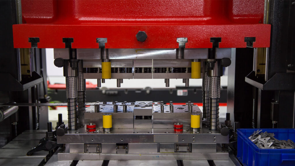
A sheet metal drawing mold for an oven chamber is a specialized forming tool designed to shape flat metal sheets into the large, deep, and precisely contoured enclosure that serves as the cooking cavity in ovens. This component must meet stringent requirements for heat resistance, structural rigidity, dimensional accuracy, and surface finish, as it is exposed to high temperatures and thermal cycling during operation. Typically made from stainless steel or aluminized steel, the oven chamber must withstand repeated heating and cooling without warping, cracking, or corrosion, ensuring safe and reliable performance over the appliance’s lifespan.
The drawing mold for the oven chamber is engineered to perform deep drawing operations, often involving complex shapes with multiple bends, recesses, and features such as mounting flanges, ventilation openings, and bracket locations. The tool usually consists of a punch and die set that carefully controls metal flow to avoid common forming defects like wrinkling, tearing, or excessive thinning, which could compromise the chamber’s strength or appearance. Given the size and depth of the oven chamber, the mold must be robust and operated on high-tonnage presses capable of delivering uniform pressure across the entire forming surface.
Because the oven chamber often features thick, reinforced edges and embossed areas to improve stiffness and thermal performance, the mold incorporates specific tooling elements to form these shapes accurately. The blank holder system is crucial in controlling the sheet metal during drawing, applying variable pressure to prevent wrinkles in the flange area while allowing sufficient metal flow in deeper sections. Lubrication is applied to reduce friction, promote smooth metal flow, and extend mold life. The mold surfaces are highly polished to minimize surface defects and ensure a clean, smooth interior finish that facilitates easy cleaning and food safety.
Secondary operations may be integrated into the mold process or performed immediately afterward, including trimming excess material, piercing holes for fasteners, and flanging edges for assembly purposes. Some oven chambers include embossed patterns or stiffening ribs formed during the drawing process to enhance rigidity without adding extra material, reducing weight and improving thermal efficiency.
Due to the critical role of the oven chamber in overall appliance safety and performance, dimensional accuracy is tightly controlled. Variations in chamber dimensions can affect door sealing, insulation fit, and heat distribution. To ensure consistency, manufacturers use inline inspection systems such as laser scanners and coordinate measuring machines to verify critical dimensions and surface quality during production. Any detected deviations prompt adjustments in the forming process or tool maintenance.
Advanced computer simulations using finite element analysis (FEA) help optimize mold design before physical prototyping, predicting material behavior and identifying potential issues. These simulations reduce trial-and-error, shorten development time, and improve first-pass success rates, saving costs and speeding time-to-market.
Automation is common in high-volume production environments, with robotic systems handling metal blanks, operating presses, removing formed parts, and transferring them to subsequent finishing or assembly stages. This reduces manual labor, increases throughput, and minimizes handling-related damage.
Environmental considerations include optimizing blank layouts to reduce scrap, recycling metal waste, and using environmentally friendly lubricants. Energy-efficient presses and process controls also contribute to sustainable manufacturing practices.
In summary, the sheet metal drawing mold for an oven chamber is a precision-engineered tool central to producing a durable, heat-resistant, and dimensionally accurate oven cavity. It balances material properties, forming mechanics, and production efficiency to deliver a critical component that directly influences oven performance, safety, and longevity.
The production of an oven chamber using a sheet metal drawing mold involves a carefully coordinated sequence of steps to ensure that each formed panel meets stringent quality and performance criteria. Because the oven chamber is subjected to repeated thermal stress, the mold must produce parts with consistent thickness and flawless surfaces to avoid weak points that could lead to premature failure or deformation. The forming process is often tightly controlled with precise press tonnage, stroke length, and speed to achieve optimal metal flow and minimize residual stresses.
Material selection plays a key role in the success of the drawing operation. Stainless steel is commonly chosen for its excellent corrosion resistance and ability to withstand high temperatures, but it can be challenging to form due to its work-hardening characteristics. The mold must be designed to accommodate these properties, often requiring optimized punch radii and draw depths to prevent cracking or tearing. The application of high-performance lubricants reduces friction between the sheet and tooling surfaces, preventing galling and promoting uniform material deformation. These lubricants also facilitate a high-quality surface finish, which is critical not only for aesthetics but also for hygiene and ease of cleaning in the finished oven.
Given the oven chamber’s size and complexity, the mold itself is typically large and composed of multiple components to allow for assembly, maintenance, and fine-tuning. Modular design elements enable specific areas of the mold to be adjusted or replaced independently, allowing for rapid adaptation to design changes or repair needs. This modularity is especially important in accommodating variations in oven models, where changes in dimensions, features, or reinforcements may be required without the need to manufacture an entirely new mold.
Throughout the production run, the mold and press setup are continuously monitored using sensors and control systems that track parameters like forming force, temperature, and cycle times. Data from these sensors help identify any anomalies that could indicate tool wear, misalignment, or material inconsistencies. Early detection allows for proactive maintenance, reducing unplanned downtime and ensuring that product quality remains consistent over long production runs.
Post-forming operations are integrated into the manufacturing line to complete the oven chamber assembly. Trimming stations remove excess flange material to precise dimensions, while punching and embossing stations create holes, slots, and stiffening features essential for mounting components and maintaining structural integrity. These operations are often performed using the same press line in a progressive die setup or through dedicated stations to maintain high throughput and minimize handling.
Quality assurance processes include both automated and manual inspection of critical dimensions, surface finish, and functional features. Advanced non-contact measurement technologies such as laser scanning and 3D optical inspection provide rapid and accurate assessments, enabling the rejection or rework of parts before they proceed to assembly. This rigorous control ensures that the oven chamber fits precisely with insulation layers, door assemblies, heating elements, and control panels, maintaining the appliance’s overall performance and safety.
Manufacturers continuously seek ways to improve the forming process and mold design. This includes exploring new alloys and coatings that offer enhanced formability and durability, as well as advanced surface treatments that can impart additional corrosion resistance or reduce fingerprinting and staining on visible interior surfaces. Simulation tools play a vital role in these efforts, allowing engineers to model material behavior under different forming conditions and iterate designs digitally before physical trials.
In addition to technical considerations, the environmental impact of producing oven chambers is increasingly important. Efficient material usage, recycling of scrap metal, and the reduction of energy consumption in presses and auxiliary equipment contribute to more sustainable production. The use of biodegradable or less hazardous lubricants further supports environmental goals and compliance with regulatory standards.
Overall, the sheet metal drawing mold for an oven chamber is a sophisticated, high-precision tool central to manufacturing a key component that directly affects the oven’s durability, safety, and user experience. Its design and operation reflect a deep integration of materials science, mechanical engineering, process control, and quality assurance—working together to produce consistent, reliable parts that meet the demanding requirements of modern kitchen appliances.
Beyond the core forming process, innovation in sheet metal drawing molds for oven chambers is increasingly influenced by advancements in digital manufacturing and Industry 4.0 technologies. Real-time monitoring systems integrated into the press and mold can collect extensive data on parameters like forming force curves, temperature variations, and cycle-to-cycle repeatability. By analyzing this data with machine learning algorithms, manufacturers can predict tool wear patterns, identify subtle shifts in process stability, and schedule maintenance more effectively, reducing downtime and extending mold life.
Moreover, digital twins—virtual replicas of the physical mold and forming process—enable simulation of complex scenarios, such as changes in material batch properties or adjustments in press speed, without halting production. This predictive capability allows engineers to fine-tune process settings remotely and in near real-time, ensuring optimal product quality and reducing scrap rates.
Material innovation also drives evolution in mold design. New stainless steel grades or coated materials offering better formability, corrosion resistance, or thermal performance enable oven chambers to be lighter, thinner, and more durable. This pushes mold designers to refine tool geometries and surface finishes to accommodate different material behaviors while maintaining or improving output quality.
The growing consumer demand for appliances with improved energy efficiency, better heat retention, and enhanced user safety translates to more complex oven chamber designs featuring integrated insulation channels, reinforcement ribs, or specialized mounting points for sensors and electronic components. These features necessitate molds capable of producing intricate shapes with consistent accuracy. High-precision machining technologies such as EDM (Electrical Discharge Machining) and ultra-precision milling are used to manufacture mold components with micro-scale tolerances, ensuring every detail of the oven chamber is faithfully reproduced.
Environmental and economic pressures also encourage the adoption of modular mold systems that allow rapid changeover between different oven models or variants. These modular systems reduce tooling costs and lead times, enabling manufacturers to respond quickly to market trends or custom orders without extensive retooling.
On the production floor, automation extends beyond forming and handling to include intelligent inspection systems that combine visual, dimensional, and surface defect detection into unified quality control workflows. These systems can immediately alert operators to anomalies and trigger corrective actions, reducing waste and enhancing overall equipment effectiveness (OEE).
Finally, as regulatory standards for appliance safety and environmental impact evolve, compliance requirements influence mold design and material selection. For example, ensuring that formed oven chambers meet strict fire safety regulations or recyclability criteria may require additional process controls or material certifications integrated into supplier and manufacturing audits.
In essence, the sheet metal drawing mold for oven chambers is no longer just a static tool but a dynamic component of a highly integrated, data-driven, and continuously improving manufacturing ecosystem. It is central not only to producing a functional and reliable oven cavity but also to enabling manufacturers to meet evolving technological, economic, and environmental challenges in the competitive appliance market.
Sheet Metal Drawing Mold For Utensils
A sheet metal drawing mold for utensils is a specialized forming tool designed to shape flat metal sheets or blanks into various types of kitchen utensils such as spoons, ladles, spatulas, or serving forks. These utensils require precise and consistent shaping to ensure both functional performance and aesthetic appeal. The mold must accommodate different utensil shapes, sizes, and thicknesses, often working with materials like stainless steel or aluminum alloys that provide durability, corrosion resistance, and a pleasing finish.
The forming process typically involves deep drawing or stamping operations where the sheet metal is drawn into the mold cavity by a punch, transforming the flat blank into a three-dimensional utensil shape. The mold design carefully controls material flow to prevent common defects such as wrinkling, tearing, or uneven thickness, which could compromise the utensil’s strength or comfort in use. The draw radius, blank holder force, and punch geometry are optimized to balance metal stretch and compression, ensuring a smooth surface without wrinkles or cracks.
Because utensils often have ergonomic features such as curved handles, tapered bowls, or decorative embossing, the mold incorporates these details into the forming surfaces. Fine surface finishes on the mold are essential to achieve a polished final product that is comfortable to hold and easy to clean. Additionally, some molds include progressive features allowing multiple forming stages in a single press cycle, combining drawing, trimming, and embossing operations to increase production efficiency.
Material handling and blank feeding systems are integrated with the mold in high-volume production environments to automate the process and maintain consistent part quality. Lubrication is applied during forming to reduce friction, improve metal flow, and extend mold life. Tooling components are made from hardened steels with surface treatments such as nitriding or coating to resist wear caused by abrasive stainless steel sheets.
The mold must also accommodate dimensional tolerances critical to utensil assembly and packaging. For example, spoons and ladles might be nested or joined with handles, requiring precise alignment features formed during drawing. Quality inspection systems, including vision and tactile sensors, verify surface finish, dimensional accuracy, and absence of defects before utensils proceed to finishing steps like polishing or heat treatment.
Design flexibility is an important consideration, as molds may be modified or adapted to produce different utensil models or styles with minimal downtime. Modular tooling and adjustable components facilitate rapid changeovers and cost-effective production of diverse product lines.
In summary, a sheet metal drawing mold for utensils is a precision tool engineered to produce durable, ergonomically designed, and visually appealing kitchenware efficiently. Its design integrates material science, forming mechanics, surface finishing, and automation to meet the demanding requirements of modern utensil manufacturing.
Producing utensils through sheet metal drawing molds requires a fine balance between precision and efficiency, as these products must consistently meet high standards for both form and function. The drawing mold’s design plays a critical role in shaping the metal blank into smooth, uniform parts with ergonomic curves that enhance usability. For instance, the contour of a spoon’s bowl or the curvature of a spatula handle must be formed without any surface defects or uneven thickness that could affect comfort or durability. Achieving this requires careful control of blank holding pressure, punch speed, and lubrication during the forming process to manage material flow and avoid issues like tearing or wrinkling.
Material choice significantly influences the mold design and forming parameters. Stainless steel is often preferred for its strength, corrosion resistance, and ability to retain a polished finish after forming. However, its high strength and work hardening characteristics mean the mold must accommodate higher forming forces and employ surfaces with excellent polish and wear resistance to minimize friction and extend tool life. In some cases, aluminum alloys are used for lighter utensils, necessitating different mold geometries and surface finishes to suit their forming behavior and final appearance.
Automation is a key component of modern utensil production lines using drawing molds. Automated feeders deliver precisely cut blanks to the press, ensuring consistent positioning and orientation for forming. After the drawing operation, robotic arms or conveyors transfer the formed pieces to trimming stations where excess material is removed and edges are deburred, creating safe and comfortable handles. Additional stations may emboss logos, patterns, or measurements onto the utensils, often integrated into the same progressive die setup to maximize efficiency and reduce handling.
Because utensils are consumer products that often come in contact with food, surface quality and cleanliness are paramount. The drawing molds are therefore maintained at very high standards, with routine polishing and inspections to prevent surface imperfections such as scratches, dents, or residual lubricant stains from transferring to the formed parts. The molds’ surfaces may also be treated with special coatings to reduce friction and resist corrosion from lubricants and forming conditions.
Continuous quality control is embedded throughout the production process. Inline sensors and cameras inspect each utensil for dimensional accuracy, surface defects, and proper feature formation. Data collected enables rapid feedback to the forming equipment, allowing real-time adjustments to maintain tight tolerances and reduce scrap rates. This data-driven approach also supports predictive maintenance of the molds by monitoring wear patterns and tool condition, thereby extending mold life and preventing unexpected downtime.
The mold’s flexibility to produce various utensil shapes and sizes is often achieved through modular tooling components that can be swapped or adjusted to accommodate design changes or new product introductions without the need for entirely new molds. This adaptability supports manufacturers in responding swiftly to market trends and customer preferences, enabling a broader product range with shorter lead times.
Environmental sustainability is increasingly important in utensil manufacturing. Efficient material usage, recycling of metal scraps generated during trimming, and the use of environmentally friendly lubricants contribute to reducing the ecological footprint. Additionally, designing molds and processes that minimize energy consumption during forming aligns with broader corporate responsibility goals.
Ultimately, the sheet metal drawing mold for utensils is a finely engineered tool that integrates mechanical precision, material science, surface engineering, and automation to produce everyday items that combine practicality, safety, and aesthetic appeal. Its design and operation underpin the reliable manufacture of high-quality utensils that meet consumer expectations in function, durability, and appearance.
Beyond the core forming process, innovation in sheet metal drawing molds for utensils continues to evolve, driven by advances in manufacturing technology and shifting consumer demands. One key area of development is the integration of smart manufacturing techniques, where sensors embedded in the mold and press monitor variables such as force distribution, temperature, and cycle time in real time. This data is analyzed through machine learning algorithms to detect early signs of tool wear or process deviations, enabling predictive maintenance and reducing costly downtime. Such monitoring helps maintain consistent part quality and extends the operational life of molds, which can be significant investments in high-volume utensil production.
Another important trend is the adoption of advanced materials and coatings for mold components. Tool steels with enhanced toughness and wear resistance, combined with surface treatments like titanium nitride or diamond-like carbon (DLC) coatings, improve mold durability and reduce friction during forming. These coatings also contribute to better surface finishes on the utensils, minimizing post-processing requirements like polishing. Additionally, new mold materials and coatings enable the forming of harder or more exotic alloys that can yield lighter, stronger, or more corrosion-resistant utensils, expanding product possibilities.
The demand for more ergonomic and aesthetically distinctive utensils has also influenced mold design. Complex shapes with ergonomic handles, textured grips, or decorative embossing are increasingly common. This requires highly precise molds with fine detail capability, often produced using high-precision CNC machining, electrical discharge machining (EDM), or even additive manufacturing techniques for prototyping and low-volume tooling. These technologies allow faster iteration during product development and greater flexibility in introducing new designs to market.
Progressive dies are widely used to combine multiple forming steps—such as drawing, trimming, piercing, and embossing—into a single automated press cycle, improving throughput and reducing labor costs. This multi-stage approach also ensures tight dimensional control and repeatability, which are crucial when utensils must fit into sets or be packaged in standardized ways. The ability to integrate additional processes, such as heat treatment or surface finishing, immediately downstream from the drawing operation further streamlines production lines.
Sustainability considerations have led manufacturers to optimize blank layouts to reduce scrap metal and improve material utilization. Scrap generated during trimming is collected and recycled, sometimes directly on-site, minimizing waste. Environmentally friendly lubricants with low toxicity and easy cleanability are replacing traditional oil-based fluids, aligning with evolving health and safety regulations as well as consumer expectations.
Finally, the growing influence of digital twin technology allows manufacturers to create virtual models of their molds and production lines. These digital replicas simulate metal flow, stress distribution, and tool wear over time, enabling engineers to optimize mold designs and production parameters before physical trials. This reduces development cycles, lowers costs, and enhances product quality. When combined with real-time production data, digital twins become powerful tools for continuous improvement and agile manufacturing.
In summary, the sheet metal drawing mold for utensils remains a vital component in the manufacture of everyday kitchen tools, but it is no longer just a passive tool. Through the integration of smart technologies, advanced materials, automation, and sustainability practices, these molds are evolving into sophisticated systems that help manufacturers deliver high-quality, innovative, and environmentally responsible products efficiently and reliably.
Sheet Metal Drawing Mold For Kitchenware
A sheet metal drawing mold for kitchenware is a precision-engineered tool used to form flat metal sheets into a wide range of kitchen items such as bowls, pots, strainers, colanders, and other cookware components. These kitchenware products require specific shapes, smooth surfaces, and durable structures to withstand everyday use, cooking temperatures, and cleaning processes. The mold must be capable of handling various metals, commonly stainless steel, aluminum, or copper alloys, selected for their thermal conductivity, corrosion resistance, and ease of maintenance.
The drawing process involves placing a flat metal blank over the die cavity, and then a punch presses the sheet into the cavity to create the desired three-dimensional form. Because kitchenware often involves deep, rounded, or complex shapes, the mold design carefully controls material flow to avoid defects like tearing, wrinkling, or excessive thinning. Features such as radii on the punch and die, blank holder pressure, and lubrication are optimized to manage the metal’s plastic deformation effectively.
Kitchenware molds often include multiple forming stages—sometimes combined into progressive dies—that not only draw the metal but also trim, emboss, and flange edges as needed for functionality or aesthetic appeal. For example, a bowl’s rim may be rolled or flanged to provide strength and safety, or decorative patterns might be embossed onto surfaces to enhance grip or visual appeal. These multi-step operations increase manufacturing efficiency by producing finished or near-finished components in a single automated process.
Given that kitchenware is in direct contact with food, surface finish quality is critical. Mold surfaces are highly polished or specially coated to produce smooth, scratch-free metal parts that resist staining and facilitate cleaning. This also minimizes the need for secondary finishing operations such as polishing or buffing, speeding production and reducing costs.
The size and complexity of kitchenware products vary widely, so molds are designed to be adaptable or modular to accommodate different shapes and sizes with minimal tooling changes. This flexibility supports production of a broad product range while keeping tooling investments manageable.
Automation plays a significant role in kitchenware manufacturing. Robotic material handling systems feed metal blanks into presses, remove formed parts, and transfer them through subsequent operations, maintaining high production rates and consistent quality. Inline inspection systems check critical dimensions and surface quality to ensure each part meets specifications before moving to assembly or packaging.
Durability and maintenance of the drawing mold are vital considerations, especially in high-volume production. Mold components are made from hardened tool steels with wear-resistant coatings to withstand repeated high-pressure forming cycles. Regular maintenance, including cleaning and polishing of mold surfaces and monitoring for wear or damage, helps maintain consistent product quality and reduces downtime.
Environmental sustainability is increasingly important in kitchenware manufacturing. Optimized blank nesting reduces scrap metal waste, which is collected and recycled efficiently. The use of environmentally friendly lubricants and energy-efficient presses also contributes to greener production processes.
In summary, a sheet metal drawing mold for kitchenware is a sophisticated tool that transforms flat metal sheets into durable, functional, and visually appealing kitchen products. Its design integrates material properties, forming mechanics, surface engineering, and automation to ensure efficient production of high-quality items that meet consumer demands for performance, safety, and aesthetics.
Producing kitchenware through sheet metal drawing molds requires careful attention to the interplay between material behavior and mold design. Metals used in kitchenware, such as stainless steel and aluminum, have distinct forming characteristics—stainless steel’s strength and work-hardening ability demand molds with precise control over drawing forces and lubrication, while aluminum’s softer nature requires different blank holding pressures and punch geometries. The mold must facilitate smooth metal flow to prevent thinning or cracking, especially in deeper or more complex shapes like large pots or colanders with perforations.
The forming process is often enhanced through multi-stage progressive dies that combine drawing with trimming, embossing, and hemming operations in a single press cycle. This integration maximizes efficiency and consistency by minimizing handling and aligning successive operations precisely. For example, after drawing a bowl shape, the same die can trim the flange, emboss decorative patterns, and roll the edges for safety and rigidity. Such comprehensive tooling requires advanced design and fabrication techniques, including computer-aided engineering (CAE) to simulate metal flow and stress distribution, ensuring each stage complements the next without causing defects.
Surface finish quality is paramount in kitchenware production. Mold surfaces undergo meticulous polishing and often feature coatings such as chromium or DLC (diamond-like carbon) to enhance hardness, reduce friction, and prolong tool life. These treatments help produce metal parts with smooth, shiny finishes that resist corrosion and staining, essential for hygiene and consumer appeal. Reduced friction from these coatings also lowers forming forces, decreasing wear and energy consumption during production.
Automation is deeply integrated into modern kitchenware manufacturing lines. Material feeding systems accurately position blanks, while robotic handling transfers formed parts through subsequent operations such as washing, drying, and inspection. Inline quality control systems utilize optical scanners and laser measurement devices to detect dimensional variances, surface imperfections, or other defects in real time, enabling immediate corrective actions and minimizing scrap.
To accommodate the wide variety of kitchenware products—ranging from small bowls to large stockpots or perforated steamers—modular mold designs are employed. These allow manufacturers to adjust or replace specific components to change product size or features without the expense and time of creating entirely new molds. This adaptability supports rapid product development cycles and responds flexibly to market trends or customer customization demands.
Maintenance and durability of the sheet metal drawing molds are critical for consistent, long-term production. Tool steels with high hardness and toughness, along with surface treatments, resist wear and deformation caused by repetitive high-pressure stamping. Scheduled maintenance, including inspection for cracks or wear and re-polishing of forming surfaces, ensures sustained product quality and reduces unplanned downtime.
Environmental considerations also influence mold design and process parameters. Efficient blank nesting minimizes material waste, while the recycling of trim scrap helps reduce environmental impact. Selection of non-toxic, biodegradable lubricants enhances workplace safety and aligns with regulatory requirements. Additionally, energy-efficient presses and optimized forming cycles reduce overall production energy consumption.
In essence, the sheet metal drawing mold for kitchenware serves as a sophisticated and vital tool in the manufacturing chain, combining precise mechanical design, advanced materials, surface engineering, and automation. It enables the transformation of simple metal sheets into high-quality kitchen products that fulfill functional, aesthetic, and safety expectations, meeting the needs of consumers and manufacturers alike.
Advancements in digital technology continue to transform sheet metal drawing molds for kitchenware, further enhancing precision, efficiency, and flexibility in production. Computer-aided design (CAD) and computer-aided manufacturing (CAM) allow engineers to create highly detailed and accurate mold models, simulating metal flow, stress points, and potential defects before physical molds are produced. These simulations help optimize mold geometry and process parameters, reducing trial-and-error cycles and accelerating product development.
Moreover, the integration of Industry 4.0 concepts, such as the use of sensors embedded in molds and forming presses, provides real-time monitoring of critical variables like pressure, temperature, and punch displacement. This data feeds into advanced analytics platforms, enabling predictive maintenance that identifies early signs of wear or malfunction, preventing costly downtime and ensuring consistent product quality. Such smart molds contribute to a more resilient and agile manufacturing environment.
In response to consumer trends favoring lightweight and ergonomically designed kitchenware, mold designs have evolved to accommodate thinner materials and more complex shapes without compromising structural integrity. This demands higher precision in controlling metal flow and strain during drawing, as well as enhanced mold durability to withstand the increased forming stresses. Advanced surface coatings and high-performance tool steels play a key role in achieving these goals.
Sustainability considerations are driving innovation in mold design and manufacturing processes. Efforts to minimize material waste through optimized nesting and precision trimming are complemented by the use of recyclable or bio-based lubricants that reduce environmental impact. Additionally, energy-efficient presses and forming techniques contribute to lower carbon footprints for kitchenware production.
Customization and small-batch production are becoming more feasible with modular and adaptable mold systems, supported by rapid tooling technologies such as additive manufacturing. This allows manufacturers to quickly respond to niche markets or limited edition product lines, offering personalized designs without extensive tooling costs or delays.
Overall, the sheet metal drawing mold for kitchenware remains a cornerstone of the manufacturing process, continuously evolving through technological advancements to meet the demands of modern production. It enables the creation of durable, functional, and attractive kitchen products while promoting efficiency, quality, and sustainability throughout the supply chain.
Sheet Metal Drawing Mold For Sink Bowl
A sheet metal drawing mold for a sink bowl is a specialized forming tool designed to shape flat metal sheets—typically stainless steel—into the curved, deep basin shape characteristic of kitchen or bathroom sink bowls. The mold must accurately control metal flow to create a smooth, uniform bowl with the required depth, diameter, and curvature, while avoiding defects like wrinkling, tearing, or uneven thickness that could compromise the sink’s structural integrity and appearance.
The drawing process involves placing a pre-cut metal blank over the die cavity, then using a punch to press the sheet metal into the cavity, gradually forming the bowl shape. Because sink bowls are relatively deep with smooth, rounded contours, the mold design must optimize factors like punch radius, die profile, and blank holder pressure to balance material stretching and compression. Proper lubrication is critical to reduce friction between the sheet and mold surfaces, ensuring smooth metal flow and preventing surface damage.
Sink bowls often require precise dimensions to fit with plumbing fixtures and countertops, so the mold must produce consistent, repeatable shapes within tight tolerances. Edge features such as flanges or rims may be incorporated either within the same drawing mold or through subsequent forming steps, providing strength, mounting surfaces, and finished aesthetics. Some molds include progressive stages combining deep drawing with trimming, flanging, or embossing to streamline production.
Because sink bowls are frequently made from stainless steel, the mold components are typically fabricated from hardened tool steel with polished surfaces or specialized coatings to resist wear and minimize friction. This enhances mold longevity and ensures the formed sink bowl has a smooth, corrosion-resistant surface finish suitable for daily use and easy cleaning.
Modern production lines for sink bowls often integrate automation for blank feeding, part removal, and transfer to secondary operations such as polishing, welding, or assembly with drain fittings. Inline quality control systems monitor dimensions, surface finish, and defect detection to maintain high standards and reduce scrap.
Environmental considerations drive efficient material usage and scrap recycling during sink bowl manufacturing. Advances in mold design and process control help reduce waste, energy consumption, and use of lubricants, contributing to more sustainable production.
In summary, the sheet metal drawing mold for a sink bowl is a precision-engineered tool essential for producing durable, functional, and visually appealing sink basins. Its design incorporates material science, forming mechanics, surface engineering, and automation to meet the demanding requirements of modern sink manufacturing.
The process of forming sink bowls through sheet metal drawing molds involves precise coordination of multiple factors to achieve a high-quality product that meets both functional and aesthetic requirements. The metal blank, usually stainless steel due to its corrosion resistance and durability, must be cut to an exact size before being drawn. This initial blank size is carefully calculated based on the sink bowl’s final dimensions and the amount of metal flow expected during forming, ensuring minimal waste while providing enough material to prevent tearing or thinning.
As the punch presses the metal into the die cavity, the blank holder applies controlled pressure to prevent wrinkling and maintain smooth metal flow. The radius of the punch and die edges is critical; too sharp a radius can cause cracking, while too large can lead to excessive thinning and distortion. Proper lubrication between the mold surfaces and the metal blank reduces friction, helping the sheet metal slide smoothly and preserving the polished surface finish necessary for kitchen and bathroom applications.
Sink bowls often require additional features such as flanged edges or mounting lips for attachment to countertops or fixtures. These features may be formed in separate steps or integrated into progressive dies that combine deep drawing, trimming, and flanging into a single automated cycle, enhancing production efficiency. Incorporating these functions into the drawing mold reduces handling and potential damage to the part, maintaining consistent quality throughout the manufacturing process.
Maintaining tight dimensional tolerances is essential because sink bowls must fit precisely with plumbing components and mounting hardware. Variations can lead to installation difficulties, water leakage, or aesthetic imperfections. Therefore, mold design and press parameters are finely tuned, and inline inspection systems continuously verify critical dimensions and surface quality to detect defects early.
The materials and coatings used on the mold tooling surfaces play a significant role in longevity and part quality. Hardened tool steels with polished finishes reduce wear and preserve surface smoothness, while advanced coatings like titanium nitride or diamond-like carbon lower friction and extend tool life. These treatments also help prevent galling or sticking of the stainless steel sheet during forming, which could damage the sink bowl’s surface.
Automation in sink bowl manufacturing lines has become increasingly sophisticated, with robotic systems handling blank loading, part removal, and transfer to subsequent processing stations such as edge finishing, welding of accessories like drain fittings, and surface polishing. These systems maintain high throughput while reducing manual labor and minimizing the risk of damage or contamination to the parts.
Environmental sustainability influences sink bowl production as well. Manufacturers optimize blank layouts to reduce scrap, recycle metal offcuts, and use environmentally friendly lubricants to minimize ecological impact. Energy-efficient presses and optimized forming cycles help reduce overall power consumption, contributing to greener manufacturing processes.
In summary, the sheet metal drawing mold for sink bowls is a complex and carefully engineered tool that plays a crucial role in transforming flat metal sheets into functional, durable, and attractive basins. By integrating precise mechanical design, surface engineering, process control, and automation, these molds enable efficient production of sink bowls that meet the rigorous demands of modern kitchens and bathrooms.
Further advancements in sheet metal drawing molds for sink bowls continue to enhance manufacturing capabilities, quality, and efficiency. One significant development is the use of advanced computer-aided engineering (CAE) tools to simulate metal flow, stress distribution, and potential thinning before physical mold fabrication. These simulations enable engineers to optimize mold geometry and process parameters, reducing trial-and-error iterations and minimizing material waste. By predicting issues such as wrinkling or tearing early, manufacturers can refine the design to ensure more consistent production outcomes.
The incorporation of sensor technology and Industry 4.0 principles into the forming process has introduced real-time monitoring of forming forces, temperatures, and tool conditions. Embedded sensors provide continuous data streams that allow operators to detect anomalies instantly and adjust press parameters or schedule maintenance proactively. This predictive maintenance approach reduces unplanned downtime and extends mold life, which is particularly valuable given the high pressures and repetitive cycles involved in deep drawing sink bowls.
Material innovations have also influenced mold design and sink bowl production. The growing use of thinner stainless steel grades to reduce product weight and material costs demands molds that can precisely control strain distribution to avoid cracking or excessive thinning. Additionally, some manufacturers experiment with new alloys or composite materials to improve corrosion resistance and durability, which requires tailoring mold surfaces and forming methods accordingly.
Surface finish remains a critical focus, as consumers expect sink bowls to be smooth, shiny, and easy to clean. Mold surfaces undergo specialized polishing techniques and may receive advanced coatings to maintain their integrity and reduce friction. These treatments contribute to producing sink bowls with superior finishes directly from the press, minimizing the need for extensive secondary polishing or finishing processes.
Automation in handling and post-processing is expanding with the integration of robotic systems that not only manage material flow but also perform tasks like welding, inspection, and packaging. These systems increase production speed, reduce labor costs, and improve safety by limiting human interaction with heavy machinery and sharp metal parts.
Sustainability goals are driving continuous improvements in the overall production cycle. Manufacturers optimize blank nesting to maximize material usage, recycle all metal scrap onsite, and implement cleaner lubrication systems. Energy-saving press technologies and process optimizations help lower the carbon footprint associated with sink bowl manufacturing.
In conclusion, the sheet metal drawing mold for sink bowls has evolved into a highly engineered tool that combines precision mechanical design, advanced materials, surface engineering, and intelligent automation. These innovations enable manufacturers to produce high-quality, durable, and attractive sink bowls efficiently and sustainably, meeting the evolving needs of consumers and industry standards alike.
Sheet Metal Drawing Mold For Sink Bowl
A sheet metal drawing mold for a sink bowl is a precision tool designed to transform flat metal sheets—most commonly stainless steel—into deep, curved basin shapes used in kitchen or bathroom sinks. This mold must carefully control the flow and deformation of the metal during forming to produce a smooth, uniform bowl without defects such as wrinkling, tearing, or uneven thickness that could compromise durability and appearance.
The drawing process involves placing a metal blank over a die cavity shaped to the sink bowl’s desired profile. A punch then presses the blank into the cavity, stretching and shaping the metal into the bowl form. Since sink bowls are often deep and rounded, the mold design pays close attention to parameters like punch and die radii, blank holder force, and lubrication to ensure the metal flows evenly and maintains sufficient thickness throughout.
Additional features such as flanged rims or mounting lips may be formed either as part of the same drawing mold or in subsequent stages. These features provide structural reinforcement, facilitate installation, and improve aesthetics. Progressive dies are sometimes used to combine drawing, trimming, flanging, and embossing steps into a continuous automated process, enhancing production efficiency and consistency.
The mold components are typically made of hardened tool steels with highly polished or coated surfaces to reduce friction, resist wear, and maintain smooth finishes on the sink bowls. Such surface quality is crucial for corrosion resistance and ease of cleaning in everyday use.
Automation in sink bowl manufacturing often includes robotic handling systems for loading blanks, removing finished parts, and transferring them to finishing operations such as polishing or assembly. Inline inspection systems help maintain dimensional accuracy and surface quality, catching defects early to minimize waste.
Sustainability considerations play a role in mold and process design, with efforts to optimize material utilization, recycle scrap metal, and use environmentally friendly lubricants. Energy-efficient forming presses and process optimizations further reduce environmental impact.
In summary, the sheet metal drawing mold for sink bowls is a complex, engineered tool that combines precise mechanical design, surface treatment, and process control to efficiently produce high-quality, durable, and attractive sink basins that meet both functional and aesthetic requirements.
The manufacturing of sink bowls using sheet metal drawing molds involves a delicate balance of material properties, tool design, and process parameters to achieve a product that is both functional and visually appealing. Typically, stainless steel is chosen for its excellent corrosion resistance, durability, and hygienic properties, making it ideal for kitchen and bathroom environments. The initial metal blank is carefully sized based on the final bowl dimensions and the amount of metal flow required during drawing, with consideration given to minimizing scrap and ensuring sufficient material thickness to avoid failures.
During the drawing process, the punch presses the metal sheet into the die cavity, causing the metal to plastically deform into the bowl shape. To prevent defects such as wrinkling or tearing, the mold design incorporates carefully calculated radii on the punch and die, along with a blank holder that applies precise pressure to control metal flow. Lubricants are applied to reduce friction between the sheet and the mold surfaces, promoting smooth material movement and protecting the polished finish of the stainless steel.
Sink bowls often feature flanged or rolled edges, which provide structural strength and facilitate mounting. These edges can be formed in secondary operations or integrated into progressive dies that perform multiple forming steps—including drawing, trimming, and flanging—in a single automated cycle. This multi-stage approach increases efficiency, reduces handling, and ensures consistent part quality.
Dimensional accuracy is critical since sink bowls must fit with plumbing fixtures and cabinetry without leaks or misalignment. As such, mold tolerances are tightly controlled, and production lines frequently include inline inspection systems that measure critical dimensions and surface quality in real time. This helps detect and correct deviations early, minimizing waste and rework.
Tooling materials and surface treatments are essential to mold performance and longevity. Hardened tool steels provide the strength needed to withstand repeated high-pressure forming cycles, while polished surfaces and advanced coatings reduce friction and resist wear. These coatings also help prevent metal sticking or galling during forming, preserving both tool and part quality.
Automation has become integral to sink bowl production, with robotic systems managing blank feeding, part removal, and transfers between forming and finishing stations. These systems maintain high throughput, improve workplace safety, and ensure consistent handling to avoid damage or contamination of parts.
Sustainability considerations influence both the mold design and production processes. Optimized blank nesting maximizes material usage, while scrap metal is collected and recycled efficiently. The use of environmentally friendly lubricants reduces health and environmental risks. Energy-efficient presses and streamlined forming operations help lower the carbon footprint of sink bowl manufacturing.
In summary, sheet metal drawing molds for sink bowls represent a sophisticated combination of mechanical engineering, material science, and process optimization. They enable the efficient production of durable, high-quality sink basins with smooth finishes and precise dimensions, fulfilling the functional and aesthetic demands of modern kitchens and bathrooms while supporting sustainable manufacturing practices.
Continuous innovation in sheet metal drawing molds for sink bowls drives improvements in quality, productivity, and adaptability. The adoption of advanced simulation software allows engineers to model the entire forming process virtually, predicting how the metal will behave under different conditions. This helps identify potential issues such as thinning, wrinkling, or tearing before any physical tooling is made, enabling rapid optimization of mold geometry and process settings. As a result, manufacturers can reduce costly trial-and-error, shorten development cycles, and minimize material waste.
Modern molds often incorporate sensors and smart monitoring systems that collect real-time data during forming operations. Parameters like punch force, temperature, and displacement are tracked continuously, allowing for immediate adjustments or alerts if deviations occur. This proactive approach to mold maintenance and process control improves tool life, reduces downtime, and ensures consistent part quality throughout production runs.
Material developments also influence sink bowl manufacturing. Thinner, higher-strength stainless steel grades are increasingly used to reduce product weight and material costs without compromising durability. This requires molds that provide precise control over strain distribution to avoid defects, as well as enhanced tooling materials and surface treatments to withstand the increased stresses. Some manufacturers also explore alternative alloys or coatings on the sink bowls themselves to enhance corrosion resistance and aesthetics, which may require tailored forming approaches.
Automation continues to expand beyond forming, with integrated robotic systems handling everything from blank loading to part finishing and packaging. These systems enhance productivity, reduce manual labor, and improve workplace safety by minimizing operator exposure to heavy machinery and sharp edges. Inline vision and laser measurement systems enable rapid inspection of every part, ensuring that only components meeting stringent quality standards proceed down the line.
Environmental sustainability remains a priority in sink bowl production. Efforts focus on maximizing material utilization through optimized blank layouts, recycling all trim scrap, and employing biodegradable or low-impact lubricants. Energy-efficient hydraulic or servo-electric presses reduce power consumption, while process improvements decrease cycle times and emissions. Collectively, these measures help manufacturers meet regulatory requirements and consumer demand for greener products.
In essence, the sheet metal drawing mold for sink bowls is a continually evolving technology that combines precision engineering, advanced materials, intelligent automation, and sustainability principles. This synergy allows manufacturers to produce high-quality, attractive, and durable sink basins efficiently while adapting to changing market needs and environmental challenges.
Sheet Metal Drawing Mold Multi-Stage Operation
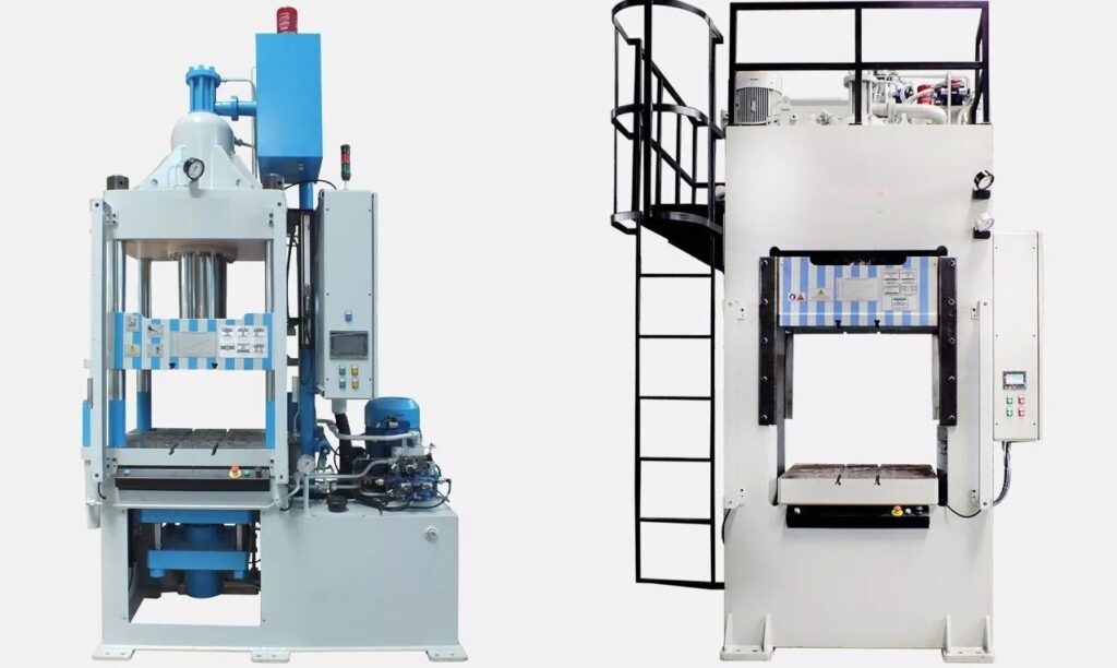
A sheet metal drawing mold designed for multi-stage operation is a sophisticated tooling system that performs several sequential forming processes in one continuous production cycle, often within a single press or stamping line. This approach enables the progressive transformation of a flat metal blank into a complex, finished part through multiple controlled deformation steps, such as drawing, ironing, trimming, flanging, embossing, and piercing.
In a multi-stage drawing mold, the metal sheet passes through a series of stations, each equipped with dedicated punches and dies that perform specific forming tasks. Initially, the blank undergoes deep drawing to create the basic shape by pressing the sheet metal into a cavity. Subsequent stations refine the part’s geometry and features—ironing thins and strengthens the walls, trimming removes excess material, flanging forms edges or lips, embossing adds decorative or functional patterns, and piercing creates holes or slots.
This integrated process eliminates the need for manual handling between steps, reducing cycle time, labor costs, and the risk of part damage or contamination. It also enhances dimensional accuracy and repeatability by maintaining precise alignment of the part throughout forming.
Multi-stage molds require precise synchronization of presses, tooling components, and material feeding systems to ensure smooth and continuous operation. The tooling is often modular, allowing reconfiguration or replacement of specific stations to accommodate different part designs or production volumes.
Materials used for the tooling are typically high-strength tool steels with specialized surface treatments to withstand the high stresses and friction generated during multiple forming operations. Lubrication systems are carefully designed to minimize wear and ensure consistent metal flow across all stages.
Overall, sheet metal drawing molds with multi-stage operations offer efficient, high-quality production of complex parts, widely used in automotive, appliance, cookware, and industrial component manufacturing.
Multi-stage sheet metal drawing molds revolutionize manufacturing by combining several forming processes into a streamlined sequence that transforms flat metal blanks into finished parts with complex geometries in a single continuous flow. This approach significantly improves efficiency, as it eliminates the need for separate operations and manual handling between steps, thereby reducing cycle times, labor requirements, and the risk of part damage or contamination.
The process begins with a blank being fed into the first station, where initial deep drawing shapes the basic form of the part by pressing the metal into a die cavity. As the blank progresses through subsequent stations, each equipped with specialized tooling, additional forming operations such as ironing to control wall thickness and strengthen the part, trimming to remove excess material, flanging to create edges or lips, embossing for decorative or functional surface patterns, and piercing to add holes or slots are performed sequentially. The part remains aligned and supported throughout, ensuring consistent dimensional accuracy and high-quality finishes.
Synchronization between press strokes, tooling movements, and material feed is crucial for multi-stage molds to operate smoothly and reliably. Modern systems often incorporate servo-electric or hydraulic presses with programmable controls that allow precise timing and force adjustments tailored to each forming stage. Automated feeding mechanisms deliver blanks accurately into the line, and robotic or mechanical transfer systems move the part seamlessly from one station to the next without manual intervention.
Tooling durability is paramount, as multi-stage operations subject molds to repeated high stresses and friction across various forming actions. Tool steels with superior hardness, toughness, and surface treatments such as nitriding or coating with titanium nitride reduce wear and galling, extending mold life and maintaining part quality. Lubrication systems are carefully designed to provide consistent application throughout the process, lowering friction and protecting both the tooling and the metal sheet.
The modular nature of many multi-stage molds allows manufacturers to adapt or replace individual stations to accommodate design changes or different production runs, enhancing flexibility and reducing tooling costs over time. Inline quality control systems, including vision inspection and dimensional measurement, monitor parts during production to detect defects early and maintain stringent quality standards.
Multi-stage sheet metal drawing molds find broad application in industries where complex, high-precision parts are required in large volumes, such as automotive body panels, appliance components, cookware items, and industrial enclosures. By integrating multiple forming steps into one automated process, they enable manufacturers to achieve high productivity, consistent quality, and cost-effective production while minimizing material waste and energy consumption.
In essence, multi-stage drawing molds represent an advanced, efficient manufacturing solution that combines mechanical engineering, automation technology, and materials science to transform sheet metal fabrication and meet the demands of modern industrial production.
As multi-stage sheet metal drawing molds continue to evolve, the integration of advanced technologies further enhances their capabilities and performance. One key development is the use of computer-aided design (CAD) and finite element analysis (FEA) during the mold design phase. These tools enable engineers to simulate metal flow, stress distribution, and potential failure points throughout each forming stage before physical molds are built. By predicting and mitigating issues such as wrinkling, tearing, or excessive thinning, manufacturers can optimize mold geometry and process parameters, reducing costly trial runs and improving first-pass yield rates.
Automation and digital controls also play a pivotal role in modern multi-stage operations. Programmable logic controllers (PLCs) and servo-driven presses provide precise control over stroke speed, force, and timing, allowing for fine-tuning of each forming step. This flexibility is especially valuable when switching between different part designs or materials, as settings can be quickly adjusted without extensive downtime. Additionally, integration with manufacturing execution systems (MES) enables real-time monitoring and data collection, supporting predictive maintenance and process optimization.
Material science advancements influence multi-stage mold design as well. The increasing use of lightweight, high-strength alloys and tailored blanks requires molds capable of handling varying material properties while maintaining part integrity. Specialized coatings and surface treatments on tooling surfaces reduce friction and wear, particularly when forming difficult-to-shape materials, thereby extending tool life and ensuring consistent part quality.
Environmental sustainability is increasingly important in multi-stage forming processes. Manufacturers strive to optimize material utilization through precise blank nesting and minimize scrap generation. Lubrication systems are designed to use eco-friendly, biodegradable oils that reduce environmental impact without compromising forming performance. Energy-efficient servo presses lower power consumption and contribute to greener production lines.
Moreover, multi-stage molds can be combined with secondary automated processes such as welding, adhesive application, or surface finishing in integrated production cells. This holistic approach streamlines manufacturing workflows, reduces handling errors, and accelerates time to market.
In conclusion, multi-stage sheet metal drawing molds represent a cornerstone of modern metal forming technology. Their ability to perform complex, sequential forming operations in a controlled, automated environment delivers high-quality, precise, and cost-effective parts across numerous industries. Ongoing innovations in design, materials, automation, and sustainability ensure these molds will continue to meet evolving production demands well into the future.
Sheet Metal Drawing Mold for Container Forming
A sheet metal drawing mold for container forming is a specialized tooling system designed to transform flat metal sheets into hollow, typically cylindrical or rectangular, container shapes used in packaging, storage, or industrial applications. These containers can range from small cans and jars to large storage drums or boxes, made from materials like steel, aluminum, or other alloys depending on the intended use.
The drawing mold works by placing a metal blank over a die cavity shaped to the desired container profile. A punch then presses the blank into the cavity, stretching and shaping the metal into a hollow form. This deep drawing process requires careful control of metal flow to avoid defects such as wrinkling, tearing, or uneven thickness, which can compromise the container’s strength and appearance.
Key design considerations for container drawing molds include the radius of the punch and die edges, blank holder force, lubrication, and blank size. Rounded edges help reduce stress concentrations and minimize the risk of cracking, while the blank holder applies pressure to control metal flow and prevent wrinkling. Proper lubrication reduces friction between the metal and tooling surfaces, facilitating smooth forming and protecting the surface finish.
For containers requiring features like flanged rims, necks, or handles, the mold design may incorporate additional forming steps or be part of a multi-stage progressive die system that combines drawing with trimming, flanging, and piercing. This integration increases efficiency and consistency, allowing high-volume production of complex container shapes with precise dimensions.
The tooling materials are usually hardened tool steels with polished or coated surfaces to withstand repeated forming cycles and reduce wear. Advanced coatings may be applied to improve mold life and reduce metal sticking during forming, ensuring consistent quality and smooth surface finishes on the containers.
Automation plays a significant role in container forming, with robotic systems handling blank feeding, part transfer between forming stations, and removal of finished containers. Inline inspection systems verify dimensions and surface quality to detect defects early, supporting high production rates and minimizing scrap.
Sustainability considerations include optimizing blank layout to reduce material waste, recycling metal scrap, using environmentally friendly lubricants, and employing energy-efficient presses. These factors help manufacturers produce containers economically while reducing environmental impact.
In summary, sheet metal drawing molds for container forming are engineered tools that enable the efficient, high-quality production of durable and precise metal containers through controlled deep drawing processes. They combine mechanical design, surface engineering, process control, and automation to meet the demands of various industries requiring metal packaging and storage solutions.
The production of metal containers using sheet metal drawing molds demands a careful balance of material properties, mold design, and process parameters to achieve strong, uniform, and defect-free parts. Typically, metals like aluminum and stainless steel are chosen for their strength-to-weight ratio, corrosion resistance, and suitability for food-grade or industrial applications. The initial metal blank is cut to size based on the final container dimensions and the expected metal flow during drawing, aiming to maximize material usage and minimize waste.
During the deep drawing process, the punch presses the blank into the die cavity, plastically deforming the metal into the hollow container shape. The mold’s geometry, particularly the punch and die radii, is engineered to reduce strain concentrations and prevent common defects such as wrinkling along the container walls or tearing near sharp corners. The blank holder plays a crucial role in controlling the metal flow, applying appropriate pressure to avoid wrinkling while allowing enough material to feed into the forming area.
Lubrication is essential in container forming to reduce friction between the sheet metal and tooling surfaces, which not only aids metal flow but also protects the high-polish finish often required for containers used in consumer products. Proper lubrication helps maintain the surface quality, preventing scratches or galling that could impact both aesthetics and corrosion resistance.
Many container designs include features such as flanged rims for sealing or stacking, necks for closures, or embossed patterns for branding and structural reinforcement. These features may be integrated into the drawing mold or formed in subsequent stages using trimming, flanging, or embossing tools. Multi-stage progressive dies are common in high-volume production, combining these operations into a continuous, automated process that ensures consistent quality and reduces handling.
Tooling materials and surface treatments are critical for mold longevity and performance. Hardened tool steels provide durability under repeated high-pressure forming cycles, while coatings like titanium nitride or chrome plating reduce wear and friction. These treatments also help prevent metal adhesion to the mold surfaces, ensuring smooth release of the formed containers.
Automation enhances container forming by streamlining blank feeding, part transfer, and finished product handling. Robotic arms or mechanical feeders maintain consistent cycle times and reduce operator intervention, improving safety and throughput. Inline inspection systems using cameras or laser scanners verify dimensions, wall thickness, and surface defects, enabling early detection of quality issues and minimizing scrap rates.
Sustainability factors are increasingly important, with manufacturers optimizing blank layouts to maximize sheet utilization and recycling all trim scrap efficiently. Environmentally friendly lubricants are adopted to reduce ecological impact, and energy-efficient servo presses help lower overall power consumption.
In conclusion, sheet metal drawing molds for container forming represent a precise and highly engineered solution for producing metal containers with consistent quality, durability, and aesthetic appeal. The combination of advanced tooling design, process control, automation, and sustainable practices ensures these molds meet the rigorous demands of industries ranging from food packaging to industrial storage.
Advancements in sheet metal drawing molds for container forming continue to push the boundaries of efficiency, precision, and versatility. Modern mold design increasingly leverages computer-aided engineering tools, such as finite element analysis (FEA), to simulate the forming process in detail. This enables engineers to predict material behavior, identify potential issues like thinning or wrinkling, and optimize mold geometries and process parameters before any physical tooling is produced. By reducing trial-and-error in the design phase, manufacturers save time and costs while improving the quality and reliability of the final containers.
The integration of smart manufacturing technologies is also transforming container forming. Sensors embedded in tooling or presses can monitor parameters such as punch force, temperature, and stroke speed in real time. These data streams feed into control systems that automatically adjust process variables to maintain optimal forming conditions, compensating for variations in material batches or environmental factors. Predictive maintenance algorithms analyze tool wear patterns, enabling timely servicing and preventing unexpected downtime, thus boosting overall productivity.
Material innovations influence mold and process design as well. The demand for lightweight yet strong containers has led to the use of advanced high-strength alloys and tailored blanks with varying thicknesses across the sheet. These materials improve performance and reduce shipping costs but require molds capable of handling complex strain distributions and maintaining uniform part integrity. Surface coatings on molds are evolving to further reduce friction and extend tool life, particularly when working with harder or coated metals.
Automation extends beyond forming to encompass complete container manufacturing lines. Robotic systems handle everything from loading blanks, transferring parts between stages, applying secondary operations like welding or sealing, to final inspection and packaging. This end-to-end automation reduces labor costs, enhances safety, and increases throughput while ensuring consistent quality.
Environmental sustainability remains a key driver in container forming advancements. Efforts focus on reducing material waste through precision blank nesting and reclaiming all scrap metal for recycling. New lubrication formulations minimize environmental impact without sacrificing performance, and energy-efficient presses contribute to lower carbon footprints. Some manufacturers also explore forming processes compatible with recycled or alternative materials, supporting circular economy goals.
In summary, sheet metal drawing molds for container forming are at the forefront of modern manufacturing technology. They combine sophisticated design, intelligent automation, advanced materials, and sustainable practices to produce high-quality containers efficiently and reliably. These innovations ensure that container manufacturing can meet the evolving demands of global markets while minimizing environmental impact.
Sheet Metal Drawing Mold Blank Holder Design
The blank holder in a sheet metal drawing mold is a critical component designed to control the flow of the metal sheet during the deep drawing process. Its primary function is to apply a controlled pressure on the metal blank around the perimeter of the punch and die interface, preventing defects such as wrinkling, which occurs when excess material buckles under compressive forces. At the same time, it must allow enough metal to flow into the die cavity to form the desired shape without tearing or excessive thinning.
The design of the blank holder involves careful consideration of several factors, including the size and shape of the blank, the material type and thickness, the drawing depth, and the specific geometry of the part being formed. The blank holder surface usually mirrors the die shape to evenly distribute pressure, ensuring uniform control of material flow.
Blank holders can be designed as fixed or adjustable components. Fixed blank holders maintain a constant pressure during the forming cycle and are simpler and less costly, but they may not accommodate variations in material behavior or complex part shapes as effectively. Adjustable blank holders use springs, hydraulic cylinders, or pneumatic systems to vary the holding force dynamically during the stroke, offering better control over material flow, reducing the risk of defects, and improving part quality.
In some advanced designs, segmented blank holders are used, consisting of multiple independently controlled sections. This allows for tailored pressure distribution, accommodating non-uniform material flow requirements in complex parts or when working with anisotropic materials.
The surface finish of the blank holder is also important; it typically has a polished or coated surface to minimize friction and prevent metal sticking during forming. Proper lubrication between the blank holder and the metal sheet further reduces friction, ensuring smooth metal flow and protecting the tooling and part surfaces.
Overall, the blank holder design is integral to the success of the sheet metal drawing process, balancing sufficient restraint to prevent wrinkling with enough freedom to allow metal to flow smoothly, resulting in high-quality, defect-free parts.
The blank holder’s role in a sheet metal drawing mold is fundamental to achieving consistent and high-quality formed parts. By exerting the right amount of pressure on the blank’s perimeter, it effectively controls the material flow into the die cavity during the punch stroke. If the blank holder pressure is too low, the metal tends to wrinkle or buckle because excess material isn’t restrained, leading to poor surface finish and structural weakness. Conversely, excessive pressure restricts metal flow, causing the material to stretch excessively, which can result in tearing or thinning that compromises the integrity of the finished part.
Designing the blank holder requires a precise understanding of the interplay between blank size, material properties, and the complexity of the formed shape. For example, deeper draws generally need higher blank holder forces to prevent wrinkling, while shallow draws may require less restraint. Materials with low ductility or higher strength typically demand more careful control of blank holding pressure to avoid failure. Additionally, the geometry of the part—such as sharp corners, varying wall depths, or non-uniform thicknesses—can necessitate specially shaped or segmented blank holders that apply pressure unevenly to match the metal flow needs.
Modern blank holder systems often employ hydraulic or pneumatic actuators controlled by feedback loops to adjust the holding force dynamically during the forming cycle. This adaptability enhances control over metal flow, reducing defects and extending tool life. For example, initial higher pressure can prevent wrinkling during early stages, then gradually decreasing force allows the metal to flow more freely as the part approaches its final shape. Such controlled pressure variation also reduces stress concentrations and uneven strain distribution within the metal.
Segmented blank holders provide additional customization by dividing the holding surface into multiple independently controlled zones. This approach is particularly useful for complex parts where different areas of the blank require varying amounts of restraint. Sensors and control systems monitor forming parameters in real time, adjusting pressure accordingly to optimize the process and ensure consistent part quality.
The surface condition of the blank holder and its interaction with the metal blank are also important considerations. A polished or coated surface reduces friction and prevents galling or sticking, which can cause surface defects or interfere with metal flow. Lubricants compatible with the blank holder material and the formed sheet metal are applied to facilitate smooth movement, enhance part finish, and extend tool life by minimizing wear.
In conclusion, the blank holder is a vital component that directly influences the success of the sheet metal drawing process. Its design and operation must strike a careful balance between controlling metal flow to prevent wrinkles and allowing sufficient material movement to avoid tearing. Advances in adjustable and segmented blank holder technologies, combined with precise control systems, enable manufacturers to produce complex, high-quality sheet metal parts reliably and efficiently.
Beyond basic design considerations, the integration of sensors and smart control systems into blank holder mechanisms is transforming how pressure is applied and monitored during the sheet metal drawing process. By embedding force sensors and displacement sensors directly into the blank holder assembly, real-time data on holding force and blank movement can be captured and analyzed. This data enables closed-loop control systems to adjust blank holder pressure dynamically in response to material behavior or forming conditions detected during the stroke. For example, if an area of the blank starts to wrinkle or stretch excessively, the system can modulate pressure instantaneously to correct the flow, improving part quality and reducing scrap.
Another important aspect is the thermal management of the blank holder. During high-speed or high-volume forming operations, friction and deformation generate heat that can affect both tooling and material properties. Excessive heat build-up in the blank holder may lead to dimensional changes or premature wear, which in turn impacts forming accuracy and tool life. Some advanced blank holders incorporate cooling channels or thermal barriers to dissipate heat efficiently and maintain stable operating conditions throughout production runs.
Material selection for blank holders also plays a crucial role. High-strength tool steels are the standard due to their ability to withstand repeated loading cycles without deformation. Surface treatments such as nitriding, carburizing, or specialized coatings like diamond-like carbon (DLC) further enhance wear resistance and reduce friction, extending the lifespan of the blank holder and improving forming consistency.
In applications involving advanced or coated sheet metals—such as galvanized steel or aluminum alloys used in automotive or appliance manufacturing—the blank holder design must account for coating preservation. Excessive pressure or friction can damage protective coatings, leading to corrosion or cosmetic defects in the final product. Therefore, blank holders may be designed with larger radii, specialized surface finishes, or lower friction coatings to handle delicate materials without compromising coating integrity.
Lastly, the trend toward flexible manufacturing and rapid product changeovers has driven the development of modular blank holder systems. These systems allow quick adjustment or replacement of blank holder segments or entire assemblies to accommodate different part geometries or material thicknesses. This modularity supports shorter setup times, increased machine utilization, and greater responsiveness to changing production demands.
Overall, the blank holder is not just a passive component but a highly engineered element central to the precision and efficiency of sheet metal drawing molds. Its evolving design incorporates mechanical, material, thermal, and electronic innovations that together optimize metal flow control, extend tool life, and ensure high-quality production across a broad range of sheet metal forming applications.
Sheet Metal Drawing Mold With Hydraulic Press
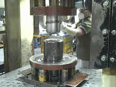
A sheet metal drawing mold combined with a hydraulic press forms a powerful system for shaping metal sheets into complex, precise parts through deep drawing. The hydraulic press provides the controlled force and motion needed to push a metal blank into the mold cavity, forming it into the desired shape by plastic deformation. Unlike mechanical presses that rely on cams or linkages for motion, hydraulic presses use fluid power to generate and control pressing force, offering advantages in flexibility, force control, and stroke speed.
Hydraulic presses allow for smooth, consistent force application throughout the entire stroke, which is essential for sheet metal drawing where gradual and controlled deformation reduces the risk of tearing or wrinkling. The ability to vary speed and force dynamically enables optimization of the forming process for different materials and part geometries. For example, a slower punch speed with steady force might be used to draw a deep or complex shape, while faster cycles can be applied for simpler forms, improving production efficiency.
The drawing mold itself consists of the punch, die, and blank holder, all mounted within the hydraulic press frame. The mold tooling is designed to match the part’s shape, with radii and clearances engineered to control metal flow and prevent defects. The blank holder applies pressure to restrain the metal blank’s edges during forming, typically controlled either mechanically or by the hydraulic press itself.
Hydraulic presses offer precise control over the blank holder force as well, sometimes using separate hydraulic circuits or pressure intensifiers to independently adjust blank holding pressure during the stroke. This independent control improves the quality of the formed parts by optimizing metal flow, reducing wrinkling, and preventing excessive thinning.
Additional benefits of hydraulic presses include their capability to deliver extremely high forces, often exceeding those achievable with mechanical presses of similar size, enabling the forming of thicker or stronger materials. They also offer flexible stroke lengths, which accommodate a wide range of part sizes and drawing depths without changing the press setup.
Integration of programmable logic controllers (PLCs) with hydraulic presses allows for automated control and repeatability, ensuring consistent forming conditions for every cycle. Safety features such as overload protection, emergency stops, and guarded press areas are standard to protect operators and equipment.
In summary, sheet metal drawing molds paired with hydraulic presses provide a versatile, powerful, and precise forming solution. Their ability to finely control force and motion during the drawing process makes them well-suited for producing high-quality, complex sheet metal parts across automotive, appliance, aerospace, and industrial sectors.
Hydraulic presses enhance the sheet metal drawing process by delivering controlled, adjustable force that adapts seamlessly to the demands of different materials and part complexities. The fluid-driven system allows for precise modulation of pressure throughout the forming cycle, reducing the risk of common defects like tearing or wrinkling by ensuring the metal is drawn smoothly into the mold cavity. Unlike mechanical presses, which often have fixed stroke profiles, hydraulic presses can adjust stroke speed and force dynamically, enabling optimized forming strategies such as slower initial drawing speeds to ease material flow, followed by faster completion strokes for efficiency.
The versatility of hydraulic presses also extends to handling a wide range of blank sizes and thicknesses. By changing the hydraulic pressure settings or tooling, operators can form both thin gauge sheets and thicker, stronger metals without extensive equipment modification. This flexibility is valuable in industries requiring frequent changeovers or diverse product lines. Additionally, hydraulic presses can accommodate complex mold designs that include multi-stage forming or progressive operations within a single cycle, improving productivity and part consistency.
Blank holder force control is often integrated directly into the hydraulic system, either via separate hydraulic circuits or adjustable pressure valves, allowing independent regulation of the holding force. This capability ensures that the metal sheet is properly restrained to prevent wrinkling, while still permitting enough material flow to avoid excessive thinning or tearing. Some advanced hydraulic presses use feedback from force sensors to maintain optimal blank holder pressure in real time, adapting to variations in material properties or temperature during production.
From a tooling perspective, sheet metal drawing molds used with hydraulic presses are typically made from hardened tool steels with precision-machined surfaces to provide smooth, wear-resistant forming areas. Mold components like the punch and die are designed with carefully calculated radii and clearances to facilitate uniform metal flow. The blank holder surface is often polished or coated to reduce friction and protect both the tooling and the sheet metal’s finish.
In addition to forming, hydraulic presses offer the advantage of applying secondary operations such as trimming, piercing, or flanging in the same press cycle by integrating additional tooling stages. This multi-functionality reduces handling and setup times, enhancing overall production efficiency.
Automation and process monitoring play significant roles in modern hydraulic press systems. Programmable logic controllers manage stroke parameters and force settings, enabling repeatable and consistent forming cycles. Sensors can monitor press performance, tooling condition, and part quality metrics, feeding data into manufacturing execution systems to support quality control and predictive maintenance. Safety systems are integrated to protect operators from high-force operations, including physical guards, light curtains, and emergency stop mechanisms.
Energy efficiency is also a focus in hydraulic press design, with technologies such as variable frequency drives and energy recovery systems reducing power consumption and operational costs. Some presses incorporate environmentally friendly hydraulic fluids and sealed systems to minimize leakage and environmental impact.
Overall, the combination of sheet metal drawing molds with hydraulic presses represents a highly adaptable and precise manufacturing solution. The ability to control force and speed dynamically, accommodate diverse materials and part designs, and integrate automation makes hydraulic press systems a preferred choice for producing high-quality, complex sheet metal components across many industries.
Hydraulic presses continue to evolve with advancements in technology, enhancing their capabilities and broadening their application in sheet metal drawing processes. One notable development is the incorporation of servo-hydraulic systems, which combine the precision of electric servo motors with the power of hydraulic actuators. These systems offer highly accurate control over ram position, velocity, and force, enabling extremely fine tuning of the drawing process. This precision helps reduce material waste, improve part consistency, and extend tooling life by minimizing shock loads and vibrations during forming.
In addition to servo-hydraulic drives, modern presses often feature multi-axis control, allowing not only vertical movement of the punch but also lateral adjustments or tilting actions. Such flexibility enables more complex forming sequences and better compensation for material springback, which is especially valuable when working with advanced high-strength steels or lightweight aluminum alloys that exhibit challenging deformation characteristics.
Another important innovation is the use of integrated condition monitoring and predictive maintenance systems within hydraulic presses. Sensors embedded throughout the press collect data on pressures, temperatures, vibrations, and cycle times, which are analyzed using artificial intelligence and machine learning algorithms. These systems can detect early signs of wear or failure, schedule maintenance proactively, and reduce unplanned downtime, thereby increasing overall equipment effectiveness (OEE) and lowering maintenance costs.
The tooling design for sheet metal drawing molds has also benefited from advances in manufacturing technologies like additive manufacturing (3D printing) and advanced machining. These technologies enable the production of complex mold geometries with internal cooling channels or optimized surface textures that improve forming performance and tool longevity. Conformal cooling channels embedded within the tooling help maintain consistent temperatures during forming, preventing thermal distortion and improving dimensional accuracy.
Material considerations continue to drive innovation in both press and mold design. The increasing use of coated and layered materials, as well as tailored blanks with varying thickness or mechanical properties across the sheet, requires presses and molds capable of adapting to non-uniform strain distributions and maintaining tight tolerances. Hydraulic presses’ adaptable force control and programmable stroke profiles make them especially suited to handle these advanced materials without compromising quality.
Finally, the integration of hydraulic presses within Industry 4.0 manufacturing environments supports fully automated production lines where forming, inspection, and post-processing are seamlessly linked. Real-time data exchange between the press, mold, robotic handlers, and quality control systems enables rapid response to process deviations, continuous optimization, and full traceability of each formed part.
In summary, hydraulic presses combined with advanced sheet metal drawing molds represent a cutting-edge manufacturing solution that leverages precise force control, adaptable motion profiles, intelligent monitoring, and modern tooling technologies. This combination meets the growing demand for complex, high-quality sheet metal components in automotive, aerospace, appliance, and industrial sectors while supporting efficient, flexible, and sustainable production.
Sheet Metal Drawing Mold Automation Integration
Integrating automation into sheet metal drawing molds has revolutionized the metal forming industry by enhancing efficiency, precision, and repeatability while reducing labor costs and human error. Automation integration typically involves the use of robotic systems, sensors, control units, and software platforms to manage various stages of the drawing process, from material handling to forming, inspection, and post-processing.
One of the first automation steps is the loading of sheet metal blanks onto the drawing press. Robotic arms or automated feeders can precisely position blanks into the mold area, ensuring consistent placement and reducing cycle times. This eliminates manual handling, which can introduce misalignment or damage to the blank, leading to defects in the final part.
During the forming cycle, sensors embedded in the press and tooling collect real-time data on parameters such as punch force, stroke position, blank holder pressure, and material deformation. These sensors feed data to programmable logic controllers (PLCs) or advanced control systems that adjust forming parameters dynamically to maintain optimal conditions. For example, if excessive force or unexpected strain is detected, the system can modify punch speed or blank holder pressure to prevent defects like tearing or wrinkling.
Post-forming, automated transfer systems move the finished part to subsequent operations such as trimming, piercing, or surface treatment, often integrated within a single production line. Vision systems and laser scanners inspect parts automatically for dimensional accuracy, surface defects, and other quality metrics, providing immediate feedback and enabling rejection or rework without human intervention.
Data from all these automation components can be centralized in manufacturing execution systems (MES) or industrial IoT platforms, allowing operators and engineers to monitor production status, track part quality, and analyze process trends. This connectivity supports predictive maintenance by identifying tooling wear or press issues before failures occur, minimizing downtime and maintenance costs.
Advanced automation also enables flexible manufacturing, where robotic systems and programmable tooling adapt quickly to different part designs or production volumes. This agility supports shorter product lifecycles and custom orders without significant setup delays.
Incorporating safety features such as light curtains, emergency stops, and interlocked guards ensures that automation does not compromise operator safety. Human-machine interfaces (HMIs) provide intuitive control panels for operators to monitor and adjust system parameters easily.
Overall, automation integration in sheet metal drawing molds transforms traditional forming operations into highly efficient, consistent, and adaptive manufacturing processes. By combining robotics, sensors, real-time controls, and data analytics, manufacturers achieve improved product quality, faster cycle times, and lower costs, positioning themselves competitively in today’s demanding market environment.
Automation integration in sheet metal drawing molds extends beyond just robotic handling and sensor feedback—it fundamentally transforms the entire production workflow into a cohesive, intelligent system. By linking various automated components through centralized control platforms, manufacturers gain unprecedented visibility and control over the forming process. This interconnectedness allows real-time optimization, where adjustments in press speed, blank holder force, or lubrication delivery can be made instantly based on sensor inputs, ensuring consistent part quality even in the face of material variability or changing environmental conditions.
The use of advanced robotics in automated drawing cells enables not only precise blank loading but also intricate handling tasks like repositioning partially formed parts, stacking finished components, or delivering blanks from upstream processes such as shearing or blanking. Collaborative robots (cobots) are increasingly employed to work safely alongside human operators, assisting with tasks that require both precision and flexibility while maintaining high throughput.
Vision systems and machine learning algorithms play a growing role in quality assurance within automated drawing lines. High-resolution cameras capture detailed images of formed parts, and AI-driven software analyzes these images to detect surface imperfections, dimensional deviations, or forming defects that may be missed by human inspectors. Over time, these systems improve through training on large datasets, leading to faster, more reliable inspections that support zero-defect manufacturing goals.
Integration with enterprise-level systems such as ERP (Enterprise Resource Planning) and PLM (Product Lifecycle Management) platforms ensures that production data flows seamlessly from the shop floor to management, enabling informed decision-making about inventory, scheduling, and process improvements. This connectivity also supports traceability requirements for regulated industries, where detailed records of each part’s forming conditions and inspection results are essential.
Another critical aspect of automation integration is the implementation of predictive maintenance strategies. By continuously monitoring key parameters such as hydraulic pressure, cycle times, vibration, and tooling wear indicators, the system can forecast when maintenance is needed before a breakdown occurs. This proactive approach minimizes unplanned downtime, reduces maintenance costs, and extends the life of expensive tooling and equipment.
Automation also enables rapid changeover capabilities, allowing manufacturing lines to switch between different part designs with minimal manual intervention. Programmable tooling and adjustable blank holders controlled via the automation system adapt quickly to new specifications, supporting just-in-time production and small batch runs that respond to market demands without sacrificing efficiency.
Safety remains a paramount concern in automated drawing operations. Systems are designed with multiple layers of protection, including physical barriers, light curtains, presence sensors, and emergency stop mechanisms, all integrated within the automation control architecture to ensure immediate response to any unsafe conditions. Operator interfaces provide clear feedback and control options, maintaining a balance between automation efficiency and human oversight.
In sum, the integration of automation into sheet metal drawing molds not only streamlines manufacturing but elevates it to a smart, adaptive, and highly responsive process. This transformation drives improved product quality, operational flexibility, and cost-effectiveness, enabling manufacturers to meet the evolving demands of complex, high-volume sheet metal production in today’s competitive industrial landscape.
As automation in sheet metal drawing molds continues to advance, the role of digital twins and simulation tools is becoming increasingly significant. Digital twins—virtual replicas of the physical drawing mold, press, and entire production line—allow engineers to simulate forming processes under various conditions before actual manufacturing begins. These simulations predict material behavior, stress distribution, potential defects, and tool wear, enabling optimization of mold design, press parameters, and automation workflows. By identifying issues early in the virtual environment, costly trial-and-error on the shop floor is minimized, reducing downtime and improving first-pass yield.
Integration of augmented reality (AR) and virtual reality (VR) technologies further supports automation by assisting operators and maintenance personnel. AR systems can overlay real-time process data or step-by-step instructions directly onto the physical equipment, facilitating troubleshooting, tool setup, or changeover without extensive training or guesswork. VR environments enable immersive training simulations, allowing workers to practice operating complex automated drawing cells safely and efficiently before engaging with live equipment.
The adoption of edge computing within automated sheet metal drawing systems enhances responsiveness and data processing speed. By analyzing sensor data locally on the press or robot controller, edge devices reduce latency and dependence on cloud connectivity, enabling faster decision-making for force adjustments, quality inspections, or emergency stops. This real-time responsiveness is critical for maintaining tight process control in high-speed forming operations.
Sustainability considerations are also driving automation innovation. Automated lubrication and cooling systems precisely control fluid application, minimizing waste and environmental impact while ensuring optimal tool and material conditions. Energy-efficient hydraulic drives and regenerative systems capture and reuse energy during press cycles, reducing overall power consumption. Automation enables continuous monitoring of resource usage, helping manufacturers meet regulatory requirements and sustainability goals.
Looking ahead, the convergence of automation with artificial intelligence (AI) and machine learning promises further leaps in sheet metal drawing mold performance. AI algorithms can analyze vast amounts of production data to detect subtle patterns or anomalies, suggesting process improvements or alerting operators to potential failures before they occur. Machine learning models can optimize forming parameters in real time for new materials or part geometries without extensive manual tuning.
In conclusion, automation integration in sheet metal drawing molds is evolving into a comprehensive, intelligent ecosystem that combines robotics, sensors, advanced control, digital simulations, and AI-driven analytics. This holistic approach transforms traditional forming processes into smart manufacturing systems capable of delivering superior quality, flexibility, and efficiency while supporting sustainability and workforce empowerment. As technology continues to progress, these automated systems will become increasingly vital to meeting the complex demands of modern sheet metal fabrication.
Sheet Metal Drawing Mold for Industrial Applications
Sheet metal drawing molds for industrial applications are engineered to meet the demanding requirements of high-volume production, complex geometries, and diverse material types commonly encountered across sectors such as automotive, aerospace, appliance manufacturing, and heavy machinery. These molds must provide precise control over metal flow to form durable, consistent parts while withstanding the rigors of continuous operation.
Industrial sheet metal drawing molds are typically constructed from high-strength tool steels with advanced surface treatments to resist wear, corrosion, and thermal fatigue. The design accounts for factors like blank size, material thickness, drawing depth, and part complexity to optimize punch and die shapes, radii, and clearances. Multi-stage drawing molds are often employed to progressively form deep or intricate parts, reducing the risk of tearing and wrinkling by distributing strain over several steps.
Given the scale and pace of industrial manufacturing, these molds are frequently integrated with hydraulic or servo-hydraulic presses, which provide the precise and adjustable force profiles necessary for consistent forming of heavy-gauge or advanced high-strength steels. Blank holders with controlled pressure systems ensure proper metal flow and dimensional accuracy throughout the cycle.
Automation plays a critical role in industrial sheet metal drawing setups. Robotic loading and unloading, real-time sensor feedback, and adaptive control systems maintain quality and efficiency across long production runs. Tooling modularity and quick-change features enable fast transitions between different parts, supporting flexible manufacturing environments.
Thermal management is a key consideration in industrial molds due to heat generated by friction and deformation. Cooling channels or heat-dissipating materials help maintain stable temperatures, reducing thermal distortion and extending tool life.
Overall, sheet metal drawing molds for industrial applications are robust, precision-engineered systems designed to deliver high productivity, repeatability, and part quality in challenging manufacturing environments, supporting the production of essential components in a wide array of industries.
In industrial applications, sheet metal drawing molds must handle a wide variety of materials, including low-carbon steels, stainless steels, aluminum alloys, and sometimes more exotic materials like titanium or magnesium alloys. Each material presents unique challenges due to differences in ductility, strength, and surface finish requirements, necessitating careful mold design and press parameter optimization. For example, forming high-strength steels requires greater force and precise control to avoid cracking, while aluminum alloys demand special attention to lubrication and tool surface finishes to prevent galling.
The complexity of parts formed in industrial settings often involves deep draws, complex contours, and multiple features such as beads, flanges, or embossing. This complexity frequently requires progressive or multi-stage drawing molds that incrementally shape the metal, reducing strain and minimizing defects. Progressive molds integrate several forming stations within a single press cycle, increasing throughput while maintaining tight tolerances and consistent quality.
Durability and maintenance considerations are paramount in industrial molds due to the high cycle counts typical in mass production. Tool steels used for punches and dies are commonly treated with coatings such as titanium nitride (TiN), chromium nitride (CrN), or diamond-like carbon (DLC) to enhance hardness, reduce friction, and extend tool life. Mold components are often designed for easy replacement or refurbishment, minimizing downtime during maintenance.
Integration with industrial automation systems enhances the reliability and efficiency of the drawing process. Sensors embedded in the mold and press monitor variables such as force, temperature, and part thickness, providing real-time data to control systems that adjust parameters on the fly. This feedback loop helps maintain optimal forming conditions despite variations in material batch properties or environmental factors.
Quality control in industrial sheet metal drawing is frequently automated through inline inspection systems using laser scanners, vision cameras, and coordinate measuring machines (CMMs). These systems detect dimensional deviations, surface defects, and form accuracy early, preventing defective parts from proceeding further in the production line and reducing scrap rates.
Energy efficiency and sustainability are increasingly critical in industrial forming operations. Modern sheet metal drawing molds and presses incorporate energy-saving technologies such as variable-speed hydraulic drives, regenerative braking, and optimized lubrication systems. Automated control of process parameters ensures minimal energy consumption while preserving part quality, supporting corporate sustainability goals and reducing operational costs.
Finally, industrial sheet metal drawing molds are often customized to meet specific production needs, including the ability to accommodate large or unusually shaped blanks, form parts with tight tolerances, or integrate secondary operations like trimming, piercing, or assembly. This customization, combined with the robustness and precision of industrial-grade tooling and automation, enables manufacturers to deliver complex, high-quality components at scale, meeting the stringent demands of industries ranging from automotive chassis parts to aerospace structural components and heavy machinery housings.
Industrial sheet metal drawing molds also emphasize process repeatability and cycle time optimization to maximize production throughput without compromising quality. Cycle times are carefully balanced through mold design, press speed settings, and automation synchronization to achieve high output rates, often running continuously for extended periods. Advanced simulation tools assist in predicting material behavior and optimizing forming sequences, allowing engineers to reduce trial runs and accelerate ramp-up phases in new production lines.
Material handling systems are integral to industrial drawing operations, with automated conveyors, robotic arms, and precision feeders ensuring consistent blank positioning and minimizing human intervention. This reduces variability and enhances safety by limiting operator exposure to heavy machinery and high-force presses.
In sectors like automotive and aerospace, where weight reduction is a key driver, sheet metal drawing molds must accommodate lightweight, high-strength materials such as aluminum-lithium alloys or ultra-high-strength steels. These materials require specialized tooling geometries and surface finishes to prevent cracking or galling during forming, as well as precise force and lubrication control. Molds may incorporate tailored blank technology, where sheets have varying thicknesses or properties, demanding adaptable forming strategies enabled by advanced press controls and sensor feedback.
Modular mold systems are increasingly popular in industrial settings, allowing manufacturers to quickly swap components like punches, dies, and blank holders to adapt to different part designs or maintenance needs. This modularity supports just-in-time manufacturing and reduces downtime, critical in industries with frequent model updates or customized orders.
Environmental controls around the forming area, including temperature and humidity regulation, further ensure consistent material behavior and part quality. Automated lubrication and cooling systems maintain optimal tool conditions, preventing premature wear and improving surface finish on finished parts.
As Industry 4.0 concepts penetrate industrial metal forming, sheet metal drawing molds become nodes in a connected manufacturing ecosystem. Data collected from molds, presses, and automation equipment feed into cloud-based platforms, enabling real-time monitoring, predictive analytics, and remote diagnostics. This connectivity enhances decision-making, supports continuous improvement initiatives, and provides traceability required for regulatory compliance or quality certifications.
In summary, sheet metal drawing molds for industrial applications are highly engineered, integrated systems designed to deliver high-quality parts at scale. Their success depends on a combination of robust tooling materials and design, precise press control, comprehensive automation, advanced quality assurance, and digital integration—all coordinated to meet the stringent demands of modern manufacturing environments.
Sheet Metal Drawing Mold for Kitchenware
Sheet metal drawing molds for kitchenware are specially designed to form various metal components used in cookware, utensils, and related household items. These molds must balance precision, durability, and cost-effectiveness while accommodating the diverse shapes, sizes, and materials typical in kitchenware manufacturing.
Common materials for kitchenware sheet metal drawing include stainless steel, aluminum, and sometimes copper or coated steels. These materials are chosen for their corrosion resistance, food safety, thermal conductivity, and aesthetic qualities. The drawing molds must be tailored to handle the specific mechanical properties of these metals, ensuring smooth metal flow during forming to prevent defects such as wrinkling, tearing, or surface blemishes that could compromise product quality or safety.
Kitchenware parts often require shallow to moderately deep draws, such as pans, bowls, lids, and trays. Drawing molds are designed with appropriately contoured punches and dies to create smooth, rounded shapes without sharp transitions, which can be weak points or uncomfortable for users. Radii and clearance between punch and die are carefully engineered to facilitate metal flow while minimizing friction and tool wear.
The molds typically incorporate blank holders or pressure pads to control metal stretching and avoid wrinkles, especially along the edges of shallow kitchenware components. Lubrication is critical to prevent galling and ensure smooth forming surfaces, often applied via automated systems for consistent coverage.
Because kitchenware manufacturing often involves high production volumes, drawing molds are made from wear-resistant tool steels with surface treatments like nitriding or chrome plating to extend tool life. Modular mold designs allow for efficient maintenance and quick changeover between different product lines, supporting the variety found in kitchenware collections.
Automation integration is common in modern kitchenware production, with robotic systems loading blanks, handling formed parts, and performing quality inspections. Inline vision systems detect surface defects or dimensional inconsistencies, maintaining high standards essential for consumer products.
Thermal management within molds is generally less demanding than in heavy industrial applications but still important to maintain tool stability and part quality during continuous operation.
Overall, sheet metal drawing molds for kitchenware combine precision engineering, robust materials, and efficient automation to produce durable, attractive, and safe metal components that meet both functional and aesthetic demands of household cooking and dining products.
In kitchenware sheet metal drawing molds, attention to detail in design is crucial to achieving the smooth, polished finishes expected by consumers. The surface quality of the mold’s punch and die directly impacts the final product’s appearance, requiring precision grinding and polishing to minimize surface imperfections and tooling marks. This is especially important for visible kitchenware parts like pots, pans, and serving trays, where aesthetic appeal is a major factor.
The forming process for kitchenware often involves relatively thin sheet metals, which demand careful control of drawing forces and blank holder pressure to prevent thinning or tearing. Since kitchenware frequently involves curved and rounded shapes, molds must accommodate these geometries with well-optimized radii and smooth transitions to avoid strain concentrations that can lead to defects or early tool failure.
Material selection in kitchenware also influences mold design. Stainless steel, common for its corrosion resistance and durability, typically requires higher forming forces and careful lubrication to prevent galling. Aluminum, favored for its lightweight and thermal conductivity, allows easier forming but can be more prone to surface scratches and dents, so mold surfaces must be especially smooth and well-maintained.
Lubrication systems integrated into the drawing process help maintain consistent forming conditions and extend tool life. Automated lubrication ensures even application, reducing friction and preventing metal-to-metal contact that can cause scoring or other damage to the mold and workpiece. This is critical in high-volume kitchenware production lines, where mold longevity and part consistency directly impact profitability.
Automation enhances efficiency and quality control in kitchenware sheet metal drawing. Robots handle the feeding of blanks, part removal, and stacking, reducing manual labor and the risk of damage or contamination. Inline inspection systems equipped with cameras or laser scanners identify dimensional deviations and surface defects in real time, allowing immediate adjustments or rejection to maintain quality standards.
Modularity in mold design supports the wide variety of kitchenware products manufacturers offer. Quick-change components and adjustable blank holders facilitate switching between different part sizes and shapes without extensive downtime. This flexibility is essential to respond to market trends, seasonal demands, and custom orders efficiently.
While kitchenware molds may not face the extreme forces or thermal stresses found in automotive or aerospace applications, durability remains important due to high production volumes. Molds are engineered for repeated cycles with minimal maintenance, incorporating wear-resistant coatings and corrosion protection to sustain performance over time.
Overall, sheet metal drawing molds for kitchenware are thoughtfully engineered systems that combine precise forming capabilities, durable materials, and automation compatibility to produce attractive, functional, and reliable household metal products at scale. This balance ensures manufacturers can meet consumer expectations while maintaining cost-effective and efficient production processes.
In addition to the core forming process, many kitchenware sheet metal drawing molds are designed to accommodate secondary operations within the same production line. These may include features such as piercing, trimming, flanging, or embossing, which add functional or decorative elements to the parts. Integrating these steps into a progressive or multi-stage drawing mold reduces handling time, improves alignment accuracy, and increases overall throughput, which is critical in the competitive kitchenware market.
Customization and innovation are also key drivers in kitchenware mold design. Manufacturers often require molds that can produce unique shapes or patterns, such as textured surfaces or ergonomic handles. This may involve incorporating specialized tooling inserts, fine detail engraving, or laser surface treatments into the mold components to meet aesthetic and functional requirements without compromising forming efficiency.
Sustainability considerations are increasingly influencing kitchenware sheet metal drawing processes. Efficient material usage through optimized blank nesting, minimizing scrap, and employing recyclable metals contribute to greener manufacturing practices. Molds designed to operate with minimal lubrication or using environmentally friendly lubricants help reduce chemical waste. Furthermore, energy-efficient presses and automation systems integrated with the molds reduce the overall carbon footprint of production.
Workforce safety is an important aspect of kitchenware production facilities. Drawing molds are often housed within automated cells that include safety barriers, interlocks, and emergency stop features to protect operators from high-force forming presses. Ergonomic design of loading and unloading stations minimizes repetitive strain injuries, while automation reduces manual handling of sharp or hot metal parts.
Continuous improvement through data collection and analysis is another area where kitchenware sheet metal drawing molds benefit from modern technology. Sensors embedded in the molds and presses monitor force, temperature, and cycle times, feeding data into manufacturing execution systems (MES). This data supports preventive maintenance, process optimization, and quality assurance initiatives, enabling manufacturers to maintain high productivity and consistent product quality.
In summary, sheet metal drawing molds for kitchenware are sophisticated tools tailored to produce a broad range of consumer metal products efficiently and reliably. By combining precise forming capabilities, secondary operation integration, customization options, sustainability focus, safety features, and data-driven process control, these molds help manufacturers meet evolving consumer demands while maintaining competitiveness and operational excellence.
Sheet Metal Drawing Mold for Automotive Parts
Sheet metal drawing molds for automotive parts are specialized tooling systems designed to form complex, high-strength metal components used throughout vehicle bodies, chassis, engine parts, and interior elements. These molds must meet stringent requirements for dimensional accuracy, surface finish, mechanical strength, and repeatability to comply with automotive industry standards and safety regulations.
Automotive sheet metal parts often involve deep draws, compound curves, and intricate features, demanding advanced mold designs that carefully control metal flow to prevent defects such as wrinkling, tearing, or thinning. Molds are typically made from hardened tool steels with precision-machined surfaces, sometimes enhanced with coatings like titanium nitride (TiN) or diamond-like carbon (DLC) to resist wear and reduce friction, which is critical when forming high-strength steels or aluminum alloys common in modern vehicles.
Due to the diversity of materials—including mild steel, high-strength low-alloy steel (HSLA), aluminum, and increasingly, advanced high-strength steels (AHSS)—drawing molds must be adaptable with optimized clearances, radii, and blank holder pressures specific to each material’s characteristics. Forming these materials requires high-capacity hydraulic or servo presses capable of delivering precise, variable force profiles to manage complex deformation patterns.
Multi-stage and progressive drawing molds are commonly employed to handle deep or complicated parts by distributing strain over several forming steps, minimizing the risk of failure and ensuring dimensional control. These molds often integrate secondary operations like trimming, piercing, or hemming to produce near-net-shape parts ready for assembly, reducing downstream processing and improving efficiency.
Automation is integral in automotive sheet metal forming lines. Robots handle blank feeding, part transfer, and stacking to maintain high throughput and reduce manual handling risks. Inline sensors and vision systems monitor key parameters like forming force, part geometry, and surface quality, enabling real-time process adjustments and ensuring consistent quality across millions of components.
Thermal management in automotive drawing molds is critical due to the high forces and speeds involved. Cooling channels within molds regulate temperature to prevent thermal distortion, which can affect part accuracy and tool longevity. Lubrication systems are precisely controlled to reduce friction and wear, supporting reliable production of large and complex parts.
Because automotive production demands both high volume and flexibility, modular mold designs and quick-change tooling enable rapid switching between different part models, supporting multiple vehicle platforms on the same production line. This modularity reduces downtime and tooling costs while allowing manufacturers to respond quickly to market changes.
Data integration with manufacturing execution systems (MES) and enterprise resource planning (ERP) platforms provides traceability and analytics for process optimization, maintenance scheduling, and quality assurance—essential for meeting the automotive industry’s rigorous standards and certifications.
Overall, sheet metal drawing molds for automotive parts represent a fusion of advanced materials science, precision engineering, automation, and digital integration, enabling the efficient production of durable, safe, and high-quality components that meet the demanding requirements of modern vehicle manufacturing.
In automotive sheet metal drawing molds, precision and durability are paramount due to the critical role these components play in vehicle safety, performance, and aesthetics. The molds must consistently produce parts that meet tight dimensional tolerances and surface finish requirements, as even minor defects can lead to assembly issues or compromised structural integrity. This demands rigorous design, manufacturing, and maintenance processes to ensure tool reliability over millions of cycles.
The variety of parts formed using sheet metal drawing molds in the automotive sector includes body panels like doors, hoods, and fenders, as well as structural elements such as reinforcements and brackets. These parts often feature complex geometries with compound curves and multiple flanges, requiring sophisticated mold shapes that control metal flow and strain distribution carefully to avoid defects like wrinkling or tearing.
Material selection heavily influences mold design and press operation. The increasing use of advanced high-strength steels (AHSS) and aluminum alloys aims to reduce vehicle weight for improved fuel efficiency and emissions, but these materials pose challenges due to their higher strength and reduced ductility. Consequently, molds must accommodate higher forming forces and precise blank holder pressure adjustments to prevent cracking or springback while maintaining shape accuracy.
Hydraulic and servo-electric presses paired with advanced control systems enable the necessary flexibility and precision in forming cycles. These presses allow variable speed and force application tailored to each stage of drawing, which is especially important when handling different materials or complex part shapes. This capability reduces defects and tool wear, extending mold life and improving overall productivity.
Integration of sensors within the molds and presses provides real-time monitoring of parameters such as force, displacement, and temperature. This data is critical for adaptive process control, allowing automatic adjustments to maintain optimal forming conditions. Early detection of anomalies helps prevent scrap and costly downtime by enabling predictive maintenance and immediate corrective actions.
Automated material handling systems work alongside drawing molds to streamline production flow. Robots and conveyors manage the loading of blanks and unloading of formed parts, reducing cycle times and minimizing human exposure to hazardous machinery. Automated inspection stations using laser scanning and vision systems verify part dimensions and surface quality immediately after forming, ensuring that only compliant parts proceed to the next manufacturing step.
Thermal management remains a key concern, as high-speed, high-force drawing generates significant heat that can cause mold distortion or material property changes. Cooling channels and thermal sensors embedded in the molds help maintain stable temperatures, which preserves part quality and prolongs tool life. In some cases, heating elements are also integrated to assist with forming certain aluminum alloys or reduce springback in high-strength steels.
Modularity in mold design supports flexible manufacturing strategies, enabling quick tool changes to accommodate different vehicle models or part revisions without extensive downtime. This adaptability is crucial in the automotive industry, where frequent updates and customization demand rapid tooling adjustments.
The extensive data generated throughout the sheet metal drawing process feeds into Industry 4.0 frameworks, supporting comprehensive analytics, quality control, and supply chain management. By leveraging digital twins and simulation models, manufacturers can optimize mold design, predict tool wear, and streamline production schedules, thereby enhancing efficiency and reducing costs.
In conclusion, sheet metal drawing molds for automotive parts embody the convergence of high-precision engineering, advanced materials, automation, and digital technologies. These molds are essential enablers of modern vehicle production, delivering reliable, high-quality components that meet the industry’s demanding standards for safety, performance, and sustainability.
Beyond the core forming process, continuous innovation in sheet metal drawing molds for automotive parts focuses on improving efficiency, sustainability, and adaptability to evolving vehicle technologies. Lightweighting remains a dominant trend, with increasing use of mixed materials, such as aluminum combined with high-strength steel or even composites. Molds must therefore be designed or adapted to handle different materials either sequentially or within the same production line, which introduces challenges related to varying thicknesses, hardness, and surface characteristics.
To address these challenges, mold designers employ advanced computer-aided engineering (CAE) tools, including finite element analysis (FEA) and metal forming simulations, to predict material behavior, optimize blank holder pressures, and minimize defects before physical tooling is manufactured. These simulations reduce prototyping time, lower costs, and improve first-pass yield rates, which is especially critical in the fast-paced automotive development cycles.
In high-volume production, mold maintenance and lifecycle management are critical to avoid unplanned downtime. Predictive maintenance strategies leverage sensor data combined with machine learning algorithms to forecast wear patterns and schedule timely interventions. This proactive approach extends tool life, improves part consistency, and lowers overall production costs.
Furthermore, the adoption of additive manufacturing techniques, such as selective laser melting (SLM), is beginning to influence mold fabrication. Additive manufacturing allows for more complex cooling channel geometries and lighter mold components that improve thermal management and reduce cycle times. This technology also enables rapid prototyping and faster tooling iteration cycles, enhancing the responsiveness of automotive manufacturers to design changes.
Environmental considerations are increasingly integrated into mold design and production processes. Efforts to reduce waste through optimized blank utilization, lower lubricant consumption with more efficient application systems, and energy-efficient press operation align with broader sustainability goals. Additionally, molds designed for easier disassembly support end-of-life recycling and refurbishment initiatives, contributing to circular economy principles within automotive manufacturing.
Human factors and workplace safety also shape mold design and integration within forming lines. Ergonomic tooling stations, automated safety guards, and collaborative robots (cobots) help reduce operator strain and exposure to hazardous conditions. These measures not only improve worker well-being but also enhance overall production reliability and quality by minimizing human error.
As the automotive industry shifts toward electrification and autonomous vehicles, sheet metal drawing molds must evolve to accommodate new part geometries and materials, such as battery enclosures, lightweight chassis components, and sensor housings. This evolution demands even greater flexibility in mold design, including modularity, adjustable tooling, and integration with advanced sensing and control systems.
In summary, sheet metal drawing molds for automotive parts continue to advance through the integration of cutting-edge simulation, manufacturing, automation, and sustainability practices. These developments ensure that mold tooling remains a cornerstone technology in delivering innovative, high-quality, and cost-effective automotive components that meet the rapidly changing demands of the global automotive market.
Sheet Metal Drawing Mold for Deep Drawing
Sheet metal drawing molds for deep drawing are specialized tooling systems designed to form metal sheets into parts with significant depth relative to their diameter or width. Deep drawing is a widely used metal forming process in which a flat blank is radially drawn into a forming die by the mechanical action of a punch, producing cup-shaped or box-shaped components with a high depth-to-diameter ratio.
The design of deep drawing molds focuses on controlling material flow to prevent common defects such as wrinkling, tearing, thinning, or excessive springback. Key components of a deep drawing mold include the punch, die, blank holder (or pressure pad), and often a binder or draw ring. The blank holder applies controlled pressure to the flange of the sheet metal blank to restrain its movement and ensure uniform material distribution during forming.
Material selection and thickness significantly influence mold design and process parameters. Common materials for deep drawing include low-carbon steels, stainless steels, aluminum alloys, and sometimes copper or brass. Each material’s ductility, yield strength, and work hardening behavior dictate forming speeds, lubrication needs, and blank holder pressure settings.
The punch and die geometry is critical in deep drawing molds. The punch radius must be large enough to allow smooth metal flow without causing tearing, while the die radius controls the flange bending and influences wrinkling tendencies. The clearance between punch and die is carefully calculated—typically slightly greater than the sheet thickness—to allow free movement while minimizing thinning.
Blank holder force is a vital control factor. Insufficient force can lead to wrinkling due to uncontrolled flange movement, whereas excessive force may cause tearing by restricting material flow. Modern deep drawing operations often use hydraulic or servo-controlled blank holders that can dynamically adjust pressure throughout the stroke to optimize forming conditions.
Lubrication plays a crucial role in reducing friction between the sheet metal and tooling surfaces, preventing galling and scoring while promoting smooth material flow. Various lubricants, including oils, greases, or dry lubricants, may be applied depending on material, part geometry, and production volume.
For deeper draws or complex shapes, multi-stage drawing molds or progressive dies are employed. These systems gradually form the blank through a series of incremental steps, reducing strain per operation and minimizing defect risks. This staged approach also allows for integration of additional forming processes such as trimming, piercing, or flanging within the same tool setup.
Mold materials must be highly durable and wear-resistant, typically constructed from hardened tool steels and often surface-treated with coatings like nitriding or chrome plating to extend tool life under high pressures and repeated cycles. Cooling channels integrated into the tooling help manage temperature buildup during production, maintaining dimensional stability and reducing thermal wear.
Automation integration is common in deep drawing production lines, including robotic blank feeding, part transfer, and automated inspection. Real-time monitoring systems track forming forces, punch displacement, and temperature to ensure consistent quality and enable predictive maintenance.
In summary, sheet metal drawing molds for deep drawing are precision-engineered tools that balance material flow control, tool durability, and process optimization to produce deep, complex metal parts efficiently and with high quality. Their design and operation are critical in industries ranging from automotive and aerospace to cookware and electronics, where deep-drawn components are essential.
Deep drawing molds require meticulous attention to the interaction between the punch, die, and blank holder to ensure uniform material flow and avoid common issues like wrinkling on the flange or thinning in the cup walls. The blank holder’s pressure must be carefully balanced—too low, and the metal may buckle; too high, and it can restrict the material from flowing properly, causing cracks or tears. Modern systems often use hydraulically controlled blank holders that adjust pressure dynamically during the draw stroke to optimize these forces in real time.
The geometry of the punch and die, including their radii and clearances, greatly affects the success of the deep drawing process. Larger punch radii reduce the likelihood of tearing but may increase drawing force requirements, while smaller radii help define sharper features but risk material failure. Die clearance is typically set slightly larger than the sheet thickness to allow smooth flow without excessive thinning or surface damage. These parameters are frequently fine-tuned through computer simulations and trial runs.
Material characteristics also play a crucial role; ductile materials like low-carbon steel or aluminum alloys respond well to deep drawing, while higher strength or less ductile materials require more precise control of forming parameters and sometimes pre-treatment such as annealing. Lubrication is essential, reducing friction between the tooling surfaces and the metal blank, preventing galling, and promoting smooth flow during forming. The choice of lubricant depends on material type, process speed, and the complexity of the part.
For very deep or complex parts, single-step drawing is often insufficient. Multi-stage drawing molds gradually form the part through successive steps, distributing the strain and reducing the risk of defects. Progressive dies may also combine drawing with trimming, piercing, or flanging operations in a single automated sequence, improving efficiency and reducing handling.
Tool steels used in deep drawing molds are subjected to high cyclic loads and wear, necessitating hardened, wear-resistant materials often enhanced with surface treatments such as nitriding or chrome plating. Cooling systems integrated into molds help manage temperature to maintain tool accuracy and extend life, as excessive heat can cause thermal expansion and dimensional changes detrimental to precision forming.
Automation plays a pivotal role in modern deep drawing operations, with robotic systems handling blank loading, part unloading, and in-line inspection to ensure consistent quality and maximize throughput. Sensors embedded in the press and tooling monitor force, displacement, and temperature data, enabling real-time adjustments and predictive maintenance, minimizing downtime.
Deep drawing molds are essential in manufacturing a wide array of products, from automotive fuel tanks and kitchen sinks to electrical enclosures and aerospace components. Their design requires a comprehensive understanding of material behavior, mechanical forces, and process dynamics to produce reliable, high-quality deep-formed parts efficiently and economically.
Advancements in deep drawing mold technology continue to evolve, driven by the demands for higher precision, faster cycle times, and the ability to work with increasingly advanced materials. One notable trend is the integration of digital twins and simulation software into the design and operation phases. By creating a virtual replica of the mold and forming process, engineers can simulate the metal flow, stress distribution, and potential defect areas before manufacturing the actual tooling. This approach significantly reduces prototyping costs and accelerates development timelines.
Another development is the use of adaptive forming technologies, where sensor data collected during the drawing process is fed back to control systems that adjust punch speed, blank holder pressure, or lubrication in real time. This closed-loop control helps maintain optimal forming conditions despite variations in material batch properties or environmental factors, resulting in higher yield rates and fewer rejected parts.
Materials science advancements also influence deep drawing molds. The increasing use of lightweight, high-strength alloys and composite metal laminates requires molds capable of precise, high-force forming without compromising tool integrity. In some cases, hybrid molds incorporating compliant or flexible sections are employed to accommodate complex geometries while reducing localized stresses on both the material and tooling.
Additive manufacturing (AM) is beginning to play a role in mold fabrication, especially for producing complex cooling channels or conformal features that are difficult or impossible to machine conventionally. AM allows for more efficient thermal management, reducing cycle times and enhancing tool life by maintaining more uniform temperatures throughout the mold during operation.
Sustainability considerations are also shaping mold design and production practices. Efforts to minimize scrap material through optimized blank layouts, the use of environmentally friendly lubricants, and energy-efficient presses align with broader industry goals of reducing environmental impact. Modular mold designs that facilitate easy repair or component replacement further extend the useful life of tooling, decreasing resource consumption.
In terms of automation, integration with Industry 4.0 technologies means that deep drawing lines are becoming smarter, with predictive maintenance systems that analyze trends in sensor data to anticipate wear or failure before it occurs. This reduces unexpected downtime and maintenance costs. Automated inspection systems employing 3D scanning or machine vision verify dimensional accuracy and surface quality immediately after forming, enabling rapid quality control and feedback.
Ergonomics and safety remain priorities as well, with automation reducing manual handling of heavy blanks and formed parts, thereby minimizing operator injury risks. Safety interlocks, guards, and collaborative robots enhance workplace safety while maintaining high production speeds.
Overall, the evolution of sheet metal deep drawing molds reflects a blend of mechanical precision, digital innovation, advanced materials, and sustainable manufacturing practices. This synergy ensures that deep drawing remains a versatile and efficient metal forming process capable of meeting the increasingly complex demands of modern industries such as automotive, aerospace, consumer electronics, and home appliances.
Sheet Metal Drawing Mold Die Design
Sheet metal drawing mold die design is a critical aspect of the metal forming process, focusing on creating a die set that accurately shapes metal blanks into desired parts through controlled deformation. The die design must consider factors such as material flow, strain distribution, tooling durability, and process efficiency to produce high-quality components consistently.
The fundamental components of a sheet metal drawing die include the punch, die block, blank holder (or hold-down), and bolster plate. The punch is the male part that pushes the sheet metal into the die cavity, while the die block provides the female cavity that defines the final part shape. The blank holder applies pressure on the flange area of the blank to control metal flow and prevent wrinkling during forming.
In designing the die, careful attention is given to the geometry of the punch and die radii. Rounded edges are necessary to allow smooth metal flow and prevent tearing or excessive thinning. The clearance between the punch and die is typically set slightly larger than the material thickness to facilitate movement but tight enough to maintain part accuracy and surface finish.
The blank holder force is a crucial parameter; it must be sufficient to prevent wrinkling but not so high as to restrict material flow, which could cause cracks. Some designs incorporate hydraulic or servo-controlled blank holders that adjust pressure dynamically during the drawing cycle to optimize forming conditions.
Material selection for the die is important for longevity and performance. Tool steels such as A2, D2, or H13 are common choices, often heat-treated for hardness and wear resistance. Surface treatments like nitriding or chrome plating may be applied to reduce friction and extend tool life.
Lubrication is integrated into the die design to minimize friction between the sheet metal and tooling surfaces. Proper lubrication improves material flow, reduces wear, and helps achieve better surface finishes. Some dies include lubrication channels or reservoirs to deliver lubricant consistently during forming.
For complex parts or deep draws, the die design may incorporate multiple stages or progressive operations. Multi-stage dies gradually form the part over several steps to reduce strain per operation and minimize defects. Progressive dies combine drawing with other operations such as trimming or piercing in a continuous sequence, improving efficiency.
Cooling systems are often integrated into die blocks to manage heat generated during forming. Temperature control helps maintain dimensional accuracy, reduces thermal expansion, and prolongs die life.
In modern manufacturing, die design increasingly leverages computer-aided design (CAD) and finite element analysis (FEA) software to simulate the drawing process. These simulations help optimize die geometry, blank holder force, and other parameters before manufacturing, reducing trial-and-error and accelerating development.
Automation integration in die design includes considerations for robotic handling, sensor placement for real-time monitoring, and compatibility with automated press systems. These features enhance production speed, repeatability, and quality control.
Overall, sheet metal drawing mold die design is a sophisticated balance of mechanical engineering, materials science, and process control aimed at producing precise, defect-free parts efficiently and reliably.
In sheet metal drawing mold die design, the control of material flow is paramount to prevent defects such as wrinkling, tearing, and excessive thinning. The blank holder plays a vital role in this, as it applies pressure on the flange of the sheet metal to regulate the amount of material that can flow into the die cavity. Optimizing blank holder force requires balancing enough pressure to avoid buckling or wrinkling without restricting the metal’s natural flow, which could cause cracks or splits. To achieve this, modern dies often incorporate hydraulic or servo-driven blank holders that can dynamically adjust force throughout the drawing stroke based on sensor feedback.
The punch and die radii are carefully designed to promote smooth material deformation. Sharp corners are avoided because they concentrate stress and increase the likelihood of tearing. Instead, generous fillets and radii help the sheet metal to bend gradually, distributing strain more evenly. The clearance between punch and die is another critical factor; it is usually set just above the material thickness to permit easy movement while maintaining dimensional accuracy and a good surface finish. Too much clearance can cause excessive thinning or wrinkling, while too little can lead to increased friction and wear.
Material selection for the die tooling directly impacts durability and cost. High-quality tool steels such as A2, D2, or H13 are typically used because they can withstand repeated high-pressure cycles without deforming or wearing excessively. These steels are often heat-treated and surface-hardened through processes like nitriding or chrome plating to improve hardness and reduce friction, extending die life and reducing maintenance intervals.
Lubrication is integral to die design, reducing friction between the sheet and tooling surfaces to prevent galling, scoring, and uneven metal flow. Some dies include channels or grooves to distribute lubricant uniformly, while others rely on external lubrication methods tailored to the specific material and forming conditions.
For parts requiring deep draws or complex shapes, die design often involves multiple stages or progressive tooling. Multi-stage dies allow the metal to be formed gradually in successive steps, reducing strain and minimizing the risk of failure. Progressive dies integrate multiple forming operations such as piercing, trimming, and bending into a single automated sequence, boosting production efficiency and consistency.
Thermal management within the die is crucial because heat generated during forming can cause thermal expansion, affecting part accuracy and potentially damaging tooling. Cooling channels embedded in die blocks circulate coolant fluids to maintain a stable temperature, ensuring dimensional consistency and prolonging tool life.
The use of advanced simulation tools like finite element analysis (FEA) has transformed die design by enabling engineers to model material behavior and optimize die geometry, blank holder force, and other parameters virtually. This predictive capability reduces costly trial-and-error in the physical world, shortens development time, and improves first-pass success rates.
Modern die design also incorporates automation features such as robotic loading and unloading compatibility, embedded sensors for monitoring force, displacement, and temperature, and data interfaces for integration into Industry 4.0 manufacturing environments. These enhancements support real-time process control, quality assurance, and predictive maintenance, minimizing downtime and improving overall productivity.
In essence, sheet metal drawing mold die design requires a deep understanding of material mechanics, tooling materials, process dynamics, and technological advancements to create dies that reliably produce complex parts with precision and efficiency while minimizing defects and tooling costs.
To further enhance sheet metal drawing mold die design, attention is given to the ergonomics and maintainability of the tooling system. Dies are often designed with modular components that can be quickly replaced or adjusted to accommodate different part variations or wear without needing to replace the entire mold. This modularity reduces downtime and tooling costs, particularly in high-volume production environments where wear can accumulate rapidly.
The incorporation of sensor technologies within the die has become increasingly common. Force sensors monitor blank holder pressure and punch load, while displacement sensors track punch position and stroke length. Temperature sensors embedded in critical areas help detect overheating that might lead to tool damage or dimensional inaccuracies. The collected data feeds into control systems for closed-loop process optimization and predictive maintenance scheduling, enhancing both product quality and tool longevity.
In advanced die designs, variable blank holder systems are employed to adapt pressure distribution according to the stage of the drawing process or the specific geometry of the part. For example, multi-zone blank holders allow different pressures to be applied across the blank flange, improving material flow control and reducing localized thinning or wrinkling.
The choice of surface finish on die components also influences forming performance. Polished surfaces reduce friction and help produce better surface finishes on formed parts, while textured surfaces can be intentionally applied to improve lubricant retention or create specific aesthetic effects on the final component.
Environmental factors are increasingly considered in die design. Selecting materials and lubricants that are less harmful and easier to recycle aligns with sustainability goals. Additionally, energy-efficient press technologies paired with well-designed dies reduce overall environmental impact by lowering electricity consumption and waste generation.
Die design for sheet metal drawing also involves anticipating springback — the elastic recovery of the metal after the forming force is removed. Designers compensate for this by adjusting die shapes or incorporating overbending features to ensure the final part meets dimensional specifications.
In high-precision applications, post-drawing operations such as trimming, ironing, or calibration may be integrated into the die or performed in subsequent steps using complementary tooling. This integration reduces handling and improves dimensional consistency.
Continuous collaboration between die designers, material scientists, process engineers, and machine operators is essential to optimize die performance. Feedback loops from production data help refine design parameters, identify potential improvements, and respond to changes in material batches or product requirements.
Overall, sheet metal drawing mold die design is a multidisciplinary endeavor that combines mechanical design, materials engineering, process control, and digital technologies. Its evolution continues to drive improvements in manufacturing efficiency, part quality, and adaptability across industries like automotive, aerospace, electronics, and consumer goods.
Sheet Metal Drawing Mold Surface Finish
Sheet metal drawing mold surface finish plays a crucial role in the success of the metal forming process, directly impacting material flow, part quality, tool life, and production efficiency. The surface texture and smoothness of the punch, die, and blank holder surfaces influence friction between the tooling and the sheet metal, affecting how the metal deforms during drawing.
A smooth, polished surface finish on the mold components typically reduces friction, allowing the sheet metal to flow more easily into the die cavity. This minimizes the risk of surface defects such as scratches, galling, or scoring on the formed part. Polished surfaces also aid in lubricant retention and distribution, further improving metal flow and reducing wear on the tooling.
Surface finish is often measured by parameters like roughness average (Ra), with typical finishes for drawing dies ranging from mirror-like polished surfaces (Ra < 0.2 micrometers) for high-quality parts to slightly rougher finishes (Ra around 0.4–0.8 micrometers) when some texture is beneficial.
In certain applications, a controlled surface texture is intentionally introduced to improve lubricant adherence. A micro-textured or patterned surface can hold lubricants in small pockets, ensuring consistent lubrication during forming and reducing the chance of dry spots that lead to increased friction or surface damage.
Surface hardness and coating also affect the surface finish performance. Hard coatings such as chromium plating or nitriding not only increase wear resistance but also maintain the smoothness of the die surfaces over prolonged production runs, preserving part quality.
Proper surface finish helps reduce forming forces, improving press efficiency and extending tool life by minimizing abrasive wear and preventing metal buildup or galling. It also contributes to better dimensional accuracy and repeatability by promoting uniform material flow without localized sticking or dragging.
To achieve the desired surface finish, mold components undergo precision grinding, polishing, and sometimes electropolishing processes. Final inspection includes surface roughness measurement and visual checks for defects.
In summary, optimizing sheet metal drawing mold surface finish is vital to achieving high-quality drawn parts, prolonging tooling life, and ensuring efficient, stable production. The right balance between smoothness, texture, hardness, and lubrication capability is tailored to the specific material and part requirements.
The importance of surface finish in sheet metal drawing molds extends beyond just the immediate forming operation—it also significantly affects maintenance cycles and overall production costs. A poor surface finish can accelerate wear on the tooling surfaces, leading to increased frequency of repairs or replacements. Over time, rough or damaged mold surfaces can cause scratches or other surface defects on the drawn parts, resulting in higher scrap rates and reduced customer satisfaction. Consequently, investing time and resources in achieving the optimal surface finish upfront often yields substantial long-term benefits.
Moreover, surface finish influences how effectively lubricants perform during the drawing process. A surface that is too smooth may cause lubricants to bead and run off, reducing their effectiveness, while a surface that is too rough might trap contaminants or wear debris, which can damage both the tooling and the workpiece. Therefore, mold designers carefully select or engineer surface textures that balance lubricant retention with minimal friction.
Technological advances have introduced new coating materials and surface treatments that further enhance surface finish characteristics. For instance, diamond-like carbon (DLC) coatings provide extremely hard, low-friction surfaces that greatly reduce wear and improve lubricant compatibility. Similarly, physical vapor deposition (PVD) coatings can produce hard, smooth, and chemically resistant surfaces tailored to specific drawing requirements.
Regular maintenance practices such as cleaning, re-polishing, and inspecting mold surfaces are essential to preserve surface finish quality over time. Automated inspection tools using laser scanning or optical microscopy help monitor surface conditions and detect early signs of wear or damage, enabling timely interventions before production quality is compromised.
In complex forming operations involving advanced high-strength steels or aluminum alloys, the demand for precise and consistent surface finishes on molds is even greater due to these materials’ sensitivity to surface friction and deformation behavior. As manufacturers adopt more stringent quality standards, surface finish optimization in drawing molds becomes a key differentiator in competitive production environments.
Ultimately, sheet metal drawing mold surface finish is a nuanced aspect of tooling design and maintenance that requires a thorough understanding of materials, lubrication, and process dynamics. Properly engineered surface finishes contribute directly to improved part quality, longer tool life, reduced downtime, and greater overall efficiency in metal forming operations.
Beyond the mechanical and functional aspects, surface finish in sheet metal drawing molds also affects the aesthetic quality of the final parts, which is especially important in consumer products where visible surfaces must be free from imperfections. A well-maintained, smooth mold surface ensures that the drawn metal parts exhibit consistent gloss, texture, and dimensional accuracy, contributing to better visual appeal and customer satisfaction.
In addition, surface finish can influence the ease of part ejection from the die. Excessive friction caused by rough surfaces may cause the formed part to stick, leading to defects, increased cycle time, or even damage to the part or tooling. Polished and well-lubricated mold surfaces facilitate smoother ejection, enabling faster production cycles and reducing the risk of part deformation or scratching during removal.
The choice of surface finish often depends on the material being formed and the specific drawing operation. For example, softer metals such as aluminum or copper alloys may require different surface roughness and lubrication strategies compared to harder steel sheets. Likewise, shallow draws or simple shapes may tolerate rougher finishes, while deep draws or complex geometries demand finer finishes to ensure uniform metal flow and prevent defects.
Manufacturers also consider environmental and economic factors when selecting surface treatments and finishes. Some coatings and polishing methods involve hazardous chemicals or consume significant energy, so companies are increasingly adopting eco-friendly alternatives that provide comparable performance without compromising sustainability goals.
Emerging technologies like laser texturing allow precise control over surface patterns at the micro and nano-scale, enabling customized friction profiles and lubrication behavior tailored to specific materials and forming processes. This capability opens new possibilities for improving forming efficiency, reducing wear, and extending die life.
Finally, collaboration between design engineers, toolmakers, and process operators is essential to define and maintain the optimal surface finish throughout the mold’s life cycle. Feedback from production monitoring and quality control helps refine surface preparation techniques and lubrication protocols, ensuring that the molds consistently deliver high-quality parts with minimal downtime.
In conclusion, sheet metal drawing mold surface finish is a multifaceted element that influences everything from metal flow and tool wear to part aesthetics and production efficiency. Meticulous attention to surface finish design, implementation, and maintenance is indispensable for achieving superior outcomes in metal forming operations.
Sheet Metal Drawing Mold With Blank Holder
A sheet metal drawing mold with a blank holder is a vital configuration used to control the flow of material during the drawing process and to prevent defects like wrinkling, tearing, or uneven thinning of the sheet. The blank holder, also referred to as the hold-down plate, applies downward pressure on the flange area of the metal blank—the portion that remains outside the die cavity during the initial stages of forming. By carefully managing this pressure, the blank holder ensures that the metal flows smoothly into the die cavity in a controlled manner rather than buckling outward or tearing at points of high stress.
In practical terms, the blank holder typically functions as a flat or contoured plate with an opening matching the shape of the drawn part. It is aligned with the die and moves vertically to clamp the blank against the die surface before the punch descends. This clamping action restricts uncontrolled radial flow of the sheet metal and forces it to stretch in a desired and predictable manner.
The force applied by the blank holder is a crucial process parameter. If the force is too low, wrinkling can occur as the sheet compresses and buckles. If the force is too high, material flow can become overly restricted, increasing the risk of tearing, especially in areas undergoing significant deformation. As such, the force must be calibrated based on the material properties, part geometry, and depth of draw. This force can be applied through various mechanisms—mechanical springs, nitrogen gas cylinders, hydraulic systems, or servo-driven actuators—each offering different levels of control and responsiveness.
In more advanced systems, the blank holder may have multiple independently controlled zones that apply variable pressures to different parts of the blank. This zoned pressure control is especially useful for complex geometries where certain regions require more restraint than others to achieve uniform material flow. Additionally, sensors may be embedded to monitor and adjust the pressure in real time during the drawing stroke, helping to eliminate defects and improve consistency.
The design of the blank holder surface is also important. It may be flat for simple shapes or contoured to match the geometry of the part being formed. This helps to maintain consistent contact and pressure distribution, reducing stress concentrations and improving part accuracy. Lubrication is often applied between the blank holder and the sheet to minimize friction and wear, and in some cases, the holder itself includes channels or textures to retain and distribute lubricants more effectively.
In applications involving high-strength steels, aluminum alloys, or stainless steel—materials that are prone to work hardening or have limited ductility—the role of the blank holder becomes even more critical. The correct design and application of blank holding force can mean the difference between a successful draw and catastrophic failure.
Overall, integrating a blank holder into a sheet metal drawing mold greatly enhances process control, part quality, and repeatability. It allows manufacturers to produce more complex and deeper drawn parts with fewer defects, reduced scrap rates, and better material utilization. In modern manufacturing environments, the blank holder is not just a passive component but an active participant in achieving high-performance, precision forming.
The blank holder’s interaction with the sheet metal during drawing is a delicate balance of forces that directly influences material flow and strain distribution. As the punch presses the metal into the die cavity, the blank holder simultaneously clamps the flange, preventing the sheet from moving uncontrollably and forming wrinkles. This coordinated action ensures the metal is stretched smoothly and evenly, allowing for deeper draws and more complex shapes without failure.
Adjusting the blank holder force often requires careful experimentation and process optimization. Too little pressure allows the sheet to buckle under compressive stresses, causing wrinkles that can compromise part integrity or require costly secondary operations to fix. Conversely, excessive blank holder pressure restricts the sheet’s ability to flow into the die cavity, increasing tensile stresses and the risk of cracks or splits, especially near corners or sharp radii.
In many modern presses, blank holder force can be dynamically controlled and adjusted throughout the stroke. Servo-driven or hydraulic blank holders can modulate pressure based on real-time feedback from force sensors or strain gauges embedded in the tooling. This capability enables adaptive control strategies that optimize material flow for each stage of the draw, improving part quality and reducing tool wear.
The geometry and surface condition of the blank holder also impact the drawing process. The holder’s surface is typically hardened and polished to reduce friction and prevent galling or metal adhesion. Lubricants applied between the blank holder and the blank further reduce friction, enabling smoother metal flow and protecting both the tool and workpiece surfaces.
For parts with irregular shapes or varying flange widths, multi-zone blank holders are often employed. These allow different pressures to be applied to separate areas of the flange, accommodating non-uniform deformation and minimizing defects. Such zoned control is particularly beneficial in automotive or aerospace applications, where complex geometries and tight tolerances are common.
Designing the blank holder to work in harmony with the punch and die is essential. The spacing between the holder and die, as well as the alignment of the entire mold assembly, must be precise to ensure uniform pressure and avoid localized stresses. Misalignment or uneven pressure can lead to uneven material flow, resulting in wrinkles, tears, or dimensional inaccuracies.
In summary, the blank holder is a critical component in sheet metal drawing molds that directly affects forming success. Its ability to control material flow through precise force application, surface design, and integration with advanced control systems enables the manufacture of complex, high-quality sheet metal parts efficiently and reliably. Properly designed and controlled blank holders reduce scrap rates, improve tool life, and expand the range of feasible part geometries in modern metal forming operations.
Beyond its fundamental role in controlling material flow, the blank holder also influences the overall efficiency and cost-effectiveness of the sheet metal drawing process. By preventing defects such as wrinkling and tearing, it reduces scrap rates and rework, directly impacting production yields. This makes the blank holder a key factor in achieving consistent quality and meeting tight dimensional tolerances, which are critical in industries like automotive, aerospace, and consumer electronics.
The integration of smart technologies with blank holders has further transformed their function. Sensors embedded within the blank holder can continuously monitor parameters such as applied force, temperature, and displacement during the drawing cycle. This data can be fed into process control systems to enable real-time adjustments, ensuring optimal forming conditions even as material properties or environmental factors vary. This level of control helps extend tool life by preventing overloading and uneven wear, reducing maintenance costs and downtime.
Hydraulic and servo-driven blank holders offer programmability and precision unmatched by traditional mechanical spring systems. They can adapt force profiles dynamically through the stroke, allowing for complex forming sequences where different sections of the blank require varying levels of restraint at different stages. Such adaptability is especially beneficial when working with advanced materials like high-strength steels and aluminum alloys, which have more challenging forming characteristics.
Another important aspect of blank holder design is ergonomics and maintenance. Easily accessible and replaceable components minimize machine downtime during tool changes or repairs. Some designs incorporate quick-release mechanisms or modular blank holders that can be swapped rapidly, enhancing flexibility and responsiveness in production lines.
The surface treatment and material choice for blank holders are optimized for durability and friction control. Hardened tool steels with polished finishes reduce wear and improve lubricant retention. Coatings such as titanium nitride or chromium can further extend tool life and improve surface hardness, reducing the risk of galling and metal adhesion.
In complex or high-volume production scenarios, blank holders are often part of fully automated systems integrated with robotic loading/unloading and inspection stations. This automation enhances throughput and consistency while minimizing human error and operator fatigue.
In conclusion, the blank holder is far more than a simple clamping device in sheet metal drawing molds. It is a sophisticated, actively controlled element that plays a central role in shaping material flow, ensuring part quality, extending tooling longevity, and enabling advanced manufacturing processes. The ongoing development of smarter, more adaptable blank holder technologies continues to push the boundaries of what can be achieved in metal forming.
Sheet Metal Drawing Mold With Punch
A sheet metal drawing mold with a punch is a fundamental setup in metal forming processes where the punch acts as the primary tool that forces the metal blank into the die cavity, shaping it into the desired form. The punch is a solid, typically hardened steel component with a precisely engineered profile that corresponds to the final shape of the drawn part. During operation, the punch moves downward, pressing the sheet metal blank against the die surface and causing the material to plastically deform and take on the cavity’s shape.
The punch’s design is critical to the success of the drawing process. Its shape must ensure smooth metal flow without causing excessive thinning or tearing. Rounded edges and radii on the punch profile help reduce stress concentrations, allowing the material to stretch gradually rather than abruptly. Sharp corners or improper geometry can lead to localized strains, increasing the risk of cracks or failure.
Material selection for punches typically involves high-strength tool steels, sometimes treated with surface hardening techniques such as nitriding or coating with wear-resistant layers like titanium nitride (TiN). These treatments improve punch durability by reducing wear and friction during the drawing cycle, especially important when working with abrasive or hard-to-form materials.
The punch surface finish directly impacts the friction between the tool and sheet metal. A polished punch surface reduces friction and sticking, facilitating smooth metal flow and improving part surface quality. It also lowers forming forces, decreasing machine load and tool wear.
In some advanced forming setups, punches are designed with complex features such as split sections or flexible segments to accommodate specific drawing challenges, allowing differential movement or controlled pressure distribution. Additionally, punches may incorporate sensors to monitor force and position in real-time, feeding data into control systems for process optimization.
The punch works in conjunction with the die and blank holder to ensure proper material flow and part accuracy. The clearance between punch and die, as well as the punch stroke length and speed, are carefully controlled parameters that affect part quality. Insufficient clearance can cause excessive wear and difficulty in metal flow, while too much clearance may result in poor dimensional accuracy or wrinkling.
Punch alignment and rigidity are essential to avoid uneven forces that could damage the part or tooling. High-precision presses and tooling setups maintain tight tolerances to ensure the punch descends perpendicular to the die surface without wobbling or misalignment.
In summary, the punch in a sheet metal drawing mold is the active shaping tool that initiates deformation, and its design, material, surface finish, and integration with the overall tooling system are crucial for achieving efficient, high-quality metal forming operations. Proper punch engineering directly impacts part precision, surface quality, tooling longevity, and production efficiency.
The punch’s role in the sheet metal drawing mold extends beyond simply pushing the metal into the die; it must be engineered to handle the stresses and repeated impacts inherent in the forming process. During each stroke, the punch experiences significant mechanical loads, including compressive forces and frictional wear from the metal blank sliding over its surface. Therefore, the punch material and heat treatment processes are carefully chosen to maximize toughness and hardness, minimizing deformation or damage over thousands or millions of cycles.
Precision manufacturing techniques such as CNC machining, grinding, and polishing are employed to produce punches with tight dimensional tolerances and smooth surfaces. This ensures consistent interaction with the sheet metal and die, maintaining uniform material flow and preventing defects such as tearing, wrinkling, or uneven thickness in the drawn part.
The punch’s geometry must also be designed to reduce ejection issues. After the metal is formed, the punch retracts, and the part must release cleanly without sticking or damage. Features like tapered edges or specialized coatings can help reduce adhesion between the metal and punch surface, facilitating smooth ejection and faster production cycles.
For deep drawing or complex shapes, punches may be designed with multiple stages or segmented areas to distribute forces more evenly and accommodate material stretching in different zones. This segmented punch design can reduce the risk of localized failure and improve the accuracy of intricate part geometries.
Lubrication plays an essential role in punch operation. A layer of lubricant between the punch and sheet metal reduces friction, lowers forming forces, and prevents galling or scoring on the punch surface. Proper lubrication extends tool life and improves part surface finish. The choice of lubricant depends on the material being formed and the process conditions, with options ranging from oils and greases to dry lubricants or specialized coatings on the punch itself.
In automated or high-volume manufacturing, punches are often integrated with sensor technology that monitors parameters such as punch force, position, and temperature. Real-time data allows process engineers to detect issues like excessive wear, misalignment, or material inconsistencies early, enabling timely adjustments and avoiding costly downtime or defective parts.
Maintenance and inspection routines for punches are vital to ensure consistent production quality. Over time, punch surfaces can develop wear marks, scratches, or chips that affect metal flow and part aesthetics. Regular polishing, recoating, or replacement keeps the punch in optimal condition, preventing the propagation of defects to the finished parts.
In sum, the punch in sheet metal drawing molds is a highly engineered component designed to withstand extreme stresses while delivering precise and consistent shaping of metal blanks. Its careful design, surface treatment, and integration with the forming system are essential to producing high-quality sheet metal parts efficiently and reliably.
In addition to its mechanical and surface characteristics, the punch design must also consider thermal effects during the drawing process. Repeated stamping cycles generate heat due to friction and deformation, which can cause thermal expansion of the punch. This expansion, if not accounted for, may alter clearances between the punch and die, potentially leading to dimensional inaccuracies or increased tool wear. To mitigate this, punches are sometimes designed with materials or coatings that have favorable thermal conductivity and expansion properties, or cooling channels may be incorporated to dissipate heat effectively.
Another critical aspect is punch alignment within the press and mold assembly. Precise alignment ensures that the punch enters the die cavity correctly, avoiding off-center loading that could cause uneven deformation, premature wear, or even tool failure. Modern presses often use guide systems or bushings with tight tolerances to maintain this alignment throughout the forming cycle. Any misalignment can lead to increased scrap rates and damage to expensive tooling components.
Punch speed and stroke profile also influence part quality and production efficiency. Variable-speed presses can optimize punch velocity to match material characteristics and part complexity, balancing the trade-offs between cycle time and forming forces. Controlled acceleration and deceleration of the punch help reduce shock loading and vibrations that could affect part accuracy or cause tool damage.
For parts requiring high precision or complex shapes, punches may be designed with additional features such as radius fillets, chamfers, or textured surfaces to control metal flow more precisely. In some cases, punches incorporate embedded heating elements or surface coatings that interact with the metal blank to enhance formability or surface finish.
In automated manufacturing lines, punches often work in tandem with sensors and robotic systems to ensure consistent part positioning, feeding, and ejection. Integration with monitoring software allows predictive maintenance, identifying wear trends before failures occur, thus reducing downtime and improving overall equipment effectiveness.
Finally, as new materials and alloys with challenging forming characteristics are introduced, punch designs continue to evolve. Advanced computational tools such as finite element analysis (FEA) enable engineers to simulate and optimize punch geometry, material selection, and surface treatments before physical production, reducing trial-and-error cycles and accelerating development timelines.
Overall, the punch is a dynamic and complex tool in sheet metal drawing molds, where every detail—from material and heat treatment to surface finish and geometric precision—plays a pivotal role in achieving high-quality, repeatable metal forming results while maximizing tool life and production efficiency.
Sheet Metal Drawing Mold Tooling Design
Sheet metal drawing mold tooling design is a critical discipline focused on creating precise, durable, and efficient tools that shape metal sheets into desired forms through plastic deformation. The tooling system typically consists of the punch, die, blank holder, and associated components, each engineered to work in harmony for optimal material flow, dimensional accuracy, and surface finish.
Designing sheet metal drawing tooling begins with understanding the part geometry, material properties, and production requirements. Complex shapes or deep draws demand more sophisticated tooling with carefully calculated clearances, radii, and pressure distribution to avoid defects such as wrinkling, tearing, or excessive thinning.
Material selection for tooling components is pivotal. Tool steels with high hardness and toughness, often enhanced by heat treatments and surface coatings, ensure longevity under cyclic loads and abrasive conditions. The die cavity is precisely machined and polished to control metal flow and surface quality, while the punch shape is optimized to apply uniform pressure and minimize stress concentrations.
The blank holder design is integrated to apply appropriate restraint on the metal blank, controlling flange movement and preventing buckling. Its force must be adjustable and uniformly distributed, sometimes featuring multi-zone control for complex parts.
Tooling design also involves considerations for lubrication management, cooling channels, and ease of maintenance. Efficient lubrication reduces friction and wear, while cooling systems manage thermal loads that can affect tool dimensions and performance.
Modern tooling designs often incorporate sensors and automation features for real-time monitoring and adaptive control, improving consistency and reducing downtime. Modular designs allow quick changeovers, enhancing production flexibility.
Overall, successful sheet metal drawing mold tooling design balances mechanical robustness, precision engineering, and process control to produce high-quality parts efficiently and reliably across diverse manufacturing environments.
Sheet metal drawing mold tooling design demands meticulous attention to the interplay between tool geometry, material behavior, and process parameters. The goal is to create tooling that not only shapes metal efficiently but also maintains consistent quality over high production volumes. This begins with detailed analysis of the part’s shape and complexity, often using computer-aided design (CAD) and finite element analysis (FEA) to simulate material flow and stress distribution during forming. These simulations help identify potential problem areas such as thinning, wrinkling, or excessive strain, allowing engineers to optimize tooling geometry before physical prototyping.
The die component of the tooling must be precisely machined with tight tolerances and polished to ensure smooth metal flow and superior surface finish on the final part. The die cavity’s radii and angles are carefully designed to reduce stress concentrations and promote gradual metal deformation, minimizing the risk of cracks or tears. Tool steel selection and surface treatments such as nitriding or PVD coatings enhance wear resistance, extending the die’s service life.
The punch must complement the die geometry, with rounded edges and optimized profiles to apply uniform pressure across the metal blank. This ensures smooth material stretching without abrupt strain gradients. Punches often undergo rigorous heat treatment and polishing to withstand repeated impacts and reduce friction.
Incorporating a blank holder with adjustable force is essential to control flange material flow. The blank holder’s design might include segmented zones with independent pressure control to accommodate complex shapes, ensuring balanced restraint and preventing wrinkles or tearing. Blank holder force is finely tuned based on material type, thickness, and part geometry, often through trial runs or adaptive control systems.
Tooling design also considers practical aspects such as ease of assembly, alignment features, and provisions for lubrication. Lubrication reduces friction between the tooling surfaces and the metal blank, preventing galling and extending tool life. Channels or grooves within the tooling may facilitate consistent lubricant application.
Thermal management is increasingly important in tooling design. Forming cycles generate heat that can cause thermal expansion and dimensional changes in the tools, potentially affecting part accuracy and tool longevity. Incorporating cooling channels or selecting materials with favorable thermal properties helps maintain stable operating conditions.
Automation integration is becoming standard in tooling design, with sensors embedded to monitor forces, temperatures, and positions in real time. This data enables predictive maintenance, process optimization, and quick response to variations in material behavior or machine performance. Modular tooling designs support fast changeovers and repairs, minimizing downtime in production.
Ultimately, successful sheet metal drawing mold tooling design is a blend of engineering precision, material science, and process control. It ensures that complex parts can be produced consistently, efficiently, and with minimal defects, meeting the stringent demands of modern manufacturing industries such as automotive, aerospace, and consumer goods.
Advancements in tooling design increasingly leverage digital technologies such as computer-aided engineering (CAE) and additive manufacturing to enhance capabilities and reduce development cycles. Using CAE, engineers can perform virtual forming simulations that predict potential issues like thinning, wrinkling, or springback, allowing early design adjustments without costly physical trials. This leads to optimized tooling geometries that improve material utilization, reduce cycle times, and increase part quality.
Additive manufacturing, or 3D printing, is now being used to produce complex tooling components with internal cooling channels or customized surface textures that were previously difficult or impossible to fabricate using traditional methods. This capability enables better thermal management and lubricant distribution, which improves tool life and forming consistency.
Material innovations also play a significant role in tooling performance. Coatings such as diamond-like carbon (DLC), titanium aluminum nitride (TiAlN), or chromium-based layers enhance surface hardness, reduce friction, and protect tooling from corrosion and wear. These surface treatments contribute to extended maintenance intervals and more stable production processes.
Modular tooling systems are designed for rapid adaptability, allowing manufacturers to switch between different parts or variants with minimal downtime. Components like punches, dies, and blank holders can be interchanged quickly, enabling flexible production schedules and reducing the need for multiple dedicated tool sets.
In high-volume or complex applications, tooling design incorporates sensor technology and automation to create “smart molds” that actively monitor forming parameters and adjust processes dynamically. Force sensors, displacement sensors, and temperature monitors embedded in the tooling provide real-time feedback to control systems, enabling precise control of blank holder pressure, punch speed, and lubrication. This level of control minimizes defects, optimizes cycle times, and extends tool life.
Additionally, tooling ergonomics and maintainability are prioritized to facilitate quick inspection, cleaning, and repairs. Features such as easy access points, standardized components, and wear indicators help technicians perform preventive maintenance more efficiently, reducing machine downtime and increasing overall productivity.
Environmental considerations are also influencing tooling design choices. Selecting materials and coatings that reduce the need for hazardous lubricants, designing tools for longer service life, and optimizing processes to minimize scrap support sustainability goals within manufacturing operations.
In summary, sheet metal drawing mold tooling design is an evolving field that integrates advanced materials, digital simulation, additive manufacturing, and smart automation to meet the increasing demands of precision, efficiency, and sustainability in modern metal forming industries.
Sheet Metal Drawing Mold For Copper
Designing a sheet metal drawing mold for copper involves special considerations due to copper’s unique material properties. Copper is highly ductile and malleable, which generally makes it easier to form compared to many steels; however, its high thermal and electrical conductivity, relatively low strength, and tendency to stick to tooling surfaces require careful tooling design and process control to achieve quality drawn parts.
The mold design starts with understanding the copper alloy type and thickness since different alloys (e.g., pure copper, brass, bronze) have varying formability and strength characteristics. Copper’s softness means tooling components like punches and dies must have extremely hard and wear-resistant surfaces to prevent rapid tool wear and galling. Tool steels with hardened, polished surfaces or coatings such as titanium nitride (TiN) or diamond-like carbon (DLC) are commonly used to minimize adhesion and friction.
Because copper can stick to tooling surfaces during forming, proper surface finish and lubrication are crucial. The die cavity and punch are polished to a mirror-like finish, reducing friction and avoiding metal transfer. Specialized lubricants designed for copper forming—often synthetic or graphite-based—are applied to ensure smooth material flow and prevent scoring or galling.
Blank holder force is carefully controlled to balance material flow and prevent wrinkling, which copper’s ductility can sometimes exacerbate. Overly high blank holder pressure can cause tearing, while insufficient pressure risks wrinkles. In some cases, adjustable or segmented blank holders are used to fine-tune pressure distribution, especially for complex shapes.
Copper’s high thermal conductivity means heat generated by friction during drawing dissipates quickly, but thermal expansion of the tooling must still be considered. Cooling channels may be integrated into the mold to maintain stable temperatures, preserving dimensional accuracy and preventing thermal distortion.
The punch geometry must feature smooth radii and gradual transitions to facilitate uniform stretching and reduce localized strain concentrations. Since copper is prone to thinning in high-strain areas, the punch and die clearance must be optimized based on copper thickness and alloy to prevent cracks or splits.
Due to copper’s softness, the mold design may also incorporate features to improve part ejection, such as tapered punch faces or coatings to reduce adhesion. In automated production environments, sensors monitoring force and position can be integrated to maintain consistent forming conditions and detect tool wear early.
Overall, sheet metal drawing molds for copper combine precise tooling geometry, high-quality surface finishes, effective lubrication strategies, and controlled forming parameters to leverage copper’s excellent formability while avoiding common issues like galling, wrinkling, or tearing. This careful approach ensures the production of smooth, dimensionally accurate copper parts for electrical components, cookware, decorative items, and other applications.
When designing sheet metal drawing molds for copper, it is important to recognize that copper’s excellent ductility allows for relatively deep draws compared to harder metals, but this advantage also brings challenges in controlling material flow to avoid defects. The mold must accommodate copper’s tendency to undergo significant plastic deformation without fracturing, which means that punch and die radii need to be carefully sized to prevent sharp bends that could cause cracking. Smooth transitions and well-rounded edges help distribute strain evenly across the blank.
Tooling components often require specialized surface treatments and coatings to combat copper’s propensity to adhere to tooling surfaces—a phenomenon known as galling. This can cause surface damage to both the part and the mold, leading to increased maintenance and part rejection rates. Polished tooling surfaces combined with appropriate lubricants help minimize friction and material transfer. Graphite-based or synthetic lubricants designed specifically for copper forming are frequently used because they withstand the heat and pressure without breaking down.
Controlling blank holder force precisely is critical in copper drawing molds. Because copper flows easily, excessive blank holder pressure can restrict material movement and cause tearing, while too little pressure can allow the flange to wrinkle or buckle. Adjustable or segmented blank holders enable fine control over pressure distribution, especially when forming complex geometries or parts with varying thickness.
The clearance between the punch and die is another key design parameter. Copper’s lower yield strength compared to steel means that the clearance should be optimized to balance between preventing excessive thinning and allowing smooth metal flow. Typical clearances are slightly larger than those used for steel to accommodate copper’s softness and reduce tool wear.
Thermal considerations are also important due to copper’s high thermal conductivity. Although heat generated during drawing is quickly dissipated, temperature fluctuations can affect tooling dimensions and part accuracy. Mold designs may include cooling passages or use materials with stable thermal expansion coefficients to maintain consistency during long production runs.
For parts that require tight dimensional tolerances or smooth surface finishes, mold designers may incorporate additional features such as coatings that reduce friction further or specialized punch shapes to manage metal flow in critical areas. Advanced forming simulations using finite element analysis (FEA) allow engineers to predict and mitigate potential problems such as thinning or wrinkling before manufacturing the tooling.
In automated or high-volume production settings, integrating sensors and monitoring systems into the mold can provide real-time data on forces, position, and temperature. This feedback helps optimize process parameters and schedule preventive maintenance, extending mold life and ensuring consistent quality.
In summary, sheet metal drawing molds for copper demand a delicate balance of precise tool geometry, surface finish quality, lubrication management, and process control. By addressing copper’s unique mechanical and thermal properties, tooling designers can produce high-quality, defect-free copper components efficiently, supporting applications in electrical, decorative, and industrial products.
In addition to the core design principles, maintenance and durability considerations are crucial when working with sheet metal drawing molds for copper. Despite copper’s softness, the repetitive forming cycles place considerable stress on tooling surfaces, especially the punch and die. Over time, even hardened and coated tools can experience wear, pitting, or minor surface damage that can degrade part quality. Therefore, regular inspection and maintenance routines are essential. Polishing worn surfaces, reapplying coatings, or even replacing tool components helps sustain optimal performance and reduces scrap rates.
Material selection for tooling must balance hardness and toughness to resist cracking and deformation while minimizing downtime caused by tool failures. Advances in powder metallurgy tool steels and composite materials offer improved resistance to adhesive wear and impact fatigue, extending the service life of copper forming molds.
Lubrication systems are often automated or semi-automated in high-volume operations to ensure consistent application and reduce manual labor. Proper lubrication not only improves material flow but also lowers forming forces, decreasing machine wear and energy consumption.
The integration of modern sensor technology and process control systems enables real-time monitoring of forming parameters. Data analytics and machine learning algorithms can predict tool wear and part quality trends, facilitating predictive maintenance strategies and reducing unexpected downtime. This smart tooling approach enhances production efficiency and reliability, critical for industries where copper parts must meet stringent quality standards.
Environmental and economic factors also influence mold design for copper. Selecting long-lasting tooling materials and effective lubrication strategies minimizes waste and resource consumption. Additionally, optimizing forming processes reduces scrap rates, material usage, and energy consumption, aligning with sustainable manufacturing goals.
In complex forming operations, multi-stage drawing molds may be employed to gradually shape copper parts while minimizing strain in any single step. Each stage uses dedicated tooling optimized for specific deformation levels, allowing for deeper draws or intricate shapes without compromising material integrity.
Finally, training for operators and maintenance personnel on the unique requirements of copper forming tooling is vital. Proper handling, setup, and maintenance ensure that tooling performs as designed and that parts meet quality specifications consistently.
Overall, the design, operation, and upkeep of sheet metal drawing molds for copper require a comprehensive approach that integrates material science, precision engineering, lubrication management, and smart manufacturing practices to achieve efficient, high-quality production of copper components.
Sheet Metal Drawing Mold For Stainless Steel
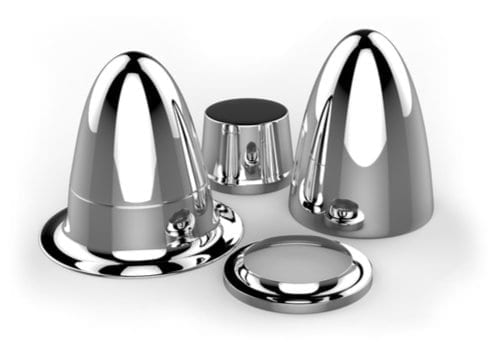
Designing sheet metal drawing molds for stainless steel involves addressing the material’s distinct mechanical and physical properties, which differ significantly from those of more ductile metals like copper or aluminum. Stainless steel is known for its high strength, corrosion resistance, and work-hardening behavior, all of which impact the forming process and tooling design.
Due to stainless steel’s higher tensile strength and lower ductility compared to softer metals, the drawing mold must be robust enough to withstand greater forming forces. Tooling components such as punches and dies are typically made from high-grade tool steels with exceptional hardness and toughness, often enhanced with surface treatments or coatings like titanium nitride (TiN) or chromium-based layers to resist abrasive wear and galling.
The design must carefully consider clearances between the punch and die. Since stainless steel work-hardens rapidly, tighter clearances are generally required to minimize material thinning and cracking during forming. However, the clearance cannot be too tight, as this would increase friction and risk tool damage. Optimizing this balance is crucial for consistent quality and extended tool life.
Surface finish of the tooling plays a critical role in stainless steel drawing molds. Polished die cavities and punch faces reduce friction and help prevent surface defects such as galling or scoring on the formed parts. Proper lubrication using high-performance lubricants compatible with stainless steel is essential to facilitate metal flow and reduce forming forces. Lubricants must also withstand the higher temperatures generated during stainless steel forming without breaking down.
Blank holder force must be precisely controlled to prevent wrinkling and tearing. Stainless steel’s lower ductility compared to mild steel means that both excessive and insufficient blank holder pressure can cause defects. Adjustable blank holders or multi-zone blank holders can improve pressure distribution, especially for parts with complex geometries or varying thickness.
Thermal considerations are important since stainless steel forming can generate significant heat due to higher forming forces and friction. Mold components may incorporate cooling channels or use materials with low thermal expansion to maintain dimensional stability during production runs.
Due to the work-hardening nature of stainless steel, multi-stage drawing processes are often employed. Gradual deformation across multiple stages reduces the risk of cracking and allows more precise control of material flow. Each stage requires tooling tailored to the specific deformation step, with careful alignment and repeatability to ensure part accuracy.
Tooling for stainless steel may also incorporate advanced features such as sensor integration for force, displacement, and temperature monitoring. Real-time data collection enables process optimization, early detection of tooling wear, and predictive maintenance scheduling, reducing downtime and scrap rates.
Finally, the mold design should facilitate easy maintenance and quick tool changes to support high-volume production environments. Modular tooling systems with standardized components can significantly reduce setup times and improve manufacturing flexibility.
In summary, sheet metal drawing molds for stainless steel combine high-strength tooling materials, precision clearances, superior surface finishes, and advanced process controls to manage the challenges posed by stainless steel’s mechanical properties. This ensures the production of durable, dimensionally accurate, and defect-free stainless steel components used in industries such as automotive, aerospace, medical devices, and kitchenware.
Designing sheet metal drawing molds for stainless steel requires careful consideration of the material’s tendency to work-harden quickly, which significantly influences forming forces and tool wear. Because stainless steel becomes stronger and less ductile as it deforms, the drawing mold must be engineered to handle increased stresses without compromising the integrity of the tooling or the part. This often means using premium-grade tool steels with superior toughness and wear resistance, combined with specialized surface coatings that reduce friction and resist galling—a common problem with stainless steel.
Tool clearances must be optimized to allow smooth material flow while minimizing excessive thinning or cracking. If the clearance is too wide, the material may wrinkle or fail to form accurately; if too narrow, it increases friction and the risk of tool damage. Achieving this balance is key and typically involves extensive simulation and prototyping. Polished tool surfaces help reduce friction, allowing stainless steel to flow more easily during the drawing process and helping to produce parts with high-quality surface finishes.
Lubrication plays a vital role in stainless steel drawing molds, where high-quality lubricants designed to withstand elevated pressures and temperatures are applied to prevent surface damage and galling. These lubricants must maintain their effectiveness throughout the forming cycle to ensure consistent part quality and prolong tool life.
The blank holder force requires precise control because improper pressure can cause common defects such as tearing or wrinkling. For stainless steel, multi-zone blank holders are often employed to apply variable pressure in different areas of the blank, especially for parts with complex geometries or varying thicknesses. This helps maintain uniform material flow and reduces the risk of localized failure.
Thermal management is another critical factor since the friction and deformation during stainless steel forming generate heat that can cause thermal expansion of the tooling components. Such expansion may lead to dimensional inaccuracies or premature wear. Cooling channels integrated into the mold, combined with tool materials selected for their thermal stability, help maintain consistent conditions during long production runs.
Multi-stage drawing is frequently necessary for stainless steel parts to reduce strain in any single step, preventing cracking and improving overall part quality. Each stage involves carefully designed tooling aligned to maintain dimensional accuracy and material integrity throughout the process.
Advanced mold designs for stainless steel also include sensors and real-time monitoring systems that track forming forces, tool wear, and temperature. This data supports adaptive control systems that can adjust process parameters on the fly, ensuring optimal forming conditions, reducing scrap, and scheduling maintenance before failures occur.
Maintenance considerations emphasize ease of tool inspection, quick replacement of wear parts, and the use of modular tooling systems that facilitate rapid changeovers, which is particularly important in high-volume or multi-part manufacturing environments.
Overall, sheet metal drawing molds for stainless steel combine rigorous engineering, precise control of process parameters, advanced materials, and digital monitoring to meet the challenges posed by stainless steel’s mechanical characteristics. This enables the efficient production of high-quality, durable stainless steel components used across diverse industries from automotive and aerospace to medical and consumer goods.
In addition to the fundamental design aspects, successful sheet metal drawing molds for stainless steel must also account for the material’s surface sensitivity and aesthetic requirements, especially in applications like kitchenware, appliances, and architectural components where appearance is critical. Stainless steel surfaces are prone to scratches, scoring, and surface imperfections during forming, so tooling surfaces need to be meticulously polished and maintained. Tooling surface roughness is minimized to prevent imprinting marks onto the part, and tooling materials are chosen for their ability to maintain this finish over extended production runs.
Furthermore, stainless steel’s corrosion resistance can be compromised if the drawing process induces surface defects or contaminates the part with foreign materials. To preserve corrosion resistance, molds are often designed to minimize contact marks and incorporate non-reactive coatings or surface treatments that avoid chemical interaction with the stainless steel blank.
In complex or deep drawing operations, specialized tooling features such as draw beads or pressure pads are used to control metal flow precisely. These features help manage the strain distribution, reduce wrinkling, and improve part shape consistency. Their design and placement require detailed analysis to optimize forming conditions and avoid excessive localized deformation that can lead to cracks.
The use of modern simulation tools has become indispensable in stainless steel mold design. Finite element analysis (FEA) allows engineers to predict material behavior, stress concentrations, and potential failure zones during the drawing process. These insights enable proactive adjustments to tool geometry, blank holder force, and lubrication strategies before physical tooling is fabricated, saving time and cost.
Automation and integration with manufacturing execution systems (MES) are increasingly common in stainless steel sheet metal forming environments. Automated material handling, robotic part removal, and inline inspection systems help maintain consistent quality and reduce manual handling damage. Tooling can be equipped with sensors that feed data into MES platforms, allowing real-time tracking of tool condition and part conformity.
Sustainability considerations are gaining prominence as well. Designing molds and processes that reduce scrap, extend tool life, and use environmentally friendly lubricants aligns with modern manufacturing goals. Efficient material usage and forming strategies also minimize energy consumption during forming, contributing to greener production cycles.
Finally, operator training and strict process controls are essential to maintain high-quality outcomes. Stainless steel drawing molds demand precise setup, lubrication application, and process monitoring to achieve the desired results consistently. Investing in skilled personnel and robust quality assurance practices complements the advanced tooling design to ensure efficient and reliable production.
In summary, sheet metal drawing molds for stainless steel encompass a blend of high-performance materials, refined tooling geometry, surface finish expertise, simulation-driven design, and integrated process controls. Together, these elements enable manufacturers to produce durable, visually appealing, and dimensionally accurate stainless steel components suited to a broad spectrum of industrial and consumer applications.
Sheet Metal Drawing Mold For Aluminum
Designing sheet metal drawing molds for aluminum involves understanding the unique properties of aluminum alloys, which differ significantly from steel and copper. Aluminum is lightweight, has excellent corrosion resistance, and good ductility, making it ideal for forming complex shapes. However, its relatively low strength and tendency to gall (adhere to tooling surfaces) require careful mold design and process optimization.
Aluminum’s ductility allows for deeper draws with less risk of cracking compared to steel, but its softness means the tooling must be designed to avoid excessive wear and surface damage. Tool steels with hard, polished surfaces or coatings such as TiN (titanium nitride) or DLC (diamond-like carbon) are often used to minimize wear and reduce friction. Since aluminum tends to stick to tooling, maintaining a highly polished mold surface and applying proper lubrication are crucial to prevent galling and surface defects.
Clearance between the punch and die is typically larger for aluminum than for steel to account for its lower strength and higher ductility, allowing smooth metal flow without excessive thinning. Excessively tight clearance can cause tearing or increased wear, while too large a clearance may lead to wrinkling or inaccurate part dimensions. Optimizing clearance based on aluminum alloy, thickness, and part geometry is essential for quality parts.
Blank holder force must be carefully controlled to manage metal flow and avoid defects. Aluminum’s ductility reduces wrinkling risk but increases the chance of thinning or tearing if the pressure is not well balanced. Adjustable blank holders or multi-zone pressure systems allow fine control, especially for complex parts or variable thickness sheets.
Lubrication plays a significant role in aluminum drawing. Specialized lubricants that reduce friction and withstand the forming pressures are applied to tooling surfaces. Graphite or synthetic-based lubricants are common, helping ensure smooth metal flow, reduce forming forces, and extend tool life.
Because aluminum has good thermal conductivity, heat generated during forming is quickly dissipated, but temperature control of the mold is still important to maintain dimensional stability and reduce thermal expansion effects. Cooling channels in the tooling or temperature-controlled presses may be employed in high-volume production.
Multi-stage drawing processes are frequently used with aluminum to form deep or complex shapes gradually, minimizing strain concentrations and avoiding tearing. Each stage uses tooling designed for incremental deformation, ensuring dimensional accuracy and surface quality.
Advanced mold designs for aluminum often integrate sensors and real-time monitoring systems that track forming forces, temperature, and tooling wear. This data supports process optimization and predictive maintenance, improving productivity and part consistency.
In summary, sheet metal drawing molds for aluminum leverage the material’s excellent formability while addressing challenges like tooling wear and galling through polished tool surfaces, optimized clearances, effective lubrication, and precise process control. This enables efficient production of lightweight, corrosion-resistant aluminum components widely used in automotive, aerospace, packaging, and consumer products.
In addition to the core design considerations, the sheet metal drawing mold for aluminum must address the material’s tendency to exhibit springback after forming due to its relatively low modulus of elasticity. This means that once the punch is removed, the aluminum part may slightly return toward its original shape, which can affect dimensional accuracy. To compensate, tooling designers often incorporate overbending or specialized die shapes that anticipate and counteract springback, ensuring the final part meets tight tolerances.
Surface finish quality is also crucial when forming aluminum, especially for applications where the appearance of the part matters, such as consumer electronics or automotive body panels. Highly polished mold surfaces reduce friction and prevent surface defects like scratches, galling, or scoring. Maintaining tooling surface integrity through regular cleaning and polishing extends tool life and preserves part quality.
The choice of lubrication is tailored to aluminum’s unique forming characteristics. Lubricants must provide excellent boundary lubrication to prevent metal-to-metal contact while remaining stable under pressure and temperature. Inadequate lubrication can lead to galling, which not only damages parts but also increases tool wear and maintenance costs. Automated lubrication systems can improve consistency and reduce waste in production environments.
Tool materials and coatings are selected not only for wear resistance but also for thermal conductivity to help dissipate heat generated during forming. Aluminum’s rapid heat transfer requires tooling materials that can maintain dimensional stability despite temperature changes, preventing issues like tool expansion that could impact clearance and part quality.
The blank holder design may include segmented or floating sections to apply variable pressure across the blank, accommodating variations in material thickness or complex part geometries. This adaptability helps prevent defects like wrinkling or tearing by ensuring uniform metal flow during the draw.
In some high-volume or precision applications, in-die sensors and monitoring systems track parameters such as force, displacement, and temperature in real time. This data feeds into control systems that can adjust press parameters dynamically, optimizing the forming process and catching issues early to reduce scrap and downtime.
Maintenance considerations emphasize ease of access to wear parts, modular tooling components for quick changeovers, and the use of materials and coatings that reduce the frequency of maintenance interventions. These factors are critical to sustaining productivity and managing costs, especially in large-scale manufacturing.
Environmental and sustainability concerns also influence mold design for aluminum. Efficient tooling designs reduce scrap and material waste, while using lubricants that are environmentally friendly and easily recoverable aligns with greener manufacturing practices. Energy-efficient forming processes and cooling systems further contribute to sustainable production.
Overall, designing sheet metal drawing molds for aluminum demands a comprehensive approach that balances the material’s excellent formability with the need for precise control over metal flow, surface quality, and tooling durability. Through careful selection of tool materials, lubrication, clearances, and process monitoring, manufacturers can reliably produce high-quality aluminum components suited for a broad range of industries, from aerospace to packaging and consumer goods.
Furthermore, when designing sheet metal drawing molds for aluminum, it is important to consider the alloy type and temper of the aluminum sheet being formed. Different alloys exhibit varying levels of strength, ductility, and work-hardening behavior, which affect the drawing process. For instance, softer aluminum alloys such as 1100 or 3003 are easier to form and less prone to cracking, while stronger alloys like 6061 or 7075 require more robust tooling and carefully controlled forming parameters to avoid defects.
The thickness of the aluminum sheet also plays a critical role in mold design. Thinner sheets are more susceptible to tearing and wrinkling, necessitating precise control of blank holder force and optimized die radii to maintain metal flow without overstressing the material. Conversely, thicker sheets require higher forming forces, demanding stronger tooling and presses capable of handling increased loads.
In addition, aluminum’s thermal expansion properties require tooling designs that accommodate temperature fluctuations during production. This is especially true in high-speed or large-scale manufacturing where repeated forming cycles generate heat in the tooling. Using materials with low thermal expansion coefficients or incorporating cooling systems within the mold helps maintain consistent clearances and dimensional accuracy.
Special considerations are also given to the ejecting system in aluminum drawing molds. Because aluminum is relatively soft, the parts may stick to the punch or die surfaces after forming. Ejector pins, stripper plates, or air blow-off systems are incorporated into the tooling design to ensure smooth and damage-free part removal, minimizing post-forming defects and speeding up cycle times.
Another important factor is the mold’s ability to accommodate secondary operations, such as trimming, piercing, or embossing. Often, multi-functional dies are designed to perform several operations in a single press stroke or progressive manner to increase efficiency and reduce handling.
To ensure high-quality production, molds for aluminum are frequently tested and validated using simulation software before manufacturing. Finite Element Analysis (FEA) and computer-aided engineering tools predict material flow, stress distribution, and potential failure points, allowing engineers to optimize die geometry, clearances, and process parameters ahead of actual production.
Finally, operator training and standard operating procedures are essential to maintain consistent forming quality. Proper setup, lubrication management, and monitoring help prevent common defects such as wrinkles, cracks, and surface imperfections.
In summary, sheet metal drawing molds for aluminum require careful consideration of alloy properties, sheet thickness, tooling materials, lubrication, thermal management, and ejecting mechanisms. Coupled with advanced simulation and operator expertise, these factors enable the efficient and reliable production of complex aluminum components that meet demanding quality and performance standards across diverse industries.
Sheet Metal Drawing Mold Engineering
Sheet metal drawing mold engineering involves the systematic design, development, and optimization of molds used to form sheet metal into desired shapes through the drawing process. This discipline integrates principles from materials science, mechanical engineering, and manufacturing technology to create tools that efficiently and accurately transform flat metal blanks into complex three-dimensional parts.
The engineering process begins with a thorough analysis of the part geometry, material properties, and production requirements. Engineers assess factors such as the metal type (steel, aluminum, copper, stainless steel, etc.), sheet thickness, alloy characteristics, and the complexity of the shape to be formed. This assessment guides critical decisions on mold design, including die shape, punch geometry, blank holder configuration, and selection of tooling materials.
A central aspect of sheet metal drawing mold engineering is controlling metal flow during deformation to prevent common defects such as wrinkling, tearing, thinning, or springback. Achieving this requires precise calculation of clearances between the punch and die, determination of blank holder forces, and incorporation of features like draw beads or pressure pads that regulate material movement. Engineers utilize empirical formulas, design standards, and increasingly, computer simulations to predict and optimize these parameters.
Material selection for mold components is critical to withstand high stresses, resist wear, and maintain dimensional stability. High-grade tool steels, often treated with heat and surface hardening processes, are commonly used. Coatings such as titanium nitride (TiN), chromium, or diamond-like carbon (DLC) may be applied to reduce friction, enhance hardness, and extend tool life.
Surface finish engineering plays an important role in mold performance. Polished die and punch surfaces reduce friction and the risk of surface defects on the formed parts. The surface roughness must be carefully controlled depending on the material being formed and the quality requirements of the finished product.
Thermal management is another important engineering consideration, especially in high-volume production where repeated forming cycles generate heat. Mold designs may include cooling channels or use materials with low thermal expansion to maintain consistent clearances and part accuracy.
Modern sheet metal drawing mold engineering relies heavily on computer-aided design (CAD) and computer-aided engineering (CAE) tools. Finite Element Analysis (FEA) enables engineers to simulate the drawing process, analyze stress and strain distribution, predict defects, and iterate mold designs before physical fabrication. This reduces development time and costs while improving product quality.
Automation and integration with manufacturing systems are increasingly incorporated in mold engineering. Features such as sensors for force, temperature, and displacement monitoring enable real-time process control and predictive maintenance, enhancing productivity and reducing downtime.
Maintenance considerations are also integral to mold engineering. Designs emphasize modularity, ease of inspection, and quick replacement of wear parts to support efficient production cycles.
In summary, sheet metal drawing mold engineering is a multidisciplinary effort that combines materials knowledge, mechanical design, simulation technology, and process control to develop molds that enable high-quality, efficient, and reliable sheet metal forming operations across a wide range of industries.
The success of sheet metal drawing mold engineering also hinges on precise tolerance control and dimensional accuracy, particularly when the formed components must interface with other parts or assemblies. Engineers must account for factors such as elastic recovery, or springback, which can cause the material to deviate slightly from the intended shape once forming pressure is released. This effect is more pronounced in certain metals like aluminum and high-strength steels, and compensation for it is integrated into the mold geometry during the design phase. In some cases, iterative adjustments are required during prototyping and early production runs to fine-tune the die and punch contours for consistent output.
Lubrication engineering is another essential aspect that ensures smooth material flow, reduces friction between the metal and mold surfaces, and prolongs tool life. The type of lubricant, its method of application, and its compatibility with both the workpiece material and tool coatings are all engineered based on the specific forming operation. Some molds are equipped with integrated lubrication systems that apply precise amounts of lubricant at controlled intervals to maintain optimal forming conditions. This is particularly important when forming metals that are prone to galling or surface scoring, such as aluminum or stainless steel.
Blank design and preparation are also key elements in mold engineering. The initial blank size, shape, and edge condition influence the material flow and final part quality. Engineers may use a circular or tailored blank with pre-trimmed features to balance material distribution and reduce wrinkling or excessive thinning during the draw. Sometimes the blank undergoes pre-forming steps to distribute stress more evenly before the main drawing operation, especially in cases of deep drawing or when forming asymmetrical parts.
Tool alignment and press compatibility are critical as well. The mold must be engineered to operate within the specifications of the available press in terms of tonnage, stroke length, and slide velocity. Misalignment or improper press settings can lead to uneven material flow, tool damage, or part defects. Advanced molds may include alignment guides, dowel pins, or hydraulic clamps to ensure precise and repeatable positioning during each cycle. In high-volume environments, sensors and monitoring systems can be integrated into the mold to detect variations in pressure, displacement, or temperature, enabling real-time feedback and adaptive control of the forming process.
Maintenance-friendly design is another hallmark of well-engineered drawing molds. Wear-prone components such as punches, dies, and guide bushings are made replaceable or modular to facilitate quick servicing and reduce downtime. Access ports, inspection slots, and modular die sections allow technicians to clean, inspect, and repair the mold without complete disassembly, improving operational efficiency. In some cases, predictive maintenance is enabled through data collection on usage cycles and force trends, helping schedule service before failure occurs.
Cost optimization is an ongoing concern in mold engineering. While high-quality materials and advanced features increase initial costs, they often yield lower long-term expenses through improved tool longevity, reduced scrap rates, and fewer interruptions. Engineers must strike a balance between upfront investment and lifecycle efficiency, particularly when molds are intended for large production runs. Design for manufacturability and ease of automation are also considered to align with broader factory operations and labor constraints.
Ultimately, sheet metal drawing mold engineering is a tightly integrated discipline that addresses not only the physical transformation of metal into functional shapes but also the performance, durability, and economics of production. From material flow analysis to mold surface treatment, every decision in the engineering process contributes to forming reliability, part accuracy, and production efficiency. This holistic approach ensures that molds not only produce consistent parts but also support lean manufacturing, automation compatibility, and high-quality standards demanded in modern industries ranging from automotive and aerospace to consumer electronics and appliances.
The integration of digital technologies further enhances the scope and capabilities of sheet metal drawing mold engineering. Computer-aided manufacturing (CAM) software enables the precise programming of machining operations for mold components, allowing for complex contours and tight tolerances to be achieved reliably during mold fabrication. High-speed CNC machining, wire EDM (Electrical Discharge Machining), and precision grinding are standard processes used to produce die and punch components with the required accuracy and surface finish. Advanced manufacturing techniques such as additive manufacturing are also being explored for complex mold inserts, conformal cooling channels, or prototyping applications, offering new design freedoms and faster development cycles.
Digital twins and simulation-driven design have become key tools in modern mold engineering. By creating a virtual replica of the mold and simulating the entire forming process—including material flow, stress distribution, thermal effects, and tool wear—engineers can predict potential failures or inefficiencies before committing to physical tooling. This predictive approach reduces the number of physical iterations needed during mold tryouts, shortens development timelines, and ensures a higher level of confidence in mold performance from the outset.
Quality assurance is tightly linked to engineering decisions, with metrology systems such as 3D scanning and coordinate measuring machines (CMMs) used to verify both the mold components and the formed parts. Engineers use these measurements to validate design assumptions, adjust for springback, and ensure that final parts fall within specified dimensional tolerances. In-line inspection systems can also be integrated into production to monitor part quality continuously and trigger corrective actions if deviations are detected.
Ergonomics and operator safety are also considered in mold engineering, especially when molds are large, heavy, or require manual intervention. Features such as accessible lifting points, safety interlocks, and modular mold sections allow for safer handling and maintenance. In fully automated environments, these considerations extend to robotic accessibility, sensor alignment, and the minimization of manual adjustments.
Sustainability and environmental impact are increasingly influencing mold engineering decisions. Tooling designs that minimize material waste, support recycling of metal scrap, and reduce energy consumption during forming are becoming standard expectations. For example, optimizing blank size to minimize trim waste or using low-friction coatings that require less lubricant contribute to more eco-friendly operations. Furthermore, molds designed for disassembly and recyclability align with circular manufacturing principles.
Training and documentation also play a vital role in mold success. Detailed engineering drawings, assembly instructions, maintenance guides, and simulation data are compiled to support mold setup, operation, and troubleshooting. These resources help ensure that the mold is used correctly and maintained to the original engineering standards, which is especially important in globally distributed manufacturing operations where tooling may be used across multiple facilities.
Ultimately, the engineering of a sheet metal drawing mold is not limited to the physical hardware—it encompasses the complete lifecycle from conceptual design through production, maintenance, and eventual decommissioning. It is a process that requires both technical precision and creative problem-solving to meet evolving industry demands for efficiency, flexibility, and quality. By combining advanced materials, smart design principles, and digital tools, mold engineers deliver solutions that enable the cost-effective manufacture of complex metal components at scale, across a broad spectrum of applications.
Sheet Metal Drawing Mold Producer
A sheet metal drawing mold producer is a specialized manufacturer responsible for designing, fabricating, testing, and delivering high-precision molds used in the metal forming industry. These producers cater to various sectors—including automotive, appliance, kitchenware, electronics, and industrial equipment—where deep drawing and forming operations are critical for creating durable, dimensionally consistent metal components from flat sheet stock.
The role of a mold producer begins with a deep understanding of the client’s requirements, which includes reviewing the final product design, production volume, chosen material (e.g., aluminum, stainless steel, copper), and forming complexity. The producer’s engineering team translates these requirements into a mold concept, using CAD software to develop the 3D geometry of punches, dies, blank holders, and associated fixtures. Tool design is often complemented with finite element simulations to assess stress points, predict thinning, wrinkling, or tearing, and validate metal flow before committing to actual fabrication.
Once the design is finalized, the mold producer selects suitable tooling materials—often high-speed steel, tool steel, or tungsten carbide—and begins machining the mold components. Precision machining centers, wire EDM, and surface grinders are commonly used to meet the tight tolerances required for forming complex geometries. Advanced producers also employ heat treatment, polishing, and coating processes to enhance mold durability, reduce wear, and improve part surface finish during production.
Producers often maintain in-house press systems for mold trials and tryouts. These presses are used to test the performance of the mold using actual production materials and simulate real-world production conditions. Adjustments to punch-die clearance, draw bead locations, and blank holding pressure are made based on tryout results to ensure that the mold performs reliably before it is delivered to the customer.
In addition to one-off molds, leading producers may offer modular die systems, progressive die setups, or transfer die solutions tailored to high-speed production lines. Some also provide support for mold automation, integrating sensors, hydraulic systems, or robotic handling features directly into the tooling system for seamless use in automated manufacturing environments.
Quality control is critical in mold production, and producers employ CMMs, laser scanning, and other metrology tools to verify each mold component against engineering specifications. Many producers are ISO-certified and adhere to stringent quality management systems, especially those serving automotive or aerospace clients.
After delivery, mold producers may provide installation support, training, and long-term maintenance services. This often includes troubleshooting guidance, spare parts provisioning, and on-site service for mold repair or refurbishment, helping extend the mold’s lifespan and maintain forming consistency over high production volumes.
Modern sheet metal drawing mold producers must also stay up to date with new material trends—such as high-strength steels or advanced alloys—and incorporate simulation technologies and digital twins into their workflows. They often collaborate closely with OEMs and tier suppliers from the early stages of product development, ensuring that the mold is optimized not only for part accuracy but also for manufacturability, efficiency, and lifecycle cost.
In summary, a sheet metal drawing mold producer is a crucial partner in the manufacturing supply chain, delivering the engineering expertise, precision tooling, and production-ready solutions needed to convert metal sheets into reliable, high-quality components at industrial scale.
The capabilities of a sheet metal drawing mold producer extend beyond simple fabrication; they encompass a full suite of engineering, prototyping, and production services that ensure molds are tailored precisely to the demands of the application. These producers often work closely with product designers and process engineers from the outset to evaluate how a part can be formed most efficiently, reducing the number of operations and tooling stages needed. Their ability to foresee forming challenges, such as draw depth limitations, material stretching, or flange wrinkling, allows them to make informed design decisions that reduce rework and production downtime later. Top-tier producers have deep expertise in handling various grades of steel, aluminum, copper, and stainless steel, and they adjust mold geometries, draw bead locations, and forming clearances based on the metal’s yield strength, ductility, and thickness.
Producers heavily rely on simulation software to virtually test the drawing process before manufacturing the tool. These simulations reveal potential failure modes such as splits or wrinkles and help refine draw radii, wall angles, and blank sizes. Once simulation results are acceptable, producers move into precision machining. This includes CNC milling of tool steel blocks for die shoes, punch forms, and blank holders, often followed by wire EDM for detailed and hard-to-reach contours. After machining, each component is heat treated to increase hardness and dimensional stability, then finish-ground and polished to exacting standards. Polishing not only enhances the visual finish but also reduces friction between the tool and metal sheet during drawing, preventing surface defects on the finished part.
After manufacturing, the mold undergoes assembly and in-house tryout on presses that replicate the customer’s forming environment. Adjustments are made as needed to dial in blank holder forces, ensure even material flow, and confirm that the finished part meets dimensional and surface finish criteria. These tryouts are an essential quality assurance step, ensuring that the mold will function reliably in the customer’s plant. Throughout the process, rigorous quality checks are performed, using tools such as coordinate measuring machines and surface profilometers to ensure precision. Any deviation is corrected before the mold is released.
Once complete, the mold is delivered with full documentation, including CAD models, material certifications, inspection reports, and maintenance guidelines. Many producers provide on-site support for mold installation, alignment, and commissioning. In the months and years that follow, they may also offer ongoing maintenance services, including regrinding, part replacement, and refurbishment to restore the mold to production-ready condition after extended use. In highly automated settings, producers may incorporate sensors and remote monitoring systems that track cycle counts, forming pressures, and temperature trends, providing predictive maintenance alerts to reduce unplanned downtime.
What distinguishes leading mold producers is their ability to scale and adapt. They can support everything from prototype tools for short-run evaluation to hardened, fully automated production dies capable of running millions of cycles with minimal maintenance. They often serve as long-term partners in development programs, adapting tools as part designs evolve and production targets increase. Their investments in advanced machinery, high-performance materials, and digital engineering make them critical enablers of modern manufacturing, ensuring that the formed components meet not only shape and strength requirements but also the economic and logistical goals of high-volume production. As global manufacturing standards continue to rise, sheet metal drawing mold producers are increasingly vital in delivering quality, speed, and reliability through expertly engineered tooling solutions.
Sheet metal drawing mold producers continuously innovate to meet the evolving needs of industries that demand higher precision, faster turnaround times, and more complex part geometries. They invest in cutting-edge technologies such as multi-axis CNC machining centers, high-speed wire EDM, and laser-assisted tooling processes, which enable the production of intricate mold features with micron-level accuracy. This precision is crucial for forming parts with tight tolerances and delicate features common in sectors like aerospace, medical devices, and advanced electronics.
Moreover, many producers have embraced Industry 4.0 principles by integrating digital workflows that connect design, manufacturing, and quality assurance systems. Real-time data from machine tools, inspection devices, and production lines feed into centralized software platforms, allowing seamless communication and rapid iteration between departments. This digital integration helps reduce errors, optimize machining strategies, and accelerate the time from concept to delivery.
Producers also focus heavily on material science advancements. The use of novel tool steels with enhanced toughness and wear resistance, combined with advanced surface coatings like diamond-like carbon or ceramic layers, dramatically extends mold life and reduces the frequency of costly maintenance shutdowns. These coatings also improve part surface quality by minimizing friction and preventing metal galling during forming.
In response to environmental concerns and sustainability goals, some mold producers are exploring eco-friendly manufacturing processes and materials. This includes recycling scrap metal from mold production, using water-based lubricants during machining and forming, and designing molds for easier repair or refurbishment to extend their useful life. The adoption of additive manufacturing for producing complex mold inserts is another area gaining traction, as it can reduce material waste and shorten lead times compared to traditional subtractive methods.
Customer collaboration is another key aspect of successful mold production. Producers often engage with clients early in the product development cycle to provide design for manufacturability (DFM) advice, helping engineers modify part geometries to better suit drawing processes and reduce tooling complexity. This collaboration often extends through prototype iterations, pilot runs, and into full production, ensuring the mold meets or exceeds performance expectations while keeping costs under control.
Finally, many sheet metal drawing mold producers offer comprehensive after-sales services, including training for customer personnel, remote diagnostics, and rapid response teams for emergency repairs. This full lifecycle support helps manufacturers maintain consistent production quality and minimize downtime, which is critical in high-volume or just-in-time manufacturing environments.
In essence, sheet metal drawing mold producers combine engineering expertise, advanced manufacturing capabilities, and strategic collaboration to deliver molds that are the backbone of efficient, high-quality metal forming operations across diverse industries worldwide.
Sheet Metal Drawing Mold Manufacturer
A sheet metal drawing mold manufacturer is a specialized company that designs, fabricates, tests, and supplies precision molds used for forming sheet metal parts through deep drawing and related metal forming processes. These manufacturers serve industries such as automotive, aerospace, appliances, electronics, and kitchenware, where high-quality, consistently shaped metal components are essential.
Manufacturers typically begin by working closely with clients to understand the part requirements, material specifications, production volumes, and any unique challenges related to the geometry or application. Their engineering teams use advanced CAD software and simulation tools to design the mold, optimizing for metal flow, minimizing defects like wrinkling or tearing, and ensuring dimensional accuracy. These designs specify key features like punch and die shapes, blank holders, draw beads, and draw radii tailored to the particular metal grade and thickness.
Once the design is finalized, manufacturing commences using high-precision machining centers, wire EDM, grinding, and polishing equipment to create mold components from tool steels or other wear-resistant materials. Heat treatment processes improve hardness and durability, while surface finishing techniques reduce friction and improve part quality. The manufacturer then assembles the mold and performs trial runs, often on in-house presses, to validate performance and make any necessary adjustments to optimize the forming process.
Quality control is critical; manufacturers employ coordinate measuring machines (CMM), laser scanners, and other metrology tools to verify the mold’s dimensional conformity and surface finish. Many manufacturers hold ISO or other quality certifications, demonstrating their commitment to consistent standards.
Beyond fabrication, leading manufacturers offer ongoing support including mold maintenance, refurbishment, and upgrades, ensuring long-term reliability and productivity for the customer. Some also incorporate automation features such as sensors, hydraulic systems, or robotic integration to support high-speed production environments.
The manufacturer’s expertise extends across a wide range of materials, including aluminum, stainless steel, copper, and advanced alloys, each demanding specific design and processing considerations. They also stay current with industry trends, utilizing digital twins, additive manufacturing for mold inserts, and environmentally conscious practices to enhance performance and sustainability.
In summary, a sheet metal drawing mold manufacturer is a key partner in converting sheet metal into functional, precise parts through expertly engineered and fabricated tooling solutions that meet the demanding requirements of modern industrial production.
Sheet metal drawing mold manufacturers play a crucial role in the entire manufacturing ecosystem by bridging the gap between design concepts and mass production of metal parts. Their work begins with deep collaboration alongside product designers and process engineers to fully understand the functional and aesthetic requirements of the finished part. This close cooperation enables manufacturers to optimize mold designs for manufacturability, balancing factors such as material behavior, part complexity, and production volume to reduce costs and improve efficiency. Manufacturers leverage powerful CAD and CAE software to simulate the forming process, identifying potential issues like thinning, wrinkling, or splitting before any physical tool is made. These simulations allow for fine-tuning mold geometry, blank size, and draw bead placement to ensure smooth metal flow and consistent results.
Once the design is validated, the manufacturing phase utilizes state-of-the-art machinery such as multi-axis CNC milling centers, wire EDM, and precision grinding machines to shape high-grade tool steels and alloys into the components of the mold. Advanced heat treatment processes increase hardness and wear resistance, essential for molds that must withstand the high pressures and repetitive cycles typical of metal drawing operations. Surface treatments and polishing reduce friction between the mold and metal sheet, which not only improves part quality but also extends tool life by minimizing wear and preventing galling.
Manufacturers conduct rigorous in-house testing using hydraulic or mechanical presses to perform tryouts, ensuring the mold produces parts within specified tolerances and without defects. This testing phase is iterative, with adjustments made to clearances, blank holder forces, and other parameters to achieve optimal performance. Quality assurance is tightly integrated throughout the process, with dimensional inspections using coordinate measuring machines and laser scanners ensuring each mold component adheres to exacting standards. This meticulous attention to detail ensures that when the mold reaches the production floor, it operates reliably and consistently.
Beyond initial fabrication and testing, many manufacturers offer comprehensive lifecycle support services. These include maintenance contracts, repair and refurbishment, technical training for operators, and even remote monitoring technologies that track mold condition and usage patterns to predict when servicing will be required. This holistic approach helps manufacturers minimize unplanned downtime and maintain production efficiency over long tool lifespans.
In response to industry trends, sheet metal drawing mold manufacturers increasingly adopt digital transformation strategies, incorporating digital twins, IoT sensors, and cloud-based data analytics to enhance design accuracy, predictive maintenance, and process automation. Additionally, sustainability considerations drive innovation in material selection, waste reduction, and energy-efficient manufacturing practices. Some manufacturers are exploring additive manufacturing to produce complex mold inserts or prototype tooling, enabling faster turnaround and design flexibility.
Overall, sheet metal drawing mold manufacturers combine engineering expertise, advanced manufacturing technologies, and comprehensive support services to deliver molds that are foundational to producing high-quality metal parts efficiently and reliably across a wide range of industrial sectors. Their role extends beyond mere tool production to becoming strategic partners in customers’ manufacturing success.
Sheet metal drawing mold manufacturers continue to evolve their capabilities to meet the increasing demands for precision, speed, and flexibility in metal forming industries. One critical aspect is their ability to handle complex, multi-stage forming processes that require molds capable of successive operations like drawing, ironing, trimming, and flanging within a single tool setup. This not only reduces the number of handling steps and cycle times but also improves part consistency and reduces scrap rates. Manufacturers design these progressive or transfer dies with careful consideration of metal flow and part geometry, incorporating features like hydraulic cushions, automatic blank feeders, and quick-change components to optimize productivity.
The integration of automation into the mold and press systems is another area where manufacturers add significant value. By embedding sensors that monitor forming pressures, temperatures, and part ejection forces, manufacturers enable real-time process control and data collection. This data feeds into manufacturing execution systems (MES) and quality control frameworks, facilitating rapid identification of issues and enabling predictive maintenance. In high-volume environments such as automotive or appliance manufacturing, these smart molds help achieve lean production goals and support just-in-time delivery schedules.
Material expertise remains central to the manufacturer’s role, as different metals behave uniquely under forming stresses. For example, high-strength steels require molds with tighter clearances and stronger structural components to handle increased forces, while aluminum’s softness demands careful surface finishing to prevent galling and scoring. Manufacturers often customize mold designs and select tool materials and coatings to match these specific material requirements, ensuring longer tool life and better part quality.
Environmental sustainability is increasingly influencing manufacturer practices. Many are adopting cleaner machining processes, such as using biodegradable cutting fluids and recycling scrap material. Energy-efficient equipment and lean manufacturing principles reduce waste and carbon footprint. Furthermore, designing molds for ease of maintenance and refurbishment extends their usable life, reducing the need for frequent replacements and the environmental impact of tooling production.
Customer service and support continue to be vital differentiators among manufacturers. Leading companies provide comprehensive training for operators and maintenance personnel, detailed documentation, and remote support options. Rapid response teams capable of on-site repairs minimize downtime in case of tool failures. Some manufacturers also offer design consultancy services to help customers optimize their part and process designs for drawing, reducing overall production costs and improving part performance.
In summary, sheet metal drawing mold manufacturers operate at the intersection of advanced engineering, precision manufacturing, and service excellence. Their continuous innovation in design, materials, automation, and sustainability positions them as indispensable partners in the production of high-quality metal parts across diverse industries. Through a combination of technical expertise, state-of-the-art technology, and customer-focused services, they ensure that sheet metal forming remains a reliable, efficient, and evolving manufacturing process.
Sheet Metal Drawing Mold Construction
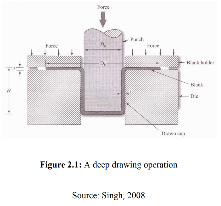
Sheet metal drawing mold construction involves the careful design and assembly of specialized tooling used to shape flat metal sheets into desired three-dimensional forms through deep drawing processes. The construction of these molds requires precision engineering to ensure the metal flows smoothly during forming, avoiding defects like tearing, wrinkling, or thinning, while maintaining dimensional accuracy and surface quality.
At the core of the mold construction are several key components: the punch, die, blank holder (or hold-down ring), and backing plate. The punch is the male part that presses into the metal sheet to shape it, while the die is the female cavity that supports the sheet and defines the final outer shape. The blank holder applies controlled pressure to hold the metal blank in place during forming, preventing wrinkles by restricting uncontrolled material flow. Together, these components must be designed with precise clearances, often a function of material thickness and ductility, to balance drawing forces and material deformation.
The construction process typically starts with the fabrication of the die block, machined from high-strength tool steel or alloy steel capable of withstanding repetitive impact and wear. Using CNC milling, wire EDM, and grinding, the die cavity is shaped to exact dimensions with smooth radii to guide the metal flow and reduce stress concentrations. The punch is manufactured to match the die profile, often with a polished surface finish to minimize friction against the metal. Surface treatments such as nitriding or coatings like titanium nitride may be applied to enhance hardness and reduce wear.
The blank holder is another critical component, designed to provide uniform pressure across the blank edge. It is typically mounted with springs or hydraulic cylinders to apply adjustable force, allowing fine-tuning during tryout. The backing plate provides structural support and absorbs the forming forces transferred from the punch and die, ensuring the mold maintains stability under heavy loads.
Assembly of the mold requires careful alignment of all components to maintain concentricity and parallelism, essential for uniform metal flow and avoiding uneven deformation. Precision dowel pins, guide pillars, and bushings are integrated to ensure repeatable, smooth motion of the punch relative to the die. The assembled mold is mounted onto a press capable of exerting the necessary tonnage for forming the particular metal and thickness.
In multi-stage or progressive mold constructions, additional features like trimming stations, ironing rings, or flange forming sections are incorporated into the tooling. These complex assemblies allow multiple forming steps in a single press cycle, improving efficiency for high-volume production.
Quality control throughout the construction process involves dimensional inspection using coordinate measuring machines, surface roughness measurements, and trial runs on test presses. Adjustments to clearances, blank holder pressures, or punch-die alignment are made as necessary to optimize performance.
In summary, sheet metal drawing mold construction is a meticulous process combining precision machining, material science, and mechanical design to produce durable tooling that can reliably transform flat metal sheets into complex, high-quality parts with consistent accuracy and surface finish.
Sheet metal drawing mold construction demands a deep understanding of material behavior, tooling mechanics, and precision manufacturing techniques to ensure the successful transformation of flat metal sheets into three-dimensional components. The process begins with selecting the appropriate materials for the mold components, typically high-grade tool steels that offer a balance of hardness, toughness, and wear resistance. These materials must withstand repeated high-pressure cycles without deforming or wearing prematurely, as any change in the mold geometry can directly affect the quality of the formed parts.
Machining the mold components involves advanced CNC milling, grinding, and wire EDM processes to achieve the precise shapes and tight tolerances required. The die cavity, punch profile, and blank holder surfaces are often polished to a mirror finish to reduce friction and prevent surface defects on the sheet metal during forming. Additionally, surface treatments such as nitriding, carburizing, or applying specialized coatings enhance hardness and corrosion resistance, extending tool life and reducing maintenance frequency.
Assembly is critical to the mold’s function, requiring careful alignment of the punch, die, and blank holder to maintain concentricity and parallelism. Precision guide pins and bushings ensure smooth, repeatable motion during each press cycle. The blank holder mechanism, whether spring-loaded, hydraulic, or pneumatic, must deliver consistent pressure to control metal flow and avoid wrinkles or tearing. Some designs incorporate adjustable blank holders to fine-tune pressure during tryouts and optimize forming conditions for different materials or thicknesses.
For complex parts or high-volume production, multi-stage molds integrate additional operations such as trimming, flanging, or ironing into the same tooling setup. These combined operations reduce cycle time and handling, improving overall efficiency and part consistency. In such molds, each station is carefully engineered to handle specific forming steps, with precise synchronization to ensure smooth transitions and minimal material stress.
During construction, thorough testing and validation take place. Trial runs are conducted on presses to observe material behavior, identify potential defects, and adjust clearances or forces accordingly. This iterative process is essential to achieving the ideal balance between tool durability, part quality, and production speed. Dimensional inspections using coordinate measuring machines confirm that the mold components meet design specifications, and surface profilometers assess finish quality.
Overall, the construction of sheet metal drawing molds is a complex blend of material selection, precision machining, mechanical design, and quality control. The resulting tooling must not only produce accurate and defect-free parts but also withstand the rigors of repeated, high-speed production cycles. Success in mold construction directly influences manufacturing efficiency, product quality, and long-term operational costs, making it a cornerstone of effective sheet metal forming processes across many industries.
In addition to the fundamental components and precision machining, the construction of sheet metal drawing molds increasingly incorporates technological advancements to enhance performance and longevity. One such advancement is the use of modular mold designs, which allow for easier maintenance, repair, and replacement of individual components without disassembling the entire mold. This modularity reduces downtime and costs associated with tooling changes, especially in production environments requiring frequent design iterations or handling multiple part variants.
Another key focus in mold construction is thermal management. During deep drawing, friction and deformation generate heat that can affect metal flow and tool life. Manufacturers address this by integrating cooling channels or temperature control systems within the mold structure. These systems maintain consistent mold temperatures, preventing thermal expansion that might alter clearances and ensuring stable forming conditions. Controlled cooling also reduces the risk of metal sticking or galling, further improving part surface quality and tool longevity.
Hydraulic and pneumatic systems are commonly incorporated to provide precise control over blank holder forces, punch movement, and ejector mechanisms. These systems enhance the mold’s adaptability, allowing fine adjustments during the setup phase and rapid response during production to compensate for material variations or process shifts. Some advanced molds feature electronically controlled actuators that enable programmable stroke profiles and force modulation, further optimizing metal flow and reducing forming defects.
Surface engineering techniques continue to play a crucial role in mold construction. Beyond traditional polishing and coating, manufacturers now apply advanced surface textures tailored to specific materials and forming conditions. Micro-texturing can reduce friction or promote controlled lubrication retention, which minimizes wear and enhances part finish. Similarly, laser texturing or chemical surface treatments create tailored friction profiles that improve metal flow control without excessive blank holder pressure.
The assembly process benefits from precision measurement tools and computer-aided alignment techniques. Laser trackers and 3D scanning systems verify component positions during assembly, ensuring that guide pins, bushings, and punch-die interfaces meet design tolerances. This accuracy is essential to prevent premature wear or uneven forces that can cause part defects or reduce mold lifespan.
Finally, documentation and traceability are integral to mold construction. Detailed records of materials, heat treatments, machining parameters, assembly steps, and inspection results provide a comprehensive history for each mold. This information supports ongoing maintenance, troubleshooting, and process optimization, as well as compliance with industry standards or customer requirements.
Overall, sheet metal drawing mold construction is a highly engineered process that combines traditional craftsmanship with modern technology. By integrating modular design, thermal control, advanced actuation, surface engineering, and precision assembly, manufacturers produce molds capable of delivering consistent, high-quality parts while maximizing durability and operational efficiency. These advancements enable manufacturers to meet the increasingly complex demands of today’s sheet metal forming industries across automotive, aerospace, consumer goods, and beyond.
Sheet Metal Drawing Mold Fabrication
Sheet metal drawing mold fabrication is the detailed manufacturing process of creating the physical tooling used in deep drawing operations to shape sheet metal into precise three-dimensional parts. This fabrication involves transforming carefully engineered designs into robust, accurate molds capable of withstanding repetitive high-pressure forming cycles while maintaining tight dimensional tolerances and superior surface finishes.
The fabrication process begins with selecting high-quality tool steel or alloy materials, chosen for their hardness, toughness, and wear resistance. These materials must endure the intense mechanical stresses and friction involved in metal drawing without deforming or deteriorating prematurely. Common choices include D2, A2, H13, or other specially treated steels, sometimes enhanced with surface coatings like titanium nitride or nitriding for added hardness and reduced friction.
Initial fabrication involves rough machining of the mold components using CNC milling machines to create the general shape of the die, punch, blank holder, and backing plate. Wire EDM (electrical discharge machining) is often employed to achieve intricate contours and sharp internal corners that are difficult to machine conventionally. This technology allows for precise cutting with minimal mechanical stresses on the material, essential for producing the detailed shapes required in complex molds.
After rough machining, components undergo heat treatment processes such as hardening and tempering to achieve the required mechanical properties. Heat treatment improves hardness and wear resistance, critical for mold longevity, while careful tempering prevents brittleness that could lead to cracking under repeated impact. Post heat-treatment, precision grinding and polishing refine the mold surfaces to exact dimensions and achieve smooth finishes, reducing friction and preventing damage to the sheet metal during forming.
Assembly follows, where components are aligned using precision dowel pins and guide pillars to ensure smooth, repeatable motion between the punch and die. The blank holder is fitted with springs or hydraulic systems to provide adjustable pressure, essential for controlling metal flow and preventing defects such as wrinkling. All moving parts are checked for clearance and alignment, with necessary adjustments made for optimal performance.
Throughout fabrication, quality control measures such as dimensional inspection with coordinate measuring machines (CMM) and surface roughness testing ensure that every component meets strict specifications. Trial runs on test presses simulate actual forming conditions to validate mold functionality, identify potential issues, and allow fine-tuning of blank holder forces, clearances, and punch stroke.
Finally, the fabricated mold may receive surface treatments or coatings to enhance durability and reduce friction. Manufacturers also document the entire fabrication process, including material certificates, heat treatment records, and inspection data, supporting traceability and ongoing maintenance.
In essence, sheet metal drawing mold fabrication is a highly precise, multi-step process combining advanced machining, metallurgy, assembly, and quality assurance. The result is a durable, accurate mold that enables efficient, consistent production of complex sheet metal parts across various industries.
The fabrication of sheet metal drawing molds is a meticulous process that demands precision at every step to ensure the final tooling can reliably produce high-quality parts. After selecting the appropriate tool steel, initial machining operations remove excess material to form the basic shape of the mold components. Advanced CNC machines are programmed to follow detailed CAD designs, often utilizing multi-axis milling to create complex geometries with tight tolerances. Wire EDM plays a crucial role in cutting intricate profiles and internal features that conventional machining cannot easily achieve, allowing for sharp corners and precise dimensions essential for proper metal flow during drawing.
Following rough machining, components undergo heat treatment to achieve the necessary hardness and strength. This step is carefully controlled because improper treatment can lead to warping, cracking, or loss of dimensional accuracy. Hardening increases wear resistance, which is vital given the repetitive mechanical stresses molds endure. After heat treatment, grinding and polishing refine the surfaces to mirror finishes where needed, minimizing friction between the mold and the metal sheet and preventing surface defects on the formed parts.
Assembly of the mold requires exact alignment of the punch, die, blank holder, and backing plates. Precision dowel pins and guide pillars ensure consistent motion and prevent lateral play during forming cycles. The blank holder mechanism is installed with adjustable force systems—springs or hydraulics—to regulate the pressure exerted on the blank, which controls metal flow and prevents wrinkling. This pressure must be carefully calibrated during initial setup and subsequent tryouts.
Quality assurance is woven into every phase of fabrication. Coordinate measuring machines verify that each mold component conforms to dimensional specifications, and surface profilometers measure roughness to ensure optimal finish. Trial runs on presses simulate real production conditions, revealing any potential issues such as uneven metal flow, excessive thinning, or part distortion. Adjustments to clearances, blank holder pressure, or punch stroke length are made iteratively to optimize performance.
In some cases, additional surface treatments or coatings are applied post-fabrication to extend tool life and reduce maintenance. These may include nitriding, titanium nitride coatings, or other specialized finishes that enhance hardness and reduce adhesion between the mold and sheet metal.
Throughout the entire fabrication cycle, thorough documentation records material batches, heat treatment parameters, machining operations, inspections, and trial results. This traceability supports maintenance planning and quality control throughout the mold’s operational lifespan.
Ultimately, sheet metal drawing mold fabrication is a complex, high-precision endeavor that integrates advanced machining, metallurgy, mechanical assembly, and rigorous testing. The final product is a durable, finely crafted tool that enables efficient, consistent production of complex sheet metal parts essential to industries such as automotive, aerospace, appliances, and electronics.
Beyond the core fabrication steps, continuous improvements in technology and materials science have significantly enhanced sheet metal drawing mold fabrication. Modern fabrication shops increasingly use computer-aided manufacturing (CAM) software integrated with CAD designs to program machining centers, ensuring consistent, repeatable production of complex mold components with minimal human error. This automation reduces lead times and improves accuracy, enabling faster turnaround from design to finished mold.
Additive manufacturing (3D printing) is also starting to influence mold fabrication, particularly for producing prototype components or intricate inserts that would be difficult or costly to machine conventionally. These 3D-printed inserts can be used to test new mold geometries or features before committing to full-scale production tooling, reducing development risk and cost. Some advanced tool steels and alloys compatible with additive processes allow production of durable inserts that can be integrated into traditional mold bases.
In fabrication facilities, precision environmental controls help maintain material stability during machining and assembly. Temperature and humidity regulation prevent material expansion or contraction that could otherwise affect dimensional accuracy. Vibration-damping setups and high-quality cutting tools further enhance machining precision, especially when working with hardened tool steels.
Toolmakers increasingly employ non-destructive testing (NDT) techniques during fabrication to detect internal flaws or stresses within mold components. Methods such as ultrasonic inspection or dye penetrant testing identify cracks, inclusions, or surface defects early, allowing repair or rejection before assembly. This practice enhances reliability and extends mold life, minimizing costly downtime during production.
Fabrication shops also emphasize ergonomic and safety considerations, designing workflows and equipment layouts to reduce operator fatigue and injury risks. Automated handling systems for heavy mold components and computer-aided inspection stations streamline the process while protecting workers.
Sustainability has become a growing priority in fabrication. Many manufacturers recycle scrap material from machining processes and utilize energy-efficient equipment to lower environmental impact. Some shops use biodegradable cutting fluids and adopt waste management programs to minimize hazardous material disposal.
Customer collaboration is a key element during fabrication, with manufacturers working closely with designers and production engineers to ensure the mold meets functional requirements and can be maintained easily. Feedback from initial tryouts leads to iterative improvements, and many fabrication specialists offer support services for mold repair, refurbishment, and upgrading as part of their offerings.
In conclusion, sheet metal drawing mold fabrication is a highly technical, evolving field that integrates advanced manufacturing technologies, quality assurance practices, and sustainable processes. The resulting molds are essential enablers of efficient, high-volume metal forming operations that produce critical components across a wide spectrum of industries.
Sheet Metal Drawing Mold Structure
The structure of a sheet metal drawing mold is designed to facilitate the controlled shaping of flat metal sheets into three-dimensional parts through deep drawing processes. It consists of several key components, each playing a vital role in guiding material flow, applying forming forces, and ensuring dimensional accuracy and surface quality.
At the heart of the mold structure is the punch, which acts as the male forming tool. The punch presses into the sheet metal blank, pushing it into the die cavity to form the desired shape. The punch is precision-machined, often polished or coated to reduce friction and prevent surface defects on the workpiece.
Opposite the punch is the die, the female part of the mold. The die provides the cavity into which the metal is drawn and supports the sheet during deformation. Its surface geometry defines the outer profile of the final part. The die must be carefully designed with appropriate radii and clearances relative to the punch to balance material flow and avoid excessive thinning or tearing.
Surrounding the punch and die is the blank holder, sometimes called a hold-down ring. The blank holder applies controlled pressure on the outer edges of the metal blank, restricting its movement to prevent wrinkling and uneven material distribution. The blank holder pressure is adjustable, allowing fine-tuning depending on the material type, thickness, and part complexity.
Supporting these main components is the die set or mold base, which provides structural integrity and houses guiding elements such as pillars, bushings, and dowel pins. These guide components ensure accurate alignment between the punch and die during each stroke of the press, maintaining consistent forming conditions and preventing tool damage.
Additional structural elements may include ejector pins or mechanisms that assist in removing the formed part from the die after the drawing operation is complete. In some mold designs, especially multi-stage or progressive molds, features like trimming stations, ironing rings, or flange forming sections are integrated to perform secondary operations within the same mold assembly.
The overall structure must withstand significant forming forces, often several tons, without deforming or losing alignment. Therefore, mold components are fabricated from hardened tool steels or alloy steels capable of enduring repeated impact and friction. Precision machining and heat treatment processes ensure the structural components maintain dimensional stability and surface quality over long production runs.
In summary, the sheet metal drawing mold structure is a carefully engineered assembly of punch, die, blank holder, and supporting framework. Each element works in concert to control material flow, apply necessary forces, and produce consistent, high-quality drawn parts while enduring the mechanical stresses of repeated forming cycles.
The structure of a sheet metal drawing mold is carefully designed to balance strength, precision, and functionality, ensuring efficient and defect-free forming of metal sheets. Central to this structure is the interaction between the punch and die, whose surfaces must be perfectly matched to guide the metal during deformation while minimizing stress concentrations that could cause tearing or excessive thinning. The die cavity is usually shaped with carefully calculated radii and draft angles to facilitate smooth metal flow, preventing sharp corners that might induce cracks or wrinkles.
The blank holder plays a crucial role in controlling the metal blank’s movement by applying adjustable pressure around its perimeter. This pressure must be sufficient to hold the sheet securely to prevent buckling or wrinkling but not so high as to restrict material flow excessively, which could lead to thinning or fracturing. Blank holders are often spring-loaded or hydraulically actuated to provide consistent, controllable force during the forming process, and in some molds, their pressure can be fine-tuned based on the material type and thickness.
Supporting elements such as the die set or mold base provide a rigid framework that resists the enormous forces generated during drawing. Precision-ground guide pillars and bushings ensure exact alignment of the punch and die throughout each press cycle, preventing misalignment that could damage the tooling or result in inconsistent part dimensions. These guides are designed for durability and minimal wear, often utilizing hardened steel components lubricated to reduce friction and prolong service life.
Ejector systems are incorporated into the mold structure to facilitate smooth removal of the finished part after forming. These systems can include pins, plates, or air blasts designed to gently push the drawn part out of the die cavity without causing distortion or surface damage. In some multi-stage molds, additional components are integrated to perform trimming, bending, or ironing operations in sequence, improving efficiency and reducing handling between process steps.
Material selection for mold components focuses on tool steels that can endure repeated high-pressure impacts and abrasive contact with the sheet metal. Heat treatment processes are applied to achieve the desired hardness and toughness, while surface finishing techniques such as polishing and coating help minimize friction and wear. The mold’s structural integrity must be maintained over thousands or millions of cycles, so attention to detail in design, material choice, and assembly is critical.
Thermal considerations also influence mold structure design, as heat generated during forming can cause thermal expansion affecting tolerances. Cooling channels or temperature control systems are sometimes embedded within the mold base to manage heat dissipation, maintaining dimensional stability and consistent forming conditions.
Ultimately, the structural design of a sheet metal drawing mold is a balance of mechanical strength, precision alignment, controlled material flow, and efficient part ejection. Each component must integrate seamlessly to ensure the mold delivers consistent, high-quality parts while enduring the rigorous demands of industrial production.
The structural design of a sheet metal drawing mold also accounts for ease of maintenance and adaptability. Modular construction techniques are often employed, where the punch, die, blank holder, and other key parts are manufactured as separate units that can be individually replaced or serviced without disassembling the entire mold. This modularity reduces downtime and enables quicker turnaround when wear or damage occurs, which is particularly important in high-volume production environments.
Within the mold assembly, precision alignment features such as dowel pins, locating shoulders, and tapered guides ensure that components fit together consistently every cycle. This repeatability is essential to maintain tight dimensional tolerances on the drawn parts and to prevent tool damage caused by misalignment or uneven forces. To further enhance alignment, some molds include self-aligning bushings or flexible couplings that accommodate slight variations while preserving overall accuracy.
Blank holder force control is often integrated into the mold structure through hydraulic or pneumatic systems that allow real-time adjustment during operation. This adaptability is crucial for processing different materials or thicknesses without needing to switch molds, providing flexibility and reducing tooling costs. Advanced systems may incorporate sensors and feedback loops that monitor forces and displacements, enabling automated optimization of blank holder pressure to minimize defects such as wrinkling or tearing.
The interface between the mold and the press machine also influences structural design. The mold base is engineered with standardized mounting features to fit securely into press bolsters, allowing rapid installation and removal. Shock absorption elements may be included to dampen impact forces and protect both the mold and the press. Additionally, mold weight and balance are carefully considered to ensure safe handling during setup and maintenance.
Surface treatments and coatings applied to mold components further enhance structural performance. Hard chrome plating, nitriding, or physical vapor deposition (PVD) coatings increase surface hardness and reduce friction, extending the service life of critical contact areas like punch faces and die cavities. These treatments also improve corrosion resistance, particularly important when forming reactive metals or in humid environments.
In more complex molds, integrated sensors or instrumentation may be embedded within the structure to monitor parameters such as temperature, pressure, or tool wear. This data supports predictive maintenance strategies, reducing unplanned downtime and optimizing mold life. Such smart mold features represent a growing trend towards Industry 4.0 integration in sheet metal forming.
In summary, the structure of a sheet metal drawing mold is a sophisticated assembly designed for precision, durability, adaptability, and efficient operation. By combining modularity, precise alignment, force control systems, and advanced surface engineering, modern molds meet the demanding requirements of high-volume manufacturing while enabling consistent production of complex sheet metal parts.
Sheet Metal Drawing Mold Components
A sheet metal drawing mold consists of several essential components that work together to shape flat metal sheets into three-dimensional parts through the drawing process. Each component has a specific function and must be precisely engineered and manufactured to ensure consistent, high-quality forming results. The primary components include:
- Punch
The punch is the male part of the mold that directly contacts and pushes the sheet metal blank into the die cavity. It defines the inner shape of the drawn part. The punch is precision machined and often polished or coated to reduce friction and prevent damage to the metal surface during forming. - Die
The die is the female counterpart to the punch, featuring a cavity that the metal is drawn into. It provides support for the sheet metal as it deforms and shapes the outer contour of the part. The die must have carefully designed radii and clearances relative to the punch to control material flow and avoid tearing or wrinkling. - Blank Holder (Hold-down Ring)
The blank holder applies pressure on the edges of the sheet metal blank to restrict its movement during drawing. This pressure helps prevent wrinkling and controls the metal flow into the die cavity. Blank holders may be spring-loaded, hydraulic, or pneumatic, with adjustable force depending on the material and part geometry. - Die Set (Mold Base)
The die set forms the structural frame that holds the punch, die, and blank holder in place. It provides rigidity and support during the forming process, ensuring proper alignment and withstanding the high forces involved. The die set includes guide pillars, bushings, and locating features to maintain accurate positioning. - Guide Pillars and Bushings
These components ensure precise alignment between the punch and die throughout the press stroke. Guide pillars are fixed rods that fit into bushings, enabling smooth, repeatable vertical movement while preventing lateral shifts that could damage tooling or produce defective parts. - Ejector System
Ejector pins or plates assist in removing the drawn part from the die cavity after forming. They push the finished component out without damaging it, facilitating rapid production cycles. Some molds may have air blowers or other mechanisms integrated for part ejection. - Backing Plate
The backing plate supports the die and absorbs forming forces transmitted through the mold. It reinforces the mold structure, distributing stress and preventing deformation or damage during operation. - Strippers
Strippers are components that help hold the sheet metal in place or strip it off the punch as it retracts after forming. They prevent the workpiece from sticking to the punch and ensure smooth ejection. - Springs or Hydraulic Systems
These provide the necessary force for the blank holder to maintain pressure on the sheet metal during forming. The type and strength of these systems are chosen based on the material properties and forming requirements. - Cooling Channels (Optional)
Some molds include integrated cooling channels within the die or mold base to regulate temperature during forming, improving tool life and part quality by controlling thermal expansion and heat buildup.
Together, these components form a precise, robust assembly designed to control material flow, apply forming forces, maintain alignment, and facilitate part removal. The quality and compatibility of these components directly influence the mold’s performance, durability, and the quality of the drawn sheet metal parts.
In addition to the primary components, several auxiliary parts and design features enhance the performance and longevity of sheet metal drawing molds. The punch, die, and blank holder surfaces are often treated or coated to reduce friction and wear, which not only extends tool life but also improves the quality of the formed parts by minimizing scratches, galling, or surface defects. Common surface treatments include hard chrome plating, nitriding, or applying specialized coatings like titanium nitride.
The precise fit and finish of guide pillars and bushings are critical because any misalignment can cause uneven forces, premature wear, or damage to both the mold and the sheet metal. These guiding components are usually made from hardened tool steel and undergo meticulous grinding and polishing to ensure smooth operation and long service life.
Ejector systems must be carefully designed to avoid deforming or scratching the delicate drawn parts during removal. The timing and force of ejection are calibrated to work seamlessly with the press cycle, enabling rapid part removal without interrupting production flow. In some complex molds, multiple ejector pins or plates may be used, strategically positioned to support the part evenly.
Backing plates and mold bases are engineered not only for strength but also to facilitate quick mold installation and removal from the press machine. Standardized mounting holes, locating features, and lifting points are incorporated to make handling safer and more efficient, which is especially important for heavy molds used in industrial settings.
Springs or hydraulic blank holder systems provide variable force control, which is essential because different materials and thicknesses behave uniquely during forming. Some advanced molds integrate sensors to monitor blank holder force in real time, allowing operators or automated systems to adjust pressure dynamically, reducing defects such as wrinkling or tearing.
Cooling channels, where used, help dissipate heat generated by friction and metal deformation. Controlled cooling prevents thermal expansion from altering critical dimensions and reduces the risk of heat-related tool damage. This is particularly important for molds used in high-speed or high-volume production environments.
Overall, the components of a sheet metal drawing mold must work in harmony, with each part designed for durability, precision, and ease of maintenance. The interaction between these components controls the flow of metal, applies appropriate forming forces, maintains alignment under stress, and ensures consistent ejection of finished parts. This complex integration is what enables efficient, repeatable deep drawing processes that produce high-quality sheet metal components across diverse industries.
Beyond the core components, the design of sheet metal drawing molds also emphasizes modularity and ease of maintenance. Many molds are constructed with interchangeable parts, such as punch inserts or die rings, which can be replaced individually when worn or damaged without requiring a complete mold rebuild. This modular approach significantly reduces downtime and tooling costs in production environments.
Material selection for each component is carefully matched to its function. For example, punches and dies are typically made from high-grade tool steels that have undergone heat treatment for hardness and wear resistance, while blank holders and mold bases may use slightly tougher alloys to absorb impact and resist deformation. Some components may also receive specialized surface treatments or coatings to reduce friction, prevent corrosion, and extend service life.
Precision machining and finishing are critical in mold manufacturing. Tolerances for punch and die clearances are often measured in microns to ensure smooth metal flow and prevent defects like tearing or wrinkling. Surfaces that contact the metal sheet are polished or textured according to specific requirements, balancing grip and slip to control material deformation.
Automation integration is increasingly common, with sensors embedded within the mold assembly to monitor variables such as force, temperature, and wear in real time. This data enables predictive maintenance and process optimization, helping manufacturers avoid unexpected breakdowns and maintain consistent quality.
The mold components must also withstand repeated, high-frequency cycles, sometimes numbering in the millions, without significant loss of performance. This demands not only strong materials but also effective lubrication strategies and thermal management to mitigate wear and heat buildup.
In some advanced molds, additional features such as multi-stage drawing stations, trimming and piercing units, or ironing rings are integrated within the same assembly. These complex designs reduce handling between operations, improve dimensional accuracy, and increase throughput, making them essential for high-volume manufacturing of intricate sheet metal parts.
Ultimately, the combination of robust, precise components, modular design, advanced materials, and smart monitoring defines modern sheet metal drawing molds. This synergy allows manufacturers to produce complex, high-quality parts efficiently while minimizing downtime and extending tool life.
Sheet Metal Drawing Mold Design
Designing a sheet metal drawing mold involves a careful balance of material properties, part geometry, process parameters, and tooling mechanics to ensure efficient forming of metal sheets into precise, defect-free shapes. The design process begins with a thorough analysis of the part’s shape, dimensions, and functional requirements, which guides the selection of appropriate mold components and their configurations.
Key considerations include the selection of suitable punch and die profiles that accommodate the part’s geometry while minimizing stresses and material thinning. The die cavity is designed with appropriate radii and clearances relative to the punch, typically based on the sheet metal thickness and material ductility, to control the metal flow during drawing and avoid failures like cracking or wrinkling.
The blank holder’s design is critical for controlling the metal blank’s movement during forming. Its force must be sufficient to prevent wrinkling but not so high as to restrict material flow, which could cause tearing. The blank holder shape often mirrors the outer contour of the part, and its pressure is adjustable—sometimes hydraulically or pneumatically—to fine-tune the forming conditions based on material and thickness.
Material selection for the mold components typically involves high-strength tool steels, heat-treated for hardness and wear resistance. Surface treatments such as polishing or coatings reduce friction between the mold and the sheet metal, improving surface finish and tool longevity.
The mold structure must be rigid and precisely aligned, incorporating guide pillars, bushings, and dowel pins to maintain exact positioning of the punch and die throughout the press stroke. This ensures consistent part quality and prevents damage to the tooling.
Thermal management is sometimes integrated into the design, with cooling channels or temperature control features to mitigate heat buildup during high-speed or long production runs. Managing temperature helps maintain dimensional accuracy and prolong tool life.
Advanced mold designs may include multi-stage operations such as trimming, ironing, or flanging within the same assembly, improving efficiency by reducing handling and secondary operations.
Ergonomics and maintenance are also factored into the design, with modular components that allow quick replacement or adjustment, and features that facilitate easy installation, alignment, and part ejection.
Overall, sheet metal drawing mold design is a complex, multidisciplinary process that combines mechanical engineering, materials science, and manufacturing expertise to create tooling capable of producing high-quality, repeatable sheet metal parts efficiently and reliably.
Designing a sheet metal drawing mold also involves detailed calculations and simulations to predict material behavior and optimize tooling geometry. Engineers often use finite element analysis (FEA) to model the forming process, assessing factors like stress distribution, strain, thinning, and potential failure points in the sheet metal. This virtual testing helps refine punch and die shapes, blank holder pressure, and clearance values before physical prototypes are made, reducing costly trial-and-error during production.
Another crucial aspect is the accommodation of springback—the elastic recovery of metal after forming—which can cause dimensional inaccuracies. Mold designers compensate for this by adjusting the mold geometry or including secondary operations such as ironing or flanging to achieve the final precise dimensions.
The mold’s punch and die clearances are carefully calculated, generally ranging between 5% to 15% greater than the sheet thickness, depending on the material type and thickness. Too tight a clearance can cause excessive tool wear and increased forming forces, while too loose a clearance can lead to poor part accuracy and defects.
Blank size and shape must be optimized as well, considering material utilization and forming characteristics. An oversized blank may increase waste and require more force, while an undersized blank risks incomplete forming or tearing. The blank holder’s contact area and pressure distribution are designed to evenly control the metal flow around the blank’s edges.
Surface finish of mold components is designed with specific roughness values tailored to the material and forming conditions. A mirror-like finish reduces friction and improves part surface quality but may require lubrication. In contrast, textured surfaces can help grip slippery metals and reduce slippage during forming.
Ejection mechanisms are integrated into the design to ensure smooth, damage-free removal of the drawn part. This may include ejector pins, stripper plates, or air blasts, with their positions and forces carefully calculated to avoid deformation or surface marking.
Manufacturing considerations also influence mold design. The mold must be manufacturable with available machining, grinding, and finishing technologies, and designed for ease of assembly and adjustment. Modular designs are preferred to allow quick replacement of wear parts like punches or die inserts, minimizing downtime.
In some designs, provisions are made for integrating sensors and automation controls that monitor forming parameters such as force, displacement, and temperature. These smart mold features support real-time adjustments and predictive maintenance, enhancing productivity and part quality.
Overall, sheet metal drawing mold design is a highly iterative and precise process that combines theoretical knowledge, computer-aided engineering, material science, and practical manufacturing insights to produce molds that reliably create complex parts with excellent surface quality and dimensional accuracy.
Material selection plays a pivotal role in sheet metal drawing mold design. Tool steels such as D2, A2, or H13 are commonly used due to their excellent hardness, toughness, and wear resistance. These steels can withstand the repetitive high stresses and abrasive conditions inherent in deep drawing operations. Heat treatment processes like quenching and tempering are applied to achieve the desired balance of hardness and toughness, ensuring the mold components maintain dimensional stability over extended production runs.
The geometry of the punch and die is intricately designed to facilitate smooth metal flow and reduce the risk of defects. Sharp corners are avoided in favor of rounded radii, which help distribute stresses more evenly and reduce localized thinning. These radii must be optimized based on the material’s ductility and thickness to prevent cracking or tearing during forming. Similarly, the die cavity’s surface is contoured to support the sheet metal as it is drawn, ensuring uniform deformation.
Blank holder design is another critical consideration. It must apply uniform pressure to the sheet metal blank’s periphery to prevent wrinkling while allowing enough material flow into the die cavity to avoid tearing. The blank holder force is adjustable, often through springs or hydraulic cylinders, to accommodate variations in material properties and thicknesses. Some advanced designs utilize segmented blank holders that can apply variable pressure in different zones for more precise control over metal flow.
Attention to thermal management is increasingly important as high-speed and high-volume forming operations generate significant heat. Cooling channels integrated into the mold components help dissipate this heat, maintaining tool hardness and preventing thermal expansion that can affect tolerances. This cooling system is typically designed to circulate water or oil efficiently without compromising the mold’s structural integrity.
The mold’s overall structural design must provide rigidity to withstand forming forces without excessive deflection. Reinforcements such as backing plates and robust mold bases distribute loads and prevent distortion. Proper alignment mechanisms like guide pins and bushings ensure repeatability and prevent damage caused by misalignment during repeated cycles.
Finally, ease of maintenance is factored into the design. Quick-release mechanisms, modular inserts, and accessible fastening points enable fast replacement or repair of worn components. This approach minimizes production downtime and extends the effective life of the mold.
Together, these design principles form the foundation of effective sheet metal drawing molds that consistently produce high-quality parts while maximizing durability and operational efficiency.
Sheet Metal Drawing Mold
A sheet metal drawing mold is a specialized tooling assembly designed to shape flat sheet metal blanks into three-dimensional parts by stretching and forming the metal through a controlled process known as deep drawing. This mold typically consists of a punch and die set, a blank holder, guide mechanisms, and ejectors, all precisely engineered to control material flow, prevent defects like wrinkling or tearing, and ensure dimensional accuracy of the finished part.
The punch acts as the male forming tool, pushing the sheet metal into the die cavity, which serves as the female counterpart defining the outer shape. The blank holder applies pressure on the sheet’s edges to control material movement during forming, avoiding wrinkles while allowing smooth flow. Proper clearance between the punch and die, typically related to sheet thickness and material type, is crucial to avoid excessive thinning or cracks.
High-strength tool steels, often heat-treated and surface-finished, are used for mold components to withstand repetitive high forces and friction while maintaining surface quality. Cooling systems, ejector mechanisms, and modular design features are commonly integrated to enhance mold performance, longevity, and ease of maintenance.
Overall, a sheet metal drawing mold is a complex and precise tool that enables efficient mass production of consistent, high-quality metal parts used across automotive, aerospace, appliance, and cookware industries, among others.
The effectiveness of a sheet metal drawing mold hinges on the careful balance between material properties, tooling geometry, and process parameters. The selection of the sheet metal material—such as steel, aluminum, copper, or stainless steel—impacts the mold design because each material has distinct ductility, strength, and friction characteristics that influence how the metal flows during forming. Mold designers adjust punch and die profiles, clearances, and blank holder forces accordingly to accommodate these differences.
The blank holder’s role is particularly vital, as it controls the metal’s flow into the die cavity by applying a uniform pressure around the blank’s edge. If the pressure is too low, wrinkling occurs; too high, and the material may tear or fracture. Adjustable blank holders, sometimes using hydraulic or pneumatic systems, allow for fine-tuning of this force to match the specific material and part geometry.
Surface finish of the mold components also affects the forming process. Polished surfaces reduce friction, helping the metal to flow smoothly and preventing surface defects, but may require lubrication to avoid galling. Conversely, slightly textured surfaces can enhance grip on slippery materials, controlling metal flow without excessive lubrication.
The mold must maintain precise alignment throughout the forming cycle, achieved through the use of guide pillars, bushings, and dowel pins. This ensures the punch and die meet perfectly every stroke, which is essential to avoid uneven forming forces that can damage the tool or produce defective parts.
Thermal considerations are increasingly important, especially in high-volume production. Heat generated by friction and metal deformation can cause thermal expansion, affecting tolerances and accelerating wear. Integrating cooling channels within the mold helps maintain a stable temperature, preserving dimensional accuracy and extending tool life.
Ejector systems are designed to safely and efficiently remove the formed part from the die without deformation or surface damage. These may include ejector pins, stripper plates, or air blasts, whose forces and timing are precisely controlled to match the part geometry and material.
Modularity in mold design allows for easier maintenance and adaptability. Interchangeable components like punch tips or die inserts can be replaced individually when worn, minimizing downtime and tooling costs. Additionally, modern molds often incorporate sensors to monitor parameters like force, temperature, and wear in real time, supporting predictive maintenance and process optimization.
Ultimately, the success of a sheet metal drawing mold depends on a harmonious integration of materials science, mechanical engineering, and manufacturing expertise to deliver durable tooling that consistently produces high-quality parts with tight dimensional control and excellent surface finish.
To further enhance the design and functionality of sheet metal drawing molds, engineers increasingly rely on advanced computer-aided design (CAD) and simulation tools. Finite Element Analysis (FEA) allows detailed modeling of the metal forming process, predicting how the sheet will behave under different conditions of stress, strain, and friction. This enables optimization of mold geometry, clearance, and blank holder pressure before physical tooling is produced, reducing trial-and-error iterations and lowering development costs.
The integration of multi-stage operations within a single mold setup has become common in modern manufacturing. Instead of requiring multiple separate press stations, processes like drawing, trimming, piercing, and ironing can be combined sequentially in one assembly. This not only accelerates production by minimizing part handling but also improves dimensional accuracy by reducing cumulative errors.
Material advances also influence mold design. High-performance tool steels with superior wear resistance and toughness allow molds to withstand higher production volumes. Coatings such as titanium nitride or diamond-like carbon reduce friction and wear further, while specialized lubricants protect both tool and sheet metal surfaces.
Automation integration is another critical trend. Smart molds equipped with sensors track parameters such as forming force, temperature, and cycle count, providing real-time feedback to operators or automated control systems. This data facilitates predictive maintenance, helping to schedule repairs before catastrophic failures occur and ensuring consistent part quality.
Ergonomic and safety considerations are increasingly incorporated into mold design. Quick-change mechanisms, lightweight components, and standardized mounting features simplify mold installation and removal, reducing operator fatigue and downtime. Safety interlocks and guards protect personnel from the hazards of press operation.
In high-precision applications, tolerances may be tightened by designing molds with adjustable features that allow fine calibration during setup. This adaptability is critical when working with new materials or complex part geometries, where slight adjustments can significantly impact final product quality.
In summary, sheet metal drawing mold design is a sophisticated engineering discipline that combines mechanical precision, material science, simulation technology, and process automation to create tooling capable of producing complex, high-quality sheet metal parts efficiently and reliably in demanding industrial environments.
EMS Metalworking Machines
We design, manufacture and assembly metalworking machinery such as:
- Hydraulic transfer press
- Glass mosaic press
- Hydraulic deep drawing press
- Casting press
- Hydraulic cold forming press
- Hydroforming press
- Composite press
- Silicone rubber moulding press
- Brake pad press
- Melamine press
- SMC & BMC Press
- Labrotaroy press
- Edge cutting trimming machine
- Edge curling machine
- Trimming beading machine
- Trimming joggling machine
- Cookware production line
- Pipe bending machine
- Profile bending machine
- Bandsaw for metal
- Cylindrical welding machine
- Horizontal pres and cookware
- Kitchenware, hotelware
- Bakeware and cuttlery production machinery
as a complete line as well as an individual machine such as:
- Edge cutting trimming beading machines
- Polishing and grinding machines for pot and pans
- Hydraulic drawing presses
- Circle blanking machines
- Riveting machine
- Hole punching machines
- Press feeding machine
You can check our machinery at work at: EMS Metalworking Machinery – YouTube
Applications:
Flange-punching
Beading and ribbing
Flanging
Trimming
Curling
Lock-seaming
Ribbing