
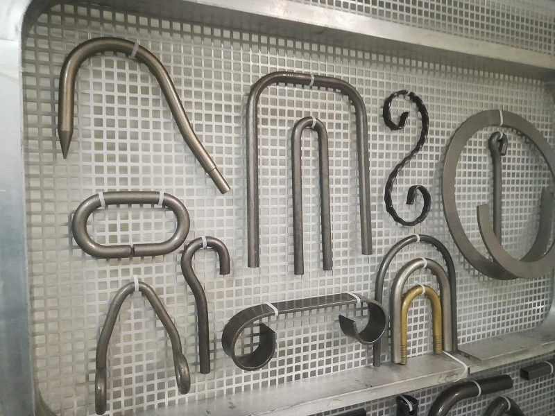
Metal Pipe Bending and Forming Machines: Metal pipe bending and forming machines are essential tools in modern manufacturing, designed to shape metal pipes and tubes into specific configurations needed across various industries such as automotive, aerospace, construction, furniture, and HVAC. These machines operate by applying controlled mechanical forces to deform metal tubes without compromising their structural integrity or surface quality. The processes include bending pipes to precise angles and radii, curling or coiling tube ends, flaring or expanding diameters, reducing sections, and creating complex multi-plane shapes.
Bending machines come in different types, including manual, hydraulic, electric, rotary draw, mandrel, roll, and CNC-controlled models, each suited for specific applications depending on pipe material, diameter, wall thickness, required bend complexity, and production volume. Rotary draw bending is often employed for precise, tight-radius bends, while roll bending is used for larger radius curves. Hydraulic pipe benders provide the power necessary for thick-walled or large-diameter pipes, and electric machines offer clean, energy-efficient operation with precise servo control. CNC pipe bending machines automate the entire bending sequence, allowing for complex, repeatable, and accurate production with minimal manual intervention.
Forming machines extend beyond bending to include operations such as flaring tube ends, expanding or reducing diameters, swaging, and curling. Curling machines shape tube ends into decorative or functional curls using rotating rollers or dies. Forming machines employ tooling like dies, rollers, mandrels, and pressure devices made from hardened materials to maintain shape accuracy and protect pipe surfaces. These machines use mechanical presses, hydraulic cylinders, electric servo motors, or combinations thereof to deliver controlled deformation forces. CNC integration is common, enabling programmable and automated forming sequences that improve repeatability, reduce waste, and support complex geometries.
Throughout these processes, internal supports such as mandrels are often used to prevent defects like wrinkling, flattening, or cracking, particularly in thin-walled or high-strength tubes. Lubrication systems reduce friction and wear, ensuring smooth operation and prolonging tooling life. Spring-back compensation is crucial in bending, where the pipe’s tendency to partially return to its original shape is offset by overbending based on material properties and tooling parameters.
Modern machines incorporate sensors and real-time feedback systems that monitor parameters such as bending angle, feed length, applied force, and tube position. These systems allow dynamic adjustments during operation to maintain precision and compensate for material variability or tooling wear. Advanced software provides graphical interfaces for programming, simulation, and diagnostics, facilitating quick setup and reducing errors.
Automation is a key feature of contemporary pipe bending and forming equipment. Machines may be integrated into production lines with robotic loading and unloading, conveyors, and downstream processes like cutting, marking, or inspection. This integration streamlines workflows, increases throughput, and minimizes manual handling. Safety features including emergency stops, protective guarding, light curtains, and ergonomic controls ensure operator protection.
Maintenance of these machines involves regular inspection and servicing of mechanical components, hydraulic or electric drive systems, sensors, and tooling to maintain consistent quality and prevent downtime. Operator training enhances safety and operational efficiency.
Materials handled by these machines range from mild steel and stainless steel to aluminum, copper, and specialized alloys, each requiring tailored machine settings and tooling to accommodate unique mechanical properties. The ability to work with diverse materials and complex shapes makes pipe bending and forming machines indispensable in manufacturing high-quality, durable components for a broad spectrum of applications.
Overall, metal pipe bending and forming machines represent a sophisticated fusion of mechanical engineering, material science, and digital control technology. Their continuous evolution supports increasing demands for precision, efficiency, and flexibility in industrial production, enabling manufacturers to meet stringent quality standards while optimizing productivity and reducing costs.
1. Design and Engineering
- Requirement Analysis: Define the machine’s capacity, pipe diameter range, bending radius, type (CNC or manual), and application.
- CAD Modeling: Create detailed 3D models of the machine components using CAD software (SolidWorks, AutoCAD).
- Material Selection: Choose materials for the frame (usually steel), rollers, bending dies (hardened steel), hydraulic parts, and control systems.
2. Material Procurement
- Purchase raw materials like:
- Steel plates, pipes, and bars for frame and components.
- Hydraulic cylinders, pumps, and motors.
- Electrical components (motors, sensors, controllers).
- CNC control units (for automated machines).
3. Frame Fabrication
- Cutting: Use laser cutting or plasma cutting to cut steel plates to shape.
- Forming: Bend or shape steel plates and profiles as required.
- Welding: Weld the frame components together with high precision to ensure rigidity and alignment.
- Surface Treatment: Clean, deburr, and paint or powder coat the frame for durability and corrosion resistance.
4. Component Manufacturing
- Machining:
- CNC machining of rollers, bending dies, shafts, and other critical parts.
- Turning, milling, drilling to achieve tight tolerances.
- Heat Treatment: Harden dies and rollers to improve wear resistance.
- Grinding/Polishing: Smooth surfaces on rollers and dies to reduce pipe damage.
5. Hydraulic System Assembly
- Assemble hydraulic cylinders, pumps, valves, and piping.
- Test hydraulic pressure and flow rates to meet bending force requirements.
6. Electrical System and Controls
- Wiring: Install wiring harnesses for motors, sensors, and control units.
- Control Panel: Set up CNC or PLC-based control systems with user interfaces.
- Programming: Load machine control software, set parameters for bending operations.
7. Machine Assembly
- Install machined parts onto the frame: rollers, bending arms, dies.
- Mount hydraulic and electrical systems.
- Align components precisely to ensure smooth pipe feeding and bending.
8. Testing and Calibration
- Run trial bends with different pipe sizes and materials.
- Adjust hydraulic pressures, motor speeds, and control parameters.
- Verify bending angles, radius accuracy, and pipe surface quality.
- Perform safety and operational checks.
9. Finishing
- Final painting or coating touch-ups.
- Attach safety guards, labels, and documentation.
- Package the machine for shipment.
10. Installation and Commissioning (optional)
- Ship and install at customer site.
- Perform final setup and operator training.
The manufacturing process of a pipe bending machine begins with careful planning and design where engineers define the machine’s capabilities such as pipe diameter range, bending radius, and type of operation—whether manual or CNC controlled. This phase involves creating detailed 3D models of the machine components using CAD software and selecting appropriate materials. Steel is commonly chosen for the frame due to its strength and durability, while hardened steel is used for bending dies and rollers to ensure long-lasting performance.
Once the design is finalized, raw materials are procured. Steel plates and bars for the frame are cut using precision methods like laser or plasma cutting, then shaped and welded together to form a rigid and accurately aligned frame. The welding process must be carefully controlled to maintain dimensional accuracy and structural integrity. Surface treatments such as cleaning, deburring, and painting or powder coating are applied to protect the machine from corrosion and wear.
Critical components such as rollers, bending dies, shafts, and other parts are manufactured through CNC machining processes including turning, milling, and drilling. These components are then heat-treated to enhance hardness and wear resistance. After heat treatment, grinding and polishing are done to ensure smooth surfaces, which is essential for bending pipes without causing damage or scratches.
The hydraulic system, which provides the necessary force for bending, is assembled with cylinders, pumps, valves, and piping. This system is carefully tested for pressure and flow rate to ensure it meets the required specifications. The electrical system and controls are also installed, including wiring for motors and sensors, and the setup of control panels that may use CNC or PLC systems. Programming of the control unit is performed to enable precise bending operations and repeatability.
With the frame and components ready, the machine assembly begins by mounting the machined parts such as rollers and bending arms onto the frame, followed by installing the hydraulic and electrical systems. Alignment is crucial during this step to ensure smooth pipe feeding and consistent bending performance.
Once assembled, the machine undergoes rigorous testing and calibration. Trial bends are performed using various pipe sizes and materials to verify bending angles, radius accuracy, and surface quality. Hydraulic pressure and motor speeds are adjusted, and the machine is checked for safety and operational reliability.
Final finishing touches are applied, including painting, attaching safety guards, and adding instructional labels and documentation. The completed pipe bending machine is then packaged for shipment to customers. Upon delivery, installation and commissioning services may be provided, which include final setup, calibration, and operator training to ensure the machine functions optimally in its working environment.
Throughout this process, attention to detail, precision machining, and rigorous quality control are essential to producing a reliable pipe bending machine capable of meeting industry standards and customer expectations.
In addition to the main manufacturing steps, several other factors contribute significantly to the quality and performance of a pipe bending machine. The selection of tooling is critical: bending dies and mandrels must be designed specifically for the pipe diameters and materials they will handle. Precision in these tools minimizes defects such as wrinkling, flattening, or cracking during bending. Mandrel bending machines, for example, use internal supports to maintain the pipe’s shape through the bending process, which is especially important for thin-walled pipes or materials prone to deformation.
Automation and control technologies are increasingly integrated into modern pipe bending machines to improve efficiency and accuracy. CNC-controlled machines can store multiple bending programs, enabling quick setup for different pipe specifications and repetitive production runs. This reduces operator error and increases throughput. Additionally, sensors and feedback systems monitor the bending process in real time, allowing the machine to adjust parameters dynamically to maintain quality.
Maintenance is another essential aspect that influences the longevity and performance of pipe bending machines. Regular lubrication of moving parts, inspection of hydraulic systems for leaks or wear, and timely replacement of worn tooling ensure consistent operation. Manufacturers often design machines with ease of maintenance in mind, including accessible components and diagnostic features.
Environmental and safety considerations also shape the manufacturing process. Machines are equipped with safety guards, emergency stop buttons, and compliance with relevant industrial standards to protect operators. Noise reduction features and ergonomic designs improve the working environment.
Finally, the development of new materials and manufacturing techniques continually advances pipe bending machine technology. For example, additive manufacturing (3D printing) allows rapid prototyping of complex components, while advanced alloys can enhance durability without increasing weight. These innovations contribute to machines that are more precise, versatile, and cost-effective.
Overall, the manufacturing of pipe bending machines is a complex, multidisciplinary process combining mechanical engineering, materials science, hydraulics, electronics, and software development. The end goal is to deliver reliable, efficient equipment tailored to a wide range of industrial applications, from automotive and aerospace to construction and shipbuilding.
Pipe Bending Machine Parts
Here’s a list of the main parts of a Pipe Bending Machine along with brief descriptions of their functions:
1. Frame
- The main structure that supports all components and provides rigidity and stability during bending operations.
2. Bending Die (Former)
- The shaped tool around which the pipe is bent. It determines the bending radius and helps maintain pipe shape.
3. Clamp Die (Clamp Block)
- Holds the pipe firmly against the bending die to prevent slipping during the bending process.
4. Pressure Die
- Applies pressure to the pipe as it is bent, supporting the outer side and preventing wrinkles or deformation.
5. Mandrel
- A rod inserted inside the pipe during bending (in mandrel bending machines) to support the inner wall and prevent collapse or wrinkling, especially for thin-walled pipes.
6. Rotary Arm (Bending Arm)
- The part that rotates the bending die and pipe to create the bend according to the required angle.
7. Hydraulic Cylinder / Pneumatic Cylinder
- Provides the force needed to move the rotary arm or apply pressure during bending.
8. Backstop / Return Mechanism
- Helps return the bending arm to its original position after the bend is completed.
9. Control Panel
- Interface for the operator to control the machine. On CNC machines, it includes programming and monitoring functions.
10. Drive Motor
- Powers the hydraulic pump or mechanical components that move the bending arm.
11. Hydraulic Pump and Valves
- Generates and controls hydraulic pressure and flow to drive cylinders and other hydraulic components.
12. Feed Rollers / Guide Rollers
- Guide and feed the pipe into the bending area, ensuring correct positioning.
13. Angle Sensor / Encoder
- Measures the bending angle to ensure accuracy and repeatability.
14. Safety Guards and Emergency Stop
- Protective covers and switches to ensure operator safety during machine operation.
A pipe bending machine consists of several key parts that work together to perform precise and controlled bending of pipes. The frame acts as the sturdy backbone of the machine, providing the necessary support and rigidity to withstand the forces involved in bending. Mounted on this frame are the bending die and clamp die. The bending die is the core tool shaped to the desired bend radius, around which the pipe is formed. The clamp die holds the pipe securely against the bending die to prevent slippage during the bending operation.
In machines designed for more delicate or thin-walled pipes, a mandrel is inserted inside the pipe to provide internal support. This prevents the pipe from collapsing or wrinkling on the inside curve during bending. The rotary arm, also known as the bending arm, rotates the bending die along with the pipe, creating the bend by moving through a specific angle. The force required for this movement is usually delivered by a hydraulic or pneumatic cylinder, which ensures smooth and powerful operation.
After the bending is complete, the backstop or return mechanism brings the rotary arm back to its original position, ready for the next pipe. Control of the machine is handled through the control panel, where the operator can set parameters, monitor the process, and in CNC machines, program multiple bending sequences for different pipe specifications. The drive motor powers the hydraulic pump or mechanical system responsible for moving the bending components.
Hydraulic pumps and valves regulate the flow and pressure of hydraulic fluid, controlling the motion and force applied by cylinders. Feed rollers or guide rollers are employed to accurately position and feed the pipe into the bending area, ensuring the pipe enters the machine in proper alignment. To achieve precision, angle sensors or encoders measure the degree of bend in real time, allowing the control system to stop the bending arm at exactly the right position.
Safety is an essential aspect of the machine’s design. Safety guards protect the operator from moving parts, and emergency stop buttons allow for immediate shutdown in case of any hazardous situation. All these components together create a highly coordinated system that efficiently bends pipes to precise angles without damaging the material, enabling their use across various industrial applications.
Beyond the fundamental parts, many pipe bending machines incorporate additional components to enhance functionality and versatility. For instance, some machines feature adjustable supports or rollers that can be repositioned to accommodate different pipe lengths or diameters, improving the machine’s adaptability to varied job requirements. Cooling systems might also be integrated to dissipate heat generated by continuous bending cycles, helping maintain consistent performance and prolonging component life.
In CNC pipe bending machines, the control panel is often connected to software that allows for complex bending sequences, including multi-axis bending and precise control of bend angles and rotation. These systems can store numerous programs, enabling quick changeovers and reducing setup time. Feedback loops from sensors ensure each bend meets the exact specifications by correcting any deviations in real time.
The hydraulic system, central to many pipe bending machines, must be designed with components capable of handling the high pressures involved. This includes high-quality pumps, valves, hoses, and cylinders rated for durability and safety. Regular maintenance of these components is essential to avoid leaks, pressure loss, or failures that could interrupt production or cause safety hazards.
Moreover, the choice of materials for parts like the bending die and rollers directly affects machine performance. Hardened steel or special alloys resist wear and deformation under repeated stress, reducing downtime for repairs or replacement. Surface treatments such as nitriding or chrome plating enhance durability and reduce friction, minimizing the risk of damaging pipes during bending.
Operators also benefit from ergonomic features such as adjustable control panels, intuitive interfaces, and clear visibility of the bending area, which together improve ease of use and reduce fatigue during extended operation. Integration with automation lines or robotic arms can further streamline production processes, enabling unattended or semi-automated bending.
Overall, pipe bending machines are complex assemblies of mechanical, hydraulic, and electronic systems designed to work harmoniously. The continuous evolution of these machines incorporates advances in materials, control technologies, and user experience, making them indispensable tools across industries like automotive, aerospace, construction, and shipbuilding.
Metal Tube Forming Machine
A Metal Tube Forming Machine is a specialized industrial machine used to shape metal tubes into desired profiles or geometries. Unlike simple bending machines that mainly create curves or angles, tube forming machines can perform a variety of processes such as bending, expanding, shrinking, flattening, and shaping tubes into complex forms for automotive, aerospace, furniture, and construction applications.
The core purpose of a metal tube forming machine is to transform straight tubes into functional parts with precise dimensions and surface quality, often required for frames, chassis components, exhaust systems, and structural supports.
These machines typically consist of a rigid frame to hold the tube securely, feeding mechanisms to control tube movement, and forming tools like dies, rollers, and mandrels to shape the tube accurately. Depending on the complexity, forming machines may be manual, hydraulic, mechanical, or CNC-controlled for automated and repeatable operations.
Common tube forming processes include rotary draw bending, roll forming, compression bending, and multi-axis bending, each suited to different shapes and material types. Advanced machines integrate sensors and computer controls to monitor parameters such as bending radius, angle, and tube position, ensuring consistency and minimizing defects.
The design of the forming tools is crucial since the tooling must accommodate variations in tube diameter, wall thickness, and material properties while preventing common issues like wrinkling, buckling, or surface damage.
In manufacturing environments, metal tube forming machines are often part of larger automated production lines, working alongside cutting, welding, and finishing equipment to produce ready-to-assemble components efficiently.
A metal tube forming machine operates by securely holding the metal tube in place and gradually applying forces through specialized tools to shape the tube into the desired form. The process often begins with feeding the tube into the machine using rollers or clamps that ensure precise positioning and movement. The forming tools, which may include bending dies, rollers, mandrels, or compression heads, then engage with the tube to manipulate its shape through bending, stretching, compressing, or rolling actions.
The machine’s frame provides the structural support necessary to withstand the forces generated during forming, maintaining alignment and preventing deformation of the equipment itself. Depending on the type of forming process, the machine may apply force through hydraulic cylinders, mechanical cams, or servo motors, each offering different levels of control, speed, and precision.
In rotary draw bending, a common tube forming method, the tube is bent around a fixed radius die while a clamp die holds it firmly to prevent slipping. This technique is favored for producing smooth, accurate bends without wrinkles or flattening. Mandrel bending adds an internal support to the tube to maintain the shape of thin-walled or delicate tubes during bending.
Roll forming machines gradually bend tubes by passing them through a series of rollers, each incrementally changing the tube’s shape. This process is efficient for producing large volumes of parts with consistent shapes. Compression bending, on the other hand, pushes the tube against a die to create bends, often used for large-radius or simple bends.
The use of CNC technology in modern tube forming machines allows for complex, multi-axis bending operations. Operators can program sequences with precise control over bend angles, rotation, and feeding length, enabling the production of intricate parts with high repeatability and minimal setup time.
Throughout the forming process, sensors and encoders monitor the tube’s position and bending parameters, feeding data back to the control system to make real-time adjustments. This reduces errors and scrap rates, improving overall efficiency.
Material properties such as tube diameter, wall thickness, and alloy type significantly influence forming parameters. The forming tools and machine settings must be adapted to accommodate these variables to avoid defects like cracking, wrinkling, or spring-back, where the tube slightly returns toward its original shape after bending.
Maintenance of tube forming machines involves regular inspection of tooling, lubrication of moving parts, and calibration of sensors and controls to ensure consistent performance. Proper upkeep prolongs machine life and maintains product quality.
Metal tube forming machines are vital in industries requiring precise tubular components, such as automotive exhaust systems, bicycle frames, HVAC ducting, and aerospace structural parts. Their ability to transform raw tubes into complex shapes efficiently makes them indispensable in modern manufacturing.
Beyond the basic forming operations, metal tube forming machines often incorporate additional features to increase versatility and productivity. For instance, some machines include automatic tube feeders that handle raw material loading and positioning, minimizing manual labor and improving cycle times. Integrated cutting units may also be present, allowing tubes to be cut to length immediately after forming, which streamlines production workflows.
Advanced machines may support multi-station setups, enabling multiple forming processes to be performed sequentially without needing to move the tube between machines. This capability is particularly valuable in high-volume manufacturing, where reducing handling and setup times directly impacts throughput and cost efficiency.
The design and manufacture of forming tools are critical for achieving high-quality results. Custom tooling can be developed to match specific tube geometries, bending radii, and material characteristics. Tooling made from hardened steel or other wear-resistant materials ensures longevity even under the repeated stresses of industrial production.
In CNC-controlled tube forming machines, software plays a pivotal role not only in controlling machine movements but also in simulating bends and detecting potential issues before actual production begins. This virtual testing helps avoid costly trial-and-error and reduces material waste.
Ergonomics and safety are also important considerations in machine design. Modern tube forming machines often include safety interlocks, guards, and emergency stop mechanisms to protect operators. User-friendly interfaces with touchscreens and intuitive controls help reduce training time and operator errors.
Environmental factors like noise, vibration, and hydraulic fluid management are addressed through engineering controls and maintenance protocols, ensuring compliance with workplace safety and environmental regulations.
As industries evolve, innovations such as robotic integration and real-time data analytics are becoming more common in tube forming machinery. Robots can automate loading, unloading, and secondary operations, while data systems provide insights into machine performance and predictive maintenance needs.
Overall, metal tube forming machines combine mechanical strength, precision engineering, and advanced control systems to deliver tailored solutions across a wide range of manufacturing sectors. Their ability to shape metal tubes efficiently and accurately makes them essential for producing durable and complex tubular components used worldwide.
Pipe Forming Machine
A Pipe Forming Machine is an industrial machine designed to shape flat metal strips or sheets into hollow pipes or tubes through a series of forming processes. Unlike tube bending machines that manipulate already-formed pipes, pipe forming machines start with flat raw material—typically metal coils or sheets—and gradually roll and weld them into pipes of various diameters and thicknesses.
The process begins by feeding a flat metal strip into the machine, where it passes through multiple forming rollers that progressively bend the strip into a cylindrical shape. These rollers are precisely positioned and shaped to ensure the metal edges align accurately for welding. Once the strip reaches the desired round profile, the edges are welded together, usually by high-frequency welding (HFW) or electric resistance welding (ERW), creating a continuous pipe.
After welding, the pipe often passes through sizing rollers that fine-tune the outer diameter and roundness, removing any distortion caused by the forming and welding processes. Additional machines downstream may perform straightening, cutting, and inspection to ensure the pipe meets strict quality standards.
Pipe forming machines are widely used in industries such as construction, oil and gas, automotive, and plumbing, producing pipes for structural purposes, pipelines, and fluid transport.
Depending on the application, pipe forming machines can produce a range of pipe sizes and materials, including steel, stainless steel, aluminum, and copper. Automation and CNC control have enhanced these machines, allowing precise control over pipe dimensions, speed, and welding quality for high-volume and consistent production.
If you want, I can explain the detailed working principles, types of pipe forming machines, or their key components. Would you like me to continue?
A pipe forming machine works by continuously feeding a flat metal strip from a coil into a series of rollers that progressively bend the strip into a circular cross-section. These rollers are carefully designed and adjusted to ensure that the metal edges come together perfectly, preparing the strip for welding. As the strip passes through the forming stations, it gradually changes shape from flat to a round pipe, with each set of rollers making incremental bends.
Once the metal edges are aligned, they move through a welding unit—commonly high-frequency welding or electric resistance welding—which fuses the edges together to form a solid seam. This seam is then typically smoothed or scarfed to remove excess weld material and improve pipe quality. Following welding, the newly formed pipe travels through sizing rollers that ensure the pipe meets exact diameter and roundness specifications by correcting any distortions introduced during forming or welding.
After sizing, the pipe may be straightened to eliminate bends or curves, then cut to predetermined lengths by an automatic saw or shear. Quality control systems, including sensors and cameras, monitor the pipe throughout the process, checking for defects such as weld inconsistencies, surface imperfections, or dimensional deviations. These feedback systems help maintain consistent quality and allow for immediate corrections.
Pipe forming machines vary in complexity, from simple mechanical models for small-diameter pipes to highly automated lines capable of producing large-diameter pipes with tight tolerances and high production speeds. The entire process is often controlled by computer systems that manage roller positions, welding parameters, cutting lengths, and inspection routines, enabling efficient and repeatable manufacturing.
Materials used for pipe forming are selected based on the pipe’s end-use requirements, with carbon steel being common for structural and industrial piping, stainless steel for corrosion resistance, and aluminum or copper for specialized applications. The machine settings and tooling must be adapted to accommodate different material properties, thicknesses, and widths to ensure optimal forming and welding.
Overall, pipe forming machines are essential for producing a wide variety of pipes used in construction, infrastructure, manufacturing, and transportation industries. Their ability to efficiently convert flat metal stock into strong, uniform pipes with precise dimensions makes them indispensable in modern industrial production.
Beyond the core forming and welding processes, pipe forming machines often include several auxiliary systems that enhance productivity, quality, and operational safety. For example, automated coil feeding systems ensure a continuous and consistent supply of raw material, reducing downtime caused by manual loading. Some machines are equipped with tension control devices that maintain proper strip tension throughout forming, preventing material distortion or edge misalignment.
To further improve weld quality, machines may incorporate preheating units that bring the edges of the metal strip to the optimal temperature before welding, reducing defects such as cracks or incomplete fusion. Post-weld heat treatment options can also be included, especially when working with high-strength or alloyed materials, to relieve internal stresses and enhance mechanical properties.
The control systems in modern pipe forming machines integrate programmable logic controllers (PLCs) or CNC technology, allowing operators to precisely adjust parameters like roller gap, welding current, line speed, and cutting length. These systems often feature touch-screen interfaces and data logging capabilities for production tracking and quality assurance.
Inspection and testing equipment such as ultrasonic weld inspection, laser measuring devices, and surface scanners may be integrated into the production line to detect weld flaws, dimensional inaccuracies, or surface defects. Real-time monitoring helps maintain high-quality standards and reduces the likelihood of defective pipes reaching customers.
Safety features are a critical part of machine design, including emergency stops, protective guarding, light curtains, and interlocks that prevent access to moving parts during operation. Ergonomic considerations ensure operators can perform tasks comfortably and efficiently while minimizing fatigue or injury risk.
Manufacturers continually develop new materials, coatings, and lubrication methods to extend the service life of forming rollers and other tooling, reducing maintenance costs and production interruptions. Innovations such as servo-driven rollers and adaptive forming technologies enable faster changeovers and more complex pipe profiles.
In industrial settings, pipe forming machines are often part of integrated production lines including decoilers, straighteners, welders, cutters, and packaging equipment, all coordinated to optimize throughput and minimize manual handling. This level of automation supports mass production of high-quality pipes used in sectors ranging from oil and gas pipelines to automotive exhaust systems and structural tubing.
The versatility, efficiency, and precision of pipe forming machines make them indispensable in modern manufacturing, enabling the large-scale production of pipes that meet stringent specifications and performance requirements across numerous industries.
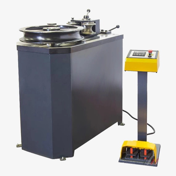
Roll Pipe Bending Machine
A Roll Pipe Bending Machine is a specialized type of pipe bending equipment that uses a set of rollers to bend pipes or tubes smoothly into desired curves or shapes. Unlike rotary draw bending, which bends the pipe around a fixed die, roll bending machines work by gradually bending the pipe through multiple passes between rollers, making them ideal for producing large-radius bends, coils, or spirals in pipes and tubes.
The machine typically features three or more rollers arranged in a triangular or linear configuration. The pipe is fed between these rollers, where adjustable pressure is applied by moving one or more rollers closer or farther apart. As the pipe passes repeatedly through the rollers, the pressure and positioning gradually bend the pipe to the required curvature without causing wrinkles or flattening.
Roll pipe bending machines are widely used in industries where large-radius bends are needed, such as shipbuilding, structural steel fabrication, HVAC ductwork, and pipeline construction. They are especially suitable for bending large-diameter or thick-walled pipes that would be difficult to bend with other methods.
The process is highly controllable, with operators adjusting roller positions to achieve the precise bend radius. Modern roll bending machines may include CNC controls and measurement systems to automate bending sequences, ensuring repeatability and accuracy.
Because roll bending applies gradual bending forces over a larger area, it tends to produce less distortion or stress on the pipe material, preserving structural integrity. The machine can handle a wide range of pipe sizes and materials, making it versatile for various applications.
If you’d like, I can provide more details on the parts of a roll pipe bending machine, the working principles, or typical applications. Would you like me to continue?
A roll pipe bending machine works by passing a pipe through a series of rollers that apply controlled pressure to gradually bend the pipe into the desired curve or radius. The rollers are typically arranged in a triangular formation, with two fixed rollers supporting the pipe and a third adjustable roller applying force from above or below. By adjusting the position of the movable roller, the operator can control the amount of bending applied during each pass. The pipe is repeatedly fed through the rollers, with incremental bending occurring on each pass until the target curvature is achieved.
The machine’s frame provides the necessary rigidity to withstand the forces involved in bending, ensuring consistent and accurate results. Roll pipe bending machines are especially effective for creating large-radius bends, gentle curves, and spirals, which are difficult or impossible to achieve with other bending methods such as rotary draw bending or mandrel bending.
Because the bending force is distributed over a wide area, roll bending minimizes deformation, wrinkles, or flattening of the pipe cross-section. This makes it well-suited for thick-walled pipes or those made from materials prone to cracking or distortion. The process is also flexible enough to accommodate different pipe diameters and wall thicknesses by simply adjusting roller positions and pressures.
Many modern roll pipe bending machines are equipped with hydraulic or servo-driven systems that automate the roller adjustments and feeding process. CNC controls allow operators to program specific bend radii and sequences, improving precision and repeatability while reducing manual intervention and setup time. Sensors and feedback mechanisms help monitor the bending angle and pipe position, enabling real-time corrections to maintain quality standards.
Roll pipe bending machines find extensive use in industries like shipbuilding, where large curved pipes are common; in construction, for structural components; and in the manufacturing of tanks, boilers, and pipelines. Their ability to produce smooth, gradual bends over long pipe lengths makes them invaluable for projects requiring precise and gentle pipe curves.
Overall, the roll pipe bending machine is a robust and versatile tool that efficiently handles bending tasks which require gradual shaping without compromising pipe integrity, making it essential in many heavy fabrication and manufacturing environments.
In addition to the core bending mechanism, roll pipe bending machines often feature adjustable supports and guides that help maintain pipe alignment during the bending process, preventing unwanted twisting or misfeeds. Some machines incorporate powered feed rollers that assist in moving the pipe smoothly through the rollers, especially useful when handling longer or heavier pipes.
Maintenance is an important consideration for roll pipe bending machines. The rollers, typically made from hardened steel or other wear-resistant materials, need regular inspection and lubrication to ensure smooth operation and to avoid surface damage to the pipes. Over time, rollers may require resurfacing or replacement to maintain bending quality.
Safety features are integral to the design, including emergency stop controls, protective guards around moving parts, and sensors to detect abnormal conditions such as pipe slippage or overloads. These measures protect operators and reduce downtime caused by accidents or equipment damage.
The versatility of roll pipe bending machines is enhanced by the ability to adapt roller configurations or swap out tooling to accommodate different pipe sizes, wall thicknesses, or material types. This flexibility allows fabricators to handle a wide range of bending tasks with a single machine.
Some advanced roll bending systems integrate with automated material handling setups, such as robotic arms or conveyors, to create fully automated bending lines. This integration minimizes manual labor, improves throughput, and enhances overall manufacturing efficiency.
As industries demand increasingly complex pipe shapes and tighter tolerances, roll pipe bending machines continue to evolve with innovations in control systems, material science, and mechanical design. These improvements enable manufacturers to meet stringent quality standards while maintaining cost-effective production.
Ultimately, the roll pipe bending machine remains a crucial asset in heavy fabrication, structural engineering, and pipeline industries, providing reliable, precise, and efficient solutions for bending large and thick-walled pipes where smooth, large-radius bends are essential.
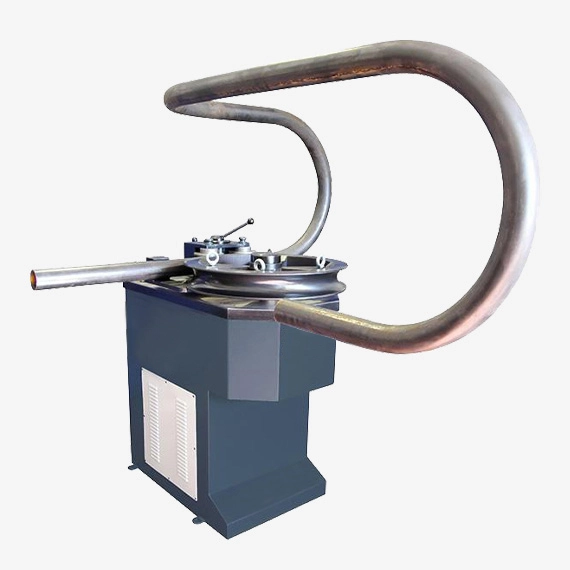
Rotary Draw Bender for Metal Pipes
A Rotary Draw Bender is a precise metal pipe bending machine designed to produce tight-radius bends with high accuracy and minimal deformation. It’s widely used in industries such as automotive, aerospace, furniture manufacturing, and construction, where complex pipe shapes and tight bends are common.
The core principle of a rotary draw bender involves clamping the pipe firmly against a shaped bending die (also called a former) and rotating this die to bend the pipe around its radius. Unlike roll bending, which gradually forms large-radius curves, the rotary draw method achieves sharp, well-defined bends with consistent cross-sectional integrity.
The machine typically includes a bending die that dictates the radius of the bend, a clamp die that holds the pipe securely in place, and a pressure die that applies force to keep the pipe snug against the bending die during rotation. A mandrel is often inserted inside the pipe to support the inner wall and prevent wrinkling or collapsing, especially when bending thin-walled or delicate pipes.
The rotary draw bender operates by clamping the pipe, then rotating the bending die through the desired angle, pulling the pipe along the die’s contour. This controlled movement reduces stress and distortion, resulting in smooth bends with minimal flattening or ovality.
Modern rotary draw benders can be manual, hydraulic, or CNC-controlled. CNC rotary draw benders offer programmable bending sequences, allowing complex parts with multiple bends to be produced efficiently and repeatedly with high precision.
This bending method is favored when tight bends and high-quality finishes are required, such as in exhaust systems, handrails, frames, and tubular structures. It offers excellent repeatability, minimal spring-back, and the ability to bend various materials including steel, aluminum, and copper alloys.
If you want, I can continue with more details on parts, working mechanisms, or typical applications of rotary draw benders. Would you like me to go on?
A rotary draw bender works by first securing the pipe between the bending die and clamp die, which holds the pipe firmly to prevent slipping during the bending process. The bending die, shaped to the desired radius, then rotates around a fixed pivot point, pulling the pipe along its curved surface to form the bend. Meanwhile, the pressure die presses against the pipe to maintain tight contact with the bending die, ensuring the pipe follows the exact contour of the die without wrinkling or distortion.
To prevent issues like wrinkling or collapse on the inside of the bend, especially with thin-walled or delicate pipes, a mandrel is often inserted inside the pipe. This mandrel acts as internal support, keeping the pipe’s cross-section intact throughout the bending process. Some machines also use a wiper die, which helps smooth the inside radius and further reduce imperfections.
The bending angle is controlled precisely by the rotation of the bending die, and modern rotary draw benders often feature angle sensors or encoders to measure the bend in real time. This allows operators or CNC systems to stop the bending process at the exact desired angle, improving accuracy and consistency across multiple parts.
In CNC rotary draw benders, operators can program multiple bends with varying angles, radii, and rotations, enabling the production of complex pipe shapes with minimal manual setup. These machines often include automated feeding systems, material clamps, and return mechanisms to streamline production and reduce cycle times.
Materials bent on rotary draw benders range from mild steel to stainless steel, aluminum, copper, and other alloys, depending on application requirements. The process preserves the pipe’s structural integrity and surface finish, making it suitable for visible or high-stress components like exhaust systems, furniture frames, hydraulic lines, and handrails.
Because the rotary draw method applies controlled force through the bending die, it minimizes spring-back—the tendency of metal to partially revert toward its original shape after bending—leading to more precise bends and reducing the need for secondary corrections.
Maintenance of rotary draw benders involves regular inspection of dies, clamps, mandrels, and hydraulic components, as well as lubrication of moving parts. Proper upkeep ensures consistent bending quality and extends machine life.
Overall, rotary draw bending provides an efficient, reliable, and precise method for forming tight-radius bends in metal pipes and tubes, making it a preferred choice in industries requiring high-quality, repeatable pipe bends.
In addition to the basic bending components, rotary draw benders often incorporate features that enhance versatility and ease of use. Adjustable tooling allows the machine to handle a wide range of pipe diameters and wall thicknesses by swapping out or repositioning bending dies, clamp dies, and mandrels. This adaptability makes the rotary draw bender suitable for diverse manufacturing needs without requiring multiple machines.
Some machines include multi-axis rotation capabilities, enabling the pipe to be rotated and bent along different planes. This is essential for producing complex, three-dimensional pipe shapes such as those found in automotive exhaust systems or aerospace tubing. Such flexibility is typically managed by CNC control systems, which precisely coordinate bending and rotation to achieve the desired geometry.
Automation features like robotic loading and unloading, automatic mandrel insertion and removal, and integrated measurement systems further increase productivity and reduce manual labor. These enhancements allow for continuous operation with minimal operator intervention, which is particularly valuable in high-volume production environments.
Quality control tools integrated into rotary draw benders include laser measurement systems and force sensors that monitor bending parameters in real time. These systems detect deviations early, enabling immediate adjustments to maintain tight tolerances and reduce scrap rates.
Safety mechanisms are also critical, with emergency stops, protective guarding, and interlocks designed to protect operators from moving parts and hydraulic pressures. Ergonomic design considerations, such as adjustable control panels and easy access to tooling, improve operator comfort and efficiency.
Materials selection for tooling is vital; bending dies and mandrels are often made from hardened steel or coated with wear-resistant materials to withstand the stresses of repeated bending operations without degrading. Proper maintenance and periodic replacement of tooling ensure consistent bending quality and machine reliability.
Rotary draw bending technology continues to evolve with advancements in materials science, control software, and mechanical design, enabling the production of ever more complex pipe shapes with greater speed and precision. This ongoing innovation keeps rotary draw benders at the forefront of metal pipe fabrication in industries ranging from automotive and aerospace to furniture and architectural construction.
Mandrel Pipe Bending Machine
A Mandrel Pipe Bending Machine is a specialized type of rotary draw bender designed to bend pipes and tubes with tight radii while maintaining the pipe’s shape and preventing defects like wrinkling, collapsing, or ovality. It’s especially useful for bending thin-walled or delicate pipes that are prone to deformation during the bending process.
The key feature of this machine is the mandrel, a flexible or segmented internal support inserted inside the pipe during bending. The mandrel supports the pipe’s inner wall, counteracting the compressive forces that cause wrinkling or collapsing on the inside of the bend. This internal support allows the pipe to maintain its round cross-section and structural integrity even at sharp bend angles.
In operation, the pipe is clamped securely against a bending die, similar to a rotary draw bender. The bending die rotates, pulling the pipe around its radius, while the mandrel inside moves synchronously to provide continuous internal support. Additional tooling such as a wiper die may be used on the inside radius to smooth the pipe and further prevent wrinkles.
Mandrel pipe bending machines come in manual, hydraulic, and CNC-controlled versions. CNC machines offer precise control over bend angles, mandrel positioning, and bending speed, enabling consistent high-quality bends and efficient production of complex pipe shapes.
These machines are widely used in industries like automotive, aerospace, oil and gas, and hydraulic systems, where maintaining pipe strength and appearance after bending is critical. Mandrel bending ensures minimal distortion, making it ideal for fuel lines, brake lines, exhaust systems, and any application requiring tight bends with high-quality finishes.
If you want, I can continue with details on the machine parts, working principles, or applications of mandrel pipe bending machines. Would you like me to go on?
A mandrel pipe bending machine operates by inserting a mandrel—a series of connected, articulated segments or a flexible steel rod—into the pipe before the bending process begins. This mandrel travels along with the pipe as it is bent around the bending die, providing continuous internal support to the pipe’s wall. The machine clamps the pipe securely against the bending die to prevent slipping, while the mandrel’s presence inside the pipe counters the compressive forces on the inside of the bend that would otherwise cause wrinkles, buckling, or collapse.
The bending die determines the bend radius, and the pipe is drawn smoothly around it, while a wiper die may be positioned on the inside radius to help smooth out any potential wrinkles at the bend start. The mandrel’s segments flex and rotate slightly to adapt to the changing curvature, ensuring support is maintained throughout the bending arc.
Mandrel bending machines typically feature hydraulic or servo motors that provide controlled bending speed and force, allowing precise control over the bending angle and minimizing spring-back. CNC-controlled models enable the programming of multiple bends with different radii and angles, improving repeatability and reducing setup times for complex pipe shapes.
This method is especially important for thin-walled pipes or those made from softer or more brittle materials, where maintaining the pipe’s cross-sectional shape and surface finish is crucial. It prevents defects that could compromise the pipe’s structural integrity or lead to failure in critical applications.
Mandrel bending machines can handle a wide range of pipe diameters and wall thicknesses by using interchangeable mandrels, dies, and wiper tools tailored to specific pipe sizes and materials. The mandrel and tooling must be carefully matched to avoid excessive friction or damage to the pipe’s interior surface.
Due to the complexity of the mandrel mechanism, these machines require regular maintenance, including inspection and lubrication of mandrel segments and associated moving parts to ensure smooth operation and longevity. Operators must also ensure that tooling is correctly installed and adjusted to prevent pipe damage and maintain bending quality.
Mandrel pipe bending is commonly used in automotive fuel and brake lines, aerospace hydraulic tubing, furniture frames, and other applications where tight bends with minimal deformation and excellent surface finish are required. The precision and quality achievable with mandrel bending make it an indispensable process in high-performance tube fabrication.
In addition to the core bending and mandrel mechanisms, mandrel pipe bending machines often incorporate advanced features to enhance performance and ease of use. Automated mandrel feeding and retrieval systems reduce manual handling, speeding up production and minimizing the risk of damage to the mandrel or pipe. Some machines are equipped with real-time monitoring systems that track bending forces, mandrel position, and pipe deformation, providing immediate feedback to operators or automated controls for adjustments.
The hydraulic or servo-driven systems provide smooth, controlled bending motions, reducing stress on both the machine and the pipe material. Precise control over bending speed and pressure helps prevent defects and ensures consistent results, especially when working with high-strength alloys or sensitive materials.
Many mandrel bending machines are CNC-controlled, allowing operators to program complex bend sequences with multiple angles and radii. This capability is particularly valuable in producing parts for industries like aerospace and automotive, where complex geometries and tight tolerances are common. The CNC system can store multiple programs, enabling quick changeovers between different production runs and improving overall efficiency.
Safety features such as emergency stops, protective guarding around moving parts, and sensors to detect abnormal conditions are integral to machine design, protecting operators and equipment. Ergonomic considerations, including easily accessible controls and clear visibility of the bending area, enhance operator comfort and reduce fatigue during extended operation.
Maintenance routines focus on keeping mandrel components lubricated and free of wear, inspecting dies and wiper tools for damage, and ensuring hydraulic systems are operating at optimal pressure. Proper maintenance prolongs machine life, maintains bending quality, and reduces unplanned downtime.
As industries push for lighter, stronger, and more complex tubular components, mandrel pipe bending machines continue to evolve with innovations in tooling materials, control algorithms, and automation integration. These advancements enable fabricators to meet stringent quality standards while maintaining cost-effective and flexible production processes.
Overall, mandrel pipe bending machines are critical for manufacturing high-quality bent pipes and tubes in applications where maintaining structural integrity, precise geometry, and excellent surface finish is essential. Their specialized design and capabilities make them a preferred choice in demanding sectors such as automotive, aerospace, hydraulics, and furniture manufacturing.
Aluminum Pipe Bender
An Aluminum Pipe Bender is a machine specifically designed to bend aluminum pipes and tubes with precision while preventing damage such as cracking, wrinkling, or flattening. Aluminum’s lightweight and malleable nature make it popular in industries like automotive, aerospace, HVAC, and construction, but its relatively low ductility compared to steel means bending requires careful control and often specialized equipment.
Aluminum pipe benders use a variety of bending methods, including rotary draw bending, mandrel bending, and roll bending, adapted to handle aluminum’s unique material properties. The machines typically feature tooling made from materials that minimize friction and surface damage, such as polished steel or coated dies.
Because aluminum pipes tend to work-harden quickly during bending, aluminum pipe benders often incorporate slower bending speeds and precise control of bending angles and forces to reduce the risk of cracking. Some machines also use internal supports like mandrels or plugs to maintain pipe shape and prevent collapse, especially for thin-walled aluminum tubing.
Hydraulic and CNC-controlled aluminum pipe benders are common, offering consistent, repeatable bends with programmable settings for complex shapes and multi-bend sequences. These features help maintain tight tolerances and high-quality finishes critical for applications where appearance and performance are important.
Additional considerations for aluminum pipe bending include controlling spring-back—the tendency of aluminum to partially return toward its original shape after bending—by applying slightly greater bend angles or using overbending techniques. Cooling or lubrication may also be used to manage heat and friction during the process.
Aluminum pipe benders come in manual, semi-automatic, and fully automatic configurations, suited for small workshops or high-volume manufacturing environments. Proper setup, tooling selection, and machine maintenance are essential to achieve optimal results when bending aluminum pipes.
If you want, I can provide details on the specific types of aluminum pipe benders, their parts, or best practices for bending aluminum pipes. Would you like me to continue?
An aluminum pipe bender functions by carefully applying bending forces that take into account aluminum’s lower ductility and higher tendency to crack compared to other metals. The process usually begins with securely clamping the pipe to prevent slipping or distortion during bending. The bending is performed using dies and rollers specifically designed or coated to minimize surface damage and reduce friction, which is important because aluminum surfaces can scratch or gall easily.
The bending speed is often controlled to be slower than with steel pipes to allow the aluminum to deform gradually without sudden stress concentrations. Machines may incorporate internal supports such as mandrels or wiper dies, especially when working with thin-walled aluminum tubing, to maintain the pipe’s cross-sectional integrity and prevent wrinkling or collapse on the inside radius of the bend.
Spring-back is a common challenge when bending aluminum, where the material partially returns toward its original shape after the bending force is removed. To compensate, operators or CNC programs often include overbending steps, bending the pipe slightly beyond the target angle so it springs back into the correct final position. Precise control and repeatability are essential to consistently achieving accurate bend angles.
Aluminum pipe benders range from manual hand-operated machines used in small workshops to fully automated CNC benders capable of producing complex, multi-bend components with high precision. CNC machines store bending programs that control bend angles, rotation, and feeding length, streamlining production and reducing operator error.
Because aluminum is softer and more prone to surface damage than steel, tooling maintenance is important; dies and rollers should be regularly inspected for wear or contamination that could mar the pipe surface. Lubrication is often used during bending to reduce friction and protect both the pipe and tooling.
Applications for aluminum pipe bending include automotive exhaust systems, aircraft structures, bicycle frames, architectural elements, and HVAC ducting, where lightweight and corrosion resistance are critical. Proper bending techniques and machine setup ensure that the aluminum pipes maintain strength, appearance, and dimensional accuracy after bending.
Overall, aluminum pipe benders provide tailored solutions that balance the material’s properties with precise mechanical control to produce high-quality bent aluminum pipes suitable for demanding industrial applications.
In addition to the core bending functions, many aluminum pipe benders are equipped with features that enhance efficiency and quality control. Automated feeding systems ensure consistent pipe positioning and reduce handling errors, which is especially important for maintaining precision in high-volume production. Some machines also include integrated measurement and feedback systems that monitor bending angles and pipe alignment in real time, allowing for immediate adjustments and reducing scrap rates.
The tooling materials and coatings used in aluminum pipe bending machines are chosen to minimize wear and prevent surface blemishes on the softer aluminum tubes. Polished or chrome-plated dies, sometimes combined with special lubricants, help maintain smooth pipe surfaces and extend the life of the tooling. Regular cleaning and maintenance of tooling are critical to avoiding scratches or indentations that could compromise the pipe’s integrity or aesthetic.
CNC control plays a significant role in modern aluminum pipe bending, enabling complex bend sequences with precise control over multiple axes, including rotation and feed length. This capability allows the production of intricate shapes such as those used in aerospace frames or custom automotive parts, where tight tolerances and repeatability are essential.
Because aluminum can be sensitive to heat generated during bending, some advanced machines incorporate cooling systems or temperature monitoring to prevent overheating that might alter material properties or cause surface oxidation. This helps preserve the mechanical characteristics and finish quality of the bent pipes.
Safety features, including emergency stops, guarding, and ergonomic controls, protect operators while facilitating efficient workflows. User-friendly interfaces reduce setup time and operator training requirements, making aluminum pipe bending accessible even in smaller production environments.
Applications for aluminum pipe bending continue to grow as industries seek lightweight, corrosion-resistant components that meet strict performance standards. Whether producing simple bends for structural tubing or complex multi-bend parts for aerospace, aluminum pipe benders combine specialized tooling, precise control, and adaptable design to meet these challenges.
In summary, aluminum pipe benders are carefully engineered machines that address the unique demands of bending aluminum tubing. Through a combination of tailored tooling, controlled bending processes, and advanced automation, these machines deliver high-quality bends that maintain the strength, appearance, and dimensional accuracy essential for modern manufacturing.
Steel Pipe Bending Machine
A Steel Pipe Bending Machine is a robust industrial machine designed to bend steel pipes and tubes into precise shapes and angles for various applications. Steel’s high strength and relatively lower ductility compared to softer metals make bending more demanding, requiring powerful machinery and specialized tooling to prevent cracking, wrinkling, or flattening of the pipe during the bending process.
Steel pipe bending machines come in various types, including rotary draw benders, mandrel benders, roll bending machines, and press bending machines. Each type is suited to different bending requirements, such as tight-radius bends, large-radius curves, or complex multi-axis shapes.
The machines typically use hardened steel dies and clamps to hold and shape the pipe securely. Hydraulic or servo-driven systems provide the necessary force to bend the steel pipe smoothly while controlling speed and pressure to avoid damage. CNC-controlled steel pipe bending machines allow for programmable bending sequences with high precision and repeatability, essential for industrial manufacturing where consistent quality is critical.
Due to steel’s stiffness and strength, pipe bending often requires higher torque and more rigid machine frames compared to machines used for softer materials. Internal supports like mandrels are commonly used in steel pipe bending to maintain cross-sectional integrity and prevent defects, especially in thin-walled or high-strength steel tubes.
Steel pipe bending machines are widely used in construction, automotive manufacturing, shipbuilding, oil and gas pipelines, and heavy machinery industries. They enable the production of structural components, exhaust systems, hydraulic lines, and other critical parts that must withstand mechanical stress and environmental conditions.
If you’d like, I can continue with more details about the working principles, key components, or applications of steel pipe bending machines. Would you like me to go on?
A steel pipe bending machine operates by securely clamping the steel pipe and applying controlled force to bend it around a shaping die or between rollers, depending on the bending method used. The machine’s robust frame is designed to withstand the high stresses involved when bending steel, which requires significant force due to steel’s strength and resistance to deformation.
In rotary draw bending, the pipe is clamped against a bending die that determines the radius of the bend, while a pressure die holds the pipe firmly in place. The bending die rotates to pull the pipe around its radius, forming a precise and consistent bend. To prevent the pipe from collapsing or wrinkling on the inside of the bend, especially with thin-walled steel tubes, an internal mandrel is often inserted to support the pipe during bending. A wiper die may also be used to smooth the inside radius and reduce wrinkles.
Roll bending machines bend steel pipes by passing them repeatedly through a series of rollers that apply gradual bending forces. This method is effective for creating large-radius bends or curves over long pipe sections. Press bending machines use a hydraulic press to bend pipes, typically suited for simpler bends or large-diameter pipes.
Steel pipe bending machines commonly use hydraulic or servo motors to provide the necessary force and precise control over bending speed and angle. CNC controls allow operators to program complex bend sequences, control multiple axes, and achieve high repeatability and accuracy. Sensors monitor bending parameters and pipe position, enabling real-time adjustments and quality assurance.
The tooling on steel pipe bending machines is made from hardened steel or specialized alloys to resist wear and maintain precision under heavy loads. Tooling must be carefully maintained to avoid surface damage to pipes, which can lead to corrosion or failure in service.
Because steel pipes are often used in structural or high-stress applications, the bending process must preserve mechanical properties. Proper machine setup, bending speed, and tooling selection are critical to avoid cracks, weakening, or deformation that could compromise pipe performance.
Applications of steel pipe bending machines span construction frameworks, automotive chassis, ship hulls, pipeline systems, and industrial machinery. Their ability to produce accurate, strong, and consistent bends in steel pipes is essential for manufacturing reliable components that meet stringent safety and performance standards.
Overall, steel pipe bending machines combine powerful mechanical systems, precision tooling, and advanced control technologies to handle the challenges of bending steel pipes, ensuring high-quality results across a wide range of industrial applications.
In addition to the primary bending functions, steel pipe bending machines often feature auxiliary systems that improve efficiency, quality, and safety. Automated feeding and positioning mechanisms help to accurately load and align pipes, reducing manual labor and increasing throughput. Some machines include automatic mandrel insertion and retrieval systems to streamline bending operations, especially in high-volume production environments.
To ensure consistent quality, many machines are equipped with real-time monitoring systems such as laser measurement devices and force sensors that track bend angles, pipe alignment, and tooling pressures. This data allows operators or control systems to make immediate adjustments, minimizing defects like spring-back, ovality, or surface damage.
Safety features are integral to machine design, including emergency stop buttons, protective guards around moving parts, and sensors that detect abnormal operating conditions to prevent accidents. Ergonomic controls and user-friendly interfaces help reduce operator fatigue and training time, contributing to safer and more productive workflows.
Maintenance is crucial for steel pipe bending machines due to the high forces and wear involved. Regular inspection of dies, clamps, mandrels, hydraulic components, and electronic controls ensures reliable performance and prolongs machine life. Proper lubrication and timely replacement of worn tooling prevent surface defects on pipes and avoid costly downtime.
Technological advancements continue to improve steel pipe bending machines, with developments in servo-electric drives, adaptive control algorithms, and smart tooling enhancing precision, speed, and flexibility. Integration with factory automation and Industry 4.0 systems enables data-driven production, predictive maintenance, and seamless communication within manufacturing lines.
Steel pipe bending remains a cornerstone process in many industries, from heavy construction and infrastructure to automotive and energy sectors. The ability to produce durable, precisely shaped steel pipe components efficiently supports the fabrication of strong, safe, and reliable structures and systems worldwide.
Overall, steel pipe bending machines represent a combination of mechanical strength, advanced control, and precision engineering that meets the demanding requirements of modern manufacturing and industrial fabrication.
Automatic Metal Tube Bender
An Automatic Metal Tube Bender is a highly advanced machine designed to bend metal tubes and pipes with minimal human intervention. It uses automated feeding, clamping, bending, and sometimes cutting operations controlled by computer numerical control (CNC) systems to produce precise, complex bends quickly and consistently. These machines are widely used in industries like automotive manufacturing, aerospace, furniture production, and construction, where high-volume and high-precision tube bending are required.
The automatic tube bender typically includes a feeding system that measures and positions the tube accurately before bending, a clamping mechanism to secure the tube firmly, and a bending unit that uses dies and rollers to form the tube to the programmed shape. CNC controls enable the operator to program multiple bends with different angles, radii, and rotations into a sequence, allowing the machine to execute complex bending tasks automatically.
Advanced models may also incorporate internal mandrels, wiper dies, and pressure dies to maintain tube shape and prevent defects like wrinkling, collapsing, or ovality, especially when working with thin-walled or delicate materials. The system can include automatic tube straightening and cutting stations, completing the fabrication process in a streamlined, continuous flow.
Sensors and feedback loops monitor bending parameters such as angle, radius, tube position, and bending force, allowing real-time adjustments to ensure accuracy and repeatability. The use of servo motors and hydraulic systems provides smooth and precise control over the bending process.
Automatic metal tube benders improve productivity by reducing setup times, minimizing human error, and enabling unattended operation. They support a wide range of materials, including steel, aluminum, copper, and stainless steel, and accommodate various tube sizes and wall thicknesses.
If you’d like, I can continue by explaining specific parts, working principles, or typical applications of automatic metal tube benders. Would you like me to go on?
An automatic metal tube bender functions by first feeding a tube from a coil or straight section into the machine with precise positioning mechanisms such as servo-driven rollers or clamps. The tube is gripped securely by clamping dies to prevent slipping or distortion during the bending process. The bending unit, which includes a bending die shaped to the desired radius and sometimes a pressure die, rotates or moves according to the programmed sequence, pulling the tube around the die to form accurate bends.
CNC controls manage the entire operation, allowing operators to input complex bending programs that define bend angles, radii, rotation of the tube, and feeding lengths. This automation enables the production of intricate tube shapes with multiple bends in a single continuous process, greatly improving efficiency and consistency compared to manual or semi-automatic methods.
To maintain the tube’s shape and prevent defects like wrinkling, collapsing, or flattening—especially with thin-walled or sensitive materials—automatic benders often incorporate internal supports such as mandrels, and external tooling like wiper dies or pressure dies. These components work together to distribute bending forces evenly and preserve the cross-sectional integrity of the tube.
Real-time sensors monitor parameters such as bending angle, tube position, and applied force, feeding data back to the control system. This feedback loop allows the machine to adjust bending speed, pressure, or feed length dynamically, ensuring tight tolerances and reducing scrap rates.
Some automatic tube benders also integrate downstream processes such as automatic cutting to length, part unloading, or even marking and inspection systems, creating a fully integrated production line. This level of automation supports high-volume manufacturing with minimal human intervention, improving throughput and reducing labor costs.
Materials commonly bent on automatic metal tube benders include various steels, aluminum, copper, and stainless steel, with the machine’s tooling and settings adapted to accommodate different material properties, wall thicknesses, and diameters. Maintenance routines focus on ensuring tooling condition, lubrication of moving parts, and calibration of sensors and control systems to maintain consistent performance.
Applications for automatic metal tube benders span automotive exhaust and chassis components, aerospace tubing, furniture frames, hydraulic lines, and architectural elements. Their precision, repeatability, and efficiency make them essential in modern manufacturing environments where quality and productivity are paramount.
Overall, automatic metal tube benders combine advanced mechanical design, computerized control, and sensor integration to deliver reliable, high-speed tube bending solutions capable of producing complex shapes with excellent accuracy and minimal waste.
Beyond the core bending and control functions, automatic metal tube benders often feature customizable tooling setups that allow quick changeovers between different tube sizes, materials, and bend profiles. This flexibility enables manufacturers to switch production runs efficiently without extensive downtime. Tooling components like bending dies, mandrels, wiper dies, and pressure dies are designed for easy installation and adjustment, ensuring that the machine can be adapted to a wide range of applications.
The integration of user-friendly human-machine interfaces (HMIs) with touchscreen controls simplifies programming and monitoring, allowing operators to create, edit, and store bending programs with minimal training. Advanced software may include simulation and verification features that preview bending sequences before actual production, reducing the risk of errors and material waste.
Safety is a critical consideration in automatic tube benders. Machines are equipped with protective guards, emergency stop buttons, light curtains, and interlocks to protect operators from moving parts and high-pressure systems. Ergonomic designs ensure operators can access controls and perform maintenance tasks comfortably and safely.
Some automatic benders are equipped with robotic loading and unloading systems, which further automate the handling of tubes, reducing manual labor and the risk of damage or injury. Combined with conveyors, automated inspection stations, and packaging systems, these features create a seamless production line from raw material to finished product.
Data connectivity and Industry 4.0 capabilities are increasingly incorporated into automatic metal tube bending machines. Through networked control systems, machines can communicate production data, maintenance alerts, and performance metrics to centralized management systems, enabling predictive maintenance and continuous process optimization.
Environmental considerations are addressed by designing machines for energy efficiency, minimizing hydraulic fluid usage, and incorporating noise reduction features. Regular maintenance and proper training help maximize machine lifespan and sustainability.
In summary, automatic metal tube benders represent a sophisticated fusion of mechanical engineering, computer control, and automation technologies. They provide manufacturers with powerful tools to produce complex tube shapes rapidly, accurately, and consistently, meeting the demands of modern industries for high quality and efficient production.
Precision Steel Pipe Bending Machine
A Precision Steel Pipe Bending Machine is a highly engineered device designed to bend steel pipes and tubes with exceptional accuracy and consistency. It is used in applications where tight tolerances, exact bend angles, and minimal deformation are critical, such as in aerospace, automotive, shipbuilding, and industrial machinery manufacturing.
This machine typically employs advanced bending methods such as CNC-controlled rotary draw bending or mandrel bending, which enable precise control over bend radius, angle, and rotation. The precision is achieved through carefully designed tooling, rigid machine frames to prevent deflection under high bending forces, and sophisticated control systems that monitor and adjust bending parameters in real time.
Precision steel pipe bending machines often incorporate features like internal mandrels to support the pipe during bending, pressure dies to maintain pipe alignment, and wiper dies to reduce wrinkles and surface defects. Sensors measure the bend angle and pipe position continuously, feeding data back to the control system to ensure the bend meets exact specifications.
Hydraulic or servo-driven motors provide smooth, controlled bending motions with the ability to handle various steel grades and pipe sizes. CNC systems allow operators to program complex bending sequences with multiple bends, rotations, and angles, improving repeatability and reducing setup times.
These machines emphasize maintaining pipe integrity by minimizing common defects such as ovality, flattening, spring-back, and cracking. Tooling materials and surface finishes are selected to prevent surface damage to the steel pipes during bending.
Applications of precision steel pipe bending machines include manufacturing exhaust systems, hydraulic lines, structural frames, and critical components where precision and reliability are paramount. Regular maintenance and calibration are essential to sustain the machine’s performance and bending accuracy over time.
If you want, I can continue with more technical details on parts, working principles, or typical use cases of precision steel pipe bending machines. Would you like me to continue?
A precision steel pipe bending machine operates by clamping the steel pipe firmly between a bending die and a clamp die, ensuring the pipe does not slip or deform during bending. The bending die rotates around a fixed pivot point, drawing the pipe along its curved surface to create the desired bend radius. A pressure die presses against the pipe to hold it tightly against the bending die, maintaining alignment and preventing distortion.
To preserve the pipe’s cross-sectional shape and prevent defects such as wrinkling or collapsing on the inside radius of the bend, an internal mandrel is often inserted. The mandrel supports the pipe from the inside and moves synchronously with the bending die. In addition, a wiper die positioned near the bend helps smooth the pipe’s inside surface and further reduces wrinkles, especially important for thin-walled or high-strength steel tubes.
The machine’s rigid frame is engineered to withstand the significant forces generated during bending, minimizing deflection that could compromise accuracy. Hydraulic or servo motors provide precise control over the bending speed and angle, allowing smooth and consistent bending motions that reduce stress concentrations and material fatigue.
Modern precision steel pipe benders use CNC control systems to program complex bending sequences involving multiple bends, rotations, and feed lengths. Real-time sensors continuously monitor the bending angle, pipe position, and force applied, feeding data back to the controller for adjustments. This feedback loop ensures that each bend adheres to tight tolerances and that any deviations are corrected immediately.
Spring-back, the tendency of steel to partially revert toward its original shape after bending, is accounted for by overbending techniques programmed into the CNC system. Tooling and process parameters are carefully selected to minimize spring-back and maintain dimensional accuracy.
In addition to the fundamental bending process, precision steel pipe bending machines often include auxiliary features that enhance their accuracy and operational efficiency. Automated tube feeding and positioning systems ensure the pipe is precisely aligned and fed into the bending station with minimal operator intervention, reducing setup time and human error.
Advanced CNC software allows operators to simulate bending sequences before production begins, verifying that programmed bends will meet design specifications without causing collisions or material issues. This virtual setup capability minimizes trial-and-error adjustments, saving material and increasing throughput.
Real-time monitoring technologies such as laser measurement systems and strain gauges continuously track pipe deformation, bend angle, and tooling load during bending. This data enables the machine to automatically compensate for variations in material properties or tooling wear, maintaining consistent bending quality over long production runs.
Safety is a critical component of precision steel pipe bending machines. Emergency stop buttons, light curtains, and protective guarding safeguard operators from moving parts and high-pressure hydraulic systems. Ergonomic design principles ensure that controls and maintenance access points are user-friendly, reducing operator fatigue and the likelihood of errors.
Maintenance protocols include routine inspection and replacement of dies, mandrels, and hydraulic components to prevent unexpected failures and maintain bending precision. Proper lubrication and calibration of sensors and actuators are also essential to sustain optimal performance.
The machines can be integrated into larger manufacturing systems, connecting with robotic loading/unloading units, cutting stations, and quality inspection modules to create fully automated pipe fabrication lines. Such integration supports high-volume production with minimal downtime and consistent product quality.
Material considerations are important; precision bending machines accommodate a wide range of steel alloys, including stainless steel and high-strength steels, each requiring specific tooling and bending parameters to avoid cracking or deformation.
In summary, precision steel pipe bending machines represent a sophisticated blend of mechanical engineering, automation, and control technology. Their ability to produce highly accurate, repeatable bends with excellent surface quality makes them indispensable in industries demanding the highest manufacturing standards.
Industrial Steel Pipe Bender
An Industrial Steel Pipe Bender is a heavy-duty machine designed for large-scale, high-volume bending of steel pipes and tubes used in industrial applications. These machines are built to handle thick-walled, large-diameter pipes and are capable of producing precise bends required in construction, shipbuilding, oil and gas pipelines, power plants, and heavy machinery fabrication.
Industrial steel pipe benders typically utilize bending methods such as rotary draw bending, mandrel bending, roll bending, or press bending, depending on the pipe size, wall thickness, and bending radius required. The machines feature robust frames and powerful hydraulic or servo-driven systems to generate the significant force needed to bend steel without causing defects like wrinkling, cracking, or flattening.
Because of the demanding nature of industrial applications, these benders often come with CNC controls for programmable bending sequences, allowing operators to produce complex shapes with multiple bends efficiently and consistently. The CNC systems monitor parameters such as bending angle, force, and pipe position to ensure accuracy and repeatability.
Key components of industrial steel pipe benders include hardened bending dies, clamp dies, pressure dies, mandrels, and wiper dies designed to withstand heavy use and provide excellent pipe support during bending. Automated feeding and positioning systems reduce manual labor and improve productivity.
Maintenance of industrial steel pipe benders focuses on keeping the hydraulic systems, tooling, and control electronics in optimal condition to prevent downtime and maintain product quality. Safety features like guards, emergency stops, and sensors are essential to protect operators in high-power environments.
These machines are crucial in producing components like pipeline elbows, structural supports, frames, and machinery parts that require strong, precise bends in steel pipes. Their durability, power, and precision make them essential equipment in heavy industrial fabrication settings.
If you want, I can continue with more details about their working principles, typical configurations, or applications. Would you like me to continue?
An industrial steel pipe bender functions by securely clamping the steel pipe between a bending die and clamp die to prevent any movement during the bending process. The bending die, shaped to the required radius, rotates or moves hydraulically or servo-mechanically to bend the pipe around its contour. A pressure die holds the pipe tightly against the bending die, ensuring it follows the desired path without slipping or distortion. For pipes with thin walls or higher susceptibility to deformation, an internal mandrel is inserted to support the pipe internally and prevent wrinkling or collapse on the inside of the bend. A wiper die may also be used to smooth out the inner radius and reduce defects.
These machines are constructed with heavy-duty frames and reinforced components to handle the large forces necessary for bending thick steel pipes or those with large diameters. Powerful hydraulic systems or servo motors control the bending force and speed, allowing operators to achieve precise bends even in challenging materials. CNC systems enable the programming of complex bending sequences, multiple bends, rotations, and lengths, improving production efficiency and repeatability.
The tooling used in industrial steel pipe benders is made from hardened steel or specialized alloys to resist wear and provide consistent bending quality. Due to the high mechanical loads involved, routine maintenance such as inspection and replacement of tooling, hydraulic fluid checks, and system calibrations are essential to prevent failures and maintain accuracy.
Safety features include emergency stop mechanisms, protective guarding around moving parts, sensors to detect abnormal operating conditions, and ergonomic designs that reduce operator fatigue and risk of injury. Automated feeding and positioning systems help reduce manual handling, speeding up production and improving accuracy.
Industrial steel pipe benders find applications in large-scale construction projects, pipeline fabrication, shipbuilding, power generation equipment, and heavy machinery manufacturing. Their ability to produce precise, strong, and defect-free bends in steel pipes under demanding conditions is critical for the reliability and safety of the final structures and systems.
Overall, industrial steel pipe benders combine robust mechanical design, advanced control technology, and durable tooling to meet the rigorous demands of heavy industrial fabrication, ensuring high productivity and consistent quality in steel pipe bending operations.
In addition to the core bending mechanisms, industrial steel pipe benders often include auxiliary systems to enhance productivity and precision. Automated loading and unloading devices reduce manual labor and improve workflow efficiency, especially when handling heavy or long pipes. Integrated measurement systems, such as laser sensors and encoders, continuously monitor pipe position, bend angle, and deformation during the process, enabling real-time adjustments and ensuring adherence to strict tolerances.
Some industrial machines are equipped with multi-axis bending capabilities, allowing pipes to be bent in complex three-dimensional shapes necessary for sophisticated pipeline routing or structural components. These capabilities are managed via CNC controls that synchronize bending, rotation, and feeding movements with high accuracy.
Tooling flexibility is also a key feature; operators can quickly switch between dies and mandrels to accommodate different pipe diameters, wall thicknesses, and materials. This versatility reduces downtime between production runs and enables manufacturers to meet diverse customer requirements without investing in multiple machines.
Because industrial steel pipe benders operate under high loads, maintenance is critical. Regular inspections of hydraulic systems, mechanical linkages, tooling, and control electronics prevent unexpected breakdowns. Lubrication schedules, wear part replacements, and calibration routines are standard practices to maintain machine reliability and bending accuracy.
Environmental and safety considerations are addressed through noise reduction technologies, efficient hydraulic designs, and comprehensive guarding systems. Operator training and safety protocols ensure that the high-powered equipment is used correctly, minimizing risk.
The combination of mechanical strength, advanced control systems, automation, and safety features makes industrial steel pipe benders indispensable in sectors where large quantities of high-quality bent steel pipes are essential. Their ability to handle demanding materials and complex bend geometries with speed and precision supports modern industrial fabrication needs effectively.
In summary, industrial steel pipe benders are engineered to deliver heavy-duty performance, high accuracy, and operational efficiency, making them vital tools for large-scale steel pipe manufacturing and fabrication industries.
Steel Tube Bending Equipment
Steel Tube Bending Equipment refers to the range of machines and tools designed to bend steel tubes into various shapes and angles required for industrial, construction, automotive, and structural applications. This equipment is engineered to handle the specific challenges posed by steel’s strength and rigidity, ensuring accurate bends without damaging the tube’s integrity or surface.
Common types of steel tube bending equipment include rotary draw benders, mandrel benders, roll bending machines, press benders, and compression benders. Each type serves different bending needs—rotary draw and mandrel benders excel at producing tight-radius, high-precision bends with minimal deformation, while roll benders are suited for creating large-radius curves or coils.
These machines often incorporate features such as hydraulic or servo-electric drives that provide the controlled force necessary for bending steel tubes of various diameters and wall thicknesses. Tooling such as bending dies, clamp dies, pressure dies, mandrels, and wiper dies work in concert to support the tube during bending, minimizing defects like wrinkling, flattening, and ovality.
Modern steel tube bending equipment is frequently CNC-controlled, allowing operators to program complex bending sequences with multiple bends and rotations, ensuring repeatability and high throughput. Sensors and feedback systems monitor bending parameters in real time to maintain quality and reduce scrap.
Auxiliary systems, including tube feeding devices, automatic mandrel insertion, and cutting stations, can be integrated with bending machines to streamline production workflows. Safety features like guarding, emergency stops, and ergonomic controls are standard to protect operators.
Applications for steel tube bending equipment range across automotive chassis, exhaust systems, furniture frames, pipeline infrastructure, HVAC systems, and industrial machinery. The choice of equipment depends on the specific material properties, bend requirements, production volume, and precision needed.
If you want, I can continue with more detailed descriptions of each equipment type, their working principles, or typical use cases. Would you like me to continue?
Steel tube bending equipment operates by applying controlled forces to a steel tube to change its shape without compromising its structural integrity. In rotary draw bending, the tube is clamped between a bending die and a clamp die; the bending die rotates, drawing the tube around its radius while the clamp die holds it firmly to prevent slipping. A pressure die presses the tube against the bending die to maintain alignment, and an internal mandrel may be inserted to support the tube’s inner wall during bending, reducing wrinkling and collapse.
Roll bending equipment uses a series of rollers to gradually bend tubes into large-radius curves or spirals, suitable for applications like architectural elements or large pipelines. Press bending applies a hydraulic press force to bend tubes around a fixed die, ideal for simpler bends or heavy, thick-walled tubes.
Modern steel tube bending machines are often equipped with CNC controls that allow precise programming of bending angles, radii, tube rotation, and feed lengths. This automation ensures consistent, repeatable bends and reduces the need for operator intervention. Sensors monitor bending forces, tube position, and angles in real time, allowing adjustments on the fly to maintain quality.
Tooling components such as dies, mandrels, and wiper dies are made from hardened materials designed to withstand repeated stress while protecting the tube surface from scratches or deformation. Tooling is often interchangeable to accommodate different tube diameters, wall thicknesses, and materials.
Auxiliary systems like automated feeding, mandrel insertion, tube straightening, and cutting enhance productivity by streamlining workflow and minimizing manual handling. Safety features including guarding, emergency stops, and ergonomic controls protect operators from moving parts and high forces involved.
Steel tube bending equipment finds applications in automotive exhaust and chassis systems, furniture manufacturing, shipbuilding, oil and gas pipelines, HVAC ducting, and structural frameworks. The choice of equipment depends on the tube material, wall thickness, diameter, bend complexity, and production volume requirements.
In summary, steel tube bending equipment combines mechanical strength, precise tooling, and advanced control technologies to produce accurate, high-quality bends in steel tubes across a wide range of industrial applications.
To further enhance the performance of steel tube bending equipment, manufacturers often integrate advanced features such as multi-axis bending capabilities, which allow tubes to be bent in three dimensions, enabling complex geometries required in aerospace, automotive, and architectural applications. These systems use synchronized movements of bending, rotation, and feeding mechanisms controlled by sophisticated CNC software to produce intricate shapes with high precision.
Maintenance and calibration of steel tube bending equipment are essential for sustaining performance and accuracy. Regular inspection of tooling for wear, lubrication of moving parts, and verification of control system parameters help prevent defects and downtime. Using high-quality tooling materials like hardened steel or specialized alloys extends tool life and maintains bending consistency.
The adoption of Industry 4.0 technologies has led to the incorporation of sensors and IoT connectivity in tube bending machines, enabling real-time monitoring of machine health, predictive maintenance, and integration into smart manufacturing systems. This connectivity facilitates data-driven decision-making, reduces unplanned outages, and optimizes production efficiency.
Environmental considerations are also addressed by designing energy-efficient hydraulic or electric drive systems and minimizing waste through precise bending processes. Ergonomic machine designs improve operator comfort and safety, reducing fatigue during extended production runs.
Training and support from equipment manufacturers play a vital role in maximizing the capabilities of steel tube bending equipment. Proper operator training ensures correct machine setup, tooling selection, and maintenance procedures, leading to higher quality output and longer machine lifespan.
Overall, steel tube bending equipment continues to evolve with technological advancements that improve precision, flexibility, productivity, and safety. These improvements enable manufacturers to meet increasingly stringent industry standards and customer demands for complex, reliable, and cost-effective bent steel tube products.
Steel Pipe Bending Process
The steel pipe bending process involves reshaping steel pipes into specific angles and curves while maintaining their structural integrity and surface quality. It begins with selecting the appropriate pipe material, diameter, wall thickness, and bending method suitable for the application’s requirements. The process typically includes several key steps:
First, the pipe is prepared by cutting it to the desired length and cleaning it to remove any dirt or coatings that might interfere with bending. Then, the pipe is positioned securely in the bending machine, where it is clamped firmly to prevent slipping or deformation during bending.
Depending on the bending method—such as rotary draw bending, mandrel bending, roll bending, or press bending—the pipe is bent by applying controlled forces to change its shape. For example, in rotary draw bending, the pipe is drawn around a bending die that determines the bend radius while clamp and pressure dies hold it in place. An internal mandrel may be inserted to support the pipe internally, preventing wrinkles or collapse, especially in thin-walled pipes.
During bending, the machine carefully controls bending speed, angle, and radius to minimize defects such as wrinkling, flattening, ovality, or cracking. Spring-back—the tendency of steel to partially return toward its original shape after bending—is compensated for by overbending to achieve precise final angles.
After bending, the pipe may undergo additional processes such as trimming, end finishing, or heat treatment to relieve stresses and improve mechanical properties. Quality inspection follows, where dimensions, bend angles, and surface conditions are verified to ensure conformity with specifications.
Throughout the process, proper tooling selection, machine calibration, and adherence to material limitations are crucial to achieve high-quality bends. The steel pipe bending process is widely used in industries like automotive, construction, oil and gas, and manufacturing to create components like exhaust systems, hydraulic lines, structural supports, and pipelines.
If you want, I can continue explaining more details about specific bending methods, tooling, or quality control in the steel pipe bending process. Would you like me to go on?
The steel pipe bending process relies heavily on the chosen bending method, each offering advantages depending on the pipe’s size, wall thickness, material, and desired bend geometry. In rotary draw bending, the pipe is firmly clamped and drawn around a bending die, with a pressure die ensuring the pipe stays aligned. This method produces precise bends with tight radii and is ideal for applications requiring accuracy and repeatability. The use of an internal mandrel supports the pipe from within during bending, preventing wrinkles or collapse, especially in thin-walled pipes.
Mandrel bending, a variation of rotary draw bending, employs a segmented or solid mandrel inserted inside the pipe, moving with the pipe during bending to provide continuous internal support. This reduces deformation and is preferred for high-quality bends in thin-walled or high-strength steel tubes.
Roll bending involves passing the pipe through three or more rollers that apply gradual bending forces, making it suitable for large-radius bends or continuous curves over long lengths of pipe. This method is commonly used for architectural applications or large-diameter pipes.
Press bending applies hydraulic force to push the pipe around a fixed die. It is simpler and better suited for large-diameter pipes or heavy wall thicknesses but offers less precision and is typically used for less complex bends.
During bending, controlling parameters like bending speed, bend radius, clamp pressure, and mandrel position is essential to minimize defects such as wrinkling on the inside radius, flattening or ovality of the pipe cross-section, and cracking due to excessive stress. Operators and CNC control systems account for spring-back by overbending slightly to achieve the desired final angle.
After bending, the pipe often undergoes quality inspection, where dimensional checks ensure bend angles and radii meet specifications. Surface inspections detect any cracks, wrinkles, or other defects. In some cases, non-destructive testing methods like ultrasonic or dye penetrant inspections are used for critical applications.
If required, secondary processes like heat treatment may be applied to relieve residual stresses induced by bending, improving the pipe’s mechanical performance. End finishing operations such as beveling or threading prepare the pipe for assembly.
Successful steel pipe bending depends on appropriate tooling selection, machine maintenance, and adherence to process parameters tailored to the pipe’s material properties and application demands. This careful approach ensures durable, reliable, and high-quality bent steel pipes for a wide range of industrial uses.
Beyond the core bending steps, process optimization is key to efficient steel pipe bending. Proper setup begins with selecting the correct bending machine type and tooling that matches the pipe’s diameter, wall thickness, and material grade. Tooling components—including bending dies, clamp dies, pressure dies, mandrels, and wiper dies—must be precisely sized and maintained to reduce surface damage and ensure consistent bend quality.
Material properties such as yield strength, ductility, and hardness influence bending parameters. For example, higher-strength steels may require slower bending speeds, higher bending forces, and more robust mandrel support to prevent cracking. Understanding these material characteristics helps in adjusting machine settings to balance bend quality with productivity.
Lubrication is often applied to tooling and pipe surfaces to reduce friction during bending, which minimizes tooling wear and prevents scratches or galling on the pipe. Proper lubrication also aids in smoother bending and longer tool life.
Spring-back compensation is a critical aspect of the bending process. Because steel tends to partially rebound after bending, operators or CNC systems program an overbend angle that offsets this effect. The exact amount of overbend depends on the material type, wall thickness, bend radius, and tooling.
To achieve high repeatability and reduce scrap, CNC-controlled bending machines employ sensors and feedback loops that monitor bend angle, clamp force, and tube position in real time. These systems can make dynamic adjustments during bending to maintain dimensional accuracy and compensate for any variations in material or tooling condition.
Post-bending inspection and testing verify that the pipes meet the required specifications. Dimensional checks measure bend angles, radii, and overall length. Surface inspections identify any defects such as cracks, wrinkles, or flattening. For critical applications, non-destructive testing methods like ultrasonic, radiographic, or dye penetrant testing may be employed to detect subsurface flaws.
Efficient workflow integration may combine bending with upstream and downstream processes such as automated feeding, cutting, end finishing, and packaging. Automation reduces manual handling, improves safety, and increases throughput.
In summary, the steel pipe bending process is a complex interplay of material science, mechanical engineering, tooling precision, and control technology. Optimizing each step ensures the production of high-quality bent steel pipes suitable for demanding industrial applications.
Automatic Metal Pipe Bending Machine
An Automatic Metal Pipe Bending Machine is a highly efficient, computer-controlled system designed to bend metal pipes and tubes with minimal manual intervention. It automates the entire bending process—feeding, clamping, bending, and sometimes cutting or marking—allowing for fast, precise, and repeatable bends in a variety of metal materials, including steel, aluminum, copper, and stainless steel.
These machines are equipped with CNC (Computer Numerical Control) systems that let operators program complex bending sequences involving multiple bends, rotations, and lengths. The CNC controller precisely manages the bending angle, feed length, tube rotation, and speed, ensuring consistent results even for complicated shapes.
The machine typically includes a feeding mechanism that accurately positions the pipe before bending, a clamping system that firmly holds the pipe to prevent slipping or distortion, and a bending unit that uses dies, rollers, and sometimes internal mandrels to form the pipe to the desired shape. Internal supports like mandrels help maintain the pipe’s cross-sectional shape during bending and prevent defects such as wrinkling or collapsing, especially in thin-walled tubes.
Automatic pipe benders often feature sensors and feedback systems that monitor bending parameters in real time, allowing the machine to adjust forces and speeds dynamically to maintain precision and reduce scrap. Some models integrate additional features like automatic tube cutting, part unloading, and even marking or labeling for fully automated production lines.
These machines are widely used in automotive manufacturing, aerospace, furniture production, HVAC, construction, and any industry requiring high-volume, high-precision tube bending. They improve productivity, reduce labor costs, and deliver consistent, high-quality bends that meet stringent dimensional and aesthetic standards.
If you want, I can continue by explaining specific components, operational principles, or typical applications of automatic metal pipe bending machines. Would you like me to go on?
An automatic metal pipe bending machine begins the process by feeding the pipe from a coil or straight section into the bending station with precise positioning mechanisms such as servo-driven rollers or clamps. The pipe is securely clamped to prevent movement or deformation during bending. The bending unit, equipped with a bending die shaped to the desired radius and often accompanied by pressure dies, rotates or moves to pull the pipe around the die, forming the bend according to the programmed angle and radius.
CNC control systems govern the entire operation, allowing operators to program complex bending sequences that include multiple bends with varying angles, radii, and rotations. This automation enables the production of intricate pipe shapes in a single continuous process, greatly enhancing efficiency and repeatability compared to manual bending.
To preserve the integrity of the pipe and avoid defects like wrinkling, flattening, or collapsing—especially with thin-walled or sensitive materials—the machine often employs internal mandrels that support the pipe internally during bending. Wiper dies and pressure dies help maintain the pipe’s external shape by reducing wrinkles and holding the pipe firmly against the bending die.
Real-time sensors continuously monitor parameters such as bending angle, pipe position, and bending force, feeding data back to the CNC system. This feedback allows dynamic adjustments during bending to maintain precision and minimize scrap rates.
Some automatic benders integrate downstream processes such as automatic cutting, unloading, and marking, creating streamlined production lines with minimal manual intervention. These capabilities enable high-volume manufacturing with consistent quality and reduced labor costs.
The machines accommodate a wide range of materials—including steel, aluminum, copper, and stainless steel—and various pipe sizes and wall thicknesses by adjusting tooling and bending parameters. Tooling maintenance, including regular inspection and lubrication, is essential to preserve surface quality and machine longevity.
Automatic metal pipe bending machines are crucial in industries like automotive, aerospace, construction, HVAC, and furniture manufacturing, where complex and precise pipe shapes are needed at scale. Their combination of advanced control, precision tooling, and automation delivers reliable, efficient production suited to modern manufacturing demands.
Overall, these machines represent the integration of mechanical engineering and digital control, providing powerful solutions for fast, accurate, and repeatable metal pipe bending across diverse industrial sectors.
In addition to the fundamental bending process, automatic metal pipe bending machines often feature customizable tooling setups that allow rapid changeovers between different pipe diameters, wall thicknesses, and bending profiles. This flexibility enables manufacturers to switch production runs quickly without significant downtime, supporting small batch runs alongside high-volume production.
User-friendly human-machine interfaces (HMIs) with touchscreen controls simplify programming, monitoring, and troubleshooting. Advanced software tools may offer simulation capabilities to visualize bending sequences before actual production, reducing errors and material waste.
Safety is a critical component, with machines equipped with protective guarding, emergency stop buttons, light curtains, and interlocks to protect operators from moving parts and hydraulic or servo-driven components. Ergonomic design helps minimize operator fatigue and facilitates maintenance tasks.
Some automatic pipe benders integrate robotic loading and unloading systems to further automate material handling, decreasing manual labor and improving throughput. Combined with conveyors and inspection stations, these systems create efficient, near-continuous production workflows.
Industry 4.0 integration enables connectivity with factory networks, allowing real-time monitoring of machine status, predictive maintenance, and data analytics to optimize performance. This connectivity supports smarter manufacturing environments focused on productivity and quality.
Maintenance routines focus on tooling condition, lubrication, sensor calibration, and hydraulic or servo system health to maintain machine accuracy and avoid unexpected downtime. Proper operator training complements maintenance to ensure safe and effective use.
In summary, automatic metal pipe bending machines combine precision engineering, advanced digital control, and automation to deliver fast, accurate, and reliable bending solutions. Their versatility and efficiency make them indispensable in industries requiring complex bent pipe components manufactured to exacting standards.
Electric Metal Pipe Bender
An Electric Metal Pipe Bender is a bending machine powered primarily by electric motors—usually servo or stepper motors—designed to bend metal pipes and tubes with precision and efficiency. Unlike hydraulic or manual benders, electric pipe benders offer cleaner operation without hydraulic fluids, quieter performance, and often greater control over bending speed and positioning.
Electric pipe benders use electric drives to control the bending arm or die rotation, the clamp pressure, and tube feeding. The use of servo motors provides smooth, programmable motion with high repeatability, making these machines well suited for complex bend sequences and small to medium production volumes.
These machines often incorporate CNC control systems that allow operators to input detailed bending programs, specifying angles, radii, tube rotation, and feed lengths. The electric drive systems respond quickly and precisely to these commands, ensuring consistent, accurate bends with minimal spring-back.
Electric metal pipe benders are generally more energy-efficient compared to hydraulic counterparts and require less maintenance since they have fewer moving parts and no hydraulic fluid to monitor or replace. They also tend to have a smaller footprint, making them suitable for compact workshops or production lines.
Applications include automotive exhaust systems, furniture frames, HVAC ducts, bicycle frames, and other components where precise, repeatable bends in metal tubing are necessary. Materials commonly bent on electric benders include steel, stainless steel, aluminum, and copper.
If you’d like, I can continue with details about the working principle, main components, or advantages and limitations of electric metal pipe benders. Would you like me to go on?
Electric metal pipe benders operate by using electric servo motors to drive the bending mechanism, which typically consists of a bending die, clamp die, and pressure die. The pipe is securely clamped to prevent slipping or deformation during bending. The servo motor rotates or moves the bending die to draw the pipe around the desired radius, while the pressure die holds the pipe firmly against the bending die to maintain alignment.
The electric servo system allows for precise control over bending speed, angle, and force, enabling smooth and accurate bends with high repeatability. Because the motors are electrically driven, the machine can execute complex bending programs with multiple bends and rotations, all managed through a CNC controller.
One of the key benefits of electric pipe benders is their energy efficiency and reduced maintenance requirements compared to hydraulic systems, as they do not rely on hydraulic fluid or pumps. The absence of hydraulics also means less noise and a cleaner working environment. Additionally, electric drives can respond rapidly to control signals, allowing fine-tuning of bending parameters in real time.
Electric pipe benders are generally compact and modular, making them suitable for smaller workshops or production lines with limited space. Their precision and programmability make them well suited for manufacturing automotive components, furniture tubing, bicycle frames, HVAC ducting, and other applications requiring consistent, high-quality bends.
Maintenance primarily involves regular inspection of mechanical components, lubrication of moving parts, and calibration of sensors and servo drives to ensure accurate performance. The CNC control interface usually includes diagnostic tools to help operators monitor system status and identify issues promptly.
Limitations may include lower maximum bending force compared to large hydraulic machines, which can restrict their use to small and medium-sized pipes or thinner wall materials. However, advances in servo motor technology are continually expanding their capabilities.
Overall, electric metal pipe benders provide a clean, efficient, and precise solution for tube bending tasks, combining advanced motor control with flexible programming to meet the demands of modern manufacturing.
Electric metal pipe benders often come equipped with advanced features such as touch-screen human-machine interfaces (HMIs) that simplify programming and operation. Operators can create, edit, and store bending programs quickly, reducing setup times and minimizing errors. Some machines offer simulation functions to visualize bending sequences before production, helping to prevent collisions and material waste.
Safety is a key aspect of these machines. They typically include emergency stop buttons, protective guards around moving parts, and sensors that detect abnormal conditions to prevent accidents. Ergonomic designs ensure operators can comfortably access controls and perform maintenance tasks.
Many electric pipe benders are designed for integration into automated production lines. They can be paired with robotic loaders, automatic feeders, and downstream processing equipment like cutters and inspection systems. This integration supports high-throughput manufacturing with minimal manual intervention.
Electric drive systems also allow for smooth acceleration and deceleration during bending, reducing stress on the pipe and tooling, which extends tool life and improves part quality. The precise control reduces spring-back effects, often eliminating the need for secondary correction processes.
In terms of environmental impact, electric benders are more energy-efficient and cleaner compared to hydraulic systems, as they do not use oil-based fluids and generate less noise. This makes them favorable in facilities aiming to reduce emissions and improve workplace conditions.
Overall, electric metal pipe benders combine modern motor control technology, user-friendly interfaces, and flexible automation capabilities to provide efficient, accurate, and reliable bending solutions suitable for a wide range of industries.
CNC Pipe Bending Machine
A CNC Pipe Bending Machine is a computer-controlled bending system designed to automate and precisely execute complex bending operations on pipes and tubes. The CNC (Computer Numerical Control) technology enables highly accurate and repeatable bends by controlling the machine’s motors, clamps, feeders, and dies according to programmed instructions.
These machines consist of key components including a bending head with a bending die, clamp and pressure dies to hold the pipe firmly, a feeding mechanism that advances the pipe to the correct position, and a rotary axis to rotate the pipe for multi-plane bends. The CNC controller orchestrates all these parts, allowing the programming of multiple bends with varying angles, radii, and rotations in a single setup.
CNC pipe bending machines use electric servo or hydraulic drives to provide smooth, controlled motion. The use of servo motors in modern CNC benders offers precise positioning and rapid response, enabling efficient bending of complex shapes and tight radii.
The programming of CNC machines is typically done via a user-friendly interface, often featuring graphical simulation software that lets operators visualize the bending process and verify programs before actual production. This reduces setup time, prevents errors, and minimizes material waste.
Sensors continuously monitor the bending angle, feed length, pipe position, and bending force, feeding data back to the CNC system for real-time adjustments to maintain accuracy and consistency. This feedback loop helps compensate for factors such as spring-back, material variability, and tooling wear.
CNC pipe benders are widely used across industries such as automotive, aerospace, furniture, shipbuilding, and construction, where precision, repeatability, and production efficiency are critical. They can handle a wide range of pipe materials, diameters, and wall thicknesses.
If you’d like, I can continue with more technical details about the components, operation, or applications of CNC pipe bending machines. Would you like me to go on?
CNC pipe bending machines operate by first securing the pipe in place with clamp and pressure dies to prevent movement or deformation during bending. The bending die then rotates or moves to draw the pipe around its contour, forming the desired bend radius. The pipe can also be rotated around its axis to create bends in multiple planes, allowing complex three-dimensional shapes to be formed in a single setup.
The feeding system precisely advances the pipe to the correct position between bends, with the entire process controlled by the CNC system according to programmed instructions. This automation enables the production of complex bending sequences with high accuracy and repeatability, significantly reducing manual labor and setup times.
Modern CNC pipe bending machines use electric servo drives or hydraulic systems to provide smooth, controlled motion. Servo-driven systems are favored for their energy efficiency, precise positioning, and rapid response, which help in producing consistent bends with minimal spring-back.
The CNC controller typically features an intuitive interface where operators can create, edit, and store bending programs. Many systems include simulation software that visually represents the bending process, helping to detect potential collisions or errors before actual production starts.
Throughout the bending process, sensors continuously monitor parameters such as bend angle, pipe position, and applied force. The CNC system uses this feedback to adjust operations in real time, compensating for material variations or tooling wear, ensuring that each bend meets exact specifications.
Tooling in CNC pipe benders—bending dies, clamp dies, pressure dies, mandrels, and wiper dies—is made from hardened materials designed to withstand repetitive stress while protecting the pipe’s surface. Tooling is often interchangeable to accommodate different pipe sizes and materials.
Applications for CNC pipe bending machines span automotive exhaust and chassis systems, aerospace tubing, furniture frames, shipbuilding, construction scaffolding, and more. Their ability to produce precise, repeatable bends efficiently makes them indispensable in modern manufacturing environments.
Maintenance focuses on ensuring the hydraulic or electric drive systems, sensors, and tooling remain in optimal condition. Proper calibration and lubrication extend the machine’s service life and maintain bending accuracy.
Overall, CNC pipe bending machines combine advanced control technology with robust mechanical design to deliver high-precision, flexible, and efficient bending solutions suitable for a wide range of industrial applications.
Beyond basic bending functions, CNC pipe bending machines often include multi-axis capabilities, enabling them to perform complex bends involving simultaneous rotation and bending in different planes. This allows for the fabrication of intricate three-dimensional pipe geometries required in aerospace, automotive, and custom structural applications.
Advanced CNC software may support offline programming, where bending sequences are created and simulated on a computer before being uploaded to the machine. This reduces downtime on the production floor and minimizes errors. Some systems also incorporate collision detection and automatic compensation features, adjusting parameters on the fly to avoid tooling or machine interference.
Integration with factory automation systems enables CNC pipe benders to become part of fully automated production lines. Robots can load and unload pipes, conveyors transport materials between processes, and quality control stations verify bend accuracy without manual intervention, greatly increasing throughput and consistency.
Sensors and monitoring systems track machine performance and usage statistics, facilitating predictive maintenance and reducing unplanned downtime. Data collected can be analyzed to optimize production schedules and improve overall equipment effectiveness (OEE).
Safety features such as light curtains, emergency stop buttons, and protective guarding are standard, ensuring operator protection in high-speed, high-force environments. Ergonomic design considerations help minimize operator fatigue and streamline maintenance tasks.
In sum, CNC pipe bending machines represent a sophisticated convergence of mechanical precision, computer control, and automation technologies. Their flexibility, accuracy, and efficiency make them essential in industries requiring complex, high-quality bent pipe components produced at scale.
Hydraulic Pipe Bender
A Hydraulic Pipe Bender is a machine that uses hydraulic power to bend pipes and tubes by applying controlled force through a hydraulic cylinder. These machines are commonly used for bending metal pipes made of steel, stainless steel, aluminum, and other metals, especially when working with larger diameters, thicker walls, or tougher materials that require significant bending force.
The core principle of hydraulic pipe bending involves a hydraulic pump generating pressure that moves a piston or ram connected to a bending die. This die presses the pipe against a fixed or movable clamp die, bending the pipe gradually around a predetermined radius. The hydraulic system allows for smooth, consistent force application, enabling the bending of heavy-duty pipes without damaging the material.
Hydraulic pipe benders can be manual, semi-automatic, or fully automatic. Manual versions require an operator to control the hydraulic lever or foot pedal, while semi-automatic and automatic machines use electronic controls, including CNC systems, to automate the bending process for higher precision and repeatability.
These machines are equipped with strong, rigid frames to withstand the high forces generated during bending and prevent deflection that could reduce accuracy. Tooling such as bending dies, clamp dies, pressure dies, and internal mandrels is often hardened steel to resist wear and protect the pipe surface.
Hydraulic pipe benders are widely used in industries such as construction, shipbuilding, automotive, pipeline installation, and manufacturing heavy machinery, where large or thick pipes need precise bending. They are especially valuable for jobs requiring high bending force and where electric or manual benders may lack sufficient power.
If you want, I can continue with more details about the working components, control systems, advantages, and typical applications of hydraulic pipe benders. Would you like me to go on?
Hydraulic pipe benders operate by using a hydraulic pump to generate pressure that moves a piston connected to the bending arm or ram. When activated, the piston pushes the bending die against the pipe, which is held securely in place by clamp and pressure dies. This controlled force gradually bends the pipe around the die’s radius, ensuring a smooth, consistent bend. The hydraulic system’s ability to apply high force makes these machines well suited for thick-walled or large-diameter pipes that require substantial power to bend.
The bending speed and pressure can be precisely controlled, either manually through valves or automatically via electronic or CNC control systems. Semi-automatic and fully automatic hydraulic benders use sensors to monitor bending angle, force, and pipe position, enabling accurate and repeatable bends with minimal operator intervention.
Hydraulic pipe benders have robust frames designed to withstand the significant stresses involved in bending heavy pipes, maintaining rigidity to ensure bending accuracy. Tooling components are made from hardened steel or other durable materials to resist wear and protect the pipe’s surface from scratches or deformation.
Maintenance of hydraulic systems includes monitoring hydraulic fluid levels and quality, inspecting seals and hoses for leaks, and regular lubrication of moving parts. Proper maintenance ensures consistent performance and extends machine lifespan.
These machines are often used in construction, shipbuilding, heavy machinery manufacturing, pipeline fabrication, and other industries where precise bending of thick or large pipes is required. Their ability to generate high bending forces makes them essential for demanding applications where other bending methods may not suffice.
Hydraulic pipe benders balance power, precision, and versatility, making them a reliable choice for industrial pipe bending tasks requiring substantial force and consistent quality.
In addition to the basic bending function, hydraulic pipe benders often feature adjustable pressure controls and variable speed pumps that allow operators to fine-tune the bending process based on pipe material, diameter, and wall thickness. This adaptability helps minimize defects such as wrinkling, flattening, or cracking.
Many hydraulic pipe benders integrate safety features like pressure relief valves to prevent overload, emergency stop buttons, and protective guards to ensure operator safety during operation. Ergonomic designs with foot pedals or hand controls make the machines easier and safer to operate.
Advanced hydraulic pipe bending machines may incorporate CNC controls for programmable bending sequences, enabling complex, multi-bend parts to be produced with high precision and repeatability. These automated systems can include feedback sensors that monitor bending angles and forces, automatically adjusting to compensate for spring-back or material variations.
Hydraulic benders can also be equipped with accessories like internal mandrels and wiper dies to support the pipe internally and smooth the bend’s inner radius, reducing deformation and improving quality, especially for thin-walled or high-strength pipes.
Because hydraulic systems can generate very high forces, these machines are particularly suited for bending large-diameter or thick-walled pipes that are difficult to bend with manual or electric systems. They are widely used in heavy industries, including oil and gas pipeline construction, shipbuilding, structural fabrication, and manufacturing of large machinery components.
Regular maintenance, including checking hydraulic fluid condition, inspecting seals, and testing system pressure, is critical to ensure consistent performance and prevent costly downtime. Proper training of operators also plays a vital role in safely and effectively using hydraulic pipe bending equipment.
Overall, hydraulic pipe benders combine powerful force application with precision control, making them indispensable tools for industrial pipe bending where strength and accuracy are paramount.
Metal Pipe Bending Machine
A Metal Pipe Bending Machine is a mechanical device designed to bend metal pipes or tubes into various shapes and angles according to specific requirements. These machines are essential in industries such as automotive, construction, aerospace, furniture manufacturing, and plumbing, where precisely bent pipes are needed for frames, exhaust systems, pipelines, and structural components.
Metal pipe bending machines come in several types, including manual, hydraulic, electric, rotary draw, mandrel, roll, and CNC-controlled machines. Each type serves different needs based on pipe material, diameter, wall thickness, bending radius, complexity of bends, and production volume.
The fundamental process involves securing the pipe in place and applying controlled force to bend it around a die or set of rollers to achieve the desired angle and curvature. Tooling components like bending dies, clamp dies, pressure dies, mandrels, and wiper dies play key roles in maintaining the pipe’s shape and preventing defects such as wrinkling, flattening, or cracking.
Modern metal pipe bending machines often feature computer numerical control (CNC) systems for programming complex bending sequences with high precision and repeatability. Automation improves efficiency, reduces labor, and ensures consistent quality in mass production.
Proper machine setup, tooling selection, and maintenance are critical for achieving accurate bends and extending the machine’s lifespan. Safety features such as guards, emergency stops, and ergonomic designs protect operators during bending operations.
If you want, I can continue with details about specific types of metal pipe bending machines, their components, working principles, or typical applications. Would you like me to go on?
Metal pipe bending machines operate by firmly clamping the pipe to prevent movement or deformation during bending. The bending die rotates or moves to draw the pipe around a predetermined radius, while pressure and clamp dies hold the pipe securely against the bending die. This controlled motion ensures the pipe bends accurately to the desired angle. In machines designed for more precise or complex bends, internal mandrels are used to support the pipe from inside, preventing wrinkles or collapse, especially in thin-walled tubes.
Different bending methods are applied depending on the machine type and the pipe characteristics. Rotary draw bending is common for precise, tight-radius bends and is often used in automotive and aerospace industries. Roll bending uses a set of rollers to gradually form large-radius bends, suitable for architectural or structural applications. Hydraulic pipe benders provide the power needed for heavy-duty bending of thick or large-diameter pipes. CNC-controlled machines automate the entire process, allowing complex multi-bend parts to be produced efficiently and consistently.
Tooling plays a crucial role in maintaining the pipe’s shape and surface integrity during bending. Dies and mandrels are typically made of hardened steel or special alloys to withstand repeated use and minimize wear. Proper lubrication of tooling and pipe surfaces reduces friction and extends tool life.
The bending process must account for spring-back—the tendency of metal to partially return to its original shape after bending—by overbending slightly to achieve the final desired angle. CNC systems often include spring-back compensation algorithms based on material properties and tooling parameters.
Maintenance includes regular inspection of mechanical components, hydraulic systems (if applicable), electronic controls, and tooling. Keeping machines well-maintained ensures bending accuracy, reduces downtime, and prolongs equipment lifespan.
Metal pipe bending machines are essential in producing components for diverse industries including automotive exhaust and chassis systems, furniture manufacturing, HVAC ducting, pipeline construction, shipbuilding, and more. Their ability to produce strong, precise bends efficiently makes them indispensable in modern manufacturing and fabrication.
Metal pipe bending machines are continuously evolving with advancements in technology, leading to greater automation, precision, and versatility. Modern machines often integrate digital controls, enabling operators to program complex bend sequences with multiple angles and rotations, reducing the need for manual adjustments and increasing throughput.
Automation components like robotic loading and unloading systems, automated feeding mechanisms, and integrated cutting or marking stations streamline production workflows and minimize human error. This is especially valuable in high-volume manufacturing environments where consistency and speed are critical.
The use of sensors and real-time feedback systems enhances bending accuracy by monitoring parameters such as bend angle, force, and tube position. These systems allow the machine to make dynamic adjustments during the bending process, compensating for material inconsistencies or tooling wear.
Safety remains a top priority in metal pipe bending operations. Machines are designed with protective guarding, emergency stop features, and ergonomic controls to reduce operator risk and fatigue. Training programs complement these features to ensure safe and effective machine use.
Material science also plays a role in bending operations. Understanding the mechanical properties of different metals—including yield strength, ductility, and work hardening characteristics—allows engineers to optimize bending parameters for each application, minimizing defects like cracking or deformation.
Environmental considerations are increasingly influencing machine design, with manufacturers seeking to reduce energy consumption and eliminate hydraulic fluids in favor of electric drives. This shift not only lowers operating costs but also reduces environmental impact and improves workplace cleanliness.
In summary, metal pipe bending machines are vital tools that combine mechanical engineering, control technology, and material science to produce precise, reliable bends across a wide range of industrial applications. Their ongoing development supports the growing demand for complex, high-quality bent pipe components in modern manufacturing.
Curling Machine For Metal Tubes
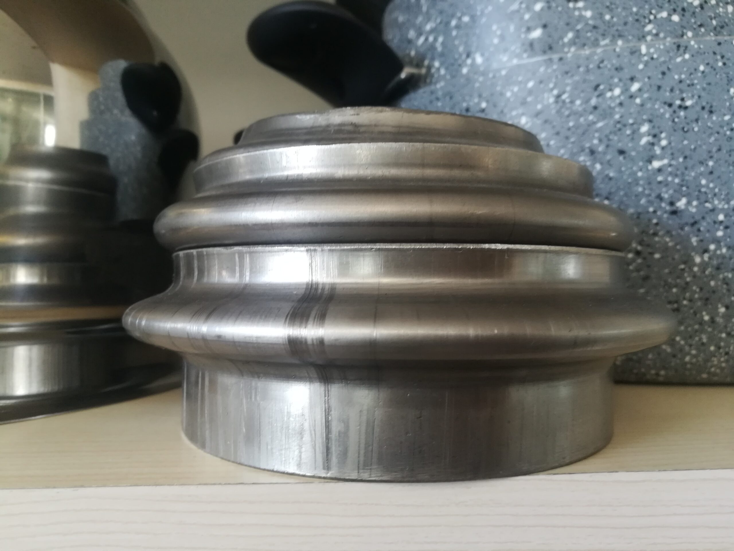
A Curling Machine for Metal Tubes is a specialized piece of equipment designed to form smooth, rounded curls or loops at the ends or along the length of metal tubes and pipes. This machine is widely used in industries such as furniture manufacturing, automotive, HVAC, and decorative metalwork, where curled tube ends add both functional and aesthetic value.
The curling process involves feeding the metal tube into the machine where rotating rollers or dies gradually bend and shape the tube end into a precise curl or coil. The machine applies controlled pressure and movement to avoid damaging the tube’s surface or structure while achieving a consistent curl diameter and shape.
Curling machines can handle various tube materials, including steel, stainless steel, aluminum, and copper, as well as different diameters and wall thicknesses. Tooling and roller configurations are often adjustable or interchangeable to accommodate diverse tube sizes and curling styles, from tight spirals to gentle curves.
Modern curling machines may be manual, semi-automatic, or fully automatic. Automated models use CNC or programmable controls to set curling parameters such as the number of turns, curl diameter, and feed speed, allowing for high precision and repeatability in mass production.
The machine’s design ensures smooth tube handling, minimizing surface scratches or deformation during curling. It often incorporates features such as adjustable feeding speed, pressure control, and safety guards to protect operators.
Applications of tube curling include creating decorative railings and frames, automotive exhaust tips, furniture legs, handrails, and HVAC ductwork components where curled tube ends facilitate attachment or improve appearance.
If you want, I can continue with more details about the working principle, components, or types of curling machines for metal tubes. Would you like me to go on?
Curling machines for metal tubes work by gradually bending the tube end around a forming roller or die that shapes the curl with precision and consistency. The tube is fed into the machine and held firmly by clamps or guides to prevent slipping or deformation. As the forming rollers rotate, they apply controlled pressure to the tube, bending it smoothly into the desired curl radius and number of turns.
The machine’s rollers and dies are typically made from hardened steel or other durable materials to withstand repeated use and maintain consistent shape accuracy. Many machines allow for adjustments to roller spacing, pressure, and rotation speed, enabling operators to customize the curl size and tightness according to specific product requirements.
Manual curling machines require operators to feed and guide the tubes, while semi-automatic and automatic machines use motorized feeding systems controlled by CNC or programmable logic controllers (PLCs). Automated machines can execute complex curling patterns with high repeatability, reducing labor and improving production efficiency.
To accommodate different tube diameters and wall thicknesses, curling machines often feature interchangeable tooling sets. This versatility makes it possible to work with a broad range of materials, including mild steel, stainless steel, aluminum, and copper.
The curling process is designed to minimize surface damage, such as scratches or dents, by using smooth rollers and controlled pressure. Some machines also include lubrication systems to reduce friction during forming.
Curling machines are commonly used in producing furniture components like chair legs and armrests, decorative metalwork such as railings and gates, automotive exhaust tips, and HVAC ductwork where curled tube ends improve functionality or aesthetics.
Safety features like emergency stops, protective guards, and sensors are integrated to protect operators from moving parts and ensure safe operation.
Overall, curling machines for metal tubes provide a reliable, efficient way to produce uniform curls and loops, combining mechanical precision with automation to meet the needs of diverse manufacturing industries.
Advanced curling machines often integrate with other tube processing equipment to create seamless production lines. For example, a curling machine might be paired with tube cutting, bending, or end-forming machines to produce fully finished components in one continuous workflow. This integration reduces handling time, increases throughput, and improves overall manufacturing efficiency.
Modern machines may also feature digital controls that allow operators to program and save curling parameters for different products. This capability enables quick changeovers between different tube sizes and curl styles, supporting flexible manufacturing and small batch runs.
Maintenance of curling machines includes regular inspection of rollers and dies for wear or damage, lubrication of moving parts, and calibration of control systems to maintain precision. Proper upkeep ensures consistent curling quality and extends machine life.
Some high-end curling machines incorporate sensors and vision systems to monitor the curling process in real time, detecting defects such as uneven curls or surface blemishes. These quality control features enable immediate adjustments or rejection of faulty parts, reducing scrap and rework.
Ergonomics and safety continue to be priorities in machine design. Adjustable work heights, easy-to-use controls, and safety interlocks protect operators while promoting efficient workflow.
In summary, curling machines for metal tubes combine mechanical durability, precise forming technology, and automation to deliver consistent, high-quality curled tube ends suitable for a wide range of industrial and decorative applications.
Forming Machine For Metal Tubes
A Forming Machine for Metal Tubes is specialized equipment used to shape metal tubes into desired profiles, shapes, or contours through processes such as bending, curling, expanding, reducing, flaring, or swaging. These machines enable manufacturers to create complex tube geometries required in industries like automotive, aerospace, furniture, construction, and HVAC.
The forming process involves applying mechanical force to deform the tube without compromising its structural integrity. Depending on the application, forming machines may use dies, rollers, mandrels, hydraulic or mechanical presses, and CNC controls to achieve precise shaping.
Common forming operations include bending tubes to specific angles or curves, flaring tube ends to create wider openings, expanding or reducing tube diameters, and curling or coiling tube ends. Each operation uses specialized tooling and machine configurations tailored to the material type, tube dimensions, and required shape.
Modern forming machines often integrate CNC technology, enabling programmable, automated control over complex sequences of forming steps. This automation improves repeatability, reduces labor, and minimizes material waste.
Forming machines must handle a variety of materials such as steel, stainless steel, aluminum, copper, and their alloys. Tooling materials and machine settings are chosen based on material properties to avoid defects like cracking, wrinkling, or excessive thinning.
If you’d like, I can continue with details about specific types of tube forming machines, their components, or typical applications. Would you like me to go on?
Forming machines for metal tubes work by applying controlled mechanical forces to reshape the tube while preserving its strength and surface quality. The tube is positioned within the machine using clamps, guides, or feeders to ensure accurate alignment during forming. Depending on the desired operation, different tooling is employed—such as bending dies for curves, flaring tools to widen ends, expanding heads to increase diameter, or swaging dies to reduce sections.
The forming force can be applied via hydraulic cylinders, mechanical presses, servo motors, or rollers, depending on the machine type and the complexity of the forming task. For bending, rotary draw or mandrel bending techniques may be used, often incorporating internal supports to prevent collapse or wrinkling in thin-walled tubes. Expanding and reducing operations reshape tube diameters gradually to meet design requirements.
CNC controls are frequently integrated to automate forming sequences, allowing for precise control over angles, lengths, pressures, and speeds. Programmable logic controllers (PLCs) and touch-screen interfaces enable operators to set parameters easily and switch between production runs efficiently.
Material selection plays a crucial role in the forming process. Different metals respond differently to deformation, requiring adjustments in machine settings and tooling. For instance, stainless steel demands slower forming speeds and greater force due to its strength, while aluminum requires careful handling to avoid cracking.
To maintain tube quality, forming machines often include lubrication systems to reduce friction and heat during processing. Tooling is manufactured from hardened materials to resist wear and maintain dimensional accuracy over time.
Applications of metal tube forming machines span many sectors. Automotive manufacturers use them for exhaust systems and chassis components; aerospace industries require complex bent and flared tubes for hydraulic and fuel systems; furniture makers create decorative frames and supports; HVAC companies shape ductwork and piping.
Regular maintenance of forming machines ensures consistent performance. This includes inspecting tooling for wear, checking hydraulic or electric drive systems, calibrating control sensors, and lubricating moving parts. Proper training of operators further enhances product quality and machine longevity.
Overall, forming machines for metal tubes provide versatile, precise, and efficient solutions for shaping tubes into the complex profiles needed in modern manufacturing.
Advanced metal tube forming machines increasingly incorporate real-time monitoring systems that track parameters like force, speed, and position throughout the forming process. These sensors feed data to the control system, enabling automatic adjustments that maintain consistent quality even when material properties vary or tooling wears down. This feedback loop reduces scrap rates and increases overall efficiency.
Some forming machines feature modular designs allowing quick tooling changes to accommodate different tube sizes, shapes, or forming operations. This flexibility supports manufacturers dealing with diverse product lines or custom orders without significant downtime.
Integration with upstream and downstream equipment—such as tube cutting, end finishing, or inspection systems—creates streamlined production lines that minimize manual handling and accelerate throughput. Robotics may be employed for loading, unloading, or transferring parts, further enhancing automation.
Environmental and ergonomic considerations are also driving machine design improvements. Electric drives replace hydraulic systems in some machines to reduce energy consumption and eliminate fluid leaks. User-friendly interfaces, adjustable workstations, and enhanced safety features improve operator comfort and reduce workplace hazards.
Material science advancements, including new alloys and coatings, influence forming techniques and machine settings. Forming machines must adapt to these evolving materials to prevent defects and maintain high product standards.
In summary, metal tube forming machines combine mechanical precision, advanced control technologies, and automation to deliver versatile, accurate, and efficient shaping solutions. Their continued development supports the increasing complexity and quality demands of modern manufacturing across multiple industries.
EMS Metalworking Machines
We design, manufacture and assembly metalworking machinery such as:
- Hydraulic transfer press
- Glass mosaic press
- Hydraulic deep drawing press
- Casting press
- Hydraulic cold forming press
- Hydroforming press
- Composite press
- Silicone rubber moulding press
- Brake pad press
- Melamine press
- SMC & BMC Press
- Labrotaroy press
- Edge cutting trimming machine
- Edge curling machine
- Trimming beading machine
- Trimming joggling machine
- Cookware production line
- Pipe bending machine
- Profile bending machine
- Bandsaw for metal
- Cylindrical welding machine
- Horizontal pres and cookware
- Kitchenware, hotelware
- Bakeware and cuttlery production machinery
as a complete line as well as an individual machine such as:
- Edge cutting trimming beading machines
- Polishing and grinding machines for pot and pans
- Hydraulic drawing presses
- Circle blanking machines
- Riveting machine
- Hole punching machines
- Press feeding machine
You can check our machinery at work at: EMS Metalworking Machinery – YouTube
Applications:
Flange-punching
Beading and ribbing
Flanging
Trimming
Curling
Lock-seaming
Ribbing