
We manufacture a SS Pipe Bending Machine Price to bend sheet metal edges. Hydraulic Press Machines are used in metalworking industries
A stainless steel pipe bending machine is a specialized tool designed to bend stainless steel pipes into various shapes and angles. It is commonly used in various industries, including construction, plumbing, and manufacturing, due to its ability to handle the unique properties of stainless steel and achieve precise bending results.
Key Components of a Stainless Steel Pipe Bending Machine
A stainless steel pipe bending machine typically consists of the following components:
- Frame: The frame provides a sturdy base for the machine and supports the bending mechanism. It is typically made from heavy-duty steel or cast iron.
- Bending Mechanism: The bending mechanism is the heart of the machine, applying the force required to bend the stainless steel pipe. It consists of a bending form, a pressure roller, a mandrel, and a hydraulic cylinder. The bending form provides the desired shape, while the pressure roller applies force to bend the pipe, and the mandrel supports the pipe from the inside to prevent flattening.
- Hydraulic Pump and Control System: The hydraulic pump and control system regulate the flow and pressure of hydraulic fluid, ensuring precise and controlled bending. It consists of a hydraulic pump, a control valve, and a pressure gauge.
- Work Table: The work table provides a stable surface for positioning and securing the stainless steel pipe during bending. It may be adjustable to accommodate different pipe sizes and bending angles.
- Controls: The controls allow the operator to operate the machine, including setting the bending angle, engaging the bending mechanism, and controlling the speed of the bending process.
Common Applications of Stainless Steel Pipe Bending Machines
Stainless steel pipe bending machines are suitable for various applications, including:
- Bending stainless steel pipes for plumbing systems
- Forming stainless steel piping for industrial applications, such as food and beverage processing
- Creating stainless steel railings, fences, and other structural components
- Manufacturing stainless steel pipes for decorative elements, such as furniture, handrails, and signage
Benefits of Stainless Steel Pipe Bending Machines
Stainless steel pipe bending machines offer several advantages over manual bending methods:
- Precise Bending Control: Hydraulic systems offer precise control over bending angles, ensuring consistent and accurate results, especially important for stainless steel pipes used in critical applications.
- Reduced Labor Costs: Automated machines reduce labor requirements and minimize the risk of human error, lowering labor costs.
- Versatility: Stainless steel pipe bending machines can handle a wide range of stainless steel pipe sizes and thicknesses.
- Consistent Quality: Automated machines produce identical parts with minimal variation, ensuring quality control.
Safety Precautions for Using Stainless Steel Pipe Bending Machines
When using stainless steel pipe bending machines, it is essential to follow safety protocols to prevent injuries and accidents:
- Thorough Training: Operators must receive comprehensive training on the operation, maintenance, and safety procedures of the stainless steel pipe bending machine.
- Personal Protective Equipment (PPE): Always wear appropriate PPE, including safety glasses, gloves, and hearing protection.
- Secure Pipe Placement: Properly secure the stainless steel pipe in the machine’s bending form and pressure roller to prevent slippage and ensure accurate bending.
- Maintain Safe Distances: Maintain a safe distance from the bending mechanism and hydraulic components during operation.
- Regular Maintenance: Follow a strict maintenance schedule to ensure the machine is in optimal condition and free of potential hazards.
- Emergency Stop Procedures: Familiarize yourself with emergency stop procedures and be prepared to act quickly in case of an unexpected issue.
Stainless steel pipe bending machines are essential tools in various industries for creating precise and durable piping systems, structural components, and decorative elements. By adhering to strict safety protocols and operating the machine with proper training and technique, individuals can effectively bend stainless steel pipes and create various components for various applications.
SS Pipe Bending Machine
Stainless steel pipe bending is a process of shaping stainless steel pipes into various desired forms and angles. It is a versatile and essential technique used in various industries, including construction, plumbing, and manufacturing. Stainless steel pipes are commonly used for their corrosion resistance, durability, and aesthetic appeal.
Types of SS Pipe Bending
There are three main types of stainless steel pipe bending:
- Manual Pipe Bending: This method involves manually applying force to the pipe to bend it into the desired shape. It is a relatively simple and inexpensive method, but it is not suitable for complex shapes or large-diameter pipes.
- Hydraulic Pipe Bending: This method uses hydraulic pressure to bend the pipe. It is more powerful than manual bending and can handle thicker and larger pipes. Hydraulic bending machines are commonly used in industrial applications.
- CNC Pipe Bending: This method utilizes computer numerical control (CNC) technology to precisely bend pipes according to specified parameters. CNC machines are the most accurate and efficient method of bending stainless steel pipes, but they are also the most expensive.
Common SS Pipe Bending Applications
Stainless steel pipe bending is used in a wide range of applications, including:
- Plumbing Systems: Stainless steel pipes are used for plumbing fixtures, water supply lines, and drainage systems. Bending allows for the creation of complex pipe runs and intricate installations.
- Industrial Piping: Stainless steel pipes are used in industrial applications for food processing, chemical handling, and other demanding environments. Bending enables the adaptation of pipelines to various structures and layouts.
- Structural Components: Stainless steel pipes are used for structural elements like railings, fences, and architectural supports. Bending allows for the creation of curved shapes and customized designs.
- Decorative Elements: Stainless steel pipes are used for decorative purposes, such as furniture legs, railing handrails, and signage. Bending enables the creation of sleek and stylish designs.
Benefits of SS Pipe Bending
SS pipe bending offers several advantages:
- Versatility: Stainless steel pipes can be bent into a wide range of shapes and angles, allowing for customized designs and applications.
- Durability: Stainless steel is a strong and durable material, making it well-suited for bending without compromising its integrity.
- Corrosion Resistance: Stainless steel’s inherent corrosion resistance ensures that bent pipes maintain their structural integrity and appearance even in harsh environments.
- Precision: Advanced bending methods, such as CNC bending, can produce precise and accurate bends, ensuring consistent results and fitment.
- Efficiency: Automated bending machines can significantly reduce labor costs and increase production efficiency, particularly for high-volume projects.
Safety Precautions for SS Pipe Bending
When bending stainless steel pipes, it is crucial to follow safety guidelines to prevent injuries and accidents:
- Thorough Training: Operators must receive comprehensive training on the specific bending method and machine operation.
- Personal Protective Equipment (PPE): Wear appropriate PPE, including safety glasses, gloves, and hearing protection, to protect from flying debris, sharp edges, and noise.
- Secure Pipe Placement: Secure the stainless steel pipe firmly in the bending device to prevent slippage or movement during the bending process.
- Maintain Safe Distances: Maintain a safe distance from the bending mechanism and hydraulic components to avoid accidental contact and potential harm.
- Proper Machine Maintenance: Follow regular maintenance schedules to ensure the machine is in good working condition and free from potential hazards.
- Emergency Stop Procedures: Familiarize yourself with emergency stop procedures and be prepared to act quickly in case of any unexpected issues or malfunctions.
By adhering to safety precautions and following proper operating procedures, individuals can effectively bend stainless steel pipes and create various components for various applications with minimal risk of injury or damage
Mandrel Pipe Bender:
A mandrel pipe bender is a specialized machine used in metalworking to bend pipes or tubes with precision and accuracy. At the heart of the mandrel pipe bender is the mandrel itself, a crucial component that supports the inner surface of the pipe during the bending process. The mandrel ensures that the pipe maintains its shape and prevents collapsing or wrinkling, resulting in high-quality bends with consistent dimensions and smooth contours.
The mandrel typically consists of several key elements, including the mandrel ball, mandrel rod, mandrel nose, mandrel arm, and mandrel head. The mandrel ball is a spherical insert that fits snugly inside the pipe and provides support against internal compression forces during bending. It is attached to the mandrel rod, a long cylindrical shaft that extends through the length of the pipe and connects to the bending machine’s hydraulic system.
The mandrel nose is the front end of the mandrel assembly and is responsible for guiding the mandrel into the pipe and positioning it accurately within the bending die. It is designed to minimize friction and ensure smooth insertion and extraction of the mandrel during the bending cycle. The mandrel arm extends from the mandrel nose and houses the hydraulic mechanisms responsible for controlling mandrel insertion, retraction, and positioning.
The mandrel head is the rear end of the mandrel assembly and houses the mandrel support mechanism, which adjusts the mandrel’s position and pressure based on the bending requirements and material properties. The mandrel head may also incorporate features such as cooling channels or lubrication systems to minimize heat buildup and friction during the bending process.
In operation, the mandrel pipe bender utilizes hydraulic pressure to exert force on the outer surface of the pipe while the mandrel supports the inner surface, ensuring uniform deformation and minimizing distortion. The bending process is controlled by a computer numerical control (CNC) system, which coordinates the movement of the bending die, mandrel, and other components to achieve precise bend angles, radii, and dimensions as specified in the design.
Mandrel pipe benders are commonly used in industries such as automotive, aerospace, construction, and manufacturing, where precision bending of pipes or tubes is required for various applications. They offer advantages such as high repeatability, flexibility in bending profiles, and the ability to produce complex shapes with minimal distortion or deformation. By incorporating advanced features such as automatic mandrel retraction, springback compensation, and anti-wrinkle systems, modern mandrel pipe benders enable efficient production of high-quality bent components with tight tolerances and superior surface finishes.
Mandrel:
The mandrel is a critical component in mandrel pipe bending machines, playing a pivotal role in ensuring the quality and accuracy of bent tubes or pipes. Essentially, the mandrel is an internal support mechanism inserted into the tube during the bending process to prevent deformation, wrinkling, or collapsing of the inner wall. It provides internal support and counteracts the compressive forces exerted on the inside of the tube as it is bent around the bending die.
The mandrel typically consists of several components, including the mandrel ball, mandrel rod, and mandrel nose. The mandrel ball is a spherical insert that fits snugly inside the tube and serves as the primary contact point between the mandrel and the inner surface of the tube. It distributes the bending forces evenly along the length of the tube and minimizes distortion or buckling.
The mandrel rod is a long, slender shaft that extends through the length of the tube and connects the mandrel ball to the hydraulic or mechanical actuation system of the bending machine. It provides structural support and transmits the bending forces from the actuation system to the mandrel ball, ensuring controlled deformation of the tube during bending.
The mandrel nose is the front end of the mandrel assembly and is responsible for guiding the mandrel into the tube and positioning it accurately within the bending die. It is designed to minimize friction and facilitate smooth insertion and extraction of the mandrel during the bending cycle. The mandrel nose may incorporate features such as lubrication channels or coatings to reduce friction and wear.
During the bending process, the mandrel is inserted into the tube through the mandrel nose and positioned at the desired location within the bending die. As the tube is bent around the die, the mandrel provides internal support, preventing distortion or collapse of the inner wall and ensuring uniform deformation of the tube profile. The mandrel is then retracted from the tube once the bending process is complete, allowing the bent tube to be removed from the machine.
Mandrels come in various sizes, shapes, and configurations to accommodate different tube diameters, wall thicknesses, and bending requirements. They may be made from materials such as steel, aluminum, or composite materials, depending on the application and performance requirements. Advanced mandrel designs may incorporate features such as cooling channels, interchangeable tips, or pneumatic actuators for enhanced functionality and versatility.
In summary, the mandrel is a critical component in mandrel pipe bending machines, providing internal support and ensuring the quality and accuracy of bent tubes or pipes. By selecting the appropriate mandrel design and configuration and implementing proper insertion and retraction techniques, manufacturers can achieve precise bending results with minimal distortion and superior surface finish.
Pipe Bending Machine:
A pipe bending machine is a specialized piece of equipment used in metalworking to bend pipes or tubes into various shapes and configurations. These machines utilize hydraulic, mechanical, or electric mechanisms to exert controlled force on the outer surface of the pipe, causing it to deform and take on the desired bend radius and angle. Pipe bending machines are widely used in industries such as automotive, aerospace, construction, and manufacturing for applications ranging from exhaust systems and roll cages to structural components and fluid conveyance systems.
The key components of a pipe bending machine include the bending die, mandrel, clamping system, and hydraulic or mechanical actuation system. The bending die is a precision-machined tooling component that defines the shape and dimensions of the bend and provides support and guidance to the pipe during the bending process. It is typically made from hardened steel or other high-strength materials to withstand the bending forces and ensure accurate and repeatable bending results.
The mandrel is an internal support mechanism inserted into the pipe during bending to prevent deformation or collapse of the inner wall. It supports the pipe internally and helps maintain its shape and integrity throughout the bending process. The clamping system secures the pipe in place during bending, preventing slippage or movement that could compromise the accuracy of the bend. It may consist of clamping dies, pressure pads, or collets that exert radial pressure on the pipe to hold it firmly against the bending die.
The actuation system provides the force necessary to bend the pipe and typically consists of hydraulic cylinders, servo motors, or mechanical linkages controlled by a computer numerical control (CNC) system. The CNC system coordinates the movement of the bending die, mandrel, and clamping system to achieve precise bend angles, radii, and dimensions as specified in the design. Advanced pipe bending machines may incorporate features such as automatic tool changeovers, multi-stack tooling, and real-time monitoring and feedback systems for enhanced productivity and efficiency.
Pipe bending machines come in various configurations, including manual, semi-automatic, and fully automatic models, depending on the level of automation and control required for specific applications. Manual machines are operated by hand or foot controls and are suitable for low-volume production or prototyping tasks. Semi-automatic machines feature hydraulic or electric actuators controlled by simple push-button interfaces and are ideal for medium-volume production runs. Fully automatic machines are equipped with CNC control systems that automate all aspects of the bending process, including tool changes, material feeding, and bend sequencing, making them suitable for high-volume production environments.
In conclusion, pipe bending machines are versatile and essential tools in metalworking that enable the fabrication of complex and precise bent components for a wide range of applications. By selecting the appropriate machine configuration and tooling setup and implementing proper operating procedures, manufacturers can achieve consistent, high-quality bending results with minimal waste and downtime.
Tube Bending Equipment
Tube bending equipment encompasses a variety of machinery and tools used in the metalworking industry to bend tubes or pipes into specific shapes, angles, and configurations. From manual hand tools to sophisticated CNC-controlled machines, tube bending equipment offers a range of capabilities to meet diverse manufacturing requirements across various industries.
- Manual Tube Benders: Manual tube benders are simple, hand-operated tools used for bending small-diameter tubes or pipes with relatively thin walls. They consist of a bending lever, which applies force to the tube against a fixed or adjustable die, allowing operators to manually bend tubes to the desired angle. Manual tube benders are cost-effective and portable, making them suitable for on-site installations, repair work, or prototyping tasks.
- Hydraulic Tube Benders: Hydraulic tube benders utilize hydraulic power to exert controlled force on the tube, allowing for precise and repeatable bending operations. These machines typically feature hydraulic cylinders, mandrels, clamping systems, and bending dies controlled by a hydraulic pump and valves. Hydraulic tube benders offer higher bending capacities, faster cycle times, and increased automation compared to manual tools, making them ideal for medium to high-volume production runs.
- Electric Tube Benders: Electric tube benders use electric motors or servo drives to power the bending mechanism, providing precise control over bending speed, force, and positioning. These machines offer the advantages of quiet operation, energy efficiency, and programmable control, making them suitable for applications requiring high accuracy and repeatability. Electric tube benders are commonly used in industries such as automotive, aerospace, and HVAC for bending tubes with tight tolerances and complex geometries.
- CNC Tube Bending Machines: CNC tube bending machines are highly automated systems equipped with computer numerical control (CNC) technology for precise and complex tube bending operations. They feature multiple axes of motion, automatic tool changeovers, and real-time monitoring and feedback systems for optimal performance and productivity. CNC tube benders offer the flexibility to produce a wide range of bend profiles, including 2D and 3D bends, with minimal setup time and operator intervention. They are used in mass production environments where high-volume production, tight tolerances, and consistent quality are paramount.
- Tube End Forming Machines: Tube end forming machines complement tube bending equipment by providing capabilities for end forming, flaring, swaging, expanding, and threading operations. These machines allow manufacturers to create finished tube ends with precise dimensions, shapes, and finishes to meet specific application requirements. Tube end forming machines are commonly used in industries such as automotive exhaust systems, furniture manufacturing, and hydraulic systems for producing tube assemblies with leak-free connections and optimal performance.
- Tube Measurement and Inspection Systems: Tube measurement and inspection systems are used to verify the dimensional accuracy, straightness, wall thickness, and surface finish of bent tubes or pipes. These systems utilize non-contact measurement techniques such as laser scanning, optical imaging, or ultrasonic testing to ensure compliance with design specifications and quality standards. Tube measurement and inspection systems help manufacturers identify defects, deviations, or inconsistencies early in the production process, enabling timely corrective actions and quality assurance.
In summary, tube bending equipment encompasses a wide range of machinery and tools designed to meet diverse bending requirements in the metalworking industry. From manual hand tools for small-scale operations to CNC-controlled machines for high-volume production, tube bending equipment offers flexibility, accuracy, and efficiency in bending tubes or pipes for various applications across industries. By selecting the appropriate equipment and implementing proper operating procedures, manufacturers can achieve precise, high-quality bent components while maximizing productivity and profitability.
Hydraulic System in Tube Bending Equipment:
The hydraulic system plays a crucial role in tube bending equipment, providing the power and control necessary to perform bending operations with precision and efficiency. It consists of several components working together to generate hydraulic pressure, transmit force, and control the movement of the bending dies, mandrel, and clamping mechanisms. Here’s an in-depth look at the key components of the hydraulic system in tube bending equipment:
- Hydraulic Pump:
- The hydraulic pump is responsible for generating hydraulic pressure by converting mechanical energy into fluid flow.
- It draws hydraulic fluid from the reservoir and delivers it to the hydraulic circuit at high pressure, providing the force required to actuate hydraulic cylinders and other hydraulic components.
- Hydraulic Cylinders:
- Hydraulic cylinders are devices that convert hydraulic pressure into linear motion.
- In tube bending equipment, hydraulic cylinders are used to actuate the bending dies, mandrel, and clamping mechanisms, applying the necessary force to deform the tube into the desired shape.
- They come in various types, including single-acting cylinders, double-acting cylinders, and telescopic cylinders, depending on the application requirements and bending forces involved.
- Control Valves:
- Control valves regulate the flow and direction of hydraulic fluid in the hydraulic system, enabling precise control over the movement of hydraulic cylinders.
- Directional control valves control the direction of fluid flow, while pressure control valves regulate hydraulic pressure, and flow control valves regulate flow rates.
- Proportional control valves provide variable control over flow rates or pressures, allowing for fine-tuning of bending parameters.
- Hydraulic Reservoir:
- The hydraulic reservoir, or hydraulic tank, stores hydraulic fluid and helps maintain system pressure and temperature.
- It also serves to remove air bubbles from the hydraulic fluid and acts as a heat sink to dissipate excess heat generated during operation.
- Hydraulic Hoses and Fittings:
- Hydraulic hoses and fittings transmit hydraulic fluid between hydraulic components, such as the pump, cylinders, valves, and reservoir.
- They must be designed to withstand high pressure and provide leak-free connections to ensure the integrity and reliability of the hydraulic system.
- Hydraulic Fluid:
- Hydraulic fluid serves as the working medium in the hydraulic system, transmitting power, lubricating components, and dissipating heat.
- Common types of hydraulic fluids include mineral oil-based fluids, synthetic fluids, and water-glycol solutions, each offering different performance characteristics and temperature ranges.
- Hydraulic Filtration System:
- The hydraulic filtration system removes contaminants, such as dirt, debris, and particulates, from the hydraulic fluid to maintain system cleanliness and prevent component wear.
- Filters, strainers, and breathers are used to remove contaminants and ensure the hydraulic fluid remains clean and free from impurities.
Overall, the hydraulic system in tube bending equipment is a critical component that provides the power and control necessary to perform bending operations accurately and efficiently. By selecting high-quality hydraulic components, maintaining proper fluid cleanliness, and implementing effective control strategies, manufacturers can optimize the performance and reliability of their tube bending equipment, resulting in high-quality bent components and increased productivity.
Bending Process in Tube Bending Equipment
The bending process is the fundamental operation performed by tube bending equipment to deform tubes or pipes into desired shapes, angles, and configurations. It involves applying controlled force to the outer surface of the tube while supporting the inner surface with a mandrel to achieve the desired bend radius and angle. Here’s a detailed explanation of the bending process in tube bending equipment:
- Material Preparation:
- Before the bending process begins, the tube or pipe must undergo material preparation, which includes cutting the tube to the required length and removing any burrs or sharp edges.
- Material preparation ensures that the tube is free from defects or imperfections that could affect the bending process and the quality of the finished product.
- Tooling Setup:
- Once the material is prepared, the tube bending machine is set up with the appropriate tooling, including bending dies, mandrels, clamping mechanisms, and pressure pads.
- Tooling setup involves selecting the correct bending die and mandrel size, adjusting the position of the clamping mechanism, and setting the bending angle and radius according to the desired specifications.
- Clamping:
- The tube is securely clamped in place between the bending dies to prevent slippage or movement during the bending process.
- Clamping is essential to ensure that the tube remains in the correct position and orientation relative to the bending dies and mandrel.
- Mandrel Insertion:
- In some bending operations, a mandrel is inserted into the tube to support the inner surface and prevent collapse or wrinkling during bending.
- The mandrel is inserted into the tube through the mandrel nose and positioned at the desired location within the bending die.
- Bending:
- The bending process begins with the application of force to the outer surface of the tube by the bending dies.
- Hydraulic or mechanical actuators exert controlled pressure on the tube, causing it to deform and bend around the bending die to the desired angle.
- The mandrel provides internal support to the tube, ensuring that the inner surface maintains its shape and integrity throughout the bending process.
- Mandrel Extraction:
- Once the bending process is complete, the mandrel is retracted from the tube to allow for easy removal.
- The mandrel is extracted from the tube through the mandrel nose, and any residual lubricant or debris is removed from the tube surface.
- Finishing Operations:
- After bending, the tube may undergo additional finishing operations, such as end forming, deburring, or surface treatment, to achieve the desired final dimensions and surface finish.
- Finishing operations help ensure that the bent tube meets the specified tolerances and quality standards required for the intended application.
- Quality Inspection:
- Finally, the bent tube undergoes quality inspection to verify that it meets the specified dimensions, tolerances, and quality requirements.
- Inspection may involve visual inspection, dimensional measurement, or non-destructive testing to ensure that the bent tube is free from defects or imperfections.
In summary, the bending process in tube bending equipment involves several sequential steps, including material preparation, tooling setup, clamping, mandrel insertion, bending, mandrel extraction, finishing operations, and quality inspection. By carefully controlling each step of the process and selecting appropriate tooling and parameters, manufacturers can achieve accurate and consistent bending results while ensuring the quality and integrity of the finished product.
CNC Control in Tube Bending Equipment
CNC (Computer Numerical Control) technology has revolutionized the tube bending industry, offering precise control, flexibility, and automation capabilities in tube bending equipment. CNC control systems allow operators to program and execute complex bending sequences with high accuracy and repeatability. Here’s an in-depth explanation of the role and functionality of CNC control in tube bending equipment:
- Programming:
- CNC tube bending machines are equipped with software interfaces that allow operators to program bending sequences using intuitive graphical interfaces or G-code programming languages.
- Operators input parameters such as bend angle, bend radius, tube dimensions, and tooling information into the CNC control system to create bending programs.
- Programming software may also include features such as simulation and collision detection to verify the feasibility of bending sequences and prevent errors or collisions during operation.
- Bend Sequencing:
- CNC control systems allow operators to define complex bending sequences involving multiple bends, straight sections, and rotation movements.
- Operators can specify the order and direction of bends, as well as the position and orientation of the tube relative to the bending dies and mandrel.
- CNC control systems optimize bend sequencing to minimize material waste, reduce cycle times, and maximize machine productivity.
- Tooling Setup:
- CNC tube bending machines feature tooling setup functions that allow operators to input tooling parameters such as bending die size, mandrel size, and clamping positions.
- Tooling setup parameters are stored in the CNC control system and recalled automatically when executing bending programs, ensuring consistent setup and minimizing setup time between production runs.
- Real-Time Control:
- During bending operations, CNC control systems provide real-time feedback and control over machine parameters such as hydraulic pressure, mandrel position, and bending speed.
- Operators can monitor bending progress, adjust parameters on the fly, and intervene if necessary to ensure optimal bending results and machine performance.
- Automatic Tool Changeovers:
- CNC tube bending machines can automatically change bending tools, such as bending dies and mandrels, based on programmed bending sequences.
- Automatic tool changeovers eliminate the need for manual tool changes between production runs, reducing setup time and increasing machine uptime.
- Error Detection and Correction:
- CNC control systems feature built-in error detection and correction mechanisms that monitor machine performance and identify deviations from programmed parameters.
- If an error or deviation is detected, the CNC control system can automatically adjust machine parameters, such as bending force or mandrel position, to correct the error and ensure consistent bending results.
- Data Logging and Reporting:
- CNC tube bending machines record bending data, such as bend angles, bend radii, and cycle times, for each production run.
- Data logging and reporting features allow operators to analyze machine performance, identify trends, and optimize bending processes for increased efficiency and quality.
In summary, CNC control is a critical component of modern tube bending equipment, providing operators with the tools and capabilities to program, execute, and optimize bending sequences with precision and efficiency. By leveraging CNC technology, manufacturers can achieve accurate, repeatable bending results while maximizing productivity and minimizing production costs.
Bend Radius in Tube Bending Equipment:
The bend radius is a crucial parameter in tube bending equipment, representing the minimum radius of curvature achievable during the bending process. It determines the smoothness of the bend and affects factors such as material deformation, wall thinning, and tooling selection. Here’s an in-depth explanation of the bend radius in tube bending equipment:
- Definition:
- The bend radius is defined as the distance from the centerline of the tube to the centerline of the bend.
- It is typically measured on the inside surface of the bend and represents the tightest curvature that the tube can achieve without causing defects or imperfections.
- Minimum Bend Radius:
- The minimum bend radius is the smallest radius that can be achieved without causing excessive deformation or damage to the tube.
- It is determined by factors such as the tube material, wall thickness, and bending method used.
- Bend Quality:
- The bend radius directly influences the quality of the bend, affecting factors such as surface finish, dimensional accuracy, and structural integrity.
- Smaller bend radii tend to produce tighter bends with sharper contours, while larger bend radii result in gentler curves with smoother transitions.
- Material Deformation:
- Achieving a tight bend radius can lead to material deformation, including stretching, compression, and thinning of the tube wall.
- Excessive deformation can cause defects such as wrinkles, buckles, or cracks, compromising the integrity of the bent tube.
- Tooling Selection:
- The bend radius determines the selection of bending dies and mandrels used in the bending process.
- Smaller bend radii require smaller bending dies and mandrels to achieve the desired curvature, while larger bend radii may require larger tooling sizes.
- Bend Limitations:
- The bend radius sets limitations on the maximum bend angle that can be achieved without causing excessive distortion or wrinkling of the tube.
- Tubes with smaller bend radii may be limited in the maximum bend angle that can be achieved before reaching the material’s elastic limit.
- Application Considerations:
- The bend radius must be carefully selected based on the specific requirements of the application, including space constraints, flow characteristics, and structural considerations.
- For example, tight bend radii may be desirable in applications requiring compact layouts or efficient fluid flow, while larger bend radii may be preferred for structural stability or aesthetic purposes.
In summary, the bend radius is a critical parameter in tube bending equipment that influences the quality, integrity, and functionality of the bent tube. By carefully selecting the appropriate bend radius and implementing proper bending techniques, manufacturers can achieve accurate and consistent bending results while ensuring the performance and reliability of the finished product.
Tube Material in Tube Bending Equipment:
The choice of tube material is a critical consideration in tube bending equipment, as it directly impacts the bending process, tooling selection, and the performance characteristics of the finished product. Here’s a detailed explanation of the importance of tube material in tube bending equipment:
- Material Properties:
- Tube materials exhibit a wide range of mechanical properties, including tensile strength, yield strength, hardness, and ductility.
- The material properties determine how the tube responds to bending forces, including its ability to withstand deformation, resist cracking, and maintain dimensional stability during bending.
- Material Compatibility:
- Tube bending equipment must be compatible with a variety of materials commonly used in tubing applications, including metals such as steel, stainless steel, aluminum, copper, brass, and titanium, as well as plastics and composites.
- Different materials require specific tooling, bending techniques, and process parameters to achieve optimal bending results while minimizing defects and material damage.
- Bending Characteristics:
- Each tube material has unique bending characteristics, including its elasticity, plasticity, and work hardening behavior.
- Some materials, such as aluminum and copper, are more ductile and easier to bend than others, while materials like stainless steel and titanium may require higher bending forces and specialized tooling to achieve the desired bend radii and angles.
- Wall Thickness:
- The wall thickness of the tube affects its bending behavior and the forces required to deform it.
- Thicker-walled tubes may require higher bending forces and larger bending dies to achieve the desired bend radii, while thinner-walled tubes may be prone to wrinkling or collapse if bent too sharply.
- Surface Finish:
- The surface finish of the tube material can impact the quality and appearance of the bent tube.
- Smooth, defect-free surfaces are desirable for applications requiring tight tolerances, minimal friction, or aesthetic appeal, while rough or uneven surfaces may affect sealing, assembly, or surface coating processes.
- Corrosion Resistance:
- Tube materials may vary in their resistance to corrosion, oxidation, and other environmental factors.
- For applications exposed to harsh environments or corrosive fluids, materials with high corrosion resistance, such as stainless steel or corrosion-resistant alloys, are preferred to ensure long-term durability and reliability.
- Cost Considerations:
- The cost of the tube material is a significant factor in the overall cost of the bending process and the finished product.
- Material cost considerations must be balanced with performance requirements, processing capabilities, and the intended application to optimize cost-effectiveness and value.
In summary, the selection of tube material is a critical decision in tube bending equipment, impacting the bending process, tooling selection, and the performance characteristics of the finished product. By carefully considering material properties, compatibility, bending characteristics, wall thickness, surface finish, corrosion resistance, and cost considerations, manufacturers can choose the most suitable material for their specific application requirements while achieving optimal bending results and product performance.
Mandrel in Tube Bending Equipment:
The mandrel is a vital component in tube bending equipment, especially in applications where maintaining the integrity of the tube’s inner diameter is essential. It provides internal support to the tube during the bending process, preventing collapse, wrinkling, or distortion of the inner wall. Here’s an in-depth explanation of the role and importance of the mandrel in tube bending equipment:
- Internal Support:
- The mandrel is inserted into the tube before bending and positioned along the bend region to provide internal support and prevent deformation of the inner wall.
- It helps maintain the roundness and dimensional accuracy of the tube’s inner diameter, ensuring uniformity and consistency in the bent tube.
- Preventing Collapse:
- During bending, the outer surface of the tube experiences compressive forces, while the inner surface experiences tensile forces.
- Without internal support from a mandrel, the tube’s inner wall may collapse or buckle under the bending forces, leading to defects or imperfections in the bent tube.
- Reducing Ovality:
- Ovality refers to the deviation of the tube’s cross-sectional shape from a perfect circle.
- By providing internal support, the mandrel helps minimize ovality and maintain the roundness of the tube’s cross-section, ensuring dimensional accuracy and consistency in the bent tube.
- Preventing Wrinkling:
- Wrinkling occurs when the tube’s inner wall buckles or folds during bending, resulting in irregularities or defects in the bent tube.
- The mandrel supports the inner wall and helps distribute bending forces evenly, reducing the likelihood of wrinkling and ensuring a smooth and uniform bend.
- Improving Bend Quality:
- The use of a mandrel in tube bending equipment improves bend quality by reducing defects such as collapse, wrinkling, ovality, and wall thinning.
- It enables tighter bend radii, sharper bend angles, and more complex bend geometries while maintaining the integrity and dimensional accuracy of the bent tube.
- Mandrel Types:
- Mandrels come in various types, including ball mandrels, plug mandrels, wiper mandrels, and segmented mandrels, each designed for specific applications and bending requirements.
- Ball mandrels feature a spherical or cylindrical shape and are suitable for general-purpose bending applications.
- Plug mandrels have a solid cylindrical shape and provide full-length support along the bend region, ideal for thin-walled or high-strength materials.
- Wiper mandrels have a tapered or conical shape and are used to remove wrinkles or imperfections from the tube’s inner wall during bending.
- Segmented mandrels consist of multiple segments that can be expanded or contracted to accommodate different tube diameters and bend radii.
- Mandrel Lubrication:
- Proper lubrication of the mandrel is essential to reduce friction between the mandrel and the tube’s inner wall, minimizing wear and ensuring smooth bending operations.
- Lubricants such as oil, grease, or dry film lubricants are applied to the mandrel surface to facilitate easy insertion and removal and reduce the risk of galling or sticking.
In summary, the mandrel is a critical component in tube bending equipment that provides internal support to the tube during bending, preventing collapse, wrinkling, or distortion of the inner wall. By selecting the appropriate mandrel type, size, and lubrication method, manufacturers can achieve high-quality, consistent bending results while ensuring the integrity and dimensional accuracy of the bent tube.
Mandrel Lubrication in Tube Bending Equipment:
Mandrel lubrication is a crucial aspect of the tube bending process, as it ensures smooth operation, minimizes wear and tear on the mandrel and tube, and prevents defects such as scoring, scratching, or galling. Proper lubrication facilitates the insertion and removal of the mandrel, reduces friction between the mandrel and the tube’s inner wall, and improves the overall quality of the bent tube. Here’s an in-depth explanation of mandrel lubrication in tube bending equipment:
- Purpose of Lubrication:
- The primary purpose of mandrel lubrication is to reduce friction between the mandrel and the inner surface of the tube during bending.
- By reducing friction, lubrication helps prevent galling, scoring, or scratching of the tube’s inner wall, ensuring smooth bending operations and minimizing wear on the mandrel and tooling.
- Types of Lubricants:
- Various types of lubricants are used in tube bending equipment, including oils, greases, dry film lubricants, and synthetic lubricants.
- Oil-based lubricants are commonly used for general-purpose bending operations, offering good lubricity and easy application.
- Grease-based lubricants provide long-lasting lubrication and are suitable for high-speed or high-load bending applications.
- Dry film lubricants form a thin, dry film on the mandrel surface, reducing friction without leaving residue or attracting contaminants.
- Synthetic lubricants offer superior performance in extreme temperatures or harsh environments and are resistant to oxidation, corrosion, and chemical degradation.
- Application Methods:
- Mandrel lubricants can be applied using various methods, including manual application, automatic lubrication systems, and spray or mist systems.
- Manual application involves applying lubricant directly to the mandrel surface using a brush, cloth, or spray bottle.
- Automatic lubrication systems dispense lubricant at predefined intervals or during specific stages of the bending process, ensuring consistent lubrication and minimizing operator intervention.
- Spray or mist systems atomize the lubricant into fine droplets, which are then directed onto the mandrel surface using compressed air or a pump, providing uniform coverage and minimizing waste.
- Frequency of Lubrication:
- The frequency of mandrel lubrication depends on factors such as the type of lubricant used, the material being bent, the bending speed, and the operating conditions.
- In general, lubrication should be applied regularly to ensure continuous lubrication of the mandrel surface and prevent dry spots or areas of excessive friction.
- Operators should monitor the condition of the mandrel and tube during bending operations and replenish lubricant as needed to maintain optimal performance.
- Effect on Bending Quality:
- Proper mandrel lubrication has a significant impact on the quality of the bending process and the finished product.
- It reduces the risk of defects such as scratches, scoring, or galling on the tube’s inner surface, ensuring smooth, uniform bends with minimal distortion or damage.
- Lubrication also helps extend the life of the mandrel and tooling, reducing maintenance requirements and downtime associated with wear-related issues.
In summary, mandrel lubrication is a critical aspect of tube bending equipment that ensures smooth bending operations, minimizes wear on the mandrel and tube, and improves the overall quality of the bent tube. By selecting the appropriate lubricant type, application method, and frequency of lubrication, manufacturers can achieve consistent, high-quality bending results while maximizing the efficiency and reliability of their tube bending processes.
Mandrel Nose in Tube Bending Equipment:
The mandrel nose is a crucial component of tube bending equipment, providing support and guidance to the mandrel during the bending process. It helps ensure proper alignment and positioning of the mandrel within the tube, minimizing friction, wear, and the risk of defects such as wrinkling or collapsing. Here’s an in-depth explanation of the role and importance of the mandrel nose in tube bending equipment:
- Definition and Function:
- The mandrel nose is the forward-facing end of the mandrel that enters the tube first and comes into direct contact with the inner surface of the tube during bending.
- Its primary function is to provide support and guidance to the mandrel, ensuring proper alignment and positioning within the tube and minimizing friction and wear.
- Material and Construction:
- Mandrel noses are typically made from materials such as steel, stainless steel, or carbide, depending on the application requirements and bending conditions.
- They may feature a smooth, polished surface to reduce friction and minimize damage to the tube’s inner wall during bending.
- Design Considerations:
- Mandrel noses come in various designs and configurations to accommodate different tube diameters, bend radii, and bending techniques.
- Common designs include tapered noses, conical noses, spherical noses, and custom-shaped noses, each offering specific benefits in terms of insertion ease, support, and compatibility with different tube materials and geometries.
- Insertion and Removal:
- The mandrel nose is designed to facilitate easy insertion and removal of the mandrel from the tube, minimizing friction and ensuring smooth bending operations.
- Tapered or conical mandrel noses may provide a gradual transition from the mandrel to the tube’s inner surface, reducing the risk of snagging or catching during insertion.
- Alignment and Support:
- Proper alignment and support of the mandrel nose within the tube are critical to maintaining the integrity and dimensional accuracy of the bent tube.
- The mandrel nose helps guide the mandrel along the bend region, preventing lateral movement or misalignment that could lead to defects such as wrinkles, buckles, or kinks.
- Friction Reduction:
- The mandrel nose’s smooth, polished surface helps reduce friction between the mandrel and the tube’s inner wall, minimizing wear and damage to both the mandrel and the tube.
- Reduced friction ensures smooth bending operations and improves the overall quality of the bent tube by minimizing surface imperfections and defects.
- Compatibility and Versatility:
- Mandrel noses are designed to be compatible with a wide range of tube materials, diameters, and bend radii, making them versatile and suitable for various bending applications.
- Custom-designed mandrel noses can be tailored to specific bending requirements, such as tight bend radii, complex geometries, or special material considerations.
In summary, the mandrel nose is a critical component of tube bending equipment that provides support, guidance, and alignment to the mandrel during the bending process. By ensuring proper design, material selection, and compatibility with different tube materials and geometries, manufacturers can achieve consistent, high-quality bending results while minimizing wear and damage to both the mandrel and the tube.
Mandrel Ball in Tube Bending Equipment:
The mandrel ball is a specialized type of mandrel used in tube bending equipment to provide internal support and prevent collapse or deformation of the tube’s inner wall during bending. It consists of a spherical or cylindrical-shaped ball mounted on the end of the mandrel shaft, allowing it to rotate freely within the tube and distribute bending forces evenly along the bend region. Here’s an in-depth explanation of the role and importance of the mandrel ball in tube bending equipment:
- Internal Support:
- The mandrel ball provides internal support to the tube during bending, preventing collapse, wrinkling, or distortion of the tube’s inner wall.
- By distributing bending forces evenly along the bend region, the mandrel ball helps maintain the roundness and dimensional accuracy of the tube’s inner diameter, ensuring uniformity and consistency in the bent tube.
- Smooth Rotation:
- The spherical or cylindrical shape of the mandrel ball allows it to rotate freely within the tube during bending, minimizing friction and wear on both the mandrel and the tube’s inner surface.
- Smooth rotation ensures uniform distribution of bending forces and reduces the risk of scoring, scratching, or galling on the tube’s inner wall.
- Reduced Friction:
- The smooth surface of the mandrel ball helps reduce friction between the mandrel and the tube’s inner wall, ensuring smooth bending operations and minimizing damage to both components.
- Reduced friction also improves the overall quality of the bent tube by minimizing surface imperfections and defects such as scratches or scoring.
- Versatility and Compatibility:
- Mandrel balls are compatible with a wide range of tube materials, diameters, and bend radii, making them versatile and suitable for various bending applications.
- They can accommodate different tube geometries, including straight sections, curves, and complex shapes, while providing consistent support and alignment during bending.
- Material Selection:
- Mandrel balls are typically made from materials such as steel, stainless steel, or carbide, depending on the application requirements and bending conditions.
- High-quality materials and precision machining ensure durability, reliability, and long service life, even in demanding bending applications.
- Application Considerations:
- Mandrel balls are commonly used in applications where tight bend radii, sharp bend angles, or thin-walled tubes are involved, as they provide effective support and prevent collapse or wrinkling of the tube’s inner wall.
- They are suitable for bending operations that require high precision, dimensional accuracy, and surface finish, such as automotive, aerospace, and hydraulic tubing applications.
In summary, the mandrel ball is a specialized component of tube bending equipment that provides internal support, smooth rotation, and reduced friction during the bending process. By ensuring proper design, material selection, and compatibility with different tube materials and geometries, manufacturers can achieve consistent, high-quality bending results while minimizing wear and damage to both the mandrel and the tube.
Mandrel Segments in Tube Bending Equipment:
Mandrel segments are a versatile and adaptable type of mandrel used in tube bending equipment to provide internal support and control the tube’s cross-sectional shape during bending. Unlike traditional mandrels that consist of a single continuous shaft, mandrel segments comprise multiple individual segments that can expand or contract to accommodate different tube diameters, bend radii, and bending requirements. Here’s an in-depth explanation of the role and importance of mandrel segments in tube bending equipment:
- Segmented Design:
- Mandrel segments consist of multiple individual segments arranged around a central axis, allowing them to expand or contract radially to fit the inner diameter of the tube.
- Each segment is typically equipped with a mechanism, such as a hydraulic cylinder, screw, or spring, that controls its radial movement and adjusts its position relative to the other segments.
- Adaptability and Versatility:
- The segmented design of mandrel segments offers greater adaptability and versatility compared to traditional mandrels, as they can accommodate a wide range of tube diameters, bend radii, and geometries without the need for separate mandrels.
- Mandrel segments can be adjusted to fit tubes of varying sizes, allowing for quick and easy setup and changeovers between different bending jobs.
- Internal Support:
- Mandrel segments provide internal support to the tube during bending, preventing collapse, wrinkling, or distortion of the tube’s inner wall.
- By distributing bending forces evenly along the bend region, mandrel segments help maintain the roundness and dimensional accuracy of the tube’s inner diameter, ensuring uniformity and consistency in the bent tube.
- Controlled Expansion:
- The radial expansion of mandrel segments is controlled and synchronized to ensure uniform support and pressure distribution along the length of the tube.
- Hydraulic, pneumatic, or mechanical actuators are used to adjust the position of each segment, allowing for precise control over the mandrel’s diameter and shape during bending.
- Minimized Marking and Distortion:
- Mandrel segments are designed to minimize marking and distortion of the tube’s inner wall during bending, thanks to their smooth surfaces and controlled expansion.
- By reducing friction and ensuring even pressure distribution, mandrel segments help produce high-quality bends with minimal surface imperfections and defects.
- Customizable Configuration:
- Mandrel segments can be configured in various arrangements and combinations to suit specific bending requirements and tube geometries.
- Manufacturers can adjust the number, size, and spacing of mandrel segments to achieve optimal support and control while minimizing interference with the bending dies and tooling.
- Application Considerations:
- Mandrel segments are suitable for a wide range of tube bending applications, including automotive, aerospace, HVAC, and plumbing, where tight tolerances, complex geometries, and high-quality bends are required.
- They are particularly useful in applications involving thin-walled tubes, delicate materials, or tight bend radii, where traditional mandrels may be impractical or insufficient.
In summary, mandrel segments are a versatile and adaptable solution for providing internal support and control in tube bending equipment. By offering greater flexibility, precision, and customization options compared to traditional mandrels, mandrel segments help manufacturers achieve consistent, high-quality bending results while minimizing setup time, tooling costs, and material waste.
Mandrel Rod in Tube Bending Equipment:
The mandrel rod is a critical component of tube bending equipment, providing internal support to the tube during bending to prevent collapse, wrinkling, or distortion of the inner wall. It is a cylindrical shaft inserted into the tube’s inner diameter and positioned along the bend region to maintain its shape and integrity. Here’s an in-depth explanation of the role and importance of the mandrel rod in tube bending equipment:
- Internal Support:
- The mandrel rod serves as an internal support structure for the tube during bending, preventing collapse, wrinkling, or distortion of the inner wall.
- It helps maintain the roundness and dimensional accuracy of the tube’s inner diameter, ensuring uniformity and consistency in the bent tube.
- Material and Construction:
- Mandrel rods are typically made from materials such as steel, stainless steel, or carbide, depending on the application requirements and bending conditions.
- They are precision-machined to tight tolerances to ensure smooth insertion, proper alignment, and minimal friction during bending operations.
- Guidance and Alignment:
- The mandrel rod provides guidance and alignment to the tube during bending, ensuring proper positioning and orientation within the bending machine.
- It helps guide the tube along the bend region and prevents lateral movement or misalignment that could lead to defects such as wrinkles, buckles, or kinks.
- Wall Thickness Control:
- By supporting the tube’s inner wall during bending, the mandrel rod helps control wall thickness variations and maintains uniformity in the bent tube.
- It prevents thinning or thickening of the tube’s inner wall, ensuring consistent material distribution and structural integrity throughout the bend region.
- Surface Finish:
- The surface finish of the mandrel rod is critical to minimizing friction and wear on both the mandrel and the tube’s inner surface.
- Smooth, polished surfaces reduce the risk of scoring, scratching, or galling during bending operations, ensuring smooth, uniform bends with minimal surface imperfections.
- Compatibility and Versatility:
- Mandrel rods are compatible with a wide range of tube materials, diameters, and bend radii, making them versatile and suitable for various bending applications.
- They can accommodate different tube geometries, including straight sections, curves, and complex shapes, while providing consistent support and alignment during bending.
- Application Considerations:
- Mandrel rods are commonly used in applications where tight bend radii, sharp bend angles, or thin-walled tubes are involved, as they provide effective support and prevent collapse or wrinkling of the tube’s inner wall.
- They are suitable for bending operations that require high precision, dimensional accuracy, and surface finish, such as automotive, aerospace, and hydraulic tubing applications.
In summary, the mandrel rod is a critical component of tube bending equipment that provides internal support, guidance, and alignment to the tube during bending. By ensuring proper material selection, construction, and surface finish, manufacturers can achieve consistent, high-quality bending results while minimizing wear and damage to both the mandrel and the tube.
Mandrel Holder in Tube Bending Equipment:
The mandrel holder is a fundamental component of tube bending equipment, providing support and stability to the mandrel during the bending process. It securely holds the mandrel in place, ensuring proper alignment and positioning within the tube to facilitate smooth and accurate bending operations. Here’s an in-depth explanation of the role and importance of the mandrel holder in tube bending equipment:
- Secure Mounting:
- The mandrel holder securely mounts the mandrel to the bending machine, preventing movement or displacement during bending operations.
- It ensures that the mandrel remains in the correct position relative to the tube, minimizing the risk of misalignment, surface defects, or dimensional inaccuracies in the bent tube.
- Adjustability:
- Many mandrel holders feature adjustable mechanisms that allow for precise positioning and alignment of the mandrel relative to the bending die and the tube.
- Operators can adjust the height, angle, and orientation of the mandrel holder to accommodate different tube diameters, bend radii, and bending requirements.
- Stability and Rigidity:
- The mandrel holder is designed to provide stability and rigidity to the mandrel assembly, minimizing vibration, flexing, or deflection during bending operations.
- A stable mandrel holder helps ensure consistent and repeatable bending results, even in high-speed or high-load bending applications.
- Compatibility with Tooling:
- Mandrel holders are compatible with various types of bending tooling, including bending dies, wiper dies, pressure dies, and clamp dies.
- They are designed to integrate seamlessly with the bending machine’s tooling system, allowing for quick and easy setup and changeovers between different bending jobs.
- Material and Construction:
- Mandrel holders are typically made from high-strength materials such as steel, aluminum, or alloy composites, to withstand the rigors of bending operations and provide long-lasting durability.
- They are precision-machined to tight tolerances to ensure proper fit and alignment with the bending machine and tooling components.
- Compatibility with Mandrel Types:
- Mandrel holders are compatible with various types of mandrels, including solid mandrels, ball mandrels, plug mandrels, and segmented mandrels.
- They are designed to accommodate different mandrel sizes, shapes, and configurations, ensuring versatility and compatibility with a wide range of bending applications.
- Ease of Maintenance:
- Mandrel holders are designed for ease of maintenance, with accessible mounting points, adjustable features, and replaceable components.
- Regular inspection, lubrication, and maintenance of the mandrel holder help prolong its service life and ensure optimal performance over time.
In summary, the mandrel holder is a critical component of tube bending equipment that provides support, stability, and alignment to the mandrel during bending operations. By securely mounting the mandrel and ensuring proper positioning relative to the tube and bending tooling, the mandrel holder helps achieve consistent, high-quality bending results while minimizing the risk of defects, errors, or damage to the equipment and the bent tube.
Mandrel Lubrication System in Tube Bending Equipment:
The mandrel lubrication system is an integral part of tube bending equipment, designed to ensure smooth operation of the mandrel during bending processes. It provides lubricant to the mandrel’s surface, reducing friction between the mandrel and the inner wall of the tube, thereby minimizing wear, preventing damage, and improving bending quality. Here’s an in-depth explanation of the role and importance of the mandrel lubrication system in tube bending equipment:
- Friction Reduction:
- The primary function of the mandrel lubrication system is to reduce friction between the mandrel and the inner surface of the tube during bending.
- By applying lubricant to the mandrel’s surface, the system minimizes resistance and drag, facilitating smooth movement and preventing damage to both the mandrel and the tube.
- Wear Prevention:
- Continuous friction between the mandrel and the tube’s inner wall can lead to wear and damage over time.
- The lubrication system helps prevent premature wear of the mandrel and tube by creating a protective barrier that reduces direct contact and minimizes abrasive forces.
- Surface Quality Improvement:
- Smooth and uniform application of lubricant ensures better surface quality of the bent tube by reducing the risk of scratches, scoring, or other surface defects.
- Improved surface quality enhances the overall appearance and performance of the final product, meeting quality standards and customer expectations.
- Consistency and Precision:
- The mandrel lubrication system ensures consistent and precise lubrication of the mandrel’s surface throughout the bending process.
- Consistent lubrication results in uniform friction reduction and improved bending quality, reducing variability and enhancing repeatability in production operations.
- Optimized Bending Performance:
- Proper lubrication of the mandrel promotes optimized bending performance by reducing energy consumption, minimizing heat generation, and improving material flow.
- Enhanced bending performance leads to higher production efficiency, lower operational costs, and better overall productivity.
- Adjustability and Control:
- Advanced mandrel lubrication systems offer adjustable settings and precise control over lubricant flow rate, pressure, and distribution.
- Operators can tailor the lubrication parameters to specific bending requirements, tube materials, and process conditions, optimizing performance and achieving desired bending results.
- Maintenance and Reliability:
- Regular maintenance and inspection of the mandrel lubrication system are essential to ensure its proper functioning and reliability.
- Routine lubricant replenishment, system cleaning, and component inspection help prevent downtime, prolong system lifespan, and maintain consistent performance over time.
In summary, the mandrel lubrication system plays a crucial role in tube bending equipment by reducing friction, preventing wear, improving surface quality, and enhancing bending performance. By ensuring proper lubrication of the mandrel’s surface, the system contributes to consistent, high-quality bending results, increased productivity, and reduced operational costs in tube bending operations.
Hydraulic Power Unit in Tube Bending Equipment
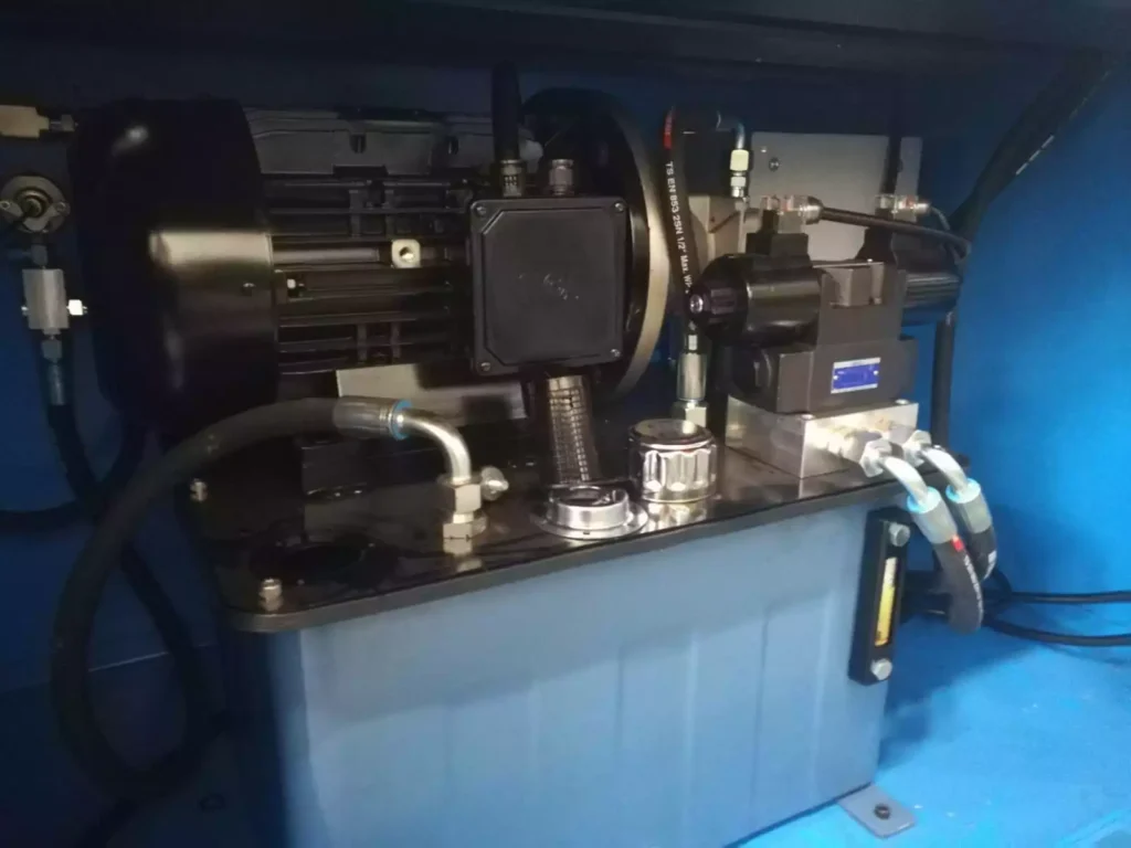
The hydraulic power unit (HPU) is a critical component of tube bending equipment, providing the necessary hydraulic pressure to actuate various functions such as clamping, bending, mandrel insertion and retraction, and die movement. It serves as the primary source of power for hydraulic systems within the bending machine, enabling precise and controlled operation of hydraulic actuators, cylinders, and valves. Here’s an in-depth explanation of the role and importance of the hydraulic power unit in tube bending equipment:
- Hydraulic Pressure Generation:
- The hydraulic power unit generates the hydraulic pressure required to operate hydraulic actuators and components throughout the bending process.
- It typically consists of a hydraulic pump, reservoir, filtration system, and control valves, which work together to generate, regulate, and distribute hydraulic fluid under pressure.
- Actuation of Bending Functions:
- The hydraulic power unit controls the actuation of various bending functions, including clamping the tube in place, applying pressure to the bending die, and advancing or retracting the mandrel.
- It provides precise and controlled movement of hydraulic cylinders and actuators, ensuring accurate positioning and force application during the bending process.
- Pressure Regulation and Control:
- The hydraulic power unit regulates hydraulic pressure levels to match the requirements of different bending operations, tube materials, and geometries.
- Pressure control valves, relief valves, and pressure regulators are used to maintain consistent pressure levels, prevent overloading, and protect the system from damage.
- Flow Control and Directional Control:
- The hydraulic power unit controls the flow of hydraulic fluid to various actuators and components, directing it to the desired location and controlling the speed and direction of movement.
- Directional control valves and flow control valves regulate the flow of hydraulic fluid, allowing for precise control over the speed and direction of hydraulic cylinders and actuators.
- System Integration and Compatibility:
- The hydraulic power unit is integrated with the bending machine’s control system, sensors, and actuators, ensuring seamless operation and coordination of bending functions.
- It is compatible with a wide range of bending machines, tooling, and accessories, allowing for flexible configuration and adaptation to different bending requirements and applications.
- Safety and Reliability:
- The hydraulic power unit is equipped with safety features such as pressure relief valves, emergency stop buttons, and overload protection devices to ensure safe operation and protect personnel and equipment from harm.
- Regular maintenance and inspection of the hydraulic power unit are essential to ensure its proper functioning, reliability, and compliance with safety standards and regulations.
- Efficiency and Performance:
- The hydraulic power unit plays a crucial role in optimizing the efficiency and performance of tube bending equipment.
- By providing precise control over hydraulic functions, it enables faster cycle times, higher production throughput, and improved bending accuracy and repeatability.
In summary, the hydraulic power unit is a vital component of tube bending equipment, providing the hydraulic pressure required to operate various bending functions with precision and control. By ensuring reliable operation, safety, and efficiency, the hydraulic power unit contributes to the overall performance and productivity of tube bending operations.
Die Sets in Tube Bending Equipment:
Die sets are essential components of tube bending equipment, serving as the primary tooling for shaping and forming tubes into desired configurations. They consist of multiple components, including the bending die, clamp die, pressure die, and mandrel, which work together to support and shape the tube during the bending process. Here’s an in-depth explanation of the role and importance of die sets in tube bending equipment:
- Bending Die:
- The bending die is the primary component of the die set responsible for forming the tube into the desired bend radius and angle.
- It typically consists of a curved or contoured surface that matches the desired bend radius, allowing the tube to be bent around it without collapsing or deforming.
- Clamp Die:
- The clamp die secures the tube in place during the bending process, preventing it from slipping or moving out of position.
- It applies clamping pressure to hold the tube firmly against the bending die, ensuring accurate and repeatable bending results.
- Pressure Die:
- The pressure die provides additional support to the outer wall of the tube, minimizing distortion, wrinkling, or ovality during bending.
- It applies pressure to the outside of the tube opposite the bending die, helping to maintain the tube’s shape and integrity throughout the bending process.
- Mandrel:
- The mandrel is an optional component of the die set used to support the inner wall of the tube during bending, particularly in applications involving tight bend radii or thin-walled tubes.
- It helps prevent collapse, wrinkling, or distortion of the inner wall, ensuring uniformity and consistency in the bent tube’s shape and dimensions.
- Compatibility and Adaptability:
- Die sets are designed to be compatible with a wide range of tube diameters, bend radii, and bending requirements.
- They can be adapted or customized to accommodate specific tube materials, geometries, and bending techniques, ensuring versatility and flexibility in tube bending operations.
- Precision and Accuracy:
- Die sets are precision-machined to tight tolerances to ensure accurate and repeatable bending results.
- They provide precise control over the bending process, allowing for consistent dimensional accuracy and repeatability in the bent tube’s shape and dimensions.
- Durability and Longevity:
- Die sets are typically made from high-strength materials such as tool steel, alloy steel, or carbide, to withstand the rigors of bending operations and provide long-lasting durability.
- Proper maintenance and care, such as lubrication, cleaning, and inspection, help prolong the life of die sets and ensure reliable performance over time.
In summary, die sets are essential components of tube bending equipment, providing the tooling necessary for shaping and forming tubes into desired configurations. By ensuring compatibility, precision, durability, and adaptability, die sets play a crucial role in achieving accurate and repeatable bending results while minimizing defects, errors, and material waste in tube bending operations.
Bending Machine Frame in Tube Bending Equipment:
The bending machine frame is the structural backbone of tube bending equipment, providing support, stability, and rigidity to the entire bending system. It forms the framework upon which all other components, including the bending head, mandrel assembly, clamp assembly, and control system, are mounted and aligned. Here’s an in-depth explanation of the role and importance of the bending machine frame in tube bending equipment:
- Structural Integrity:
- The bending machine frame is constructed from high-strength materials such as steel or cast iron to ensure structural integrity and stability during bending operations.
- It is designed to withstand the forces and stresses generated during bending, providing a stable platform for precise and accurate tube manipulation.
- Support for Components:
- The bending machine frame supports and aligns all other components of the bending system, including the bending head, mandrel assembly, clamp assembly, and control system.
- It ensures proper positioning and alignment of these components, minimizing vibration, deflection, or misalignment during bending operations.
- Rigidity and Stability:
- The bending machine frame is engineered to be rigid and stable, minimizing flexing, bending, or distortion during bending operations.
- Rigidity and stability are essential for maintaining accuracy and repeatability in tube bending, ensuring consistent results across multiple bending cycles.
- Absorption of Vibrations:
- The bending machine frame absorbs and dampens vibrations generated during bending, reducing noise, vibration, and fatigue in the machine structure.
- This helps improve operator comfort, reduce equipment wear, and prolong the life of machine components.
- Alignment and Parallelism:
- The bending machine frame provides reference surfaces and alignment features to ensure proper alignment and parallelism of bending components.
- Accurate alignment is critical for achieving precise bends with uniform wall thickness and dimensional accuracy in the bent tube.
- Accessibility for Maintenance:
- The bending machine frame is designed to provide easy access to internal components for maintenance, inspection, and repair.
- Removable panels, access doors, and service ports allow operators to perform routine maintenance tasks quickly and efficiently, minimizing downtime and maximizing machine uptime.
- Adaptability and Customization:
- The bending machine frame can be adapted or customized to accommodate specific bending requirements, tube geometries, and production environments.
- Modular construction and interchangeable components facilitate upgrades, retrofits, and customization to meet changing production needs and industry standards.
In summary, the bending machine frame is a critical component of tube bending equipment, providing the structural support, stability, and alignment necessary for precise and accurate tube manipulation. By ensuring rigidity, stability, and accessibility for maintenance, the bending machine frame contributes to the overall performance, reliability, and longevity of tube bending operations.
Bending Head in Tube Bending Equipment:
The bending head is a pivotal component of tube bending equipment, responsible for applying controlled forces to the tube to achieve the desired bend radius and angle. It houses the bending die and other critical components necessary for shaping the tube, and it provides the mechanism for translating the bending motion to the tube material. Here’s an in-depth explanation of the role and importance of the bending head in tube bending equipment:
- Die Mounting and Alignment:
- The bending head securely mounts and aligns the bending die, ensuring its proper orientation and position relative to the tube.
- Accurate die alignment is crucial for achieving precise bend angles and radii and maintaining dimensional accuracy in the bent tube.
- Force Application:
- The bending head applies controlled forces to the tube to induce plastic deformation and form the desired bend.
- It provides the mechanism for exerting bending forces evenly along the length of the tube, minimizing distortion, wrinkles, or defects in the bent section.
- Bend Angle Control:
- The bending head controls the angle of bend by regulating the amount of force applied to the tube and the distance traveled by the bending die.
- Precise control over bend angle ensures consistency and repeatability in tube bending operations, meeting quality standards and specifications.
- Bend Radius Adjustment:
- The bending head allows for adjustment of the bend radius by changing the curvature of the bending die or adjusting the position of the tube relative to the die.
- Flexibility in bend radius adjustment enables the bending head to accommodate different tube diameters, wall thicknesses, and bend requirements.
- Mandrel Integration:
- In mandrel-supported bending applications, the bending head integrates with the mandrel assembly to provide support and control to the inner wall of the tube.
- It coordinates the movement and positioning of the mandrel relative to the tube and bending die, ensuring proper support and minimizing distortion or collapse of the tube’s inner wall.
- Material Compatibility:
- The bending head is designed to accommodate a wide range of tube materials, including steel, stainless steel, aluminum, copper, and various alloys.
- It is engineered to exert the necessary bending forces without causing material deformation, cracking, or other forms of damage to the tube.
- Automation and Control:
- Advanced bending heads feature automation and control systems that enable programmable bending sequences, angle adjustments, and bend radius changes.
- Automation improves efficiency, reduces setup time, and enhances repeatability in tube bending operations, particularly in high-volume production environments.
In summary, the bending head is a crucial component of tube bending equipment, responsible for applying controlled forces to the tube to achieve precise bends with uniform radii and angles. By ensuring accurate die alignment, controlled force application, and flexibility in bend angle and radius adjustment, the bending head plays a key role in achieving high-quality, repeatable bending results in various tube bending applications.
Control System in Tube Bending Equipment:
The control system is a critical component of tube bending equipment, responsible for managing and coordinating the operation of various machine functions to achieve precise and accurate tube bending. It consists of hardware and software components that enable operators to program bending sequences, adjust parameters, monitor process variables, and ensure safe and efficient operation of the bending machine. Here’s an in-depth explanation of the role and importance of the control system in tube bending equipment:
- Sequence Programming:
- The control system allows operators to program bending sequences, specifying parameters such as bend angles, bend radii, and mandrel positions for each bend.
- Programmable sequences enable automation of bending operations, reducing setup time, minimizing errors, and improving repeatability in production environments.
- Parameter Adjustment:
- Operators can adjust various parameters such as bending speed, mandrel pressure, and clamp force through the control system.
- Parameter adjustments enable fine-tuning of bending processes to accommodate different tube materials, geometries, and bending requirements, optimizing bending quality and efficiency.
- Real-time Monitoring:
- The control system provides real-time monitoring of process variables such as tube position, bend angle, mandrel pressure, and motor torque.
- Real-time feedback allows operators to detect deviations from desired parameters and make immediate adjustments to ensure bending accuracy and consistency.
- Safety Interlocks:
- The control system incorporates safety interlocks and emergency stop features to ensure operator safety and prevent accidents during machine operation.
- Safety features include interlocks that prevent machine movement when access doors are open, emergency stop buttons that halt machine operation in case of emergency, and safety sensors that detect abnormal conditions and trigger alarms.
- Data Logging and Analysis:
- The control system logs process data such as bending parameters, machine status, and alarm events for analysis and troubleshooting.
- Data logging capabilities enable operators to identify trends, diagnose issues, and optimize machine performance over time, improving productivity and reducing downtime.
- Integration with CAD/CAM Systems:
- Advanced control systems can be integrated with computer-aided design/computer-aided manufacturing (CAD/CAM) software for seamless data transfer and programming.
- Integration with CAD/CAM systems streamlines the programming process, allowing operators to import part designs directly into the control system and generate bending programs automatically.
- Remote Monitoring and Diagnostics:
- Some control systems offer remote monitoring and diagnostics capabilities, allowing operators to monitor machine status and performance from a distance.
- Remote access enables troubleshooting, software updates, and maintenance tasks to be performed remotely, reducing downtime and improving overall equipment efficiency.
In summary, the control system is a crucial component of tube bending equipment, providing the interface for programming, monitoring, and controlling bending operations. By enabling automation, parameter adjustment, real-time monitoring, and safety interlocks, the control system ensures precise and efficient tube bending while enhancing operator safety and productivity.
Pressure Die in Tube Bending Equipment:
The pressure die is a vital component of tube bending equipment, playing a crucial role in ensuring the quality and accuracy of bent tubes. It applies pressure to the outer surface of the tube opposite the bending die, providing support and control to minimize distortion, wrinkles, or ovality during the bending process. Here’s an in-depth explanation of the role and importance of the pressure die in tube bending equipment:
- Support and Stability:
- The pressure die provides additional support and stability to the tube during bending, preventing it from deforming or collapsing under the bending forces.
- It helps maintain the shape and integrity of the tube, ensuring consistent dimensional accuracy and surface finish in the bent section.
- Reduction of Distortion:
- By exerting pressure on the outer surface of the tube, the pressure die helps reduce distortion, wrinkling, or ovality that may occur during bending.
- It distributes bending forces evenly along the length of the tube, minimizing localized deformation and ensuring uniformity in the bent profile.
- Control of Wall Thinning:
- The pressure die assists in controlling wall thinning, particularly in thin-walled tubes or tight bend radii, where excessive deformation may occur.
- By supporting the outer wall of the tube, it helps prevent excessive stretching or thinning of the material, maintaining wall thickness and structural integrity in the bent section.
- Minimization of Wrinkles and Surface Defects:
- The pressure die applies uniform pressure to the tube’s outer surface, minimizing the formation of wrinkles, folds, or surface defects during bending.
- It ensures smooth and consistent contact between the tube and the bending die, promoting a high-quality surface finish in the bent section.
- Compatibility with Mandrel Systems:
- In mandrel-supported bending applications, the pressure die coordinates with the mandrel to provide optimal support and control throughout the bending process.
- It works in conjunction with the mandrel to maintain tube roundness, prevent collapse, and ensure uniformity in wall thickness and surface finish.
- Adjustability and Flexibility:
- Pressure dies are designed to be adjustable and flexible to accommodate different tube diameters, wall thicknesses, and bending requirements.
- They may feature interchangeable components or adjustable mechanisms that allow for quick and easy setup and adjustment to suit specific bending applications.
- Material Compatibility:
- Pressure dies are engineered to be compatible with a wide range of tube materials, including steel, stainless steel, aluminum, copper, and various alloys.
- They are designed to exert the necessary pressure without causing material deformation, surface damage, or other forms of material failure.
In summary, the pressure die is a critical component of tube bending equipment, providing support, stability, and control to the tube during bending operations. By minimizing distortion, controlling wall thinning, and reducing surface defects, the pressure die ensures high-quality, accurate bending results while maintaining dimensional accuracy and structural integrity in the bent tubes.
Clamp Die in Tube Bending Equipment:
The clamp die is an essential component of tube bending equipment, responsible for securely holding the tube in place during the bending process. It applies clamping force to prevent the tube from moving or slipping out of position, ensuring accurate and repeatable bending results. Here’s an in-depth explanation of the role and importance of the clamp die in tube bending equipment:
- Tube Positioning and Alignment:
- The clamp die positions and aligns the tube relative to the bending die and mandrel, ensuring proper orientation and contact during the bending process.
- It holds the tube securely in place, minimizing movement or displacement and ensuring accurate bending angles and radii.
- Prevention of Tube Slippage:
- The clamp die applies clamping force to the tube, preventing it from slipping or shifting during bending.
- It ensures consistent contact between the tube and the bending die, minimizing errors and deviations in the bent profile.
- Minimization of Springback:
- By securely holding the tube in place, the clamp die helps minimize springback, the tendency of the tube to return to its original shape after bending.
- It maintains constant pressure on the tube throughout the bending process, preventing springback-induced errors and ensuring accurate final dimensions.
- Enhancement of Bending Accuracy:
- The clamp die contributes to the overall accuracy and precision of tube bending by providing stable and consistent clamping force.
- It eliminates variability in tube positioning and alignment, resulting in repeatable bending results with minimal dimensional variation.
- Compatibility with Different Tube Diameters and Materials:
- Clamp dies are designed to accommodate a wide range of tube diameters, wall thicknesses, and materials.
- They may feature adjustable jaws or interchangeable components that allow for quick and easy adaptation to different tube sizes and materials.
- Optimization of Production Efficiency:
- Reliable clamping provided by the clamp die reduces the need for manual repositioning or readjustment of the tube during bending.
- It streamlines the bending process, improves workflow efficiency, and reduces overall cycle times, increasing productivity and throughput.
- Safety Considerations:
- Proper clamping of the tube is essential for operator safety, preventing accidents such as tube ejection or misalignment during bending.
- Clamp dies are equipped with safety features such as interlocks and guards to ensure safe operation and protect personnel from injury.
In summary, the clamp die is a critical component of tube bending equipment, ensuring secure positioning and alignment of the tube during bending operations. By preventing tube slippage, minimizing springback, and enhancing bending accuracy, the clamp die contributes to the overall efficiency, productivity, and safety of tube bending processes.
Bend Radius Adjustment Mechanism in Tube Bending Equipment:
The bend radius adjustment mechanism is a crucial feature of tube bending equipment, allowing operators to precisely control the radius of bends formed in tubes. This mechanism enables flexibility in bending operations, accommodating different bend radii required for various applications and ensuring accurate shaping of tubes according to design specifications. Here’s an in-depth explanation of the role and importance of the bend radius adjustment mechanism in tube bending equipment:
- Versatility in Bending Applications:
- The bend radius adjustment mechanism enables tube bending equipment to accommodate a wide range of bending applications, from tight radii bends to larger radius bends.
- Operators can adjust the bend radius according to specific design requirements, material properties, and functional needs, ensuring compatibility with diverse application scenarios.
- Flexibility in Tube Geometries:
- Different tube geometries may necessitate varying bend radii to achieve desired shapes and configurations.
- The bend radius adjustment mechanism allows operators to tailor the bending process to the specific geometry of the tube, ensuring precise and accurate shaping without compromising structural integrity or dimensional accuracy.
- Adaptability to Material Properties:
- Different tube materials exhibit varying degrees of elasticity and ductility, affecting their response to bending forces.
- The bend radius adjustment mechanism enables operators to optimize bend radii for specific material properties, minimizing material deformation, stress concentration, and the risk of defects such as wrinkling or cracking.
- Precision Control over Bend Characteristics:
- Precise control over the bend radius adjustment mechanism enables operators to achieve consistent and repeatable bend characteristics, such as bend angle, radius, and profile.
- Fine-tuning the bend radius ensures uniformity in the bent sections of tubes, meeting quality standards, and design specifications with high accuracy and reliability.
- Dynamic Adjustments During Bending:
- In some tube bending processes, dynamic adjustments to the bend radius may be necessary to accommodate changes in tube geometry or material behavior.
- The bend radius adjustment mechanism allows for real-time adjustments during bending operations, ensuring adaptive and responsive control over the bending process to achieve optimal results.
- Ease of Operation and Setup:
- Modern tube bending equipment is equipped with user-friendly bend radius adjustment mechanisms that facilitate intuitive operation and setup.
- Operators can quickly and easily adjust the bend radius using manual controls, digital interfaces, or automated programming, minimizing setup time and increasing overall operational efficiency.
- Compatibility with Mandrel Bending Systems:
- In mandrel-supported bending applications, the bend radius adjustment mechanism works in conjunction with the mandrel system to achieve precise control over the bending process.
- It enables coordinated adjustments to both the bend radius and mandrel position, ensuring proper support and control over the tube during bending to prevent deformation or collapse.
In summary, the bend radius adjustment mechanism is a critical feature of tube bending equipment, providing operators with the flexibility and precision to tailor bending operations to specific requirements. By enabling versatility in bending applications, adaptability to material properties, and precise control over bend characteristics, the bend radius adjustment mechanism enhances the efficiency, accuracy, and quality of tube bending processes.
Mandrel in Tube Bending Equipment:
The mandrel is a fundamental component of tube bending equipment, particularly in mandrel-supported bending processes. It serves multiple crucial functions in ensuring the quality, accuracy, and integrity of bent tubes. Here’s an in-depth explanation of the role and importance of the mandrel in tube bending equipment:
- Internal Support and Control:
- The mandrel provides internal support and control to the tube during bending, preventing collapse, wrinkling, or distortion of the inner wall.
- It helps maintain the roundness and integrity of the tube’s cross-section, ensuring uniform wall thickness and dimensional accuracy in the bent section.
- Reduction of Ovality and Wrinkling:
- By exerting outward pressure against the inner wall of the tube, the mandrel helps minimize ovality and wrinkling that may occur on the inside radius of bends.
- It supports the tube’s inner surface, distributing bending forces evenly and reducing the risk of deformation or surface defects.
- Improvement of Bend Quality and Surface Finish:
- The mandrel contributes to the overall quality and surface finish of bent tubes by providing consistent support and control throughout the bending process.
- It helps achieve smooth and uniform bends with minimal distortion, ensuring high-quality surface finish and aesthetic appeal in the finished product.
- Prevention of Tube Springback:
- The mandrel helps mitigate springback, the tendency of the tube to return to its original shape after bending, by providing internal support and control.
- It maintains constant pressure against the inner wall of the tube, counteracting the effects of elastic recovery and ensuring the desired bend angle and radius are maintained.
- Compatibility with Thin-Walled Tubes:
- Mandrels are particularly beneficial in bending thin-walled tubes, where the risk of collapse or distortion is higher.
- They provide critical internal support, allowing thin-walled tubes to be bent with greater precision and reliability without compromising structural integrity.
- Variety of Mandrel Types:
- Mandrels come in various types and configurations to accommodate different bending applications, tube materials, and geometries.
- Common types include ball mandrels, plug mandrels, wiper mandrels, and segmented mandrels, each suited to specific bending requirements and challenges.
- Integration with Control Systems:
- In advanced tube bending equipment, mandrels are often integrated with control systems to enable precise positioning, movement, and pressure control.
- Integration allows for automated adjustment of mandrel position and pressure based on bending parameters, ensuring optimal support and control throughout the bending process.
In summary, the mandrel is a critical component of tube bending equipment, providing internal support, control, and stability to the tube during bending operations. By minimizing distortion, improving bend quality, and preventing springback, the mandrel ensures high-quality, accurate, and repeatable bending results, particularly in mandrel-supported bending applications.
Wiper Die in Tube Bending Equipment:
The wiper die is an essential component of tube bending equipment, particularly in mandrel-supported bending processes. It plays a crucial role in ensuring the quality, accuracy, and integrity of bent tubes by providing support and control to the outer surface of the tube during bending. Here’s an in-depth explanation of the role and importance of the wiper die in tube bending equipment:
- Outer Surface Support:
- The wiper die provides external support and control to the outer surface of the tube during bending, minimizing distortion, wrinkles, or surface defects.
- It helps maintain the shape and integrity of the tube’s outer surface, ensuring uniformity in wall thickness and dimensional accuracy in the bent section.
- Reduction of Ovality and Wrinkling:
- By exerting pressure against the outer wall of the tube, the wiper die helps minimize ovality and wrinkling that may occur on the outside radius of bends.
- It supports the tube’s outer surface, distributing bending forces evenly and reducing the risk of deformation or surface imperfections.
- Enhancement of Bend Quality and Surface Finish:
- The wiper die contributes to the overall quality and surface finish of bent tubes by providing consistent support and control throughout the bending process.
- It helps achieve smooth and uniform bends with minimal distortion, ensuring high-quality surface finish and aesthetic appeal in the finished product.
- Prevention of Tube Springback:
- The wiper die helps mitigate springback, the tendency of the tube to return to its original shape after bending, by providing external support and control.
- It maintains constant pressure against the outer wall of the tube, counteracting the effects of elastic recovery and ensuring the desired bend angle and radius are maintained.
- Compatibility with Thin-Walled Tubes:
- Wiper dies are particularly beneficial in bending thin-walled tubes, where the risk of distortion or collapse is higher.
- They provide critical external support, allowing thin-walled tubes to be bent with greater precision and reliability without compromising structural integrity.
- Variety of Wiper Die Designs:
- Wiper dies come in various designs and configurations to accommodate different bending applications, tube materials, and geometries.
- Common designs include roller wiper dies, pressure wiper dies, and shoe wiper dies, each suited to specific bending requirements and challenges.
- Integration with Control Systems:
- In advanced tube bending equipment, wiper dies are often integrated with control systems to enable precise positioning, movement, and pressure control.
- Integration allows for automated adjustment of wiper die position and pressure based on bending parameters, ensuring optimal support and control throughout the bending process.
In summary, the wiper die is a critical component of tube bending equipment, providing external support, control, and stability to the tube during bending operations. By minimizing distortion, improving bend quality, and preventing springback, the wiper die ensures high-quality, accurate, and repeatable bending results, particularly in mandrel-supported bending applications.
Mandrel Lubrication System in Tube Bending Equipment:
The mandrel lubrication system is an essential feature of tube bending equipment, particularly in mandrel-supported bending processes. It plays a crucial role in ensuring smooth operation, reducing friction, and preventing wear and tear on the mandrel and tube during bending. Here’s an in-depth explanation of the role and importance of the mandrel lubrication system in tube bending equipment:
- Friction Reduction:
- The mandrel lubrication system applies lubricant to the mandrel surface, reducing friction between the mandrel and the inner surface of the tube during bending.
- By minimizing friction, the lubrication system ensures smoother movement of the mandrel within the tube, reducing the risk of galling, scoring, or surface damage.
- Prevention of Tube Sticking:
- Lubrication helps prevent the tube from sticking to the mandrel surface during bending, particularly in high-speed or high-pressure bending operations.
- It facilitates easy removal of the mandrel from the bent tube after bending, minimizing the risk of tube deformation or damage.
- Heat Dissipation:
- During bending, friction between the mandrel and the tube generates heat, which can affect the material properties of the tube and the mandrel.
- The mandrel lubrication system helps dissipate heat by reducing friction, preventing overheating and thermal damage to both the tube and the mandrel.
- Extended Tool Life:
- Proper lubrication reduces wear and tear on the mandrel surface, extending its service life and reducing the frequency of maintenance and replacement.
- It also prolongs the life of other components in the bending system, such as wiper dies and pressure dies, by minimizing wear and friction-related damage.
- Improved Bending Quality:
- By reducing friction and preventing sticking, the mandrel lubrication system contributes to improved bending quality and accuracy.
- It ensures smoother, more consistent bending operations, resulting in higher-quality bends with minimal surface defects or imperfections.
- Compatibility with Different Tube Materials:
- Mandrel lubricants are formulated to be compatible with a wide range of tube materials, including steel, stainless steel, aluminum, copper, and various alloys.
- They provide effective lubrication and friction reduction without compromising the integrity or properties of the tube material.
- Automatic Lubrication Systems:
- Some tube bending equipment is equipped with automatic lubrication systems that deliver lubricant to the mandrel surface at regular intervals during bending.
- Automatic systems ensure consistent and uniform lubrication, reducing the need for manual intervention and optimizing bending efficiency.
In summary, the mandrel lubrication system is a critical component of tube bending equipment, ensuring smooth operation, reducing friction, and prolonging tool life. By preventing tube sticking, dissipating heat, and improving bending quality, the lubrication system enhances the efficiency, accuracy, and reliability of mandrel-supported tube bending processes.
Mandrel Extraction System in Tube Bending Equipment:
The mandrel extraction system is a crucial feature of mandrel-supported tube bending equipment, facilitating the removal of the mandrel from the bent tube after the bending process is complete. This system ensures smooth extraction of the mandrel without damaging the tube or compromising the quality of the bend. Here’s an in-depth explanation of the role and importance of the mandrel extraction system in tube bending equipment:
- Prevention of Tube Deformation:
- The mandrel extraction system ensures gentle and controlled removal of the mandrel from the bent tube, minimizing the risk of tube deformation, distortion, or damage.
- It prevents the tube from collapsing or collapsing, maintaining its structural integrity and dimensional accuracy in the bent section.
- Smooth Mandrel Removal:
- The extraction system facilitates smooth and efficient removal of the mandrel from the tube without excessive force or resistance.
- It ensures that the mandrel can be extracted smoothly, even in cases where tight bends or complex geometries are involved, reducing the risk of mandrel jamming or sticking inside the tube.
- Compatibility with Different Tube Diameters and Wall Thicknesses:
- Mandrel extraction systems are designed to accommodate a wide range of tube diameters, wall thicknesses, and bending configurations.
- They can be adjusted or configured to suit specific tube sizes and bending requirements, ensuring compatibility with various application scenarios.
- Minimization of Production Downtime:
- Efficient mandrel extraction reduces the time required between bending cycles, minimizing production downtime and improving overall equipment productivity.
- It allows operators to quickly and seamlessly transition between bending operations, optimizing workflow efficiency and throughput.
- Protection of Mandrel and Tube Surfaces:
- The extraction system is designed to protect the surfaces of both the mandrel and the tube during extraction, minimizing the risk of damage or surface imperfections.
- It ensures that the mandrel can be removed without scratching, scoring, or marring the inner surface of the tube, maintaining high-quality bend finishes.
- Integration with Control Systems:
- In advanced tube bending equipment, the mandrel extraction system may be integrated with control systems to enable automated extraction procedures.
- Integration allows for precise control over extraction parameters, such as speed, force, and timing, ensuring consistent and reliable mandrel removal across multiple bending cycles.
- Safety Considerations:
- Mandrel extraction systems incorporate safety features to protect operators and prevent accidents during the extraction process.
- Safety mechanisms may include interlocks, sensors, and emergency stop functions to ensure safe operation and prevent injury to personnel.
In summary, the mandrel extraction system is a critical component of mandrel-supported tube bending equipment, ensuring smooth and efficient removal of the mandrel from the bent tube. By minimizing tube deformation, optimizing production uptime, and protecting mandrel and tube surfaces, the extraction system enhances the efficiency, accuracy, and reliability of tube bending processes.
Tube Bending Software:
Tube bending software is a sophisticated tool used in conjunction with tube bending equipment to streamline and optimize the bending process. It provides advanced capabilities for design, simulation, programming, and control, allowing manufacturers to achieve precise and efficient tube bending operations. Here’s an in-depth explanation of the features and importance of tube bending software:
- Design Capabilities:
- Tube bending software allows designers to create and modify tube geometries, including straight sections, bends, and complex shapes.
- Design tools typically include parametric modeling, CAD functionality, and intuitive user interfaces for easy manipulation of tube profiles and configurations.
- Simulation and Analysis:
- Advanced simulation features enable engineers to visualize and analyze bending processes before actual production.
- Simulation tools predict and evaluate factors such as material behavior, springback, and deformation, helping optimize bending parameters and prevent defects.
- Programming and Control:
- Tube bending software generates machine-readable programs that drive the tube bending equipment, specifying bending angles, radii, feed rates, and other parameters.
- Programming interfaces may include graphical user interfaces (GUIs), numerical control (NC) programming, or application programming interfaces (APIs) for seamless integration with production systems.
- Optimization Algorithms:
- Many tube bending software packages incorporate optimization algorithms to automatically determine the optimal bending sequence and parameters for a given tube geometry and material.
- These algorithms minimize material waste, reduce cycle times, and optimize tool utilization, maximizing productivity and efficiency.
- Compatibility with Various Machine Types:
- Tube bending software is compatible with a wide range of tube bending machines, including CNC mandrel benders, CNC press benders, and rotary draw benders.
- Compatibility ensures that manufacturers can leverage the software’s capabilities regardless of the type or brand of their tube bending equipment.
- Integration with CAD/CAM Systems:
- Integration with computer-aided design/computer-aided manufacturing (CAD/CAM) systems streamlines the workflow from design to production.
- Seamless data exchange between design and manufacturing environments ensures consistency and accuracy throughout the tube bending process.
- Real-Time Monitoring and Feedback:
- Some tube bending software solutions offer real-time monitoring and feedback capabilities, providing operators with insights into machine performance, process deviations, and quality metrics.
- Real-time data enables proactive adjustments and troubleshooting, minimizing downtime and maximizing yield.
- Training and Support:
- Tube bending software vendors typically offer comprehensive training and support services to help users maximize the benefits of the software.
- Training programs cover software features, best practices, and troubleshooting techniques, ensuring users have the knowledge and skills to leverage the software effectively.
In summary, tube bending software is a powerful tool that enhances the efficiency, accuracy, and productivity of tube bending operations. By providing advanced design, simulation, programming, and control capabilities, tube bending software enables manufacturers to optimize their processes, reduce costs, and deliver high-quality products to market efficiently.
Pressure Die in Tube Bending Equipment:
The pressure die is a critical component of tube bending equipment, particularly in mandrel-supported bending processes. It plays a crucial role in stabilizing and controlling the outer surface of the tube during bending, ensuring accurate and high-quality bends. Here’s an in-depth explanation of the role and importance of the pressure die in tube bending equipment:
- External Support and Control:
- The pressure die provides external support and control to the outer surface of the tube opposite the bending die.
- It helps stabilize the tube and prevents it from deforming or wrinkling during bending, ensuring uniformity and accuracy in the bent section.
- Minimization of Ovality and Wrinkling:
- By exerting pressure against the outer wall of the tube, the pressure die helps minimize ovality and wrinkling that may occur on the outside radius of bends.
- It supports the tube’s outer surface, distributing bending forces evenly and reducing the risk of deformation or surface imperfections.
- Enhancement of Bend Quality and Surface Finish:
- The pressure die contributes to the overall quality and surface finish of bent tubes by providing consistent support and control throughout the bending process.
- It helps achieve smooth and uniform bends with minimal distortion, ensuring high-quality surface finish and dimensional accuracy in the finished product.
- Prevention of Tube Springback:
- The pressure die helps mitigate springback, the tendency of the tube to return to its original shape after bending, by providing external support and control.
- It maintains constant pressure against the outer wall of the tube, counteracting the effects of elastic recovery and ensuring the desired bend angle and radius are maintained.
- Compatibility with Different Tube Diameters and Wall Thicknesses:
- Pressure dies are designed to accommodate a wide range of tube diameters, wall thicknesses, and bending configurations.
- They can be adjusted or configured to suit specific tube sizes and materials, ensuring compatibility with diverse application requirements.
- Integration with Control Systems:
- In advanced tube bending equipment, pressure dies may be integrated with control systems to enable precise positioning, movement, and pressure control.
- Integration allows for automated adjustment of pressure die parameters based on bending parameters, ensuring optimal support and control throughout the bending process.
- Safety Considerations:
- Properly designed pressure dies incorporate safety features to prevent accidents and protect operators during the bending process.
- Safety mechanisms may include interlocks, guards, and sensors to ensure safe operation and prevent injury to personnel.
In summary, the pressure die is a critical component of tube bending equipment, providing external support, control, and stability to the tube during bending operations. By minimizing deformation, improving bend quality, and preventing springback, the pressure die ensures high-quality, accurate, and repeatable bending results, particularly in mandrel-supported bending applications.
Mandrel Lubrication System in Tube Bending Equipment:
The mandrel lubrication system is an essential feature of tube bending equipment, particularly in mandrel-supported bending processes. It plays a crucial role in ensuring smooth operation, reducing friction, and preventing wear and tear on the mandrel and tube during bending. Here’s an in-depth explanation of the role and importance of the mandrel lubrication system in tube bending equipment:
- Friction Reduction:
- The mandrel lubrication system applies lubricant to the mandrel surface, reducing friction between the mandrel and the inner surface of the tube during bending.
- By minimizing friction, the lubrication system ensures smoother movement of the mandrel within the tube, reducing the risk of galling, scoring, or surface damage.
- Prevention of Tube Sticking:
- Lubrication helps prevent the tube from sticking to the mandrel surface during bending, particularly in high-speed or high-pressure bending operations.
- It facilitates easy removal of the mandrel from the bent tube after bending, minimizing the risk of tube deformation or damage.
- Heat Dissipation:
- During bending, friction between the mandrel and the tube generates heat, which can affect the material properties of the tube and the mandrel.
- The mandrel lubrication system helps dissipate heat by reducing friction, preventing overheating and thermal damage to both the tube and the mandrel.
- Extended Tool Life:
- Proper lubrication reduces wear and tear on the mandrel surface, extending its service life and reducing the frequency of maintenance and replacement.
- It also prolongs the life of other components in the bending system, such as wiper dies and pressure dies, by minimizing wear and friction-related damage.
- Improved Bending Quality:
- By reducing friction and preventing sticking, the mandrel lubrication system contributes to improved bending quality and accuracy.
- It ensures smoother, more consistent bending operations, resulting in higher-quality bends with minimal surface defects or imperfections.
- Compatibility with Different Tube Materials:
- Mandrel lubricants are formulated to be compatible with a wide range of tube materials, including steel, stainless steel, aluminum, copper, and various alloys.
- They provide effective lubrication and friction reduction without compromising the integrity or properties of the tube material.
- Automatic Lubrication Systems:
- Some tube bending equipment is equipped with automatic lubrication systems that deliver lubricant to the mandrel surface at regular intervals during bending.
- Automatic systems ensure consistent and uniform lubrication, reducing the need for manual intervention and optimizing bending efficiency.
In summary, the mandrel lubrication system is a critical component of tube bending equipment, ensuring smooth operation, reducing friction, and prolonging tool life. By preventing tube sticking, dissipating heat, and improving bending quality, the lubrication system enhances the efficiency, accuracy, and reliability of mandrel-supported tube bending processes.
Mandrel Extraction System in Tube Bending Equipment:
The mandrel extraction system is a crucial feature of mandrel-supported tube bending equipment, facilitating the removal of the mandrel from the bent tube after the bending process is complete. This system ensures smooth extraction of the mandrel without damaging the tube or compromising the quality of the bend. Here’s an in-depth explanation of the role and importance of the mandrel extraction system in tube bending equipment:
- Prevention of Tube Deformation:
- The mandrel extraction system ensures gentle and controlled removal of the mandrel from the bent tube, minimizing the risk of tube deformation, distortion, or damage.
- It prevents the tube from collapsing or collapsing, maintaining its structural integrity and dimensional accuracy in the bent section.
- Smooth Mandrel Removal:
- The extraction system facilitates smooth and efficient removal of the mandrel from the tube without excessive force or resistance.
- It ensures that the mandrel can be extracted smoothly, even in cases where tight bends or complex geometries are involved, reducing the risk of mandrel jamming or sticking inside the tube.
- Compatibility with Different Tube Diameters and Wall Thicknesses:
- Mandrel extraction systems are designed to accommodate a wide range of tube diameters, wall thicknesses, and bending configurations.
- They can be adjusted or configured to suit specific tube sizes and bending requirements, ensuring compatibility with diverse application scenarios.
- Minimization of Production Downtime:
- Efficient mandrel extraction reduces the time required between bending cycles, minimizing production downtime and improving overall equipment productivity.
- It allows operators to quickly and seamlessly transition between bending operations, optimizing workflow efficiency and throughput.
- Protection of Mandrel and Tube Surfaces:
- The extraction system is designed to protect the surfaces of both the mandrel and the tube during extraction, minimizing the risk of damage or surface imperfections.
- It ensures that the mandrel can be removed without scratching, scoring, or marring the inner surface of the tube, maintaining high-quality bend finishes.
- Integration with Control Systems:
- In advanced tube bending equipment, the mandrel extraction system may be integrated with control systems to enable automated extraction procedures.
- Integration allows for precise control over extraction parameters, such as speed, force, and timing, ensuring consistent and reliable mandrel removal across multiple bending cycles.
- Safety Considerations:
- Properly designed mandrel extraction systems incorporate safety features to prevent accidents and protect operators during the extraction process.
- Safety mechanisms may include interlocks, guards, and sensors to ensure safe operation and prevent injury to personnel.
In summary, the mandrel extraction system is a critical component of mandrel-supported tube bending equipment, ensuring smooth and efficient removal of the mandrel from the bent tube. By minimizing tube deformation, optimizing production uptime, and protecting mandrel and tube surfaces, the extraction system enhances the efficiency, accuracy, and reliability of tube bending processes.
Mandrel Ball System in Tube Bending Equipment:
The mandrel ball system is a fundamental component of mandrel-supported tube bending equipment, designed to provide internal support to the tube during bending processes. It consists of a ball or sphere attached to the end of the mandrel, which helps maintain the inner diameter and prevent collapse or wrinkling of the tube during bending. Here’s an in-depth explanation of the role and importance of the mandrel ball system in tube bending equipment:
- Internal Support and Control:
- The mandrel ball system provides internal support and control to the tube during bending, ensuring uniformity and accuracy in the bent section.
- It helps maintain the inner diameter of the tube, preventing collapse, distortion, or wrinkling, particularly in thin-walled or delicate tubes.
- Prevention of Tube Collapse:
- The mandrel ball supports the inner surface of the tube, preventing it from collapsing or deforming under the compressive forces exerted during bending.
- It ensures that the tube retains its structural integrity and dimensional stability, even when subjected to tight radius bends or high-pressure bending operations.
- Minimization of Wrinkling and Surface Imperfections:
- By providing internal support, the mandrel ball system helps minimize wrinkling, rippling, or surface imperfections on the inner radius of bends.
- It ensures smooth and uniform bending without compromising the surface finish or aesthetic quality of the bent tube.
- Compatibility with Different Tube Materials and Geometries:
- Mandrel ball systems are compatible with a wide range of tube materials, including steel, stainless steel, aluminum, copper, and various alloys.
- They can accommodate different tube geometries, including round, square, rectangular, and irregular shapes, making them versatile for various bending applications.
- Adjustability and Customization:
- The mandrel ball system can be adjusted or customized to suit specific bending requirements, tube sizes, and material properties.
- Adjustable features may include ball size, material composition, surface coatings, and attachment mechanisms, allowing for flexibility and adaptability in different bending scenarios.
- Enhancement of Bending Accuracy and Precision:
- The mandrel ball system contributes to the overall accuracy and precision of tube bending operations by ensuring consistent internal support and control.
- It helps maintain tight tolerances and dimensional accuracy in the bent section, meeting strict quality standards and specifications.
- Integration with Mandrel Lubrication Systems:
- Mandrel ball systems may be integrated with mandrel lubrication systems to enhance performance and efficiency during bending.
- Lubrication ensures smooth movement of the mandrel ball within the tube, reducing friction and minimizing wear and tear on both the mandrel and the tube.
In summary, the mandrel ball system is a critical component of mandrel-supported tube bending equipment, providing internal support and control to the tube during bending processes. By preventing collapse, minimizing wrinkling, and ensuring bending accuracy, the mandrel ball system contributes to the efficiency, quality, and reliability of tube bending operations.
Wiper Die in Tube Bending Equipment:
The wiper die is an essential component of tube bending equipment, particularly in mandrel-supported bending processes. It plays a crucial role in controlling the outer surface of the tube during bending, ensuring smooth transitions and maintaining bend quality. Here’s an in-depth explanation of the role and importance of the wiper die in tube bending equipment:
- Outer Surface Control:
- The wiper die supports and controls the outer surface of the tube as it passes through the bending die.
- It helps maintain the shape and integrity of the tube profile, ensuring smooth transitions and preventing surface imperfections or defects.
- Removal of Wrinkles and Ripples:
- By exerting pressure against the outer surface of the tube, the wiper die helps remove wrinkles, ripples, or surface imperfections that may occur during bending.
- It ensures that the outer surface of the tube remains smooth and uniform, enhancing the aesthetic quality and functionality of the bent section.
- Minimization of Ovality and Distortion:
- The wiper die minimizes ovality and distortion on the outer radius of bends by providing consistent support and control.
- It helps maintain the roundness and dimensional accuracy of the tube, ensuring that bends meet tight tolerances and specifications.
- Reduction of Friction and Wear:
- Properly designed wiper dies incorporate smooth and durable surfaces that minimize friction and wear during bending.
- They help prolong the life of both the wiper die itself and other components in the bending system, reducing maintenance costs and downtime.
- Compatibility with Various Tube Materials and Sizes:
- Wiper dies are designed to accommodate a wide range of tube materials, including steel, stainless steel, aluminum, copper, and various alloys.
- They can be adjusted or customized to suit different tube sizes, wall thicknesses, and bending configurations, ensuring compatibility with diverse application requirements.
- Integration with Control Systems:
- In advanced tube bending equipment, wiper dies may be integrated with control systems to enable precise positioning, movement, and pressure control.
- Integration allows for automated adjustment of wiper die parameters based on bending parameters, ensuring optimal support and control throughout the bending process.
- Safety Considerations:
- Properly designed wiper dies incorporate safety features to prevent accidents and protect operators during the bending process.
- Safety mechanisms may include interlocks, guards, and sensors to ensure safe operation and prevent injury to personnel.
In summary, the wiper die is a critical component of tube bending equipment, providing essential support and control to the outer surface of the tube during bending processes. By removing wrinkles, minimizing distortion, and ensuring smooth transitions, the wiper die enhances the efficiency, accuracy, and reliability of tube bending operations, particularly in mandrel-supported bending applications.
Mandrel Lubrication System in Tube Bending Equipment:
The mandrel lubrication system is a crucial feature of tube bending equipment, especially in mandrel-supported bending processes. It ensures smooth operation and minimizes friction between the mandrel and the inner surface of the tube during bending. Here’s a detailed explanation of the role and significance of the mandrel lubrication system:
- Friction Reduction:
- The primary function of the mandrel lubrication system is to reduce friction between the mandrel and the inner surface of the tube during bending.
- By applying lubricant to the mandrel surface, it creates a lubricating film that minimizes direct contact between the mandrel and the tube, reducing frictional forces.
- Prevention of Tube Sticking:
- Tube sticking can occur when the mandrel becomes lodged inside the tube after bending, making extraction difficult and potentially damaging the tube.
- The mandrel lubrication system helps prevent tube sticking by reducing adhesion between the mandrel and the tube surface, allowing for easier extraction after bending.
- Heat Dissipation:
- Friction between the mandrel and the tube generates heat, which can lead to thermal deformation of the tube material and affect the bending process.
- The mandrel lubrication system helps dissipate heat by reducing friction, preventing overheating and thermal damage to the tube and the mandrel.
- Extended Tool Life:
- Proper lubrication reduces wear and tear on the mandrel surface, extending its service life and reducing the frequency of maintenance and replacement.
- It also prolongs the life of other components in the bending system, such as wiper dies and pressure dies, by minimizing wear and friction-related damage.
- Improvement of Bending Quality:
- By reducing friction and preventing sticking, the mandrel lubrication system contributes to improved bending quality and accuracy.
- It ensures smoother, more consistent bending operations, resulting in higher-quality bends with minimal surface defects or imperfections.
- Compatibility with Various Tube Materials:
- Mandrel lubricants are formulated to be compatible with a wide range of tube materials, including steel, stainless steel, aluminum, copper, and various alloys.
- They provide effective lubrication and friction reduction without compromising the integrity or properties of the tube material.
- Automatic Lubrication Systems:
- Some tube bending equipment is equipped with automatic lubrication systems that deliver lubricant to the mandrel surface at regular intervals during bending.
- Automatic systems ensure consistent and uniform lubrication, reducing the need for manual intervention and optimizing bending efficiency.
In summary, the mandrel lubrication system plays a crucial role in ensuring smooth and efficient tube bending operations. By reducing friction, preventing sticking, dissipating heat, and extending tool life, it contributes to the overall efficiency, accuracy, and reliability of tube bending processes.
Pressure Die in Tube Bending Equipment:
The pressure die is a vital component of tube bending equipment, particularly in processes involving mandrel support. It serves multiple functions crucial to achieving precise bends and maintaining the integrity of the tube material. Here’s an in-depth look at the role and significance of the pressure die:
- External Support:
- The pressure die provides external support to the outer surface of the tube opposite the bending die.
- This support is essential for maintaining the shape of the tube during bending and preventing deformation or wrinkling.
- Minimization of Ovality:
- Ovality refers to the distortion of the cross-sectional shape of the tube during bending, leading to an oval or non-circular profile.
- The pressure die helps minimize ovality by exerting uniform pressure on the tube, ensuring that it maintains its original shape throughout the bending process.
- Prevention of Wrinkling:
- Wrinkling occurs when the inner radius of the bend experiences excessive compressive forces, leading to creases or folds in the material.
- The pressure die helps prevent wrinkling by supporting the inner surface of the tube and distributing bending forces evenly.
- Control of Springback:
- Springback is the tendency of the tube to return to its original shape after bending, resulting from the elastic properties of the material.
- The pressure die plays a role in controlling springback by exerting pressure on the tube during bending, minimizing the degree of rebound.
- Enhancement of Bend Quality:
- By providing external support and controlling deformation, the pressure die contributes to the overall quality of the bend.
- It ensures that bends are smooth, uniform, and free from defects, meeting dimensional accuracy requirements and aesthetic standards.
- Compatibility with Different Tube Materials:
- Pressure dies are designed to accommodate a wide range of tube materials, including steel, stainless steel, aluminum, copper, and alloys.
- They can be customized or adjusted to suit the specific characteristics of different materials, ensuring optimal bending performance.
- Integration with Control Systems:
- In modern tube bending equipment, pressure dies may be integrated with control systems to enable precise adjustment of bending parameters.
- Integration allows for real-time monitoring and adjustment of pressure levels, optimizing bend quality and consistency.
- Safety Considerations:
- Properly designed pressure dies incorporate safety features to prevent accidents and protect operators during the bending process.
- Safety mechanisms may include guards, interlocks, and sensors to ensure safe operation and prevent injury.
In summary, the pressure die is a critical component of tube bending equipment, providing essential support and control during the bending process. By minimizing ovality, preventing wrinkling, controlling springback, and enhancing bend quality, the pressure die ensures the production of high-quality, accurately formed bends in various tube materials.
Mandrel Extractor System in Tube Bending Equipment:
The mandrel extractor system is an essential component of tube bending equipment, especially in mandrel-supported bending processes. It facilitates the removal of the mandrel from the bent tube after the bending operation is complete. Here’s an in-depth explanation of the role and importance of the mandrel extractor system:
- Gentle Mandrel Removal:
- The primary function of the mandrel extractor system is to gently remove the mandrel from the inside of the bent tube without causing damage to either the mandrel or the tube.
- This gentle extraction process ensures that the tube retains its dimensional accuracy and surface finish after bending.
- Prevention of Tube Deformation:
- Improper mandrel removal can lead to deformation or distortion of the tube, particularly in cases where tight bending radii or thin-walled tubes are involved.
- The mandrel extractor system minimizes the risk of tube deformation by exerting controlled force and maintaining proper alignment during extraction.
- Smooth Extraction Process:
- The extractor system is designed to ensure a smooth and efficient extraction process, minimizing production downtime and optimizing workflow.
- Smooth extraction prevents delays in the bending process and allows for seamless transition to the next bending operation.
- Compatibility with Various Tube Sizes and Materials:
- Mandrel extractor systems are designed to accommodate a wide range of tube sizes, wall thicknesses, and materials.
- They can be adjusted or customized to suit specific bending requirements, ensuring compatibility with diverse application scenarios.
- Integration with Control Systems:
- In advanced tube bending equipment, mandrel extractor systems may be integrated with control systems to enable automated extraction procedures.
- Integration allows for precise control over extraction parameters, such as speed, force, and timing, ensuring consistent and reliable mandrel removal across multiple bending cycles.
- Safety Features:
- Properly designed mandrel extractor systems incorporate safety features to prevent accidents and protect operators during the extraction process.
- Safety mechanisms may include interlocks, guards, and sensors to ensure safe operation and prevent injury to personnel.
- Maintenance and Servicing:
- Mandrel extractor systems require regular maintenance and servicing to ensure optimal performance and reliability.
- Routine maintenance tasks may include cleaning, lubrication, inspection, and replacement of worn components to prevent downtime and maintain production efficiency.
In summary, the mandrel extractor system is a critical component of tube bending equipment, facilitating the safe and efficient removal of the mandrel from the bent tube. By ensuring gentle extraction, minimizing tube deformation, and optimizing workflow, the extractor system contributes to the overall efficiency, accuracy, and reliability of tube bending processes.
Mandrel Ball System in Tube Bending Equipment:
The mandrel ball system is a key component in tube bending equipment, especially in mandrel-supported bending processes. It serves to provide internal support to the tube during bending, ensuring the maintenance of its shape and integrity throughout the bending operation. Here’s an in-depth explanation of the role and significance of the mandrel ball system:
- Internal Support:
- The mandrel ball system provides internal support to the tube during bending, preventing collapse or distortion of the tube’s inner diameter.
- This support is essential for maintaining the integrity of the tube’s cross-sectional shape and preventing deformation during the bending process.
- Prevention of Wrinkling and Rippling:
- By providing internal support, the mandrel ball system helps prevent wrinkling and rippling of the tube’s inner surface, particularly in tight bends or complex geometries.
- It ensures that the inner radius of the bend remains smooth and uniform, without any surface imperfections that could compromise the quality of the bend.
- Control of Tube Wall Thinning:
- During bending, the outer wall of the tube experiences stretching, while the inner wall undergoes compression.
- The mandrel ball system helps control wall thinning by supporting the inner wall, distributing the compressive forces evenly, and minimizing material deformation.
- Reduction of Ovality:
- Ovality refers to the distortion of the tube’s cross-sectional shape, resulting in an oval or non-circular profile.
- The mandrel ball system helps minimize ovality by providing consistent internal support, ensuring that the tube maintains its circular shape throughout the bending process.
- Enhancement of Bending Accuracy:
- By maintaining the shape and integrity of the tube during bending, the mandrel ball system contributes to the overall accuracy and precision of the bending operation.
- It helps ensure that bends are formed with the desired dimensions and tolerances, meeting the requirements of the application or industry standards.
- Compatibility with Different Tube Materials:
- Mandrel ball systems are designed to be compatible with various tube materials, including steel, stainless steel, aluminum, copper, and alloys.
- They can accommodate different tube diameters, wall thicknesses, and material properties, making them versatile for a wide range of bending applications.
- Integration with Lubrication Systems:
- In some tube bending equipment, the mandrel ball system may be integrated with lubrication systems to reduce friction and minimize wear during bending.
- Lubrication ensures smooth movement of the mandrel ball within the tube, improving bending efficiency and prolonging the life of the mandrel and tube.
In summary, the mandrel ball system plays a critical role in ensuring the quality, accuracy, and integrity of tube bends in mandrel-supported bending processes. By providing internal support, controlling deformation, and minimizing surface imperfections, the mandrel ball system contributes to the overall efficiency and reliability of tube bending operations.
Mandrel Lubrication System in Tube Bending Equipment:
The mandrel lubrication system is a crucial component of tube bending equipment, particularly in mandrel-supported bending processes. It ensures smooth operation and minimizes friction between the mandrel and the inner surface of the tube during bending. Here’s an in-depth explanation of its role and significance:
- Friction Reduction:
- The primary function of the mandrel lubrication system is to reduce friction between the mandrel and the inner surface of the tube during bending.
- By applying lubricant to the mandrel surface, it creates a lubricating film that minimizes direct contact between the mandrel and the tube, reducing frictional forces.
- Prevention of Tube Sticking:
- Tube sticking can occur when the mandrel becomes lodged inside the tube after bending, making extraction difficult and potentially damaging the tube.
- The mandrel lubrication system helps prevent tube sticking by reducing adhesion between the mandrel and the tube surface, allowing for easier extraction after bending.
- Heat Dissipation:
- Friction between the mandrel and the tube generates heat, which can lead to thermal deformation of the tube material and affect the bending process.
- The mandrel lubrication system helps dissipate heat by reducing friction, preventing overheating and thermal damage to the tube and the mandrel.
- Extended Tool Life:
- Proper lubrication reduces wear and tear on the mandrel surface, extending its service life and reducing the frequency of maintenance and replacement.
- It also prolongs the life of other components in the bending system, such as wiper dies and pressure dies, by minimizing wear and friction-related damage.
- Improvement of Bending Quality:
- By reducing friction and preventing sticking, the mandrel lubrication system contributes to improved bending quality and accuracy.
- It ensures smoother, more consistent bending operations, resulting in higher-quality bends with minimal surface defects or imperfections.
- Compatibility with Various Tube Materials:
- Mandrel lubricants are formulated to be compatible with a wide range of tube materials, including steel, stainless steel, aluminum, copper, and various alloys.
- They provide effective lubrication and friction reduction without compromising the integrity or properties of the tube material.
- Automatic Lubrication Systems:
- Some tube bending equipment is equipped with automatic lubrication systems that deliver lubricant to the mandrel surface at regular intervals during bending.
- Automatic systems ensure consistent and uniform lubrication, reducing the need for manual intervention and optimizing bending efficiency.
In summary, the mandrel lubrication system plays a crucial role in ensuring smooth and efficient tube bending operations. By reducing friction, preventing sticking, dissipating heat, and extending tool life, it contributes to the overall efficiency, accuracy, and reliability of tube bending processes.
Pressure Die in Tube Bending Equipment:
The pressure die is a critical component of tube bending equipment, especially in mandrel-supported bending processes. It serves multiple essential functions to ensure the precision and integrity of the bent tubes. Here’s a detailed explanation of its role and significance:
- External Support:
- The pressure die provides external support to the tube opposite the bending die. It helps to maintain the shape and integrity of the tube during the bending process.
- This support is crucial for preventing distortion or collapse of the tube, particularly in cases of tight-radius bends or thin-walled tubes.
- Control of Wall Thinning:
- During bending, the outer wall of the tube experiences stretching, while the inner wall undergoes compression.
- The pressure die helps to control wall thinning by exerting uniform pressure on the tube, ensuring that material deformation is evenly distributed.
- Reduction of Ovality:
- Ovality refers to the distortion of the tube’s cross-sectional shape, resulting in an oval or non-circular profile.
- The pressure die minimizes ovality by providing consistent support to the tube’s outer surface, ensuring that the bend maintains a circular shape.
- Prevention of Wrinkling:
- Wrinkling occurs when the inner radius of the bend experiences excessive compressive forces, leading to creases or folds in the material.
- The pressure die helps prevent wrinkling by supporting the outer surface of the tube and distributing bending forces evenly.
- Control of Springback:
- Springback is the tendency of the tube to return to its original shape after bending, due to the elastic properties of the material.
- The pressure die plays a role in controlling springback by exerting pressure on the tube during bending, minimizing the degree of rebound.
- Enhancement of Bend Quality:
- By providing external support and controlling deformation, the pressure die contributes to the overall quality and accuracy of the bend.
- It ensures that bends are formed with the desired dimensions and tolerances, meeting the requirements of the application or industry standards.
- Compatibility with Various Tube Materials:
- Pressure dies are designed to accommodate a wide range of tube materials, including steel, stainless steel, aluminum, copper, and alloys.
- They can be adjusted or customized to suit specific material properties, ensuring optimal bending performance.
- Integration with Control Systems:
- In modern tube bending equipment, pressure dies may be integrated with control systems to enable precise adjustment of bending parameters.
- Integration allows for real-time monitoring and adjustment of pressure levels, optimizing bend quality and consistency.
In summary, the pressure die is an indispensable component of tube bending equipment, providing essential support and control during the bending process. By minimizing distortion, preventing wrinkling, and ensuring bend accuracy, the pressure die contributes to the efficiency, accuracy, and reliability of tube bending operations.
Wiper Die in Tube Bending Equipment:
The wiper die is a crucial component of tube bending equipment, especially in mandrel-supported bending processes. It plays a vital role in maintaining the integrity and quality of the tube during bending operations. Here’s a detailed explanation of its functions and significance:
- Outer Surface Control:
- The primary function of the wiper die is to control the outer surface of the tube as it passes through the bending die.
- It ensures that the outer surface remains smooth and free from imperfections, enhancing the overall quality of the bend.
- Removal of Wrinkles and Ripples:
- Wrinkles and ripples can occur on the outer surface of the tube during bending, particularly in tight-radius bends or with thin-walled tubes.
- The wiper die helps remove wrinkles and ripples by exerting pressure on the outer surface, ensuring a smooth and uniform finish.
- Minimization of Ovality:
- Ovality refers to the distortion of the tube’s cross-sectional shape, resulting in an oval or non-circular profile.
- The wiper die minimizes ovality by providing consistent support to the outer surface of the tube, ensuring that the bend maintains a circular shape.
- Prevention of Surface Defects:
- Surface defects such as scratches, gouges, or dents can compromise the integrity and aesthetics of the bend.
- The wiper die helps prevent surface defects by ensuring that the outer surface of the tube remains in contact with a smooth and properly aligned surface.
- Enhancement of Bend Quality:
- By controlling the outer surface of the tube, the wiper die contributes to the overall quality and accuracy of the bend.
- It ensures that bends are formed with the desired dimensions and tolerances, meeting the requirements of the application or industry standards.
- Compatibility with Various Tube Materials:
- Wiper dies are designed to accommodate a wide range of tube materials, including steel, stainless steel, aluminum, copper, and alloys.
- They can be customized or adjusted to suit specific material properties, ensuring optimal bending performance.
- Integration with Control Systems:
- In modern tube bending equipment, wiper dies may be integrated with control systems to enable precise adjustment of bending parameters.
- Integration allows for real-time monitoring and adjustment of wiper die pressure, optimizing bend quality and consistency.
- Maintenance and Replacement:
- Proper maintenance and periodic replacement of the wiper die are essential to ensure continued performance and bending quality.
- Regular inspection and cleaning help prevent wear and damage, prolonging the life of the wiper die and maintaining bend quality over time.
In summary, the wiper die is a critical component of tube bending equipment, responsible for controlling the outer surface of the tube and ensuring bend quality. By removing wrinkles, minimizing ovality, and preventing surface defects, the wiper die contributes to the efficiency, accuracy, and reliability of tube bending operations.
Mandrel Extractor System in Tube Bending Equipment:
The mandrel extractor system is an integral part of tube bending equipment, particularly in mandrel-supported bending processes. It facilitates the safe and efficient removal of the mandrel from the bent tube after the bending operation is completed. Here’s an in-depth explanation of its functions and significance:
- Gentle Mandrel Removal:
- The primary function of the mandrel extractor system is to gently remove the mandrel from the inside of the bent tube without causing damage to either the mandrel or the tube.
- This gentle extraction process is essential to ensure that the tube retains its dimensional accuracy and surface finish after bending.
- Prevention of Tube Deformation:
- Improper mandrel removal can lead to deformation or distortion of the tube, particularly in cases where tight bending radii or thin-walled tubes are involved.
- The mandrel extractor system minimizes the risk of tube deformation by exerting controlled force and maintaining proper alignment during extraction.
- Smooth Extraction Process:
- The extractor system is designed to ensure a smooth and efficient extraction process, minimizing production downtime and optimizing workflow.
- Smooth extraction prevents delays in the bending process and allows for a seamless transition to the next bending operation.
- Compatibility with Various Tube Sizes and Materials:
- Mandrel extractor systems are designed to accommodate a wide range of tube sizes, wall thicknesses, and materials.
- They can be adjusted or customized to suit specific bending requirements, ensuring compatibility with diverse application scenarios.
- Integration with Control Systems:
- In advanced tube bending equipment, mandrel extractor systems may be integrated with control systems to enable automated extraction procedures.
- Integration allows for precise control over extraction parameters, such as speed, force, and timing, ensuring consistent and reliable mandrel removal across multiple bending cycles.
- Safety Features:
- Properly designed mandrel extractor systems incorporate safety features to prevent accidents and protect operators during the extraction process.
- Safety mechanisms may include interlocks, guards, and sensors to ensure safe operation and prevent injury to personnel.
- Maintenance and Servicing:
- Mandrel extractor systems require regular maintenance and servicing to ensure optimal performance and reliability.
- Routine maintenance tasks may include cleaning, lubrication, inspection, and replacement of worn components to prevent downtime and maintain production efficiency.
In summary, the mandrel extractor system is a critical component of tube bending equipment, facilitating the safe and efficient removal of the mandrel from the bent tube. By ensuring gentle extraction, minimizing tube deformation, and optimizing workflow, the extractor system contributes to the overall efficiency, accuracy, and reliability of tube bending operations.
Mandrel Ball System in Tube Bending Equipment:
The mandrel ball system is a fundamental component in tube bending equipment, particularly in mandrel-supported bending processes. It serves to provide internal support to the tube during bending, ensuring the maintenance of its shape and integrity throughout the bending operation. Here’s an in-depth explanation of the role and significance of the mandrel ball system:
- Internal Support:
- The primary function of the mandrel ball system is to provide internal support to the tube during bending, preventing collapse or distortion of the tube’s inner diameter.
- This support is crucial for maintaining the integrity of the tube’s cross-sectional shape and preventing deformation during the bending process.
- Prevention of Wrinkling and Rippling:
- Wrinkling and rippling of the tube’s inner surface can occur during bending, particularly in tight-radius bends or with thin-walled tubes.
- The mandrel ball system helps prevent wrinkling and rippling by providing consistent internal support, ensuring a smooth and uniform bend.
- Control of Tube Wall Thinning:
- During bending, the outer wall of the tube experiences stretching, while the inner wall undergoes compression.
- The mandrel ball system helps control wall thinning by supporting the inner wall of the tube, distributing the compressive forces evenly and minimizing material deformation.
- Reduction of Ovality:
- Ovality refers to the distortion of the tube’s cross-sectional shape, resulting in an oval or non-circular profile.
- The mandrel ball system minimizes ovality by providing uniform support to the tube’s inner surface, ensuring that the bend maintains a circular shape.
- Enhancement of Bending Accuracy:
- By providing internal support and controlling deformation, the mandrel ball system contributes to the overall accuracy and precision of the bend.
- It helps ensure that bends are formed with the desired dimensions and tolerances, meeting the requirements of the application or industry standards.
- Compatibility with Various Tube Materials:
- Mandrel ball systems are designed to accommodate a wide range of tube materials, including steel, stainless steel, aluminum, copper, and alloys.
- They can be customized or adjusted to suit specific material properties, ensuring optimal bending performance.
- Integration with Lubrication Systems:
- In some tube bending equipment, the mandrel ball system may be integrated with lubrication systems to reduce friction and minimize wear during bending.
- Lubrication ensures smooth movement of the mandrel ball within the tube, improving bending efficiency and prolonging the life of the mandrel and tube.
In summary, the mandrel ball system is a critical component of tube bending equipment, responsible for providing internal support to the tube during bending operations. By preventing wrinkling, controlling wall thinning, and enhancing bending accuracy, the mandrel ball system contributes to the efficiency, accuracy, and reliability of tube bending processes.
Mandrel Lubrication System in Tube Bending Equipment:
The mandrel lubrication system is an essential component of tube bending equipment, particularly in mandrel-supported bending processes. It ensures smooth operation and minimizes friction between the mandrel and the inner surface of the tube during bending. Here’s a detailed explanation of its role and significance:
- Friction Reduction:
- The primary function of the mandrel lubrication system is to reduce friction between the mandrel and the inner surface of the tube during bending.
- By applying lubricant to the mandrel surface, it creates a lubricating film that minimizes direct contact between the mandrel and the tube, reducing frictional forces.
- Prevention of Tube Sticking:
- Tube sticking can occur when the mandrel becomes lodged inside the tube after bending, making extraction difficult and potentially damaging the tube.
- The mandrel lubrication system helps prevent tube sticking by reducing adhesion between the mandrel and the tube surface, allowing for easier extraction after bending.
- Heat Dissipation:
- Friction between the mandrel and the tube generates heat, which can lead to thermal deformation of the tube material and affect the bending process.
- The mandrel lubrication system helps dissipate heat by reducing friction, preventing overheating and thermal damage to the tube and the mandrel.
- Extended Tool Life:
- Proper lubrication reduces wear and tear on the mandrel surface, extending its service life and reducing the frequency of maintenance and replacement.
- It also prolongs the life of other components in the bending system, such as wiper dies and pressure dies, by minimizing wear and friction-related damage.
- Improvement of Bending Quality:
- By reducing friction and preventing sticking, the mandrel lubrication system contributes to improved bending quality and accuracy.
- It ensures smoother, more consistent bending operations, resulting in higher-quality bends with minimal surface defects or imperfections.
- Compatibility with Various Tube Materials:
- Mandrel lubricants are formulated to be compatible with a wide range of tube materials, including steel, stainless steel, aluminum, copper, and various alloys.
- They provide effective lubrication and friction reduction without compromising the integrity or properties of the tube material.
- Automatic Lubrication Systems:
- Some tube bending equipment is equipped with automatic lubrication systems that deliver lubricant to the mandrel surface at regular intervals during bending.
- Automatic systems ensure consistent and uniform lubrication, reducing the need for manual intervention and optimizing bending efficiency.
In summary, the mandrel lubrication system plays a crucial role in ensuring smooth and efficient tube bending operations. By reducing friction, preventing sticking, dissipating heat, and extending tool life, it contributes to the overall efficiency, accuracy, and reliability of tube bending processes.
Pressure Die in Tube Bending Equipment:
The pressure die is a vital component of tube bending equipment, particularly in mandrel-supported bending processes. It plays a critical role in ensuring the precision and integrity of the bent tubes. Here’s an in-depth explanation of its functions and significance:
- External Support:
- The primary function of the pressure die is to provide external support to the tube opposite the bending die. It helps maintain the shape and integrity of the tube during the bending process.
- This support is essential for preventing distortion or collapse of the tube, especially in cases of tight bending radii or thin-walled tubes.
- Control of Wall Thinning:
- During bending, the outer wall of the tube experiences stretching, while the inner wall undergoes compression.
- The pressure die helps control wall thinning by exerting uniform pressure on the tube, ensuring that material deformation is evenly distributed.
- Reduction of Ovality:
- Ovality refers to the distortion of the tube’s cross-sectional shape, resulting in an oval or non-circular profile.
- The pressure die minimizes ovality by providing consistent support to the tube’s outer surface, ensuring that the bend maintains a circular shape.
- Prevention of Wrinkling:
- Wrinkling occurs when the inner radius of the bend experiences excessive compressive forces, leading to creases or folds in the material.
- The pressure die helps prevent wrinkling by supporting the outer surface of the tube and distributing bending forces evenly.
- Control of Springback:
- Springback is the tendency of the tube to return to its original shape after bending, due to the elastic properties of the material.
- The pressure die plays a role in controlling springback by exerting pressure on the tube during bending, minimizing the degree of rebound.
- Enhancement of Bend Quality:
- By providing external support and controlling deformation, the pressure die contributes to the overall quality and accuracy of the bend.
- It ensures that bends are formed with the desired dimensions and tolerances, meeting the requirements of the application or industry standards.
- Compatibility with Various Tube Materials:
- Pressure dies are designed to accommodate a wide range of tube materials, including steel, stainless steel, aluminum, copper, and alloys.
- They can be adjusted or customized to suit specific material properties, ensuring optimal bending performance.
- Integration with Control Systems:
- In modern tube bending equipment, pressure dies may be integrated with control systems to enable precise adjustment of bending parameters.
- Integration allows for real-time monitoring and adjustment of pressure levels, optimizing bend quality and consistency.
In summary, the pressure die is an indispensable component of tube bending equipment, providing essential support and control during the bending process. By minimizing distortion, preventing wrinkling, and ensuring bend accuracy, the pressure die contributes to the efficiency, accuracy, and reliability of tube bending operations.
Wiper Die in Tube Bending Equipment:
The wiper die is a critical component of tube bending equipment, especially in mandrel-supported bending processes. It serves multiple essential functions to ensure the precision and integrity of the bent tubes. Here’s a detailed explanation of its role and significance:
- Outer Surface Control:
- The primary function of the wiper die is to control the outer surface of the tube as it passes through the bending die.
- It ensures that the outer surface remains smooth and free from imperfections, enhancing the overall quality of the bend.
- Removal of Wrinkles and Ripples:
- Wrinkles and ripples can occur on the outer surface of the tube during bending, particularly in tight-radius bends or with thin-walled tubes.
- The wiper die helps remove wrinkles and ripples by exerting pressure on the outer surface, ensuring a smooth and uniform finish.
- Minimization of Ovality:
- Ovality refers to the distortion of the tube’s cross-sectional shape, resulting in an oval or non-circular profile.
- The wiper die minimizes ovality by providing consistent support to the tube’s outer surface, ensuring that the bend maintains a circular shape.
- Prevention of Surface Defects:
- Surface defects such as scratches, gouges, or dents can compromise the integrity and aesthetics of the bend.
- The wiper die helps prevent surface defects by ensuring that the outer surface of the tube remains in contact with a smooth and properly aligned surface.
- Enhancement of Bend Quality:
- By providing external support and controlling deformation, the wiper die contributes to the overall quality and accuracy of the bend.
- It ensures that bends are formed with the desired dimensions and tolerances, meeting the requirements of the application or industry standards.
- Compatibility with Various Tube Materials:
- Wiper dies are designed to accommodate a wide range of tube materials, including steel, stainless steel, aluminum, copper, and alloys.
- They can be customized or adjusted to suit specific material properties, ensuring optimal bending performance.
- Integration with Control Systems:
- In modern tube bending equipment, wiper dies may be integrated with control systems to enable precise adjustment of bending parameters.
- Integration allows for real-time monitoring and adjustment of wiper die pressure, optimizing bend quality and consistency.
- Maintenance and Replacement:
- Proper maintenance and periodic replacement of the wiper die are essential to ensure continued performance and bending quality.
- Regular inspection and cleaning help prevent wear and damage, prolonging the life of the wiper die and maintaining bend quality over time.
In summary, the wiper die is a critical component of tube bending equipment, responsible for controlling the outer surface of the tube and ensuring bend quality. By removing wrinkles, minimizing ovality, and preventing surface defects, the wiper die contributes to the efficiency, accuracy, and reliability of tube bending operations.
Mandrel Extractor System in Tube Bending Equipment:
The mandrel extractor system is an integral part of tube bending equipment, particularly in mandrel-supported bending processes. It facilitates the safe and efficient removal of the mandrel from the bent tube after the bending operation is completed. Here’s an in-depth explanation of its functions and significance:
- Gentle Mandrel Removal:
- The primary function of the mandrel extractor system is to gently remove the mandrel from the inside of the bent tube without causing damage to either the mandrel or the tube.
- This gentle extraction process is essential to ensure that the tube retains its dimensional accuracy and surface finish after bending.
- Prevention of Tube Deformation:
- Improper mandrel removal can lead to deformation or distortion of the tube, particularly in cases where tight bending radii or thin-walled tubes are involved.
- The mandrel extractor system minimizes the risk of tube deformation by exerting controlled force and maintaining proper alignment during extraction.
- Smooth Extraction Process:
- The extractor system is designed to ensure a smooth and efficient extraction process, minimizing production downtime and optimizing workflow.
- Smooth extraction prevents delays in the bending process and allows for a seamless transition to the next bending operation.
- Compatibility with Various Tube Sizes and Materials:
- Mandrel extractor systems are designed to accommodate a wide range of tube sizes, wall thicknesses, and materials.
- They can be adjusted or customized to suit specific bending requirements, ensuring compatibility with diverse application scenarios.
- Integration with Control Systems:
- In advanced tube bending equipment, mandrel extractor systems may be integrated with control systems to enable automated extraction procedures.
- Integration allows for precise control over extraction parameters, such as speed, force, and timing, ensuring consistent and reliable mandrel removal across multiple bending cycles.
- Safety Features:
- Properly designed mandrel extractor systems incorporate safety features to prevent accidents and protect operators during the extraction process.
- Safety mechanisms may include interlocks, guards, and sensors to ensure safe operation and prevent injury to personnel.
- Maintenance and Servicing:
- Mandrel extractor systems require regular maintenance and servicing to ensure optimal performance and reliability.
- Routine maintenance tasks may include cleaning, lubrication, inspection, and replacement of worn components to prevent downtime and maintain production efficiency.
In summary, the mandrel extractor system is a critical component of tube bending equipment, facilitating the safe and efficient removal of the mandrel from the bent tube. By ensuring gentle extraction, minimizing tube deformation, and optimizing workflow, the extractor system contributes to the overall efficiency, accuracy, and reliability of tube bending operations.
Mandrel Ball System in Tube Bending Equipment:
The mandrel ball system is a fundamental component in tube bending equipment, particularly in mandrel-supported bending processes. It serves to provide internal support to the tube during bending, ensuring the maintenance of its shape and integrity throughout the bending operation. Here’s an in-depth explanation of its functions and significance:
- Internal Support:
- The primary function of the mandrel ball system is to provide internal support to the tube during bending, preventing collapse or distortion of the tube’s inner diameter.
- This support is crucial for maintaining the integrity of the tube’s cross-sectional shape and preventing deformation during the bending process.
- Prevention of Wrinkling and Rippling:
- Wrinkling and rippling of the tube’s inner surface can occur during bending, particularly in tight-radius bends or with thin-walled tubes.
- The mandrel ball system helps prevent wrinkling and rippling by providing consistent internal support, ensuring a smooth and uniform bend.
- Control of Tube Wall Thinning:
- During bending, the outer wall of the tube experiences stretching, while the inner wall undergoes compression.
- The mandrel ball system helps control wall thinning by supporting the inner wall of the tube, distributing the compressive forces evenly and minimizing material deformation.
- Reduction of Ovality:
- Ovality refers to the distortion of the tube’s cross-sectional shape, resulting in an oval or non-circular profile.
- The mandrel ball system minimizes ovality by providing uniform support to the tube’s inner surface, ensuring that the bend maintains a circular shape.
- Enhancement of Bending Accuracy:
- By providing internal support and controlling deformation, the mandrel ball system contributes to the overall accuracy and precision of the bend.
- It helps ensure that bends are formed with the desired dimensions and tolerances, meeting the requirements of the application or industry standards.
- Compatibility with Various Tube Materials:
- Mandrel ball systems are designed to accommodate a wide range of tube materials, including steel, stainless steel, aluminum, copper, and alloys.
- They can be customized or adjusted to suit specific material properties, ensuring optimal bending performance.
- Integration with Lubrication Systems:
- In some tube bending equipment, the mandrel ball system may be integrated with lubrication systems to reduce friction and minimize wear during bending.
- Lubrication ensures smooth movement of the mandrel ball within the tube, improving bending efficiency and prolonging the life of the mandrel and tube.
In summary, the mandrel ball system is a critical component of tube bending equipment, responsible for providing internal support to the tube during bending operations. By preventing wrinkling, controlling wall thinning, and enhancing bending accuracy, the mandrel ball system contributes to the efficiency, accuracy, and reliability of tube bending processes.
Mandrel Lubrication System in Tube Bending Equipment:
The mandrel lubrication system is an essential component of tube bending equipment, particularly in mandrel-supported bending processes. It ensures smooth operation and minimizes friction between the mandrel and the inner surface of the tube during bending. Here’s a detailed explanation of its role and significance:
- Friction Reduction:
- The primary function of the mandrel lubrication system is to reduce friction between the mandrel and the inner surface of the tube during bending.
- By applying lubricant to the mandrel surface, it creates a lubricating film that minimizes direct contact between the mandrel and the tube, reducing frictional forces.
- Prevention of Tube Sticking:
- Tube sticking can occur when the mandrel becomes lodged inside the tube after bending, making extraction difficult and potentially damaging the tube.
- The mandrel lubrication system helps prevent tube sticking by reducing adhesion between the mandrel and the tube surface, allowing for easier extraction after bending.
- Heat Dissipation:
- Friction between the mandrel and the tube generates heat, which can lead to thermal deformation of the tube material and affect the bending process.
- The mandrel lubrication system helps dissipate heat by reducing friction, preventing overheating and thermal damage to the tube and the mandrel.
- Extended Tool Life:
- Proper lubrication reduces wear and tear on the mandrel surface, extending its service life and reducing the frequency of maintenance and replacement.
- It also prolongs the life of other components in the bending system, such as wiper dies and pressure dies, by minimizing wear and friction-related damage.
- Improvement of Bending Quality:
- By reducing friction and preventing sticking, the mandrel lubrication system contributes to improved bending quality and accuracy.
- It ensures smoother, more consistent bending operations, resulting in higher-quality bends with minimal surface defects or imperfections.
- Compatibility with Various Tube Materials:
- Mandrel lubricants are formulated to be compatible with a wide range of tube materials, including steel, stainless steel, aluminum, copper, and various alloys.
- They provide effective lubrication and friction reduction without compromising the integrity or properties of the tube material.
- Automatic Lubrication Systems:
- Some tube bending equipment is equipped with automatic lubrication systems that deliver lubricant to the mandrel surface at regular intervals during bending.
- Automatic systems ensure consistent and uniform lubrication, reducing the need for manual intervention and optimizing bending efficiency.
In summary, the mandrel lubrication system plays a crucial role in ensuring smooth and efficient tube bending operations. By reducing friction, preventing sticking, dissipating heat, and extending tool life, it contributes to the overall efficiency, accuracy, and reliability of tube bending processes.
Pressure Die in Tube Bending Equipment:
The pressure die is a vital component of tube bending equipment, especially in mandrel-supported bending processes. It plays a critical role in ensuring the precision and integrity of the bent tubes. Here’s an in-depth explanation of its functions and significance:
- External Support:
- The primary function of the pressure die is to provide external support to the tube opposite the bending die. It helps maintain the shape and integrity of the tube during the bending process.
- This support is essential for preventing distortion or collapse of the tube, especially in cases of tight bending radii or thin-walled tubes.
- Control of Wall Thinning:
- During bending, the outer wall of the tube experiences stretching, while the inner wall undergoes compression.
- The pressure die helps control wall thinning by exerting uniform pressure on the tube, ensuring that material deformation is evenly distributed.
- Reduction of Ovality:
- Ovality refers to the distortion of the tube’s cross-sectional shape, resulting in an oval or non-circular profile.
- The pressure die minimizes ovality by providing consistent support to the tube’s outer surface, ensuring that the bend maintains a circular shape.
- Prevention of Wrinkling:
- Wrinkling occurs when the inner radius of the bend experiences excessive compressive forces, leading to creases or folds in the material.
- The pressure die helps prevent wrinkling by supporting the outer surface of the tube and distributing bending forces evenly.
- Control of Springback:
- Springback is the tendency of the tube to return to its original shape after bending, due to the elastic properties of the material.
- The pressure die plays a role in controlling springback by exerting pressure on the tube during bending, minimizing the degree of rebound.
- Enhancement of Bend Quality:
- By providing external support and controlling deformation, the pressure die contributes to the overall quality and accuracy of the bend.
- It ensures that bends are formed with the desired dimensions and tolerances, meeting the requirements of the application or industry standards.
- Compatibility with Various Tube Materials:
- Pressure dies are designed to accommodate a wide range of tube materials, including steel, stainless steel, aluminum, copper, and alloys.
- They can be adjusted or customized to suit specific material properties, ensuring optimal bending performance.
- Integration with Control Systems:
- In modern tube bending equipment, pressure dies may be integrated with control systems to enable precise adjustment of bending parameters.
- Integration allows for real-time monitoring and adjustment of pressure levels, optimizing bend quality and consistency.
In summary, the pressure die is an indispensable component of tube bending equipment, providing essential support and control during the bending process. By minimizing distortion, preventing wrinkling, and ensuring bend accuracy, the pressure die contributes to the efficiency, accuracy, and reliability of tube bending operations.
Overview of Bending and Press Machines in Industrial Applications
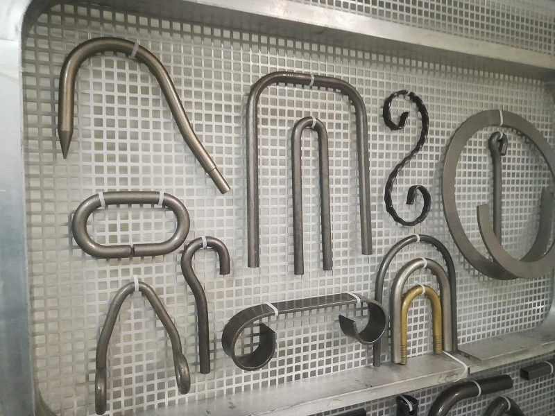
In the modern manufacturing and metalworking industries, bending and press machines are indispensable tools that shape, form, and modify metal and other materials with high precision. These machines are designed to handle various tasks, from simple bending operations to complex shaping processes, catering to a wide range of applications across multiple industries. The effectiveness and versatility of these machines make them critical in producing parts and components for automotive, aerospace, construction, and other heavy industries.
Bending and press machines are essential in transforming raw materials into finished products by applying force to alter the shape and properties of metals and other materials. The machines are designed to handle different materials, including steel, stainless steel (SS), aluminum, and more. These machines vary in size and capacity, from small, manual models used in workshops to large, automated systems in industrial manufacturing plants.
Types of Bending and Press Machines:
- Hydraulic Press Machines: Utilize hydraulic pressure to exert force, offering high precision and control in operations such as pressing, bending, and punching.
- Press Brake Machines: Specifically designed for bending sheet metal into various shapes by clamping the workpiece between a matching punch and die.
- Pipe Bending Machines: Used to bend pipes and tubes into desired angles and shapes, essential in plumbing, construction, and automotive industries.
- Sheet Metal Bending Machines: These machines focus on bending and shaping sheet metal, often used in fabrication shops and manufacturing lines.
Importance of Precision in Metalworking
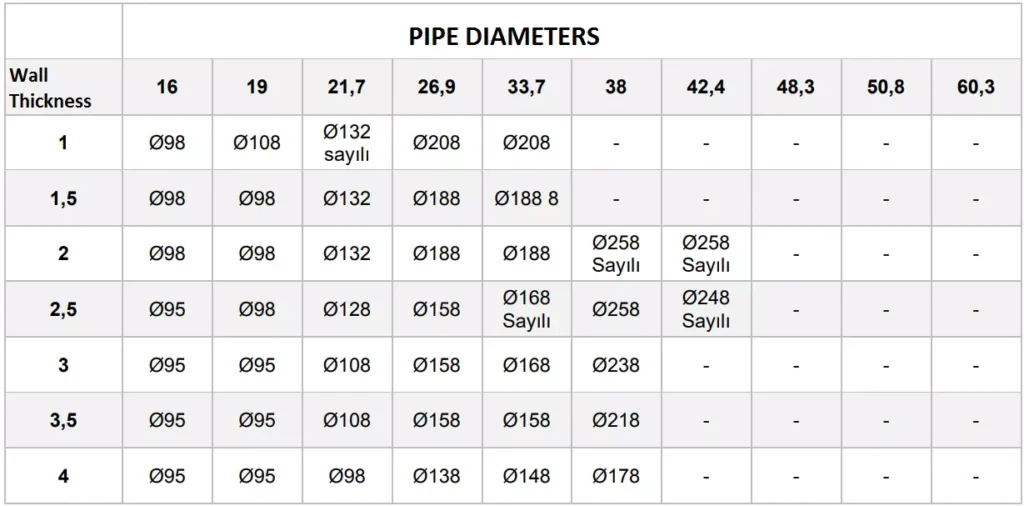
Precision is paramount in metalworking, as even minor deviations can lead to significant issues in the final product. Accurate bending and shaping are critical for ensuring that parts fit together correctly, maintain structural integrity, and meet the required specifications. The precision offered by modern bending and press machines allows manufacturers to produce complex components with tight tolerances, reducing the need for additional finishing processes and minimizing material waste.
Key Factors Influencing Precision:
- Machine Calibration: Proper calibration ensures the machine operates within the specified tolerances, providing consistent results.
- Tooling Quality: High-quality tools, such as dies and punches, are essential for achieving precise bends and shapes.
- Material Properties: Understanding the material’s properties, including its thickness, tensile strength, and ductility, is crucial for selecting the right machine settings.
- Operator Skill: Experienced operators can optimize machine settings and techniques to achieve the best results, even with challenging materials.
Overview of Bending and Press Machines
Bending and press machines are categorized based on their operating principles, applications, and the materials they handle. Below is a brief overview of some common types of bending and press machines:
1.3.1 Hydraulic Press Machines Hydraulic press machines operate by using a hydraulic cylinder to generate compressive force. They are highly versatile, allowing for various applications such as bending, forming, punching, and drawing. Hydraulic presses are known for their ability to exert high forces with great precision, making them ideal for heavy-duty applications. The introduction and working principles of hydraulic press machines will be discussed in more detail in the following sections.
1.3.2 Press Brake Machines Press brake machines are specialized machines used primarily for bending sheet metal. These machines utilize a combination of a punch and die to shape metal into specific angles and forms. Press brakes can be manual, hydraulic, or CNC-controlled, with each type offering different levels of automation and precision. The versatility of press brakes makes them a staple in metal fabrication shops.
1.3.3 Pipe Bending Machines Pipe bending machines are designed to bend pipes and tubes into various shapes and angles without compromising the material’s structural integrity. These machines are essential in industries such as plumbing, automotive, and construction, where precise pipe bends are required. Pipe bending machines can be hydraulic, pneumatic, mechanical, or electric, each offering different advantages depending on the application.
1.3.4 Sheet Metal Bending Machines Sheet metal bending machines focus on bending thin, flat sheets of metal into specific shapes. These machines are commonly used in the automotive and aerospace industries, where precision is critical. The machines can be manually operated, hydraulic, or CNC-controlled, offering various levels of control and automation.
Key Terminology and Concepts
Understanding the key terminology and concepts related to bending and press machines is essential for selecting the right equipment and optimizing its use. Below are some important terms that will be used throughout this document:
- Tonnage: The amount of force a machine can exert, usually measured in tons. For example, a 100-ton hydraulic press can exert 100 tons of force.
- Punch and Die: The tools used in press brake machines to shape metal. The punch presses into the die, which holds the workpiece.
- CNC (Computer Numerical Control): A method of automating machine tools using computers to control their movement and operation.
- Bend Radius: The radius of the inside curve of a bent section of metal. The bend radius is critical in determining the integrity and appearance of the bend.
- Ductility: The ability of a material to undergo deformation without breaking. Ductility is an important factor in bending operations.
Applications of Bending and Press Machines
Bending and press machines are used in a wide range of applications, from simple bending tasks to complex forming and shaping operations. Some common applications include:
- Automotive Industry: Producing car body parts, exhaust systems, and chassis components.
- Aerospace Industry: Manufacturing aircraft components, including fuselage panels and structural supports.
- Construction: Fabricating steel beams, columns, and other structural elements.
- Plumbing and HVAC: Bending pipes and tubes for plumbing, heating, and ventilation systems.
- Heavy Machinery: Forming and shaping parts for heavy equipment, such as cranes and bulldozers.
These applications highlight the versatility and importance of bending and press machines in modern manufacturing. The following sections will delve deeper into specific types of machines, their working principles, and the factors to consider when choosing the right equipment for your needs.
Hydraulic Press Machines: An Overview
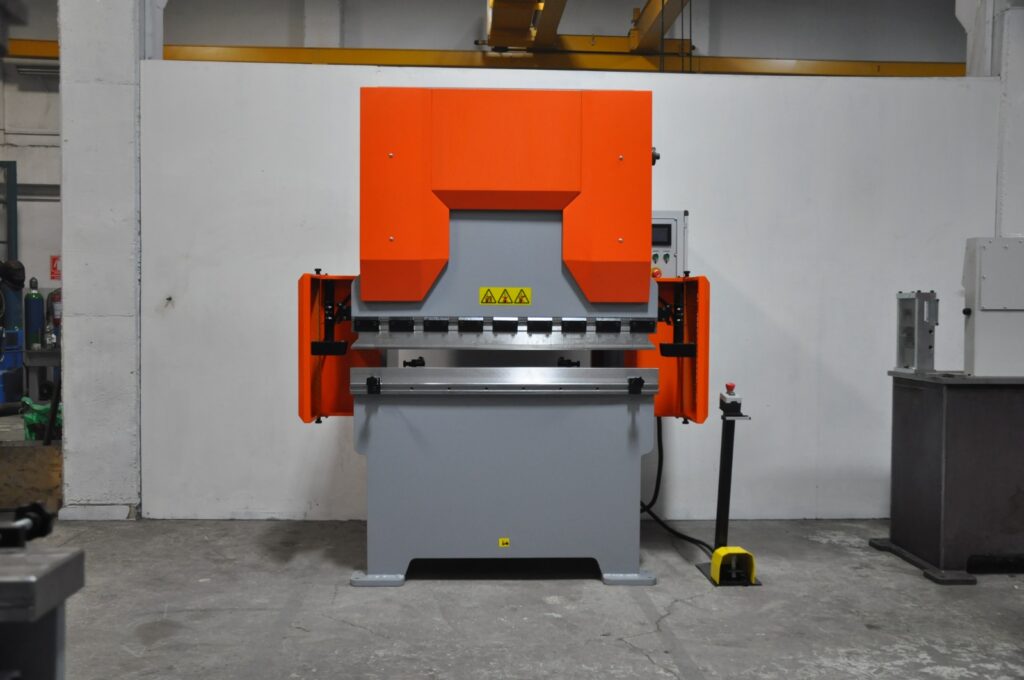
Hydraulic press machines are a cornerstone of modern manufacturing, offering unmatched power and precision in shaping, molding, and forming materials. These machines harness the power of hydraulics—a technology that uses fluid pressure to generate force—enabling them to perform tasks that require significant force with high accuracy. In this section, we will explore the fundamentals of hydraulic press machines, their working principles, various types, and key specifications that are critical for their selection and application in different industries.
2.1 Hydraulic Press Machine Introduction
Hydraulic press machines are used in a variety of industries for tasks that require compressive force. The concept behind hydraulic presses is based on Pascal’s law, which states that when pressure is applied to a confined fluid, the pressure is transmitted equally in all directions. This principle allows hydraulic presses to generate enormous amounts of force with relatively little input, making them highly efficient for industrial applications.
Key Characteristics:
- High Force Generation: Hydraulic presses can generate forces ranging from a few tons to several thousand tons, depending on the machine’s design and application.
- Versatility: These machines can perform a wide range of operations, including forging, stamping, bending, punching, and drawing.
- Precision: Hydraulic presses offer precise control over the applied force and movement, which is essential for tasks that require high accuracy.
- Customizability: Hydraulic presses can be customized with different types of tooling, making them adaptable to various tasks.
Hydraulic press machines are widely used in industries such as automotive manufacturing, aerospace, construction, and heavy machinery production. Their ability to handle large-scale operations with precision makes them a valuable asset in any industrial setting.
2.2 Hydraulic Press Machine Working Principles
The working of a hydraulic press machine is based on the simple but powerful principle of fluid mechanics. The machine typically consists of two cylinders: a smaller cylinder (called the slave cylinder) and a larger cylinder (called the master cylinder). These cylinders are connected by a pipe filled with hydraulic fluid, usually oil.
Working Process:
- Applying Force: When force is applied to the smaller cylinder (using a lever or a motor), it creates pressure in the hydraulic fluid.
- Pressure Transmission: According to Pascal’s law, the pressure in the fluid is transmitted equally throughout the system, causing the larger cylinder to move.
- Force Amplification: Because the larger cylinder has a greater surface area, the force exerted by it is much greater than the force applied to the smaller cylinder. This allows the machine to perform tasks that require significant force, such as pressing or bending metal.
Control Mechanisms:
- Pressure Control Valves: These valves regulate the amount of pressure applied to the hydraulic fluid, allowing the operator to control the force exerted by the machine.
- Flow Control Valves: These valves control the speed of the hydraulic fluid, which in turn controls the speed of the machine’s movement.
- Directional Control Valves: These valves direct the flow of hydraulic fluid to different parts of the system, enabling the machine to perform various operations.
Hydraulic press machines can be operated manually, semi-automatically, or fully automatically, depending on the level of control and automation required. Modern hydraulic presses often incorporate computerized control systems (CNC) for enhanced precision and efficiency.
2.3 Hydraulic Press Specifications
When selecting a hydraulic press machine, understanding its specifications is crucial to ensure that it meets the requirements of the intended application. Key specifications include:
2.3.1 Tonnage (Force Capacity)
- Definition: Tonnage refers to the maximum force that the hydraulic press can exert, usually measured in tons.
- Importance: The tonnage requirement depends on the material being processed and the operation being performed. For example, a higher tonnage is needed for tasks such as forging thick metal parts compared to bending thin sheets.
- Examples: A 100-ton hydraulic press is commonly used in medium-scale operations, while a 1000-ton hydraulic press is suitable for large-scale industrial applications.
2.3.2 Stroke Length
- Definition: Stroke length is the distance the press ram (the moving part of the machine that exerts force) can travel in one cycle.
- Importance: The stroke length determines the depth to which the material can be compressed or formed. It is particularly important in operations like deep drawing or molding.
- Adjustability: Many hydraulic presses allow the stroke length to be adjusted according to the specific requirements of the operation.
2.3.3 Bed Size
- Definition: The bed size is the working surface area of the press where the material is placed.
- Importance: The bed size must accommodate the dimensions of the workpiece being processed. A larger bed size is required for bigger workpieces.
- Customization: Some hydraulic presses offer interchangeable beds to handle different workpiece sizes.
2.3.4 Ram Speed
- Definition: Ram speed refers to the speed at which the press ram moves during operation.
- Importance: The speed of the ram can affect the quality of the operation. For example, slower speeds may be needed for precision tasks, while faster speeds are suitable for high-volume production.
- Control: Hydraulic presses often have adjustable ram speeds to suit different tasks.
2.3.5 Hydraulic System Pressure
- Definition: This is the pressure at which the hydraulic fluid operates within the system, usually measured in pounds per square inch (PSI) or bar.
- Importance: Higher system pressure allows for greater force generation but also requires more robust components to handle the increased stress.
- Safety: Hydraulic presses are equipped with safety mechanisms to prevent over-pressurization, which could lead to system failure.
2.4 100 Ton Hydraulic Press Specifications
A 100-ton hydraulic press is a versatile and commonly used machine in many industries, capable of handling a wide range of tasks from bending and forming to punching and drawing.
Key Specifications of a 100 Ton Hydraulic Press:
- Tonnage: 100 tons of maximum force, suitable for medium to large-scale operations.
- Stroke Length: Typically around 8 to 12 inches, with adjustability for different tasks.
- Bed Size: A standard bed size might be around 36 x 24 inches, but this can vary depending on the manufacturer.
- Ram Speed: Variable, often ranging from 10 to 30 mm/s, depending on the operation.
- System Pressure: Generally operates at around 3000 PSI, providing the necessary force without compromising safety.
Applications:
- Automotive Manufacturing: Used for pressing, forming, and shaping automotive parts.
- Metal Fabrication: Ideal for bending and shaping metal components in medium-scale production.
- Construction Equipment Manufacturing: Useful in the production of parts for heavy machinery and construction tools.
2.5 1000 Ton Hydraulic Press
The 1000-ton hydraulic press represents a significant leap in force capacity, making it suitable for the most demanding industrial applications. These machines are typically used in heavy industries where large-scale and high-force operations are required.
Key Specifications of a 1000 Ton Hydraulic Press:
- Tonnage: 1000 tons of maximum force, designed for heavy-duty tasks.
- Stroke Length: Can range from 12 to 24 inches, depending on the specific model and application.
- Bed Size: Large beds, often exceeding 72 x 48 inches, to accommodate massive workpieces.
- Ram Speed: Slower speeds, typically around 5 to 15 mm/s, due to the immense force being applied.
- System Pressure: Operates at high pressures, usually around 5000 PSI, to deliver the required force.
Applications:
- Shipbuilding: Used in the production of large metal components for ships and submarines.
- Aerospace: Essential for forming and shaping large aircraft components.
- Heavy Machinery Production: Involved in the manufacturing of parts for mining equipment, cranes, and other heavy-duty machinery.
2.6 Horizontal Hydraulic Press Machine
Horizontal hydraulic press machines differ from the more common vertical models in that the ram moves horizontally rather than vertically. This configuration is particularly useful for specific applications such as bending long pieces of metal or pressing components that are difficult to position vertically.
Advantages of Horizontal Hydraulic Press Machines:
- Versatility: Can handle a variety of tasks including bending, pressing, and straightening long workpieces.
- Ease of Operation: Easier to load and position large or awkwardly shaped workpieces.
- Space Efficiency: Horizontal presses can be more space-efficient in certain workshop layouts.
Applications:
- Railway Manufacturing: Used for bending and forming long steel rails.
- Pipeline Construction: Ideal for bending and forming large pipes used in oil, gas, and water pipelines.
- Structural Engineering: Employed in the production of long beams and structural components.
2.7 Small Horizontal Hydraulic Press
Small horizontal hydraulic presses are designed for applications that require less force and smaller workpieces. These machines are commonly used in workshops and smaller manufacturing facilities where space and budget constraints are factors.
Key Features:
- Compact Design: Takes up less space, making it ideal for small workshops.
- Lower Tonnage: Typically ranges from 10 to 50 tons, suitable for light to medium tasks.
- Ease of Use: Simple controls and operation, often with manual or semi-automatic settings.
Applications:
- Automotive Repair Shops: Used for pressing and straightening components like axles and shafts.
- Small Fabrication Shops: Ideal for bending and forming smaller metal parts.
- Maintenance Operations: Useful in on-site repairs and maintenance tasks where portability is required.
3. Press Brake Machines and Bending Applications
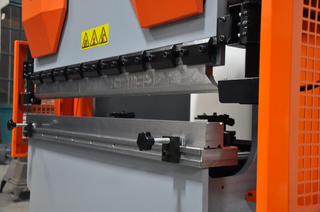
Press brake machines play a pivotal role in the metal fabrication industry, offering the precision and versatility required to transform flat metal sheets into complex shapes and structures. These machines are specifically designed for bending operations, making them indispensable in various manufacturing processes. This section delves into the functionality and applications of press brake machines, explores different bending techniques, and highlights the nuances of hydraulic press bending machines, including those tailored for sheet metal applications.
3.1 Press Brake Machine: Functionality and Applications
A press brake machine is a specialized tool used to bend and shape metal sheets and plates with high accuracy. Unlike general-purpose press machines, press brakes are specifically engineered to perform bending operations, making them essential in industries such as automotive, aerospace, construction, and manufacturing.
Key Functionalities:
- Bending: The primary function of a press brake is to bend metal sheets along a straight axis. This is achieved by clamping the metal between a punch and a die and applying force to create the desired angle.
- Forming: Beyond simple bends, press brakes can form complex shapes by combining multiple bending operations. This allows for the creation of intricate components required in various applications.
- Precision Cutting: Some advanced press brakes are equipped with features that allow for precise cutting or shearing of metal sheets during the bending process.
Applications:
- Automotive Industry: Manufacturing car body panels, chassis components, and exhaust systems.
- Aerospace Industry: Producing aircraft components, including fuselage sections and structural supports.
- Construction: Fabricating steel beams, columns, and other structural elements for buildings and infrastructure projects.
- Electronics: Creating enclosures and frames for electronic devices and appliances.
- Furniture Manufacturing: Designing and producing metal frames and supports for furniture pieces.
3.2 Press Brake Bending: Techniques and Precision
Bending is a fundamental operation in metalworking, and press brakes offer the precision and control necessary to achieve consistent and accurate results. Various bending techniques can be employed depending on the material, thickness, and desired outcome.
Bending Techniques:
- Air Bending: In this method, the punch presses the metal into the die without fully contacting it. This allows for greater flexibility in adjusting the bend angle and reduces stress on the material. Air bending is suitable for applications requiring variable angles and is widely used in sheet metal fabrication.Advantages:
- Versatility in bend angles.
- Reduced tooling wear.
- Lower force requirements compared to bottom bending.
- Bottom Bending (V-Die Bending): Here, the punch presses the metal all the way into the die, resulting in a more precise bend angle. This technique is ideal for applications where high accuracy and consistency are paramount.Advantages:
- Higher precision in bend angles.
- Better repeatability for mass production.
- Suitable for thicker materials.
- Coining: A specialized form of bottom bending where the metal is pressed into a highly precise shape within the die. Coining is used for intricate bends and is often employed in applications requiring fine details and superior surface finishes.
Precision Considerations:
- Tooling Quality: High-quality punches and dies are essential for achieving precise bends. The condition of the tooling directly impacts the accuracy and consistency of the bending process.
- Machine Calibration: Regular calibration ensures that the press brake operates within the specified tolerances, maintaining the precision of each bend.
- Material Properties: Understanding the ductility, tensile strength, and thickness of the material is crucial for selecting the appropriate bending parameters and avoiding defects such as cracking or warping.
- Operator Skill: Skilled operators can optimize machine settings and bending techniques to achieve the desired precision, especially when working with challenging materials or complex shapes.
3.3 Bend Press Machine: Overview
Bend press machines, often referred to interchangeably with press brake machines, are designed specifically for bending operations in metal fabrication. These machines vary in size, capacity, and control mechanisms, allowing them to cater to a wide range of applications from small workshops to large industrial facilities.
Types of Bend Press Machines:
- Manual Bend Press Machines: These are operated manually by the user, typically using a lever or hydraulic pump to apply force. They are suitable for small-scale operations and simple bending tasks.Advantages:
- Lower cost.
- Simplicity and ease of use.
- Ideal for light-duty applications.
- Hydraulic Bend Press Machines: Utilize hydraulic systems to apply force, offering greater control and higher tonnage capabilities compared to manual machines. They are widely used in medium to large-scale operations.Advantages:
- Higher force generation.
- Precise control over bending parameters.
- Suitable for a variety of materials and thicknesses.
- CNC Bend Press Machines: Equipped with computer numerical control (CNC) systems, these machines offer automated and programmable bending operations. They are ideal for high-precision and high-volume production environments.Advantages:
- Enhanced precision and repeatability.
- Ability to handle complex and intricate bends.
- Increased efficiency and reduced manual intervention.
Key Features:
- Adjustable Backgauges: Allow operators to set the precise location of the bend, ensuring consistency across multiple bends.
- Multiple Axes Control: Enables the machine to perform bends at various angles and positions without manual adjustments.
- Safety Features: Includes guards, emergency stop buttons, and sensors to ensure safe operation and protect operators from potential hazards.
3.4 Hydraulic Press Bending Machine
Hydraulic press bending machines combine the force-generating capabilities of hydraulic systems with the precision of press brakes to perform bending operations with high efficiency and accuracy. These machines are essential in applications where consistent and reliable bends are required, especially in medium to high-volume production settings.
Working Principles: Hydraulic press bending machines operate by using a hydraulic cylinder to exert force on the punch, which in turn bends the metal sheet against the die. The hydraulic system allows for smooth and controlled application of force, enabling precise bending angles and consistent results.
Advantages:
- High Force Capacity: Capable of handling thick and strong materials that require significant force to bend.
- Precision Control: Hydraulic systems offer fine control over the bending process, allowing for accurate and repeatable bends.
- Versatility: Suitable for a wide range of materials, including steel, aluminum, and stainless steel, making them adaptable to various industrial applications.
Applications:
- Automotive Manufacturing: Bending automotive body panels and structural components with high precision.
- Aerospace Industry: Forming aircraft parts that require exacting specifications and tight tolerances.
- Construction: Creating structural steel components for buildings and infrastructure projects.
- Heavy Machinery Production: Fabricating parts for construction equipment, mining machinery, and industrial tools.
3.5 Hydraulic Sheet Metal Bending Machine
Hydraulic sheet metal bending machines are specialized press brakes designed to handle the specific challenges associated with bending thin metal sheets. These machines leverage hydraulic systems to provide the necessary force and control for precise sheet metal fabrication.
Key Features:
- Enhanced Precision: Hydraulic systems ensure that each bend is executed with high accuracy, minimizing deviations and maintaining consistency.
- Adjustable Clamping Force: Allows for the secure holding of thin sheets without causing deformation or damage during the bending process.
- Integrated Control Systems: Modern hydraulic sheet metal bending machines often feature computerized controls for automated bending sequences, reducing manual intervention and increasing efficiency.
Benefits:
- Reduced Material Waste: Precise bending reduces the likelihood of errors and rework, leading to less material wastage and lower production costs.
- Increased Productivity: Automated and semi-automated systems enable faster production rates, meeting the demands of high-volume manufacturing.
- Versatility: Capable of handling a variety of sheet metal thicknesses and materials, making them suitable for diverse applications.
Applications:
- Appliance Manufacturing: Producing metal housings and components for household appliances such as refrigerators, washing machines, and ovens.
- Electronics Enclosures: Creating precise and compact metal enclosures for electronic devices and equipment.
- Furniture Manufacturing: Bending metal sheets for modern and ergonomic furniture designs.
- Signage and Displays: Forming metal panels used in signage, displays, and advertising materials.
3.6 Integration of CNC Technology in Press Brake Machines
The integration of Computer Numerical Control (CNC) technology into press brake machines has revolutionized the bending process, enhancing precision, efficiency, and flexibility. CNC press brakes are programmed with specific bending sequences, allowing for automated and repeatable operations that meet the stringent demands of modern manufacturing.
Advantages of CNC Press Brake Machines:
- Automation: Reduces the need for manual adjustments, minimizing human error and increasing production speed.
- Programmability: Allows for the storage and execution of complex bending programs, enabling the production of intricate shapes and multiple bends in a single setup.
- Consistency: Ensures that each bend is executed with the same precision, maintaining quality across large production runs.
- Ease of Use: User-friendly interfaces and software enable operators to input and modify bending programs with minimal training.
Applications:
- High-Precision Industries: Essential in industries such as aerospace and medical device manufacturing, where exacting standards must be met.
- Mass Production: Ideal for large-scale manufacturing where consistency and speed are critical.
- Customization: Facilitates the production of customized parts and components without significant downtime for setup changes.
3.7 Challenges and Considerations in Press Brake Bending
While press brake machines offer significant advantages in metal bending operations, several challenges and considerations must be addressed to ensure optimal performance and longevity of the equipment.
Common Challenges:
- Material Springback: After bending, materials tend to return partially to their original shape, known as springback. Proper compensation techniques and machine settings are required to achieve the desired final angle.
- Tooling Wear: Frequent bending operations can lead to wear and tear of punches and dies, affecting the quality of bends. Regular maintenance and timely replacement of tooling are essential.
- Setup Time: Adjusting machine settings and tooling for different bending tasks can be time-consuming, impacting overall productivity. CNC press brakes help mitigate this by enabling quick program changes.
- Operator Training: Skilled operators are necessary to manage machine settings, troubleshoot issues, and ensure consistent quality. Investing in training programs can enhance operational efficiency.
Key Considerations:
- Machine Selection: Choosing the right press brake machine involves assessing factors such as tonnage capacity, stroke length, bed size, and control systems based on the specific application requirements.
- Tooling Quality: High-quality punches and dies are crucial for achieving precise and consistent bends. Investing in durable tooling can reduce maintenance costs and improve overall performance.
- Maintenance Practices: Regular maintenance, including lubrication, inspection, and calibration, ensures that the press brake operates efficiently and extends its operational lifespan.
- Safety Measures: Implementing safety protocols, such as using protective guards and emergency stop mechanisms, protects operators and prevents accidents in the workplace.
3.8 Innovations in Press Brake Technology
Advancements in press brake technology continue to enhance the capabilities and efficiency of bending operations. Innovations such as servo-electric systems, advanced control software, and enhanced automation features are driving the evolution of press brake machines.
Servo-Electric Press Brakes: Servo-electric press brakes use electric motors to control the movement of the ram, offering precise positioning and energy-efficient operation. These machines provide faster cycle times and reduced maintenance compared to traditional hydraulic systems.
Advanced Control Software: Modern press brake machines are equipped with sophisticated software that enables real-time monitoring, automatic adjustments, and predictive maintenance. Features like automatic backgauges, bend allowance calculations, and integrated CAD/CAM systems streamline the bending process and improve accuracy.
Enhanced Automation: Automation features, including robotic loading and unloading, automated tool changes, and integrated quality control systems, increase productivity and reduce manual labor. These advancements are particularly beneficial in high-volume production environments where efficiency and consistency are paramount.
Sustainability Initiatives: Manufacturers are increasingly focusing on energy-efficient press brake machines that reduce power consumption and minimize environmental impact. Innovations such as regenerative braking systems and energy recovery mechanisms contribute to more sustainable manufacturing practices.
3.9 Case Studies: Press Brake Machines in Action
Automotive Manufacturing: In the automotive industry, press brake machines are used to fabricate various components such as door panels, chassis parts, and engine components. The precision offered by CNC press brakes ensures that each part meets the stringent quality standards required for vehicle assembly. For example, a major automotive manufacturer utilizes a fleet of 100-ton hydraulic press brakes to produce consistent and high-quality body panels, reducing production time and minimizing material waste.
Aerospace Industry: Aerospace manufacturers rely on hydraulic sheet metal bending machines to produce aircraft components with exacting specifications. The high precision and repeatability of CNC press brakes enable the production of complex parts such as fuselage sections and wing components. By integrating advanced control systems, aerospace companies can achieve the necessary tolerances and maintain the integrity of critical components.
Construction Sector: In the construction industry, press brake machines are used to fabricate structural steel elements like beams, columns, and trusses. Hydraulic press brakes with large bed sizes and high tonnage capacities are essential for handling the thick and heavy materials used in construction projects. For instance, a construction equipment manufacturer employs 1000-ton hydraulic press brakes to produce large steel beams, ensuring structural integrity and compliance with safety standards.
Electronics Manufacturing: Electronics manufacturers use small hydraulic sheet metal bending machines to create precise enclosures and frames for devices such as smartphones, laptops, and medical equipment. The ability to perform intricate bends with high accuracy ensures that the final products meet design specifications and fit seamlessly with other components.
3.10 Best Practices for Operating Press Brake Machines
To maximize the efficiency and lifespan of press brake machines, adhering to best practices is essential. These practices encompass proper machine setup, maintenance, and operational techniques that ensure consistent quality and safety.
Machine Setup:
- Accurate Alignment: Ensure that the punch and die are properly aligned to prevent uneven bends and reduce tooling wear.
- Proper Tooling Selection: Choose the appropriate punches and dies based on the material type, thickness, and desired bend angle.
- Parameter Optimization: Set the correct bending force, ram speed, and stroke length according to the material properties and bending requirements.
Maintenance:
- Regular Inspections: Conduct routine inspections of hydraulic systems, electrical components, and mechanical parts to identify and address potential issues early.
- Lubrication: Keep moving parts well-lubricated to reduce friction and prevent wear.
- Tooling Maintenance: Clean and maintain punches and dies to ensure optimal performance and extend their lifespan.
Operational Techniques:
- Consistent Feeding: Ensure that metal sheets are fed consistently into the press brake to maintain uniform bends.
- Monitoring and Adjustment: Continuously monitor the bending process and make necessary adjustments to maintain precision.
- Safety Protocols: Implement and enforce safety protocols, including the use of personal protective equipment (PPE) and adherence to operational guidelines.
Training and Education:
- Operator Training: Provide comprehensive training for operators to ensure they understand machine operation, safety procedures, and maintenance practices.
- Continuous Improvement: Encourage operators to stay updated with the latest techniques and technologies in press brake operations through ongoing education and training programs.
3.11 Conclusion
Press brake machines are integral to the metal fabrication industry, offering the precision and versatility required to produce a wide range of components and structures. Understanding the functionality, bending techniques, and specific applications of different press brake machines, including hydraulic and CNC models, is essential for optimizing their use in various industrial settings. By adhering to best practices and leveraging advancements in press brake technology, manufacturers can achieve high-quality results, enhance productivity, and maintain a competitive edge in the market.
In the following sections, we will explore other specialized bending machines, including pipe bending machines and sheet metal bending machines, to provide a comprehensive overview of the tools available for metal shaping and forming operations.
Pipe Bending Machines
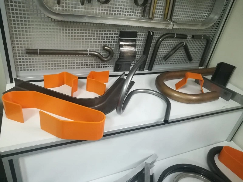
Pipe bending machines are essential tools in industries where precise and efficient bending of pipes and tubes is required. These machines are used to create complex pipe shapes that are crucial in various applications, from plumbing and construction to automotive and aerospace industries. In this section, we will explore the different types of pipe bending machines, including pneumatic, mechanical, hydraulic, and specialized machines for bending stainless steel (SS) and heavy pipes. We’ll also discuss the benefits and considerations for choosing the right pipe bending machine for specific applications.
4.1 Pneumatic Pipe Bending Machine
Pneumatic pipe bending machines utilize compressed air to generate the force needed to bend pipes. These machines are commonly used in applications that require moderate force and precision, making them suitable for a variety of industries, including automotive and HVAC (Heating, Ventilation, and Air Conditioning).
Working Principles:
- Air Compression: The machine operates by compressing air in a cylinder, which then forces a piston to move. This movement is transferred to the bending tool, which applies the necessary force to bend the pipe.
- Controlled Force: The force applied can be adjusted by regulating the air pressure, allowing for precise control over the bending process.
Advantages:
- Simplicity: Pneumatic systems are generally simpler and easier to maintain than hydraulic systems, with fewer components and less potential for leaks.
- Cost-Effectiveness: Pneumatic machines are often more affordable than their hydraulic counterparts, making them a good option for smaller operations.
- Safety: Pneumatic systems are inherently safer in environments where fire hazards are a concern, as they do not involve flammable fluids.
Applications:
- Automotive Industry: Bending exhaust pipes and other components where moderate force and precision are required.
- HVAC Systems: Shaping pipes and ducts for heating, ventilation, and air conditioning installations.
- General Fabrication: Suitable for bending tasks in small to medium-sized fabrication shops.
4.2 Mechanical Pipe Bending Machine
Mechanical pipe bending machines rely on mechanical force generated by gears, levers, and other mechanical components to bend pipes. These machines are known for their durability and reliability, making them suitable for high-volume production environments.
Working Principles:
- Mechanical Leverage: The machine uses mechanical leverage to amplify the force applied by the operator, allowing it to bend pipes with precision.
- Gear Systems: Gears and cams are often used to control the movement and force applied to the bending tool, ensuring consistent results.
Advantages:
- Durability: Mechanical pipe bending machines are built to last, with robust components that can withstand the rigors of high-volume production.
- Consistency: The use of gears and mechanical systems ensures consistent and repeatable bends, which is crucial in mass production.
- Ease of Use: These machines are typically straightforward to operate, with manual or semi-automatic controls that allow for precise adjustments.
Applications:
- Construction Industry: Bending steel pipes for structural applications, such as scaffolding and frameworks.
- Manufacturing: Producing bent pipes for various industrial products, including furniture, machinery, and equipment.
- Shipbuilding: Shaping pipes used in marine applications, where durability and precision are critical.
4.3 SS Pipe Bending Machine
Stainless steel (SS) pipes are widely used in industries that require corrosion-resistant and durable materials, such as food processing, pharmaceuticals, and chemical processing. Bending stainless steel pipes requires specialized machines that can handle the unique properties of this material without causing damage or deformation.
Key Features:
- Enhanced Tooling: SS pipe bending machines are equipped with hardened tooling that can withstand the high tensile strength of stainless steel, preventing tool wear and ensuring clean bends.
- Precision Control: These machines offer precise control over the bending process, allowing for tight bend radii and complex shapes without compromising the material’s integrity.
- Cooling Systems: Some SS pipe bending machines are equipped with cooling systems to prevent the material from overheating during the bending process, which could lead to discoloration or weakening of the stainless steel.
Advantages:
- Corrosion Resistance: SS pipe bending machines are designed to maintain the corrosion-resistant properties of stainless steel, making them ideal for applications in harsh environments.
- High Precision: The machines can produce precise bends with minimal springback, ensuring that the final product meets exact specifications.
- Versatility: Suitable for a wide range of applications, from sanitary piping in food processing to chemical transport lines in industrial settings.
Applications:
- Food and Beverage Industry: Bending pipes for sanitary processing lines, where cleanliness and corrosion resistance are paramount.
- Pharmaceutical Industry: Shaping pipes for sterile environments, including drug manufacturing and medical device production.
- Chemical Processing: Creating corrosion-resistant piping systems for transporting aggressive chemicals and other hazardous materials.
4.4 Steel Pipe Bending Machine
Steel pipe bending machines are designed to handle the rigors of bending steel pipes, which are commonly used in construction, infrastructure, and heavy industry. These machines are built to provide the necessary force and control to bend steel pipes without compromising their structural integrity.
Key Features:
- High Tonnage Capacity: Steel pipe bending machines are equipped with powerful hydraulic or mechanical systems capable of exerting the high forces required to bend steel.
- Robust Construction: The machines are built with heavy-duty frames and components to handle the stress of bending thick and strong steel pipes.
- Advanced Control Systems: Many steel pipe bending machines feature CNC controls, allowing for precise and automated bending processes.
Advantages:
- Strength and Durability: Steel pipe bending machines are capable of bending thick-walled and large-diameter steel pipes with high precision, ensuring that the final product meets structural requirements.
- Versatility: These machines can handle a wide range of steel pipe sizes and thicknesses, making them suitable for various applications in construction and heavy industry.
- Efficiency: The use of advanced control systems and automated features allows for efficient production, reducing labor costs and increasing throughput.
Applications:
- Construction: Bending steel pipes for structural applications, such as beams, columns, and supports in buildings and infrastructure projects.
- Oil and Gas Industry: Shaping steel pipes for pipelines, drilling rigs, and other critical infrastructure in the energy sector.
- Heavy Machinery Manufacturing: Producing bent steel components for construction equipment, mining machinery, and industrial tools.
4.5 Heavy Pipe Bending Machine
Heavy pipe bending machines are specialized for handling large-diameter and thick-walled pipes that require significant force to bend. These machines are used in industries where large-scale infrastructure projects and heavy-duty applications are common.
Key Features:
- High Force Capability: Heavy pipe bending machines are equipped with hydraulic systems capable of generating extremely high forces, often exceeding 1000 tons, to bend large and thick pipes.
- Large Bed Size: These machines feature expansive working areas to accommodate the size of the pipes being bent, allowing for precise positioning and control.
- Reinforced Components: The machines are built with reinforced frames, tooling, and hydraulic systems to handle the stress of bending heavy pipes without deformation.
Advantages:
- Capability: Heavy pipe bending machines can handle pipes with large diameters and thick walls, which are typically used in major infrastructure projects.
- Precision: Despite their size, these machines offer precise control over the bending process, ensuring that large pipes meet exacting specifications.
- Durability: Built to withstand the demands of heavy industry, these machines offer long service life and reliable performance in challenging environments.
Applications:
- Pipeline Construction: Bending large-diameter pipes for oil, gas, and water pipelines that span long distances and require precise engineering.
- Shipbuilding: Shaping heavy steel pipes for marine vessels, where durability and structural integrity are crucial.
- Power Generation: Producing bent pipes for power plants and energy infrastructure, including those used in nuclear and fossil fuel power generation.
4.6 Hydraulic Pipe Bending Machine
Hydraulic pipe bending machines are among the most versatile and powerful options for bending pipes in various industries. These machines utilize hydraulic pressure to apply force, offering precise control and the ability to handle a wide range of pipe sizes and materials.
Working Principles:
- Hydraulic Force: The machine uses a hydraulic cylinder to apply force to the bending tool, which then bends the pipe to the desired angle.
- Adjustable Pressure: Operators can adjust the hydraulic pressure to control the force applied, allowing for precise bends even in challenging materials.
Advantages:
- Versatility: Hydraulic pipe bending machines can handle a variety of materials, including steel, aluminum, and stainless steel, making them suitable for diverse applications.
- Precision: The hydraulic system offers fine control over the bending process, ensuring consistent results with minimal springback.
- Power: These machines are capable of generating significant force, allowing them to bend thick and strong pipes with ease.
Applications:
- Automotive Manufacturing: Bending exhaust pipes, roll cages, and other components where precision and strength are required.
- Aerospace Industry: Shaping pipes used in aircraft hydraulic systems, fuel lines, and other critical applications.
- Construction: Bending steel pipes for structural applications, such as beams, columns, and support structures.
4.7 Electric Pipe Bending Machine
Electric pipe bending machines offer an alternative to hydraulic and pneumatic systems, using electric motors to generate the force needed for bending operations. These machines are known for their energy efficiency, precision, and ease of use.
Key Features:
- Electric Motor Drive: The machine uses an electric motor to drive the bending tool, providing precise control over the bending process.
- Programmable Controls: Many electric pipe bending machines feature CNC or digital controls, allowing for automated and repeatable bending sequences.
- Quiet Operation: Electric machines tend to operate more quietly than hydraulic or pneumatic systems, making them suitable for environments where noise is a concern.
Advantages:
- Energy Efficiency: Electric pipe bending machines consume less energy compared to hydraulic systems, making them more cost-effective in the long run.
- Precision and Consistency: The use of electric motors and digital controls ensures precise and repeatable bends, which is critical in high-volume production.
- Ease of Maintenance: Electric machines have fewer moving parts compared to hydraulic systems, resulting in lower maintenance requirements and longer service life.
Applications:
- Furniture Manufacturing: Bending metal pipes for furniture frames, including chairs, tables, and shelving units.
- Medical Equipment: Shaping pipes used in medical devices and equipment, where precision and cleanliness are essential.
- Automotive Aftermarket: Producing custom exhaust systems, roll cages, and other automotive components.
4.8 Small Pipe Bending Machine
Small pipe bending machines are designed for applications that involve smaller-diameter pipes and require less force. These machines are commonly used in workshops, small-scale manufacturing, and maintenance operations.
Key Features:
- Compact Design: Small pipe bending machines are portable and space-efficient, making them ideal for use in confined spaces or on job sites.
- Manual or Semi-Automatic Operation: These machines are typically operated manually or with semi-automatic controls, offering a balance between control and ease of use.
- Versatility: Despite their small size, these machines can handle a variety of materials and bending angles, making them suitable for diverse applications.
Advantages:
- Portability: Small pipe bending machines are easy to transport and set up, making them ideal for on-site work and maintenance tasks.
- Cost-Effectiveness: These machines are typically more affordable than larger models, making them accessible to small businesses and workshops.
- Ease of Use: Simple controls and operation make these machines user-friendly, even for operators with limited experience.
Applications:
- Plumbing: Bending pipes for plumbing installations and repairs, including copper, PVC, and other materials.
- HVAC: Shaping small-diameter pipes for heating, ventilation, and air conditioning systems.
- DIY and Home Workshops: Suitable for hobbyists and small-scale fabricators working on custom projects.
4.9 Pipe Bending Machine Price Considerations
When selecting a pipe bending machine, understanding the factors that influence price is crucial to making an informed investment. The price of a pipe bending machine can vary significantly based on several key factors, including machine type, capacity, features, and brand.
Factors Influencing Price:
- Machine Type: Hydraulic and electric pipe bending machines are generally more expensive than pneumatic or mechanical models due to their advanced features and higher force capabilities.
- Capacity: Machines capable of bending larger-diameter or thicker-walled pipes typically cost more due to the increased force requirements and more robust construction.
- Control Systems: CNC-controlled machines with programmable features and automated bending sequences are priced higher than manual or semi-automatic models.
- Brand and Quality: Established brands with a reputation for quality and reliability often command higher prices, but they also offer better performance, durability, and support.
Cost vs. Functionality:
- Entry-Level Machines: Suitable for small-scale operations, workshops, and maintenance tasks, these machines offer basic functionality at a lower cost.
- Mid-Range Machines: Ideal for medium-sized businesses and manufacturers, offering a balance between price and advanced features.
- High-End Machines: Designed for large-scale production and heavy industry, these machines offer the highest levels of precision, automation, and durability but come at a premium price.
Making the Right Investment:
- Assessing Needs: Consider the specific requirements of your operation, including the types of materials, pipe sizes, and production volume, to choose a machine that meets your needs without overspending.
- Long-Term Value: While higher-end machines may have a higher initial cost, their durability, efficiency, and advanced features can lead to lower operational costs and better ROI over time.
- Supplier Support: Look for suppliers that offer good after-sales support, including training, maintenance, and parts availability, as this can significantly impact the total cost of ownership.
4.10 Conclusion
Pipe bending machines are crucial tools in various industries, offering the ability to shape and form pipes to precise specifications. Understanding the different types of pipe bending machines, including pneumatic, mechanical, hydraulic, and specialized machines for stainless steel and heavy pipes, is essential for selecting the right equipment for your needs. By considering factors such as machine capacity, control systems, and price, manufacturers and operators can make informed decisions that optimize productivity and ensure the quality of their products.
Sheet Metal Bending Machines
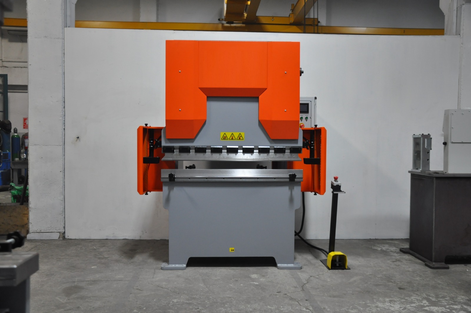
Sheet metal bending machines are essential in the fabrication of metal components, allowing manufacturers to create a wide range of shapes and structures from flat metal sheets. These machines are used across various industries, from automotive to aerospace, and play a critical role in producing everything from simple bends to complex geometries. In this section, we will explore the different types of sheet metal bending machines, including electric, hydraulic, automatic, and CNC-controlled machines. We will also discuss their applications, benefits, and factors to consider when selecting the right machine for specific tasks.
5.1 Electric Sheet Metal Bending Machine
Electric sheet metal bending machines use electric motors to generate the force needed to bend metal sheets. These machines are known for their energy efficiency, precision, and ease of use, making them a popular choice in many fabrication shops.
Key Features:
- Electric Motor Drive: These machines are driven by electric motors, which provide precise control over the bending process and allow for consistent and repeatable results.
- Programmable Controls: Many electric bending machines come with digital or CNC controls, enabling operators to program bending sequences and angles for automated operations.
- Quiet Operation: Electric machines tend to be quieter than hydraulic models, making them suitable for environments where noise reduction is important.
Advantages:
- Energy Efficiency: Electric machines are more energy-efficient than hydraulic machines, reducing operational costs over time.
- Precision: The electric motor provides consistent power, allowing for precise bends with minimal variability.
- Ease of Maintenance: With fewer moving parts and no hydraulic fluid, electric bending machines typically require less maintenance and have lower operating costs.
Applications:
- Light Fabrication: Suitable for bending thin sheets of metal, making them ideal for light fabrication tasks such as creating enclosures, brackets, and panels.
- Electronics Manufacturing: Used to bend metal components for electronic devices, where precision and consistency are critical.
- Custom Fabrication: Ideal for small workshops and custom fabrication businesses that require flexible and precise bending capabilities.
5.2 Small Sheet Bending Machine
Small sheet bending machines are designed for tasks that involve smaller pieces of sheet metal. These machines are typically more compact and easier to use, making them ideal for workshops and small-scale operations.
Key Features:
- Compact Design: Small sheet bending machines are designed to be portable and space-efficient, allowing them to be used in smaller workspaces.
- Manual or Semi-Automatic Operation: These machines often feature manual or semi-automatic controls, providing a balance between precision and ease of use.
- Versatile Tooling: Despite their size, small sheet bending machines can be equipped with a variety of tooling to handle different bending tasks.
Advantages:
- Portability: The compact size of these machines makes them easy to transport and set up, allowing for flexible use in different locations.
- Affordability: Small sheet bending machines are typically less expensive than larger models, making them accessible to small businesses and workshops.
- Ease of Use: Simple controls and operation make these machines user-friendly, even for operators with limited experience.
Applications:
- DIY and Custom Projects: Ideal for hobbyists and small-scale fabricators working on custom projects.
- Maintenance and Repair: Used in maintenance shops for bending small metal parts and components during repairs.
- Prototype Development: Suitable for creating prototypes and small production runs, where flexibility and quick setup are important.
5.3 Automatic Bending Machine
Automatic bending machines are designed to streamline the bending process by automating various aspects of the operation. These machines are equipped with advanced control systems that allow for precise and repeatable bending without the need for constant operator intervention.
Key Features:
- Automation: Automatic bending machines are capable of performing multiple bends in a single setup, reducing the need for manual adjustments and increasing productivity.
- CNC Controls: Many automatic bending machines are equipped with CNC (Computer Numerical Control) systems that allow for the programming of complex bending sequences.
- High Throughput: These machines are designed for high-volume production, making them ideal for industries that require large quantities of bent metal parts.
Advantages:
- Increased Efficiency: Automation reduces the time required for setup and bending, leading to higher production rates and lower labor costs.
- Consistency: Automatic machines ensure that each bend is executed with the same precision, reducing variability and improving product quality.
- Flexibility: The ability to program complex bending sequences allows for the production of intricate and custom shapes with minimal manual intervention.
Applications:
- Mass Production: Used in industries such as automotive and aerospace, where large quantities of parts with consistent quality are required.
- Complex Fabrication: Suitable for producing parts with multiple bends or intricate shapes that would be difficult to achieve manually.
- High-Precision Manufacturing: Ideal for applications where exacting tolerances and repeatability are essential, such as in the production of medical devices and electronics.
5.4 CNC Sheet Bending Machine
CNC sheet bending machines represent the pinnacle of precision and automation in sheet metal bending. These machines are controlled by computer numerical control (CNC) systems, which allow for highly accurate and repeatable bending operations.
Key Features:
- CNC Control: CNC sheet bending machines are equipped with computerized controls that allow operators to program and execute complex bending sequences with high precision.
- Automated Tooling: These machines often feature automated tooling systems that can change punches and dies as needed, further increasing efficiency and reducing setup time.
- Real-Time Monitoring: CNC systems provide real-time monitoring of the bending process, allowing operators to make adjustments on the fly and ensuring that each bend meets the required specifications.
Advantages:
- High Precision: CNC control ensures that each bend is performed with exacting accuracy, making these machines ideal for applications where precision is critical.
- Repeatability: The ability to store and recall bending programs allows for consistent results across multiple production runs, reducing variability and waste.
- Complexity: CNC sheet bending machines can perform intricate bends and form complex shapes that would be difficult or impossible to achieve with manual machines.
Applications:
- Aerospace Industry: Used to produce aircraft components with exacting tolerances and complex shapes.
- Automotive Manufacturing: Essential for the production of car body panels, chassis components, and other critical parts that require high precision.
- Electronics and Appliances: Ideal for creating metal enclosures, frames, and other components used in electronics and household appliances.
5.5 What is a CNC Bending Machine?
A CNC bending machine is a specialized type of bending machine that uses computer numerical control (CNC) to automate the bending process. CNC machines are programmed with specific instructions that control the movement of the machine’s bending tools, allowing for precise and repeatable operations.
How CNC Bending Machines Work:
- Programming: Operators program the CNC machine using specialized software, inputting parameters such as bend angles, material thickness, and sequence of operations.
- Tool Movement: The CNC system controls the movement of the bending tools, ensuring that each bend is executed according to the programmed instructions.
- Feedback Loops: CNC machines often include feedback systems that monitor the bending process in real-time, allowing for automatic adjustments to maintain precision.
Benefits of CNC Bending Machines:
- Precision: CNC bending machines offer unparalleled precision, with the ability to produce bends with tight tolerances and consistent quality.
- Efficiency: Automation reduces the time required for setup and bending, increasing throughput and reducing labor costs.
- Flexibility: The ability to program complex bending sequences allows for the production of custom and intricate shapes with minimal manual intervention.
Applications:
- Industrial Manufacturing: Used in high-volume production environments where consistency and precision are critical.
- Custom Fabrication: Ideal for producing custom parts and components, especially those with complex geometries.
- Prototyping: CNC bending machines are valuable in the development of prototypes, allowing for rapid iteration and precise adjustments.
5.6 Hydraulic Press Bending Machine
Hydraulic press bending machines combine the power of hydraulic systems with the precision of press brakes to perform bending operations with high efficiency and accuracy. These machines are widely used in industries that require consistent and reliable bends in a variety of materials, including steel, aluminum, and stainless steel.
Working Principles:
- Hydraulic Force: The machine uses a hydraulic cylinder to apply force to the bending tool, which then bends the metal sheet to the desired angle.
- Adjustable Pressure: Operators can adjust the hydraulic pressure to control the force applied, allowing for precise bends even in challenging materials.
Advantages:
- High Force Capacity: Hydraulic press bending machines are capable of exerting significant force, making them suitable for bending thick and strong materials.
- Precision: The hydraulic system provides fine control over the bending process, ensuring consistent results with minimal variability.
- Versatility: These machines can handle a wide range of materials and thicknesses, making them suitable for various industrial applications.
Applications:
- Automotive Manufacturing: Bending automotive body panels and structural components with high precision.
- Construction: Creating structural steel components for buildings and infrastructure projects.
- Heavy Machinery Production: Fabricating parts for construction equipment, mining machinery, and industrial tools.
5.7 Hydraulic Sheet Metal Bending Machine
Hydraulic sheet metal bending machines are specialized press brakes designed to handle the specific challenges associated with bending thin metal sheets. These machines leverage hydraulic systems to provide the necessary force and control for precise sheet metal fabrication.
Key Features:
- Enhanced Precision: Hydraulic systems ensure that each bend is executed with high accuracy, minimizing deviations and maintaining consistency.
- Adjustable Clamping Force: Allows for the secure holding of thin sheets without causing deformation or damage during the bending process.
- Integrated Control Systems: Modern hydraulic sheet metal bending machines often feature computerized controls for automated bending sequences, reducing manual intervention and increasing efficiency.
Benefits:
- Reduced Material Waste: Precise bending reduces the likelihood of errors and rework, leading to less material wastage and lower production costs.
- Increased Productivity: Automated and semi-automated systems enable faster production rates, meeting the demands of high-volume manufacturing.
- Versatility: Capable of handling a variety of sheet metal thicknesses and materials, making them suitable for diverse applications.
Applications:
- Appliance Manufacturing: Producing metal housings and components for household appliances such as refrigerators, washing machines, and ovens.
- Electronics Enclosures: Creating precise and compact metal enclosures for electronic devices and equipment.
- Furniture Manufacturing: Bending metal sheets for modern and ergonomic furniture designs.
5.8 Choosing the Right Sheet Metal Bending Machine
Selecting the right sheet metal bending machine involves considering several factors, including the material being bent, the required precision, production volume, and budget. Here are some key considerations to keep in mind:
Material Type and Thickness:
- Material: Different machines are better suited for specific materials. For example, hydraulic machines are ideal for thick steel sheets, while electric machines may be better for lighter materials.
- Thickness: The thickness of the material will determine the required force, with thicker materials needing more powerful machines.
Bending Precision:
- Tolerances: If your application requires tight tolerances, a CNC or hydraulic bending machine may be the best choice due to their precision and consistency.
- Complexity: For complex bending operations involving multiple bends or intricate shapes, a CNC machine will provide the necessary control and flexibility.
Production Volume:
- Low Volume: For small production runs or custom projects, a manual or small sheet bending machine may suffice.
- High Volume: For large-scale production, an automatic or CNC bending machine is more appropriate due to their higher efficiency and automation capabilities.
Budget Considerations:
- Initial Investment: CNC and hydraulic machines tend to have higher upfront costs but offer long-term benefits in precision, efficiency, and flexibility.
- Operating Costs: Consider the long-term costs of maintenance, energy consumption, and tooling when selecting a machine.
Supplier Support:
- After-Sales Service: Choose a supplier that offers good after-sales support, including maintenance, training, and access to spare parts.
- Warranty: Look for machines that come with a comprehensive warranty, which can protect your investment and reduce the risk of unexpected costs.
5.9 Future Trends in Sheet Metal Bending Machines
The field of sheet metal bending is constantly evolving, with new technologies and innovations improving the efficiency, precision, and versatility of bending machines. Here are some trends shaping the future of sheet metal bending:
Automation and Robotics:
- Increased Automation: Automation is becoming more prevalent in sheet metal bending, with robots and automated systems taking over tasks such as loading, unloading, and tool changes, leading to higher productivity and lower labor costs.
- Collaborative Robots: Also known as cobots, these robots work alongside human operators to assist with bending operations, enhancing efficiency while maintaining flexibility.
Advanced CNC Systems:
- Real-Time Monitoring: CNC systems are becoming more advanced, with features such as real-time monitoring, predictive maintenance, and automatic adjustments ensuring higher precision and reducing downtime.
- AI Integration: Artificial intelligence (AI) is being integrated into CNC systems to optimize bending processes, improve decision-making, and enhance overall efficiency.
Sustainability Initiatives:
- Energy Efficiency: Manufacturers are focusing on creating more energy-efficient bending machines that reduce power consumption without compromising performance.
- Material Waste Reduction: Innovations in tooling and process control are helping to reduce material waste, leading to more sustainable manufacturing practices.
Customization and Flexibility:
- Modular Machines: Modular designs allow for easy customization of bending machines, enabling manufacturers to adapt to different tasks and requirements without significant downtime.
- Flexible Tooling: Advances in tooling technology are allowing for more flexible and adaptable bending operations, making it easier to switch between different products and designs.
5.10 Conclusion
Sheet metal bending machines are vital tools in modern manufacturing, offering the precision, flexibility, and efficiency needed to produce high-quality metal components. Understanding the different types of machines—such as electric, hydraulic, automatic, and CNC models—and their specific applications is crucial for selecting the right equipment for your needs. By considering factors such as material type, bending precision, production volume, and budget, manufacturers can make informed decisions that enhance productivity and ensure the quality of their products.
Bending Press Machine Price Considerations
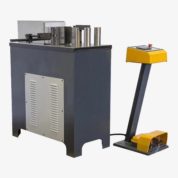
When investing in bending press machines, understanding the factors that influence pricing is essential for making an informed and cost-effective decision. Bending press machines come in various types and configurations, each with different features and capabilities that affect their overall cost. In this section, we will explore the key factors that determine the price of bending press machines, including specifications, features, brand reputation, and market demand. We will also discuss how to balance cost with functionality to ensure that you select the right machine for your specific needs.
6.1 Factors Affecting Bending Press Machine Price
The price of a bending press machine is influenced by several factors, including its type, specifications, features, brand, and market conditions. Understanding these factors can help you determine which machine offers the best value for your investment.
6.1.1 Machine Type
- Manual vs. Automated Machines: Manual bending press machines are generally less expensive than automated or CNC-controlled machines due to their simpler design and lower manufacturing costs. However, automated machines, while more expensive, offer greater efficiency, precision, and productivity, which can justify the higher initial investment.
- Hydraulic vs. Mechanical Presses: Hydraulic presses are typically more expensive than mechanical presses because of their complex hydraulic systems, which provide greater force and control. Mechanical presses, while less costly, may be more suitable for applications where speed is prioritized over precision.
6.1.2 Specifications and Capacity
- Tonnage: The tonnage, or force capacity, of a bending press machine is one of the primary factors influencing its price. Machines with higher tonnage are capable of bending thicker and stronger materials but come with a higher price tag due to the more robust construction and powerful hydraulic or mechanical systems required.
- Bed Size: The size of the machine’s bed, which determines the maximum size of the workpiece it can handle, also affects the price. Larger beds increase the machine’s versatility but require more material and engineering, leading to higher costs.
- Stroke Length: The stroke length, or the distance the press ram can travel, is another critical specification. Machines with longer stroke lengths can accommodate deeper bends, which adds to the complexity and cost of the machine.
6.1.3 Features and Technology
- CNC Controls: Bending press machines equipped with CNC (Computer Numerical Control) systems are significantly more expensive than those with manual or semi-automatic controls. CNC systems offer the ability to program and automate complex bending sequences, enhancing precision and productivity, which justifies their higher price.
- Automation and Robotics: Machines with advanced automation features, such as automatic tool changers, robotic loading and unloading, and real-time monitoring systems, command higher prices due to the added technology and the potential for increased production efficiency.
- Safety Features: Enhanced safety features, such as light curtains, safety guards, and emergency stop systems, can also contribute to the overall cost of the machine. These features are essential for protecting operators and ensuring compliance with safety regulations, particularly in high-volume production environments.
6.1.4 Brand and Quality
- Reputation: The reputation of the manufacturer or brand plays a significant role in the price of bending press machines. Established brands with a history of quality, reliability, and excellent after-sales support often charge a premium for their products. While these machines may be more expensive upfront, they often offer better performance, durability, and long-term value.
- Quality of Materials: The quality of the materials used in the construction of the machine, such as the steel for the frame and the components of the hydraulic system, affects both the machine’s durability and price. Higher-quality materials lead to longer-lasting machines but increase manufacturing costs.
6.1.5 Market Demand and Availability
- Supply and Demand: Market conditions, such as the balance between supply and demand, can also influence the price of bending press machines. During periods of high demand, prices may rise due to limited availability. Conversely, prices may decrease during periods of low demand or excess supply.
- Import and Export Costs: For machines that are imported, factors such as tariffs, shipping costs, and currency exchange rates can affect the final price. These costs can vary significantly depending on the country of origin and the location of the buyer.
6.2 Cost vs. Functionality: Making the Right Investment
When selecting a bending press machine, it is essential to balance cost with functionality to ensure that the machine meets your specific needs without exceeding your budget. Here are some strategies to help you make a cost-effective investment:
6.2.1 Assessing Your Needs
- Production Volume: Consider the volume of production when choosing a machine. If your operation involves high-volume production, investing in a more expensive, automated machine may be justified by the increased efficiency and reduced labor costs. For lower-volume operations, a less expensive manual or semi-automatic machine may be sufficient.
- Material Type and Thickness: The types of materials you work with, including their thickness and strength, will determine the necessary tonnage and capabilities of the machine. Ensure that the machine you choose can handle your specific material requirements without overpaying for unnecessary capacity.
- Complexity of Bends: If your applications involve complex bends or require high precision, investing in a CNC-controlled machine may be worth the higher cost. However, for simpler bends, a manual or mechanical machine may provide adequate functionality at a lower price.
6.2.2 Evaluating Long-Term Costs
- Operating Costs: Consider the long-term operating costs of the machine, including energy consumption, maintenance, and tooling. While a machine with advanced features may have a higher upfront cost, it could offer lower operating costs and higher efficiency, leading to savings over time.
- Durability and Reliability: Machines made with higher-quality materials and components tend to have longer service lives and require less maintenance. Investing in a durable, reliable machine can reduce downtime and maintenance costs, providing better long-term value.
- Resale Value: Some high-quality machines maintain their value well and can be resold at a good price if your needs change. This can offset some of the initial investment costs and provide flexibility in the future.
6.2.3 Exploring Financing and Leasing Options
- Financing: Many manufacturers and dealers offer financing options that allow you to spread the cost of the machine over time. This can make it easier to afford a higher-quality machine without straining your budget.
- Leasing: Leasing is another option that allows you to use a high-quality machine without the full upfront cost. Leasing can be particularly advantageous if you need the machine for a specific project or a limited time.
6.2.4 Considering Used or Refurbished Machines
- Used Machines: Purchasing a used bending press machine can be a cost-effective way to acquire high-quality equipment at a lower price. However, it is essential to thoroughly inspect the machine for wear and tear and ensure that it has been well-maintained.
- Refurbished Machines: Refurbished machines offer a middle ground between new and used equipment. These machines have been restored to good working condition and often come with warranties, providing reliability at a reduced cost.
6.2.5 Comparing Suppliers and Brands
- Supplier Reputation: Work with reputable suppliers who offer good after-sales support, including training, maintenance, and access to spare parts. A reliable supplier can significantly impact the total cost of ownership by helping you keep the machine in good working condition.
- Brand Comparison: Compare different brands and models to find the best balance between price and features. Look for reviews and case studies to understand how the machines perform in real-world applications and whether they meet industry standards.
6.3 Case Studies: Price Considerations in Real-World Scenarios
Case Study 1: Small Fabrication Shop A small metal fabrication shop required a bending press machine for custom projects involving light to medium-gauge steel. After evaluating their needs, they opted for a mid-range hydraulic press with manual controls. While they considered a CNC machine, the additional cost was not justified given their low production volume. The hydraulic press offered the necessary force and precision at a reasonable price, allowing the shop to handle a variety of projects without overextending their budget.
Case Study 2: High-Volume Automotive Manufacturer A large automotive manufacturer needed a new bending press machine to increase production efficiency for body panels. They chose a high-end CNC-controlled hydraulic press with automated tool changers and real-time monitoring. Although the machine was significantly more expensive than manual or semi-automatic models, the investment was justified by the increased throughput, reduced labor costs, and high precision required for automotive production. The machine’s advanced features also allowed for quicker setup times and reduced downtime, further enhancing productivity.
Case Study 3: Start-Up in the Aerospace Industry A start-up aerospace company needed a bending press machine capable of producing complex, high-precision components. Given their limited budget, they explored options for used and refurbished CNC machines. They found a reputable supplier offering a refurbished CNC press brake that met their specifications at a fraction of the cost of a new machine. The refurbished machine provided the precision and functionality needed for aerospace applications, allowing the start-up to meet industry standards without exceeding their budget.
6.4 Conclusion
When considering the purchase of a bending press machine, it is crucial to weigh the cost against the functionality and long-term value of the machine. Factors such as machine type, specifications, features, brand reputation, and market demand all play a significant role in determining the price. By carefully assessing your specific needs, evaluating long-term costs, exploring financing or leasing options, and comparing suppliers and brands, you can make a well-informed decision that balances cost with the required functionality. Whether you are a small shop or a large manufacturer, selecting the right bending press machine is an investment that can enhance productivity, improve product quality, and contribute to the overall success of your operation.
EMS Metalworking Machinery
We design, manufacture and assembly metalworking machinery such as:
- Hydraulic transfer press
- Glass mosaic press
- Hydraulic deep drawing press
- Casting press
- Hydraulic cold forming press
- Hydroforming press
- Composite press
- Silicone rubber moulding press
- Brake pad press
- Melamine press
- SMC & BMC Press
- Labrotaroy press
- Edge cutting trimming machine
- Edge curling machine
- Trimming beading machine
- Trimming joggling machine
- Cookware production line
- Pipe bending machine
- Profile bending machine
- Bandsaw for metal
- Cylindrical welding machine
- Horizontal pres and cookware
- Kitchenware, hotelware
- Bakeware and cuttlery production machinery
as a complete line as well as an individual machine such as:
- Edge cutting trimming beading machines
- Polishing and grinding machines for pot and pans
- Hydraulic drawing presses
- Circle blanking machines
- Riveting machine
- Hole punching machines
- Press feeding machine
You can check our machinery at work at: EMS Metalworking Machinery – YouTube
Applications:
- Beading and ribbing
- Flanging
- Trimming
- Curling
- Lock-seaming
- Ribbing
- Flange-punching